A comparison of reinforcement efficiency of various types of carbon nanotubes in polyacrylonitrile...
11
A comparison of reinforcement efficiency of various types of carbon nanotubes in polyacrylonitrile fiber Han Gi Chae, T.V. Sreekumar 1 , Tetsuya Uchida 2 , Satish Kumar * School of Polymer, Textile and Fiber Engineering, Georgia Institute of Technology, Atlanta, GA 30332, USA Received 28 March 2005; received in revised form 5 August 2005; accepted 30 August 2005 Available online 23 September 2005 Abstract Polyacrylonitrile (PAN)/carbon nanotubes (CNTs) composite fibers were spun from solutions in dimethyl acetamide (DMAc), using single wall (SWNTs), double wall (DWNTs), multi wall (MWNTs) carbon nanotubes, and vapor grown carbon nanofibers (VGCNFs). In each case, CNT content was 5 wt% with respect to the polymer. Structure, morphology, and properties of the composite fibers have been characterized using X-ray diffraction, Raman spectroscopy, scanning and transmission electron microscopy, tensile tests, dynamic mechanical tests, as well as thermal shrinkage. While all nanotubes contributed to property improvements, maximum increase in modulus (75%) and reduction in thermal shrinkage (up to 50%) was observed in the SWNT containing composites, and the maximum improvement in tensile strength (70%), strain to failure (110%), and work of rupture (230%) was observed in the MWNTs containing composites. PAN orientation is higher in the composite fiber (orientation factor up to 0.62) than in the control PAN fiber (orientation factor 0.52), and the PAN crystallite size in the composite fiber is up to 35% larger than in the control PAN (3.7 nm), while the overall PAN crystallinity diminished slightly. Nanotube orientation in the composite fibers is significantly higher (0.98 for SWNTs, 0.88 for DWNTs, and 0.91 for MWNTs and VGCNFs) than the PAN orientation (0.52–0.62). Improvement in low strain properties (modulus and shrinkage) was attributed to PAN interaction with the nanotube, while the improvement in high strain properties (tensile strength, elongation to break, and work of rupture) at least in part is attributed to the nanotube length. Property improvements have been analyzed in terms of nanotube surface area and orientation. q 2005 Elsevier Ltd. All rights reserved. Keywords: Carbon nanotube; Polyacrylonitrile; Carbon fiber 1. Introduction Carbon fibers developed since 1960s are now widely used in composite applications. Vapor grown carbon nano fibers (VGCNFs) developed in 1980s [1], and carbon nanotubes (single wall—SWNTs [2,3], double wall—DWNTs [4,5], and multiwall—MWNTs [6]) developed in 1990s have exceptional physical, mechanical, electrical, thermal, and optical properties [7,8] and are sometimes heralded to be the ultimate reinforcing systems for polymer and other matrices. Significant break- throughs have been reported in processing carbon nanotubes [9–11] and carbon nanotube/polymer composite films [12–18] and fibers [19–21]. Pristine or functionalized [22–28] carbon nanotubes have been dispersed in more than 25 polymer matrix systems, including semi-crystalline [29,30] and amorphous [31,32] thermoplastics, thermosetting polymers [33,34], water soluble polymers [35], liquid crystalline polymers [20,36], and conjugated polymers [37,38]. Carbon nanotubes are also being used to reinforce ceramics [39–41] and metal matrices [42–44]. Property improvements with carbon nanotubes include enhanced tensile modulus [45–47], tensile strength [47–49], torsional modulus [50], compressive strength [51,52], fatigue behavior [53], toughness [47], glass transition temperature [47,54–56], electrical conductivity [57,58], thermal conductivity [17,59], solvent resistance [47,60,61], and reduction in thermal shrinkage [47,51,56], as well as anisotropic optical properties [47]. Carbon nanotube based materials are also being evaluated for their functional characteristics, such as charge storage device [62–64], field emission [65–67], sensors of chemical [68,69], stress [70], and temperature [71,72]. Carbon nanotubes are being dispersed in polymer matrices using organic solvents, or aqueous media with the aid of surfactant [73,74], in situ polymerization [20], as well as in melt [75]. While poly(vinyl alcohol) (PVA) [13,19,76], poly(methyl methacrylate) Polymer 46 (2005) 10925–10935 www.elsevier.com/locate/polymer 0032-3861/$ - see front matter q 2005 Elsevier Ltd. All rights reserved. doi:10.1016/j.polymer.2005.08.092 * Corresponding author. Tel.: C1 404 894 7550. E-mail address: [email protected] (S. Kumar). 1 Current address: DMSRDE, Kanpur 208 013, India. 2 Current address: Faculty of Engineering, Okayama University, Okayama 700-8530, Japan.
-
Upload
independent -
Category
Documents
-
view
1 -
download
0
Transcript of A comparison of reinforcement efficiency of various types of carbon nanotubes in polyacrylonitrile...

A comparison of reinforcement efficiency of various types
of carbon nanotubes in polyacrylonitrile fiber
Han Gi Chae, T.V. Sreekumar1, Tetsuya Uchida2, Satish Kumar*
School of Polymer, Textile and Fiber Engineering, Georgia Institute of Technology, Atlanta, GA 30332, USA
Received 28 March 2005; received in revised form 5 August 2005; accepted 30 August 2005
Available online 23 September 2005
Abstract
Polyacrylonitrile (PAN)/carbon nanotubes (CNTs) composite fibers were spun from solutions in dimethyl acetamide (DMAc), using single wall
(SWNTs), double wall (DWNTs), multi wall (MWNTs) carbon nanotubes, and vapor grown carbon nanofibers (VGCNFs). In each case, CNT
content was 5 wt% with respect to the polymer. Structure, morphology, and properties of the composite fibers have been characterized using X-ray
diffraction, Raman spectroscopy, scanning and transmission electron microscopy, tensile tests, dynamic mechanical tests, as well as thermal
shrinkage. While all nanotubes contributed to property improvements, maximum increase in modulus (75%) and reduction in thermal shrinkage
(up to 50%) was observed in the SWNT containing composites, and the maximum improvement in tensile strength (70%), strain to failure (110%),
and work of rupture (230%) was observed in the MWNTs containing composites. PAN orientation is higher in the composite fiber (orientation
factor up to 0.62) than in the control PAN fiber (orientation factor 0.52), and the PAN crystallite size in the composite fiber is up to 35% larger than
in the control PAN (3.7 nm), while the overall PAN crystallinity diminished slightly. Nanotube orientation in the composite fibers is significantly
higher (0.98 for SWNTs, 0.88 for DWNTs, and 0.91 for MWNTs and VGCNFs) than the PAN orientation (0.52–0.62). Improvement in low strain
properties (modulus and shrinkage) was attributed to PAN interaction with the nanotube, while the improvement in high strain properties (tensile
strength, elongation to break, and work of rupture) at least in part is attributed to the nanotube length. Property improvements have been analyzed
in terms of nanotube surface area and orientation.
q 2005 Elsevier Ltd. All rights reserved.
Keywords: Carbon nanotube; Polyacrylonitrile; Carbon fiber
1. Introduction
Carbon fibers developed since 1960s are now widely used in
composite applications. Vapor grown carbon nano fibers
(VGCNFs) developed in 1980s [1], and carbon nanotubes
(single wall—SWNTs [2,3], double wall—DWNTs [4,5], and
multiwall—MWNTs [6]) developed in 1990s have exceptional
physical, mechanical, electrical, thermal, and optical properties
[7,8] and are sometimes heralded to be the ultimate reinforcing
systems for polymer and other matrices. Significant break-
throughs have been reported in processing carbon nanotubes
[9–11] and carbon nanotube/polymer composite films [12–18]
and fibers [19–21]. Pristine or functionalized [22–28] carbon
0032-3861/$ - see front matter q 2005 Elsevier Ltd. All rights reserved.
doi:10.1016/j.polymer.2005.08.092
* Corresponding author. Tel.: C1 404 894 7550.
E-mail address: [email protected] (S. Kumar).1 Current address: DMSRDE, Kanpur 208 013, India.2 Current address: Faculty of Engineering, Okayama University, Okayama
700-8530, Japan.
nanotubes have been dispersed in more than 25 polymer matrix
systems, including semi-crystalline [29,30] and amorphous
[31,32] thermoplastics, thermosetting polymers [33,34], water
soluble polymers [35], liquid crystalline polymers [20,36], and
conjugated polymers [37,38]. Carbon nanotubes are also being
used to reinforce ceramics [39–41] and metal matrices [42–44].
Property improvements with carbon nanotubes include
enhanced tensile modulus [45–47], tensile strength [47–49],
torsional modulus [50], compressive strength [51,52], fatigue
behavior [53], toughness [47], glass transition temperature
[47,54–56], electrical conductivity [57,58], thermal conductivity
[17,59], solvent resistance [47,60,61], and reduction in thermal
shrinkage [47,51,56], as well as anisotropic optical properties
[47]. Carbon nanotube based materials are also being evaluated
for their functional characteristics, such as charge storage
device [62–64], field emission [65–67], sensors of chemical
[68,69], stress [70], and temperature [71,72]. Carbon nanotubes
are being dispersed in polymer matrices using organic solvents,
or aqueous media with the aid of surfactant [73,74], in situ
polymerization [20], as well as in melt [75]. While poly(vinyl
alcohol) (PVA) [13,19,76], poly(methyl methacrylate)
Polymer 46 (2005) 10925–10935
www.elsevier.com/locate/polymer
H.G. Chae et al. / Polymer 46 (2005) 10925–1093510926
(PMMA) [50,77], and epoxy [78,79] based composites
received early attention and perhaps remain the most studied
polymer/CNT systems to date, polyacrylonitrile/CNT compo-
sites are turning out to be quite important [47,60,62,80–89].
Polyacrylonitrile is a commercially important polymer [90]
and is the predominant precursor for carbon fibers [91]. PAN/
CNT films and fibers with significant property improvements
are being processed [47,62,84,85] from solutions in dimethyl
formamide or in dimethyl acetamide, suggesting good
interaction between polyacrylonitrile and carbon nanotubes,
and the preliminary stabilization [86] and carbonization studies
[87] on PAN/CNT composites have been reported. Which type
of carbon nanotube will have the best reinforcement efficiency?
This question has received little attention to date [92], and there
are no reported fiber studies, comparing the reinforcement
efficiencies of different types of nanotubes. Here, the
reinforcement efficiency of SWNTs, DWNTs, MWNTs, and
VGCNFs has been compared in polyacrylonitrile fiber at
5 wt% nanotube content.
2. Experimental
PAN (molecular weight 100,000 g/mol) obtained from
Japan Exlan Co. Ltd. was dried in vacuo at 90 8C. SWNTs
were obtained from Carbon Nanotechnologies, Inc. (Houston,
TX), DWNTs from Nanocyl, Co. (Belgium), MWNTs from
Iljin Nanotech, Co. (Korea), and VGCNFs (PR-24-HT, heat
treated at 2850 8C) from Applied Sciences, Inc. (Cedarville,
OH). The amount of catalytic impurity in each type of
nanotube was estimated from the thermogravimetric analysis
(TGA) under air based on the residual weight [93]. Based on
this analysis, the impurity was 2.4, 5.4, 2.5, and 0.3 wt% in
SWNT, DWNT, MWNT, and VGCNF, respectively. N,N-
dimethylacetamide (DMAc) was obtained from Sigma–
Aldrich, Co. and was used as received. CNTs (1.5 g) were
dispersed in 300 mL DMAc using simultaneous sonication
(Cole–Parmer 8891R-DTH, 80 W, 43 kHz) and stirring, until
dispersion reached optical homogeneity. SWNTs, MWNTs,
and VGCNFs formed optically homogeneous dispersion in less
than 10 h of sonication, while highly entangled DWNTs
required continuous sonication for 2 weeks before optically
homogenous dispersion could be obtained. 28.5 g PAN was
separately dissolved in 150 mL DMAc at 70 8C, and PAN/
Fig. 1. Schematic diagram of the dr
DMAc solution was added to the CNT/DMAc dispersion and
homogenized while stirring. Excess solvent was evaporated to
obtain the desired solution concentration of 30 g solids
(PANCCNT) in 150 mL DMAc. Accounting for impurity,
CNT content, in each case was 5G0.3 wt% with respect to the
weight of the polymer.
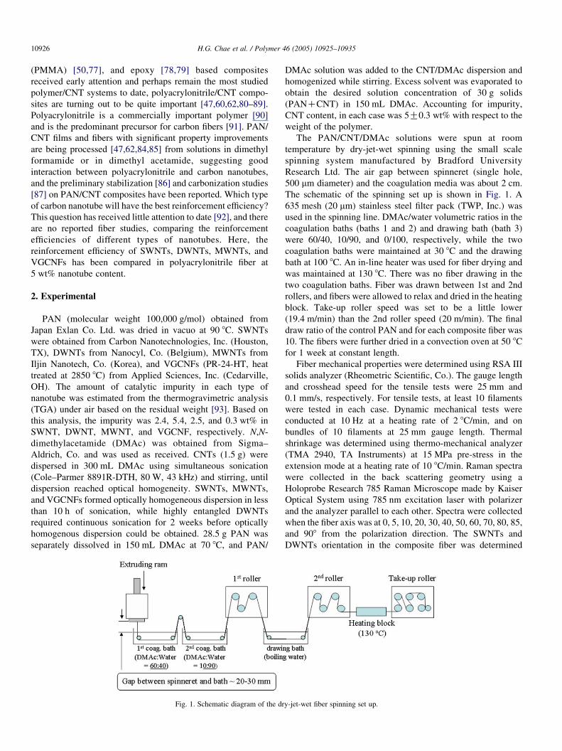
The PAN/CNT/DMAc solutions were spun at room
temperature by dry-jet-wet spinning using the small scale
spinning system manufactured by Bradford University
Research Ltd. The air gap between spinneret (single hole,
500 mm diameter) and the coagulation media was about 2 cm.
The schematic of the spinning set up is shown in Fig. 1. A
635 mesh (20 mm) stainless steel filter pack (TWP, Inc.) was
used in the spinning line. DMAc/water volumetric ratios in the
coagulation baths (baths 1 and 2) and drawing bath (bath 3)
were 60/40, 10/90, and 0/100, respectively, while the two
coagulation baths were maintained at 30 8C and the drawing
bath at 100 8C. An in-line heater was used for fiber drying and
was maintained at 130 8C. There was no fiber drawing in the
two coagulation baths. Fiber was drawn between 1st and 2nd
rollers, and fibers were allowed to relax and dried in the heating
block. Take-up roller speed was set to be a little lower
(19.4 m/min) than the 2nd roller speed (20 m/min). The final
draw ratio of the control PAN and for each composite fiber was
10. The fibers were further dried in a convection oven at 50 8C
for 1 week at constant length.
Fiber mechanical properties were determined using RSA III
solids analyzer (Rheometric Scientific, Co.). The gauge length
and crosshead speed for the tensile tests were 25 mm and
0.1 mm/s, respectively. For tensile tests, at least 10 filaments
were tested in each case. Dynamic mechanical tests were
conducted at 10 Hz at a heating rate of 2 8C/min, and on
bundles of 10 filaments at 25 mm gauge length. Thermal
shrinkage was determined using thermo-mechanical analyzer
(TMA 2940, TA Instruments) at 15 MPa pre-stress in the
extension mode at a heating rate of 10 8C/min. Raman spectra
were collected in the back scattering geometry using a
Holoprobe Research 785 Raman Microscope made by Kaiser
Optical System using 785 nm excitation laser with polarizer
and the analyzer parallel to each other. Spectra were collected
when the fiber axis was at 0, 5, 10, 20, 30, 40, 50, 60, 70, 80, 85,
and 908 from the polarization direction. The SWNTs and
DWNTs orientation in the composite fiber was determined
y-jet-wet fiber spinning set up.

H.G. Chae et al. / Polymer 46 (2005) 10925–10935 10927
from the peak intensity of tangential band (ca. 1590 cmK1)
assuming Gaussian intensity distribution with respect to the
polarization direction [94]. The orientation of MWNTs in the
composite fiber was determined from the graphite (002)
azimuthal scan obtained from X-ray diffraction. From the
orientation factor of the graphite plane normal, K0.455,
orientation factor of the graphite plane was determined to be
0.91 on the assumption of the symmetry of orientation along
the a and b axes. The orientation of the VGCNF was also
determined from the graphite (002) azimuthal scan. The
graphitic layers in VGCNFs make an angle of 158 to the fiber
axis [95]. Therefore, to determine the orientation of VGCNFs,
the azimuthal scan profile was fitted by two Gaussian peaks,
with peak positions located at G158 around the equator as
described elsewhere [95]. Wide angle X-ray diffraction
(WAXD) patterns were obtained on multifilament bundles by
Rigaku Micromax-007 (operated at 45 kV, 66 mA, lZ1.5418 A) using Rigaku R-axis IVCC detection system.
The diffraction patterns were analyzed using AreaMax V. 1.00
and MDI Jade 6.1. PAN orientation was determined from the
(200,110) azimuthal scans (2qZ16.78) using the previously
described procedure [47]. PAN crystallinity was determined by
area-calculation of deconvoluted integrated diffraction patterns
[96–98]. In PAN/MWNTs and PAN/VGCNFs composite
fibers, the graphite peak was also present and was excluded
from the PAN crystallinity calculation. The PAN crystal size
was determined from the peak at 2qZ16.78 using the Scherrer
equation with KZ0.9 [99]. Fiber tensile fractured surfaces
were observed on the gold coated samples by scanning electron
microscopy (LEO 1530 SEM operated at 15 kV). Transmission
electron microscopy (TEM) specimens for the composite fibers
were prepared by detachment method using parlodian [100].
Bright field TEM images were recorded on Mitsubishi
Microscope Film using JEM 2000EX (operated at 200 kV).
Fig. 2. Bright field TEM images of carbon nanotubes used in this st
3. Results and discussion
Fig. 2 shows the bright field TEM images of various
nanotubes used in this study. As expected, SWNTs show
5–50 nm diameter bundles or ropes, with an average diameter
of about 30 nm. Diameters of DWNTs were about 5 nm, and
they mostly existed as individual tubes, however, these were
highly entangled. The average diameter of MWNTs was about
20 nm, and these also existed as mostly individuals, though
entangled. Diameter of vapor grown carbon nano fibers was
about 60 nm and they appeared to be relatively free of
entanglements. As mentioned in the experimental section,
DWNTs, due to high degree of entanglement, were the most
difficult to disperse. By comparison SWNTs and MWNTs were
readily dispersed by sonication, suggesting a relatively less
entangled structure in these two types of nanotubes. TGA plots
indicate that SWNT, DWNT, MWNT, and VGCNF degra-
dation peaks in air at about 500, 440, 600, and 700 8C,
respectively (Fig. 3(A)). Degradation in MWNT and VGCNF
is delayed due to the existence of the layered graphitic structure
in these. For comparison, thermogravimetric analysis results in
nitrogen (Fig. 3(B)) show that all nanotubes do exhibit
degradation in the 800–1000 8C range. SWNT exhibit the
most degradation followed by DWNT, MWNT, and VGCNF.
Raman spectra (Fig. 4) show that the intensity of the disorder
band (ca. 1300 cmK1) in MWNTs and in VGCNF is quite high,
suggesting highly defective graphitic structure in these two
cases. Among the four types of tubes, SWNTs appear to have
the highest perfection followed by DWNTs.
Mechanical properties and various structural parameters for
the control PAN and the composite fibers are listed in Table 1.
All composite fibers exhibit improved mechanical properties
over the control PAN. Increase in modulus and decrease in
shrinkage is the highest in SWNT containing fibers, while
udy: (a) SWNTs, (b) DWNTs, (c) MWNTs, and (d) VGCNFs.

Fig. 3. Thermogravimetric analysis plots of (a) SWNTs, (b) DWNTs, (c) MWNTs, and (d) VGCNFs powder at a heating rate of 10 8C/min in (A) air and (B) nitrogen.
Fig. 4. Raman spectra for pristine (a) SWNTs, (b) DWNTs, (c) MWNTs, and
(d) VGCNFs powder.
H.G. Chae et al. / Polymer 46 (2005) 10925–1093510928
increase in tensile strength, strain to failure, and toughness was
the highest in MWNTs containing fibers. Improvement in all
the properties in PAN/DWNTs and PAN/VGCNFs composite
fibers was intermediate to that of PAN/SWNTs and PAN/
MWNTs. While conventional fillers and reinforcements
improve modulus and strength at the expense of strain to
failure and toughness, all nano carbon reinforcements used in
this study improved all mechanical properties, including up to
230% improvement in fiber toughness (with just 5 wt%
MWNTs) as measured from the area under the stress–strain
curve.
Storage modulus at 140 8C is enhanced by almost a factor of
6 (for SWNT containing fibers), while the tan d peak
temperature increased from 100 8C for the control PAN to
109 8C for the PAN/SWNTs composite, and the magnitude of
the tan d peak decreased from O0.3 for the control PAN to
below 0.2 for the composite fibers (Fig. 5). Storage moduli in
the entire temperature range for the MWNT and VGCNF
containing composite fibers were quite comparable to each
other. On the other hand, the storage modulus of the composite
containing DWNT was substantially higher than that of the
control fiber, above the glass transition temperature, while it
only exhibited a moderate increase at room temperature. Width
of the tan d vs temperature plot for the composite fibers (except
SWNT containing fibers) is significantly reduced as compared
to that of the control PAN. This suggests a narrower spectrum
of relaxation times in the composites than in PAN, a result of
polymer interaction with the nanotubes. In the case of SWNT
containing fibers, tan d peak is broadened towards high
temperature. We conjecture that PAN interactions with
SWNT are stronger than with other larger diameter nanotubes,
and that PAN segments closer to the SWNT exhibit tan d loss at
higher temperature than the segments farther from it, leading to
the broadening in the high temperature region. Intercalation of
PAN in the SWNT bundle may also be partially responsible for
the tan d broadening behavior.
SWNT containing fibers exhibited most improvement in the
thermal shrinkage behavior, followed by MWNTs, VGCNF,
and DWNT, respectively (Fig. 6). In the control PAN fiber, as
there are no nanotubes, amorphous chains are free to relax,
unless constrained by the crystalline regions. In the PAN–CNT
composite, due to polymer nanotube interaction, an additional
constraint is imposed on the PAN molecules, resulting in
improved thermal shrinkage performance. DWNT containing
samples exhibit poor performance due to high degree of
entanglement and agglomeration. Under comparable spinning
conditions, PAN orientation factors in the composite fibers were
0.62, 0.60, 0.57, and 0.53 for SWNT, MWNT, VGCNF, and
DWNT containing fibers, while the orientation of the control
PAN fiber was 0.52. All types of CNTs, including VGCNF,
resulted in enhanced polymer orientation, with SWNT resulting
in most enhancements. Normally fibers with high degree of
orientation results in large thermal shrinkage, and unoriented
fiber would exhibit no entropic shrinkage. Considering that the
nanotube containing fibers exhibit higher orientation than
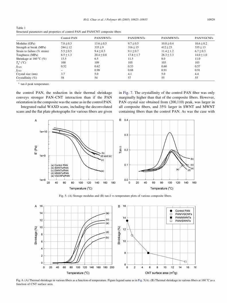
Table 1
Structural parameters and properties of control PAN and PAN/CNT composite fibers
Control PAN PAN/SWNTs PAN/DWNTs PAN/MWNTs PAN/VGCNFs
Modulus (GPa) 7.8G0.3 13.6G0.5 9.7G0.5 10.8G0.4 10.6G0.2
Strength at break (MPa) 244G12 335G9 316G15 412G23 335G13
Strain to failure (% strain) 5.5G0.5 9.4G0.3 9.1G0.7 11.4G1.2 6.7G0.3
Toughness (MPa) 8.5G1.3 20.4G0.8 17.8G1.7 28.3G3.3 14.0G1.0
Shrinkage at 160 8C (%) 13.5 6.5 11.5 8.0 11.0
Tga (8C) 100 109 105 103 103
fPAN 0.52 0.62 0.53 0.60 0.57
fCNT – 0.98 0.88 0.91 0.91
Crystal size (nm) 3.7 5.0 4.1 5.0 4.4
Crystallinity (%) 58 54 57 55 55
a tan d peak temperature.
H.G. Chae et al. / Polymer 46 (2005) 10925–10935 10929
the control PAN, the reduction in their thermal shrinkage
conveys stronger PAN–CNT interaction than if the PAN
orientation in the composite was the same as in the control PAN.
Integrated radial WAXD scans, including the deconvoluted
scans and the flat plate photographs for various fibers are given
Fig. 5. (A) Storage modulus and (B) tan d vs tem
Fig. 6. (A) Thermal shrinkage in various fibers as a function of temperature. Figure le
function of CNT surface area.
in Fig. 7. The crystallinity of the control PAN fiber was only
marginally higher than that of the composite fibers. However,
PAN crystal size obtained from (200,110) peak, was larger in
all composite fibers, and 35% larger in SWNT and MWNT
containing fibers than the control PAN. As was the case with
perature plots of various composite fibers.
gend same as in Fig. 5(A). (B) Thermal shrinkage in various fibers at 160 8C as a

Fig. 7. WAXD patterns, integrated radial scans and the deconvoluted profiles
for (a) control PAN, (b) PAN/SWNTs, (c) PAN/DWNTs, (d) PAN/MWNTs,
and (e) PAN/VGCNFs.
H.G. Chae et al. / Polymer 46 (2005) 10925–1093510930
orientation, composite fiber containing DWNTs exhibited the
smallest increase in crystal size. PAN is currently the
predominant precursor for carbon fibers. Stabilization and
carbonization studies on PAN/carbon nanotubes composites
point to the potential of this composite system as a precursor
for next generation carbon fiber [86,87]. Fibers with larger
PAN crystals and higher polymer molecular orientation are
expected to lead to a more perfect and higher orientation
carbon fiber with improved mechanical properties.
Tensile fractured surfaces reveal fibrillar structure in both
the control PAN and the PAN/CNTs composite fibers (Fig. 8).
Many more fibril ends are observed in PAN/SWNT fiber than
in PAN/MWNT fiber. SWNT bundles are known to be
wrapped by PAN molecules [60,62], and we suggest that the
fibril ends observed in PAN/SWNT composite are PAN
wrapped SWNTs bundles (Fig. 8(b)). The fact that numerous
fibril ends are visible in PAN/SWNT than in PAN/MWNT,
suggests that SWNT or SWNT bundles are much shorter than
MWNTs. Higher tensile strength and higher toughness of the
PAN/MWNT fiber, over that of the PAN/SWNT fiber is
attributed to longer MWNTs than SWNTs. This behavior is
analogous to the increased tensile strength with increasing
molecular weight in polymers [101–104].
Bright field TEM images of thin peeled composite fibers
as well as the schematics showing the presence of carbon
nanotubes are shown in Fig. 9. SWNTs, MWNTs, as well
as VGCNFs are mostly oriented along the fiber axis.
However, these are not quite straight, as kinked, bent, and
curved nanotubes were generally observed. SWNT bundle
diameter in the composite fiber is about 10 nm [105]. This
represents partial exfoliation of the SWNT bundles, as the
diameter of the SWNT ropes in the powder used in this
study was about 30 nm. SWNT, MWNT, and VGCNF
agglomeration was not observed in these composite fibers.
Occasionally MWNTs with orientation perpendicular to the
fiber axis were also observed. SWNT bundles were typically
100–300 nm long (Fig. 9(a)), while MWNTs longer than
1 mm were often observed (Fig. 9(c)). VGCNFs also
survived the sonication and fiber processing conditions,
and were also typically longer than 1 mm. However, due to
the stacked cup geometry [92,106], the strength of the
VGCNF is lower than that for the MWNTs, resulting in
lower tensile strength improvement in PAN/VGCNF than in
PAN/MWNT. In PAN/DWNT composite fiber, the dispersed
nanotubes were mostly individuals and well oriented.
However, TEM images also reveal the presence of
entangled and unoriented DWNTs globules (Fig. 9(b)).
The limited property improvements in PAN/DWNT compo-
site fibers are a result of the presence of these unoriented
and entangled DWNT globules. The size of these DWNT
globules is in the range of 50–200 nm, which is below the
resolution limit of the optical microscope and explains why
solutions containing such globules appeared to be mostly
optically homogeneous.
The enhancements in tensile and dynamic mechanical
properties as well as reduced thermal shrinkage, all point to
interaction between carbon nanotubes and the PAN matrix.
The question is what factors are responsible for different
levels of property improvements with different nanotubes.
Low strain properties (modulus and thermal shrinkage) were
most improved in PAN/SWNT, while high strain properties
(tensile strength, strain to failure, and toughness) were most
improved in PAN/MWNT. As addressed above, the
improvements in high strain properties are a result of longer
MWNT than SWNTs. The improvements in low strain
properties are dominated by the polymer/CNT interaction,
which will depend on the interface area. Strength of the
interaction may also depend on the nanotube curvature, as
due to higher non planar strains arising from pyramidization
of the conjugated carbon atoms and p-orbital misalignment
between adjacent pairs of conjugated carbon atoms
[107,108], smaller diameter tubes would provide stronger
interaction than the larger diameter tubes. This would favor
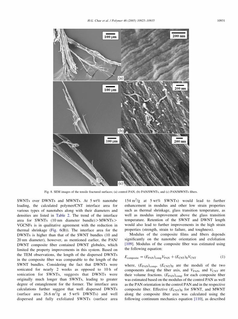
Fig. 8. SEM images of the tensile fractured surfaces; (a) control PAN, (b) PAN/SWNTs, and (c) PAN/MWNTs fibers.
H.G. Chae et al. / Polymer 46 (2005) 10925–10935 10931
SWNTs over DWNTs and MWNTs. At 5 wt% nanotube
loading, the calculated polymer/CNT interface area for
various types of nanotubes along with their diameters and
densities are listed in Table 2. The trend of the interface
area for SWNTs (10 nm diameter bundle)OMWNTsOVGCNFs is in qualitative agreement with the reduction in
thermal shrinkage (Fig. 6(B)). The interface area for the
DWNTs is higher than that of the SWNT bundles (10 and
20 nm diameter), however, as mentioned earlier, the PAN/
DWNT composite fiber contained DWNT globules, which
limited the property improvements in this system. Based on
the TEM observations, the length of the dispersed DWNTs
in the composite fiber was comparable to the length of the
SWNT bundles. Considering the fact that DWNTs were
sonicated for nearly 2 weeks as opposed to 10 h of
sonication for SWNTs, suggests that DWNTs were
originally much longer than SWNTs, leading to greater
degree of entanglement for the former. The interface area
calculations further suggest that well dispersed DWNTs
(surface area 26.6 m2/g at 5 wt% DWNTs) and well
dispersed and fully exfoliated SWNTs (surface area
154 m2/g at 5 wt% SWNTs) would lead to further
enhancement in modulus and other low strain properties
such as thermal shrinkage, glass transition temperature, as
well as modulus improvement above the glass transition
temperature. Retention of the SWNT and DWNT length
would also lead to further improvements in the high strain
properties (strength, strain to failure, and toughness).
Modulus of the composite films and fibers depends
significantly on the nanotube orientation and exfoliation
[109]. Modulus of the composite fiber was estimated using
the following equation:
Ecomposite Z ðEPANÞcompVPAN C ðECNTÞIIVCNT (1)
where, (EPAN)comp, (ECNT)II are the moduli of the two
components along the fiber axis, and VPAN, and VCNT are
their volume fractions. (EPAN)comp for each composite fiber
was estimated based on the modulus of the control PAN as well
as the PAN orientation in the control PAN and in the respective
composite fiber. Effective (ECNT)II for SWNT, and MWNT
along the composite fiber axis was calculated using the
following continuum mechanics equation [110], as described

Fig. 9. Bright field TEM images and the schematics showing the presence of carbon nanotubes in various composite fibers; (a) PAN/SWNTs, (b) PAN/DWNTs, (c)
PAN/MWNTs, and (d) PAN/VGCNFs.
H.G. Chae et al. / Polymer 46 (2005) 10925–1093510932
elsewhere [47,109]:
1
ðECNTÞIIZ
1
E1
hcos4qiC
1
E2
hsin4qiC
1
G12
K2n12
E1
� �hsin4
qcos2qi
Z1
E2
C1
G12
K2n12
E1
K2
E2
� �hcos2
qi
C1
E1
C1
E2
K1
G12
C2n12
E1
� �hcos4
qi
(2)
where E1, E2, and G12 are the longitudinal, transverse, and in-
plane shear moduli, respectively, and n12 is the Poisson’s ratio.
Elastic constants and Poisson’s ratios for various nanotubes used
in this study were obtained from the literatures [111–116] and
are listed in Table 3. Due to variation in diameter and chirality,
the shear modulus of SWNT bundle depends on its diameter
[117]. Shear modulus of the 20 nm diameter bundle was reported
to be 1 GPa, while that for the 4.5 nm diameter bundle it was
about 6 GPa. Based on the shear modulus of graphite (4.5 GPa)
and the geometric packing factor, it was estimated that the shear
modulus of nanotubes with homogeneous diameters should
approach 19.5 GPa. Values of axial modulus and shear modulus
between the planes for MWNTs are based on the reported values

Table 2
Physical carbon nanotube parameters, as well as theoretical and experimental moduli of the various composite fibers
Diameter
(nm)
CNT density
(g/cm3)
CNT
(wt%)
CNT
(vol%)
PAN/CNT interface area in the
composite fiber at 5 wt% load-
ing (m2/g)
PAN/CNT composite fiber tensile
modulus (GPa)
Theoretical Experimental
VGCNF 60 1.95 [116] 5.0 3.1 1.3 9.7 10.6
MWNT 20 1.8 [116] 3.3 5.6 10.7 10.8
SWNT bundle 20 1.3 [112] 4.6 7.7 11.9 –
10 15.4 – 13.6
4.5 34.2 21.4 –
DWNT 5 1.5 [5] 4.0 26.6 – 10.8
Exfoliated SWNT 1 1.3 [112] 4.6 154 29.7 –
H.G. Chae et al. / Polymer 46 (2005) 10925–10935 10933
for graphite [118]. Calculations [119] of axial and shear moduli
for various diameter tubes suggest that for 20 nm diameter
MWNT tubes, values of E1 and G12 listed in Table 3 based on
graphite elastic constants are quite reasonable. Poisson’s ratio of
0.14 was also extrapolated based on the calculations reported in
reference [119]. Graphite planes in VGCNFs make an angle of
158 to the nano fiber axis [95]. Modulus of VGCNF calculated
using Eq. (2) and the misorientation angle of 158, represents the
modulus along the VGCNF axis, which we term as ECNT. Thus
axial modulus of VGCNF (ECNT) was determined to be 50 GPa
[95]. The effective VGCNF modulus along the composite fiber
axis, (ECNT)II was estimated to be 44.3 GPa based on the axial
VGCNF modulus of 50 GPa and the VGCNF orientation in the
composite fiber.
Calculated composite fiber moduli as a function of
Herman’s orientation factor for various nanotubes are plotted
in Fig. 10. Due to the graphite plane misorientation in the
VGCNFs, the modulus of the composite fiber is relatively
insensitive to the VGCNF orientation, and even at the ideal
VGCNF orientation, the modulus of the composite fiber is
relatively low. MWNT and SWNT containing fibers exhibit
significant modulus dependence on orientation and on SWNT
exfoliation. For example, the modulus of the fiber containing
5 wt% MWNT is predicted to be 15 GPa at MWNT orientation
of 0.98, while for the ideal MWNT orientation (orientation
factor 1), it is predicted to be 34 GPa. This is assuming that the
PAN orientation is the same as observed in PAN/MWNT fiber
reported in Table 1. However, PAN orientation is also likely to
increase with increase in CNT orientation. Therefore, the
calculated modulus values in Fig. 10 represent a lower limit.
By comparison, calculated modulus of SWNT containing fibers
is predicted to be higher, even at lower orientation, provided
SWNT bundles are at least partially exfoliated. For example, at
SWNT orientation of 0.98, the modulus of the PAN/SWNT
Table 3
The elastic constants of SWNTs and MWNTs
SWNTs MWNTs
1 nm 4.5 nm 20 nm
E1 (GPa) 640 [112–115] 1060 [118]
E2 (GPa) 15 [115] 50 [111]
G12 (GPa) 19.5 [117] 6 [117] 1 [117] 4 [118]
n12 0.17 [115] 0.14 [119]
composite fiber is predicted to be 21, and 29 GPa for the
SWNT bundle diameter values of 4.5, and 1 nm diameters.
The experimentally observed moduli for SWNT and
MWNT containing composite fibers are in excellent agreement
with the theoretical values (Table 2). The experimental value of
13.6 GPa for the PAN/SWNT composite is in between the
predicted value of 11.9 GPa for 20 nm diameter rope and
21.4 GPa for the 4.5 nm diameter rope. From TEM studies, the
rope diameter in the PAN/SWNT composite fiber was
estimated to be about 10 nm. The experimental modulus for
VGCNF containing composite fiber is somewhat higher than
the theoretical values. VGCNF exhibit two types of mor-
phologies, where a second outer layer is composed of highly
oriented graphite. The presence of such VGCNF will result in
higher observed modulus than the value calculated based on the
morphology where all graphite layers are oriented at 158 to the
nano fiber axis [95].
In summary, this study clearly shows that polymer/CNT
composite fibers can be solution processed using SWNT,
DWNT, MWNT, as well as VGCNF. All nanotubes exhibit
improvements in tensile, dynamic mechanical, and thermal
shrinkage properties and result in higher polymer orientation
Fig. 10. The calculated tensile modulus of composite fibers containing 5 wt%
carbon nanotubes, as a function of carbon nanotube orientation factor,
assuming that PAN orientation in the composite fiber is the same as given in
the respective composite fibers in Table 1. Points are calculated values, and
lines are interpolations.

H.G. Chae et al. / Polymer 46 (2005) 10925–1093510934
and crystallite size. The increased polymer orientation and
crystal size point to the potential of PAN/CNT composite as the
precursor for next generation carbon fiber. Highly entangled
DWNTs were most difficult to disperse. All well dispersed
nanotubes exhibit high orientation in the drawn composite
fiber, while the entangled DWNT globules were unoriented. In
the case of PAN/DWNT, poor nanotube dispersion resulted in
limited property improvements. While, even the relatively
cheaper VGCNF result in useful property gains, the most
improvements in properties come from highly dispersed small
diameter tubes of long lengths. While the synthesis control can
lead to longer nanotubes, they have to be preserved in
unentangled state to achieve good dispersion with minimum
or no sonication. Achieving ultrahigh nanotube orientation
(orientation factor above 0.98) is critical for obtaining high
modulus composite fibers containing MWNTs or large
diameter SWNT bundles.
Acknowledgements
Financial support for this work from the Office of Naval
Research (N00014-01-1-0657), Air Force Office of Scientific
Research (F49620-03-1-0124), and Carbon Nanotechnologies,
Inc., and the experimental assistance of Marilyn Minus for
X-ray diffraction studies are gratefully acknowledged.
References
[1] US Patent 4,565,684; 1986.
[2] Iijima S, Ichihashi T. Nature 1993;363:603–5.
[3] Bethune DS, Kiang CH, Devries MS, Gorman G, Savoy R, Vazquez J,
et al. Nature 1993;363:605–7.
[4] Bandow S, Takizawa M, Hirahara K, Yudasaka M, Iijima S. Chem Phys
Lett 2001;337:48–54.
[5] Sugai T, Yoshida H, Shimada T, Okazaki T, Shinohara H. Nano Lett
2003;3(6):769–73.
[6] Iijima S. Nature 1991;354:56–8.
[7] Baughman RH, Zakhidov AA, Heer WA. Science 2002;297:787–92.
[8] Thess A, Lee R, Nikolav P, Dai H, Petit P, Robert J, et al. Science 1996;
273:483–7.
[9] Li YL, Kinloch IA, Windle AH. Science 2004;304:276–8.
[10] Ericson LM, Fan H, Peng HQ, Davis VA, Zhou W, Sulpizio J, et al.
Science 2004;305:1447–50.
[11] Zhang M, Atkinson KR, Baughman RH. Science 2004;306:1358–61.
[12] Shaffer MSP, Windle AH. Adv Mater 1999;11:937–41.
[13] Zhang X, Liu T, Sreekumar TV, Kumar S, Moore VC, Hauge RH, et al.
Nano Lett 2003;3:1285–8.
[14] Cooper CA, Ravich D, Lips D, Mayer J, Wagner HF. Compos Sci Tech
2002;62:1105–12.
[15] Benoit JM, Corraze B, Chauvet O. Phys Rev B 2002;65(24):241405.
[16] Bhattacharrya AR, Sreekumar TV, Liu T, Kumar S, Ericson LM,
Hauge RH, et al. Polymer 2003;44:2373–7.
[17] Biercuk MJ, Liaguno MC, Radosavljevic M, Hyun JK, Johnson AT.
Appl Phys Lett 2002;80:2767–9.
[18] Kim B, Lee J, Yu I. J Appl Phys 2003;94:6724–8.
[19] Zhang X, Liu T, Sreekumar TV, Kumar S, Hu X, Smith K. Polymer
2004;45:8801–7.
[20] Kumar S, Dang TD, Arnold FE, Bhattacharyya AR, Min BG, Zhang XF,
et al. Macromolecules 2002;35:9039–43.
[21] Dalton AV, Collins S, razal J, Munoz E, Ebron VH, Kim BG, et al.
J Mater Chem 2004;14:1–3.
[22] Chen J, Hamon MA, Hu H, Chen YS, Rao AM, Eklund PC, et al. Science
1998;282:95–8.
[23] Bahr JL, Yang JP, Kosynkin DV, Bronikowski MJ, Smalley RE,
Tour JM. J Am Chem Soc 2001;123:6536–42.
[24] Chen J, Rao AM, Lyuksyutov S, Itkis ME, Hamon MA, Hu H, et al.
J Phys Chem B 2001;105:2525–8.
[25] Ramesh S, Ericson LM, Davis VA, Saini RK, Kittrell C, Pasquali M,
et al. J Phys Chem B 2004;108:8794–8.
[26] Star A, Liu Y, Grant K, Ridvan L, Stoddart JF, Steuerman DW, et al.
Macromolecules 2003;36:553–60.
[27] Peng HQ, Alemany LB, Margrave JL, Khabashesku VN. J Am Chem
Soc 2003;125:15174–82.
[28] Niyogi S, Hamon MA, Hu H, Zhao B, Bhowmik P, Sen R, et al. Acc
Chem Res 2002;35:1105–13.
[29] Wu M, Shaw LL. J Power Sources 2004;136:37–44.
[30] Mylvaganam K, Zhang LC. J Phys Chem B 2004;108:5217–20.
[31] Clayton LM, Sikder AK, Kumar A, Cinke M, Meyyappan M,
Gerasimov TG, et al. Adv Funct Mater 2005;15:101–6.
[32] Sen R, Zhao B, Perea D, Itkis ME, Hu H, Love J, et al. Nano Lett 2004;4:
459–64.
[33] Martin CA, Sandler JKW, Windle AH, Schwarz MK, Bauhoffer W,
Schulte K, et al. Polymer 2005;46:877–86.
[34] Pecastaings G, Delhaes P, Derre A, Saadaoui H, Carmona F, Cui S.
J Nanosci Nanotechnol 2004;4:838–43.
[35] Zhao B, Hu H, Haddon RC. Adv Funct Mater 2004;14:71–6.
[36] Mrozek RA, Kim BS, Holmberg VC, Taton TA. Nano Lett 2003;3:
1665–9.
[37] Satake A, Miyajima Y, Kobuke Y. Chem Mater 2005;17:716–24.
[38] Sainz R, Benito AM, Martinez MT, Galindo JF, Sotres J, Baro AM, et al.
Adv Mater 2005;17:278–81.
[39] An LN, Xu WX, Rajagopalan S, Wang CM, Wang H, Fan Y, et al. Adv
Mater 2004;16:2036–40.
[40] Lupo F, Kamalakaran R, Scheu C, Grobert N, Ruhle M. Carbon 2004;42:
1995–9.
[41] Ning JW, Zhang JJ, Pan YB, Guo JK. Mater Sci Eng A 2003;357:392–6.
[42] Laurent C, Peigney A, Rousset A. J Mater Chem 1998;8:1263–72.
[43] Kuzumaki T, Ujiie O, Ichinose H, Ito K. Adv Eng Mater 2000;2:416–8.
[44] Flahaut E, Peigney A, Laurent C, Marliere C, Chastel F, Rousset A. Acta
Mater 2000;48:3803–12.
[45] Velasco-Santos C, Martinez-Hernandez AL, Fisher FT, Ruoff R,
Castano VM. Chem Mater 2003;15:4470–5.
[46] Thostenson ET, Chou TW. J Phys D 2002;35:L77–L80.
[47] Sreekumar TV, Liu T, Min BG, Guo H, Kumar S, Hauge RH, et al. Adv
Mater 2004;16:58–61.
[48] Mamedov AA, Kotov NA, Prato M, Guldi DM, Wicksted JP, Hirsch A.
Nature Mater 2002;1:190–4.
[49] Coleman JN, Cadek M, Blake R, Nicolosi V, Ryan KP, Belton C, et al.
Adv Funct Mater 2004;14:791–8.
[50] Ma H, Zeng J, Realff ML, Kumar S, Schiraldi DA. Compos Sci Tech
2003;63:1617–28.
[51] Zeng JJ, Saltysiak B, Johnson WS, Schiraldi DA, Kumar S. Compos B
2004;35:245–9.
[52] Kumar S, Doshi H, Srinivasarao M, Park JO, Schiraldi DA. Polymer
2002;43:1701–3.
[53] Ren Y, Fu YQ, Liao K, Li F, Cheng HM. Appl Phys Lett 2004;84:
2811–3.
[54] Pham JQ, Mitchell CA, Bahr JL, Tour JM, Krishanamoorti R, Green PF.
J Polym Sci B 2003;41:3339–45.
[55] Gong XY, Liu J, Baskaran S, Voise RD, Young JS. Chem Mater 2000;
12:1049–52.
[56] Baek JB, Lyons CB, Tan LS. Macromolecules 2004;37:8278–85.
[57] Grunlan JC, Mehrabi AR, Bannon MV, Bahr JL. Adv Mater 2004;16:
150–3.
[58] Sandler JKW, Kirk JE, Kinloch IA, Shaffer MSP, Windle AH. Polymer
2003;44:5893–9.
[59] Shenogin S, Xue LP, Ozisik R, Keblinski P, Cahill DG. J Appl Phys
2004;95:8136–44.

H.G. Chae et al. / Polymer 46 (2005) 10925–10935 10935
[60] Guo H, Sreekumar TV, Liu T, Marylin M, Kumar S. Polymer 2005;
46(9):3001–5.
[61] Potschke P, Fornes TD, Paul DR. Polymer 2002;43:3247–55.
[62] Liu T, Sreekumar TV, Kumar S, Hauge RH, Smalley RE. Carbon 2003;
41:2427–51.
[63] Kymakis E, Alexandrou I, Amaratunga GAJ. J Appl Phys 2003;93:
1764–8.
[64] Xiao QF, Zhou X. Electrochim Acta 2003;48:575–80.
[65] Wang QH, Setlur AA, Lauerhaas JM, Dai JY, Seelig EW, Chang RPH.
Appl Phys Lett 1998;72:2912–3.
[66] Kim JY, Kim M, Choi JH. Synth Met 2003;139:565–8.
[67] Park JH, Choi JH, Moon JS, Kushinov DG, Yoo JB, Park CY, et al.
Carbon 2005;43:698–703.
[68] Sayago I, Terrado E, Lafuente E, Horrillo MC, Maser WK, Benito AM,
et al. Synth Met 2005;148:15–19.
[69] Abraham JK, Philip B, Witchurch A, Varadan VK, Reddy CC. Smart
Mater Struct 2004;13:1045–9.
[70] Zhao Q, Frogley MD, Wagner HD. Polym Adv Tech 2002;13:759–64.
[71] Wood JR, Zhao Q, Frogley MD, Meurs ER, Prins AD, Peijs T, et al. Phys
Rev B 2000;62:7571–5.
[72] Raravikar NR, Keblinski P, Rao AM, Dresselhaus MS, Schadler LS,
Ajayan PM. Phys Rev B 2002;66:235424.
[73] Wang H, Zhou W, Ho DL, Winey KI, Fischer JE, Glinka CJ, et al. Nano
Lett 2004;4:1789–93.
[74] Matarredona O, Rhoads H, Li ZR, Harwell JH, Balzano L, Resasco DE.
J Phys Chem B 2003;107:13357–67.
[75] Potschke P, Bhattacharyya AR, Janke A. Eur Polym J 2004;40:137–48.
[76] Cadek M, Coleman JN, Barron V, Hedicke K, Blau WJ. Appl Phys Lett
2002;81:5123–5.
[77] Jin Z, Pramoda KP, Xu G, Goh SH. Chem Phys Lett 2001;337:43–7.
[78] Schadler LS, Giannaris SC, Ajayan PM. Appl Phys Lett 1998;73:
3842–4.
[79] Gojny FH, Wichmann MHG, Kopke U, Fiedler B, Schulte K. Compos
Sci Tech 2004;64:2363–71.
[80] Pirlot C, Willems I, Fonseca A, Nagy JB, Delhalle J. Adv Eng Mater
2002;4:109–14.
[81] Pirlot C, Mekhalif Z, Fonseca A, Nagy JB, Demortier G, Delhalle J.
Chem Phys Lett 2003;372:595–602.
[82] Weisenberger MC, Grulke EA, Jacques D, Rantell T, Andrews R.
J Nanosci Nanotech 2003;3:535–9.
[83] Ye HH, Lam H, Titchenal N, Gogotsi Y, Ko F. Appl Phys Lett 2004;85:
1775–7.
[84] Ge JJ, Hou H, Li Q, Graham MJ, Greiner A, Reneker DH, et al. J Am
Chem Soc 2004;126:15754–61.
[85] Ko F, Gogotsi Y, Ali A, Naguib N, Ye HH, Yang GL, et al. Adv Mater
2003;15(14):1161–5.
[86] Min BG, Sreekumar TV, Uchida T, Kumar S. Carbon 2005;43(3):
599–604.
[87] Koganemaru A, Bin Y, Agari Y, Matsuo M. Adv Funct Mater 2004;
14(9):842–50.
[88] Kim SH, Min BG, Lee SC, Park SB, Lee TD, Park M, et al. Fibers Polym
2004;5:198–203.
[89] Wang B, Li JW, Wang HP, Jiang JM, Liu YQ. Macromol Symp 2004;
216:189–94.
[90] Masson JC. Acrylic fiber technology and applications. New York:
Marcel Dekker; 1995.
[91] Bahl OP, Shen Z, Lavin JG, Ross RA. In: Donnet JB, Wang TK,
Rebouillat S, Peng JCM, editors. Carbon fibers. New York: Marcel
Dekker; 1998. p. 1–84.
[92] Cadek M, Coleman JN, Ryan KP, Nicolosi V, Bister G, Fonseca A, et al.
Nano Lett 2004;4(2):353–6.
[93] Chiang IW, Brinson BE, Smalley RE, Margrave JL, Hauge RH. J Phys
Chem B 2001;105:1157–61.
[94] Liu T, Kumar S. Chem Phys Lett 2003;378:257–62.
[95] Uchida T, Anderson DP, Minus ML, Kumar S. J Mater Sci; in press.
[96] Hobson RJ, Windle AH. Macromolecules 1993;26:6903–7.
[97] Yamane A, Sawai D, Kameda T, Kanamoto T, Ito M, Porter RS.
Macromolecules 1997;30:4170–8.
[98] Sawai D, Yamane A, Kameda T, Kanamoto T, Ito M, Yamazaki H, et al.
Macromolecules 1999;32:5622–30.
[99] Cullity BD. Elements of X-ray diffraction. 2nd ed. Reading, MA:
Addison-Wesley Publishing Company; 1978 p. 102.
[100] Shimamura K, Minter JR, Thomas EL. J Mater Sci Lett 1983;18:
54–8.
[101] Donald AM, Windle AH. In: Cahn RW, Davis EA, Ward IM, editors.
Liquid crystalline polymers. Cambridge: Cambridge University Press;
1992. p. 250.
[102] Zimmerman J, Kohan MI. J Polym Sci A 2001;39:2565–70.
[103] Luo S, Grubb DT, Netravali AN. Polymer 2002;43:4159–66.
[104] Ledbetter HD, Rosenberg S, Hurtig CW. Mater Res Soc Symp Proc
1989;134:253–64.
[105] Uchida T, Kumar S. J Appl Polym Sci 2005;98(3):985–9.
[106] Endo M, Kim YA, Hayashi T, Yangisawa T, Muramatsu H, Ezaka M,
et al. Carbon 2003;41:1941–7.
[107] Hamon MA, Itkis ME, Niyogi S, Alvarez T, Kuper C, Menon M, et al.
J Am Chem Soc 2001;123:11292–3.
[108] Dumitrica T, Landis CM, Yakobson BI. Chem Phys Lett 2002;360:
182–8.
[109] Liu T, Kumar S. Nano Lett 2003;3:647–50.
[110] Ward IM, Hadley DW. An introduction to the mechanical properties of
solid polymers. New York: Wiley; 1995 p. 300 [reprinted].
[111] Koerner H, Liu W, Alexander M, Mirau P, Dowty H, Vaia RA. Polymer
2005;46(12):4405–20.
[112] Lu JP. Phys Rev Lett 1997;79:1297–300.
[113] Gao GH, Cagin T, Goddard WA. Nanotechnology 1998;9:184–91.
[114] Sinnott SB, Shenderova OA, White CT, Brenner DW. Carbon 1998;
36:1–9.
[115] Popov VN, Van Doren VE, Balkanski M. Solid State Commun 2000;
114:395–9.
[116] Provided by the manufacturer.
[117] Salvetat JP, Briggs GAD, Bonard JM, Bacsa RR, Kulik AJ, Stockli T,
et al. Phys Rev Lett 1999;82:944–7.
[118] Johnson W. The structure of PAN based carbon fibers and relationship to
the physical properties. In: Watt W, Perov BV, editors. Handbook of
composites. Strong fibers, vol. 1. New York: Elsevier Sicence Publisher;
1988. p. 393.
[119] Shen L, Li J. Phys Rev B 2005;71:035412.