Prefabricated Reinforcement - BCA
98
I
-
Upload
khangminh22 -
Category
Documents
-
view
2 -
download
0
Transcript of Prefabricated Reinforcement - BCA

I
Prefabricated Reinforcement
H a n d b o o k

The Prefabricated Reinforcement Handbook is published by the Productivity Development Unit, Technology
Development Division of the Construction Industry Development Board.
©Construction Industry Development Board, November 1997
All rights reserved. No part of this publication may be reproduced or transmitted in any form or by any
means, without permission in writing from the publisher.
Every effort is made to ensure the accuracy of the information presented in this Handbook. The Handbook should always be reviewed by those using it with regard to the full circumstances of its particular application . Accordingly, no liability for negligence or otherwise can be accepted by CIDB, the members of its committee, its servants or agents.

FOREWORD
The use of prefabricated reinforcement is an efficient and cost-effective option for projects having to
use in-situ construction, particularly in respect of minimising wastage and overcoming site constraints. It is
especially beneficial to Singapore's construction industry which is acutely short of skilled workers. Together
with other buildable features, it will help to raise construction productivity, improve quality and reduce our
heavy reliance on foreign workers.
This handbook is another effort by the industry to help engineers increase the buildability of their
designs. It identifies the areas where prefabricated reinforcement can be used and promotes the use of
standardised meshes and cages. The Handbook helps engineers by providing necessary design tables,
construction details where relevant and annotations of prefabricated reinforcement. Some design examples
are also provided.
I wish to thank members of the Steering Committee for their valuable feedback to this Handbook. I
also wish to record my appreciation to TEG Engineering Consultants, Ho & Chang Consultants, B.R.C.
Weldmesh (S.E.A.) Pte Ltd and Eastern Wire Pte Ltd who prepared most of the draft. I am confident that this
Handbook will contribute to a better understanding and wider application of prefabricated reinforcement
in the construction industry.
Tan Ee Ping
Chairman of Steering Committee
Prefabricated Reinforcement Handbook

;;
ACKNOWLEDGMENT
The Prefabricated Reinforcement Handbook was developed jointly by CIDB, TEG Engineering
Consultants, Ho & Chang Consultants, B.R.C. Weldmesh (S.E.A) Pte Ltd and Eastern Wire Pte Ltd.
Cl DB would like to thank the chairman and members of the Steering Committee for their contributions
towards the development of this Handbook.
Steering Committee
Chairman
Members
Secretariat
Name
Mr Tan Ee Ping
Dr Kog Yue Choong
Mr Lam Siew Wah
Mr Tan Tian Chong
Mr Gan Eng Oon
Mr Shum Chee Hoong
Mr Graeme Forrest-Brown
Mr Shahzad Nasim
Mr Ong Chan Leng
Mr K Srivelan
Mr Poon Hin Kong
Mr Eddie Wong
Mr Lai Huen Poh
Mr Lee Kut Cheung
Mr Chuang Shaw Peng
Mr Edward D'Silva
Mdm Chia Oi Leng
Dr Tan Guan
Mr Ang Lion Aik
Ms Phua Hui Chun
Organization
Tan Ee Ping & Partners
Beca Carter Hollings & Ferner (S .E.Asia) Pte Ltd
(also representing Association of Consulting Engineers Singapore)
Construction Industry Development Board
Construction Industry Development Board
DP Architects Pte Ltd
Housing & Development Board
Maunsell Consultants (Singapore) Pte Ltd
Meinhardt Pte Ltd
Public Works Department
Public Works Department
Real Estate Developers' Association of Singapore
Real Estate Developers' Association of Singapore
RSP Architects Planners & Engineers (Pte) Ltd
RSP Architects Planners & Engineers (Pte) Ltd
Singapore Contractors Association Ltd
Singapore Institute of Architects
ST Architects & Engineers Pte Ltd
TY Lin South East Asia Pte Ltd
Construction Industry Development Board
Construction Industry Development Board
CIDB would also like to thank the following people for their valuable comments.
EJ Consultants Pte Ltd
Obayashi (Singapore) Pte Ltd
Singapore Technologies Construction Pte Ltd


iv
CONTENTS PAGE
APPENDIX
(A) WELDED WIRE FABRIC DIMENSIONS (B) WELDED WIRE FABRIC TABLES (C) TYPES OF FABRIC LAP (D) BEAM LINK CAGE CONVERSION TABLE FOR PLAIN MILD
STEEL BAR (E) COLUMN LINK CAGE CONVERSION TABLE FOR PLAIN MILD
STEEL BAR (F) LIST OF REINFORCEMENT FABRICATORS
76 77-78 79 80
81
82

INTRODUCTION
OBJECTIVE
The objective of this Handbook is to promote the wider use of prefabricated reinforcement (welded
wire fabric and prefabricated cages) by providing useful guidelines to engineers in the design of structural
elements using such reinforcement. The wider use of prefabricated reinforcement will raise productivity,
reduce site labour and shorten construction time.
SCOPE OF THE HANDBOOK
This Handbook contains tables of welded wire fabric and prefabricated cages. Design of reinforcement
is based on BS8110: Structural Use of Concrete: Part 1: 1985, including subsequent revisions up to 1993.
Prefabricated reinforcement can be used in slabs, columns, beams, walls, drains and pilecaps. Detailing of
reinforcement in two-dimensional and isometric views and guidelines on installation are also provided.

2
WELDED WIRE FABRIC (WWF)
Welded Wire Fabric is manufactured using automatic welding machines, where parallel series of
high strength cold drawn reinforcing wires are welded together in a square or rectangular grid. It uses
electrical resistance welding process to fuse the intersecting wires into a homogeneous section and fix a ll
wires in their proper position. Plain wires, deformed wires or a combination of both may be used in welded
wire fabric .
In Singapore, WWF are manufactured in accordance to Singapore Standards SS 32: Welded Steel
Fabric for the Reinforcement of Concrete. The characteristic yield strength of WWF is 485 N/mm2. Most of
the local manufacturers have their WWF certified to the Singapore Quality Mark Scheme ensuring consistent
quality of the product. However, engineers may also obtain a copy of test certificates from the supplier to
ensure that the strength of the wire meets the requirements.
Currently, the four most commonly used preferred WWF are:
"A" Series: Square fabrics with wires at 200 mm spacing in both directions.
"B" Series: Rectangular fabrics with main w ire spacing of 100 mm and cross
wire spacing of 200 mm.
"D" Series: Square fabric with wires at 100 mm spacing in both directions.
" E" Series: Square fabric w ith wires at 150 mm spacing in both directions.
A, D and E fabrics series have equal sizes of wire and spacing in both directions. They are used
where the structures they reinforced have to be equally strong in both directions, therefore providing similar
areas of steel. B series fabrics are generally used in structures where the principal steel is in one direction,
and the steel in the other direction is the minimum required by BS 8110. Standard sheet sizes of 6 m (length)
by 2.4 m (width) are usually available ex-stock. Cut-to-size sheets are also readily ava ilable from the supplier
in flat sheets or bent to required shape.
"Engineered" fabric series and "Designer" fabric series may also be fabricated by varying the diameter,
spacing and position of the wire. In this Handbook, a new series of Designer fabric is introduced to increase
the choices of WWF available. Engineers may also specify their own Designer Fabric or Engineered fabric
in consultation with the suppliers.

I
PREFABRICATED CAGES
Prefabricated reinforcement improves site productivity and shortens construction time. Off-site
fabrication, in the controlled environment of a factory, has the benefit of much higher productivity, better
quality control and far less wastage of material. The contractor avoids keeping large quantity of material on
site, minimises the tedious tasks of manual cutting, bending, laying and fixing of steel bars in the traditional
manner.
WWF as described earlier is the most common prefabricated reinforcement used. WWF can be
made from different types of reinforcement steel and is available up to the size of 16 mm diameter, e.g.
main wire Tempcore bar Tl6 and cross wire cold drawn wire H 10.
WWF in the form of beam link cages or column link cages is ideal for forming a quick skeleton of
reinforcement onto which the main reinforcement can be secured. This form of cages is widely used in HDB
projects and is starting to be used in the private sector.
Apart from the flat sheets and bent fabric where the intersections are resistance welded, flat, bent or
3-dimensional prefabricated reinforcement can also be formed using a mig welder to spot weld the
reinforcement bars and/ or WWF cages together. These assemblies are rigid enough for transport to site
without damage and they can be lifted and dropped into the formwork ready to be concreted . With a mig
welder it is possible to produce prefabricated reinforcement with diameters larger than 16 mm. This Handbook
provides information on the use of prefabricated column cages, beam cages, pile caps and other structural
elements. Engineers should check with the manufacturer for more information on design considerations,
detailing and supply of the prefabricated reinforcement.
3

4
GUIDE TO SECTIONS
The following Sections feature design guidelines and examples using prefabricated reinforcement
for slabs, beams, columns, walls, pilecaps and other applications. Design assumptions as well as relevant
details are also provided.
New annotations such as S2Tl0-200 (beam link cage), 3LH10-175 (column close link cage),
WA 125-A 10 (wall type), 1 RP150 (single pile type for precast reinforced concrete driven pile) and 5BP600
(5 pilegroup type for bored pile) have been introduced in an attempt to standardise the specifications of
these prefabricated reinforcement.
SECTION ONE
SLAB REINFORCEMENT

5
SECTION ONE: SLAB REINFORCEMENT
This Section enables engineer to select welded wire fabric (WWF) from design tables based on the design considerations
shown below for one-way and two-way continuous slabs.
1.1 Design Considerations
1. 25mm nominal cover to steel reinforcement is adopted.
2. 2.7 kN/m 2 is taken as Superimposed Dead Loads (including dead load for finishes, partition, services, etc.).
3. Concrete Grade 30 is adopted in the design for Table 'SA 1' to Table 'SA 18'.
4 . Design criteria complies to BS 8110: Part 1: 1985: Section Three.
5. Design Tables are categorised based on shortest slab span, Lx criteria followed by ultimate design loads
(excluding slab self weight) as shown in Table 'A' below.
TABLE 'A'
Slab Span, Lx Ultimate Design Loads, W Design Table
(kN/m2)
ws 8.6 'SAl'
8.6 < w s 11.8 'SA2'
11.8 < w s 15.8 'SA3' Lx S 3.0
15.8 < w s 23.8 'SA4'
23.8 < w s 27.8 'SA5'
27.8 < w s 35.8 'SA6'
w s 8.6 'SA7'
8.6 < w s 11.8 'SA8'
11.8 < w s 15.8 'SA9'
3.0 < Lx S 3.6 15.8 < w s 23.8 'SAlO'
23.8 < w s 27.8 'SAll'
27.8 < w s 35.8 'SA12'
w s 8.6 'SA13'
8.6 < w s 11.8 'SA14'
3.6 < Lx S 4.8 11.8 < w s 15.8 'SA15'
15.8 < w s 23.8 'SA16'
23.8 < w s 27.8 'SA17'
27.8 < w s 35.8 'SA18'
6. Mesh provided in Table 'SA 1' to Table 'SA 18' are designed based on the longest slab span dimension, Lx and
highest end of ultimate design load category, W of the Table 'A' above.
7. Engineer shall consider the continuity effect if adjacent slab panels are of different thickness and/or having
drop affecting the design effective depth .
8. Extra allowance of reinforcement areas i.e. 50mm has been provided to the designed required steel area
when selecting the mesh.

1.2 Examples On Slab Design
EXAMPLE (1) Design Data : Slab sizes: ly= 6.5 m, lx = 3.0 m. 1. Slab type: Two Adjacent Edges Discontinuous. 2. Design live load, ll = 3.0 kN/m2
Superimposed Dead load, SDL = 2.7 kN/m 2
Design Method: Step l: For lx = 3.0 m ==> Table 'SA 1' to Table 'SA6' Step 2: Calculate the ultimate design load (excluding slab self-weight),
w = ( 1.4 X SDL) + ( 1.6 X ll) = ( 1.4 X 2.7) + ( 1.6 X 3.0) = 8.58 kN/m2
W < 8.6 kN/m2 ==>go to Table 'SA 1' Step 3: Span Ratio= ly/lx = 6.5/ 3.0 = 2.17 > 2.0 ==>One-Way Slab==> Column "9"
Slab Panel Type : Two Adjacent Edges Discontinuous ==> Row "4" RESULT==> 125 mm thick slab with
I
WWF B8 (Top Mesh - lx Direction), WWF A7 (Top Mesh - ly Direction ) and WWF B6 (Bottom Mesh) satisfying deflection, shear a nd moment criteria.
(Note: If engineer prefers other slab thickness to be used, the design has to be extended to Step 4.) Step 4: Work out the self-weight difference between the slab thickness preferred and one recommended in the
Design Table 'SA 1'. For instance, slab thickness 150 mm is preferred. • New additional weight due to increase in slab thickness
= (0.15- 0.125) x 24 = 0.6 kN/m 2
• New ultimate design load = (1.4 x 0.6 + 8.58) = 9.42 kN/m2 ==>go to Table 'SA2' • Repeat Step 3=> read Column "9" & Row "4" • RESULT==> 125 mm thick slab with
WWF B8 (Top Mesh - lx Direction), WWF B6 (Top Mesh- ly Direction) and WWF B8 (Bottom Mesh) satisfying deflection, shear and moment criteria.
Therefore, engineer can use the preferred slab thickness 150 mm with the above designed mesh.
EXAMPLE (2) : Design Data: 1. Slab Sizes: ly = 6.0 m, lx = 4.0 m. 2. Slab Type: Interior Panel. 3. Design live load, ll = 6.0 kN/m2
Superimposed Dead load, SOL= 5.0 kN/ m2
Design Method: Step l: For lx = 4.0 m=> Table 'SA 13 ' to Table 'SA 18' Step 2: Calculate the ultimate design load (excluding slab self-weight),
w = ( 1.4 X SOL) + ( 1.6 X ll) = ( 1.4 X 5.0) + ( 1.6 X 6.0) = 16.6 kN/m2
15.8 kN/m2 < W.:::. 23.8 kN/m2 ~go to Table 'SA 16' Step 3: Span Ratio= ly/lx = 6/4 = 1.5 < 2.0 ~Two-Way Slab~ Column "6"
Slab Type: Interior Panel ~ Row "1" • RESULT ~ 175 mm thick slab with
+
WWF DA 10/ 10 (Top Mesh- lx Direction), WWF B8 (Top Mesh - ly Direction) and WWF DE9 /8 (Bottom Mesh) satisfying deflection, shear and moment criteria.
Step 4: Slab thickness 225 mm is preferred. • New additional weight due to increase in slab thickness
= (0.225- 0.175) x 24 = 1.2 kN/m2
• 'New' ultimate design load = (1.4 x 1.2 + 16.6) = 18.28 kN/ m2 ==>go to Table 'SA 16' • RESULT ~ 225 mm thick slab with
WWF OA 10/ 10 (Top Mesh - lx Direction), WWF B8 (Top Mesh - ly Di rection ) and WWF DE9 / 8 (Bottom Mesh) satisfying deflection, shear and moment criteria.
6

1.3 Slab Design Tables
SLAB SPAN Lx .s_ 3.0m
TABLE SA 1 Concrete
W < 8.6 kN/m2 Grade ULTIMATE (SDL +LL) - 30N/mm2
TWO-WAY SLAB DESIGN IN ACCORDANCE TO BS 8110: PART 1: 1985: SECTION THREE
TYPES OF SLAB PANEL (Ly/ Lx ) Ratio ONE-WAY SLAB
1.0 1.1 1.2 1.3 1.4 1.5 1.75 2.0 1. INTERIOR PANELS Thickness (mm) 125 125 125 125 125 125 125 125 125
Top mesh (lx direction) A7 A7 A7 A7 B6 B6 B6 B6 B6
Top mesh (ly direction) A7 A7 A7 A7 A7 A7 A7 A7 B6
Bottom mesh A7 A7 A7 A7 A7 A7 A7 A7 B6
2. ONE SHORT EDGE Thickness (mm) 125 125 125 125 125 125 125 125 125 DISCONTINUOUS Top mesh (lx direction) A7 A7 B6 B6 B6 B6 B6 B6 B6
Top mesh (ly direction) A7 A7 A7 A7 A7 A7 A7 A7 A7
Bottom mesh A7 A7 A7 A7 A7 A7 A7 B6 B6
3. ONE LONG EDG E Thickness (mm) 125 125 125 125 125 125 125 125 125 DISCONTINUOUS Top mesh (lx direction) A7 B6 B6 B6 B6 B6 B8 B8 B8
Top mesh (ly direction) A7 A7 A7 A7 A7 A7 A7 A7 A7
Bottom mesh A7 A7 A7 A7 A7 A7 A7 B6 B6
4. TWO ADJACENT Thickness (mm) 125 125 125 125 125 125 125 125 125 EDGE Top mesh (lx direction) B6 B6 B6 B6 B6 B8 B8 B8 B8 DISCONTINUOUS
Top mesh (ly direction) A7 A7 A7 A7 A7 A7 A7 A7 A7
Bottom mesh A7 A7 B6 B6 B6 B6 B6 B6 B6
5. TWO SHORT EDGE Thickness (mm) 125 125 125 125 125 125 125 125 125 DISCONTINUOUS Top mesh (lx direction) A7 B6 B6 B6 B6 B6 B6 B6 B6
Top mesh (ly direction) A7 A7 A7 A7 A7 A7 A7 A7 A7
Bottom mesh A7 A7 A7 A7 A7 B6 B6 B6 B6
6. TWO LONG EDGE Thickness (mm) 125 125 125 125 125 125 125 125 125 DISCONTINUOUS Top mesh (lx direction) A7 A7 A7 A7 A7 A7 A7 A7 A7
Top mesh (ly direction) A7 A7 A7 A7 A7 A7 A7 A7 A7
Bottom mesh A7 A7 B6 B6 B6 B8 B8 B8 B8
7. THREE EDGE Thickness (mm) 125 125 125 125 125 125 125 125 125 DISCONTINUOUS
Top mesh (lx direction) B6 B6 B6 B6 B8 B8 B8 B8 B8 (ONE LONG EDGE CONTINUOUS) Top mesh (ly direction) A7 A7 A7 A7 A7 A7 A7 A7 A7
Bottom mesh A7 B6 B6 B6 B6 B6 B6 B6 B6
8. THREE EDGE Thickness (mm) 125 125 125 125 125 125 125 125 125 DISCONTINUOUS Top mesh (lx direction) A7 A7 A7 A7 A7 A7 A7 A7 A7 (ONE SHORT EDGE CONTINUOUS) Top mesh (ly direction) B6 B6 B6 B6 B6 B6 B6 B6 B6
Bottom mesh A7 B6 B6 B6 B8 B8 B8 B8 B8
9. FOUR EDGES Thickness (mm) 125 125 125 125 125 125 125 125 125 DISCONTINUOUS
Top mesh (lx direction) A7 A7 A7 A7 A7 A7 A7 A7 A7
Top mesh (ly direction) A7 A7 A7 A7 A7 A7 A7 A7 A7
Bottom mesh B6 B6 B6 B8 B8 B8 B8 B8 B8
7

SLAB SPAN Lx ~ 3.0m Concrete TABLE SA2 ' 8.6 kN/m2 < W < 11.8 kN/m2 Grade
ULTIMATE (SOL +LL) 30N/mm2 -
TWO-WAY SLAB DESIGN IN ACCORDANCE TO BS 8110: PART 1: 1985 : SECTION THREE
TYPES OF SLAB PANEL (Ly/ Lx ) Ratio ONE-WAY SLAB
1.0 1.1 1.2 1.3 1.4 1.5 1.75 2.0 1. INTERIOR PANELS Thickness (mm) 125 125 125 125 125 125 125 125 125
Top mesh (lx direction) A7 A7 B6 B6 B6 B6 B6 B8 B8
Top mesh (ly direction) A7 A7 A7 A7 A7 A7 A7 A7 A7
Bottom mesh A7 A7 A7 A7 A7 B6 B6 B6 B6
2. ONE SHORT EDGE Thickness (mm) 125 125 125 125 125 125 125 125 125 DISCONTINUOUS Top mesh (lx direction) B6 B6 B6 B6 B6 B6 B8 B8 B8
Top mesh (ly direction) A7 A7 A7 A7 A7 A7 A7 A7 A7
Bottom mesh A7 A7 A7 B6 B6 B6 B6 B6 B6
3. ONE LONG EDGE Thickness (mm) 125 125 125 125 125 125 125 125 125 DISCONTINUOUS Top mesh (lx direction) B6 B6 B6 B8 B8 B8 B8 B8 B8
Top mesh (ly direction) A7 A7 A7 A7 A7 A7 A7 A7 A7
Bottom mesh A7 A7 B6 B6 B6 B6 B8 B8 B8
4. TWO ADJACENT Thickness (mm) 125 125 125 125 125 125 125 125 125 EDGE Top mesh (lx direction) B6 B6 B8 B8 B8 B8 88 88 B8 DISCONTINUOUS
Top mesh (ly direction) B6 86 B6 86 B6 B6 B6 B6 B6
Bottom mesh A7 86 B6 86 B6 B6 B8 B8 B8
5. TWO SHORT EDGE Thickness (mm) 125 125 125 125 125 125 125 125 125 DISCONTINUOUS Top mesh (lx direction) B6 B6 B6 B6 B6 B8 B8 B8 B8
Top mesh (ly direction) A7 A7 B5 A7 A7 A7 A7 A7 A7
Bottom mesh A7 B6 B6 86 B6 86 B6 B6 B6
6. TWO LONG EDGE Thickness (mm) 125 125 125 125 125 125 125 125 125 DISCONTINUOUS Top mesh (lx direction) A7 A7 A7 A7 A7 A7 A7 A7 A7
Top mesh (ly direction) B6 B6 B6 B6 B6 B6 B6 B6 B6
Bottom mesh A7 B6 B6 B8 B8 88 B8 B8 B8
7. THREE EDGE Thickness (mm) 125 125 125 125 125 125 125 125 125 DISCONTINUOUS
Top mesh (lx direction) B6 B8 B8 (ONE LONG EDGE B8 B8 B8 B8 B8 B8 CONTINUOUS) Top mesh (ly direction) A7 A7 A7 A7 A7 A7 A7 A7 A7
Bottom mesh B6 B6 B6 B6 B6 B8 B8 B8 B8
8. THREE EDGE Thickness (mm) 125 125 125 125 125 125 125 125 125 DISCONTINUOUS Top mesh (lx direction) A7 A7 A7 A7 A7 A7 A7 A7 A7 (ONE SHORT EDGE CONTINUOUS) Top mesh (ly direction) B6 86 B6 B6 B6 B6 B6 B6 B6
Bottom mesh B6 B6 B8 B8 B8 B8 B8 B8 B8
9. FOUR EDGES Thickness (mm) 125 125 125 125 125 125 125 150 150 DISCONTINUOUS
Top mesh (lx direction) A7 A7 A7 A7 A7 A7 A7 A8 A8
Top mesh (ly direction) A7 A7 A7 A7 A7 A7 A7 A8 A8
Bottom mesh 88 B8 B8 B8 B8 B8 B8 B8 B8
8

SLAB SPAN Lx.::; 3.0m Concrete TABLE SA3
11.8 kN/m2 < W < 15.8 kN/m 2 Grade ULTIMATE (SDL +LL) - 30N/mm2
TWO-WAY SLAB DESIGN IN ACCORDANCE TO BS 8110: PART 1: 1985: SECTION THREE
TYPES OF SLAB PANEL (Ly/ Lx ) Ratio ONE-WAY SLAB
1.0 1.1 1.2 1.3 1.4 1.5 1.75 2.0 1. INTERIOR PANELS Thickness (mm) 125 125 125 125 125 125 125 125 125
Top mesh (lx direction) B6 B6 B6 B6 BS BS BS BS BS
Top mesh (ly direction) B6 B6 B6 B6 B6 B6 B6 B6 B6
Bottom mesh A7 A7 B6 B6 B6 B6 B6 B6 B6
2. ONE SHORT EDGE Thickness (mm) 125 125 125 125 125 125 125 125 125 DISCONTINUOUS Top mesh (lx direction) B6 B6 B6 BS BS BS BS BS BS
Top mesh (ly direction) B6 B6 B6 B6 B6 B6 B6 B6 B6
Bottom mesh B6 B6 B6 B6 B6 B6 B6 B6 BS
1 ONE LONG EDGE Thickness (mm) 125 125 125 125 125 125 125 125 125 DISCONTIN UOUS Top mesh (lx direction) B6 BS BS BS BS BS BS BS BS
Top mesh (ly direction) B6 B6 B6 B6 B6 B6 B6 B6 B6
Bottom mesh B6 B6 B6 B6 BS BS BS BS BS
4. TWO ADJACENT Thickness (mm) 125 125 125 125 125 125 125 125 125 EDGE Top mesh (lx direction) BS BS BS BS BS BS BS B9 B9 DISCONTIN UOUS
Top mesh (ly direction) B6 B6 B6 B6 B6 B6 B6 B6 B6
Bottom mesh B6 B6 B6 BS BS BS BS BS BS
5. TWO SHORT EDGE Thickness (mm) 125 125 125 125 125 125 125 125 125 DISCONTINUOUS Top mesh (lx direction) B6 BS BS BS BS BS BS BS BS
Top mesh (ly direction) A7 A? A? A7 A7 A7 A7 A7 A?
Bottom mesh B6 B6 B6 B6 B6 B6 BS BS BS
6. TWO LONG EDGE Thickness (mm) 125 125 125 125 125 125 150 150 150 DISCONTINUOUS Top mesh (lx direction) A7 A? A? A7 A7 A? AS AS AS
Top mesh (ly direction) B6 B6 B6 B6 B6 B6 B6 B6 B6
Bottom mesh B6 B6 BS BS BS BS BS BS BS
7. THREE EDGE Thickness (mm) 125 125 125 125 125 125 125 125 125 DISCONTINUOUS
Top mesh (lx direction) BS BS BS BS BS BS BS B9 B9 (ONE LONG EDGE CONTINUOUS) Top mesh (ly direction) A? A7 A7 A7 A7 A? A? A? A?
Bottom mesh E7 BS BS BS BS BS BS BS BS
S. THREE EDGE Thickness (mm) 125 125 125 125 125 125 125 150 150 DISCONTINUOUS Top mesh (lx direction) A7 A? A7 A7 A? A? A? AS AS (ONE SHORT EDGE CONTINUOUS) Top mesh (ly di rection) BS BS BS BS BS BS BS B6 B6
Bottom mesh AS BS BS BS BS BS B9 BS BS
9. FOUR EDGES Thickness (mm) 125 125 125 125 125 150 150 150 150 DISCONTINUOUS
Top mesh (lx direction) A7 A7 A7 A7 A? AS AS AS AS
Top mesh (ly direction) A7 A? A7 A? A7 AS AS AS AS
Bottom mesh A9 D7 DES/S DES/S DES/S BS BS BS BS
9

SLAB SPAN Lx ~ 3.0m Concrete TABLE SA4
15.8 kN/m2 < W < 23.8 kN/m2 Grade ULTIMATE (SDL +LL) - 30N/mm2
TWO-WAY SLAB DESIGN IN ACCORDANCE TO BS 8110: PART 1: 1985: SECTION THREE
TYPES OF SLAB PANEL (Ly/ Lx) Ratio ONE-WAY SLAB
1.0 1.1 1.2 1.3 1.4 1.5 1.75 2.0
1. INTERIOR PANELS Thickness (mm) 125 125 125 125 125 125 125 125 125
Top mesh (lx direction) BS BS BS BS BS BS BS BS BS
Top mesh (ly direction) B6 B6 B6 B6 B6 B6 B6 B6 B6
Bottom mesh B6 B6 B6 BS BS BS BS BS BS
2. ONE SHORT EDGE Thickness (mm) 125 125 125 125 125 125 125 125 125 DISCONTINUOUS Top mesh (lx direction) BS BS BS BS BS BS BS B9 B9
Top mesh (ly direction) BS BS BS BS BS BS BS BS BS
Bottom mesh B6 B6 BS BS BS BS BS BS BS
3. ONE LONG EDGE Thickness (mm) 125 125 125 125 125 125 125 125 125 DISCONTINUOUS Top mesh (lx direction) BS BS BS BS B9 B9 B9 B10 B10
Top mesh (ly direction) BS BS BS BS BS BS BS BS BS
Bottom mesh B6 BS BS BS BS BS BS B9 B9
4. TWO ADJACENT Thickness (mm) 125 125 125 125 125 125 150 150 150 EDGE Top mesh (lx direction) D7 DES/S DES/S DE9/S DE9/S DE9/S B9 B9 B9 DISCONTINUOUS
Top mesh (ly direction) BS BS BS BS BS BS BS BS BS
Bottom mesh BS BS BS BS BS BS BS BS BS
5. TWO SHORT EDGE Thickness (mm) 125 125 125 125 125 125 125 125 125 DISCONTINUOUS Top mesh (lx direction) BS BS BS BS BS BS B9 B9 B9
Top mesh (ly direction) A7 A7 A7 A7 A7 A7 A7 A7 A7
Bottom mesh BS BS BS BS BS BS BS BS BS
6. TWO LONG EDGE Thickness (mm) 125 125 125 150 150 150 150 150 150 DISCONTINUOUS Top mesh (lx direction) A7 A7 A7 AS AS AS AS AS AS
Top mesh (ly direction) BS BS BS BS BS BS BS BS BS
Bottom mesh BS BS BS BS BS BS B9 B9 B9
7. THREE EDGE Thickness (mm) 125 125 125 125 125 150 150 150 150 DISCONTI NUOUS
Top mesh (lx direction) BS BS B9 B9 B9 B9 B9 B9 B9 (ONE LONG EDGE CONTINUOUS) Top mesh (ly direction) A7 A7 A7 A7 A7 AS AS AS AS
Bottom mesh D7 D7 DES/S DES/S DES/S BS BS BS BS
S. THREE EDGE Thickness (mm) 125 125 150 150 150 150 150 150 150 DISCONTINUOUS Top mesh (lx direction) A7 A7 AS AS AS AS AS AS (ONE SHORT EDGE AS CONTINUOUS) Top mesh (ly direction) BS BS BS BS BS BS BS BS BS
Bottom mesh ES DES/S BS BS BS B9 B9 B10 B1 0
9. FOUR EDGES Thickness (mm) 125 150 150 150 150 150 150 150 150 DISCONTINUOUS
Top mesh (lx direction) AS AS AS AS AS AS AS AS A7
Top mesh (ly direction) A7 AS AS AS AS AS AS AS AS
Bottom mesh E9 DES/S DES/S DES/S DE9/S DE9/S DE9/S DE10/S DE10/S
JO

SLAB SPAN Lx.::; 3.0m Concrete TABLE SAS 23.8 kN/m2 < W < 27.8 kN/m2
Grade ULTIMATE (SDL +LL) - 30N/mm2
TWO-WAY SLAB DESIGN IN ACCORDANCE TO BS 8110: PART 1: 1985: SECTION THREE
TYPES OF SLAB PAN EL (Ly/ Lx ) Ratio ONE-WAY SLAB
1.0 1.1 1.2 1.3 1.4 1.5 1.75 2.0 1. INTERIOR PANELS Thickness (mm) 125 125 125 125 125 125 125 125 125
Top mesh (lx direction) BS BS BS BS BS BS B9 B9 B9
Top mesh (ly direction) BS BS BS BS BS BS BS BS BS
Bottom mesh B6 B6 BS BS BS BS BS BS BS
2. ONE SHORT EDGE Thickness (mm) 125 125 125 125 125 125 125 125 125 DISCONTINUOUS Top mesh (lx direction) D7 A10 DES/S DES/S DES/S EA10/10 DE9/S DE9/S DE9/S
Top mesh (ly direction) BS BS BS BS BS BS BS BS BS
Bottom mesh BS BS BS BS BS BS BS BS BS
3. ONE LONG EDGE Thickness (mm) 125 125 125 125 125 150 150 150 150 DISCONTINUOUS Top mesh (lx direction) D7 DES/S DES/S DE9/S DE9/S B9 B9 B9 B9
Top mesh (ly direction) BS BS BS BS BS B6 B6 B6 B6
Bottom mesh BS BS BS BS BS BS BS BS BS
4. TWO ADJACENT Thickness (mm) 125 125 125 125 150 150 150 150 150 EDGE Top mesh (lx direction) E9 EA10/10 AA 13110 AA13/10 EA10/10 DE9/S DE9/S AA13/10 AA13/10 DISCONTINUOUS
Top mesh (ly direction) BS BS BS BS BS BS BS BS BS
Bottom mesh ES D7 DES/S DES/S BS BS BS BS BS
5. TWO SHORT EDGE Thickness (mm) 125 125 125 125 125 125 125 125 125 DISCONTINUOUS Top mesh (lx direction) BS B8 BS BS B9 B9 B9 B9 B9
Top mesh (ly direction) A7 A7 A7 A7 A7 A7 A7 A7 A7
Bottom mesh A9 D7 D7 D7 DES/S DES/S DES/S DES/S DES/S
6. TWO LONG EDGE Thickness (mm) 125 125 150 150 150 150 150 150 150 DISCONTINUOUS Top mesh (lx direction) A7 A7 AS AS AS AS AS AS AS
Top mesh (ly direction) BS BS BS BS BS BS BS BS BS
Bottom mesh A9 DES/S BS BS BS B9 B9 B1 0 B10
7. THREE EDGE Thickness (mm) 125 125 125 150 125 150 150 150 150 DISCONTINUOUS
Top mesh (lx direction) BS B9 B9 B9 B9 B9 B10 B10 B10 (ONE LONG EDGE CONTINUOUS) Top mesh (ly direction) A7 A7 A7 AS AS AS AS AS AS
Bottom mesh D7 E9 EA10/10 DES/S DES/S DES/S DES/S EA10/10 EA10110
S. THREE EDGE Thickness (mm) 125 125 125 150 150 150 150 150 150 DISCONTINUOUS Top mesh (lx direction) A7 A7 A7 AS AS AS AS AS AS (ONE SHORT EDGE CONTINUOUS) Top mesh (ly direction) B9 B9 B9 BS BS BS BS BS BS
Bottom mesh D7 EA10/10 AA13/1 0 DES/S DE9/S DE9/S DE1 0/S DE10/S DE10/S
9. FOUR EDGES Thickness (mm) 150 150 150 150 150 150 150 150 150 DISCONTINUOUS
Top mesh (lx direction) AS AS AS AS AS AS AS AS AS
Top mesh (ly direction) AS AS AS AS AS AS AS AS AS
Bottom mesh A10 EA10/10 EA10/10 AA13/10 AA13110 AA13/10 DA10/10 DA10/10 DA10110
ll

SLAB SPAN Lx.::; 3.0m Concrete TABLE SA6 27.8 kN/m2 < W < 35.8 kN/m2 Grade
ULTIMATE (SDL +LL) - 30N/mm2
TWO-WAY SLAB DESIGN IN ACCORDANCE TO BS 8110: PART 1: 1985: SECTION THR EE
TYPES OF SLAB PANEL (Ly/ Lx ) Ratio ONE-WAY SLAB
1.0 1.1 1.2 1.3 1.4 1.5 1.75 2.0 1. INTERIOR PANELS Thickness (mm) 125 125 125 125 125 125 150 150 150
Top mesh (lx direction) D7 DE8/8 DE8/8 DE8/8 DE9/8 DE9/8 89 89 89 Top mesh (ly direction) 88 88 88 88 88 88 88 88 88
Bottom mesh 88 88 88 88 88 88 88 88 88
2 ONE SHORT EDGE Thickness (mm) 125 125 125 125 125 125 150 150 150 DISCONTINUOUS Top mesh (lx direction) EAl0/10 EAl0/10 EAl0/10 AA13/1 0 DE8/8 AA13/10 DE9/8 DE9/8 DE9/8
Top mesh (ly direction) 88 88 88 B8 B8 B8 B8 B8 B8
Bottom mesh E8 D7 DE8/8 DE8/8 B8 DE8/8 B8 B8 B8
3. ONE LONG EDGE Thickness (mm) 125 125 125 150 150 150 150 150 150 DISCONTINUOUS Top mesh (lx direction) EAl0/10 AA13/10 AA13/10 DE9/8 DE9/8 DE9/8 DEl 0/8 DEl0/8 DEl0/8
Top mesh (ly direction) B8 B8 B8 B8 B8 B8 B8 B8 B8
Bottom mesh D7 DE8/8 DE8/8 B8 B8 B8 B9 B9 B9
4. TWO ADJACENT Thickness (mm) 125 125 150 150 150 150 150 150 175 EDGE Top mesh (lx direction) AA13/10 AA13/10 AA13/10 DAl0/10 DAl0/10 EA 13/10 EA13/10 DISCONTINUOUS ElO El l
Top mesh (ly direction) B8 B8 B8 B8 B8 B8 B9 B8 88
Bottom mesh DE8/8 DE8/8 DE8/8 DE8/8 DE8/8 EAl0/10 DE9/8 DE9/8 DE9/8
5. TWO SHORT EDGE Thickness (mm) 125 125 125 125 150 150 150 150 150 DISCONTINUOUS Top mesh (lx direction) B8 B9 B9 B9 B9 B9 B9 B9 B9
Top mesh (ly direction) A7 A7 A7 A7 A8 A8 A8 A8 A8
Bottom mesh D7 DE8/8 DE8/8 DE8/8 DE8/8 DE8/8 DE8/8 DE8/8 DE8/8
6. TWO LONG EDGE Thickness (mm) 125 150 150 150 150 150 150 150 150 DISCONTINUOUS Top mesh (lx direction) A7 A8 A8 A8 A8 A8 A8 A8 A8
Top mesh (ly direction) B8 B8 B8 B8 B8 B8 B8 B8 B8
Bottom mesh D7 DE8/8 DE8/8 DE9/8 DE9/8 DEl0/8 EA13/10 EA13/10 EA13/10
7. THREE EDGE Thickness (mm) 150 150 150 150 150 150 150 150 150 DISCONTINUOUS
Top mesh (lx direction) (ONE LONG EDGE B8 B9 B9 B10 Bl 0 BlO B11 Bl l Bll CONTINUOUS) Top mesh (ly direction) A8 A8 A8 A8 A8 A8 A8 A8 A8
Bottom mesh D7 E9 EAl0/10 EAl 0/10 EAl0/10 AA13/10 AA13/10 AA1311 0 AA13/10
8. THREE EDGE Thickness (mm) 125 150 150 150 150 150 150 150 150 DISCONTINUOUS Top mesh (lx direction) A7 A8 A8 A8 A8 A8 A8 A8 A8 (ONE SHORT EDGE CONTINUOUS) Top mesh (ly direction) B9 B8 B8 B8 B8 B8 B8 B8 B8
Bottom mesh Al l EAl0/1 0 AA13/10 AA13/10 DAl0/10 DA10/10 EA13/10 DE1 1/9 DEll /9
9. FOUR EDGES Thickness (mm) 150 150 150 150 150 150 150 150 150 DISCONTINUOUS
Top mesh (lx direction) A8 A8 A8 A8 A8 A8 A8 A8 A8
Top mesh (ly direction) A8 A8 A8 A8 A8 A8 A8 A8 A8
Bottom mesh D8 A12 A13 E1 2 E12 E13 Dl l D12 D1 2
12

SLAB SPAN 3.0m < Lx.::; 3. 6m Concrete TABLE SA7
W < 8.6 kN/m2 Grade ULTIMATE (SDL +LL) - 30N/mm2
TWO-WAY SLAB DESIGN IN ACCORDANCE TO BS 8110: PART 1: 1985: SECTION THREE
TYPES OF SLAB PANEL (Ly/ Lx ) Ratio ONE-WAY SLAB
1 1.1 1.2 1.3 1.4 1.5 1.75 2.0
1. INTERIOR PANELS Thickness (mm) 125 125 125 125 125 125 125 125 125
Top mesh (lx direction) A7 B6 B6 B6 B6 B6 BS BS BS
Top mesh (ly direction) A7 A7 A7 A7 A7 A7 A7 A7 A7
Bottom mesh A7 A7 A7 B6 B6 B6 B6 B6 B6
2. ONE SHORT EDGE Thickness (mm) 125 125 125 125 125 125 125 125 . 125 DISCONTINUOUS Top mesh (lx direction) B6 B6 B6 B6 BS BS BS BS BS
Top mesh (ly direction) B6 B6 B6 B6 B6 B6 B6 B6 B6
Bottom mesh A7 B6 B6 B6 B6 B6 B6 B6 B6
3. ONE LONG EDGE Thickness (mm) 125 125 125 125 125 125 125 125 125 DISCONTINUOUS Top mesh (lx direction) B6 B6 BS BS BS BS BS BS BS
Top mesh (ly direction) B6 B6 B6 B6 B6 B6 B6 B6 B6
Bottom mesh A7 B6 B6 B6 B6 B6 BS BS BS
4. TWO ADJACENT Thickness (mm) 125 125 125 125 125 125 125 125 125 EDGE Top mesh (lx direction) DISCONTINUOUS E7 BS BS BS BS BS BS BS BS
Top mesh (ly direction) B6 B6 B6 B6 B6 B6 B6 B6 B6
Bottom mesh B6 B6 B6 B6 BS BS BS BS BS
5. TWO SHORT EDGE Thickness (mm) 125 125 125 125 125 125 125 125 125 DISCONTINUOUS Top mesh (lx direction) B6 B6 BS BS BS BS BS BS BS
Top mesh (ly direction) A7 A7 A7 A7 A7 A7 A7 A7 A7
Bottom mesh B6 B6 B6 B6 B6 B6 B6 B6 B6
6. TWO LONG EDGE Thickness (mm) 125 125 125 125 125 125 150 150 150 DISCONTINUOUS Top mesh (lx direction) A7 A7 A7 A7 A7 A7 AS AS AS
Top mesh (ly direction) B6 B6 B6 B6 B6 B6 B6 B6 B6
Bottom mesh B6 B6 BS BS BS BS BS BS BS
7. THREE EDGE Thickness (mm) 125 125 125 125 125 125 125 125 125 DISCONTINUOUS
Top mesh (lx direction) BS BS BS BS BS BS BS BS BS (ONE LONG EDGE CONTINUOUS) Top mesh (ly direction) A7 A7 A7 A7 A7 A7 A7 A7 A7
Bottom mesh AS BS BS BS BS BS BS BS BS
S. TH REE EDGE Thickness (mm) 125 125 125 125 125 125 150 150 150 DISCONTINUOUS Top mesh (lx direction) A7 A7 A7 A7 A7 A7 AS AS AS (ONE SHORT EDGE CONTINUOUS) Top mesh (ly direction) BS BS BS BS BS BS B6 B6 B6
Bottom mesh AS BS BS BS BS BS BS BS BS
9. FOUR EDGES Thickness (mm) 125 125 125 150 150 150 150 150 150 DISCONTINUOUS
Top mesh (lx direction) A7 A7 A7 AS AS AS AS AS AS
Top mesh (ly direction) A7 A7 A7 AS AS AS AS AS AS
Bottom mesh BS BS BS BS BS BS BS BS BS
J3

SLAB SPAN 3.0m < Lx.::; 3.0m Concrete TABLE SAS 8.6 kN/m2 < W < 11.8kN/m2
Grade ULTIMATE (SDL +LL) - 30N/mm 2
TWO-WAY SLAB DESIGN IN ACCORDANCE TO BS 8110: PART 1: 1985 : SECTION THREE
TYPES OF SLAB PAN EL (Ly/ Lx ) Ratio ONE-WAY SLAB
1.0 1.1 1.2 1.3 1.4 1.5 1.75 2.0 1. INTERIOR PANELS Thickness (mm} 125 125 125 125 125 125 125 125 125
Top mesh (lx direction} B6 B6 B6 BS BS BS BS BS BS
Top mesh (ly direction} B6 B6 B6 B6 B6 B6 B6 B6 B6
Bottom mesh E6 B6 B6 B6 B6 B6 BS BS BS
2 ONE SHORT EDGE Thickness (mm} 125 125 125 125 125 125 125 '125 125 DISCONTINUOUS Top mesh (lx direction} BS BS BS BS BS BS BS BS BS
Top mesh (ly di rection} B6 B6 B6 B6 B6 B6 B6 B6 B6
Bottom mesh B6 B6 B6 B6 B6 BS BS BS BS
3. ONE LONG EDGE Thickness (mm} 125 125 125 125 125 125 125 150 150 DISCONTINUOUS Top mesh (lx direction} BS BS BS BS BS BS B9 BS BS
Top mesh (ly direction} B6 B6 B6 B6 B6 B6 B6 B6 B6
Bottom mesh B6 B6 B6 BS BS BS BS BS BS
4. TWO ADJACENT Thickness (mm} 125 125 125 125 125 125 150 150 150 EDGE Top mesh (lx direction} BS BS BS BS BS BS BS BS BS DISCONTINUOUS
Top mesh (ly di rection} BS BS BS BS BS BS B6 B6 B6
Bottom mesh B6 B6 BS BS BS BS BS BS BS
5. TWO SHORT EDGE Thickness (mm} 125 125 125 125 125 125 125 125 125 DISCONTINUOUS Top mesh (lx direction} BS BS BS BS BS BS BS BS BS
Top mesh (ly direction} A7 A7 A7 A7 A7 A7 A7 A7 A7
Bottom mesh B6 B6 B6 BS BS BS BS BS BS
6. TWO LONG EDGE Thickness (mm} 125 125 125 150 150 150 150 150 150 DISCONTINUOUS Top mesh (lx direction} A7 A7 A7 AS AS AS AS AS AS
Top mesh (ly direction} BS BS BS B6 B6 B6 B6 B6 B6
Bottom mesh B6 BS BS BS BS BS BS B9 B9
7. THREE EDGE Thickness (mm} 125 125 125 125 125 125 150 150 150 DISCONTINUOUS
Top mesh (lx direction} BS BS BS BS B9 B9 BS BS BS (ONE LONG EDGE CONTINUOUS} Top mesh (ly direction} A7 A7 A7 A7 A7 A7 AS AS AS
Bottom mesh BS BS BS BS BS BS BS BS BS
S. THREE EDGE Thickness (mm} 125 125 125 150 150 150 150 150 150 DISCONTINUOUS Top mesh (lx direction} A7 A7 A7 AS AS AS AS AS AS (ONE SHORT EDGE CONTINUOUS} Top mesh (ly direction} BS BS BS BS BS BS BS BS BS
Bottom mesh BS BS BS BS BS BS BS B9 B9
9. FOUR EDGES Thickness (mm} 150 150 150 150 150 150 150 150 150 DISCONTINUOUS
Top mesh (lx di rection} AS AS AS AS AS AS AS AS AS
Top mesh (ly direction} AS AS AS AS AS AS AS AS AS
Bottom mesh A9 DES/S DES/S DES/S DES/S DES/S DE9/S DE9/S DE9/S
J4

SLAB SPAN 3.0m < Lx .s 3.6m Concrete TABLE SA9
11.8 kN/m2 < W < 15.8 kN/m2 Grade ULTIMATE (SOL +LL) - 30N/mm2
TWO-WAY SLAB DESIGN IN ACCORDANCE TO BS 8110: PART 1: 1985 : SECTION THREE
TYPES OF SLAB PANEL (Ly/ Lx ) Ratio ONE-WAY SLAB
1.0 1.1 1.2 1.3 1.4 1.5 1.75 2.0 1. INTERIOR PANELS Thickness (mm) 125 125 125 125 125 125 125 125 125
Top mesh (lx direction) BS BS BS BS BS BS BS BS BS
Top mesh (ly direction) B6 B6 B6 B6 B6 B6 B6 B6 B6
Bottom mesh B6 B6 B6 BS BS BS BS BS BS
2. ONE SHORT EDGE Thickness (mm) 125 125 125 125 125 125 125 125 . 125 DISCONTINUOUS Top mesh (lx direction) DE7/S DE7/S DE7/S DES/S DES/S DES/S DES/S DE9/S DE9/S
Top mesh (ly direction) BS BS BS BS BS BS BS BS BS
Bottom mesh B6 B6 BS BS BS BS BS BS BS
3. ONE LONG EDGE Thickness (mm) 125 125 125 150 150 150 150 150 150 DISCONTINUOUS Top mesh (lx direction) DE7/7 A10 DES/S BS BS BS B9 B9 B9
Top mesh (ly direction) BS BS BS B6 B6 B6 B6 B6 B6
Bottom mesh B6 BS BS BS BS BS BS BS BS
4. TWO ADJACENT Thickness (mm) 125 125 125 150 150 150 150 150 150 EDGE Top mesh (lx direction) D7 DES/S DES/S DES/S DES/S DES/S DE9/S DE9/S DE9/S DISCONTINUOUS
Top mesh (ly direction) BS BS BS BS BS BS BS BS BS
Bottom mesh BS BS BS BS BS BS BS BS BS
5. TWO SHORT EDGE Thickness (mm) 125 125 125 125 125 125 125 125 150 DISCONTINUOUS Top mesh (lx direction) BS BS BS BS BS BS B9 BS BS
Top mesh (ly direction) A7 A7 A7 A7 A7 A7 A7 A7 AS
Bottom mesh BS BS BS BS BS BS BS BS BS
6. TWO LONG EDGE Thickness (mm) 125 125 150 150 150 150 150 150 175 DISCONTINUOUS Top mesh (lx direction) A7 A7 AS AS AS AS AS AS AS
Top mesh (ly direction) BS BS BS BS BS BS BS B6 B6
Bottom mesh BS BS BS BS BS BS B9 B9 B9
7. THREE EDGE Thickness (mm) 125 150 150 150 150 150 150 150 150 DISCONTINUOUS
Top mesh (lx direction) BS BS BS BS B9 B9 B9 B9 B9 (ONE LONG EDGE CONTINUOUS) Top mesh (ly direction) A7 AS AS AS AS AS AS AS AS
Bottom mesh D7 BS BS BS BS BS BS BS BS
S. THREE EDGE Thickness (mm) 125 150 150 150 150 150 150 150 150 DISCONTINUOUS Top mesh (lx direction) A7 AS AS AS AS AS AS AS AS (ONE SHORT EDGE CONTINUOUS) Top mesh (ly direction) BS BS BS BS BS BS BS BS BS
Bottom mesh D7 BS BS BS BS B9 B9 B10 B1 0
9. FOUR EDGES Thickness (mm) 150 150 150 150 150 150 150 175 175 DISCONTINUOUS Top mesh (lx direction) AS AS AS AS AS AS AS AS B10
Top mesh (ly direction) AS AS AS AS AS AS AS AS B1 0
Bottom mesh D7 DES/S DES/S EA 10/10 DE9/S DE9/S DE9/S DE9/S DE9/S
15

SLAB SPAN 3.0m < Lx .:::;3.6m Concrete TABLE SAlO ULTIMATE (SDL +LL) 15.8 kN/m2 < W < 23.8 kN/m2 Grade
- 30N/mm2
TWO-WAY SLAB DESIGN IN ACCORDANCE TO BS 8110: PART 1: 1985 : SECTION THREE
TYPES OF SLAB PANEL (Ly/ Lx ) Ratio ONE-WAY SLAB
1.0 1.1 1.2 1.3 1.4 1.5 1.75 2.0 1. INTERIOR PANELS Thickness (mm) 125 125 125 125 150 150 150 150 150
Top mesh (lx direction) D7 DES/S DES/S EA10110 BS BS B9 B9 B9
Top mesh (ly direction) BS BS BS BS BS BS BS BS BS
Bottom mesh BS BS BS BS BS BS BS BS BS
2. ONE SHORT EDGE Th ickness (mm) 150 150 150 150 150 150 150 150 150 DISCONTINUOUS Top mesh (lx direction) D7 DES/S DES/S DES/S DES/S EA 10/10 DE9/S DE9/S DE9/S
Top mesh (ly direction) BS BS BS BS BS BS BS BS BS
Bottom mesh BS BS BS BS BS BS BS BS BS
3. ONE LONG EDGE Thickness (mm) 150 150 150 150 150 150 150 150 150 DISCONTINUOUS Top mesh (lx direction) D7 DES/S DES/S DE9/S DE9/S AA13/10 DE10/S DE10/S DE10/S
Top mesh (ly direction) BS BS BS BS BS BS BS BS BS
Bottom mesh BS BS BS BS BS BS B9 B9 B9
4. TWO ADJACENT Thickness (mm) 150 150 150 150 150 150 150 150 150 EDGE Top mesh (lx direction) DISCONTINUOUS E9 EA10/10 AA 13/10 AA13110 AA13110 DA10/10 DA10/10 EA13110 EA13/10
Top mesh (ly direction) BS BS BS BS BS BS BS BS BS
Bottom mesh ES D7 DES/S DES/S DES/S EA 1011 0 DE9/S DE9/S DE9/S
5. TWO SHORT EDGE Thickness (mm) 150 150 150 150 150 150 150 150 150 DISCONTINUOUS Top mesh (lx direction) BS BS BS BS B9 B9 B9 B9 B9
Top mesh (ly direction) AS AS AS AS AS AS AS AS AS
Bottom mesh A9 D7 D7 A10 DES/S DES/S DES/S DES/S DES/S
6. TWO LONG EDGE Thickness (mm) 150 150 150 150 175 175 175 175 175 DISCONTINUOUS Top mesh (lx direction) AS AS AS AS AS AS AS AS AS
Top mesh (ly direction) BS BS BS BS BS BS BS BS BS
Bottom mesh A9 DES/S DES/S DES/S B9 B9 B10 B10 B10
7. THREE EDGE Thickness (mm) 150 150 150 150 150 150 150 175 175 DISCONTINUOUS
Top mesh (lx direction) BS BS B9 (ONE LONG EDGE B10 B10 B10 B11 B10 B10 CONTINUOUS) Top mesh (ly direction) AS AS AS AS AS AS AS AS AS
Bottom mesh A10 EA10/10 EA10/10 EA10110 AA13/10 AA13/10 AA13/10 DE9/S DE9/S
S. THREE EDGE Thickness (mm) 150 150 150 150 150 175 175 175 175 DISCONTINUOUS Top mesh (lx direction) AS AS AS AS AS AS AS AS AS (ONE SHORT EDGE CONTINUOUS) Top mesh (ly direction) B9 B9 B9 B9 89 BS BS BS BS
Bottom mesh D7 EA10/10 AA13/10 AA13/10 DA10/10 DE9/S DE10/S DE10/S DE10/S
9. FOUR EDGES Thickness (mm) 150 150 175 175 175 175 175 175 175 DISCONTINUOUS Top mesh (lx direction) AS AS AS AS AS AS AS AS AS
Top mesh (ly direction) AS AS AS AS AS AS AS AS AS
Bottom mesh DS E 11 AA13/10 AA13/10 AA13/10 DA10110 DA10/10 EA 13/10 EA 13/10
J6

SLAB SPAN 3.0m < Lx s 3.4m Concrete TABLE SA11 ULTIMATE (SDL +LL) 23.8 kN/m2 < W < 27.8 kN/m2 Grade
- 30N/mm2
TWO-WAY SLAB DESIGN IN ACCORDANCE TO BS 8110: PART 1: 1985 : SECTION THREE
TYPES OF SLAB PANEL (Ly/ Lx ) Ratio ONE-WAY SLAB
1.0 1.1 1.2 1.3 1.4 1.5 1.75 2.0 1. INTERIOR PANELS Thickness (mm) 150 150 150 150 150 150 150 150 150
Top mesh (lx direction) ES D7 DES/S DES/S DES/S DE9/S DE9/S DE9/S DE9/S
Top mesh (ly direction) BS BS BS BS BS BS BS BS BS
Bottom mesh BS BS BS BS BS BS BS BS BS
2. ONE SHORT EDGE Thickness (mm) 150 150 150 150 150 150 175 175 175 DISCONTINUOUS Top mesh (lx direction) DES/S DES/S DES/S EA10/10 DE9/S DE9/S DE9/S DE9/S DE9/S
Top mesh (ly direction) BS 8S BS BS 8S 8S BS BS BS
Bottom mesh BS BS BS BS BS BS BS 8S BS
3. ONE LONG EDGE Thickness (mm) 150 150 150 150 150 150 150 150 150 DISCONTINUOUS Top mesh (lx direction) DES/S DES/S DE9/S DE9/S DE10/S DE 10/S EA 13/1 0 DE 11/S DE 11/S
Top mesh (ly direction) 8S BS BS BS BS BS BS BS 8S
Bottom mesh BS BS 8S 8S B9 B9 B9 B10 B10
4. TWO ADJACENT Thickness (mm) 150 150 150 150 150 175 175 175 175 EDGE Top mesh (lx direction) AA13/10 DA10/10 DA10/10 DA10/10 DISCONTINUOUS DES/9 DE9/9 DE9/9 DE10/S DE1 0/9
Top mesh (ly direction) BS BS BS BS BS BS BS 8S BS
Bottom mesh D7 DES/S DES/S EA10/10 DE9/S DES/S DE9/S DE9/S DE9/S
5. TWO SHORT EDGE Thickness (mm) 150 150 150 150 150 150 150 150 150 DISCONTINUOUS Top mesh (lx direction) BS 8S B9 B9 B9 B9 B10 810 B10
Top mesh (ly direction) AS AS AS AS AS AS AS AS AS
Bottom mesh D7 A10 DES/S DES/S DES/S DES/S DES/S DE9/S DE9/S
6. TWO LONG EDGE Thickness (mm) 150 150 150 175 175 175 175 175 175 DISCONTINUOUS Top mesh (lx direction) AS AS AS AS AS AS AS AS AS
Top mesh (ly direction) BS BS BS BS BS BS BS 8S BS
Bottom mesh D7 DES/S DE9/S DE9/S DE9/S AA13/10 DE10/S EA13/10 EA13/10
7. THREE EDGE Thickness (mm) 150 150 150 150 150 175 175 175 175 DISCONTINUOUS
Top mesh (lx direction) B9 B10 B10 B10 B1 1 810 B1 0 B11 81 1 (ONE LONG EDGE CONTINUOUS) Top mesh (ly direction) AS AS AS AS AS AS AS AS AS
Bottom mesh DES/9 DES/9 DE9/9 DE9/9 DE9/9 DE9/S DE9/S DE9/S DE9/S
S. THREE EDGE Thickness (mm) 150 150 175 175 175 175 175 175 175 DISCONTINUOUS Top mesh (lx direction) AS AS AS AS AS AS AS AS AS (ONE SHORT EDGE CONTINUOUS) Top mesh (ly direction) B9 B9 BS BS BS 8S 8S BS 8S
Bottom mesh DES/9 DE9/9 DE9/S DE9/S AA12/10 DE10/S A13/10 EA 13/10 EA13/10
9. FOUR EDGES Thickness (mm) 150 175 175 175 175 175 175 175 175 DISCONTINUOUS
Top mesh (lx direction) AS AS AS AS AS AS AS AS AS
Top mesh (ly direction) AS AS AS AS AS AS AS AS AS
Rnttnm mP'h A12 DE9/9 DE9/9 DE10/9 DE1 0/9 DE10/9 DE11 /9 DE11 /9 DE11/9
17

SLAB SPAN 3.0m < Lx s) .6m Concrete TABLE SA 12 27.8 kN/m2 < W < 35.8 kN/m2
Grade ULTI MATE (SDL +LL) 30N/mm2 -
TWO-WAY SLAB DESIGN IN ACCORDANCE TO BS 8110: PART 1: 1985 : SECTION THREE
TYPES OF SLAB PANEL (Ly/ Lx ) Ratio ONE-WAY SLAB
1.0 1.1 1.2 1.3 1.4 1.5 1.75 2.0 1. INTERIOR PANELS Thickness (mm) 150 150 150 150 150 150 150 150 175
Top mesh (lx direction) BS BS B9 B9 B9 B10 B1 0 B10 B9
Top mesh (ly direction) B6 B6 BS BS BS BS BS BS BS
Bottom mesh A9 D7 D7 DES/S DES/S DES/S DES/S DE9/S DES/S
2. ONE SHORT EDGE Thickness (mm) 150 150 150 150 150 150 150 150 175 DISCONTINUOUS Top mesh (lx direction) BS B9 B9 B9 B10 B1 0 B11 B11 B1 0
Top mesh (ly direction) BS BS BS BS BS BS BS BS BS
Bottom mesh D7 D7 DES/S DES/S DES/S DE9/S DE9/S DE9/S DES/S
3. ONE LONG EDGE Thickness (mm) 150 150 150 150 175 175 175 175 175 DISCONTINUOUS Top mesh (lx direction) BS B9 B10 B10 B10 B11 B 11 B11 B11
Top mesh (ly direction) BS BS BS BS BS BS B8 BS BS
Bottom mesh D7 DES/S DES/S DE9/S DES/S DE9/S DE9/S DE10/S DE10/S
4. TWO ADJACENT Thickness (mm) 150 150 150 175 175 175 175 175 175 EDGE Top mesh (lx direction) B10 B10 B11 B1 0 B10 B1 1 B11 B11 B11 DISCONTINUOUS
Top mesh (ly direction) B9 B9 B9 BS BS BS BS BS BS
Bottom mesh EA10/10 EA 10/10 AA13/10 DE9/S DE9/S DE9/S DE10/S DE10/S DE10/S
5. TWO SHORT EDGE Thickness (mm) 150 150 150 150 150 150 150 175 175 DISCONTINUOUS Top mesh (lx direction) B9 B9 B10 B10 B10 B1 1 B11 B10 B10
Top mesh (ly direction) AS AS AS AS AS AS AS AS AS
Bottom mesh E9 EA 10/10 EA10/10 EA 10/10 AA13/10 AA13/10 AA13/10 DE9/S DE9/S
6. TWO LONG EDGE Thickness (mm) 150 150 150 175 175 175 175 175 175 DISCONTINUOUS Top mesh (lx direction) AS AS AS AS AS AS AS AS AS
Top mesh (ly direction) B9 B9 B9 BS BS BS BS BS BS
Bottom mesh E9 AA13/10 AA13/10 DE10/S DE10/S DE 11 /S DE 11/S DE12/S DE 12/S
7. THREE EDGE Thickness (mm) 150 150 175 175 175 175 175 175 175 DISCONTINUOUS
Top mesh (lx direction) B10 B11 B11 B11 B11 B11 B12 (ONE LONG EDGE B12 B 12 CONTINUOUS) Top mesh (ly direction) AS AS AS AS AS AS AS AS AS
Bottom mesh E10 E11 E 10 E11 E 11 E11 DE10/9 DE11 /9 DE11 /9
S. THREE EDGE Thickness (mm) 150 150 175 175 175 175 175 175 175 DISCONTINUOUS Top mesh (lx direction) AS AS AS AS AS AS AS AS AS (ONE SHORT EDGE CONTINUOUS) Top mesh (ly direction) B10 B10 B9 B9 B9 B9 B9 B9 B9
Bottom mesh E1 0 E11 DE10/9 DE10/9 DE11 /9 DE11 /9 DE12/9 DE12/9 DE12/9
9. FOUR EDGES Th ickness (mm) 150 175 175 175 175 175 175 175 175 DISCONTINUOUS
Top mesh (lx direction) AS AS AS AS AS AS AS AS AS
Top mesh (ly direction) AS AS AS AS AS AS AS AS AS
Bottom mesh A13 A13 D10 D11 D11 D12 D12 D13 B13
J8

SLAB SPAN 3.6m < Lx _s 4.8m Concrete TABLE SA13
W < 8.6 kN/m2 Grade ULTIMATE (SDL +LL) - 30N/mm2
TWO-WAY SLAB DESIGN IN ACCORDANCE TO BS 8110: PART 1: 1985: SECTION THREE
TYPES OF SLAB PANEL (Ly/ Lx ) Ratio ONE-WAY SLAB
1.0 1.1 1.2 1.3 1.4 1.5 1.75 2.0
1. INTERIOR PANELS Thickness (mm) 150 150 150 150 150 150 150 150 150
Top mesh (lx direction) E7 BS BS BS BS BS BS BS BS
Top mesh (ly direction) B6 B6 B6 B6 B6 B6 B6 B6 B6
Bottom mesh B6 B6 B6 B6 BS BS BS BS BS
2. ONE SHORT EDGE Thickness (mm) 150 150 150 150 150 150 150 150 150 DISCONTINUOUS Top mesh (lx direction) BS BS BS BS BS BS BS BS BS
Top mesh (ly direction) BS BS BS BS BS BS BS BS BS
Bottom mesh B6 B6 BS BS BS BS BS BS BS
3. ONE LONG EDGE Thickness (mm) 150 150 150 150 150 150 175 175 175 DISCONTINUOUS Top mesh (lx direction) BS BS BS BS BS B9 B9 B9 B9
Top mesh (ly direction) BS BS BS BS BS BS B6 B6 B6
Bottom mesh B6 BS BS BS BS BS BS BS BS
4. TWO ADJACENT Thickness (mm) 150 150 150 150 150 150 150 150 150 EDGE Top mesh (lx direction) D7 DES/S DES/S EA10110 DE9/S DES/S DE9/S DE9/S DE9/S DISCONTINUOUS
Top mesh (ly direction) BS BS BS BS BS BS BS BS BS
Bottom mesh BS BS BS BS BS BS BS BS BS
5. TWO SHORT EDGE Thickness (mm) 150 150 150 150 150 150 150 150 1 so DISCONTINUOUS Top mesh (lx direction) BS BS BS BS BS BS BS 89 89
Top mesh (ly direction) AS AS AS AS AS AS AS AS AS
Bottom mesh BS BS BS BS BS BS BS BS BS
6. TWO LONG EDGE Thickness (mm) 150 150 175 175 175 175 175 200 200 DISCONTINUOUS Top mesh (lx direction) AS AS AS AS AS AS AS D6 D6
Top mesh (ly direction) BS BS BS BS BS BS BS BS BS
Bottom mesh BS BS BS BS BS BS 89 89 89
7. THREE EDGE Thickness (mm) 175 175 175 175 175 175 175 175 175 DISCONTINUOUS
Top mesh (lx direction) BS BS BS BS B9 B9 B9 B9 B9 (ONE LONG EDGE CONTINUOUS) Top mesh (ly direction) AS AS AS AS AS AS AS AS AS
Bottom mesh A9 DE7/7 DE7/7 DE717 DES/S DES/S DES/S DES/S DES/S
S. THREE EDGE Thickness (mm) 150 150 175 175 175 175 175 200 200 DISCONTINUOUS Top mesh (lx direction) AS AS AS AS AS AS AS D6 D6 (ONE SHORT EDGE CONTINUOUS) Top mesh (ly direction) BS BS BS BS BS BS BS BS BS
Bottom mesh ES DES/S DES/S DES/S DES/S DE9/S DE9/S B9 B9
9. FOUR EDGES Thickness (mm) 175 175 175 175 175 175 200 200 200 DISCONTINUOUS
Top mesh (lx direction) AS AS AS AS AS AS D6 D6 D6
Top mesh (ly direction) AS AS AS AS AS AS D6 D6 D6
Bottom mesh D7 DES/S DES/S DE9/S DE9/S DE9/S DE9/S DE9/S DE9/S
J9

SLAB SPAN 3.6m < Lx < 4.8m - Concrete TABLE SA14 8.6 kN/m2 < W < 11.8 kN/m2 Grade ULTIMATE (SDL +LL)
30N/mm2
TWO-WAY SLAB DESIGN IN ACCORDANCE TO BS 8110: PART 1: 1985 : SECTION THREE
TYPES OF SLAB PANEL (Ly/ Lx ) Ratio ONE-WAY SLAB
1.0 1.1 1.2 1.3 1.4 1.5 1.75 2.0 1. INTERIOR PANELS Thickness (mm) 125 150 150 150 150 150 150 175 175
Top mesh (lx direction) D7 D7 A10 DE8/8 DE8/8 DE8/8 DE9/8 B8 B8
Top mesh (ly direction) B8 B8 B8 B8 B8 B8 B8 B6 B6
Bottom mesh B8 B8 B8 B8 B8 B8 B8 B8 B8
2. ONE SHORT EDGE Thickness (mm) 150 150 150 150 150 150 175 175 175 DISCONTINUOUS Top mesh (lx direction) D7 DE8/8 DE8/8 DE8/8 DE8/8 DE9/8 DE8/8 EA10/10 EA10/10
Top mesh (ly direction) B8 B8 B8 B8 B8 B8 B8 B8 B8
Bottom mesh B8 B8 B8 B8 B8 B8 B8 B8 B8
3. ONE LONG EDGE Thickness (mm) 150 150 150 175 175 175 175 175 175 DISCONTINUOUS Top mesh (lx direction) D7 DE8/8 EA10/10 DE8/8 DE9/8 DE9/8 AA1 3/10 DE10/8 DE10/8
Top mesh (ly direction) B8 B8 B8 B8 B8 B8 B8 B8 B8
Bottom mesh 88 B8 88 B8 88 88 B8 B9 B9
4. TWO ADJACENT Thickness (mm) 150 175 175 175 175 175 175 175 175 EDGE Top mesh (lx direction) EA10/10 DE8/8 DE8/8 DE9/8 DE9/8 DE9/8 DE10/8 DE10/8 DE1 0/8 DISCONTINUOUS
Top mesh (ly direction) B8 B8 88 88 88 B8 BB BB BB
Bottom mesh D7 B8 B8 B8 88 BB B9 B9 B9
5. TWO SHORT EDGE Thickness (mm) 150 150 175 175 175 175 175 175 175 DISCONTINUOUS Top mesh (lx direction) B8 B8 BB 88 88 BB B9 B9 89
Top mesh (ly direction) AB A8 AB A8 AB A8 AB AB AS
Bottom mesh E8 D7 BB B8 BB BB B8 BB 88
6. TWO LONG EDGE Thickness (mm) 150 175 175 175 175 200 200 200 200 DISCONTINUOUS Top mesh (lx direction) AB A8 AB AS AB D6 D6 D6 D6
Top mesh (ly direction) BB 88 BB B8 BB B8 B8 BB BB
Bottom mesh EB 88 BB B9 B9 B9 B9 B10 B10
7. THREE EDGE Thickness (mm) 175 175 175 175 175 175 175 175 175 DISCONTINUOUS
Top mesh (lx direction) BB B9 B9 B9 B10 B10 (ONE LONG EDGE 810 810 810 CONTINUOUS) Top mesh (ly direction) AB AS AB AB AB A8 A8 A8 A8
Bottom mesh D7 A10 DEB/8 DEB/8 DEB/8 DEB/8 DE9/8 DE9/8 DE9/8
8. THREE EDGE Thickness (mm) 175 175 175 175 200 200 200 200 200 DISCONTINUOUS
Top mesh (lx direction) A8 AB A8 A8 D6 D6 D6 D6 D6 (ONE SHORT EDGE CONTINUOUS) Top mesh (ly direction) 88 BB BB B8 88 B8 B8 B8 B8
Bottom mesh D7 DE8/8 DE8/8 DE9/8 DE9/8 DE9/8 AA1 3/10 DE10/8 DE10/8
9. FOUR EDGES Thickness (mm) 175 175 175 200 200 200 200 200 200 DISCONTINUOUS Top mesh (lx direction) A8 A8 AB D6 D6 D6 D6 D6 D6
Top mesh (ly direction) AS AS AS D6 D6 D6 D6 D6 D6
Bottom mesh DE8/9 ElO DE9/9 AA13/10 AA13/10 AA13/10 DA10/10 DA10/10 DA10/10
20

SLAB SPAN 3.6m < Lx _s 4.8m
TABLE SA15 Concrete
ULTIMATE (SDL +LL) 11 .8 kN/m2< W < 15.8 kN/m2 Grade - 30N/mm2
TWO-WAY SLAB DESIGN IN ACCORDANCE TO BS 8110: PART 1: 1985: SECTION THREE
TYPES OF SLAB PANEL (Ly/ Lx ) Ratio ONE-WAY SLAB
1.0 1.1 1.2 1.3 1.4 1.5 1.75 2.0
1. INTERIOR PANELS Thickness (mm) 150 150 150 175 175 175 175 175 175
Top mesh (lx direction) D7 DES/S DES/S DES/S DES/S EA10110 DE9/S DE9/S DE9/S
Top mesh (ly direction) BS BS BS BS BS BS BS B6 B6
Bottom mesh BS BS BS BS BS BS BS BS . BS
2. ONE SHORT EDGE Thickness (mm) 150 175 175 175 175 175 175 175 175 DISCONTINUOUS Top mesh (lx direction) EAl0/10 DES/S DES/S DES/S DE9/S DE9/S DE9/S AA13/10 AA13/10
Top mesh (ly direction) BS BS BS BS BS BS BS BS BS
Bottom mesh D7 BS BS BS BS BS BS BS BS
1 ONE LONG EDGE Thickness (mm) 150 175 175 175 175 175 175 175 175 DISCONTINUOUS Top mesh (lx direction) EA10/10 DES/S DE9/S DE9/S AA13/10 DE10/S DE10/S EA 13/10 EA 13/10
Top mesh (ly direction) BS BS BS BS BS BS BS BS BS
Bottom mesh D7 BS BS BS BS B9 B9 B10 B10
4. TWO ADJACENT Thickness (mm) 175 175 175 175 175 175 200 200 200 EDGE Top mesh (lx direction) EA 10110 AA13/10 AA13/10 AA13/10 DA10/1 0 DA10/10 DA10/10 DA10/1 0 DA10/10 DISCONTINUOUS
Top mesh (ly direction) BS BS BS BS BS BS BS BS BS
Bottom mesh D7 DES/S DES/S DES/S DE9/S DE9/S DE9/S DE9/S DE9/S
5. TWO SHORT EDGE Thickness (mm) 175 175 175 175 175 175 175 175 175 DISCONTINUOUS Top mesh (lx direction) BS BS B9 B9 B9 B9 B10 B10 B10
Top mesh (ly direction) AS AS AS AS AS AS AS AS AS
Bottom mesh D7 D7 DES/S DES/S DES/S DES/S DES/S EA10/10 EA 10/10
6. TWO LONG EDGE Thickness (mm) 175 17S m 700 700 700 700 700 700 DISCONTINUOUS Top mesh (lx direction) AS AS AS D6 D6 D6 D6 D6 D6
Top mesh (ly direction) BS BS BS BS BS BS BS BS BS
Bottom mesh D7 DES/S DE9/S DE9/S DE9/S AA13/10 EA13/10 EA 13/10 EA1 3/10
7. THREE EDGE Thickness (mm) 175 175 175 175 175 175 200 200 200 DISCONTINUOUS
Top mesh (lx direction) (ONE LONG EDGE B9 B9 B10 B10 B11 B11 B10 B11 B11 CONTINUOUS) Top mesh (ly direction) AS AS AS AS AS AS D6 D6 D6
Bottom mesh E9 EA 10/10 EA1 0/10 AA13/10 AA13/10 AA13/10 AA13/10 AA13110 AA13/10
S. THREE EDGE Thickness (mm) 175 175 175 175 200 200 200 200 200 DISCONTINUOUS Top mesh (lx direction) AS AS AS AS D6 D6 D6 D6 D6 (ONE SHORT EDGE CONTINUOUS) Top mesh (ly direction) B9 B9 B9 B9 BS BS BS BS BS
Bottom mesh E9 EA10/10 AA13/10 DA10/10 AA13/10 DA10/10 EA13/100 EA 13/10 EA 13/10
9. FOUR EDGES Thickness (mm) 175 200 200 200 200 200 200 200 200 DISCONTINUOUS Top mesh (lx direction) AS D6 D6 D6 D6 D6 D6 D6 D6
Top mesh (ly direction) AS D6 D6 D6 D6 D6 D6 D6 D6
Bottom mesh A12 A12 E 11 E1 2 E1 2 D10 E13 D11 D11
2J

SLAB SPAN 3.6m < Lx.:::; 4.8m Concrete TABLE SA16 Grade ULTIMATE (SDL +LL) 15.8 kN/m2 < W < 23.8 kN/m2 30N/mm2 -
TWO-WAY SLAB DESIGN IN ACCORDANCE TO BS 8110: PART 1: 1985 : SECTION THREE
TYPES OF SLAB PANEL (Ly/ Lx ) Ratio ONE-WAY SLAB
1.0 1.1 1.2 1.3 1.4 1.5 1.75 2.0 1. INTERIOR PANELS Thickness (mm) 175 175 175 175 175 175 175 200 200
Top mesh (lx direction) E9 EAl0/10 AA13/10 AA13/10 AA13/10 DA10/10 DAl0/1 0 DE1 0/S DE l OiS
Top mesh (ly direction) BS BS BS BS BS BS BS BS BS
Bottom mesh ES D7 DES/S DES/S DES/S DE9/S DE9/S B9 B9
2. ONE SHORT EDGE Thickness (mm) 175 175 175 175 175 200 200 200 200 DISCONTINUOUS Top mesh (lx direction) ElO Ell E1 1 E12 E12 AA13/10 DAl 0/10 DA 10110 DAl0/10
Top mesh (ly direction) BS BS BS BS BS BS BS BS B8
Bottom mesh DES/8 DES/S DE8/8 EAl0/10 DE9/8 DES/S DE9/S DE9/S DE9/8
3. ONE LONG EDGE Thickness (mm) 175 175 175 175 200 200 200 225 225 DISCONTINUOUS Top mesh (lx direction) ElO A13 E12 B11 DAl0/10 EA 13/10 DEll /9 DEll /9 DEll /9
Top mesh (ly direction) BS BS B8 B9 B8 B8 B8 BS BS
Bottom mesh DE8/8 DES/S DE9/S DE11 /9 DE9/S DE9/S DE10/S DE1 0/S DEl0/8
4. TWO ADJACENT Thickness (mm) 175 175 200 200 200 200 200 200 200 EDGE Top mesh (lx direction) E1 1 E12 E12 D10 E13 E13 DISCONTINUOUS D12 D12 D12
Top mesh (ly direction) B9 B9 B9 B9 B9 B9 B9 B9 B9
Bottom mesh DE8/9 DE9/9 AA13/10 AA13/10 AA13/10 DAl 0/10 DAl 0/10 EA13110 EA 13/10
5. TWO SHORT EDGE Thickness (mm) 175 175 175 175 175 200 200 200 200 DISCONTINUOUS Top mesh (lx direction) B9 B10 BlO BlO BlO BlO Bl O Bll Bl l
Top mesh (ly direction) AS AS AS AS AS D6 D6 D6 D6
Bottom mesh DE8/9 DES/9 DE9/9 DE9/9 DE9/9 AA13/10 AA1 3/1 0 AA13/10 AA13/10
6. TWO LONG EDGE Thickness (mm) 175 175 200 200 200 200 225 250 250 DISCONTINUOUS Top mesh (lx direction) AS AS D6 D6 D6 D6 A9 D7 D7
Top mesh (ly direction) B9 B9 B9 B9 B9 B9 BS BS BS
Bottom mesh DE8/9 DE9/9 AA13/10 DE10/10 EA 13/10 EA13/10 DEll iS DE 11/S DE 11/8
7. THREE EDGE Thickness (mm) 200 200 200 200 200 200 200 200 200 DISCONTINUOUS
Top mesh (lx direction) BlO BlO B11 (ONE LONG EDGE B11 Bl l B1 2 B 12 B12 B12 CONTINUOUS) Top mesh (ly direction) D6 D6 D6 D6 D6 D6 D6 D6 D6
Bottom mesh DS A12 E11 A13 E12 E1 2 DlO E1 3 E 13
S. THREE EDGE Thickness (mm) 175 200 200 200 200 200 225 225 225 DISCONTINUOUS Top mesh (lx direction) AS D6 - D6 D6 D6 D6 A9 A9 A9 (ONE SHORT EDGE CONTINUOUS) Top mesh (ly direction) BlO BlO B10 B10 BlO BlO B9 B9 B9
Bottom mesh A12 E11 E12 E 13 E13 D1 2 DE12/9 DE12/9 DE12/9
9. FOUR EDGES Thickness (mm) 200 200 200 200 200 200 225 225 225 DISCONTINUOUS
Top mesh (lx direction) D6 D6 D6 D6 D6 D6 A9 A9 A9
Top mesh (ly direction) D6 D6 D6 D6 D6 D6 A9 A9 A9
Bottom mesh E11 E12 E13 D11 D1 2 D12 D12 D12 D1 2
22

SLAB SPAN 3.6m < Lx.:; 4.8m Concrete TABLE SA17
23.8 kN/m2 < W < 27.8 kN/m2 Grade ULTIMATE (SDL +LL) - 30N/mm2
TWO-WAY SLAB DESIGN IN ACCORDANCE TO BS 8110: PART 1: 1985: SECTION THREE
TYPES OF SLAB PANEL (Ly/ Lx ) Ratio ONE-WAY SLAB
1.0 1.1 1.2 1.3 1.4 1.5 1.75 2.0 1. INTERIOR PANELS Thickness (mm) 175 175 175 175 175 175 200 200 200
Top mesh (lx direction) All A1 2 El l E1 2 E12 E1 2 DAl0/10 EA 13/10 EA13/10 Top mesh (ly direction) BS BS BS BS BS BS BS BS BS
Bottom mesh D7 DES/S DES/S EAl0/10 DE9/S DE9/S DE9/S DE9/S DE9/S
2. ONE SHORT EDGE Thickness (mm) 175 175 175 175 175 200 200 200 200 DISCONTINUOUS Top mesh (lx direction) El l A13 E12 DlO E1 3 E12 E13 E13 E13
Top mesh (ly direction) B9 B9 B9 B9 B9 BS BS BS B8
Bottom mesh EA l0/1 0 EA 10/1 0 AA13/10 AA13/10 AA1 3/10 DE9/8 DE9/8 AA13/10 AA13/1 0
3. ONE LONG EDGE Thickness (mm) 175 175 200 200 200 200 200 225 225 DISCONTINUOUS Top mesh (lx direction) El l A12 E12 E13 E13 Dll D12 D13 D13
Top mesh (ly direction) B9 B9 B8 B8 BS B8 B8 B8 B8
Bottom mesh EA 10/10 AA13/10 DE9/8 DE9/8 AA 13/10 DEl 0/8 EA1 3/10 EA13/1 0 EA 13/10
4. TWO ADJACENT Thickness (mm) 175 200 200 200 200 200 200 200 200 EDGE Top mesh (lx direction) E12 E12 E13 E13 Dl l D12 D12 D13 D13 DISCONTINUOUS
Top mesh (ly direction) BlO B9 B9 B9 B9 B9 B9 B9 B9
Bottom mesh A1 2 DE9/9 DE9/9 DEl0/9 DEl0/9 DEl 0/9 DEl l /9 DEl l /9 DE l l /9
5. TWO SHORT EDGE Thickness (mm) 175 200 200 200 200 200 200 200 200 DISCONTINUOUS Top mesh (lx direction) BlO BlO Bl O BlO BlO Bll Bl l Bl l Bll
Top mesh (ly direction) AS D6 D6 D6 D6 D6 D6 D6 D6
Bottom mesh E 10 DE8/9 El O DE9/9 DE9/9 DE9/9 DE10/9 DE10/9 DEl 0/9
6. TWO LONG EDGE Thickness (mm) 175 200 200 200 200 200 225 225 225 DISCONTINUOUS Top mesh (lx direction) AS D6 D6 D6 D6 D6 A9 A9 A9
Top mesh (ly direction) Bl O B9 B9 B9 B9 B9 B8 B8 B8
Bottom mesh ElO DE9/9 DEl 0/9 DE ll /9 DEll /9 DE12/9 DEl l /8 DE 11/8 DE 1118
7. THREE EDGE Thickness (mm) 200 200 200 200 200 200 200 225 225 DISCONTINUOUS
Top mesh (lx direction) BlO Bll Bl l (ONE LONG EDGE B12 B12 B12 DE13/8 B1 2 B1 2 CONTINUOUS) Top mesh (ly direction) D6 D6 D6 D6 D6 D6 D6 A9 A9
Bottom mesh A12 E 11 E12 E12 DlO E1 3 E1 3 E13 E1 3
8. THREE EDGE Thickness (mm) 200 200 200 200 200 225 225 225 225 DISCONTINUOUS Top mesh (lx direction) D6 D6 D6 D6 D6 A9 A9 A9 A9 (ONE SHORT EDGE CONTINUOUS) Top mesh (ly direction) BlO BlO Bl O BlO Bl 0 BlO Bl O BlO B10
Bottom mesh A12 E12 E13 E13 D1 2 D12 D12 D13 D13
9. FOUR EDGES Thickness (mm) 200 200 225 225 225 225 225 225 225 DISCONTINUOUS Top mesh (lx direction) D6 D6 A9 A9 A9 A9 A9 A9 A9
Top mesh (ly direction) D6 D6 A9 A9 A9 A9 A9 A9 A9
Bottom mesh E12 E13 E13 Dl l D12 D12 D13 D13 D13
23

SLAB SPAN 3.6m < Lx ~ 4.8m Concrete TABLE SA18
27.8 kN/m2 < W < 35.8 kN/m2 Grade ULTIMATE (SDL +LL) - 30N/mm2
TWO-WAY SLAB DESIGN IN ACCORDANCE TO BS 8110: PART 1: 1985 : SECTION THREE
TYPES OF SLAB PANEL (Ly/ Lx ) Ratio ON E-WAY SLAB
1.0 1.1 1.2 1.3 1.4 1.5 1.75 2.0 1. INTERIOR PANELS Thickness (mm) 175 175 175 175 175 200 200 200 200
Top mesh (lx direction) Ell E1 2 DlO E13 Dl l E13 Dll D12 D12
Top mesh (ly direction) B9 B9 B9 B9 B9 B9 B9 B9 B9
Bottom mesh E9 El 0 DE9/9 DEl 0/90 DE l0/9 AA 13110 DAl 0/10 DA 10110 DAl0/10
2. ONE SHORT EDGE Thickness (mm) 175 200 200 200 200 200 200 200 200 DISCONTINUOUS Top mesh (lx direction) E12 E 12 DlO E13 E1 3 Dl l D12 D12 D12
Top mesh (ly direction) Bl O B9 B9 B9 B9 B9 B9 B9 B8
Bottom mesh A12 DE9/9 DE9/9 DE9/9 DE l0/9 DEl0/9 DE l0/9 DEll /9 DEll /9
3. ONE LONG EDGE Thickness (mm) 175 200 200 200 200 200 200 225 225 DISCONTINUOUS Top mesh (lx direction) E 12 DlO E13 D12 D12 D13 D13 D13 D13
Top mesh (ly direction) BlO B9 B9 B9 B9 B9 B9 B9 B9
Bottom mesh A12 DE9/9 DEl 0/9 DEl0/9 DEl l /9 DEll /9 DE 12/9 DEll /9 DEll /9
4. TWO ADJACENT Thickness (mm) 200 200 200 200 200 200 225 225 225 EDGE Top mesh (lx direction) E12 E13 D1 2 D12 D13 D13 D13 D13 D13 DISCONTINUOUS
Top mesh (ly direction) BlO BlO BlO BlO BlO BlO B9 B9 B9
Bottom mesh El l A13 E1 2 E13 E13 D11 Dl l D1 2 D12
5. TWO SHORT EDGE Thickness (mm) 200 200 200 200 200 200 200 200 200 DISCONTINUOUS Top mesh (lx direction) BlO Bll Bl l B11 Bll B 12 B12 B12 B12
Top mesh (ly direction) D6 D6 D6 D6 D6 D6 D6 D6 D6
Bottom mesh A12 Ell Ell E12 E12 E12 E13 E 13 E13
6. TWO LONG EDGE Thickness (mm) 200 200 200 200 200 225 225 250 250 DISCONTINUOUS Top mesh (lx direction) D6 D6 D6 D6 D6 A9 A9 D7 D7
Top mesh (ly direction) BlO BlO Bl O BlO Bl O B9 B9 B9 B9
Bottom mesh A12 E12 E13 D1 2 D13 D12 D1 3 DE 13/9 DE 13/9
7. THREE EDGE Thickness (mm) 200 200 200 200 225 225 225 250 250 DISCONTINUOUS
Top mesh (lx direction) Bl l B12 DE13/8 DE13/8 DE 13/8 DE13/8 DE13/8 DE13/8 DE13/8 (ONE LONG EDGE CONTINUOUS) Top mesh (ly direction) D6 D6 D6 D6 A9 A9 A9 D7 D7
Bottom mesh E12 Dl O E13 Dll E13 E13 D12 D11 Dl l
8. THREE EDGE Thickness (mm) 200 200 200 200 225 225 250 250 250 DISCONTINUOUS Top mesh (lx direction) D6 D6 D6 D6 A9 A9 D7 D7 D7 (ONE SHORT EDGE CONTINUOUS) Top mesh (ly direction) B11 Bll B11 Bll B1 1 Bl l BlO BlO BlO
Bottom mesh A13 E13 D12 D13 D12 D13 D1 3 D13 D13
9. FOUR EDGES Thickness (mm) 200 200 225 225 225 225 250 275 275 DISCONTINUOUS Top mesh (lx direction) D6 D6 A9 A9 A9 A9 D7 Al O AlO
Top mesh (ly direction) D6 D6 A9 A9 A9 A9 D7 A10 AlO
Bottom mesh E13 D12 D12 D13 D13 D13 D13 D13 D13
24

25
1.4 Illustration On Use Of Mesh
SINGLE-BEND FABRIC
L1
I I -
I I I I I I I I I I I I
-' I I
I I I I I I
I I
1 MAIN WIRES
CROSS WIRES (SINGLE BEND)
- - - v- -_j L _ __ __ -~
Plan of Top Reinforcement at Slab
DOUBLE-BEND FABRIC Ll
II .----
I I I I I I DOUBLE BEND
-' 'i I I I I L __ _ __ _ v- --- --- -
[._
Plan of Top Reinforcement at Slab
ANCHORAGE LENGTH
Isometric View
Isometric View
+ l ~
SLAB I
MAIN WIRES
CROSS WlRES
BEAM I WALL
Main Wires Anchoro ge length to Engineer's Requirement
I SLAB
MAIN WIRES
CROSS WlRES
Anchorage length to Engineer's Requiremen_t ~
f----BEAM I WALL
Cross Wires

1/3 LXI
LJ L~ESH
1/4 LY2
~
LX1 LX2 LX3
fLL I I I -'-I I I I I I I I II I I I II ~ I I _l____~ II --y I 1 ~ 1 II I I L---:r:::: __ _j L ____ ::::· c..:::-_j=:-t--+ I~ ,-- 1 ----, ,- -- -- I I
: :: ~l :: : I II ~ II ~ I I II II --y I I I I II I I I I II I ~-~L ____ _jL ___ 7 -~
!J TYPICAL LAYOUT PLAN FOR ONE-JAY &: TWO-JAY SLAB
LXI LX2 LX3
1/3 LXI 1/3 LX2 1/3 LX2 1/4 LX3 1/4 LX3
~II
MESH J [ LMESH LMESH MESH J [ SECTION X - X
LY2 LYI
1/4 LY2 1/4 LYI 1/4 LYI
(l_
I 0
"' oj_
LMESH MESH J LMESH MESHJ L
ADDITIONAL REINFORCEMENT -TO ENGINEER S REQUIREMENT
SECTION Y - Y
LYl LY2
1/3 LY1 1/3 LY2
,---- CONTINUTY BAR 30% of Equival nt Area of Bottom Mesh (for Continuous Slab) 50% of Equival nt Area of Bottom Mesh (for Simply-Supported Slab)
~~~~~~~~~~~ k w LMESH
TYPICAL DETAIL OF CONTINUTY BAR IN THE MAIN DIRECTION (For Bottom Mesh not anchoring into Beam)
LYl LY2
1/4 LY1 1/4 LY2
L MESH
TYPICAL DETAIL IN THE SECONDARY DIRECTION (For One-Way Slab)
26

+"
27
L1
1/3 L1 1/3 L1
0
~ r- TOP MESH
1[] II I
~ '------ BOTTOM MESH
~
DROP > 100 AT SUPPORT
8 TOP MESH v
a.
._! ~----=Cr=~~==~
+
BOTTOM MESH
DROP ~ 100 AT SUPPORT
Anchorage Anchorage
8 TOP MESH- v
a.
II
0
3 .all j..
L BOTTOM MESH
~ ADDITIONAL REINFORCEMENT TO ENGINEER'S REQUIREMENT
TYPICAL DETAIL OF DROP AT SLAB
Lap
L-BEND FOR TOP MESH
ADDITIONAL REINFORCEMENT TO ENGINEER'S REQUIREMENT
250 (EXAMPLE)
'--------- ADDITIONAL REINFORCEMENT TO ENGINEER'S REQUIREMENT
TYPICAL SCUPPER DRAIN DETAIL

SUSPENDED SLABS
View through section
Top
Location of supports
Sheets moy be produced with longitudinal reinforcement ot specific centres to match spacing of metal deck ribs. In the example shown, the longitudinal reinforcement is ot 150mm centres. Because mesh con be supplied in larger and wider sheets than standards, fewer laps are necessary Flying ends and sidewires avoid build up af reinforcement ot lap positions.
28
29
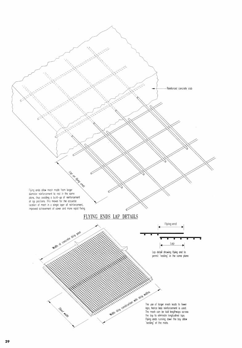
Flying ends allow mesh made from larger diameter reinforcement to rest in the same plane, thus avoiding o build - up of reinforcement at lop posi tions. This makes for the accurate location of mesh in o single Ioyer of re inforcement, improved achievement of cover and more rapid fixing.
FLYING ENDS LAP DETAILS
• •
Flying end
I ~ Lap ~ I Lap detail showing flying end to permit 'nesting' in the some plane
The use of larger mesh leads to fewer lops, hence less reinforcement is used. The mesh can be laid lengthways across the bay to eliminate longitudinal laps. Flying ends running down the boy allow 'nesting' of the mots.

SECTION TWO
BEAM REINFORCEMENT

30
SECTION TWO: BEAM REINFORCEMENT
This Section provides guidelines on specifying prefabricated reinforcement link cages and capping links.
2.1 Design And Detailing Considerations
1. Annotation for beam link cage :-
Link Numbers of Link Link Link - Link Spacing, Sv Type per Beam Material Diameter (mm)
Cross-Section (mm)
S, L n R, T, D, H 10, 13 75, 100, 125, 150, 200, 250, 300
For Specifying Beam Link Cage :-
Example ( 1 ): ~Rl.Q-200 ====> detailed as U - lJ consists of 1 number Open Link Cage of 1 Omm diameter Plain Mild Steel Bar at 200mm spacing.
Example (2): ~A Q 11 - 150 ====> detailed as lffJf](JJr - moDJ consists of 4 number Open Link Cage of 13mm diameter Deformed Hard Drawn W ire at 150mm spacing.
Example (3): ~ J t! 11- 250 ====> detailed as lf[][Jr - ro 01 consists of 3 number Open Link Cage of 13mm diameter Plain Hard Drawn Wire at 250mm spacing.
Example (4): l J I lQ - 250 ====>detailed as lrrJ[]Jr - fDD1 consists of 3 number Close Link Cage of lOmm diameter Tempcore Deformed Bar at 250mm spacing.
Notes: rliJ ( 1) Internal beam links shall not overlap each others ==> rLO.JJ or rn (2) Digit " 1" between alphabets "S" and "R" in Example ( 1) above is omitted and is not required when specifying 1 number link
per beam cross-section.
2. Annotation for beam capping link:-
Open Link Link Diameter - Recommended Capping Link Spacing, S. Link Material (mm) (mm)
s R, T, D, H 10, 13 75, 100, 125, 150, 200, 250,300
Example ( 1 ): ~ t! lQ- 300
consists of 1 number top beam capping link of 1 Omm diameter Plain Hard Drawn Wire at 300mm spacing.
3 . Legends :- (a) Prefix 'S' denotes open link cage (e.g . .S.R, .S.T, .S.D, .S.H)
(b) Prefix 'L' denotes close link cage (e.g. lR, lT, lD, lH) (c) R' denotes links using Plan Mild Steel Bar (fy. = 250 N/ mm2 )
(d) T' denotes links using Tempcore Deformed Bar (fyv = 460 N/mm2 )
(e) D' denotes links using Deformed Hard Drawn Wire (fyv = 485 N/ mm2 )
(f) H' denotes links using Plain Hard Drawn Wire (fyv = 485 N/ mm2 )
4. Engineer shall avoid specifying link cage using Plain Mild Steel Bar, ' R' and Plain Hard Drawn Wire, 'H' to
avoid confusion when applying.
5. Engineer shall note and design accordingly the link cage when beam is subjected to torsion.
6. Conversion table of beam link cage for Plain Mild Steel Bar to other type of link material is shown in the
Appendix.
7. When adopting for prefabricated reinforcement bars cage, engineer shall consider and liaise with fabricators,
if necessary, to verify the feasible cage size, lapping and lifting requirements.

Cl
2.2 Illustration On Use Of Beam Cage
BEAM OPEN STIRRUP CAGE AND CAPPING IJNK
Overall Length Varies {max. = 2200)
100 TYP.
1· {50 loiiN.) r
'- Carrier Wires
~q ...cg rS Copping Unk with
Carrier Wires
ELEVATION {Engineer shall note and take into consideration of the Carrier Wires in his design and detailing)
SECTION
Lerend D = Beam Depth B = Beam Width TC = Top Cover BC = Bottom Cover SC = Side Cover = 25mm (minimum) TC + BC = 85mm Cl
0 1-
~ ~ Position of Open Stirrup
Cl
LJ Position of Cappin' Link
POSITIONS OF CARRIER WIRES ( To verify with supplier )
OR OR
Position (1) Position (2) Position (3)
USE OF CAPPING IJNK ( To .eer's Requirement )
r Capping Unk {optional), if only 2 nos. main top reinforcement is required
Top of Beam/Slob :::=-:1=~~=-:;::::::j
Cl
Slab Reinft.
~ Case (1)
n· Copping Unk with Carrier Wires shall be used, if only more than 2 nos. main top reinforcement required
Slab Reinft. 0
n-Capping Unk with Carries Wires shall be used
y Top of Beam
Slab Reinft.
~ ~ Case (2) Case (3)
31

D
32
EXAMPLES OF BEAM OPEN IJNK AND CAPPING LINK
D
Example '1' (ForB < 200nun)
n-Capping Link with Carrier Wires (if necessory)
LJ Example '3' (For 400mm ,< B < 600mm)
D
Example '2' (For 200mm ~ B < 400mm)
~Capping Link with Carrier Wires ~ 1 ~ (if necessory)
Example '4' (For 600mm < B ~ 750mm)
r-Copping Link with Carrier Wires -i (if necessary)
B
Example '5' (For 750mm < B ,< 950mm) Example '6' (For 950mm < B ~ 1100mm)
]--Copping Link with Carrier Wre --i (if necessary)
D
11--1---11---ll-- ---ll->---f+- 4 Nos. Links 11-*- -+ofl--- 11-*- --11--f.._ 5 Nos. Links eg. S4T10-250 eg. S5T10- 250
...__ ~~~~~~ rooom B
(I) Internal links shall not overlap as sholfll in the diagram.
(2) Examples above indicate maximum numbers of link for a specific width of beam. Numbers of link required shall be determined by Engineer.
(3) Le~end : Sl = Distance between tension bars shall not be greater than 160mm for zero percentage of moment distribution.
S2 = Maximum lateral spacing of link legs shall not more than effective beam deoth.

EXAMPLES OF BEAM OPEN UNK AND CAPPING UNKS SUPPORTING PRECAST SLABS
Example '1' : Double Link Cage System (For Narrow Beam)
Example '2' : Multiple Link Cage System (For Wide Beam)
S2 S2 S2 S2
S1 Sl Sl S1 S1
Example '3' : Capping Link Cage
Le~end : Sl = Distance between tension bars shall not be greater than 160mm for zero percentage of moment distribution.
S2 = Maximum lateral spacing of link legs shall not more than effective beam depth.
33

(.) .c.
2.3
La
yin
g S
eq
ue
nc
e O
f P
refa
bri
ca
ted
Be
am
Ca
ge
INST
ALLA
TION
SEQ
UENC
E (1
) :
BEAM
S TB
1 +TB
2+ TB
3
®-,
., ,./
.®
/
///
//
./
'~
• IN
STAL
LATI
ON S
EQUE
NCE
(2)
: BE
AMS
TB
H TB
5
/@
<t
• IN
STAL
LATI
ON S
EQUE
NCE
(3)
: BE
AM T
B6
CONN
ECTI
ON
BARS
CCNN
ECTI
ON
BARS
CO
NNEC
TIO
N BA
RS
~
/®
®
CONN
ECTI
ON
BARS

SECTION THREE
COLUMN REINFORCEMENT

2.4 Bean-Column Intersection Detail
Link nongor bars - slop shari of column face
PRIMARY BEAM
Bottom span bars - Primary Beam bars slop short of column face
\ . '-- Column hnk cage
with Main Reinforcement Bars slroighl through junction
BEAM-COLUMN INTERSECTION DETAIL
Top support bars Primar.y Beam bars placed above Secondary Beam bars
Bottom span bars - Secondary Beam bars slop short of column face
35 t

SECTION THREE : COLUMN REINFORCEMENT
This Section enables engineer to specify from the design tables, column link cage for various sizes of column using
T 13 and T 16 as the main vertical reinforcement bars. T 16 diameter bar is the maximum bar size which is currently
available by machine fabrication . Larger bar size can be introduced by manual fabrication .
The link cage can also be used independently without the main reinforcement bars if so desired.
To achieve higher column capacity, engineer may install additional vertical reinforcement bars to the cage and/or
use higher grades of concrete.
3.1 Design Considerations
1. Annotation for column reference number with its specific steel reinforcement cage are shown in the following
examples.
Example ( 1 ): CA25/ 25-Tl from Column Design Table 'CA2', where,
CA -Denotes reinforced concrete column designed based on Grade 30 concrete
25/25 -Denotes 250mm x 250mm reinforced concrete square column
T 1 -Denotes specific main vertical reinforcement bars 4T13 with 1 number complete close link indicated as LRS-150 are used
Example (2) : CA35/ 60-T6 from Column Design Table 'CA24', where,
CA - Denotes rectangular reinforced concrete column designed based on Grade 30 concrete
35/ 60 -Denotes 350mm x 600mm reinforced concrete rectangular column
T6 -Denotes specific main vertical reinforcement bars 14T16 with 1 number complete close link and 2 numbers "C" link
indicated as 3 LR8-17 5 are used
2. The derivation of Design Ultimate Vertical Load, N (in kN) in the design tables is in accordance to Clause
(3 .8.4 .4) in BS 8110 : Part 1: 1985 : Section Three for short braced column supporting an approximately
symmetrical arrangement of beams, and assumed to be pinned at each floor. Engineer shall exercise his own
judgement when using the design tables such as when bending or unbraced condition is to be taken into
consideration .
N (in kN) = 0.35 feu Ac + 0.67 Asc fy where,
f'" -Denotes characteristic strength of concrete used (N/mm 2 )
-Denotes net cross-section area of concrete in a column (mm 2)
-Denotes area of main vertical reinforcement bars (mm 2 )
-Denotes characteristic strength of steel reinforcement bars (460 N/mm2)
3 . Annotation for column link cage:-
Numbers of Link
n
Example ( 1 ):
Example (2):
Example (3):
NOTE:-
Close Link Link - Link Spacing, S. Link Material Diameter (mm)
{mm}
L R, D,H 6, 8, 10, 13 100, 125,150,200,250, 300
lRlQ- 200
consists of 1 number complete close link cage of 1 Omm diameter Plain Mild Steel Bar at 200mm spacing .
;H.Q.U-150
consists of 1 number complete close link cage and 2 numbers "C" link of 13mm diameter Deformed Hard
Drawn Wire at 150mm spacing .
.Qltl.ii -ill consists of 1 number complete close link cage and 5 numbers "C" link of 8mm diameter Plain Hard Drawn
Wire at 125mm spacing.
"C" link is considered as one link in the annotation above.
36


3.2 Column Design Tables
Column Design Table: CAl Column Size: 200 mm x 200 mm
Concrete Grade: 30 N/mm2
Column Vert Reinf Asc (prov'd) Asc (prov'd ) Link Cage Ult Vert Load Steel/Concrete Ref. No. Prov'd (mm2) (%) Prov'd Capacity (kN) Prov'd (kg/ m3)
CA20/20-T1 4T13 531 1.33 LR8-150 580 151
CA20/20-T2 4T1 6 804 2.01 LR8-175 660 198
Column Design Table: CA2 Column Size: 250 mm x 250 mm
Concrete Grade: 30 N/ mm 2
Column Vert Reinf Asc (prov'd) Asc (prov'd) Link Cage Ult Vert Load Steel/Concrete Ref. No. Prov'd (mm2) (%) Prov'd Capacity (kN) Prov'd (kg/ m3)
CA25/25-T1 4T13 53 1 0.85 LR8-150 810 105
CA25/25-T2 4T16 804 1.29 LR8-175 900 134
Column Design Table: CA3 Column Size: 300 mm x 300 mm
Concrete Grade: 30 N/mm2
Column Vert Reinf Asc (prov'd) Asc (prov'd) Link Cage U It Vert Load Steel/Concrete Ref. No. Prov'd (mm2) (%) Prov'd Capacity (kN) Prov'd (kg/ m3)
CA30/30-T1 4T13 53 1 0.59 LR8-150 11 00 79
CA30/30-T2 6T13 796 0.88 LR8-150 1180 102
CA30/30-T3 8T16 1062 1.18 LR8-150 1260 125
CA30/30-T4 4T1 6 804 0.89 LR8-175 1180 98
CA30/30-T5 6T1 6 1206 1.34 LR8-175 1300 133
CA30/30-T6 8T16 1608 1.79 LR8-175 1420 168
Column Design Table: CA4 Column Size: 350 mm x 350mm
Concrete Grade: 30 N/ mm 2
Column Vert Reinf Asc (prov'd) Asc (prov'd) Link Cage Ult Vert Load Steel/Concrete Ref. No. Prov'd (mm2) (%) Prov'd Capacity (kN) Prov'd (kg/ m3)
CA35/35-T1 4T13 53 1 0.43 LR8-150 1440 62
CA35/35-T2 6T13 796 0.65 LR8-150 1520 79
CA35/35-T3 8T13 1062 0.87 LR8-150 1600 96
CA35/35-T4 4T16 804 0.66 LR8-175 1530 76
CA35/35-T5 6T16 1206 0.98 LR8-175 1650 102
CA35/35-T6 8T1 6 1608 1.31 LR8-175 1770 127
Column Design Table: CA5 Column Size: 400 mm x 400 mm
Concrete Grade: 30 N/ mm 2
Column Vert Reinf Asc (prov'd) Asc (prov'd) Link Cage Ult Vert Load Steel/Concrete Ref. No. Prov'd (mm 2) (%) Prov'd Capacity (kN) Prov'd (kg/ m3)
CA40/40-T1 8T13 10,62 0.66 LR8-150 2000 77
CA40/40-T2 12T13 1593 1.00 LR8-150 2150 103
CA40/40-T3 4T16 804 0.50 LR8-175 1920 61
CA40/40-T4 8T16 1608 1.01 LR8-175 2160 100
CA40/40-T5 12T16 2413 1.51 LR8-175 2400 140
38

Column Design Table: CA6 Column Size: 450 mm x 450 mm
Concrete Grade: 30 N/ mm 2
Column Vert Reinf Asc (prov'd) Asc (prov'd) Link Cage Ult Vert Load Stee l/Concrete Ref. No. Prov'd (mm2) (%) Prov'd Capacity (kN) Prov'd (kg/ m3)
CA45/45-T1 8T1 3 1062 0.52 LR8-150 2440 63
CA45/45-T2 12T1 3 1593 0.79 LR8- 150 2600 84
CA45/45-T3 4T1 6 804 0.40 LR8- 175 2370 50
CA45/45-T4 8T1 6 1608 0.79 LR8-1 75 2610 82
CA45/45-T5 12T16 2413 1.19 LR8- 175 2840 11 3
Column Design Table: CAl Column Size: 500 mm x 500 mm
Concrete Grade: 30 N/ mm 2
Column Vert Reinf Asc (prov'd) Asc (prov'd) Link Cage Ult Vert Load Steel/Concrete Ref. No. Prov'd (mm2) (%) Prov'd Capacity (kN) Prov'd (kg/ m3)
CA50/50-T1 8T1 3 1062 0.42 3 LR8- 150 2940 ' 63
CA50/50-T2 12T13 1593 0.64 3 LR8-150 3100 80
CA50/50-T3 16T1 3 2124 0.85 3 LR8-1 50 3260 96
CA50/50-T4 8T1 6 1608 0.64 3 LR8-175 3100 76
CA50/50-T5 12T 16 2413 0.97 3 LR8-175 3340 101
CA50/50-T6 16T16 32 17 1.29 3 LR8- 175 3580 127
Column Design Table: CAB Column Size: 600 mm x 600 mm
Concrete Grade: 30 N/ mm 2
Column Vert Reinf Asc (prov'd) Asc (prov'd) Link Cage Ult Vert Load Steel/Concrete Ref. No. Prov'd (mm 2) (%) Prov'd Capacity (kN) Prov'd (kg/ m3)
CA60/60-T1 12T13 1593 0.44 5 LR8-150 4250 68
CA60/60-T2 16T1 3 2124 0.59 5 LR8-1 50 4410 80
CA60/60-T3 20T1 3 2655 0.74 5 LR8- 150 4570 91
CA60/60-T4 8T1 6 1608 0.45 5 LR8-17 5 4260 57
CA60/60-T5 12T16 2413 0.67 5 LR8,175 4500 81
CA60/60-T6 16T1 6 32 17 0.89 5 LR8-175 4740 99
CA60/60-T7 20T1 6 402 1 1.12 5 LR8-175 4980 116
Column Design Table: CA9 Column Size: 200 mm x 400 mm
Concrete Grade: 30 N/ mm 2
Column Vert Reinf Asc (prov'd) Asc (prov'd) Link Cage Ult Vert Load Steel/Concrete Ref. No. Prov'd (mm 2) (%) Prov'd Capacity (kN) Prov'd (kg/ m3)
CA20/40-T1 4T1 3 53 1 0.66 LR8- 150 1000 89
CA20/40-T2 8T1 3 1062 1.33 LR8-150 11 60 14 1
CA20/40-T3 4T16 804 1.01 LR8-175 1080 11 0
CA20/40-T4 8T1 6 1608 2.01 LRS-175 1320 189
39

Column Design Table: CA10 Column Size: 200 mm x 500 mm
Concrete Grade: 30 N/ mm 2
Column Vert Reinf Asc (prov'd) Asc (prov'd) Link Cage Ult Vert Load Steel/Concrete Ref. No. Prov'd (mm2) (%) Prov'd Capacity (kN) Prov'd (kg/ m3)
CA20/50-Tl 6T13 796 0.80 2 LR8- 150 1290 102
CA20/50-T2 10T13 1327 1.33 2 LR8-150 1450 144
CA20/50-T3 6T16 1206 1.21 2 LR8- 175 141 0 129
CA20/50-T4 10T16 20 11 2.01 2 LR8- 175 1650 192
Column Design Table: CA 11 Column Size: 200 mm x 600 mm
Concrete Grade: 30 N/ mm2
Column Vert Reinf Asc (prov'd) Asc (prov'd) Link Cage Ult Vert Load Steel/Concrete Ref. No. Prov'd (mm 2) (%) Prov'd Capacity (kN) Prov'd (kg/ m3)
CA20/60-Tl 8T13 1062 0.88 3 LR8-1 50 1580 11 2
CA20/60-T2 12T13 1593 1.33 3 LR8-150 1730 146
CA20/60-T3 8T16 1608 1.34 3 LR8-175 1740 142
CA20/60-T4 12T16 2413 2.01 3 LR8-175 1980 194
Column Design Table: CA12 Column Size: 200 mm x 700 mm
Concrete Grade: 30 N/ mm2
Column Vert Reinf Asc (prov'd) Asc (prov'd) Link Cage Ult Vert Load Steel/Concrete Ref. No. Prov'd (mm2 ) (%) Prov'd Capacity (kN) Prov'd (kg/ m3)
CA20/70-Tl 8T13 1062 0.76 3 LR8-150 1790 99
CA20/70-T2 10T13 1327 0.95 3 LR8-150 1870 114
CA20/70-T3 14T13 1858 1.33 3 LR8-150 2020 144
CA20/70-T4 8T16 1608 1.1 5 3 LR8- 175 1950 125
CA20/70-T5 10T1 6 2011 1.44 3 LR8-175 2070 147
CA20/70-T6 14T1 6 28 15 2.01 3 LR8-1 75 2310 192
Column Design Table: CA13 Column Size: 200 mm x 800 mm
Concrete Grade: 30 N/ mm 2
Column Vert Reinf Asc (prov'd) Asc (prov'd) Link Cage Ult Vert Load Steel/Concrete Ref. No. Prov'd (mm2) (%) Prov'd Capacity (kN) Prov'd (kg/ m3)
CA20/80-Tl 8T13 1062 0.66 3 LR8-150 2000 90
CA20/80-T2 12T13 1593 1.00 3 LR8-150 2150 116
CA20/80-T3 16T13 2124 1.33 3 LR8-150 23 10 142
CA20/80-T4 8T16 1608 1.01 3 LR8-175 2160 11 2
CA20/80-T5 12T1 6 2413 1.51 3 LR8- 175 2400 151
CA20/80-T6 16T16 3217 2.01 3 LR8-1 75 2640 191
40

Column Design Table: CA14 Column Size: 200 mm x 1 000 mm
Concrete Grade: 30 N/ mm2
Column Vert Reinf Asc (prov'd) Asc (prov'd) Link Cage Ult Vert Load Steel/Concrete Ref. No. Prov'd (mm2) (%) Prov'd Capacity (kN) Prov'd (kg/ m3)
CA20/ 1 00-Tl 12Tl 3 1593 0.80 5 LR8-150 2570 104
CA20/ 1 OO-T2 16Tl 3 2124 1.06 5 LR8- 150 2730 125
CA20/ 1 OO-T3 20T13 2655 1.33 5 LR8-150 2890 145
CA20/ 1 00-T 4 12T16 24 13 1.2 1 5LR8-175 2820 130
CA20/ 1 OO-T5 16T16 3217 1.61 5LR8-175 3060 162
CA20/ 1 OO-T6 20T1 6 402 1 2.01 5 LR8-175 3300 193
Column Design Table: CA15 Column Size: 250 mm x 400 mm
Concrete Grade: 30 N/ mm2
Column Vert Reinf Asc (prov'd) Asc (prov'd) Link Cage Ult Vert Load Steel/ Concrete Ref. No. Prov'd (mm2) (%) Prov'd Capacity (kN) Prov'd (kg/ m3)
CA25/40-Tl 4T1 3 53 1 0.53 LR8- 150 1210 74
CA25/40-T2 8T1 3 1062 1.06 LR8-150 1370 ,115
CA25/40-T3 4T1 6 804 0.80 LR8-175 1290 91
CA25/40-T4 8T1 6 1608 1.61 LR8-175 1530 154
Column Design Table: CA16 Column Size: 250 mm x 500 mm
Concrete Grade: 30 N/ mm2
Column Vert Reinf Asc (prov'd) Asc (prov'd) Link Cage Ult Vert Load Steel/Concrete Ref. No. Prov'd (mm2) (%) Prov'd Capacity (kN) Prov'd (kg/ m3)
CA25/50-Tl 6T1 3 796 0.64 2 LR8-150 1550 85
CA25/50-T2 10T1 3 1327 1.06 2 LR8-150 1710 11 8
CA25/50-T3 6T1 6 1206 0.97 2 LR8-175 1670 106
CA25/50-T4 10T16 201 1 1.61 2 LR8-175 1910 157
Column Design Table: CA17 Column Size: 250 mm x 600 mm
Concrete Grade: 30 N/mm2
Column Vert Reinf Asc (prov'd) Asc (prov'd) Link Cage Ult Vert Load Steel/Concrete Ref. No. Prov'd (mm2) (%) Prov'd Capacity (kN) Prov'd (kg/ m3)
CA25/60-T1 8T1 3 1062 0.71 3 LR8-150 1890 93
CA25/60-T2 12T13 1593 1.06 3 LR8-150 2050 121
CA25/60-T3 8T16 1608 1.07 3 LR8-175 2050 116
CA25/60-T4 12T1 6 2413 1.61 3 LR8-175 2290 158
Column Design Table: CA18 Column Size: 250 mm x 700 mm
Concrete Grade: 30 N/ mm2
Column Vert Reinf Asc (prov'd) Asc (prov'd) Link Cage Ult Vert Load Steel/Concrete Ref. No. Prov'd (mm2) (%) Prov'd Capacity (kN) Prov'd (kg/ m3)
CA25/70-T1 8T1 3 1062 0.61 3 LR8-150 2150 83
CA25/70-T2 10T1 3 1327 0.76 3 LR8-150 2230 94
CA25/70-T3 14T1 3 1858 1.06 3 LR8-150 2390 11 8
CA25/70-T4 8T1 6 1608 0.92 3 LR8-175 2320 102
CA25/70-T5 10T1 6 2011 11 5 3 LR8-1 75 2440 120 I CA25/70-T6 14T1 6 281 5 1.61 3 LR8-1 75 2680 156
[.
41


Column Design Table: CA23 Column Size: 350 mm x 500 mm
Concrete Grade: 30 N/ mm2
Column Vert Reinf Asc (prov'd) Asc (prov'd) Lin k Cage Ult Vert Load Steel/Concrete Ref. No. Prov'd (m m2) (%) Prov'd Capacity (kN) Prov'd (kg/ m3)
CA35/50-T1 6T13 796 0.46 2 LR8-150 2070 65
CA35/50-T2 10T13 1327 0.76 2 LR8- 150 2230 89
CA35/50-T3 12T1 3 1593 0.91 2 LR8-150 2310 101
CA35/50-T4 6T16 1206 0.69 2 LR8-175 2200 80
CA35/50-T5 10T16 2011 11 5 2 LR8-175 2440 11 6
CA35/50-T6 12T16 2413 138 2 LR8-175 2560 134
Column Design Table: CA24 Column Size: 350 mm x 600 mm
Concrete Grade: 30 N/ mm2
Column Vert Reinf Asc (prov'd) Asc (prov'd ) Lin k Cage U It Vert Load Steel/ Concrete Ref. No. Prov'd (m m2) (%) Prov'd Capacity (kN) Prov'd (kg/ m3)
CA35/60-T1 8T1 3 1062 0.51 3 LR8-1 50 2520 71
CA35/60-T2 12T13 1593 0.76 3 LR8-150 2680 91
CA35/60-T3 14T13 1858 0.88 3 LR8-150 2760 101
CA35/60-T4 8T16 1608 0.77 3 LR8-175 2680 87
CA35/60-T5 12T16 2413 1.15 3 LR8-175 2920 117
CA35/60-T6 14T16 2815 134 3 LR8-175 3040 133
Column Design Table: CA25 Column Size: 450 mm x 600 mm
Concrete Grade: 30 N/ mm2
Column Vert Reinf Asc (prov'd) Asc (prov'd) Link Cage Ult Vert Load Steel/Concrete Ref. No. Prov'd (mm2) (%) Prov'd Capacity (kN) Prov'd (kg/ m3)
CA45/60-T1 12T13 1593 0.59 5 LR8-1 50 3310 85
CA45/60-T2 16T1 3 2124 0.79 5 LR8-150 3470 101
CA45/60-T3 12T16 2413 0.89 5 LR8-175 3550 104
CA45/60-T4 16T16 32 17 1.19 5 LR8-175 3790 127
43

3.3 Illustration On Use Of Column Cage
REQUIREMENT OF COLUMN UNK CAGE
1. ALTERNATE OUTER t.AAJN BARS SfW..L BE TIED BY 'C' LINKS IF THE SPACING ARE EQUAL OR LESS ~ 150mm ( FOR a,< 150mm )
I a a a a a a
t.AAJN BARS~ c: Ei: J COMPLETE CLOSED Ll: _] l 'C' LINK (denoted by a prefix 'L')
EXAMPLES OF COLUMN UNK CAGE CARRIER WIRES
CONCRETE COVER TO LINKS
.---1--t----t--il • (TYPICAL)
Enmple '1'
COMPLETE CLOSED LINK {TYPICAL)
Single Column Link Cage CONSISTS OF ONE COMPLETE CLOSED LINK ( e.g. LR10-200 ) 0
Example '3' Triple Column Link Cage CONSISTS OF ONE COMPLETE CLOSED LINK AND TWO 'C' LINKS ( e.g. 3LH10-175 ) n:tr
Example '5' 'I'tro "Inttrlocking" Column Link Cages for T-Shaped Columns
2. All ALTERNATE t.AAJN BARS SfW..L BE TIED BY 'C' LINKS IF THE SPACING EXCEEDS 150mm ( FOR b > ... 150mm )
b b b b b b I ' I' 'I ·1· ·1
t.AAJNMRS-w=c c Eit J COMPLETE CLOSED LINKS _j l 'C' LINK (denoted by a prefix 'L")
• . . • :~ •
• • •
'. C LINK {TYPICAL)
Example '2' Double Column Link Cage CONSISTS OF ONE COMPLETE CLOSED LINK AND ONE 'C' LINK ( e.g. 2LDB-200 ) C::O
' • --~
•
• ~
• • =
Example '4' 'I'tro "Interlocking" Column Link Cages for L-Shaped Columns CONSISTS OF TWO COMPLETE CLOSED LINKS AND TWO 'C' LINKS (e.g. 4LH10-250) ~
CONSISTS OF TWO COMPLETE CLOSED LINKS AND THREE 'C' LINKS
( •.g. 5LDIJ-150) ~
44
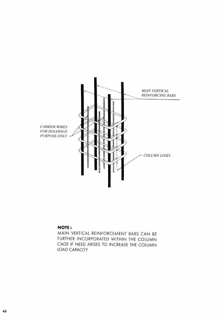
45
CARRIER WIRES FOR HOLDINGS PURPOSE ONLY
NOTE:
MAIN VERTICAL REINFORCING BARS
COLUMN LINKS
MAIN VERTICAL REINFORCEMENT BARS CAN BE FURTHER INCORPORATED WITHIN THE COLUMN CAGE IF NEED ARISES TO INCREASE THE COLUMN LOAD CAPACITY

SECTION FOUR

46
SECTION FOUR: WALL REINFORCEMENT
This Section enables engineer to specify from the design tables, a new range of WWF for various sizes of reinforced
concrete walls. Only 1 Omm and 13mm diameter of bars with 150mm and 200mm spacing in either main, cross or
both directions of the welded wire fabric series are considered in the design.
Other mesh series if required may be used subject to the engineer's requirement.
To achieve high load capacity, engineer may install additional vertical reinforcement bars to the mesh and/ or use
higher grades of concrete.
4.1 Design Considerations
1. Annotation for wall reference number with its specific mesh are shown in the following examples.
Example ( 1 ): WA 125-A 10 from Building Wall Design Table 'WA 1 ', where,
W - Denotes reinforced concrete wall
A -Denotes wall design based on Grade 30 concrete
125 -Denotes 125mm thick reinforced concrete wal l
A 10 - Denotes A 1 0 Standard WWF is used for both sides of wall
Example (2): WB300-DA 13d/ 10 from Building Wall Design Table 'WB5', where,
W - Denotes reinforced concrete wall
B - Denotes wall design based on Grade 35 concrete
300 - Denotes 300mm thick reinforced concrete wall
DA 13d/ 10 -Denotes DA 13d/ 10 Designer WWF is used for both sides bf wall
2. Nominal concrete cover of 25mm is used in the design unless otherwise specified by engineer.
3 . Concrete characteristic strength of 30 N/mm2 and 35 N/mm2 are adopted in the Design Table 'WA 1' to
Table 'WAS' and Table 'WB 1' to Table 'WB8' respectively.
4. The derivation of Design Ultimate Vertical Load, N (in kN) in the design table is in accordance to Clause
(3.9.3 .6.1) in BS 8110: Part 1: 1985: Section Three for stocky braced reinforced wall supporting approximately
symmetrical arrangement of slabs and beams, and assumed to be pinned at each floor. Engineer shall exercise
his own judgement when using the design tables such as when bending or unbraced condition is to be taken
into consideration.
N (in kN) = 0.35 feu Ac + 0.67 Asc fy where,
feu -Denotes characteristic strength of concrete used (N/mm2 )
A -Denotes net cross-section area of concrete in a column (mm2)
Ac -Denotes area of main vertical reinforcement bars (mm2 )
fy - Denotes characteristic strength of welded wire fabric wires (485 N/mm2)
5. "C" links are to be provided and specified by Engineer whenever necessary.
6. Steel/Concrete content (in kg/ m3 ) and its percentage are an estimated values without taking into account of
lapping zone.
7. Engineer shall consider and liaise with fabricators, whenever necessary, for any other available mesh, and to
verify the necessary lapping and lifting requirements.

4.2 Wall Design Tables
Building Wall Design Table: Thickness: 125 mm
WA1 Concrete Grade : 30 N/mm2
Wall WWF Ult Vert Load % of Vertical Reinf Steel/Concrete Ref No. Size Capacity (KNm}
% of Horizontal Reinf (kg/m3}
WA 125-A 10 A10 1560 0.63 99 0.63
WA 125-AA 13110 AA13/10 1730 1.06 133 0.63
WA 125-DA 10/10 DA1 0/10 1810 1.26 148
0.63
WA 125-EA 13/10 EA 13/10 1900 1.49 160 0.63
WA 125-EA 1 Od/1 0 EA 10d/10 2000 1.76 181
0.63
WA125-B13 B13 2150 2.12 216
0.63
WA 125-DA 1 Od/1 0 DA10d/10 2300 2.51 247
0.63
WA 125-EA 13d/1 0 EA 13d/1 0 2480 2.97 27 1
0.63
WA 125-DA 13d/10 DA 13d/10 2980 4.25 382 0.63
Building Wall Design Table: Thickness: 150 mm
WA2 Concrete Grade : 30 N/mm2
Wall WWF Ult Vert Load % of Vertical Reinf Steel/Concrete Ref No. Size Capacity (KNm} % of Horizontal Reinf (kg/m3}
WA150-A10 A10 1820 0.52 82
0.52
WA 150-AA 13110 AA13/10 1990 0.88 11 0
0.52
WA 150-DA 10/10 DA 10110 2070 1.05 123
0.52
WA 150-EA 13/10 EA13/10 21 60 1.24 134 0. 52
WA 150-EA 10d/1 0 EA 10d/10 2270 1.47 151
0.52
WA150-B13 B13 24 10 1.77 180
0.52
WA 150-DA 1 Od/1 0 DA1 0d/10 2560 2.09 206
0.52
WA 150-EA 13d/1 0 EA 13d/10 2740 2.48 226
0.52
WA 150-DA 13d/1 0 DA 13d/10 3240 3.54 318 0.52
47

Building Wall Design Table: Thickness: 175 mm
WA3 Concrete Grade : 30 N/mm2
Wall WWF Ult Vert load % of Vertical Reinf Steel/Concrete Ref No. Size Capacity (KNm)
% of Horizontal Reinf (kg/m3)
WA175-A10 A10 2080 0.45 71
0.45
WA 175-AA 13/10 AA13/10 2250 0.76 95 0.45
WA 175-DA 10/10 DA10/10 2330 0.90 106
0.45
WA 175-EA 13/10 EA13/10 2420 1.06 114 0.45
WA 175-EA 1 Od/1 0 EA 10d/10 2530 1.26 129
0.45
WA175-813 813 2670 1.52 154
0.45
WA 175-DA 1 Od/1 0 DA10d/10 2830 1.80 176
0.45
WA 125-EA 13d/10 EA 13d/1 0 30 10 2.12 194
0.45
WA 175-DA 13d/1 0 DA 13d/10 3510 3.03 273 0.45
Building Wall Design Table: Thickness: 200 mm
WA4 Concrete Grade : 30 N/mm2
Wall WWF Ult Vert load % of Vertical Reinf Steel/Concrete Ref No. Size Capacity (KNm)
% of Horizontal Reinf (kg/m3)
WA200-AA 13/10 AA13/10 2520 0.66 83
0.39
WA200-DA 1 0/1 0 DA 10/10 2590 0.79 93 0.39
WA200-EA 13/1 0 EA13/10 2680 0.93 100 0.39
WA200-EA 1 Od/1 0 EA10d/10 2790 1.10 113
0.39
WA200-8 13 813 2930 1.33 135
0.39
WA200-DA 1 Od/1 0 DA10d/10 3090 1.57 154
0.39
WA200-EA 13d/1 0 EA 13d/1 0 3270 1.86 170
0.39
WA200-DA 13d/1 0 DA3d/1 0 3770 2.65 239
0.39
48

Building Wall Design Table: Thickness: 225 mm
WAS Concrete Grade : 30 N/mm2
Wall WWF Ult Vert Load % of Vertical Reinf Steel/Concrete Ref No. Size Capacity (KNm) % of Horizontal Reinf (kg/m3)
WA225-EA 10/10 EA10/10 271 0 0.49 64
0.35
WA225-AA 13/10 AA13/10 2780 0.59 74
0.35
WA225-DA 10/10 DA10/10 2860 0.70 82
0.35
WA225-EA 13/10 EA 13/10 2950 0.83 89 0.35
WA225-EA10d/10 EA 10d/10 3050 0.98 101
0.35
WA225-B13 B13 3200 1.1 8 120
0.35
WA225-DA 1 Od/1 0 DA10d/10 3350 1.40 137
0.35
WA225-EA 13d/1 0 EA13d/10 3530 1.65 151
0.35
WA225-DA 13d/1 0 DA13d/10 4030 2.36 212 0.35
Building Wall Design Table: Thickness: 250 mm
WAG Concrete Grade : 30 N/mm2
Wall WWF Ult Vert Load % of Vertical Reinf Steel/Concrete Ref No. Size Capacity (KNm)
% of Horizontal Reinf (kg/m3)
WA250-EA 10/10 EA10/10 2970 0.44 58
0.3 1
WA250-AA 13/10 AA13/10 3040 0.53 66
0.31
WA2 50-DA 10/1 0 DA10/10 31 20 0.63 74
0.3 1
WA250-EA 13/10 EA 13/10 3210 0.74 80
0.3 1
WA250-EA 1 Od/1 0 EA10d/10 3320 0.88 90
0.3 1
WA250-B13 B13 3460 1.06 108
0.31
WA250-DA 1 Od/1 0 DA 10d/10 3610 1.26 123
0.31
WA250-EA 13d/1 0 EA13d/10 3790 1.49 136
0.31
WA250-DA 13d/1 0 DA 13d/10 4290 2.1 2 191 0.31
49


Building Wall Design Table: Thickness: 125 mm
WB1 Concrete Grade : 30 N/mm2
Wall WWF Ult Vert Load % of Vertical Reinf Steel/Concrete Ref No. Size Capacity (KNm)
% of Horizontal Reinf (kg/m3)
WB125-A10 A10 1780 0.63 99
0.63
WB 125-AA 13/10 AA13/10 1950 1.06 133
0.63
WB 125-DA 10/10 DA 10/10 2020 1.26 148
0.63
WB 125-EA 13/10 EA13/10 2110 1.49 160 0.63
WB 125-EA 1 Od/1 0 EA 10d/10 2220 1.76 181
0.63
WB125-B13 B13 2360 2.12 216
0.63
WB 125-DA 1 Od/1 0 DA10d/10 2510 2.51 247
0.63
WB 125-EA 13d/1 0 EA13d/10 2690 2.97 271
0.63
WB 125-DA 13d/1 0 DA1 3d/10 3190 4.2 5 382 0.63
Building Wall Design Table: Thickness: 150 mm
WB2 Concrete Grade : 35 N/mm2
Wall WWF Ult Vert Load % of Vertical Reinf Steel/Concrete Ref No. Size Capacity (KNm)
% of Horizontal Reinf (kg/m3)
WB150-A 10 A1 0 2080 0.52 82
0.52
WB 150-AA 13/10 AA1 3/10 2250 0.88 110 0.52
WB 150-DA 10/10 DA 10/10 2330 1.05 123
0.52
WB 150-EA 13/10 EA13/10 2420 1.24 134 0. 52
WB 150-EA 1 Od/1 0 EA10d/10 2530 1.47 151
0.52
WB 150-813 B13 2670 1.77 180
0.52
WB 150-DA 1 Od/1 0 DA10d/10 2820 2.09 206
0.52
WB 150-EA 13d/1 0 EA 13d/10 3000 2.48 226
0.52
WB 150-DA 13d/1 0 DA13d/10 3500 3.54 318 0.52
51


Building Wall Design Table: Th ickness: 225 mm
WBS Concrete Grade : 35 N/mm2
Wall WWF Ult Vert load % of Vertical Reinf Steel/Concrete Ref No. Size Capacity {KNm) % of Horizontal Reinf {kg/m3)
W8225-EA 10110 EA10/10 3100 0.49 64
0.35
W8225-AA 13/10 AA 13110 3170 0.59 74 0.35
W8225-DA 10110 DA10/10 3250 0.70 82
0.35
W8225-EA 13/10 EA13/10 3340 0.83 89 0.35
W8225-EA 1 Od/1 0 EA10d/10 3440 0.98 101
0.35
W8225-8 13 813 3590 1.18 120
0.35
W8225-DA 1 Od/1 0 DA10d/10 3740 1.40 137
0.35
W8225-EA 13d/1 0 EA 13d/10 3920 1.65 151
0.35
W8225-DA 13d/10 DA13d/10 4420 2.36 212 0.35
Building Wall Design Table: Thickness: 250 mm
WB6 Concrete Grade : 30 N/mm2
Wall WWF Ult Vert load % of Vertical Reinf Steel/Concrete Ref No. Size Capacity {KNm)
% of Horizontal Reinf {kg/m3)
W8250-EA 10/10 EA10/10 3410 0.44 58
0.3 1
W82 50-AA 13/1 0 AA 13110 3480 0.53 66 0.31
W8250-DA10/10 DA10/10 3550 0.63 74
0.31
W8250-EA 13/10 EA13/10 3640 0.74 80 0.31
W8250-EA 1 Od/1 0 EA10d/10 3750 0.88 90
0.3 1
W8250-813 813 3890 1.06 108
0.31
W8250-DA 1 Od/1 0 DA10d/10 4040 1.26 123
0.3 1
W8250-EA 13d/1 0 EA13d/10 4220 1.49 136
0.31
W8250-DA 13d/1 0 DA13d/10 4720 2.12 191 0.31
53

Building Wall Design Table: Thickness: 275 mm
WB7 Concrete Grade : 35 N/mm2
Wall WWF Ult Vert Load % of Vertical Reinf Steel/Concrete Ref No. Size Capacity (KNm)
% of Horizontal Reinf (kg/m3)
WB275-EA 10/10 EA10/10 3710 0.40 52
0.29
WB275-AA 13/10 AA 13/10 3780 0.48 60
0.29
WB275-DA10/10 DA 10/10 3860 0.57 67
0.29
WB275-EA 13/10 EA 13/10 3950 0.68 73 0.29
WB275-EA 1 Od/10 EA 10d/10 4060 0.80 82
0.29
WB275-B13 B13 4200 0.97 98
0.29
WB275-DA 1 Od/1 0 DA 10d/1 0 4350 1.14 112
0.29
WB275-EA 13d/1 0 EA 13d/1 0 4530 1.35 123
0.29
WB275-DA 13d/1 0 DA13d/10 5030 1.93 174 0.29
Building Wall Design Table: Thickness: 300 mm
WB8 Concrete Grade : 35 N/mm2
Wall WWF Ult Vert Load % of Vertical Reinf Steel/Concrete Ref No. Size Capacity (KNm)
% of Horizontal Reinf (kg/m3)
WB300-AA 13/10 AA13/10 4090 0.44 55
0.26
WB300-DA 1 0/1 0 DA10/10 4170 0.52 62
0.26
WB300-EA 13/1 0 EA13/10 4260 0.62 67
0.26
WB300-EA 1 Od/1 0 EA10d/10 4360 0.73 75
0.26
WB300-B13 B13 4510 0.88 90
0.26
WB300-DA 1 Od/1 0 DA 1 Od/1 0 4660 1.05 103
0.26
WB300-EA 13d/1 0 EA13d/10 4840 1.24 113
0.26
WB300-DA 13d/1 0 DA 13d/10 5340 1.77 159 0.26
54


56
ADDmONAL REINFORCEt.IENT (Example)
ADDmONAL U-t.IESH
DOOR OPENING
ADDmONAL REINFORCEt.IENT
CROSS WIRES
WATER-STOP TO --, DESIGNER'S REQUIREt.IENT
SECTION A - A
v Floor
: : I I I OPENING I I
i FDDITIONAL REINFORCEMENT I I TO ENGINEER'S REQUIREMENT I
I
I I\ //I I
I I
I I I ADDITIONAL VERTICAL I END LINK 'c '
I ADDITIONAL HORIZONTAL- w I I END LINK ' c ' I I
1/\ I
I I I I I I I I I I I I I I
I I ADDITIONAL REINFORCEMENT--~ - I I TO ENGINEER'S REQUIREMENT I I I
TYPICAL DETAIL OF WALL OPENING
\1 Floor
t.IAIN WIRES
DETAIL 'A'

SECTION FIVE
PILECAP REINFORCEMENT

VIEW THROUGH SECTION
BALCONY SPANDREL PANELS
57

SECTION FIVE : PILECAP REINFORCEMENT
This Section enables engineer to specify prefabricated reinforcement details for reinforced concrete pilecaps for
single pile to 5-pilegroup. The pilecaps include those on precast concrete driven piles and bored piles.
Design pile capacity is based on pile material strength. Engineer shall use his own discretion when soil parameters
governing the design of pile capacity. Engineer shall liaise with fabricators for feasible cage. When machine fabrication
is not possible for reinforcement bar above 16mm diameter or due to their bars arrangement, manual fabrication
could be adopted.
5.1 Design Considerations
1. Annotation for pilegroup reference number with its specific type, size and number of piles are shown in the
following examples.
Example ( 1 ): 1 RP 150 from Pilecap Design Table ' RP 1 ', where,
1 RP -Denotes single pile for precast reinforced concrete driven pile
150 - Denotes 150mm x 150mm precast reinforced concrete driven pile size
Example (2): 5BP450 from Pilecap Design Table 'BP1 ',where,
5BP - Denotes 5 Pilegroup for bored pile
450 -Denotes 450mm diameter bored pile size
2 . Pile working capacity based on material strength is used in the pilecap design.
(i) For Grade 45 Precast Reinforced Concrete Driven Piles :-
Pile Working Capacity (in kN) = (45)N/mm 2 x (Pile Area)mm 2 x ( 10·3) kN
4
(i i) For Grade 35 Bored Piles:-
Pile Working Capacity (in kN) = (35)N/ mm2 x (Pile Area)mm 2 x ( 10·3 ) kN
5
3 . Load factor 1.5 to pile working capacity is adopted in the pilecap design.
4 . Piles spacings of 3.0 and 2.5 times are adopted for precast reinforced concrete driven pile and bored pile
respectively subject to engineer's requirement.
5. Pile penetration of 1 OOmm and 125mm are used in the pilecap design for precast reinforced concrete driven
piles and bored piles respectively unless otherwise required by engineer.
6 . Individual pile deviation from its true position is taken to be 75mm in the design.
7. Concrete covers to all sides and from pile cut-off level to nearer reinforcement are taken as 50mm unless
otherwise specified by engineer.
8. Steel reinforcement of f1, 460 N/mm2 and concrete characteristic strength, feu, 35 N/mm2 are adopted in the
design. The use of other grade of concrete and/ or larger concrete covers are subjected to engineer's requirement
such as when severe exposure is to be met.
9. Provisional of 0.13% of concrete sectional area of pilecap for top layers of reinforcement and pile's reinforcement
anchorage length are subjected to Engineer's requirement.
10. Horizontal binder reinforcement is taken as 25% of the main reinforcement areas of pilecap.
11. Engineer shall carry out his own check to ensure design shear stress along column perimeter is not exceeding
0.8 ff:"u or 5 N/mm 2, whichever the lesser. Recommended minimum critical column perimeter shown in the
design tables shall be taken as a guide.
58

1.11
'()
5.2
S
tan
da
rd N
ota
tio
n F
or
Pil
ec
ap
Fo
r P
rec
as
t R
ein
forc
ed
Co
nc
rete
Dri
ve
n P
ile
s a
nd
Bo
red
Pil
es
PILE
S
RC C
OLU
IAN
/WAU
{R
EFER
TO
COLU
MN
SCHE
DULE
)
RC G
ROUN
D BE
AM/S
LAB
REIN
F T1
RE
INF
T2
LOW
EST
l£VE
L OF
SL
AB O
R BE
AM S
OFf
iT
y (U
NLES
S OT
HERW
ISE
STAT
ED)
PILE
CUT
-OFT
LEV
EL
PILE
S
RC C
OLUM
N/W
ALL
{REF
ER T
O CO
LU'-IN
SCH
EDUL
E)
STOP
OF
SLAB
OR
BEAM
UN
LESS
OTH
ERW
ISE
STAT
ED
PILE
CU
T-O
FF L
EVEL
Exam
ple
'1'
: Ty
pica
l Pi
leca
p Se
ctio
nal
Det
ail
with
Sla
b or
Bea
m o
n To
p Ex
ampl
e '2
' :
Typi
cal
Pile
cap
Sect
iona
l D
etai
l w
ith S
lab
or B
eam
Cas
e To
ð
er
NOTE
S (1
) Pr
ovisi
on o
f To
p La
yers
of R
einf
orce
men
ts (T
1 an
d T2
) an
d Pi
le's
Rei
nfor
cem
ent
Anc
hora
ge L
engt
h (L
) ar
e su
bjec
ted
to E
ngin
eer's
req
uire
men
t. (2
) C
oncr
ete
Cove
rs, C
1 an
d C2
= 50
mm
. (3
) Pi
le P
enet
ratio
n, P
= 10
0 m
m (
for
Prec
ast
Rei
nfor
ced
Con
cret
e D
riven
Pile
).
= 12
5 m
m (
for
Bore
d Pi
le).

0.
0
5.3
S
atn
da
rd N
ota
tio
n F
or
Pil
ecap
Fo
r S
ing
le P
ile A
nd
2 P
ile
gro
up
o__!_
r------~
REJN
F T1
{to
p)
REIN
F 81
{b
otto
m)
I (
I I
I I ~
I
, RE
INF
T2 (
top)
I a
~ a
:I 1
PILE
GROU
P PL
AN
REJN
F B2
{bo
ttom
)
REIN
F B3
0
{BIN
DERS
)
~
~
>-
REIN
F T1
(to
p)
r-
--+
-RE
INF
81
{bot
tom
) RE
INF
81a
(bot
tom
)
I I
I I
I .
I I
I I
I I
l I
, RE
INF
T2 (
top)
RE
INF
82 {
botto
m)
REIN
F B3
I
I (B
INDE
RS)
I .
I b ! b
I
• :I
2 PI
LEGR
OUP
PLAN
-rrr
r ~
I ~
_!_I
]
REIN
F T2
' 1 I
I I
,-RE
INF
T1
-f-
11
1 -f-
~--
II!
I 1
jl
---
---
---
-'h-1
----
----
-I
~--
1--W
I--_-_j
__ l _
_ J_:_
l _
_ l_
_l_
__
[>
--
REIN
F B3
{8
I I
I I
I I
I I
I I
--j--
t--T-~--t-
-1---
REIN
F B1
a (
-" --
~--t
-----j
-1+--
~--~:A
RE
INF
B2 (
2 I
I I
I [)I
I
_I
_ _
j L
-1-
I
.L_~
_L_
I rt
-t rt
-1·
I I
REIN
F B1
(1
I I
I I
: I
I I
NDER
S)
rd
Loye
r) d
Loye
r)
st L
ayer
)
,J
I I
I I
I
: I
:-:
: 2
NOS.
PILE
l -U
_..l
Jjj_
SECT
ION
2-2
NOTE
S (1
) Pr
ovisi
on o
f To
p La
yers
of R
einf
orce
men
ts (T
1 an
d T2
) an
d Pi
le's
Rei
nfor
cem
ent
Anc
hora
ge L
engt
h (L
) ar
e su
bjec
ted
to E
ngin
eer's
req
uire
men
t. (2
) C
oncr
ete
Cove
rs, C
1 an
d C2
= 50
mm
. (3
) Pi
le P
enet
ratio
n, P
= 10
0 m
m (
for
Prec
ast
Rein
forc
ed C
oncr
ete
Driv
en P
ile).
= 12
5 m
m (
for
Bore
d Pi
le).

0. -
5.4
S
tan
da
rd N
ota
tio
n F
or
Pil
ec
ap
Fo
r 3
Pil
eg
rou
p a
nd
4 P
ile
gro
up
"
>-
o__!
.., "
Cl
Q.
C2 I
0 I·!
·I':
3
PILE
GROU
P PL
AN
REIN
F T1
(to
p}
REIN
F B3
tO
(B
INDE
RS}
REIN
F 82
(bo
ttom
}
REIN
F 81
(b
otto
m}
REIN
F 81
a (
botto
m}
REIN
F B4
(bo
ttom
}
REIN
F 81
(b
otto
m}
REIN
F 81
a (
botto
m}
REIN
F B3
(BI
NDER
S}
.!JJ
t t ~ I
REIN
F 81
+
82
(1st
Ioy
er}
,, RE
INF
81 a
(3r
d La
yer}
I I :
:
-: f·
I :
I : j
.; I 3
NOS
. PI
LE
Q_i_ C
l
I L
~RDn(
~) [ f
# I I
I rtJM
=:~ i·~:
l .
I -
-_
1___
)___
., RE
INF
B2o
(bot
tom
}
-_
j I
, --
"
>-
Q.
-L
__
_J
.., -
iJJ
I
.cl
II
I '
. -+
+ I
-1---,
T
~ t-
--H
--
"
C2
. 1
r--r-
---,
---
:--~--
_I
I /
__
_j
I -
1-
L' -I
1--
--RE
INF
B3 0
(B
INDE
RS}
I X
b 1
o
REIN
F B3
{BI
NDER
S}
~_j__
...L-IH
--t---
REIN
F B2
o (4
th l
.llye
r) I
--{-
-RE
INF
81a
(3rd
l.ll
yer}
-!'" -
-RE
INF
82 {
2nd
Ioye
r}
--
I> -l
liJ--
l---
RE
INF
81
{ht
laye
r}
4 NO
S. P
ILE
NOTE
S (1
) Pr
ovisi
on o
f To
p La
yers
of R
einf
orce
men
ts (T
l an
d T2
) an
d Pi
le's
Rei
nfor
cem
ent
Anc
hora
ge L
engt
h (L
) ar
e su
bjec
ted
to E
ngin
eer's
req
uire
men
t. (2
) C
oncr
ete
Cove
rs, C
l an
d C2
= 50
mm
. (3
) Pi
le P
enet
ratio
n, P
= 10
0 m
m (
for
Prec
ast
Rein
forc
ed C
oncr
ete
Driv
en P
ile).
= 125
mm
ifo
r Bo
red
Pile
).

0.
h)
5.5
S
tan
da
rd N
ota
tio
n F
or
Pil
ecap
Fo
r 5
Pil
eg
rou
p
E 0
~REIN
f T1
(to
p)
~--
~f--RE
INf
B1
(bot
tom
)
Ttl 1---r;
::=lil::::::;::::
:~-===~f~l ==
=, ,==
=, ;===4-~
111~~ ~
~g;:
~ ~
---
---
~--
--1"
"
"
>-
"
a..
-,-_
1
L _
_ _
l
!.JJ
!=t
Fl1
!
I I
I · :t
_::
_jf
l!:
__ ~
C2
-:-l
~ +' ~
dj±l
I
I --
~
-:-_j
L_
' I
i ---l.
..
a J
b b
X
5 PI
LEGR
OUP
PLAN
f----
REIN
f B3
0
(BIN
DERS
)
RE
INf
B3 (
BIND
ERS)
,---
;---r--
-ttt
-t---
REI!o
lf B2
a (4
th
Laye
r)
. ~ ~ t-~ ~
RE
INf
B1a
(3r
d La
yer)
-L.
~ ~
RE
INf
82 (
2nd
laye
r)
,---4
&-+
--
REIN
f 8
1 (1
11 l
ayer
)
5 NO
S. P
ILE
SECT
ION
5-5
NOTE
S (1
) Pr
ovisi
on o
f To
p La
yers
of R
einf
orce
men
ts (T
1 an
d T2
) an
d Pi
le's
Rei
nfor
cem
ent
Anc
hora
ge L
engt
h (L
) ar
e su
bjec
ted
to E
ngin
eer's
req
uire
men
t. (2
) C
oncr
ete
Cove
rs, C
1 an
d C2
= 50
mm
. (3
) Pi
le P
enet
ratio
n, P
= 100
mm
(fo
r Pr
ecas
t Re
info
rced
Con
cret
e D
riven
Pile
). =
125 m
m (
for
Bore
d Pi
le).

0..
(.,)
5.6
P
ile
ca
p D
es
ign
Ta
ble
s F
or
Pre
ca
st
Re
info
rce
d C
on
cre
te D
riv
en
Pil
es
TAB
LE R
Pl:
SC
HE
DU
LE
OF
PIL
EC
AP
DE
TA
ILS
FO
R P
RE
CA
ST
RE
INF
OR
CE
D C
ON
CR
ET
E D
IRV
EN
PIL
ES
Pile
grou
p P
ilegr
oup
Wo
rkin
g
Pil
ecap
Pa
ram
ete
rs (
mm
) R
ein
forc
emen
t D
etai
ls
Min
mum
Col
umn
Ref
eren
ce
Ca
pa
city
(kN
) X
y
D
a b
c d
Rei
nf B
1
Rei
nf B
2 R
einf
B4
Rei
nf B
3 R
einf
T1
Rei
nf T
2 P
erim
eter
Req
'd (
mm
)
1 RP
150
250
700
700
700
350
6T13
6 6T
13
5T13
6T
13
6T13
20
0
2RP
150
500
1200
70
0 70
0 35
0 25
0 6T
13
10R
13
5T13
6T
13
1 OT1
3 35
0
3RP
150
750
1200
11
50
800
350
250
300
150
7T16
4T
13
2T13
5T
13
11T1
3 11
T13
450
4RP
150
1000
12
00
1200
70
0 35
0 25
0 10
T13
10T1
3 5T
13
10T1
3 1 O
T13
650
5RP
150
1250
14
00
1400
70
0 35
0 35
0 13
T13
13T1
3 5T
13
13T1
3 13
T13
800
1 RP
175
340
700
700
700
350
6T13
6T
13
5T13
6T
13
6T13
25
0
2RP
175
680
1250
70
0 80
0 35
0 27
5 6T
13
11T1
3 5T
13
6T13
11
T13
400
3RP
175
1020
12
50
1150
80
0 35
0 27
5 30
0 15
0 6T
16
4T13
2T
13
5T13
1 O
T13
10T1
3 60
0
4RP
175
1360
12
50
1250
80
0 35
0 27
5 8T
16
8T16
5T
13
8T16
8T
16
750
5RP
175
1700
15
00
1500
80
0 35
0 40
0 12
T16
12T1
6 5T
13
12T1
3 12
T13
950
1 RP
200
450
700
700
700
350
6T13
6T
13
5T13
6T
13
6T13
30
0
2RP
200
900
1300
70
0 80
0 35
0 30
0 6T
16
11T1
3 5T
13
6T13
11
T13
500
3RP
200
1350
13
00
1230
80
0 35
0 30
0 35
0 18
0 8T
16
4T13
2T
13
5T13
12
T13
12T1
3 75
0
4RP
200
1800
13
00
1300
80
0 35
0 30
0 11
T16
11T
16
5T13
11
T13
11T1
3 10
00
5RP
200
2250
16
00
1600
80
0 35
0 45
0 15
T16
15T1
6 5T
16
15T1
3 15
T13
1250
1 RP
250
700
700
700
700
350
6T13
6T
13
5T13
6T
13
6T13
45
0
2RP
250
1400
14
50
700
1000
35
0 37
5 6T
20
10T1
6 7T
13
6T13
10
T16
600
3RP
250
2100
14
50
1360
10
00
350
375
440
220
8T20
6T
13
3T13
7T
13
14T1
3 14
T13
900
4RP
250
2800
14
50
1450
10
00
350
375
10T2
0 10
T20
7T13
10
T16
10T1
6 12
00
5RP
250
3500
18
00
1800
10
00
350
550
14T2
0 14
T20
7T16
14
T16
14T1
6 14
50
1 RP
275
850
700
700
700
350
6T13
6T
13
5T13
6T
13
6T13
55
0
2RP
275
1700
15
50
700
1100
35
0 42
5 5T
25
12T1
6 7T
13
5T16
12
T16
650
3RP
275
2550
15
50
1450
11
00
350
425
500
250
6T25
6T
16
3T16
7T
13
12T1
6 12
T15
950
4RP
275
3400
15
50
1550
11
00
350
425
12T2
0 12
T20
7T13
12
T16
12T1
6 13
00
5RP
275
4250
19
00
1900
11
00
350
600
16T2
0 16
T20
7T16
16
T16
16T1
6 16
00

0.
.to
Pile
gro
up
Ref
eren
ce
1 RP
300
2RP
300
3RP
300
4RP
300
5RP
300
1 RP
350
2RP
350
3RP
350
4RP
350
5RP
350
1 RP
375
2RP
375
3RP
375
4RP
375
5RP
375
1 RP
400
2RP
400
3RP
400
4RP
400
5RP
400
1 RP
450
2RP
450
3RP
450
4RP
450
5RP
450
TAB
LE R
P2
: S
CH
ED
UL
E O
F P
ILE
CA
P D
ET
AIL
S F
OR
PR
EC
AS
T R
EIN
FO
RC
ED
CO
NC
RE
TE
DR
IVE
N P
ILE
S
Pile
gro
up
Wo
rkin
g
Pil
ecap
Pa
ram
ete
rs (
mm
) R
ein
forc
emen
t D
etai
ls
Min
mum
Co
lum
n
Ca
pa
city
(kN
) X
y
D
a b
c d
Rei
nf B
1 R
einf
B2
Rei
nf B
4 R
einf
B3
Rei
nf T
l R
einf
T2
Peri
me
ter
Req
'd (
mm
)
1010
80
0 80
0 70
0 40
0 7T
13
7T13
5T
13
7T13
7T
13
650
I
2020
17
00
800
1100
40
0 45
0 6T
25
13T1
6 7T
13
6T16
13
T16
750
3030
17
00
1580
11
00
400
450
520
260
7T25
6T
16
3T16
7T
13
13T1
6 13
T16
1150
4040
17
00
1700
11
00
400
450
13T2
5 13
T25
7T16
T 13
T16
13T1
6 15
00
5050
21
00 2
100
1100
40
0 65
0 15
T25
15T2
5 8T
16
1 5T1
6 15
T16
1900
1380
80
0 80
0 70
0 40
0 7T
13
7T13
5T
13
7T13
7T
13
900
2760
18
50
800
1200
40
0 52
5 7T
25
15T1
6 8T
13
7T16
15
T16
950
4140
18
50
1730
12
00
400
525
620
310
9T25
6T
16
3T16
8T
13
15T1
6 15
T16
1400
5520
18
50
1850
11
00
400
525
15T2
5 15
T25
5T13
15
T16
15T1
6 20
50
6900
23
00
2300
11
00
400
750
20T2
5 20
T25
8T20
20
T16
20T1
6 26
00
1580
80
0 80
0 80
0 40
0 7T
13
7T13
5T
13
7T13
7T
13
850
3160
19
50
800
1250
40
0 57
5 7T
28
16T1
6 8T
13
7T16
16
T16
1050
4740
19
50
1820
12
50
400
575
720
360
8T28
6T
20
3T20
8T
16
14T2
0 14
T20
1550
6320
19
50
1950
12
00
400
575
17T2
5 17
T25
8T16
17
T16
17T1
6 21
50
7900
24
00
2400
12
00
400
800
22T2
5 22
T25
9T20
22
T16
22T1
6 26
50
1800
85
0 85
0 80
0 42
5 6T
16
6T16
5T
13
6T16
6T
16
1000
3600
20
50
850
1250
42
5 60
0 8T
28
18T1
6 9T
13
8T16
18
T16
1150
5400
20
50
1900
14
00
425
600
700
350
7T32
6T
20
3T20
9T
16
13T2
0 13
T20
1550
7200
20
50
2050
12
50
425
600
17T2
8 17
T28
8T20
17
T16
17T1
6 23
00
9000
25
50
2550
12
50
425
850
21T2
8 21
T28
10T2
0 21
T16
21T1
6 29
00
2280
90
0 90
0 80
0 45
0 7T
16
7T16
5T
13
7T16
7T
16
1250
4560
22
50
900
1400
45
0 67
5 8T
32
21T1
6 9T
16
8T16
21
T16
1300
6840
22
50
2070
14
00
450
675
780
390
9T32
6T
20
3T20
9T
16
15T2
0 15
T20
1950
9120
22
50
2250
12
50
450
675
21T2
8 21
T28
-10T
20
21T1
6 21
T16
2950
11
400
2850
28
50
1250
45
0 97
5 28
T28
28T2
8T
9T25
28
T16
28T1
6 36
50
--
---
-

e;
5.7
Pil
ecap
Des
ign
Tab
les
Fo
r B
ore
d P
iles
TAB
LE B
Pl:
SC
HE
DU
LE
OF
PIL
EC
AP
DE
TA
ILS
FO
R B
OR
ED
PIL
ES
Pile
grou
p Pi
legr
oup
Wor
king
P
ilec
ap P
ara
me
ters
(m
m)
Re
info
rce
me
nt
Det
ails
M
inm
um C
olum
n R
efer
ence
C
apac
ity (
kN)
X
y D
a
b c
d R
einf
B 1
Rei
nf B
1 a
Rei
nf B
2 R
einf
B2a
R
einf
B4
Rei
nf B
3 R
einf
Tl
Rei
nf T
2 Pe
rimet
er R
eq'd
(m
m)
1 BP
450
1110
10
0 10
0 70
0 50
0 8T
13
8T13
3T
13
8T13
8T
13
750
2BP
450
2220
22
00
1000
11
50
500
600
8T25
16
T16
6T13
8T
16
16T1
6 80
0
3BP
450
3330
22
00
2050
11
50
500
600
700
350
9T25
8T
16
4T16
6T
16
17T1
6 17
T16
1200
4B
P 45
0 44
40
2200
22
00
1150
50
0 60
0 20
T20
20T2
0 8T
16
20T1
6 20
T16
1600
5BP
450
5550
26
00
2600
11
50
500
800
19T2
5 19
T25
10T1
6 20
T16
20T1
6 20
00
1 BP
500
1370
10
00
1000
70
0 50
0 8T
13
8T13
3T
13
8T13
8T
13
950
2BP
500
2740
23
00
1000
11
50
500
650
9T25
18
T16
5T16
9T
16
18T1
6 10
00
3BP
500
4110
23
00
2140
11
50
500
650
760
380
11T2
5 8T
20
4T20
7T
16
19T1
6 19
T16
1500
4BP
500
5480
23
00
2300
11
50
500
650
18T2
5 18
T25
10T1
6 18
T16
18T1
6 20
00
5BP
500
6850
28
00
2800
11
50
500
900
23T2
5 23
T25
9T20
23
T16
23T1
6 25
00
1 BP
600
1980
11
00
1100
80
0 55
0 10
T13
1 OT1
3 4T
13
10T1
3 1 O
T13
1150
2BP
600
3960
26
00
1100
14
00
550
750
7T32
24
T16
10T1
3 7T
20
24T1
6 11
50
3BP
600
5940
26
00
2420
14
00
550
750
880
440
9T32
10
T20
5T20
9T
16
19T2
0 19
T20
1750
4BP
600
7920
26
00
2600
14
00
550
750
16T3
2 16
T32
9T20
16
T20
16T2
0 23
00
5BP
600
9900
33
00
3300
14
00
550
1100
20
T32
20T3
2 9T
25
20T2
0 20
T20
2850
1 B
P 70
0 26
90
1200
12
00
800
600
11T1
3 11
T13
5T13
11
T13
11T1
3 15
50
2BP
700
5380
30
00
1200
14
00
600
900
11T3
2 18
T20
11T1
6 11
T20
18T2
0 15
50
3BP
700
8070
30
00
2760
15
00
600
900
1040
52
0 13
T32
12T2
0 6T
20
9T20
25
T20
25T2
0 21
50
4BP
700
1076
0 30
00
3000
14
00
600
900
22T3
2 22
T32
9T25
22
T20
22T2
0 31
00
5BP
700
1345
0 37
00
3700
14
00
600
1250
29
T32
29T3
2 12
T25
29T2
0 29
T20
3900
1 BP
800
3520
13
00
1300
80
0 65
0 11
T16
11T1
6 4T
23
11T1
3 11
T13
2000
2BP
800
7040
33
00
1300
15
00
650
1000
8T
32
8T32
21
T20
9T20
8T
25
21T2
0 19
00
3BP
800
1056
0 33
00
3040
15
00
650
1000
11
60
580
10T3
2 10
T32
14T2
0 10
T32
7T20
12
T20
21T2
0 21
T20
2800
4BP
800
1408
0 33
00
3300
15
00
650
1000
14
T32
14T3
2 14
T32
14T3
2 14
T25
14T2
5 37
50
5BP
800
1760
0 42
00
4200
15
00
650
1450
20
T32
20T3
2 20
T32
2 0T3
2 10
T32
20T2
5 20
T25
4700

0.
0.
Pile
gro
up
Refe
renc
e
1 BP
900
2BP
900
3BP
900
4BP
900
5BP
900
1 BP
1000
2BP
1000
3BP
1000
4BP
1000
5BP
1000
1 BP
1100
2BP
1100
3BP
1100
4BP
1100
5BP
1100
1BP
1200
2BP
1200
3BP
1200
4BP
1200
5BP
1200
Pile
grou
p W
ork
ing
Cap
aci
ty (
kN)
X
4450
14
00
8900
37
00
1335
0 37
00
1780
0 37
00
2225
0 46
00
5500
15
00
1100
0 40
00
1650
0 40
00
2200
0 40
00
2750
0 51
00
6650
16
00
1330
0 44
00
1995
0 44
00
2660
0 44
00
3325
0 55
00
7920
17
00
1584
0 47
00
2376
0 47
00
3168
0 47
00
3960
0 60
00
TAB
LE B
P2
: S
CH
ED
UL
E O
F P
ILE
CA
P D
ET
AIL
S F
OR
BO
RE
D P
ILE
S
Pil
ecap
Pa
ram
ete
rs {
mm
) R
ein
forc
emen
t D
etai
ls
y D
a
b c
d Re
inf
B 1
Rei
nf B
1 a
Rein
f B
2 R
einf
B2a
R
einf
B4
1400
80
0 70
0 12
T16
12T1
6
1400
15
00
700
1150
10
T32
10T3
2 24
T20
3410
16
00
700
1150
13
40
670
13T3
2 13
T32
16T2
0 13
T32
8T20
3700
16
00
700
1150
19
T32
19T3
2 19
T32
19T3
2
4600
16
00
700
1600
25
T32
25T3
2 25
T32
25T3
2
1500
80
0 75
0 10
T20
10T2
0
1500
15
00
750
1250
15
T32
15T3
2 25
T20
3690
16
50
750
1250
14
60
730
16T3
2 16
T32
18T2
0 16
T32
9T20
4000
16
00
750
1250
24
T32
24T3
2 24
T32
24T3
2
5100
16
00
750
1800
35
T32
35T3
2 35
T32
35T3
2
1600
90
0 80
0 10
T20
10T2
0
1600
18
00
800
1400
15
T32
15T3
2 22
T25
4030
21
00
800
1400
16
20
810
17T3
2 17
T32
16T2
5 17
T32
8T25
4400
21
00
800
1400
25
T32
25T3
2 25
T32
25T3
2
5500
21
00
800
1950
34
T32
34T3
2 34
T32
34T3
2
1700
10
00
850
10T2
0 10
T20
1700
21
00
850
1500
16
T32
16T3
2 27
T25
4310
21
00
850
1500
17
40
870
21T3
2 21
T32
18T2
5 21
T32
9T25
4700
24
00
850
1500
27
T32
27T3
2 27
T32
27T3
2
6000
24
00
850
2150
39
T32
39T3
2 39
T32
39T3
2
Min
mum
Co
lum
n
Rein
f B
3 R
einf
T1
Rei
nf T
2 P
erim
eter
Req
'd (
mm
)
5T13
12
T16
12T1
6 25
50
13T2
0 10
T20
24T2
0 24
00
10T2
5 29
T20
29T2
0 33
00
10T3
2 19
T25
19T2
5 44
00
13T3
2 25
T25
25T2
5 55
00
6T1
3 10
T20
10T2
0 31
50
11T2
5 15
T16
25T2
0 29
50
14T2
5 34
T20
34T2
0 39
50
12T3
2 24
T25
24T2
5 52
50
17T3
2 35
T20
35T2
0 65
50
6T1
3 10
T20
10T2
0 32
50
12T2
5 15
T20
22T2
5 29
00
14T2
5 33
T25
33T2
5 36
50
13T3
2 25
T25
25T2
5 48
50
17T3
2 34
T25
34T2
5 60
50
6T13
10
T20
10T2
0 34
00
13T2
5 16
T20
27T2
5 29
00
13T3
2 39
T25
39T2
5 43
00
15T3
2 30
T25
30T2
5 49
50
19T3
2 39
T25
39T2
5 62
00

SECTION SIX
OTHER APPLICATIONS OF
PREFABRICATED REINFORCEMENT

SECTION SIX : OTHER APPLICATIONS OF PREFABRICATED REINFORCEMENT
This Sections provides general detailing for various structural reinforced concrete elements which prefabricated
reinforcement bars by manual fabrication and/or welded wire fabric could be adopted.
6.1 General Notes On Applications
1. Standard series of welded wire fabric are widely specified by engineers for use in non-suspended ground
slabs, suspended floor slabs, building walls, external retaining walls, strip and pad footings, box-culverts, open
and closed drains and any other reinforced concrete structural elements and architectural features such as fin
and parapet walls. Such structural components could be in the forms of precast, prestressed or cast-in-situ
elements.
2. Where standard mesh does not meet a particular design requirement, custom-made welded wire fabric termed
as "Designer" or "Engineered" series can be manufactured by specialist suppliers upon engineer's request
and early consultation.
3. Similarly, to reduce site wastage, overcome tight working space and increase productivity and speed on
construction as well as when fabric could not meet the design requirement for higher reinforcement content,
prefabricated reinforcement bars cage to be factory-made prior sending to project sites for such structural
elements could be made.
4. Engineer shall liaise with specialist suppliers and fabricators on the feasible cage to meet lifting, lapping and
installation requirements.
5. Engineer may consider to use structural couplers, if need arises, to meet lapping, lifting and installation
requirements on site.
67

68
6.2 Retaining Wall
H--- Approved Gravel wrapped with Filter Cloth all round
z 0 v; z I=!
a c /- GRANUlAR FILL /
TOP MESH (b)
Ill Ill Ill Ill il _ J I TENSION LAP BOTIOM MESH (o)
'- [ "PREFABRJCATED REWORCEIIENT CAGE
FOR SHEAR KEY (IF REQUIRED)
0
EXAMPLE (1) : TYPICAL SECTION OF RETAINING fALL

c
z 0 in z ~
1------++-- IAAIN WIRES
~'11---- Approved Gravel wrapped with Filter Cloth all round
b a / GRANULAR FILL /
TOP MESH (d)
BOTIOI.4 1.4ESH(c)
EXAMPLE (2) : TYPICAL SECTION OF RETAINING fALL
69

r: • • • •
VIEW THROUGH SECTION
vrF!?
STRUCTURAL WALL AND FOOTING
70
( I I
I )
\ ~--Structural Wall
(>
I
--- Footing

6.3 Non-Suspended Slab And Footing
750 {EXAMPLE)
MESH {TOP OR/AND BOTTOM TO ENGINEER'S REQUIREMENT)
4T16 + R10-200 CAGE (EXAMPLE)
LEAN CONCRETE
TYPICAL NON-SUSPENDED R.C. SLAB
ADDITIONAL ANCHOR BARS ( o & b) TO ENGINEER'S REQUIREMENT ( Optional )
NON-SUSPENDED R.C. SlAB
END n-MESH
MESH
R.C. WALL
MESH
FOOTING
~-LEAN CONCRETE
TYPICAL DETAIL FOR STRIP FOOTING & EXTERNAL R.C. FASCIA WALL
71
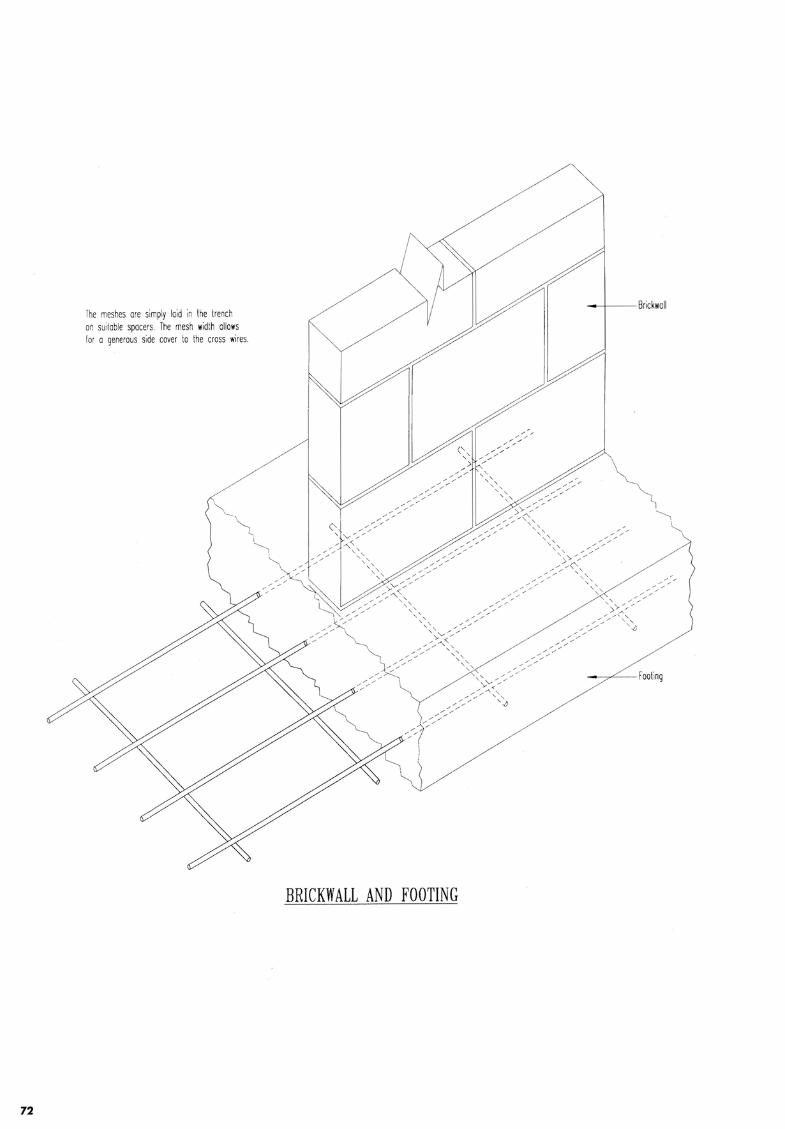
72
The meshes are simply laid in the trench or. suitable spacers. The mesh width allows lor o generous side cover to the cross wires.
I !
- -+-- -Brick wall
BRICKWALL AND FOOTING
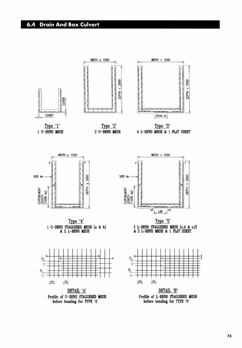
6.4 Drain And Box Culvert
WIDTH~ 1500 WIDTH > 1500
,--, - ,--, -
0 0 0 0 0 0
"" "" v v
u :::t: ~ I-D.. D..
a:: w w
~ Cl Cl
(_)
_j I ' - ,_ COVER l lfNSION LAP I
Tne '1' Type '2' Tne '3' 1 U-BEND MESH 2 U-BEND MESH 4 L-BEND MESH & 1 FLAT SHEIIT
WIDTH ~ 1500 WIDTH > 1500
b - -:--:•a d .- - ,I
50%/>s - 8 50%/>s- 0 0
~_L
0 0 'I
I
T
0
""
Tne '4' 1 U-BEND STAGGERED MESH (a & b)
& 2 L-BEND MESH
b
DETAIL 'A' Profile of U-BEND STAGGERED MESH
before bending for TYPE '4'
0
0
"" 1\
~ 1 I
li: ~ :? w -':::c:
Cl
<ZI-~ li:~O =>zo w-(_)_J~
J _
e,f i LAP I c,d
Type '5' 2 L-BEND STAGGERED MESH (c,d & e,f) & 2 1-BEND MESH & 1 FLAT SHEET
0
~_L
I
~ I
T
c
DETAIL 'B' Profile of L-BEND STAGGERED MESH
before bendin« for TYPE '5'
d c
73

WIDTH VARIES
r--- .----
r-~ L -BEND t.IESH L-BEND t.IESH
~ U-BEND STAGGERED t.IESH
~ADDmONAL nE BARS fOR HAUCHING TO ENGINEER'S REQUIREt.lENT
"" /
~ I " / I
TYPICAL SECTION OF R.C. DRAIN
TYPICAL L-BEND MESH TYPICAL U-BEND STAGGERED MESH
74

Vl w
~ I
6:: w 0
Vl w
WIDTH {. 1.5m
I I
I-- MESH-
Vl w 1'i" ~ I 1-o._ w 0
WIDTH > 15m
I
MESH
h , ~ -c: ~ ~- . >.< .... A ·~·,; :
TYPICAL SECTION OF CLOSED DRAIN
WIDTH > 1.5m
.--MESH
t ~-· ~ ,.><i EG
-' -
TYPICAL SECfiON OF BOX CULVERT
WIDTH > 1.5m
rMESH
~ ~MESH MESH -
I 1-
. ~ ~ i ADDITIONAL TIE BAR \ S ~n (lYI'ICI<) --"'- ~I ~u ·\ ~~~---·~-- --- - ~-... ~ ... _:-:c.,,.,..-,-·· .. . -,-· .. ~-'0- ./T <·>-·'·.·· .· ·: ... . '<_:.· •. · ..;~I §
'- I /.
LI.4ESH
TYPICAL SECTION FOR LARGE SIZE CLOSED DRAIN
CL
i :5
I j
i
75


Welded Wire Fabric Dimensions
~ L
Le~end
L w ~m ~c
~ I c:rb-\])7
w w
- length of sheet - width of sheet - main wire diameter - cross wire diameter
Ll T0c
~1
-
Jp,
_1~2
gJ t -
L
Can be Single Wire or Twin Wire
Pm - pitch of main wire Pc - pitch of cross wire Ml, M2 - main wire overhang Sl, S2 - cross wire overhang
76

TABLE FOR WELDED WIRE FABRIC
WWF Cross- Sectional Area Wire Spacing Wire Diameter Nominal Ref. No. (mm2/m) (mm) (mm) Mass
Main Cross Main Cross Main Cross (kg/m2 )
SQUARE FABRIC: A, D & E SERIES
D13 1327 1327 100 100 13 13 20.84 D12 1131 1131 100 100 12 12 17.77 Dll 950 950 100 100 11 11 14.92 E1 3 885 885 150 150 13 13 13 .90 D10 786
I 786 100 100 1Q 1Q 12.35
E12 754 754 150 150 12 12 11 .84 A13 664 664 200 200 13 13 10.43 D9 636 636 100 100 9 9 9.99 Ell 634 634 150 150 11 11 9.96 A12 566 566 200 200 12 12 8.89 E10 524 524 150 150 10 10 8.;23 DB 503 503 100 100 8 8 790 All 475 475 200 200 11 11 746 E9 424 424 150 150 9 9 6.66
A10 393 393 200 200 10 10 6.17 D7 385 385 100 100 7 7 6.05 E8 335 335 150 150 81 8 5.26 A9 318 318 200 200 9 9 5.00 D6 283 283 100 100 6 6 4.45 E7 257 257 150 150 7 7 4.04 AS 251 251 200 200 8 8 3.94 A7 192 192 200 200 7 7 3.02 E6 189 189 150 150 6 6 2.97 A6 141 141 200 200 6 6 2.21 A5 98 98 200 200 5 5 1.54
RECTANGULAR FABRIC: B SERIES
B1 3 1327 393 100 200 13 10 13.51 B1 2 1131 251 100 200 12 8 10.85 Bll 950 251 100 200 11 8 9.43 B10 786 251 100 200 10 8 8.14 B9 636 251 100 200 9 8 6.97 B8 503 251 100 200 g 8 5.92 B7 385 192 100 200 7 7 4.53 B6 283 192 100 200 6 7 3.73
77

TABLE FOR WELDED WIRE FABRIC (continued)
WWF Cross- Sectional Area Wire Spacing Wire Diameter " Nominal Ref. No. (mm2/m) (mm) !l (mm) Mass
Main Cross Main Cross Main Cross (kg/m2)
DESIGNER FABRIC SERIES
DE12/ 9 1131 424 100 150 9 12.21
DE11 / 9 950 424 100 150 9 ' 10.79
DE10/9 786 424 100 150 9 9.50 DE9/9 636 424 100 150 9 8.33 DE8/9 503 424 100 150 9 7.28
DA 13d/ 10 2655 393 100 200 2X1 3 10 23 .94 EA13d/ 10 1770 393 150 200 2X l:l, 10 16.99 DA10d/ 10 1571 393 100 200 2x l0
d 10 15.43
DA 12/ 10 1131 393 100 200 12 10 11 .97 EA1 0d/ 10 1047 393 150 200 2X10 10 11.31 EA 13/ 10 885 393 150 200 13 10 10.04 DA10/ 10 786 393 100 200 10 .,, lO 9.26 AA 13/ 10 664 393 200 200 13 , 10 8.30 EA 10/ 10 524 393 150 200 10 ' 10 7.20 DEll / 8 950 335 100 150 11 8 10.09 DE10/ 8 786 335 100 150 lO 8 8.80 DE9/8 636 335 100 150 9 8 7.63 DE8/ 8 503 335 100 150 8 8 6.58 DE7/ 7 385 257 100 150 7 7 5.04 EA8/ 7 335 192 150 200 8 7 4.14
Interpretation of Designer Fabric Reference Number: The first two alphabet denotes the spacing of the Designer fabric, i.e. A for 200 mm spacing, D for 100 mm spacing
and E for 150 mm spacing. The diameter of the wire follows the spacing and a small letter " d" after the main wi re
diameter denotes twin or double wire fabric.
D E 9 I 8
E
Cross wire diameter - 8mm
Separator ------Main wire diameter- 9 mm
Cross wire spacing - 150mm
Main wire spacing - 1 OOmm
A 13 d I 10
Cross wire diameter - 10mm
Separator
Denotes twin or double main wire
Main wire diameter- 13mm
Cross wire spacing - 200mm
Main wire spacing- 150mm
78

79
TYPES OF FABRIC LAP
Plain welded wire fabric (plain WWF) bonds to concrete by the positive mechanical anchorage at each intersection.
Deformed welded wire fabric (deformed WWF) utilises wire deformation plus the welded intersection for bond and
anchorage. According to SS:32, the minimum weld shear stress requirement for plain WWF is 250 MPa and deformed
WWF is 140 MPa. Based on this requirement, a lap splice with two welded intersection overlapping is sufficient to
transfer the full yield strength for plain WWF. As for deformed WWF the lap length could be reduced depending on
the number of welded intersection present with the lap.
Full Yield Strength Layered Lap
• The most common type lapping used. • Transfer the full yield strength of the
reinforcement. • Too great an accumulation of laps
can be avoided by staggering the sheet arrangement.
Half Yield Strength Layered Lap
• Transfer half the yield strength of the reinforcement.
• May be use for side laps across
beams.
Reversed or Nested-in-Plane Lap
• Particularly useful in situations of maximum stress to maintain the lapped reinforcement in the same
plane.
Flying Ends Lap
• Alternative method of in-plane lapping where one sheet is provided with a lap length overhang without welded intersections.
• The lap length is determined as for lapped bars (plain or deformed wires) and, without welded intersection on lapped wires, the ultimate anchorage bond stress of fabric do not apply
Non-yield strength transfer splice lap
• May be used for secondary direction lapping over beam or secondary direction lapping where splice transfer is not important.
Full Yield Strength Layered Lap
Half Yield Strength Layered Lap
Reversed or Nested-in-PianeLap
Flying Ends Lap
Non-Yield Strength Transfer Splice Lap

BEAM LINK CAGE CONVERSION TABLE FOR PLAIN MILD STEEL BAR
Link Characteristic Strength of Link Cage
Spacing fyv = 250 N/mm2
Sv (mm) R10 R13
75 Tl0-125 T13-125
D10-125 D13-125
Hl0-125 H13-125
100 T10-150 T13-150
D10-150 D13-150
H10-150 H13-150
125 T10-200 T13-200
D10-200 D13-200
H10-200 H13-200
150 Tl0-250 T13-250
D10-250 D13-250
H10-250 H13-250
200 Tl0-300 Tl0-200
D10-300 D10-200
H 10-300 H10-200
250 Tl0-300 Tl0-250
D10-300 D10-250
H10-300 H10-250
300 Tl0-300 Tl0-250
D10-300 D 10-300
H 10-300 H10-300
( 1) Table above is derived from the following formulas:
= ( V- Vc} bv 0.87 fyv
where, A.v - Area of two legs
of link with diameter 0
bv - Width of the beam v - Design shear stress vc - Design concrete shear stress
(2) Example for conversion for a specific grade of link cage with a specific spacing using table above. => Converting R 10-100 link cage to link cage of other characteristic strength.
From table above:- T1 0-150, D 10-150 or H 10-150 is equivalent to R 10-100. (Note: Engineer can choose link type i.e. open or close link. If open beam link cage is used, material type for capping link is preferably similar to link cage shall also be adopted)
(3) Legends: (a) Prefix'S' denotes open link cage (e.g . .S,T, .S,D,,..S.H) (b) Prefix 'L' denotes close link cage (e.g . .LT, .LD, .LH) (c) 'R' denotes links using Plain Mild Bar (fyv = 250N/mm 2 )
(d) 'T' denotes links using Tempcore Deformed Wire (fyv = 460N/mm 2 )
(e) 'D' denotes links using Deformed Hard Drawn Wire (fyv = 485N/mm 2)
(f) 'H' denotes links using Plain Hard Drawn Wire (fyv = 485N/mm 2)
80

8J
COLUMN LINK CAGE CONVERSION TABLE FOR PLAIN MILD STEEL BAR
Link Characteristic Strength of Link Cage
Spacing fyv = 250 N/mm2
Sv (mm) LR8 LR 10 LR 13
100 LDS-100 LD10-100 LD13-100
LHS-100 LH10-100 LH 13-100
125 LDS-125 LD10-125 LD13-125
LHS-125 LH 10-125 LH13-125
150 LDS-150 LD10-150 LD13-150
LHS-150 LH10-150 LH 13-150
200 LDS-200 LD10-200 LD 13-200
LHS-200 LH 10-200 LH 13-200
250 LDS-250 LD 10-250 LD13-250
LHS-250 LH10-250 LH 13-250
300 LDS-300 LD10-300 LD13-300
LHS-300 LH10-300 LH 13-300
1. Example for conversion for a specific grade of link cage with a specific spacing using table above. ::::::> Converting 1 number complete column close link cage LR 10-100 to link cage of other
characteristic strength. From table above: - LD 10-150 or LH 10-150 is equivalent to LR 10-100.
2. Legends: (a) Prefix 'L' denotes column close link cage (e.g . .LT, .LD, .LH) (b) 'R' denotes links using Plain Mild Bar (fyv = 250N/ mm2 )
(c) 'T' denotes links using Tempcore Deformed Bar (fyv = 460N/mm2)
(d) 'D' denotes links using Deformed Hard Drawn Wire (fyv = 485N/ mm2 )
(e) 'H' denotes links using Plain Hard Drawn Wire (fyv = 485N/ mm2 )

List of Reinforcement
Fabricators

LIST OF REINFORCEMENT FABRICATORS
Fabricators Address Telephone Fax
Asia Steel Welded Mesh Co Ltd 11 Tuas Avenue 3, S639410 861 7333 8625968
2 Angkasa Marketing (S) Pte Ltd 10 Arumugam Road #09-00,
Lion Industrial Building, S409957 7595973 743 7252
3 B.R.C. Weldmesh (S.E.A.) Pte Ltd 350Jalan Boon Lay, S619530 265 2333 2664728
4 Burwill Trading Pte Ltd 35 Pioneer Road, S628503 8622306 8632865
5 Eastern Wire Pte Ltd 27 Jalan Buroh, S619483 2650066 261 8562
6 Econ Industries Pte Ltd 2 Ang Mo Kio St 64, Ang Mo Kio
Industrial Park 3, S569084 4842222 4842221
7 Legend Building Supplies Pte Ltd 4 Kian Teck Drive, S628821 2652857 2652849
8 LiSteel Singapore Pte Ltd 11 T uas Avenue 16,
Jurong, S638929 8622467 862 1664
9 Natsteel Ltd 22 Tanjong Kling Road, S628048 265 1233 265 8317
10 Panwah Steel Pte Ltd 116 Middle Road, #08-01 ICB
Enterprise House, S 188972 3372237 338 8221
11 Viewforth Trading
& Engineering Pte Ltd 5 Tuas Avenue 1, S639490 8620033 861 6448
82