Electron transport through a single-molecule junction with multiple pathways under time-periodic...
19
arXiv:1401.4222v1 [cond-mat.mes-hall] 17 Jan 2014 Electron transport through a single-molecule junction with multiple pathways under time-periodic fields: A Floquet-scattering formalism Liang-Yan Hsu ∗ and Herschel Rabitz † Department of Chemistry, Princeton University, Princeton, New Jersey 08544, USA We develop a new general formulation to explore light-driven electron transport through a single- molecule device with multiple pathways. Three individual systems are proposed including (i) a two-terminal molecular junction based on phenyl-acetylene macrocycle (PAM), (ii) PAM with three terminals, and (iii) a parallel molecular circuit. The computations show that PAM-based optoelec- tronic switches have robust large on-off ratios and weak-field operating conditions, which are not sensitive to asymmetric molecule-lead couplings. In addition, field-amplitude power laws for one- and two-photon assisted tunneling are evident in the computational results, and the laws can be proven by using perturbation analysis. For PAM-based optoelectronic routers, we show that it is possible to manipulate the direction of electric current through the PAM molecule by using a weak linearly polarized laser field. For parallel circuits made of molecular quantum dots, the condition of coherent destruction of tunneling is derived by using the rotating wave approximation and the high-frequency approximation. PACS numbers: 05.60.Gg, 72.40.+w, 73.63.-b, 85.65.+h Keywords: Molecular electronics, Quantum transport, Driven transport, Molecular wires I. INTRODUCTION Molecular electronics is an active field with many po- tential applications and novel innovations in nanoelec- tronic devices 1–7 . An ultimate goal in molecular elec- tronics is to construct molecule-based integrated circuits. To achieve this goal, understanding electron transport through a single-molecule device (junction) is a required first step. During the past two decades, great experi- mental progress has been made on single-molecule junc- tions due to advancements in microfabrication and self- assembly techniques 8,9 . In addition, improvements in theoretical modeling have enabled successful explana- tions and predictions of experimental observations, e.g., Kondo effect 10,11 , thermoelectricity 12 , orbital gating 13 , destructive quantum interference 14–16 , and conductance dependence upon molecular conformation 17–19 . The Landauer formula combined with the non-equilibrium Green’s function method 20–25 has become a common ap- proach to analyze electron transport through a single- molecule junction in the absence of applied fields. For a practical device, the capability of manipulating current by applying such fields is necessary. Therefore, control of electron transport, e.g., by means of light 26 or gate electrodes 10,13 , is a prime issue for molecular electronics. Light is a potential control tool for operating ul- trafast electronic devices due to a wide variety of control options, e.g., field strength, phase, frequency, and polarization, compared with a static field pro- vided by gate electrodes. Since 1960s 27 electron trans- port in the presence of a coherent light field has at- tracted general interest due to photon assisted tun- neling observed in mesoscopic systems exposed to mi- crowave radiation 28,29 . In superconductor-insulator- superconductor tunnel junctions 27,30 and semiconductor nanostructures 31,32 , light-driven electron transport has been extensively studied for some time. Recently, light-driven electron transport at the molec- ular level became an emerging field due to experimen- tal improvements in molecular junctions 33 . Moreover, a wealth of coherent light sources in the visible and the infrared regime, compatible with electronic energy scales of molecular systems, motivated innovative theoretical studies in this field 34–44 . Within a time-dependent per- turbation theory along with the extended H¨ uckel model, photon-assisted tunneling was predicted in the presence of high-intensity fields 34,35 . Theoretical studies using Floquet theory together with a tight-binding model have shown that molecular wires can act as coherent quantum ratchets 36 , and that current rectification 37 , shot noise control 38,39 , photon-assisted tunneling 40,41 , and coherent destruction of tunneling could be observed in a linear molecular wire. Vibrational effects 42 , memory effects 43 , and optimal control of shot noise 44 have been investi- gated in a two-level model. However, most studies focus on linear molecular wires or few-level models and neglect the nature of molecular structure, e.g., cross-conjugated molecules and polycyclic aromatic hydrocarbons, which offer multiple pathways for tunneling electrons. Multiple pathways in a molecular junction can be re- garded as forming a “network”, which is of importance in molecular electronics for several reasons. First, such networks can be thought of as analogous to electric cir- cuits, e.g., a double-backbone molecule corresponding to a parallel circuit. Based on Kirchhoff’s circuit laws, the conductance of two parallel constituents in a circuit equals the sum of the conductance of the individuals. However, at the molecular scale Kirchhoff’s circuit laws do not hold since the phase coherence length of tun- neling electrons is comparable to the circuit scale, i.e., quantum interference effects play an important role. A conductance superposition law in a parallel circuit has been proposed 47,48 and experimentally reported 49 . Sec- ond, pathway differences in a network can lead to de-
-
Upload
independent -
Category
Documents
-
view
1 -
download
0
Transcript of Electron transport through a single-molecule junction with multiple pathways under time-periodic...
arX
iv:1
401.
4222
v1 [
cond
-mat
.mes
-hal
l] 1
7 Ja
n 20
14
Electron transport through a single-molecule junction with multiple pathways under
time-periodic fields: A Floquet-scattering formalism
Liang-Yan Hsu∗ and Herschel Rabitz†
Department of Chemistry, Princeton University, Princeton, New Jersey 08544, USA
We develop a new general formulation to explore light-driven electron transport through a single-molecule device with multiple pathways. Three individual systems are proposed including (i) atwo-terminal molecular junction based on phenyl-acetylene macrocycle (PAM), (ii) PAM with threeterminals, and (iii) a parallel molecular circuit. The computations show that PAM-based optoelec-tronic switches have robust large on-off ratios and weak-field operating conditions, which are notsensitive to asymmetric molecule-lead couplings. In addition, field-amplitude power laws for one-and two-photon assisted tunneling are evident in the computational results, and the laws can beproven by using perturbation analysis. For PAM-based optoelectronic routers, we show that it ispossible to manipulate the direction of electric current through the PAM molecule by using a weaklinearly polarized laser field. For parallel circuits made of molecular quantum dots, the conditionof coherent destruction of tunneling is derived by using the rotating wave approximation and thehigh-frequency approximation.
PACS numbers: 05.60.Gg, 72.40.+w, 73.63.-b, 85.65.+h
Keywords: Molecular electronics, Quantum transport, Driven transport, Molecular wires
I. INTRODUCTION
Molecular electronics is an active field with many po-tential applications and novel innovations in nanoelec-tronic devices1–7. An ultimate goal in molecular elec-tronics is to construct molecule-based integrated circuits.To achieve this goal, understanding electron transportthrough a single-molecule device (junction) is a requiredfirst step. During the past two decades, great experi-mental progress has been made on single-molecule junc-tions due to advancements in microfabrication and self-assembly techniques8,9. In addition, improvements intheoretical modeling have enabled successful explana-tions and predictions of experimental observations, e.g.,Kondo effect10,11, thermoelectricity12, orbital gating13,destructive quantum interference14–16, and conductancedependence upon molecular conformation17–19. TheLandauer formula combined with the non-equilibriumGreen’s function method20–25 has become a common ap-proach to analyze electron transport through a single-molecule junction in the absence of applied fields. For apractical device, the capability of manipulating currentby applying such fields is necessary. Therefore, controlof electron transport, e.g., by means of light26 or gateelectrodes10,13, is a prime issue for molecular electronics.Light is a potential control tool for operating ul-
trafast electronic devices due to a wide variety ofcontrol options, e.g., field strength, phase, frequency,and polarization, compared with a static field pro-vided by gate electrodes. Since 1960s27 electron trans-port in the presence of a coherent light field has at-tracted general interest due to photon assisted tun-neling observed in mesoscopic systems exposed to mi-crowave radiation28,29. In superconductor-insulator-superconductor tunnel junctions27,30 and semiconductornanostructures31,32, light-driven electron transport hasbeen extensively studied for some time.
Recently, light-driven electron transport at the molec-ular level became an emerging field due to experimen-tal improvements in molecular junctions33. Moreover, awealth of coherent light sources in the visible and theinfrared regime, compatible with electronic energy scalesof molecular systems, motivated innovative theoreticalstudies in this field34–44. Within a time-dependent per-turbation theory along with the extended Huckel model,photon-assisted tunneling was predicted in the presenceof high-intensity fields34,35. Theoretical studies usingFloquet theory together with a tight-binding model haveshown that molecular wires can act as coherent quantumratchets36, and that current rectification37, shot noisecontrol38,39, photon-assisted tunneling40,41, and coherentdestruction of tunneling could be observed in a linearmolecular wire. Vibrational effects42, memory effects43,and optimal control of shot noise44 have been investi-gated in a two-level model. However, most studies focuson linear molecular wires or few-level models and neglectthe nature of molecular structure, e.g., cross-conjugatedmolecules and polycyclic aromatic hydrocarbons, whichoffer multiple pathways for tunneling electrons.
Multiple pathways in a molecular junction can be re-garded as forming a “network”, which is of importancein molecular electronics for several reasons. First, suchnetworks can be thought of as analogous to electric cir-cuits, e.g., a double-backbone molecule correspondingto a parallel circuit. Based on Kirchhoff’s circuit laws,the conductance of two parallel constituents in a circuitequals the sum of the conductance of the individuals.However, at the molecular scale Kirchhoff’s circuit lawsdo not hold since the phase coherence length of tun-neling electrons is comparable to the circuit scale, i.e.,quantum interference effects play an important role. Aconductance superposition law in a parallel circuit hasbeen proposed47,48 and experimentally reported49. Sec-ond, pathway differences in a network can lead to de-
2
structive quantum interference50–60, which can be ex-ploited to form single-molecule optoelectronic switches59,single-molecule electric revolving doors60, and quantuminterference effect transistors51,52,56. Destructive quan-tum interference with tunneling has been experimen-tally observed in aromatic hydrocarbons16,61 and cross-conjugated molecules14,15 at room temperature, indicat-ing that molecular structure can be a key resource forcoherent quantum transport. Third, a network such asa single molecule connected to multi-terminals62,63 couldform a nanoscale router. In order to manipulate currentin a molecular router, an understanding of the correlationbetween the molecular structure and current direction isrequired.We present a new general formulation to explore laser-
driven transport through three individual networks con-sisting of (i) a two-terminal molecular junction based onphenyl-acetylene macrocycle (PAM)45,46, (ii) PAM withthree terminals, and (iii) a parallel molecular circuit. Theformulation generalizes a scattering analysis based onsingle-particle Greens functions within the framework ofthe non-Hermitian Floquet theory38,39. The new formu-lation is valid for arbitrary strength as well as frequencyof a driving field and enables the modeling of light-driventransport through multi-terminal and multi-orbital sys-tems in terms of transmission probabilities. We will dis-cuss field-amplitude power laws in the weak-field regime,the effects of asymmetric molecule-electrode couplings,and the influence of laser polarization on electron trans-port through PAM.
II. FORMULATION
A. Model Hamiltonian
Electron transport through a single-molecule junctionin the presence of time-periodic fields can be describedby the time-dependent Hamiltonian Htot(t) composed ofthe external-field-driven molecular Hamiltonian Hmol(t),the lead (electrode) HamiltonianHlead, and the molecule-lead coupling termHcoup, i.e., Htot(t) = Hmol(t)+Hlead+Hcoup. To focus on the effect of molecular networks, weremove other possible effects, e.g., many-body interac-tions, and adopt a single-electron tight-binding model todescribe Hmol(t)
Hmol(t) =∑
nn′
Hnn′(t)a†nan′ , (1)
where an (a†n) are Fermion operators which annihilate(create) an electron in the atomic orbital |n〉 in themolecule. The field-driven molecular Hamiltonian sat-isfies Hmol(t) = Hmol(t + T ) due to the time-periodicfield with frequency ω = 2π/T . Note that the field is notlimited to lasers, and it can be any type of time-periodicresource. In Eq. (1) the atomic orbitals n and n′ neednot be nearest neighbors, i.e., long-range interactions be-tween the atomic orbitals n and n′ can be considered.
We use a noninteracting electron gas model to describethe leads
Hlead =
κ∑
α
∑
q
ǫαqb†αqbαq, (2)
where κ is the total number of the electrodes and bαq(b†αq) are Fermion operators which annihilate (create) anelectron in the state |αq〉 with energy ǫαq in the lead α.The molecule-lead coupling term is
Hcoup =
κ∑
α
∑
q
∑
n
Vαq,nb†αqan +H.c., (3)
where Vαq,n denotes the electron transfer integrals be-tween the atomic orbital |n〉 of the molecule and the or-bital |αq〉 in the lead. The coupling function in the energydomain is defined as
Γα,nn′(ǫ) = 2π∑
q
V ∗αq,nVαq,n′δ(ǫ− ǫαq), (4)
and its Fourier transform in the time domain is
Γα,nn′(t) =1
~
1
2π
∫ ∞
−∞
dǫΓα,nn′(ǫ)× e−iǫt~
=1
~
∑
q
V ∗αq,nVαq,n′e−
iǫαqt
~ . (5)
The off-diagonal terms of the coupling function orig-inate from the interactions between |αq〉 in the leadα and two different atomic orbitals on the molecule.As |αq〉 only interacts with a specific atomic orbital|v〉 on the molecule, i.e., n = n′ = v, we can deriveΓα,vv(ǫ) = 2π
∑q |Vαq,v |
2δ(ǫ − ǫαq), consistent with the
previous result38,59.
B. Fundamental Solution
In the Heisenberg picture, the time-evolution opera-tor U(t, t0) associated with the total system HamiltonianHtot(t) is governed by the equation
i~dU(t, t0)
dt= Htot(t)U(t, t0), (6)
and the equations of motion of the electron annihila-tion operators can be expressed in terms of Htot(t) andU(t, t0) as follows
i~dan(t)
dt= −U †(t, t0)[Htot(t), an]U(t, t0), (7)
i~dbαq(t)
dt= −U †(t, t0)[Htot(t), bαq]U(t, t0). (8)
By substitution of Eqs. (1) – (3) into Eqs. (7) and (8),we obtain equations of motion for electron annihilation

3
operators in a single-molecule junction
dan(t)
dt= −
i
~
∑
n′
Hnn′(t)an′(t)−i
~
∑
αq
V ∗αq,n(t)bαq(t),
dbαq(t)
dt= −
i
~ǫαqbαq(t)−
i
~
∑
n
Vαq,n(t)an(t). (9)
The linear differential equations in Eq. (9) have theformal solution38,39
bαq(t) =∑
n
〈αq|U(t, t0)|n〉an(t0)
+
κ∑
α′
∑
q′
〈αq|U(t, t0)|α′q′〉bα′q′(t0), (10)
where bαq(t) is determined by the initial conditions an(t0)and bα′q′(t0). The electrodes are initially in a thermalequilibrium state described by the initial density matrixρ0 = e−(Hleads−
∑α µαNα)/kBθ, where θ is the temperature,
Nα =∑
q b†αqbαq is an electron number operator, and µα
is the chemical potential associated with the lead α. Asa result, the average electron occupation number at t0can be expressed as 〈b†α′q′(t0)bαq(t0)〉 = δα′αδq′qfα(ǫαq),
where fα(ǫ) = (1 + e(ǫ−µα)/kBθ)−1 is the Fermi functionof the lead α. For a two terminal system with symmetricchemical potentials, the left and right chemical potentialscan be respectively written as µL = µ−eVSD/2 and µR =µ+ eVSD/2, in terms of the zero-bias chemical potentialµ, electric charge e, and the source-drain voltage VSD.
C. Electric Current and Rate Equations
To explore electric current in the presence of a fieldwith time-period T , we define the time-averaged current
Iα in the lead α as an integral over the time intervalT ,38,39
Iα =1
T
∫ T
0
〈Iα(t)〉dt. (11)
The symbol 〈 〉 denotes ensemble average, e.g., 〈Iα(t)〉 isthe ensemble-averaged current in the lead α at time t64 ,
〈Iα(t)〉 = −ed〈Nα(t)〉
dt= −e
d〈∆Nα(t)〉
dt, (12)
where the ensemble-averaged electron number change〈∆Nα(t)〉 between time t and t0 is
〈∆Nα(t)〉 = 〈Nα(t)〉 − 〈Nα(t0)〉
=∑
q
〈b†αq(t)bαq(t)〉 − 〈b†αq(t0)bαq(t0)〉. (13)
Eq. (12) indicates that as the ensemble-averaged elec-tron number in the lead α decreases with time, i.e.,d〈Nα(t)〉/dt < 0, the current flows into the electrode α,i.e., 〈Iα(t)〉 > 0. At the initial time t = t0 all electrons
are at equilibrium, i.e., 〈a†n′(t0)an(t0)〉 = δn′n〈Nn(t0)〉,
〈b†α′q′(t0)bαq(t0)〉 = δα′αδq′qfα(ǫαq). In addition, we as-sume that at t = t0 the electrons between the lead andthe molecule have no interaction, i.e., 〈a†n(t0)bαq(t0)〉 =〈b†αq(t0)an(t0)〉=0. By virtue of these conditions, substi-tuting Eq. (10) into Eq. (13) results in the relation
〈∆Nα(t)〉 =∑
qn
|〈αq|U(t, t0)|n〉|2〈Nn(t0)〉+
∑
α′qq′
(|〈αq|U(t, t0)|α
′q′〉|2fα′(ǫα′q′)− fα(ǫαq))
(14)
=∑
qn
(|〈αq|U(t, t0)|n〉|
2〈Nn(t0)〉 − |〈n|U(t, t0)|αq〉|2fα(ǫαq)
)
+∑
α′ 6=α
∑
qq′
(|〈αq|U(t, t0)|α
′q′〉|2fα′(ǫα′q′)− |〈α′q′|U(t, t0)|αq〉|2fα(ǫαq)
). (15)
Here the backscattering term has been elim-inated by invoking the relation fα(ǫαq) =〈αq|U †(t, t0)U(t, t0)|αq〉fα(ǫαq) and 1 =
∑n |n〉〈n| +∑
αq |αq〉〈αq|.
After substituting Eq. (15) into Eq. (12) and taking thelong-time limit t0 → −∞, the ensemble-averaged current
〈Iα(t)〉 can be expressed as
〈Iα(t)〉 = −e∑
qn
[kαq,n(t)〈Nn(t0)〉 − kn,αq(t)fα(ǫαq)]
− e∑
α′ 6=α
∑
qq′
[kαq,α′q′(t)fα′(ǫα′q′)− kα′q′,αq(t)fα(ǫαq)] ,
(16)
4
where kn,αq(t) ≡ limt0→−∞ddt |〈n|U(t, t0)|αq〉|
2 denotesthe rate that an electron tunnels from the orbital |αq〉in the lead α to the orbital |n〉 on the molecule, andkαq,α′q′(t) ≡ limt0→−∞
ddt |〈αq|U(t, t0)|α
′q′〉|2 denotes therate that an electron tunnels from the orbital |α′q′〉 inthe lead α′ to the orbital |αq〉 in the lead α. In the long-time limit t0 → −∞, all transient currents die out sokαq,n〈Nn(t0)〉 can be ignored in our analysis. In addi-tion, kn,αqfα(ǫαq) corresponds to a periodic charging ofthe molecule driven by external time-periodic fields38,39
and it contributes zero current over a period T (The de-tailed derivation is in Appendix A). Therefore, the time-averaged current in lead α reads
Iα = −e
T
∫ T
0
dt
κ∑
α′ 6=α
∑
qq′
[kαq,α′q′(t)fα′(ǫα′q′)
− kα′q′,αq(t)fα(ǫαq)], (17)
indicating that the current is only relevant to the lead-to-lead tunneling rates and the Fermi functions.
Furthermore, using the following relations,
d〈α′q′|U †(t, t0)|αq〉
dt=i
~[ǫαq〈α
′q′|U †(t, t0)|αq〉
+∑
n
V ∗αq,n〈α
′q′|U †(t, t0)|n〉], (18)
d〈αq|U(t, t0)|α′q′〉
dt= −
i
~[ǫαq〈αq|U(t, t0)|α
′q′〉
+∑
n
Vαq,n〈n|U(t, t0)|α′q′〉], (19)
the lead-to-lead tunneling rate kαq,α′q′(t) can be ex-pressed in terms of 〈αq|U(t, t0)|n〉 and 〈αq|U(t, t0)|α
′q′〉
as
kαq,α′q′(t) = limt0→−∞
d
dt|〈αq|U(t, t0)|α
′q′〉|2
= limt0→−∞
i
~
∑
n
V ∗αq,n〈α
′q′|U †(t, t0)|n〉
× 〈αq|U(t, t0)|α′q′〉+ c.c. (20)
D. Propagators in terms of Green’s functions
To derive the ensemble-averaged current 〈Iα(t)〉, theevaluation of the matrix elements of the propagators,e.g., 〈αq|U(t, t0)|n〉 and 〈αq|U(t, t0)|α
′q′〉, is needed. Westart from the interaction picture and separate the totalHamiltonian into the uncoupled Hamiltonian H0(t) =Hmol(t) + Hlead and the coupling Hamiltonian Hint =Hcoup. The propagator U0(t, t0) associated with H0(t) isgoverned by the equation
i~dU0(t, t0)
dt= H0(t)U0(t, t0). (21)
It is readily seen that U0(t, t0) = Umol(t, t0)Ulead(t, t0),where Ulead(t, t0) = exp(− i
~Hlead(t − t0)) and
Umol(t, t0) = T+ exp(− i~
∫ t
t0Hmol(t
′)dt′). Here, T+ is the
time ordering operator.By virtue of Eqs. (6) and (21), we can obtain
U(t, t0) = U0(t, t0)−i
~
∫ t
t0
dt′U0(t, t′)HcoupU(t′, t0).
(22)
By substituting Eq. (22) into 〈αq|U(t, t0)|n〉,〈n|U(t, t0)|αq〉 and 〈αq|U(t, t0)|α
′q′〉, and us-ing the fact that 〈αq|U0(t, t0)|n〉 = 0 and〈αq|U0(t, t
′)|α′q′〉 = δαα′δqq′ exp(−i~ǫαq(t − t′)), we
find
〈n|U(t, t0)|αq〉 = −i
~
∑
n′
V ∗αq,n′
∫ t
t0
dt′e−i~ǫαq(t
′−t0)〈n|U(t, t′)|n′〉, (23)
〈αq|U(t, t0)|α′q′〉 = δαα′δqq′e
− i~ǫαq(t−t0) −
1
~2
∑
n
∑
n′
Vαq,nV∗α′q′,n′
∫ t
t0
dt′e−i~ǫαq(t−t′)
×
∫ t′
t
dt′′e−i~ǫα′q′ (t
′′−t0)〈n|U(t′, t′′)|n′〉. (24)
Eq. (23) and Eq. (24) can be further simplified usingthe retarded and advanced Green’s functions defined as
GR(t, t′) ≡ −iθ(t− t′)U(t, t′), (25)
GA(t, t′) ≡ iθ(t′ − t)U(t, t′), (26)
where θ(t− t′) is the Heaviside function and Eq. (25) sat-isfies GR(t, t′) = [GA(t, t′)]† and U(t, t′) = i~(GR(t, t′)−GA(t, t′)). Note that GR(t, t′) and GA(t, t′) are theGreen’s functions for the total system. From Eq. (25),the Fourier transforms of the retarded and advanced
5
Green’s functions in the energy domain are, respectively,
GR(t, ǫ) ≡ limη→+0
G(t, ǫ + iη)
= −i
~lim
η→+0
∫ ∞
0
dτei(ǫ+iη)τ
~ U(t, t− τ), (27)
GA(t, ǫ) ≡ limη→+0
G(t, ǫ − iη)
=i
~lim
η→+0
∫ 0
−∞
dτei(ǫ−iη)τ
~ U(t, t− τ), (28)
in which GR(t, ǫ) = [GA(t, ǫ)]†. Note that the to-tal Hamiltonian has time-periodic symmetry Htot(t) =Htot(t + T ), leading to U(t, t′) = U(t + T, t′ + T ) andGR(A)(t, ǫ) = GR(A)(t + T, ǫ). As a result, the retardedand advanced Green’s function in the energy domain can
be expanded in a Fourier series
GR(t, ǫ) =
∞∑
k=−∞
GR(k)(ǫ)e−ikωt, (29)
where the Fourier coefficient GR(k)(ǫ) is
GR(k)(ǫ) =1
T
∫ T
0
GR(t, ǫ)eikωtdt. (30)
It can be readily shown that by letting t0 → −∞,τ = t− t′, and dτ = −dt′ in Eq. (23), and making use ofEq. (27), Eq. (23) becomes
〈n|U(t, t0)|αq〉 = e−i~ǫαq(t−t0)
∑
n′
V ∗αq,n′GR
nn′(t, ǫαq),
(31)
where GRnn′(t, ǫαq) stands for 〈n|G
R(t, ǫαq)|n′〉 for conve-
nience.Similarly, by letting t0 → −∞, τ = t′ − t′′ and dτ =
−dt′′, Eq. (24) becomes
〈αq|U(t, t0)|α′q′〉 = −
i
~e−
i~(ǫαqt−ǫα′q′ t0)
∑
n
∑
n′
Vαq,nV∗α′q′,n′
∫ t
−∞
dt′ei~(ǫαq−ǫα′q′ )t
′
GRnn′(t′, ǫα′q′). (32)
Furthermore, by letting τ = t− t′ and dτ = −dt′ in Eq. (32), the matrix element 〈αq|U(t, t0)|α′q′〉 becomes
〈αq|U(t, t0)|α′q′〉 = −
i
~e−
i~ǫα′q′ (t−t0)
∑
n
∑
n′
Vαq,nV∗α′q′,n′
∫ ∞
0
dτe−i~(ǫαq−ǫα′q′ )τGR
nn′(t− τ, ǫα′q′). (33)
Note that we do not show the term δαα′δqq′e− i
~ǫαq(t−t0)
in Eq. (32) and Eq. (33) because of the condition α 6=α′ in Eq. (17). Eq. (31) and Eq. (33) can be used forexpressing kα′q′,αq(t) and kαq,α′q′(t) in Eq. (17) in termsof the retarded (advanced) Green’s functions.
E. Transmission and Landauer-type Formula
In most of the literature related to coherent quantumtransport, the current formula is expressed in terms of
transmission functions. In this section, we will show thatthe rate equation (Eq. (17)) and the lead-to-lead tunnel-ing rates correspond to the Landauer-type formula andtransmission functions, respectively.
Use of 〈α′q′|U †(t, t0)|n〉 = (〈n|U(t, t0)|α′q′〉)∗ and sub-
stitution of Eq. (31) and Eq. (33) into Eq. (20) give
kαq,α′q′(t) = limt0→−∞
d
dt|〈αq|U(t, t0)|α
′q′〉|2
=1
~2
∑
n1n2n3n4
V ∗αq,n1
Vα′q′,n2Vαq,n3V∗α′q′,n4
∫ ∞
0
dτe−i~(ǫαq−ǫα′q′ )τ [GR
n1n2(t, ǫα′q′)]
∗GRn3n4
(t− τ, ǫα′q′) + c.c.,
(34)
where we use n1 and n2 instead of n and n′ in Eq. (31) as well as n3 and n4 instead of n and n′ in Eq. (33).
6
By invoking Eq. (34) and after some manipulations,∑
qq′ kαq,α′q′(t)f(ǫα′q′) can be written as
∑
qq′
kαq,α′q′(t)fα′(ǫα′q′) =1
~
1
2π
∑
n1n2n3n4
∫ ∞
0
dτ
(1
~
∑
q
V ∗αq,n1
Vαq,n3e− i
~ǫαqτ
)
× 2π∑
q′
Vα′q′,n2V∗α′q′,n4
exp(i
~ǫα′q′τ)[G
Rn1n2
(t, ǫα′q′)]∗GR
n3n4(t− τ, ǫα′q′)f(ǫα′q′ ) + c.c. (35)
By using Eq. (4), Eq. (5) and∫Γα,nn′(ǫ)g(ǫαq)dǫ =
2π∑
q V∗αq,nVαq,n′g(ǫ), Eq. (35) becomes
∑
qq′
kαq,α′q′fα′(ǫα′q′ ) =
1
h
∑
n1n2n3n4
∫ ∞
0
dτΓα,n1n3(τ)
∫ ∞
−∞
dǫei~ǫτΓα′,n4n2(ǫ)
× [GRn1n2
(t, ǫ)]∗GRn3n4
(t− τ, ǫ)f(ǫ) + c.c. (36)
Then, by use of Eq. (29), expansion of [GRn1n2
(t, ǫ)]∗
and GRn3n4
(t− τ, ǫ) in Eq. (36) in a Fourier series gives
∑
qq′
kαq,α′q′fα′(ǫα′q′) =
1
h
∞∑
k,k′=−∞
ei(k′−k)ωt
∑
n1n2n3n4
∫ ∞
−∞
dǫ
∫ ∞
0
dτei(ǫ+k~ω)τ
~
× Γα,n1n3(τ)Γα′,n4n2(ǫ)[GR(k′)n1n2
(ǫ)]∗GR(k)n3n4
(ǫ)fα′(ǫ) + c.c.
(37)
Since the complex conjugate part in Eq. (37) con-
tributes∫ 0
−∞dτ , we can make use of the Fourier trans-
form of the coupling function, i.e., Γα,n1n3(ǫ + k~ω) =∫∞
−∞dτe
i(ǫ+k~ω)τ~ Γα,n1n3(τ), and reduce Eq. (37) to
∑
qq′
kαq,α′q′fα′(ǫα′q′) =1
h
∞∑
k,k′=−∞
ei(k′−k)ωt×
∫ ∞
−∞
dǫTr[Γα(ǫ+ k~ω)GR(k)(ǫ)Γα′(ǫ)GA(k′)(ǫ)]fα′(ǫ),
(38)
where Tr[Γα(ǫ + k~ω)GR(k)(ǫ)Γα′(ǫ)GA(k′)(ǫ)] =∑n1n2n3n4
Γα,n1n3(ǫ+k~ω)GR(k)n3n4(ǫ)Γα′,n4n2(ǫ)G
A(k′)n2n1 (ǫ).∑
qq′ kα′q′,αqfα(ǫαq) can be derived by repeating the
procedure from Eq. (35) to Eq. (38).Finally, substitution of Eq. (38) into Eq. (17) and use
of 1T
∫ T
0 dtei(k′−k)ωt = δ(k′ − k) give the time-averaged
current without spin degeneracy
Iα =e
h
κ∑
α′ 6=α
∞∑
k=−∞
∫ ∞
−∞
dǫ[T(k)α′α(ǫ)fα(ǫ)− T
(k)αα′(ǫ)fα′(ǫ)],
(39)
and the transmission functions
T(k)αα′(ǫ) = Tr[Γα(ǫ+ k~ω)GR(k)(ǫ)Γα′(ǫ)GA(k)(ǫ)], (40)
which corresponds to the tunneling of an electron fromthe lead α′ to the lead α with energy ǫ accompanied byk-photon absorption (k > 0) or emission (k < 0). Note
that in general cases T(k)αα′(ǫ) 6= T
(k)α′α(ǫ) if molecules have
no generalized parity symmetry37,65.Eq. (39) enables dealing with transport in multi-
terminal systems in a time-periodic driving field and itis straightforward to show that
∑α Iα = 0 which sat-
isfies the continuity equation. The correspondence be-tween Eq. (17) and Eq. (39) reveals the connection be-tween the lead-to-lead tunneling rates and the transmis-sion functions. In addition, the trace form in Eq. (40)enables the formulation to be applied to realistic mod-els, e.g., a molecular Hamiltonians derived from thedensity-functional method in a maximally localized Wan-nier function representation66,67.In the absence of the external driving field (Hmol(t)
is time-independent), using the fact that T(k)αα′(ǫ) =
T(k)α′α(ǫ) = δk,0T
(k)αα′(ǫ) reduces Eq. (39) to the Landauer-
type current formula,
Iα =e
h
κ∑
α′ 6=α
∫ ∞
−∞
dǫT(0)αα′(ǫ)[fα(ǫ)− fα′(ǫ)], (41)
where T(0)αα′(ǫ) = Tr[Γα(ǫ)G
R(0)(ǫ)Γα′(ǫ)GA(0)(ǫ)], whichis consistent with the results derived from Fisher-Leerelation68 and Meir-Wingreen formula69.For a two terminal system, i.e., α = R and α′ = L,
assuming that the coupling function satisfies ΓL(ǫ) =|u〉ΓL,uu(ǫ)〈u| and ΓR(ǫ) = |v〉ΓR,vv(ǫ)〈v|, Eq. (39) re-duces to
IR =e
h
∞∑
k=−∞
∫ ∞
−∞
dǫ[T(k)LR (ǫ)fR(ǫ)− T
(k)RL (ǫ)fL(ǫ)],
(42)
where T(k)RL (ǫ) = ΓR,vv(ǫ + k~ω)ΓL,uu(ǫ)|G
R(k)vu (ǫ)|2 and
T(k)LR (ǫ) = ΓL,uu(ǫ + k~ω)ΓR,vv(ǫ)|G
R(k)uv (ǫ)|2, which are
consistent with the results derived by Hanggi et al.38,39.
7
F. Solving for GR(k)nn′ (ǫ) Using the Wide Band Limit
Approximation and Non-Hermitian Floquet Theory
To solve for the Fourier coefficients of the retarded (ad-vanced) Green’s functions, we start from the Schrodingerpicture and consider the dynamics of 〈n|U(t, t0)|n
′〉,
i~d
dt〈n|U(t, t0)|n
′〉 =∑
n′′
[Hmol(t)]nn′′〈n′′|U(t, t0)|n′〉
+∑
αq
V ∗αq,n〈αq|U(t, t0)|n
′〉. (43)
The first and second terms on the right-hand side corre-spond to the dynamics governed by the molecular Hamil-tonian and influenced by the leads, respectively. Byvirtue of Eq. (5) and Eq. (22), the last term in Eq. (43)can be expressed in terms of memory functions as
−i∑
α
∑
n′′
∫ t
t0
dt′Γα,nn′′(t− t′)〈n′′|U(t′, t0)|n′〉. (44)
Moreover, we adopt the Markov process approximationfor the memory function, i.e., Γα,nn′′(t−t′) = Γα,nn′′δ(t−t′), and the last term in Eq. (43) becomes
−i
2
∑
α
∑
n′′
Γα,nn′′〈n′′|U(t, t0)|n′〉, (45)
where the factor of 1/2 comes from∫ t
t0dt′δ(t −
t′)〈n′′|U(t′, t0)|n′〉 = 〈n′′|U(t, t0)|n
′〉/2. Note that theMarkov process approximation for the memory functionis equivalent to the wide band limit approximation, i.e.,Γα,nn′(ǫ) = Γα,nn′ = constant. As Γα,nn′(ǫ) is energy-
independent, its Fourier transform is Γα,nn′′δ(t− t′).Substitution of Eq. (45) into Eq. (43) gives
i~d
dt〈n|U(t, t0)|n
′〉
=
(∑
n′′
[Hmol(t)]nn′′ −i
2
∑
α
∑
n′′
Γα,nn′′
)〈n′′|U(t, t0)|n
′〉,
(46)
which can be equivalently written as
i~d
dt|ψ(t)〉 =
(Hmol(t)−
i
2
∑
α
Γα
)|ψ(t)〉, (47)
where the wavefunction |ψ(t)〉 is related to the propa-gator U(t, t0) via the relation |ψ(t)〉 = U(t, t0)|ψ(t0)〉.Eq. (47) is a linear, time-periodic (Hmol(t) = Hmol(t +T )), non-Hermitian ordinary differential equation, whosecomplete solution based on the Floquet theory can bewritten as
|ψλ(t)〉 = exp[−i(ǫλ/~− iγλ)t]|φλ(t)〉, (48)
where exp[−i(ǫλ/~ − iγλ)t] and |φλ(t)〉 are the Floquetexponent (characteristic exponent) and Floquet eigen-states respectively. Moreover, ǫλ and 1/γλ correspond to
the quasienergy and lifetime of the Floquet eigenstates|φλ(t)〉. Here the Floquet eigenstate is a periodic func-tion of time, i.e., |φλ(t+ T )〉 = |φλ(t)〉.By substitution of Eq. (48) into Eq. (47), the under-
lying time-dependent Schrodinger equation can be castinto the Floquet eigenvalue equation
HF |φλ(t)〉 = (ǫλ − i~γλ)|φλ(t)〉, (49)
HF = Hmol(t)−i
2
∑
α
Γα − i~d
dt, (50)
where HF is the so-called Floquet Hamiltonian in an ex-tended Hilbert space72. Note that HF is non-HermitianHamiltonian70,71 so its adjoint eigenvalue equation satis-fies
H†F |χλ(t)〉 = (ǫλ + i~γλ)|χλ(t)〉. (51)
The eigenstates |φλ(t)〉 and the adjoint states |χλ(t)〉form a complete biorthogonal basis in an extendedHilbert space.Due to the time-periodic symmetry of the Floquet
eigenstates |φλ(t + T )〉 = |φλ(t)〉, a complete solutioncan be also constructed as73,
|ψλ(t)〉 = exp(−iqλ,ζ~t)|φλ,ζ(t)〉, (52)
where qλ,ζ = ǫλ − i~γλ + ζ~ω for any integer ζ and|φλ,ζ(t)〉 = |φλ,0(t)〉 exp(iζωt). For consistency, we usethe notation |φλ,0(t)〉 instead of |φλ(t)〉 in the followingderivations. The quasienergies ǫλ,0 can be mapped intothe first Brillouin zone, ǫ−~ω/2 < ǫλ,0 ≤ ǫ+~ω/2, whereǫ is an arbitrary chosen real number. Note that for fixedtime t, the Floquet states of the first Brillouin zone forma complete set in R, i.e.,
∑λ∈1st BZ |φλ,0(t)〉〈χλ,0(t)| = 1,
where 1st BZ denotes the first Brillouin zone74. By sub-stituting Eq. (52) into Eq. (47), we arrive at the followingeigenvalue equation
HF |φλ,ζ(t)〉 = qλ,ζ |φλ,ζ(t)〉, (53)
where |φλ,ζ(t)〉 has time-periodic symmetry and can bedecomposed into a Fourier series,
|φλ,ζ(t)〉 =
∞∑
k=−∞
|φkλ,ζ〉 exp(ikωt). (54)
Note that different Floquet states have the followingproperty,
|φk+k′
λ,ζ 〉 = |φkλ,ζ−k′ 〉. (55)
To further facilitate the analysis, we substitute 1 =∑n |n〉〈n| and Eq. (54) into Eq. (53), and perform
the Fourier transform on both sides of Eq. (53),
i.e.,∫ T
0 dt exp(−ik′ωt)/T , and then derive a time-independent infinite-dimensional eigenvalue matrix equa-tion
∑
nk
[HF ]n′k′,nkφn,kλ,ζ = qλζφ
n′,k′
λ,ζ . (56)
8
Here, φn,kλ,ζ = 〈n|φkλ,ζ〉 and [HF ]n′k′,nk denotes the matrixelements of the time-averaged Floquet Hamiltonian overa period T . Moreover, [HF ]n′k′,nk can be cast as
[HF ]n′k′,nk = [H(k′−k)mol ]n′n − δk′k
i
2
∑
α
Γα,n′n
+ δn′nδk′kk~ω, (57)
whereH(k′−k)mol is the Fourier coefficient ofHmol(t) defined
as
H(k′−k)mol =
1
T
∫ T
0
dtHmol(t)e−i(k′−k)ωt. (58)
Similarly, we can derive the adjoint eigenvalue equationof Eq. (59)
∑
nk
[H†
F ]n′k′,nkχn,kλ,ζ = qλζχ
n′,k′
λ,ζ . (59)
With the help of Eq. (48), it is straightforward to showthat the propagator in Eq. (43) can be expressed as
U(t, t0) =∑
λ∈1st BZ
e−i(ǫλ~
−iγλ)(t−t0)|φλ,0(t)〉〈χλ,0(t0)|.
(60)
By combining Eq. (27), Eq. (30) and Eq. (60), and mak-ing use of Eq. (55), the Fourier coefficients of the retardedGreen’s function can be written as
GR(k)nn′ (ǫ) =
∑
λ∈1st BZ
+∞∑
ζ=−∞
〈n|φ−kλ,ζ〉〈χ
0λ,ζ |n
′〉
ǫ− (ǫλ − i~γλ + ζ~ω)(61)
=∑
λ∈1st BZ
+∞∑
ζ=−∞
φn,−kλ,ζ φn
′,0λ,ζ
ǫ− qλ,ζ, (62)
where φn′,0
λ,ζ = 〈n′|φ0λ,ζ〉 = 〈χ0λ,ζ |n
′〉70. Note that Eq. (62)is used to numerically solve for the retarded Green’s func-tions in this paper.
As Hmol is time-independent, G(R)(k)nn′ (ǫ) = 0 for k 6= 0.
As a result, Eq. (62) can reduce to
GR(0)nn′ (ǫ) =
∑
λ∈1st BZ
+∞∑
ζ=−∞
φn,0λ,ζφn′,0λ,ζ
ǫ− qλ,ζ, (63)
which is equivalent to the retarded Green’s function
GRnn′(ǫ) =
∑
ν
φnν φn′
ν
ǫ− qν, (64)
derived from a time-independent Hamiltonian eigenvaluematrix equation
∑
n
〈n′|Hmol −i
2
∑
α
Γα|n〉φnν = qν φ
n′
ν . (65)
zy
xlead L
(a)
laser
molecule
(b)
molecule
lead R
ω
lead L lead R
x
y
Θ
E cos(ωt)
FIG. 1. (a) The single-molecule optoelectronic switch is madeof two electrodes (left and right leads), PAM, and a monochro-matic laser field. (b) The xy-plane projection of the single-molecule optoelectronic device. The PAM molecule is placedin the xy plane of the device and contains four identical meta-benzene based building blocks, indicated by the dashed lines,Θ is the angle between the polarization direction of the laserand the x axis.
For a two-level system it is more convenient to useEq. (64) instead of Eq. (63) since the former can be solvedanalytically (see section IVB).To summarize, current through a single-molecule junc-
tion under a time-periodic field can be computed nu-merically according to the following five steps: (i) con-struct the molecular Hamiltonian Hmol(t) and couplingfunctions Γα, (ii) solve the Floquet eigenvalue equation,Eq. (56), and then obtain its eigenvalues and eigenvec-tors, (iii) evaluate the matrix element of the retardedGreen’s function by substitution of the eigenvalues andeigenvectors into Eq. (62), (iv) compute the transmissionfunctions by using Eq. (40), and (v) compute the currentby using Eq. (39).
III. TWO-TERMINAL NETWORK SYSTEM:
SINGLE-MOLECULE OPTOELECTRONIC
SWITCH
Here and in section IV, we explore laser-driven trans-port through three systems with multiple pathways byemploying the method derived in the section II. The firstsystem shown in Fig. 1 (a) is a two-terminal molecularjunction based on a PAM molecule45,46 in the presenceof a monochromatic laser field. According to a previ-ous study59, the first system is an effective optoelectronicswitching device due to its large on-off current ratios andweak-field operating conditions, both of which are notsensitive to the Fermi level of the electrodes. However,except for the Fermi level of the electrodes, the previ-ous study did not consider other experimental conditions,e.g., asymmetric molecule-lead coupling and laser polar-
9
ization, which may affect the large on-off current ratiosand weak-field operation. To examine whether the firstsystem is a robust optoelectronic switch, we study laser-driven transport through the PAM molecule by changingthe field amplitude, coupling function strength, and laserpolarization direction.For simplicity, we adopt the Huckel model and the
electric dipole approximation to describe the molecularHamiltonian Hmol(t) because PAM is a typical conju-gated molecule and we only consider weak-field opera-tion. As a result, the molecular Hamiltonian can be ex-pressed as
Hmol(t) =∑
n
(E0 − ern ·E(t))a†nan +∑
nn′
∆a†nan′ ,
(66)
E(t) = (E cosΘx+ EsinΘy) cos(ωt), (67)
where E0 is the energy of the pz-orbital on the car-bon atoms, ∆ is the resonance integral between directly-bonded carbon atoms, a†n and an are Fermion oper-ators which create and annihilate an electron in thepz-orbital |n〉 on the n-th carbon of PAM at positionrn = xnx + yny, and E(t) is a time-dependent electricfield propagating along the z direction with the field am-
plitude E, frequency ω, and polarization angle Θ betweenthe laser field and the x axis (see Fig. 1 (b)). Note that rnis derived from the geometry optimization of PAM at theB3LYP/6-31G(d) level using the Gaussian 09 program75.The parameters E0 = −6.553 eV and ∆ = −2.734 eV arefrom photo-electron spectroscopy experiments76. Withinthe wide band limit approximation, the coupling func-tions have the form
ΓL = |u〉ΓL,uu〈u|, (68)
ΓR = |v〉ΓR,vv〈v|, (69)
where |u〉 and |v〉 respectively denote the pz-orbital onthe contact carbon atoms u and v. Substituting Eq. (66)into Eq. (58) gives
H(k′−k)mol = δkk′(
∑
n
E0a†nan +
∑
nn′
∆a†nan′)
− δkk′±1eE
2(xn cosΘ + yn sinΘ)a†nan. (70)
Substitution of Eqs. (68), (69), and (70) into Eq. (57)yields the following time-averaged Floquet Hamiltonianmatrix
HF =
k = −2 k = −1 k = 0 k = 1 k = 2
. . ....
......
......
k′ = −2 · · · A− 2~ωI B 0 0 0 · · ·
k′ = −1 · · · B A− ~ωI B 0 0 · · ·
k′ = 0 · · · 0 B A B 0 · · ·
k′ = 1 · · · 0 0 B A+ ~ωI B · · ·
k′ = 2 · · · 0 0 0 B A+ 2~ωI · · ·...
......
......
. . .
, (71)
where A and B are block matrices with elementsAn′,n = [H
(0)mol]n′,n − (i/2)(δn′uδnuΓL,uu + δn′vδnvΓR,vv)
and Bn′,n = [H(±1)mol ]n′,n, respectively. By solving
Eq. (56) and performing steps (iii) – (v), we can obtainthe transmission and the light-driven current through thePAM-based optoelectronic switch.
A. Zero-Field : Destructive Quantum Interference
In an experiment, the measured current through asingle-molecule junction is dependent on the chemical na-ture of the electrodes and linker groups, e.g., the typesof electrodes such as Au and Ag77, electrode conforma-tions such as Au(111) and Au(100), hollow and on-top
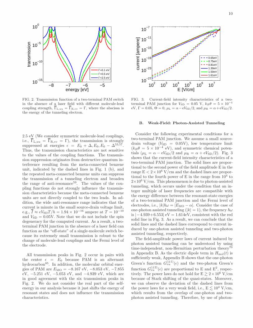
contacts78–80, and the types of linker groups such asthiol (−SH) and amine (−NH2) groups81,82. The influ-ence of these effects can be modeled as the self-energyderived from scattering formulations or non-equilibriumGreen’s functions, if the system is in the coherent tun-neling regime, i.e., molecules with short length and largeinjection gap at low temperature5,83,84. Therefore, inthis section, we model the influence of the electrodes andthe linker groups via changing the values of the couplingfunctions (the imaginary term of the self-energy) in orderto examine whether the destructive quantum interferencecaused by the PAM-based molecular network is sensitiveto molecule-lead couplings.Fig. 2 depicts the transmission of the two-terminal
PAM junction with different molecule-lead couplingstrength in the absence of a laser field. For Γ = 0.1, 0.5,
10
−8 −7 −6 −510
−15
10−10
10−5
100
energy [eV]
tran
smis
sion
Γ=0.1 eVΓ=0.5 eVΓ=2.5 eV
FIG. 2. Transmission function of a two-terminal PAM switchin the absence of a laser field with different molecule-leadcoupling strength, ΓL,uu = ΓR,vv = Γ, where the abscissa isthe energy of the tunneling electron.
2.5 eV (We consider symmetric molecule-lead couplings,i.e., ΓL,uu = ΓR,vv = Γ), the transmission is stronglysuppressed at energies ǫ = E0 + ∆, E0, E0 − ∆53,57.Thus, the transmission characteristics are not sensitiveto the values of the coupling functions. The transmis-sion suppression originates from destructive quantum in-terference resulting from the meta-connected benzeneunit, indicated by the dashed lines in Fig. 1 (b), andthe repeated meta-connected benzene units can suppressthe transmission of a tunneling electron and broadenthe range of anti-resonance59. The values of the cou-pling functions do not strongly influence the transmis-sion characteristics because the meta-connected benzeneunits are not directly coupled to the two leads. In ad-dition, the wide anti-resonance range indicates that thecurrent is minute in the small source-drain voltage limit,e.g., I ≈ eVSDT/h = 1.94 × 10⁻¹⁶ ampere at T = 10−10
and VSD = 0.05V. Note that we do not include the spindegeneracy for the computed current. As a result, a two-terminal PAM junction in the absence of a laser field canfunction as the “off-state” of a single-molecule switch be-cause its extremely small transmission is robust to thechange of molecule-lead couplings and the Fermi level ofthe electrode.
All transmission peaks in Fig. 2 occur in pairs withthe center ǫ = E0 because PAM is an alternanthydrocarbon85. In addition, the molecular orbital ener-gies of PAM are EMO = −8.167 eV, −8.053 eV, −7.855eV, −5.251 eV, −5.053 eV, and −4.939 eV, which arein good agreement with the six transmission peaks inFig. 2. We do not consider the real part of the self-energy in our analysis because it just shifts the energy ofresonant states and does not influence the transmissioncharacteristics.
102
103
104
105
106
107
10−27
10−23
10−19
10−15
10−11
10−7
curr
ent [
ampe
re]
E [V/cm]
0.65eV0.75eV0.81eV1.30eV1.50eV1.61eV
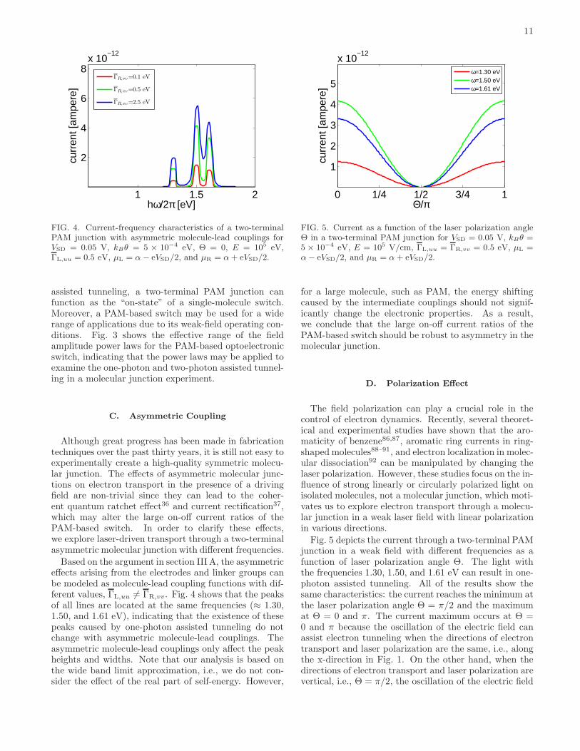
FIG. 3. Current-field intensity characteristics of a two-terminal PAM junction for VSD = 0.05 V, kBθ = 5 × 10⁻⁴
eV, Γ = 0.05, Θ = 0, µL = α−eVSD/2, and µR = α+eVSD/2.
B. Weak-Field: Photon-Assisted Tunneling
Consider the following experimental conditions for atwo-terminal PAM junction. We assume a small source-drain voltage (VSD = 0.05V), low temperature limit(kBθ = 5 × 10⁻⁴ eV), and symmetric chemical poten-tials (µL = α − eVSD/2 and µR = α + eVSD/2). Fig. 3shows that the current-field intensity characteristics of atwo-terminal PAM junction. The solid lines are propor-tional to the second power of the field amplitude E in therange E < 2×10⁶ V/cm and the dashed lines are propor-tional to the fourth power of E in the range from 104 to2×106 V/cm. This phenomenon is due to photon-assistedtunneling, which occurs under the condition that an in-teger multiple of laser frequencies are compatible withthe energy difference between the resonant-state energiesof a two-terminal PAM junction and the Fermi level ofelectrodes, i.e., |k|~ω = |EMO − α|. Consider the case ofone-photon assisted tunneling (|k| = 1), the frequency ~ωis |−4.939+6.553| eV = 1.614eV, consistent with the redsolid line in Fig. 3. As a result, we can conclude that thesolid lines and the dashed lines correspond to current in-duced by one-photon assisted tunneling and two-photonassisted tunneling, respectively.
The field-amplitude power laws of current induced byphoton assisted tunneling can be understood by usingtime-independent, non-Hermitian perturbation theory70
in Appendix B. As the electric dipole term in Hmol(t) issufficiently weak, Appendix B shows that the one-photon
Green’s function G(±1)vu (ǫ) and the two-photon Green’s
function G(±2)vu (ǫ) are proportional to E and E2, respec-
tively. The power laws do not hold for E & 2×10⁶ V/cmbecause of Stark shifting of the quasi-states. Moreover,we can observe the deviation of the dashed lines fromthe power laws for a very weak field, i.e., E . 104 V/cm,which results from the overlap of one-photon and two-photon assisted tunneling. Therefore, by use of photon-
11
1 1.5 2
2
4
6
8x 10
−12
curr
ent [
ampe
re]
hω/2π [eV]
ΓR,vv=0.1 eV
ΓR,vv=0.5 eV
ΓR,vv=2.5 eV
FIG. 4. Current-frequency characteristics of a two-terminalPAM junction with asymmetric molecule-lead couplings forVSD = 0.05 V, kBθ = 5 × 10⁻⁴ eV, Θ = 0, E = 105 eV,ΓL,uu = 0.5 eV, µL = α− eVSD/2, and µR = α+ eVSD/2.
assisted tunneling, a two-terminal PAM junction canfunction as the “on-state” of a single-molecule switch.Moreover, a PAM-based switch may be used for a widerange of applications due to its weak-field operating con-ditions. Fig. 3 shows the effective range of the fieldamplitude power laws for the PAM-based optoelectronicswitch, indicating that the power laws may be applied toexamine the one-photon and two-photon assisted tunnel-ing in a molecular junction experiment.
C. Asymmetric Coupling
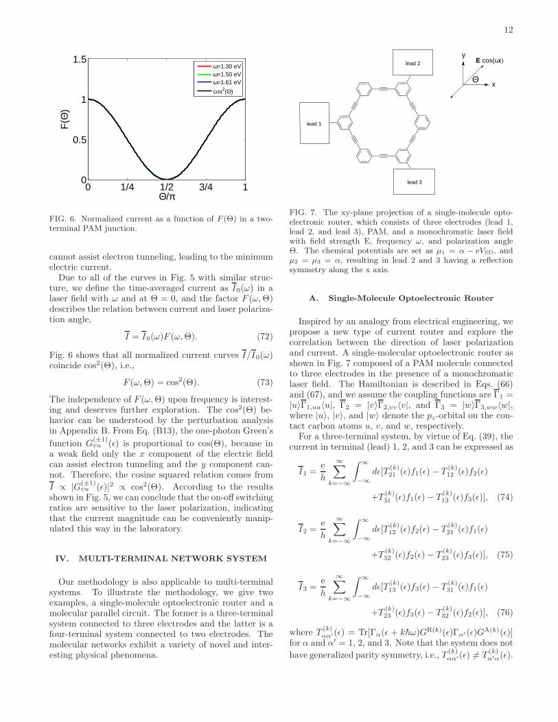
Although great progress has been made in fabricationtechniques over the past thirty years, it is still not easy toexperimentally create a high-quality symmetric molecu-lar junction. The effects of asymmetric molecular junc-tions on electron transport in the presence of a drivingfield are non-trivial since they can lead to the coher-ent quantum ratchet effect36 and current rectification37,which may alter the large on-off current ratios of thePAM-based switch. In order to clarify these effects,we explore laser-driven transport through a two-terminalasymmetric molecular junction with different frequencies.
Based on the argument in section IIIA, the asymmetriceffects arising from the electrodes and linker groups canbe modeled as molecule-lead coupling functions with dif-ferent values, ΓL,uu 6= ΓR,vv. Fig. 4 shows that the peaksof all lines are located at the same frequencies (≈ 1.30,1.50, and 1.61 eV), indicating that the existence of thesepeaks caused by one-photon assisted tunneling do notchange with asymmetric molecule-lead couplings. Theasymmetric molecule-lead couplings only affect the peakheights and widths. Note that our analysis is based onthe wide band limit approximation, i.e., we do not con-sider the effect of the real part of self-energy. However,
0 1/4 1/2 3/4 1
1
2
3
4
5
x 10−12
curr
ent [
ampe
re]
Θ/π
ω=1.30 eVω=1.50 eVω=1.61 eV
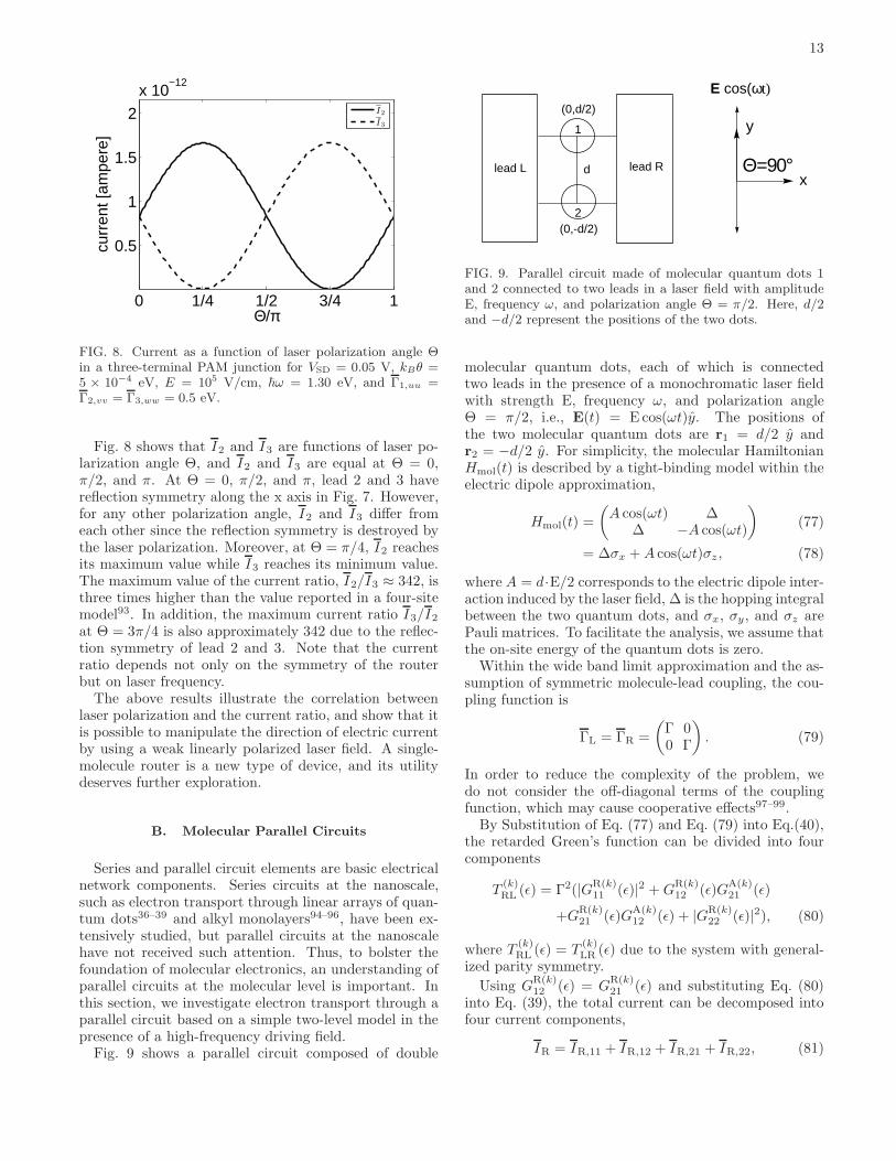
FIG. 5. Current as a function of the laser polarization angleΘ in a two-terminal PAM junction for VSD = 0.05 V, kBθ =5 × 10⁻⁴ eV, E = 105 V/cm, ΓL,uu = ΓR,vv = 0.5 eV, µL =α− eVSD/2, and µR = α+ eVSD/2.
for a large molecule, such as PAM, the energy shiftingcaused by the intermediate couplings should not signif-icantly change the electronic properties. As a result,we conclude that the large on-off current ratios of thePAM-based switch should be robust to asymmetry in themolecular junction.
D. Polarization Effect
The field polarization can play a crucial role in thecontrol of electron dynamics. Recently, several theoret-ical and experimental studies have shown that the aro-maticity of benzene86,87, aromatic ring currents in ring-shaped molecules88–91, and electron localization in molec-ular dissociation92 can be manipulated by changing thelaser polarization. However, these studies focus on the in-fluence of strong linearly or circularly polarized light onisolated molecules, not a molecular junction, which moti-vates us to explore electron transport through a molecu-lar junction in a weak laser field with linear polarizationin various directions.
Fig. 5 depicts the current through a two-terminal PAMjunction in a weak field with different frequencies as afunction of laser polarization angle Θ. The light withthe frequencies 1.30, 1.50, and 1.61 eV can result in one-photon assisted tunneling. All of the results show thesame characteristics: the current reaches the minimum atthe laser polarization angle Θ = π/2 and the maximumat Θ = 0 and π. The current maximum occurs at Θ =0 and π because the oscillation of the electric field canassist electron tunneling when the directions of electrontransport and laser polarization are the same, i.e., alongthe x-direction in Fig. 1. On the other hand, when thedirections of electron transport and laser polarization arevertical, i.e., Θ = π/2, the oscillation of the electric field
12
0 1/4 1/2 3/4 10
0.5
1
1.5F
(Θ)
Θ/π
ω=1.30 eVω=1.50 eVω=1.61 eV
cos2(Θ)
FIG. 6. Normalized current as a function of F (Θ) in a two-terminal PAM junction.
cannot assist electron tunneling, leading to the minimumelectric current.Due to all of the curves in Fig. 5 with similar struc-
ture, we define the time-averaged current as I0(ω) in alaser field with ω and at Θ = 0, and the factor F (ω,Θ)describes the relation between current and laser polariza-tion angle,
I = I0(ω)F (ω,Θ). (72)
Fig. 6 shows that all normalized current curves I/I0(ω)coincide cos2(Θ), i.e.,
F (ω,Θ) = cos2(Θ). (73)
The independence of F (ω,Θ) upon frequency is interest-ing and deserves further exploration. The cos2(Θ) be-havior can be understood by the perturbation analysisin Appendix B. From Eq. (B13), the one-photon Green’s
function G(±1)vu (ǫ) is proportional to cos(Θ), because in
a weak field only the x component of the electric fieldcan assist electron tunneling and the y component can-not. Therefore, the cosine squared relation comes from
I ∝ |G(±1)vu (ǫ)|2 ∝ cos2(Θ). According to the results
shown in Fig. 5, we can conclude that the on-off switchingratios are sensitive to the laser polarization, indicatingthat the current magnitude can be conveniently manip-ulated this way in the laboratory.
IV. MULTI-TERMINAL NETWORK SYSTEM
Our methodology is also applicable to multi-terminalsystems. To illustrate the methodology, we give twoexamples, a single-molecule optoelectronic router and amolecular parallel circuit. The former is a three-terminalsystem connected to three electrodes and the latter is afour-terminal system connected to two electrodes. Themolecular networks exhibit a variety of novel and inter-esting physical phenomena.
lead 3
lead 2
x
y
Θ
E cos(ωt)
lead 1
FIG. 7. The xy-plane projection of a single-molecule opto-electronic router, which consists of three electrodes (lead 1,lead 2, and lead 3), PAM, and a monochromatic laser fieldwith field strength E, frequency ω, and polarization angleΘ. The chemical potentials are set as µ1 = α − eVSD, andµ2 = µ3 = α, resulting in lead 2 and 3 having a reflectionsymmetry along the x axis.
A. Single-Molecule Optoelectronic Router
Inspired by an analogy from electrical engineering, wepropose a new type of current router and explore thecorrelation between the direction of laser polarizationand current. A single-molecular optoelectronic router asshown in Fig. 7 composed of a PAM molecule connectedto three electrodes in the presence of a monochromaticlaser field. The Hamiltonian is described in Eqs. (66)and (67), and we assume the coupling functions are Γ1 =|u〉Γ1,uu〈u|, Γ2 = |v〉Γ2,vv〈v|, and Γ3 = |w〉Γ3,ww〈w|,where |u〉, |v〉, and |w〉 denote the pz-orbital on the con-tact carbon atoms u, v, and w, respectively.For a three-terminal system, by virtue of Eq. (39), the
current in terminal (lead) 1, 2, and 3 can be expressed as
I1 =e
h
∞∑
k=−∞
∫ ∞
−∞
dǫ[T(k)21 (ǫ)f1(ǫ)− T
(k)12 (ǫ)f2(ǫ)
+T(k)31 (ǫ)f1(ǫ)− T
(k)13 (ǫ)f3(ǫ)], (74)
I2 =e
h
∞∑
k=−∞
∫ ∞
−∞
dǫ[T(k)12 (ǫ)f2(ǫ)− T
(k)21 (ǫ)f1(ǫ)
+T(k)32 (ǫ)f2(ǫ)− T
(k)23 (ǫ)f3(ǫ)], (75)
I3 =e
h
∞∑
k=−∞
∫ ∞
−∞
dǫ[T(k)13 (ǫ)f3(ǫ)− T
(k)31 (ǫ)f1(ǫ)
+T(k)23 (ǫ)f3(ǫ)− T
(k)32 (ǫ)f2(ǫ)], (76)
where T(k)αα′(ǫ) = Tr[Γα(ǫ + k~ω)GR(k)(ǫ)Γα′(ǫ)GA(k)(ǫ)]
for α and α′ = 1, 2, and 3. Note that the system does not
have generalized parity symmetry, i.e., T(k)αα′(ǫ) 6= T
(k)α′α(ǫ).
13
0 1/4 1/2 3/4 1
0.5
1
1.5
2
x 10−12
curr
ent [
ampe
re]
Θ/π
I2
I3
FIG. 8. Current as a function of laser polarization angle Θin a three-terminal PAM junction for VSD = 0.05 V, kBθ =5 × 10⁻⁴ eV, E = 105 V/cm, ~ω = 1.30 eV, and Γ1,uu =Γ2,vv = Γ3,ww = 0.5 eV.
Fig. 8 shows that I2 and I3 are functions of laser po-larization angle Θ, and I2 and I3 are equal at Θ = 0,π/2, and π. At Θ = 0, π/2, and π, lead 2 and 3 havereflection symmetry along the x axis in Fig. 7. However,for any other polarization angle, I2 and I3 differ fromeach other since the reflection symmetry is destroyed bythe laser polarization. Moreover, at Θ = π/4, I2 reachesits maximum value while I3 reaches its minimum value.The maximum value of the current ratio, I2/I3 ≈ 342, isthree times higher than the value reported in a four-sitemodel93. In addition, the maximum current ratio I3/I2at Θ = 3π/4 is also approximately 342 due to the reflec-tion symmetry of lead 2 and 3. Note that the currentratio depends not only on the symmetry of the routerbut on laser frequency.The above results illustrate the correlation between
laser polarization and the current ratio, and show that itis possible to manipulate the direction of electric currentby using a weak linearly polarized laser field. A single-molecule router is a new type of device, and its utilitydeserves further exploration.
B. Molecular Parallel Circuits
Series and parallel circuit elements are basic electricalnetwork components. Series circuits at the nanoscale,such as electron transport through linear arrays of quan-tum dots36–39 and alkyl monolayers94–96, have been ex-tensively studied, but parallel circuits at the nanoscalehave not received such attention. Thus, to bolster thefoundation of molecular electronics, an understanding ofparallel circuits at the molecular level is important. Inthis section, we investigate electron transport through aparallel circuit based on a simple two-level model in thepresence of a high-frequency driving field.Fig. 9 shows a parallel circuit composed of double
lead L lead Rx
y
E cos(ωt)
d
(0,d/2)
(0,-d/2)
Θ=90°
1
2
FIG. 9. Parallel circuit made of molecular quantum dots 1and 2 connected to two leads in a laser field with amplitudeE, frequency ω, and polarization angle Θ = π/2. Here, d/2and −d/2 represent the positions of the two dots.
molecular quantum dots, each of which is connectedtwo leads in the presence of a monochromatic laser fieldwith strength E, frequency ω, and polarization angleΘ = π/2, i.e., E(t) = E cos(ωt)y. The positions ofthe two molecular quantum dots are r1 = d/2 y andr2 = −d/2 y. For simplicity, the molecular HamiltonianHmol(t) is described by a tight-binding model within theelectric dipole approximation,
Hmol(t) =
(A cos(ωt) ∆
∆ −A cos(ωt)
)(77)
= ∆σx +A cos(ωt)σz , (78)
where A = d·E/2 corresponds to the electric dipole inter-action induced by the laser field, ∆ is the hopping integralbetween the two quantum dots, and σx, σy , and σz arePauli matrices. To facilitate the analysis, we assume thatthe on-site energy of the quantum dots is zero.Within the wide band limit approximation and the as-
sumption of symmetric molecule-lead coupling, the cou-pling function is
ΓL = ΓR =
(Γ 00 Γ
). (79)
In order to reduce the complexity of the problem, wedo not consider the off-diagonal terms of the couplingfunction, which may cause cooperative effects97–99.By Substitution of Eq. (77) and Eq. (79) into Eq.(40),
the retarded Green’s function can be divided into fourcomponents
T(k)RL (ǫ) = Γ2(|G
R(k)11 (ǫ)|2 +G
R(k)12 (ǫ)G
A(k)21 (ǫ)
+GR(k)21 (ǫ)G
A(k)12 (ǫ) + |G
R(k)22 (ǫ)|2), (80)
where T(k)RL (ǫ) = T
(k)LR (ǫ) due to the system with general-
ized parity symmetry.
Using GR(k)12 (ǫ) = G
R(k)21 (ǫ) and substituting Eq. (80)
into Eq. (39), the total current can be decomposed intofour current components,
IR = IR,11 + IR,12 + IR,21 + IR,22, (81)
14
(a) (b) (c) (d)
FIG. 10. Schematic representation of the four current com-ponents. (a) IR,11. (b) IR,12. (c) IR,21. (d) IR,22.
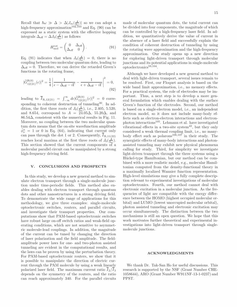
0 20 40 60 80 1000
2
4
6
8
A [∆]
I [eΓ
/h]
IR
IR,11
IR,12
FIG. 11. Current-field intensity characteristics of a parallelcircuit based on double molecular quantum dots for VSD =0.5 V, kBT = 0, ∆ = 0.1 eV, ~ω = 10∆, and Γ = 0.1∆.We assume symmetric chemical potentials for the two leads,i.e.,µL = µ− eVSD/2 and µR = µ+ eVSD/2.
where
IR,uv =eΓ2
h
∞∑
k=−∞
∫ ∞
−∞
dǫ|GR(k)uv (ǫ)|2[fR(ǫ)− fL(ǫ)].
(82)
and u(v) = 1 or 2. Note that IR,11 = IR,22 and
IR,12 = IR,21 due to GR(k)11 (ǫ) = G
R(k)22 (ǫ) and G
R(k)12 (ǫ) =
GR(k)21 (ǫ). The schematic representation of the four cur-
rent components is shown in Fig. 10.
Fig. 11 shows the current-field intensity characteristicsof a parallel circuit based on double molecular quantumdots in a high-frequency driving field (~ω = 10∆). In theabsence of the laser field, i.e., A = 0∆, we can observeIR,11 ≈ IR,12 and IR ≈ 4IR,11, which can be understoodquantitatively by the following discussion. First, in theabsence of the laser field, Eq. (82) can reduce to
IR,uv =eΓ2
h
∫ ∞
−∞
dǫ|GR(0)uv (ǫ)|2[fR(ǫ)− fL(ǫ)]. (83)
For a two-level system, by virtue of Eq. (64), the re-
tarded Green’s functions |GR(0)11 (ǫ)|2 and |G
R(0)12 (ǫ)|2 have
analytical forms and can be approximated as
|GR(0)11 (ǫ)|2 =
1
4
∣∣∣∣1
ǫ−∆− iΓ+
1
ǫ+∆− iΓ
∣∣∣∣2
(84)
≈1
4
(1
(ǫ−∆)2 + Γ2+
1
(ǫ+∆)2 + Γ2
), (85)
and
|GR(0)12 (ǫ)|2 =
1
4
∣∣∣∣1
ǫ−∆− iΓ−
1
ǫ+∆− iΓ
∣∣∣∣2
(86)
≈1
4
(1
(ǫ−∆)2 + Γ2+
1
(ǫ+∆)2 + Γ2
). (87)
The cross terms in Eq. (84) and Eq. (86) correspondto constructive and destructive quantum interference be-tween two resonant states, respectively100, and they canbe neglected in the resonant tunneling regime. There-
fore, we have |GR(0)11 (ǫ)|2 ≈ |G
R(0)12 (ǫ)|2. In addition,
for the condition that the energy levels of all resonantstates are between µR and µL, we can approximate∫∞
−∞dǫ|G
R(0)11 (ǫ)|2[fR(ǫ)−fL(ǫ)] ≈
∫∞
−∞dǫ|G
R(0)11 (ǫ)|2. We
substitute Eqs. (85) and (87) into Eq. (83) and make
use of∫∞
−∞dǫ|G
R(0)11 (ǫ)|2 = π/2Γ, and then we derive
IR,11 ≈ IR,12 ≈ πeΓ/2h and IR ≈ 2πeΓ/h ≈ 4IR,11,which are in quantitatively good agreement with the nu-merical results in Fig. 11.In the presence of the laser field (A 6= 0), Fig. 11
shows that IR,12 becomes almost zero at A = 24∆, 55∆,
and 86∆ while IR,11 reaches local maximum values atthe same positions, indicating that the individual cur-rent components can be manipulated by a laser field. Tounderstand this behavior, we transform the Hamiltonianin Eq. (78) into a rotating frame101
Hrotmol(t) = U †
rot(t)Hmol(t)Urot(t)− i~U †rot(t)
dUrot(t)
dt
=
(0 ∆ei
A~ω
sin(ωt)
∆e−i A~ω
sin(ωt) 0
)(88)
by using the operator
Urot(t) = exp
(−i
A
~ωsin(ωt)σz
). (89)
This transformation gives a good description of the dy-namics of a time-periodic system for the high-frequencydriving condition ~ω ≫ ∆ and the strong-field driv-ing condition A > ∆ hold101. Using that eia sin(b) =∑∞
m=−∞ Jm(a)eimb and J−m(a) = (−1)mJm(a), whereJm(a) are Bessel functions of the first kind and m areintegers, we have
Hrotmol(t) =
∞∑
m=−∞
∆
(0 Jm( A
~ω )eimωt
(−1)mJm( A~ω )e
imωt 0
).
(90)
15
Recall that ~ω ≫ ∆ > ∆|Jm( A~ω )| so we can adopt a
high-frequency approximation102,103 and Eq. (90) can beexpressed as a static system with the effective hoppingintegrals ∆eff = ∆J0(
A~ω ) as follows
Hrotmol =
(0 ∆eff
∆eff 0
). (91)
Eq. (91) indicates that when J0(A~ω ) = 0, there is no
coupling between two molecular quantum dots, leading to∆eff = 0. Therefore, we can derive the retarded Green’sfunctions in the rotating frame,
|GR(0)12(21)(ǫ)|
2 =1
4
∣∣∣∣1
ǫ−∆eff − iΓ−
1
ǫ+∆eff − iΓ
∣∣∣∣2
= 0,
(92)
leading to IR,12(21) =∫∞
−∞dǫ|G
R(0)12(21)(ǫ)|
2 = 0 corre-
sponding to coherent destruction of tunneling30. In ad-dition, the first three roots of J0(
A~ω ), i.e., 2.405, 5.520,
and 8.654, correspond to A = 24.05∆, 55.20∆, and86.54∆, consistent with the numerical results in Fig. 11.Moreover, no coupling between the two molecular quan-tum dots means that the on-site wavefunction amplitudeφnν = 1 or 0 in Eq. (64), indicating that current onlycan pass through the dot 1 or 2. Consequently, IR,11(22)
reaches local maxima at the first three roots of J0(A~ω ).
This section showed that the current components of amolecular parallel circuit can be manipulated by a stronghigh-frequency driving field.
V. CONCLUSIONS AND PROSPECTS
In this study, we develop a new general method to sim-ulate electron transport through a single-molecule junc-tion under time-periodic fields. This method also en-ables dealing with electron transport through quantumdots and other nanostructures in a strong driving field.To demonstrate the wide range of applications for thismethodology, we give three examples: single-moleculeoptoelectronic switches, routers, and parallel circuits,and investigate their transport properties. Our com-putations show that PAM-based optoelectronic switcheshave robust large on-off switch ratios and weak-field op-erating conditions, which are not sensitive to asymmet-ric molecule-lead couplings. In addition, the magnitudeof the current can be tuned by changing the directionof laser polarization and the field amplitude. The field-amplitude power laws for one- and two-photon assistedtunneling are evident in the computational results, andthe laws can be proven by using the perturbation theory.For PAM-based optoelectronic routers, we show that itis possible to manipulate the direction of electric cur-rent through the PAM molecule by using a weak linearlypolarized laser field. The maximum current ratio I2/I3depends on the symmetry of the routers, and the ratiocan reach approximately 340. For the parallel circuits
made of molecular quantum dots, the total current canbe divided into four components, the magnitude of whichcan be controlled by a high-frequency laser field. In ad-dition, we quantitatively derive the value of current inthe absence of a laser field and successfully explain thecondition of coherent destruction of tunneling by usingthe rotating wave approximation and the high-frequencyapproximation. Our study opens up a new directionfor exploring light-driven transport through molecularjunctions and its potential applications in single-moleculeoptoelectronics59,104.
Although we have developed a new general method todeal with light-driven transport, several issues remain tobe resolved. First, our Floquet analysis is based on thewide band limit approximation, i.e., no memory effects.For a practical system, the role of electrodes may be im-portant. Thus, a next step is to develop a more gen-eral formulation which enables dealing with the surfaceGreen’s function of the electrodes. Second, our methodis based on a single-electron model, i.e., an independentelectron model, so it does not include many-body ef-fects such as electron-electron interactions and electron-photon interactions105. Lehmann et al. have investigatedvibrational effects in a two-site system42, but they onlyconsidered a weak thermal coupling limit, i.e., no many-body effect such as polarons106,107 in their study. Thesynergistic effects of many-body interactions and photon-assisted tunneling may exhibit new physical phenomenacalling for study. Third, for simplicity we investigatelight-driven transport through the three systems using aHuckel-type Hamiltonian, but our method can be com-bined with a more realistic model, e.g., molecular Hamil-tonian computed from the density-functional theory ina maximally localized Wannier function representation.High-level simulations may give a fully complete descrip-tion relevant to experimental investigations of molecularoptoelectronics. Fourth, our method cannot deal withelectronic excitation in a molecular junction. As the fre-quencies of light are compatible with the energy differ-ence between the HOMO (highest occupied molecular or-bital) and LUMO (lowest unoccupied molecular orbital),photon assisted tunneling and electronic excitation mayoccur simultaneously. The distinction between the twomechanisms is still an open question. We hope that thiswork motivates further theoretical and experimental in-vestigations into light-driven transport through single-molecule junctions.
ACKNOWLEDGMENTS
We thank Dr. Tak-San Ho for useful discussions. Thisresearch is supported by the NSF (Grant Number CHE-1058644), ARO (Grant Number W911NF-13-1-0237) andPPST.
16
Appendix A: Periodic Charging of the Molecule
Substitution of Eq. (31) into∑
qn |〈n|U(t, t0)|αq〉|2
gives
qα(t) = e∑
qn
|〈n|U(t, t0)|αq〉|2fα(ǫαq) (A1)
=e
2π
∫dǫTr[GR(t, ǫ)Γα(ǫ)G
A(t, ǫ)]fα(ǫ), (A2)
in which qα(t) corresponds to the charge contributed bythe lead α to the molecule. It can be proved that qα(T ) =qα(0) since G
R(t, ǫ) and GA(t, ǫ) are periodic functions oftime.Integration of the tunneling rate kn,αq(t) multiplied by
the Fermi function fα(ǫαq) over a period T and use of thefundamental theorem of calculus gives
∑
qn
∫ T
0
dtkn,αq(t)fα(ǫαq)
=∑
qn
∫ T
0
dt1
dt|〈n|U(t, t0)|αq〉|
2fα(ǫαq)
=∑
qn
(|〈n|U(T, t0)|αq〉|
2 − |〈n|U(0, t0)|αq〉|2)fα(ǫαq).
(A3)
By substitution of Eq. (A2) into Eq. (A3) and usingthe relation GR(A)(t, ǫ) = GR(A)(t+ T, ǫ), we can obtain
e
T
∑
qn
∫ T
0
dtkn,αq(t)fα(ǫαq) =qα(T )− qα(0)
T
= 0, (A4)
indicating that e∫ T
0 dtkn,αqfα(ǫαq) corresponds to peri-odic charging of the molecule driven by external time-periodic fields and contributes zero current over a period.In addition, we can invoke Eq. (31) to prove that
kαq,n(t) is a periodic function of time. Then, it followsthat the first two terms in Eq. (16) average to zero.
Appendix B: Time-Independent Non-Hermitian
Perturbation Theory
Eq. (56) and its adjoint eigenvalue equation can beexpressed as
HFφλ,ζ = qλ,ζφλ,ζ , (B1)
H†
Fχλ,ζ = qλ,ζχλ,ζ , (B2)
where the eigenstates φλ,ζ and χλ,ζ form a complete
biorthogonal basis, i.e., χ†λ,ζφλ,ζ =
∑nk χ
n,k∗λ,ζ φn,kλ,ζ =
∑nk φ
n,kλ,ζφ
n,kλ,ζ = δλλ′δζζ′ , and the eigenvalues q∗λ,ζ =
qλ,ζ70. In the previous section, the quasienergies qλ,0
and Floquet states φλ,0 are chosen in the first Brillouinzone, while here for convenience we choose qλ,0 and φλ,0which correspond to the energies and the states derivedfrom a Hamiltonian without a driving field, i.e., qλ,0 = qνand φn,0λ,0 = φnν in Eq. (65).As the external laser field is weak, we can divide the
time-averaged Floquet Hamiltonian into two parts
HF = H0 + ΛH1, (B3)
where Λ is a dimensionless parameter ranging continu-ously from 0 (zero perturbation) to 1 (the full pertur-bation), H0 is a non-Hermitian unperturbed Hamilto-nian, and H1 is a perturbed Hamiltonian. According toEq. (71), we separate HF into
H0 =
. . ....
......
......
· · · A− 2~ωI 0 0 0 0 · · ·· · · 0 A− ~ωI 0 0 0 · · ·· · · 0 0 A 0 0 · · ·· · · 0 0 0 A+ ~ωI 0 · · ·· · · 0 0 0 0 A+ 2~ωI · · ·
......
......
.... . .
,
(B4)
and
H1 =
. . ....
......
......
· · · 0 B 0 0 0 · · ·· · · B 0 B 0 0 · · ·· · · 0 B 0 B 0 · · ·· · · 0 0 B 0 B · · ·· · · 0 0 0 B 0 · · ·
......
......
.... . .
. (B5)
We begin with the unperturbed non-Hermitian Hamil-tonian H0, which has known eigenvalues and eigenstates
H0φ0λ,ζ = q
(0)λ,ζφ
(0)λ,ζ , (B6)
H†
0χ(0)λ,ζ = q
(0)λ,ζχ
(0)λ,ζ , (B7)
which satisfy∑
nk χ(0)nk∗λ,ζ φ
(0)nkλ,ζ = δλλ′δζζ′ and q
(0)∗λ,ζ =
q(0)λ,ζ . Note that H0 and H
†
0 are block diagonal matricesso
φ(0)n,kλ,ζ = φ
(0)n,kλ,ζ δk,ζ . (B8)
χ(0)n,kλ,ζ = χ
(0)n,kλ,ζ δk,ζ . (B9)
If H1 is sufficiently weak, φλ,ζ and qλ,ζ can be writtenas a power series in Λ,
φλ,ζ = φ(0)λ,ζ + Λφ
(1)λ,ζ + Λ2φ
(2)λ,ζ + ..., (B10)
qλ,ζ = q(0)λ,ζ + Λq
(1)λ,ζ + Λ2q
(2)λ,ζ + ..., (B11)
17
Substituting Eqs. (B3), (B10), and (B11) intoEq. (B1), expanding Eq. (B1) in powers of Λ, and mul-
tiplying by χ(0)†λ′,ζ′ give the first-order correction to the
coefficients of the wave function
φ(1)n,−kλ,ζ =
∑
λ′ζ′
∑
n′k′
∑
n′′k′′
χ(0)n′′,k′′∗
λ′,ζ′ [H1]n′′k′′,n′k′φ(0)n′,k′
λ,ζ
q(0)λ,ζ − q
(0)λ′,ζ′
φ(0)n,−kλ′,ζ′ ,
(B12)
where (λ′, ζ′) 6= (λ, ζ). Eq. (B12) has a similar form to
the first-order correction for the coefficients of the wavefunction derived from standard time-independent pertur-bation theory. According to Eq. (66), we obtain
[H1]n′′k′′,n′k′
= −eE
2(xn′ cosΘ + yn′ sinΘ)δn′′,n′δk′′,k′±1. (B13)
By substitution of φλ,ζ = φ(0)n,kλ,ζ +φ
(1)n,kλ,ζ into Eq. (62)
and by virtue of Eqs. (B8), (B9), (B12) and (B13), it isstraightforward to derive
GR(±1)nn′ (ǫ) =
∑
λ
+∞∑
ζ=−∞
φn,∓1λ,ζ φn
′,0λ,ζ
ǫ− qλ,ζ(B14)
≈∑
λ
φ(0)n,∓1λ,0 φ
(0)n′,0λ,0
ǫ− qλ,0+∑
λ
φ(0)n,∓1λ,∓1 φ
(1)n′,0λ,∓1
ǫ− qλ,∓1+∑
λ
φ(1)n,∓1λ,0 φ
(0)n′,0λ,0
ǫ − qλ,0+∑
λ
+∞∑
ζ=−∞
φ(1)n,∓1λ,ζ φ
(1)n′,0λ,ζ
ǫ− qλ,ζ, (B15)
where the first term is equal to zero and we neglect thefourth term which corresponds to the next-order correc-tion. As a result, we obtain
GR(±1)nn′ (ǫ) ≈
∑
λ
φ(0)n,∓1λ,∓1 φ
(1)n′,0λ,∓1
ǫ− qλ,∓1+∑
λ
φ(1)n,∓1λ,0 φ
(0)n′,0λ,0
ǫ− qλ,0,
(B16)
Suppose the energy of a tunneling electron is close tothe energy of a particular one-photon quasistate S, i.e.,ǫ ≈ ǫS∓~ω, and is far away from the other states. Then,Eq. (B16) becomes
GR(±1)nn′ (ǫ) ≈
φ(0)n,∓1S,∓1 φ
(1)n′,0S,∓1
ǫ− qS,∓1, (B17)
According to Eqs. (B12) and (B13), we can show
GR(±1)nn′ (ǫ) ∝ φ
(1)n′,0S,∓1 ∝ E, (B18)
which indicates that the current induced by one-photonassisted tunneling is proportional to E2. Moreover, byusing the second-order correction to the coefficients ofthe wave function (not shown here), we can derive that
GR(±2)nn′ (ǫ) ∝ E2, (B19)
and the current induced by two-photon assisted tunnelingis proportional to E4.
Note that Eq. (B12) is generally valid in the case of
q(0)λ,ζ 6= q
(0)λ′,ζ′ , e.g., the high frequency limit. However,
according to Eqs. (B8), (B9), and (B13), the conditions
q(0)λ,ζ 6= q
(0)λ′,ζ′ can reduce to q
(0)λ,±1 6= q
(0)λ′,0. We found that
all states satisfy q(0)λ,±1 6= q
(0)λ′,0, so it is reasonable to apply
the analysis to establish the field-amplitude power laws.
∗ [email protected]† [email protected] A. Nitzan and M. A. Ratner, Science 300, 1384 (2003).2 M. A. Reed, Procedings of the IEEE 87, 652 (1999).3 C. Joachim, J. K. Gimzewski and A. Aviram, Nature 408,541 (2000).
4 N. J. Tao, Nature Nanotechnology 1, 173 (2006).5 S. M. Lindsay and M. A. Ratner, Adv. Mater. 19, 63(2007).
6 M. A. Ratner, Nature Nanotechnology 8, 378 (2013).
7 S. V. Aradhya and L. Venkataraman, Nature Nanotech-nology 8, 399 (2013).
8 M. A. Reed, C. Zhou, C. J. Muller, T. P. Burgin, andJ. M. Tour, Science 278, 252 (1997).
9 H. Park, J. Park, A. K. L. Lim, E. H. Anderson,A. P. Alivisatos, and P. L. McEuen, Nature 407, 57(2000).
10 J. Park, A. N. Pasupathy, J. I. Goldsmith, C. Chang,Y. Yaish, J. R. Petta, M. Rinkoski, J. P. Sethna,H. D. Abruna, P. L. McEuen, and D. C. Ralph, Nature
18
417, 722 (2002).11 W. Liang, M. P. Shores, M. Bockrath, J. R. Long, and H.
Park, Nature 417, 725 (2002).12 P. Reddy, S.-Y. Jang, R. A. Segalman, and A. Majumdar,
Science 315, 1568 (2007).13 H. Song, Y. Kim, Y. H. Jang, H. Jeong, M. A. Reed, and
T. Lee, Nature 462, 1039 (2009).14 C. M. Guedon et al., Nature Nanotech. 7, 305 (2012).15 V. Rabache et al., J. Am. Chem. Soc. 28, 10218 (2013).16 C. R. Arroyo et al., Angew. Chem. Int. Ed. 52, 3152
(2013).17 L. Venkataraman, L.;J. E. Klare, C. Nuckolls, M. S. Hy-
bertsen, M. L. Steigerwald, Nature 442, 725 (2006).18 A. Mishchenko, D. Vonlanthen, V. Meded, M. Burkle,
C. Li, I. V. Pobelov, A. Bagrets, J. K. Viljas, F. Pauly,F. Evers, M. Mayor, T. Wandlowski, Nano Lett. 10, 156(2010).
19 A. Mishchenko, L. Zotti, D. Vonlanthen, M. Burkle,F. Pauly, J. C. Cuevas, M. Mayor, T. Wandlowski, J.Am. Chem. Soc. 133, 184 (2011).
20 S. Datta, Quantum Transport: Atom To Transistor, Cam-bridge, (2005).
21 M. Di Ventra, Electron Transport in Nanoscale Systems,Cambridge, (2008).
22 J. Taylor, H. Guo, and J. Wang, Phys. Rev. B 63, 245407(2001).
23 S. H. Ke, H. U. Baranger, and W. T. Yang, Phys. Rev.B 70, 085410 (2004).
24 X. Yin, Y. Li, Y. Zhang, P. Li, J. Zhao, Chem. Phys.Lett. 422, 111 (2006).
25 S. H. Ke, H. U. Baranger, and W. T. Yang, J. Am. Chem.Soc. 126, 15904 (2004).
26 S. J. van der Molen et al., Nano Lett. 9, 76 (2009).27 A. H. Dayem and R. J. Martin, Phys. Rev. Lett. 8, 246
(1962).28 P. K. Tien and J. P. Gordon, Phys. Rev. 129, 647 (1963).29 C. A. Stafford and N. S. Wingreen, Phys. Rev. Lett. 76,
1916 (1996).30 F. Grossmann, T. Dittrich, P. Jung, and P. Hanggi, Phys.
Rev. Lett. 67, 516 (1991).31 L. P. Kouwenhoven, S. Jauhar, J. Orenstein, P. L.
McEuen, Y. Nagamune, J. Motohisa, and H. Sakaki,Phys. Rev. Lett. 395, 3443 (1994).
32 G. Platero and R. Aguado, Phys. Rep. 395, 1 (2004).33 R. Arielly, A. Ofarim, G. Noy, and Y. Selzer, Nano Lett.
11, 2968 (2011).34 A. Tikhonov, R. D. Coalson, and Y. Dahnovsky, J. Chem.
Phys. , 116, 10909 (2002).35 A. Tikhonov, R. D. Coalson, and Y. Dahnovsky, J. Chem.
Phys. , 117, 567 (2002).36 J. Lehmann, S. Kohler, P. Hanggi, and A. Nitzan, Phys.
Rev. Lett. , 88, 228305 (2002).37 J. Lehmann, S. Kohler, and P. Hanggi, J. Chem. Phys.
118, 3283 (2003).38 J. Lehmann, S. Camalet, S. Kohler, and P. Hanggi, Phys.
Rev. Lett. 90, 210602 (2003).39 S. Camalet, S. Kohler, and P. Hanggi, Phys. Rev. B 70,
155326 (2004).40 A. Keller, O. Atabek, M. Ratner, and V. Mujica, J. Phys.
B: At. Mol. Opt. Phys. 35, 4981 (2002).41 I. Urdaneta, A. Keller, O. Atabek, and V. Mujica, J.
Phys. B: At. Mol. Opt. Phys. 38, 3779 (2005).42 J. Lehmann, S. Kohler, V. May, and P. Hanggi, J. Chem.
Phys. 121, 2278 (2004).
43 T. S. Ho, S. H. Hung, H. T. Chen, and S, I Chu, Phys.Rev. B 79, 235323 (2009).
44 G. Q. Li and U. Kleinekathofer, Eur. Phys. J. B 76, 309(2010).
45 M. M. Haley, J. J. Pak, and S. C. Brand, Topics in CurrentChemistry 201, 81 (1999).
46 A. S. Shetty, J. Zhang, and J. S. Moore, J. Am. Chem.Soc. 118, 1019 (1996).
47 M. Magoga, M. and C. Joachim, Phys. Rev. B 59, 16011(1999).
48 N. D. Lang and P. Avouris, Phys. Rev. B 62, 7325 (2000).49 H. Vazquez, R. Skouta, S. Schneebeli, M. Kamenetska, R.
Breslow, L. Venkataraman, and M. S. Hybertsen, NatureNanotech. 7, 663 (2012).
50 S. Sautet and C. Joachim, Chem. Phys. Lett. 153, 511(1988).
51 D. M. Cardamone, C. A. Stafford, and S. Mazumder,Nano Lett. 6, 2422 (2006).
52 S. H. Ke and W. T. Yang, Nano Lett. 8, 3257 (2008).53 L.-Y. Hsu and B.-Y. Jin, Chem. Phys. 355, 177 (2009).54 J. Rincon, K. Hallberg, A. A. Aligia, and S. Ramasesha,
Phys. Rev. Lett. 103, 266801 (2009).55 A. A. Kocherzhenko, F. C. Grozema, and L. D. A. Siebbe-
les, J. Phys. Chem. C 114, 7973 (2010).56 A. A. Kocherzhenko, L. D. A. Siebbeles, and F. C.
Grozema, J. Phys. Chem. Lett. 1753, 2 (2011).57 T. Hansen, G. C. Solomon, D. Q. Andrews, and M. A.
Ratner, J. Chem. Phys. 131, 194704 (2009).58 Y. Tsuji, A. Staykov, and K. Yoshizawa, J. Am. Chem.
Soc. 133, 5955 (2011).59 L.-Y. Hsu and H. Rabitz Phys. Rev. Lett. 109, 186801
(2012).60 L.-Y. Hsu, E. Y. Li, and H. Rabitz Nano Lett. 13, 5020
(2013).61 M. Mayor et al., Angew. Chem. Int. Ed. 42, 5834 (2003).62 S. Ami, M. Hliwa, and C. Joachim, Chem. Phys. Lett.
367, 662 (2003).63 S. Ami, M. Hliwa, and C. Joachim, Nanotech. 14, 283
(2003).64 H. Haug A.-P. Jauho, Quantum Kinetics in Transport and
Optics, Springer, (1997).65 S. Kohler, J. Lehmann, and P. Hanggi, Phys. Rep. 406,
379 (2005).66 A. A. Mostofi, J. R. Yates, Y.-S. Lee, I. Souza, D. Van-
derbilt, N. Marzari, Comput. Phys. Commun. 178, 685(2008).
67 Y.-S. Lee and N. Marzari, Phys. Rev. Lett. 95, 076804(2005).
68 D. S. Fisher and P. A. Lee, Phys. Rev. B 23, 6851 (1981).69 Y. Meir and N. S. Wingreen, Phys. Rev. Lett. 68, 2512
(1992).70 M. M. Sternheim and J. F. Walker, Phys. Rev. C. 6, 114
(1972).71 F. H. M. Faisal and J. V. Moloney, J. Phys. B: At. Mol.
Phys. 14, 3603 (1981).72 H. Sambe, Phys. Rev. A 7, 2203 (1973).73 J. H. Shirley, Phys. Rev. 138, B979 (1965).74 M. Grifoni and P. Hanggi, Phys. Rep. 304, 229 (1998).75 M. J. Frisch et al., Gaussian 09, Revision A.02, Gaussian,
Inc.,Wallingford CT, 2009.76 J. P. Lowe and K. A. Peterson Quantum Chemistry, (El-
sevier, 2006).77 J. W. Lawson and C. W. Bauschlicher Jr, Phys. Rev. B
74, 125401 (2006).
19
78 H. Kondo, H. Kino, J. Nara, T. Ozaki, and T. Ohno,Phys. Rev. B 73, 235323 (2006).
79 S.-H. Ke , H. U. Baranger, and W. Yang, J. Am. Chem.Soc. 126, 15987 (2004).
80 J. Nara, W. T. Geng, H. Kino, N. Kobayashi, andT. Ohno, J. Chem. Phys. 121, 6485 (2004).
81 X. D. Cui, A. Primak, X. Zarate, J. Tomfohr, O. F.Sankey, A. L. Moore, T. A. Moore, D. Gust, G. Harris,and S. M. Lindsay, Science 294, 571 (2001).
82 L. Venkataraman,J. E. Klare, I. W. Tam, C. Nuckolls,M. S. Hybertsen, and M. L. Steigerwald, Nano Lett. 6,458 (2006).
83 A. Nitzan, J. Jortner, J. Wilkie, A. L. Burin, and M.Ratner, J. Phy. Chem. B 104, 5661 (2000).
84 A. Nitzan, Annu. Rev. Phys. Chem. 52, 681 (2001).85 L. Salem, The Molecular Orbital Theory of Conjugated
Systems (W. A. Benjamin, Inc.,1966).86 I. S. Ulusoy and M. Nest, J. Am. Chem. Soc. 133, 20230
(2011).87 K. Moore and H. Rabitz, Nature Chem. 4, 72 (2012).88 I. Barth , J. Manz, Y. Shigeta, and K. Yagi, J. Am. Chem.
Soc. 128, 7043 (2006).89 M. Kanno, H. Kono, Y. Fujimura, and S. H. Lin, Phys.
Rev. Lett. 104, 108302 (2010).90 H. Mineo, Masahiro Yamaki, Y. Teranishi, M. Hayashi,
S. H. Lin, and Y. Fujimura, J. Am. Chem. Soc. 134,14279 (2012).
91 K. Nobusada and K. Yabana, Phys. Rev. A 75, 032518(2007).
92 M. F. Kling et al. Science 312, 246 (2006).93 J. Lehmann, S. Camalet, S. Kohler, and P. Hanggi, Chem.
Phys. Lett. 368, 282 (2003).94 H. Song, M. A. Reed, and T. Lee, Adv. Mater. 23, 1583
(2011).95 D. J. Wold and C. D. Frisbie, J. Am. Chem. Soc. 122,
2970 (2000).96 W. Wang, T. Lee, and M. A. Reed, Phys. Rev. B 68,
035416 (2003).97 M. G. Reuter, T. Seideman, and M. A. Ratner, Nano
Lett. 11, 4692 (2011).98 M. G. Reuter, G. C. Solomon, T. Hansen, T. Seideman,
and M. A. Ratner, J. Phys. Chem. Lett. 2, 1667 (2011).99 M. G. Reuter, M. C. Hersam, T. Seideman, and M. A.
Ratner, Nano Lett. 12, 2243 (2012).100 L.-Y. Hsu and B.-Y. Jin, Chem. Phys. Lett. 457, 279
(2008).101 S. Ashhab, J. R. Johansson, A. M. Zagoskin, and F. Nori,
Phys. Rev. A 75, 063414 (2007).102 F. Grossmann, P. Jung, T. Dittrich, and P. Hanggi, Z.
Physik B 84, 315 (1991).103 S. Kohler, S, Camalet, M. Strass, J. Lehmann, G. Ingold,
and P. Hanggi, Chem. Phys. Lett. 296, 243 (2004).104 M. Galperin and A. Nitzan, Phys. Chem. Chem. Phys.
14, 9421 (2012).105 L.-Y. Hsu and B.-Y. Jin, J. Chem. Phys. 133, 144705
(2010).106 M. Galperin, M. A. Ratner and A. Nitzan, Nano Lett. 5,
125 (2005).107 M. Galperin, M. A. Ratner and A. Nitzan, J. Phys.: Con-
dens. Matter 19, 103201 (2007).