ELECTROMAGNETIC TRANSMISSION THROUGH FRACTAL APERTURES IN INFINITE CONDUCTING SCREEN
34
Progress In Electromagnetics Research B, Vol. 12, 105–138, 2009 ELECTROMAGNETIC TRANSMISSION THROUGH FRACTAL APERTURES IN INFINITE CONDUCTING SCREEN B. Ghosh, S. N. Sinha, and M. V. Kartikeyan Department of Electronics and Computer Engineering Indian Institute of Technology Roorkee-247667, India Abstract—Fractals contain an infinite number of scaled copies of a starting geometry. Due to this fundamental property, they offer multiband characteristics and can be used for miniaturization of antenna structures. In this paper, electromagnetic transmission through fractal shaped apertures in an infinite conducting screen has been investigated for a number of fractal geometries like Sierpinski gasket, Sierpinski carpet, Koch curve, Hilbert Curve and Minkowski fractal. Equivalence principle and image theory are applied to obtain an operator equation in terms of equivalent surface magnetic current over the aperture surface. The operator equation is then solved using method of moments (MoM) with the aperture surface modeled using triangular patches. Numerical results are presented in terms of transmission coefficient and transmission cross-section for both parallel and perpendicular polarizations of incident plane wave which show the existence of multiple transmission bands. 1. INTRODUCTION The problem of electromagnetic coupling between two regions via apertures in conducting screens has been the subject of interest to researchers for many years due to their applications in frequency selective surfaces (FSS), antenna arrays, and electromagnetic interference and compatibility. The electromagnetic field coupling through small apertures and arrays of apertures in conducting screens illuminated by a plane wave has been analyzed in [1–3]. The transmission characteristics of multiple apertures of rectangular and Corresponding author: B. Ghosh ([email protected]).
Transcript of ELECTROMAGNETIC TRANSMISSION THROUGH FRACTAL APERTURES IN INFINITE CONDUCTING SCREEN

Progress In Electromagnetics Research B, Vol. 12, 105–138, 2009
ELECTROMAGNETIC TRANSMISSION THROUGHFRACTAL APERTURES IN INFINITE CONDUCTINGSCREEN
B. Ghosh, S. N. Sinha, and M. V. Kartikeyan
Department of Electronics and Computer EngineeringIndian Institute of TechnologyRoorkee-247667, India
Abstract—Fractals contain an infinite number of scaled copies ofa starting geometry. Due to this fundamental property, they offermultiband characteristics and can be used for miniaturization ofantenna structures. In this paper, electromagnetic transmissionthrough fractal shaped apertures in an infinite conducting screen hasbeen investigated for a number of fractal geometries like Sierpinskigasket, Sierpinski carpet, Koch curve, Hilbert Curve and Minkowskifractal. Equivalence principle and image theory are applied to obtainan operator equation in terms of equivalent surface magnetic currentover the aperture surface. The operator equation is then solvedusing method of moments (MoM) with the aperture surface modeledusing triangular patches. Numerical results are presented in terms oftransmission coefficient and transmission cross-section for both paralleland perpendicular polarizations of incident plane wave which show theexistence of multiple transmission bands.
1. INTRODUCTION
The problem of electromagnetic coupling between two regionsvia apertures in conducting screens has been the subject ofinterest to researchers for many years due to their applications infrequency selective surfaces (FSS), antenna arrays, and electromagneticinterference and compatibility. The electromagnetic field couplingthrough small apertures and arrays of apertures in conducting screensilluminated by a plane wave has been analyzed in [1–3]. Thetransmission characteristics of multiple apertures of rectangular and
Corresponding author: B. Ghosh ([email protected]).

106 Ghosh, Sinha, and Kartikeyan
circular shape in a thick conducting screen have been analyzed in [4, 5]using the Fourier transform and mode matching methods. A thinconducting screen perforated with multiple apertures has a band passcharacteristics when illuminated by a plane wave of varying frequency.This makes it a useful candidate in the design of microwave filters,FSS, electromagnetic band gap (EBG) materials, bandpass radoms,artificial dielectric and antenna reflectors or ground planes [6].
Over last few years, fractal geometries have been widely usedin the design of antennas and frequency selective surfaces (FSS). Acomprehensive review of the applications of fractals in electromagneticscan be found in [7]. Due to their self similar properties, the fractalbased frequency selective surfaces offer multiple bands. Also, dueto their space filling properties, they can be used to miniaturizethe dimensions of the unit cell. A dual-band fractal FSS based onSierpinski gasket was reported in [8]. Various frequency selectivesurfaces based on self-similar prefractals for multiband and dual-polarized applications can be found in [9]. A high impedancemetamaterial surface based on Hilbert curve has been shown to havea reflection coefficient Γ � +1, when illuminated by a plane wave [10].
Photonic band gap structures are capable of reflecting theelectromagnetic waves at a selected frequency and are convenientlyconstructed by using a periodic arrangement of dielectric materials.The dimension of the photonic band gap structures has to be fewtimes the wavelength of the point of total reflection which makes itvery large for larger wavelength applications, especially in microwavefrequency regime. Frequency selective surfaces are also capable oftotally reflecting the incident electromagnetic wave. However, thefrequency of total reflection is determined by the lateral dimensionof unit cell and hence, it requires a larger surface area. On the otherhand, it was shown in [11, 12] that the planar metallic fractal can reflectelectromagnetic wave at a wavelength much larger than the dimensionof sample size. The fractal pattern shows a quasi log periodic behaviorfor lower order iterations of fractal geometry, and the response becomeslog periodic for large number of iterations. It was pointed out in [13]that the increase in number of iterations downshifts the passbands,as well as, the stop bands. A fractal slit based on the same fractalgeometry was analyzed in [14], where, it was pointed out that thefractal slit supports the subwavelength transmission of electromagneticwaves.
In this paper, we numerically investigate the problem ofelectromagnetic transmission through fractal apertures in a thininfinite conducting screen illuminated by a plane wave. The basictechnique used in the analysis is based upon the ‘generalized network

Progress In Electromagnetics Research B, Vol. 12, 2009 107
formulation for aperture problems’ using method of moments [15].First, the equivalence principle is applied to divide the problem intotwo equivalent problems — one for each region. The boundaryconditions are invoked on the aperture surface to obtain the operatorequation in terms of equivalent surface magnetic current density.The integral equation is then solved using the method of momentswith RWG functions [16]. Near-field and far-field behavior of fractalapertures are characterized in terms of transmission coefficient andtransmission cross-section, respectively.
2. FORMULATION OF THE PROBLEM
The general problem of electromagnetic transmission through multiplearbitrarily-shaped apertures in an infinite conducting screen is shownin Fig. 1. The apertures are assumed to be in z = 0 plane. Anarbitrarily polarized plane wave is incident on the aperture from z < 0region making an angle θi with z-axis. The medium for region ‘a’(z < 0) is characterized by (µa, εa) and region ‘b’ (z > 0) by (µb, εb).Equivalence principle is applied to separate the original probleminto two equivalent problems. As shown in Fig. 2, the aperturesA1, A2, . . . , AN are closed by perfect electric conductors (PEC) andequivalent surface magnetic currents +M and −M are placed over theaperture regions on opposite sides to ensure the continuity of tangentialcomponent of electric field. The surface magnetic current is definedas M = n × E where n is the unit outward normal and E is the
Figure 1. General problemgeometry of multiple arbitrarilyshaped apertures in an infiniteconducting screen.
Figure 2. Equivalent problem af-ter the application of equivalenceprinciple.

108 Ghosh, Sinha, and Kartikeyan
ImagePlane
M
iM i
J
z=0
Region ‘a’
2M
Region ‘a’
z=0
iM i
J
ImageTheory
Region ‘b’
2M
Region ‘b’
ImageTheory
z=0z=0
ImagePlane
M− −
(a) Region z < 0 (b) Region z > 0
Figure 3. Equivalent problem after the application of image theory.
electric field on the apertures of original problem. Now, image theory isapplied to further simplify the equivalent problems for the two regions,as shown in Fig. 3. The general formulation of the problem is thesame as that described in [17], except for the calculation of singular
integrals. Expanding M as M =N∑
n=1VnMn, and applying the method
of moments, the problem can be expressed in terms of the followingmatrix equation:
[Y ]−→V = −→I i (1)
where
[Y ] = 4[⟨
−Wm, Hfst
(Mn
)⟩]N×N
(2)
−→I i = 2
[⟨Wm, H
iot
⟩]N×1
(3)
and
V = [Vn]N×1 (4)
Here, Wm and Mn are the mth and nth weighting and basisfunctions, respectively, H
fst (Mn) is the tangential component of
magnetic field on the apertures due to an equivalent surface magneticcurrent Mn radiating in free space, and H
iot is the tangential
component of magnetic field over the apertures due to an incidentplane wave. Using Galerkin’s method, i.e., Wm = Mm, the admittance

Progress In Electromagnetics Research B, Vol. 12, 2009 109
matrix can be expressed as
Ymn = 4⟨−Mm, H
fst
(Mn
)⟩(5)
Following the procedure described in [17], an element of admittancematrix can be expressed in terms of RWG function over the nth sourcetriangle with observation point at the centroid of mth triangle as
Ymn =jωεlmln
4π
ρc+
m (r) . 1A+
n
∫∫T+
nρ+
n (r ′)G (rc+m |r ′) ds′
+ρc+m (r) . 1
A−n
∫∫T−
nρ−n (r ′)G (rc+
m |r ′) ds′
+ρc−m (r) . 1
A+n
∫∫T+
nρ+
n (r ′)G (rc−m |r ′) ds′
+ρc−m (r) . 1
A−n
∫∫T−
nρ−n (r ′)G (rc−
m |r ′) ds′
+lmlnπjωµ
{1
A+n
∫∫T+
nG(rc+
m |r ′) ds′− 1A−
n
∫∫T−
nG(rc+
m |r ′) ds′
− 1A+
n
∫∫T+
nG(rc−
m |r ′) ds′+ 1A−
n
∫∫T−
nG(rc−
m |r ′) ds′
}(6)
where lm and ln are the lengths of the mth and nth edges shared bytriangle pairs T±
m and T±n , respectively and G(r|r ′) is the free space
Green’s function which is given by G(r|r ′) = exp(−jk|r−r′|)|r−r′| .
Equation (6) involves integrals of the following form
Fjpq =
∫∫Tq
ρj
(r ′)G (
rp|r ′) ds′ p, q = 1, 2, 3, . . . , Pj = 1, 2, 3 (7)
and
ϕpq =∫∫
Tq
G(rp|r ′) ds′; p, q = 1, 2, 3, . . . , P (8)
where P is the total number of triangles. Integrals in (7) and (8)are singular when the source and observation triangles coincide i.e.,p = q and hence, require some special numerical considerations fortheir evaluation. A number of research works have been reportedbased on singularity subtraction approach [13–16]. However, as hasbeen pointed out in [22], a singularity cancellation method is not onlymore accurate but also has the advantage that the integrals can beevaluated using purely numerical quadrature schemes. Therefore, thesingularity cancellation method proposed in [22] has been used in thispaper. Once the integrals are calculated and stored, the complete
110 Ghosh, Sinha, and Kartikeyan
admittance matrix can be expressed in the following form
Ymn =jωεlmln
4π
1
A+nρc+
m · F j(n+)p(m+)q(n+) − 1
A−nρc+
m · F j(n−)p(m+)q(n−)
+ 1A+
nρc−
m · F j(n+)p(m−)q(n+) − 1
A−nρc−
m · F j(n−)p(m−)q(n−)
+lmlnπjωµ
{1
A+nϕp(m+)q(n+) − 1
A−nϕp(m+)q(n−)
− 1A+
nϕp(m−)q(n+) + 1
A−nϕp(m−)q(n−)
}(9)
Here, the subscript p(m±) denotes the triangle number of eitherplus or minus triangle associated with mth RWG function. Thesubscript q(n±) has a similar meaning. Superscript j(n±) is the freevertex number of either plus or minus triangle associated with thenth RWG function. Hence, by using this admittance matrix fillingapproach, possible double calculation of the same surface integral canbe avoided.
For plane wave incidence, an element of the excitation vector −→I i
can be expressed as
Iim = lm
{ρc+
m ·H iot
(rc+m
)+ ρc−
m ·H iot
(rc−m
)}(10)
where
Hiot
(rc±m
)=
(uθH
iθ + uϕH
iϕ
)e−jki·rc±
m
ki = −k(x sin θi cosϕi + y sin θi sinϕi + z cos θi)
By solving (1) for the unknown coefficients, the transmitted powerPtrans and the far-field magnetic field Hm can be computed. Fromthese quantities, the transmission coefficient, T , and the transmissioncross-section, τ , can be determined by following [15] and are given by
T =12Re
(V−→I i∗
)η|H io|2A cos θi
(11)
τ =ω2ε2
8π
∣∣∣Im−→V
∣∣∣2 / ∣∣∣H io∣∣∣2 (12)
where A is the total area of the aperture, θi is the angle of incidenceof the plane wave and η is the intrinsic impedance of the medium.
In this work, the transmission cross-section has been normalizedwith respect to the first resonant wavelength, λ1, of fractal geometryand is expressed in dB as
τ(dB) = 10 log(
τ
(λ1)2
)(13)

Progress In Electromagnetics Research B, Vol. 12, 2009 111
(a) x-polarized incident wave (b) y-polarized incident wave
Figure 4. Transmission coefficient for a row of 4 square aperturesversus the spacing between the apertures at normal incidence.
3. NUMERICAL RESULTS
Based on the formulation described in Section 2, a MATLAB code hasbeen developed to find the transmission properties of various fractalapertures. In all the numerical examples, we have considered free spaceon either side of the screen. In order to verify the accuracy of thedeveloped code, first we have computed the transmission coefficientfor a row of four square apertures at normal incidence with differentspacing between the apertures. Fig. 4 compares the results obtainedfrom the present analysis with those reported in [3], where an excellentagreement can be seen. Fig. 5 shows the transmission cross section ofsix apertures for perpendicular polarization with angle of incidenceequal to 45◦. Again, the results can be seen to agree well with thosegiven in [3, Fig. 14].
3.1. Sierpinski Gasket
Sierpinski gasket [23] can be constructed by subtracting a centralinverted triangle from the original triangle. If this process issuccessively iterated on the remaining triangles, then after an infinitenumber of iterations, we obtain the ideal Sierpinski gasket fractal. ASierpinski gasket of 2nd iteration is shown in Fig. 6. Before analyzingthe gasket geometry, we first analyzed the transmission characteristicsof a single triangular aperture in the conducting screen illuminatedby a plane wave at normal incidence. The variation of transmissioncoefficient for different base width (w) with a fixed height (h) of 120 mmis shown in Fig. 7 for x- and y-polarized incident waves. Since theelectric field vector for x-polarized incident wave is perpendicular to

112 Ghosh, Sinha, and Kartikeyan
(a) ϕ�= 0o (b) ϕ =90o
Figure 5. Transmission cross-section of six rectangular apertures fora plane wave with perpendicular polarization. The angle of incidenceis 45◦. The dimension of each aperture is 1λ × 0.5λ and the distancebetween each aperture is 0.25λ.
Figure 6. Sierpinski gasket of 2nd iteration.
the height of the triangle, the resonant frequency remains constant withresonant wavelength approximately equal to 2h. For the y-polarizedincident wave, it can be seen from Fig. 7(b) that the resonant frequencyshifts downwards as w is increased and for each case, the resonantwavelength is approximately 2w. Thus, the dimension perpendicularto the electric field determines the resonant frequency of the aperture,a behavior similar to that exhibited by a rectangular aperture. Asimilar behavior can be seen from Fig. 8, which shows the variation oftransmission coefficient for different h, with w = 120 mm.
The properties of a five iteration Sierpinski monopole antennahave been studied in [24]. It was found that the antenna shows log-periodic behavior with the bands separated by a factor of 2. Also, asthe order of iteration is increased, the frequency shifts toward lowerfrequency region. Here, we have considered a 2nd iterated Sierpinski

Progress In Electromagnetics Research B, Vol. 12, 2009 113
(a) x-polarized incident wave (b) y-polarized incident wave
Figure 7. Transmission coefficient of a triangular aperture of differentbase width (w) with height (h) = 120 mm.
(a) x-polarized incident wave (b) y-polarized incident wave
Figure 8. Transmission coefficient of a triangular aperture of differentheight (h) with base width (w) = 120 mm.
gasket aperture as shown in Fig. 9 with h = 88.9 mm. The transmissioncoefficients for three different iterations are shown in Fig. 10 for arange of frequencies from 0.1 to 12 GHz. Table 1 summarizes the mainperformance parameters of the Sierpinski gasket aperture.
It can be seen from the table that, as the order of iterationincreases, the resonant frequency shifts downwards. Also, thetransmission coefficients at a particular resonant frequency increasewith the order of iteration with a low transmission between two passbands. Hence, the structure exhibits good bandpass characteristics.From a study of the aperture magnetic current distribution, itwas found that, as the order of iteration increases, the magnitudeof equivalent magnetic surface current increases, which causes theincrease in transmission coefficient. In [8], a dual band FSS based

114 Ghosh, Sinha, and Kartikeyan
Table 1. Transmission parameters of Sierpinski gasket aperture.
Iteration
x-polarized incident wave y-polarization incident wave
ResonantTransmission Ratio Resonant Transmission Ratio
Frequencycoefficient (f n +1 / f n ) Frequency coefficient (f n +1 / f n )
(GHz) (GHz)
0 1.54 2.31 - 1.54 2.31 -
1.40 4.05 - 1.37 4.09 -
1 4.60 1.49 3.29 4.58 1.49 3.34
1.32 7.80 - 1.31 7.78 -
2 3.90 3.61 2.95 3.92 3.59 2.99
8.90 2.09 2.28 8.95 2.08 2.28
on Sierpinski gasket dipole was reported and it was stated that thefirst two resonant frequency occur at
2hλ1
= 0.42hλ2
= 1.13 (14)
where λ1 and λ2 are the free space wavelength for first two resonantfrequencies. According to (14), the first two resonant frequencies forthe present geometry should be at 1.35 GHz and 3.81 GHz. FromTable 1, it can be seen that the first two resonant frequencies occur at1.32 GHz and 3.90 GHz which are within 2% of those predicted by (14).Also, the frequency ratios between successive resonant frequencies tendto approach 2, which is the scale factor of gasket geometry, for higherorder bands as the number of iterations increases. Since the initial
Figure 9. Sierpinski gasket aperture of 2nd iteration in infiniteconducting screen. The white portions denote the aperture regions.
Progress In Electromagnetics Research B, Vol. 12, 2009 115
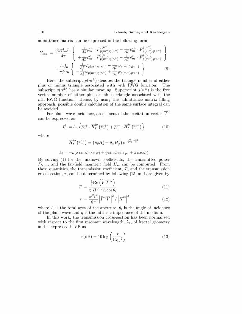
(a) x-polarized incident wave (b) y-polarized incident wave
Figure 10. Transmission coefficient of Sierpinski gasket aperture fordifferent iterations at normal incidence.
(a) x-polarized incident wave (b) y-polarized incident wave
Figure 11. Variation of transmission coefficient of 2nd iteratedSierpinski gasket aperture for different flare angle at normal incidence.
triangle was an equilateral triangle, the response of the aperture for x -and y-polarized incident wave is almost similar.
Next, the flare angle of the triangle was varied. The transmissioncharacteristics of the gasket aperture for three values of flare angles,α = 30◦, α = 45◦ and α = 60◦ for x - and y-polarized incident wavesat normal incidence have been studied and are shown in Fig. 11. Itis evident from Fig. 11(a) that, as the flare angle of gasket aperturedecreases, the transmission coefficient at the first resonant frequencyincreases. This is in line with our expectations, since a similarbehavior was exhibited by a single aperture (Fig. 7(a)). It may bementioned here that a similar variation of the resonant frequencies hasbeen seen for a Sierpinski monopole antenna [25]. The transmissioncoefficient at the second and third resonant frequency decreases with

116 Ghosh, Sinha, and Kartikeyan
the decrease in flare angle and the response for a flare angle of 30◦becomes almost flat for frequencies greater than 6 GHz. However, asshown in Fig. 11(b), for y-polarized incident wave, the fractal propertyremains unchanged, with a upward shift of resonant frequency as theflare angle is decreased. It is because, for y-polarized incident wave,the electric field is perpendicular to the base length and a decrease inflare angle means a smaller base length which corresponds to higherresonant frequencies.
The far-field characteristics of the gasket aperture have beenexpressed in terms of the transmission cross-section. The transmissioncross-section patterns of gasket aperture in two principle planes φ = 0◦and φ = 90◦ for x - and y-polarized incident wave are shown in Fig. 12.It can be seen from the figures that at higher resonant frequencies, thepatterns become more directive and also, side lobes are generated.
(a) x-polarized; φ = 0o cut (b) x-polarized; φ = 90o cut
(c) y-polarized; φ = 0 o cut (d) y-polarized; φ = 90o cut
Figure 12. Transmission cross-section patterns of 2nd iteratedSierpinski gasket aperture at three resonant frequencies with normalincidence.

Progress In Electromagnetics Research B, Vol. 12, 2009 117
(a) Parallel polarization (b) Perpendicular polarization
Figure 13. Variation of transmission coefficient of a triangularaperture for different angles of incidence.
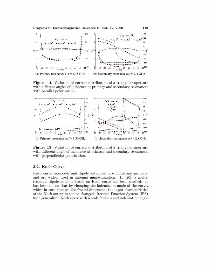
Next, in order to find out the behavior of the aperture for differentincidence angle, the angle of incidence was varied. In this case, thetransmission coefficient is normalized with respect to the incidentpower density at normal incidence rather than the actual power densityat oblique incidence. First, the behavior of a single triangular apertureof dimension w = 120 mm and h = 120 mm was analyzed for differentangles of incidence for both parallel and perpendicular polarizations.The variation of transmission coefficient for different angles of incidenceare shown in Fig. 13. As the angle of incidence is increased, for parallelpolarization, a weak second resonance is generated around 2.4 GHzcorresponding to h
λ = 0.96. On the other hand, the second resonanceappears around 2.8 GHz for perpendicularly polarized incident wavewhich gives w
λ = 1.12. Also, the value of transmission coefficientdecreases as the angle of incidence is increased and this decrementis sharper for perpendicular polarization. In order to get an insightinto this phenomenon, we have plotted the surface current distributionover the triangular aperture. The plots of magnitude and phase ofy-component of current along y = −31.25 cut for parallel polarizationat 1.15 GHz and 2.4 GHz are shown in Fig. 14. It can be seen fromthe current distribution that, at the primary resonant frequency ofthe triangular aperture, the magnitude and phase of My is almostuniform over the entire width of the triangle. Also, it is evident that themagnitude of the current changes very little with the change in angle ofincidence at primary resonance. At the second resonance, the currentdistribution shows a nearly uniform phase distribution for normalincidence. However, as the angle of incidence is varied, the phase of My
changes around the center line of the triangle which causes a resonance.The magnitude of current is well below the magnitude at primary
118 Ghosh, Sinha, and Kartikeyan
resonance which causes a weak response. Similar behavior is obtainedfor perpendicular polarization as seen from Fig. 15. As the angleof incidence is increased, the magnitude of current decreases sharplyfor perpendicular polarization as compared to parallel polarization,which causes a sharp decrease in the value of transmission coefficientat oblique incidence for perpendicular polarization.
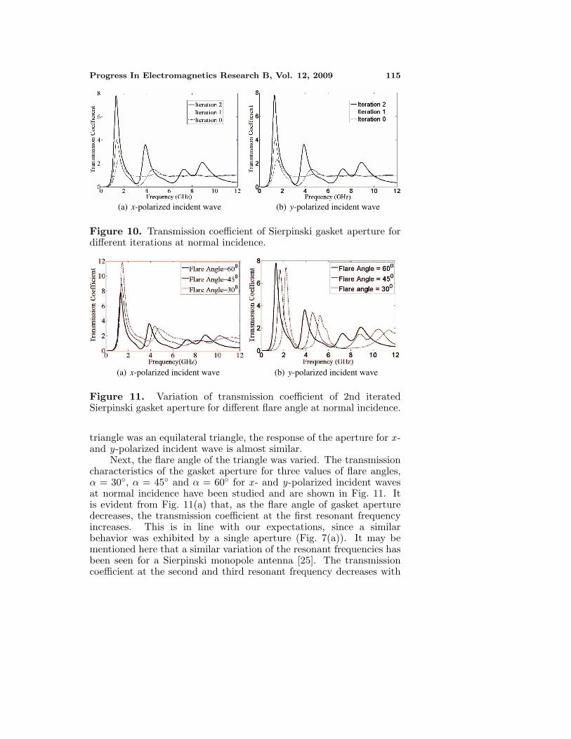
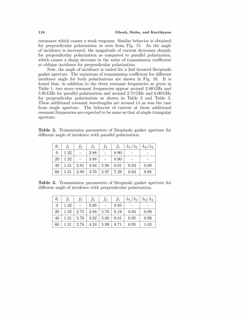
Now, the angle of incidence is varied for a 2nd iterated Sierpinskigasket aperture. The variations of transmission coefficient for differentincidence angle for both polarizations are shown in Fig. 16. It isfound that, in addition to the three resonant frequencies as given inTable 1, two more resonant frequencies appear around 2.80 GHz and5.95 GHz for parallel polarization and around 2.75 GHz and 6.00 GHzfor perpendicular polarization as shown in Table 2 and Table 3.These additional resonant wavelengths are around 1λ as was the casefrom single aperture. The behavior of current at those additionalresonant frequencies are expected to be same as that of single triangularaperture.
Table 2. Transmission parameters of Sierpinski gasket aperture fordifferent angle of incidence with parallel polarization.
θi f1 f2 f3 f4 f5 h1/λ2 h2/λ4
0 1.32 - 3.88 - 8.90 - -20 1.32 - 3.88 - 8.90 - -40 1.31 2.81 3.84 5.98 8.01 0.83 0.8960 1.31 2.80 3.76 5.97 7.29 0.83 0.88
Table 3. Transmission parameters of Sierpinski gasket aperture fordifferent angle of incidence with perpendicular polarization.
θi f1 f2 f3 f4 f5 h1/λ2 h2/λ4
0 1.32 - 3.88 - 8.95 - -20 1.32 2.75 3.88 5.78 8.18 0.94 0.9940 1.31 2.78 3.92 5.80 8.81 0.95 0.9960 1.31 2.78 4.24 5.99 8.71 0.95 1.03
Progress In Electromagnetics Research B, Vol. 12, 2009 119
(a) Primary resonance at f = 1.15 GHz (b) Secondary resonance at f = 2.4 GHz
Figure 14. Variation of current distribution of a triangular aperturewith different angles of incidence at primary and secondary resonanceswith parallel polarization.
(a) Primary resonance at f = 1.30 GHz (b) Secondary resonance at f = 2.8 GHz
Figure 15. Variation of current distribution of a triangular aperturewith different angle of incidence at primary and secondary resonanceswith perpendicular polarization.
3.2. Koch Curve
Koch curve monopole and dipole antennas have multiband propertyand are widely used in antenna miniaturization. In [26], a multi-resonant dipole antenna based on Koch curve has been studied. Ithas been shown that by changing the indentation angle of the curve,which in turn changes the fractal dimension, the input characteristicsof the Koch antennas can be changed. Iterated Function System (IFS)for a generalized Koch curve with a scale factor s and indentation angle

120 Ghosh, Sinha, and Kartikeyan
(a) Parallel polarization (b) Perpendicular polarization
Figure 16. Variation of transmission coefficient of 2nd iteratedSierpinski gasket aperture for different angles of incidence.
θ can be expressed as [26],
W1
(xy
)=
(1s 00 1
s
) (x′
y′
)(15)
W2
(xy
)=
(1s cos θ −1
s sin θ1s sin θ 1
s cos θ
) (x′
y′
)+
(1s
0
)(16)
W3
(xy
)=
( 1s cos θ 1
s sin θ−1
s sin θ 1s cos θ
) (x′
y′
)+
( 12
1s sin θ
)(17)
W4
(xy
)=
(1s 00 1
s
) (x′
y′
)+
( s−1s
0
)(18)
where
s = 2(1 + cos(θ)) (19)
The self-similarity dimension of the curve is given by
D =log 4log s
(20)
Hence, by changing the indentation angle, we can change the fractaldimension. Generalized Koch curve geometries for two indentationangles are shown in Fig. 17.
Here, we have investigated the transmission properties of theKoch fractal slot of varying fractal dimension in an infinite conducting

Progress In Electromagnetics Research B, Vol. 12, 2009 121
(a) Indentation angle = 20 o (b) Indentation angle = 60 o
Figure 17. Koch curve with different indentation angles.
screen illuminated by a plane wave. For the present analysis, we haveconsidered a rectangular slot of length 20 cm along the x-axis andwidth 5 mm along the y-axis as the initiator. A y-polarized wave isassumed to be normally incident on the Koch slot. Fig. 18 shows thetransmission coefficients of a Koch slot of 60◦ indentation angle forthree different iterations. It can be seen that the resonant frequenciesreduce as the order of iteration is increased. This is expected, since thetotal length of the slot increases with the order of iteration althoughthe end-to-end length remains constant at 20 cm. Another factorthat has a strong influence on the value of the resonant frequenciesand the magnitude of transmission coefficient at resonance, is theindentation angle. The variation of the primary resonant frequency(fr1) for the first three iterations is given in Table 4 and the variation
Figure 18. Transmission coeffi-cient of Koch fractal slot for dif-ferent iterations with 60◦ indenta-tion angle.
Figure 19. Variation of trans-mission coefficient with differentindentation angle at primary res-onant frequency of Koch fractalslot of 3rd iteration.
122 Ghosh, Sinha, and Kartikeyan
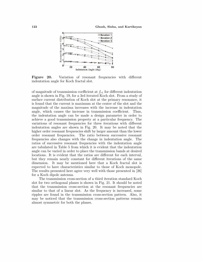
Figure 20. Variation of resonant frequencies with differentindentation angle for Koch fractal slot.
of magnitude of transmission coefficient at fr1 for different indentationangle is shown in Fig. 19, for a 3rd iterated Koch slot. From a study ofsurface current distribution of Koch slot at the primary resonance, itis found that the current is maximum at the center of the slot and themagnitude of the maxima increases with the increase in indentationangle, which causes the increase in transmission coefficient. Thus,the indentation angle can be made a design parameter in order toachieve a good transmission property at a particular frequency. Thevariations of resonant frequencies for three iterations with differentindentation angles are shown in Fig. 20. It may be noted that thehigher order resonant frequencies shift by larger amount than the lowerorder resonant frequencies. The ratio between successive resonantfrequencies also changes with the change in indentation angle. Theratios of successive resonant frequencies with the indentation angleare tabulated in Table 5 from which it is evident that the indentationangle can be varied in order to place the transmission bands at desiredlocations. It is evident that the ratios are different for each interval,but they remain nearly constant for different iterations of the samedimension. It may be mentioned here that a Koch fractal slot isexpected to have characteristics similar to those of Koch monopole.The results presented here agree very well with those presented in [26]for a Koch dipole antenna.
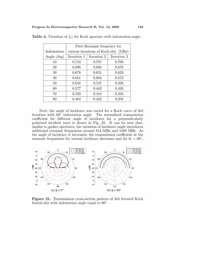
The transmission cross-section of a third iteration standard Kochslot for two orthogonal planes is shown in Fig. 21. It should be notedthat the transmission cross-section at the resonant frequencies aresimilar to that of a linear slot. As the frequency is increased, someripples are found in the transmission cross-section pattern. Also, itmay be noticed that the transmission cross-section patterns remainalmost symmetric for both the planes.
Progress In Electromagnetics Research B, Vol. 12, 2009 123
Table 4. Variation of fr1 for Koch aperture with indentation angle.
First Resonant frequency forIndentation various iterations of Koch slot (GHz)Angle (deg) Iteration 1 Iteration 2 Iteration 3
10 0.710 0.707 0.70620 0.698 0.686 0.67830 0.678 0.651 0.63340 0.651 0.604 0.57350 0.618 0.547 0.50060 0.577 0.482 0.42070 0.529 0.410 0.33580 0.484 0.342 0.258
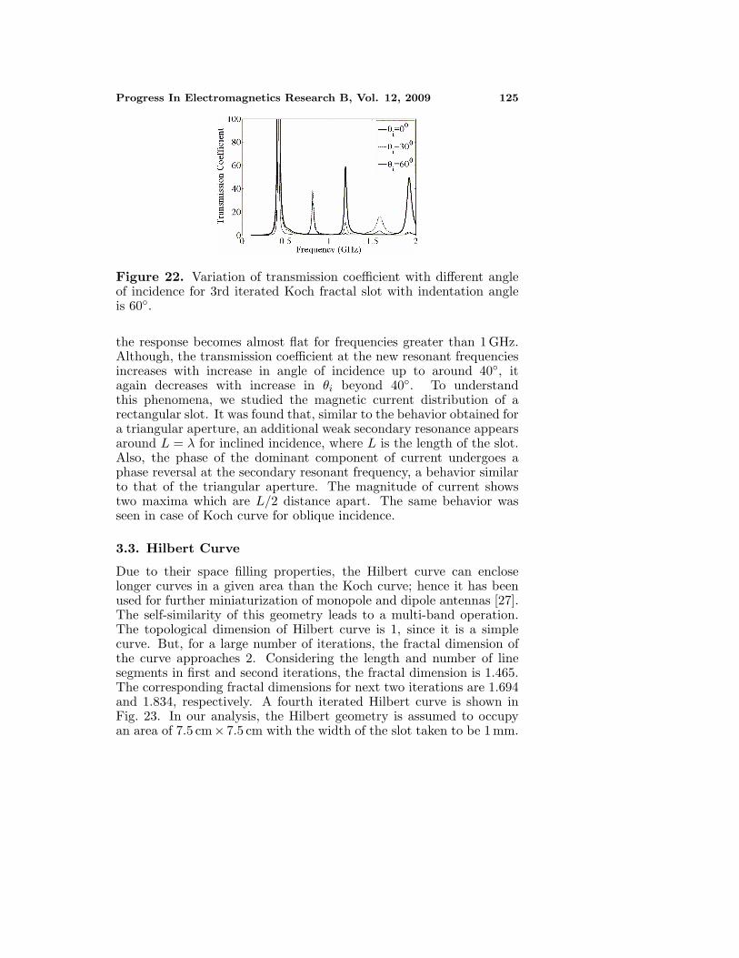
Next, the angle of incidence was varied for a Koch curve of 3rditeration with 60◦ indentation angle. The normalized transmissioncoefficient for different angle of incidence for a perpendicularlypolarized incident wave is shown in Fig. 22. It can be seen that,similar to gasket apertures, the variation of incidence angle introducesadditional resonant frequencies around 814 MHz and 1580 MHz. Asthe angle of incidence is increased, the transmission coefficient at theresonant frequencies for normal incidence decreases and for θi = 60◦,
(a) φ = 0 o (b) φ = 90o
Figure 21. Transmission cross-section pattern of 3rd iterated Kochfractal slot with indentation angle equal to 60◦.

124 Ghosh, Sinha, and Kartikeyan
Table 5. Ratios between successive resonant frequencies of generalizedKoch slot.
IndentationAngle
FractalDimension
FractalIteration
f2/f1 f3/f2 f4/f3
1 3.09 1.68 1.4110 1.006 2 3.08 1.68 1.40
3 3.08 1.68 1.401 3.08 1.68 1.41
20 1.023 2 3.06 1.68 1.403 3.06 1.68 1.401 3.07 1.68 1.41
30 1.053 2 3.04 1.63 1.443 3.03 1.67 1.401 3.05 1.68 1.42
40 1.099 2 3.00 1.67 1.423 2.98 1.65 1.421 3.02 1.67 1.42
50 1.165 2 2.95 1.65 1.403 2.92 1.63 1.391 2.98 1.66 1.42
60 1.262 2 2.88 1.63 1.413 2.83 1.62 1.401 2.94 1.66 1.42
70 1.404 2 2.79 1.63 1.403 2.73 1.60 1.361 2.81 1.68 1.40
80 1.625 2 2.67 1.62 1.363 2.59 1.58 1.34
Progress In Electromagnetics Research B, Vol. 12, 2009 125
Figure 22. Variation of transmission coefficient with different angleof incidence for 3rd iterated Koch fractal slot with indentation angleis 60◦.
the response becomes almost flat for frequencies greater than 1 GHz.Although, the transmission coefficient at the new resonant frequenciesincreases with increase in angle of incidence up to around 40◦, itagain decreases with increase in θi beyond 40◦. To understandthis phenomena, we studied the magnetic current distribution of arectangular slot. It was found that, similar to the behavior obtained fora triangular aperture, an additional weak secondary resonance appearsaround L = λ for inclined incidence, where L is the length of the slot.Also, the phase of the dominant component of current undergoes aphase reversal at the secondary resonant frequency, a behavior similarto that of the triangular aperture. The magnitude of current showstwo maxima which are L/2 distance apart. The same behavior wasseen in case of Koch curve for oblique incidence.
3.3. Hilbert Curve
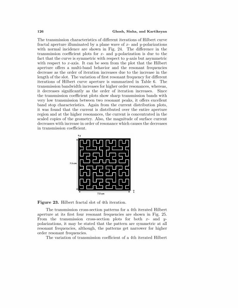
Due to their space filling properties, the Hilbert curve can encloselonger curves in a given area than the Koch curve; hence it has beenused for further miniaturization of monopole and dipole antennas [27].The self-similarity of this geometry leads to a multi-band operation.The topological dimension of Hilbert curve is 1, since it is a simplecurve. But, for a large number of iterations, the fractal dimension ofthe curve approaches 2. Considering the length and number of linesegments in first and second iterations, the fractal dimension is 1.465.The corresponding fractal dimensions for next two iterations are 1.694and 1.834, respectively. A fourth iterated Hilbert curve is shown inFig. 23. In our analysis, the Hilbert geometry is assumed to occupyan area of 7.5 cm× 7.5 cm with the width of the slot taken to be 1 mm.
126 Ghosh, Sinha, and Kartikeyan
The transmission characteristics of different iterations of Hilbert curvefractal aperture illuminated by a plane wave of x - and y-polarizationswith normal incidence are shown in Fig. 24. The difference in thetransmission coefficient plots for x - and y-polarization is due to thefact that the curve is symmetric with respect to y-axis but asymmetricwith respect to x -axis. It can be seen from the plot that the Hilbertaperture offers a multi-band behavior and the resonant frequenciesdecrease as the order of iteration increases due to the increase in thelength of the slot. The variation of first resonant frequency for differentiterations of Hilbert curve aperture is summarized in Table 6. Thetransmission bandwidth increases for higher order resonances, whereas,it decreases significantly as the order of iteration increases. Sincethe transmission coefficient plots show sharp transmission bands withvery low transmission between two resonant peaks, it offers excellentband stop characteristics. Again from the current distribution plots,it was found that the current is distributed over the entire apertureregion and at the higher resonances, the current is concentrated in thescaled copies of the geometry. Also, the magnitude of surface currentdecreases with increase in order of resonance which causes the decreasesin transmission coefficient.
Figure 23. Hilbert fractal slot of 4th iteration.
The transmission cross-section patterns for a 4th iterated Hilbertaperture at its first four resonant frequencies are shown in Fig. 25.From the transmission cross-section plots for both x - and y-polarizations, it may be stated that the pattern are symmetric at allresonant frequencies, although, the patterns get narrower for higherorder resonant frequencies.
The variation of transmission coefficient of a 4th iterated Hilbert

Progress In Electromagnetics Research B, Vol. 12, 2009 127
(a) x-polarized incident wave (b) y-polarized incident wave
Figure 24. Transmission coefficient of Hilbert slot for differentiterations at normal incidence.
Table 6. Primary resonant frequency of Hilbert curve aperture ofdifferent iteration
Primary resonant frequency (GHz)Iteration x-polarized y-polarized
1 1.383 0.6662 0.908 0.4523 0.614 0.3064 0.440.4 0.2172
aperture with angle of incidence is shown in Fig. 26. Again, someadditional resonances occur as the angle of incidence is increased.The transmission coefficients at these additional resonant frequenciesincrease with the increase in angle of incidence. The occurrence ofthese resonance can again be explained in similar manner as in Kochslot from the current distribution which shows additional maxima atinclined incidence. For perpendicular polarization, some additionalresonant frequencies appear but, the transmission coefficients at thesefrequencies are very small as compared to those at the resonantfrequencies for normal incidence. Also, the transmission coefficientat a particular resonant frequency decreases with increase in angleof incidence and the decrease is sharper in case of perpendicularpolarization.

128 Ghosh, Sinha, and Kartikeyan
(a) x-polarized; φ = 0 o cut (b) x-polarized;φ = 90o cut
(c) y-polarized; φ = 0o cut (d) y-polarized; φ = 90o cut
Figure 25. Transmission cross-section pattern of 4th iterated Hilbertslot at the first four resonant frequencies.
(a) Parallel polarization (b) Perpendicular polarization
Figure 26. Variation of transmission coefficient with different angleof incidence of 4th iterated Hilbert slot.

Progress In Electromagnetics Research B, Vol. 12, 2009 129
Figure 27. Sierpinski carpet aperture of 3rd iteration.
3.4. Sierpinski Carpet
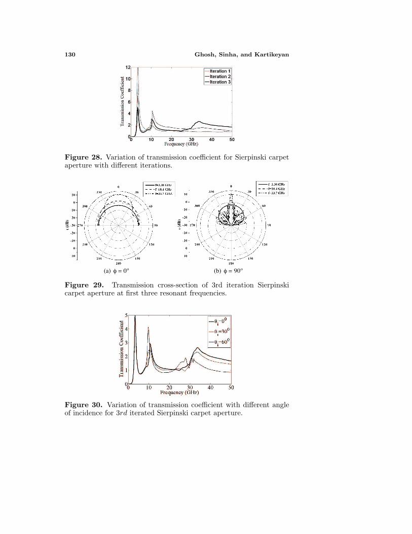
Another fractal that can be used in multi-band antennas and FSSis Sierpinski carpet fractal [9]. The geometry of a third iteratedSierpinski carpet structure is shown in Fig. 27. The dimensionused in the present analysis has an initial rectangular geometryof dimensions 1.2 cm× 12 cm. The transmission characteristics ofdifferent iterations of the fractal aperture for x -polarized incident waveat normal incidence are shown in Fig. 28. Again, it can be notedfrom the plots that the resonant frequency decreases as the order ofiteration increases. Basically, the first iteration consists of a singleaperture of dimension 0.4 cm× 4 cm with the larger dimension alongy direction. The first resonance occurs at a frequency of 3.30 GHzwhose corresponding wavelength is twice the length of the slot in y-direction. In the next iteration, the aperture dimension gets reducedby a factor 3, and hence it is expected to have the second resonantfrequency which is three times the first resonant frequency. Thus, theratio between the successive resonant frequencies is approximately 3.For a 3rd iteration Sierpinski carpet aperture the resonant frequenciesoccurs at 3.3 GHz, 10.4 GHz and 33.7 GHz with frequency ratios asf2/f1 = 3.15 and f3/f2 = 3.24. Hence, the resonant frequencies areseparated by a factor approximately equal to the theoretical value 3.
The transmission cross-section patterns of 3rd iterated Sierpinskicarpet fractal aperture for x -polarized incident wave in two orthogonalplanes are shown in Fig. 29. It can be seen from the plots that themaximum value of transmission cross section increases for higher order
130 Ghosh, Sinha, and Kartikeyan
Figure 28. Variation of transmission coefficient for Sierpinski carpetaperture with different iterations.
(a) φ = 0o (b) φ = 90o
Figure 29. Transmission cross-section of 3rd iteration Sierpinskicarpet aperture at first three resonant frequencies.
Figure 30. Variation of transmission coefficient with different angleof incidence for 3rd iterated Sierpinski carpet aperture.
Progress In Electromagnetics Research B, Vol. 12, 2009 131
resonant frequencies. Also, for ϕ = 90◦ plane, a large number of sidelobes are generated for third resonant frequency.
The effect of variation of incidence angle for parallel polarizationon the behavior of Sierpinski carpet aperture is shown in Fig. 30. It canbe seen from the plot that as the incidence angle is increased, the thirdresonance peak gets distorted and some spurious peaks arise around30 GHz.
3.5. Minkowski Curve
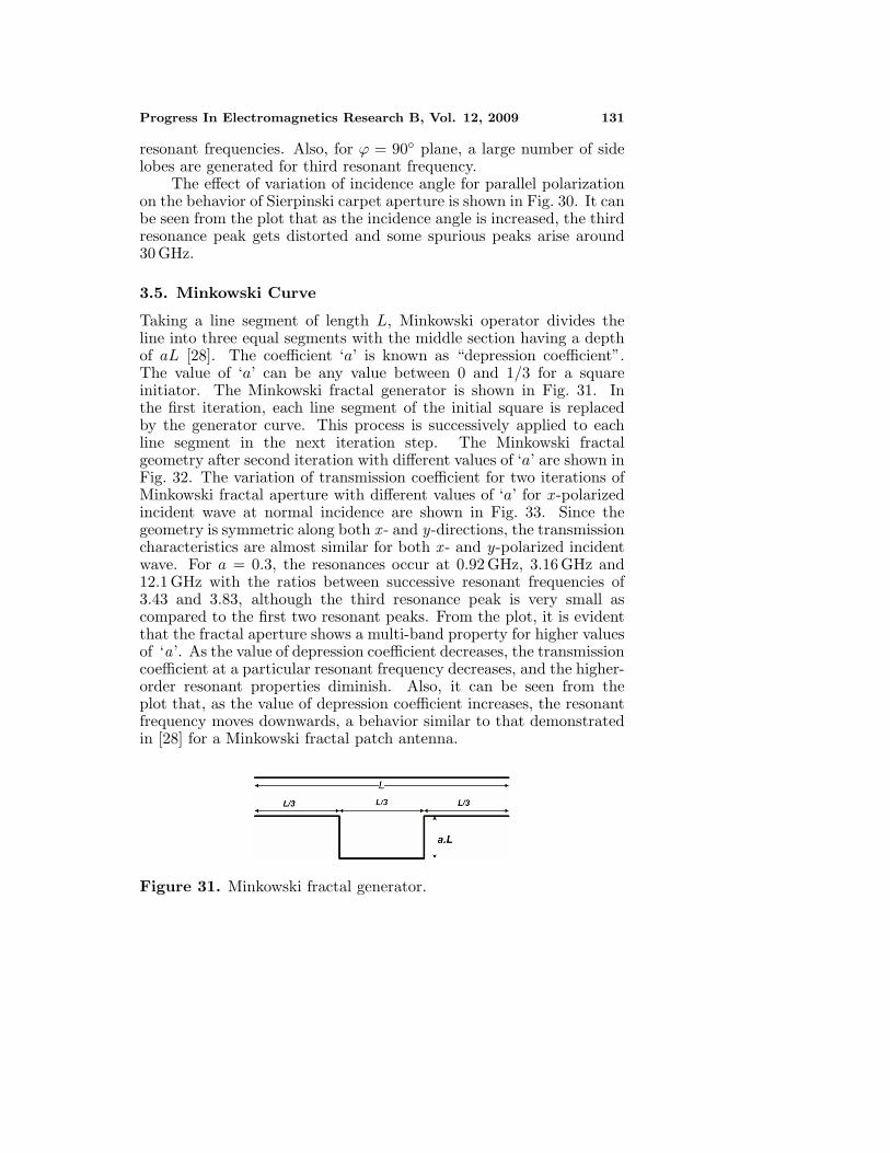
Taking a line segment of length L, Minkowski operator divides theline into three equal segments with the middle section having a depthof aL [28]. The coefficient ‘a’ is known as “depression coefficient”.The value of ‘a’ can be any value between 0 and 1/3 for a squareinitiator. The Minkowski fractal generator is shown in Fig. 31. Inthe first iteration, each line segment of the initial square is replacedby the generator curve. This process is successively applied to eachline segment in the next iteration step. The Minkowski fractalgeometry after second iteration with different values of ‘a’ are shown inFig. 32. The variation of transmission coefficient for two iterations ofMinkowski fractal aperture with different values of ‘a’ for x -polarizedincident wave at normal incidence are shown in Fig. 33. Since thegeometry is symmetric along both x - and y-directions, the transmissioncharacteristics are almost similar for both x - and y-polarized incidentwave. For a = 0.3, the resonances occur at 0.92 GHz, 3.16 GHz and12.1 GHz with the ratios between successive resonant frequencies of3.43 and 3.83, although the third resonance peak is very small ascompared to the first two resonant peaks. From the plot, it is evidentthat the fractal aperture shows a multi-band property for higher valuesof ‘a’. As the value of depression coefficient decreases, the transmissioncoefficient at a particular resonant frequency decreases, and the higher-order resonant properties diminish. Also, it can be seen from theplot that, as the value of depression coefficient increases, the resonantfrequency moves downwards, a behavior similar to that demonstratedin [28] for a Minkowski fractal patch antenna.
Figure 31. Minkowski fractal generator.

132 Ghosh, Sinha, and Kartikeyan
(a) a = 0.3 (b) a = 0.2
(c) a = 0.1
Figure 32. Minkowski fractal geometries after second iteration fordifferent values of depression coefficients.
(a)1st Iteration (b) 2nd Iteration
Figure 33. Transmission coefficient of Minkowski fractal aperturefor two iterations with different depression coefficients for x-polarizedincident wave at normal incidence.

Progress In Electromagnetics Research B, Vol. 12, 2009 133
(a) φ = 0 o (b) φ = 90 o
Figure 34. Transmission cross-section of 2nd iterated Minkowskifractal aperture at three resonant frequencies with a = 0.3 for x -polarized incident wave at normal incidence.
Figure 35. Variation of transmission coefficient with different angleof incidence for 2nd iterated Minkowski aperture.
The transmission cross-section of second iterated Minkowskifractal aperture for a = 0.3 with x -polarized incident wave is shownin Fig. 34. It can be seen from the transmission cross-sectionpatterns that the value of transmission cross-section increases forhigher resonant frequencies, but the number of side lobes also increasesat higher order resonances. Since the geometry is symmetric in x - andy-plane, the cross-section patterns are also symmetric.
The variation of transmission coefficient for different angle ofincidence with a = 0.3 is shown in Fig. 35. The transmissioncoefficients at first and second resonant frequencies get reduced withincrease in angle of incidence and for higher angles of incidence, thethird resonances almost vanishes and hence, the multiband propertyof fractal is lost.

134 Ghosh, Sinha, and Kartikeyan
4. CONCLUSION
Numerical results for a number of fractal shaped apertures in an infiniteconducting screen illuminated by a plane wave have been presentedwhich show the existence of multiple passbands. For a Sierpinskifractal aperture, the bands are separated by a factor 2, which issimilar to that obtained for a Sierpinski monopole antenna. As longas the initial triangle is equilateral, the transmission characteristicsare similar for x- and y-polarized incident wave. Also, it has beenfound that the fractal property of the gasket aperture depends on theflare angle of the triangle as well as on the polarization of incidentwave. The band separation also changes at oblique incidence due tothe generation of some new passbands. Also, it is evident form theresults that the number of passbands equals the number of iterationsfor Sierpinski carpet aperture. However, for Sierpinski gasket aperture,a transmission band is obtained for the initial triangular geometry andfor any number of iterations, say k, the number of passbands are always(k + 1), as was in case of fractal multiband antenna and FSS. Also,it is true for each fractal geometry that the log periodic behavior canbe achieved by using a large number of iterations and since here, weare considering the prefractal geometries, the behavior is quasi logperiodic.
Similar to that of a Koch fractal monopole antenna, the Kochfractal slot also possesses multiband characteristics and the locationof different passbands can be changed by changing the indentationangle. Hilbert curve fractal slots are very efficient for the reductionof resonant frequency, although the bandwidth of passbands decreasessignificantly for higher iterations. It has been found that some newpassbands occur with the increase in angle of incidence for parallelpolarization, whereas, the transmission coefficient at the resonantfrequencies decreases significantly with increase in angle of incidencefor perpendicular polarization. It may be noted that the Hilbertcurve fractal geometry is not strictly self-similar as pointed out in[27], because additional line segments are required to connect the fourscaled and rotated copies. However, the lengths of these additional linesegments are small as compared to the overall length of the fractal,especially when the order of iteration is very large, which makes thegeometry self-similar. For larger order iterations, the self-similaritydimension of the fractal approaches 2 which makes it a true space-filling curve. For lower order iterations, the self-similarity dimensionof the fractal geometry can be much less than 2 [27].
The Sierpinski carpet fractal aperture also offers multiplepassbands with the passbands separated by a factor of 3, equal to
Progress In Electromagnetics Research B, Vol. 12, 2009 135
the self-similarity factor of the geometry. Also, it has been foundthat the variation of incidence angle does not change the transmissioncharacteristics for lower frequencies, but the third resonance getsdistorted. Lastly, it has been shown that the characteristics ofMinkowski fractal depend upon the depression coefficient of theMinkowski operator. The transmission coefficient decreases with theincrease in angle of incidence, although the ratios of successive bandsremain same.
It must also be added here that that the fractals having space-filling properties give rise to enhanced subwavelength transmissionas was seen in [11–14]. For example, the lowest frequency ofHilbert curve aperture is 0.2171 GHz for a y-polarized incident wave,corresponding to a wavelength of 138.12 cm which is many times thelateral dimension of the square which it fills. Since the geometryis not symmetric in both planes, the response of the aperture aredifferent for different polarizations as was also seen in case of H shapedfractal slit [14]. The existence of subwavelength transmission can alsobe found in Koch curve due to their frequency reduction capability.Koch slot was found to have resonant frequencies of 0.484 GHz and0.577 GHz for indentation angles of 80◦ and 60◦, respectively. Thecorresponding wavelengths are 61.98 cm and 51.99 cm which are muchlarger than the Koch curve length. Since, the increase in indentationangle causes the resonant frequency to shift downward and also, themagnitude of transmission coefficient increases, it can be said thatat higher indentation angle there is a more enhanced subwavelengthtransmission. For Minkowski fractal aperture, the lowest resonantfrequency is 0.92 GHz for a 2nd iterated fractal with a = 0.3,corresponding to a wavelength of 32.6 cm. Again the wavelength ismuch larger than the lateral dimension of fractal geometry.
On the other hand, self similar structures like Sierpinski gasket andSierpinski carpet do not exhibit subwavelength transmission, since forthese structures the reduction in the first resonance frequency is verysmall for higher order iterations.
REFERENCES
1. Rahmat-Samii, Y. and R. Mittra, “Electromagnetic couplingthrough small apertures in a conducting screen,” IEEE Trans.Antennas Propagat., Vol. 25, 180–187, Mar. 1977.
2. Sarkar, T. K., M. F. Costa, I. Chin-Lin, and R. F. Harrington,“Electromagnetic transmission through mesh covered aperturesand aperture arrays of apertures in a conducting screen,” IEEETrans. Antennas Propagat., Vol. 32, 908–913, Sept. 1984.
136 Ghosh, Sinha, and Kartikeyan
3. Andersson, T., “Moment-Method calculations on apertures usingbasis singular function,” IEEE Trans. Antennas Propagat.,Vol. 41, 1709–1716, Dec. 1993.
4. Park, H. and H. J. Eom, “Electromagnetic scattering frommultiple rectangular apertures in a thick conducting screen,”IEEE Trans. Antennas Propagat., Vol. 47, No. 6, 1056–1060,June 1999.
5. Park, Y. B. and H. J. Eom, “Electromagnetic transmissionthrough multiple circular apertures in a thick conducting plane,”IEEE Trans. Antennas Propagat., Vol. 52, No. 4, 1049–1055,Apr. 2004.
6. Chen, C. C., “Transmission of microwave through perforated flatplates of finite thickness,” IEEE Trans. Microwave Theory Tech.,Vol. 21, 1–6, Jan. 1973.
7. Werner, D. H. and R. Mittra (eds.), Frontiers in Electromagnetics,Chapter 1–3, Piscataway, NJ, IEEE Press, 2000.
8. Romeu, J. and Y. Rahmat-Samii, “Fractal FSS: A novel dual-bandfrequency selective surface,” IEEE Trans. Antennas Propagat.,Vol. 48, 1097–1105, July 2000
9. Gianvittorio, J. P., J. Romeu, S. Blanch, and Y. Rahmat-Samii, “Self-similar prefractal frequency selective surfaces formultiband and dual polarized applications,” IEEE Trans.Antennas Propagat., Vol. 51, 3088–3096, Nov. 2003.
10. McVay, J., N. Engheta, and A. Hoorfar, “High impedancemetamaterial surfaces using Hilbert curve inclusions,” IEEEMicrowave and Wireless Components Letters, Vol. 14, 130–132,Mar. 2004.
11. Wen, W., L. Zhou, J. Li, W. Ge, C. T. Chan and P. Sheng,“Subwavelength photonic band gaps from planar fractals,”Physical Review Lett., vol. 89, No. 22, 223901, Nov. 2002.
12. Zhou, L., C. T. Chan, and P. Sheng, “Theoritical studies on thetransmission and reflection properties of metallic planar fractals,”J. Phys. D: Applied Phys., Vol. 37, 368–373, 2004.
13. Hou, B., G. Xu, and W. Wen, “Tunable band gap properties ofplanar metallic fractals,” J. Appl. Phys., Vol. 95, No. 6, 3231–3233,Mar. 2004.
14. Wen, W., L. Zhou, B. Hou, C. T. Chan, and P. Sheng, “Resonanttransmission of microwaves through subwavelength fractal slits ina metallic plate,” Physical Review B72, 153406, 2005.
15. Harrington, R. F. and J. R. Mautz, “A generalized networkformulation for aperture problems,” IEEE Trans. Antennas

Progress In Electromagnetics Research B, Vol. 12, 2009 137
Propagat., Vol. 24, 870–873, Nov. 1976.16. Rao, S. M., D. R. Wilton, and A. W. Glisson, “Electromagnetic
scattering by surfaces of arbitrary shape,” IEEE Trans. AntennasPropagat., Vol. 30, 409–418, May 1982.
17. Chin-Lin, I. and R. F. Harrington, “Electromagnetic transmissionthrough an aperture of arbitrary shape in a conducting screen,”Tech Rep-82-5 on Contract N00014-76-C-0025, Syracuse Univ.,Apr. 1982.
18. Wilton, D. R., S. M. Rao, A. W. Glisson, D. H. Schaubert,O. M. Al-Bundak, and C. M. Butler, “Potential integralsfor uniform and linear source distributions on polygonal andpolyhedral domains,” IEEE Trans. Antennas Propagat., Vol. 32,276–281, Mar. 1984.
19. Graglia, R. D., “On the numerical integration of the linear shapefunctions times the 3D Green’s function or its gradient on a planetriangle,” IEEE Trans. Antennas Propagat., Vol. 41, 1448–1455,Oct. 1993.
20. Eibert, T. F. and V. Hansen, “On the calculation of potentialintegrals for linear source distributions on triangular domains,”IEEE Trans. Antennas Propagat., Vol. 43, 1499–1502, Dec. 1995.
21. Rossi, L. and P. J. Cullen, “On the fully numerical evaluationof the linear shape function times 3D Green’s function on a planetriangle,” IEEE Trans. Microwave Theory Tech., Vol. 47, 398–402,Apr. 1999.
22. Khayat, M. A. and D. R. Wilton, “Numerical evaluation ofsingular and near-singular potential integrals,” IEEE Trans.Antennas Propagat., Vol. 53, 3180–3190, Oct. 2005.
23. Peitgen, H. O., H. Jurgens, and D. Saupe, Chaos and Fractals,New Frontiers in Science, Springer-Verlag, New York, 1992.
24. Puente, C., J. Romeu, R. Pous, and A. Cardama, “On thebehavior of Sierpinski multiband fractal antenna,” IEEE Trans.Antennas Propagat., Vol. 46, 517–524, Apr. 1998.
25. Baliarda, C. P., C. B. Borau, M. N. Rodero, and J. Romeu, “Aniterative model for fractal antennas: Application to the Sierpinskigasket antenna,” IEEE Trans. Antennas Propagat., Vol. 48, 713–719, May 2000.
26. Vinoy, K. J., J. K. Abraham, and V. K. Varadan, “On therelationship between fractal dimension and the performance ofmulti-resonant dipole antennas using Koch curves,” IEEE Trans.Antennas Propagat., Vol. 51, 2296–2303, Sept. 2003.
27. Vinoy, K. J., K. A. Jose, V. K. Varadan, and V. V. Varadan,

138 Ghosh, Sinha, and Kartikeyan
“Hilbert curve fractal antenna: A small resonant antenna forVHF/UHF applications,” Microwave and Optical TechnologyLetters, Vol. 29, 215–219, 2001.
28. Ataeiseresht, R., C. Ghobadi, and J. Nourinia, “A novel analysisof Minkowski fractal microstrip patch antenna,” Journal ofElectromagnetic Waves and Applications, Vol. 20, No. 8, 1115–1127, 2006.