
phy-layer techniques utilizing distributed apertures
193
SECURE COMMUNICATIONS: PHY-LAYER TECHNIQUES UTILIZING DISTRIBUTED APERTURES Dissertation Submitted to The School of Engineering of the UNIVERSITY OF DAYTON In Partial Fulfillment of the Requirements for The Degree of Doctor of Philosophy in Engineering By Devin William Spatz Dayton, Ohio May, 2020
-
Upload
khangminh22 -
Category
Documents
-
view
1 -
download
0
Transcript of phy-layer techniques utilizing distributed apertures
SECURE COMMUNICATIONS: PHY-LAYER TECHNIQUES UTILIZING
DISTRIBUTED APERTURES
Dissertation
Submitted to
The School of Engineering of the
UNIVERSITY OF DAYTON
In Partial Fulfillment of the Requirements for
The Degree of
Doctor of Philosophy in Engineering
By
Devin William Spatz
Dayton, Ohio
May, 2020
lwallace1
Thesis/dissertation approval

SECURE COMMUNICATIONS: PHY-LAYER TECHNIQUES UTILIZING
DISTRIBUTED APERTURES
Name: Spatz, Devin William
APPROVED BY:
Michael C. Wicks, Ph.D.Advisory Committee ChairmanProfessor Emeritus, Electrical andComputer Engineering
Eric J. Balster, Ph.D.Advisory CommitteeAssociate Professor and Chair,Electrical and Computer Engineering
Guru Subramanyam, Ph.D.Committee MemberProfessor, Electrical & ComputerEngineering
Lorenzo Lo Monte, Ph.D.Committee MemberChief Scientist, TelephonicsCorporation
Robert J. Wilkens, Ph.D., P.E.Associate Dean for Research and InnovationProfessorSchool of Engineering
Eddy M. Rojas, Ph.D., M.A., P.E.Dean, School of Engineering
ii

© Copyright by
Devin William Spatz
All rights reserved
2020

ABSTRACT
SECURE COMMUNICATIONS: PHY-LAYER TECHNIQUES UTILIZING
DISTRIBUTED APERTURES
Name: Spatz, Devin William
University of Dayton
Advisor: Dr. Michael C. Wicks
Directional modulation is a physical (PHY) layer security technique which corrupts the
modulation format received at non-intended receiver angles while preserving the communi-
cation modulation format to an intended receiver. The current state-of-the-art in directional
modulation techniques is limited in that information content, however corrupted, remains
persistent at all angles and spatial security can only be achieved in angle, but not in range.
The spatial diversity afforded through distributed aperture antennas enables the extension
of the state-of-the-art in directional modulation technology by fundamentally altering the
incident information content as a function of spatial position and enabling limited reception
of information content over a region in range and angle. The concept of a spatial ”coher-
ence basket” is established in this manuscript through near-field propagation modeling and
spatio-temporal simulations to describe the information reception region which can be cre-
ated through distributed aperture design. Concept effectiveness is demonstrated for digital
communications through modeling and simulation and a novel hardware implementation
for distributed aperture technology is developed and experimentally demonstrated using
Software Defined Radio (SDR) hardware.
iii

Dedicated to my mother Teresa Spatz
iv

ACKNOWLEDGMENTS
I would like to express my sincere gratitude to my committee chair, Dr Michael Wicks,
for his guidance and support throughout my doctoral program. It was through his encour-
agement that I chose to pursue a doctorate and discover new research areas. He has been a
great mentor to me both academically and professionally throughout my time as a graduate
student. Furthermore, I would like to thank Dr Guru Subramanyam, Dr Eric Balster, and
Dr Lorenzo Lo Monte for serving on my doctoral committee. As past advisers and mentors
in my undergraduate and masters studies, I have each of my committee members to thank
for the engineer and researcher that I have become.
Furthermore, I want to acknowledge my family and friends for their never-ending sup-
port. I owe a great thanks to my good friend and colleague Devin Smarra for whom I
have worked alongside for many years as a fellow student and co-worker. Finally, I want
to acknowledge my fiancee Emily. She has been completely supportive of me through all of
the highs and lows of my academic career and I couldn’t have done this without her.
v
TABLE OF CONTENTS
ABSTRACT . . . . . . . . . . . . . . . . . . . . . . . . . . . . . . . . . . . . . . . . iii
DEDICATION . . . . . . . . . . . . . . . . . . . . . . . . . . . . . . . . . . . . . . . iv
ACKNOWLEDGMENTS . . . . . . . . . . . . . . . . . . . . . . . . . . . . . . . . . v
LIST OF FIGURES . . . . . . . . . . . . . . . . . . . . . . . . . . . . . . . . . . . . viii
LIST OF TABLES . . . . . . . . . . . . . . . . . . . . . . . . . . . . . . . . . . . . . xiii
CHAPTER I. INTRODUCTION . . . . . . . . . . . . . . . . . . . . . . . . . . . 1
1.1 Objectives . . . . . . . . . . . . . . . . . . . . . . . . . . . . . . . . . . . 31.2 Contributions . . . . . . . . . . . . . . . . . . . . . . . . . . . . . . . . . . 41.3 Outline . . . . . . . . . . . . . . . . . . . . . . . . . . . . . . . . . . . . . 5
CHAPTER II. LITERATURE REVIEW . . . . . . . . . . . . . . . . . . . . . . . 6
2.1 Secure Multi-User Communications . . . . . . . . . . . . . . . . . . . . . 62.1.1 Physical (PHY) Layer Security Techniques . . . . . . . . . . . . . 72.1.2 Directional Modulation . . . . . . . . . . . . . . . . . . . . . . . . 8
2.2 Antenna Array Technologies . . . . . . . . . . . . . . . . . . . . . . . . . 112.2.1 Distributed Apertures . . . . . . . . . . . . . . . . . . . . . . . . . 112.2.2 Frequency Diverse Array (FDA) . . . . . . . . . . . . . . . . . . . 14
2.3 Radar Concepts . . . . . . . . . . . . . . . . . . . . . . . . . . . . . . . . 152.3.1 Multi-Input Multiple-Output (MIMO) Radar . . . . . . . . . . . . 152.3.2 Orthogonal Netted Radar Systems (ONRS) . . . . . . . . . . . . . 16
2.4 Motivating Technologies . . . . . . . . . . . . . . . . . . . . . . . . . . . . 17
CHAPTER III. DISTRIBUTED APERTURES . . . . . . . . . . . . . . . . . . . . 21
3.1 Far-Field Distributed Aperture Analysis . . . . . . . . . . . . . . . . . . . 223.1.1 Mathematical Background . . . . . . . . . . . . . . . . . . . . . . 243.1.2 Array Factor Pattern Synthesis . . . . . . . . . . . . . . . . . . . . 28
3.2 Near-Field Distributed Aperture Analysis . . . . . . . . . . . . . . . . . . 363.2.1 Near-Field Array Factor Pattern . . . . . . . . . . . . . . . . . . . 373.2.2 Aperture True-Time Delay . . . . . . . . . . . . . . . . . . . . . . 403.2.3 Distributed Aperture Waveforms (DAWs) . . . . . . . . . . . . . . 42
3.3 Coherence Basket Concept . . . . . . . . . . . . . . . . . . . . . . . . . . 463.3.1 Information Content Modeling . . . . . . . . . . . . . . . . . . . . 483.3.2 Signal Bandwidth vs. Aperture Baseline . . . . . . . . . . . . . . 543.3.3 Coherence Basket Analysis . . . . . . . . . . . . . . . . . . . . . . 59
3.4 Application to PHY Layer Security . . . . . . . . . . . . . . . . . . . . . 763.4.1 Near-Field / Far-Field Reception Regions . . . . . . . . . . . . . . 773.4.2 Aperture Weighting Methods . . . . . . . . . . . . . . . . . . . . . 783.4.3 Sub-Aperture Array Factor Pattern Variance . . . . . . . . . . . . 80
CHAPTER IV. DIRECTIONAL MODULATION . . . . . . . . . . . . . . . . . . 83
4.1 Overview of Waveform Diversity . . . . . . . . . . . . . . . . . . . . . . . 84
vi

4.2 Communications Modulation Techniques . . . . . . . . . . . . . . . . . . 864.2.1 Amplitude-Shift Keying (ASK) Modulation . . . . . . . . . . . . . 864.2.2 Phase-Shift Keying (PSK) Modulation . . . . . . . . . . . . . . . 894.2.3 Frequency Shift Keying (FSK) Modulation . . . . . . . . . . . . . 91
4.3 Distributed Coherent Communications . . . . . . . . . . . . . . . . . . . . 934.3.1 Multi-Transmitter Symbol Interference . . . . . . . . . . . . . . . 954.3.2 Spatial Symbol Interference . . . . . . . . . . . . . . . . . . . . . . 994.3.3 Communications Coherence Basket . . . . . . . . . . . . . . . . . 1014.3.4 PHY Layer Security Considerations for Communications . . . . . 103
4.4 Simulation Methodology & Results . . . . . . . . . . . . . . . . . . . . . . 1054.4.1 Communications System Implementation . . . . . . . . . . . . . . 1064.4.2 Parametric Studies . . . . . . . . . . . . . . . . . . . . . . . . . . . 1154.4.3 Angle Study . . . . . . . . . . . . . . . . . . . . . . . . . . . . . . 1174.4.4 Range Study . . . . . . . . . . . . . . . . . . . . . . . . . . . . . . 1204.4.5 Discussion . . . . . . . . . . . . . . . . . . . . . . . . . . . . . . . 123
CHAPTER V. EXPERIMENTATION ARCHITECTURE & IMPLEMENTATION 124
5.1 System Architecture . . . . . . . . . . . . . . . . . . . . . . . . . . . . . . 1245.1.1 Software Defined Radio (SDR) Technology . . . . . . . . . . . . . 1265.1.2 Hardware Architecture . . . . . . . . . . . . . . . . . . . . . . . . 1295.1.3 Software Architecture . . . . . . . . . . . . . . . . . . . . . . . . . 130
5.2 Calibration Overview . . . . . . . . . . . . . . . . . . . . . . . . . . . . . 1335.2.1 Relative Delay . . . . . . . . . . . . . . . . . . . . . . . . . . . . . 1345.2.2 Phase Coherency . . . . . . . . . . . . . . . . . . . . . . . . . . . . 1355.2.3 Amplitude Imbalances . . . . . . . . . . . . . . . . . . . . . . . . . 1375.2.4 Sources of Timing and Phase Error . . . . . . . . . . . . . . . . . 1375.2.5 Calibration Architectures . . . . . . . . . . . . . . . . . . . . . . . 1395.2.6 Algorithm Implementation . . . . . . . . . . . . . . . . . . . . . . 141
5.3 Experimental System Implementation . . . . . . . . . . . . . . . . . . . . 1465.3.1 Hardware Configuration . . . . . . . . . . . . . . . . . . . . . . . . 1475.3.2 Software Implementation . . . . . . . . . . . . . . . . . . . . . . . 1485.3.3 System Prototype . . . . . . . . . . . . . . . . . . . . . . . . . . . 159
5.4 Experimental Procedure & Results . . . . . . . . . . . . . . . . . . . . . . 1605.4.1 Simulation Loop-Back Experiment . . . . . . . . . . . . . . . . . . 1605.4.2 Hardware Loop-Back Experiment . . . . . . . . . . . . . . . . . . 1665.4.3 Over-the-Air Experiment . . . . . . . . . . . . . . . . . . . . . . . 1695.4.4 Experimental Testing Limitations . . . . . . . . . . . . . . . . . . 171
CHAPTER VI. SUMMARY AND FUTURE WORK . . . . . . . . . . . . . . . . 172
6.1 Novel Contributions . . . . . . . . . . . . . . . . . . . . . . . . . . . . . . 1736.2 Future Work . . . . . . . . . . . . . . . . . . . . . . . . . . . . . . . . . . 174
BIBLIOGRAPHY . . . . . . . . . . . . . . . . . . . . . . . . . . . . . . . . . . . . . 176
vii
LIST OF FIGURES
2.1 Displaced Phase Center Aperture (DPCA) . . . . . . . . . . . . . . . . . . . . . 18
3.1 Motivational Concept for Distributed Aperture based PHY Layer Security . . . 21
3.2 2-Element ULA: Aperture Geometry Visualization . . . . . . . . . . . . . . . . 29
3.3 2-Element ULA: Array Factor Pattern - Rectangular Plot . . . . . . . . . . . . 29
3.4 2-Element ULA: Array Factor Pattern - Polar Plot . . . . . . . . . . . . . . . . 30
3.5 2-Element ULA: Array Factor Pattern - 3D Visualization . . . . . . . . . . . . 30
3.6 5-Element ULA: Array Factor Pattern - Polar Plot . . . . . . . . . . . . . . . . 31
3.7 5-Element ULA: Array Factor Pattern - Polar Plot (Nulling at 11.5 Degrees) . 31
3.8 5-Element ULA: Array Factor Pattern - Polar Plot (Nulling at 23.6 Degrees) . 32
3.9 5-Element ULA: Array Factor Pattern - Polar Plot (Reinforcement at 25.0 Degrees) 32
3.10 1-D Linear Geometry Array Factor Pattern (Theta Cut) . . . . . . . . . . . . . 34
3.11 1-D Squared Geometry Array Factor Pattern (Theta Cut) . . . . . . . . . . . . 34
3.12 1-D Inverse Exponential Geometry Array Factor Pattern (Theta Cut) . . . . . 35
3.13 2-D Array Pattern Geometries . . . . . . . . . . . . . . . . . . . . . . . . . . . 35
3.14 2-D Geometry Based Array Factor Patterns . . . . . . . . . . . . . . . . . . . . 36
3.15 Spatial Signal Strength for Isotropically Radiated Sinusoids at 200 m . . . . . . 38
3.16 Spatial Signal Strength for Isotropically Radiated Sinusoids at 2 km . . . . . . 39
3.17 Spatial Signal Strength for Isotropically Radiated Sinusoids at 20 km . . . . . . 39
3.18 Distributed Aperture Waveform Realizations of Sinusoidal Source Waveform . 44
3.19 Distributed Aperture Waveform Realizations of LFM Source Waveform . . . . 45
3.20 Coherence Basket: Bandwidth = 1 GHz, Aperture Element Positions = (-50 m,
0 m), (0 m, 0 m), (50 m, 0 m), Observation Distance = 20 m . . . . . . . . . . 49
viii

3.21 Coherence Basket: Bandwidth = 1 GHz, Aperture Element Positions = (-50 m,
0 m), (0 m, 0 m), (50 m, 0 m), Observation Distance = 40 m . . . . . . . . . . 50
3.22 Coherence Basket: Bandwidth = 10 MHz, Aperture Element Positions = (-50
m, 0 m), (0 m, 0 m), (50 m, 0 m), Observation Distance = 40 m . . . . . . . . 51
3.23 Coherence Basket: Bandwidth = 10 MHz, Aperture Element Positions = (-50
m, 0 m), (0 m, 0 m), (50 m, 0 m), Observation Distance = 60 m . . . . . . . . 52
3.24 Coherence Basket: Bandwidth = 10 MHz, Aperture Element Positions = (-50
m, 0 m), (0 m, 0 m), (50 m, 0 m) . . . . . . . . . . . . . . . . . . . . . . . . . . 53
3.25 Coherence Basket: Bandwidth = 13 MHz, Aperture Element Positions = (-50
m, 0 m), (0 m, 0 m), (50 m, 0 m), Observation Distance = 60 m . . . . . . . . 55
3.26 Coherence Basket: Bandwidth = 13 MHz, Aperture Element Positions = (-50
m, 0 m), (0 m, 0 m), (50 m, 0 m) . . . . . . . . . . . . . . . . . . . . . . . . . . 56
3.27 Coherence Basket: Bandwidth = 10 MHz, Aperture Element Positions = (-60
m, 0 m), (0 m, 0 m), (60 m, 0 m), Observation Distance = 60 m . . . . . . . . 57
3.28 Coherence Basket: Bandwidth = 10 MHz, Aperture Element Positions = (-60
m, 0 m), (0 m, 0 m), (60 m, 0 m) . . . . . . . . . . . . . . . . . . . . . . . . . . 58
3.29 Coherence Basket: Bandwidth = 25 MHz, Aperture Element Positions = (-200
m, 0 m), (0 m, 0 m), (200 m, 0 m), Coherence Location = (0 m, 500 m) . . . . 61
3.30 Coherence Basket: Bandwidth = 25 MHz, Aperture Element Positions = (-200
m, 0 m), (0 m, 0 m), (200 m, 0 m), Coherence Location = (171 m, 470 m) . . . 62
3.31 Coherence Basket: Bandwidth = 25 MHz, Aperture Element Positions = (-200
m, 0 m), (0 m, 0 m), (200 m, 0 m), Coherence Location = (321 m, 383 m) . . . 63
3.32 Coherence Basket: Bandwidth = 25 MHz, Aperture Element Positions = (-200
m, 0 m), (0 m, 0 m), (200 m, 0 m), Coherence Location = (433 m, 250 m) . . . 64
3.33 Coherence Basket: Bandwidth = 25 MHz, Aperture Element Positions = (-200
m, -200 m), (200 m, -200 m), (-200 m, 200 m), (200 m, 200 m), Coherence
Location = (0 m, 700 m) . . . . . . . . . . . . . . . . . . . . . . . . . . . . . . 66
3.34 Coherence Basket: Bandwidth = 25 MHz, Aperture Element Positions = (-200
m, -200 m), (200 m, -200 m), (-200 m, 200 m), (200 m, 200 m), Coherence
Location = (606 m, 350 m) . . . . . . . . . . . . . . . . . . . . . . . . . . . . . 67
ix
3.35 Coherence Basket: Bandwidth = 25 MHz, Aperture Element Positions = (-200
m, -200 m), (200 m, -200 m), (-100 m, 200 m), (100 m, 200 m), Coherence
Location = (0 m, 700 m) . . . . . . . . . . . . . . . . . . . . . . . . . . . . . . 68
3.36 Coherence Basket: Bandwidth = 25 MHz, Aperture Element Positions = (-200
m, -200 m), (200 m, -200 m), (-100 m, 200 m), (100 m, 200 m), Coherence
Location = (606 m, 350 m) . . . . . . . . . . . . . . . . . . . . . . . . . . . . . 69
3.37 Coherence Basket: Bandwidth = 25 MHz, Aperture Element Positions = (43.7
m, -91.2 m), (-196.1 m, -192.3 m), (85.1 m, 180.6 m), (-74.2 m, 87.9 m), Coher-
ence Location = (600 m, 600 m) . . . . . . . . . . . . . . . . . . . . . . . . . . 71
3.38 Coherence Basket: Bandwidth = 25 MHz, Aperture Element Positions = (-107.6
m, 173.8 m), (77.4 m, 5.4 m), (-95.3 m, 24.2 m), (12.5 m, -103.4 m), Coherence
Location = (600 m, 600 m) . . . . . . . . . . . . . . . . . . . . . . . . . . . . . 72
3.39 Coherence Basket: Bandwidth = 25 MHz, Aperture Element Positions = (-171.4
m, -123.1 m), (-280.1 m, -266.1 m), (201.4 m, -263.8 m), (105.9 m, -191.5 m),
Coherence Location = (600 m, 600 m) . . . . . . . . . . . . . . . . . . . . . . . 73
3.40 Coherence Basket: Bandwidth = 25 MHz, Aperture Element Positions = (-
169.1 m, 133.3 m), (-298.9 m, 39.7 m), (-3.6 m, 241.4 m), (-203.5 m, 149.0 m),
Coherence Location = (600 m, 600 m) . . . . . . . . . . . . . . . . . . . . . . . 74
3.41 Array Pattern Amplitude Variations from Modified Weighting Vector . . . . . 80
3.42 Array Factor Amplitude Maximum for On-Off Excitation of Elements . . . . . 82
4.1 Motivational Concept for Directional Modulation based Communications . . . 83
4.2 BPSK Symbol Interference: No Interference (Left), 2-Signal Interference (Cen-
ter), 3-Signal Interference (Right) . . . . . . . . . . . . . . . . . . . . . . . . . . 97
4.3 QPSK Symbol Interference: No Interference (Left), 2-Signal Interference (Cen-
ter), 3-Signal Interference (Right) . . . . . . . . . . . . . . . . . . . . . . . . . . 98
4.4 Symbol Alignment (2 Aperture Elements, 2 Samples per Symbol) . . . . . . . . 99
4.5 Symbol Alignment (2 Aperture Elements, 3 Samples per Symbol) . . . . . . . . 100
4.6 Symbol Alignment (3 Aperture Elements, 2 Samples per Symbol) . . . . . . . . 100
4.7 Symbol Alignment (3 Aperture Elements, 3 Samples per Symbol) . . . . . . . . 101
4.8 PHY-Layer Simulation Architecture in GNU Radio . . . . . . . . . . . . . . . . 107
x

4.9 Preamble Sequence Detection (30% BER) . . . . . . . . . . . . . . . . . . . . . 115
4.10 Distributed Coherence Communications System Simulator Flowgraph . . . . . 117
4.11 Angle Study: BPSK Modulation, BW = 50 MHz, SPS = 1, SNR = 20 dB,
Aperture Element Locations = (-200 m, 0 m), (-66.67 m, 0 m), (66.67 m, 0 m),
and (200 m, 0 m), Coherence Location = (321 m, 383 m) . . . . . . . . . . . . 118
4.12 Angle Study: QPSK Modulation, BW = 50 MHz, SPS = 1, SNR = 20 dB,
Aperture Element Locations = (-200 m, 0 m), (-66.67 m, 0 m), (66.67 m, 0 m),
and (200 m, 0 m), Coherence Location = (321 m, 383 m) . . . . . . . . . . . . 119
4.13 Range Study: BPSK Modulation, BW = 50 MHz, SPS = 1, SNR = 20 dB,
Aperture Element Locations = (-200 m, 0 m), (-66.67 m, 0 m), (66.67 m, 0 m),
and (200 m, 0 m), Coherence Location = (321 m, 383 m) . . . . . . . . . . . . 121
4.14 Range Study: QPSK Modulation, BW = 50 MHz, SPS = 1, SNR = 20 dB,
Aperture Element Locations = (-200 m, 0 m), (-66.67 m, 0 m), (66.67 m, 0 m),
and (200 m, 0 m), Coherence Location = (321 m, 383 m) . . . . . . . . . . . . 122
5.1 Conceptual Model . . . . . . . . . . . . . . . . . . . . . . . . . . . . . . . . . . 125
5.2 Distributed Processing Architecture . . . . . . . . . . . . . . . . . . . . . . . . 131
5.3 Relative Delayed Signals . . . . . . . . . . . . . . . . . . . . . . . . . . . . . . . 135
5.4 Incoherent Sinusoidal Signals . . . . . . . . . . . . . . . . . . . . . . . . . . . . 136
5.5 GNU Radio: Matched Filter Implementation . . . . . . . . . . . . . . . . . . . 150
5.6 GNU Radio: Calibration Receiver Flowgraph . . . . . . . . . . . . . . . . . . . 151
5.7 GNU Radio: Coherence Parameter Update Implementation . . . . . . . . . . . 153
5.8 GNU Radio: Stream Multiplexer Implementation . . . . . . . . . . . . . . . . . 155
5.9 TX Distributed Aperture . . . . . . . . . . . . . . . . . . . . . . . . . . . . . . 160
5.10 Incoherent Operation Pre-Calibration . . . . . . . . . . . . . . . . . . . . . . . 162
5.11 Coherent Operation Post-Calibration . . . . . . . . . . . . . . . . . . . . . . . . 163
5.12 Multi-Channel Incoherent Operation Pre-Calibration . . . . . . . . . . . . . . . 165
5.13 Multi-Channel Coherent Operation Post-Calibration . . . . . . . . . . . . . . . 166
xi

5.14 Hardware Loopback Multi-Channel Incoherent Operation: Pre-Calibration . . . 168
5.15 Hardware Loopback Multi-Channel Coherent Operation: Post-Calibration . . . 168
5.16 OTA Multi-Channel Incoherent Operation: Pre-Calibration . . . . . . . . . . . 170
5.17 OTA Multi-Channel Coherent Operation: Post-Calibration . . . . . . . . . . . 170
xii

LIST OF TABLES
3.1 Distributed Array Configurations . . . . . . . . . . . . . . . . . . . . . . . . . . 33
4.1 Common PRBS Feedback Polynomials . . . . . . . . . . . . . . . . . . . . . . . 108
4.2 Digital Modulation Scheme Characteristics . . . . . . . . . . . . . . . . . . . . 109
5.1 Experimental System Components List . . . . . . . . . . . . . . . . . . . . . . 130
5.2 Experimental System Configuration . . . . . . . . . . . . . . . . . . . . . . . . 147
5.3 Multiple Channel Calibration Sequence . . . . . . . . . . . . . . . . . . . . . . 157
xiii

CHAPTER I
INTRODUCTION
The challenges associated with designing and implementing secure, multi-user com-
munications systems are constantly evolving as rapid technological advancements enable
connectivity at an unprecedented scale. As fifth generation (5G) cellular network stan-
dards continue to develop, it is imperative to study the impact of 5G enabling technologies,
including utilization of the millimeter wave spectrum and multiple-input multiple-output
(MIMO) beamforming techniques, on network security at the physical (PHY) layer. Current
security concerns with 5G consider the vulnerability of networks to denial-of-service (DoS)
attacks and the potential for unauthorized access and data theft from an information-centric
standpoint. Addressing these concerns while delivering the connectivity and throughput de-
manded by users and the Internet of Things (IoT) requires novel approaches to security at
the PHY layer.
A secure, multi-user communications scheme is necessary to address the challenges asso-
ciated with secure network connectivity while leveraging existing and developing 5G stan-
dards and technologies. PHY layer security techniques offer the potential to enable spatially
constrained channel coverage while simultaneously increasing underlying information secu-
rity. Among widely researched PHY layer security techniques, directional modulation (DM)
is promising due to the direction-dependent modulation format (in angle) and the corre-
sponding high bit error rate (BER) incurred at non-intended angles. Distributed apertures
(DA) are an antenna array technology that leverage widely spaced sub-apertures to in-
troduce spatial diversity in signal transmissions. The effects of spatial diversity offer the
potential to extend the state-of-the-art in directional modulation technology to achieve both
range and angle dependent modulation formats.
1

From an analysis point of view, the effectiveness of PHY layer techniques in information
security are dependent on the ability to determine the worst case performance (allowing an
eavesdropper to successfully intercept a message) for a given technique. Much of the pre-
vailing literature in PHY layer security assumes perfect conditions involving the behavior of
radio frequency (RF) systems and antenna aperture effects in order to establish information
theoretic bounds for best case performance in emerging PHY layer techniques. By neglect-
ing to consider these effects, it becomes impossible to assess the conditions (regions in space
/ time / etc.) over which an eavesdropper will still be able to intercept communications.
Currently, available modeling & simulation (M & S) capabilities are insufficient to model
the integrated effects of PHY layer techniques on information security when realizable radio
frequency (RF) systems are taken into account. For this reason it is necessary to approach
analysis as a system of systems problem, considering isolated effects of each system along
with the overall interactions which are expected to occur.
Analysis of the 5G PHY layer from a systems engineering perspective enables a more
realistic view of the effects encountered in modern re-configurable RF systems such as those
encountered in 5G. A motivating example of this approach involves the information the-
oretic assumption that the information content of a signal is only visible in the mainlobe
of an antenna aperture. This assumption may be valid in low signal-to-noise ratio (SNR)
environments where antenna aperture sidelobe levels and null levels will render reception
unsuccessful, but the narrow-band signal assumption tells us that the information content
is still present in the sidelobes of the aperture radiation pattern. More importantly, antenna
aperture nulls do not ensure that information will be sufficiently suppressed as null depth
is dependent on how precisely the phase shifters in a system are able to operate such that
signal cancellation will occur in a specified direction. In reality, phase shifter error becomes
2

the limiting factor to the depth of the null achievable in the array factor pattern. A theoret-
ical/simulated null depth can be orders of magnitude different from that which is realizable
in an experimental system. Furthermore, when range and corresponding propagation loss
is taken into account a close-by eavesdropper located in a sidelobe or null may reasonably
receive the same signal levels as an intended receiver located at a greater distance in the
mainlobe. This example establishes the need for system of systems approach to the mod-
eling and simulation of PHY layer techniques as well as a novel PHY layer technique for
constraining information transmission spatially as a function of angle and range.
1.1 Objectives
The objective of this research is to develop a new paradigm for modeling PHY layer
effects and to integrate the unique capabilities of distributed apertures with DM and PHY
layer security technologies to provide spatially isolated, secure communications over a defined
window in space and time. Physical effects corresponding to DA aided DM technology along
with corresponding modulation schemes will be modeled, simulated, and experimentally
verified independently and then integrated for system demonstration as designated in the
following four hypotheses.
Hypothesis 1: Distributed apertures component. Spatial diversity in distributed aper-
tures, when properly leveraged, results in a disconnect in information content not recognized
by traditional array factor patterns. This enables a range component to information coher-
ence which can be leveraged to extend the state-of-the-art in DM technology.
Hypothesis 2: Communications modulation component. PHY layer security techniques,
when properly identified for common modulation schemes, will increase BER within non-
intend observation regions.
3
Hypothesis 3: Performance bounds component. A systems of systems approach to M&
S can produce worst case performance bounds on spatial coverage and BER.
Hypothesis 4: Integration of DA technology with PHY layer techniques enables limited
reception zones for communications information content as experimentally demonstrated
using software defined radio (SDR) platforms
1.2 Contributions
The primary contributions made by this dissertation span across the theory, modeling
& simulation, and experimental demonstration of space-time modulation technologies. The
three main areas of contribution are as follows:
Contribution 1: Extension of State-of-the-Art in Directional Modulation Technology
Through leveraging distributed aperture antennas and corresponding techniques, the
current state-of-the-art in directional modulation ”directionality” has been extended to
consider range along with angle for the transmission of modulation formats. Unlike prior
approaches in extending directional modulation techniques to include range, the contribu-
tion here is that information content / modulation format at all other ranges is different
rather than identical and attenuated through spatially overlapping beams.
Contribution 2: Development of Systems-Level M& S for PHY Layer Techniques
Analysis of PHY layer techniques as a system of systems problem is utilized to develop
worst case performance models. RF system considerations and aperture effects are simulated
to determine the spatial extent over which developed PHY layer techniques are effective.
Contribution 3: Demonstration of Distributed Space-Time Technologies
4
The main hurdle in demonstrating distributed aperture technologies in the past has been
establishing timing between transceivers such that coherency can be achieved. This work
implements timing techniques from the literature along with novel techniques developed
in this work on low cost, commercial off-the-shelf (COTS) software defined radio (SDR)
hardware to achieve coherency and demonstrate the space-time techniques developed in
this dissertation.
1.3 Outline
The technical progression of this dissertation manuscript is as follows. Chapter 2 con-
sists of a literature review of motivating technologies - summarizing developments in the
areas of sparse / distributed apertures, Multiple-Input Multiple-Output (MIMO) communi-
cations and radar systems, coherent radar concepts, and directional modulation schemes. In
Chapter 3, sparse/distributed apertures are simulated and statistically analyzed as physical
layer mechanism for achieving spatial information suppression. In Chapter 4, distributed
communications concepts are investigated for multiple modulation schemes. Concepts iden-
tified in the literature review are evaluated through theoretical analysis and simulation as
to reduce observability of information spatially. Chapters 5 describes the design and imple-
mentation, respectively, of an experimental platform capable of testing PHY layer concepts.
Finally, Chapter 6 summarizes the results obtained and discusses future research extensions
of PHY layer technologies.
5
CHAPTER II
LITERATURE REVIEW
The following literature review examines select antenna array, radar, and communi-
cations technologies in the context of enabling dense, multi-user communications while
promoting spatio-temporal information security. It does not cover antenna and radar top-
ics including distributed apertures, frequency diverse arrays, netted radar, and multi-input
multiple-output (MIMO) radar beyond that which is necessary for development of concepts
in this research.
2.1 Secure Multi-User Communications
Much of the current literature in the areas of multi-user communications and secured
communications is complimentary in nature. In both technologies, the primary aim is to
limit the transmission of energy in space-time to only provide coverage to intended users.
These technologies differ with regard to how spurious energy in space-time is considered.
Multi-user communications systems aim to minimize the energy wasted in non-intended
locations while often neglecting the information content which is transmitted in antenna
sidelobes. Conversely, secure communications systems aim to limit the amount information
that can be discerned in non-intended locations, often at the expense of wasting energy to
accomplish this objective. The areas of directional modulation and physical (PHY) layer
security techniques (beyond those leveraged in directional modulation) are investigated in
the literature to address these challenges.
6

2.1.1 Physical (PHY) Layer Security Techniques
In the Open Systems Interconnect (OSI) model for telecommunications systems, the first
layer is the physical (PHY) layer. The PHY layer describes the transmission technologies
that enable communication between nodes in a network. ?? In the context of this research,
the PHY layer considers the modulation scheme, transmitter/receiver architecture, antenna
aperture (element patterns, sub-aperture patterns, and sub-aperture placement), and beam
forming techniques applied at the aperture level. These PHY layer technologies are studied
in the literature as a means to provide an additional layer of security beyond what is afforded
by strong encryption schemes at higher layers in the OSI model.
Recent contributions in the PHY layer literature involve re-imagining antenna array
weighting vectors for security as opposed to optimal power transmission. [1, 2, 3, 4] The
redundancy of space-time transmissions is considered by Li et. al. as an opportunity to re-
duce peak transmission power while introducing randomized weighting vectors resulting in
seemingly random transmissions to unintended receivers. [1] Furthermore, Li et. al. consid-
ers the randomization of array weighting vectors using statistical distributions unknown to
an eavesdropper which makes it possible to reduce the effectiveness of blind deconvolution
in non-cooperative receivers. [2] Finally, utilization of extra transmitters or relays to inject
noise is considered by Goel et. al. through which a message is preserved in the direction of
an intended receiver while appearing distorted in the direction of potential eavesdroppers.
[3, 4] Each of these techniques enable information corruption to unintended receivers during
the transmission stage while maintaining a clear communications channel with an intended
receiver.
7
In the MIMO context, Li et. al. exploits ambiguities in MIMO blind equalization
ambiguity to employ physical layer transmission without need for source coding. By relax-
ing the power requirement in weighting vector calculation, weighting vectors can become
randomized to prevent eavesdropping blind equalization algorithms from successfully recov-
ering symbols. The removal of training for channel estimation requires that up-link channel
reciprocity can be used to estimate the channel to the intended receiver. [5, 6]
From a transmitter/receiver hardware perspective, Software Defined Radio (SDR) plat-
forms have recently been demonstrated in literature as a flexible platform for implementing
physical layer security [7, 8]. Hiari et. al. demonstrates a MIMO-based space modulation
technique (SMT) using a single SDR platform and a transmit array RF switch network.
Antenna index coding is utilized across SMTs to implement spatial modulation. [7] Con-
versely, a distributed network of SDR controlled elements is demonstrated by Fan et. al. to
exploit phase coherence to a single point and phase dithering around the alignment phase to
introduce physical layer security. Received signal strength (RSS) of an unintended receiver
outside of the point of coherence is demonstrated to experience large signal variations. Un-
der this architecture, modulation schemes including Pulse Amplitude Modulation (PAM)
and Quadrature Amplitude Modulation (QAM) have been shown to suffer increases in bit
error rate when coherence is lost. [8]
2.1.2 Directional Modulation
Directional Modulation (DM) is a physical-layer security technique which provides direction-
dependent transmission of modulated signals. Research in DM technology is well repre-
sented in the literature and primary aspects of the technology including mathematical for-
8
mulations, performance metrics, synthesis approaches, and experimental results have been
summarized by several comprehensive review papers. [9, 10]
In contrast to traditional antenna array beamforming, DM techniques aim to pro-
vide direction-dependent modulation schemes which have distorted constellations in non-
intended directions. This requires an added layer of complexity beyond standard beam-
forming techniques in which information content (waveforms / modulation schemes) is
omni-directional and only the energy distribution is directionally dependent. A common
approach to achieve directional dependence of modulation schemes is the randomization
of array weighting vectors. When an interfering space-time varying signal is superimposed
with the information signal in the array sidelobes, the resulting sidelobe modulation scheme
becomes distorted by changes in signal amplitude and phase. Furthermore, the space-time
varying component of the inference signal, when synchronized with the data symbol rate,
prevents the separation of the message component and the interfering component as the
statistics of the interfering component are time varying. [11] This technique is paramount
in achieving directional dependence of modulation schemes.
Building on the successes of Multiple-Input Multiple-Output (MIMO) radar and commu-
nications technologies, DM techniques are considered as a means to simultaneously transmit
multiple independent information sources in different directions. Ding et. al. decomposes
two dissimilar information signals (BPSK and QPSK modulated datastreams) into sepa-
rate parallel channels given an M-by-N MIMO channel architecture. The resulting radiated
information content is spatially separated with each independent data stream received only
by the corresponding receiver as verified by spatial BER plots. [12] Similarly, Xie et. al. ap-
proaches multi-beam DM synthesis through an artificial noise-aided zero-forcing approach.
9

[13] Both of these approaches to multi-beam DM provide a foundation for enabling dense,
multi-user communication channels leveraging existing antenna array technologies.
Unlike the MIMO approach to directional modulation, other methods considered in
literature employ aperture synthesis to simultaneously transmit different message content in
different directions. The basis of aperture synthesized directional modulation is considered
in [14] when a-priori knowledge of a characterized transmit radiation pattern is exploited
in a two-element array. Splitting of the in-phase and quadrature components of the signal
across the two co-located antennas, each with a different but well characterized radiation
pattern, allows for directional modulation in an intended direction.
From an information security perspective, it is essential that unintended receivers are
unable to estimate the channel state information (CSI) between themselves and the message
source. Estimation of CSI through the receiver node transmitting training symbols is con-
sidered in [15] such that channel reciprocity can be used to influence the weighting vector
in order to ensure successful decoding of modulated signals by intended receivers and denial
of unintended eavesdroppers as CSI is not known. These techniques are further developed
in the radar literature for denial of bi-static hosting as considered in [16, 17, 18]. In each
instance, a masking signal is transmitted from a common aperture to prevent a radar from
being used as an illumination by a bi-static receiver. When these techniques are considered
in the context of DM, it becomes possible to realize a massive, multi-user communications
scheme which simultaneously provides secure communications between users and a common
transmitter.
10

2.2 Antenna Array Technologies
In radio frequency (RF) systems, antenna arrays control the spatial aspect of energy
transmission and reception. Traditionally, antenna arrays employ λ/2 spacing between
aperture elements in order to maintain desirable properties such as a high peak-to-sidelobe
ratio and the absence of grating lobes in the array factor pattern. Unfortunately, the main-
lobe beamwidth is inversely proportional to the aperture baseline length therefore requiring
extension of the aperture baseline to in turn narrow the resulting beam. [19] In the context
of enabling dense, multi-user communications channels, this aspect of array design must be
overcome while maintaining array designs that are realizable with commercially available
hardware. To address this challenge, distributed/sparse arrays are surveyed in the litera-
ture to reduce antenna mainlobe beamwidths while simultaneously mitigating undesirable
properties that are inherent to these array architectures. The following sections introduce
distributed apertures (DA) and frequency diverse arrays (FDA) and discuss the advantages
and disadvantages of these array architectures.
2.2.1 Distributed Apertures
Distributed apertures are a subset of antenna array technologies which employ multiple
sub-apertures spaced often thousands of wavelengths apart. The long aperture baseline
enables narrow mainlobe beamwidths while introducing grating lobes and high sidelobes in
the array factor pattern. [20] As a result of the narrow achievable mainlobe beamwidths,
distributed apertures have been demonstrated in the literature for electromagnetic interfer-
ence (EMI) rejection and coherent fusion imaging. [21] Despite numerous advantages over
traditional array architectures, there exist several challenges including beam steering, clut-
ter rejection, and coherent operation which must be addressed in the design of distributed
11

apertures. [22] These aspects of distributed apertures are surveyed in the literature and
covered in the following sections along with selected applications which have been enabled
by DA technology.
Beam Steering
Traditional λ/2-spaced arrays compute beam steering vectors using the far-field assump-
tion. Under this assumption, there exists no true time delay between elements and therefore
the steering vector only is dependent on relative phase shifts between array elements. These
assumptions often do not apply for distributed apertures as targets and interference sources
often fall into the near-field due to the largest array dimension being the aperture baseline
length. As a result, beam steering vectors must account for true time delays between aper-
ture elements and therefore are dependent on both angle and range. [20] This property of
DA technology is ideal for enabling dense, multi-user communications as array transmissions
can be limited to a spatial window in range and angle.
Clutter Rejection
Throughout the literature, DA technology is integrated into MIMO radar and communi-
cations systems to provide improved electromagnetic interference rejection and detection of
over resolved targets. [21] The utilization of multiple sub-apertures distributed over a large
aperture baseline (multiple wavelengths to thousands of wavelengths separation) provides
angular resolution of potentially milli-radians. As the angular resolution is improved, it
becomes possible to resolve co-located targets and sources of interference which are indis-
tinguishable by traditional arrays. These advantages come at the cost of targets/interference
existing in the near-field and high side-lobes / grating lobes for unequal/equal aperture ele-
12
ment spacing. [21] Results from this work serve as motivation for using distributed apertures
and waveform diversity for dense/secure communications systems as co-located users can be
addressed separately through beam forming techniques as angular resolution is improved.
Coherent Operation
Spatial and temporal coherence is essential to the operation of distributed apertures
as differences in sub-aperture array elements and spatial positions between sub-aperture
elements will result in positioning and timing errors. [22] To address this challenge, self-
coherence of distributed apertures has been explored in the literature. Spatial coherence
can be addressed through the utilization of a phase reference common to all sub-apertures
such as clutter returns. Similarly, sub-aperture errors such as array distortion, differences
in electrical lengths, along with other generalized deterministic errors can be accounted for
through a strong signal source present in the environment which can be used for determina-
tion of phase element corrections. [22] Many other coherence techniques have been explored
in the netted radar literature and will addressed during the development of a distributed
coherent SDR architecture.
Applications
Beyond applications in beamforming and clutter/interference rejection, distributed aper-
tures have been demonstrated in the literature to have utility in radar imaging. When cou-
pled with sub-aperture orthogonality, distributed apertures provide N monostatic and N2
bi-static observation angles of a scene. Coherent fusion of the Fourier sampling from each
of the mono-static and bi-static angles results in an increase in resolution as compared to
13

solely mono-static radar SAR images and improved cross-range resolution in MIMO radar
applications. [21, 23]
2.2.2 Frequency Diverse Array (FDA)
The frequency diverse array (FDA) is an array technology which achieves range-dependent
beamforming through the application of a progressive frequency shifts across aperture ele-
ments. In the FDA concept, the relative phase differences between apertures elements are
time-varying due to frequency offsets between elements. The resulting beam scan angle
therefore depends on the range from the transmit aperture. Through this concept, addi-
tional degrees of freedom are afforded as message content and aperture element spacing
need not be uniform for the application of FDA concepts. [24]
In the traditional FDA architecture, phase shifts across array elements are linearly
increasing resulting in a ”sweeping” of the mainlobe in angle as a function of range. Wang
et al. extends the traditional architecture to a symmetric FDA which illuminates a single
region in angle-range space due to constructive/destructive interference of beam patterns.
Furthermore, bounds are established on BER achieved as a function of angle for the resulting
DM architecture. [25].
Applications of FDA technology have been investigated in the DM literature as a means
to enable PHY layer security in both range and angle as compared to traditional approaches
which only achieve information security in range. Through the application of pre-defined
sets of phase offsets [26] or time-modulated non-linear logarithmically increasing phase shifts
[27] across elements in the FDA, range dependence in directional modulation has been
demonstrated theoretically. Nusenu et al. accomplishes range dependence by synchronizing
phase changes with the symbol rate while Cheng et al. increases the phase offsets as
14

a function of time. In both instances, theoretical Bit Error Rates (BER) calculated as a
function of range and angle demonstrate the potential for range-angle dependent directional
modulation schemes. [26, 27] Furthermore, through the application of random frequency
offsets in [28], robustness is found against multiple eavesdroppers as each channel in the
FDA has a random frequency offset meaning that only the transmitter can obtain perfect
Channel State Information (CSI) necessary to obtain the underlying source of information.
2.3 Radar Concepts
The primary goal in surveying a diverse range of radar and communications technologies
is to leverage cross-domain knowledge of signal propagation to influence the information con-
tent present at any point in space and time. Radar technologies including coherent/netted
radar and MIMO serve as the foundation to many of the current developments in PHY
layer security and have a rich literature associated with the physical properties of these
techniques. The following sections will provide a survey of the literature in MIMO and
netted radar technologies with an emphasis on the published techniques which enable the
implementation of these algorithms on real hardware.
2.3.1 Multi-Input Multiple-Output (MIMO) Radar
MIMO radar systems employ multiple independent transmit and receive antennas in
order to synthesize multiple virtual antenna apertures. In this technique, N transmitters
radiating orthogonal waveforms transmit to M receivers which can receive all orthogonal
waveforms simultaneously, resulting in a field of N ·M virtual elements. [29] Compared
with traditional radar systems, MIMO processing techniques enable the simultaneous effect
15
of two-way beam patterns for any set of N transmitters and M receivers in the MIMO
antenna array. [30]
When MIMO radar techniques are applied to spatial/directional modulation, MIMO
channel indices (and corresponding orthogonal waveforms or modulation schemes) can be
employed as the information content during transmission as a form of radar embedded com-
munications. [31, 32] Space shift keying (SSK) is explored by Jeganathan et. al. in which the
index of the active antenna in the MIMO transmit array represents the information content.
In this implementation of spatial modulation, no traditional modulation/demodulation is
necessary as the received signal indices directly correspond to the information content. [31]
Furthermore, channel estimation constraints are analyzed by Renzo et. al. to establish
performance bounds of SSK when channel state information is not available. [32]
Secure transmission is also possible in MIMO radar systems by utilizing eigenbeam space
division multiplexing (E-SDM). In this technique, the best channels in terms of channel qual-
ity are used for communication of the information signal while the other path communicates
a Gaussian signal as a dummy signal. [33] In a different context, MIMO channel estimation
is considered in [34] as a source of randomization common between the transmitter and an
intended receiver which can be used as a source of encryption.
2.3.2 Orthogonal Netted Radar Systems (ONRS)
Orthogonal Netted Radar Systems (ORNS) consist of multiple radars operating in the
same frequency band which transmit orthogonal waveforms. [35] The use of an orthogonal
coding set across radars enables the simultaneous realization of N mono-static and (N2)
bi-static configurations. [36] When compared with non-coherent radars, coherent radar
signal processing enables the realization of significant gains in Signal-to-Noise Ratio (SNR).
16

This is achieved through multiple radar nodes transmitting time and phase aligned signals.
Multi-aperture cohere on receive techniques, in which the signal returns at each receiver are
aligned and fused, result in an increase in processing gain from N , where N is the number
of transmitters, to N2. Furthermore, full multi-aperture cohere on transmit operation, in
which signal energy is time and phase aligned on a target, along with cohere on receive
operation results in an array gain of N3. [37]
One primary challenge in both MIMO radar and Orthogonal Netted Radar Systems
(ORNS) is the estimation of delay and phase differences between transmit and receive aper-
ture elements. When orthogonal waveforms are transmitted from each aperture element,
cross-correlation of returns across radar platforms can be used to determine the delay and
phase errors associated between platforms. [37, 38] This process depends on the existence
of sufficiently large orthogonal waveform sets in both code length and set size. [35] An
expansive volume of literature exists on the topic of waveform orthogonality and code set
design including polyphase codes [36, 39, 40], pulse based codes [41, 42], and orthogonal
signals sharing the same frequency spectrum [43]. Identification of new codes is still an
on-going challenge in the literature that will lead to more sophisticated netted radar system
applications in the future. [35]
2.4 Motivating Technologies
This research in secured communications is motivated by a number of key technologies
pioneered by Rome Air Development Center from the 1950’s forward.
17

Displaced Phase Center Aperture (DPCA)
In the 1960’s, Syracuse University Research Corporation (SURC - SRC) in collabora-
tion with Rome Air Development Center (RADC - AFRL/RI) investigated and invented
sidelobe modulation. This occurred in parallel with the invention of Displaced Phase Cen-
ter Aperture (DPCA) by General Electric (GE) Utica in the late 1950’s to early 1960’s.
These techniques allow an aperture with multiple elements to look like its either moving
or stationary. This concept is illustrated in Figure 2.1 below showing an N-element array
which shifts three active elements across the array from pulse-to-pulse. As the phase center
is displaced, the main-beam of the array appears to be moving for stationary observers and
static for observers in motion parallel to the array. This result is important to delivering
secured communications to a non-static user as DCPA can be employed to keep the main-
lobe centered on the user without the need for beam steering. In turn, a signal delivered to
the intended user can remain at a constant amplitude.
Figure 2.1: Displaced Phase Center Aperture (DPCA)
18

In the case of a moving platform, DCPA causes the antenna beam to appear stationary
as the phase center follows the motion of the platform. In the case of a static platform,
the array appears to be moving as the phase center will move along the path parallel to
the platform. This technology presents the basis for fixed aperture-based techniques to
deceive eavesdroppers of aperture message content and behavior while delivering consistent
performance to an intended user.
Sidelobe Cancellation / Modulation
Sidelobe cancellation is a technique in radar in which an auxiliary receiver element
spaced sufficiently far away from the RX aperture can be used to adaptively suppress
the sidelobe interference in the mainlobe returns. By design, Sidelobe Canceler (SLC)
technology was designed to be receive only. This changed when researchers at RADC used
a SLC as a transmit (TX) array. The joint effort from SURC and RADC resulted in a
demonstration of sidelobe modulation (TX SLC) at the Verona test site. A key person in
this development from RADC was Paul Van Etten.
The sidelobe modulation concept serves as a motivation for secure communications
development in distributed apertures. First and foremost, sidelobe modulation can be
used to deny eavesdroppers from successfully decoding messages if noise is injected and
modulated into sidelobe channels. Furthermore, this technique presents an opportunity to
transmit messages in the sidelobes independently of the message content in the main lobe.
Multiple-Input Multiple-Output (MIMO)
MIMO technology serves as the basis for many modern physical layer techniques in
secured communications. Originally developed at Bell Labs with the support of the govern-
19

ment, MIMO exploits multiple transmitters to communicate with a given receiver. They
key to MIMO in the communications sense is that a single receiver can receive the same
message from N-many transmitters all with different modulation schemes and correspond-
ing bit error rates (BER) from reception. Since the same message is transmitted in full by
each transmitter element, the union of all the received signals can be used to recover the
original message without error.
Taking a lesson from MIMO, every TX element must transmit the entire message even if
each node employs a different modulation in the communications case or orthogonal wave-
forms in the radar case. This aspect of MIMO can be exploited by having every TX element
transmit the same message content, though scaled, masked, or otherwise manipulated, such
that the message will cohere at a point in space and appear in original form. Through this
technique it is possible to exploit the advantages of MIMO while further securing commu-
nications systems.
20
CHAPTER III
DISTRIBUTED APERTURES
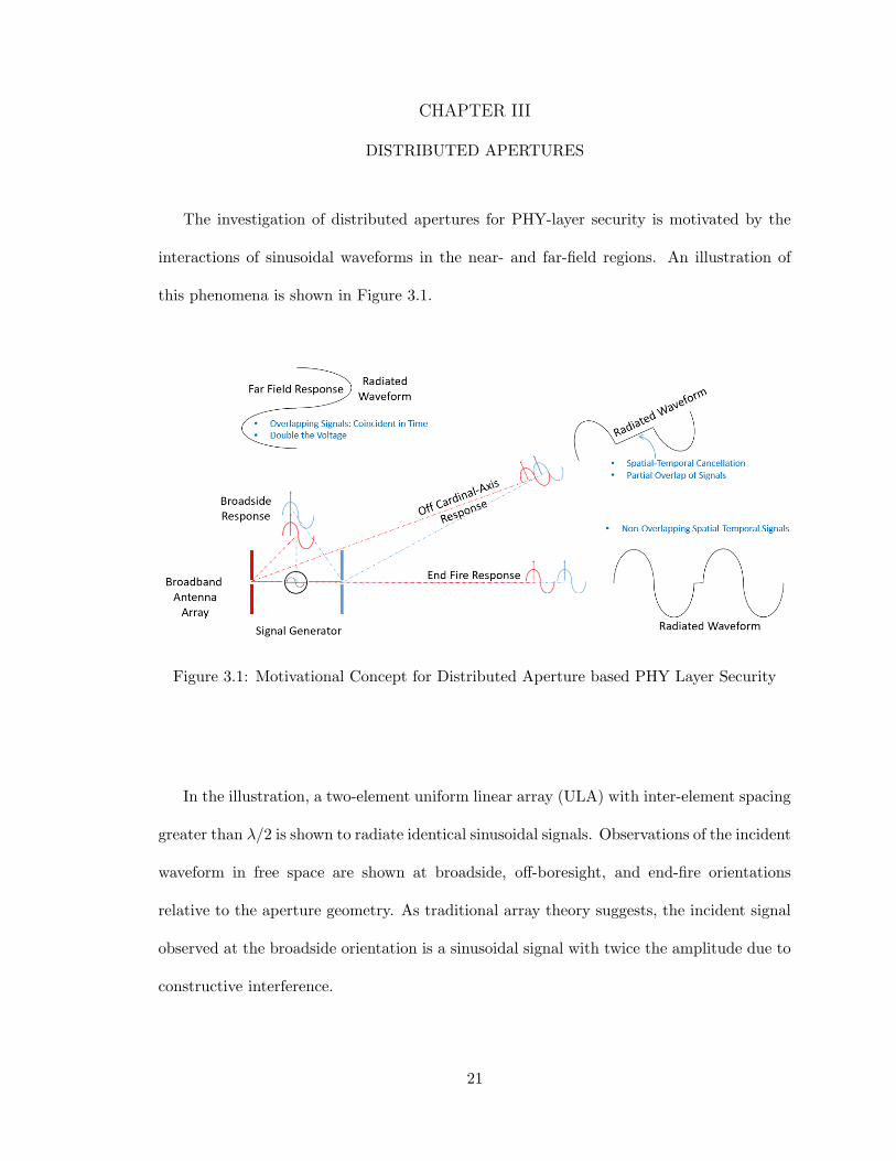
The investigation of distributed apertures for PHY-layer security is motivated by the
interactions of sinusoidal waveforms in the near- and far-field regions. An illustration of
this phenomena is shown in Figure 3.1.
Figure 3.1: Motivational Concept for Distributed Aperture based PHY Layer Security
In the illustration, a two-element uniform linear array (ULA) with inter-element spacing
greater than λ/2 is shown to radiate identical sinusoidal signals. Observations of the incident
waveform in free space are shown at broadside, off-boresight, and end-fire orientations
relative to the aperture geometry. As traditional array theory suggests, the incident signal
observed at the broadside orientation is a sinusoidal signal with twice the amplitude due to
constructive interference.
21

At the end-fire orientation, the incident waveform contradicts traditional, λ/2-spaced,
aperture theory where complete destructive interference is expected. Instead, the incident
waveform consists of both radiated source signals separated in time corresponding to the
spacing between the aperture elements. This behavior occurs since total destructive inter-
ference requires that signals reach a point in space at the same point in time with phase
separation of 180·. When the time difference of arrival (which occurs as a result of aper-
ture separation) exceeds the signal duration, each signal will appear without distortion and
separated in time.
Finally, the off-boresight orientation provides the most unique result. Traditional, λ/2-
spaced, aperture theory suggests that the waveform incident in the off-boresight orientation
will be identical to the source waveform in structure, but attenuated in amplitude corre-
sponding to the array factor pattern at the corresponding angle. Instead, the waveform
incident in the off-boresight orientation does not resemble the source signal, but rather is
the linear super-position of the two (or more) source signals each with a delay and phase
shift corresponding to the incident signal location.
This concept serves as a motivation for studying distributed apertures as a source of
PHY layer security that extends beyond what is currently afforded through traditional
aperture design. The following sections examine distributed aperture array factor patterns
and corresponding waveforms in the near-field and far-field regions followed by the extension
of these findings to improve common PHY-layer security techniques.
3.1 Far-Field Distributed Aperture Analysis
In antenna array theory, distributed apertures are a subset of arrays which employ uni-
form or non-uniform inter-element spacing of greater than λ/2. Compared to conventional
22

apertures, distributed apertures exhibit improved angular resolution, tracking accuracy, and
interference rejection due to the separation of sub-apertures over an large baseline. Despite
numerous advantages, the extended baseline employed by distributed apertures gives rise
to antenna pattern grating lobes (for equally spaced sub-apertures) and highly degraded
sidelobes (for unequally spaced sub-apertures).
When implemented in multi-static RF systems (communications and radar), distributed
transmit / receive apertures are divided into multiple sub-apertures which often employ
arbitrary bi-static angles. Typically, small, but non-zero bi-static angles are selected in
various spatial locations relative to each other to establish a long aperture baseline which can
be used to improve the performance of RF and radar systems. Through optimization of sub-
aperture locations, many advantages can be discovered in employing aperture sparsity such
as an increased power-aperture product, improved main-lobe angle accuracy, and enhanced
null steering in receive apertures.
In the context of this research, distributed apertures provide multiple degrees of freedom
useful in developing PHY layer security mechanisms and in turn disrupting communications
to non-intended receivers. When the motivational concept from the previous section is
considered, message content in aperture sidelobes will no longer necessarily match that of
the mainlobe. This is a powerful result in secured communications and serves as further
motivation for exploring distributed apertures as a means to develop secure communications
systems. The following sections develop foundational results in distributed aperture theory
through the general case implementation of the array factor equation.
23

3.1.1 Mathematical Background
A mathematical analysis is performed to develop an understanding of how distributed
aperture element placement impacts the array factor pattern and overall gain of a distributed
aperture. Emphasis is placed on where grating lobes will appear in the array factor pattern
and how strategic placement of array elements can be exploited to achieve desired far-
field array factor patterns and properties. Common expressions of the array factor pattern
assume uniform linear placement of array elements, allowing for simplification of the array
factor equation, but this assumption is not practical for the analysis of spatially distributed
systems. Therefore, the three-dimensional location of each element in the aperture must
be considered. The generalized array factor equation as a function of θ and φ is given as
follows:
AF (θ, φ) =N∑n=0
ωne−jk·rn (3.1)
where ω is the complex weighting vector, k is the wave vector given by spherical coordi-
nates (θ, φ) , and rn is the position vector. Each entry in the position vector describes the
x, y, and z position of an element in the distributed aperture.
ω = [ω1ω2 · · ·ωN ] (3.2)
k = [kxkykz] =2π
λ[sin(θ)cos(φ)sin(θ)sin(φ)cos(θ)] (3.3)
24

r = [xnynzn] (3.4)
Following this mathematical development, the generalized array factor equation for a
3-D distribution of elements is as follows:
AFxyz(θ, φ) =N∑n=0
wne−j 2π
λ(sin(θ)cos(φ)xn+sin(θ)sin(φ)yn+cos(θ)zn) (3.5)
From this general formulation of the array factor equation, simplified cases for linear
(1-D) and planar (2-D) arrays are developed mathematically and analyzed with regard to
sidelobe and grating-lobe positions.
Linear Array (x-axis)
Under the linear array assumption, the array factor equation is simplified to the following
form:
AFx(θ, φ) =N∑n=0
wne−j 2π
λsin(θ)cos(φ)xn (3.6)
Assuming a uniform weighting vector is applied across all aperture elements, the array
factor is further simplified to:
AFx(θ, φ) =N∑n=0
e−j2πλsin(θ)cos(φ)xn (3.7)
The array factor for given θ and φ angles is the weighted sum of the array factor
contribution from each element. To control the array factor pattern, elements can be placed
25
at x-axis locations which contribute e−jπ or ejπ to the array factor. Mathematically this
can be expressed as follows:
e−jπ = e−j2πλsin(θ)cos(φ)xn (3.8)
By taking the natural logarithm of each side of the expression and solving for all possible
x-axis element locations, the locations at which grating lobes and nulls will occur are found
as follows:
−j(π ± 2πm) = −j 2π
λsin(θ)cos(φ)xn,min,m = 0, 1, ·, inf (3.9)
xn,min =(1± 2m)
2sin(θ)cos(φ)(3.10)
−j(2π ± 2πm) = −j 2π
λsin(θ)cos(φ)xn,min,m = 0, 1, ·, inf (3.11)
xn,min =(1±m)
sin(θ)cos(φ)(3.12)
Using these realizations as guidelines, it is possible to place grating lobes and nulls in any
direction to accomplish a multitude of array design goals. This concept is further explored
through simulations in a later section.
26

Planar Array (x-y plane)
Following the linear case, the planar array case can be considered by expanding the dot
product. The resulting array factor equation considers element locations in the xy-plane as
follows:
AFxy(θ, φ) =N∑n=0
e−j2πλ(sin(θ)cos(φ)xn+sin(θ)sin(φ)yn) (3.13)
By taking the natural logarithm of both sides of the expression and solving for all
possible x-axis element locations, the locations at which grating lobes and nulls will occur
are found as follows:
−j(π ± 2πm) = −j 2π
λsin(θ)cos(φ)xn + sin(θ)sin(φ)yn,m = 0, 1, ·, inf (3.14)
(1± 2m)
2sin(θ)= cos(φ)xn,min + sin(φ)yn,max (3.15)
xn,min =(1± 2m)
2sin(θ)cos(φ)− tan(φ)yn,max (3.16)
yn,min =(1± 2m)
2sin(θ)cos(φ)− cot(φ)xn,max (3.17)
−j(2π ± 2πm) = −j 2π
λsin(θ)cos(φ)xn + sin(θ)sin(φ)yn,m = 0, 1, ·, inf (3.18)
27
(1±m)
sin(θ)= cos(φ)xn + sin(φ)yn (3.19)
xn,min =(1±m)
sin(θ)cos(φ)− tan(φ)yn,max (3.20)
yn,min =(1± 2m)
2sin(θ)cos(φ)− cot(φ)xn,max (3.21)
The result for the planar array case reveals unsurprisingly that the solution space of
locations that will result in array factor pattern grating lobes and nulls increases as the
dimensionality of space increases. Building on these findings, methods for controlling array
factor patterns are considered in the following section.
3.1.2 Array Factor Pattern Synthesis
To perform array factor pattern analysis for distributed apertures, a simulation tool is
created in MATLAB. [44] The simulation tool can produce array factor patterns for ar-
bitrary 1-D, 2-D and 3-D arrays. Model parameters including operating frequency, array
element locations, weighting vector, theta/phi ranges for simulation, and theta/phi cut an-
gles for plotting allow for flexible specification of the aperture. The far-field model produces
various visualizations of the array and corresponding characteristics. Figure 3.2 visualizes
the aperture geometry which is specified in the model configuration file.
28
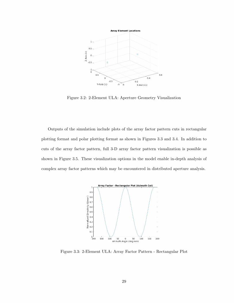
Figure 3.2: 2-Element ULA: Aperture Geometry Visualization
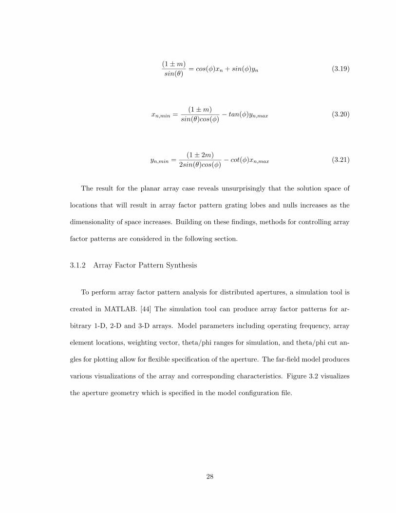
Outputs of the simulation include plots of the array factor pattern cuts in rectangular
plotting format and polar plotting format as shown in Figures 3.3 and 3.4. In addition to
cuts of the array factor pattern, full 3-D array factor pattern visualization is possible as
shown in Figure 3.5. These visualization options in the model enable in-depth analysis of
complex array factor patterns which may be encountered in distributed aperture analysis.
Figure 3.3: 2-Element ULA: Array Factor Pattern - Rectangular Plot
29
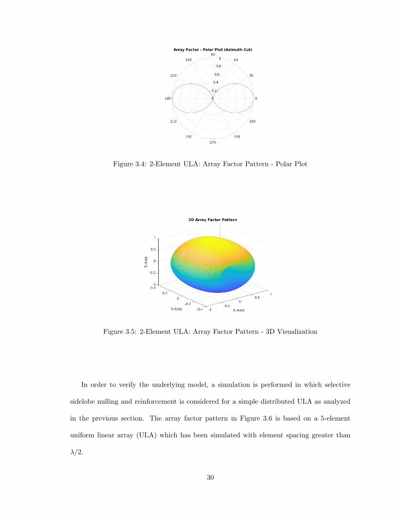
Figure 3.4: 2-Element ULA: Array Factor Pattern - Polar Plot
Figure 3.5: 2-Element ULA: Array Factor Pattern - 3D Visualization
In order to verify the underlying model, a simulation is performed in which selective
sidelobe nulling and reinforcement is considered for a simple distributed ULA as analyzed
in the previous section. The array factor pattern in Figure 3.6 is based on a 5-element
uniform linear array (ULA) which has been simulated with element spacing greater than
λ/2.
30

Figure 3.6: 5-Element ULA: Array Factor Pattern - Polar Plot
According to the distributed aperture theory established in the previous sections, nulling
of the grating lobes should be achievable by placing additional aperture elements at the
locations corresponding the angles at which grating lobes occur. Figures 3.7 and 3.8 show
the resulting array factor pattern when an aperture element is added to null the grating
lobes occurring at 11.5 and 23.6 degrees, respectively.
Figure 3.7: 5-Element ULA: Array Factor Pattern - Polar Plot (Nulling at 11.5 Degrees)
31

Figure 3.8: 5-Element ULA: Array Factor Pattern - Polar Plot (Nulling at 23.6 Degrees)
Finally, the opposite behavior can be applied for which an aperture element is added to
reinforce a lobe in the array factor pattern. Figure 3.9 shows the addition of an element to
the array such that the sidelobe at 25.0 degrees is reinforced.
Figure 3.9: 5-Element ULA: Array Factor Pattern - Polar Plot (Reinforcement at 25.0Degrees)
32
This study has demonstrated fundamental distributed aperture concepts and verified
the operation of the distributed aperture modeling and simulation tool.
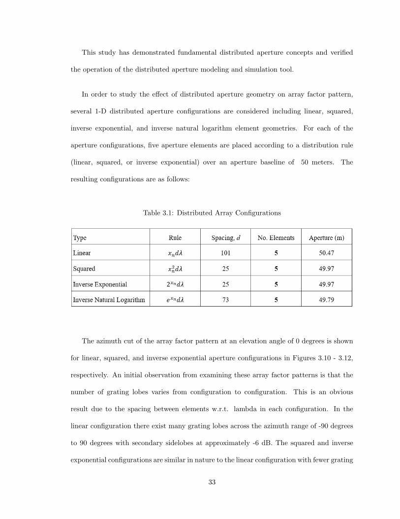
In order to study the effect of distributed aperture geometry on array factor pattern,
several 1-D distributed aperture configurations are considered including linear, squared,
inverse exponential, and inverse natural logarithm element geometries. For each of the
aperture configurations, five aperture elements are placed according to a distribution rule
(linear, squared, or inverse exponential) over an aperture baseline of 50 meters. The
resulting configurations are as follows:
Table 3.1: Distributed Array Configurations
The azimuth cut of the array factor pattern at an elevation angle of 0 degrees is shown
for linear, squared, and inverse exponential aperture configurations in Figures 3.10 - 3.12,
respectively. An initial observation from examining these array factor patterns is that the
number of grating lobes varies from configuration to configuration. This is an obvious
result due to the spacing between elements w.r.t. lambda in each configuration. In the
linear configuration there exist many grating lobes across the azimuth range of -90 degrees
to 90 degrees with secondary sidelobes at approximately -6 dB. The squared and inverse
exponential configurations are similar in nature to the linear configuration with fewer grating
33
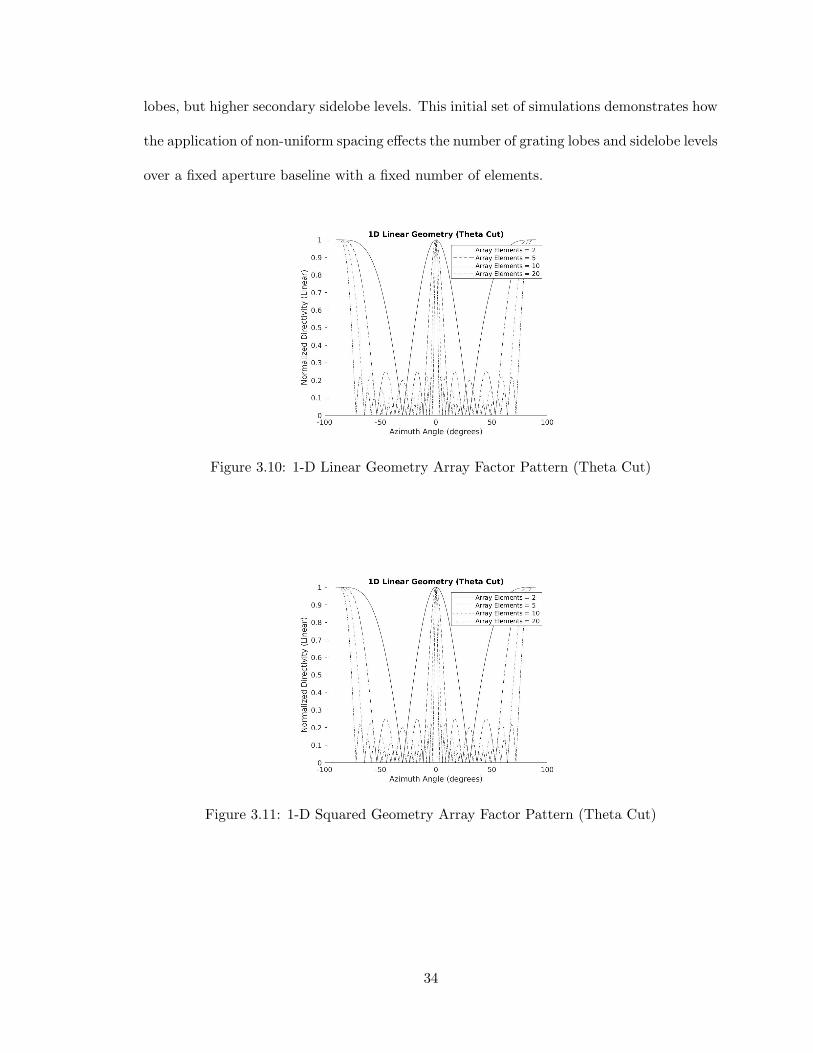
lobes, but higher secondary sidelobe levels. This initial set of simulations demonstrates how
the application of non-uniform spacing effects the number of grating lobes and sidelobe levels
over a fixed aperture baseline with a fixed number of elements.
Figure 3.10: 1-D Linear Geometry Array Factor Pattern (Theta Cut)
Figure 3.11: 1-D Squared Geometry Array Factor Pattern (Theta Cut)
34

Figure 3.12: 1-D Inverse Exponential Geometry Array Factor Pattern (Theta Cut)
Beyond the analysis of 1-D distributed apertures, 2-D distributed apertures are con-
sidered for additional spatial diversity. The 2-D distributed aperture geometries under
consideration are shown in Figure 3.13. The resulting array factor patterns for two to five
aperture elements are shown in Figure 3.14 for each type of array element distribution.
Figure 3.13: 2-D Array Pattern Geometries
35

Figure 3.14: 2-D Geometry Based Array Factor Patterns
The resulting array factor pattern examples show how array element placement and
the number of elements in an aperture will result in (predictable) changes in the location
and levels of high sidelobes and grating lobes in the array factor pattern. Other simula-
tions performed thus far have well characterized distributed aperture properties including
mainlobe beamwidth, beam reinforcement, and null placement, but arbitrary aperture ele-
ment placement as shown in this example will be further considered for PHY layer security
applications.
3.2 Near-Field Distributed Aperture Analysis
In the study of antenna apertures, the boundary between the near-field and far-field
regions is approximated by the following conditions:
R >2D2
λ(3.22)
36

R >> D (3.23)
R >> λ (3.24)
where D is the maximum linear dimension of the aperture, lambda is the wavelength,
and R is the range at which the near-field / far-field boundary is approximated.
For traditional apertures which employ λ/2 inter-element spacing, the far-field can rea-
sonably be expected to be determined by R >> D as D is typically no more than an order
of magnitude greater than the wavelength. Conversely, distributed apertures employ an
aperture baseline which may span multiple orders of magnitude larger than the wavelength.
In these instances, the far-field can be determined by R > 2D2
λ meaning that the minimum
far-field distance increases exponentially with regard to the aperture baseline.
Based upon these considerations, a distributed aperture with a wavelength of 0.1 m
(3 GHz) employing an aperture baseline of 100 m can reasonably be considered to have a
minimum far-field range of 100 km. For this reason, a distributed aperture can be expected
to operate at ranges well within the near-field. Under such conditions, the steering vector
must account for the true time delay between aperture elements to determine near-field
signal representations. [20]
3.2.1 Near-Field Array Factor Pattern
In the previous section, the textbook definition of near-field and far-field regions was
considered with regard to distributed apertures. With the understanding that distributed
37

aperture operation often occurs in the near-field, a spatial domain simulation tool was
developed to characterize the spatial phase coherence patterns. In order to characterize the
effects of near-field / far-field propagation for distributed aperture operation, a 4-element
distributed aperture is considered with elements at (-25m,0m), (-25m,-10m), (25m,0m), and
(25m,-10m). The resulting spatial signal strength of a sinusoidal carrier signal is observed
over a rectangular region 20 m wide in the x-dimension and 0.5 m wide in the y-dimension
at a range of 200 m, 2 km, and 20 km from the aperture phase center at (0,0) as shown in
Figures 3.15, 3.16, and 3.17, respectively.
Figure 3.15: Spatial Signal Strength for Isotropically Radiated Sinusoids at 200 m
38

Figure 3.16: Spatial Signal Strength for Isotropically Radiated Sinusoids at 2 km
Figure 3.17: Spatial Signal Strength for Isotropically Radiated Sinusoids at 20 km
39

The effect observable through this simulation is that the distributed aperture near-field
extends far beyond that of traditional λ/2 spaced arrays with a range of 20 km being
necessary to approximate far-field conditions. This validates the assumptions made in the
previous section that the distributed aperture far-field extends far beyond that of traditional
λ/2-spaced apertures.
3.2.2 Aperture True-Time Delay
The spatially diversity realized through distributed apertures gives rise to deterministic
delay and phase differences between each aperture element and every spatial location in
the near-field region. As identical signals are simultaneously propagated by all distributed
aperture elements, a spatial observation location will receive the signals from the distributed
aperture elements at time(s) corresponding to differences in distance between each of the
aperture elements and the observation location. The true-time delay induced by the aper-
ture fundamentally alters the structure of spatially incident signals.
In practice, the effects of aperture true-time delay are largely dependent on system func-
tionality. From a distributed aperture radar standpoint, perfect constructive interference
of identical radar signals from N-many distributed aperture elements results in a SNR gain
of 10log10(NTX). This maximum achievable SNR gain is realized when the carrier phase
and information content from each distributed aperture element are coherent at a spatial
location. Intentional time and phase alignment of signals at a spatial location to achieve
SNR gain is called cohere-on-transmit operation.
When radar pulse compression is considered via an optimal linear filter (matched filter),
a phase and information coherent pulse will appear as a single peak response in the time
domain with a return magnitude N-times that of a single aperture element return. As
40

aperture true-time delay is introduced by a distributed aperture configuration at a point
in space where the signals are not coherent, the output of the matched filter will become
a series of peaks separated by delays equal to the delays between aperture elements and
the receiver. From this standpoint, true-time delay results in a loss of energy relative to a
spatially coherent pulse.
Meanwhile in the context of distributed aperture communications, the ”energy” loss
observed in the radar application case is not nearly as simple. Neglecting differences in
propagation loss between each transmitter and a receiver location, all spatial locations
continuously receive signal energy from all transmitter elements in a distributed aperture.
This occurs since communications are, generally speaking, continuous in nature rather than
pulsed with a corresponding duty cycle. With (digital) data modulated onto a carrier
signal, every location in space will receive a modulated carrier signal from all distributed
aperture transmitters with potentially different information content corresponding to the
true-time delay from the distributed aperture configuration. When the distributed aperture
is functioning in a cohere-on-transmit mode, all information content will be aligned at the
receiver and reception will be possible. Meanwhile, when signals of different information
content interfere, the resulting demodulated signal result may become erroneous.
Another way of considering the communications case is with regards to signal-to-interference
pulse noise ratio (SINR). If the transmitted signals are phase coherent at a location, there
is no ”array factor” loss from the destructive interference of the carrier signals. In this
instance, the SINR can be characterized by the number of ”information coherent” trans-
mitters and the communications modulation scheme employed. An in-depth analysis of the
effects of information coherence will be performed in the next chapter.
41
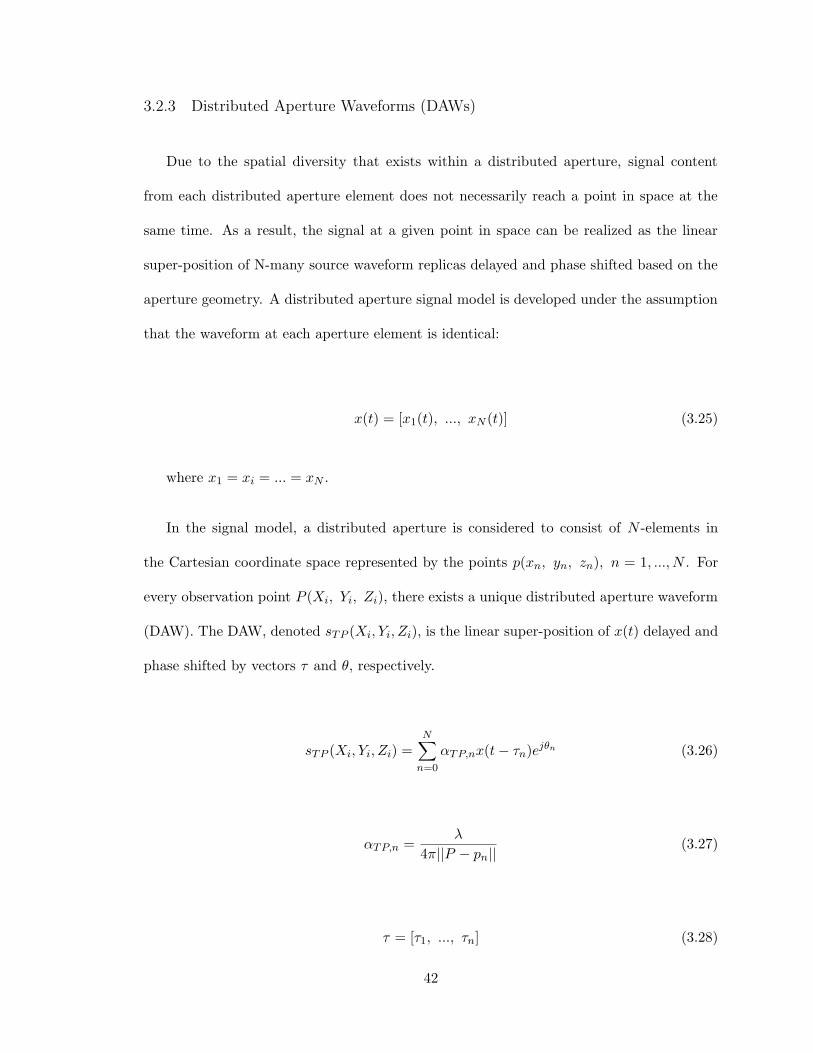
3.2.3 Distributed Aperture Waveforms (DAWs)
Due to the spatial diversity that exists within a distributed aperture, signal content
from each distributed aperture element does not necessarily reach a point in space at the
same time. As a result, the signal at a given point in space can be realized as the linear
super-position of N-many source waveform replicas delayed and phase shifted based on the
aperture geometry. A distributed aperture signal model is developed under the assumption
that the waveform at each aperture element is identical:
x(t) = [x1(t), ..., xN (t)] (3.25)
where x1 = xi = ... = xN .
In the signal model, a distributed aperture is considered to consist of N -elements in
the Cartesian coordinate space represented by the points p(xn, yn, zn), n = 1, ..., N . For
every observation point P (Xi, Yi, Zi), there exists a unique distributed aperture waveform
(DAW). The DAW, denoted sTP (Xi, Yi, Zi), is the linear super-position of x(t) delayed and
phase shifted by vectors τ and θ, respectively.
sTP (Xi, Yi, Zi) =N∑n=0
αTP,nx(t− τn)ejθn (3.26)
αTP,n =λ
4π||P − pn||(3.27)
τ = [τ1, ..., τn] (3.28)
42

θ = [θ1, ..., θn] (3.29)
where (Xi, Yi, Zi) is the location of an observation point in space and αn, τn, and θn
are the propagation loss, delay, and phase shift between the n-th aperture element and a
given point in space, respectively. The resulting signal at point (Xi, Yi, Zi) is the linear
super-position of each of the source waveforms from each sparse aperture element.
This concept is illustrated in Figure 3.18 in which three types of DAW realizations are
shown for a sinusoidal source signal as radiated by a two-element distributed aperture. In
the top sub-figure, the sinusoidal source signals are shown to exhibit complete construc-
tive interference at an observation point as would be realized through cohere-on-transmit
operation in which the initial delay and phase shift values at each aperture are specified
such that signal energy coheres at a given spatial location. The middle sub-figure shows the
constructive/destructive interference of the sinusoidal source signals when a relative phase
shift exists between the signals at a given point in space. The corresponding DAW here is
identical to the source waveform since information content is aligned, but the signal mag-
nitude is reduced from destructive interference in phase. Finally, the DAW in the bottom
sub-figure shows the realization of the same sinusoidal signals at a spatial location at which
the distributed aperture signals exhibit a relative delay, but no relative phase shift. The
resulting DAW here exhibits constructive and destructive interference due to the relative
delay between the aperture elements and the spatial observation location. This behavior
and the corresponding DAW realizations serve as the motivation for characterization of
DAWs.
43

Figure 3.18: Distributed Aperture Waveform Realizations of Sinusoidal Source Waveform
44
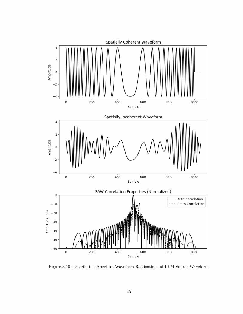
Figure 3.19: Distributed Aperture Waveform Realizations of LFM Source Waveform
45

Beyond a baseband sinusoidal signal, more complex waveforms can be considered within
the context of DAWs. Consider the radar case where a linear frequency modulated (LFM)
waveform is transmitted from a distributed aperture as shown in Figure 3.19. In the spatially
coherent case, the LFM waveform is reinforced in amplitude as shown in the top sub-figure.
Meanwhile, when a spatially incoherent point is considered, the time and phase delays
between the distributed aperture elements and the spatial location result in a DAW which
is unique in appearance relative to the source waveform as shown in the middle sub-figure.
Since the LFM waveform is typically used for matched filtering / pulse compression in radar
applications, the auto-correlation of the source LFM is plotted against the cross-correlation
of the two DAWs in the bottom sub-figure. This result is powerful in that the spatially
incoherent DAW naturally exhibits interference rejection properties such that returns from
all spatially incoherent locations will not result in as strong of a matched filter response as
returns from a spatially coherent location.
What is important to note in both of these instances is that the waveforms which are
studied are baseband signal representations. This means that the spatial separation between
baseband signals corresponds to the bandwidth of the synthesized waveform. Meanwhile,
the interference of the continuous sinusoidal carrier signals at which these baseband signals
are transmitted on results in the array factor pattern loss. This is important to keep in
mind for the spatio-temporal analysis performed in the remainder of this research.
3.3 Coherence Basket Concept
From an analytical standpoint, the spatial extent over which spatial coherence will
occur in a distributed aperture system must be quantified. This region, henceforth called
a ”coherence basket”, corresponds to the region over which a spatially coherent waveform
46

is manifested and tolerant of the effects characterized in the previous sections. A ”layered”
approach is taken to determine the characteristics of the coherence basket based upon the
distributed aperture geometry and signal bandwidth. A more specific conceptualization
of the coherence basket is established in the next chapter which is specific to distributed
aperture communications systems and corresponding communications parameters including
modulation format, samples per symbol, and symbol rate. Each of these system aspects
are parameterized and studied in the following sections to describe the coherence basket as
system properties are varied.
Starting with the distributed aperture geometry, two layers of the coherence basket
concept can be established. First, traditional array factor pattern calculations provide
information about the signal energy (array factor pattern) radiated from the aperture as
a function of range and angle. This provides information about the SNR that may be
observed spatially, but neglects to consider the underlying information content present at
that location. The array factor pattern is only concerned with additive phases which are
essential from a received signal standpoint (nulls, lobes) and therefore is defined over all
spatial locations without regard for the presence of the intended information content.
The second layer of the coherence basket concept considers information coherence. This
describes the spatial region over which identical information content (baseband signal con-
tent) radiated from multiple spatially diverse aperture elements can be received at the
same time. The multiplication of these two spatial patterns reveals the extent of the basic
coherence basket over which the signal strength is highest and the incident information
content is coherent. This aspect of the coherence basket will be of primary focus in this sec-
tion through the development of an information content modeling tool and corresponding
analysis of various aperture and system configurations.
47

3.3.1 Information Content Modeling
The modeling of information coherence and corresponding coherence basket regions
requires the spatial visualization of signal content as radiated from aperture elements in the
time domain. Points and/or regions in space at which the SAME information content from
each aperture coincides forms a coherence basket. If an impulse is transmitted from each
aperture element, the wavefront can be viewed at snapshots in time which correspond to
a distance for which the wavefront has propagated from an aperture element. Consider a
three element distributed aperture with elements at (-50, 0) m, (0, 0) m and (50, 0) m as
shown in Figure 3.20. Each aperture element, indicated by an ’x’ in the figure, is shown to
be radiating a wavefront as indicted by the circle drawn around each aperture element. At
this particular snapshot in time which corresponds to a wavefront propagation distance of
20 meters, there is no overlap of any of the wavefronts from the aperture elements.
48
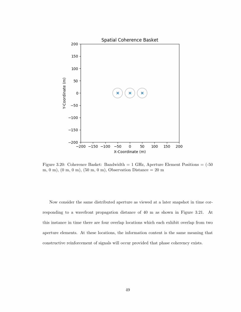
Figure 3.20: Coherence Basket: Bandwidth = 1 GHz, Aperture Element Positions = (-50m, 0 m), (0 m, 0 m), (50 m, 0 m), Observation Distance = 20 m
Now consider the same distributed aperture as viewed at a later snapshot in time cor-
responding to a wavefront propagation distance of 40 m as shown in Figure 3.21. At
this instance in time there are four overlap locations which each exhibit overlap from two
aperture elements. At these locations, the information content is the same meaning that
constructive reinforcement of signals will occur provided that phase coherency exists.
49

Figure 3.21: Coherence Basket: Bandwidth = 1 GHz, Aperture Element Positions = (-50m, 0 m), (0 m, 0 m), (50 m, 0 m), Observation Distance = 40 m
By extension of this concept, every spatial location will simultaneously receive signals
from N-many aperture elements. For M-many overlapping signals with the same information
content there will be N-M spatially incident signals which will not have the same information
content. This means that regardless of the carrier phase of incident signals, the lack of the
same information content (as represented through signal overlap at an instance in time)
will mean that the resulting signal will not necessarily have the same information content
as the source signal upon observation. The resulting signals at these locations are DAWs
as developed earlier in this chapter.
50
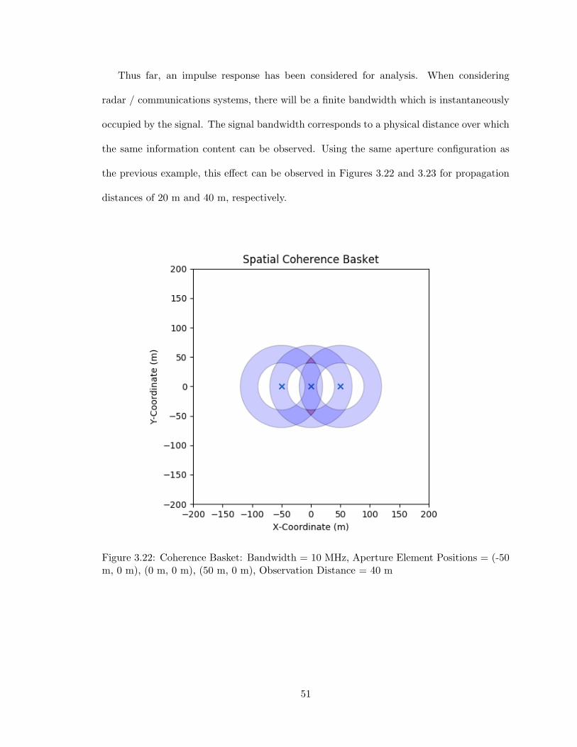
Thus far, an impulse response has been considered for analysis. When considering
radar / communications systems, there will be a finite bandwidth which is instantaneously
occupied by the signal. The signal bandwidth corresponds to a physical distance over which
the same information content can be observed. Using the same aperture configuration as
the previous example, this effect can be observed in Figures 3.22 and 3.23 for propagation
distances of 20 m and 40 m, respectively.
Figure 3.22: Coherence Basket: Bandwidth = 10 MHz, Aperture Element Positions = (-50m, 0 m), (0 m, 0 m), (50 m, 0 m), Observation Distance = 40 m
51

Figure 3.23: Coherence Basket: Bandwidth = 10 MHz, Aperture Element Positions = (-50m, 0 m), (0 m, 0 m), (50 m, 0 m), Observation Distance = 60 m
At a signal bandwidth of 10 MHz there is now a ring-shaped region of the same informa-
tion content which is propagated from each aperture element. In the snapshot corresponding
to 40 m of wavefront propagation, there are three regions which represent different types of
information overlap. These regions are no overlap, partial overlap, and full overlap of in-
formation content as represented by the light blue, dark blue, and red regions, respectively.
As discussed previously, regions with no overlap or partial overlap will still have informa-
tion content from all aperture elements, but it will not necessarily be the same information
content as intended.
52
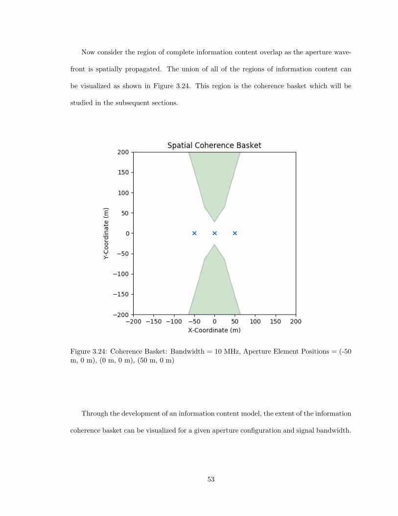
Now consider the region of complete information content overlap as the aperture wave-
front is spatially propagated. The union of all of the regions of information content can
be visualized as shown in Figure 3.24. This region is the coherence basket which will be
studied in the subsequent sections.
Figure 3.24: Coherence Basket: Bandwidth = 10 MHz, Aperture Element Positions = (-50m, 0 m), (0 m, 0 m), (50 m, 0 m)
Through the development of an information content model, the extent of the information
coherence basket can be visualized for a given aperture configuration and signal bandwidth.
53

Using these capabilities, the trade-space of signal bandwidth and aperture baseline (extent
of an aperture configuration) is studied in the following section.
3.3.2 Signal Bandwidth vs. Aperture Baseline
From an information content perspective, a coherence basket defines a region where
identical information content coincides simultaneously. The spatial extent of this region
is determined by the spatio-temporal properties of the distributed aperture configuration.
According to Fourier properties, the minimum synthesizable pulse width is expressed as
follows:
tpulse =1
BW(3.30)
where BW is the signal bandwidth occupied by a radar/communications system ex-
pressed in Hertz.
This minimum pulse width, expressed as a time duration, corresponds to a spatial dis-
tance over which the same information content is present through the following expression:
dpulse =c
BW(3.31)
where c is the speed of light in meters per second and BW is the signal bandwidth in
Hertz.
This simple relationship between the signal bandwidth and speed of light establishes
the spatial extent over which information content is simultaneously observable as the signal
54
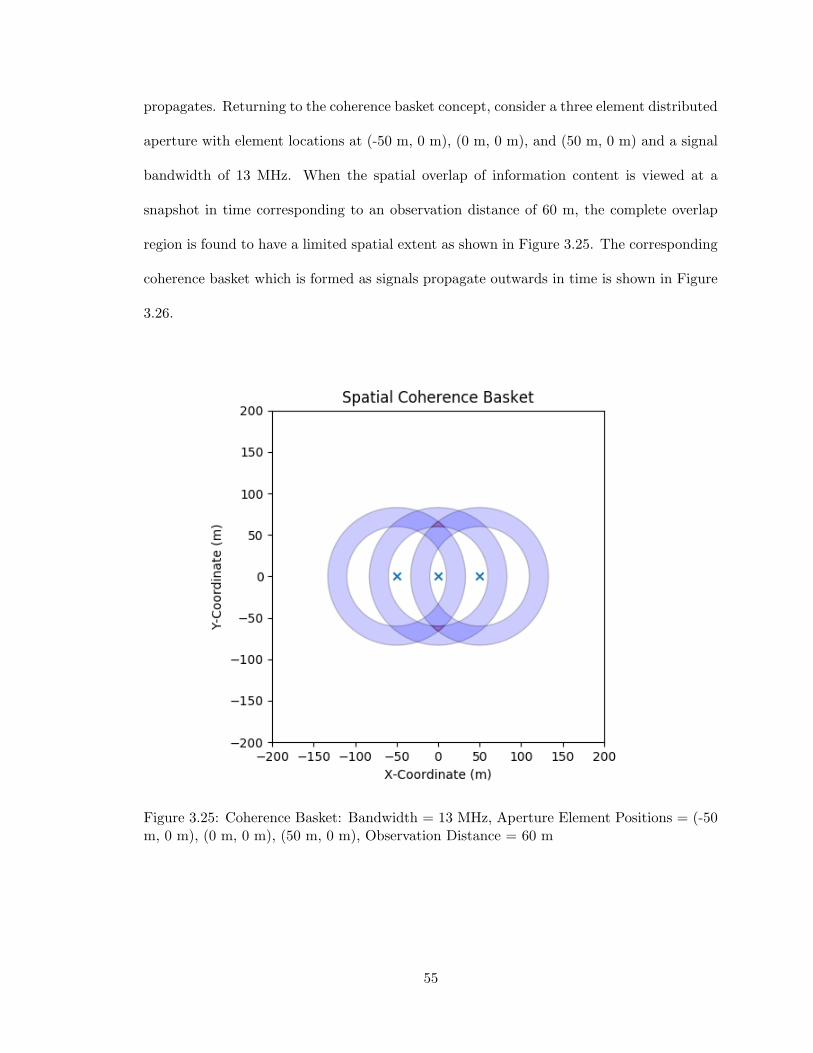
propagates. Returning to the coherence basket concept, consider a three element distributed
aperture with element locations at (-50 m, 0 m), (0 m, 0 m), and (50 m, 0 m) and a signal
bandwidth of 13 MHz. When the spatial overlap of information content is viewed at a
snapshot in time corresponding to an observation distance of 60 m, the complete overlap
region is found to have a limited spatial extent as shown in Figure 3.25. The corresponding
coherence basket which is formed as signals propagate outwards in time is shown in Figure
3.26.
Figure 3.25: Coherence Basket: Bandwidth = 13 MHz, Aperture Element Positions = (-50m, 0 m), (0 m, 0 m), (50 m, 0 m), Observation Distance = 60 m
55
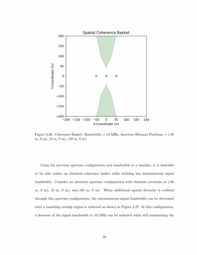
Figure 3.26: Coherence Basket: Bandwidth = 13 MHz, Aperture Element Positions = (-50m, 0 m), (0 m, 0 m), (50 m, 0 m)
Using the previous aperture configuration and bandwidth as a baseline, it is desirable
to be able realize an identical coherence basket while utilizing less instantaneous signal
bandwidth. Consider an alternate aperture configuration with elements locations at (-60
m, 0 m), (0 m, 0 m), and (60 m, 0 m). When additional spatial diversity is realized
through this aperture configuration, the instantaneous signal bandwidth can be decreased
until a matching overlap region is achieved as shown in Figure 3.27. In this configuration,
a decrease of the signal bandwidth to 10 MHz can be achieved while still maintaining the
56

same information content region as the previous aperture configuration. The corresponding
coherence basket for this aperture configuration and bandwidth is shown in Figure 3.28.
Figure 3.27: Coherence Basket: Bandwidth = 10 MHz, Aperture Element Positions = (-60m, 0 m), (0 m, 0 m), (60 m, 0 m), Observation Distance = 60 m
57

Figure 3.28: Coherence Basket: Bandwidth = 10 MHz, Aperture Element Positions = (-60m, 0 m), (0 m, 0 m), (60 m, 0 m)
Spatial diversity as realized through distributed apertures offers an alternate and com-
plementary method for decreasing the region over which signal information content can be
observed. In distributed apertures, true-time delay between spatially diverse aperture ele-
ments results in the realization of spatial regions over which the same information content
will coincide at simultaneously. As sub-aperture spacing increases, the region over which a
signal observable decreases. The complimentary effects of aperture baseline length and sig-
nal bandwidth on observable region of information content results in the baseline-bandwidth
product paradigm. In this paradigm, increases in the aperture baseline length will decrease
58

the region over which information content can be observed which in turn relaxes the sig-
nal bandwidth requirements to maintain a given spatial information extent. This property
is key to the effectiveness of distributed apertures in limiting the observability of signal
information content.
As a result of increased spatial separation between aperture elements, the coherence
basket becomes increasingly smaller. This makes logical sense as the intersection of multiple
rings will not occur at all ranges when the center of each ring is far enough away from the
rest. Therefore, a wider aperture baseline can be used to increase differences in delays
between information content at non-cohered locations. Conversely, a larger instantaneous
signal bandwidth results in a shorter resolvable pulse width which means that smaller
aperture baselines will result in the same overlap properties.
3.3.3 Coherence Basket Analysis
Following the development of the coherence basket in terms of general aperture baseline
and signal bandwidth, various distributed aperture configurations can be evaluated to study
the extent of the coherence basket. In this analysis, there are three types of coherence
baskets of interest; natural coherence baskets, cohere-on-transmit coherence baskets, and
partial coherence baskets.
The first type of coherence basket, coined natural coherence basket, describes the one
or more spatial region(s) for which information signals are naturally coherent given an
arbitrary aperture configuration. These regions represent the spatial overlap which occurs
in the absence of beamforming techniques applied at the aperture level. Natural coherence
baskets are an indicator of the spatial diversity which exists within an aperture and the
corresponding spatial extent of information coherence which can be achieved.
59

The second type of coherence basket, coined cohere-on-transmit (COT) coherence bas-
ket, describes the spatial region of information coherence which results when the coherence
location is specified through aperture level COT techniques. This region will contain the
specified coherence point, but will extend beyond this point in all directions based upon
the aperture geometry. When this technique is implemented, the effective location of all
aperture elements changes relative to the point of coherence based upon the effective de-
lays applied. This will be the primary type of coherence basket under investigation for the
remainder of this chapter.
Finally, the final type of coherence basket, coined partial coherence basket, describes the
spatial regions for which some, but not all, information signals are coherent. These regions
will contain reinforced information content from multiple information coherent aperture
elements, while also containing a high level of information content interference from the non-
coherent information content sources. Based on this interference from potentially multiple
sources, this region is expected to receive highly corrupted information content.
Uniform Linear Geometry
A logical starting point for coherence basket analysis is uniform linear aperture ge-
ometries. These aperture geometries span the x-axis and employ equally spaced elements
centered at (0 m, 0 m). Consider a three element aperture with element locations at (-200
m, 0 m), (0 m, 0 m), and (200 m, 0 m) and a bandwidth of 25 MHz as shown in Figure
3.29. When the aperture is cohered to a location of (0 m, 500 m), the coherence basket
can be observed to contain the coherence point (0 m, 500 m) while extending outwards in
both the x and y dimensions. Furthermore, the coherence basket appears mirrored over the
x-axis, exhibiting identical spatial properties as the intended coherence basket.
60

Figure 3.29: Coherence Basket: Bandwidth = 25 MHz, Aperture Element Positions = (-200m, 0 m), (0 m, 0 m), (200 m, 0 m), Coherence Location = (0 m, 500 m)
An identical aperture configuration with element locations at (-200 m, 0 m), (0 m, 0
m), and (200 m, 0 m) and a bandwidth of 25 MHz is now considered. The coherence point
is placed at 20, 40, and 60 degrees off boresight of the aperture as shown in Figures 3.30,
3.31, and 3.32, respectively.
61

Figure 3.30: Coherence Basket: Bandwidth = 25 MHz, Aperture Element Positions = (-200m, 0 m), (0 m, 0 m), (200 m, 0 m), Coherence Location = (171 m, 470 m)
When the coherence point is located at (171 m, 470 m) which corresponds to 20 de-
grees off boresight, the coherence basket rotates accordingly such that the coherence point
is contained. The shape of the coherence basket has maintained the same length, but has
increased slightly in width. This is due to a decrease in the available spatial diversity be-
tween aperture elements after coherence parameters are applied. Furthermore, the mirrored
coherence basket again appears mirrored directly across the x-axis with the same spatial
properties.
62
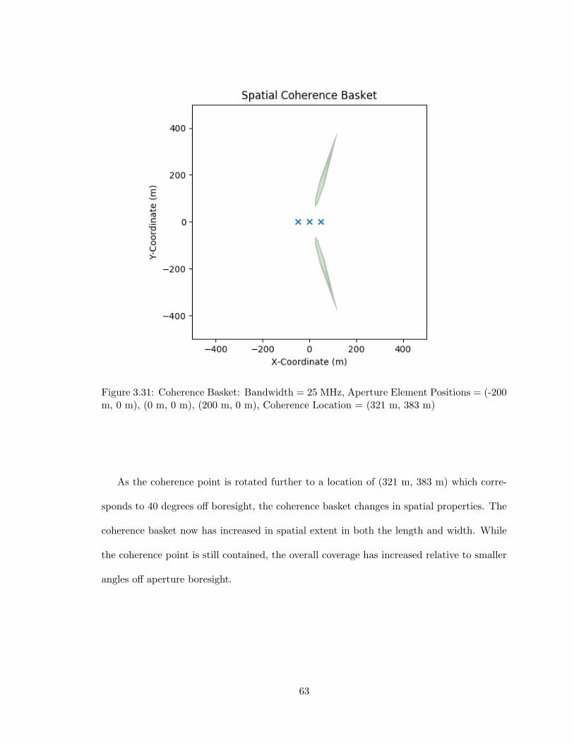
Figure 3.31: Coherence Basket: Bandwidth = 25 MHz, Aperture Element Positions = (-200m, 0 m), (0 m, 0 m), (200 m, 0 m), Coherence Location = (321 m, 383 m)
As the coherence point is rotated further to a location of (321 m, 383 m) which corre-
sponds to 40 degrees off boresight, the coherence basket changes in spatial properties. The
coherence basket now has increased in spatial extent in both the length and width. While
the coherence point is still contained, the overall coverage has increased relative to smaller
angles off aperture boresight.
63

Figure 3.32: Coherence Basket: Bandwidth = 25 MHz, Aperture Element Positions = (-200m, 0 m), (0 m, 0 m), (200 m, 0 m), Coherence Location = (433 m, 250 m)
Finally, the coherence point is rotated to a location of (433 m, 250 m) which corresponds
to 60 degrees off boresight. When coherence parameters are applied to achieve coherence
at this point, the coherence basket becomes unbounded and instead occupies a constant
angle which extends outwards in range. This is due to insufficient spatial diversity between
aperture elements and the coherence point such that when coherence parameters are applied,
the aperture elements ”appear” to be much more closely spaced.
64
Uniform Planar Geometry
From the coherence basket study in the previous section, it was determined that the
coherence basket increases in size as spatial diversity decreases between aperture elements
and a coherence point. Although increasing the aperture baseline or bandwidth would
increase the spatial diversity, planar arrays can be considered to achieve sufficient spatial
diversity in multiple dimensions. Consider a four element distributed aperture with element
locations at (-200 m, -200 m), (200 m, -200 m), (-200 m, 200 m), and (200 m, 200 m) and
a bandwidth of 25 MHz as shown in Figure 3.33. When the coherence location is chosen
to be (0 m, 700 m) to account for the aperture extending 200 m in the +x direction,
the coherence basket is found to be approximately the same size as the previous linear
aperture configuration since the aperture extent along the x-axis is the same as the previous
configuration.
65

Figure 3.33: Coherence Basket: Bandwidth = 25 MHz, Aperture Element Positions = (-200m, -200 m), (200 m, -200 m), (-200 m, 200 m), (200 m, 200 m), Coherence Location = (0m, 700 m)
Now consider the same planar aperture configuration with the coherence location at (606
m, 350 m) which corresponds to an angle of 60 degrees off boresight as shown in Figure
3.34. In the linear aperture configuration, an angle of 60 degrees off boresight resulted
in the coherence basket becoming unbounded due to a lack of spatial diversity along the
y-axis. For the planar aperture geometry, the coherence basket is instead maintained with
a spatial extent less than that of the 0 degree coherence location. This is due to the fact
66

that the planar array has sufficient spatial diversity along both the x and y -axes allowing
for a coherence basket to form over a finite region.
Figure 3.34: Coherence Basket: Bandwidth = 25 MHz, Aperture Element Positions = (-200m, -200 m), (200 m, -200 m), (-200 m, 200 m), (200 m, 200 m), Coherence Location = (606m, 350 m)
The previous two examples have leveraged a square planar aperture to maximize the
spatial diversity along both the x- and y-axes. While this approach was more effective than
a linear aperture, the spatial requirements are inherently increased. A trapezoidal planar
aperture is now considered with element locations at (-200 m, -100 m), (200 m, -100 m),
(-100 m, 100 m), and (100 m, 100 m) and a bandwidth of 25 MHz as shown in Figure
67

3.35. This aperture configuration maintains the same aperture baseline in both the x and y
dimensions while occupying less overall area. When the coherence location is again taken to
be (0 m, 700 m), the resulting coherence basket is unbounded with a narrow angle extending
in the +x direction.
Figure 3.35: Coherence Basket: Bandwidth = 25 MHz, Aperture Element Positions = (-200m, -200 m), (200 m, -200 m), (-100 m, 200 m), (100 m, 200 m), Coherence Location = (0m, 700 m)
Next consider the same aperture configuration with the coherence point at (606 m,
350 m) which corresponds to an angle of 60 degrees off boresight as shown in Figure 3.36.
This aperture configuration produces a coherence basket nearly identical to that of the
68

square planar array when the coherence location is at the same angle. From this aperture
configuration it is evident that maintaining the same aperture spatial diversity relative to
the coherence location will maintain the coherence basket shape and size.
Figure 3.36: Coherence Basket: Bandwidth = 25 MHz, Aperture Element Positions = (-200m, -200 m), (200 m, -200 m), (-100 m, 200 m), (100 m, 200 m), Coherence Location = (606m, 350 m)
Random Planar Geometry
From the studies of linear and planar aperture geometries, it is evident that spatial
diversity relative to a coherence location is the primary factor in reducing the extent of
the coherence basket. With this in mind, random planar geometries can be considered
69
to determine how important the actual location of aperture elements is relative to the
coherence basket extent which can be achieved. In order to generate a random planar
geometry, aperture element locations are drawn from a zero-mean uniform distribution
x ∈ [−200, 200]. The first random aperture configuration has elements at (43.7 m, -91.2
m), (-196.1 m, -192.3 m), (85.1 m, 180.6 m), and (-74.2 m, 87.9 m) and has a bandwidth
of 25 MHz. When cohered to a location of (600 m, 600 m), the resulting coherence basket
is unbounded and spans over a moderately wide angle. Examining the aperture geometry,
there is little spatial diversity across the aperture relative to the previous examples since
the random element locations do not span the entire possible range.
70

Figure 3.37: Coherence Basket: Bandwidth = 25 MHz, Aperture Element Positions = (43.7m, -91.2 m), (-196.1 m, -192.3 m), (85.1 m, 180.6 m), (-74.2 m, 87.9 m), Coherence Location= (600 m, 600 m)
Using the same random aperture generation methodology, a second random planar array
is created as shown in Figure 3.38. In this aperture which has elements at (-107.6 m,
173.8 m), (77.4 m, 5.4 m), (-95.3 m, 24.2 m), and (12.5 m, -103.4 m) there exists another
unbounded distributed aperture. Unlike the previous example, the coherence basket spans
a smaller angle due to the greater spatial diversity which exists across the aperture. In both
of these instances, the random aperture configuration is unable to match the performance
of a square planar aperture or a linear aperture.
71

Figure 3.38: Coherence Basket: Bandwidth = 25 MHz, Aperture Element Positions =(-107.6 m, 173.8 m), (77.4 m, 5.4 m), (-95.3 m, 24.2 m), (12.5 m, -103.4 m), CoherenceLocation = (600 m, 600 m)
In order to increase the spatial diversity in the aperture while maintaining a random
planar aperture, the aperture element locations are now drawn from a zero-mean uniform
distribution x ∈ [−300, 300]. The resulting random planar aperture has aperture element
locations at (-171.4 m, -123.1 m), (-280.1 m, -266.1 m), (201.4 m, -263.8 m), and (105.9
m, -191.5 m) and a coherence location at (600 m, 600 m) as shown in Figure 3.39. In
this configuration, the coherence basket now spans a finite region which is long and narrow
in appearance. This result is possible as the spatial diversity along the x-axis is nearly
72

that of the square planar or linear apertures while the spatial diversity along the y-axis is
considerably less.
Figure 3.39: Coherence Basket: Bandwidth = 25 MHz, Aperture Element Positions =(-171.4 m, -123.1 m), (-280.1 m, -266.1 m), (201.4 m, -263.8 m), (105.9 m, -191.5 m),Coherence Location = (600 m, 600 m)
Finally, a second random planar aperture is created from the same distribution resulting
in aperture elements at (-169.1 m, 133.3 m), (-298.9 m, 39.7 m), (-3.6 m, 241.4 m), and
(-203.5 m, 149.0 m) as shown in Figure 3.40. Unfortunately, this random distribution of
elements exhibits very little spatial diversity relative to the coherence location at (600 m,
600 m) and therefore is spatially unbounded and spans a larger angle.
73
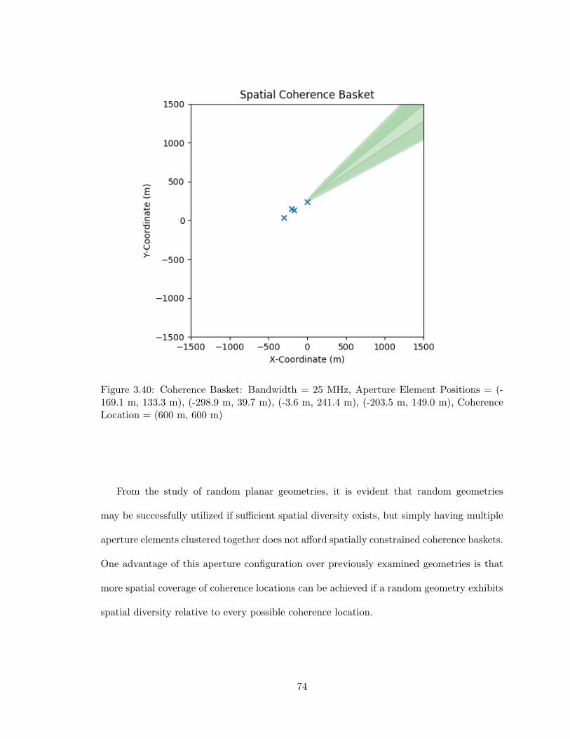
Figure 3.40: Coherence Basket: Bandwidth = 25 MHz, Aperture Element Positions = (-169.1 m, 133.3 m), (-298.9 m, 39.7 m), (-3.6 m, 241.4 m), (-203.5 m, 149.0 m), CoherenceLocation = (600 m, 600 m)
From the study of random planar geometries, it is evident that random geometries
may be successfully utilized if sufficient spatial diversity exists, but simply having multiple
aperture elements clustered together does not afford spatially constrained coherence baskets.
One advantage of this aperture configuration over previously examined geometries is that
more spatial coverage of coherence locations can be achieved if a random geometry exhibits
spatial diversity relative to every possible coherence location.
74

Discussion
The application of distributed apertures to achieve spatial security of information con-
tent requires sufficient spatial diversity and bandwidth. Through spatial simulations, it
has been shown that the increase of instantaneous signal bandwidth can be used to reduce
the extent of the spatial coherence basket formed by an aperture, but is no substitute for
sufficient spatial diversity existing in an aperture geometry. Furthermore, when cohere-on-
transmit beamforming of information content is taken into consideration, there must be
sufficient spatial diversity relative to the coherence location in order to achieve a spatially
constrained coherence basket. When sufficient spatial diversity is not sufficient, the region
of information coherence becomes unbounded and resembles the mainlobe of an aperture
without the presence of sidelobes which still extends the literature in PHY layer security
concepts.
With this in mind, the coherence basket is not constrained by the antenna beamwidth,
but rather by the spatial diversity of the transmit aperture. Within the mainlobe or any
sidelobe in an antenna radiation there are many wavelengths of spatial coverage. Although
the sinusoidal carrier signal energy may add coherently within the mainlobe, the information
content will only be additive at the coherence point and locally until the probability of error
becomes to great. Therefore, the combination of information content and phase coherence
effects can create a narrow spatial window over which reception can be achieved.
Given a distributed aperture with multiple available degrees of freedom, it becomes
possible to establish multiple coherence baskets which operate on the same frequency si-
multaneously. This can be achieved through the utilization of multiple sub-sets of aperture
elements which each cohere in a independent location. Multiple COT locations can be
75
achieved through sub-sets of an aperture which each steer in a direction and have a null-
space in the direction of another COT location.
Finally, one key property of the coherence basket with regard to bandwidth is that
positioning errors have negligible effects on the information coherence property. When
digital sampling is considered, the bandwidth determines how much tolerance exists for
spatial separation between aperture elements for the signal envelope will change. Although
it is desirable to reduce the extent of this physical region by decreasing the pulse width,
signal bandwidths are often not able to be readily increased within existing systems.
3.4 Application to PHY Layer Security
The analysis of distributed apertures in this chapter has served as the basis for devel-
oping novel, aperture-centric PHY layer security techniques. Through far-field analysis,
calculation of the array factor pattern was generalized for 1D/2D distributed apertures and
pattern manipulation was considered through aperture element placement to achieve three
objectives; null placement, grating lobe mitigation, and sidelobe level reduction. Following
analysis of the far-field, the near-field region was defined for distributed apertures and the
concept of Distributed Aperture Waveforms (DAWs) was developed to characterize spa-
tially dependent waveforms in the near-field. Finally, the concept of information coherence
was introduced and a ”coherence basket” theory was developed to define the extent over
which information content is present in the near-field. Each of these techniques and the
corresponding analyses demonstrate the spatial information security which can be achieved
through distributed aperture design and implementation.
Although distributed aperture design can independently achieve spatial security, the
layered application of additional PHY layer security techniques can be employed to fur-
76

ther secure a communications system. The following sections consider distributed aperture
techniques including weighting vector design and sub-aperture selection to achieve assured
communications in an intended receiver while degrading communications to would-be eaves-
droppers.
3.4.1 Near-Field / Far-Field Reception Regions
In a secure communications context, isolation of an intended receiver from would-be
eavesdroppers requires that the main beam of an aperture is sufficiently narrow as to con-
tain only the intended receiver. In the far-field region, distributed aperture spatial diversity
enables mainlobe beamwidths to be multiple orders of magnitude smaller than traditional
apertures. When eavesdroppers fall outside of the mainlobe of the distributed aperture,
received signals experience an SNR (relative to the intended receiver) which corresponds
to the array factor pattern. This result is inherently useful in the discussion of PHY layer
security as decreasing the SNR of a signal for a would-be eavesdropper decreases the likeli-
hood that the signal may be recovered. Furthermore, situational awareness of eavesdropper
positions coupled with many aperture elements enables array factor pattern nulling to be
performed such that reception by an would-be eavesdropper is further degraded.
For the near-field region of distributed aperture operation, the coherence basket con-
cept has developed as a natural means of rejection of would-be eavesdroppers. While the
distributed aperture array factor pattern is defined over all spatial locations, the coherence
basket only exists for a given message over a limited spatial region. This means that in
contrast to the far-field case where the array factor pattern in a given direction determines
how degraded a message will be, the near-field array factor pattern has no effect on how
well a signal can be received except for in the coherence basket. Instead, the message re-
77

ceived outside the coherence basket will be fundamentally different than the transmitted
signal regardless of received SNR. The application of distributed apertures in this context
presents a ”naturally secure” spatial signal environment which prevents source signals from
being intercepted.
3.4.2 Aperture Weighting Methods
The complex weighting vector in multi-element apertures defines the amplitude and
relative phase shift of signals being transmitted from each aperture element. Traditionally,
the weighting vector is utilized to achieve beamforming / beamsteering functionality with
the weighting vector magnitude controlling the aperture sidelobe levels and weighting vector
phase angle controlling the beamsteering angle. In the context of spatially secure distributed
apertures, the weighting vector phase angle at every element must be utilized to achieve
cohere-on-transmit operation as to determine the spatial location of the coherence basket.
This leaves the weighting vector magnitude as a degree of freedom at every element which
may be further develop PHY layer security.
Consider the array factor pattern of an arbitrary distributed aperture in the far-field
region. The mainlobe will exhibit a narrow beamwidth and many grating lobes and/or
high sidelobes. When real valued weights are applied to the aperture, the sidelobes and
grating lobes will change location and magnitude. For a (1) linear array pointing broadside,
(2) linear array pointing in a different direction using a linear phase progression, or (3)
approximately linear distributed aperture pointed to a given direction using appropriate
phase weights: the main-lobe gain is equal to the sum of the element weights due to the
fixed phase weighting vector. If the amplitude weighting vector is varied during message
transmission while maintaining a constant sum of the weights, the gain in the main-lobe
78

direction remains unchanged. Since the sum of the weights across the array is constant, the
message in the main-beam is not degraded. Meanwhile, the message outside of the main-
beam will become degraded as the gain of the sidelobes will change in synchronization with
changes of the aperture weights.
To visualize the process of introducing random fluctuations in a array factor pattern,
consider a short array of ten elements. A simple example of a change in amplitude in the
AF pattern can be achieved by reducing the weight of any inner aperture element to be
’0’ as shown in Figure 3.41. The resulting array configurations for the two sets of element
weights are (1) uniform weighting over ten elements with a constant weight of 1 and (2)
uniform weighting over nine elements with the sum of the weights equal to 10/9. Since the
sum of the weights and aperture baseline are constant, the array factor gain toward the
receiver is unchanged, but the array factor gain toward all would-eavesdroppers varies and
causes a signal amplitude change that cannot be separated from the change in the aperture
weighting vector. If the would-be eavesdropper is located at +37.5 degrees (the green line)
there is a variation of over 10 dB introduced (bottom right of Figure 3.41).
79
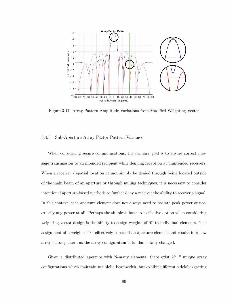
Figure 3.41: Array Pattern Amplitude Variations from Modified Weighting Vector
3.4.3 Sub-Aperture Array Factor Pattern Variance
When considering secure communications, the primary goal is to ensure correct mes-
sage transmission to an intended recipient while denying reception at unintended receivers.
When a receiver / spatial location cannot simply be denied through being located outside
of the main beam of an aperture or through nulling techniques, it is necessary to consider
intentional aperture-based methods to further deny a receiver the ability to recover a signal.
In this context, each aperture element does not always need to radiate peak power or nec-
essarily any power at all. Perhaps the simplest, but most effective option when considering
weighting vector design is the ability to assign weights of ‘0’ to individual elements. The
assignment of a weight of ‘0’ effectively turns off an aperture element and results in a new
array factor pattern as the array configuration is fundamentally changed.
Given a distributed aperture with N-many elements, there exist 2N−2 unique array
configurations which maintain mainlobe beamwidth, but exhibit different sidelobe/grating
80
lobe properties. This can be selectively energizing few or all aperture elements with the sole
condition that the end aperture elements must always be energized to maintain the aperture
baseline. From this complete set, array configurations can be selected in which a minimum
number of elements are transmitting at any given point in time. Should these unique array
configurations be applied as weights on a symbol-by-symbol or message-by-message basis,
the positions of grating lobes, sidelobes, and nulls will shift such that there is a large power
variation in non-intended receiver angles over a received transmission. A special subset of
all unique array configurations is the DPCA case when a fixed number of elements is moved
along the aperture baseline causing the mainlobe to appear to move w.r.t. a stationary
observer or remain static w.r.t. a moving observer.
Generation of a Pseudo Random Binary Sequence (PRBS) serves as a potential way
to generate all possible array configurations. In a PRBS a sequence, bits do not repeat
for up to a maximum length bits. The sequence contains all possible sequences of a fixed
length which occur in an order that statistically similar to a completely random sequence.
Usage of a PRBS source for the weighting vector causes the array factor pattern to be
highly difficult to predict for an unintended observer. Furthermore, a PRBS source can be
used to simulate all possible array configurations such that array factor pattern amplitude
minimum/maximum/difference can be calculated and used as a performance metric for a
given set of array locations.
A 10-element linear array over a 160 λ aperture baseline is considered to determine
the minimum and maximum array factor pattern levels achievable by selectively energizing
elements. In the study, each possible combination of inner-elements being in an on/off
state is considered and the corresponding array factor pattern is calculated for a range of
angles. The resulting minimum and maximum properties are plotted alongside the ratio
81

of minimum to maximum array factor pattern in Figure 3.42. The ratio of minimum to
maximum array factor pattern level serves as the foundation for amplitude based PHY layer
security mechanisms as amplitude fluctuations can be introduced across a fixed array on a
symbol-by-symbol basis.
Figure 3.42: Array Factor Amplitude Maximum for On-Off Excitation of Elements
82
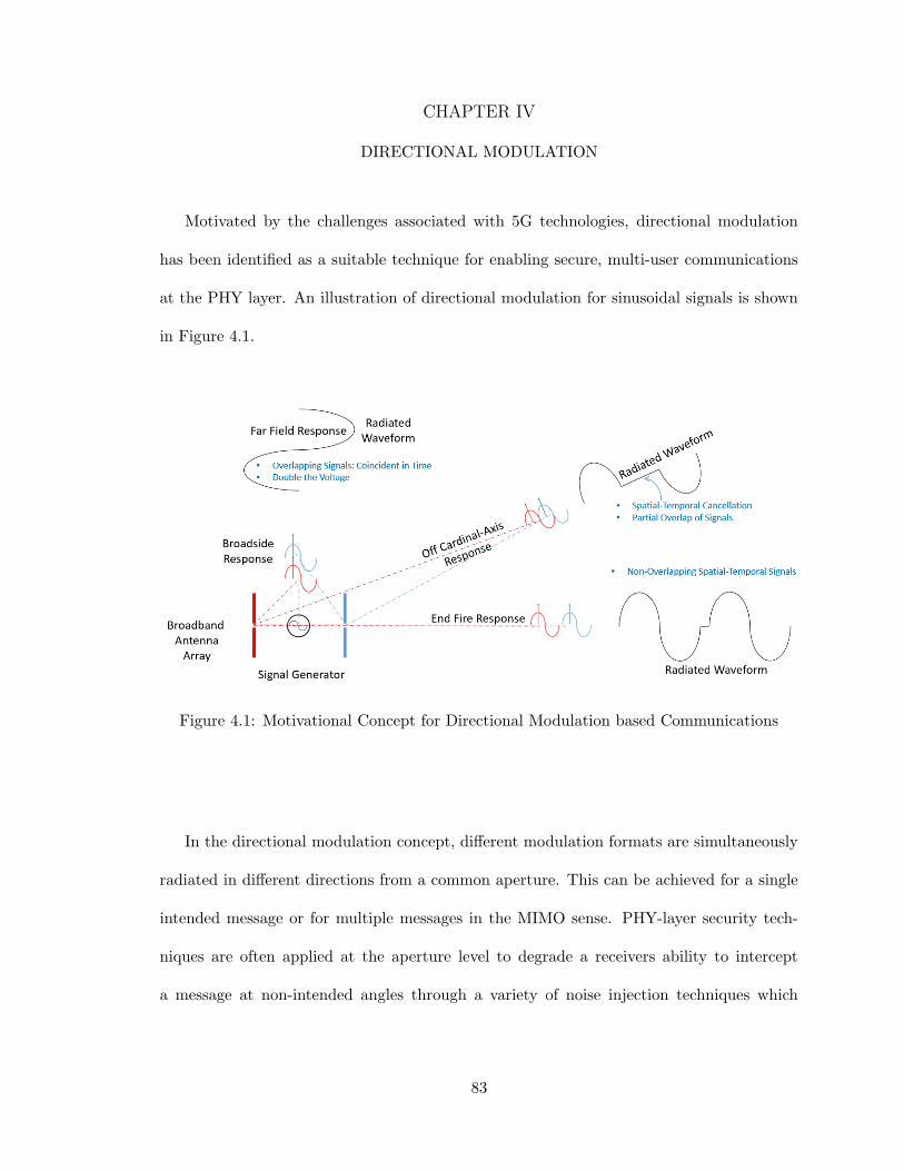
CHAPTER IV
DIRECTIONAL MODULATION
Motivated by the challenges associated with 5G technologies, directional modulation
has been identified as a suitable technique for enabling secure, multi-user communications
at the PHY layer. An illustration of directional modulation for sinusoidal signals is shown
in Figure 4.1.
Figure 4.1: Motivational Concept for Directional Modulation based Communications
In the directional modulation concept, different modulation formats are simultaneously
radiated in different directions from a common aperture. This can be achieved for a single
intended message or for multiple messages in the MIMO sense. PHY-layer security tech-
niques are often applied at the aperture level to degrade a receivers ability to intercept
a message at non-intended angles through a variety of noise injection techniques which
83
are well established in the literature. Through this combination of techniques, directional
modulation enables secure communications channels in angle space.
One current challenge in directional modulation is the transmission of messages depen-
dent on both range and angle. Several approaches to address range have been explored
in the literature, but there is currently a lack of a sound methodology to validate these
concepts and quantify the extent of their coverage/leakage of information. Although there
exist several papers in the literature which propose range dependent techniques for direc-
tional modulation, none consider physics-based aperture effects and the resulting effects on
information security. Through this research, distributed coherent aperture technology will
be leveraged to extend the current state-of-the-art in directional modulation technology by
demonstrating both a angle and range component to information security.
In this chapter, common digital modulation schemes are analyzed from a PHY layer se-
curity perspective to identify methods which ensure communications to an intended receiver
while simultaneously degrading communication with all would-be eavesdroppers. Following
this analysis, distributed communications concepts are developed based on the distributed
aperture foundations developed in the previous chapter. The accompanying analysis estab-
lishes best/worst case performance of distributed communications techniques along with a
methodology for modeling and simulation. Finally, a distributed communications simulation
tool is developed and simulations are performed to empirically establish the performance of
the developed PHY-layer security techniques.
4.1 Overview of Waveform Diversity
Effective design of secure communications concepts requires an understanding of the
degrees-of-freedom (DoF) which can be utilized within a system. In the previous chapter,
84

the DoF enabled through distributed aperture design were considered in the context of PHY
layer security. Expanding on the aperture-level DoF, the field of waveform diversity can
be considered to realize additional DoF which can be leveraged at the information content
and waveform synthesis level in a communications system. One aspect of particular impor-
tance to maximize the DoF available in a system is understanding the various orthogonal
properties and how they can be used to realize multiple signals transmitted from a common
aperture. Common orthogonal properties are listed as follows:
� In-Phase / Quadrature Components
� Polarization Diversity
� Code Division Multiplexing
� Time Division Multiplexing
� Frequency Division Multiplexing
� Beam-Space Orthogonality
While this list is not exhaustive, these techniques serve as the basis within most radar
and communications systems for enabling multi-user, multi-function system operation.
Analysis of secure communications systems from a waveform diversity perspective enables a
broad understanding of how a system can be secured/exploited and the trade space for re-
alizing simultaneous losses and gains. Furthermore, it bridges the aperture-level techniques
with the information content to establish a unified view of PHY layer security. In the
following sections, digital modulation techniques are examined from a waveform diversity
perspective to determine how to maximize aperture utilization while ensuring that would-be
eavesdroppers are unable to receive the information content transmitted by the aperture.
85

4.2 Communications Modulation Techniques
Communication over the electromagnetic spectrum requires information content to be
modulated onto a periodic carrier signal. This is typically accomplished through three
main types of modulation; analog, digital, and pulse. Among these modulation schemes,
digital modulation is of primary interest in this research due to its prevalence in modern
communications systems. Within digital modulation schemes, there exists phase-shift key-
ing (PSK), amplitude-shift keying (ASK), frequency-shift keying (PSK), and quadrature
amplitude modulation (QAM) which are unique in how each approaches the modulation
process.
Motivated by state-of-the-art directional modulation and PHY layer security techniques
in the literature, this section examines each of these digital modulation schemes for PHY
layer vulnerabilities which can be exploited though the application of distributed aperture
aided techniques. In the following analysis, each modulation scheme is evaluated from a
waveform diversity perspective and techniques are proposed to protect information in the
mainlobe while simultaneously degrading information reception to would-be eavesdroppers
at all other locations.
4.2.1 Amplitude-Shift Keying (ASK) Modulation
In Amplitude-Shift Keying (ASK) modulation schemes, digital data is modulated onto
a periodic carrier waveform as variations in amplitude. As a form of digital modulation,
there must exist a finite number of amplitude levels which represent the modulated digital
data. For instance, two discrete amplitude levels represent a single bit, four discrete levels
represent two bits, eight discrete levels represent three bits, and so on. Since amplitude levels
86

must be highly distinguishable for demodulation to be performed, the channel SNR will
determine how many amplitude levels can be used. From a PHY-layer security perspective,
this leaves ASK modulation highly susceptible to intentional variations in amplitude level
during the transmission of a message.
As a simple illustration of this concept, On-Off Keying (OOK) modulation is considered.
As the simplest form of ASK, OOK represents digital data through the presence/absence
of the carrier wave. A binary ’1’ is represented through the presence of the carrier, and
a binary ’0’ state is represented through the absence of the carrier. During demodulation
with a hard-decision boundary, OOK requires a high average bit energy-to-noise power
spectral density (Eb/N0) relative to other digital modulation schemes. [45] When multiple
amplitude levels are considered in ASK modulation schemes, the energy-to-noise power
spectral density becomes the limiting factor in the demodulation process as this determines
how closely constellation points can be located such that demodulation can occur under
reasonable SNR considerations.
PHY Layer Analysis
From a PHY layer security perspective, ASK modulation inherently requires a consis-
tent analog channel. Therefore, time-varying channel behavior created through aperture
effects presents a potential vulnerability of ASK modulation schemes. Based on the anal-
ysis performed in the prior chapter, the complex weighting vector employed in traditional
or distributed aperture beamforming can be used to introduce time-varying changes in the
amplitude and phase properties of an analog channel between the transmit aperture and an
unintended receiver.
87

There exist several PHY-layer techniques which can be applied to corrupt the channel
between the transmit aperture and an eavesdropper. By utilizing the degrees of freedom
provided by beam-space synthesis, changes in the antenna weighting vector can be used to
obfuscate message content using seemly random fluctuations in sidelobe amplitude levels.
Assuming a fixed sum of weights, the received signal amplitude in the sidelobes depends
both on the message content at an instance in time and the antenna weighting vector.
Depending on the distribution of the weighting vector, amplitude fluctuations can range
from 3 dB gain to 20 dB or more of loss from the ideal amplitude levels as was found
through simulations in the prior chapter. The resulting symbol-by-symbol variation in
amplitude levels will increase the BER across an entire message received by eavesdroppers.
Due to the synchronization between these events, the message is not recoverable in the
intercepted grating lobes and sidelobes as amplitude changes from antenna weighting are
not separable from the message content. This technique draws from MIMO directional
modulation schemes in which different transmitter indices being switched on/off results
in changes in the sidelobe angles in the AF pattern, but is unique in that the received
amplitude at each spatial location does not correspond to the information content.
A second technique that can be used to corrupt eavesdropper channels is the injection of
artificial noise (AN) into the aperture beam pattern. This concept has been widely explored
in the directional modulation literature and has been found to be highly effective against
eavesdroppers for a variety of modulation schemes. In this technique, AN is projected into
the null-space of the aperture steering vector such that AN is projected to all eavesdroppers
while a minimal amount of AN is transmitted in the direction of the intended recipient. [46]
This technique is versatile in nature and can be ”layered” onto other PHY-layer techniques
to maximize channel corruption for would-be eavesdroppers.
88

A final PHY layer technique for ASK modulated signals is leveraging the true-time
delay properties of distributed apertures. The spatial diversity afforded through distributed
apertures results in information content from each transmit aperture element reaching an
eavesdropper location at a different point in time. When considering the delay between the
signal from the closest aperture element and the farthest aperture element from a point
in space, it is possible that signal content from one symbol period will “leak” into the
next demodulation period. The resulting signal received at any point in time becomes the
linear superposition of many signals of potentially different information content. Should
enough signal energy leak into the next demodulation period, it is likely that the hard
decision boundary utilized during demodulation will incorrectly map the received signal.
This results in the corruption of the received signals and dependent on the spatial properties
of the channel, results in the true information content becoming unrecoverable.
4.2.2 Phase-Shift Keying (PSK) Modulation
In Phase-Shift Keying (PSK) modulation schemes, digital data is modulated onto a
periodic carrier waveform as variations in phase. As a form of digital modulation, there must
exist a finite number of phase angles which represent the modulated digital data. Common
PSK modulation schemes include Binary PSK (BPSK) and Quadrature PSK (QPSK) which
represent 1 or 2 bits of information through 2 or 4 phase angles, respectively. Higher-order
PSK modulation formats such as 8-PSK exist, but are often not used as the error-rate
becomes too high compared to other modulation schemes. Since demodulation of PSK
modulated signals is based in phase detection, PSK schemes are more resilient to changes
in SNR than ASK modulation schemes. From a PHY layer security perspective, secure
89

communications using PSK modulation schemes requires multiple symbol interference to
decrease demodulation performance.
PHY Layer Analysis
There exist several PHY layer techniques which can be applied to corrupt the channel
between the transmit aperture and an eavesdropper for PSK modulation schemes. A first
technique is the utilization of the spatial diversity as afforded by distributed apertures.
When the delay between the signal from the closest aperture element and the farthest
aperture element from a point in space is considered, it is possible that signal content from
one symbol period will “leak” into the next demodulation period. As the aperture baseline
is extended, information content from multiple symbols away in a message can interfere at a
point in space and time. For PSK modulation schemes, the linear superposition of multiple,
potentially dissimilar, signals can result in constructive reinforcement, partial destructive
interference, or total destructive interference in the in-phase / quadrature domain resulting
in incorrect demodulation of information symbols.
A second PHY layer security technique effective against PSK modulation schemes is
AN injection into the null-space of the aperture steering vector. This technique is generally
effective against all modulation schemes as the presence of high levels of noise degrades the
SNR in the channel. While PSK modulation schemes such as BPSK are somewhat resilient
to low SNR conditions, higher order PSK modulation schemes become quickly degraded
as SNR conditions decrease. Regardless of performance in low SNR conditions, injection
of AN at levels at or above that of the intended message content will severely degrade
communications system performance.
90

4.2.3 Frequency Shift Keying (FSK) Modulation
In Frequency-Shift Keying (FSK) modulation schemes, digital data is represented by
shifts in the frequency of a periodic carrier waveform. As a form of digital modulation,
there exist a finite number of frequency offsets which represent the modulated digital data.
The simplest form of frequency modulation, Binary Frequency-Shift Keying (BFSK), uses
a pair of frequencies to transmit binary information. Meanwhile, multiple FSK (MFSK)
modulation schemes exist where more than two frequencies are utilized, often equally spaced
within an frequency offset from the carrier frequency. [47]
There exist numerous advantages of FSK modulation including better immunity to noise
as compared with other modulation schemes as well as a lower probability of error during
reception. Unfortunately, this comes at the cost of lower spectral efficiency as offsets between
frequencies do not fully utilize the spectral resources available over a given bandwidth. [48]
From a PHY layer security perspective, FSK modulation is less susceptible to artificial
noise driven techniques as this technique provides an inherently high SNR as information
is carried on separate frequencies. For this reason, alternate methods must be considered
to achieve spatial isolation for which a transmitted message can be successfully received.
PHY Layer Analysis
From a PHY layer security perspective, FSK modulation assumes that only valid tone
combinations will exist at any instance in time. For BFSK modulation it is assumed that
either the ”mark” frequency or the ”space” frequency will be transmitted, but not both.
Similarly, in MFSK modulation schemes, it is assumed that each frequency will only be
present when it corresponds to the underlying information being transmitted. From this
91
perspective, there exist several PHY layer techniques which can be applied to corrupt the
channel between the transmit aperture and an eavesdropper.
By utilizing the degrees of freedom afforded through distributed aperture beam-space
synthesis, it is possible to transmit different frequency content in the sidelobes than in the
mainlobe. This is achieved by injecting signal content into the aperture which has a beam-
space null in the direction of the intended receiver. Utilizing this technique, injection of
frequency content, rather than artificial noise, can be used to corrupt message reception
to unintended receivers. A modified FSK modulation scheme would transmit the correct
frequency to a desired location (the receiver) while transmitting multiple frequencies with
controlled, but varying, amplitudes to all other locations (the eavesdroppers). Interception
of FSK modulated messages by easvsedroppers under this technique would be prevented as
determining the correct symbol frequency mapping at a given point in time would not be
possible. For this technique to be sucessful, an algorithm must be created which varies from
the inteferer model for FSK modulation schemes where the amplitude of each frequency is
assumed to be constant and interferers would exist at a different received power level. [49]
For FSK modulated signals, a suitable PHY-layer security algorithm shall:
� Maximize the gain of the correct frequency signal in the receiver direction
– Over all angles within the main beam
� Minimize the gain of the incorrect frequency signal in the receiver direction
– Also, over all angles within the main beam
� Vary the gain of both frequency signals in all other directions
– Variation on a bit-by-bit basis
92
– Seemly random appearance of variation
– Statistically equal amplitudes
A second PHY-layer technique applicable to FSK is again leveraging the true-time delay
properties of distributed apertures. The spatial diversity afforded by distributed apertures
results in information content from each transmit aperture element reaching an eavesdropper
location at a different point in time. In the context of FSK, both/multiple frequencies can be
present during the same reception period as signal content from one symbol period ”leaks”
into the next demodulation period. Since multiple frequencies may interfere, each frequency
will have a power level resultant from the constructive/destructive phase coherence at each
frequency. This means that each location in space will receive different power levels and
frequencies based on the distributed aperture configuration for a given weighting vector
and transmitted information content. As a result of the presence of multiple frequencies at
varying power levels, the demodulation process will be degraded.
4.3 Distributed Coherent Communications
In the previous chapter, the sparse aperture waveform (SAW) concept was developed
to describe the interaction of multiple sparse/distributed aperture signals in the near-field.
This concept is naturally extensible to communications signals through the realization that
all manifestations of electromagnetic (EM) energy in space and time correspond to an
underlying (digital) message. This distinction is important as techniques in the secure com-
munications literature normally consider how to degrade the reception of a source message,
but not how to fundamentally change the underlying information content that is present
at a point in space and time. Since sparse/distributed apertures fundamentally change the
information content present at each point in space and time, they create a natural form of
93

information security in the spatial domain. When the reception and demodulation process
is subsequently considered, would-be eavesdroppers may be able to demodulate the mes-
sage which manifests itself at their location, but the message itself may not be the same as
the source message. In such an instance, security can be quantified by how dissimilar the
underlying message is at a spatial location rather than the likelihood that a symbol will be
demodulated in error.
For secure communications, it is always necessary to provide assured communications
between a transmitter and an intended receiver, while denying all other would-be eaves-
droppers the ability to intercept the message. This inherently requires distributed aperture
signals to be coherent at the location of an intended receiver, therefore requiring the develop-
ment of distributed coherent communications concepts. Techniques in distributed aperture
coherence from the previous chapter may be leveraged to achieve coherence of communica-
tions signals at the location of an intended receiver. By applying such techniques, a number
of assumptions can be made as to the expected system behavior. First of all, it is assumed
that BER is arbitrarily high at all angles and all ranges except for a spatial location at
which the signals are cohered. Furthermore, it is assumed that poor BER is maintained in
non-cohered locations across ALL SNR values, rather than following the typical curve which
shows BER increase as SNR decreases. These assumptions provide a reasonable hypothesis
for modeling and simulation of distributed coherent communications as the combined effect
of communications modulation parameters (samples-per-symbol, modulation type, signal
constellation, bandwidth) and aperture element configurations in the spatial domain are
considered.
From a PHY layer security perspective, performance bounding is necessary to deter-
mine the viability of distributed aperture communications techniques as an effective means
94

to deny would-be eavesdroppers. Traditional techniques in performance bounding have
been determined to be insufficient as the interactions between systems cannot be modeled
through closed-form expressions. Instead, a system-of-systems perspective is adopted for
analysis in which each individual system is studied in isolation. For each system, all param-
eters dependent on other systems are abstracted such that an understanding of best/worst
case performance can be studied over a wide range of values and operation conditions. For
instance, the super-set of all possible aperture configurations can be abstracted to distances
between elements w.r.t any point in space to isolate the effect of spatial diversity on spa-
tial message dependence. The analysis presented in the following sections develops a new
paradigm for modeling PHY layer effects and subsequently evaluates distributed coherent
communications within this paradigm to establish realistic expected performance against
would-be eavesdroppers. These studies include the analysis of time and spatial domain sym-
bol interference caused by distributed apertures and the development of spatial bounding
over which assured communications are expected to occur.
4.3.1 Multi-Transmitter Symbol Interference
For all of the distributed aperture configurations studied thus far, the signal content at
a point in space and time consists of the spatio-temporal interference of the source signals
as propagated to that location. Rather than arbitrary waveforms from the source, dis-
tributed coherent communications considers the propagation, and therefore interference, of
communications signals which represent underlying information content. Taking a modula-
tion format agnostic approach to analysis, distributed aperture geometries are generalized
such that the number of interfering signals of similar/dissimilar information content can be
determined and the effect of multiple symbol interference can be characterized.
95

Consider an N-element distributed aperture which is radiating a sequence of communi-
cations symbols with one sample per symbol to all non-intended receiver locations. Based
upon the digital sampling rate employed by the transmit aperture, relative true-time delays
can be calculated between the positions of the transmit sub-apertures and an unintended
receiver location. These relative delays represent the separation of signal energy (with the
same information content) at an observed point in space. When identical signals are trans-
mitted from all sub-apertures, there are several symbol interference scenarios which can
occur during over-the-air transmission within the radiative near-field. Assuming contin-
uous signal transmission, the number of overlapping signals is constant and equal to the
number of sub-apertures operating in the distributed aperture. A generalization of the
interference scenarios which may occur are as follows:
1. Total Constructive Reinforcement
2. Partial Constructive Reinforcement
3. Total Destructive Interference of In-Phase OR Quadrature Component
4. Total Destructive Interference of In-Phase AND Quadrature Components
5. Partial Destructive Interference
To visualize all of these phenomena, symbol interference diagrams have been created
for BPSK and QPSK modulation schemes as shown in Figure 4.2 and Figure 4.3, respec-
tively. In each of these figures, the base symbol constellation is shown alongside interference
scenarios for two and three symbol interference cases.
96

Figure 4.2: BPSK Symbol Interference: No Interference (Left), 2-Signal Interference (Cen-ter), 3-Signal Interference (Right)
The BPSK modulation case exhibits both total constructive reinforcement and total
destructive reinforcement in the 2-symbol interference case. For the 3-symbol interfer-
ence case there is a combination of total constructive reinforcement, partial constructive
reinforcement, and partial destructive interference. The latter of these scenarios for the
3-symbol interference case occurs when two (delayed) symbols of dissimilar information
content interfere with one symbol of the correct information content.
97
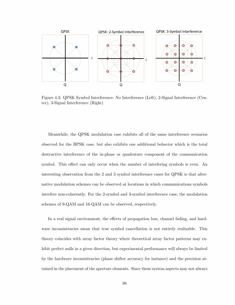
Figure 4.3: QPSK Symbol Interference: No Interference (Left), 2-Signal Interference (Cen-ter), 3-Signal Interference (Right)
Meanwhile, the QPSK modulation case exhibits all of the same interference scenarios
observed for the BPSK case, but also exhibits one additional behavior which is the total
destructive interference of the in-phase or quadrature component of the communication
symbol. This effect can only occur when the number of interfering symbols is even. An
interesting observation from the 2 and 3 symbol interference cases for QPSK is that alter-
native modulation schemes can be observed at locations in which communications symbols
interfere non-coherently. For the 2-symbol and 3-symbol interference case, the modulation
schemes of 9-QAM and 16-QAM can be observed, respectively.
In a real signal environment, the effects of propagation loss, channel fading, and hard-
ware inconsistencies mean that true symbol cancellation is not entirely realizable. This
theory coincides with array factor theory where theoretical array factor patterns may ex-
hibit perfect nulls in a given direction, but experimental performance will always be limited
by the hardware inconsistencies (phase shifter accuracy for instance) and the precision at-
tained in the placement of the aperture elements. Since these system aspects may not always
98
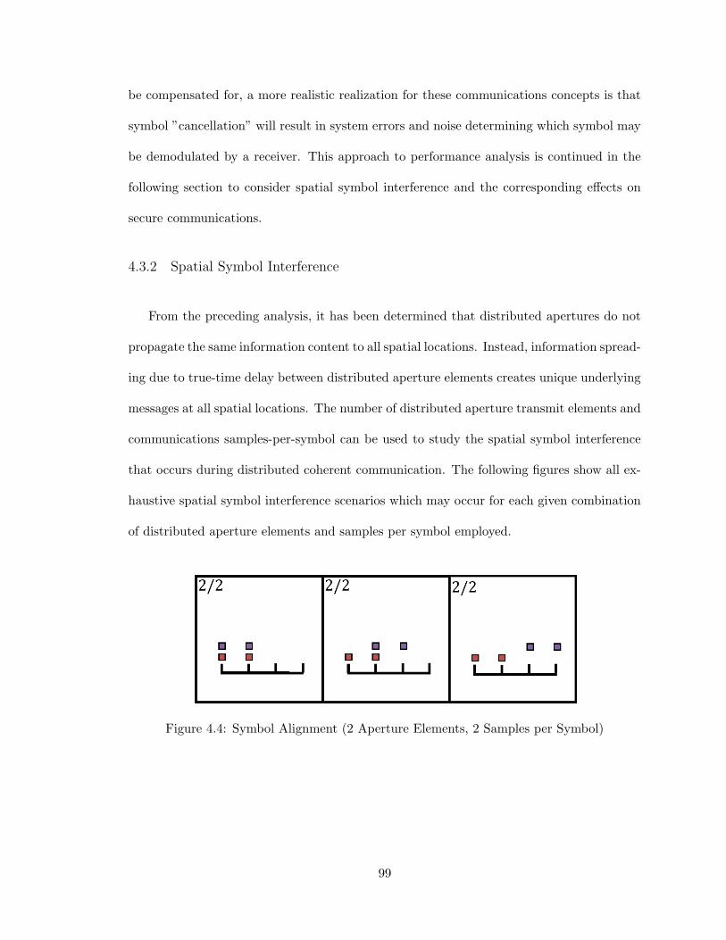
be compensated for, a more realistic realization for these communications concepts is that
symbol ”cancellation” will result in system errors and noise determining which symbol may
be demodulated by a receiver. This approach to performance analysis is continued in the
following section to consider spatial symbol interference and the corresponding effects on
secure communications.
4.3.2 Spatial Symbol Interference
From the preceding analysis, it has been determined that distributed apertures do not
propagate the same information content to all spatial locations. Instead, information spread-
ing due to true-time delay between distributed aperture elements creates unique underlying
messages at all spatial locations. The number of distributed aperture transmit elements and
communications samples-per-symbol can be used to study the spatial symbol interference
that occurs during distributed coherent communication. The following figures show all ex-
haustive spatial symbol interference scenarios which may occur for each given combination
of distributed aperture elements and samples per symbol employed.
Figure 4.4: Symbol Alignment (2 Aperture Elements, 2 Samples per Symbol)
99

Figure 4.5: Symbol Alignment (2 Aperture Elements, 3 Samples per Symbol)
Figure 4.6: Symbol Alignment (3 Aperture Elements, 2 Samples per Symbol)
100

Figure 4.7: Symbol Alignment (3 Aperture Elements, 3 Samples per Symbol)
The alignment of information content in each of these instances represents the time
domain visualization of the coherence basket concept established in the previous chapter.
Although the alignment of information content from less than the maximum number of
aperture elements does inherently mean that there is information interference, the infor-
mation content will be demodulated incorrectly if the modulation scheme densely occupies
the constellation domain and interfering symbols are located far away in the constellation
diagram.
4.3.3 Communications Coherence Basket
In the previous chapter, a generalized ”coherence basket” concept was developed for
distributed apertures. The analysis of the coherence basket and its corresponding spatial
extent was defined in terms of instantaneous signal bandwidth and aperture spatial diver-
sity in order to remain waveform agnostic. For communications systems, there exist several
101

modulation parameters which effect the bandwidth and corresponding spatial extent of
the coherence basket including samples-per-symbol and pulse shaping filter roll-off factor.
The samples-per-symbol in a communications system describes how many digital samples
are used to represent a single symbol in the time domain. Since the instantaneous sig-
nal bandwidth describes the minimum resolvable pulse width, the employment of multiple
samples-per-symbol effectively reduces the minimum resolvable pulse width resulting in an
increase in the coherence basket size. The effective bandwidth is represented mathematically
as follows:
Beffective = NspsB (4.1)
where B is the instantaneous communications signal bandwidth and Nsps is the number
of samples-per-symbol.
Meanwhile, pulse shaping filters present another consideration for the minimum spatial
extent of a communications symbol. Typically, pulse shaping filters such as the root-raised
cosine (RRC) filter are used to limit inter-symbol interference (ISI) in the temporal domain
by limiting the effective bandwidth of the symbol. While this technique is effective in
limiting the effect of distortion in communications channels, the limiting of the effective
bandwidth corresponds to a larger spatial extent over which a communications symbol can
be intercepted at a snapshot in time. This can be expressed mathematically as follows:
Beffective =(1 + β)Rp
2(4.2)
102
where Beffective is the effective bandwidth, β is the pulse shaping filter rolloff factor,
and Rp is the communications pulse rate.
From this analysis it is evident that communications techniques which facilitate assured
communications to an intended receiver also enable a wider spatial reception zone over which
eavesdroppers can intercept information since decreased bandwidth results in increase spa-
tial coherence basket extent. Although arbitrarily increasing the signal bandwidth reduces
the size/extent of the coherence basket, this approach is generally impracticable in real
communications systems. Channel bandwidths employed by 4G/5G communications sys-
tems provide limited spatial symbol resolution and general scaling of channel bandwidth
(without regard for spectrum licensing) still requires increasingly more complex and expen-
sive hardware. An alternate and complementary method for reducing the coherence basket
extent is increasing the aperture baseline. This conclusion exemplifies the importance of
spatial diversity though distributed apertures to enable spatially secure communications.
4.3.4 PHY Layer Security Considerations for Communications
At the beginning of this chapter, digital modulation schemes where evaluated for PHY
layer security vulnerabilities. As a general means of achieving secure communications, the
coherence basket concept is highly effective limiting the region over which reception of the
source information content is possible. Beyond this technique, there were several PHY
layer security techniques developed in the previous chapter which were identified to be
effective in denying eavesdroppers. The identified techniques including aperture weighting
vector manipulation and sub-aperture selection must be considered in the context of secure
communications to realize the true benefits of these techniques.
103

In the first PHY layer security technique, the aperture weighting vector is considered
as source of signal amplitude variance in both the near-field and far-field regions. Through
this technique, changes in the weighting vector result in variable gain in the sidelobes
of the array factor pattern while maintaining gain within the mainlobe of the aperture.
In order for this technique to be effective in impacting the reception of ASK and QAM
modulated signals, the changes in the array factor pattern must not be separable from the
information content being transmitted. This is addressed through synchronizing aperture
weighting vector changes with changes in the information content on a symbol-by-symbol
basis. Provided that there are sufficiently many sets of weights which are applied randomly
with regard to the information content, this technique will effectively prevent the true
information content from being decoupled from the received amplitude at non-intended
receiver locations. It should be noted that this technique is only effective on amplitude
based modulation schemes and at spatial locations for which sufficient variation in array
factor pattern gain can be achieved through changes to the aperture weighting vector. For
these reasons, this technique should be used in conjunction with other PHY layer techniques
in order to assure PHY layer security over all of space and time.
The second PHY layer security technique utilizes sub-apertures within a distributed
aperture to achieve variance in the locations of sidelobes and grating lobes in the array fac-
tor pattern. While this technique is again effective at disrupting the reception of ASK and
QAM modulation formats, there are further implications which can be drawn within the
context of communications. Consider an arbitrary four element distributed aperture which
is cohered to a point in space. Each element in the aperture operates independently from
all other aperture elements and transmits signal content with a delay and phase shift which
corresponds to the coherence location. Since each aperture element operates independently,
104
any sub-set of the aperture can be enabled at any point in time and the signal content at
the cohered location will still be the same (with a magnitude corresponding to the number
of active transmitters). Meanwhile, the signal content at all other spatial locations outside
the coherence basket is determined by the interference of the transited signals as delayed
by the aperture geometry. As aperture elements are switched on/off, the resulting infor-
mation symbols which cohere at all spatial locations will change. This switching behavior
introduces both amplitude variation from a signal energy standpoint as well as variation in
the information content that is present at any location. The combination of these factors
make this PHY-layer technique effective against all types of digital modulation schemes.
A final PHY layer security technique is the application of artificial noise injection as is
widely considered in the literature. While every technique considered thus far can be used
to fundamentally change the information content that is received at all locations in space
and time, the layered model to information security adopted in this research benefits from
the simultaneous application of as many techniques as possible. The application of artificial
noise injection degrades the SNR at all locations outside of the main beam of the aperture
therefore increasing the BER of all would-be eavesdroppers.
4.4 Simulation Methodology & Results
Effective modeling and simulation of communications systems requires in-depth knowl-
edge of both the deterministic and random processes which comprise the system. For mod-
eling simple communications phenomena such as the performance of a communications link
in Gaussian noise, closed-form mathematical models are readily available. As more complex
communications systems are considered, higher fidelity models are needed to address the
transient effects occurring within analog/digital receivers, inter-symbol interference (ISI),
105

and rapidly changing communications channels. In these instances, computer-aided simu-
lations are often favored to capture the effects of random processes which cannot be aptly
modeled in closed form. Effective characterization of the PHY-layer security concepts ex-
plored in this research requires the use of computer-aided simulations as intentionally cor-
rupted channels will exhibit variable performance in the spatial and temporal domains.
The following sections describe the communication simulator implementation and paramet-
ric studies performed in support of the research hypotheses.
4.4.1 Communications System Implementation
Simulation of the PHY-layer techniques presented in this research requires simultaneous
consideration for the spatial, spectral, and temporal domains. Conventional simulation soft-
ware packages for communications well represent the spectral and temporal domains, but
insufficiently model the spatial effects of constructive/destructive wave interference which
occur during near-field and far-field propagation. Based on this assessment of commu-
nications simulation software, an open-source software package called GNU Radio [50] is
selected as the foundation for which a suitable spatial/spectral/temporal simulator can be
constructed.
GNU Radio is an open-source software toolkit for implementing signal processing sys-
tems and software defined radio. The software provides a block based approach to signal
processing providing an extensive library of communications sub-system models and exten-
sive flexibility for block specification in the C and Python programming languages. This
framework provides a unique software development pipeline which enables algorithm proto-
typing, system simulation, and experimentation for PHY-layer concepts all within the same
platform. An example GNU Radio ”flowgraph” is shown in Figure 4.8.
106

Figure 4.8: PHY-Layer Simulation Architecture in GNU Radio
Using the capabilities provided through GNU Radio, an end-to-end communications
system simulator is designed to obtain performance bounds on common modulation schemes
operating under the researched PHY layer techniques. The following sections detail the
software implementation including the modulation schemes and PHY-layer channel model
used to perform spatial BER simulations.
Binary Data
A bit error rate tester (BERT) describes test equipment which measures the quality of
a communications link as received by a device under test. The utilized performance metric,
bit error rate (BER), is the rate at which incorrectly demodulated bits occur. Calculation
107

of such a performance metric requires two data components; a test pattern and preamble
sequence. The test pattern is a sequence of bits for which the BER is calculated against
while the preamble sequence is used to align the received test pattern with the reference
test pattern.
A suitable test pattern should be of sufficient length such that a BER can be specified
with a given confidence level, test all possible inter-symbol interference (ISI) cases, and
optimally be normally distributed in nature. Pseudo-random binary sequences (PRBS) are
generally employed in BERT equipment to satisfy these requirements. PRBS generation
is achieved through linear-feedback shift registers which utilize a feedback polynomial of
previous shift register values to generate the next value in the sequence. Maximal-length
polynomials exist which maximize the period of the sequence for a given number of bits. A
table for common maximal-length feedback polynomials given as follows using polynomials
found in [51].
Table 4.1: Common PRBS Feedback Polynomials
Bits (N) Period (2N − 1) Feedback Polynomial
7 127 x6 + x5 + 115 32,767 x15 + x14 + 123 8,388,607 x22 + x21 + 1
Sequences generated using the maximal-length feedback polynomials exhibit a high auto-
correlation to sidelobe ratio which make their usage as a preamble sequence ideal. For this
reason, a PRBS will be used for both the preamble and data sequences such that effective
preamble detection can be performed and all ISI cases for a given number of bits can be
evaluated within the communications channel.
108

Modulation
Following the analysis of various digital modulation schemes at the beginning of this
chapter, ASK, PSK, and QAM modulation schemes were identified to be highly susceptible
to the PHY-layer effects studied in this research. Based on this assessment, BPSK, QPSK, 8-
PSK, and 16-QAM modulation formats are considered for symbol modulation. A summary
of the modulation formats along with common characteristics are given in the following
table.
Table 4.2: Digital Modulation Scheme Characteristics
Modulation ModulationType
Bits perSymbol
Phases I-ChannelLevels
Q-ChannelLevels
BPSK PSK 1 2 N/A N/AQPSK PSK 2 4 N/A N/A8-PSK PSK 3 8 N/A N/A16-QAM ASK 4 N/A 4 4
Data modulation using each of these modulation schemes is implemented in GNU Radio
using the ”Constellation Modulator” block. For each modulation format, the binary data-
stream is mapped to points on the constellation diagram according to the bits-per-symbol
and constellation points associated with the scheme. The resulting constellation point, rep-
resented in the time domain as a complex signal consisting of the respective in-phase and
quadrature components, is repeated successively in the time domain according to the spec-
ified samples-per-symbol. As a final step, a pulse shaping filter is applied to the modulated
data-stream to bandlimit the signal. This process is performed using a root-raised cosine
filter with a excess bandwidth of 0.35, or 35 percent.
109

During the modulation/demodulation process, there exists an ambiguity in many digital
modulation formats which causes the received signal, post clock-recovery, to map constel-
lation points to the wrong symbols. For BPSK, there exists a 180 degree phase ambiguity,
while higher order modulations such as QPSK and 8-PSK have 90 degree and 45 degree
phase ambiguities, respectively. Differential coding is a technique which provides unam-
biguous signal demodulation when ambiguous signal states exist through pre-coding and
decoding the data-stream. The data in this process becomes dependent on both the current
state as well as the prior state. This technique is applied for all PSK and QAM formats to
resolve unambiguous signal reception.
Data and Preamble Separation
Due to the high anticipated BER in the simulated communications schemes, pream-
ble detection cannot be guaranteed for all simulated scenarios. To address this issue, the
preamble pattern and data patterns are separated after modulation and subjected to sepa-
rate channel models before being recombined at the output. The data pattern is subjected
to a channel model considering all modeled PHY layer effects while the preamble pattern is
only subjected to basic propagation effects. Through this process, preamble detection can
be assured such that the true BER can be calculated for every simulation scenario. This is
essential in determining the true effectiveness of PHY layer techniques.
Channel Modeling
The distributed aperture channel model considers the effects of distributed aperture
propagation and the application of coherence parameters in the near-field region. In the
formulation of a channel model, the full sample delay, τ , and phase shift, θ between each
110

distributed aperture transmit element location and a receiver location are calculated as
follows:
τ [i] =
⌊‖PRX(x, y, z)− PTX(x, y, z)[i]‖2c/fs
⌋, i = 1, 2, ..., N (4.3)
θ[i] = 2π
[‖PRX(x, y, z)− PTX(x, y, z)[i]‖2c/fs
mod 1
], i = 1, 2, ..., N (4.4)
where PRX(x, y, z) is the array of transmitter element locations, PRX(x, y, z) is the
receiver element location, c is the speed of light, and fs is the receiver sampling frequency.
The calculation of delay and phase shift is repeated for the coherence location in order
to determine the coherence parameters as follows:
τCOT [i] =
⌊‖PCOT (x, y, z)− PTX(x, y, z)[i]‖2c/fs
⌋(4.5)
θCOT [i] = −2π
[‖PCOT (x, y, z)− PTX(x, y, z)[i]‖2c/fs
mod 1
](4.6)
where all parameters are identical to the previous calculations except for PCOT (x, y, z)
which is the coherence location rather than the receiver location.
The delay parameters calculated for both the receiver location and coherence location
must be normalized to express only the differences in path delay between each transmitter
element and the receiver/coherence location in space. This is achieved though subtraction
111

of the minimum delay in each set such that all delays are relative to the transmit aperture
element with the minimum delay relative to the location of interest in space.
τ [i] = bτ [i]−min τc , i = 1, 2, ..., N (4.7)
τCOT [i] = bτCOT [i]−min τCOT c , i = 1, 2, ..., N (4.8)
For the coherence parameter delay, this process must be taken one step further such
that signals are aligned at the coherence location in space. In essence, the signal observed
at the coherence location must appear as if no delay is present between aperture elements
at that location in space. This is achieved using the following algorithm:
τCOT [i] = max τCOT − τCOT [i], i = 1, 2, ..., N (4.9)
The resulting delay and phase shift vectors for the communications channel being mod-
eled as as follows:
τchannel = τ + τCOT (4.10)
θchannel = θ + θCOT (4.11)
The second aspect of near-field channel modeling is the calculation of propagation loss
between each distributed aperture transmit element and the receiver location.
112

L[i] =
(λ
4π‖PRX(x, y, z)− PTX(x, y, z)[i]‖2
)2
, i = 1, 2, ..., N (4.12)
where λ is the wavelength at the communications channel center frequency. The resulting
received power from each distributed aperture transmit element at the receiver location is
then calculated and normalized:
Before received power can be considers, the effects of phase coherence loss (e.g. ar-
ray factor pattern) must be calculated. It is assumed that all aperture elements have an
equal weight such that the coherence loss is only dependent on the normalized path loss
between each distributed aperture transmit element and the receiver location. The modified
expression for coherence loss is given as follows:
AF =N∑n=1
L[i]
maxLexp−jθchannel[i] (4.13)
From the path loss vector and the coherence loss, AF, it is now possible to calculate the
received power from each individual transmitted signal as follows:
PRX [i] = GTX,dB +GRX,dB + PTX,dB + 10log10L[i] + 10log10|AF |, i = 1, 2, ..., N (4.14)
PRX.normalized[i] =PRX [i]
maxPRX, i = 1, 2, ..., N (4.15)
where GTX is the transmitter antenna gain in dB, GRX is the receiver antenna gain in
dB, PTX is the transmitter power in dBm, and PRX is the resulting received power from
each transmit aperture element.
113

The resulting delays, phase shifts, and losses calculated through the channel model are
applied at the signal level to compute the signal incident at the receive aperture such that
communications demodulation can be performed.
Demodulation
A traditional demodulation architecture is employed in the GNU Radio based simulator
where received signals are processed using a frequency locked loop, polyphase clock sync,
and Costas loop. This architecture enables signal demodulation in the presence of frequency
and phase offsets. Once the carrier signal is recovered and frequency offsets are corrected
for, hard decision boundaries are used to map signals on the constellation diagram back to
symbols. Following the symbol mapping process, a differential coding demapping process
is applied to reverse the differential coding process and recover the correct symbols free
of ambiguities. Following the demapping process, a differential decoder is applied to the
bitstream to recover the original information content.
Bit Error Rate Calculation
Using the demodulated bitstream, the BER must be calculated for each simulated sce-
nario. As discussed earlier in this section, the source bitstream is structured as follows:
Guard Bits — Preamble — Guard Bits — Data Sequence
where guard bits are repeated binary zeros, the preamble is a sequence with high auto-
correlation properties, and the data sequence is a PRBS of sufficient length such that
the BER can be computed to a desired accuracy. Detection of the preamble sequence
requires convolution of the reference preamble sequence with the received bitstream. It
114
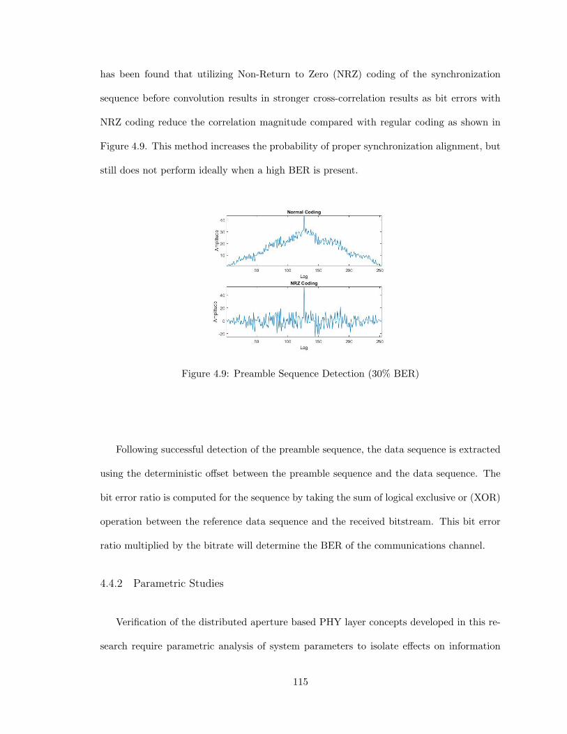
has been found that utilizing Non-Return to Zero (NRZ) coding of the synchronization
sequence before convolution results in stronger cross-correlation results as bit errors with
NRZ coding reduce the correlation magnitude compared with regular coding as shown in
Figure 4.9. This method increases the probability of proper synchronization alignment, but
still does not perform ideally when a high BER is present.
Figure 4.9: Preamble Sequence Detection (30% BER)
Following successful detection of the preamble sequence, the data sequence is extracted
using the deterministic offset between the preamble sequence and the data sequence. The
bit error ratio is computed for the sequence by taking the sum of logical exclusive or (XOR)
operation between the reference data sequence and the received bitstream. This bit error
ratio multiplied by the bitrate will determine the BER of the communications channel.
4.4.2 Parametric Studies
Verification of the distributed aperture based PHY layer concepts developed in this re-
search require parametric analysis of system parameters to isolate effects on information
115

security. In particular, parameters including modulation format, distributed aperture con-
figuration, bandwidth, and samples-per-symbol are of interest. Utilizing the distributed
coherent communications simulator to simulate individual test scenarios, a Python script is
created interface with the simulator and update parameters such that range/angle studies
can be performed. The simulator is verified in the next section followed by the parametric
study in range/angle of multiple system configurations to validate PHY layer concepts.
Simulator Verification
The techniques described in the previous sections are implemented in GNU Radio to
create a distributed coherence communications simulator as shown in Figure 4.10. In order
to verify the operation of the simulator before performing parametric studies, a BPSK test
sequence is simulated for a four element distributed aperture with aperture elements at
locations (-200 m, 0 m), (-66.67 m, 0 m), (66.67 m, 0 m), and (200 m, 0 m) which is cohered
to a location of (321 m, 383 m). At the cohered location where there is no true-time delay
between aperture elements, reception of the BPSK signal is expected to occur with an error
rate corresponding only to the SNR in the channel. Through initial testing of the simulator,
reception of the BPSK test sequence was found to be successful and the BER was influenced
only by the SNR and not the distributed aperture phenomena which is as expected given
observation at the coherent location in space. Now that the simulator has been verified,
angle and range studies for a four element linear distributed aperture are performed to
quantify the effects of distributed aperture channels on BER.
116

Figure 4.10: Distributed Coherence Communications System Simulator Flowgraph
4.4.3 Angle Study
A standard metric of performance in PHY layer security is the BER versus eavesdropper
angle. In the context of distributed apertures, the coherence basket concept has illustrated
the feasibility of information content existing only over a limited angle span. In order to
verify this concept, a distributed aperture is considered with element locations at (-200 m,
-200 m), (-200 m, 200 m), (200 m, -200 m), and (200 m, 200 m) and a coherence location
at (606 m, 350 m) which corresponds to angle of degrees. The communications system
employs BPSK modulation with 50 MHz of bandwidth, 1 samples-per-symbol, and an SNR
at the receiver of 20 dB. Simulation of this system configuration over an angle span of -90
degrees to 90 degrees results the BER plot shown in Figure 4.11. The red dashed line
117

represents the minimum measurable BER which can be achieved based upon the number
of communications symbols tested for each system configuration.
Figure 4.11: Angle Study: BPSK Modulation, BW = 50 MHz, SPS = 1, SNR = 20 dB,Aperture Element Locations = (-200 m, 0 m), (-66.67 m, 0 m), (66.67 m, 0 m), and (200m, 0 m), Coherence Location = (321 m, 383 m)
From the simulated result, it is evident that a high BER of 0.1 or higher is maintain
across all non-coherent angles for the simulated range from the aperture phase center.
Meanwhile, the BER is ≤ 10−3 at the coherence location which occurs at 40 degrees. With
a beamwidth of approximately 5 degrees the coherence region is found to be sufficiently
118

narrow as to deny eavesdroppers while still providing assured communications to an intended
receiver. This simulation is repeated for the QPSK modulation scheme in Figure 4.12.
Figure 4.12: Angle Study: QPSK Modulation, BW = 50 MHz, SPS = 1, SNR = 20 dB,Aperture Element Locations = (-200 m, 0 m), (-66.67 m, 0 m), (66.67 m, 0 m), and (200m, 0 m), Coherence Location = (321 m, 383 m)
The system angle study for the QPSK modulation scheme is nearly identical to the BPSK
study. Communications performance is heavily corrupted over all eavesdropper angles while
assured communications is possible without error (beyond that caused by SNR) at the
coherence location corresponding to an angle of 40 degrees. From this result it is evident
that for PSK modulation schemes, the distributed aperture technique is format independent
119

(BPSK vs. QPSK vs. 8PSK) and the BER at eavesdroppers locations occurs due to the
information content at those locations being fundamentally altered rather than the channel
simply being degraded in SNR. The next section will consider the range performance for
the same system configuration.
4.4.4 Range Study
A common limitation of PHY layer security techniques is denying eavesdroppers which
exist at the same angle as the intended receiver, but at a different range. From the dis-
tributed aperture simulations in the previous chapter, it has been determined that creating
coherence baskets which exist over a limited region in range and angle is achievable. Utiliz-
ing the same system configuration as the previous section, a parametric study in range is
performed as shown in Figure 4.13.
120
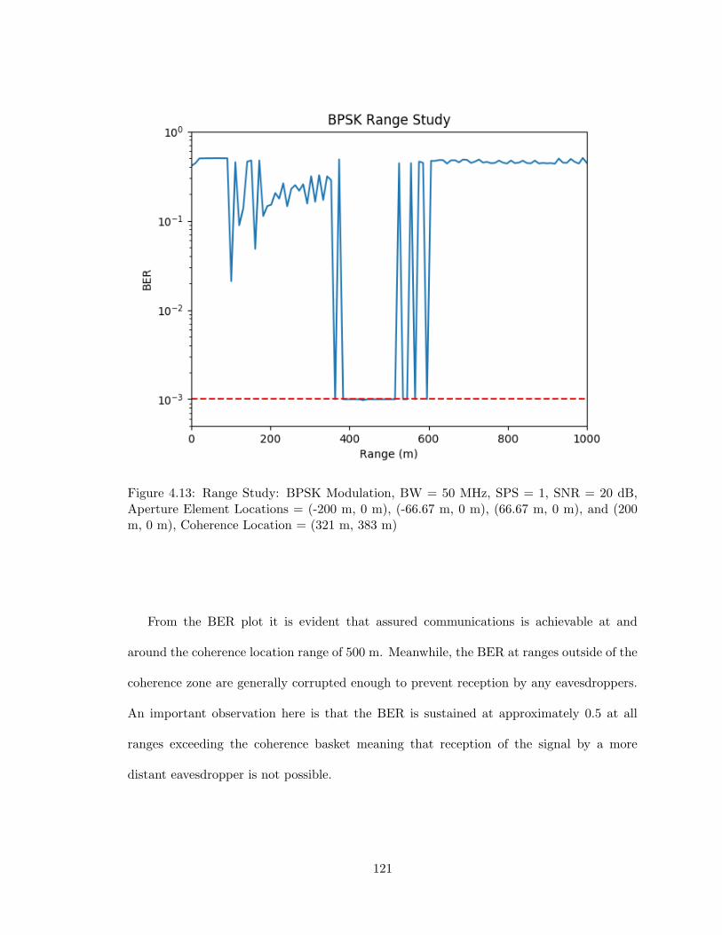
Figure 4.13: Range Study: BPSK Modulation, BW = 50 MHz, SPS = 1, SNR = 20 dB,Aperture Element Locations = (-200 m, 0 m), (-66.67 m, 0 m), (66.67 m, 0 m), and (200m, 0 m), Coherence Location = (321 m, 383 m)
From the BER plot it is evident that assured communications is achievable at and
around the coherence location range of 500 m. Meanwhile, the BER at ranges outside of the
coherence zone are generally corrupted enough to prevent reception by any eavesdroppers.
An important observation here is that the BER is sustained at approximately 0.5 at all
ranges exceeding the coherence basket meaning that reception of the signal by a more
distant eavesdropper is not possible.
121

Figure 4.14: Range Study: QPSK Modulation, BW = 50 MHz, SPS = 1, SNR = 20 dB,Aperture Element Locations = (-200 m, 0 m), (-66.67 m, 0 m), (66.67 m, 0 m), and (200m, 0 m), Coherence Location = (321 m, 383 m)
Repeating the system simulation for the QPSK modulation scheme as shown in Figure
4.14, it is again evident that BPSK and QPSK perform nearly identically in this context.
This result is again reassuring in the determination that distributed aperture phenomena
alter the underlying information content and do not depend on a specific PSK modulation
format.
122

4.4.5 Discussion
Through the parametric study of distributed coherent communications system geome-
tries in range and angle, it has been demonstrated that distributed aperture propagation
results in a coherence basket over which assured communication may occur. Outside of
the coherence basket, the BER is found to be intrinsically high in the absence of noise.
This result alone extends the literature in directional modulation technology as information
content at non-cohered locations is naturally corrupted without noise injection techniques.
Furthermore, the information security afforded in range extends the state-of-the-art in di-
rectional modulation technology. From this analysis, it is evident that distributed apertures
present a true form of directional security. The following chapter continues the development
of PHY layer concepts through the investigation of the feasibility of coherent operation of
multiple distributed transmitters which is necessary to realize the simulated concepts using
real hardware.
123
CHAPTER V
EXPERIMENTATION ARCHITECTURE & IMPLEMENTATION
The development of distributed aperture communications concepts for PHY layer se-
curity throughout this manuscript has assumed the feasibility of phase coherent system
architectures. Traditionally, achieving phase coherency across an aperture has required
the ability to distribute a stable timing reference across all sub-apertures. For this rea-
son, achieving coherency has been typically limited to common aperture systems for which
physical clock distribution could be achieved using physical connections. Taking a platform
agnostic approach, an architecture is developed in this chapter for calibration of Software
Defined Radio (SDR) hardware to perform phase coherent operation across any arbitrarily
large distributed aperture system. Following the development of a suitable architecture,
calibration techniques are described alongside a suitable hardware/software implementa-
tion. Finally, phase coherence is demonstrated experimentally using a distributed aperture
and the requirements for testing distributed aperture concepts are discussed based on the
analysis presented throughout this manuscript.
5.1 System Architecture
The secure, multi-user communications scheme presented in this research is based on a
four ”layer” approach to information transmission as shown in Figure 5.1. From a systems
perspective, each layer in the conceptual model represents an independent set of degrees of
freedom through which radar and communications techniques can be applied.
124
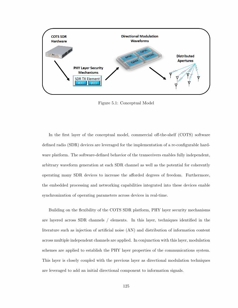
Figure 5.1: Conceptual Model
In the first layer of the conceptual model, commercial off-the-shelf (COTS) software
defined radio (SDR) devices are leveraged for the implementation of a re-configurable hard-
ware platform. The software-defined behavior of the transceivers enables fully independent,
arbitrary waveform generation at each SDR channel as well as the potential for coherently
operating many SDR devices to increase the afforded degrees of freedom. Furthermore,
the embedded processing and networking capabilities integrated into these devices enable
synchronization of operating parameters across devices in real-time.
Building on the flexibility of the COTS SDR platform, PHY layer security mechanisms
are layered across SDR channels / elements. In this layer, techniques identified in the
literature such as injection of artificial noise (AN) and distribution of information content
across multiple independent channels are applied. In conjunction with this layer, modulation
schemes are applied to establish the PHY layer properties of the communications system.
This layer is closely coupled with the previous layer as directional modulation techniques
are leveraged to add an initial directional component to information signals.
125
The final layer of the conceptual model realizes the collective SDR-based sub-apertures
as a phase coherent distributed aperture. Through proper calibration techniques applied
across SDR channels and devices, concepts including COT beamforming, beam steering,
and weighting are applied to enable an added layer of information security to transmitted
information content. This layer is responsible for extending the directional properties es-
tablished in the previous layer to account for both angle and range which completes the
multi-layer conceptual model. Collectively, these layers enable information security between
a distributed transmit aperture and all intended receivers.
The following sections present hardware and software concepts and technologies which
are necessary for the implementation of the described system architecture. Following an
assessment of each core technology, an experimental platform is developed which leverages
these technologies to achieve coherency across a distributed aperture.
5.1.1 Software Defined Radio (SDR) Technology
The term ”software-defined radio” describes any radio frequency (RF) system which im-
plements traditionally hardware based components in software. These components include,
but are not limited to, amplifiers, filters, mixers, modulators/demodulators, and detec-
tors. These software components are implemented on general-purpose processors (GPP) or
through general-purpose computation on graphics processing units (GPGPU) which per-
form equivalent operations on baseband RF data which is sampled in the digital domain.
Despite the capability for many traditionally hardware driven functionalities to be imple-
mented in software, an RF front-end and analog-to-digital (ADC) and digital-to-analog
(DAC) converters are still crucial to SDR design and operation. The reduced hardware re-
quirements result in a generic RF front-end architecture between SDRs which enables radio
126

functionality to become hardware agnostic. This architecture uniquely allows for software-
defined functionality developed on one SDR to be executable on any other SDR therefore
enabling massive system scale-ability.
A unique feature of SDR hardware over traditional architectures is that SDR software
can be reconfigured during program operation therefore allowing SDR devices to change
device behavior on-the-fly. When combined with real-time processing techniques, SDR
systems are capable of collecting information about the environment and changing modes
of operation accordingly. This complete flexibility enables many degrees-of-freedom in single
modes operation (such as frequency agility and waveform diversity) as well as the ability to
change behavior completely (radar mode to communications mode) using the same hardware
configuration. Since no single SDR hardware/software architecture exits, the timescale for
which software reconfiguration occurs may vary from re-loading firmware to fully arbitrary,
digital-at-every-element operation enabling dynamic changes in behavior.
Although many pros and cons exist in the discussion of SDR technology, a primary
challenge with regard to this research is the poor timing characteristics exhibited by SDRs.
The usage of lower quality oscillators in SDR hardware results in the presence of frequency
and phase noise. As multiple SDRs are integrated, the effects of frequency and phase noise
across channels are aggregated which complicates achieving phase coherency. To approach
this challenge, reference signals for the local oscillator (LO) and 1 pulse per second (PPS)
signals are typically distributed to all SDRs. Unfortunately, synchronization of LOs in
the SDR architecture only fixes the phase reference problem. Further problems in timing
are associated with the delay paths between transmitter / receiver channels along with
communications protocol latency between the SDR and a controller system. From an RF
perspective, this is a combination of the starting trigger for when signals are sent through
127

the DAC and RF front-end (governed by the 1 PPS signal) as well as the delay induced by
the RF front-end hardware. To guarantee precise timing between devices, it is necessary to
calibrate out these differences between hardware platforms using more sophisticated signal
processing techniques.
Space-time coding serves as a novel example of multi-dimensional waveform diversity
enabled through flexible, coherent, and frequency agile transmit/receive (T/R) hardware.
As applied to space-time coding concepts in this research, coherency and precise timing are
essential to algorithm implementation. A primary challenge associated with this application
is the utilization of low-cost software defined radio (SDR) hardware which is not intended
for precision timing in place of high-cost test equipment and traditional T/R modules. From
a systems perspective, SDR hardware lives/dies by timing and not coherency while T/R
modules live/die based on coherency. Timing is employed as a substitute for coherency
in SDR systems as coherency can be achieved as a result of precise timing. Since SDR
technology is not inherently designed for high precision timing, novel methods must be
devised to establish timing between SDR channels or devices. Unique to the approach
taken in this research is the concept of maintaining continuous operation on all system
channels to achieve timing-based coherency over all aspects of operation and updating
timing parameters (delay and phase offset between channels) on the fly during operation.
This architecture based on real-time processing and continuous streaming maintains timing
behavior between channels such that coherence between channels at the start of each pulse
in a traditional T/R module sense is not of concern.
128
5.1.2 Hardware Architecture
Leveraging the unique capabilities enabled through SDR hardware, low-cost COTS SDR
devices are selected for the distributed aperture transmitter and receiver ”nodes” to enable
multi-channel, coherent, system operation. After a study of the current state-of-the-art in
COTS SDR hardware available, the Ettus Research Universal Software Radio Peripheral
(USRP) devices were selected due to RF characteristics, software compatibility, and most
importantly reliable software drivers for handling API calls and sample streaming. The
distributed transmit aperture is based on the 4-channel, phase coherent USRP N310 SDR
due to the high channel count and phase coherency (but not timing) across channels. Mean-
while, the receiver nodes are based on the low-cost, 2-channel USRP B210 SDR which is
powered over a USB 3.0 interfacing making it ideal for data collection during field testing.
Interfacing with SDR hardware requires capable processing hardware to stream signals
to and from the SDR device and handle signal processing operations. Through extensive
testing across multiple system configurations, it has been determined that processors with
high single-core clock rates perform best when handling sample streaming to and from SDR
devices. Furthermore, real-time signal processing tasks benefit from multiple-core processor
architectures as well as sufficient high-speed RAM. In order to meet these requirements, a
desktop computer system was designed using COTS components and build to control the
USRP N310 SDR. Meanwhile, high-performance consumer grade laptops were selected to
interface with the USRP B210 SDR hardware over the native USB 3.0 connection.
A final aspect of the hardware architecture was establishing communication between
nodes to enable any node to change behavior based upon the state of the other nodes
in the system. For simplicity, inter-node connectivity within the hardware architecture
129

is approached through conventional computer networking topologies. A local network is
created for the experimental setup using a network switch and Ethernet cabling between
nodes. Network functionality is achieved by running a DHCP server on the transmitter
system which will assign network addresses to all system nodes and facilitate routing of
communications between the nodes. Through this configuration, low latency communication
can be achieved between all nodes in the system.
A complete list of all hardware used within the described architecture is tabulated in the
following table. This list additionally includes RF hardware such as cables and antennas
which are necessary for experimentation.
Table 5.1: Experimental System Components List
TX Aperture RX Aperture
Controller Desktop LaptopSDR USRP N310 USRP B210Antenna (4) Log-Periodic (1) Log-PeriodicCables (4) 10 m RG-58 (1) 0.5 m RG-58Other Network Switch
RouterCAT5 Networking Cable
5.1.3 Software Architecture
From a software perspective, SDR configuration / control and real-time processing algo-
rithms must communicate across distributed processing nodes to achieve timing and phase
coherent operation across the distributed aperture. Each SDR-based node in the system
is equipped with processing capabilities (either through an embedded operating system or
a connected host system) and connected to all other nodes over a wired/wireless network.
Through these connections, signal processing functionality can be performed at each node to
130
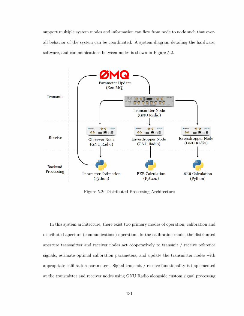
support multiple system modes and information can flow from node to node such that over-
all behavior of the system can be coordinated. A system diagram detailing the hardware,
software, and communications between nodes is shown in Figure 5.2.
Figure 5.2: Distributed Processing Architecture
In this system architecture, there exist two primary modes of operation; calibration and
distributed aperture (communications) operation. In the calibration mode, the distributed
aperture transmitter and receiver nodes act cooperatively to transmit / receive reference
signals, estimate optimal calibration parameters, and update the transmitter nodes with
appropriate calibration parameters. Signal transmit / receive functionality is implemented
at the transmitter and receiver nodes using GNU Radio alongside custom signal processing
131
”blocks” written in Python. This unique software implementation allows for parameter
values at the transmitter node to be received over a network connection (through TCP
sockets as facilitated through the open-source ZeroMQ messaging library) and updated
in real-time within the GNU Radio flowgraph. This ”closed-loop” feedback configuration
allows for the distributed aperture transmitter to change the behavior of each aperture
element until timing and phase coherent transmission to the desired receiver is achieved.
The second mode of operation is the operational mode in which communications se-
quences are transmitted to both intended receivers and eavesdroppers. In this mode,
known communications sequences are stored at the transmitter and receiver nodes. As
the distributed transmit aperture emits a known preamble sequence and data payload,
the receiver nodes record the spectrum and perform software demodulation and preamble
sequence detection to capture the message. Using the Python scripting language for pro-
cessing, BER calculation is performed at each node between the reference message and the
received message in order to determine the BER rate associated with each receiver node’s
position in space. Following the reception of BER values from each receiver node, the dis-
tributed transmit aperture changes system parameters or waits for an operator to change
receiver node positions before continuing operation.
Generally speaking, the development of real-time processing systems using SDR hard-
ware presents a challenge when algorithm latency exceeds sample clock latency. The al-
gorithms leveraged in this experimental system for parameter estimation, communication
between nodes, and flowgraph modification require processing time that scales upward as
the system sample rate increases. This proves problematic for increasing sample rates as
processing operations need to be completed in shorter periods of time to provide data to
higher speed systems. There are a number of ways to reduce algorithm latency when devel-
132
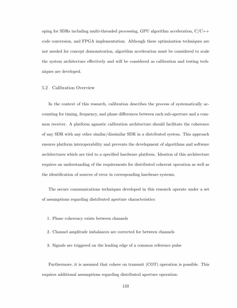
oping for SDRs including multi-threaded processing, GPU algorithm acceleration, C/C++
code conversion, and FPGA implementation. Although these optimization techniques are
not needed for concept demonstration, algorithm acceleration must be considered to scale
the system architecture effectively and will be considered as calibration and testing tech-
niques are developed.
5.2 Calibration Overview
In the context of this research, calibration describes the process of systematically ac-
counting for timing, frequency, and phase differences between each sub-aperture and a com-
mon receiver. A platform agnostic calibration architecture should facilitate the coherence
of any SDR with any other similar/dissimilar SDR in a distributed system. This approach
ensures platform interoperability and prevents the development of algorithms and software
architectures which are tied to a specified hardware platform. Ideation of this architecture
requires an understanding of the requirements for distributed coherent operation as well as
the identification of sources of error in corresponding hardware systems.
The secure communications techniques developed in this research operate under a set
of assumptions regarding distributed aperture characteristics:
1. Phase coherency exists between channels
2. Channel amplitude imbalances are corrected for between channels
3. Signals are triggered on the leading edge of a common reference pulse
Furthermore, it is assumed that cohere on transmit (COT) operation is possible. This
requires additional assumptions regarding distributed aperture operation:
133

1. Delay and phase shift parameters between each sub-aperture and a common receiver
can be estimated
2. Estimated parameters can be applied to cohere the aperture to a common spatial
location
Common to all of these assumptions is the need for the estimation of time varying
”coherence parameters” which represent the delay and phase shift present at each aper-
ture element relative to a common reference point. While these parameters are readily
determined through modeling & simulation, realizable systems require sophisticated signal
processing techniques to achieve comparable results. This challenge serves as the motivation
for SDR technology as system parameters can be estimated and applied in real-time with-
out the need for power-cycling a system which in turn changes parameter values. For this
reason, multiple sources of variability/error can be estimated and corrected for en masse,
further promoting a platform invariant approach to system calibration. The following sec-
tions describe each type of error in detail along with an approach to perform estimation of
the parameter value.
5.2.1 Relative Delay
In the digital domain where continuous signals are represented by discrete-time samples,
delay measures the difference between the starting sample position of a signal and a reference
sample position. The sampling rate determines the number of samples required to represent
a time delay in a system with one sample being equivalent to 1fs
seconds. The concept of
relative delay is illustrated in Figure 5.3.
134
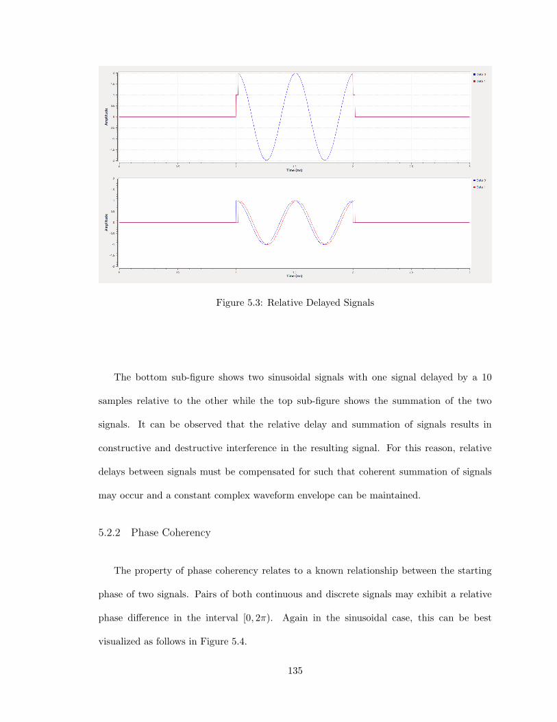
Figure 5.3: Relative Delayed Signals
The bottom sub-figure shows two sinusoidal signals with one signal delayed by a 10
samples relative to the other while the top sub-figure shows the summation of the two
signals. It can be observed that the relative delay and summation of signals results in
constructive and destructive interference in the resulting signal. For this reason, relative
delays between signals must be compensated for such that coherent summation of signals
may occur and a constant complex waveform envelope can be maintained.
5.2.2 Phase Coherency
The property of phase coherency relates to a known relationship between the starting
phase of two signals. Pairs of both continuous and discrete signals may exhibit a relative
phase difference in the interval [0, 2π). Again in the sinusoidal case, this can be best
visualized as follows in Figure 5.4.
135
Figure 5.4: Incoherent Sinusoidal Signals
The bottom sub-figure shows two sinusoidal signals with no relative delay or amplitude
imbalance which are 4π3 radians out-of-phase. It can be observed that the summation of
the two signals as shown in the top sub-figure results in a sinusoidal signal that exhibits
destructive interference as the resulting amplitude is not a factor of two greater than the
amplitude of the input signals.
From a signal energy perspective, phase and corresponding incoherent signals can be
visualized in the in-phase/quadrature (I/Q) plane. Two signals with equal magnitude,
when summed coherently, will result in a signal with twice the magnitude. Conversely, two
signals which are separated by π radians of phase shift will interfere destructively and result
in a signal magnitude of zero. All other cases exhibit some combination of constructive /
136

destructive interference, but will always result in degradation of the signal in magnitude
and phase unless coherent addition occurs.
5.2.3 Amplitude Imbalances
The final form of coherence error is caused by amplitude imbalances between two or more
signals. These imbalances originate from differences in hardware (RF components, cable
losses, antennas) and variations in propagation loss across different types of RF channels.
In the context of COT beamforming, large aperture baselines result in sub-aperture to re-
ceiver angle diversity. Assuming that all sub-apertures are oriented identically, the antenna
element gain will vary from sub-aperture to sub-aperture. These differences in amplitude
are integral to the operation of any distributed aperture system as amplitude imbalances
determine the severity of the delay and phase imbalances identified in the previous sec-
tions. Amplitude matched systems can realize full COT gains in SNR while unbalanced
systems could exhibit delay and/or phase biases that are dominated by the strongest signal
components.
5.2.4 Sources of Timing and Phase Error
Effective estimation of coherency parameters (timing and phase) requires an under-
standing of the sources of error both deterministic and random in a transmitter/receiver
architecture. Building on the error sources identified in the previous section, a transceiver
system can be broken down into three main sub-systems: digital backend, analog frontend,
and transducer (antenna). Each sub-system contributes timing errors and phase delays in-
dependent of other components and transceivers. Fortunately, many of the sources of error
are deterministic in nature and can be calibrated out of the system. Through identification
137

of error sources in each sub-system it is possible approach calibration such that coherency
can be achieved.
The first transceiver sub-system is the digital backend which controls sample timing and
baseband frequency synthesis. Sample timing is initiated on the rising-edge of an internal
or external clock signal. Timing errors here arise due to timing misalignment between
clock sources between transceiver systems and internal delays between the rising-edge of
the trigger and when a signal is generated, both of which are deterministic in nature.
Methods such as clock-distribution or GPS locked oscillators are often utilized in 1 PPS
timing generation to address the former issue while calibration is used to address the latter.
The second sub-system is the analog frontend which is responsible for up/down-conversion
of baseband signals to a carrier frequency. This is accomplished by utilizing an analog RF
mixer fed by a local oscillator (LO) signal. The crystal oscillators used to generate the LO
signal experience thermally induced frequency drift during operation causing a frequency
error which is best modeled as a random process. A phase error is produced on the sig-
nal due to the instantaneous frequency error observed over a finite time interval. System
architectures employing a shared LO signal are simpler to cohere as this source of error
is not present. In addition to the random frequency error, there are deterministic phase
errors due to the starting phase of the LO signal when a signal passes through the mixer
and the combined phase delay due to the RF components. These phase delays vary with
clock signal and from RF component to RF component but are deterministic in nature, so
calibration is effective.
The final subsystem is the transducer component of the system where signals from
the analog frontend are propagated using an antenna element. Transmission cables and
138

real apertures introduce a phase delay in the system, but the error source is generally
deterministic and again can be calibrated for. Unresolved timing and phase errors between
transceivers contribute to variations in angle, range, and extent of the coherency basket.
5.2.5 Calibration Architectures
The selection of a suitable calibration technique for phase coherence and cohere on
transmit (COT) beamforming depends on a compatible system architecture. Typically,
closed-loop and open-loop architectures are considered in this discussion depending on the
availability of a feedback loop in the calibration process. Each of these techniques are
described in more detail in the following sections and the decision to utilize a closed-loop
calibration architecture is justified.
Open-Loop Calibration
In control system theory, an open-loop system does not rely on feedback signals to
condition system output. This model describes radio frequency systems for which inter-
nal system characterization and physics-based modeling drive the output of the system.
Such approaches reduce system infrastructure requirements, both in terms of computa-
tional requirements and established communications links, at the cost of being unable to
adapt system parameters based on received stimulus at an arbitrary location external to
the system.
Translated to the challenges of distributed aperture coherence and COT beamforming,
open-loop calibration architectures require extensive knowledge of sub-apertures position
relative to a given point in space and the characteristics of each sub-aperture. Provided
139

that a priori knowledge of the system exists, open-loop architectures enable flexible system
operation across the spatial domain.
Closed-Loop Calibration
In contrast to open-loop systems, closed-loop systems utilize feedback signals to condi-
tion system output. This model describes systems for which external observations of the
system state (or system effects) can be used improve or correct system operation. Closed-
loop systems require external sensing, computational capabilities, and communication links
to complete the feedback loop. Although this architecture comes at a significant cost in
terms of system complexity, it enables precise calibration to the actual conditions present
in a system and the environment.
In terms of the challenges of distributed aperture coherence and COT beamforming,
closed-loop calibration architectures require a cooperative receiver which can function as
part of the calibration process. While this requirement is restrictive in nature, it enables
precise estimation of channel state information between transmit sub-apertures and the
receiver. System parameters such as timing, phase, and frequency offsets between chan-
nels can be characterized in real-time and updated to ”lock-on” to coherency. Calibration
through a closed-loop architecture is effective in calibrating out deterministic error sources
and frequent polling of parameter estimates allow for coherency to be maintained over ex-
tended timescales. For these reasons, a closed-loop calibration architecture is adopted for
the following calibration algorithm implementation.
140
5.2.6 Algorithm Implementation
The calibration algorithm used in this research originates from a technical report from
the Massachusetts Institute of Technology (MIT) Lincoln Laboratory. [37] In the report, dis-
tributed aperture coherence is achieved through the transmission of orthogonal waveforms
to estimate relative phase and delay differences between distributed aperture elements. Al-
though this approach is intended for radar applications where common target returns serve
as a COT location, the algorithm is compatible and can be adapted for closed-loop commu-
nications systems where a cooperative receiver can estimate ”coherence parameters” and
provide feedback to the transmitter. At a high level, the algorithm for coherence parameter
estimation is as follows:
1. Transmit orthogonal simultaneously waveforms from each transmit aperture element
2. Receive orthogonal waveforms at closed-loop receiver
3. Estimate coherence parameters for each transmit aperture element
4. Provide closed-loop feedback of coherence parameters to transmit aperture elements
The following sections describe each aspect of coherence parameter estimation process
from a theory-based perspective and discusses various aspects of algorithm implementation
using realizable hardware/software systems as identified at the beginning of this chapter.
Orthogonal Waveforms
The basis for distributed aperture calibration is the ability to transmit (unique) wave-
forms simultaneously from two or more aperture elements and determine the relative delay
141
and phase shifts between the aperture elements and a common spatial location. Separation
of the transmitted waveforms by a receiver requires that the unique waveforms are orthog-
onal in the time domain such that closely spaced temporal returns do not interfere and
degrade coherence parameter estimates.
From a mathematical perspective, two vectors are considered orthogonal when the inner
product of the vectors is zero. This property is used more generally in waveform design
to describe a set of waveforms (vectors) that exhibit low cross-correlation and high auto-
correlation across the entire set. This property is expressed mathematically as follows:
∫ ∞−∞
x(t)y(t)dt = 0 (5.1)
N∑n=1
x[n]y[n] = 0 (5.2)
The property of low cross-correlation within orthogonal waveform sets means that there
is an inherent degree of separability between waveforms. Through signal processing of
simulatenously transmitted orthogonal waveforms, relative delay and phase shift parameters
between multiple transmitters can be extracted. [37] Scaleability of this approach requires
N-many orthogonal waveforms to resolve N-many transmitters simultaneously. There exist
several well known orthogonal waveform sets including polyphase codes, Linear Frequency
Modulation (LFM) ”chirp” waveforms, and many other alternatives which vary in set size
and length. Selection of an appropriate orthogonal waveform set requires consideration
for the delay / Doppler properties of the waveform set. The following sections consider
polyphase codes and LFM waveforms with regard to the estimation of distributed aperture
coherence parameters.
142

LFM Chirp Linear frequency modulation (LFM) describes signals which exhibit a time-
varying instantaneous frequency which is swept over a fixed time interval and bandwidth.
Ideal orthogonal properties are realized through a two-code set of orthogonal waveforms
including the up-chirp and down-chirp LFM waveforms. An up-chirp LFM starts at fre-
quency f0 and ends at frequency f1 while a down-chirp starts at frequency f1 and ends
at frequency f0. These waveforms exhibit high signal processing gain as a function of the
time-bandwidth product and exhibit low signal processing sidelobes which are ideal from a
detection standpoint.
Despite the limited size of the LFM waveform set, the Doppler tolerance of this waveform
is ideal for the calibration procedure. Theoretically, this would enable calibration to be
successful on moving platforms from a waveforms perspective.
Polyphase Codes Polyphase sequences are a class of phase-coded orthogonal waveforms
which exhibit near ideal auto-correlation and low cross-correlation properties. These wave-
forms rely on phase coding of a carrier signal using a fixed set of potential phase values.
A number of polyphase codes exist in the literature of varying size and length. Identifica-
tion of these sets is typically achieved through optimization techniques such as simulated
annealing in order to determine sets with the best properties. Unlike the LFM waveforms,
polyphase codes are not Doppler tolerant as orthogonality of these waveforms is derived
from the instantaneous phase values.
143

Matched Filtering
The matched filter is an optimal linear filter for a sequence which will maximize the
output SNR for detection in the presence noise and interference. In discrete time, the
matched filter is is represented by h[n] in the following expression for convolution:
y[n] =∞∑
k=−∞h[n− k]x[k] (5.3)
The gain from matched filtering, known as the pulse compression ratio in this context,
is determined by the time-bandwidth product of the waveform:
GPulseCompression = 20log10(B · τ) (5.4)
where B is the bandwidth of the signal and τ is the time duration of the signal.
Computation of the matched filter result for received signals enables the determination
of relative delays and phase shifts at which signals are received relative to the transmitted
waveform. The process for detection and processing of transmitted orthogonal signals from
distributed aperture transmitters is covered in the following section.
Detection & Estimation
Estimation of coherence parameters is dependent on the successful detection of received
orthogonal signals. Under the assumption that minimal cross-correlation exists between
orthogonal waveforms and high SNR conditions exist, detection could be achieved through
simple thresholding and peak detection. In real signal environments, there is likely a low
144
SNR even after matched filtering under which reference signals must be detected. For this
reason, the constant false alarm rate (CFAR) adaptive thresholding algorithm should be
used for detection to reduce the probability of false alarm Pfa.
Parameter estimation of delay is achieved by determining the indices that each orthog-
onal waveform occurs at post matched filtering and computing the corresponding relative
delay between channels. For phase shift, the phase angle of the complex signal return at
the index at which each detection occurs is calculated. This phase angle represents the
phase shift that channel exhibits relative to the reference waveform. From these calculated
values, the delays associated with each sub-aperture are normalized across the set such that
one sub-aperture requires no additional delay. When applied at the distributed transmit
aperture, these parameters will result in transmitted signals being phase coherent and time
aligned at the intended receiver location.
Statistical Ranking and Selection
Calibration of distributed transmit apertures is not a one-time process which produces
deterministic results. Numerous factors including transmitter/receiver positioning, EM
spectral interference, and internal oscillator drifting over time influence the coherence pa-
rameter estimation process. Under low SNR conditions, further challenges arise as calibra-
tion signals can commonly be missed during the detection process and false alarm signals
can instead be detected for parameter estimation. In order to overcome these challenges
and produce stable coherence parameter estimations, more sophisticated methods must be
devised.
Statistical methods in ranking and selection can be utilized to improve coherence pa-
rameter estimates over multiple timescales. Utilizing elementary statistical methods, com-
145

putation of parameter estimation mean and variance over multiple estimation attempts is a
simple way to mitigate the effect of outlier results which arise from missed detections in the
estimation process. Furthermore, more sophisticated methods such as the Rinnot two-step
selection procedure can be leveraged to close in on more precise estimates of underlying pa-
rameter values utilizing relatively small sample sizes along with methods such as statistical
bootstrapping. These methods are useful not only in improving the parameter estimation
process, but also ensuring that real-time system behavior operates consistently in low SNR
environments.
Beyond basic parameter estimation, it is desirable to perform parameter tracking such
that future parameter values can be predicted and compared against real-time estimates.
When these changes in parameter estimates are considered over longer time scales, parame-
ter tracking proves to be a potential way to account for random processes such as oscillator
clock drift. Implementation of algorithms such as the Kalman filter should enable general
improvements to coherency across the distributed aperture and afforded resilience against
small changes in system behavior.
5.3 Experimental System Implementation
To demonstrate distributed aperture coherence, the calibration algorithm is imple-
mented within an experimental system prototype. The experimental system leverages the
hardware and software architectures described at the beginning of this chapter to implement
a distributed aperture communications system. The following sections describe the hard-
ware configuration and corresponding software implementation which enable closed-loop
calibration within the experimental system.
146
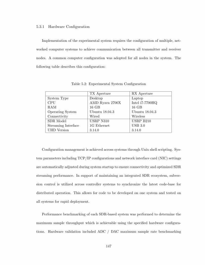
5.3.1 Hardware Configuration
Implementation of the experimental system requires the configuration of multiple, net-
worked computer systems to achieve communication between all transmitter and receiver
nodes. A common computer configuration was adopted for all nodes in the system. The
following table describes this configuration:
Table 5.2: Experimental System Configuration
TX Aperture RX Aperture
System Type Desktop LaptopCPU AMD Ryzen 2700X Intel i7-7700HQRAM 16 GB 16 GBOperating System Ubuntu 18.04.3 Ubuntu 18.04.3Connectivity Wired Wireless
SDR Model USRP N310 USRP B210Streaming Interface 1G Ethernet USB 3.0UHD Version 3.14.0 3.14.0
Configuration management is achieved across systems through Unix shell scripting. Sys-
tem parameters including TCP/IP configurations and network interface card (NIC) settings
are automatically adjusted during system startup to ensure connectivity and optimized SDR
streaming performance. In support of maintaining an integrated SDR ecosystem, subver-
sion control is utilized across controller systems to synchronize the latest code-base for
distributed operation. This allows for code to be developed on one system and tested on
all systems for rapid deployment.
Performance benchmarking of each SDR-based system was performed to determine the
maximum sample throughput which is achievable using the specified hardware configura-
tions. Hardware validation included ADC / DAC maximum sample rate benchmarking
147

across single / multiple simultaneous channels on transmit and receive. As expected, the
USRP N310 can achieve simultaneous transmit/receive across multiple channels, but at
limited sample rates due to the 1 Gigabit Ethernet interface. Meanwhile the USRP B210 is
able to operate at much higher sample rates due to the USB 3.0 interface. Actual sample
rates must be scaled down accordingly to account for the processing overhead required by
the GNU Radio flowgraph.
System performance can be increased in the future by upgrading the connectivity on
the USRP N310 to dual 10 Gigabit Ethernet such that full sample rates can be achieved.
Furthermore, the USRP N310 is designed to operate in a streaming configuration or as an
embedded system. In the embedded configuration, GNURadio flowgraphs can be executed
directly on the SDR. This is advantageous to system performance as the host-to-device
transport layer bottleneck is eliminated allowing for higher sample rates to be achieved. It
should noted that embedded processors (such as the embedded ARM processor in the USRP
N310) often operate with clock rates significantly lower than consumer grade processors.
As a result, algorithms should be implemented in the FPGA fabric to achieve optimal
performance while leveraging the embedded processor for control over the data within the
FPGA.
5.3.2 Software Implementation
The software implementation of the experimental prototype must achieve three pri-
mary functions; distributed aperture calibration, communications BER testing, and system
command & control. Each system functionality is implemented within the GNU Radio
framework which was utilized for modeling & simulation in the previous chapter. Individ-
ual functions are wrapped within signal processing ”blocks” which consist of an underlying
148
theoretic concept/algorithm, defined control mechanism when applicable, software (Python)
implementation, and test bench for validation. These blocks are described in the following
sections corresponding to the functionality that they achieve.
Distributed Aperture Calibration
The calibration algorithm described mathematically in the previous section is imple-
mented in software to enable real-time calibration of multiple distributed aperture trans-
mitter elements. Various digital signal processing (DSP) techniques are leveraged in the
implementation to accelerate processing routines and best adapt the calibration algorithm
within the software architecture that has been devised for the experimental system. Each
component of the algorithm is described in the following section along with GNU Radio
representations of the algorithm implementation.
Matched Filter Upon the simultaneous reception of orthogonal waveforms at the (coop-
erative) receiver, matched filtering is applied to separate the waveforms which are received
from each transmitter. For computational efficiency, matched filtering is implemented by
the Discrete Fourier Transform (DFT) with complexity O(nlogn) over convolution which
has complexity O(n2). In this implementation, the DFT of the received signal and each of
the orthogonal waveforms is computed. Through multiplication of each frequency-domain
orthogonal waveform with the received signal and subsequent application of the Inverse Fast
Fourier Transform (IFFT), the time-domain signals for each orthogonal waveform can be
obtained.
The FFT-based implementation of matched filtering is implemented as a GNU Radio
signal processing block in GNU Radio as shown in Figure 5.5. A two-input, one-output
149

block takes a vector of input stream samples along with the reference waveform as inputs.
The assumption is that the reference waveform, if read from a binary file, is created at
the same sample rate as the input data stream. Each input to the block is transformed
into the frequency domain via the FFT and conjugate multiplication is performed on the
two data streams followed by an inverse Fourier transform (IFFT) to recover the matched
filter output in the time domain. The output of the matched filter is subjected to further
processing in later stages of the calibration algorithm.
Figure 5.5: GNU Radio: Matched Filter Implementation
Coherence Parameter Estimation The second stage of the calibration algorithm in-
volves the detection of returns from each distributed aperture transmitter and the subse-
quent estimation of relative delay and phase shift parameters from the returns. To imple-
ment this stage of the algorithm in software, each matched filtered datastream corresponding
to the received signal from each distributed aperture transmitter is sent from GNU Radio
to an external Python processing script over a ZeroMQ TCP socket as shown in Figure 5.6.
150
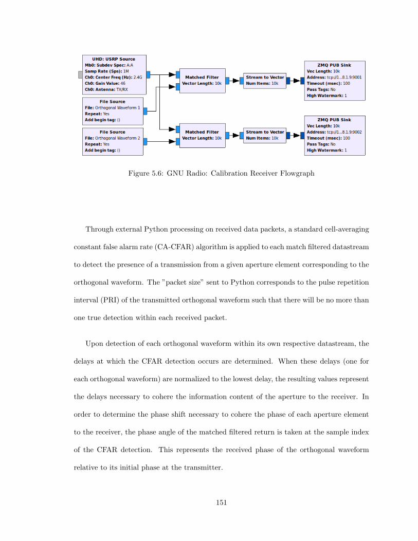
Figure 5.6: GNU Radio: Calibration Receiver Flowgraph
Through external Python processing on received data packets, a standard cell-averaging
constant false alarm rate (CA-CFAR) algorithm is applied to each match filtered datastream
to detect the presence of a transmission from a given aperture element corresponding to the
orthogonal waveform. The ”packet size” sent to Python corresponds to the pulse repetition
interval (PRI) of the transmitted orthogonal waveform such that there will be no more than
one true detection within each received packet.
Upon detection of each orthogonal waveform within its own respective datastream, the
delays at which the CFAR detection occurs are determined. When these delays (one for
each orthogonal waveform) are normalized to the lowest delay, the resulting values represent
the delays necessary to cohere the information content of the aperture to the receiver. In
order to determine the phase shift necessary to cohere the phase of each aperture element
to the receiver, the phase angle of the matched filtered return is taken at the sample index
of the CFAR detection. This represents the received phase of the orthogonal waveform
relative to its initial phase at the transmitter.
151
Verification of estimation integrity is an important aspect of maintaining coherence over
different timescales. Over short timescales, coherence parameter estimate accuracy is first
validated during each estimation process by checking the number returns detected by the
CFAR algorithm. Since the packet size passed to Python corresponds with the orthogonal
waveform PRI, a detection count exceeding one is an indication that the wrong signal
return may have been selected for parameter estimation. Furthermore, detection accuracy
is improved by implementing ”memory” within the estimator that runs N-many estimation
cycles and performs elementary statistical analysis (mean and variance) to determine if
returning the mean estimate value will achieve coherence within the system as observed
during the calibration period.
Coherence Parameter Update The final stage of the calibration algorithm is the ap-
plication of estimated coherence parameters to the distributed aperture transmitter. A
main requirement of the hardware/software architecture which enables SDR timing as a
replacement for coherency is the ability to continuously update parameters at software
runtime. Many GNU Radio blocks support parameter updates at runtime, but there are
various methods through which the parameters are ”polled” during runtime. The ”function
probe” in GNU Radio calls a function at a defined polling rate and updates a corresponding
parameter at each function call. This function enables external parameters to be obtained
during flowgraph operation.
A ”delay & phase shift” block is implemented in GNU Radio which applies a specified
full-sample delay and phase shift to an input data stream as shown in Figure 5.7. In the
implementation the delay and phase shift parameters are received through a ZeroMQ socket
and polled via the function probe interface. These parameters are then updated at runtime
152

which directly influences the relationship between the input and output signals of the block
to cohere the output signal at the receiver.
Figure 5.7: GNU Radio: Coherence Parameter Update Implementation
System Command & Control
From a system-of-systems standpoint, system control can be characterized based on how
tightly integrated timing is across the entire system. At the lowest and most precise level,
clock-based timing in an FPGA implementation will provide clock-cycle accurate timing
between system functionality. This precision allows for deterministic behavior in response
to system stimulus, but comes at the cost that modes / functionality must be designed at a
low level requiring more rigidity in system behavior. More flexibility is afforded as control
is off-loaded to higher level programming languages, but timing is not constrained by the
update rate of the system parameters. Finally, distributed computing solutions enable the
maximum level of flexibility as more complex processing routines can be offloaded to external
systems, but timing becomes dependent on messaging latency and parameter update time
across the entire system. Ultimately, distributed control is desirable for this experimental
system such that multiple modes of operation can be achieved.
153

The implementation of distributed control in a system inherently requires communi-
cations messaging patterns between the nodes in a network. For this particular system
architecture, it is necessary for each node to be able to send and receive messages. The
transmitter/central node must be able to send system state (calibration / testing) messages
to each receiver node. Meanwhile, each receiver node must be capable of sending coherence
parameters to each of the transmit aperture nodes. In order to facilitate multiple modes
operation and achieve calibration across an arbitrary number of aperture elements, two
novel mechanisms/techniques have been created.
Stream Multiplexer Facilitating multiple-mode SDR operation while remaining phase
and timing coherent requires multiplexing between signal ”streams” without stopping signal
transmission. GNU Radio supports multiple methods for switching between streams, but
generally requires the specification of the number of samples between multiplexer states.
In order to facilitate each of the experimental modes within the distributed control ar-
chitecture, a custom Python implementation of a stream multiplexer was created which
supports multiple stream inputs and outputs which can be independently mapped. The
corresponding GNU Radio heir flowgraph is shown in Figure 5.8.
154
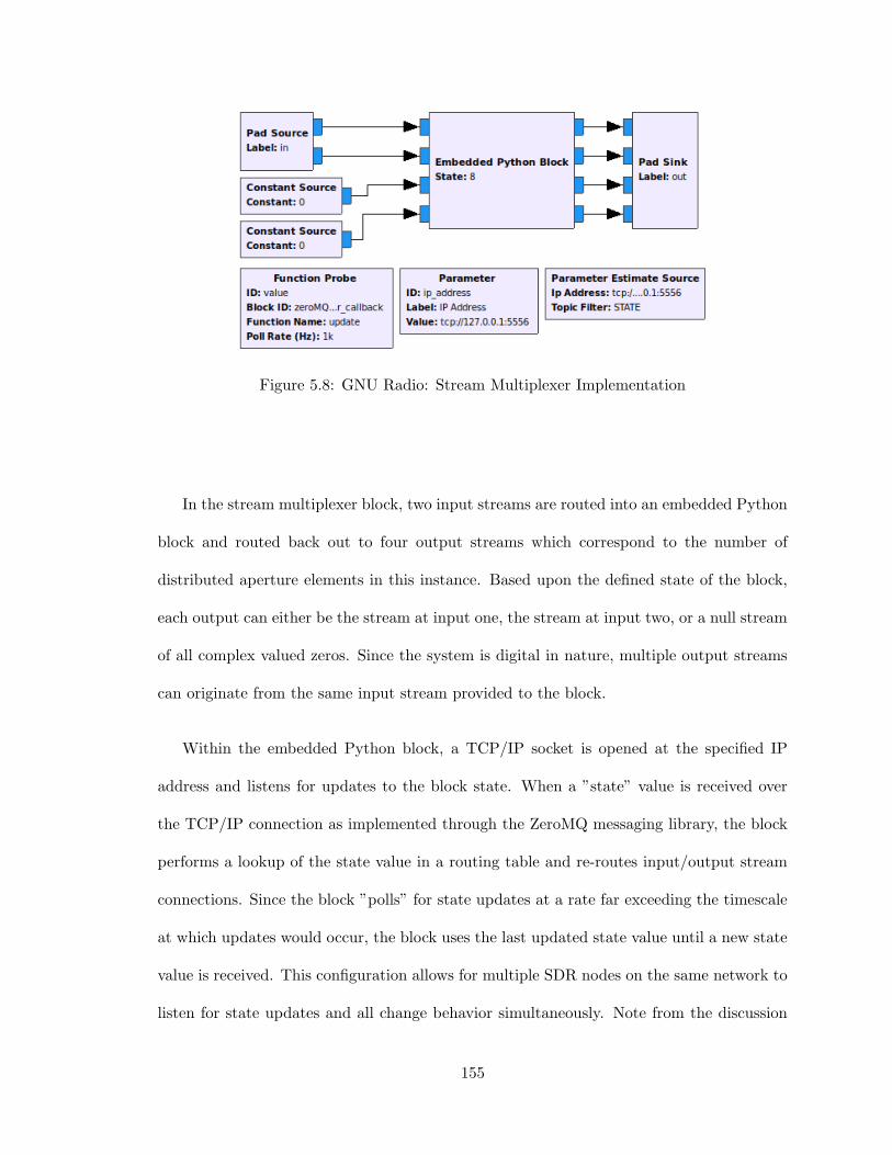
Figure 5.8: GNU Radio: Stream Multiplexer Implementation
In the stream multiplexer block, two input streams are routed into an embedded Python
block and routed back out to four output streams which correspond to the number of
distributed aperture elements in this instance. Based upon the defined state of the block,
each output can either be the stream at input one, the stream at input two, or a null stream
of all complex valued zeros. Since the system is digital in nature, multiple output streams
can originate from the same input stream provided to the block.
Within the embedded Python block, a TCP/IP socket is opened at the specified IP
address and listens for updates to the block state. When a ”state” value is received over
the TCP/IP connection as implemented through the ZeroMQ messaging library, the block
performs a lookup of the state value in a routing table and re-routes input/output stream
connections. Since the block ”polls” for state updates at a rate far exceeding the timescale
at which updates would occur, the block uses the last updated state value until a new state
value is received. This configuration allows for multiple SDR nodes on the same network to
listen for state updates and all change behavior simultaneously. Note from the discussion
155

of system timing that the timing tolerance of state updates will correspond to the polling
rate within the block.
This control block is essential to the experimental system for numerous reasons. First,
the stream multiplexer enables multiple mode operation where calibration signals and BER
testing signals can be multiplexed onto a common aperture. Secondly, the stream multi-
plexer enables the realization of a novel multi-channel / multi-device calibration scheme
which is discussed in the following section.
Multi-Channel / Multi-Device Calibration The calibration methods investigated
thus far utilize two orthogonal waveforms to estimate coherence parameters between two
aperture elements and a cooperative receiver. Extension of this methodology beyond two
channels requires orthogonal waveform sets with unique (orthogonal) waveforms for every
channel. Given the requirement for both delay and phase shift estimation, many common
orthogonal waveform sets are fundamentally insufficient or incompatible with high channel
count systems. An alternate approach has been developed in this research through which
two orthogonal waveforms are used to perform pairwise calibration between aperture el-
ements followed by a normalization of calibration parameters across the entire aperture.
This approach works based on the principle that SDR systems are inherently waveform
agile and do not require the switching of T/R modules between on/off states to transmit
waveforms in such a pairwise manner. Since delay and phase shift values are maintained
as long as the SDR is in constant operation, multiplexing orthogonal waveforms to each
SDR transmit port (via the stream multiplexer block) allows for an entire set of coherence
parameters to be estimated for the system. Calibration of a four channel aperture can be
readily achieved using this methodology as follows:
156
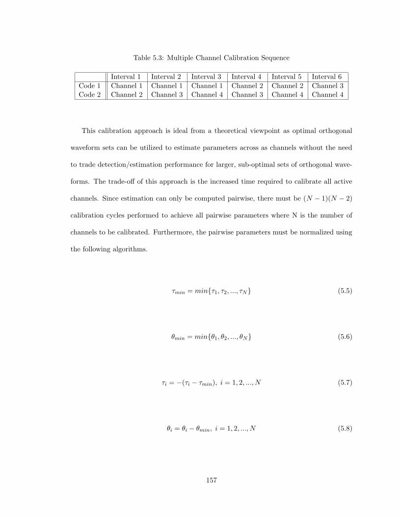
Table 5.3: Multiple Channel Calibration Sequence
Interval 1 Interval 2 Interval 3 Interval 4 Interval 5 Interval 6
Code 1 Channel 1 Channel 1 Channel 1 Channel 2 Channel 2 Channel 3Code 2 Channel 2 Channel 3 Channel 4 Channel 3 Channel 4 Channel 4
This calibration approach is ideal from a theoretical viewpoint as optimal orthogonal
waveform sets can be utilized to estimate parameters across as channels without the need
to trade detection/estimation performance for larger, sub-optimal sets of orthogonal wave-
forms. The trade-off of this approach is the increased time required to calibrate all active
channels. Since estimation can only be computed pairwise, there must be (N − 1)(N − 2)
calibration cycles performed to achieve all pairwise parameters where N is the number of
channels to be calibrated. Furthermore, the pairwise parameters must be normalized using
the following algorithms.
τmin = min{τ1, τ2, ..., τN} (5.5)
θmin = min{θ1, θ2, ..., θN} (5.6)
τi = −(τi − τmin), i = 1, 2, ..., N (5.7)
θi = θi − θmin, i = 1, 2, ..., N (5.8)
157

where τi is the delay between transmit element i and the receiver, θi is the phase shift
between transmit element i and the receiver, and N is the number of transmit elements
that are being calibrated. The resulting delays are normalized to the shortest estimated
delay and taken to be negative to result in the alignment of signals at a point in space.
Meanwhile, the phase shifts are normalized to the lowest estimated phase shift to avoid
phase wrapping across the set of phase shifts.
Communications Bit Error Rate Testing
The final mode of operation is the implementation of a bit error rate tester (BERT).
In communications system testing, a BERT calculates channel BER by transmitting and
receiving a pseudo-random binary sequence (PRBS) over the channel of interest. Typically,
a preamble sequence will be appended to the PRBS sequence such that detection and
alignment can be achieved. A primary challenge in the testing of secure communications
waveforms is achieving detection and alignment of the preamble sequence. Under cohered
communications links, the BER is expected to only be a function of the SNR and therefore
any transmitted preamble sequence should correlate well on reception provided a sufficient
SNR. Meanwhile, under all other operating conditions in which the receiver location is not
within the coherence basket, the BER will be sufficiently high such that correlation of the
preamble sequence will likely result in improper alignment even under ideal SNR conditions.
As a result of this, a new method must be devised in order to align data such that the BER
can be calculated for receiver locations outside of the coherence basket.
The devised solution examines how coherence parameters are applied across all aperture
elements. Due to the concept of negative delay not being feasible in a real system, all delays
are normalized such that the sub-aperture with the longest delay requires no additional
158

delay and all other sub-apertures implement delays normalized to that sub-aperture. With
this in mind, a data alignment scheme is realizable in which the preamble sequence is only
transmitted from the sub-aperture (element) with the longest delay and then all transmitters
can begin to operating normally by starting transmission of their own signal content delayed
only by the length of the preamble less the normalized delay between aperture elements.
This enables the preamble sequence to be transmitted without aperture effects and for the
elements to operate as a distributed aperture seamlessly if transmission on all other elements
is performed according to normalized delays. In practice, this can be achieved using the
”stream multiplexer” by only having the aperture element with the longest delay receiving
the calibration stream and all other element receiving a null datastream.
5.3.3 System Prototype
The experimental platform realized for coherence validation is comprised of a 4-element
transmit aperture as shown in Figure 5.9. Each aperture element consists of an 850 MHz to
6.5 GHz log periodic antenna (LP0965) mounted on a tripod with a 10-meter, RG-58 SMA
cable connecting the aperture element to the USRP N310 SDR. As a result of the software-
defined nature of the experimental system architecture, precision cables are not necessary
as amplitude and phase imbalances will be calibrated out during the normal calibration
routine.
159

Figure 5.9: TX Distributed Aperture
5.4 Experimental Procedure & Results
By leveraging the experimental system developed in this chapter, distributed aperture
coherence concepts are experimentally validated. The experimental procedure consists of
three stages including system simulation, hardware loop-back testing, and over-the-air test-
ing. This approach enables controlled testing of algorithms and system behaviors in isolation
before real signal environments are considered. Simulated scenarios will be tested under
these experimental conditions to validate conceptual models and corresponding simulation
results. The following sections describe each experimental scenario and present experimen-
tal findings.
5.4.1 Simulation Loop-Back Experiment
Leveraging the real-time calibration algorithm implemented in GNU Radio and Python,
coherence parameter estimation and compensation is demonstrated. Initially, two sinusoidal
160

signals are considered which exhibit different delay and phase shift properties as shown
in Figure 5.10. By applying the calibration procedure, orthogonal waveforms are simul-
taneously transmitted from all aperture channels and processing is performed such that
coherence parameters between the two channels are estimated. The resulting coherence pa-
rameters are applied to the two channels and the initial sinusoidal signals are re-transmitted
as shown in Figure 5.11. As can be observed in the resulting figure, coherence in both phase
and time alignment is achieved between the two channels using the real-time calibration
procedure as implemented in GNU Radio. There is a small margin of phase estimation
error which can be seen in the resulting signals, but the channels are effectively coherent.
In each of these figures, the coherent summation of the two signals is shown to demonstrate
the effects on signal amplitude which are afforded through successful aperture calibration.
161

Figure 5.10: Incoherent Operation Pre-Calibration
162
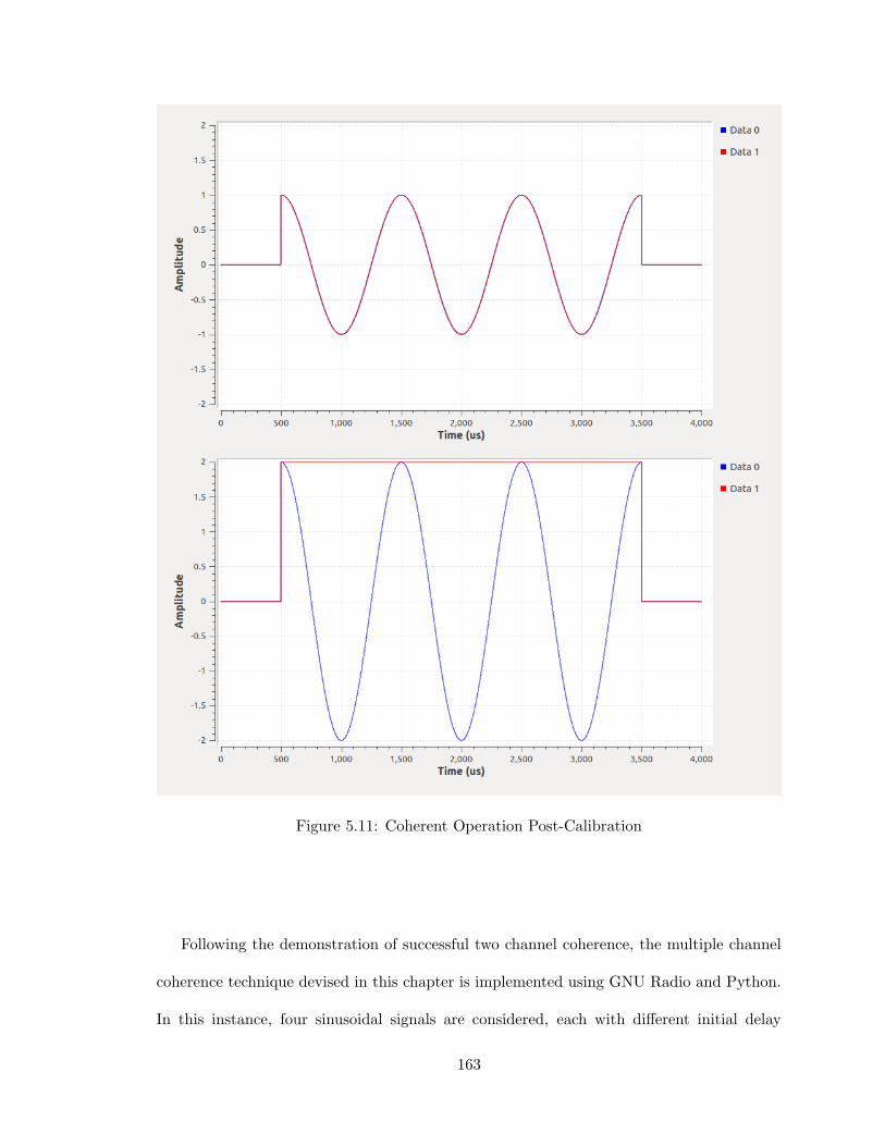
Figure 5.11: Coherent Operation Post-Calibration
Following the demonstration of successful two channel coherence, the multiple channel
coherence technique devised in this chapter is implemented using GNU Radio and Python.
In this instance, four sinusoidal signals are considered, each with different initial delay
163

and phase shift properties as shown in Figure 5.14. By applying the multiple channel
calibration procedure, pairs of elements transmit orthogonal waveforms and corresponding
coherence parameters are estimated pairwise. Once all coherence parameters are estimated,
the resulting set of coherence parameters is applied to the four channels and the initial
sinusoidal signals are again re-transmitted as shown in Figure 5.15. As can be observed in
the resulting figure, coherence in both phase and time alignment is achieved between all
four channels using the devised multiple channel calibration technique. This technique, now
verified through simulation, will be tested experimentally in the following sections.
164

Figure 5.12: Multi-Channel Incoherent Operation Pre-Calibration
165

Figure 5.13: Multi-Channel Coherent Operation Post-Calibration
5.4.2 Hardware Loop-Back Experiment
The simulated loop-back experiment in the previous section proved that multiple channel
coherence can be achieved in situ. Transitioning from an artificial signal environment to the
experimental hardware platform, this experiment demonstrates multiple channel coherence
in a SDR hardware loop-back configuration. A simple RF closed-loop configuration is
realized in which each transmitter channel from the USRP N310 SDR is connected to an
166

RF power combiner via SMA cables. The transmitted signals constructively/destructively
interfere within the power combiner emulating the behavior which will occur during over-
the-air propagation. Then the output of the power combiner is received on a USRP B210
SDR such that the incident signal may be processed for coherence parameter estimation as
well as signal visualization. Through the isolation of transmitted signals from propagation
phenomena, this configuration allows coherence algorithms to be tested when real hardware
induced delays and phase shifts are introduced to the signals in addition to the delays and
phase shifts initially created in software. Success in this experiment requires the ability to
estimate channel coherence parameters in real-time during a calibration mode and perform
real-time updates of coherence parameters to successfully cohere reference signals at the
intended receiver.
Using the same methodology as the previous simulated experiment, four sinusoidal sig-
nals with different initial delay and phase shift properties are synthesized as shown in Figure
5.14. By applying the multiple channel calibration procedure, pairs of elements transmit or-
thogonal waveforms and corresponding coherence parameters are estimated pairwise. Once
all coherence parameters are estimated, the resulting set of coherence parameters is applied
to the four channels and the initial sinusoidal signals are again re-transmitted as shown in
Figure 5.15. From this result it can be observed that the calibrated signals have a con-
stant envelope with approximately four times the magnitude of a single signal prior to the
calibration routine.
167

Figure 5.14: Hardware Loopback Multi-Channel Incoherent Operation: Pre-Calibration
Figure 5.15: Hardware Loopback Multi-Channel Coherent Operation: Post-Calibration
While the calibration routine as been shown to achieve multi-channel coherence in both
simulation and experimentally, long-term coherence requires precise software control and
exception handling. Through the experimental testing leading to this result, a number of
software related anomalies were encountered. A primary source of failure in the algorithm
occurred when the detection stage of the calibration algorithm failed to detect a return
168
(due to SNR) or detected multiple returns (due to false detection). In these instances
the algorithm was known to produce a false estimate of the coherence parameters. While
software exception handling cases were developed for several common sources of algorithm
failure, a stable software implementation (over long timescales) requires exception handling
for all possible degenerate cases.
5.4.3 Over-the-Air Experiment
The final coherence experiment considers multi-channel calibration via over-the-air prop-
agation. In this configuration, the hardware loop-back experiment is repeated with antennas
and physical separation between aperture elements. The 4-element distributed aperture
from Figure 5.9 is used as the transmit aperture and a USRP B210 SDR receiver node
is positioned 5-meters away from the phase center of the transmit aperture. Using the
same multiple channel calibration procedure as the hardware loop-back experiment, four
sinusoidal signals with different delays and phase shifts are successfully cohered. The trans-
mitted signals are shown before the calibration procedure in Figure 5.16 and after the in
Figure 5.17. From the resulting signals it is evident that multi-channel coherence can be
readily achieved across an SDR-based distributed aperture which proves the underlying
technical feasibility of the techniques devised and simulated in this manuscript.
169

Figure 5.16: OTA Multi-Channel Incoherent Operation: Pre-Calibration
Figure 5.17: OTA Multi-Channel Coherent Operation: Post-Calibration
170

5.4.4 Experimental Testing Limitations
Throughout this research, many discoveries have been made with regard to experimental
demonstration of distributed coherent apertures and distributed coherent communications
techniques. While the experimental system is designed to perform all necessary functionali-
ties for system testing, an outdoor testing range is necessary to achieve the spatial diversity
necessary to validate the simulations performed in the previous chapter. Conversely, scaling
of the system bandwidth to decrease the necessary spatial diversity requires the implementa-
tion of the GNU Radio / Python code on the USRP N310 FPGA. Due to these limitations,
this research is concluded with validation of the experimental platform through cohere-on-
transmit calibration to prove that the developed techniques are feasible using an SDR-based
hardware platform.
171
CHAPTER VI
SUMMARY AND FUTURE WORK
The research presented in this manuscript considers the fusion of conventional direc-
tional modulation techniques with distributed aperture antennas to achieve enhanced spa-
tial information security at the PHY layer. Directional modulation techniques traditionally
approach spatial information security through degrading the modulation format and SNR
of communications signals in the angle domain, but lack sufficient resolution to achieve po-
sitional information security due to the employment of traditional aperture architectures.
Meanwhile, distributed apertures are known to be capable of achieving high spatial resolu-
tion, yet have strict timing/coherence requirements which have traditionally have presented
a limitation to their usage in communications systems. Through the fusion of these tech-
niques along with the creation of novel signal processing techniques, the presented work
establishes a directional modulation scheme which transmits an intended message to the
position (in range and angle) of an intended receiver while transmitting an alternative or
degraded message to all other spatial locations.
Through the employment of modeling & simulation techniques in the spatial, tempo-
ral, and joint spatio-temporal domains, system aspects including bandwidth and distributed
aperture geometry are associated with unique signal representations and spatial information
coherence regions. Aperture geometries with sufficient spatial diversity are found to pro-
duce information coherence baskets bounded in angle and range while sub-optimal aperture
configurations are still found to exhibit a single information beam without sidelobes from
an information perspective. From a communications modeling perspective, these aperture
geometries are found to produce sufficiently high BER at non-intended receiver locations
such that communications are successfully corrupted in both range and angle depending
172

on the distributed aperture configuration utilized. Finally, a COTS hardware/software ar-
chitecture is developed and experimentally tested in order to validate the feasibility of the
techniques developed throughout this research.
6.1 Novel Contributions
The presented research has extended the body of knowledge in PHY layer security by:
� Identifying distributed aperture antennas as a means to achieve spatially secure com-
munications in both range and angle.
� Introducing distributed aperture waveforms and the impact of such waveforms on
interference rejection and natural denial of eavesdroppers.
� Introducing the spatial coherence basket as the region created by a distributed aper-
ture transmitter geometry over which the source information content is present.
� Characterizing the relationship between distributed aperture geometries (including
random arrays) and instantaneous bandwidth to determine the spatial coherence bas-
ket properties which are attainable.
� Identifying PHY layer security vulnerabilities of ASK, PSK, FSK, and QAM modu-
lation schemes with regard to distributed aperture based techniques.
� Demonstrating the effectiveness of distributed apertures in sustaining a high BER at
all eavesdropper locations in range and angle through communications system simu-
lation.
173

� Developing a flexible SDR-based hardware/software architecture for achieving infor-
mation/phase coherence and cohere-on-transmit operation across an arbitrary dis-
tributed aperture configuration.
� Demonstrating cohere-on-transmit operation experimentally across a COTS SDR-
based distributed aperture through over-the-air transmission.
6.2 Future Work
Improved communications security is a two-way street. That which is good for us is
inherently good for others. Since absolute spatial information security is often a misnomer,
self-identification of vulnerabilities is a necessity to approach true information security.
Based on this approach, this work can be advanced by adapting direction finding and Space
Time Adaptive Processing (STAP) techniques to both leverage and exploit distributed
aperture transmitter behaviors.
From a direction finding perspective, it is desirable to prevent eavesdroppers from de-
termining the location at which a transmitter is located. Traditional time difference of
arrival (TDOA) and phase difference of arrival (PDOA) techniques must be considered in
the context of distributed apertures due to the effects spatial diversity on the aperture phase
center. Should individual distributed aperture transmitter elements be able to be localized,
it is of interest to determine if information content can be successfully ascertained through
nulling of distributed aperture transmitter elements.
Meanwhile, STAP is a signal processing technique which utilizes adaptive array process-
ing algorithms to improve in radar target detection. Traditionally, STAP has considered
λ/2-spaced phased arrays and the respective processing in angle-Doppler space. By applying
174

distributed aperture concepts to STAP, it becomes possible to estimate the clutter power
at and around a cell, located in both range and angle relative to the distributed aperture,
such that detection can be improved. The fusion of these two techniques would enable great
improvements in the radar detection gains traditionally enabled by STAP alone.
175
BIBLIOGRAPHY
[1] X. Li, M. Chen, and E. P. Ratazzi, “Space-time transmissions for wireless secret-
key agreement with information-theoretic secrecy,” in IEEE 6th Workshop on Signal
Processing Advances in Wireless Communications, 2005., June 2005, pp. 811–815.
[2] Xiaohua Li, Juite Hwu, and E. P. Ratazzi, “Array redundancy and diversity for wire-
less transmissions with low probability of interception,” in 2006 IEEE International
Conference on Acoustics Speech and Signal Processing Proceedings, vol. 4, May 2006,
pp. IV–IV.
[3] S. Goel and R. Negi, “Guaranteeing secrecy using artificial noise,” IEEE Transactions
on Wireless Communications, vol. 7, no. 6, pp. 2180–2189, June 2008.
[4] R. Negi and S. Goel, “Secret communication using artificial noise,” in VTC-2005-Fall.
2005 IEEE 62nd Vehicular Technology Conference, 2005., vol. 3, Sep. 2005, pp. 1906–
1910.
[5] Xiaohua Li and E. P. Ratazzi, “Mimo transmissions with information-theoretic secrecy
for secret-key agreement in wireless networks,” in MILCOM 2005 - 2005 IEEE Military
Communications Conference, Oct 2005, pp. 1353–1359 Vol. 3.
[6] Xiaohua Li, Mo Chen, and E. P. Ratazzi, “Array-transmission based physical-layer
security techniques for wireless sensor networks,” in IEEE International Conference
Mechatronics and Automation, 2005, vol. 3, July 2005, pp. 1618–1623 Vol. 3.
[7] O. Hiari and R. Mesleh, “A reconfigurable sdr transmitter platform architecture for
space modulation mimo techniques,” IEEE Access, vol. 5, pp. 24 214–24 228, 2017.
[8] X. Fan, Z. Zhang, W. Trappe, Y. Zhang, R. Howard, and Z. Han, “Secret-focus: A
practical physical layer secret communication system by perturbing focused phases in
distributed beamforming,” in IEEE INFOCOM 2018 - IEEE Conference on Computer
Communications, April 2018, pp. 1781–1789.
[9] Y. Ding and V. Fusco, “A review of directional modulation technology,” International
Journal of Microwave and Wireless Technologies, vol. 8, no. 7, p. 981–993, 2016.
[10] ——, “Developments in directional modulation technology,” Forum for Electromag-
netic Research Methods and Application Technologies (FERMAT), vol. 13, 01 2016.
[11] O. N. Alrabadi and G. F. Pedersen, “Directional space-time modulation: A novel
approach for secured wireless communication,” in 2012 IEEE International Conference
on Communications (ICC), June 2012, pp. 3554–3558.
[12] Y. Ding and V. F. Fusco, “Mimo-inspired synthesis of directional modulation systems,”
IEEE Antennas and Wireless Propagation Letters, vol. 15, pp. 580–584, 2016.
176
[13] T. Xie, J. Zhu, and Y. Li, “Artificial-noise-aided zero-forcing synthesis approach for
secure multi-beam directional modulation,” IEEE Communications Letters, vol. 22,
no. 2, pp. 276–279, Feb 2018.
[14] A. Narbudowicz, M. J. Ammann, and D. Heberling, “Directional modulation for com-
pact devices,” IEEE Antennas and Wireless Propagation Letters, vol. 16, pp. 2094–
2097, 2017.
[15] Z. Gao, Y. Yang, and K. J. R. Liu, “Eavesdropping-resistant space-time network coding
for cooperative communications,” in 2011 IEEE International Conference on Commu-
nications (ICC), June 2011, pp. 1–5.
[16] S. Ertan, H. D. Griffiths, M. C. Wicks, P. Antonik, D. Weiner, R. Adve, and
I. Fotinopoulos, “Bistatic radar denial by spatial waveform diversity,” in RADAR 2002,
Oct 2002, pp. 17–21.
[17] P. Antonik, R. Bonneau, R. Brown, S. Ertan, V. Vannicola, D. Weiner, and M. Wicks,
“Bistatic radar denial/embedded communications via waveform diversity,” in Proceed-
ings of the 2001 IEEE Radar Conference (Cat. No.01CH37200), May 2001, pp. 41–45.
[18] H. D. Griffiths, M. C. icks, D. einer, R. Adve, P. A. Antonik, and I. Fotinopoulos,
“Denial of bistatic hosting by spatial-temporal aveform design,” IEE Proceedings -
Radar, Sonar and Navigation, vol. 152, no. 2, pp. 81–88, April 2005.
[19] C. A. Balanis, Antenna Theory: Analysis and Design, 2016.
[20] R. S. Adve, R. A. Schneible, M. C. Wicks, and R. Mcmillan, “Space-time adaptive
processing for distributed aperture radars.”
[21] V. J. Amuso, R. A. Schneible, Y. Zhang, and M. C. Wicks, “Distributed apertures
for robustness in radar and communications (darrc),” in 2015 IEEE Radar Conference
(RadarCon), May 2015, pp. 0111–0116.
[22] K. Molz, “Distributed aperture radar using small satellites,” pp. 1–12, 01 1989.
[23] V. J. Amuso, R. A. Schneible, Y. Zhang, and M. C. Wicks, “Distributed apertures for
robustness in radar and communications (darrc),” 2015 IEEE Radar Conference, 2015.
[24] P. Antonik, M. C. Wicks, H. D. Griffiths, and C. J. Baker, “Frequency diverse array
radars,” in 2006 IEEE Conference on Radar, April 2006, pp. 3 pp.–.
[25] W. Wang, “Dm using fda antenna for secure transmission,” IET Microwaves, Antennas
Propagation, vol. 11, no. 3, pp. 336–345, 2017.
[26] S. Y. Nusenu, W. Wang, and S. Ji, “Secure directional modulation using frequency
diverse array antenna,” in 2017 IEEE Radar Conference (RadarConf), May 2017, pp.
0378–0382.
177

[27] Q. Cheng, J. Zhu, T. Xie, J. Luo, and Z. Xu, “Time-invariant angle-range depen-
dent directional modulation based on time-modulated frequency diverse arrays,” IEEE
Access, vol. 5, pp. 26 279–26 290, 2017.
[28] X. Wei, Y. Xiao, Y. Xiao, Q. You, and W. Chen, “Spatial and directional modula-
tion with random frequency diverse array,” in 2018 IEEE 8th Annual Computing and
Communication Workshop and Conference (CCWC), Jan 2018, pp. 976–979.
[29] C. Wolff. (2019) Mimo radar systems. [Online]. Available:
http://www.radartutorial.eu/02.basics/MIMO-radar.en.html
[30] F. C. Robey, S. Coutts, D. Weikle, J. C. McHarg, and K. Cuomo, “Mimo radar the-
ory and experimental results,” in Conference Record of the Thirty-Eighth Asilomar
Conference on Signals, Systems and Computers, 2004., vol. 1, Nov 2004, pp. 300–304
Vol.1.
[31] J. Jeganathan, A. Ghrayeb, L. Szczecinski, and A. Ceron, “Space shift keying mod-
ulation for mimo channels,” IEEE Transactions on Wireless Communications, vol. 8,
no. 7, pp. 3692–3703, July 2009.
[32] M. Di Renzo, D. De Leonardis, F. Graziosi, and H. Haas, “Space shift keying (ssk—)
mimo with practical channel estimates,” IEEE Transactions on Communications,
vol. 60, no. 4, pp. 998–1012, April 2012.
[33] T. Takimura, H. Sasaoka, and H. Iwai, “Secret information transmission scheme using
mimo system,” in 2014 IEEE Fifth International Conference on Communications and
Electronics (ICCE), July 2014, pp. 554–559.
[34] A. D. Harper and X. Ma, “Mimo wireless secure communication using data-carrying
artificial noise,” IEEE Transactions on Wireless Communications, vol. 15, no. 12, pp.
8051–8062, Dec 2016.
[35] H. Deng, “Orthogonal netted radar systems,” IEEE Aerospace and Electronic Systems
Magazine, vol. 27, no. 5, pp. 28–35, May 2012.
[36] Hai Deng, “Polyphase code design for orthogonal netted radar systems,” IEEE Trans-
actions on Signal Processing, vol. 52, no. 11, pp. 3126–3135, Nov 2004.
[37] K. M. Cuomo, S. Coutts, J. C. McHarg, N. B. Pulsone, and F. C. Robey, “Wideband
aperture coherence processing for next generation radar (nexgen),” Massachusetts In-
stitute of Technology Lincoln Laboratory, Tech. Rep., 2004.
[38] S. Coutts, K. Cuomo, J. McHarg, F. Robey, and D. Weikle, “Distributed coherent
aperture measurements for next generation bmd radar,” in Fourth IEEE Workshop on
Sensor Array and Multichannel Processing, 2006., July 2006, pp. 390–393.
178

[39] H. Deng, “Radar signal design for configuring a netted radar system with existing
monostatic radar,” in 2004 International Waveform Diversity Design Conference, Nov
2004, pp. 1–3.
[40] B. Liu, Z. He, J. Zeng, and B. Liu, “Polyphase orthogonal code design for mimo radar
systems,” in 2006 CIE International Conference on Radar, Oct 2006, pp. 1–4.
[41] H. Deng, “Waveform design and orthogonal netted radar systems,” in 2004 Interna-
tional Waveform Diversity Design Conference, Nov 2004, pp. 1–4.
[42] Hai Deng, “Synthesis of binary sequences with good autocorrelation and crosscorrela-
tion properties by simulated annealing,” IEEE Transactions on Aerospace and Elec-
tronic Systems, vol. 32, no. 1, pp. 98–107, Jan 1996.
[43] A. T. Fam and R. Kadlimatti, “Good code sets from complementary pairs via polyphase
chips,” in MILCOM 2016 - 2016 IEEE Military Communications Conference, Nov
2016, pp. 952–957.
[44] The MathWorks, Inc., “Matlab.” [Online]. Available:
https://www.mathworks.com/products/matlab.html
[45] Qinghui Tang, S. K. S. Gupta, and L. Schwiebert, “Ber performance analysis of an
on-off keying based minimum energy coding for energy constrained wireless sensor
applications,” in IEEE International Conference on Communications, 2005. ICC 2005.
2005, vol. 4, May 2005, pp. 2734–2738 Vol. 4.
[46] W. Zhang, M. Le, B. Li, J. Wang, and J. Peng, “Directional modulation-enhanced
multiple antenna arrays for secure and precise wireless transmission,” Sensors (Basel,
Switzerland), vol. 19, 2019.
[47] R. W. World. (2012) Fsk advantages — fsk disadvantages — frequency shift keying.
[Online]. Available: https://www.rfwireless-world.com/Terminology/Advantages-and-
Disadvantages-of-FSK.html
[48] ——. (2012) 2fsk vs 4fsk — difference between 2fsk modulation and 4fsk mod-
ulation. [Online]. Available: https://www.rfwireless-world.com/Terminology/2FSK-
modulation-vs-4FSK-modulation.html
[49] J. Anthes. (2007) Ook, ask and fsk modulation in
the presence of an interfering signal. [Online]. Available:
https://wireless.murata.com/pub/media/products/apnotes/ook.pdf
[50] GNU Radio Project, “Gnu radio.” [Online]. Available: http://gnuradio.org
[51] P. Alfke. (1996) Efficient shift registers, lfsr counters,
and long pseudo-random sequence generators. [Online]. Available:
https://www.xilinx.com/support/documentation/applicationnotes/xapp052.pdf
179