A joint PHY/MAC cross-layer design for UWB under power control
14
A joint PHY/MAC cross-layer design for UWB under power control Rashid A. Saeed a, * , Sabira Khatun b , Borhanuddin Mohd Ali b , Khazani Abdullah b a Telekom Malaysia R&D Sdn. Bhd., Lingkaran Teknokrat Timur, 63000 Cyberjaya, Selangor D.E., Malaysia b Department of Computer and Communications Systems Engineering, Engineering Faculty, Universiti Putra Malaysia, 43400 UPM, Serdang, Selangor, Malaysia article info Article history: Received 30 December 2007 Received in revised form 27 August 2009 Accepted 6 November 2009 Available online 14 December 2009 Keywords: Ultra-wideband Power control Narrowband interference NBI TOA abstract Power control (PC) is a critical parameter for the design and evaluation of UWB-based WPAN networks due to its distributed control nature and non-fixed topology. The main issues in UWB PC are the channel gain fluctuations induced by indoor channel fluctuation and interference arising from narrowband systems. In this paper we introduce a joint PHY/ MAC technique for DS-UWB power control design by exploiting the high time resolution of the UWB signal for channel gain improvement and mitigate the narrowband interference to reduce transmitted power. The results indicate that the proposed approach achieves bet- ter BER and throughput over previous works. Ó 2009 Elsevier Ltd. All rights reserved. 1. Introduction Ultra-wideband (UWB) technology will play a key role in short range wireless connectivity. This is due to the potential advantages of UWB transmissions such as low power consumption, very high data rate, immunity to multipath fading, less complex transceiver hardware, and location capabilities. Ultra-wideband as a physical layer technique brings many features to the network. Interest in UWB is motivated by features due to extremely wide bandwidth (several GHz) [1]; potential for significant multipath capture, fine time resolution, high data rate, and low power transmission. These features also bring sev- eral challenges to UWB physical layer and upper layers design, for instance the need for the receiver to have a long acqui- sition time due to the very short pulse, the need to operate with a dynamic interference profile from other spectrum users (narrowband systems) as well as UWB network users, arising from the large bandwidth UWB physical layer. In the network and during the transmission, the MAC layer needs to reconfigure the power control (PC) from time to time. This is due to channel gain variation, wireless channel fluctuation, and nodes mobility. For robust PC design, ranging between nodes should be performed for adaptive channel gain estimation [2]. UWB suffers from narrowband interference (NBI) due to the large bandwidth that UWB spreads over. PC is considered as an effective way in DS-UWB-based systems to combat mul- ti-user interference (MUI), which guarantee the required signal-to-interference and noise-ratio (SINR) at the receiver. How- ever, this is not true in multiple radio interference (MRI) environments. For example, when a link experiences deep narrowband interferer, power control significantly increases its transmission power to keep the same SINR at the receiver. This large transmission power introduces large interference to other links and reduces the system capacity [3]. So for accu- rate power control design, NBI should be mitigated. In [4], the proactive and adaptive approach for rate assignment and power control problems has been examined. The pa- per discussed the tradeoffs between throughput and range to promote fairness in the network by power control optimiza- tion. However, the effect of mobility on the protocol was not investigated rather only stationary nodes are considered. 0045-7906/$ - see front matter Ó 2009 Elsevier Ltd. All rights reserved. doi:10.1016/j.compeleceng.2009.11.003 * Corresponding author. Tel.: +60 173023065; fax: +60 388839599. E-mail address: [email protected] (R.A. Saeed). Computers and Electrical Engineering 36 (2010) 455–468 Contents lists available at ScienceDirect Computers and Electrical Engineering journal homepage: www.elsevier.com/locate/compeleceng
-
Upload
independent -
Category
Documents
-
view
2 -
download
0
Transcript of A joint PHY/MAC cross-layer design for UWB under power control

Computers and Electrical Engineering 36 (2010) 455–468
Contents lists available at ScienceDirect
Computers and Electrical Engineering
journal homepage: www.elsevier .com/ locate/compeleceng
A joint PHY/MAC cross-layer design for UWB under power control
Rashid A. Saeed a,*, Sabira Khatun b, Borhanuddin Mohd Ali b, Khazani Abdullah b
a Telekom Malaysia R&D Sdn. Bhd., Lingkaran Teknokrat Timur, 63000 Cyberjaya, Selangor D.E., Malaysiab Department of Computer and Communications Systems Engineering, Engineering Faculty, Universiti Putra Malaysia, 43400 UPM, Serdang, Selangor, Malaysia
a r t i c l e i n f o a b s t r a c t
Article history:Received 30 December 2007Received in revised form 27 August 2009Accepted 6 November 2009Available online 14 December 2009
Keywords:Ultra-widebandPower controlNarrowband interferenceNBITOA
0045-7906/$ - see front matter � 2009 Elsevier Ltddoi:10.1016/j.compeleceng.2009.11.003
* Corresponding author. Tel.: +60 173023065; faxE-mail address: [email protected] (R.A. Saeed
Power control (PC) is a critical parameter for the design and evaluation of UWB-basedWPAN networks due to its distributed control nature and non-fixed topology. The mainissues in UWB PC are the channel gain fluctuations induced by indoor channel fluctuationand interference arising from narrowband systems. In this paper we introduce a joint PHY/MAC technique for DS-UWB power control design by exploiting the high time resolution ofthe UWB signal for channel gain improvement and mitigate the narrowband interferenceto reduce transmitted power. The results indicate that the proposed approach achieves bet-ter BER and throughput over previous works.
� 2009 Elsevier Ltd. All rights reserved.
1. Introduction
Ultra-wideband (UWB) technology will play a key role in short range wireless connectivity. This is due to the potentialadvantages of UWB transmissions such as low power consumption, very high data rate, immunity to multipath fading, lesscomplex transceiver hardware, and location capabilities. Ultra-wideband as a physical layer technique brings many featuresto the network. Interest in UWB is motivated by features due to extremely wide bandwidth (several GHz) [1]; potential forsignificant multipath capture, fine time resolution, high data rate, and low power transmission. These features also bring sev-eral challenges to UWB physical layer and upper layers design, for instance the need for the receiver to have a long acqui-sition time due to the very short pulse, the need to operate with a dynamic interference profile from other spectrum users(narrowband systems) as well as UWB network users, arising from the large bandwidth UWB physical layer.
In the network and during the transmission, the MAC layer needs to reconfigure the power control (PC) from time to time.This is due to channel gain variation, wireless channel fluctuation, and nodes mobility. For robust PC design, ranging betweennodes should be performed for adaptive channel gain estimation [2]. UWB suffers from narrowband interference (NBI) due tothe large bandwidth that UWB spreads over. PC is considered as an effective way in DS-UWB-based systems to combat mul-ti-user interference (MUI), which guarantee the required signal-to-interference and noise-ratio (SINR) at the receiver. How-ever, this is not true in multiple radio interference (MRI) environments. For example, when a link experiences deepnarrowband interferer, power control significantly increases its transmission power to keep the same SINR at the receiver.This large transmission power introduces large interference to other links and reduces the system capacity [3]. So for accu-rate power control design, NBI should be mitigated.
In [4], the proactive and adaptive approach for rate assignment and power control problems has been examined. The pa-per discussed the tradeoffs between throughput and range to promote fairness in the network by power control optimiza-tion. However, the effect of mobility on the protocol was not investigated rather only stationary nodes are considered.
. All rights reserved.
: +60 388839599.).

456 R.A. Saeed et al. / Computers and Electrical Engineering 36 (2010) 455–468
An uncoordinated MAC protocol for UWB networks with rate adaptation and interference mitigation to improve through-put and energy consumption was presented in [5]. The impulsive interference was mitigated at the physical layer as well asat the link layer. However, the ranging capability was not used. Uncoordinated UWB tailored MAC algorithm medium accessnetworks (UWB)2 was described in [6] based on pure Aloha with synchronization. (UWB)2 exploited ranging capability of-fered by UWB PHY layer. Distance information between transmitter and receiver was collected during control packet ex-change. Multi-user interference (MUI) was modelled based on packet collisions.
In [7] a dynamic channel coding (DCC) based protocol was extended by incorporating a model for a UWB mobile ad hocnetworks physical layer as well as new MAC layer protocols. Joint PHY/MAC layer design was developed with the idea ofarranging the physical layer and the MAC protocol such that collisions may be replaced by rate reduction. Due to the advan-tages of pulsed TH-UWB, it has been adopted to come out with an interference mitigation scheme that reduces the impact ofstrong interferers.
In this paper, we introduce a joint PHY/MAC design for DS-UWB power control design by exploiting the high time reso-lution of the UWB signal for high ranging estimation accuracy using time-of-arrival (TOA) algorithm for non-line-of-sight(NLOS) environments and mitigate the narrowband interference to reduce transmitted power using doublet Gaussian pulseshape. The rest of the paper is organized as follows. In Section 2, the UWB signal model is presented; Section 3 discusses thepower control design evaluation. Sections 4 and 5 present ranging estimation and narrowband interference analysis and mit-igation, respectively. Simulation numerical results and discussions are presented in Section 6. Finally, Section 7 concludesthe paper.
2. UWB signal model
A Gaussian doublet is comprised of a pair of separated second order Gaussian monocycle, a positive pulse followed by anegative pulse. This offers two degrees of freedom, time separation between the two pulses in the doublet and time sepa-ration between doublets
pðtÞ ¼ p0ðtÞ � p1ðtÞ ð1Þ
The second Gaussian derivative pG2(t) can be expressed as:
pG2ðtÞ ¼ �AG21� ðt � lÞ2=r2ffiffiffiffiffiffiffi
2pp
r2exp �ðt � lÞ2
2r2
!ð2Þ
where the parameter r determines the monocycle width Tp. The effective time duration of the waveform that contains99.99% of the total monocycle energy is Tp = 7r centered on l = 3.5r. The factor AG2 is introduced so that the total energyof the monocycle is normalized to unity, i.e.
Rp2
G2ðtÞdt ¼ 1. With spectrum analysis of Eq. (2) the energy spectral density(ESD):
jPðxÞj2 ¼ 4pe � ðwt2pÞ
2 � e�ðxtpÞ2 � ½1� cos xTn� ð3Þ
Since x = 2pf, the null frequencies in ESD are, p(2fTn) = 0, 2p, . . ., 2kp,. . ., then f = (k/Tn), where k = 1,2,. . .. Using Eqs. (1)–(3),the doublet Gaussian pulse in time domain and frequency domain are shown in Figs. 1 and 2, respectively.
The null frequencies of Gaussian doublet in Fig. 2 can be controlled by regulating the position of the second Gaussianpulse (the first pulse p0(t) begins at t = 0, the second one p1(t) begins at t = Tn). From the figure we can see that the powerspectral density (PSD) is skewed. As depicted in Fig. 2 there notch spectral in the doublet waveform which can be used tomitigate interference from other systems.
-0.2 -0.1 0 0.1 0.2
-0.5
0
0.5
1
t(nsec)
Nor
mal
ized
am
plitu
de
Time-Domain of the Doublet Gaussian Pulse p(t)
Fig. 1. Time–domain representation for Gaussian doublet pulse with time delay between the pulses Tn = 0.1 ns.

0 2 4 6 8 10 12x 10 9
10-25
10-20
10-15
10-10
10-5
100
Frequency-domain of the Doublet Gaussian Pulse p(t)
Frequency [Hz]
Nor
mal
ized
PSD
[dB]
FCC emission limit
Fig. 2. Power spectral density (PSD) of doublet Gaussian pulse and FCC emission limit for indoor systems.
R.A. Saeed et al. / Computers and Electrical Engineering 36 (2010) 455–468 457
3. Power control design
Power control is the process of determining the transmitted power of each communication terminal in the UWB network.Adjusting the transmitted power is extremely important for UWB ad hoc networks because the transmitting node needs tosense the signal-to-interference and noise-ratio (SINR) at receiving node [8]. If the SINR is lower than the target value thenthe transmitting node increases its transmitted power and vice versa so as to improve the total system performance.
A measure of the link quality (related to bit error rates) is the SINR observed at the receiver [9]. Indeed the link through-put is an increasing function of the signal-to-interference and noise-ratio (SINR). Thus, the link power control is an increasingfunction of the SINR. To simplify the discussion, we base our formulation of the power control problem directly on the SINRand consider the above problems of mobility and NBI. Let
SINR ¼PijðtÞgijðtÞ
r2rec þ
PQk¼1;k – i;j
PkgkjðtÞ þ r2bmjm2Ij
ð4Þ
where pij(t) = (mpNs)2 is the received power which results from correlation output (mp) between the transmitted pulse andtemplate signal during the interval Tf. Ns = 1/Tfrij is the number of pulse per symbol, rij is the data rate in the link between iand j. r2
rec is the noise power, which can be expressed as [4]:
r2rec ¼ N0mpNs ¼ N0B ð5Þ
where B is the signal bandwidth and N0 is ambient Gaussian noise power spectral density. The multi-access interferencepower is proportional to the number Ns of the integrated pulses and it shapes, which can be expressed as:
XQ
k¼1k–ik–j
PkgkjðtÞ ¼ Nsr2aðNu � 1Þ ¼ r2
a
Tf rijðNu � 1Þ ð6Þ
where Nu is the number of users and r2a is the power of the interference resulting from one user. The interference is due to
the synchronism amongst different users signals and to the pseudorandom codes. The possibility of removing this undesiredinterference mainly depends on the characteristics of the codes used for separating data flows, and on the degree of system-level synchronization. In realistic scenarios devices do not achieve ideal synchronization and codes lose orthogonality due todifferent propagation delays on different paths, the receiver might not be capable of completely removing the presence of theundesired signals, and as a consequence, system performance is affected by MUI. A detailed analysis of MUI has been dis-cussed extensively in [12].
The last part of Eq. (4) is r2bmjm2Ij
¼ NsPavg jPðf Þj2 is the variance of the narrowband interference, Ij is the set of narrowbandnodes that can cause interference at UWB node j, Pavg is the average power of interferer signal, which is calculated from thecorrelation matrix of interference samples, and |P(f)|2 is the is the power spectral density (PSD) of the received pulse. Nar-rowband interference has a large impact on the system performance which affects the quality of the radio link, producingmore packet losses, and results in an overall rate reduction and increased energy consumption. Therefore, it needs to be ta-ken into account as early as in the design phase.
Finally, gij(t) in Eq. (4) is the channel gain between node i to node j, respectively, i; j 2 f1;2;3; . . . ;Ng; gijðtÞ is modelled asa combination of distance |xi � xj|, path loss (a) and Rayleigh fading (multipath) channel C(t) where:

458 R.A. Saeed et al. / Computers and Electrical Engineering 36 (2010) 455–468
gijðtÞ ¼g0ðtÞPK
k¼1jXk
i � Xk�1i j
a=CkðtÞ
ð7Þ
g0(t) is a reference value for power gain evaluated at D = 1 m. To calculate the distance between the nodes we can write:
jxi � xjj ¼ c � sij ð8Þ
where c is the speed of light and sij is the estimated time of received signal at node j, given by [10]:
sij ¼ sTOA þ e ð9Þ
where sTOA is the time-of-arrival and e is the time offset obtained from mean acquisition time, which is the time the receiverneed to synchronize with the transmitter for more accurate time-of-arrival estimation. The time-of-arrival (TOA) techniquecomputes the estimation of the propagation delay between transmitter and receiver. In order to do that the maximum like-lihood estimator has been used [11]:
sToAðMLÞðrÞ ¼ arg mins2R
e� 1
N0
RTobsðrðtÞ�sðt�sdÞÞ2dt
� �ð10Þ
where N0 is the power spectral density (PSD) of the noise and Tobs is the observation interval over which the estimation isperformed. We can write that, for each link i there is a lower SINR threshold cT
i , reflecting a certain QoS the link has to main-tain in order to operate properly [12]. Therefore, we require that:
SINR ¼m2
pCijcðsTOA þ eÞ�a
½r2rec þ r2
aðNu � 1Þ þ Pavg jPðf Þj2�Tf rij
P cTi ðtÞ ð11Þ
UWB communication system parameters (such as the number of users, bit rates and achieved SINR) represent the re-sources made available by the UWB physical layer (such as pulse shape, bandwidth, processing gain, and number of pulsesper bit). By adjusting these system parameters, it is possible to design a high throughput MAC protocol for UWB. The widerange of values of the UWB parameters enables the design of highly adaptive PHY/MAC design which may be matched to awide range of service requirements [11]. In addition to focusing on the resources to be managed, possible constraints im-posed by the UWB technology itself must be taken into account. In the next section we will discuss ranging estimation be-tween nodes and narrowband interference mitigation for more robust power control design.
4. Ranging design
The fine time resolution of UWB signals enables potential applications in high-resolution of channel gain adaptation. Thenovel aspect of UWB TOA is that the multipath time-spread in many channels of interest is often 100–1000 times the inher-ent time resolution of the UWB signal detected in a matched filter receiver. Some of the parameters that have been tradi-tionally used for distance calculation are the received signal strength intensity (RSSI), the angle of arrival (AOA) andtime-of-arrival (TOA) [11].
Amongst these parameters, RSSI is the least adequate in the case of UWB because of the cumulative impulsive signalsstrength due to multipath and requires a site-specific path loss model [13]. The estimation of AOA, on the other hand, re-quires multiple antennas (or at least an antenna capable of beam-forming) at the receiver. This requirement implies sizeand complexity demands that are often not compatible with the low-cost, small-size constraints associated with applica-tions such as wireless sensor networks, which UWB technology is particularly suited for. Given a transmitted signal s(t),the corresponding received signal can be written as:
rðtÞ ¼ hðtÞ � sðtÞ þ nðtÞ þ nbðtÞ ð12Þ
where h(t) is the channel impulse response and n(t) and nb(t) are AWGN and narrowband interference, respectively. If thesignal propagates over a perfect channel the impulse response can be written as:
hðtÞ ¼ AðdÞdðt � sðdÞÞ ð13Þ
where d is the distance between the transmitter and the receiver. The received signal can be written as:
rðtÞ ¼ AðdÞsðt � sðdÞÞ þ nðtÞ þ nbðtÞ ð14Þ
Eq. (14) indicates that distance d can be estimated from either attenuation A(d) or delay s(d). The use of A(d) versus s(d)determines the method for estimating distance; received signal strength intensity (RSSI) versus time-of-arrival (TOA),respectively. The TOA technique computes distance based on the estimation of the propagation delay between transmitterand receiver. TOA is the most commonly used distance estimation method in the radar field.
Assume that a single UWB pulse is transmitted over a multipath channel, then the received signal can be expressed as thesum of the first signal path, other multipath components and noise:

Fig. 3. Time-of-arrival (TOA) estimation algorithm flow chart.
R.A. Saeed et al. / Computers and Electrical Engineering 36 (2010) 455–468 459
rðtÞ ¼ a1pðt � s1Þ þXL
l¼2
alpðt � slÞ þ nðtÞ þ nbðtÞ ð15Þ
where s1 < s1 < . . . < sl. L is the number of multipaths, where L is unknown. We also assume that the delay and channel coef-ficient for the strongest multipath component, s and a, are determined beforehand by means of a correlation technique; forexample, they can be estimated by exhaustively searching possible delay positions, and choosing the one with maximumcorrelation output [12]. A two-step algorithm as in [10], can be employed first to obtain a rough estimate of the signal delaysand then to seek the strongest component in the block. Then, consider the signal components including and prior to thestrongest path and truncating the �rðtÞ to t 6 Tp=2, we can write:
~rðtÞ ¼ �rðtÞ; t 6Tp
2
~rðtÞ ¼ ~a1pðt þ ~s1Þ þXM
l¼2
~alpðt þ ~slÞ þ ~nðtÞ þ ~nbðtÞð16Þ
where Tp is the doublet Gaussian pulse width p(t), M is the number of multipath components before the strongest compo-nent. If M = 0, then ~s1 ¼ 0; ~a1 ¼ �1, and the second term in Eq. (16) is ignored. ~nðtÞ is white Gaussian noise truncated to thetime interval (�1, Tp/2] [14]. After wideband filtering and sampling ~rðtÞ, we can write the vector ~r as:
~r ¼ ~a1p~s1þXM
l¼2
~alp~slþ ~nþ ~nb ð17Þ
where p~slis a vector consisting samples from pðt þ ~slÞ with the same length of ~r. Since ~n and ~nb are a white Gaussian and
narrowband interference vectors, then we can write the estimated ~s1 as:
fs1 ¼ arg max~s1
min~a1 ;M;~a;~s
~r� ~a1p~s1�XM
l¼2
~alp~sl
����������
224 35 ð18Þ

FCC part 15 limit (-41.3 dBm/MHz) Si
gnal
Pow
er (
Wat
t)
1.6 1.9 2.4 3.1 4
UWB
5 10.6 Frequency (GHz)
UNI-ISM bandIEEE802.11a
FWA
ISM bandIEEE802.11b/g
PCS
GPS
Fig. 4. Spectrum crossover of the narrowband interferers in UWB systems.
460 R.A. Saeed et al. / Computers and Electrical Engineering 36 (2010) 455–468
where ~a ¼ ½~a2 . . . ~aM � and ~s ¼ ½~s2 . . . ~sM �. The computation of TOA estimation by Eq. (18) was evaluated by using the iterationin Fig. 3 coded by matlab� 7.4. The thresholds of the algorithm, h~s1 and h~a1 , are important thresholds that determine the per-formance of the estimator. Therefore, those critical thresholds can be selected based on some statistical information obtainedfrom channel impulse response in specific environment [15].
5. Interference analysis and mitigation
UWB systems are able to co-exist with narrowband technologies due to regulation by FCC in February 2002, as shown inFig. 2. However, conversely the influence of narrowband signals on the UWB system can be significant, and in the extremecase, these signals may jam the UWB receiver completely [12]. Even though narrowband signals interfere with only a smallfraction of the UWB spectrum, due to their relatively high power with respect to the UWB signal, the performance and capac-ity of UWB systems can be affected considerably. Recent studies show that the BER performance of the UWB receivers isgreatly degraded due to the impact of narrowband interference (NBI) [3] (shown in Fig. 4).
Consider the presence of narrowband interferer signal within the DS-UWB system. Then the signal at the receiver can bewritten as:
rðtÞ ¼XNu
k¼1
ffiffiffiffiffiffiffiffiffiffiffiffiAkEðkÞc
q Xi
bðkÞi
XNc�1
l¼0
cðkÞl hðkÞðtÞ � pðt � lTc � iTf Þ þ nðtÞ þ nbðtÞ ð19Þ
where Nu is number of users, Ak represent the attenuations due to pth loss, which is function of the transmitter–receiverdistance, EðkÞðcÞ is the energy per transmitted pulse for user k. This is modelled with doublet Gaussian pulse p(t). n(t) is theGaussian process with two sided power spectral density N0/2 and nb(t) is the narrowband interference, hk(t) is thetime-invariant asynchronous multipath channel impulse response for user k. ‘�’ denotes convolution. In order to evaluatethe narrowband interference analytically, we construct a discrete time equivalent model of the narrowband interferenceby sampling nb(t) every Ts seconds, with Ts� Tc. The vector containing the discrete sample is given as:
nb�! ¼ ½nbð0Þ; nbðTsÞ; . . . ;nbðNw � 1ÞTs�T ; nb
�! 2 R ð20Þ
where Ts is the sampling time, Nw = Tw/Ts is the number of samples in observation window Tw over which the receiver oper-ates. The power spectral density of the narrowband interference can be written as:
Snbðf Þ ¼Nb=2; f I � Bb=2 6 jf j 6 fI þ Bb=20; otherwise
�ð21Þ
where fI and Bb are the central frequency and bandwidth of the narrowband interference, respectively, and Nb/2 is the powerspectral density (PSD) of the interference within its bandwidth. We consider two types of in-band interference (IBI); anIEEE802.11a system with central frequency fI = 5.3 GHz, and bandwidth Bb = 200 MHz, fixed wireless access (FWA) networkwith central frequency fI = 3.9 GHz and bandwidth Bb = 160 MHz [3]. The autocorrelation function of nb(t) is therefore given by:
RbðsÞ ¼Nb
2~RbðsÞ ð22Þ
where ~RbðsÞ ¼ 2Bb cosð2pfIsÞ sin cðpBbsÞ, and we can evaluate NBI variance as:
r2b ¼ Ab
Nb
2j~Rbj ð23Þ
Pulse shaping is an emerging approach for a more efficient usage of the precious radio spectrum resources and to fit toFCC spectrum mask. It considers an expanded view of the wireless channel by managing and adapting pulse parameterdimensions of time, frequency, space, power, and coding. In the next section, we will discuss pulse shaping in order toself-adapt the UWB pulse parameters and minimize in-band narrowband interference typically; WLAN and Fixed WirelessAccess (FWA).

R.A. Saeed et al. / Computers and Electrical Engineering 36 (2010) 455–468 461
5.1. Pulse shaping for spectrum adaptation
In the analysis herein, we assume an all Rake (ARake) receiver, which consists of multiple correlators employing the tem-plate signal of v(t) = p(t) � p(t � sk), sk is the excess delay of the kth path. When appropriately synchronized and assumingthe pulse shape p(t) known to the receiver, the correlation output over a symbol interval of the kth path, denoted byrk ðk ¼ 1;2; . . . ;NrÞ, is given by:
rk ¼ bðkÞi sk þ nbk þ nk ð24Þ
where bðkÞi is estimated at detector, and sk, nk, nbk are the symbol interval of the kth path for the transmitted signal, AWGNsignal, and narrowband interference signal, respectively
sk ¼ ANs
XNs�1
i¼0
Z 1
�1prðtÞ½prðtÞ � prðt � skÞ� ¼ ANsmpðdÞ
nk ¼XNs�1
i¼0
Z 1
�1nðt þ iTf þ ciTcÞvðtÞdt
nbk ¼XNs�1
i¼0
Z 1
�1iðt þ iTf þ ciTcÞvðtÞdt
ð25Þ
The correlation matrix of the interference samples Rnb¼ Efnbkn�blg are collected over a symbol interval at different paths.
Since the UWB spectrum will be basically constant over the frequency range of NBI centered at fI [17], then (k, l) element ofRnb
can be derived as:
½Rnb�k;l ¼ NsjPrðfIÞj2½2Rnb
ð0Þ � RnbðekÞ � Rnb
ðelÞ� ð26Þ
where |Pr(fI)|2 is the power spectral density of the received pulse pr(t) at the frequency fI.We can conclude that the effect of NBI on UWB systems is maximum when the NBI center frequency overlaps with nom-
inal center frequency of UWB spectrum. To mitigate the presence of narrowband interference in UWB receiver a notch filtershould be placed after the ARake to filter out the interference part around fI(|Pr(fI)|2 = 0) from the pulse power spectrum|Pr(f)|2. Then we can write the transfer function of the notch filter as:
Hðf Þ ¼ 1� u f � fI þBb
2
� �� u f � fI �
Bb
2
� �� �� ð27Þ
and impulse response as:
hðtÞ ¼ dðtÞ � Bbej2pfI t sin cðBbtÞ ð28Þ
where Bb represents the width of the spectral notch, which is set to be sufficiently larger than the bandwidth of the narrow-band interference. This can be performed by a filter bank [12]. Having notched out the interference, the remaining signal isrestored to the time domain by performing inverse Fourier transform, which can be expressed as:
~rðtÞ ¼ Abipnotchðt � iTf � ciTcÞ þ nðtÞ ð29ÞpnotchðtÞ ¼ prðtÞ � PrðfIÞBbej2pfI t sin cðBbtÞ ð30Þ
where t is in nanosecond and Bb is in gigahertz. For suppression of typical NBI, Bb� 1; moreover, due to the low power ofUWB transmission system, Pr(fI) is also of a small value. So the notched pulse is expected to be only slightly different frompr(t). The rest of the signal processing takes place in time domain.
6. Numerical results and discussion
MATLAB�
7.4.1 has been used as simulation tool to analyze the performance of the UWB system described in this paper. Inour simulation, a random distribution wireless ad hoc network was assumed in extendable area of 15 � 15 m for indoorenvironment i.e. smart home and hotspot scenarios. For UWB signal structure, two bands direct sequence spread spectrum(DS-UWB) were used in this thesis in addition to multi-band orthogonal frequency division multiplexing (OFDM-UWB) forcomparison purposes. The signal bandwidth was defined according to IEEE802.15.3a proposal for PHY and MAC layers,whereby there are three types of UWB bandwidths were employed, namely 3.1 GHz for DS-SS UWB (lower band), 2 GHzand 4.744 GHz for DS-CDMA (upper band) UWB system, and 528 MHz for MB-UWB system with four groups of bands pro-posed by IEEE802.15.3a study group to increase the capacity with propagation delay of a. The UWB PHY/MAC layer designwas studied using the modified Saleh–Valenzuela multipath fading channel model. Since we assume that transmissions aretypically over short-to-medium distances, shadow fading was ignored. Gaussian doublet pulse was used due to its simplicityand flexibility in design and generation. The main design and performance parameters and their associated values are illus-trated in Table 1.
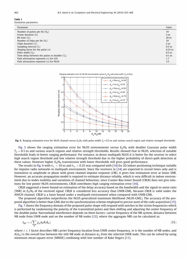
Table 1Simulation parameters.
Parameter Value
Number of pulses per bit (Np) 10Frame duration (Tf) 2 nsBit time (Tb) 20 nsNumber of chips per bit (Nc) 10Chips duration (Tc) 2 nsSampling interval (Ts) 0.5 nsShaping factor for the pulse (r) 0.25 nsPulse width (Tp) 0.5 nsTime delay between the pulses in doublet (Tn) 0.1 nsPath attenuation exponent (a) for LOS 1.7Path attenuation exponent (a) for NLOS 3.5
0 2 4 6 8 10 12 14 16 18 200
0.5
1
1.5
2
2.5
3
3.5
Eb/N0(dB)
Ranging estimation error for NLOS environments versus E b/N0 with pulse width (TP=0.5ns)
Ran
ging
est
imat
ion
erro
r (m
)
θτ1=10ns,θα1=0.25
θτ1=1ns,θα1=0.25
θτ1=10ns,θα1=0.50
θτ1=1ns,θα1=0.50
θτ1=10ns,θα1=0.75
θτ1=1ns,θα1=0.75
Fig. 5. Ranging estimation error for NLOS channel versus Eb/N0 with pulse width Tp = 0.5 ns and various search region and relative strength thresholds.
462 R.A. Saeed et al. / Computers and Electrical Engineering 36 (2010) 455–468
Fig. 5 shows the ranging estimation error for NLOS environments versus Eb/N0 with doublet Gaussian pulse widthTp ¼ 0:5 ns and various search regions and relative strength thresholds. Results showed that in NLOS, selection of suitablethresholds leads to better ranging performance. For instance, in dense multipath NLOS it is better for the receiver to selecthigh search region threshold and low relative strength threshold due to the higher probability of direct-path detection atthese values. However higher Eb/N0 transmission with lower thresholds still gives good performance.
The results in Fig. 6 with hs1 ¼ 10 ns and ha1 ¼ 0:25 was compared with [14] for 2D indoor positioning technique suitablefor impulse radio networks in multipath environment. Since the receivers in [14] are expected to record times only and isinsensitive to amplitude or phase with given channel impulse response (CIR), it gives low estimation error at lower SNR.However, an accurate propagation model is required to estimate distance reliably, which is very difficult in indoor environ-ment due to nodes mobility and variations of channel behaviour, since Cramer-Rao lower bound (CRLB) does not give solu-tions for low power NLOS environments, CRLB contributes high ranging estimation error [16].
CRLB suggested a lower bound on estimation of the delay accuracy based on the bandwidth and the signal-to-noise ratio(SNR) in Eb/N0 of the received signal. CRLB is considered less accuracy than UWB-GML, because CRLB is valid under theAWGN channel. CRLB is a loose bound under a multipath environment when compared with UWB-GML.
The proposed algorithm outperforms the NLOS generalized maximum likelihood (NLOS-GML). The accuracy of the pro-posed algorithm is better than GML due to the synchronization scheme employed to precise asset of the code acquisition [15].
Fig. 7 shows the frequency domain of the proposed pulse shape will respond with notches in the victim frequencies whichis performed by randomizing the polarity of the transmitted pulses and then shifting and adjusting the center frequency ofthe doublet pulse. Narrowband interference depends on three factors: carrier frequency of the NB system, distance betweenNB node from UWB node and on the number of NB nodes [12], where the aggregate NBI can be calculated as:
Iagr ¼ kX
m
vmnbAðdmÞ ð31Þ
where k 6 1 factor describes NBI carrier frequency location from UWB center frequency, m is the number of NB nodes, andA(dm) is the overall loss between the mth NB node at distance dm from the selected UWB node. This can be solved by usingminimum mean-square-error (MMSE) combining with low number of Rake fingers [11].

0 2 4 6 8 10 12 14 16 18 200
0.2
0.4
0.6
0.8
1
1.2
1.4
1.6
1.8
2
Eb/N0(dB)
Ranging estimation error for NLOS environments versus E b/N0 with pulse width (TP=0.5ns)
Ran
ging
est
imat
ion
erro
r (m
)
proposed NLOS-GML2D NLOS-CRLB
Fig. 6. Ranging estimation error (REE) for NLOS with pulse width Tp = 0.5 ns and hs1 ¼ 10 ns, ha1 ¼ 0:25.
3 4 5 6 7 8 9 10 1110
-25
10-20
10-15
10-10
10-5
100
Adjusted Frequency Domain
Frequency (GHz)
Nor
mal
ized
ES
D (
dB)
FWA fnotch=3.9GHz
WLAN fnotch=5.8GHz
Fig. 7. Normalized power spectral density (PSD) for UWB doublet Gaussian pulse to mitigate interference from WLAN with center frequency fI = 5.8 GHzand FWA center frequency fI = 3.9 GHz.
R.A. Saeed et al. / Computers and Electrical Engineering 36 (2010) 455–468 463
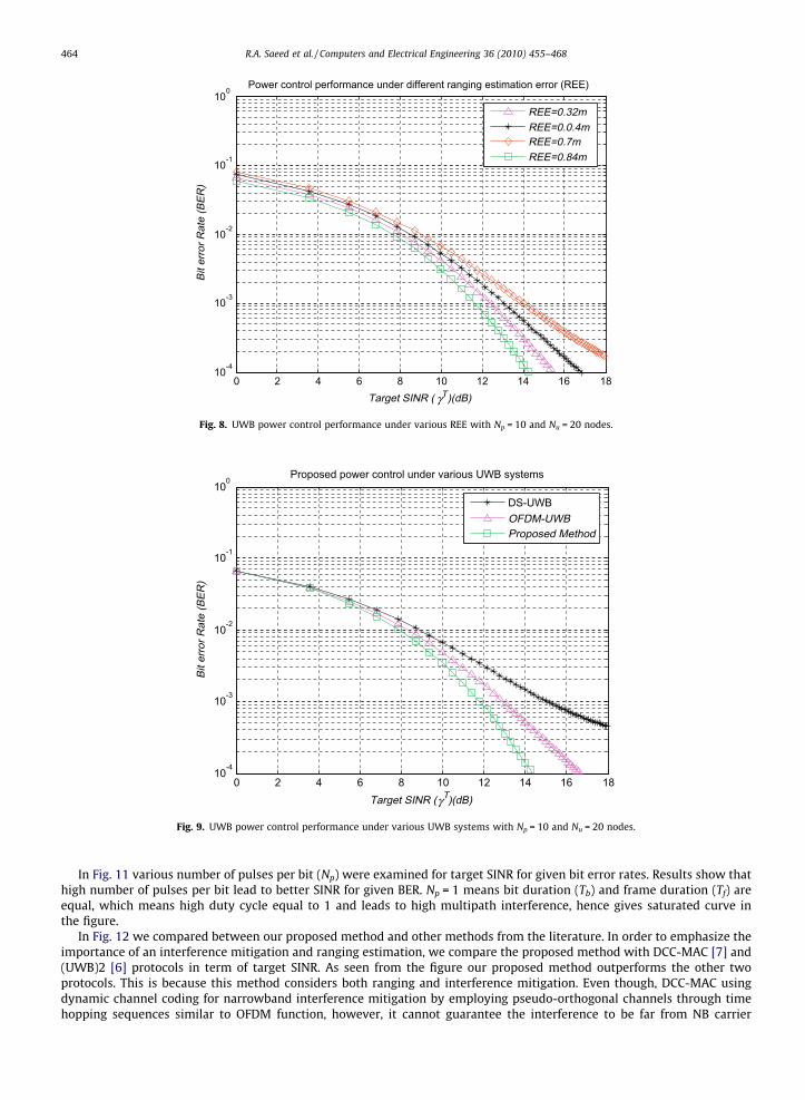
Fig. 8 shows the effect of ranging estimation error (REE) in power control performance. Recall the results in Fig. 6, theranging estimation error at Eb=N0 ¼ 10 dB for the proposed method is (REE = 0.32 m), NLOS-GML is (REE = 0.4 m), 2D is(REE = 0.7 m), and for NLOS CRLB is (REE = 0.84). From the figure the high range estimation error (REE) leads to wrong powercontrol calculation which leads to high bit error rate (BER).
Fig. 9 shows the power control performance for conventional DS-UWB, OFDM-UWB, and DS-UWB after pulse shaping. Theproposed method outperforms IEEE802.15.3a proposed systems, OFDM-UWB and DS-UWB, due to interference mitigationeffects.
Fig. 10 shows the performance of UWB power control system as evaluated from Eq. (9) with various number of nodes(10, 20, 30, 40, and 50 nodes). For high number of users (30, 40, and 50) the BER is saturated due to increased number ofpacket collisions, heavy loads in the medium and multi-user interference (MUI). This problem can be solved by adoptingspace diversity that can be provided by ranging algorithm [16]. Another method to avoid multipath interference is tolower the duty cycle of the system, and can be achieved by increasing the pulse duration (Tf), where duty cycle is givenby [18]:
duty cycle ¼ Tf =Tp ð32Þ
By transmitting pulses with time delay greater than the maximum expected multipath delay, unwanted reflections can beavoided at the receiver.
0 2 4 6 8 10 12 14 16 1810-4
10-3
10-2
10-1
100
Target SINR ( γT)(dB)
Bit
erro
r Rat
e (B
ER)
Power control performance under different ranging estimation error (REE)
REE=0.32mREE=0.0.4mREE=0.7mREE=0.84m
Fig. 8. UWB power control performance under various REE with Np = 10 and Nu = 20 nodes.
0 2 4 6 8 10 12 14 16 1810-4
10-3
10-2
10-1
100
Target SINR (γT)(dB)
Bit
erro
r Rat
e (B
ER)
Proposed power control under various UWB systems
DS-UWBOFDM-UWBProposed Method
Fig. 9. UWB power control performance under various UWB systems with Np = 10 and Nu = 20 nodes.
464 R.A. Saeed et al. / Computers and Electrical Engineering 36 (2010) 455–468
In Fig. 11 various number of pulses per bit (Np) were examined for target SINR for given bit error rates. Results show thathigh number of pulses per bit lead to better SINR for given BER. Np = 1 means bit duration (Tb) and frame duration (Tf) areequal, which means high duty cycle equal to 1 and leads to high multipath interference, hence gives saturated curve inthe figure.
In Fig. 12 we compared between our proposed method and other methods from the literature. In order to emphasize theimportance of an interference mitigation and ranging estimation, we compare the proposed method with DCC-MAC [7] and(UWB)2 [6] protocols in term of target SINR. As seen from the figure our proposed method outperforms the other twoprotocols. This is because this method considers both ranging and interference mitigation. Even though, DCC-MAC usingdynamic channel coding for narrowband interference mitigation by employing pseudo-orthogonal channels through timehopping sequences similar to OFDM function, however, it cannot guarantee the interference to be far from NB carrier

0 2 4 6 8 10 12 14 16 1810-4
10-3
10-2
10-1
100
Target SINR (γT)(dB)
Bit
erro
r Rat
e (B
ER)
Proposed power control under various numbers of nodes
Nu=50 nodes
Nu=40 nodes
Nu=30 nodes
Nu=20 nodes
Nu=10 nodes
Fig. 10. Proposed UWB power control performance under various numbers of nodes with Np = 10.
0 2 4 6 8 10 12 14 16 1810-4
10-3
10-2
10-1
100
Target SINR (γT)(dB)
Bit
erro
r Rat
e (B
ER)
Proposed power control under various numbers of pulses per bit
Np=1
Np=10
Np=20
Np=30
Np=40
Fig. 11. Proposed UWB power control performance under various numbers of pulses per bit with Nu = 20 nodes.
R.A. Saeed et al. / Computers and Electrical Engineering 36 (2010) 455–468 465
frequency. Hence could not contribute better BER for given SINR. The three methods converged at low SINR values becausebelow SINR = 5 dB the dominant interference is the multi-user interference (MUI) [12].
Fig. 13 compares the throughput between the proposed method and DCC-MAC and (UWB)2. The throughput of (UWB)2decreases with the number of nodes because (UWB)2 needs a common control channel for RTS-CTS handshake to access to adestination. In dense non-line-of-sight areas (UWB)2 contribute large ranging estimation error. DCC-MAC outperforms(UWB)2 but the performance still degraded as the number of nodes increases, compared with the proposed system. Thisis due to two reasons: first, because narrowband interference is combated in the MAC layer using rate adaptation, which failswith strong interferences like IEEE802.11a and IEEE802.16; second, when the number of nodes grows, nodes should dependon its local resources to avoid flooding the medium with control messages that would increase MUI.

0 5 10 1510-4
10-3
10-2
10-1
100
Target SINR (γT)(dB)
Bit
erro
r Rat
e (B
ER)
Comparison between the proposed method and other related works
(UWB)2
DCC-MACproposed Method
Fig. 12. Comparison of BER performance of our proposed method and DCC-MAC and (UWB)2 with Nu = 20 and Np = 10.
0 10 20 30 40 50 60 70 80 90 1000
0.1
0.2
0.3
0.4
0.5
0.6
0.7
0.8
0.9
1Performance of proposed method compared with other related works
number of nodes
Thro
ughp
ut
(UWB)2
DCC-MACProposed method
Fig. 13. Performance comparison between proposed method and other related methods.
466 R.A. Saeed et al. / Computers and Electrical Engineering 36 (2010) 455–468
7. Conclusion
Power control transmission is an essential MAC/PHY aspect in which accurate power control will reduce the total powerconsumption, implying long battery life, and controlled interference level in the network. The performance evaluation of ul-tra-wideband (UWB) power control design has been investigated. Several parameters were examined to achieve optimalpower control based on ranging estimation and interference mitigation. Ranging estimation was evaluated by time-of-arrivaltechnique to perform the accurate timing detection. A mitigation technique using pulse shaping approach was proposed,while cognitive radio can be a topic for further studies in interference mitigation. For future work on robust and adaptivepower control, more cross-layer parameters i.e. synchronization, should be considered.
References
[1] Federal Communications Commission, First Report and Order, FCC-02-48, Revision of Part 15 of the Commission’s rules for UWB transmission systems,FCC; February 2002.
[2] Kolenchery S, Townsend J, Freebersyser J, Bilbro G. Performance of local power control in peer-to-peer impulse radio networks with bursty traffic.GLOBECOM 2000;2:910–6.

R.A. Saeed et al. / Computers and Electrical Engineering 36 (2010) 455–468 467
[3] Romeo G, Franco M. On the coexistence of power controlled ultra-wideband systems with UMTS, GPS, DCS1800, and fixed wireless systems. IEEE TransVehicular Technol 2005;45(1).
[4] Raja J, Pierre B, Cristina VL. U-MAC: a proactive and adaptive UWB medium access control protocol. Wireless Commun Mobile Comput2005;5(5):563–9.
[5] Manuel F, Marz R, Le Boudec J-Y. Managing Impulsive Interference in Impulse Radio UWB Networks. In: Proceedings of the International Conference onBroadband Networks; October 2006.
[6] Di Benedetto M-G, De Nardis L, Junk M, Giancola G. (UWB)2: uncoordinated, wireless baseborn, medium access control for UWB communicationnetworks. IEEE Mobile Networks Appl Special Issue on WLAN Optimiz MAC Network Levels 2004;3(7):64–6.
[7] Le Boudec J-Y, Ruben M, Joerg W. A MAC protocol for UWB low power mobile ad-hoc networks based on dynamic channel coding with interferencemitigation. EPFL Technical Report ID: IC/2004/02, Lausanne, Switzerland; 2004.
[8] Hayajneh M, Abdallah CT. Statistical learning theory to evaluate the performance of game theoretic power control algorithms for wireless data inarbitrary channels. In: Proceedings of the IEEE Wireless Communication and Networking Conference, New Orleans; 2003. p. 723–8.
[9] Kohno YY, Lie R. Optimum multi-user detection in UWB multiple access communications systems. In: Proceedings of the IEEE ICC, vol. 2;2002. p. 812–6.[10] Gezici S, Sahinoglu Z, Poor HV. A two-step TOA estimation algorithm for IR-UWB systems. In: Proceedings of the 13th European signal processing
conference, Antalya; September 2005.[11] Foerster JR. The Performance of a DS-UWB System in the Presence of Multipath, Narrowband Interference, and Multiuser Interference. In: Proceedings
of the conference on UWB systems and technologies, Baltimore, USA; May 2004. p. 87–91.[12] Ghavami M, Michael LB, Kohno R. Ultra wideband signals and systems in communication engineering. John Wiley and Sons; 2004.[13] Saleh AA, Valenzuela RA. A statistical model for indoor multipath propagation. IEEE J Sel Areas Commun 2002;5:128–37.[14] Guo W, Filer NP, Barton SK. 2D indoor mapping and positioning using an impulse radio network. Boston: Kluwer Academic Publishers; 2002.[15] Yong J, Scholtz RA. Ranging in a dense multipath environment using radio link. IEEE J Sel Areas Commun 2002;20(9).[16] Qi Y, Kobayashi H. A unified analysis for cramer-rao lower bound for non-line-of-sight geolocation. In: Conference on information sciences and
systems; March 20–22, 2002.[17] Chu X, Murch R. The effect of NBI on UWB time-hopping systems. IEEE Trans Wireless Commun 2004;3(5):1431–6.[18] Di Benedetto M-G, Giancola G. Understanding ultra-wideband radio fundamentals. NJ: Prentice Hall; 2004.
Dr. Rashid A. Saeed received his Ph.D. majoring in Communications and Network Engineering at Universiti Putra Malaysia(UPM), 2007, Malaysia. He is senior researcher in Telekom Malaysia™, Research and Development Innovation Center. He was aSenior Researcher, MIMOS Berhad from January 2007 to January 2009. Dr. Rashid has been published more than 60 researchpapers/tutorials/book chapter on Wireless Communications and networking in peer-reviewed academic journals and confer-ences, where he successfully filed 5 patents. He is Senior MIEEE since 2001 and Sigma Xi. His research interests are in the areasPHY/MAC cross-layer design in UWB and WiMAX.
Sabira Khatun received her B.Sc. (Hons.), M.Sc. in Applied Mathematics and Ph.D. on Hydromagnetic Stability from the Uni-versity of Rajshahi, Bangladesh in 1988, 1990 and 1994, respectively. She received her second Ph.D. in Communications andNetworking from University Putra Malaysia in 2003. She became a Lecturer at the Discipline of Computer Science and Engi-neering, University Khulna, Bangladesh in 1991 Assistant Professor in 1994. She joined as Senior Lecturer at university PutraMalaysia in 1998. She is a member of IEEE and her research interest in Wireless Communications and SDR.
Borhanuddin Mohd Ali received his B.Sc. (Hons.) electrical and electronics engineering from loughborough university oftechnology in 1979, his M.Sc. and Ph.D. in electromagnetics engineering, from the University of Wales (cardiff), in 1981 and1985, respectively. He became a lecturer at Universiti Putra Malaysia (UPM) in 1985, associate professor in 1993 and professorin 2003. Presently, he is the director of the institute of multimedia and software, UPM. He is a senior member of IEEE. He hasbeen the chair of IEEE Malaysia section 2002–2004, and previously the chair of comsoc chapter, 1999–2002. His researchinterest spans Wireless Communications, and Network Engineering.

468 R.A. Saeed et al. / Computers and Electrical Engineering 36 (2010) 455–468
Mohamad Khazani Abdullah received his B.Sc. and M.Sc. in electrical engineering from University of Missouri at Rolla, USA, in1990 and 1993, respectively, and Ph.D. from Universiti Malaya, Malaysia, in 1999. He was attached as Head, Photonics DevicesUnit, Research and Development Division, Telekom Malaysia, from April 1996 to August 2000. He joined University PutraMalaysia as an Associate Professor in 1999. His research interests include fiber optics devices, non-linear optics, DWDM systems,and OCDMA systems.