snapMac: A generic MAC/PHY architecture enabling flexible MAC design
23
snapMac: A generic MAC/PHY architecture enabling flexible MAC design q Pieter De Mil ⇑ , Bart Jooris, Lieven Tytgat, Jeroen Hoebeke, Ingrid Moerman 1 , Piet Demeester Department of Information Technology, IBCN Research Group, Ghent University – iMinds, G. Crommenlaan 8 Box 201, 9050 Gent, Belgium article info Article history: Received 20 April 2013 Received in revised form 15 November 2013 Accepted 12 January 2014 Available online 22 January 2014 Keywords: Radio hardware abstraction MAC/PHY architecture Reconfigurable MAC Flexible Time accurate radio driver abstract Timing is a key issue in many wireless, lower-layer (e.g., physical and data link layer) com- munication protocols. Maintaining time-critical behavior while increasing MAC protocol complexity is the challenge for many MAC implementations. To comply with stringent time constraints, current MAC implementations typically require such a tight integration to the radio driver that they become one monolithic block of code with MAC-specific logic hard coded at the lowest firmware level. Execution of time-critical functions in the firmware is a good strategy, but results in limited flexibility for MAC designers because the radio driver is dedicated for specific MAC protocol logic. We propose ‘‘snapMac’’: a generic MAC/PHY architecture with a clean separation between the MAC protocol logic at the user level and the execution at the radio firmware level (Patent Pending). Our gen- eric programming interface enables more flexibility, an easy way to compose new MAC designs, and getting feedback from the radio capabilities We demonstrate the feasibility and performance of this architecture by implementing it on a resource-constrained wire- less sensor node. The experimental evaluation shows, for example, that we can simulta- neously keep the flexibility of a software ACK and meet the ACK timing constraints as specified in the 802.15.4 standard. We also achieve 97% (i.e., 218 kbit/s) of the theoretical 802.15.4 throughput. This new implementation approach for MAC/PHY interactions has potential to be applied in other domains (e.g., WiFi, software defined radio, cognitive radio, etc.). Demonstrating the portability of snapMac is future work. ‘‘snapMac’’ enables the design and execution of new MAC protocols in a snap. Ó 2014 Elsevier B.V. All rights reserved. 1. Introduction 1.1. Situation and problem statement More and more devices are being connected to the Internet (Internet of Things (IoT) vision [1]), enabling a wide range of applications having varying requirements. Libelium [2] – a Wireless Sensor Network (WSN) platform provider – lists more than 50 IoT applications, grouped in different domains such as Smart Cities, Smart Metering, Security & Emergencies, Retail, Logistics, Home Automa- tion, etc. Communication is mostly wireless, although the underlying PHY technology can vary (e.g., IEEE 802.15.4, Bluetooth, WiFi). The PHY hardware sets the upper bounds on the data rate (e.g., 250 kbit/s for the 2.4 GHz 802.15.4 PHY) but it are the radio driver and the Medium Access Control (MAC) layer who play an important role to meet the dispersed set of application requirements [3]. Because of these diverse applications requirements, lots of MAC protocols [4] were proposed over the last decades. Even in the IEEE 802.15.4-2006 [5] standard, multiple options are available: beacon-enabled or not, (un) slotted 1570-8705/$ - see front matter Ó 2014 Elsevier B.V. All rights reserved. http://dx.doi.org/10.1016/j.adhoc.2014.01.004 q Patent Pending ⇑ Corresponding author. Tel.: +32 479445858. E-mail address: [email protected] (P. De Mil). URL: http://ibcn.intec.ugent.be (P. De Mil). 1 Principal corresponding author. Ad Hoc Networks 17 (2014) 37–59 Contents lists available at ScienceDirect Ad Hoc Networks journal homepage: www.elsevier.com/locate/adhoc
-
Upload
independent -
Category
Documents
-
view
2 -
download
0
Transcript of snapMac: A generic MAC/PHY architecture enabling flexible MAC design
Ad Hoc Networks 17 (2014) 37–59
Contents lists available at ScienceDirect
Ad Hoc Networks
journal homepage: www.elsevier .com/locate /adhoc
snapMac: A generic MAC/PHY architecture enabling flexibleMAC design q
1570-8705/$ - see front matter � 2014 Elsevier B.V. All rights reserved.http://dx.doi.org/10.1016/j.adhoc.2014.01.004
q Patent Pending⇑ Corresponding author. Tel.: +32 479445858.
E-mail address: [email protected] (P. De Mil).URL: http://ibcn.intec.ugent.be (P. De Mil).
1 Principal corresponding author.
Pieter De Mil ⇑, Bart Jooris, Lieven Tytgat, Jeroen Hoebeke, Ingrid Moerman 1, Piet DemeesterDepartment of Information Technology, IBCN Research Group, Ghent University – iMinds, G. Crommenlaan 8 Box 201, 9050 Gent, Belgium
a r t i c l e i n f o
Article history:Received 20 April 2013Received in revised form 15 November 2013Accepted 12 January 2014Available online 22 January 2014
Keywords:Radio hardware abstractionMAC/PHY architectureReconfigurableMACFlexibleTime accurate radio driver
a b s t r a c t
Timing is a key issue in many wireless, lower-layer (e.g., physical and data link layer) com-munication protocols. Maintaining time-critical behavior while increasing MAC protocolcomplexity is the challenge for many MAC implementations. To comply with stringenttime constraints, current MAC implementations typically require such a tight integrationto the radio driver that they become one monolithic block of code with MAC-specific logichard coded at the lowest firmware level. Execution of time-critical functions in thefirmware is a good strategy, but results in limited flexibility for MAC designers becausethe radio driver is dedicated for specific MAC protocol logic. We propose ‘‘snapMac’’: ageneric MAC/PHY architecture with a clean separation between the MAC protocol logicat the user level and the execution at the radio firmware level (Patent Pending). Our gen-eric programming interface enables more flexibility, an easy way to compose new MACdesigns, and getting feedback from the radio capabilities We demonstrate the feasibilityand performance of this architecture by implementing it on a resource-constrained wire-less sensor node. The experimental evaluation shows, for example, that we can simulta-neously keep the flexibility of a software ACK and meet the ACK timing constraints asspecified in the 802.15.4 standard. We also achieve 97% (i.e., 218 kbit/s) of the theoretical802.15.4 throughput. This new implementation approach for MAC/PHY interactions haspotential to be applied in other domains (e.g., WiFi, software defined radio, cognitive radio,etc.). Demonstrating the portability of snapMac is future work. ‘‘snapMac’’ enables thedesign and execution of new MAC protocols in a snap.
� 2014 Elsevier B.V. All rights reserved.
1. Introduction
1.1. Situation and problem statement
More and more devices are being connected to theInternet (Internet of Things (IoT) vision [1]), enabling awide range of applications having varying requirements.Libelium [2] – a Wireless Sensor Network (WSN) platform
provider – lists more than 50 IoT applications, grouped indifferent domains such as Smart Cities, Smart Metering,Security & Emergencies, Retail, Logistics, Home Automa-tion, etc. Communication is mostly wireless, although theunderlying PHY technology can vary (e.g., IEEE 802.15.4,Bluetooth, WiFi). The PHY hardware sets the upper boundson the data rate (e.g., 250 kbit/s for the 2.4 GHz 802.15.4PHY) but it are the radio driver and the Medium AccessControl (MAC) layer who play an important role to meetthe dispersed set of application requirements [3].
Because of these diverse applications requirements, lotsof MAC protocols [4] were proposed over the last decades.Even in the IEEE 802.15.4-2006 [5] standard, multipleoptions are available: beacon-enabled or not, (un) slotted
38 P. De Mil et al. / Ad Hoc Networks 17 (2014) 37–59
CSMA-CA or Guaranteed Time Slots. Also in the 802.15.4e[6] standard multiple MAC techniques (time slotted chan-nel hopping, asynchronous multi-channel adaptation, lowlatency deterministic networks, etc.) and frame formats(multi-superframe, slotframe, etc.) are specified to supporta wide range of industrial and commercial applications. Asa result, a MAC designer needs to implement a complexalgorithm (with stringent time constraints) that can exe-cute radio actions in a time accurate manner.
A MAC designer basically wants the freedom to com-pose any MAC design, with time-accurate execution andwithout the need for changing the radio driver firmware.Conversely, a firmware engineer basically wants to imple-ment a performant driver, with a generic interface andwithout the need for making it MAC protocol specific. WithsnapMac we target both MAC designers and firmware engi-neers. In [7], an important requirement of the future datalink layer is given in the definition: ‘‘In order for IoT systemsto achieve full interoperability, as well as the support of het-erogeneous technologies (. . .), this data link layer must allowfor diversity’’. Diversity means being able to design com-pletely new MAC protocols, but also being able to changethe MAC protocol at run-time in order to achieve interop-erability with other devices. Ideally, the driver firmware isMAC agnostic and a generic interface is presented to a MACdesigner. This will enable both reusability and portability.
1.2. Contributions
We have been working on WSN solutions since 2005and experienced that we had to design various MAC proto-cols. In 2012, we published our pluralisMAC [8] frame-work. This allows for flexible switching between MACprotocols (so-called maclets). These maclets use sharedfunctions for controlling the radio. We have designed thefirst version of pluralisMAC on top of a traditional radiodriver (TinyOS CC2420 driver). This meant that most ofthe MAC functions were tied to the driver, and time-accu-rate execution was not possible. In a national project,iMinds and RMoni have designed a new sensor platform(RM-090,2 using the CC2520 radio chip). There was noCC2520 driver available, so we took this opportunity to de-sign it ourselves, keeping in mind the lessons we hadlearned. We addressed this challenging problem by design-ing snapMac: a generic MAC/PHY framework for flexibleMAC design. Such a framework must allow to achieve the re-quired time accuracy but with a clean separation betweenMAC and radio driver, hereby increasing flexibility, adapt-ability and portability at both levels. To proof this, we haveimplemented the proposed architecture on a resource-con-strained sensor node and evaluated key metrics like ACKtiming, throughput, round trip time and energy consump-tion. As such the key contributions of this article are thefollowing:
� We present a novel generic MAC/PHY architecture,implemented on a resource-constrained device.� We describe in detail how this architecture works.
2 RM-090 info: http://www.rmoni.com/en/products/hardware/rm090.
� We show that MAC design is more flexible, easier andmore time-accurate by using our chain of commandstechnique.� We experimentally validate the implementation of the
snapMac architecture both in terms of functionalityand performance regarding all essential individualmechanisms and a Low Power Listening MAC protocol.� We describe the portability and reusability options of
snapMac, which are not demonstrated in this paper.
1.3. Paper structure
The remainder of the paper is organized as follows. Sec-tion 2 presents the related work. In Section 3, we describethe goals that enable MAC protocols to use a generic pro-gramming interface, portable across multiple heteroge-neous platforms without sacrificing time accurateexecution of the protocol logic. In Section 4 we proposeour snapMAC concept. In Section 5 we show how to usesnapMAC from a MAC layer point of view. We demonstratethe operation in an asynchronous multi-channel receiver-based communication scenario. Section 6 presents the per-formance evaluation of our snapMAC implementation. Sec-tion 7 discusses the portability of snapMac (becauseporting to other platforms is work in progress). Finally,Section 8 states our conclusions.
2. Related work
In this section, we highlight the bottlenecks on re-source-constrained platforms, the related work in theWSN domain, and the related work in non-WSN domains.
2.1. Bottlenecks on resource-constrained platforms
We have identified the bottlenecks on a resource-con-strained platform. A WSN platform is relatively con-strained in term of resources (e.g., a class 1 node has10 kB data size and 100 kB code size [9]). The processingpower should be kept to the minimum to support theapplication and to guarantee the maximum node lifetime.The design of a generic MAC/PHY architecture shouldtherefore cope with the resource scarcity, while still allow-ing sufficient flexibility.
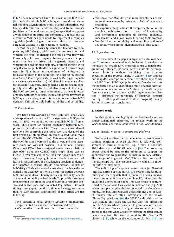
The radio chip of a typical sensor node (or NetworkInterface Card), depicted in Fig. 1, is responsible for trans-mitting or receiving data that is generated or consumed onthe processing unit (processor on host PC, microcontrolleron a stand-alone sensor node). This data needs to be trans-ferred to the radio unit via a communication bus (e.g., SPI).When multiple peripherals are connected to a shared com-munication bus, unpredictable access timings and/or pack-et transfer rate are often unavoidable. On the TelosB(TMote Sky) platform [10], the CC2420 radio chip and theflash storage unit share the SPI bus with the processingunit. An SPI bus arbiter is needed to grant access to a spe-cific slave unit. Hence, it might take some time to getaccess to the bus when a transfer to/from the flash storagedevice is active. The same is valid for the Zolertia Z1platform [11], while on the waspmote platform [12] the
Host PC
Processor
User level
Kernel level
Communication bus
Network Interface Card / Sensor Node Microcontroller
Communication bus
Radio Chip
Time Reference
RX/TX Packet Buffer Control lines
User level
Kernel level
Fig. 1. Typical setup of a Network Interface Card (NIC) or sensor node plugged into a host PC communication bus (e.g., PCI, USB, etc.). The NIC/sensor nodetypically has a microcontroller and radio chip interconnected via an on-board communication bus (e.g., SPI) and control lines. Unlike a NIC, a sensor nodecan operate without host PC.
User levelApplications
Transport, Routing, etc.
<<Hardware Independent Interface>>
Kernel levelDriverLower MAC Packet formatting
Radio control
Bus management
Interrupt management
<<R-HAL>><<B-HAL>> <<I-HAL>>
Upper MAC (without protocol control)
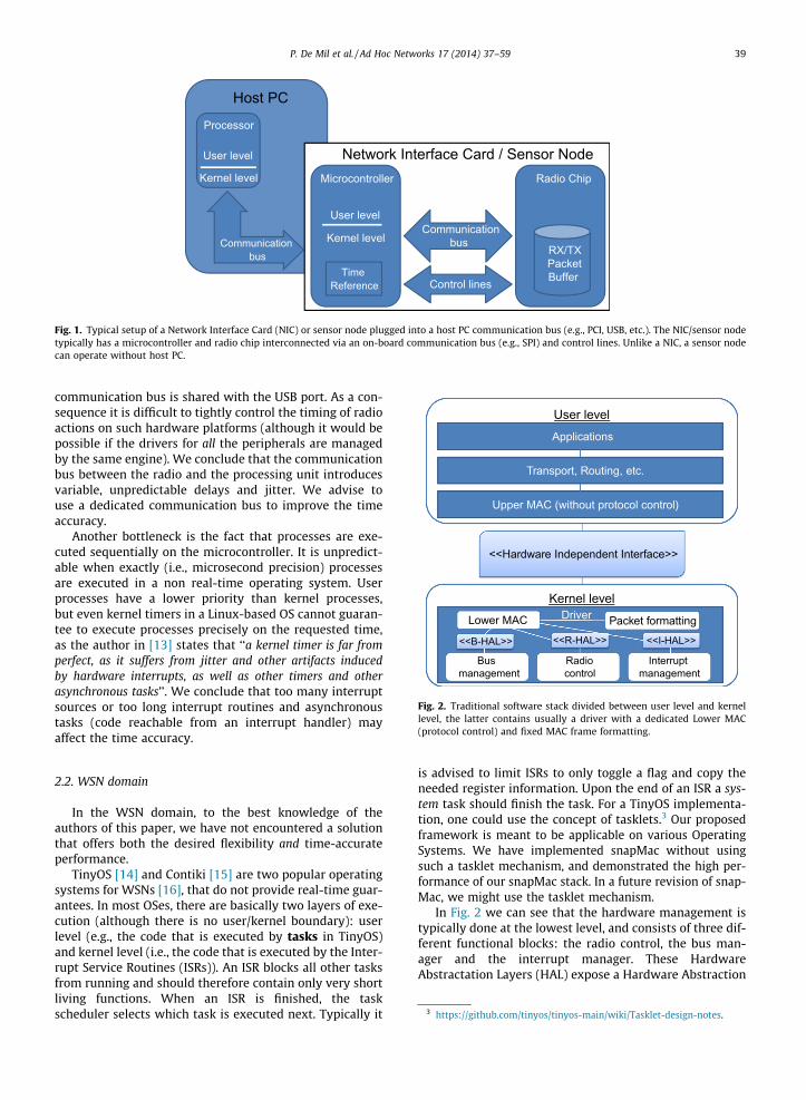
Fig. 2. Traditional software stack divided between user level and kernellevel, the latter contains usually a driver with a dedicated Lower MAC(protocol control) and fixed MAC frame formatting.
P. De Mil et al. / Ad Hoc Networks 17 (2014) 37–59 39
communication bus is shared with the USB port. As a con-sequence it is difficult to tightly control the timing of radioactions on such hardware platforms (although it would bepossible if the drivers for all the peripherals are managedby the same engine). We conclude that the communicationbus between the radio and the processing unit introducesvariable, unpredictable delays and jitter. We advise touse a dedicated communication bus to improve the timeaccuracy.
Another bottleneck is the fact that processes are exe-cuted sequentially on the microcontroller. It is unpredict-able when exactly (i.e., microsecond precision) processesare executed in a non real-time operating system. Userprocesses have a lower priority than kernel processes,but even kernel timers in a Linux-based OS cannot guaran-tee to execute processes precisely on the requested time,as the author in [13] states that ‘‘a kernel timer is far fromperfect, as it suffers from jitter and other artifacts inducedby hardware interrupts, as well as other timers and otherasynchronous tasks’’. We conclude that too many interruptsources or too long interrupt routines and asynchronoustasks (code reachable from an interrupt handler) mayaffect the time accuracy.
3 https://github.com/tinyos/tinyos-main/wiki/Tasklet-design-notes.
2.2. WSN domain
In the WSN domain, to the best knowledge of theauthors of this paper, we have not encountered a solutionthat offers both the desired flexibility and time-accurateperformance.
TinyOS [14] and Contiki [15] are two popular operatingsystems for WSNs [16], that do not provide real-time guar-antees. In most OSes, there are basically two layers of exe-cution (although there is no user/kernel boundary): userlevel (e.g., the code that is executed by tasks in TinyOS)and kernel level (i.e., the code that is executed by the Inter-rupt Service Routines (ISRs)). An ISR blocks all other tasksfrom running and should therefore contain only very shortliving functions. When an ISR is finished, the taskscheduler selects which task is executed next. Typically it
is advised to limit ISRs to only toggle a flag and copy theneeded register information. Upon the end of an ISR a sys-tem task should finish the task. For a TinyOS implementa-tion, one could use the concept of tasklets.3 Our proposedframework is meant to be applicable on various OperatingSystems. We have implemented snapMac without usingsuch a tasklet mechanism, and demonstrated the high per-formance of our snapMac stack. In a future revision of snap-Mac, we might use the tasklet mechanism.
In Fig. 2 we can see that the hardware management istypically done at the lowest level, and consists of three dif-ferent functional blocks: the radio control, the bus man-ager and the interrupt manager. These HardwareAbstractation Layers (HAL) expose a Hardware Abstraction
40 P. De Mil et al. / Ad Hoc Networks 17 (2014) 37–59
Interface that simplifies the hardware management. Typi-cal functions exposed are enabling/disabling the hardwareclock, request or release the bus, adjust some radio settingslike channel, transmit power, etc. The MAC functionalitybuilds on top of these interfaces and exposes a HardwareIndependent Interface towards user space. This layer istherefore also called the Hardware Independent Layer(HIL).
In TinyOS, the basic HIL that must be provided for everyplatform is the ActiveMessageC configuration. This definesthe message buffer format to be used, and has send andreceive function calls. A send call is executed as soon aspossible after the moment it is called. This results in anunpredictable time between the call, and the actual send-ing of the frame. In addition, the time accuracy of the callitself has a large spread. We have measured the delaybetween the requested transmit time, and the effectivetransmit time to be almost uniformly distributed between10–20 ms on a TMote Sky node running TinyOS. Hence aMAC designer who wants accurate frame transmissiontimings (in microseconds range) has to implement this inkernel space, hereby hampering reusability of the MACcode. Ideally, the basic (radio) functions are made availableto the MAC designer, so that she has the flexibility to com-pose new MAC designs without changing the driver.
In standard TinyOS, the actual frame formatting is doneinside the driver. We will show that we can give control onframe formatting to the MAC designer, hereby enablingboth flexibility for the MAC designers (no need to adjustthe driver) and portability for driver developers (no needto take into account specific frame formatting).
In [17], Hauer presents a platform independent IEEE802.15.4-2006 MAC implementation (TKN 15.4) for Tiny-OS. It is stated that in most typical sensor node platforms,‘‘these (ed., timing) requirements can practically not bemet by a platform independent MAC protocol, rather theyshould be pushed from the MAC to the PHY, ideally to
User level
Applications
Transport, Routing, etc.
<<snapMac Data Plane>>
Kernel levelDriver
snapMac engine
Full Control MAC
<<snapMac Control Plane>>
<<Command>>snapMac modules
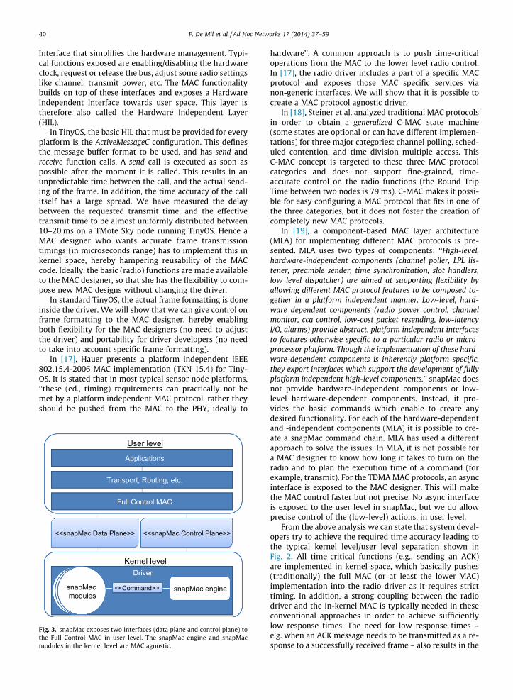
Fig. 3. snapMac exposes two interfaces (data plane and control plane) tothe Full Control MAC in user level. The snapMac engine and snapMacmodules in the kernel level are MAC agnostic.
hardware’’. A common approach is to push time-criticaloperations from the MAC to the lower level radio control.In [17], the radio driver includes a part of a specific MACprotocol and exposes those MAC specific services vianon-generic interfaces. We will show that it is possible tocreate a MAC protocol agnostic driver.
In [18], Steiner et al. analyzed traditional MAC protocolsin order to obtain a generalized C-MAC state machine(some states are optional or can have different implemen-tations) for three major categories: channel polling, sched-uled contention, and time division multiple access. ThisC-MAC concept is targeted to these three MAC protocolcategories and does not support fine-grained, time-accurate control on the radio functions (the Round TripTime between two nodes is 79 ms). C-MAC makes it possi-ble for easy configuring a MAC protocol that fits in one ofthe three categories, but it does not foster the creation ofcompletely new MAC protocols.
In [19], a component-based MAC layer architecture(MLA) for implementing different MAC protocols is pre-sented. MLA uses two types of components: ‘‘High-level,hardware-independent components (channel poller, LPL lis-tener, preamble sender, time synchronization, slot handlers,low level dispatcher) are aimed at supporting flexibility byallowing different MAC protocol features to be composed to-gether in a platform independent manner. Low-level, hard-ware dependent components (radio power control, channelmonitor, cca control, low-cost packet resending, low-latencyI/O, alarms) provide abstract, platform independent interfacesto features otherwise specific to a particular radio or micro-processor platform. Though the implementation of these hard-ware-dependent components is inherently platform specific,they export interfaces which support the development of fullyplatform independent high-level components.’’ snapMac doesnot provide hardware-independent components or low-level hardware-dependent components. Instead, it pro-vides the basic commands which enable to create anydesired functionality. For each of the hardware-dependentand -independent components (MLA) it is possible to cre-ate a snapMac command chain. MLA has used a differentapproach to solve the issues. In MLA, it is not possible fora MAC designer to know how long it takes to turn on theradio and to plan the execution time of a command (forexample, transmit). For the TDMA MAC protocols, an asyncinterface is exposed to the MAC designer. This will makethe MAC control faster but not precise. No async interfaceis exposed to the user level in snapMac, but we do allowprecise control of the (low-level) actions, in user level.
From the above analysis we can state that system devel-opers try to achieve the required time accuracy leading tothe typical kernel level/user level separation shown inFig. 2. All time-critical functions (e.g., sending an ACK)are implemented in kernel space, which basically pushes(traditionally) the full MAC (or at least the lower-MAC)implementation into the radio driver as it requires stricttiming. In addition, a strong coupling between the radiodriver and the in-kernel MAC is typically needed in theseconventional approaches in order to achieve sufficientlylow response times. The need for low response times –e.g. when an ACK message needs to be transmitted as a re-sponse to a successfully received frame – also results in the
P. De Mil et al. / Ad Hoc Networks 17 (2014) 37–59 41
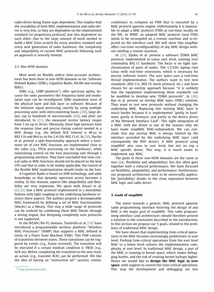
radio driver being frame type dependent. This implies thatthe reusability of both MAC implementation and radio dri-ver is very low, as they are dependent on the implementedstandard (or proprietary protocol) and also dependent oneach other. Due to the large amount of work needed tobuild a MAC from scratch for every wireless standard andevery new generation of radio hardware, the complexityand adaptability of current MAC protocols following suchan approach is severely limited.
2.3. Non-WSN domains
Most work on flexible and/or time-accurate architec-tures has been done in non-WSN domains so far: SoftwareDefined Radios (SDRs), Cognitive Radio, WLAN and overlayMACs.
SDRs (e.g., USRP platform4), offer spectrum agility, be-cause the radio parameters like frequency band and modu-lation type can be reconfigured. SDRs implement most ofthe physical layer and link layer in software. Because ofthe intensive signal processing (mostly by using multipleprocessing units with interconnecting buses [20]), large de-lays (up to hundreds of microseconds [20]) and jitter areintroduced. In [21], the measured receive latency rangesfrom 1 ms up to 30 ms. Obviously, these high latencies limitthe response time and precise timing control needed in aMAC design (e.g., the default ACK timeout is 48 ls in802.11b and 864 ls in the 2.4 GHz 802.15.4). In [20], Nychiset al. present a split-functionality approach where a mini-mum set of core MAC functions are implemented close tothe radio (e.g., FPGA processing on the hardware), whilemaintaining control on the host processing unit through aprogramming interface. They have concluded that time-crit-ical radio or MAC functions should not be placed on the hostCPU and that in order to be widely applicable, the control ofthe flexible MAC implementation should reside on the host.
A Cognitive Radio is based on SDR technology, and addsknowledge so that dynamic spectrum access becomes areality. In this domain, aspects like adaptability and flexi-bility are very important. We agree with Ansari et al.[22,23] that a MAC protocol implemented in a monolithicfashion with tight coupling to the underlying hardware re-stricts these aspects. The authors propose a decomposableMAC framework by defining a set of MAC functionalities(blocks) as a library. This way a wide range of protocolscan be realized by combining these MAC blocks througha wiring engine, but designing completely new protocolsis not supported.
In the WLAN (Wi-Fi) domain, Tinnirello et al. [24] haveintroduced a programmable wireless platform ‘‘WirelessMAC Processors’’ (WMP) that supports a MAC defined interms of a Finite State Machine (FSM). This FSM consistsof transitions between states. These transitions can be trig-gered by events (e.g., frame received). The transition willbe executed if a certain boolean condition is TRUE (e.g.,ACK on). Before completing the transition to the new state,an action (e.g., transmit ACK) can be performed. We likethe idea of having an ‘‘instruction set’’ (actions, events,
4 http://www.ettus.com/.
conditions) to compose an FSM that is executed by aMAC protocol agnostic engine. Unfortunately it is impossi-ble to adapt a MAC protocol (FSM) at run-time, locally onthe NIC. In WMP, an adapted MAC protocol (new FSM)needs to be recompiled on a remote machine and re-in-jected on the interface card. We will show that snapMacoffers run-time reconfigurability of any MAC design with-out needing a remote machine.
In [25], Djukic et al. present a software TDMA MACprotocol, implemented in Linux user level, running overcommodity 802.11 hardware. The focus is on tight syn-chronization of pairs of nodes. The 1.5 GHz laptop runsLinux with real-time extensions, which is necessary forprecise software timers. The user space uses a real-timethread implementation. The authors want to test newstandards (802.11s, 802.16 mesh protocol, etc.) and havechosen for an overlay approach because ‘‘it is unlikelythat the equipment implementing these standards canbe modified to develop new TDMA protocols’’. In [26],Rao et al. present an overlay MAC layer (OML) solution.They want to test new protocols without changing theunderlying MAC. Replacing this existing MAC layer ismuch harder because it is implemented ‘‘partly in hard-ware, partly in firmware, and partly in the device driverof the Network Interface Card’’. This tight integration ofa MAC with the driver is one of the reasons why wehave made snapMAC MAC-independent. We can con-clude that any overlay MAC is always limited by theinterface provided by the underlying MAC layer (andconsequently the PHY driver). A MAC protocol usingsnapMAC also runs in user level, but not on top aMAC specific driver. This way, it is much easier toimplement any MAC.
The goals in these non-WSN domains are the same asours (i.e., flexibility and adaptability), but this often goestogether with a reduced performance. We have focussedon flexibility, adaptability, and performance. Furthermore,our proposed architecture aims to be universally applica-ble (portability) thanks to the clean separation betweenMAC logic and radio driver.
3. Goals of snapMAC
The move towards a generic, MAC protocol agnosticradio programming interface fostering the design of anyMAC is the major goal of snapMAC. This radio program-ming interface (and architecture) should therefore presenta solution to the constraints described in the introduction.In this section we propose our 5 goals, related to the prob-lems of traditional MAC design.
We have shown that implementing time-critical opera-tions in the MAC becomes increasingly problematic in userlevel. Pushing time-critical operations from the user levelMAC to a lower level reduces the implementation com-plexity at user level. In traditional MAC design, a part ofthe MAC is running in kernel space, which makes debug-ging harder, and the risk of creating kernel lockups higher.Hence we would like to design the MAC logic in userspace, with support to control the time-critical operations.This way the development and debugging are less
42 P. De Mil et al. / Ad Hoc Networks 17 (2014) 37–59
complicated. Moreover this also increases the portabilityas different platforms/operating systems only have to sup-ply the generic interface and execution environment.
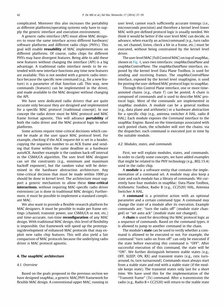
A generic radio interface (API) must allow MAC design-ers to reuse the same interface across different hardware/software platforms and different radio chips (PHYs). Thisgoal will enable reusability of MAC implementations ondifferent platforms. Of course, radio chips for differentPHYs may have divergent features. Being able to add thesenew features without changing the interface (API) is a bigadvantage. A traditional radio interface needs to be ex-tended with new interface functions any time new featuresare available. This is not needed with a generic radio inter-face because the specific new command (e.g., for a new fea-ture) is a parameter of that function call. This way, newcommands (features) can be implemented in the driver,and made available to the MAC designer without changingthe API.
We have seen dedicated radio drivers that are quiteaccurate only because they are designed and implementedfor a specific MAC protocol (traditional concept). In ourconcept the radio driver must be MAC protocol and MACframe format agnostic. This will advance portability ofboth the radio driver and the MAC protocol logic to otherplatforms.
Some actions require time-critical decisions which can-not be made at the user space MAC protocol level. Forexample, checking if the ACK request-bit is set in a header,copying the sequence number to an ACK frame and send-ing that frame within the same deadline as a hardwareautoACK. Another example is the random back-off intervalin the CSMA/CA algorithm. The user level MAC designercan set the constraints (e.g., minimum and maximumbackoff exponent), but the random value will be deter-mined in the hardware abstraction architecture. Anytime-critical decision that must be made within 1000 lsshould be done in kernel level. The architecture must sup-port a generic mechanism to allow these time-criticalinteractions, without requiring MAC-specific radio driverextensions (as is done in traditional MAC design). Further-more, it must be possible to implement a standard compli-ant MAC.
We also want to provide a flexible research platform forMAC designers. It must be possible to make per frame set-tings (channel, transmit power, use CSMA/CA or not, etc.)and time-accurate, run-time reconfiguration of any MACdesign. With traditional MAC design, this level of flexibilityis impossible. Our framework will speed up the prototyp-ing/development of enhanced MAC protocols that may ex-ploit new radio chip features. This will also yield a faircomparison of MAC protocols because the underlying radiodriver is MAC protocol agnostic.
4. The snapMAC architecture
4.1. Overview
Based on the goals proposed in the previous section wehave designed snapMac, a generic MAC/PHY framework forflexible MAC design. A conventional upper MAC, running in
user level, cannot reach sufficiently accurate timings (i.e.,microseconds precision) and therefore a kernel level lowerMAC with pre-defined protocol logic is usually needed. Wethink it would be better if the user level MAC can decide, inadvance, when exactly an action/command (e.g., turn radioon, set channel, listen, check a bit in a frame, etc.) must beexecuted, without being constrained by the kernel leveldriver.
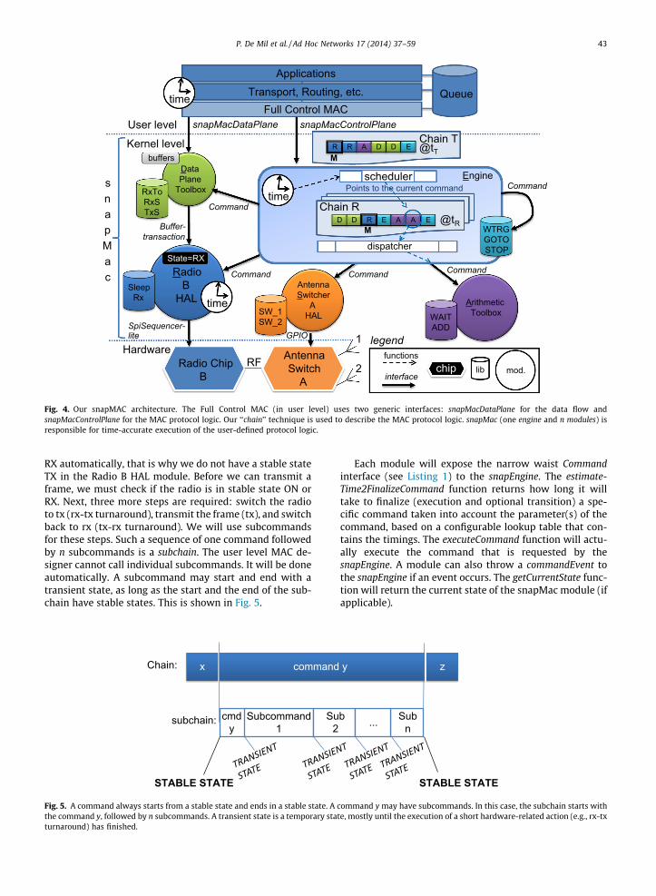
The user level MAC (Full Control MAC) on top of snapMac,shown in Fig. 4, uses two interfaces: snapMacDataPlane andsnapMacControlPlane. The snapMacDataPlane interface, ex-posed by the kernel level Data Plane Toolbox, is used forsending and receiving frames. The snapMacControlPlaneinterface, exposed by the kernel level snapEngine, is usedfor posting the user-defined MAC protocol logic to snapMac.
Through this Control Plane interface, one or more time-annoted chains (e.g., chain T) can be posted. A chain iscomposed of commands and is used to describe MAC pro-tocol logic. Most of the commands are implemented insnapMac modules. A module can be a general toolbox(e.g., data plane and arithmetic) or a hardware abstractionfor a specific chip (e.g., antenna switcher A HAL, radio BHAL). Each module exposes the Command interface to thesnapMac Engine. Based on the timestamps associated witheach posted chain, the scheduler will sort the chains. viathe dispatcher, each command is executed just in time bythe suitable module.
4.2. Modules, states, and commands
First, we will explain modules, states, and commands.In order to clarify some concepts, we have added examplesthat might be related to the PHY technology (e.g., 802.15.4)used in the radio chip.
A module is a software entity that contains the imple-mentation of a command set. A module may also keep astate and each module has a library of commands. We cur-rently have four modules in snapMac: Data Plane Toolbox,Arithmetic Toolbox, Radio B (e.g., CC2520) HAL, AntennaSwitcher A HAL.
A command is a primitive action with an optionalparameter and a certain command type. A command maychange the state of a module after its execution. Examplecommands are: ‘‘turn the radio off’’ (module state chan-ged) or ‘‘set auto ack’’ (module state not changed).
A chain is used for describing the MAC protocol logic asa sequence of commands. Based on the command types, itis allowed to jump to another command in the chain.
The module’s state can be used to verify whether a com-mand is allowed to be executed or not. For example, thecommand ‘‘turn radio on from off’’ can only be executed ifthe state before executing this command is ‘‘OFF’’. Aftersuccessful execution of this command, the state will be‘‘ON’’. We further distinguish between stable states (e.g.,OFF, SLEEP, ON, RX) and transient states (e.g., rxtx turn-around, tx, txrx turnaround). Commands must always startfrom a stable state and end with a stable state (if the mod-ule keeps state). The transient states only last for a shorttime. We have used this for the implementation of the‘‘Transmit frame’’ (Tx) command. After a transmission theradio (e.g., Radio B = CC2520) will return to the stable state
ApplicationsTransport, Routing, etc.
Chain TR A D D E @tT
User level
Kernel level
Chain RD D E A A E @tR
time
Data Plane
ToolboxRxTo RxS TxS
Radio B
HALSleep
Rx
Buffer- transaction
State=RX
Radio Chip B
Antenna Switcher
A HALSW_1
SW_2
time Arithmetic ToolboxWAIT
ADD
WTRG GOTO STOP
Command
Command
Command
SpiSequencer- lite
Command
GPIO
Command
snapMacControlPlanesnapMacDataPlane
Engine
Full Control MAC
R
R
scheduler
M
M
1Antenna Switch
A2RF
dispatcher
Points to the current command
functions
interfacechip lib mod.
legend
time Queue
buffers
Hardware
snapMac
Fig. 4. Our snapMAC architecture. The Full Control MAC (in user level) uses two generic interfaces: snapMacDataPlane for the data flow andsnapMacControlPlane for the MAC protocol logic. Our ‘‘chain’’ technique is used to describe the MAC protocol logic. snapMac (one engine and n modules) isresponsible for time-accurate execution of the user-defined protocol logic.
P. De Mil et al. / Ad Hoc Networks 17 (2014) 37–59 43
RX automatically, that is why we do not have a stable stateTX in the Radio B HAL module. Before we can transmit aframe, we must check if the radio is in stable state ON orRX. Next, three more steps are required: switch the radioto tx (rx-tx turnaround), transmit the frame (tx), and switchback to rx (tx-rx turnaround). We will use subcommandsfor these steps. Such a sequence of one command followedby n subcommands is a subchain. The user level MAC de-signer cannot call individual subcommands. It will be doneautomatically. A subcommand may start and end with atransient state, as long as the start and the end of the sub-chain have stable states. This is shown in Fig. 5.
command
cmd y
Subcommand 1
Su2
subchain:
STABLE STATE
Chain: x
Fig. 5. A command always starts from a stable state and ends in a stable state. Athe command y, followed by n subcommands. A transient state is a temporary staturnaround) has finished.
Each module will expose the narrow waist Commandinterface (see Listing 1) to the snapEngine. The estimate-Time2FinalizeCommand function returns how long it willtake to finalize (execution and optional transition) a spe-cific command taken into account the parameter(s) of thecommand, based on a configurable lookup table that con-tains the timings. The executeCommand function will actu-ally execute the command that is requested by thesnapEngine. A module can also throw a commandEvent tothe snapEngine if an event occurs. The getCurrentState func-tion will return the current state of the snapMac module (ifapplicable).
y
Sub n
STABLE STATE
b ...
z
command y may have subcommands. In this case, the subchain starts withte, mostly until the execution of a short hardware-related action (e.g., rx-tx
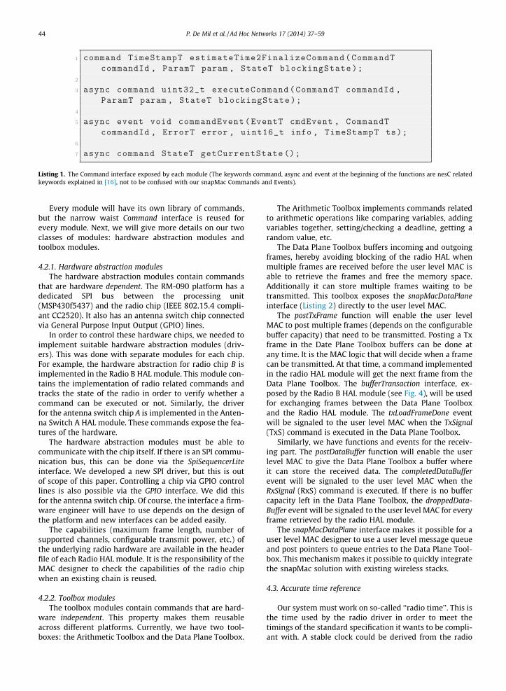
Listing 1. The Command interface exposed by each module (The keywords command, async and event at the beginning of the functions are nesC relatedkeywords explained in [16], not to be confused with our snapMac Commands and Events).
44 P. De Mil et al. / Ad Hoc Networks 17 (2014) 37–59
Every module will have its own library of commands,but the narrow waist Command interface is reused forevery module. Next, we will give more details on our twoclasses of modules: hardware abstraction modules andtoolbox modules.
4.2.1. Hardware abstraction modulesThe hardware abstraction modules contain commands
that are hardware dependent. The RM-090 platform has adedicated SPI bus between the processing unit(MSP430f5437) and the radio chip (IEEE 802.15.4 compli-ant CC2520). It also has an antenna switch chip connectedvia General Purpose Input Output (GPIO) lines.
In order to control these hardware chips, we needed toimplement suitable hardware abstraction modules (driv-ers). This was done with separate modules for each chip.For example, the hardware abstraction for radio chip B isimplemented in the Radio B HAL module. This module con-tains the implementation of radio related commands andtracks the state of the radio in order to verify whether acommand can be executed or not. Similarly, the driverfor the antenna switch chip A is implemented in the Anten-na Switch A HAL module. These commands expose the fea-tures of the hardware.
The hardware abstraction modules must be able tocommunicate with the chip itself. If there is an SPI commu-nication bus, this can be done via the SpiSequencerLiteinterface. We developed a new SPI driver, but this is outof scope of this paper. Controlling a chip via GPIO controllines is also possible via the GPIO interface. We did thisfor the antenna switch chip. Of course, the interface a firm-ware engineer will have to use depends on the design ofthe platform and new interfaces can be added easily.
The capabilities (maximum frame length, number ofsupported channels, configurable transmit power, etc.) ofthe underlying radio hardware are available in the headerfile of each Radio HAL module. It is the responsibility of theMAC designer to check the capabilities of the radio chipwhen an existing chain is reused.
4.2.2. Toolbox modulesThe toolbox modules contain commands that are hard-
ware independent. This property makes them reusableacross different platforms. Currently, we have two tool-boxes: the Arithmetic Toolbox and the Data Plane Toolbox.
The Arithmetic Toolbox implements commands relatedto arithmetic operations like comparing variables, addingvariables together, setting/checking a deadline, getting arandom value, etc.
The Data Plane Toolbox buffers incoming and outgoingframes, hereby avoiding blocking of the radio HAL whenmultiple frames are received before the user level MAC isable to retrieve the frames and free the memory space.Additionally it can store multiple frames waiting to betransmitted. This toolbox exposes the snapMacDataPlaneinterface (Listing 2) directly to the user level MAC.
The postTxFrame function will enable the user levelMAC to post multiple frames (depends on the configurablebuffer capacity) that need to be transmitted. Posting a Txframe in the Date Plane Toolbox buffers can be done atany time. It is the MAC logic that will decide when a framecan be transmitted. At that time, a command implementedin the radio HAL module will get the next frame from theData Plane Toolbox. The bufferTransaction interface, ex-posed by the Radio B HAL module (see Fig. 4), will be usedfor exchanging frames between the Data Plane Toolboxand the Radio HAL module. The txLoadFrameDone eventwill be signaled to the user level MAC when the TxSignal(TxS) command is executed in the Data Plane Toolbox.
Similarly, we have functions and events for the receiv-ing part. The postDataBuffer function will enable the userlevel MAC to give the Data Plane Toolbox a buffer whereit can store the received data. The completedDataBufferevent will be signaled to the user level MAC when theRxSignal (RxS) command is executed. If there is no buffercapacity left in the Data Plane Toolbox, the droppedData-Buffer event will be signaled to the user level MAC for everyframe retrieved by the radio HAL module.
The snapMacDataPlane interface makes it possible for auser level MAC designer to use a user level message queueand post pointers to queue entries to the Data Plane Tool-box. This mechanism makes it possible to quickly integratethe snapMac solution with existing wireless stacks.
4.3. Accurate time reference
Our system must work on so-called ‘‘radio time’’. This isthe time used by the radio driver in order to meet thetimings of the standard specification it wants to be compli-ant with. A stable clock could be derived from the radio

Listing 2. The snapMacDataPlane interface exposed by the Data Plane Toolbox module (The keywords command and event at the beginning of thefunctions are nesC related keywords explained in [16], not to be confused with our snapMac Commands and Events).
P. De Mil et al. / Ad Hoc Networks 17 (2014) 37–59 45
chip itself (via the GPIO pins of the radio and a externalclock input on the microcontroller) but the radio can onlydeliver a clock when it is active. This would take too muchenergy and is unfeasible in low-power applications. Thesymbol time (Tsymbol) (e.g., 16 ls) used in the radio chipmust be a multiple of the microcontroller’s ‘‘system time’’(e.g., 1 ls). If we can match the system time with the radiotime, we have a very big advantage for our time accuratedriver. Other sensor boards often use a 32,768 Hz crystalwhich can only achieve a Tsymbol of 15.259 ls [27]. Thisis not accurate (4.6% error). For this reason we have notused the standard 32,768 Hz crystal for our microcontrol-ler. A 32,000 Hz crystal was chosen, after confirmationfrom Texas Instruments that this was OK for the microcon-roller. By using a 32,000 Hz ± 40 ppm crystal, we can map5
this crystal on 1 ls sub-symbol ticks which is 16 timessmaller than the 2.4 GHz 802.15.4 symbol time. This willallow us to define and execute the MAC protocol logic veryaccurately.
4.4. Protocol logic through chains
The user level MAC is not allowed to call the modules’commands directly. Instead, the MAC protocol logic is de-fined by the MAC designer by composing commands intoso-called chains. The purpose of a chain is to have timeaccurate execution of the MAC protocol logic. Supposewe want the transmission of a frame to be executed at timetM. Most likely some steps need to be taken in order to beable to execute this task at the requested time. For exam-ple, we might need to switch on the radio, the frame needsto be loaded into the radio buffer, we might want to set acustom transmit power, the radio needs to be switchedto transmit mode until finally it is able to start the trans-mission of the frame at tM. Moreover, once the frame trans-mission is finished we might want to shut down the radioas fast as possible. This task can be described in a chaincomposed of several commands. In Section 5 this will beexplained in more detail.
5 This is how we have mapped our 32,000 Hz crystal: 32,000 Hz times500 is 16 MHz; 16 MHz divided by 16 is 1 MHz, 1 tick every microsecond.
In order to facilitate the execution of such a sequence ofcommands we force the use of exactly one master com-mand that has absolute time with respect to the radio time,and slave times that are relative to requested executiontime of the master command. Slave commands that areto be executed before the master time have negative rela-tive times while slave commands that need to be executedafter the master time have positive relative times. In eachchain the master command must be completed on the re-quested time. Consequently, negative slaves commandsmust be executed sequentially. It is not allowed for nega-tive slaves to take an alternative path. This is because wewant to execute the master command on the requestedtime. If we would allow alternative paths before the mastercommand, we cannot know when to start the first slavecommand. However, the MAC designer does not need toworry about those ‘‘slave’’ times. The snapMac Engine willuse the estimateTime2FinalizeCommand function in order todecide when the first slave command should be executedin order to meet the deadline of the master command. Acompiler directive is available to add some time margin(e.g., 30 ls) that will be added to the result of the estimate-Time2FinalizeCommand function for every negative slave inorder to anticipate for unexpected interrupt routines. Thisway it is possible to achieve the requested execution timeof the Master command more precisely. If many externalinterrupts are expected, we could increase this time mar-gin at the cost of having a (slightly) less energy-efficientsolution. If too many external interrupts are expected(e.g., sample the ADC with 100 ksps), we advise to use aseparate application processor.
Our chain concept is an alternative for a Finite State Ma-chine. We believe it gives more flexibility to a MAC de-signer, thanks to the ability to compose, reload or adaptchains at run-time. It also gives the opportunity to accu-rately plan the execution of commands.
4.5. Command types
We have defined a set of fine-grained commands as a li-brary so that the user level MAC designer can realize anyMAC by combining these commands in one or more chains.
46 P. De Mil et al. / Ad Hoc Networks 17 (2014) 37–59
Every command should be aware that it is part of a chain.Once the snapEngine passes the execution token to a com-mand (there can only be one at the time), it is that com-mand that decides how the chain should proceed.
We have defined different types of commands:
� Continue (C): this is the default type. After execution ofa command, the next command in the chain is executed.Commands with command type C can be used any-where in the chain. All the other commands are notallowed as negative slaves.� Skip on condition (S): this type will be used for com-
mands that are verifying a condition (e.g., check if abit is set or not). If the condition is not true, the nextcommand in the chain will be executed. If the conditionis true, we will skip the next command in the chain andcontinue the execution of the chain.� Skip on event (T): this type will be used for commands
that are waiting on a event (i.e., trigger), during a user-defined duration (timer). If the timer expires (i.e., theevent did not occur) the next command will be exe-cuted. If the event occurs before the timer expires, wewill skip the next command and continue the executionof the chain.
The snapEngine owns four special commands: GOTO,JUMP, WTRG (Wait Trigger) and STOP. The GOTO com-mand makes it possible to go to another command (desig-nated by an absolute value) in the chain. We typically havea type S or type T command before a GOTO command, be-cause this allows us to take an alternative path in thechain. The JUMP command allows to jump to another com-mand (designated by a relative offset) in the chain. TheWTRG command waits for an event (i.e., trigger) from amodule. Other commands must be used to check whichevent it was (e.g., frame that needs to be transmitted,
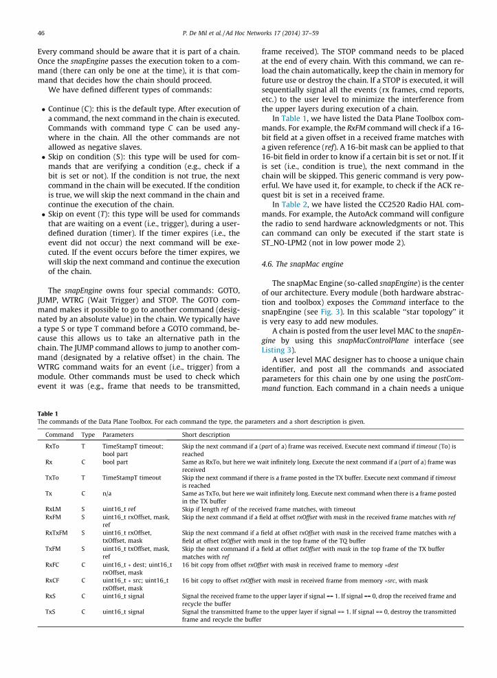
Table 1The commands of the Data Plane Toolbox. For each command the type, the param
Command Type Parameters Short description
RxTo T TimeStampT timeout;bool part
Skip the next command if areached
Rx C bool part Same as RxTo, but here we wreceived
TxTo T TimeStampT timeout Skip the next command if this reached
Tx C n/a Same as TxTo, but here we win the TX buffer
RxLM S uint16_t ref Skip if length ref of the receRxFM S uint16_t rxOffset, mask,
refSkip the next command if a
RxTxFM S uint16_t rxOffset,txOffset, mask
Skip the next command if afield at offset txOffset with m
TxFM S uint16_t txOffset, mask,ref
Skip the next command if amatches with ref
RxFC C uint16_t � dest; uint16_trxOffset, mask
16 bit copy from offset rxOf
RxCF C uint16_t � src; uint16_trxOffset, mask
16 bit copy to offset rxOffset
RxS C uint16_t signal Signal the received frame torecycle the buffer
TxS C uint16_t signal Signal the transmitted frameframe and recycle the buffe
frame received). The STOP command needs to be placedat the end of every chain. With this command, we can re-load the chain automatically, keep the chain in memory forfuture use or destroy the chain. If a STOP is executed, it willsequentially signal all the events (rx frames, cmd reports,etc.) to the user level to minimize the interference fromthe upper layers during execution of a chain.
In Table 1, we have listed the Data Plane Toolbox com-mands. For example, the RxFM command will check if a 16-bit field at a given offset in a received frame matches witha given reference (ref). A 16-bit mask can be applied to that16-bit field in order to know if a certain bit is set or not. If itis set (i.e., condition is true), the next command in thechain will be skipped. This generic command is very pow-erful. We have used it, for example, to check if the ACK re-quest bit is set in a received frame.
In Table 2, we have listed the CC2520 Radio HAL com-mands. For example, the AutoAck command will configurethe radio to send hardware acknowledgments or not. Thiscan command can only be executed if the start state isST_NO-LPM2 (not in low power mode 2).
4.6. The snapMac engine
The snapMac Engine (so-called snapEngine) is the centerof our architecture. Every module (both hardware abstrac-tion and toolbox) exposes the Command interface to thesnapEngine (see Fig. 3). In this scalable ‘‘star topology’’ itis very easy to add new modules.
A chain is posted from the user level MAC to the snapEn-gine by using this snapMacControlPlane interface (seeListing 3).
A user level MAC designer has to choose a unique chainidentifier, and post all the commands and associatedparameters for this chain one by one using the postCom-mand function. Each command in a chain needs a unique
eters and a short description is given.
(part of a) frame was received. Execute next command if timeout (To) is
ait infinitely long. Execute the next command if a (part of a) frame was
ere is a frame posted in the TX buffer. Execute next command if timeout
ait infinitely long. Execute next command when there is a frame posted
ived frame matches, with timeoutfield at offset rxOffset with mask in the received frame matches with ref
field at offset rxOffset with mask in the received frame matches with aask in the top frame of the TQ buffer
field at offset txOffset with mask in the top frame of the TX buffer
fset with mask in received frame to memory �dest
with mask in received frame from memory �src, with mask
the upper layer if signal == 1. If signal == 0, drop the received frame and
to the upper layer if signal == 1. If signal == 0, destroy the transmittedr
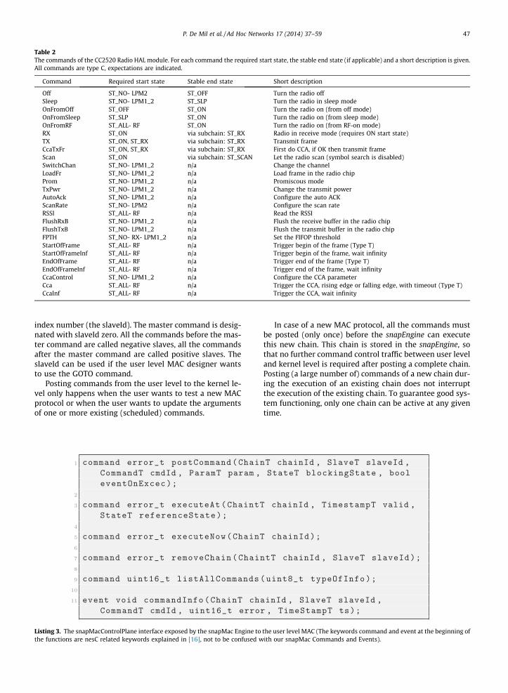
Table 2The commands of the CC2520 Radio HAL module. For each command the required start state, the stable end state (if applicable) and a short description is given.All commands are type C, expectations are indicated.
Command Required start state Stable end state Short description
Off ST_NO- LPM2 ST_OFF Turn the radio offSleep ST_NO- LPM1_2 ST_SLP Turn the radio in sleep modeOnFromOff ST_OFF ST_ON Turn the radio on (from off mode)OnFromSleep ST_SLP ST_ON Turn the radio on (from sleep mode)OnFromRF ST_ALL- RF ST_ON Turn the radio on (from RF-on mode)RX ST_ON via subchain: ST_RX Radio in receive mode (requires ON start state)TX ST_ON, ST_RX via subchain: ST_RX Transmit frameCcaTxFr ST_ON, ST_RX via subchain: ST_RX First do CCA, if OK then transmit frameScan ST_ON via subchain: ST_SCAN Let the radio scan (symbol search is disabled)SwitchChan ST_NO- LPM1_2 n/a Change the channelLoadFr ST_NO- LPM1_2 n/a Load frame in the radio chipProm ST_NO- LPM1_2 n/a Promiscous modeTxPwr ST_NO- LPM1_2 n/a Change the transmit powerAutoAck ST_NO- LPM1_2 n/a Configure the auto ACKScanRate ST_NO- LPM2 n/a Configure the scan rateRSSI ST_ALL- RF n/a Read the RSSIFlushRxB ST_NO- LPM1_2 n/a Flush the receive buffer in the radio chipFlushTxB ST_NO- LPM1_2 n/a Flush the transmit buffer in the radio chipFPTH ST_NO- RX- LPM1_2 n/a Set the FIFOP thresholdStartOfFrame ST_ALL- RF n/a Trigger begin of the frame (Type T)StartOfFrameInf ST_ALL- RF n/a Trigger begin of the frame, wait infinityEndOfFrame ST_ALL- RF n/a Trigger end of the frame (Type T)EndOfFrameInf ST_ALL- RF n/a Trigger end of the frame, wait infinityCcaControl ST_NO- LPM1_2 n/a Configure the CCA parameterCca ST_ALL- RF n/a Trigger the CCA, rising edge or falling edge, with timeout (Type T)CcaInf ST_ALL- RF n/a Trigger the CCA, wait infinity
P. De Mil et al. / Ad Hoc Networks 17 (2014) 37–59 47
index number (the slaveId). The master command is desig-nated with slaveId zero. All the commands before the mas-ter command are called negative slaves, all the commandsafter the master command are called positive slaves. TheslaveId can be used if the user level MAC designer wantsto use the GOTO command.
Posting commands from the user level to the kernel le-vel only happens when the user wants to test a new MACprotocol or when the user wants to update the argumentsof one or more existing (scheduled) commands.
Listing 3. The snapMacControlPlane interface exposed by the snapMac Engine tothe functions are nesC related keywords explained in [16], not to be confused w
In case of a new MAC protocol, all the commands mustbe posted (only once) before the snapEngine can executethis new chain. This chain is stored in the snapEngine, sothat no further command control traffic between user leveland kernel level is required after posting a complete chain.Posting (a large number of) commands of a new chain dur-ing the execution of an existing chain does not interruptthe execution of the existing chain. To guarantee good sys-tem functioning, only one chain can be active at any giventime.
the user level MAC (The keywords command and event at the beginning ofith our snapMac Commands and Events).
Previous command TX Next
command
subchain:
STABLE STATE
legendTX
Transmit frame
toRx
STATE_ON STATE_RX
toTx
blocking state: STATE_TXFR
Stop chainchain:
During execution of TX subchain, we can already start the next command .
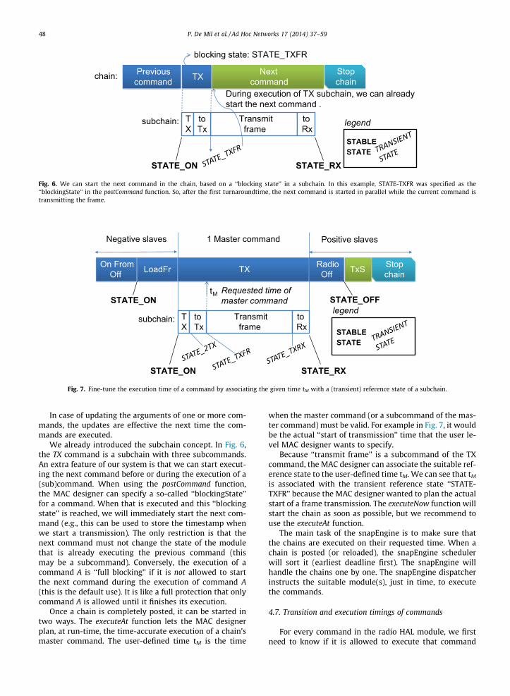
Fig. 6. We can start the next command in the chain, based on a ‘‘blocking state’’ in a subchain. In this example, STATE-TXFR was specified as the‘‘blockingState’’ in the postCommand function. So, after the first turnaroundtime, the next command is started in parallel while the current command istransmitting the frame.
LoadFr
1 Master command Positive slaves
TX
Transmit frame
toRx
subchain:
STATE_ON STATE_RX
TX
STATE_ON
STABLE STATE
legend
Stop chainTxS
Negative slaves
tM
toTx
On From Off
Radio Off
STATE_OFF Requested time of master command
Fig. 7. Fine-tune the execution time of a command by associating the given time tM with a (transient) reference state of a subchain.
48 P. De Mil et al. / Ad Hoc Networks 17 (2014) 37–59
In case of updating the arguments of one or more com-mands, the updates are effective the next time the com-mands are executed.
We already introduced the subchain concept. In Fig. 6,the TX command is a subchain with three subcommands.An extra feature of our system is that we can start execut-ing the next command before or during the execution of a(sub)command. When using the postCommand function,the MAC designer can specify a so-called ‘‘blockingState’’for a command. When that is executed and this ‘‘blockingstate’’ is reached, we will immediately start the next com-mand (e.g., this can be used to store the timestamp whenwe start a transmission). The only restriction is that thenext command must not change the state of the modulethat is already executing the previous command (thismay be a subcommand). Conversely, the execution of acommand A is ‘‘full blocking’’ if it is not allowed to startthe next command during the execution of command A(this is the default use). It is like a full protection that onlycommand A is allowed until it finishes its execution.
Once a chain is completely posted, it can be started intwo ways. The executeAt function lets the MAC designerplan, at run-time, the time-accurate execution of a chain’smaster command. The user-defined time tM is the time
when the master command (or a subcommand of the mas-ter command) must be valid. For example in Fig. 7, it wouldbe the actual ‘‘start of transmission’’ time that the user le-vel MAC designer wants to specify.
Because ‘‘transmit frame’’ is a subcommand of the TXcommand, the MAC designer can associate the suitable ref-erence state to the user-defined time tM. We can see that tM
is associated with the transient reference state ‘‘STATE-TXFR’’ because the MAC designer wanted to plan the actualstart of a frame transmission. The executeNow function willstart the chain as soon as possible, but we recommend touse the executeAt function.
The main task of the snapEngine is to make sure thatthe chains are executed on their requested time. When achain is posted (or reloaded), the snapEngine schedulerwill sort it (earliest deadline first). The snapEngine willhandle the chains one by one. The snapEngine dispatcherinstructs the suitable module(s), just in time, to executethe commands.
4.7. Transition and execution timings of commands
For every command in the radio HAL module, we firstneed to know if it is allowed to execute that command
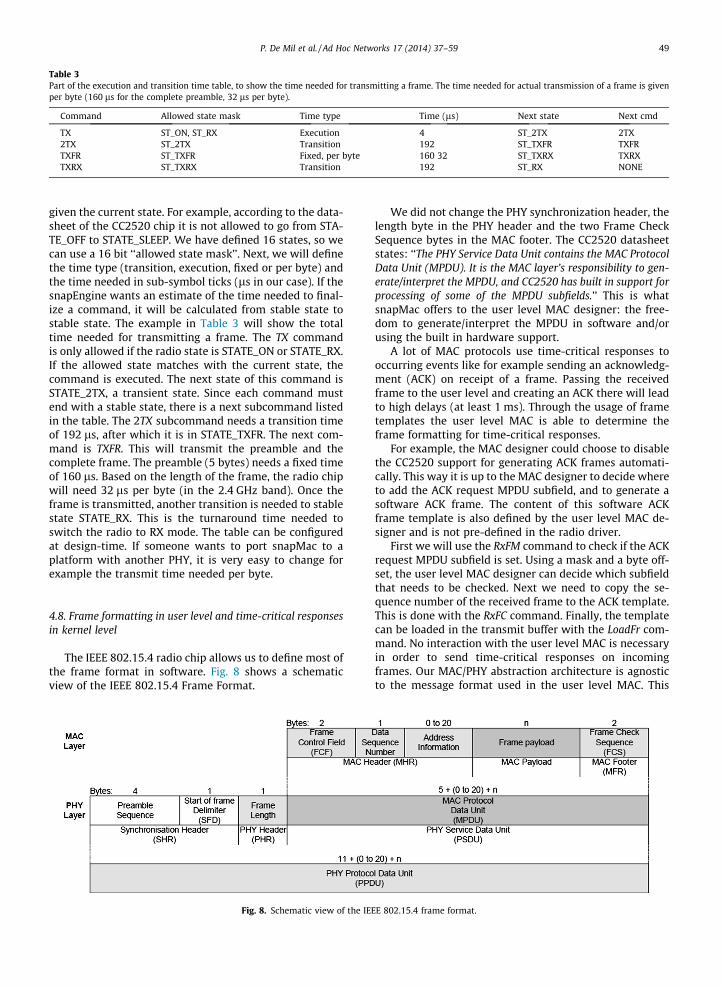
Table 3Part of the execution and transition time table, to show the time needed for transmitting a frame. The time needed for actual transmission of a frame is givenper byte (160 ls for the complete preamble, 32 ls per byte).
Command Allowed state mask Time type Time (ls) Next state Next cmd
TX ST_ON, ST_RX Execution 4 ST_2TX 2TX2TX ST_2TX Transition 192 ST_TXFR TXFRTXFR ST_TXFR Fixed, per byte 160 32 ST_TXRX TXRXTXRX ST_TXRX Transition 192 ST_RX NONE
P. De Mil et al. / Ad Hoc Networks 17 (2014) 37–59 49
given the current state. For example, according to the data-sheet of the CC2520 chip it is not allowed to go from STA-TE_OFF to STATE_SLEEP. We have defined 16 states, so wecan use a 16 bit ‘‘allowed state mask’’. Next, we will definethe time type (transition, execution, fixed or per byte) andthe time needed in sub-symbol ticks (ls in our case). If thesnapEngine wants an estimate of the time needed to final-ize a command, it will be calculated from stable state tostable state. The example in Table 3 will show the totaltime needed for transmitting a frame. The TX commandis only allowed if the radio state is STATE_ON or STATE_RX.If the allowed state matches with the current state, thecommand is executed. The next state of this command isSTATE_2TX, a transient state. Since each command mustend with a stable state, there is a next subcommand listedin the table. The 2TX subcommand needs a transition timeof 192 ls, after which it is in STATE_TXFR. The next com-mand is TXFR. This will transmit the preamble and thecomplete frame. The preamble (5 bytes) needs a fixed timeof 160 ls. Based on the length of the frame, the radio chipwill need 32 ls per byte (in the 2.4 GHz band). Once theframe is transmitted, another transition is needed to stablestate STATE_RX. This is the turnaround time needed toswitch the radio to RX mode. The table can be configuredat design-time. If someone wants to port snapMac to aplatform with another PHY, it is very easy to change forexample the transmit time needed per byte.
4.8. Frame formatting in user level and time-critical responsesin kernel level
The IEEE 802.15.4 radio chip allows us to define most ofthe frame format in software. Fig. 8 shows a schematicview of the IEEE 802.15.4 Frame Format.
Fig. 8. Schematic view of the IEE
We did not change the PHY synchronization header, thelength byte in the PHY header and the two Frame CheckSequence bytes in the MAC footer. The CC2520 datasheetstates: ‘‘The PHY Service Data Unit contains the MAC ProtocolData Unit (MPDU). It is the MAC layer’s responsibility to gen-erate/interpret the MPDU, and CC2520 has built in support forprocessing of some of the MPDU subfields.’’ This is whatsnapMac offers to the user level MAC designer: the free-dom to generate/interpret the MPDU in software and/orusing the built in hardware support.
A lot of MAC protocols use time-critical responses tooccurring events like for example sending an acknowledg-ment (ACK) on receipt of a frame. Passing the receivedframe to the user level and creating an ACK there will leadto high delays (at least 1 ms). Through the usage of frametemplates the user level MAC is able to determine theframe formatting for time-critical responses.
For example, the MAC designer could choose to disablethe CC2520 support for generating ACK frames automati-cally. This way it is up to the MAC designer to decide whereto add the ACK request MPDU subfield, and to generate asoftware ACK frame. The content of this software ACKframe template is also defined by the user level MAC de-signer and is not pre-defined in the radio driver.
First we will use the RxFM command to check if the ACKrequest MPDU subfield is set. Using a mask and a byte off-set, the user level MAC designer can decide which subfieldthat needs to be checked. Next we need to copy the se-quence number of the received frame to the ACK template.This is done with the RxFC command. Finally, the templatecan be loaded in the transmit buffer with the LoadFr com-mand. No interaction with the user level MAC is necessaryin order to send time-critical responses on incomingframes. Our MAC/PHY abstraction architecture is agnosticto the message format used in the user level MAC. This
E 802.15.4 frame format.
50 P. De Mil et al. / Ad Hoc Networks 17 (2014) 37–59
feature allows for maximal flexibility in frame formats.Radio driver developers also benefit from this approachas they do not need to bother about frame types, thereforeresulting in a cleaner (and faster) implementation.
4.9. Conclusion
Our architecture differs significantly in several aspectswith respect to current implementations in the WSN do-main. The first difference is the snapMAC concept itself: aclean separation between the user level MAC protocoland the kernel level. In the kernel level, we have a centralsnapMac Engine in combination with toolboxes and hard-ware abstraction modules. No MAC-specific time-criticalfunctions are present in the kernel. We also introduced ageneric snapMacControlPlane programming interface (be-tween the MAC control running in user level and the snap-Mac Engine running in kernel level). This enables postingof time-annoted command chains that contain the MACprotocol logic. The last aspect relates to our requirementthat the radio driver must be independent of the frame for-mat in order to maximize MAC design flexibility. Thereforewe brought the frame formatting to the user level MAC.Combining all of the above results in reusability of MACdesigns in a generic way while guaranteeing the time-crit-ical execution of any MAC.
5. How to use snapMAC from a user level MACperspective?
Here we will show the transmitter command chainneeded for asynchronous multi-channel receiver-basedcommunication (in non-beacon mode). This example isone of the new IEEE 802.15.4e solutions for handling the
DATA FRAME ACK requested
Frame in TX buffer
RX FRAME
Check ACK
ON/TX
RX Sleep
TX
RX Sleep
channel 26
Copy DS
Loaddata frame
Waiting for frame in TX buffer
TXRX
TXRX
Waiting for frame in RX buffer
Load
On from sleep
AYchannel 26
Fig. 9. Example of asynchronous multi-channel receiver-based communicationidentifiers in Fig. 10.
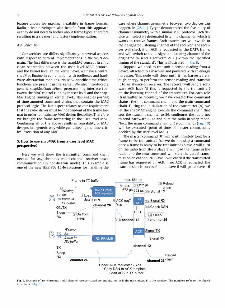
case where channel asymmetry between two devices canhappen. In [28,29], Tytgat demonstrated the feasibility ofchannel asymmetry with a similar MAC protocol. Each de-vice will select its designated listening channel on which itwants to receive frames. Each transmitter will switch tothe designated listening channel of the receiver. The recei-ver will check if an ACK is requested in the DATA frame,and will switch to the designated listening channel of theoriginator to send a software ACK (within the specifiedtiming of the standard). This is illustrated in Fig. 9.
Suppose we need to transmit a sensor reading from adevice, attached to a machine and powered with an energyharvester. This node will sleep until it has harvested en-ough energy to perform the sensor reading and transmitit to an always-on receiver. The receiver will send a soft-ware ACK back (if this is requested by the transmitter)on the listening channel of the transmitter. For each role(transmitter or receiver), we have created two commandchains: the init command chain, and the main commandchain. During the initialization of the transmitter (A), welet the snapMAC engine execute the command chain thatsets the transmit channel to 26, configures the radio notto send hardware ACKs and puts the radio in sleep mode.Next, the main command chain of 19 commands (Fig. 10)will be executed (point of time of master command isdecided by the user level MAC).
The master command (0) will wait infinitely long for aframe to be transmitted (so we do not skip a commandonce a frame is ready to be transmitted) Slave 2 will turnon the radio from sleep, slave 3 will load the frame in theradio, and the next command will start the actual trans-mission on channel 26. Slave 5 will check if the transmittedframe has requested an ACK. If no ACK is requested, thetransmission is successful and slave 6 will go to slave 16
requested? Yes
ACK
RX ACK
channel 26
channel 26
channel 12
channel 12
N to ACK template
max. 864 µs
352 µs Signal TX
Signal RX
Check DSN
Signal TX
ACK in TX buffer
CK req? es
Signal RX
192 µs Reload chain
Reload chain
max. 672 µs
SFDSleep
. A is the transmitter, B is the receiver. The numbers refer to the slaveId

Switch Channel 12
Load Frame
TxWait ∞ on TX frame
in queue
TxTransmit frame
RXReceive mode
StartOfFrameWait 672 µs
TxFM(Check if ACK requested in
tx frame)
GOTO Slave 16
RxTo Wait 192 µs on rec.
frameRxTxFM
(Check Sequence Number)
TxS Signal transmitted fr.
STOP Reload chain after 15 µs
No frame received
No ACK requested Frame arrived in TX queue
ACK requested (skip next CMD)
OnFromSleep
GOTO Slave 17
Switch Channel 26 Sleep
Wrong sequence number
No frame start detectedFrame start (SFD) detected(skip next)
Frame received (skip next)
Sequence number OK (skip next)
RxSSignal received fr.
GOTO Slave 17
GOTO Slave 17
Fig. 10. The command chain for the transmitter in this example contains 19 commands. We have not shown the init command chain (configures the radioto use channel 26 and not to send hardware ACKs.)
P. De Mil et al. / Ad Hoc Networks 17 (2014) 37–59 51
in order to signal the transmission to the user level MAC.However, if an ACK is requested, slave 6 will be skippedand we are going to prepare the reception of an ACK onchannel 12 (slave 7 and 8). We have chosen to wait forthe start of a frame with a timeout of 672 ls. If no framestart is detected before this timeout, command 10 is exe-cuted (jump to slave 17). However, if the start of a frameis detected we will skip slave 10 and wait 192 ls forreceiving the ACK frame (slave 11). If a complete frame isreceived, we will signal (slave 13) this to the user levelMAC. Next, we will check the sequence number in slave14. If it is OK, we will skip slave 15 and signal an acknowl-edged transmission to the MAC. After setting the channelto the designated channel of the receiver, we turn the radioin sleep mode and reload this command chain after 15 ls.
Oscilloscope
A
BSniffer Wireshark
Logic Analyzer
Spectrum Analyzer
Fig. 11. The experimental set-up. Nodes A, B and sniffer S are RM-090boards.
6. Functional validation and performance evaluation
We used our RM-090 nodes to evaluate snapMAC interms of software ACK timings, throughput, round triptime, beacon interval time accuracy and energy consump-tion. We have also designed a Low Power Listening MAC.We have created chains, so our experiments also serve asa functional validation of snapMac.
6.1. Experimental setup
The experimental set-up is shown in Fig. 11. Using theAgilent Technologies DS03062A oscilloscope together witha 4.5 Ohm resistor allows us to visualize the current con-sumption of node A. Node A is also connected to our SaleaeLogic Analyzer. Node B and sniffer node S are in close
vicinity. The sniffer node S is connected through USB toour laptop. The sniffed 802.15.4 frames are encapsulatedinto UDP frames using the ZigBee Encapsulation Protocol(ZEP) and sent to WireShark 1.2.8. The included time-stamps are captured on node S, and we have verified theaccuracy with a spectrum analyzer.
6.2. Software ACK
Here we want to show that (a) our sofware ACK meetsthe timing constraints as defined in the 802.15.4 standardand (b) that it is very reliable. As in [30], we refer to thetime between transmission of the last byte of a data frameuntil the reception of the last byte of the complete ACKframe as ACK time. According to the 802.15.4 standard,the maximum ACK time is 864 ls. The ACK time is alsoillustrated in Fig. 9. We have used the chain as describedin the previous section, without the channel switching.We started with a frame length of 9 (minimum alloweddata frame length), sent these data frames 500 times at25 frames per second before we increased the frame lengthwith 6. Our sniffer captured this traffic and based on this
650
700
750
800
850
900
950
1000
1050
1100
9 15 21 27 33 39 45 51 57 63 69 75 81 87 93 99 105
111
117
123
AC
K ti
me
(µs)
frame length (byte)
Influence of frame length on software ACK time
Average snapMac802.15.4 Standard Limit
Fig. 13. Influence of data frame length on the ACK time.
52 P. De Mil et al. / Ad Hoc Networks 17 (2014) 37–59
trace file we calculated the ACK time and we also mea-sured the reliability.
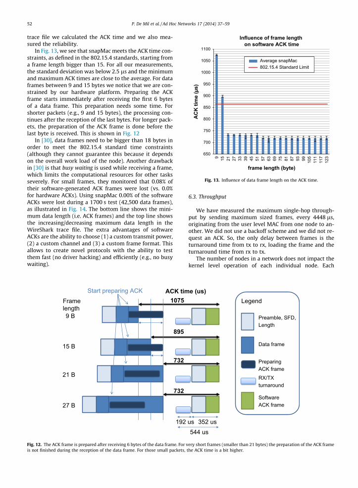
In Fig. 13, we see that snapMac meets the ACK time con-straints, as defined in the 802.15.4 standards, starting froma frame length bigger than 15. For all our measurements,the standard deviation was below 2.5 ls and the minimumand maximum ACK times are close to the average. For dataframes between 9 and 15 bytes we notice that we are con-strained by our hardware platform. Preparing the ACKframe starts immediately after receiving the first 6 bytesof a data frame. This preparation needs some time. Forshorter packets (e.g., 9 and 15 bytes), the processing con-tinues after the reception of the last bytes. For longer pack-ets, the preparation of the ACK frame is done before thelast byte is received. This is shown in Fig. 12
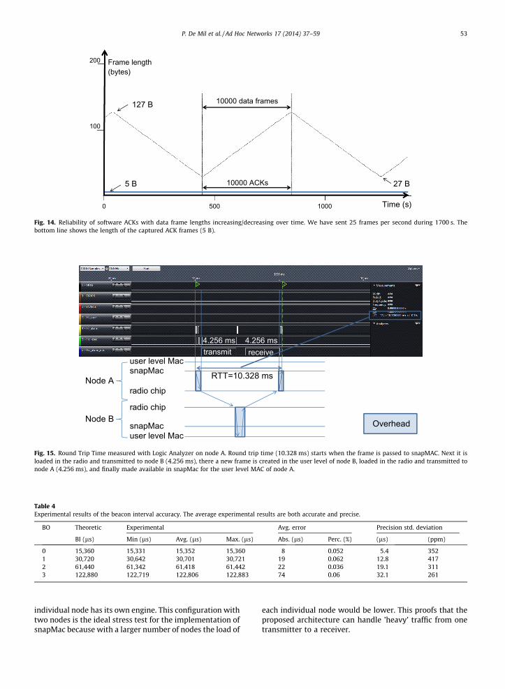
In [30], data frames need to be bigger than 18 bytes inorder to meet the 802.15.4 standard time constraints(although they cannot guarantee this because it dependson the overall work load of the node). Another drawbackin [30] is that busy waiting is used while receiving a frame,which limits the computational resources for other tasksseverely. For small frames, they monitored that 0.08% oftheir software-generated ACK frames were lost (vs. 0.0%for hardware ACKs). Using snapMac 0.00% of the softwareACKs were lost during a 1700 s test (42,500 data frames),as illustrated in Fig. 14. The bottom line shows the mini-mum data length (i.e. ACK frames) and the top line showsthe increasing/decreasing maximum data length in theWireShark trace file. The extra advantages of softwareACKs are the ability to choose (1) a custom transmit power,(2) a custom channel and (3) a custom frame format. Thisallows to create novel protocols with the ability to testthem fast (no driver hacking) and efficiently (e.g., no busywaiting).
1075
21 B
15 B
9 B
895
732
ACK tim
27 B
732
Start preparing ACKFrame length
192
Fig. 12. The ACK frame is prepared after receiving 6 bytes of the data frame. For vis not finished during the reception of the data frame. For those small packets,
6.3. Throughput
We have measured the maximum single-hop through-put by sending maximum sized frames, every 4448 ls,originating from the user level MAC from one node to an-other. We did not use a backoff scheme and we did not re-quest an ACK. So, the only delay between frames is theturnaround time from tx to rx, loading the frame and theturnaround time from rx to tx.
The number of nodes in a network does not impact thekernel level operation of each individual node. Each
Preamble, SFD, Length
e (us)
Preparing ACK frame
Software ACK frame
Data frame
Legend
RX/TX turnaround
352 usus544 us
ery short frames (smaller than 21 bytes) the preparation of the ACK framethe ACK time is a bit higher.
Frame length (bytes)
10000 500 Time (s)
100
200
10000 data frames
10000 ACKs 5 B
127 B
27 B
Fig. 14. Reliability of software ACKs with data frame lengths increasing/decreasing over time. We have sent 25 frames per second during 1700 s. Thebottom line shows the length of the captured ACK frames (5 B).
transmit receive
snapMac
radio chip Node A
radio chip
snapMacNode B
user level Mac
user level Mac
RTT=10.328 ms
4.256 ms 4.256 ms
Overhead
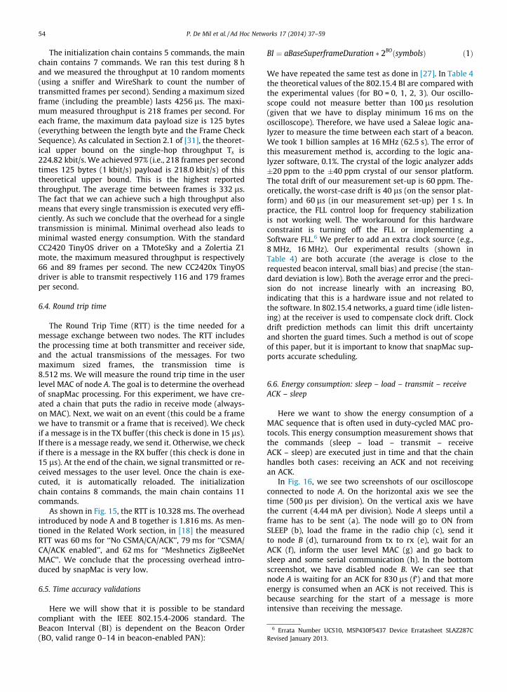
Fig. 15. Round Trip Time measured with Logic Analyzer on node A. Round trip time (10.328 ms) starts when the frame is passed to snapMAC. Next it isloaded in the radio and transmitted to node B (4.256 ms), there a new frame is created in the user level of node B, loaded in the radio and transmitted tonode A (4.256 ms), and finally made available in snapMac for the user level MAC of node A.
Table 4Experimental results of the beacon interval accuracy. The average experimental results are both accurate and precise.
BO Theoretic Experimental Avg. error Precision std. deviation
BI (ls) Min (ls) Avg. (ls) Max. (ls) Abs. (ls) Perc. (%) (ls) (ppm)
0 15,360 15,331 15,352 15,360 8 0.052 5.4 3521 30,720 30,642 30,701 30,721 19 0.062 12.8 4172 61,440 61,342 61,418 61,442 22 0.036 19.1 3113 122,880 122,719 122,806 122,883 74 0.06 32.1 261
P. De Mil et al. / Ad Hoc Networks 17 (2014) 37–59 53
individual node has its own engine. This configuration withtwo nodes is the ideal stress test for the implementation ofsnapMac because with a larger number of nodes the load of
each individual node would be lower. This proofs that theproposed architecture can handle ’heavy’ traffic from onetransmitter to a receiver.
6 Errata Number UCS10, MSP430F5437 Device Erratasheet SLAZ287CRevised January 2013.
54 P. De Mil et al. / Ad Hoc Networks 17 (2014) 37–59
The initialization chain contains 5 commands, the mainchain contains 7 commands. We ran this test during 8 hand we measured the throughput at 10 random moments(using a sniffer and WireShark to count the number oftransmitted frames per second). Sending a maximum sizedframe (including the preamble) lasts 4256 ls. The maxi-mum measured throughput is 218 frames per second. Foreach frame, the maximum data payload size is 125 bytes(everything between the length byte and the Frame CheckSequence). As calculated in Section 2.1 of [31], the theoret-ical upper bound on the single-hop throughput Ts is224.82 kbit/s. We achieved 97% (i.e., 218 frames per secondtimes 125 bytes (1 kbit/s) payload is 218.0 kbit/s) of thistheoretical upper bound. This is the highest reportedthroughput. The average time between frames is 332 ls.The fact that we can achieve such a high throughput alsomeans that every single transmission is executed very effi-ciently. As such we conclude that the overhead for a singletransmission is minimal. Minimal overhead also leads tominimal wasted energy consumption. With the standardCC2420 TinyOS driver on a TMoteSky and a Zolertia Z1mote, the maximum measured throughput is respectively66 and 89 frames per second. The new CC2420x TinyOSdriver is able to transmit respectively 116 and 179 framesper second.
6.4. Round trip time
The Round Trip Time (RTT) is the time needed for amessage exchange between two nodes. The RTT includesthe processing time at both transmitter and receiver side,and the actual transmissions of the messages. For twomaximum sized frames, the transmission time is8.512 ms. We will measure the round trip time in the userlevel MAC of node A. The goal is to determine the overheadof snapMac processing. For this experiment, we have cre-ated a chain that puts the radio in receive mode (always-on MAC). Next, we wait on an event (this could be a framewe have to transmit or a frame that is received). We checkif a message is in the TX buffer (this check is done in 15 ls).If there is a message ready, we send it. Otherwise, we checkif there is a message in the RX buffer (this check is done in15 ls). At the end of the chain, we signal transmitted or re-ceived messages to the user level. Once the chain is exe-cuted, it is automatically reloaded. The initializationchain contains 8 commands, the main chain contains 11commands.
As shown in Fig. 15, the RTT is 10.328 ms. The overheadintroduced by node A and B together is 1.816 ms. As men-tioned in the Related Work section, in [18] the measuredRTT was 60 ms for ‘‘No CSMA/CA/ACK’’, 79 ms for ‘‘CSMA/CA/ACK enabled’’, and 62 ms for ‘‘Meshnetics ZigBeeNetMAC’’. We conclude that the processing overhead intro-duced by snapMac is very low.
6.5. Time accuracy validations
Here we will show that it is possible to be standardcompliant with the IEEE 802.15.4-2006 standard. TheBeacon Interval (BI) is dependent on the Beacon Order(BO, valid range 0–14 in beacon-enabled PAN):
BI ¼ aBaseSuperframeDuration � 2BOðsymbolsÞ ð1Þ
We have repeated the same test as done in [27]. In Table 4the theoretical values of the 802.15.4 BI are compared withthe experimental values (for BO = 0, 1, 2, 3). Our oscillo-scope could not measure better than 100 ls resolution(given that we have to display minimum 16 ms on theoscilloscope). Therefore, we have used a Saleae logic ana-lyzer to measure the time between each start of a beacon.We took 1 billion samples at 16 MHz (62.5 s). The error ofthis measurement method is, according to the logic ana-lyzer software, 0.1%. The crystal of the logic analyzer adds�20 ppm to the �40 ppm crystal of our sensor platform.The total drift of our measurement set-up is 60 ppm. The-oretically, the worst-case drift is 40 ls (on the sensor plat-form) and 60 ls (in our measurement set-up) per 1 s. Inpractice, the FLL control loop for frequency stabilizationis not working well. The workaround for this hardwareconstraint is turning off the FLL or implementing aSoftware FLL.6 We prefer to add an extra clock source (e.g.,8 MHz, 16 MHz). Our experimental results (shown inTable 4) are both accurate (the average is close to therequested beacon interval, small bias) and precise (the stan-dard deviation is low). Both the average error and the preci-sion do not increase linearly with an increasing BO,indicating that this is a hardware issue and not related tothe software. In 802.15.4 networks, a guard time (idle listen-ing) at the receiver is used to compensate clock drift. Clockdrift prediction methods can limit this drift uncertaintyand shorten the guard times. Such a method is out of scopeof this paper, but it is important to know that snapMac sup-ports accurate scheduling.
6.6. Energy consumption: sleep – load – transmit – receiveACK – sleep
Here we want to show the energy consumption of aMAC sequence that is often used in duty-cycled MAC pro-tocols. This energy consumption measurement shows thatthe commands (sleep – load – transmit – receiveACK – sleep) are executed just in time and that the chainhandles both cases: receiving an ACK and not receivingan ACK.
In Fig. 16, we see two screenshots of our oscilloscopeconnected to node A. On the horizontal axis we see thetime (500 ls per division). On the vertical axis we havethe current (4.44 mA per division). Node A sleeps until aframe has to be sent (a). The node will go to ON fromSLEEP (b), load the frame in the radio chip (c), send itto node B (d), turnaround from tx to rx (e), wait for anACK (f), inform the user level MAC (g) and go back tosleep and some serial communication (h). In the bottomscreenshot, we have disabled node B. We can see thatnode A is waiting for an ACK for 830 ls (f’) and that moreenergy is consumed when an ACK is not received. This isbecause searching for the start of a message is moreintensive than receiving the message.
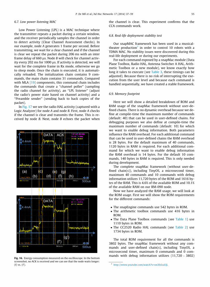
P. De Mil et al. / Ad Hoc Networks 17 (2014) 37–59 55
6.7. Low power listening MAC
Low Power Listening (LPL) is a MAC technique wherethe transmitter repeats a packet during a certain window,and the receiver periodically samples the channel in orderto detect activity (Clear Channel Assessment checks). Inour example, node A generates 1 frame per second. Beforetransmitting, we wait for a clear channel and if the channelis clear we repeat the packet during 206 ms with an interframe delay of 660 ls. Node B will check for channel activ-ity every 202 ms for 1000 ls. If activity is detected, we willwait for the complete frame in Rx mode, otherwise we goto sleep mode. Once the chain is executed, it is automati-cally reloaded. The initialization chain contains 9 com-mands, the main chain contains 31 commands. Comparedwith MLA [19] components, this command chain includesthe commands that create a ‘‘channel poller’’ (samplingthe radio channel for activity), an ‘‘LPL listener’’ (adjustthe radio’s power state based on channel activity) and a‘‘Preamble sender’’ (sending back to back copies of thepacket).
In Fig. 17 we see the radio HAL activity (captured with aLogic Analyzer) for node A and node B. First, node A checksif the channel is clear and transmits the frame. This is re-ceived by node B. Next, node B echoes the packet when
DATA
(a)
500us
4.4mA
ACK
t
I
500us
4.4mA
t
I
(b)(c)
(d)(e)
(f)(g)
(f’)
DATA
(h)
(g’)
Fig. 16. Energy consumption measured on the oscilloscope. In the bottomscreenshot, no ACK is received and we can see that the node waits longer:(f) vs. (f’).
the channel is clear. This experiment confirms that theCCA commands work.
6.8. Real-life deployment stability test
Our snapMAC framework has been used in a musical-theater production7 in order to control 10 robots with aTDMA MAC. No stability issues were discovered during thisreal-life deployment or during our experiments.
For each command exposed by a snapMac module (DataPlane Toolbox, Radio HAL, Antenna Switcher A HAL, Arith-metic Toolbox or a new module), we know exactly howlong it takes to execute (see Table 3, these timings can beadjusted). Because there is no risk of interrupting the exe-cution from the user level and because each command ishandled sequentially, we have created a stable framework.
6.9. Memory footprint
Here we will show a detailed breakdown of ROM andRAM usage of the snapMac framework without user-de-fined chains. There is no dynamic overhead because we de-fine at compile-time the maximum number of commands(default: 40) that can be used in user-defined chains. Fordebugging purposes we also define at compile-time themaximum number of commands (default: 10) for whichwe want to enable debug information. Both parametersinfluence the RAM overhead. For each additional commandthat can be used in user-defined chains the RAM overheadis 28 bytes. For the default maximum of 40 commands,1120 bytes in RAM is required. For each additional com-mand for which we want to enable debug informationthe RAM overhead is 14 bytes. For the default 10 com-mands, 140 bytes in RAM is required. This is only neededduring development.
The complete snapMac framework (without user-de-fined chain(s)), including TinyOS, a microsecond timer,maximum 40 commands and 10 commands with debuginformation utilizes 11,720 bytes of the ROM and 1616 by-tes of the RAM. This is 4.6% of the available ROM and 10.1%of the available RAM on our RM-090 node.
Now we have analyzed the RAM usage, we will look atthe ROM usage. First we will show the ROM requirementsfor the different commands:
� The snapEngine commands use 542 bytes in ROM.� The arithmetic toolbox commands use 416 bytes in
ROM.� The Data Plane Toolbox commands (see Table 1) use
1110 bytes in ROM.� The CC2520 Radio HAL commands (see Table 2) use
1734 bytes in ROM.
The total ROM requirement for all the commands is3802 bytes. The snapMac framework without any com-mands and user-defined chain(s), including TinyOS, amicrosecond timer, maximum 0 commands and 0 com-mands with debug information utilizes (11,720 � 3802)
7 http://www.youtube.com/watch?v=on3fzlzaUjI.
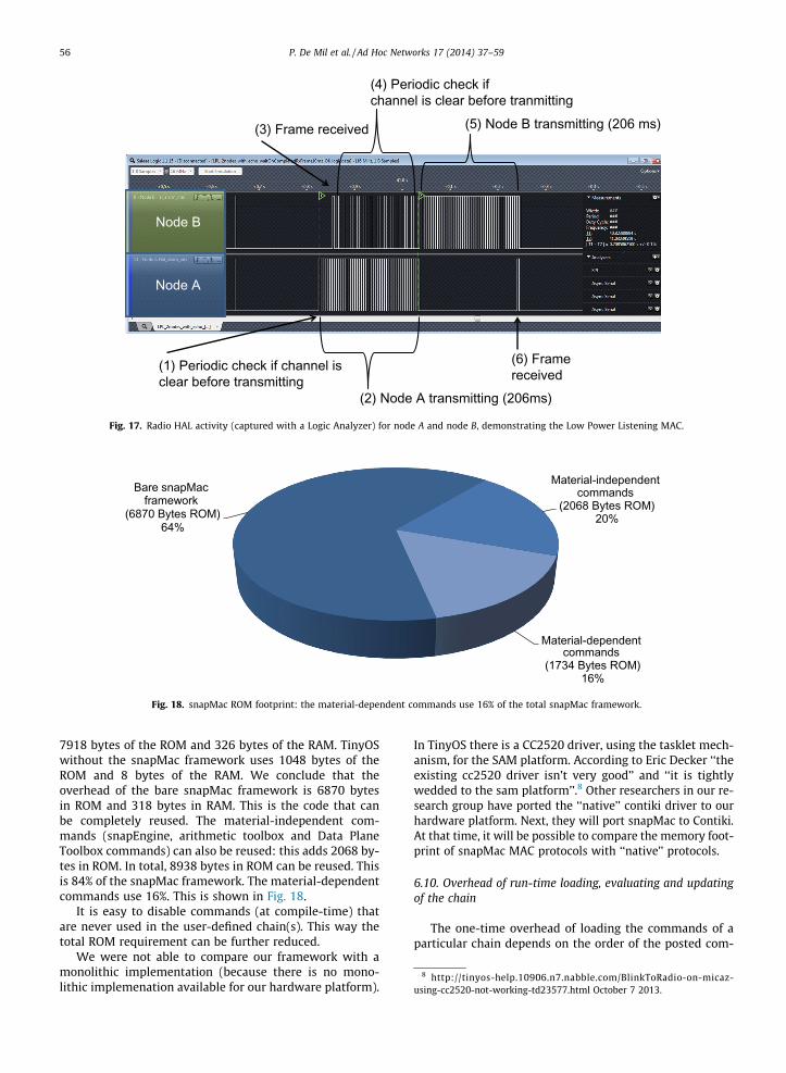
(2) Node A transmitting (206ms)
(3) Frame received (5) Node B transmitting (206 ms)
(4) Periodic check if channel is clear before tranmitting
(1) Periodic check if channel is clear before transmitting
(6) Frame received
Node A
Node B
Fig. 17. Radio HAL activity (captured with a Logic Analyzer) for node A and node B, demonstrating the Low Power Listening MAC.
Bare snapMac framework
(6870 Bytes ROM)64%
Material-independent commands
(2068 Bytes ROM)20%
Material-dependent commands
(1734 Bytes ROM)16%
Fig. 18. snapMac ROM footprint: the material-dependent commands use 16% of the total snapMac framework.
8 http://tinyos-help.10906.n7.nabble.com/BlinkToRadio-on-micaz-using-cc2520-not-working-td23577.html October 7 2013.
56 P. De Mil et al. / Ad Hoc Networks 17 (2014) 37–59
7918 bytes of the ROM and 326 bytes of the RAM. TinyOSwithout the snapMac framework uses 1048 bytes of theROM and 8 bytes of the RAM. We conclude that theoverhead of the bare snapMac framework is 6870 bytesin ROM and 318 bytes in RAM. This is the code that canbe completely reused. The material-independent com-mands (snapEngine, arithmetic toolbox and Data PlaneToolbox commands) can also be reused: this adds 2068 by-tes in ROM. In total, 8938 bytes in ROM can be reused. Thisis 84% of the snapMac framework. The material-dependentcommands use 16%. This is shown in Fig. 18.
It is easy to disable commands (at compile-time) thatare never used in the user-defined chain(s). This way thetotal ROM requirement can be further reduced.
We were not able to compare our framework with amonolithic implementation (because there is no mono-lithic implemenation available for our hardware platform).
In TinyOS there is a CC2520 driver, using the tasklet mech-anism, for the SAM platform. According to Eric Decker ‘‘theexisting cc2520 driver isn’t very good’’ and ‘‘it is tightlywedded to the sam platform’’.8 Other researchers in our re-search group have ported the ‘‘native’’ contiki driver to ourhardware platform. Next, they will port snapMac to Contiki.At that time, it will be possible to compare the memory foot-print of snapMac MAC protocols with ‘‘native’’ protocols.
6.10. Overhead of run-time loading, evaluating and updatingof the chain
The one-time overhead of loading the commands of aparticular chain depends on the order of the posted com-
P. De Mil et al. / Ad Hoc Networks 17 (2014) 37–59 57
mands. When the n commands of a chain are posted in thecorrect order, the snapMac engine does not need to re-or-der these commands.
At this moment we have an overhead of approximately40 ls (16 MHz microcontroller) per executed command(without optimizations) including state machine checking(which could be disabled in deployment).
At any time it is possible to update the parameter of aparticular command. The next time the command is exe-cuted, the updated parameter will be used.
7. Future work: portability of snapMac
In this section we describe the different options of snap-Mac regarding the portability of the framework and theMAC protocols.
7.1. Framework
Supporting new hardware platforms (i.e., another PHYradio chip) only requires a minimum of changes if thesame OS (i.e., TinyOS) is already supported on the newhardware platform. For example, the Zolertia Z1 hardwareplatform supports TinyOS, but has an older radio chip(CC2420). For this radio chip we need to develop an appro-priate radio HAL module in snapMac. The snapEngine andthe Toolbox modules remain unchanged. The material-dependant Hardware Abstraction modules (e.g., RadioHAL, Antenna Switcher, etc.) define their own commandsand expose their commands via the unaltered Commandinterface. The commands listed in Table 2 are most likelyapplicable to a new radio chip, with exception of theSwitchChan command if the radio operates on a singlechannel. For each of these commands, a specific implemen-tation for the hardware chip is required. If the hardwarechip offers extra (chip specific) functionality, extra com-mands can be added to the new Hardware Abstractionmodule. Our Command interface is generic, so this inter-face will remain the same on all the supported hardwareplatforms. The MAC designer is now able to use thesenew commands in its composition of the commandchain(s) at user level.
Our CC2520 Radio HAL module has 1020 lines of code, ofwhich 516 lines of code are specific for the CC2520. Support-ing the CC2420 radio chip would require replacing these 516lines of code with the CC2420 specific instructions.
Supporting another OS (e.g., Contiki OS) requires a portof the snapMac framework. If the new OS is written in C,most of the nesC code can be reused, but one would needto adapt snapMac to the constructs used in the new OS.Once snapMac is ported to a new OS, the user-definedchains can be reused. This would allow us to port existingMAC protocols across different operating systems. We havenot yet completed the port to Contiki OS.
7.2. MAC protocols
With snapMac it will be possible to reuse a MAC proto-col chain across different hardware platforms with thesame PHY. Many IEEE 802.15.4 compatible radio chips are
available. Once the radio HAL module for a new chip iswritten, all the existing MAC protocol chains can be reused.
Reusing a MAC protocol chain across different hardwareplatforms with a different PHY is also possible, but the MACdesigner should check the capabilities and features of thenew PHY. The IEEE 802.15.4 supports different PHYs (fre-quency, data rate, modulation). Supporting different fre-quencies and data rates (e.g., 868 MHz, 20 kbps) onlyrequires two updates: (1) change the supported channellist, (2) change the time needed to transmit (this time, asconfigure in Table 3, relates to the data rate). In [32] an802.15.4 based MAC is adapted on a powerline communi-cation (PLC) non-wireless medium. This demonstrates thefuture applicability of our snapMac framework.
8. Conclusions
The major goal of the snapMAC concept is to fosterreusability of MACs on different hardware/software/radioplatforms.
We have shown that the snapMac architecture supportsany time-accurate user level Full Control MAC (1) whichcommunicates through a generic radio interface (2) witha MAC protocol agnostic radio driver (3) that allows gener-ic time-critical interactions (4) while maintaining maxi-mum flexibility and freedom for MAC designers (5). ThesnapMac architecture changes MAC implementation sig-nificantly. First of all, we invented a scheduling (planning)based technique (time-annotated chains) to describe theMAC protocol logic. Second, frame formatting is done inuser space in contrast to driver space. Third, a genericMAC protocol agnostic driver can respond instantly onevents. Fourth, we have defined two generic MAC protocolagnostic interfaces between the MAC and the radio driver.
This architecture has been implemented and evaluatedon the RMoni RM-090 wireless sensor nodes running theTinyOS operating system. We showed that the ACK time iswithin the 802.15.4 limit for frames bigger than 15 bytes.We also showed that we can reach up to 97% of the theoret-ical throughput. Our implementation enables energy-efficient execution of duty-cycled MAC designs becausewe can plan the execution of commands just in time.Although our implementation is oriented towards WSNs,the architecture and the interfaces can be used on PCs withany wireless NIC. In such a scenario the proposed snapMac’driver’ part is the firmware running on the NIC, and anyMAC can be implemented on the PC’s user level. The onlytask of the kernel would then be to enable communicationbetween the PC’s user level MAC and the NIC firmware.
Concluding we can state that the snapMAC architectureincreases reusability and decreases complexity of MACimplementations as well as the underlying radio drivers.Moreover the architecture enables time-accurate execu-tion of radio-related actions and instant reaction on timesensitive events in a generic way.
References
[1] J.-P. Vasseur, A. Dunkels, Interconnecting Smart Objects with IP: TheNext Internet, Morgan Kaufmann Publishers Inc., San Francisco, CA,USA, 2010.
58 P. De Mil et al. / Ad Hoc Networks 17 (2014) 37–59
[2] Libelium sensor applications ranking, 2013. <http://www.libelium.com/top_50_iot_sensor_applications_ranking/>.
[3] A. Bachir, M. Dohler, T. Watteyne, K.K. Leung, Mac essentials for wirelesssensor networks, IEEE Commun. Surv. Tutorials (2012) 222–248.
[4] P. Huang, L. Xiao, S. Soltani, M. Mutka, N. Xi, The evolution of macprotocols in wireless sensor networks: a survey, IEEE Commun. Surv.Tutorials PP (2012) 1–20.
[5] IEEE Standard for Information Technology – Telecommunicationsand Information Exchange Between Systems – Local andMetropolitan Area Networks – Specific Requirements Part 15.4:Wireless Medium Access Control (MAC) and Physical Layer (PHY)Specifications for Low-Rate Wireless Personal Area Networks(WPANs), Technical Report, 2006.
[6] IEEE Standard for Local and metropolitan area networks–Part 15.4:Low-Rate Wireless Personal Area Networks (LR-WPANs)Amendment 1: MAC sublayer, Technical Report, 2012.
[7] Deliverable d1.4? converged architectural reference model for theiot v2.0, 2013. <http://www.iot-a.eu/public/public-documents/documents-1/1/1/d1.4/atdownload/file>.
[8] P. De Mil, P. Ruckebusch, J. Hoebeke, I. Moerman, P. Demeester,Pluralismac: a generic multi-mac framework for heterogeneous,multiservice wireless networks, applied to smart containers,EURASIP J. Wireless Commun. Netw. 2012 (2012) 166.
[9] C. Bormann, Guidance for light-weight implementations of theinternet protocol suite, 2013.
[10] Tmote sky sensornode, 2013. <http://www.crew-project.eu/portal/wilab/sensornode-tmote-sky>.
[11] Zolertia z1 low-power wireless module, 2013. <http://www.zolertia.com/ti>.
[12] Libelium waspmote, the sensor device for developers, 2013. <http://www.libelium.com/products/waspmote>.
[13] Linux device drivers, 3rd edition (chapter 7, section 4), 2013. <http://www.makelinux.net/ldd3/chp-7-sect-4>.
[14] Tinyos, open source os for low-power wireless devices, 2013.<http://www.tinyos.net/>.
[15] Contiki, open source os for the internet of things, 2013. <http://www.contiki-os.org/>.
[16] T. Reusing, Comparison of operating systems tinyos and contiki,Sensor Nodes – Oper. Netw. Appl. (SN) 7 (2012).
[17] J. Hauer, TKN15.4: An IEEE 802.15.4 MAC Implementation for TinyOS2, Technical Report, 2009.
[18] R. Steiner, T. Mück, A. Fröhlich, C-mac: a configurable mediumaccess control protocol for sensor networks, in: 2010 IEEE Sensors,2010, pp. 845–848.
[19] K. Klues, G. Hackmann, O. Chipara, C. Lu, A component-basedarchitecture for power-efficient media access control in wirelesssensor networks, 2007.
[20] G. Nychis, T. Hottelier, Z. Yang, S. Seshan, P. Steenkiste, Enabling macprotocol implementations on software-defined radios, in:Proceedings of the 6th USENIX Symposium on Networked SystemsDesign and Implementation, NSDI’09, USENIX Association, Berkeley,CA, USA, 2009, pp. 91–105.
[21] T. Schmid, O. Sekkat, M.B. Srivastava, An experimental study ofnetwork performance impact of increased latency in softwaredefined radios, in: Proceedings of the Second ACM InternationalWorkshop on Wireless Network Testbeds, Experimental Evaluationand Characterization, WinTECH ’07, ACM, New York, NY, USA, 2007,pp. 59–66.
[22] J. Ansari, X. Zhang, A. Achtzehn, M. Petrova, P. Mahonen,Decomposable mac framework for highly flexible and adaptablemac realizations, in: 2010 IEEE Symposium on New Frontiers inDynamic Spectrum, 2010, pp. 1–2.
[23] J. Ansari, X. Zhang, A. Achtzehn, M. Petrova, P. Mahonen, A flexiblemac development framework for cognitive radio systems, in: 2011IEEE Wireless Communications and Networking Conference(WCNC), 2011, pp. 156–161.
[24] I. Tinnirello, G. Bianchi, P. Gallo, D. Garlisi, F. Giuliano, F. Gringoli,Wireless mac processors: programming mac protocols oncommodity hardware, in: 2012 Proceedings IEEE INFOCOM, 2012,pp. 1269–1277.
[25] P. Djukic, P. Mohapatra, Soft-tdmac: A software tdma-based macover commodity 802.11 hardware, in: 2009 IEEE INFOCOM, 2009,pp. 1836–1844.
[26] A. Rao, I. Stoica, An overlay mac layer for 802.11 networks, in:Proceedings of the 3rd International Conference on Mobile Systems,Applications, and Services, MobiSys ’05, ACM, New York, NY, USA,2005, pp. 135–148.
[27] A. Hernandez, P. Park, IEEE 802.15.4 Implementation based onTKN15.4 using TinyOS, Technical Report, 2011.
[28] L. Tytgat, O. Yaron, I. Moerman, P. Demeester, Energy awareness inself-growing sensor networks, in: 2012 IEEE 17th InternationalWorkshop on Computer Aided Modeling and Design ofCommunication Links and Networks (CAMAD), 2012, pp. 241–245.
[29] L. Tytgat, O. Yaron, S. Pollin, I. Moerman, P. Demeester, Analysis andexperimental verification of frequency based interference avoidancemechanisms in ieee 802.15.4, IEEE/ACM Transactions onNetworking, accepted for publication, (2014).
[30] W.-B. Pottner, S. Schildt, D. Meyer, L. Wolf, Piggy-backing linkquality measurements to ieee 802.15.4 acknowledgements, in: 2011IEEE 8th International Conference on Mobile Adhoc and SensorSystems (MASS), 2011, pp. 807–812.
[31] F. Sterlind, A. Dunkels, Approaching the maximum 802.15.4 multi-hop throughput, in: Proceedings of ACM HotEmNets, ACM, 2008.
[32] C. Chauvenet, B. Tourancheau, D. Genon-Catalot, 802.15.4, a maclayer solution for plc, in: AICCSA’10, ACS/IEEE, 2010.
Pieter De Mil received his Master in IndustrialElectrical Engineering in 2003 at the Kath-olieke Hogeschool (KAHO) Sint-Lieven, Ghent,Belgium. In 2005 he also received the Mastersdegree in Computer Science from the GhentUniversity (UGent) in Belgium. He then joinedthe research group on Internet Based Com-munication Networks & Services (IBCN,www.ibcn.intec.ugent.be) at Ghent University.As a member of this research group, he is alsoaffiliated with the Interdisciplinary institutefor BroadBand Technology (iMinds, http://
www.iminds.be). There, he is involved in many research projects whichfocus on embedded software for wireless sensor and actuator networks,wireless mesh networks, positioning and home and building automation.
As of 2008, he is also pursuing a PhD degree within these research domains.In 2013, he founded snapTonic (http://www.snapTonic.net ), providingwireless solutions to companies who need a dedicated wireless solution fortheir use cases (smart cities, smart energy, smart lighting, smart textile,smart home automation, indoor positioning, etc.).Bart Jooris received his Bachelor in Electron-ics in 1997 from the Katholieke HogeschoolBrugge Oostende (KHBO), Belgium. In 2002 hethen obtained his Master in Informatics fromGhent University (UGent), Ghent, Belgium.From September 2002 until March 2004 hedesigned hardware, firmware and devicedrivers for the retail sector at ‘Real Software’(now ‘Centric Belgium’). In 2004, he joined theresearch group on Internet Based Communi-cation Networks & Services (IBCN, http://www.ibcn.intec.ugent.be). As a member of
this research group, he is also affiliated with the Interdisciplinary insti-tute for BroadBand Technology (iMinds, http://www.iminds.be). There, heworked on European and national projects concerning Internet and data
communication in the railway sector until 2007. Since 2007 he isresponsible for the large wireless testlab facilities of the IBBT TechnicalTest centre (iLab.t) in Ghent, Belgium.Lieven Tytgat received his Master in Indus-trial Science on Electronics in 2004 from theHogeschool West-Vlaanderen (HoWest), Bel-gium. In 2005 he then received the Master inIndustrial Management and ICT from theKatholieke Universiteit Leuven (KULeuven),Belgium. Successively he obtained the Masterof Science on elektrotechnics in 2007 at GhentUniversity (UGent), Belgium. He then joinedthe research group on Internet Based Com-munication Networks & Services (IBCN,www.ibcn.intec.ugent.be) at Ghent Univer-
sity. As a member of this research group, he is also affiliated with theInterdisciplinary institute for BroadBand Technology (iMinds, http://www.iMinds.be). There, he is pursuing a PhD degree and he is involved in
P. De Mil et al. / Ad Hoc Networks 17 (2014) 37–59 59
many research projects which focus on wireless networks, SoftwareDefined Radio and Cognitive Radio.
Jeroen hoebeke received the Masters degreein Computer Science engineering in 2002from Ghent University (UGent), Belgium.Since August 2002, he has been affiliated withthe Internet Based Communication Networks& Services (IBCN, www.ibcn.intec.ugent.be) ofthe Department of Information Technology atGhent University, where he obtained a PhD in2007 on adaptive ad hoc routing and VirtualPrivate Ad Hoc Networks. To this end, he wasfirstly granted a scholarship of the Institutefor Innovation by Science and Technology in
Flanders (IWT), and later a research assistantship of the Funds of Scien-tific Research Flanders (FWO). He is currently postdoctoral researcher atIBCN where he is conducting research on mobile and wireless networks,
personal networks, self-organizing virtual networks, Future Internet andsensor networks. As a member of this research group, he is also affiliatedwith the Interdisciplinary institute for BroadBand Technology (iMinds,http://www.iminds.be). He is and has been involved in several nationaland international industrial and fundamental research projects targetinga wide range of application domains such as personal networking,machine-to-machine communication, e-health, emergency networking.Ingrid Moerman received her degree inElectrical Engineering (1987) and the Ph.Ddegree (1992) from the Ghent University(UGent, Belgium), where she became a part-time professor in 2000. She is a staff memberof the research group on Internet BasedCommunication Networks & Services (IBCN,http://www.ibcn.intec.ugent.be), where she isleading the research on mobile and wirelesscommunication networks. Since 2006 shejoined the Interdisciplinary institute forBroadBand Technology (iMinds, http://
www.iminds.be), where she is coordinating several interdisciplinaryresearch projects. Her main research interests include: Sensor Networks,
Cooperative and Cognitive Networks, Wireless Access, Self-OrganizingDistributed Networks and Experimentally-supported research. IngridMoerman has a longstanding experience in running national and EUresearch funded projects. At the European level, Ingrid Moerman is inparticular very active in the FP7 FIRE (Future Internet Research andExperimentation) research area, where she is coordinating the CREWproject and further participating in IP OpenLab, IP Fed4FIRE, IP OFELIA,STREP SPITFIRE, STREP EVARILOS. In the FP7 research area on FutureNetworks, she is involved in IP LEXNET, STREP CONSERN, and STREPSEMAFOUR. She is author or co-author of more than 500 publications ininternational journals or conference proceedings. She is associate editorof the EURASIP Journal on Wireless Communications and Networking andvice-president of the expert panel on Informatics and Knowledge Tech-nology of the Research Foundation Flanders (FWO).
Piet Demeester is professor in the faculty ofEngineering at Ghent University (UGent, Bel-gium). He is head of the research group‘‘Internet Based Communication Networks &Services’’ (IBCN, http://www.ibcn.intec.ugent.be) that is part of the Department ofInformation Technology (INTEC) of GhentUniversity and that is also affiliated with theInterdisciplinary Institute for BroadbandTechnology (iMinds, http://www.iminds.be).He is Fellow of the IEEE. After finishing a PhDon Metal Organic Vapor Phase Epitaxy for
photonic devices in 1988, he established a research group in this areaworking on different material systems (AlGaAs, InGaAsP, GaN). Thisresearch was successfully transferred to IMEC in 2002 and resulted in 12
PhDs and 300 publications in international journals and conference pro-ceedings. In 1992 he started research on communication networks andestablished the IBCN research group. The group is focusing on severaladvanced research topics: Network Modeling, Design & Evaluation;Mobile & Wireless Networking; High Performance Multimedia Process-ing; Autonomic Computing & Networking; Service Engineering; Content& Search Management and Data Analysis & Machine Learning. Theresearch of IBCN resulted in about 50 PhD’s, 1250 publications in inter-national journals and conference proceedings, 30 international awardsand 4 spin-off companies.