Electroless Deposition of Ni-P Coatings on HNBR for ... - MDPI
18
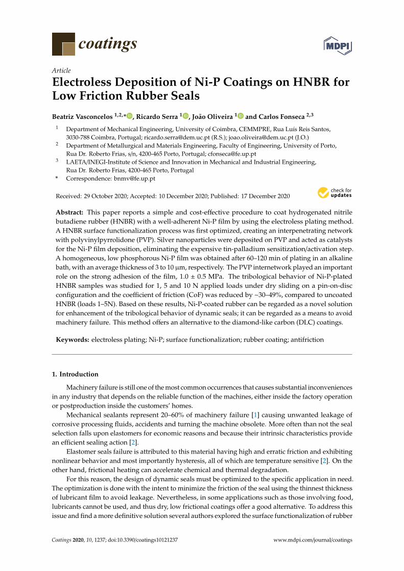
coatings Article Electroless Deposition of Ni-P Coatings on HNBR for Low Friction Rubber Seals Beatriz Vasconcelos 1,2, * , Ricardo Serra 1 , João Oliveira 1 and Carlos Fonseca 2,3 1 Department of Mechanical Engineering, University of Coimbra, CEMMPRE, Rua Luís Reis Santos, 3030-788 Coimbra, Portugal; [email protected] (R.S.); [email protected] (J.O.) 2 Department of Metallurgical and Materials Engineering, Faculty of Engineering, University of Porto, Rua Dr. Roberto Frias, s/n, 4200-465 Porto, Portugal; [email protected] 3 LAETA/INEGI-Institute of Science and Innovation in Mechanical and Industrial Engineering, Rua Dr. Roberto Frias, 4200-465 Porto, Portugal * Correspondence: [email protected] Received: 29 October 2020; Accepted: 10 December 2020; Published: 17 December 2020 Abstract: This paper reports a simple and cost-effective procedure to coat hydrogenated nitrile butadiene rubber (HNBR) with a well-adherent Ni-P film by using the electroless plating method. A HNBR surface functionalization process was first optimized, creating an interpenetrating network with polyvinylpyrrolidone (PVP). Silver nanoparticles were deposited on PVP and acted as catalysts for the Ni-P film deposition, eliminating the expensive tin-palladium sensitization/activation step. A homogeneous, low phosphorous Ni-P film was obtained after 60–120 min of plating in an alkaline bath, with an average thickness of 3 to 10 μm, respectively. The PVP internetwork played an important role on the strong adhesion of the film, 1.0 ± 0.5 MPa. The tribological behavior of Ni-P-plated HNBR samples was studied for 1, 5 and 10 N applied loads under dry sliding on a pin-on-disc configuration and the coefficient of friction (CoF) was reduced by ~30–49%, compared to uncoated HNBR (loads 1–5N). Based on these results, Ni-P-coated rubber can be regarded as a novel solution for enhancement of the tribological behavior of dynamic seals; it can be regarded as a means to avoid machinery failure. This method offers an alternative to the diamond-like carbon (DLC) coatings. Keywords: electroless plating; Ni-P; surface functionalization; rubber coating; antifriction 1. Introduction Machinery failure is still one of the most common occurrences that causes substantial inconveniences in any industry that depends on the reliable function of the machines, either inside the factory operation or postproduction inside the customers’ homes. Mechanical sealants represent 20–60% of machinery failure [1] causing unwanted leakage of corrosive processing fluids, accidents and turning the machine obsolete. More often than not the seal selection falls upon elastomers for economic reasons and because their intrinsic characteristics provide an efficient sealing action [2]. Elastomer seals failure is attributed to this material having high and erratic friction and exhibiting nonlinear behavior and most importantly hysteresis, all of which are temperature sensitive [2]. On the other hand, frictional heating can accelerate chemical and thermal degradation. For this reason, the design of dynamic seals must be optimized to the specific application in need. The optimization is done with the intent to minimize the friction of the seal using the thinnest thickness of lubricant film to avoid leakage. Nevertheless, in some applications such as those involving food, lubricants cannot be used, and thus dry, low frictional coatings offer a good alternative. To address this issue and find a more definitive solution several authors explored the surface functionalization of rubber Coatings 2020, 10, 1237; doi:10.3390/coatings10121237 www.mdpi.com/journal/coatings
-
Upload
khangminh22 -
Category
Documents
-
view
0 -
download
0
Transcript of Electroless Deposition of Ni-P Coatings on HNBR for ... - MDPI
coatings
Article
Electroless Deposition of Ni-P Coatings on HNBR forLow Friction Rubber Seals
Beatriz Vasconcelos 1,2,* , Ricardo Serra 1 , João Oliveira 1 and Carlos Fonseca 2,3
1 Department of Mechanical Engineering, University of Coimbra, CEMMPRE, Rua Luís Reis Santos,3030-788 Coimbra, Portugal; [email protected] (R.S.); [email protected] (J.O.)
2 Department of Metallurgical and Materials Engineering, Faculty of Engineering, University of Porto,Rua Dr. Roberto Frias, s/n, 4200-465 Porto, Portugal; [email protected]
3 LAETA/INEGI-Institute of Science and Innovation in Mechanical and Industrial Engineering,Rua Dr. Roberto Frias, 4200-465 Porto, Portugal
* Correspondence: [email protected]
Received: 29 October 2020; Accepted: 10 December 2020; Published: 17 December 2020�����������������
Abstract: This paper reports a simple and cost-effective procedure to coat hydrogenated nitrilebutadiene rubber (HNBR) with a well-adherent Ni-P film by using the electroless plating method.A HNBR surface functionalization process was first optimized, creating an interpenetrating networkwith polyvinylpyrrolidone (PVP). Silver nanoparticles were deposited on PVP and acted as catalystsfor the Ni-P film deposition, eliminating the expensive tin-palladium sensitization/activation step.A homogeneous, low phosphorous Ni-P film was obtained after 60–120 min of plating in an alkalinebath, with an average thickness of 3 to 10 µm, respectively. The PVP internetwork played an importantrole on the strong adhesion of the film, 1.0 ± 0.5 MPa. The tribological behavior of Ni-P-platedHNBR samples was studied for 1, 5 and 10 N applied loads under dry sliding on a pin-on-discconfiguration and the coefficient of friction (CoF) was reduced by ~30–49%, compared to uncoatedHNBR (loads 1–5N). Based on these results, Ni-P-coated rubber can be regarded as a novel solutionfor enhancement of the tribological behavior of dynamic seals; it can be regarded as a means to avoidmachinery failure. This method offers an alternative to the diamond-like carbon (DLC) coatings.
Keywords: electroless plating; Ni-P; surface functionalization; rubber coating; antifriction
1. Introduction
Machinery failure is still one of the most common occurrences that causes substantial inconveniencesin any industry that depends on the reliable function of the machines, either inside the factory operationor postproduction inside the customers’ homes.
Mechanical sealants represent 20–60% of machinery failure [1] causing unwanted leakage ofcorrosive processing fluids, accidents and turning the machine obsolete. More often than not the sealselection falls upon elastomers for economic reasons and because their intrinsic characteristics providean efficient sealing action [2].
Elastomer seals failure is attributed to this material having high and erratic friction and exhibitingnonlinear behavior and most importantly hysteresis, all of which are temperature sensitive [2]. On theother hand, frictional heating can accelerate chemical and thermal degradation.
For this reason, the design of dynamic seals must be optimized to the specific application in need.The optimization is done with the intent to minimize the friction of the seal using the thinnest thicknessof lubricant film to avoid leakage. Nevertheless, in some applications such as those involving food,lubricants cannot be used, and thus dry, low frictional coatings offer a good alternative. To address thisissue and find a more definitive solution several authors explored the surface functionalization of rubber
Coatings 2020, 10, 1237; doi:10.3390/coatings10121237 www.mdpi.com/journal/coatings
Coatings 2020, 10, 1237 2 of 18
with diamond-like carbon (DLC) films [3] which allowed significant improvement of the tribologicalproperties of the sliding rubber contacts, while keeping the elastomeric and sealing properties of therubber. However, the DLC method involves an expensive and sophisticated experimental apparatusthat often cannot be scaled-up.
An alternative to DLC coatings would be to coat the rubber parts with a thin metallic or ceramiclayer resistant to corrosion, wear, and abrasion and that possesses lubrication properties.
Electroless Ni-P (ENP) coating has been widely used on machining and finishing tools [4] toextend the life of moulds, extruders for plastics, and pumps and valves that are exposed to aggressiveservice conditions [4,5]. Furthermore, electroless plating (ELP) has been considered a very promisingmetallization process due to its straightforward implementation (there is no need for complex and/orcostly equipment as in vacuum-based vapor deposition methods) and to the resulting homogeneouscoatings even on non-conductive and complex shaped surfaces. ELP was already successfully applied ona myriad of polymeric substrates, namely polyethylene terephthalate (PET) [6], acrylonitrile-butadienestyrene (ABS) polymer [7–9], carboxylated nitrile butadiene rubber (XNBR) [10], and thermoplasticpolyurethane (TPU) [11]. The main disadvantage of ELP is its need for a surface functionalizationstep which traditionally involves the sensitization of the surface with stannous chloride followed byactivation in palladium chloride solutions [12].
This costly and heavily polluting sensitization—activation step has been increasingly replaced byseeding the functionalized surface with particles of the metal to be deposited, or of another inexpensivemetal with catalytic potential that acts as auto-catalyst. This method was successfully employed oncopper plating of ABS by Garcia et al. [7], by dipping the previously functionalized substrate withpolyacrylic acid (PAA) in a copper sulphate solution to induce copper ion adsorption by ion-exchange.The substrate was then immersed in sodium borohydride (NaBH4) for subsequent reduction of theCu2+ into Cu particles. Similarly, Tang et al. [12] promoted the Ni2+ exchange on the surface ofchitosan-modified ABS sheets followed by its reduction in potassium borohydride. Despite theseworks, ELP on rubber substrates remains a mostly unexplored topic in the literature, although it has astrong potential for rubber coating and, thus, impart it with a non-stick and low friction surface.
In this paper, a method is proposed to functionalize hydrogenated nitrile butadiene rubber(HNBR), one of the oldest and most used oil-resistant elastomers [13], to obtain a well adherent,low frictional Ni-P coating. HNBR functionalization proceeded by dipping the substrate in a solutionof polyvinylpyrrolidone (PVP) in chloroform (CHCl3) to create a PVP-rich surface network using amodified surface physical interpenetrating network (SPIN) [14]. ELP was used as the coating method,using silver particles as catalytic sites for a well-adherent and low friction Ni-P film.
2. Materials and Methods
2.1. Sample Preparation
The substrates were prepared from an HNBR sheet, with 3 mm thickness and shore hardness of75 shore A, acquired from The Plastic Shop (Coventry, UK). The rubber was 99.5% hydrogenated andits acrylonitrile (ACN) content was 34%. The HBNR sheet was cut into 35 × 12 mm samples whichwere then manually abraded with emery paper mesh 600, until approximately 0.5 mm were removedfrom both sides. Finally, the samples were ultrasonicated in boiled distilled water for 30 min and driedat 90 ◦C until constant weight. This is an essential surface cleaning procedure since rubber plasticizerstend to exude, leading to irreproducible HNBR surface states [15].
2.2. PVP Coating
A solution of PVP (MW 29,000, Sigma Company, St. Louis, MO, USA) in chloroform (CHCl3)(for analysis EMSURE® ACS ISO reagent, Merck, Germany) was prepared at 15% (m/v) concentration.The samples were dipped in the PVP solution for 15–30 min, at room temperature, and then immediately
Coatings 2020, 10, 1237 3 of 18
immersed in n-hexane (for HPLC, VWR International Ltd., Lutterworth, UK) for 30 min. The samples,now named PHNBR (PVP-coated HNBR), were dried at room temperature overnight and at 60 ◦C for 2 h.
2.3. HNBR Surface Activation and Electroless Nickel Plating
The PHNBR samples were subjected to Ag+ adsorption for 30 min using a silver nitrate solution(AgNO3, 90 g/L, reagent grade, ≥99.8%, Sigma Company, St. Louis, MO, USA). The samples wererinsed in water, to remove any non-adsorbed ionic silver, and reduction of the fixated Ag+ occurredin a sodium borohydride solution (NaBH4, 5 g/L, reagent grade, Riedel-de Haën, Sigma-Aldrich,Darmstadt, Germany) for 30 min. Afterwards, the samples were ultrasonicated in distilled water toremove any traces of loosely attached silver. Electroless nickel plating (ENP) was carried out in analkaline bath containing nickel sulphate (NiSO4 6H2O, 40 g/L, ACS reagent ≥98%, Sigma Company,St. Louis, MO, USA) as the Ni2+ source, tri-sodium citrate (C6H5Na3O7 2H2O, 20 g/L, laboratoryuse 99.5%+, Chem-Lab, Belgium) as a stabilizer and chelating agent, and sodium hypophosphite(NaH2PO2 H2O, 30 g/L, Acros Oganics, Geel, Belgium) and dimethylamine borane (DMAB, 2 g/L, 97%,Sigma Company, St. Louis, MO, USA) as reducing agents. Ammonia (Normapur, 28% NH3, VWR,Strasbourg, France) was used to adjust the pH of the plating bath to 8.5 ± 0.2. The plating proceeded at40 ± 5 ◦C for 60 min with mild stirring. After that, the samples were thoroughly rinsed by distilledwater and dried until a constant weight at 60 ◦C was reached.
2.4. Characterization
2.4.1. Surface Functionalization
Contact angle (CA) measurement was used to evaluate HNBR’s wettability after the PVP coating.Theta Lite (TL100) Optical Tensiometer equipment, with an acquisition frequency of 5 frames per secondwas used. Ultrapure water was chosen for the liquid phase and a Young—Laplace approximation wasapplied to calculate the contact angle for 6 measurements per sample.
Fourier transform infrared spectra were recorded on JASCO FT/IR-4100 equipment (JASCOInternational Co. Ltd., Hachioji, Japan) with an ATR (ATR PRO410-M) accessory to characterize HNBR’sorganic structure and to identify PVP’s presence on the PHNB samples. Each spectra was the sum of64 scans performed with a resolution of 4 cm−1.
2.4.2. Ni-P Film
The morphology and elemental composition of the Ni-P plated samples’ surfaces and cross-sectionswere assessed by scanning electron microscopy (SEM, Quanta 400 FEG, FEI company, Hillsboro,OR, USA), with energy dispersive X-ray spectroscopy (EDS). The samples were fractured uponimmersion in liquid nitrogen and coated in a SPI Module Sputter Coater equipment with an Au/Pdthin film.
The microstructure of the Ni-P films was evaluated as to its crystallinity by XRD analysis.The equipment was a PANalytical X’Pert PRO MPD (Almelo, The Netherlands), using Cu Kα radiationat 45 kV and 40 mA with a parallel beam in θ–2θ geometry. X-ray collection was performed with aPIXcel detector in receiving slit mode.
2.4.3. Mechanical Tests
The mechanical properties of the PHNBR samples were evaluated according to ASTM D 412-16,using a tensile testing machine, (Shimadzu, EZ Test, Kyoto, Japan at a 500 mm/min strain rate.The results displayed are relative to the mean of 3 tested samples.
Qualitative assessment of the adhesion was first performed by the Scotch tape test, following theASTM D3359 standard. The adhesion of the Ni-P films was also quantified by the direct pull-off (DPO)test according to the ASTM D4541 standard. An aluminium stud (Ø15 mm) was bonded to the Ni-Pplated PHNBR samples (60 × 20 mm) with an epoxy adhesive (Standard Araldite®) and left to cure for
Coatings 2020, 10, 1237 4 of 18
14 h. A spew fillet of approximately 1–2 mm of adhesive was formed at the stud edge (see Figure 1 for aschematic representation). The force at which the separation of the Ni-P film and the PHNBR interfaceoccurs was recorded with a tensile test machine (Shimadzu, EZ Test) at a crosshead speed of 5 mm/minby pulling off the aluminium stud (Ø16 mm). A minimum of 4 measurements were performed.
Coatings 2020, 10, x FOR PEER REVIEW 4 of 19
Figure 1 for a schematic representation). The force at which the separation of the Ni-P film and the PHNBR interface occurs was recorded with a tensile test machine (Shimadzu, EZ Test) at a crosshead speed of 5 mm/min by pulling off the aluminium stud (Ø16 mm). A minimum of 4 measurements were performed.
Figure 1. Schematic representation of the direct pull-off (DPO) test.
2.4.4. Tribological Tests
The coefficient of friction (CoF) was evaluated on a pin-on-disk apparatus working at room temperature and 30–35% relative humidity, against a 10 mm diameter AISI 52,100 ball. The tests were carried out in triplicate for pristine HNBR and Ni-P plated PHNBR samples, at a linear speed of 0.1 m/s, using 1, 5 and 10 N loads for 6500 cycles in a 10 mm track radius. The CoF reported in this work is the average of the last 1000 cycles of 3 samples for each condition.
2.4.5. Surface Conductivity
The surface conductivity was measured with a home-made four points probe device, equipped with 2 mm spaced gold-coated spring-loaded probes (RS Amidata). In order to evaluate the effect of mechanical stress (90° bending) on the electrical properties, a 10 A current was applied through the sample (35 × 12 mm) extremities while the potential difference was measured at the current injection points with a high precision voltmeter equipped with an acquisition system (500 samples/s). The bending movements were manually controlled.
3. Results and Discussion
3.1. PVP Coating on the HNBR Surface
As of most elastomers, the surface of HNBR is chemically inert, due to the presence of nitrile groups and the saturation of the butadiene units [16]. Thus, prior to Ni-P deposition, the HNBR sample surface was functionalized to provide surface groups with affinity to the metal to be plated. This step was carried out by following a modified surface physical interpenetrating network (SPIN) technique developed by Desai et al. [14], which promotes the entrapment of a dissolved polymer within a solid polymer network. PVP was chosen as the functional polymer in this work, as it is known to protect/stabilize and nucleate metal nanoparticles [17] such as silver and nickel [4,15,17–22], through its functional groups C=O, C-N and pyrrole rings distributed along the molecular chain [22]. In the SPIN technique, the base polymer’s (HNBR) network swelling is promoted in a solution of the functional polymer (PVP), which is then rapidly collapsed in a non-solvent for HNBR, leaving the PVP physically entrapped on the HNBR’s surface. Chloroform (CHCl3) was chosen as the swelling solvent and, given that it is crucial to promote the penetration of PVP molecules into the HNBR surface layer, immersion times of 15 and 30 min were selected from preliminary experiments.
Applied force
excess epoxy
aluminium stud
metallized HNBR
Figure 1. Schematic representation of the direct pull-off (DPO) test.
2.4.4. Tribological Tests
The coefficient of friction (CoF) was evaluated on a pin-on-disk apparatus working at roomtemperature and 30–35% relative humidity, against a 10 mm diameter AISI 52,100 ball. The tests werecarried out in triplicate for pristine HNBR and Ni-P plated PHNBR samples, at a linear speed of 0.1 m/s,using 1, 5 and 10 N loads for 6500 cycles in a 10 mm track radius. The CoF reported in this work is theaverage of the last 1000 cycles of 3 samples for each condition.
2.4.5. Surface Conductivity
The surface conductivity was measured with a home-made four points probe device, equippedwith 2 mm spaced gold-coated spring-loaded probes (RS Amidata). In order to evaluate the effectof mechanical stress (90◦ bending) on the electrical properties, a 10 A current was applied throughthe sample (35 × 12 mm) extremities while the potential difference was measured at the currentinjection points with a high precision voltmeter equipped with an acquisition system (500 samples/s).The bending movements were manually controlled.
3. Results and Discussion
3.1. PVP Coating on the HNBR Surface
As of most elastomers, the surface of HNBR is chemically inert, due to the presence of nitrilegroups and the saturation of the butadiene units [16]. Thus, prior to Ni-P deposition, the HNBRsample surface was functionalized to provide surface groups with affinity to the metal to be plated.This step was carried out by following a modified surface physical interpenetrating network (SPIN)technique developed by Desai et al. [14], which promotes the entrapment of a dissolved polymerwithin a solid polymer network. PVP was chosen as the functional polymer in this work, as it isknown to protect/stabilize and nucleate metal nanoparticles [17] such as silver and nickel [4,15,17–22],through its functional groups C=O, C-N and pyrrole rings distributed along the molecular chain [22].In the SPIN technique, the base polymer’s (HNBR) network swelling is promoted in a solution of thefunctional polymer (PVP), which is then rapidly collapsed in a non-solvent for HNBR, leaving the PVPphysically entrapped on the HNBR’s surface. Chloroform (CHCl3) was chosen as the swelling solventand, given that it is crucial to promote the penetration of PVP molecules into the HNBR surface layer,immersion times of 15 and 30 min were selected from preliminary experiments.
Coatings 2020, 10, 1237 5 of 18
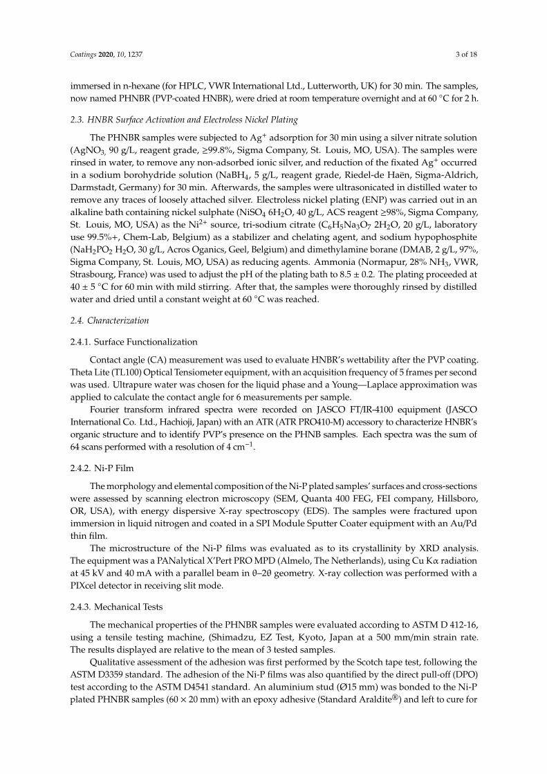
The prepared HNBR samples were then immersed in a 15% PVP:CHCl3 solution after which theswollen samples were immediately quenched in hexane. The surfaces of the PVP-functionalized HNBR(PHNBR) were assessed by ATR-FTIR spectroscopy for 15 and 30 min. ATR-FTIR spectra of the HNBRsurface before and after immersion are shown in Figure 2. The HNBR spectrum, Figure 2a, shows twobands at 2920 and 2850 cm−1, assigned to C-H stretching in the -CH2 butadiene and acrylonitrile groups,respectively [16,23], as well as a band at 913 cm−1 [24], assigned to the -CH=CH2 deformation at theterminal/side, which is characteristic of HNBR. The strong peaks at 1007, 1031, 1097 and 1733 cm−1 areascribed to rubber additives. The band at 1733 cm−1 is related to the C-O-C stretching vibration aspresented by stearic acid or curing agents [25], and the 1007–1100 cm−1 bands may be due to a silicareinforcing agent [26].
Coatings 2020, 10, x FOR PEER REVIEW 5 of 19
The prepared HNBR samples were then immersed in a 15% PVP:CHCl3 solution after which the swollen samples were immediately quenched in hexane. The surfaces of the PVP-functionalized HNBR (PHNBR) were assessed by ATR-FTIR spectroscopy for 15 and 30 min. ATR-FTIR spectra of the HNBR surface before and after immersion are shown in Figure 2. The HNBR spectrum, Figure 2a, shows two bands at 2920 and 2850 cm−1, assigned to C-H stretching in the -CH2 butadiene and acrylonitrile groups, respectively [16,23], as well as a band at 913 cm−1 [24], assigned to the -CH=CH2
deformation at the terminal/side, which is characteristic of HNBR. The strong peaks at 1007, 1031, 1097 and 1733 cm−1 are ascribed to rubber additives. The band at 1733 cm−1 is related to the C-O-C stretching vibration as presented by stearic acid or curing agents [25], and the 1007–1100 cm−1 bands may be due to a silica reinforcing agent [26].
Figure 2. ATR-FTIR spectra of: (a) pristine hydrogenated nitrile butadiene rubber (HNBR), HNBR after immersion in a PVP:CHCl3 solution for (b) 15 min and (c) 30 min and quenching in hexane for 30 min.
After the SPIN surface functionalization, the HNBR peaks in the fingerprint region are shielded by a top layer, Figure 2b,c, and the main characteristic peaks of PVP are detected at 1658 cm−1 (due to the amide carbonyl group), 1460 and 1423 cm−1 (assigned to the -CH2 absorption), and 1290 cm−1
(absorption of the tertiary amine group) [27]. Even though the increased 1658 cm−1 band area may suggest that more PVP is entrapped for 30
min immersion, it was noticed that HNBR samples already show roundness of the edges and corners due to over-swelling. Thus, an immersion time of 15 min was chosen to carefully foster the rise of a PVP SPIN layer on HNBR, yet minimizing the permanent rubber damage due to over-swelling.
After immersing HNBR for 15 min in a 15% (m/v) PVP:CHCl3, elongation at break increased by 11%, while the ultimate tensile strength and Young’s modulus (YM) decreased by 0.3% and 48%, respectively, as shown in Figure 3. These results indicate that HNBR becomes softer after the chloroform treatment. This behavior has been previously reported by other authors [28,29] who studied the influence of PVP on polymeric blends, and observed a decrease in the mechanical properties of the blends, when compared with those of the polymer. The PVP penetration weakens the HNBR inter-chain interactions, thus behaving as a plasticization agent [29]. To note that it was in our best interest to minimize the exposure time to chloroform, for its well-known toxicity. Regretfully its replacement with another solvent was not possible, as PVP solubility is limited to a small number
Figure 2. ATR-FTIR spectra of: (a) pristine hydrogenated nitrile butadiene rubber (HNBR), HNBR afterimmersion in a PVP:CHCl3 solution for (b) 15 min and (c) 30 min and quenching in hexane for 30 min.
After the SPIN surface functionalization, the HNBR peaks in the fingerprint region are shieldedby a top layer, Figure 2b,c, and the main characteristic peaks of PVP are detected at 1658 cm−1 (due tothe amide carbonyl group), 1460 and 1423 cm−1 (assigned to the -CH2 absorption), and 1290 cm−1
(absorption of the tertiary amine group) [27].Even though the increased 1658 cm−1 band area may suggest that more PVP is entrapped for
30 min immersion, it was noticed that HNBR samples already show roundness of the edges and cornersdue to over-swelling. Thus, an immersion time of 15 min was chosen to carefully foster the rise of aPVP SPIN layer on HNBR, yet minimizing the permanent rubber damage due to over-swelling.
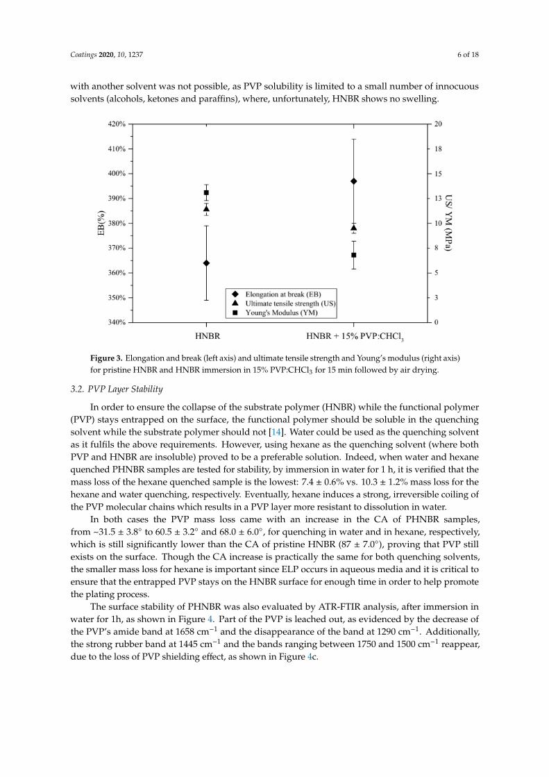
After immersing HNBR for 15 min in a 15% (m/v) PVP:CHCl3, elongation at break increasedby 11%, while the ultimate tensile strength and Young’s modulus (YM) decreased by 0.3% and 48%,respectively, as shown in Figure 3. These results indicate that HNBR becomes softer after the chloroformtreatment. This behavior has been previously reported by other authors [28,29] who studied theinfluence of PVP on polymeric blends, and observed a decrease in the mechanical properties of theblends, when compared with those of the polymer. The PVP penetration weakens the HNBR inter-chaininteractions, thus behaving as a plasticization agent [29]. To note that it was in our best interest tominimize the exposure time to chloroform, for its well-known toxicity. Regretfully its replacement
Coatings 2020, 10, 1237 6 of 18
with another solvent was not possible, as PVP solubility is limited to a small number of innocuoussolvents (alcohols, ketones and paraffins), where, unfortunately, HNBR shows no swelling.
Coatings 2020, 10, x FOR PEER REVIEW 6 of 19
of innocuous solvents (alcohols, ketones and paraffins), where, unfortunately, HNBR shows no swelling.
Figure 3. Elongation and break (left axis) and ultimate tensile strength and Young’s modulus (right axis) for pristine HNBR and HNBR immersion in 15% PVP:CHCl3 for 15 min followed by air drying.
3.2. PVP Layer Stability
In order to ensure the collapse of the substrate polymer (HNBR) while the functional polymer (PVP) stays entrapped on the surface, the functional polymer should be soluble in the quenching solvent while the substrate polymer should not [14]. Water could be used as the quenching solvent as it fulfils the above requirements. However, using hexane as the quenching solvent (where both PVP and HNBR are insoluble) proved to be a preferable solution. Indeed, when water and hexane quenched PHNBR samples are tested for stability, by immersion in water for 1 h, it is verified that the mass loss of the hexane quenched sample is the lowest: 7.4 ± 0.6% vs. 10.3 ± 1.2% mass loss for the hexane and water quenching, respectively. Eventually, hexane induces a strong, irreversible coiling of the PVP molecular chains which results in a PVP layer more resistant to dissolution in water.
In both cases the PVP mass loss came with an increase in the CA of PHNBR samples, from ~31.5 ± 3.8° to 60.5 ± 3.2° and 68.0 ± 6.0°, for quenching in water and in hexane, respectively, which is still significantly lower than the CA of pristine HNBR (87 ± 7.0°), proving that PVP still exists on the surface. Though the CA increase is practically the same for both quenching solvents, the smaller mass loss for hexane is important since ELP occurs in aqueous media and it is critical to ensure that the entrapped PVP stays on the HNBR surface for enough time in order to help promote the plating process.
The surface stability of PHNBR was also evaluated by ATR-FTIR analysis, after immersion in water for 1h, as shown in Figure 4. Part of the PVP is leached out, as evidenced by the decrease of the PVP’s amide band at 1658 cm−1 and the disappearance of the band at 1290 cm−1. Additionally, the strong rubber band at 1445 cm−1 and the bands ranging between 1750 and 1500 cm−1 reappear, due to the loss of PVP shielding effect, as shown in Figure 4c.
Figure 3. Elongation and break (left axis) and ultimate tensile strength and Young’s modulus (right axis)for pristine HNBR and HNBR immersion in 15% PVP:CHCl3 for 15 min followed by air drying.
3.2. PVP Layer Stability
In order to ensure the collapse of the substrate polymer (HNBR) while the functional polymer(PVP) stays entrapped on the surface, the functional polymer should be soluble in the quenchingsolvent while the substrate polymer should not [14]. Water could be used as the quenching solventas it fulfils the above requirements. However, using hexane as the quenching solvent (where bothPVP and HNBR are insoluble) proved to be a preferable solution. Indeed, when water and hexanequenched PHNBR samples are tested for stability, by immersion in water for 1 h, it is verified that themass loss of the hexane quenched sample is the lowest: 7.4 ± 0.6% vs. 10.3 ± 1.2% mass loss for thehexane and water quenching, respectively. Eventually, hexane induces a strong, irreversible coiling ofthe PVP molecular chains which results in a PVP layer more resistant to dissolution in water.
In both cases the PVP mass loss came with an increase in the CA of PHNBR samples,from ~31.5 ± 3.8◦ to 60.5 ± 3.2◦ and 68.0 ± 6.0◦, for quenching in water and in hexane, respectively,which is still significantly lower than the CA of pristine HNBR (87 ± 7.0◦), proving that PVP stillexists on the surface. Though the CA increase is practically the same for both quenching solvents,the smaller mass loss for hexane is important since ELP occurs in aqueous media and it is critical toensure that the entrapped PVP stays on the HNBR surface for enough time in order to help promotethe plating process.
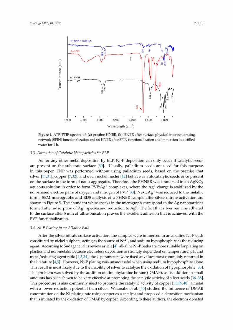
The surface stability of PHNBR was also evaluated by ATR-FTIR analysis, after immersion inwater for 1h, as shown in Figure 4. Part of the PVP is leached out, as evidenced by the decrease ofthe PVP’s amide band at 1658 cm−1 and the disappearance of the band at 1290 cm−1. Additionally,the strong rubber band at 1445 cm−1 and the bands ranging between 1750 and 1500 cm−1 reappear,due to the loss of PVP shielding effect, as shown in Figure 4c.
Coatings 2020, 10, 1237 7 of 18
Coatings 2020, 10, x FOR PEER REVIEW 7 of 19
Figure 4. ATR-FTIR spectra of: (a) pristine HNBR, (b) HNBR after surface physical interpenetrating network (SPIN) functionalization and (c) HNBR after SPIN functionalization and immersion in distilled water for 1 h.
3.3. Formation of Catalytic Nanoparticles for ELP
As for any other metal deposition by ELP, Ni-P deposition can only occur if catalytic seeds are present on the substrate surface [30]. Usually, palladium seeds are used for this purpose. In this paper, ENP was performed without using palladium seeds, based on the premise that silver [11,31], copper [7,32], and even nickel nuclei [12] behave as autocatalytic seeds once present on the surface in the form of nano-aggregates. Therefore, the PHNBR was immersed in an AgNO3 aqueous solution in order to form PVP:Ag+ complexes, where the Ag+ charge is stabilized by the non-shared electron pairs of oxygen and nitrogen of PVP [33]. Next, Ag+ was reduced to the metallic form. SEM micrographs and EDS analysis of a PHNBR sample after silver nitrate activation are shown in Figure 5. The abundant white specks in the micrograph correspond to the Ag nanoparticles formed after adsorption of Ag+ species and reduction to Ag0. The fact that silver remains adhered to the surface after 5 min of ultrasonication proves the excellent adhesion that is achieved with the PVP functionalization.
Figure 5. Scanning electron microscopy (SEM) micrographs of a PVP-coated HNBR (PHNBR) sample after silver nitrate activation and energy dispersive X-ray spectroscopy (EDS) analysis. The white specks correspond to nanoparticles of Ag.
Figure 4. ATR-FTIR spectra of: (a) pristine HNBR, (b) HNBR after surface physical interpenetratingnetwork (SPIN) functionalization and (c) HNBR after SPIN functionalization and immersion in distilledwater for 1 h.
3.3. Formation of Catalytic Nanoparticles for ELP
As for any other metal deposition by ELP, Ni-P deposition can only occur if catalytic seedsare present on the substrate surface [30]. Usually, palladium seeds are used for this purpose.In this paper, ENP was performed without using palladium seeds, based on the premise thatsilver [11,31], copper [7,32], and even nickel nuclei [12] behave as autocatalytic seeds once presenton the surface in the form of nano-aggregates. Therefore, the PHNBR was immersed in an AgNO3
aqueous solution in order to form PVP:Ag+ complexes, where the Ag+ charge is stabilized by thenon-shared electron pairs of oxygen and nitrogen of PVP [33]. Next, Ag+ was reduced to the metallicform. SEM micrographs and EDS analysis of a PHNBR sample after silver nitrate activation areshown in Figure 5. The abundant white specks in the micrograph correspond to the Ag nanoparticlesformed after adsorption of Ag+ species and reduction to Ag0. The fact that silver remains adheredto the surface after 5 min of ultrasonication proves the excellent adhesion that is achieved with thePVP functionalization.
3.4. Ni-P Plating in an Alkaline Bath
After the silver nitrate surface activation, the samples were immersed in an alkaline Ni-P bathconstituted by nickel sulphate, acting as the source of Ni2+, and sodium hypophosphite as the reducingagent. According to Sudagar et al.’s review article [4], alkaline Ni-P baths are more suitable for plating onplastics and non-metals. Because electroless deposition is strongly dependent on temperature, pH andmetal/reducing agent ratio [4,5,34], these parameters were fixed at values most commonly reported inthe literature [4,5]. However, Ni-P plating was unsuccessful when using sodium hypophosphite alone.This result is most likely due to the inability of silver to catalyze the oxidation of hypophosphite [35].This problem was solved by the addition of dimethylamine borane (DMAB), as its addition in smallamounts has been shown to be very effective at promoting the catalytic activity of silver seeds [36–38].This procedure is also commonly used to promote the catalytic activity of copper [35,39,40], a metalwith a lower reduction potential than silver. Watanabe et al. [40] studied the influence of DMABconcentration on the Ni plating rate using copper as a catalyst and proposed a deposition mechanismthat is initiated by the oxidation of DMAB by copper. According to these authors, the electrons donated

Coatings 2020, 10, 1237 8 of 18
by the oxidation of DMAB are used to reduce Ni2+ to Ni0 and, since DMAB is quickly depleted due toits residual concentration, the oxidation reaction of hypophosphite proceeds promoted by the alreadyreduced nickel particles.
Coatings 2020, 10, x FOR PEER REVIEW 7 of 19
Figure 4. ATR-FTIR spectra of: (a) pristine HNBR, (b) HNBR after surface physical interpenetrating network (SPIN) functionalization and (c) HNBR after SPIN functionalization and immersion in distilled water for 1 h.
3.3. Formation of Catalytic Nanoparticles for ELP
As for any other metal deposition by ELP, Ni-P deposition can only occur if catalytic seeds are present on the substrate surface [30]. Usually, palladium seeds are used for this purpose. In this paper, ENP was performed without using palladium seeds, based on the premise that silver [11,31], copper [7,32], and even nickel nuclei [12] behave as autocatalytic seeds once present on the surface in the form of nano-aggregates. Therefore, the PHNBR was immersed in an AgNO3 aqueous solution in order to form PVP:Ag+ complexes, where the Ag+ charge is stabilized by the non-shared electron pairs of oxygen and nitrogen of PVP [33]. Next, Ag+ was reduced to the metallic form. SEM micrographs and EDS analysis of a PHNBR sample after silver nitrate activation are shown in Figure 5. The abundant white specks in the micrograph correspond to the Ag nanoparticles formed after adsorption of Ag+ species and reduction to Ag0. The fact that silver remains adhered to the surface after 5 min of ultrasonication proves the excellent adhesion that is achieved with the PVP functionalization.
Figure 5. Scanning electron microscopy (SEM) micrographs of a PVP-coated HNBR (PHNBR) sample after silver nitrate activation and energy dispersive X-ray spectroscopy (EDS) analysis. The white specks correspond to nanoparticles of Ag.
Figure 5. Scanning electron microscopy (SEM) micrographs of a PVP-coated HNBR (PHNBR) sampleafter silver nitrate activation and energy dispersive X-ray spectroscopy (EDS) analysis. The whitespecks correspond to nanoparticles of Ag.
The Ni-P deposition becomes visible about 2 min after immersion of the silver activated sample,and the reaction progresses with a strong release of gas bubbles starting at the bottom of the sampleand extending to the edges. The gas bubbles are an indication of the reduction mechanism, as arelease of hydrogen ions is a consequence of the reduction of Ni2+ by the hypophosphite ion (H2PO2
−).Phosphorous is formed from the reaction between hypophosphite and the adsorbed hydrogen ions [5].
3.5. Ni-P Film Properties
3.5.1. Morphology and Adhesion
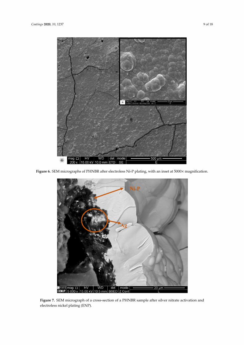
The surface morphology of the Ni-P plated sample is shown in the SEM micrograph of Figure 6.The substrate surface is fully covered by the Ni-P film and a close inspection of the surface of a platedsample, as shown in the inset in Figure 6, leads to the conclusion that the deposition of Ni-P occurs innodules, in a “cauliflower-like” shape common to electroless plated Ni-P metallic alloys. The particlestend to agglomerate close together, forming a non-porous and well compacted film. The cracksobserved on the deposit surface are most likely a consequence of the formation of compressive stressesin the phosphorous deposits [41].
Figure 7 shows the cross-section of the Ni-P plated PHNBR. A homogeneous Ni-P film can beseen, which covers the substrate surface, following the irregular shape of the PHNBR substrate withoutany interfacial free spaces.
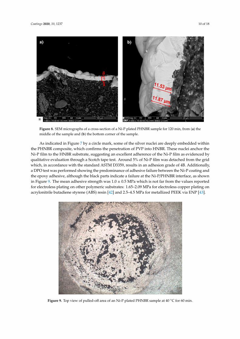
The average thickness of the Ni-P coating is about 3 µm after 60 min plating and, as shown inFigure 8, the thickness increases to ~10–12 µm when the plating time is doubled to 120 min. As theplating starts at the bottom and at the edges around the sample, followed by a lateral growth fromoutside to inside, there is a thickness difference of ~2 µm between the center (Figure 8a) and at theedges (Figure 8b) of the samples.
Coatings 2020, 10, 1237 9 of 18
Coatings 2020, 10, x FOR PEER REVIEW 9 of 19
Figure 6. SEM micrographs of PHNBR after electroless Ni-P plating, with an inset at 5000× magnification.
Figure 7 shows the cross-section of the Ni-P plated PHNBR. A homogeneous Ni-P film can be seen, which covers the substrate surface, following the irregular shape of the PHNBR substrate without any interfacial free spaces.
Figure 7. SEM micrograph of a cross-section of a PHNBR sample after silver nitrate activation and electroless nickel plating (ENP).
The average thickness of the Ni-P coating is about 3 µm after 60 min plating and, as shown in Figure 8, the thickness increases to ~10–12 µm when the plating time is doubled to 120 min. As the
Ni-P
Ag
Figure 6. SEM micrographs of PHNBR after electroless Ni-P plating, with an inset at 5000×magnification.
Coatings 2020, 10, x FOR PEER REVIEW 9 of 19
Figure 6. SEM micrographs of PHNBR after electroless Ni-P plating, with an inset at 5000× magnification.
Figure 7 shows the cross-section of the Ni-P plated PHNBR. A homogeneous Ni-P film can be seen, which covers the substrate surface, following the irregular shape of the PHNBR substrate without any interfacial free spaces.
Figure 7. SEM micrograph of a cross-section of a PHNBR sample after silver nitrate activation and electroless nickel plating (ENP).
The average thickness of the Ni-P coating is about 3 µm after 60 min plating and, as shown in Figure 8, the thickness increases to ~10–12 µm when the plating time is doubled to 120 min. As the
Ni-P
Ag
Figure 7. SEM micrograph of a cross-section of a PHNBR sample after silver nitrate activation andelectroless nickel plating (ENP).
Coatings 2020, 10, 1237 10 of 18
Coatings 2020, 10, x FOR PEER REVIEW 10 of 19
plating starts at the bottom and at the edges around the sample, followed by a lateral growth from outside to inside, there is a thickness difference of ~2 µm between the center (Figure 8a) and at the edges (Figure 8b) of the samples.
Figure 8. SEM micrographs of a cross-section of a Ni-P plated PHNBR sample for 120 min, from (a) the middle of the sample and (b) the bottom corner of the sample.
As indicated in Figure 7 by a circle mark, some of the silver nuclei are deeply embedded within the PHNBR composite, which confirms the penetration of PVP into HNBR. These nuclei anchor the Ni-P film to the HNBR substrate, suggesting an excellent adherence of the Ni-P film as evidenced by qualitative evaluation through a Scotch tape test. Around 5% of Ni-P film was detached from the grid which, in accordance with the standard ASTM D3359, results in an adhesion grade of 4B. Additionally, a DPO test was performed showing the predominance of adhesive failure between the Ni-P coating and the epoxy adhesive, although the black parts indicate a failure at the Ni-P/PHNBR interface, as shown in Figure 9. The mean adhesive strength was 1.0 ± 0.5 MPa which is not far from the values reported for electroless plating on other polymeric substrates: 1.65–2.09 MPa for electroless copper plating on acrylonitrile butadiene styrene (ABS) resin [42] and 2.5–4.5 MPa for metallized PEEK via ENP [43].
Figure 9. Top view of pulled-off area of an Ni-P plated PHNBR sample at 40 °C for 60 min.
Figure 8. SEM micrographs of a cross-section of a Ni-P plated PHNBR sample for 120 min, from (a) themiddle of the sample and (b) the bottom corner of the sample.
As indicated in Figure 7 by a circle mark, some of the silver nuclei are deeply embedded withinthe PHNBR composite, which confirms the penetration of PVP into HNBR. These nuclei anchor theNi-P film to the HNBR substrate, suggesting an excellent adherence of the Ni-P film as evidenced byqualitative evaluation through a Scotch tape test. Around 5% of Ni-P film was detached from the gridwhich, in accordance with the standard ASTM D3359, results in an adhesion grade of 4B. Additionally,a DPO test was performed showing the predominance of adhesive failure between the Ni-P coating andthe epoxy adhesive, although the black parts indicate a failure at the Ni-P/PHNBR interface, as shownin Figure 9. The mean adhesive strength was 1.0 ± 0.5 MPa which is not far from the values reportedfor electroless plating on other polymeric substrates: 1.65–2.09 MPa for electroless copper plating onacrylonitrile butadiene styrene (ABS) resin [42] and 2.5–4.5 MPa for metallized PEEK via ENP [43].
Coatings 2020, 10, x FOR PEER REVIEW 10 of 19
plating starts at the bottom and at the edges around the sample, followed by a lateral growth from outside to inside, there is a thickness difference of ~2 µm between the center (Figure 8a) and at the edges (Figure 8b) of the samples.
Figure 8. SEM micrographs of a cross-section of a Ni-P plated PHNBR sample for 120 min, from (a) the middle of the sample and (b) the bottom corner of the sample.
As indicated in Figure 7 by a circle mark, some of the silver nuclei are deeply embedded within the PHNBR composite, which confirms the penetration of PVP into HNBR. These nuclei anchor the Ni-P film to the HNBR substrate, suggesting an excellent adherence of the Ni-P film as evidenced by qualitative evaluation through a Scotch tape test. Around 5% of Ni-P film was detached from the grid which, in accordance with the standard ASTM D3359, results in an adhesion grade of 4B. Additionally, a DPO test was performed showing the predominance of adhesive failure between the Ni-P coating and the epoxy adhesive, although the black parts indicate a failure at the Ni-P/PHNBR interface, as shown in Figure 9. The mean adhesive strength was 1.0 ± 0.5 MPa which is not far from the values reported for electroless plating on other polymeric substrates: 1.65–2.09 MPa for electroless copper plating on acrylonitrile butadiene styrene (ABS) resin [42] and 2.5–4.5 MPa for metallized PEEK via ENP [43].
Figure 9. Top view of pulled-off area of an Ni-P plated PHNBR sample at 40 °C for 60 min. Figure 9. Top view of pulled-off area of an Ni-P plated PHNBR sample at 40 ◦C for 60 min.

Coatings 2020, 10, 1237 11 of 18
The adhesion and structural integrity of the Ni-P film plated on HNBR were evaluated understrong deformation conditions by using an indirect method, namely by measuring the electricalresistance while bending the samples repetitively at 90◦, as shown in Figure 10. It is apparent thatthe normalized resistance increases sharply upon deformation but rapidly stabilizes around a valuelower than R0 (R/R0 = 0.25–0.36). One should consider that upon sample bending the convex side ofthe film is stretched, whereas the concave side is compressed. The first should translate into a highercracking of the film, leading to a resistance increase, whereas the compression observed on the concaveside will close the fissures, thus decreasing the resistance. In the end, a lower resistance is obtained onthe bent sample. Eventually some of the fissures that existed in the film were closed, forming newconductive paths. When the film is unbent, returning to its original shape, it first reaches a higherresistance, R/R0 = 1.5–2.9. This means that the cracks formed upon bending closed, re-establishingsome conductive paths, although some gaps between the Ni-P islands remained. Looking at thedecreasing trend of R/R0, this also means that the Ni-P structure rearranges such that more adherentislands progressively form. However, further studies are needed to clarify what really happens to theNi-P upon repetitive bending. In the end, the electrical resistance variation due to the mechanical stressis negligible, supporting the conclusion that the film keeps its integrity upon mechanical deformation.No debris were observed whatsoever after several cycles, proving the excellent adhesion of the filmto HNBR.
Coatings 2020, 10, x FOR PEER REVIEW 11 of 19
The adhesion and structural integrity of the Ni-P film plated on HNBR were evaluated under strong deformation conditions by using an indirect method, namely by measuring the electrical resistance while bending the samples repetitively at 90°, as shown in Figure 10. It is apparent that the normalized resistance increases sharply upon deformation but rapidly stabilizes around a value lower than R0 (R/R0 = 0.25–0.36). One should consider that upon sample bending the convex side of the film is stretched, whereas the concave side is compressed. The first should translate into a higher cracking of the film, leading to a resistance increase, whereas the compression observed on the concave side will close the fissures, thus decreasing the resistance. In the end, a lower resistance is obtained on the bent sample. Eventually some of the fissures that existed in the film were closed, forming new conductive paths. When the film is unbent, returning to its original shape, it first reaches a higher resistance, R/R0 = 1.5–2.9. This means that the cracks formed upon bending closed, re-establishing some conductive paths, although some gaps between the Ni-P islands remained. Looking at the decreasing trend of R/R0, this also means that the Ni-P structure rearranges such that more adherent islands progressively form. However, further studies are needed to clarify what really happens to the Ni-P upon repetitive bending. In the end, the electrical resistance variation due to the mechanical stress is negligible, supporting the conclusion that the film keeps its integrity upon mechanical deformation. No debris were observed whatsoever after several cycles, proving the excellent adhesion of the film to HNBR.
Figure 10. Normalized resistance during 90° bending and unbending of Ni-P plated PHNBR samples, in a logarithmic scale.
3.5.2. Composition and Structure
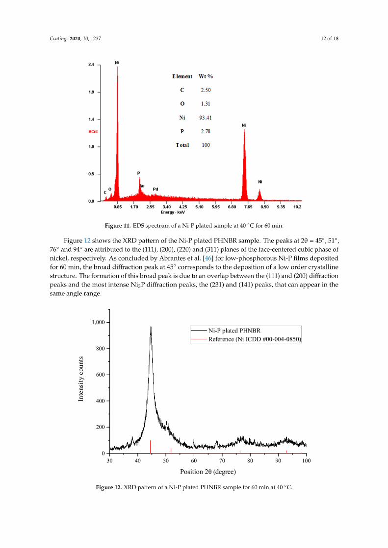
Figure 11 shows an EDS spectrum of the Ni-P plated PHNBR sample deposited at 40 °C for 1 h. As expected, the film consists mostly of nickel and phosphorous. The low phosphorous content (2.78 wt %) is due to the alkaline nature of the plating bath and allows for the classification of the deposit as a low-phosphorous coating [4,5,44,45]. Elemental boron was not detected in the EDS analysis, despite the use of DMAB. Indeed, Wattanabe et al. [40] only found 0.2% of boron in their deposited nickel films (using ~8 g/L of DMAB) while Shao et al. [36] did not detect this element in their silver catalyzed Ni deposition when using 0.2 g/L of DMAB and six times less sodium hypophosphite than that used in this work.
Figure 10. Normalized resistance during 90◦ bending and unbending of Ni-P plated PHNBR samples,in a logarithmic scale.
3.5.2. Composition and Structure
Figure 11 shows an EDS spectrum of the Ni-P plated PHNBR sample deposited at 40 ◦C for 1 h.As expected, the film consists mostly of nickel and phosphorous. The low phosphorous content(2.78 wt %) is due to the alkaline nature of the plating bath and allows for the classification of the depositas a low-phosphorous coating [4,5,44,45]. Elemental boron was not detected in the EDS analysis,despite the use of DMAB. Indeed, Wattanabe et al. [40] only found 0.2% of boron in their depositednickel films (using ~8 g/L of DMAB) while Shao et al. [36] did not detect this element in their silvercatalyzed Ni deposition when using 0.2 g/L of DMAB and six times less sodium hypophosphite thanthat used in this work.
Coatings 2020, 10, 1237 12 of 18
Coatings 2020, 10, x FOR PEER REVIEW 12 of 19
Figure 11. EDS spectrum of a Ni-P plated sample at 40 °C for 60 min.
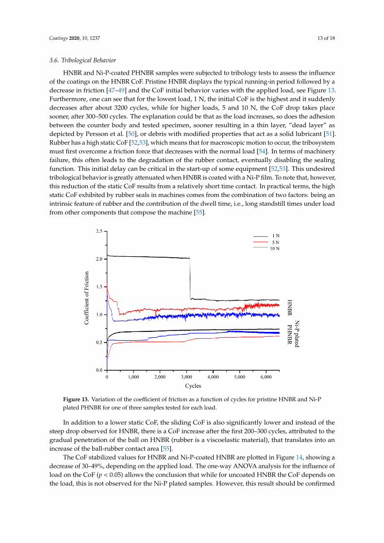
Figure 12 shows the XRD pattern of the Ni-P plated PHNBR sample. The peaks at 2θ = 45°, 51°, 76° and 94° are attributed to the (111), (200), (220) and (311) planes of the face-centered cubic phase of nickel, respectively. As concluded by Abrantes et al. [46] for low-phosphorous Ni-P films deposited for 60 min, the broad diffraction peak at 45° corresponds to the deposition of a low order crystalline structure. The formation of this broad peak is due to an overlap between the (111) and (200) diffraction peaks and the most intense Ni3P diffraction peaks, the (231) and (141) peaks, that can appear in the same angle range.
Figure 12. XRD pattern of a Ni-P plated PHNBR sample for 60 min at 40 °C.
3.6. Tribological Behavior
HNBR and Ni-P-coated PHNBR samples were subjected to tribology tests to assess the influence of the coatings on the HNBR CoF. Pristine HNBR displays the typical running-in period followed by
Figure 11. EDS spectrum of a Ni-P plated sample at 40 ◦C for 60 min.
Figure 12 shows the XRD pattern of the Ni-P plated PHNBR sample. The peaks at 2θ = 45◦, 51◦,76◦ and 94◦ are attributed to the (111), (200), (220) and (311) planes of the face-centered cubic phase ofnickel, respectively. As concluded by Abrantes et al. [46] for low-phosphorous Ni-P films depositedfor 60 min, the broad diffraction peak at 45◦ corresponds to the deposition of a low order crystallinestructure. The formation of this broad peak is due to an overlap between the (111) and (200) diffractionpeaks and the most intense Ni3P diffraction peaks, the (231) and (141) peaks, that can appear in thesame angle range.
Coatings 2020, 10, x FOR PEER REVIEW 12 of 19
Figure 11. EDS spectrum of a Ni-P plated sample at 40 °C for 60 min.
Figure 12 shows the XRD pattern of the Ni-P plated PHNBR sample. The peaks at 2θ = 45°, 51°, 76° and 94° are attributed to the (111), (200), (220) and (311) planes of the face-centered cubic phase of nickel, respectively. As concluded by Abrantes et al. [46] for low-phosphorous Ni-P films deposited for 60 min, the broad diffraction peak at 45° corresponds to the deposition of a low order crystalline structure. The formation of this broad peak is due to an overlap between the (111) and (200) diffraction peaks and the most intense Ni3P diffraction peaks, the (231) and (141) peaks, that can appear in the same angle range.
Figure 12. XRD pattern of a Ni-P plated PHNBR sample for 60 min at 40 °C.
3.6. Tribological Behavior
HNBR and Ni-P-coated PHNBR samples were subjected to tribology tests to assess the influence of the coatings on the HNBR CoF. Pristine HNBR displays the typical running-in period followed by
Figure 12. XRD pattern of a Ni-P plated PHNBR sample for 60 min at 40 ◦C.
Coatings 2020, 10, 1237 13 of 18
3.6. Tribological Behavior
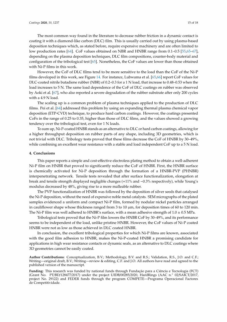
HNBR and Ni-P-coated PHNBR samples were subjected to tribology tests to assess the influenceof the coatings on the HNBR CoF. Pristine HNBR displays the typical running-in period followed by adecrease in friction [47–49] and the CoF initial behavior varies with the applied load, see Figure 13.Furthermore, one can see that for the lowest load, 1 N, the initial CoF is the highest and it suddenlydecreases after about 3200 cycles, while for higher loads, 5 and 10 N, the CoF drop takes placesooner, after 300–500 cycles. The explanation could be that as the load increases, so does the adhesionbetween the counter body and tested specimen, sooner resulting in a thin layer, “dead layer” asdepicted by Persson et al. [50], or debris with modified properties that act as a solid lubricant [51].Rubber has a high static CoF [52,53], which means that for macroscopic motion to occur, the tribosystemmust first overcome a friction force that decreases with the normal load [54]. In terms of machineryfailure, this often leads to the degradation of the rubber contact, eventually disabling the sealingfunction. This initial delay can be critical in the start-up of some equipment [52,53]. This undesiredtribological behavior is greatly attenuated when HNBR is coated with a Ni-P film. To note that, however,this reduction of the static CoF results from a relatively short time contact. In practical terms, the highstatic CoF exhibited by rubber seals in machines comes from the combination of two factors: being anintrinsic feature of rubber and the contribution of the dwell time, i.e., long standstill times under loadfrom other components that compose the machine [55].
Coatings 2020, 10, x FOR PEER REVIEW 13 of 19
a decrease in friction [47–49] and the CoF initial behavior varies with the applied load, see Figure 13. Furthermore, one can see that for the lowest load, 1 N, the initial CoF is the highest and it suddenly decreases after about 3200 cycles, while for higher loads, 5 and 10 N, the CoF drop takes place sooner, after 300–500 cycles. The explanation could be that as the load increases, so does the adhesion between the counter body and tested specimen, sooner resulting in a thin layer, “dead layer” as depicted by Persson et al. [50], or debris with modified properties that act as a solid lubricant [51]. Rubber has a high static CoF [52,53], which means that for macroscopic motion to occur, the tribosystem must first overcome a friction force that decreases with the normal load [54]. In terms of machinery failure, this often leads to the degradation of the rubber contact, eventually disabling the sealing function. This initial delay can be critical in the start-up of some equipment [52,53]. This undesired tribological behavior is greatly attenuated when HNBR is coated with a Ni-P film. To note that, however, this reduction of the static CoF results from a relatively short time contact. In practical terms, the high static CoF exhibited by rubber seals in machines comes from the combination of two factors: being an intrinsic feature of rubber and the contribution of the dwell time, i.e., long standstill times under load from other components that compose the machine [55].
Figure 13. Variation of the coefficient of friction as a function of cycles for pristine HNBR and Ni-P plated PHNBR for one of three samples tested for each load.
In addition to a lower static CoF, the sliding CoF is also significantly lower and instead of the steep drop observed for HNBR, there is a CoF increase after the first 200–300 cycles, attributed to the gradual penetration of the ball on HNBR (rubber is a viscoelastic material), that translates into an increase of the ball-rubber contact area [55].
The CoF stabilized values for HNBR and Ni-P-coated HNBR are plotted in Figure 14, showing a decrease of 30–49%, depending on the applied load. The one-way ANOVA analysis for the influence of load on the CoF (p < 0.05) allows the conclusion that while for uncoated HNBR the CoF depends on the load, this is not observed for the Ni-P plated samples. However, this result should be confirmed with a more significant number of samples. It is noteworthy to mention that the CoF values obtained are within the range of those usually measured on Ni-P plated metallic parts such as steel [56–58].
Figure 13. Variation of the coefficient of friction as a function of cycles for pristine HNBR and Ni-Pplated PHNBR for one of three samples tested for each load.
In addition to a lower static CoF, the sliding CoF is also significantly lower and instead of thesteep drop observed for HNBR, there is a CoF increase after the first 200–300 cycles, attributed to thegradual penetration of the ball on HNBR (rubber is a viscoelastic material), that translates into anincrease of the ball-rubber contact area [55].
The CoF stabilized values for HNBR and Ni-P-coated HNBR are plotted in Figure 14, showing adecrease of 30–49%, depending on the applied load. The one-way ANOVA analysis for the influence ofload on the CoF (p < 0.05) allows the conclusion that while for uncoated HNBR the CoF depends onthe load, this is not observed for the Ni-P plated samples. However, this result should be confirmed

Coatings 2020, 10, 1237 14 of 18
with a more significant number of samples. It is noteworthy to mention that the CoF values obtainedare within the range of those usually measured on Ni-P plated metallic parts such as steel [56–58].Coatings 2020, 10, x FOR PEER REVIEW 14 of 19
Figure 14. Mean and standard deviation of the CoF for the last 1000 cycles of the pin-on-disc test for pristine HNBR and Ni-P plated PHNBR for each load.
Finally, a prolonged (69,000 cycles) pin-on-disc test with a 5 N load was performed, in order to test the tribological behavior of the films in limit conditions. Even though the CoF increased to 0.68, it is still ~40% lower than that of pristine HNBR, see Figure 15. The SEM micrograph of the wear track after the pin-on-disc test shows that the cauliflower shaped Ni-P film seen in Figure 6 disappeared and the wear debris are visible, together with grooves in the direction of the pin movement. This is an indication of abrasive wear, in good agreement with the predominant wear mechanism of ENP films [59–63]. However, the film remains fully functional, as attested from the final CoF value.
Figure 15. Variation of the coefficient of friction of Ni-P plated PHNBR sample at 5 N for 69,000 cycles and SEM micrograph of the sample after the test.
The most common way found in the literature to decrease rubber friction in a dynamic contact is coating it with a diamond-like carbon (DLC) film. This is usually carried out by using plasma-based deposition techniques which, as stated before, require expensive machinery and are often limited to
Figure 14. Mean and standard deviation of the CoF for the last 1000 cycles of the pin-on-disc test forpristine HNBR and Ni-P plated PHNBR for each load.
Finally, a prolonged (69,000 cycles) pin-on-disc test with a 5 N load was performed, in order totest the tribological behavior of the films in limit conditions. Even though the CoF increased to 0.68,it is still ~40% lower than that of pristine HNBR, see Figure 15. The SEM micrograph of the wear trackafter the pin-on-disc test shows that the cauliflower shaped Ni-P film seen in Figure 6 disappearedand the wear debris are visible, together with grooves in the direction of the pin movement. This isan indication of abrasive wear, in good agreement with the predominant wear mechanism of ENPfilms [59–63]. However, the film remains fully functional, as attested from the final CoF value.
Coatings 2020, 10, x FOR PEER REVIEW 14 of 19
Figure 14. Mean and standard deviation of the CoF for the last 1000 cycles of the pin-on-disc test for pristine HNBR and Ni-P plated PHNBR for each load.
Finally, a prolonged (69,000 cycles) pin-on-disc test with a 5 N load was performed, in order to test the tribological behavior of the films in limit conditions. Even though the CoF increased to 0.68, it is still ~40% lower than that of pristine HNBR, see Figure 15. The SEM micrograph of the wear track after the pin-on-disc test shows that the cauliflower shaped Ni-P film seen in Figure 6 disappeared and the wear debris are visible, together with grooves in the direction of the pin movement. This is an indication of abrasive wear, in good agreement with the predominant wear mechanism of ENP films [59–63]. However, the film remains fully functional, as attested from the final CoF value.
Figure 15. Variation of the coefficient of friction of Ni-P plated PHNBR sample at 5 N for 69,000 cycles and SEM micrograph of the sample after the test.
The most common way found in the literature to decrease rubber friction in a dynamic contact is coating it with a diamond-like carbon (DLC) film. This is usually carried out by using plasma-based deposition techniques which, as stated before, require expensive machinery and are often limited to
Figure 15. Variation of the coefficient of friction of Ni-P plated PHNBR sample at 5 N for 69,000 cyclesand SEM micrograph of the sample after the test.
Coatings 2020, 10, 1237 15 of 18
The most common way found in the literature to decrease rubber friction in a dynamic contact iscoating it with a diamond-like carbon (DLC) film. This is usually carried out by using plasma-baseddeposition techniques which, as stated before, require expensive machinery and are often limited tolow production rates [64]. CoF values obtained on NBR and HNBR range from 0.1–0.5 [55,65–67],depending on the plasma deposition techniques, DLC film compositions, counter-body material andconfiguration of the tribological test [65]. Nonetheless, the CoF values are lower than those obtainedwith Ni-P films in this work.
However, the CoF of DLC films tend to be more sensitive to the load than the CoF of the Ni-Pfilms developed in this work, see Figure 14. For instance, Lubwama et al. [65,66] report CoF values forDLC-coated nitrile butadiene rubber (NBR) of 0.2–0.3 for a 1 N load, that increase to 0.48–0.53 when theload increases to 5 N. The same load dependence of the CoF of DLC coatings on rubber was observedby Aoki et al. [67], who also reported a severe degradation of the rubber substrate after only 200 cycleswith a 4.9 N load.
The scaling up is a common problem of plasma techniques applied to the production of DLCfilms. Pei et al. [64] addressed this problem by using an expanding thermal plasma chemical vapordeposition (ETP-CVD) technique, to produce hard carbon coatings. However, the coatings presentedCoFs in the range of 0.25 to 0.35, higher than those of DLC films, and the values showed a growingtendency over the tribological test, even for 1 N loads.
To sum up, Ni-P-coated HNBR stands as an alternative to DLC or hard carbon coatings, allowing fora higher throughput deposition on rubber parts of any shape, including 3D geometries, which isnot trivial with DLC. Tribology tests proved that these films decrease the CoF of HNBR by 30–49%,while combining an excellent wear resistance with a stable and load independent CoF up to a 5 N load.
4. Conclusions
This paper reports a simple and cost-effective electroless plating method to obtain a well-adherentNi-P film on HNBR that proved to significantly reduce the CoF of HNBR. First, the HNBR surfaceis chemically activated for Ni-P deposition through the formation of a HNBR-PVP (PHNBR)interpenetrating network. Tensile tests revealed that after surface functionalization, elongation atbreak and tensile strength displayed negligible changes (+11% and −0.3% respectively), while Young’smodulus decreased by 48%, giving rise to a more malleable rubber.
The PVP functionalization of HNBR was followed by the deposition of silver seeds that catalysedthe Ni-P deposition, without the need of expensive noble metal catalysts. SEM micrographs of the platedsamples evidenced a uniform and compact Ni-P film, formed by nodular nickel particles arrangedin cauliflower shape whose thickness ranged from 3 to 10 µm, for deposition times of 60 to 120 min.The Ni-P film was well adhered to HNBR’s surface, with a mean adhesive strength of 1.0 ± 0.5 MPa.
Tribological tests proved that the Ni-P film lowers the HNBR CoF by 30–49%, and its performanceseems to be independent of the load, unlike pristine HNBR. However, the CoF values of Ni-P coatedHNBR were not as low as those achieved in DLC coated HNBR.
In conclusion, the excellent tribological properties for which Ni-P films are known, associatedwith the good film adhesion to HNBR, makes the Ni-P-coated HNBR a promising candidate forapplications in high wear resistance contacts or dynamic seals, as an alternative to DLC coatings where3D geometries cannot be easily coated.
Author Contributions: Conceptualization, B.V.; Methodology, B.V. and R.S.; Validation, R.S., J.O. and C.F.;Writing—original draft, B.V.; Writing—review & editing, C.F. and J.O. All authors have read and agreed to thepublished version of the manuscript.
Funding: This research was funded by national funds through Fundação para a Ciência e Tecnologia (FCT)(Grant No. PT/BD/128477/2017) under the project UIDB/00285/2020, HardRings (AAC n.◦ 02/SAICT/2017,project No. 29122) and FEDER funds through the program COMPETE—Programa Operacional Factoresde Competitividade.
Coatings 2020, 10, 1237 16 of 18
Acknowledgments: The authors would like to acknowledge CEMUP for SEM analysis.
Conflicts of Interest: The authors declare no conflict of interest. The funders had no role in the design of thestudy; in the collection, analyses, or interpretation of data; in the writing of the manuscript, or in the decision topublish the results.
References
1. Affonso, L.O.A. Machinery Failure Analysis Handbook: Sustain Your Operations and Maximize Uptime; Elsevier:Amsterdam, The Netherlands, 2013.
2. Flitney, R.K. Seals and Sealing Handbook; Elsevier: Amsterdam, The Netherlands, 2011.3. Lubwama, M.; Corcoran, B.; Sayers, K. DLC films deposited on rubber substrates: A review. Surf. Eng. 2014,
31, 1–10. [CrossRef]4. Sudagar, J.; Lian, J.; Sha, W. Electroless nickel, alloy, composite and nano coatings—A critical review.
J. Alloys Compd. 2013, 571, 183–204. [CrossRef]5. Loto, C.A. Electroless Nickel Plating-A Review. Silicon 2016, 8, 177–186. [CrossRef]6. Garcia, A.; Polesel-Maris, J.; Viel, P.; Palacin, S.; Berthelot, T. Localized Ligand Induced Electroless Plating
(LIEP) Process for the Fabrication of Copper Patterns onto Flexible Polymer Substrates. Adv. Funct. Mater.2011, 21, 2096–2102. [CrossRef]
7. Garcia, A.; Berthelot, T.; Viel, P.; Mesnage, A.; Jégou, P.; Nekelson, F.; Roussel, S.; Palacin, S. ABS PolymerElectroless Plating through a One-Step Poly(acrylic acid) Covalent Grafting. ACS Appl. Mater. Interfaces 2010,2, 1177–1183. [CrossRef] [PubMed]
8. Garcia, A.; Berthelot, T.; Viel, P.; Polesel-Maris, J.; Palacin, S. Microscopic Study of a Ligand InducedElectroless Plating Process onto Polymers. ACS Appl. Mater. Interfaces 2010, 2, 3043–3051. [CrossRef]
9. Olivera, S.; Muralidhara, H.; Venkatesh, K.; Gopalakrishna, K.; Vivek, C.S. Plating on acrylonitrile-butadiene-styrene (ABS) plastic: A review. J. Mater. Sci. 2016, 51, 3657–3674. [CrossRef]
10. Du, W.; Zou, H.; Tian, M.; Zhang, L.; Wang, W. Electrically conductive acrylonitrile-butadiene rubberelastomers prepared by dopamine-induced surface functionalization and metallization. Polym. Adv. Technol.2011, 23, 1029–1035. [CrossRef]
11. Vasconcelos, B.; Vediappan, K.; Oliveira, J.; Fonseca, C. Mechanically robust silver coatings prepared byelectroless plating on thermoplastic polyurethane. Appl. Surf. Sci. 2018, 443, 39–47. [CrossRef]
12. Tang, X.; Wang, J.; Wang, C.; Shen, B. A novel surface activation method for Ni/Au electroless plating ofacrylonitrile–butadiene–styrene. Surf. Coatings Technol. 2011, 206, 1382–1388. [CrossRef]
13. Klingender, R.C. (Ed.) Handbook of Specialty Elastomers; Informa UK Limited: Abingdon, Oxfordshire, UK, 2008.14. Desai, N.P.; Hubbell, J.A. Solution technique to incorporate polyethylene oxide and other water-soluble
polymers into surfaces of polymeric biomaterials. Biomaterials 1991, 12, 144–153. [CrossRef]15. Khalifa, O.R.; Sakr, E. Electroless Nickel-Phosphorus-Polymer Composite Coatings. Open Corros. J. 2009,
2, 211–215. [CrossRef]16. Perraud, S.; Vallat, M.-F.; David, M.-O.; Kuczynski, J. Network characteristics of hydrogenated nitrile
butadiene rubber networks obtained by radiation crosslinking by electron beam. Polym. Degrad. Stab. 2010,95, 1495–1501. [CrossRef]
17. Wang, M.-Q.; Yan, J.; Du, S.-G.; Li, H. Electroless plating of PVC plastic through new surface modificationmethod applying a semi-IPN hydrogel film. Appl. Surf. Sci. 2013, 277, 249–256. [CrossRef]
18. Pandey, A.; Manivannan, R. Chemical reduction technique for the synthesis of nickel nanoparticles. Int. J.Eng. Res. Appl. 2015, 5, 96–100.
19. Mafi, I.R.; Dehghanian, C. Comparison of the coating properties and corrosion rates in electroless Ni–P/PTFEcomposites prepared by different types of surfactants. Appl. Surf. Sci. 2011, 257, 8653–8658. [CrossRef]
20. Kim, J.H.; Min, B.R.; Won, J.; Joo, S.H.; Kim, H.S.; Kang, Y.S. Role of Polymer Matrix in Polymer/Silver Complexesfor Structure, Interactions, and Facilitated Olefin Transport. Macromolecules 2003, 36, 6183–6188. [CrossRef]
21. Sivaiah, K.; Kumar, K.N.; Naresh, V.; Buddhudu, S. Structural and Optical Properties of Li+: PVP & Ag+:PVP Polymer Films. Mater. Sci. Appl. 2011, 2, 1688–1696. [CrossRef]
22. Guo, R.; Wen, J.; Gao, Y.; Li, T.; Yan, H.; Wang, H.; Niu, B.; Jiang, K. Effect of the adhesion of Ag coatings onthe effectiveness and durability of antibacterial properties. J. Mater. Sci. 2018, 53, 4759–4767. [CrossRef]
Coatings 2020, 10, 1237 17 of 18
23. Passador, F.R.; Rodolfo, A., Jr.; Pessan, L.A. In Situ Dynamic Vulcanization of Poly (Vinyl Chloride)/Acrylonitrile-butadiene Rubber Blends. J. Macromol. Sci. Part B 2009, 48, 282–298. [CrossRef]
24. Sanches, N.B.; Pedro, R.; Diniz, M.F.; Mattos, E.D.C.; Cassu, S.N.; Dutra, R.D.C.L. Infrared Spectroscopy Appliedto Materials Used as Thermal Insulation and Coatings. J. Aerosp. Technol. Manag. 2013, 5, 421–430. [CrossRef]
25. Lou, W.; Zhang, W.; Liu, X.; Dai, W.; Xu, D. Degradation of hydrogenated nitrile rubber (HNBR) O-ringsexposed to simulated servo system conditions. Polym. Degrad. Stab. 2017, 144, 464–472. [CrossRef]
26. Kim, J.-T.; Lee, D.-Y.; Oh, T.-S. Characteristics of nitrile-butadiene rubber layered silicate nanocompositeswith silane coupling agent. J. Appl. Polym. Sci. 2003, 89, 2633–2640. [CrossRef]
27. Peng, C.; Hou, Z.; Zhang, C.; Li, G.; Lian, H.; Cheng, Z.; Lin, J. Synthesis and luminescent propertiesof CaTiO3: Pr3+ microfibers prepared by electrospinning method. Opt. Express 2010, 18, 7543–7553.[CrossRef] [PubMed]
28. Salih, S.I.; Jabur, A.R.; Mohammed, T. The Effect of PVP Addition on the Mechanical Properties of TernaryPolymer Blends. In Proceedings of the IOP Conference Series: Materials Science and Engineering, Kerbala,Iraq, 26–27 March 2018; p. 012071.
29. Ravindra, C.; Sarswati, M.; Sukanya, G.; Shivalila, P.; Soumya, Y.; Deepak, K. Tensile and thermal propertiesof poly (vinyl) pyrrolidone/vanillin incorporated polyvinyl alcohol films. Res. J. Phys. Sci. 2015, 3, 1–6.
30. Krishnan, K.H.; John, S.; Srinivasan, K.N.; Praveen, J.; Ganesan, M.; Kavimani, P.M. An overall aspect ofelectroless Ni-P depositions-A review article. Met. Mater. Trans. A 2006, 37, 1917–1926. [CrossRef]
31. Pang, H.; Bai, R.; Shao, Q.; Gao, Y.; Li, A.; Tang, Z. A novel Ag catalyzation process using swelling impregnationmethod for electroless Ni deposition on Kevlar® fiber. Appl. Surf. Sci. 2015, 359, 280–287. [CrossRef]
32. Li, W.; Shi, G.; Lu, Y. Copper-catalyzed electroless nickel coating on poly(ethylene terephthalate) board forelectromagnetic application. Int. J. Mater. Res. 2014, 105, 797–801. [CrossRef]
33. Zhang, Z.; Zhao, B.; Hu, L. PVP Protective Mechanism of Ultrafine Silver Powder Synthesized by ChemicalReduction Processes. J. Solid State Chem. 1996, 121, 105–110. [CrossRef]
34. Mallory, G.O.; Hajdu, J.B. Electroless Plating: Fundamentals and Applications; William Andrew: Orlando, FL,USA, 1990.
35. Zenkiewicz, M.; Moraczewski, K.; Rytlewski, P.; Stepczynska, M.; Jagodzinski, B. Electroless metallization ofpolymers. Arch. Mater. Sci. Eng. 2015, 74, 67–76.
36. Shao, Q.-S.; Bai, R.-C.; Tang, Z.-Y.; Gao, Y.-F.; Sun, J.-L.; Ren, M.-S. Durable electroless Ni and Ni-P-B platingon aromatic polysulfonamide (PSA) fibers with different performances via chlorine-aided silver activationstrategy. Surf. Coat. Technol. 2016, 302, 185–194. [CrossRef]
37. Lu, Y.; Xue, L.; Li, F. Silver nanoparticle catalyst for electroless Ni deposition and the promotion of itsadsorption onto PET substrate. Surf. Coat. Technol. 2010, 205, 519–524. [CrossRef]
38. Fatema, U.K.; Gotoh, Y. Iodine-aided palladium-free catalyzation process for durable electroless nickelplating on Kevlar® fiber. Surf. Coat. Technol. 2012, 206, 3472–3478. [CrossRef]
39. Hajdu, J.; Mallory, G.O. Electroless Plating: Fundamentals and Applications; American Electroplaters and SurfaceFinishers Society: Orlando, FL, USA, 1990; pp. 193–206.
40. Watanabe, H.; Honma, H. Direct electroless nickel plating on copper circuits using DMAB as a secondreducing agent. In Proceedings of the 2nd 1998 IEMT/IMC Symposium (IEEE Cat. No.98EX225), Tokyo,Japan, 15–17 April 1998; pp. 149–153.
41. Meyer, J. Eigenschaften und Anwendungen von Chemisch Nickel-Dispersionsschichten. Mater. Werkst. 2008,39, 958–962. [CrossRef]
42. Han, X.; Wang, G.; He, Y.; Wang, Y.; Qiao, Y.; Zhang, L. Surface modification of ABS with Cr6+ free etchingprocess in the electroless plating. J. Adhes. Sci. Technol. 2018, 32, 2481–2493. [CrossRef]
43. Zhai, T.; Chen, J.; Gui, B.; Wang, Q.; Yang, D.A. Electroless Deposition of Ni-P on Poly (ether etherketone)/Multi-Walled Carbon Nanotubes Composite and Improvement of the Electrical Conductivity inDirection of Thickness. J. Electrochem. Soc. 2015, 162, D613–D618. [CrossRef]
44. Agarwala, R.C.; Agarwala, V. Electroless alloy/composite coatings: A review. Sadhana 2003, 28, 475–493. [CrossRef]45. Schlesinger, M. Electroless Deposition of Nickel. Mod. Electroplat. 2011, 4, 447–458. [CrossRef]46. Abrantes, L.M.; Fundo, A.; Jin, G. Influence of phosphorus content on the structure of nickel electroless
deposits. J. Mater. Chem. 2001, 11, 200–203. [CrossRef]47. Mofidi, M.; Prakash, B. Influence of counterface topography on sliding friction and wear of some elastomers
under dry sliding conditions. Proc. Inst. Mech. Eng. Part J J. Eng. Tribol. 2008, 222, 667–673. [CrossRef]
Coatings 2020, 10, 1237 18 of 18
48. Thirumalai, S.; Hausberger, A.; Lackner, J.; Waldhauser, W.; Schwarz, T. Effect of the type of elastomericsubstrate on the microstructural, surface and tribological characteristics of diamond-like carbon (DLC)coatings. Surf. Coat. Technol. 2016, 302, 244–254. [CrossRef]
49. Shen, M.-X.; Dong, F.; Zhang, Z.-X.; Meng, X.-K.; Peng, X. Effect of abrasive size on friction and wearcharacteristics of nitrile butadiene rubber (NBR) in two-body abrasion. Tribol. Int. 2016, 103, 1–11. [CrossRef]
50. Persson, B.N.J. Rubber friction: Role of the flash temperature. J. Phys. Condens. Matter 2006, 18, 7789–7823.[CrossRef] [PubMed]
51. Baek, D.K.; Khonsari, M. Fretting behavior of a rubber coating: Friction characteristics of rubber debris. Wear2006, 261, 1114–1120. [CrossRef]
52. Mang, T.; Bobzin, K.; Bartels, T. Industrial Tribology: Tribosystems, Friction, Wear and Surface Engineering,Lubrication; John Wiley & Sons: Hoboken, NJ, USA, 2011.
53. Tuononen, A.J. Onset of frictional sliding of rubber–glass contact under dry and lubricated conditions.Sci. Rep. 2016, 6, 27951. [CrossRef] [PubMed]
54. Brizmer, V.; Kligerman, Y.; Etsion, I. Elastic–plastic spherical contact under combined normal and tangentialloading in full stick. Tribol. Lett. 2006, 25, 61–70. [CrossRef]
55. Martinez-Martinez, D.; De Hosson, J. On the deposition and properties of DLC protective coatings onelastomers: A critical review. Surf. Coat. Technol. 2014, 258, 677–690. [CrossRef]
56. Saravanan, I.; Elayaperumal, A.; Devaraju, A.; Karthikeyan, M.; Raji, A. Wear behaviour of electroless Ni-Pand Ni-P-TiO2 composite coatings on En8 steel. Mater. Today Proc. 2020, 22, 1135–1139. [CrossRef]
57. Tamilarasan, T.R.; Sanjith, U.; Rajendran, R.; Rajagopal, G.; Sudagar, J. Effect of Reduced Graphene OxideReinforcement on the Wear Characteristics of Electroless Ni-P Coatings. J. Mater. Eng. Perform. 2018,27, 3044–3053. [CrossRef]
58. Chang, S.-H.; Chang, C.-C.; Liang, C. Electroless Ni-P plating and Heat Treatments on S45C Carbon Steel.IOP Conf. Ser. Mater. Sci. Eng. 2013, 46, 012003. [CrossRef]
59. Gawne, D.; Ma, U. Wear mechanisms in electroless nickel coatings. Wear 1987, 120, 125–149. [CrossRef]60. Sahoo, P.; Das, S.K. Tribology of electroless nickel coatings—A review. Mater. Des. 2011, 32, 1760–1775. [CrossRef]61. Kanani, N. Tribological Behaviour of Electroless Nickel. Trans. IMF 1992, 70, 14–18. [CrossRef]62. Behera, A.; Sahoo, A.K. Wear behaviour of Ni based superalloy: A review. Mater. Today Proc. 2020. [CrossRef]63. Mukhopadhyay, A.; Barman, T.K.; Sahoo, P. Normal Partitions and Hierarchical Fillings of N-Dimensional Spaces;
IGI Global: Hershey, PA, USA, 2018; pp. 297–331.64. Pei, Y.T.; Eivani, A.; Zaharia, T.; Kazantzis, A.; Van De Sanden, M.R.; De Hosson, J.T.M. High throughput
deposition of hydrogenated amorphous carbon coatings on rubber with expanding thermal plasma.Surf. Coatings Technol. 2014, 245, 74–83. [CrossRef]
65. Lubwama, M.; Corcoran, B.; McDonnell, K.; Dowling, D.; Kirabira, J.; Sebbit, A.; Sayers, K. Flexibility andfrictional behaviour of DLC and Si-DLC films deposited on nitrile rubber. Surf. Coat. Technol. 2014, 239, 84–94.[CrossRef]
66. Lubwama, M.; McDonnell, K.; Kirabira, J.; Sebbit, A.; Sayers, K.; Dowling, D.; Corcoran, B. Characteristicsand tribological performance of DLC and Si-DLC films deposited on nitrile rubber. Surf. Coat. Technol. 2012,206, 4585–4593. [CrossRef]
67. Aoki, Y.; Ohtake, N. Tribological properties of segment-structured diamond-like carbon films. Tribol. Int.2004, 37, 941–947. [CrossRef]
Publisher’s Note: MDPI stays neutral with regard to jurisdictional claims in published maps and institutionalaffiliations.
© 2020 by the authors. Licensee MDPI, Basel, Switzerland. This article is an open accessarticle distributed under the terms and conditions of the Creative Commons Attribution(CC BY) license (http://creativecommons.org/licenses/by/4.0/).