
Liquid electrolyte development for low-temperature lithium-ion ...
Upload
uni-erlangenCategory
view
0download
0
Research article
Received: 12 July 2013 Revised: 10 December 2013 Accepted: 12 December 2013 Published online in Wiley Online Library: 5 February 2014
(wileyonlinelibrary.com) DOI 10.1002/sia.5364
186
Electrochemical behavior in simulated body fluidof TiO2 nanotubes on TiAlNb alloy elaborated invarious anodizing electrolyteAnca Mazare,a,b Mirela Dilea,a,c Daniela Ionitaa* and Ioana Demetrescua
The present study is focused on tailoring the morphology of TiO2 nanotubes obtained on Ti6Al7Nb alloy and evaluating theirelectrochemical behavior in simulated body fluid. The presence of the α and β phases on the Ti6Al7Nb alloy leads to a two-scaleorganization of the nanotubes on the samples – which in turn affects the electrochemical stability. Furthermore, five differenttypes of TiO2 nanotubes were obtained in various electrolytes (e.g. Generation I, a mixture of Generation II and Generation III,Generation III). Electrochemical behavior analysis of all obtained nanotubes morphologies was composed of Tafel plots, cyclicvoltammetry and electrochemical impedance spectroscopy and was correlated with morphology data obtained from SEM(nanotubes diameters from top-view and nanotube length from cross-section view). The electrochemical results showed thatmorphologicalmodifications of the Ti6Al7Nb alloy’s surface by electrochemical anodizing have induced changes to the electrochemicalbehavior of the material, evident in the corrosion rates. Copyright © 2014 John Wiley & Sons, Ltd.
Keywords: Ti6Al7Nb; anodization; TiO2 nanotubes; SEM; cyclic voltammetry; EIS
* Correspondence to: D. Ionita, University Politehnica Bucharest, Faculty of AppliedChemistry and Materials Science, Polizu no 1-7, 011061, Bucharest, Romania.E-mail: [email protected]
a Faculty of Applied Chemistry and Materials Science, University PolitehnicaBucharest, Polizu no 1-7, 011061, Bucharest, Romania
b Present address: Department of Materials Science and Engineering, UniversityErlangen–Nuremberg, WW4-LKO, Martensstrasse 7, D-91058, Erlangen, Germany
c Present address: Faculty of Biotechnical Systems Engineering, UniversityPolitehnica Bucharest, 313 Splaiul Independentei, 060042, Bucharest, Romania
Introduction
Electrochemical stability in bioliquids is one of themost importantcharacteristics of metallic surgical implants, as Ti and Ti alloys,[1,2]
and was intensively studied in various media[3–5] and at differenttemperatures.[6] One of the recently used procedures in order toimprove corrosion behavior of such implants consists in buildingnanoarchitectures as nanotubes on the metallic substrate.[7–9]
Nowadays, TiO2 nanotubes are relatively easily obtained byelectrochemical anodizing.[10–12] However, currently, the emphasisis on tailoring themorphology[13] of nanostructures in order to bettercorrelate with their intended applications. Because of their goodelectrochemical stability as well as their good biocompatibility[14]
combined with being suitable for growing well-adhered bioactivesurface layers,[15] one possible application is as implant materials.[8,16]
Even though the effect of the nanotopographical features of Ti/TiO2
electrode surface on the electrochemical stability in bioliquids wassubject of various papers,[17–19] there are still some aspects regardingstability of TiO2 nanotubes needing investigations. It is to point outthat in literature, various researchers reported on the corrosionbehavior of nanotubular Ti and its alloys in simulated body fluidsunder various conditions. Taking into account that the compositionof the alloys, the nanotubes dimensions and their interspaces weredifferent, the results are not consistent. Some authors[20,21] reporthigher corrosion current densities for nanotubular structures,whereas others[7] reported that the electrochemical stability of TiO2
nanotubes with diameters of 22–59nm increased and that of TiO2
nanotubes with diameter larger than 86nm decreased. J.-U. Kimet al.[9] evaluated the influence of the alloy composition (Ti-29Nb-xZr alloys) on the electrochemical behavior of TiO2 nanotubes,reporting that the presence of the TiO2 nanotubes on the surfaceof the samples leads to a decrease in the corrosion current density,as compared with the untreated alloys. It is obvious that themorphology and electrochemical stability behavior of nanotubes
Surf. Interface Anal. 2014, 46, 186–192
are both influenced by the metallic substrate, in our caseTi6Al7Nb – a two-phase alloy, which is known for having a goodbehavior in bioliquids.[22,23]
The most important new finding of the present paper is thatelaborated nanotubes from both α and β phases of the alloyare tested in simulated body fluid (SBF) that despite some contro-versies in literature[24,25] may still be considered the predictor ofbioactivity because of the possibility of forming precursors ofhydroxyapatite.[26] The ‘apatite-forming ability’ leads to theexistence of an apatite layer on the implant, which according toKokubo test[27,28] has been widely assumed to be a predictor ofbioactivity in vivo. The stability in SBF is an expression of thequality of the protective film formed on the surface. It is well knownthat after immersion in SBF solution, in time, thin hydroxyapatitefilms are formed on the alloys’ surfaces and as hydroxyapatite is acomponent of bone, promotes osseointegration.[29] Thus, it isprimordial to know the corrosion behavior in SBF of the implantmaterial.
The aim of the present paper is a study about correlationsbetween the electrochemical stability and the morphology ofnanotubular layers obtained in various electrolytes on Ti6Al7Nballoy. The comparison and ranking of studied nanotubes properties
Copyright © 2014 John Wiley & Sons, Ltd.

Electrochemical behavior of TiO2 nanotubes on TiAlNb alloy in SBF
after selecting their elaboration electrolytes and process parame-ters was proposed taking into account that such properties couldbe important in bioapplications as cell growth. Considering vcorr,an increasing stability scale was established.
Experimental part
TiO2 nanotubes growth
Ti6Al7Nb samples with 1mm thickness were used as substrate.The composition of the alloy was 5.88% Al, 6.55% Nb, 0.03% Fe,0.10% C, 0.2% O, 0.07% N, 0.02% H and 87.05% Ti.[30] Sampleswere grinded on SiC paper with different grits such as 500, 800,1200, 2400 and 4000. The samples were then degreased inacetone and ethanol successively (5min each) in an ultrasonicbath, followed by rinsing with deionized water.
TiO2 nanotubes were obtained by electrochemical anodizingusing a two-electrode configuration with platinum as cathodeand Ti6Al7Nb substrate as anode. The anodizing conditions aswell as the used electrolytes are listed in Table 1. The potentialwas swept from 0V to 20 V with either 0.1 V/s for S1–S3 or0.5 V/s for S4–S5, and then the potential was kept constant atthe desired anodizing potential. All electrochemical anodizingexperiments were carried out at room temperature (25 oC ± 1 oC).
Nanotubes morphology
The morphology of the obtained TiO2 nanotubes was observedusing a QUANTA INSPECT F SEM with a 1.2 nm field emission gun.The length of the nanotubes was measured from cross-sectionimages, obtained from mechanically cracked samples.
Electrochemical characterization
Electrochemical behavior characterization was conducted with anAutolab (PGSTAT N301) potentiostatic assembly of three electrodesin a single compartment using the sample as working electrode,platinum as a counter electrode and Ag/AgCl (KCl saturated solution)as a reference electrode. All experimentswere carried out in SBF, withthe following composition[27]: NaCl=7.996g/L, NaHCO3=0.350g/L,KCl= 0.224g/L, K2HPO4 · H2O=0.228g/L, MgCl2× 6H2O=0.305g/L,HCl = 1mol/cm3, CaCl2 = 0.278 g/L, Na2SO4 = 0.071 g/L, (CH2OH)
3CNH2 tris(hydroxymethyl)aminomethane = 6.057 g/L. The SBFsolution was used without further modifications during thecorrosion tests.
Tafel plots
The polarization curves were registered between ±200mV andfree potential at a scan rate of 2mV/s and corrosion parameterssuch as jcorr – current density, Ecorr – corrosion potential and vcorr– corrosion rate were evaluated.
Table 1. Electrolyte composition and anodizing conditions
Sample Electrolyte Voltage Time
S1 1M H3PO4 + 0.5wt.% HF 20 V 2 h
S2 CH3COOH : H2O 1 : 7 vol.%+ 0.5wt.% HF 20 V 2 h
S3 Glycerol : H2O 60 : 40 vol.%+0.5wt.% NH4F 20 V 2 h
S4 Ethylene glycol + 0.5wt.% NH4F+ 2M H2O 20 V 45min
S5 Glycerol + 0.5wt.% NH4F + 2M H2O 20 V 45min
Surf. Interface Anal. 2014, 46, 186–192 Copyright © 2014 John
Cyclic voltammetry
Cyclic voltammetry measurements were carried out within thepotential domain from �0.8 V to +1.5 V with a scan rate of2mV/s, using a VoltaLab 40 (PGZ301 Universal Potentiostat &VoltaMaster 4).
Electrochemical impedance spectroscopy
The applied amplitude of the alternating current potential was10mV and impedance spectra were acquired in the frequencyrange of 10�2
–105 Hz. Electrochemical impedance spectroscopy(EIS) data were fitted with NOVA 1.7 software (Metrohm AutolabB.V., Utrecht, The Netherlands) and resulting in equivalent electri-cal circuits, Nyquist and Bode plots.
187
Results and discussion
Ti6Al7Nb is a ternary titanium alloy with a microstructureconsisting of two phases: α and β, the first being enriched in Aland the latter in Nb. When the porosification behavior of bothphases was studied,[31] it was observed that if the alloy wassubjected to 0.5wt.% hydrofluoric acid (HF) solution (for a shorttime), the α and β phases have a different etch reactivity to fluo-ride containing electrolytes – thus leading to different nanotubemorphologies. The different morphologies formed on Ti alloys inα and β phases were the subject of various papers[8,31,32] devotedto nanotubes microstructure.
TiO2 nanostructures can be obtained in various anodizingconditions, for example, applied potential, anodizing time,electrolyte and so on.[11,12] In our case, experiments were carriedout at room temperature, the voltage was kept constant as wellas the anodizing time (except for S4 and S5 where the timewas decreased). Nevertheless, a key anodizing condition wasmodified – the electrolyte. In literature,[10,33] some authorsclassify the electrolytes in three generations, that is, GenerationI – aqueous HF electrolytes or acidic HF mixtures, Generation II– buffered neutral aqueous electrolyte with addition of fluoridesalts and Generation III – organic electrolytes with low contentof water and addition of fluoride salts (NH4F or NaF). In general,nanotubes obtained in organic electrolyte with low content ofwater present an unprecedented homogeneity and degree ofregularity as compared with nanotubes obtained in other typeof electrolytes.
Considering the used electrolytes, S1 was obtained in anaqueous electrolyte (Generation I), whereas S2 was obtained inan aqueous electrolyte with an addition of acetic acid – in orderto obtain more mechanically robust nanotubes.[33] For S3, theelectrolyte was a mixture of aqueous and organic electrolyte withaddition of NH4F (a mixture between Generation II and Genera-tion III). S4 and S5 samples were both obtained in differentorganic electrolytes with low content of water (Generation III).
The difference in the used of electrolytes is reflected in themorphology of the nanotubes, as can be seen in the SEM top-view and cross-section images from Fig. 1. Regarding themorphology of the nanotubes, two aspects are important, theinner diameter and the length of the nanotubes. Moreover, itwas reported that the spacing between the nanotubes has alsoan influence.[15,34] It is well known that the diameter is determinedby the applied potential (the diameter is directly proportionalwith the applied potential) and that the length is dependent onthe anodizing time (longer anodizing time leads to longer
Wiley & Sons, Ltd. wileyonlinelibrary.com/journal/sia
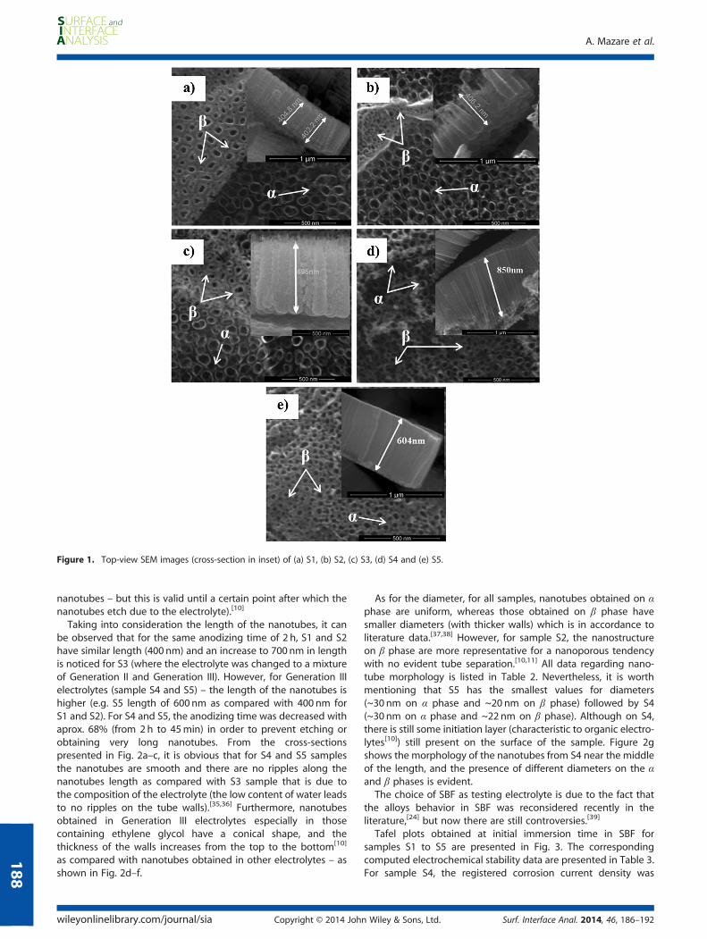
Figure 1. Top-view SEM images (cross-section in inset) of (a) S1, (b) S2, (c) S3, (d) S4 and (e) S5.
A. Mazare et al.
188
nanotubes – but this is valid until a certain point after which thenanotubes etch due to the electrolyte).[10]
Taking into consideration the length of the nanotubes, it canbe observed that for the same anodizing time of 2 h, S1 and S2have similar length (400 nm) and an increase to 700 nm in lengthis noticed for S3 (where the electrolyte was changed to a mixtureof Generation II and Generation III). However, for Generation IIIelectrolytes (sample S4 and S5) – the length of the nanotubes ishigher (e.g. S5 length of 600 nm as compared with 400 nm forS1 and S2). For S4 and S5, the anodizing time was decreased withaprox. 68% (from 2h to 45min) in order to prevent etching orobtaining very long nanotubes. From the cross-sectionspresented in Fig. 2a–c, it is obvious that for S4 and S5 samplesthe nanotubes are smooth and there are no ripples along thenanotubes length as compared with S3 sample that is due tothe composition of the electrolyte (the low content of water leadsto no ripples on the tube walls).[35,36] Furthermore, nanotubesobtained in Generation III electrolytes especially in thosecontaining ethylene glycol have a conical shape, and thethickness of the walls increases from the top to the bottom[10]
as compared with nanotubes obtained in other electrolytes – asshown in Fig. 2d–f.
wileyonlinelibrary.com/journal/sia Copyright © 2014 Joh
As for the diameter, for all samples, nanotubes obtained on αphase are uniform, whereas those obtained on β phase havesmaller diameters (with thicker walls) which is in accordance toliterature data.[37,38] However, for sample S2, the nanostructureon β phase are more representative for a nanoporous tendencywith no evident tube separation.[10,11] All data regarding nano-tube morphology is listed in Table 2. Nevertheless, it is worthmentioning that S5 has the smallest values for diameters(~30 nm on α phase and ~20 nm on β phase) followed by S4(~30 nm on α phase and ~22 nm on β phase). Although on S4,there is still some initiation layer (characteristic to organic electro-lytes[10]) still present on the surface of the sample. Figure 2gshows the morphology of the nanotubes from S4 near the middleof the length, and the presence of different diameters on the αand β phases is evident.
The choice of SBF as testing electrolyte is due to the fact thatthe alloys behavior in SBF was reconsidered recently in theliterature,[24] but now there are still controversies.[39]
Tafel plots obtained at initial immersion time in SBF forsamples S1 to S5 are presented in Fig. 3. The correspondingcomputed electrochemical stability data are presented in Table 3.For sample S4, the registered corrosion current density was
n Wiley & Sons, Ltd. Surf. Interface Anal. 2014, 46, 186–192

Figure 2. Details of nanotubes walls for: (a) S3, (b) S4, (c) S5; and of diameters variation along the length of the nanotubes for: (d) S3, (e) S4, (f) S5 andphase distribution for (g) S4.
Table 2. Nanotube morphology – diameter and length
Sample Diameter (nm) Length(μm)
α phase β phase
S1 70 30–40 0.40
S2 60 20–30 0.40
S3 65 30–40 0.70
S4 30 18–22 0.85
S5 30 20–24 0.60
Figure 3. Tafel plots of S1–S5 samples at initial immersion time insimulated body fluid: S1 - dark green triangle, S2 - black square, S3 -red square, S4 - green circle, S5 - blue stars.
Electrochemical behavior of TiO2 nanotubes on TiAlNb alloy in SBF
189
three times that of sample S5. All samples have electrochemicalparameters corresponding to very stable behavior in thestability scale. However, it follows that among these samples,the highest electrochemical stability (smallest corrosion rate)is attributed to S5 – obtained in an organic electrolyte withlow content of water, and the obtained morphology has thesmallest diameters on both phases (when comparing toother samples).
Surf. Interface Anal. 2014, 46, 186–192 Copyright © 2014 John
Considering the corrosion rate (vcorr), the following increasingstability scale can be established:
Wiley & Sons, Ltd. wileyonlinelibrary.com/journal/sia

Figure 5. Nyquist plots of S1, S2, S3, S4 and S5 in simulated body fluid:S1 - green triangle, S2 - black square, S3 - red rhombus, S4 - blue circle, S5 -purple star.
Table 3. Corrosion parameters and standard deviation
Sample Ecorr/V (vs Ag/AgCl) jcorr/μAcm-2 vcorr/mm/year
S1 �0.104 0.2017 0.4183× 10�4
S2 �0.203 0.3865 0.8014× 10�4
S3 �0.106 0.2383 0.4941× 10�4
S4 �0.168 0.4430 0.9184× 10�4
S5 �0.148 0.1514 0.3138× 10�4
A. Mazare et al.
190
S4 < S2 < S3 < S1 < S5 (1)
For comparison, the bare Ti6Al7Nb alloy was also electrochem-ically characterized. The corrosion potential of the bare alloy was�0.459 V (vs Ag/AgCl) and the corrosion current density was6.872μAcm�2. Thus, one can observe that the presence of TiO2
nanotubes on the samples’ surface leads to the improvement ofthe electrochemical parameters.Cyclic voltammetry curves from S1 to S5 samples are shown in
Fig. 4 and samples are stable, no breakdown phenomena wereobserved in the studied potential range despite the aggressivepresence of chloride anions. The reverse scan curves of allsamples come above the forward scan, and such behavior maybe the evidence of an additional layer being deposited onnanotubes, phenomena which are confirmed by EIS studies (as willbe later mentioned). Cyclic voltammetry curves of samples in SBFshow constant current in the potential range 300–1100mV (vsAg/AgCl) (corresponding to the presence of oxide) and increasingcurrent after about 1100mV (vs Ag/AgCl) (corresponding to oxygenevolution on the oxide covered surface). The passivity domain ishighest for S5 (1.4 V) followed by S3 (1.38V) and S2 (1.3 V), S1(1.14 V) and S4 (1.05V). The highest value for the passivationcurrent (ipas) was recorded for sample S4 (0.01511mAcm�2), andfor sample S5 the recorded passivation current was one order ofmagnitude lower. Higher ipas values indicate the presence of amore defective oxide. It has been previously proposed that theincrease in current density observed at potentials above 1200mV(vs Ag/AgCl) could be related to the formation of Ti compoundssuch as NaTiPO4,
[40] aspect that was observed for S1 and S5 samples.The EIS analysis and the corresponding Nyquist plots of the
impedance data were evaluated with Autolab NOVA software, forexample, Nyquist plots are presented in Fig. 5. The Bode
Figure 4. Cyclic voltammetry curves of S1–S5 samples at initial immersiontime in simulated body fluid.
Figure 6. (a) Bode plots for S1–S5 samples (S1 - red circle, S2 - blue star,S3 - green triangle, S4 - pink rhombus, S5 - black triangle) and (b) equiv-alent electric circuit.
wileyonlinelibrary.com/journal/sia Copyright © 2014 John Wiley & Sons, Ltd. Surf. Interface Anal. 2014, 46, 186–192

Table 4. Equivalent electric circuit parameters
Sample Rsol/Ω Rpl/Ω Qpl/μΩ�1 npl Rbl/Ω Qbl/μΩ
�1 nbl
S1 133 70800 8.93 0.790 385000 13.00 0.843
S2 134 58000 15.49 0.745 172000 11.80 0.853
S3 123 63000 14.22 0.802 269000 12.22 0.856
S4 113 51800 23.60 0.715 130000 9.20 0.846
S5 146 73700 7.40 0.819 457000 18.01 0.861
Electrochemical behavior of TiO2 nanotubes on TiAlNb alloy in SBF
191
diagrams corresponding to the EIS results obtained at open cir-cuit potential are shown in Fig. 6a.
The EIS spectra exhibit a typical behavior for a metallic materialcovered by a porous film that is exposed to an electrolyticenvironment. Two time constants are observed in the spectra:the first in the high-frequency part that arises from the ohmicelectrolyte resistance and the impedance resulting from thepenetration of the electrolyte through a porous film, and thesecond in the low-frequency part accounting for the process atthe substrate/electrolyte interface. It can be noted that the phaseangle drops to zero degrees at high frequencies, indicating thatthe impedance is dominated by solution resistance. Moreover,in the low-frequency region, the phase angle drops slightlytoward lower values thus indicating the contribution of surfacefilm resistance to the impedance. The maximum value of phaseshift angle in a wide range of frequency shown in Bode diagramsare similar and average of ~70o.
The equivalent circuit model for all samples shown in Fig. 6aalso indicated the two time constants, which corresponds to abarrier layer and porous layer due to the interaction of TiO2
nanotubes with Ca and P ions present in the solution. Thepresented results are confirmation of the higher barrier effect ofthe anodic films and that the protective layer remains efficientagainst the aggressive anions present in the SBF, indicated alsoin the literature.[41]
For the equivalent circuit, Rsol is the solution resistance, Rpl isthe charge transfer resistance and Qpl is the constant phase ele-ment of the nanotube layer, Rbl is the charge transfer resistanceand Qbl is the constant phase element of the thin barrier layer.[42]
Nyquist plots are presented in Fig. 5, while the correspondingequivalent electric circuits’ data are listed in Table 4. The n valuesfor the barrier layer indicate a pseudocapacitive character of theporous oxide layer and barrier layer.
From data in Table 4, it is possible to see that the Rbl values arehigher than the respective Rpl values. Consequently, it can beconcluded that the inner layer determines the electrochemicalstability of the biomaterial.
Rpl values are higher for the S5 samples than for S1, S3, S2 andS4, indicating that the film formed on the alloy is thicker and/orhas lower porosity. In this idea, it is possible that the filmmorphology is affected by the metallic substrate. The hypothesisof the film formed on the S5 samples being thicker and/or lessporous than that formed on other samples seems reasonable,because the Qpl values are lower in the former case, as shownin Table 4. Also, the npl values are higher for S5.
The resistance of TiO2 nanotube electrodes does not consistsolely of the resistance between the top and the bottom of thenanotubes,[43] but the resistance between the electrolyte solutionand the bottom change connecting electrode Ti6Al7Nb substrate.
Despite the fact that establishing a clear, quantitative relationshipbetween size (diameter and length) of titanium dioxide nanotubes
Surf. Interface Anal. 2014, 46, 186–192 Copyright © 2014 John
and electrical resistance is difficult, the influence of nanotubesmorphology was evaluated.
Conclusions
Different morphology TiO2 nanotubes were obtained on bothphases (α and β) of Ti6Al7Nb alloy via electrochemical anodizing.The formation of more protective or bioactive layers on Ti alloysis investigated by electrochemical anodization in differentelectrolytes and similar conditions as, (S1), aqueous electrolyte withan addition of acetic acid (S2), a mixture of aqueous and organicelectrolyte (S3) and in two different organic electrolytes with lowcontent of water (S4 and S5) – in similar anodizing conditions.
On the basis of the corrosion rate (vcorr) obtained from theelectrochemical characterization of the nanotubes, an increasingstability scale was established: S4< S2< S3< S1< S5. The sampleobtained in an organic electrolyte (glycerol) with low content ofwater (S5) presented the highest electrochemical stability. Allelectrochemical procedures corroborated the same conclusionand confirmed a better stability for nanostructures, without anybreakdown for all studies nanotubes, but having various electro-chemical stabilities as a function of the nanotubular morphologies.Taking into account, the experimental data we do consider forsuch titanium nanotubes layers, the possibility of bioapplicationsas cell growth.
Acknowledgements
The authors gratefully acknowledge the financial support of theRomanian National CNCSIS Grant IDEI PCCE No. 248/2010. Theauthors would like to thank Roxana Trusca for SEM analysis.
References[1] P. Kovacs, J. A. Davidson, in Medical applications of titanium and its
alloys: the materials and biological issues (Eds. S. A. Brown, J. E.Lemons) ASTM STP, 1996, pp.163–178.
[2] C. Vasilescu, P. Drob, E. Vasilescu, I. Demetrescu, D. Ionita, M.Prodana, S. I. Drob, Corros. Sci. 2011, 53, 902.
[3] A. W. E. Hodgson, Y. Mueller, D. Forster, S. Virtanen, Electrochim. Acta2002, 47, 1913.
[4] G. T. Burstein, C. Liu, Corros. Sci. 2007, 49, 4926.[5] M. V. Popa, I. Demetrescu, E. Vasilescu, P. Drob, S. Lopez, J. Mirza
Rosca, D. Ionita, C. Vasilescu, Electrochim. Acta 2004, 49, 2113.[6] G. T. Burstein, C. Liu, R. M. Souto, Biomaterials 2005, 26, 245.[7] C. Liu, Y. Wang, M. Wang, W. Huang, P. K. Chu, Surf. Coat. Tech. 2011,
206, 63.[8] M. Mîndroiu, C. Pirvu, R. Ion, I. Demetrescu, Electrochim. Acta 2012,
56, 193.[9] J.-U. Kim, B.-H. Kim, K. Lee, H.-C. Choe, Y.-M. Ko, J. Nanosci.
Nanotechnol. 2011, 11, 1636.[10] P. Roy, S. Berger, P. Schmuki, Angew. Chem. Int. Ed. 2011,
50, 2904.[11] D. Kowalski, D. Kim, P. Schmuki, Nano Today 2013, 8, 235.
Wiley & Sons, Ltd. wileyonlinelibrary.com/journal/sia
A. Mazare et al.
192
[12] K. R. Hebert, S. P. Albu, I. Paramasivam, P. Schmuki, Nat. Mater. 2012,11, 162.
[13] K. S. Brammer, C. J. Fransen, S. Jin, Trends Biotechnol. 2012,30, 315.
[14] S.-H. Oh, R. R. Finores, C. Daraio, L.-H. Chen, S. Jin, Biomaterials 2005,26, 4938.
[15] K. S. Brammer, O. Seunghan, C. J. Cobb, L. M. Bjursten, H. van derHeyde, S. Jin, Acta Biomater. 2009, 5, 3215.
[16] A. Mazare, M. Dilea, D. Ionita, I. Titorencu, V. Trusca, E. Vasile,Bioelectrochem. 2012, 87, 124.
[17] I. Demetrescu, C. Pirvu, V. Mitran, Bioelectrochem. 2010, 79, 122.[18] I. Man, C. Pirvu, I. Demetrescu, Rev. Chim-Bucharest 2008, 59, 615.[19] S. Tamilsevi, V. Raman, N. Rajendran, Electrochim. Acta 2006,
52, 839.[20] V. S. Saji, H. C. Choe, W. A. Brantley, Acta Biomater. 2009,
5, 2303.[21] V. S. Saji, H. C. Choe, Corros. Sci. 2009, 51, 1658.[22] M. V. Popa, D. Raducanu, E. Vasilescu, P. Drob, D. Cojocaru, C. Vasilescu,
S. Ivanescu, J. C. Mirza Rosca, Mater. Corros. 2008, 59, 919.[23] M. V. Popa, I. Demetrescu, D. Iordachescu, A. Cimpan, E. Vasilescu,
P. Drob, D. Ionita, C. Vasilescu, M. Istratescu, Mater. Corros. 2007,58, 667.
[24] M. Bohner, J. Lemaitre, Biomaterials 2009, 30, 2175.[25] H. Pan, X. Zhao, B. W. Darvell, W. W. Lu, Acta Biomater. 2010, 6, 4184.[26] L. Jonasova, F. A. Muller, A. Helebrant, J. Strnad, P. Greil, Biomaterials
2002, 23, 3095.[27] T. Kokubo, Biomaterials 1991, 12, 155.[28] T. Kokubo, H. Takadama, Biomaterials 2006, 27, 2907.
wileyonlinelibrary.com/journal/sia Copyright © 2014 Joh
[29] E. Goyenvalle, N. J. M. Guyen, E. Aguado, N. Passuti, G. Daculsi,J. Mater. Sci. - Mater. Med. 2003, 3, 219.
[30] M. Dilea, A. Mazare, D. Ionita, I. Demetrescu,Mater. Corros. 2013, 64, 493.[31] V. S. Saji, H. C. Choe, W. A. Brantley, J. Mater. Sci. 2009, 44, 3975.[32] J. M. Macak, H. Tsuchiya, L. Taveira, A. Ghicov, P. Schmuki, J. Biomed.
Mater. Res. 2005, 75A, 928.[33] C. A. Grimes, G. K. Mor, TiO2 Nanotube Arrays: Synthesis, Properties
and Applications, Springer, Boston (MA), 2009.[34] J. M. Macak, H. Tsuchiya, L. Taveira, S. Aldabergerova, P. Schmuki,
Angew. Chem. Int. Ed. 2005, 44, 7463.[35] A. Kaczmarek, T. Klekiel, E. Krasicka-Cydzik, Surf. Interface Anal. 2010,
42, 510.[36] P. Schmuki, S. Virtanen, Electrochemistry at the Nanoscale, Springer,
New York (NY), 2009.[37] E. Krasicka-Cydzik, JAMME 2010, 43, 424.[38] E. Krasicka-Cydzik, in Titanium Alloys - Towards Achieving Enhanced
Properties for Diversified Applications (Eds: A. K. M. Nurul Amin),InTech 2012, pp. 175–200.
[39] D. K. Pattanayak, S. Yamaguchi, T. Matsushita, T. Kokubo, T.Nakamura, J. R. Soc. Interface 2012, 9, 2145.
[40] D. M. Considine, Van Nostrand’s Scientific Encyclopedia, fifth edition,Van Nostrand, New York (NY), 1976.
[41] A. Gomez Sanchez, W. Schreiner, J. Ballarre, A. Cisilino, G. Duffó, S.Ceré, Surf. Interface Anal. 2013, 45, 1395.
[42] M. A. Ameer, A. M. Fekry, S. M. Shanab, Int. J. Electrochem. Sci. 2011,6, 1572.
[43] P. Xiao, Y. Zhang, B. Batalla Garcia, S. Sepehri, D. Liu, G. Cao,J. Nanosci. Nanotechnol. 2008, 8, 1.
n Wiley & Sons, Ltd. Surf. Interface Anal. 2014, 46, 186–192
Copyright © 2022 FDOKUMEN