Elastic Buckling of Single-Stepped Columns with End and ...
11
Computational Engineering and Physical Modeling 1-4 (2018) 25-35 How to cite this article: Salama MI. Elastic Buckling of Single-Stepped Columns with End and Intermediate Axial Loads. Comput Eng Phys Model 2018;1(4):25–35. https://doi.org/10.22115/cepm.2018.147218.1046 2588-6959/ © 2018 The Authors. Published by Pouyan Press. This is an open access article under the CC BY license (http://creativecommons.org/licenses/by/4.0/). Contents lists available at CEPM Computational Engineering and Physical Modeling Journal homepage: www.jcepm.com Elastic Buckling of Single-Stepped Columns with End and Intermediate Axial Loads M.I. Salama Department of Civil Engineering, Faculty of Engineering, Kafrelsheikh University, Egypt Corresponding author: magdy1000@ hotmail.com https://doi.org/10.22115/CEPM.2018.147218.1046. ARTICLE INFO ABSTRACT Article history: Received: 01 September 2018 Revised: 21 December 2018 Accepted: 18 February 2019 Buckling study of single-stepped columns subjected to both intermediate and end axial loads are introduced in this paper. The column understudy is considered as two segments where the upper and the lower parts have different cross section moment of inertia or different material and subjected to intermediate load at the location of the cross section change beside the end load. All the classical end conditions of the studied column are considered in this paper as pinned ends, clamped ends, clamped-free ends and clamped-pinned ends. The analysis is developed using finite element method to study the effect of each parameter may be affect in the buckling loads. These parameters are i) ratio of the intermediate axial load to the end axial load, ii) the intermediate load location as a ratio to the column span and, iii) the ratio of flexural rigidity of lower segment to that of upper one. The obtained numerical results are introduced in many interaction curves to obtain the buckling loads for each end conditions considering the other parameters. A comparison between the obtained results and that of the available theoretical studies shows the accuracy and the simplicity of the present work to get the critical load. Keywords: Stepped column; Intermediate axial loads; Buckling; Finite element method.
-
Upload
khangminh22 -
Category
Documents
-
view
0 -
download
0
Transcript of Elastic Buckling of Single-Stepped Columns with End and ...

Computational Engineering and Physical Modeling 1-4 (2018) 25-35
How to cite this article: Salama MI. Elastic Buckling of Single-Stepped Columns with End and Intermediate Axial Loads. Comput
Eng Phys Model 2018;1(4):25–35. https://doi.org/10.22115/cepm.2018.147218.1046
2588-6959/ © 2018 The Authors. Published by Pouyan Press.
This is an open access article under the CC BY license (http://creativecommons.org/licenses/by/4.0/).
Contents lists available at CEPM
Computational Engineering and Physical Modeling
Journal homepage: www.jcepm.com
Elastic Buckling of Single-Stepped Columns with End and
Intermediate Axial Loads
M.I. Salama
Department of Civil Engineering, Faculty of Engineering, Kafrelsheikh University, Egypt
Corresponding author: magdy1000@ hotmail.com
https://doi.org/10.22115/CEPM.2018.147218.1046.
ARTICLE INFO
ABSTRACT
Article history:
Received: 01 September 2018
Revised: 21 December 2018
Accepted: 18 February 2019
Buckling study of single-stepped columns subjected to both
intermediate and end axial loads are introduced in this paper.
The column understudy is considered as two segments where
the upper and the lower parts have different cross section
moment of inertia or different material and subjected to
intermediate load at the location of the cross section change
beside the end load. All the classical end conditions of the
studied column are considered in this paper as pinned ends,
clamped ends, clamped-free ends and clamped-pinned ends.
The analysis is developed using finite element method to
study the effect of each parameter may be affect in the
buckling loads. These parameters are i) ratio of the
intermediate axial load to the end axial load, ii) the
intermediate load location as a ratio to the column span and,
iii) the ratio of flexural rigidity of lower segment to that of
upper one. The obtained numerical results are introduced in
many interaction curves to obtain the buckling loads for each
end conditions considering the other parameters. A
comparison between the obtained results and that of the
available theoretical studies shows the accuracy and the
simplicity of the present work to get the critical load.
Keywords:
Stepped column;
Intermediate axial loads;
Buckling;
Finite element method.

26 M.I. Salama/ Computational Engineering and Physical Modeling 1-4 (2018) 25-35
Introduction
The critical buckling load of columns and its behaviour is an important item in the different
structures study. Earlier, Leonhard Euler obtained the critical buckling load for pinned ends
column with uniform cross section which frequently termed as the Euler load. Columns with
uniform cross section are not the most economical form to be stable against buckling. In many
applications of the civil engineering, stepped columns may be required from the view of the
economical design especially when the column subjected to intermediate and end axial loads.
Examples to this loading case are crane columns in industrial buildings and columns supporting
intermediate floors. The case of a two segment column with pinned ends compressed by end and
intermediate axial forces was studied by Timoshenko and Gere [1]. Exact buckling loads for
columns with uniform cross section under the effect of intermediate and end axial loads have
been derived by C. M. Wang and I. M. Nazmul [2]. They divide the column to two segments and
the differential equations for each segment are investigated and solved together to get the
stability criterion. Wilson [3] used a finite difference scheme to represent the fourth order
differential equation for the stepped column under end axial load only to get an approximate
buckling load. Salama [4] introduced a theoretical analysis of the stability of stepped column
under end and intermediate axial loads using the potential energy method considering pinned
ends and clamped-free ends only. The buckling problem of two portions stepped column is
developed by Pinarbasi and et. [5]. They solved the derived differential equations by using the
variational iteration method (VIM). In this paper, stability study of two segment stepped columns
under the effect of combined axial loads are developed using finite element method considering
different combination of end conditions and the results are compared with other studies.
2. Theoritical analysis
2.1. Assumptions
Consider a stepped column as shown in Figure (1-a) subjected to end axial load P1 at top end and
an intermediate axial load P2 at a distance x = L from the bottom with the following
assumptions:
a) b)
Fig. 1. a) Stepped column subjected to end and intermediate axial loads, b) Finite element model.
x
L
L
E I2
E I1
y
P1
P2
P2P1 +

M.I. Salama/ Computational Engineering and Physical Modeling 1-4 (2018) 25-35 27
i. The used material is linearly elastic.
ii. No initial imperfection of the column.
iii. No local buckling at any cross-section along the column length is allowed.
iv. The moments of inertia of the upper and lower parts are I1 and I2 respectively.
2.2. Method of Analysis
Firstly, the stability of the stepped column under end and intermediate loads depends on the
following ratios
i. Ratio of the intermediate axial load to the end axial load m= (P1+P2)/P1.
ii. The intermediate load location as a ratio to the total column length.
iii. Ratio of moment of inertia of lower segment to that of the upper segment n= I2/I1.
The buckling load can be expressed by the following formula
2
1
2
21)( Lk
IEPP
cr
(1)
Where
E denotes the modulus of elasticity of column material,
denotes the buckling load coefficient that depends on the ratios m, n and and
k denotes end condition parameter for the uniform column under end axial load
k =1.00 ---------------- for pinned ends column [P-P]
k =0.50 ---------------- for clamped ends column [C-C]
k =0.699 -------------- for clamped-pinned ends column [C-P]
k =2.00 ---------------- for clamped-free ends column [C-F]
Assuming values for the ratios m, n and for each particular case, the column under study is
modelled as a three dimensions frame element as shown in Figure (1-b) with very large number
of elements. The classical end conditions are considered in the models under study. The critical
buckling loads for the considered column have been obtained using SAP2000 program based on
the finite element method.
Mode shapes for different values of the location of the intermediate load (α) (for C-C column as
an example) are shown in Figure (2) that describe the buckling behaviour of the considered
column.

28 M.I. Salama/ Computational Engineering and Physical Modeling 1-4 (2018) 25-35
Fig. 2. Effect of the intermediate load location in the buckling shape of the stepped column (C-C column)
To study the interaction relation between the buckling loads P1 and P2, equation (1) can be
rewritten in the following form
2
1
2
222
1
2
11)(
,)( Lk
IEAP
Lk
IEAP
crcr
(2)
Where, A1 and A2 are the buckling factors for the end and intermediate loads that can be
expressed as follows
121 . AmAA
Generally, each one of these factors depends on the other and the increasing of one of them
causes the other to decrease. The relation between these factors is obtained by numerical analysis
using finite element method for a certain value of the ratios n and
3. Results and discussion
Finite element analysis solution for two-segment stepped columns subjected to both intermediate
and end axial loads are presented in Figures (3) to (6) for pinned ends, clamped-pinned ends,
clamped ends and clamped-free ends respectively. Each figure describe the interaction relation
between the end and intermediate axial loads represented by factors A1 and A2 for different
locations of the intermediate load () and different moment of inertia ratio of lower segment to
that of the upper one (n).
=0.10 =0.30 =0.50 =0.70 =0.90

M.I. Salama/ Computational Engineering and Physical Modeling 1-4 (2018) 25-35 29
(a)
(b)
(c)
Fig. 3. Bucking loads parameters of columns with pinned ends (P-P)
under intermediate load P2 and end load P1
(a) n=1.0, (b) n=2.0 and (c) n=4.0
30 M.I. Salama/ Computational Engineering and Physical Modeling 1-4 (2018) 25-35
(a)
(b)
(c)
Fig. 4. Bucking loads parameters of columns with clamped – pinned ends (C-P).
under intermediate load P2 and end load P1
n=1.0, (b) n=2.0 and (c) n=4.0
M.I. Salama/ Computational Engineering and Physical Modeling 1-4 (2018) 25-35 31
(a)
(b)
(c)
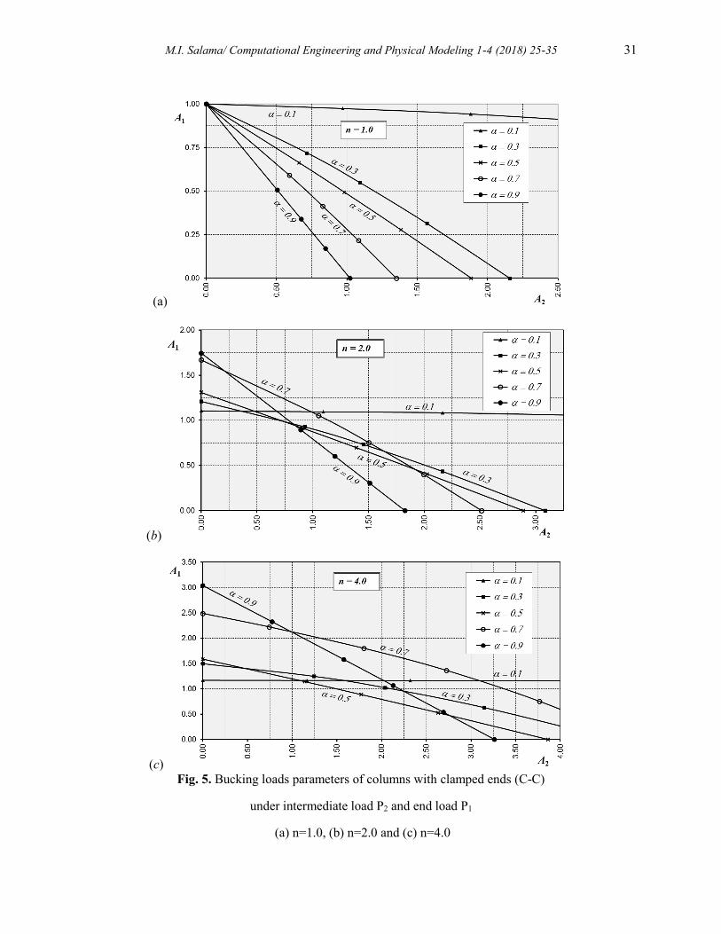
Fig. 5. Bucking loads parameters of columns with clamped ends (C-C)
under intermediate load P2 and end load P1
(a) n=1.0, (b) n=2.0 and (c) n=4.0

32 M.I. Salama/ Computational Engineering and Physical Modeling 1-4 (2018) 25-35
(a)
(b)
(c)
Fig. 6. Bucking loads parameters of columns with clamped - free ends (C-F)
under intermediate load P2 and end load P1
(a) n=1.0, (b) n=2.0 and (c) n=4.0

M.I. Salama/ Computational Engineering and Physical Modeling 1-4 (2018) 25-35 33
From these figures, it is obvious that the buckling factor A1 decrease almost linearly as the
buckling factor A2 increases. Curvature of some relations seems more pronounced for certain
values of different according the ratio n and the end conditions. Also, it can be noticed that
when the intermediate axial load is absent (P2=0), for different values of n, the buckling factor A1
is very close to the exact buckling factor for each end conditions.
4. Comparison of the results
The obtained results are checked by comparison with the available results computed in the
published references.
Table (1) shows the comparison of results obtained from this study with the exact results solved
by Timoshenko and Gere [1] for the column with pinned ends considering the intermediate load
location at the mid-span of the column ( =0.5).
Table 1
Comparison of the buckling load factor A1 with exact results obtained by Timoshenko [1] for stepped P-P
column ( =0.5).
m
n
1.00 1.25 1.50 1.75 2.00
Exact F.E.M. Exact F.E.M. Exact F.E.M. Exact F.E.M. Exact F.E.M.
1.00 1.0000 1.0000 1.1077 1.1077 1.1883 1.1883 1.2500 1.2500 1.2985 1.2985
1.25 0.8882 0.8882 0.9900 0.9900 1.0671 1.0671 1.1268 1.1268 1.1739 1.1739
1.50 0.7981 0.7981 0.8939 0.8939 0.9673 0.9673 1.0246 1.0246 1.0702 1.0702
1.75 0.7240 0.7240 0.8142 0.8142 0.8840 0.8840 0.9388 0.9388 0.9826 0.9826
2.00 0.6623 0.6622 0.7472 0.7473 0.8135 0.8135 0.8658 0.8658 0.9079 0.9079
3.00 0.4926 0.4926 0.5609 0.5609 0.6153 0.6153 0.6589 0.6590 0.6945 0.6945
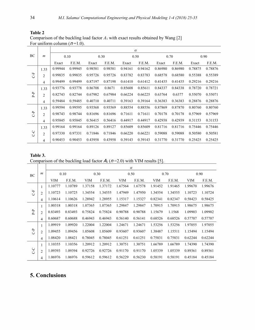
Another comparison with the exact results for uniform columns determined by C. M. Wang and
I. M. Nazmul [2] is given in Table (2).
Also, a comparison with the results obtained by Pinarbasi and et.[5] using variational l iteration
method (VIM) to solve the differential equations is given in Table (3).
These comparisons shows perfect match and the present method can be used simply by the
designer engineers.
34 M.I. Salama/ Computational Engineering and Physical Modeling 1-4 (2018) 25-35
Table 2
Comparison of the buckling load factor A1 with exact results obtained by Wang [2]
For uniform column (n =1.0).
BC m
0.10 0.30 0.50 0.70 0.90
Exact F.E.M. Exact F.E.M. Exact F.E.M. Exact F.E.M. Exact F.E.M.
C-F
1.33 0.99944 0.99945 0.98581 0.98581 0.94161 0.94162 0.86980 0.86980 0.78875 0.78876
2 0.99835 0.99835 0.95726 0.95726 0.83782 0.83783 0.68578 0.68580 0.55388 0.55389
4 0.99499 0.99499 0.87197 0.87198 0.61410 0.61412 0.41435 0.41435 0.29216 0.29216
P-P
1.33 0.93776 0.93778 0.86708 0.8671 0.85608 0.85611 0.84337 0.84338 0.78720 0.78721
2 0.82743 0.82744 0.67982 0.67984 0.66224 0.66225 0.63764 0.6377 0.55070 0.55071
4 0.59484 0.59485 0.40710 0.40711 0.39163 0.39164 0.36383 0.36383 0.28876 0.28876
C-P
1.33 0.99594 0.99595 0.93568 0.93569 0.88554 0.88556 0.87869 0.87870 0.80760 0.80760
2 0.98743 0.98744 0.81696 0.81696 0.71611 0.71611 0.70178 0.70178 0.57969 0.57969
4 0.95845 0.95845 0.56415 0.56416 0.44917 0.44917 0.42938 0.42939 0.31153 0.31153
C-C
1.33 0.99164 0.99164 0.89126 0.89127 0.85609 0.85609 0.81716 0.81716 0.75446 0.75446
2 0.97330 0.97331 0.71846 0.71846 0.66220 0.66221 0.59088 0.59088 0.50580 0.50581
4 0.90453 0.90453 0.43958 0.43958 0.39143 0.39143 0.31770 0.31770 0.25425 0.25425
Table 3.
Comparison of the buckling load factor A1 (n =2.0) with VIM results [5].
BC m
0.10 0.30 0.50 0.70 0.90
VIM F.E.M. VIM F.E.M. VIM F.E.M. VIM F.E.M. VIM F.E.M.
C-F
1 1.10777 1.10789 1.37158 1.37172 1.67564 1.67578 1.91452 1.91465 1.99670 1.99676
2 1.10723 1.10725 1.34554 1.34555 1.47949 1.47950 1.34554 1.34555 1.10723 1.10724
4 1.10614 1.10626 1.28942 1.28955 1.15317 1.15327 0.82341 0.82347 0.58423 0.58425
P-P
1 1.00318 1.00318 1.07365 1.07365 1.29847 1.29847 1.70915 1.70915 1.98675 1.98675
2 0.83493 0.83493 0.75824 0.75824 0.90788 0.90788 1.15679 1.1568 1.09903 1.09902
4 0.60687 0.60688 0.46943 0.46943 0.56140 0.56141 0.68526 0.68526 0.57707 0.57707
C-P
1 1.09919 1.09920 1.22004 1.22004 1.24671 1.24671 1.53256 1.53256 1.97055 1.97055
2 1.09455 1.09456 1.05608 1.05609 0.93607 0.93607 1.38487 1.15511 1.15494 1.15494
4 1.08420 1.08421 0.78045 0.78045 0.61251 0.61251 0.75831 0.75831 0.62244 0.62244
C-C
1 1.10355 1.10356 1.20912 1.20912 1.30751 1.30751 1.66789 1.66789 1.74390 1.74390
2 1.09393 1.09394 0.92726 0.92726 0.91170 0.91170 1.05339 1.05339 0.89361 0.89361
4 1.06976 1.06976 0.59612 0.59612 0.56229 0.56230 0.58191 0.58191 0.45184 0.45184
5. Conclusions
M.I. Salama/ Computational Engineering and Physical Modeling 1-4 (2018) 25-35 35
Finite element method is performed to study the stability of two-segment stepped columns
subjected to both intermediate and end axial loads. The classical end conditions are considered in
this paper such as pinned ends, clamped ends, clamped-free ends and pinned-clamped ends.
Many curves that describe the interaction relation between the end and intermediate critical loads
are introduced in this paper for each end conditions. These curves are given for various values of
the intermediate load location ratio and the ratio between the flexural rigidity between the lower
and upper parts. The obtained results can be obtained directly by design engineers and the
desired method can be simply modelled by the designers.
The obtained results are compared with the available exact results for special cases and the other
results in the published references and theses comparison show an excellent accuracy.
References
[1] Timoshenko SP, Gere JM. Theory of elastic stability. Courier Corporation; 1983.
[2] Wang CM, Wang CY, Nazmul IM. Stability Criteria for Euler Columns with Intermediate and End
Axial Loads. J Eng Mech 2003;129:468–72. doi:10.1061/(ASCE)0733-9399(2003)129:4(468).
[3] HOBLIT FM. Buckling Load of a Stepped Column. J Aeronaut Sci 1951;18:124–6.
doi:10.2514/8.1871.
[4] Salama MI. Buckling Loads of Columns with Suddenly Changing Cross-Section Subjected to
Combined End and Intermediate Axial Forces. thirteen Int. Conf. Struct. Geotech. Eng. Ain Shams
Univ., 2009.
[5] Pinarbasi S, Okay F, Akpinar E, Erdogan H. Stability analysis of two-segment stepped columns
with different end conditions and internal axial loads. Math Probl Eng 2013;2013.