
Efficient and Enhanced Multi-Target Tracking with Doppler Measurements
18
Efficient and Enhanced Multi-Target Tracking with Doppler Measurements XUEZHI WANG University of Melbourne DARKO MU ² SICKI Hangyang University RICHARD ELLEM FIONA FLETCHER DSTO, Australia In many radar and sonar tracking systems, the target state typically includes target position and velocity components that are estimated from a time sequence of target position and Doppler measurements. The use of measured Doppler information directly in the target trajectory estimation leads to a nonlinear filter implementation such as the extended Kalman filter (EKF), particle filter etc. We investigate a method for including Doppler measurements as part of the data association process and then assess the benefits of this approach. It is well understood that data association performance can dominate the total performance of a tracker that is designed to track targets in the presence of clutter. In this case, the Doppler component of the measurements may be used in combination with the target position measurement as an additional discriminant of measurement origin. We have developed a simple but efficient Doppler data association (DDA) method which utilises both position and Doppler measurements for single and multi-target tracking. If the Doppler measurements are not used in trajectory state estimation, then the nonlinear filters for the incorporation of Doppler measurements are not required, however a significant improvement in tracking performance is still observed. The proposed DDA method is demonstrated using both the linear multi-target integrated probabilistic data association algorithm (LMIPDA) and the linear multi-target integrated track splitting algorithm (LMITS) in an active sonar underwater multi-target tracking scenario. Manuscript received April 11, 2007; revised October 2, 2007 and January 27, 2008; released for publication May 11, 2008. IEEE Log No. T-AES/45/4/935101. Refereeing of this contribution was handled by W. Koch. This work was supported by Maritime Operations Division, Defence Science and Technology Organisation (DSTO), and the Melbourne Systems Laboratory, University of Melbourne. A brief version of this paper appears in Proceedings of the International Conference on Information, Decision and Control, Adelaide, Australia, Feb. 11—14, 2007. Authors’ addresses: X. Wang, Melbourne Systems Laboratory, Dept. of Electrical and Electronic Engineering, University of Melbourne, Australia, E-mail: ([email protected]); D. Mušicki, Hangyang University, Republic of Korea, E-mail: (Darko.Muš[email protected]); R. Ellem, Maritime Operations Division, DSTO, PO Box 1500, Edinburgh SA 5111, Australia; F. Fletcher, Intelligence, Surveillance and Reconnaissance Division, DSTO, PO Box 1500, Edinburgh SA 5111, Australia. 0018-9251/09/$26.00 c ° 2009 IEEE I. INTRODUCTION In addition to target position measurements, target Doppler or range rate measurements may provide additional information about target kinematic state and therefore can be incorporated into the tracker to enhance tracking performance. When position and velocity are the primary components of a target state, target tracking is usually performed in a Cartesian coordinate system despite the fact that sensor observations are taken from a polar or spherical coordinate system [1, 2]. In this case, sensor measurements, such as range, bearing, and elevation may be converted into the Cartesian system to avoid using nonlinear filters [3]. However, when target Doppler is included as part of the measurement vector, nonlinear estimators have to be used to cope with the nonlinearity between the target kinematic state (e.g. position, velocity, etc.) and its range rate measurement [4]. In addition, it is shown in [5] that the measurement errors between range and range rate can be correlated. These facts become major issues when target Doppler measurements are to be incorporated in the tracker to improve target tracking performance. A modified joint probabilistic data association (JPDA) algorithm is described in [6], which utilises range rate measurements in addition to position measurements using a nonlinear measurement model. The extended Kalman filter (EKF) is then applied as the backbone filter. This results in an improved tracking performance and reduced computational load over a standard JPDA for multi-target tracking in the presence of clutter. In [7], an interacting multiple model (IMM) estimator consisting of a number of EKF modules is used to cope with target range rate measurements for an airborne early warning system tracking scenario. Similar approaches can also be found in [2], [8] (and references therein). The literature suggests that one has to use nonlinear filters in the system to cope with the inclusion of Doppler measurements. In [9], [10], the problem of correlated errors is addressed and a sequential filtering technique is proposed. The error correlation between converted position measurements and range rate measurements [5] is decoupled by constructing a pseudo measurement and the converted position measurement and range rate measurement are then sequentially used to update the estimated target state. Another sequential filtering technique referred to as the two-step optimal estimator in [11] may also be used for a tracking system which contains Doppler measurements. Although an improved performance can be observed, sequential filtering algorithms [9—11] still rely on the use of EKFs for computing the estimated state update with Doppler measurements. While algorithm complexity may increase, the use of EKFs may potentially introduce 1400 IEEE TRANSACTIONS ON AEROSPACE AND ELECTRONIC SYSTEMS VOL. 45, NO. 4 OCTOBER 2009 Authorized licensed use limited to: UNIVERSITY OF MELBOURNE. Downloaded on February 9, 2010 at 06:55 from IEEE Xplore. Restrictions apply.
-
Upload
independent -
Category
Documents
-
view
2 -
download
0
Transcript of Efficient and Enhanced Multi-Target Tracking with Doppler Measurements

Efficient and EnhancedMulti-Target Tracking withDoppler Measurements
XUEZHI WANGUniversity of Melbourne
DARKO MU²SICKIHangyang University
RICHARD ELLEM
FIONA FLETCHERDSTO, Australia
In many radar and sonar tracking systems, the target statetypically includes target position and velocity components that areestimated from a time sequence of target position and Dopplermeasurements. The use of measured Doppler information directlyin the target trajectory estimation leads to a nonlinear filterimplementation such as the extended Kalman filter (EKF),particle filter etc. We investigate a method for including Dopplermeasurements as part of the data association process and thenassess the benefits of this approach. It is well understood thatdata association performance can dominate the total performanceof a tracker that is designed to track targets in the presence ofclutter. In this case, the Doppler component of the measurementsmay be used in combination with the target position measurementas an additional discriminant of measurement origin. We havedeveloped a simple but efficient Doppler data association (DDA)method which utilises both position and Doppler measurementsfor single and multi-target tracking. If the Doppler measurementsare not used in trajectory state estimation, then the nonlinearfilters for the incorporation of Doppler measurements arenot required, however a significant improvement in trackingperformance is still observed. The proposed DDA method isdemonstrated using both the linear multi-target integratedprobabilistic data association algorithm (LMIPDA) and the linearmulti-target integrated track splitting algorithm (LMITS) in anactive sonar underwater multi-target tracking scenario.
Manuscript received April 11, 2007; revised October 2, 2007 andJanuary 27, 2008; released for publication May 11, 2008.
IEEE Log No. T-AES/45/4/935101.
Refereeing of this contribution was handled by W. Koch.
This work was supported by Maritime Operations Division, DefenceScience and Technology Organisation (DSTO), and the MelbourneSystems Laboratory, University of Melbourne.
A brief version of this paper appears in Proceedings of theInternational Conference on Information, Decision and Control,Adelaide, Australia, Feb. 11—14, 2007.
Authors’ addresses: X. Wang, Melbourne Systems Laboratory,Dept. of Electrical and Electronic Engineering, Universityof Melbourne, Australia, E-mail: ([email protected]);D. Mušicki, Hangyang University, Republic of Korea, E-mail:(Darko.Muš[email protected]); R. Ellem, Maritime OperationsDivision, DSTO, PO Box 1500, Edinburgh SA 5111, Australia;F. Fletcher, Intelligence, Surveillance and Reconnaissance Division,DSTO, PO Box 1500, Edinburgh SA 5111, Australia.
0018-9251/09/$26.00 c° 2009 IEEE
I. INTRODUCTION
In addition to target position measurements,target Doppler or range rate measurements mayprovide additional information about target kinematicstate and therefore can be incorporated into thetracker to enhance tracking performance. Whenposition and velocity are the primary componentsof a target state, target tracking is usually performedin a Cartesian coordinate system despite the factthat sensor observations are taken from a polar orspherical coordinate system [1, 2]. In this case, sensormeasurements, such as range, bearing, and elevationmay be converted into the Cartesian system to avoidusing nonlinear filters [3]. However, when targetDoppler is included as part of the measurementvector, nonlinear estimators have to be used to copewith the nonlinearity between the target kinematicstate (e.g. position, velocity, etc.) and its range ratemeasurement [4]. In addition, it is shown in [5] thatthe measurement errors between range and rangerate can be correlated. These facts become majorissues when target Doppler measurements are to beincorporated in the tracker to improve target trackingperformance.A modified joint probabilistic data association
(JPDA) algorithm is described in [6], which utilisesrange rate measurements in addition to positionmeasurements using a nonlinear measurement model.The extended Kalman filter (EKF) is then appliedas the backbone filter. This results in an improvedtracking performance and reduced computational loadover a standard JPDA for multi-target tracking in thepresence of clutter. In [7], an interacting multiplemodel (IMM) estimator consisting of a numberof EKF modules is used to cope with target rangerate measurements for an airborne early warningsystem tracking scenario. Similar approaches canalso be found in [2], [8] (and references therein).The literature suggests that one has to use nonlinearfilters in the system to cope with the inclusion ofDoppler measurements. In [9], [10], the problemof correlated errors is addressed and a sequentialfiltering technique is proposed. The error correlationbetween converted position measurements and rangerate measurements [5] is decoupled by constructinga pseudo measurement and the converted positionmeasurement and range rate measurement are thensequentially used to update the estimated targetstate. Another sequential filtering technique referredto as the two-step optimal estimator in [11] mayalso be used for a tracking system which containsDoppler measurements. Although an improvedperformance can be observed, sequential filteringalgorithms [9—11] still rely on the use of EKFs forcomputing the estimated state update with Dopplermeasurements. While algorithm complexity mayincrease, the use of EKFs may potentially introduce
1400 IEEE TRANSACTIONS ON AEROSPACE AND ELECTRONIC SYSTEMS VOL. 45, NO. 4 OCTOBER 2009
Authorized licensed use limited to: UNIVERSITY OF MELBOURNE. Downloaded on February 9, 2010 at 06:55 from IEEE Xplore. Restrictions apply.
filter stability and performance issues which areinherently associated with the EKF [2, 9, 12, 13].Other standard nonlinear filters in the literature,such as the unscented KF [14] or particle filters[15] could potentially be used to replace the EKFfor a better performance, however, the additionalcomputational burden may become a practicalissue.One of the most challenging problems for
multi-target tracking in clutter is differentiatingbetween measurements originating from a targetof interest and measurements arising from othertarget returns or clutter. This is known as the dataassociation problem in the target tracking literature[16]. To this end, the Doppler component of themeasurements may be used in combination withthe target position measurement as an additionaldiscriminant of measurement origin to help solvethe problem of tracking closely spaced targets [17].In fact, in all of the existing approaches mentionedabove, a notable achievement in common is theimproved data association performance benefitedfrom the incorporation of Doppler measurements. Inthis paper we investigate the benefit of incorporatingDoppler measurements directly into data associationand present a simple but efficient Doppler dataassociation (DDA) method which utilizes bothposition and Doppler measurements for bothsingle and multi-target tracking data association.A brief version of this paper has appeared in[18].In the DDA, a joint measurement likelihood for
both Doppler and position measurements is consideredfor data association while possible contributions tothe target state estimate from Doppler measurementsmay or may not be ignored. The major differencebetween DDA and existing approaches is that in theDDA, the target Doppler measurement may be directlyused only for data association. As a consequence, theuse of nonlinear filters can be avoided. As we will seelater in this paper, an improved tracking performancecan be observed when heavy false measurements arepresent, whilst the increase in algorithm complexitydue to the use of Doppler measurements in DDA isminimal. Furthermore, the proposed DDA methodprovides a simple, efficient, and robust use of Dopplermeasurements for a conventional tracker that canachieve similar performance improvements to thosereported in the target tracking literature without theadditional complexity associated with the use ofnonlinear filters.The proposed DDA method can be used in the
majority of algorithms for target tracking in clutter,e.g. probabilistic data association (PDA), JPDA[16], joint integrated PDA (JIPDA) [19] to name afew. In this paper we derive DDA method with theintegrated track splitting filter (ITS) [20], with thespecial case of integrated PDA (IPDA) [21]. Both ITS
and IPDA recursively update both the probability oftarget existence and target trajectory state estimate.The probability of target existence is used as a trackquality measure for false track discrimination. ITSis related to multi-hypotheses tracking (MHT) [1].They are both multi-scan target tracking algorithms,meaning that each track probability density function(pdf) is a set of components, where each componentis the target trajectory state estimate assuming thatone sequence of measurements represents targetdetections over time. However, ITS is conceptuallysimpler than MHT, i.e., it decouples track birthprocess from the track maintenance process, makingit simpler conceptually and less computationallydemanding than MHT. MHT track quality measureis the score [1] of each component, and each trackcomponent of MHT is maintained independently(terminated and/or confirmed). ITS track is maintainedin its entirety; all track components are confirmedor terminated simultaneously. Thus, stretching thedefinition somewhat, ITS is the mean estimator oftarget existence and MHT is the maximum likelihoodestimator of target existence [20]. IPDA [21] extendsthe PDA [16] by adding the probability of targetexistence as well as the notion of nonuniform cluttermeasurement density.Optimal multi-target tracking approach as used
in MHT, JPDA, and JIPDA is computationally verydemanding in an environment of heavy clutter and/ormore than a small number of targets present. In ournumerical examples we use a suboptimal multi-targetframework of “linear multi-target” (LM) tracking[22, 23], which leads to the implementation of both amodified LM integrated probabilistic data association(LMIPDA) [22] (denoted as LMIPDA-DDA) and amodified LM integrated track splitting (LMITS) [22]algorithms (denoted as LMITS-DDA).The effectiveness of the DDA method is
demonstrated via an active sonar underwater trackingscenario and the performance of algorithms withand without DDA is compared. Simulated resultsindicate that the trackers with DDA have a significantperformance improvement in terms of a reducednumber of confirmed false tracks and a lowercomputational load compared with those withoutDDA.The rest of the paper is organised as follows. In
the next section, the system models for multi-targettracking in clutter are reviewed. In Section III, wefirst present the derivation of the DDA methodin a unified ITS framework which leads to thepopular ITS and IPDA algorithms. We then extendthese to the LMIPDA-DDA and LMITS-DDAalgorithms for multi-target tracking in the LMframework. Simulation results and discussion are thenpresented in Section IV, followed by a conclusion inSection V. Some derivation details are provided in theAppendices.
WANG ET AL.: EFFICIENT AND ENHANCED MULTI-TARGET TRACKING WITH DOPPLER MEASUREMENTS 1401
Authorized licensed use limited to: UNIVERSITY OF MELBOURNE. Downloaded on February 9, 2010 at 06:55 from IEEE Xplore. Restrictions apply.

II. SYSTEM MODELS
A. Target Model
The trajectory of an individual target ¿ is modelledby
x¿k+1 = Fkx¿k +º
¿k , º¿k »N (º¿k ;0,Q¿k ) (1)
where x¿k denotes the ¿ th target state at time k, Fk isthe system transition matrix and º¿k is zero mean whiteGaussian1 noise with covariance Q¿k . For example, ina 3D Cartesian coordinate system, the target state maytypically be a vector of 6 components consisting ofposition and velocity for each axis, i.e.,
x¿k = [xk _xk yk _yk zk _zk]0: (2)
B. Target Measurements
At scan k, a set of mk sensor measurementsZk = fzk,1,zk,2, : : : ,zk,mkg are selected from the sensordetections. Each measurement zk,j , j = 1,2, : : : ,mkis a vector of four components which consistof both position and range rate measurementsfrom a particular target, i.e., zk,j = fyck,j ,ydk,jg. Theaccumulated measurement sequence up to time k isexpressed as
Zk = fZ1,Z2, : : : ,Zkg or Zk = fYkc,Ykdg: (3)
With respect to (2), the position measurement fromtarget ¿ at time k is linearly related to the target state:
yck =Hckx¿k +!
¿k (4)
where !¿k »N (!¿k ;0,Rc,¿k ). For the state defined in (2),Hck is given by
Hck =
2641 0 0 0 0 0
0 0 1 0 0 0
0 0 0 0 1 0
375 :Similarly, the Doppler (range rate) measurement
from target ¿ can be expressed as
ydk = h(x¿k) + n
¿k (5)
where the measurement error is assumed to be aGaussian n¿k »N (n¿k ;0,Rd,¿k ) and h(x¿k) is given by [2]
h(x¿k ) =(xk ¡ xsk)( _xk ¡ _xsk)+ (yk ¡ ysk)( _yk ¡ _ysk)+ (zk ¡ zsk)(_zk ¡ _zsk)p
(xk ¡ xsk)2 + (yk ¡ ysk)2 + (zk ¡ zsk)2
(6)where xsk = [x
sk, _x
sk,y
sk, _y
sk,z
sk, _z
sk]0 is the known sensor
state vector at time k. We assume that the systemprocess noise º¿j and measurement noises !
¿k and n
¿i
are independent of each other for all j,k, i, and ¿ .
1N (x; x,§) denotes that the random variable x is Gaussiandistributed with mean x and covariance §.
From measurement models (4) and (5) we canstraightforwardly write the following conditional pdfs
p(yck j x¿k ) =N (yck;Hckx¿k ,Rc,¿k ) (7)
p(ydk j x¿k ) =N (ydk ;h(x¿k ),Rd,¿k ) (8)
p(yck,ydk j x¿k ) = p(yck j x¿k)p(ydk j x¿k )
=N÷yckydk
¸;·Hckx
¿k
h(x¿k)
¸,
"Rc,¿k 0
0 Rd,¿k
#!:
(9)
C. Clutter Measurements
The number of clutter measurements at each timek is modelled as a nonhomogenous Poisson process,which means that the clutter measurement density atdifferent points in surveillance space may be different.Each clutter measurement associates with a positionmeasurement and a range rate measurement pair andwe may reasonably assume that the position andrange rate components of a clutter measurement areindependent. The clutter density of a measurement zk,imay be expressed as the product of the spatial cluttermeasurement density ½ck,i and clutter Doppler pdf ½
dk,i,
i.e.,
½k,i¢=½(zk,i) = ½
ck,i½
dk,i = ½
c(yck,i)½d(ydk,i) (10)
which is defined on the space constructed by bothposition and Doppler. In this work, both ½dk,i and ½
ck,i
are assumed known a priori or estimated [24].
III. DOPPLER DATA ASSOCIATION
In this section, we first derive the DDA algorithmin a generic integrated track model for single targettracking for both IPDA and ITS. This model is thenextended to the case of multi-target tracking byintroducing the LM procedure which leads to theLMIPDA and LMITS algorithms.The following definitions are used below.
Âk event that the underlying target exists attime k,
μk,i event that the ith measurement is the targetmeasurement and all others are cluttermeasurements at time k,
zk,i ith measurement of Zk,μk,0 event that all selected measurements are clutter
measurements at time k,»k(c) event that the cth out of Ck (mutually
exclusive) track components is true at k.
The multi-target tracking problem involvesestimating the joint posterior density of each targetstate x¿k at time k given sensor detection sequences (3)
1402 IEEE TRANSACTIONS ON AEROSPACE AND ELECTRONIC SYSTEMS VOL. 45, NO. 4 OCTOBER 2009
Authorized licensed use limited to: UNIVERSITY OF MELBOURNE. Downloaded on February 9, 2010 at 06:55 from IEEE Xplore. Restrictions apply.
up to time k, i.e.,
p(x¿k ,¿k j Zk), ¿ = 1, : : : ,N (11)
where N is the total number of target tracks. For thesingle target case N = 1, we will drop the superscript¿ for clarity.
A. Integrated Track Model
In the case of single target tracking, the track stategiven by (11) may be written as
p(xk,Âk j Zl) = PfÂk j Zlgp(xk j Âk,Zl) (12)
where l = k is used for estimation and l = k¡ 1 isused for prediction. We assume that p(xk j Âk,Zk¡1) isa sum of Ck mutually exclusive components, i.e.,
p(xk j Âk,Zk¡1)¢=
CkXc=1
Pf»k(c) j Âk,Zk¡1gp(xk j »k(c),Âk,Zk¡1)
(13)where
CkXc=1
Pf»k(c) j Âk,Zk¡1g= 1
andPf»k(c) j Âk,Zk¡1g ¸ 0:
A physical explanation of the track component is thata track component at time k is the estimated trackstate obtained by choosing a single measurement perscan time up to time k, where the chosenmeasurements may include null measurements ornondetections [20]. The following properties hold.
1) If the number of components is Ck and thereare mk validated measurements at time k, the numberof components at time k+1 is given by
Ck+1¢=Ck £ (mk +1): (14)
2) The event »k+1(c) is a joint event of »k(c) andμk,i, i.e.,
»k+1(c)¢=h»k(c),μk,ii (15)
which means that each pair of hComponent, SelectedMeasurementi at time k creates a new component fortime k+1. This includes the null measurement.
Under a Bayesian framework, the joint posteriordensity (12) is estimated recursively. Specifically, ateach measurement sampling time k, given priordensities PfÂk¡1 j Zk¡1g and p(xk¡1 j Âk¡1,Zk¡1), therecursion involves the following four steps.Step 1 Compute the predicted densities
PfÂk j Zk¡1g and p(xk j Âk,Zk¡1)–prediction.
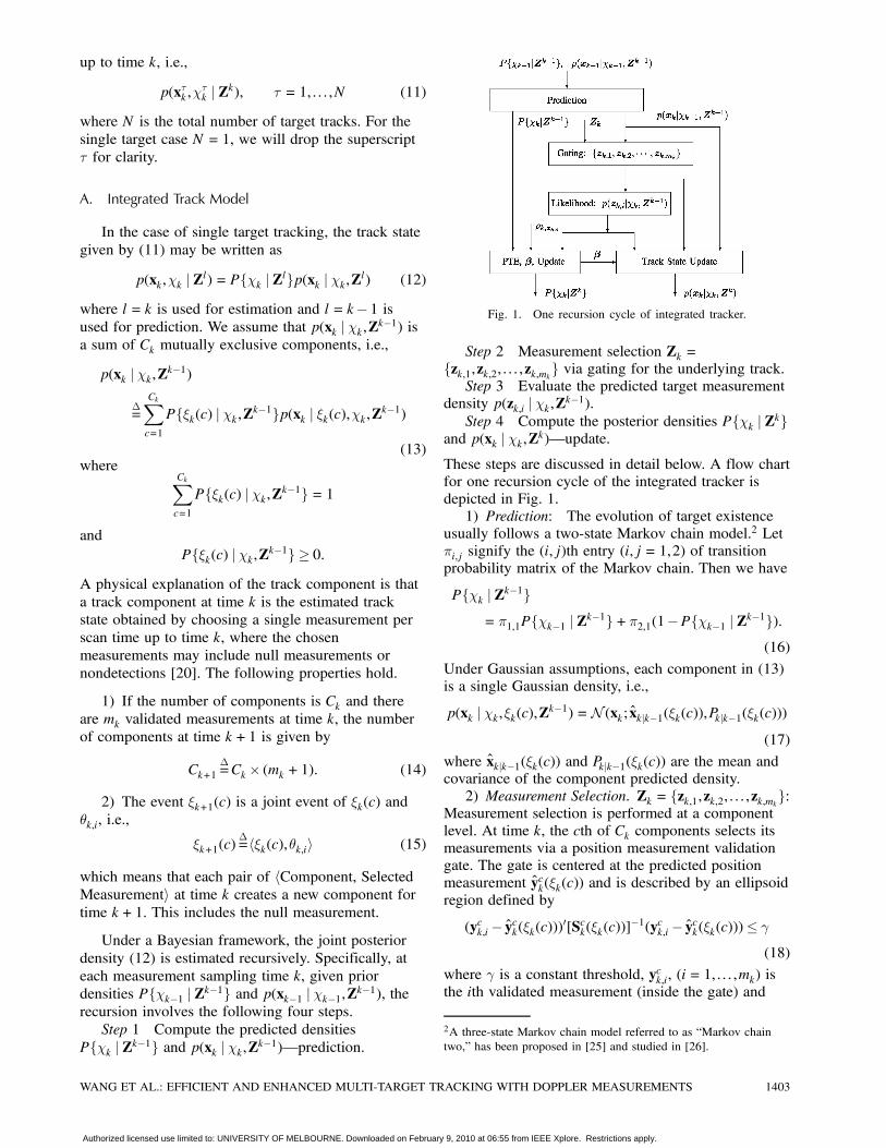
Fig. 1. One recursion cycle of integrated tracker.
Step 2 Measurement selection Zk =fzk,1,zk,2, : : : ,zk,mkg via gating for the underlying track.Step 3 Evaluate the predicted target measurement
density p(zk,i j Âk,Zk¡1).Step 4 Compute the posterior densities PfÂk j Zkg
and p(xk j Âk,Zk)–update.These steps are discussed in detail below. A flow chartfor one recursion cycle of the integrated tracker isdepicted in Fig. 1.1) Prediction: The evolution of target existence
usually follows a two-state Markov chain model.2 Let¼i,j signify the (i,j)th entry (i,j = 1,2) of transitionprobability matrix of the Markov chain. Then we have
PfÂk j Zk¡1g= ¼1,1PfÂk¡1 j Zk¡1g+¼2,1(1¡PfÂk¡1 j Zk¡1g):
(16)
Under Gaussian assumptions, each component in (13)is a single Gaussian density, i.e.,
p(xk j Âk,»k(c),Zk¡1) =N (xk; xkjk¡1(»k(c)),Pkjk¡1(»k(c)))(17)
where xkjk¡1(»k(c)) and Pkjk¡1(»k(c)) are the mean andcovariance of the component predicted density.2) Measurement Selection. Zk = fzk,1,zk,2, : : : ,zk,mkg:
Measurement selection is performed at a componentlevel. At time k, the cth of Ck components selects itsmeasurements via a position measurement validationgate. The gate is centered at the predicted positionmeasurement yck(»k(c)) and is described by an ellipsoidregion defined by
(yck,i¡ yck(»k(c)))0[Sck(»k(c))]¡1(yck,i¡ yck(»k(c)))· °(18)
where ° is a constant threshold, yck,i, (i= 1, : : : ,mk) isthe ith validated measurement (inside the gate) and
2A three-state Markov chain model referred to as “Markov chaintwo,” has been proposed in [25] and studied in [26].
WANG ET AL.: EFFICIENT AND ENHANCED MULTI-TARGET TRACKING WITH DOPPLER MEASUREMENTS 1403
Authorized licensed use limited to: UNIVERSITY OF MELBOURNE. Downloaded on February 9, 2010 at 06:55 from IEEE Xplore. Restrictions apply.

Sck(»k(c))3 is the innovation covariance of the cth
component. Note that in this gating process, only theposition measurement components are used to form atrack gate for selecting the validated measurement set.3) Predicted Target Measurement PDF.
p(zk,i j Âk,Zk¡1): The predicted measurement pdfunder the hypothesis of zk,i being a targetmeasurement is denoted as
¤k,i¢=p(zk,i j Âk,Zk¡1) (19)
which can be written as
p(zk,i j Âk,Zk¡1)
=CkXc=1
Pf»k(c) j Âk,Zk¡1gp(zk,i j Âk,»k(c),Zk¡1)
=CkXc=1
Pf»k(c) j Âk,Zk¡1gp(yck,i,ydk,i j Âk,»k(c),Zk¡1)
(20)where the last term of (20) is the measurementlikelihood function conditioned on the event »k(c)which can be approximated as
p(yck,i,ydk,i j Âk,»k(c),Zk¡1)
=
Zxk
p(yck,i,ydk,i j xk)p(xk j Âk,»k(c),Zk¡1)dxk
¼ p(yck,i j Âk,»k(c),Zk¡1)p(ydk,i j Âk,»k(c),Zk¡1)¼N (yck,i; yck(»k(c)),Sck(»k(c)))N (ydk,i; ydk (»k(c)),Sdk (»k(c))= ¤ck,i(»k(c))¤
dk,i(»k(c)) (21)
where
¤ck,i(¢)¢= j2¼Sck(¢)j¡1=2 expf¡ 1
2 (yck,i(¢)¡ yck(¢))0[Sck(¢)]¡1(yck,i(¢)¡ yck(¢))g
(22)¤dk,i(¢)¢= j2¼Sdk (¢)j¡1=2 expf¡ 1
2 (ydk,i(¢)¡ ydk (¢))0[Sdk (¢)]¡1(ydk,i(¢)¡ ydk (¢))g:
(23)
The approximation used in (21), which basicallyclaims that the joint likelihood is a product of bothposition measurement likelihood and range ratemeasurement likelihood, is derived in the Appendix I.4) Update. PfÂk j Zkg and p(xk j Âk,Zk):a) Probability of target existence update:
Following the standard IPDA derivation [21] (alsopresented in Appendix IV), the factor of the data
3In general, the innovation covariance also depends on themeasurements. For simplicity, we do not explicitly symbolise thisdependency in this paper.
association ±k is defined by
±k = PDPG
Ã1¡
mkXi=1
¤k,i½k,i
!(24)
where PD and PG are the target detection probabilityand gate probability, and the parameters ¤k,i and ½k,iare given by (19)—(21) and (10), respectively. Then
PfÂk j Zkg=(1¡ ±k)PfÂk j Zk¡1g1¡ ±kPfÂk j Zk¡1g
(25)
¯k,i¢=Pfμk,i j Âk,Zkg
=PfÂk,μk,i j ZkgPfÂk j Zkg
=1
1¡ ±k
8<:1¡PDPG, i= 0
PDPG¤k,i½k,i
i > 0: (26)
Clearly, the contribution of target Doppler informationis reflected in the data association factor (24), theprobability of target existence (25), and the dataassociation probabilities (26).b) Track update:
p(xk j Âk,Zk)
=mkXi=0
p(xk j Âk,μk,i,Zk)Pfμk,i j Âk,Zkg
=mkXi=0
¯k,ip(xk j Âk,zk,i,Zk¡1) (27)
=mkXi=0
CkXc=1
Pf»k(c) j Âk,Zk¡1g¯k,i¤k,i(»k(c))
¤k,i
£p(xk j »k(c),Âk,zk,i,Zk¡1) (28)
=Ck+1Xc=1
Pf»k+1(c) j Âk,Zkgp(xk j »k+1(c),Âk,Zk)
(29)
where ¤k,i(»k(c)) and ¤k,i in (28) are given by (21) and(19) respectively. The derivation of (28) is presentedin the Appendix II and (29) is obtained by expressing(28) as a Gaussian sum equation (13) based on(14)—(15). The conditional posterior densityp(xk j »k(c),Âk,zk,i,Zk¡1) in (28) is given by
p(xk j »k(c),Âk,zk,i,Zk¡1)
=p(zk,i j xk)p(xk j »k(c),Âk,Zk¡1)
p(zk,i j Âk,»k(c),Zk¡1)
=p(yck,i j xk)p(ydk,i j xk)p(xk j »k(c),Âk,Zk¡1)p(yck,i j Âk,»k(c),Zk¡1)p(ydk,i j Âk,»k(c),Zk¡1)
:
(30)
Due to the nonlinear relationship between target stateand target Doppler as shown in (5), evaluating (30)
1404 IEEE TRANSACTIONS ON AEROSPACE AND ELECTRONIC SYSTEMS VOL. 45, NO. 4 OCTOBER 2009
Authorized licensed use limited to: UNIVERSITY OF MELBOURNE. Downloaded on February 9, 2010 at 06:55 from IEEE Xplore. Restrictions apply.

requires the use of a nonlinear filter, such as the EKF.In our simulations, we elect not to use the Dopplermeasurements for track state update, which isequivalent to
p(ydk,i j xk)¼ p(ydk,i j Âk,»k(c),Zk¡1) (31)
and they cancel out from (30). Consequently, (30)becomes the standard Kalman filter form [27], i.e.,
p(xk j »k(c),Âk,zk,i,Zk¡1)
¼ p(yck,i j xk)p(xk j »k(c),Âk,Zk¡1)p(yck,i j Âk,»k(c),Zk¡1)
=N (xk(»k(c)); xc,ikjk,Pc,ikjk) (32)
where the superscripts a,b in (32) signify that theunderlying quantities are obtained given the ath trackcomponent using the bth position measurement yck,b. Inother words, (32) is the output of a Kalman filter withpredicted state and covariance xkjk¡1(»k(c)) andPkjk¡1(»k(c)) respectively, that uses measurement y
ck,i.
B. IPDA and ITS with DDA
The integrated track model derived in Section IIIAhas virtually brought the track splitting approach [20]and IPDA-based approach [21] for target trackingwith measurement domain uncertainties to a unifiedframework and it offers the opportunity to understandthese algorithms from a different aspect.1) The integrated track model will become an
IPDA formulation if
Ck = 1 and Pf»k(1)g= 1 (one component):
After target trajectory state estimation with mkmeasurements, all Ck+1 =mk +1 “components”are merged into one component using the PDAapproximation,
xkjk =mkXi=0
¯k,ixikjk (33)
Pkjk =mkXi=0
¯k,i(Pikjk + x
ikjk(x
ikjk)
0)¡ xkjkx0kjk: (34)
2) The equations in Section IIIA describe theITS formulation for Ck > 1. As the number ofcomponents grows exponentially in time, a componentmerge/prune procedure must be used to maintain afeasible computational complexity for the ITS. Furtherdetails can be found in [28].
C. Linear Multi-Target Method
In a multi-target environment, the LM method[22] (also presented in Appendix V) treats allmeasurements from “other” targets as clutter.Consequently, the clutter density within a track gate
is modulated by possible contributions from targetsfollowed by other tracks. The LM method calculates amodified clutter density for each track gate and uses itto evaluate the data association factor ±k in (24) andthus the probability of target existence in (25) anddata association probabilities in (26) for each of Ntracks.Let μ¿k,i denote the event that the ith measurement
(i= 1,2, : : : ,mk) is originated from the target followedby track ¿ at time k. The probability that the ithmeasurement is associated with track ¿ is thenapproximated by
P¿i¢=Pfμ¿k,i,¿k j Zk¡1g (35)
¼ P¿DP¿GPf¿k j Zk¡1g¤¿k,i=½
¿k,i
mkXj=1
¤¿k,j=½¿k,j
(36)
where Pf¿k j Zk¡1g is the prior probability of target¿ existence as defined in [21] and ½¿k,i is the in-gateclutter density. For the nonparametric approach [16],½¿k,i is assumed to be constant over all in-gate cluttermeasurements, i.e., ½¿k,i = ½
¿k . Thus (36) reduces to
P¿i = P¿DP
¿GPf¿k j Zk¡1g
¤¿k,im¿kX
j=1
¤¿k,j
(37)
where ¤¿k,i is defined by (19).The modified clutter density in the gate of track ¿
(due to the presence of multi-target measurements),denoted by −¿k,i [22], can be derived as
−¿k,i = ½ck,i½
dk,i+
NX¾=1,¾ 6=¿
¤¾k,iP¾i
1¡P¾i(38)
which replaces ½k,i in (24) and (26). Therefore, withthe LM method we have
±¿k = P¿DP
¿G
0@1¡ m¿kX
i=1
¤¿k,i−¿k,i
1A (39)
and
¯¿k,i =1
1¡ ±¿k
8<:1¡P¿DP¿G i= 0
P¿DP¿G
¤¿k,i−¿k,i
i > 0: (40)
It is then straightforward to obtain the multi-targetLMIPDA-DDA and LMITS-DDA tracking algorithmsfrom their single target tracking versions simplyby replacing (24) and (26) with (39) and (40),respectively.
IV. SIMULATION RESULTS AND DISCUSSION
In this section, the performance of the LMIPDAand LMITS algorithms with and without DDA are
WANG ET AL.: EFFICIENT AND ENHANCED MULTI-TARGET TRACKING WITH DOPPLER MEASUREMENTS 1405
Authorized licensed use limited to: UNIVERSITY OF MELBOURNE. Downloaded on February 9, 2010 at 06:55 from IEEE Xplore. Restrictions apply.

compared via an active sonar underwater targettracking scenario. We first present the active sonarscenario, then define criteria of interest for thecomparison and then discuss the simulation results.
A. Active Sonar Underwater Tracking
A shallow water environment with a constantwater depth of 200 m and constant sound speedof 1520 m/s was used for the simulation study.Acoustic propagation is modelled using standardstraight ray multipath expansions with propagationeffects such as spreading, attenuation, sea surface andbottom reflection and scattering represented by theApplied Physics Laboratory, University of Washington(APL-UW) High Frequency Acoustic Model4 [29].The active sonar source/sensor is represented
by a small planar array suitable for high frequencyacoustic transmission and reception. During thesimulation, the source/sensor starts at a depth of40 m at the XY-coordinate origin and moves witha constant speed of 3 m/s and a heading of 0 degtrue North. The active source transmits a sequenceof 75 directional, 1/2 second pulses, every 8 s overa 10 min period. These pulses consist of either CWor linear frequency modulated (LFM) waveformsthat represent two different sensor range and Dopplerresolutions. In general, the CW pulses will have muchbetter Doppler resolution and poorer range resolutionthan the LFM pulses. In this study, the CW pulse hasa nominal range resolution of 225 m and Dopplerresolution of 0.05 m/s and the LFM pulse has a rangeresolution of 0.8 m and Doppler resolution of 6.6 m/s.The active sensor is capable of detecting targets inthe forward-looking direction bounded by bearingand elevation angles in the interval [¡48,+48] degand ranges in the interval [375,4500] m. The sensorarray allows multiple, independent, directional receivebeams with a nominal beamwidth resolution of 6 degto be steered in both the horizontal and verticaldirections. The target Doppler is assumed to belimited to the interval [¡21,21] m/s to allow for thedetection of typical target speeds up to 40 knots.A set of 10 targets have been used to provide
a suitable multiple target tracking scenario for thesimulation study as shown in Fig. 2. Each target stateis modelled by (1) and (2) where the system transitionmatrix Fk and the noise covariance matrix Qk aregiven by
Fk = diag(F1,F1,F1), F1 =·1 T
0 1
¸
Qk = diag(Q1,Q1,Q1), Q1 =·T3=3 T2=2
T2=2 T
¸q
4A surface wind speed of 10 knots and seabed sediment typeconsisting of very fine sand were used for the sea surface andbottom properties.
TABLE ITarget descriptions and initial states
Target Description Initial States: L0[m]; S [m/s]; h [±]
1 Submarine [¡1500,2000,¡80] 8.68 56.32 Surface Ship [2400,2025,0] 11.58 300.33 Small Boat [¡1800,4300,0] 7.53 120.34 Point Buoy [1500,2500,¡10] 05 Point Buoy [¡500,3675,¡10] 06 Point Bottom [1000,1000,¡200] 07 Point Bottom [¡1000,1500,¡200] 08 Point Bottom [¡1500,3300,¡200] 09 Point Bottom [500,3500,¡200] 010 Point Bottom [¡500,2600,¡200] 0
and where T denotes the data sampling interval. Inthis scenario, the sensor transmitted pulse interval is8 s, however, the data sampling interval for trackingwill vary due to finite sound propagation time andvarying target ranges. The system process noiseparameter is chosen to be q= 0:1. The initial location,speed, and heading of each target is shown in Table I.The targets include two extended moving targetsrepresenting a submarine at a depth of 80 m (target 1)and a surface ship (target 2), one moving singlepoint target representing a small boat (target 3), twostationary targets at a depth of 10 m representingfixed surface buoys (targets 4—5) and five stationarytargets at a depth of 200 m that represent fixedbottom features (targets 6—10). The moving targetsare assumed to have constant speed and headingthroughout the simulation. The extended submarinetarget is represented by a set of 14 scattering pointsarranged in a fixed pattern of length 60 m that isrelative to the heading of the target. The extendedsurface ship target is similarly represented by a setof 11 scattering points arranged in a fixed pattern oflength 100 m.The transmitted pulses from the active source
propagate out to the target, are scattered by thetarget and return to the active sensor where they arereceived as multiple target echo returns. A set ofpropagation paths containing up to 3 bottom bouncesare computed in each direction resulting in a totalof 196 returns for each target scattering point. Thetargets are modelled using either a single or set ofpoint-like scatterers with a fixed omni-directionalscattering response in bearing and elevation andknown target strength. A sonar equation modelis used to determine the received signal strengthfor each target echo return. An active sonar signalprocessing model that varies with pulse type is thenused to compute the response of the sonar systemto the complete set of received target echo returns.In this model, a measurement clustering processcombines multiple target echo returns that fall withinthe same sensor measurement resolution cell in range,Doppler, bearing and elevation into a single clustered
1406 IEEE TRANSACTIONS ON AEROSPACE AND ELECTRONIC SYSTEMS VOL. 45, NO. 4 OCTOBER 2009
Authorized licensed use limited to: UNIVERSITY OF MELBOURNE. Downloaded on February 9, 2010 at 06:55 from IEEE Xplore. Restrictions apply.
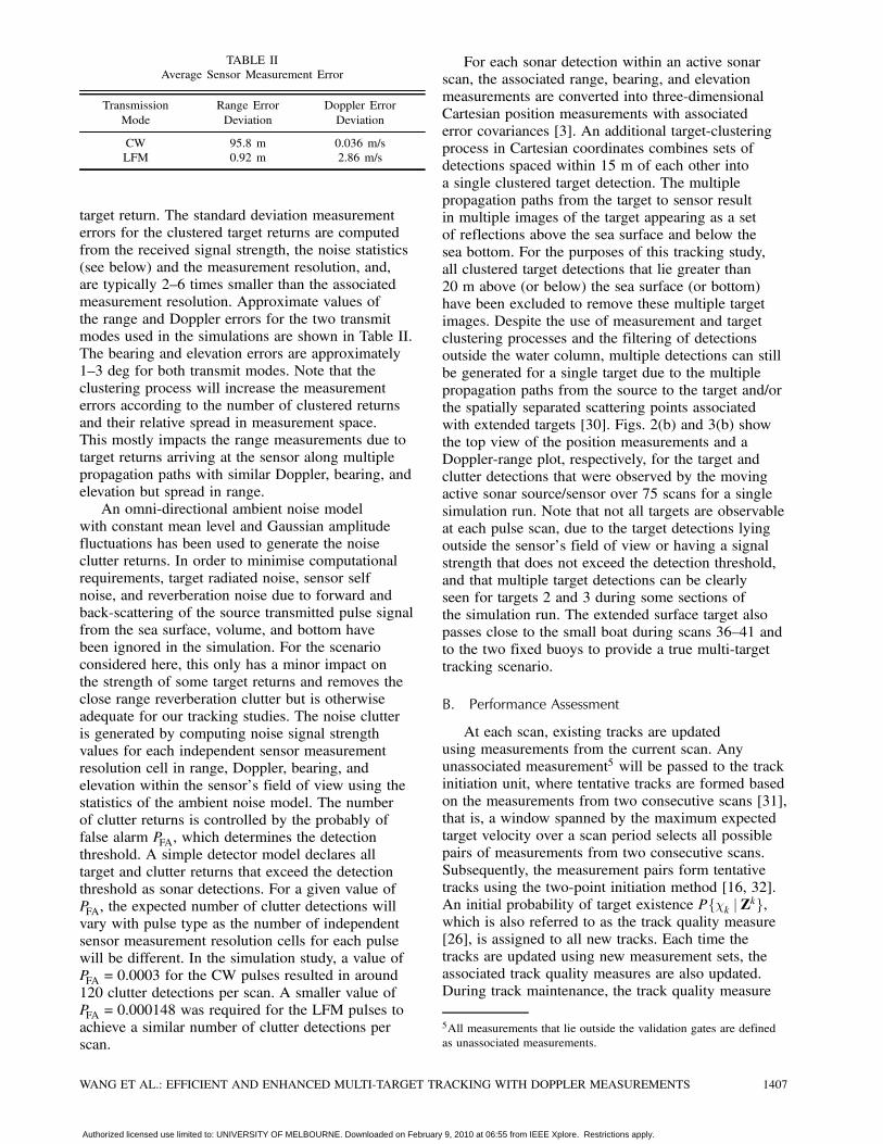
TABLE IIAverage Sensor Measurement Error
Transmission Range Error Doppler ErrorMode Deviation Deviation
CW 95.8 m 0.036 m/sLFM 0.92 m 2.86 m/s
target return. The standard deviation measurementerrors for the clustered target returns are computedfrom the received signal strength, the noise statistics(see below) and the measurement resolution, and,are typically 2—6 times smaller than the associatedmeasurement resolution. Approximate values ofthe range and Doppler errors for the two transmitmodes used in the simulations are shown in Table II.The bearing and elevation errors are approximately1—3 deg for both transmit modes. Note that theclustering process will increase the measurementerrors according to the number of clustered returnsand their relative spread in measurement space.This mostly impacts the range measurements due totarget returns arriving at the sensor along multiplepropagation paths with similar Doppler, bearing, andelevation but spread in range.An omni-directional ambient noise model
with constant mean level and Gaussian amplitudefluctuations has been used to generate the noiseclutter returns. In order to minimise computationalrequirements, target radiated noise, sensor selfnoise, and reverberation noise due to forward andback-scattering of the source transmitted pulse signalfrom the sea surface, volume, and bottom havebeen ignored in the simulation. For the scenarioconsidered here, this only has a minor impact onthe strength of some target returns and removes theclose range reverberation clutter but is otherwiseadequate for our tracking studies. The noise clutteris generated by computing noise signal strengthvalues for each independent sensor measurementresolution cell in range, Doppler, bearing, andelevation within the sensor’s field of view using thestatistics of the ambient noise model. The numberof clutter returns is controlled by the probably offalse alarm PFA, which determines the detectionthreshold. A simple detector model declares alltarget and clutter returns that exceed the detectionthreshold as sonar detections. For a given value ofPFA, the expected number of clutter detections willvary with pulse type as the number of independentsensor measurement resolution cells for each pulsewill be different. In the simulation study, a value ofPFA = 0:0003 for the CW pulses resulted in around120 clutter detections per scan. A smaller value ofPFA = 0:000148 was required for the LFM pulses toachieve a similar number of clutter detections perscan.
For each sonar detection within an active sonarscan, the associated range, bearing, and elevationmeasurements are converted into three-dimensionalCartesian position measurements with associatederror covariances [3]. An additional target-clusteringprocess in Cartesian coordinates combines sets ofdetections spaced within 15 m of each other intoa single clustered target detection. The multiplepropagation paths from the target to sensor resultin multiple images of the target appearing as a setof reflections above the sea surface and below thesea bottom. For the purposes of this tracking study,all clustered target detections that lie greater than20 m above (or below) the sea surface (or bottom)have been excluded to remove these multiple targetimages. Despite the use of measurement and targetclustering processes and the filtering of detectionsoutside the water column, multiple detections can stillbe generated for a single target due to the multiplepropagation paths from the source to the target and/orthe spatially separated scattering points associatedwith extended targets [30]. Figs. 2(b) and 3(b) showthe top view of the position measurements and aDoppler-range plot, respectively, for the target andclutter detections that were observed by the movingactive sonar source/sensor over 75 scans for a singlesimulation run. Note that not all targets are observableat each pulse scan, due to the target detections lyingoutside the sensor’s field of view or having a signalstrength that does not exceed the detection threshold,and that multiple target detections can be clearlyseen for targets 2 and 3 during some sections ofthe simulation run. The extended surface target alsopasses close to the small boat during scans 36—41 andto the two fixed buoys to provide a true multi-targettracking scenario.
B. Performance Assessment
At each scan, existing tracks are updatedusing measurements from the current scan. Anyunassociated measurement5 will be passed to the trackinitiation unit, where tentative tracks are formed basedon the measurements from two consecutive scans [31],that is, a window spanned by the maximum expectedtarget velocity over a scan period selects all possiblepairs of measurements from two consecutive scans.Subsequently, the measurement pairs form tentativetracks using the two-point initiation method [16, 32].An initial probability of target existence PfÂk j Zkg,which is also referred to as the track quality measure[26], is assigned to all new tracks. Each time thetracks are updated using new measurement sets, theassociated track quality measures are also updated.During track maintenance, the track quality measure
5All measurements that lie outside the validation gates are definedas unassociated measurements.
WANG ET AL.: EFFICIENT AND ENHANCED MULTI-TARGET TRACKING WITH DOPPLER MEASUREMENTS 1407
Authorized licensed use limited to: UNIVERSITY OF MELBOURNE. Downloaded on February 9, 2010 at 06:55 from IEEE Xplore. Restrictions apply.
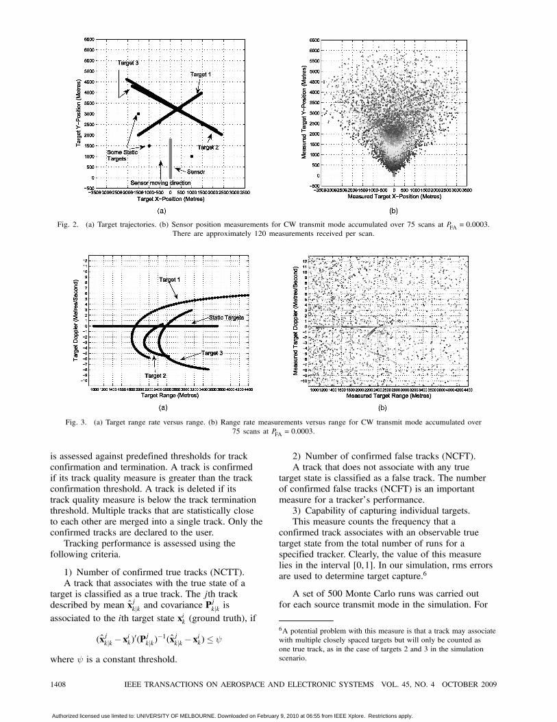
Fig. 2. (a) Target trajectories. (b) Sensor position measurements for CW transmit mode accumulated over 75 scans at PFA = 0:0003.There are approximately 120 measurements received per scan.
Fig. 3. (a) Target range rate versus range. (b) Range rate measurements versus range for CW transmit mode accumulated over75 scans at PFA = 0:0003.
is assessed against predefined thresholds for trackconfirmation and termination. A track is confirmedif its track quality measure is greater than the trackconfirmation threshold. A track is deleted if itstrack quality measure is below the track terminationthreshold. Multiple tracks that are statistically closeto each other are merged into a single track. Only theconfirmed tracks are declared to the user.Tracking performance is assessed using the
following criteria.
1) Number of confirmed true tracks (NCTT).A track that associates with the true state of a
target is classified as a true track. The jth trackdescribed by mean xjkjk and covariance P
jkjk is
associated to the ith target state xik (ground truth), if
(xjkjk ¡ xik)0(Pjkjk)¡1(xjkjk ¡ xik)· Ã
where à is a constant threshold.
2) Number of confirmed false tracks (NCFT).A track that does not associate with any true
target state is classified as a false track. The numberof confirmed false tracks (NCFT) is an importantmeasure for a tracker’s performance.3) Capability of capturing individual targets.This measure counts the frequency that a
confirmed track associates with an observable truetarget state from the total number of runs for aspecified tracker. Clearly, the value of this measurelies in the interval [0,1]. In our simulation, rms errorsare used to determine target capture.6
A set of 500 Monte Carlo runs was carried outfor each source transmit mode in the simulation. For
6A potential problem with this measure is that a track may associatewith multiple closely spaced targets but will only be counted asone true track, as in the case of targets 2 and 3 in the simulationscenario.
1408 IEEE TRANSACTIONS ON AEROSPACE AND ELECTRONIC SYSTEMS VOL. 45, NO. 4 OCTOBER 2009
Authorized licensed use limited to: UNIVERSITY OF MELBOURNE. Downloaded on February 9, 2010 at 06:55 from IEEE Xplore. Restrictions apply.
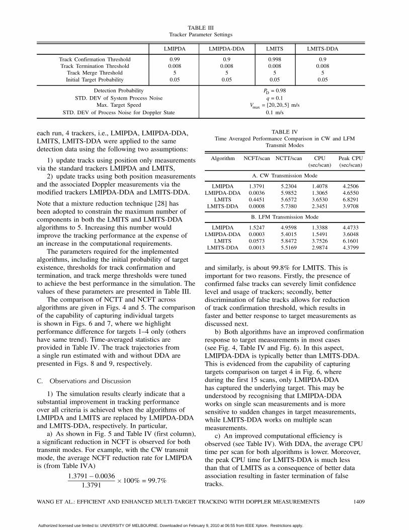
TABLE IIITracker Parameter Settings
LMIPDA LMIPDA-DDA LMITS LMITS-DDA
Track Confirmation Threshold 0.99 0.9 0.998 0.9Track Termination Threshold 0.008 0.008 0.008 0.008Track Merge Threshold 5 5 5 5Initial Target Probability 0.05 0.05 0.05 0.05
Detection Probability PD = 0:98STD. DEV of System Process Noise q= 0:1
Max. Target Speed Vmax = [20,20,5] m/sSTD. DEV of Process Noise for Doppler State 0.1 m/s
each run, 4 trackers, i.e., LMIPDA, LMIPDA-DDA,LMITS, LMITS-DDA were applied to the samedetection data using the following two assumptions:
1) update tracks using position only measurementsvia the standard trackers LMIPDA and LMITS,2) update tracks using both position measurements
and the associated Doppler measurements via themodified trackers LMIPDA-DDA and LMITS-DDA.
Note that a mixture reduction technique [28] hasbeen adopted to constrain the maximum number ofcomponents in both the LMITS and LMITS-DDAalgorithms to 5. Increasing this number wouldimprove the tracking performance at the expense ofan increase in the computational requirements.The parameters required for the implemented
algorithms, including the initial probability of targetexistence, thresholds for track confirmation andtermination, and track merge thresholds were tunedto achieve the best performance in the simulation. Thevalues of these parameters are presented in Table III.The comparison of NCTT and NCFT across
algorithms are given in Figs. 4 and 5. The comparisonof the capability of capturing individual targetsis shown in Figs. 6 and 7, where we highlightperformance difference for targets 1—4 only (othershave same trend). Time-averaged statistics areprovided in Table IV. The track trajectories froma single run estimated with and without DDA arepresented in Figs. 8 and 9, respectively.
C. Observations and Discussion
1) The simulation results clearly indicate that asubstantial improvement in tracking performanceover all criteria is achieved when the algorithms ofLMIPDA and LMITS are replaced by LMIPDA-DDAand LMITS-DDA, respectively. In particular,a) As shown in Fig. 5 and Table IV (first column),
a significant reduction in NCFT is observed for bothtransmit modes. For example, with the CW transmitmode, the average NCFT reduction rate for LMIPDAis (from Table IVA)
1:3791¡ 0:00361:3791
£100%= 99:7%
TABLE IVTime Averaged Performance Comparison in CW and LFM
Transmit Modes
Algorithm NCFT/scan NCTT/scan CPU(sec/scan)
Peak CPU(sec/scan)
A. CW Transmission Mode
LMIPDA 1.3791 5.2304 1.4078 4.2506LMIPDA-DDA 0.0036 5.9852 1.3065 4.6550
LMITS 0.4451 5.6572 3.6530 6.8291LMITS-DDA 0.0008 5.7380 2.3451 3.9708
B. LFM Transmission Mode
LMIPDA 1.5247 4.9598 1.3388 4.4733LMIPDA-DDA 0.0003 5.4015 1.5491 3.6048
LMITS 0.0573 5.8472 3.7526 6.1601LMITS-DDA 0.0013 5.5169 2.9874 4.3799
and similarly, is about 99.8% for LMITS. This isimportant for two reasons. Firstly, the presence ofconfirmed false tracks can severely limit confidencelevel and usage of trackers; secondly, betterdiscrimination of false tracks allows for reductionof track confirmation threshold, which results infaster and better response to target measurements asdiscussed next.b) Both algorithms have an improved confirmation
response to target measurements in most cases(see Fig. 4, Table IV and Fig. 6). In this aspect,LMIPDA-DDA is typically better than LMITS-DDA.This is evidenced from the capability of capturingtargets comparison on target 4 in Fig. 6, whereduring the first 15 scans, only LMIPDA-DDAhas captured the underlying target. This may beunderstood by recognising that LMIPDA-DDAworks on single scan measurements and is moresensitive to sudden changes in target measurements,while LMITS-DDA works on multiple scanmeasurements.c) An improved computational efficiency is
observed (see Table IV). With DDA, the average CPUtime per scan for both algorithms is lower. Moreover,the peak CPU time for LMITS-DDA is much lessthan that of LMITS as a consequence of better dataassociation resulting in faster termination of falsetracks.
WANG ET AL.: EFFICIENT AND ENHANCED MULTI-TARGET TRACKING WITH DOPPLER MEASUREMENTS 1409
Authorized licensed use limited to: UNIVERSITY OF MELBOURNE. Downloaded on February 9, 2010 at 06:55 from IEEE Xplore. Restrictions apply.
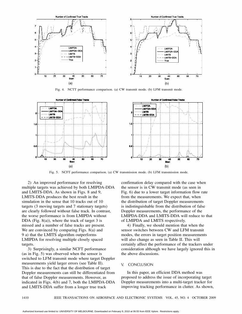
Fig. 4. NCTT performance comparison. (a) CW transmit mode. (b) LFM transmit mode.
Fig. 5. NCFT performance comparison. (a) CW transmission mode. (b) LFM transmission mode.
2) An improved performance for resolvingmultiple targets was achieved by both LMIPDA-DDAand LMITS-DDA. As shown in Figs. 8 and 9,LMITS-DDA produces the best result in thesimulation in the sense that 10 tracks out of 10targets (3 moving targets and 7 stationary targets)are clearly followed without false track. In contrast,the worse performance is from LMIPDA withoutDDA (Fig. 8(a)), where the track of target 3 ismissed and a number of false tracks are present.We are convinced by comparing Figs. 8(a) and9 a) that the LMITS algorithm outperformsLMIPDA for resolving multiple closely spacedtargets.3) Surprisingly, a similar NCFT performance
(as in Fig. 5) was observed when the sensor isswitched to LFM transmit mode where target Dopplermeasurements yield larger errors (see Table II).This is due to the fact that the distribution of targetDoppler measurements can still be differentiated fromthat of false Doppler measurements. However, asindicated in Figs. 4(b) and 7, both the LMIPDA-DDAand LMITS-DDA suffer from a longer true track
confirmation delay compared with the case whenthe sensor is in CW transmit mode (as seen inFig. 6) due to a lower target information flow ratefrom the measurements. We expect that, whenthe distribution of target Doppler measurementsis indistinguishable from the distribution of falseDoppler measurements, the performance of theLMIPDA-DDA and LMITS-DDA will reduce to thatof LMIPDA and LMITS respectively.4) Finally, we should mention that when the
sensor switches between CW and LFM transmitmodes, the errors in target position measurementswill also change as seen in Table II. This willcertainly affect the performance of the trackers underconsideration although we have largely ignored this inthe above discussions.
V. CONCLUSION
In this paper, an efficient DDA method wasproposed to address the issue of incorporating targetDoppler measurements into a multi-target tracker forimproving tracking performance in clutter. As shown,
1410 IEEE TRANSACTIONS ON AEROSPACE AND ELECTRONIC SYSTEMS VOL. 45, NO. 4 OCTOBER 2009
Authorized licensed use limited to: UNIVERSITY OF MELBOURNE. Downloaded on February 9, 2010 at 06:55 from IEEE Xplore. Restrictions apply.
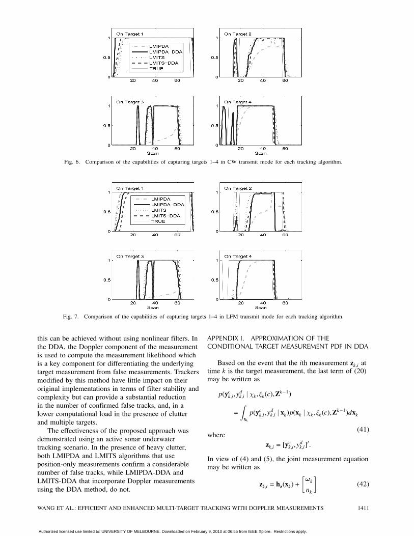
Fig. 6. Comparison of the capabilities of capturing targets 1—4 in CW transmit mode for each tracking algorithm.
Fig. 7. Comparison of the capabilities of capturing targets 1—4 in LFM transmit mode for each tracking algorithm.
this can be achieved without using nonlinear filters. Inthe DDA, the Doppler component of the measurementis used to compute the measurement likelihood whichis a key component for differentiating the underlyingtarget measurement from false measurements. Trackersmodified by this method have little impact on theiroriginal implementations in terms of filter stability andcomplexity but can provide a substantial reductionin the number of confirmed false tracks, and, in alower computational load in the presence of clutterand multiple targets.The effectiveness of the proposed approach was
demonstrated using an active sonar underwatertracking scenario. In the presence of heavy clutter,both LMIPDA and LMITS algorithms that useposition-only measurements confirm a considerablenumber of false tracks, while LMIPDA-DDA andLMITS-DDA that incorporate Doppler measurementsusing the DDA method, do not.
APPENDIX I. APPROXIMATION OF THECONDITIONAL TARGET MEASUREMENT PDF IN DDA
Based on the event that the ith measurement zk,i attime k is the target measurement, the last term of (20)may be written as
p(yck,i,ydk,i j Âk,»k(c),Zk¡1)
=Zxkp(yck,i,y
dk,i j xk)p(xk j Âk,»k(c),Zk¡1)dxk
(41)where
zk,i = [yck,i,y
dk,i]
0:
In view of (4) and (5), the joint measurement equationmay be written as
zk,i = hz(xk)+·!k
nk
¸(42)
WANG ET AL.: EFFICIENT AND ENHANCED MULTI-TARGET TRACKING WITH DOPPLER MEASUREMENTS 1411
Authorized licensed use limited to: UNIVERSITY OF MELBOURNE. Downloaded on February 9, 2010 at 06:55 from IEEE Xplore. Restrictions apply.
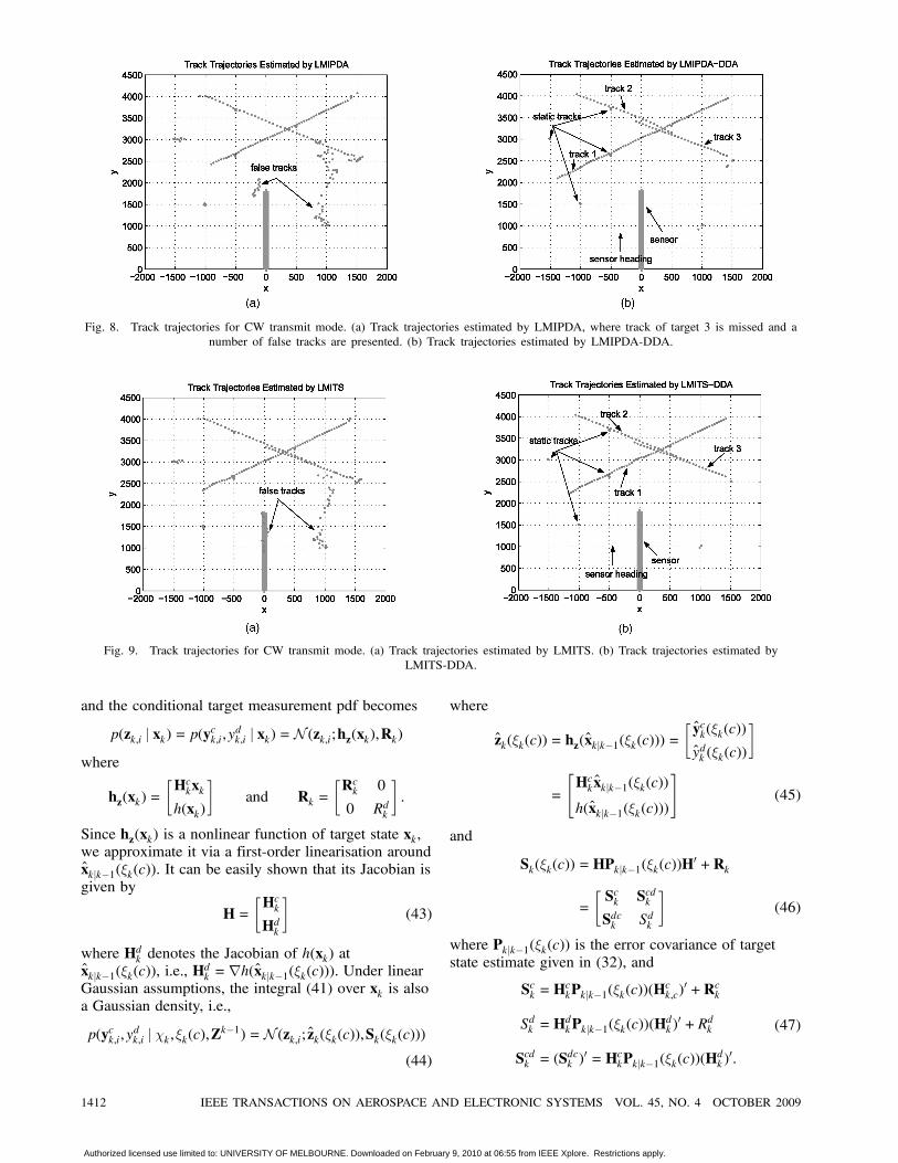
Fig. 8. Track trajectories for CW transmit mode. (a) Track trajectories estimated by LMIPDA, where track of target 3 is missed and anumber of false tracks are presented. (b) Track trajectories estimated by LMIPDA-DDA.
Fig. 9. Track trajectories for CW transmit mode. (a) Track trajectories estimated by LMITS. (b) Track trajectories estimated byLMITS-DDA.
and the conditional target measurement pdf becomes
p(zk,i j xk) = p(yck,i,ydk,i j xk) =N (zk,i;hz(xk),Rk)where
hz(xk) =·Hckxkh(xk)
¸and Rk =
·Rck 0
0 Rdk
¸:
Since hz(xk) is a nonlinear function of target state xk,we approximate it via a first-order linearisation aroundxkjk¡1(»k(c)). It can be easily shown that its Jacobian isgiven by
H=·HckHdk
¸(43)
where Hdk denotes the Jacobian of h(xk) atxkjk¡1(»k(c)), i.e., H
dk =rh(xkjk¡1(»k(c))). Under linear
Gaussian assumptions, the integral (41) over xk is alsoa Gaussian density, i.e.,
p(yck,i,ydk,i j Âk,»k(c),Zk¡1) =N (zk,i; zk(»k(c)),Sk(»k(c)))
(44)
where
zk(»k(c)) = hz(xkjk¡1(»k(c))) =·yck(»k(c))
ydk (»k(c))
¸
=
"Hckxkjk¡1(»k(c))
h(xkjk¡1(»k(c)))
#(45)
and
Sk(»k(c)) =HPkjk¡1(»k(c))H0+Rk
=·Sck ScdkSdck Sdk
¸(46)
where Pkjk¡1(»k(c)) is the error covariance of targetstate estimate given in (32), and
Sck =HckPkjk¡1(»k(c))(H
ck,c)
0+Rck
Sdk =HdkPkjk¡1(»k(c))(H
dk )0+Rdk
Scdk = (Sdck )
0 =HckPkjk¡1(»k(c))(Hdk )0:
(47)
1412 IEEE TRANSACTIONS ON AEROSPACE AND ELECTRONIC SYSTEMS VOL. 45, NO. 4 OCTOBER 2009
Authorized licensed use limited to: UNIVERSITY OF MELBOURNE. Downloaded on February 9, 2010 at 06:55 from IEEE Xplore. Restrictions apply.

Due to the term Scdk , the position and Dopplermeasurements are not independent for any givencomponent. In this work, we approximate Scdk =(Sdck )
0 ¼ 0. In view of (45)—(47), Equation (44)becomes
p(yck,i,ydk,i j Âk,»k(c),Zk¡1)
=N (zk,i(»k(c)); zk(»k(c)),Sk(»k(c)))¼N (yck,i; yck(»k(c)),Sck(»k(c)))N (ydk,i; ydk (»k(c)),Sdk (»k(c)))= ¤ck,i(»k(c))¤
dk,i(»k(c)): (48)
Note that in the presence of a large positionmeasurement error, state estimation will also yield alarge error. Consequently, the Doppler measurementpdf approximated via the nonlinear model (42) maynot reflect the true target Doppler measurement pdf.Alternatively, we may find the Doppler measurementpdf in (48) by estimating target Doppler stateseparately as in Appendix III.
APPENDIX II. DERIVATION OF p(xk j Âk,zk,i,Zk¡1)Based on the definition (13), the last term of (27)
is given by
p(xk j Âk,zk,i,Zk¡1)
=p(zk,i j xk,Âk,Zk¡1)p(zk,i j Âk,Zk¡1)
p(xk j Âk,Zk¡1)
=p(zk,i j xk)
p(zk,i j Âk,Zk¡1)CkXc=1
Pf»k(c) j Âk,Zk¡1g
£p(xk j »k(c),Âk,Zk¡1)
=CkXc=1
Pf»k(c) j Âk,Zk¡1gp(zk,i j xk)
p(zk,i j Âk,Zk¡1)
£p(xk j »k(c),Âk,Zk¡1)p(zk,i j »k(c),Âk,Zk¡1)p(zk,i j »k(c),Âk,Zk¡1)
=CkXc=1
p(zk,i j »k(c),Âk,Zk¡1)p(zk,i j Âk,Zk¡1)
Pf»k(c) j Âk,Zk¡1g
£p(xk j »k(c),Âk,zk,i,Zk¡1)
=CkXc=1
¤k,i(»k(c))¤k,i
Pf»k(c) j Âk,Zk¡1g
£p(xk j »k(c),Âk,zk,i,Zk¡1): (49)
APPENDIX III. RANGE RATE ESTIMATION
In our simulation, the Doppler state of target ¿ ,denoted as _r¿k , is assumed to be a constant subject to aGaussian random noise ek »N (ek;0,Qdk ), i.e.,
_r¿k+1 = _r¿k + ek: (50)
Note that (5) can also be written as
ydk =Mdk_r¿k + nk (51)
where Mdk = 1. In some cases, we can estimate the
target Doppler state _rk using a separate estimatorbased on (50) and (51), and therefore, can thendetermine the required predicted measurement pdfp(ydk j Âk,Zk¡1).For example, in the LMIPDA-DDA algorithm, a
simple PDA estimator is added for estimating targetrange rate and thus providing Doppler measurement
likelihood for (19). Let _r¿
k¡1jk¡1 and Pd,¿k¡1jk¡1 be the
range rate estimate and error variance for track ¿ . Therecursion of range rate estimation for track ¿ at time kis given by the following steps.
1) Prediction:
_r¿
kjk¡1 = _r¿
k¡1jk¡1
Pd,¿kjk¡1 = Pd,¿k¡1jk¡1 +Q
dk
yd,¿k = _r¿
kjk¡1
Sd,¿k = Pd,¿kjk¡1M0d+R
dk :
(52)
2) Compute the likelihood of the ith range ratemeasurement for track ¿ as
¤d,¿k,i = p(ydk,i j Âk,Yk¡1d )
= j2¼Sd,¿k j¡1=2 expá12
(ydk,i¡ ydk )2Sd,¿k
!: (53)
Note that, (53) is used for the evaluation of (19).3) Update the range rate using the data association
probabilities ¯¿k,i from (40) as
_r¿
kjk =mkXi=0
¯¿k,i[ _r¿
kjk¡1 +K¿i (y
dk,i¡ ydk )] =
mkXi=0
¯¿k,i _r¿ ,i
kjk
Pd,¿kjk =mkXi=0
¯¿k,i(P¿ ,ikjk +(_r
¿ ,i
kjk ¡ _r¿
kjk)( _r¿ ,i
kjk ¡ _r¿
kjk)0)
where K¿i = Pdkjk¡1(S
d,¿k )
¡1 and P¿ ,ikjk = (1¡K¿i )Pd,¿kjk¡1.
APPENDIX IV. UPDATE OF TARGET EXISTENCE ANDDATA ASSOCIATION PROBABILITIES
Let Âk denote the complement of Âk, i.e., the eventthat the target does not exist and note that
PfÂk j Zk¡1g= 1¡PfÂk j Zk¡1g: (54)
Applying the Bayes formula, we have
PfÂk j Zkg
=p(Zk j Âk ,Zk¡1)PfÂk j Zk¡1g
p(Zk j Âk ,Zk¡1)PfÂk j Zk¡1g+p(Zk j Âk ,Zk¡1)PfÂk j Zk¡1g
(55)
WANG ET AL.: EFFICIENT AND ENHANCED MULTI-TARGET TRACKING WITH DOPPLER MEASUREMENTS 1413
Authorized licensed use limited to: UNIVERSITY OF MELBOURNE. Downloaded on February 9, 2010 at 06:55 from IEEE Xplore. Restrictions apply.

where Zk contains mk measurements at current scan kand
p(Zk j Âk,Zk¡1)
= p(Zk,mk j Âk,Zk¡1)
= p(Zk,mk j Âk,μk,0,Zk¡1)Pfμk,0 j Âk,Zk¡1g
+mkXj=1
p(Zk,mk j Âk,μk,j ,Zk¡1)Pfμk,j j Âk,Zk¡1g:
(56)The first term in (56) is given by
p(Zk,mk j Âk,μk,0,Zk¡1)¢=p(Zk j Âk,Zk¡1)
= p(Zk j Âk,mk,Zk¡1)Pfmk j μk,0,Zk¡1g
=mkYj=1
pc(zk,j)Pofmk,mkg (57)
where pc(zk,i) signifies clutter pdf at the ithmeasurement and is given by
pc(zk,j) =½k,iZ
Vk
½cdV=½k,imk: (58)
The number of clutter measurements in (57) followsPoisson distribution, denoted by Pofm,¸g withparameter ¸= mk, i.e.,
Pfmk j μk,0,Zk¡1g= Pofmk,mkg= e¡mkmmkkmk!
:
In particular,
Pfmk j μk,j>0,Zk¡1g= Pofmk ¡1,mkg
= Pofmk,mkgmkmk: (59)
The other terms in (56) are given by
Pfμk,j j Âk,Zk¡1g=PDPGmk
(60)
Pfμk,0 j Âk,Zk¡1g= 1¡PDPG (61)
and
p(Zk,mk j Âk,μk,j ,Zk¡1)
= p(Zk j Âk,μk,j ,mk,Zk¡1)Pfmk j μk,j ,Zk¡1g
=
0@ mkYi=1,i 6=j
pc(zk,i)
1A¤k,jPofmk ¡ 1,mkg=
ÃmkYi=1
pc(zk,i)Pofmk,mkg!
¤k,jpc(zk,j)
mkmk: (62)
Substitute (57)—(62) into (56) and we have
p(Zk j Âk,Zk¡1) =mkYi=1
pc(zk,i)Pofmk,mkg
£241¡PDPG +PDPG mkX
j=1
¤k,j½k,j
35=
mkYi=1
pc(zk,i)Pofmk,mkg(1¡ ±k):
(63)
In view of (54), (57), and (63), the probability oftarget existence (55) can be written as
PfÂk j Zkg=(1¡ ±k)PfÂk j Zk¡1g1¡ ±kPfÂk j Zk¡1g
: (64)
The data association probabilities can bestraightforwardly derived from their definitions usingBayes formula, where all terms have already beengiven above.
¯k,0¢=Pfμk,0 j Âk,Zkg
=p(Zk j μk,0,Âk,Zk¡1)Pfμk,0 j Âk,Zk¡1g
p(Zk j Âk,Zk¡1)
=1¡PDPG1¡ ±k
(65)
and for i > 0
¯k,i¢=Pfμk,i j Âk,Zkg
=p(Zk j μk,i,Âk,Zk¡1)Pfμk,i j Âk,Zk¡1g
p(Zk j Âk,Zk¡1)
=PDPG1¡ ±k
¤k,i½k,i
: (66)
APPENDIX V. LINEAR MULTI-TARGET DERIVATION
The prior probability that a selected measurementat time k will be a detection of target ¿ equals theprobability that the target exists and that the target isdetected (given that it exists) and that its measurementis selected: P¿DP
¿GPfÂk j Zk¡1g. This probability is
split amongst the selected measurements to obtain anapproximation of the prior probability of measurementi association to target ¿ at time k:
P¿i ¼ P¿DP¿GPf¿k j Zk¡1g¤¿k,i=½
¿k,i
mkXj=1
¤¿k,j=½¿k,j
: (67)
If a measurement j is not selected by track ¿ , thenP¿j = ¤
¿k,j = 0. The probabilities P
¿i are assumed to
be independent from track to track; thus the mutual
1414 IEEE TRANSACTIONS ON AEROSPACE AND ELECTRONIC SYSTEMS VOL. 45, NO. 4 OCTOBER 2009
Authorized licensed use limited to: UNIVERSITY OF MELBOURNE. Downloaded on February 9, 2010 at 06:55 from IEEE Xplore. Restrictions apply.
exclusiveness of measurement source is not enforcedhere.When updating track ¿ in a single target
environment, the track measurement likelihood ratio1¡ ±¿k given by (24), as well as the data associationprobabilities ¯¿k,i, given by (26), depend on the ratio oftarget measurement density and clutter measurementdensity at zk,i, i= 1, : : : ,mk given by
P¿DP¿G¤
¿k,i
½k,i: (68)
When updating track ¿ in a multi-target situation,the target measurement density is modified by theprior probability that measurement zk,i is not adetection of any other track:
P¿DP¿G¤
¿k,i
Y´ 6=¿(1¡P´i ): (69)
Clutter measurement density ½k,i must also bemultiplied by the probability that measurement zk,i isnot a detection of other targets. Additionally, whenupdating track ¿ , possible detections of other tracks¾ 6= ¿ are also unwanted detections and add to theclutter density. Thus, the equivalent target density atthe position of measurement zk,i when updating track¿ equals
½k,iY´ 6=¿(1¡P´i ) +
X¾ 6=¿¤¾k,iP
¾i
Y´ 6=¿ ,¾
(1¡P´i )
=Y´ 6=¿(1¡P´i )
0@½k,i+X¾ 6=¿¤¾k,i
P¾i1¡P¾i
1A (70)
where the term P¾iQ´ 6=¿ ,¾(1¡P´i ) denotes the prior
probability that measurement zk,i is the detection oftarget ¾, discounting target ¿ . Thus, when updatingtrack ¿ , the ratio of target measurement density toclutter measurement density becomes
P¿DP¿G¤
¿k,i
½k,i
LM¡!P¿DP
¿G¤
¿k,i
Y´ 6=¿(1¡P´i )
Y´ 6=¿(1¡P´i )
0@½k,i+X¾ 6=¿¤¾k,i
P¾i1¡P¾i
1A=
P¿DP¿G¤
¿k,i
½k,i+X¾ 6=¿¤¾k,i
P¾i1¡P¾i
: (71)
The net effect when updating track ¿ using the LMmethod is replacing the clutter measurement density½k,i, i= 1, : : : ,mk with
−¿k,i = ½k,i+X¾ 6=¿
¤¾k,iP¾i
1¡P¾i(72)
in the expressions for measurement likelihood ratioand data association probabilities represented by (24)and (26).
REFERENCES
[1] Blackman, S.Multiple Target Tracking with Radar Applications.Norwood, MA: Artech House, 1986.
[2] Blackman, S., and Popoli, R.Design and Analysis of Modern Tracking Systems.Norwood, MA: Artech House, 1999.
[3] Mo, L., Song, X., Sun, Z. K., and Bar-Shalom, Y.Unbiased converted measurements for tracking.IEEE Transactions on Aerospace and Electronic Systems,34, 3 (July 1998), 1023—1027.
[4] Farina, A., and Studer, F. A.Radar Data Processing, vol. 1, Introduction and Tracking.New York: Wiley, 1985.
[5] Bar-Shalom, Y.Negative correlation and optimal tracking with Dopplermeasurements.IEEE Transactions on Aerospace and Electronic Systems,37, 3 (2001), 1117—1120.
[6] Kameda, H., Tsujimichi, S., and Kosuge, Y.Target tracking under dense environments using rangerate measurements.Proceedings of the 37th SICE Annual Converence,International Session Papers, July 29—31, 1998, 927—932.
[7] Yeom, S-W., Kirubarajan, T., and Bar-Shalom, Y.Track segment association, fine-step IMM andinitialization with Doppler for improved trackperformance.IEEE Transactions on Aerospace and Electronic Systems,40, 1 (Jan. 2004), 293—309.
[8] Kosuge, Y., Iwama, H., and Miyazaiki, Y.A tracking filter for phased array radar with range ratemeasurement.Proceedings of 1991 International Conference on IndustrialElectronics, Control and Instrumentation (IECON ’91),vol. 3, Oct. 28—Nov. 1, 1991, 2555—2560.
[9] Wang, J. G., Long, T., and He, P. K.Use of the radial velocity measurement in target tracking.IEEE Transactions on Aerospace and Electronic Systems,39, 2 (Apr. 2003), 401—413.
[10] Duan, Z. S., Han, C. Z., and Li, X. R.Sequential nonlinear tracking filter with range-ratemeasurements in spherical coordinates.Proceedings of the 7th International Conference onInformation Fusion, Stockholm, Sweden, June 28—July1, 2004, 599—605.
[11] Gurfil, P. and Kasin, N. J.Two-step optimal estimator for three-dimensional targettracking.IEEE Transactions on Aerospace and Electronic Systems,41, 3 (July 2005), 780—793.
[12] Lerro, D., and Bar-Shalom, Y.Tracking with debiased consistent convertedmeasurements versus EKF.IEEE Transactions on Aerospace and Electronic Systems,29, 3 (1993), 1015—1022.
[13] Wan, E. A., and Van Der Menve, R.The unscented Kalman filter for nonlinear estimation.Proceedings of Adaptive Systems for Signal Processing,Communications, and Control Symposium 2000, Oct. 1—4,2000, 153—158.
[14] Julier, S. J., and Uhlmann, J. K.Unscented filtering and nonlinear estimation.Proceedings of the IEEE, 92, 3 (Mar. 2004), 4001—422.
[15] Doucet, A., Gordon, J., and Krishnamurthy, V.Particle filter for state estimation of jump Markov linearsystems.Proceedings of Signal Processing, 49, 3 (Mar. 2001),613—624.
WANG ET AL.: EFFICIENT AND ENHANCED MULTI-TARGET TRACKING WITH DOPPLER MEASUREMENTS 1415
Authorized licensed use limited to: UNIVERSITY OF MELBOURNE. Downloaded on February 9, 2010 at 06:55 from IEEE Xplore. Restrictions apply.

[16] Bar-Shalom, Y., and Fortmann, T. E.Tracking and Data Association.Burlington, MA: Academic Press, 1988.
[17] Blair, W. D., and Brandt-Pierce, M.NNJPDA for tracking closely-spaced Rayleigh targetswith possibly merged measurements.Proceedings of SPIE Conference on Signal and DataProcessing of Small Targets, Oct. 1, 1999, 396—408.
[18] Wang, X., Mušicki, D., Ellem, R., and Fletcher, R.Enhanced multi-target tracking with Dopplermeasurements.Proceedings of International Conference on Information,Decision and Control (IDC 2007), Adelaide, Australia,Feb. 11—14, 2007, 53—58.
[19] Mušicki, D., and Evans, R.Joint integration probabilistic data association-JIPDA.IEEE Transactions on Aerospace and Electronic Systems,40, 3 (July 2004), 1093—1099.
[20] Mušicki, D., La Scala, B., and Evans, R.The integrated track splitting filter-efficient multi-scansingle target tracking in clutter.IEEE Transactions on Aerospace and Electronic Systems,43, 4 (Oct. 2007), 1409—1425.
[21] Mušicki, D., Evans, R. J., and Stankovic, S.Integrated probabilistic data association.IEEE Transactions on Automatic Control, 39, 6 (June1994), 1237—1241.
[22] Mušicki, D., and La Scala, B.Multi-target tracking in clutter without measurementassignment.IEEE Transactions on Aerospace and Electronic Systems,44, 2 (Apr. 2008).
[23] Mušicki, D., and Suvorova, S.Tracking in clutter using IMM-IPDA based algorithms.IEEE Transactions on Aerospace and Electronic Systems,44, 1 (Jan. 2008).
[24] Mušicki, D., and Morelande, M.Gate volume estimation for target tracking.Proceedings of 7th International Conference on InformationFusion (Fusion 2004), Stockholm, Sweden, June 2004.
Xuezhi Wang received the B.S. degree in avionics from Northwest PolytechnicalUniversity, Xian, China in 1982 and the Ph.D. degree in signal and systems fromthe Department of Electrical & Electronic Engineering, University of Melbourne,Australia in 2001.He has been involved in radar and sonar signal processing research and
development since 1983. He had been working with the Co-operative ResearchCenter for sensor signal and information processing (CSSIP), Australia from2001 to 2005. He is now a research fellow with the Melbourne SystemsLaboratory, in the Department of Electrical & Electronic Engineering, Universityof Melbourne, Australia. He has worked as a key player on many industrialcontracts in the area of target tracking, data fusion and sensor network issues fordefense research agencies both in Australia and USA since 2001.His research interests are in stochastic signal processing, information theory,
Bayesian estimation, data fusion and Situation assessment.
[25] Mušicki, D.Automatic tracking of maneuvering targets in clutterusing IPDA.Ph.D. dissertation, University of Newcastle, New SouthWales, Australia, Sept. 1994.
[26] Wang, X., and Mušicki, D.Low elevation sea-surface target tracking.IEEE Transactions on Aerospace and Electronic Systems,44, 2 (Apr. 2007), 764—774.
[27] Ho, Y. C., and Lee, R. C. K.A Bayesian approach to problems in stochastic estimationand control.IEEE Transactions on Automatic Control (1964), 333—339.
[28] Salmond, D. J.Mixture reduction algorithms for target tracking in clutter.Proceedings of SPIE Conference on Signal and DataProcessing of Small Targets, vol. 1305, 1990, 434—445.
[29] Applied Physics Laboratory, University of WashingtonAPL-UW High Frequency Ocean Environmental AcousticModels Handbook.APL-UW TR 9407, AEAS 9501, Oct. 1994.
[30] Mušicki, D., Wang, X., Fletcher, F., and Ellem, R.Efficient active sonar multi-target tracking.Proceedings of IEEE OCEANS’06 Asia Pacific, Singapore,May 16—19, 2006.
[31] Helmick, R. E., and Watson, G. A.IMM-IPDAF for track formation on maneuvering targetsin cluttered environments.Proceedings of SPIE Conference on Signal and DataProcessing of Small Targets, vol. 2235, 1994, 460—471.
[32] Bar-Shalom, Y., Chang, K. C., and Blom, H. A. P.Automatic track formation in clutter with a recursivealgorithm.Proceedings of 28th Conference on Decision and Control,Tampa, FL, Dec. 1989, 1402—1408.
1416 IEEE TRANSACTIONS ON AEROSPACE AND ELECTRONIC SYSTEMS VOL. 45, NO. 4 OCTOBER 2009
Authorized licensed use limited to: UNIVERSITY OF MELBOURNE. Downloaded on February 9, 2010 at 06:55 from IEEE Xplore. Restrictions apply.

Darko Mušicki was born in Belgrade, Serbia, in 1957. He completed a B.E.degree in electrical engineering at the University of Belgrade in 1979. Hecompleted a M.Sc. in communications in 1984 at the University of Belgrade,Serbia. He completed a Ph.D in 1994 at the University of Newcastle, NSW.After graduating he worked in the area of radar system design and
simulations, as well as fast digital signal processing implementations. He wasmember of the academic staff between 1985 and 1988 at the University ofBelgrade, Serbia. He worked for Entropy Data Pty. Ltd. from 1988 to 2002,when he joined the University of Melbourne, Australia. He finished his tenureat the University of Melbourne, Australia, as a Principal Research Fellow atthe Melbourne System Laboratory of the Electrical and Electronic EngineeringDepartment. He is now an independent consultant.Since 1984 Darko Mušicki was involved in target tracking research and
design, information fusion, and nonlinear estimation, as well as resourceallocation and wireless sensor networks. His other interests have ranged acrossmany areas, including radar systems design and simulation, signal processing,as well as efficient software development. Darko Mušicki is the (co) author of anumber of often cited publications in his chosen fields. He is currently serving asthe President of ISIF (International Society for Information Fusion).
Richard Ellem completed a B.Sc. (Hons) in mathematics and physics at theUniversity of New England in 1993 and a Ph.D. in theoretical physics at theAustralian National University in 1998.He joined Maritime Operations Division, Defence Science and Technology
Organisation in March 1999 where he has worked on sonar array, signal and dataprocessing for various active and passive sonar systems and is currently a SeniorResearch Scientist working in the area of sonar detection and tracking for torpedosystems.
Fiona Fletcher received a B.Sc. (Hons) degree in applied mathematics from theUniversity of Adelaide, Australia, in 1999 and a Ph.D. degree in electrical andelectronic engineering from the University of Melbourne, Australia, in 2005.She joined the Defence Science and Technology Organisation, Australia,
in 1999 where she has worked on tracking approaches for applications such astorpedo defence and emitter localisation for UAVs. Her research interests includemulti-target tracking, passive tracking and decentralised data fusion.
WANG ET AL.: EFFICIENT AND ENHANCED MULTI-TARGET TRACKING WITH DOPPLER MEASUREMENTS 1417
Authorized licensed use limited to: UNIVERSITY OF MELBOURNE. Downloaded on February 9, 2010 at 06:55 from IEEE Xplore. Restrictions apply.