
A large streamer chamber muon tracking detector in a high-flux fixed-target application
21
* Corresponding author. E-mail address: pinsky@uh.edu Nuclear Instruments and Methods in Physics Research A 435 (1999) 354}374 A large Streamer Chamber muon tracking detector in a high-#ux "xed-target application The Spin Muon Collaboration (SMC) D. Adams!,1, B. Adeva",2, E. Arik#,3, A. Arvidson$,4, B. Badelek$,%,5, M.K. Ballintijn&,6,7, G. Bardin’,8, G. Baum),9, P. Berglund*, L. Betev+,9,10, I.G. Bird’,8,11, R. Birsa,, P. Bjo K rkholm$,12, B.E. Bonner!,1, N. de Botton’,8, M. Boutemeur-,1,13, F. Bradamante,, A. Bravar.,9, A. Bressan,,14, S. Bu K ltmann),9,15, E. Burtin’,8, C. Cavata’,8, D. Crabb/,1, J. Cranshaw!,1,16, T. C 7 uhadar&,#,3,6, S. Dalla Torre,, R. van Dantzig&,6, B. Derro0,1, A. Deshpande-,1, S. Dhawan-,1, C. Dulya0,1,17, A. Dyring$,18, S. Eichblatt!,1,19, J.C. Faivre’,8, D. Fasching1,1,20, F. Feinstein’,8, C. Fernandez",2, S. Forthmann’,9, B. Frois’,8, A. Gallas",2, C. Garabatos",2,9, J.A. Garzon",2,5, T. Gaussiran!,1, H. Gilly&,9, M. Giorgi,, E. von Goeler5,21, S. Goertz6,1, I.A. Golutvin7, A. Gomez-Tato5, G. Gracia",2, N. de Groot&,6,22, M. Grosse Perdekamp0,1,23, E. Gu K lmez#,3, K. Haft+,9, D. von Harrach.,9, T. Hasegawa8,24,25,26, P. Hautle9,27, N. Hayashi8,24,28, C.A. Heusch9,29, N. Horikawa8,24, V.W. Hughes-,1, G. Igo0,1, S. Ishimoto8,24,30, T. Iwata8,24, E.M. Kabu{.,9, T. Kageya8,24, A. Karev7, H.J. Kessler4,9, T.J. Ketel&,6, J. Kiryluk%,5, Iu. Kiryushin7, A. Kishi8,24, Yu. Kisselev7, L. Klostermann&,6,31, D. Kra K mer),9, W. Kro K ger9,29, K. Kurek%,5, J. Kyyna K ra K inen9,*,32, M. Lamanna,,14, U. Landgraf 4,9, K. Lau3,1,21, T. Layda9, J.M. Le Go! ’,8, F. Lehar’,8, A. de Lesquen’,8, J. Lichtenstadt:,33, T. Lindqvist$, M. Litmaath&,6,19, M. Lowe!,1,20, A. Magnon’,8, G.K. Mallot.,9, F. Marie’,8, A. Martin,,8, J. Martino’,6, T. Matsuda8,24,26, B. Mayes3,1, J.S. McCarthy/,1, K. Medved7, W. Meyer6,9, G. van Middelkoop&,6, D. Miller1,1, Y. Miyachi8,24, K. Mori8,24, J. Moromisato5,21, J. Nassalski%,5, L. Naumann9,34, T.O. Niinikoski9, J.E.J. Oberski&,6, A. Ogawa8,24, C. Ozben#,3, D.P. Parks3,21, H. Pereira’,8, A. Penzo,, F. Perrot-Kunne’,8, D. Peshekhonov7,16, R. Piegaia9,-,1,35,36, L. Pinsky3,*,1, S. Platchkov’,8, M. Plo",2, D. Pose7, H. Postma&,6, J. Pretz.,9, T. Pussieux’,8, J. Pyrlik3,1, G. Raa K del9, I. Reyhancan#,3, G. Reicherz6,9, 0168-9002/99/$ - see front matter ( 1999 Elsevier Science B.V. All rights reserved. PII: S 0 1 6 8 - 9 0 0 2 ( 9 9 ) 0 0 5 5 6 - 2
-
Upload
independent -
Category
Documents
-
view
1 -
download
0
Transcript of A large streamer chamber muon tracking detector in a high-flux fixed-target application

*Corresponding author.E-mail address: [email protected]
Nuclear Instruments and Methods in Physics Research A 435 (1999) 354}374
A large Streamer Chamber muon tracking detectorin a high-#ux "xed-target application
The Spin Muon Collaboration (SMC)
D. Adams!,1, B. Adeva",2, E. Arik#,3, A. Arvidson$,4, B. Badelek$,%,5,M.K. Ballintijn&,6,7, G. Bardin',8, G. Baum),9, P. Berglund*, L. Betev+,9,10,
I.G. Bird',8,11, R. Birsa,, P. BjoK rkholm$,12, B.E. Bonner!,1, N. de Botton',8,M. Boutemeur-,1,13, F. Bradamante,, A. Bravar.,9, A. Bressan,,14,
S. BuK ltmann),9,15, E. Burtin',8, C. Cavata',8, D. Crabb/,1, J. Cranshaw!,1,16,T. C7 uhadar&,#,3,6, S. Dalla Torre,, R. van Dantzig&,6, B. Derro0,1, A. Deshpande-,1,
S. Dhawan-,1, C. Dulya0,1,17, A. Dyring$,18, S. Eichblatt!,1,19, J.C. Faivre',8,D. Fasching1,1,20, F. Feinstein',8, C. Fernandez",2, S. Forthmann',9, B. Frois',8,
A. Gallas",2, C. Garabatos",2,9, J.A. Garzon",2,5, T. Gaussiran!,1, H. Gilly&,9,M. Giorgi,, E. von Goeler5,21, S. Goertz6,1, I.A. Golutvin7, A. Gomez-Tato5,G. Gracia",2, N. de Groot&,6,22, M. Grosse Perdekamp0,1,23, E. GuK lmez#,3,
K. Haft+,9, D. von Harrach.,9, T. Hasegawa8,24,25,26, P. Hautle9,27,N. Hayashi8,24,28, C.A. Heusch9,29, N. Horikawa8,24, V.W. Hughes-,1, G. Igo0,1,
S. Ishimoto8,24,30, T. Iwata8,24, E.M. Kabu{.,9, T. Kageya8,24, A. Karev7,H.J. Kessler4,9, T.J. Ketel&,6, J. Kiryluk%,5, Iu. Kiryushin7, A. Kishi8,24, Yu. Kisselev7,
L. Klostermann&,6,31, D. KraK mer),9, W. KroK ger9,29, K. Kurek%,5,J. KyynaK raK inen9,*,32, M. Lamanna,,14, U. Landgraf 4,9, K. Lau3,1,21, T. Layda9,
J.M. Le Go! ',8, F. Lehar',8, A. de Lesquen',8, J. Lichtenstadt:,33, T. Lindqvist$,M. Litmaath&,6,19, M. Lowe!,1,20, A. Magnon',8, G.K. Mallot.,9, F. Marie',8,A. Martin,,8, J. Martino',6, T. Matsuda8,24,26, B. Mayes3,1, J.S. McCarthy/,1,K. Medved7, W. Meyer6,9, G. van Middelkoop&,6, D. Miller1,1, Y. Miyachi8,24,
K. Mori8,24, J. Moromisato5,21, J. Nassalski%,5, L. Naumann9,34, T.O. Niinikoski9,J.E.J. Oberski&,6, A. Ogawa8,24, C. Ozben#,3, D.P. Parks3,21, H. Pereira',8,A. Penzo,, F. Perrot-Kunne',8, D. Peshekhonov7,16, R. Piegaia9,-,1,35,36,
L. Pinsky3,*,1, S. Platchkov',8, M. Plo",2, D. Pose7, H. Postma&,6, J. Pretz.,9,T. Pussieux',8, J. Pyrlik3,1, G. RaaK del9, I. Reyhancan#,3, G. Reicherz6,9,
0168-9002/99/$ - see front matter ( 1999 Elsevier Science B.V. All rights reserved.PII: S 0 1 6 8 - 9 0 0 2 ( 9 9 ) 0 0 5 5 6 - 2

1Supported by the U.S. Department of Energy.2Supported by Comision Interministerial de Ciencia y Tecnologia.3Partially supported by TUBITAK and the Centre for Turkish-Balkan Physics Research and Application (Bogazic7 i University).4Now at The Royal Library, 102 41 Stockholm, Sweden.5Supported by the Polish State Committee fofr Scienti"c Research (KBN) grant nr.2 P03B08114 and 2P03B13214.6Supported by the National Science Foundation (NWO) of the Netherlands.7Now at Rational Software Benelux, 2132 WT Hoofddorp, The Netherlands.8Supported by the Commissariat a l'Energie Atomique.9Supported by the Bundesministerium fuK r Bildung, Wissenschaft, Forschung und Technologie.10Now with University of California, Department of Physics, Los Angeles, CA 90024, USA; permanent address: CERN, 1211 Geneva
23, Switzerland.11Now at CEBAF, Newport News, VA 23606, USA.12Now at Ericsson Infocom AB, Sweden.13Now at University of Montreal, H3C, 3J7, Montreal, PQ, Canada.14Now at CERN, 1211 Geneva 23, Switzerland.15Now at University of Virgina, Department of Physics, Charlottesville, VA 22901, USA.16Now at Texas Tech Univ., Lubbock, TX 79409-1031, USA.17Now at CIEMAT, Avda Complutense 22, 28040 Madrid, Spain.18Now at Swedish Space Corporation, 171 04 Solva, Sweden.19Now at Fermi National Accelerator Laboratory, Batavia, Ill 60510, USA.20Now at University of Wisconsin, Madison, WI, USA.21Supported by the U.S. National Science Foundation.22Now at Bristol Univ., Brisol, UK.23Now at Brookhaven National Laboratory, Upton, NY 11973, USA.24Supported by Monbusho Grant-in-Aid for Scienti"c Research (International Scienti"c Research Program and Specially Promoted
Research).25Permanent address: Faculty of Engineering, Miyazaki University, 889-21 Miyazaki-Shi, Japan.26Permanent address: Faculty of Engineering, Miyazaki University, 889-21 Miyazaki-Shi, Japan.27Permanent address: Paul Scherrer Institut, 5232 Villigen, Switzerland.28Permanent address: The Institute of Physical and Chemical Research (RIKEN), Wako 351-01, Japan.29Permanent address: University of California, Institute of Particle Physics, Santa Cruz, CA 95064, USA.30Permanent address: KEK, Tsukuba-Shi, 305 Ibaraki-Ken, Japan.31Now at Ericsson Telecommunication, 5120 AA Rijen, The Netherlands.32Now at University of JyvaK skylaK , Department of Physics, FTN-40351, JyvaK skylaK , Finland.33Supported by the Israel Science Foundation.34Deceased.35Permanent address: Physics Department, University of Buenos Aires, 1428 Buenos Aires, Argentina.36Now at Department of Physics, Yale University, New Haven, 06511 CT, USA.37Permanent address: The American University, Washington, D.C. 20016, USA.38Now at University of Alabama at Huntsville, Huntsville, Alabama, USA.39Now at DESY, Hamburg, Germany.40Present address. ESFR, F-38043 Grenoble, France.41Permanent address: Warsaw Universeity of Technology, 00-665 Warsaw, Poland.42Now at Enron, Inc., Houston, Texas, USA.43Now at F. Ho!mann-La Roche Ltd., CH-4070 Basel, Switzerland.44Now at Oak Ridge Nat. Lab., Oak Ridge, TN 3783-6393, USA.
A. Rijllart9, J.B. Roberts!,1, S. Rock9,37, M. Rodriguez$,35, E. Rondio&,6,L. Ropelewski%,5, A. Rosado$,9, B. Roscherr-,1, I. Sabo:,33, J. Saborido",2,A. Sandacz%,5, D. Sanders3,1,21,38, I. Savin7, P. Schiavon,, A. Schiller2,9,
K.P. SchuK ler-,39,1, R. Segel1,21, R. Seitz/,9,13, Y. Semertzidis9,23, s. Sergeev7,F. Sever&,40,6, P. Shanahan1,1,21,19, E.P. Sichtermann&,6, F. Simeoni,, G.I. Smirnov7,
A. Staude+,9, A. Steinmetz.,9,36, U. Stiegler9, H. Stuhrmann',9, M. Szleper%,5,
D. Adams et al. / Nuclear Instruments and Methods in Physics Research A 435 (1999) 354}374 355

K.M. Teichert+,9, F. Tessarotto,, D. Thers',8, W. Tlaczala%,5,41, S. Trentalange0,1,A. Tripet),9, I. Tzamouranis3,1,42, G. Unel0,1, M. Velasco1,1,21,14, J. Vogt+,9,R. Voss9, R. Weinstein3,21, C. Whitten0,1, R. Willumeit2,9, R. Windmolders;,
W. Wislicki%,5, A. Witzmann4,9,43, N. Zamiatin7, A.M. Zanetti,, K. Zaremba%,5,41,J. Zhao2,9,44
! Bonner Laboratory, Rice University, Houston, TX 77251-1892, USA" Department of Particle Physics, University of Santiago, 15706 Santiago de Compostela, Spain
# Bogazic7 i University and Istanbul Technical University, Istanbul, Turkey$ Department of Radiation Sciences, Uppsala University, 75121 Uppsala, Sweden
% Soltan Institute for Nuclear Studies and Warsaw University, 00681 Warsaw, Poland& NIKHEF, Delft University of Technology, FOM and Free University, 1009 AJ Amsterdam, The Netherlands
' C.E.A. Saclay, DAPNIA, 91191 Gif-sur-Yvette, France) Physics Department, University of Bielefeld, 33501 Bielefeld, Germany
* Low Temperature Laboratory and Institute of Particle Physics Technology, Helsinki University of Technology, Espoo, Finland+ Physics Department, University of Munich, 80799 Munich, Germany
, Department of Physics, INFN Trieste and University of Trieste, 34127 Trieste, Italy- Department of Physics, Yale University, New Haven, 06511 CT, USA
. Institute for Nuclear Physics, University of Mainz, 55099 Mainz, Germany/ Department of Physics, University of Virginia, Charlottesville, VA 22901, USA0 Department of Physics, University of California, Los Angeles, CA 90024, USA
1 Department of Physics, Northwestern University, Evanston, IL 60208, USA2 GKSS, 21494 Geesthacht, Germany
3 Department of Physics, University of Houston, and Institute for Beam Particle Dynamics, Houston, TX 77204, USA4 Physics Department, University of Freiburg, 79104 Freiburg, Germany
5 Department of Physics, Northeastern University, Boston, MA 02115, USA6 Physics Department, University of Bochum, 44780 Bochum, Germany
7 JINR, Dubna, RU-141980 Dubna, Russia8 CIRSE and Department of Physics, Nagoya University, Furo-Cho, Chikusa-Ku, 464 Nagoya, Japan
9 CERN, 1211 Geneva 23, Switzerland: School of Physics, Tel Aviv University, 69978 Tel Aviv, Israel; Faculty of Science, University of Mons, 7000 Mons, Belgium
Received 10 March 1999; accepted 14 May 1999
Abstract
Arrays of limited streamer tubes of the Iarocci type were deployed in our experiment at CERN as part of a forwardmuon detector system with provisions for the beam to pass through the center of each panel in the array. A total of 164 m]4 m panels were assembled with inductive readout strips on both sides of each panel. An active feedback systemwas deployed to regulate the high voltage to the streamer tubes to insure a constant e$ciency for minimum ionizingparticles. The arrays were operated in this environment for over "ve years of data taking. Streamer tube track-reconstruction e$ciencies and tube replacement rates are reported. ( 1999 Elsevier Science B.V. All rights reserved.
1. Introduction
This paper reports on our experience in the de-ployment of a large streamer tube array as part ofour deep-inelastic muon scattering experiment,NA47 at CERN, to study the spin-dependent struc-
ture function g1
of the nucleon. The detector,known within our collaboration as ST6/7, was ori-ginally installed and "rst used to take data in 1992,and was thereafter in continuous use in data collec-tion through the conclusion of the experiment'sdata taking in 1996. Located approximately 20 m
356 D. Adams et al. / Nuclear Instruments and Methods in Physics Research A 435 (1999) 354}374

Fig. 1. This is a typical SCARF high voltage plateau of 700 V ofa 6.2 m long chamber from cosmic rays.
45DAG is the registered trademark for colloidal graphite inmethyl isobutyl keytone (MIBK) manufactured by AchesonColloiden B.V., Scheemda, Holland, The Netherlands.
downstream of the polarized scattering target, be-hind an iron absorber wall, this detector wascentered on the beamline and served as the primaryscattered muon tracker. The detector consisted offour 4 m]4 m modules, each of which containedfour planes of streamer tubes. Each separatestreamer tube plane was "tted with a set of externalinductive readout strips which were deployed onboth the front and rear faces of each plane. Thus,the entire array comprised 16 planes of streamertubes and a total of 32 planes of coordinates of stripreadouts. The number and orientation of the planeswere selected based on results of Monte Carlocalculations which simulated the inherent geomet-ric ine$ciency of streamer tubes due to their&85% active area as seen by a perpendicularlyincident beam.
We believe this to have been the "rst deploymentof streamer tubes in an open spectrometer in directproximity to a high-energy muon beamline ina "xed target experiment. We will describe here thenovel features and accomplishments of this de-tector including (a) the special properties of thetubes themselves along with a description of thestructure in which they were deployed, (b) the useof a direct feedback system to stabilize the perfor-mance of the detector, (c) the design of the low-costreadout electronics system, and (d) "nally a sum-mary of the performance of the detector as a wholeincluding our experience with the longevity of thetubes under beam conditions.
2. Individual streamer tubes
The individual chambers were constructed at theHouston-Northeastern Streamer Chamber Assem-bly and Research Facility (SCARF), located atthe University of Houston [1,2]. The chambers(SCs) are individual self-contained polyvinyl-chloride (PVC) packages that enclose PVC extru-sions which in turn form eight individual &1 cmwide streamer tubes (STs). Each tube enclosesa single 50 lm silver-plated tungsten wire, in themanner of Iarocci et al. [3], including the use ofthree small plastic wire supports spaced approxim-ately evenly along the wire. SCARF improved sev-eral key procedures for the production of these
chambers, including (a) the careful control ofthe technique used to coat the PVC by carbonDAG,45 (b) adoption of new burn-in procedures,(c) development of new wiring and staking devices,(d) a modi"cation of the speci"cations for and in-spection of the PVC, and (e) the use of novel pro-cedures for leak detection [4]. As a result of theseimprovements, the noise rate was greatly reducedand long high-voltage plateaus were routinelyachieved. Each 4.1 m long chamber of 8 STs each,was su$ciently quiet that it could be employed toobserve cosmic ray rates, running in a self-triggeredmode without any external coincidence mechanism.
Many streamer chamber production groupshave operated since 1986 [5]. In general, typicalhigh-voltage plateaus reported by these groupshave been in the range of 50}400 V [2]. In contrast,streamer chamber plateaus from chambers produc-ed at SCARF typically averaged 700 V [1]. Fig. 1 isa SCARF plateau of the chamber 6.2 m long. Whatis shown is the cosmic ray rate vs. high voltage (HV)with no coincidence required, but with a dead timeof 850 ns inserted after each detected pulse. Itshould be noted that after the installation of thedetector and an evaluation of the readout elec-tronics, the decision was taken to run on the knee,
D. Adams et al. / Nuclear Instruments and Methods in Physics Research A 435 (1999) 354}374 357

Fig. 2. The cross section of a chamber consisting of eightstreamer tubes within the supersleeve sheath. The readout stripswere constructed from thin double-sided copper-clad G-10sheets with the strip pattern cut into one side. The strip side ofthese G-10 sheets was bonded directly to the exterior of thesupersleeves, which allowed removal of the individual chamberscontained inside without any e!ect upon the strip structure. Theread-out strips (1) on one side ran parallel to the wires and onthe other side (2) they were slanted at an angle of 22.53.
46Sintrex is manufactured by Airex S.A., CH 5643 Sins, Swit-zerland.
several hundred volts below the plateau to reducethe net charge collected on the wires in an e!ort toincrease the longevity of the chambers. The use ofthe feedback setup which is described below madethis running point su$ciently stable in e$ciency.
3. Array structure
To mount the chambers in the detector, PVC`super-sleevesa were employed, each containingfour of the 8-wire chambers. The readout stripswere bonded to the outer surfaces of these super-sleeves rather than directly to the chambers, asshown in cross section in Fig. 2. When a single8-tube SC itself failed, it was removed from thesupersleeve by simply sliding it out. A previouslyburned-in spare SC was inserted to replace it. Thus,a chamber replacement could typically be accomp-lished by as few as two persons during a single 15minute access to the experiment without having tointerfere with any of the other components of thedetector.
Due to the necessity of allowing the beam to passthrough the chamber, a central deadened region ofapproximately 8 cm radius was provided by manu-
facturing sets of special chambers with centralsemi-circular deadened regions of 8 cm radius. Thedeadening was accomplished by two separate tech-niques, each of which worked very well. Onemethod consisted of simply potting the central re-gion of the wired PVC extrusions with an epoxy "ll.The other method required sleeving the wires in thecentral region with &0.5 mm copper tubes whichwere soldered in place to e!ectively increase thewire diameter and correspondingly dramaticallydecrease the gas ampli"cation factor in that region.The second method was preferable only in that itprovided considerably less material in the actualbeam path which served to minimize the scatteringof beam particles as seen from further downstream.
Fig. 3 is a schematic side view of a typical mod-ule. A central hexcelTM support plane carries thefour layers of streamer chambers, with two layerson each side. Both of the streamer chamber layerson one side have horizontal wire orientation andthe two on the opposite side are arranged vertically.Each set of supersleeves has the associated readoutstrip planes bonded to either side, and the twoadjacent SC layers are o!set perpendicular to thewire direction with respect to each other to reducethe likelihood that the extrusion walls align fromone layer to the next. The two SC layers on eachside of the hexcelTM were further separated bya foam spacer. The spacer consisted of a 5 mm thicksheet of SintrexTM,46 a foamed polystyrene. Theadhesive used to bond all of the components to-gether was AralditTM AY103/HY951, a two-com-ponent epoxy which cured overnight at tempera-tures between 253C and 303C. The coordinatereadout strips were fabricated from 1.7 mm G-10"berglass sheets, copper clad on both sides. Theside adjacent to the tubes had the copper dividedinto individual strips approximately 1 cm wide byusing a circular saw blade to just cut away thecopper between the strips. The far side copper wasleft in one continuous sheet. The two readout coor-dinates associated with each SC layer had theirstrips running in di!erent directions, and thus werecapable of providing two-dimensional track hit
358 D. Adams et al. / Nuclear Instruments and Methods in Physics Research A 435 (1999) 354}374

Fig. 3. A schematic side view of a typical module containing four layers of streamer chambers and eight planes of readout strips. Therewere four such modules employed during the SMC experiment.
information from each individual SC layer. One setof the strips ran parallel to the tube directions witha strip centered directly over each individual wire.The strips on the other side of the supersleeve hada spacing of 1 cm and were aligned diagonally withtilt of 22.53 with respect to the wire direction. Inoperation, the strips have an image charge inducedon them by the formation of streamers within thecell. In practice, the streamers created by chargedparticle passage tend to spread along the wire di-rection. This has the a!ect of increasing the numberof crossing strips which have signi"cant chargepulses induced on them from a single hit. The widthof the contiguous block of strips that exceed thre-shold due to the induced charge from a singleincident particle is termed the cluster size. Theangle of 22.53was chosen as a compromise betweenminimization of this cluster size and the maximiza-tion of the ability to localize the track hit locationusing a stereo reconstruction technique. The output
of the strips is carried by twisted pair ribbon cableto the data acquisition electronics cards which weremounted directly on the modules. One side of eachtwisted pair was soldered to the individual readoutstrip with the complementary wire being solderedto the corresponding copper ground plane on theother side of the G-10 sheet.
4. High-voltage and gas supply
The high-voltage (HV) and gas connections weremade directly to the ends of the SCs themselves andthere was no common electrical ground betweenthe HV and the readout electronics. In practice, theHV connections were made along the upper andbeam-left edges of the detector while the electronicswere mounted along the lower and beam-rightedges. Gas connections were made initially tothe HV input sides with `daisy-chaina tubes on
D. Adams et al. / Nuclear Instruments and Methods in Physics Research A 435 (1999) 354}374 359

alternating ends linking up to 10 tubes in a single-series circuit. The output from the end of each daisychain was connected to the external gas returnsystem where #ow was monitored to expose gasleaks in the system.
The gas inputs were supplied through individ-ually controlled lines to each 96 SC set of horizon-tal and vertical SCs in each 4-plane module. Due tothe higher currents toward the center of the de-tector, the central SCs were ganged in two daisychains of four chambers each with two 10-chambergangs on either side. The #ow through each gangwas roughly balanced to be equivalent. The input#ows were regulated by CERN supplied #owcontrollers. The #ow rates during running wereset to generally average one volume exchangein each plane approximately every 5}6 hs undernormal conditions. Of course, the smaller centralgangs would receive a proportionally greaternumber of exchanges when compared with the10-tube gangs. The gas employed throughoutthe experiment was 75% isobutane and 25%argon by volume. It is worth noting that we wereable to use lower purity (&99%) isobutane asa cost-saving measure by terminating use of eachbottle with no less than 5% remaining. The perfor-mance of the SCs as not noticeably a!ected by thisprocedure when compared with their performanceusing the more costly high-purity (&99.9%) iso-butane.
One hundred and sixty independently control-lable and readable HV channels were available,supplied by four CAMAC controllable CAENModel SY127/A432 crates. In order to power theSTs, individual HV channels were split to supplyseveral SCs each. The chambers near the beamoperate at rates over 5 kHz. In that region fewerSCs are served per HV channel, whereas for thechambers farther away from the beam, up to 7 wereserved per HV channel. Minimum readable cur-rents on each HV channel are 100 nA. IndividualSCs, unless aged by high cumulative rates, havequiescent currents of less than 10 nA, so that evenwhen 10 SCs are connected to one channel, thequiescent current cannot be measured on theseHV supplies. In the presence of the muon beam,which nominally contained 4]107 during a 2.4 sbeam spill, currents increase to approximately
100 lA/chamber for the chambers adjacentto the beam. Several SCs away from the centerthe current is only 1/100 of that value. For opti-mal control, HV connections in one SC planehave the two central chambers connected toa single HV channel, followed respectively to eachside by groups of 3, 6, and "nally two groups ofseven chambers each. We used one 40 channelCAEN HV supply per module. Thus, this schemeleaves four spare HV channels per 40 channelpower supply.
To improve the longevity of the SCs a feature ofthe high-voltage supply that allowed multiple cur-rent limits to be used on each channel was em-ployed. During the beam spill the current limitswere set high enough to avoid trips under nominalbeam conditions. For example, as already noted,currents as high as 100 lA were experienced byindividual central SCs during beam spills. Betweenspills, which typically had a total cycle time of14.4 s, the limit was reduced back to the nominalbeam o! value. For channels that drew more beamo! current than this value, the response of thepower supply was to operate in a current limitedmode, decreasing the voltage su$ciently to reducethe current to that limit (typically set at 2 lA foreach HV channel). The higher beam-on limit wasrestored early enough prior to the arrival of thenext beam spill to allow the operating voltage onall of the SCs to recover to their nominal values.Evidence was seen of persistent discharges in iso-lated individual chambers initiated by exposure tothe beam. These discharges were e!ectively quen-ched by the beam-o! lower current limit. This tech-nique allowed a few weak SCs to be usedsuccessfully which would otherwise have had tohave been replaced. In many cases these highbeam-o!-current chambers seemed to `heala them-selves and get better over time. Individual SCsexposed to high radiation for several months mayshow quiescent currents which may be as much asa factor 10 000 higher than the normal quiescentcurrent, yet their detector e$ciencies did not seemto be impaired. The currents of these chamberswere monitored closely for signs of approachingfailure. Some of the spare HV channels were used tomonitor individual SCs which exhibited signs ofadvanced aging. Also, as mentioned above, when
360 D. Adams et al. / Nuclear Instruments and Methods in Physics Research A 435 (1999) 354}374

Fig. 4. The detector e$ciency e is plotted vs. the voltage of theanode wires of the streamer tubes (full circles). Also shown arethe average pulse charge (Q' in relative number of ADCchannels (open squares), and the average cluster size in numberof strips (open circles). The arrow indicates the chosen operatingvoltage.
an SC failed and was replaced by new chamber, thenew SC was conditioned by slowly raising the ap-plied HV. A spare HV channel was used for this`burn-ina and this was typically accomplishedwhile the beam was on and the detector was inactive data-taking use.
5. Stabilization of streamer chamber gainvia high-voltage feedback loop
5.1. Chamber response as a function ofoperating voltage and environment
Outside of the already described deadened re-gion through which the beam passes, the chargedparticle #ux in ST6/7 was high enough that carehad to be taken in selecting an operating voltage.The integrated #ux in the beam halo in the vicinityof the ST6/7 detector was approximately 10% ofthe nominal central beam intensity. This impliedthe total nominal #ux through the entire array was&106 s~1. We were thus faced with con#ictingconsiderations. As the voltage was increased, a gainin e$ciency resulted. However, the gain in e$cien-cy was paid for with higher chamber currents,which manifested themselves as increasing trip rateand probably reduced chamber lifetimes. In addi-tion, the cluster size increased thereby worseningslightly the spatial resolution and the numberof noise hits became larger. This can be seen inFig. 4 where the tube e$ciency as well as theaverage pulse height and cluster size of the signalsare shown as a function of the applied high voltage.Since we had no experience with the lifetime ofa large streamer tube system in a high #ux environ-ment, we chose the operating voltage as low aspossible, near the knee of the e$ciency plateau.The bene"ts from this choice were small chambercurrent and cluster size. However, at the selectedvoltage (arrow in Fig. 4), we could see e$ciency#uctuations from day to night and as thunder-storms rolled in, as well as a gradual overalldrop in e$ciency as winter approached. Sincethe successful analysis of our data depends on beingsensitive to asymmetries of a few per mil, suchshort term e$ciency #uctuations could not betolerated.
The e$ciency is closely tied to the pulse heightspectrum of the streamer signals through the thre-shold setting of the readout electronics. At thechosen high voltage, these spectra change dramati-cally with temperature and pressure. This is shownin Fig. 5(a) for three di!erent pressures and inFig. 5(b) for three di!erent temperatures. In thesemeasurements the HV was kept constant at a valuecorresponding to the knee of the e$ciency plateau.The charge of the signals was measured witha 140 ns wide gate. This characterizes the signalsstrength relevant for the e$ciency but is not thetotal streamer charge. The change of the spectra inFig. 5 due to di!erent temperatures and pressuresentail intolerable e$ciency changes. To overcomethis problem we chose the following operating phil-osophy: rather than running the SCs at a constanthigh voltage, we chose to run them at a constantmean value of the pulse height spectrum, which ismuch more tightly correlated to the e$ciency. Themethod by which this operating mode was imple-mented is described below.
D. Adams et al. / Nuclear Instruments and Methods in Physics Research A 435 (1999) 354}374 361

Fig. 5. (a) The pulse height spectrum for muons is shown for 760 mbar and for overpressures above 760 mbar of 30 mbar and 60 mbar.All measurements were taken at the same 183C ambient temperature. (b) The pulse height spectrum is shown for temperatures 173C,19.03C, and 22.03C. All measurements were taken at a pressure of 760 mbar and with a HV setting of 4.60 kV.
5.2. Stabilization of the average streamer charge
The system employed is composed of three ele-ments: data gathering, data analysis and high-volt-age tuning. A dedicated small monitor 8-tubechamber and a similar control chamber, both ofthe same design as the ST6/7 SCs, were used tomeasure the integrated pulse height. These chamberswere connected to the same gas system and kept atthe same HV as the ST6/7 array. They were situatednear ST6/7 in the beam halo and so they experiencedessentially the same environmental conditions. Thestreamer pulse was picked up capacitively from theanode wire of the test chamber, and was measuredby an ADC. The ADC gate and the readout triggerwere provided by coincident hits in two scintillatorcounters, which sandwich the monitor and controlchambers. During a machine spill, signals fromabout 200 halo muons were recorded. Betweenspills, events from a pulser-trigger were collected andused to determine the pedestal of the ADC. Alsoo!-spill, signals from a constant current generatorwas used to monitor the ADC stability.
An IBM compatible PC computer read the ADCvia CAMAC. After 10 000 recorded pulses which
took about 10 min, a correction to the present highvoltage was determined. From these data the meanpulse height was calculated after proper pedestalsubtraction, and then compared to a nominalvalue. If they di!ered by more than 0.8% a correc-tion signal, together with the di!erence between thenominal and measured charge value, was sent tothe control-computer of the experiment. The con-trol-computer calculated a correction to the HVevery 20 min. In order to avoid oscillations theapplied correction was only 2/3 of that whichwould be needed to bring the mean pulse heightback to its nominal value in one cycle. At the end ofeach 20 min period a new measurement of the aver-age charge was initiated.
This automatic control system required built insafety features. The correct performance of themonitor chamber was ensured by comparing itsresponse to that of the control chamber. Potentialproblems were excluded by the monitoring of theobserved calibration charge. If there was notenough available beam to collect the required10 000 triggers in the 20 min cycle of the control-computer, no correction to the HV was applied. Inall cases where a problem was detected a message
362 D. Adams et al. / Nuclear Instruments and Methods in Physics Research A 435 (1999) 354}374

Fig. 6. The e$ciency of the detector based upon the subsequento!-line SMC track reconstruction software is plotted over a typ-ical 450 h data-taking period. Also plotted for reference are themeasured ambient temperature and pressure, as well as the HVsetting chosen by the feedback hardware.
47SGS Thomson Microelectronics, Subsystems, Engineeringand R.F. Division, Centro Direzionale Colleoni, PalazzoAndromeda 3, 20041 Agrate Brianza (Milano), Italy.
48Costruzioni Apparecchiature Elettroniche Nucleari S.p.A.,Via Vetraia 11, 55049 Viareggio, Italy.
was sent to the experiment operator. As a "nalsafety precaution, upper and lower absolute HVlimits were imposed.
A summary of the systems performance is shownin Fig. 6, which displays the e$ciency of thedetector, evaluated with the track reconstructionsoftware, together with the variations of the tem-perature, atmospheric pressure and the high volt-age adjustments. These parameters are plottedversus time and cover a typical sub-period of SMCdata-taking. One can conclude from the plot thatthe feedback loop con"nes the mean value of thesignal amplitude distribution within tight limits,which stabilized the track reconstruction e$ciencyof the streamer tube system to better than 1%. Thesuccess of this system for the ST6/7 detector led tothe implementation of a similar system for a seconddetector group the following year.
6. Readout and data acquisition electronics
6.1. Overview
The readout electronics were expressly designedfor this application to provide the needed capabili-
ties at a minimum cost per channel. The detectorhad 384 strips for each of the 32 sets of readoutcoordinates, which implies 12 288 total channelswere needed to readout the entire detector. Thetotal cost of all of the readout hardware remainedbelow 20 CHF (Swiss Francs) per channel (in 1992CHF).
The readout electronics consists of three basiccomponents. The front end begins with 32-channelshift register cards which were designed by us incollaboration with SGS Thomson,47 who alsomanufactured the boards for us. These cards, whichwere designated by SGS Thomson as IP32 cards,employed their proprietary D-779 Integrated Cir-cuits. The individual D-779s were mounted on sep-arate surface-mount hybrid boards which alsocontained some of the supporting circuit elements.The IP32 cards were physically attached to thestreamer tube readout strips with card edge con-nectors. Each card gathered inputs from 32 con-tiguous readout strips. The 10]32 cm IP32 cardswere ganged on a common 20-conductor ribboncable serial bus in chains of 12 cards (or 384 chan-nels total), with each chain uniquely associatedwith a single set of readout strips, forming a singlecoordinate. These 12 card IP32 chains were con-nected via that bus to an intermediate modulelocated in the experimental area near the detector.These modules were custom made to our speci"ca-tions by CAEN,48 and were subsequently desig-nated by them as their SY480 Splitter Boards. Theindividual SY480 modules were deployed in rackmountable crates of eight modules each. Thus, eachsuch SY480 crate was capable of servicing oneentire module of four streamer chamber planes withits eight sets of readout planes. The output of eachSY480 crate was sent via two 40 conductor ribboncables to a CAMAC module also designed for us byCAEN, and subsequently designated by them astheir C267 Streamer Tube Acquisition System(STAS) CAMAC module. This setup is depictedschematically in Fig. 7.
D. Adams et al. / Nuclear Instruments and Methods in Physics Research A 435 (1999) 354}374 363

Fig. 7. A block diagram of the ST67 readout electronics showing the three main components, the SGS IP32 cards which were mountedon the detector, the CAEN SY480 which was located in the hall next to the detector, and the CAEN C267 STAS which was located in theelectronics barrack &30 cable meters away.
49 `D779, CMOS Quad Sense Ampli"er and Shift Register forStreamer Tube Detectora, Data Sheet (No Date), SGS ThomsonMicroelectronics, Subsystems, Engineering and R.F. Division,Centro Direzionale Colleoni, Palazzo Andromeda 3, 20041Agrate Brianza (Milano), Italy.
6.2. The D779 streamer tube shift registerintegrated circuit
The D779 streamer tube shift register chip isbased on high speed CMOS technology and hasbeen documented elsewhere.49 Each D779 chip
contains 4 analog signal input channels witha nominal input impedance of 100 ). The logicalstructure of the chip is shown in Fig. 8. There aretwo separate grounds. One ground is the detectorreadout strip analog reference ground, and theother is the TTL digital ground. A major source ofelectronic noise is present due to TTL digitalswitching occurring on the same board with lowlevel analog signals. Whenever a TTL devicechanges digital logic state, there tends to be a brief`rebounda ripple on the digital ground. Therefore,the only contact between these two grounds on the
364 D. Adams et al. / Nuclear Instruments and Methods in Physics Research A 435 (1999) 354}374

Fig. 8. The logical structure of the D779 four-channel IC is shown. These were deployed on small surface mount boards that alsocontained the local trigger coincidence logic and the four individual input preamps.
IP32 cards occurs within the D779 chip, whereinterference e!ects can be minimized. Any violationof this ground separation has the potential to intro-duce a noise level on the inputs.
There is a single common threshold level inputto each D779, which is referenced to the digitalground. The reference voltage must come from anexternal voltage source on the board, connected tothe supply voltage. This can cause some di$cultyduring transient conditions, when the digitalground reference can shift, e!ectively shifting theabsolute threshold reference with it. Steps can betaken to moderate such e!ects by using local on-board voltage regulation as a reference on eachindividual board.
When an input signal exceeds the threshold levelon any of the four input channels, an internal stor-age digital one-shot is placed in the high state. Anexternal clock pulse is required to regulate thedigital one-shot. This clock signal is generated oneach IP32 board individually by a crystal control-led oscillator. The version of the IP32 boards used
in the ST6/7 array employs a 6 MHz crystal, butthe D779 chip, and the card design as a whole arerated for clock rates of up to 10 MHz. The one-shotresets on the sixth clock rise after it was originallyset. Since the arrival of input hits are asynchronouswith this clock, the width of the one-shot variesfrom a minimum of 5 clock pulses to a maximum of6 clock pulses. This process is `non-retriggeringa,which implies that hits received while the one-shotis high do not reset the clocking. This in principalprovides a rate limitation for the readout elec-tronics as well as a potential for admitting back-ground hits, as is discussed further below. A TTLpulse must arrive at the Shift Register Load(SRLD) input to the D779 while the digital one-shot is still high in order to cause the transfer of thehit information to the output shift register for thatchannel. In particular, it is the fall of the SRLDpulse that triggers the transfer.
The 4 one-shots on the SGS card are internallyOR'ed. This OR'ed TTL level is visible at one of theoutputs of the D779. The outputs of all D779s on
D. Adams et al. / Nuclear Instruments and Methods in Physics Research A 435 (1999) 354}374 365

each IP32 card are e!ectively OR'ed, and a single!0.5 V NIM level output is provided. One mayemploy this digital OR in the trigger logic if neces-sary, although this was not done in the presentapplication.
6.3. The SGS IP32 Card Support Functions
There are four potentiometers on each IP32 cardwhich allow adjustment of the thresholds for theD779 chips in groups of two (i.e. in four gangs oreight contiguous channels). The reference voltagemay either be a local on-board value as mentionedabove, or a global value supplied from the chainbus connecting the IP32 cards. The D779 chiprequires a normal #5VDC supply (VCC), andeach IP32 card has its own on board (LM7805)5 VDC regulator. The board is typically suppliedwith #9.5 VDC power from the SY480 modulesalong the chain bus. In principle, #6 VDC wouldbe su$cient, but the higher supply voltage is usedto insure that an overvoltage is always available tothe regulators, even under the most severe #uctu-ations in the power bus current. Each IP32 cardtypically draws less than 100 mA under normaloperations.
It is possible for a background hit to occur afterthe triggering event and prior to the arrival of theSRLD signal. When this happens, the shift registerfor that background is loaded and the backgroundhit is recorded. Since background hits increase theamount of computer time necessary to reconstructthe tracks, these are more problematic than theearly hits which simply cause ine$ciencies becauseof the non-retriggering nature of the D779sone-shots. To counter this late occurring hitbackground problem, a pair of external gangedone-shots are provided for each individual D779.The "rst of these one-shots is set with the rise of thedigital OR from the D779. The second is set uponthe fall of the "rst, and must be high for the SRLDsignal to be passed to the D779. The widths of thesetwo one-shots can be adjusted to create a delayedtime window during which the SRLD must bereceived in order to reach the D779 and cause theshift registers to be loaded. This timing is shown inFig. 9. The time window is set to correspond to thetrigger delay and thus for each D779 individually
will act to suppress any late arriving backgroundhits. The creation of a dead-time for each D779individually by early arriving background hits isnot a!ected, and still represents a limitation to themaximum rate achievable. With a 10 MHz clockdriving the one-shots, 600 ns are required as a min-imum between distinguishable hits on the sameD779. With the 6 MHz clock used during the SMCexperiment this value was 1 ls.
Once the SRLD has been received, the shift regis-ters in each D779 are loaded, and are ready to bereadout. This is accomplished by applying a shiftclock pulse to the shift register (SR) clock input ofthe D779s. The shift register data is shifted out viathe SROUT output of the D779, and the SRINinputs data from farther up the shift register chain.All of the D779s on each IP32 card are daisy-chained into an e!ective 32-bit shift register whenviewed by the IP32 input and output. The datastate is determined on the rising edge of each SRclock pulse. The SR clock speed can be up to4 MHz.
The D779s also require an occasional RE-FRESH pulse as an input to adjust the o!set null ofthe sense ampli"ers. This pulse must be a minimumof 500}800 ns wide and for the SGS-ThomsonIP32 card, it is nominally 1 ls wide at 30}40 Hz.During the REFRESH pulse, the inputs are dis-abled producing an e!ective 3]10~5 relative deadtime.
The IP32's circuitry also provides an inputampli"er stage as a preamp for the D779's input.Fig. 10 shows the schematic for the typical preamp.R1 and C1 provide a low-pass "lter with a timeconstant of about 30 ns. This acts as an e!ectivecharge integrator for the input pulse. The streamertube readout strips are electrically isolated andneutral, but as a streamer (negative charge) forms inthe tubes, the image charge induced on the readoutstrip will be a local positive pulse. If one integratedthe entire input activity from a single strip, it wouldclearly be charge neutral. However, the extremeasymmetry in the pulse shape allows one to e!ec-tively treat it as a 50 ns positive pulse. In reality, theend of the readout strip opposite to the card is openand unterminated, leading to non-inverting re#ec-tions. The width of diagonal strips is di!erent fromthat of the parallel strips, and the lengths of the
366 D. Adams et al. / Nuclear Instruments and Methods in Physics Research A 435 (1999) 354}374

Fig. 9. The relative timing of the D779's DATA digital one-shot is shown with respect to the IP32's DELAY and SHOT timings. TheDELAY width is adjusted to set the SHOT window at the proper time to be coincident with the arrival of the LOAD signal from theexperiment trigger which must fall while the DATA is still high to e!ect a transfer to the readout shift registers. The Shot width isadjusted to account for the maximum variation in the LOAD's arrival with respect to the DATA's rise due to among other factors thedi!erent transit times for signals at di!erent strip distances from the readout end. This arrangement allows one to choose between theextremes of too many out-of-time background hits and an increased deadtime for individual groups of four channels.
diagonal strips vary considerably. The cables con-necting the strips to the input card edge connectorsof the IP32s are 100 ) twisted pair to impedancematch the hybrid inputs, but cannot universallymatch the transmission line impedance's of thestrips. Further, the mechanical construction did notachieve a uniformity in distance (or glue thickness)over the length of the strips to better than perhapsas much as 0.1}0.5 mm. All of these e!ects causedistortions to the observed waveforms arriving atthe input to the preamps. However, the underlyingcharge asymmetric pulse shape can be recovered
with this charge integrating front end. The nominalampli"cation of the input pulse as seen at the D779inputs is 8.38. Thus, the e!ect of the threshold asapplied to the hybrid (threshold) input is to dividethat by 8.38. So, for example a 25 mV Threshold onthe IP32 would admit approximately 3 mV signalsto the input of the D779.
As noted elsewhere in this paper, the decision torun the streamer tubes below their nominal plateauhigh voltage was made after the electronics hadbeen constructed and installed. On plateau one cantypically set the actual threshold at the D779 to
D. Adams et al. / Nuclear Instruments and Methods in Physics Research A 435 (1999) 354}374 367
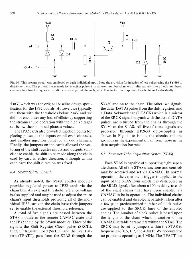
Fig. 10. This preamp circuit was employed on each individual input. Note the provision for injection of test pulses using the SY 480 todistribute them. The provision was made for injecting pulses into all even number channels or alternatively into all odd numberedchannels to allow testing for crosstalk between adjacent channels, as well as to test the response of each channel individually.
5 mV, which was the original baseline design speci-"cation for the IP32 boards. However, we typicallyran them with the thresholds below 2 mV and wedid not encounter any loss of e$ciency supportingthe streamer tube operation with the high voltagesset below their nominal plateau values.
The IP32 cards also provided injection points forplacing pulses at the inputs on all even channels,and another injection point for all odd channels.Finally, the jumpers on the cards allowed the vec-toring of the shift register inputs and outputs su$-cient to enable the shift to be made along the chaincard by card in either direction, although withineach card the shift direction was "xed.
6.4. SY480 Splitter Board
As already noted, the SY480 splitter modulesprovided regulated power to IP32 cards via thechain bus. An external threshold reference voltageis also supplied and may be used to adjust the entirechain's input thresholds providing all of the indi-vidual IP32 cards in the chain have their jumpersset to enable the external threshold reference.
A total of "ve signals are passed between theSTAS module in the remote CAMAC crate andthe IP32 chain by the SY480 modules. Three of thesignals: the Shift Register Clock pulses (SRCK),the Shift Register Load (SRLD), and the Test Pat-tern (TPATT), pass from the STAS through the
SY480 and on to the chain. The other two signals:the data (DATA) pulses from the shift registers, anda Data Acknowledge (DTACK) which is a mirrorof the SRCK signal in synch with the actual DATApulses, are returned from the chains through theSY480 to the STAS. All "ve of these signals areprocessed through HP2630 opto-couplers asshown in Fig. 11 to isolate the circuits and thegrounds in the experimental hall from those in thedata acquisition barrack.
6.5. Streamer Tube Acquisition System (STAS)
Each STAS is capable of supporting eight separ-ate chains. All of the STAS's functions and controlsmay be accessed and set via CAMAC. In normaloperation, the experiment trigger is applied to theinput of the STAS from which it is distributed asthe SRLD signal, after about a 100 ns delay, to eachof the eight chains that have been enabled viaCAMAC to be in operation. The individual chainscan be enabled and disabled separately. Then aftera few ls, a predetermined number of clock pulsesare applied to the SRCK lines of the enabledchains. The number of clock pulses is based uponthe length of the chain which is another of theCAMAC settable parameters within the STAS. TheSRCK may be set by jumpers within the STAS tofrequencies of 0.5, 1, 2, and 4 MHz. We encounteredno problems operating at 4 MHz. The TPATT line
368 D. Adams et al. / Nuclear Instruments and Methods in Physics Research A 435 (1999) 354}374

Fig. 11. The HCPL 2630 opto-couplers were deployed for all signals passing between the STAS and the SY480 in order to allowabsolute electrical isolation between the electronics on or near the detector and the STAS located remotely in the barrack. Both (a) thetypical circuit for signals passing from the STAS to the detector and (b) the circuit for signals passing back to the STAS are shown. Notethat the VCC bias voltage for the 74,128 drivers has to be brought over the data cable to maintain the isolation for the returning signals.
is modulated in synchronization with the SRCKthrough a cycling 8-bit pattern which also is anindependent CAMAC settable parameter for eachchain. The TPATT is vectored by the jumpers onthe IP32 cards to act as the input to the mostremote card in the chain. The number of channelsread back by the STAS is actually 32 more than thenumber in the chain, the "nal 32 then being 4 rep-etitions of the TPATT sequence, verifying that thefour chain shift process is functioning properly.
Upon return the DATA lines are read in syn-chronization with the pulses on the correspondingDTACK lines, and bear no time synchronizationwith the original SRCK signal. Thus, there is notiming constraint upon the length of the lines fromthe STAS to the chains. Note that the arrival delayof the SRLD signal can become problematic if ithas to go from the experiment trigger and up to theSTAS, then out to the detector. This can be over-come by providing a fast trigger directly to theSY480 modules which have been modi"ed by us toaccept such a signal and then OR it with eacharriving SRLD from the STAS. This fast trigger
then has to remain high until the SRLD arrivesfrom the STAS to continue the cycle under itscontrol. Note the drop of the SRLD initiates a fastclear and resets the IP32 cards to resume takingdata.
As each DATA shift is read, an automatic spar-ci"cation occurs. When a hit is shifted in, a counteris set, and up to seven successive hits may becounted. When the "rst non-hit shift occurs aftera string of hits, the prior information is formed intoa single 16-bit word which encodes the address ofthe last hit and the width of the contiguous clusterof hits. The chain number is also encoded in eachsuch data word. Clusters of greater than sevencontiguous hits require more than one word. Thesedata is stored in memory bu!ers 4096]16-bitwords deep for each channel. A separator word isplaced between successive events. In practice, dur-ing the SMC, each STAS was always readout aftereach trigger. The data words sent via CAMACinclude a separator word identifying each chainfollowed by the data from that chain. Empty chainshave a single dummy null data word. The entire
D. Adams et al. / Nuclear Instruments and Methods in Physics Research A 435 (1999) 354}374 369

50The streamer tube arrays were actually installed in 1991and preliminary beam trials also occurred during that year. Thereadout electronics were not available however until 1992, andthe evaluations conducted in 1991 were made with readoutelectronics borrowed from the Gran Sasso LVD experiment aswell as from our colleagues from the University of Padova.
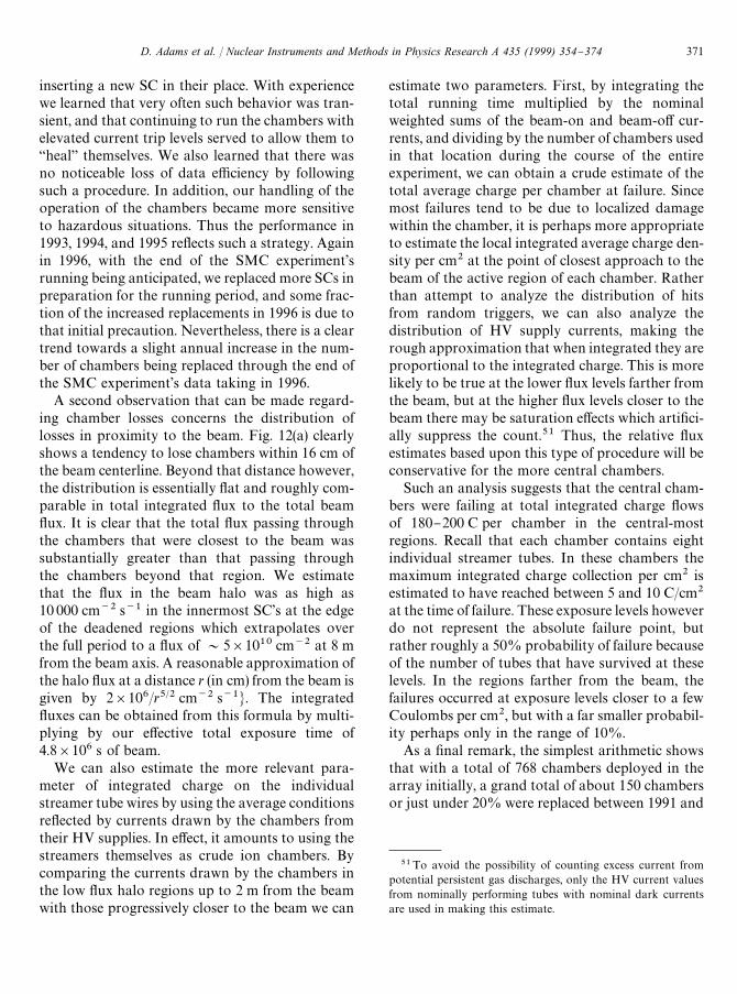
Fig. 12. (a) The total number of tubes replaced vs. distance fromthe beam is shown. The positive direction is generally to the sideof the greatest #ux, the asymmetry being due to the upstreamspectrometer magnet. However, this plot also includes the cham-bers that were deployed horizontally and the positive distance isvertically upward in the lab. These results integrate the experi-ence of 16 planes deployed for "ve years of data taking. (b) Thenumber of individual chambers replaced, binned by year isshown. The large number of replacements in the "rst year wasin#uenced by our inexperience with the detector. The relativeincrease in the last year of running also re#ects a conservativedecision to make the detector as e$cient as possible.
system was quite robust and was operated for muchof the time with only `novicea experts on duty. Wemanaged to keep the system operational virtuallycontinuously with only about 24 spare IP32 cardsto support the 384 deployed cards and a singlespare STAS to support the four normally in use.We had only "ve spare SY480 modules to support32 in use. The only tense moments occurred on twooccasions when we had to send one of the STASmodules to CAEN to be repaired. At no time didthe SMC experience any signi"cant loss of runningtime due to ST6/7 electronics problems. At all othertimes we had plenty of spare components availableto maintain the system in full working order. Over-all, it was reliable and trouble free.
7. Performance summary
7.1. Longevity of streamer chambers
As noted initially, the SMC experiment ran atCERN over "ve periods of about 120 days per yearfrom 1992 through 1996,50 and during that entiretime the ST6/7 detector was essentially in continu-ous service. From that experience it is possible toassess the longevity of the individual streamerchambers under this type of secondary-beamline,"xed-target running condition.
Fig. 12 shows the number of individual SCs thatwere replaced, both as a function of year and asa function of location in the array with respect tothe beam. The "rst comment that is in order con-cerns the very large number of chambers replacedduring the initial period of operation (105 cham-bers in 1991}92) as seen in Fig. 12(b). This largee!ect could possibly have been due to an `infantmortalitya phenomenon. A certain fraction of thesefailures might have been caused by defects thatwere the result of latent fabrication #aws or bydamage sustained in shipping and handling. Un-
doubtedly, some of these initial losses were of thatnature. However, given the testing procedures usedat SCARF and our experience with subsequentinstallation of replacement chambers, most ofwhich came from the same general production lotsand were shipped and handled alongside of theinitially deployed chambers, such losses were tooinfrequent to explain the high number of initialreplacements.
Rather, we feel that a large measure of this aber-ration was due to signi"cant changes in our behav-ior as we became more experienced with the use ofthe chambers in this type of high #ux environment.For example, initially we were reluctant to raise thebeam-o! HV trip current levels for SCs whichdeveloped higher dark currents. We typicallyremoved such chambers and discarded them,
370 D. Adams et al. / Nuclear Instruments and Methods in Physics Research A 435 (1999) 354}374
51To avoid the possibility of counting excess current frompotential persistent gas discharges, only the HV current valuesfrom nominally performing tubes with nominal dark currentsare used in making this estimate.
inserting a new SC in their place. With experiencewe learned that very often such behavior was tran-sient, and that continuing to run the chambers withelevated current trip levels served to allow them to`heala themselves. We also learned that there wasno noticeable loss of data e$ciency by followingsuch a procedure. In addition, our handling of theoperation of the chambers became more sensitiveto hazardous situations. Thus the performance in1993, 1994, and 1995 re#ects such a strategy. Againin 1996, with the end of the SMC experiment'srunning being anticipated, we replaced more SCs inpreparation for the running period, and some frac-tion of the increased replacements in 1996 is due tothat initial precaution. Nevertheless, there is a cleartrend towards a slight annual increase in the num-ber of chambers being replaced through the end ofthe SMC experiment's data taking in 1996.
A second observation that can be made regard-ing chamber losses concerns the distribution oflosses in proximity to the beam. Fig. 12(a) clearlyshows a tendency to lose chambers within 16 cm ofthe beam centerline. Beyond that distance however,the distribution is essentially #at and roughly com-parable in total integrated #ux to the total beam#ux. It is clear that the total #ux passing throughthe chambers that were closest to the beam wassubstantially greater than that passing throughthe chambers beyond that region. We estimatethat the #ux in the beam halo was as high as10 000 cm~2 s~1 in the innermost SC's at the edgeof the deadened regions which extrapolates overthe full period to a #ux of &5]1010 cm~2 at 8 mfrom the beam axis. A reasonable approximation ofthe halo #ux at a distance r (in cm) from the beam isgiven by 2]106/r5@2 cm~2 s~1N. The integrated#uxes can be obtained from this formula by multi-plying by our e!ective total exposure time of4.8]106 s of beam.
We can also estimate the more relevant para-meter of integrated charge on the individualstreamer tube wires by using the average conditionsre#ected by currents drawn by the chambers fromtheir HV supplies. In e!ect, it amounts to using thestreamers themselves as crude ion chambers. Bycomparing the currents drawn by the chambers inthe low #ux halo regions up to 2 m from the beamwith those progressively closer to the beam we can
estimate two parameters. First, by integrating thetotal running time multiplied by the nominalweighted sums of the beam-on and beam-o! cur-rents, and dividing by the number of chambers usedin that location during the course of the entireexperiment, we can obtain a crude estimate of thetotal average charge per chamber at failure. Sincemost failures tend to be due to localized damagewithin the chamber, it is perhaps more appropriateto estimate the local integrated average charge den-sity per cm2 at the point of closest approach to thebeam of the active region of each chamber. Ratherthan attempt to analyze the distribution of hitsfrom random triggers, we can also analyze thedistribution of HV supply currents, making therough approximation that when integrated they areproportional to the integrated charge. This is morelikely to be true at the lower #ux levels farther fromthe beam, but at the higher #ux levels closer to thebeam there may be saturation e!ects which arti"ci-ally suppress the count.51 Thus, the relative #uxestimates based upon this type of procedure will beconservative for the more central chambers.
Such an analysis suggests that the central cham-bers were failing at total integrated charge #owsof 180}200 C per chamber in the central-mostregions. Recall that each chamber contains eightindividual streamer tubes. In these chambers themaximum integrated charge collection per cm2 isestimated to have reached between 5 and 10 C/cm2
at the time of failure. These exposure levels howeverdo not represent the absolute failure point, butrather roughly a 50% probability of failure becauseof the number of tubes that have survived at theselevels. In the regions farther from the beam, thefailures occurred at exposure levels closer to a fewCoulombs per cm2, but with a far smaller probabil-ity perhaps only in the range of 10%.
As a "nal remark, the simplest arithmetic showsthat with a total of 768 chambers deployed in thearray initially, a grand total of about 150 chambersor just under 20% were replaced between 1991 and
D. Adams et al. / Nuclear Instruments and Methods in Physics Research A 435 (1999) 354}374 371

52The arrays were essentially 4 m wide and there were 48chambers, each with eight 0.9 cm wide active tube widths.
1996. If one ignores the 1991}92 replacements, theaverage number of replacements totaled less that1.5% of the deployed total per year.
7.2. Detector ezciency
A detailed discussion of the track reconstructionalgorithms employed during the SMC experimentis beyond the scope of this paper. We present hereonly a brief overview of the technique employedand our experience with the e$ciencies of the indi-vidual chamber layers [6,7].
Due to the existence of the the walls between thestreamer tubes and the walls of the chamber andsupersleeve enclosures, only about 85.9% of thefrontal area of the detector is sensitive volume fortracks with normal incidence.52 The measured vari-ation in this value had a standard deviation of only0.83% due to construction di!erences from planeto plane. Although the overlaps of the dead regionsin adjacent planes were designed to be minimized,in practice about 5% of the adjacent net dead areasdid overlap (i.e. 5% of the 14.1% geometricallydead area in a typical plane was also masked bya similar adjacent dead area in the immediatelyadjacent similar plane). The measured e$ciency isalso in#uenced by slight ine$ciencies in the vicinityof the internal chamber plastic wire supports.
There are two general contributions to the nete$ciency to get a hit when a particle traversesa plane. First there is the probability that astreamer will be formed, and second, if a streamerforms, there is a subsequent probability that thesignal induced on the readout strip will cause a bitto be loaded into the shift register. We have deter-mined that the "rst probability is on the order of90% for tracks that enter the sensitive volume. Inpractice the product of the geometric ine$ciencyand the streamer production probability are com-bined. That product typically gave a combinede$ciency to form a streamer at or above 80% for#uxes of up to about 2000 cm~2 s~1. This valuedropped roughly linearly to about 74% at a #ux of6000 cm~2 s~1, which occurred at about 2 cm from
the edge of the deadened regions or about 10 cmfrom the beam. This is the highest #ux value forwhich we have reliable e$ciency data. The corre-sponding readout e$ciencies are between 90% and95% at the lowest #uxes, where the variations aredue to many factors. There was about a 3% system-atically lower readout e$ciency for the diagonalcoordinates with respect the corresponding parallelstrips on the opposite side of the same ST plane. Atthe highest #uxes the readout e$ciency droppeddown to about 84%. A potential explanation forthis reduction is the decrease in e!ective voltage bythe larger net currents drawn during the spill atthe higher #uxes. Combining these e!ects, one ob-tains a net e$ciency to produce a hit in a givencoordinate of close to 80% at #uxes below2000 cm~2 s~1, and of about 65% at a #ux of6000 cm~2 s~1. Fig. 13 shows an e$ciency plot fora single plane of SCs as a function of the track'scrossing point in the plane of the wires. The view istransverse to the wire direction. The crossing pointsof the incident muon tracks were determined forthis plot from selected events using the other 31coordinates. The value plotted is the combinedgeometric and streamer formation e$ciency.
As noted elsewhere in this paper, typically thestreamers produced hits in several adjacent strips ineach coordinate. In about 90% of the hits thecluster size was either only one or two strips, withthe distribution being slightly larger for the diag-onal strips. Given the organization of the detectorinto four geometrically distinct modules, each con-taining four separate independent coordinates withtwo sets of strips for each coordinate, we chose touse a track reconstruction technique to take ad-vantage of that arrangement. Using informationavailable from the external scintillator hodoscopes,we isolated regions of interest that were alignedalong the projected paths indicated by the triggerdata. Within those regions in each module, multiplecoordinate intersections which we refer to as`multipointsa were searched for. The minimum re-quirement for a multipoint was the proximate(within &1 cm) crossing of hits from a minimum offour coordinates, at least three of which were non-parallel. Once multipoints had been determined ineach module, potential tracks were identi"ed byminimum allignment requirements for at least three
372 D. Adams et al. / Nuclear Instruments and Methods in Physics Research A 435 (1999) 354}374

Fig. 13. The measured combined geometric and streamer e$ciency is plotted for a typical plane of Streamer Chambers as a function ofthe track's crossing point in the plane of the wires. The view is eeeeeetransverse to the wire direction. The crossing points of the incidentmuon eeeetracks were determined for this plot from selected events using eeethe other 31 coordinates. The lower plot is an expandedview of the central region of the upper plot. The individual points are plotted for 1 mm bins and the statistical errors are shown. Theinternal PVC wall structures are clearly visible.
multipoints. Once such candidates were identi"ed,more conventional chi-squared minimization tech-niques were used to "t the track to the individualcoordinates included within the multipoints. Therewere also arbitrary criteria used to abort the analy-sis of individual events in the interest of savingcomputer time. Any event that contained morethan 20 multipoints in one coordinate or more than10 candidate tracks was aborted and not analyzedfurther. This procedure was carefully checked toinsure that it did not introduce any false asymmet-ries into the SMC data.
Overall in the SMC experiment we were able toreconstruct muon tracks for &90% of all rawprimary muon triggers. A careful analysis of the
excluded events indicates that for all events inwhich a clean muon track was present, the net trackreconstruction e$ciency was on the order of&99%. In addition, we achieved a spatial resolu-tion of &2.5 mm at the front face of the detectorarray, and an angular resolution of &0.5 mrad fortracks passing through the entire array under nom-inal running conditions.
8. Conclusions
We have deployed a large area streamer chamberarray in a high #ux "xed target experiment ingeneral proximity to the beam, and successfully
D. Adams et al. / Nuclear Instruments and Methods in Physics Research A 435 (1999) 354}374 373

operated it throughout the entire running of theSMC experiment. We have also succeeded instabilizing the e$ciency of the detector to an abso-lute range of &1%. The streamer chamber arraysand the associated readout system we developedturned out to be one of the most robust and reliabledetector systems of the SMC experiment. Wewish to acknowledge the assistance in the designand development of the electronics of both SGSThomson and CAEN.
Acknowledgements
We wish to acknowledge the assistance in thedesign and development of the electronics of S. Elia,M. Grassi, S. Pedretti, W. Sangalli, and G. Scroccifrom SGS Thomson's Subsystems, Engineering& R.F. Division in (Colleoni) Agrate, Italy; C.Planzo of SGS Thomson's Geneva o$ce; as well asG. Franchi, M. Givoletti, and F. Vivaldi of CAENin Viareggio, Italy. We also gratefully acknowledgethe loan of some readout boards during our earlydeployment from S. Cavestro of the University ofPaduova and from L. Votano of the LaboratoriNazionali di Frascati. We acknowledge thehelp and assistance of all of the CERN support
sta!, too numerous to list, who have eased ourburdens and provided essential assistance. Amongthe personnel at CERN, a special thank you mustgo to Y. Camp, E. (Liz) Cumiskey (now deceased),J.-M. Demolis, and L. Veronneau. Speci"c fundingsupport for he ST6/7 detector hardware was pro-vided by the U.S. Department of Energy, the U.S.National Science Foundation, and the Bundes-ministerium fuK r Bildung, Wissenschaft, Forschungund Technologie.
References
[1] D. Hungerford et al., Nucl. Intr. & Meth. A 286 (1990) 155.[2] K. Lau, et al., Streamer chamber for muon tracking at the
SSC, In: T. Dombeck, et al. (Eds.), Proceedings of Sympo-sium on Detector Development for the SuperconductingSupercollider, Fort Worth, TX 1990.
[3] E. Iarocci, Nucl. Intr. & Meth. 217 (1983) 30.[4] R. Weinstein, private communication. These developments
are considered proprietary and cannot be disclosed in anyfurther detail here.
[5] T. Lyons, MIT/SLD Streamer Tube Factory, private com-munication.
[6] A. Gomez Tato, Ph.D. Thesis, University of Santiago deCompostella, Santiago de Compostella, Spain, 1994.
[7] J.J. Saborido, Ph.D. Thesis, University of Santiago de Com-postella, Santiago de Compostella, Spain, 1995.
374 D. Adams et al. / Nuclear Instruments and Methods in Physics Research A 435 (1999) 354}374