Biomechanical Evaluation of the Elbow Using Roentgen Stereophotogrammetric Analysis

Proceedings of ASME 2012 11th Biennial Conference OnEngineering Systems Design And Analysis
ESDA2012July 2-4, 2012, Nantes, France
ESDA2012-82451
EFFICIENCY OF KNEE BRACES: A BIOMECHANICAL APPROACH BASED ONCOMPUTATIONAL MODELING
Baptiste Pierrat∗, Jerome Molimard,Laurent Navarro, Stephane Avril
Ecole Nationale Superieure des MinesCIS-EMSE, CNRS:UMR5146, LCG
F-42023 Saint-EtienneFrance
Email: [email protected]
Paul Calmels, Pascal EdouardLaboratory of Exercise Physiology
CHU Hopital Bellevue25, boulevard PasteurF-42055 Saint-Etienne
France
ABSTRACTKnee orthotic devices are widely proposed by physicians and
medical practitioners for preventive or therapeutic objectives inrelation with their effects, usually known as to stabilize joint orrestrict ranges of motion. The objectives of this work are tocharacterize the mechanical performance of knee orthoses us-ing a Finite Element Model of a braced human leg. The interfaceproperties of the model are calibrated against experimental datameasured by full-field measurements of 3D displacement over thesurface of a patient’s leg. The results show that the mechanicalaction of knee braces is essentially limited by skin/fabric andskin/muscles sliding. Finally, the model leads to a better un-derstanding of the knee/brace interaction, and of the role of thebrace components on the stability of the injured knee. Thanks tothis computational tool, novel brace designs can be tested andevaluated for an optimal mechanical efficiency of the devices.
INTRODUCTIONThe knee is the largest joint in the body and is vulnerable
to injury during sport activities and to degenerative conditionssuch as arthrosis. Knee orthotic devices are widely proposed byphysicians and medical practitioners for preventive or therapeu-tic objectives in relation with their effects, usually known as to
∗Address all correspondence to this author.
stabilize joint or restrict ranges of motion.Knee injuries are common and account for 15-50% of all
sports injuries [1]. Annually, more than 1 million emergency de-partment visits and 1.9 million primary care outpatient visits arefor acute knee pain in the United States [2]. Radiographic stud-ies of US and European populations aged ≥45 years show ratesof 14.1% for men and 22.8% for women for osteoarthritis of theknee [3]. Knee braces are prescribed for various knee syndromessuch as ligament tears or disruptions, patellofemoral syndrome,iliotibial band syndrome, knee arthrosis and knee laxities [4].These physio-pathological conditions involve pain and/or func-tional instability. These conditions are prevalent and are a hugeburden on individuals and healthcare systems.
Clinicians have attempted to help patients through biome-chanical devices such as knee orthoses or braces since the1970s [5]. Numerous action mechanisms have been proposedand investigated such as proprioceptive improvements [6–10],strain decrease on ligaments [11–15], neuromuscular controlenhancement [16–19], joint stiffness increase [20] and correc-tive off-loading torque for unicompartimental knee osteoarthri-tis [21–25].
Numerous studies aimed to justify the use of knee orthosesin medical practice. These studies were reviewed by [5, 26–29].The following conclusions have been reported:
1. Mechanical/physiological effects have been highlighted, but
1 Copyright c© 2012 by ASME

their level and mechanisms remain poorly known.2. Only a few high-level clinical studies exist, and the effec-
tiveness of bracing versus no bracing on improving qualityof life has not been conclusively demonstrated.
Possible explanations of 1 having no perceptible effect on 2 arethat mechanical action levels are too low, or that patients do notcomply to the orthopedic treatment and do not wear enough thedevice due to comfort issues. What is more, these studies arebased on questionable methods and results lack authority.
As a consequence of these uncertainties, medical practition-ers and manufacturers still lack a simple evaluation tool for kneeorthoses. A french committee of experts highlighted this prob-lem [30] and stated that orthoses must be evaluated by takingboth the mechanisms of action and the desired therapeutic ef-fects into account. Mechanical actions of knee orthoses havebeen evaluated using experimental devices either on cadavericknees [31] or on surrogate legs [20,32–34]. Nevertheless, the ca-daveric knee method leads to unreliable results because of sub-stantial scatter (anatomical and physiological variances); the sur-rogate method avoids knee variability but developed legs werepoorly representative of a real human limb and/or tests were con-ducted on very specific braces and do not allow to understandbracing mechanisms in general. Besides, these tests are far fromaccurate in reproducing the dynamical conditions of real move-ments such as running or walking for instance.
In order to answer these issues, an original Finite ElementModel approach has been developed. This model was built inagreement and cooperation with medical practitioners and or-thotic industrials, in a tentative of linking design problems, braceability to prevent a given pathology and patient comfort. An im-portant objective and the first step towards this approach was tofeed and validate the model thanks to experimental data. As thereare a huge variety of orthoses on the market, the focus was placedon mass-produced knee braces, in opposition to individualizedorthotic devices. They are usually made of synthetic textiles andmay incorporate bilateral hinges and bars, straps, silicone anti-slipping pads and patella hole. Different hinge systems exist inorder to reproduce knee kinematics [5]. A typical design of anusual brace is depicted in Fig. 1. They are prescribed either forprophylactic or functional purposes [27].
METHODSFinite Element Model Of The Braced Knee
The model was developed under Abaqus R© v6.10-2. Thismodel is not aimed to be patient specific, but to understand theforce transfer mechanisms between the rigid parts of the kneebrace and the joint through the brace fabric, the patient skin andsoft tissues.
Textile
Metal bar
Hinge
Patella hole
Strap
FIGURE 1: MASS-PRODUCED KNEE ORTHOSIS: USUALCOMMERCIALLY AVAILABLE MODEL.
Geometry. 3D geometry of the human leg was obtainedfrom a whole body PET-CT (Positron Emission Tomography -Computed Tomography) scan. This scan comes from an onlineDICOM sample image sets [35] and this particular scan exhibitedgood contrast between bones and soft tissues. The DICOM datastates that the subject is a 34 year old female. The lower bodyconsisted of about 500 slices of thickness 2 mm and resolution500x500 pixels. A leg was cropped and segmented thanks to thesoftware ImageJ [36]. Segmentation was performed by thresh-olding, resulting in 1 material identified as soft tissues. Boneareas corresponding to femur, patella, tibia and fibula were hol-lowed. This segmented stack was then finely meshed in 3D inAvizo R© and imported in Rhinoceros R© for surface reconstruc-tion. Finally, surfaces were imported in Abaqus R© in order tocontrol mesh generation with the Abaqus R© meshing tools. Theupper leg was separated from the lower leg in order to get 2 sep-arate parts, as seen in Fig. 1. This last step was done in orderto avoid any internal knee stiffness and in a concern of modelingknee flexion without convergence problems due to the high de-formation of elements in the center knee area. Patella was mod-elled as a separate shell part. Skin geometry was constructed byoffsetting the external boundary of the soft tissue part, resultingin a separate shell part. Finally, the leg was scaled in order toreach the dimensions of a median French male leg (2006 FrenchMeasurement Campaign). Details of the leg geometry construc-tion can be seen in Fig. 2.
Geometry of the orthosis was designed from determination
2 Copyright c© 2012 by ASME

3D geometry of patella, upper and lowerparts of the leg
Skin
Leg assembly
Original PET-CT scan slices
Corresponding segmented images
FIGURE 2: RECONSTRUCTED LEG SURFACES FROMSEGMENTED SCAN SLICES.
of the mechanically important features of usual existing braces.The identified features, as depicted in Fig. 1 and Fig. 3, are:
- 3 metal bars on each side,- A hinge system between bars consisting of 2 hinges on each
side with a blocking feature to prevent hyper-extension,- A polymeric textile with identified orientations transferring
efforts from the joint to the metal bars,- Fitting straps made of a different textile.
An assumption was made that the patella hole is not mechani-cally significant, hence the choice not to model it. The resultingbrace model is reported in Fig. 3.
Mesh And Materials. Soft tissues were meshed with160 000 C3D10M elements (10-node quadratic tetrahedral ele-ments), which provide improved performance and accuracy over
Material #1(shell elements)
Undeformablebars
Hinges
Material #2(shell elements)
FIGURE 3: FINITE ELEMENT MODEL OF THE ORTHOSIS.
the 4-node tetrahedral elements [37]. The material was defined ashomogeneous, isotropic, quasi-incompressible and hyper-elastic.A Neo-Hookean strain energy function was used [38–40]. Thisfunction may be written:
W =G2(I1 −3)+
K2(J−1)2 (1)
where G and K are the material parameters, I1 = Tr(F.Ft) is the
first deviatoric strain invariant, J = det(F) the volume ratio, Fthe deformation gradient, F = J−1/3F the deviatoric part of thedeformation gradient and Tr the trace of a matrix. The constitu-tive properties represent the homogenized properties of muscles,fat, tendons and fascias. Value for G has already been identifiedfor the leg [40] and was set to 8 kPa. K was set to 10G = 80 kPain order to have a quasi-incompressible material (correspondingto a Poisson’s ratio of 0.45).
Bones were modeled as rigid bodies by fixing the surfacenodes.
The skin was meshed with 11 000 S4R elements [37](quadrilateral shell elements with reduced integration) of thick-ness 1 mm, as already modeled by [41, 42]. The material wasdefined as homogeneous, isotropic, quasi-incompressible andhyper-elastic. An Ogden strain energy function was used [41,42].This function may be written:
W =2µ
α2 (λα
1 +λα
2 +λα
3 )+K2(J−1)2 (2)
where α , µ and K are the constitutive parameters, λ i = J−1/3λi
3 Copyright c© 2012 by ASME
are the deviatoric principal stretches, λi the principal stretches,J = det(F) the volume ratio and F the deformation gradient. Val-ues of α and µ have been identified by [42] on the forearm. µ
was set to 15 kPa, α to 35 kPa and K to 1 kPa. As identifiedby [42], a pre-stress of 4 kPa was applied in circumferential andlongitudinal directions of the skin at the start of the analysis.
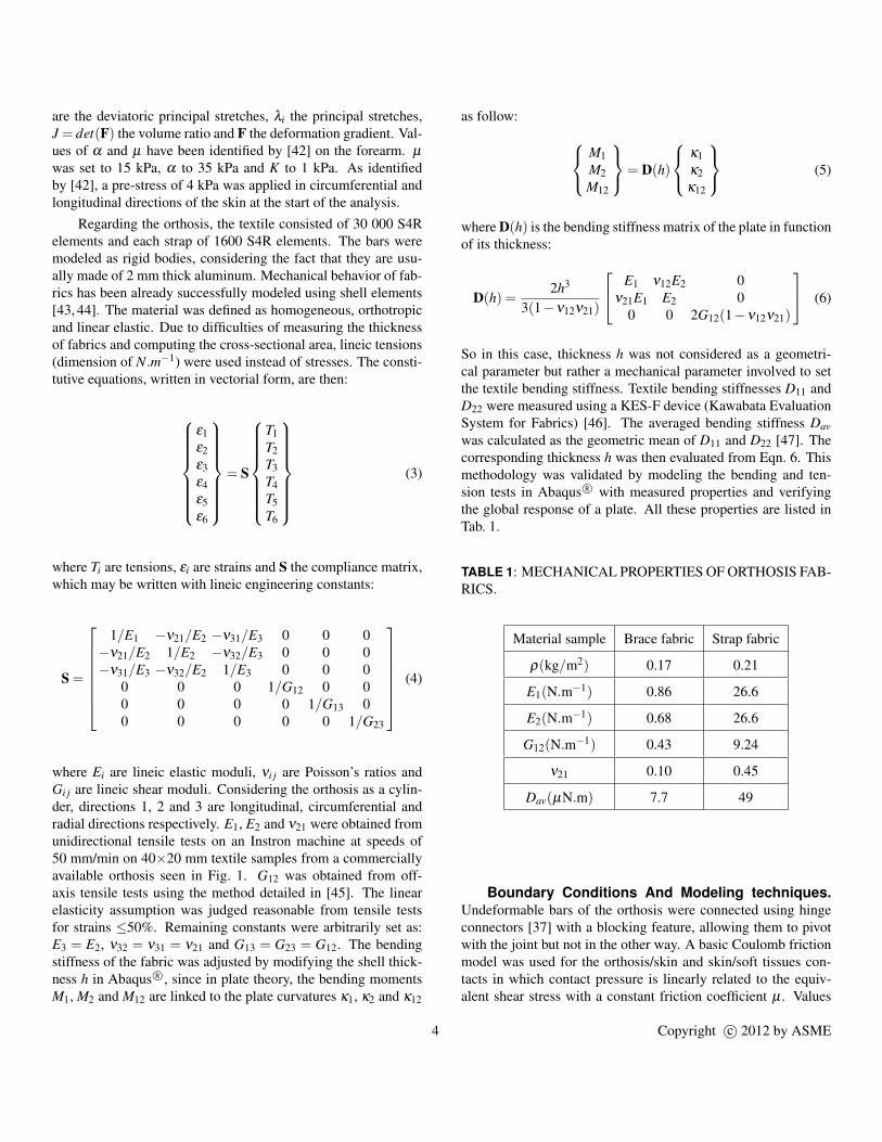
Regarding the orthosis, the textile consisted of 30 000 S4Relements and each strap of 1600 S4R elements. The bars weremodeled as rigid bodies, considering the fact that they are usu-ally made of 2 mm thick aluminum. Mechanical behavior of fab-rics has been already successfully modeled using shell elements[43, 44]. The material was defined as homogeneous, orthotropicand linear elastic. Due to difficulties of measuring the thicknessof fabrics and computing the cross-sectional area, lineic tensions(dimension of N.m−1) were used instead of stresses. The consti-tutive equations, written in vectorial form, are then:
ε1ε2ε3ε4ε5ε6
= S
T1T2T3T4T5T6
(3)
where Ti are tensions, εi are strains and S the compliance matrix,which may be written with lineic engineering constants:
S =
1/E1 −ν21/E2 −ν31/E3 0 0 0
−ν21/E2 1/E2 −ν32/E3 0 0 0−ν31/E3 −ν32/E2 1/E3 0 0 0
0 0 0 1/G12 0 00 0 0 0 1/G13 00 0 0 0 0 1/G23
(4)
where Ei are lineic elastic moduli, νi j are Poisson’s ratios andGi j are lineic shear moduli. Considering the orthosis as a cylin-der, directions 1, 2 and 3 are longitudinal, circumferential andradial directions respectively. E1, E2 and ν21 were obtained fromunidirectional tensile tests on an Instron machine at speeds of50 mm/min on 40×20 mm textile samples from a commerciallyavailable orthosis seen in Fig. 1. G12 was obtained from off-axis tensile tests using the method detailed in [45]. The linearelasticity assumption was judged reasonable from tensile testsfor strains ≤50%. Remaining constants were arbitrarily set as:E3 = E2, ν32 = ν31 = ν21 and G13 = G23 = G12. The bendingstiffness of the fabric was adjusted by modifying the shell thick-ness h in Abaqus R©, since in plate theory, the bending momentsM1, M2 and M12 are linked to the plate curvatures κ1, κ2 and κ12
as follow: M1M2M12
= D(h)
κ1κ2κ12
(5)
where D(h) is the bending stiffness matrix of the plate in functionof its thickness:
D(h) =2h3
3(1−ν12ν21)
E1 ν12E2 0ν21E1 E2 0
0 0 2G12(1−ν12ν21)
(6)
So in this case, thickness h was not considered as a geometri-cal parameter but rather a mechanical parameter involved to setthe textile bending stiffness. Textile bending stiffnesses D11 andD22 were measured using a KES-F device (Kawabata EvaluationSystem for Fabrics) [46]. The averaged bending stiffness Davwas calculated as the geometric mean of D11 and D22 [47]. Thecorresponding thickness h was then evaluated from Eqn. 6. Thismethodology was validated by modeling the bending and ten-sion tests in Abaqus R© with measured properties and verifyingthe global response of a plate. All these properties are listed inTab. 1.
TABLE 1: MECHANICAL PROPERTIES OF ORTHOSIS FAB-RICS.
Material sample Brace fabric Strap fabric
ρ(kg/m2) 0.17 0.21
E1(N.m−1) 0.86 26.6
E2(N.m−1) 0.68 26.6
G12(N.m−1) 0.43 9.24
ν21 0.10 0.45
Dav(µN.m) 7.7 49
Boundary Conditions And Modeling techniques.Undeformable bars of the orthosis were connected using hingeconnectors [37] with a blocking feature, allowing them to pivotwith the joint but not in the other way. A basic Coulomb frictionmodel was used for the orthosis/skin and skin/soft tissues con-tacts in which contact pressure is linearly related to the equiv-alent shear stress with a constant friction coefficient µ . Values
4 Copyright c© 2012 by ASME

of µbrace for different fabric/skin systems are available in the lit-erature, averaging 0.7 for Spenco R© [48], or ranging from 0.3(Teflon R©) to 0.43 (cotton and polyester) [49]. A value of 0.3was chosen. Concerning the skin/soft tissues contact, no datawas found in the literature for friction coefficient measurements.This parameter µleg was assumed to be 0.2. Influence of theseparameters will be discussed in the FEM Results section. Skinwas attached to soft tissues at the top and bottom of the leg. Nocontact was defined between the upper and lower parts of the leg.A quasi-static analysis was performed using the Explicit solver[37], consisting in three steps:
- Step 1: a displacement field was applied to the undeformedorthosis to enlarge the brace and make it fit at the right placearound the joint.
- Step 2: contact were activated, previously applied displace-ments were released in order to let the brace compress theleg and reach the mechanical equilibrium.
- Step 3: a joint kinematic was imposed, in this case a simple90◦ flexion.
To reproduce knee flexion kinematics, the femur was fixedwhereas a physiological displacement of the tibia/fibula was en-forced [50] (rotation with slight displacement of the center ofrotation). Displacement of the patella was also enforced in agree-ment with its real kinematics during a flexion [50]. The behaviorof the orthosis at different steps of the analysis is depicted inFig. 4.
Output fields. In a concern of comparing results fromthe model to experimentally measurable fields, displacementsfields of the skin and the orthosis were output. Logarithmicstrains and tensions were also output, as well as contact pres-sures.
Experimental MethodsExperiments were conducted on a dynamic dynamomet-
ric device (Con-Trex R©) reproducing the physiological move-ment of knee flexion-extension, with a reasonable reproducibil-ity (Fig. 5b). Two positions were specially investigated: neutralor anatomical referent position (straight leg) and bent leg aftera 90◦ flexion movement. Attention has been paid on differentsituations:
- Skin slipping without wearing an orthosis,- Combined skin and orthosis slipping.
Experimental system is a fringe projection technique coupledwith frequency-based analysis of speckle images (Fig. 5a). Thesystem has been already described in [51]: basic features are thesimultaneous measurement of the (U,V,W )t displacement and(X ,Y,Z)t shape vectors, with a resolution of few hundredth ofpixels, and a spatial resolution of respectively 8 and 1 pixels.
Initial orthosis mesh
Brace on leg afterSteps 1 and 2
Deformedconfigurationduring Step 3
FIGURE 4: MAXIMUM LOGARITHMIC DEFORMATIONAT DIFFERENT STEPS OF THE ANALYSIS.
Region of interest is a 150×113 mm2 area on the upper part ofthe thigh.
Results And DiscussionFEM Results
The complete FE analysis completed in about 4 hours on8 CPUs at 2.4 Ghz. All given strains are in-plane logarithmicstrains. The brace textile underwent circumferential strains be-tween 5 and 25% after the fitting step (before flexion) becausethe diameter of the orthosis was smaller than the diameter of theleg. After the flexion step, circumferential strains remained thesame, whereas the textile deformed longitudinally up to 30% onthe patella area due to the increasing surface in the front partof the leg. These high strains correspond to lineic tensions of150 N.m−1. Creases were observed behind the joint (poplitealarea), revealing the realistic behavior of the textile modeling(Fig. 4). These creases are usually observed on real braces dur-ing a flexion. The typical leg diameter discontinuity due to softtissue compressions observable on real braces at the brace/leg in-terfaces was also observed in FE results. Skin strains peaked atthe patella area after the flexion: longitudinal strains were 25%
5 Copyright c© 2012 by ASME

(a) (b)
FIGURE 5: OPTICAL SYSTEM (a) AND ONGOING MEA-SUREMENTS ON ISOKINETIC DEVICE (b).
in this region. Contact pressures averaged 2.1 kPa at the surfaceof the skin under the brace. Such values correspond to pressuresapplied by a class II compression stocking (2.0 - 2.7 kPa). Localmaximum values of 30 kPa were found in the popliteal area dueto creases. Patients wearing braces often complain of discom-fort in this area. Values of 10 kPa were observed in the patellaarea as well as at the front of the tibia, where the bone lies justunder the skin. It is very difficult to compare these values withpain pressure threshold values from the literature because exist-ing studies lack consistency and use questionable measurementmethods [52]. Brace pressure was transmitted to soft tissues: ob-servation of hydrostatic pressure inside the leg showed that areaswhere leg curvature radius was low exhibited the higher pres-sures [40]. For instance, pressures of 5, 8 and 7 kPa were respec-tively observed on the sides of the thigh, the patella area and thecalf.
In order to understand and compare the different mecha-nisms governing the displacements of the skin and brace, obser-vations were made on the same area as experimental measure-ments. Two major slipping phenomena were observed duringthe flexion (Fig. 6):
- The skin slipped on soft tissues with a maximum magnitudeof 5 mm in the area of interest. This may be due to the lowerleg pulling the skin during flexion, like a belt pulley, and/orbecause of the orthosis adhering and dragging the skin be-low.
- The orthosis slipped on the skin with a maximum magnitudeof 1.1 mm in the area of interest. This is also due to theflexion movement and the belt pulley effect.
Magnitudes of displacements of the skin and brace weregoverned by friction coefficients of the soft tissues/skin andskin/textile interfaces respectively (µleg and µbrace). Changing
these parameters sensibly affected strains, slipping magnitudesand mechanisms, as described in Tab. 2.
These different mechanisms might affect brace performanceand comfort, because they interfere with the direct stiffness trans-fer from rigid elements of the orthosis to the joint. They alsoaffect comfort because a slipping brace will irritate the patient’sskin and will tend to move on the leg, leading to a misplacedhinge system.
FIGURE 6: DISPLACEMENT FIELD ALONG THIGH AXISBETWEEN STRAIGHT AND BENT LEG OBTAINED FROMFE MODEL. UNITS OF THE COLORBAR ARE METERS.
Experimental ResultsExperiments successfully barely showed any displacement
discontinuity between the orthosis and the skin in the area of in-terest, as observed in Fig. 7. The skin displacement was 2.5 cmat the skin/brace interface. In this case, it cannot be stated thatskin displacement is only due to skin slipping, because the sub-ject may have moved his pelvis during the flexion, leading to aglobal advancing displacement. What is more, the quadricepsmuscle is attached to the patella and is dragged towards the jointduring the flexion. These two phenomena were not modeled inthe FE model, which can explain the difference of global dis-placement magnitude. Experiments without orthosis showed alower displacement magnitude of the skin of about 1.5 cm in thearea of interest. This result confirms the dragging effect of theorthosis: stiffening the joint area, the orthosis prevents skin de-formation in this area, which leads to higher deformation and/orslipping in other areas.
6 Copyright c© 2012 by ASME

TABLE 2: DESCRIPTION OF SLIPPING AND DEFORMA-TION MECHANISMS OF THE SKIN AND ORTHOSIS FORDIFFERENT FRICTION COEFFICIENTS.
Case µleg valueµbracevalue
Slipping mechanism
1frictionless
(0)medium
(0.5)
Skin slipped on soft tissues, brace ad-hered to skin. The belt pulley effectdeformed and dragged the skin butmostly in areas where there was nobrace, because the sticking brace pre-vented high strains in the skin.
2medium
(0.5)low(0.1)
Brace slipped on skin, brace adheredto soft tissues. Skin deformed dueto the belt pulley effect but the bracedid not follow skin deformation as itslipped instead of deforming.
3 high (1.0)high(1.0)
Brace and skin did not slip sensibly,both were deformed due to the beltpulley effect.
4frictionless
(0)low(0.1)
Both brace and skin slipped but didnot deform much.
DiscussionThe FE model is subject to limitations because it is not
patient-specific. Even if it has not been demonstrated, it is highlyprobable that several patient-specific leg factors influence themechanical response of the brace-leg system. These factors mayinclude mechanical properties of the different leg constituents(skin, soft tissues) as well as the quantity of adipose tissue or thegeometry of the leg itself. Nevertheless, the purpose of this workis not to compute the actual efficiency and comfort of a partic-ular brace-leg system, but to understand the general mechanicalmechanisms governing these phenomena. In that way, the devel-oped generic model is perfectly suited, even if work remains tobe done in validating and exploiting it.
The two slipping mechanisms are thought to lower the effi-ciency of orthoses by altering stiffness transfer. It was supposedthat skin slipped on underlying tissues, but it could also be mus-cle stretching leading to skin displacement. This skin displace-ment was successfully verified by experimental measurementsand reproduced in the FE model. As regard to the brace slippingmechanism, its magnitude was observed to insignificant, whichindicates that µbrace � µleg. The latter mechanism was overesti-mated in the FE model.
As a consequence, the comparison of the results from the FEmodel and experimental full field measurements has to be seen asa way to validate the modeling choices, and not as a quantitativevalidation. More specifically, the computed values of slippingmagnitudes are not expected to reach the measured values, but
FIGURE 7: DISPLACEMENT FIELD ALONG THIGH AXISBETWEEN STRAIGHT AND BENT LEG OBTAINED FROMFULL FIELD MEASUREMENTS. UNITS OF THE COLOR-BAR ARE METERS.
the fact that the skin displacement is observed is very promisingand validate the choice of modeling the skin as a separate layer.In the field of orthotics in general, quantification of both skin anddevice slipping in different situations is very important becauseit might significantly affect the performance and comfort of thedevice, and differ from what the device has been designed for.
Other modeling choices may be discussed, such as the re-tained values of friction coefficients. The brace-skin friction co-efficient in particular is subject to caution, as the authors of stud-ies [48, 49] report that many parameters influence the frictionsuch as skin humidity, applied force, and the place where it ismeasured. It must be emphasized that there is a strong lack ofmechanical data in the literature concerning the skin/underlyingtissue interface, which would probably exhibit a more complexbehavior than a basic isotropic Coulomb friction model.
Regarding the experimental procedure, even if conclusiveresults were obtained, only one brace-leg system has been testedand there is no information concerning the repeatability of suchresults.
ConclusionAn adaptable FE model was successfully developed and
tested under Abaqus R©. Features and modeling techniques of thismodel proved to be relevant from experimental results. Fabricexhibited realistic behavior, creases were observed during a jointflexion. Leg behavior and leg/brace interactions were judged re-alistic; comparing numerical results with optical full-field mea-
7 Copyright c© 2012 by ASME

surements of interface displacements partially validated the slip-ping behavior of the skin on underlying tissues, and justified themodeling choices. Adjustable friction properties of the numeri-cal model allowed us to identify different slipping mechanisms,which may be a critical aspect in evaluating the performance andcomfort of an orthosis.
Future WorkAs most constitutive properties are derived from literature,
a study about their sensitivity needs to be performed. The FEmodel will then be used to perform a parametric study on key de-sign parameters, in order to identify mechanically influent char-acteristics on both performance and comfort of knee braces. Theresults may contribute to the design of an optimized orthosis.
ACKNOWLEDGMENTThis work was supported by the Center of Medical Technol-
ogy and by a consortium of orthotic industrials and research cen-ters, including Gibaud R©, Lohman Rauscher R©, Thuasne R©, theFrench Textile and Apparel Institute, the Laboratory of ExercisePhysiology and the Center for Health Engineering.
REFERENCES[1] de Loes, M., Dahlstedt, L. J., and Thomee, R., 2000. “A
7-year study on risks and costs of knee injuries in male andfemale youth participants in 12 sports”. Scandinavian Jour-nal of Medicine & Science in Sports, 10(2), Apr., pp. 90–97.
[2] Levy, D. B., Dickey-White, H. I., Kardon, E. M., Talavera,F., Scaletta, T., Halamka, J. D., and Kulkarni, R., 2011. Softtissue knee injury.
[3] Woolf, A. D., and Pfleger, B., 2003. “Burden of major mus-culoskeletal conditions”. Bulletin of the World Health Or-ganization, 81(03), pp. 646–656.
[4] Skinner, H., 2006. Current Diagnosis and Treatment in Or-thopedics. McGraw-Hill Professional Publishing, Black-lick, OH, USA.
[5] Genty, M., and Jardin, C., 2004. “Place des ortheses enpathologie ligamentaire du genou. revue de la litterature”.Annales de Readaptation et de Medecine Physique, 47(6),Aug., pp. 324–333.
[6] Barrack, R. L., Skinner, H. B., and Buckley, S. L., 1989.“Proprioception in the anterior cruciate deficient knee”. TheAmerican Journal of Sports Medicine, 17(1), Jan., pp. 1–6.
[7] Corrigan, J., Cashman, W., and Brady, M., 1992. “Proprio-ception in the cruciate deficient knee”. J. Bone Joint Surg.Br., 74-B(2), Mar., pp. 247–250.
[8] McNair, P. J., Stanley, S. N., and Strauss, G. R., 1996.“Knee bracing: Effects on proprioception”. Archives
of Physical Medicine and Rehabilitation, 77(3), Mar.,pp. 287–289.
[9] Birmingham, T. B., Kramer, J. F., Kirkley, A., Inglis, J. T.,Spaulding, S. J., and Vandervoort, A. A., 2001. “Knee brac-ing for medial compartment osteoarthritis: effects on pro-prioception and postural control”. Rheumatology, 40(3),Mar., pp. 285 –289.
[10] Thijs, Y., Vingerhoets, G., Pattyn, E., Rombaut, L., andWitvrouw, E., 2009. “Does bracing influence brain activ-ity during knee movement: an fMRI study”. Knee Surgery,Sports Traumatology, Arthroscopy, 18(8), Dec., pp. 1145–1149.
[11] Beynnon, B., Pope, M., Wertheimer, C., Johnson, R., Flem-ing, B., Nichols, C., and Howe, J., 1992. “The effect offunctional knee-braces on strain on the anterior cruciateligament in vivo”. J Bone Joint Surg Am, 74(9), Oct.,pp. 1298–1312.
[12] Beynnon, B. D., Johnson, R. J., Fleming, B. C., Peura,G. D., Renstrom, P. A., Nichols, C. E., and Pope, M. H.,1997. “The effect of functional knee bracing on the ante-rior cruciate ligament in the weightbearing and nonweight-bearing knee”. The American Journal of Sports Medicine,25(3), June, pp. 353–359.
[13] Beynnon, B. D., and Fleming, B. C., 1998. “Anterior cru-ciate ligament strain in-vivo: A review of previous work”.Journal of Biomechanics, 31(6), June, pp. 519–525.
[14] Fleming, B. C., Renstrom, P. A., Beynnon, B. D., En-gstrom, B., and Peura, G., 2000. “The influence offunctional knee bracing on the anterior cruciate ligamentstrain biomechanics in weightbearing and nonweightbear-ing knees”. The American Journal of Sports Medicine,28(6), Nov., pp. 815–824.
[15] Hinterwimmer, S., Graichen, H., Baumgart, R., and Plitz,W., 2004. “Influence of a mono-centric knee brace on thetension of the collateral ligaments in knee joints after sec-tioning of the anterior cruciate ligament–an in vitro study”.Clinical Biomechanics, 19(7), Aug., pp. 719–725.
[16] Osternig, L. R., and Robertson, R. N., 1993. “Effects ofprophylactic knee bracing on lower extremity joint positionand muscle activation during running”. The American Jour-nal of Sports Medicine, 21(5), Sept., pp. 733–737.
[17] Wu, G. K., Ng, G. Y., and Mak, A. F., 2001. “Effectsof knee bracing on the sensorimotor function of subjectswith anterior cruciate ligament reconstruction”. The Amer-ican Journal of Sports Medicine, 29(5), Oct., pp. 641–645.PMID: 11573924.
[18] Ramsey, D. K., Wretenberg, P. F., Lamontagne, M., andNemeth, G., 2003. “Electromyographic and biomechanicanalysis of anterior cruciate ligament deficiency and func-tional knee bracing”. Clinical Biomechanics, 18(1), Jan.,pp. 28–34.
[19] Theoret, D., and Lamontagne, M., 2006. “Study on three-
8 Copyright c© 2012 by ASME

dimensional kinematics and electromyography of ACL de-ficient knee participants wearing a functional knee braceduring running”. Knee Surgery, Sports Traumatology,Arthroscopy, 14(6), Apr., pp. 555–563.
[20] Lunsford, T. R., Lunsford, B. R., Greenfield, J., and Ross,S. E., 1990. “Response of eight knee orthoses to valgus,varus and axial rotation loads”. Journal of Prosthetics andOrthotics, 2(4), p. 274.
[21] Giori, N. J., 2004. “Load-shifting brace treatment for os-teoarthritis of the knee: A minimum 2 1/2-year follow-upstudy.”. Journal of Rehabilitation Research and Develop-ment, 41(2), Mar., pp. 187–193.
[22] Nadaud, M. C., Komistek, R. D., Mahfouz, M. R., Den-nis, D. A., and Anderle, M. R., 2005. “In vivo Three-Dimensional determination of the effectiveness of the os-teoarthritic knee brace: A multiple brace analysis”. J. BoneJoint Surg. Am., 87(suppl 2), Dec., pp. 114–119.
[23] Gaasbeek, R. D., Groen, B. E., Hampsink, B., van Heer-waarden, R. J., and Duysens, J., 2007. “Valgus bracingin patients with medial compartment osteoarthritis of theknee: A gait analysis study of a new brace”. Gait & Pos-ture, 26(1), June, pp. 3–10.
[24] Schmalz, T., Knopf, E., Drewitz, H., and Blumentritt, S.,2010. “Analysis of biomechanical effectiveness of valgus-inducing knee brace for osteoarthritis of knee”. Journal ofRehabilitation Research and Development, 47(5), pp. 419–429.
[25] Kutzner, I., Kuther, S., Heinlein, B., Dymke, J., Bender,A., Halder, A. M., and Bergmann, G., 2011. “The effect ofvalgus braces on medial compartment load of the knee joint- in vivo load measurements in three subjects”. Journal ofBiomechanics, 44(7), Apr., pp. 1354–1360.
[26] Paluska, S. A., and McKeag, D. B., 2000. “Knee braces:current evidence and clinical recommendations for theiruse”. American Family Physician, 61(2), Jan., pp. 411–418, 423–424.
[27] Thoumie, P., Sautreuil, P., and Mevellec, E., 2001.“Ortheses de genou. premiere partie : Evaluation des pro-prietes physiologiques a partir d’une revue de la litterature.knee orthosis. first part : evaluation of physiological justifi-cations from a literature review”. Annales de Readaptationet de Medecine Physique, 44(9), Dec., pp. 567–580.
[28] Thoumie, P., Sautreuil, P., and Mevellec, E., 2002.“Ortheses de genou. Evaluation de l’efficacite clinique apartir d’une revue de la litterature. knee orthosis.”. An-nales de Readaptation et de Medecine Physique, 45(1),Jan., pp. 1–11.
[29] Beaudreuil, J., Bendaya, S., Faucher, M., Coudeyre, E.,Ribinik, P., Revel, M., and Rannou, F., 2009. “Clinicalpractice guidelines for rest orthosis, knee sleeves, and un-loading knee braces in knee osteoarthritis”. Joint BoneSpine, 76(6), Dec., pp. 629–636.
[30] Ribinik, P., Genty, M., and Calmels, P., 2010. “Evaluationdes ortheses de genou et de cheville en pathologie del’appareil locomoteur. avis d’experts”. Journal de Trau-matologie du Sport, 27(3), Sept., pp. 121–127.
[31] France, E. P., and Paulos, L. E., 1990. “In vitro assessmentof prophylactic knee brace function”. Clinics in SportsMedicine, 9(4), Oct., pp. 823–841.
[32] Paulos, L. E., France, E. P., Rosenberg, T. D., Jayaraman,G., Abbott, P. J., and Jaen, J., 1987. “The biomechanicsof lateral knee bracing”. The American Journal of SportsMedicine, 15(5), Sept., pp. 419–429.
[33] France, E. P., Paulos, L. E., Jayaraman, G., and Rosenberg,T. D., 1987. “The biomechanics of lateral knee bracing”.The American Journal of Sports Medicine, 15(5), Sept.,pp. 430 –438.
[34] Cawley, P. W., France, E. P., and Paulos, L. E., 1989. “Com-parison of rehabilitative knee braces”. The American Jour-nal of Sports Medicine, 17(2), Mar., pp. 141 –146.
[35] MELANIX, 2012. Dicom sample image sets. pubim-age.hcuge.ch:8080.
[36] Rasband, W., 1997-2011. “ImageJ”. National Institutes ofHealth, Bethesda, Maryland, USA.
[37] Simulia, 2010. ABAQUS 6.10-2 User Documentation. Das-sault Systems.
[38] Linder-Ganz, E., Shabshin, N., Itzchak, Y., and Gefen, A.,2007. “Assessment of mechanical conditions in sub-dermaltissues during sitting: a combined experimental-MRI andfinite element approach”. Journal of Biomechanics, 40(7),pp. 1443–1454.
[39] Avril, S., Bouten, L., Dubuis, L., Drapier, S., and Pouget,J., 2010. “Mixed experimental and numerical approach forcharacterizing the biomechanical response of the human legunder elastic compression”. Journal of Biomechanical En-gineering, 132(3), Mar., pp. 031006–8.
[40] Dubuis, L., Avril, S., Debayle, J., and Badel, P., 2011.“Identification of the material parameters of soft tissues inthe compressed leg”. Computer Methods in Biomechanicsand Biomedical Engineering, Aug.
[41] Evans, S. L., and Holt, C. A., 2009. “Measuring the me-chanical properties of human skin in vivo using digital im-age correlation and finite element modelling”. The Jour-nal of Strain Analysis for Engineering Design, 44(5), July,pp. 337–345.
[42] Flynn, C., Taberner, A., and Nielsen, P., 2010. “Mechani-cal characterisation of in vivo human skin using a 3D force-sensitive micro-robot and finite element analysis”. Biome-chanics and Modeling in Mechanobiology, 10(1), Apr.,pp. 27–38.
[43] Chen, B., and Govindaraj, M., 1995. “A physically basedmodel of fabric drape using flexible shell theory”. TextileResearch Journal, 65(6), June, pp. 324–330.
[44] Chen, B., and Govindaraj, M., 1996. “A parametric study of
9 Copyright c© 2012 by ASME

fabric drape”. Textile Research Journal, 66(1), Jan., pp. 17–24.
[45] E.V., M., and V.V., V., 2003. “Determination of theshear modulus of orthotropic materials from off-axis ten-sion tests”. Composite Structures, 62(3), pp. 379–382.
[46] Wu, Z., Au, C., and Yuen, M., 2003. “Mechanical prop-erties of fabric materials for draping simulation”. Interna-tional Journal of Clothing Science and Technology, 15(1),Feb., pp. 56–68.
[47] ASTM Standard D1388 - 08, 2011. Standard test methodfor stiffness of fabrics.
[48] Sanders, J. E., Greve, J. M., Mitchell, S. B., and Zachariah,S. G., 1998. “Material properties of commonly-used inter-face materials and their static coefficients of friction withskin and socks”. Journal of Rehabilitation Research andDevelopment, 35(2), June, pp. 161–176.
[49] Gerhardt, L., Lenz, A., Spencer, N. D., Munzer, T., andDerler, S., 2009. “Skin-textile friction and skin elasticityin young and aged persons”. Skin Research and Technol-ogy: Official Journal of International Society for Bioengi-neering and the Skin (ISBS) and International Society forDigital Imaging of Skin (ISDIS) and International Societyfor Skin Imaging (ISSI), 15(3), Aug., pp. 288–298. PMID:19624425.
[50] Klein, P., and Sommerfeld, P., 2008. Biomecanique desmembres inferieurs : Bases et concepts, bassin, membresinferieurs. Elsevier.
[51] Molimard, J., Boyer, G., and Zahouani, H., 2010.“Frequency-Based image analysis of random patterns: analternative way to classical stereocorrelation”. Journal ofthe Korean Society for Nondestructive Testing, 30(3), June,pp. 181–193.
[52] Pons, J. L., 2008. Wearable Robots: Biomechatronic Ex-oskeletons, 1 ed. Wiley, Apr.
10 Copyright c© 2012 by ASME
Copyright © 2022 FDOKUMEN