Epitaxial CdSe-Au Nanocrystal Heterostructures by Thermal Annealing
Upload
independentCategory
view
2download
0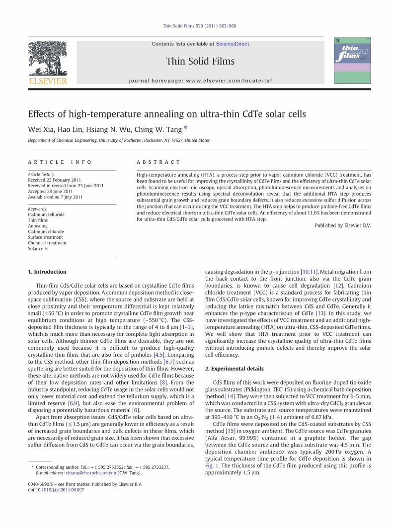
Thin Solid Films 520 (2011) 563–568
Contents lists available at ScienceDirect
Thin Solid Films
j ourna l homepage: www.e lsev ie r.com/ locate / ts f
Effects of high-temperature annealing on ultra-thin CdTe solar cells
Wei Xia, Hao Lin, Hsiang N. Wu, Ching W. Tang ⁎Department of Chemical Engineering, University of Rochester, Rochester, NY 14627, United States
⁎ Corresponding author. Tel.: +1 585 2753552; fax:E-mail address: [email protected] (C.W. Tan
0040-6090/$ – see front matter. Published by Elsevierdoi:10.1016/j.tsf.2011.06.097
a b s t r a c t
a r t i c l e i n f oArticle history:Received 23 February 2011Received in revised form 23 June 2011Accepted 28 June 2011Available online 7 July 2011
Keywords:Cadmium tellurideThin filmsAnnealingCadmium chlorideSurface treatmentChemical treatmentSolar cells
High-temperature annealing (HTA), a process step prior to vapor cadmium chloride (VCC) treatment, hasbeen found to be useful for improving the crystallinity of CdTe films and the efficiency of ultra-thin CdTe solarcells. Scanning electron microscopy, optical absorption, photoluminescence measurements and analyses onphotoluminescence results using spectral deconvolution reveal that the additional HTA step producessubstantial grain growth and reduces grain boundary defects. It also reduces excessive sulfur diffusion acrossthe junction that can occur during the VCC treatment. The HTA step helps to produce pinhole-free CdTe filmsand reduce electrical shorts in ultra-thin CdTe solar cells. An efficiency of about 11.6% has been demonstratedfor ultra-thin CdS/CdTe solar cells processed with HTA step.
+1 585 2733237.g).
B.V.
Published by Elsevier B.V.
1. Introduction
Thin-film CdS/CdTe solar cells are based on crystalline CdTe filmsproduced by vapor deposition. A common deposition method is close-space sublimation (CSS), where the source and substrate are held atclose proximity and their temperature differential is kept relativelysmall (b50 °C) in order to promote crystalline CdTe film growth nearequilibrium conditions at high temperature (~550 °C). The CSS-deposited film thickness is typically in the range of 4 to 8 μm [1–3],which is much more than necessary for complete light absorption insolar cells. Although thinner CdTe films are desirable, they are notcommonly used because it is difficult to produce high-qualitycrystalline thin films that are also free of pinholes [4,5]. Comparingto the CSS method, other thin-film deposition methods [6,7] such assputtering are better suited for the deposition of thin films. However,these alternative methods are not widely used for CdTe films becauseof their low deposition rates and other limitations [8]. From theindustry standpoint, reducing CdTe usage in the solar cells would notonly lower material cost and extend the tellurium supply, which is alimited reserve [6,9], but also ease the environmental problem ofdisposing a potentially hazardous material [6].
Apart from absorption issues, CdS/CdTe solar cells based on ultra-thin CdTe films (≤1.5 μm) are generally lower in efficiency as a resultof increased grain boundaries and bulk defects in these films, whichare necessarily of reduced grain size. It has been shown that excessivesulfur diffusion from CdS to CdTe can occur via the grain boundaries,
causing degradation in the p–n junction [10,11]. Metal migration fromthe back contact to the front junction, also via the CdTe grainboundaries, is known to cause cell degradation [12]. Cadmiumchloride treatment (VCC) is a standard process for fabricating thinfilm CdS/CdTe solar cells, known for improving CdTe crystallinity andreducing the lattice mismatch between CdS and CdTe. Generally itenhances the p-type characteristics of CdTe [13]. In this study, wehave investigated the effects of VCC treatment and an additional high-temperature annealing (HTA) on ultra-thin, CSS-deposited CdTe films.We will show that HTA treatment prior to VCC treatment cansignificantly increase the crystalline quality of ultra-thin CdTe filmswithout introducing pinhole defects and thereby improve the solarcell efficiency.
2. Experimental details
CdS films of this work were deposited on fluorine-doped tin oxideglass substrates (Pilkington, TEC-15) using a chemical bath depositionmethod [14]. They were then subjected to VCC treatment for 3–5 min,whichwas conducted in a CSS systemwith ultra-dry CdCl2 granules asthe source. The substrate and source temperatures were maintainedat 390–410 °C in an O2:N2 (1:4) ambient of 6.67 kPa.
CdTe films were deposited on the CdS-coated substrates by CSSmethod [15] in oxygen ambient. The CdTe source was CdTe granules(Alfa Aesar, 99.99%) contained in a graphite holder. The gapbetween the CdTe source and the glass substrate was 4.5 mm. Thedeposition chamber ambience was typically 200 Pa oxygen. Atypical temperature-time profile for CdTe deposition is shown inFig. 1. The thickness of the CdTe film produced using this profile isapproximately 1.5 μm.

Fig. 1. A typical temperature profile for the deposition of ultra-thin CdTe films using theCSS method.
Fig. 3. PL spectra with surface excitation for: CSS-deposited ultra-thin CdTe film withoutany treatment, with VCC treatment, with HTA treatment, andwith HTA+VCC treatments.
564 W. Xia et al. / Thin Solid Films 520 (2011) 563–568
The HTA treatment was carried out in a tube furnace undernitrogen at a temperature up to 560 °C for a duration up to 45 min.Nitrogen flow under atmospheric pressure wasmaintained during theentire process.
Following HTA treatment, the CdS/CdTe coated substrates weresubjected to another VCC treatment for 2 to 6 min. The substrate andsource temperatures were maintained at 390–410 °C.
The back contact was MoOx/Ni comprising a 40-nm MoOx as thebuffer layer [16] deposited by thermal evaporation on CdTe surfaceand a 200-nm Ni layer as the electrode deposited by DC sputtering.Prior to forming the back contact, the CdTe film was rinsed with
Fig. 2. SEM images for: CSS-deposited ultra-thin CdTe film (a) without any treatment, (b) with VCC treatment, (c) with HTA treatment, and (d) with HTA+VCC treatments.

Fig. 4. PL spectra and the corresponding deconvoluted PL peaks for CSS-deposited ultra-thin CdTe film (a) without any treatment, (b) with HTA treatment, (c) with VCC treatment,and (d) with HTA+VCC treatments. PL spectra were obtained with interface excitation and at 40 K.
565W. Xia et al. / Thin Solid Films 520 (2011) 563–568
deionized water to remove any CdCl2 residue from the VCC treatmentprocess. The active area of the CdTe solar cells was 0.10±0.005 cm2,which was defined by mechanically scribing the CdS/CdTe/Ni layerstack with a razor blade.
The morphology of the CdTe films was examined using scanningelectron microscopy (SEM) (Zeiss, Supra 40VP, operating voltage:20 kV). The thickness of the CdTe films was measured using asurface profilometer (KLA-Tencor Alpha Step D-120). Opticalabsorption measurements were obtained with a Perkin-ElmerLambda 900 spectrophotometer. Photoluminescence (PL) mea-surements were carried out using a He–Ne laser (Research Electro-Optical, 30992, 12 mW, 633 nm) as the excitation source and fiberoptic spectrometer (Ocean Optics, USB 4000) as the detector. Thesolar cell current–voltage (J–V) data were obtained using aKeithley source meter (Model 2400) and a tungsten-lamp-basedsolar simulator (Solux 3SS4736-50 W solar simulator). The solarsimulator was calibrated with a silicon photodiode (HamamatsuS1787-12). The incident light intensity on the solar cell was80 mW/cm2. The values of the current density were corrected byintegrating the photo-response of the cells with AM 1.5 solarspectrum. Spectral response measurements were obtained using acalibrated 1/4 m monochromator (ARC SpectroPro 275).
3. Results and discussions
In Fig. 2 the SEM images (a–d) show the evolution of CdTe graingrowth as a result of HTA and VCC treatments. The CSS-deposited CdTefilmwithout any treatment (Image a) has a relatively small grain size ofabout 0.5 μm.VCC treatmenton the CdTefilm (Image b) doesnot appearto change the grain size significantly, although it tends to smooth thegrain facets. On the other hand, HTA treatment induces large CdTe graingrowth as shown in Image c. The average grain size of the HTA-treatedfilm is significantly larger than that of the untreated film. As shown inImage d, subsequent VCC treatment of the HTA-treated film producesfurther grain growth as well as more rounded grain facets.
Fig. 3 shows the PL spectra of these CdTe films with excitationdirected at the free CdTe surface. The prominent features are bandswith peaks at ~1.430 eV and ~1.585 eV. The ~1.585 eV band, knownas the “near-band-edge (NBE) band”, has been attributed to boundexcitons [17,18] and used as an indicator of CdTe crystallinity [19]. Asshown in Fig. 3a, the NBE peak increases significantly with HTA andVCC treatments, indicating improvements in CdTe crystallinity.Known as the “surface defect band (SDB)”, the ~1.430 eV band ispresumably due to intrinsic defects [17]. As shown in Fig. 3b, the NBE/SDB intensity ratio also increases with HTA and VCC treatments,

566 W. Xia et al. / Thin Solid Films 520 (2011) 563–568
further supporting that the CdTe quality is improved. The NBE peakintensity and NBE/SDB intensity ratio are the highest for the CdTe filmwith HTA+VCC treatment, which corresponds to the largest CdTegrains as shown in Fig. 2.
The CdS/CdTe interface was also characterized by PL measure-ments. The PL spectra, taken with excitation through the substrate,feature a broad peak around 1.4 eV, which broadens and shifts tolower energy with HTA and VCC treatments. As Fig. 4 shows, toanalyze the evolution of these spectra, they were deconvoluted intofour Gaussian components using Origin Pro 8.0 with peaks located at~1.43, ~1.38, ~1.35, and ~1.30 eV, which have been attributed tovarious species in the literatures. The ~1.43 eV band is the surfacedefect band also observed from the free surface. The ~1.38 eV bandhas been assigned to CdTe1− xSx [20] and the ~1.35 eV band tocadmium vacancy complexes [17]. The small ~1.30 eV band, which isonly observed in CdTe with treatments, has not been identified. Fig. 5ashows that the intensity of the defect band is reduced with HTA andVCC treatments, suggesting that the defect concentration at the CdS/CdTe interface is reduced [21]. It is known that VCC treatment canpromote sulfur diffusion from CdS to CdTe [22,23]. As Fig. 5b shows,the intensity of the ~1.38 eV band increases significantly with VCCtreatment, a clear evidence that CdTe1− xSx is being formed near theinterface. It is also noteworthy that the ~1.38 eV band for the filmswith HTA and HTA+VCC treatments is considerably weaker com-pared to the film with VCC treatment only, suggesting the additional
Fig. 5. PL spectra with interface excitation showing the evolution of: (a) the interfacedefect band, and (b) the CdTe1− xSx band with various HTA and VCC treatments.
HTA treatment can mitigate excessive sulfur diffusion in the VCCtreatment.
Fig. 6a shows the absorption of ultra-thin CdTe films near theabsorption edge region. It is evident that the absorption edge shifts tolower energy with post-deposition treatments, especially the VCCtreatment. This red shift is consistentwith the formation of CdTe1− xSx,a lowbandgap component resulting from the incorporation of sulfur inCdTe films with these treatments. The bandgap of CdTe1− xSx wasextracted from the absorption spectra using a linearfit at the thresholdregion [23], as illustrated in Fig. 6a. Using the extracted bandgap ofCdTe1− xSx and an established relation between the bandgap andstoichiometry of CdTe1− xSx [24,25]:
Eg xð Þ = 1:74⋅ x2−1:01⋅ x + 1:51 ð1Þ
the values of x are calculated and presented in Fig. 6b with relation tothe bandgap of CdTe1− xSx.
HTA itself can promote the sulfur diffusion from CdS to CdTe as aresult of high temperature, causing the x value in CdTe1− xSx toincrease from 0.8% in the cell without any treatment to 1.3% in the cellwith just HTA treatment. However, HTA is less effective compared toVCC treatment in promoting sulfur diffusion with the latter producingan apparently higher x value of 2.3% in the cell with just VCCtreatment despite shorter treatment duration. Furthermore, it isnoteworthy that HTA treatment prior to VCC treatment can suppress
Fig. 6. (a) Absorption at the band edge region for ultra-thin CdTe films with various HTAandVCC treatments. (b) the x values of CdTe1−xSx in relation to the bandgapof CdTe1−xSx.

Fig. 7. (a) Photo and (b) dark J–V curves for ultra-thin CdS/CdTe solar cells with variousHTA and VCC treatments.
Table 1Device performances of ultra-thin CdS/CdTe solar cells with various HTA and VCCtreatments. The thickness of CdTe films is 1.5 μm.
Cell HTA VCC Device performances
Rsh (Ω) Rs (Ω) Jsc (mA/cm2) Voc (mV) FF (%) η (%)
1168A N N 1363 770 18.4 630 42.4 4.91168B Y N 3078 257 19.6 690 52.0 7.01168C N Y 8681 40 21.1 750 67.2 10.61168D Y Y 14,971 52 21.9 778 68.2 11.6
567W. Xia et al. / Thin Solid Films 520 (2011) 563–568
sulfur diffusion resulting from the VCC treatment. This can be seen inthe cell with HTA plus VCC treatment where x value is only 1.8%.Sulfur diffusion from CdS to CdTe can proceed via Fickian bulk and
Fig. 8. Spectral response curves for ultra-thin CdS/CdTe solar cells with various HTA andVCC treatments.
grain-boundary processes in the CdTe layer. The reported activationenergy for these two processes are ~3.0 and ~2.0 eV, respectively [26],suggesting that sulfur diffusion via the grain boundaries is dynami-cally faster than that via the bulk. As inferred from the PL andabsorption analysis, the suppression of sulfur diffusion by the HTAtreatment is consistent with SEM observation (Fig. 2) showing largegrain growth induced by HTA, which implies a reduction in grainboundaries in CdTe.
Fig. 7a and b shows the photo and dark J–V characteristics of ultra-thin CdTe solar cells with various treatments using MoOx/Ni as theback contact. Compared to the reference cell (without any treatment),the cell with only HTA treatment exhibits significantly improvementin open-circuit voltage (Voc), short-circuit current (Jsc) and fill factor(FF), although it is still substantially inferior to the cell with only VCCtreatment. Combining HTA and VCC treatments further enhances thecell performance over the VCC treatment alone, as shown in Table 1.The improvement in Voc is consistent with the reduction of reversesaturation current shown in Fig. 7b, indicating an increase in CdTegrain size due to HTA treatment does not necessarily compromise theshunt resistance in ultra-thin CdTe solar cells. Table 1 includes thedynamic shunt resistance, Rsh, and dynamic series resistance, Rs,calculated from the slope of dJ/dV at Jsc and Voc, respectively [27]. Thecell with both HTA and VCC treatments yields excellent Rsh and Rs, aswell as the highest efficiency of 11.6%.
Fig. 8 shows the spectral response curves for the ultra-thin CdTecells with various HTA and VCC treatments. It is clear that theimprovement in quantum efficiency is significantly higher in the longwavelength region and for cells that have been subjected to HTA andVCC treatments. The low quantum efficiency in ultra-thin CdTe solarcell, particularly near band edge region, can be attributed toincomplete light absorption [6,9] and recombination loss at the backcontact [6]. According to the analysis of the absorption edge in Fig. 6,the red shift in the band edge region is due to CdTe1− xSx, theformation of which is enhanced with HTA and VCC treatments. Thus,the increase in quantum efficiency can be partly due to increasedCdTe1− xSx absorption. Reduction in the recombination loss at theback contact can also contribute to the increase in quantum efficiency.This implies improved crystal quality in the ultra-thin CdTe films,which are supported by PL, absorption, and SEM characterizations.
We have performed preliminary light soaking tests on the ultra-thin CdTe cells. Under an equivalent of approximately one sunillumination (compact fluorescent light source and 1 kW/m2) andlaboratory environment and temperature of 45 °C, cells with andwithout HTA treatments decay approximately 4–5% after 1000 h ofcontinuous illumination.
4. Conclusions
We have found high-temperature annealing (HTA), an additionalprocess step prior to vapor cadmium chloride (VCC) treatment, to beuseful for producing high-quality ultra-thin CdTe films. SEM, opticalabsorption and PL measurements reveal substantial growth in CdTegrain size and reduction in defects related to grain boundary andexcessive sulfur diffusion. An efficiency of about 11.6% has been

568 W. Xia et al. / Thin Solid Films 520 (2011) 563–568
demonstrated for ultra-thin CdS/CdTe solar cells processed with theHTA step.
References
[1] C. Ferekides, J. Britt, Sol. Energy Mater. Sol. Cells 35 (1994) 255.[2] X. Wu, Sol. Energy 77 (2004) 803.[3] T. Aramoto, S. Kumazawa, H. Higuchi, T. Arita, S. Shibutani, T. Nishio, J. Nakajima,
M. Tsuji, A. Hanafusa, T. Hibino, K. Omura, H. Ohyama, M. Murozono, Jpn. J. Appl.Phys. 36 (1997) 6304.
[4] N. Amin, T. Isaka, T. Okamoto, A. Yamada, M. Konagai, Jpn. J. Appl. Phys. 38 (1999)4666.
[5] N. Amin, K. Sopian, M. Konagai, Sol. Energy Mater. Sol. Cells 91 (2007) 1202.[6] A. Gupta, V. Parikh, A.D. Compaan, Sol. Energy Mater. Sol. Cells 90 (2006) 2263.[7] E.W. Jones, V. Barrioz, S.J.C. Irvine, D. Lamb, Thin Solid Films 517 (2009) 2226.[8] B.E. McCandless, J.R. Sites, in: A. Luque, S. Hegedus (Eds.), Handbook of
Photovoltaic Science and Engineering, John Wiley & Sons Ltd, West Sussex,England, 2003, p. 617.
[9] A. Gupta, A.D. Compaan, 31st IEEE Photovoltaic Specialists Conference, Lake BuenaVista, FL, January 3–7, Conference Proceedings, 2005, p. 235.
[10] B.E. McCandless, I. Youm, R.W. Birkmire, Prog. Photovoltaics Res. Appl. 7 (1999)21.
[11] W. Song, D. Mao, V. Kaydanov, T.R. Ohno, J.U. Trefny, R.K. Ahrenkiel, D.H. Levi, S.Johnston, B.E. McCandless, Am. Inst. Phys. Conf. Proc. 462 (1999) 194.
[12] K.D. Dobson, I. Visoly-Fisher, G. Hodes, D. Cahen, Sol. Energy Mater. Sol. Cells 62(2000) 295.
[13] T.X. Zhou, N. Reiter, R.C. Powell, R. Sasala, P.V. Meyers, 24th IEEE PhotovoltaicSpecialists Conference, IEEE, Waikoloa, HI, December 5–9, Conference Proceedings,1994, p. 103.
[14] T.L. Chu, S.S. Chu, N. Schultz, C.Wang, C.Q.Wu, J. Electrochem. Soc. 139 (1992) 2443.[15] C. Ferekides, J. Britt, Y. Ma, L. Killian, 23rd IEEE Photovoltaic Specialists Conference,
IEEE, Louisville, KY, May 10–14, Conference Proceedings, 1993, p. 389.[16] H. Lin, W. Xia, H.N. Wu, C.W. Tang, Appl. Phys. Lett. 97 (2010) 123504.[17] R. Ahmad-Bitar, H. Moutinho, F. Abulfotuh, L. Kazmerski, Renewable Energy 6
(1995) 553.[18] J. Aguilar-Hernández, G. Contreas-Puente, J. Vidal-Larramendi, O. Vigil-Galán, Thin
Solid Films 426 (2003) 132.[19] D.P. Halliday, J.M. Eggleston, K. Durose, J. Cryst. Growth 186 (1998) 543.[20] H.R. Moutinho, M.M. Al-Jassim, D.H. Levi, P.C. Dippo, L.L. Kazmerski, J. Vac. Sci.
Technol., A 16 (1998) 1251.[21] T.H. Myers, J.F. Schetzina, S.T. Edwards, A.F. Schreiner, J. Appl. Phys. 54 (1983) 4232.[22] W.K. Metzger, D. Albin, M.J. Romero, P. Dippo, M. Young, J. Appl. Phys. 99 (2006)
103703/1.[23] W. Xia, J.A.Welt, H. Lin, H.N.Wu,M.H. Ho, C.W. Tang, Sol. EnergyMater. Sol. Cells 94
(2010) 2113.[24] B.E.McCandless, L.V. Moulton, R.W. Birkmire, Prog. Photovoltaics Res. Appl. 5 (1997)
249.[25] K. Ohata, J. Saraie, T. Tanaka, Jpn. J. Appl. Phys. 12 (1973) 1641.[26] B.E. McCandless, M.G. Engelmann, R.W. Birkmire, J. Appl. Phys. 89 (2001) 988.[27] R. Kishore, Solid-State Electron. 32 (1989) 493.
Copyright © 2022 FDOKUMEN