Effect of Rotor Bars Shape on the Single-Phase Induction ...
24
energies Article Effect of Rotor Bars Shape on the Single-Phase Induction Motors Performance: An Analysis toward Their Efficiency Improvement Ioannis D. Chasiotis 1 , Yannis L. Karnavas 1, * and Franck Scuiller 2 Citation: Chasiotis, I.D.; Karnavas, Y.L.; Scuiller, F. Effect of Rotor Bars Shape on the Single-Phase Induction Motors Performance: An Analysis toward Their Efficiency Improvement. Energies 2022, 15, 717. https:// doi.org/10.3390/en15030717 Academic Editor: Jordi-Roger Riba Ruiz Received: 9 December 2021 Accepted: 11 January 2022 Published: 19 January 2022 Publisher’s Note: MDPI stays neutral with regard to jurisdictional claims in published maps and institutional affil- iations. Copyright: © 2022 by the authors. Licensee MDPI, Basel, Switzerland. This article is an open access article distributed under the terms and conditions of the Creative Commons Attribution (CC BY) license (https:// creativecommons.org/licenses/by/ 4.0/). 1 Electrical Machines Laboratory, Department of Electrical and Computer Engineering, Democritus University of Thrace, 671 00 Xanthi, Greece; [email protected] 2 Naval Academy Research Institute, Ecole Navale, CC 600, CEDEX 9, F-29240 Brest, France; [email protected] * Correspondence: [email protected]; Tel.: +30-25410-79509 Abstract: Mandatory regulations are published worldwide for the efficiency of line-operated electric motors. The small-sized single-phase induction motors (SPIMs) will not be off the hook in terms of efficiency, since new regulations are scheduled to be introduced regarding them no later than July 2023. By doing so, the efficiency of capacitor-run SPIMs will be forced to exceed the (currently) typical ratings and comply with the requirements of the IE3 (i.e., premium) efficiency class. Since this task is challenging, the already published research works investigated several design, control, and manufacturing aspects. Nevertheless, less attention has been devoted to the study of the rotor bar’s shape impact, both on the SPIMs’ efficiency and starting capability. This gap is filled in this work by examining rotor squirrel-cage configurations with eight different bar shapes for the case of a four-pole/1.0 HP capacitor-run SPIM. A sensitivity analysis, which involves the simultaneous variation of the bar’s cross-sectional area, run-capacitor value, and auxiliary to main winding turns ratio, is performed. The motor’s electromagnetic behavior is estimated through finite element analysis. Through the acquired results, useful directions toward the SPIMs’ efficiency enhancement are provided, while simultaneously conclusions—not found elsewhere—are drawn concerning performance quantities, such as the motor’s starting current, currents shift angle, particular losses, breakdown torque, etc. Keywords: efficiency standards; electrical machines design; finite element analysis; motor perfor- mance; rotor bars shape; single-phase induction motors 1. Introduction The single-phase induction motors (SPIMs) hold a considerable share of the global electrical machines market, as they are utilized in an impressive number of applications (e.g., power tools, compressors, vacuum cleaners, conveyor belts, sewing and washing machines, grinders, refrigerators, food mixers, microwave ovens, air conditioners, hair and grain dryers, heating-circulating pumps, fans, centrifugal pumps, etc.) [1]. Their rated output power ranges from sub-fractional up to few kilowatts, and they are available in different configurations, depending upon the method for making them self-starting motors. They can be met in the following five types: (a) split-phase, (b) shaded poles, (c) capacitor-start/induction-run, (d) capacitor-start/capacitor-run, and (e) capacitor-run SPIMs. The starting mechanism is necessary, since the applied single-phase current creates only a pulsating magnetic field. So, even if the rotor is energized due to induction, the torque needed for the motor’s rotation is not developed. This will make the rotor vibrate but not to rotate. When the SPIMs are put into operation through the starting mechanism and by means of a rotating magnetic field, their rotor continues to rotate. Among the aforementioned topologies, the capacitor-run SPIM gains great popularity, as it has important advantages (e.g., simple structure, increased robustness, lower starting Energies 2022, 15, 717. https://doi.org/10.3390/en15030717 https://www.mdpi.com/journal/energies
-
Upload
khangminh22 -
Category
Documents
-
view
1 -
download
0
Transcript of Effect of Rotor Bars Shape on the Single-Phase Induction ...
energies
Article
Effect of Rotor Bars Shape on the Single-Phase InductionMotors Performance: An Analysis toward TheirEfficiency ImprovementIoannis D. Chasiotis 1 , Yannis L. Karnavas 1,* and Franck Scuiller 2
Citation: Chasiotis, I.D.; Karnavas,
Y.L.; Scuiller, F. Effect of Rotor Bars
Shape on the Single-Phase Induction
Motors Performance: An Analysis
toward Their Efficiency Improvement.
Energies 2022, 15, 717. https://
doi.org/10.3390/en15030717
Academic Editor: Jordi-Roger
Riba Ruiz
Received: 9 December 2021
Accepted: 11 January 2022
Published: 19 January 2022
Publisher’s Note: MDPI stays neutral
with regard to jurisdictional claims in
published maps and institutional affil-
iations.
Copyright: © 2022 by the authors.
Licensee MDPI, Basel, Switzerland.
This article is an open access article
distributed under the terms and
conditions of the Creative Commons
Attribution (CC BY) license (https://
creativecommons.org/licenses/by/
4.0/).
1 Electrical Machines Laboratory, Department of Electrical and Computer Engineering, Democritus Universityof Thrace, 671 00 Xanthi, Greece; [email protected]
2 Naval Academy Research Institute, Ecole Navale, CC 600, CEDEX 9, F-29240 Brest, France;[email protected]
* Correspondence: [email protected]; Tel.: +30-25410-79509
Abstract: Mandatory regulations are published worldwide for the efficiency of line-operated electricmotors. The small-sized single-phase induction motors (SPIMs) will not be off the hook in termsof efficiency, since new regulations are scheduled to be introduced regarding them no later thanJuly 2023. By doing so, the efficiency of capacitor-run SPIMs will be forced to exceed the (currently)typical ratings and comply with the requirements of the IE3 (i.e., premium) efficiency class. Sincethis task is challenging, the already published research works investigated several design, control,and manufacturing aspects. Nevertheless, less attention has been devoted to the study of the rotorbar’s shape impact, both on the SPIMs’ efficiency and starting capability. This gap is filled in thiswork by examining rotor squirrel-cage configurations with eight different bar shapes for the caseof a four-pole/1.0 HP capacitor-run SPIM. A sensitivity analysis, which involves the simultaneousvariation of the bar’s cross-sectional area, run-capacitor value, and auxiliary to main winding turnsratio, is performed. The motor’s electromagnetic behavior is estimated through finite elementanalysis. Through the acquired results, useful directions toward the SPIMs’ efficiency enhancementare provided, while simultaneously conclusions—not found elsewhere—are drawn concerningperformance quantities, such as the motor’s starting current, currents shift angle, particular losses,breakdown torque, etc.
Keywords: efficiency standards; electrical machines design; finite element analysis; motor perfor-mance; rotor bars shape; single-phase induction motors
1. Introduction
The single-phase induction motors (SPIMs) hold a considerable share of the globalelectrical machines market, as they are utilized in an impressive number of applications(e.g., power tools, compressors, vacuum cleaners, conveyor belts, sewing and washingmachines, grinders, refrigerators, food mixers, microwave ovens, air conditioners, hairand grain dryers, heating-circulating pumps, fans, centrifugal pumps, etc.) [1]. Theirrated output power ranges from sub-fractional up to few kilowatts, and they are availablein different configurations, depending upon the method for making them self-startingmotors. They can be met in the following five types: (a) split-phase, (b) shaded poles,(c) capacitor-start/induction-run, (d) capacitor-start/capacitor-run, and (e) capacitor-runSPIMs. The starting mechanism is necessary, since the applied single-phase current createsonly a pulsating magnetic field. So, even if the rotor is energized due to induction, thetorque needed for the motor’s rotation is not developed. This will make the rotor vibratebut not to rotate. When the SPIMs are put into operation through the starting mechanismand by means of a rotating magnetic field, their rotor continues to rotate.
Among the aforementioned topologies, the capacitor-run SPIM gains great popularity,as it has important advantages (e.g., simple structure, increased robustness, lower starting
Energies 2022, 15, 717. https://doi.org/10.3390/en15030717 https://www.mdpi.com/journal/energies

Energies 2022, 15, 717 2 of 24
current, high power factor over a wide speed and load range, etc.) over the other SPIMtypes [2]. The structure of this motor is quite similar to that of a three-phase squirrel-cageinduction motor (IM). The major difference is related to the arrangement of the stator’smain and auxiliary winding. These windings are phase-shifted spatially by 90 electricaldegrees. At the same time, a permanent capacitor is connected in series with the auxiliarywinding during both the motor’s starting and running operation. The lap (either single- ordouble-layered) and the double-layer first-class sinusoidal winding layouts are the mostcommon choices. The SPIM’s stator and rotor cores are manufactured of thin laminationsof electrical steels. The low-carbon or silicon steels are mostly used, since the low costis the main priority at the SPIMs’ mass production. Regarding the rotor’s squirrel-cage,it is made of a conductive alloy through die casting. This process permits the bars to beconnected directly to the end-rings, and it has been established as the most cost-effectivesolution for bulk manufacturing of IMs squirrel-cages [3]. The squirrel-cage conductivematerial can be either aluminum or copper. The aluminum is more frequently selectedat the construction of small SPIMs due to its low cost, while it allows better flexibilityin the bar’s shape [4]. The replacement of aluminum with copper improves the motor’sefficiency but deteriorates its starting torque, as the copper’s electrical conductivity is muchhigher. The die-casting magnesium alloys are an attractive alternative as mentioned in [5],especially for applications that demand a high starting torque. For the rotor bars design,various geometries of semi-closed, closed, or open slots have been proposed in order tofind out which one benefits the motor’s operational characteristics. The bar designs areclassified into four types (design classes) based on the directions provided by the NationalElectrical Manufacturers Association (NEMA). Each one of them results in a differentmotor’s torque–slip curve and affects substantially the machine’s running performanceand starting capability.
The capacitor-run SPIM’s starting torque and efficiency are quite low. The startingtorque of commercial SPIMs is usually equal to 30–70% of its nominal one, while theirefficiency barely exceeds 78% (even for motors with output power equal to or higher than1.0 HP). The high efficiency of these machines was not—until recently—a strict requirement,as they are employed at low-power applications. Their horsepower ranges from 0.25 upto 1.5 HP. Most of them are designed so as to deliver the nominal torque at the lowestcost and fulfill the maximum temperature limit. However, a large number of them areproduced daily. Additionally, recent research works highlighted that if their efficiencycould be enhanced beyond the typical ratings, significant savings would be achieved [6].
Nowadays, mandatory regulations have been adopted worldwide aiming to acceleratethe motors market transformation toward IE3 (premium) and IE4 (super premium) efficiencyclasses [7]. The IEC/EN 60034-30-1 standard (published by the International ElectrotechnicalCommission (IEC) in March 2014) defines the four efficiency classes for the line-operatedsingle-speed motors. This standard includes both the single-phase and three-phase squirrel-cage IMs with two, four, six, and eight poles. Moreover, it covers a wide scope of products, asmotors with rated output power from 0.12 up to 1000 kW and supply voltage from 50 V up to1 kV are involved. According to the latest relevant European Union legislation, the efficiencyof the three-phase medium-sized IMs (i.e., with output power in the range of 0.75–375 kW)must meet the IE3 ratings since January 2017 [8]. Very recently, i.e., since July 2021, thepremium efficiency is also mandatory for the large-sized three-phase IMs (i.e., with ratedoutput power in the range of 375–1000 kW), expanding even more the scope of motors. In thesame year, a new regulation was introduced with respect to the small motors whose ratedoutput power is equal to or above 0.12 kW and below 0.75 kW. The efficiency of the abovemotors will have to reach the IE2 level and move toward IE3 in the forthcoming years, as arevised version of the regulation is expected to be released. A similar regulation is scheduledto be introduced concerning the small-sized SPIMs no later than July 2023 [9]. By that time, itis believed that (a) the quantitative evaluation of the energy savings, achieved by amendingthe efficiency standards for small electric motors will be completed, and (b) it will be clarifiedwhether such standards would be technologically feasible and economically justified. In the
Energies 2022, 15, 717 3 of 24
United States of America, the NEMA published new efficiency standards, too. Since 2010,the general-purpose line-fed electric motors from 1 to 200 HP have to satisfy the minimumrequirements of NEMA Premium Efficiency. In June 2016, the scope of motors was expandedonce again with the “Integral Horsepower Motor Rule”. Under this rule, all the single-speedIMs have to comply with the NEMA Premium Efficiency level. The smaller motors were notoff the hook in terms of efficiency. Specifically, the Department of Energy (DOE) adopted anenergy-efficiency standard, namely “Small Motor Rule”, for fractional horsepower IMs [10].This standard includes both single-phase and three-phase IMs with (a) horsepower from 0.25up to 3.0 HP and (b) two, four, and six poles. This rule is applied to SPIMs that incorporateeither a capacitor during the start-up phase or capacitor(s) during both the start-up phaseand running operation. The minimum efficiency values, set by this standard, are close oreven equal to those imposed by the IE3 efficiency class. It can be said that the efficiency of theSPIMs will be forced to exceed IE2 and move toward the IE3 class sooner than expected [11].
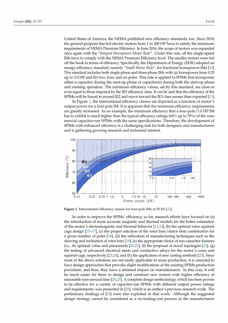
In Figure 1, the international efficiency classes are depicted as a function of motor’soutput power for a four-pole IM. It is apparent that the minimum efficiency requirementsare greatly increased. As an example, the minimum efficiency that a four-pole/1.0 HP IMhas to exhibit is much higher than the typical efficiency ratings (64% up to 78%) of the com-mercial capacitor-run SPIMs with the same specifications. Therefore, the development ofSPIMs with enhanced efficiency is a challenging task for both designers and manufacturersand is gathering growing research and industrial interest.
Figure 1. International efficiency classes for four-pole IMs at 50 Hz [12].
In order to improve the SPIMs’ efficiency, so far, research efforts have focused on (a)the introduction of more accurate magnetic and thermal models for the better estimationof the motor’s electromagnetic and thermal behavior [13,14], (b) the optimal rotor squirrel-cage design [15–17], (c) the proper selection of the rotor bars/stator slots combination fora given number of poles [18], (d) the utilization of manufacturing techniques such as theskewing and inclination of rotor bars [19], (e) the appropriate choice of run-capacitor features(i.e., its optimal value and placement) [20,21], (f) the proposal of novel topologies [22], (g)the testing of advanced electrical steels and conductive alloys for the motor’s cores andsquirrel-cage, respectively [23,24], and (h) the application of new casting methods [25]. Sincemost of the above solutions are not easily applicable to mass production, it is essential tohave design approaches that provoke slight modifications of the existing SPIMs productionprocedure, and thus, they have a minimal impact on manufacturers. In this way, it willbe much easier for them to design and construct new motors with higher efficiency atreasonable turn-around time [26,27]. A complete design methodology, which has been provento be effective for a variety of capacitor-run SPIMs with different output power ratingsand requirements, was presented in [28], which is an author’s previous research work. Thepreliminary findings of [29] were also exploited in that work. Although the suggesteddesign strategy cannot be considered as a no-tooling-cost process as the manufacturers
Energies 2022, 15, 717 4 of 24
will not avoid the electromagnetic re-design of entire machine series, it relies on low-costsolutions/modifications. These solutions are: (a) the employment of low-loss magneticmaterials for the motor’s cores, (b) the axial lengthening of the stator and rotor cores, (c) theusage of the double-layer first-class sinusoidal winding instead of the lap one, (d) the properdetermination of the auxiliary winding parameters (i.e., number of turns and run-capacitorvalue), and (e) the design of rotor bars and end-rings by following the provided directions.The efficiency of the obtained SPIMs was found to be much higher than the typical valuesthat are met at the commercial motors. So, important energy savings were recorded, whilesimultaneously, the SPIMs were advantageous from a manufacturing and economic point ofview compared to the motors that derive from the classical design approach (described in [30]).It is to be noted that the new efficiency levels are achievable with the present technology andalso by taking into consideration the standardized frame sizes.
2. Motivation and Contribution of the Work
However, the investigations that were conducted in [28] refer to capacitor-run SPIMsthat have a squirrel-cage rotor with semi-closed slots of trapezoidal cross-section. Thespecific rotor bar geometry is commonly preferred by IM designers and manufacturers.Notwithstanding that, there are plenty of other alternatives regarding the bar’s shapethat are used at commercial SPIMs. The impact of the bar’s shape on numerous motor’sperformance quantities has been studied partially in already published research worksthat deal with the design of machines that have a squirrel-cage rotor, such as the three-phase IMs, the line-start permanent magnet synchronous motors (LPMSMs), and theline-start synchronous reluctance motors. For instance, inverter-fed high-speed three-phaseIMs with semi-closed and closed rotor bars of different shape were designed, analyzed,and compared to each other in [31]. Few useful observations were drawn in [32] for thesame motor type by taking the voltage unbalance effect into account. Furthermore, acomparison among various bar structures was made in [33] for an IM with rotor coremade of amorphous material. The impact of the bar’s geometry on the efficiency, powerfactor, and torque ripple was studied in [34,35], by analyzing the IM’s operation underboth healthy and faulty (i.e., with broken rotor bar(s)) conditions. In [36], the trade-offamong the machine’s operational characteristics and their correlation with the geometricalparameters was discussed. A systematic approach to perform the design optimization of asquirrel-cage IM by focusing on the rotor slot configuration was proposed in [37,38]. Anadequate number of different squirrel-cage designs was investigated in [39,40], where thetransient performance of an LPMSM with copper squirrel-cage was considered. Rotor slotsof different shape but with the same cross-sectional area were utilized in [41,42], too. Asimilar study was carried out in [43] for a line-start synchronous reluctance motor.
On the basis of the foregoing, it is clear that this research topic is not sufficientlyaddressed in the available literature regarding the SPIMs. Aiming to fill this gap, eightdifferent rotor bar shapes (i.e., trapezoidal, oval, pent, polygonical, round, drop, rectangular,and quadrangular) are examined here for a four-pole/1.0 HP capacitor-run SPIM. Thecalculation of the machine’s basic dimensions and the rest of the geometrical parametersis conducted by applying the design methodology that was presented in [28]. The effectof the bar’s shape on the motor’s efficiency and power factor is highlighted with thehelp of a sensitivity analysis, which involves the simultaneous variation of (i) the bar’scross-sectional area, (ii) the run-capacitor value, and (iii) the auxiliary to main windingturns ratio. The performance of each motor is estimated through the finite element analysis.The resulted SPIMs are compared with regard to the motor’s net mass, starting current,breakdown torque, and shift angle between the winding currents. The above features areof great importance for industrial motors, but less attention has been devoted to themin the relevant literature. So, useful conclusions—not found elsewhere—are extracted inthis work. In addition, directions that could be valuable for designers and manufacturerstoward the SPIMs’ efficiency enhancement are given. Last but not least, the generalizationof the design approach (proposed in [28] by the authors) is evaluated.
Energies 2022, 15, 717 5 of 24
The paper is organized as follows: in Section 3, the motor’s specifications and theapplied constraints are described. Section 4 provides a thorough insight in significantaspects of the SPIMs design and analyzes the critical design parameters that will be setunder investigation. The models employed for the SPIM’s performance determinationare presented in Section 5. The acquired sensitivity analysis results along with the relateddiscussion are given in Section 6. A detailed comparison of the SPIMs with the highestefficiency is made in Section 7. In Section 8, the impact of: (i) SPIM’s capacitance on themagnetizing reactance and magnetic saturation factor, (ii) skin effect on the rotor barsresistance and leakage reactance, and (iii) bar’s shape on the rotor ohmic losses is displayedand commented. Finally, Section 9 concludes the work.
3. Specifications of the SPIM under Study
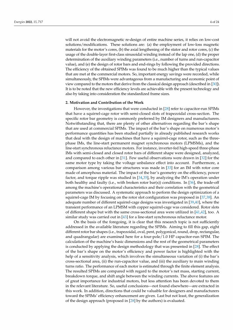
The motor under study is a four-pole capacitor-run SPIM with 24 stator slots, 30 non-skewed rotor bars, and nominal output power equal to 746 W. Its desirable operationalcharacteristics as well as its mounting type and insulation class are summarized in Table 1.All the considered specifications and constraints are in accordance with: (a) the latestinternational efficiency standards for electric motors and (b) the industrial trends. Theinformation about the minimum requirements of the international efficiency classes fora four-pole IM at 50 Hz is tabulated in Table 2. The efficiency target has been set here soas to meet the minimum efficiency of IE3 efficiency class (i.e., η ≥ 82.5%). The rest of theperformance quantities (e.g., starting to nominal torque ratio (Tst/Tn), starting to nominalcurrent ratio (Ist/In), etc.) have been specified based on the data found in the commercialcatalogues of SPIMs manufacturers. The strict constraints concerning the wire currentdensity of the main and auxiliary winding (Jm and Ja respectively) help to guarantee thefollowing: (a) the motor’s satisfactory thermal behavior and (b) its operation under free-cooling conditions. According to the industrial standards and practices, the wire currentdensity should be in the range of 3.1 A/mm2 to 6.2 A/mm2 for enclosed-type motors,while much higher values are acceptable for air-vented or open-frame constructions.
Table 1. SPIM’s operational characteristics and applied constraints.
Parameter Value/Type
Rated output power, Pn 746 WRated output torque, Tn ≥4.8 Nm
Rated speed, nm ≥1400 rpmNumber of poles, 2p 4Supply voltage, Un 230 VSupply frequency, f 50 Hz
Line current at nominal operation, In ≤5.0 AEfficiency at nominal operation, η ≥82.5%
Power factor at nominal operation, cosφ ≥0.9Starting to nominal torque ratio, Tst/Tn ≥0.35Starting to nominal current ratio, Ist/In ≤8.0
Main/aux. winding wire current density, Jm/Ja ≤3.50 A/mm2
Net mass, M ≤14.0 kgMounting Foot
Insulation class BDesign type N
Table 2. Minimum 50 Hz efficiency values defined in IEC/EN 60034-30-1:2014 for a four-pole/1.0 HP IM.
Efficiency Class Value (Minimum)
Standard Efficiency IE1 72.1%High Efficiency IE2 79.6%
Premium Efficiency IE3 82.5%Super Premium Efficiency IE4 85.7%
Energies 2022, 15, 717 6 of 24
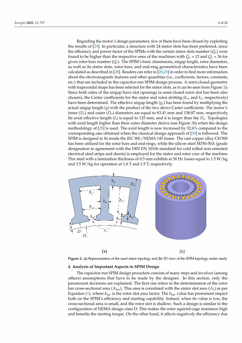
Regarding the motor’s design parameters, few of them have been chosen by exploitingthe results of [29]. In particular, a structure with 24 stator slots has been preferred, sincethe efficiency and power factor of the SPIMs with the certain stator slots number (Qs) werefound to be higher than the respective ones of the machines with Qs = 12 and Qs = 36 forgiven rotor bars number (Qr). The SPIM’s basic dimensions, airgap length, rotor diameters,as well as its stator slots, rotor bars, and end-ring geometrical characteristics have beencalculated as described in [28]. Readers can refer to [28,29] in order to find more informationabout the electromagnetic features and other quantities (i.e., coefficients, factors, constants,etc.) that are included in the capacitor-run SPIM design process. A semi-closed geometrywith trapezoidal shape has been selected for the stator slots, as it can be seen from Figure 2a.Since both sides of the airgap have slot openings (a semi-closed rotor slot has been alsochosen), the Carter coefficients for the stator and rotor slotting (kcs and kcr respectively)have been determined. The effective airgap length (ge) has been found by multiplying theactual airgap length (g) with the product of the two above Carter coefficients. The motor’sinner (Ds) and outer (Do) diameters are equal to 83.41 mm and 138.87 mm, respectively.Its axial effective length (L) is equal to 125 mm, and it is larger than the Do. Topologieswith axial length higher than their outer diameter derive (see Figure 2b) when the designmethodology of [28] is used. The axial length is now increased by 32.6% compared to thecorresponding one obtained when the classical design approach of [30] is followed. TheSPIM is designed to fit inside the IEC 90L/NEMA 145 frame. The cast copper alloy C81500has been utilized for the rotor bars and end-rings, while the silicon steel M350-50A (gradedesignation in agreement with the DIN EN 10106 standard for cold rolled non-orientedelectrical steel strips and sheets) is employed for the stator and rotor core of the machine.This steel with a lamination thickness of 0.5 mm exhibits at 50 Hz losses equal to 1.5 W/kgand 3.5 W/kg for operation at 1.0 T and 1.5 T, respectively.
Figure 2. (a) Representation of the used stator topology and (b) 3D view of the SPIM topology under study.
4. Analysis of Important Aspects in SPIM Design
The capacitor-run SPIM design procedure consists of many steps and involves (amongothers) assumptions that have to be made by the designer. In this section, only theparamount decisions are explained. The first one refers to the determination of the rotorbar cross-sectional area (Abar). This area is correlated with the stator slot area (As) as perEquation (1), where kbar is the rotor slot area factor. The kbar value has prominent impactboth on the SPIM’s efficiency and starting capability. Indeed, when its value is low, thecross-sectional area is small, and the rotor slot is shallow. Such a design is similar to theconfiguration of NEMA design class D. This makes the rotor squirrel-cage resistance highand benefits the starting torque. On the other hand, it affects negatively the efficiency due
Energies 2022, 15, 717 7 of 24
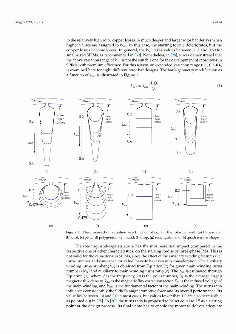
to the relatively high rotor copper losses. A much deeper and larger rotor bar derives whenhigher values are assigned to kbar. In this case, the starting torque deteriorates, but thecopper losses become lower. In general, the kbar takes values between 0.35 and 0.60 forsmall-sized SPIMs, as recommended in [30]. Nonetheless, in [28], it was demonstrated thatthe above variation range of kbar is not the suitable one for the development of capacitor-runSPIMs with premium efficiency. For this reason, an expanded variation range (i.e., 0.2–0.6)is examined here for eight different rotor bar designs. The bar’s geometry modification asa function of kbar is illustrated in Figure 3.
Abar = kbarAsQs
Qr(1)
0.2
0.6
.
.
.
.
.
.
.
.
.
.
.
.
.
.
.
.
.
.
.
.
.
.
.
..
.
Rotoroutersurface
Airgap
0.2
0.6
.
.
.
.
.
.
.
.
.
.
.
..
.
Rotoroutersurface
Airgap
0.2
0.6
.
.
.
.
.
.
.
.
.
.
.
.
.
.
.
.
.
.
.
.
.
.
.
..
.
Rotoroutersurface
Airgap
0.475
0.2
.
.
.
.
.
.
.
.
Rotoroutersurface
Airgap
0.2
0.475
.
.
.
.
.
.
.
.
.
.
.
.
.
.
.
.
Rotoroutersurface
Airgap
0.2
0.6
.
.
.
.
.
.
.
.
.
.
.
.
.
.
Rotoroutersurface
Airgap
0.2
0.45
.
.
.
.
.
.
.
.
Rotoroutersurface
Airgap
kbar
kbar
kbar
kbarkbar
kbar
kbar
Rotoroutersurface
Airgap
0.2
0.6
kbar
.
.
.
.
.
.
.
.
.
.
.
.
.
.
.
.
.
.
.
.
.
..
.
.
.
.
.
(a) (b) (c) (d)
(e) (f) (g) (h)
Figure 3. The cross-section variation as a function of kbar for the rotor bar with (a) trapezoidal,(b) oval, (c) pent, (d) polygonical, (e) round, (f) drop, (g) rectangular, and (h) quadrangular shape.
The rotor squirrel-cage structure has the most essential impact (compared to therespective one of other characteristics) on the starting torque of three-phase IMs. This isnot valid for the capacitor-run SPIMs, since the effect of the auxiliary winding features (i.e.,turns number and run-capacitor value) have to be taken into consideration. The auxiliarywinding turns number (Na) is obtained from Equation (2) for given main winding turnsnumber (Nm) and auxiliary to main winding turns ratio (a). The Nm is estimated throughEquation (3), where f is the frequency, 2p is the poles number, Bg is the average airgapmagnetic flux density, kdis is the magnetic flux correction factor, Em is the induced voltage ofthe main winding, and kwm is the fundamental factor of the main winding. The turns ratioinfluences considerably the SPIM’s magnetomotive force and its overall performance. Itsvalue lies between 1.0 and 2.0 in most cases, but values lower than 1.0 are also permissible,as pointed out in [28]. In [30], the turns ratio is proposed to be set equal to 1.5 as a startingpoint at the design process. Its final value has to enable the motor to deliver adequate
Energies 2022, 15, 717 8 of 24
torque at the start-up phase and exhibit the desirable efficiency under nominal operation.The decision about the turns ratio defines the run-capacitor value (Crun). The turns ratioand the Crun are interdependent, which is perceptible from Equation (4), where In is theSPIM’s nominal line current and Un is the supply voltage.
Na = aNm (2)
Nm =2pEm
2√
2πkdisBgDsLkwm f(3)
Crun =In
2π f Un(a2 + 1)(4)
All the above critical design parameters (i.e., kbar, Crun and a) are set here underthorough investigation. As already noted, the variation range of kbar is 0.2–0.6 (with a stepof 0.025) for the majority of the rotor bar topologies. Its maximum value is different for thebars of round, drop, and quadrangular shape. This makes their implementation feasible.The variation range of Crun is 18–30 µF, with a step of 1.0. The Nm and the turns ratio arespecified through the sensitivity analysis targeting the fulfillment of the set objective, i.e.,the development of SPIMs with: (i) satisfactory starting capability (i.e., Tst/Tn ≥ 0.35) and(ii) the highest possible efficiency under this condition. In the view of the foregoing, the totalnumber of the examined models is equal to 153,945 (5 × 21,900 + 2 × 15,144 + 1 × 14,157).Specifically, when the SPIM has trapezoidal, rectangular, polygonical, pent, and oval rotorbars, 21,900 models were created and analyzed in each case. The corresponding number isequal to 15,144 for the motors with bars of round and drop shape, while 14,157 models withquadrangular bars were developed and analyzed.
5. SPIM Modeling and Finite Element Analysis
The capacitor-run SPIM’s electromagnetic behavior is determined through the conduc-tion of voltage-driven time-stepping finite element analysis (FEA) simulations in a two-dimensional environment. Its performance under both nominal operation and locked-rotorcondition is estimated by using ANSYS® Electromagnetics Suite Software, which enablesthe coupling between the motor’s magnetic circuit and the external electric circuit. The lastone consists of the main and auxiliary winding, the run-capacitor, and the supply source.The machine is simulated as connected directly to the mains line-voltage of 230 V at 50 Hz.The SPIM’s currents’ signal, speed signal, torque signal, magnetic flux density distribution atthe stator and rotor core, and current density distribution at the rotor bars are the outputsof the developed FEA model under the motor’s nominal operation. Its particular lossesare specified by processing the extracted information. The models and/or the analyticalequations that have been employed for the losses claculation are briefly described here. Undersinusoidal magnetic flux condition, the iron losses (Piron) of the motor’s stator and rotor corederive from Equation (5), which exploits the well-known Bertotti loss separation model. ThePiron are divided into hysteresis (Ph), classical eddy current (Pc), and excess eddy current (Pe)losses. The applied formula contains the fundamental frequency of the magnetic field ( f ), themagnetic flux amplitude (Bm), the coefficients of hysteresis, classical eddy current, and excesseddy current losses (kh, kc, and ke respectively) and the coefficient β, which is related to thehysteresis losses. All the above coefficients depend on the steel’s properties.
Piron = Ph + Pc + Pe = kh f Bβm + kc f 2B2
m + ke f 1.5B1.5m (5)
The SPIM’s stator windings copper losses (Pscl) are obtained from Equation (6), whereRm is the main winding resistance, Ra is the auxiliary winding resistance, and Ia,rms andIm,rms are the rms currents of the main and auxiliary winding, respectively. The windingresistance varies with the temperature. Hence, the Rm and Ra are modified according to theconsidered temperature through Equation (7). At this expression, R0 is the phase resistanceat the reference temperature Tre f , sR is the slope of resistance-temperature characteristic

Energies 2022, 15, 717 9 of 24
(i.e., the temperature coefficient of resistance of the conductor), and T is the prevailingtemperature. The oil-filled or paper capacitors, which are incorporated at the motor of thistype, are not ideal (i.e., they do not exhibit only capacitance). They have imperfectionswithin their materials that create resistance. This resistance is called equivalent seriesresistance (RESR), and it is typically set equal to 1.0% of the capacitor reactance. Forexample, the RESR of a run-capacitor of 4.5 uF at 50 Hz supply frequency is equal to 7.07 Ω.So, the capacitor losses (Pcap) are specified as per Equation (8).
Pscl = Ra I2a,rms + Rm I2
m,rms (6)
R = R0
[1 + sR
(T − Tre f
)](7)
Pcap = RESR I2a,rms (8)
The rotor ohmic losses (Prcl) of the squirrel-cage bars are determined by utilizingEquation (9) and by considering: (i) the impact of the skin effect on the rotor bars and(ii) that the rotor bar currents have components only in the direction of the z-axis at thetwo-dimensional model. The quantities, incorporated in Equation (9), are the rotor barsnumber (Qr), the bar’s axial length (lbar), the bar’s electrical conductivity (σbar), the currentdensity of each element (Jz,i), and the area of each element (Ai) in which the bar is dividedwhen the FEA is performed. Since the skin effect creates a non-uniform current densitydistribution, the AC copper losses of each rotor bar are calculated as the sum of the lossesin each element. The mechanical losses include the frictional (Pf ) and the windage losses(Pwind). The first one comes as a consequence of the bearings, and they are dependent onthe lubricant, the shaft’s rotational speed, mass and friction coefficient, and the bearing’stype, diameter, and load. They are approximated through Equation (10), where ωm is theangular speed of the shaft, kb is the friction coefficient (it ranges typically from 0.08 up to0.20), G is the gravitational acceleration constant, Db is the bearing inner diameter, andMr is the mass of the rotating components. The Mr involves the mass of the rotor core,squirrel-cage, shaft, end plates, and bearing. The windage losses have two components, i.e.,the losses in airgap and the losses at the rotor’s end surfaces. The losses in the airgap arerepresented by the first term of Equation (11), where kr is the rough coefficient (it rangesfrom 1.0 up to 1.4, for a smooth surface kr = 1), C f is the torque coefficient, ρair is the airdensity, Dr is the rotor’s outer diameter, and Dsha f t is the shaft diameter. The C f is decidedby the Couette Reynolds number (Re). The Re is given in Equation (12), where µair is thedynamic viscosity of air and g is the airgap length. For given Re, the value of C f is acquiredwith the help of Equation (13). The second term of Equation (11) represents the losses atthe rotor’s end surfaces. In this case, C f depends on the tip Reynolds number (Rer), whichis provided in Equation (14). Now, the C f is estimated by using Equation (15). Finally,the capacitor-run SPIM’s efficiency derives from Equation (16), where Pn is the motor’snominal output power.
Prcl =Qr
∑j=1
No of j−thbar elements
∑i=1
(Jz,i · Ai)2 · lbar
σbar Ai(9)
Pf = 0.5ωmkb MrGDb (10)
Pwind =π
32krC f ρairω3
mD4r L +
164
C f ρairω3m
(D5
r − D5sha f t
)(11)
Re =ρairωmDrg
2µair(12)
Energies 2022, 15, 717 10 of 24
C f = 10 (2g/Dr)0.3
Re, Re< 64
C f = 2 (2g/Dr)0.3
R0.6e
, 64 < Re < 500
C f = 1.03 (2g/Dr)0.3
R0.5e
, 500 < Re < 104
C f = 0.065 (2g/Dr)0.3
R0.6e
, 104 < Re
(13)
Rer =ρairωmD2
r4µair
(14)
C f =
3.87R0.5
er, Re < 3 · 105
C f =0.146R0.1
er, 3 · 105 < Re
(15)
η =Pn
Pn + Pscl + Prcl + Piron + Pcap + Pf + Pwind(16)
6. Sensitivity Analysis Results
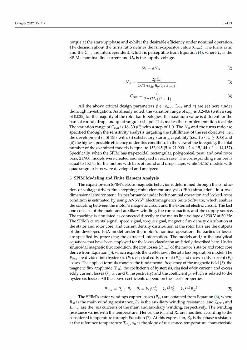
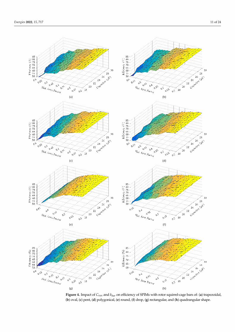
The impact of kbar and Crun on the SPIM’s efficiency and power factor is illustratedin Figures 4 and 5, respectively. For given kbar, the relation between the turns ratio andCrun is revealed in Figure 6. At this point, it has to be noted that the nominal rotationalspeed of the developed SPIMs remains almost constant for given kbar. The speed presents asmall variation (i.e., 7–22 rpm) as the Crun varies and rotor bars of different shapes are used.Consequently, it can be considered that for a given kbar, the motors operate at the same slip,regardless of the bar’s geometry. By inspecting the curves of Figure 4, it is observed thatthe efficiency increases as lower values are assigned to kbar. The efficiency maximizationoccurs when kbar = 0.2 for all the examined bar designs. The tendency of the efficiencycan be explained through the motor’s loss decoupling. Its maximization coincides withthe main/auxiliary winding copper losses minimization. The stator windings copperlosses are the dominant loss type. The iron and capacitor losses augment as the rotorbar’s cross-sectional area becomes larger. Indicatively, it is reported that the efficiency ofthe SPIMs with the trapezoidal bars declines by up to 2.0% as the kbar varies from 0.2 to0.6. This comes as a result of the magnetic saturation at the rotor’s teeth. For the samekbar variation range, the capacitor losses are tripled. Only the rotor ohmic losses follow adecreasing trend due to the lower squirrel-cage resistance. The sum of the frictional andwindage losses remains almost constant as the motor’s nominal output power is deliveredat about the same rotational speed.
Considerable differences are recorded among the losses of the SPIMs with differentrotor squirrel-cage configuration as the kbar ranges from 0.2 to 0.275. Beyond the lastmentioned value, the stator windings copper losses of the machines with drop and roundrotor bars increase extensively. The kbar value should not be higher than 0.375 for the abovegeometries so as to conclude to motors with efficiency at least equal to that of the IE1efficiency class (i.e., η ≥ 72.1%). The respective value is equal to 0.425 when bars of pentand trapezoidal cross-section are employed. For bars of quadrangular, oval, polygonical,and rectangular shape, the kbar should not be higher than 0.45.
Energies 2022, 15, 717 11 of 24
(b)
(c) (d)
(e) (f)
(g) (h)
(a)
Figure 4. Impact of Crun and kbar on efficiency of SPIMs with rotor squirrel-cage bars of: (a) trapezoidal,(b) oval, (c) pent, (d) polygonical, (e) round, (f) drop, (g) rectangular, and (h) quadrangular shape.
Energies 2022, 15, 717 12 of 24
(a) (b)
(c) (d)
(e) (f)
(g) (h)
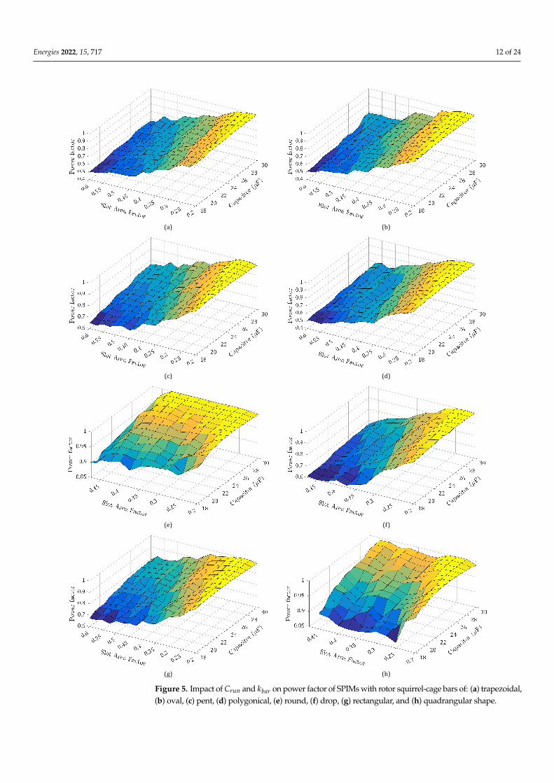
Figure 5. Impact of Crun and kbar on power factor of SPIMs with rotor squirrel-cage bars of: (a) trapezoidal,(b) oval, (c) pent, (d) polygonical, (e) round, (f) drop, (g) rectangular, and (h) quadrangular shape.
Energies 2022, 15, 717 13 of 24
(a) (b)
(c) (d)
(e) (f)
(g) (h)
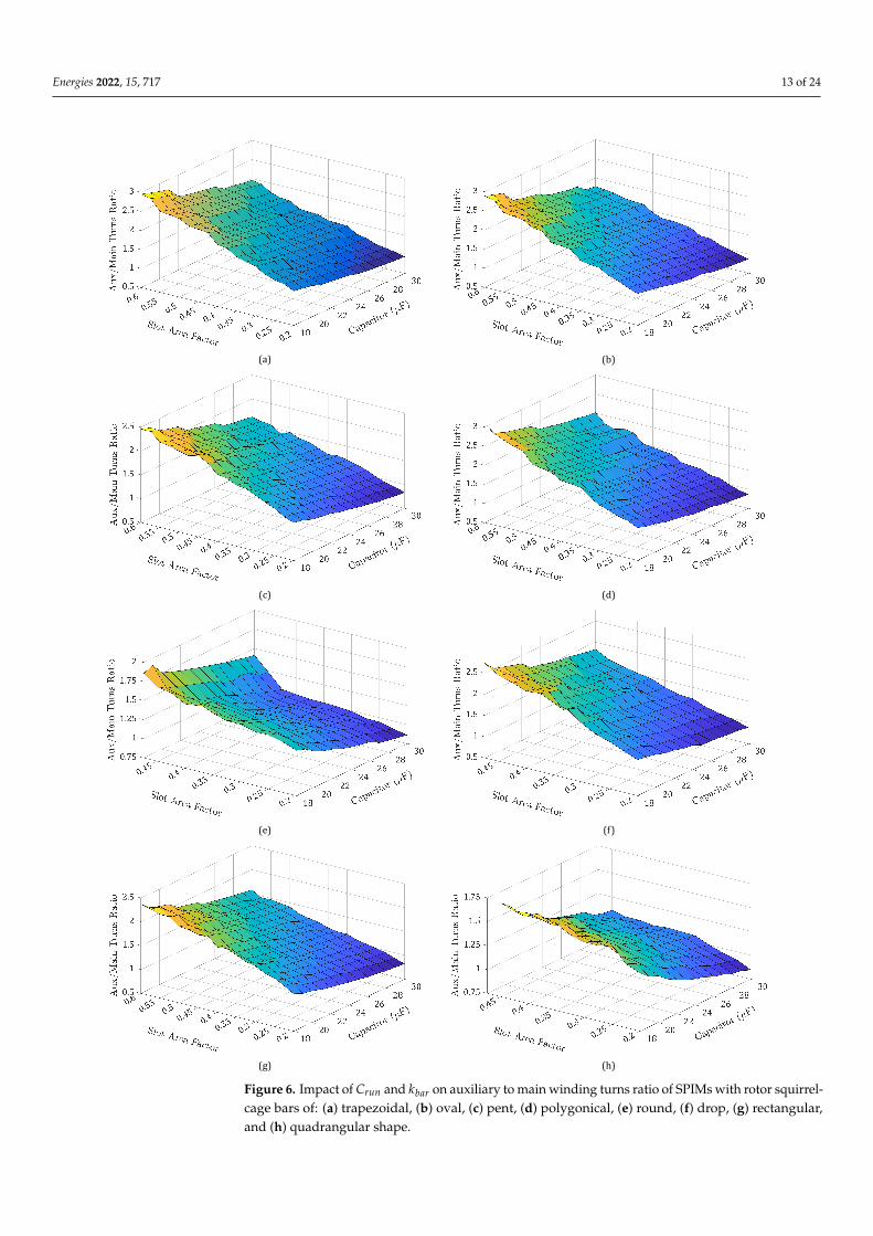
Figure 6. Impact of Crun and kbar on auxiliary to main winding turns ratio of SPIMs with rotor squirrel-cage bars of: (a) trapezoidal, (b) oval, (c) pent, (d) polygonical, (e) round, (f) drop, (g) rectangular,and (h) quadrangular shape.

Energies 2022, 15, 717 14 of 24
The SPIM’s efficiency is at least equal to or higher than that set by the IE3 efficiencyclass, when kbar = 0.2, independently of the rotor bar’s shape. This validates the directions,given in [28], concerning the kbar value toward the achievement of premium efficiency. Thesame efficiency level is also attainable when kbar = 0.225. This does not happen for thebars with polygonical and drop cross-section. For kbar = 0.2, the efficiency increases as theCrun gets a higher value. The difference between the minimum and maximum calculatedefficiency values ranges from 0.35% to 1.05%. All the loss types, except from the rotorohmic losses, are reduced when the Crun becomes higher. For the majority of the resultedmodels, the efficiency is maximized when the Crun varies from 25 µF to 30 µF for the wholevariation range of kbar. The efficiency often gets its maximum value when Crun = 26 µF.It seems that a capacitance equal to or higher than 25 µF is the most appropriate choicefor the SPIM under study. Exceptions to the above statement are the topologies withpolygonical and quadrangular shape, where the efficiency maximization occurs whenCrun = 25 µF. Another exception is the SPIMs with rectangular bars, since the efficiencybecomes maximum when Crun = 27 µF.
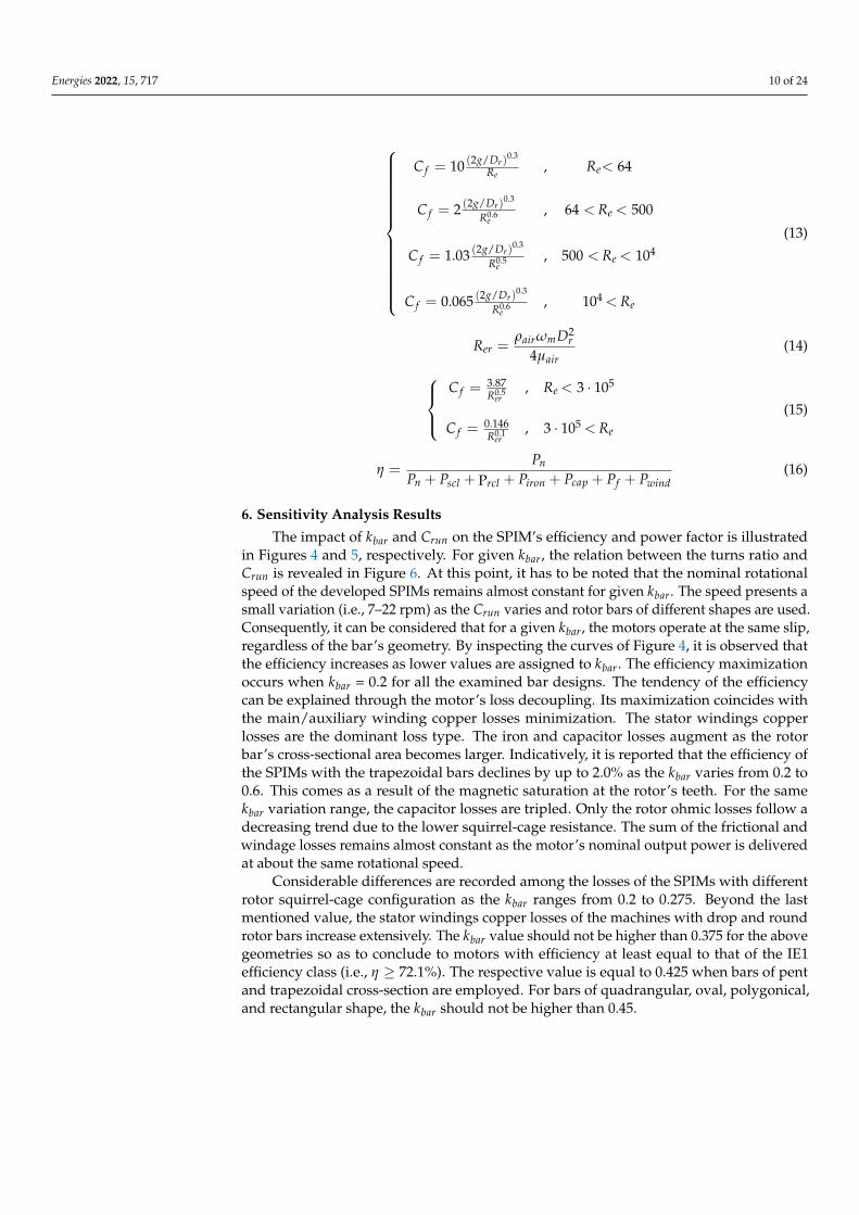
The augmentation of Crun with the simultaneous decrement of kbar enhances the powerfactor. Generally, a high power factor (i.e., cosφ ≥0.85) is recorded throughout the whole kbarvariation range. The most curves, given in Figure 5, have the same tendency. Only for theround and quadrangular bars, the curve’s tendency is quite different. For given Crun, thepower factor maximization happens when kbar = 0.2. The auxiliary to main winding turnsratio declines when either the rotor bar’s cross-sectional area is getting smaller or a highervalue is selected for the Crun. The large number of turns for the auxiliary winding increasesgreatly the stator copper losses and makes the SPIM’s efficiency lower. For kbar = 0.2 (i.e., thevalue at which both the motor’s efficiency and power factor are maximized), the turns ratio ofthe developed models lies always between 0.8 and 1.5. This proves that the recommendations,made in [28], for the turns ratio variation range are the proper ones for the design of SPIMswith premium efficiency. At the same time, it validates once again the generalization andeffectiveness of the introduced design methodology. Additionally, the folllowing can bestated: (a) the efficiency target is satisfied at all the SPIM models regardless of the rotorbar’s shape, (b) the new efficiency ratings can be reached when the design parameters ofboth the squirrel-cage rotor structure and the stator windings are suitably specified, (c) thedetermination of the specific geometrical features is interdependent, and (d) for kbar = 0.2,there are notable differences for the efficiency and power factor of the resulted SPIM models.As a consequence, more attention is paid to other operational characteristics (e.g., startingcurrent, breakdown torque, shift angle between the currents, etc.) in the next section.
7. Comparison of the SPIMs with the Highest Efficiency
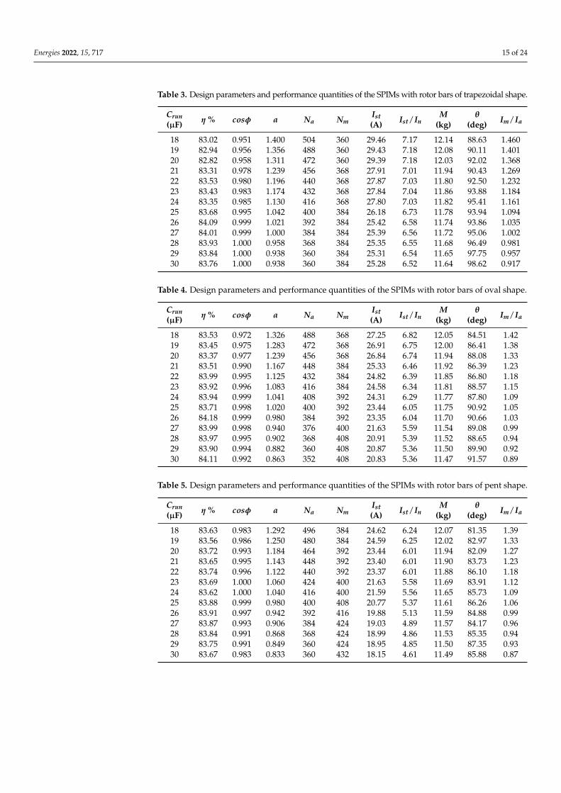
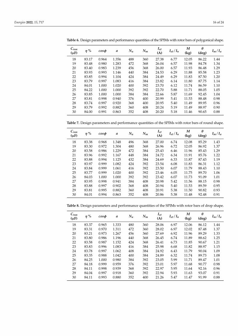
The design parameters and the performance quantities of the capacitor-run SPIMswith the highest efficiency (i.e., with kbar = 0.2) are summarized in Table 3–10. The half-view (½) part of these machines as well as the magnetic flux density distribution under themotor’s nominal operation are shown in Figure 7. For the specific SPIMs, the subsequentcomments can be made:
(a) The constraints regarding: (i) the motor’s net mass (i.e., M ≤14.0 kg), (ii) the main/auxiliary winding current densities (i.e., Jm, Ja ≤3.5 A/mm2), and (iii) the starting tonominal torque ratio (i.e., Tst/Tn ≥ 0.35) are met. Moreover, the starting to nominalcurrent ratio (Ist/In) is always lower than 8.0. The SPIMs with pent and rectangularrotor bars present the lowest values for this ratio, and they have clear advantage overthe other models. The Ist/In ratio ranges from 4.61 to 6.24 for the machines with barsof pentagonal shape. The ratio value ranges from 4.82 to 6.42 when rectangular barsare utilized. On the contrary, the topologies with trapezoidal bars exhibit the highestvalues for this ratio, i.e., 6.52–7.17. The starting current decreases notably as the rotorbar’s cross-sectional area becomes smaller and a capacitance of high value is used.
Energies 2022, 15, 717 15 of 24
Table 3. Design parameters and performance quantities of the SPIMs with rotor bars of trapezoidal shape.
Crun(µF) η % cosφ a Na Nm
Ist(A) Ist/In
M(kg)
θ(deg) Im/Ia
18 83.02 0.951 1.400 504 360 29.46 7.17 12.14 88.63 1.46019 82.94 0.956 1.356 488 360 29.43 7.18 12.08 90.11 1.40120 82.82 0.958 1.311 472 360 29.39 7.18 12.03 92.02 1.36821 83.31 0.978 1.239 456 368 27.91 7.01 11.94 90.43 1.26922 83.53 0.980 1.196 440 368 27.87 7.03 11.80 92.50 1.23223 83.43 0.983 1.174 432 368 27.84 7.04 11.86 93.88 1.18424 83.35 0.985 1.130 416 368 27.80 7.03 11.82 95.41 1.16125 83.68 0.995 1.042 400 384 26.18 6.73 11.78 93.94 1.09426 84.09 0.999 1.021 392 384 25.42 6.58 11.74 93.86 1.03527 84.01 0.999 1.000 384 384 25.39 6.56 11.72 95.06 1.00228 83.93 1.000 0.958 368 384 25.35 6.55 11.68 96.49 0.98129 83.84 1.000 0.938 360 384 25.31 6.54 11.65 97.75 0.95730 83.76 1.000 0.938 360 384 25.28 6.52 11.64 98.62 0.917
Table 4. Design parameters and performance quantities of the SPIMs with rotor bars of oval shape.
Crun(µF) η % cosφ a Na Nm
Ist(A) Ist/In
M(kg)
θ(deg) Im/Ia
18 83.53 0.972 1.326 488 368 27.25 6.82 12.05 84.51 1.4219 83.45 0.975 1.283 472 368 26.91 6.75 12.00 86.41 1.3820 83.37 0.977 1.239 456 368 26.84 6.74 11.94 88.08 1.3321 83.51 0.990 1.167 448 384 25.33 6.46 11.92 86.39 1.2322 83.99 0.995 1.125 432 384 24.82 6.39 11.85 86.80 1.1823 83.92 0.996 1.083 416 384 24.58 6.34 11.81 88.57 1.1524 83.94 0.999 1.041 408 392 24.31 6.29 11.77 87.80 1.0925 83.71 0.998 1.020 400 392 23.44 6.05 11.75 90.92 1.0526 84.18 0.999 0.980 384 392 23.35 6.04 11.70 90.66 1.0327 83.99 0.998 0.940 376 400 21.63 5.59 11.54 89.08 0.9928 83.97 0.995 0.902 368 408 20.91 5.39 11.52 88.65 0.9429 83.90 0.994 0.882 360 408 20.87 5.36 11.50 89.90 0.9230 84.11 0.992 0.863 352 408 20.83 5.36 11.47 91.57 0.89
Table 5. Design parameters and performance quantities of the SPIMs with rotor bars of pent shape.
Crun(µF) η % cosφ a Na Nm
Ist(A) Ist/In
M(kg)
θ(deg) Im/Ia
18 83.63 0.983 1.292 496 384 24.62 6.24 12.07 81.35 1.3919 83.56 0.986 1.250 480 384 24.59 6.25 12.02 82.97 1.3320 83.72 0.993 1.184 464 392 23.44 6.01 11.94 82.09 1.2721 83.65 0.995 1.143 448 392 23.40 6.01 11.90 83.73 1.2322 83.74 0.996 1.122 440 392 23.37 6.01 11.88 86.10 1.1823 83.69 1.000 1.060 424 400 21.63 5.58 11.69 83.91 1.1224 83.62 1.000 1.040 416 400 21.59 5.56 11.65 85.73 1.0925 83.88 0.999 0.980 400 408 20.77 5.37 11.61 86.26 1.0626 83.91 0.997 0.942 392 416 19.88 5.13 11.59 84.88 0.9927 83.87 0.993 0.906 384 424 19.03 4.89 11.57 84.17 0.9628 83.84 0.991 0.868 368 424 18.99 4.86 11.53 85.35 0.9429 83.75 0.991 0.849 360 424 18.95 4.85 11.50 87.35 0.9330 83.67 0.983 0.833 360 432 18.15 4.61 11.49 85.88 0.87
Energies 2022, 15, 717 16 of 24
Table 6. Design parameters and performance quantities of the SPIMs with rotor bars of polygonical shape.
Crun(µF) η % cosφ a Na Nm
Ist(A) Ist/In
M(kg)
θ(deg) Im/Ia
18 83.17 0.964 1.356 488 360 27.38 6.77 12.05 86.22 1.4419 83.48 0.980 1.283 472 368 26.04 6.57 11.98 84.78 1.3420 83.40 0.983 1.239 456 368 26.00 6.57 11.93 86.48 1.2921 83.93 0.993 1.146 440 384 24.53 6.29 11.88 85.58 1.2322 83.85 0.994 1.104 424 384 24.49 6.29 11.83 87.50 1.2023 83.79 0.997 1.083 416 384 23.82 6.14 11.80 87.75 1.1424 84.01 1.000 1.020 400 392 23.70 6.12 11.74 86.59 1.1025 84.22 1.000 1.000 392 392 22.70 5.88 11.71 88.05 1.0526 83.85 1.000 1.000 384 384 22.66 5.87 11.69 92.45 1.0427 83.81 0.998 0.940 376 400 20.99 5.41 11.53 88.48 0.9828 83.74 0.997 0.920 368 400 20.95 5.40 11.49 89.95 0.9629 83.79 0.992 0.882 360 408 20.24 5.19 11.49 88.97 0.9030 84.00 0.991 0.863 352 408 20.20 5.18 11.46 90.65 0.88
Table 7. Design parameters and performance quantities of the SPIMs with rotor bars of round shape.
Crun(µF) η % cosφ a Na Nm
Ist(A) Ist/In
M(kg)
θ(deg) Im/Ia
18 83.38 0.968 1.348 496 368 27.00 6.74 12.08 85.29 1.4319 83.30 0.972 1.304 480 368 26.96 6.72 12.05 86.92 1.3720 83.58 0.986 1.229 472 384 25.43 6.46 11.96 85.43 1.2921 83.96 0.992 1.167 448 384 24.72 6.34 11.91 85.76 1.2222 83.88 0.994 1.125 432 384 24.69 6.33 11.87 87.43 1.1923 83.97 0.999 1.082 424 392 23.54 6.08 11.83 86.31 1.1224 83.84 0.999 1.061 416 392 23.50 6.07 11.79 88.43 1.1025 83.77 0.999 1.020 400 392 23.46 6.05 11.75 89.70 1.0626 84.03 1.000 1.000 392 392 23.42 6.07 11.73 91.09 1.0127 83.95 0.998 0.941 384 408 20.98 5.42 11.56 88.15 0.9828 83.88 0.997 0.902 368 408 20.94 5.40 11.53 89.59 0.9529 83.81 0.995 0.882 360 408 20.91 5.38 11.50 90.82 0.9330 84.01 0.994 0.863 352 408 20.86 5.38 11.48 92.48 0.91
Table 8. Design parameters and performance quantities of the SPIMs with rotor bars of drop shape.
Crun(µF) η % cosφ a Na Nm
Ist(A) Ist/In
M(kg)
θ(deg) Im/Ia
18 83.37 0.965 1.333 480 360 28.06 6.97 12.06 86.12 1.4419 83.31 0.970 1.311 472 360 28.02 6.97 12.02 87.48 1.3720 83.21 0.973 1.267 456 360 27.69 6.92 11.96 89.29 1.3321 83.80 0.986 1.196 440 368 26.45 6.74 11.89 88.62 1.2522 83.58 0.987 1.152 424 368 26.41 6.73 11.85 90.67 1.2123 83.83 0.996 1.083 416 384 25.98 6.68 11.82 88.97 1.1524 83.78 0.997 1.062 408 384 24.92 6.43 11.79 90.04 1.0925 83.35 0.988 1.042 400 384 24.89 6.32 11.74 89.73 1.0826 84.25 1.000 0.980 384 392 23.05 5.99 11.71 89.47 1.0127 84.18 0.999 0.959 376 392 23.01 5.97 11.68 90.77 0.9828 84.11 0.998 0.939 368 392 22.97 5.95 11.64 92.16 0.9629 84.04 0.997 0.918 360 392 22.94 5.93 11.63 93.07 0.9130 84.11 0.993 0.880 352 400 21.26 5.47 11.47 91.99 0.88
Energies 2022, 15, 717 17 of 24
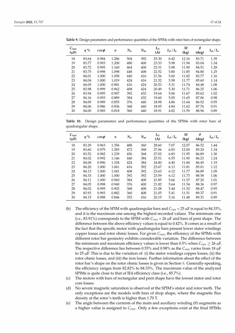
Table 9. Design parameters and performance quantities of the SPIMs with rotor bars of rectangular shape.
Crun(µF) η % cosφ a Na Nm
Ist(A) Ist/In
M(kg)
θ(deg) Im/Ia
18 83.64 0.984 1.286 504 392 25.30 6.42 12.16 83.71 1.3919 83.77 0.993 1.200 480 400 23.33 5.98 11.94 83.04 1.3420 83.72 0.995 1.160 464 400 23.31 5.98 11.90 84.51 1.2821 83.75 0.998 1.098 448 408 22.52 5.80 11.85 84.80 1.2522 84.01 1.000 1.058 440 416 21.56 5.60 11.82 83.77 1.1623 84.04 1.000 1.019 424 416 21.52 5.58 11.77 85.60 1.1424 84.05 1.000 0.981 416 424 20.53 5.31 11.74 84.48 1.0825 83.98 0.999 0.962 408 424 20.49 5.30 11.71 86.25 1.0626 83.94 0.995 0.907 392 432 19.64 5.06 11.67 85.62 1.0227 84.16 0.993 0.889 384 432 19.60 5.05 11.65 87.06 0.9828 84.09 0.989 0.855 376 440 18.98 4.86 11.64 86.92 0.9529 84.06 0.986 0.836 368 440 18.95 4.84 11.62 87.76 0.9130 84.00 0.983 0.818 360 440 18.91 4.82 11.59 88.96 0.89
Table 10. Design parameters and performance quantities of the SPIMs with rotor bars ofquadrangular shape.
Crun(µF) η % cosφ a Na Nm
Ist(A) Ist/In
M(kg)
θ(deg) Im/Ia
18 83.29 0.963 1.356 488 360 28.60 7.07 12.07 86.52 1.4419 83.60 0.979 1.283 472 368 27.06 6.83 12.00 85.20 1.3420 83.52 0.982 1.239 456 368 27.02 6.83 11.95 86.89 1.3021 84.02 0.992 1.146 440 384 25.51 6.55 11.90 86.23 1.2422 84.08 0.996 1.104 424 384 24.80 6.40 11.84 86.45 1.1923 84.20 1.000 1.061 416 392 23.67 6.13 11.81 85.01 1.1224 84.13 1.000 1.041 408 392 23.63 6.12 11.77 86.89 1.0925 84.33 1.000 1.000 392 392 23.59 6.12 11.73 88.58 1.0626 84.11 1.000 0.960 384 400 21.85 5.66 11.57 87.20 1.0127 84.05 0.998 0.940 376 400 21.82 5.64 11.54 88.36 0.9728 84.02 0.995 0.902 368 408 21.08 5.44 11.52 88.47 0.9529 83.93 0.993 0.882 360 408 21.05 5.41 11.51 89.37 0.9130 84.15 0.988 0.846 352 416 20.15 5.16 11.48 89.31 0.89
(b) The efficiency of the SPIM with quadrangular bars and Crun = 25 µF is equal to 84.33%,and it is the maximum one among the highest recorded values. The minimum one(i.e., 83.91%) corresponds to the SPIM with Crun = 26 µF and bars of pent shape. Thedifference between the above efficiency values is equal to 0.42%. It comes as a result ofthe fact that the specific motor with quadrangular bars present lower stator windingscopper losses and rotor ohmic losses. For given Crun, the efficiency of the SPIMs withdifferent rotor bar geometry exhibits considerable variation. The difference betweenthe minimum and maximum efficiency values is lower than 0.5% when Crun ≥ 26 µF.The respective difference lies between 0.55% and 0.98% as the Crun varies from 18 µFto 25 µF. This is due to the variation of: (i) the stator windings copper losses, (ii) therotor ohmic losses, and (iii) the iron losses. Further information about the effect of therotor bar’s shape on the rotor ohmic losses is given in Section 8. Generally-speaking,the efficiency ranges from 82.82% to 84.33%. The maximum value of the analyzedSPIMs is quite close to that of IE4 efficiency class (i.e., 85.7%).
(c) The motors with bars of rectangular and pent shape have the lowest stator and rotorcore losses.
(d) No severe magnetic saturation is observed at the SPIM’s stator and rotor teeth. Theonly exceptions are the models with bars of drop shape, where the magnetic fluxdensity at the rotor’s teeth is higher than 1.70 T.
(e) The angle between the currents of the main and auxiliary winding (θ) augments asa higher value is assigned to Crun. Only a few exceptions exist at the final SPIMs.
Energies 2022, 15, 717 18 of 24
The shift angle is close enough or equal to the ideal value (i.e., 90 electrical degrees)for the whole variation range of Crun. The achievement of the ideal angle value iscrucial for two reasons. The first one refers to the generation of circular rotating fields.Unlike the three-phase IMs, circular rotating fields are not inherently formed at thecapacitor-run SPIMs. Rotating fields with elliptical shape are produced due to thebackward fields, especially when the shift angle is far away from 90 electrical degrees.When the above happens, the motor’s performance is substantially degraded. Thesecond reason is related to the maximization of the SPIM’s delivered output torquefor given absorbed current. A high value of Crun is preferable at the machines withpent and rectangular bars, aiming for the currents shift angle to approach the idealvalue. The shift angle becomes higher than 90 electrical degrees when trapezoidalbars are incorporated and Crun ≥ 23 µF. With respect to the ideal angle, a lower valueis preferable rather than a higher one. In the latter case, the SPIM’s operation may benoisy due to the torque fluctuations and the vibrations.
(f) A necessary condition for the SPIM’s torque ripple minimization (besides the slottingand higher-order current harmonics effect reduction) is the ratio of the main toauxiliary winding current amplitudes (Im/Ia) to be equal to the turns ratio. Thiscondition is fulfilled, as the value of the Im/Ia ratio is almost equal to the turns ratio.
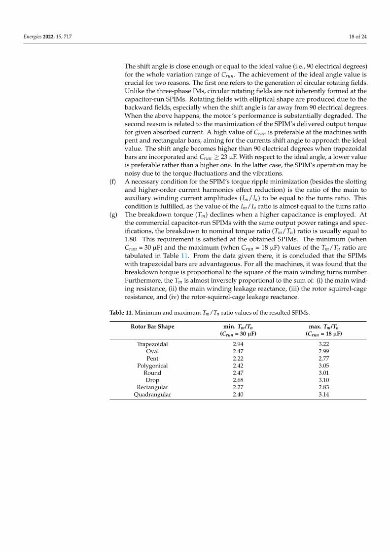
(g) The breakdown torque (Tm) declines when a higher capacitance is employed. Atthe commercial capacitor-run SPIMs with the same output power ratings and spec-ifications, the breakdown to nominal torque ratio (Tm/Tn) ratio is usually equal to1.80. This requirement is satisfied at the obtained SPIMs. The minimum (whenCrun = 30 µF) and the maximum (when Crun = 18 µF) values of the Tm/Tn ratio aretabulated in Table 11. From the data given there, it is concluded that the SPIMswith trapezoidal bars are advantageous. For all the machines, it was found that thebreakdown torque is proportional to the square of the main winding turns number.Furthermore, the Tm is almost inversely proportional to the sum of: (i) the main wind-ing resistance, (ii) the main winding leakage reactance, (iii) the rotor squirrel-cageresistance, and (iv) the rotor-squirrel-cage leakage reactance.
Table 11. Minimum and maximum Tm/Tn ratio values of the resulted SPIMs.
Rotor Bar Shape min. Tm/Tn max. Tm/Tn(Crun = 30 µF) (Crun = 18 µF)
Trapezoidal 2.94 3.22Oval 2.47 2.99Pent 2.22 2.77
Polygonical 2.42 3.05Round 2.47 3.01Drop 2.68 3.10
Rectangular 2.27 2.83Quadrangular 2.40 3.14

Energies 2022, 15, 717 19 of 24
(a) (b)
(c) (d)
(e) (f)
(g) (h)
Figure 7. View (½) part and magnetic flux density distribution under nominal operation of the SPIMwith Crun = 18 µF and rotor bars of: (a) trapezoidal, (b) oval, (c) pent, (d) polygonical, (e) round,(f) drop, (g) rectangular, and (h) quadrangular shape.
8. Further Considerations
This section provides insight into aspects concerning SPIM’s operational characteristicsthat have to be taken into account by the designer.
8.1. Effect of Capacitance on Magnetizing Reactance and Magnetic Saturation Factor
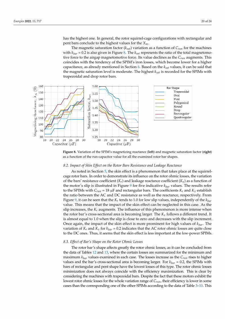
The magnetizing reactance (Xm) variation as a function of the run-capacitor value(Crun) for the SPIMs with kbar = 0.2 is depicted in Figure 8. The Xm increases as theCrun becomes higher, since a larger number of main winding turns (Nm) are utilized(Tables 3–10). The specific quantity is strongly dependent on the Nm. It is also affected bythe rotor bar’s shape due to the resulted magnetic saturation. The above is apparent fromthe topologies with Crun = 18 µF, Nm = 360, and trapezoidal, quadrangular, polygonical,and drop bars. Although the above motors have the same Nm, their Xm is different. TheSPIM with trapezoidal bars has the lowest Xm, while that with rotor slots of drop shape
Energies 2022, 15, 717 20 of 24
has the highest one. In general, the rotor squirrel-cage configurations with rectangular andpent bars conclude to the highest values for the Xm.
The magnetic saturation factor (ksat) variation as a function of Crun for the machineswith kbar = 0.2 is also given in Figure 8. The ksat represents the ratio of the total magnetomo-tive force to the airgap magnetomotive force. Its value declines as the Crun augments. Thiscoincides with the tendency of the SPIM’s iron losses, which become lower for a highercapacitance, as already mentioned in Section 6. Based on the ksat values, it can be said thatthe magnetic saturation level is moderate. The highest ksat is recorded for the SPIMs withtrapezoidal and drop rotor bars.
Figure 8. Variation of the SPIM’s magnetizing reactance (left) and magnetic saturation factor (right)as a function of the run-capacitor value for all the examined rotor bar shapes.
8.2. Impact of Skin Effect on the Rotor Bars Resistance and Leakage Reactance
As noted in Section 5, the skin effect is a phenomenon that takes place at the squirrel-cage rotor bars. In order to demonstrate its influence on the rotor ohmic losses, the variationof the bars’ resistance coefficient (Kr) and leakage reactance coefficient (Kx) as a function ofthe motor’s slip is illustrated in Figure 9 for five indicative kbar values. The results referto the SPIMs with Crun = 18 µF and rectangular bars. The coefficients Kr and Kx establishthe ratio between the AC and DC resistance as well as the reactance, respectively. FromFigure 9, it can be seen that the Kr tends to 1.0 for low slip values, independently of the kbarvalue. This means that the impact of the skin effect can be neglected in this case. As theslip increases, the Kr augments. The influence of this phenomenon is more intense whenthe rotor bar’s cross-sectional area is becoming larger. The Kx follows a different trend. Itis almost equal to 1.0 when the slip is close to zero and decreases with the slip increment.Once again, the impact of the skin effect is more prominent for high values of kbar. Thevariation of Kr and Kx for kbar = 0.2 indicates that the AC rotor ohmic losses are quite closeto the DC ones. Thus, it seems that the skin effect is less important at the low-power SPIMs.
8.3. Effect of Bar’s Shape on the Rotor Ohmic Losses
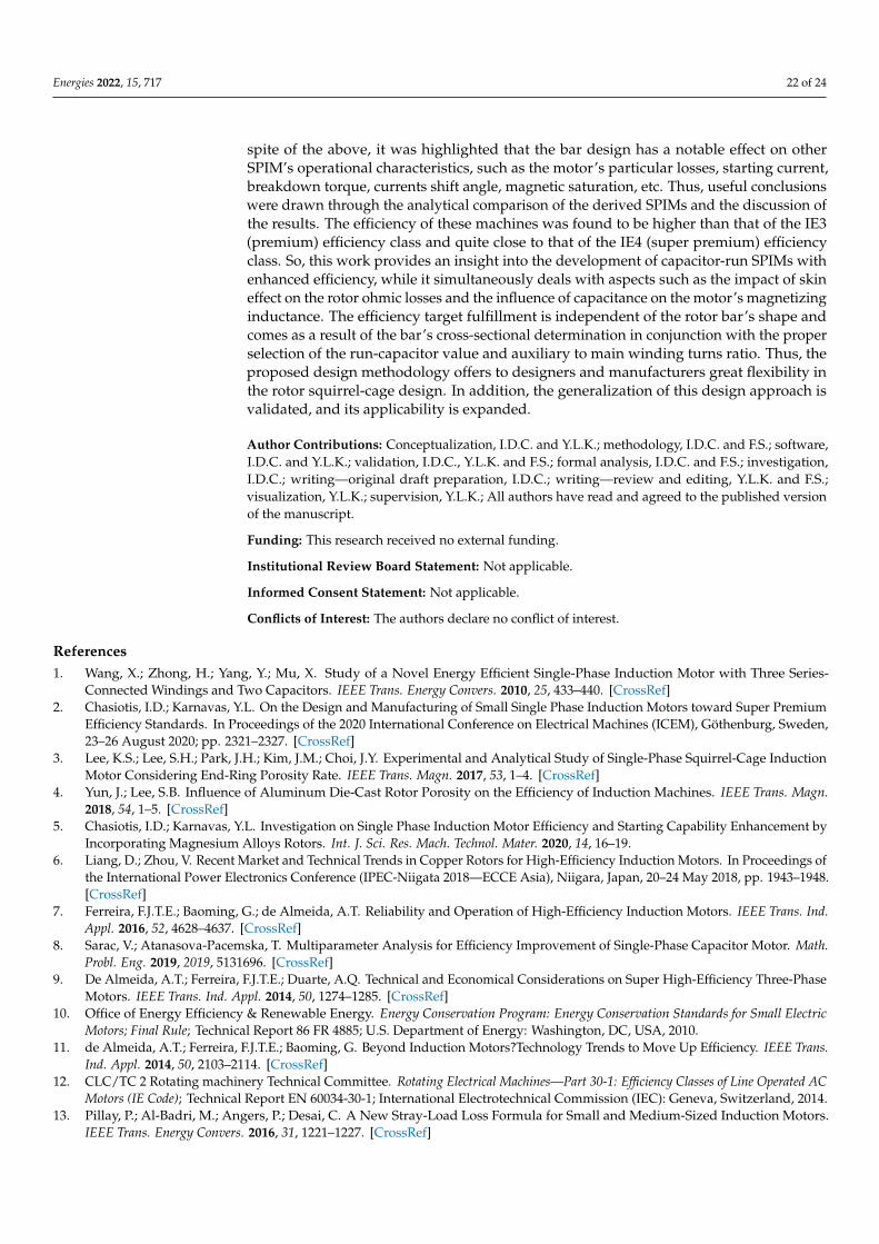
The rotor bar’s shape affects greatly the rotor ohmic losses, as it can be concluded fromthe data of Tables 12 and 13, where the certain losses are summarized for the minimum andmaximum kbar values examined in each case. The losses increase as the Crun rises to highervalues and the bar’s cross-sectional area is becoming larger. For kbar = 0.2, the SPIMs withbars of rectangular and pent shape have the lowest losses of this type. The rotor ohmic lossesminimization does not always coincide with the efficiency maximization. This is clear byconsidering the machines with trapezoidal bars. Despite the fact that these motors exhibit thelowest rotor ohmic losses for the whole variation range of Crun, their efficiency is lower in somecases than the corresponding one of the other SPIMs according to the data of Table 3–10. This
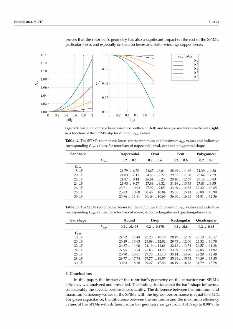
Energies 2022, 15, 717 21 of 24
proves that the rotor bar’s geometry has also a significant impact on the rest of the SPIM’sparticular losses and especially on the iron losses and stator windings copper losses.
Figure 9. Variation of rotor bars resistance coefficient (left) and leakage reactance coefficient (right)as a function of the SPIM’s slip for different kbar values.
Table 12. The SPIM’s rotor ohmic losses for the minimum and maximum kbar values and indicativecorresponding Crun values, for rotor bars of trapezoidal, oval, pent and polygonical shape.
Bar Shape Trapezoidal Oval Pent Polygonical
kbar 0.2 . . . 0.6 0.2 . . . 0.6 0.2 . . . 0.6 0.2 . . . 0.6
Crun18 µF 21.79 . . . 6.70 24.67 . . . 6.84 28.49 . . . 11.46 24.39 . . . 6.3020 µF 21.83 . . . 7.11 24.56 . . . 7.22 29.82 . . . 11.98 25.64 . . . 7.7922 µF 21.87 . . . 8.14 26.64 . . . 8.23 29.40 . . . 12.67 27.14 . . . 8.8324 µF 21.93 . . . 9.27 27.89 . . . 9.32 31.16 . . . 13.33 27.81 . . . 9.5526 µF 23.71 . . . 10.02 27.99 . . . 9.65 33.69 . . . 14.55 29.32 . . . 10.6528 µF 23.83 . . . 10.68 30.48 . . . 10.84 35.35 . . . 15.11 30.80 . . . 10.9030 µF 23.96 . . . 11.81 30.49 . . . 10.66 36.80 . . . 16.35 31.81 . . . 12.36
Table 13. The SPIM’s rotor ohmic losses for the minimum and maximum kbar values and indicativecorresponding Crun values, for rotor bars of round, drop, rectangular and quadrangular shape.
Bar Shape Round Drop Rectangular Quadragular
kbar 0.2 . . . 0.475 0.2 . . . 0.475 0.2 . . . 0.6 0.2 . . . 0.45
Crun18 µF 24.72 . . . 11.49 23.23 . . . 10.79 28.19 . . . 12.09 23.19 . . . 10.1720 µF 26.19 . . . 13.63 23.09 . . . 12.02 29.73 . . . 12.60 24.32 . . . 10.7822 µF 26.87 . . . 14.00 24.19 . . . 12.61 32.12 . . . 13.54 26.57 . . . 11.2824 µF 27.95 . . . 15.54 25.63 . . . 14.25 33.59 . . . 13.99 27.85 . . . 11.9226 µF 28.70 . . . 15.61 27.75 . . . 15.10 35.14 . . . 14.96 29.29 . . . 12.4828 µF 29.77 . . . 17.74 27.77 . . . 16.55 35.91 . . . 15.52 30.29 . . . 13.3530 µF 30.64 . . . 18.28 29.27 . . . 17.46 36.19 . . . 16.73 31.79 . . . 13.78
9. Conclusions
In this paper, the impact of the rotor bar’s geometry on the capacitor-run SPIM’sefficiency was analyzed and presented. The findings indicate that the bar’s shape influencesconsiderably the specific performance quantity. The difference between the minimum andmaximum efficiency values of the SPIMs with the highest performance is equal to 0.42%.For given capacitance, the difference between the minimum and the maximum efficiencyvalues of the SPIMs with different rotor bar geometry ranges from 0.31% up to 0.98%. In
Energies 2022, 15, 717 22 of 24
spite of the above, it was highlighted that the bar design has a notable effect on otherSPIM’s operational characteristics, such as the motor’s particular losses, starting current,breakdown torque, currents shift angle, magnetic saturation, etc. Thus, useful conclusionswere drawn through the analytical comparison of the derived SPIMs and the discussion ofthe results. The efficiency of these machines was found to be higher than that of the IE3(premium) efficiency class and quite close to that of the IE4 (super premium) efficiencyclass. So, this work provides an insight into the development of capacitor-run SPIMs withenhanced efficiency, while it simultaneously deals with aspects such as the impact of skineffect on the rotor ohmic losses and the influence of capacitance on the motor’s magnetizinginductance. The efficiency target fulfillment is independent of the rotor bar’s shape andcomes as a result of the bar’s cross-sectional determination in conjunction with the properselection of the run-capacitor value and auxiliary to main winding turns ratio. Thus, theproposed design methodology offers to designers and manufacturers great flexibility inthe rotor squirrel-cage design. In addition, the generalization of this design approach isvalidated, and its applicability is expanded.
Author Contributions: Conceptualization, I.D.C. and Y.L.K.; methodology, I.D.C. and F.S.; software,I.D.C. and Y.L.K.; validation, I.D.C., Y.L.K. and F.S.; formal analysis, I.D.C. and F.S.; investigation,I.D.C.; writing—original draft preparation, I.D.C.; writing—review and editing, Y.L.K. and F.S.;visualization, Y.L.K.; supervision, Y.L.K.; All authors have read and agreed to the published versionof the manuscript.
Funding: This research received no external funding.
Institutional Review Board Statement: Not applicable.
Informed Consent Statement: Not applicable.
Conflicts of Interest: The authors declare no conflict of interest.
References1. Wang, X.; Zhong, H.; Yang, Y.; Mu, X. Study of a Novel Energy Efficient Single-Phase Induction Motor with Three Series-
Connected Windings and Two Capacitors. IEEE Trans. Energy Convers. 2010, 25, 433–440. [CrossRef]2. Chasiotis, I.D.; Karnavas, Y.L. On the Design and Manufacturing of Small Single Phase Induction Motors toward Super Premium
Efficiency Standards. In Proceedings of the 2020 International Conference on Electrical Machines (ICEM), Göthenburg, Sweden,23–26 August 2020; pp. 2321–2327. [CrossRef]
3. Lee, K.S.; Lee, S.H.; Park, J.H.; Kim, J.M.; Choi, J.Y. Experimental and Analytical Study of Single-Phase Squirrel-Cage InductionMotor Considering End-Ring Porosity Rate. IEEE Trans. Magn. 2017, 53, 1–4. [CrossRef]
4. Yun, J.; Lee, S.B. Influence of Aluminum Die-Cast Rotor Porosity on the Efficiency of Induction Machines. IEEE Trans. Magn.2018, 54, 1–5. [CrossRef]
5. Chasiotis, I.D.; Karnavas, Y.L. Investigation on Single Phase Induction Motor Efficiency and Starting Capability Enhancement byIncorporating Magnesium Alloys Rotors. Int. J. Sci. Res. Mach. Technol. Mater. 2020, 14, 16–19.
6. Liang, D.; Zhou, V. Recent Market and Technical Trends in Copper Rotors for High-Efficiency Induction Motors. In Proceedings ofthe International Power Electronics Conference (IPEC-Niigata 2018—ECCE Asia), Niigara, Japan, 20–24 May 2018, pp. 1943–1948.[CrossRef]
7. Ferreira, F.J.T.E.; Baoming, G.; de Almeida, A.T. Reliability and Operation of High-Efficiency Induction Motors. IEEE Trans. Ind.Appl. 2016, 52, 4628–4637. [CrossRef]
8. Sarac, V.; Atanasova-Pacemska, T. Multiparameter Analysis for Efficiency Improvement of Single-Phase Capacitor Motor. Math.Probl. Eng. 2019, 2019, 5131696. [CrossRef]
9. De Almeida, A.T.; Ferreira, F.J.T.E.; Duarte, A.Q. Technical and Economical Considerations on Super High-Efficiency Three-PhaseMotors. IEEE Trans. Ind. Appl. 2014, 50, 1274–1285. [CrossRef]
10. Office of Energy Efficiency & Renewable Energy. Energy Conservation Program: Energy Conservation Standards for Small ElectricMotors; Final Rule; Technical Report 86 FR 4885; U.S. Department of Energy: Washington, DC, USA, 2010.
11. de Almeida, A.T.; Ferreira, F.J.T.E.; Baoming, G. Beyond Induction Motors?Technology Trends to Move Up Efficiency. IEEE Trans.Ind. Appl. 2014, 50, 2103–2114. [CrossRef]
12. CLC/TC 2 Rotating machinery Technical Committee. Rotating Electrical Machines—Part 30-1: Efficiency Classes of Line Operated ACMotors (IE Code); Technical Report EN 60034-30-1; International Electrotechnical Commission (IEC): Geneva, Switzerland, 2014.
13. Pillay, P.; Al-Badri, M.; Angers, P.; Desai, C. A New Stray-Load Loss Formula for Small and Medium-Sized Induction Motors.IEEE Trans. Energy Convers. 2016, 31, 1221–1227. [CrossRef]
Energies 2022, 15, 717 23 of 24
14. Bacher, J.; Waldhart, F.; Muetze, A. 3-D FEM Calculation of Electromagnetic Properties of Single-Phase Induction Machines. IEEETrans. Energy Convers. 2015, 30, 142–149. [CrossRef]
15. Kurt, M.S.; Fenercioglu, A. Rotor Slot Distance Effects on Output Parameters in Single Phase Induction Motors. Hittite J. Sci. Eng.2018, 5, 31–35. [CrossRef]
16. Lee, H.J.; Im, S.H.; Um, D.Y.; Park, G.S. A Design of Rotor Bar for Improving Starting Torque by Analyzing Rotor Resistance andReactance in Squirrel Cage Induction Motor. IEEE Trans. Magn. 2018, 54, 1–4. [CrossRef]
17. Yousefian, M.; Mosaddegh, H.R.; Zarchi, H.A. Optimal Design of a Single-Phase Two-Value Capacitor Induction Motor with FanLoad. In Proceedings of the Iranian Conference on Electrical Engineering (ICEE), Mashhad, Iran, 8–10 May 2018; pp. 1298–1303.[CrossRef]
18. Mach, M.; Cipin, R.; Toman, M.; Hajek, V. Impact of Number of Rotor Slots on Performance of Three-Phase and Single-PhaseInduction Machines. In Proceedings of the 2018 IEEE International Conference on Environment and Electrical Engineering and2018 IEEE Industrial and Commercial Power Systems Europe (EEEIC/I CPS Europe), Palermo, Italy, 12–15 June 2018; pp. 1–6.[CrossRef]
19. Heo, C.G.; Kim, H.M.; Park, G.S. A Design of Rotor Bar Inclination in Squirrel Cage Induction Motor. IEEE Trans. Magn. 2017,53, 1–4. [CrossRef]
20. Hosseini, S.M. Performance improvement of capacitor-run single-phase induction motors by non-orthogonal armature windings.In Proceedings of the International Symposium on Power Electronics, Electrical Drives, Automation and Motion (SPEEDAM),Anacapri, Italy, 22–24 June 2016; pp. 1336–1341. [CrossRef]
21. Elkholy, M.M. Optimal Energy Saving for Variable Speed Single Phase Induction Motor Drives. In Proceedings of the 19thInternational Middle East Power Systems Conference (MEPCON), Cairo, Egypt, 19–21 December 2017; pp. 753–764. [CrossRef]
22. Abdel-Khalik, A.S.; Diab, M.S.; Ahmed, S.; Massoud, A.M. A New Single Tooth Winding Layout for a Single-Phase InductionMotor with Segmented Stator. In Proceedings of the 41st Annual Conference of the IEEE Industrial Electronics Society IECON,Yokohama, Japan, 9–12 November 2015; pp. 102–107. [CrossRef]
23. Mallard, V.; Parent, G.; Demian, C.; Brudny, J.F.; Delamotte, A. Increasing the Energy Efficiency of Induction Machines by theUse of Grain-Oriented Magnetic Materials and Die Casting Copper Squirrel Cage in the Rotor. IEEE Trans. Ind. Appl. 2019,55, 1280–1289. [CrossRef]
24. Liu, Y.; Han, P.; Bazzi, A.M. A Comparison of Rotor Bar Material of Squirrel-Cage Induction Machines for Efficiency EnhancementPurposes. In Proceedings of the 17th European Conference on Power Electronics and Applications (EPE’15 ECCE-Europe),Geneva, Switzerland, 8–10 September 2015; pp. 1–7. [CrossRef]
25. Szab?, L. A Survey on the Efficiency Improve of Electrical Machines. In Proceedings of the 26th International Workshop onElectric Drives: Improvement in Efficiency of Electric Drives (IWED), Moscow, Russia, 30 January–2 February 2019; pp. 1–6.[CrossRef]
26. Cavagnino, A.; Vaschetto, S.; Ferraris, L.; Gmyrek, Z.; Agamloh, E.B.; Bramerdorfer, G. Striving for the Highest Efficiency ClassWith Minimal Impact for Induction Motor Manufacturers. IEEE Trans. Ind. Appl. 2020, 56, 194–204. [CrossRef]
27. Um, D.Y.; Park, G.S. Determination Scheme of Stator Parameters for Making Rotating Fields Circular in a Single-Phase InductionMotor. IEEE Trans. Magn. 2020, 56, 1–5. [CrossRef]
28. Chasiotis, I.D.; Karnavas, Y.L. A Novel Design Methodology for the Compliance of Single Phase Induction Motors with RecentIndustrial Premium Efficiency Standards. Eng. Rep. 2020, 2, e12265. [CrossRef]
29. Karnavas, Y.L.; Chasiotis, I.D. Design and Manufacturing of a Single-Phase Induction Motor: A Decision Aid Tool Approach. Int.Trans. Electr. Energy Syst. 2017, 27, e2357. [CrossRef]
30. Boldea, I.; Nasar, S.A. The Induction Machines Design Handbook, 2nd ed.; CRC Press: Boca Raton, FL, USA, 2010.31. Zhao, H.; Guo, X.; Eldeeb, H.H.; Xu, G.; Zhan, Y.; Mohammed, O.A. Design and Analysis of Inverter-Fed High-Speed Induction
Motors with Closed Rotor Slots Taking Enclosure Effect into Account. In Proceedings of the IEEE Applied Power ElectronicsConference and Exposition (APEC), New Orleans, LA, USA, 15–19 March 2020; pp. 729–733. [CrossRef]
32. Donolo, P.; Bossio, G.; De Angelo, C. Analysis of Voltage Unbalance Effects on Induction Motors with Open and Closed Slots.Energy Convers. Manag. 2011, 52, 2024–2030. [CrossRef]
33. Yang, W.; Huang, C.; Zhang, Q. Optimization of Squirrel-Cage Rotor for Amorphous Asynchronous Motor. In Proceedings of the2019 Chinese Automation Congress (CAC), Hangzhou, China, 22–24 November 2019; pp. 2107–2110. [CrossRef]
34. Makhetha, E.; Muteba, M.; Nicolae, D.V. Effect of Rotor bar Shape and Stator Slot Opening on the Performance of Three PhaseSquirrel Cage Induction Motors with Broken Rotor Bars. In Proceedings of the Southern African Universities Power Engineer-ing Conference/Robotics and Mechatronics/Pattern Recognition Association of South Africa (SAUPEC/RobMech/PRASA),Bloemfontein, South Africa, 28–30 January 2019; pp. 463–468. [CrossRef]
35. Maloma, E.; Muteba, M.; Nicolae, D.V. Effect of Rotor Bar Shape on the Performance of Three Phase Induction Motors withBroken Rotor Bars. In Proceedings of the International Conference on Optimization of Electrical and Electronic Equipment(OPTIM) & 2017 Intl Aegean Conference on Electrical Machines and Power Electronics (ACEMP), Brasov, Romania, 25–27 May2017; pp. 364–369. [CrossRef]
36. Nardo, M.D.; Marfoli, A.; Degano, M.; Gerada, C.; Chen, W. Rotor Design Optimization of Squirrel Cage Induction Motor—PartII: Results Discussion. IEEE Trans. Energy Convers. 2021, 36, 1280–1288. [CrossRef]
Energies 2022, 15, 717 24 of 24
37. Lee, G.; Min, S.; Hong, J.P. Optimal Shape Design of Rotor Slot in Squirrel-Cage Induction Motor Considering Torque Characteris-tics. IEEE Trans. Magn. 2013, 49, 2197–2200. [CrossRef]
38. Marfoli, A.; Nardo, M.D.; Degano, M.; Gerada, C.; Chen, W. Rotor Design Optimization of Squirrel Cage Induction Motor—Part I:Problem Statement. IEEE Trans. Energy Convers. 2021, 36, 1271–1279. [CrossRef]
39. Sorgdrager, A.J.; Wang, R.J.; Grobler, A.J. Transient Performance Investigation and Taguchi Optimization of a Line-Start PMSM.In Proceedings of the 2015 IEEE International Electric Machines Drives Conference (IEMDC), Coeur d’ Alene, ID, USA, 10–13May 2015; pp. 590–595. [CrossRef]
40. Sorgdrager, A.J.; Wang, R.J.; Grobler, A.J. Multiobjective Design of a Line-Start PM Motor Using the Taguchi Method. IEEE Trans.Ind. Appl. 2018, 54, 4167–4176. [CrossRef]
41. Lyskawinski, W.; Jedryczka, C.; Szelag, W. Influence of Magnet and Cage Shape on Properties of the Line Start SynchronousMotor with Powder Hybrid Rotor. In Proceedings of the International Symposium on Electrical Machines (SME), Naleczow,Poland, 18–21 June 2017; pp. 1–6. [CrossRef]
42. Lu, W.; Luo, Y.; Zhao, H. Influences of Rotor Bar Design on the Starting Performance of Line-Start Permanent Magnet SynchronousMotor. In Proceedings of the 6th International Conference on Electromagnetic Field Problems and Applications (ICEF), Dalian,China, 19–21 June 2012; pp. 1–4. [CrossRef]
43. Kersten, A.; Liu, Y.; Pehrman, D.; Thiringer, T. Rotor Design of Line-Start Synchronous Reluctance Machine with Round Bars.IEEE Trans. Ind. Appl. 2019, 55, 3685–3696. [CrossRef]