Repair of Reinforced Concrete Elements using Fiber Reinforced Polymers
Upload
khangminh22Category
view
0download
0
219 NIGERIAN JOURNAL OF TECHNOLOGICAL DEVELOPMENT, VOL. 18, NO.3, SEPTEMBER 2021
*Corresponding author: [email protected] doi: http://dx.doi.org/10.4314/njtd.v18i3.6
ABSTRACT: Corrosion of steel and spalling of concrete in reinforced concrete elements have become a common
occurrence in structures that are built around marine environment. This research investigated the effect of chloride on
the steel in reinforced concrete beams. Mechanical tests such as; compressive, flexural and bond strengths were done
on replicate concrete elements which were cast and buried for a maximum of one year in the Lagos lagoon. Twenty-
four number of 150 mm x 150 mm x 600 mm sized reinforced concrete beams were cast for the flexural strength test,
while forty-eight concrete cubes were cast for both compressive and bond strength tests, samples were cured in both
lagoon and fresh water (The fresh water is for the control). A finite element program, ANSYS was used to model the
deformation (deflection) of the steel reinforcement in the beams. Results showed a general reduction in compressive,
flexural and bond strengths for the concrete samples buried in the lagoon, while those buried in freshwater showed an
increase in strength as the concrete ages. The modelled results of the reinforcement showed a one-year deformation
rate (r = 0.0181) in the steel of concrete buried in lagoon water. This value was used to estimate the future and past
deformation values of these reinforcements due to chloride attack.
KEYWORDS: Chloride, lagoon water, steel, reinforced concrete, deformation
[Received Sept. 28, 2020; Revised June 7, 2021; Accepted Aug. 4, 2021] Print ISSN: 0189-9546 | Online ISSN: 2437-2110
I. INTRODUCTION
Reinforced concrete elements have been in use in the
construction industry for many decades, and this may
continue for many years to come. However, one major
problem that concrete has faced over time is deterioration,
especially for reinforced concrete in marine or coastal
environment.
Deterioration of reinforced concrete structures due to
harsh environmental conditions has led to performance
degradation of these elements. The premature deterioration of
structures before completing expected service life is a major
concern for engineers and researchers. Deterioration rate of
structures depends on the exposure conditions and extent of
maintenance (Sanjeev et al., 2014).
The most common causes of deterioration in steel
reinforcement through corrosion is the ingress of chloride into
reinforced concrete (Torres et al., 2004, Akinyele et al., 2018).
Corrosion is the chemical or electrochemical reaction between
a material, usually a metal and its humid or hydrated
environment, which causes the material and its properties to
deteriorate (Neville, 2012). Corrosion is a radical destructive
process which takes place in a material, causing the material
to deteriorate progressively with time (Suvash and Adewumi,
2018). The damage caused by corrosion to bridge, highway
and other structural elements have brought about a huge
economic loss to many countries of the world. In the USA, it
is reported that 300-400 million dollars per year are required
for the renovation of bridges and car parks alone (Li et al.,
2009). In the UK, £500 million is spent on concrete repair per
year, while in China, the annual loss due to corrosion has
reached 100 billion RMB (Li et al., 2009).
In reinforced concrete, corrosion of steel reinforcement
is an electrochemical reaction, in which ions pass from one
medium to another. The hydration process in concrete operate
mainly in the alkaline medium (pH > 7) and forms thin passive
protection layers on the steel. This layer consists of a degree
of hydrated iron oxide- Fe2+ and Fe3+, and it is a few
nanometres thick. The layer is secured from any form of
mechanical damage, but the ingress of chloride ions (Cl-)
through tiny pores in concrete will cause this layer to break
after chemical reactions have taken place, then corrosion of
the steel will then set in. The resistivity of concrete depends
on the corresponding corrosion in concrete (Kumar 1998; Liu
and Weyers 1998; Paul and Van Zijl 2017; Van Zijl and Paul
2018; Langford and Broomfield 1987; Bertolini et al 2004).
The following reactions occur at anode and cathode;
Anode:
Fe→Fe²++2e- (Metallic iron), FeO. (H2O)x (Rust) (1)
Cathode:
½O2 +H2 O+2e- →2OH. (2)
Modelling the Deformation of Steel-bars in
Reinforced Concrete Beams Submerged in Lagoon
J. O. Akinyele1*, U. T. Igba1, F. M. Alayaki1, S. I. Kuye 2
1Department of Civil Engineering, Federal University of Agriculture, Abeokuta, Nigeria. 2Department of Mechanical Engineering, Federal University of Agriculture, Abeokuta, Nigeria.

220 NIGERIAN JOURNAL OF TECHNOLOGICAL DEVELOPMENT, VOL. 18, NO.3, SEPTEMBER 2021
(Mehta and Monteiro 2006).
The presence of oxygen and humidity (water) are two
essential parameters that normally start up corrosion process,
the rate of corrosion will be slow if these two elements are
absent (Isgor and Razaqpur 2006; Gaidis 2004; Mullick
2004).
The following reactions show how corrosion takes place;
Fe2++ 2OH- → Fe(OH)2 (Ferrous Hydroxide) (3)
4Fe(OH)2 + 2H2O + O2 → 4Fe(OH)3 (Ferric Hydroxide) (4)
2Fe(OH)3 → 2H2 O+Fe2O3 · H2 O (Rust) (5)
A lot of research has been done to overcome the problem
of corrosion in reinforced concrete structures. Some corrosion
inhibitors have been developed, and different protective
techniques against corrosion have also been suggested. Xu et
al. (2012), inferred that fly ash will increase the corrosion
resistance of concrete by reducing concrete porosity, by this,
the rate of penetration of harmful ions can be reduced. The use
of super-plasticizers and mineral admixtures such as
pozzolanic materials was suggested by Maslehuddin et al.
(1992). The low-nickel stainless bar is known to reduce the
rate of corrosion by providing high alkaline concrete pore
solution (Criado et al., 2011). Steel corrosion can be reduced
by the use of amino alcohol corrosion inhibitors (Jamil et al.,
2005; Morris and Vazquez, 2002). Carbonation depth can be
reduced with Calcium nitrate corrosion inhibitors by
improving chloride threshold values (Sideris and Savva,
2005). Benzotriazole and polyvinylpyrrolidone also improve
corrosion resistance (Ann et al., 2006; Gurten et al., 2005).
The degradation of the concrete elements and corrosion
of the reinforcement of some bridge structures on the Lagos
lagoon in Nigeria has called for the investigation of the
deformation and structural integrity of this very important
structures. Figures 1 and 2 showed the corroded reinforcement
and steel sheeting of a bridge and a jetty on the Lagos lagoon.
These structural impediments have been giving stakeholders
in the construction industry serious concern and it has
motivated this investigation. This work aims at determining
the rate of deformation of steel bars in reinforced concrete
elements buried in chloride infested water environment, using
both physical and computer modelled reinforced concrete
beams under sustained loading.
Figure 1: Corroded Reinforcement in Concrete.
Figure 2: Corroded Sheet pile on the lagoon.
II. MATERIALS AND METHODS
A. Chemical Analysis of Water Samples
The pH, salinity, turbidity and the composition of ions
such as Cl-, SO4 2-, Fe2+in the water samples were analysed for
both the fresh and lagoon water in accordance to BS 8550
(2010) at the University of Lagos Concrete Laboratory,
Akoka, Lagos.
B. Preparation of Concrete Samples
The experimental analysis considered two sets of the
specimen having three replicates of concrete beams, concrete
cubes and concrete cubes for the pull-out test. In this
experimental program, concrete specimens designated as
BL40 were fully submerged in natural seawater that contains a
high concentration of salts (chloride and sulphate) in the
Lagos lagoon which is an offshoot of the Atlantic Ocean, at a
depth of 3m and close to the third mainland bridge. Other sets
of concrete which served as the control and were designated
as BF40, were cured in freshwater, at the civil engineering
laboratory of the Federal University of Agriculture Abeokuta.
The target strength of concrete in this experiment was 40
N/mm2 with a water-cement ratio of 0.45 (concrete mix ratio
1:1:1). These are the average values used for the design of
bridge structures in Nigeria based on available information BS
5400 (1990).
Batching were done by weight according to ASTM C31
(2011) and BS 1881-2 (2011). A total of forty-eight (48) cubes
(150 x 150 x 150 mm sized) were prepared for the
compressive and bond strength test, while a total number of
twenty-four (24) reinforced concrete beams of size 150 mm x
150 mm x 600 mm were cast with 12 mm diameter high yield
steel reinforcing bars according to ASTM D790 (2014) and
BS EN 12390-3 (2009) for the flexural strength test.
The curing of the concrete samples (cubes, beams and
cubes for pull out test) were carried out at 28, 90, 220 and 365
days. Samples cured in freshwater were cured in a curing tank
in the laboratory at a temperature of 23 ± 5 oC depending on
the season of the year, while the other samples were cured in
the Lagos lagoon.

OLAWALE et al: STRENGTH CHARACTERISTICS OF M40 GRADE CONCRETE USING WASTE PET 221
C. Compressive Strength Test
At the end of each curing regime, the crushing of the
concrete cube was done in the concrete and soil mechanics
laboratory with the use of Compression Testing Machine (the
machine used was CN 370, 2000 kN. Impact test equipment).
The crushing was done at the rate of 405 kN/min following
BS 12390-3 (2009). The cubes were removed from the curing
tank and lagoon water and wiped with a dry cloth. The cubes
were tested to failure by crushing, the failure load was divided
by the area of each cube to obtain the compressive strength of
the samples. The average compressive strength for each
specimen was taken from three replicates of each cube as the
compressive strength.
D. Flexural Strength Test
This test was carried out on the beam specimens using a
Universal Testing Machine (Okhart Digital Machine, OK 600
kN, 2012 model). The beams were simply supported at the
ends, with the load applied at the mid-span of each beam to
form a three-point loading arrangement. At the end of the
curing days, the beams were removed from both the lagoon
and freshwater and taken to the laboratory for the testing. The
load was gradually applied on each beam until failure of the
beams, three replicates of each beam were tested and the
average results were used. This test was done following the
ASTM D790 (2014) standard.
E. Bond Strength Test
A 12 mm diameter high yield steel rod was cut into short
pieces of 250 mm length and placed at the centre of the mould
which was cleaned and oiled. The steel rod extended 50 mm
outside the mould on both sides. The concrete was mixed to
homogeneous state using a mobile rotating mixer, the fresh
concrete was then placed in a mould in three layers using a
hand trowel. Each layer was compacted using 16 mm diameter
tampering rod and tamped 25 times. The specimens were then
de-moulded after 24 hours of casting and some specimen were
cured in freshwater while the remaining samples were buried
in the lagoon water for curing.
At the end of each curing days (28, 90, 220, and 365
days), the samples were then subjected to the pull-out test. The
testing machine for this pull-out test was a loaded rig on which
a load cell equipment was mounted. The steel rod was held by
the upper jaw of the machine while the concrete cube was
supported by two steel elements. The force was applied at a
loading rate of 5 kN per seconds by the hydraulic jack by
pulling out the steel rod from the concrete cube. This test was
done by following ASTM C234 (1991) and BS EN 1542:
(1999). The bond strength (bond stress) was calculated using
the standard formula:
𝐵𝑠 =𝑃
𝑙𝜋∅ (6)
Where P= failure load (ultimate load) kN,
l = embedded length (150 mm ),
∅= Steel reinforcement bar diameter (12mm).
Figures 3 and 4 showed the cubes used for the bond test at
28 and 365 days for samples buried in lagoon water, while
Figures 5 and 6 showed the samples cured in freshwater at 28
and 365 days. The rust on the samples cured in lagoon water
is very conspicuous when compared to the samples cured in
freshwater.
Figure 3: BL40 at 28 days curing.
Figure 4: BL40 at 365 days curing.
Figure 5: BF40 at 28 days curing.
222 NIGERIAN JOURNAL OF TECHNOLOGICAL DEVELOPMENT, VOL. 18, NO.3, SEPTEMBER 2021
Figure 6: BF40 at 365 days curing.
F. Scanning Electron Microscopy (SEM)
The samples were cut into small sizes of 5mm thickness
and 15 mm length, after which the samples were coated with
zinc coating, an electrically conductive material, which
allowed the easy penetration of electron into the specimens.
The samples were then mounted in the stem stub of the SEM
machine, inside a relatively high pressured vacuum chamber,
and electron gun was shot at the samples. Images from
polished surfaces of these concrete fragments allow evidence
of the microstructural arrangements of the concrete fragments.
The test was carried out on concrete fragments at 28, 90, 220
and 365 days for the two samples. Scanning electron
microscopy (SEM)-based images came from scanning
electron microscopy JEOL JSM7600F.
G. Finite Element Modelling
Finite element modelling of the steel rod inside the
concrete was carried out using the ANSYS software. The
purpose of this analysis was to determine the effect of chloride
ion on the steel and rebar deformation under sustained load at
28 and 365 days only. Flexural test results obtained from the
laboratory were used for the beam loading, while the
compressive strength obtained for BL40 and BF40 at the end of
28 and 365 days test were used for the modelling of the
reinforced concrete beam strength. The characteristic strength
of steel (fy) was 460 N/mm2, the modulus of elasticity (Es) was
200 kN/mm2 and the factor of safety (γm) was 1.3. These
values were used to predict the rebar deformation in concrete
(BS 8110-1, 1997). The formula adopted in the prediction of
the deformation of steel rod for past and future years was:
𝐴𝑓 = 𝑃𝑐[1 ± 𝑟]^𝑛 (7)
where:
Af = future year or past year value
Pc = Initial value at 28 days
r = One-year deformation rate
n= number of forecast years after base year (n>1)
III. RESULTS AND DISCUSSION
A. Water Analysis Results
The results for the water analysis is shown in Table 1; the
pH value for the lagoon water was 6.9, which is within the
neutral axis, the colour of the lagoon water was cloudy yellow,
while that of freshwater was colourless, the freshwater was
odourless while the lagoon water had an unpleasant sharp
smell. The chloride in fresh water was very low and cannot
significantly cause corrosion in steel when compared to
lagoon water. It should be noted that the water samples were
tested at the end of the curing days. The table showed that
there is a very high concentration of chloride in the lagoon
water, and the ion is known to attack iron rod in reinforced
concrete structures. This must have been responsible for the
deterioration observed in Figures. 1 and 2 above.
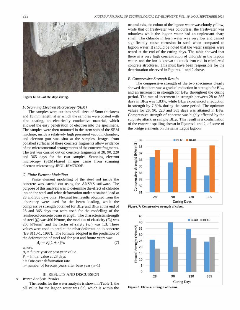
B. Compressive Strength Results
The compressive strength of the two specimens clearly
showed that there was a gradual reduction in strength for BL40
and an increment in strength for BF40 throughout the curing
period. The rate of increment in strength between 28 to 365
days in BF40 was 1.83%, while BL40 experienced a reduction
in strength by 7.69% during the same period. The optimum
values for 28, 90, 220 and 365 days was attained in BF40.
Compressive strength of concrete was highly affected by the
sulphate attack in sample BL40. This result is a confirmation
of the concrete spalling shown in Figures 1 and 2, of some of
the bridge elements on the same Lagos lagoon.
Figure. 7: Compressive strength of cubes.
Figure 8: Flexural strength of beams.
31
32
33
34
35
36
37
38
39
28 90 220 365
Co
mp
ress
ive
stre
ngh
t (N
/mm
2)
Curing Days
BL40 BF40
0
5
10
15
20
25
30
35
40
45
28 90 220 365
Fle
xu
ral
Str
engh
t (N
/mm
2)
Curing Days
BL40 BF40

OLAWALE et al: STRENGTH CHARACTERISTICS OF M40 GRADE CONCRETE USING WASTE PET 223
C. Flexural Strength Test
The flexural strength of BL40 in the first 90 days had the
optimum average flexural strength in all curing environments.
This was due to the chemical reaction between the lagoon
water and the Ettringite, Ca(OH)2, and C–S–H gel which was
actively generated from an early age of the beam structures
which included the steel rod buried in the lagoon. However,
this reaction took a reversal after the 90th day with a gradual
reduction in strength. At this stage, the negative effect of
sulphate salts on the concretes and chloride on the steel
reinforcement caused the reduction in strength. The
freshwater cured beams gradually increased in strength from
the 28 to the 365 days, leading to the optimum strength after
curing for one year in BF40 with a flexural strength of 28.3
N/mm2 compared to BL40 with flexural strength value of 24.4
N/mm2 during the same period. Fig.8 showed the result of the
flexural test carried out on the beams.
D. Bond Strength of Concrete Specimens
The pull-out test results for the determination of bond
strength in reinforced concrete structures is shown in Fig. 9,
while the slipping distance of steel rod from concrete is shown
in Fig.10. The bond strength results generally showed that
BF40 had increased bond strength at the rate of 46.3% between
28 to 365 days with the peak strength at 18.60 N/mm2. The
BL40 sample, however, behaved differently, the bond strength
peaked at 90 days with a value of 26.52 N/mm2 but took a
downturn to 16.79 N/mm2 at the end of 365 days. The bond
strength results of the sample cured in lagoon water (BL40) is
in agreement with the findings of Demis et al., (2010),
Apostolopoulos (2012), Igba et al., (2019). Wherein both
cases the bond strength increased with increase in corrosion
level at the initial stage of curing and later decreased as the
concrete ages. The initial increase in bond strength was due to
the increased roughness of the steel-concrete interface caused
by the growth of the expansive rust. The reduction in bond
strength over a long period can be attributed to the reduction
in cross-sectional area of steel and the loss of adhesive
properties of the steel surface due to rust.
The reverse in bond strength can be linked to the
negative effect of chloride that ingresses into the concrete and
attacks the steel reinforcement, whereby allowing corrosion to
set in and encouraged the eventual reduction in the bond
strength and increased slipping distance between concrete and
steel. The slipping distance of both concrete specimens
increases as the curing days increased, but the samples buried
in the lagoon generally had higher slip than the sample in
freshwater, the optimum slip was observed on the 365th day
for both BF40 and BL40 at 11.5 mm and 14.5 mm respectively.
The general increment in bond strength of BF40
overtime further confirmed the report of Falade and Oyekan
(2006) “that the bond strength of reinforced concrete
structural elements depended on the bond between concrete
and reinforcement to ensure effective transfer of stress from
steel reinforcement to the surrounding concrete and that the
bond was usually high at later age because the compressive
strength of concrete and the grip effect on reinforcement
increased with age”. This however did not apply to the sample
buried in the lagoon, due to chloride attack on the steel
reinforcement, as showed in Figure 4.
Figure 9: The bond strength result.
Figure 10. Slipped distance of steel rod.
0
5
10
15
20
25
30
28 90 220 365
Bo
nd
Str
engh
t (N
/mm
2)
Curing Days
BF40 BL40
0
2
4
6
8
10
12
14
16
28 90 220 365
Slip
dis
tan
ce (
mm
)
Curing Days
BL40 BF40
Table 1: Water analysis result.
Water type Salinity
(mg/l)
TDS
(ppm)
Sediments
(mg/l)
PH NO3-
(mg/l)
ZnO
(mg/l)
PO43-
(mg/l)
SO42-
(mg/l)
Cl-
(mg/l)
Fe+2
(mg/l)
Lagoon 469.7 650 18 6.9 7.28 7.36 0.02 20 260 0.42
Fresh 28.9 190 - 6.9 2.32 2.4 0.01 6 16 0.06

224 NIGERIAN JOURNAL OF TECHNOLOGICAL DEVELOPMENT, VOL. 18, NO.3, SEPTEMBER 2021
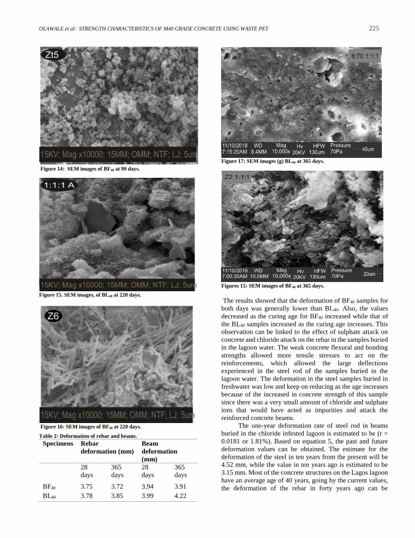
E. SEM Analysis Results
The purpose of this test is to determine the microstructural
properties of each concrete samples at the end of the curing
days. The SEM analysis results revealed the microstructural
properties of each sample at 28, 90, 220 and 365 days. There
were many portions of small hydration crystals and large
holes in BL40 samples as seen in Figs. 11-17. The main reason
was due to the small number of hydration crystals and their
uneven distribution in the cement matrix, resulting in the
production of many large pores and a decrease in the strength
when compared to samples buried in freshwater.
The BF40 samples showed the microstructures of the un-
corroded concrete samples, there were lots of fibrous and
flocculent hydrated calcium silicate, but no obvious corrosion
products or micro-damage was observed in the figures as no
external sulphate ions entered into the concrete.
There were smaller holes in BF40 concrete samples as
seen in the figures, which must have led to a general increase
in strength (compressive, flexural and bond). The main
microstructure features identifiable from their typical
morphology were as follows: ettringite needles, calcium
silicate hydrates (C-S-H), and tricalcium aluminate
monosulphate hydrates (AFm) mainly seen in BL40.
Activities of Ettringite, Ca(OH)2, and C–S–H gel were
actively generated in the early age of BL40 and the amounts
of these materials generated were confirmed to increase with
time. It was believed that the full submergence of these
samples buried in the lagoon water ended up creating
microstructures with more defects, as lots of more pronounced
micropores were noticed in BL40 on the 365th-day sample.
In BF40 at 220 days, (Fig.16) the microstructure indicated that
the cement hydration reaction was nearly complete and
produced many needle-like and sheet-like crystals. The
microstructure of BF40 was composed of reticular amorphous
and needle-like C-S-H phase where calcium hydroxide
crystals were locally embedded. The BF40 had a
microstructure with fewer defects which in turn increased the
generation of components such as hydrated calcium silicates
(C-S-H) crystals, elements that improved the composite
mechanical properties.
The ability of sulphate ion to penetrate the large pores
of BL40 also encouraged the ingress of chloride ions present
in the lagoon water into the concrete samples. The steel rod in
the reinforced concrete beams was attacked by the chloride
ion as the age of curing increased. This reaction must have led
to the poor performance of BL40 in both the flexural and bond
strength tests, and the generally large slip distance observed
during the bond strength test (Fig.10). The corroded surface
of the steel rod as a result of chloride attack reduced the
bonding strength between the concrete and the steel
reinforcements.
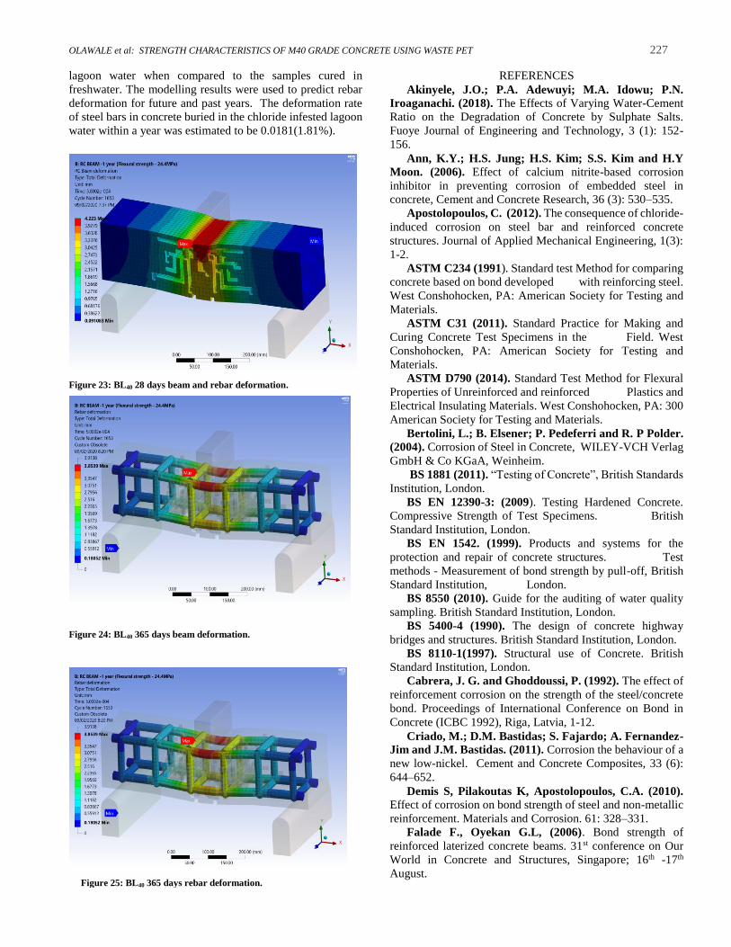
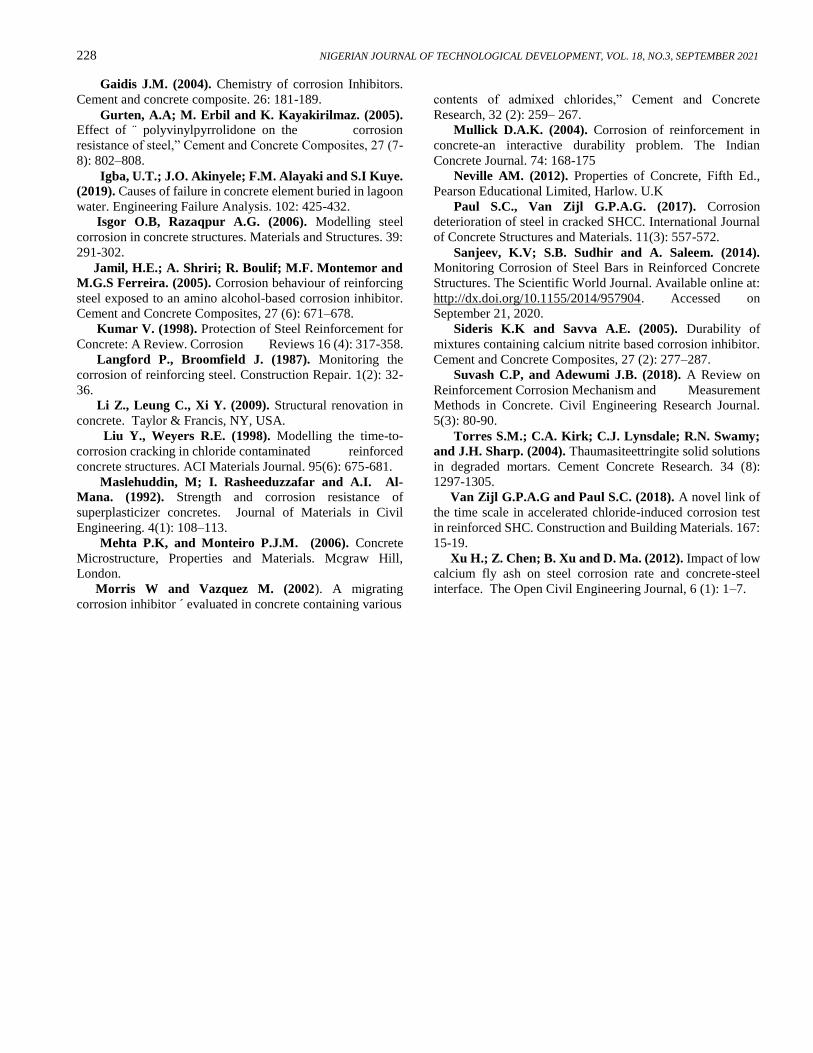
F. Modelling of Steel Deformation in Flexure
The flexural behaviour of the steel reinforcement in the
concrete beams was modelled using ANSYS software for 28
and 365 days only. This was to mathematically predict the
deformations of concrete beams and the steel bars inside the
concrete under loading, taken into consideration the curing
environment of each beam and the effect of chloride on the
flexural resistance of the steel bar in concrete. The results
from Figs. 18 – 25 showed a very interesting trend, these
results are summarised in Table 2.
Figure 11. SEM Images of BL40 at 28 days.
Figure 12. SEM images of BF40 at 28 days.
Figure 13. SEM images of BL40 at 90 days.
OLAWALE et al: STRENGTH CHARACTERISTICS OF M40 GRADE CONCRETE USING WASTE PET 225
Figure 14: SEM images of BF40 at 90 days.
Figure 15. SEM images, of BL40 at 220 days.
Figure 16: SEM images of BF40 at 220 days.
Table 2: Deformation of rebar and beams.
Specimens Rebar
deformation (mm)
Beam
deformation
(mm)
28
days
365
days
28
days
365
days
BF40 3.75 3.72 3.94 3.91
BL40 3.78 3.85 3.99 4.22
Figure 17: SEM images (g) BL40 at 365 days.
Figures 15: SEM images of BF40 at 365 days.
The results showed that the deformation of BF40 samples for
both days was generally lower than BL40. Also, the values
decreased as the curing age for BF40 increased while that of
the BL40 samples increased as the curing age increases. This
observation can be linked to the effect of sulphate attack on
concrete and chloride attack on the rebar in the samples buried
in the lagoon water. The weak concrete flexural and bonding
strengths allowed more tensile stresses to act on the
reinforcements, which allowed the large deflections
experienced in the steel rod of the samples buried in the
lagoon water. The deformation in the steel samples buried in
freshwater was low and keep on reducing as the age increases
because of the increased in concrete strength of this sample
since there was a very small amount of chloride and sulphate
ions that would have acted as impurities and attack the
reinforced concrete beams.
The one-year deformation rate of steel rod in beams
buried in the chloride infested lagoon is estimated to be (r =
0.0181 or 1.81%). Based on equation 5, the past and future
deformation values can be obtained. The estimate for the
deformation of the steel in ten years from the present will be
4.52 mm, while the value in ten years ago is estimated to be
3.15 mm. Most of the concrete structures on the Lagos lagoon
have an average age of 40 years, going by the current values,
the deformation of the rebar in forty years ago can be

226 NIGERIAN JOURNAL OF TECHNOLOGICAL DEVELOPMENT, VOL. 18, NO.3, SEPTEMBER 2021
Figure 20: BF40 365 days beam deformation.
estimated to be 1.82 mm, and these estimates are based on the
annual deformation rate and the use of Eq. (5).
Figure 18: BF40 28 days beam deformation.
Figure19: BF40 28 days rebar deformation.
Figure 21: BF40 365 days rebar deformation.
Figure 22: BL40 28 days beam deformation.
IV. CONCLUSION
This experiment has investigated the role played by both
sulphate and chloride ions on the deterioration of the
structural members of some concrete elements buried in
lagoon water and using fresh water as control.
The mechanical test on the concrete samples buried in
the chloride infested lagoon showed depletion in strength as
the concrete ages, while the samples in freshwater behaved
like a typical concrete in a normal environment. The
microstructural analysis revealed the large pores that were
formed in the samples buried in the lagoon, these pores were
formed as a result of chemical reactions between the concrete
elements and sulphates ions, which created a weak bond
within the concrete matrix, the large pores allowed the ingress
of chloride ion into the concrete, and eventually exposed the
reinforcement to attacks.
The corrosion in the steel as a result of chloride attack
led to low bond strength and high slipping distance in the
concrete buried in the lagoon. The modelling results revealed
the effect of chloride on the high deformation and deflections
that occurred in steel rods of concrete samples buried in the
OLAWALE et al: STRENGTH CHARACTERISTICS OF M40 GRADE CONCRETE USING WASTE PET 227
Figure 25: BL40 365 days rebar deformation.
lagoon water when compared to the samples cured in
freshwater. The modelling results were used to predict rebar
deformation for future and past years. The deformation rate
of steel bars in concrete buried in the chloride infested lagoon
water within a year was estimated to be 0.0181(1.81%).
Figure 23: BL40 28 days beam and rebar deformation.
Figure 24: BL40 365 days beam deformation.
REFERENCES
Akinyele, J.O.; P.A. Adewuyi; M.A. Idowu; P.N.
Iroaganachi. (2018). The Effects of Varying Water-Cement
Ratio on the Degradation of Concrete by Sulphate Salts.
Fuoye Journal of Engineering and Technology, 3 (1): 152-
156.
Ann, K.Y.; H.S. Jung; H.S. Kim; S.S. Kim and H.Y
Moon. (2006). Effect of calcium nitrite-based corrosion
inhibitor in preventing corrosion of embedded steel in
concrete, Cement and Concrete Research, 36 (3): 530–535.
Apostolopoulos, C. (2012). The consequence of chloride-
induced corrosion on steel bar and reinforced concrete
structures. Journal of Applied Mechanical Engineering, 1(3):
1-2.
ASTM C234 (1991). Standard test Method for comparing
concrete based on bond developed with reinforcing steel.
West Conshohocken, PA: American Society for Testing and
Materials.
ASTM C31 (2011). Standard Practice for Making and
Curing Concrete Test Specimens in the Field. West
Conshohocken, PA: American Society for Testing and
Materials.
ASTM D790 (2014). Standard Test Method for Flexural
Properties of Unreinforced and reinforced Plastics and
Electrical Insulating Materials. West Conshohocken, PA: 300
American Society for Testing and Materials.
Bertolini, L.; B. Elsener; P. Pedeferri and R. P Polder.
(2004). Corrosion of Steel in Concrete, WILEY-VCH Verlag
GmbH & Co KGaA, Weinheim.
BS 1881 (2011). “Testing of Concrete”, British Standards
Institution, London.
BS EN 12390-3: (2009). Testing Hardened Concrete.
Compressive Strength of Test Specimens. British
Standard Institution, London.
BS EN 1542. (1999). Products and systems for the
protection and repair of concrete structures. Test
methods - Measurement of bond strength by pull-off, British
Standard Institution, London.
BS 8550 (2010). Guide for the auditing of water quality
sampling. British Standard Institution, London.
BS 5400-4 (1990). The design of concrete highway
bridges and structures. British Standard Institution, London.
BS 8110-1(1997). Structural use of Concrete. British
Standard Institution, London.
Cabrera, J. G. and Ghoddoussi, P. (1992). The effect of
reinforcement corrosion on the strength of the steel/concrete
bond. Proceedings of International Conference on Bond in
Concrete (ICBC 1992), Riga, Latvia, 1-12.
Criado, M.; D.M. Bastidas; S. Fajardo; A. Fernandez-
Jim and J.M. Bastidas. (2011). Corrosion the behaviour of a
new low-nickel. Cement and Concrete Composites, 33 (6):
644–652.
Demis S, Pilakoutas K, Apostolopoulos, C.A. (2010). Effect of corrosion on bond strength of steel and non-metallic
reinforcement. Materials and Corrosion. 61: 328–331.
Falade F., Oyekan G.L, (2006). Bond strength of
reinforced laterized concrete beams. 31st conference on Our
World in Concrete and Structures, Singapore; 16th -17th
August.
228 NIGERIAN JOURNAL OF TECHNOLOGICAL DEVELOPMENT, VOL. 18, NO.3, SEPTEMBER 2021
Gaidis J.M. (2004). Chemistry of corrosion Inhibitors.
Cement and concrete composite. 26: 181-189.
Gurten, A.A; M. Erbil and K. Kayakirilmaz. (2005). Effect of ¨ polyvinylpyrrolidone on the corrosion
resistance of steel,” Cement and Concrete Composites, 27 (7-
8): 802–808.
Igba, U.T.; J.O. Akinyele; F.M. Alayaki and S.I Kuye.
(2019). Causes of failure in concrete element buried in lagoon
water. Engineering Failure Analysis. 102: 425-432.
Isgor O.B, Razaqpur A.G. (2006). Modelling steel
corrosion in concrete structures. Materials and Structures. 39:
291-302.
Jamil, H.E.; A. Shriri; R. Boulif; M.F. Montemor and
M.G.S Ferreira. (2005). Corrosion behaviour of reinforcing
steel exposed to an amino alcohol-based corrosion inhibitor.
Cement and Concrete Composites, 27 (6): 671–678.
Kumar V. (1998). Protection of Steel Reinforcement for
Concrete: A Review. Corrosion Reviews 16 (4): 317-358.
Langford P., Broomfield J. (1987). Monitoring the
corrosion of reinforcing steel. Construction Repair. 1(2): 32-
36.
Li Z., Leung C., Xi Y. (2009). Structural renovation in
concrete. Taylor & Francis, NY, USA.
Liu Y., Weyers R.E. (1998). Modelling the time-to-
corrosion cracking in chloride contaminated reinforced
concrete structures. ACI Materials Journal. 95(6): 675-681.
Maslehuddin, M; I. Rasheeduzzafar and A.I. Al-
Mana. (1992). Strength and corrosion resistance of
superplasticizer concretes. Journal of Materials in Civil
Engineering. 4(1): 108–113.
Mehta P.K, and Monteiro P.J.M. (2006). Concrete
Microstructure, Properties and Materials. Mcgraw Hill,
London.
Morris W and Vazquez M. (2002). A migrating
corrosion inhibitor ´ evaluated in concrete containing various
contents of admixed chlorides,” Cement and Concrete
Research, 32 (2): 259– 267.
Mullick D.A.K. (2004). Corrosion of reinforcement in
concrete-an interactive durability problem. The Indian
Concrete Journal. 74: 168-175
Neville AM. (2012). Properties of Concrete, Fifth Ed.,
Pearson Educational Limited, Harlow. U.K
Paul S.C., Van Zijl G.P.A.G. (2017). Corrosion
deterioration of steel in cracked SHCC. International Journal
of Concrete Structures and Materials. 11(3): 557-572.
Sanjeev, K.V; S.B. Sudhir and A. Saleem. (2014). Monitoring Corrosion of Steel Bars in Reinforced Concrete
Structures. The Scientific World Journal. Available online at:
http://dx.doi.org/10.1155/2014/957904. Accessed on
September 21, 2020.
Sideris K.K and Savva A.E. (2005). Durability of
mixtures containing calcium nitrite based corrosion inhibitor.
Cement and Concrete Composites, 27 (2): 277–287.
Suvash C.P, and Adewumi J.B. (2018). A Review on
Reinforcement Corrosion Mechanism and Measurement
Methods in Concrete. Civil Engineering Research Journal.
5(3): 80-90.
Torres S.M.; C.A. Kirk; C.J. Lynsdale; R.N. Swamy;
and J.H. Sharp. (2004). Thaumasiteettringite solid solutions
in degraded mortars. Cement Concrete Research. 34 (8):
1297-1305.
Van Zijl G.P.A.G and Paul S.C. (2018). A novel link of
the time scale in accelerated chloride-induced corrosion test
in reinforced SHC. Construction and Building Materials. 167:
15-19.
Xu H.; Z. Chen; B. Xu and D. Ma. (2012). Impact of low
calcium fly ash on steel corrosion rate and concrete-steel
interface. The Open Civil Engineering Journal, 6 (1): 1–7.
Copyright © 2022 FDOKUMEN