Effect of refractive index mismatch on multi-photon direct laser writing
11
Effect of refractive index mismatch on multi- photon direct laser writing Henry E. Williams, 1,4 Zhenyue Luo, 2,4 and Stephen M. Kuebler, 1,2,3,* 1 Chemistry Department, University of Central Florida, Orlando, FL 32816, USA 2 CREOL, The College of Optics and Photonics, University of Central Florida, Orlando, FL 32816, USA 3 Physics Department, University of Central Florida, Orlando, FL 32816, USA 4 These authors contributed equally to the work. *[email protected] Abstract: This work reports how the process of three-dimensional multi- photon direct laser writing (mpDLW) is affected when there is a small mismatch in refractive index between the material being patterned and the medium in which the focusing objective is immersed. Suspended-line microstructures were fabricated by mpDLW in the cross-linkable epoxide SU-8 as a function of focus depth and average incident power. It is found that even a small refractive index contrast of Δn = + 0.08 causes significant variation in feature width and height throughout the depth of the material. In particular, both the width and height of features can either increase or decrease with depth, depending upon how much the average incident laser power exceeds the threshold for writing. Vectorial diffraction theory is used to obtain insight into the origin of the effect and how to compensate for it. We demonstrate that varying the average focused power is a practical means for controlling the variation in feature size with focal depth. ©2012 Optical Society of America OCIS codes: (350.3390) Laser materials processing; (220.4000) Microstructure fabrication, (220.1010) Aberrations. References and links 1. W. Zhou, S. M. Kuebler, K. L. Braun, T. Yu, J. K. Cammack, C. K. Ober, J. W. Perry, and S. R. Marder, “An efficient two-photon-generated photoacid applied to positive-tone 3D microfabrication,” Science 296(5570), 1106–1109 (2002). 2. H. Misawa and S. Juodkazis, 3D Laser Microfabrication: Principles and Applications (Wiley-VCH, Weinheim, 2006). 3. A. Marcinkevičius, V. Mizeikis, S. Juodkazis, S. Matsuo, and H. Misawa, “Effect of refractive index-mismatch on laser microfabrication in silica glass,” Appl. Phys., A Mater. Sci. Process. 76(2), 257–260 (2003). 4. S. Wong, M. Deubel, F. Pérez-Willard, S. John, G. A. Ozin, M. Wegener, and G. von Freymann, “Direct laser writing of three-dimensional photonic crystals with a complete photonic bandgap in chalcogenide glasses,” Adv. Mater. (Deerfield Beach Fla.) 18(3), 265–269 (2006). 5. G. Zhou and M. Gu, “Direct optical fabrication of three-dimensional photonic crystals in a high refractive index LiNbO 3 crystal,” Opt. Lett. 31(18), 2783–2785 (2006). 6. Q. Sun, H. Jiang, Y. Liu, Y. Zhou, H. Yang, and Q. Gong, “Effect of spherical aberration on the propagation of a tightly focused femtosecond laser pulse inside fused silica,” J. Opt. A, Pure Appl. Opt. 7(11), 655–659 (2005). 7. N. Huot, R. Stoian, A. Mermillod-Blondin, C. Mauclair, and E. Audouard, “Analysis of the effects of spherical aberration on ultrafast laser-induced refractive index variation in glass,” Opt. Express 15(19), 12395–12408 (2007). 8. F. Luo, J. Song, X. Hu, H. Sun, G. Lin, H. Pan, Y. Cheng, L. Liu, J. Qiu, Q. Zhao, and Z. Xu, “Femtosecond laser-induced inverted microstructures inside glasses by tuning refractive index of objective’s immersion liquid,” Opt. Lett. 36(11), 2125–2127 (2011). 9. S. N. S. Reihani, H. R. Khalesifard, and R. Golestanian, “Measuring lateral efficiency of optical traps: The effect of tube length,” Opt. Commun. 259(1), 204–211 (2006). 10. M. J. Booth and T. Wilson, “Strategies for the compensation of specimen-induced spherical aberration in confocal microscopy of skin,” J. Microsc. 200(1), 68–74 (2000). 11. I. Escobar, G. Saavedra, M. Martínez-Corral, and J. Lancis, “Reduction of the spherical aberration effect in high- numerical-aperture optical scanning instruments,” J. Opt. Soc. Am. A 23(12), 3150–3155 (2006). 12. C.-H. Lee, T.-W. Chang, K.-L. Lee, J.-Y. Lin, and J. Wang, “Fabricating high-aspect-ratio sub-diffraction-limit structures on silicon with two-photon photopolymerization and reactive ion etching,” Appl. Phys., A Mater. Sci. Process. 79(8), 2027–2031 (2004). #175085 - $15.00 USD Received 28 Aug 2012; revised 12 Oct 2012; accepted 12 Oct 2012; published 17 Oct 2012 (C) 2012 OSA 22 October 2012 / Vol. 20, No. 22/ OPTICS EXPRESS 25030
-
Upload
independent -
Category
Documents
-
view
2 -
download
0
Transcript of Effect of refractive index mismatch on multi-photon direct laser writing
Effect of refractive index mismatch on multi-photon direct laser writing
Henry E. Williams,1,4 Zhenyue Luo,2,4 and Stephen M. Kuebler,1,2,3,* 1Chemistry Department, University of Central Florida, Orlando, FL 32816, USA
2CREOL, The College of Optics and Photonics, University of Central Florida, Orlando, FL 32816, USA 3Physics Department, University of Central Florida, Orlando, FL 32816, USA
4These authors contributed equally to the work. *[email protected]
Abstract: This work reports how the process of three-dimensional multi-photon direct laser writing (mpDLW) is affected when there is a small mismatch in refractive index between the material being patterned and the medium in which the focusing objective is immersed. Suspended-line microstructures were fabricated by mpDLW in the cross-linkable epoxide SU-8 as a function of focus depth and average incident power. It is found that even a small refractive index contrast of Δn = + 0.08 causes significant variation in feature width and height throughout the depth of the material. In particular, both the width and height of features can either increase or decrease with depth, depending upon how much the average incident laser power exceeds the threshold for writing. Vectorial diffraction theory is used to obtain insight into the origin of the effect and how to compensate for it. We demonstrate that varying the average focused power is a practical means for controlling the variation in feature size with focal depth.
©2012 Optical Society of America
OCIS codes: (350.3390) Laser materials processing; (220.4000) Microstructure fabrication, (220.1010) Aberrations.
References and links 1. W. Zhou, S. M. Kuebler, K. L. Braun, T. Yu, J. K. Cammack, C. K. Ober, J. W. Perry, and S. R. Marder, “An
efficient two-photon-generated photoacid applied to positive-tone 3D microfabrication,” Science 296(5570), 1106–1109 (2002).
2. H. Misawa and S. Juodkazis, 3D Laser Microfabrication: Principles and Applications (Wiley-VCH, Weinheim, 2006).
3. A. Marcinkevičius, V. Mizeikis, S. Juodkazis, S. Matsuo, and H. Misawa, “Effect of refractive index-mismatch on laser microfabrication in silica glass,” Appl. Phys., A Mater. Sci. Process. 76(2), 257–260 (2003).
4. S. Wong, M. Deubel, F. Pérez-Willard, S. John, G. A. Ozin, M. Wegener, and G. von Freymann, “Direct laser writing of three-dimensional photonic crystals with a complete photonic bandgap in chalcogenide glasses,” Adv. Mater. (Deerfield Beach Fla.) 18(3), 265–269 (2006).
5. G. Zhou and M. Gu, “Direct optical fabrication of three-dimensional photonic crystals in a high refractive index LiNbO3 crystal,” Opt. Lett. 31(18), 2783–2785 (2006).
6. Q. Sun, H. Jiang, Y. Liu, Y. Zhou, H. Yang, and Q. Gong, “Effect of spherical aberration on the propagation of a tightly focused femtosecond laser pulse inside fused silica,” J. Opt. A, Pure Appl. Opt. 7(11), 655–659 (2005).
7. N. Huot, R. Stoian, A. Mermillod-Blondin, C. Mauclair, and E. Audouard, “Analysis of the effects of spherical aberration on ultrafast laser-induced refractive index variation in glass,” Opt. Express 15(19), 12395–12408 (2007).
8. F. Luo, J. Song, X. Hu, H. Sun, G. Lin, H. Pan, Y. Cheng, L. Liu, J. Qiu, Q. Zhao, and Z. Xu, “Femtosecond laser-induced inverted microstructures inside glasses by tuning refractive index of objective’s immersion liquid,” Opt. Lett. 36(11), 2125–2127 (2011).
9. S. N. S. Reihani, H. R. Khalesifard, and R. Golestanian, “Measuring lateral efficiency of optical traps: The effect of tube length,” Opt. Commun. 259(1), 204–211 (2006).
10. M. J. Booth and T. Wilson, “Strategies for the compensation of specimen-induced spherical aberration in confocal microscopy of skin,” J. Microsc. 200(1), 68–74 (2000).
11. I. Escobar, G. Saavedra, M. Martínez-Corral, and J. Lancis, “Reduction of the spherical aberration effect in high-numerical-aperture optical scanning instruments,” J. Opt. Soc. Am. A 23(12), 3150–3155 (2006).
12. C.-H. Lee, T.-W. Chang, K.-L. Lee, J.-Y. Lin, and J. Wang, “Fabricating high-aspect-ratio sub-diffraction-limit structures on silicon with two-photon photopolymerization and reactive ion etching,” Appl. Phys., A Mater. Sci. Process. 79(8), 2027–2031 (2004).
#175085 - $15.00 USD Received 28 Aug 2012; revised 12 Oct 2012; accepted 12 Oct 2012; published 17 Oct 2012(C) 2012 OSA 22 October 2012 / Vol. 20, No. 22/ OPTICS EXPRESS 25030
13. S. H. Park, T. W. Lim, D.-Y. Yang, H. J. Kong, J.-Y. Kim, and K.-S. Lee, “Direct laser patterning on opaque substrate in two-photon polymerization,” Macromol. Res. 14(2), 245–250 (2006).
14. T. Grossmann, S. Schleede, M. Hauser, T. Beck, M. Thiel, G. von Freymann, T. Mappes, and H. Kalt, “Direct laser writing for active and passive high-Q polymer microdisks on silicon,” Opt. Express 19(12), 11451–11456 (2011).
15. A. del Campo and C. Greiner, “SU-8: a photoresist for high-aspect-ratio and 3D submicron lithography,” J. Micromech. Microeng. 17(6), R81–R95 (2007).
16. K. K. Seet, S. Juodkazis, V. Jarutis, and H. Misawa, “Feature-size reduction of photopolymerized structures by femtosecond optical curing of SU-8,” Appl. Phys. Lett. 89(2), 024106 (2006).
17. M. Deubel, G. von Freymann, M. Wegener, S. Pereira, K. Busch, and C. M. Soukoulis, “Direct laser writing of three-dimensional photonic-crystal templates for telecommunications,” Nat. Mater. 3(7), 444–447 (2004).
18. S. Juodkazis, V. Mizeikis, K. K. Seet, M. Miwa, and H. Misawa, “Two-photon lithography of nanorods in SU-8 photoresist,” Nanotechnology 16(6), 846–849 (2005).
19. S. Shukla, X. Vidal, E. P. Furlani, M. T. Swihart, K.-T. Kim, Y.-K. Yoon, A. Urbas, and P. N. Prasad, “Subwavelength direct laser patterning of conductive gold nanostructures by simultaneous photopolymerization and photoreduction,” ACS Nano 5(3), 1947–1957 (2011).
20. A. Tal, Y.-S. Chen, H. E. Williams, R. C. Rumpf, and S. M. Kuebler, “Fabrication and characterization of three-dimensional copper metallodielectric photonic crystals,” Opt. Express 15(26), 18283–18293 (2007).
21. S. Tottori, L. Zhang, F. Qiu, K. K. Krawczyk, A. Franco-Obregón, and B. J. Nelson, “Magnetic helical micromachines: fabrication, controlled swimming, and cargo trasnport,” Adv. Mater. (Deerfield Beach Fla.) 24(6), 811–816 (2012).
22. K. Venkatakrishnan, S. Jariwala, and B. Tan, “Maskless fabrication of nano-fluidic channels by two-photon absorption (TPA) polymerization of SU-8 on glass substrate,” Opt. Express 17(4), 2756–2762 (2009).
23. H. E. Williams, D. J. Freppon, S. M. Kuebler, R. C. Rumpf, and M. A. Melino, “Fabrication of three-dimensional micro-photonic structures on the tip of optical fibers using SU-8,” Opt. Express 19(23), 22910–22922 (2011).
24. G. Witzgall, R. Vrijen, E. Yablonovitch, V. Doan, and B. J. Schwartz, “Single-shot two-photon exposure of commercial photoresist for the production of three-dimensional structures,” Opt. Lett. 23(22), 1745–1747 (1998).
25. E. S. Wu, J. H. Strickler, W. R. Harrell, and W. W. Webb, “Two-photon lithography for microelectronic application,” SPIE 1674, 776–782 (1992).
26. P. Török, P. Varga, Z. Laczik, and G. R. Booker, “Electromagnetic diffraction of light focused through a planar interface between materials of mismatched refractive indices: an integral representation,” J. Opt. Soc. Am. A 12(2), 325–332 (1995).
27. P. Török and P. Varga, “Electromagnetic diffraction of light focused through a stratified medium,” Appl. Opt. 36(11), 2305–2312 (1997).
28. B. Šantić, “Measurement of the refractive index and thickness of a transparent film from the shift of the interference pattern due to the sample rotation,” Thin Solid Films 518(14), 3619–3624 (2010).
29. H. B. Sun, T. Tanaka, and S. Kawata, “Three-dimensional focal spots related to two-photon excitation,” Appl. Phys. Lett. 80(20), 3673–3675 (2002).
30. S. Nakanishi, H. B. Sun, and S. Kawata, “Elasticity of two-photon-fabricated nano-wires,” Proc. SPIE 6645, 664514–1 - 664514–9 (2007).
31. J. Serbin, A. Egbert, A. Ostendorf, B. N. Chichkov, R. Houbertz, G. Domann, J. Schulz, C. Cronauer, L. Fröhlich, and M. Popall, “Femtosecond laser-induced two-photon polymerization of inorganic-organic hybrid materials for applications in photonics,” Opt. Lett. 28(5), 301–303 (2003).
1. Introduction
Direct laser writing (DLW) by multi-photon excitation (mpDLW) has attracted considerable interest as an effective single-step technique for fabricating 3D structures with sub-micron lateral and axial resolution [1,2]. Several investigators have reported that DLW is affected by refractive index contrast (RIC, see Fig. 1) between the high-NA focusing objective (or objective immersion oil, n1) and the writing material (n2) because the refractive index mismatch introduces spherical aberration that distorts the focused irradiance point spread function (IPSF) and consequently changes the size and shape of photo-patterned features [3–5]. For example, Wegener et al. investigated the effect of RIC when performing mpDLW in As2S3 chalcogenide glasses (n2 = 2.5) and found that the aspect ratio (height/width) of the written features changes greatly with focal depth [4]. Gu et al. studied laser patterning in lithium niobate (LiNbO3, n2 = 2.2) and concluded that RIC causes the written voids to become larger and more distorted with increasing focal depth [5]. The effect of RIC on DLW in silica has also been examined [6], and it was found that secondary maxima in the IPSF can substantially elongate the photo-damaged regions [3]. To date, most research has focused on large RIC. Although a few reports discuss how low RIC affects laser induced damage [3,7], these results cannot be readily applied to mpDLW because it proceeds via a different mechanism.
#175085 - $15.00 USD Received 28 Aug 2012; revised 12 Oct 2012; accepted 12 Oct 2012; published 17 Oct 2012(C) 2012 OSA 22 October 2012 / Vol. 20, No. 22/ OPTICS EXPRESS 25031
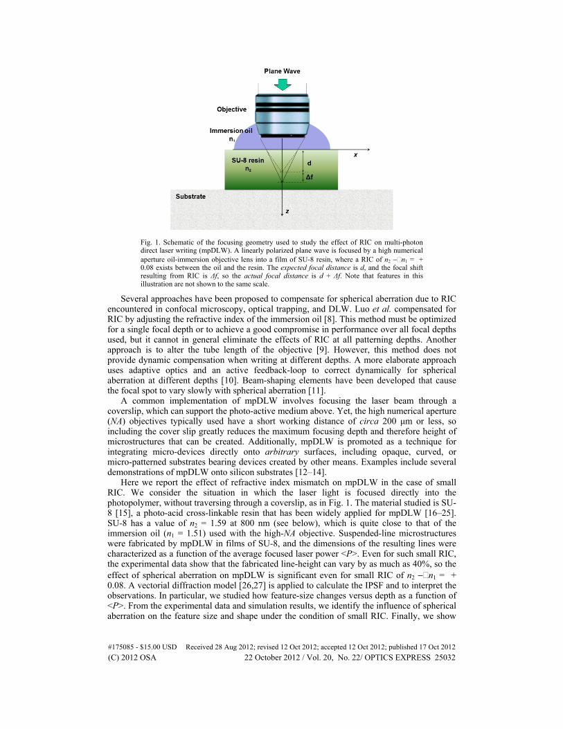
Fig. 1. Schematic of the focusing geometry used to study the effect of RIC on multi-photon direct laser writing (mpDLW). A linearly polarized plane wave is focused by a high numerical aperture oil-immersion objective lens into a film of SU-8 resin, where a RIC of n2 − n1 = + 0.08 exists between the oil and the resin. The expected focal distance is d, and the focal shift resulting from RIC is Δf, so the actual focal distance is d + Δf. Note that features in this illustration are not shown to the same scale.
Several approaches have been proposed to compensate for spherical aberration due to RIC encountered in confocal microscopy, optical trapping, and DLW. Luo et al. compensated for RIC by adjusting the refractive index of the immersion oil [8]. This method must be optimized for a single focal depth or to achieve a good compromise in performance over all focal depths used, but it cannot in general eliminate the effects of RIC at all patterning depths. Another approach is to alter the tube length of the objective [9]. However, this method does not provide dynamic compensation when writing at different depths. A more elaborate approach uses adaptive optics and an active feedback-loop to correct dynamically for spherical aberration at different depths [10]. Beam-shaping elements have been developed that cause the focal spot to vary slowly with spherical aberration [11].
A common implementation of mpDLW involves focusing the laser beam through a coverslip, which can support the photo-active medium above. Yet, the high numerical aperture (NA) objectives typically used have a short working distance of circa 200 μm or less, so including the cover slip greatly reduces the maximum focusing depth and therefore height of microstructures that can be created. Additionally, mpDLW is promoted as a technique for integrating micro-devices directly onto arbitrary surfaces, including opaque, curved, or micro-patterned substrates bearing devices created by other means. Examples include several demonstrations of mpDLW onto silicon substrates [12–14].
Here we report the effect of refractive index mismatch on mpDLW in the case of small RIC. We consider the situation in which the laser light is focused directly into the photopolymer, without traversing through a coverslip, as in Fig. 1. The material studied is SU-8 [15], a photo-acid cross-linkable resin that has been widely applied for mpDLW [16–25]. SU-8 has a value of n2 = 1.59 at 800 nm (see below), which is quite close to that of the immersion oil (n1 = 1.51) used with the high-NA objective. Suspended-line microstructures were fabricated by mpDLW in films of SU-8, and the dimensions of the resulting lines were characterized as a function of the average focused laser power <P>. Even for such small RIC, the experimental data show that the fabricated line-height can vary by as much as 40%, so the effect of spherical aberration on mpDLW is significant even for small RIC of n2 − n1 = + 0.08. A vectorial diffraction model [26,27] is applied to calculate the IPSF and to interpret the observations. In particular, we studied how feature-size changes versus depth as a function of <P>. From the experimental data and simulation results, we identify the influence of spherical aberration on the feature size and shape under the condition of small RIC. Finally, we show
#175085 - $15.00 USD Received 28 Aug 2012; revised 12 Oct 2012; accepted 12 Oct 2012; published 17 Oct 2012(C) 2012 OSA 22 October 2012 / Vol. 20, No. 22/ OPTICS EXPRESS 25032
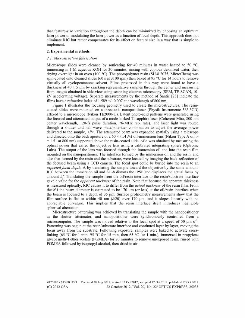
that feature-size variation throughout the depth can be minimized by choosing an optimum laser power or modulating the laser power as a function of focal depth. This approach does not eliminate RIC but rather compensates for its effect on feature size in a way that is simple to implement.
2. Experimental methods
2.1. Microstructure fabrication
Microscope slides were cleaned by sonicating for 40 minutes in water heated to 50 °C, immersing in 1 M aqueous KOH for 30 minutes, rinsing with copious deionized water, then drying overnight in an oven (100 °C). The photopolymer resin (SU-8 2075, MicroChem) was spin-coated onto cleaned slides (60 s at 3100 rpm) then baked at 95 °C for 14 hours to remove virtually all cyclopentanone solvent. Films processed in this way were found to have a thickness of 40 ± 5 μm by cracking representative samples through the center and measuring from images obtained in side-view using scanning electron microscopy (SEM, TE-SCAN, 10-kV accelerating voltage). Separate measurements by the method of Šantić [28] indicate the films have a refractive index of 1.589 +/‐ 0.007 at a wavelength of 800 nm.
Figure 1 illustrates the focusing geometry used to create the microstructures. The resin-coated slides were mounted on a three-axis nanopositioner (Physik Instrumente 563.3CD) affixed to a microscope (Nikon TE2000-U). Latent photo-acid patterns were generated using the focused and attenuated output of a mode-locked Ti:sapphire laser (Coherent-Mira, 800-nm center wavelength, 120-fs pulse duration, 76-MHz rep. rate). The laser light was routed through a shutter and half-wave plate/polarizer combination to adjust the average power delivered to the sample, <P>. The attenuated beam was expanded spatially using a telescope and directed onto the back aperture of a 60 × /1.4 NA oil-immersion lens (Nikon Type A oil, n = 1.51 at 800 nm) supported above the resin-coated slide. <P> was obtained by measuring the optical power that exited the objective lens using a calibrated integrating sphere (Optronic Labs). The output of the lens was focused through the immersion oil and into the resin film mounted on the nanopositioner. The interface formed by the immersion oil and the resin, and also that formed by the resin and the substrate, were located by imaging the back-reflection of the focused beam using a CCD camera. The focal spot could be buried into the resin to an expected focal depth, d, by translating the sample toward the objective by the same amount. RIC between the immersion oil and SU-8 distorts the IPSF and displaces the actual focus by amount Δf. Translating the sample from the oil/resin interface to the resin/substrate interface gave a value for the apparent thickness of the resin. Note that because the apparent thickness is measured optically, RIC causes it to differ from the actual thickness of the resin film. From the NA the beam diameter is estimated to be 170 μm (or less) at the oil/resin interface when the beam is focused to a depth of 35 μm. Surface profilometry measurements show that the film surface is flat to within 40 nm (λ/20) over 170 μm, and it slopes linearly with no appreciable curvature. This implies that the resin interface itself introduces negligible spherical aberration.
Microstructure patterning was achieved by translating the sample with the nanopositioner as the shutter, attenuator, and nanopositioner were synchronously controlled from a microcomputer. The sample was moved relative to the focal spot at a speed of 50 μm s−1. Patterning was begun at the resin/substrate interface and continued layer by layer, moving the focus away from the substrate. Following exposure, samples were baked to activate cross-linking (65 °C for 1 min, 95 °C for 15 min, then 65 °C for 1 min.), immersed in propylene glycol methyl ether acetate (PGMEA) for 20 minutes to remove unexposed resin, rinsed with PGMEA followed by isopropyl alcohol, then dried in air.
#175085 - $15.00 USD Received 28 Aug 2012; revised 12 Oct 2012; accepted 12 Oct 2012; published 17 Oct 2012(C) 2012 OSA 22 October 2012 / Vol. 20, No. 22/ OPTICS EXPRESS 25033
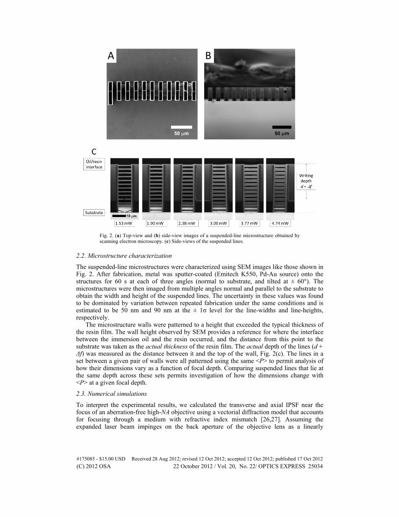
Fig. 2. (a) Top-view and (b) side-view images of a suspended-line microstructure obtained by scanning electron microscopy. (c) Side-views of the suspended lines.
2.2. Microstructure characterization
The suspended-line microstructures were characterized using SEM images like those shown in Fig. 2. After fabrication, metal was sputter-coated (Emitech K550, Pd-Au source) onto the structures for 60 s at each of three angles (normal to substrate, and tilted at ± 60°). The microstructures were then imaged from multiple angles normal and parallel to the substrate to obtain the width and height of the suspended lines. The uncertainty in these values was found to be dominated by variation between repeated fabrication under the same conditions and is estimated to be 50 nm and 90 nm at the ± 1σ level for the line-widths and line-heights, respectively.
The microstructure walls were patterned to a height that exceeded the typical thickness of the resin film. The wall height observed by SEM provides a reference for where the interface between the immersion oil and the resin occurred, and the distance from this point to the substrate was taken as the actual thickness of the resin film. The actual depth of the lines (d + Δf) was measured as the distance between it and the top of the wall, Fig. 2(c). The lines in a set between a given pair of walls were all patterned using the same <P> to permit analysis of how their dimensions vary as a function of focal depth. Comparing suspended lines that lie at the same depth across these sets permits investigation of how the dimensions change with <P> at a given focal depth.
2.3. Numerical simulations
To interpret the experimental results, we calculated the transverse and axial IPSF near the focus of an aberration-free high-NA objective using a vectorial diffraction model that accounts for focusing through a medium with refractive index mismatch [26,27]. Assuming the expanded laser beam impinges on the back aperture of the objective lens as a linearly
#175085 - $15.00 USD Received 28 Aug 2012; revised 12 Oct 2012; accepted 12 Oct 2012; published 17 Oct 2012(C) 2012 OSA 22 October 2012 / Vol. 20, No. 22/ OPTICS EXPRESS 25034
polarized plane wave with uniform amplitude A, the electric field and the associated irradiance distribution within the SU-8 film can be expressed as:
( ) ( ) ( ) ( ){ }1 3 3 2, , cos 2 sin 2 2 cos ,x y zE r z iA I I e I e i I eϕ ϕ ϕ ϕ = − + + −
(1)
( ) ( ) ( ) { } ( )2 22 2 2 *1 2 3 1 3, , , , 4 cos 2Re cos 2 .I r z E r z I I I I Iϕ ϕ ϕ ϕ= = + + + (2)
The radial and axial coordinates are represented by r and z, respectively. The azimuthal angle φ is defined with respect to the direction of the incident linearly polarized optical field, and
( ) ( ) ( ) ( )1 1 1 2 0 0 1 1 0 2 2 1
0
, cos sin cos sin exp cos ,s pI r z J k rn i ik zn dα
θ θ τ τ θ θ φ θ θ= + + (3a)
( ) ( ) ( ) ( )2 1 1 2 0 0 1 1 0 2 2 1
0
, cos sin sin sin exp cos ,sI r z J k rn i ik zn dα
θ θ τ θ θ φ θ θ= + (3b)
( ) ( ) ( ) ( )3 1 1 2 0 0 1 1 0 2 2 1
0
, cos sin cos sin exp cos .s pI r z J k rn i ik zn dα
θ θ τ τ θ θ φ θ θ= − + (3c)
In Eq. (3), k0 = 2π/λ is the wave number in vacuum. The maximum half-angle of the light convergence cone is α, so NA = n1sinα. θ1 and θ2 are angles at which rays propagate in the immersion oil and the resin, respectively, as determined using Snell’s law. The Fresnel transmission coefficients for s- and p-polarizations are τs and τp, respectively. The RIC between the immersion oil and the resin introduces spherical aberration quantified by
( )0 1 1 2 2cos cos .k d n nφ θ θ= − − (4)
In this work, the focused irradiance distribution is discussed in terms of a normalized IPSF given by
0( , , ) ( , , ) / .IPSF r z I r z Iϕ ϕ= (5)
I0 is the peak irradiance of the focused beam when there is no RIC. In the presence of RIC, I0 = I(0, 0, 0) at d = 0, because the PSF is undistorted when it is focused precisely at the interface formed by the immersion oil and the resin film. To maintain consistency with the experimental conditions, all calculations were performed using λ = 800 nm, n1 = 1.51, n2 = 1.59, and NA = 1.4.
3. Results and discussion
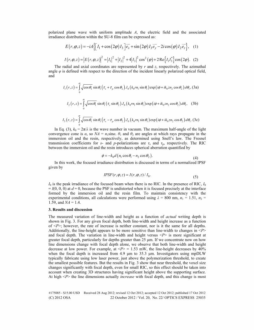
The measured variation of line-width and height as a function of actual writing depth is shown in Fig. 3. For any given focal depth, both line-width and height increase as a function of <P>; however, the rate of increase is neither constant, nor is it the same for all depths. Additionally, the line-height appears to be more sensitive than line-width to changes in <P> and focal depth. The variation in line-width and height versus <P> is more significant at greater focal depth, particularly for depths greater than 25 μm. If we concentrate now on how line dimensions change with focal depth alone, we observe that both line-width and height decrease at low power. For example, at <P> = 1.53 mW, the line-height decreases by 40% when the focal depth is increased from 4.9 μm to 35.3 μm. Investigators using mpDLW typically fabricate using low laser power, just above the polymerization threshold, to create the smallest possible features. But the results in Fig. 3 show that near threshold, the voxel size changes significantly with focal depth, even for small RIC, so this effect should be taken into account when creating 3D structures having significant height above the supporting surface. At high <P> the line dimensions actually increase with focal depth, and this change is most
#175085 - $15.00 USD Received 28 Aug 2012; revised 12 Oct 2012; accepted 12 Oct 2012; published 17 Oct 2012(C) 2012 OSA 22 October 2012 / Vol. 20, No. 22/ OPTICS EXPRESS 25035
apparent with line-height. For example, at <P> = 3.77 mW the line-height increases by 9% when the focal depth is increased from 4.9 μm to 16.1 μm. For intermediate power, the overall variation in line-width is less dramatic, but interestingly the line-height initially increases with focal depth and then begins to decrease again.
Compared to the ascending scan method [29], the suspended-line approach used here offers two advantages for investigating the dimensions of written features. First, in the ascending-scan method it is difficult to observe small features, with width on the order of 200 nm or below, as these are least likely to survive the post-exposure processing. Features of this size are more readily observed using the suspended-line approach because the robust walls anchor the finer suspended lines. Second, in order to explore the effect of RIC, it is necessary to explore how feature-size changes versus focal depth within the medium. The ascending-scan method can only provide this information if it is performed as a function of resin-film thickness. This approach would be more labor intensive and has not yet been attempted, to the best of our knowledge.
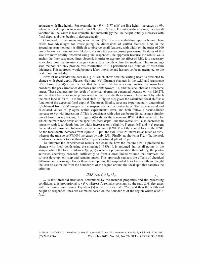
Now let us consider the data in Fig. 4, which show how the writing beam is predicted to change with focal depth. Figures 4(a) and 4(b) illustrate changes in the axial and transverse IPSF. From Fig. 4(a), one can see that the axial IPSF becomes asymmetric, the main lobe broadens, the peak irradiance decreases and shifts toward + z, and the side lobes at + z become larger. These changes are the result of spherical aberration generated because n2 > n1 [26,27], and its effect becomes more pronounced as the focal depth increases. The amount by which the main lobe shifts to + z is the focal shift Δf. Figure 4(c) gives the calculated focal shift as a function of the expected focal depth d. The green-filled squares are experimentally determined Δf obtained from SEM images of the suspended-line micro-structures. The experimental and calculated values of Δf agree within experimental error, and both follow a pseudo-linear increase to + z with increasing d. This is consistent with what can be predicted using a simpler model based on ray tracing [7]. Figure 4(b) shows the transverse IPSF at that value of z for which the main lobe peaks at the specified focal depth. The transverse IPSF also decreases in intensity with focal depth, but the width increases only slightly. Figures 4(d) and 4(e) present the axial and transverse full-width at half-maximum (FWHM) of the central lobe in the IPSF. As the focal depth increases from 0 μm to 30 μm, the axial FWHM increases as much as 60%, whereas the transverse FWHM increases by only 15%. Finally, as shown in Fig. 4(f), the peak irradiance decreases to less than 40% of I0 at a writing depth of 30 μm.
To interpret the experimental results, we examine how the feature size is predicted to change with focal depth using the simulated IPSFs. It is assumed that at all points in the sample where the local irradiance I(r, φ, z) exceeds a polymerization threshold Ith, the photo-activated chemistry proceeds sufficiently to form a cross-linked volume that survives the solvent development step and remains intact. This approach neglects the effects of chemical diffusion and shrinkage. Under these assumptions, the suspended lines have width and height that can be estimated from the boundaries of the region around the focal spot that satisfies the criterion
th 0( , , ) / .IPSF r z I Iϕ > (6) Ith is the threshold irradiance determined by the material properties and the processing
conditions. I0 is proportional to <P>, whereas Ith remains constant, so the ratio Ith/I0 decreases with increasing laser power. Equation (5) is used to calculate IPSF, and then the width and height of suspended lines are estimated based on the boundaries of the region where IPSF > Ith/I0.
#175085 - $15.00 USD Received 28 Aug 2012; revised 12 Oct 2012; accepted 12 Oct 2012; published 17 Oct 2012(C) 2012 OSA 22 October 2012 / Vol. 20, No. 22/ OPTICS EXPRESS 25036
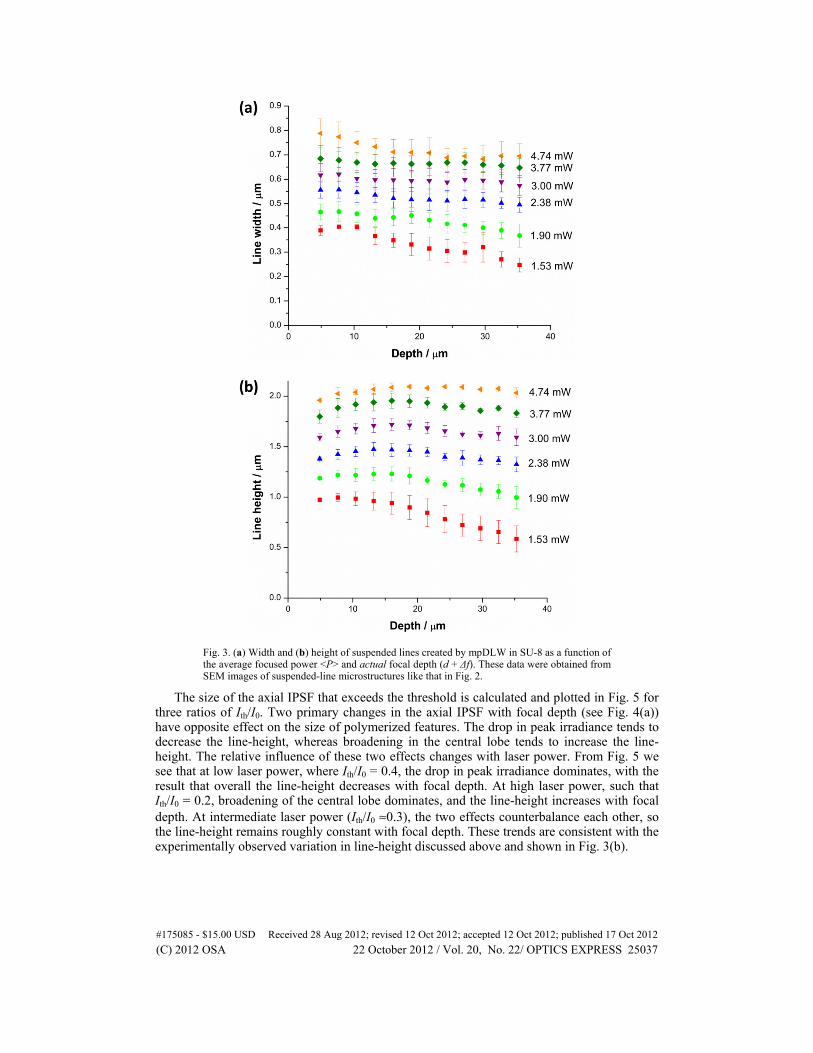
Fig. 3. (a) Width and (b) height of suspended lines created by mpDLW in SU-8 as a function of the average focused power <P> and actual focal depth (d + Δf). These data were obtained from SEM images of suspended-line microstructures like that in Fig. 2.
The size of the axial IPSF that exceeds the threshold is calculated and plotted in Fig. 5 for three ratios of Ith/I0. Two primary changes in the axial IPSF with focal depth (see Fig. 4(a)) have opposite effect on the size of polymerized features. The drop in peak irradiance tends to decrease the line-height, whereas broadening in the central lobe tends to increase the line-height. The relative influence of these two effects changes with laser power. From Fig. 5 we see that at low laser power, where Ith/I0 = 0.4, the drop in peak irradiance dominates, with the result that overall the line-height decreases with focal depth. At high laser power, such that Ith/I0 = 0.2, broadening of the central lobe dominates, and the line-height increases with focal depth. At intermediate laser power (Ith/I0 ≈0.3), the two effects counterbalance each other, so the line-height remains roughly constant with focal depth. These trends are consistent with the experimentally observed variation in line-height discussed above and shown in Fig. 3(b).
#175085 - $15.00 USD Received 28 Aug 2012; revised 12 Oct 2012; accepted 12 Oct 2012; published 17 Oct 2012(C) 2012 OSA 22 October 2012 / Vol. 20, No. 22/ OPTICS EXPRESS 25037
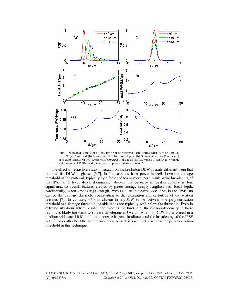
Fig. 4. Numerical simulations of the IPSF versus expected focal depth d when n1 = 1.51 and n2 = 1.59. (a) Axial and (b) transverse IPSF for three depths. (b) Simulated values (blue trace) and experimental values (green-filled squares) of the focal shift Δf versus d. (d) Axial FWHM, (e) transverse FWHM, and (f) normalized peak irradiance versus d.
The effect of refractive index mismatch on multi-photon DLW is quite different from that reported for DLW in glasses [3,7]. In this case, the laser power is well above the damage threshold of the material, typically by a factor of ten or more. As a result, axial broadening of the IPSF with focal depth dominates, whereas the decrease in peak-irradiance is less significant, so overall features created by photo-damage simply lengthen with focal depth. Additionally, when <P> is high enough, even axial or transverse side lobes in the IPSF can exceed the damage threshold contributing to the elongation and distortion of the written features [7]. In contrast, <P> is chosen in mpDLW to be between the polymerization threshold and damage threshold, so side lobes are typically well below the threshold. Even in extreme situations where a side lobe exceeds the threshold, the cross-link density in these regions is likely too weak to survive development. Overall, when mpDLW is performed in a medium with small RIC, both the decrease in peak irradiance and the broadening of the IPSF with focal depth affect the feature size because <P> is specifically set near the polymerization threshold in this technique.
#175085 - $15.00 USD Received 28 Aug 2012; revised 12 Oct 2012; accepted 12 Oct 2012; published 17 Oct 2012(C) 2012 OSA 22 October 2012 / Vol. 20, No. 22/ OPTICS EXPRESS 25038
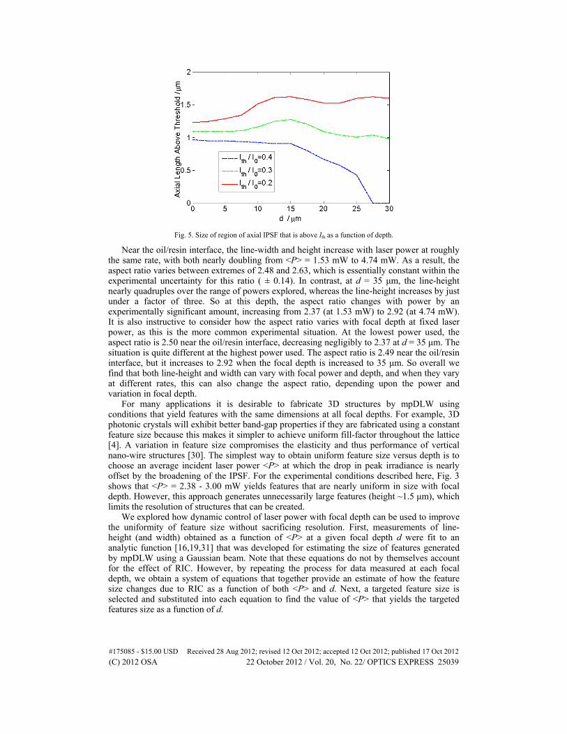
Fig. 5. Size of region of axial IPSF that is above Ith as a function of depth.
Near the oil/resin interface, the line-width and height increase with laser power at roughly the same rate, with both nearly doubling from <P> = 1.53 mW to 4.74 mW. As a result, the aspect ratio varies between extremes of 2.48 and 2.63, which is essentially constant within the experimental uncertainty for this ratio ( ± 0.14). In contrast, at d = 35 μm, the line-height nearly quadruples over the range of powers explored, whereas the line-height increases by just under a factor of three. So at this depth, the aspect ratio changes with power by an experimentally significant amount, increasing from 2.37 (at 1.53 mW) to 2.92 (at 4.74 mW). It is also instructive to consider how the aspect ratio varies with focal depth at fixed laser power, as this is the more common experimental situation. At the lowest power used, the aspect ratio is 2.50 near the oil/resin interface, decreasing negligibly to 2.37 at d = 35 μm. The situation is quite different at the highest power used. The aspect ratio is 2.49 near the oil/resin interface, but it increases to 2.92 when the focal depth is increased to 35 μm. So overall we find that both line-height and width can vary with focal power and depth, and when they vary at different rates, this can also change the aspect ratio, depending upon the power and variation in focal depth.
For many applications it is desirable to fabricate 3D structures by mpDLW using conditions that yield features with the same dimensions at all focal depths. For example, 3D photonic crystals will exhibit better band-gap properties if they are fabricated using a constant feature size because this makes it simpler to achieve uniform fill-factor throughout the lattice [4]. A variation in feature size compromises the elasticity and thus performance of vertical nano-wire structures [30]. The simplest way to obtain uniform feature size versus depth is to choose an average incident laser power <P> at which the drop in peak irradiance is nearly offset by the broadening of the IPSF. For the experimental conditions described here, Fig. 3 shows that <P> = 2.38 - 3.00 mW yields features that are nearly uniform in size with focal depth. However, this approach generates unnecessarily large features (height ~1.5 μm), which limits the resolution of structures that can be created.
We explored how dynamic control of laser power with focal depth can be used to improve the uniformity of feature size without sacrificing resolution. First, measurements of line-height (and width) obtained as a function of <P> at a given focal depth d were fit to an analytic function [16,19,31] that was developed for estimating the size of features generated by mpDLW using a Gaussian beam. Note that these equations do not by themselves account for the effect of RIC. However, by repeating the process for data measured at each focal depth, we obtain a system of equations that together provide an estimate of how the feature size changes due to RIC as a function of both <P> and d. Next, a targeted feature size is selected and substituted into each equation to find the value of <P> that yields the targeted features size as a function of d.
#175085 - $15.00 USD Received 28 Aug 2012; revised 12 Oct 2012; accepted 12 Oct 2012; published 17 Oct 2012(C) 2012 OSA 22 October 2012 / Vol. 20, No. 22/ OPTICS EXPRESS 25039
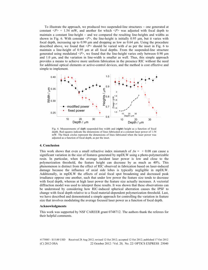
To illustrate the approach, we produced two suspended-line structures − one generated at constant <P> = 1.54 mW, and another for which <P> was adjusted with focal depth to maintain a constant line-height − and we compared the resulting line-heights and widths as shown in Fig. 6. With constant <P>, the line-height is initially 0.95 μm, but it varies with focal depth, increasing up to 0.99 μm and dropping as low as 0.64 μm. Using the procedure described above, we found that <P> should be varied with d as per the inset in Fig. 6 to maintain a line-height of 0.95 μm at all focal depths. From the suspended-line structure generated using modulated <P>, we found that the line-height varies only between 0.90 μm and 1.0 μm, and the variation in line-width is smaller as well. Thus, this simple approach provides a means to achieve more uniform fabrication in the presence RIC without the need for additional optical elements or active-control devices, and the method is cost effective and simple to implement.
Fig. 6. Measurements of (left) suspended-line width and (right) height as a function of focal depth. Red squares indicate the dimensions of lines fabricated at a constant laser power of 1.54 mW. The black circles represent the dimensions of lines fabricated when the laser power was adjusted as a function of focal depth, as per the inset.
4. Conclusion
This work shows that even a small refractive index mismatch of Δn = + 0.08 can cause a significant variation in the size of features generated by mpDLW using a photo-polymerizable resin. In particular, when the average incident laser power is low and close to the polymerization threshold, the feature height can decrease by as much as 40%. This phenomenon is distinct from the effect of RIC observed in fabrication based on laser-induced damage because the influence of axial side lobes is typically negligible in mpDLW. Additionally, in mpDLW the effects of axial focal spot broadening and decreased peak irradiance oppose one another, such that under low power the feature size tends to decrease with focal depth, whereas at high laser power the feature size actually increases. A vectorial diffraction model was used to interpret these results. It was shown that these observations can be understood by considering how RIC-induced spherical aberration causes the IPSF to change with focal depth relative to a fixed material-dependent polymerization threshold. Last, we have described and demonstrated a simple approach for controlling the variation in feature size that involves modulating the average focused laser power as a function of focal depth.
Acknowledgments
This work was supported by NSF CAREER grant 0748712. The authors thank the referees for their helpful comments.
#175085 - $15.00 USD Received 28 Aug 2012; revised 12 Oct 2012; accepted 12 Oct 2012; published 17 Oct 2012(C) 2012 OSA 22 October 2012 / Vol. 20, No. 22/ OPTICS EXPRESS 25040