
E-SPONDER System: A new Communication Infrastructure for Future Emergency Networks.
8
E-SPONDER System: A new Communication Infrastructure for Future Emergency Networks. T. Campana 1 , M. Casoni 1 , A. Marousis 2 , K. Maliatsos 2 , A. Karagiannis 2 1 Department of Engineering ’Enzo Ferrari’, University of Modena and Reggio Emilia, Italy. {tiziana.campana, maurizio.casoni}@unimore.it 2 National Technical University of Athens, Mobile Radio-Communications Laboratory, Greece. {amarous, maliatsos, akarag}@mobile.ntua.gr Abstract—This paper describes a novel emergency commu- nication network architecture implemented within the FP7 EU project E-SPONDER [1]. It is characterized by the deployment of heterogeneous wireless systems and also by its holistic ap- proach achieving reliability, high performance, reconfigurability and standalone operation. It is a complete suite of real-time communication technologies built to support the first responders [1] with information services during disaster events. This work investigates the system architecture in an aircraft landing incident and describes a field test carried on at Schiphol airport in Amsterdam. More specifically, a scalable and adaptive telecom- munication architecture that ensures voice, video and data between first responders and command centers at all times, even under extreme conditions, is presented. The structure and functionalities of the VoIP subsystem that operates above the proposed heterogeneous E-SPONDER network architecture is described, with a detailed scenario analysis. Finally, the paper presents how the recommended solutions are integrated into an implementable platform. Index Terms—Emergency networks; communication services; wireless systems, adaptive heterogeneous architecture. I. I NTRODUCTION An emergency network contains the telecommunication infrastructure of a public safety system, and it is used to provide communication support to all the personnel involved in the emergency and rescue operations. The employment of wireless communications to provide successful and efficient coordination of first response in emergency situations is a challenging task. One of the first key problems is the lack of interoperability among equipment devices and infrastructures of legacy systems that constitute of different access and backhaul networks [2]. During crisis events, a long chain of communication points in distant locations, from operation control centers to first responders on the incident area, should be established and maintained as long as possible. Moreover, in case backhaul legacy network communication collapses, the distinct aforementioned communication links should be replaced by proper alternative communication paths. The de- sign of a modern public safety system and a cutting edge emergency network architecture requires the use of stateof- the-art ICT technologies that should be supported. This is translated into the selection of the best set of applications and technologies that can provide the most effective response to crisis events. Emerging broadband Radio Access Technologies (RAT) [3] such as WiMAX or LTE(A)/HSPA/HSPA+ offer new advantages in terms of QoS for management crisis issues. Lower latency and higher offered throughput enable the use of real-time applications that were formerly forbidden in emer- gency communications. Broadband technologies are necessary as the rescue operations are currently abetted by high quality a) images/photos, b) video streaming from the incident area and c)voice services among all the communication points. The FP7 EU E-SPONDER [1] project offers a scalable and hierarchical architecture for the involved communication ele- ments. The approach guiding the E-SPONDER project is based on the fusion of variable forms of field-derived data within a central system which will then provide information analysis and decision support applications at designated locations in order to provide in situ support to first responders that operate in Critical Infrastructures. Statistics show that efficient emer- gency system can reduce accident losses to 6%, compared with situations without emergency system. As a result, an efficient emergency system is a key to cope with all kinds of sudden events and improve safety of cities and countries. The proposed ICT network exploits diverse technology resources that perfectly match the requirements for each intermediate wireless link. Intelligence is distributed at the endpoints of each communication path that will be ad-hoc established in the time of crisis. The rest of the paper describes the emergency system architecture and gives an overview of the deployed communication services in future emergency systems. II. SYSTEM ARCHITECTURE AND NETWORK TOPOLOGY This section describes the main features of the proposed emergency system, in terms of network topology and archi- tecture. A generic emergency architecture is composed by: • an Emergency Operations Center (EOC), that works as the central command and control, and manages all the emergency operations, see Section (II-C); • a number of Mobile Emergency Operations Center (MEOCs), i.e. vehicles providing quick support among the involved emergency entities, see Section (II-B) . • First Responders, each one equipped with an FR Unit (FRU), that are the on field rescue operators, like police- men,firefighters, and so forth, see Section (II-A). The following sections describe the different network segments in E-SPONDER architecture.
Transcript of E-SPONDER System: A new Communication Infrastructure for Future Emergency Networks.
E-SPONDER System: A new CommunicationInfrastructure for Future Emergency Networks.
T. Campana1, M. Casoni1, A. Marousis2, K. Maliatsos2, A. Karagiannis2
1Department of Engineering ’Enzo Ferrari’, University of Modena and Reggio Emilia, Italy.{tiziana.campana, maurizio.casoni}@unimore.it
2National Technical University of Athens, Mobile Radio-Communications Laboratory, Greece.{amarous, maliatsos, akarag}@mobile.ntua.gr
Abstract—This paper describes a novel emergency commu-nication network architecture implemented within the FP7 EUproject E-SPONDER [1]. It is characterized by the deploymentof heterogeneous wireless systems and also by its holistic ap-proach achieving reliability, high performance, reconfigurabilityand standalone operation. It is a complete suite of real-timecommunication technologies built to support the first responders[1] with information services during disaster events. This workinvestigates the system architecture in an aircraft landing incidentand describes a field test carried on at Schiphol airport inAmsterdam. More specifically, a scalable and adaptive telecom-munication architecture that ensures voice, video and databetween first responders and command centers at all times,even under extreme conditions, is presented. The structure andfunctionalities of the VoIP subsystem that operates above theproposed heterogeneous E-SPONDER network architecture isdescribed, with a detailed scenario analysis. Finally, the paperpresents how the recommended solutions are integrated into animplementable platform.
Index Terms—Emergency networks; communication services;wireless systems, adaptive heterogeneous architecture.
I. INTRODUCTION
An emergency network contains the telecommunicationinfrastructure of a public safety system, and it is used toprovide communication support to all the personnel involvedin the emergency and rescue operations. The employment ofwireless communications to provide successful and efficientcoordination of first response in emergency situations is achallenging task. One of the first key problems is the lack ofinteroperability among equipment devices and infrastructuresof legacy systems that constitute of different access andbackhaul networks [2]. During crisis events, a long chainof communication points in distant locations, from operationcontrol centers to first responders on the incident area, shouldbe established and maintained as long as possible. Moreover,in case backhaul legacy network communication collapses,the distinct aforementioned communication links should bereplaced by proper alternative communication paths. The de-sign of a modern public safety system and a cutting edgeemergency network architecture requires the use of stateof-the-art ICT technologies that should be supported. This istranslated into the selection of the best set of applications andtechnologies that can provide the most effective response tocrisis events. Emerging broadband Radio Access Technologies(RAT) [3] such as WiMAX or LTE(A)/HSPA/HSPA+ offer
new advantages in terms of QoS for management crisis issues.Lower latency and higher offered throughput enable the use ofreal-time applications that were formerly forbidden in emer-gency communications. Broadband technologies are necessaryas the rescue operations are currently abetted by high qualitya) images/photos, b) video streaming from the incident areaand c)voice services among all the communication points.The FP7 EU E-SPONDER [1] project offers a scalable andhierarchical architecture for the involved communication ele-ments. The approach guiding the E-SPONDER project is basedon the fusion of variable forms of field-derived data within acentral system which will then provide information analysisand decision support applications at designated locations inorder to provide in situ support to first responders that operatein Critical Infrastructures. Statistics show that efficient emer-gency system can reduce accident losses to 6%, comparedwith situations without emergency system. As a result, anefficient emergency system is a key to cope with all kinds ofsudden events and improve safety of cities and countries. Theproposed ICT network exploits diverse technology resourcesthat perfectly match the requirements for each intermediatewireless link. Intelligence is distributed at the endpoints ofeach communication path that will be ad-hoc established in thetime of crisis. The rest of the paper describes the emergencysystem architecture and gives an overview of the deployedcommunication services in future emergency systems.
II. SYSTEM ARCHITECTURE AND NETWORK TOPOLOGY
This section describes the main features of the proposedemergency system, in terms of network topology and archi-tecture. A generic emergency architecture is composed by:
• an Emergency Operations Center (EOC), that worksas the central command and control, and manages all theemergency operations, see Section (II-C);
• a number of Mobile Emergency Operations Center(MEOCs), i.e. vehicles providing quick support amongthe involved emergency entities, see Section (II-B) .
• First Responders, each one equipped with an FR Unit(FRU), that are the on field rescue operators, like police-men,firefighters, and so forth, see Section (II-A).
The following sections describe the different network segmentsin E-SPONDER architecture.
(a) (b)
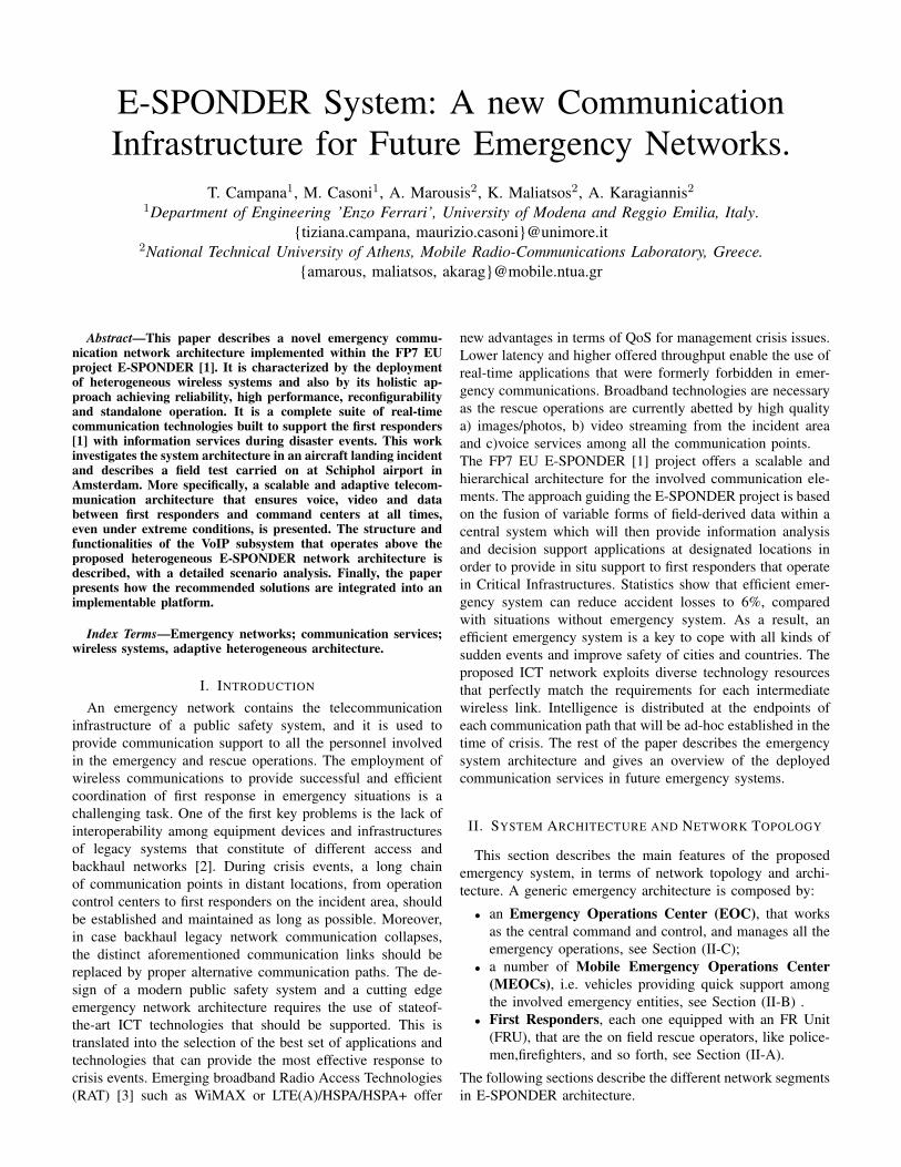
Figure 1. The FRU components: (a) The Jacket and Smart Phone (b) TheLPS tag (66 x 92 x 28 mm3).
A. First Responder Unit (FRU)
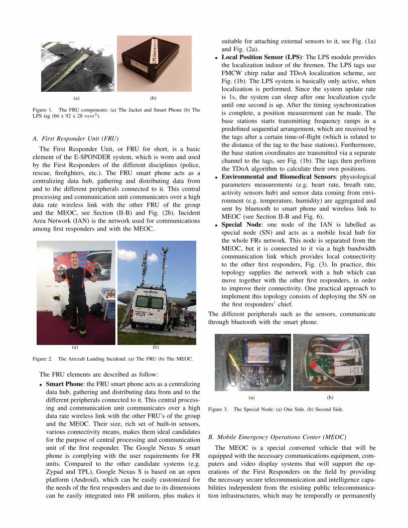
The First Responder Unit, or FRU for short, is a basicelement of the E-SPONDER system, which is worn and usedby the First Responders of the different disciplines (police,rescue, firefighters, etc.). The FRU smart phone acts as acentralizing data hub, gathering and distributing data fromand to the different peripherals connected to it. This centralprocessing and communication unit communicates over a highdata rate wireless link with the other FRU of the groupand the MEOC, see Section (II-B) and Fig. (2b). IncidentArea Network (IAN) is the network used for communicationsamong first responders and with the MEOC.
(a) (b)
Figure 2. The Aircraft Landing Incidend: (a) The FRU (b) The MEOC.
The FRU elements are described as follow:• Smart Phone: the FRU smart phone acts as a centralizing
data hub, gathering and distributing data from and to thedifferent peripherals connected to it. This central process-ing and communication unit communicates over a highdata rate wireless link with the other FRU’s of the groupand the MEOC. Their size, rich set of built-in sensors,various connectivity means, makes them ideal candidatesfor the purpose of central processing and communicationunit of the first responder. The Google Nexus S smartphone is complying with the user requirements for FRunits. Compared to the other candidate systems (e.g.Zypad and TPL), Google Nexus S is based on an openplatform (Android), which can be easily customized forthe needs of the first responders and due to its dimensionscan be easily integrated into FR uniform, plus makes it
suitable for attaching external sensors to it, see Fig. (1a)and Fig. (2a).
• Local Position Sensor (LPS): The LPS module providesthe localization indoor of the firemen. The LPS tags useFMCW chirp radar and TDoA localization scheme, seeFig. (1b). The LPS system is basically only active, whenlocalization is performed. Since the system update rateis 1s, the system can sleep after one localization cycleuntil one second is up. After the timing synchronizationis complete, a position measurement can be made. Thebase stations starts transmitting frequency ramps in apredefined sequential arrangement, which are received bythe tags after a certain time-of-flight (which is related tothe distance of the tag to the base stations). Furthermore,the base station coordinates are transmitted via a separatechannel to the tags, see Fig. (1b). The tags then performthe TDoA algorithm to calculate their own positions.
• Environmental and Biomedical Sensors: physiologicalparameters measurements (e.g. heart rate, breath rate,activity sensors hub) and sensor data coming from envi-ronment (e.g. temperature, humidity) are aggregated andsent by bluetooth to smart phone and wireless link toMEOC (see Section II-B and Fig. 6).
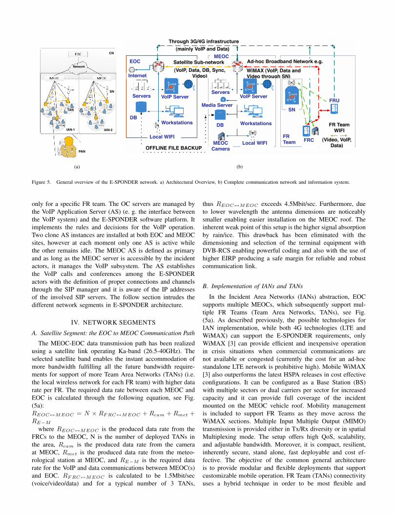
• Special Node: one node of the IAN is labelled asspecial node (SN) and acts as a mobile local hub forthe whole FRs network. This node is separated from theMEOC, but it is connected to it via a high bandwidthcommunication link which provides local connectivityto the other first responders, Fig. (3). In practice, thistopology supplies the network with a hub which canmove together with the other first responders, in orderto improve their connectivity. One practical approach toimplement this topology consists of deploying the SN onthe first responders’ chief.
The different peripherals such as the sensors, communicatethrough bluetooth with the smart phone.
(a) (b)
Figure 3. The Special Node: (a) One Side. (b) Second Side.
B. Mobile Emergency Operations Center (MEOC)
The MEOC is a special converted vehicle that will beequipped with the necessary communications equipment, com-puters and video display systems that will support the op-erations of the First Responders on the field by providingthe necessary secure telecommunication and intelligence capa-bilities independent from the existing public telecommunica-tion infrastructures, which may be temporally or permanently

(a) (b)
Figure 4. General overview of the MEOC: (a) The MEOC Design (b) The External Telecommunication Systems.
unavailable due to major crisis event. In case the publictelecommunication infrastructure is available, MEOC will beinteroperable with it. MEOC will act as a virtual bridgebetween the first responders in the incident field and the EOClocated at the headquarters. Thus, MEOC design deals withissues such as communications and IT infrastructure, interop-erability of systems and services, security of communicationand data exchanges, ability to perform virtually almost allEOC functions in a mobile modality and smart interfaces tothe system. Moreover, the MEOC equipment is crucial forthe whole telecommunication infrastructure, since it will bethe intersection of many different technologies and data paths.The components are logically grouped in design modules listedbelow, Fig. (4):
• Platform - Vehicle Modification: the MEOC will behosted on a market available vehicle that will serve as theMEOC platform. This module contains the driver cabin,operator rooms, rack area, roof and power supply roominfrastructures that are MEOC basic elements, see Fig.(4) and Fig. (2b).
• Operator equipments: the end users will operate in theoperator rooms. The equipment is directly related withthe users, like the input devices, the 3D and 2D monitors,the Satellite phone, the GPS, the Emergency Power Off(EPO) system and the Audio Visual distribution andautomation system.
• External equipment: The systems and sensors that willbe placed on the MEOC roof and are not part of theTelecommunication Systems are grouped in the "ExternalEquipment" module. The main systems that are part ofthis module are the GPS system, the MeteorologicalStation and the day/night camera, Fig. (4b).
• IT Components: The software applications and serviceswill be hosted in workstations, servers and their relatedIT infrastructure that are logically grouped as "IT Com-
ponents" module. The IT Components will be mainlyhosted at the rack area of the vehicle. As an example,the IT components may include an application server, aservices server, a DB server, a GIS server, a 3D generatorworkstation, device controllers, storage and DVR (DigitalVideo Recorder) media.
• Telecom Components: The "Telecom Components"module mainly refers to the Real-Time CommunicationServer (RTCS). This module is responsible for manag-ing and configuring physical communication between E-SPONDER system elements - EOC (see Section II-C),MEOCs and FRUs and it also provides necessary infras-tructure to provide voice/video communication servicesto the E-SPONDER system.
• Internal telecommunication systems (Internal TLC):The Internal telecommunication systems contains theMEOC’s Networking and Routing infrastructures whichare devoted to support inner communications within sev-eral MEOC components, see Fig: (4a).
• External telecommunication systems (Core Network- External TLC): The External telecommunication sys-tems (Core Network) refer to the MEOC’s telecommuni-cation components that are used for the communicationwith EOC and/or other authorities. The technologies thatare proposed for this purpose are Satellite Communi-cations, VHF/UHF receiver/transmitter, TETRA, 2G/3Gand WiMAX.
• Incident Area Network (IAN): The Incident Area Net-work is the network segment directly involved in theemergency response; it is deployed on the emergencyfield and it consists of: (1) the MEOC telecommunicationequipment, (2) the first responder units (FRUs). Thetechnologies proposed are WiMAX, 2G/3G and IEEE802.11g, see Fig. (5).

Regarding the communication between the FR chief and theMEOC, the considered technologies are IEEE 802.16 and3G + evolutions. The IEEE 802.16 solution can be deployedby means of a WiMAX base-station located in the MEOC,which provides larger radio coverage than IEEE 802.11g. Inparticular, IEEE 802.16e can be adopted to provide mobile-optimized connectivity in the 2 GHz frequency band. Similarto before, 3G and its evolutions can be adopted to implementthe FRC-to-MEOC communication through an infrastructure-based network.
C. Emergency Operations Center
The Emergency Operations Center (EOC) is the centralcommand and control, and manages all the emergency op-erations. It provides the basic infrastructure such as a meetingroom but also the required infrastructure used for connectingwith the MEOC and from there with the FRUs and forproviding the respective communications or data services. TheEOC operator:• focuses in an overview of the different MEOC units and
not directly on the FRs that belong to each MEOC.• focuses in obtaining an overview of the system.The IT Components provide various functionalities such as
a Geographic Information System, the Data Fusion function,the Web portal and others in order to support the EOC person-nel to perform their duties. The Telecom Components providereal time data as well as voice and video communicationcapabilities among all layers in the E-SPONDER system. TheOperators Equipment consists of various subsystems (e.g.2D and 3D user interfaces as well as input devices) for theinteraction with the system. The Internal TelecommunicationComponents (Internal TCL) are required to setup a LocalArea Network in order to connect all the different subsys-tems to the fully functional EOC system. The ExternalTelecommunications Components (External TLC) providethe means to communicate over various communication tech-nologies with MEOCs and with External Systems from e.g.Police Forces or the Fire Department. A more detailed analysisfor each of the components will be provided in a future work.
III. APPLICATIONS AND SERVICES
In any emergency system, all the involved operators haveto communicate with each other in order to coordinate allthe necessary rescue operations in the best and most reliableway. Therefore, several different communication paths andservices have to be supported in order to provide efficient androbust emergency operations. During a disaster event, all theinvolved rescue elements (i.e., FRs, FRC, MEOC and EOC)have to be able to make voice calls based on user-definedhierarchical scheme, that can be provided by means of Voiceover IP (VoIP) services [4]. Besides VoIP, it is useful for theEOC to receive real-time images of the incident area, providedby means of a Video over IP (VIP) application, in order tohave greater awareness of the situation and of all the realdamages and, consequently, to take effective decisions. Boththese multimedia applications represent the main, but also themost critical, communication services during a disaster event.
In fact, they are sensitive to delay and jitter that can underminethe perceived audio/video quality. Moreover, the FRs shouldalso detect and monitor some parameters, like temperature,heartbeat, and so forth, by means of sensors, whose collectedinformation have to be transmitted to the operation controlcenters. Naturally, there is the need to also provide a datatransmission path of generic information from the incidentarea, like a picture or a map. Among all the communicationservices to be provided, VoIP and VIP are those that havethe highest bandwidth requirements. The sensor data and filetransfer services also require certain bandwidth capacities,but much less than VoIP and VIP. Therefore, they do notintroduce significant band occupancy problems. As for theTeam Area Network (TAN) (i.e. the local wireless networkfor each FR team), we assume that the predominant servicesare VoIP communications and sensor data, which is calculatedat a required data rate of 1.2 Mbit/s [5]. As far as the linksFRC - MEOC and MEOC - EOC are concerned, VoIP, VIP,sensor data services are supported in the uplink and mainlydata transfer services in the downlink, where the overall bit-rate requested is around 550 kbit/s [5].
A. The SIP Protocol in the VoIP E-SPONDER Subsystem
The SIP protocol [6] is a peer-to-peer protocol thatperfectly matches the scalable star topology of E-SPONDERhierarchical networking with intelligence distributed to thenetwork edge, embedded in the endpoints. SIP features areimplemented in the FR terminals and within the EOC andMEOC entities. SIP services follow the fundamental IPprotocol prescriptions where each intermediate node withinthe network is a passive entity with limited intelligence.Through this attribute an increased scalability of the networkand the granularity of solutions to implement VoIP sessionsis achieved. As a signaling protocol, SIP employs designelements similar to the HTTP request/response transactionmodel. Each resource of a SIP network, such as a user agent,is identified by a Uniform Resource Identifier (URI). In thecase of the E-SPONDER platform, an expression of a typicalSIP URI is given as follows: sip:[email protected].
The main objective of the E-SPONDER VoIP subsystem is theprovision of voice communication between the hierarchallyorganized E-SPONDER actors under diverse conditionsthat are met during a crisis. In order to achieve this goal,multiple SIP servers have been implemented and coordinatedin several entities of the network. In the E-SPONDER demodeployment, Asterisk SIP servers are used [7]. The termSIP manager refers to the Asterisk Manager Interface. Letus assume the simplest E-SPONDER deployment consistedof the EOC, a MEOC and an FR team. Three SIP serversare installed on: a) the EOC communication server, b) theMEOC communication server, c) the Special Node (SN) ofthe FR team. The SIP servers are either in operational stateor idle depending on the current circumstances. The EOCand MEOC SIP servers (the OC servers) are coordinated,while the FR SIP server is pre-configured to provide services
PAN
IAN-2
TAN
IAN-1
Network
CN
SN
(a)
DB
Servers
EOCMEOC
FRTeam FRC
Internet
Local WIFI
VoIP Server
DB
MEOC Camera
WorkstationsWorkstations
Local WIFI
FRUMedia Server
VoIP ServerServers
OFFLINE FILE BACKUP
Through 3G/4G infrastructure
(mainly VoIP and Data)
FR Team WIFI
(Video, VoIP, Data)
Satellite Sub-network
(VoIP, Data, DB, Sync, Video)
Ad-hoc Broadband Network e.g.
WiMAX (VoIP, Data and Video through SN)
SN
(b)
Figure 5. General overview of the E-SPONDER network. a) Architectural Overview, b) Complete communication network and information system.
only for a specific FR team. The OC servers are managed bythe VoIP Application Server (AS) (e. g. the interface betweenthe VoIP system) and the E-SPONDER software platform. Itimplements the rules and decisions for the VoIP operation.Two clone AS instances are installed at both EOC and MEOCsites, however at each moment only one AS is active whilethe other remains idle. The MEOC AS is defined as primaryand as long as the MEOC server is accessible by the incidentactors, it manages the VoIP subsystem. The AS establishesthe VoIP calls and conferences among the E-SPONDERactors with the definition of proper connections and channelsthrough the SIP manager and it is aware of the IP addressesof the involved SIP servers. The follow section intrudes thedifferent network segments in E-SPONDER architecture.
IV. NETWORK SEGMENTS
A. Satellite Segment: the EOC to MEOC Communication Path
The MEOC-EOC data transmission path has been realizedusing a satellite link operating Ka-band (26.5-40GHz). Theselected satellite band enables the instant accommodation ofmore bandwidth fulfilling all the future bandwidth require-ments for support of more Team Area Networks (TANs) (i.e.the local wireless network for each FR team) with higher datarate per FR. The required data rate between each MEOC andEOC is calculated through the following equation, see Fig.(5a):REOC↔M EOC = N × RF RC↔M EOC + Rcam + Rmet +RE−M
where REOC↔M EOC is the produced data rate from theFRCs to the MEOC, N is the number of deployed TANs inthe area, Rcam is the produced data rate from the cameraat MEOC, Rmet is the produced data rate from the meteo-rological station at MEOC, and RE−M is the required datarate for the VoIP and data communications between MEOC(s)and EOC. RF RC↔M EOC is calculated to be 1.5Mbit/sec(voice/video/data) and for a typical number of 3 TANs,
thus REOC↔M EOC exceeds 4.5Mbit/sec. Furthermore, dueto lower wavelength the antenna dimensions are noticeablysmaller enabling easier installation on the MEOC roof. Theinherent weak point of this setup is the higher signal absorptionby rain/ice. This drawback has been eliminated with thedimensioning and selection of the terminal equipment withDVB-RCS enabling powerful coding and also with the use ofhigher EIRP producing a safe margin for reliable and robustcommunication link.
B. Implementation of IANs and TANs
In the Incident Area Networks (IANs) abstraction, EOCsupports multiple MEOCs, which subsequently support mul-tiple FR Teams (Team Area Networks, TANs), see Fig.(5a). As described previously, the possible technologies forIAN implementation, while both 4G technologies (LTE andWiMAX) can support the E-SPONDER requirements, onlyWiMAX [3] can provide efficient and inexpensive operationin crisis situations when commercial communications arenot available or congested (currently the cost for an ad-hocstandalone LTE network is prohibitive high). Mobile WiMAX[3] also outperforms the latest HSPA releases in cost effectiveconfigurations. It can be configured as a Base Station (BS)with multiple sectors or dual carriers per sector for increasedcapacity and it can provide full coverage of the incidentmounted on the MEOC vehicle roof. Mobility managementis included to support FR Teams as they move across theWiMAX sections. Multiple Input Multiple Output (MIMO)transmission is provided either in Tx/Rx diversity or in spatialMultiplexing mode. The setup offers high QoS, scalability,and adjustable bandwidth. Moreover, it is compact, resilient,inherently secure, stand alone, fast deployable and cost ef-fective. The objective of the common general architectureis to provide modular and flexible deployments that supportcustomizable mobile operation. FR Team (TANs) connectivityuses a hybrid technique in order to be most flexible and
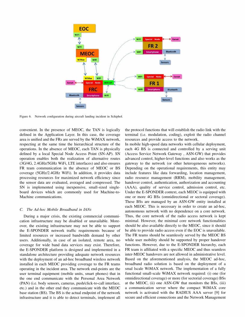
Figure 6. Network configuration during aircraft landing incident in Schiphol.
convenient. In the presence of MEOC, the TAN is logicallydefined in the Application Layer. In this case, the coveragearea is unified and the FRs are served by the WiMAX network,respecting at the same time the hierarchical structure of theoperations. In the absence of MEOC, each TAN is physicallydefined by a local Special Node Access Point (SN-AP). SNoperation enables both the realization of alternative routes(3G/4G, 2.4GHz/5GHz WiFi, LTE interfaces) and also ensuresFR team communication in the absence of MEOC or BScoverage (5GHz/2.4GHz WiFi). In addition, it provides dataprocessing resources for maximized network efficiency sincethe sensor data are evaluated, averaged and compressed. TheSN is implemented using inexpensive, small-sized single-board devices which are commonly used for Machine-to-Machine communications.
C. The Ad-hoc Mobile Broadband in IANs
During a major crisis, the existing commercial communi-cation infrastructure may be disabled or unavailable. More-over, the existing infrastructure may not be able to supportthe E-SPONDER network traffic requirements because oflimited resources or increased bandwidth demand by otherusers. Additionally, in case of an isolated, remote area, nocoverage for wide band data services may exist. Therefore,the E-SPONDER platform is designed and implemented in astandalone architecture providing adequate network resourceswith the deployment of an ad-hoc broadband wireless networkinstalled in each MEOC providing coverage to the FR teamsoperating in the incident area. The network end-points are theuser terminal equipment (mobile units, smart phones) that inthe one end communicate with the Personal Area Network(PAN) (i.e. body sensors, cameras, push/click-to-call interface,etc.) and in the other end they communicate with the MEOCbase station (BS). The BS is the actual endpoint of the networkinfrastructure and it is able to detect terminals, implement all
the protocol functions that will establish the radio link with theterminal (i.e. modulation, coding), exploit the radio channelresources and provide access to the network.In mobile high-speed data networks with cellular deployment,each 4G BS is connected and controlled by a serving unit(Access Service Network Gateway , ASN-GW) that providesadvanced control, higher-level functions and also works as thegateway to the network (or other heterogeneous networks).Depending on the operational requirements, this entity mayinclude features like data forwarding, location management,radio resource management (RRM), mobility management,handover control, authentication, authorization and accounting(AAA), quality of service control, admission control, etc.Under the E-SPONDER context, each MEOC is equipped withone or more 4G BSs (omnidirectional or sectoral coverage).These BSs are managed by an ASN-GW entity installed ateach MEOC. This is necessary in order to create an ad-hoc,autonomous network with no dependence on a core network.Thus, the core network of the radio access network is keptminimal. However, the minimal core network functionalitiesshould be also available directly to the MEOC, since it shouldbe able to provide radio access even if the EOC is unavailable.The FR teams should be seamlessly served by the MEOC BSwhile user mobility should be supported by proper handoverfunctions. However, due to the E-SPONDER hierarchy, eachFR team is affiliated with a specific MEOC and thus seamlessinter-MEOC handovers are not allowed in administrative level.Based on the aforementioned analysis, the MEOC ad-hoc,broadband radio solution is based on the deployment of asmal lscale WiMAX network. The implementation of a fullyfunctional small-scale WiMAX network required: (i) one (foromnidirectional coverage) or more (for sectorial coverage) BSsat the MEOC, (ii) one ASN-GW that monitors the BSs, (iii)a communication server where the compact WiMAX corenetwork is activated with the RADIUS AAA server [9] forsecure and efficient connections and the Network Management
System software for the configuration of the BSs and the ASN-GW. The designed solution for the base station and the ASN-GW equipment has been incorporated to the E-SPONDERplatform covering all possible scenarios.
D. The Ad-hoc in Team Area Networks
The connectivity within the FRs teams is based on aheterogeneous architecture that provides flexible and adaptablecoverage for all possible scenarios. Specifically, in the pres-ence of MEOC, the TAN is logically defined in the applicationlayer and all the corresponding parameters are determinedcentrally by the MOEC base station. The FRs are served bythe 4G/WiMAX network that controls also the hierarchicalE-SPONDER structure. In the absence of MEOC, each TANis physically defined by a local AP in the proximity of eachFR team. Specifically, in the extreme case of limited coverageor MEOC absence, a credit card- sized SN is activated inorder to reconfigure each TAN network connection locallyoperating either as a WiFi AP or as a WiMAX- WiFi bridge.Additionally, the SN supports a light SIP server enabling thevoice communications among the FR team members in theabsence of the MOEC or infrastructure availability providingseamless communications to FRs. Furthermore, the SN unithas enough storage to back up the measurement data untilthe main network becomes operational and enough processingpower in order to perform initial data processing of thesensor data (i.e. compress data and reduce the throughputrequirements). Beyond the wireless interfaces the SN runs aNetwork Manager (unix service) for the network selection,the FR Team Measurement Manager (node.js), the FT TeamMeasurement Temporary storage (node.js), and the FR TeamSIP Server (Asterisk). The SN is carried by the FRC and it ischaracterized by its low power consumption. The next sectionevaluates the FR-to-FR communications through the use ofEEE 802.11 technologies; in particular, we focus on the radiocoverage range for an IEEE 802.11g network in two scenarios,namely an indoor and outdoor cases.
V. EXPERIMENT: FR-TO-FR COMMUNICATIONS
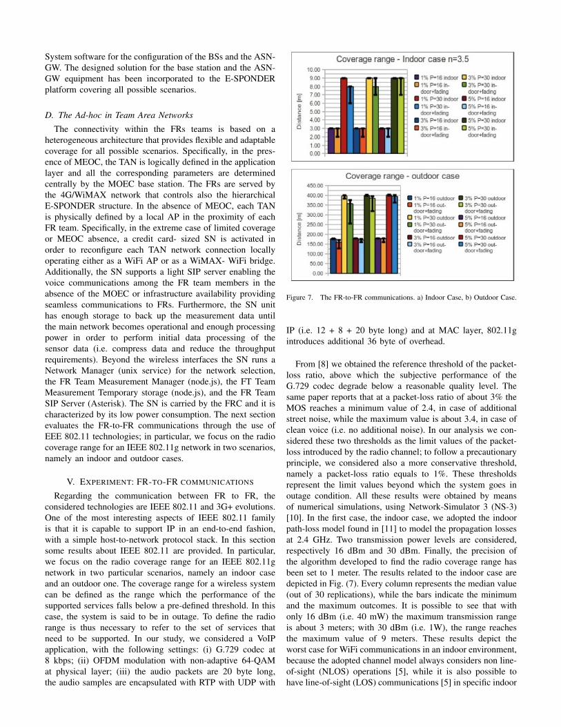
Regarding the communication between FR to FR, theconsidered technologies are IEEE 802.11 and 3G+ evolutions.One of the most interesting aspects of IEEE 802.11 familyis that it is capable to support IP in an end-to-end fashion,with a simple host-to-network protocol stack. In this sectionsome results about IEEE 802.11 are provided. In particular,we focus on the radio coverage range for an IEEE 802.11gnetwork in two particular scenarios, namely an indoor caseand an outdoor one. The coverage range for a wireless systemcan be defined as the range which the performance of thesupported services falls below a pre-defined threshold. In thiscase, the system is said to be in outage. To define the radiorange is thus necessary to refer to the set of services thatneed to be supported. In our study, we considered a VoIPapplication, with the following settings: (i) G.729 codec at8 kbps; (ii) OFDM modulation with non-adaptive 64-QAMat physical layer; (iii) the audio packets are 20 byte long,the audio samples are encapsulated with RTP with UDP with
Figure 7. The FR-to-FR communications. a) Indoor Case, b) Outdoor Case.
IP (i.e. 12 + 8 + 20 byte long) and at MAC layer, 802.11gintroduces additional 36 byte of overhead.
From [8] we obtained the reference threshold of the packet-loss ratio, above which the subjective performance of theG.729 codec degrade below a reasonable quality level. Thesame paper reports that at a packet-loss ratio of about 3% theMOS reaches a minimum value of 2.4, in case of additionalstreet noise, while the maximum value is about 3.4, in case ofclean voice (i.e. no additional noise). In our analysis we con-sidered these two thresholds as the limit values of the packet-loss introduced by the radio channel; to follow a precautionaryprinciple, we considered also a more conservative threshold,namely a packet-loss ratio equals to 1%. These thresholdsrepresent the limit values beyond which the system goes inoutage condition. All these results were obtained by meansof numerical simulations, using Network-Simulator 3 (NS-3)[10]. In the first case, the indoor case, we adopted the indoorpath-loss model found in [11] to model the propagation lossesat 2.4 GHz. Two transmission power levels are considered,respectively 16 dBm and 30 dBm. Finally, the precision ofthe algorithm developed to find the radio coverage range hasbeen set to 1 meter. The results related to the indoor case aredepicted in Fig. (7). Every column represents the median value(out of 30 replications), while the bars indicate the minimumand the maximum outcomes. It is possible to see that withonly 16 dBm (i.e. 40 mW) the maximum transmission rangeis about 3 meters; with 30 dBm (i.e. 1W), the range reachesthe maximum value of 9 meters. These results depict theworst case for WiFi communications in an indoor environment,because the adopted channel model always considers non line-of-sight (NLOS) operations [5], while it is also possible tohave line-of-sight (LOS) communications [5] in specific indoor

scenarios [11] (i.e. communications inside a single room).More specifically, the use of adaptive rate-control mechanismsallows the wireless stations to adapt their transmission rateto the channel state, which can greatly improve the networkperformance. For instance, the use of the ERP-OFDM physicallayer operating at 6 Mbit/s helps both in enhancing the trans-mission range and in transmission power reduction. Finally, itis also possible to appreciate that by allowing more loss (i.e.from 1% to 3% or 5%) the coverage range increases.
Fig. (7) depicts the outdoor WiFi case; here we consideredthe [12] path-loss channel model that assumes perfect LOSoperation. Only diffraction (due to the terrain) has been consid-ered (diffraction loss increase with the reduction of antennas’heights). Even in this case it is clear that the transmissionpower has a great impact on the transmission range. Asbefore, the range increases with the growth of the the packetloss ratio (from 1% to 5%); moreover, the presence/absenceof fast-fading has a great effect on the variability of thecoverage range. It is important to note that, as opposite to theprevious case, this is a best-case because the LOS assumptionis valid only in specific outdoor scenarios (i.e. LOS point-to-point links). This discussion shows that, depending on theconsidered scenario (i.e. indoor or outdoor) the radio coveragerange for commodity WiFi devices can be adequate to provideservice access to the first responders operating on the field.
VI. FIELD TEST: AIRCRAFT LANDING INCIDENT
E-SPONDER system has been tested in a complex andlarge-scale emergency situation, has been simulating anaircraft landing incident. The field test is held at AmsterdamSchiphol Airport in Netherlands. The locations and scenariosfor the field test has been chosen based on the demonstrablefeatures and capacities of E-SPONDER system. Duringthe field test, firemen tested the E-SPONDER system inoperational conditions. The scenario of field test is reportedbelow.
A Boeing 777 that has reported a fire in the cabin asksfor permission to land at Amsterdam Schiphol Airport.The Airport Fire Officer announces a ’VOS-groot’ (aircraftincident at Schiphol Airport-high impact) and gives the Boeingpermission to land. The Boeing does not transport dangeroussubstances. Once landed, a specialized team controls thesituation outside the aircraft (e.g. preventing fire as a resultfrom ’hot brakes’). As Schiphol is unable to contact theBoeing’s crew and the doors of the aircraft remain unopened,a mobile staircase is placed in front the aircraft’s door. Thesix fire fighters that man the water tender enter the aircraft viathe mobile staircase. They note that a fire has broken out onthe main deck. Multiple victims lie on the main deck or aretrapped in their seats. Rescue and fire extinguishing activitiesare started immediately. The development of the scenarioafter this point is decided on by the E-SPONDER consortiumin consultation with the participating firemen. Fig. (6) showsthe network configuration during the aircraft landing incidentin Schiphol. To support E-SPONDER communications, manytechnologies have been taken into account. These are, seeFig. (6):
• IEEE 802.16-based: known as "WiMAX" from the com-mercial point-of-view provides point-to-multipoint con-nectivity, as well as mesh connectivity, to metropolitanareas (with maximum theoretical range of 50 km). Oneof the key aspects of IEEE 802.16 is its QoS supportby means of traffic differentiation and classification. Thistechnology is used for FR chief-to-MEOC communica-tions.
• Bluetooth: is a wireless technology working in the 2.4GHz ISM band. It allows connecting computers, periph-erals, phones and other devices to exchange data overdistances of up to 100m (typically 10m). This technologyis used for Sensors - FR communications.
• Finally, the WiFi module can provide a broadband, shortrange data link involving the MEOC and FRs and FRchief (FRC) - FRs.
Heterogeneous wireless communication systems have been in-tegrated in a holistic approach that is characterized as reliable,robust, and of seamless operation to the end-users/FRs.
VII. CONCLUSIONS
This work describes an emergency ICT infrastructure capa-ble of providing secure and reliable communication to first re-sponders during any crisis event as analyzed and developed inthe FP7 EU project E-SPONDER. The most suitable networktopology and architecture have been identified. Furthermore,it is provided the real implementation of an ad-hoc commu-nication network that operates efficiently. As a future work,two more field tests will be done in France in two emergencyscenarios: (1) a large vessel on fire in Marseille; and (2) acollapsed office building in Manosque.
ACKNOWLEDGMENT
This research has received funding from the EuropeanUnion Seventh Framework Programme (FP7/2007-2013) un-der grant agreement n◦ [242411].
REFERENCES
[1] FP7 - E-SPONDER EU Research project, www.e-sponder.eu[2] H. Miller, R. Granato, J. Feuerstein, and L. Ruffino, ”Toward interop-
erable first response,” IT Professional, vol. 7, pp. 13–20, 2005[3] Network working group stage 2 and 3 rel.1.1, pub. by the WiMAX
forum[4] B. Goode, ”Voice over internet protocol (VoIP)”, Proceedings of the
IEEE, vol. 90, no. 9, pp. 1495–1517, 2002[5] A.Paganelli, D.Saladino, M.Casoni, ”QoS Performance Evaluation of
Multimedia Services in Emergency Networks,” in 8th InternationalIWCMC Conference, 2012, Aug. 2012, pp. 933–938
[6] A. Johnston, SIP: understanding the session initiation protocol,Artech’09
[7] Asterisk PBX, www.asterisk.org[8] M. E. Perkins, "Characterizing the Subjective Performance of the ITU-T
8 kb/s Speech Coding Algorithm Ð ITU-T G.729"[9] C. Rigney et al. ”Remote dial-in user service (radius)”, IETF RFC 2865
[10] Network-Simulator 3 (NS-3), www.nsnam.org[11] A. Bose and C. Heng Foh, ”A Practical Path Loss Model For Indoor
WiFi Positioning Enhancement”, 6th International Conference on Infor-mation, Communications Signal Processing, 2007
[12] D. B. Green and M. S. Obaidat, ”An Accurate Line of Sight PropagationPerformance Model for Ad-Hoc 802.11 Wireless LAN (WLAN) Devices”, IEEE Int’l Conf. on Commun. (ICC), 2002
[13] M. Casoni, D. Saladino, A. Karagiannis, D. Komnakos, S. Sagkriotis,J. Wagner, N. Joram, and F. Ellinger, ”An ad-hoc emergency networkfor crisis events”, in Future Network and Mobile Summit (FutureNet-workSummit), 2013, pp. 1–12, IEEE, 2013