Dynamic turning control of a quadruped locomotion robot using oscillators
14
Dynamic Turning Control of a Quadruped Locomotion Robot using Oscillators Katsuyoshi Tsujita Hiroomi Toui and Kazuo Tsuchiya Dept. of Aeronautics and Astronautics, Graduate School of Engineering,Kyoto University, Yoshida Hon-machi, Sakyo, Kyoto 606–8501 E-mail:[email protected] Abstract The authors have proposed a dynamic turning control system of a quadruped robot by using nonlinear oscillators. It is composed of a spontaneous locomotion controller and voluntary motion controller. In this article, capability of dynamic turning motion of the proposed control system is verified through numerical simulations and hardware experiments: Various turning speed and orientation make the motion of the robot asymmetry in terms of duty ratio, stride and center of pressure. The proposed controller actively and adaptively controls redundant DOF to cancel the dynamic asymmetry and established stable turning motion at various locomotion speed and turning orientation. keywords: Quadruped locomotion robot, Oscillators, Turning motion 1 INTRODUCTION Locomotion is one of the basic functions of a mobile robot. Using leg is one of the strategies for accomplishing locomotion. It allows the robot to move on rough terrain. Therefore, a considerable amount of research has been done on motion control of legged locomotion robots. This article treats the motion control of a quadruped robot, with emphasis on the dynamic turning control. In the future, a walking robot will be required which can carry out various tasks on unstructured terrain. The walking robot is required to realize the real-time adaptability to a changing environment and maneuverability to generate voluntary motion according to context of changing environment. Biological research of the last years has made great contributions to overcome such difficulties; during a spontaneous motion such as straight walking, a lot of joints and muscles are organized into a collective unit to be controlled as if it had fewer degrees of freedom but to retain the necessary flexibility for a changing environment. On the other hand, during a voluntary motion such as turning walk, another organized collective unit emerges selectively according to the commanded signal[1]. 1
Transcript of Dynamic turning control of a quadruped locomotion robot using oscillators

Dynamic Turning Control of a Quadruped Locomotion Robot
using Oscillators
Katsuyoshi Tsujita Hiroomi Toui and Kazuo Tsuchiya
Dept. of Aeronautics and Astronautics, Graduate School of Engineering, Kyoto University,
Yoshida Hon-machi, Sakyo, Kyoto 606–8501
E-mail:[email protected]
Abstract
The authors have proposed a dynamic turning control system of a quadruped robot by using
nonlinear oscillators. It is composed of a spontaneous locomotion controller and voluntary motion
controller. In this article, capability of dynamic turning motion of the proposed control system
is verified through numerical simulations and hardware experiments: Various turning speed and
orientation make the motion of the robot asymmetry in terms of duty ratio, stride and center of
pressure. The proposed controller actively and adaptively controls redundant DOF to cancel the
dynamic asymmetry and established stable turning motion at various locomotion speed and turning
orientation.
keywords: Quadruped locomotion robot, Oscillators, Turning motion
1 INTRODUCTION
Locomotion is one of the basic functions of a mobile robot. Using leg is one of the strategies for
accomplishing locomotion. It allows the robot to move on rough terrain. Therefore, a considerable
amount of research has been done on motion control of legged locomotion robots. This article treats
the motion control of a quadruped robot, with emphasis on the dynamic turning control.
In the future, a walking robot will be required which can carry out various tasks on unstructured
terrain. The walking robot is required to realize the real-time adaptability to a changing environment
and maneuverability to generate voluntary motion according to context of changing environment.
Biological research of the last years has made great contributions to overcome such difficulties; during
a spontaneous motion such as straight walking, a lot of joints and muscles are organized into a collective
unit to be controlled as if it had fewer degrees of freedom but to retain the necessary flexibility for a
changing environment. On the other hand, during a voluntary motion such as turning walk, another
organized collective unit emerges selectively according to the commanded signal[1].
1
The knowledge inspired robotics researchers and a considerable amount of research has been done
on biologically inspired control systems for walking robots which enable to adapt to variances of the
environment based on the CPG(Central Pattern Generator) principle[2]–[6].
However, not so many researches treat the maneuverability of quadruped robots. In order to make
a voluntary motion such as turning motion, it is very important for the robot to have maneuverability.
Jindrich et al.[7] investigated coordination of all legs of hexapods during turning, and clarified the
maneuverability of hexapod insects in terms of the role of each leg. Holmes et al. clarified that the
turning motion of a hexapod locomotion is caused by the mechanical relationship between COM(Center
Of Mass) and COP(Center Of Pressure). According to them, straight locomotion becomes unstable and
turning motion becomes stable under a condition of COM and COP.
The controller for turning locomotion is usually designed as a sequence of programmed stable mo-
tions. In this type of controller, it is difficult to generate the appropriate succeeding step keeping stability
and adaptability on real-time. Therefore, many of these types of controllers treat static locomotion with
the static balance.
In this article, a new control system is proposed for dynamic turning motion of a quadruped robot by
using nonlinear oscillators. The proposed control system consists of a spontaneous locomotion controller
and a voluntary motion controller. The spontaneous locomotion controller is designed as a oscillator
network that have mutual interactions among the oscillators with the feedback signals of the external
sensors and generates an adaptive gait pattern according to the variance of the environment through
the mutual entrainments. On the other hand, the voluntary motion controller controls the posture of
the main body and also tunes some locomotion parameters of the spontaneous locomotion controller
according to the various locomotion speed and the various turning orientation.
The performance of the proposed control system is verified by numerical simulations and hardware
experiments.
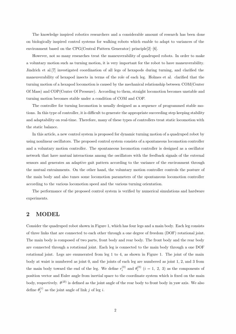
2 MODEL
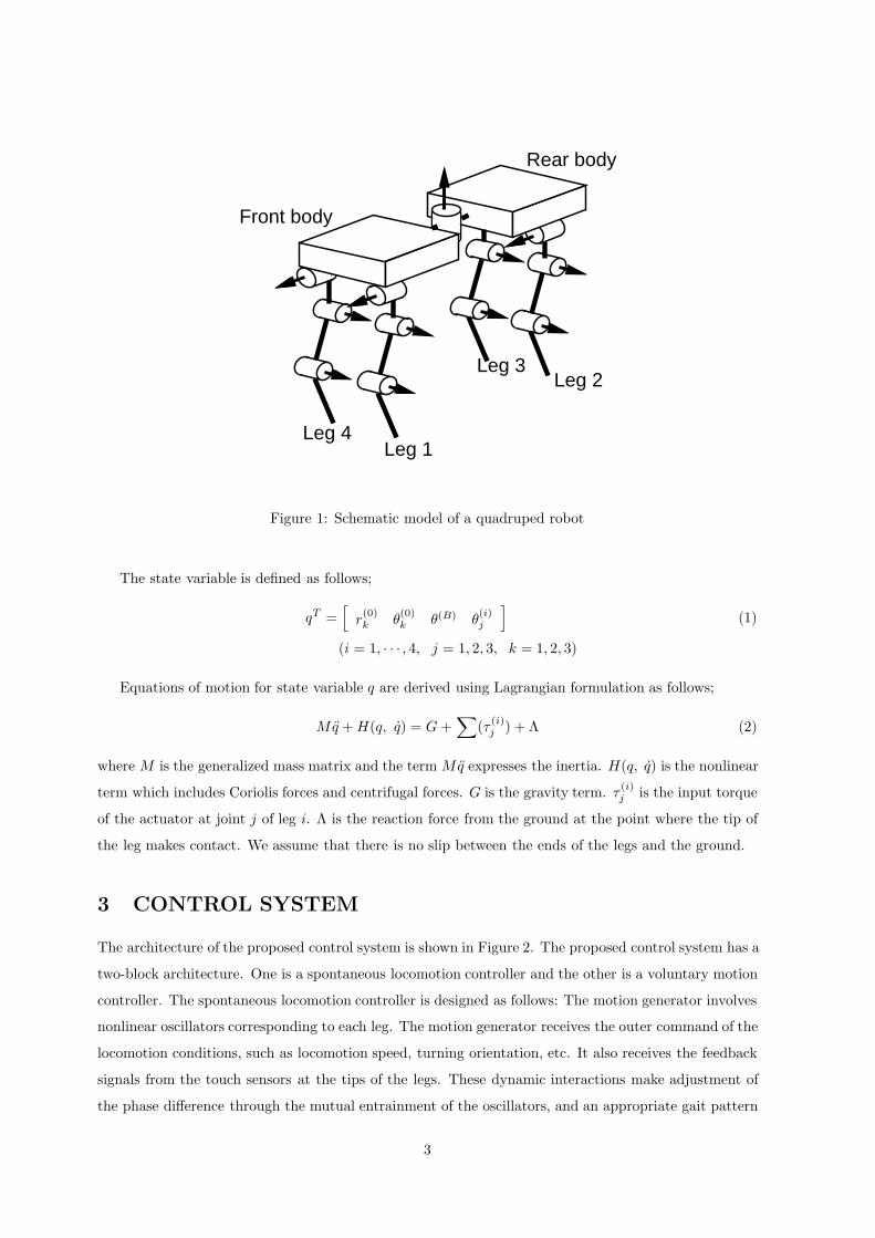
Consider the quadruped robot shown in Figure 1, which has four legs and a main body. Each leg consists
of three links that are connected to each other through a one degree of freedom (DOF) rotational joint.
The main body is composed of two parts, front body and rear body. The front body and the rear body
are connected through a rotational joint. Each leg is connected to the main body through a one DOF
rotational joint. Legs are enumerated from leg 1 to 4, as shown in Figure 1. The joint of the main
body at waist is numbered as joint 0, and the joints of each leg are numbered as joint 1, 2, and 3 from
the main body toward the end of the leg. We define r(0)i and θ
(0)i (i = 1, 2, 3) as the components of
position vector and Euler angle from inertial space to the coordinate system which is fixed on the main
body, respectively. θ(B) is defined as the joint angle of the rear body to front body in yaw axis. We also
define θ(i)j as the joint angle of link j of leg i.
2
Front body
Rear body
Leg 1
Leg 2Leg 3
Leg 4
Figure 1: Schematic model of a quadruped robot
The state variable is defined as follows;
qT =[
r(0)k θ
(0)k θ(B) θ
(i)j
](1)
(i = 1, · · · , 4, j = 1, 2, 3, k = 1, 2, 3)
Equations of motion for state variable q are derived using Lagrangian formulation as follows;
Mq + H(q, q) = G +∑
(τ (i)j ) + Λ (2)
where M is the generalized mass matrix and the term Mq expresses the inertia. H(q, q) is the nonlinear
term which includes Coriolis forces and centrifugal forces. G is the gravity term. τ(i)j is the input torque
of the actuator at joint j of leg i. Λ is the reaction force from the ground at the point where the tip of
the leg makes contact. We assume that there is no slip between the ends of the legs and the ground.
3 CONTROL SYSTEM
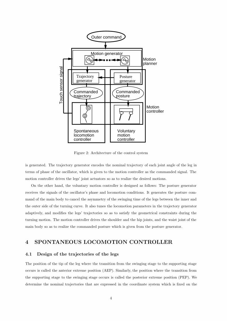
The architecture of the proposed control system is shown in Figure 2. The proposed control system has a
two-block architecture. One is a spontaneous locomotion controller and the other is a voluntary motion
controller. The spontaneous locomotion controller is designed as follows: The motion generator involves
nonlinear oscillators corresponding to each leg. The motion generator receives the outer command of the
locomotion conditions, such as locomotion speed, turning orientation, etc. It also receives the feedback
signals from the touch sensors at the tips of the legs. These dynamic interactions make adjustment of
the phase difference through the mutual entrainment of the oscillators, and an appropriate gait pattern
3
Trajectorygenerator
Posturegenerator
Motionplanner
Motioncontroller
Tou
ch s
enso
r si
gnal
Outer command
Motion generator
Spontaneouslocomotioncontroller
Voluntarymotioncontroller
Commandedposture
Commandedtrajectory
Figure 2: Architecture of the control system
is generated. The trajectory generator encodes the nominal trajectory of each joint angle of the leg in
terms of phase of the oscillator, which is given to the motion controller as the commanded signal. The
motion controller drives the legs’ joint actuators so as to realize the desired motions.
On the other hand, the voluntary motion controller is designed as follows: The posture generator
receives the signals of the oscillator’s phase and locomotion conditions. It generates the posture com-
mand of the main body to cancel the asymmetry of the swinging time of the legs between the inner and
the outer side of the turning curve. It also tunes the locomotion parameters in the trajectory generator
adaptively, and modifies the legs’ trajectories so as to satisfy the geometrical constraints during the
turning motion. The motion controller drives the shoulder and the hip joints, and the waist joint of the
main body so as to realize the commanded posture which is given from the posture generator.
4 SPONTANEOUS LOCOMOTION CONTROLLER
4.1 Design of the trajectories of the legs
The position of the tip of the leg where the transition from the swinging stage to the supporting stage
occurs is called the anterior extreme position (AEP). Similarly, the position where the transition from
the supporting stage to the swinging stage occurs is called the posterior extreme position (PEP). We
determine the nominal trajectories that are expressed in the coordinate system which is fixed on the
4
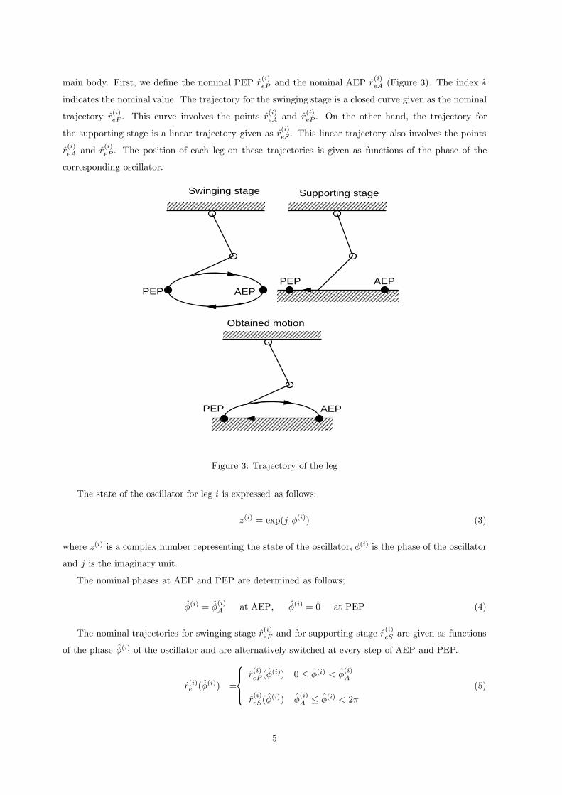
main body. First, we define the nominal PEP r(i)eP and the nominal AEP r
(i)eA (Figure 3). The index ∗
indicates the nominal value. The trajectory for the swinging stage is a closed curve given as the nominal
trajectory r(i)eF . This curve involves the points r
(i)eA and r
(i)eP . On the other hand, the trajectory for
the supporting stage is a linear trajectory given as r(i)eS . This linear trajectory also involves the points
r(i)eA and r
(i)eP . The position of each leg on these trajectories is given as functions of the phase of the
corresponding oscillator.
Swinging stage Supporting stage
Obtained motion
PEP AEP
AEP
AEPPEP
PEP
Figure 3: Trajectory of the leg
The state of the oscillator for leg i is expressed as follows;
z(i) = exp(j φ(i)) (3)
where z(i) is a complex number representing the state of the oscillator, φ(i) is the phase of the oscillator
and j is the imaginary unit.
The nominal phases at AEP and PEP are determined as follows;
φ(i) = φ(i)A at AEP, φ(i) = 0 at PEP (4)
The nominal trajectories for swinging stage r(i)eF and for supporting stage r
(i)eS are given as functions
of the phase φ(i) of the oscillator and are alternatively switched at every step of AEP and PEP.
r(i)e (φ(i)) =
r(i)eF (φ(i)) 0 ≤ φ(i) < φ
(i)A
r(i)eS(φ(i)) φ
(i)A ≤ φ(i) < 2π
(5)
5
The nominal duty ratio β(i) for leg i is defined to represent the ratio between the nominal time for
the supporting stage and the period of one cycle of the nominal locomotion.
β(i) = 1 − φ(i)A
2π(6)
4.2 Design of the gait pattern
The gait patterns, which are the relationships between motions of the legs, are designed.
Each pattern is represented by a matrix of phase differences Γ(m)ij as follows;
φ(j) = φ(i) + Γ(m)ij (7)
where, m = 1, 2 represent transverse walk pattern and rotary walk pattern, respectively. m = 3, 4, 5
represent trot pattern, pace pattern and bounce pattern, respectively.
4.3 Leg motion control
The angle of joint j of leg i is derived from the geometrical relationship between the trajectory r(i)e (φ(i))
and the joint angle. θ(i)j is written as a function of phase φ(i) as follows;
θ(i)j = θ
(i)j (φ(i)) (8)
The commanded torque at each joint of the leg is obtained by using local feedback control as follows;
τ (B) = KPB(θ(B) − θ(B))3 + KDB( ˙θ(B)
− θ(B)) (9)
τ(i)1 = KP1(θ
(i)1 − θ
(i)1 )3 + KD1(
˙θ(i)
1 − θ(i)1 ) (10)
τ(i)j = KPj(θ
(i)j − θ
(i)j ) + KDj(
˙θ(i)
j − θ(i)j ) (11)
(i = 1, · · · , 4, j = 2, 3)
where τ(B) and τ(i)j are the actuator torques at the connection joint between front body and rear body,
and at joint j of leg i, respectively.
4.4 Gait pattern control
We design the phase dynamics of the oscillators corresponding to each leg as follows;
φ(i) = ω + g(i)1 + g
(i)2 (i = 1, · · · , 4) (12)
g(i)1 = −K
(φ(i) − φ(j) − Γ(m)
ij
)(13)
g(i)2 = (φ(i)
A − φ(i)A )δ(t − t0) (14)
t0 : the moment leg i touches the ground
where K is a constant number and δ is Delta-Function.
The oscillators form a dynamic system that affects each other through two types of interactions.
One is continuous interaction from g(i)1 which depends on the nominal gait pattern. The other is the
6

pulse-like interactions g(i)2 which is caused by the feedback signals from the touch sensor. Actually, this
effect is realized by resetting the phase of the oscillator from the actual value φ(i)A to the nominal value
φ(i)A . Through these interactions, the oscillators generate gait patterns that satisfy the requirements of
the environment.
5 VOLUNTARY MOTION CONTROLLER
In order to realize the turning motion voluntarily, the robot has to coordinate many degrees of freedom
under kinematical or dynamic constraint conditions. In the turning motion, there may be considered
two typical cases: One is kinematical turn and the other is dynamic turn. In the kinematical turn,
locomotion velocity is slow and the dynamic influences such as centrifugal forces or other nonlinear
dynamic forces can be ignorable, but geometrical and kinematical constraint conditions are dominant
and determines the turning motion. On the other hand, in dynamic turn, locomotion velocity is fast
and obtained gait patterns are two-legs supporting gait such as trot, pace and bounce. In this case,
there is less number of the geometrical and the kinematical constraints than the ’slow speed locomotion.’
However, dynamic forces act on the system during turning motion and those cannot be ignorable. For
example, centrifugal forces act on the system in the opposite direction of the center of the arc of turning
path. Therefore, the robot needs to be compensated for the influences of several kinds of forces such as
centrifugal force.
5.1 Kinematical turn
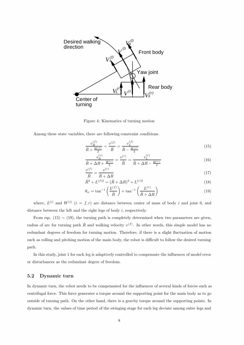
Figure 4 expresses a simple model for kinematic turn. In this model, there are several assumptions as
follows;
1. Motion of the robot is restricted in two-dimensional motion. i.e. Rolling and pitching motions of
the robot are ignored.
2. All legs generates continuous propulsion velocity.
3. There is no slip between the legs and the ground.
There are nine state variables of this simple model as follows;
1. v(i)j : Propulsion velocity of leg j of body i.
(i = f (front), r (rear), j = L (Left), R (Right))
2. v(i): Propulsion velocity at the geometrical center of body i. (i = f, r)
3. R: Desired radius of arc for turning path.
4. ∆R: Distance of turning path between the front and the rear bodies.
5. θw : Yaw angle of joint 0.
7
Front body
Rear body
Center of turning
Yaw joint
Desired walkingdirection
VL(r)
V(f)
V(f)L
V(f)
R
VR(r)V (r)
Figure 4: Kinematics of turning motion
Among these state variables, there are following constraint conditions.
v(f)R
R + W (f)
2
=v(f)
R=
v(f)L
R − W (f)
2
(15)
v(r)R
R + ∆R + W (r)
2
=v(r)
R=
v(r)L
R + ∆R− W (r)
2
(16)
v(f)
R=
v(r)
R + ∆R(17)
R2 + L(f)2 = (R + ∆R)2 + L(r)2 (18)
θw = tan−1
(L(f)
R
)+ tan−1
(L(r)
R + ∆R
)(19)
where, L(i) and W (i) (i = f, r) are distance between center of mass of body i and joint 0, and
distance between the left and the right legs of body i, respectively.
From eqs. (15) ∼ (19), the turning path is completely determined when two parameters are given,
radius of arc for turning path R and walking velocity v(f). In other words, this simple model has no
redundant degrees of freedom for turning motion. Therefore, if there is a slight fluctuation of motion
such as rolling and pitching motion of the main body, the robot is difficult to follow the desired turning
path.
In this study, joint 1 for each leg is adaptively controlled to compensate the influences of model error
or disturbances as the redundant degree of freedom.
5.2 Dynamic turn
In dynamic turn, the robot needs to be compensated for the influences of several kinds of forces such as
centrifugal force. This force generates a torque around the supporting point for the main body as to go
outside of turning path. On the other hand, there is a gravity torque around the supporting points. In
dynamic turn, the values of time period of the swinging stage for each leg deviate among outer legs and
8
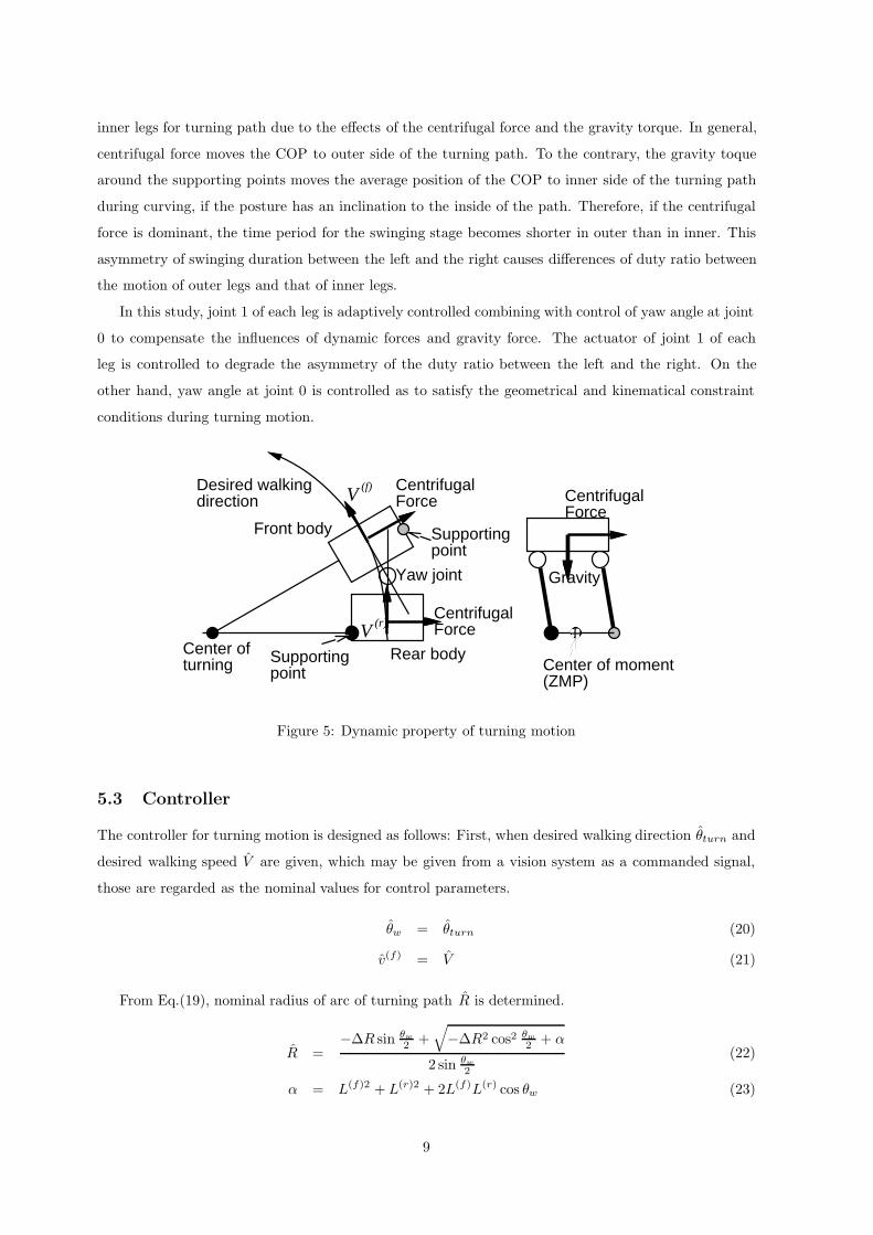
inner legs for turning path due to the effects of the centrifugal force and the gravity torque. In general,
centrifugal force moves the COP to outer side of the turning path. To the contrary, the gravity toque
around the supporting points moves the average position of the COP to inner side of the turning path
during curving, if the posture has an inclination to the inside of the path. Therefore, if the centrifugal
force is dominant, the time period for the swinging stage becomes shorter in outer than in inner. This
asymmetry of swinging duration between the left and the right causes differences of duty ratio between
the motion of outer legs and that of inner legs.
In this study, joint 1 of each leg is adaptively controlled combining with control of yaw angle at joint
0 to compensate the influences of dynamic forces and gravity force. The actuator of joint 1 of each
leg is controlled to degrade the asymmetry of the duty ratio between the left and the right. On the
other hand, yaw angle at joint 0 is controlled as to satisfy the geometrical and kinematical constraint
conditions during turning motion.
Front body
Rear bodyCenter of turning
Yaw joint
Desired walkingdirection
CentrifugalForce
CentrifugalForce
Supportingpoint
Supportingpoint
CentrifugalForce
V(f)
V (r)
Gravity
Center of moment(ZMP)
Figure 5: Dynamic property of turning motion
5.3 Controller
The controller for turning motion is designed as follows: First, when desired walking direction θturn and
desired walking speed V are given, which may be given from a vision system as a commanded signal,
those are regarded as the nominal values for control parameters.
θw = θturn (20)
v(f) = V (21)
From Eq.(19), nominal radius of arc of turning path R is determined.
R =−∆R sin θw
2 +√−∆R2 cos2 θw
2 + α
2 sin θw
2
(22)
α = L(f)2 + L(r)2 + 2L(f)L(r) cos θw (23)
9
From Eqs.(15) ∼ (17), and by using nominal duty ratio β (i), the nominal stride for each leg is
calculated.
S(i) =β(i)Tsw
1 − β(i)
R + W (f)
2
RV (24)
S(j) =β(j)Tsw
1 − β(j)
R + ∆R− W (r)
2
RV (25)
(i = 1, 2, j = 3, 4) (26)
These nominal values of strides are given to the trajectory generator in the motion planning system.
The input torques at joint 0 and joint 1 of each leg are designed as follows;
Joint 0
τ0 = KP0(θw − θ0) − KD0θ0 (27)
Joint 1 of each leg
˙θ(i)
1 = KS(β(I) − β(O)) O : outer leg, I : inner leg
τ(i)1 = KP1(θ
(i)1 − θ
(i)1 ) − KD0θ
(i)1 (28)
6 NUMERICAL SIMULATION
Numerical simulations are implemented to verify the performance of the proposed control system. Table
1 shows the physical parameters of the robot which are used in numerical simulations.
Table 1
Width 0.20 [m] Length of link 1 0.188 [m]
Length 0.36 [m] Length of link 2 0.193 [m]
Height 0.05 [m] Mass of link 1 0.918 [kg]
Total Mass 8.4 [kg] Mass of link 2 0.595 [kg]
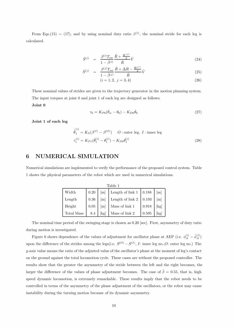
The nominal time period of the swinging stage is chosen as 0.20 [sec]. First, asymmetry of duty ratio
during motion is investigated.
Figure 6 shows dependence of the values of adjustment for oscillator phase at AEP (i.e. φ(i)A − φ
(i)A )
upon the difference of the strides among the legs(i.e. S(O) −S(I), I: inner leg no.,O: outer leg no.) The
y-axis value means the ratio of the adjusted value of the oscillator’s phase at the moment of leg’s contact
on the ground against the total locomotion cycle. These cases are without the proposed controller. The
results show that the greater the asymmetry of the stride between the left and the right becomes, the
larger the difference of the values of phase adjustment becomes. The case of β = 0.55, that is, high
speed dynamic locomotion, is extremely remarkable. These results imply that the robot needs to be
controlled in terms of the asymmetry of the phase adjustment of the oscillators, or the robot may cause
instability during the turning motion because of its dynamic asymmetry.
10
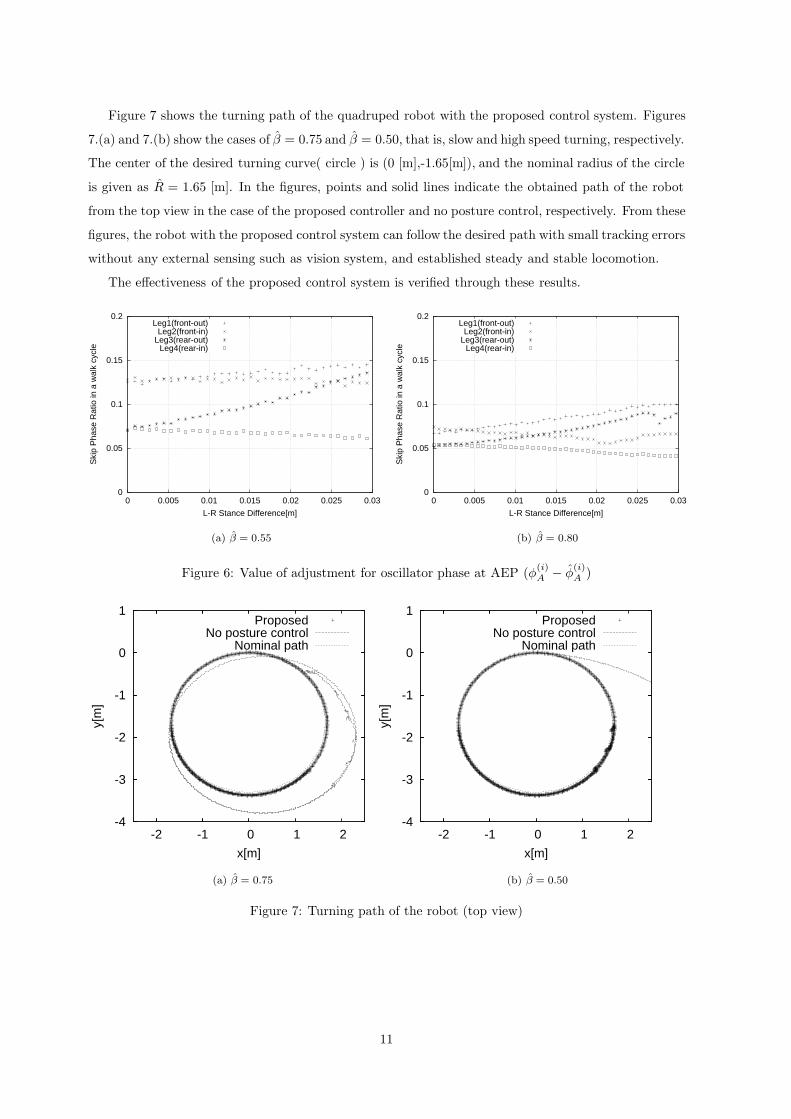
Figure 7 shows the turning path of the quadruped robot with the proposed control system. Figures
7.(a) and 7.(b) show the cases of β = 0.75 and β = 0.50, that is, slow and high speed turning, respectively.
The center of the desired turning curve( circle ) is (0 [m],-1.65[m]), and the nominal radius of the circle
is given as R = 1.65 [m]. In the figures, points and solid lines indicate the obtained path of the robot
from the top view in the case of the proposed controller and no posture control, respectively. From these
figures, the robot with the proposed control system can follow the desired path with small tracking errors
without any external sensing such as vision system, and established steady and stable locomotion.
The effectiveness of the proposed control system is verified through these results.
0
0.05
0.1
0.15
0.2
0 0.005 0.01 0.015 0.02 0.025 0.03
Ski
p P
hase
Rat
io in
a w
alk
cycl
e
L-R Stance Difference[m]
Leg1(front-out)Leg2(front-in)
Leg3(rear-out)Leg4(rear-in)
0
0.05
0.1
0.15
0.2
0 0.005 0.01 0.015 0.02 0.025 0.03
Ski
p P
hase
Rat
io in
a w
alk
cycl
e
L-R Stance Difference[m]
Leg1(front-out)Leg2(front-in)
Leg3(rear-out)Leg4(rear-in)
(a) β = 0.55 (b) β = 0.80
Figure 6: Value of adjustment for oscillator phase at AEP (φ(i)A − φ
(i)A )
-4
-3
-2
-1
0
1
-2 -1 0 1 2
y[m
]
x[m]
ProposedNo posture control
Nominal path
-4
-3
-2
-1
0
1
-2 -1 0 1 2
y[m
]
x[m]
ProposedNo posture control
Nominal path
(a) β = 0.75 (b) β = 0.50
Figure 7: Turning path of the robot (top view)
11
7 HARDWARE EXPERIMENTS
Performance of the proposed control system is verified through hardware experiments. The quadruped
robot has three DOF for each leg and one DOF on the main body. Each joint is driven by Harmonic
Drive DC actuator. Maximum actuator torque is 4.6 [Nm] and maximum rotational speed is 3.5 [rad/s].
Load cell is equipped at the tip of each leg and play roles of touch sensor and force sensor. Actuator
drivers and amplifiers for force sensors are mounted on the main body.
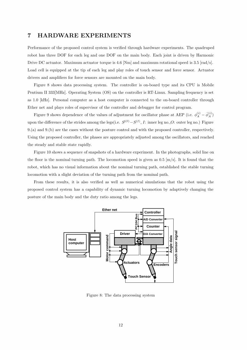
Figure 8 shows data processing system. The controller is on-board type and its CPU is Mobile
Pentium II 333[MHz]. Operating System (OS) on the controller is RT-Linux. Sampling frequency is set
as 1.0 [kHz]. Personal computer as a host computer is connected to the on-board controller through
Ether net and plays roles of supervisor of the controller and debugger for control program.
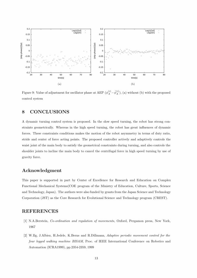
Figure 9 shows dependence of the values of adjustment for oscillator phase at AEP (i.e. φ(i)A − φ
(i)A )
upon the difference of the strides among the legs(i.e. S(O)−S(I), I: inner leg no.,O: outer leg no.) Figure
9.(a) and 9.(b) are the cases without the posture control and with the proposed controller, respectively.
Using the proposed controller, the phases are appropriately adjusted among the oscillators, and reached
the steady and stable state rapidly.
Figure 10 shows a sequence of snapshots of a hardware experiment. In the photographs, solid line on
the floor is the nominal turning path. The locomotion speed is given as 0.5 [m/s]. It is found that the
robot, which has no visual information about the nominal turning path, established the stable turning
locomotion with a slight deviation of the turning path from the nominal path.
From these results, it is also verified as well as numerical simulations that the robot using the
proposed control system has a capability of dynamic turning locomotion by adaptively changing the
posture of the main body and the duty ratio among the legs.
A/D Converter
Counter
Touch Sensor
D/A Converter
Controller
Driver
Ether net
Hostcomputer
Mo
tor
com
man
d
An
gle
dat
a
To
uch
sen
sor
sig
nal
PC
104
Bu
s
ActuatorsEncoders
Figure 8: The data processing system
12
-0.2
-0.15
-0.1
-0.05
0
0.05
0.1
0.15
0.2
20 30 40 50 60 70 80
(ski
p ph
ase)
/(2p
i)
time[s]
Leg1(Out)Leg2(In)
-0.2
-0.15
-0.1
-0.05
0
0.05
0.1
0.15
0.2
20 30 40 50 60 70 80
(ski
p ph
ase)
/(2p
i)
time[s]
Leg1(Out)Leg2(In)
(a) (b)
Figure 9: Value of adjustment for oscillator phase at AEP (φ(i)A −φ
(i)A ), (a) without (b) with the proposed
control system
8 CONCLUSIONS
A dynamic turning control system is proposed. In the slow speed turning, the robot has strong con-
straints geometrically. Whereas in the high speed turning, the robot has great influences of dynamic
forces. These constraints conditions makes the motion of the robot asymmetry in terms of duty ratio,
stride and center of force acting points. The proposed controller actively and adaptively controls the
waist joint of the main body to satisfy the geometrical constraints during turning, and also controls the
shoulder joints to incline the main body to cancel the centrifugal force in high speed turning by use of
gravity force.
Acknowledgment
This paper is supported in part by Center of Excellence for Research and Education on Complex
Functional Mechanical Systems(COE program of the Ministry of Education, Culture, Sports, Science
and Technology, Japan). The authors were also funded by grants from the Japan Science and Technology
Corporation (JST) as the Core Research for Evolutional Science and Technology program (CREST).
REFERENCES
[1] N.A.Berstein, Co-ordination and regulation of movements, Oxford, Pergamon press, New York,
1967
[2] W.Ilg, J.Albiez, H.Jedele, K.Berns and R.Dillmann, Adaptive periodic movement control for the
four legged walking machine BISAM, Proc. of IEEE International Conference on Robotics and
Automation (ICRA1999), pp.2354-2359, 1999
13
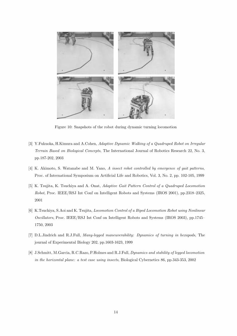
Figure 10: Snapshots of the robot during dynamic turning locomotion
[3] Y.Fukuoka, H.Kimura and A.Cohen, Adaptive Dynamic Walking of a Quadruped Robot on Irregular
Terrain Based on Biological Concepts, The International Journal of Robotics Research 22, No. 3,
pp.187-202, 2003
[4] K. Akimoto, S. Watanabe and M. Yano, A insect robot controlled by emergence of gait patterns,
Proc. of International Symposium on Artificial Life and Robotics, Vol. 3, No. 2, pp. 102-105, 1999
[5] K. Tsujita, K. Tsuchiya and A. Onat, Adaptive Gait Pattern Control of a Quadruped Locomotion
Robot, Proc. IEEE/RSJ Int Conf on Intelligent Robots and Systems (IROS 2001), pp.2318–2325,
2001
[6] K.Tsuchiya, S.Aoi and K. Tsujita, Locomotion Control of a Biped Locomotion Robot using Nonlinear
Oscillators, Proc. IEEE/RSJ Int Conf on Intelligent Robots and Systems (IROS 2003), pp.1745–
1750, 2003
[7] D.L.Jindrich and R.J.Full, Many-legged maneuverability: Dynamics of turning in hexapods, The
journal of Experimental Biology 202, pp.1603-1623, 1999
[8] J.Schmitt, M.Garcia, R.C.Razo, P.Holmes and R.J.Full, Dynamics and stability of legged locomotion
in the horizontal plane: a test case using insects, Biological Cybernetics 86, pp.343-353, 2002
14