Stress-Triggered Changes in Peripheral Catecholaminergic ...
Upload
khangminh22Category
view
2download
0
lAllAt inItYV
(VI eni
(11.
là— La— La/
—à
«NC
NOVEMBER 10, 1977
WHAT LIES AHEAD FOR 64-KILOBIT CCD MEMORIES/65
E-beam lithography system turns out wafers fast/96
Signature analysis and emulation speed microprocessor testing/ 107
lFOJR ect ronics
,
• Triggered oscillators lock on precise time measurements
'-3te.elielle,

U] ill 3466A DIGITAL MULTIMETER
VV1 I 1- 1 • PACK ARO
OFF
Introducing HP's 3466A...
The right DMM decision means lj.iV sensitivity and autoranging in a 4-1/2 digit instrument.
HP's 3466A gives you unusual measurement capability in a 41/2-digit DMM. It combines autoranging with 1 µV sensitivity...mean-ingful resistance measurements to 1 milliohm with 2-terminal convenience...true RMS measurements with 100 kHz band-width .. plus 5-function measurement ease.
High ohm and DC volt sensitivity. Now you can make meaningful measurements to 1 µVDC or 1 milliohm with this autoranging 41/2 -digit DMM. And for low value resistance measurements, you no longer need 4 terminals. The 3466A has a front-panel adjustment that lets you null lead and contact resistance for faster, more convenient measurements.
True RMS Volts and Amps. In addition to 100 kHz band-width with true RMS, the 3466A gives you selective DC coupling to allow DC plus AC true RMS measurements with both cur-
rent and voltage (two extra functions you normally don't get with a DMM). That means you can make direct true RMS measurements of signals such as digital pulse trains as well as sinusoidal waveforms.
Battery and probe versatility. You can operate this DMM from the line or select rechargeable lead-acid batteries for com-plete portability. And to extend the 3466A's capabilities, choose from HP's wide selection of probe accessories, including RF, high voltage and Touch-Hold probes.
Diode test. Another added plus with the 3466A is a diode test function to speed equipment servicing and troubleshooting. You simply select the 1 kri range and read the forward voltage drop across the diode or transistor junction directly on the digital readout.
Excellent DMM value. Five standard and three extra mea-surement functions, 38 ranges autoranging, high sensitivity, true RMS and more. And the 3466A has survived HP's demanding abuse testing program, so you know it's rugged and reliable. That's a lot of capability for a $575* DMM. Or get battery portability for $650*. Your HP field engineer has all the details. contact him today. •Domestic U.S.A. price only.
the right decision FIP DMM's-
mV it/i RO
' LI LI o
11011 ¿000
PA mA
-FUNCTION
POWER rn V ••••• V = mA ".- mA 140
ON...C1
CIODDEI (rnt/ mV µA 0
RANGE 1200V MO V 0
20 200 2 20 200 2000 20 AUTO
OCILIGWAI 41-
INPUT
vo
'too, op, MAO
COM
24. teed MAX MAX
L
2A NMI
HEWLETT PACKARD
1507 Page Mill Road. Palo Alto Calltorma 94304 097 08
Fo' assostance call Wasrungton (301) 948-6370. Ciscago (312) 255-9800 Atlanta (404)955-1508 L.os Angeles ( 213) 877-1262
Circle 900 on reader service card

USE!
Introducing I IP's New Optically Coupled Line Receiver
Eliminate troublesome system ground loops and increase long distance communication noise immunity with HP'S new easy-to-use optically coupled line receiver. An internal IC regulator serves as a line termination and allows direct connection to transmission lines without any additional components.
Use of a high-speed, high-gain output photo IC permits data rates in excess of 10 Mbits/second. An internal shield provides excellent common mode rejection even at these high data rates.
The HCPL-2602 is designed for high-speed data transmission applications such as computer-peripheral interface, instrumentation, and simplex/multiplex data transmission.
Priced at $6.65* in quantities of 1000. the HCPL-2602 is in stock at any franchised distributor. In the U.S., contact Hall-Mark. Hamilton/Avnet,
Pioneer Standard, Schweber, Wilshire or the Wyle Distribution Group (Liberty-Elmar) for immediate delivery.
1507 Page MI I Road, Palo ato. California 94304 In Canada. just call Hamilton/Avnet or Zentronics. Ltd. •L s
HEWLETT h T PACKARD
01703 A For assistance call: Washington (301) 948-6370, Chicago (312) 255-9800, Atlanta ( 404) 955-1500. Los Angeles (213) 877, 282
Electronics/November 10, 1977 Circle 1 on reader service card 1

Meet the first Serial Data Generator with 2048-bit memory • and broad pattern
generation flexibility
“so, .51•IAL.DA. 'II
SI( 11•••
•••
CLOCK IIIOCIE CYCLE 11100E
••• au. ••••• reA•
anill AMU
...... • • rk It ITUDf
• • • 41 • • • • • • • • • • • •
a dailkaandeadanalliaalaa •
1«' 0•1:I"•'
• • • OCK 1.01 CYCIL111•UL VI000 TRIG
2 1 e
FIRST !Ill
.oer, .1114,1 541, ,
• !:
a e
DAI A 8
reàee# OR MAI
ID CI IL
word -PRBS-word word -MS-würol In MIXED MODE, HP's 8018A alternately generates PRBS and word information, simulating preamble-data message-postamble patterns.
HP's new 8018A, for faster, easier serial system testing. This new 50 Hz to 50 MHz Serial Data Generator greatly simplifies simulation of complex serial data such as disc and telecommunications patterns. You can easily program the 8018A with up to 2048 bits to design and trouble-shoot serial interfaces and bus systems. The number of words, word length and PRBS length are conveniently set with thumbwheel switches letting you program the 8018A to generate a frame of words with selectable word length; a data stream with bit-by-bit variable length; a WORD-PRBS-WORD sequence; or a PRBS only. And you can select from AUTO, BIT, WORD and FRAME cycle modes.
Pushbutton selection of amplitude up to 15V (including fixed ECL) and bit rate also speeds setups. And data can either be programmed manually, or, with the HP-IB** option ($425*), under calculator or computer control or with HP's 15263 Card Reader ($600*).
Circle 2 on reader service card
3S 110 r:
Instrument is shown with optional handles.
A look at the front panel shows that you can choose between a single 2048-bit channel or dual 1024-bit chan-nels that are clocked simultaneously. You can also select either NRZ or RZ formats; internal or external clocking. You have outputs for word trigger, first and last bit, and clock.
Priced at $3475*, the 8018A gives you simulated serial data that used to require a computer. But it has the flex-ibility and high quality output needed for a variety of lab or production serial data-testing needs. Ask your local HP field engineer for all the details. 'Domestic U.S.A price only.
"HP's implementation of IEEE Standard 488-1975.
HEWLETT elk PACKARD
1507 Page Mill Road, Palo Alto, California 94304
For »seance call Wastangton (301) 948-6370. Ctscago (312)
255-9800. Atlanta (404) 955-1500. Los Angeles (213) 877.1292
0.1
Electronics The International Magazine of Electronics Technology
29 Electronics Review AUTOMATIC TEST EQUIPMENT: LSI testers hit price low, 29 COMPUTERS: Vonderschmitt warns of Japanese computer threat, 30 COMMUNICATIONS: Electronic mail system will broadcast messages, 31 MEDICAL: Voice system generates messages for handicapped, 32 SOLID STATE: Intel upsetting picture for large ROM pinouts, 35 COMPUTERS: Lack of software may hurst DEC's 32-bit mini, 36 PACKAGING & PRODUCTION: Laser directs harness assembly, 38 CONSUMER: Focusing chip for camera matches images, 40 NEWS BRIEFS: 42
55 Electronics International JAPAN: Laboratory is growing 5-in.-diameter ingots, 55 WEST GERMANY: IC and sensor plate control light dimmer, 55 AROUND THE WORLD: 56
65 Probing the News SOLID STATE: The CCD's future takes on a bright hue, 65 PEOPLE: Matsushita's new chief to push R&D, 69 COMMERCIAL: Solar cells click in irrigation test, 72 COMMUNICATIONS: Motorola gets green light for cellular trial, 74
89 Technical Articles INSTRUMENTS: Ovenless oscillators will resolve 20-ps pulses, 89 PACKAGING & PRODUCTION: E beam improves its throughput, 96 DESIGNER'S CASEBOOK: Number-generator sequence extended, 102 Optocoupler transmits pulse width accurately, 103 Timer IC circuit separates repetition rate and duty cycle control, 105 INSTRUMENTS: Diagnosis with emulation yields fast fault-finding, 107 COMPONENTS: What you should know about data-converter drift, 111 ENGINEER'S NOTEBOOK: Simple go/no-go tester checks op amps, 116 One-shot and flip-flop add single-sweep option to scope, 117 Shunt diode extends linear range of LED, 119
127 New Products IN THE SPOTLIGHT: Nodal tester handles semiconductors, 127 COMPONENTS: Carbon resistor networks replace discretes, 131 SEMICONDUCTORS: 16-k dynamic RAM has dual latch modes, 139 DATA HANDLING: Graphics terminal has raster scan, 146 SUBASSEMBLIES: Dc-to-dc converters handle 12 watts, 155 INSTRUMENTS: 10-MHz logic analyzer plugs into scope, 163 PACKAGING & PRODUCTION: TV system eases wafer dicing, 168 MICROWAVES: Signal generator spans 10.0 to 15.5 GHz, 174 MATERIALS: 189
Departments Publisher's letter, 4 Readers' comments, 6 News update, 8 Editorial, 12 People, 14 Meetings, 20 Electronics newsletter, 25 Washington newsletter, 49 Washington commentary, 50 International newsletter, 53 Engineer's newsletter, 120 New literature, 191
Services Employment opportunities, 198 Reprints available, 210 Reader service card, 215
Vol. 50, No. 23 • November 10, 1977
Highlights
Cover: Oscillator measures pulses faster, 89
A triggered oscillator that can be phase-locked permits time-interval generation with a resolution of 50 picoseconds and interval measurement with a 20-ps resolution. Ovens are not necessary because the circuits can be designed to be immune to component, temperature, and power-supply variations, within a given range.
Cover illustration by Mark Smith.
CCDs bidding to replace floppy disks, 65
The time may be ripe for a shift to charge-coupled-device memories in the computer industry. With 65,536-bit CCDs becoming available, first widespread use probably will be as a successor to fixed-head storage, because no system redesign is necessary.
Maskless e-beam unit has high throughput, 96 A lithography system with a large, square electron beam is printing 2.5-gm patterns on wafers at the rate of 22 exposures an hour: a throughput found in commercial wafer production. Such systems use com-puter control rather than masks to form patterns, which can have 1-gm geometry.
Tester matches wits with microprocessors, 107
By using the microprocessor socket of a system under test, a new troubleshooting instrument can test the system's functions with in-circuit emulation. It also performs signature analysis for isolation of compo-nent faults.
In the next issue . . .
New pyroelectric vidicon widens applica-tions for thermal imaging . . . the tech-nology behind Japanese video tape record-ers . . . a calculator program that designs cascaded tuned circuits: the first of two parts.
Electronics/November 10, 1977 3
Electronics
EDITOR-IN-CHIEF: Kemp Anderson
EXECUTIVE EDITOR: Samuel Weber
MANAGING EDITOR: Arthur Erikson, International
SENIOR EDITORS: Laurence Altman, William F. Arnold, Ray Connolly, Lawrence Curran, John Johnsrud, H. Thomas Maguire, Stephen E. Scrupski, Gerald M. Walker
ART DIRECTOR: Fred Sklenar
ASSOCIATE EDITORS: Howard Wolff, Alfred Rosenblatt
DEPARTMENT EDITORS Aerospace/Military: Ray Connolly Circuit Design: Vincent Biancomano Communications & Microwave:
Richard Gundlach Components: Lucinda Mattera Computers: Raymond P. Capece Consumer: Gerald M. Walker Instrumentation: Stephen E. Scrupski New Products: H. Thomas Maguire,
Michael J. Riezenman Packaging & Production: Jerry Lyman Solid State: Laurence Altman
CHIEF COPY EDITOR: Margaret Eastman
COPY EDITORS: Ben Mason, Mike Robinson
ART: Charles D. Ciatto, Associate Director Paula Piazza, Assistant Director
EDITORIAL SECRETARIES: Janet Noto, Penny Kaplan
EDITORIAL ASSISTANT: Marilyn B. Rosoff
FIELD EDITORS Boston: Lawrence Curran ( Mgr.) Pamela Hamilton
Los Angeles: Larry Waller ( Mgr.) Midwest: Larry Armstrong ( Mgr.) New York: Bruce LeBoss ( Mgr.) San Francisco: William F. Arnold ( Mgr.) Washington: Ray Connolly ( Mgr.) Frankfurt: John Gosch London: Kevin Smith Paris: Arthur Erikson Tokyo: Charles Cohen
McGRAW-HILL WORLD NEWS Editor: Michael Johnson Brussels: James Smith Milan: Andrew Heath Moscow: Peter Hann Paris: Andrew Lloyd Stockholm: Robert Skole Tokyo: Robert E. Lee
PUBLISHER: Dan McMillan
ADVERTISING SALES MANAGER: Paul W. Reiss
MARKETING ADMINISTRATION MANAGER: Wallis Clarke
CIRCULATION MANAGER: Karl Peterson
MARKETING SERVICES MANAGER: Tomlinson Howland
RESEARCH MANAGER: Margery D. Sholes
Publisher's letter navid Chu and Keith Ferguson, co-'authors of the article on the trig-gered phase-locked oscillator and its applications in two new Hewlett-Packard instruments, have a long history of cooperation at HP. They worked together on the 5360 com-puting counter in the late 1960s, and again in the group that spawned the instruments described in the article on page 89. Chu is the inventor of the trig-
gered phase-locked oscillator, with a patent granted in 1975, and was the project leader for the 5370A coun-ter. Ferguson was the project leader on the 5359A time synthesizer, which also uses the oscillator. He says that " it was a fortuitous circumstance that Dave came along with his invention just when we needed it." The instrument was originally conceived as a plug-in unit for a counter, but Ferguson says this idea was scrapped when they realized that much of the counter capability would go unused with the synthesizer. So they decided to design it as a separate box. The two instruments have much in
common, using identical power sup-plies, time-base sections, and micro-processor control sections. Moreover, Chu says, " leaders of all new projects make this group the first stop, to see what they can use before beginning the design." Chu received his BSEE degree from
the University of California at Berkeley and his MSEE and PhD from Stanford University. He has been with HP since 1962, with some time off for leaves of absence while he worked on his doctorate. He has also spent some time in Liberia teaching college- level mathematics and physics courses.
Ferguson has his bachelor's, mas-ter's, and doctoral degrees in elec-trical engineering from Massachu-setts Institute of Technology and has worked at HP full time since 1965. He had previously worked some summers for the firm while doing graduate work.
M ost designers "just don't under-stand how to determine the
worst-case accuracy degradation due to temperature drift," says Paul Prazak, a design engineer with the data-conversion products group at Burr-Brown, who wrote the article on page Ill. "They simply take all the drift parameters and add them together, so they often buy a better converter than they really need."
Prazak joined Burr-Brown about 41/2 years ago and has since been busy making solid contributions in the converter area. Yet the job with Burr-Brown is his first in electronics. Prazak received his bachelor's de-gree in electrical engineering at California State University in Sacra-mento, going on to take his MSEE at the University of Arizona in Tucson. As for the future, he sees higher
levels of integration for data-conver-sion products. "We will be putting more and more in the hybrid pack-age, and more and more on the chips inside the package. Rather than developing new technology, though, we'll be putting existing technology to better use with the refinement of production techniques."
November 10, 1977 Volume 50. Number 23 96.448 copes of es issue printed
Published every other Thursday by McGraw-Hill, Inc. Founder: James H. McGraw 1860.1948 Publication office 1221 Avenue of the Americas. N.Y., N.Y. 10020; second class postage paid at New York, N Y. and additional mailing offices.
Executive, editorial, circulation and advertising addressee Electron. ics. McGraw-Hill Building, 1221 Avenue 01 the Americas. New York, N.Y. 10020. Telephone (212)997.1221. Teletype 12.7960 TWO 710-581-4879 Cable address. MCGRAWHILL NE W TOR K.
Subscriptions limited lo professional persons with active responsibility in electronics technology. No subscriptions accepted without complete identification or subscriber name, title or job function, company or orga-nization, and product manufactured or services performed. Based on information supplied, the publisher reserves the right lo reject non-qualified requests. Subscription rates: in the United Slates and posses-sions $ 14 one year. $25 two years, $35 three years; company addressed and company libraries $20 one year. $36 two years. $50 three years; APO/FPO addressed $35 one year only, canada and Mexico $ 16 one year. $28 two years. $40 three years; Europe $40 one year. $71 two years. $ 100 three years. Japan. Israel and Brazil $65 one year, $ 115 two years. $ 165 three years; Australia and New Zealand $90 one year. $ 170 two years, $240 three years. including air freight; all other countries $45 one year. $80 two years. $ 112 three years. Limited quota of subscriptions available at higher-than-basic rate for persons allied to field served. Check with publisher for these rates. Single copies $460 Please allow tour to eight weeks for shipment
Officers of McGraw-Hill Publications Company: Gordon L. Jones. President, Paul F McPherson. Executive Vice- President. Group Vice. President: Gene W. Simpson, Senior vice.Presidents: Russell F. Ander-son; James E. Boddort Planning & Development; David G. Jensen, Manufacturing; Ralph R. Schulz, Editorial; Vice-Presidents: Denis C. Steen. European Operations; David P Forsyth. Research. Douglas Greenwald. Economics, James E. Hackett. Controller. Robert L Leyburn. Circulation; Edward E. Schirmer, Sales
Officers of the Corporation: Harold W. McGraw, Jr., President, Chief Executive Officer, and Chairman of the Board; Robert N. Landes, Senior Vice President and Secretary; Ralph J Webb, Treasurer.
Title registered in U.S. Patent Office; Copyright 1977 by McGraw. Hill, Inc. All rights reserved. The contents of this publication may not be reproduced in whole or in part without the consent of copyright owner:
Subscribers The publisher, upon written request to our New York office from any subscriber, agrees to refund that part ol the subscrip-lion price applying to copies not yet mailed. Please send change- of. address notices or complaints lo Fulfillment Manager; subscription orders to Circulation Manager. Electronics, al address below. Change-of -address notices should provide old as well as new address. including postal zip code number. 11 possible, attach address label from recent issue. Allow one month for change to become effective
Postmaster: Please send form 3579 to Fulfillment Manager, Electron-ics, P.O. Box 430, Hightstown. N.J. 08520.
4 Electronics/November 10, 1977

YOUR BEST BUY IN SWEEP FUNCTION GENERATORS The Krohn-Hite Model 1200 offers linear sweep (up or down) plus sine, square or triangle waveforms from . 2Hz to 3 MHz. Features in-clude: 1500:1 tuning dial plus vernier; external VC crid CV output; push button ccntro.; DC offset control; auxiliary TTL output, separate HI and LO outputs and much more! Take advantage of this price while we're in a generous mood. Call (617) 580-1660 for more details.
XE
V
— 1 — 1 --1- 1
1.111/Yellern
•
SECOND BEST LESS SWEEP The new Model 1000 has cil the quality features of the 1200 except sweep!
sic 0 FR 1=e N.-ric3 r\I Avon Industrial Park, Avon, Mass. 02322 • (617 58.0-' 560
Circle 5 on reader service card
SALES OFFICES ALA.. Huntsville ( 205) 534-9771. ARIZ.. Scottsdale • CAL.. :.41r, Jose ( 408) 292-3220 . n(..,ewoort , 2' a) 674 6850 COL.. Denver 1303) 773-1218 CONN.. W Hartford 2031 525-7647, FLA., Orlando ( 305) 894-4401. GA.. Atlanta 4.. HAWAII. Honolulu (808) 941-1514. ILL.. Arlington Hts ( 3121 394.3380. KS.. Overland Park ( 9031 384-2710. LA.. Lafayette ( 318) 984-3516 MASS., Wakefield 617) 245 5-1 M CH . ,ioiii—teld ( 313) 569-4497 MINN.. St Paul 16121 645-5816 MO.. St Louis 1314) 741-5400, N M.. Albuquerque ( 505) 255-2330 N.J.. Cherry Hill ( 609) 482-005‘. N.Y.. Elmorit • • .; d8-21iCli. Rochester ( 716) 328-2230. Syracuse 1315) 431-6666 Vestal 1607, 785-9947. N.C.. Burungto, (919) 22-7-3639. 01$10. Chesterland ( 216) 729-2222. Dayton ( 513) 434-8993. OKLA.. " uls.-. 1918) 299-2636. ORE.. Port and ( 503) 297-2248. TEX.. Dallas ( 714) 661-0400 Houston ( 713J 688-1431. UTAH, Salt Lake City ( 801) 942-2031. VA.. Falls Church ( 703) 573.8787. WA. Bellevue ( 206) 454-3400 CANADA. Montreal Quebec ( 514i 341-7630 Ottawa Ontario ( 613) 235-512 - . Toronto, Ontario ( 416)445-9900. Vancouver. British Columbia (504) 253 3555. FIJI f..«. Nova Scotia ( 902)454-8321. St John s Newfoundland 709 26.2422
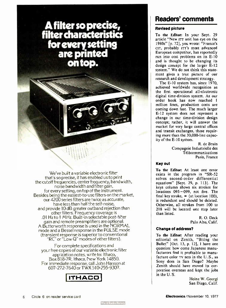
A filter so precis!, filter characteristics for every setting
are printed on top.
r r4t
We've built a variable electronic filter that's so precise, it has enabled us to print
the cutoff frequencies, center frequency, bandwidth, noise bandwidth and filter gain,
for every setting, on top of the instrument. Besides beina the easiest-to-use filters on the market,
our 4200 series filters are twice as accurate, have less than half the self-noise,
and provide 10 dB greater outband rejection than other filters. Frequency coverage is
.01 Hz to 1 MHz. Built-in selectable post-filter gain and remote preamplifiers are optional.
A Butterworth response is used in the NORMAL mode and a Bessel response in the PULSE mode (transient response is superior to conventional
or "Low Q" modes of other filters).
For complete specifications and your free copies of our variable electronic filter
application notes, write to: Ithaco, Box 818-7R, Ithaca, New York 14850.
For immediate response, call John Hanson at 607-272-7640 or TWX 510-255-9307.
ITHACO
Readers' comments Revised picture
To the Editor: In your Sept. 29 article "New rrr unit has eye on the 1980s" [p. 72], you wrote: "France's CIT, probably trr's most advanced European competitor, has reportedly run into cost problems on its E-10 and is thought to be changing its design concept for the larger E-12 system." We do not think this state-ment gives a true picture of our research and development strategy. The E-10 system has, since 1970,
achieved worldwide recognition as the first operational all-electronic digital time-division system. As our order book has now reached 1 million lines, production costs are coming down fast. The much larger E-12 system does not represent a change in our time-division design concept; rather, it will answer the market for very large central offices and transit exchanges, those requir-ing more than the 30,000-line capac-ity of the E-10 system.
R. de Bruin Compagnie Industrielle des
Télécommunications Paris, France
Key out
To the Editor: At least one error exists in the program in "SR-52 solves second- order differential equations" [Sept. 29, p. 113]. The keys column shows six strokes for locations 095 — 099, not five. The final key stroke, = (at location 100), is redundant and should be deleted. Otherwise, all strokes from 100 to 218 will be located one step later than listed.
R. O. Deck Palo Alto, Calif.
Change of address?
To the Editor: After reading your editorial on Zenith, "Biting the Bullet" [Oct. 13, p. 12], I have one question: how come Japanese manu-facturers find it profitable to manu-facture color iv sets in the U. S., as Sony does in San Diego? Maybe Zenith should have moved its cor-poration overseas and kept the jobs in the U. S.
Heinz W. Georgi San Diego, Calif.
6 Circle 6 on reader service card Electronics/November 10, 1977

Hot newcircuit ideas with RCA op amps and arrays.
When you put RCA BiMOS op amps together with other RCA op amps and arrays, they have a way of making circuits easier, more effective and often less expensive.
One-knob function generator.
1,000,000/1 frequency range-1 Hz to 1 MHz—with a single control knob and just three op amps. Two CA3080 variable op amps (one on input, one as output hysteresis switch), plus one CA3160 internally compensated BiMOS op amp as buffer.
Electronic alarm.
/
4!" ---"nnumme""mil
Wide signal swing of the CA3130 combined with the variable gain control features of the CA3094 produce yelp. wail, two-tone and other sounds in sirens and alarms.
Low-power timing signal.
Multivibrator using CA3078 micropower op amp generates a timing signal from a 1.5 V battery supply with just 3 microwatts of power. A CA3078 exclusive.
Bandgap reference supply.
Foi' power supplies and DVMs, it provides 2.35 V reference. Uses a CA3078 micropower op amp as a buffer for the bandgap reference, the CA3086 transistor array. Elimi-nates need for discrete diodes.
Audio power amp.
,
A C.',A3094 variable op amp plus a CA3183 transistor array provide push-pull output of 100 mA average. Driv9s high impedance speakers.
Sanple-and- hold system.
Ideal for single supply, low-cosi applicatio is. Samples inputs ranging from 0 to 10 V. The BiMOS CA3140 makes it possible.
Wien bridge oscillator.
C2
Ri•R2•R
50 Hz, F, • 3.3 /.111 100 Hz, , • 1.6 MO I kHz, • 160 kn
Jo Hz, F • 16 kll 30 Hz, F • 5.1 PO
360
500 n
OUTPUT 19 V p- p TO 22 V p- p
TAD < 0.3 %
I- CA3019 I DIODE ARRAY
1
CA3140 op amp and CA3019 diode array combine to produce a low-cost wien bridge with 50 Hz to 30 kHz range.
Battery voltage monitor.
CA 3097
CA3097 array has all the d iodes, transistors, SCRs and PUTs you need to provide a visual or aural signal indicating low battery charge.
There's a lot more you can do with RCA's full line of Linear ICs. Get complete details on these and other useful circuits in our new brochure. Contact RCA Solid State
headquarters in Somerville, NJ; Sunbury-on-Thames, Middlesex, England; Quickborn 2085, West Germany; Ste. Anne-de-Bellevue, Quebec, Canada; Sao Paulo, Brazil; Tokyo, Japan.
RCA Linear IC experience is working for you.
Rell Circle 7 on reader service card

News update
WE'RE le
EQUIPMENT RENTALS 1
More people More plant More experience
The Continental concept of sales and service has grown to a team of more than 150 " Professionals" in 10 nation-wide offices.
Rental inventory, offices, service and calibration labs exceed 60,000 square feet of floor space.
In-house service, experienced personnel and four hundred thousand dollars/month in new equipment purchases keep us # 1.
Rent with Confidence Coll Continental Rental/
Get our FREE Catalog
Div. Continental Resources, Inc. 175 Middlesex Turnpike, Bedford, MA 01730 (617) 275-0850
FOR IMMEDIATE RESPONSE CALL: N.E. (617) 275-0850; L.I. (516) 752-1622; NY, NJ (201) 654-6900;
Florida (800) 638-4050; Gtr. Phila. (609) 234-5100; Wash., D.C. area (301) 948-4310; Mid West (312) 439-4700; So. Central (800) 323-9656; Costa Mesa, CA (714) 540-6566; L.A., CA (213) 638-0454; Santa Clara, CA (408) 735-8300.
la Supporting its contention that cathode-ray-tube consoles will ulti-mately supplant the conventional massive analog displays now found in industrial instrumentation facili-ties, Honeywell Inc.'s Process Con-trol divisions in Fort Washington, Pa., and Phoenix, Ariz., have made major enhancements of its two-year-old TDC 2000 digital process-control system.
Developed around the CP 1600 16,384- bit microprocessor from General Instrument Corp.'s Microel-ectronics group in Hicksville, N. Y., the TDC 2000 links microprocessor controllers and cRT-based operator stations via coaxial cable to one another or to a central process computer [Electronics, Nov. 13, 1975, p. 25]. The additions to the system,
unveiled last month, include histor-ical and real-time trend receirding, alarm annunciation and displays, logging, CRT and keyboard interface with intelligent multiplexers, digital start/stop operations, and uninter-rupted automatic control. The latter feature is a Honeywell development that automatically detects the mal-function of from one to eight basic controllers, announces that to the operator, switches in a reserve controller, and resumes control of the process, "all in less than a second," says L. Bruce Hilsee, the Honeywell divisions' manager of sales development. Some of the enhancements are
provided for the TDC 2000 system by modifications to the system soft-ware, at no cost to the user. Other system additions are through mem-ory cards, costing $ 1,000 to $ 1,200 each. These cards plug into existing connectors and make it possible to update installed systems without massive wiring changes.
In the two years since it intro-duced the TDC 2000, Honeywell has sold more than 100 systems, involv-ing more than 8,000 control loops, with a total value estimated at $70 million to $80 million. Systems have been ordered in the U. S. and Canada, Latin America, Europe, South Africa, Taiwan, and Japan.
Bruce LeBoss
Circle 8 on reader service card

Tomorrow testing is here! The GR 2230 is testing:
• thick and thin film networks
• hybrid circuits
• discrete components on reels
• sequenced components
• diodes and transistors
• small functional modules/circuits
• switches and relays • transformers
• hi-rel components
• D/A-A/D converters
In all of these areas:
• production control
• incoming inspection
• quality monitoring
• environmental testing
Components • Networks • Modules Test them all automatically on one tester GenRads 2230
Interfaces with a variety of handlers
Automate your testing with a computer-controlled component, network and module tester for under $ 20,000.
These days, multi- leaded networks and modules have become so complex, you simply can't get away with sample testing.
Yet in-house or calculator- based test systems are just too slow, and the computer-controlled ones cost an arm and a leg.
But now there's the GR 2230. At the heart of this compact bench-top system
is a small but powerful microcomputer. To give you computer-controlled speed, accuracy and flexibility. The 2230 will test components, networks,
modules, and small PC boards at speeds up to 80 tests per second, measuring to specified limits the performance of each circuit component.
It can be programmed by just about anyone, thanks to its unique English-language macro-instruction keyboard. Programs are then auto-matically stored on magnetic cards for easy retrieval.
In addition, the system will continuously print out all test data and can be easily interfaced to virtually any device handler. The GR 2230. A computer-controlled tester you
can afford. Now that you can't afford to be without a computer-controlled tester.
GenRad 300 BAKER AVENUE. CONCCRD, MASSACHUSETTS 01742 • ATLANTA 404 394-5380 • BOSTON 617 646-0550 • CHICAGO 312 884-6900 • DALLAS 214 234-3357 • DAYTON 513 294.1500 LOS ANGELES 714 540-9830 • NEW YORK ( NY) 212 964-2722. ( NJ) 201 791-8990 • SAN FRANC ISCO 408 985-0662 * WASHINGTON. DC 301 948-7071 • TORONTO 416 252-3395. ZURICH (01) 55 24 20
Electronics/November 10, 1977 Circle 9 on reader service card 9

Editorial
The hidden threat in capital-gains reform
Capital-gains taxes may seem a subject pretty far removed from most engineers and their everyday jobs. Yet there is a vital relationship between the two. Indeed, it has been the special tax status of dollars invested in such things as the stock of new, young companies that has fueled the financing of a whole generation of entrepreneurs brash enough to pit their technological edge against bigger, more conservative companies. The result, of course, has been companies that are now important factors in the nation's economy. Think, for example, of the jobs created by an Intel, by a Digital Equipment Corp., to say nothing of the jobs at all the companies supplying them and all the companies they supply.
Right now, there are moves afoot in Washington to end the special capital-gains provisions for taxation of the profits on investments— that is, on money put out at risk. Somewhat offsetting that elimination would be some new benefits such as investment tax incentives, liberalized depreciation, and the ending of double taxation of corporation dividends first a tax on the corporations' profits, then one on the dividend paid to shareholders. The trouble is, however, that the lower tax
rates applied to capital gains, as compared with ordinary income, have been a great incentive to investors to take the higher risk inherent in buying the stock of fledgling companies. Up until the last few years, the small companies with strong technological positions have been able to find financial support in the venture-capital market. Without the capital-gains tax inducement, though, many executives fear, sources of venture
capital will dry up. Why take a high risk with
your money, they ask, if you haven't a chance to get a big payoff? More and more, perceptive executives are
discovering this overlooked pitfall in the Administration's tax proposals. Ray Stata, president of Analog Devices, for one, points out that there is a vast difference between primary and secondary capital investment. Primary investment is the purchase of stock from a company, thereby giving it the capital it needs to function. Secondary investment is the later change in ownership of the stock, such as buying and selling on a stock exchange. Stata believes that, whatever is done with secondary investment profits, primary investment should keep the benefit of a preferential tax treatment — perhaps even be made free of tax — to promote the funding that has been so vital to new company start-ups.
What's more, a number of organizations are looking into what can be done to head off this tax "reform." WEMA has a task force already in operation, and it has the job of formulating a position on current tax proposals. The group is now in the process of surveying
member companies to obtain hard data to back up its arguments on the importance of preferential capital-gains taxes to new firms. So far some 200 returns have come in, and between 700 and 1,000 are hoped for. WEMA plans to take the results before
Congress and help shape pending legislation in favor of protecting and promoting the innovation that has made the U. S. economy so strong. Beyond that, both engineers and companies have a stake in this problem and should make their voices heard not only through group action, such as WEMA'S approach, but through individually contacting their congressional representatives.
12 Electronics/November 10, 1977
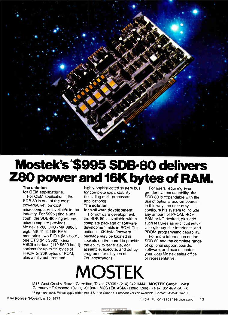
Mosteles*S995 SDIEW30 delivers Z80 power and 16K bytes of RAM.
The solution for OEM applications.
For OEM app:icat.ons, the SDB-80 is one of the most powerful, yet ;ow-cost microcomputers available in the industry. For $995 (single unit cost), the SDB-80 single-board microcomputer provides Mostek's Z80 CPU (MK 3880), eight MK 4116 / 6K RAM memories, two PIO's (MK 3881), one CTC (MK 3882), serial ASCII interface ( 110-9600 baud) sockets for up to 5K bytes of PROM or 20K bytes of ROM, plus a fully- buffered and
hghly-sophisticated system bus for complete expandability (hcluding multi-processor applications) The solutior for software development.
For software development, the SDB-80 is available with a complete package of software development aids in ROM. This optional 10K byte firmware package may be located in sockets on the board to provid9 the abi:ity to generate, edit, assemble, execute, and debug programs for all types of Z80 applications.
MOSTEK
For users requiring even greater system capability, the SDB-80 is expandable with the use of optional add-on boards. In this way, the user may configure his system to include any amount of PROM, ROM, RAM or I/O desired, plus add such features as in-circuit emu-lation,floppy-disk interfaces, and PROM programming capability.
For more information on the SDB-80 and the complete range of optiona, support boards, software, and boxes, contact your local Mostek sales office or representative.
1215 West Crosby Road • Carrollton, Texas 75006 • (214) 242-0444 • MOSTEK GmbH West Germany • Telephone. (0711) 701096 • MOSTEK ASIA • Hong Kong • Telex: 85148MKA HX
*Single unit cost. Prices apply within trie U.S and Canada. Eurocard version available. Contact Mostek GmbH.
Electronics/November 10, 1977 Circle 13 on reader service card 13

Be sure you're using the most
up-to-date GE miniature lamp
design data. Out-of-date information could affect your designs adversely and new data on new lamps could lead the way to new ideas. Take a minute to
check the dates on these seven catalogs be sure you've got the most up-to-date information at your fingertips, and help you pick the best GE miniature lamps for each of your design needs.
• All catalogs are free. • Data and information is current. • Organized for quick, easy, accurate reference. • Saves you valuable time.
#3-5257-R Halogen-Cycle Lamps
Revised April, 1977. The 12 pages feature greatly expanded data in-cluding lamp specifications, char-acteristics, design considerations and selection guide.
gent teachor. treed beam
Erho,i..fee 'davi Arri:LiYiee
to get the Job oone
"7=
#3-6383 Farm Tractor Sealed Beam Lamps Revised September, 1976. Four pages feature the expanded line farm equipment, including dia-grams of lamp beam patterns.
#3-5211 Sealed Beam Lamps
Revised September, 1975. Lists electrical and physical specifica-tions, applications and numerical index in 16 pages.
• . .
#3-7070 Miniature Lamps
Revised April, 1977. Features al-most 100 new lamps not previously listed; covers almost 600 lamps, 40 pages.
cg
#3-6016 Sub-Miniature Lamps
Revised May, 1976. Includes latest data on more than 194 lamps of '/o diameter and smaller, 28 pages.
#3-5259R2 All- Glass Wedge Base Lamps
Revised March. 1977. Contains all specifications and data for 11 newest wedge base lamps plus revised drawings and engineering specifications on the lull line.
Form 5000 Miniature, Sealed Beam
and Glow Lamps Revised February, 1976. Features 36 pages of technical lamp data covering 950 lamps, both miniature and sealed beam. Lists lamps In numerical order
To get your free GE lamp catalogs today. Call your local GE Miniature Lamp Products Dept. Specialist. Or write: General Electric Miniature Lamp Products Dept. #3382, Nela Park, Cleveland, Ohio 44112,
GENERAL ELECTRIC
People
Noncopier. James Campbell counts for
sales on the desire to up office productivity.
facturing computer-controlled print-ers, telecopier units, electronic typ-ing, or word-processing, systems, and remote terminals that can tie into a Xerox-operated computer ser-vice network. Linked together, these products add up to the so-called "of-fice of the future," which has not exactly been living up to expecta-tions as the replacement for conven-tional office gear. Change in regard. Many compa-
nies found "you couldn't even force secretaries into such EDP [electronic data-processing] centers," explains Campbell, who joined Xerox in 1969 to set up the computer services unit after serving as president of Grey-hound Computer Corp. and spending 15 years with IBM Corp. But time, coupled with the experience of using desk-side word processors and print-ers, has made potential operators more amenable to the new breed of equipment, he says. Now they regard them as helpful products rather than a threat, he maintains. To make its impact on the market-
place, Xerox has been setting a lively pace this year with five major new office products introduced so far. The latest came only late last month— a family of 10 word-processing machines, an area in which Xerox had lagged. The com-pany leads in the telecopier market, Campbell says, "growing in direct proportion to unhappiness with the U. S. mail." "The challenge is to show the
customer where he can get added values and cost benefits," he says. "And we have all the tools to make a real impact on business."
16 Circle 16 on reader service card Electronics/November 10, 1977

GI's EAROM is the most advanced memory chip available. It can do more things than a RAM, ROM, PROM or EPROM.
EAROM is non-volatile. Unlike a RAM, it doesn't lose its data in a blackout, or from battery failure. Another ' fling. An EAROM is electrically erasable and repro-grammable. So you don't get stuck with costly inventories like you can with one-shot programmed ROMs and PROMs. With an EAROM you're never locked in. You can program and re-program it. You can erase and rewrite it electrically over and over again— in circuit or at-the-bench without an ultraviolet light. And unlike UV EPROMs, stray sunlight or X- rays can't accidentally wipe out an EAROM's data. EAROM is word alter-able, too. There's no need to clear the memory completely.
Only General Instrument Microelectronics makes a full line
MEMORY SITS ORGANIZATION PART NUMBER READ ACCESS ERASE/WRITE MODE
512 32 • 16 E82051 3s. 16 bd word
1024 255 < 4 ER1105 2P8 32.4 block/4 bd word
1400 loti x 14 ER1400 2 8ms 14 bd word
4096 1074 x 4
ER2401A 2M4 1024,4 block/4 bll wad
ER3400 650ns , wordoc„7 bd word
IVY- c'.. ER3401 9SOns
8192 2048 x 4 E82805 2in3 2048.4 block 4 bli word
of EAROMs with bit densities from 512 to 8192. In fact, we wrote the book on EAROMs. Find out how GI microcircuitry can help put your product in a class by itself. Write or call General Instrumeni Microelectronics, 600 West John Street Hicksville, New York 11802. Telephone (516) 733-3107.
We help you compete
EA ROM
hi
GENERAL INSTRUMENT CORPORATION
MICROELECTRONICS

Intel delivers real-time industry's most complete
It starts with the industry's broadest selection for design flexibility.
Intel's family of cost effective single board microcomputer products is growing to keep pace with a changing world.
We delivered the world's first complete computer on a single board in February 1976. It contained CPU, data and program memory, and both serial and parallel 1/0.Today we're delivering five Single Board Computers. For cost-conscious, stand-alone applications there's our new SBC 80/04, under $100* in OEM quantities. At the high performance end of the spectrum is our SBC 80/20, with full multimaster system capabilities.
You can expand the capabilities of these SBCs and tailor a system to your specific applica-tion, selecting from over 25 memory expansion boards, digital and analog I/O boards, communi-cations interface boards, mass storage systems and a high speed math processor. Or, you can choose one of our packaged System 80s with a customized complement of expansion boards.
INTEL SINGLE BOARD COMPUTERS
Product CPU RAM (bytes)
EPROM (bytes)
Bus Interface
SBC 80/20-4 8080A 4K 8K (2716) 4K (2708)
Multimaster
SBC 80/20 8080A 2K 8K (2716) 4K (2708)
Multimaster
SBC 80/10 8080A 1K 4K (2708) Single master
SBC 80/05 8085 512 4K (2716) 2K (2708)
Multimaster
SBC 80/04 8085 256 4K (2716) 2K (2708)
None
18
MULTIBUST" architecture provides a standard you can live and grow with.
The key to efficient utilization of Inters SBC family is our Multibus. It's the superior bus architecture designed to maximize system
throughput and provide an industry standard you can build on.
Multibus enables you to add processing power to your system in modular increments. It fully supports
multimaster systems with up to 16 parallel processors and ensures efficient single master or multimaster system operation with multi-level vector-ed interrupt capability and bus trans-fers at up to five million bytes per second.
It's no wonder over 30 other manufacturers have already jumped aboard the Intel Multibus and are now supplying special purpose peripheral boards compatible with it. And, because Multibus is the accepted industry standard architecture, il it's your link to future SBC developments.
RMX /80Tm Real-Time Multitasking Executive provides a framework for your application software.
RMX/80 is the most advanced multitasking operating system for any Single Board Computer. For applications that monitor and control a number of interrelated asynchronously occurring events, it can dramatically cut software develop-ment time and costs. You develop software only for the individual tasks of your application, and the RMX/80 operating system does the rest providing all intertask communications and
Electronics/November 10, 1977

multitasking software for the Single Board Computer family.
synchronization according to the task priorities you define.
RMX/80 is compact and modular, allowing you to expand and tailor your system software as easily and efficiently as your SBC hardware. The complete RMX/80 executive resides on board in a single 2K byte EPROM chip. Your task programs and the standard RMX/80 I/O drivers you select can reside in additional on-board memory, eliminating the
need for bootstrap peripheral devices, or on diskette in modules that are callable
by the executive.
,o .e --e- ,90 -9:--c4 96,
b- dv
o -t-, .5' -re-
c-o c-• ...,.,. qp>, lez,
4, C. 0 <,...,,e
m?..>. .4..4.'
C17, j 'eb
e.,-..„. c.
For solutions to real time multitask applica-tions, RMX/80 software makes Intel single board microcomputers the sensible alternative to component-level designs or far more costly mini-computer systems.
Intel development support gets you to market faster.
Intel stands behind you with development support that makes your job easier and less time consuming.
Electronics/November 10, 1977
The Intellec® Microcomputer Devel-opment System enables you to build pro-grams and debug them in modular form in assembly language or PL/M, our high level system programming language, then link them with standard RMX/80 modules using the Intellec ISIS-II operating system. And, integration of system software with system hardware is simplified by Intel ICE In-Circuit Emulation with symbolic debugging.
Intel gives Single Board Computer users a head start with our comprehensive
SBC System Configuration Planning Kit. It's more than a catalog of our SBC products. It contains products, parameters and easy-to-use worksheets — everything you'll need to configure the optimum SBC solution for your application.
For your copy of the planning kit, or for on-site assistance in configuring and pricing your SBC system, contact your local Intel represen-tative or distributor. Or write: Intel Corporation, 3065 Bowers Avenue, Santa Clara, California 95051. Telephone: (408) 246-7501.
°delivers.
*100 quantity, domestic USA price only. I/O drivers, terminators, EPROMs or ROMs not included.
Circle 18 for information Circle 19 for information and demonstration
19

Meetings
Were first on the Buss* (488)
... with programmable D.C. currents and voltages!
Our 501J meets the IEEE 488/1975* interface specs to let your computer, p..p's or programmable
calculator call up voltages from 0.1e to 200Vdc or current from 10nA to 100mAdc at
speeds to 50µ seconds with accuracy to -±0.005%.
Put these NBS traceable values to work checking A/D converters and other voltage or current
sensitive function modules— Prices from $1595. Contact Bob Ross at (617) 268-9696.
c.œ
Electronic Development Corp. 11 Hamlin Street, Boston, Mass. 02127
(617) 268-9696
Electro-Time/77 U. S.— Design and Manufacture of Electronic Watches, International Society for Hybrid Microelectronics, Florida Chapter, Marco Beach Hotel, Marco Island, Fla., Dec. 1 — 2.
Semiconductor Interface Specialists Conference, IEEE, Carillon Hotel, Miami Beach, Dec. 1 — 3.
Chicago Fall Conference on Consum-er Electronics, IEEE, Ramada-O'Hare Inn, Des Plaines, III., Dec. 5-6.
International Electron Devices Meet-ing, IEEE, Washington Hilton Hotel, Washington, D. C., Dec. 5 — 7.
National Telecommunications Con-ference, IEEE, Marriott Hotel, Los Angeles, Dec. 5 — 7.
1977 Winter Simulation Conference, IEEE, National Bureau of Standards, Gaithersburg, Md., Dec. 5 — 7.
Miami International Conference on Alternative Energy Sources, U. S. Energy Research and Development Administration et al., Fountaine-bleau Hotel, Miami Beach, Dec. 5-7.
Computer Networks Symposium, National Bureau of Standards, Gai-thersburg, Md., Dec. 15.
1978 Winter Consumer Electronics Show, Electronic Industries Associa-tion, Las Vegas Convention Center and Hilton Hotel, Las Vegas, Jan. 5 — 8.
Conference on Integrated and Guided Wave Optics, IEEE, Salt Lake Hilton, Salt Lake City, Utah, Jan. 16— 18.
Reliability and Maintainability Con-ference, IEEE, Biltmore Hotel, Los Angeles, Jan. 24 — 26.
Power Engineering Society Winter Meeting, IEEE, Statler Hilton Hotel, New York, Jan. 29— Feb. 3.
International Solid State Circuits Conference, IEEE, San Francisco Hil-ton, San Francisco, Feb. 15 — 17.
20 Circle 20 on reader service card Electronics/November 10, 1977

Did you know that you can save $1,005 by buying a
Fluke 1953A Counter instead?
That's right. Fluke's 1953A Universal Counter-
Timer mainframe plus IEEE Pro-gramming option will cost you just $1,595.* Instead of the $2,600 or more you'd pay for comparable models. And you'll get excellent systems per-
formance plus extras you didn't count on. Like "clean dropout." If the signal is
too small, the 1953A will show zeros. Theirs can give you a wrong reading. Our frequency range on Channel A
is 125 MHz. Theirs is 100 MHz. Our Z-axis time interval marker is
standard. Theirs is optional.
Board access is better on the 1953A. We use one custom I.C. They use many. Our input capacity on Channels A
and B is 30 pF. Theirs is 40 pF. And our Channel B frequency response is 25 MHz. Theirs is 10 MHz. The 1953A is half the weight, con-
sumes one-fifth the power and makes no noise at all. On theirs you'll hear the fan and switching regulator. Our switch and control "feel" is as
good as theirs, and our front panel labeling is much less confusing. Where the 1953A shows 9 digits all
the time, theirs offers 9 digits only on
Channel C. And, if you need the option of Parallel
BCD for both control and data out, we have it. They don't.
So, if you're in the market for a pro-grammable counter, consider the Fluke 1953A. And consider how much you'll save. For data out today, dial our toll-free
hotline, 800-426-0361. John Fluke Mfg. Co., Inc., P.O. Box 43210, Mountlake Terrace, WA 98043. Fluke (Nederland) B.V., P.O. Box 5053, Tilburg, The Nether-lands. Phone: (013) 673-973. Telex: 52237.
*U.S. price only
The 1953A. A programmable counter at a reasonable price.
FLUKE
For Demonstration circle 216 on reader service card For literature circle 21 on reader service card
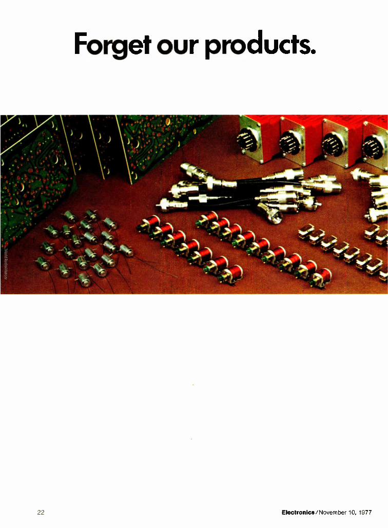

Major manufacturers forget them all the time. Polaroid. DEC. Honeywell. Tandy. Foxboro. Ford. Bendix. Our products are easy to forget. Because, once installed, all of
That's why Ingersoll-Rand depends on our time delay relays to preserve compressor life against insufficient oil pres-sure at start-up or on the job. Why the revolutionary 1978 Diesel Oldsmobile uses a Hi-G Magnetec solenoid to control the fuel supply. Why Tandy Communications Antennas/ Radio Shack chooses communi-cation connectors from Hi-G Cambridge Products for their CB radio antennas.
Hi-G's quality products (trans-formers, solenoids, timers, printed circuit boards and others) do what they are meant to do. Keep right on working.
Our products work. And keep working. So it's fine with us if you forget them. Just remem-ber our name. Hi-G Incor-porated, 580 Spring Street, Windsor Locks, CT 06096.
Remember our name. Electronics/November 10, 1977 C,rcle 23 on reader service card 23

MOD-POT offers still more. New switch.
New conductive plastic element. Allen-Bradley introduces a new rotary switch for the MOD-POT series. Designed for signal level circuits. Tested for current levels as low as 15 milliamps, with 5-volt open circuit. Plus new conductive plastic resistance elements with low turning torque for velvet-smooth rotation. And CRV of typically less than 0.2%. Linear and modified log tapers (OW and COW) available from 100 ohms to 1 megohm. All feature smooth character-
istics, particularly at resistance roll-on and roll-off positions. Come to the original source for MOD-POTS. We have what you need; our distributors
have them when your need is now. Ask for Publication 5217.
oreurceeeeree e42"egze.e and low contact resistance.
va4 („e4 4ee/e fe. emeeP7-44-.. rotary
(CW or CCW actuation), push-pull or momentary push. Gang switching capability.
and concentric shafts also available.
Quality in the best tradition.
Circle 24 on reader service card
( A-B / Milwaukee, Wisconsin 53204
for low low turning torque, excellent linearity and ideal roll on/roll off.
re-leezée,eee,
resistance track is embedded into substrate.
9-16(eA,e7-72-eddeCe
Ze4, -,2e2he.- Choice of solder lug or PCB pins.
ALLEN—BRADLEY EC165

Electronics newsletter Smaller, cheaper A second-generation LSI-11 microcomputer is expected to be announced
later this month by the Components Group of Digital Equipment Corp., son of LSI-11
Marlboro, Mass. The new version, which will use the same basic DEC-to use 16-k RAM produced four-chip set as the original, will introduce the 16-k random-
access memory into the LSI-11 family. The microcomputer is believed to offer the same performance as the original, but some configurations will cut the volume by two thirds and the price by about 40%. Designated the LSI-11/2, it will consist essentially of a central-processing-unit board, a memory board, a new serial interface board, and a new mounting cage. A typical system, consisting of CPU board, 32,768 words of memory, inter-face board, and cage, will probably sell for less than $2,000.
National developing Very-large-scale mos integrated circuits built with 2-micrometer pattern geometries are coming next year, according to Pierre Lamond, National
2-micrometer Semiconductor Corp.'s new director of technology. While most of the MOS process industry is struggling with 4-µm structures, Lamond claims that National
has put together electron-beam masks and projection-printing techniques "that make possible 2-µm prototype devices in the next 12 months and production in 1979." National's first such device will be a 64-k charge-coupled-device memory. The process is a payoff from the $30 million-plus R&D effort launched by National this year. Other projects are in subnano-second logic, injection logic, and magnetic bubbles. Like many U. S. semiconductor manufacturers, National is putting increased emphasis on n-mos technology for next-generation devices.
AMO, Intel ready
with 32-k ROMs
Two of the biggest suppliers of mos read-only memories will ship samples of high-performance 32-k parts by the first quarter. Advanced Micro Devices Inc. has already begun accepting 32-k orders, according to Ben Anixter, mos marketing manager. The 350-ns, 5-v part is fully static and conforms to the industry-standard JEDEC pinout. Intel Corp., the largest supplier of big n-mos ROMS, will begin shipping its fully static 32-k design with non-JEDEc pinouts ( see p. 35). Equally important, at the same time Intel will make available the industry's first fully compatible 32-k single-5-v erasable programmable ROM.
Logic analyzer Hewlett-Packard Co.'s Colorado Springs division is about to take the wraps off a new 20-megahertz logic analyzer for use in designing and
from HP alms troubleshooting both synchronous and asynchronous digital systems. at two systems Through simple keyboard control, the new Model 1615A can be config-
ured three ways —as a 24-bit state analyzer 256 words deep, as an 8-bit timing analyzer 256 words deep, or as a combined 16-bit state and 8-bit timing analyzer each 256 words deep with both operating simultaneously. With an HP 180 series oscilloscope, the 1615A will cost about $7,000.
Complete fiber-optic A company put together by communications entrepreneur and consultant Irving B. Kahn is likely to cause a stir at the Western Cable Show and
system for CATV Convention in San Diego ( Nov. 9 — 11) with its first showing of a shown at San Diego complete fiber-optic system tailored for the cable television industry. The
company is Times Fiber Communications Inc. of Wallingford, Conn.; its system can transmit 12 color TV channels over a single fiber. The cable will
Electronics/ November 10, 1977 25

Electronics newsletter
connect the optical signal source at the antenna to the CATV head end, then function as a supertrunk, or main cable, to carry the signal to distribution points. But, says Kahn, head of an array of companies making fiber-optic equipment for the cable TV business, "there's no reason why the same cable won't be used for distribution cable as well and ultimately bring TV signals right into the subscribers' homes."
MicroNova I ine Data General Corp. is announcing its first business computer in the microNova line. Less than $ 14,000 buys a processor, 64 kilobytes of
gets Its first memory, a display terminal, and a dual-diskette drive. The language business machine spoken is Data General's business version of Basic, which was previously
available only on larger machines, since it required the disk-based real-time operating system. Adapting business Basic down to the microcom-puter level, where it now runs on the diskette-based operating system, is just a start for Data General. The Southboro, Mass., manufacturer will soon flood its microNova line with hardware and software products as part of an aggressive campaign in both the boards and boxes.
Robot gets 'eyes' Robots have long relied on a sense of touch to perform industrial operations, but now Auto-Place Inc. has given them eyes as well. Early
to find parts next year, the Troy, Mich., firm will start shipping a standard robot that on conveyor will search for and pick parts from a moving conveyor before it does its
other materials-handling or assembling tasks. Under the control of an Imsai 8080 computer, which is built around a Z-80 microprocessor, and using a pattern-recognition scheme, the unit uses a pair of General Electric charge-injection-device cameras: one to direct the X-Y motion of the arm, and another on the end of the arm to orient the hand to the moving part. The system— called AP-C2— will be tagged at a hefty $50,000, about five times the price of the simple Series 50 robot that it uses. Earlier vision-equipped robots made by the firm have been limited to inspection chores. At Ford Motor Co., for example, they are used to weed out defective parts from those that will be used in transmissions. In that task, the robot detects whether holes have been drilled in the proper positions.
Beckman C-MOS
DAC compatible
with microprocessors
Beckman Instruments is shipping samples of a pair of 12-bit hybrid digital-to-analog converters that are the first to provide the convenience of microprocessor compatibility plus the low power dissipation of c-mos circuitry. Both units contain double-buffered input latches and can accept either TTL or c-mos logic inputs. The internal c-mos circuitry is laid out on a single chip that incorporates level translators, registers, analog switches, and switch .drivers as well. One device, the 7545, is a four-quadrant multiplying unit that typically consumes less than 10 milliwatts of power. The other device, the 7546, is a complete general-purpose converter containing both a reference and an output amplifier. Beckman, which plans to have the new units in production during January, is pricing commercial versions of the 7545 at about $22 and the 7546 at $43 in hundreds.
26 Electronics November 10, 1977

Signetics Op Amps: Fast Performers Fbacly For
Fast Delivery. Choose from three new op amps with high slew rates. One specifies the industry's lowest noise: 4nV/ A -7!
The next time you find yourself searching the specification tables for a high-performance op amp, be sure to search ours. You'll find a broad offering— more than 60 models, each with package and temperature options. You'll also discover three new entries, one of which is likely to provide that exceptional spec you need. Our Quiet Performer: SE/NE5534. If low noise is critical to your de-sign, then you need our new SE/ NE5534. There's not another op amp around with better noise performance. With in_plit noise specified at 4nVN,' z at 1 kHz, this device can drive a 600-ohm load. Great for quality audio equipment and instru-mentation/control cir-cuits. Our quiet per-former also offers a generous 10-MHz bandwidth µsec slew rate.
When you compare the SE/NE5534 with stan-dards like the µA741 and LM307, you'll find that it of-fers superior performance—spec for spec. This out-standing op amp is internally compensated for gains equal to, or greater than, 3. And if you want to opti-mize frequency response for unity gain, capacitive load, low overshoot, etc., you can do so easily with an external capacitor.
Two For High Slew. For those designs demanding high slew rates, you should look into our super-fast per-formers—the SE/NE530 or SE/NE538. Internally
compensated, both of these devices have excellent input characteristics.
The SE/NE530 is a superior re-replacement for any device in the
gA741 family. With high slew rates of 18V/sec (+1 gain) and 25V/sec (— 1 gain)—plus a small-signal bandwidth of 3 MHz—this op amp is a veri-table workhorse for num-erous applications. Select-ing it over a 741-type device translates to im-
proved performance, greater design flexi-bility and reduced inventory.
the SE/NE538, you get 40V/µsec slew at a minimum gain of +5/-4. This guaranteed speed comes without power penalty, as
e maximum supply current required isjust mA. If you're using op amps like the µA741, M301A or BiFETs, you could be getting
better performance with our 530 or 538. ove up to better op amp performance. Move up
gnetics. For complete details, use the coupon be-or contact your local Signetics distributor.
signnties a subsidiary of U.S. Phs Corporation
Signetics Corporation 811East Argues Avenue
Sunnyvale.Caldornia 94086 Telephone 408/739-7700
To: Signetics Information Services, 811 E. Argues Ave., P.O. Box 9052, Sunnyvale, CA 94086
Please send technical data and sample(s) for the following op amp(s):
111 Low-Noise SE/14E5534 D High Slew SE/NE530 High Slew SE/NE538
0 My need is urgent; have an applications specialist phone me at once: ( ext
Name Title
Company Division
Address MS
City State Zip
I'm also interested in any other op amps you offer for this application: Em1110 j
Electronics/November 10, 1977 Circle 27 on reader service card 27

The only Double-Balanced xers with a 2-YEAR (=RANT featuring Hi-Rel tested diod Introduced in 1971 at $7.95...
still only
$11 95 . ( 500 pieces)
$9.95 ( 1-49)
• including diodes!
Yes, a two-year guarantee for hermetically sealed DBM's is now a reality . . . made pos-sible by an accelerated- life diode screening program adopted at Mini-Circuits.
Each Schottky diode used in Mini-Circuits' SRA-1 mixers is now preconditioned by the HTRB (High Temperature Reverse Bias) technique, pre-viously reserved almost exclusively for semicon-ductors assigned to space applications. With HTRB testing, each diode is operated for 168 hours at 150C with one volt reverse bias applied.
To screen out " infant mortality", the diodes are deliberately stressed to accelerate aging and to force time- related failure modes to take their toll. In conventional testing or " baking", the diode does not experience anywhere near the stress encoun-tered with the HTRB program. Hence, the ability at Mini-Circuits' to locate the potentially- unreliable diodes before they are assembled into SRA-1 units And, with double-balanced mixers, the overall re liability hinges almost entirely on the diodes used.
Yes, the HTRB procedure costs us more and screens out more devices. But our goal is to improve reliability to a level unmatched for off-the-shelf DBM's at no increase in cost to our cus-tomers. You — our customers by your overwhelm-ing confidence in our product line have made us the number one supplier of DBM's in the world.
To earn your continuing support, we are now employing HTRB Hi-Rel testing for every diode used in the SRA-1, at no increase in cost to you. So, for the same low price of $7.95, you can purchase our SRA-1, with a two-year guarantee, including diodes.
To ensure highest system reliability demand highest quality diodes on your source-control drawings and purchase orders. Specify SRA-1 mixers, with HTRB tested diodes from Mini- Cir-cuits:.. where low price now goes hand- in-hand with unmatched quality.
MODEL SRA-1 Freq. range MHz LO • 0 5.500 RE 0 5 500 IF dc 50n
Conversion loss clFi One octave IFOM band edge Total range il
Isolation (dB) TYP. Lower band edge to LO.RF 50 one decade higher 101F 45 Mid range LO.RF 45
10- IF 40 Upper band edge to LO.RF 35 one octave lower 1.0•IF 30
Min. Electronic attenuation 20 mF0 3 dB
Signal, 1 dB compression level + I dBrn Impedance all ports 50 ohms
e 'ouee :
WE'VE GROWN Customer acceptance of our products has been so overvehelmmg.
we've been forced to move to larger facolitles — THANKS
Nso " 2625 East 14th Street Brooklyn New York 11235 ( 212) 769-0200 Domestic and International Telex 125460 International Telex 620156
Typ Max S 5 ;o
S Min
415 35 30 25 25 20
Mini-Circuits .
MINI-CIRCUITS LABORATORY
International Representelires CI AFRICA Akira ( PTV I Ltd P 0 Box 9813 Johannesburg 2000 S Africa 0 AUSTRALIA: General Electronoc Services. 99 Alekander Street New South Wales. Australia 2065 0 ENGLAND Dale Electronics. Dale House Marl Road Frimley Green Camberley Surrey 0 EASTERN CANADA: BD Hummel 2224 Maynard Avenue Utica NY 13502 13151 736-7821 0 FRANCE, SCIE - DIMES 31 Rue George Sand 91120 Falaoseau France 0 GERMANY, AUSTRIA, SWITZERLAND. DENMARK: Industrial Electronics GMBH 6000 Frankfurt ' Main Kluberstrasse 14 West Germany O INDIA: Gaekwar Enterprise Kama Mahal M L Dananukar Marg Bombay 400 026 India 0 ISRAEL: VectronIcS Ltd 69 Gordon Street Tel-Aviv Israel D NETHERLANDS. BELGIUM. LUXEMBOURG' Coln,. Veldweg It Hattern Holland
; NORWAY naramatoir AS OslensrOvelen 62 Oslo 6 Norway 0 SINGAPORE & MALAYSIA tr,,,I.glq Co tl'T El Ltd 87 Brokd Time, Road Songagdoe Y MWd ,,
[: SWEDEN iiiiigerad •rorrok AB Boa 43 S- 1825I Dtursholm Sweden
U S DésInbulOrS NORTHERN CALIFORNIA. PENN.SIOCK C " , • • • • , • - , 4.- Y48-6533 D SOUTHERN CALIFORNIA. ARIZONA
NEW YORK: NEW Y0111( MIC4l.WAVE DoSERoBWORS COMPANY 6, Mall Dove Commack N Y 1'225 516 543-4776

Electronics review SignIficant developments In technology and busIness
LSI testers are designed to sell for under $40,000 Bench-top units from Megatest
and Aaar, fabricated with LSI,
compete with testers in
the $ 170,000-and-up class
As the cost of increasingly complex microprocessors and peripheral chips plummets, the cost of testing them has been rising. The sophisticated circuitry requires complex testing equipment.
But what LSI has created, LSI can solve, say two firms marketing under-$40,000 testers for large-scale integrated circuits—a far cry from the $ 170,000-and-up systems like the Sentry series from Fairchild Systems Technology and Tektronix Inc.'s S-3260 systems.
Megatest Corp. of Sunnyvale, Calif., and Adar Associates Inc. of Burlington, Mass., showed their low-cost bench-top testers at the Semi-conductor Test Symposium, Cherry Hill, N. J., in late October. Key to their equipment is the use of a level of LSI that is the same as in the devices to be tested. The more expensive—and older— systems rely on medium-scale integrated circuits.
Megatest, formed to build and market its new system, says it already has several of its Q8000 systems installed at Intel for testing 8080-family devices and other systems in place at "two other major semiconductor makers." Adar, al-ready on the market with LSI testers in the $ 100,000-and-up class, is just introducing a system with many similarities to the California firm's products, but with a wider range of programmability, it says.
At the Cherry Hill symposium, manufacturers of the large systems were quick to point out the short-comings of the low-cost systems, although some may have such mod-els on their own drawing boards. "Big tester manufacturers have talked to us about small systems such as these," says a spokesman for a major computer maker. The price break in Megatest's
Q8000 and Adar's MX- 17 is possi-ble because they use reference devices— duplicates of the device under test — to generate test pat-terns. They don't need large amounts of memory to store test stimuli and
the expected responses. This approach allows program-
ming at the device level— standard instructions applied to the reference device may be expanded over several clock cycles, just as microprocessors expand users' instructions. Thus the programmer need not tediously dis-sect the cycle-by-cycle operation of the device under test, another signifi-cant cost advantage.
For example, a microprocessor can be checked by writing a short program for the reference processor, which will generate the required test patterns for each clock cycle. The program runs in both processors, and
Testy. Small but powerful, new breed of LSI testers like the MX- 17 from Adar fit on a
tabletop. The testers derive their low cost from the use of LSI in their design. They are also
relatively easily programmed in the langJage being used with the device under test.
Electronics/November 10, 1977 29

Electronics review
the new testers compare the outputs. Megatest president Stephen Bisset
says a 2.5-kilobyte program for a microprocessor will generate a test sequence about 1 million clock cycles long—a test length that would require about 40 megabytes of storage with the usual stored-response testing. The use of refer-ence devices in separate hardware modules also applies to other periph-eral chips and even to the one-chip microprocessors, which include on-chip read-only memories.
However, such an approach means that a separate reference module is required for each new device to be tested. They can cost from $3,000 to $4,000 each, according to Bisset.
Possible threat. Do these low-cost testers pose a threat to the large Fairchild and Tektronix testers? Not really, claims Michael Chalkley, manager for Fairchild's Sentry systems in San Jose, Calif. He says that the low-cost testers are best in high-volume situations where one particular device is being tested. But since a separate reference module is required for each device, a typical user must invest in many costly modules. Such thoughts are echoed by
Douglas H. Smith, senior product engineer at Tektronix in Beaverton, Ore. "The machine is great, if you can get away with it — if, for exam-ple, you're a semiconductor manu-facturer," he says. "But in incoming inspection, the problem is the prod-uct mix. Lots of different products are typically being used. And even supposedly identical devices from different manufacturers, although they may work alike in a system, may not test out alike." To such comments, Bisset ac-
knowledges that users with a high mix would have to make a sub-stantial investment. But the more typical case, he says, is that of a user buying only about 10 different devices in a microprocessor family.
Another consideration is trace-ability of failures. Device customers generally prefer the same test equip-ment used by their suppliers, and this means the biggies. It makes it easier to agree when a device has
failed. Bisset says semiconductor makers using his system are consid-ering supplying users with reference modules for just this reason.
Computers
Vonderschmitt warns
of Japanese threat
The U. S. computer industry is in danger of being surpassed by Japa-nese competition, just as the color television industry was. This was part of a warning issued late last month to American semiconductor and equipment manufacturers by Bernard V. Vonderschmitt, the vice president and general manager of RCA Corp.'s Solid State division in Somerville, N. J. He was speaking at the Semiconductor Test Symposium, a meeting that also heard represen-tatives of American equipment man-ufacturers sing the praises of the quality of parts being supplied them by Japanese components makers.
Vonderschmitt gave notice that foreign competititors, particularly the Japanese, have set their sights on computers and digital components. "Their focus is on minicomput-ers, microcomputers, smart termi-
Look out. Computer manufacturing in the
U. S. could go the way of the TV industry,
says RCA's Bernard Vonderschmitt.
nais, and other peripherals," and, he adds, they are aiming to gain the advantage in these end-equipment markets through their massive devel-opment programs in large-scale and very-large-scale integration.
Like 1969. Of great significance to U. S. semiconductor and equip-ment manufacturers, Vonderschmitt notes, is that "foreign manufacturers can take complex devices and inte-grate them into equipment faster than has been demonstrated here." As a result, "the data processing industry is today where the color television industry was in 1969," with respect to Japanese competi-tion. "By 1976, they caught and passed American industry. Unless we are more diligent, there will be major losses of market."
Vonderschmitt told the Institute of Electrical and Electronic Engi-neers' gathering of some 800 Ls! vendors, users, and test-system man-ufacturers, that just as the Japanese focused on reliability in gaining the leadership position in the consumer market, they are doing the same in the digital electronics market. "Cur-rently, foreign manufacturers are spending twice the amount of U. S. manufacturers in the testing of complex Ls! devices," he notes, and this is evident in the quality and reliability of Japanese parts.
Superior parts. The already strong presence of Japanese manufacturers in U. S. semiconductor markets is indicated by users of Lst memories. "The threat is serious," says Paul Groner, manager of circuit design at Sperry Univac's minicomputer oper-ations in Irvine, Calif. While Mostek Corp.'s 4,096-bit dynamic random-access memory is a mainstay of Univac's lines, Groner has looked at other vendors to supplement Mostek. "The Japanese parts are as good if not better than the American parts," he says.
Fujitsu Ltd. is the only Japanese vendor thus far given vendor approv-al by the Univac operation. But Groner is evaluating other vendors for 16,384-bit RAMS for future systems. "Again, the Japanese 16-ks look very good," he says. The quality of Japanese parts is
30 Electronics/November 10, 1977

"quite impressive," agrees L. Lloyd Morgan, quality control manager of Qantel Corp. in Hayward, Calif. The manufacturer of business computer systems uses large quantities of 22-pin 4-k dynamic RAMS from Nippon Electric Corp. " Incoming failure rates of Japanese 4-ks are 10 to 40 times lower than those of U. S. manufacturers," Morgan notes. Once installed, the Japanese parts
look good too. At Amdahl Corp. in Sunnyvale, Calif., "We're seeing roughly a three-times lower failure rate with Japanese 4-k dynamic RAMS, based on 20 million hours of device operation," says Stephan Margossian, test manager. LII
Communications
Mail system will
broadcast messages Like to send a one-page letter in less than a minute to locations through-out the U. S. for about the price of a 13-cent stamp? It may be possible by January with an electronic sys-tem being put together for operation next January by Digital Broad-casting Corp., of Vienna, Va.,
expressly organized to provide such electronic mail service.
Digital Broadcasting plans to do it with a combination of new equip-ment and ideas, including specially developed low-cost terminals, its own computer-controlled communica-tions network, and a frequency-modulated transmitting technique that broadcasts messages to their final destinations to avoid local tele-phone-line charges.
Special terminals. "We're count-ing on truly low-cost terminals we've developed that are implemented with microprocessors and bubble mem-ory, our own switching network, and the use of the existing Telenet [packet-switching] network, and commercial fm stations," says Wil-liam von Meister, president of both TDX Systems Inc. in nearby McLean, Va., and Digital Broadcasting, its subsidiary. "We'll be able to lease a cathode-ray-tube terminal to a cus-tomer for as little as $ 10 a month or a printer terminal for about $25." The terminals will receive transmis-sions from some 50 commercial fm stations located at major population centers that are being equipped to handle the messages. Transmitter terminals can be ordinary CRT or word-processing units a customer
may already be working with. Digital Broadcasting's charges
compare, for example, with the approximately $ 90- per- month charge for a teletypewriter terminal leased from Western Union. With an additional charge for each message sent, teletypewriter costs are gener-ally agreed to average out to 60 to 80 cents per message when a high volume of messages are being han-dled— at least five times the Digital Broadcasting figure. Some facsimile machines renting for under $30 per month may sound cheaper, but dial-up charges between the facsimile terminals add to the costs. Von Meister's terminals can also
operate in a very unusual manner: the frequency-modulated data can be fed to any number of terminals over the 120-volt power mains in a building. All that is required is a single receiver-decoder driven by a master antenna.
Enthusiasm. When von Meister described his system at a seminar on electronic mail held in New York City late last month by Yankee Group, the Cambridge, Mass., mar-ket researchers, he was swamped with dozens of business cards from company representatives who wanted more information. Howard
DIGITAL BROADCASTING CORP. COMPUTER
AND COMMUNICATIONS
NETWORK
47-TELENET NETWORK
MODEM
DEDICATED LINE
4800 B/s MODEM ro.
FORWARD ERROR CONTROL
r e. SUBCARRIER GENERATOR
COMMERCIAL FM BROADCAST STATION
FM TRANS MITT ER
USER LOCATION NO
CATHODE RAY TUBE OR WORD
PROCESSOR
TONE KEY TELEPHONE
USER LOCATION NO. 2
RECEIVER DECODER
PRINTER
CATHODE-RAY-TUBE TERMINAL
HIGH-QUALITY PRINTER
Mail call. Digital Broadcasting's electronic mail scheme needs no special sending terminals for access to the Telenet network. But on the
receive end, the company will supply relatively inexpensive units it has designed that will decode signals broadcast by a local fm station.
Electronics/November 10, 1977 31

Electronics review
Anderson, president of the Yankee Group, sees von Meister's approach as a move against the high local-access charges of the Bell system. "Von Meister has found a way to get to the local terminal inexpensively," says Anderson. " His packet-switched radio approach, which the-oretically can be the equivalent of time-division multiplexing, offers the small and medium data-communica-tions user some of the advantages that now only the larger Fortune 500 companies can afford." Von Meister's digital broadcasting
service allows a user to input data to Digital Broadcasting's host comput-er in McLean via Telenet's packet-switched network now available in some 80 cities across the nation. The computer determines, from the cod-ing scheme attached, the destination of a message and routes it over dedi-cated 4,800- bit- per-second lines to the fm station nearest the recipient. The stations broadcast messages in digital format at a 4,800-baud rate over a portion of the unused fm subcarrier. This is the method often used by Musak to broadcast uninter-rupted background music.
According to von Meister, each fm broadcast station will be equip-ped with encoding equipment con-sisting of microprocessor- imple-mented forward error-control cir-cuitry and a subcarrier generator that allows the messages to be rebroadcast. A terminal at the user's location, equipped with a receiver-decoder, a microprocessor controller, and memory, receives and prints the message or displays it on a CRT. The receiving terminals require no
modems, data sets, or telephone connections. Three types of terminal will be available, along with the receiver-decoders: a CRT with bubble memory, produced in Japan— von Meister will not reveal by whom— capable of storing 10,000 characters, or more than 10 CRT pages of 640 characters; an electrostatic message printer made by sci Inc., Huntsville, Ala. [Electronics, March 3, p. 31] that outputs 480 characters in 1 second; and a standard form- feed 120-character-per-second teleprinter for higher-quality hard copy. E
Medical
Electronic voice system generates
messages for vocally handicapped Many vocally impaired children and adults, such as those handicapped by cerebral palsy, multiple sclerosis, and some nervous disorders, cannot even use pencil and paper to make themselves understood. It is for these individuals that the Votrax division of Federal Screw Works has devel-oped a hand-held, battery-operated electronic voice system.
By modifying techniques it origi-nally used for industrial voice-response systems, the Troy, Mich., firm has been able to package a programmable speech synthesizer in a box that resembles a beefed-up hand-held calculator. Called the Phonic Mirror HandiVoice, the de-vice will sell for just under $2,000 when it is available next April. It will be handled by HC Electronics, the Mill Valley, Calif., marketing division of American Hospital Sup-ply Corp. that demonstrated proto-types at the annual convention of the American Speech and Hearing As-sociation in Chicago earlier this month. "HandiVoice speaks by stringing
together phonemes, the basic sounds that make up spoken words much the way letters make up printed words," explains R. Trezevent Wig-fall, a product consultant to Votrax. The user builds messages by entering a series of three-digit commands on the device's calculator- like keyboard. The digit combinations correspond to words that are to be produced by the machine. As many as 40 commands can be
stored until the "talk" button is pressed; then they are fed to the phonetic synthesizer, an electronic analog of the human vocal system, which articulates the sounds through a 4-ohm, 400-milliwatt speaker built into the top edge of the 4-pound package, which is about 10 inches long, 5 in. wide, and 31/2 in. high. "Theoretically, it has an unlimited vocabulary, since it stores the sounds that make up all words, not just a limited selection of words," Wigfall points out.
Votrax originally developed the synthesizer for such industrial appli-cations as inventory control, person-
Voices. Calculator-like 4-lb HandiVoice from Votrax, at left, stores and produces up to 40
words keyed in via three-digit codes. For more severely handicapped, larger lap-sized
synthesizer, at right, relies on 128 touch-sensitive keypads that correspond directly to
specific words. The unit accommodates four different vocabulary overlays.
32 Electronics/November 10, 1977

Complete instructions on how to assemble a
data acquisition system:
Buy National Semiconductor's new ADC0816 and plug it in. It's a complete data acquisition system on a chip. ( Details on reverse.)
Electronics/November 10, 1977 Circle 33 on reader service card 33
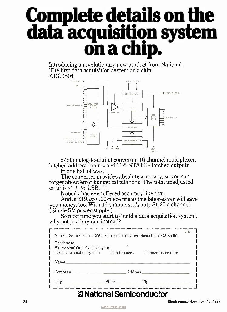
Complete details on the data acquisition system
on a chip. Introducing a revolutionary new product from National. The first data acquisition system on a chip. ADC0816.
16 »MO" iN.,),5 •
• BO /41.11,SS
PIMPESSLATOIENPel
xPANtillIN CONTROL
1 1
I I 1 111 ,ISTO
o /.
CC,
—0
8-bit analog-to-digital converter, 16-channel multiplexer, latched address inputs, and TRI-STATE e latched outputs.
In one ball of wax. The converter provides absolute accuracy, so you can
forget about error budget calculations. The total unadjusted error is < -± 1/2 LSB.
Nobody has ever offered accuracy like that. And at $19.95 (100-piece price) this labor-saver will save
you money, too. With 16 channels, it's only $1.25 a channel. (Single 5V power supply.)
So next time you start to build a data acquisition system, why not just buy one instead?
um 1 National Semiconductor, 2900 Semiconductor Drive, Santa Clara, CA 85051
Gentlemen: Please send data sheets on your: D data acquisition system Ill references Li microprocessors
Name
Company Address
City State _ Zip
M National Semiconductor 34 Electronics/November 10, 1977

Electronics review
nel training, and voiced-output com-puter systems. Wigfall is reluctant to discuss the electronics of the synthe-sizer, except to say that it is made of a mix of standard and custom inte-grated circuits that produce and amplify phonemes. In NandiVoice, the electronics is built on a single printed-circuit board that is epoxy-potted for protection. To keep size, weight, and power
low on the portable synthesizer, Votrax researchers pared the voca-bulary slightly, eliminating some intonation patterns, as well as pho-nemes uncommon in English.
Microprocessor control. The syn-thesizer is controlled by Motorola Inc.'s M6800 microprocessor, which also continuously scans the keyboard and drives a three-digit liquid-crystal readout that displays the codes as they are entered. Besides storing synthesizer commands neces-sary to pronounce 45 phonemes, the unit's 8,192 bytes of read-only mem-ory are programmed with coded commands for 893 words, all 26 letters, 13 word prefixes and suf-fixes, and 16 short phrases. An addi-tonal 1.5 kilobytes of ROM stores the program. "The microprocessor can also
scroll through any of the display's digits, allowing the user to start and stop the display to select codes and any keyboard function with a single switch closure," Wigfall says. With an optional breath-, or muscle-acti-vated switch, even the severely physically impaired can build and speak messages. Votrax has been testing a larger, breadboarded ver-sion since late 1975. Depending on the severity of their disability, patients have been able to construct messages after only minutes of instruction. A second version of the synthe-
sizer is configured as a lapboard with 128 touch-sensitive key-pad areas that can be overlaid with printed words or graphic symbols. "It's aimed at the individual with a lower level of cognition or abstrac-tion," Wigfall says. " It requires just a pointing skill." As many as four vocabulary overlays boost the num-ber of words the unit produces. 0
Solid state
Intel upsetting large ROM pinouts
by abandoning 16-k configuration
Digital system designers should brace themselves for a shoot-out in read-only memory pinouts —a situa-tion that could seriously retard the market for high-density, next-gener-ation ROMS. Here's the problem: for its upcoming 32,768- and 65,536-bit parts, Intel Corp., the biggest sup-plier of today's 2316E I 6,384-bit ROMS, is abandoning the 16-k type of configuration approved by the Joint Electron Device Engineering Coun-cil other manufacturers are follow-ing [Electronics. Sept. 15, p. 73].
Intel is doing this because it wants to ensure compatibility with another product that only it is currently prepared to produce— the single- 5-volt 32-k electronically alterable pro-grammable ROMS that designers will use while developing a new system and before committing to masked ROMS. If enough of the industry follows Intel so that two ROM camps are formed, then once again, as happened with the 4,096- bit dy-namic random-access memories, us-ers will be denied an industrywide standard when shopping for parts.
In 1974, it was the nonstandard approach to pinout configurations by suppliers of RAMS that caused mas-sive confusion among mainframe and peripheral equipment designers and set back the 4-k RAM market for two years. If pinout discrepancies develop in upcoming big ROMS, next-generation microcomputer designs could be in serious trouble, since high-density ROMS are essential for providing the large program storage needed in new microcomputer-based equipment.
Critical pin 18. According to Larry Jordan, Intel's strategic mar-keting manager for ROM products, "Our competitors simply have not looked ahead and made their new parts compatible with erasable PROMS and high-performance micro-computers. ROMS, erasable PROMS,
and microcomputers all must be
designed as components in an inte-gral system, not just piecemeal, as they apparently are doing."
Jordan points out that to maintain compatibility when going from the JEDEc-approved 16-k pinouts to 32-k and 64-k ROM levels, great care must be exercised in specifying which pins are to perform such functions as power down, chip select, and address enable. "As you go from the 16-k to the 32-k level, for example," says Jordan, "you must provide an addi-tional pin for addressing the addi-tional bits." This pin has to come out of a chip-select slot — there are three available on 16-k ROM devices. "The problem is that other sup-
pliers are specifying pin 18 for the new address or chip-enable slot, and that's just plain wrong, because pin 18 must be used for a power-down mode if the new 32-k ROMS are to be compatible with upcoming 32-k erasable PROMS," Jordan says. "Moreover, by choosing pin 18, these suppliers' future ROMS will not only be noninterchangeable with future erasable PROMS, but will not even have a power-down mode."
Intel's 32-k ROM, which will be available in the first quarter, to-gether with its new 32-k erasable PROM, will maintain its pin 18 for power-down control as in the pinouts for the 16-k part, and make pin 20 the chip-select pin and pin 21 the new address enable. "This pinout configuration will be identical with our 32-k erasable PROMS," says Jordan, "so that users can prototype new systems with erasable PROMS and then switch part for part to the mask ROM in production." As if there aren't problems enough
with 32-k devices, Jordan sees even more confusion with 64-k ROMS.
Early suppliers have indicated that they will keep the 64-k ROM in a 24-pin package, the same size as for the 32-k parts. "But," says Jordan, "if you do that, you lose the output-
Electronics/November 10, 1977 35

Electronics review
control function— it must go as an additional address line. Without out-put control, you end up with 64-k ROMS that won't work efficiently with high-throughput microcomput-ers, where address control is used to manage the processor bus and main-tain fast system speed. Our answer is to go to a 28-pin design, rather than give up output control."
Nevertheless, all other major sup-pliers of ROM and erasable PROM parts are sticking to the industry standard pinouts designated by re-cent JEDEC meetings. Included in this group are Mostek, American Micro Devices, General Instrument, Texas Instruments, Electronic Arrays, Mo-torola Semiconductor, Fairchild Semiconductor, and American Mi crosystems. According to Derrel Cocker, Mostek's memory market-ing manager, "We view Intel's new pinout as simply the response of a supplier coming late into the 32- and 64-k ROM market. Unlike the fully static Intel parts, our edge-activated ROM designs can conform to the JEDEC pinouts for ROMS and PROMS and still provide all the necessary control functions for high-perform-ance microcomputer systems. That's because edge-activated designs allow the user to control the duration that the outputs remain active. Therefore we don't need an additional output-enable function as is required in the Intel configuration." CI
Computers
Software may slow
DEC's 32-bit mini
With its newest minicomputer, Digi-tal Equipment Corp. for the first time embraced 32-bit architecture. But the Maynard, Mass., minicom-puter leader might find the 32-bit marketplace, which concentrates on scientific analysis and flight simula-tion, tough to penetrate. The reason? The new VAX- 11/780, with a typi-cal system cost of around $200,000, might have trouble proving it is superior to other manufacturers' ma-chines, despite some design niceties
Bigger mini. New 32-bit system from DEC, ranging from $ 128,000 up. will be competing for
markets now dominated by Interdata and Systems Engineering Labs.
like a built-in LSI-11 microcom-puter to perform self-diagnostics and a large instruction set.
DEC apparently has decided to concentrate on making its 32-bit entry suitable as an upgrading for users of its 16-bit PDP-11 line. In doing so, it has not yet produced the software tailored to a 32-bit design and may have compromised some of the hardware as well. It relies for now on an emulation mode that runs with software from the 16-bit ma-chines. This mode forfeits many 32-bit performance advantages. True, a native 32-bit mode is available, but the only 32-bit package announced with the machine is a Fortran compiler for high-speed scientific applications. However, Bernard La-croute, VAX's product manager, points out that its operating system is "the most powerful of any mini-computer, and it lays the ground-work for future software products." But, he adds, "one thing at a time." "You cannot take advantage of a
32-bit machine unless you've got full 32-bit software across the board— and the development of that soft-ware is not trivial," says Harold R. Buchanan, processor product-line manager for Interdata Corp., Oceanport, N. J., the leading sup-plier of 32-bit machines for the simulation market. " It doesn't mat-ter how big DEC is, you can only generate software just so quickly."
Interdata, which introduced its
32-bit machines in 1973, supplies most of the computers for simulators built by Singer Co.'s Simulation Products division in Binghamton, N. Y., and Singer has about 80% of what is expected to be a $75 million-a-year computer market over the next five years. The other major 32-bit computer supplier is Systems Engineering Laboratories Inc., Fort Lauderdale, Fla. Hardware edge. Besides software,
the machines from Interdata and SEL have the edge in several hardware aspects. Interdata's 8/32 and sEL's 92/75 each offer a microprogram-ming feature that allows the user to tailor the processor for a special application. However, the VAX has no such feature, usually of interest to original equipment makers.
Moreover, the bus structure of the VAX appears to be inferior to those of the competition. Says Samuel H. Bosch, product marketing director for SEL, "The vo rate of the VAX, at 13.3 megabytes per second, is half that of our 32/55 introduced over two years ago." Also, sEL's and Interdata's buses allow their com-puters to be hooked together in multiple-processing configurations. DEC'S cannot, though it will support the company's network software, DECnet. Such multiple processing can be extremely important: the simulator for the space shuttle uses 18 Interdata minicomputers.
In time, DEC will develop its 32-bit
36 Electronics/November 10, 1977

Four ways to do 8x8 Multiplication
DEVICE
ORGANIZATION
TYPICAL SPEED
POWER
1
.,1111'
,1 , 111 1.,,,O..
o
&-ii:7;7?c,i)---; .?
çrili," >> i ' \+ ,, •\•\V
MM! 67558
8 X 8
100 NS
TRW MPv-8
8 x 8
AMD 25S05 (FD 93S43)
2 X 4
TI (MSI) 74S27415
4 X 4
130 NS 75 NS 75 NS
1W 1.8 W 5W 5.4W
PACKAGE 40- PIN 40-PIN 24-PIN 20-PIN
NUMBER OF PACKAGES
TE CHNIQUE
1 1 8 12
COMBINATORIAL (BOOTH)
COMBINATORIAL COMBINATORIAL (BOOTH)
COMBINATORIAL (WALLACE)
ROUNDING
MFG. PROCESS SECOND SOURCE DATA REP.
TOTAL $ At 100 UP quantity
_ YES YES NO NO
LSÍTTL TRIPLE DIFFUSION
S TTL S, TTL
YES NO YES NO
SIGNED and UNSIGNED
SIGNED ONLY
SIGNED UNSIGNED ONLY ONLY
MIL
COM
110 115 210 —140
64 70 (Fan not included.)
124 68
300 fpm cooling required
Europe Monolithic Memories, GmbH 8000 Munich 80 Mauerkircherstr. 4 West Germany Tel: (089) 982601, 02, 03, 04 Telex: (841) 524385
Far East MMI Japan KK Parkside-Flat Bldg. 4-2-2, Sendagaya Shibuya-Ku Tokyo 151, Japan Tel: (3) 403-9061 Telex: ( 781) 26364
United States Monolithic Memories, Inc. 1165 East Argues Avenue Sunnyvale. CA 94086 Tel: (408) 739-3535 TWX: 910-339-9229
(Second sourcing from ITT Semiconductor.)
For more information, phone,TWX or write.
Monolithic Memories Electronics/November 10, 1977 Circle 37 on reader se'vice card 37

Thin-Trim' capacitors
Tucked in the corner of this IV' Pulsar Watch is a miniature
capacitor which is used to trim the crystal. This Thin-Trim capacitor is one of Our 9410 series, has an adjustment range of 7 to 45 pf., and is . 200" x . 200" x .050" thick. The Thin-Trim concept provides a variable device to replace fixed tuning techniques and cut-and-try methods of adjustment. Thin-Trim capacitors are available in a variety of lead configurations making them very easy to mount.
A smaller version of the 9410 is the 9402 series with a maximum
capacitance value of 25 pf. These are per-fect for applications in sub-miniature cir-cuits such as ladies electronic wrist watches and phased array MIC's.
Johanson Manufacturing Corporation, Rockaway Valley Road., Boonton, N.J. 07005. Phone ( 201) 334-2676, TWX 710-987-8367.
Ceta•tdoe
Electronics review
software, even promising programs for business applications. But as it does, it will be faced with another problem: internal competition. The $128,000 minimum-configuration cost of the VAX is well above that of the top-end PDP-11/70. But DEC
might find larger VAX configura-tions competing with its mainframe line of 36-bit DECsystem units already on the market.
DEC, however denies there will be a problem. "We even expect to produce lower-end machines out of the mainframe line," says Andrew C. Knowles, a DEC vice president. DEC has announced a 32-bit Cobol compiler for late next year, so appar-ently it has business uses in mind. As for other applications, "we're inter-ested in all markets," Lacroute says.0
Packaging & Production
Laser beam directs
harness assembly Borrowing from the technology of the automated supermarket check-out counter, Grumman Aerospace Corp. has hit upon a novel method for fabricating the giant electrical cable harnesses that go into the Navy's F-14 fighter. Dubbed the programmed light director, Grum-man's system relies on tagging bundles of wires with a bar-coded label that resembles the new product coding of the supermarket. Scanned with a hand-held optical reader, information on the label is used to control a laser whose light beam traces out the path on a cable layout board that the wires must take. All a harness maker must do is follow the moving spot of the laser beam, pressing the wires into cable clamps fastened to the board. "The light director has given us a
30% savings in labor and virtually eliminated wiring errors on our large harnesses," declares Walter Maier, group head of manufacturing tech-
Tagged. Optical reader of Grumman's
assembly system scans coded tag that indi-
cates where harness wires are to be run.
nology at Grumman's facility in Great River, N. Y. This savings adds up to quite a large number, points out Bruno Caputo, the facility's general manager, since Grumman's harness wiring operation handles more than 6,000 miles of wire in the course of a year. Thousands of wires. Just the
F- 14's main harness alone can repre-sent a staggering amount of work. It is 50 feet long and has 1,200 different wires routed over 490 paths. The paths for up to 48 wiring harnesses are stored in a disk memory , accessed by a Digital Equipment Corp. PDP-8 minicom-puter. The computer controls a posi-tioning system that moves an arm carrying a standard 0.5-watt he-lium-neon laser over a wiring board 3 feet by 30 ft. The arm is driven horizontally by a stepper motor, while another stepper adjusts a mirror on the arm that projects the laser light, passed through a beam expander, to a 0.5-inch-diameter spot onto the board.
All wires going to the same desti-nation must be bundled and labeled with their destination tag before they can be laid out with the light direc-tor. When the harness maker wants to position a group of wires, he
MANUFACTURING ( ORPORATI(
38 Circle 38 on reader service card Electronics/November 10, 1977

13 ways to reduce waste from slice to circuit. All with Zeiss optics.
Zeiss has a lucky 13 microscopes for the electronics industry, and a new brochure that describes them. Between its covers you'll find money-saving, waste-cutting applications described for every step from slice to circuit.
The microscopes range in size from the small, economical Standard T for the daily routine of the production line to the Novascan 30 Scanning Electron Microscope.
Along the way you'll find such unique instruments as the revolutionary Axiomat that sets new standards of stability and image quality for microscopes, and the Light-Section Micro-scope that cuts a profile, non-destructively.
Optics and versatility
Two invaluable characteristics distinguish all Zeiss micro-scopes, large and small:
1. superior performance of Zeiss optics for brightfield, dark-field, Nomarski differential interference contrast, polarized light, photography;
2. easy switch ing from one technique to another.
Send for this 10-page brochure with many striking photo-micrographs and details on all 13 microscopes.
Nationwide service
Carl Zeiss, Inc., 444 5th Avenue, New York, N.Y. 10018 (212)730-4400. Branches in:Atlanta, Boston, Chicago, Columbus, Houston, I os Angeles San Francisco VVashin2,ton, D.C. In Canada: 45 Valleybrook Drive, Don Mills, Ont., IVI3B 2S6. Or call (416) 449-4660.
THE GREAT NAME IN OPTICS
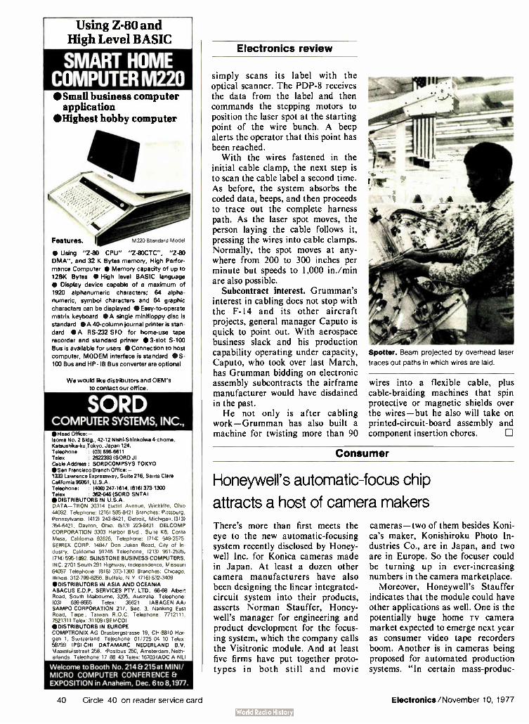
Using Z-80 and High Level BASIC
SMART HOME COMPUTER r11220 •Small business computer
application 'Highest hobby computer
t
Features. M220 Standard Model
• Using "Z-83 CPU" "2-80CTC", "2-80
DMA", and 32 K Bytes memory, High Perfor-
mance Computer • Memory capacity of up to 12« Bytes • High level BASIC language
• Display device capable of a maximum of
1920 alphanumeric characters; 64 alpha-
numeric, symbol characters and 64 graphic
characters can be displayed • Easy-to-operate
matrix keyboard • A single minifloppy disc is
standard • A 40-column journal printer is stan-
dard • A RS-232 SIO for home-use tape
recorder and standard printer • 3-slot S-100
Bus is available for users • Connection to host
computer, MODEM interface is standard • S-
100 Bus and HP- IB Bus converter are optional
We would like distributors and OEM's
to contact our office.
SORD COMPUTER SYSTEMS, INC., • Head Office: — Isoma No. 2 Bldg., 42-12 Nishi-Shinkoiwa 4-chome, Katsushika-ku,Tokyo, Japan 124. Telephone : 1031 696-6611 Telex • 26223931SORD J) Cable Address: SORDCOMPSYS TOKYO •San Francisco Branch Office:-1333 Lawrence Expressway, Suite 216, Santa Clara California 95051, U.S.A. Telephone: : 1406) 247-1614, (816) 373-1300 Telex : 362-046 (SORD SNTAI e DISTRIBUTORS IN U.S.A. DATA—TRON 30314 Euclid Avenue, Wickliffe, Ohio 44092. Telephone: 12161 585-8421 Branches: Pittsburg, Pennsylvania. (412) 243-8421, Detroit, Michigan. (313) 354-6421, Dayton, Ohio. 15131 223-8421. DELCOMP CORPORATION 3303 Harbor Blvd., Suite K6, Costa Mesa, California 92626, Telephone: 17141 549-2575. SEIREX CORP. 14847 Don Julian Road, City of In-dustry. California 91746 Telephone; 12131 961-2535, 17141 595-1692. SUNSTONE BUSINESS COMPUTERS, INC. 2701 South 291 Highway; Independence, Missouri 64057 Telephone: 18161 373-1303 Branches: Chicago, Illinois. 312-799-8256, Buffalo, N.Y. 17161632-3409 ODISTRIBUTORS IN ASIA AND OCEANIA ABACUS E.D.P. SERVICES PTY. LTD. 66-68 Albert Road, South Melbourne, 3205, Australia. Telephone: 1031 699-8555 Telex: 35621 1ABAG EN AA) SAMPO CORPORATION 217, Sec. 3, Nanking East Road, Taipei, Taiwan R.O.C. Telephone: 7712111, 7521311 Telex: 31109 ISEMCO) ODISTRIBUTORS IN EUROPE COMPTRONIX AG Drusbergstrasse 19, CH-8810 Hor-gen 1, Switzerland. Telephone: 01/725 04 10 Telex: 58799 IPSI CH) DATAMARC NEDERLAND By. Maassluisstraat 258, 4 ostbus 250, Amsterdam, Neth-erlands. Telephone: 17 88 43 Telex: 16703 ( A0C A NL)
Welcome to Booth No. 214 Et 215 at MINI/
MICRO COMPUTER CONFERENCE Et
EXPOSITION in Anaheim, Dec. 6to 8,1977.
Electronics review
simply scans its label with the optical scanner. The PDP-8 receives the data from the label and then commands the stepping motors to position the laser spot at the starting point of the wire bunch. A beep alerts the operator that this point has been reached. With the wires fastened in the
initial cable clamp, the next step is to scan the cable label a second time. As before, the system absorbs the coded data, beeps, and then proceeds to trace out the complete harness path. As the laser spot moves, the person laying the cable follows it, pressing the wires into cable clamps. Normally, the spot moves at any-where from 200 to 300 inches per minute but speeds to 1,000 in./min are also possible.
Subcontract interest. Grumman's interest in cabling does not stop with the F-14 and its other aircraft projects, general manager Caputo is quick to point out. With aerospace business slack and his production capability operating under capacity, Caputo, who took over last March, has Grumman bidding on electronic assembly subcontracts the airframe manufacturer would have disdained in the past. He not only is after cabling
work—Grumman has also built a machine for twisting more than 90
Spotter. Beam projected by overhead laser traces out paths in which wires are laid.
wires into a flexible cable, plus cable-braiding machines that spin protective or magnetic shields over the wires— but he also will take on printed-circuit-board assembly and component insertion chores. CI
Consumer
Honeywell's automatic-focus chip
attracts a host of camera makers
There's more than first meets the eye to the new automatic-focusing system recently disclosed by Honey-well Inc. for Konica cameras made in Japan. At least a dozen other camera manufacturers have also been designing the linear integrated-circuit system into their products, asserts Norman Stauffer, Honey-well's manager for engineering and product development for the focus-ing system, which the company calls the Visitronic module. And at least five firms have put together proto-types in both still and movie
cameras— two of them besides Koni-ca's maker, Konishiroku Photo In-dustries Co., are in Japan, and two are in Europe. So the focuser could be turning up in ever-increasing numbers in the camera marketplace.
Moreover, Honeywell's Stauffer indicates that the module could have other applications as well. One is the potentially huge home TV camera market expected to emerge next year as consumer video tape recorders boom. Another is in cameras being proposed for automated production systems. "In certain mass-produc-
40 Circle 40 on reader service card Electronics/November 10, 1977

Put our new UART and BIT RATE GENERATOR together and what have you got?
The first programmable CMOS Communications System. With the Harris HD-6402/6402A CMOS/LSI, and HD-4702/ 6405 CMOS Bit Rate Generator, you can convert parallel data to serial and back again asynchronously, substantially reduc-ing the amount of interconnect in your data acquisition systems. Now, all it takes is two lines to connect terminals to com-
puters, for example, instead of the spaghetti of wire used in older systems. And, only with Harris do you enjoy the benefits of all-
CMOS technology. Like less power consumption, permitting remote, hand-held battery-operated systems. Faster speed. Fewer and smaller components for added economy in equip-ment costs. Plus full temperature ranges, including military. The Harris HD-6402/6402A, designed to replace the older
and slower P-channel types, is the industry's first CMOS UART. It features an industry standard pinout. Single power supply—operates on 4 to 11 volts. And its fast ... 12F.K Baud...the fastest UART in operation today. The Harris all-CMOS Bit Rate Generator provides the
necessary clock signals for the UART. The HD-4702 generates 13 commonly used bit rates, while the HD-6405 provides two additional bits and consumes significantly less power. with no pull-up resistors.
If you've been waiting for CMOS for your modems, printers. peripherals, and remote data acquisition systems designs, your wait is over! Now Harris technology has something you can really work with. And you can start today?
For full details, call the Harris Hot Line. or write: Harris Semiconductor, P.O. Box 883, Melbourne, FL 32901.
HARRIS HOT LINE! 1-800-528-6050,Ext.455
fall toll.fnx for phone number of your nearby Harris sales office. authorized distributor or expedited literature service.
8 BIT
ARALLEL
r-4M1-1
BRU
1
TRANSMITE
RECEIVER
UART
>D<DC>C SERIAL DATA
)000C
RECEIVER
TRANSMITTER
UART
8 BIT
PARALLEL
2 cc
HD-4702/6405 FEATURES
• CMOS • TTL Compatible • Low Power Dissipation: 4.0mW TYP. ( 6405); 4.5mW TYR ( 4702) • Conforms to EIA RS-404 • One unit controls up to eight transmission channels • On-chip input pull-up circuit (4702 only) • 16 pin Cerdip and Epoxy dual-
in-line packages • Second source available
Hams Technology... Your Competitive Edge
HD-6402/6402A FEATURES
• CMOS • Operation from D.C. to 4.0MHz • Low power—TYP. 10 mW (a 2.0MHz
• •( V to 11V operation • l'rogrammable word length. stop bits and parity • Automatic data formatting and status generation • Compatible with industry standard UART's • Second source available
HARRIS cm ). SEMICONDUCT OR
PRODUCTS DIVISION
Electronics/November 10, 1977 Circle 41 on reader service card 41

Nnumwr MITEL
MILITARY OR COMMERCIA ANALOG SWITCH
CMOS ANALOG SWITCHES FOR MANY APPLICA-TIONS — CROSS-POINT, ANALOG-TO-DIGITAL AN DIGITAL-TO-ANALOG CONVERSION, ANALOG OR DIGITAL MIXING, TRANSMISSION GATING, ETC.
LL CONVERTER
cc
I cAc clr ,`.,`., • •
LLJ II.
11 1 i.E. 8x4 ó ' ó óal'In MEMORY
8x4 ANALOG SWITCH ARRAY
MT8804B CMOS/LSI 8804B 8 x 4 ANALOG SWITCH ARRAY
FEATURING: • TO 18v, 9v PEAK DIGITAL ANO ANALOG SIG
LEVELS • 501-2"ON" RESISTANCE OF SWITCHES ITYP.I • 50.BETWEEN "ON" VALUES OF SWITCHES (TV • — 50db CROSSTALK AT Fis 1 MHz BETWEEN SWITCHES
• 65 db "ON OFF" OUTPUT VOLTAGE RATIO ITYP I • LESS THAN 0.5% DISTORTION AT Fis 1 KHz • MASTER RESET OF CONTROL MEMORY OTHER CMOS ANALOG SWITCHES INCLUDE: MD4016B — QUAD BILATERAL ANALOG SWITCH/
TRANSMISSION GATE M04066B—QUAD BILATERAL ANALOG SWITCH/
TRANSMISSION GATE M04051B— 8-CHANNEL ANALOG MULTIPLEXER/
DEMULTIPLEXER M04052B—DIFFERENTIAL 4-CHANNEL ANALOG
MULTIPLEXER/DEMULTIPLEXER M040536 — TRIPLE 2-CHANNEL ANALOG
MULTIPLEXER/DEMULTIPLEXER
r rr-1 re 1,, torrn.11,,r, v,rite,,r pft , le
Adin 18 AIRPORT BLVD BROMONT. QUEBEC. CANADA
014 JOE 1L0 -514' 534-2321 TLX 05-267474
MITEL W Semiconductor
Electronics review
News briefs
EIA develops new interface standard for terminals A new digital standard for the interface between data terminals and data circuit terminations has been developed by the Electronic Industries Associa-tion. Known as RS-449, the new standard retains all the functional capabili-ties of the earlier EIA RS-232C, which the association says is "now archaic," and introduces 10 new interchange circuits to enhance it. It provides standard 37-pin and 9-pin interface connectors, together with latching arrangements. In addition to greater noise immunity, RS-449 increases data-signaling rates to 2 megabits per second and permits increases up to 60 m (200 ft) in the length of an interconnecting cable. Copies of the new standard and the associated industrial electronics bulletin are available for $9.50 and $4.25, respectively, from EIA's Standards Sales Office, 2001 Eye St., N. W., Washington, D. C. 20006.
Collins qualifies first NBS data-encryption chip... Rockwell International's Collins Group has become the first manufacturer to qualify a microelectronics chip for sale under the Federal Data Encryption Standard. The standard, adopted earlier this year by the National Bureau of Standards, is designed to protect data in computer memories from unautho-rized access or modification during transmission [Electronics, March 3, p. 74]. The Collins Group at Newport Beach, Calif., says its device, known as MOS 765-5914-001, will be sold only as part of larger hardware systems.
... While Motorola tools up for faster device Although Motorola's Government Electronics division in Scottsdale, Ariz., has not yet qualified its chip that executes the Data Encryption Standard algorithm [Electronics, July 7, p. 40], it is selling many of them for prototypes and promising to replace each one with a forthcoming faster chip. Expected by the first of the year, the new chip will be usable with standard 9,600-baud systems. Motorola also has plans for products that will eliminate awkward key handling. Hand-held units for key entry will store many keys that are identified by simple numbers.
TRW forms new Communications Group TRW Electronics, the Los Angeles-based unit of TRW Inc. of Cleveland, is combining three of its data and telecommunications divisions into a new Communications Group, effective Jan. 1. In the new group are the present Communications Systems & Services division, which builds remote terminals for retail and financial markets, the Datacorn division, which markets distrib-uted data-processing equipment, and Vidar, a producer of digital transmis-sion and switching equipment. Richard A. Campbell, presently general manager of the Communications Systems & Services division, will head the new group, expected to give TRW a share of what it regards as important business markets by combining the technology, marketing, and manufac-turing of the three divisions.
Borg-Warner acquires interest in AMI, sets 5-year custom IC pact Borg-Warner Corp of Chicago and Robert Bosch North America Inc., a wholly owned subsidiary of Robert Bosch GmbH of West Germany, have signed a 50/50 joint venture agreement to acquire the 25% ownership in American Microsystems Inc. of Santa Clara, Calif., previously sold to Bosch GmbH for some $ 14 million [Electronics, July 7, p. 25]. Concurrently, AMI and Borg-Warner signed a five-year agreement calling for AMI to develop custom MOS integrated circuits for Borg-Warner, a producer of industrial, transportation, and air-conditioning equipment.
tion situations, automated equip-ment must sense the presence of a part or a component within limited boundaries," explains Stauffer at
Honeywell's facility in Denver, Colo. The Honeywell module could be used to focus the camera on the part.
Designed by a research-and-devel-
42 Circle 42 on reader service card Electronics/November 10, 1977

Your 16K ROM is already in our inventory.
Two week delivery.
We can have a 16K ROM in your hands in two weeks. Because we tear weeks of waiting out of the normal ROM prototype/production cycle. We do it by mass producing wafers— ready for final mask— so that we have them in inventory, ready for your code. It's like getting off-the-shelf delivery on a custom part. That saves you at least four weeks right there, and gives you a big jump on the competition.
With our last mask capability we can start a new product cycle right now — instead of falling back to ground zero with a full 6 to 7 week turn-around staring us both in the face. The result: your prototype can be ready in two weeks, and you're ready to roll into production.
At Synertek, we give you choices. Whether your input media is paper tapes, punch card. EPROMs, Bipolar
ROMs. or even another 16K ROM. we can turn it around. Fast. Last mask, for a faster, less expensive production cycle.
For complete information, contact Bob Cushman at Synertek. or your local Synertek distributor. 3050 Coro-nado Drive. Santa Clara, Calif. 95051. Telephone (408) 984-8900. TWX. 910-338-0135.
Synertek Electronics/November 10, 1977 Circle 43 on reader service card 43
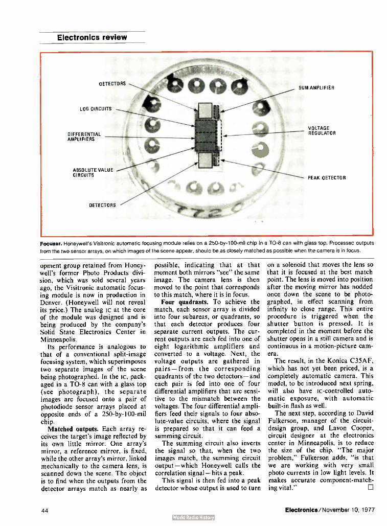
Electronics review
DETECTORS
LOG CIRCUITS
DIFFERENTIAL AMPLIFIERS
ABSOLUTE VALUE CIRCUITS
DETECTORS
90 SUM AMPLIFIER
VOLTAGE REGULATOR
PEAK DETECTOR
Focuser. Honeywell's Visitronic automatic focusing module relies on a 250-by- 100-mil chip in a TO-8 can with glass top. Processed outputs
from the two sensor arrays, on which images of the scene appear, should be as closely matched as possible when the camera is in focus.
opment group retained from Honey-well's former Photo Products divi-sion, which was sold several years ago, the Visitronic automatic focus-ing module is now in production in Denver. ( Honeywell will not reveal its price.) The analog lc at the core of the module was designed and is being produced by the company's Solid State Electronics Center in Minneapolis.
Its performance is analogous to that of a conventional split-image focusing system, which superimposes two separate images of the scene being photographed. In the lc, pack-aged in a TO-8 can with a glass top (see photograph), the separate images are focused onto a pair of photodiode sensor arrays placed at opposite ends of a 250-by- 100-mil chip. Matched outputs. Each array re-
ceives the target's image reflected by its own little mirror. One array's mirror, a reference mirror, is fixed, while the other array's mirror, linked mechanically to the camera lens, is scanned down the scene. The object is to find when the outputs from the detector arrays match as nearly as
possible, indicating that at that moment both mirrors "see" the same image. The camera lens is then moved to the point that corresponds to this match, where it is in focus.
Four quadrants. To achieve the match, each sensor array is divided into four subareas, or quadrants, so that each detector produces four separate current outputs. The cur-rent outputs are each fed into one of eight logarithmic amplifiers and converted to a voltage. Next, the voltage outputs are gathered in pairs— from the corresponding quadrants of the two detectors—and each pair is fed into one of four differential amplifiers that are sensi-tive to the mismatch between the voltages. The four differential ampli-fiers feed their signals to four abso-lute-value circuits, where the signal is prepared so that it can feed a summing circuit. The summing circuit also inverts
the signal so that, when the two images match, the summing circuit output— which Honeywell calls the correlation signal— hits a peak.
This signal is then fed into a peak detector whose output is used to turn
on a solenoid that moves the lens so that it is focused at the best match point. The lens is moved into position after the moving mirror has nodded once down the scene to be photo-graphed, in effect scanning from infinity to close range. This entire procedure is triggered when the shutter button is pressed. It is completed in the moment before the shutter opens in a still camera and is continuous in a motion-picture cam-era. The result, in the Konica C35AF,
which has not yet been priced, is a completely automatic camera. This model, to be introduced next spring, will also have ic-controlled auto-matic exposure, with automatic built-in flash as well. The next step, according to David
Fulkerson, manager of the circuit-design group, and Layon Cooper, circuit designer at the electronics center in Minneapolis, is to reduce the size of the chip. "The major problem," Fulkerson adds, "is that we are working with very small photo currents in low light levels. It makes accurate component-match-ing vital."
44 Electronics/November 10, 1977

The New Giant
•
optoelectronics Affiliation with Siemens gives Litronix all you could want from an
optoelectronics source.
On OCTOBER 18, x977, Siemens A.G., an $8 billion per year firm, acquired an 80% interest in Litronix through a wholly-owned subsidiary — bringing financial stability, new technologies and dozens of new products to the American firm.
Foremost among the new technologies and products are LCD displays, high-power infra-red emitters, green, yellow and red GaP LEDs, and a full line of phóto detectors. Nearly all types of optoelectronic products will now be available from Litronix.
Litronix Will operate under its own name and market all products in the U.S. and abroad through the same distributors and sales representatives as before.
All resources devoted to components
Litronix ceased manufacture of calculators and digital watches in January 1977. All the design and production capability once devoted to these products is now directed entirely to components. The component portion of the company's business has always been highly successful. Now, operating from a strong financial position, Litronix will resume its place as
the leading source of advanced, cost-effective optoelectronic components.
New, advanced products coming fast
Already in 1977 Litronix has developed 21 new products. With the recent affiliation, new product development is being further accelerated. The company's line of displays, lamps and other opto devices is being broadened and upgraded. Special emphasis is being placed on " intelligent" displays and indicators — devices which incorporate a display and integrated logic in the same package.
The recently introduced DL-1416 alphanumeric display, which interfaces exactly like a RAM, is an apt example. Such devices eliminate need for much associated interface and logic circuitry — simplifying design and producing a sizable net saving in the production cost of customers' products. Litronix is the uncontestable leader in this promising extension of optoelectronic integration.
When you have need for virtually anything in optoelectronics, contact Litronix at 19000 Homestead Road, Cupertino, California 95014. Phone (408) 257-7910.
litronix An affiliate of Siemens.
Electronics/November 10, 1977 Circle 45 on reader service card 45

The better counter choice: Counting is not complicated: unless you've got noise and transients on your measurement signals.
Noise can trigger the input circuitry just like the signal and thereby give a false count. Transients can destroy it.
Therefore Philips high-frequency counters employ unique, PIN-diode circuitry that auto-matically and continuously attenuates the input signal to a level just above the trigger window. The signal therefore triggers the input circuitry, the noise does not. At the same time the PIN-diode circuitry is fast acting, so transients are caught and attenuated in time.
This way, the operating sensivity is condi-tioned to match the signal's amplitude, giving the counter a wide trigger window.
Fully automated counters: 80 MHz model PM 6661 n) 520 MHz model PM 6664 (2) employing the unique HF PIN-diode input.
Universal counters: all having 10 mV sensitivity.80 MHz model PM 6611 (3) 80 MHz counter/timer PM 6612 (4) with 100 ns resolution. 250 MHz model PM 6613 (5) 520 MHz model PM 6614 (6)1 GHz model PM 6615 (7); last three have separate HF input.
Compact timer/counters: 80 MHz model PM 6622 (8) with 100 Ps resolution and trigger hold-off facility; 520 MHz model PM 6624 (9) and 1 GHz model PM 6625 ow have same 100 Ps resolu-tion plus separate HF counting input.
8
eax counter' temer ek111411, WOns
, rot S.Silarl
— L H 1256 -?8
4.1 AO TC•••1, ..••••
Time interval measurements, on the other hand, have fundamentally different requirements for the input circuitry. Timing demands a narrow trigger window in order to minimise the influence of hysteresis. There-fore error-free, high frequency counting and timing facilities cannot be provided by the same input circuitry without compromising one or both measurement parameters. Therefore all our instruments have sepárate input channels, each optimised for either frequency or time interval measurements. With Philips you can thus be sure of a better, as well as a bigger choice: whatever your application.
P.M'S
6
le) 3853925'06 g ••••
PM SS11 PMPHM M « M S .fflOelbeermi
is) 013308582 (*--1-.T.
NI« IIIN.110/
•G111HiL
10

123456789
timer/counters too An eleven-model choice of fully automatic counters; universal counters and counter/timers Fully automatic counting Models PM 6661 and PM 6664 are fully automatic and represent the ultimate in easy operation, by having no controls other than the on/off switch. The former counts to 80 MHz, the latter to 520 MHz: both with optimum signal condi-tioning and high stability time-bases. Dimensions are extremely compact, weight only 1,45 kg and the 8-digit LED display is bright and easy to read.
Error-free from 80 to 1000 MHz Four universal counters and one counter/timer cover this frequency range, the VHF and UHF models having the unique Philips PIN-diode cicuitry that is proof against noise and that maximises the value of a high 10 mV sensitivity. Moreover, optimum counting accuracy is ensured by a wide choice of high-stability X-tal oscillators, which match your individual needs. This accuracy is extended to the field via the optional built-in battery pack.
The basic 80 MHz instrument is model PM 6611, while the PM 6612 offers basic timing facilities in addition to error-free counting. Models PM 6613, 6614 and 6615
are dedicated counters having frequency ranges of 250 MHz, 520 MHz and 1 GHz.
The high-performance stand-ards of all these instruments can be further extended by plug-in options that provide: - a BCD output - a D/A converter that gives an analog " magnifying glass" view of any three digits
- and a serial data output for operation with IEC/IEEE Bus interface systems.
Compact timer/counters The timer/counters feature power-ful performance in the same compact housing as the previously described frequency counters. Each has specific measurement facilities. All have the following common features: - 80 MHz direct frequency count-
ing - high DC-coupled 20 mV
sensitivity - versatile time interval (averaging) measurements down to 1 ns
- and period, ratio and conditioned pulse counting Depending on your individual needs, you then select the
A high-speed, high-resolution, systems instrument
Model PM 6650 below is a systems instrument that features accurate, noise- and transient-suppressed counting to 512 MHz on a special frequency channel. And time interval averaging measurements with up to 1 ps resolution on the timing channel. Plug-in modules extend the performance: two increase the frequency range to either 1 GHz or 12.6 GHz; another boosts the basic 50 mV sensitivity to 1 mV. User options are numerous.
PHILIPS
- _ • o
_ o 1[01C_. . 9
— 1
specific model with either: - trigger hold-off to extend the timing capability as provided by model PM 6622. This allows spurious signals such as contact bounce to be ignored; enables period measurements to be made on double-pulse signals and permits a specific signal to be " picked-out" from a pulse train, to give just three examples of this instruments timing versatility.
- extended frequency counting, on a separate input, to 520 MHz for model PM 6624 or to 1 GHz for model PM 6625. These two instruments thus offer the same error-free counting facilities as the universal counters, while retaining the 100 Ps resolution of the time interval averaging technique.
The timer/counters also offer the same choice of timebase as the universal counters and the same plug-in options and battery operation.
Get the full facts on the bigger, better counter and timer/counter choice. Tick the reader service number, fill in the coupon or contact Philips at the address below.
Please send me full details on:
El Fully automated counters PM 6661 and 6664
E Universal cou -iters PM 6611 to 6615 El Timer/counters PM 6622,6624 and 6625 E Universal model PM 6650
EAll Philips Test and Measuring Instruments
Name
Department
Company
Address
City Country
For further information call our toll-free HOT LINE number 800 631-7172 or contact: Philips Test & Measuring Inc., 85 McKee Drive, Mahwah, New Jersey 07430 or in Canada: 6 Leswyn Road.Toronto, Ontario, Canada M6A1K2 Tel. (416) 789-7188
Philips Test di Measuring Instruments Inc.
A NORTH AMERICAN PHILIPS COMPANY PHILIPS
Circle 47 on reader service card 47

RCA announces the
HEATPIPE SCR New dynamically cooled transcalent device
delivers more watts per ounce, more amps per inch.
RCA brings you a brand new solid-state way to handle big power. For motor speed controls. Welding controls. Electrochemical refining. Power conditioning. Electric vehicles. Induction heating. Military and space applications. Use it where size, weight and cooling are vital concerns. Because the HEATPIPE SCR combines
the outstanding heat-dissipation ability of isothermal heat pipes with the electrical functions of a silicon thyristor.
Heat from the silicon evaporates water within this unique heat-pipe system. Vapor travels along the interior of the heat-pipe, cools and condenses. Capillary action of the wick pumps the water back to be evaporated all over again.
New design possibilities
This RCA breakthrough means you can pack more power into less volume and weight than ever before. Up to 400 A RMS, up to 1200V peak blocking voltage. 500 watt dissipation and low thermal im-pedance. In only 12 ounces and about 14 cubic inches. Other devices that reach
Circle 48 on reader service card
CATHODE TERMINAL
SILICON WAFER
WICK
HEAT PIPE
r ANODE TERMINAL
- CERAMIC TO METAL SEAL ENVELOPE
Heat pipe literally pulls heat away from silicon chip, allowing higher power levels,
the same levels weigh 10 to 15 pounds! You can try whole new design approaches.
Without heavy relays, bulky mechanical switches, or multiple devices in parallel. And you can design knowing that the HEATPIPE SCR has passed severe life, environmental,
shock, vibration and surge tests.
We'll be glad to help you apply the HEATPIPE SCR and companion transistor and rectifier. For more information contact
Marketing Man-ager, Solid State Power Devices,
RCA, Lancaster, PA 17604. Or call
(717) 397-7661.
RCA

Washington newsletter
Four compete for
U.S. overseer role
in new IEC system
Peterson offered
OTA directorship
by Congress
DOE lining up
electric vehicle
users for demonstration
NASA's Frosch
confirms headquarters
reorganization
To meet membership requirements of the new international components certification system known as IECQ, to be chartered in January by the International Electrotechnical Commission ( see p. 50), the American IEC committee will evaluate next month four proposals to set up an indepen-dent National Supervising Inspectorate. Candidates include Underwriters Laboratories Inc., Inter Tek Services Corp., Los Angeles; Science Applica-tions, Inc., Palo Alto, Calif.; and CASE— the Coordinating Agency of Supplier Evaluation. CASE was set up to serve the aerospace industry and is operated by Aerojet Liquid Rocket Co., Sacramento, Calif.
The congressional Office of Technology Assessment has found a candidate to fill the vacancy created by the July 1 resignation of director Emilio Q. Daddario. If he accepts the offer, the new director of the $8.3 million OTA and its staff of more than 130 will be Russell W. Peterson, former Republican governor of Delaware and research chemist who earlier headed Du Pont Corp.'s R&D division. He now serves as chairman of the White House Council on Environmental Quality.
The Department of Energy is lining up two types of commercial organiza-tions to participate in its demonstration program for electric and hybrid vehicles [Electronics, March 3, p. 49]. Selection of large fleet operators, like telephone companies or department stores, as well as organizations akin to automobile dealers that will lease or sell and maintain vehicles for individuals will begin next spring. First participants in each category will be funded to buy 200 to 400 vehicles beginning about August 1978 from any of the 109 U. S. electric vehicle makers whose models meet the user's needs, according to Energy officials. The number of vehicles involved in the estimated six-year life of the program is expected to range from 7,500 to 10,000. The department has named Booz-Allen and Hamilton, Bethesda, Md., management consultants, to provide planning and manage-ment support for the project. Overall cost of the effort is expected to range from $ 150 million to $200 million.
NASA is implementing its headquarters reorganization on Nov. 8, as promised by administrator Robert Frosch [Electronics, Oct. 27, p. 34]. In a new organization chart that Frosch says "looks like a much more simplified wiring diagram" seven offices— including six assistant administrators' posts— were either abolished or retitled and their respon-sibilities changed. Major assistant posts eliminated include: planning and program integration, with responsibilities going to the chief scientist and the associate for space and terrestrial applicants; institutional manage-ment, with duties now held within management operations excepting headquarters procurement which goes to the procurement director; industry affairs and technology utilization, with responsibilities spread through four offices; energy programs, now to be handled by aeronautics and space technology. Personnel programs becomes a part of management operations, as does the abolished systems management office. The program assurance office was also dropped and duties assigned to the chief engineer pending further study.
Electronics/November 10, 1977 49

Washington commentary
IECQ: Will it help or hurt your business?
When the International Electrotechnical Com-mission convenes January 9 in Geneva, the three-day meeting will involve setting up a new system for international certification of the quality of electronic components. It is expected to have an enormous impact on world trade. Though the U. S. and the 16 other nations that have spent seven years structuring the system called IECQ— for IEC Quality Assessment Sys-tem—and are preparing to become fully-certi-fied members, many Americans are unaware of the system and its potential impact. A voluntary worldwide quality-assessment
system for components, the IECQ is open to any nation. Much as military specifications are applied in the U. S., a manufacturer will be able to certify performance and quality of products to a standard. The commission's standards will be the desired base for specifications, but in their absence a national or company standard may be used provisionally. The premise is that certified components will be acceptable by buyers in all participating countries without further tests.
Only the beginning?
If it works, international-components trade would become simpler, faster, and more exten-sive. Moreover, its proponents hope that the system will be extended to include other products, notably instruments, after the bugs are worked out of the components program. Who are the system's proponents? In the
United States they include the Electronic Indus-tries Association, which first proposed it, the U. S. National Committee of the IEC, and the American National Standards Institute. Of the IEC'S 43 member countries, the 16 others active in setting up the IECQ system include: Australia, Belgium, Canada, Denmark, France, Germany, Hungary, Israel, Italy, Japan, the Netherlands, Norway, Poland, Sweden, the United Kingdom, and the USSR. Each has formed a national authorized institution to act for it in structuring the IECQ. In the U. S., that is the IEC National Committee. Additionally, each country must have a national standards organization and pay dues. Now the preliminaries are over. The 17
nations have come up with basic rules for IECQ membership, a constitution and bylaws, and are near approval of detailed operating rules. In January, each country must decide if it wants to be a fully-certifying member with a vote. To qualify, a country must have formed a national
supervising inspectorate and a calibration service and must develop an operating plan called the National Statement of Surveillance Arrangements. It is a complex procedure, and one that will prove more complicated for the U. S. than for many other nations, which have government agencies to assist in these roles.
Even though the EIA first proposed creation of the IECQ in 1970, its bdard of governors only voted that the U. S. join as a fully-certifying member in October. It has been a tough selling job to persuade American component makers and distributors that they will gain more from the IECQ than it will cost them. The EIA engi-neering vice president, Allen Wilson, cannot be accused of overstatement when he says "There will be some rather intense activity over the next several months within EIA and the U. S. national committee of IEC in development of a needed organization and in determining its operational costs and interest within the producer and user segments for support of the system."
Old and new challenges
Another laborer in the American vineyard planting the seeds of an IECQ system is Leon Podolsky, president of the U. S. IEC committee and chairman of EIA'S exploratory committee on the program. For those in industry who question IECQ'S benefits against its still uncertain costs in a highly price-competitive components market, it is worth recalling the origins of the 1970 EIA proposal. At that time it eeemed a necessary substitute for the Cenelec Plan then being implemented in Western Europe. That plan would have barred all countries except members of the European Economic Community and the European Free Trade Association from compo-nents trade in that region. With American components dominating world technology, U. S. manufacturers viewed Cenelec as another artifi-cial barrier to free market entry. But that was 1970.
In 1977, a growing number of Americans anxious to protect their home markets are adopting protectionist views— especially some smaller components makers who see themselves one day crushed between the jaws of a vise made up of American multinationals on one side and their Japanese and European counterparts on the other. Convincing them that the IECQ will ultimately work to their benefit is another task for the system's advocates that may prove as difficult as those they have already overcome.
Ray Connolly
50 Electronics/ November 10, 1977

TYPE 192P PACER" FILM CAPACITORS TRIGATE PULSE TRANSFORMERS
BEAT THE SPACE /COST SOUFEZT
Polyester-film dielectric, heat- shrinkable plastic sleeve . . . the kind of construction that saves both space and cost.
Unique construction . . . all turns of extended foil electrodes terminated in metal end caps . . . assures best- possible non- inductive capacitor section.
End caps provide controlled dimensions . . . suitable for automatic insertion on printed wiring boards.
High humidity resistance . . . end caps over capacitor sec-tions are effective moisture barriers.
Voltage ratings from 80 to 600 WVDC. Capacitance values from .0001 to .39 pf. Standard capacitance tolerances,
±-20%. Operating temperature range, —55°C to +85°C.
Write for Engineering Bulletin 2066C to Technical Literature Service, Sprague Electric Co., 35 Marshall St., North Adams, Mass. 01247.
THE BROAD-LINE PRODUCER OF ELECTRONIC PARTS
4,P 71:3
SPRAGUE /HE MM. Of /111•0111,
Circle 221 on reader service card
SERIES 201C3001201C400 MODULES
ACTIVE FILTERS FOR USE
WITH MnIMMS Designed for low speed modem applications.
Provide all necessary filtering for originate only, answer only, or answer/originate operation.
Series 207C300 transmit modules feature 6- pole filter to suppress output sidebands, reduce harmonic distortion.
Series 207C400 receive modules include 10-pole filter to eliminate noise and local carrier signals.
Absolute max. ratings include supply voltages of +18V (V..), — 18V (VEE), 5.5V (V.o). Operating temp. range is 0' to + 70°C. Storage temp. range is — 40° to +125°C.
Write for Engineering Bulletin 22113 to Technical Literature Service, Sprague Electric Co. 35 Marshall St., North Adams, Mass. 01247.
THE BROAD-LINE PRODUCER OF ELECTRONIC PARTS
110
SPRAGUE Aolà.• 9111.1.1,
1
THE INDUSTRY'S LOWEST- COST SCR TRIGGERS
a Dependable enough for industrial equipment, yet priced for high-volume commercial use.
• Balanced pulse characteristics and energy transfer, mini-mum saturation effect, fast pulse rise time, increased cur-rent capability, improved energy transfer efficiency.
Variety of turns ratios available with line voltage ratings to 240 VAC or 550 VAC. Operating temperature range, —10°C to +70°.
✓ Plug-in design, protected by thermoplastic sheath. Axial-lead and pre-molded designs also available.
Write for Engineering Bulletin 40003B to Technical Literature Service, Sprague Electric Co. 35 Marshall St., North Adams, Mass. 01247.
THE BROAD-LINE PRODUCER OF ELECTRONIC PARTS
4,•7124
SPRAGUE
Circle 222 on reader service card
TYPE 115P FILMITE® ' I.' CAPACITORS
SPRAGUE
LOW DISSIPATION FACTOP
« Polypropylene film dielectric . . . similar to polystyrene in high a-c current- carrying capability, but has added advan-tage of 105°C operation.
Conformally coated with flame retardant epoxy.
Ideal in solid-state TV vertical circuits, r-f generators, pulse-forming networks, plus other applications where high a-c curent flow is found.
Capacitance change with temperature less than 3% over operating temperature range of —55°C to + 85°C.
Capacitance values from .001 to .47 i.LF, voltage ratings from 400 to 1600 WVDC.
Write for Engineering Bulletin 2090 to Technical Literature Service, Sprague Electric Co. 35 Marshall St., North Adams, Mass. 01247.
THE BROAD-LINE PRODUCER OF ELECTRONIC PARTS SPRAGUE]
Imf ma•m of It AO
Circle 50 on reader service card Circle 51 on reader service card

WHY ARE MORE LEADING COMPANIES
AND UNIVERSITIES BUYING DEC FROM
%1ST CGIURITER?
1 DISCOUNTS • Everyone can qualify for
discounts, which range up
to 20%. Special discount plans for
qualified educational and OEM
organizations are available.
2 DELIVERY ▪ Prompt delivery of fac-
tory- fresh DEC compo-
nents and products is provided
off- the-shelf. Plus, we also stock DEC 11V03(', DECLAB' equiva-
lent, and 11/03 Computing Sys-
tems, and can rapidly deliver both
standard and customized systems.
3 SERVICE Each customer and order • is handled on a personal-
ized basis. We can help you con-
figure your system or select the
proper component. Expedited de-
livery, rapid replies to information
requests, and courteous treatment
are assured.
fiRST CGUPUTER 764 BURR OAK DRIVE WESTMONT, ILLINOIS 60559
Call fiFIST first
4 CUSTOM CONFIGURATIONS • We will custom build sys-
tems to your specific require-
ments, with no resulting delays in
delivery. We can package your
system in a functional yet attrac-
tive desk, and provide additional
memory, interfaces, terminals, and
peripherals.
5. ADDED VALUE Valuable software en-
hancements for each DEC
11V03®, DECLAB' equivalent, or
11 /03 Computing System deliv-
ered by First Computer are pro-
vided from our continually grow-
ing software library. Custom
configurations are built to order,
fully integrated, and tested prior
to shipment.
6 • Because all of our systems
are thoroughbred DEC', we can
provide for on- site field service
by DEC's own factory trained
technicians world-wide.
WORLD-WIDE FIELD SERVICE
ip Corp Maynard. Ma
Circle 52 on reader service card
7. WARRANTY We provide the same war-
ranty as DEC', plus, ask
us about our priority exchange plan.
• tal or long-term leasing of
complete systems. Ask about how
these programs can help you meet
your system acquisition and bud-
get requirements.
RENTAL/LEASING We offer short-term ren-
WHAT THIS MEANS TO YOU
COMPLETE SYSTEMS
Standard or custom DEC 11V03,
DECLAB - equivalent, or 11/03
Computing Systems with a $ 1,000
savings and shipment in 30 to 60
days.
COMPONENTS
A complete stock of LSI-11' and
11 03' products for immediate
delivery—at ATTRACTIVE DIS-
COUNTS.
Call FiFIST first to find out how
much money and time you can
save. Call Don Berteau at (312)
920-1050.

International newsletter
Fiber-optic cable made In pilot production at the English glassmakers Pilkington Brothers Ltd. is a fiber-optic cable based on the bulk-chemical-treatment process developed
with bulk process by the Catholic University of America [Electronics, Oct. 27, p. 126]. Tile
is in production single-fiber cable is intended for communications over 1-km distances requiring a modest 50-kHz bandwidth. Present attenuations are in the region of 15 dB/km, with samples achieving 10 dB/km. Cost is 68¢ per meter for a 50-km package, but this should fall to around 17¢ once volume production begins. Pilkington has the exclusive European license for the process; Canada Wire and Cable Ltd. has the North American license; and Sumitomo of Japan has the Far East license.
Instrument maker
in Germany seeks
role in U.S. markets
Before the end of the year, West Germany's VDO Adolf Schindling AG will start production at its new Winchester, Va., plant-- initially turning out instruments for cars Volkswagen will be making in the U.S. In another move to enhance its position in the U. S., the firm has bought 25% of Solid State Scientific Inc., Montgomeryville, Pa. VDO has long used the American firm's complementary-mos circuits in automobile quartz clocks. The new link provides for cooperation in developing C-mos circuitry and other devices.
English word processor Ricoh Ltd. has become Japan's first company to make and market an English-language word processor. It is starting production at a rate of
from Japan's Ricoh about 100 units a month. The $ 14,000 processor features a single-line
available in Great Britain cathode-ray-tube monitor for checking the text before typing and a double daisy-wheel printer that can type at 33 characters a second. Its floppy disk can store 225,000 characters. Ricoh has been shipping the systems to Ultronic Data Systems Ltd. in Great Britain since August and will sell them in Japan to trading companies, foreign companies, and law offices. The firm says it is also studying sales in the U. S.
Cobol package for Aiming to capitalize on the worldwide business investment in the Cobol high-level language, a small London software consultant, Micro Focus
microprocessors Ltd. has developed for microprocessor-based terminals a compact Cobol
aimed at business compiler that requires as little as 8 kilobytes of program storage. The firm's CIS ( for compact interactive standard) Cobol will allow users to run existing programs and develop new ones on microcomputers, which have interactive capabilities that make it extremely easy to edit out syntax errors. The package has been developed for Dataskill, Ia.'s software subsidiary, at a cost in excess of $ 100,000. It is being run on the ICL 1500 transaction processor inherited from Singer Business Systems. Now the Micro Focus team, approved by Intel to develop user software, has its sights set on the microprocessors from the principal Silicon Valley makers. All that is needed to adapt the compiler to a processor is a run-time system written in the appropriate machine language. To incorporate a bigger user dictionary, the compiler can occupy 16 kilobytes of program memory for 500 user statements and 1,000 commands.
Electronics/November 10, 1977 53

Acti"on! It made us the leader in electronic equipment rentals.
When you call Electro Rent, expect act.on.
Our representatives are action-oriented specialists who can answer your questions quickly and get you the necessary equipment in hours.
We back them up with the nation's largest electronic equipment inventory and a network of service centers from coast to coast.
Find out why more people rent or lease their electronic equipment from the leader. Call us now for equipment, applications assistance or a free catalog. Or write our Marketing Manager at: Electro Rent, 4131 Vanowen Place, Burbank. CA 91505.
Call toll-free 800-423-2337 for immediate action! ElectroRent
Circle 54 on reader service card
In California call 800--232-2173 A Telecor Company
Interested in buying quality used equipment? Ask for our Equipment Sales Division.

Electronics international Significant developments in technology and business
Japanese laboratory is growing
silicon ingots 5 inches in diameter
Yet another example of the Japanese determination to forge ahead in the semiconductor world is a successful laboratory effort to grow single-crystal silicon ingots that are 5 inches in diameter. These are not the first 5- in. ingots: American firms such as Dow Corning Corp., Mid-land, Mich., have samples of this size available. But the Japanese think they will be able to reduce the number of wafer defects signifi-cantly by their method of growing the ingots under low pressure. So far, 5- in. ingots with lengths of
150 millimeters have been grown by the Czochralski method from 7- kilo-gram melts at the Musashino Elec-trical Communication Laboratory of the Nippon Telegraph and Tele-phone Public Corp. But they are only a start — the goal is 1- meter-long ingots.
Integrated-circuit makers are hardly ready to handle the 5-in. wafers— they are in the middle of switching their production lines to the 4- in, size, both in Japan and in the U.S. [Electronics, March 17, p. 78]. However, there is no question that they will be interested, because the larger the wafer, the easier it is to develop bigger very- large-scale ics and to fabricate them economically. 8 in. possible. The crystal-growing
furnace, made to order by Kokusai Electric Co., could grow ingots up to 8 in. in diameter, although not 1 m long. Essentially, it is a 3- in, growing unit scaled to twice the size in each dimension. The crucible can hold a 30- kg silicon melt— four or five times as much as a 3- in. unit. The hefty power requirements of the electrical heaters that give a large, high-efficiency hot zone dictate the use of three-phase ac power, rather than the usual dc, with thyristor phase control. Where the unit differs from 3- in.
furnaces is the growth of ingots in a crucible argon atmosphere at a
Big melter. Standing 4.5 m high, furnace is
turning out 5- in.-diameter silicon ingots
10-torr partial vacuum, instead of argon at the normal atmospheric pressure of 760 torr. The reduced pressure is expected to greatly reduce the amount of oxygen that enters the melt from the silica cruci-ble. Oxygen is undesirable because it leads to larger defect sizes during high-temperature wafer processing. Today's ingots often contain 10 8 oxygen atoms per cubic centimeter. The reduced pressure also is
expected to slash the amount of pure argon required. While the 10-torr atmosphere is not hard to produce, it does pose some operating problems for the vacuum pump, so its effi-ciency is low in the 5-in, furnace, and the oil in the pump degrades. However, the lab is working with pump manufacturers to design more satisfactory equipment.
Fewer faults. The researchers have grown perhaps a dozen ingots so far — they will not give a precise number— and are still evaluating them. Their goal is no dislocations and the minimum density of stacking faults possible. With smaller equip-ment that operates at 10 torr, they have produced 3- in. ingots with no dislocations and fewer than 10 stack-ing faults per square centimeter for experimental 65,536-bit random-access memories. Run-of-the-mill wafers from production facilities have no dislocations and less than 500 stacking faults, with better quality available at a premium price. The development of the 5- in, ingot
is part of NIT'S ongoing work on semiconductors for telephone equip-ment. However, the firm does coop-erate with the Japanese semicon-ductor makers banded together in the VLSI effort to develop technology for general-purpose computers. El
West Germany
IC and sensor plate
control dimmer switch In today's world of microelectronics, one notable anachronism is the household dimmer switch that uses a knob controlling a rheostat to change the electric- light level in a room. At least, that is what engi-neers at West Germany's Siemens AG contend. To update dimmer design, they have developed an inte-
Electronice/November 10, 1977 55

Electronics international
grated circuit that works with a touch-sensitive sensor plate to do away with the rheostat and the control knob. With the new lc and the sensor
plate, control of the light level is radically different from that with the conventional knob and rheostat. Touch the plate with a finger and the light comes on. Keep the finger on the plate for half a second or more, and the light either dims or brightens. The fc-plate combination will undercut the price of the rheo-stat. It is intended as an export item, notably for the U. S. market, as well as for domestic use. The S566B is based on p-channel
metal-oxide-semiconductor depletion technology. It integrates some 1,000 transistors and contains essentially signal-evaluation circuitry, flip-flops, and comparison and counting circuits. The lc accepts the touch-initiated pulses and evaluates their duration. Using counting, timing, and pulse-shaping circuitry, it pro-duces a staircase-shaped signal con-trolling an external triac that in turn controls the power applied to the light bulb. When the sensor plate is touched,
the resistance of an external resistor network changes as a result of the added resistance of the human body. This changes the input voltage to the
Around the world
Sealed magnetic switch to shrink phone exchange, power use Coming up: sealed magnetic switches as replacements for miniature mechanical crossbar units in the Japanese D-10 electronic telephone exchanges. They will require only 40% of the space of the crossbars, and overall volume of the standard eight-by-eight matrix, including control equip-ment, is 70% that of the present setup.
This space savings will permit more efficient use of telephone offices in land-poor Japan. The new switches also will serve handily in export versions of the D-10. The unsealed crossbars need controlled environments to main-tain high reliability. So for many foreign sales, the Japanese have had to use the more tolerant reed switches, which must be individually fabricated, sealed, and mounted on pc boards. The new switch package, with 16 contact pairs each, will be hermetically sealed in nitrogen. A joint project of the Nippon Telegraph and Telephone Public Corp. and its
four exchange suppliers, the new units have a drive power of 35 watts, instead of the crossbars' 90 W. Switching time is 5 milliseconds, instead of 8 ms. With about a third the different types of parts as the crossbar, they should be cheaper to make. When the X and Y coils of a particular contact pair are energized by a
pulse, only that pair operates. Other contacts are only half-selected, so they do not operate. Hysteresis of the iron core on which the fixed contact of each pair is mounted keeps the pair closed after power is removed. A negative pulse applied to the X coil releases them.
European Space Agency is set to launch a weather satellite Poised for a November 15 launching at Cape Canaveral, Europe's first meteorological satellite, the Meteosat, is the European Space Agency's contribution to the United Nations' Global Atmospheric Research Program. It also is ESA's first nonresearch satellite.
Meteosat's multispectral radiometer system will photograph the earth and its clouds in both the visible and the infrared range by scanning in line-by-line fashion as the satellite rotates some 100 times a minute. The change from one line to the next is accomplished by tilting the telescope optics—an approach that ESA hopes will give a V/2-mile resolution with significantly better picture quality than the tilting mirror in front of the telescope optics in the U. S. satellites that are part of the UN program. The American system gives a resolution of 1/2 mi in the visible spectrum. Another feature of Meteosat is its electronic antenna-despinning system, rather than the usual mechanical system, to ensure steady antenna orientation toward the earth while the satellite spins.
lc from 0 volts to about 8 v. The fc's signal-evaluation circuit-
ry determines how long the touch lasts and the control pulses for the triac are produced in subsequent circuitry. Phase control techniques for the gate of the triac are used over a range of 30° to 150°. In this 120° range, the triac input can have any of 86 levels, with each level repre-senting a certain stage of brightness of the electric light.
If the finger is kept constantly on the plate, the light will go from one extreme to the other in about 3V2 s, or 7 s from dark (30°) to bright (150°) and then to dark. This control sweep is repeated as long as the finger remains on the plate. If the finger is removed and reapplied, the evaluation circuitry detects the inter-ruption of the input pulse that results, and a flip-flop then changes its state and initiates a reversal of the control action. Thus a dimming light may be made to brighten, and vice versa.
Less than $ 1. An electronic gadget for which dimmer makers must pay a lot of money? "Not at all," says Gunter Katholing, product manager for consumer fcs in Siemens's Munich-based Components division. He says that in volume quantities the circuit will sell for under $ 1 — less than the cost of the rheostat. The sensor is simply a metallic plate that is part of a resistor network, so it is virtually a penny item. The lc, in whose design the
German light-fixture producer Kopp GmbH participated, will be available shortly. Early next year, one of the biggest American light-fixture pro-ducers (whose name Katholing pref-ers not disclose now) will start marketing light dimmers built around the S566B and the sensor.
Since the fc-based dimmer uses no mechanical parts, its operation is inaudible. Also, because the rheostat is eliminated, the dimmer can be made much smaller than a conven-tional type. But dimmer manufac-turers will probably not exploit the advantage of reduced size, Katholing says. They may prefer to stick to the dimmer dimensions built into the standard wall boxes.
56 Electronics/November 10, 1977


Dow Corning 631 molding The advantages of silicone The advantages ofepoxy. And something more.
At first it might appear pretentious to announce a new generation of semiconductor-grade molding compounds. "New generation" implies a product so outstanding, so totally unique, that it overshadows all existing technology. But that is precisely what we have developed. We've taken the best advantages of silicone. The best advantages of epoxy. And put them together in one very unique product. Dow Corning` 631 silicone/epoxy molding compound.
What this new generation of molding compound means to you is that now you have the best advan-tages of silicone and epoxy in one product specifi-cally designed for integrated circuit applica-tions. And it means some-thing more. It means that now every other molding compound is second best.
1111111111101g

_a Dow Corning 631. Better than silicone. compouna. Dow Corning 631 silicone/epoxy mold-ing compound represents a breakthrough
in a very real sense. It's the only molding compound that combines the compatibility and ease of molding of silicone compounds with the salt atmosphere resistance of epoxy compounds. The graph at right proves our point. After 600 hours' exposure to corrosive salt atmos-phere, none of the devices that were molded in Dow Corning 631 silicone/epoxy compound failed. That's a major advantage over ordi-nary silicone molding compounds.
Dow Corning 631. Better than epoxy. Dow Corning 631's advantages over silicone are only half the story. It's also the only molding compound that combines the high strength and strong lead seal of epoxy with the
80
60
=' 40
20
o
85% RH/85 C, LINEAR IC,
-±-15 VOLT BIAS
EPDXY B
DC' E31
1 1 I 1 1
2000 4000 HOURS
outstanding mois-ture resistance of silicone. The auto-clave resistance of Dow Corning 631 is very nearly as high as that of an all-silicone mold-ing compound. And look what happened on 85°C/85% R.H.-bias testing.

AUTOCLAVE ON 4011 C-MOS DEVICES AUTOCLAVE ON 7400 -FL DEVICES O FAILURE
50 NO 4 NO 1
40
301-
1°1—
o 1
100 200 300
EPDXY B
NO 2
DC - 631--y
C) HOURS ( 15 PSIG STEAM- 121 °C)
. 00
% FAILURE
NO 4 NO
NO
EPDXY B
DC ' 631
100 200 300 400
HOURS . 15 PSIG STEAM- 121 °C)
Dow Corning 631. Unmatched design flexibility. Dow Corning 631 sili-cone/epoxy molding compound gives you the compatability, the moisture resistance and the unmatched ease of molding of silicone compounds. It gives you excellent 85/85-bias protection. It gives you the high strength, the strong lead seal, and the superb salt spray resistance of epoxy compounds. And it gives you all those advantages in one product. You can solve a problem with Dow Corning 631 that you wouldn't even approach with conventional molding compounds.
You have our word on how good Dow Corning 631 is. But we don't want you to just take our word for it. We want you to see for your-self. For samples and more information, write Dow Corning Corporation, Box 1767, Midland, Michigan 48640. Or, for immediate attention, call (517) 496-4682.
Dow Corning 631 silicone/epoxy molding compbund. Now everything else is second best.
Hong Kong Dow Corning Asia, Ltd. P&O Building, 9th Floor 21 Des Voeux Road C Ph. 5-258035/7
Toronto 6747 Campobello Road Mississauga, Ontario L5N 2M1 416/826-9700
Brussels Dow Corning International, Ltd. Chaussee de la Hulpe, 177 1170 Brussels, Belgium Ph. 02/673.80.60
Munich Dow Corning GmbH 8 Munchen 50 Pelkovenstrasse 152 Ph. 89/14861
France Dow Corning SarL 140 Avenue Paul Doumer 92500-Rueil Malmaison, France Ph. 1/977.0040
São Paulo Dow Corning do Brazil Ltda. Caiza Postal 4102-01000 So Paulo, Brazil Ph. 52-2572, 52-8672
Mexico City Dow Corning de Mexico, S.A.deC.V. Paseo de las Palmas 751, Piso 5 Mexico 10, D.F., Mexico Ph_ 905 5 40 31 10
DOW CORNING AD- 7-516
-DOW CORNING

FOR RENT... the truly universal PROM Programmers from Data I/O that enable you to program any of the more than 200 PROMs now available. A single Data I/O programmer—the Model V or Model IX—can be used to program every single commercially available PROM. Data I/O programmers are universal You can use them to program any PROM, and more than 200 PROMs are currently available. This ineens you don't have to get a separate programmer to accommodate different PROMs. With ether the Model V or Model IX and the appropriate per-sonality card, you can program any PROM or its second source equivalent. Moreover, one personality module can be used to program all PROMs within a generic family and keep your yield at the maximum.
ROM emulation and editing capabilities are built-in, making software develop-ment a breeze and virtually eliminating PROM waste. All the Data I/O programmers save lab time and slash your development expense. These are
edeen e«.
r-- • — 7 .— re a e e e 4 3 a,
*ea»
LI*11.•.rj
Anaheim, CA (714) 879.0561 • Mountain View, CA (415) 968-8845 Fort Lauderdale, FL (305) 771-3500 • Des Plaines, IL (312) 827-6670 Burlington, MA (617) 273-2770 • Gaithersburg. MD ( 301) 9.41-0620
Oakland, NJ (201) 337-3757 • Cleveland, OH ( 216) 4.,2-8080 Dallas, TX (214) 661-8082 • Houston, TX (713) 780-7218
Seatt e, WA (206) 641-6444 • Rexdale, Ontario, Canada (416) 6,5-7513 Montreal, Quebec Canada ( 514) 681-9246 • Northridge, CA ( 213) 993-RENT ( 7368)
portable, rugged, human-engineered and easy to use units. They're ideal for field service. Both the Model V and Model IX offer a direct display readout of PROM or RAM data at any address and offer unlimited data editing capabilities. Operation is totally automatic, and you can enter data manually through the keyboard or load it automatically from a preprogrammed master PROM. There are built-in error checking rou-tines to insure accurate and correct data trans-fers, and serial or parallel I/O are standard. These unique PROM programmers and their per-sonality cards are available now.
Rental Electronics, Inc.
ore than 11, electronic instruments._ ff-the-shelf, throughout North America.
Tel me more about the Data I/0 PROM Programmers now!
Call me at E Send me your Equipment Sales
Catalog—I might be interested in buying some of your great "previously owned" equipment on a money-back guarantee.
El I have a pressing need rght
now for the following:
Please phone me immediately at
Wit
E Send me a copy of your free illustrated Rental Catalog.
Name
Title
Company
Address
City
State Zip
Phone No Ext.
GSA i/GS-04S-21963 Neg
1977 Rental Electronics, Inc.
Complete this coupon and return it today to the world's oldest and largest electronic equipment rental firm, REI, 19347 Londelius St., Northridge, California 91324
Ye,
101.C.,1•1.
••••C,
wft•
WOOL,
•••••••••• we.*
C rcle 57 on reader service card 57

ComputerAutomation's NAKED MINI % 4/10 is the most exciting spread we've ever dished up: a high-speed, versatile, 16-bit processor, up to 4K words of RAM/PROM memory, and four dis-tributed I/O channels. All on a single board. And this powerful, multi-register minicomputer sells for micro prices.
Value, however, is a lot of things. Such as per-formance, versatility, and a faster, lower cost way of getting a product to market. For the 4/10, your real savings just begin to start with the sale price. Its large instruction set (including multiply/divide as standard) pays off with exceptional programming versatil-ity, faster development, less memory used. Options include floating-point instructions and double-register shifts.
84
03
- .
II „ 70 e
Its four distributed I/O channels are anothe money saver, cutting interfacing costs by up to half. Our unique Intelligent Cables ( 19 available) give you interface capability with a broad variety of standard and nonstandard peripheral device Distributed I/O has other advantages. Its auto I/O instructions are easier to program, take less memory, and execute faster than traditional pro-grammed I/O. And it has the advantages of DM at about half the cost.
•
CRC
C23 9 6o. .
Ii
ITt 8!.5
10 o
' :, •, ‘ ii : :,W ett- - I,:" 7 i 'cle -I
ip IF • *Me; , 4 . o , 73_537
le ED MIN/ 0 .r . • .t, 19 Ty. ,,, - !"....A / 12 ' SiNrafilliall
\,._... _ PAT. 415* slo- I' . 'I ' • • , :', «mi. 1...1.: dir . Ati-ti '' I . . .. . • ea ' i
., J •
I 1
9 • RP10 " " r_ se_
-

s/IAXI-BUS that allows ipterfacing with the wide ariety of in•erchangeable memories and I/O ontrollers in the NAKED MINI 4 family.
What about software? It's one of the 4/10's eal strengths. Not only a wide range of software, )ut also software optimized individually for both levelopment and execution needs.
Available software ranges from the simplest — memory-based system that runs in as few as 4K
SRO
'00 10 ,
• è
:,
r, 4
loa
• I . • 0 44
10, • • . go/ 10.
. —•
io
C11•
lo . 11 • • • 1
blown, disk op erating msyste that supports FORTRAN IV, BASIC, PASCAL, and MACRO 4 assembler.
In terms of hardware and software, the 4/10 is fully compatible with its higher performance brothers, the 4/30 and 4/90.
Okay, we've served up our new 4/10 mini with lots of standard and optional hors d'óeuvres. Still hungry for information? Contact Department
1161, NAKED MINI Division, 18651 Von Karman, Irvine, CA 92713,, (714) 83:3-8830, for our new brochure. It's quite a bit of food for thought.
ComputerAutomation Naked Mini. Division
.q 11
••• \e
o•••• - 11 ("L ".1 •
• • .
ti
_ _ •
e 'Id •
20, .
50 13 28
• • £3
9..• 49 .. j11 42 8 31 cç • 6 2
r -
et. 47
• • 121 • 33
• 32
V INT. - C1 41 - k • • e e re.. eltep
RP9 . .C1O e. 40
TC ° 44 C14 ek 39 ye . 31 s Ct•
é • gies'i • )•
•, e 36 / (
5
3; 1
• •• 9" 3 ° •
IS •
--
+ f. ea
22 • •
•• NAKE±) MINI products are so only under volume purchase agreements.
9
a 3
6■111, 5611k '
••• • 1111M•
11-
1111 ease '••
•-•••RTMIN' e
1.• 41/Plail 61•11.61118
•16511116
51 In
111011111
›.11:. pl R1»
oliarow 4. 1 wigs*
.6. 01.1111..1111
•• 411.118 C3 .L.4ran
RP2 . d111189 • IBM!
21.. MIMI
«NB%.
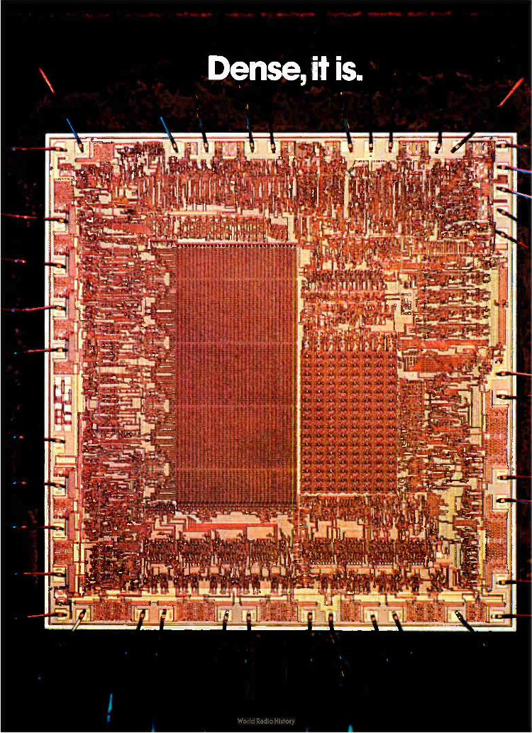
Dense, it is.
1111.111111111.1111111111111111=11110MM11111.1111111111111111111111118.111•110111111111/111Mr

Dumb, it ain't
Our new S2000 microcomputer contains more than 13,000 transistors on a chip less than .2- square. It was designed specific-ally to run appliances. Yet it's flexible enough for all kinds of products now de-pendent on electromechanical controls. The S2000 is an entire microcomputer on
a single chip, with expandable program ROM and versatile I O. So you can imple-ment or enhance your control schemes quickly and easily.
It's an amazingly efficient circuit, too. All 51 instructions in its powerful software set occupy just one ROM byte apiece. All but two execute in four microseconds, a single machine cycle. And this fast NMOS device can operate from one power supply.
For less than $5 each in quantity, each S2000 contains: 1. The CPU, including Control Unit, Arith-metic Logic Unit, Registers and Program Counter. 2. 1Kx8 ROM ( externally readable and expandable to 8Kx8). 3. 256-bit RAM. 4. 29 I/O lines. 5. 7- segment display ( normal or inverted) decoder and LED drivers. 6. Triac drive capability. 7. Line frequency ( 50 60 Hz) timer. 8. TouchControl capacitative switch interface. 9. Three- level subroutine stack and two flags.
10. Power-on reset and clock oscillator.
Soon, other 52000 family microcom-puters will have vacuum fluorescent display drivers and on-chip 2K ROMs. In addition, AMI welcomes modifications to the 52000 to meet your particular I/O requirements, making your system even more cost effective. Our Microcomputer Development Center
(MDC) contains a powerful array of hard-ware and software tools to get your product to the market fast. Its intelligent 6800 microprocessor system controls a CRT with a flexible text editor, a smart macro- assembler, and a built-in PROM burner. The DEV-2000 Development Board lets
you do hardware emulation and software debug at the same time. The SES-2000 Static Emulator Module plugs right into your prototype. Our Logic Analyzer gives you computer power to create your own diagnostic display layouts and formats. And we even have software that simulates the S2000 within the MDC. What more could you ask, except for
some Application Engineers to help you do a fast turnaround. We have those, too. Specialists in the S2000 are ready and waiting for your call at ( 408) 246-0330. Or simply write to AMI Marketing, 3800 Homestead Road, Santa Clara CA 95051. You'll be amazed how smart one dense little chip can be.
am:
>Ttei4e AMI
AMERICAN MICROSYSTEMS, INC
Circle 61 on reader service card 61


Digital announces a PDP-8 with
m enormous memory. Something big has just
appened to the world's most unous small computer. In fact, Dmething enormous.
Digital has just put 128K of lemory into the PDP-8.
This act is brought to you y a powerful new memory tanagement option called T8-A. And by two new MOS temory modules that fit large mounts of memory into small mounts of space. Simply by iding these 16K or 32K mod-les in whatever combination ou choose, you now expand our PDP-8/A into something igger. What's even better, you an mix MOS and core. And lat means you can protect your To am in non-volatile core hile you expand your data ase in MOS.
And thanks to the KT8-A all memory is under new man-ment. Not only does the
.5e8-A let you address up to 28K words of memory, but it lso offers you memory reloca-on and memory protection, trhile asking little in operating ystem overhead so you get ister system performance. W -iat's the cost of these
normous advancements? hat's the next attraction.
The new PDP-8A MOS
is as low as $11,000. And the top of the line 8A625 with 128K is yours for as little as $18,050.
They're the new big-memory Eights from Digital. Step right up.
Large memories aren't our only new trick.
New hardware and soft-ware improvements are also in the PDP-8 spothght.
The VK8-A is a new low cost PDP-8A option that pro-vides high quality video output plus keyboard and printer inter-faces. Video character genera-tion uses a super-sharp 9x9 dot matrix for high resolution on single or multiple CRT monitors up to one thousand feet away.
Also new for PDP-8 users is MACREL/LINKER — a sophis-ticated assembler with MACRO facilities that lets you implement, expand and update your system faster while reducing software development time.
And last but not least there's DECNET 8 — a series of software protocols that let you
form your own PDP-8 network. The PDP-8. Bigger.
Smaller. And better than ever. A short while ago, we made
big news with DECstation 78. A low-end system that set new highs for ease of use and simplicity.
Now we're expanding the PDP-8 family up, as well as down, and that means new opportunities for OEMs and end-users alike. Look into what's happening with PDP-8s. Call your nearest Digital sales office today.
Or send the coupon to PDP-8 Marketing Communi-cations, Digital Equipment Corporation, 129 Parker Street, PK3-1/M34, Maynard, Massachu-setts 01754. European headquar-ters: 12, ay. des Morgines, 1213 Petit-Lancy/Geneva. In Canada: Digital Equipment of Canada, Ltd.
d n °Ilan 17DP-8 Marketing Communications Digital Equipment Corporation, 129 Parker Street, PK3-1/M34, Maynard, MA 01754 Please send additional information about the PDP-8 family.
Name Title
nemory models are available at Company nices that are as crowd-pleasing s their performance. For a 16K I Address A205 you'll pay as little as City State Zip 3900 (quan. 1). 8A425 with 64K
Phone
Application L_ Eino7_1
OEM End-User
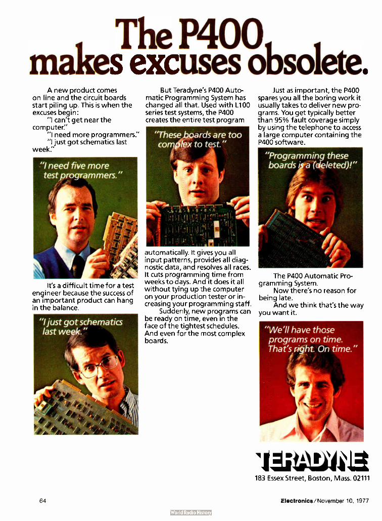
The P400 makes excuses obsolete.
A new product comes on line and the circuit boards start piling up_ This is when the excuses begin:
"I can't get near the computer."
"I need more programmers." "I just got schematics last
week."
"I need five more test programmers."
It's a difficult time for a test engineer because the success of an important product can hang in the balance.
But Teradyne's P400 Auto-matic Programming System has changed all that. Used with L100 series test systems, the P400 creates the entire test program
"These boards are too complex to test."
automatically. It gives you all input patterns, provides all diag-nostic data, and resolves all races. It cuts programming time from weeks to days. And it does it all without tying up the computer on your production tester or in-creasing your programming staff.
Suddenly, new programs can be ready on time, even in the face of the tightest schedules. And even for the most complex boards.
Just as important, the P400 spares you all the boring work it usually takes to deliver new pro-grams. You get typically better than 95% fault coverage simply by using the telephone to access a large computer containing the P400 software.
"Programming these boards a (deleted)!"
The P400 Automatic Pro-gramming System.
Now there's no reason for being late.
And we think that's the way you want it.
"We'll have those programs on time. That's right. On time."
llettee4vile 183 Essex Street, Boston, Mass. 02111
64 Electronics/November 10, 1977

The CCD's future takes on a bright hue 65-k devices, now available as samples from semiconductor
houses, will initially replace fixed-head and floppy disk storage
by Larry Armstrong, Midwest bureau manager
The computer industry may be on the verge of embracing the charge-coupled-device memory. A pair of semiconductor firms are now ship-ping samples of 65,536-bit parts, and two more are talking about it. In all, they give users a choice of three different CCDS in the first size large enough to promise a cost-effective, solid-state replacement for mechan-ical storage. Though most computer users are
still playing with the new devices in their laboratories, the first wide-spread application of the CCD will probably be as a successor to fixed-head disk storage, especially low-end floppy disks. Like the CCD, mechan-ical disks store data in a serial format, easing the device's entry into that market without changes in system architecture.
But the high volumes that semi-conductor producers are counting on will come from application as auxil-iary or even main storage, supplant-ing metal-oxide-semiconductor and core random-access memories. That change, however, will not come about until there is a redesign of computer systems. The time is ripe for a shift to
CCDS, with the 65-k part the thresh-old size for widespread acceptance. "There has been a lot of interest at the 16-k level, with substantial numbers of units sold," reports Gilbert F. Amelio, vice president and general manager of Fairchild Camera & Instrument Corp.'s MOS/CCD Products division. "But the really big volume users— the main-frame computer houses and others — haven't entered. They've been by-standers, watching the smaller guys." Almost to a man, the large
1 II Ill 1—>
CLOCK 2
REGEN ERATOR
INPUT/ OUTPUT CONTROL
t R/W
.4-- Ay
I 0
Sever. Serial- parallel-serial structure uses extra clock. Data is clocked in and out of each loop
at 5 MHz, but runs at 156 kHz through 32 parallel shift registers. Device is from TI.
users now are saying "the CCD is it," adds Amelio.
Texas Instruments Inc., which had not sold CCD memories, led the foray when it took the wraps off its 65-k chip last March [Electronics, March 17, p. 38]. Fairchild, though, was fast on its heels with a scaled-up version of its earlier 16-k parts, and Intel Corp. plans samples of its 65-k CCD by March. The Intel part is due about the same time as Motorola Inc. is scheduled to produce a similar product, built with Fairchild masks. But with the exception of the Fair-child- Motorola team, the highly competitive semiconductor industry has made no attempt to standardize its designs.
Texas Instruments first unveiled its CCD in a unique 16- pin, 400-mil-wide ceramic package. But it has just completed a 36% smaller version that will fit into the standard 300-mil mos package that is at least a dimensional match for the Fairchild part, although pinouts are different. Moreover, Intel is telling customers
about a device that requires 18 pins. But the real differences are in
organization. Fairchild and TI are offering CCDS organized as 16 by 4-k by 1, the industry parlance for 16 randomly accessible shift registers, each 4,096 bits long and arranged in an interleaved serial- parallel-serial structure that keeps power low and operating rate high. The look of a RAM. Intel is trying
to make its part look more like a random-access memory, with 256 loops of 256 bits each. "We chose to make our loops shorter, thus reduc-ing latency time," says William Regitz, memory products manager at the Santa Clara, Calif., firm. "We believe that will be the factor that will establish ccos with a broader base of customers," bringing the parts down the learning curve faster. Toward the same goal, the Intel version— unlike the other two ap-proaches and its own earlier charge-coupled devices— is totally compat-ible with transistor-transistor logic. Average latency time, a function
Electronics/November 10, 1977 65

Probing the news
of loop length and maximum data rate, is the time it takes to get access to a bit in the middle of a loop. It is roughly comparable to a RAM'S access time. For the Intel part, which runs up to 2.5 megahertz, latency time is 125 microseconds. With their longer loops, the Ti and Fairchild designs offer a 400-µs latency time when they are being operated at their maximum data rate of 5 MFIZ. Slow data access does not bother
Intel's CCD competitors. "I maintain that the CCD is not intended to be used as a fast access device," says John Hewkin, manager of mos memory marketing strategy at Ti's Houston facility. " It's intended to store blocks of data. It will be the cheapest form of read-write storage known to man, and the system archi-tecture will develop around the rela-tive device costs." His firm consid-ered building a CCD with many more shorter loops like Intel's, but rejected the design. "Each loop requires a regenerator and a sense amp, so overhead circuitry takes up less chip area on a 16-loop part than on one with 256 loops," he says.
Latency isn't primary. Adds Fair-child's Amelio: " Latency time is not the most important consideration to the user." It will take some rethink-ing of computer architecture to come
up with a memory system where latency time is transparent, he admits, but once that is done, no one will want to pay a premium for a low time. "Our strategy in the CCD
marketplace is to give the user what he needs to get off the ground," he says, "but not to build in so much performance that it's not possible to get down the cost curve." In the long haul, he says, what will count is the bottom line of price per bit, not latency or transfer rate.
Designs similar to the virtual memory systems being shipped today could easily be implemented with CCDS. "We'll see configurations with CCD as main memory, and a fast static RAM buffer between it and the central processor," says David C. Ford, strategic marketing manager for memories at Motorola's Austin, Texas, mos center. "Main memory will be shifted into the buffer in blocks as required by the system," he explains, much the same way as today's fast buffer cache memories use slower main storage. Data in the CCD would be loaded into the fast RAM buffer in page mode, adds TI'S Hewkin. He points out that the data rate of TI'S 65-k device- 170 nano-seconds— exactly matches the page-mode data rate for its fastest mos dynamic RAMS.
Every one of the manufacturers agrees that charge-coupled devices will be harder to use than dynamic RAMS, however. "There's got to be a
Beyond the computers
Besides the computer applications of charge-coupled devices— as main memory and disk replacement, or perhaps as secondary memories between the two— manufacturers of CCDs are targeting their products to noncom-puter markets, where users are trying to solve special problems with memory. These markets include such applications as television imaging or cathode-
ray-tube refresh on terminals and audio storage between analog-to-digital and digital-to-analog converters. "They can be used for anything that requires serial data transfer, including telecommunications, radar, and time-related data transforms," says John Hewkin of Texas Instruments. "There seems to be an emerging volume of this type of application," says Fairchild's Gilbert Amelio, "each small to medium in volume, but in total adding up to a large number of units."
Another solid-state mass storage device, of course, is looming only a little further down the road: the bubble memory, which has the added advantage of being nonvolatile. Intel's William Regitz makes the point that "dynamic RAMs haven't replaced core, because there are certain applications where nonvolatility is an overriding concern." Eventually, he says, CCDs will beat disk and bubbles on cost, " but each will have their niche in the market. The only question is how big each niche will be."
reason to go to CCDS," says Ford, "and that reason will be cost. Dynamic RAMS are more difficult to use than static RAMS, but people choose to go for dynamic RAMS
because they're cheaper." And the CCDS' cost advantage is
significant: Fairchild's Amelio says that the parts will maintain a minimum 4-to- 1 advantage over RAMS and quite possibly better. How soon the new devices will reach that low price is still a question with different replies, however. "The 64-k CCD is now selling for
$70 to $ 100, but within the next couple of months we'll see lower prices," says Hewkin. His company is sticking with its original projection of $ 13 CCDS by the end of next year. That price figures out to about 20 millicents per bit, about half what the industry figures dynamic RAMS will sell for at the same time.
"But we expect to see CCDS at a third or a quarter of the bit cost of RAMS in 1979," Hewkin says. TI
plans to further reduce the chip size of its 65-k device to that of its 16-k RAM by the end of 1979. This shrink will give the CCD a 4-to- 1 real-estate advantage. Run on the same produc-tion lines as MOS RAMS, the CCD should be a better-yielding device, since top-level polysilicon electrodes are electrically connected, eliminat-ing some of the shorts that cause dynamic RAMS to fail. In five years, CCD cost per bit will be about 2 or 3 millicents, or comparable in cost to moving-head disks, Fairchild's Ame-lio estimates.
But the key to final acceptance of CCDS, insists Intel's Regitz, is stan-dardization. "Users expect at least some minimum compatibility," he reasons, "but they won't have it on the first round of 65-k CCDS." Regitz points out that suppliers of the devices have completely incompa-tible parts, all the way down to the socket level. "The closest any of the devices come to similarity is the fact that Fairchild and Ti have both opted for 16-pin devices, and the 16-by-4-k- by- 1 array," he says. "But Fairchild's is in the standard 0.3-inch-wide package and TI'S is in the nonstandard 0.4- in.-wide configura-tion." For its part, Intel uses the 0.3-in. package, but it is an 18-pin device. LI
66 Electronics/November 10, 1977

The Choice In Laboratory & Systems
Measurement Data Precision provides for
precision laboratory or Automatic Test Equipment and Data Acqui-sition requirements by offering a selection of multimeters en-compassing a wide range of speci-fications, features, and options... a selection that will meet almost all precision laboratory and monitoring control needs.
MODEL 7500 Model 7500 is a 51/2 digit
multi-speed instrument that will perform a full conversion 1000 times per second! It is completely programmable in function, range, mode, timing, and conversion speeds. DCV accuracy is 0.007% of input • 0.001% range -±-1 1.s.d. for 6 months; sensitivity isliLV DC and AC and 1m1; DCV and ACV measurement from 1pV to 1000V. As a true universal ratiometer, the 75001also enables the user to choose both the numerator and denominator independently, and every measurement— DC Volts, AC Volts, and Resistance— can be made on a ratio basis to any other if desired.
Model 7500 provides for full incorporation into any computer-based, high-speed, multi-channel automatic test or data acquisition
ter
system. In addition, a broad range of standard options are avail-able, including built-in micro-processor-controlled IEEE 488 BUS or RS232/TTY Output. Base price is $2995.00.*
MODEL 3500 Model 3500 is a full-function,
autoranging, 51/2-digit instrument with 6 months basic accuracy of • 0.007% of reading • 0.001% of range • 1 1.s.d. All important control and state signals are brought to rear panel connectors for use in automated control, test, and computing systems. Voltage ratio is included.
Time-buffered isolated BCD Output, brought out through Standard DTL/TTL interface circuits, permit asynchronous printing, recording, and/or display. In addition, Model 3500 features measurement of DC volts, AC volts, Resistance, Ratio and local/remote Ranging and Triggering plus excellent common-mode and normal-mode rejection. Base price is $995.00.*
wononancznnmonnEemi .•,,,
‘, PRIuslud,
\.
MODEL 3400 Model 3400 is the world's
most accurate systems/lab 41/2 digit multimeter. It is a fully programmable system multimeter and a highly versatile stand-alone, autaranging laboratory multimeter.
Full 100% overranging, basic DCV accuracy of • 0.007% of input _-_• 1 1.s.d. for 6 months, mea-sures from • 10 microvolts to -_1,000 VDC, ACV from 10 micro-volts to 750V, resistance from 10 miliiohnis to 20 Megohms, AC/DC, DC/DC voltage ratio and full remote control rup to 12 con-versions per second. It has com-plete capacity, and its BCD out-put is fully printer-compatible. IEEE Standard 488 BUS is op-tional. Base price is $795.00.* With true RMS AC Volts-$895.00.*
Data Precision Corporation Audubon Road Wakefield, MA 01880 USA (617) 246-1600, TELEX (0650) 949341.
*Price L SA
DATA PRECISION
...years ahead

The Ansley "D"
Connector...
Our new series of male and fe-male "D" connectors offer you a cost effective external mass termi-nation cable and connector system second to none. Its uniqueness be-gins with a one-piece "D" con-nector package that meets industry standards for size, pin spacing, and contact reliability. With no loose parts to match up, positive cable-to-contact alignment is as-sured. Conductors are mass termi-nated in seconds with our standard BLUE MACSTM hand or bench tools. The results? Faster installa-tion, higher reliability.
Contact pins are spaced on .0545" centers — a perfect fit for any standard inter-cabinet "D" type connector application. Our new "D" connectors are designed to mate with standard .050" pitch flat cable as well as our new, improved jacketed cable — the only flexible flat cable engineered specifically for out-of-cabinet use.
a new L meaning
to cost effectiveness.
The Ansley BLUE MACSTM jack-eted cable is U.L. listed for ex-ternal interconnection of electronic equipment. Electrically, it outper-forms standard jacketed twisted pairs in typical I/O applications. And there's no special zipper lock tubing required — reducing the need for an extra cable accessory. Installation is faster, easier. And like all Ansley connectors, you can daisy chain our "D" types any-where in the cable — along with our DIP socket, card edge, or pc board connectors.
Cable alignment and high con-tact reliability is assured — because both cable and connector are grooved for absolute alignment. Our patented TULIPTm 4-point in-sulation- displacing contacts are permanently fixed and sealed-in to provide a reliable, gas-tight, corrosion-free mass termination.
For the full reliability/cost ef-fectiveness story and technical data, call or write:
"IEE3 ArtsLe_y The mass termination company.
T&B/Ansley Corporation • Subsidiary of Thomas 8i Betts Corporation 3208 Humboldt St. • Los Angeles, CA 90031 • Tel. ( 213) 223-2331 • TWX 910-321-3938
Available through authorized Ansley distributors
In Canada: T&B/Ansley, Ltd. 700 Thomas Ave., Industrial Park lberville, P.Q.
Circle 68 on reader service card
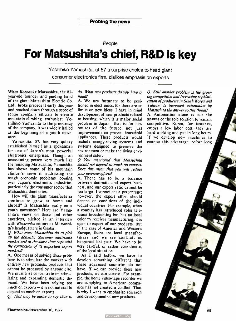
Probing the news
People
For Matsushita's chief, R&D is key Yoshihiko Yamashita, at 57 a surprise choice to head giant
consumer electronics firm, dislikes emphasis on exports
When Konosuke Matsushita, the 82-year-old founder and guiding hand of the giant Matsushita Electric Co. Ltd., broke precedent early this year and reached down through a score of senior company officials to elevate mountain-climbing enthusiast Yo-shihiko Yamashita to the presidency of the company, it was widely hailed as the beginning of a youth move-ment.
Yamashita, 57, has very quicky established himself as a spokesman for one of Japan's most powerful electronics enterprises. Though an unassuming person very much like the founding Matsushita, Yamashita has shown some of his mountain climber's nerve in addressing the tough economic problems looming over Japan's electronics industries, particularly the consumer sector that Matsushita dominates. How will the giant manufacturer
continue to grow at home and abroad? Is Matsushita really on a youth movement? Here are Yama-shita's views on these and other questions, elicited in an interview with Electronics editors at Matsushi-ta's headquarters in Osaka. Q. What must Matsushita do to pick up the domestic consumer electronics market and at the same time cope with the contraction of its important export markets? A. One means of solving these prob-lems is to stimulate the market with entirely new products, products that cannot be produced by anyone else. We must first concentrate on stimu-lating and expanding domestic de-mand. We have been relying too much on exports— it is not natural to depend so much on exports. Q. That may be easier to say than to
Electronics/November 10, 1977
do. What new products do you have in mind? A. We are fortunate to be posi-tioned in electronics, for there are no limits on new ideas. I have in mind development of new products related to housing, which is a major social problem in Japan— that is, for new houses of the future, not just improvements on present household appliances. These products would include energy-saving systems and systems designed to preserve the environment or make the living envi-ronment safer. Q. You mentioned that Matsushita should not depend so much on exports. Does this mean that you will reduce your overseas efforts? A. There has to be a balance between domestic and export busi-ness, and our export ratio cannot be too large. I cannot set a percentage; however, the export effort should depend on conditions of the indi-vidual countries. For example, when a country has introduced color tele-vision broadcasting but has no local color iv receiver manufacturing, it is open to export of our products. But in the case of America and Western Europe, there are local manufac-turers and we see conflict, as happened last year. We have to be very careful, or rather considerate, of the local situation. As I said before, we have to
develop something different that these advanced countries do not have. If we can provide these new products, we can coexist. For exam-ple, the home video-tape recorder we are supplying to American compa-nies has not created a conflict. That is why I want to emphasize research and development of new products.
Q. Still another problem is the grow-ing competition and increasing sophisti-cation of producers in South Korea and Taiwan. Is increased automation by Matsushita the answer to this threat? A. Automation alone is not the answer or the sole solution to remain competitive. Korea, for instance, enjoys a low labor cost; they are hard-working and put in long hours. If we develop new machines to counter this advantage, before long
69

Suppress Power Line
EMI Comin'
or Goin'
Series JX5400 Filters reduce noise
emanating from or interfering with
equipment UL recognized. Available in
4 different circuit configura-tions to solve specific EMI problems. Effective in sup-pressing both common mode (line-to-ground) and differen-tial mode ( line-to-line) interfer-ence. Two case styles, with load terminals extending from back or top of plated steel shielded housing, both incor-porating standard IEC male line cord connector. Ideal for filtering external transients in 150 KHz-30 MHz range in equipment containing low-level logic circuitry. For complete technical data, write
for Engineering Bulletin 8212 to: Technical Literature Service, Sprague Electric Co., 35 Marshall St., North Adams, Mass. 01247.
SPRAGUE° THE MARK OF RELIABILITY
Probing the news
Korea will have the same equipment plus low labor rates. So we cannot compete with automation alone. In-stead, I return to my original point— we must develop unique products that nobody else can make. Q. What market opportunities do American electronics firms have in Japan these days? A. The American electronics manu-facturers are better at industrial products than the Japanese, and therefore Japan offers a good market with a big potential for these compa-nies. American companies should study the Japanese market first, especially in industrial electronics. It is often said that it is impossible for Americans to succeed in Japan, but that is not true. For example, IBM has been very successful. Q. Your appointment as president of Matsushita has caused comment in Japan. Is this indeed a youth move-ment? A. It is a general trend and will continue. This company was led in the past by K. Matsushita, an outstanding leader and founder. But he cannot live forever. So we have
reached a turning point, a change from the traditional organization of Japanese companies to this new trend. Another change, caused by the growing size of this company, has been from one-man leadership to group effort. Communication is a problem in a large company. It is necessary to let all the employees know what is happening. Q. As manager of Matsushita's air conditioner department you gained a reputation for turning around a falter-ing operation. What did you learn then that will be useful now? A. I learned that the principles of good management are the same no matter where they are applied. The same fundamentals that were suc-cessful in a small operation can be used in operating a large enterprise. Q. Though you have just begun, having been president since February, what would you like to be remembered for when it comes time for you to retire? A. When I leave, I would like to see our younger employees busy and full of hope and ambition for the future. I hope to leave the company youth-ful, forward-looking, because when this atmosphere prevails, the compa-ny succeeds. D
Japan's youth movement
There is a trend in Japan toward elevating younger managers to top spots, but it is contrary to the national tradition of moving people up based on seniority and age. Therefore, Konosuke Matsushita's move to bypass his own chain of command to put 57-year-old Toshihiko Yamashita in charge of the company he founded still raised some eyebrows in the island nation's tightly knit industrial community, although Yamashita is hardly a teen-ager, ager, even by Japanese standards.
But the maneuver worked because the firm's hierarchy was well along in age and the company had just had a good business year, and because the decision came from the founder himself. Careful to ease the feelings of those passed over, Matsushita pointed out that he wanted someone who could be president for at least 10 years—thus eliminating most of the directors and managers in line for the job.
Other firms have made similar moves. For example, in January 1976 the cofounders of Sony Corp., Masaru lbuka and Akio Morito, passed the presidency and vice presidency to Kazuo lwama (then 56) and Norio Ohga (then 45). Two top executives, the brothers Hiroshi Kawashima, managing director of Nippon Gakki Co., and Kiyoshi Kawashima, newly appointed president of Honda Motor Co., are both in their forties. Also, SS Pharmaceu-tical Co. recently named 41-year-old Naokata Taido president, and the new president of Nittan Valve Co. is 46-year-old Teijiro Sugimoto.
According to one Japanese business publication, in the first quarter of 1977, 40 large corporations appointed new presidents; 20 were under 60, 17 were in their fifties, and 3 in their forties. Not exactly a tidal wave of youth, it is still a noticeble trend in this country so dominated by traditional practices and veneration of age.
70 Circle 70 on reader service card Electronics/November 10, 1977

PUSH to initiate automatic in-circuit testing of all of your analog,
hybrid and digital boards. Test all of your printed circud boards aid, in many cases, completely eliminate costly functional testing. Faultfinders FF101C and FF303 in-circuit test systems give you the flexibility you need with a broad range of CPU/peripheral compatibility. And you can get full time utilization o' the system computer with foreground/background programming to execute automatic pi.ogram generation. text editing, data analysis or file maintenance even while you're testing boards.
You'll be testing more boards, bigger boards and more complex boards, so now is a good time to start checking on what Faultfinder in-circuit test systems can do to make the job more cost-efficient. Call your Faultfinder
representative: Latham, Tom Coleman, ( 518) 783-7786; Chicago, Al Roraus, ( 312) 696-0335; San Francisco, Bruce Douglas, ( 408) 732-9020; Irvine, Chuck Hults, ( 714) 549-4901: Europe, Marty Liebman, ( 49) 6196-44008; England, Mike Cook, ( 44) 4204-3443 Or start with the coupon.
177 FAULTFINDERS Inc 15 AVIS DRIVE, LATHAM, NY 12110
Show me how Faultfinder in- circuit test systems can improve our production testing
NAME
COMPANY
ADDRESS
CITY
TITLE
ZIP
EL
L__J
Electronics/November 10, 1977 Circle 71 on reader service card 71

Probing the news
Photovoltaics
Solar cells click in helping record yield in irrigation test by Lawrence Curran, Boston bureau manager
This summer the sun helped corn to grow in Nebraska as never before— by shining on the photovoltaic equip-ment driving irrigation machinery. The experiment at a University of Nebraska test site in Mead also used herbicides and a hybrid strain of corn to extract 150 to 180 bushels per acre from the land, well above the statewide average of 135 bushels. The photovoltaic system was de-
signed and built by the Massachu-setts Institute of Technology's Lin-coln Laboratory and is the largest solar-cell-powered unit in existence to date. Now that the harvest is in, it will drive fans in corn-drying bins. Eventually, plans are to employ it year-round, for irrigation and grain drying in summer and fall, and perhaps to drive motors used in fertilizer production and to power heating systems in livestock sheds.
Lincoln Lab, in Lexington, Mass., was prime contractor for the Depart-ment of Energy's division of solar technology [Electronics, Oct. 13, p. 26]. The lab won the $ 1 million
contract last December and worked in conjunction with the University of Nebraska's agricultural engineering department in Lincoln, which has charge of the irrigation research.
Ervin "Bud" Lyon, assistant task leader for the irrigation experiment in Lincoln Lab's energy systems engineering group, says that a photo-voltaic system of this kind would be prohibitively expensive for farmers now, mainly because solar cell costs, about $5 per cell, are still too high. The system's success to date, how-ever, indicates that photovoltaics could be a viable alternative to utility power for irrigation if cell costs are brought down to 10 to 20 cents within 10 years, especially in a state such as Nebraska, where the present energy cost for irrigation is about $81 million a year.
Three subsystems. There are three principal elements in the photovol-taic system: the array, a battery trailer, and an equipment trailer. The array is huge, consisting of some 97,000 individual solar cells in two
325-foot-long rows, each containing 14 modules that can be tilted to the optimum angle to collect the sun's energy. The solar cells were supplied to the Department of Energy for the experiment by Sensor Technology Inc., Chatsworth, Calif., and Solarex Corp., Rockville, Md.
Lyon says that the system ran some 10 hours a day, driving a 10-horsepower dc motor to pump water from a re-use pit through pipes to the rows of corn. The re-use pit collects the runoff for recycling into the field and can be replenished from a nearby well that uses utility power to drive a 30- hp pump motor. The initial plan had been to experiment with both dc and ac pump motors for the re- use pit, but problems devel-oped with the three-phase inverters that were to have converted the de bus voltage to ac. The dc pump motor gets its power
from 28 solar panels. These are connected in parallel and produce 120 to 140 volts of dc bus voltage, with the dc bus connected to two strings each containing 19 lead-acid batteries, also connected in parallel. Lyon says the 6-v batteries have a total usable storage capacity of about 80 kilowatt-hours. The system produced 25 kilowatts peak power. The control system for the instal-
lation, housed in the equipment trailer along with the data-collection switch gear and power-conditioning equipment, has been manual or semi-automatic. By December, Lyon says, Lincoln Lab engineers hope to have an automatic control system using an Intel 8080 microprocessor. Eventually, Lyon says, "we hope to automatically control the irrigation schedule itself."
Focusing the sun's glow. Solar Array dominates Nebraska landscape in experimental irrigation system.

BUSS ELECTRONIC FUSES.
Nearly every type of fuse and fuse holder you need to protect electronic circuits and devices you can get from us, easy. For example, Buss
Semiconductor Fuses; 700 volts, with extremely low 12t and 1p let-thru values. TRON R Rectifier Fuses, 1/2 to 1,000 amps, up to 600 volts. Fusetron" dual-element time-delay fuses. Buss quick-acting glass tube fuses. Buss signal-indicating, alarm-activating fuses. TRON sub-miniature pigtail fuses. Buss sub-miniature GMW fuses. Buss telecommunications fuses. Buss military fuses. And Buss fuse holders and fuse blocks. Get your
hands on exactly what you want. Write us now. Ask for Buss Bulletin SFB.
leSs FusES HLJNANN MANUF TuRiniC a McGraw-EdIson Company Chvuston
Earth Oty MIssour, 63045
WE MAKE IT EASY TO GET YOUR HAND N WHAT YOU WANT
Electronics/November 10, 1977 73
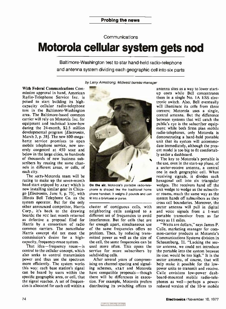
Probing the news
Communications
Motorola cellular system gets nod Baltimore-Washington test to star hand-held radio-telephone
and antenna system dividing each geographic cell into six parts
by Larry Armstrong, Midwest bureau manager
With Federal Communications Com-mission approval in hand, American Radio-Telephone Service Inc. is poised to start building its high-capacity cellular radio- telephone tern in the Baltimore-Washington area. The Baltimore-based common carrier will rely on Motorola Inc. for equipment and technical know-how during the 24-month, $2.5 million developmental program [Electronics, March 3, p. 38]. The new 800-mega-hertz service promises to open mobile telephone service, now sev-erely congested at 450 MHZ and below in the large cities, to hundreds of thousands of new business sub-scribers by reusing the same chan-nels in different areas, or cells, of each city. The AR-rs-Motorola team will be
racing to make up the seven-month head start enjoyed by AT&T which is now installing similar gear in Chica-go [Electronics, June 9, p. 75], with Illinois Bell Telephone Co. as the system operator. But for the only other announced competitor, Harris Corp., it's back to the drawing boards: the FCC last month returned as defective a proposal filed for Harris by a consortium of radio common carriers. The noncellular Harris concept did not meet the commission's desire for a high-capacity, frequency-reuse system.
That idea— frequency reuse— is central to the cellular concept, which also seeks to control transmission power and thus use the spectrum more efficiently. The system works this way: each base station's signal can be heard by users within the specific geographic area, or cell, that the signal reaches. A set of frequen-cies is allocated for each cell within a
On the air. Motorola's portable radio-tele-
phone is shaped like the traditional home
phone handset. It weighs 2 pounds and can
fit into a briefcase or purse.
cluster of contiguous cells, with neighboring cells assigned to a different set of frequencies to avoid interference. But for cells that are far enough apart, simultaneous use of the same frequencies offers no problem. Then, by reducing trans-mitted power as well as the size of the cell, the same frequencies can be used more often. This opens the service for more subscribers by subdividing cells.
After several years of comprom-ising on channel spacing and signal-ing schemes, AT&T and Motorola have compatible proposals— though there will be differences in execu-tion. For example, Motorola prefers distributing its switching offices to
antenna sites as a way to lower start-up costs while Bell concentrates them in a single No. IA ESS elec-tronic switch. Also, Bell eventually will illuminate its cells from three corners; Motorola uses a single, central antenna. But the difference between systems that will catch the public's eye is the subscriber equip-ment: while both firms plan mobile radio-telephones, only Motorola is demonstrating a hand-held portable unit that its system will accommo-date immediately, although the pres-ent model is too big to fit comfortab-ly under a dashboard. The key to Motorola's portable is
the use, even in the start-up phase, of a sector-receive antenna, a central one in each geographic cell. When receiving signals, it divides each hexagonal cell into six triangular wedges. The receivers hand off the unit wedge to wedge as the subscrib-er roams, much the same way as the system hands off subscribers as they cross cell boundaries. Moreover, the sector antenna will pull in digital and voice signals from a 1-watt portable transceiver from as far away as 11 miles.
"Watts are dollars," says James P. Caile, marketing manager for com-mon-carrier products at Motorola's Communications Systems division in Schaumburg, Ill. "Lacking the sec-tor antenna, we could not introduce the portable into the system because its cost would be too high." It is the sector antenna, of course, that will help make it possible for the low-power units to transmit and receive. Caile envisions low- power dash-board-mounted mobile radio-tele-phones as well— perhaps a power-reduced version of the 10-w mobile
74 Electronics/November 10, 1977

Newest ESI 66
twAren.AAA„.
UNIKNOWN
Model 252 Digital lmpecance Meter
1,41-C Got' chal ...and for only $695
(U.S.A. only)
weeder" does it all even Dissipation Factor.
At $695, incoming inspection and evaluation of passive components becomes easily affordable. You not only measure L, R, C and G with high accuracy over wide ranges, but the dissipation factor reads out also. Check these features in this light, compact, easy to transport teste-: • Measures D as well as L, R, C, G, automatically • Light weight; tilt stand handle. • 0.25% basic accuracy. • Wide ranges. • 1 kHz test frequency. • 2 measurements/sec. • External bias. • 4-terminal connection. • Analog outputs. • Low power design.
ELECTIO SCIENTIFiC
• Large 31/2 -digit display • Front panel cust cover (option). • Input protection. Measurements are simple, fast and accurate
. . Set the range and connect to unknown. Four-terminal KELVIN KLIPSR are included, and a front panel dust cover is optional. The Model 252 can also be combined with ESI's Model I412B Limits Comparator for go/no-go testing. Handy tiltstand handle completes this value
buy, along with the assurance of our precision measurement name: Electro Scientific Industries, 13900 NW Scence Park Dr., Portland, Ore. 97229. Units will be available in November, so request
a demo today. Telephone 503/641-4141.
Circle 75 on reader service card

Probing the news
On the inside. The radio-telephone shown
will be used with the Baltimore-Washington
test. Newer model is on drawing board.
that Motorola is developing for Bell's system, he hints.
Motorola showed its first portable radio-telephone in 1973 after it peti-tioned the FCC for an experimental license to operate a portable system in New York City—a proposal the FCC never considered. The company has since redesigned the unit, which vice president Martin Cooper dubs "a second-generation technological demonstration." It now has a pro-duction model on the drawing boards, pushing the twin goals of lowering power consumption and raising the level of integration. " It still has a couple of problems," Cooper says. "It's bigger than we'd like it, and we'd like a unit that can be more easily carried. But within two years, we'll be producing a marketable product." It will sell for around $2,000—just $200 more than the present mobile, he adds. From the cupboard. Motorola
drew heavily on other products for some of the modules in the portable. For example, the second interme-
diate-frequency amplifier and dis-criminator in the unit's receiver section were slightly modified from the firm's Pageboy II paging re-ceiver, and the audio preamplifier module came directly from the MX300 line of hand-held portable radios. These radios also supplied the transmitter audio amplifier and deviation limiter module, says Don-ald L. Linder, manager of Motoro-la's communications research labo-ratory at Schaumberg.
But the rest of the portable presented more of a challenge to Motorola designers. Since the radio is designed for full duplex operation, it requires substantial filtering to isolate the two signals. "The key in making the portable unit small is the size of the duplexer," Linder says. A cigar-box sized module in mobile radios, it has been reduced consider-ably. The miniaturization was eased by the cellular system's 800-MHz operation and 45-MHz separation between transmit and receive fre-quencies. However, the primary fac-
We're showin off for Commonwealth Edison.
Chicago's Commonwealth Edison uses Ramtek color graphic displays for rapid display and status reporting of pipelines, valves, pumps, and other generating station data A clear, color-coded display is updated every 5.0 seconds, giving near-instantaneous visual scan- log-alarm functions, bar graphs, one-line piping diagrams, flow status, etc
Before the Ramtek systems were installed, status reporting was by hardwired mimic boards, black and white alphanumeric CRTs and typers
The Ramtek system not only costs less, it also allows more information to be presented to the operator in a form that is quickly and easily under-
stood This results in better operator efficiency, and faster alarm reaction time In Commonwealth Edisons 16,000 Megawatt system, thirty Ramtek color graphics displays will be utilized

tor is the portable's transmission at only 1 w, instead of the 30 w that today's systems demand. The frequency synthesizer serves
both transmitter and receiver, and is of the mix-down and divide type with a voltage-controlled oscillator at 70 mHz and complementary metal-oxide semiconductor pro-grammable dividers, Linder says. The output of the synthesizer is stepped and multiplied to get the 666 channels spaced 30 kilohertz apart that both Motorola and Bell are using in their systems. The cell concept requires that the
transceiver operate at any one of four power levels, as directed by the base-station computer, "to prevent mobiles and portables close to the antenna from overloading nearby channels, and to reduce cochannel interference between reused frequen-cies when the unit is in a good posi-tion for propagating," Linder says. Motorola controls the current in the final state of the power amp with a dc feedback network that produces
the four levels in 6-decibel steps. It has come up with a very small circu-lator, a ferrite device that protects the power amplifier from energy reflected back from the antenna. Output power is fed through the circulator to the duplexer and finally to the printed-circuit antenna.
Silence. In addition, when the subscriber is not talking, the power amplifier is shut down entirely by a voice-operated switch that Motorola has developed to preserve battery life. The portable telephone uses 15 plug-in replaceable thick-film mod-ules, some borrowed from other products and most designed specifi-cally for the unit. In the transmitter, receiver, and synthesizer sections, these are built into metal boxes that shield the receiver. Two custom and five standard
integrated circuits control the syn-thesizer's programmable counters, recognize incoming calls that carry the unit's digital address, and pro-vide an output signal to the trans-mitter when the user is requesting
service. This signal includes the portable's identification number that allows the system operator to bill the user for radio-telephone service. "In future designs, however, we'll use a c-mos microprocessor for the logic functions," Linder says. A pc board on the front of the
radio carries the 14-switch array as well as a standard 1-MHz crystal and tone generator lc that create tone signals when the keys are depressed. The board also holds light-emitting-diode indicators for transmit and busy signals, and a c-mos flip-flop that latches on and off keys. The back of the case is molded
around six rechargeable nickel-cadmium batteries that supply 7.5 volts to the circuitry. "That gives the user a half-hour of conversation time and keeps the receiver on standby all day to pick up incoming calls," Caile says. "That's equivalent to 10 aver-age mobile telephone calls, more than enough power to cover average mobile telephone usage, which is three to six calls per day."
BOILER 3 START —UP
905 , 1 r
I 22 le 859 Pt'
ccow ecc:r ,TAMDC14 51111
IAS 631 r
...AS 631 r POI SH ICC
[COI,
1 r 121 .1/
C." 555 I 1 ,
859 Psi 25 « Le/we
500 95 % 581
518 O
& BY —PASS 859 ,
I come at I 35 62 .
905 , 905r 859 Sm.
OlIr [ XI 35 62 MILS
CDC M ., I r
IM31 22 : hi 121
err • 33
LP
1 , " 35 11,1,11
111 121 *II
C3140 1.01.15,4 Py141,
31
I r e3I .32
Commonwealth Edison monitors on-off, full-empty, flow status, and other parameters on a Ramtek FS-2400 Color is assigned for steam, water, no-flow, and oil flow to differentiate visually between materials and status On the RM-9000. resolutions from 240 lines x 320 elements to 512 lines x 640 elements are available
Commonwealth Edison is but one of a growing number of customers who are finding that Ramteks raster scan modular graphics and imagery systems are giving them the expandability, flexibility, and increased productivity they need Besides the basic alphanumeric and imaging capability, Ramtek offers a wide variety of other functions including graphics— vectors, conics, plots, bar charts—pseudocolor, and grey-scale translation
Ask about our new Ramtek RM-9000 family that is totally controlled by a standard 8080 micro-processor that really makes it easy to develop and download your own control software
To find out more about how Ramtek can show off for you, call or write Ramtek Corporation, 585 North Mary Avenue, Sunnyvale, California 94086 (408) 735-8400
ttamtek Our Experience Shows
Circle 77 on reader service carc

Analysis of Variance Engineering Analysis & Schematics

Time Series Analysis 1-.>•ressior Analysis Business Analysis
With our new friendly computer,
solving problems won't seem like work anymore.
Introducing System 45. Formally, it's called the HP System 45 Desk-top Computer, but you'll come to regard it as a valuable friend. It fits in your workstation, ready to go the instant you have a problem. Gives you the ability to perform more thorough analyses. faster, and with less effort than you ever imagined.
System 45's friendliness comes from the integration of several problem-solving capabilities in one compact chassis. It puts powerful graphics. high performance I/O, big memory, and mass storage all together at your fingertips. Most important, System 45's design enables you to fully exploit these capabilities without getting involved in its internal operating routines. The power to handle big
tasks. Though small enough to go wherever your work demands, -System 45 is big enough to handle 85 x 85 matrix inversions or tenth-
order ordinary differential equations. You can easily handle most of the problems you've been assigning to a big computer: Clin-lab data base management, thermal analysis, high-speed data acquisition and control, state variable analysis, structural analysis for virtually any geometry, production scheduling and control, or electronic circuit analysis—to name but a few. Conversational Problem-
solving. Solutions are straight-forward because you communicate with System 45 in conversational BASIC. The dialog is so relaxed it seems almost human. Type in your data and commands and System 45 presents your formatted results on its high-resolution CRT. Need hard-copy? A single command exactly duplicates your plot, drawing or data table on the optional built-in printer. A logical growth path. Like
any true friend, System 45 will stick by you as your problems grow and change. You can expand the mem-
HEWLETT àhwir PACKARD
P 0 Box 30' Loveland Colorado 80537
ory, add performance options, or plug-in your choice of peripherals, including floppy and hard discs. For more convenience and versatility, you can round out your system with a selection of programs from our growing software library. Ask for an introduction. To
learn more, drop us a line in Loveland, home oi the friendly computers. Or call your local HP Sales Office for an introduction to the System 45.
D Please have a salesman call. E 11/10/77
Phone Ej Please send more information. My application interest is: D Engineering Design.
Numerical Analysis. Data acquisition and control.
Name Company Address City/State/Zip P.O. Box 301, Loveland, Colorado 80537
For assisteffle Cae Washtngton (301) 948-W70, Cho (312)
255-9800 Atlanta (404)955-1500, Los Angeles (213) 877-1282
Circle 79 on reader service card
40M

Think about expanding your pulse generation capabilities...
think about TM 500.

More waveforms for more applications. When you're working witn today's logic systems, involving a variety of implementations, you need instru-mentation built to perform complex functions. This TM 500 pulse genera-tor is such an irstrument.
Advanced stimulus functions such as overlapping ano non-overlapping bi-phase clocks help solve race prob-lems and determine critical timing.
B;phase Clocks
When working with mixed logic sys-tems, two-frequency synchronous clocks operating at different fre-quencies ard different logic levels can be configured.
1 XPIS
4.- 1•••
Two Frequency Synchronous Clocks
Also, this instrumentation provides translation capability between com-mon logic farni ¡ es: CMOS to ECL or TTL to CMOS, for example. A unique pulse restoration or superbt-ffer ca-pability, witn high or low input im-pedance and 50!! output impedance, helps you procuce low aberration signals in unterminated lines.
sr 50)3
Pu!se Restoration
Dual pu se geleration within one unit provides self contained burst gener-ation. In this mode, burst rate and width, and pulse rate and width with-in each burst can be individually controlled.
Self Contained Burst
A counted bust feature, with thumb-wheel switches, gives exact control when selecting pulses for use with shift registers. CCD delay lines and data transmission. With this instru-mentat on it is not necessary to reset burst control if widh and duration is changed within the burst. When working with a large number of pulses, more stability and ease of resolution is assured.
C:ountec Burst
When desired, two pulse generators are operable as independent instru-ments. Both outputs provide true and complement pulses, and other types of mixed pulses. Both outputs are controlled by independent high and low dials.
Independent Pulse Generation
Frequency capabilities are 50 MHz at 20V for MOS and CMOS logic and 250 MHz at 5V for ECL and Schottky TTL. Square wave trigger outputs can be viewed when narrow pulses decrease scope visibility, and sim-plify counter triggering.
Tektronix has designed a TM 500 pulse generator system capable of these functions and more. Two pulse generators (PG 508 and PG 502) and an independent digital delay (DD 501), packaged together in a versa-tile mainframe, meet a wider range of applications.
As a single package its compact, portable and easily adapted to the lab or field. As part of the highly con-figurable TM 500 line its mechanical and electronic performance can be adapted to suit your specific needs.
If you prefer a bench set-up the three plug- ins ( PG 502-PG 508-DD 501) can be installed in a TM 500 mainframe to sit conveniently and neatly on a bench top. When your needs demand a portable test unit, the three plug-in modules can be packed in the small-as-a-suitcase TM 515 Traveler Main-frame.
In addition to this mechanical con-figurability, your pulse generator unit can be combined with other TM 500 modules to expand your present test and measurement library.
A powerful combination of TM 500 modules—PG 502, PG 508, DD 501 and a mainframe—work for you in two ways: together to surpass their own individual limits, independently to continue meeting your instru-mentation needs.
For further information or a demon-stration of the TM 500 family of in-struments, write or phone: Tektronix, Inc., P.O. Box 500, Beaverton. Ore-gon 97077, (503) 644-0161 Ext. 5283. In Europe: Tektronix Limited, P.O. Box 36, St. Peter Port, Guernsey, Channel Islands.
Tektronix COMMITTED TO EXCEL LENCE
For Technical Data circle 80 on Reader Service Card For Demonstration circle 81 on Reader Service Card
TM 500... designed for configurability.


The new Hewlett-Packard Graphics Terminal uses a microprocessor and raster scan technology to combine high performance with low cost.
The HP 2648A introduces a whole range of bright ideas to graphics. There's so much power built into the terminal itself that you can perform everything from auto-plots to zoom without any CPU help at all.
Auto-Plot. You don't need to know program-ming or invest in costly software. Once you've entered your facts and figures from the alphanu-meric keyboard, press a few keys and your tabular data is plotted instantly.
Raster Scan. No more pulling down the blind to make your plots visible. Our display is clear and easy' to read even in bright light. And the raster scan technology permits selective erase, cutting down the time it takes to modify your picture also.
Zoom and Pan. This lets you magnify any area of the display up to 16 times. And you can pan in any direction for closeup investigation of complex designs, without having to reinitialize the data.
Area Shading and Pattern Definition. This makes it easy to distinguish areas with similar shapes, such as bar charts, mechanical parts and architectural drawings.
Rubber-band Line. You can draw trial sketches, such as architectural floor plans, with or without CPU connection. Think of the time and money you'll save by cutting down mistakes.
Independent Display Memories. Both alphanumeric and graphic data can be shown inde-pendently or at the same time. And you can carry on a dialogue with the CPU without disturbing the picture.
The HP 2648A also has all the advantages of our popular HP 2645A alphanumeric terminal. Specifically: mass-storage on 110K byte cartridges (you can store graphics as well as data); soft keys' to speed up repetitive jobs; one-button self-test; plug-in PC boards for easy maintenance; extensive data communication and off-line capabilities.
This bright new look in graphic terminals is
designed for such applica-tions as electrical, mechan-
ical and architectural design. For process and
control. For scientific plots. And for business planning.
We'd like to give you a graphic demonstration of everything the HP 2648A
can do. Send us the coupon and we'll set it up.
Or contact the nearest Hewlett-Packard sales
HEWLETT ilk PACKARD
office listed in the White Pages. We're sure you'll
get the picture.
Yes, I'd like to take a closer look at your low-cost HP 2648A Graphics Terminal.
c Contact me to arrange Send me complete a demonstration. information.
Name
Company Phone
Address
City/State/Zip
Mail to: Ed Hayes, Marketing Manager, Hewlett-Packard Data Terminals Division, 19400 Homestead Road, Dept. 607, Cupertino CA 95014.
427(1i111.1 1
Circle 83 on reader service card

Now you can mass t rmlna with n000n co
111 Here's another industry first from 3M that's good news for you: the Scotchflex brand Delta Ribbon Connector System for intra-system or I/O interconnections. In computer applications in telecommunications, in any place or any way you want to use flat cable and ribbon connectors, this versatile system can do the job at sharply reduced assembly time and labor costs.
nnectors.
With Scotchflex Delta Ribbon Connectors, no stripping, soldering or other wire preparation is necessary. You can mass terminate a parallel- lay 50-conductor (25- pair) .0425" center-spaced flat cable in less than 30 seconds with one step. That's about ten times faster than other available methods. And thanks to 3M's field- proven, gold-plated berylium copper U-contacts,
all connections are reliably corrosion-resistant and gas-tight.
After termination, there are more savings. You can buss from point to point without disassembling or breaking existing cables. And there's no need to redesign or rework first generation components. This Scotchflex system mates perfectly with all standard miniature ribbon connectors.
84 Electronics/November 10, 1977

n 30 seco
fhere's no costly nvestment to make in Dquipment or training. All you ieed are two locator plates ind the Scotchflex manual )r pneumatic assembly )ress. You can start mass erminating assemblies luickly and economically. Jo special operator skills ire required. Rejects and *eworking are greatly ninimized,
nc s or less!
The Scotchflex Delta Ribbon system includes 50-position male and female connectors, plus appropriate bail mount, screw mount and jack screw kits, strain relief clips and dust covers. Color-coded flat cable is available in parallel-lay conductors #28 AWG stranded or #26 AWG solid.
Only 3M offers you so broad a range of flat cable and system components. A nationwide network of stocking distributors. Best off-the-shelf availability. Proven performance. And the unmatched experience of the people who pioneered mass terminations.
"Scotchflex" is a registered trademark of 3M Co.
Scotchflex systems from 3V The source.
3 COMPANY
See our catalog in EEM, page 2256
Electronics/November 10, 1977 Circle 85 on reader service card 85


Announcing a new standard in scope timing measurements.
For A-time measurements to 0.002% accuracy*
and 100 psec resolution...
HP's the Answer. Here's a brand new concept in scopes. HP's revolutionary 1743A It has an internal crystal-oscillator time-base ref-erence for high 0.002% accuracy*... second-generation A-time capability for added measurement flexibility and convenience.., and a 5-digit LED read-out for resolution to 1 part in 150,000.
Priced at just $3300**, this 100 MHz scope provides up to 200 times greater timing accuracy than previous .-time scopes. And the combination of crystal-oscillator and second-generation .X-time capability means easier timing measurements: Triggered delay measurements.
Now. A-time measurements can be made automatically by positioning markers on the waveform. This means greater speed and convenience in mea-suring pulse widths and periods. Plus, direct readouts of changing time inter-vals without touching scope controls. Delay functions to zero. Now you
can measure A time from the first pulse leading edge to any place on screen. That means greater resolution and ac-curacy. plus easy .X-time measurements with respect to noncyclical pulses such as flags and handshake signals.
Continuously variable sweep that remains calibrated. Now you can use the sweep vernier without changing the LED time-display calibra-tion. Make one major division equal to a clock period, com-press a long data train to keep it within the dis-play window, or increase readout resolution up to
a factor of three and still read A time directly and accurately.
Trigger to channel A and B. Now you can measure .1 time between the trigger signal and events on both chan-nels. This allows you to measure A time between a flag and the start of a data train, to make phase measurements on dual clocks, or to measure skew between data channels. And there's much more. Your local
HP field engineer has the details.
And here's something NEW for scopes. HP's Easy-IC Probes. A new idea for probing high-density IC circuits that eliminates shorting hazards, simplifies probe connection to DIP's and generally speeds IC trouble- shooting. Ask your
HP field engineer about them.
HEWLETT di gl PACKARD
1507 Page Attdi Road Palo Alto Cahlorna 94304
ass(stance .11 WashIngton ( 301) 948.6370 ChIcago 13121
255-9800 Atlanta ( 404) 955.1500. Los Angeles ( 213) 877-1282
Circle 87 on reader service card
* 15°C to 35°C specification.
** Domestic U.S.A. price only.

Our Model 3001 starts at $2,750. For that you get a signal generator that's already frequency program-mable with 0.001% accuracy over the 1 to 520 MHz frequency range. If you also want to program your out-put power, we have a programmable attenuator option available for $500.
If you'd like to spend a little more, add our external frequency standard option for $ 150. That makes the accuracy the same as your standard. Or spend another $500 for an inter-nal reference frequency standard with 5 x 10 -9 day stability. But if you want to spend much more than that, you're going to have to buy some-
body else's signal generator. Count on at least $ 10,000. Frankly, we think your money would be better spent buying another Wavetek Model 3001.
Here's another advantage. If you need to get on the bus (now or later), our new Model 3910 Con-verter makes you GPIB compatible. But before you spend anything on any signal generator, get a demon-stration of our Model 3001. That won't cost you a cent. SPECIFICATIONS
Frequency Range: 1-520 MHz Accuracy: -±-.001% Resolution: 1 kHz
Stability: 0.2 ppm per hour Output Range: + 13 dBm to
—137 dBm Flatness: -±0.75 dB AM Modulation: 0-90% FM Deviation: 0-10 kHz and
0-100 kHz Internal Modulation Rates:
400 Hz and 1 kHz WAVETEK Indiana Incorporated, PO. Box 190, 66 North First Avenue, Beech Grove, Indiana 46107, Phone (317) 783-3221, TWX 810-341-3226.
W AV -TE
You can pay a lot more for a programmable signal generator.
But why?

Technical articles E Time, a critical commodity in today's high-speed circuitry, can be controlled well only when it is measured well. Engineers have continually sought means to measure time intervals with greater and greater preci-sion, and bench instruments today generally allow measurements down to around 100 picoseconds. Now, a new oscillator, which can be both triggered and phase-locked, allows routine time measurements of well below 100 picoseconds. Triggered oscillators are generally used for time-to-
phase conversion, when the phase information must be preserved. By observing the phase later, it is possible to estimate when the trigger pulse must have arrived to start the oscillation. But the oscillators cannot achieve the stability levels required for picosecond measure-ments, because their frequency is a function of variable internal circuit parameters. Moreover, any attempt to stabilize them by locking them to an external reference oscillator destroys the essential phase relationships that existed before the locking. The new phase-locked triggered-oscillator circuit,
however, responds to an input trigger not by starting but by suspending operation for a brief, known period of time. Then, after its restart, the phase-locked loop does not destructively pull the frequency back into its original phase, as an ordinary loop would, but instead locks the new phase to the reference. As a result, the first instru-ments (see Fig. I) to use the circuit can generate time intervals with a resolution of 50 picoseconds (the Hewlett-Packard 5359A time synthesizer) and measure them with a resolution of 20 Ps ( the HP 5370A universal time-interval counter).
Simple circuit
Yet the new circuit is very simple. Apart from passive elements and one ordinary operational amplifier, digital logic circuits are the only building blocks used. The frequency response of the components need not go very much beyond the oscillator frequency. There are no ovens, even for oscillators used in subnanosecond timing applications, since the circuits can be designed to be immune, within a given range, to variations in compo-nents, temperature, and power supply. The basic triggered oscillator ( Fig. 2) consists of an
inverting gate and an external delay. When the input to the gate is low, the oscillator runs at a frequency with a
Oven less oscillators will resolve 20-picosecond pulses Triggered and phase-locked,
new circuits permit precise time
measurement and synthesis
by David C. Chu and Keith M. Ferguson, 1-few/eft-Packard Co Santa Clara, Calif,
1. New unite. Two new instruments, the 5359A time synthesizer ( left) and the 5370A universal time-interval counter (right) use new
triggered pase-locked oscillator to provide picosecond resolutions. The synthesizer delivers precise time intervals down to within 50 ps, while
the counter measures time intervals down to within 20 ps. Each also uses a microprocessor for computations and control.
eM1 .
rn {-7 ernrs
Electronics/November 10, 1977 89

INPUT TRIGGER
INPUT TRIGGER
OUTPUT
OUTPUT
2. Triggered oscillator. The basic triggered oscillator comprises a
gate with a delay in a feedback loop. The output is in phase with the
input trigger, but frequency is determined by circuit parameters. The
period of the oscillations is twice the loop delay.
period that is twice the delay around the feedback loop. When placed in the basic phase-locked loop, the oscil-
lation frequency is voltage-tuned across a narrow range by a varactor across the output ( Fig. 3). Note that the tuning voltage to the voltage-controlled oscillator is a dc signal, changing very slowly to compensate for variations in temperature, power supply, and circuit component values. The output of the vco is fed to two channels: a mixer and a frequency scaler. The mixer generates a beat frequency with the external reference oscillator. The mixer's output is a signal at the difference frequency, f.— f, where f0 is the reference frequency and f is the vco frequency. The frequency scaler produces an output at frequency f/N. The two signals, at frequencies f.— f and f/N, are then
fed through inverting gates to a phase detector (Motorola MC12040), which monitors the positive tran-sistions of the two inputs. The detector's output pulses are filtered and integrated, producing a voltage signal that tunes the vco via the varactor diode, thus closing the phase-lock loop.
Under locked conditions, the two signals to the phase detector, DV and MX, are of the same frequency and in phase:
f/N = f
Hence, the vco frequency, f, is:
f = fo(N)/(N + 1)
Note that it is slightly offset from the reference frequency. If, for example, N is 256, then f= fo x 256/257, or f is about 0.996 f.. As long as the input is held low, this locked condition remains. Two points are worth noting here. First, since mixing
is done by a positive-edge-triggered D-type flip-flop, a positive transition at the mixer output, Q, signifies phase coincidence at the input between reference and vco frequencies. Second, the two phase-detector inputs, DV and MX, are in phase and at frequency f./(N + 1). A positive transition in MX occurs at the same time as a positive transition in DV, which occurs when the scaler "turns over" — switches from the full count of N — 1 to 0.
Figure 4 shows a simplified block diagram of the
VOLTAGE-CONTROLLED OSCILLATOR
INPUT
SYNTHESIZED FREQUENCY f
REFERENCE FREQUENCY fo
TUNING VOLTAGE
SCALER
MIXER
LOOP FILTER
— 41—Wse—
r—u- 77 PHASE
DETECTOR MC12040
V
DV MX
OO f/N
0
3. Phase-locked loop. Basic loop comprises voltage-controlled
oscillator feeding its output to both a mixer and a scaler, or divider.
Phase detector inputs are equal in frequency and in phase at positive
transitions. Tuning is performed by varactor across VCO output.
complete phase-locked loop with a triggering input. Under quiescent conditions, the vco loop is operating at frequency f. An input trigger pulse sets the lockout flip-flop. The time difference, r, of the arrival of Q and )( to the inhibit gate generates a positive pulse at the gate's output of duration r , which stops the oscillation of the vco within half a period, 1/2 (r, is designed to be longer than T/2). After r, , the inhibit signal disappears and the oscillation recommences, but note that it is now in phase with the removal of the inhibit, which is precisely r 1 in time after the trigger input. Thus the phase of the new oscillations is directly
related to the time of arrival of the trigger input. Also, it is independent of the phase of the oscillations before the trigger input arrival.
Maintaining the new phase
Now, the goal is to maintain this new phase while the oscillator remains phase-locked to the reference. The new phase of the oscillator will be translated into a new phase of the beat frequency through the mixer by the same angle, but at the mixer output's lower frequency.
At this point, the phase detector must be disabled or else it will produce a sudden change in tuning voltage that will shift the vco frequency. The new phase of MX thus is momentarily shielded from the phase detector by the signal S, which goes high with output )( of the lockout flip-flop. The signal S acts on the two inverting gates to the phase detector, causing both DV and MX to go low and thus disabling the phase detector. The same signal also resets the scaler and holds it at count 0.
90 Electronics/November 10, 1977

TRIGGER
RESET
STARTABLE OSCILLATOR
LOCKOUT FLIP FLOP
INHIBIT GATE
PHASE-SHIFT, OSCILLATOR
VERNIER BURST
REFERENCE
VERNIER COINCIDENCE
VOLTAGE-CONTROLLED OSCILLATOR
I
SCAt ER
Q
LOOP FILTER
U
PHASE DETECTOR
DV MX
SIGNALS
MIXER
COINCIDENT FLIP-FLOP
Do-4. Triggered loop. To trigger the phase-locked loop of Fig. 3, a lockout flip-flop, a delay, and another gate are added at input. VCO operation
is temporarily suspended for a known delay time, and when inputs to phase detector are again coincident, VCO is again locked.
Meanwhile, the new beat frequency signal from the mixer will reach a positive transition of its own accord, signifying that the vco and the reference are phase-coincident. This transition switches the phase-coinci-dence flip-flop to the low state, which in turn causes signal S to go low, allowing the scaler to start counting from 0 to 1, 2, ... etc. (see waveforms in Fig. 5). The removal of signal S also causes both DV and MX
to rise simultaneously. The phase detector, which always monitors positive transitions from both inputs, accepts the rise as a satisfactory phase-locked condition, produces no significant correction pulses at its output, and therefore causes no frequency change in the vco. From this point on, the loop acts precisely as it did
before the arrival of the trigger input, but the new phase of the oscillator is preserved. Since the divider has been adjusted in phase to match the new mixer output phase, phase locking will continue at the new mixer phase. Note that should the lockout flip-flop be reset at this point, the vco will not shift phase, nor will the quiescent lock condition be affected. However, if a reset signal is applied to the lockout flip-flop, then the loop will be ready for another trigger input to change the phase of the vco once again, if desired. As shown in Fig. 4, the output of the vco can be
obtained directly as an output or as a startable oscillator through a gate that suppresses all oscillations before the arrival of the trigger input. Alternately, it can be used for vernier adjustment purposes, as is discussed later.
As for actual circuit values, in the 5370A, the trig-gered phase-locked oscillator uses a 200-megahertz reference f„ and a scaler factor N = 256. Most circuits used are commercially available emitter-coupled logic. The exception is the mixer flip-flop, which is made with a proprietary Hp process that produces bipolar tran-sistors with an f, of 5 gigahertz. The oscillator itself is a hybrid circuit with a 5-GHz transistor and is built in microstrip on a ceramic substrate. The op amp is an ordinary LM307. The lock range of the phase-locked loop is designed to cover the worst-case power supply and temperature variations.
The time synthesizer
The 5359A time synthesizer uses the triggered phase-locked oscillator to generate pulses with precisely set delays after the arrival of the trigger pulse ( Fig. 6). The external trigger signal starts a 100-MHz triggered phase-locked oscillator, the oscillations of which are then counted by the presettable down-counters. The main advantage of the startable oscillator is that it eliminates the jitter otherwise associated with the random-phase relationship between the external trigger and the internal crystal. The phase-locked loop assures timing accuracy over long intervals (up to 160 milliseconds). The two digital dividers are each presettable to any
count from 1 to 16,777,215. Each divider circuit consists of a single, custom integrated circuit built with emitter-function logic (multiple-emitter devices), which contains
Electronics/November 10, 1977 91

OF LOCKOUT FLIP FLOP
OSCILLATOR OUTPUT
0 OF MIXER
SIGNALS
DV
MX
I 73
innnnn OLD PHASE OSCILLATION
ULJULJUL
D INPUT TO COINCIDENT FLIP-FLOP
NEW PHASE OSCILLATION
SCALER STATE N-1, 0, 1, .. x, 1 2 N-1, 0,1, 2,
5. Locking in. Waveforms for the triggered phase-locked oscillator of Fig. 4 show that when trigger occurs, oscillator output is interrupted for
known delay time. Signal S disables phase detector until signals DV and MX are in phase.
a 24-bit divider chain and a 25- bit holding register used for automatically reloading the count register with the preset number. Counting a 100-mHz clock, the dividers yield a resolution of 10 ns. Analog interpolators then divide this interval into increments of about 50 ps. The two timing channels allow a delay and a width to be specified with an external trigger or a period and a width to be specified for an internal trigger mode. The scheme just described gives excellent incremental
accuracy. However, to achieve absolute accuracy, it is necessary to take into account the various fixed delays through the various amplifiers and timing circuits. These delays will vary from instrument to instrument and will generally be a function of temperature, the aging of components, and the amplitude of the output signal. The 5359A provides an internal method of automatic calibra-tion to compensate for these fixed offsets. The 5359A has an automatic calibration feature,
based on a pulse-coincidence detector and a micropro-cessor, which interprets the results. The autocalibration circuit has two functions: it injects signals into the timing path, which then follow precisely the same path that is to be followed by the signals generated during actual operation, and it provides a coincidence detector to compare the timing relationships of the output signals and internal references.
In designing a coincidence detector that is capable of detecting differences of less than a nanosecond, care must be taken to compensate for delay errors in the detector itself. The relationship of interest is the one that occurs at the input to the trigger amplifiers; however, this relationship is not necessarily the same as the one seen by the detector, because of delay differences in the amplifiers and the interconnections (as well as in the detector itself). In order for the detector to be useful, it
must compensate for these differences. A block diagram of the coincidence detector is shown
in Fig. 7a, and a timing diagram in Fig. 7b. The signal from trigger T, starts a ramp, which is applied to one input of a voltage comparator. The other input is a level voltage from a digital- to-analog converter. Trigger T, is delayed through an unknown but constant delay and then causes the output of the comparator to be sampled.
Calibration
To calibrate the coincidence detector, the two trigger inputs are connected to the same signal, thus defining coincidence. The output voltage from the d-a converter is varied until the relationship shown in Fig. 7b is obtained, and it is then left constant for subsequent measurements.
In measuring coincidence, if the ramp has not yet crossed the voltage level when the comparator is sampled, trigger 1 is known to have occurred before trigger 2 and vice versa. In fact, the circuit might better be described as a "precedence detector," since it actually determines which of two signals occurs first — as the timing relationship is varied, the microprocessor defines coincidence as the point of reversal of the order of occurrence. Averaging is used to minimize the effects of random noise on the signals. A single command either from the front panel or from
the IEEE-488 interface bus starts the calibration process, which takes about 2 seconds and generates six constants. A recalibration should be performed if changes are made in the output amplitude or offset, if significant changes have occurred in the operating temperature, or whenever the greatest accuracy is required. Whenever new delay, width, or period data is entered
into the machine, the microprocessor automatically uses
92 Electronics/November 10, 1977

EXTERNAL
TRIGGER SYNC
I TRIGGER AMPLIFIERS
DIGITAL SYNC DELAY
DIGITAL e DELAY NO 1
— 160 ms IN 10-ns STEPS
1 STARTABLE OSCILLATOR ILOCK TO CRYSTAL)
1 DIGITAL DELAY NO. 2
0 — 160 ms IN 10-ris STEPS
ANALOG DELAY NO. 1
0 — 10 ns
ANALOG DELAY NO. 2
O — 10 ns
771>
OUT
OUTPUT
AUTO— CALIBRATE
8. Time synthesizer. The 5359A time synthesizer uses the triggered
phase-locked oscillator along with digital and analog delays to deliver
pulsed outputs with known time intervals between them. Analog
dividers control intervals down to about 50 ps.
the calibration constants in calculating the numbers to be supplied to the digital and analog delay circuits. Once these delays are set up, they operate independently from the microprocessor, allowing it freedom to monitor the front panel and the interface bus. The trigger amplifiers are located just before the
output connectors for the sync output and the main output ( Fig. 6). As the output amplitude and offset are varied, the trigger level is readjusted to remain at the nominal 50% point of the output signal. By moving the output signal until it coincides with the sync output (of with a signal delayed a known number of clock periods from the sync output), the fixed delays in the circuit can be measured, stored, and used in subsequent computa-tions. A similar technique is used to calibrate the width and the period for the internal trigger mode. The same calibration circuitry is also used to calibrate
the step size in the two analog interpolators. With the analog delay set to its minimum value, the output is adjusted for coincidence with an internal reference. The digital delay chain is then shortened by one clock period, and the analog delay adjusted to bring the signals back into coincidence. The value set into the analog delay at this point is known to represent one clock period of the oscillator, and from this the step size of the analog delay can be calculated (assuming linearity in the delay). An additional benefit of this automatic calibration is
the ability to sample the signals from the 5359A with external trigger amplifiers, thus correcting for delays external to the timing generator from, say, cables or amplifiers or waveshape-generating devices. The HP 5363 time-interval probes can be placed on the sync output and main output signals at the point of actual interest, and the outputs from these probes connected to the calibration circuits in the time synthesizer in place of
RAMP GENERATOR
SUCCESSIVE-APPROXIMATION
REGISTER
COMPARATOR
SAMPLER
TO MICRO PROCESSOR
DIGITAL-TO-ANALOG
CONVERTER
SAMPLING INPUT
(a)
FIXED DELAY
T2
T2 DELAYED
(SAMPLING INPUT)
D-A CONVERTER OUTPUT
RAMP
COMPARATOR OUTPUT
b1
7. Calibration. Two trigger inputs generate a pulse whose width is
set by the interval during which the ramp exceeds the d-a converter's
output. Circuit also detects which of two triggers occurred first, since
microprocessor can interpret comparator's output.
the trigger signals. The synthesizer provides control outputs to the probes to vary the trigger conditions as necessary to calibrate both delay and width.
In the vernier chronotron, the time between a trigger pulse and the next available clock pulse is measured in much the same way as the fraction of a graduation is indicated in a pair of vernier calipers. (This method has been used for many years by physicists in nuclear measurements and is, in fact, the principle used in the Eldorado 796 time-interval counter.) A trigger pulse starts an oscillator of period To[ 1 + ( 1/N)J, which beats against the clock period To, as shown in Fig. 8. Coinci-dence between vernier and clock is detected, terminating the vernier count, N. The time difference between trigger and the next clock is given by (TON ,)/N.
Hidden problems
The vernier method, neat as it appears, has many hidden practical problems. For one thing, the scheme is extremely sensitive to the frequency stability of the vernier train (the main clock is the time base and is assumed to be stable). An interpolation factor of N requires stability of the order of 1/N 2 under all condi-tions, long-term and short-term. Another difficulty is that subnanosecond coincidence resolution requires
Electronics/November 10, 1977 93

MAIN CLOCK, T = To
VERNIER BURST, T = Toll + 1/NI
"NEXT" CLOCK
TRIGGER
NI
COINCIDENCE
8. Vernier interpolation. The time interval between the input trigger pulse and the "next" clock can be determined by counting the number
of pulses between the trigger and the point of next coincidence ( in this case, four). Unknown interval is proportional to this number.
TIME-BASE CLOCK
TRIGGERED PHASE-LOCKED OSCILLATOR 1
TRIGGERED PHASE- LOCKED OSCILLATOR 2
ns 'Mr
ns
1,1 •••
NI
,1•••" 91M,
START
Image•
'Mr
«I— 5.02 ns \Mir
STOP 4
'Mr
START COINCIDENCE I COINCIDENCE
••••I
•I•11.
No
STOP
257 TIME INTERVAL = 5 IND + — 256 (NI N2)) ns
N2
9. Dual verniers. In the 5370A time-interval counter, two triggered phase-locked oscillators are used, one triggered by the start pulse, the
other by the stop pulse. A microprocessor computes the time interval after the vernier bursts have been counted.
subnanosecond detection. Also, the circuit must be able to identify the "next" clock pulse without ± 1 count ambiguity. Finally, both start and stop pulses must be accounted for, and both may appear randomly with respect to the main clock and to each other (stop may come before, during, or after the start). The use of the triggered phase-locked oscillator solves
the first two problems. Phase-locking eliminates all long-term drifts, the major difficulty, and a constantly running oscillator has no post-trigger frequency settling compared with one starting from rest, thus minimizing short-term instability. Note that the period of oscillation is precisely that required by the vernier scheme, i.e., To[ 1 + ( UN)]. From the mixer, coincidence detection is automatically given by the phase crossover between reference and trigger oscillator. As shown in Fig. 4, the vernier burst and the coincidence signal are readily available.
Identifying the "next" clock pulse explicitly and gating it out may require some tricky decision making, since the trigger may be very close to the clock. However, it is extremely easy to identify it implicitly. Note that there is a one-to-one correspondence between each vernier clock and each main clock pulse up to
coincidence (dotted line on Fig. 8). Therefore, the "next" clock pulse must have occurred at a time before coincidence that is equal to To multiplied by N, , the number of pulses in the vernier burst, in contrast to the trigger, which occurred N,To[l + ( 1/N)] seconds before coincidence.
Main clock counting may now begin at coincidence. The resulting count, when increased by N, , is indistin-guishable from starting counting at the "next" clock. Starting and stopping counts only at coincidences provide synchronous gating for both oscillators, main and vernier. There is no ± 1 count ambiguity in synchro-nous gating.
This synchronous gating idea is extended to account for both start and stop pulses in the dual vernier method of interpolation used by the 5370A universal time-interval counter for time-interval measurements. Both start and stop pulses are treated the same way. Systematic errors in the two interpolators are self-canceling, and there is no restriction that start must procede stop.
Figure 9 shows the timing waveforms of the dual vernier scheme. Start and stop pulses each start their own individual triggered phase-locked oscillator. The
94 Electronics/November 10, 1977

5-, 10-MHz INPUT
EXTERNAL TRIGGER
START
STOP
TRIGGER LEVEL CONTROL
ARMING CONTROL
200-MHz REFERENCE FREQUENCY
MULTIPLY
.1 TRIGGERED PHASE-LOCKED OSCILLATOR 1
e_el TRIGGERED PHASE-LOCKED OSCILLATOR 2
d
N1 BURST
CO 1
N2
BURST
CO 2
SELECT
N2
COUNTER
No COUNTER
10-MHz TIME BASE
CONTROL
CONTROL
OUTPUT
10. Measurements section. The 5370A counter has the two triggered phase-locked oscillators feeding their respective vernier-burst
counters. Outputs go to the bus of the microprocessor, which then performs computations to determine unknown time interval.
period is the same for both, Tà1 + ( 1/N)], where T. is the main clock period. Coincidence between the start vernier and the main clock is detected (the point labeled "start coincidence"). This terminates the number of start vernier counts at
In exactly the same manner, the stop coincidence terminates the stop venier count at N2 . The two coinci-dences are also used to gate the main clock, producing a main clock burst, N.. The sign of N. is positive if start coincidence precedes stop coincidence and negative if vice versa. (Sign is immaterial if they are simultaneous, since N0=0). All gating is synchronous and no ± 1 count ambiguity exists. The time interval is then computed by the microprocessor from:
+ time interval = To[No+N 1 N (N, — N2)]
The 5370A universal time-interval counter
Dual vernier interpolation and triggered phase-locked oscillators are combined with a microprocessor in the 5370A counter to provide a powerful time-interval measuring instrument ( Fig. 10). In the instrument, statistical functions have been included to allow more complete characterization of time intervals. In addition to the mean, it is possible to display standard deviation, as well as to display maximum and minimum values within a sample.
In this unit, T. is 5 ns, representing a 200-MHz clock, with interpolation factor N = 256, for a quantization resolution of approximately 20 Ps. This figure compares with the quantization limit of 2 ns using the conventional technique of counting cycles of an internal 500-MHz clock. Taking into account system noise and other factors, the typical measurement jitter is 35 ps root mean square. The instrument is capable of measuring positive or
negative time intervals, where a positive time interval is one in which the start pulse occurs first and a negative time interval is one in which the stop occurs first. Also, a unique arming circuit prevents the measurement from fluctuating randomly between readings differing by one period. In addition to time-interval measurements, it is possible to measure frequency and period with high precision, either by using internally generated gates from one period to 1 second or by using external gating. The number of events occurring within the gate can be
monitored, giving both event and time information. Microprocessor-controlled light-emitting-diode push-button switches display the current status of the machine even when under program control via the interface bus. The microprocessor also measures the voltages of the trigger levels and displays them digitally. The statistical capabilities of the 5370A allow the instrument to self-characterize its jitter and offset. The offset may then be calibrated out by the set reference feature.
Electronics/November 10, 1977 95

1. Electron-beam line. Electron-beam lithography systems of the EL-1 type on this semicon-
ductor production line at IBM's East Fishkill, N. Y. facility have a throughput of 22 silicon
wafer exposures per hour for 57-millimeter wafers with 2.5-micrometer lines and spaces.
Scanning electron-beam system turns out IC wafers fast
by E. V. Weber and H. S. Yourke, IBM Corp., Hopewell Junction, N. Y.
CI Sometimes the answer to achieving the ever smaller geometries needed in semiconductor pattern-making is 'think big.' So it is with the first scanning-electron-beam system that achieves the throughput necessary for commercial chip production. The EL- 1 ( Fig. 1) scans the wafer with a square beam that covers much more of the surface than the round beam of other scanning systems. Thus more of a pattern can be exposed in an equivalent time, and wafer throughput rises dramatically. This one-of-a-kind machine points the way to commercial wafer production by electron-beam lithography. The principal advantage of electron-beam lithography
over optical lithography systems is that it avoids the limitations of resolution and depth of focus imposed by the wavelength of light. Scanning systems, which rely on computer control rather than masks to form the pattern, also have a high degree of pattern flexibility. For exam-ple, etching different patterns on adjacent areas of a wafer is accomplished easily and quickly. Moreover, eliminating the mask used in contact and projection
optical lithography systems saves time and reduces errors and defects.
Scanning systems also make it possible to control microscopic pattern distortions in real time. Finally, they excel in overlaying new patterns on previously etched levels of a chip. An example of a high-quality pattern of 2.5-micrometer dimensions that was produced by a scan-ning system is shown in Fig. 2. [ For a full introduction to electron-beam technology, refer to Electronics, May 12, p. 89.]
Raising throughput
The principal obstacle to full deployment of scanning systems in integrated-circuit production has been the difficulty of achieving the necessary throughput for cost-effective use. The throughput for the two commercially available scanning machines is only about one exposure an hour. Of course, these machines are primarily intended for mask making, but their production rate gives an idea of the distance that is to be traveled to meet
96 Electronics/November 10, 1977

2. Small patterns. High-quality integrated-circuit chip was exposed
by the electron-beam scan of the EL- 1. Minimum conductor widths,
such as in the line segment shown between arrows, are 2.5 pm. With
minor modifications, this machine will be able to expose 1-pm lines.
lc makers' standards of 20 to 30 exposures an hour. The alternative electron-beam solution to the through-
put problem is a projection system. Masks are used in such systems to expose all image points on a wafer at one time. While projection-system development is still under way, the problems of mask fabrication and handling have slowed progress toward a practical machine. The EL-1 may be seen as a compromise: it uses the
principle of the bigger exposure area found in projection machines together with the maskless flexibility of scan-ning units. In most other scanning systems, the beam is pencil-shaped, which gives a limited, round coverage of the wafer area. The square beam of the EL-1 produces an image as big as the smallest pattern element to be constructed— much bigger than other scanning systems' beams. The result is a throughput of 22 wafer exposures an hour, based on 57-millimeter (21/4-inch) wafers with 2.5-micrometer geometry.
Putting it to work
First use of the EL- 1, at IBM'S East Fishkill facility in Hopewell Junction, N. Y., has been for the production of bipolar large-scale integrated circuits. The unit's ease of data transfer, quick turnaround, and ability to balance inventory by mixing different patterns on a wafer make electron-beam exposure economically attractive even for lc patterns with line widths thick enough to be exposed with light optics.
Rapid pattern exposure is achieved by scanning a small, square wafer area, called a field, with a square projected image, called the spot. The sides of the spot are as long as the smallest dimension of the pattern that is being exposed. At a given current density, a 2.5-gm square spot is equivalent to a 5-by-5 array of 0.5-gm round spots, but it requires only 1/25th the exposure time ( Fig. 3). The square spot scans the field in a stepped fashion,
moving from one grid on the field to the next by magnetic and electric deflection. When the scan of the field is complete, the stepping table that holds the wafer moves it so that the adjacent unexposed field is within the deflection range of the beam. The field-scan procedure (top of Fig. 4) produces an
exposure with an edge gradient equal to the beam's edge slope (defined as the distance from the edge of the spot
r- 5 SPOTS MUM"
5 SPOTS
E-BEAM INTENSITY-FA
.41.1
1 SPOT
r- 1 SPOT
5 x 5 = 25 ROUND SPOTS
1. ...I 14— EQUAL OPTIC RESOLUTION
SPOT POSITION
3. On the spot. Other electron-beam lithography systems scan the
image of IC patterns with a small circular spot. In the EL- 1, a square
spot equivalent to many circular spots is scanned across the silicon
surface of a wafer. This procedure drastically cuts exposure time.
that the beam's intensity takes to rise from 10% to 90% of its full value). In practical implementations, the square-beam approach provides better than an order-of-magnitude advantage in writing speed over other scan-ning systems.
Because limiting a pattern to a design made on a grid equal to the minimum line width of that pattern would be unduly restrictive, an offset capability is included in the EL- 1. Spots may be displaced from their nominal location in increments of '/5 of a spot (bottom of Fig. 4). The electron-optical column that focuses and shapes
the beam is designed to provide the maximum beam current and field size at the required edge slope. For instance, placing the deflection coil within the projection lens minimizes chromatic and electron-electron-interac-tion effects that result from the large currents used. Dynamic correction of focus and astigmatism keeps edge slope to less than 1/10,000 the length of the field. To obtain a workable lithographic tool, many engi-
neering tradeoffs were necessary among such key performance parameters as throughput, edge slope, field size, current density, and overlay. Moreover, the applica-tions in which these machines are used may influence these parameters. For example, field size when exposing chips smaller than 5 mm on a side is best adjusted to equal the chip size. On the other hand, larger chips are easily fabricated by the use of interstitial registration marks that make it possible to stitch adjacent fields together with optimum overlay and throughput. A set of performance specifications for the EL- 1's
initial application at East Fishkill is listed in the table. As product requirements demand, the system may be adjusted to make exposures with dimensions that are in the 1-gm range.
On the spot
The square spot as big as the smallest pattern dimen-sion is the chief design feature giving the system its rapid exposure rate. But to achieve this high throughput and to get good overlay (layer-to-layer registration) and large exposure field sizes, other features play an important role. Among them: • Advanced electron optics to obtain high beam current for quick large-field exposures with high resolution. • A combination of narrow- and wide-bandwidth deflec-
Electronics/November 10, 1977 97

4. Checkerboard scan. For exposure purposes, a field is divided
into a matrix of small squares. The shaped electron beam is stepped
to each square in the matrix. It can be offset to expose lines centered
on a grid of finer resolution than spot size.
tion of the beam for a good signal-to-noise ratio. • A deflection cycle that repeats itself exactly, thereby ensuring that any errors are reproduced exactly— which aids error correction. • Automatic measurement of deflection errors and compensation for them in order to attain maximum pattern accuracy. • Four-mark registration with an associated deflection modification to give optimum overlay of patterns and to permit matching of boundaries on adjacent fields. • A three-step highly automated sequence for wafer handling and alignment, which boosts throughput. • Beam-deflection correction of errors in the position of the table that steps the wafer from field to field, thereby giving a high stepping speed and rapid settling. • Use of servomechanisms to maintain beam current, spot focus, and column alignment over long periods.
Combining deflections
Within a given exposure field, the electron beam is positioned chiefly by a large-range, narrow-bandwidth magnetic deflection. During writing, a bidirectional magnetic ramp ( Fig. 5) deflects the beam in a bidirec-tional raster fashion. Superimposed on this ramp is a bucking sawtooth applied by a small-range, wide-band-width electrostatic deflection. This combination causes the beam to step. In addition, a small-range, moderate-bandwidth electrostatic deflection compensates for errors. Restricting these larger bandwidths to small ranges results in minimum deflection noise and minimum random pattern error. The deflection cycle of the EL- 1 is a three-part repeti-
tion. In standard operation, the cycle repeats even while a new wafer is being loaded. The object is a steady-state deflection, so that distortions due to eddy currents, thermal currents, etc., will repeat at all points.
During the registration part of the cycle ( Fig. 6a), the computer scans the beam sequentially over the locations of four registration marks. During the writing part of the
TABLE: EL- I EXPOSURE SYSTEM SPECIFICATIONS
Field size ( maximum writing)
Spot shape
Spot size ( 50% intensity)
Edge Slope CI — 90%)
Beam voltage
Beam current ( at 50 A/cm2 )
Overlay (30)*
Throughput for 57-mm wafer (76 chips)
Writing grid
Writing grid offset capability
5 mm
square
2.5 pm
0.5 pm
25 kV
3 pA
0.5 pm
22 wafer exposures per hour
2.5 pm
0.5 pm increments
•t he 30 error between the contel lines of two patterns on different layets designed to he coincident.
cycle ( Fig. 6b), the beam scans sequentially over the entire field. Each possible location is addressed, with the computer blanking out the beam at points that do not require exposure. This approach ensures that pattern differences will not change the deflection history. In general, densities of Lsi patterns are high enough so that, even though throughput is slightly less than for deflec-tion that addresses only the points to be exposed, the decrease is negligible and is far outweighed by the increase in accuracy. The move part of the cycle is the time that it takes the
stepping table to move the wafer to the next exposure field. During the move, a special deflection ( Fig. 6c) is always executed. Occasionally, it is used in conjunction with a focus fixture in the electron-optical column for automatic sensing and correction of focus.
Righting deflection errors
Repetitive deflection of the square beam gives the system its ability to define line widths and positions precisely. But repetition is not enough; the spots must be accurately positioned in order to obtain compatibility with different electron-beam or optical tools.
Accurate deflection is obtained by scanning a calibra-tion grid on a special target and then compensating for sensed errors. The grid ( Fig. 7) is an array formed by square openings in a layer of gold on a silicon substrate. To measure deflection error, the grid is positioned on
the stepping table, and the beam scans it. As the beam moves from the gold, which has a relatively high back-scatter coefficient, to the silicon, which has a relatively low backscatter coefficient, the current changes in back-scatter detectors. The time of this change is recorded. A special program selects the times associated with
selected grid points, edits and averages them to obtain centers, and then compares the results with a table of expected centers to obtain the deflection error. The table is based on calibrated locations of the grid marks on the target being used; thus the grid does not have to be perfect. The error figure goes into programs that generate
piecewise-linear corrections to the deflection. Usually, the error-measurement program applies previous correc-tions when directing the beam over the grid, and the new corrections are applied to the earlier ones. This iterative
98 Electronics/November 10, 1977

DEFLECTION
INANWs/ MA/VVVW
MAGNETIC RAMP
ELECTROSTATIC SAWTOOTH
ELECTROSTATIC OFFSET
ELECTROSTATIC MODIFICATION
TIME
5. Combined scan. A combination of narrow-bandwidth magnetic
deflection and wide-bandwidth electrostatic deflection precisely posi-
tions the electron beam. This combination scan reduces deflection
error and noise to acceptable manufacturing levels.
procedure minimizes the accuracy required of the correction electronics, since it does not permit errors to accumulate. Typical errors before and after correction are illustrated in Fig. 8.
It also is necessary to coordinate the registration scan, when the beam checks four registration marks on the wafer, with the subsequent write scan. The calibration target comes into play here, too. After the correction process just described, which is a writing-scan correc-tion, the program calculates the expected positions of several grid points designated as test registration marks— basing these calculations on a write scan of the grid. Then the electron beam operates in the registra-tion-scan mode to locate these registration marks, and the difference between the observed and the calculated positions is sensed. This error information is stored and used during registration to adjust the sensed positions of the wafer registration marks so that they correspond with the writing scan.
These measurements and corrections of deflection errors bring the field being scanned on the wafer to within 30 parts per million of ideal. However, ideal deflection may not achieve optimum overlay of succes-sive patterns required for the manufacture of semicon-
ductor devices. Some causes of deviations from the ideal are: imperfect mechanical positioning of the wafer on the table, wafer distortions caused by processing, and inac-curacies in previous patterns. As in any photolithographic process, accurate regis-
tration is essential for optimum overlay of successive patterns on a chip and to properly mesh adjacent expo-sure fields on a chip. With the EL- 1, registration goes a step beyond simple mechanical adjustment to registra-tion marks, and the scanning beam is adjusted to them. The system achieves optimum overlay by locating the
-registration marks in the four corners of the previous pattern and adjusting magnification, rotation, transla-tion, and shape of the field to match it to the marks. Typically, the marks are features formed as a byproduct of earlier processing.
Registration gives accuracy
The detection process is quite similar to the one used in deflection correction. It depends upon the fact that the energy distribution and quantity of back-scattered elec-trons are essentially constant when the beam scans a flat surface, but change when the beam crosses an edge formed by a change in material or by the topography of the wafer surface. Automatic gain-control circuitry compensates for wide signal variations between wafers of different types and between different processing levels on a given chip. Each time the signal crosses a registration edge,
special circuitry transmits the time to the control computer. To identify each of the marks, the computer edits the sequence of time samples and correlates it to a model. Then deflection modifications are generated to match the writing field to the registration marks. The average error of magnification is used to obtain
an approximation of height errors and to form a focus correction. Even though depth of focus is an order of magnitude greater than for light optics, this correction helps achieve accuracy. The maximum size of the exposure field is limited, but
chips can be made of more than one field — as large as a whole wafer, even—by stitching fields together. Marks
) ) )
) ) )
(a) REGISTER w WRITE MOVE
6. Three-step. A repeating three-part deflection cycle maintains distortion constant over all points in a field. First step (a) is a registration
scan followed by a writing scan (b) over the entire field. Last is a move cycle ( c) in which the beam steps to a new field.
Electronics/November 10, 1977 99

7. Calibration. A grid consisting of an array of square openings in a
layer of gold on a silicon substrate (a) is the reference for the EL- 1's
circuitry for deflection error compensation. Signals ( b) from the
gold's high backscatter yield errors in grid position.
between adjacent fields are shared, thereby making their boundaries coalesce. The system can write a new registration mark before
an earlier one degrades to the point of unusability. Space is allocated for rewriting a mark three times, each at a new location. In some cases, rewriting can take place at a previously used location.
This four-mark registration is the final step in a three-part sequence designed to provide progressively finer adjustments of the wafer's alignment to the beam. First, as wafers enter the EL- 1, a mechanical handler places them on carriers and subsequently positions them under the beam. The positioning locates the wafer relative to the beam to ± 75 gm. The second step is a registration process involving the
entire wafer. It adjusts the magnification and rotation in
the individual field to provide an alignment of wafer and beam within 2m to 5 gm of each other. The necessary registration data is obtained by scanning two special marks on the wafer. Third, the four- mark registration procedure further positions and modifies the writing field to obtain an overlay of better than ± 0.5 gm. To provide rapid stepping of the table as it moves the
wafer from one field to the next, a dc servo motor drive smoothly accelerates and decelerates to a stop without hunting for a precise position. Design emphasis was on rapid settling of the table to within ± 7.5 gm of the desired position. Then a beam deflection in response to a position encorder achieves beam-to-table accuracy better than 2.5 gm. This two-prong approach makes it possible for the table to move 5 mm to another field and settle within 250 milliseconds.
Load and unload
Another design feature that speeds the production rate is a vacuum interlock combining the wafer transport with the valving mechanism that removes the air. The volume of air that must be removed is small enough so that the system can be rapidly pumped to an interme-diate volume, then opened to the large main chamber, which is at vacuum, giving a transition from atmosphere to 10 -6 torr in 4 s. This combination of transfer and interlock makes it possible to exchange a wafer on the stepping table with the next wafer that is at atmosphere in about 15 s.
Another feature that insures maintenance of high throughput is a set of servomechanisms that monitor and adjust alignment of the electron-optical column and parameters of the electron-beam gun during the period in which the table is stepping the wafer from one field to the next. These servomechanisms insure satisfactory exposure quality over long periods of time. Periodically, the edge definition of the beam is monitored by the scanning of a focus target. The various components of EL- 1 go together as indi-
DEFLECTION ERROR BEFORE CORRECTION
2.1 pm
-y
4.875 mm
bl
DEFLECTION ERROR AFTER CORRECTION ( ERROR < 0.1 pm)
2.4-pm DISPLACEMENT OF THE GRID CENTER FROM THE BEAM CENTER
8. Deflection correction. Typical three-dimensional plots of X deflection error before and after correction (a and b, respectively) show how a
scanning system can electronically correct itself. In this case, a 2.1-pm error is reduced to less than 0.1 pm.
100 Electronics/November 10, 1977

3330 DISK
SYSTEM/370
SYSTEM/7
DIGITAL CONTROL UNIT
PATTERN
DEFLECTION
FEEDBACK
ANALOG
BLANK
L . DEFLECTION
FEEDBACK
COLUMN
TABLE
VACUUM
POWER
FOCUS
ASTIGMATISM ADJUSTMENT
INTERLOCK
HANDLER
9. Automated electron-beam. The major components of the EL- 1 are a vacuum beam-producing column with an automatic wafer handler, a
digital control unit, analog correction circuitry, and an IBM System/370 plus magnetic-disk memory as the central controller.
cated in Fig. 9. A System/370 computer is the central control element. The principal information store is a 3330 disk storage, containing such key data as pattern descriptions, wafer maps describing pattern types and locations on the wafer, descriptions of deflection patterns to define field size, and the locations of registration marks. As part of system preparation, a deflection path suit-
able for writing a pattern, is transferred from disk to the deflection memory in the digital control unit. Under control of the system clock in this unit's timing section, the deflection data causes a sequence of digital control signals to be transmitted to the deflection circuitry in the analog unit.
Beam drive
This circuitry in turn produces the appropriate drive for the beam to follow the paths of Fig. 6. Once the deflection has stabilized, the System/370 control program causes the table to move the calibration target under the beam, transmits a pattern to the pattern section of the digital control unit, and activates the feedback sensors. When the beam is in the vicinity of the selected grid marks, the pattern section unblanks it. Back-scatter signals are processed by hardware and soft-ware to form the set of deflection corrections, which are placed in the correction memory of the digital control unit. When the deflection has been corrected, the system is
ready to write on the wafers. The operator tells the control program for the System/370 which wafer map to use. The control program initiates the transfer of the first wafer to the stepping table via a System/7 computer, which interfaces and monitors the subsystems. The wafer registration mark specified in the wafer map is then moved under the beam.
After the three-step registration cycle is completed at the first field, the pattern defined by the wafer map is called out, the field is corrected on the basis of the registration information, and the pattern is written. The wafer moves to the next field site, and the
sequence of four-mark registration, write, and move repeats for each of the fields on the rest of the wafer. Patterns could differ at each exposure, depending on what is specified in the wafer map. When the last exposure is completed, the table may move to the focus target or the calibration target to collect data and deter-mine whether focus or deflection has drifted enough to call for an update. Such updates to corrections are required only infrequently.
If the following batch of wafers requires a different field size, an appropriate deflection and the corrections previously acquired for that deflection are loaded. The corrections are checked, but the previous corrections usually are adequate, so writing proceeds without correc-tion convergence. Numerous different deflection cycles are available to optimize field size and accommodate different registration marks.
Small dimensions
For the past three years, the EL-1 has been success-fully exposing bipolar patterns on silicon wafers. High-quality images with minimum dimensions of 2.5 gm and layer-to-layer registration of well under 0.5 gm are being routinely achieved in the large-scale production of bipolar wafers.
In the future, this capability could easily be extended to pattern geometry with 1-gm detail. Addition of higher-speed data-conversion circuitry to raise through-put to even higher levels and a redesigned wafer staging area for handling larger wafers are other possible system improvements.
Electronics/November 10, 1977 101

Designer's casebook
Feedback extends sequence of random-number generator by J. T. Harvey AWA Research Laboratory, New South Wales, Australia
Altering the periodicity of its sequence from 2^' to 2^ makes a pseudorandom number generator more useful in such applications as frame synchronization, numbering, or identification in a digital communications system. The modification has little effect on the pseudorandomness of the number sequence, and it can be implemented with just a simple shift register and a slightly changed feed-back loop. The usual pseudorandom, or maximal-sequence,
generator is shown in (a). It combines a simple feedback circuit with a shift register having a serial output that (in the binary case) is a modulo 2 sum of the nth stage output and one or more of the previous stage outputs. No matter what feedback taps are chosen, however, the output sequence will have a periodicity of 2^-1, because an n-bit register cannot cycle through the zero state (where the state is defined by its binary contents).
Obviously as the table in (a) indicates, it is impossible for all the stages simultaneously to contain a 0, because once in this state no new state can be generated with the simple logic used.
Most of the practical sequence generators therefore employ automatic detection of the 0 state on power up, in order to generate a logic 1 state at the output of one register, using a NOR gate as shown. After initialization, though, the random generator will cycle with a period of 2^-', because the 0 state never recurs. However, as shown in (b), the number of states cycled through can be increased to 2^ if the last input to the NOR gate is connected to the Q.«, stage, instead of the output of the Q. stage, and if the output of the NOR is connected to a summing port, instead of the set input being connected at the last flip-flop. The resulting m-sequence will now contain an equal number of Is and Os. The logic needed to implement the summing port is
small. In most cases, it need consist of a half-adder or a few resistors only. Note from the table in (b) that the all-zero state is detected and used to generate a logic 1. The same basic circuit can be used in the feed-forward
mode to detect a sequence of n bits, too, as (c) proves. This method for checking the presence of a given sequence is of value when the error probability is low. During high-error bursts, however, the circuit's effi-
(a)
CLOCK
(b)
ADDER (MODULO 2)
o FEEDBACK
OUTPUT MAXIMAL SEQUENCE
' STATE CONTENTS FEEDBACK
1 00. 1 1
2n-1 feedback cu cul
OUTPUT EXTENDED M SEQUENCE
ADDER (MODULO 2)
0, 0,
CLOCK
—4— 02 Cl2 — — — D. 1-1,,
STATE CONTENTS FEEDBACK NOR MODIFIED FEEDBACK
1 00 1 1 1 0
0 00 0 0 1 1
2" —' 10 0 feedgaecnkdsci0rcnuit ° depends on
feedback circuit
SYNC INDICATOR (LOW) FOR VALID INPUT SEQUENCE
Balanced states. The usual n-stage, pseudo-random number generator cannot generate an equal number of is and Os because it cannot
cycle through the register's all-zero state (a). Modified circuit cycles through all 2^ states (instead of the usual 2" states) and detects Os ( b).
Circuit can be used in feed-forward mode to detect repeating sequences (c).
102 Electronics/November 10, 1977

ciency is reduced because isolated, incorrect bits generate m + 1 parity errors when there are m taps driving a half (modulo 1) adder. Note that the sequence-recognizer circuit in (c) does
not require additional logic to prohibit the acceptance of the (false) all-zero data state. A standard sequence
checker will give a valid output when it is fed continually by Os, because it would predict the next input to be a 0, once the register is filled. Thus, an additional n-input NOR gate and an exclusive-OR gate must be added to a standard feed-forward checker to reject an all-zero sequence within the data stream.
Optocoupler transmits pulse width accurately by Tadeuz Goszczy(Iski Industrial Institute of Automation and Measurements, Warsaw, Poland
Though optocouplers work fine in most pulse applica-tions, shortcomings in their switching and temperature characteristics make them poor at such tasks as trans-mitting pulse-width modulated signals accurately. Add-ing an operational amplifier to the optocoupler circuit will improve its response time and reduce the effects of temperature on output voltage, enabling it to transmit a pulse width as small as 2 microseconds with an error of only 200 nanoseconds. If a second optocoupler is added to the circuit, temperature problems will be virtually eliminated. An optocoupler is limited in its ability to transmit
pulse width accurately because of two major factors: the response speed of the device is reduced by feedback currents that flow from the output port of the phototran-sistor to its base, and the current-transfer ratio is highly dependent on temperature. In either the emitter-follower or common-emitter configuration, an output voltage change produces the feedback current and an equal change across the collector-to-base capacitance. A certain time is required for the capacitor to charge to the voltage; this limits the response time and can cause errors in pulse-width transmission.
In addition, the switching times as well as the ampli-tude of the output pulse generated by this current source vary with temperature. All errors may be greatly reduced if the output voltage of the phototransistor is clamped to a near-zero level for any level of output current, in effect making its load resistance zero so that no feedback current is generated.
Tying a current-limiting resistor and an op amp to the output port of an MCT-26 optocoupler does the job, as shown in Fig. la. Two separate bidirectional feedback loops, comprising a diode in series with a 5.6-volt zener diode, are connected across the op amp. The 3.3-kilohm resistors supply sufficient bias to the zeners. The op amp works as a zero-cross detector having
essentially open-loop gain. Any signals emanating from the MCT-26 will be introduced to the LM301A op amp, causing it to saturate and switching on one of the two zeners in the feedback loop (depending on the signal polarity). The input voltage is thus forced to zero. The switching speed of the optocoupler is high, being
determined mainly by the op amp's slew rate of approxi-
mately 10 volts per microsecond. The circuit speed can thus be raised above the rated bandwidth of the optocou-pler, assuming the MCT-26 equivalent load resistance is only a few ohms. A small temperature error will still exist, because
temperature variations will cause a current change in the MCI-26, and this will cause a change in the op amp's zero-crossing times. Replacing the 75-kilohm resistor with the phototransistor of another optocoupler, as shown in (b), will reduce the temperature error below
+15 V
MCT-26
IN
PHOTOTRANSISTOR
(a)
lb)
+15 V
1N914 1N5232
1N914
3.3 kn
-15 V
-15 V
Accurate transmission. Phototransistor passes signals to output
without pulse distortion. Two feedback loops with op amp work in
zero-crossing detector (a) to reduce response time and prevent
feedback currents that slow circuit speed, causing errors. Replacing
a load resistor by second phototransistor ( b) reduces temperature-
generated errors by an order of magnitude.
Electronics/November 10, 1977 103

AC in the 'all DC in the field. HP recorders do it with the flip of a switch. Hewlett-Packard's instrumentation tape recorders have a simple switch that lets you change from AC to DC operation. That means the same high performance four channel or eight channel HP recorder used in the laboratory can also be used in a rugged field environment. Out there your HP recorder will operate from either a 12 or 28 volt DC power
source without an external inverter. Recording is economical because
you use inexpensive %-inch tape. And these compact machines are designed to meet Hewlett-Packard's own tough environmental specifi-cations. Both machines have the same
features including six tape speeds from 15/32 ips to 15 ips which give
HEWLETT-PACKARD, 16399 West Bernardo Drive, San Diego, CA 92127
Please send me complete details on Hewlett-Packard Instrumentation Tape Recorders.
Name
Company _
Address City
State Zip
Application Telephone Number
you a 32:1 time base compression or expansion for flexibility and easy data analysis. Select direct record-ing from 50 Hz to 64 KHz with SNR up to 38 dB; FM recording from DC to 5 KHz with SNR up to 48 dB. Standard features include TTL re-mote control, a pushbutton built-in ca:ibratIon source, tape /tach servo, flutter compensation and voice channel.
Start using one high performance recorder both in the lab and in the field. Make the switch to Hewlett-Packard. (3964A, four channels, priced from $6300;* 3868A, eight channels, priced from $9200,* OEM discounts available.) 'Domestic CSA orice only.
HEWLETT â PACKARD
Fo as 550ca S9sOnQto a01)948-b3 :0490(112) 25.9800 50a,IO (404) 95.-I500 Los 9090es .' 3 8'7.n282
Circle 104 on reader service card

3 ns per CC. This ensures equal temperature-dependent voltage drops across both optocouplers, and with them connected as shown, the temperature-generated voltages will cancel. The op amp's temperature coefficient is
negligible in comparison and need not be considered. E
Designer's casebook is a regular feature in Electronics. We invite readers to submit original and unpublished circuit ideas and solutions to design problems. Explain briefly but thoroughly the circuit's operating gyinciple and purpose. Well pay $50 for each item published.
Timer IC circuit separates rep rate and duty cycle control by Arturo Sancholuz Laboratorio Nacional de Hidraulica, Caracas, Venezuela
Combining both halves of a 556 dual timer with an operational amplifier in this simple circuit enables inde-pendent control of the output frequency and the duty cycle. The frequency is adjustable throughout the normal 10-hertz-to- 10-kilohertz range of the 556, and the duty cycle is selectable from 1% to 99% of the total waveform period. As shown in the figure, one half of the 556 (A1) is
connected as an astable multivibrator, oscillating at a frequency given by f= 1.4/(R, + R2)C. This oscillator is the frequency-governing element in the circuit. The negative-going edge of signal v, periodically trig-
gers timer A2 , which operates as a monostable multivi-brator. An exponential ramp emanating from the threshold port of Al drives A2 through the 531 op amp. The duty cycle in this timer is determined not by
No relation. A, runs at frequency set by R,. But duty cycle is selected by R3, which controls signal offset at threshold port of A2. No feedback
loops link A, and A2, thereby ensuring independent adjustment of rep rate and duty cycle. Timing diagram details operation.
external resistance-capacitance elements, but by the voltage on the threshold port. The output of A2 will remain high if the threshold voltage stays below two thirds of the supply voltage, V„. This circuit can generate a dc offset voltage at the port to modify the threshold-switching time. The voltage at the threshold port is determined by the
two input voltages, v, and v, , at the summing junction. Thus:
R5 R, V4 = V2(R5 + R6 ) + V3(k5+ R6
Voltage v, is an exponential ramp resulting from charging C through resistances R, and R2. The boun-daries of the signal, determined by the internal compara-tors of A,, lie between V3 V„ and 2/3 V. The 531 op amp is a buffer for the high-impedance A2
signal and prevents current from flowing into the timing port, which could charge C from V„ through R, and R,. Dc voltage v, can be varied from 2/3 Vor to V„. Thus it can be seen that R3 will determine how large a dc voltage is superimposed on v2 , thereby controlling the duty cycle. Since there are no feedback loops linking A, and A2 , it is clear that frequency and duty cycle adjust-ments are independent.
Electronics/November 10, 1977 105

If you're this kind of systems OEM, You're building complex turnkey projects. You need more than "iron". You know that your best buy is not a mixed bag of
bottom-priced components, but a proved system, with all essential support, from a supplier who becomes your working partner.
we're your kind of computer systems source. We're different. Instead of selling you black boxes, we supply complete computer systems. We've been doing this for seven years. We have a state-of-the-art line of standard processors,
memories, I/O devices, terminals and other peripherals. Plus proved system operating software that speeds
Two Modcomp IV and four Modcomp II processors are the center of a new digital traffic control system for the city of Baltimore, engineered by TRW Inc. The TRW system has the capacity to control signals at 1200 key intersections in the city, and also provide surveillance of a five-mile section of the Jones Falls Expressway.
your application programming. Advanced network and transaction software. And we'll quote special hardware and software where needed.
You'll like our systems engineering help, because we understand system problems. And we don't love you and leave you, but supply full support — field service, documentation, personnel training, even sales support. What you get from MODCOMP is a fully checked-
out system, factory burned-in, ready to bring on-line quickly and efficiently.
Get the full MODCOMP OEM story, by asking for the brochure, "Power Tools For Building OEM Systems". Modular Computer Systems Inc., 1650 W. McNab Road, Fort Lauderdale, Fla. 33309. (305) 974-1380.
MODCOMP The systems store.
European Headquarters:
Export House, Woking, Surrey, England Phone: (04862) 71471
Circle 106 on reader service card

Combining diagnosis and emulation yields fast fault-finding
Signature analysis and in- circuit emulation
via microprocessor socket give test instrument
powerful troubleshooting capabilities
by Laurence Badagliacca and Robert Catterton, Millennium Systems Inc., Cupertino. Calif.
0 The explosion of microprocessor-based equipment has proved a mixed blessing for many manufacturers. Replacing hard-wired logic with a microprocessor dramatically multiplies product features and provides a base for future product enhancements. But microproces-sor-based products do not readily lend themselves to traditional test and maintenance techniques, primarily because most of today's test equipment is still in the pre-microprocessor era. What is really needed is an instru-ment as versatile and as intelligent as the products it must test. A new instrument called the Microsystem Analyzer
(Fig. 1) takes many of the techniques used to design new
products and adapts them to test and maintenance purposes. The key to the SA's abilities is its use of the microprocessor socket in the system under test as a common testpoint. This socket is the focus for the system functions, and microprocessor development systems have taken advantage of this with in-circuit emulation. The µSA also uses in-circuit emulation to perform overall functional tests of system operation and adds a new diagnostic technique, recently introduced by Hewlett-Packard, called signature analysis [Electronics, March 3, p. 89]. The combination provides capabilities more powerful than either approach used alone (see Table 1).
Test techniques for digital equipment have, of course,
1. Combination. The Micro-
system Analyzer combines in-
circuit emulation with signature
analysis to provide both func-
tional testing and component
fault isolation for microproces-
sor-based equipment.
Electronics/November 10, 1977 107

TABLE 1. EMULATION
ADVANTAGES AND
OF COMBINING IN-CIRCUIT SIGNATURE ANALYSIS
Operates without built-in
test source
System level
diagnostics
Module fault
isolation
Component fault
isolation
In-circuit emulation and signature analysis
yes yes yes yes
In-circuit emulators
yes yes no no
Signature analysis
no no no yes
been available for a long time. The new instrument can be put in perspective by being viewed in relation to these earlier techniques and their degree of applicability to microprocessor-based products: • Logic analysis. The class of instruments called logic analyzers is generally used to passively monitor and store bit streams. Instrument manufacturers have tried to make the logic analyzers easier to use and in some cases have tailored the instruments specifically to micropro-cessor applications. However, analysis of bit streams and timing diagrams is often beyond the capabilities of repair personnel. Because of this, logic analysis is typi-cally used by designers and has limited use in production testing or in maintenance. • Board testing. Large computer-based board testers can use simulation techniques and can perform an intel-ligent analysis of output data to provide excellent fault diagnosis. They are particularly useful for production-line testing of long board runs. But because of their complexity, board testers are large and expensive instru-ments and are seldom found outside the factory. • Built-in self-testing. A major advantage of the micro-processor is its self-testing capability. The tradeoff here is cost, particularly when the self-test involves adding function keys and display hardware to the equipment. Also, for self-testing to work, the kernel of the system (processor and memory) must remain operational. • In-circuit emulation. Here, the instrument is attached to the system under test by an emulation cable plugged into the microprocessor socket, and when the failed system must be diagnosed, all of the test instrument resources—diagnostic programs, memory, and periph-eral equipment— become available. This method is gaining popularity on the production line, where proce-dures can be standardized and where skilled personnel are available to take the results of the functional tests and perform component fault-isolation procedures.
Functional testing
These four methods, although effective for certain tests, do not lend themselves to component fault isolation in the field. Consequently, the µSA combines in-circuit emulation, an effective functional test technique, with signature analysis, which because of its error-detection capabilities can perform the component fault isolation and is also easy to use. Table 1 shows the individual strengths of each of these approaches, as well as the
benefits to be derived from combining the two. Functional testing combined with board replacement
is the basis for many field maintenance programs. A functional test is typically based on a diagnostic program that exercises the major components of the system—the central processing unit generates outputs to memory, peripheral devices, and other input/output ports or an external bus— and then analyzes the results in order to isolate the failure. The benefits of functional testing are significant when
compared with trial-and-error board replacement: the faulty module is located much quicker, and only the bad module is replaced. These benefits can greatly reduce the number of boards floating in the repair cycle. But if module replacement is not practical, functional testing can at least limit the area within which the faulty component lies.
There is a growing trend, particularly in micropro-cessor products, to build a functional-testing capability into the system itself. Though this is an excellent use of the microprocessor's capability, it has its disadvantages. It increases the development effort and increases product cost, since it can require extra memory, displays, and input devices. Then, even the self-testing portion of the product can sometimes be faulty, which complicates maintenance.
However, in-circuit emulation requires only that the system clock be operational to accomplish functional tests. Table 2 compares built-in functional tests with the in-circuit emulation approach in its utilization of system resources.
Component fault isolation
Besides performing functional tests, a field mainte-nance instrument should aid in component fault isola-tion. Although board replacement is generally the preferred technique for on-site repair, sometimes compo-nent fault isolation is necessary or desirable. Module replacement, for example, may be impossible because a replacement module may not be available, or it may be impractical. Many microprocessor systems consist of large boards, and even in multiboard systems the fault may exist in an area that is not modular or easily replaced. Many companies also wish to decentralize module repair centers to reduce the repair cycle, mini-mize inventory, and get the board back into the local inventory faster. The availability of a low-cost compo-nent fault-isolation instrument can make the decentrali-zation economical.
Signature analysis provides the best and most cost-effective solution to fault isolation. It is straightforward and usable by a less experienced technician who need not even understand the system under test. He merely causes a defined stimulus pattern to be applied to the system and checks the correctness of the signature generated at a particular node. On the negative side, signature analysis in its simplest
form must be built into a product in the form of stimu-lus-generation firmware—a requirement that limits its usefulness. Typically, development costs and schedules, not to mention other design constraints, award mainte-nance considerations a lower priority. Also, design engi-
108 Electronics/November 10, 1977

How signature analysis works To indicate its fault-free operation, a complex digital inte-grated circuit can be made to produce a few, easily verifiable digits. This "signature" is the basis for signature analysis, a technique for detecting faulty components in a failed digital system. The assumption is that the system, if exercised with a
complicated enough stimulus pattern, will produce a predictable and essentially unique serial stream of digital data at each of its nodes. But because the streams will each be hundreds or thousands of bits long, they must be compressed to make them recognizable to the human operator. Thus the two keys to signature analysis are data stream compression and network stimulation.
Data stream compression is done with polynomial code-generation technology, which has been widely used in digital error-detection and -correction techniques. It is
based on the use of serial shift registers with feedback, where the feedback makes the contents of the shift register a function of both prior and current data. The data compression in the µSA provides a 16-bit
compressed pattern or signature, yielding 65,536 possible individual signatures. The signature bits are displayed as four hexadecimal characters. The compression logic is designed to insure that the probability that two different bit streams will yield the same signature is vanishingly small ( less than 0.002%). The fundamental requirement of network stimulation is
that it forces state changes at each node of the digital system. It can be done with firmware built into the product or with eternal stimuli. The more practical approach, and the method implemented in the µSA, is external network stimulation.
neers must be educated in the use of the technique. Even if signature analysis were instantly implemented, there would be a long lag before these new designs reached the field. Finally, it involves some increase in production cost, because of the small amount of additional hardware plus additional time required to test the signature anal-ysis hardware. The built-in approach to signature analysis also
requires that some minimum amount (the kernel) of the system under test be operable. Also, some portion of the kernel, usually memory, has to be reserved to generate an appropriate stimulus for signature taking. Yet such built-in stimulus generation by itself is virtually incap-able of isolating to the component level those faults that affect the kernel's performance through a feedback loop. A faulty component in a feedback loop causes all the other components in the loop to produce invalid signa-tures. Isolation of these faults therefore also requires provision, usually built in, for physically breaking the loop containing the fault.
TABLE 2: IN-CIRCUIT BUILT-IN
EMULATION COMPARED TO FUNCTIONAL TESTS
Resource of system under
test
Resources required for system to be testable
Built-in functional test
In-circuit emulation functional test
CRT/keyboard or other operator interface
yes no
Diagnostic read. only memory
yes no
System random-access and read-only memory
no no
Central processing unit yes no
System input/output partly yes no
Address and data bus yes no
Control bus yes no
System clock yes yes
Since functional testing is based upon feedback loops and component testing requires their absence, an instru-ment that uses both methods must be able to open and close loops selectively, depending upon the type of test to be performed. This is where the technique of in-circuit emulation really shines. Because the microprocessor is the common element in most such loops, control of the cpu allows them to be closed or opened selectively as the test requires.
Enhanced signature analysis
A signature analysis system to which functional testing and in-circuit emulation have been added gains other important capabilities. In the case of a partial failure in a fairly complex product, a functional test can narrow down the source of an error enough for compo-nent testing to begin. Then, the feedback loops can be selectively opened, bit patterns generated, and signature analysis used for more precise fault isolation.
In the case of a completely inoperative system, the use of signature analysis without in-circuit emulation would require, first of all, that jumpers be built into the system to allow the isolation of the CPU and clock and to open feedback loops selectively. Then both the CPU and clock, after isolation, would have to be made operable and brought into a free-running state, as it were. Finally the diagnostic read-only memory, which contains the bit streams used in signature analysis, would have to be tested and made operable. The addition of in-circuit emulation eliminates the
need for jumpers, as well as the requirement that the CPU and diagnostic ROM be operable. One of the most impor-tant advantages of in-circuit emulation is that, being software-controlled, it eliminates the need for a fixed diagnostic ROM to generate the bit stream. The use of a fixed ROM means that only one general-purpose signa-ture stream will be used, which cannot account for new conditions or changes that may arise during the product life. In-circuit emulation allows different signature streams to be used, depending on the type of error. Further, the signature start and stop operations can be done with bit patterns under program control. The µSA's system architecture ( Fig. 2) is similar to
Electronics/November 10, 1977 109

SYSTEM BUS
MASTER CENTRAL
PROCESSING UNIT
DEBUG LOGIC
SLAVE CPU
EMULATION PROBE
SIGNATURE ANALYZER
SIGNATURE PROBES
START
PROBE
CLOCK
STOP
MASTER MEMORY READ-0N LY/
RANDOM-ACCESS MEMORY
KEYBOARD ANO
DISPLAYS
COMMON MEMORY USER-DIAGNOSTIC PROGRAMMABLE ROM! ROM RAM OVERLAY
REAL-TIME TRACE
DUAL RS-232 4-k RAM
2. Overall system. The Microsystem Analyzer uses dual processors— master and slave— to allow easy adaptation to new microprocessors,
since the slave processor need only be changed. Signature analyzer draws on common memory for its pattern of stimulus bits.
Millenium's Universal One development system, in which universality is achieved by dividing the system into two functional areas. Those functions that are related to operator interaction are controlled by the master CPU, and those functions that are related to the system under test are controlled by a second, or slave, CPU. This dual-system architecture enables the instru-ment to support new microprocessors with the addition of a new slave CPU card (at present the gsA supports the 8080A and 6800 cPus).
Servicing with intelligence
Diagnostic programs either for go/no-go testing or for signature stimulus are executed from a user ROM plugged into the instrument's front panel. Programs resident in user memory also can be executed. All normal in-circuit emulation functions are provided, such as memory display and modification, i/o port display and modification, real-time breakpoint and emulation, and real-time emulation of existing systems with display sampling.
Signatures can be taken with a hand-held probe and displayed as four hexadecimal digits. The signature period is determined by program start-stop addresses, by external start-stop events, or by counting clock pulses. The instrument detects unstable conditions and holds the last recorded stable signature. Clock and data phasing can be controlled to ensure repetitive signatures over a wide range of circuit variations. When the instrument is used to service a microproces-
sor-based system, the microprocessor is removed and the emulation cable is plugged into its socket. Then the instrument's clock probe is connected to the system under test (note that the only part that must be working on the equipment is its clock). If the clock is not working, a pulse-width measurement capability helps in troubleshooting the clock circuits. Finally, the diagnostic
programmable ROMS, predesigned for the particular system under test, are plugged into the instrument, in sockets on the front panel. The first section to be tested is the system micropro-
cessor itself, since if the system checks out with the emulation cable plugged in, it can be assumed the micro-processor has failed. However, problems here are rare. The instrument next checks the PROMS, RAM, lights, and switches in the system under test and then does a serial vo test by sending out a certain character and making a comparison when it returns. With this procedure, the fault can be associated with a
particular module, at which point signature analysis can take over to isolate the fault. The signature analysis bit stream is in the PROM, and the logic for the signature analysis is built into the instrument. The user then can begin probing the circuitry for signatures, following a troubleshooting tree.
What lies ahead
The microprocessor, having opened up many new applications opportunities for the electronics industries, also has brought with it a need for a new class of development and servicing aids. The µSA is the leading edge of a class of instruments optimized for servicing microprocessor-based equipment. Future instruments of this type will extend not only the concept of flexible, universal microprocessor servicing, but also the use of a combination of such techniques as in-circuit emulation for top-down functional testing and signature analysis for component fault isolation.
Obvious areas for improvement are more sophisticated operating systems, software for diagnostic program crea-tion, and more automatic servicing techniques. Other considerations for the next generation of instruments include local and remote storage media, telecommunica-tions down-loading, and guided probing.
110 Electronics/November 10, 1977

0 Exactly how inaccurate will a change in temperature make an analog-to-digital or digital-to-analog converter? As designers are well aware, a 12-bit device may provide a much lower accuracy at its operating-temperature extremes, perhaps only to 9 or even 8 bits. But for lack of more precise knowledge, many play it safe (and expen-sive) and overspecify.
Yet it is fairly simple to determine a converter's absolute worst-case degradation from its various drift specifications. Considering these specifications sepa-rately and examining their basis will help to unravel the labyrinth of converter drift and show how to go about calculating the actual worst-case drift error for most devices.
Accuracy drift for a d-a converter or a successive-approximation a-d converter has three primary compo-nents: its gain, offset, and nonlinearity temperature coef-ficients. Instead of calling out the gain and offset drifts separately, some manufacturers specify a full-scale drift, which takes both into account. Another important speci-fication in many applications is differential nonlinearity, which reflects the equality (or rather, the inequality) of the analog steps between adjacent digital codes. But, since this parameter is really describing only the distri-bution of the linearity error, its temperature coefficient does not contribute to the converter's worst-case accuracy drift.
Examining the components of drift
The transfer function of a d-a converter will illustrate how the different kinds of drift degrade accuracy.
In a bipolar d-a converter, which produces both posi-tive and negative analog voltages, offset drift changes all the output voltages by an equal amount, moving the entire transfer function up or down from the ideal in parallel to it ( Fig. la). The drift of the converter's voltage reference is the main cause of this error— which may also be called the minus-full-scale drift, since it occurs even when all the input bits are logic 0 or off. In a unipolar unit, the offset drift is usually much smaller, being due mostly to drift in the offset voltage of the output operational amplifier and secondarily to leakage in the current switches.
Unlike offset drift, gain drift rotates the transfer function (Fig. lb). In a bipolar unit it does so around minus full scale (all bits off), and in a unipolar unit it does so around zero (again all bits off). The gain drift affects each output voltage by the same percentage (not the same amount), tipping the transfer function at an angle to the ideal. In general, about 70% of this drift is caused by the drift of the converter's voltage reference.
Obviously, then, reference drift is a major contributor to total inaccuracy due to gain and offset drift. A positive temperature coefficient for the reference causes the transfer function to rotate about zero, as shown in Fig. lc for a bipolar converter. Since the gain and bipolar offset drifts due to the reference will always be opposite in direction, the worst-case accuracy drift may be less than half the sum of the individual drift specifica-tions. In a unipolar converter, the gain and offset drifts may well add together, but the unipolar offset drift is usually insignificant compared to the magnitude of the
What designers should know about data-converter drift Understanding the components
of worst-case degradation can help
in avoiding overspecification
by Paul Prazak Burr-Brown Research Corp., Tucson, Ariz.
Electronics/November 10, 1977 111

ANALOG OUTPUT (V0)
0000
1111
VFSR = IV- FS - V-FSI
WHERE VFs• = FULL-SCALE RANGE n= NUMBER OF BITS
Vo Vrsf, [ • • + V- FS •+- VOFFSET b, b2 13,
VOÇF$ET = V- /SAC,JA V-FS,F 1.
ACTUAL
• •
• . IDEAL • •
• •
• •
ERROR (LS B)
DIGITAL INPUT
I I I I I I I I I I I I I I I ▪ DIGITAL INPUT
LSB = VFs. r
(a)
0000
V- FS
ERROR (ism 3
2
lb/
ANALOG OUTPUT
ACTUAL
. • ••
• •
• •
m 1 l
IDEAL
V•FS,c7,,
. I V.F%EnL
4CLIC
1111
DIGITAL INPUT IbI
- VFSR ,DF 4, VFSR AC, A t.
VFSRIOFAI. 411( =
re, b2 141 Vo . VF5•11+.1K) 1.7 +-4-'• • • . FJ . v 's
V.FS tou, FULL -SCALEv.Fs . c ,E,..7 0 = 21
• DIGITAL INPUT
0000 ••
•
•
ERROR (LSB) 3
2 1 0
-1 -2 -3
IDEAL
ANALOG OUTPUT (V0)
. •
1111
DIGITAL I INPUT
Ibl
dC1V,FS ,CMV FS
GAIN DRIFT = aV.Fs - .1V- Fs - 2aV.Fs
DIGITAL INPUT
1. Effects of drift. For a bipolar d-a converter, offset drift (a) moves
the unit's transfer function up or down, whereas gain drift ( b) rotates
it about digital zero. Both of these errors are chiefly due to reference
drift (c), which causes a rotation about analog zero.
gain drift, so it is not so important a factor. Full-scale drift describes the change in the output
voltage when all the bits are on. For a unipolar converter, it is simply the sum of the offset and gain drifts. In contrast, for a bipolar converter, the full-scale drift is the sum of half the reference drift, the gain drift exclusive of the reference, and the offset drift exclusive of the reference, or unipolar offset drift.
Poor tracking causes linearity drift
Finally, linearity drift reflects the shift in the analog output voltage from the straight line drawn between the output value when all the bits are off (minus full scale) and the output value when all the bits are on (plus full scale). This error is caused by the varying temperature coefficients of the ratio resistances of the converter's current-weighting (scaling) resistors, as well as the ratio drifts of the base-emitter voltages and betas of its tran-sistor current switches.
Since the change in linearity with temperature depends on how closely various parameters track each other, and not on absolute parameter values, it is fairly easy to control with present-day hybrid and monolithic technologies. As a result, linearity drift is usually much smaller than either the gain or offset drift. Moreover, it is generally guaranteed to be within some maximum limit over the converter's full operating temperature range. Another specification that is important in some appli-
cations is bipolar zero drift, which reflects the change in the output voltage of a bipolar converter at midscale, when only the most significant bit is on and all other bits are off. This drift error at zero is not affected by reference drift at all, but is caused mainly by poor tracking in the converter's scaling resistors and current switches. Therefore, it appears as a random variation about zero, and it has a worst-case magnitude equal to the offset drift exclusive of the reference plus half the gain drift exclusive of the reference. To understand more fully how these drift errors are
generated, consider the simplified schematic (Fig. 2) of a typical 12-bit bipolar d-a converter. Circuit operation is fairly simple. The reference current flows through refer-ence transistor Q„ producing a voltage drop across resistor R„ Since the base of Q, is connected to the bases of all the other transistor current switches, the same potential is also generated across resistors R, through R12. The multiple emitters of the transistors cause current density to be the same for each of these binarily weighted current sources, thereby providing good matching and tracking of the transistors' VBE and 13.
Tracking errors tend to cancel
Now suppose that, because of temperature or aging, the value of every resistor on network RN 1 increases by 1%. Since the reference current remains constant, the voltage across these resistors also increases by 1%, so the output current and the output voltage are unchanged. If, instead, the values of all the resistors on network RN2 increase by 1%, the reference current decreases by 1%, reducing the voltage across R, by 1% and causing the output current to drop by 1%. However, since the value
112 Electronics/November 10, 1977

2. Typical d-a circuit. In general, the circuit design for a d-a converter largely compensates for tracking errors in the resistor networks and
transistor current switches. By far the dominant error source is the drift of the zener diode that makes up the reference.
of the feedback resistor, RF, is now 1% higher, the output voltage, which is equal to IouTRF, does not change. The converter compensates for variations in transistor
VBE and a in the same manner. Although the individual resistors on RN, and RN, may have temperature coeffi-cients as high as ± 50 parts per million per degree Celsius, the tracking of these resistors, and therefore their contribution to drift in linearity and gain, is typi-cally as little as 1 to 2 ppmrC. In fact, the only error sources for which the circuit does not compensate are the drifts in offset voltage and offset current of amplifiers A, and A2, as well as the drift of the zener reference diode. By far, the dominant error source is the drift of this zener, while the offsets of Al contribute to the gain drift exclusive of the reference, and the offsets of A, contri-bute to offset drift exclusive of the reference.
The effect of reference drift
To evaluate the effect of variations in the reference voltage on the overall accuracy of the converter requires determining the variation in output voltage for a change in ambient temperature. A good first-order approxima-tion is to assume that all other drift errors— those due to tracking errors and random variations— are zero.
Writing the node equation for the summing junction at the inverting input of amplifier A2 yields:
V V V _Oa R + _ SEER __BELR K pl. + 1242_ 121 o F EEO EEF 2 2^
where K is a gain constant, and b, through bn represent the digital bits, which are either 1 or 0, depending on whether a bit is on or off. This equation may be used to determine the output voltage for any digital input. At minus full scale, with b, = b2 = = b0 = 0, the
output voltage becomes:
RF VOUT = V- Fs = [ri — REF Bpo v
At bipolar zero (b, = 1, b2 = b3 = = b0 = 0), the output voltage for an idealiD c,oRnEFverter is equal to zero:
\i = Bpz = — V R K — — RF— ] ota V RBpo REF
At plus full scale, with b, = b, = = b, = I. the output voltage becomes:
VOUT = V+FS = v REF 'REF
Solving the equation for V Bpz for gain constant K yields:
Electronics/November 10, 1977 113
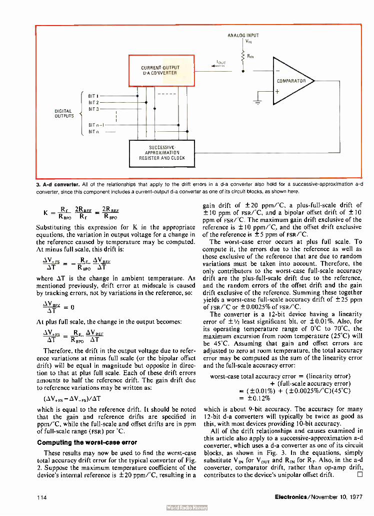
DIGITAL OUTPUTS
e BIT 1
BIT 2
BIT 3
CURRENT-OUTPUT A CONVERTER
BIT n-1
BIT n
SUCCESSIVE-APPROXIMATION
REGISTER AND CLOCK
ANALOG INPUT VIN
RIN
COMPARATOR
3. A-d converter. All of the relationships that apply to the drift errors in a d-a converter also hold for a successive-approximation a-d
converter, since this component includes a current-output d-a converter as one of its circuit blocks, as shown here.
_ RF 2RRFF 2Riur RBPO RF R BP°
Substituting this expression for K in the appropriate equations, the variation in output voltage for a change in the reference caused by temperature may be computed. At minus full scale, this drift is:
AV_ Fs RF à‘/ RFF àT RBpo àT
where àT is the change in ambient temperature. As mentioned previously, drift error at midscale is caused by tracking errors, not by variations in the reference, so:
.4.181
AT —
At plus full scale, the change in the output becomes:
RF AN/ REF AT R Bpo àT
Therefore, the drift in the output voltage due to refer-ence variations at minus full scale (or the bipolar offset drift) will be equal in magnitude but opposite in direc-tion to that at plus full scale. Each of these drift errors amounts to half the reference drift. The gain drift due to reference variations may be written as:
(AV+ Fs — AV_ Fs)/AT
which is equal to the reference drift. It should be noted that the gain and reference drifts are specified in ppm/°C, while the full-scale and offset drifts are in ppm of full-scale range ( Fsn) per °C.
Computing the worst-case error
These results may now be used to find the worst-case total accuracy drift error for the typical converter of Fig. 2. Suppose the maximum temperature coefficient of the device's internal reference is ± 20 ppm/°C, resulting in a
gain drift of ± 20 ppm/°C, a plus- full-scale drift of ± 10 ppm of FsRfC, and a bipolar offset drift of ± 10 ppm of FsRPC. The maximum gain drift exclusive of the reference is ± 10 ppm/°C, and the offset drift exclusive of the reference is ± 5 ppm of FsR/°C. The worst-case error occurs at plus full scale. To
compute it, the errors due to the reference as well as those exclusive of the reference that are due to random variations must be taken into account. Therefore, the only contributors to the worst-case full-scale accuracy drift are the plus-full-scale drift due to the reference, and the random errors of the offset drift and the gain drift exclusive of the reference. Summing these together yields a worst-case full-scale accuracy drift of ± 25 ppm of FsR/°C or ± 0.0025% of FsR/°C. The converter is a 12-bit device having a linearity
error of ±'/2 least significant bit, or ± 0.01%. Also, for its operating temperature range of 0°C to 70°C, the maximum excursion from room temperature (25°C) will be 45°C. Assuming that gain and offset errors are adjusted to zero at room temperature, the total accuracy error may be computed as the sum of the linearity error and the full-scale accuracy error:
worst-case total accuracy error = (linearity error) + (full-scale accuracy error)
= ( ± 0.01%) + (± 0.0025%/°C)(45°C) = ± 0.12%
which is about 9-bit accuracy. The accuracy for many 12-bit d-a converters will typically be twice as good as this, with most devices providing 10-bit accuracy.
All of the drift relationships and causes examined in this article also apply to a successive-approximation a-d converter, which uses a d-a converter as one of its circuit blocks, as shown in Fig. 3. In the equations, simply substitute VIN for V ouT and RIN for RF. Also, in the a-d converter, comparator drift, rather than op-amp drift, contributes to the device's unipolar offset drift. D
114 Electronics/November 10, 1977
MIL/NASA QUALIFIED RECTIFIERS
WE HELPED WRITE THE " BOOK"!
Military Specilications What's in a Number ?
For over a decade Military Specifications
have been written around Semtech E.I.A. registered medium power rectifiers.
Many suppliers can provide parts with the same JAN. JANTX or JANTXV label. Although these devices may comply with the appropriate military specification, there can be significant differences in the design and
manufacture that may affect the reliability; such as,different lead materials, pin materials,
body materials, junction types and junction
areas. Devices of one manufacturer are not necessarily the same as those of another,
even though they are labeled with the
same part number.
Semlech Corporation is one of the few manufacturers in the industry that has its own government approved Qualification Test
Facilities equipped to perform tests that meet
the requirements of Military and Space programs. A NASA approved Radiographic Inspection (X-Ray) facility rounds out the total
capability of Semtech's environmental and test facilities.
We have earned the confidence of the Military establishment by supplying reliable devices to government specifications throughout our history.
MILS-19500/2400 JAN, JANTX, JANTXV 1N645*-1 JAN, JAN—X, JANTXV 1N647*-1 .IAN. JAN IX, JANTX V 1N649*-1 MIL-S-19500/279C (NAVY) JAN, JAN IX 1N3644* JAN, JAN TX 1N3645* JAN, JAN FX 1N3646* JAN, JANTX 1N3647* MIL-S-19500/286C JAN, JANTX, JANTXV 1N4245 JAN. JANTX, JANTXV 1N4246 JAN, JANTX, JANTXV 1N4247 JAN, JANTX, JANTXV 1N4248 JAN, JAtir X, JANTXV 1N4249
MIL-S-19500/3598 JAN, JAN.TX, JANTXV 1N4942 JAN, JANTX, JANTXV 1N4944 JAN, JANTX, JANTW 1N4946 JAN, JANTX, JANT:W 1N4947 JAN, JANTX, JANTXV 1N4948 MIL-S.19500/411C JAN, JANTX, JANTXV 1N5415 JAN, JANTX, JANTXV 1N5416 JAN, JANTX, JANTXV 1N5417 JAN, JANTX, JANT XV 1N5418 JAN, JANTX, JANTXV 1N5419
MIL-S-19500/420A JAN, JANTX, JANTXV 1N5550 JAN, JANTX, JANTXV 1N5551 JAN, JANTX, JANTXV 1N5552 JAN, JANTX, JANTXV 1N5553 JAN, JANTX, JANTKV 1N5554 MILS-19500/4278 JAN, JANTX, JANTXV 1N5614 JAN, JANTX, JANTXV 1N5616 JAN. JANTX, JANTXV 1N5618 JAN, JANTX, JANTXV 1N5620 JAN, JANTX, JANTKV 1N5622 MIL-S-19500/4298 JAN. JANTX, JANTXV 1N5615 JAN, JANTX, JANTXV 1N5617 JAN, JANTX, JANTXV 1N5619 JAN, JANTX, JANTXV 1N5621 JAN, JANTX, JANTXV 1N5623
Not E.I.A. registered by Semtech Corporation.
MIL-S-19500/484(EL) JAN, JANTX 1N5835 JAN, JANTX 1N5836 MIL-S-19500/503(EL) JAN, JANTX, JANTXV 1N6073 JAN, JANTX, JANTXV 1N6074 JAN, JANTX, JANTXV 1N6075 JAN, JANTX, JANTXV 1N6076 JAN, JANTX, JANTXV 1N6077 JAN, JANTX, JANTXV 1N6078 JAN, JANTX, JANTXV 1N6079 JAN, JANTX, JANTXV 1N6080 JAN, JANTX, JANTXV 1N6081
NEW! Transient Voltage Suppressors MIL-S-19500/516(EL) JAN, JANTX, JANTXV 1N6102 thru 1N6137 JAN, JANTX, JANTXV 1N6102A thru 1N6137A JAN, JANTX, JANTXV 1N6138 thru 1N6173 JAN, JANTX, JANTXV 1N61 38A thru 1N61 73A
NASA (MSFC) Approvals 85M01645 ( NASA) S1N645S & S1N6495
85MC3895 ( NASA) Si N4245.1. S1N4247 1, S1N4249 1, S1N4942 1,S1N4946 1 & S1N4948 1
85M03896 (NASA) S1N5199, S1N5201, S1N5417 1 & S1N5419 1
RELIABILITY COSTS LESS!
1975 NATIONAL SBA SUBCONTRACTOR OF THE YEAR
a lai CORPORATION SEMTECH
652 Mitchell Road. Newbury Park. Calibrera 91320 805, 498 2111 • ( 213) 628.5392 • TWX 910 336 1264
CHICAGO ( 312) 352 3227 • DALLAS ( 214) 234 6523 DAYTON ( 513( 274 8356 • FLORIDA ( 305)644 5404 MARY( AND ( 301) 937 0070 NEW JERSEY ( 2011654 4884
SIAN FAANCISCO ( 415) 494 0113 . SEATTLE ( 206)455 4807 r:UROPE AN SALES Bourns AG Zug Switzerland ( 0421232 242
Electronics/November 10, 1977 Circle 115 on reader service card 115
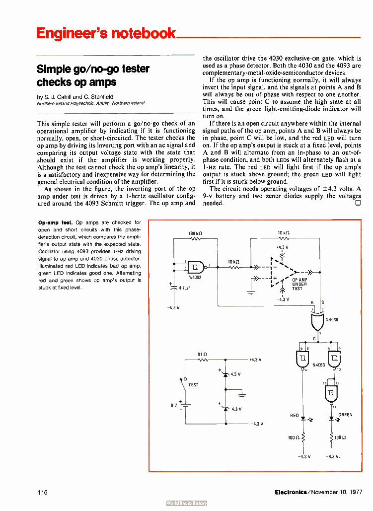
Engineer's notebook
Simple go/no-go tester checks op amps by S. J. Cahill and C. Stanfield Northern Ireland Polytechnic, Antrim, Northern Ireland
This simple tester will perform a go/no-go check of an operational amplifier by indicating if it is functioning normally, open, or short-circuited. The tester checks the op amp by driving its inverting port with an ac signal and comparing its output voltage state with the state that should exist if the amplifier is working properly. Although the test cannot check the op amp's linearity, it is a satisfactory and inexpensive way for determining the general electrical condition of the amplifier. As shown in the figure, the inverting port of the op
amp under test is driven by a 1-hertz oscillator config-ured around the 4093 Schmitt trigger. The op amp and
Op-amp test. Op amps are checked for
open and short circuits with this phase-
detection circuit, which compares the ampli-
fier's output state with the expected state.
Oscillator using 4093 provides 1-Hz driving
signal to op amp and 4030 phase detector.
Illuminated red LED indicates bad op amp,
green LED indicates good one. Alternating
red and green shows op amp's output is
stuck at fixed level.
the oscillator drive the 4030 exclusive-OR gate, which is used as a phase detector. Both the 4030 and the 4093 are complementary-metal-oxide-semiconductor devices.
If the op amp is functioning normally, it will always invert the input signal, and the signals at points A and B will always be out of phase with respect to one another. This will cause point C to assume the high state at all times, and the green light-emitting-diode indicator will turn on.
If there is an open circuit anywhere within the internal signal paths of the op amp, points A and B will always be in phase, point C will be low, and the red LED will turn on. If the op amp's output is stuck at a fixed level, points A and B will alternate from an in-phase to an out-of-phase condition, and both LEDS will alternately flash at a 1-Hz rate. The red LED will light first if the op amp's output is stuck above ground; the green LED will light first if it is stuck below ground. The circuit needs operating voltages of ± 4.3 volts. A
9-v battery and two zener diodes supply the voltages needed.
180 kS2
4.7µF -4.3V
91 S.2
9 V
%4093
10 kS2 \AA.
+4.i3 V
10 kS2 .‘ >- •.
1 .>>- ye OP AMP TUENITER
'1`
-4% V
4.3 V
4.3 V
RED
100 02
-4 3 V - 4 3 V.
44030
10
GREEN
100 S2
116 Electronics/November 10, 1977

One-shot and flip-flop add single-sweep option to scope by M.C.W. Moerdijk N. V Kema, Arnhem, the Netherlands
Oscilloscopes that have a Z axis, or intensity modulation, input can easily be modified for the single-sweep option if needed, provided the scope's sweep (time-base) signal is externally available. This inexpensive Z-axis blanking circuit has been used successfully with the popular Philips PM3210 oscilloscope and can be used with the older Dumont scopes as well. As shown in the figure, the internal sweep signal is
connected to the time-base terminal of the circuit. The scope is placed in the external trigger mode and preset to a suitable triggering level.
Input ( Y-axis) signals exceeding the trigger point initialize the internal sweep, and the signal is traced across the scope face. The negative edge of the ramp (X-axis) signal terminates the trace period, firing the 74121 one-shot multivibrator, which in turn resets the 7476 J-K flip-flop. The flip-flop drives the following comparator high, generating a signal to the scope's Z axis that blanks the trace before the time base can sweep again ( if the input signal is above the set threshold).
Depressing the momentary-contact switch generates a negative-going pulse to the preset input of the flip-flop, thereby setting Q and resetting the Z-axis line. This reset scheme is most effective in applications where Y-axis signals trigger the ramp generator only occasionally,
I Id? TIME BASE
(a I
1N4007
+5 V 0.1 pF
41-
4 5
74121 ONE-SHOT
+5 V
2.2 kS2
PRESET +5 V 16 K 7476
6 CLOCK
4
_L CLEAR
+5 V
Y AXIS (SIGNAL)
TIME BASE
A
TRIGGER POINT
MANUAL RESET
RESET
0 0-
470 kS2
+15 V
+5 V
READY
22 S2
BC212
+15 V
10 kS2
I kS-2 -15 V
1N4007
Z AXIS
(INTENSITY MODULATION)
One sweep per trigger. Adding single-sweep option to Z-axis scope requires a one-shot, J-K flip-flop, and comparator, assuming that
external time-base option is available. Trigger signal initiates ramp, and scope then displays signal for one cycle of the time base. Falling edge
of ramp generates signal to Z axis, blanking trace until circuit is reset manually.
Electronics/November 10, 1977 117

THE GREAT
4k STATIC RAM RACE
In a world of claims and counter-claims, one thing is clear. EMM SEMI is still in the lead. Of course, we not only had a healthy head start, but we field a whole family of 4K static RAMs.
We delivered the industry's first 4K static RAM in 1975, a full year and a half before anyone else. We are now delivering 7 basic static RAM types with many versions
of each, and producing them at a greater monthly rate than our nearest competitors combined.
By now we have more 4K static RAMs operating in a wider range of customer equipment than anyone else in the semiconductor memory business — from 10 Megabyte IBM add-on memory systems to hobbyist microprocessor kits.
Whatever your application, from mass storage to telecommunica-tions, from medical electronics to toys and games, chances are there's an EMM SEMI static RAM just right for you. Please call or write today for full details — and ask about our byte oriented RAMs, too.
Memory at work MIMI sen inc. a subsidiary of Electronic Memories & Magnetics Corporation • 3883 N. 28th Avenue, Phoenix, Arizona 85107 • (602) 263-0202
118 Circle 118 on reader service card Electronics/November 10, 1977

even if the signals exceed the threshold point for a considerable length of time thereafter. When the trigger threshold is exceeded periodically, a partial sweep will often be generated— the result of initiating the manual
reset while the ramp generator is running. III
Engineers notebook is a regular feature in Electronics. We invite readers to submit original design shortcuts, calculation aids, measurement and test techniques, and other ideas for saving engineering time or cost. We'll pay $50 for each item published.
Shunt diode extends linear range of LED by R. W. Dawson Bell Laboratories, Crawford Hill, Holmdel, N. J.
A standard diode in series with a resistor can be used to extend the linear operating range of a light-emitting diode, increasing its effectiveness as an intensity-modulated light source in an optical communications system.
In essence, the linear region of the LED'S output
becomes responsive to the modulating signal, which can therefore be larger than when its influence is confined to a small segment of the LED'S nonlinear region. Admit-tedly, the resistor-diode combination can draw consid-erable power, but a larger current source is often less expensive than an LED capable of greater output. The LED on which the circuit is based is made of
alternating layers of gallium aluminum arsenide and gallium arsenide. Also known as a double-heterostruc-ture injection LED, it has an output characteristic that varies linearly for a current input of 20 to 65 milliam-peres. To improve on that linearity, the diode-resistor network need only lower the LED'S barrier potential, shifting the operating curve so as to bring the nonlinear knee point well below the minimum modulating signal. Thus, any diode will do, provided its barrier potential is lower than the LED'S—that is, less than 1.5 to 2 volts. The diode is connected in series with a current-
limiting resistor, and the combination is connected across the LED. This acts to increase the relative optical output by 20% to 60%, depending on the diode used and the series resistance. The diode-resistor combination is normally selected to allow nearly all the current to pass through the shunt at low values and through the LED at high levels, but this ideal is not always attained.
In operation, the standard diode reaches its switch-on point before the LED reaches its barrier potential, so that the LED sees a low voltage across its terminal at low currents. This pre-biases the LED toward its conducting region, or in other words, shifts the entire current-voltage characteristics to the left, as shown in the lower part of the figure. As viewed by a given modulating signal, normally operating near the LED'S knee, the curve is shifted from a nonlinear Q point to the linear portion, as shown.
Several types of standard diodes were tested as shunt diodes, including GaAs, silicon, and point-contact germanium devices. The one that did the most to improve the linear range of the GaAlAs-GaAs device was a germanium-alloy diode. (Other types of LEDS have slightly different current-voltage characteristics and might require a different type of shunt diode.) The germanium alloy diode, together with a series
resistance of 5 to 20 ohms and roughly three times the normal current input, increased the linearity of the LED used in this circuit by (260 — 180)/180, or 44%, as may be determined from the main figure. Use of a smaller series resistance would extend the range still further, but at the cost of raising the total drain current to about 300 milliamperes. 0
More linear. The optical diode's linearity is improved when a stan-
dard diode-resistor combination is placed in shunt with it. This shifts
the LED's l-V characteristics to left, as shown in lower part of figure.
The percent improvement is found from the curves at top.
Electronics/November 10, 1977 119

Engineer's newsletter
Wire chassis often If the cost and weight of your solid-steel chassis is too high, how about switching to the welded-wire type? E. H. Titchener Co. of Binghamton,
beat solid-metal N. Y., can supply a holder for 2'/2-by- 11-by- 11-inch logic cards that uses types hollow 3/16-inch-diameter steel wire and 10 0.060-inch strip stampings and costs
only $2.50 per unit in large quantities. A large 1 P/2-by- 19-by- 16-inch rack-mounted unit that is fabricated with the same technique is in the $28 price range.
Minicomputer maker Digital Equipment Corp., Maynard, Mass., has already switched from solid metal to wire frame chassis for some of its machines. The DEC manufacturing engineers have found that the approach slashes structural costs and weight, gives more efficient cooling and better accessibility, and also reduces assembly time on the PDP-11/03 and 11/04 minicomputers.
Flexible-circuit Short lengths of flexible printed-circuit cables are often used to connect parts of large electronic systems, since they eliminate wiring errors and can
jumpers come with be folded to any shape. But they generally need connectors or pins added to built-In connections them to mate them to the rest of the system. This additional hardware is
unnecessary on flexible-circuit elements called sculptured cables from Advanced Circuit Technology of Merrimack, N. H. Made by a special chemical milling process, the new jumpers have 25-mil-wide, 10-mil-thick rigid copper fingers at their ends. These terminations may be made straight, staggered, at right angles to the cable length, and at any pitch, and they can be either plugged into mating connectors or wave-soldered to printed-circuit boards. The method adds to reliability, as well as eliminating the higher labor costs that are incurred with conventional types of flexible jumpers.
How to plot a neat You're measuring frequency response, and you would like to pick frequen-cies that will produce evenly spaced points when plotted along the
frequency horizontal axis of the semilogarithmic graph paper. How do you figure out response curve which to pick? It's easy, says Glenn Darilek of Southwest Research
Institute, San Antonio, Texas, if you use a calculator and if you recognize that each value will be larger than the previous one by a factor of the nth root of 10, where n is the number of points you have decided you want to plot per decade. For example, if you're plotting frequencies between 10 and 100 kHz and you want five points, you calculate the fifth root of 10, or 1.585, and the frequencies will then be 10, 15.85, 25.12, 39.82, 63.11, and 100 kHz.
40-pin carrier The pins on a standard 40-pin Lsi circuit package can easily get damaged or misaligned after you have plugged and unplugged it a few times from an
conserves 40-pin integrated-circuit socket or socket panel. So Augat Inc. of Attleboro, LSI packages Mass., has made a carrier with 40 much sturdier pins. You plug the
delicate package into it once and once only. But the carrier-plus-package can be plugged and unplugged as often as you like without risk.
Jerry Lyman
120 Electronics/November 10, 1977

The Sinclair PDM35. A personal digital multimeter
at only $49.95 A digital multimeter used to mean
an expensive, bulky piece of equipment. The Sinclair PDM35 changes that.
It's got all the functions and features you want in a digital multimeter, yet they're neatly packaged in a rugged but light pocket-size case, ready to go anywhere.
The Sinclair PDM35 gives you all the benefits of an ordinary digital multimeter — quick clear re'adings, high accuracy and resolution, high input impedance. Yet at $49.95 it costs less than you'd expect to pay for an analog meter!
The Sinclair PDM35 is tailor made for anyone who needs to make rapid measurements. Development engineers, field service engineers, lab technicians, and computer specialists will find it ideal.
With its rugged construction and battery operation, the PDM35 is perfectly suited for hand work in the field, while its angled display and
optional AC power facility make it just as useful on the bench.
Features of the PDM35
31/2 digit resolution. Sharp, bright, easily read I.E1) display, reading up to ± 1.999. Automatic polarity selection. Resolution of 1 mV and 0.1 nA. Direci reading of semiconductor forward voltages at 5 different currents. Resistance measurement up to 20 MI 1. l% of reading accuracy.
Operation from replaceable battery or AC adapter. Industry standard 10 Mil input impedance.
Technical Specification
1X Volts (4 ranges) Range: 1 m V to 1000 V. Accuracy of reading: 1.0% ± 1 count. Note: 10 MI i input impedance. AC Volts (40 Hz-5 kHz) %Range: 1 V to 500 V. Accuracy of
reading: 1.0% ± 2 counts. DC Current (6 ranges) Range: 1 nA to 200mA.
Accuracy of reading: 1.0% ± 1 count. Note: Max. resolution 0.1 nA. Resistance (5 ranges) Range:11i to 20 Mil. Accuracy of reading: 1.5% ± 1 count. Note: Also provides 5 junction-test ranges. Dimensions: 6 in x 3 in x 11/2 in. Weight: 61/2 oz. Power supply: 9 V battery or Sinclair AC adapter. Sockets: Standard 4 mm for resilient plugs. Supplied with: Leads, test prods, operating instructions, carrying wallet. Options: AC adapter for 117 V 60 Hz power. De Luxe padded carrying wallet. 30kV high-voltage probe.
The Sinclair credentials Sinclair have pioneered a whole
range of electronic world-firsts — from programmable pocket calculators to miniature TVs — holding a world-lead in innovative electronics. The PI)M35 embodies six years' experience in digital multimeter design, in which time Sinclair have become one of the world's largest producers.
Find out more!
You can see the PDM35 at any of the Sinclair distributors listed on this page. Or, if you'd like full details of operation and performance, and a complete distributor list, just send the coupon below. We'll send you all the facts by return.
The Sinclair PDM35 will make your life a lot easier — send the coupon today!
Send to: Sinclair Radionics Inc, Galleria, 115 East 57th Street, New York, N.Y. 10022, U.S.A. Please send me full illustrated details of the Sinclair P1).\135 personal digital multimeter, without obligation.
Name
Position
Company
Address
5,0
« 0
I I I 1975
1"1-1=1fflui-- World leaders in fingertip electronics
Sinclair Radionics Inc, Galleria,115 East 57th Street, New York, N.Y. 10022, U.S.A.
See thc PDM 35 at: Carter McCormic & Peirce Inc., Farmington Mich. 313 477 7700; Crane & Egeo Corp., Elmoni, N.Y. 516 488 2100; F. L. W. Inc.. Costa Mesa, California. 714 751 7512; International Standard Components, Los Altos, California. 415 941 2600; Ossmann Instruments Inc., Syracuse, N.Y. 315 437 6666; Par Associates, Denver, Colorado. 303 355 2363; PVA Company, La Grange, Ill. 312 352 1037; Scientific Associates, Washington D.C. 703 573 8787; Southern Peripherals & Instruments Inc., Atlanta, Georgia. 404 455 351S.
Electronics/November 10, 1977 Circle 121 on reader service card 121

Multiwiré: Field modifiable.
Of the many benefits offered by Multiwire, one of the most important is its simplicity 01 change and repair. Multiwire boaris are normally easier to change after assembly or in the field than multilayer.
All wires are exposed in the typical Multiwire board. To make a change, use a blade to cut the conductor that you want to correct, and remove a portion of the wire to avoid bridging. Then, just solder in a jumper wire and
fasten down with epoxy or urethane. Changes in Multiwire boards can
easily be accomplished in minutes by field service technicians.
Multilayer changes, of course, are an entirely different story. Corrections are difficult at best and frequently impossible. As one engineer familiar with multilayer puts it: "Corrections ... are something of a disaster."
With Multiwire, to replace a discrete or DIP that has failed, the component
Electronics/November 10, 1977

Multilayer: Field discardable.
is simply unsoldered; the plated-through holes stand up just as well if not better than regular PC board holes. W th multilayer, however, a soldering iron often lifts the land off the board, with many ensuing problems.
Of course, Multiwire will need fewer repairs to begin with. The Multiwire manufacturing method has far greater yield, usually better than 99% reliability at incoming inspection.
And now, consider some other key advantages of Mukiwire: Shorter lead times. No artwork required except for basic ground planes and plug-in connections. Lower design and tooling costs. Much faster first-piece delivery.
To take advantage of Mulliwire, all you supply us is an interconnection list from which we prepare the input data for our numerically controlled machines. Or you can prepare your
own input from our software. Since all of the logic is placed by N /C-controlled equipment made up from the wire running lists, changes in circuit design only require a change in your wire list.
For more information, write to Multiwire Marketing Department. Or call us at 516-448-1117. In New England, 603-889-0083. In California, 714-991-6030. For Texas, 214-234-2873.
Multiwiré from Photocircuits. Division of Kollmorgen Corporation, Glen Cove, New York 11542
Electronics/November 10, 1977 Circle 123 on reader service card 123

Rent'em From GE Short or long-term instrument rentals give
you flexibility and economy. GE has over 9,000 instruments available for
immediate shipment: o Tek Scopes o Biddle Megger Insulation Testers o H-P Signal Generators o Honeywell Oscillographs o Complete Data Systems o Esterline Angus Recorders o GE Chart Recorders Modems o Communication Terminals . . .all calibrated to the manufacturer's specs.
We have over 100 Sales/Service Centers,
and one of them is near you. In addition to maintaining our Rental Inventory, they can also repair and calibrate your own equipment.
Don't borrow someone else's GE Rental Catalog. Call collect (518) 372-9900 or your nearest Sales/Service Center
anuicitrentai® Instruments
GENERAL ELECTRIC ALA. BIRMINGHAM (215) 925-3104* ARIZ. PHOENIX (602) 278-8515 or 8516. TUCSON (602) 294-3139 • CAL. LOS ANGELES (213) 642-5350, SAN FRANCISCO (415) 436-9260 • COL. DENVER (303) 371-1260 • CONN. SOUTHINGTON (203) 621-4059 • FLA. JACKSONVILLE (904) 751-0610* GA. ATLANTA (404) 457-5563 • ILL. CHICAGO (219) 933-4500* IND. INDIAN-APOLIS (317) 639-1565 • KY. LOUISVILLE (502) 452-3311 • LA. NEW ORLEANS (504) 367-6528 • MD. BALTIMORE (301) 332-4700 • MASS. BOSTON (617) 396-9600 Ext. 160, SPRING-FIELD (413) 781-1111. MICH. DETROIT (313) 285-6700 Ext. 208 • MINN. MINNEAPOLIS (612) 522-4396 • MO. KANSAS CITY (816)231-4377,ST. LOUIS (314)965-71150 N.J. CLIFTON (201) 471-6556 • N.Y. BUFFALO (716) 876-1200, SCHENECTADY (518) 385-2195 • N.Y.C. CLIFTON, N.J. (201)471-6556* N.C. CHARLOTTE (704)525-0311 • OH. CINCINNATI (513) 874 - 8512, CLEVELAND (216) 523-6382, TOLEDO (419) 691-3501* OR. PORTLAND (503)221-51010 PA. PHILADELPHIA (609)424-4450, PITTSBURGH (412) 462-7400* TEX. DALLAS (214) 357-7341, HOUSTON (713) 672-3570 • VA. RICHMOND (804) 232-6733 • WASH. SEATTLE (206) 854-0211 • W.V. CHARLESTON (304) 345-0920 • WISC. MILWAUKEE (414) 744-0110 • PUERTO RICO PONCE (809) 843-4225.
126 Circle 126 on reader service card Electronics/November 10, 1977

Nodal tester handles semiconductors Teradyne in-circuit unit adds that capability to node-to-node continuity
and guarded-component testing of loaded circuit boards
by Lawrence Curran, Boston bureau manager
The L529 assembly inspection sys-tem for loaded circuit boards an-nounced last month by Teradyne Inc. [Electronics, Oct. 27, P. 33] serves notice that the Boston compa-ny is going after the in-circuit board test market in a big way. To date, that market has been left mainly to Faultfinders Inc. and Zehntel Inc., but Jeff Hotchkiss, product manager for in-process test equipment at Teradyne, has set his sights on having a 25% market share by the end of next year. The new unit is a prescreening
unit for locating assembly and com-
ponent faults on loaded analog, hybrid and digital circuit boards having as many as 700 nodes before they go to a functional tester, Hotch-kiss says, and was designed with simplicity of programming as one of Teradyne's prime objectives. In or-der to reach that objective and still detect 60% to 90% of the faults on a board, Teradyne has come up with three simple types of tests that are incorporated into a microprocessor-controlled system. The L529 performs node-to-node
continuity tests to pinpoint shorts and opens on a board and node-to-node guarded-component tests for resistive and reactive components,
guarding out active semiconductor devices. These two types of tests are not new for in-circuit board testers, but, Hotchkiss maintains, the third test type— nodal testing of the semi-conductor devices—employs an in-novation not found in competitive machines.
In this test type, node-to-ground impedance tests are performed with all nodes taken to ground. Then each node is driven with 0.2 volt dc for the resistors, 0.2 y ac for capacitors and inductors, and + 2.5 y and — 2.5
to exercise semiconductor junc-tions. Hotchkiss says that conven-tional in-circuit testers working on nodes that include a diode, for exam-
Electronics/November 10, 1977 127

New products
pie, would do a guarded-component type of test, "but if there's a semi-conductor device nested in there, it can take a lot of programming to guard it out." The three test types are put into a
canned routine that cannot be easily tampered with, he says. The ap-proach allows a junior technician to
program a complex board in a few hours. Even a test program for a fully loaded board with 700 nodes or test points can be developed in less than a day with the L529, which Hotchkiss says compares with one to three weeks for other in-circuit testers.
Three steps are included in pro-
A new series of enclosures syled ano cesigned to house
new ¡owls
There are scores of uses for Bud's new Contempo Series, the versatile mini-enclosures. Well engineered, solidly constructed, clean and contemporary. Four styles, 22 sizes in either woodgrain and eggshell, or black pebble and smooth gray finish. The Contempo Series, the newest idea for your ideas. From Bud! For literature, phone Bud toll free: (800) 321-1764; in Ohio, (800) 362-2265.
Complete manufacturing facilities at two locations:
Bud Industries, Inc. 4605 East 355th Street Willoughby, Ohio 44094 Bud West, Inc. 3838 North 36th Avenue Phoenix, Arizona 85019
gramming the system. The compo-nents are first defined for the system by being labeled with an R for a resistor, Q for transistor, X for a diode, and so on. Besides the label, the programmer also enters into the system the component class— resis-tive, reactive, semiconductor, inte-grated. This definition step tells the system which type of test to perform on each component. The second programming step is
entry of the node list—a simple interconnect list for the board, which the user develops as he builds up the test fixture for the board using a bed-of-nails kit that Teradyne pro-vides. Finally, the programmer ini-tiates the learn step, which estab-lishes nominal values and tolerances for the board to be tested by entering a list of those values. The program-mer uses figures obtained from about a dozen known good boards of the same type. Programming is done on a console
that has an interactive keyboard and cathode-ray-tube display. Besides the programming console, the L529 includes an operator's test station and board handler. The test station has a control panel, two tape drives, and a strip printer that generates diagnostic error messages. The board handler, first used on Tera-dyne's L429 shorts-detection system, uses weighted rods rather than the more conventional vacuum fixtures for applying the contact force for the board being tested.
Hotchkiss says that the L529 has tested in 10 seconds hybrid boards that previously required 45 s to a minute of test time. Hybrid boards contain both digital and analog components. He looks for the ma-chine to boost by some 300% the productivity of the functional tester for which it prescreens.
Prices start at $54,500 for testing boards with up to 100 nodes. Modules for increasing that to 700, in 100-node increments, are $5,000 each, and the bed-of-nails test kits are about $ 1,000 per board type. Delivery is 12 to 16 weeks. Manufacturing Systems Division, Teradyne
Inc., 183 Essex St., Boston, Mass. 02111.
Call Jeff Hotchkiss at [617] 482-2700. [338]
128 Circle 128 on reader service card Electronics/November 10, 1977

173E1 21 1[1:C0111:11: ir ffirûl 12-17_ ffifERiffirTil
0 0 0
Oil nUt7IM li00=JD\IER: 1_ Our Metal Nitride Ox de Silicon NVM are fully reprogrammable in-circuit
They offer long-duration storage security without battery backup or " power-on" auxiliaries.
HIGH DATA RETENTION Data is secure for a minimum of 10,000 hours and can be read 10 10 times between refresh cycles. PROGRAM VERSATILITY Neon NVMs offer entire memory or word alterability. Anc it can all be done in-circuit a minimum o' 105 times. Millisecond write times are ideal for applications in the human-response range. SYSTEM COMPATIBILITY We built in on-chip decoding, and T1L and CMOS compatibility. Plus, Nitran NVMs can be reprbgrammed without addit:onal power supplies or power supply switching. PRODUCT AVAILABILITY Nitran NVMs are available off-the-shelf for parallel data applications in 64x4 and 256x4 configurations;
inErmirm
and for serial data applications in 21x16, 16x18 and 1024x1 configurations. If you don't see what you need, tell us about it. We custom design NVIMs, too.
Unique Nitron process puts silicon nitride and silicon dioxide layers between MOS gate and substrate. When volage is applied, trapped charge offsets threshold voltage. Charge remains after voltage is removed.
Need information fast? Call Nitron NVM Marketing at (408) 255-7550. Or fill in the coupon below for your NVM Fact Kit.
1•11177101,1
Mail to: NITRON NVM Marketing 10420 Bubb Road Cupertino, CA 95014
TELL ME MORE! I'm interested in (check box):
fl 16\14M40 21x16 NC7033
256x4 (- 1 16x18 NC7050 NC7035
1/41 El '\g l i El Complete NVM Fact Kit
Send to:
name & title
company
address
city state zip
Electronics/November 10, 1977 129
Circle 129 on reader service card

Intel delivers PDP-11 memory for people who can't afford to wait.
When you're in a hurry for more semiconductor memory for your PDP-11, call Intel. We deliver memory for the full PDP-11 line. And because we're the largest manufacturer of semiconductor memory in the world, delivery is when you want it.
Why wait? Since you've chosen the leader to supply your minicomputer, it makes sense to go to the leader for memory, too. That's us.
Intel memory systems save you more than time. Our in-1670 add-on memory for the PDP-11/70 is one example. It gives you four times the capacity in the same frame compared to the DEC MJ11-A core memory. And built in Error Correction Code (ECC) and Error Logging improve up-time and reduce maintenance time by automatically correcting and recording single-bit failures and detecting and recording double-bit errors.
For PDP-11 add-in memory go with our in-4711 plug in boards. You'll get memory that's even faster than DEC's. 16K words per hex-wide board. With or without parity. To further expand PDP-11 memory and reduce UNIBUSTM' loading choose our in-4011 add-on. With memory man-agement you can expand to 128K words in 16K increments. And since the in-4011 requires only one UNIBUS load, you get added system flexibility.
Get more memory for your LSI-11 and PDP-11/03 in less space with our in-1611 add-in memory. You get up to 32K words, in 8K increments, on a single, two-wide, board. That's up to eight times the memory you get with a DEC board.
When you can't afford to wait call us at 800-538-8476. In California and Canada, call 408-734-8102, x575. We'll save you time, and much more.
intel delivers.
Intel Memory Systems 1302 N. Mathilda Avenue Sunnyvale, California 94086
I can't wait! Must have delivery in Ill 5 Days Ill 30 Days El Days
II Please call me at Ext
D Please send me information on following:
LSI-11, PDP-11/03 PDP-11/04 D PDP-11/05
PDP-11/34 PDP-11/35
semiconductor memory for the
LI PDP-11/40 PDP-11/45 PDP-11/55 PDP-11/70
Name/Title Company Mail Station Address City/State/Zip
UNIBUS is a trademark of Digital Equipment Corp. Maynard, Mass.
Circle 130 on reader service card

Intel MEMORY SYSTEMS
U.S. AND CANADA
SALES OFFICES
ALABAMA Col- Ins-Co Huntsville 205 881-9512
Glen White Assoc Huntsville ,205 • 883-9394
ARIZONA Intel Corp Phoenrx 602- 242-7205
BFA Corp Scottsdale .602 994-5400
CALIFORNIA Intel Corp Santa Ana 714.835-9642
Intel Corp Sunnyvale 408 738-387C
Earle Assoc San Dreg° 714 • 278-5441
MAC- I Berkeley ,415 843-7625
MAC-I Cupertino •408 257-9880
MAC- I Fountain Valley .714 839-3341
MAC-I Woodland Hats •213 347-1374
COLORADO Intel Corp Decreer .303. 373-4920
BFA Corp Denver (303. 837-1247
CONNECTICUT Intel Corp Danbury 203 792-8366
FLORIDA Intel Corp Ft Lauderdale 305 971-7200
Intel Corp Orlando •305 , 628-2393
Col- Ins-Co Orlando (3051423-7615
GEORGIA Col- Ins-Co Stone Mountain (4041299-2138
ILLINOIS Intel Corp Oak Brook ,312 325-9510
Data Electronic; Ch cago ,312, 283-0300
INDIANA Data Electronics Indianapolis 13171784-6360
IOWA Technical Reps Inc Cedar Rapids 1319 , 396-5662
KANSAS Technical Reps Inc Olathe (913' 782-1177
LOUISIANA Col-Ins•Co Baton Rouge , 504 292-1755
MARYLAND Intel Corp Timonium (301 252-7742
Glen White Assoc Timonium 301 252-7742
Mesa Inc Rockville 301 881-8430
MASSACHUSETTS Intel Corp Chelmsford ,617 256-4131
Computer Marketing Inc Waltham
617 , 890-1776
MICHIGAN Intel Corp Southfield 313 353-0920
Lowry and Assoc Inc Brighton 313, 227-7067
MINNESOTA Intel Corp Bloomington 612 835-6722
Data Electronics Mtnneapolls ,6I2 786-9666
MISSOURI Technical Rep-, Hatelwood 314 ( 31-52(
NEW JERSEY Intel Corp Erllson 201 985-9100
NEW MEXICO BFA Corp Albugueroue 505 292-1212
BFA Corp Las Cruces 505 523-0543
NEW YORK Intel Corp Hauppauge 516 231-3300
Intel Corp Rochester 716 328-7340
Intel Corp Poughkeepsie 914 473-2303
Measurement Tech Inc Great Neck 516 482-3500
T-Sguared Inc Pittsford 716 381-2551
T-Sguared Inc Syracuse 315 463-8592
NORTH CAROLINA Col- Ins-Co Winston Salem 919 748-0297
Glen Whole Assoc Raleigh 919 787-7016
OHIO Intel Corn Dayton 513 890-5350
Intel Corp Euclid 216 289-0101
Lowry and Assoc Inc Cleveland 216 464-8113
Lowry and Assoc Inc Dayton 513 435-4795
OREGON ES Chase Co Portland 503 620-9616
PENNSYLVANIA Intel Corp Ft Washington 215 542-9444
Lowry and Assoc Inc Pittsburgh 412 922-5110
0 E D Electronics Inc Hatboro 215 674-9600
TENNESSEE Glen White Assoc Germantown 901 754-0483
Glen White Assoc Johnson City 615 928-0184
TEXAS Intel Corp Dallas 214 241-9521
Mycrosysterns Mktg Inc Austin 512 472-2492
Mycrosysterns Mktg Inc Dallas 214 238-7157
Mycrosystems Mktg Inc Houston 713 783-2900
UTAH BFA Corp Salt Lake City 801. 466-6522
VIRGINIA Glen White Assoc Lynchburg 804 384-6920
WASHINGTON ES Chase Co Seattle 20ii 762-4824
CANADA
Intel Semiconductor Corp of Canada
Ottawa 613 232-8576
Multi:0k Inc Ottawa 613 825-4553
EUROPEAN MARKETING
HEADQUARTERS
BELGIUM
Intel International
Brussels Tel 02 66030 10 Telex 24814
ORIENT MARKETING
HEADQUARTERS
JAPAN
Tokyo Tel 03 426-9261 Telex 781-28426
New products
Components
Carbon networks replace discretes
Off-the-shelf resistor net,
aimed at display use,
is priced under cermet
performance cermet versions. The first part, now available in
sample quantities, is a ceramic substrate with seven 200-ohm resis-tors screened on it in an isolated pattern. " It's designed to replace the discrete carbon-composition current-limiting resistors used with light-emitting-diode displays," says Dwayne A. MacDonald, marketing manager for the division's electronic controls group. "Displays don't re-quire tight resistor tolerances, be-
Equipment manufacturers are now cause the human eye can't detect accustomed to replacing multiple slight variations in illumination," he discrete resistors with thick-film cer- explains. met-resistor networks to pare as- Resistor tolerance for the seven sembly costs and save printed- devices is ± 5%, and each is rated at circuit-board real estate. Yet many 0.15 watt. Temperature coefficient applications do not demand— and of resistance is — 425 parts per users should not have to pay for— million per °C maximum over an the precise tolerances that cermet operating temperature range of networks afford. — 55°C to 105°C. The I 4-pin single So Centralab Electronics has de- in- line package, coated with a phe-
cided to develop a standard network nolic resin and measuring 1.6 by line using the carbon system, which 0.425 by 0.2 inches thick, will sell for has been available up to now only on less than 15 cents in large quantities. custom products. The devices will be In lots of 1,000 pieces, the network tagged from 15% to 25% below their will cost 35 cents. cermet equivalents. The Milwaukee- The network's specifications are based division of Globe-Union Inc. is better than those of carbon-composi-one of the few remaining firms that tion resistors measured to MIL-R-offers carbon-resistor networks as 11F, MacDonald points out, and the well as the most expensive high- network is superior in moisture
.11111111111111% ‘4At‘-4-irirrf' 4e‘rir
Electronics/November 10, 1977 131

LIMIT ONLY ONE
PYROSCAN SYSTEM FOR EACH CUSTOMER
Pyroscan 100 system
FEATURES:
• 20 thermocouple and 7 Platinum RTO ranges available
• First and last channel pro-gramming
• Resolution 1.0 or 0.1 degree C or F • Manual/single/continuous scan • System expansion made easy • Variable dwell and scan rate • Internal clock option • Printed paper tape record • Highly stable cold reference
junction • Linearized over sensor range • Screw terminals for TC inputs • Single or dual limit alarm cpt ons • Easy to order • Easy to obtain • Easy to operate
Corporate Office 630 East Young St.
Santa Ana, CA 92705 Telephone. 4714) 540-4914
PNX: 910-595-1787 Cable: Newlab, Santa Ana
CA 92705
Whether you have one or one hundred temperature sensors to monitor, the Newport Pyroscan System will do your job . .. and only one System is all you should need.
Pyroscan systems provide the flexibility and expandability to meet your present and future needs. A Pyroscan 30 System is
wired to accept three 10-channel cards while Pyroscan 100 rs wired for ten cards. Just plug in the cards as your requirement changes, attach your sensors, and that's all there is to it.
Newport's building block approach allows you to start with a Scan Programmer and one 10 channel switch card (without cabling) for only $380. Go to a full logging system and pay $ 1480 for the first ten channels. A :30 channel system is only $ 1810. How about a ten channel switching
card that is addressed by BCD code tor only $ 145? A module change allows you to
switch to a different thermocouple type. Ask about Newport's Custom mod
centers for your special application convenience. Send for the Pyroscan 8 page brochure. U.S. Prices only.
X NEWPORT Newport BV
P.O. Box 7759 Schiphol East
The Netherlands Telephone: (20) 45-20-52
Telex: 844-16347
Newport Laboratories GmbH 6072 Dreieich
Max-Planck-Strasse 13 Postfach 102163
German Federal Republic Phone: (06103) 64041/63042 Telex- 417908 (NEWPT D)
Circle 132 or reader service card
The magazine you're reading now, could be your own. Drop off the routing list. Ge'. your own fresh, unclipped copy mailed to your home or office. Turr to the subscription card in the back of the magazine. If somebocy has beat you to it, write: Electronics, P.O. Box 430, Hightstown, N.J. 08520.
New products
resistance, temperature cycling, load life, and short-term overload tests. It is priced higher than seven discretes, which typically sell for about 1 cent each in large quantities, but that difference is often erased by its lower insertion cost, and networks also reduce procurement, inventory, in-spection, and testing costs, MacDon-ald says.
Centralab plans other off-the-shelf carbon-resistor networks in the display area, varying the number of resistors per package, as well as resistor values. It is looking, too, for other products that might be stan-dardized, such as multiple-divider or one-side common-resistor networks or commonly used RC networks. Centralab Electronics Division of Globe-
Union Inc., 5757 N. Green Bay Ave., Milwau-
kee, Wisc. 53201 [341]
Solid-state relay operates
from — 55 to 110 C
Housed in a low-profile, hermeti-cally sealed dual in- line package, the model 682-1 solid-state relay is a thick-film hybrid circuit designed to meet the requirements of MIL-R-28750/9. The optically coupled unit operates from — 55°C to 110°C and
handles input voltages from 3 to 16 volts dc, making it compatible with transistor-transistor and high-noise-immunity logic. Its output can handle 1 ampere at 250 y root mean
132 Electronics/November 10, 1977

Our new 5100/5101A calibrators can calibrate VTVMs, VOMs, 41/2 - and most 51/2 -digit DMMs a-round, in a fraction of the time it takes you now! (It's a cal lab in a box! All at an average price under $9,000.) For $10,000 to $15,000, you could
invest in an intricate maze of instru-ments that takes a wizard to operate. Or, you could fill a room with com-puter-based hardware and expensive talent. About $100,000 worth. The Fluke .1P-controlled alternative. We've designed the new 5100A and
5101A for production test, QA and cal lab applications that need large system flexibility at a fraction of large system cost. The heart of our new meter cali-
brators is a microprocessor that elim-inates mechanical switches—the larg-est contributor to failure in conven-tional calibrators.
And, you can enter your tolerances in dB, volts or percent. The p.P con-verts for you! Far safety, store cur-rent or voltage limits and protect both your operator and the meter being calibrated. Microprocessor control also facili-
tates scaling (for linearity checking), and makes your calibrator a range-less instrument, always selecting the proper range for maximum resolution, automatically!
Automation or economy? Fluke has both. The 5100A is perfect for manual
bench operation or integration into
I -
1 71011
your existing cal system to upgrade it to Fluke standards of calibration excellence. Priced at $6,995*, you save dollars but don't sacrifice accu-racy or overall performance. For perfection in automated cali-
bration, you'll want the 5101A with its mini-tape cassette reader, a unique new feature that allows you to store up to 58 calibration settings, includ-ing limits and tolerances. Only $8,995*. Both models have a friendly calcu-
lator-type keyboard. And, both have the RS232 or IEEE 488 system op-tions you want for remote operation or hard-copy printouts of results.
Call (800) 426-0361, toll free. Ask for complete technical specs or the location of your local Fluke office or representative. Or, write: John Fluke Mfg. Co., Inc., P.O. Box 43210, Mount-lake Terrace, WA 98043.
*U.S. price only.
Command Performance: Demand Fluke Calibrators.
FLUKE 2010-8001
For Literature circle 133 For Demonstration circle 269

Revolutionary cooling extrusion cuts size and cost in half. Here is the first in a new series of unique cooling extrusions from Wakefield. A totally different design concept
called "High Fin Density" allows Extrusion 5113 to give the same cooling performance as devices needing nearly twice as much space. And because of substantial material
savings, the 5113 is half the price of the larger units— only $1.10 per inch.
Until now. the space between fins of an extrusion could be no less than 1/4 the height of the fins. This limited the surface cooling area of the fins for any given size extrusion.
"High Fin Density" has changed all this by reducing the space between fins to as little as 1/10 their height. The result is a tremendous gain in cooling efficiency with 130 sq. in. of cooling surface per linear inch of extrusion. Knowledgeable people say this is
the most significant breakthrough in the history of cooling devices. But then, what would you expect from the leader? Write or call for full details.
—WAKEFIELD ENGINEERING INC.
morà 77 AUDUBON ROAD WAKEFIELD MA 01880 (61 TVVX 710-348.6713 AN e.› ECitel3 COrvh 'ANY
Circle 134 on reader service card
From Electronics Magazine Book Series. Zero-risk trial offer.
Name
Applying Microprocessors 2nd and 3rd generation technology. 26 detailed applications from data networks to video games. $9.95
Title
Company
Street
City
Signature
State Zip_
Electronics Book Series P.O. Box 669, Hightstown, N.J. 08520
Send me copies of "Applying Micro-processors" at $9.95 per copy. Discounts of 40% on orders of 10 or more copies. I must be fully satisfied or you will refund full payment if the book is returned after ten-day trial examination. CI Payment enclosed D Bill firm D Bill me
Charge to my credit card: American Express D Diners Club
0 BankAmericard D Master Charge
Acc't No
Date exp.
On Master Charge only, first numbers above name
New products
square. Zero- voltage turn- on minimizes electromagnetic interfer-ence. The relay sells for $27.50 in 1,000-piece quantities. Teledyne Relays, 3155 W. El Segundo Blvd.,
Hawthorne, Calif. 90250. Phone (213) 679-
2205 [343]
Carbon-film resistor
drifts only 200 ppm/°C
The GPR 5000X general-purpose resistor is a carbon-film component with a tolerance of 2% and a temper-ature coefficient of ± 200 parts per million per °C. Said to be price-
competitive with carbon-composition resistors, the GPR 5000X units are offered with resistance values from 10 ohms to 22 megohms. They have a maximum working-voltage rating of 350 volts and can dissipate V2 watt although they are housed in 1/4-m/-sized packages. Mepco/Electra Inc., Columbia Road, Morris-
town, N. J. 07960. Phone (201) 539-2000
[344]
Metal-film resistors have
tolerances to 0.05%
A line of precision metal-film resis-tors with values from 50 ohms to 250 kilohms is available with tolerances from 1% down to 0.05%. The first model in the new series is the 0.1-watt PTF 55, which has a diameter of 0.094 inch and a length of 0.260
134 Electronics/November 10, 1977

— P3:C814-CP
CHECK US. We've been coming up with better instrumentation recorders for more than 40 years. And we're willing to put our reputation on the line. So check the boxes below for the type of recording equipment you need and send us this page. We'll send you some no-nonsense specs that will stand up to the toughest comparisons you care to make.
VISICORDER OSCILLOGRAPHS
E Graphic data acquisition system (One to 32 channels, dc to 5000 Hz, choice of eight plug-in signal conditioning modules.)
E Linescan facsimile-type recorder (DC to 8 MHz; X, Y, Y', Z axis; high resolution, broad gray scale.)
D Recording oscilloscope (DC to lo MHz; X, Y, Y', Z axis; up to one million in/sec writing speed.)
E Light-beam galvanometer recorders (DC to 25 kHz, up to 36 channels.)
SIGNAL CONDITIONING
E Gage control units (Multi-excitation, calibration, balance, filtering, suppression, various gain ranges.)
E Thermocoupre compensai ion unit (Calibration, suppression and span controls.)
E Amplifier/attenuator units ( Differential, single ended, multi-bandwidth, various gain ranges.)
MAGNETIC TAPE SYSTEMS
III Large-reel portable (DC to 2 MHz, 15-inch reels.) III Small-reel portable ¡ DC to 1 MHz, 101/2-inch reels.) CI Laboratory systems (DC to 4 MHz, 16-inch reels.)
SIGNAL ANALYZERS
LI Correlation/probab:lity analyzers III Fourier transform analyzers E Histogram recorders
INDUSTRIAL TEST SYSTEMS
LI Die casting test systems Ill Welding test systems O Data communications recording systems CI Air/oil circuit breaker analyzer system
SPECIAL MILITARY PRODUCTS
O Digital cartridge tape recorder Ill Shipboard analog tape recorder O Airborne analog tape recorder O Special applications recording osci I lographs
To get a free catalog that describes all of our instrumentation recording systems, just circle the Reader Service Number.
WE'LL SHOW YOU A BETTER WAY. Honeywell
Honeywell Test Instruments Division • MS-218 • Box 5227 • Denver, Colorado 80217
Circle 135 on reader service card

faster, easier mote accurate less expensive
METER CALIBRATION
The Rotek PAMC-100 Programmable, Automatic
Calibration System
A new relatively inexensive system that can pay for itself in less than two years. Provides all these features . . .
• High accuracy ( 0.002% DC, 0.025% AC) • Easy-to-use software • Low initial & maintenance costs • Hard copy test results • Expandable, via IEEE 488 bus • Extremely high calibration throughput • Broad flexibility for future needs
Send for new, free brochure with all details &
specifications.
220 GROVE STREET BOX 504,
WALTHAM, MASS. 02154 INSTRUMENT CORP. TEL. 617-899-4611
FIOTEIK
New products
in. Additional units will follow early in 1978. PIF resistors are expected to find
wide application as matched sets or networks in a variety of applications (analog- to-digital and digital- to- ana-log converters, medical electronics, test equipment, etc.) in which the designer will be able to specify TCR tracking and initial tolerance ratios much tighter than the absolute requirements of each individual re-sistor. This is expected to allow cost savings approaching 50%. The resistors are priced in the
general range of 40 cents each in thousands. Normal delivery time is 8 to 10 weeks. Dale Electronics Inc., Box 74, Norfolk, Neb.
68701. Phone (402) 371-0080 [345]
TOPICS
C. P. Clare & Co., Chicago, Ill., has increased the current-carry-ing capability of its series 203 solid-state relay from 0.75 to 1.5 amperes while raising the with-stand voltage to 600 volts peak. The upgraded unit sells for $7.20 in thousand-piece lots.... The Intertechnical Group Inc., Ir-vington, N. Y., is offering a series of subminiature film dielectric capacitors no bigger than a TO-5 can. The units have polyester, metalized polyester, and polycar-bonate film dielectrics with a thickness of about 0.002 millime-ter. . . . American Technical Ceramics, Huntington Station, N. Y., announces the QPL listing of its style CDR11 through - 14 and CDR21 through -25 capaci-tors to MIL-C-55681/4 and -/ 5. The new qualification is in addi-tion to the firm's present QPL listing on MIL-C-11272 for CY80 styles, which will be maintained. ... Struthers-Dunn Inc., Pit-man, N. J., a major factor in the electromechanical relay market-place has entered the low-profile area with its 400 series. The single-pole units can handle up to 2 A, the multipole relays up to 1 A. All can be mounted on printed-circuit boards spaced 15 mm (19/32 inch) apart.
136 Circle 136 on reader service cad Electronics/November 10, 1977

P3-C814-CP
CHALLENGE US. Are you looking for a better way to monitor, condition, record or analyze data? Then challenge us. Describe your recording or signal analysis problem in the space below and send us this page. We'll get back to you with our recommendation.
WE'LL SHOW YOU A BETTER WAY. Honeywell
Honeywell Test Instruments Division • MS-218 • Box 5227 • Denver, Colorado 80217

About the only No Touch Controls we don't make you haven't asked for.Yet.

re the ones
For years, MICRO SWITCH s been the leading maker of
Is Touch Controls. That's because we're also
; ders when it comes to listening switching problems where -charucal devices Just don't fill - bill. And then solving them th industry's broadest line of otoelectnc and proximity trols. For example, the ferrous-
sitive XK can detect metal gets of any thickness, either \ring or stationary. There's also - vane-operated AV and the ;gnetically operated SR, both turmg dependable Hall-effect 1hnology and high speed opera-!ri unaffected by dust and dirt. You can also choose from a
se selection of solid state FY sximity sensors designed to be ectly compatible with program-.le controllers and solid state c. These self-contained controls e models ranging from 14 mm • ameter to 76 mm.
For materials other than •tals or where distances are too •at for proximity switches, CRO SWITCH offers a com-te line of photoelectric controls.
At shorter distances, choose m MLS4A controls with a range : feet or MLS7A controls that up to 10 feet Both are DC ered and use advanced inte-
;ted circuitry to increase
There are also models with ch greater scanning ranges, - the high intensity MLS5A that •s up to 250 feet in clean air through dust, smog, steam
Is other pollutants at shorter Itances.
Another model provides a rung range up to 700 feet. IAnd whether you need prox-ity or photoelectric controls,
'11 be getting solid state design 4 delivers long life. Which is at you've come to expect from ! leading maker of No Touch ntrols. MICRO SWITCH will pro-
e you with held engineers for slication assistance and a net-rk of authorized distributors for .availability. Write us for ails or call 815/235-6600
LIVISION OF HONEYWELL ICRO SWITCH FREEPORT it LINOIS 61032
New products
Semiconductors
Dynamic RAM has dual latch modes
Intel 16-k memory line
can operate with latched
or unlatched outputs
Called third-generation 16-k dy-namic random-access memories, In-tel Corp.'s 2117 series combines the best features of the first commer-cially available 16,384-bit dynamic RAM, Intel's latched 2116, and :he industry-standard Mostek unlatched 4116 with significant design im-provements. What is more, it pro-vides direct replacements for all types of first- and second-generation I 6-k RAMS, says memory product manager, Bill Regitz. The new chip design is based on
the same process used to produce the 2116. This standard two-layer poly-silicon n-channel metal-oxide-semi-conductor technology has been used to produce 16-k RAMS and other high-density Intel memory compo-nents for nearly three years. It gives the 2117 the highest performance achieved to date in production I6-k RAMS.
The 2117-2 is specified with a maximum access time of 150 nano-seconds. The cycle time is specified at 320 ns, which is 55 ns faster than previous 16-k RAMS with the same access time.
Power dissipation and maximum
supply current have also been reduced. Current spiking, which gen-erates system power-line noise, has been cut in half. Also, the 2117 provides the wide operating margins, a full ± 10% tolerance on all three power supplies ( + 12 and ± 5 volts), and transistor-transistor-logic com-patibility with 300 millivolts of addi-tional noise margin over competitive I6-k chips. The 2117 replaces the latched
2116 as well as the unlatched 4116. However, the system designer has the option of using a new 2117 clock mode that provides the equivalent of a latched output. One application of the new mode
is hidden refresh. It holds the data output valid following a read access. As a result, a read cycle can be extended to a read and refresh cycle without affecting data validity. The 2117 family is packaged in
standard 16-pin dual in-line pack-ages. It contains three speed select-ions: the 2117-2 with 150-ns maxi-mum access, 320-ns read or write, and 375-ns read-modify-write cycle; the 2117-3 with 200-ns maximum access, 375-ns read or write, and 375-ns rmw cycle; and the 2117-4 with 250-ns, 410-ns, and 515-ns times, respectively. All timing char-acteristics are guaranteed over the ± 10% supply tolerance and an oper-ating temperature range of 0°C to 70°C. Maximum power dissipation of
the 2117-3 is 465 milliwatts in active operation and 20 mw in standby. Maximum average operating current is 35 milliamperes. This figure drops to 1.5 mA when RAS and CAS, the
MICRO SWITCH products are able worldwide through Honeywell rnational 139

Or take a look at our versatile, extremely rugged high-voltage Lead Assemblies and Receptacles. Meeting a wide range of military requirements, you'll find them in heads-up displays for tactical aircraft. They're fully shielded against RFI, and designed to withstand severe vibration, shock and handling. Integrally molded ends provide positive mating and a perfect seal. Accommodates up to 50 KVDC at altitude. And a wide choice of mounting and operational design is available. For more information, call ( 717) 367-1105, or write AMP Capitron Division, Elizabethtown, Pa. 17022.
AMP has a better way.
Circle 141 on reader service card
'There's another name for high-flying MIL-approved connectors. AMP And there are more of them than ever before. Because now our externally-keyed 0.100" center line Box Connectors are approved to M1L-C-55302. And they are specified on F-16 and F-18 avionics systems. External keying eliminates the need to use contact positions. So you can make even higher density connections .. . up to 110 positions. And do it with all of the versatility our unique four-beam box contact design allows.
We've also added a new super-small member to the Box Connector family ... the Mil-approved Mini- Box. It's available with up to 128 positions, has external keying and contacts on 0.050" center lines. It has all the high reliability advantage s of our regular Box Connector design plus low insertion/withdrawal force and extra space savings. For more information, call (717) 564-0100, or write AMP Incorporated.
Harrisburg, Pa. 17105.
Circle 140 on reader service card
INCORPORATED

AMP EUROPE Austria - AMP Austria, Branch of AMP Deutschland GmbH. Morkgraf-Ruediger Str. 6-8, 1150 Vienna. Phone: 924191/92
Belgium - AMP Belgium. Branch of AMP-Holland B.V. ' Rue de Brabant 62-66, Brussels. Phone: 322.17.55.17
Finland - AMP Finland OY Postilokero 3, 00401 Helsinki 40 Phone: 90/584122
France- AMP de France. 29 Chaussée Jules-César. Boite Pastels No. 39. 95301 Pontoise France. Phone: 030 82 20, 030 92 30
Germany - AMP Deutschland GmbH. Ampérestrasse 7.11, 607 langen, B. FFM., West Germany. Phone: (06103) 7091
Great Britain - AMP of Great Britain Limited, Terminal House, Stonmore, Middlesex, England. Phone: 01-954-2356
Holland - AMP Holland B.V., Paplerstraat 2.4 5223 AW 's-Hertogenbosch, Holland. Phone: (073) 125221
Italy - AMP Italia S.p '. A. Via FretsIli Carvi 15, 10093 Collegno (Torino), Italy. Phone: 785-656
Spain - AMP Es/3(0okt, S.A., Apartado 5294. Pedro IV, 491, 495, Barcelona 5, Spain. Phone: 307-75-50
Sweden - AMP Scandinavia AB, Datavogen 5, 17500 Jakobsberg, Sweden, Mailing Address: Pack S-175 20 JARFALLA 1, Sweden. Phone: 0758/10400
Switzerland - AMP AG, Haldenstrasse 11, 6006 Luzern, Switzerland, Phone: ( 414) 235421, 235422, 235423
AMP NORTH AMERICA Canada - AMP OF CANADA LTD., 20 Esno Park Drive, Markham, Ontario, Ph: 416-499-1251
Mexico - AMP de Mexico, S.A., Apartado Postal 179, Naucalpan de Juarez, Edo, de Mexico, Phone: Mexico City 576-41-55
Puerto Rice - AMP OF CANADA LTD., 677 Calé de Diego, Rio Piedras, Puerto Rico 00924, Phone: ( 809) 766-2346
United States - AMP Incorporated, Harrisburg, Po 17105, Phone 717-564-0100
AMP SOUTH AMERICA Argentina - AMP S.A. Argentina 4 de Febrero, 76 Villa Zugla - SAN MARTIN, Buenos Aires, Argentina, Phone: 752-4612
Brazil - AMP do Brasil Ltda., AV Comendador Martinelli 185, Lapa, Sao Paulo, Phone: 262-4353
AMP PACIFIC Australia - Australian AMP Pty. Limited, 155 Briens Road, Northmead, N.S.W. 2152 Australia, Mailing Address: P.O. Box 194, Baulkham Hills, N.S.W. 2153 Aus. Ph: 630-7377
Japan - AMP ( Japan), Ltd., No. 15-14, 7-Chome, Roppongi Minato-Ku, Tokyo, Japan, Ph: 404-7171
Products and services for many specialized industries are provided by the AMPLIVERSAL Division. In the United States, this division is known as AMP Special Industries.
For Amp products and services in other countries, write: AMP International Division, Harrisburg, PA 17105, USA.
Electronics/November 10, 1977
New products
row- and column-address select in-puts, are high.
All inputs have a 400-millivolt noise margin. Output drive is 4.1 MA when low and - 5 mA when high (read cycles or hidden refresh cycles only). The 2117 devices normally oper-
ate as unlatched-output RAMS, with conventional multiplexed address in-puts, RAS and CAS. Strobe timings are not critical, allowing high per-formance to be maintained at the system level. On-chip latches are provided for address and data inputs. The output is three-state. All inputs, including clocks, and the output are TTL-compatible. The refresh interval is 2 milliseconds. A new function - cAs-controlled
output latching - increases the 2117's applications range. The CAS strobe may be used independently of the RAS strobe to keep the data output valid instead of allowing it to return to the high-impedance state. As a result, the 21 17 can emulate latched-output RAM functions, in-cluding hidden refresh, which allows a refresh cycle to be performed without disturbing the data output state.
Minor changes in clock system timing are required to use this new mode. To emulate the normal latched-output operation of such RAMS as the 2104A and 2116, the 2117 clocks can be used as follows: hold the CAS clock low and allow the RAS clock to go high. This reduces power dissipation and keeps data output valid through an ensuing refresh cycle. The output returns to the normal high-impedance state when CAS goes high. With the normally latched devices
such as the 2116 and 2104A, hidden refresh is implemented by running a RAS-only refresh cycle after a RAS-CAS read cycle. With the 2117, RAS is clocked as before, but CAS is held low continuously, thus maintaining valid output data from the read cycle through the refresh cycle.
Prices in quantities of 100 and up are: 2117-2, $55.00; 2117-3, $41.00; and 2117-4, $39.00. All selections in the family are supplied in ceramic packages. The company expects to
begin deliveries in OEM volumes in the fourth quarter. Intel Corp., 3065 Bowers Ave., Santa Clara,
Calif. 95051 [411]
Three-stage fm amplifier
includes detector, afc drive
The CA3089 intermediate-frequen-cy amplifier-limiter for fm tuners and receivers is a monolithic circuit that includes three gain stages, with level detectors for each stage, a doubly balanced quadrature fm de-tector, and an audio amplifier. Among the other features that make the device suitable for use in fm stereo receivers are: delayed auto-matic-gain-control voltage for the radio-frequency amplifier, an auto-matic-frequency-control drive cir-cuit, and an output signal that can drive a tuning meter and operate stereo-switching logic.
Pin- and function-compatible with the same-numbered part originally introduced by RCA, the CA3089 has a typical limiting sensitivity of 10
microvolts at - 3 decibels and a typical recovered-audio level of 400 millivolts. Housed in a 16-pin plastic dual in-line package, it sells for $1.90 in hundreds. Signetics Corp., P. 0. Box 9052, 811 East
Argues Ave., Sunnyvale, Calif. 94086. [413]
Audio power driver operates
from ± 40-V supplies
In a typical audio power amplifier, about 10 discrete transistors and diodes are used in the circuit that drives the power-output stage. The LM391 replaces these devices; its
141
Av X Distributors: Cramer Electronics/ Elmar Electronics/ Future Electronics/Jaco Electronics/ Liberty Electronics! Texas Instrument Supply Company
Electronics/November 10, 1977 Circle 143 on reader service card 143
New products
WHEN YOU CAN'T AFFORD
LED verseiit
design tec ni ues
foR electRonics engineeRs
EleCtfOrliCS
ièóeok Series
Of Lamy
digits ,°° .1 ,,, em-°°"fued r.. on 05 rom the Vtitrrie zero flow "Cd o
and 7 'Ymboj repte, furl: 'Ugh' Ur' ih
h030, the full
e".8the ...1;1:7jc:j ...goy hr ed ,,'h'ePf)
-Yrdie ThetitnhOla
og„ . Was chosr,t to ror bkIt) F •' m symbol, and Power it limit 'Peon n
tO hr 'err
the'n°
Riled the '°mm0 °4r,I SCs 0th8 Pon, nombre, 00th s flerdej hat tha to
8" o. „. II Protider ° hr ^ mber:"T'd'`.;‘:ht:,"er °Mt.'
Th,, „ '3.buiPen " hoh 10.k. ror 10 .„, no,
0;;;I'
"gme
'rP,eled as not 1,,o0
I. kaolin enlallcal
o
2
a
bols
°
;Men
You'll save time and money, and avoid errors, when you
put this gold mine of design techniques on your desk. With
almost 300 articles drawn from Electronics Magazine's popular feature, "Engineer's Notebook," this is an indispensable storehouse of solutions to a whole range of design problems you may encounter. You can rely on it for
expert guidance at every point in the development of an engineering project—when you're making measurements
. . . interpreting data . . . making calculations . . • choosing materials. • . controlling environment . . . laying
out and purchasinc components . . . and interconnecting components swiftly and accurately. No other reference available gives you the professional edge you get with this
"must-have" sourcebook.
550000 'o,
2
3
e
e
•.ao .Uose
37
144 Electronics/November 10, 1977

TO RE-INVENT THE WHEEL
lo
'S iip lar
III
Here's just a sampling of the vast range of useful information you'll have at your fingertips . . .
• How to use soluble masks to protect pc • boards from solder.
• How to evaluate power dissipation in • microcircuit design.
• How to hand-solder DIP circuits to save • testing dollars.
• How to compare the power of C-MOS with • TTL.
• How to really look at low-drift IC op amps. • • How to accurately trim closed resistor loops. •
• How to drive LEDs directly from C-MOS logic outputs. •
• How to convert coordinates and find SWRs graphically. •
• How to compare coaxial-cable shielding effectiveness.
• How to calculate resistance for sum and difference networks.
• How to use a programmable calculator to • analyze filter designs.
• How to compute response of RLC • networks with a short program.
• How to eliminate stray signals in remotely • gain-switched op amps.
• How to chart power losses for hybrid- • combined amplifiers.
• How to reduce IC FET op-amp input bias currents.
• •
How to build timing circuits for noisy envi-ronments. How to approximate waveforms with exponential functions. How to increase an instruction set without increasing word length. How to extend the life of digital recording heads. How to add numeric readout to logic probe displays. How to pick the right film for better oscillo-scope pictures. How to use a frequency counter to measure capacitance. How to evaluate high-energy pulse effects on materials. How to operate a logic gate as a flip-flop. How to chose the right detector for rf power measurements. How to measure the access time of bipolar read-only memories. How to test power supplies quickly and cheaply. How to get the most out of a digital multi-meter. And much, much more.
Order today, and don't forget the other valuable books in the Electronics Books Series listed on the coupon below.
Electronics Book Series P. 0. Box 669, Hightstown, N. J. 08520
1. Microprocessors Send me copies at $8.95 per copy. 2. Applying Microprocessors Send me copies at $9.95 per copy. 3. Large Scale Integration Send me copies at $9.95 per copy. 4. Basics of Data Communications Send me copies at $12.95 per copy. 5. Circuits for Electronics Engineers Send me copies at $15.95 per copy. 6. Design Techniques
for Electronics Engineers Send me copies at $15.95 per copy.
Electronics. I. ñl É Book Series
Electronics/November 10, 1977
Discounts of 40% on orders of 10 or more copies of each book.
If after my 10-day free-trial examination I am not fully satisfied, I understand that my full payment will be refunded.
D Payment enclosed El Bill firm E Bill me Charge to my credit card:
D American Express E Diners Club D BankAmericard E Master Charge
Acc't No. Date exp
On Master Charge only, first numbers above name
Name Title
Company
Street
City State Zip
SIGNATURE
145

RF Paw ANOilers? One unit may be all you'll ever
need.
111111-If you have the ENI Model 440LA ultra-wideband solid state power amplifier, all you need is a laboratory signal generator and you've got the ultimate in linear power for such applica-tions as RFI/EMI testing, NMR/ENDOR, RF transmis-sion, ultrasonics and more.
Capable of supplying more than 40 watts of RF power into any load impedance, the 440LA covers the frequency range of 150 kHz to 300 MHz.
We could mention uncondi-tional stability, instantaneous failsafe provisions and abso-lute protection from overloads and transients, but that's what you expect from any ENI power amplifier, and the 440LA is no exception!
Our catalog contains complete specifications on the 440LA as well as the entire line of ENI amplifiers, and is available without obligation, of course.
For further information or a demonstration, contact ENI, 3000 Winton Road South, Rochester, New York 14623. Call 716-473-6900, or Telex 97-8283 ENI ROC.
ENI The World's Leader in Power Amplifiers
New products
Data handling
Graphics terminal has raster scan
Tektronix uses mapping
to ease the mixing of
characters and graphics
Tektronix Inc., long a maker of cath-ode-ray-tube displays, has embraced television-style raster scanning, which cannot be beat for flexibility in handling both characters and graphics. In contrast to high-resolu-tion storage-refresh display termi-nals, the Beaverton, Ore., manufac-turer's 4025 terminal produces images with patterns of dots. Also, Tektronix is taking a novel approach to dot-pattern storage: using what it calls virtual mapping, it references 112-dot cells of graphics memory to a list, rather than addressing each dot. This way characters and graphics can actually be interspersed on screen, and the entire image can
be scrolled up or down by users. Herbert K. Quigley, marketing
support manager of Tektronix's in-formation display group, explains that the 4020 series, which com-prises the 4025 and the alphanu-meric-only 4024, serves different markets than the firm's storage-tube terminals. In the latter, the lines generated are actually stored by the CRT, but "for applications requiring a lot of alphanumeric data entry, and in some cases graphics capabili-ties, raster scan is best," Quigley says. The major difference between the
4025 and the graphics terminals of other manufacturers, including Hewlett-Packard Co. [Electronics, July 7, p. 139] and Ramtek Corp. is the integration of the alphanumeric and graphics data. Since both data types are referenced by an 8-by- 14-dot cell— which represents a char-acter in the former and a dot pattern in the latter—a pointer moving through a list of cells as scanning occurs either gets characters from a read-only memory or graphics data from a random-access memory. The result is that the screen image,
Circle 146 on reader service card Electronics/November 10, 1977

Kodak precision line film LP4 and LP7—line projection film on either a 4- or 7-mil base. It is designed for producing high-quality negatives of line originals. This tough Estar base film provides...
Adaptable. • high contrast • wide latitude in expo-
sure and development • orthochromatic
sensitivity
• matte level sufficient for quick and easy drawdown
• machine processing • minimum pinhole
tendency
It adapts to your needs and conditions. Can help cut waste and save money.
Our "Take a New Look" packet outlines all product details and per-formance charts for the Precision Line products. For your free copy, write Eastman Kodak Company, Dept. P04805, Rochester, N.Y. 14650.
Kodak .?1E41111g LF'4 and LF'7
111111
u film
RESULTS COUNT
Electronics/November 10, 1977 Circle 147 on reader service card 147

New MCL power generators feature flexibility, high output, minimum distortion. Main frames for 115 VAC and for 208/220/240 VAC operation. Six standard front panel plug-ins provide freqLency range from 10 MHz to 2500 MHz with a minimum output of 65 watts. Two optional plug-in modules are available which p-oduce 100 watts narrow-banded.
Single knob tuning for each plug-in provides exact frequency selection. Front panel, direct frequency readout is accurate to 1 percent. Solid-state mainframe designed for minimum components,
optimum reliability. Residual AM held to .1 percent, eliminating nearly all AM distortion in output waveform. Generates con-tinuous or 1 KHz square wave pulsed output. External AM sig-nal generator can be added with single plug-in connection. Exter-nal pulse circuit is TTL compati-ble. Automatic VSWR protection.
Write or call for your 4-page power generator brochure: Tom Rys, MCL, Inc., 10 N. Beach, LaGrange, IL 60525. (312) 354-4350.
Circle 148 on reader service card
1977 Answer Book. It makes your job easier. $25. Who makes what? Over 4000 products. more than 5000 manufacturers with their iocal contracts and distributors, directory of trade names and catalogs, post-paid inquiry cards for 5-second ordering of current catalogs.
Electronics Buyers Guide 1221 As e. of the Americas Ness York. N.Y. 10020
Yes. send me a copy of The Answer Book. Use enclosed $25 ( USA and Canada only. elseo here send $35). Full money back guarantee if returned within 10 days.
Name
Company
Street
LcitY State Zip
New products
though a mix of two data types, can be treated as one. The user defines the screen area
allotted for graphics, which can extend into buffer-memory storage beyond the screen limits —and there-fore can be scrolled up or down. Once the graphics regions are declared in terms of character coor-dinates, the microprocessor-based 4025 sets up an array of 16-byte elements- 14 bytes for the 112 dots per cell and 2 bytes for the cell's address. The virtual-bit mapping uses
memory efficiently, since only in the graphics regions must every picture element be represented by a bit in RAM; otherwise data comes from the ROM character generator. But the integration of the two data types is a far more important aspect than memory savings. "The integration works well for putting together reports, for example, where graphs and charts can be combined with text," says Jack Liskear, product marketing manager. The disadvantage of virtual map-
ping lies in the manipulation of the graphs themselves. Other graphics terminals, which use a standard mapping, like HP'S, can zoom and pan the images. Their one-to-one storage of picture elements in ran-dom-access memory, makes possible the direct implementation of algo-rithms for magnification, rotation, and translation. The 4025, with its green P39
phosphor, displays 34 lines of 80 characters or 640 by 480 dots for graphics. Prices for the basic termi-nal start at $3,595 with standard interfacing; polling options and in-terfacing to IBM 370 computers will be available. Tektronix Inc., P. O. Box 500, Beaverton,
Ore. 97077 [361]
Fixed-head disk drives offer
special control features
Two hard-disk subsystems for sale to minicomputer end users employ a Winchester-type technology, which provides a head-loading area for
148 Electronics/November 10, 1977

Dialight Switches
A switch for all reasons. Reason 1: Dialight offers three switch configurations to meet all your needs—snap-action switches with silver contacts for mod-erate- level applications, snap-action switches with gold contacts for intermediate- level applications, and wiping-action switches with gold contacts for low-level applications. Each cf these ranges is served by two switching actions—momentary ( life: 750,000 operations) and alternate ( life: 250,000 operations).
Reason 2: Dialight's snap-action and wiping-action switches come in a new modular design concept a common switch body for either high or low current operation. All 554 series switches and matching indicators have the same rear-panel projection dimensions.
The snap-action switching mechanism guarantees a fast closing and opening rate. This insures that contact force and contact resistance
15
SNAP ACTION SILVER CONTACTS
'125 VAC apples to snap acton s
CURRENT 7A
SWITCH OPERATING RANGES
IA SCOrnA 50mA
PRODUCT SELECTOR GUIDE _
SWITCHING ACTIONS
Snap-Silver contacts
Snap-Gold contacts
Wiping-Gold contacts
SPDT DPDT SPDT DPDT SPOT OPDT
MOMENTARY 0 0 0 0 0 0 ALTERNATE 0 0 0 0 0 0
OPTIONS
Ma" Sq
PUSH BUTTON
W' Sq.
CAP
W' x 3/4 "
SIZES
3/4 " Sq. 3(," x 1" BEZEL MOUNTING TO ACCOMMODATE 0 o o o 0
0 o o .N11 BEZEL MOUNTING WITH BARRIERS TO ACCOMMODATE
PANEL MOUNTING TO ACCOMMODATE 0 0 0 0
MATCHING INDICATORS 0 o o o II
are independent of the switch's actuation speed. In the wiping-action switch, the contacts
are under constant pressure (A unique Dialight design). This insures long life with a minimum build-up of contact resistance.
Both switch types are tease-proof.
25mA 15mA I mA
VOLTAGE DC
30
—24
—15
— 5 1
Reason 3: Dialight offers a wide variety of panel and snap- in bezel mounting switches with momen-tary and alternate action configurations in SPDT and DPDT
types. There are over 240 switch variations to choose from.
The 554 illuminated switch, designed for front of panel lamp replacement, gives you a choice of five different bezel sizes... 3/4" x 1", 5/8" x 3/4 ", 3/4 " square, We square, and 1/2" square. The first four sizes are also available with barriers. You also get a choice of six cap colors ... white, blue, amber, red, green, and light yellow .... four different underlying filter colors... red, green, amber, and blue and a variety of engraved or hot-stamped legends ... over 300 cap styles ... over 100,000 combinations.
There is also a variety of terminal connections... solder blade, quick connect, and for PC board insertions.
Reason 4: Dia light's 554 series is designed as a low cost switch with computer-grade quality.
P/ N 554 — 1121 (1K PRICING)
65 EACH
See Dialled
DIALIGH A North American Philips Company
203 Harrison Place, Brooklyn, N.Y. 11237 (212) 497-7600
Electronics/November 10, 1977 Circle 149 on reader service card 149

It shows a simplified way to specify the test yoke for your CRT display. Our engineers have developed a unique concept—the yoke energy constant—as a way to estimate yoke inductance and current. From there, its an easy step to specify a yoke " by the numbers". Try it. Call or write for your copy.* See for yourself how
Syntronic's years of experience can add up to C . getting a better yoke for your display.
ognier.,rne•eid Syntronic Instruments, In
100 Industrial Road, Addisor,, IL 60101 (312) 543-6444
*Or see Pages 405 to 408 in EEM
New products
startup and shutdown, so the heads are always in contact with the disk. The head-per-track disk drives also offer special control features: error correction, channel-program opera-tion, and configuration flexibility.
With the error-correction feature, the disk controller calculates a 32-bit error-checking code that is written on the disk after the data. It then recalculates the checkwords when the data is read and checks for errors. The technique allows the detection of single-burst errors up to Il bits long in a 512-byte sector. The channel-program operation or
command-queuing feature allows the subsystem to receive commands from the data channel instead of from the programmed input/output control. This eliminates interruption of the central processing unit for as many as 16 of the blocks and increases the multiple-sector trans-fer-performance factor.
Configuration flexibility simply means that up to four of the drives can be daisy-chained together. Since the model 6063 has a capacity of 1 megabyte and the model 6064 can hold 2 megabytes, the user has a choice of 1 to 8 megabytes in 1-megabyte increments.
Both drives can transfer data at a rate of 910,000 bytes per second with an average access time of 10.12 milliseconds. They can be used with the Nova and Eclipse computers and are compatible with several of Data General's software packages. The 1-megabyte 6063 sells for $9,900 with drive and controller, while the 6064 is priced at $ 13,900. Add-on 1-megabyte drives go for $7,900, and 2-megabyte units cost $ 11,900. De-livery time will be 90 days, begin-
150 Circle 150 on reader service carc Electronics/November 10, 1977

Behind all these pretty faces...
beats a heart of coiled stainless steel.
No Cherry snap-action switch has ever died of a broken
heart. Because there's a coil spring at the heart of every Cherry switch that expands and contracts again and again and never gets tired. Or breaks. Compare that to the stamped spring many switch builders use. The kind of spring that gets tired . . . and breaks. (Snap. Drat!)
This stainless steel coil spring mechanism not only in-sures long life, it provides large overtravel to make our switches quicker, easier to design- in and to install. Which is why more than 300 million of them have been designed-
in and installed. So far. Cherry snap- action switches are available in gold
crosspoint design for low energy switching. In general purpose, miniature and subminiature designs. In low torque. Light force. Open or enclosed. Panel mount pushbutton. And more.
For free catalog of all the Cherry switches, just circle the reader service number below. If you're in a hurry, our direct line number is 312/689-7702 ... and we'll throw in a switch sample of your choice.
CHERRY ELECTRICAL PRODUCTS CORP. 3608 Sunset Avenue, Waukegan, Illinois 60085
SWITCHES and KEYBOARDS -- Available locally from authorized distributors.
Electronics/November 10, 1977 Circle 151 on reader service card 151

WE'VE GOT THE MERCURY REED RELAY YOU VINT...
No matter how small a Packatsec YOU 11«d.
The handful of styles you see here represent
the widest range of mer-cury wetted reed relays in the
industry today. Over 115 different combinations of options and fea-
tures to meet the most demanding requirements. All Gordos mercury reed
relays feature: mercury wetted contacts; no-bounce switching; low and stable contact
resistance and extremely high reliability over a long life. For high density packaging — our mini PCB models, the smallest in the business.
For complete specs send for free Bulletin RR409 Call or write GORDOS CORPORATION, 250 Glen-wood Avenue, Bloomfield, N.J. 07003. Telephone (201) 743-6800 TWX 710 994-4787. GORDCL5
fling in December of this year. Data General Corp., Route 9, Southboro,
Mass. 01803. Phone Dan Tanner at (617)
366-8911 [ 3631
Disk system for Tek 4051
holds 0.5 megabytes
Designed for use with the Tektronix 4051 graphics system, a dual floppy-disk subsystem— the model 3200 — provides more than half a megabyte of fast random-access storage for programs and data. Completely transparent to 4051 commands, the 3200 plugs into the 4051 read-only-memory port to get access to the operating system. The 3200 uses a fast voice-coil
head-positioning system to achieve an average access time of less than 0.167 second and a worst-case time of less than 0.333 s. Data is always transferred to the 4051 at the highest rate it can accept. The model 3200 uses inexpensive
IBM-compatible diskettes to store more than 250,000 bytes of data each. The industry-standard format allows the exchange of programs and data with users of many_ different computer systems.
In addition to all of the standard 4051 mass-storage commands, the 3200 has special commands that allow copying files from diskette to diskette, and saving and retrieving individual bytes and records in files, as well as merging files, and running diagnostics.
In singles, the 3200 sells for $4,950. It is available immediately. Second Source Industries, 735 Addison St.,
Berkeley, Calif. 94710 [364]
CORPORATION
152 Circle 152 on reader service card Electronics/November 10, 1977

TI's .3" VLED displays: High contrast. Uniform color. Low cost.
Get more display for your money. Choose TI's .3" VLED seven-segment displays.
You get color. Easy-to-read red. Bright amber. Cool green. The right color for any application.
You get top performance. Excellent con-trast. Wide, unrestricted viewing angle. Continuous uniform segments. Segment-to-segment matching ratio is
1.5:1, and typical brightness is 500 µcd. For ease on your assembly line, all TI
.3" displays are categorized by letter code for uniformity of luminous intensity.
You get economy. Compare the price› given in the table. They're less than those of other .3" contenders, making TI's dis-plays an outstanding value for your money.
TI's .3" Color Seven-Segment VLED Display Family
Price
Red 100 Pcs. e TI L312 Left and Right Decimal, Common Anode TI L313 Right Decimal, Common Cathode TI L327 Left Decimal, 1- 1 Overflow
$1.36 1.36 1.36
Amber e TI L316 Left and Right Decimal, Common Anode 2.85 TI L317 Right Decimal, Common Cathode TI L329 Left Decimal, ±-1 Overflow
2.85 2.85
Green
0
TI L314 Left and Right Decimal, Common Anode TI L315 Right Decimal, Common Cathode
2.85 2.85
TI L328 Left Decimal, -±-1 Overflow 2.85
FREE VLED data sheets for all TI optoelectronics products are available on request. Applications Notes. A 32-page booklet on VLED applica-tions including such topics as filter selection for VLEDs, display interface with the TMS 8080A system, VSWR indi-cator using VLEDs.
Texas Instruments Incorporated I Inquiry Answering Service , P. O. Box 5012, M/S 308.
Dallas, Texas 75222
Please send me a copy of your new Optoelectronics Applications booklet.
Please send me data sheets on the following products:
Name
Company
I Address
I City State Zip
Title
C) 1977 Texas Instruments Incorporated
TEXAS INSTRUMENTS INCORPORATED 93213A
Circle 1 53 on reader service card

ce• Now... 1, the next 4Se generation of bench DMMs! Two New Keithley Models offer uncompromising performance and outstanding value.
• Accuracy 31/2's can't match: 0.04% +- 1 digit on dc volts and ohms
• Large, bright, 20,000-count LED display that's quick and easy to read.
• Convenient bench size that won't get " lost" yet doesn't crowd.
• Exceptional reliability.
Model 178 offers functions and ranges for most measurements: 100µV to 1200V dc, 100µV to 1000V ac, 0.112 to 20M12. At $ 199* it is a remarkable value!
Model 179 is a full-function, multi-feature model offering the same
advantages as the 178. Plus TRMS AC;
10µV Sensitivity; Hi and Lo Ohms; AC and DC Current.
Yet it's still half the price you'd expect. Only $289*!
Model 1 79
Both models feature designed-in reliability. Rugged circuits use a minimum of parts— high quality, off-the-shelf parts - carefully assembled and tested by Keithley (we've been making sensitive laboratory instrumentation for more than 30 years.)
Outstanding overload protection and rugged mechanical design keep both
units going even after severe abuse. One-year accuracy specifications minimize recalibration costs. Local assistance keeps downtime to a mini-mum should service ever be needed. A battery option, user installable,
gets you off " line" for critical measure-ments or for field use. Nine other accessories add versatility.
Keithley's 178 and 179 are designed, built and supported to provide continuous usability at the lowest total cost of ownership. Need autoranging, more accuracy or
sensitivity? See Keithley's complete line of DMMs.
For complete specifications and immediate delivery on the 178 and 179, call your local Keithley representative (see adjoining list). Or, call or write: Keithley Instruments, Inc., 28775 Aurora Road, Cleveland, Ohio 44139. (216) 248-0400. In Europe: D-800 München 70, Heiglhofstrasse 5, West Germany. (089) 7144065.
KEITHLEY • U S domestuc price only The measurement engineers.
154 Circle 154 on reader service card Electronics/November 10, 1977

To order your Keithley DMM: ALABAMA: Huntsville, (205) 883-8660 ARIZONA: Phoenix, (602) 944-9185 ARKANSAS: (214) 231-9489 (Dallas, TX) CALIFORNIA: Los Angeles, (213) 836-6170 San Diego, 4714) 226-0305 San Francisco (408) 257-8333
COLORADO: Denver, (303) 795-0250 CONNECTICUT: (800) 225-3409, Toll Free DELAWARE: (215) 657-0330 (Philadelphia, PA) DISTRICT OF COLUMBIA:
(703) 573-8787 (Arlington, VA) FLORIDA: Ft Lauderdale, (305) 776-4800
Melbourne, (305) 723-0766 Orlando, (305) 425-5505 Pensacola, 4904) 243-6424
GEORGIA: Atlanta. (404) 939-1674 IDAHO: (303) 795-0250 (Denver, CO) ILLINOIS: Chicago, (312) 585-5485 INDIANA: Incianapolis, (317) 293-0696 IOWA: Cedar Rapids, (319) 365-8071 KANSAS: Kansas City, (913) 492-7020
Wichita, (316) 788-0621 KENTUCKY: Lexington, (317) 293-0696
(Indianapolis, IN) Louisville, (216) 729-2222 (Cleveland, OH)
LOUISIANA: Baton Rouge, (504) 626-9701 MAINE: (617) 944-6660 (Boston, MA) MARYLAND: Baltimore, (301) 321-1411
South. (703) 573-8787 (Arlington. VA) MASSACHUSETTS: Boston, (617) 944-6660 MIC:HIGAN: Detroit, (313) 569-4497 MINNESOTA: Minneapolis, (612) 559-1976 MISSISSIPPI: (504) 626-9701 (Baton Rouge, LA) MISSOURI: St. Louis, (314) 426-7055 MONTANA: 303) 795-0250 (Denver. CO) NEBRASKA: (913) 492-7020 (Kansas City, KS) NEVADA: (213) 836-6170 (Los Angeles, CA) NEW HAMPSHIRE: (617) 944-6660 (Boston, MA) NEW JERSEY: North, (201) 368-0123
South, (215) 657-0330 ( Philadelphia, PA) NEW MEXICO: Albuquerque, (505) 255-2440 NEW YORK: Metro New York, (201) 368-0123
Syracuse, . 315) 454-9314 (Paramus, NJI NORTH CAROLINA: Durham, (919) 682-2383 NORTH DAKOTA: (612) 559-1976 (Minneapolis, MN) OHIO: Cleveland, (216) 729-2222
Dayton, (513) 434-8993 OKLAHOMA: (214) 231-9489 (Dallas, TX) OREGON: Portland, (503) 297-2248 PENNSYLVANIA: Philadelphia, (215) 657-0330
Pittsburgh, (216) 729-2222 (Cleveland, OH)
RHODE ISLAND: (617) 944-6660 (Boston, MA) SOUTH CAROLINA: Columbia, (803) 798-3297 SOUTH DAKOTA: (612) 559-1976 (Minneapolis, MN) TENNESSEE: Oak Ridge, (615) 482-5761 TEXAS: Austin, (512) 451-7463
Dallas, (214) 231-9489. Houston, (713) 783-1492 UTAH: (303) 795-0250 (Denver, CO) VERMONT: (617) 944-6660 (Boston, MA) VIRGINIA: Arlington, (703) 573-8787 WASHINGTON: Bellevue, (206) 454-3400 WEST VIRGINIA: (216) 729-2222 (Cleveland, OH) WISCONSIN: Milwaukee, (414) 464-5555 WYOMING: (303) 795-0250 (Denver, CO)
CANADA BRITISH CO-UMBIA: Vancouver, (604) 732-7317 MANITOBA: Winnipeg, (204) 475-1732 ONTARIO: Toronto, (416) 638-0218
Ottawa, (613) 521-8251 QUEBEC: Montreal, (514) 735-4565
EUROPE FRANCE: Palaiseau, (01) 928-00-48 UNITED KINGDOM: Reading, Berks. (0734) 861287/88
WEST GERMANY: Munchen. (089) 7144065
Or call Keithley's Toll Free DMM Hot Line (800) 321-0560
KEITHLEY
New products
Subassemblies
Dc-dc converters handle 12 watts
Twelve new models in
converter line have
single or dual outputs
Not content with stopping after its first venture into the dc-to-dc con-verter business [Electronics, June 23, p. 160], Computer Products Inc. is broadening its line with higher-powered offerings than their initial PM900 5- and 6-watt entries. The new line is designated PM800 and includes 12 models rated at 10 and 12 w.
Eight of the PM800 series are single-output units, with the other four having dual outputs. There are 5-volt and 12-v input units each offering single outputs of 5, 9, 12, and 15 y dc, and dual outputs of ± 12 and ± 15 y dc. Output currents for the converters range from ± 412 milliamperes for the dual-output versions to 2 amperes for the single-output units. Thomas Pantelakis, project engi-
neer who designed these and the earlier converters, says that the PM800 series "has all the advan-tages of the 5-watt units, but at a higher power. They incorporate es-sentially the same circuits, with larger parts to handle the higher power." The advantages he cites are the units' high efficiency, low ripple and noise on the outputs, and six-sided shielding from radiation.
Efficiency at full rated load is typically 65% and drops only to 60% with output loads as low as 10% of the rated output. Noise and ripple are 1 millivolt root mean square maximum and 50 my peak-to-peak maximum at a bandwidth of 20 megahertz. Output current limiting and output short-circuit protection for shorts lasting up to eight hours are additional features, and all
models in the PM800 line will auto-matically restart when a short circuit
DC ,OC CONVOIMITIM OVIDC
1111f6C OUST w 1200*
P114802 DC Di f °NYE-Rif P
1V01. ' N 04 OUT .
is removed. The converters measure 3.5 by 2.5
by 0.88 inches and are among the first offerings from Computer Products to come with substantial discounts for original equipment manufacturers. Single-quantity prices for the single-output models are $86, dropping to $52 in OEM quantites. The dual-output units are priced singly at $92, or $55 in OEM quantities. Delivery is from stock, or consult the company for large orders. Computer Products Inc., 1400 N. W. 70th
St., Fort Lauderdale, Fla. 33307. Phone
Royal Orton at (305) 974-5500. [381]
Low-cost peak detector
works from — 55"C to 125
The 4085SM analog peak detector is a hybrid device that operates over the temperature range from — 55°C to I 25°C. The unit has an input-voltage range of ± 10 volts, a maximum 250C droop rate of 0.06 millivolt per millisecond, and a small-quantity price of $81. Dy-namic errors are less than 0.01% for frequencies up to 500 hertz. The detector tracks input signals
and holds the peak value until it is reset or until a higher peak occurs. It also has a hold mode in which it ignores higher peaks. Maximum acquisition time is 200 microseconds, typical input offset is 2 millivolts (adjustable to zero), typical input offset drift is 50 microvolts/°C, and input bias current is a maximum of
The measurement engineers.
Electronics/November 10, 1977 155

ri HIGH TECHNOLOGY
It takes three essential elements to successfully pioneer dreams into reality.
INITIATIVE . . . INTELLIGENCE . . .
A SENSE OF PURPOSE. Motorola, approaching its 50th Anniversary, has been able to successfully combine its pioneering spirit, the experience of a half Century of technological know-how, and its considerable resources into the pursuit of new and innovative technology for today's changing world.
Our engineers accept the challenge take the initiative and more often than not, soar to new heights in the creative application of down to earth high technology.
It's a big jump, but if you're ready to make it, we'll help you "SPREA D YOUR WINGS".
ELECTRICAL ENGINEERS: Programmer/Analysts, Hardware- SoftwareTELEPHONE SWITCHING)
MICROWAVE& SYSTEMS ENGINEERS
MOTOROLA.. . WE'RE THE PEOPLE WITH THE SOLID FOUNDATION, ... AND REALISTIC AMBITIONS.
Please send resume, including salar history, in confidence to:
MOTOROLA MOTOROLA INC. COMMUNICATIONS GROUP 1301 East Algonquin Road Schaumburg, Illinois 60196
Circle 156 on reader service card equal employment opportunity/affirmative action employer

New products
15 picoamperes, according to the firm. Versions of the 4085 that operate
over narrower temperature ranges are available at lower prices. The 4085KG works from 0°C to 70°C and sells for $49 in single units, while the 4085BM, which is rated for operation from — 25°C to 85°C, is priced at $64. Burr-Brown Research Corp., International
Airport Industrial Park, Tucson, Ariz. 85734.
Phone Joe Santen at (602) 294-1431 [383]
Isolated v-f converter
has 125-decibel CMRR
Combining some of the best proper-ties of isolation amplifiers and volt-age-to-frequency converters, a de-vice called the IVFC provides a minimum common-mode rejection ratio of 125 decibels, 4 kilovolts of input-output isolation, and inher-ently monotonic performance. The unit has a maximum nonlinearity of 0.01% (typically better than 0.005%) and has a maximum gain drift of 15 parts per million/°C. Maximum input offset drift is 1.5 microvolts/°C and maximum output offset drift is 20 µv/°C. Completely encapsulated and
El E E
8
S
The complete controller for IEEE 488 bus users.
...
Talk/Listen
Control
New S-D Model 3530 Instrumentation Controller is designed specifically for IEEE BUS applications!
Controls any IEEE-488 compatible instrument!
Universally accepted high-level language BASIC!
Microcomputer system with 32k byte memory!
RS232C/TTY current loop interface standard!
Full 64 character ASCII keyboard! Highly legible CRT display! Convenient " load 'n go" keys!
For literature, contact Scientific Devices or Systron-Donner Data P -oducts Division, 935 Detroit Avenue, Concord, CA 94518. Phone ( 415) 798-9900.
SYSTROhl DONINIER
Circle 157 on reader service card
If this magazine • is worth your time, it's worth 540. Drop off the routing list. Avoid the Perils of Passalong. Get your own fresh, unclipped copy mailed to your home or office. $ 14 (540 per issue) for a one-year U.S. subscription. ($16 in Canada.) Turn to the subscription card in the back of the magazine. If somebody beat you to it, write: Electronics, P.O. Box 430, Hightstown, N.J. 08520.
Electronics/November 10, 1977 157

PEEK -A- BUG.
From the great socket-makers comes a world of universal designers. bread-boxes, and every other microelectronic training aid you could ever use.
Inside these pages lies the simple road to circuit design, from solderless breadboarding to complete
Authorized Stocking Representatives
Los Angeles Calif New York N Y Carrada 12131,328-9770 (201) 467-8585 Edmonton. Alberta
San Francisco. Calif Syracuse. N.Y. (493) 455-4122 1415) 961-2828 (315) 699-2651 Winnipeg. Manitoba
I:Woodbridge. Conn Dayton. Ohio
Orlando. Florida
Chicago. Illinois
Denver. Colorado (303) 534-1356
1305) 351-1841
(312) 956-8090
Kansas City. Kansas Seattle, Washington (913) 649-8952
1203) 397-1461
Dallas. Texas 1214) 328-5484
1513) 222-0011
Philadelphia. Pa 1215) 723-8733
Fairfax. Virginia (7031 273-1803 (206) 938-4166 Vancouver.
Or 772-9295
British Columbia 1604) 687-2621
(204) 774-6286
Circle 158 on reader service card
Free Catalog on Breadboarding Aids & More!
design systems. And it's all for the asking. Send for our free 24 page -Bugworks catalog today!
lfl D®
I ri
E&L INSTRUMENTS, INC. 61 First Street, Derby, Conn 06418 (203) 735-8774 Telex No 96 3536
TM
If this magazine is worth your time, it's worth 54C. Drop off the routing list. Avoid the Perils of Passalong. Get your own fresh, unclipped copy mailed to your home or office. $ 14 ( 540 per issue) for a one-year U.S. subscription. ($ 16 in Canada.) Turn to the subscription card in the back of the magazine. If somebody beat you to it, write: Electronics, P.O. Box 430, Hightstown, N.J. 08520.
New products
shielded in a module that measures 4 by 4 by 0.75 inches, the IVFC sells for $ 195. Delivery time is two weeks. Dynamic Measurements Corp., 6 Lowell
Ave., Winchester, Mass. 01890. Phone toll-
free ( 800) 225-1151 [ 384]
Unit combines outputs of
synchro-digital converters
A digital combiner module, model MSC-36, combines the outputs of two synchro-to-digital converters to produce a single 19- bit digital output for two-speed synchro systems. Un-like some analog approaches to this technique, the digital combiner has no crossover stability problems. Its maximum translation error is 0.0013° ( less than 5 seconds of arc). Housed in a module that measures 2
by 4 by 0.8 inches, the MSC-36 sells for $ 325 and has a delivery time of two to six weeks. North Atlantic Industries Inc., 200 Terminal
Dr., Plainview, N. Y. 11803. Phone Ken Salz
at (516) 681-8600 [ 386]
Open-frame supplies
power floppy-disk drives
Designed for incorporation into systems using the newer ac-powered floppy-disk drives, a line of open-frame power supplies includes three models. The 2BXFD is aimed at applications involving the Shugart Mini Floppy (or equivalent) drive. It puts out 12 volts dc at 0.9 ampere and 5 y dc at 0.5 A. In small quanti-ties, it sells for $46.95. The 2PFD and 2QXFD supplies
158 Electronics/November 10, 1977

Who needs another source for solenoids?
You do if you want Potter & Brumfield quality, know-how, fast delivery.
Traditional Quality Imagine! The same great quality you've come to expect in NB relays is now available in a new line of general purpose solenoids. Al-though solenoids from NEI may be a new idea to you, they're not exactly new products for us. We've manufactured them for years on a special order basis for specialized applications.
Industry Standards The Potter & Brumfield name gives new meaning to solenoid quality with our new S11 and S11L series. You can't buy more cost-effective solenoids for demanding photocopy machine, industrial control equipment, tape recorder, or machine tool applications. The S11 and S11L are industry standard
box frame, AC-DC solenoids which meet or exceed the performance of competitive units. We offer pull-on-operate or push-on-operate models with . 187" quick connect termina-tions. Coil voltages are 6 to 24V DC and 24 to 120V AC for the S11, and 6 to 24V DC for the S11 L. Coil powers from 8 watts continuous, up to 30 watts (Sil L) intermittent duty. Coils rated Class A (105°C).
Low Cost Performance When low cost plus performance is impor-tant, our new C-frame S34 series is the only choice. The decision is especially easy when you have a volume application like appli-ances, vending machines, or valve actuators.
If a little more pull is needed, take a look at our S9 series. It, too, features low cost C-
frame construction, but provides a higher range cf force charwteristics for tougher jobs.
Coil powers are from 5 watts (S9: 6 watts) continuous duty to 10 watts intermittent duty. Standard voltages of 6, 12,24 DC, and 24 and 120 AC are available. Terminations are stan-dard .187" quick connects. Acetate yarn fin-ished coils meet Class A (105°C) insulation requirements.
Really Big Jobs Some jobs call for muscle, and that's when our heavy duty solenoids really perform. Holding forces range up to 170 oz. continu-ous, and up to 200 oz. intermittent duty. That's power! All you need for a wide range of tougn applications. And, it's available in our S4 and S4H seles heavy duty solenoids. They pack more power in less space.
Coil voltages for the S4 and S4H are 6 to 24V AC and 6 to 220V DC. Standard termina-tions are .187" quick connect with optional wire leads or solder terminals. Varnish im-pregnated coils meet Class A (105°C) and Class B (130°C) insulation requirements.
Engineering Help When a standard wont do, you can rely on us to develop a finished product to solve your specialized application problem. We can call on our relay, switch, time delay relay. or con-trol sub-assembly engineering to help deliver a solution. Solenoid/switch combinations illustrate
our broad capability in but one small way.
Solenoid actuated switch assemblies provide low cost control for garage doors, home ap-pliances, heating and air-conditioning, or automated conveyor systems. Assemblies with one or two "M" style switches are avail-able, with ratings to 10. 15 and 20 amps @ 125/250V AC, 1/2 HP. Solenoid coil voltages are 12 to 240V AC and 6 to 120V DC. Where corrosive or dirty environments can
be anticipated, our encapsulated solenoids really shine. Our Model S99 is designed to operate two-way diaphragm or piston type valves. Corrosion resistant materials handle water and dry or lubricated gases as well as air with ease. Hexagonal plunger design as-sures proper operation even when handling water with particulate contaminates up to .02" diameter. Coil voltages are 6 to 120V AC and 6 to 24V DC. Standard mounting is by 3/4" x 20 UNEF 2A nut.
Specials and Variations
Need a special or variation of a standard solenoid? NB can help! Specify the solenoid you need and we can build it for you—special mountings, optional terminations, intermedi-ate voltages, custom markings, and special plunger-end configurations. All engineered and built with NB care and attention to quality.
For complete information and specifica-tions, contact your P&B Sales Representa-tive, or write or call Potter & Brumfield Divi-sion AME Incorporated, Princeton, Indiana 47671. 812 386 1000.
Aret
Potter & Brumfield
Electronics/November 10, 1977 Circle 159 on reader service card

o • <iereo%
ELORG: ELECTRONIC COMPONENTS FROM THE U.S.S.R.
Integrated Circuits • Solid-State Devices Electronic Tubes • Various Evacuated Electronic Devices and Discharge Tubes Resistors Capacitors Ferrite Articles
COMPLETE DEPENDABILITY FULLY GUARANTEED.
Because they have been put to severe tests in most diverse instrumentations and circuits. Becausethey have been most thoroughly designed and elaborated. Because they have been manufactured with every technological duty meti-culously followed and watched. Because they have been checked up by uncompromising Quality Control.
ELORG embodies huge industrial and scientific potential of the U.S.S.R. in every field of radio-electronics.
ELORG displays electronic components
at the U.S.S.R. National Exhibition in Los Angeles, November 9 to 29, 1977
WELCOME!
New products
are for single and dual floppy-disk drives, respectively. The 2PFD is a triple-output unit that provides 24 y dc at 4.0 A, 5 y dc at 3.0 A, and 5 y dc at 0.6 A. Also a three-output supply, the 2QXFD puts out 24 NI at 4 A, 5 v at 6 A, and — 12 vat I A. The 2PFD sells for $ 117.50, and the 2QX FD for $ 134.95.
All outputs are fully adjustable and are regulated to within 0.15% against both line and load variations, with the exception of the two lowest-powered outputs (0.5 and 0.6 A), which are controlled by fixed mono-lithic regulators and have a total tolerance of ± 3%. Deliveries are from stock to two weeks. Alpha Power Inc., 20536 Plummer St.,
Chatsworth, Calif. 91311. Phone Ken
Lauchner at (213) 998-9873 [385]
Dual output power supply
uses recessed barrier strip
The model CM 2.15.100 power-supply module is a ± 15-volt unit that can deliver up to 100 milliam-peres from each output. What makes the supply unusual is its input/out-put connection scheme. Instead of pins, the module has a recessed barrier strip that both saves space and provides protection against breakage and accidental shorting of leads. Through holes and conven-tional molded-in threaded inserts give the user a choice of mounting methods. The supply is regulated to within 0.01% against line and load variations. It sells for $55 in small quantities. Calex Mfg. Co., 3305 Vincent Rd., Pleasant
Hill, Calif. 94523. Phone Ron Kreps at (415)
932-3911 [387]
160 Circle 160 on reader service card Electronics/November 10, 1977

We've Bridged the Gap
If GenRad's 1796 dynamic digital/analog board test system is too much machine for your application, and you need more performance than GenRad's 1795 digital tester normally provides, then you probably need GenRad's new 1799 Digital/Analog Test System. Our unmatched experience with board testing tells us that the 1799 is just the right system for many of today's applications.
A key feature of the 1799 is that it is an integrated system, which simply means it was designed as a hybrid tester. When you compare its performance with other hybrid testers on the market which are derived by adding analog capability ( via IEEE-bus based instruments) to a
digital system, you'll find a world of difference.
Interface for the unit under test ( UUT) is compatible with that of the 1795 and with the hybrid section of the 1796. Also, the fixed or program-mable digital driver/sensors operate through a universal scanner which allows either digital or analog source and measure capability at each I/O pin.
For the complete story on the 1799 Digital/Analog Test System, request a copy of our new brochure.
The difference in software is the difference in testers
GenRad 300 BAKER AVENUE. CONCORD, MASSACHUSETTS 01742 • ATLANTA 404 394 5380 • BOSTON 617 646.0550
CHICAGO 312 884-6900 • DALLAS 214 234-3357 • DAYTON 513 294•1500 • LOS ANGELES 714 5.-9830. NEW YORK MY, 712 964-2722. INJI 201 791 8990 • SAN FRANCISCO 408 985-0662 • WAS1RNGTON. DC 301 948.7071 • TORONTO 416 252.3395. ZURICH 101155 24 20
Electronics/November 10, 1977 Circle 161 on reader service card 161

Some of these components will probably never The others will just come close.
The SR, XL, XK and AV are solid state position sensors featuring almost infinite life. All offer zero speed operation with some up to 100 Khz. ES current sensor utilizes Hall-effect IC and protects against damage from short circuits or overcurrent conditions.
Snap-action V3, SM and SX switches offer wide variety of actuators, electrical capacity and termination.
Mercury switches offer hermetic sealing, a variety of electrical capacity and broad temperature ranges at a low cost.
"
ari-ual devices for low installed cost, electrical flexibility an • a ac-tive panel appearance. Series 8 miniature manual switches provide small size and wide variety of operators. DIVI offers inexpensive snap-in panel mount design.
Solid state keyboards provide high reliability no mechanical keyboard can offer. Panel sealed versions also available.

ar out. New products
The solid state key-Lard, AML lighted push-uttons and sensors you see ere will probably never ! ear out. Because they're all !slid state.
Each is based on a Hall-; fect integrated circuit. A rcuit that's been tested ough billions of opera-
ons without failing. And roven by performance in ousands of applications. The precision electro-
i echarucal components you ie here come close. Simply lecause of the careful way ey're designed and put gether.
Like the long-life -rsions of our snap-action 3, SM and SX precision tches. Available in a wide
. ety of sizes, electrical ;trigs, terminals, actuators, intact forms and operating I aracteristics — some tested a mechanical life of over
6,000,000 operations. MICRO SWITCH will
; ovide you with field gmeers for application
rsistance and a network of thorized distributors for
,cal availability. Write us for -tails or call 815/235-6600.
And find out how you ; get a component that 1.-s on forever. Or at least rmes very, very close. ICRO SWITCH HEE PORT. ILLINOIS 6103 2
DIVISION OF HONEYWELL
I CRO SWITCH products are ailable worldwide through oneywell international.
Instruments
Logic analyzer plugs into scope
10-MHz, 32-channel
unit takes up only one
standard-sized slot
The latest logic analyzer in Scanop-tik's LC series is a 10-megahertz, 32-channel unit that plugs into Tektronix 7000 series oscilloscopes. Unlike some other similar plug- ins, the LC-732 is only one module wide and has a digital delay feature built in. It can delay up to 65,000 clock pulses after being triggered, or it can hold off triggering until the specified address has come up a preset number of times. The trigger word can be the 16-bit address bus, the 8-bit data bus, or a combination of the two, for a 24-bit trigger word.
The LC-732 has a storage capacity of 64 32-bit words.
Included with the logic analyzer is an input cable assembly that con-tains a microprocessor personality board. This board has positions for interfacing the 732 with the 8080A, 6800, and Z80 microprocessors us-ing a 40-pin clip-on connector. A general-purpose position on the board allows the user to configure the system for any other micropro-cessor or digital system. Priced at $3,250, the analyzer has a delivery time of 60 days. Scanoptik Inc., P. O. Box 1745, Rockville,
Md. 20850. Phone Jerry Shumway at (301)
977-9660 [351]
Impedance meter goes
down to 0.3 m0 full scale
The EMT 328 micro-impedance meter permits the measurement of very low impedances: it has 10 ranges from 0.3 milliohm full scale
163
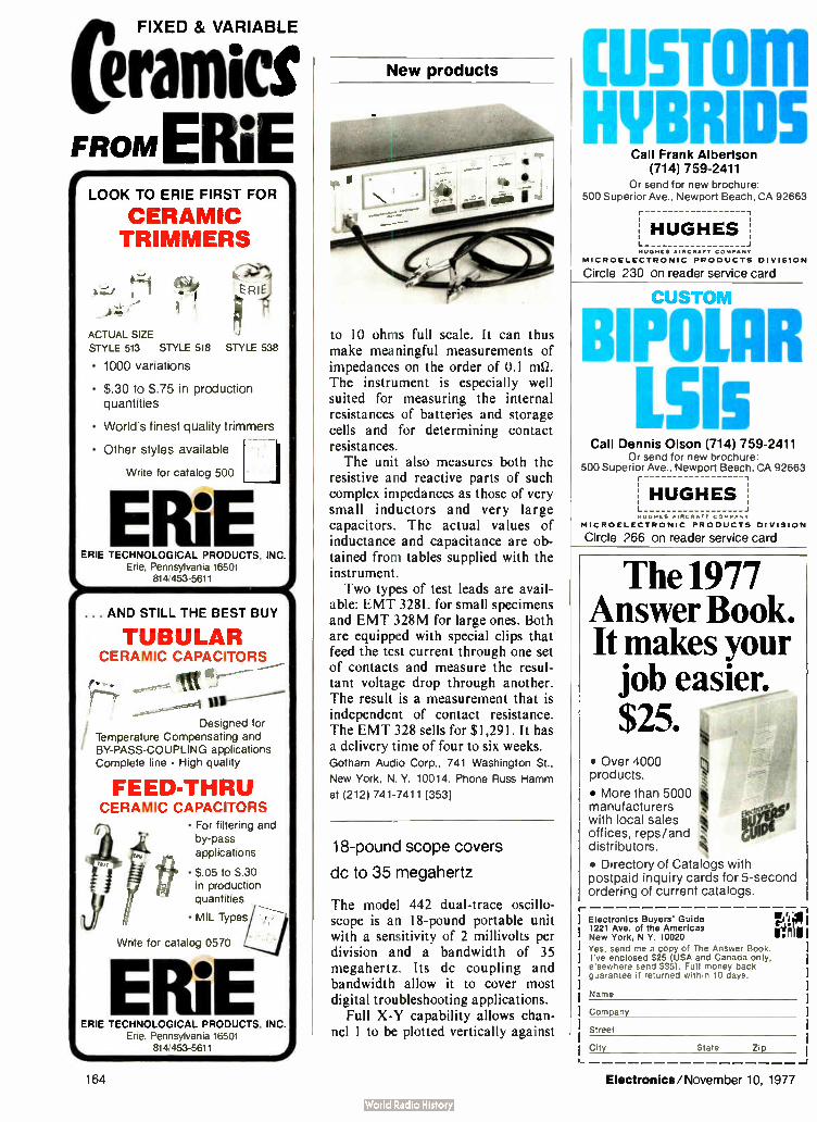
FIXED & VARIABLE
eramics FROM ERIE
LOOK TO ERIE FIRST FOR
CERAMIC TRIMMERS
k—i i
ACTUAL SIZE STYLE 513 STYLE 518 STYLE 538
• 1000 variations
• $.30 to $. 75 in production quantities
• World's finest quality trimmers
• Other styles available -
Write for catalog 500
ERIE
ERLE?
ERIE TECHNOLOGICAL PRODUCTS, INC. Erie, Pennsylvania 16501
814/453-5611
... AND STILL THE BEST BUY
TUBULAR CERAMIC CAPACITORS
ro - - Ititt
Designed for
Temperature Compensating and
/ BY-PASS-COUPLING applications Complete line - High quality
FEED-THRU CERAMIC CAPACITORS
• For filtering and
by-pass
applications
• $. 05 to $.30 in production
quantities
• MIL Types
Write for catalog 0570
EME ERIE TECHNOLOGICAL PRODUCTS, INC.
Erie, Pennsylvania 16501
L_ 814/453-5611
New products
to 10 ohms full scale. It can thus make meaningful measurements of impedances on the order of 0.1 ma The instrument is especially well suited for measuring the internal resistances of batteries and storage cells and for determining contact resistances. The unit also measures both the
resistive and reactive parts of such complex impedances as those of very small inductors and very large capacitors. The actual values of inductance and capacitance are ob-tained from tables supplied with the instrument. Two types of test leads are avail-
able: EMT 328L for small specimens and EMT 328M for large ones. Both are equipped with special clips that feed the test current through one set of contacts and measure the resul-tant voltage drop through another. The result is a measurement that is independent of contact resistance. The EMT 328 sells for $ 1,291. It has a delivery time of four to six weeks. Gotham Audio Corp., 741 Washington St.,
New York, N. Y. 10014. Phone Russ Hamm
at (212) 741-7411 [353]
18-pound scope covers
dc to 35 megahertz
The model 442 dual-trace oscillo-scope is an 18-pound portable unit with a sensitivity of 2 millivolts per division and a bandwidth of 35 megahertz. Its dc coupling and bandwidth allow it to cover most digital troubleshooting applications.
Full X-Y capability allows chan-nel 1 to be plotted vertically against
CUM HYBRIDS
Call Frank Albertson (714) 759-2411
Or send for new brochure: 500 Superior Ave Newport Beach, CA 92663
! HUGHES]' HUGHES AIRCRAFT COMPANY
MICROELECTRONIC PRODUCTS DIVISION
Circle 230 on reader service card
CUSTOM
BIPOLAR L515
Call Dennis Olson (714) 759-2411 Or send for new brochure:
500 Superior Ave., Newport Beach, CA 92663
HUGHES MUGNES • IRCR•fr CO AAAAA
MICROELECTRONIC PRODUCTS DIVISION
Circle 266 on reader service card
The 1977 Answer Book. It makes your job easier. $25.
• Over 4000 products.
• More than 5000 manufacturers with local sales offices, reps/and distributors. • Directory of Catalogs with postpaid inquiry cards for 5-second ordering of current catalogs.
Electronics Buyers Guide 1221 Ave. of the Americas New York, N Y. 10020 Yes, send me a copy of The Answer Book. I've enclosed $25 ( USA and Canada only, elsewhere send $35). Full money back guarantee if returned within 10 days.
Name
rep
Company
Street
City State Zip
-J
164 Electronics/November 10, 1977

After you look at the specs,
look how long they're guaranteed.
The accuracy specs for the Dana 5100 5%2 digit multimeter are guaranteed for a full year. Not 90 days. Not 6 months. That means you only have to calibrate it once a year.
All other multimeters have to be cali-brated an average of three times a year. At about $75 a pop. Which makes their $995 units a lot more expensive to own than the Dana 5100 at $1145,
Instead of sitting in the shop for six weeks over the course of the year, the Dana 5100 will stay right where you are. Measuring AC, DC, Ohms and frequency
•1.1 S domestic pnces
MKOT OSOWICF
OOV ;
GUF.;.LF
(yes, frequency too) with very high accu-racy. Just like the specs say. For a year at a time.
When you look at it that way, one thing becomes obvious.The cost of own-ing a multimeter is a lot more important than the price.
Write Dana Laboratories, Inc., 2401 Campus Dr., Irvine, CA 92715 for all the specs. And take a good look. With specs that good, you'll be glad you only have to give it up once a year. Others measure by us.
I c: r-1 I LI LI i I
Acv Dcv Kr) KHI
OFF ° 3199
4
FILTER
onnn
UP ON AUTO
939 («VITT a
Dana 5100. Ask for a free demonstration
before you consider anything less.
POWER Am- IL. ON OFF
'41411.
For Product Demonstration circle 165 For Literature Only circle 232

Introducing
KERAMAX ano a new kind at performance up to 3300°F in air
with KERAMAX LaCr03 elements.
KERAMAX high temperature furnaces and LaCr03 heating elements excel where others pale by delivering higher working temperatures in oxidizing atmospheres with stability, durability, simple operation and a lower cost/service life ratio. KERAMAX developed by Nippon Kagaku Togyo Co., Ltd. provides a new level of performance at the highest working tem-peratures, whether for R&D, materials testing or production. Furnace Applications • Growing single crystals of ( for example), ferrite for VTR heads • High temperature pro-perties measuring • Ceramics sintering • Metal and slag heat treatment KERAMAX LaCr03 Elements • Longer service life at higher working tempera-tures in oxidizing atmospheres • Lower cost/ service life ratio • Near zero resistance tem-perature coefficients at high temperatures; negligible electric resistance change due to aging • Excellent sensitivity and stability for precise temperature control; easy operation • Automatc control ease • Allows direct elec-tricity supply at room temperature • Silicon car-bide power units applicable for KERAMAX • Suitable for use as light source and electrodes
• Write or Telex for Complete Details
Pule Nishimura Bldg. 13-11, Nishi-Gotanda 1-Chome,
Shinagawa-ku, Tokyo 141, Japan Phone: 03-494-0471 Telex: TOK 2467455
New products
channel 2, with both input attenua-tors functioning. The scope's 150-
millivolt external-trigger sensitivity
allows it to trigger on transistor-transistor- logic levels even when a 10x probe must be used to reduce capacitive loading. The 442 sells for
$1,225, FOB Beaverton. Tektronix Inc., P.O. Box 500, Beaverton,
Ore. 97077 [354]
TOPICS Instruments
ECD Corp., Cambridge, Mass., has developed a tweezer-like chip probe for its hand-held 31/2-digit capacitance meter. The new probe a lows the battery-op-erated C-Meter to measure the capacitance of small chip capaci-tors. Designed for chips with terminal spacings from 0.02 to 0.30 inch, the probe sells for $39.... Ailtech, a Cutler-Ham-mer Co., Farmingdale, N. Y., has introduced several new op-tions for its 707 and 727 spec-trum analyzers. Among them: digital absolute power readout, remote tuning, switchable presel-ector, variable video filter, and selectable 100-hertz or 300-Hz intermediate-frequency filters. ... GenRad Inc., Concord, Mass., is offering an instrument called the 2220 Bug Hound, which is said to greatly simplify the pro-cess of physically locating shorts, opens, bad integrated circuits, and other faults on printed-circuit boards. A key feature of the instrument is its current-tracing probe, which allows the user to follow currents along metalization tracks.
Gas Sensing Semiconductor
FIGARO TGS GAs SENSOR
quickly senses even small
amount of gas.
Applications
1. Natural Gas- Leak Alarm 2. Propane Gas- Leak Alarm
3. ( arbon Monoxide Detector
O. Automatic Fan Control 5. Hri• ' 1)ere. nog
combustible gases contained in smoke)
6. Alcohol Detector (Detector for drunken
driver)
7. Air Pollution Monitor
helo, d,r, b. roe
FIGARO ENGINEERING INC. •Head Office .3 3 Ifigasiloovonaka. Tovonaka
City. Osaka. 56u. JAPAN TELEX 05286155 FIGARO J CABLE FIGARO TOYONAKA
TEL (061 849-2156
*North America: 3303 Harbor Boulevard. Suite D-8. Costa Mesa. California 92626. U S.A. TELEX 678396 CABLE FIGARENGIN COSTAMESA (' FI 17141 751-4103
Circle 231 on reader service card
CUSTOM
CRYSTAL FILTERS
Call Vic Gill (714) 759-2411 Or send for new brochure:
500 Superior Ave., Newport Beach, CA 92663
HUGHES ii MUGHFS AIRCRAFT COMPANY
MICROELECTRONIC PRODUCTS DIVISION
Circle 267 on reader service card
STANDARD ELECTRONIC MODULES
Call Ed Skinner (714) 759-2411 Or send for new brochure:
500 Superior Ave., Newport Beach, CA 92663
HUGHES HLIGHES AIRCRAFT COMPANY
MICROELECTRONIC PRODUCTS DIVISION
166 Circle 166 on reader service card Circle 233 on reader service card

Fluke creates panel thermometers for people
smart enough to look inside.
You have to know what's inside when all digital thermometers look alike on the outside. Because there's only one line of panel
mounted 1° or 0.2° digital thermome-ters with Fluke's recognized traditions of reliabihty, quality and technology. Our 2160A and 2170A instruments. For openers, our LSI design uses only
81 electronic parts. That's 50 parts few-er than the other recognized line. Few-er parts means greater reliability. Then, our accuracy is so compre-
hensive, you'll find it difficult to com-pare with other digital thermometers. We give you specs that have meaning
in the real world. And no one else does that. We take operating time and am-bient temperature into consideration. You get Total Instrument Accuracy, in °F or °C. The 2160A is a front mounting, 4
digit thermometer that resolves 1°C or 1°F over the entire temperature range of any of eight thermocouple types (J, K, E, T, R, S, B, C).That's a tempera-ture range of — 200°C to + 2327°C. The 2170A offers 0.2° resolution. And these meters were designed for
user convenience. You can mount, re-move, calibrate, and select temperature scale (`F or °C) all from the front pan-
el. Options include isolated digital and analog outputs, a multi-point switch and a set point comparator. And the price begins at only $299.*
(OEM agreements available.) All of this would seem to make one
point: You can't judge a panel mounted digital thermometer by its cover. Unless Fluke is on the outside. For data out today. dial our toll-free
hotline, 800-426-036i John Fluke Mfg. Co., Inc., P.O. Box 43210, Mountlake Ter-race, WA 98043. Fluke (Nederland) B.V., P.O. Box 5053, Tilburg, The Netherlands. Phone: (013) 673-973 Telex: 52237.
*U.S. price only.
Accurate 10 digital thermometry for only $299.
FLUKE
Circle 234 for literature Circle 16 7 for cemonstration

CUSTOM CRYSTAL OSCILLATORS
Call Vic Gill (714) 759-2411 Or send for new brochure:
500 Superior Ave.. Newport Beach, CA 92663
1 HUGHES HUGHES AIRCRAFT COMPANY
MICROELECTRONIC PRODUCTS DIVISION
Circle 268 on reader service card
CUSTOM HYBRIDS
Call Frank Albertson (714) 759-2411
Or send for new brochure: 500 Superior Ave., Newport Beach, CA 92663
fI HUGHES HUGHES AIRCRAFT COMPANY
MICROELECTRONIC PRODUCTS DIVISION
Circle 235 on reader service card
CMOS Crystal Oscillators in low profile TO-5 •
Frequency range is 10 kHz to 300 kHz (divided outputs to 1 kHz, low as one cycle per month available). Low milliamp current consumption. Ac-curacy ± 0.01%. Shock 1000 g. Hybrid thick and thin film chip and wire design is rugged and ideally suited for portable equipment. Details in Gold Book & EEM.
STATEK CORPORATION 512 N. Main Orange. California 92658 Telephone: ( 714) 639-7810 TELEX 67-8394
New products
Packaging & Production
TV system eases
wafer dicing
Split-field optical unit
makes water alignment
faster and less fatiguing
A split-field optical system with a television-screen display is designed to take much of the physiological and psychological fatigue out of high-precision wafer dicing. Offered as an option on M-1000 saws, the TV- 1000 alignment system provides 100X magnification on a 9-inch TV monitor. Its dual reticle, which is generated digitally, can be set to the exact width of the saw blade's kerf (the actual width of material sawed away by a particular blade). For ease in viewing, the reticles can be shown as either black or white images. With the new system, first- pass
alignment typically takes about 10 seconds. The second, perpendicular, cut can be aligned in about 5 seconds. An M-1000 dicing system fitted with a TV- 1000 alignment
system sells for about $3,000 more than one fitted with a standard microscope— approximately $21,000 versus $ 18,000. Delivery time is about six weeks. Micro Automation Inc., 3170 Coronado Dr.,
Santa Clara, Calif. 95051. Phone (408) 988-
2180 [391]
Pin-insertion machines
ensure high reliability
A line of pin-insertion machines, which use shoulder pins to assemble hybrid substrates, produces mechan-ical attachments of extreme reliabil-ity. Each pin is staked very tightly to make the assemblies almost immune to shock and vibration. During stak-ing, the top of the pin is expanded to
168 Circle 168 on reader service card Electronics/November 10, 1977

PDP-11 users, let the computer experts help
you play your hancl DEC* computers are among the best ever. Everybody
knows that. But even with DEC there is room for improvement. We took advantage of that fact
and made the best ever even better. In the process, we've given you a chance to super-
charge your present PDP-11* instead of upgrading to the next computer. We've
given you more time and improved your cash flow with the most com-plete line of sophisticated computer
enhancements on the market today. They are available off the
shelf. The are priced com-petitive13. They install in
minutes. They provide imme-diate results. And, in every
instance, they outperform the competition. They should. We are the only computer people in the business.
We are the only people really qualified to help you play out your hand and win.
Here are all the cards in our present deck: CACHE/34', CACHE/40- and CACHE/45', a series of 2048-byte single-board buffer mem-
ories which increase processing speeds as much as 100% in the PDP-11/34, PDP-11/40 and
PDP-11/45. SCAT/45-, an add-in memory which installs 128K of high-speed memory on the Fastbus* of the PDP-11/45, PDP-11/50 and
PDP-11/55. QUADRASYNC- , a quad interface board between the PDP-11 Unibus* and 4 asyn-chronous serial communication channels which
presents only one load to the Unibus. Current loop or EIA/RS-232 versions available. REBUS-, a dual-width board which supplies a repeating function for the Unibus
without requiring space for an entire system unit. And UNI VER-TER', an adapter which converts the LSI* bus to a Unibus structure
and gives the LSI-11 access to a megabyte of memory.
There are more cards coming. In fact, we would like to build something especially for you. Well tell you all about it when you write for details on our present line. Able Write now. Able Computer Technology, Inc., 1616 South Lyon Street,
Santa Ana, California. (714) 547-6236. TWX 910-595-1729.
the computer experts ' ) E( t•N PM' and FASTBUS are registered tracemarks of Digital Equipment Corpora: hri.
Circle 169 on reader service card

THERE'S REALLY ONLY ONE SOURCE FOR COMPLETE, UP-TO-DATE, ANALYZED DATA ON
THE RELIABILITY EXPERIENCE OF DISCRETE SEMICONDUCTOR DEVICES.
That's RAC Data Book
TRANSISTOR/
DIODE DATA, 1977 • Failure rates, screens, stresses,
failure modes and mechanisms
• More than one billion part-hours
• Over 250 pages—fully indexed
• Thousands of detail data entries; scores of data summaries on transistors, diodes, thyristors, and optoelectronics.
• Order by catalogue no. DSR-2. $50 per copy ($60 non-U.S.)
RAC Reliability Analysis Center RADC/RBRAC • Grilfiss AFB, NY 13441 • Tel. ( 315) 330-4151; Autovon 587-4151
RAC is a DoD Information Analysis Center Operated by IIT Research Institute
Circle 170 on reader service card
Now measure AC and DC on any voltmeter with the NEW
CURRENT GUNTM
\ from F.W.Bell
The all-new Cur-rentGun isaclamp-on instrument that lets you read AC and DC from 0 to 1 kHz and from 0 to 200A quickly. easily. safely — without breaking the connection. Use with any voltmeter ... or get a reproduction of the wave form on a scope! Two ranges. 0 to 10A and 0 to 100A with 100% overrange. Only three controls: zero, range selector and press-to-read button.
Less than $200 Accessories available to greatly expand ranges — higher and lower. Request complete specs today.
A Subsod,ary of rae Arnold fngmeering Company 1 4949 Freeway Drive East Columbus Ohio 43229
Phone 614i 888-7501 TWX 810-337-2851
ELL INC
New products
approximately twice its original di-ameter. The result is good electrical reliability that eliminates the need for a solder reflow process or hand soldering.
Designated the model UDI/ UDW-829, the machine consists of an automatic feed, an escapement mechanism, a transfer unit, and a pressure- sensitive staking head con-nected to a conventional dc welder power supply. Close control of the welding parameters and staking pressure permits reliable operation even on fragile 15- mil substrates with fine ( 16- mil) pins. The pin inserter sells for less than $ 10,000. A variety of special indexing, feeding, and fixturing devices can be included at extra cost. Cambridge Automatic Division, Eyelet Tool Co., 15 Erie Dr., Natick, Mass. 01760. Phone Dave Spencer at ( 617) 653-9002 [393]
Unit bonds capacitor chips
to tape-mounted lead frames
An automated bonder that produces either two or four bonds at a time has been designed to attach capac-itor chips to microminiature lead frames mounted on 16-millimeter polyimide tape. Designated the mod-el LF/C bonder, the unit employs a gold- to- gold thermocompression-bonding technique. While the lead frames are fed in on their tapes, the
capacitors are positioned in stainless-steel boats that each hold about 10 to 20 chips. Available options include manual and automatic tape indexing, automatic chip indexing, capacitance checking, and optical inspection. The price, depending upon options, ranges from $ 25,000
170 Circle 236 on reader service card Electronics/November 10, 1977

Ask Control Data
From Control Data. you get both core and advanced semi-conductof memory. You get "state of the art" in high den-sity packaging techniques. (Example: the 94550 semi-conductor memory provides 1 megabyte in the 51/4 ' rack shown above!) You get com-petitive pricing, in cus:om or off-the- shelf standard con-figurations!
I-Phone (612) 830-6018 or write: Richard J. Koebler, OEM Market'ig Mana_ger. Computer Memor;, Ask our OefT1 people i
Manufacturing Divisiord.41001 East Bloomingtcrn Freeway. Bloomington. Minnesota 55420. Please tell me more about your OEM Memories!
FEA:tunE
94400
„es ,(16
.3e )°8 32‘‹ y, e
4i( ,( 819
eà< 9132 le /s13I9 y, 819
94405 4K )(9 eYs 9 stogie (.-5
veage
Also available: UNITEMP core. In 13- mil and 18- mil sizes. UNITEMP is the temperature- independent magnetic ferrite core stable over the entire MT tempera-ture range (0 -90- C). Enclosures. For mounting core or semicorductor mod-ules in standard E.IA 19" racks.
Cabinets measure 51/4 " or 10 1,2" high, 20" deep: cards mount horizontally. Self-contained cooling fans direct air horizontally across the modules. Both core and semi-conductor modules can be incorporated to a maximum of 1 megabyte.
NAME
MM MIMI MIMI Ma IMMIS Ma MIMI BEIM MINIM MUM MU MIMMI MUM MIMI MI MUM 111111111 MIMIC MUM IMUMM
COMPANY _ _ ADDRESS @Es CONTROL DATA I COR,PORFION I
CITY STArE ZIP PHONE__
WM MI NM Ian M. MIME. IM ffll NM UM MIR IBM MI MI JI
Electronics/November 10, 1977 Circle 171 on reader service card 171

5YEAR WARRANTY ON EALTD-r( POWER SUPPLI
CALEX MFG. CO., INC. 3355 Vincent Road Pleasant Hill, CA 94523 Tel: (415) 932-3911
Telex: 338 506
Circle 172 on reader service card
RLOSINIT(H MULTI-POSITION SLIDE SWITCHES
FOR INDUSTRIAL APPLICATIONS
A most versatile switch family designed specifically for printed circuit applica-tions featuring a unique wiping action to assume a low contact resistance—
This is called our MSSA Series.
e1,2,3, or 4 POLE OPTION
• CHOICE OF 3 or 4 POSITIONS
*VERTICAL PC OR RIGHT ANGLE MOUNTING
•GOLD OR SILVER PLATED CONTACTS AND TERMINALS
• PC LEVELLING TABS FOR ADDED STABILITY
• EPDXY SEALED TERMINALS
• QUALITY AT ECONOMY P
Ask Custo Service for a sample and 7
FILED ELECTRONIC PRODUCTS, INC
AUGAT"...c Tel: ( 617) 685-4371 TVVX: 71 ) 342-0552
New products
to $37,000. Delivery time is 14 to 16 weeks. Wells Electronics Inc., Weltek Division, 1701
S. Main St., South Bend, Ind. 46623 [395]
2-inch LCDs mount easily
on printed-circuit boards
A solderless, pinless connector for mounting 2-inch liquid-crystal dis-plays to printed-circuit boards con-sists of a holder containing two Zebra conductive-elastomeric con-nectors and a bezel. The holder provides a 60-mil space under the LCD to accommodate a semicon-ductor circuit. A gas-tight connec-tion is created when the holder
compresses the Zebra connector be-tween the display and the pc board.
Prices for the entire assembly range from $3.65 each in small quantities to 74 cents apiece in lots of 10,000. Delivery time is two to four weeks. Technical Wire Products Inc., 129 Demody
St., Cranford, N. J. 07016. Phone (201) 272-
5500 [ 394]
Flexiprobe penetrates
coatings on solder joints
A unpluggable piercing Flexiprobe is designed to penetrate almost any substance or residue on solder joints to yield accurate test readings on printed-circuit boards. The unit flex-es on irregular surfaces, then re-aligns itself after contact with a test point. Ostby and Barton Co., 487 Jefferson Blvd.,
Warwick, R. I. 02886. Phone (401) 739-7310
[396]
172 Circle 239 on reader service card Electronics/November 10, 1977

Proven problem solvers
from Eire
I/O AND RACK AND PANEL CONNECTORS
Meets every iio wire size requ rement from 18 to 30 AWG. They feature easy mating/unmating and locking of mated connectors with a single jack screw operation. High-density contact spacings range from . 100" to . 150" grids, with 20 to 165 contacts with solder, crimp, wire wrap and other terminations. Lightweight aluminum covers are available for cosmetic appeal, wire clamping and strain relief. They utilize the Varicon'" contact which has a 25 year record of reliable service.
siississt
PC CARD ENCLOSURES
The versatile Varipak II card enclosures are constructed from standard components and ell accommodate any number (34 cards and card sizes :o meet your custom requirements. They come complete with guide plates, card guides, and connector mounting panels. Your local distributor offers immediate delivery on 64 standard models in 19" and 24" widths.
BACKPANEL SYSTEMS
Are you locking for compact, ready-macfe backpanel interconnects for your daughter cards to reduce costs? Elco offers metal plate backpanels with pc connectors for automatic and hand wire wrapping which provide built-in ground and voltage interconnections. To further simplify your task and eliminate wire wrapping, Elco offers pc backpanels in two sided and multilayer configurations providing all ground, power and signal interconnections for mounted card edge or metal-to-metal connectors with contact spacings from . 100" to . 156". All backpanels are custom engineered to fit your exact needs in sizes accommocating as many as 20,000 contacts.
ELCO CORPORATION'S catalogs are available upon request for any of these products. In most cases, these products are immediately available from distributor stock. For custom products or engineering assistance, we'll be glad to help you. Just call us, Elco connects . . . worldwide!
Elco Connects! Circle
CARD EDGE CONNECTORS
Elco has been the supplier of reliable card edge connectors for years. Now additional sizes in the standard line and a new line of wire-wrappable connectors with . 156" centers are offered. All standard contact spacings from . 100" to . 156" for all termination techniques are available including, QPL, military qualifications to MIL-C-21097/21 and UL recognition. And they're immediately available from your local distributor.
2- PIECE METAL-TO-METAL PC CONNECTORS
For the user, who needs the most reliable card-to-card connection, end-to-end, at right angles or stacking connections, we offer the greatest variety of metal-to- metal contacts and connectors available anywhere. Expect off-the-shelf delivery from our distributors on most configurations that include .050" staggered, . 100" to .200" spacing, 1 to 96 contacts, various termination styles, with or without card guides and hardware for most any application. Most are mil spec, QPL and UL recognized. Connections are mede by our Varicon" contact providing hermaphroditic, gas-tight joints with millions of operating hours proving their reliability.
Elco Corporation 2250 Park Place El Segundo, Ca 90245 TWX 910-325-6602/213 675-3311
Geg a Gulf , Western manufacturing company
1 73 on reader service card 173
Elco Corporation

ELECTRONICS REPRINTS
No of copies wanted New reprints
R-718 Display makers strive to refine their technologies 8 pp $3.00
R-716 Special report — Japanese wave in semiconductor technology 24
pp $3.00 _R-714 Special report — active filter
technology 6 pp $3.00 R-713 Electron- beam lithography
draws fine line 10 pp $3.00 R-712 Special report— large-scale inte-
gration 16 pp $3.00 R-710 Personal computers mean busi-
ness 8 pp $2.00 _ R-708 So you want to be a consultant
6 pp $2.00
Charts R-516 Electronic symbols $2.00
_ R-213 Electromagnetic spectrum ( up-dated 1976) $3.00
R-326 Optical spectrum (6-page report and chart) $3.00
Books R-711 Circuits for electronics engi-
neers: 306 circuits in 51 func-tional groups— Electronics Book Series $ 15.95
_ R-704 Thermal design in electronics $5.00
R-701 Applying microprocessors— Electronics Book Series $9.95
_ R-608 Basics of Data Communica-tions— Electronics Book Series $12.95
- R-602 Large Scale Integration— Elec-tronics Bock Series $9.95
R-520 Microprocessors— Electronics Book Series $8.95
- R-011 Computer-aided Design 135 pp
$4.00 _ R-032 Active Filters 88 pp $4.00
Payment must accompany your order
Make check or money order payable to Elec-tronics Reprints. All orders are shipped prepaid by parcel post. Allow two to three weeks for delivery. For additional information call (609) 448-1700 ext. 5494.
Mail your order to: Janice Austin ELECTRONICS REPRINTS P.O. Box 669 Hightstown, N.J. 08520
Back issues now available: 1960 to 1969, $5.00 each 1970 to 1973, $3.00 each 1974 to 1976, $4.00 each
New products
Microwaves
Generator spans 10 to 15.5 GHz
K-band instrument delivers
10 dBm, can be modulated
internally or externally
A K-band signal generator delivers 10 dBm ( 10 milliwatts) of output power over the frequency range from 10.0 to 15.5 gigahertz. Designated the model 1819A, the instrument has a calibrated attenuator that provides precise output levels down to — 90 dBm. Its applications include the testing of communications equip-ment, radars, and weapons systems. Three types of modulation —
frequency, square-wave, and pulse— can be produced using either the generator's built-in source or an external signal. The internal source provides modulation rates variable from 10 hertz to 10 kilohertz. Pulse widths can be set from 0.2 to 2,000 microseconds, and the pulsed rf
output can be delayed from 0.3 to 2,000 1.4.s, relative to the modulating pulse, for easy scope-monitoring. The 1819A also includes a 25-mw C-band signal source that provides similar capabilities from 5 to 7.75 GHz. It sells for $7,750 and has a 30-day delivery time. Polarad Electronic Instruments, 5 Delaware
Dr., Lake Success, N. Y. 11040. Phone (516)
328-1100 [ 401]
Broadband oscillators
are light in weight
A family of yttrium-iron-garnet-tuned oscillators includes five units that, among them, cover the fre-quency range from 2 to 18 gigahertz. The heaviest unit in the series, the AV-71211, weighs just 1 pound and puts out 7 dBm over 12 to 18 GHZ. The lightest oscillator, the AV-7216, is a mere 6 ounces and delivers 8 dBm from 2 to 6 GHZ. It has a calculated mean time between fail-ures of 73,900 hours at 71 °C case temperature; at 100°C the calculated MTBF is more than 46,000 hours under the most severe category (mis-
174 Electronics/November 10, 1977

When was the last time you saved money
and got the counter
A frequency counter you wante • applications. All have been should deliver all the perfor- conceived as cost-effective mance you expected when you placed the order. If the counter is a B&K-PRECISION you'll be getting that plus something equally important—a price that you can easily afford.
B&K-PRECISION has engineered a line of full-feature frequency counters to suit most
MODEL 1850
Hz guaranteed
MODEL 1827
• 30MHz guaranteed;
50MHz typical
• Compact size, portable
MODEL 1820
• 80MHz guaranteed:
100MHz typical
• Period, event and time measurements
answers to frequency measurement needs in communications, lab, field and plant applica-tions. Every B&K-PRECISION counter fea-tures: autoranging, liberal input overload protection, a minimum of 1Hz resolution, conservative specifications, and easy-to- read LED displays.
MODEL 1801 • 40MHz guaranteed:
60MHz typical
helot ci
At the top end of our line is the new Model 1850, very conservatively rated at 520MHz. Features include: TCXO time base... Period measurements from 5Hz to 1MHz ... Leading zero suppression...Bright .43" LED display... Gate times from 10 ms to 10 seconds. $450.
The 1820 Universal Counter is one of the most versatile counters available at any price. Frequency measurement typically extends be-yond 100MHz...Period measurements from 5Hz to 1MHz . . . Period average, auto and manual positions . . . Elapsed time measure-ments to 9999.99 seconds (plus overflow)... Totalizes event counts to 999999 ( plus over-flow)... $260.
OKPRECISION
At only 8120, the 1827 portable frequency counter is slightly larger than a pocket calculator. 30MHz guaranteed: 50MHz typical . Battery saver for all-day field use . . . Full
range of optional accessories available.
The 1801 is a rugged frequency counter designed for production line and mainte-nance applications. Readings to 40M Hz guar-anteed: 60MHz typical . . . Easy to use and read ... Wide range input eliminates the need for level adjustments. $200.
Isn't it time you stopped sacrificing features and performance for price? See your local distributor for immediate delivery.
DYNASCAN CORPORATION
for further information circle 238
6460 W Cortland Avenue, Chicago, IL 60635 312 889-9087
in Canada: Atlas Electronics, Ontario International Sales: Empire Exporters, Inc., 270 Newtown Roaas Plainview. L I., NY 11803
for salesman to call circle 175

moo THE NUMONICS
1224 INTELLIGENT DIGITIZER
PUTS GRAPHICS
ON SPEAKING TERMS WITH YOUR
COMPUTER FOR UNDER $ 4000.
At last. An electronic graphics calculator that adds the program and memory power
of a micro-computer and front-end digitizer. One easy-to-operate unit that's both
portable and programmable for custom application and on-site use. Input data via
the alpha numeric keyboard or the Electronic Digitizer itself. Data goes directly to
the micro-processor for calculations, output to a 16-digit display and/or computer
interface. And you've a choice of either character serial or EIA-RS232C output for-
mats standard. Data batching, axis rotation, scaling, point-to-point area and length
measurements. . .with the Numonics 1224's library of field changeable programs,
we can put your computer on speaking terms with graphics. At less than $4000.
May we tailor one for you?
ci NUMONICS 418 Pierce St., Lansdale, Pa. 19446 ( 215) 362-2766 Circle 176 on reader service card
• Fast TurnAround 25 days from your design to prototype circuits
• Low Cost Save 80% over a fully custom design
'Reduced Circuit Size Multiple saving by reducing circuit size 90%
• Proven Process Standard CMOS assures high reliability and dependable delivery
INTERNATIONAL MICROCIRCUITS,INC.
New products
site launch) of HDBK-217B. With the exception of the Ku-
band AV71211, all oscillators in the series include buffer amplifiers for increased power output and in-creased resistance to frequency pull-ing. They are fundamental transistor units built using thin-film gold-on-ceramic construction. Their pack-ages are all hermetically sealed and filled with inert gas for enhanced reliability. Delivery times range from 30 to 120 days, according to the company. Avantek Inc., 3175 Bowers Ave., Santa
Clara, Calif. 95051. Phone William W.
Berridge at (408) 249-0700 [403]
Programmable field-intensity
meter covers 11 to 18 GHz
The model NM-67 electromagnetic interference field- intensity meter is a self-contained, programmable, mi-crowave receiver with spectrum-analyzer capability and tracking pre-selection. It covers the range from 1 to 18 gigahertz and is expandable up to 40 GHZ. The instrument's frequency and
amplitude outputs are suitable for XY plotting and for conversion to digital form. Frequency readout is digital. Delivery of the meter is from stock. Singer Instrumentation Division, 5340 Alla
Rd., Los Angeles, Calif. 90066. Phone (213)
822-3061 [405]
1111 Lio 4e, a.. e • '
ee •
- 3004 Lawrence Expwy., Santa Clara, Ca. 95050 (408) 735-9370
176 Circle 237 on reader service card Electronics/November 10, 1977
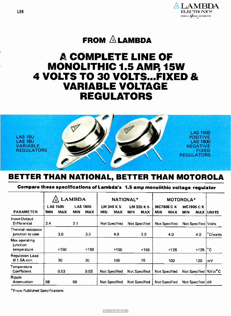
LAMBDA L88 ELFX"I'li(
OVVIS101,1 et
FROM A LAMBDA
A COMPLETE LINE OF MONOLITHIC 1.5 AMP, 15W
4 VOLTS TO 30 VOLTS...FIXED & VARIABLE VOLTAGE
REGULATORS
LAS 15U LAS 18U VARIABLE REGULATORS
Nitale
A_llcire.„eV,\\ e
LAS 1500 POSITIVE LAS 1800
NEGATIVE FIXED
REGULATORS
BETTER THAN NATIONAL, BETTER THAN MOTOROLA
Compare these specifications of Lambda's 1.5 amp monolithic voltage regulator
PARAMETER
A LAMBDA LAS 1505 LAS 1805
MIN MAX MIN MAX
NATIONAL*
LM 340 K 5 LM 320 K 5
MIN MAX MIN MAX
MOTOROLA*
MC7805 C K MC7905 C K
MIN MAX MIN MAX UNITS
Input-Output Differential 2.4 2.1 Not Specified Not Specified Not Specified Not Specified Volts
Thermal resistance
junction to case 3.0 3.0 4.0 3.0 4.0 4.0 °C/watts
Max operating
junction
temperature +150 +150 +150 +150 +125 +125 °C
Regulation Load
@ 1.5A min 30 30 100 75 100 120 mV
Temperature Coefficient 0.03 0.03 Not Specified Not Specified Not Specified Not Specified %Vo/°C
Ripple Attenuation 58 59 Not Specified Not Specified Not Specified Not Specified dB
*From Published Specifications

ALAMBDA LAS 1500 AND 1800 SERIES
FIXED AND ADJUSTABLE MONOLITHIC
VOLTAGE REGULATORS 4 TO 30VDC, 1.5A
POS. AND -2 TO 30VDC, 1.5A NEG.
The only monolithic voltage regulators in the industry performing 100% burn-in under load!
Guaranteed to maximize and expand system reliability!
Now available LAS 15U, LAS 18U adjustable monolithic voltage regulators
OUTSTANDING FEATURES
Guaranteed input-output differential- 2.4 volts pos. and 2.1 volts neg.
[II Pin- for pin replacement for LM309, LM340, LM340A,LM320, MC7800,MC7900, 12A7800 and µA7900series regulators.
D Lower thermal resistance ( more usable output power)- 3°C/VV
D 4 to 30V output available ( positive); -2 to -30 volt output available ( negative)
O Guaranteed load regulation at 1.5 amps- 30 mV
D Guaranteed line regulation at 1.0 amp- 100mV
• Guaranteed temperature coefficient- 0.03% Vo per °C
D Guaranteed ripple attenuation-58 db O Internal short circuit and overload
protection • Thermal and safe area protection
C Guaranteed output noise voltage- 10µV/volt of output ( 1500 Series)
ORDERING INFORMATION
V,
VOLTS MODEL 10
AMPS
PRICE QTY.
1-24 25-49 50-99 100-249 250-499 500-999 1000-2499 2500-4999
430 LAS 15U 1.5 $4.13 $ 3.75 $3.45 $ 3.23 $ 3.00 $ 2.85 $ 2.70 $ 2.55 5 LAS 1505 1.5 2.75 2.50 2.30 2.15 2.00 2.00 1.90 1.80 6 LAS 1506 1.5 2.75 2.50 2.30 2.15 2.00 2.00 1.90 1.80 8 LAS 1508 1.5 2.75 2.50 2.30 2.15 2.00 2.00 1.90 1.80 10 LAS 1510 1.5 2.75 2.50 2.30 2.15 2.00 2.00 1.90 1.80 12 LAS 1512 1.5 2.75 2.50 2.30 2.15 2.00 2.00 1.90 1.80 15 LAS 1515 1.5 2.75 2.50 2.30 2.15 2.00 2.00 1.90 1.80 18 LAS 1518 1.5 2.75 2.50 2.30 2.15 2.00 2.00 1.90 1.80 20 LAS 1520 1.5 2.75 2.50 2.30 2.15 2.00 2.00 1.90 1.80 24 LAS 1524 1.5 2.75 2.50 2.30 2.15 2.00 2.00 1.90 1.80 28 LAS 1528 1.5 2.75 2.50 2.30 2.15 2.00 2.00 1.90 1.80
-30 to 2.6 LAS 18U 1.5 5.40 5.03 4.73 4.50 4.28 4.05 3.82 3.60 -2 LAS 1802 1.5 3.60 3.35 3.15 3.00 2.85 2.70 2.55 2.40 5 LAS 1805 1.5 3.60 3.35 3.15 3.00 2.85 2.70 2.55 2.40
-5.2 LAS 18052 1.5 3.60 3.35 3.15 3.00 2.85 2.70 2.55 2.40 -6 LAS 1806 1.5 3.60 3.35 3.15 3.00 2.85 2.70 2.55 2.40 -8 LAS 1808 1.5 3.60 3.35 3.15 3.00 2.85 2.70 2.55 2.40 -10 LAS 1810 1.5 3.60 3.35 3.15 3.00 2.85 2.70 2.55 2.40 -12 LAS 1812 1.5 3.60 3.35 3.15 3.00 2.85 2.70 2.55 2.40 -15 LAS 1815 1.5 3.60 3.35 3.15 3.00 2.85 2.70 2.55 2.40 -18V LAS 1818 1.5 3.60 3.35 3.15 3.00 2.85 2.70 2.55 2.40 -20V LAS 1820 1.5 3.60 3.35 3.15 3.00 2.85 2.70 2.55 2.40 -24V LAS 1824 1.5 3.60 3.35 3.15 3.00 2.85 2.70 2.55 2.40 -28V LAS 1828 1.5 3.60 3.35 3.15 3.00 2.85 2.70 2.55 2.40
2

LAS 1500,15U SERIES
Regulator Performance Specifications 1.5 amp positive regulators The LAS 1500 Series of three-terminal voltage regulators are monolithic integrated circuits designed for use in applications
requiring a well regulated fixed value positive output voltage for load current variations up to 1.5 amperes. The LAS 15U device is a
4-terminal adjustable positive-output voltage regulator. The LAS 1500 Series is available in fixed output voltage values ranging
from +5V to +28V. The output voltage of the LAS 15U is adjustable from +4V to +30V. Both the LAS 1500 Series and the LAS
15U feature internal current limiting, thermal shutdown, and safe area protection for the series pass Darlington. A hermetically
sealed steel TO 3 package is employed for high reliability, and low thermal resistance, when used with an appropriate heatsink.
PARAMETER SYMBOL VIN TEST CONDITIONS
lo Tj
Input Voltage VIN 5mA 0-125°C Output Voltage) Vo V, to V, . 5mA to 1.0A. 25°C Input Output Differential . . . VIN-Vo 1 OA 0-125°C Output Current lc, V, 25°C Standby Current lo v, 25°C Standby Current Change with input(' ) Alp V, to V, . 5mA 25°C
Standby Current Change with Load Alo V, 5mA to 1.5A. 25°C Maximum Current Limit ILIM . V, - 0•125°C Short-Circuit Current(' ) . Is 70V 0-125°C Short-Circuit Current(' ) IS 30V - 0-125°C Power Dissipation(' " 1
Thermal Resistance Junction to-case
Storage Temperature Maximum Operating Junction
Temperature T., Regulation - Loadl °1 IFILGIL V, 5mA to 1.5A. 25°C Regulation - Line I' I IREG/IN V, to V, 0.1A . 25°C
V, to V, 0.5A 25°C V, to V, 1.0A 25°C
Temperature Coefficient . TC V, 0.1A il 125°C
Output Noise Voltagel' ' / • VN• V, 0.1A 0•125°C RippleAttenuation . . RA . V, . . 1.0A , . 0-1 25°C Control Voltage VC V, to V, 5mA 25°C
Notes
0/ NA inin,urn V 6V DC
ROJC
TSTG
("I Values of 35V applies to V. of 04V to • 12V. Values of 40V applies to Vo 01
ofts .15 to .30 volts. / V, • V. • 5V. V, • V. + 15V or the maximum input voltage whichever is less.
) Nominal output voltages are specified under ordering information
R,
Vo • Vc I • - 1 R, - rosistance from output to control R, - resistance from cont.° ,
R,
10 common
FUNCTIONAL BLOCK DIAGRAM
CURRENT LIMITING 4101. FIER
• itiPlitiPitili
SAFE AREA PROTECTION
VOLTAGE RE COL A110 AMPLIf
t 1 331
SE tifE
OM • IDEPENOS 011881
0 OUTPUT POlI
0 CONTROL WIN 2, FOR LAS ISO 001
AS ISM. LAS ISU
0 COMMON IFIN I & CAST,
TRIS INTERNAL CONNECTION 10, MED ton MO ON,
I")
I' )
1505-1528 TEST LIMITS
MIN MAX
. Vo 2.4V 3b1401(') .95IV.1(° ) 1 051V01
2.4 1 5
10
13
05 28 1 8 08 15
3 -65 +150
-55 +150 06
............ 1.0 • • 20 20 0 03
10
581 11 1
LAS 15U TEST LIMITS
MIN MAX
V. • 2.4V (') 351401(') 4(') 24
1 5 10 .
1 3
0 75 28 1 II
08. 15
3 -65 + 150
-55 + 150 06
..... • 20 20 003
..... 10 581s2) ....
350 4.0
UNITS
volts
vol ts
volts
amps
MA
rnA
rnA
.1101.15
watts
° C Her wall
°C
oc V„
% Vo %
% % VoCC 02Vrmb/V
$21) V
F or poutive regulator V, = Vo • 20V or the masonuon input voltage sidhechever is less
Apples to those devices with 'Vo l. 2V to 18V
Applies to those devices with 'Vo l. 20V to 30V
Instantaneous regulation
Ornate above Tc = 105•C 333 rnW per •C
Specified in aiVrrnsivolt output. BW 10HZ - 100K HZ
Ripple attenuation s specified for a 1 Vrms. 120 HZ ',spirt ripple. Ripple altenuatron Is a
minimum or 58 db at 5 volts output and is 1 db less for each volt increase in output voltage
LAS 1505-1528
0.188R MAX BOTH ENDS
0.066 0.059
3 0.043 0 ,A _ 0.08 2 LEADS
0.151 0.161 DIA 2 HOLES
0.205 0.225
OUTLINE DRAWING
O \ 1.050 MAX
I
0.525R MAX
..1 4 - 1.575 MAX 0.066
LAS 15U
0.188R MAX BOTH ENDS
0.83 r MAX DIA
1.177 T7177 -
0.326 0.308
MTG .480 BASE .480
0.655.4
1' 0.675
FUNCTION PIN 1500 SERIES
1 Input 2 Output case Common
0.059
0.043
477 IA 3EADDS
1.050 MAX
0.52DR MAX
.4-- .575 MAX 0.830 r MAX DIA
MTG BASE
0.326 0.308
.460
_L.
.151 DIA.
2 HOLES
.420 T4'6
130 .470/ I I l-1-4-a
1 DIA 0.420 -LI L io- .265 '-- -in 070T:)" .070 ....I t..- 200 '
_I_ 7670 I... 655 .4 675
PIN FUNCTION
1 5U
1 Common (elec) 2 Control 3 Output 4 Input case Common
3

LAS 1500,15U SERIES Operational Data
RIPPLE ATTENUATION, dB
70
so
50
ito
30
zo
10
INPUT-OUTPUT DIFFERENTIAL VOLTS
OUTPUT CURRENT (AMPS)
2.5
1.5
1.0
0.5
4.0
3.5
3.0
2.5
2.0
1.5
1.0
0.5 T J - -100°C
T = 125°C o. 0 5 10 15 20 25 30 35
INPUT - OUTPUT VOLTAGE, VOLTS
Tj = —55°C
TJ = 0°C
Tj s. 25°C
TYPICAL CURRENT LIMIT VS INPUT-OUTPUT VOLT. DIFF.
POWER DISSIPATION(WATTS)
lo
o
= 0
= 1A
25A lo = 5
mA
-55 -25 0 25 50 75 100 125
JUNCTION TEMPERATURE, 'C
TYPICAL MINIMUM INPUT-OUTPUT DIFFERENTIAL VOLTAGE VS JUNCTION TEMPERATURE
f 120Hz - 10 = 0.5A
Vin = 10VDC + 1Vrrns
- TA - 25-C !
I
0 5 10 15 20 25
OUTPUT VOLTAGE, VOLTS
TYPICAL RIPPLE ATTEN-UATION VS OUTPUT VOLTAGE
30
1000
o
g 100 L,—
tai
CC o Là4
10
I.-
a.
- 1.0
150
r—vin ' = 1cni Vo = 5V -t - I, = 0.5A TA = 25"C
20
15
10
5
O •N N -55 90 100 110 120 130 140
CASE TEMPERATURE (%) MEASURED BETWEEN THE TERMINALS
RIPPLE ATTENUATION, dB
10 100 1K 10K 100K 1M
FREQUENCY, HERTZ
TYPICAL OUTPUT IM-PEDANCE VS FRE-QUENCY
80
70
60
50
ao 30
20
10
POWER DE RATING
Vin = 10VDC + 1Vrms
V o = 5V 14 4 I•
I 0.5A o TA =
11 1 _ I
150
10 100 1K 10K 100K
FREQUENCY, HERTZ
TYPICAL RIPPLE ATTENUATION VS FREQUENCY
1000 e - 100 o
10 - a-1—•
1.0
Vin - V0 r= 10V
10 = 0.5A f = lkHz
TA 25°C
5 10 15 20 25 3)
OUTPUT VOLTAGE, VOLTS
TYPICAL OUTPUT IM-PEDANCE VS OUTPUT VOLTAGE
4

LAS 1800,18U SERIES
Regulator Performance Specifications 1.5 amp negative regulators The LAS 1800 series of three-terminal voltage regulators are monolithic integrated circuits designed for use in applications requiring a well-regulated fixed value negative output voltage for load current variations up to 1.5 amperes. The LAS 18U device is a 4-terrninal adjustable negative-output voltage regulator. The LAS 1800 Series is available in fixed output voltage values ranging from -2V to -28V. The output voltage of the LAS 18U is adjustable from -2.6V to -30V. Both the LAS 1800 Series and the LAS 18U feature internal current limiting, thermal shutdown, and safe area protection for the series pass Darlington. A hermetically sealed steel TO 3 package is employed for high reliability, and low thermal resistance, when used with an appropriate heatsink.
Notes
1')
(°1
PARAMETER
TEST CONDITIONS
SYMBOL VIN I Tj
Input Voltage VIN . 5mA. , . . 0-125°C Output Voltage(' ) V„ V. Io V, 5mA to 1.0A. 25°C
Input Output Differential . . VIN-Vo ..... 0 125°C
Output Current lo V, 25°C
Standby Current lo V, 25°C Standby Current Change with
input(*) Ai o V, to V, . 5rnA 25°C Standby Current Change
with Load Alo . V, . . . 5mA to 1.54 . 25°C
Maximum Current Limit . . ILIM - V, 0 125°C
Short-Car nt Current(') . , Is -20V 0 125°C
Short-Circuit Currenel ) IS 0 125°C Power Dissipation(' Il Po
Thermal Resistance
Junction to case
Storage Temperature
Maximum Operating Junction
Temperature
R OJC
TSTG
Ii Regulation Loadt • I IRI CD, V, . 5mA tri 1.54. 25°C
Regulation - Line 1°1 IR/ GIIN . V, tir V, 0.1A 25°C
V, tri V, 0.5A .. 25°C
V, ti, V; 1.0A 25°C
Temperature Coefficient . T C • V, 0.14 0 125°C Output Noise Vonagel' ' I . . VN. . . V, . . 0.14 . 0 125°C
RippleAttenuation ,. , RA . V, 0 125°C
Control Voltage VC V, ti, V, 5rnA 25°C
Maximum input voltage n -6 Volts Values ol 35V amuies u Vo .ol -2V to - I2V Values I -40V aPPlies to
Vo of - 15io - 30 volis.
V, - V,, -5V V, = Vo - 15V or the Itereteuth value of input voltage whii heygn
s scalier n"aqni mill,.
LAS 1802-1821 TEST LIMITS
MIN MAX
-3l -- 4U, •
. . .95 IV0 '(' 21
'i 1.05 lv.1
1 5
10
1 3
... 0.5 2.8 1.8
. 0.8
15
3
-65 . 150
-55 .150
0.6
1.0 .
2.0.
2.0
003
10
591
LAS 18U TEST LIMITS
MIN MAX
-351--401(' 21,'
-30 -2 601 2 I
1.5 10
1 3
. 0 75 28
1.8
08 15
3 -65 .150
-55 + 150 .
06
1.0
2.0
2.0
. . 0.03
10 591'
-26 -2.25
UNITS
volts
vol ts
volts
amps mA
rnA
rnA
amps
amps
amps
Watt', •
°C per watt
*C
% V„
% Vo
% Vo
% Vo
% Ver C
. Vrrns/V
db
. V
0) For negative regulator V, • Vo -20V or the minimurn value of inclut voltage whichever smaller in magnitude.
(') Applies to those devices with IVol • 2V to 18V
(') Applies to those devices with IVo l• 20V to 30V Instantaneous regulation
01 Nominal output voltages are specified under ordering Information 1.1 1 Derate above Tc - 105°C 333 mW per °C Specified in pVrms/volt output. BW = 101-1Z - 100K HZ
l• I Vo • VC Il -I A, - resistance from output to control R. - resistance fl ues control Ripple attenuation is specified for a 1 Vrrns. 120 HZ input rIpple. Ripple attenuation n a
R, minimum of 59 db at -2 volts output and is 1db less for each volt increase in output voltage
to common
FUNCTIONAL BLOCK DIAGRAM
Lus 1100.145115
OUTPUT INN 11
CONTROL IPIN II FOR I. ASIIIU LINO,
COMMUN 1 &CASE/
THIS INTERNAL CONNECTION FOR FIREO LASI800 ONLY
OUTLINE DRAWING
LAS 1802-1828
• LI!', 0E"::::Z
0.059
.4- .575 MAX 0.83 MAX DIA
0.038 2 LEADS
1.177 trn
0.151 o „, 0.161 2 HOLES
l-050
0.5250 MAX
MTG CASE .1•0
-gy Mg7_
0.420
0.20b 02?S
FUNCTION PIN 1800 SERIES
LAS 18U
0.0888 MAX BOTH ENDS
0.066 0.059
0.043 ,m-cd DIA
4 LEAOS
.420
.7-475
1.050 MAX
0.5250 MAX
MT BASE
0.177 1.197
72"
18°
-t 0.326
.480
.480
.130
.151 DIA.
2 MOLES
28S .265
.074 .200 7675 855
676
FUNCTION PIN 18U
1 Common 1 Input ( elect) 2 Output 2 Output
Case Input 3 Control
5

LAS 1800,18U SERIES
Operational Data OUTPUT CURRENT, AMPS
3.0
2.5
2.0
1.5
1.0
0.5
O
= 0°C
T = 25°C
T = 125°C
0 5 10 15 20 25 30
INPUT OUTPUT DIFFERENTIAL VOLTAGE, VOLTS
TYPICAL CURRENT LIMIT VS INPUT-OUTPUT VOLTAGE DIFFERENTIAL
INPUT-OUTPUT DIFFERENTIAL VOLTS 1.5
1.25
1.0
0.75
0.5
0.25
0 0 25 50 75 100 125 150
JUNCTION TEMPERATURE, °C
TYPICAL INPUT-OUTPUT DIFFERENTIAL VOLTAGE VS JUNCTION TEMPERATURE
RIPP
LE ATTENUATION, dB
80
70
60
50
40
30
20
VI, = 10Vdc 1Vrms-
Io = 0.5V
f = 120Hz TA = 25'C I
I OUTPUT IMPEDANCE, MILLIOHMS
1000
POWER DISSIPATION(WATTS)
RIPPLE ATTENUATION, dB
20
15
10
5
O —ff —55 90 100 110 120 130 140 150
CASE TEMPERATURE('C)
MEASURED BETWEEN THE TERMINALS
80
70
60
50
40
30
20
10
0 10
POWER DERATING
11.
Vin = — 10Vdc + 1 Vrms
V, = —5V
» I,
_ TA = 25 °C
100 1K 10K 100K
FREQUENCY, HERTZ
TYPICAL RIPPLE ATTENUATION VS FREQUENCY
V.. =. -10V V. = - 5V o 0.5A
100 T — A
10
1.0
0 5 .10 - 15 -20 -25 30 10 100 1K 10K 100K
OUTPUT VOLTAGE, VOLTS
TYPICAL RIPPLE
ATTENUATION VS OUTPUT VOLTAGE
FREQUENCY, HERTZ
TYPICAL OUTPUT IMPEDANCE VS FREQUENCY
1M
OUTPUT IMPEDANCE, MIL LIOHMS 1000
100
10
; Ti 10V
= 05A
f = IkHz
A - 25"C
-5 -10 -15 -20 -25 -30
OUTPUT VOLTAGE, VOLTS
TYPICAL OUTPUT
IMPEDANCE VS OUTPUT VOLTAGE
6

LAS 1500,15U, 1800,18U SERIES
Connection Diagrams POSITIVE REGULATOR LAS 1505-1528
II Ripp e • 2rt, rrtv.
Lane and Load Regula,.
EEC TIFIED INPUT
SOOOL..1
5000
C t
SOLID TANTALUM
JUT PU T
1.5 AMP POWER SUPPLY CIRCUIT
SOL IO TANTALUM
T P.
CURRENT REGULATOR CIRCUIT
IN c
+
40000
IN PI, T
— 20 V
4000.uf
3
C o
300p f
SOL TAS AL UM
1.5 AMP POWER SUPPLY CIRCUIT
I AS 1800
NEGATIVE REGULATOR LAS 1802-1828
02
DUAL REGULATOR CIRCUIT
POSITIVE
OUTPUT
300p f
300p f
OUTPUT
co
RECTIFIED
NEGATIVE INPuT
OUTPUT •
5000pf
SOL ID
TANTALUM
IL
CURRENT REGULATION CIRCUIT
LAS 15U
4
Ripple .
5000 Pf
CI 2u SOLID TANTALUM
OUT PUT
1.5 AMP ADJUSTABLE POWER SUPPLY
RECTIFIED INPUT
ADJUSTABLE CURRENT REGULATOR
RECTIFIED
INPU T
+ 20V
4
C o
T,DO,a f A
E
L AS I5U
LAS 18U
CI
SOLID
TANTA LIM
LAS I8U OU T PU T
1.5 AMP ADJUSTABLE POWER SUPPLY
POS ITI VE
OUTPUT
4000 pi 300p!
c
COMMON
40000
RECTIFIED
INPUT •
— 20V
300}a f
±15 VOLT ADJUSTABLE REGULATORS
C I N = 10000/A
OUT = 100µf/A
Cl TO BE PLACED AS CLOSE
AS PRACTICAL TO DEVICE
NEGAT IVE
OUTPUT
REC TIFIED
INPUT
(L 7PL,
'O•
ADJUSTABLE CURRENT REGULATOR
7

PRODUCT FLOW CHART for Power Semiconductors
PROBED, PASSIVATED
WAFERS
SAW, BREAK, CLEAN
DICE PRIOR TO ASSEMBLY
100% DIE VISUAL INSPECTIONS
FOR METAL, CRACKS, OXIDE ALIGNMENT
DIE ATTACH AND 100% INSPECTION
WIRE BOND
100% VISUAL INSPECTION
CAP JEDEC TO 3 RESISTANCE WELD (STEEL)
BRAZE SEAL (COPPER)
LEAK TEST (GROSS)
LEAK TEST ( FINE)
100% DC PARAMETRIC
TEST, + 25'C
100% SECOND BREAKDOWN TEST
POWER DAR LINGTONS AND
SWITCHING TRANSISTORS
100% POWER CYCLE
VOLTAGE REGULATORS
SAMPLE AC PARAMETERS
100% DC PARAMETRIC TEST, +25`'C VOLTAGE REGULATORS
SAMPLE AC PARAMETERS
SAMPLE DC PARAMETRIC
TEST AT +200 C POWER DAR LINGTONS
AND SWITCHING TRANSISTORS
SELECT LIFE TEST SAMPLES
CONDUCT LIFE TEST
FINISHED GOODS
STOCK
Each die is 100% high power visual class probed and electrically tested for all pertinent DC parameters. Rejects are inked.
The 3" wafer is visually inspected prior to sawing. The wafer is grooved by use of a saw, and the dice are separated by fracture along the saw groove.
Prior to package assembly, each die is subject to 100 power micro-scopic inspection to eliminate devices with visual defects that could cause failure in normal application.
Each die is attached to a JEDEC TO 3 package base using Sn/Pb/Ag soft solder. Each package and die is inspected for solder void and proper orientation.
Aluminum wires are ultrasonically bonded to both die and package terminals Each bond is inspected arid each wire pulled ( Flick Test).
Prior to package sealing, each subassembly is subject to 50 power visual inspection to ensure device bond integrity, freedom from foreign material, and conformance to die visual standards All devices are cleaned arid baked for 14 hours.
Lambda devices utilizing TO 3 packages are hermetically sealed in a JEDEC TO 3 package. Steel base packages are resistance welded. Copper base packages are braze sealed. Cold welding is not used.
Each device is gross leak tested by use of fluorocarbon bubble testing.
A helium tracer gas leak test to 5X10 .8 is used to eliminate d evices with defective seals. Testing is done to a 1.5 ACIL. If parts fail they are 100% tested. ( Min 50 devices/lot)
All devices are electrically tested for conformance to +25°C DC param-eters. Automatic test equipment assures proper testing.
All power Darlingtons are tested to conformance to the specified for-ward biased second breakdown current ( ls/b). Non-destructive ' sib test techniques assure conformance to applicable safe operating area (SOA).
All devices are power cycled for 4 hours between case temperatures of 50°C and 100°C. Power dissipation during the heating cycle is ap-proximately 5 watts resulting in approximately 40 cycles in 4 hours.
All devices are electrically retested for conformance to +25"C DC parametees.
Each production lot of power Darlingtons is sample tested for con-formance to all specified device DC parameters at Ti = +200°C, in-
cluding BVCER and ICE R. Testing of product at + 200°C assures the utmost in device stability in a power Darlington were specified.
Periodic tests are performed upon randomly selected device samples to assure product quality. Tests performed include solderability, temper-ature cycling, seal, moisture resistance, terminal strength, mechanical shock, vibration, acceleration, radiographic inspection, and power burn-in (thermal fatigue). Test results are available to qualified personnel upon request to Lambda.
(Lambda staffed sales and service offices o
MID-ATLANTIC REGION Melville, New York 11746 515 B•oad Hollow Road
Tel 516 694 4200 TWX 510 224 6484
Long Island, N.Y.: New York. N.Y Northern New Jersey Tel 516-694-4200
NORTH-EASTERN REGION Lexington. Massachusetts 02173
Delaware: Eastern Pennsylvania +2,1, e
Southern New Jersey Tel 617 861 8585TWX 710 326 7558 Tel 215 279 5644
Southern Virginia: North 8 South Carolina:
Alabama: Georgia. Tennessee; Mississippi
Tel 704 542 1991
Largo. Florida
T, 813 596 5151
e
Maryland: Dist. of Columbia. Northern Virginia Te 703 451 9340
Rochester. New York T, 716..1‘,11, ' 7.
Poughkeepsie. New York Ter 914 297 -1800
o SOUTH-WESTERN REGION
Dallas. Texas 75231
1,051, 3.•• • • • le' 214 214 341 5130
Tlev X 910 861 9048
Houston. Texas Tel 713 464 r, ,,5•1
Oklahoma Tel E.ton , • Pi
o MID-WESTERN REGION
Arlington Heights. III 60005
Minneapolis, Minnesota
Cleveland. Ohio. Western Pennsylvania
7. : 16 585 7808
o FAR-WESTERN REGION Carson, Calif 90746 2060 1 S Arma,ee As.e Te 2,3 53' 834 , TVVx 9,0 346 649
Denver. Colorado
o NORTH-WESTERN REGION Sunnyvale. California 94086
For application Information
call Chris Field at our Corpus
Christi Plant 512-883-6251
POWER SEMICONDUCTORS DESIGNED, DEVELOPED AND MANUFACTURED BY
A I,
PRINTED IN USA

We know your needs. Electronics Magazine Book Series. Zero-risk trial offer.
micRopRocessoRs rmIlm mffilm Wifffifff TTTTTTTTTT
TTTTTT TTTT TIMM !Miff? Iffffffiff PITTIMT lifffffrff MR!!! WM!!! IIMMT 11,17M WTTITMT B
APPLYING MICROPROCESSORS
mymm Immm mnrm TTTTTTTTTT
mmt IfITMT TTTTTTTTTT
YMMT New hardware, software and applications
BectroniΠflUzek Series
1. Microprocessors What you must know about available microprocessor téchnology, devices, informa-tion, 4th printing. $8.95
2. Applying Microprocessors 2nd and 3rd generation tech-nology. 26 detailed applica-tions from data networks to video games. $9.95
LaRae scale Ration
L I
L I L I Electronics Book Series
3. Large Scale Integration Covers the basic technology, new LSI devices, LSI testing procedures, plus system design and applications. $9.95
4. Basics of Data Communications Includes 47 articles from Data Communications magazine covering more than 11 key areas. $12.95
CIRCUITS CIRCUITS CIRCUITS CIRCUITS CIRCUITS CIRCUITS fOR eieCTROIIICS
ineeRs
darBOSICS OF a
COMMUNICaT1ONS dara --dam daTa daTa daTa dara daTa 13ectronics daTa Book Series
5. Circuits for Electronics Engineers Contains 306 circuits arranged by 51 functions from Ampli-fiers to Voltage Regulating Circuits. Saves design drudgery. $15.95
Electronics Book Series McGraw-Hill Publications Company, Shoppenhangers Rd., Maidenhead, Berkshire SL62QL, England.
e-4 leb
1. Send me copies of " Microprocessors" at $8.95 per copy. 2. Send me copies of "Applying Microprocessors" at $9.95 per copy. 3. Send me copies of " Large Scale Integration" at $9.95 per copy. 4. Send me copies of " Basics of Data Communications" at $12.95 per copy. 5. Send me copies of "Circuits for Electronics Engineers" at $ 15.95 per copy. Discounts of 40% on orders of 10 or more copies.
I must be fully satisfied or you will refund full payment if the book is returned after ten-day trial examination.
Payment enclosed CI Bill firm D Bill me — — — — — — — — — — —
Charge to my credit card: D American Express D Diners Club 0 BankAmericard D Master Charge
Acc't No. Date exp. Interbank No
On Master Charge only, first numbers above name
Name Title
Company
Street
City State Zip
Signature
Electronics/November 10, 1977 187

T-METER MEANS TOUGH This digital thermometer is virtually indestructible...drop proof, shock proof, water proof, chemical proof, you name it. We have hurled it against stone walls, immersed it in boiling water for an hour, and submerged it for a week in a salt water fish tank without harming it. Its electronics are cast in silicon. Its teflon-coated probes and cables resist chemicals. It is so rugged that we confidently offer a 3 Year Full Warranty. Tough, accurate, and versatile, spanning — 100°C to 200°C and — 150°F to 400°F, the T- Meter (with standard probe) achieves ±0.5°C (±0.9°F) accuracy over —55°C to 125`C (-67°F to 257°F). Optional high accuracy probes for special applications achieve -4-0.1°C ( t0.15°F), covering
the MIL range in 20°C increments. You can supplement the standard 3' probe with lengths of 10', 25', and 100'. And you can special order lengths to 3,000'! Tough as nails and nuisance-free, this fully guaranteed pocket-sized time-saver will cut your costs in a host of practical applications. Our reps stock T-Meters at $239. Standard probe, $25. General purpose high accuracy probe, $30. Others available.
ECD CORP. 196 Broadway Cambridge, MA 02139 (617) 661-4400 EC»
SALES OFFICES: AL, Huntsville (205) 5315896; AZ, Scot-sdale Ki.02) 947-7841: CA. Costa Mesa (714. 540-7160; CA, Sunnyvale (408) 733-8690; CO. Denver (303) 750-1222; FL. Winter Haven (813) 294-5815; GA. Cnainblee (404) 457-7117: IL, Elk Grove 'till ( 312) 593-0282; IN. riclianapol is ( 317) 293-9827; MD. Silver Spring (301) 622-4200: MA, Wakefield (617) 245-5940; MN. Minneapolis (612) 78:-1611; MO. KansasCity (816) 358-7272:So. NJ 'Philadelphia (215)674-9600; NM. A Ibuquerque (505) 299-7658; NY, Great Neck (516)482-3500. (212)895-7177. Syracuse (315) 446-022C: NC. Raleigh (9)9) 787.5818; Orl. Centerville ( 5131433.8171: TX. Houston (713) 688-9971: TX. Richardson (214) 231-2573.
Circle 188 on reader service card
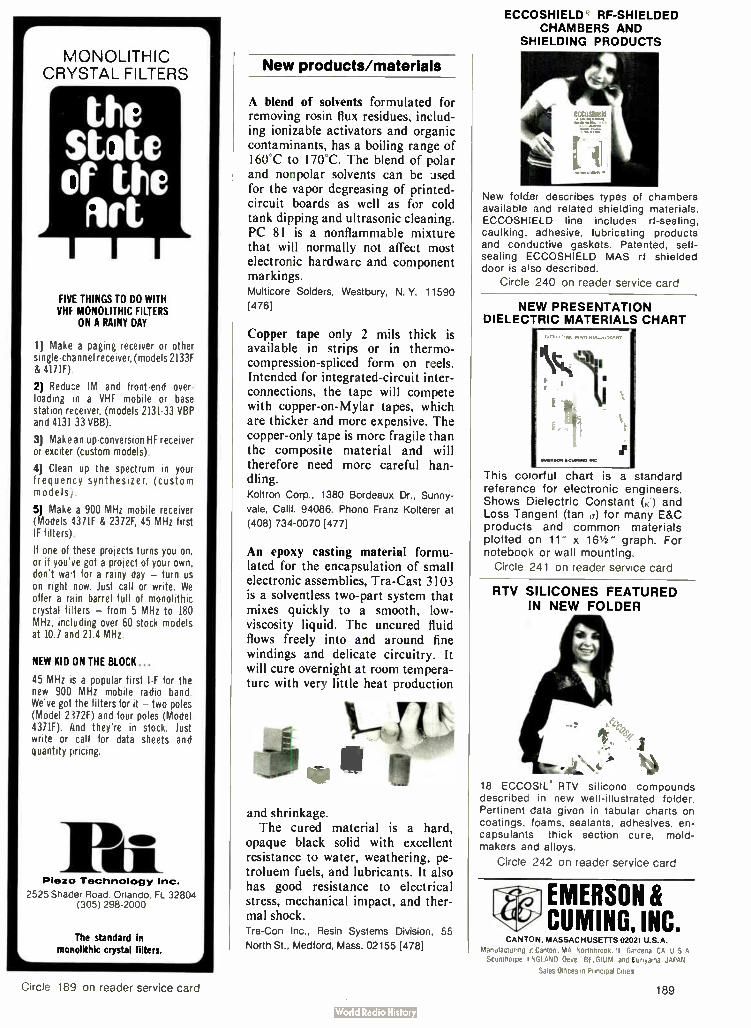
ECCOSHIELD RF-SHIELDED CHAMBERS AND
SHIELDING PRODUCTS
FIVE THINGS TO DO WITH VHF MONOLITHIC FILTERS
ON A RAINY DAY
MONOLITHIC CRYSTAL FILTERS
the State of the lit
1) Make a paging receiver or other single- channel receiver, ( models 2133F & 417IF).
2) Reduce IM and front-end over-loading in a VHF mobile or base station receiver, (models 2131-33 VBP and 4131 33 VBB).
3] Makean up-conversion HF receiver or exciter (custom models).
4) Clean up the spectrum in your frequency synthesizer, (custom models).
5) Make a 900 MHz mobile receiver (Models 4371F & 2372F, 45 MHz first IF filters).
If one of these projects turns you on, or if you've got a project of your own, don't wet for a rainy day — turn us on right now. Just call or write. We offer a rain barrel full of monolithic crystal filters — from 5 MHz to 180 MHz, including over 60 stock models at 10.7 and 21.4 MHz.
NEW KID ON THE BLOCK...
45 MHz is a popular first I-F for the new 900 MHz mobile radio band. We've got the filters for it — two poles (Model 2372F) and four poles (Model 4371F). And they're in stock. Just write or call for data sheets and quantity pricing.
Pia Plezo Technology Inc.
2525 Shader Road Orlando FL 32804 (305) 298-2000
The standard in monolithic crystal filters.
New products/materials
A blend of solvents formulated for removing rosin flux residues, includ-ing ionizable activators and organic contaminants, has a boiling range of 160°C to 170°C. The blend of polar and nonpolar solvents can be used for the vapor degreasing of printed-circuit boards as well as for cold tank dipping and ultrasonic cleaning. PC 81 is a nonflammable mixture that will normally not affect most electronic hardware and component markings. Multicore Solders, Westbury, N. Y. 11590
[476]
Copper tape only 2 mils thick is available in strips or in thermo-compression-spliced form on reels. Intended for integrated-circuit inter-connections, the tape will compete with copper-on-Mylar tapes, which are thicker and more expensive. The copper-only tape is more fragile than the composite material and will therefore need more careful han-dling. Koltron Corp., 1380 Bordeaux Dr., Sunny-
vale, Calif. 94086. Phone Franz Kolterer at
(408) 734-0070 [477]
An epoxy casting material formu-lated for the encapsulation of small electronic assemblies, Tra-Cast 3103 is a solventless two-part system that mixes quickly to a smooth, low-viscosity liquid. The uncured fluid flows freely into and around fine windings and delicate circuitry. It will cure overnight at room tempera-ture with very little heat production
and shrinkage. The cured material is a hard,
opaque black solid with excellent resistance to water, weathering, pe-troluem fuels, and lubricants. It also has good resistance to electrical stress, mechanical impact, and ther-mal shock. Tra-Con Inc., Resin Systems Division, 55
North St., Medford, Mass. 02155 [478]
New folder describes types of chambers available and related shielding materials. ECCOSHIELD line includes rf-sealing, caulking, adhesive, lubricating products and conductive gaskets. Patented, self-sealing ECCOSHIELD MAS rf shielded door is also described.
Circle 240 on reader service card
NEW PRESENTATION DIELECTRIC MATERIALS CHART
This colorful chart is a standard reference for electronic engineers. Shows Dielectric Constant (K') and Loss Tangent (tan (r) for many E&C products and common materials plotted on 11" x 161/2 " graph. For notebook or wall mounting.
Circle 241 on reader service card
RTV SILICONES FEATURED IN NEW FOLDER
j
18 ECCOSII: RTV silicone compounds described in new well-illustrated folder. Pertinent data given in tabular charts on coatings, foams, sealants, adhesives, en-capsulants thick section cure, mold-makers and alloys.
Circle 242 on reader service card
EMERSON & CUMING, INC.
CANTON. MASSACHUSETTS 02021 U.S.A.
Manufacturing .e Canton. MA, Northbrook. IL. Grdena, CA. U S A Scunthorpe. I NGLAND. °eye. BELGIUM. and turiyama. JAPAN
Sales Offices in Principal Cities
Circle 189 on reader service card 189

Engineers
Technolp ical Leaaer ni
or 3 cades!
Ampex, headquartered on the San Francis-co Peninsula, is the company that "invent-ed" the magnetic recording industry.
The technology pioneered by Ampex over three decades has affected many aspects of our modern lifestyles, and has established Ampex as a leader in magnetic recording. Our continued ef-fort in developing new technology has always been the key to our leadership. Right now our Advanced Technology, Data Products and Audio-Video Systems Divisions are embarking on several new programs. To insure the success of these programs we are seeking innovative graduate engineers with experience in the fields listed below.
Opportunities like this don't happen very often. But they're happening at Ampex now.
Advanced Technology Division electron beam and optical recording
• magnetic recording • tape or film handling • Servos
• high-bit rate digital circuit design • optics • signal analysis • pattern recognition • high frequency circuit • communications theory
Data Products Division • circuit systems design of very high-bit rate systems
Manager Corporate Staffing AMPEX Corporation Building 2, 2655 Bay Road Redwood City, CA 94063 Dept. 4
Name Address City, State, Zip Phone
• disk read/write systems and equalizing systems for tape recorders
• codes for magnetic recording • precision servo systems for both linear po-
sitioners and rotating systems • mechanical design of high precision systems in
disk recorders and in longitudinal, helical and transverse scan tape recorders
Audio-Video Systems Division • analog videotape signal systems • digital video signal processing • servo systems • videotape editing • professional audio recorders • head technology • TV cameras
If you think you have something valuable to offer in any of these or closely related areas, and if you would like to join some of America's most talented engineers, please send your resume or a letter out-lining your qualifications to: Ampex Corporation, ATTN: J.C. Puckett, Building 2, 2655 Bay Road, Redwood City, CA 94063. Or you can send us this coupon and we'll get back to you. We are an equal opportunity employer m/f.
Occupation Years of Experience Employer
AMPEX 190 Electronics/November 10, 1977

New literature
Sensors. The flexibility of lead-sulfide sensors and the detection capabilities of lead-selenide sensors are highlighted in two application notes. The one on lead-sulfide sensors provides information on elec-trical performance, configuration, packaging, and environmental-stress characteristics. The second applica-tion note provides the same informa-tion with an additional section on how to bias circuits. A third note discusses the packaging designs for silicon sensors. Infrared Industries Inc., Waltham, Mass. 02154. Circle reader service number 421.
Temperature controls. A 40-page booklet featuring more than 2,000 temperature controls provides tech-nical data for electronic, electrome-chanical, indicating, and nonindi-cating models. Featured is a section on achieving better temperature con-trol, including how to heat the system, selecting the temperature controller, and what affects control
ema accuracy. Operating information is provided. Fenwal Inc., 400 Main SL, Ashland, Mass. [422]
Safety standards. The 12th edition of the standard for safety on industrial
control equipment, UL 508, covers the requirements for industrial-control devices. However, these re-quirements do not cover devices rated at more than 600 volts, such as electronic and static devices. Copies may be obtained at $4.00 per copy. For $ 10.00 you can receive this publication plus all revisions added while this standard is in effect. Underwriters Laboratories Inc., Attn: Publications Stock Dept., 333 Pfingsten Rd., Northbrook, Ill. 60062
Noise elimination. "Elimination of Noise in Low-Level Circuits," a 20-page bulletin, shows how to design low-level wide-bandwidth data systems that are noise-free down to and including the microvolt region. Included are recent developments in measurement technology, plus expla-nations of electrical noise sources, proper impedance matching, trans-ducer characteristics, common-mode rejection, grounding methods, ca-
Two New Refreshing Alternatives PAIEGRAPHIC soms a 7000 SERIES
rn ••••••
'4
Dollar For Dollar, The Best Performing, Most Powerful,
Intelligent Graphics Systems
DYNAMIC TEKTRONIX "* REFRESH COMPATIBLE All MEGRAPHIC Sys-tems feature 100% vec-tor refresh. Sharp, bright lines with 12 bits of screen resolution. Indi-vidual vectors or sym-bois can be erased, translated, rotated, or scaled in real-time. No need to blank the entire screen to change one, one hundred, one thousand, ten thousand, or more points!
Loca; minicomputer power eliminates the host or minimizes its support requirements.
Our 5014 emulates all Tektronix 40104014" Series storage termi-nals. MEGATEK's EDS adds powerful local edit capabilities, not available on a stor-age tube. Easy to use, easy to pay for. Flexible, cost effec-tive systems. backed by MEGATEK engineering and software support. PDP-11, DATA GEN-ERAL, and OEM inter-faces available. We lis-ten to your problems and solve them with quality products.
MEGATEK CORPORATION
The Refreshing Alternative"'
1055 Shafter Street San Diego, California 92106 (714) 224-2721
• -TEKTRONIX" is a registered trademark of Tektronix. Inc..
use of which in no way constitutes endorsement.
Electronics/November 10, 1977 Circle 191 on reader service card 191

Industry's First
14-Bit A/D In a DIP
• Highest resolution A/D available in a DIP
• Fully specified from 0° to 70°C
• +1/2 LSB linearity error • 0.04% accuracy • Conversion time:
250 usec max • Power consumption:
230 mW typical • Adjustment free • 24-pin hermetic DIP
MN 5260 $219.00*
in 100 quantity
Micro Networks Corporation 324 Clark Street, Worcester, MA 01606 (617) 852-5400 TWX 710-340-0067
New literature
bling systems, signal conditioning, and amplifier types. Marketing Ser-vices, Gould Inc., Instrument Systems Division, 3631 Perkins Ave., Cleveland, Ohio 44114 [426]
Compounds. Nearly 200 compounds and coordination compounds made from platinum, palladium, ruthe-nium, rhodium, iridium, osmium, and gold are listed in a 16-page cata-log. The coordination compound sec-tion includes information on ap-pearance and characteristics along with a suggested use for each. Matthey Bishop Inc., Malvern, Pa. 19355 [424]
IR emitters and injection lasers. A 24-page product guide provides data and outlines for infrared emitters and injection lasers. Included are ir-emitting diodes, single-diode in-jection lasers, stacked diode lasers, laser arrays, and optically coupled isolators. An applications section is featured with schematics of drive circuits for these devices. RCA Corp., Box 3200, Route 202, Somerville, N. J. 08876 [425]
Planar gas-discharge displays. A 16-page application note, "Screened Image Displays," discusses a variety of possible applications for designers of consumer, computer, and instru-mentation displays. Four applica-tions of screened image displays are detailed and diagramed. Specifica-tions, matrices, standard numeric illustrations, and alphanumeric fonts will help those who wish to specify their own design. Beckman Instru-ments Inc., Information Displays Operations, 350 North Hayden Rd., Scottsdale, Ariz. 85257 [427]
Temperature measurement. The sec-ond edition of the "Temperature Measurement Handbook" contains more than 200 pages of temperature-measurement products. A 38-page data section provides temperature-millivolt tables for thermocouple calibrations in Celsius and Fahren-heit. New additions to the second edition include solid-state tempera-ture controllers, digital thermome-ters, resistance temperature-detector
ELECTRONICS REPRINTS New reprints
R-718 Display makers strive to refine their technologies 8 pp $3.00
R-716 Special report — Japanese wave in semiconductor technology 24
pp $3.00 R-714 Special report — active filter
technology 6 pp $3.00 R-713 Electron- beam lithography
draws fine line 10 pp $3.00
_ R-712 Special report — large-scale inte-gration 16 pp $3.00
R-710 Personal computers mean busi-ness 8 pp $2.00
R-708 So you want to be a consultant 6 pp $2.00
Charts _ R-516 Electronic symbols $2.00 _ R-213 Electromagnetic spectrum (up-
dated 1976) $3.00 R-326 Optical spectrum (6-page report
and chart) $3.00
Books _ R-711 Circuits for electronics engi-
neers: 306 circuits in 51 func-tional groups— Electronics Book Series $ 15.95
_ R-704 Thermal design in electronics $5.00
_ R-701 Applying microprocessors— Electronics Book Series $9.95
_ R-608 Basics of Data Communica-tions— Electronics Book Series $12.95
_ R-602 Large Scale Integration— Elec-tronics Book Series $9.95
_ R-520 Microprocessors— Electronics Book Series $8.95
R-011 Computer-aided Design 135 pp
$4.00 R-032 Active Filters 88 pp $4.00
Payment must accompany your order
Make check or money order payable to Elec-tronics Reprints. All orders are shipped prepaid by parcel post. Allow two to three weeks for delivery. For additional information call (609) 448-1700 ext. 5494.
Mail your order to: Janice Austin ELECTRONICS REPRINTS P.O. Box 669 Hightstown, N.J. 08520
Back issues now available: 1960 to 1969, $5.00 each 1970 to 1973, $3.00 each 1974 to 1976, $4.00 each
192 Circle 192 on reader service card Electronics/November 10, 1977

Sol-20. First it was THE SMALL COMPUTER. Now, it's THE SMALL COMPUTER SYSTEM.
A year ago, we inlroduced the Sol-20. It wasn't the first small computer. It was the first complete small computer with everything needed to :let it up and on the air as it came from the factory. The keyboard, interfaces, extra memory. factory backup. and service notes were all there.
The results are in: Sol-20 is now the number one small computer in the world. Sols aren't the cheapest, just the most valuable.
We originally designed the Sol-20 as the heart of a complete computer system. So now to solve the problems of science. engineering, education. business management and control and manufacturing, we offer fixed price Sol systems in either kit or fully tested and assmmblecl form. We offer language flexibility. Extended BASIC. ASSEM-BLER. PILOT BASIC and FORTRAN
IV. We offer Helios II/PTDOS, an extraordinarily capable disk operating system. And remember, though we call these small or personal computer systems. they have more power per dollar than anything ever offered. They provide performance fully comparable and often superior to mini-computer systems costing tens of thousands of dollars more.
What you get. What it costs. Typical systems include Sol
System I priced at $1649 in kit form, $2129 fully assembled and tested. In-cluded are a Sol-20/8 with SOLOS personality module storing essential system software. an 8192 word memory, a 12" TVrvideo monitor, a cassette recorder with BASIC tape and al necessary cables.
Sol System II has the same equip-ment with a larger capacity 16.384 word
memory. It sells for $1883 in kit form: $2283 fully assembled.
For even more demanding tasks. Sol System III features Sol-20/16 with SOLOS. 32.768 words of memory. the video monitor and the dual drive Helios II Disk Memory System with the PTDOS disk operating system and Extended DISK BASIC Diskette. Prices. $4750 in kit form, 35450 fully assembled and tested.
More information. For the most recent literature and
a demonstration. see your dealer listed below. Or if more convenient, contact us directly. Please address Processor Technology Corporation. Box J. 7100 Johnson Industrial Drive. Pleasanton. CA 94566. Phone W15) 829-2600.
Processor k-AZ:Tempe (602)894-1129; Phoenix 602)942-7300; Tuc,;on ( 602 27-4579. CA*. Berkeley (415)845-6366; Costa Mesa (714)646-0221; Fresno (209)266-9566: Hayward (415)537-2983; Lawndale (213)371-2421 Orange (714)633-1222; Pasadena (213)684-3311; Sacramento (916)443-4944; San Francisco (415)431-0640, (415)421-8686; San Jose (408)377-4685, (408)226-8383; San Rafael ( 415)457-9311; Santa Clara (408)249-4221; Sunnyvale (408)735-7480; Tarzana ( 213)343-3919; Van Nuys (213) 786-7411: Walnut Creek (415)933 8252; Westminster (714)894.9131. CO: Boulder (303)449-6233; Englewood (303)761-6232. FL: Fort Landerdale (305)561-2983; Miami (305)264-2983; Tampa (813)879-4301. GA: Atlanta (404)455-0647. IL: Champaign (217)359-5883; Evanston (312)326-6800; Lombard (312)620-5808. IN: Bloomington (812)334-3607; Indiasapol is (317)842-2983, (317)251-3139. IA: Davenport (319)386-3330. KY: Louisville (502)456-5242. MI: Ann Arbor (313)995-7616; Royal Oak (313)576-0900; Troy (313)362-0022. MN: Minneapolis (612)927-5601. NJ: Hoboken (201)420-1644; Iselin ( 201)283-0E00. NY: Middle Island (516)732-4446; New York City ( 222)686-7923; White Plains (914)949-3282. NC: Raleigh (919)781-0003. OH: Columbus (614)486-7761; Dayton (513)296-1248. OR: Beaverton (503)644-2686; Eugene (503)484-1040; Portland (503)223-3496. RI: Warwick(401)738-4477. SC: Columbia (803)771-7824. TN: Kingsport (615)245-8081. TX: Arlington (817)469-1502; Houston (713)526-3456, (713)772-5257; Lubbock (806)797-1468; Richardson (214)231-1096. VA: McLean (703)821-8333; Reston (703)471-9330; Virginia Beach (804)340-1977. WA: Bellevue (206)746-0651; Seattle ( 206)524-4101. WI: Milwaukee (414)259-9140 WASHINGTDN D.C. (203)362-2127. CANADA: Ottawa i 613)236-7767; Toronto (416)484-9708, (416482-8080, (416)598-0262; Vancouver (604)7:36-7474, (604)438-3282.
Electronics/November 10, 1977 Circle 193 on reader service card 193

New... Ultrasonic Solder System for Fluxless tinning of plated leads.
Blackstone's new TP-6 l'Itrasonie solder pot is ideal for production line tinning of gold, tin, nickel, solder and other plated leads...without flux. ('hick these outstanding features:
• Insulated, stainless steel pot; 4" x 8" x1-1/2" deep • Totally activated pot volume permits multiple tinning of many components. • Designed lOr use with 63/37, 60/40 and other electronic grade solders. • operation to 800°F solder temperature.
Send for complete descriptive literaturc.
Y 1111 Allen Strect,Jamestown, New 1471 BLACKSTONE ULTRASONICS INC
Phone 716-665-2620 Telex 91 -522
Circle 194 on reader service card
RECTIFIER BRIDGES PB Series! 300 Amp. surge. 1,500V RMS dielectric strength U.L. Component Recognition. Lots of features. Competitively priced. Write or use Inquiry Number for O.E.M. application card for free samples and condensed catalog of bridges.
Ill" Buy from the specialist C • devices id electroni cGRtAYr OAKS IA0VET.wYx0N7KERS.10 6N Y 10i7109141 C • 0.0021
For application information, call Toll Free: 830 431-1532
New literature
elements, and thin-film detectors. Omega Engineering Inc., Box 4047, Stamford, Conn. 06907 [430]
System measurements. How diag-nostic and performance measure-ments on frequency-division multi-plex basebands can be made more simple and quick using a spectrum analyzer and tracking generator is detailed in an application note from Marconi Instruments, Division of Marconi Electronics Inc., 100 Stone-hurst Court, Northvale, N. J. 07647 [428]
Ac and dc motors. A list of thou-sands of ac and dc motors classified as induction, synchronous, and torque are covered in a 100-page catalog. Motors from 0.750 to 5.375 in. in outer diameter, with power outputs ranging from subfractional to 3 horsepower are described. imc Marketing Division, 570 Main St., Westbury, N. Y. 11590 [429]
Wiring products. An illustrated bro-chure that unfolds into an 18-by-24-inch wall chart offers information on 36 different types of high-tempera-ture insulated wire. It covers ther-moplastic, asbestos, silicone rubber, and fluorocarbon materials on a variety of solid, stranded, and spe-cially plated conductors. The guide is organized by increasing tempera-ture service. Radix Wire Co., 26260 Lakeland Blvd., Cleveland, Ohio 44132 [432]
Instruments. Information for engi-neering personnel who wish to buy, rent, or lease electronic equipment is given in a 74-page catalog, which takes into consideration obsolescence and budget, capital, and mainte-
194 Circle 243 on reader service card Electronics/November 10, 1977

Introducing the next generation of
data acquisition systems.
The incredibly versatile Adac System 1000.
This remarkable system can operate in an almost unlimited range of applications. In its simplest form, the System 1000 can function as a low cost peripheral expander to the most popular minicomputers. When incorporating a DEC LSI-11 microcomputer, it can act as a stand-alone control system or as a remote intelligent terminal.
A single System 1000 can provide up to 700 high level analog input channels, or 128 analog low level input chan-nels, or 700 digital I/O functions. For even greater capacity, a Model 1950 Bus repeater card allows additional 1000 Sys-tems to accommodate as many analog or digital I/O mod-ules as desired.
System 1000 in the stand-alone configuration comes with minimum memory of 4K RAM with up to 24K of additional memory possible in both RAM and ROM. The LSI-11 16 bit
resident computer can communicate with any of the exten-sive library of Adac analog and digital I/O modules or other LSI-11 compatible modules. Applications include digitizing outputs of thermocouples, strain gages, isolation amplifiers, LVDT, RTD, photomultipliers, potentiometers, optical scan-ners, oi giving outputs to scopes, pen recorders and actuators.
And that's just the beginning. Adac digital I/O modules handle inputs from Digi-switches, shaft encoders, motor controls and relays wilh outputs to printers, cassettes, lamps, relays, solenoids ... you name it.
So, when you need a ttP based, or front end system with analog or digital I 0, take a look at the Adac System 1000.
Sales offices throughout the world.
15 CUMMINGS PARK • WOBURN • MASSACHUSETTS 01801 • TELEPHONE: (617) 935-6668 • TELEX: 949329
Electronics/November 10, 1977 Circle 195 on reader service card 195

1977Answer Book. It makes your job easier. $25.
"WHO MAKES WHAT?"
"WHERE ARE THEIR NEAREST SALES OFFICES?"
\ "WHO ARE THEIR
DISTRIBUTORS?"
"WHO / MANUFACTURES
THIS TRADE NANIE?" (See Directory of Trade Names)
"WHAT COMPANIES MAKE THE PRODUCTS I NEED?"
(See alphabetical directory of 4000 products)
"WHAT ARE THEIR LOCAL PHONE
NUMBERS?" (See alphabetical
directory of over 5000
manufacturers)
"HOW CAN I GET THEIR CURRENT
CATALOGS FAST?" (See directory of catalogs by product and by company,
including catalog inquiry cards for 5-second ordering)
Electronics Buyers' Guide 1221Avenue of the Americas New York, N.Y. 10020 me I Yes, send me a copy of Electronics Buyers' Guide. I've enclosed $25 (USA and Canada only, elsewhere send S35). Full money back guarantee if returned within 10 days.
Name
Company
Street
New literature
nance requirements. Analyzers, fre-quency counters and timers, genera-tors, oscilloscopes, and micropro-cessor design and test systems are detailed. A separate section dis-cusses a system called "Inventory and Delivery Information in One Minute," which provides answers on the availability, price, and delivery of any instrument. United States Instrument Rentals Inc., 951 Indus-trial Rd., San Carlos, Calif. [431]
Opto-isolators. A 22-page handbook describes how to use opto-isolators effectively, including techniques for increasing speed, connecting circuits for use with transistor-transistor-logic devices, and circuit diagrams for various applications. Litronix Inc., 19000 Homestead Rd., Cuper-tino, Calif. 95014 [433]
Instruments. Articles on improving instrument transmission, reflection accuracy, and phase measurements are contained in a 57-page catalog. Technical data is provided for such instruments as solid-state sweep gen-erators, and multiband, dual-band, and single-band plug-in sweep gener-ators, with ranges from 100 kilohertz to 40 gigahertz. Diagrams and charts provide additional backup information. Wiltron Co., 825 East Middlefield Rd., Mountain View, Calif. 94043 [434]
Telecommunications. A 16-page handbook covering technical aspects and applications of modems, auto-matic dialers, and associated equip-ment, is a compilation of material from data-communications semi-
Iyadic
TELECOMMUNICAT IONS FROM THE TERMINAL USER S VIEWPOINT
nars. Included are dozens of graphs and diagrams that illustrate the properties and operations of these properties. Vadic Corp., 505 East Middlefield Rd., Mountain View, Calif. 94043 [436]
City State Zip
196 Electronics / November 10, 1977

THE STANDARD FOR TACTICAL MICROWAVE LANDING SYSTEMS
Kearfott's Microwave Landing System is completely self-contained scanning beam system that inc,udes all the necessary airborne and ground equipment required to safely provide Category Il approach and landing guidance for all types of aircraft—VTOL. STOL, and COL.
The AN TPN-30 ground equipment and AN/ARN-128 airborne equipment constitute the most modern scanning beam landing system available today. It has been designed for and successfully tested to the most stringent environmental requirements of the US. Navy and U.S. Marine Corps. ( MIL-E-16400 and MIL-E-5400).
The system features reliable performance which has been achieved by drastically reducing the com-plexity of the scanning antenna and by employing digi-tal electronics throughout. All solid state, with full system BITE, the equipment has demonstrated that it will operate in excess of 2300 hours in adverse envi-ronmental conditions without experiencing a compo nent failure.
For additional information write to: The Singer Company. Kearfott Division, 1150 McBride Ave, Little Falls, N.J. 07424.
Kearfott's AN TPN-30 Scanning Beam Microwave Landing System for U.S. Marine Corps.
Ground System
• • 20 Azimuth • 0-20 Elevation • 10-Minute Set Up • Integral Alignment Sight and Levels • Weight- 115 pounds • 200 watts at 115 Vac. 50-400 Hz or 24 volt Battery
Airborne Subsystem
The airborne system provides the following information to the pilot:
• Air Selectable G'ideslope 3 - 12 • Course Deviation—Localizer & Glideslope • Range to Touchdown in 1:100s nmi, Rate Range in Knots • Minimum Useable Glideslope • Alert to an Obstacle Region • Relative Vertical Position of Obstacle • Ground Station Identification • Automatic -Soft Course' . • Weight- 23.2 lb. Volume 0.5 f3 • Power-95 watts
System Characteristics Operational Frequencies Range Data Rate
Number of Channels Accuracy
Azimuth Elevation 15.450 to 15.700 GHz 10nmi with 25mm of rain hour 7.5 scans/second
20 0.2 Az. 0.1 EL
DME 960 to 1211 MHz (TACAN Band) 40nmi Wth 25mm of rain/hour 30 second ( track) 150'sec. acquisition 252 100 ft Kearfott
Electronics/November 10, 1977
a division of The SINGER Company
Circle 197 on reader service card 197

THURSDAY, November 17, 1977
BEGINNING AT 11:00 A.M. ( CST)
ASSETS SURPLUS TO THE PRESENT OPERATION OF
BOWMAR CANADA LIMITED Moved for convenience of sale to: 8000 Bluffton Road • Fort Wayne, Indiana
SEMICONDUCTOR PRODUCTION PROCESSING EQUIPMENT ALSO SUITABLE FOR LABORATORY RESEARCH AND DEVELOPMENT PREVIOUSLY USED FOR PROCESSING LIGHT EMITTING DIODES GALLIUM ARSENIDE- GALLIUM PHOSPHIDE TECHNOLOGIES
MAJORITY PURCHASED NEW 1970 to 1975
Featuring:
AMT MODEL AMG-500 EPITAXIAL REACTOR, wi LEPEL RF GENERATOR
AMT SILICON OXIDE FILM DEPOSITION SYSTEM, w/ LOAD STATION
VEECO MODEL 770 VACUUM SYSTEMS, w/ MODEL VS-770 POWER SUPPLY
12:VARIAN AIR COOLED VACUUM SYSTEMS 12 CVC VACUUM SYSTEMS
7 BTU AND DIFFUSION TUBULAR MUFFEL FURNACES
LFE PLASMA STRIPPERS — MICRO-TECH MASK ALIGNERS — WEST BOND BALL BONDER — KULICKE AND SOFFA ULTRASONIC BONDERS —
HEATH MONOCHROMATOR PHOTO-LITHOGRAPHIC MASK ALIGNER AND
DEVELOPER
pirmi9-1; 1
• 0
VEECO MODEL 770 VACUUM SYSTEM
27) CANADIAN CABINETS AND MICROVOID VERTICAL AND HORIZONTAL ENVIRONMENTAL
CABINETS AND WET CHEMICAL BENCHES 9 PACIFIC WESTERN AND MICRO-TECH PROBERS BLACK & WEBSTER ELECTROSET COMPONENT
BONDER 129) BAUSCH & LOMB, NIKON AND REICHERT
PRECISION MICROSCOPES HEWLETT PACKARD DUAL TRACE OSCILLOSCOPE
BECKMAN RATIO RECORDING SPECTROPHOTOMETER
OCA INFRA-RED BELT FURNACE NORTON DICING AND SLICING SAW NEVAN PRECISION DIAMOND SAW
GRACO AUTOMATIC INCAPSULATING SPRAY MACHINE
PRECISION LABORATORY AND ELECTRONIC TESTING EQUIPMENT
MICRO-TECH MASK ALIGNER
IMMEDIATE DELIVERY
• NO APPROVAL NECESSARY
VIEW OF DIFFUSION TUBU-LAR MUFFEL FURNACES
(Deposit of 25% ( Cash or Certified Check) required at time al sale)
FOR FURTHER INFORMATION OR DESCRIPTIVE ILLUSTRATED BROCHURE TELEPHONE - WRITE — WIRE:
AMT MODEL AMG-500 EPITAXIAL REACTOR, w/LEPEL RF GENERATOR
-
AMT SILICON OXIDE FILM DEPOSITION SYSTEM, w/LOAD STATION
INSPECTION: Monday, Tuesday and Wednesday, November 14th, 15th and 16th, 9:00 A.M. to 4:30 P.M. each day
IC•A•L AUCTIONEERS
Inc. APPRAISERS NUMBER ONE to contact when contemplating a sale! Suite 903 • 999 West Big Beaver Road • Troy, Michigan 48084 • 313/362-0520
198 Electronics/November 10, 1977

10 nsec $6995 Meet CSC's LP- 3. The multi-family logic probe that's as fast as a
high-speed memory scope. At about 1/100th the price.
You won't want to be without this compact, enormously versatile test and troubleshooting tool that does the work of a level detector, pulse detector pulse stretcher ano memory probe. It gives you instant, positive indications of circuit condit:ons—capturing one-shot ana low-rep- rate pulses (down to 1Onsec) that are barely visible, even on a fast scope. Easy to use. No sync, polarity or circuit load-ing to worry about: just set a switch to the proper logic family, connect two clip leads to the circuit's supply and touch the probe tip to the node under test. You get an instant picture of circuit conditions: Separate LED's indicate logic " 1", logic "C" and all pulse transitions. To store single-shot and low-rep- rate pulses, simply set the PULSE/MEMORY switch to MEMORY.
At $69.95, LP-3 simplifies testing, debugging and servicing all types of digital circuits, with pulses as fast as 1Onsec. See your CSC dealer today. Or call 203-624-3103 (East Coast) or 415-421-8872 (West Coast) for the name of your local stockirg distributor and a full-line catalog.
Logic Family Switch— TTL/DTL or CMOS matches Logic " 1" and "0" levels; CMOS position also comp-atible with HTL, HiNIL and MOS Iodic.
PULSE/MEMORY Switch & LED— PULSE position detects and stretches pulses. as nar-row as 10 nanoseconds to 1/y) sec.; MEMORY stores single-shot and low-rep-rate events indefinitely; HI/L0 LED's remain active.
HI/L0 LED's— Display level ( HI- logic " 1", LO-logic " 0") of signal activity.
Interchangeable probetips— Straight tip supplied; optional alligator clip and insulated quick'-connecting clip available. Optional input ground lead.
Plug-in leads- 24" supplied, with alligator clips. Virtually any length leads may be connected via phono jack.
'Manufacturer's Recommended Resale ©1977 Continental Specialties Cor
Specifications Input impedance 500,000A
Threshold's (switch selectable) DTL/TTL HTL/CMOS
logic 1 thresholds (HI-LED) 2.25V ± .10V 70% Vcc 10%
logic 0 thresholds (LO-LED) 0.80V ± 05V 30% Vcc .± 10% Min. detectable pulse width 1Onsec. guaranteed Pulse detector (PULSE LED') in PULSE position of PULSE/
MEMORY switch, 'Ao-sec. pulse stretcher makes high-speed pulse train or single events (H- or — transitions) visible; in MEMORY position, first transition lights and latches LED
Operating temperature 0-50°C Pnysical size (I x w x d) 58 x 1.0 x 0.7" ( 147 x:25.4 x 17.8mm) Weight 3oz. (.085Kg)
Power leads removable 24" (610mm) with color-coded insulated clips: others available.
Input protection overload, t 25V continuous; 117' VAC for less than 10 sec.; reverse polarity, 50V
LOGIC
LOGIC *V"
LOGIC
LOGIC 0
LOGIC I
LOGIC "O'
PI LED.ON
ISO LED 054 PULSE LED SLINKS ON FOR 1 /10 DEC .
Ilr''. -.......
HI LED ON
LO LOON
I..- T II MOSEC.- 01
LED ON
LO LEO ON
, V I=7:4E TP. SITIOINS. PULSE LEO EONES
HI LED-ON, LO LED DOES NO, RESPOND TO NARROW PULSES
PULSE LED
OGF
JOINS PUISE TRAkSiTIONS PULSE LEO BLINKS
IC, LED ON. MI LED DOES NOT RESPOND TO NARROW PLAICES
CONTINENTAL SPECIALTIES CORPORATION
=M= 44 Kendall Street, Box 1942 New Haven. CT 06509
203-624-3103 TWX 710-465-1227 West Coast. 351 California St.. Santrirancisco, CA 94104 .
415-421-8872 TWX 910-372-799e Great Britain: CSC UK LTD.
Seur Abad. North Feltham Trading Estate. Felthara.Middlesex.EngMnd.
01-.890-8782 Intl Telex_ 851-881-36.69
Circle 199 om reader serulce card
L,
/
0 0 0 to
0

Classified section FOR ENGINEERING/TECHNICAL EMPLOYMENT OPPORTUNITIES CLASSIFIED SALES REPRESENTATIVES Ana ma Jane Core 404/892 2868 Bos Hait Buchanan 617/262 1160 Chicago Bill hfiggens 312/751-3733
Dallas Denver Detroit
Mac Hueshs Mike Taylor Stmrley Klotz Mac Huesfis
216/781 7000 214/742-1747 303/837 1010 313/873 7410
Houston Mike Taylor Los Angeles Stan Kassin New York Larry Kelly Philadeonia Dan Ferro
713/659-8381 213/487-1160 212/997-3564 215/568-6161
Pittsburgh Dean Genge 412/391-1314 San Francisco M.E Kenny 415/362-4600 Stamford Holt Buchanan 203/359-2860 XEROX 400 TELECOP1EF1 212/997-6800
r E:T•NI Engineers
Positions Available In Our Modern Plant Located Within 30 Minutes Of
Milwaukee, Wis. And 1 Hour Of Chicago, II.
Eaton, a FORTUNE 150 Corporation, is seeking:
* Senior Project Inverter Design Engineer
Candidate must have 8-10 years experience in power electronics design/development with an em-phasis on inverters. Must have proven achievements in inverter power circuit design and development. Some systems background desirable. BSEE Degree necessary. Must be capable of Senior Project Engineer responsibility in inverter design/develop-ment.
* Power Electronics Packaging Engineer
Candidate must have 5-8 years experience in high power electronics packaging. Should be capable of handling the thermo, mechanical and electrical aspects of high power electronics packaging. Must be capable of handling project engineering level responsibility in packaging high power industrial electronics.
LE:T•N
Qualified candidates will receive an excellent start-ing salary commensurate with experience plus one of the finest company paid benefit programs.
Please Submit Resume With Salary History To Employee Relations Supervisor
EATON Corporation Industrial Drives Operation
Kenosha Division 3122 14th Ave.
Kenosha, Wis 53140
SEMTECHCORPORATION
Expanding manufacturer of quality power rectifiers
offers excellent opportunity for:
MOS PROCESS ENGINEER PHOTORESIST
Participates in bringing into production a new
generation of field effect power transistors.
Requires BS in Electronics or Physics plus a minimum of 3 years experience in MOS wafer fabrication.
Salary commensurate with experience and ability.
Excellent benefits including profit sharing.
Send resume with complete salary history to:
SEMTECH CORPORATION 852 Mitchell Road
Newbury Park, Calif. 91320
Equal Opportunity Employer M/F
Broadcast Products Division
ENGINEERING SECTION MANAGER
This is an opportunity to join Harris, a diversified, strongly growing electronics and communications company, noted for successful plan-ning and management. Our Division is an expanding leader, active worldwide, in radio and television broadcast and related equipment. A key technical management position in a major product line is
currently available. This position represents an immediate career opportunity for personal growth and management development in a progressive division of Harris Corporation.
Position responsibilities include the direction of all activities related to commercial broadcast transmitter design. Support of existing products, new pioduct conception and development, as well as direct supervision of design engineers is required.
Qualifications for this opportunity include BS/MSEE and a history of personal growth as exhibited by increasing levels of responsibility including design engineering, project engineering, and supervisory experience. Experience in the R. F. product area helpful but not essential. We offer favorable career prospects in a growth environment,
competitive salaries and excellent benefits, and relocation assistance to our desirable small, progressive city. Please direct resume in con-fidence, giving full pertinent details Including salary progression, in confidence to: Mr. Lawrence E. Carlstone, Professional Employment Supervisor, Harris Corporation, Broadcast Products Division, Quincy, Illinois 62301.
MCOMMUNICATIONS AND INFORMATION HANDLING
H.1kFtFZIS
An Equal Opportunity Employer—Male and Female
200 Electronics/November 10, 1977

Engineers... are you pigeonholed? We won't keep you pigeonholed in the same old assignment, year after year. After all, variety is the spice of a life's work. And we have a commitment to it. We make our living selling variety: command and control systems, complete air defense systems, radar systems, sonar systems, computer systems and much more. We're part of a company of 36,000 people, active in more than 550 major product areas in 80 technologies. Plenty of room for developing interests, plenty of room for growth.
Our Systems Division engineers enjoy technical diversity because of our program variety, and growth opportunities that we're steadily expanding. They benefit from the technically oriented management which put us on our strong growth curve. And they enjoy a good professional environment, where many of our people wear 10, 15, and 20 year service pins.
Any more good news? Well, yes. We're hiring now.
For quick action, reach for your phone instead of your resume...call M. F. Duggins collect ( 714) 871-4080, Ext. 5410 between 8 A.M. and 4 P.M. Monday through Friday. Or send your resume to: Professional Employment—Ground Systems Group E, 1901 W. Malvern, Fullerton, CA 92634.
U.S. citizenship required • Equal opportunity M/F/HC employer
HUGHES HUGHES AIRCRAFT COMPAÑY
Communications System Engineers. Must understand hardware/software interaction signa! processing, spread spectrum.
Senior Systems Engineers. Tactical, strategic system application of radar. sonar communications, electro-optical soft-ware. data processing and command and control technologies.
Communication Analysts. Lead/direct application of systems theory, applied math. estimation, probability to communication system problems.
Data Processing and Software Analysts. System level data processing architecture analysis, design, performance evaluation for multisensor systems.
Display System Engineers. Long term oppor-tunity to lead display product definition/ selection for military C&C Systems.
Radar Systems Engineers. Lead/direct radar system conceptual design/analysis. Integration of radar, weapon, command and control systems.
Senior Air Defense Engineers. BSEE, Math or Physics, project management experience in real-time hardware software systems.
Hardware System Engineers. Large scale data processing, peripheral display sys-tems design, specification, integration checkout.
Systems Analysts. Systems Theory, applied math backgrot_nd. Variety of problems requiring modern analysis teciniques.
Electronics / November 10, 1977 201

COMMUNICATION EXPERTS
FORD SIGNALS A NEW CAREER
The Electrical and Electronics Division is gearing to meet the demands of the technological revolution in automatic communications systems. Ford Motor Company will continue as a leader in communication techniques and design. We are seeking an individual that can make immediate and significant contribu-tions to our Advanced Entertainment Activity as a Principal Engineer.
QUALIFICATIONS • BSEE/MSEE preferred • Proven Cost effective innovation record • At least 5 years experience in high technology
communications engineering, i.e., digital fre-quency synthesis, phase lock loops, active and solid state filters, and custom LSI ( digital and linear) application.
• RF signal experience necessary, exposure to other electronic control devises is preferred.
• 1-2 years supervisory experience. Ford Represents exciting opportunity for this indi-vidual. The position offers an excellent salary and is located near Dearborn, Michigan. Benefits include fully paid life, hospital and disability insurances, dental and retirement programs, and lease car privi-leges. An attractive savings and stock investment plan is also available.
Please reply in confidence to:
Electrical & Electronics Division
Attn: Salaried Personnel P.O. Box 2053 EEE Building—Room B-094 Dearborn, Michigan 48121
FREE Your
dream job
We hope you're happy in your cur-
rent position, but
there's always that
ideal job you'd
prefer if you knew
about it.
That's why it
makes sense to have
your resume on file
in the Electronics
Manpower Register,
a computerized data
bank containing the
qualifications of
career-conscious
ELECTRON ICS
readers just like
yourself.
You'll benefit from nation-wide expo-
sure to industry firms privileged to search
the system, and
since the computer
never forgets, if you match up with their
job requirements
you'll be brought
together in confi-
dence.
To take advantage
of this free service,
mail your resume to
the address below.
We'll do the rest.
ELECTRONICS MANPOWER REGISTER Post Office Box 900
New York, N.Y. 10020
202 Electronics/November 10, 1977

Engineering-Software Professionals
The New Era in Computer Controlled ltilecommunications Is U and that means exceptional career opportunity on the leading edge of a vast new technological frontier. GTE Automatic Electric is a world leader in this rapidly emerging new phase of one of the world's largest industries. You'll have the opportunity to advance your career in a highly professional environment ... and working with concepts that are ahead of existing technology.
Highly visible, and promotable poshions are available for software professionals who have above-average credentials in definition and design at advanced levels in the following areas:
• Distributed Processing Architecture • Computer Aided Design & Development • AD/DA Systems interface • Top-down Systems Design
• Data Base Systems • Real Time Systems • Systems Diagnostics • Signal Processing • Stored Program Digital Systems
• Telecommunication switching and control systems (microprocessor or large CPU controlled)
• Large scale on-line systems management and executives • Simulation • Application Software
If you have recent experience in one or more of these areas and a BS, MS, or PhD in Electrical Engineering, Computer Science, Math or the equivalent in technical qualification and accomplishment, we would like to tell you more about this major expansion in our long term research and development program. We are committed to maintaining our position of leadership in this exciting new field, and as a member of the GTE Family (ranked among the top R&D spenders in industry in 1976), can provide you with the support and resources to do the job.
For rapid contact,
CALL COLLECT (312)681-7729 weekdays from 8 am to 5 pm cdt Or forward your resume, including recent salary history to Manager of Technical Employment, Dept. 471 A6
Cap AUTOMATIC ELECTRIC LABORATORIES 400 N Wolf Road Northlake, IL 60164
An Equal Opportunity Employer M/F
Electronics/November 10, 1977 203

ENGINEERS BURNS and ROE an internationally recognized leader in the engineering and construction of power plants is seeking proven professionals with a minimum of 3 years engineering experience in the following dis-ciplines:
MECHANICAL ELECTRICAL
CIVIL Our current projects require the expertise of engineers capable of contributing to our advanced technology while developing personally and professionally.
We offer excellent compensation, including a fully-company paid benefits package.
Forward resume including detailed work history and salary requirement in confidence to: Mr. R. B. TROUT
550 Kinderkamack Road Oradell, N.J. 07649
An Equal Opportunity Employer M/F
Burns and Roe
SEMINAR INSTRUCTORS Microprocessor- Minicomputers Management & Applications One to Five Day Sessions In U.S., Canada & Europe
Send resume & dates available to: SIR JOHN CO. Box 7143
Overland Park, Ks. 66207 (913) 649-8952
RELIABILITY MAINTAINABILITY Participate in Shipboard electronic systems acquisition management. Perform engi-neering evaluations, develop re-liability, maintainability and test specifications. BSEE or equivalent with 5 years experience.
Please forward resumes to:
Mr. L. Orlando
General Research Corporation
(SYR DIVISION) Suite 700 Park Place
7926 Jones Branch Drive McLean, Virginia 22101 Equal Opportunav Emplot er
TECHNICAL TRANSLATIONS
English/French by profes-sional translator with over 10 years experience in elec-tronic and electrical systems. Call or write:
JEAN LOUIS AVRIL 5ter, rue des Bois
92310 SEVRES FRANCE Tel: iii 027.68.99
FOR WESTERN ACTION Free resume preparation and distribution to exceptional fee paid opportunities. Send experience and salary history to:
The Wescott Agency Box 4428,
Vancouver, WA 98662.—
THE ANSUL COMPANY NEEDS AN
ELECTRONICS DEVELOPMENT ENGINEER Opportunity for degreed Electrical Engineer with several years experi-ence in analog and digital design.
Responsibilities include: design and development of electronic peripher-al circuits and devices for new automatic fire protection system, maintain. adapt and revise existing systems: act as advisory to our Manufacturing. Marketing and Quality Assurance people and coordinate contracts for product approvals with Underwriters Laboratories. Factory Mutual. etc.
You'll btiork at our world headquarters in Marinette. Wisc., an attractive small city on the shores of Green Bay. Here you'll find good schools (including a University Center). pleasant small city living and a rich vari-ety of outdoor recreational activities. Ansul is a dynamic $100 million international company producing fire protection equipment and specialty industrial chemicals.
Send resume and salary history to:
Eric R. Heiberg THE ANSUL COMPANY One Stanton Street Marinette, Wisconsin 54143
AN EQUAL OPPORTUNITY EMPLOYER M/F MINORITIES AND WOMEN ARE ENCOURAGED TO APPLY
NOTICE TO EMPLOYERS:
Why we can recommend
our readers for the top jobs
The subscribers to this magazine have qualified professionally to receive it. They are also paid subscribers— interested enough in the technological content to have paid a minimum of $ 14 for a subscription. As subscribers to ELECTRONICS, our readers have told you
several things about themselves. They are ambitious. They are interested in expanding their knowledge in specific areas of the technology. And they are sophisticated in their need for and use of business and technology information.
Our readers are now in senior engineering or engineering management, or they are on the road toward those levels. In either case, they are prime applicants for the top jobs in almost any area.
If you are interested in recruiting the best people in electronics, these pages are open to you for your recruitment advertising.
Our readers are not "job-hoppers". To interest them you will have to combine present reward with challenge and opportunity for future career advancement.
The cost of recruitment advertising on these pages is $46 per ad-vertising inch. For information call or write:
Electronics Post Office Box 900, New York, NY 10020
Phone 212/997-2556
204 Electronics/November 10, 1977

Software Development Engineer LSI /CAD
The position requires a person with substantial experience in the design of advanced LS' circuits, with knowledge of CAI) systems. Specific experience should include design rule verification of I,SI circuits, testing of digital I,SI circuits or experience with development of manual or automated layout systems.
BSEE or equivalent experience necessary as well as experience in programming scientific applications.
Salary is open. Benefits include liberal insurance, educational support and profit sharing programs.
Send detailed resume and salary history to Mary Walhood, TEKTRONIX, INC., P.O. Box 500, ES5, Beaverton, Oregon 97077.
An Equal Opportunity Employer M F H.
lëktronix-COWARTED TO EXCELLENCE
WHERE DO YOU FIT? 1111 In today's job market, that
is. One way to see if you're in
demand is to check the em-
ployment opportunities
contained in ELEC-
TRONICS' Classified Sec-tion. Another way to get a read-
ing is to place a blind ( box
number) Position Wanted
ad there. The cost is low
(only $ 1.25 per line) and the
results are often rewarding. For more information call
or write:
ELECTRONICS Post Office Box 900 New York, N.Y. 10020 Phone: 212/997-2556
ELECTRONIC DESIGN ENGINEERS AND TECHNICIANS
Design and develop custom electronic control assemblies and solid state sensors for use in a broad line of industrial applications. Products uti-lize a wide range of analog and digital components including microprocessors in con-junction with electromechanical devices.
Minimum Requirements: Engineers: BSEE Degree and 3 or
more years' circuit design experience
Technicians: Associate Degree or equivalent and 5 or more years' industrial related experience.
Salary commensurate with education and experience. P&B is an electronic & elec-tromechanical manufacturer and offers an ex-cellent benefit package, good working conditions and high growth rate. Please submit resume and salary requirement to:
AMF INCORPORATED POTTER & BRUMFIELD DIVISION
200 Richland Creek Drive— Princeton, Indiana 47671
Attn: Peggy A. Michas
IT I.qal Opportunity Employe, hi; t
We're Looking For Exceptional Talent
We've Dpenings for both hardware and software people, engineers and programmers capable of innovative multidisci-plinary design. You will play key roles in developing our ambi-tious new digital business system, a pioneering effort with strong emphasis on human interface engineering. We offer you exposure to the entire range of current electronic technologies and expect you to be proficient in at least a few of the following disciplines:
digital systems architecture network architecture & protocols common carrier interfacing logic system design circuit design language design hardware/software partitioning displays and keyboards A-D/D-A conversion signal processing RF transmission techniques data communication microprocessor design fault-tolerant design performance measurement
Our dynamic West Coast group is rapidly expanding and of-fers unusual opportunities for advancement. If you're ready for this kind of challenge, please send your resume to
Burroughs Corporation
Attention: Barbara Rausin, Dept E-1027 460 Sierra Madre Villa
Pasadena, California 91109 I ()ppr,r, ton
Electronics/November 10, 1977 205

SWITZERLAND Tele-control and Industrial Electronics
Increasing automation everywhere is continually opening up new fields of application for tele-control systems and industrial electronics. By expanding our range of products and systems we are aiming at strengthening our position on world markets. To reinforce our team of engineers we are looking for a
Graduate Electrical Engineer
for the
Development of Digital Equipment and Systems
from the Initial Concept right through to Production
To name but a few typical applications; automation of networks for the distribution of electricity, water, gas and oil, automatic train control, industrial automation and process control.
Close contact with the practical aspects of applications enable our engineers to keep constantly abreast of technical developments, enabling them to gain experience in the use of microprocessors and to broaden their professional horizon by working inti-mately with software development groups, with the test laboratories, the sales and engineering groups.
Of course, applicants who already possess such experience will find a post offer-ing excellent prospects for the future. But also those who have just graduated will also find an opportunity of working under expert leadership and becoming a member of a team with a varied field of activity. For advanced training it is possible to attend suitable external and internal courses. Applicants must have a good knowledge of German.
Swiss citizens or aliens with a class C permit are asked to submit their applica-tions, quoting cipher 195/11/76, to Mr. Wehrli, Dept. PDE-A, BBC Brown, Boyen i & Co., Ltd. CH-5401 Baden, Switzerland.
BBC BROWN BOVERI
BBC Brown, Boyen i & Company Ltd., CH-5401 Baden, Switzerland
PROJECT ENGINEERS
or a young and dynamic organi-zation IN ISRAEL which extends its activity for consulting in Industrial application of:
COMPUTER CONTROL PROJECTS PROCESS CONTROL SYSTEMS
MICRO COMPUTER TECHNOLOGY
Duties include advising and lead-ing junior engineers.
Qualifications include initiative to promote new and advanced projects in Israeli industry.
Prefered 5 years of industrial experience. WrIte to
The Industrial Automation Institute Israel Institute Of Productivity
4. Henrietta Szold St PO El 33010 Tel-Aviv, Israel
.... — We have been placing graduate ENGINEERS
1 # In FEE- PAID positions l THROUGHOUT THE U.S since I ti 59. Over 1.000 client companies. We are graduate engineers work- II ing full-time for you. Send resume I & salary history today or request confidential application 1 ATOMIC PERSONNEL, INC. I
1 Sude L 1518 Walnut St, Phila., Pa 19102 l An Employment Agency
L.. — Foe All Technical Fields ....j
POSITIONS VACANT
Electronics Development Engineer North Carolina firm seeking EDE Minimum 8 yrs. experience with major machining manufacturer in the development of electronic controls for cigarette making and packing ma-chines. College graduate. Preferably PE. 71/2 hour work day. Salary $ 18-25. 5K. Minimum travel. Excellent company benefits. Equal Opportunity Employer. Piedmont, North Carolina location Send resume to Mrs. Beverly Wilson, Job Service. Box 82. Winston-Salem, North Carolina 27102.
Georgia Tech Engineering Experi-ment Station — Needs Electrical Engineers to perform defense systems analysis/operations re-search in client-oriented environ-ment. Computer Modeling and electronic system simulation experience desired. MSEE/MSIE re-quired. Send resume to Mr. R.P. Zim-mer, Engineering Experiment Station, Georgia Institute of Technology, At-lanta, Georgia 30332. An Equal Op-portunity Employer.
EMPLOYMENT SERVICE
"How To Get A Job Overseas" 253 pages! Jam-Packed info + Directory 300 firms $5 Transworld. Box 90802-1-IR Los Angeles 90009.
Engineers— discrete, personal, reputable national fee paid place-ment serv. Murkett Assoc. Box 527, Montgomery, AL 36101.
BUSINESS OPPORTUNITY
How To Earn Money As A Consultant (including specimen contracts) $ 21 Business Psychology Intl 890/44 National Press Bldg Washington, DC 20045
Would you hire an engineer who
couldn't
understand this
magazine? Of course not. ELECTRONICS is
the technical publication for
technical people. If they can't
understand it, they can't receive
it. That's why, when you're look-
ing for qualified engineers, you
should consider our Classified
Section.
For only $46.00 per inch your
recruitment advertising will
reach 46,000 pre-screened en-
gineers—that's just $ 1 per thou-sand!—as they're reading to
combat job obsolescence, while
they're thinking about their
future and bettering themselves.
There's no charge for type-
setting and free layout service is
provided.
For more information call or
write:
ELECTRONICS Post Office Box 900 New York, N.Y. 10020 Phone: 212 997-2556
206 Electronics/November 10, 1977

-INSTRUMENTATION-&CONTROL ENGINEERS BS-MSEE
Principal Engineer to lead a group of EE's having total responsibility for on-line instru-mentation in film manufacture. Requires leadership qualities and approximately 10 years experi-ence in electro-mechanical in-strumentation. New England— to $30,000. Senior Electronic Engineer As project leader, will apply engi-neering and scientific principals and techniques to the design and development of microprocessor based systems and their applica-tion to process control. Requires minimum of 5-years related expe-rience including digital logic de-sign and firmware development. Upstate New York—to $24,000. Electronic Product Engineer involves the development of new analog-digital products from de-sign stage to production. Includes product improvement, perform-ance problem solving and defi-ciency correction. Requires at least one year in product design or manufacturing engineering with training in computer or micro-processor desirable. New England —to $22,000. If you are interested in these or related opportunities, please reply in confidence to:
WETERRINGS & AGNEW PROFESSIONAL PI ••• • '41 LASULT 4r.:
'
WHERE DO YOU FIT? In today's job market, that
is. One way to see if you're
in demand is to check the employment opportuni-
ties contained in ELEC-TRONICS' Classified Sec-tion.
Another way to get a
reading on your value is to place a blind ( box num-
ber) Position Wanted ad
there. The cost is low (only $1.25 per line) and the
results are often reward-ing.
For more information
call or write:
ELECTRONICS Post Office Box 900 New York, N.Y. 10020 Phone: 212 997-2556
I'm my own boss.
I work for Schlumberger. There's nothing rou-tine about a career with Schlumberger. Just ask Larry Gutman who joined us a year ago.
"Working as a field en-gineer fo- Schlumberger is everything I thought it would be," says Larry. "I like to be outdoors. Work with my hands. And keep my own hours.
"I'm responsiole for myself, my crew—and everything that happens on the job. It's really excit-ing to make things work out right. "Some people aren't
cut out for this. t takes a special person. I work long, hard hours—and sometimes it's tough to stay awaKe.
"But it's worth it. Because I'm sa;isfied
with myself and my work ...and you can't beat the money." Ready for a challenge?
Maybe this is for you. If you're fresh out of school with a degree in electrical engineering—or if you have no more than three years' work experience, let's talk. Just fill out the coupon and we'll tell you all about the career opportunities with Schlumberger. Or call collect: (713)
928-4218. Openings are available in Louisiana, Texas and Oklahoma.
Schlumberger Well Services PO. Box 2175 Houston, Texas 77001
NAME
ADDRESS
CITY STATE ZIP
SCHOOL
DEGREE
GRADUATICN DATE
ELECTRICAL ENGINEERS
An Equal Opportunity Employer M F
N
Job-seekers be the first to know with McGraw-Hill's Advance Job Listings By having our weekly ADVANCE JOB LISTINGS sent to your home every Monday you can be :he first to know about open-ings both in and out of your field. AJL will enable you to contact anxious recruitment maragers BEFORE their ads ap-pear in Lpcoming issues of 21 McGraw-Hill publications. To receive a free sample copy, plus information about our low subscription rates, fill out and return the coupon below.
• • •
ADVANCE JOB LISTINGS / P.O. BOX 900 / NY 10020 PLEASE SEND A SAMPLE CCPY OF ADVANCE JOB LISTINGS TO
NAME ADDRESS
Electronics/November 10, 1977
CITY STATE/ZIP
Circle 207 on reader service card 207

Electronics advertisers November 10,19n
Able Computer Technology
ADAC
• Adret Electronigue
• AEG Telefunken
• Aleo Electronic Products
• Allen-Bradley
AMP Potter 11. Brumfield
American Microsystems Inc.
• Amp, Inc.
Ampex
• Analog Devices
Ansley (Thomas a Betts)
• APEM
AV% Corporation
• F. W. Bell
CEC Division/Bell a Howell Company
• Ba, K Precision, Div. Dynamo) Corp.
Blackstone Corp.-Uitrasonice Div.
• Boums, Inc.
j Bud Industries, Inc.
• MGR / Busemann Mfg. Co.
Cal« Mfg., Inc.
• Carlo Erb, SA
• Centralab Electronics Division
• Cherry Electrical Products
169 • Data Precision
195 • Dialight
52 Digital PDP
9E 8 Dow Corning Resins a Chemicals
172 • Ducatl Ehttrotecnica Microferad
67 • Gordo@ Corp.
149 • Oral« Industries
62-63 Harris Semiconductor
152
194
41
56A 56D • Hewlett- 2nd C. 1, 10. 11, 58, 59, 82, 83, 86, 87, 104 Packard
12E • HI-0 Incorporated
24 Eastman Kodak Company, Graphics Markets 147 Div. • HI-43 D'Italle
159
60-61
140-141
190
128
68
20E
143
170
213
175
214
4thc
128
73
172
4E
3rd c
151
Computer Automation, Inc., Naked Mini Div. 78 - 79
• Continental Specialties
Continental Rentals, Div. of Continental Resources
• Control Data Corporation
• Dana Labs
199
8
171
• ECD Corp.
• E a L Instruments
Elco Corporation
Electro Rent Corp.
• Electro Scientific Industries
• Electronic Applications Co.
• Electronic Devices, Inc.
• Electronic Development Corp.
EMM-Electronic MemorWe a Magnetics
Electronic Navigation Industries
Elorg Eloctronorgtechnice
• Emerson a Cuming, Inc.
English Electric Valve Co.
• Erie Technological Products
Essex Group Sub of United Tech
Faultfinders, Inc.
Figaro Engineering, Inc.
First Computer Corporation
• John Fluke Mfg. Co., Inc.
Futek
• General Electric-Instrument Rental Div.
General Electric Miniature Lamp
General Instrument, Microelectronic,
165 • GenRad
188 Honeywell TbD
158 • Hughes Aircraft
173 Intel Memory Systems
54 Intel-Microcomputer Components
75 • Interface
213 International Microcircuits Inc.
194 • alnico, Inc.
20 • Johanson Manufacturing Corp.
118 KAL
146 Keithley Instruments
23-24
16E
135, 137
164, 166, 168
130, 131
18-19
213
176
6
38
198
154-155
160 Kolimorgen Corp., Photocircults Division 122-123
189 • Krohn-Hlte Corp.
209 • Lambda Electronics
164 Litronix
5
177-186
45
214 •• Matsu. Electric Co., Ltd. 10E
71 Matsushita Electric Trading Company 121
166 MCL, Inc. 148
52 Megatek Corporation 191
167, 133, 21 • Micro Networks
166 • Microswitch, Div. of Honeywell
126 • Microwave Power Devices
16 • Mini-Circuits Laboratory
17 3M Company
161. 9 Mitel Semiconductor, Inc.
192
138-139 162-163
142
28
84-85
42
208 Electronics/November 10, 1977

LEV Triodes are putting the heat on industry.
But not too much, or too little. - The wider the range, the closer you get to the exact power you need and EEV triodes for industrial r-f heating range from 1 kWupwards. , So, the better the result
r—To: EEV, Chelmsford, Essex, CM1 2QU, EnglanD with EEV. Please send me details of EEV triodes for industrial
In glazed ceramics or glass, r— f heating. E EEV triodes are conservatively General information. D Piease tick.
rated and designed to give you long Or information for equipment type
and reliable service. Name If you need sound advice on
Position which tube is right for your equip-ment, please get on the hot line to Company
us at Chelmsford. Address
Telephone
EEV/M-Olvr Members of GEC-turnover £2054 million
Telex
$5168/EWW
ENGLISH ELECTRIC VALVE CO LTD, CHELMSFORD, ESSEX, ENGLAND CM1 2QU. TEL (0245) 61777 TELEX 99103. GRAMS ENELECTICO CHELMSFORD
Electronics/November 10, 1977 Circle 209 or reader service card 209

ELECTRONICS REPRINTS
No. 01 Cope wanted New reprints R-718 Display makers strive to refine
their technologies 8 pp $3.00 R-716 Special report — Japanese wave
in semiconductor technology 24
pp $3.00 _ R-714 Special report— active filter
technology 6 pp $3.00 R-713 Electron- beam lithography
draws fine line 10 pp $3.00 R-712 Special report — large-scale inte-
gration 16 pp $3.00 _ R-710 Personal computers mean busi-
ness 8 pp $2.00 R-708 So you want to be a consultant
6 pp $2.00
Charts R-516 Electronic symbols $2.00
- R-213 Electromagnetic spectrum (up-dated 1976) $3.00
R-326 Optical spectrum (6-page report and chart) $3.00
Books R-711 Circuits for electronics engi-
neers: 306 circuits in 51 func-tional groups— Electronics Book Series $ 15.95
- R-704 Thermal design in electronics $5.00
R-701 Applying microprocessors— Electronics Book Series $9.95
R-608 Basics of Data Communica-tions— Electronics Book Series $12.95
R-602 Large Scale Integration— Elec-tronics Book Series $9.95
R-520 Microprocessors— Electronics Book Series $8.95
R-011 Computer-aided Design 135 pp $4.00
R-032 Active Filters 88 pp $4.00
Payment must accompany your order
Make check or money order payable to Elec-tronics Reprints. All orders are shipped prepaid by parcel post. Allow two to three weeks for delivery. For additional information call (609) 448-1700 ext. 5494.
Mail your order to: Janice Austin ELECTRONICS REPRINTS P.O. Box 669 Hightstown, N.J. 08520
Back issues now available: 1960 to 1969, $5.00 each 1970 to 1973, $3.00 each 1974 to 1976, $4.00 each
Modular Computer Systems
Monolithic Memories
Mooted( Corp.
Motorola
• National Semiconductor Corp.
• Newport Labs
Nikkei Electronics
Nitron
• North American Philips
Numonics
Optron, Inc.
• Oscilloquartz
• Philips Industries
• Philips TMI
• Piezo Technology
Plessey Microcomputer Products
• Pleasey Semiconductor
• Precision Monolithic. Inc.
Processor Technology
• R 2E
RAC-Reliability Analysis Center
Ramtek
RCA Electro-Optica
RCA Solid Slate
at Rental Electronics, Inc.
• Rhone Poulenc-Chimie Fine
• Rohde 8 Schwarz
Rotek Instrument Corp.
Semtech Corporation
SEPA S.p.A.
• !Runic.
106 • Siemens AG Munich
37 Signetics Corporation
13 Sinclair Radionics Ltd. Minimeter
156 Singer Kearfott
33. 34 Bord Computer Systems, Inc.
132 Sprague Electric
203 • Statek Corp.
129 Synertek
20E Syntronic Instruments, Inc.
176 Systron-Donner, Data Products Div.
14 • Tektronix
54 • Tektronix Datatek NV
10-11 Teradyne, Inc.
46-47 Texas Instruments, Component.
189 Thick Film Systems, Inc.
124-125 • Triplett Corporation
2E-3E • Trio Kenwood Corporation
15 • TRW LSI Products
193 Wakefield Engr.
39 • Wavelek Indiana
170 • Weston Schlumberger
76-77 $ Carl Zeiss, Inc.-Micro
7E
27
121
197
40
51.70
168
43
150
157
80-81
17E
64
153
174
11E
57
122-123
134
88
15E
39
Classified and employment advertising 48 F J Eberle Manager 212-997-2557
7
57
13E211
1E21E24E
136
115
126
18E
A.M.F. Incorporated The Amid Company Atomic Personnel Inc. B.B.C. Brown BovIer 8 Company Burns & Roe Burroughs Corporation Eaton Corporation Ford Electrical 8 Electronics Division G.T.E. Automatic Electric Laboratories General Research Harris Broadcasting Prod Hughes Aircraft Jean Louis Avril Schlumberger Semtech Corporation Sir John Company Tektronix The Industrial Automation Institute Weterrings 8 Agnew The Wescott Agency
205 204 206 206 204 205 200 202 203 204 200 201 204 207 200 204 205 206 207 204
For more information of complete product line see
advertisement in the latest Electronics Buyers Guide • Advertisers In Electronics International
$ Advertisers in Electronics domestic edition
210 Electronics/November 10, 1977

POLYIMI E VS.E1Pilligf
Kerimid®601
Inn
After drilling and soldering extreme magnification show
no resin smear or delamination interrupting
circuitry.
Epoxy
After drillino and soldering n u tivii‘I‘ re - extreme magnification shows
Ili11Milli ‘ . .111i.1.1.. smear anc delamination ii thil.slizill causing circuit
malfunction. IIIIiiiWaieq
Now approved for military use.* Kerimid 601 can significantly improve production yields by dramatically reducing
smear and delami nation. Which, when you consider the defective rate of epoxy boards, more than pays for the higher cost of Keri mid 601. Not :o mention the gain it offers to your reputation for reliability in meeting promised delivery dates and in ultimate in-use func-tioning. In fact, one customer of ours hasn't rejected one circuit board due to smear or delami nation in three years.
Keri mid 601 makes all this possible because it brings to circuit packaging the twin advantages of high heat resistance ( 4-500°F) and epoxy processability (355 1F/200Psi). Additionally, void-free laminates offer improved characteristics over epoxies in z-dimen-sional stability and moisture resistance.
We think the combination of production and performance advantages offered by Keri mid 601 makes it well worth your investigation.
For more information, direct inquiries to: Rhodia Inc. Specialty Plastics Department, P.O. Box 125, Monmouth Junction, New Jersey 08852 (201) 846-7700. Rhone-Poulenc, 22 Av. Montaigne, Paris-8e, HERImill, France 256-4000. GM A SUBSIDIAR, OF RHÔNE-POULENC
* MIL P-13949/10 Amendment 2 MIL P-55617 revision B; MIL G-55636 revision B.
Electronics/ November 10, 1977 Circle 211 on reader service card 211

If this magazine is worth your time, ifs worth 540. Drop off the routing list. Avoid the Perils of Passalong. Get your own fresh, unclipped copy mailed to your home or office. $ 14 (540 per issue) for a one-year U.S. sub-scription. ($ 16 in Canada). Turn to the sub-scription card in the back of the magazine. If somebody beat you to it, write:Electronics, P.O. Box 430, Hightstown, N.J. 08520.
Electronics 4iann*k. /MINK ialmamin THE INTERNATIONAL MAGAZINE OF ELECTRONICS TECHNOLOGY
1\11-11,
Advertising Sales Staff
Advertising sales manager: Paul W. Reiss 1221 Avenue of the Americas, New York, N.Y. 10020 [212] 997-4371 Atlanta, Ga. 3030* Glen N. Dougherty 100 Colony Square. 1175 Peachtree St., N.E. [404] 892-2868 Boston, Mass. 02118: Frank Mitchell 607 Boylston St. [617] 262-1160 Chicago, M. 60011 645 North Michigan Avenue Robert W. Bartlett [ 312) 751-3739 Robert M. Denmead [312) 751-3738 Cleveland, Ohio 44119: William J. Boyle [716] 586-5040 Dallas, Texas 75201: John J. Uphues 2001 Bryant Tower, Suite 1070 [214] 742-1747
Denver, Colo. 80209: Harry B. Doyle, Jr. 123 Speer Blvd. #400 [303] 837-1010 Detroit, Michigan 48202: Robert W. Bartlett 1400 Fisher Bldg. [313] 873-7410 Houston, Texas 77002: John J. Uphues 601 Jefferson Street. Dresser Tower [713] 659-8381 Los Angeles, Calif. 90010: Robert J. Rielly Bradley K. Jones, 3200 Wilshire Blvd., South Tower [213) 487-1160 MInneapolie, Minn. 58495: Robert M. Denmead 4015 W. 65th St. [312] 751-3738 New York, N.Y. 10020 1221 Avenue of the Americas Michael J. Stoller [212] 997-3616 Matthew T. Reseska [212] 997-3617 Philadelphia, Pa. 19102: Matthew T. Reseska Three Parkway [212] 997-3617 Pittsburgh, Pe. 152= Matthew T. Reseska 4 Gateway Center [212] 997-3617 Rochester, N.Y. 14534: William J. Boyle 1175 Pittsford-Victor Rd., Pittsford, N.Y. [716] 586-5040 San Francisco, Calif. 84111: Don Farris Robert J. Rielly, 425 Battery Street, [415) 362-4600 Paris: Patrick Mouillard 17 Rue-Georges Bizet, 75116 Paris, France Tel: 720-73-01 Geneva: 1 rue du Temple, Geneva, Switzerland Tel: 32-35-63
United Kingdom 8 Scandinavia: Robert Ghey 34 Dover Street, London W1 Tel: 01-493-1451 Scandinavia: Andrew Karnig and Assoc. Kungsholmsgatan 10 112 27 Stockholm, Sweden Tel 08 51 68 70 Telex: 179 51 Milan: Luigi Rancati 1 via Baracchini, Italy Phone 86-90-656 Brussels: 23 Chaussee de Wavre Brussels 1040. Belgium Tel: 13-73-95 Frankfurt / Main: Fritz Krusebecker Liebigstrasse 27c, Germany Phone 72 01 81
Tokyo: Tatsumi Katagiri, McGraw-Hill Publications Overseas Corporation, Kasumigaseki Building 2-5, 3-chome, Kasumigaseki, Chiyoda-Ku, Tokyo, Japan [581] 9811
Business Department Thomas M. Egan Production Manager [212] 997-3140 Carol Gallagher Production Manager International [212] 997-2045
Betty Preis Production Manager Domestic [212] 997-2908
Roberta Cummings Production Assistant [212] 997-2044 Frances Vallone Reader Service Manager [212] 997-6057
Electronics Buyers' Guide H.7. Howland, General Manager [212] 997-6642
Regina Hera, Directory Manager [212) 997-2544 Roberta Cummings Production Manager [212) 997-2044 Frances Vallons, Reader Service Manager [212) 997-6057
Classified and Employment Advertising Frank EberW, Manager [212] 997-2557
212 Electronics/November 10, 1977

A Breakthrough in Pressure Transducer Design The highest performance requirements of a transducer can be met economically and effi-ciently with the use of the CEC" 1000 Sput-tered Gage Pressure Transducer, the most consistently accurate, stable and reliable thin film transducer available. Obtainable in full scale pressure ranges from 15 to 10,000 psi, the. CEC" 1000 also features an innovative double case isolation which insures against externally induced mounting stresses.
Manufactured in accordance with the pro-gram quality requirements of MIL-Q-9858A,
parameters of your application. You may be surprised to hear of the Total Error-Band Per-
formance attainable with the CEC" 1000.
the CEC" 1000 provides combined linearity, hysteresis and non-repeatability of 0.25% of the full scale output. Advanced techniques in sputtered film deposition have created sens-ing elements which deliver performance sta-bility. of ± 0.1%, or better, for extended opera-tion under the most severe environmental conditions. The CEC" 1000 is. capable of Total Error-
Band Performance and long-term stability— far exceeding the performance of "average"
transducers. Tell us your operational
BELL E, HOWELL CEC Division 360 SIERRA MADRE VILLA PASADENA, CALIFORNIA 91109
CEC is a registered trademark of Bell 8. Howell
c Bell & Howell 1975
Circle 213 on reader service card
Converting Force to mV's? That Takes iør Interface...
II
...Interface, Incldesigner ilnd builder of a full line of precision strain gage load cells for force measurement r,,nd test !systems. This low range Minibeam cell offers a guaranteed error band of less than ± 0.04%, is thermally compensated to within 8 pprni°F, yet a priced as low as $160 in unit quantities. Like all Interface load cells, it's warranteed for 2 years.
For specifications on 5 to 150 pound capacity Minibeams that operate in tension or compression—for details on load cells with capacities to 100 tons, contact Interface, Inc., 7401 E. Butherus Dr., Scottsdale, AZ 85260 USA. (602) 948-5555. Telex 668-394.
Low Profile Sealed Super- Mini Super- Min
interface ADVANCED FORCE MEASUREMENT
50 Million opera tions
With TTL loads,
our new reed
relay offers
maximum con-
tact resistance
of 0.12 ohms,
after more than
50 million
operations.
And a contact
resistance delta
EA
of 0.01 ohms.
maximum.
Sticking and
missed opera-
tions are es-
sentially elim-
inated.
Call or write for
information
on the RX-1.
Electronic Applications Company
4918 Santa Anita Ave., El Monte, CA 91734 213/442-3212 TWX 910/587-3351
Circle 244 on reader service card Ci-de 245 on reader service card 213

DATELINE: MUNICH, LONDON,
TOKYO, PARIS, MILAN, BUDAPEST,
MELBOURNE, TEL AVIV, MOSCOW,
BERNE, WARSAW, HONG KONG, OSLO,
SAO PAULO, FRANKFURT, PRAGUE •
Technological developments have never been contained by national boundaries. This is particularly true in electronics. To know what's going on in your profession, you have to know what's going on around the world.
Our editors are stationed around the world. Their assignment is inter-national coverage of the electronics
technology—coverage you cannot get anywhere else.
In 1976, 38 per cent of the informa-tion contained in our editorial pages originated outside the U.S. We publish the only International Edition in the field. It is read by over 20,000 subscribers in 120 countries outside North America.
The U.S. one-year subscription price is 14 dollars. That's a bargain in any language. Please turn to the subscription card at the back of this magazine.
Electronics
THE INTERNATIONAL 01 ELECTRONICS TLL:i INuL
IIIMMfflM1111/1/M.
*NMWF
EPENDABLE
ESSEX X GROUP
Subsidiary of
UNITED TECHNOLOGIES
Whether you're looking for a sensitive miniature D.C. relay or a versatile A.C. power contactor,
rely on Essex/Stancor.
Our relays and contactors are depend-able! At Essex, we engineer for per-
formance and doublecheck for quality. That's why you control it better when
you control it with Essex. Essex/ Stancor products are available off-
the-shelf from electronic distributors everywhere. For more information,
see your local distributor or write us for our free catalog:
Essex/Stancor, 3501 W. Addison St.,
Chicago, IL 60618, 313 / 643-7400.
214 Circle 246 on reader service card Electronics/November 10, 1977

Now from Centralab Pioneers in Thick Film Technology...
LOW COST CERBON f'. NETWORKS
• d 11
111111111111I1111
•
,
•
Networks Save Money Ne:works are in big-volume demand for one simple reasor). Compared witn discretes, they save. They save on assembly cos:s. They save PC board space. They save on iiventory. They save on inspection ane test-
inc. They save on ratio matching. And they can save instalation errors.
Ce-itraiab knows networks. We pioneered thick film networks back in 1945. Since then we've procuced millions In fact, we've delivered more
than 200,000,000 units.
Now, Save More With CERBON Ceitra ab SIP thick film networks are now available wits CERBON
— Centralab's patented resistor system. CERBON ccsts substantially less than cermet, yet it is measurably superior to carbon composition in critical areas. See chart oelow for some typical performance corn-
pasoris.
Compa CERBON Resistors With: Carbon Discretes
Typical 14 Watt Resistors
Measurement Centralab CERBON
Carbon Ccmaosition (MIL-R-11F)
-CR .ppni C)
250 (a - 55°C 350 (a + 105°C
±800 (,, 55°C -±625 (,, 4-105°C
Duantec Noise • 0 clb 1pv v)
7 db max 0 to 0 db • '
(not specified in NIL-R-11F)
Short Term Overload :%.1R max.)
i C - ±2.5
Give a Little — Get a Lot! If you've wanted to use networks to enjoy
their many benefits, but couldn't justify the cos-, consider this: CERBON meets or ex-
ceeds the performance requirements of over
85% of all resistor applications. So, if you can give a little on the precise tolerances of cer-
met — which you may not need — CERBON networks from Centralab cari get you all the
cos:-saving benefits o' networks — at a price
you can afford.
For More Information: Whether your needs are for standard off-the-
shelf SIP resistor or resistor/capacitor net-
works, or for custom hybrid designs. we will show you how you can save with CERBON.
Talk to your Centralab Representative, or call (414) 228-2874, Cen:ralab Circuit Product Sales.
Puediecti euc (iced iitemtleeciftee («de caw.
111113111111
‘7"'11111111.111.11e111..1fil
CENTRA_AB ELECTRONIC DIVISIUN GLOBE-LNION INC.
5757 North G-een Bay Avenue Milwaukee. WiF,ainsin 53201
Ceramic Capacitors • Filters • • Switches • Potentiometers • Trimmer Resistors
Circle 901 on reader service card
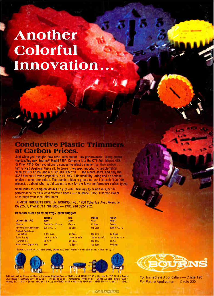
Con o uctive Plastic T at Carbon Prices. Just when you thought " low cost" also meant low performance", alo the dazzling new Bourns Model 3355. Compare it to the CTS 201. Mepco or Piher PT15. Our revolutionary conductive plastic element vs. their carbon .. fact is we outperform them all. To prove it, we spec important characteristics such as CRV at 1% and a TC of 500 PPM/ C ... the others don't. And only the 3355 has board-wash capability. a UL-94V-1 flammability rating and an optional choice of nine rotor colors. The standard blue is priced at just 11e each ( 100,000 pieces). . . about what you'd expect to pay for the lower performance carbon types.
Send today for complete details on a colorful rew way to design superior performance for your cost effective needs -- the Model 3355 Trimmer. Direct or through your local distributor.
TRIMPOT PRODUCTS DIVISION, BOURNS, INC., 1200 Columbia Ave., Riverside, CA 92507. Phone: 714 781-5050 — TWX: 910 332-1252.
CATALOG SHEET SPECIFICATION COMPARISONS
BOU1NS CTS MEPCO PIKER CHARACTERISTIC 335E 201' 460' PT15*
Element Conductive Plastic Carbon Carbon Carbon
Temperature Coefficient 500 PPM/ °C No Spec No Spec 1030 PPM/ °C
Contact Resistance Variation 1 0°/ max. No Spec No Spec No Spec
Power Rating .25 W at 70°C .25 W at 55°C .25 W at 55`C .25 W at 40°C
Flammability UL-9xIV-1 No Spec No Spec UL-94
Board Wash Capability Yes No Spec No Spec Na Spec
'Source: CTS Series 201 Data Sheet, Mepco Data Sheet ME1004, Piher Data Sheet F-2002 Rev 7/73
International Marketing Affiliates: Europe:A Headquarters — Switzerland 042/23 22 42 • Belgian i 01/216 2005 • France 01/2039633 • Germany 0711/24 29 36 • Italy 02/32 56 88 • Netherlaids 70/87 44 00 • United Kingdom 01/572 6531 • Norway 2/71 18 72 • Sweden 764/20 110 • Japan 075/921 9111 • Australia 02/55-0411 03/95-9566 • IsraBI 77 71 15/6'7
For Immediate Application — Circle 120 For Future Application — Circle 220
Copyright © 2022 FDOKUMEN