Magnetic Locomotion for In-Pipe Inspection Robots
231
Magnetic Locomotion for In-Pipe Inspection Robots George Henry Jackson-Mills University of Leeds School of Mechanical Engineering Submitted in accordance with the requirements for the degree of Doctor of Philosophy June, 2020
-
Upload
khangminh22 -
Category
Documents
-
view
2 -
download
0
Transcript of Magnetic Locomotion for In-Pipe Inspection Robots

Magnetic Locomotion for In-PipeInspection Robots
George Henry Jackson-MillsUniversity of Leeds
School of Mechanical Engineering
Submitted in accordance with the requirements for the degree of
Doctor of Philosophy
June, 2020

This thesis is dedicated to my wife, Cass.I couldn’t have done it without you.
i

Intellectual Property Statement
The candidate confirms that the work submitted is his own and that appro-priate credit has been given where reference has been made to the work ofothers.
This work was supported by National Grid Gas Transmission (NGGT) andits project partners Synthotech, Premtech, and Pipeline Integrity Engineersas part of Project GRAID: Gas Robotic Agile Inspection Device. ESPRCGrant Number: 1657711
The work in Chapter 2 of this thesis has appeared in the following public-ation: G. H. Mills, A. E. Jackson, and R. C. Richardson, Advancesin the inspection of unpiggable pipelines, Robotics, vol. 6, no. 4, p. 36, 2017.
The work in Chapter 6 of this thesis has appeared in the following pub-lication: Mills, G. H., Liu, J. H., Kaddouh, B. Y., Jackson, A. E.,& Richardson, R. C. (2018, September). Miniature Magnetic Robots ForIn-Pipe Locomotion. In Memorias de Congresos UTP (pp. 289-300)
In the mentioned publications the candidate was responsible for the collec-tion, review, data analysis, and writing of material. The remaining authorscontributed guidance and proof reading.
This copy has been supplied on the understanding that it is copyright ma-terial and that no quotation from the thesis may be published without properacknowledgement.
The right of George Henry Jackson-Mills to be identified as Author of this
ii

work has been asserted by him in accordance with the Copyright, Designsand Patents Act 1988.
© 2020 The University of Leeds and George Henry Jackson-Mills.
iii

Acknowledgements
I would like to thank my supervisors, Professor Robert Richardson, andDr Andrew Jackson for all of their support, guidance, and encouragementthroughout the research and preparation of this thesis.
To my funders, National Grid Gas Transmission who made this work pos-sible. Furthermore, thank you to the GRAID project partners, and espe-cially Synthotech for their invaluable industry knowledge and guidance.
Thanks to everyone in the Library Study Group for all the laughs. Ourtime in the Library was well spent even if the research sometimes got abit messy. Also to my friends in the lab, and particularly Dom Jones whoconvinced me to keep going when I felt like quitting to become a landscapegardener, I think I’ll save it for retirement.
To my family back in Manchester; Mum, Dad, Elliott, Lucie, and Suzie.For always being there when I needed them, and a perfect retreat to forgetall the thesis based troubles here in Leeds.
Finally to Cassie. During the short time it’s taken me to finish this thesiswe moved in together, got engaged in Paris, got two cats (Salem and Diego),got married, got pregnant, bought our first house (you did all the work),and had our beautiful boy Jasper. I love you both so much and I don’tknow what I’d do without you.
Cheers.
iv

Abstract
Pipeline Inspection Gauge’s, (PIGs) currently inspect 95.4% of the UnitedKingdom’s National Transmission System (NTS) for the transportation ofnatural gas. The remaining 4.6% found in Above Ground Installations(AGIs) is deemed ”unpiggable” due to its complex geometry. Current ro-botic technology entering these pipelines requires expensive modificationsto the pipeline to gain inspection access. A system that can bypass modify-ing the pipe and complete a condition inspection could generate a minimumsaving of £60 million and 2145 tonnes of CO2 over a 20 year period.
This thesis explores new approaches towards the robotic inspection offerrous pipeline systems with the design and development of a wheeled mag-netic robot for sub 100mm pipelines. The work begins with a thoroughliterature review surrounding the field of in-pipe robotics. The target en-vironment is analysed and the requirements and specification of the robotare generated. Methods of creating magnetic traction wheels are exploredand a rubber coated flux plate magnetic array wheel is developed and testedexperimentally. The developed flux plate array wheels were found to chan-nel the power of 6 rare-earth magnets into a single wheel contact point andcreated a force equal to that of the 6 magnets (83N) combined at the costof a 90% reduced field depth. The application of rubber coating increasedthe frictional co-efficient µs of the wheels from 0.27 to 0.71, at the cost ofhalving the contact force to a mean of 41N. A high level LabVIEW con-trol system was developed to communicate with the robot’s micro-controllerover wireless Bluetooth using a custom serial protocol to minimise the mes-sage size for speed. Conceptual mechanical designs were conceived and twosystems chosen to suit requirements for a 2-inch (50.8mm) pipeline, and a4-inch (101.6mm) pipeline were developed further. A robust prototype ofthe 4-inch robot was fabricated using 3D printing techniques, the designwas preferred for its curved wheelbase geometry, allowing it to negotiateconvex and concave corner cases. Unlike current magnetic systems of itssize the robot was found to complete all orientations of descending convexcases as well as all corner case angles of 115 or greater.
v

Contents
1 Introduction 11.1 Research background . . . . . . . . . . . . . . . . . . . . . . . . . . . . . 2
1.1.1 National Grid Gas Transmission System . . . . . . . . . . . . . . 21.1.2 Premature Asset Replacement . . . . . . . . . . . . . . . . . . . 31.1.3 Robotic Pipe Inspection . . . . . . . . . . . . . . . . . . . . . . . 31.1.4 Project GRAID . . . . . . . . . . . . . . . . . . . . . . . . . . . . 4
1.2 Motivation for research . . . . . . . . . . . . . . . . . . . . . . . . . . . . 41.3 Scope of the research . . . . . . . . . . . . . . . . . . . . . . . . . . . . . 51.4 Research aims and objectives . . . . . . . . . . . . . . . . . . . . . . . . 5
1.4.1 Objectives . . . . . . . . . . . . . . . . . . . . . . . . . . . . . . . 51.5 Contributions of the thesis . . . . . . . . . . . . . . . . . . . . . . . . . . 6
1.5.1 Published work (Appendix A/B) . . . . . . . . . . . . . . . . . . 61.6 Outline of thesis . . . . . . . . . . . . . . . . . . . . . . . . . . . . . . . 7
2 Literature Review 92.1 Pipe network environment . . . . . . . . . . . . . . . . . . . . . . . . . . 10
2.1.1 Pipe Bends and Joints . . . . . . . . . . . . . . . . . . . . . . . . 112.1.2 Methods of pipe inspection in operation . . . . . . . . . . . . . . 122.1.3 Locomotion Categories . . . . . . . . . . . . . . . . . . . . . . . . 122.1.4 Traction Generation . . . . . . . . . . . . . . . . . . . . . . . . . 14
2.2 Robotic locomotion categories . . . . . . . . . . . . . . . . . . . . . . . . 162.2.1 Pipeline Inspection Gauges . . . . . . . . . . . . . . . . . . . . . 172.2.2 Wheeled Locomotion . . . . . . . . . . . . . . . . . . . . . . . . . 182.2.3 Track Locomotion . . . . . . . . . . . . . . . . . . . . . . . . . . 23
vi

CONTENTS
2.2.4 Screw Locomotion . . . . . . . . . . . . . . . . . . . . . . . . . . 282.2.5 Snake Locomotion . . . . . . . . . . . . . . . . . . . . . . . . . . 302.2.6 Inchworm Locomotion . . . . . . . . . . . . . . . . . . . . . . . . 342.2.7 Fluid Locomotion . . . . . . . . . . . . . . . . . . . . . . . . . . 362.2.8 Walking Locomotion . . . . . . . . . . . . . . . . . . . . . . . . . 37
2.3 Magnetic traction locomotion . . . . . . . . . . . . . . . . . . . . . . . . 382.4 NTS environment . . . . . . . . . . . . . . . . . . . . . . . . . . . . . . . 39
2.4.1 Pipeline infrastructure . . . . . . . . . . . . . . . . . . . . . . . . 402.4.2 Natural gas . . . . . . . . . . . . . . . . . . . . . . . . . . . . . . 442.4.3 Environment summary specification . . . . . . . . . . . . . . . . 45
2.5 Literature summary . . . . . . . . . . . . . . . . . . . . . . . . . . . . . 452.6 Literature discussion . . . . . . . . . . . . . . . . . . . . . . . . . . . . . 482.7 Literature conclusion . . . . . . . . . . . . . . . . . . . . . . . . . . . . . 52
3 Robot Requirements Analysis 543.1 Introduction . . . . . . . . . . . . . . . . . . . . . . . . . . . . . . . . . . 553.2 Locomotion and traction method requirements . . . . . . . . . . . . . . 55
3.2.1 Traction requirement criteria and selection . . . . . . . . . . . . 573.2.2 Locomotion requirement criteria and selection . . . . . . . . . . . 59
3.3 Robot Specification . . . . . . . . . . . . . . . . . . . . . . . . . . . . . . 623.4 Discussion and conclusion . . . . . . . . . . . . . . . . . . . . . . . . . . 64
4 Design of Magnetic Traction Wheels 664.1 Introduction . . . . . . . . . . . . . . . . . . . . . . . . . . . . . . . . . . 67
4.1.1 Simplifying in-pipe geometry problems . . . . . . . . . . . . . . . 674.2 Methods of designing a magnetic traction robot . . . . . . . . . . . . . . 68
4.2.1 Magnetic wheel design . . . . . . . . . . . . . . . . . . . . . . . . 684.2.2 Chassis traction design . . . . . . . . . . . . . . . . . . . . . . . . 70
4.3 Magnetic wheel requirements and specification . . . . . . . . . . . . . . 714.4 Design and assembly of the magnetic wheel . . . . . . . . . . . . . . . . 714.5 Magnetic wheel experimentation . . . . . . . . . . . . . . . . . . . . . . 73
4.5.1 Normal force . . . . . . . . . . . . . . . . . . . . . . . . . . . . . 734.5.2 Increasing friction . . . . . . . . . . . . . . . . . . . . . . . . . . 80
4.6 Discussion and conclusion . . . . . . . . . . . . . . . . . . . . . . . . . . 83
vii

CONTENTS
5 Embedded System and Software Design 865.1 Introduction . . . . . . . . . . . . . . . . . . . . . . . . . . . . . . . . . . 87
5.1.1 System requirements . . . . . . . . . . . . . . . . . . . . . . . . . 875.2 Hardware . . . . . . . . . . . . . . . . . . . . . . . . . . . . . . . . . . . 90
5.2.1 Robot Micro-Controller . . . . . . . . . . . . . . . . . . . . . . . 915.2.2 Communication . . . . . . . . . . . . . . . . . . . . . . . . . . . . 915.2.3 Actuation and Power . . . . . . . . . . . . . . . . . . . . . . . . . 925.2.4 Circuit Integration . . . . . . . . . . . . . . . . . . . . . . . . . . 92
5.3 Open loop control system . . . . . . . . . . . . . . . . . . . . . . . . . . 965.3.1 High level control: LabVIEW . . . . . . . . . . . . . . . . . . . . 965.3.2 Low level control: micro-controller . . . . . . . . . . . . . . . . . 102
5.4 Discussion and conclusions . . . . . . . . . . . . . . . . . . . . . . . . . . 103
6 Mechanical and Conceptual Design of Magnetic Robots 1056.1 Introduction . . . . . . . . . . . . . . . . . . . . . . . . . . . . . . . . . . 106
6.1.1 Conceptual Design Process . . . . . . . . . . . . . . . . . . . . . 1066.1.2 Prototype Design Requirements . . . . . . . . . . . . . . . . . . . 107
6.2 Mechanical power transmission and layout . . . . . . . . . . . . . . . . . 1086.2.1 Transmission design and motor layout . . . . . . . . . . . . . . . 108
6.3 Concept designs for a 2-inch pipeline . . . . . . . . . . . . . . . . . . . . 1136.3.1 Concept 1: planetary spherical parallel axis . . . . . . . . . . . . 1146.3.2 Concept 2: co-axial coupled drive and steering . . . . . . . . . . 1156.3.3 Concept 3: bevel spur gear parallel axis . . . . . . . . . . . . . . 1186.3.4 Prototype development . . . . . . . . . . . . . . . . . . . . . . . 120
6.4 Concept and prototype for step case obstacles . . . . . . . . . . . . . . . 1256.4.1 Optimal curvature . . . . . . . . . . . . . . . . . . . . . . . . . . 1266.4.2 Concept 4: bevel with rear wheelbase . . . . . . . . . . . . . . . 130
6.5 Discussion and conclusion . . . . . . . . . . . . . . . . . . . . . . . . . . 133
7 Robot Obstacle Statics, Experimentation and Evaluation 1357.1 Introduction . . . . . . . . . . . . . . . . . . . . . . . . . . . . . . . . . . 1367.2 Overcoming step-case obstacles . . . . . . . . . . . . . . . . . . . . . . . 136
7.2.1 Concave case . . . . . . . . . . . . . . . . . . . . . . . . . . . . . 1387.2.2 Convex case . . . . . . . . . . . . . . . . . . . . . . . . . . . . . . 144
viii

CONTENTS
7.3 Experimental testing . . . . . . . . . . . . . . . . . . . . . . . . . . . . . 1487.3.1 Concave cases . . . . . . . . . . . . . . . . . . . . . . . . . . . . . 1487.3.2 Convex cases . . . . . . . . . . . . . . . . . . . . . . . . . . . . . 151
7.4 Real in-pipe operation . . . . . . . . . . . . . . . . . . . . . . . . . . . . 1557.4.1 Contact loss in-pipe . . . . . . . . . . . . . . . . . . . . . . . . . 156
7.5 Discussion and conclusions . . . . . . . . . . . . . . . . . . . . . . . . . . 158
8 Conclusions and Future Work 1608.1 Assessment of research objectives . . . . . . . . . . . . . . . . . . . . . . 1618.2 Conclusions . . . . . . . . . . . . . . . . . . . . . . . . . . . . . . . . . . 162
8.2.1 Magnetic traction wheels . . . . . . . . . . . . . . . . . . . . . . 1628.2.2 Embedded system and software design . . . . . . . . . . . . . . . 1638.2.3 Magnetic in-pipe robot for step-case negotiation . . . . . . . . . 1648.2.4 Conclusion summary . . . . . . . . . . . . . . . . . . . . . . . . . 164
8.3 Future work . . . . . . . . . . . . . . . . . . . . . . . . . . . . . . . . . . 1648.3.1 Magnetic traction wheels . . . . . . . . . . . . . . . . . . . . . . 1658.3.2 Embedded System and Software Design . . . . . . . . . . . . . . 1658.3.3 Magnetic in-pipe robot for step-case negotiation . . . . . . . . . 165
References 1688.4 Appendix A: Published Work ”Advances in the Inspection of Unpiggable
Pipelines” . . . . . . . . . . . . . . . . . . . . . . . . . . . . . . . . . . . 1828.5 Appendix B: Published Work ”Miniature Magnetic Robots For In-Pipe
Locomotion” . . . . . . . . . . . . . . . . . . . . . . . . . . . . . . . . . 196
ix

List of Figures
2.1 The most commonly encountered in-pipe bends and joints in networksA-G. . . . . . . . . . . . . . . . . . . . . . . . . . . . . . . . . . . . . . . 11
2.2 The eight main elements of in-pipe robotic locomotion A-F. . . . . . . . 132.3 Four most common traction systems used in-pipe. A. Gravity, B. Wall-
Press, C. Adhesion, D. Fluid-Flow. Where A-C rely on wall-contact tomove, and D - fluid-flow systems use the wall to slow down, or not at allin the case of free-flowing passive systems. . . . . . . . . . . . . . . . . . 14
2.4 Typical planar wall-press designs; A: 2, B: 3, and C: 4 arm designs. . . . 152.5 Parallelogram and pantograph centralised adaptability mechanisms. . . 152.6 Motion singularity problem in a T-section [1]. . . . . . . . . . . . . . . . 162.7 Self-driving PIG [2]. . . . . . . . . . . . . . . . . . . . . . . . . . . . . . 172.8 Kurt II, an autonomous wheeled in-pipe robot [3]. . . . . . . . . . . . . 192.9 MRINSPECT IV +; the latest instalment in an in-pipe robot series
designed and developed at Sungkyunkwan University [4]. . . . . . . . . . 202.10 The Adaptable Quad Arm Mechanism AQAM: a wheeled wall-pressing
robot for 260mm - 300mm pipes [5]. . . . . . . . . . . . . . . . . . . . . 212.11 Hanyang Universities two-plane in-pipe robot [6]. . . . . . . . . . . . . . 222.12 Osaka Gas Company, magnetic in-pipe robot [7]. . . . . . . . . . . . . . 222.13 MagneBike developed by Autonomous Systems Lab, ALSTOM uses wheeled
magnetic wheels with actuated lateral leverl arms to overcome magneticcontact forces [8]. . . . . . . . . . . . . . . . . . . . . . . . . . . . . . . . 24
2.14 Sewage cleaning robot [9]. . . . . . . . . . . . . . . . . . . . . . . . . . . 252.15 FAMPER CAD model and assembled robot [10]. . . . . . . . . . . . . . 262.16 Hanyang’s two module caterpillar wall-pressing robot [11]. . . . . . . . . 27
x

LIST OF FIGURES
2.17 PAROYS-II an articulated caterpillar pipe robot [12]. . . . . . . . . . . 282.18 Heli-Pipe screw wall-press system [13]. . . . . . . . . . . . . . . . . . . . 302.19 Osaka University’s SPRING pipe robot [14]. . . . . . . . . . . . . . . . . 312.20 Pipetel’s Explorer [15]. . . . . . . . . . . . . . . . . . . . . . . . . . . . . 322.21 Kangawa Snake Robot [16]. . . . . . . . . . . . . . . . . . . . . . . . . . 332.22 PIRATE, gas network autonomous inspection robot [17]. . . . . . . . . . 342.23 3SPR Parallel Manipulator inchworm pipe robot [18]. . . . . . . . . . . 352.24 CMMWorm, continuous-wave peristalsis pipe robot [19]. . . . . . . . . . 352.25 MORITZ pipe inspection robot [20]. . . . . . . . . . . . . . . . . . . . . 372.26 OmniClimbers: Omni-directional magnetic wheeled climbing robot [21]. 392.27 M-Blocks, magnetic robots that use angular momentum to break mag-
netic bonds and solve both concave and convex step cases [22]. . . . . . 402.28 The growth of the bulk of National Transmission System between its
inception in 1966 and 1983 [23]. . . . . . . . . . . . . . . . . . . . . . . . 412.29 Construction and installation of an underground pipe network being lay
down before burial. [24]. . . . . . . . . . . . . . . . . . . . . . . . . . . . 412.30 PIG grate entrance from a main PIG launch vessel onto an AGI site [24],
a type of interior T-Section to from the main. . . . . . . . . . . . . . . . 422.31 Render of underground pipe network on an AGI, 2-inch risers can be
seen entering the network from above ground access points [24]. . . . . . 432.32 Render of the GRAID robot within a concept launch vessel that would
be fitted to the AGI due for inspection [24]. The launch vessel floods therobot from ATM (atmospheric pressure) to full pressure with nitrogento remove oxygen before entry. . . . . . . . . . . . . . . . . . . . . . . . 44
2.33 History of In-Pipe Robotic Locomotion [25]. . . . . . . . . . . . . . . . . 46
4.1 Simplification of in-pipe obstacles, reducing the problem to two dimen-sional step-cases. . . . . . . . . . . . . . . . . . . . . . . . . . . . . . . . 68
4.2 Types of magnetic wheel design; standard ring magnet (A), outer magnetplacement wheel (B), shielded magnet array (C), and magnetised chassis(D). . . . . . . . . . . . . . . . . . . . . . . . . . . . . . . . . . . . . . . 69
4.3 Different possible magnetic skeleton chassis frames for in-pipe magneticrobots. . . . . . . . . . . . . . . . . . . . . . . . . . . . . . . . . . . . . . 70
xi

LIST OF FIGURES
4.4 Different design for the mountable wheel hub built into the magnetic fluxplates. A: D-Shaft. B: Hex. C: Multiple D-Shaft. D: Key. E: Nucleus.F: Triangular. . . . . . . . . . . . . . . . . . . . . . . . . . . . . . . . . . 73
4.5 Components of the magnetic wheels ready to be assembled for a 5mmflux plate, 6mm length x 6mm diameter x 6 magnet array. . . . . . . . . 74
4.6 Diagram of the magnetic wheel test rig set-up. . . . . . . . . . . . . . . 754.7 Standard magnet pull test over a 5mm range for both a regular N42 disc
magnet, and a magnet wheel array. . . . . . . . . . . . . . . . . . . . . . 764.8 Mean force for various wheel configurations (force +/- SD) . . . . . . . 774.9 Comparison of the effect of wheel magnet array rotation angle on the
peak force produced by the wheel for both a three and six wheel array. . 784.10 Graph of the force to pull a free rotating magnetic wheel from a right
angle concave case where the wheel is in double contact. . . . . . . . . . 794.11 Graph of the force to pull a free rotating magnetic wheel from a 90 wall
up to a convex corner case, and then detach from the corner case. . . . . 804.12 Graph showing the force to pull a rotation locked uncoated magnetic
wheel across a steel contact. . . . . . . . . . . . . . . . . . . . . . . . . . 814.13 Bar chart showing the average pull force for a 665A wheel at four different
points around the wheel in both aligned and misaligned conditions. . . 824.14 Graph of the force required to pull the rubber coated magnet up the
steel block with the axle locked in contact at the 180 mark in4.13. . . . 834.15 Wear of the rubber coating showing after five repetitions of friciton test-
ing on the linear force tester. . . . . . . . . . . . . . . . . . . . . . . . . 84
5.1 A: Laptop PC with Bluetooth built-in. B: USB Xbox controller receiver.C: Xbox 360 wireless controller. D: 300W power pack. E: Robot elec-tronics prototype breadboard. . . . . . . . . . . . . . . . . . . . . . . . . 90
5.2 Diagram of the integrated circuit. . . . . . . . . . . . . . . . . . . . . . . 945.3 Diagram of the assembled robot hardware circuit to be embedded in a
mechanical system. . . . . . . . . . . . . . . . . . . . . . . . . . . . . . . 965.4 Diagram of the high level control system used to develop the robot software. 975.5 Overall system architecture including simplified LabVIEW and mirco-
controller programs. . . . . . . . . . . . . . . . . . . . . . . . . . . . . . 98
xii

LIST OF FIGURES
5.6 LabVIEW method to convert user control inputs to condensed serialcommands to be transmitted to the micro-controller. . . . . . . . . . . . 101
5.7 Arduino method to convert condensed LabVIEW serial commands touse-able micro-controller instructions to be passed to components. . . . 103
6.1 Flow diagram showing the conceptual design process used in this chapter.1076.2 Robotic Concept 1: Spherical planetary design based on layout 42 in
Table 6.2. . . . . . . . . . . . . . . . . . . . . . . . . . . . . . . . . . . . 1146.3 Robotic Concept 2: Based on layout 12 in Table 6.2, where the drive
and steering are linked and then mirrored. . . . . . . . . . . . . . . . . . 1166.4 Robotic Concept 2: Based on layout 12 in Table 6.2, with an combined
spur gear transmission axle. . . . . . . . . . . . . . . . . . . . . . . . . . 1206.5 Exploded view of concept 3 early wheel design. . . . . . . . . . . . . . . 1226.6 In-pipe design of the 2-inch concept, avoiding double wheel contact with
both walls. . . . . . . . . . . . . . . . . . . . . . . . . . . . . . . . . . . 1246.7 In-pipe design of the 2-inch concept, avoiding double wheel contact with
both walls. . . . . . . . . . . . . . . . . . . . . . . . . . . . . . . . . . . 1256.8 Chassis interaction with a convex curve case. Robot A: standard chassis
design. Robot B: estimated clearance design. Robot C: optimally gen-erated clearance curve. . . . . . . . . . . . . . . . . . . . . . . . . . . . . 127
6.9 Minimal contact curve generation for convex step-case, example using a32mm front wheel, 10mm rear, and 65mm wheelbase. . . . . . . . . . . . 128
6.10 Change in curve generation with an increase in the wheelbase of the robot.1296.11 Schematic diagram of the robot dual bevel robot with rear magnetic wheel.1306.12 Schematic diagram of the robot dual bevel robot with rear magnetic wheel.133
7.1 Concave case section one: robot approaches the wall. . . . . . . . . . . . 1397.2 Concave case section two: robot is in double contact case with the step
at wheel one. . . . . . . . . . . . . . . . . . . . . . . . . . . . . . . . . . 1417.3 Concave case section three: robot has overcome double contact and ro-
tation about the corner has begun. . . . . . . . . . . . . . . . . . . . . . 1427.4 Concave case section four: robot is in double contact case with the step
at wheel two. . . . . . . . . . . . . . . . . . . . . . . . . . . . . . . . . . 143
xiii

LIST OF FIGURES
7.5 Convex case section one: robot angle is at 90, ready to start rotationabout the corner. . . . . . . . . . . . . . . . . . . . . . . . . . . . . . . . 145
7.6 Convex case section two: robot has begun rotation around the cornerand is the weakest magnetic contact case for wheel one. . . . . . . . . . 146
7.7 Convex case section three: wheel one has passed the corner and is nowattempting to pull the rear passive wheel around the corner. . . . . . . . 147
7.8 Convex case section four: wheel two is in the weakest magnetic case. . . 1487.9 Test rig used to evaluate the robots performance on both concave and
convex step cases at varying angles. . . . . . . . . . . . . . . . . . . . . . 1497.10 Concave case performed on the test rig. A: approaching the corner case.
B: Double contact, the motor ramps up to overcome the unwanted con-tact force. C: The robot rotates around the concave corner after detach-ment. D: The completion of the concave corner case. . . . . . . . . . . . 151
7.11 Graph showing the effect of an increase in wheel friction co-efficient onthe contact forces at w1c1 and w1c2 for drive wheels with a pull strengthof 9.5N. . . . . . . . . . . . . . . . . . . . . . . . . . . . . . . . . . . . . 152
7.12 Robot attempting the convex corner case. A: Approaching the step case.B: The point of weakest contact for the magnetic wheel. C: Rotation ofthe robot around the convex corner. D: The robot can go no further asthe passive rear wheel halts movement. . . . . . . . . . . . . . . . . . . . 153
7.13 Robot completing the convex corner case. A: Approaching the step case.B: The point of weakest contact for the magnetic wheel. C: Rotation ofthe robot around the convex corner. D: The robot completes the case. . 153
7.14 Robot completing the convex corner case. A: Approaching the step casein reverse. B: The back wheels lose contact at the convex weak cornerpoint. C: The chassis rotates about the wheel axis. D: The robot crashes.154
7.15 The difference in angle between a 4-inch pipe connection with a 48-inchpipe, and a 4-inch pipe with a 12-inch pipe. . . . . . . . . . . . . . . . . 155
7.16 Graph of the change in approach angle with different size pipe connectionfittings and different size target pipe inspection diameters. . . . . . . . . 155
xiv

LIST OF FIGURES
7.17 Pictures from the real world tests on a decommissioned 1016mm naturalgas pipeline. A: Driving vertically. B: Inverted. C: On the outer side ofthe pipe. D: Iron particles and scales that ”clogged” the wheel flux. E:Full shot view of the pipe size versus the robot size. . . . . . . . . . . . 157
xv

List of Tables
2.1 National Transmission System (NTS) possible path variables, obstacles,and environmental (Env) conditions. [26] . . . . . . . . . . . . . . . . . 45
2.2 In-pipe environment, conditions, and pathways, categorised by roboticchallenge level as shown by in-pipe robots reviewed in literature. . . . . 48
2.3 A summary of the most relevant robotics systems reviewed in this chapter.X (horizontal), Y (vertical), L (elbow), T (T-section), V (valves), - (un-known). . . . . . . . . . . . . . . . . . . . . . . . . . . . . . . . . . . . . 49
2.4 A summary of the various environments and conditions found within theNational Transmission System (NTS) that should be considered in thisresearch. . . . . . . . . . . . . . . . . . . . . . . . . . . . . . . . . . . . . 50
3.1 Requirements for an ideal robotic locomotion system within the NationalTransmission System AGI environment. . . . . . . . . . . . . . . . . . . 56
3.2 In-pipe robot, traction selection criteria to be analysed against possibletraction methods. . . . . . . . . . . . . . . . . . . . . . . . . . . . . . . . 58
3.3 In-pipe robot traction selection matrix based on the criteria defined inTable 3.2. . . . . . . . . . . . . . . . . . . . . . . . . . . . . . . . . . . . 59
3.4 In-pipe robot locomotion selection criteria and definitions of relative low(0), medium (3), and high (5) scores. Criteria are categorised by pipepath (Path), obstacles (Obs), general robot attributes (Att), and envir-onment conditions (Env). . . . . . . . . . . . . . . . . . . . . . . . . . . 60
3.5 In-pipe robot locomotion selection matrix based on the criteria definedin Table 3.4. Criteria are categorised by pipe path (Path), obstacles(Obs), general robot attributes (Att), and environment conditions (Env). 61
xvi

LIST OF TABLES
3.6 Complete in-pipe robot specification based on the NTS environment ana-lysis and locomotion and traction methods explored in this chapter. . . 63
4.1 Requirements for the robots magnetic wheel design. . . . . . . . . . . . 724.2 Test program used in the Mecmesin tensile tester to produce normal
force results. . . . . . . . . . . . . . . . . . . . . . . . . . . . . . . . . . 764.3 Test program used in the Mecmesin tensile tester to produce concave
results. . . . . . . . . . . . . . . . . . . . . . . . . . . . . . . . . . . . . . 794.4 Test program used in the Mecmesin tensile tester to produce convex results. 804.5 Test program used in the Mecmesin tensile tester to produce concave
results. . . . . . . . . . . . . . . . . . . . . . . . . . . . . . . . . . . . . . 81
5.1 Major requirements of the software control features . . . . . . . . . . . . 885.2 Major requirements of the hardware system . . . . . . . . . . . . . . . . 895.3 Micro-controller options considered for robot development comparison
table . . . . . . . . . . . . . . . . . . . . . . . . . . . . . . . . . . . . . . 915.4 Comparison table of bluetooth vs wifi . . . . . . . . . . . . . . . . . . . 925.5 Micro Metal Gearmotor selection table: High-power 6V precious metal
brushed [27]. All gear ratios ar erated to 1.6 Amp stall current and andNo-load current of 0.07 Amps. . . . . . . . . . . . . . . . . . . . . . . . 93
5.6 Cluster array elements that store each individual robots data and con-figuration settings. . . . . . . . . . . . . . . . . . . . . . . . . . . . . . . 99
6.1 The currently defined requirements and parameters for use in conceptgeneration and design. . . . . . . . . . . . . . . . . . . . . . . . . . . . . 108
6.2 Selection Table of Motor Layout against Transmission Design . . . . . . 1106.3 Selection criteria used in the transmission decision matrix, Table 6.4 to
choose optimal an design solution from Table 6.2. . . . . . . . . . . . . . 1116.4 The decision matrix of used to select an ideal transmission design in
conjunction with the criteria presented in Table 6.3, as well as the designsof the layouts 11 - 72 in Table 6.2. . . . . . . . . . . . . . . . . . . . . . 112
6.5 Key design features in the spherical concept in Figure 6.2. . . . . . . . . 1156.6 Key design features in the coupled drive and steering design in Figure 6.6.1176.7 Key features in concept 3, bevel spur gear parallel axis design in Figures
6.4 and 6.5 . . . . . . . . . . . . . . . . . . . . . . . . . . . . . . . . . . 121
xvii

LIST OF TABLES
6.8 Selection criteria to choose concept to carry to prototype development . 1236.9 Dimensions of the CH12 approximate volume. . . . . . . . . . . . . . . . 1246.10 Final Concept: Bill of Materials . . . . . . . . . . . . . . . . . . . . . . . 1266.11 Design of concept 4: a dual bevel connection robot with a rear magnetic
wheelbase and curve for convex case locomotion. . . . . . . . . . . . . . 132
7.1 Description of parameters used within the free body diagrams in theconcave and convex cases. . . . . . . . . . . . . . . . . . . . . . . . . . . 138
7.2 Step-case rig: robot experimental results for concave testing at differentangles. . . . . . . . . . . . . . . . . . . . . . . . . . . . . . . . . . . . . . 150
7.3 Step-case rig: robot experimental results for convex testing at differentangles. . . . . . . . . . . . . . . . . . . . . . . . . . . . . . . . . . . . . . 154
xviii
Abbreviations
AGI Above Ground Network ATEX ATmospheres EXplosivesATM Atmospheric Pressure BPS Bits Per SecondBW Butt Welding C Centigrade; CelsiusCA Corrosion Allowance CAD Computer Aided DesignCG Centre of Gravity CIPS Cathodic Interval Protection SurveyCO2 Carbon Dioxide COM Serial Communication PortCR Carriage Return CW Continuous WeldingDC Direct Current DN Nominal DiameterEC Eddy Current Testing ECDS External Corrosion Direct AssessmentEFW Electric Fusion Welding EMI Electromagnetic InspectionFPV First Person View FW Field WeldingGRAID Gas Robotic Agile Inspection
DeviceGUI Graphical User Interface
ID Inner Diameter IDE Integrated Development EnvironmentIMU Inertial Measurement Unit ISO IsometricLED Light Emitting Diode LiPo Lithium PolymerMFL Magnetic Flux Leakage MOP Maximum Operating PressureNDT Non-Destructive Testing NGGT National Grid Gas TransmissionNTS National Transmission System OD Outer DiameterPIE Pipeline Integrity Engineers PIG Pipeline Inspection GaugePWM Pulse Width Modulation RPM Revolutions Per MinuteSD Standard Deviation SW Socket WeldingTRL Technology Readiness Level WB Wheel Base
xix

Chapter 1
Introduction
1

1.1 Research background
1.1 Research background
Across the globe, pipeline networks have been constructed for efficient transportationof fluids, whether they contain gas, oil, or water. Many of these networks are nowreaching the end of their design lives and are due for replacement, however with thecondition of their interior walls unknown it is impossible to tell which pipes should takepriority. Main transmission lines; large straight pipelines which connect key stationsaround the world, are easily inspected using a Pipeline Inspection Gauge (PIG). Thesecylindrical devices are uncontrollable after insertion, relying only on the in-pipe fluidflow to move. The problem lies within pipe networks that consist of more than juststraight sections; those that contain complex bends, junctions and highly varying fluidflow velocities. These installations are impossible to inspect using an uncontrollablePIG and hence the focus of this thesis will be the robotic inspection of these unpiggablepipelines.
1.1.1 National Grid Gas Transmission System
The United Kingdom’s National Transmission System (NTS) is comprised of a 7,600kmnetwork of welded steel pipeline for the transportation of high pressure natural gas at aMaximum Operating Pressure (MOP) of 97 bar in main branches. Most of this systemwas constructed during the 1970’s and 1980’s and was built with a 40 year design lifein mind, this period is now coming to an end [23]. In order to keep the network in safeworking condition these assets must be inspected to determine the amount of damagethey have sustained over their years in service. Damage can be caused through methodssuch as corrosion, creep, degradation, constant temperature change and can result inthe erosion of the inner pipe wall as well as other defects. Currently 95.4% of the NTScan be evaluated in-line; through pigging. The remaining 4.6% (350km) of the NTSis considered unpiggable, and consists of Above Ground Installations (AGIs) of whichthere are over 200 scattered across the country [26]. These relatively small sections ofpipe network are deemed unpiggable and are present in any pipe network: the in-lineassessment of unpiggable pipelines is therefore a global problem.
Despite the name most of the pipework found in an above ground installation isburied, with only a small portion available for visual analysis. The interior conditionof the buried pipework has not been seen since the installations took place, howeverthe networks are known to be in safe condition thanks to large safety margins used
2

1.1 Research background
for initial design. These protective measures include: thicker pipes than necessary, useof external protective coatings, and employing cathodic protection to reduce corrosion[28].
1.1.2 Premature Asset Replacement
Currently if any corrosion issues are suspected then the underground pipe network isexcavated for closer inspection at reduced flow, sometimes this requires shutting downthe site completely. In high pressure installations such as these pipelines can reach upto 95% Corrosion Allowance (CA) before failure occurs, because of this many of theseexcavations are considered premature. Roughly thirty of these replacements are cur-rently undertaken each year, this method is expensive, damaging to the environment,and causes disruption to customers and the running of the network. During the re-placement of pipework and one valve on a small AGI the environmental cost of carbonreleased into atmosphere was estimated at 700 tonnes. Considering that the typicalwestern home will produce 5 tonnes of carbon emissions a year this is equal to running140 households.
1.1.3 Robotic Pipe Inspection
Robotic inspection of the interior condition of the network will eliminate the risk of re-placing these assets prematurely, and hence stop the needless excavation of the site. Arobotic solution will not require excavation of a site, needing access to only pre-existingpipework the system could enter and survey the network from an above ground entrancepoint. The successful development of a robotic platform with the ability to safely andaccurately determine the condition of the unpiggable high pressure pipework, will en-able pipe maintenance to be completed using a risk based replacement methodology.The rewards for achieving this goal are great; avoidance of disruption caused by ex-cavations, unnecessary asset replacement, and unplanned shut downs, will result in aminimum saving of £60 million and 2145 tonnes of CO2 over a 20 year period [24].
Research into in-pipe robots began in the mid 1980’s, from this point onwards thefield of in-pipe robotics inspection only grew. The research area became popular dueto the unique shape of the environment (encompassing walls) and the prevalence ofpipes in the modern world. Many robotic systems have been created for the inspection
3

1.2 Motivation for research
of large bore straight pipes, however unpiggable pipelines remain a challenge. Theprimary difficulty in unpiggable sections is the inspection of large ranges of pipelinediameters. Although many attempts have been made over the years to create systemswith extremely adaptive diameters no robot has been created that can inspect everypipe size present on an unpiggable network such as an AGI. Solving this problem wouldrequire the development of a small system capable of scaling the walls of the pipe, ora sophisticated articulated system that could re-form into larger configurations. Theseare substantial robotic challenges and ones that so far have not been solved.
1.1.4 Project GRAID
In order to tackle the issue of unpiggable AGI’s in the NTS a funded research projectwas launched in 2015. Project GRAID (Gas Robotic Agile Inspection Device) aimsto design and build a robotic inspection device that determines the true condition ofpipeline assets in below-ground high pressure gas installations. National Grid GasTransmission (NGGT) initiated Project GRAID with £5.7m of Ofgem funding for theinspection of unpiggable pipelines. Together with three SME’s; Synthotech, Premtech,and Pipeline Integrity Engineers (PIE), NGGT should see the project’s completion by2018. The project as a whole will be managed by PIE, Premtech will design the robotslaunch and retrieval facilities as well as use point-to-point cloud mapping to create a3D model of the AGI sites. Synthotech will design and develop the in-pipe roboticplatform, which is currently scoped to inspect 750mm - 900mm Nominal Diameter(DN) pipes and will be able to travel up to 100 metres around two bends. The workpresented in this thesis shares the same overarching aim as Project GRAID [26].
1.2 Motivation for research
The motivation for this research is to create a robotic inspection device capable of loco-motion within existing pipeline infrastructure. By inspecting the interior network pipeassets before hitting the end of their design life their true condition can be assessed andunnecessary excavations will be avoided. By accessing pipelines through entrances thatalready exist, the environmental costs for creating new connection points on naturalgas pipelines can be mitigated. This thesis explores the problems faced when usingrobots to inspect unpiggable pipeline networks and the route which has been taken to
4

1.3 Scope of the research
solve these issues. This thesis will present the theory, design, and analysis of proposedrobotic devices capable of inspecting ferrous unpiggable pipelines such as AGIs foundon the NTS. There are few examples of magnetic inspection robots within the field ofin-pipe robotics that are also capable of exploring small diameter pipelines. The roboticsolution proposed will bring cost effective inspection of ferrous unpiggable pipelines onestep closer.
1.3 Scope of the research
The research carried out in this thesis focuses on the robotic locomotion method usedto traverse the National Transmission System and related AGI networks. The scope ofthis work has been narrowed to solve specific locomotion issues regarding small wall-climbing robots, and specifically locomotion of tight spaces with minimal actuators.The work does not include methods of localisation in-pipe, optimisation of distancestravelled and hence battery life. The robot intends to tackle in-pipe path problems(as in joints and connections) rather than obstacles (such as pipe damage, grease andcontaminants, and weld beads).
1.4 Research aims and objectives
The aim of this project is to design and develop a miniature magnetic robot cap-able of inspecting high pressure unpiggable pipelines using low diameter access points.Through negotiation of simplified convex and concave obstacles complex in-pipe geo-metry paths will be overcome and large bore pipes will become accessible for inspection.The robot will be designed such that manufacture and assembly is simple and smallbatch productions can be rapidly fabricated. This will be achieved through 3D printing,and the robots miniature size.
1.4.1 Objectives
The major objectives to achieve this aim were:
1. Review current literature to better understand and critically assess exist-ing literature surrounding state-of-the-art in-pipe robotics and to evaluate the
5

1.5 Contributions of the thesis
performance of current locomotion methods used to negotiate complex pipe geo-metries.
2. Understand the in-pipe environment by assessing the national grid gas net-work and developing a robotic specification and set of requirements to choosethe correct traction and locomotion methods.
3. Design a detailed locomotion system for the robot and use this as afoundation to create a platform on which the robot can be built.
4. Design and develop a software system to communicate with an embeddedrobot micro-controller.
5. Generate detailed conceptual designs based upon the robot requirementsand specification, the locomotion system, and the electronics package. Fabricatea working prototype using rapid techniques.
6. Assess the performance of the robot in a range of step-cases simulatingcomplex in-pipe geometry.
1.5 Contributions of the thesis
The original work completed during this research has contributed to knowledge in thefollowing main areas:
1. A novel magnetic robot to overcome ferrous convex and concave corner cases ofsteel structures in 4-inch (101.6mm) pipelines.
2. A novel magnetic wheeled robot capable of ferrous in-pipe exploration within a2-inch (50.8mm) diameter pipeline. (Published Paper 1).
3. A novel LabVIEW program and integrated micro-controller system allowing con-trol of multiple wireless robots over serial communication.
1.5.1 Published work (Appendix A/B)
1. G. H. Mills, A. E. Jackson, and R. C. Richardson, Advances in the inspectionof unpiggable pipelines, Robotics, vol. 6, no. 4, p. 36, 2017.
6

1.6 Outline of thesis
1. Mills, G. H., Liu, J. H., Kaddouh, B. Y., Jackson, A. E., & Richardson,R. C. (2018, September). Miniature Magnetic Robots For In-Pipe Locomotion.In Memorias de Congresos UTP (pp. 289-300)
1.6 Outline of thesis
This thesis will consist of eight chapters in the following structure:
Chapter 2: Literature ReviewA review of the current state-of-the-art in-pipe and out-pipe robotic systems relevantto the work presented in the thesis. The review focuses on the locomotion and trac-tion methods used by these robots and their individual abilities in overcome in-pipeobstacles.
Chapter 3: Robot Requirements AnalysisA detailed specification for the robotic system that is to be deployed within the ferrousnatural gas pipeline. The aim of this chapter is to create the specific requirementsneeded to generate a robotic solution from the data gathered about the in-pipe envir-onment.
Chapter 4: Design of Magnetic Traction WheelsAn overview will be given surrounding the magnetic traction, the methods utilised, andthe optimisation of magnetic forces in order to produce a combined magnetic tractionand locomotion method.
Chapter 5: Embedded System and Software DesignWork surrounding the design of the electrical systems to meet the robot specificationcriteria. The chapter will explore the use of actuators and control methods to drive themagnetic adhesion wheels. The wireless communication method between a high leveland low level robot controller will be defined, and an optimised command protocol willbe developed.
Chapter 6: Mechanical and Conceptual Design of Magnetic RobotsA detailed view into the design methods of magnetic robots, it will cover an overview of
7

1.6 Outline of thesis
the robots capabilities, mechanical design, and power transmission. This chapter willincorporate the previously explored magnetic design, the electronic design as well asthe control system and manufacture method. The chapter will start with basic mech-anical concepts that were explored to find a suitable magnetic locomotion method forrestricted space in-pipe applications.
Chapter 7: Robot Obstacle Statics, Experimentation and EvaluationThis chapter brings together the work from preceding chapters and combines the know-ledge gained into one functional prototype. This final prototype is mathematically ana-lysed in static and dynamic conditions attempting step-case problems. The robot istested experimentally to determine the limits of its functionality when moving aroundconcave or convex cases in different orientations. After assessment the robot is deployedinto real world in-pipe environments.
Chapter 8: Conclusions and Future WorkThis chapter details the conclusions that have been drawn from the work in previouschapters before summarising the research and its findings. The benefits of using theproposed systems are discussed and recommendations are made for further research.
8

Chapter 2
Literature Review
9

2.1 Pipe network environment
This chapter presents a review of the current state-of-the-art in-pipe and out-pipe ro-botic systems relevant to the work presented in the thesis. The review focuses on thelocomotion and traction methods used by these robots and their individual abilities toovercome in-pipe obstacles. The review will cover a large number of systems so that thegeneral trends and overall capabilities of different in-pipe robot types can be assessed.The resultant overview of the research field will highlight gaps in knowledge that willformulate the basis for research carried out in this thesis.
Pipeline networks transport fluids such as oil, gas, water, and sewage between keylocations through an estimated total of 2.5 million km (2.2 million miles) of global in-frastructure [26]. Failure to adequately inspect and replace pipes results in pipe failureand subsequent loss of fluid transport, environmental damage, large excavations res-ulting in transport delays and air pollution. Most of the worlds pipelines are relativelyeasily inspected using advanced Pipeline Inspection Gauges or ”PIG’s”; passive devicesplaced into the pipe and driven by the flow of the transported fluid (type A in Figure2.2). However, PIG’s are uncontrollable and unable to adapt to sharp changes in pipedirection and diameter, making complex pipe infrastructure impossible to inspect. Itis estimated that just 0.5% of pipe networks are inaccessible to conventional ”PIG-GING” technology, the remaining 99.5% generally consisting of large bore, straightpiggable lines. Whilst this proportion may seem low, the remaining 12,500 km rep-resents the most valuable pipes in the network; Above Ground Installations (AGI’s).Many of these unpiggable networks are now reaching the end of their design lives andare due for replacement, however with the condition of their interior walls unknown it isimpossible to tell which pipes should take replacement priority. It has been estimatedthat through the use of advanced inspection techniques, savings made from unnecessarypipeline replacement could be equivalent to £14,000 per km a year.
2.1 Pipe network environment
This section will cover the topic of in-pipe robotic locomotion methods for Unpiggablepipelines. Figure 2.2 provides a visual summary of the eight types of in-pipe locomotionused in modern pipe robotics. These elements cover the primary methods of movementin the pipe be it passive, or active. These primary elements can be combined with
10

2.1 Pipe network environment
other elements as well as different traction methods to create a diverse array of in-piperobotic systems.
2.1.1 Pipe Bends and Joints
Unpiggable pipe networks vary in diameter range, material, and fluid type and can bejoined in various methods and configurations. Categorised pipe joint configurations areshown in Figure 2.1. Horizontal sections (2.1.A) are considered the baseline for in-pipecomplexity, any in-pipe robot should be able to navigate these. Configurations B-Gare more complex, passing through them requires advanced motion planning techniques.
Figure 2.1: The most commonly encountered in-pipe bends and joints in networks A-G.
Valves, are particularly difficult, designs such as plug valves (2.1.B) can split thecross-section in two which can hinder full bore robots. Changes in diameter (2.1.C) area common occurrence in unpiggable systems, many robots take measures to preparefor this obstacle specifically. Vertical sections (2.1.D) require a traction method thatmust also overcome gravity. Elbows (2.1.E) are very commonly encountered and areoften described in terms of their bend radius; lower radius bends are tighter harder tonavigate. T-Sections (2.1.F) are extremely challenging obstacles due to their lack ofwall support; only sophisticated robotic platforms can navigate these. Each of thesein-pipe obstacles can be found in any orientation and possibly even back-to-back e.g.
11

2.1 Pipe network environment
encountering two consecutive bends. Step cases (2.1.G), can occur at a flange face orlarge valve connection where the pipe diameter may differ slightly, resulting in a smallstep up or down in diameter around the entire circumference of the pipe. Developinga single robot to solve all of these problems in a wide range of diameters is currentlyunheard of and often requires a fleet of multiple systems in different class sizes. Inthis review significant robots that have furthered the research field will be presented.Current state-of-the-art methods of in-pipe travel and inspection are discussed as wellas the future abilities of in-pipe robots. By analysing the barriers facing current tech-nology and the methods being employed to overcome them, breakthroughs can be madetowards universal in-pipe inspection. This review addresses in particular the problemssurrounding shape adaptability, fleets, and system classes and their role in universalpipe inspection.
2.1.2 Methods of pipe inspection in operation
Pipeline inspection gauges are used worldwide to inspect consistent diameter pipelinesfor large and fast inspections, usually via Magnetic Flux Leakage (MFL) Non-DestructiveTesting (NDT) modules built into the pigging device [29]. Work has been done on op-timising PIG’s for many years, however there is little novelty in these devices besidescontrol aspects such as speed and flow rate by braking [30], [31], [32], or optimisationof travel through curved pipe sections [33]. Currently the most effective method foranalysing the condition of unpiggable pipe assets is through Close Interval ProtectionSurveys (CIPS) [28]. Although other test methods exist such as EC (Eddy CurrentTesting), Electro-Magnetic Inspection (EMI), and ECDS (External Corrosion DirectAssessment). By providing a detailed profile of the potential difference between thepipeline and the soil CIPS can be interpreted to evaluate the condition of the pipecoatings and assess whether the cathodic protection is working or is compromised.CIPS is flawed in that it can only detect the presence of corrosion and cannot identifythe scale of the problem, it can also be affected by external factors which may cause afalse alarm; detecting a problem where there is none [34].
2.1.3 Locomotion Categories
In-pipe inspection robots have the potential to inspect the condition of these vitalassets. Many potential robotic solutions have been proposed to inspect these ”unpig-
12

2.1 Pipe network environment
Figure 2.2: The eight main elements of in-pipe robotic locomotion A-F.
gable” pipelines that are classified by their locomotion mechanism into eight types inFigure 2.2. PIGs (2.2.A) are transport fluid driven devices, although very effectivein horizontal pipes they cannot be controlled in complex networks. Wheeled robots(2.2.B) are the simplest method of in-pipe locomotion and can be used in combinationwith many other element types. Tracked robots (2.2.C), also known as caterpillars, areused as an alternative to wheeled systems, their large surface contact area generateshigh friction and reduces the chance of losing wall contact. Screw robots (2.2.D) usea spiral inspection path, they perform well in vertical sections and are resistant to slipdue to their angled approach, even against an in-pipe flow. Snake robots (2.2.E) takeadvantage of the length of the pipe, they are generally modular and adaptable to manyin-pipe environments. Inchworm robots (2.2.F) are slower than other types but cangenerally carry higher payloads due to their need for high wall-traction forces, useful inindustrial transport tasks where speed is unimportant. Propeller based robots (2.2.G)use transported fluid medium to navigate pipelines and have the advantage of not re-lying on walls for any movement, however they cannot move in offline systems withoutfluid. Walking robots (2.2.H) use legs with multiple degrees of freedom (D.O.F) tomove, their end effectors have low surface areas, useful in cutting through in-pipe wallcontaminants.
13

2.1 Pipe network environment
2.1.4 Traction Generation
Not only do in-pipe robots use unique locomotion methods, their traction methods,presented in 2.3, also differ depending on the application. These traction methodsare; Gravity (2.3.A), reliance on gravity alone restricts vehicles to only horizontal andlightly inclined pipes. Wall-Pressing (2.3.B), using the reaction force from the enclosedwalls, usually in combination with diametric adaptation mechanisms. Adhesion (2.3.C),refers to methods that allow climbing of walls by adhering to the surface, this couldbe mechanical climbing using spines, chemical glues, or magnetic adhesion by utilisingferrous materials to produce a reaction force. Fluid Flow (2.3.D), utilising the transportmedium to move usually in combination with a passive or propeller device. Throughthe combination of these traction methods and the locomotion elements presented in2.2 specialised hybrid in-pipe systems can be created.
Figure 2.3: Four most common traction systems used in-pipe. A. Gravity, B. Wall-Press, C. Adhesion, D. Fluid-Flow. Where A-C rely on wall-contact to move, and D- fluid-flow systems use the wall to slow down, or not at all in the case of free-flowingpassive systems.
Initially when issues surrounding in-line inspection of unpiggable pipelines becameapparent, traditional gravity based exploration robots were re-purposed for the task.These robots were generally track or wheel based and built to handle rough terrain,they were not well suited to the pipeline environment and could explore only horizontalsections and gentle inclines. Although these systems performed adequately in large boresewage and water based networks. It wasn’t until robotic systems developed methods ofin-pipe traction such as wall-pressing, magnetics, and fluid flow that the more complexpipeline configurations could be explored.
Wall-pressing is the most popular method of generating in-pipe traction, these sys-
14

2.1 Pipe network environment
tems mostly consist of a chassis that is kept concentric with pipe using some form oflocomotion method or ”plane” of contact with the wall. These planes are normallytracks or wheel subsystems that are mounted perpendicular to the chassis. Wall-pressdesigns using varying numbers of planes, each with set-up having their own advantagesand disadvantages.
Figure 2.4: Typical planar wall-press designs; A: 2, B: 3, and C: 4 arm designs.
A great advantage of having a concentric chassis is the distance to each contactplane is constant and methods of adaptability to pipe diameter changes can be centrallylocated. The parallelogram mechanism and pantograph scissor mechanisms are amongthe most commonly used in wall-pressing in-pipe robotics. These mechanisms workwell because the planes of the tracks, or wheels remain parallel with the chassis of therobot and if centred properly, parallel with the inner wall of the pipe. Although theyhave many variations, basic versions of these mechanisms based on lead screw rotationare shown in Figure 2.5.
Figure 2.5: Parallelogram and pantograph centralised adaptability mechanisms.
With these benefits come disadvantages; Wall-press traction has limited adaptabil-ity when it comes to changing pipe diameters. Extension of the mechanism in Figure2.5 are limited to by the factors of robot length and target pipe width, with decreasingpipe size and increasing length robots become less manoeuvrable through any geometrybesides horizontal sections in Figure 2.1. The issue is that wall-pressing in-pipe robotsmust maintain constant contact with the inner walls of the pipe, in certain cases contact
15

2.2 Robotic locomotion categories
becomes impossible for planar designs. The loss of contact occurs namely in T-Sectionjunctions (Figure 2.1.F) where a section of the normally encompassing wall is removed,Figure 2.6.
Figure 2.6: Motion singularity problem in a T-section [1].
2.2 Robotic locomotion categories
Using a database of in-pipe research robots ranked by quality and novelty the keysystems that have influenced the field have been selected and reviewed. These roboticplatforms have been categorised in terms of their primary locomotion method, tractionsystem, and their specified pipe diameter range. There have been many in-pipe robotliterature reviews carried out in previous researchers work for use in industrial powerplants [35], water mains [36], hybridised locomotion methods [37], [38] including specificfocus on wall-press systems [39], or general in-pipe reviews [40]. The general consensusin these reviews is to categorise the robots in terms of the most common combinedmethods e.g. ”Wall-press” which can actually be a combination of different locomotionmethods with wall-press being the traction method. In order to complete a more indepth review, section 2.2 will look at robots from each of the eight in-pipe locomotioncategories in detail. The strengths, weaknesses, and research direction of each element
16

2.2 Robotic locomotion categories
type will be presented and discussed.
2.2.1 Pipeline Inspection Gauges
PIG’s may be simple devices but they are still the most efficient method of inspectingstraight pipelines with a constant bore, Figure 2.7. New methods of pigging pipelinesare still being developed, for example in 2005 the University of Durham developeda new form of ”PIG” [2] which incorporates a propeller, driven by the fluid flowingin the pipe as a mobile power source. The turbine rotates a double threaded screwshaft upon which a nut sits. The double thread transforms the rotary motion intoa reciprocating movement through the rotation of the nut on the shaft, this in turncauses the attached brushes to reciprocate. The Brushes embedded in the chassis willonly allow movement in a single direction depending on which way they are facing,this results in a steady motion either upstream or downstream. The design of theself-driving PIG has been verified experimentally to crawl both up and downstreamand the in-pipe turbine based propulsion was found to be a reliable source of power.Another example of modern PIG is the fluid driven robot for high flow liquid pipesdeveloped at the Massachusetts Institute of Technology. The robot relies on fluid flowas all PIG’s do, however this system has a novel magnetic brake to control the speedof the chassis [41]. This braking system consist of a three axis wall-press mount witha rotatable inner section, when rotated the magnets align normal force is increased atthe wall-pressing feet.
Figure 2.7: Self-driving PIG [2].
PIG’s are currently the most efficient method of pipe inspection, were it not for theirinability to move independently of the gas flow they would be used be used everywhere.
17
2.2 Robotic locomotion categories
Unfortunately the passive design makes them unable to manoeuvre anything other thana straight pipe section. This is why robotic platforms must instead be designed inorder to inspect Unpiggable pipelines. Selection of the base element type for theseplatforms is heavily influenced by the obstacles that the robot is specified to encounter,these obstacles can be typically broken down into a number of complex pipe geometryproblems.
2.2.2 Wheeled Locomotion
Classified by the use of wheels as a main locomotion method, these systems can becombined with any of the four traction methods. When combined with wall-pressand magnetic traction methods simple wheel based systems become efficient in-piperobots. Shows wheeled systems (orange) are the most prevalent method of in-pipelocomotion, being used in 43% of all systems. This is due to their adaptability andease of combination with other locomotion types excluding tracks to create hybridin-pipe systems. Wheeled systems are predominantly used with wall press tractionmethods, 49% of all wall pressing robots using wheel locomotion.
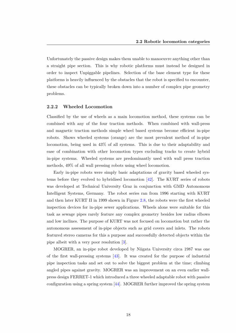
Early in-pipe robots were simply basic adaptations of gravity based wheeled sys-tems before they evolved to hybridised locomotion [42]. The KURT series of robotswas developed at Technical University Graz in conjunction with GMD AutonomousIntelligent Systems, Germany. The robot series ran from 1996 starting with KURTand then later KURT II in 1999 shown in Figure 2.8, the robots were the first wheeledinspection devices for in-pipe sewer applications. Wheels alone were suitable for thistask as sewage pipes rarely feature any complex geometry besides low radius elbowsand low inclines. The purpose of KURT was not focused on locomotion but rather theautonomous assessment of in-pipe objects such as grid covers and inlets. The robotsfeatured stereo cameras for this a purpose and successfully detected objects within thepipe albeit with a very poor resolution [3].
MOGRER, an in-pipe robot developed by Niigata University circa 1987 was oneof the first wall-pressing systems [43]. It was created for the purpose of industrialpipe inspection tasks and set out to solve the biggest problem at the time; climbingangled pipes against gravity. MOGRER was an improvement on an even earlier wall-press design FERRET-1 which introduced a three wheeled adaptable robot with passiveconfiguration using a spring system [44]. MOGRER further improved the spring system
18

2.2 Robotic locomotion categories
Figure 2.8: Kurt II, an autonomous wheeled in-pipe robot [3].
forming a scissor structure similar to a pantograph mechanism, a popular choice fordiametric change methods in the future. Simple wheeled wall-press systems like are thecommon in-pipe movement method and are present in many robotic systems. Manyuse a passive spring design, like the adaptable wheel wall-press system for 140mm- 200mm diameter pipelines [45]. Kanagawa University, Yokohama Japan created awheeled wallpress system for 125mm - 180mm pipes uses a central worm gear withthree linkage connectors with active drive wheels to press into the pipe rather than themore common lead screw method [46]. This direct gear method is useful for smallerdiameter pipe robots where space is at a premium. Shanghai Jiaotong University,China, used a three planed wheeled wallpress vehicle with a lead screw based linkagedesign to increase or decrease the adaptive pipe range of the robot [47].
MRINSPECT is a series of advanced wall-pressing wheeled in-pipe robot series de-signed and developed at Sungkyunkwan University, which have been in developmentfor over a decade [4], [48], [49], [50]. The robot, presented in Figure 2.9, is capableof performing all types of geometry manoeuvres besides valves and has a 50mm ad-aptability range from 130mm - 180mm. MRINSPECT uses a multi-axial differentialgear system to control each of its four wheeled legs angles through active bevel driveconnections. The body frame of the robot consists of a spring loaded central rod whichsupports two sets of linkages either end, the springs force the linkages to adapt to anydiametric changes in-pipe. The active wheeled driving modules are connected to thelinkages at both ends allowing them to be in contact at different heights depending
19

2.2 Robotic locomotion categories
Figure 2.9: MRINSPECT IV +; the latest instalment in an in-pipe robot series designedand developed at Sungkyunkwan University [4].
on the in-pipe geometry [51]. MIT developed a similar wheeled wall-press system forleak detection in the for 100mm pipelines for in-pipe leak detection. The robot has asmall compliant spring in each wall-press wheel to account for slight defects or weldsin the pipe [52]. Large robots can also be built with the wheeled wall-press design,DEWALOP is a cleaning in-pipe robot for 800mm - 1000mm pipes [53]. The robotuses linear actuators rather than linkages to achieve sufficient normal force on the pipewalls, this would be viable for a robot this large but not for smaller systems.
Shenyang Institute of Automation have proposed a system which allows differentrobots to be created from the same platform. Although based around the same classsize and pipe diameter of 200mm three different systems were developed from one,MMU [54]. These wheeled wall-pressing systems performed different functions; MMU1could adapt to slight changes in pipe diameter, MMU2 was focused on detecting defects,MMU3 added a propeller function for fluid travel. The use of one common skeletonallowed these systems to be created from one design with relative ease compared acomplete re-design.
In 2012, YonSei University developed an advanced wheeled system that can adaptto vertical pipe sections, elbows, and even T-Sections. The Adaptable Quad ArmMechanism (AQAM), presented in Figure 2.10 is a wheeled wall-pressing robot for
20

2.2 Robotic locomotion categories
Figure 2.10: The Adaptable Quad Arm Mechanism AQAM: a wheeled wall-pressingrobot for 260mm - 300mm pipes [5].
260mm - 300mm pipes, consisting of four arm mounted wheels in a single plane [5].The robot has impressive manoeuvrability due to its four controllable arms and swivelmechanism to angle the wheels and hence rotate the robot in-pipe. This design allowsthe robot move through extremely complex in-pipe geometry such as T-Sections intoa reduced vertical pipe section. AQAM shares its single plane design with HanyangUniversity’s single-plane wheeled system [6].
These two systems have an advantage over multi-plane wall-pressing robots, byrotating in the pipe they can always maintains contact with the pipe walls in mostcomplex obstacles. The problem faced with single plane contact is stability, any loss ofwall contact in these designs will de-centralise the robot and make recovery extremelydifficult. This is especially restrictive for the system developed at Hanyang University,shown in Figure 2.11, as the robot was capable of 80mm - 100mm diameter pipes andhence only has a 20mm adaptability range [55]. Larger robots can also cover a widerange of diameters, Shanghai developed a large 3 planed wheeled system with a paral-lelogram mechanism that allowed adaptation from 400mm - 650mm pipelines. HanyangUniversity also take a novel approach to wall-pressing using a wheeled clutch systemthat overpowers the wall-press active wheels. This clutch system allows for emergencyretrieval of the robot form 100mm pipelines [56].
Through the addition of magnetic materials, wheeled in-pipe robots can capital-ise on the ferrous properties of certain pipelines. Magnetic wheeled robots allow theoperator to scale walls and maintain normal force without the need for wall-pressing
21

2.2 Robotic locomotion categories
Figure 2.11: Hanyang Universities two-plane in-pipe robot [6].
functions. The first magnetic in-pipe robot was developed by the Osaka Gas Companyin 1995, the system was a dual wheeled magnetic concept for the inspection 150mm -600mm iron pipelines [7].The concept was designed specifically to solve the T-sectiongeometry problem without the need for a wall press robot, as these generally strugglewith in-pipe valves and other sharp obstacle negotiation.
Figure 2.12: Osaka Gas Company, magnetic in-pipe robot [7].
MagneBike, presented in Figure 2.13, is an advanced example of a wheeled in-pipe robot using magnetic traction that can steer in a large range of in-pipe dia-meters developed by Autonomous Systems Lab, ALSTOM. Not only this but in-pipeobstacles such as T-Sections become trivial [8]. MagneBike could inspect a maximumpipeline diameter of 300mm and was designed for industrial applications inspecting
22

2.2 Robotic locomotion categories
power plants. MagneBike’s use of wall adhesion in-pipe reduces all complex in-pipeobstacles to either convex or concave corners which it must overcome. The robot cancomplete convex and concave bends in any orientation with or against gravity becauseif its dual active drive magnetic wheels [57], [58], [59]. The system has 5 degrees offreedom each with an actuator, 2 for drive, two for lifting, one for steering. The twolateral lever arms integrated into the same rotational axis of the wheels allow the robotlift the wheels off in concave corner case thus allowing the robot to continue up thestep with becoming stuck in double contact. This mechanism can also be used to sta-bilise the wheels by essentially giving four extra points of contact and potentially avoidthe magnets clipping off at an angle [60]. The simplified concave and convex problemfor magnetic robots is also outlined in work from ALSTOM systems, such as in theirwheeled mobile magnetic robots, such as the hexagonal climbing robot [61]. Magne-bike has advanced to 3D in-pipe visualisation of the robot in order for a remote userto drive the vehicle effectively in complex spaces based on odometry and a three-axisaccelerometer [62]. University Tenga National built a micro magnetic wheeled robot forthe inspection of 80mm - 180mm pipelines [63]. Their magnetic wheel traction consistsof neodymium magnetic discs surrounded by a low carbon steel 1018 ferromagnetichousing, the configuration is much like a pot magnet with attached gears.
Wheeled systems are even used in conjunction with PIG-like locomotion; using thefluid force to accelerate. Kantaro a wheeled wall-pressing in-pipe robot for sewagepipe applications developed at Kyushu Institute of Technology, Japan takes a differentapproach to wall-pressing by combining it with a fluid driven locomotion [64]. Relyingsimply on pipe geometry to sit in the pipe, whilst it also has adaptability built in tomove from 200mm - 300mm diameters. Fully autonomous with passive damping springsand no tether, the system was ambitious, boasting the ability to manoeuvre throughpipe bends without the need for a controller.
2.2.3 Track Locomotion
Track, or caterpillar based locomotion can be used in the place of wheels, they hold theadvantage when generating friction. The large contact surface area makes these systemsmore stable but also generally larger than their wheeled counterparts. Caterpillar trackshave been used in 11% of in-pipe systems and are growing in popularity in researchrobotics, Figure 2.1.Tracked systems are also predominantly wall-pressing with 75% of
23

2.2 Robotic locomotion categories
Figure 2.13: MagneBike developed by Autonomous Systems Lab, ALSTOM useswheeled magnetic wheels with actuated lateral leverl arms to overcome magnetic con-tact forces [8].
all caterpillar robots using the traction method, the remaining 25% relying on gravityalone. In situations where smooth terrain is not guaranteed high contact area caterpillartank tracks are considered superior as opposed to the point contacts on wheel systems.They excel at moving over obstacles and rough terrain and are often used in cleaningapplications.
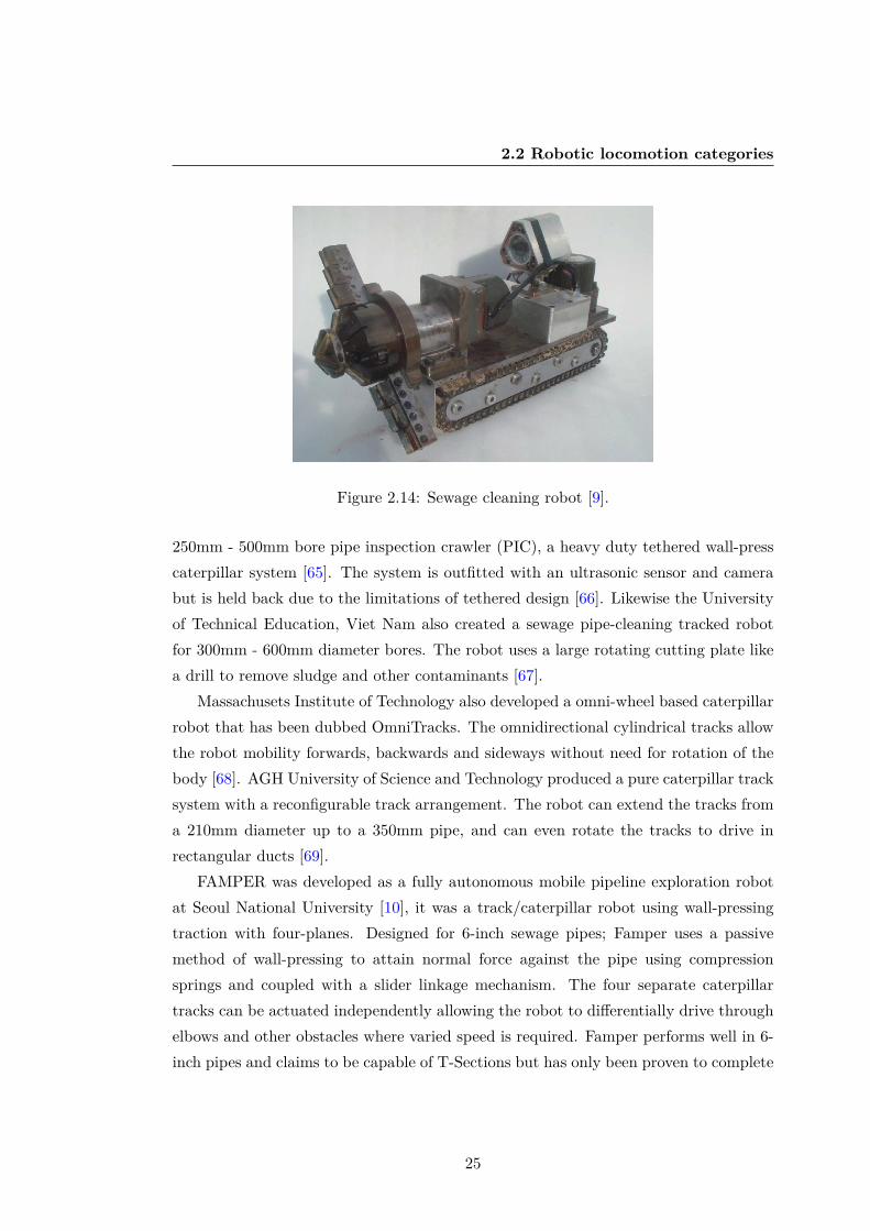
Pure track systems have been developed in recent years such as the in-pipe cleaningrobot developed in 2011 by the University of Technical Education in Viet Nam shownin Figure 2.14. The robot is tasked with cleaning the inner surface of sewage pipeswhere many contaminants, greases, and oils are likely to be present. In this case theincreased surface area in contact with the interior of the pipeline is ideal for generatinghigh tractive effort and reducing slippage. The robot is specified to enter 300 - 600mmpipes, because it does not rely on wall press it needs no function for changing diameterso could potentially enter very large pipes. However the robot is equipped with a 300mmbore cleaning device to remove debris and residue from the sewage pipes and hence isonly really effective in its specified range. For the function of this design perhaps a wallpress system would have been better suited, especially as the cleaning tool could be keptin line with the pipes central axis [9]. The sewage robot is similar in structure to the
24
2.2 Robotic locomotion categories
Figure 2.14: Sewage cleaning robot [9].
250mm - 500mm bore pipe inspection crawler (PIC), a heavy duty tethered wall-presscaterpillar system [65]. The system is outfitted with an ultrasonic sensor and camerabut is held back due to the limitations of tethered design [66]. Likewise the Universityof Technical Education, Viet Nam also created a sewage pipe-cleaning tracked robotfor 300mm - 600mm diameter bores. The robot uses a large rotating cutting plate likea drill to remove sludge and other contaminants [67].
Massachusets Institute of Technology also developed a omni-wheel based caterpillarrobot that has been dubbed OmniTracks. The omnidirectional cylindrical tracks allowthe robot mobility forwards, backwards and sideways without need for rotation of thebody [68]. AGH University of Science and Technology produced a pure caterpillar tracksystem with a reconfigurable track arrangement. The robot can extend the tracks froma 210mm diameter up to a 350mm pipe, and can even rotate the tracks to drive inrectangular ducts [69].
FAMPER was developed as a fully autonomous mobile pipeline exploration robotat Seoul National University [10], it was a track/caterpillar robot using wall-pressingtraction with four-planes. Designed for 6-inch sewage pipes; Famper uses a passivemethod of wall-pressing to attain normal force against the pipe using compressionsprings and coupled with a slider linkage mechanism. The four separate caterpillartracks can be actuated independently allowing the robot to differentially drive throughelbows and other obstacles where varied speed is required. Famper performs well in 6-inch pipes and claims to be capable of T-Sections but has only been proven to complete
25

2.2 Robotic locomotion categories
Figure 2.15: FAMPER CAD model and assembled robot [10].
vertical T-sections from a horizontal down, utilising gravity in its favour during thecontact-loss phase of the manoeuvre. The full-bore design of Famper leaves little roomfor shape adaptability, with a full range of just 127mm - 157mm, the purpose of which ismainly for obstacle negotiation. The lack of adaptability makes Famper unsuitable forany situation other than 6-Inch pipelines [70].This is a common occurrence with passiveadaptability even in larger robots, systems such as AQAM which are exceptionallymobile and adaptable to changes in pipe geometry [5].
Caterpillar Wall-press systems are one of the most adaptive types of system in termsof shape adaptability. Tarbiat Modares University used active parallelogram adaptionin a three-planed caterpillar wall-press system which could adapt from 250mm - 350mm,however this could be increased by altering the length of the linkages [71]. The leadscrew used to alter the height of the tracks keeps all three planes extended at the samerate and hence keeps the chassis central in the pipe. Nigata University’s tracked robotuses an adapted scissor mechanism can passively adapt from 140mm - 210mm [72].
Hanyang University developed a two module caterpillar wall-pressing robot usingdifferential steering and a passive adaptability module using a four bar mechanism toproduce the required normal force on the tracks. This system could handle 80mm- 100mm pipes and can tackle many difficult in-pipe obstacles using the two-moduledesign [11]. The separate tracked modules were connected via a tension spring whichwould drag the rear or front module through an obstacle, removing the need for both
26

2.2 Robotic locomotion categories
Figure 2.16: Hanyang’s two module caterpillar wall-pressing robot [11].
modules to steer.AGH University have prototyped a large in-pipe robot for the inspection of 200mm
pipelines that uses caterpillar tracks on a linkage which can alter their effective diameter[73]. This allows the robot to travel horizontally in a range of pipes from 201mm -235mm. Although vertical travel is possible, this is only the case when the tracks arefully extended essentially making vertical travel possible only in a 235mm pipe.
AGH’s systems low adaptability range is in stark contrast with Ritsumeikan Univer-sity’s parallelogram crawler; a caterpillar wall-press system with an impressive adaptivediameter of 136mm - 226mm almost double its own length [74]. Ritsumeikan have infact developed multiple version of the system and has another under-actuated parallel-ogram robot with modular style caterpillar tracks [75].
PAROYS-II uses an actively controlled pantograph mechanism with a partiallypassive spring mechanism, this allows large changes to be controlled and small obstaclesto be ignored [12]. Its use of a second set of articulated caterpillar tracks allows a hugeadaptive range of 400mm - 700mm. The tracks are actively adaptable as the frontand rear tracks are connected via an active joint [76]. The joint contains structuralcompliance and can passively maintain wall contact and normal force with the use offorces sensing control algorithms. PAROYS has been used in conjunction with advancedcontrol simulations to determine a case to complete T-sections while avoiding contactloss at the pipe junction. With this model the curve trajectory needed for motion
27

2.2 Robotic locomotion categories
Figure 2.17: PAROYS-II an articulated caterpillar pipe robot [12].
planning of the robot through a branched section can be determined, however it hasonly been shown to complete these cases in simulations [77], [78].
Similarly Pukyong National University’s tracked in-pipe robot uses modules withboth passive and active adaptability mechanisms [79]. The shape adaptability is con-trolled using a driven threaded shaft lead screw and allows for transitions between300mm - 500mm effective diameter by altering the position of a four bar linkage. Thesecond module replaces the lead screw with a compression spring allowing for both pass-ive and active diametric adaptations. Gunma university prodcued a magnetic caterpil-lar track robot capable of inspection pipelines with a diameter of 150mm and above, therobot has been shown to be capable of negotiating T-sections. The track locomotionallows a detachment from one of the two driving spurs in the case of non-continoussurfaces [80].
2.2.4 Screw Locomotion
Screw systems are defined by the method of locomotion in-pipe, using a rotary motionto drive themselves forward using a spiral track, to move through the pipe in a pitchedcircle. These systems are always wall-pressing as they rely on the inner walls in order tothread through the pipes, this allows them to climb vertical pipelines with ease. Screwlocomotion robots are generally very difficult to back-drive due to their angled wheelsor tracks, making them effective in high flow networks. Screw systems have stayed
28

2.2 Robotic locomotion categories
relatively steady in terms of growth in Figure 2.33 although the element is only usedin 9% of research systems.
Heli-Pipe a screw wall-press system has a diametric adaptive ability of just 10mm,as a result four different prototypes were made, ranging from 170mm - 40mm. Thelargest of the systems having a range of 10mm and the smallest 5mm [13]. Emergingmethods of in-pipe adaptability show the possibility of continuously deforming systemswith many degrees of freedom. This sprung wall-press screw design is quite commonto in-pipe robotics, and is used again by Ritsumeikan University, Japan to create ascrew drive robot capable of completing T-sections. The Ritsumeikan robot is uniquein that it has an active link between two of it’s drive modules that allows it to select adirection at a pipe junction. Like other spring press designs this robot has limited pipediametric adaptability and is only suit to 109mm - 129mm pipelines. Tokyo Institute ofTechnology created a small diameter screw style system an order of magnitude smaller,for just 10mm - 20mm pipelines. At this scale motion is very limited and so the robottakes inspiration from the way helical bacteria produce movement using flagellum. Therobots mechanical actuation consist of just four wires running down the body whichcontract in different modes to rotate the flexible body [81]. An similarly interestingand novel micro screw robot has been developed by the Tokyo Institute of Technology,Yokohama, a robot that consists of just three intertwined hollow tubes. The hollowtubes can be inflated to force the twisted bundle of tubes into a helical formation, byinflating each of the three tubes intermittently the robot can screw its way through apipe of just 8mm - 20mm [82].
SPRING is a screw type wall-press robot developed at Osaka University, although itrelies on full wall traction it is unlike traditional full-bore wall-press systems which keeptheir chassis centralised in the pipe [14]. The design consists of many connected moduleswhich form a continuous tight spiral some of which contain wheels allowing the robotto move in a spiral motion. When faced with a sharp change in diameter the robot canstretch this spiral increasing its pitch and therefore decreasing its diameter to less thanhalf its optimal width of 150mm pipelines. This function is entirely possible becauseof the lack of a centralised chassis, making the robot very adaptable when faced withobstacles such as valves. Current issues include the complexity of the design, optimalredesign of the robot is very difficult due to the amount of parameters involved and soa simulation tool had been created to aid in this. Shenyang Institute of Automation
29

2.2 Robotic locomotion categories
Figure 2.18: Heli-Pipe screw wall-press system [13].
produced a much simpler robot, also for 150mm pipelines that is actuated using just oneDC motor to turn the body of the robot. The wheeled-screw system was quite complexand featured no diametric adaptation method which caused it to become stuck in thepipe often. Their solution was to create a ”lock up” control mechanism which activateswhen stuck allowing the robot to reverse and escape the locked contact point [83].
Shenyang University created a wall-press robot based on helix movement in-pipe,capable of 250mm - 300mm pipeline exploration using a passively adaptive four barlinkage [84]. The robot can complete complex manoeuvres such as T-Sections using itsactive drive module to steer the course.
Screw robots have also been combined with magnetic [85] and is quite a popularmethod of locomotion in-pipe for medical applications. An external field is not use-ablefor underground in-pipe applications, the field would need to be extremely strong, andthe location of the robot would need to be known which is not the case.
2.2.5 Snake Locomotion
In-pipe snake robots are typically feature articulated joints in a modular design pairedwith wheels or tracks for locomotion. The articulation allows many degrees of freedomwithin a single system making them very versatile in their approach to obstacles. Inthe last 15 years, in-pipe snake robots have become the preferred method of commercial
30

2.2 Robotic locomotion categories
Figure 2.19: Osaka University’s SPRING pipe robot [14].
pipeline inspection and account for 13% of in-pipe robotic research.The PipeTron series developed by HiBot, Tokyo is a multitude of robotic in-pipe
exploration snake robots. Predominantly designed for tight bend systems such as re-fineries and chemical plants, the system is tethered for instant retrieval and consists ofpassively articulated wheels connected in a series [86]. The passive torsion springs ineach module joint allow the robot to bend and alter shape depending on the problemencountered and the width of the pipe without requiring further actuators. Due torelatively low range of passive adaptability multiple platforms have been created foreach commonly encountered pipe diameter: 75mm, 100mm and 150mm.
The Explorer series is a prime example of the amount of effort going into translationof robots for different size pipelines, initially developed at Carnegie Mellon University[15]. This large snake robot is designed for the inspection of live gas networks underoperating conditions, however it requires a full bore to operate with little adaptabilityranging from just 150mm - 200mm. Multiple systems have now been developed foroperations in larger than specified networks [87]. PIBOT is a 350mm - 400mm snakerobot system similar in it’s modular style to the explorer series, it’s focus is the deliveryof its NDT module into unpiggable natural gas pipelines. The drive modules on-boarduse wall-pressing wheel traction to position the magnetic flux leakage (MFL) module,the MFL system is then deployed via a pantograph mechanism [88]. Natural gas snakerobots have also been developed at Sungkyunkwan University for use with NDT MFL
31

2.2 Robotic locomotion categories
Figure 2.20: Pipetel’s Explorer [15].
equipment [89]. The robot is a standard articulated snake structure with two activedrive modules, two controls, and other modules with tethered power. The novel workin the robot is the Double Active Universal Joint (DAUJ) which is present between themodules. This was developed for routing a snake vehicle through the tight bends andenables control of the joint compliance. The National Energy Technology Laboratoryof the US Department of Energy have created a wall-press wheeled snake robot forunpiggable pipelines to carry MFL modules through the pipe. The tethered robot”RoboScan” uses compliant wall-pressing drive modules to maintain traction in-pipe[90].
Kanagawa University, presented an unusual and interesting method for coping withvarious pipe diameters. The robot is a hybrid of caterpillar and snake components,built from modular units each containing a driving caterpillar track [16]. Connectingthree or more units allows the robot to drive in-pipe, should a larger diameter needto be traversed the number of driving units can be increased. Promising results wereshown in experimental pipes of 100mm - 300mm, an exceptional range for a robot withmodules of just 50mm. A similar method of this dimateric adaptation in snake robotshas been explored by Applied Cybernetics, Norway. The snake robot they created for250mm - 300mm pipelines. The robot can span the pipe with active joints between itswheeled drive modules, although the active joint range is not as large as Kangawa’ssystem [91].
Czech Technical University, Prague have developed a snake robot with the purposeof identifying new methods of generating pipe contact without relying on traditionalwall-press mechanisms such as pantographs and parallelogram linkages [92]. The mod-ular snake robot consists of many segments each of which contain both rotary and
32

2.2 Robotic locomotion categories
Figure 2.21: Kangawa Snake Robot [16].
translational actuators, this allows the snake to form structures much more complexthan full bore robots. The shape adaptability of 100mm is already greater than twicethe length of the body segments which measure just 50mm, with greater numbers ofsegments this robot may even be able to handle a wider range of diameters.
PIRATE was an in-pipe robot with the intended purpose of autonomous inspectionof the gas distribution network in the Netherlands [17]. The robot is snake-like, andmodular in nature featuring articulated clamping modules that can actively change theheight of the robot to adapt to changes in pipe diameter. The design of the clampingmodules was somewhat similar to the first proposal for a passively adaptive threewheeled inspection robot, [44]. However unlike passive systems the active articulatedjoints allow for an efficient change in pipe diameters, stretching to twice its originalinspection diameter from 125mm - 63mm [93].
Snake robot’s can also be used out-pipe, and generally grip and wrap themselvesaround pipe obstacles, such as Carnegie Mellon University’s unified snake robot for50mm pipe climbing using shape memory alloys (SMA’s) [94]. While out-pipe snakemethods are not generally applicable to in-pipe locomotion the general actuation ofthe robots still applies. This is also true of OC Robotics, snake-arm system which ishighly flexible and dynamic for movement in close range tethered areas of a minimum100mm pipeline. The snake-arm can enter a hole and search for a defect using therobots base as stabilisation [95]. This is currently used in the aerospace industry butcould be applied to an in-pipe robot to search pipe branches at a reduced range.
33

2.2 Robotic locomotion categories
Figure 2.22: PIRATE, gas network autonomous inspection robot [17].
2.2.6 Inchworm Locomotion
In-pipe inchworms are currently only wall-pressing, they generate traction through largenormal force applied at the front or back module whilst a central module contractsand extends in sequence. The high normal forces needed to support the robot duringcontraction makes these systems generally well suited for carrying high payloads. Theuse of point contact in inchworms and the removal of wheels or tracks makes themmuch more stable than other designs. Inchworms are also generally less prone to slipdue to contaminants in-pipe as they can ”cut” through the grease. Use of inchwormsis quite widespread in the field, 11% of systems were found to use this technique in thestudy.
A highly mobile inchworm inspection robot based on a parallel manipulator, de-veloped at YonSei University. This wall-press inspection device can handle 205mm -305mm pipes the large inspection range coupled with its ability to traverse T-Sectionsmakes up for the slow inspection speed [96].
These platforms have shown promise in industrial networks and have inspired thefurther exploration of large inchworm systems such as the 3SPR parallel manipulatorunder development at Yanshan University. This is a large two-module in-pipe inchwormrobot, although currently in a theoretical state is intended to have large load carryingcapacity for industrial applications [18].
Industrial pipeline networks often contain large amounts of oil and grease traces;it is these applications where wall-pressing systems such as these excel due to theirlow contact area end effectors. Case Western Reserve University have developed a
34

2.2 Robotic locomotion categories
Figure 2.23: 3SPR Parallel Manipulator inchworm pipe robot [18].
new method of in-pipe robotic locomotion using continuous-wave peristalsis, the samemechanism employed by earthworms [19]. The robot, named CMMWorm, is composedof many interlinked joints forming a mesh like structure that can deform in the presenceof an environmental change. The braided mesh can currently smoothly expand andcontract from 220mm - 180mm and although currently unable to steer through in-pipeobstacles the mechanism shows great promise in shape adaptability research. Theserobots can potentially alter their effective diameters in-pipe in any section of theirbody.
Figure 2.24: CMMWorm, continuous-wave peristalsis pipe robot [19].
On the smaller end of the scale, a micro inch-worm robot for 17mm - 10mm pipelineshas been developed at the National Universuty of Defense Technology, Changsha,China. The robot has a unique self-locking mechanism that allows it to drasticallyincrease normal force in a single module allowing inchworm movement at the second
35

2.2 Robotic locomotion categories
module by contraction. The locking mechanism is a three footed folding linkage witha lead screw based actuator [97].
The flexible squirm pipe robot developed at the Automation School, Beijing Uni-versity is another example of a novel adaptation of an inchworm device. The inchwormconfiguration of the robot is a standard two part lead screw design, interestingly thoughthis robot is designed to utilise the pressure of the pipe fluid to move much like a PIG,and is equipped with a nozzle tip that helps guide it through bends and T-sections [98].
A novel bristle mechanism based inchworm design has been developed by DailanUniversity of Technology, China. Similar to the University of Durhams bristle basedPIG [2] this robot uses many bristles as points of contact and relies on bending forceof each strand to produce movement [99]. The robot is asupported in-pipe by passivewall-press modules that ensure the system remains concentric with the pipeline.
2.2.7 Fluid Locomotion
Propeller based locomotion is quite unusual in pipe inspection, used in combinationwith mainly fluid flow in water pipes this niche application featured in only 3% ofreviewed systems. These water pipe inspection robots have the opportunity to utilisethe fluid and develop swimming robots for use in leak detection. The main advantageof propeller systems is removing the need for wall contact altogether.
A swimming in pipe robot was developed at the Massachusetts Institute of Tech-nology as a solution to the challenges faced by robots relying on wall contact in watertransport networks. The robot, MIT-MRL contains a chassis with housed electronicsand two propellers for propulsion, the swimming nature of the robot allows explorationof pipes 100mm and above autonomously [100].
The University of Sheffield took a different approach to swimming, developing amodular robot which can manipulate the fluid in order to generate propulsion in acertain direction by combining their chassis to form complex shapes. Each of themodules in this system form a section of a hydraulic system which when connected toanother module forms a flowing network [101].
Although primarily a caterpillar track type robot, the Multifunctional Mobile Unit,MMU3 [54] also utilised a propeller in a version specified for fluid travel.
36

2.2 Robotic locomotion categories
Figure 2.25: MORITZ pipe inspection robot [20].
2.2.8 Walking Locomotion
Walking type in-pipe robots use multi D.O.F. legs to move around the pipe, these aregenerally complex and quite large due to the number of actuators involved. Walkingtypes which incorporate wall-pressing functions sacrifice mobility for increased stability,these are generally slower in-pipe. As a trade-off, the application of active wall pressingmechanisms give them a great amount of control over the applied normal force in pipeand they can deliver heavier payloads. Walking systems are somewhat uncommon withonly 7% of research robots using the technique although they have been appearing moreoften in recent years, seen in FIGURE 2.1.
MORITZ, a pipe inspection robot built at the Technical University of Munich wasone of the first walking style robots to be developed [20]. Using 2 modules with a totalof eight legs with 2 actuators each, a bending joint, and a rotation joint this complexsystem had a large number of degrees of freedom for an in-pipe robot. MORITZ wascapable of travelling through 600mm - 700mm diameter pipes thanks to the highlyvariable actuated legs, each with 2 degrees of freedom, extension of these legs allowednormal force to be controlled and frictional forces strong enough to hold up to 20kgpayloads. The high amounts of control and increased carrying capabilities compared topassive systems make robots such as MORITZ ideal for industrial inspection of powerplants, where safety is a priority over speed of inspection and power requirements.
37

2.3 Magnetic traction locomotion
2.3 Magnetic traction locomotion
Magnetic traction is used in many areas such as ship hull inspection, tank inspectionand cleaning, and medical applications. Reviews of magnetic wall-climbing deviceshave previously been performed [102], this literature search will focus on key robots aswell as the current state-of-the-art for wall-climbing magnetic systems. Some of theserobots would work quite well in-pipe such as a caterpillar magnetic robot that cancomplete concave cases from 10 to 90 approach angles. The robot uses a magnetictrack with alternate facing poles at each track point, its configuration is a triangulartrack to avoid double contact cases on approach [103]. A downside of this system isthat double contact can still be made if the target angle is equal to the track angle.This robot could be adapted to in-pipe work but is only capable of concave cases.The caterpillar robot had magnetised tracks with direct contact of the magnets at thewall, a different approach to creating a magnetic wheel is to create a magnetic chassiswith a regular wheel that puts traction through the axle. A novel magnetic wheel ofthis design was developed which sported a symmetrically centralised unit [104]. Thewheel is a standard rubber tire with a large magnetic skirt that envelopes the wheel.This configuration allows magnetic forces to still adhere the wheel even in a pipe likecurvature. A magnetic cleaning robot from Zhejiang University also uses this designmethod to spray down dirt using a water jet in a tank. Its magnetic structure is heldwithin the chassis and not the wheel themselves, this means the robots chassis distanceto the pipe must be a maintained at the correct point, and that a stronger magnetmust be used to produce the same magnetic force relative to magnets that may beused within the wheels instead [105]. In some cases direct wheel contact is not evenneeded, like the magnetic in-pipe actuated device has been developed at Tohoko GakuinUniversity for 33mm - 40mm inspections. The robot uses a shape memory allow shieldto wall-press, and then uses magnetic vibration actuators to move through the pipe[106].
Other magnetic traction system locomotion methods that could be adapted in-pipeinclude Omni-Climber, shown in Figure 2.26. This multi-directional magnetic wheeledrobot has built in chassis compliance which allows it to adapt to a wide range of pipediameters [21]. This could be adapted to in-pipe scenarios allowing a small robot toexplore pipes which are respectively large in diameter. In a similar weight class butcompletely different approach is HyReCRo (Hybrid Redundant Climbing Robot), is
38

2.4 NTS environment
Figure 2.26: OmniClimbers: Omni-directional magnetic wheeled climbing robot [21].
a walking robot developed form climbing three dimensional magnetic structures. Ituses switchable permanent magnets which can be turned on and off but do not needconstant energy supply like electro-magnets. The robot prototype based on a walking3RPR style parallel robot has been shown to be able to climb convex cases but notconvex [107].
Magnetics have been used to create reconfigurable robots, for instance magneticmodular robots developed at MIT Science and Artificial Intelligence Lab. M-Blocks aremagnetic self-assembling cuboid that can reconfigure around each other, these systemsuse a flywheel to store angular momentum inside the robot and then by rapidly brakingthe flywheel the angular momentum transferred to the body can be used to movearound concave and convex corners. The robots themselves are attached at the cornersby permanent magnets, the momentum from the flywheel is strong enough to breakthe bonds of the permanent magnet when needed [22].
2.4 NTS environment
This section will explore the general environment, conditions, paths, and obstacles,that may be encountered within the National Transmission System. The robots aim tocomplete the inspection of Above Ground Installations (AGI’s), an AGI consists manyfunctional mechanical components and there are a wide range of different obstaclesand potential opportunities for robotic inspection. This section will explore known andexpected environmental conditions on an unpiggable AGI site.
39

2.4 NTS environment
Figure 2.27: M-Blocks, magnetic robots that use angular momentum to break magneticbonds and solve both concave and convex step cases [22].
2.4.1 Pipeline infrastructure
After the discovery of natural gas along the UK’s continental shelf in 1965, the first18-inch gas feeder lines were built just two years later in 1967 [108]. From this point on-wards the network rapidly expanded and most of the network was constructed between1966 - 1983 [23]. Within this time frame 5150km of the total 7600km of pipeline hadbeen built, the specific growth of the NTS in this time period is shown in Figure 2.28.
As the gas travels from the North Sea the pressure in the pipes drops and the gasmust be re-pressurised in a AGI compressor station using gas driven turbines. Thereare 25 compressor AGIs across the network compressing the gas from 48 bar to 65 bar[109]. The construction material of the NTS pipelines consisted completely of weldedlow carbon steel most of which was buried within on site of the AGI compressor stationsshown in Figure 2.29. Most NTS infrastructure initially had a 40-year design life andthe earlier sections are now due for replacement including these now buried pipelines.
Obstacles vary AGI’s, there will however be common obstacles present. T-Sectionssuch as those seen in 2.1.F will occur between small diameter pipelines and the largerpipes. Vertical sections will occur when heading below ground and high and low radiusbends will be present everywhere. Valves will be present in many different forms and
40

2.4 NTS environment
0
515
1107
3055
3539 3714
46914904
5150
0
1000
2000
3000
4000
5000
6000
1966 1968 1970 1972 1974 1976 1978 1980 1982 1984
NT
Sle
ng
thin
Km
Year of construc!on
Figure 2.28: The growth of the bulk of National Transmission System between itsinception in 1966 and 1983 [23].
Buried Network
Figure 2.29: Construction and installation of an underground pipe network being laydown before burial. [24].
diametric changes will be found at many connection points. All of these features andobstacles can seen in Figure [24].
Existing access points
Existing access points were first reviewed and it was found that two methods wouldmake access possible, these are the PIG grate, and the 2-inch risers. The PIG grate,seen in Figure 2.30 exists as a barrier between the AGIs main transmission line andthe entrance point of the gas to the AGI. The grate forces the PIG to continue downthe main transmission path and away from the unpiggable AGI, but it also provides a
41

2.4 NTS environment
possible entrance to the system. The barriers purpose is to stop PIG’s crashing intothe T-section connection point. Each AGI site has a PIG launch point to launch PIG’sfrom one site down the main transmission lines to another site, the connection to theAGI is also along this line. The grate is necessary because PIG’s are inherently simplefluid driven sensors and cannot be controlled, when they pass the T-section they canpotentially crash and become stuck. Most of the largest diameter sections (40-inch,1016mm+) connect directly to the cross-country grid network and anything beyondthe PIG grate is inspect-able through pigging.
PIG Grate
Figure 2.30: PIG grate entrance from a main PIG launch vessel onto an AGI site [24],a type of interior T-Section to from the main.
GRAID is a large magnetic robot specified for mid range diameter of 750mm -900mm and used a large custom launch vessel to access the network. This is thediameter range chosen to be inspected to cover the most of the AGIs infrastructurewith a single robot as this is the most common pipeline range that can cover the mostasset volume [24]. These access points still remain unused for robotic inspection.
Launching and retrieving robots
When using a robotic inspection device the first problem faced is the method of entranceto the pipeline. The actual bulk of the pipework within the AGIs is mostly buried underthe site and hence inaccessible to humans as seen in Figure 2.29. To enter a robot suchas the into the national grid gas transmission system a launch vessel must be used.It is critical no oxygen is present inside the gas pipeline, combined with a spark thiscould cause an explosive catastrophe. The vessel acts as an airlock of sorts between the
42

2.4 NTS environment
2-inch riser
AGI riser entrance
Figure 2.31: Render of underground pipe network on an AGI, 2-inch risers can be seenentering the network from above ground access points [24].
atmosphere and the natural gas pipeline. The robot is sealed inside the launch vesseland is then flooded with nitrogen to remove all trace of oxygen from the system, onlythen is the pipe flooded with pressurised natural gas and the valve opened. The launchvessel shown in Figure 2.32 can be fitted to the existing above ground network usinga hot-tap procedure and can then be driven into the underground network. Theseprocedures are used to fit custom pipework however these procedures can be quitecostly and price increases with an increase in robot diameter (and hence launch vesseldiameter) [110].
The NTS is a highly valuable system, a robot which is stuck or lost in a live pipewill require a shut-down to retrieve and possibly even an excavation. The robot mustbe retrievable before being granted access to pipeline assets. This can be achieved withthe use of a tether to wind a potentially broken down robot back to the launch vesselso that it can be retrieved. Large modifications must be made to the existing pipenetwork to fit the launch vessel in Figure 2.32, it would be much simpler to use existingaccess points. Using existing pipelines the flooding procedure would remain the samehowever the hot-tap procedure would not be required.
43

2.4 NTS environment
Robot “GRAID”
Figure 2.32: Render of the GRAID robot within a concept launch vessel that would befitted to the AGI due for inspection [24]. The launch vessel floods the robot from ATM(atmospheric pressure) to full pressure with nitrogen to remove oxygen before entry.
2.4.2 Natural gas
When inspecting a natural gas pipeline with any kind of device, procedure states thatthe pipeline section be shut off and that the natural gas is flooded into the atmosphere.This shut-down is not only costly to the consumer, it is also costly to the environment.This is why Project GRAID aims to Inspect the underground network under live gasconditions, this will be done by venting only a small section of pipeline, entering therobot into this section, and then flooding the section with Nitrogen to purge any oxygenwithin. By doing this the losses caused through inspection based gas venting can belargely negated. Anything entering the AGI network including robots must also beATEX rated and pressure tested according to the strict explosion safety regulations[111]. It is vital that no oxygen enters the NTS as when mixed with natural gas andany ignition source an explosion can readily occur.
Flow rate within the NTS across the main pipelines can move at speeds of up to11 m/s in the main lines and around 5 m/s in an AGI. Pressure in an AGI can bebetween 48 bar to 65 bar [109], however the pressure in a main line can be anything up96 bar. The internal walls can contain contaminants present in-pipe (e.g. grease, oil),the condition of specific pipelines is not currently known.
44

2.5 Literature summary
2.4.3 Environment summary specification
The above ground installations in-pipe and out-pipe environment can be summarisedin Table 2.1. This environment specification determined the most appropriate methodto inspect the system as well as the locomotion and traction methods.
Table 2.1: National Transmission System (NTS) possible path variables, obstacles, andenvironmental (Env) conditions. [26]
Path: pipelineentrance points
2-inch risers either side of main valves(50.8mm). 48-inch PIG traps (1219.2mm) through grate.
Path: pipelinediametric range
Range is 2”- 48” or 50.8mm - 1219.2mm, with the mostcommon range being 750mm - 900mm in an AGI.
Path: in-pipe jointspresent
T-sections, high and low radius bends, angledpipes including verticals.
Path: jointOrientation
Obstacles can be present in all orientations but areusually at right angles with mitred connections.
Path: typicallengths on an AGI
valves, T-sections (1m), straight (10m-40m), vertical(1m-5m), diameter reduction (1m-3m), elbow (1m-6m).
Obstacle: in-pipe features Weld beads, valves.Env: pipeline material Mild Steel (Ferrous)Env: gas composition Natural gas.Env: gas flow speed 0 - 5m/sEnv: gas flow pressure 0 - 94bargEnv: contaminants Grease, oil, residue, iron scales.
2.5 Literature summary
An in-depth analysis of in-pipe robot publications over the last 30 years is presentedin Figure 2.33.C Categorised by locomotion type and year published it gives a highlevel overview of the trends in the development of in-pipe inspection robots based on234 published systems. The literature search was performed using the keywords; in-
45

2.5 Literature summary
Figure 2.33: History of In-Pipe Robotic Locomotion [25].
pipe, pipe, tube, system, robot, platform, in combination with locomotion and tractionmethods across multiple publishers. The volume of research robots being produced wasfound to steadily increase with time as the field has grown, this reflects on the necessityof pipe inspection as more networks become out-dated around the globe.
Chapter 2 explored the literature surrounding the relevant subject areas of in-piperesearch, and the many methods currently in use to solve these inspection problems.The key points of in-pipe inspection such as the sizes of these pipelines and networksaccess points will be broken down into smaller manageable problems and then simplifiedto find the most elegant solution. By creating a detailed specification based on thesesimplified problems the proposed robot will contain the tools necessary to complete theaims and objectives set out in this work.
Table 2.3 provides a summary of robots reviewed in this section, where in-pipegeometry obstacles have been simplified to X (horizontal), Y (vertical), L (elbow), T (T-section), V (valves). The capability of the robot to traverse these obstacles is denotedby (3) when capable, (7) when incapable, and (-) when a possibility in future versionsof the system. Table 2.4 summarises the characteristics of the various environmentsand conditions that will be considered in this research. The environment conditionswithin the NTS can vary greatly depending on the section of pipe being inspected. Thework of this thesis will focus primarily on the problem of AGI’s; unpiggable pipelineswith greatest environmental variance. The difficulty or challenge level of a particularsection of pipe will be determined entirely by the robot that is attempting to traverse
46

2.5 Literature summary
it.The gas filled environment can consist of varying speeds and pressure when live,
these provide challenges in terms of robot corrosion, power requirements and pressuresealing. In a dry pipe (gas turned off) these challenges can be ignored, however evenwithout gas the in-pipe environment on the NTS proposes a significant challenge torobotic design. The in-pipe environment, conditions, and pathway hazards that canpossibly be encountered have been categorised by robotic challenge level in Table 2.2.
For pipe pathway obstacles such as the various bends and joints present, the dif-ficulty of each of these can be inferred from the literature search, and which robotswee able to complete them in Table 2.3. In this table all robots could complete thehorizontal path (X) making this an easy in terms of robotic design, it is the bare min-imum required. Vertical (Y) sections were mostly completed, with only 3 of the studiedrobots failing. Elbows (L) were completed by all but 1 system, T-sections (T) werecompleted by only 14 robots, this is unsurprising as it is considered a great challengeand the topic of many in-pipe robotics papers. Valves, especially straight plug valveswould be the most difficult obstacle to the reviewed robots, mainly due to many ofthese robots using full-bore to design the robot making the obstacle unavoidable. Sud-den step changes may also be considered threatening obstacles to robot locomotion asmany operate under the assumption of smooth diameter transitions. This is speciallytrue of passively adaptive wall-press systems which cannot choose to adapt accordingly.PIG grate meshes are a specialised and rare obstacle, they are extremely challengingas they are specifically designed to stop PIG devices from entering a pipe branch.
Other conditions that provide a challenge for robotic system present in the NTSinclude grease, oil, residue, and iron and rust flake particles on the pipe walls. Theseare difficult environment challenges that all affect he traction that can be generatedby a robot, hindering it’s movement, or in the case of fluid-driven systems the abilityto slow down. To counter this the robot will to generate a strong normal force at thepipe wall contact, on the more extreme end of this condition a robot will possibly evenneed a self-cleaning device to remove the friction reducing residue from the locomotionsystem. Weld beads are physical steel obstacles formed through joining of pipelines,they are the leftover ridges from various welding forms used in the network manufactureand connection via Continuous Welding (CW), Electric Fusion Welding (EFW), FieldWelding (FW), Socket Welding (SW), or Butt Welding (BW) of pipelines.
47

2.6 Literature discussion
Table 2.2: In-pipe environment, conditions, and pathways, categorised by robotic chal-lenge level as shown by in-pipe robots reviewed in literature.
Hazard Category Minor Robotic Challenge Major Robotic Challenge
EnvironmentGas flow < 1m/s Gas flows > 1m/sPressure < 2 bar Pressure > 2 barNo gas present Gas present - corrosion
Pathways andObstacles
Horizontal section Vertical sectionElbow T-sectionGradual diameter change Plug valveWeld beads Step diameter changePipe defects, imperfections PIG grate
InteriorConditions
Oil / grease on walls Oil / grease poolsIron flakes /rust on walls
Large rustcorrosion bubbles
Minor damage(cracked pipe)
Major damage(deformed pipe)
2.6 Literature discussion
Since the development of the first wall-pressing in-pipe robot in 1987 the technique hasbecome the most popular method of generating traction in the field with over 23% ofrobots applying it in some way in Figure 2.33. The popularity of wall-pressing sys-tems stems from their ability to take advantage of the encompassing walls to generatetraction. This feature is guaranteed in pipe networks and allows robots to easily movehorizontally and even vertically thanks to the ability to generate friction in any orient-ation. Issues arise with wall-pressing robots when obstacles such as T-Sections presentthemselves and there is a possibility for contact loss. Systems were shown to havevarying abilities depending on the number of points of contact with the wall varyingbetween two, three or four planes of contact, examples of which are shown in Figure
48

2.6 Literature discussion
Table 2.3: A summary of the most relevant robotics systems reviewed in this chapter.X (horizontal), Y (vertical), L (elbow), T (T-section), V (valves), - (unknown).
In-Pipe Robot Summary TableRobot Name Ref Locomotion Traction Min Max X Y L T VFluid Modules [101] Modular Swimming 125 ∞ 3 3 3 3 3
MagneBike [8] Magnetic Wheel 250 ∞ 3 3 3 3 -MIT-MRL [100] Swimming Swimming 100 ∞ 3 3 3 3 3
Osaka Robot [7] Magnetic Wheel 150 600 3 3 3 3 -PAROYS-II [12] Caterpillar Wallpress 400 700 3 3 3 3 7
MOGRER [43] Wheel Wallpress 520 800 3 3 3 7 7
Pukyong Robot [79] Wheel Wallpress 300 500 3 3 3 - 7
HELI-PIPE Series [13] Screw Wheel 40 173 3 3 3 7 7
KANTARO [64] Wheel Wallpress 200 300 3 7 3 3 7
MORITZ [20] Walking Wallpress 600 700 3 3 - - 7
Tarbiat Robot [71] Caterpillar Wallpress 250 350 3 3 3 - 7
YonSei Robot [96] Inchworm Inchworm 205 305 3 3 3 - 7
PIRATE [17] Wheel Wallpress 41 125 3 3 3 - 7
PIPETRON I - VII [86] Snake Wheel 75 150 3 3 3 3 7
EXPLORER II [87] Snake Wallpress 150 200 3 3 3 3 3
MRINSPECT VI+ [4] Wheel Wallpress 130 180 3 3 3 3 7
Shenyang Robot [54] Wheel Wallpress 250 300 3 3 3 - 7
AQAM [5] Wheel Wallpress 259 305 3 3 3 3 7
CMMWorm [19] Inchworm Inchworm 180 220 3 - 3 - 7
FAMPER [10] Caterpillar Wallpress 127 157 3 3 3 3 7
FERRET-1 [44] Wheel Wallpress 90 120 3 3 3 7 7
Two-Plane Robot [6] Wheel Wallpress 80 100 3 7 3 3 7
AGH Robot [69] Caterpillar Wallpress 210 210 3 7 3 7 7
Kangawa Robot [16] Caterpillar Snake 300 300 3 3 3 3 -LOCOSNAKE [92] Snake Snake 120 120 3 3 3 3 -SPRING [14] Screw Wallpress 150 150 3 3 3 - 7
49

2.6 Literature discussion
Table 2.4: A summary of the various environments and conditions found within theNational Transmission System (NTS) that should be considered in this research.
Environment Conditions and characteristic features
All natural gaspipeline interiors
Weld beadsOil and grease present on wallIron and rust flakes present on wallCorrosive natural gas present when livePressures up to 97 bar
Piggable Pipelines(Distribution mains)
Accounts for 95.4% (7250km) of NTSLarge diameter 18+ inchesHighest gas flow and pressureGrated pipe junctions (prevent PIG’s entering)
Unpiggable Pipelines(Above Ground Installations)
Accounts for 4.6% (350km) of NTSVarying pipe diameters and junctionsVarying flow ratesPipelines diameters 2 - 18+ inchesValves of assorted types (e.g Butterfly, stop)Sudden diameter changes (steps)Risers either side of valvesPIG trap collection and entranceMany pipe junctions (Elbows, T-Sections)Oil and grease collections at junctionsTurbulent gas flows
50

2.6 Literature discussion
2.2.The field of in-pipe robotics research is heavily invested in the use of these classic
wall-pressing systems, many of which have low diameter adaptability ranges. Thesesystems are stable and efficient in their specified diameter range but none of the tra-ditional systems reviewed showed the capability adapt to large changes. Systems suchas AGH Universities 200mm robot with only a 34mm adaptability range would not beable to cope with even a ×1.5 increase in pipe diameter and would lose the ability toclimb angled pipe sections. In some cases, such as Hanyangs flat pipeline inspectionrobot a change over 20mm would cause it to become completely unstable and unable toperform even basic locomotion tasks. Many of these robots would be deemed unsuit-able for inspection of AGI networks. Some of these designs are simply too constrainedby size due to their reliance on a chassis that is always concentric with the pipe. Whilethe central mount provides a good base for adaptability mechanism control it does notbenefit transformation range. This limitation means that pipe networks with large vary-ing diameters cannot be inspected without an entire fleet of different class wall-presssystems. Assuming a medium size wall-press robot with 100mm adaptability range,a network with pipes ranging from 200mm - 1000mm diameters would require eightseparate robots to inspect. Entering 8 different size systems into one network mayrequire multiple access points on the pipe into the correct bore diameter and wouldneed to be repeated across the AGI until the inspection is complete. The use of snakewall-pressing robots overcomes the limitations of traditional wall-pressing systems withmultiple planar contact. Snake robots with wall-pressing capabilities can utilise artic-ulated limbs to increase their effective diameter well over the range of parallelogramand pantograph mechanisms. For instance Kangawa University’s snake system has anadaptability range of 100mm - 300mm [16]. Snake systems hold a great advantage overfull-bore designs as they can be entered into smaller pipes as an access point into largernetworks. This non full-bore design also allows them to pass through tricky obstaclessuch as valves which would stop most traditional wall-press systems in their tracks.
Lateral rotation around the inside of the pipe walls without the need to rotate thebody relative to the pipe axis provides a large advantage to long robots in a relativelysmall diameter pipe. Omnidirectional wheels such as those in MIT’s OmniTracks [68],are ideal for cases such as these. Tracked systems are very popular for industrialcleaning purposes, this makes sense as they have the highest gravity based traction,
51

2.7 Literature conclusion
which is all that is needed for sewage pipelines where verticals are not really used fortransportation. Caterpillar tracks can be bulky and heavy but in most applicationsthey are chosen for this bulk and extra weight gives the robot an advantage in gainingtraction in an very low friction sewage or contaminant filled pipe. Snake robots canbe very articulate if a low diameter than the intended pipe bore and in this case canovercome difficult obstacles such as plug valves which sit central in the pipe that wouldbe impossible for a full bore system [112]. However trends for in-pipe snake robots pointtend to use full bore systems in well established diameter pipelines where diametric veryrare. Snake robots that can use both wall-press to complete vertical sections and alsoavoid sub-full bore obstacles are very rare. Non-traditional methods of in-pipe tractiongeneration such as vacuum powered wall-climbing and van der waals forces are notreally applicable to in-pipe robotics work as they generally require ideal conditionswhich are not present in-pipe. For instance vacuum robots would need to conform tomany different diameters [113], and van der waals force requires perfect contact andzero contaminants [114].
2.7 Literature conclusion
This review has presented an in-depth analysis of literature surrounding the project,a historical overview of the field, as well as displaying the current trends of in-pipetechnology, with a specific emphasis on the locomotion methods used. In-pipe robotsare incredibly diverse and many different hybrid systems have been developed, some ofwhich have fulfilled specific niches of pipe inspection. However, the inspection of highlyvarying diameter networks is an area that has not been fully explored. Tackling thisproblem would require a method of locomotion that is not constrained by pipe size. Thisis a complex issue and one that cannot be solved using full bore wall-pressing robotsdue to the limitations inherent in their diametric adaptability mechanisms. Snake stylelocomotion methods have been shown capable of spanning pipe bores with complexarticulated systems, however neither wall-press or snake systems are close to exploringthe entire specified 50.8mm - 1016mm range within the NTS. The only systems capableof this are wall-climbing robots that do not rely on pressing contact with the pipe atall times. A gap in the research has been revealed for a small (<2 inch) in-pipe roboticsystem that can scale inner pipe walls. There is currently no in-pipe wall climbingrobot at this scale, and by filling this gap in the knowledge there is the potential to
52

2.7 Literature conclusion
inspect the entire pipe range within an AGI.As the pipes on the NTS are predominantly ferrous steel an ideal traction method
would be magnetic adhesion, other wall-climbing methods will not be viable in-pipe.The grand challenge for magnetic robots its overcome complex 3D geometry in everorientation, these problems are often represented as concave and convex steps the robotsmust tackle. Many magnetic robots appear capable of vertical sections, and commonlyconcave steps, but completion of convex steps appear rare for in-pipe robots. Themost capable and applicable in-pipe magnetic robots that have been reviewed and arecapable of both convex and concave step cases are generally large (<200mm) due toa high number of actuators required to overcome these problems. Completing bothstep cases with a small magnetic robotic system would require a minimal number ofactuators. Solving this problem would allow access to larger underground pipe networksthrough smaller existing pipeline connections.
53

Chapter 3
Robot Requirements Analysis
54

3.1 Introduction
This Chapter develops a detailed specification for the robotic system that is to be de-ployed within the ferrous natural gas pipeline. The aim of this chapter is to create thespecific requirements needed to generate a robotic solution from the data gathered aboutthe in-pipe environment.
3.1 Introduction
Chapter 2 explored the various traction and locomotion techniques for use in the fieldof in-pipe robotics. This chapter will cover requirements of the robot and the sub-sequent specification. The environment of the National Grid Network will be definedand aspects such as pipe diameter ranges and the likely size of entrance points on thesystem will be explored. The completed specification and requirements analysis willultimately decide on key factors such as the robots traction and locomotion methods.In order to be operational in the environment defined in Chapter 2 the robot will needto meet the requirements in Table 3.1.
3.2 Locomotion and traction method requirements
Using a decision matrix the traction and locomotion methods will be scored againstthe criteria found by reviewing the target inspection composition, environment, andobstacles present in Table 2.1. The decision matrix will give each possible solutionfor a criteria a score in terms of suitability. Each solution will be scored either: 1(low), 3(medium), or 5(high) in Tables 3.3, and 3.5. The scoring system is based onthe literature read and reviewed in Chapter 2. The scores reflect the requirementsthat need to be fulfilled in order to use that traction or locomotion method. Forexample in the case of a PIG based on the literature research these are generally fastand efficient devices for inspecting long straight pipelines, and so will score highly onspeed and range. However these devices are also generally uncontrollable and difficultto manoeuvre, and hence will be scored low areas such as path navigation of elbowsand T-sections.
By generalising the locomotion and traction methods capabilities based on the tasksthey can complete and the specific cases they are used in within publications, thestrongest methods for use in the national transmission system should become apparent.The table scoring system cannot account for every individual robot reviewed as there
55

3.2 Locomotion and traction method requirements
Table 3.1: Requirements for an ideal robotic locomotion system within the NationalTransmission System AGI environment.
Requirement Description
Robot can enterthrough existing features
Robot should fit within a commonexisting connection on an AGI (e.g2-inch or 4-inch riser)
Robot can movethrough all pipe junctions
Robot needs to be able to overcomeall path in-pipe obstacles it faces.
Robot can move verticallyThere are vertical sections presentin the pipe - the robot will need tobe able to scale them.
Robot can be controlledremotely
Robot will need to be driven on-siteby an operator to complete theinspection.
Robot can handle allin-pipe diameters
Robot should be able to inspect theentire range of pipe diameters onsite from 2 - 48 inch.
56

3.2 Locomotion and traction method requirements
are unique cases for each style of locomotion and traction that may go against thegeneral use. Using the completed decision matrix each of the traction and locomotionmethods will be queried on each criteria, the score will be applied and then summedto give the most suitable option which will be taken into account when selecting thein-pipe robots traction and locomotion methods.
3.2.1 Traction requirement criteria and selection
When considering the traction requirements of the robot in Table 3.2 the selectioncriteria are based on paths, obstacles, or environment conditions that may adverselyaffect traction designs. These criteria include gas flow reliance, (does the tractionmethod need fluid flow force to move, e.g. a PIG). Wall condition reliance, (does thetraction need high friction co-efficient at the walls ). Pipe orientation reliance, (doesthe traction method require ideal horizontal pipelines, is it possible to complete verticalsections). Diameter reliance, (can the traction method be used in constantly changingpipeline diameters). Weight reliance, (does the robot require extremely light or heavydesign weight to generate traction). Design space refers to the cross-section of the pipethat needs to be used for the particular traction method e.g a fluid flow needs to covermost of the cross-section to generate the fluid pressure behind it, and hence requires alarge design space.
Table 3.3 considers the four previously defined traction methods; gravity, wall-press, adhesion, and fluid-flow. Now that the environment conditions have been definedadhesion will be refined to ”magnetic adhesion”, this is most reasonable method ofadhesion in a ferrous environment. The four traction methods will be scored againstthe criteria in Table 3.2 and the totals will be calculated to indicate the correct solution.
From the applied scores and total points for each traction method in Table 3.3 wecan deduce that the most advantageous traction method is magnetic adhesion. Fluid-flow scored the lowest which is to be expected as flow is unreliable and requires afull-bore design unless it is liquid. Gravity traction only works in constant horizontalpipelines with just shallow (<30%) inclines. Wall-press scored second highest, this isunsurprising given that it is the most popular in-pipe traction method in industry andresearch, it is more reliable than gas flow and can overcome verticals unlike gravitybased traction. Magnetic adhesion is the highest scoring and should be used over theother methods. This method has all the advantages of wall-press but without the need
57

3.2 Locomotion and traction method requirements
Tabl
e3.
2:In
-pip
ero
bot,
trac
tion
sele
ctio
ncr
iteria
tobe
anal
ysed
agai
nst
poss
ible
trac
tion
met
hods
.
Trac
tion
Sele
ctio
nC
riter
iaSc
ore
1-L
ow3
-Med
ium
5-H
igh
Gas
flow
relia
nce
Req
uire
shi
ghga
sflo
wsp
eed
Som
ega
sflo
wre
quire
dN
ore
quire
men
tsfo
rflo
w
Wal
lcon
ditio
nre
lianc
eR
equi
res
clea
nwa
llco
nditi
ons
(no
sludg
e)R
equi
res
rela
tivel
ycl
ean
surfa
ceR
equi
res
noid
ealc
ondi
tions
Pipe
orie
ntat
ion
relia
nce
Req
uire
sho
rizon
talp
ipel
ines
Req
uire
sno
mor
eth
ansh
allo
wgr
adie
nts
No
requ
irem
ents
,can
doal
lorie
ntat
ions
Dia
met
erre
lianc
eR
equi
res
cons
tant
diam
eter
Req
uire
ssm
alla
mou
nts
ofdi
amet
ricch
ange
Can
com
plet
ea
larg
era
nge
ofdi
amet
ers
Wei
ght
relia
nce
Req
uire
ssp
ecifi
cro
bot
weig
htan
dba
lanc
e(h
eavy
orlig
ht)
Req
uire
sso
me
weig
htco
nsid
erat
ion
Doe
sno
tre
quire
ahi
ghor
low
weig
ht
Des
ign
spac
eR
equi
res
alo
tof
desig
npa
cean
dwo
rkR
equi
res
som
eex
tra
desig
nsp
ace
Req
uire
slit
tlede
sign
spac
e
58

3.2 Locomotion and traction method requirements
Table 3.3: In-pipe robot traction selection matrix based on the criteria defined in Table3.2.
TractionSelection Criteria
Traction Method ScoreGravity Wall-Press Magnetic Adhesion Fluid-Flow
Gas flow reliance 5 5 5 1Wall condition reliance 3 5 1 5Pipe orientation reliance 1 5 5 5Diameter reliance 5 3 5 1Weight reliance 1 3 3 5Design space 5 1 5 1TOTAL 20 22 24 18
for full-bore designs or adaptability, small adhesion traction robots in large pipes canalso make obstacles such as T-sections trivial compared to a wall-press in the samepipeline. Some methods of adhesion are tricky to apply as the material of the pipelinemakes a large difference. In the case of the NTS all of the pipework is steel and somagnetic adhesion will work reliably, and hence can be chosen over wall-press. Theconclusion from an analysis of the traction requirements is that magnetic adhesion willbe used as the traction method in the specification for the robot.
3.2.2 Locomotion requirement criteria and selection
The locomotion selection criteria in Table 3.4 look at all possible environment pipelinepaths (Path) and unexpected obstacles (Obs) that could be encountered. In this table ahigh score is given to the path or obstacle and it is then categorised into a low, medium,or high category. Attributes which give the locomotion method an advantage are given ahigh score, and locomotion methods at a disadvantage for the path or obstacle are givena low score. When the scores are applied in Table 3.5 the highest total will determinethe most generally suitable locomotion method in the overall environment. Attributes(Att) generally associated with specific locomotion methods as well as environment(Env) conditions are also considered in Table 3.4.
From the applied scores in the locomotion selection matrix in Table 3.5 we can
59

3.2 Locomotion and traction method requirements
Tabl
e3.
4:In
-pip
ero
bot
loco
mot
ion
sele
ctio
ncr
iteria
and
defin
ition
sof
rela
tive
low
(0),
med
ium
(3),
and
high
(5)
scor
es.
Crit
eria
are
cate
goris
edby
pipe
path
(Pat
h),o
bsta
cles
(Obs
),ge
nera
lrob
otat
trib
utes
(Att
),an
den
viro
nmen
tco
nditi
ons
(Env
).
Loco
mot
ion
Sele
ctio
nC
riter
iaSc
ore
1-L
ow3
-Med
ium
5-H
igh
Path
:2-
inch
pipe
Unl
ikel
yto
fit2-
inch
Cou
ldpo
ssib
lyfit
2-in
chLi
kely
tofit
2-in
chPa
th:
T-s
ectio
nU
nlik
ely
toco
mpl
ete
obst
acle
Cou
ldpo
ssib
lyco
mpl
ete
obst
acle
Like
lyto
com
plet
eob
stac
leO
bs:
valv
eU
nlik
ely
toco
mpl
ete
obst
acle
Cou
ldpo
ssib
lyco
mpl
ete
obst
acle
Like
lyto
com
plet
eob
stac
lePa
th:
elbo
wO
nly
high
radi
usbe
ndM
ediu
mra
dius
bend
Low
radi
usbe
ndPa
th:
diam
etric
chan
geU
nlik
ely
toco
mpl
ete
obst
acle
Cou
ldpo
ssib
lyco
mpl
ete
obst
acle
Like
lyto
com
plet
eob
stac
lePa
th:
vert
ical
Unl
ikel
yto
com
plet
eob
stac
leC
ould
poss
ibly
com
plet
eob
stac
leLi
kely
toco
mpl
ete
obst
acle
Path
:ho
rizon
tal
Unl
ikel
yto
com
plet
eob
stac
leC
ould
poss
ibly
com
plet
eob
stac
leLi
kely
toco
mpl
ete
obst
acle
Att
:co
ntro
lC
ompl
exto
cont
rol
Inte
rmed
iate
toco
ntro
lSi
mpl
eto
cont
rol
Att
:po
wer
cons
umpt
ion
Hig
hpo
wer
cons
umpt
ion
Med
ium
powe
rco
nsum
ptio
nLo
wpo
wer
cons
umpt
ion
Att
:sp
eed
Fast
in-p
ipe
trav
elsp
eed
Med
ium
in-p
ipe
trav
elsp
eed
Hig
hin
-pip
etr
avel
spee
dA
tt:
rang
eG
ener
ally
low
rang
eG
ener
ally
med
ium
rang
eG
ener
ally
long
rang
eA
tt:
desig
nvo
lum
eR
equi
res
ala
rge
work
spac
eR
equi
res
am
ediu
mwo
rksp
ace
Req
uire
sa
smal
lwor
kspa
ceEn
v:pr
essu
reC
ompl
exto
mak
ere
sista
ntIn
term
edia
teto
mak
ere
sista
ntSi
mpl
eto
mak
ere
sista
ntEn
v:ga
sflo
wM
assiv
ely
hind
ered
byga
sflo
wSo
mew
hat
hind
ered
byga
sflo
wBa
rely
hind
ered
byga
sflo
wEn
v:wa
llco
nditi
onR
equi
res
clea
npi
pewa
llsR
equi
res
rela
tivel
ycl
ean
pipe
Req
uire
sno
idea
lcon
dito
ns
60
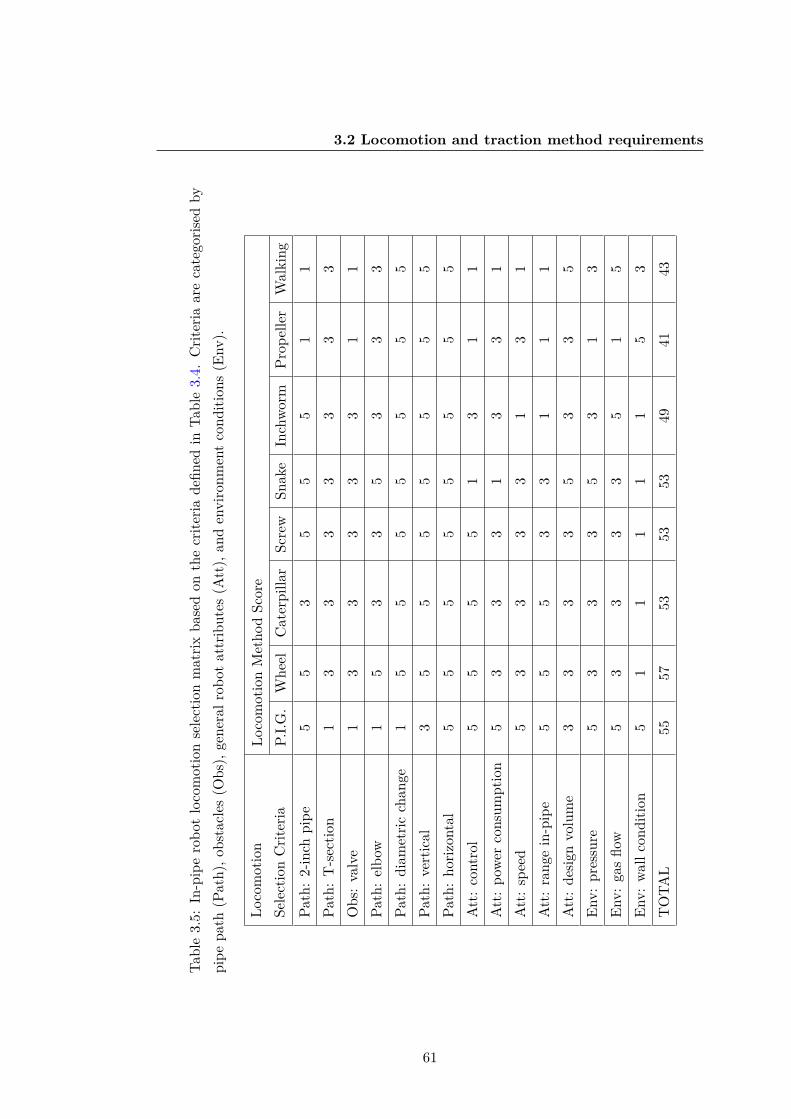
3.2 Locomotion and traction method requirements
Tabl
e3.
5:In
-pip
ero
bot
loco
mot
ion
sele
ctio
nm
atrix
base
don
the
crite
riade
fined
inTa
ble
3.4.
Crit
eria
are
cate
goris
edby
pipe
path
(Pat
h),o
bsta
cles
(Obs
),ge
nera
lrob
otat
trib
utes
(Att
),an
den
viro
nmen
tco
nditi
ons
(Env
).
Loco
mot
ion
Sele
ctio
nC
riter
iaLo
com
otio
nM
etho
dSc
ore
P.I.G
.W
heel
Cat
erpi
llar
Scre
wSn
ake
Inch
worm
Prop
elle
rW
alki
ngPa
th:
2-in
chpi
pe5
53
55
51
1Pa
th:
T-s
ectio
n1
33
33
33
3O
bs:
valv
e1
33
33
31
1Pa
th:
elbo
w1
53
35
33
3Pa
th:
diam
etric
chan
ge1
55
55
55
5Pa
th:
vert
ical
35
55
55
55
Path
:ho
rizon
tal
55
55
55
55
Att
:co
ntro
l5
55
51
31
1A
tt:
powe
rco
nsum
ptio
n5
33
31
33
1A
tt:
spee
d5
33
33
13
1A
tt:
rang
ein
-pip
e5
55
33
11
1A
tt:
desig
nvo
lum
e3
33
35
33
5En
v:pr
essu
re5
33
35
31
3En
v:ga
sflo
w5
33
33
51
5En
v:wa
llco
nditi
on5
11
11
15
3T
OTA
L55
5753
5353
4941
43
61

3.3 Robot Specification
see the predictions for the best performing in-pipe locomotion method. PIG scoresvery highly in the matrix however this method is unusable in unpiggable pipelines, it’shigh score is a testament to how effective this method is in the larger bore, straightpipelines. Wheeled is the highest scoring method as it completes the widest range ofobstacles with the greatest efficiency. Caterpillar tracks are generally high tractioncompared to wheels and avoid slip, they scored on par with both screw and snakelocomotion. Screw is generally useful for slow high traction movement and is coupledwell with wall-press or fluid flow traction, it would not pose much of an advantage withan adhesive traction method. Snake in-pipe robots are often wall-press, but they canuse wall-press whilst avoiding mid-pipe obstacles. This method scores highly as thesnake robots can adapt to obstacles such as plug valves. Inchworms score low becauseversus the other methods due to the slow speed, generally this would be a slow wall-press system, it does not hold much of an advantage when coupled with an adhesivetraction method. Propeller locomotion scores the lowest because of its reliance on thepipe fluid contents, in a water fluid pipeline this method may be feasible however in agas line prop locomotion would have to be based on flight of a drone style system. Thedone would have to constantly fly in to the flow to avoid being blown away, this wouldnot be efficient or feasible. Walking robots are slow systems that provide little benefitversus other methods, within the literature the biggest advantage of a walking robotis the relatively high payloads they can carry. The high payload systems are generallywall-press [18], and would not be suited to adhesion methods.
3.3 Robot Specification
The list of robot requirements can be narrowed further to identify the the essentialproblems. Abstraction of the requirements moves the focus of the problem from manyparticular and small issues to the general and essential in order to lead directly to thecrux of the problem [115]. Defining the key problems ensures that the core functionsrequired of robotic concepts will become clear. By using the tables generated from boththe environmental specifications in Table 2.1, and the locomotion and traction methodTables 3.4, 3.2 the robot requirements can now be refined.
To properly refine the specification the crux of the design will be the reduction ofsize, and power consumption of the robot. This will take precedent over the technicalfunction (obstacle navigation and locomotion), and other focuses such as manufactur-
62

3.3 Robot Specification
ing, cost, and safety (retrievable design). This is the correct focus as the aim is to enterthe small pipelines to enter the larger bores, this will emphasises simple designs withminimal actuators. The robot will enter 2-inch (50.8mm) pipe risers to access largepipelines (50.8mm - 1016mm). The robot could also enter by using the PIG launcheras an entrance to the network, the robot can then enter through the PIG grate andinto the AGI.
Table 3.6: Complete in-pipe robot specification based on the NTS environment analysisand locomotion and traction methods explored in this chapter.
RobotConsideration
Specification
Geometry Cross-section <101.6mmLocomotion Method Wheeled (from Table 3.5)Traction Method Magnetic Adhesion (from Table 3.3)Navigation and Planning IMU on-board for robot orientation
ControlSimple control scheme (standard joystick).Method of steering.
Range>5m (cover distance between riserentrance points)
Speed >1 robot length a secondOperation Time >20 minutes for short operation
CommunicationsLow power Bluetooth or Wi-Fi. Untethereddue to capstan effect of tethers around pipecorners [116].
Electronics and Power<100mAh average current draw to conservebattery life. Rechargeable
EnduranceConstructed of strong plastic, ABS.Resistant to falls and crashes
Environment ResistanceGas flow and pressure resistance to bedeveloped at higher TRL
InspectionOn board camera, with headlights for visualinspection
63

3.4 Discussion and conclusion
3.4 Discussion and conclusion
Detailed environmental information is very important when planning a robotic inspec-tion tool. The information around current AGIs is limited as the nature of the prob-lem requires assessment of the in-pipe environment and condition as it is currentlyunknown. The current knowledge has been gathered from visits to AGIs, visual inspec-tion on NGGT sites, and reports from project GRAID which involved a portion of sitemapping [24]. The information is presented in section 2.4 and is then summarised inTable 2.1. From this research, small 2-Inch access points seem to be the most efficientaccess point due to their common presence on the network and the fact that they can beaccessed above ground. There is the possibility of using a larger robot such as GRAIDand hot-tapping a custom connection point but a hot tap procedure will incur a highcost which increases with diameter of connection.
Section 3.2 explores the use different locomotion and traction methods for roboticmovement in the pipe environment. The traction method selected was magnetic adhe-sion, and the locomotion method was wheeled. The justification for this is that wheeledmagnetic robot will be able to explore ferrous pipelines limited only by the smallestrated diameter pipes it can explore. The robot may not be as effective as a large robotin terms of speed, it could be possible to use the systems in a swarm style to inspectthe large pipes with many small robots at once. A drawback of focusing the designon magnetic adhesion is that it will only be applicable in ferrous pipelines. Lower tierpipelines such as household level gas mains (tier 1) are currently being replaced withPVC. These new non-ferrous replaced pipelines will not be inspect-able with a magneticrobot in the future.
When deciding on the using wireless or tethered communication the pros and cons ofeach were assessed against the chosen robot specification. Advantages of using a tetherinclude; the reliability of the communication, removal of a large portion of electroniccontrol, and indefinite battery life. An issue with tether-less systems is the lack ofa reliable method of retrieval assuming system failure, the robot will likely have arelatively small battery life so range may become a problem. A disadvantage is thatthe tether will be connected to a computer and battery at the launch end and a customvessel would be needed to do this as a tether cannot be breaching the AGI into openatmosphere to reach the operator. As well as this, the weight of the tether will likelyreduce the small robots range as it has to drag an increasing mass, and any corners
64

3.4 Discussion and conclusion
in-pipe will incur, which is why even large tethered systems such as GRAID are onlyspecified to negotiate two 90 bends [116], [26]. The defined robot specification cannow be taken forward into the next stages of development in 4 where the design of themagnetic adhesion traction system and the wheeled locomotion system will be explored.
65

Chapter 4
Design of Magnetic Traction Wheels
66

4.1 Introduction
In this chapter an overview will be given surrounding the magnetic traction to be usedin the wheels, the methods utilised, and the optimisation of magnetic forces in orderto produce a combined magnetic traction and locomotion method. The developed mag-netic wheel will be tested and analysed to determine the most efficient configuration tomaximise magnetic force.
4.1 Introduction
Magnetic traction is one of only a few traction methods capable of allowing a robot totravel normal to surfaces in any orientation in reference to gravity. Others may includeglue [117], Van der Waals force [114], or vacuum suction [118]. Like these other methods,in order for locomotion with these methods to work, contact with the surface mustbe maintained. The major advantage of magnetic traction over these other adhesionmethods in a ferrous pipeline is the reliability and simplicity as determined in Chapter2. Magnets can be introduced into many locomotion methods such as caterpillar,screw, mecanum wheels, and legged devices. The locomotion method defined by therequirements for the robot is a wheeled system. In this chapter the wheeled locomotionwill be combined with the traction method form a magnetic wheel design.
4.1.1 Simplifying in-pipe geometry problems
To understand the requirements needed of the magnetic wheel, the defined in-pipeobstacles problems are reviewed with this traction method in mind. Many of thein-pipe problems can be simplified as wall-press, and hence full bore robots are nolonger needed to generate movement. Plans to tackle obstacles such as T-Sectionshave been shown to require advanced motion planning for robots when using tractionmethods such as wall-press [1]. When tackled using small magnetic traction robotsthese problems can be simplified to just two extreme cases; concave and convex. Thesimplification of standard in-pipe geometry to these convex and concave step casesis presented in Figure 4.1. By completing these two problems without detaching themagnetic wheel base the majority of in-pipe obstacles can be overcome.
67

4.2 Methods of designing a magnetic traction robot
Figure 4.1: Simplification of in-pipe obstacles, reducing the problem to two dimensionalstep-cases.
4.2 Methods of designing a magnetic traction robot
When designing a magnetic robot there are a number of different approaches to consider,these include the method of generating traction, e.g. should the wheel be magnetic orthe robot body? How many magnetic contact points should be used? Will the robotbe stable? What type of locomotion should be used? In this section standard methodsof magnetic wheel design as well as chassis stabilisation methods will be explored.
4.2.1 Magnetic wheel design
There are four different types of standard magnet wheel configuration as seen in theliterature. As shown in Figure 4.2, these are the standard ring magnet (A), outermagnet placement wheel (B), shielded magnet array (C), and magnetised chassis (D).Of all of these methods, method A is the least common in the reviewed literature,designs B - D have multiple examples of use with slightly different methods howeverthe principle is the same. Method B has been used to create wheels with magnets placedon the outer tread rather than the dual flux plate design to inspect vessels [119]. The
68

4.2 Methods of designing a magnetic traction robot
A B C D
Figure 4.2: Types of magnetic wheel design; standard ring magnet (A), outer magnetplacement wheel (B), shielded magnet array (C), and magnetised chassis (D).
dual plate design (C) with an interior ring magnet has been used to create a robot thatclimbs walls and ceilings [120]. Multiples of this style of magnet wheel have been placedin parallel to make a large wheel unit for adhesion with only thin ferrous wall thickness[121]. This design has even been used with removable shielding pins to create novelwheels that allow easier detachment of high magnetic forces. [122]. This configurationis extremely similar to a common pot magnet, which are commonly created and soldto increase the strength of magnet without increasing the size and cost of the magnetitself. The non-magnetised wheel design (D) uses magnets in the surrounding (andnon-rotating) chassis to generate traction at the wheel by applying pressure throughthe chassis attachment point to the wheel. This method has previously been usedwith rubber wheels with external magnetic platform surrounding it [104] and also fora water-jet cleaning robot [105].
An advantage of using magnetic traction is that wall-press methods do not need tobe used. This means that a magnetic robot does not need to be the size of the full pipebore and can actually be many times smaller than the pipes diameter and still be ableto freely move in any orientation. Being many times smaller than the pipeline givesthe robot a great advantage in that in-pipe geometry problems such as those in Figure2.1 can be simplified greatly, an example of how different problems can be simplified isgiven in Figure 4.1.
69

4.2 Methods of designing a magnetic traction robot
H I J K L M N
A B C D E F G
Figure 4.3: Different possible magnetic skeleton chassis frames for in-pipe magneticrobots.
4.2.2 Chassis traction design
Figure 4.1 also show the robots climbing around step cases in different orientationsboth against and with gravity and even upside down. The robot will have to remainstable in all of these configurations to safely complete an inspection without becomingimmobile. In order to complete the step cases in any orientation, the robot magneticattachment points should be considered, more magnetic points will make the robotstable but also harder to move and less manoeuvrable. Some possible magnetic chassisskeletons for in-pipe robots are presented in Figure 4.3. These attachment points arenot necessarily actuated wheels, as some will just provide extra stability in the caseof the robot being held in orientations against its own weight in any reference plane.Non-actuated contact points can be free rolling bearing wheels, or even ball bearings.
The simplest skeleton is presented in Figure 4.3.A, with just one point of contactthe robot would be unstable in all directions. Magnetic frame B and C are stable whenvertically travelling up a wall however when driving on a 90 wall horizontally will fallas they are free to rotate around the tow points of contact axis. D with three points ofcontact is the minimum to become stable in-pipe. Common four-wheeled vehicles tendto use the magnetic wheels as the traction frame and hence would use H and I style.Caterpillar systems with multiple points of magnetic contact would use styles M or G.
70

4.3 Magnetic wheel requirements and specification
As more magnetic attachment points are added to the base frame manual detach-ment of the robot from an inspection point may become a concern. Typically a launchpad must be used to transfer a large magnetic robot from one point to another [26].Detachment is not a concern for a robot at this specified size of sub 100mm, the robotcan simply drive onto a carrier plate in the launcher.
4.3 Magnetic wheel requirements and specification
Based on previous in-pipe and out-pipe magnetic research and robotic examples therequirements for the robot have been defined. Important factors for magnetic wheels ona small in-pipe robot are presented in Table 4.1 as desired features with accompanyingdescriptions and associated design requirements.
4.4 Design and assembly of the magnetic wheel
To fit the requirements, the overall design of the wheel will follow the shielded magnetarray design outlined in Figure 4.2.C. Permanent rare-earth neodymium magnets arecurrently the strongest permanent magnets in terms of magnetic field intensity (Gauss)available [124]. Neodymium magnets are ranked in strength by their maximum energyproduct from grade N35 to N52 where the number after ”N” represents the strengthwith the highest value relating to the strongest magnet. The grade used in the wheeldesign is N42 which is the most widely available, N52 magnets are stronger but notwidely available in many sizes.
To direct the strength of all magnets into the wheel contact area they will be heldbetween two steel plates that redirect the flux to the wheels contact point. The arrayconfiguration will also protect the magnets as they are susceptible to corrosion, andtheir increasing brittleness with increasing strength grade.
The shape is circular, this is the most common magnet shape and allows for densepacking of magnets in the array. The wheel flux plate radius is 16mm for a total of32mm diameter and the inner mountable area radius is 7.5mm. This restriction comesfrom the workspace available in a 50.8mm pipeline and leaves 8.5mm of space for eachmagnet. The diameter of the magnets is 6mm allowing 1mm clearance from the outerwheel contact area to the spacer, and allowing 1.5mm for the spacer. The rated pullsof the 2mm, 4mm, and 6mm length magnets used in the wheel have respective pull
71

4.4 Design and assembly of the magnetic wheel
Table 4.1: Requirements for the robots magnetic wheel design.
Desired feature Description Design requriement
Protectedfrom impact
Rare earth magnets arebrittle and prone to shatteron direct contact.
Magnets should notcome in direct contactwith steel pipe
Uniform contactforce at all points
Force should be the sameat all points for completingconcave and convex casesno matter the wheel angle.
Magnetic force shouldbe stable throughoutrotation
Mountableaxis geometry
Wheel needs to be mountedeasily onto a shaft.
Non-circular shaftmount geometry.
Thin profileWheel should be ascompact as possbile tofit in the pipeline.
No unnecessaryextremities.
High wheelmagnetic forcedensity
Wheels force should begreater the robot totalweight in a compact space.
High-force densitymagnets. Such asrare-earth magnets.
Shieldedfrom corrosion
Rare earth magnets arebrittle and prone to shatter ondirect contact [123]
Protective casing orcoating.
High friction
Magnets need a highfriction co-efficient to togenerate traction of smoothsteel surfaces.
Rubber materialcoating.
Balancedmagnetic forceand wheel torque
Magnetic force of the wheelmust be balanced with the motortorque so not to stall in theworst case (double contact).
Rubber coating mustreduce wheel magneticforce to overcome rightangle double contact.
72

4.5 Magnetic wheel experimentation
A B C D E F
Figure 4.4: Different design for the mountable wheel hub built into the magnetic fluxplates. A: D-Shaft. B: Hex. C: Multiple D-Shaft. D: Key. E: Nucleus. F: Triangular.
strengths of 0.73kg, 1.1kg, and 1.4kg, as stated by the manufacturer [125]. The heightof the magnets is variable to allow for modifying the wheel strength. The hub design formounting the magnets is the triangular method shown in Figure 4.4.F, the advantageof this design is the subtle transition from circular to triangular, maximising space formagnets on the array.
The number in an array is variable, the maximum number of 6mm diameter magnetsthat could possibly fit in the 32mm wheel is 12 but for the purpose of allowing structuralsupport in the magnet spacer and stop magnet movement during wheel use the numberof magnets in the array will be set to 6. An example of a two magnet wheels using5mm flux plates is shown in Figure 4.5, one with an array of 6 magnets, and the otherwith an array of 3.
4.5 Magnetic wheel experimentation
All magnetic wheel experimentation has been completed with the Mecmesin tensiletesting machine with a 1000N load cell of model: ”MultiTest 5-i - Intelligent LoadcellILC-S” [126]. The load cell has an accuracy of 0.1% full scale (1N). The diagram inFigure 4.6 shows the complete set-up used. The data for each type of experiment waslogged directly from the load cell to the computer and then analysed in MATLAB. Foreach experiment the input program written to perform it is presented in a table withineach subsection.
4.5.1 Normal force
The normal force is the reactive force caused by the attraction of the magnet to thesteel, this force is highest when the wheel is in direct contact with the steel. To test
73

4.5 Magnetic wheel experimentation
6 & 3 Magnetarray on flux plate
3D printedmagnet spacer
Opposite poleflux plate
6
3
Figure 4.5: Components of the magnetic wheels ready to be assembled for a 5mm fluxplate, 6mm length x 6mm diameter x 6 magnet array.
the peak normal force at this point the wheel is loaded into the custom rig and lockedin position on the wheels drive shaft. The drive-shaft consist of a 3D printed profilethat matches the triangle profile of the wheel in Figure 4.4.F. The shaft houses twobearings which sit on a 5mm stainless steel non-ferrous rod. The rotation of the wheelis locked in place with a grub screw inside a shaft collar which is embedded in oneside of the shaft. For tests where rotation is necessary the grub screw can be loosenedallowing free rotation on the bearings about the central steel shaft. The test programparameters for the normal force wheel experiments are presented in Table 4.2
Flat plate
The pull force of the wheel peaks around 82N in Figure 4.7, just before contact is made,as the wheel is pulled back it loses half of its force in around 0.06mm. When comparedto a regular N42 disc magnet which is unshielded by flux plates and open to the air thepull force is halved around 0.7mm.
Figure 4.8 shows an increase in peak force for magnetic wheel arrays when the fluxplate thickness is increased. An increase in plate thickness increases the maximumamount of magnetic flux that can be channelled from the array to the contact point.
74

4.5 Magnetic wheel experimentation
Steel block with !lat, concave,
and convex edges
Interchangeable
magnet wheel mount
Magnet wheel
attachment rig
Wheel rotation lock
1000N Load cell
Magnet wheel test piece
Figure 4.6: Diagram of the magnetic wheel test rig set-up.
75

4.5 Magnetic wheel experimentation
Table 4.2: Test program used in the Mecmesin tensile tester to produce normal forceresults.
CommandLinear stage speed(mm/min)
Target Value Target Unit
RUN -6.00 0.00 Load (N)ZERO DISPLACEMENT 0.00 N/ACLEAR DATA 0.00 N/ARUN 30.00 5.00 Displacement (mm)RUN -30.00 0.00 Displacement (mm)
CYCLE X56.00 2.00 Displacement (mm)-6.00 0.00 Displacement (mm)
END
Magnetic heel ormal orce over 5mm665A w n f on flat plate
Peak wheel normal force
Bearing Compression
0 0.5 1 1.5 2 2.5 3 3.5 4 4.5 5
Horizontal Displacement (mm)
0
10
20
30
40
50
60
70
80
90
100
Fo
rce
(N
)
Magnet Wheel 665A
10x5x5 N42 Disc Magnet
Figure 4.7: Standard magnet pull test over a 5mm range for both a regular N42 discmagnet, and a magnet wheel array.
76

4.5 Magnetic wheel experimentation
Differing Magnet Thickness 3mm Plates
Magnet Wheel Configurations
0
10
20
30
40
50
60
70
80
90
100
Forc
e (
N)
Differing Magnet Thickness 5mm Plates
Magnet Wheel Configurations
0
10
20
30
40
50
60
70
80
90
100
Forc
e (
N)
2mm Array 4mm Array 6mm Array 2mm Array 4mm Array 6mm Array
263A 463A 663A 265A 465A 665A
Figure 4.8: Mean force for various wheel configurations (force +/- SD)
For smaller force magnets such as the 2mm array the maximum flux output from themagnets is already being held by the steel plate and so the force will no longer increasewith an increase in steel thickness. Tests using the 6mm magnets with 5mm plates ada 6 magnet array (665) will be used to ensure the maximum wheel load is used in thetests to use the most range on the 1000N load cell.
Magnet array alignment
For robot operation when traversing concave and convex step cases the magnetic forceat points along the wheels circumference should be as uniform as possible. A uniformfield allows the wheel to be predictable in its behaviour, for each case. A non-uniformwheel may be harder or easier to move from a double contact concave case dependingon the specific point in contact, this could change for each obstacle. To investigatethe possibility of the gaps between the magnets in the array causing force changes twowheel configurations were tested with an array of 6 and an array of 3 magnets. Figure4.9 shows the results of the alignment test. The misaligned six magnet array (665A)wheel configuration showed a drop of 0.3N from 82.9N, a 0.4% drop in force. Themisaligned three magnet array (635A) dropped in force from 44.2N to 42.5N resultingin a 3.8% drop in force.
77

4.5 Magnetic wheel experimentation
Normal Force for Aligned Magnet Array vs Misaligned
Magnet Wheel Configurations
10
20
30
40
50
60
70
80
90
100
Forc
e (
N)
Error (STD)
665AAligned
635MMisaligned
635AAligned
665MMisaligned
All 5mm flux plates
All magnets 6x6mm
665MMisaligned
635AAligned
635MMisaligned
Magnet WheelConfiguration Key
665AAligned
Figure 4.9: Comparison of the effect of wheel magnet array rotation angle on the peakforce produced by the wheel for both a three and six wheel array.
Concave case
The concave pull case takes place in free rotation to simulate the robot overcoming theconcave case where the peak force occurs just after the double contact case has beenbroken. The parameters used in this test are present in Table 4.3. The peak force ofthis case is around 56N, compared to the peak force of 83N that the 665A wheel seenon a standard flat plate. The graph 4.10 shows that in double contact the force of thewheel at both contact points drops to 67% of the peak force on a flat plate.
78

4.5 Magnetic wheel experimentation
Table 4.3: Test program used in the Mecmesin tensile tester to produce concave results.
CommandLinear stage speed(mm/min)
Target value Target unit
RUN -6.00 0.00 Load (N)ZERO DISPLACEMENT 0.00 N/A N/A
CYCLE X56.00 3.00 Displacement (mm)-6.00 0.00 Displacement (mm)
END
0 0.1 0.2 0.3 0.4 0.5 0.6 0.7 0.8 0.9 1
Horizontal Displacement (mm)
0
10
20
30
40
50
60
Forc
e (
N)
Average c c p o for free to roll wheel (665A)oncave ase ull ff
Bearing Compression
Figure 4.10: Graph of the force to pull a free rotating magnetic wheel from a rightangle concave case where the wheel is in double contact.
Convex case
Graph 4.11 shows the averaged force over five reps for a wheel in free rotation movingfrom a flat 90 wall up to a 90 corner case. The red highlighted area represents thewheels approach up to the corner case. During this section the wheel is rolling withpeaks and troughs caused by impurities in the steel plate. The force increases as itapproaches the corner section, this is because the magnetic force is acting towards thefull contact steel area. The force decreases to a minimum as it reaches 45 to the corner,and then increase as it is pulled from the steel up to the point of corner contact breakwhere the force drop drastically back to open air levels and then tapers to negligible
79

4.5 Magnetic wheel experimentation
levels.
Table 4.4: Test program used in the Mecmesin tensile tester to produce convex results.
CommandLinear stage speed(mm/min)
Target value Target unit
RUN 30.00 0.00 Load (N)RUN -30.00 15.00 Displacement (mm)ZERO DISPLACEMENT 0.00 N/A N/A
CYCLE X530.00 15.00 Displacement (mm)-30.00 0.00 Displacement (mm)
END
0 5 10 15
Horizontal Displacement (mm)
0
2
4
6
8
10
Forc
e (
N)
Average for a 665AConvex Case Pull Off of Freely Rotating Wheel
Corner Approach
Corner Contact
Figure 4.11: Graph of the force to pull a free rotating magnetic wheel from a 90 wallup to a convex corner case, and then detach from the corner case.
4.5.2 Increasing friction
To assess the maximum traction that can be generated by the wheel the wheel waslocked in place to stop rotation and dragged along the steel surface. From the peakdrag force and the known normal force the co-efficient of friction can be calculated andapplied to wheels of other normal force values.
Figure 4.12 shows 4 reps of pulling the magnetic wheel in steel flux plate on steel
80

4.5 Magnetic wheel experimentation
Table 4.5: Test program used in the Mecmesin tensile tester to produce concave results.
CommandLinear stage speed(mm/min)
Target value Target unit
RUN -6.00 0.00 Load (N)ZERO DISPLACEMENT 0.00 N/A N/A
CYCLE X56.00 3.00 Displacement (mm)-6.00 0.00 Displacement (mm)
END
0 0.5 1 1.5 2 2.5 3 3.5 4 4.5 5
Horizontal Displacement (mm)
0
5
10
15
20
25
30
Fo
rce
(N
)
Vertical wheel pulllocked (665A) : non-coated steel on steel
R1
R2
μs
μ regionk
Wheel rotationon mount shaft
R3
R4
Figure 4.12: Graph showing the force to pull a rotation locked uncoated magnetic wheelacross a steel contact.
plate contact The highlighted curved movement at the start of loading is caused byslack in the shaft allowing the wheel to rotate slightly before being pulled completely.The mean average of the pull test peaks in 4.12 is 22.6N, using this as the frictionalforce the co-efficient of friction in equation 4.3.
Ff = µs ·N (4.1)Ff
N= µs (4.2)
22.682.9 = 0.27 (4.3)
The rubber material used is ”Plasti-dip: Plastic/Rubber Paint”, this material ispainted onto the wheels as a liquid, it contracts as it dries forming a tight rubber
81

4.5 Magnetic wheel experimentation
Rubber coating normal force at different points on the wheel
Angle of wheel during testing (°)
0
10
20
30
40
50
60
Forc
e (
N)
0° 90° 180° 270°
0°
90°
180°
270°
Rubber coated magnetwheel array
Figure 4.13: Bar chart showing the average pull force for a 665A wheel at four differentpoints around the wheel in both aligned and misaligned conditions.
seal. The rubber seal increases the friction co-efficient of the wheel as it acts as atire between the magnet and the steel contact point, there is also the added benefitof sealing the rare-earth magnets from corrosion. Because of the small distance atwhich the wheels magnetic force is affected any frictional material application shouldbe considered against the maximum normal force. The peak force of the wheel with itsapplied rubber coating was experimentally tested at four different points around thewheel, the results are displayed in Figure 4.13, the mean force of the contact pointsaround the wheel is 51.9N.
The rubber coated wheel was tested in the same way as it was before coating. Theforce increases until the wheel begins to move, it then steadily rises under static move-ment, this is likely due to slight temperature increases in the wheel as it is undergoingsliding friction. Each subsequent test the force of the wheel increases slightly, this isbecause the rubber material wears after each test as seen in Figure 4.15. The force ofthe first pull test before wear is used to calculate the frictional co-efficient (19.4N).
µs − rubber19.427.4 = 0.71N (4.4)
82

4.6 Discussion and conclusion
0 0.5 1 1.5 2 2.5 3 3.5 4 4.5 5
Horizontal Displacement (mm)
0
5
10
15
20
25
30
Forc
e (
N)
Vertical locked wheel pull: rubber coated(665A) on steel
μsμ regionk
Wheel rotationon mount shaft R1
R2
R3
R4
Figure 4.14: Graph of the force required to pull the rubber coated magnet up the steelblock with the axle locked in contact at the 180 mark in4.13.
4.6 Discussion and conclusion
This section will review the chosen design of the magnetic wheel against the initialrequirements put forward in the beginning of the chapter.
The flux plate magnet array configuration can produce contact forces equal orgreater than the sum of the magnet arrays combined pull force under normal circum-stances the wheel produced maximum pull forces of 82.9N whereas the manufacturersrated pull force of the 6x6mm N42 magnets produce 13.73N each, six of these shouldproduce a pull force of 82.38N. To review the uniformity of the magnetic force of thearray wheel an experiment was conducted in which the alignment of the array wasaltered. When a magnet wheel is uncoated and the contact is steel on steel there isa minor change in contact force when the wheel magnets are directly aligned vs whenthey are misaligned. The drop in force is small enough to be negligible when the mag-nets are misaligned with the contact point, however it is more pronounced when thearray is spaced further apart. For robotic traction the rubber coating has a larger ef-fect on the wheel contact uniformity than alignment, even a small thickness differencein a thin coating of 0.06mm can cause the maximum force to drop to half of the toprated pull force so minor thickness differences in the outer rubber coating will effectthe wheel more than the 0.4 - 3.8% drop in force observed in the experiment. Figure4.7 showed that the designed magnet wheels have a concentrated but shallow magneticfield around the contact area of the wheel. The larger reaching field of the disc magnet
83

4.6 Discussion and conclusion
Rubber contact wear after multiple sliding tests
Figure 4.15: Wear of the rubber coating showing after five repetitions of friciton testingon the linear force tester.
took over 10 times the displacement to reach 50% of it’s maximum pull force. Thismeans higher force of the array design can be negated in a very small distance duringconcave cases allowing simple detachment of the wheel in double contact. A negative ofthis is that very small amounts of high frictional coating will cause the wheel tractionto fall quickly versus a standard magnet design. This means an array configurationwheel needs a higher starting design force to reach the same coated normal force valueas a standard magnet.
To create a thin profile wheel to entire pipelines the flux plate and magnet arrayprofile has been chosen. Other options included chassis magnet arrays which were largeand not viable for corner cases. The number of magnets in the array can be increasedby optimising the 3D-printed spacer, more magnets in the array will give the same forcefor a smaller profile. The thin profile of the wheel will be combined with a transmissionmethod on the main shaft whether it is a direct drive or a geared connection. Thedrive transmission method will require mountable geometry, the chosen axis geometryis triangular to reduce the loss of plate material, and to allow 3D printing of shaftswithout the need for sharp edges.
The flux plates shield the magnets both from impact and potential corrosion. Therubber track coating of ”Plasti-dip” further increases protection of the magnets fromcorrosion by sealing the gap between the 3D printed magnet array spacer and the innerflux plate magnet contact point. The frictional co-efficient has been increased withthe use of the applied rubber coating, the frictional co-efficient µs increased from 0.27
84
4.6 Discussion and conclusion
to 0.71. The force frictional forces need to move both the steel and rubber wheelswere very similar in terms of traction however the rubber wheel is far superior as itprovides a reduced detachment force needed in a concave double contact case. Thislower detachment force requires lower motor torque to overcome and hence smallermotors on the robot. The wheel coating takes four hours to dry in total so replacementof wheel tread after inspection use is not an issue, multiples should me made beforehandto replace during deployments.
The wheels designed in this chapter will be used in the further design and develop-ment of the magnetic robot in Chapter 6.
85

Chapter 5
Embedded System and Software Design
86

5.1 Introduction
This chapter looks at the electrical systems to meet the robot specification criteria laiddown in Chapter 3. The chapter will explore the use of actuators and control methodsto drive the magnetic adhesion wheels designed in Chapter 4. The wireless communic-ation method between a high level and low level robot controller will be defined, and anoptimised command protocol will be developed.
5.1 Introduction
The work in this chapter is focused on the development of a complete open-loop controlprogram that interacts with a robot micro-controller. The specifications and require-ments for the desired features of the control program are set out for both the hardwareand software.
5.1.1 System requirements
The system requirements for the robotic control software are defined in Table 5.1 andrequirements for the robots hardware design are presented in Table 5.2.
87

5.1 Introduction
Table 5.1: Major requirements of the software control features
Desiredcontrol feature
Description Software requirement
Highlycontrollable
Robot should capable offorward, reverse, turn onspot, turn slowly to adjustwheel contact in a corner.
An input control method thatmaps pilots actions to motorcontrol messages.
Simpleoperation
The robot software shouldbe simple to use and therobots actions should bepredictable based on inputs.
Intuitive control scheme,that allows control overthe robot with minimal training.
Wirelesscommunication
The robot has beenspecified to operatewithout a tether.
Message output from control PCthat can be read and executed byrobot software (two programs)
Low latencybetween inputand execution
For smooth control of therobot low ping betweeenthe controller pilot and themicro-controller is required.
Minimal message package sizebetween communicating systems.Optimised send/receive speed.
88

5.1 Introduction
Table 5.2: Major requirements of the hardware system
Desired hardwarefeature
Description Hardware requirement
Small physicalpackage
The electronic hardware shouldbe as small as possible to fit therobot pipe entrance requirements.
Advanced micro-controllersand control boards withminimal breakout pins,stacked to minimise volume.
Wirelesscommunication
The robot has been specified tooperate without a tether.
Integrated robot controllerand wireless communicationdevice.
Skid steeringRobot will use skid steering tosimplify locomotion and reducedesign volume.
Dual-motor drive systemable to perceive commandsfrom the micro-controller.
Low powerconsumption
The robot will require a battery(wireless) and hence powerconsumption should be keptminimal to increase battery life.
Power consumption ofcomponents should beconsidered when selectinghardware.
User controlof hardware
The user should be able to controlthe robotic hardware with minimaltraining using simple controls.
Standard joystick such asXbox 360 controllerwhich is widely used.
To achieve these requirements, the specific objectives are:
• Define the hardware to be used in the system to be embedded within the micro-controller robot.
• Develop an open-loop control program to communicate with a wireless micro-controller.
• Develop a slave micro-controller program to receive information from the main pro-gram and react accordingly
89

5.2 Hardware
• Assess the open-loop system against the requirements.
5.2 Hardware
The high level hardware used is presented in Figure 5.1. A laptop PC, runs the mainprogram and is also used to communicate with the robot hardware over Bluetooth.The graphical user interface runs on PC to pilot the robot, using a Microsoft Xbox 360controller (wired or wireless). The PC communicates with the robotic micro-controllerusing wireless transmission over Bluetooth. The main program is built using LabVIEWdeveloped by National Instruments. LabVIEW was chosen as the programming lan-guage due to it’s simple methods of hardware interface. The micro-controller robots areprogrammed using the arduino IDE, the language is predominantly C, and C++. Abreadboard for the development of the prototype robot circuit is powered via a 300Wpower supply.
C
A
E
D
B
Figure 5.1: A: Laptop PC with Bluetooth built-in. B: USB Xbox controller receiver.C: Xbox 360 wireless controller. D: 300W power pack. E: Robot electronics prototypebreadboard.
90

5.2 Hardware
5.2.1 Robot Micro-Controller
The most popular micro-controllers for sub 100mm robots are summarised in 5.3. TheArduino Pro Mini series is a condensed version of the 328 chip from an Arduino UNOminus the unnecessary peripherals, they are a well supported device with many librarieswhich helps development speed. The Teensy 3.2 has the disadvantage of requiring avoltage regulator to function. This is because the 2 cell lithium polymer (LiPo) batteryrequired to power the 6V motors runs at 8.4 volts at its highest charge and the Teensy3.2 is only 6V tolerant. Compared to the Arduino Pro Mini which can take a maximumof 12V board supply it only offers a mild inconvenience vs the the speed which is upto 12 times faster in the 3.3V version, and 6 times as fast as the 5V board. The ESPand the Teensy 3.6 are both simply too large to warrant development despite the fasterspeed processing. Based on this, the Teensy 3.2 is the most suitable selection for finaldevelopment.
Table 5.3: Micro-controller options considered for robot development comparison table
Micro-controller Voltage Clock Speed (MHz)Size (mm)x y
Arduino Pro Mini 3.3 8 33.00 18.00Arduino Pro Mini 5 16 33.00 18.00Teensy 3.2 3.3 96 35.00 18.00ESP32 3.3 160 55.00 28.00Teensy 3.6 3.3 180 62.30 18.00
5.2.2 Communication
Communication will be wireless, the most commonly used Bluetooth and Wi-Fi moduleswere compared in Table 5.4. The power draw stated is the consumption during constantcommunication, as this communication line is intended for piloting it will be constantlyopen and hence near this maximum value throughout the robots deployment. TheBluetooth model was chosen rather than Wi-Fi despite its larger size due to the lowerpower consumption for similar in maximum baud rate. Battery size is limited, soreduction of power consumption will ultimately increase inspection time. The Bluetooth
91

5.2 Hardware
SMIRF Gold module is rated for transmission distances up to 100m.
Table 5.4: Comparison table of bluetooth vs wifi
Wirelessmodule
Inputvoltage (V)
Powerdraw (mA)
Baud ratemax (bps)
Size (mm)x y
BluetoothSmirf Gold
3.3 - 6.0 40 115200 45.0 17.0
Wifi ModuleESP8266
3.0 - 3.6 215 115200 25.0 14.5
5.2.3 Actuation and Power
DC motors are the most suitable actuators to drive the robots wheels as they are simpleto control versus stepper motors and do not have limited range of servos. The DC motorused is the 6V (Micro Metal Gearmotor) manufactured by Pololu, these are driven by aPololu TB6612FNG dual motor driver with a Pulse Width Modulation (PWM) signalfrom the micro-controller. There low and medium voltage versions of these motors inboth 12V and 6V, however the power rating for each is the same. The 12V require a3S LiPo (11.1V) battery increasing the size.
The selection of these motors was based on the price and versatility, there are manydifferent motor gear ratios which produce different torque values, as shown in Table5.5. The motors, including the gearboxes are all the exact same dimension size (10mmx 12mm square face) except for the 1000:1 motor which has an extended gearbox. Theuniform dimensions make the motors switch-able between prototype versions dependingon required torque and speed. Motor selection has the greatest subsequent effect onbattery selection. The battery is required to supply 6V, through a 2S Lithium Polymer(LiPo). The 2S LiPo was selected to be a Turnigy nano-tech 2S 260mah battery. Theserun at 7.4V but can be modulated to 6V with PWM.
5.2.4 Circuit Integration
The components are integrated into the development breadboard and wired into acomplete circuit. In Figure 5.2 the complete circuit on intended for embedding into the
92

5.2 Hardware
Table 5.5: Micro Metal Gearmotor selection table: High-power 6V precious metalbrushed [27]. All gear ratios ar erated to 1.6 Amp stall current and and No-loadcurrent of 0.07 Amps.
No-load speed (RPM) Stall torque (kg/cm) Max power (W) Gear Ratio6000 0.11 - 5:13000 0.22 1.6 10:11000 0.57 1.5 30:1590 0.86 1.3 50:1410 1.3 1.4 75:1310 1.7 1.3 100:1210 2.4 1.2 150:1150 3.0 1.1 210:1120 3.4 1.1 250:1100 4.0 1.1 298:184 5.5 1.1 380:131 12 - 1000:1
93

5.2 Hardware
VINGND
RX
TX
2
3
4
5
6
7
8
9
10
11
12
AGN
3.3V
A9
A8
A7
A6
A5
A4
A3
A2
A1
A0
13
A1
4
PR
G
GN
D
3.3
V
Vb
a
3.3V
3.3V
GND
GND
+VE
-VE
PWMA
AIN2
AIN1
STBY
BIN1
BIN2
PWMB
GND
GND
VCC
A01
A02
B02
B01
VMO
GND
+VE
-VE
RTS
RX
TX
3.3V
CTS
GND
SHD
VIN
GND
5V
7.4V
GND
470Ω
1kΩ
Motor Driver TB6612FNG
MicroMetalMotorB
MicroMetalMotorA
Bluetooth SMIRF Gold
V R
eg
S7
V9
A
LilyPad LED 1&2
Teensy 3.2
26
0m
Ah
LiP
o
Micro USB Serial
Figure 5.2: Diagram of the integrated circuit.
robot is presented. This circuit contains features such as the LiPo battery pack whichreplaces the bench power supply.
Not shown in the diagram is a separate first person view (FPV) camera circuitmounted on the robot. This camera is separate due to its requirement of 3.3 volt powerwith high current draw that cannot be provided by a Teensy output. The two resistorsin the circuit in Figure 5.2 form a potential divider. The divider reduces the 8.4 voltssupplied by the battery down to a range that is sub 3.3 volts that can be read by bythe logic pin (A0) on the Teensy. The equation used to the choose the potential dividerresistor values is given in equation 5.1.
94

5.2 Hardware
Vout = Vs ·R2(R1 +R2) (5.1)
Where: Vs = Voltage source (V)R1 Resistor value 1 (Ω)R2 Resistor value 2 (Ω)Vout Voltage out (V)
VP inBatteryMax = 8.4 · 470(1000 + 470) = 2.686 (5.2)
VP inBatteryMin = 6.6 · 470(1000 + 470) = 2.11 (5.3)
The power going through the resistor voltage divider is calculated in equation 5.7,the result of 32mW through 1kΩ resistor is safe as it is below the standard safety ratingfor a 1
16 Watt (62.5mW) power rated resistor. The power through the 470Ω is even less.
V
RSum= I (5.4)
8.41470 = 0.00571A = 5.71mA (5.5)
I2 ·R = P (5.6)
0.005712 ∗ 1000 = 0.032W = 32mW (5.7)
The maximum input voltage that is required to be read is 8.4V, which is reduced to2.686V (5.2) on the analogue pin through the potential divider. The minimum voltageat which it is safe to re-charge a LiPo is at 3.0V per cell, beyond this point the batterymust be disposed of as battery integrity is compromised.
This must be prevented as a battery failure will cause the robot to shut-down andbecome uncontrollable in an inaccessible location. To prevent the charge from droppingto this minimal value a battery warning system is in place should to indicate when thebattery reaches un-safe levels, it is set to 3.3V per cell (6.6V total). This value is shownto be at 2.11V on the analog pin (5.3). The completed hardware package embedded inthe robot is shown in Figure 5.3. This completed hardware stack is just 45mm x 18mmx 14mm (excluding motors LEDs and battery).
95

5.3 Open loop control system
Motor Driver TB6612FNG
Teensy 3.2
Bluetooth SMIRF Gold
V Reg S7V9A
260mAh LiPoLilyPad LED 1&2
MicroMetalMotorB
MicroMetalMotorA
Figure 5.3: Diagram of the assembled robot hardware circuit to be embedded in amechanical system.
5.3 Open loop control system
The open loop control software developed in this section is designed to interface withthe hardware circuit to produce robot motion from user inputs. The high level overviewof the control system used is presented in Figure 5.4. The intended close loop conditionis for the human driving the robot to make changes based on their visual feedback.The visual feedback will be provided either by line of sight or by the first person viewcamera on the separate control circuit.
This section will explain the software system architecture in greater detail. Agraphical representation of the system architecture and brief overview of how the twoindividual programs is shown in Figure 5.5. In this set-up the LabVIEW program actsas the higher level controller, sending user driven commands to the lower level robotmicro-controller.
5.3.1 High level control: LabVIEW
LabVIEW is the chosen high level programming language because it excels in hard-ware integration. This allows easy access of multiple input devices for human use suchas COM Port integration, keyboard and gamepad input devices, and PC Bluetooth
96

5.3 Open loop control system
Xbox 360
Controller User Inputs
Keyboard
Robot Hardware
& Motor Driver
Motor
Speed
Direction
String
Bluetooth Serial
Transmission
LabVIEW
PC Program
Digital
Outputs
PWM
Signals
Motor movement
and robot
wheel actuation
Figure 5.4: Diagram of the high level control system used to develop the robot software.
integration. LabVIEW also makes the creation of functional GUI’s simple to integ-rate into a program, this is advantageous when using human pilots that require visualfeedback. The developed LabVIEW program uses state machine architecture with fourmain states; initialise, write, read, and shut-down. The LabVIEW program has fourstates in which the program operates, these run one at a time, at the end of each statea decision is made on which state to progress to.
Initialisation and stop states
The first state initialises the program, this is completed through user input. The userinputs commands into the GUI that are then loaded into the programs main datacluster, the parameters available to alter are presented in Table 5.6. The robot clusterarray functions as the spine of the program and provides a constant data stream fromwhich information is pulled, altered, and loaded. The robot cluster array is constantlyupdated throughout each section of the program loop. Disabling features such as ”SerialRead?” are used to decrease program load when many robots are connected as the readfunction takes up the most time within the program.
The program then connects to the robot Bluetooth radio, Bluetooth SMIRF radiodevices have two COM ports, one for sending and one receiving. Only one COM port isrequired on the LabVIEW end in order for bi-directional transmission to work though,
97

5.3 Open loop control system
Send
Serial
Laptop PC: LabVIEW
Keyboard
or Joypad
FPV Display
Goggles
Update
GUI
Receive
Serial
Decode
Serial
Receive
Inputs
Encode
Inputs
Send
Serial
Receive
Serial
Decode
Inputs
Execute
Commands
Encode
Data
Read
Analog Pins
Motors
Headlights
FPV
Camera
Robot Micro-Controller
Input
Output
Process
Network
System
Architecture
Figure 5.5: Overall system architecture including simplified LabVIEW and mirco-controller programs.
98

5.3 Open loop control system
Table 5.6: Cluster array elements that store each individual robots data and configur-ation settings.Cluster ArrayItem
Clusterdata type
TypicalValue
UserInitialise
Item Description
COM Port Integer 0 - 255 INPUTRadio COM portto connect to
Radio COMStatus
Boolean 0 - 1 INPUT Radio connected or not?
Radio I.D. String 7BA5 INPUTDefine radio I.D.to connect (4 characters)
Radio Connect Boolean 0 - 1 OUTPUTWas radio connectionsuccessful?
Serial Write? Boolean 0 - 1 INPUTWrite commands tothis radio?
Serial Sent Character [20] OUTPUTSerial sent byLabVIEW
Serial Read? Boolean 0 - 1 INPUTRead data fromthis radio?
Serial Received Character [20] OUTPUTSerial received byLabVIEW
Baud Rate Integer 9600+ INPUTUser defined baud ratefrom 9600 to 115200 (BPS)
COM Speed Integer 0 - 60+ OUTPUTCalculated robotCOM speed (Hz
Bits Recieved Integer 0+ OUTPUTCounts the bits receivedtotal (to calculate baud rate)
Number ofRobots
Integer 1 -10+ INPUTInput number robots toattempt connection with
99

5.3 Open loop control system
the ”OUTGOING” port is the correct connection in LabVIEW. In order to prevent afalse positive connection message due to an incomplete COM port close procedure, thenext step is to check the connection of each robot with a small serial handshake. Asimple carriage return (CR) is sent as a message to do this. LabVIEW waits to see ifthe robot replies and if so, confirms that connection to that robot has been established.The handshake is repeated for each robot that is flagged for connection attempts in theGUI. Each unique robot’s information is kept within a data cluster which also holds allthe users initialise variable inputs. Cluster information defined as an ”INPUT” mustbe set by the user before running the program to enable the feature.
After the initialisation state LabVIEW enters the main program loop states. Theuser is able to activate the shut-down state at any time after this by pressing the stopbutton on the GUI. The shut-down state will procede to close all COMS one at a timein the reverse operation of the initialisation state. The shut-down state allows safeclosing of all COM ports for immediate reconnection.
Write and read states
The second state, ”write” and the third ”read” form the main program loop, the pro-gram will cycle through these two states until the user activates shut-down. Whena human is operating a robot the primary send data is converted from human inputinto the send commands. When considering human operation, an appropriate controlscheme needed to created and be as simple as possible to use. To accompany differentpreferred control styles different control schemes within the master program are avail-able in the program. A game-pad or a keyboard are available for use, they preferredoption is specified in the settings before running the program. The control schememapped to the input devices is common for remote control or simulated vehicles andhave been designed to be simple to use. The messages sent through the keyboard areslightly different as the there are no analog inputs, therefore the PWM range must bepreset. The LabVIEW user input and serial communication method is described indetail in Figure 5.6.
100

5.3 Open loop control system
0
1 0 0 0 0 0
User input control
Turn
Left
-32k
Top SpeedHeadlights
Right Trigger (RT)
Forwards (FWD) (+32k)
Left Trigger (LT)
Backwards (BWD) (-32k)
Turn
Right
+32k
Steering Analog Stick
Deadzone (DZ)
1 0 1 1 1 1 1101
Speed & Direction Triggers
0DZDZ
Steering Stick
(R)+127-127(L) (FWD) +127-127 (BWD)
63 95
63 Therefore 16k becomes 63 converted value
FWD95
32k encoder range is converted to 0-127 range
95-63
16k
Left Motor
Right Motor
+
32
Input Encoder Values
Booleans (Input Buttons)
Key
A B
1 0
X Y
0 0
A 0 D F
To Byte To ByteTo Nibble
To HEX To HEXTo HEX To HEX To HEX
8
Send over Bluetooth serial to micro-controller
+48+55 +48 +55
+55*Modify HEX to
ASCII Character values
Numbers +48
Letters +55
Figure 5.6: LabVIEW method to convert user control inputs to condensed serial com-mands to be transmitted to the micro-controller.
Once the user inputs have been encoded to the serial character message in LabVIEW
101

5.3 Open loop control system
they are sent over Bluetooth to the robot micro-controller. Due to the limitations ofASCII serial only a limited number of characters exist without double-meaning. Forinstance, not shown in the serial message is the last character of the message whichmarks the end of a message, this is the carriage return ”CR” which has the decimalvalue 13 and acts as a new line in standard protocol. If a nibble (a package of 4-bits) ofdecimal value 13 is sent to the micro-controller it will be read as a ”CR” new line andruin the message. ASCII decimal values have different double meanings from values 0to 31, therefore these values are un-usable in communication. To avoid this LabVIEWtakes the controller inputs and converts them to HEX, the HEX values are sent throughto the the robot as ASCII characters. For instance a nibble value of 13 which wouldnormally be interpreted as a carriage return is written as its HEX value ”D”. TheASCII character D has a decimal value of 68 so to convert 13 to 68 an addition of55 is made. The micro-controller receives ”D” (68) removes 55 to convert back to theoriginal nibble value. The modifier value is constant, and is 48 for numbers, and 55 forletters according to the standard ASCII Table [127].
The read state of the program receives messages back from the micro-controller anddecodes them using the same method as the low level micro-controller, shown in 5.7.
5.3.2 Low level control: micro-controller
The low level control system receives the serial messages from LabVIEW and covertsthem back to useable motor bytes as shown in 5.7. Once this serial ASCII decodingis complete the robot micro-controller combines the character bytes to return the fullmotor command and the button array. The motors commands are decoded and appliedto the motor driver and the button array is treated as a set of boolean switches toperform tasks such as turning the headlights on and off. Other button functions includechanging the top speed by editing the PWM multiplier, e.g. 0.5 = Slow (63), 1 =Medium (127), 2 = Fast (255). This is very useful for slow driving in tight areas whichrequire slow manoeuvres.
102

5.4 Discussion and conclusions
00 0 0 1 0 1 0
1 0 1 1 1 1 11
1 0 0 0
A 0 D F8
1 0 1 0
0 000 0 000
0 000
<< 4 Bitshift
1 0 1 0
1 0 11
0 0 0 1 1 1 10
1 0 10 0 0 0 1
<< 4 Bitshift
A|0 Combine D|F Combine
LEDS ON LM: FWD PWM: 32*2 = 64 RM: FWD PWM: 95*2 = 190
Resulting action: robot turns headlights on and turns right.
Receive Bluetooth serial to micro-controller
Read pins (e.g. battery voltage) and encode back to serial char.
Send over Bluetooth serial to LabVIEW
-55 -55 -55-48 -48
Convert back to
0 - 15 HEX Range
Figure 5.7: Arduino method to convert condensed LabVIEW serial commands to use-able micro-controller instructions to be passed to components.
5.4 Discussion and conclusions
The software requirements set out in 5.1 have been fulfilled with the development of theLabVIEW high level control program, and the accompanying low level micro-controllerprogram. The robot is highly controllable and performs a full range of motor movementsincluding forward, reverse, and slow turns. The method for inputting the commandsuses a simple controller based system that is easy to learn with minimal practice. Therobot high level program communicates over wireless Bluetooth radio and has built inarchitecture to allow multiple Bluetooth robots to be connected at the same time. Tofulfil the software requirement of low latency in Table 5.1, the serial messages have
103

5.4 Discussion and conclusions
been optimised to just reduce the length of the message that needs to be sent. Theprocess has been optimised down to 5 character messages over serial. In order to dothis one each motors command data is stored in a single byte, with the highest bitbeing direction and the remaining 7 controlling PWM speed. In use this gives half theresolution for resulting speed commands with only 128 values in the full 256 PWMrange. This loss in resolution does not detrimentally affect the user piloting the robotas the end wheel speed of the robot is low due to high torque requirements form themagnets.
The hardware requirements for the robotic platforms set out in 5.2 have beenachieved. To create a small physical package or ”stack” size the components wereselected with volume reduction as a top priority. Smaller micro-controllers have beenused instead of larger more powerful models, two motors were used within the same sizerange as the controller. Limiting the motor number to two fulfils both the small physicalpackage size requirement and the simple skid-steering requirement. The circuit designwent through many iterations and it should be noted that the Teensy micro-controlleris easily interchangeable with Arduino Pro-Mini 3.3V or 5V boards which were used inearly hardware prototypes. The previous Arduino Pro Mini design has been completelyreplaced with the faster Teensy 3.2 with no adverse effects and the program structure,language, and IDE remain the same. The Bluetooth radio hardware allows wirelesscommunication across a serial TX/RX pipe channel from the low level micro-controllerto the high level LabVIEW program. The Bluetooth design choice also greatly contrib-uted the optimisation of the circuit for low power consumption. The secondary optionof a Wi-Fi ESP8266 module is half the size, however it consumes over 5 times the powerdraw under constant communication with no increase in communication speed as bothbaud rates cap at 115200 BPS.
Both the software and hardware systems developed meet their requirements as setout at the start of this chapter. Now that the system architecture is in place and aelectronic circuit stack is produced it is used as a basis for the conceptual design andprototyping of magnetic in-pipe robots in.
104

Chapter 6
Mechanical and Conceptual Design of MagneticRobots
105

6.1 Introduction
This Chapter presents a detailed view into the design methods of magnetic robots, it willcover an overview of the robots capabilities, mechanical design, and power transmission.This chapter will incorporate the previously explored magnetic design, the electronicdesign as well as the control system and manufacture method. The chapter will startwith basic mechanical concepts that were explored to find a suitable magnetic locomotionmethod for restricted space in-pipe applications.
6.1 Introduction
In Chapter 3 the challenges faced in the in-pipe environment were defined as require-ments. It was determined a magnetic robot was most suited as a result of the decisionmatrix 3.5, and the optimal way to employ magnetic properties into a wheel designwere explored in Chapter 4. With the groundwork complete for the necessary circuitdesign from Chapter 5 the electrical system can be built into prototype robot. Theselection of prototypes to take forward will be those that make it through the initialconcept design stages and into full test models. In Chapter 5, a preliminary selection ofwas made regarding suitable DC motors for the in-pipe robot. The motor was selecteddue to it’s capability for interchangeable design and has been used as the model in thepreliminary mechanical concept designs. Once the decision has been made to selectone of the generated solutions a mathematical model will be produced. The model willfocus on finding the required minimum force generated by the magnetic wheels andthe torque required by the motors to turn the wheels at a minimum and to overcomethe step cases as defined in the geometry requirements. A suitable gear ratio from theinterchangeable motor designs can then be selected.
6.1.1 Conceptual Design Process
This chapter aims to integrate the previously designed wheel, and electronic systemsinto mechanical design concepts. To achieve this, many concepts with the potential tobe brought into a further development stage are generated. During this chapter designsthat either cannot complete the requirements, or those that do not provide a significantadvantage over a preferable design will be systematically ruled out.
106

6.1 Introduction
Start Finish
Generate
concept design
Evaluate against
requirements
Rule out
concept
Can combine
concept?
Fits
requirements?
Yes
NoNo Yes
Develop
Prototype
Develop concept
further
Concept
feasible?Yes No
Figure 6.1: Flow diagram showing the conceptual design process used in this chapter.
6.1.2 Prototype Design Requirements
The robots volume must be used efficiently for navigation in the smaller 2-inch pipelinesas defined and selected in Chapter 3. The aim of the concept designs should be min-imise volume of mechanical components and therefore reduce complexity in the drivetransmission system. The robot should also be able to complete concave and convexstep-cases, the ability of concepts to perform these tasks will be reviewed after eachdesign stage. The base components that form the robot communication and compu-tation systems have been previously selected. Theses base components will form asignificant portion of the robots total volume so for design flexibility the battery sizewill remain undefined. This will allow the battery to be reduced in size to create roomfor slightly larger transmission designs, providing they hold advantages over other morecompact methods. Table 6.1 contains the currently defined information that will beused in the generation of concepts throughout this section. This will narrow the scopeand the allow the generation of concepts to be specific to the problem specification.
107

6.2 Mechanical power transmission and layout
Table 6.1: The currently defined requirements and parameters for use in concept gen-eration and design.
Requirements Defined in Value/Notes
Function Chapter 3Enter a 2-inch pipeline,complete step-cases.
Steering capabilities Chapter 3Simple skid or tank steering,as well as reversing functionality.
Wheel design Chapter 4Two flux plate design with interiormagnet array, diameter is variable.
Electronic stack design Chapter 5Volume of stack is defined,orientation of components flexible.
Motor number Chapter 5Two motors (minimum to fulfilskid steering requirement)
Software design Chapter 5 LabVIEW control over Bluetooth serial.Motor layout Chapter 6 To be defined in current chapterTransmission method Chapter 6 To be defined in current chapterChassis design Chapter 6 To be defined in current chapterBattery size Chapter 6 To be defined in current chapter
6.2 Mechanical power transmission and layout
6.2.1 Transmission design and motor layout
There are many methods of mechanical power transmission, in order to determine thosethat propose suitable solutions the methods must first be gathered. Considering powertransmission methods, the most common methods selected are presented in Table 6.2.The table explores the layout combinations and the space efficiency in a particular pipeaxis in all possible combinations of layout and transmission. The methods of powertransmission are systematically combined with motor layouts in order to eliminateprinciples that are unsuitable for the final robot. The process of elimination will bedefined first by functionality, and then by volume efficiency of the assembly in Table6.3. There are methods that were considered but not included such as crown gears and
108

6.2 Mechanical power transmission and layout
helical gears as these mechanisms are nearly identical in terms of layout to spur andbevel/worm gears respectively and differ in only functionality.
Transmission methods 1 to 4 use traditional mechanical gearing methods. Bevelgears can transmit torque at a an angle but also produce thrust force along the rota-tion axis and therefore require a stopping mechanism such as a shaft collar. Spur gearsproduce no lateral thrust and are the simplest method of power transmission. Wormgears general have high gear ratios and are difficult to back-drive which is useful forholding a magnetic robot when climbing vertically. Planetary gears are a combinationof multiple small gears supporting a larger gear that acts as the wheel. One of thesmaller spur gears is the drive from the motor, the remaining spur gears are idle andsimply support the planetary wheel. Belt transmission is a combination of spur gearssupporting a belt at each end with one of the gears being the driven pinion. Belt trans-mission (method 5) has the advantage of transferring torque over long distances withoutrequiring a large gear train, its disadvantage is that it may require tensioning. Fric-tion drive (method 6) is essentially the same as bevel or spur gear transmission exceptinstead of gear teeth the contact point at the mesh, the force is transmitted throughthe friction of the materials on the belt faces. This has the benefit of providing slip atthe gears in high torque circumstances, potentially saving gear teeth from shredding.Damage to the motor can also be prevented if the maximum torque transmission onthe friction drive is balanced just below the maximum torque output of the motor. Slipcan be shorten th lifespan of the drives as the material wears, it also requires tighteningwhich is a major downside in terms of space efficiency (requires a slot), they are alsohard to manufacture relative to traditional gears. Direct drive is the simplest methodof transmission as it only requires a mount to the motor shaft, the disadvantage isthat the motor orientation dictates the layout of the robot. The transmission methodsdesigned in Table 6.2 are intentionally simplistic and do not cover the possibilities ofusing combined transmission methods. The possibility of using combined systems willbe explored if there appears to be a significant advantage.
Each possible transmission combination has been explored in Table 6.2, the criteriafor success of the transmission design can be applied. The criteria are presented inTable 6.3 where they are given weighted score values depending on the performancesof each design.
The criteria cover factors such as the overall size of the transmission assembly vs
109
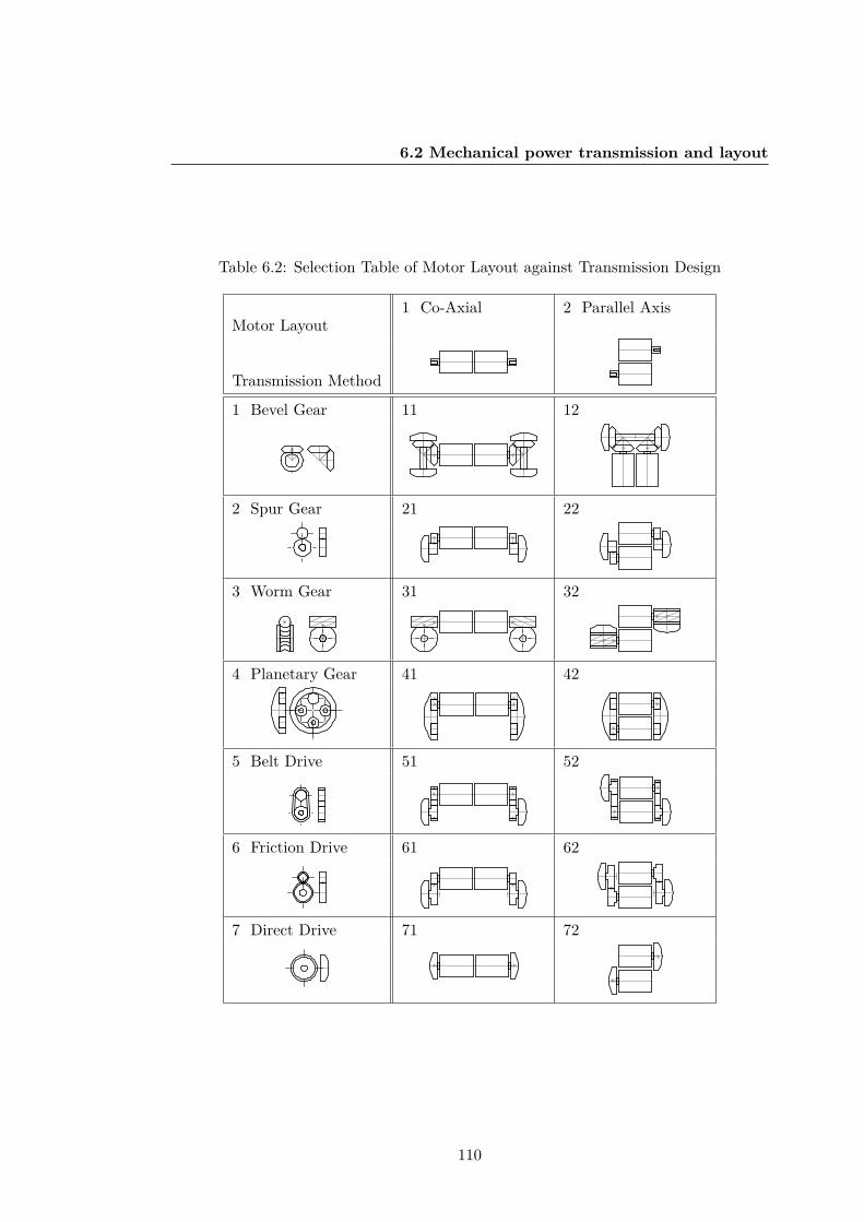
6.2 Mechanical power transmission and layout
Table 6.2: Selection Table of Motor Layout against Transmission Design
Motor Layout1 Co-Axial 2 Parallel Axis
Transmission Method
1 Bevel Gear 11 12
2 Spur Gear 21 22
3 Worm Gear 31 32
4 Planetary Gear 41 42
5 Belt Drive 51 52
6 Friction Drive 61 62
7 Direct Drive 71 72
110

6.2 Mechanical power transmission and layout
Table 6.3: Selection criteria used in the transmission decision matrix, Table 6.4 tochoose optimal an design solution from Table 6.2.
Transmissiondesign criteria
Score1 - Low 3 - Medium 5 - High
Sizevs motor
Greater than100% motor
Neither smallnor large
Less than100% motor
Steeringcapability
Cannot steer(wheels in-line)
Large turningradius
Low truningradius
Min in-piperadius
Large sub-optimalminimum radius
Neither smallnor large
Small optimalpipe radius
Ease ofmanufacture
Difficult to produceNeither difficultnor simple
Simple toproduce
Step casenegotiation
Impossible to climbNeither difficultnor simple
Simple toclimb
the motor size (It is required to be compact). Steering capability is required to movein the pipe so it is weighted accordingly. Minimum in-pipe radius refers to the drivingdirection of the robot, e.g. if the robot is long (co-axial design) the drive wheels canalso be co-axial (design 21 in Table 6.2) or perpendicular (design 11). The minimumpipe radius of design 11 is half that of design 21. Design 11 has perpendicular wheels toits drive axle and can drive lengthways down the pipe with the width of just over onemotor. Whereas design 21 has wheels with a n axle parallel to the motors axis and mustdrive head on with a width of over two motors (double the minimum in-pipe radiusof design 11). Ease of manufacture refers to how simple this design is to produce, thecomponents for this robot will be small and making bespoke belts and friction driveswill be difficult. Some of these belt like drives such as those used in designs 51, 52,61, and 62. These designs will also require belt tensioners to be built into the designand will take a considerable amount of volume within the robot assembly. Step-casenegotiation ability is ideal and must also be considered at this stage, the transmissiondesigns will be judged on how simple it will be to modify to overcome these obstacles.Generally designs need to have the capability to make wheel contact with walls at thecentral axis of the robot (so that corner cases do not cause a rotation of the robot).
111

6.2 Mechanical power transmission and layout
This is untrue for designs with one such as designs 22, 52, 62, and 72, with have wheelswith a different offset axis. These robots would require large wheels such as designs 41,and 42 to make symmetrical wall contact and therefore make these designs redundantvs the planetary gear system. The values for each of these designs when comparedagainst the criteria were scored in Table 6.4, the scores were then totalled in order tofind the best suited designs to take forward into conceptual design.
Table 6.4: The decision matrix of used to select an ideal transmission design in con-junction with the criteria presented in Table 6.3, as well as the designs of the layouts11 - 72 in Table 6.2.
11 12 21 22 31 32 41 42 51 52 61 62 71 72Sizevs motor
1 3 3 3 3 3 1 1 3 3 3 3 5 5
Steeringcapability
1 3 3 5 1 1 5 5 3 3 3 3 3 3
Min in-piperadius
5 5 1 3 5 5 1 3 1 3 1 3 1 3
Ease ofmanufacture
5 5 5 5 3 3 5 5 1 1 1 1 5 5
Step casenegotitaion
5 5 3 1 5 5 3 5 3 1 2 1 3 1
TOTAL 17 21 15 17 17 17 15 19 11 11 10 11 17 17
From Table 6.4, the most suitable designs with the highest total points are designs12 (score of 21), and 42 (score of 19). Many of the other designs averaged at a scoreof 17. Because of it’s potential in a straight pipeline, design 11 will be chosen to goforward from the number of robots scoring 17. These transmission designs will formthe basis of the concept designs taken forward in section 6.3:
• Design 11: bevel co-axial
• Design 12: bevel parallel axis
• Design 42: planetary parallel axis
112

6.3 Concept designs for a 2-inch pipeline
6.3 Concept designs for a 2-inch pipeline
In this section concept designs will be created from previously selected transmissiondesigns, electronic components, and custom designed chassis models. After systematicelimination of unsuitable principles via the decision matrix in section 6.2 three differenttransmission designs were developed further. These transmission designs are developedinto a conceptual design with a focus on designs that will work in a 2-inch pipeline. Themain focus of this first concept investigation is to enter the robot into a 50mm pipeline.For this purpose the robot will be designed with effective use of space as the mainselection parameter, and with step-case negotiation taking a lower priority. The focuson 2-inch pipelines allows for initial concepts to solve basic design problems such asfitting the robot components within a 2-inch cross section. The first problem to focus onwill be, fitting within a 2-inch pipeline. Each concept is designed in SOLIDWORKS asa master sketch base drawing. This typically involves drawing one sketch on each planeand drawing the intersections of motors and gear meshes. Modelling the prototypesin this way ensures that components fit. Placement of components quickly can bedone using ”blocks” within SOLIDWORKS. This function is useful as it creates anindividual object from each sketch that can interact allowing you to create mechanismsand linkage design. The design process for creating these robot models using thetransmission method as a base is as follows:
• Draw in the wheel rotation axis on a plane intersecting with the origin.
• Draw in transmission method e.g. bevel gear connection. Including Bearing seatingand mechanical components such as shaft collars.
• Draw in wheel design this is done relative to target pipe size to maximise the magneticforce allowed through wheel volume without contacting the pipe boundary.
• Draw in motor placement.
• Draw in electronic stack from the wireless micro-controller circuit.
• Alter placement of components using drawing blocks to create a use-able layout.
• Generate Chassis around the layout that incorporates space for all components.
• Place connections and fastener points, e.g. slotting/push fit points, screw holes, andnut traps.
113

6.3 Concept designs for a 2-inch pipeline
6.3.1 Concept 1: planetary spherical parallel axis
The spherical design presented in 6.2 is based on layout 42 in Table 6.2, a planetaryparallel axis system. The motors are placed in a parallel layout and drive the twomain wheels through a planetary gear. The planetary gears contain two idle passivegears which define the rotational axis of the wheels as the centre of the robot. Eitherside also contains a shield to place hold the wheels in place laterally. Design space forthe magnetic wheels is reduced due to limited possible wheel space caused by motorplacement and the planetary gear system. The steel flux plates would need a largeinternal diameter to account for the inner planetary gear, thus reducing the room forthe magnetic array placement. This would result in a reduced magnetic force at thewheels vs the standard wheel design in 4.
E GF
A CB
2 3 4
5
5
6
55
8
68 5
7
5
7
1
Figure 6.2: Robotic Concept 1: Spherical planetary design based on layout 42 in Table6.2.
114

6.3 Concept designs for a 2-inch pipeline
Table 6.5: Key design features in the spherical concept in Figure 6.2.
Part No. Description1 Battery storage area, including motor drivers.2 Micro-controller unit for control with over Bluetooth.3 Planetary wheel tread to increase friction on steel contact.4 Planetary wheel guard stops lateral movement in wheel assembly.5 DC motors in parallel configuration.6 Planetary wheel drive pinion connected on to each DC motor.7 Planetary outer wheel and magnetic array flux plate assembly.8 Planetary wheel idle gears hold the main wheels stable in place.
Concept design 1 needs to be stabilised in the order to stop the chassis from rollinginstead of the of the motors turning the wheels, there are a few ways to do this includinggyroscopes, magnets, rear wheel [128]. An advantage of a completely spherical designis that it will fit in any pipe obstacle in a pipe diameter less than the diameter of therobot. This design would be suitable for both convex and concave step negotiation,however it would require a central magnet to keep the body in place or a small chassisextension to prevent the rotation of the motors simply rotating the chassis about theplanetary gear. Steering would be performed using a tank style drive system, rotatingone wheel to turn, or drive in opposite direction to rotate on the spot. The motorplacement is in the y-axis of the pipeline which limits the accessible pipe width. Theassembly is so large due to this that the robot is 49mm in diameter making it almost fullbore in a 50.8mm (2-inch) diameter pipeline. This coupled with the need for magneticwheel assemblies along the same axis in such a limited amount of space makes thisdesign inefficient.
6.3.2 Concept 2: co-axial coupled drive and steering
The second robot concept design presented in Figure 6.3, is based on design 11 in Table6.2. The robot is a co-axial bevel system with active motorised steering, the main issuewith design 11 was its lack of steering capability. The key feature of this design isthe inclusion of another set motors to enable coupled steering, the four motor system
115

6.3 Concept designs for a 2-inch pipeline
is shown in detail in 6.3. This concept investigates the increase in motor complexityto achieve driving and steering in a single shaft axis and essentially incorporates twomodel 11’s stacked on top of each other. Because the two steering columns can berotated independently they can be driven at the same time in opposite directions. Aseach motor turns the steering column a counter torque is applied to the robot, howeverif both motors turn in opposite directions the counter torques are cancelled and thebody remains parallel in the pipeline.
A B
C D E
1a
1
2
2
4
3
3
5
6
5
6
7a
7b8
7b
12b
9 10
11
11
12b
12a
13
13
7b
12b
13
5
1b
5
6
Figure 6.3: Robotic Concept 2: Based on layout 12 in Table 6.2, where the drive andsteering are linked and then mirrored.
116

6.3 Concept designs for a 2-inch pipeline
Table 6.6: Key design features in the coupled drive and steering design in Figure 6.6.
Part No. Description.1a Chassis 3D printed left half.1b Chassis 3D printed right half.2 Early magnetic flux plate design (20mm diameter).3 3D printed struts for support in the bevel housing.4 Screws, six used in total to hold the design together.5 Wheel drive bevel gear for the rear drive shaft.6 Steering drive bevel gear for the rear steering column.7a Front wheel drive motor for the front column.7b Rear wheel drive motor for the rear column.8 Encoder shaft and magnet reading pair.9 Motor drive pinion for rear wheel drive bevel.10 Motor steering pinion for rear steering bevel.11 Magnet array in early wheel design.12a Front wheel steering motor for the front column.12b Rear wheel steering motor for the rear column.13 Wheel drive transmission bevel.
117

6.3 Concept designs for a 2-inch pipeline
This robots unique drive method requires the drive shaft to be mounted through thesteering column in order to connect with the drive bevel of the wheel, shown in Figure6.3.E. When manufacturing this part, it was 3D printed using non-assembly techniquesto avoid any assemble of this tricky part. The steering column rotates the entire drivewheel around the drive shaft. This is made possible because the interaction betweenthe drive transmission bevel and the shaft bevel are at 90 to each other. The 90 bevelconnection allows rotation of one bevel around the other whilst maintaining constantgear mesh and putting no strain on the system. This robot was partially completed asa drive test model and as such does not contain any of the electronic stack design inthe assembly. This robot would be driven using direct tether control, the addition of awireless control package would be added at a later stage in the prototype development.
The concept presented some disadvantages in pipe negotiation. Turning was un-stable when completely at a 90 angle for both motors because at this angle the bodyof the chassis was free to rotate about the now shared rotation axis for both wheels.This problem could be overcome by the installation of stabilisers in the form of eitherstruts off the main 3D printed bodies 1a and 1b in 6.3, or through extra magnetic basepoints for stability. The magnet wheels themselves were early prototypes of the magnetwheels developed and refined in Chapter 4, larger magnets would be required in orderfor this design to be viable, and hence more space would be required for the wheels.The robot is 152mm long, roughly three times the specified diameter of the pipe. Thisis due to the addition of two more motors to allow steering, this extra length reducesthe maximum in-pipe radius that can be completed by the robot. However the steeringmethod does allow travel around a pipe without rotation of the robots body, this al-lows the robot to tackle corners by following the easiest path. This robot would not becapable of completing either a convex or a concave step case due to it’s geometry. Thewheels of the robot can only directly contact a wall case when turned at a completeright angle and hence only in a pipe larger than roughly 200mm in order for it to turnside-on.
6.3.3 Concept 3: bevel spur gear parallel axis
This concept design is based upon layout 12 in Table 6.2 and contains a bevel drivespur shaft gearbox in a vertical parallel configuration. Due to the size constraints whendesigning the robot for a 2-inch diameter pipe, the motors were mounted perpendicular
118

6.3 Concept designs for a 2-inch pipeline
to drive-shaft and the wheels vs the standard configuration in layout 12. The changefrom horizontal to vertical alignment allowed for the design of smaller transmissionshafts to the main wheels, however it also meant the wheels rotation axes were nolonger in the same plane as the drive motors. In order to rectify this problem thetorque is transferred to the bevel drive shafts and then from a spur gear to the mainwheel axle seen in Figure 6.4.D and 6.4.E. Each drive-shaft transmits power throughthe spur gear on the opposite side to drive the wheel with a transmission ratio of 1.2:1.These sections are 3D printed, they are assembled with 5mm I.D. 8mm O.D. bearingswhich are push fit into the chassis during assembly. These allow smooth rotation andlocating the centres for transmission assembly, keeping meshing distance of the gearsconstant. Although the motors are interchangeable depending on the desired gear ratiothe current 250:1 motors used in this concept allow a max wheel speed of 80 RPM.Dimensions of the robot concept can be found in Table 6.9.
The main body of the robot is printed as two separate halves (Figure 6.4, 11a and11b) and screwed together after the addition of motors, electronics and battery. Theprototype was formed using Objet material VeroWhite (60g) and Tango+ (4g) as wellas breakaway support (186g) to form a complete model. The total build time for onerobot is three hours:45 and requires an hour of support cleaning from surroundingmaterial due to the delicacy and small size of the robot parts. Shown in the Table 2is the bill of materials required to assemble the robot. The price is quoted as £171 toproduce one unit, however the printing costs for the chassis account for 66% of thisprice. This price is based on the production of one robot, charged at a £25 hourly ratefor use of the Objet 1000 printer and a printing time of 3 hours. These costs could bereduced if the robot were to be printed in batches.
The wheel design is presented in Figure 6.5, this was the second magnetic wheeldesign created for use in a concept pipe robot, the first being in concept 2’s. Changeswere made to this wheel including a 3D printed soft material sleeve built into the wheelarray (2), and an endcap piece to clamp the assembly. This end-cap also has a rubberlike 3D printed coating to increase traction at the pipeline when in magnetic contact.The wheel in the exploded view is screwed together to fully define movement laterally,the screw holes line up because of the wheel to drive spur gear meshing point (9). Thismeshing point is simply a 2D spline that is matched on each subsequent part of theassembly when drawn in CAD, but when 3D printed ensures the assembly is built in the
119

6.3 Concept designs for a 2-inch pipeline
A B
C D E
23
5 6a6b
1 4
7
11a
11b
13 15
1
18
9
10
1
14
11b
216
11a
15
4
7
7 17 18 4
19
11a
7
17
18
4
Figure 6.4: Robotic Concept 2: Based on layout 12 in Table 6.2, with an combinedspur gear transmission axle.
correct orientation. The array of 9 magnets was used to fit a much magnetic surfacearea as possible within the plates, but was limited by the addition of the clampingscrews. The 3D printed magnetic array holder and spacer (8) ensures the distancebetween the magnets is equally spaced and remains shielded between the flux plates inaccordance with the specification set out in chapter 4.
6.3.4 Prototype development
Once the three 2-inch magnetic pipe robot prototypes had been designed, one of theconcepts was selected to move on to the prototyping stage. It was important to select
120

6.3 Concept designs for a 2-inch pipeline
Table 6.7: Key features in concept 3, bevel spur gear parallel axis design in Figures 6.4and 6.5
Part No. Description.1 Transmission shaft with bevel and spur gears2 Rubber wheel coating to increase friction3 Bluetooth Smirf module for wireless coms4 Shaft collar 5mm I.D5 Status Lilypad LED6a 3D printed chassis left half6b 3D printed chassis right half7 Steel flux plate8 3D printed magnetic array holder and spacer9 Wheel to drive spur gear meshing point10 Sparkfun motor driver breakout board 1.2A peak11a 6x4x2mm magnet (0.75kg pull each)11b Left wheel drive motor12 Right wheel drive motor13 Arduino pro mini 3.3V14 Turnigy nano-tech 7.4V 260mah battery15 Screw connection point, 6 in total16 8mm O.D 5mm I.D shielded bearing17 Drive spur gear for transmission to the left wheel18 Transmission bevel from bevel pinion to shaft19 Bevel pinion from left wheel drive motor
the most promising robot to build into the physical model. To determine the robotwith the most potential the robots in their concept CAD model stage were comparedwith using the criteria presented in Table 6.8.
All concepts would be capable of the basic manoeuvres of driving in a 2-inch pipelineand completing multi-direction al steering however space available for magnetic wheelspace design varied greatly. Concept 1 (Figure 6.2)due to its planetary design would
121

6.3 Concept designs for a 2-inch pipeline
4
4
7
710
15
217
Figure 6.5: Exploded view of concept 3 early wheel design.
have room for large outer diameter flux plates (32mm), however the inner diameterwould be greatly reduced to avoid hitting the chassis and idle gears. Concept 2 (Figure6.3) has room for only 20mm wheels, and with greatly reduced flux plate and magnetthickness due to the complex bevel transmission design. Concept 3 (Figure 6.4) haswheels placed outside the width of the robot chassis and contains no internal mech-anisms hence has the highest workspace volume for wheel design. Stability is poorin concept one due to its lack of a rear wheel, the robot relies on a magnetic chassisto keep it from moving in relation to the wheels. The magnetic force would have tobe very large to keep the chassis from rotating due to the counter torque applied atthe wheels. Stability of concept 2 is also poor due to the turning mechanism, as therobot approached 90 at the wheel the chassis is free to rotate around the turned wheelaxis, stability modifications would need to be made to make this viable. Concept 3has average stability, it is stable only in certain situations such as horizontal driving,verticals when the body is facing upwards. This is because the design has no rearmagnetic wheel and as such the body is free to rotate about the wheel axis when in anunbalanced position.
Concept 1 does not have sufficient space for a battery due to the volume needed for
122

6.3 Concept designs for a 2-inch pipeline
Table 6.8: Selection criteria to choose concept to carry to prototype development
Criteria Concept 1 Concept 2 Concept 3Fits in 2-inch pipe 3 3 3
Multi-directional steering 3 3 3
Magentic wheel space Average Low HighPotential chassis and wheel stability Poor Poor AverageSufficeint space for components Low Average GoodPotential to complete concave (2-inch) 3 3 3
Potential to complete convex (2-inch) 3 7 7
Advance to prototype develpoment? 7 7 3
the parallel axis motor design and the spherical limitation. The limit for battery sizehas already been reached for a 2s lipo (40mm x 19mm x 15mm), a potential solutionto this would be to place two 1s batteries in series however this would make chargingimpractical. This concept may show promise at a larger scale or with a modified andextended body for more space but when the design is extended there are better choicesfor transmission. Concept 2 also has poor component space, the four motors take upthe majority of the robots volume. Components would be place on the sides of therobot, this would be enough for the electronic stack however the battery would provedifficult just as in concept 1. Concept 3 space at the rear of the robot for components,however increasing the length of the robot decreases the lowest possible radius bend itcan complete. Concept 2 is the only robot incapable of completing a concave step casein a 2-inch pipeline, this is because there is no wheel clearance from the chassis andthus would never be able to touch the concave wall with the magnetic wheels. Concept1 is the only robot with the potential to overcome a convex case in a 2-inch pipeline asit has no rear end or second wheel with the possibility to crash into the curve.
The result of the comparison is that concept 3, the bevel and spur gear parallelaxis design should be taken forward to prototyping. The design of the concept robotto fit inside a 2-inch pipeline is pushing the limits of the volume available as shownin Figure 6.6. The gap between the wheel and the pipe (1) is just 1mm, and the gapbetween the beneath of the robot and the pipe (2) is 8mm. It is shown at 6.6-3 how thewheel end-cap interacts with the pipe to increase wheel contact surface area to reduce
123

6.3 Concept designs for a 2-inch pipeline
Table 6.9: Dimensions of the CH12 approximate volume.
Length (mm) Width (mm) Height (mm)85.10 46.88 38.65
slippage of the robot. This contact is specific to 2-inch pipelines and is used to makeup for the single point of contact at the main magnet wheel on each side of the pipe.This contact is not present in pipes larger than a 2-inch diameter but is moderatedby the increased contact of the magnet wheels, e.g. in a large 1m diameter pipe fluxplates will be in contact and the wheel will have full force range through the rubberTango material. The full maximum dimensions of the robot are presented in Table 6.9.In Figure 6.7, images of the completed robot prototype are presented fully assembledwith all components present in isometric view (A) and frontal view (B).
1
Front Isometric
2 3Ø50mm Pipe
Figure 6.6: In-pipe design of the 2-inch concept, avoiding double wheel contact withboth walls.
The components used to build the magnetic in-pipe robot are listed in full in 6.10.Components which were design and manufactured in house consist of all 3D printedparts, and the steel magnetic flux plates which were discussed in 4.
124

6.4 Concept and prototype for step case obstacles
A B
Figure 6.7: In-pipe design of the 2-inch concept, avoiding double wheel contact withboth walls.
6.4 Concept and prototype for step case obstacles
Concept 3 was selected for a 2-inch pipeline, however it was still unable to completethe convex step case. The robot must be able to complete the convex case to performinspection and exploration of all in-pipe geometry. Because concept 3 is at it’s limitfor space in a 2-inch pipeline (Figure 6.6) this design must now be modified with theremoval of the 2-inch constraint. Removing the space constraint will allow for thedesign of a system capable of both concave and convex cases. In order to access aconcave case a front portion of the wheels must be left open to wall contact at the edgeof the design. This is a necessity for wall-climbing, if direct wheel contact cannot bemade with the target wall due to chassis interference than this requirement will not befulfilled. As well as this, in order to remain stable the robot must maintain contactwith the pipe at the rear of the chassis to halt rotation of the body around the wheelaxis. Maintaining constant magnetic contact whilst moving around a convex cornerposes a problem which is shown in Figure 6.8-A. This section will first look at how wecan overcome curved convex step case problems without crashing the robot or losingwheel contact in attempt to rectify the problems faced by concept 3 in this regard. Therobot will be simplified to a 2D model with open wheel contact at the front and rearwheels for step case movement and no presumed boundary on the space required forelectronic components.
125

6.4 Concept and prototype for step case obstacles
Table 6.10: Final Concept: Bill of Materials
Part No Component Quantity Mass (g) Price
1 Pololu MicroMetalGear Motor 250:1 2 20 25.82 Arduino Pro Mini 328 - 3.3V/8MHz 1 2 8.03 Bluetooth Smirf Mate Silver 1 12 20.04 Motor Drive TB6612FNG 1 2 7.25 Arduino LilyPad LED 1 0.25 1.16 Turnigy 260mah 2S 35∼70C Lipo 1 14 4.17 3D Printed Left Chassis 1 12 23.18 3D Printed Right Chassis 1 12 23.19 3D Printed Motor Shaft Gear 2 1 1.910 3D Printed Drive-Shaft 2 2 3.811 3D Printed Wheel Hub 2 9 17.312 3D Printed Wheel Magnet Array 2 3 5.813 N42 Grade Magnets 6 x 4 x 2mm 18 8.1 5.014 Steel Magnetic Flux Plates 4 30 20.015 Steel Bearings MR85zz 5x8x2.5mm 8 3.2 3.816 Shaft Collars 5mm 2 6 0.817 Screws/Nuts/Washers 72 7.2 0.1
TOTAL 121 143.75 170.9
6.4.1 Optimal curvature
The simplification of in-pipe geometry problems to step cases was earlier 4.1. It showedhow the issue of complex in-pipe geometry can be simplified to concave and convexstep cases as a worst case scenario. The chapter discussed the issues of overcoming thetwo cases and the problems faced when using magnetic traction methods and definedwheeled locomotion as the primary suitable method for the in-pipe robot. During theconceptual design phase the mechanical considerations of the robot must be consideredwhen travelling around these two obstacles. The layout and transmission design of therobot will have a significant effect on the way these problems are tackled so the designlimitations in each case should be considered.
126

6.4 Concept and prototype for step case obstacles
Now that the robot has been developed further it must be tested against these step-cases. For safe completion of all step cases in any possible in-pipe orientation, the nextversion of the robot should have a magnetic wheelbase in constant contact with thepipe. The robot is unstable in the transition from upside-down orientation to 90 degreeand cannot drive forwards facing down due to its lack of a rear magnet. To avoid thisin the future a rear magnet must be attached to stop unstable chassis rotation aboutthe front wheel in this transition case.
The initial concept designs presented in section 6.3 do contain appropriate geometryfor convex step case negotiation. It is not possible for the two-inch concept robots tocomplete a convex case as they encounter interference shown in Figure 6.8: A. For therobots to complete this case they must force contact loss at W2.
For the completion of this obstacle it was necessary to modify the future designswith ground clearance between the wheelbase to avoid contact with step-case whenmoving around the corner as in Figure 6.8, (A). This could be done with a simple gap(6.8, B), but in order to maximise the space available for the robot the optimal curvefor convex movement can be found as in (6.8, C). This modification to the chassisand wheelbase frame does require that the two-inch specification limit must be broken.The next robot will be designed two solve all of these cases whilst keeping the robot ascompact as possible.
A B C
Figure 6.8: Chassis interaction with a convex curve case. Robot A: standard chassisdesign. Robot B: estimated clearance design. Robot C: optimally generated clearancecurve.
Figure 6.9 presents a diagram of a two wheel simplified robot model, with the
127

6.4 Concept and prototype for step case obstacles
geometry required to build an ideal curve spline. The method to create the splinebegins with choosing the two wheel radius rw1 and rw2, and the length of the wheelbaseof the model Lwb. Because this is the absolute minimum curve, a safety factor Sf isnecessary to apply to rw1 to allow a gap between te corner and the underside of therobot chassis. The curve is generated between these two smaller wheels, a line is drawnfrom Cw1 to w2 that is tangent to the rear wheel. Another tangent line is drawn fromCw2 to W1, the points where these lines intersect the wheel onW1: p11, p51 and on W2:p12, p52 mark the range of points that the wheel comes into contact with through itsrotation of 90 about the convex corner. To define points on the spline tangent linesare drawn from W1 to the opposite tangent point on W2, this can be done for anynumber of points to further define the spline, five points are used to generate the curvein Figure 6.10.
rw1
rw2
p1p21
p31
p41
p51
cw1
rw1 f- S
rw1 f- S
cw2
w c1 1 w c2 1
p12
p11
p42
p32
p22
p52
p43
p33
p23
Lwb
Figure 6.9: Minimal contact curve generation for convex step-case, example using a32mm front wheel, 10mm rear, and 65mm wheelbase.
The parameters used in the generation of the optimal curve in 6.10 are presentedin Table 6.4.1. Once the geometry has been created it is used in SOLIDWORKS as abasis to build a chassis for the robot. It also shows how an increase in the wheelbase ofthe robot can drastically increase the required ride height of the chassis during normaloperation.
This curve is generated specifically for the convex case, however there a specificcases where a curve must also be used on the top section of the robot. Specifically in
128

6.4 Concept and prototype for step case obstacles
Robot Curve Generation Parameters Value (mm)
rw1 32rw2 10Sf 1Lwb 65
w c1 1
w c2 1
L1
L2
L1
L3
L4
L5
L6
L7
L8
L9
L10
L11
cw2
cw1
Figure 6.10: Change in curve generation with an increase in the wheelbase of the robot.
Wheelbase L1 L2 L3 L4 L5 L6 L7 L8 L9 L10 L11
Length (mm) 15 20 25 30 35 40 45 50 55 60 65
the case of a large robot moving through a small relative diameter pipeline and comingto a concave case. In this concave case the outer convex corner partnered with theconcave case causes need for a curve to avoid collision. In a relatively large pipelinethis does not matter as the body is always clear.
The curve generation method was created using SOLIDWORKS, this has since beenreplicated mathematically in MATLAB, the script works out many tangents to createa spline defined on a number of points defined by the user, this removes the need todraw many tangent lines by hand.
129

6.4 Concept and prototype for step case obstacles
6.4.2 Concept 4: bevel with rear wheelbase
The concept 4 robot presented in Figure 6.11, and the part description for each labelis given in Table 6.11. The robot is based upon concept 3 (6.3.3) and has been modi-fied with the added information learned from studying the curvature for convex casesrequired in section 6.4.1. The robot maintains the dual bevel drive transmission designin an identical layout configuration to 6.2.
A
C
B
D
1
4
5
23
6
7
8
9
10a12a
7
15
13
14
12b
16
11a
17a
17b
18
419 2
2827 26
24b 23
22
3 21
10a11a
11a
20
25
Figure 6.11: Schematic diagram of the robot dual bevel robot with rear magnetic wheel.
The space constraint of a 2-inch pipe has been lifted so a simple layout is all that wasneeded, the gearbox transfer in concept 3 is no longer required. This also removes the
130

6.4 Concept and prototype for step case obstacles
need to print small 1mm module spur gears to transfer to the main wheel drives. Thetorque from the motors can be transferred through the bevel gears at a 1:1 transmissionratio. The circuit stack used is the same, as well as the motor choice and ratio, and thebattery is the same model 260mah LiPo. A 3.3V FPV camera has been added for visualinspection and feedback during operator driving, this will allow the operator to squareup to a concave or convex step case and ensure the robot is perpendicular before drivingforwards. This is necessary for remote operations where the robots position relative tothe in-pipe geometry problem cannot be determined through line of sight. To assist indark conditions, two LED headlights have been fitted to the custom camera mount inFigure 6.11 at parts 17a, and 17b. The camera is attached at the head of the chassisbody and has an adjustable mount that uses a slider design (part 19) a screw throughthe slider secures the camera at the required angle. The FPV camera is not integratedinto the main robot circuit and is powered from a separate 1S LiPo which is not shownin Figure 6.11, this will battery will be placed above the motors (24b) and beneath themotor driver (23).
131

6.4 Concept and prototype for step case obstacles
Table 6.11: Design of concept 4: a dual bevel connection robot with a rear magneticwheelbase and curve for convex case locomotion.
Part No. Description. Part No. Description.1 Magnetic flux plate 15 Right chassis section2 FPV camera antennae 16 Bearing mount3 Bluetooth Smirf COM 17a/b Camera LED’s4 FPV camera 3.3V 18 Wheel shaft connector5 Wheel clamp 19 Camera tilt adjustment6 Shaft collar 5mm I.D 20 Arduino pro mini 3.3V7 Rear magnet shaft 21 Connection pins8 Rear shaft chassis mount 22 Battery 2S LiPo 260mah9 Screw holes 23 Motor driver
10a/b Wheel drive bevels 24b Left micrometal motor11a/b Motor pinion bevels 25 Convex curvature12a/b Rear magnets 10mm 26 Bearing 5mm I.D
13 Motor chassis section 27 Wheel flux plate shaft14 Left chassis section 28 Magnet array 6mm
The magnetic wheel design on concept 3 uses the latest wheel model, the triangularhole in the centre allows the 3D printed shafts to be fitted and stops turning of thewheel without the need for screws required in concept 3 wheel design shown in Figure6.5. Because of the lack of screws the magnetic wheels are clamped using part 5, andscrew into the ends of the wheel shafts (part 27). The overall dimensions (x,y,z) ofconcept 4 are 84mm x 54mm x 84mm, this allows the robot to fit within a 4-inch(101.6mm) pipeline. The main modification to this design is the addition of rear wheelmagnetic base in accordance with the optimal curvature generated in 6.4.1. This willallow this robot to move around convex obstacles without interruption. The rear wheelchassis housing (part 8) is removable and can be swapped out for different designs withdifferent wheelbase lengths. Within this chassis is a free to spin rear axle (part 7), andon the end of this shaft is a 10x5mm N42 neodymium magnet (axially magnetised) thatkeeps the chassis from rotating in orientations where gravity is not in favour (upside-down). Like concept design 3 this robot will be taken forward to a full prototype build
132

6.5 Discussion and conclusion
in order to test the performance of the system on in the real word. The prototyperobot has been 3D printed in PLA using a BCN3D Sigmax 3D printer, it is presentedin Figure 6.12 with a front view (A) and isometric view (B).
A B
Figure 6.12: Schematic diagram of the robot dual bevel robot with rear magnetic wheel.
6.5 Discussion and conclusion
In this chapter the mechanical design and overall layout of the in-pipe robots wasconsidered. The most important criteria as defined in chapter 3 in terms of conceptdesign of concepts were used to determine the focus of the robots. Initially this wasdeemed to be the overall volume of the robot in keeping with the original aim todevelop an in-pipe robot capable of entering a 2-inch pipeline. Designing a robot todrive inside a 2-inch (50.8mm) diameter places many constraints on the design whichmake it inefficient to use standard four wheel configurations. The transmission methodswere found to have the biggest impact on the layout of the robot and so three differentconcepts using three different transmission layouts were designed in CAD software. Thedesigns were compared against criteria to assess their feasibility as potential prototypesand the most promising (concept 3) in section 6.3.3, was chosen. This was the mostsuitable of the 2-inch robot designs, however concept 3 would still be unable to completeconvex pipe sections. The necessary geometry to move around convex corners whilstmaintaining magnetic contact with the pipe is difficult in small diameter pipelines. Itis impossible for a robot like concept 3 to complete a case convex step-case due as itschassis crashes with the corner case and does not allow the magnetic wheels to get
133

6.5 Discussion and conclusion
any purchase. A gap must be present between the wheel and the rear contact pointof the chassis in order to allow the wheels over the edge. The geometry necessary tocomplete this case was investigated and an ideal curve to avoid convex contact wasproposed. This ideal curve cannot be applied to the 2-inch concepts without breakingthe size constraint set by the pipe as the concepts already use the bulk of the pipewith electronics and mechanical transmission systems. In order to apply the curveand design a robot that could possibly complete both concave and convex obstaclesthe 2-inch constraint was lifted and replaced with the criteria of ”complete all obstaclecases”. This lead to the conceptual design and then prototype development of concept4 in Figure 6.11. Concept 4 is taken forward into chapter 7 to undergo experimentaltesting to determine performance when tackling these obstacles.
134

Chapter 7
Robot Obstacle Statics, Experimentation andEvaluation
135

7.1 Introduction
This chapter brings together the work from preceding chapters and combines the know-ledge gained into one functional prototype. This final prototype is mathematically ana-lysed in static and dynamic conditions attempting step-case problems. The robot istested experimentally to determine the limits of its functionality when moving aroundconcave or convex cases in different orientations. After assessment the robot is deployedinto real world in-pipe environments.
7.1 Introduction
This section will bring together the work done in the previous chapters to experiment-ally test the final prototype version of the robot. The presented final prototype is amobile platform for magnetic locomotion of any standard ferrous structure both in-pipeand out-pipe. In this chapter the effect of changes in vehicle parameters on the staticand dynamic models will be investigated to determine the optimal solution for obstaclenegotiation in the cases of concave and convex bends.
The magnetic robot consists of two sets of wheels with reaction forces, the rearwheels are free to spin and assumed frictionless, the front larger wheels are driven by asingle DC motor each. The robot is stable and at rest when placed in any orientation ona steel plate it is even capable of hanging upside-down (inverted). Static friction fromthe motor’s gearbox coupled with the frictional force at the wheel contacts preventsmovement of the robot on a any plane. The robot never enters sliding friction inpractice as the weight of the assembled robot is 0.12kg and the wheels are operate atforces of well over this 1.56N limit. Because the vehicle is magnetic, there a constantforce at the contact point of the wheels acting perpendicular to the surface, assumingthe material is ferrous.
7.2 Overcoming step-case obstacles
In this section the mechanics of the robot climbing both a concave and a convex step casewill be explored. In these cases a right angle step will be used in the most challengingorientation. For the case of the concave step this will be from 0 − 90, and for theconvex case it will be 90 − 0. In a real world environment these step cases canexist in any orientation in-pipe, the variables that change in these other cases are thedirection of gravity, and a change in weight distribution. These cases are assumed to
136

7.2 Overcoming step-case obstacles
be performed in large diameter pipes (>1m) such that the pipe is so large it can beassumed the wheel contact points share the same in-pipe height. Maximum torqueat the motor is based on a 250:1 MicroMetal Motor [27] from the motor torque tableselected in 5.5.
Cases will be considered statically at most points around the obstacles to determineforces present in the robot at each stage of movement. When taking moments about apoint on the robot it is important to note that every magnetic force is balanced by itsown reaction force at the point where it acts in contact with the wall. The only forcesthat are considered in the calculation of the system are the weight of the robot and theforce of the torque from the motor. The magnetic forces are re-applied later. Momentsin the y-axis are taken around the robots centre of gravity, (CG). All cases have beensolved using the planar static equilibrium equations as a basis in equations 7.1, 7.2,and 7.3. Standard equations used in this chapter are also completed from equation 7.4,to 7.11.
∑Fx = 0 (7.1)∑Fz = 0 (7.2)∑My = 0 (7.3)
RPS = RPM
60 = 120/60 = 2 (7.4)
Tmmax = 0.33N −m (7.5)
Gratio = rp
rg= 0.008
0.008 = 1 (7.6)
Faxle max = Gratio · (Tmmax/rp) = 0.33/0.008 = 41.2N (7.7)
Fw1 max = Famax · rg
rw1= 20 · 0.008
0.016 = 20.6N (7.8)
Ffmax = uw1 · (Fmag1) = 0.71 · (9.5) = 6.7N (7.9)
W1circ = pi · (rw1 · 2) = 0.05m (7.10)
Vmax = RPS ·W1circ = 0.1ms−1 (7.11)
137

7.2 Overcoming step-case obstacles
Table 7.1: Description of parameters used within the free body diagrams in the concaveand convex cases.
Parameter Description
w1c1 Wheel one, pipe contact point onew1c2 Wheel one, pipe contact point twow2c1 Wheel two, pipe contact point onew2c2 Wheel two, pipe contact point twoc.g. Location of the centre of gravitymg Force of the weight of the robotθR Angle of the robot from the normal orientationcw1 Location of centre of wheel onecw21 Location of centre of wheel twoFf Force of frictionFN Force of the normal at the wheel contact pointFT m Force of the torque at the motorFmag1 Force provided by magnetic wheel 1Fmag2 Force provided by magnetic wheel 2
7.2.1 Concave case
The concave case is present in pipe bends as either high or low radius bends, the mostextreme case is the mitred bend which forms a right angle. It can also be present as avalve flange in-pipe which acts as a sharp change in diameter.
Concave: section 1
Section 1 begins with the robot approaching a concave step case corner arrangement.The free body diagram of this case is displayed in Figure 7.1. Section one is a simplesplit of the weight components between the two points of contact to find the reaction.To solve this case forces are resolved in terms of the normal force direction of the robotwhich is the same for both FN w1c1 and FN w2c1. By taking moments around cw1 andignoring the magnetic forces for now:
138

7.2 Overcoming step-case obstacles
Mcw1 = mg ∗ Lxcw1cg (7.12)
Solve for the reaction force by taking the sum of moments around any point asequal to zero from equation 7.3.
FN w2c1 = Mcw1Lxcw1 w2c1
(7.13)
FN w1c1 = mg − FN w2c1 (7.14)
Where: Lxcw1 w2c1 = Length in x− axis from cw1 to w2c1
Now the magnetic forces can be re-applied. These forces are always applied directlyperpendicular to the tangent point of wheel contact (the floor), and are therefore alwayscoincident with the centre of the wheel. These forces are always collinear with thenormal contact force and hence can be applied after the weight distribution of therobot has been calculated.
FN w2c1 = FN w2c1 + Fmag1 (7.15)
FN w1c1 = FN w1c1 + Fmag2 (7.16)
w1c1
cw1
cw2
c.g.Lcw1_cg
Lcw1_w2c1
w2c1
mg
FTm
FTwFf
FN_w1c1FN_w2c1
x
z
Fmag1Fmag2
Figure 7.1: Concave case section one: robot approaches the wall.
The variance found in this section is that the start angle of the pipe can be anythingfrom 0 − 360. This affects the direction of the weights force vector and can cause an
139

7.2 Overcoming step-case obstacles
increase or a decrease in the normal force on each wheel depending on the orientation.The minimum normal force caused by the weight of the robot is found when the centreof gravity (c.g.) is vertically below the wheel contact points. Section 1 is assumed toend at the point that magnetic wheel 1 is just about to come into contact with thegradient attachment point of the step case.
Concave: section 2
For section 2 the vehicle starts with magnetic wheel 1 touching the pipe at two contactpoints. At this point the magnetic force of the wheel is now split between the twopoints of contact in the main wheel w1c1 and w1c2. From Section 4.5.1 it is known thata double contact case causes the normal force of the each contact to drop from 100 to67%. The requirements for the completion of this section are that the motor torqueand applied force at the wanted contact point overcomes the unwanted attractive forceof the wheel in double contact; Fmag1 at w1c1. It is important to note that duringthis section magnetic force does not change because the robot never actually moves.The magnetic force only alters (shifting force to w1c2) once wheel begins to come offthe plate. It is assumed for simplicity of calculations that during double contact casesthat the weight is now split between the two outer contact points, in this case: w1c2
and w2c1. The beam is simplification of the problem is represented in the free bodydiagram in Figure 7.2. The concave step-case is where the robot experiences it’s torquepeak, higher than any other movement.
During section 2 the motors ramp up to overcome the magnetic holding forceFmag1 w1c1 at w1c1, which is keeping the wheel locked in the double contact position.This is the most important part of the concave problem as the robot must have bothenough torque to overcome the total strength of the magnet. By resolving forces inz and taking moments around w2c1 the force required at w1c2 to overcome the forceof the magnet Fmag1 w1c1 at w1c1 can be found. The force required is related to thewheelbase length, presented in equation 7.17.
Ff w1c2 = Fmag1 w1c1 ·Lxcw1 w2c1 + rw1
Lxcw1 w2c1(7.17)
This relationship shows that a wheelbase equal to the radius of wheel one rw1)
would require half the force of w1c1 at w1c2 in order to bring the normal reaction forceof Fmag1 w1c1 to zero. As the wheelbase increases (keeping constant radius at wheel
140

7.2 Overcoming step-case obstacles
one) the force required by Ff w1c2 needed tends to the force of Fmag1 w1c1.The maximum torque from the motor relates to the torque at the wheel by equation
7.8. In this double contact case it can be assumed that the torque is split equally atboth contact points whilst there remains sufficient normal force to transfer traction atthe contact point. The limit for sufficient traction at w1c1 is given by equation 7.20.
Ff w1c2 = Fmag1 w1c1 − Ff w1c2 ·(Lxcw1 w2c1 + rw1)
Lxcw1 w2c1(7.18)
Ff w1c2 · (1 + (Lxcw1 w2c1 + rw1)Lxcw1 w2c1
) = Fmag1 w1c1 (7.19)
Ff w1c2 = Fmag1 w1c1
(1 + (Lxcw1 w2c1+rw1)Lxcw1 w2c1
)(7.20)
After this limit is reached the frictional force will no longer be equal. More forceis transferred into w1c2 as the maximum traction force at w1c1 falls to zero and thenormal force FN w1c1 is negated. This causes the Ff w1c2 to increase exponentially asmore of the wheel torque becomes available. During this section the Ff w1c1 actuallyacts into the wall, increasing the normal force FN w1c2. This force is not useful to themovement however. It may initially stop slip due to the larger normal force, howeverwhen the w1c1 limit is reached this increased normal force is also reduced with thereduction in traction.
w1c1
cw1
cw2
c.g.Lw1c2_cg
Lw1c2_w2c1
w2c1
mg
FTm
FT_w1c1Ff
FN_w1c1
w1c2
FN_w1c2
FT_w1c2
Ff
FN_w2c1
x
z
FR_w2c1
θw2c1
Fmag1 Fmag2
Fmag1
Figure 7.2: Concave case section two: robot is in double contact case with the step atwheel one.
141

7.2 Overcoming step-case obstacles
At the end of this section the reaction force at w1c1 has reduced to zero and therobot is now ready to climb the step case in section 3.
Concave: section 3
In section 3 the has just moved off from unwanted contact force and the robot is nowrotating around the corner case and moving up the wall. As the front wheel movesup the back wheel is swung into the corner case whilst maintaining magnetic contactat the point w2c1. During this section the entire body of the robot is rotating aroundthe corner case, this changes the weight distribution throughout the movement andis dependent on the original orientation of the robot and the total angle of the case.This section ends when wheel 2 is just about to make contact with the wall whilstmaintaining contact with the lower portion of the step case. It is assumed in thismodel that the robots second magnetic wheel lies beyond it’s chassis such that doublecontact can be been made (a perfect two wheel system). The free body diagram forthis case is presented in 7.3.
w1c2cw1
cw2
c.g.Lw1c2_cg
Lw1c2_w2c1
w2c1
mg
FTm
FTw
Ff
FN_w2c1
FN_w1c2
FR_w2c1
x
z
θR
θw2c1
Fmag1
Fmag2
Figure 7.3: Concave case section three: robot has overcome double contact and rotationabout the corner has begun.
142

7.2 Overcoming step-case obstacles
Concave: section 4
In section 4 the robot has completed its rotation about the step case and has now madecontact with the wall at w2c2. The motor power must now increase to generate enoughwheel traction to bring the reaction force of w2c1 to zero ready to pull off from the startof the step case. This section ends when the reaction force w2c1 is reduced to zero andis completed providing 7.21 is achieved.
Ff w1c2 > FN w2c1 (7.21)
w1c2cw1
FTw
Ff
FN_w1c2
x
z
Lw1c2_cg
w2c1
w2c2 cw2
c.g.
mg
FTm
Lw1c2_w2c1
θR
FN_w2c1
FN_w2c1
Fmag1
Fmag2
Fmag2
Figure 7.4: Concave case section four: robot is in double contact case with the step atwheel two.
After section 4 the robot moves off from the step case after disconnecting w2c1 fromthe pipe. The step-case has been completed and the robot is now in it’s new pipeorientation and can move on to it’s next obstacle.
143

7.2 Overcoming step-case obstacles
7.2.2 Convex case
The convex geometry step case is present at every connection from a small diameterriser into a larger diameter pipeline. Getting around this obstacle is unavoidable if thelarger diameter pipes are to be entered from the smaller connected bores. The convexstep case is the harder of the two cases as there are some orientations which the robotcannot complete.
Convex: section 1
Section 1 begins with on a vertical wall with a robot angle of 90. The robot drivesto the corner of the step case, this section ends just as the robot is about to beginits rotation around the corner. When driving up to the corner the robots frictionalco-efficient and the torque at the wheel provided by the drive motors must be greaterthan the robots weight.
(FT w >mg
2 (7.22)
Ff >mg
2 (7.23)
144

7.2 Overcoming step-case obstacles
x
z
w1c1
FTw
Ff
FN_w1c1
FTm
c.g.Lw1c1_w2c1
Lw1c1_cg
cw2w2c1
FN_w2c1mg
θR
Fmag1
Fmag2
Figure 7.5: Convex case section one: robot angle is at 90, ready to start rotation aboutthe corner.
Convex: section 2
During section two the first wheel of the robot begins to rotate about the corner. Thiscase is the opposite of the concave case section 2 at double wheel contact in that therobot is required to have a large wheel force to hold the weight of the robot during thecontact of w1c1 with the corner. From chapter 4 it was discovered that Fmag1 at thiscase is reduced to almost 10% of it’s maximum pull force. Therefore to complete thissection the robot must fulfil equation 7.24.
Fmag1 ∗ 0.1 > mg
2 (7.24)
145

7.2 Overcoming step-case obstacles
x
z
w1c1
FTw
Ff
Lcw1_w2c1c.g.
cw2
w2c1
FN_w2c1
FR_w2c1
θw2c1
mg
FN_w1c1
FTm
θR
Lcw1_cgFmag1
Fmag2
Figure 7.6: Convex case section two: robot has begun rotation around the corner andis the weakest magnetic contact case for wheel one.
Convex: section 3
I section 3, shown in Figure 7.7 the robot has rotated both drive wheels around thecorner and it begins to drive off. The robot is still rotating and the rear wheel is comingcloser to the corner case as it is dragged around by the main wheels.
It’s at this point that a huge force begins to be placed on the rear wheel due tothe counter torque on the body produced by the front wheel. The force is large andinto the wall at FR w2c1, and due to the rotation of the robot the main driving forceis parallel to the floor at Ff and the component in the Z − plane at w2c1 has reducedto a minimum. This lack of vertical force component, the weight of the robot actingagainst the wanted force, combined with the counter torque from the wheel, and theresistance from the magnet to move into the corner position means that there are threeelements causing a negative force in the Z − plane about the chassis that keeps therobot trapped in this position. This case is only possible where mg acts away from the
146

7.2 Overcoming step-case obstacles
convex corner.
x
z
Lcw1_cg
Lcw1_w2c1w1c1 FTwFf
FN_w1c1
c.g.
cw2
w2c1
FN_w2c1
FR_w2c1
θw2c1
mg
FTm
θR
Fmag2
Fmag1
Figure 7.7: Convex case section three: wheel one has passed the corner and is nowattempting to pull the rear passive wheel around the corner.
Convex: section 4
This case is especially significant when moving around the corner in the opposite dir-ection, because the rear wheel magnet is in the weakest case it’s holding force is sig-nificantly reduced to 10% of its maximum. When the robot rotates round the cornerthe rear wheel at a reduced force must balance the moment caused by the robot weightand fulfil the condition in 7.25. Failing to to this causes a detachment of the rear wheelfollowed by a rotation around the front axle and the robot crashing into the wall. Thereaction from the crash can cause a complete detachment of the main wheel and therobot to fall off the pipe.
Fmag2 ∗ 0.1 ∗ cos(45) > mg ∗ Lw2c1mgx (7.25)
147

7.3 Experimental testing
x
z
Lcw1_w2c1
Lcw1_cg
FTm c.g.
cw2
w2c1
FN_w2c1
FR_w2c1
θw2c1
mgθR
w1c1 FTwFf
FN_w1c1
Fmag1Fmag2
Figure 7.8: Convex case section four: wheel two is in the weakest magnetic case.
After section 4 the robot moves off from the step case after successfully completingits rotation around the convex. The step-case has been completed and the robot is nowin it’s new pipe orientation and can move on to it’s next obstacle.
7.3 Experimental testing
This section covers the rig based testing of the final robot in various orientations ofconcave and convex cases. The rig set-up, shown in 7.9 consists of two main steel platesmounted to a central bearing such that two edges of the plate are always touching. Thesecondary plate can be rotated around the first to alter the angle of the step case usingthe 360 protractor mounters centrally behind the plates. The bottom plate is fixedin place and the secondary plate is clamped in place to halt movement during testing.The clamp attaches to the Rexroth frame which is fixed mounted to a 14.3kg block ofsteel. The rig has been used to gather experimental data showing the robots ability toclimb step cases.
7.3.1 Concave cases
The concave cases were tested from a 75 acute angle up to a 180 flat case. Reviewingthe cases in the free body diagram, the most challenging aspect of the concave problem
148

7.3 Experimental testing
Central adjustable
bearing
Fixed bottom plate
Secondary adjustable step case plate
can rotate from 45° - 315°
Steel block base
Rexroth adjustable
base frame
360 !ixed protractor to adjust step angle
Figure 7.9: Test rig used to evaluate the robots performance on both concave andconvex step cases at varying angles.
149

7.3 Experimental testing
is the double contact of main drive wheels in Concave: section 2 (Section 7.2.1). Theexperimental tests show that this is correct, the robot easily handles sections A, butbecomes locked in double contact at Figure 7.10.B. At this point each of the 9.5Nwheels hold 67% normal force in each contact point (6.4N). When the PWM value ofboth motors reaches high enough (240/255) the wheels are detached slightly from theunwanted contact point and the magnetic flux immediately transfers into the remainingcontact point. The main contact point returns to 100% at 9.5N force and the robotleaves double contact section. After leaving double contact the robot is free and torotate during around the corner until the rear magnets reach the corner case. Detachingthe rear magnets at 100% requires 1.6N force each, a quarter of that needed to detachthe main drive wheels. After detaching the rear magnets the robot is free to move init’s new inverted plane in Figure 7.10.
The concave cases tested are summarised in Table 7.2, including the PWM valuesreached as recorded on the LabVIEW input program. PWM values reached in this caserelate to the load on the motor required to complete the manoeuvre, a PWM value of255 represents the maximum possible power that can be applied to the motor, if avalue of 255 is reached before completing the case the motors will have stalled and therobot will have failed the case. A value of 240 as shown in both the 90 degree and 75degree concave cases confirms that the robot is close to its maximum power output asis expected in these cases which were predicted to be the hardest of the concave stepangles to complete.
Table 7.2: Step-case rig: robot experimental results for concave testing at differentangles.
Step-CaseStepAngle ()
ForwardDescending
ReverseDescending
ForwardAscending
ReverseAscending
PWM
Flat 180 Y Y Y Y 60Concave 135 Y Y Y Y 60Concave 90 Y Y Y Y 240Concave 75 N F Y Y 240
In a worst case where all the weight of the robot (0.12kg) acts on the wanted contactpoint and causes a 0.5N reduction in normal force of the main wheel contact (8%). The
150

7.3 Experimental testing
Concave Step Case: Ascending Vertical
B: Double ContactA: Approach C: Concave Rotation D: Completion
Figure 7.10: Concave case performed on the test rig. A: approaching the corner case.B: Double contact, the motor ramps up to overcome the unwanted contact force. C:The robot rotates around the concave corner after detachment. D: The completion ofthe concave corner case.
corner case presented in Figure 7.10 is closest to this worst concave situation. The robotcan comfortably complete the concave case in this and any other orientation, the factorthat affects this case the most is the wheel force and the wheel frictional co-efficientas shown in Figure 7.11. The graph shows the minimum required frictional co-efficientneeded to overcome a concave step-case is between 0.6 and 0.65. The frictional co-efficient of the rubber coated wheels is 0.71 from Chapter 4, hence the robot is able tocomplete any concave step-case as long as the rubber coating is maintained. The wheelsstrength used to calculate these values was the 9.5N wheels used in the experiments.The relationships are exactly the same given a different wheel strength as they areindependent of the force, changing the wheel strength only alters the Y-axis scaling.
7.3.2 Convex cases
The robot is shown approaching an ascending 90 convex case in Figure 7.12.A , andthen reaching the weakest contact point at B. From Chapter 4, the weakest force on thestep-case was calculated to be around 10% of the wheels maximum pull force (0.95N).The robot continues rotating around the corner with a tractive force of 0.67N at eachwheel at 45 to the corner. As it rotates around the corner in section C the wheel forcereturns to maximum pull force and the robot attempts to pull itself around the stepcase. At section D, the rear wheel has become stuck close to the edge of the corner.This is a combined effect of the wheel torque increasing as the robot progresses around
151

7.3 Experimental testing
Effect of the co-efficient of friction on the concave step-case
0.1 0.2 0.3 0.4 0.5 0.6 0.7 0.8 0.9 1
Co-efficient of friction
0
2
4
6
8
10
12
14
Forc
e (
N)
w1c1mag
w1c1traction
w1c2normal
w1c2traction
w1c1normal
UnwantedContact Detachment
Magnetic WheelFriction Co-efficient
Figure 7.11: Graph showing the effect of an increase in wheel friction co-efficient onthe contact forces at w1c1 and w1c2 for drive wheels with a pull strength of 9.5N.
the corner, and hence the counter torque of the body which resists rotation increasing.The result at this point is that the motors either stall or the wheels slip depending onthe wheel pull force.
In the case of 7.13 the robot manages to complete the convex corner case becausegravity is working in its favour instead of against it as in 7.12. The robot can fall inthis case if the rear magnets are not strong enough. During convex rotation in part Cwhen the rear wheels reach the corner and are at 10% pull force the chassis’s rotationaround the corner can cause detachment. This detachment is seen in another similarcase example in 7.14. B, and causes the robot to crash. It should be noted that thiscrash position is recoverable with remote control as the main drive wheels have notbeen detached.
Table 7.3 shows the cases completed by the robot as well as the PWM values in-putted from the control LabVIEW program to achieve the result. The robot completes115 in its worst case ascending orientation as seen in Figure 7.12. Although the robotcan make it around 90 corners in ideal cases, the minimum case for pipeline is from a4-inch to a 12-inch pipeline as seen in Figures 7.15. Figure 7.16 shows a graph of the
152

7.3 Experimental testing
Convex Step Case: Ascending Vertical
B: Weakest ContactA: Approach C: Convex Rotation D: Movement Halted
Figure 7.12: Robot attempting the convex corner case. A: Approaching the step case.B: The point of weakest contact for the magnetic wheel. C: Rotation of the robotaround the convex corner. D: The robot can go no further as the passive rear wheelhalts movement.
B: Weakest ContactA: Approach C: Convex Rotation D: Completion
Convex Step Case: Descending Vertical
Figure 7.13: Robot completing the convex corner case. A: Approaching the step case.B: The point of weakest contact for the magnetic wheel. C: Rotation of the robotaround the convex corner. D: The robot completes the case.
153

7.3 Experimental testing
Acute Convex Step Case: Reverse rear wheel contact-loss
B: Contact LossA: Approach C: Chassis Rotation D: Crash
Figure 7.14: Robot completing the convex corner case. A: Approaching the step casein reverse. B: The back wheels lose contact at the convex weak corner point. C: Thechassis rotates about the wheel axis. D: The robot crashes.
change in approach angle from 6-inch - 48-inch pipelines with both a 4-inch an 2-inchconnection.
Table 7.3: Step-case rig: robot experimental results for convex testing at differentangles.
Step-CaseStepAngle ()
ForwardDescending
ReverseDescending
ForwardAscending
ReverseAscending
PWM
Flat 0 \ \ \ \ \Convex 45 N N N F 60Convex 90 Y F N Y 60Convex 100 Y Y N Y 60Convex 110 Y Y N Y 60Convex 115 Y Y Y* Y 60, *120Convex 120 Y Y Y Y 60Convex 135 Y Y Y Y 60Flat 180 Y Y Y Y 60
154

7.4 Real in-pipe operation
96.28°
4-Inch
48-Inch
115.5°
4-Inch
12-Inch
Figure 7.15: The difference in angle between a 4-inch pipe connection with a 48-inchpipe, and a 4-inch pipe with a 12-inch pipe.
10 15 20 25 30 35 40 45
Target Pipe Diameter (Inch)
90
100
110
120
130
140
150
En
tra
nce
An
gle
(D
eg
ree
s)
Entrance angle from a 4-inch pipelines and 2-inch s
4-Inch
2-Inch
12
115
Figure 7.16: Graph of the change in approach angle with different size pipe connectionfittings and different size target pipe inspection diameters.
7.4 Real in-pipe operation
Corrosion in gas pipelines can cause unstable ferritic scales in-pipe [129], that form partof the corrosion-erosion process that causes the failure of the pipe. To view how therobot might handle this type of problem the robot was tested in a real NTS 42-inch(1016mm) pipeline [26] provided by National Grid Gas Transmission to Synthotech’stest site. The pipe was retrieved from a working AGI after replacement, the conditionwas that of an expected 40-year old underground pipeline. Figure 7.17 presents picturesof the robot exploring the pipeline, after operation the robot wheels were covered in
155

7.4 Real in-pipe operation
iron particles that reduced both the normal force and friction force provided by thewheels (D).
During tests on the real site the robot was found to function until the wheels became”clogged” by the scales of iron that had been broken from the pipe surface, or iron dustand powered sitting in the pipe that had been picked up by the magnets along theway. This dust is hard to remove as it is attracted to the wheels and . The build upof this material effectively reduces the magnetic force of the wheels as creates an ironcasing around the magnet. Because the wheel is effectively encased in iron at this pointthe friction co-efficient drops drastically to that of iron on steel (0.27). With reducedmagnetic force caused by the iron casing causes a drop in normal force at the wheel.When this point is reached movement is extremely difficult and will cause the robotswheels to slip, the robot will then be stuck in a state of wheel-spin. A secondary issueis the clogging of the bearings with iron deposits, this severely hinders movement is theparticles are fine enough to enter the gaps in the shielding. This can potentially ruinthe bearings and force them to require replacement.
7.4.1 Contact loss in-pipe
Robot crashes are caused by contact loss at the wheels, crashes where the robot com-pletely detaches from the surface will generally fall onto hard steel surfaces beneathdamaging the system. Some contact loss is recoverable, other cases require interventionto rescue the robot. A crash case is recoverable in most cases as long as the main wheelsare in contact with the pipeline. The counter-rotation of the body due to the toque atthe bevel gears will cause the detached rear wheels to re-connect with the pipeline. Inthe case of the robot not being able to make contact with ferrous material at the rearwheel it is capable of driving both forwards and in reverse in these conditions. Un-recoverable conditions include Contact loss due to reduced magnetic attraction. Thiscan be caused by the wheels becoming coated in iron scales or particles during inspec-tion. Contact loss of main drive wheels; loss of contact at the drive wheels renders therobot unmoveable by any command. The robot can also become stuck due to loss offrictional rubber wheel coating, this can wear during use and expose the flux plates un-derneath. This can cause the robot to constantly wheel-slip due to the reduced tractionand could cause the robot to become irretrievable during operation.
156

7.4 Real in-pipe operation
D E
C
A
B
Gathered iron
particles1016mm
Figure 7.17: Pictures from the real world tests on a decommissioned 1016mm naturalgas pipeline. A: Driving vertically. B: Inverted. C: On the outer side of the pipe. D:Iron particles and scales that ”clogged” the wheel flux. E: Full shot view of the pipesize versus the robot size.
157

7.5 Discussion and conclusions
7.5 Discussion and conclusions
This section looked at the problem of overcoming step-case problems using the proto-type in-pipe robot. The robot was examined statically around four major sections ofeach step case to determine forces acting at various points. The robot was then testedin a lab environment to simulate step-cases in various orientations and view observedforces from the static analysis. The robot was then deployed in a real off-line naturalgas pipeline which had been decommissioned from the National Transmission System.
The concave case defines the maximum required force of the robot. When the robotis in double contact with the wall a force equal to that of the of the normal force atthe unwanted contact point must be generated at the wanted contact point. As foundin Chapter 4 the force at each point is equal to 67% of the peak force on a flat plate.The torque needed at the motors to break contact can be reduced by shortening thewheelbase, however this also makes the robot more unstable in a convex case whererear wheels may detach, as seen in Figure 7.13. The friction co-efficient needed to breakdouble contact was calculated in Figure 7.11 to be between 0.6 and 0.65 independentof the wheel force. The robot is able to fulfil this requirement reliably as it’s rubbercoated wheels have a co-efficient of friction of 0.71.
Overcoming the rear wheel problem in that of convex section 3 in an ascendingconvex case is the biggest challenge faced by the robot design. Without a drivingforce at the rear wheels it and with gravity working against the direction of intendedtravel the robot will become stuck as seen in Figure 7.12. However the robot is able tocomplete this worst case scenario at a minimum of 115 which would allow it to enter aconnected pipeline of 12-inches maximum as shown by Figure 7.15. This problem willneed to be solved to enter higher diameter pipelines.
In Table 7.3 the robot uses a lower PWM and hence a lower total power to movearound these convex cases vs concave cases in Table 7.2. The PWM value to completeconvex cases is 60 out of a total 255 PWM, which relates to around one quarter of theavailable power unlike the concave cases where near maximum is reached at 240/255.The reason for this difference is that a failure in the convex case results in wheel spin onthe convex corner rather than a stall due to double contact at the concave corner. Thisresults shows that the issue of convex case completion is related to the robot geometry,and cannot be solved with more power at the wheel drive.
In the real world testing the decommissioned pipeline had been left open to the
158

7.5 Discussion and conclusions
elements and as a result of its reaction with the oxygen in the atmosphere the pipecontained a lot of rust which was picked up by the robots wheels. In a real gas pipelinethere is no oxygen present for safety reasons and hence rust will not be present. Itis assumed that the ”scales” and particles found in the real pipeline will behave in asimilar vein.
159

Chapter 8
Conclusions and Future Work
160

8.1 Assessment of research objectives
This chapter details the conclusions that have been drawn from the work in previouschapters before summarising the research and its findings. The benefits of using theproposed systems are discussed and recommendations are made for further research.
8.1 Assessment of research objectives
1. Review current literature to better understand and critically assess existingliterature surrounding state-of-the-art in-pipe robotics and to evaluate the per-formance of current locomotion methods used to negotiate complex pipe geomet-ries.
The literature surrounding the field of in-pipe robotics has been collated andorganised in Chapter 2. The limitations of full-bore robots and wall-press ad-aptation designs were discussed and a gap in knowledge was discovered. Theminiature magnetic in-pipe robots in this work were developed as a result of thisfinding.
2. Understand the in-pipe environment by assessing the national grid gas net-work and developing a robotic specification and set of requirements to choose thecorrect traction and locomotion methods.
Information surrounding the history of the NTS and the likely problems andobstacles present was gathered in Section 2.4. The environment information wasthen analysed, once fully understood the robot requirements and specification inSection 3.3 were generated.
3. Design a detailed locomotion system for the robot and use this as a found-ation to create a platform on which the robot can be built.
Multiple approaches to locomotion systems were investigated, however magneticwheel designs were chosen fro development in Section 4.2.1 as a result of theenvironment requirements. The magnetic wheel best suited for the robots envir-onment was experimentally assessed in Section 4.5 and the behaviour of magneticwheel adhesion force in step-case geometry was demonstrated.
4. Design and develop a software system to communicate with an embeddedrobot micro-controller.
161

8.2 Conclusions
A high level control program was developed using LabVIEW to take user inputdrive commands and communicate them over wireless Bluetooth transmission inSection 5.3.1. The robot communicates using a custom serial communicationmethod to increase communication speed between the high level and low levelcontrollers.
5. Generate detailed conceptual designs based upon the robot requirements andspecification, the locomotion system, and the electronics package. Fabricate aworking prototype using rapid techniques.
In Section 6.3, many concept in-pipe robots designs were generated using dif-ferent transmission methods and layouts. The concepts were assessed againstthe requirements and four high-ranking designs were developed further. A two-wheeled robot has been developed in Section 6.3 to investigate level of inspectionachievable using restrictive design volume. The base geometric obstacles facedby magnetic in-pipe robots were highlighted and defined as concave and convexgeometry problems. A method to overcome these problems was incorporated intoa robotic solution 6.4.
6. Assess the performance of the robot in a range of step-cases simulatingcomplex in-pipe geometry.
The step-case simulation rig in Section 7.3 is used to assess the robots performancewhen traversing step-cases both concave and convex. Experimental studies haveverified the robot’s ability to overcome these obstacles and determined the rangesand orientations it is capable of.
8.2 Conclusions
8.2.1 Magnetic traction wheels
• When building a flux plate magnet array, the final configuration produces contactforces equal or greater than the sum of the magnet arrays combined provided theflux plate is thick enough not to become saturated. Under normal circumstancesthe wheel produced maximum pull forces of 82.9N whereas the manufacturersrated pull force of the 6x6mm N42 magnets produce 13.73N each, six of theseshould produce a pull force of 82.38N.
162

8.2 Conclusions
• A thin coating of 0.06mm rubber can cause the maximum force of the magnetic wheelto drop to half of the top rated pull force. This means that the rubber coatinghas a larger effect on the wheel contact uniformity than alignment of the interiormagnet array, even minor thickness differences in the outer rubber coating willeffect the wheel more than the 0.4 - 3.8% drop in force observed experimentally.
• The designed magnet wheels have a concentrated but shallow magnetic field aroundthe contact area of the wheel. The larger reaching field of the disc magnet tookover 10 times the displacement to reach 50% of it’s maximum pull force. Whencoated in rubber sealant the wheels have around half the normal force but equaltraction, this provides a great advantage during concave cases allowing simpledetachment of the wheel in double contact without losing drive force.
8.2.2 Embedded system and software design
• The software requirements have been fulfilled with the development of a high levelcontrol program built in LabVIEW. The accompanying low level micro-controllerprogram allows sending and receiving of wireless signals to move around its en-vironment. The high level program communicates contains built in architectureto allow multiple Bluetooth robots to be connected at the same time. To fulfilthe software requirement of low latency, the custom serial messages have beenoptimised to just minimise the length of the message that needs to be sent.
• The hardware requirements for the robotic platforms have been achieved. A smallphysical package or ”stack” has been developed with small micro-controllers suchas the Teensy 3.6 and the Arduino Pro Mini have been used. the number ofmotors was limited to two fulfil both the small physical package size requirementand the simple skid-steering requirement,
• The Bluetooth design choice greatly contributed the optimisation of the circuit forlow power consumption. The secondary option of a Wi-Fi ESP8266 module ishalf the size, however it consumes over 5 times the power draw under constantcommunication with no increase in communication speed as both baud rates capat 115200 BPS.
163

8.3 Future work
8.2.3 Magnetic in-pipe robot for step-case negotiation
• To overcome a convex corner case a gap must be present between the wheel and therear contact point of a magnetic robot chassis in order to allow the wheels overthe edge. The geometry necessary to complete this case was investigated andan ideal curve to avoid convex contact was generated. This ideal curve can beapplied to other robotic systems given their wheelbase length and wheel diameter.
• The robot can overcome concave step-cases in all orientations. Chance of contact lossat the main drive wheels during these cases is minimal and requires a misjudge-ment on the wheel alignment when approaching the case such that the wheels arenot perpendicular to the wall.
• The robot can complete all orientations of descending convex cases. When ascendingthe robot fails to proceed once the rear wheel reaches the top of the convex case.The robot can complete all angles past 115 corner cases in any orientation.
8.2.4 Conclusion summary
The developed robot uses magnetic wheels designed to increase the force at contactto greatly increase traction versus a regular open-air magnet. The shallow magneticfield allows the robot to easily break the double contact in a concave case once theunwanted force has been overcome. The software makes driving the device simple witheasy to use control schemes on keyboard or gamepad. The optimised serial and highCPU clock rate message makes input response smooth with no lag. The curve geometrypresent between front and rear wheels allows the robot to move around a large portionof convex step cases. The front wheel torque is balanced with rubber coated magnetto ensure any concave obstacle can be completed no matter the orientation.
8.3 Future work
This section looks at future improvements that could benefit the design of the in-piperobot in order to further the work carried out in this thesis.
164

8.3 Future work
8.3.1 Magnetic traction wheels
• The array magnetic traction wheel design should be applied to the passive rearwheel designs. The current rear wheels are simple countersunk axially magnetisedmagnets and could be upgraded to provide a higher contact force. A highercontact force at the rear wheel set would prevent contact loss over descendingconvex cases.
• Wheel coating methods could be improved to resist against wear during operation,this can cause constant wheel slip in a field test, making the robot irretrievable.
8.3.2 Embedded System and Software Design
• Swarm control could be implemented in the system to allow a group of robots tocomplete an inspection together. The framework for connecting many robotsalready exists within the developed LabVIEW high level controller, research mustbe conducted on the correct control algorithms for this system.
• Distance sensing between each magnetic-robot could be implemented to localise ro-bots ins swarm. This could be done using acoustic sensing in a network suchthat each can ”hear” the position of the other systems in the pipe. Faster micro-controller processing speed would be needed to achieve the sample frequency toperform acoustic detection.
• It would be beneficial to have a from of NDT sensor integrated into the robot. Thesensor could be a standard magnetic flux leakage system.
• The material the robot is driving onto is unknown in environments other than thenational transmission system. The robot could come into contact with a wall thatis not ferrous and crash. A magnetometer or an array of hall effect sensors mightbe used to check changes in the flux density inside the magnet wheel. This coulddetermine a change in magnetic fields when the robots wheels come into contactwith a ferrous wall.
8.3.3 Magnetic in-pipe robot for step-case negotiation
• The major obstacle for the in-pipe robot is the inability to clear some ascendingconvex corner cases. This problem could be solved with the addition of a force
165

8.3 Future work
component on the rear axle. This could be a servo which acts as a lever betweenthe chassis and the pipe or another DC motor on the rear axles. A gear trainor belt system from the main drive wheels to the rear may be the best option tokeep the size and number of actuators on the robot low.
• It is important to make sure both wheels hit the corner case at the same time, this iscalled ”squaring-up” the wheels and is necessary for moving around both concaveand convex step cases. Without squaring-up in the case of concave problems therobot can end up at an awkward angle and require reversing to attempt again.In the convex case it can cause wheel contact loss in as the force required by eachmagnet is doubled when only one is in contact, this is especially troublesome forthe weaker passive rear magnets. Using the FPV the operator of the robot canadjust the robot to be in line with the obstacle through vision however in thefuture this should be done autonomously. The robot can be fitted with two closerange laser range finders to determine the distance from the robot to the wall orstep. The sensors can be read to determine the distance from each wheel andalter the wheel speed accordingly to match the distance values.
• The FPV camera itself could be improved to switch on and off to conserve batterythrough the micro-controller logic and added to the LabVIEW program as a bootoption. The FPV camera could be upgraded to higher resolution system withon-board recording. This would allow inspection data to be recorded and viewedafter the mission to see defects in higher resolution, as well as record data withoutthe need to transmit back to the controller constantly as this currently invokesa large current cost (300mAh) on the separate LiPo. The camera could also beupgraded with a pan and tilt servo attachment to allow control of the visualinspection area.
• For insertion of the robot into live gas mains, suitable ATEX rating is required. Thiswill involve a lot of design work to create a use-able system that is leak proof andcapable of being pressurised. This work will be required if the robot is to enter areal live gas main on the national grid.
• The main drive wheelbase could be reduced in assembly size. Machined non-ferrousmetal gears as well as a metal seating shaft could allow for a thinner axle rod as
166

8.3 Future work
it is not bound by 3D printed material strength and accuracy. The bearing sizeand shaft collar could then also be reduced in size.
One of the two concave or convex cases can potentially be negated in smallpipelines by rotating the entire body of the robot about the pipe axis. By doingthis the robot could choose the path with the convex obstacle or the oppositeconcave. To achieve this work could be done on improving the robot steering,such as the inclusion of omni wheels so that the robot may turn whilst keepingparallel to the pipes central axis.
167

References
[1] S.-g. Roh, J.-S. Lee, H. Moon, H. R. Choi, et al., “Modularized in-pipe robotcapable of selective navigation inside of pipelines,” in Intelligent Robots and Sys-tems, 2008. IROS 2008. IEEE/RSJ International Conference on, pp. 1724–1729,IEEE, 2008.
[2] Z. Hu and E. Appleton, “Dynamic characteristics of a novel self-drive pipelinepig,” IEEE Transactions on Robotics, vol. 21, no. 5, pp. 781–789, 2005.
[3] L. Paletta, E. Rome, and A. Pinz, “Visual object detection for autonomous sewerrobots,” in Intelligent Robots and Systems, 1999. IROS’99. Proceedings. 1999IEEE/RSJ International Conference on, vol. 2, pp. 1087–1093, IEEE, 1999.
[4] S. U. Yang, H. M. Kim, J. S. Suh, Y. S. Choi, H. M. Mun, C. M. Park, H. Moon,and H. R. Choi, “Novel robot mechanism capable of 3d differential driving in-side pipelines,” in Intelligent Robots and Systems (IROS 2014), 2014 IEEE/RSJInternational Conference on, pp. 1944–1949, IEEE, 2014.
[5] D. Lee, J. Park, D. Hyun, G. Yook, and H.-s. Yang, “Novel mechanisms andsimple locomotion strategies for an in-pipe robot that can inspect various pipetypes,” Mechanism and Machine Theory, vol. 56, pp. 52–68, 2012.
[6] Y.-S. Kwon, B. Lee, I.-C. Whang, W.-k. Kim, and B.-J. Yi, “A flat pipelineinspection robot with two wheel chains,” in Robotics and Automation (ICRA),2011 IEEE International Conference on, pp. 5141–5146, IEEE, 2011.
[7] Y. Kawaguchi, I. Yoshida, H. Kurumatani, T. Kikuta, and Y. Yamada, “Internalpipe inspection robot,” in Robotics and Automation, 1995. Proceedings., 1995IEEE International Conference on, vol. 1, pp. 857–862, IEEE, 1995.
168

REFERENCES
[8] F. Tache, W. Fischer, G. Caprari, R. Siegwart, R. Moser, and F. Mondada, “Mag-nebike: A magnetic wheeled robot with high mobility for inspecting complex-shaped structures,” Journal of Field Robotics, vol. 26, no. 5, pp. 453–476, 2009.
[9] K. Tadakuma, R. Tadakuma, K. Nagatani, K. Yoshida, S. Peters, M. Udengaard,and K. Iagnemma, “Crawler vehicle with circular cross-section unit to realize side-ways motion,” in Intelligent Robots and Systems, 2008. IROS 2008. IEEE/RSJInternational Conference on, pp. 2422–2428, IEEE, 2008.
[10] J.-H. Kim, G. Sharma, and S. S. Iyengar, “Famper: A fully autonomous mo-bile robot for pipeline exploration,” in Industrial Technology (ICIT), 2010 IEEEInternational Conference on, pp. 517–523, IEEE, 2010.
[11] Y.-S. Kwon and B.-J. Yi, “Design and motion planning of a two-module collabor-ative indoor pipeline inspection robot,” IEEE Transactions on Robotics, vol. 28,no. 3, pp. 681–696, 2012.
[12] J. Park, D. Hyun, W.-H. Cho, T.-H. Kim, and H.-S. Yang, “Normal-force controlfor an in-pipe robot according to the inclination of pipelines,” IEEE transactionson Industrial Electronics, vol. 58, no. 12, pp. 5304–5310, 2011.
[13] M. HORODINCA, A. PREUMONT, and I. BURDA, “The heli-pipe inspectionrobots architecture for curved pipes,” in International Conference of Manufac-turing Systems ICMS, pp. 149–154, 2003.
[14] T. Nishihara, K. Osuka, and I. Tamura, “Development of a simulation modelfor inner-gas-pipe inspection robot: Spring,” in SICE Annual Conference 2010,Proceedings of, pp. 902–904, IEEE, 2010.
[15] H. Schempf, E. Mutschler, A. Gavaert, G. Skoptsov, and W. Crowley, “Visualand nondestructive evaluation inspection of live gas mains using the explorera”¢family of pipe robots,” Journal of Field Robotics, vol. 27, no. 3, pp. 217–249,2010.
[16] K. Sato, T. Ohki, and H.-o. Lim, “Development of in-pipe robot capable of copingwith various diameters,” in Control, Automation and Systems (ICCAS), 201111th International Conference on, pp. 1076–1081, IEEE, 2011.
169

REFERENCES
[17] E. Dertien, S. Stramigioli, and K. Pulles, “Development of an inspection robotfor small diameter gas distribution mains,” in Robotics and Automation (ICRA),2011 IEEE International Conference on, pp. 5044–5049, IEEE, 2011.
[18] Y. Lu, J. Yu, C. Sui, and J. Han, “Design of in-pipe 3spr/3rps parallel manipulatorand its kinestatics analysis,” in Cyber Technology in Automation, Control, andIntelligent Systems (CYBER), 2015 IEEE International Conference on, pp. 42–47, IEEE, 2015.
[19] A. S. Boxerbaum, K. M. Shaw, H. J. Chiel, and R. D. Quinn, “Continuous waveperistaltic motion in a robot,” The international journal of Robotics Research,vol. 31, no. 3, pp. 302–318, 2012.
[20] A. Zagler and F. Pfeiffer, “” moritz” a pipe crawler for tube junctions,” in Roboticsand Automation, 2003. Proceedings. ICRA’03. IEEE International Conferenceon, vol. 3, pp. 2954–2959, IEEE, 2003.
[21] M. Tavakoli, C. Viegas, L. Marques, J. N. Pires, and A. T. De Almeida, “Omni-climbers: Omni-directional magnetic wheeled climbing robots for inspection offerromagnetic structures,” Robotics and Autonomous Systems, vol. 61, no. 9,pp. 997–1007, 2013.
[22] J. W. Romanishin, K. Gilpin, and D. Rus, “M-blocks: Momentum-driven, mag-netic modular robots,” in 2013 IEEE/RSJ International Conference on Intelli-gent Robots and Systems, pp. 4288–4295, IEEE, 2013.
[23] T. I. Williams, A history of the British gas industry. Oxford University Press,USA, 1981.
[24] N. N. G. G. Transmission, “Project graid: Gas robotic agile inspection device.progress report,” tech. rep., Ofgem, Gas Network Innovation Competition (NIC),2015.
[25] G. H. Mills, A. E. Jackson, and R. C. Richardson, “Advances in the inspectionof unpiggable pipelines,” Robotics, vol. 6, no. 4, p. 36, 2017.
[26] N. N. G. G. Transmission, “Project graid: Gas robotic agile inspection device.progress report 5,” tech. rep., Ofgem, Gas Network Innovation Competition(NIC), 2017.
170

REFERENCES
[27] Pololu Robotics and Electronics, Micro Metal Gearmotors, 6 2019. Rev. 4.1.
[28] M. Tan, F. Varela, K. Wang, et al., “Field experiences of using electrochemicallyintegrated electrode arrays as corrosion monitoring probes for visualizing buriedpipeline corrosion,” in CORROSION 2019, NACE International, 2019.
[29] M. R. Kandroodi, B. N. Araabi, M. N. Ahmadabadi, F. Shirani, and M. M.Bassiri, “Detection of natural gas pipeline defects using magnetic flux leak-age measurements,” in 2013 21st Iranian Conference on Electrical Engineering(ICEE), pp. 1–6, IEEE, 2013.
[30] T. T. Nguyen, H. R. Yoo, Y. W. Rho, and S. B. Kim, “Speed control of pig usingbypass flow in natural gas pipeline,” in ISIE 2001. 2001 IEEE InternationalSymposium on Industrial Electronics Proceedings (Cat. No. 01TH8570), vol. 2,pp. 863–868, IEEE, 2001.
[31] T. T. Nguyen, S. B. Kim, H. R. Yoo, and Y. W. Rho, “Modeling and simulationfor pig flow control in natural gas pipeline,” KSME International Journal, vol. 15,no. 8, pp. 1165–1173, 2001.
[32] H. S. Han, J. J. Yu, C. G. Park, and J. G. Lee, “Development of inspection gaugesystem for gas pipeline,” KSME international Journal, vol. 18, no. 3, pp. 370–378,2004.
[33] T. T. Nguyen, D. K. Kim, Y. W. Rho, and S. B. Kim, “Dynamic modelingand its analysis for pig flow through curved section in natural gas pipeline,” inProceedings 2001 IEEE International Symposium on Computational Intelligencein Robotics and Automation (Cat. No. 01EX515), pp. 492–497, IEEE, 2001.
[34] F. Gan, Z.-W. Sun, G. Sabde, and D.-T. Chin, “Cathodic protection to mit-igate external corrosion of underground steel pipe beneath disbonded coating,”Corrosion, vol. 50, no. 10, pp. 804–816, 1994.
[35] G. Caprari, A. Breitenmoser, W. Fischer, C. Hurzeler, F. Tache, R. Siegwart,O. Nguyen, R. Moser, P. Schoeneich, and F. Mondada, “Highly compact robotsfor inspection of power plants,” Journal of Field Robotics, vol. 29, no. 1, pp. 47–68, 2012.
171

REFERENCES
[36] J. M. M. Tur and W. Garthwaite, “Robotic devices for water main in-pipe in-spection: A survey,” Journal of Field Robotics, vol. 4, no. 27, pp. 491–508, 2010.
[37] A. Nayak and S. Pradhan, “Investigations of design issues related to in-pipeinspection robots,” International Journal of Emerging Technology and AdvancedEngineering, vol. 4, no. 3, 2014.
[38] N. S. Roslin, A. Anuar, M. F. A. Jalal, and K. S. M. Sahari, “A review: Hybridlocomotion of in-pipe inspection robot,” Procedia Engineering, vol. 41, pp. 1456–1462, 2012.
[39] N. A. B. H. Yahya, N. Ashrafi, and A. H. Humod, “Development and adaptabilityof in-pipe inspection robots,” IOSR Journal of Mechanical and Civil Engineering,vol. 11, no. 4, pp. 1–8, 2014.
[40] L. Shao, Y. Wang, B. Guo, and X. Chen, “A review over state of the art of in-piperobot,” in 2015 IEEE International Conference on Mechatronics and Automation(ICMA), pp. 2180–2185, IEEE, 2015.
[41] C. Choi and K. Youcef-Toumi, “Robot design for high flow liquid pipe networks,”in 2013 IEEE/RSJ International Conference on Intelligent Robots and Systems,pp. 246–251, IEEE, 2013.
[42] J. Ong, D. Kerr, and K. Bouazza-Marouf, “Design of a semi-autonomous mod-ular robotic vehicle for gas pipeline inspection,” Proceedings of the Institutionof Mechanical Engineers, Part I: Journal of Systems and Control Engineering,vol. 217, no. 2, pp. 109–122, 2003.
[43] T. Okada and T. Sanemori, “Mogrer: A vehicle study and realization for in-pipe inspection tasks,” IEEE Journal on Robotics and Automation, vol. 3, no. 6,pp. 573–582, 1987.
[44] T. Okada and T. Kanade, “A three-wheeled self-adjusting vehicle in a pipe, ferret-1,” The International journal of robotics research, vol. 6, no. 4, pp. 60–75, 1987.
[45] A. Gargade, D. Tambuskar, and G. Thokal, “Modelling and analysis of pipeinspection robot,” International Journal of Emerging Technology and AdvancedEngineering, vol. 3, no. 5, pp. 120–126, 2013.
172

REFERENCES
[46] H.-o. Lim and T. Ohki, “Development of pipe inspection robot,” in 2009 ICCAS-SICE, pp. 5717–5721, IEEE, 2009.
[47] Y. Zhang and G. Yan, “In-pipe inspection robot with active pipe-diameter adapt-ability and automatic tractive force adjusting,” Mechanism and Machine Theory,vol. 42, no. 12, pp. 1618–1631, 2007.
[48] H. R. Choi and S.-g. Roh, “In-pipe robot with active steering capability for movinginside of pipelines,” in Bioinspiration and Robotics Walking and Climbing Robots,IntechOpen, 2007.
[49] S.-g. Roh and H. Choi, “Strategy for navigation inside pipelines with differential-drive inpipe robot,” in Proceedings 2002 IEEE International Conference on Ro-botics and Automation (Cat. No. 02CH37292), vol. 3, pp. 2575–2580, IEEE, 2002.
[50] H. M. Kim, J. S. Suh, Y. S. Choi, T. D. Trong, H. Moon, J. Koo, S. Ryew,and H. R. Choi, “An in-pipe robot with multi-axial differential gear mechanism,”in 2013 IEEE/RSJ international conference on intelligent robots and systems,pp. 252–257, IEEE, 2013.
[51] S.-g. Roh and H. R. Choi, “Differential-drive in-pipe robot for moving insideurban gas pipelines,” IEEE transactions on robotics, vol. 21, no. 1, pp. 1–17,2005.
[52] D. Chatzigeorgiou, K. Youcef-Toumi, and R. Ben-Mansour, “Design of a novel in-pipe reliable leak detector,” IEEE/ASME Transactions on Mechatronics, vol. 20,no. 2, pp. 824–833, 2014.
[53] L. Mateos and M. Vincze, “In-pipe robot with capability of self stabilizationand accurate pipe surface cleaning,” in Proceedings of the IEEE InternationalConference on Automation Science and Engineering, vol. 2013, p. 7, 2013.
[54] P. Li, S. Ma, B. Li, and Y. Wang, “Multifunctional mobile units with a sameplatform for in-pipe inspection robots,” in Intelligent Robots and Systems, 2008.IROS 2008. IEEE/RSJ International Conference on, pp. 2643–2648, IEEE, 2008.
[55] Y.-S. Kwon, H. Lim, E.-J. Jung, and B.-J. Yi, “Design and motion planning ofa two-moduled indoor pipeline inspection robot,” in 2008 IEEE InternationalConference on Robotics and Automation, pp. 3998–4004, IEEE, 2008.
173

REFERENCES
[56] Y.-S. Kwon, B. Lee, I.-C. Whang, and B.-J. Yi, “A pipeline inspection robot witha linkage type mechanical clutch,” in 2010 IEEE/RSJ International Conferenceon Intelligent Robots and Systems, pp. 2850–2855, IEEE, 2010.
[57] F. Tache, W. Fischer, R. Siegwart, R. Moser, and F. Mondada, “Compact mag-netic wheeled robot with high mobility for inspecting complex shaped pipe struc-tures,” in 2007 IEEE/RSJ International Conference on Intelligent Robots andSystems, pp. 261–266, IEEE, 2007.
[58] A. Breitenmoser, F. Tache, G. Caprari, R. Siegwart, and R. Moser, “Magnebike:Toward multi climbing robots for power plant inspection,” in Proceedings of the9th International Conference on Autonomous Agents and Multiagent Systems:Industry track, pp. 1713–1720, International Foundation for Autonomous Agentsand Multiagent Systems, 2010.
[59] F. Tache, F. Pomerleau, W. Fischer, G. Caprari, F. Mondada, R. Moser, andR. Siegwart, “Magnebike: Compact magnetic wheeled robot for power plant in-spection,” in 2010 1st International Conference on Applied Robotics for the PowerIndustry, pp. 1–2.
[60] F. Tache, W. Fischer, R. Moser, F. Mondada, and R. Siegwart, “Adapted mag-netic wheel unit for compact robots inspecting complex shaped pipe structures,”in 2007 IEEE/ASME international conference on advanced intelligent mechat-ronics, pp. 1–6, IEEE, 2007.
[61] W. Fischer, G. Caprari, R. Siegwart, and R. Moser, “Very compact climbingrobot rolling on magnetic hexagonal cam-discs, with high mobility on obstaclesbut minimal mechanical complexity,” in ISR 2010 (41st International Symposiumon Robotics) and ROBOTIK 2010 (6th German Conference on Robotics), pp. 1–7,VDE, 2010.
[62] F. Tache, F. Pomerleau, G. Caprari, R. Siegwart, M. Bosse, and R. Moser,“Three-dimensional localization for the magnebike inspection robot,” Journal ofField Robotics, vol. 28, no. 2, pp. 180–203, 2011.
[63] M. R. A. M. Zin, K. S. M. Sahari, J. M. Saad, A. Anuar, and A. T. Zulkarnain,“Development of a low cost small sized in-pipe robot,” Procedia Engineering,vol. 41, pp. 1469–1475, 2012.
174

REFERENCES
[64] A. A. Nassiraei, Y. Kawamura, A. Ahrary, Y. Mikuriya, and K. Ishii, “Conceptand design of a fully autonomous sewer pipe inspection mobile robot” kantaro”,”in Robotics and Automation, 2007 IEEE International Conference on, pp. 136–143, IEEE, 2007.
[65] M. M. Moghaddam and A. Hadi, “Control and guidance of a pipe inspectioncrawler (pic),” in International symposium on automation and robotics, pp. 11–14, 2005.
[66] M. M. Moghaddam and M. R. A. Tafti, “Design, modeling and prototyping ofa pipe inspection robot,” in 22nd International Symposium on Automation andRobotics in Construction ISARC, pp. 11–14, 2005.
[67] N. Truong-Thinh, N. Ngoc-Phuong, and T. Phuoc-Tho, “A study of pipe-cleaningand inspection robot,” in 2011 IEEE International Conference on Robotics andBiomimetics, pp. 2593–2598, IEEE, 2011.
[68] K. Tadakuma, A. Ming, M. Shimojo, R. Tadakuma, K. Nagatani, K. Yoshida,and K. Iagnemma, “Basic running test of the cylindrical tracked vehicle withsideways mobility,” in 2009 IEEE/RSJ International Conference on IntelligentRobots and Systems, pp. 1679–1684, IEEE, 2009.
[69] M. Ciszewski, T. Buratowski, M. Giergiel, P. Ma lka, and K. Kurc, “Virtual pro-totyping, design and analysis of an in-pipe inspection mobile robot,” Journal ofTheoretical and Applied Mechanics, vol. 52, no. 2, pp. 417–429, 2014.
[70] J.-H. Kim, “Design of a fully autonomous mobile pipeline exploration robot(famper),” 2008.
[71] M. M. Moghaddam, M. Arbabtafti, and A. Hadi, “In-pipe inspection crawleradaptable to the pipe interior diameter,” International Journal of Robotics andAutomation, vol. 26, no. 2, p. 135, 2011.
[72] T. Oya and T. Okada, “Development of a steerable, wheel-type, in-pipe robotand its path planning,” Advanced Robotics, vol. 19, no. 6, pp. 635–650, 2005.
[73] M. Ciszewski, M. Wac lawski, T. Buratowski, M. Giergiel, and K. Kurc, “Design,modelling and laboratory testing of a pipe inspection robot,” Archive of Mech-anical Engineering, vol. 62, no. 3, pp. 395–408, 2015.
175

REFERENCES
[74] A. Kakogawa and S. Ma, “Speed analysis for three driving modules of an in-pipeinspection robots for passing through bent pipes,” in Robotics and Biomimetics(ROBIO), 2014 IEEE International Conference on, pp. 1731–1736, IEEE, 2014.
[75] A. Kakogawa, S. Ma, and S. Hirose, “An in-pipe robot with underactuated paral-lelogram crawler modules,” in 2014 IEEE International Conference on Roboticsand Automation (ICRA), pp. 1687–1692, IEEE, 2014.
[76] J. Park, T. Kim, and H. Yang, “Development of an actively adaptable in-piperobot,” in 2009 IEEE International Conference on Mechatronics, pp. 1–5, IEEE,2009.
[77] Y. Kang, J. Park, and H. Yang, “Analytical approach of the in-pipe robot onbranched pipe navigation and its solution,” International Journal of Mechanical,Aerospace, Industrial, Mechatronic and Manufacturing Engineering, vol. 7, no. 5,pp. 907–911, 2013.
[78] J. W. Park, W. Jeon, Y. K. Kang, H. S. Yang, and H. Park, “Instantaneouskinematic analysis for a crawler type in-pipe robot,” in 2011 IEEE InternationalConference on Mechatronics, pp. 381–385, IEEE, 2011.
[79] J. Min, Y. D. Setiawan, P. S. Pratama, S. B. Kim, and H. K. Kim, “Develop-ment and controller design of wheeled-type pipe inspection robot,” in Advancesin Computing, Communications and Informatics (ICACCI, 2014 InternationalConference on, pp. 789–795, IEEE, 2014.
[80] K. Nagaya, T. Yoshino, M. Katayama, I. Murakami, and Y. Ando, “Wirelesspiping inspection vehicle using magnetic adsorption force,” IEEE/ASME Trans-actions on Mechatronics, vol. 17, no. 3, pp. 472–479, 2012.
[81] M. Kurata, T. Takayama, and T. Omata, “Helical rotation in-pipe mobile robot,”in 2010 3rd IEEE RAS & EMBS International Conference on Biomedical Roboticsand Biomechatronics, pp. 313–318, IEEE, 2010.
[82] T. Takayama, H. Takeshima, T. Hori, and T. Omata, “A twisted bundled tubelocomotive device proposed for in-pipe mobile robot,” IEEE/ASME Transactionson Mechatronics, vol. 20, no. 6, pp. 2915–2923, 2015.
176

REFERENCES
[83] P. Li, S. Ma, B. Li, Y. Wang, and Y. Liu, “Self-rescue mechanism for screwdrive in-pipe robots,” in 2010 IEEE/RSJ International Conference on IntelligentRobots and Systems, pp. 2843–2849, IEEE, 2010.
[84] C. Ye, L. Liu, X. Xu, and J. Chen, “Development of an in-pipe robot with twosteerable driving wheels,” in Mechatronics and Automation (ICMA), 2015 IEEEInternational Conference on, pp. 1955–1959, IEEE, 2015.
[85] S. Guo, Q. Yang, L. Bai, and Y. Zhao, “Magnetic driven wireless multiple cap-sule robots with different structures,” in 2018 IEEE International Conference onMechatronics and Automation (ICMA), pp. 626–630, IEEE, 2018.
[86] P. Debenest, M. Guarnieri, and S. Hirose, “Pipetron series-robots for pipe in-spection,” in Applied Robotics for the Power Industry (CARPI), 2014 3rd Inter-national Conference on, pp. 1–6, IEEE, 2014.
[87] D. Da€™Zurko, N. G. Association, et al., “Completion of development of ro-botics systems for inspecting unpiggable transmission pipelines,” tech. rep.,NYSEARCH/Northeast Gas Association, 2013.
[88] D.-K. Kim, H.-R. Yoo, J.-S. Yoo, D.-K. Kim, S.-H. Cho, S.-J. Koo, R.-Y. Woo,and H.-K. Jung, “Development of mfl system for in-pipe robot for unpiggable nat-ural gas pipelines,” in 2013 10th International Conference on Ubiquitous Robotsand Ambient Intelligence (URAI), pp. 51–54, IEEE, 2013.
[89] H. Choi and S. Ryew, “Robotic system with active steering capability for internalinspection of urban gas pipelines,” Mechatronics, vol. 12, no. 5, pp. 713–736, 2002.
[90] G. C. Vradis and W. Leary, “Development of an inspection platform and a suite ofsensors for assessing corrosion and mechanical damage on unpiggable transmissionmains,” tech. rep., Northeast Gas Association (US), 2004.
[91] S. A. Fjerdingen, P. Liljeback, and A. A. Transeth, “A snake-like robot for internalinspection of complex pipe structures (piko),” in 2009 IEEE/RSJ InternationalConference on Intelligent Robots and Systems, pp. 5665–5671, IEEE, 2009.
[92] E. Prada, M. Valasek, I. Virgala, A. Gmiterko, M. Kelemen, M. Hagara, andT. Liptak, “New approach of fixation possibilities investigation for snake robot
177

REFERENCES
in the pipe,” in Mechatronics and Automation (ICMA), 2015 IEEE InternationalConference on, pp. 1204–1210, IEEE, 2015.
[93] E. Dertien, M. M. Foumashi, K. Pulles, and S. Stramigioli, “Design of a robot forin-pipe inspection using omnidirectional wheels and active stabilization,” in 2014IEEE International Conference on Robotics and Automation (ICRA), pp. 5121–5126, IEEE, 2014.
[94] C. Wright, A. Buchan, B. Brown, J. Geist, M. Schwerin, D. Rollinson, M. Tesch,and H. Choset, “Design and architecture of the unified modular snake robot,”in 2012 IEEE International Conference on Robotics and Automation, pp. 4347–4354, IEEE, 2012.
[95] R. Buckingham, V. Chitrakaran, R. Conkie, G. Ferguson, A. Graham, A. Lazell,M. Lichon, N. Parry, F. Pollard, A. Kayani, et al., “Snake-arm robots: a newapproach to aircraft assembly,” tech. rep., SAE Technical Paper, 2007.
[96] W. Jeon, J. Park, I. Kim, Y.-K. Kang, and H. Yang, “Development of highmobility in-pipe inspection robot,” in System Integration (SII), 2011 IEEE/SICEInternational Symposium on, pp. 479–484, IEEE, 2011.
[97] J. Yang, Y. Xue, J. Shang, and Z. Luo, “Research on a new bilateral self-lockingmechanism for an inchworm micro in-pipe robot with large traction,” Interna-tional Journal of Advanced Robotic Systems, vol. 11, no. 10, p. 174, 2014.
[98] Y. Zhang, M. Zhang, H. Sun, and Q. Jia, “Design and motion analysis of a flex-ible squirm pipe robot,” in 2010 International Conference on Intelligent SystemDesign and Engineering Application, vol. 1, pp. 527–531, IEEE, 2010.
[99] Z. Wang and H. Gu, “A bristle-based pipeline robot for ill-constraint pipes,”IEEE/ASME Transactions On Mechatronics, vol. 13, no. 3, pp. 383–392, 2008.
[100] Y. Wu, D. Chatzigeorgiou, K. Youcef-Toumi, and M. Zribi, “Modeling and para-meter estimation for in-pipe swimming robots,” in American Control Conference(ACC), 2015, pp. 2007–2013, IEEE, 2015.
[101] M. J. Doyle, X. Xu, Y. Gu, F. Perez-Diaz, C. Parrott, and R. Groß, “Modu-lar hydraulic propulsion: A robot that moves by routing fluid through itself,”
178

REFERENCES
in Robotics and Automation (ICRA), 2016 IEEE International Conference on,pp. 5189–5196, IEEE, 2016.
[102] N. Khirade, R. Sanghi, and D. Tidke, “Magnetic wall climbing devicesa€”a re-view,” in Proceedings of the International Conference on Advances in Engineering& Technology, Singapore, pp. 29–30, 2014.
[103] F. Rochat, P. Schoeneich, O. T.-D. Nguyen, and F. Mondada, “Tripillar: Mini-ature magnetic caterpillar climbing robot with plane transition ability,” in MobileRobotics: Solutions and Challenges, pp. 343–350, World Scientific, 2010.
[104] K. Liu, W. Zhang, and P. Zeng, “Symmetrically centralized magnetic-wheel unitfor wall-climbing robots,” in Proceedings of the 13th IASTED International Con-ference ROBOTICS AND APPLICATIONS,(August 29-31, 2007), 2007.
[105] W. Song, H. Jiang, T. Wang, D. Ji, and S. Zhu, “Design of permanent magneticwheel-type adhesion-locomotion system for water-jetting wall-climbing robot,”Advances in Mechanical Engineering, vol. 10, no. 7, p. 1687814018787378, 2018.
[106] H. Yaguchi, “Magnetic actuator capable of inspection in a complex pipe by phasecontrol of multiple electromagnetic vibration components,” IEEE Transactionson Magnetics, vol. 51, no. 11, pp. 1–4, 2015.
[107] A. Peidro, M. Tavakoli, J. M. Marın, and O. Reinoso, “Design of compact switch-able magnetic grippers for the hyrecro structure-climbing robot,” Mechatronics,vol. 59, pp. 199–212, 2019.
[108] M. E. Falkus, Always Under Pressure: A History of North Thames Gas Since1949. Springer, 1988.
[109] J. McHugh, “The engineering of the national transmission system of the britishgas corporation,” Proceedings of the Institution of Mechanical Engineers, Part A:Power and Process Engineering, vol. 197, no. 3, pp. 179–196, 1983.
[110] W. F. Rush Jr, B. K. Campbell, K. C. Hardy, and L. A. Sweetwood, “Processand apparatus for insertion of robots in gas distribution systems,” Aug. 26 1997.US Patent 5,660,202.
179

REFERENCES
[111] N. H. Versloot, A. Klein, and M. De Maaijer, “The atex directives: Explosionsafety and regulation, the european approach,” Emerg. Plan. Prep. Prev. Re-sponse, Hoboken, NJ, USA: John Wiley & Sons, Inc, pp. 389–404, 2010.
[112] T. Sato, T. Kano, R. Kobayashi, and A. Ishiguro, “Snake-like robot driven bydecentralized control scheme for scaffold-based locomotion,” in 2012 IEEE/RSJInternational Conference on Intelligent Robots and Systems, pp. 132–138, IEEE,2012.
[113] J. Xiao and A. Sadegh, “City-climber: a new generation wall-climbing robots,”in Climbing and Walking Robots: towards New Applications, IntechOpen, 2007.
[114] K. Autumn, Y. A. Liang, S. T. Hsieh, W. Zesch, W. P. Chan, T. W. Kenny,R. Fearing, and R. J. Full, “Adhesive force of a single gecko foot-hair,” Nature,vol. 405, no. 6787, p. 681, 2000.
[115] G. Pahl and W. Beitz, Engineering design: a systematic approach. SpringerScience & Business Media, 2013.
[116] J. H. Jung, N. Pan, and T. J. Kang, “Generalized capstan problem: Bending ri-gidity, nonlinear friction, and extensibility effect,” Tribology International, vol. 41,no. 6, pp. 524–534, 2008.
[117] F. Rochat, V. Hirschmann, T. Barras, H. BLEUER, and F. Mondada, “Climbingrobot with thermal glue,” in Field Robotics, pp. 415–420, World Scientific, 2012.
[118] L. Briones, P. Bustamante, and M. A. Serna, “Wall-climbing robot for inspectionin nuclear power plants,” in Proceedings of the 1994 IEEE International Confer-ence on Robotics and Automation, pp. 1409–1414, IEEE, 1994.
[119] M. Eich and T. Vogele, “Design and control of a lightweight magnetic climbingrobot for vessel inspection,” in 2011 19th Mediterranean Conference on Control& Automation (MED), pp. 1200–1205, IEEE, 2011.
[120] Y. Zhang, T. Dodd, K. Atallah, and I. Lyne, “Design and optimization of mag-netic wheel for wall and ceiling climbing robot,” in 2010 IEEE InternationalConference on Mechatronics and Automation, pp. 1393–1398, IEEE, 2010.
180

REFERENCES
[121] W. Fischer, F. Tache, and R. Siegwart, “Inspection system for very thin andfragile surfaces, based on a pair of wall climbing robots with magnetic wheels,”in 2007 IEEE/RSJ International Conference on Intelligent Robots and Systems,pp. 1216–1221, IEEE, 2007.
[122] S.-C. Han, J. Kim, and H.-C. Yi, “A novel design of permanent magnet wheel withinduction pin for mobile robot,” International Journal of Precision Engineeringand Manufacturing, vol. 10, no. 4, pp. 143–146, 2009.
[123] W. Li, A. Li, and H. Wang, “Anisotropic fracture behavior of sintered rare-earthpermanent magnets,” IEEE transactions on magnetics, vol. 41, no. 8, pp. 2339–2342, 2005.
[124] J. Coey, “Permanent magnet applications,” Journal of Magnetism and MagneticMaterials, vol. 248, no. 3, pp. 441–456, 2002.
[125] “Magnet expert. 6mm neodymuim magnet products: F362-25, d-f364, f644-25.” https://www.first4magnets.com/circular-disc-rod-c34/
6mm-diameter-wide-magnets-t55. Accessed: 2019-06-24.
[126] Mecmesin, MultiTest 5-i Technical Datasheet ref 431-343-09, 4 2019. Rev. 4.1.
[127] V. G. Cerf, “Ascii format for network interchange,” tech. rep., 1969.
[128] R. H. Armour and J. F. Vincent, “Rolling in nature and robotics: a review,”Journal of Bionic Engineering, vol. 3, no. 4, pp. 195–208.
[129] M. Hernandez-Rodriguez, D. Martinez-Delgado, R. Gonzalez, A. P. Unzueta,R. Mercado-Solıs, and J. Rodriguez, “Corrosive wear failure analysis in a naturalgas pipeline,” Wear, vol. 263, no. 1-6, pp. 567–571, 2007.
181

8.4 Appendix A: Published Work ”Advances in the Inspection ofUnpiggable Pipelines”
8.4 Appendix A: Published Work ”Advances in the In-spection of Unpiggable Pipelines”
This appendix presents the work from Chapter 2 which has been published in an aca-demic journal:
• G. H. Mills, A. E. Jackson, and R. C. Richardson, Advances in the inspection ofunpiggable pipelines, Robotics, vol. 6, no. 4, p. 36, 2017.
182

robotics
Review
Advances in the Inspection of Unpiggable Pipelines
George H. Mills *, Andrew E. Jackson and Robert C. Richardson
School of Mechanical Engineering, University of Leeds, Leeds LS2 9JT, UK; [email protected] (A.E.J.);[email protected] (R.C.R)* Correspondence: [email protected]
Received: 2 October 2017; Accepted: 23 November 2017; Published: 29 November 2017
Abstract: The field of in-pipe robotics covers a vast and varied number of approaches to theinspection of pipelines with robots specialising in pipes ranging anywhere from 10 mm to 1200 mm indiameter. Many of these developed systems focus on overcoming in-pipe obstacles such as T-sectionsand elbows, as a result important aspects of exploration are treated as sub-systems, namely shapeadaptability. One of the most prevalent methods of hybridised locomotion today is wall-pressing;generating traction using the encompassing pipe walls. A review of wall-pressing systems hasbeen performed, covering the different approaches taken since their introduction. The advantagesand disadvantages of these systems is discussed as well as their effectiveness in the inspection ofnetworks with highly varying pipe diameters. When compared to unconventional in-pipe robotictechniques, traditional full-bore wall-pressing robots were found to be at a disadvantage.
Keywords: in-pipe; review; locomotion
1. Introduction
Pipeline networks transport fluids such as oil, gas, water, and sewage between key locationsthrough an estimated total of 2.5 million km (2.2 million miles) of global infrastructure [1]. Failureto adequately inspect and replace pipes results in pipe failure and subsequent loss of fluid transport,environmental damage, large excavations resulting in transport delays and air pollution. Most ofthe worlds pipelines are relatively easily inspected using advanced Pipeline Inspection Gauges or‘PIGs’; passive devices placed into the pipe and driven by the flow of the transported fluid. However,PIGs are uncontrollable and unable to adapt to sharp changes in pipe direction and diameter, makingcomplex pipe infrastructure impossible to inspect. It is estimated that just 0.5% of pipe networks areinaccessible to conventional ‘PIGGING’ technology, the remaining 99.5% generally consisting of largebore, straight piggable lines. Whilst this proportion may seem low, the remaining 12,500 km representsthe most valuable pipes in the network; Above Ground Installations (AGI’s). Many of these unpiggablenetworks are now reaching the end of their design lives and are due for replacement, however with thecondition of their interior walls unknown it is impossible to tell which pipes should take replacementpriority. It has been estimated that through the use of advanced inspection techniques, savings madefrom unnecessary pipeline replacement could be equivalent to £14,000 per km a year [2].
1.1. Pipe Bends and Joints
Unpiggable pipe networks vary in diameter range, material, and fluid type and can be joinedin various methods and configurations. Categorised pipe joint configurations are shown in Figure 1.Horizontal sections (Figure 1A) are considered the baseline for in-pipe complexity, any in-pipe robotshould be able to navigate these. Configurations B to F are more complex, passing through themrequires advanced motion planning techniques.
Robotics 2017, 6, 36; doi:10.3390/robotics6040036 www.mdpi.com/journal/robotics
8.4 Appendix A: Published Work ”Advances in the Inspection ofUnpiggable Pipelines”
183

Robotics 2017, 6, 36 2 of 13
Robotics 2017, 6, 36 2 of 13
Figure 1. The most commonly encountered in-pipe bends and joints in networks.
Valves, are particularly difficult as designs such as plug valves (Figure 1B) can split the cross-section in two hindering full-bore robots. Changes in diameter (Figure 1C) are a common occurrence in unpiggable systems, many robots take measures to prepare for this obstacle specifically. Vertical sections (Figure 1D) require a traction method that must also overcome gravity. Elbows (Figure 1E) are very commonly encountered and are often described in terms of their bend radius; lower radius bends are tighter harder to navigate. T-Sections (Figure 1F) are extremely challenging obstacles due to their lack of wall support; only sophisticated robotic platforms can navigate these [3]. Each of these in-pipe obstacles can be found in any orientation and possibly even back-to-back e.g., encountering two consecutive bends. Developing a single robot to solve all of these problems in a wide range of diameters is currently unheard of and often requires a fleet of multiple systems in different class sizes [4]. In this review significant robots that have furthered the research field will be presented. Current state-of-the-art methods of in-pipe travel and inspection are discussed as well as the future abilities of in-pipe robots. By analysing the barriers facing current technology and the methods being employed to overcome them, breakthroughs can be made towards universal in-pipe inspection. This review addresses in particular the problems surrounding shape adaptability, fleets, and system classes and their role in universal pipe inspection.
1.2. Robotic in-Pipe Locomotion
In-pipe inspection robots have the potential to inspect the condition of these vital assets by manoeuvring through the network. This is no simple feat, and one of the first challenges faced is the generation of traction within the environment. Many potential robotic solutions have been proposed to inspect these ‘unpiggable’ pipelines, all of which utilised one of the in-pipe traction methods, presented in Figure 2. These traction methods are; Gravity (Figure 2A), reliance on gravity alone restricts vehicles to only horizontal and lightly inclined pipes. Wall-Pressing (Figure 2B), using the reaction force from the enclosed walls, usually in combination with diametric adaption mechanisms. Wall adhesion (Figure 2C), utilising ferrous pipelines to produce a reaction force. Fluid Flow (Figure 2D), utilising the transport medium to move usually in combination with a passive PIG or propeller device. Through the combination of these traction methods and the locomotion elements presented in Figure 2 specialised hybrid in-pipe systems can be created.
Figure 2. In-pipe traction method free body diagrams.
Figure 1. The most commonly encountered in-pipe bends and joints in networks.
Valves, are particularly difficult as designs such as plug valves (Figure 1B) can split the cross-section intwo hindering full-bore robots. Changes in diameter (Figure 1C) are a common occurrence in unpiggablesystems, many robots take measures to prepare for this obstacle specifically. Vertical sections (Figure 1D)require a traction method that must also overcome gravity. Elbows (Figure 1E) are very commonlyencountered and are often described in terms of their bend radius; lower radius bends are tighter harderto navigate. T-Sections (Figure 1F) are extremely challenging obstacles due to their lack of wall support;only sophisticated robotic platforms can navigate these [3]. Each of these in-pipe obstacles can be foundin any orientation and possibly even back-to-back e.g., encountering two consecutive bends. Developinga single robot to solve all of these problems in a wide range of diameters is currently unheard of and oftenrequires a fleet of multiple systems in different class sizes [4]. In this review significant robots thathave furthered the research field will be presented. Current state-of-the-art methods of in-pipe traveland inspection are discussed as well as the future abilities of in-pipe robots. By analysing the barriersfacing current technology and the methods being employed to overcome them, breakthroughs can bemade towards universal in-pipe inspection. This review addresses in particular the problems surroundingshape adaptability, fleets, and system classes and their role in universal pipe inspection.
1.2. Robotic in-Pipe Locomotion
In-pipe inspection robots have the potential to inspect the condition of these vital assets bymanoeuvring through the network. This is no simple feat, and one of the first challenges faced isthe generation of traction within the environment. Many potential robotic solutions have been proposedto inspect these ‘unpiggable’ pipelines, all of which utilised one of the in-pipe traction methods, presentedin Figure 2. These traction methods are; Gravity (Figure 2A), reliance on gravity alone restricts vehicles toonly horizontal and lightly inclined pipes. Wall-Pressing (Figure 2B), using the reaction force from theenclosed walls, usually in combination with diametric adaption mechanisms. Wall adhesion (Figure 2C),utilising ferrous pipelines to produce a reaction force. Fluid Flow (Figure 2D), utilising the transportmedium to move usually in combination with a passive PIG or propeller device. Through the combinationof these traction methods and the locomotion elements presented in Figure 2 specialised hybrid in-pipesystems can be created.
Robotics 2017, 6, 36 2 of 13
Figure 1. The most commonly encountered in-pipe bends and joints in networks.
Valves, are particularly difficult as designs such as plug valves (Figure 1B) can split the cross-section in two hindering full-bore robots. Changes in diameter (Figure 1C) are a common occurrence in unpiggable systems, many robots take measures to prepare for this obstacle specifically. Vertical sections (Figure 1D) require a traction method that must also overcome gravity. Elbows (Figure 1E) are very commonly encountered and are often described in terms of their bend radius; lower radius bends are tighter harder to navigate. T-Sections (Figure 1F) are extremely challenging obstacles due to their lack of wall support; only sophisticated robotic platforms can navigate these [3]. Each of these in-pipe obstacles can be found in any orientation and possibly even back-to-back e.g., encountering two consecutive bends. Developing a single robot to solve all of these problems in a wide range of diameters is currently unheard of and often requires a fleet of multiple systems in different class sizes [4]. In this review significant robots that have furthered the research field will be presented. Current state-of-the-art methods of in-pipe travel and inspection are discussed as well as the future abilities of in-pipe robots. By analysing the barriers facing current technology and the methods being employed to overcome them, breakthroughs can be made towards universal in-pipe inspection. This review addresses in particular the problems surrounding shape adaptability, fleets, and system classes and their role in universal pipe inspection.
1.2. Robotic in-Pipe Locomotion
In-pipe inspection robots have the potential to inspect the condition of these vital assets by manoeuvring through the network. This is no simple feat, and one of the first challenges faced is the generation of traction within the environment. Many potential robotic solutions have been proposed to inspect these ‘unpiggable’ pipelines, all of which utilised one of the in-pipe traction methods, presented in Figure 2. These traction methods are; Gravity (Figure 2A), reliance on gravity alone restricts vehicles to only horizontal and lightly inclined pipes. Wall-Pressing (Figure 2B), using the reaction force from the enclosed walls, usually in combination with diametric adaption mechanisms. Wall adhesion (Figure 2C), utilising ferrous pipelines to produce a reaction force. Fluid Flow (Figure 2D), utilising the transport medium to move usually in combination with a passive PIG or propeller device. Through the combination of these traction methods and the locomotion elements presented in Figure 2 specialised hybrid in-pipe systems can be created.
Figure 2. In-pipe traction method free body diagrams. Figure 2. In-pipe traction method free body diagrams.
8.4 Appendix A: Published Work ”Advances in the Inspection ofUnpiggable Pipelines”
184

Robotics 2017, 6, 36 3 of 13
Initially when issues surrounding in-line inspection of unpiggable pipelines became apparent,traditional gravity based exploration robots were re-purposed for the task [5]. These robots weregenerally track or wheel based and built to handle rough terrain, they were not well suited to thepipeline environment and could explore only horizontal sections and gentle inclines. Although thesesystems performed adequately in large bore sewage and water based networks. It wasn’t until roboticsystems developed advanced methods of in-pipe traction such as wall-pressing, adhesion throughmagnetics, and fluid flow that the more complex pipeline configurations could be explored. Using themethods of traction in Figure 2 as a design basis, many variations of in-pipe locomotion have beencreated to solve in-pipe tasks. Figure 3 shows the different systems classified by their locomotionmechanism into the eight types labelled. PIGs (Figure 3A) are transport fluid driven devices, althoughvery effective in horizontal pipes they cannot be controlled in complex networks. Wheeled robots(Figure 3B) are the simplest method of in-pipe locomotion and can be used in combination with manyother element types. Tracked robots (Figure 3C), also known as caterpillars, are used as an alternativeto wheeled systems, their large surface contact area generates high friction and reduce chances oflosing wall contact. Screw robots (Figure 3D) use a spiral inspection path, they perform well in verticalsections and are resistant to slip due to their angled approach, even against an in-pipe flow. Snakerobots (Figure 3E) take advantage of the length of the pipe, they are generally modular and adaptableto many in-pipe environments. Inchworm robots (Figure 3F) are slower than other types but cangenerally carry higher payloads due to their need for high wall-traction forces, useful in industrialtransport tasks where speed is unimportant. Propeller based robots (Figure 3G) use transported fluidmedium to navigate pipelines and have the advantage of not relying on walls for any movement,however they cannot move in offline systems without fluid. Walking robots (Figure 3H) use legs withmultiple degrees of freedom (D.O.F) to move, their end effectors have low surface areas, useful incutting through in-pipe wall contaminants.
Robotics 2017, 6, 36 3 of 13
Initially when issues surrounding in-line inspection of unpiggable pipelines became apparent, traditional gravity based exploration robots were re-purposed for the task [5]. These robots were generally track or wheel based and built to handle rough terrain, they were not well suited to the pipeline environment and could explore only horizontal sections and gentle inclines. Although these systems performed adequately in large bore sewage and water based networks. It wasn’t until robotic systems developed advanced methods of in-pipe traction such as wall-pressing, adhesion through magnetics, and fluid flow that the more complex pipeline configurations could be explored. Using the methods of traction in Figure 2 as a design basis, many variations of in-pipe locomotion have been created to solve in-pipe tasks. Figure 3 shows the different systems classified by their locomotion mechanism into the eight types labelled. PIGs (Figure 3A) are transport fluid driven devices, although very effective in horizontal pipes they cannot be controlled in complex networks. Wheeled robots (Figure 3B) are the simplest method of in-pipe locomotion and can be used in combination with many other element types. Tracked robots (Figure 3C), also known as caterpillars, are used as an alternative to wheeled systems, their large surface contact area generates high friction and reduce chances of losing wall contact. Screw robots (Figure 3D) use a spiral inspection path, they perform well in vertical sections and are resistant to slip due to their angled approach, even against an in-pipe flow. Snake robots (Figure 3E) take advantage of the length of the pipe, they are generally modular and adaptable to many in-pipe environments. Inchworm robots (Figure 3F) are slower than other types but can generally carry higher payloads due to their need for high wall-traction forces, useful in industrial transport tasks where speed is unimportant. Propeller based robots (Figure 3G) use transported fluid medium to navigate pipelines and have the advantage of not relying on walls for any movement, however they cannot move in offline systems without fluid. Walking robots (Figure 3H) use legs with multiple degrees of freedom (D.O.F) to move, their end effectors have low surface areas, useful in cutting through in-pipe wall contaminants.
Figure 3. The eight main elements of in-pipe robotic locomotion (A–F).
These basic locomotion elements are more often than not used in conjunction with another, forming a hybrid system. An example of a hybrid system would be an articulated snake robot that uses caterpillar tracks to move, or a screw robot that using wheels for rotation. Of the 234 systems reviewed only 18% were robots that used just one type, with the rest combining two or more. Wall-pressing is the most popular method of generating in-pipe traction, with 44% of robotic research systems applying it. These systems mostly consist of a chassis that is kept concentric with the pipe using some form of locomotion method or ‘plane’ of contact with the wall. These planes are normally tracks or wheel subsystems that are mounted perpendicular to the chassis. Wall-press designs using varying numbers of planes, each with set-up having their own advantages and disadvantages as shown in Figure 4. A great advantage of having a concentric chassis is the distance to each contact
Figure 3. The eight main elements of in-pipe robotic locomotion (A–H).
These basic locomotion elements are more often than not used in conjunction with another,forming a hybrid system. An example of a hybrid system would be an articulated snake robot that usescaterpillar tracks to move, or a screw robot that using wheels for rotation. Of the 234 systems reviewedonly 18% were robots that used just one type, with the rest combining two or more. Wall-pressing isthe most popular method of generating in-pipe traction, with 44% of robotic research systems applyingit. These systems mostly consist of a chassis that is kept concentric with the pipe using some formof locomotion method or ‘plane’ of contact with the wall. These planes are normally tracks or wheelsubsystems that are mounted perpendicular to the chassis. Wall-press designs using varying numbersof planes, each with set-up having their own advantages and disadvantages as shown in Figure 4.
8.4 Appendix A: Published Work ”Advances in the Inspection ofUnpiggable Pipelines”
185

Robotics 2017, 6, 36 4 of 13
A great advantage of having a concentric chassis is the distance to each contact plane is constantand methods of pipe diameter adaptability can be centrally located. The parallelogram mechanismand pantograph scissor mechanisms are among the most commonly used in wall-pressing in-piperobotics. These mechanisms perform well because the planes of contact remain parallel with the chassisof the robot and if centred properly, the inner wall of the pipe. Although they have many variationsthe most common use the rotation of a central lead screw in combination with a bar linkage design toachieve both traction, and size adaptability.
Robotics 2017, 6, 36 4 of 13
plane is constant and methods of pipe diameter adaptability can be centrally located. The parallelogram mechanism and pantograph scissor mechanisms are among the most commonly used in wall-pressing in-pipe robotics. These mechanisms perform well because the planes of contact remain parallel with the chassis of the robot and if centred properly, the inner wall of the pipe. Although they have many variations the most common use the rotation of a central lead screw in combination with a bar linkage design to achieve both traction, and size adaptability.
Figure 4. Examples of wall-pressing robots with; (A): 2, (B): 3, and (C): 4 plane designs.
2. Review of in-Pipe Locomotion Systems
An in-depth analysis of in-pipe robot publications over the last 30 years has been presented in Figure 5. Categorised by locomotion type and year published it gives a high level overview of the trends in the development of in-pipe inspection robots based on 234 published systems. The literature search was performed using the keywords; in-pipe, pipe, tube, system, robot, platform, in combination with locomotion and traction methods across multiple publishers. The volume of research robots being produced was found to steadily increase with time as the field has grown, this reflects on the necessity of pipe inspection as more networks become out-dated around the globe.
Figure 5. Locomotion types found in research based in-pipe robotic platforms.
Using the database of in-pipe research robots the key systems that have influenced the field have been selected and reviewed. These robotic platforms have been categorised in terms of their primary locomotion method, traction method, and their specified pipe diameter range. This section will look at robots from each of the eight in-pipe locomotion categories in detail. The strengths, weaknesses, and research direction of each type will be discussed later in Section 3.
2.1. Pipeline Inspection Gauges
PIGs may be simple devices but they are still the most efficient method of inspecting straight pipelines with a constant bore. New methods of pigging pipelines are still being developed, for example in 2005 the University of Durham developed a new form of “PIG” [6] which incorporates a propeller, driven by the fluid flowing in the pipe as a mobile power source. Brushes embedded in the
Figure 4. Examples of wall-pressing robots with; (A): 2, (B): 3, and (C): 4 plane designs.
2. Review of in-Pipe Locomotion Systems
An in-depth analysis of in-pipe robot publications over the last 30 years has been presented inFigure 5. Categorised by locomotion type and year published it gives a high level overview of thetrends in the development of in-pipe inspection robots based on 234 published systems. The literaturesearch was performed using the keywords; in-pipe, pipe, tube, system, robot, platform, in combinationwith locomotion and traction methods across multiple publishers. The volume of research robots beingproduced was found to steadily increase with time as the field has grown, this reflects on the necessityof pipe inspection as more networks become out-dated around the globe.
Robotics 2017, 6, 36 4 of 13
plane is constant and methods of pipe diameter adaptability can be centrally located. The parallelogram mechanism and pantograph scissor mechanisms are among the most commonly used in wall-pressing in-pipe robotics. These mechanisms perform well because the planes of contact remain parallel with the chassis of the robot and if centred properly, the inner wall of the pipe. Although they have many variations the most common use the rotation of a central lead screw in combination with a bar linkage design to achieve both traction, and size adaptability.
Figure 4. Examples of wall-pressing robots with; (A): 2, (B): 3, and (C): 4 plane designs.
2. Review of in-Pipe Locomotion Systems
An in-depth analysis of in-pipe robot publications over the last 30 years has been presented in Figure 5. Categorised by locomotion type and year published it gives a high level overview of the trends in the development of in-pipe inspection robots based on 234 published systems. The literature search was performed using the keywords; in-pipe, pipe, tube, system, robot, platform, in combination with locomotion and traction methods across multiple publishers. The volume of research robots being produced was found to steadily increase with time as the field has grown, this reflects on the necessity of pipe inspection as more networks become out-dated around the globe.
Figure 5. Locomotion types found in research based in-pipe robotic platforms.
Using the database of in-pipe research robots the key systems that have influenced the field have been selected and reviewed. These robotic platforms have been categorised in terms of their primary locomotion method, traction method, and their specified pipe diameter range. This section will look at robots from each of the eight in-pipe locomotion categories in detail. The strengths, weaknesses, and research direction of each type will be discussed later in Section 3.
2.1. Pipeline Inspection Gauges
PIGs may be simple devices but they are still the most efficient method of inspecting straight pipelines with a constant bore. New methods of pigging pipelines are still being developed, for example in 2005 the University of Durham developed a new form of “PIG” [6] which incorporates a propeller, driven by the fluid flowing in the pipe as a mobile power source. Brushes embedded in the
Figure 5. Locomotion types found in research based in-pipe robotic platforms.
Using the database of in-pipe research robots the key systems that have influenced the field havebeen selected and reviewed. These robotic platforms have been categorised in terms of their primarylocomotion method, traction method, and their specified pipe diameter range. This section will lookat robots from each of the eight in-pipe locomotion categories in detail. The strengths, weaknesses,and research direction of each type will be discussed later in Section 3.
2.1. Pipeline Inspection Gauges
PIGs may be simple devices but they are still the most efficient method of inspecting straightpipelines with a constant bore. New methods of pigging pipelines are still being developed, for example
8.4 Appendix A: Published Work ”Advances in the Inspection ofUnpiggable Pipelines”
186

Robotics 2017, 6, 36 5 of 13
in 2005 the University of Durham developed a new form of “PIG” [6] which incorporates a propeller,driven by the fluid flowing in the pipe as a mobile power source. Brushes embedded in the chassiswill only allow movement in a single direction depending on the direction the brushes are facing,this results in a steady motion either upstream or downstream.
2.2. Wheeled Systems
Classified by the use of wheels as a main locomotion method, these systems can be combinedwith any of the four traction methods. When combined with wall-press and magnetic traction methodssimple wheel based systems become efficient in-pipe robots. Shows wheeled systems (orange) are themost prevalent method of in-pipe locomotion, being used in 43% of all systems. This is due to theiradaptability and ease of combination with other locomotion types excluding tracks to create hybridin-pipe systems. Wheeled systems are predominantly used with wall press traction methods, with 49%of all wall pressing robots using wheel locomotion.
MOGRER, an in-pipe robot developed by Niigata University circa 1987 was one of the firstwall-pressing systems [7]. It was created for the purpose of industrial pipe inspection tasks and setout to solve the biggest problem at the time; climbing angled pipes against gravity. MOGRER wasan improvement on an even earlier wall-press design FERRET-1 which introduced a three wheeledadaptable robot with passive configuration using a spring system [8]. MOGRER further improved thespring system forming a scissor structure similar to a pantograph mechanism, a popular choice fordiametric change methods in the future. Advanced wall-pressing systems have been in developmentfor over a decade, MRINSPECT is a wheeled in-pipe robot series designed at SungkyunkwanUniversity [9]. The robot is capable of performing all types of geometry manoeuvres besides valvesand has a 50 mm adaptability range from 130 to 180 mm. MRINSPECT uses a multi-axial differentialgear system to control each of its four wheeled legs angles through active bevel drive connections.
Shenyang Institute of Automation have proposed a system which allows different robots to becreated from the same platform. Although based around the same class size and pipe diameter of200 mm three different systems were developed from one Multifunctional Mobile Unit, MMU [10].These wheeled wall-pressing systems performed different functions; MMU1 could adapt to slightchanges in pipe diameter, MMU2 was focused on detecting defects, MMU3 added a propeller functionfor fluid travel. The use of one common skeleton allowed these systems to be created from one designwith relative ease compared a complete re-design. Advanced wheeled systems can adapt to almostall in-pipe obstacles, AQAM is a wheeled wall-pressing robot for 260–300 mm pipes, consisting offour arm mounted wheels in a single plane [11]. The robot has impressive manoeuvrability due to itsfour controllable arms and swivel mechanism to angle the wheels and hence rotate the robot in-pipe.This design allows the robot move through extremely complex in-pipe geometry such as T-Sectionsinto a reduced vertical pipe section. AQAM shares its single plane design with Hanyang University’ssingle-plane wheeled system [3]. These two systems have an advantage over multi-plane wall-pressingrobots, by rotating in the pipe they can always maintains contact with the pipe walls in most complexobstacles. The problem faced with single plane contact is stability, any loss of wall contact in thesedesigns will de-centralise the robot and make recovery extremely difficult. This is especially restrictivefor Hanyangs system as the robot was capable of 80 mm–100 mm diameter pipes and hence onlyhas a 20 mm adaptability range. Larger robots can also cover a wide range of diameters, Shanghaideveloped a large 3 planed wheeled system with a parallelogram mechanism that allowed adaptionfrom 400 mm to 650 mm pipelines.
Wheeled in-pipe robots have capitalised on the ferrous properties of pipelines, magnetic robotsallow the user to scale walls and maintain normal force without the need for wall-pressing functions.The first magnetic in-pipe robot was developed by the Osaka Gas Company in 1995, the system was adual wheeled magnetic concept for the inspection 150–600 mm iron pipelines [12]. The concept wasdesigned specifically to solve the T-section geometry problem without the need for a wall press robot,as these generally struggle with in-pipe valves and other sharp obstacle negotiation. MagneBike is
8.4 Appendix A: Published Work ”Advances in the Inspection ofUnpiggable Pipelines”
187

Robotics 2017, 6, 36 6 of 13
an advanced example of a wheeled in-pipe robot using magnetic traction that can steer in a largerange of in-pipe diameters, not only this but in-pipe obstacles such as T-Sections become trivial [13].MagneBike could inspect a maximum pipeline diameter of 300 mm and was designed for industrialapplications inspecting power plants. MagneBike’s use of wall adhesion in-pipe reduces all complexin-pipe obstacles to either convex or concave corners which it must overcome. This simplified problemis outlined in other wheeled mobile magnetic robots, such as the hexagonal climbing robot fromALSTOM systems [14]. Other magnetic traction systems have developed locomotion methods thatcould be adapted in-pipe, Omni-Climber is a multi-directional magnetic wheeled robot with built inchassis compliance, allowing it to adapt to a wide range of pipe diameters [15]. This could be adaptedto in-pipe scenarios allowing a small robot to explore pipes which are respectively large in diameter.
Wheeled systems are even used in conjunction with PIG-like locomotion; using the fluid force toaccelerate. Kantaro a wheeled wall-pressing in-pipe robot for sewage pipe applications developedat Kyushu Institute of Technology, Japan takes a different approach to wall-pressing by combining itwith a fluid driven locomotion [16]. Relying simply on pipe geometry to ‘sit’ in the pipe, whilst it alsohas adaptability built in to move from 200 mm to 300 mm diameters. Fully autonomous with passivedamping springs and no tether, the system was ambitious, boasting the ability to manoeuvre throughpipe bends without the need for a controller.
2.3. Tracked Systems
Track, or caterpillar based locomotion can be used in the place of wheels, they hold the advantagewhen generating friction. The large contact surface area makes these systems more stable butalso generally larger than their wheeled counterparts. Caterpillar tracks have been used in 11%of in-pipe systems and are growing in popularity in research robotics, Figure 5 Tracked systemsare also predominantly wall-pressing with 75% of all caterpillar robots using the traction method,the remaining 25% relying on gravity alone.
Famper was developed as a fully autonomous mobile pipeline exploration robot at Seoul NationalUniversity [17], it was a track/caterpillar robot using wall-pressing traction with four-planes. Designedfor 6-inch sewage pipes; Famper uses a passive method of wall-pressing to attain normal force againstthe pipe using compression springs and coupled with a slider linkage mechanism. The four separatecaterpillar tracks can be actuated independently allowing the robot to differentially drive throughelbows and other obstacles where varied speed is required. Famper performs well in 6-inch pipesand claims to be capable of T-Sections but has only been proven to complete vertical T-sections froma horizontal down, utilising gravity in its favour during the contact-loss phase of the manoeuvre.The full-bore design of Famper leaves little room for shape adaptability, with a full range of just127–157 mm, the purpose of which is mainly for obstacle negotiation. The lack of adaptability makesFamper unsuitable for any situation other than 6-Inch pipelines. This is a common occurrence withpassive adaptability even in larger robots, systems such as AQAM which are exceptionally mobileand adaptable to changes in pipe geometry [11]. Caterpillar Wall-press systems are one of the mostadaptive types of system in terms of shape adaptability. Tarbiat Modares University used activeparallelogram adaption in a three-planed caterpillar wall-press system which could adapt from 250 mmto 350 mm, however this could be increased by altering the length of the linkages [18]. The lead screwused to alter the height of the tracks keeps all three planes extended at the same rate and hence keepsthe chassis central in the pipe. Nigata University’s tracked robot uses an adapted scissor mechanismcan passively adapt from 140 mm to 210 mm [19]. Hanyang University developed a two modulecaterpillar wall-pressing robot using differential steering and a passive adaptability module using afour bar mechanism to produce the required normal force on the tracks. This system could handle80–100 mm pipes and can tackle many difficult in-pipe obstacles using the two-module design [20].The separate tracked modules were connected via a tension spring which would drag the rear or frontmodule through an obstacle, removing the need for both modules to steer. AGH University haveprototyped a large in-pipe robot for the inspection of 200 mm pipelines that uses caterpillar tracks on a
8.4 Appendix A: Published Work ”Advances in the Inspection ofUnpiggable Pipelines”
188

Robotics 2017, 6, 36 7 of 13
linkage which can alter their effective diameter [21]. This allows the robot to travel horizontally ina range of pipes from 201 mm to 235 mm. Although vertical travel is possible, this is only the casewhen the tracks are fully extended essentially making vertical travel possible only in a 235 mm pipe.AGH’s systems low adaptability range is in stark contrast with Ritsumeikan University’s parallelogramcrawler; a caterpillar wall-press system with an impressive adaptive diameter of 136 mm to 226 mmalmost double its own length [22].
Paroys-II uses an actively controlled pantograph mechanism with a partially passive springmechanism, this allows large changes to be controlled and small obstacles to be ignored [23]. Its use ofa second set of articulated caterpillar tracks allows a huge adaptive range of 400–700 mm. SimilarlyPukyong National University’s tracked in-pipe robot uses modules with both passive and activeadaptability mechanisms [24]. The shape adaptability is controlled using a driven threaded shaft leadscrew and allows for transitions between 300 mm to 500 mm effective diameter by altering the positionof a four bar linkage. The second module replaces the lead screw with a compression spring allowingfor both passive and active diametric adaptions.
2.4. Screw Systems
Screw systems are defined by the method of locomotion in-pipe, using a rotary motion to drivethemselves forward using a spiral track, to move through the pipe in a pitched circle. These systems arealways wall-pressing as they rely on the inner walls in order to thread through the pipes, this allowsthem to climb vertical pipelines with ease. Screw locomotion robots are generally very difficult toback-drive due to their angled wheels or tracks, making them effective in high flow networks. Screwsystems have stayed relatively steady in terms of growth in Figure 5 although the element is only usedin 9% of research systems.
Heli-Pipe a screw wall-press system has a diametric adaptive ability of just 10 mm, as a resultfour different prototypes were made, ranging from 170 mm to 40 mm. The largest of the systemshaving a range of 10 mm and the smallest 5 mm [25]. Emerging methods of in-pipe adaptabilityshow the possibility of continuously deforming systems with many degrees of freedom. SPRING is ascrew type wall-press robot developed at Osaka University, although it relies on full wall traction it isunlike traditional full-bore wall-press systems which keep their chassis centralised in the pipe [26].The design consists of many connected modules which form a continuous tight spiral some of whichcontain wheels allowing the robot to move in a spiral motion. When faced with a sharp change indiameter the robot can stretch this spiral increasing its pitch and therefore decreasing its diameterto less than half its optimal width of 150 mm pipelines. This function is entirely possible because ofthe lack of a centralised chassis, making the robot very adaptable when faced with obstacles suchas valves. Current issues include the complexity of the design, optimal redesign of the robot is verydifficult due to the amount of parameters involved and so a simulation tool had been created to aidin this. Shenyang University created a wall-press robot based on helix movement in-pipe, capable of250 mm to 300 mm pipeline exploration using a passively adaptive four bar linkage [27]. The robotcan complete complex manoeuvres such as T-Sections using its active drive module to steer the course.
2.5. Snake Systems
In-pipe snake robots are typically feature articulated joints in a modular design paired withwheels or tracks for locomotion. The articulation allows many degrees of freedom within a singlesystem making them very versatile in their approach to obstacles. In the last 15 years, in-pipe snakerobots have become the preferred method of commercial pipeline inspection and account for 13% ofin-pipe robotic research.
The PipeTron series developed by HiBot, Tokyo is a multitude of robotic in-pipe explorationsnake robots. Predominantly designed for tight bend systems such as refineries and chemical plants,the system is tethered for instant retrieval and consists of passively articulated wheels connected in aseries [28]. The passive torsion springs in each module joint allow the robot to bend and alter shape
8.4 Appendix A: Published Work ”Advances in the Inspection ofUnpiggable Pipelines”
189

Robotics 2017, 6, 36 8 of 13
depending on the problem encountered and the width of the pipe without requiring further actuators.Due to relatively low range of passive adaptability multiple platforms have been created for eachcommonly encountered pipe diameter: 75 mm, 100 mm and 150 mm. The Explorer series is a primeexample of the amount of effort going into translation of robots for different size pipelines, initiallydeveloped at Carnegie Mellon University [4]. This large snake robot is designed for the inspectionof live gas networks under operating conditions, however it requires a full bore to operate with littleadaptability ranging from just 150–200 mm. Multiple systems have now been developed for operationsin larger than specified networks.
Kanagawa University, presented an unusual and interesting method for coping with various pipediameters. The robot is a hybrid of caterpillar and snake components, built from modular units eachcontaining a driving caterpillar track [29]. Connecting three or more units allows the robot to drivein-pipe, should a larger diameter need to be traversed the number of driving units can be increased.Promising results were shown in experimental pipes of 100–300 mm, an exceptional range for a robotwith modules of just 50 mm. Czech Technical University, Prague have developed a snake robot with thepurpose of identifying new methods of generating pipe contact without relying on traditional wall-pressmechanisms such as pantographs and parallelogram linkages [30]. The modular snake robot consistsof many segments each of which contain both rotary and translational actuators, this allows the snaketo form structures much more complex than full bore robots. The shape adaptability of 100 mm isalready greater than twice the length of the body segments which measure just 50 mm, with greaternumbers of segments this robot may even be able to handle a wider range of diameters. PIRATE was anin-pipe robot with the intended purpose of autonomous inspection of the gas distribution network in theNetherlands [31]. The robot is snake-like, and modular in nature featuring articulated clamping modulesthat can actively change the height of the robot to adapt to changes in pipe diameter. The design of theclamping modules was somewhat similar to the first proposal for a passively adaptive three wheeledinspection robot, [7]. However unlike passive systems the active articulated joints allow for an efficientchange in pipe diameters, stretching to twice its original inspection diameter from 125 mm to 63 mm.
2.6. Walking Systems
Walking type in-pipe robots use multi D.O.F. legs to move around the pipe, these are generallycomplex and quite large due to the number of actuators involved. Walking types which incorporatewall-pressing functions sacrifice mobility for increased stability, these are generally slower in-pipe. As atrade-off, the application of active wall pressing mechanisms give them a great amount of control overthe applied normal force in pipe and they can deliver heavier payloads. Walking systems are somewhatuncommon with only 7% of research robots using the technique although they have been appearing moreoften in recent years as seen in Figure 5. MORITZ, a pipe inspection robot built at the Technical Universityof Munich was one of the first walking style robots to be developed [32]. Using 2 modules with a totalof eight legs with 2 actuators each, a bending joint, and a rotation joint this complex system had a largenumber of degrees of freedom for an in-pipe robot. MORITZ was capable of travelling through 600 mmto700 mm diameter pipes thanks to the highly variable actuated legs, each with 2 degrees of freedom,extension of these legs allowed normal force to be controlled and frictional forces strong enough to holdup to 20 kg payloads. The high amounts of control and increased carrying capabilities compared topassive systems make robots such as MORITZ ideal for industrial inspection of power plants, where safetyis a priority over speed of inspection and power requirements.
2.7. Inchworm Systems
In-pipe inchworms are currently only wall-pressing, they generate traction through large normalforce applied at the front or back module whilst a central module contracts and extends in sequence.The high normal forces needed to support the robot during contraction makes these systems generallywell suited for carrying high payloads. The use of point contact in inchworms and the removal ofwheels or tracks makes them much more stable than other designs. Inchworms are also generally less
8.4 Appendix A: Published Work ”Advances in the Inspection ofUnpiggable Pipelines”
190

Robotics 2017, 6, 36 9 of 13
prone to slip due to contaminants in-pipe as they can “cut” through the grease. Use of inchworms isquite widespread in the field, 11% of systems were found to use this technique in the study.
A highly mobile inchworm inspection robot based on a parallel manipulator, developed at YonSeiUniversity. This wall-press inspection device can handle 205–305 mm pipes the large inspection rangecoupled with its ability to traverse T-Sections makes up for the slow inspection speed [33]. These platformshave shown promise in industrial networks and have inspired the further exploration of large inchwormsystems such as the 3SPR parallel manipulator under development at Yanshan University. This is a largetwo-module in-pipe inchworm robot, although currently in a theoretical state is intended to have largeload carrying capacity for industrial applications [34]. Industrial pipeline networks often contain largeamounts of oil and grease traces; it is these applications where wall-pressing systems such as these exceldue to their low contact area end effectors. Case Western Reserve University have developed a newmethod of in-pipe robotic locomotion using continuous-wave peristalsis, the same mechanism employedby earthworms [35]. The robot, named CMMWorm, is composed of many interlinked joints forminga mesh like structure that can deform in the presence of an environmental change. The braided meshcan currently smoothly expand and contract from 220 mm to 180 mm and although currently unableto steer through in-pipe obstacles the mechanism shows great promise in shape adaptability research.These robots can potentially alter their effective diameters in-pipe in any section of their body.
2.8. Propeller
Propeller based locomotion is quite unusual in pipe inspection, used in combination with mainlyfluid flow in water pipes this niche application featured in only 3% of reviewed systems. These waterpipe inspection robots have the opportunity to utilise the fluid and develop swimming robots for usein leak detection. The main advantage of propeller systems is removing the need for wall contactaltogether. A swimming in pipe robot was developed at the Massachusetts Institute of Technologyas a solution to the challenges faced by robots relying on wall contact in water transport networks.The robot, MIT-MRL contains a chassis with housed electronics and two propellers for propulsion,the swimming nature of the robot allows exploration of pipes 100 mm and above autonomously [36].The University of Sheffield took a different approach to swimming, developing a modular robot whichcan manipulate the fluid in order to generate propulsion in a certain direction by combining theirchassis to form complex shapes. Each of the modules in this system form a section of a hydraulicsystem which when connected to another module forms a flowing network [37]. The MultifunctionalMobile Unit, MMU3 [6] also utilised a propeller in a version specified for fluid travel.
2.9. Summary
Table 1 provides a summary of robots reviewed in this section, where in-pipe geometry obstacleshave been simplified to X (horizontal), Y (vertical), L (elbow), T (T-section), V (valves). The capabilityof the robot to traverse these obstacles is denoted by (
Robotics 2017, 6, 36 10 of 13
[16] KANTARO Wheel Wall-Press 200 300 100 [31] PIRATE Wheel Wall-Press 41 125 84 - [28] PIPETRON I–VII Snake Wheel 75 150 75 [26] SPRING Screw Wall-Press 75 150 75 - [4] EXPLORER II Snake Wall-Press 150 200 50 [9] MRINSPECT VI+ Wheel Wall-Press 130 180 50 [27] Shenyang Robot Wheel Wall-Press 250 300 50 - [11] AQAM Wheel Wall-Press 259 305 46 [35] CMMWorm Inchworm Inchworm 180 220 40 - - [17] FAMPER Caterpillar Wall-Press 127 157 30 [8] FERRET-1 Wheel Wall-Press 90 120 30 [3] Two-Plane Robot Wheel Wall-Press 80 100 20 [21] AGH Robot Caterpillar Wall-Press 210 210 0 [30] LOCOSNAKE Snake Snake 120 120 0 -
3. Discussion
Since the development of the first wall-pressing in-pipe robot in 1987 the technique has become the most popular method of generating traction in the field with over 23% of robots applying it in some way Figure 5. The popularity of wall-pressing systems stems from their ability to take advantage of the encompassing walls to generate traction. This feature is guaranteed in pipe networks and allows robots to easily move horizontally and even vertically thanks to the ability to generate friction in any orientation. Issues arise with wall-pressing robots when obstacles such as T-Sections present themselves and there is a possibility for contact loss. Systems were shown to have varying abilities depending on the number of points of contact with the wall varying between two, three or four planes of contact, examples of which are shown in Figure 4.
The field of in-pipe robotics research is heavily invested in the use of these classic wall-pressing systems, many of which have low diameter adaptability ranges. These systems are stable and efficient in their specified diameter range but none of the traditional systems reviewed showed the capability adapt to large changes. Systems such as AGH Universities 200 mm robot with only a 34 mm adaptability range would not be able to cope with even a 1.5× increase in pipe diameter and would lose the ability to climb angled pipe sections. In some cases, such as Hanyangs flat pipeline inspection robot a change over 20 mm would cause it to become completely unstable and unable to perform even basic locomotion tasks. Many of these robots would be deemed unsuitable for inspection of AGI networks. Some of these designs are simply too constrained by size due to their reliance on a chassis that is always concentric with the pipe. While the central mount provides a good base for adaptability mechanism control it does not benefit transformation range. This limitation means that pipe networks with large varying diameters cannot be inspected without an entire fleet of different class wall-press systems. Assuming a medium size wall-press robot with 100 mm adaptability range, a network with pipes ranging from 200 mm to 1000 mm diameters would require eight separate robots to inspect. Entering 8 different size systems into one network may require multiple access points on the pipe into the correct bore diameter and would need to be repeated across the AGI until the inspection is complete.
The use of snake wall-pressing robots overcomes the limitations of traditional wall-pressing systems with multiple planar contact. Snake robots with wall-pressing capabilities can utilise articulated limbs to increase their effective diameter well over the range of parallelogram and pantograph mechanisms. For instance Kangawa University’s snake system has an adaptability range of 100–300 mm [29]. Snake systems hold a great advantage over full-bore designs as they can be entered into smaller pipes as an access point into larger networks. This non full-bore design also allows them to pass through tricky obstacles such as valves which would stop most traditional wall-press systems in their tracks.
) when capable, (
Robotics 2017, 6, 36 9 of 13
inspection range coupled with its ability to traverse T-Sections makes up for the slow inspection speed [33]. These platforms have shown promise in industrial networks and have inspired the further exploration of large inchworm systems such as the 3SPR parallel manipulator under development at Yanshan University. This is a large two-module in-pipe inchworm robot, although currently in a theoretical state is intended to have large load carrying capacity for industrial applications [34]. Industrial pipeline networks often contain large amounts of oil and grease traces; it is these applications where wall-pressing systems such as these excel due to their low contact area end effectors. Case Western Reserve University have developed a new method of in-pipe robotic locomotion using continuous-wave peristalsis, the same mechanism employed by earthworms [35]. The robot, named CMMWorm, is composed of many interlinked joints forming a mesh like structure that can deform in the presence of an environmental change. The braided mesh can currently smoothly expand and contract from 220 mm to 180 mm and although currently unable to steer through in-pipe obstacles the mechanism shows great promise in shape adaptability research. These robots can potentially alter their effective diameters in-pipe in any section of their body.
2.8. Propeller
Propeller based locomotion is quite unusual in pipe inspection, used in combination with mainly fluid flow in water pipes this niche application featured in only 3% of reviewed systems. These water pipe inspection robots have the opportunity to utilise the fluid and develop swimming robots for use in leak detection. The main advantage of propeller systems is removing the need for wall contact altogether. A swimming in pipe robot was developed at the Massachusetts Institute of Technology as a solution to the challenges faced by robots relying on wall contact in water transport networks. The robot, MIT-MRL contains a chassis with housed electronics and two propellers for propulsion, the swimming nature of the robot allows exploration of pipes 100 mm and above autonomously [36]. The University of Sheffield took a different approach to swimming, developing a modular robot which can manipulate the fluid in order to generate propulsion in a certain direction by combining their chassis to form complex shapes. Each of the modules in this system form a section of a hydraulic system which when connected to another module forms a flowing network [37]. The Multifunctional Mobile Unit, MMU3 [6] also utilised a propeller in a version specified for fluid travel.
2.9. Summary
Table 1 provides a summary of robots reviewed in this section, where in-pipe geometry obstacles have been simplified to X (horizontal), Y (vertical), L (elbow), T (T-section), V (valves). The capability of the robot to traverse these obstacles is denoted by () when capable, () when incapable, and (-) when a possibility in future versions of the system.
Table 1. Robot Type, Adaptability, and In-Pipe Capabilities.
REF No. Information Element Adaptability In-Pipe GeometryRobot Name Type 1 Type 2 Min Max Range X Y L T V
[13] MagneBike Magnetic Wheel 250 ∞ U - [37] Fluid Modules Modular Swimming 125 ∞ U [36] MIT-MRL Swimming Swimming 100 ∞ U [12] Osaka Robot Magnetic Wheel 150 600 450 - [23] PAROYS-II Caterpillar Wall-Press 400 700 300 [7] MOGRER Wheel Wall-Press 520 800 280 [2] Pukyong Robot Wheel Wall-Press 300 500 200 - [29] Kangawa Robot Caterpillar Snake 100 300 200 - [25] HELI-PIPE Series Screw Wheel 40 173 133 [18] Tarbiat Robot Caterpillar Wall-Press 250 350 100 - [34] YonSei Robot Inchworm Inchworm 205 305 100 - [32] MORITZ Walking Wall-Press 600 700 100 - -
) when incapable, and (-)when a possibility in future versions of the system.
Table 1. Robot Type, Adaptability, and In-Pipe Capabilities.
REF No.Information Element Adaptability In-Pipe Geometry
Robot Name Type 1 Type 2 Min Max Range X Y L T V
[13] MagneBike Magnetic Wheel 250 ∞ U
Robotics 2017, 6, 36 10 of 13
[16] KANTARO Wheel Wall-Press 200 300 100 [31] PIRATE Wheel Wall-Press 41 125 84 - [28] PIPETRON I–VII Snake Wheel 75 150 75 [26] SPRING Screw Wall-Press 75 150 75 - [4] EXPLORER II Snake Wall-Press 150 200 50 [9] MRINSPECT VI+ Wheel Wall-Press 130 180 50 [27] Shenyang Robot Wheel Wall-Press 250 300 50 - [11] AQAM Wheel Wall-Press 259 305 46 [35] CMMWorm Inchworm Inchworm 180 220 40 - - [17] FAMPER Caterpillar Wall-Press 127 157 30 [8] FERRET-1 Wheel Wall-Press 90 120 30 [3] Two-Plane Robot Wheel Wall-Press 80 100 20 [21] AGH Robot Caterpillar Wall-Press 210 210 0 [30] LOCOSNAKE Snake Snake 120 120 0 -
3. Discussion
Since the development of the first wall-pressing in-pipe robot in 1987 the technique has become the most popular method of generating traction in the field with over 23% of robots applying it in some way Figure 5. The popularity of wall-pressing systems stems from their ability to take advantage of the encompassing walls to generate traction. This feature is guaranteed in pipe networks and allows robots to easily move horizontally and even vertically thanks to the ability to generate friction in any orientation. Issues arise with wall-pressing robots when obstacles such as T-Sections present themselves and there is a possibility for contact loss. Systems were shown to have varying abilities depending on the number of points of contact with the wall varying between two, three or four planes of contact, examples of which are shown in Figure 4.
The field of in-pipe robotics research is heavily invested in the use of these classic wall-pressing systems, many of which have low diameter adaptability ranges. These systems are stable and efficient in their specified diameter range but none of the traditional systems reviewed showed the capability adapt to large changes. Systems such as AGH Universities 200 mm robot with only a 34 mm adaptability range would not be able to cope with even a 1.5× increase in pipe diameter and would lose the ability to climb angled pipe sections. In some cases, such as Hanyangs flat pipeline inspection robot a change over 20 mm would cause it to become completely unstable and unable to perform even basic locomotion tasks. Many of these robots would be deemed unsuitable for inspection of AGI networks. Some of these designs are simply too constrained by size due to their reliance on a chassis that is always concentric with the pipe. While the central mount provides a good base for adaptability mechanism control it does not benefit transformation range. This limitation means that pipe networks with large varying diameters cannot be inspected without an entire fleet of different class wall-press systems. Assuming a medium size wall-press robot with 100 mm adaptability range, a network with pipes ranging from 200 mm to 1000 mm diameters would require eight separate robots to inspect. Entering 8 different size systems into one network may require multiple access points on the pipe into the correct bore diameter and would need to be repeated across the AGI until the inspection is complete.
The use of snake wall-pressing robots overcomes the limitations of traditional wall-pressing systems with multiple planar contact. Snake robots with wall-pressing capabilities can utilise articulated limbs to increase their effective diameter well over the range of parallelogram and pantograph mechanisms. For instance Kangawa University’s snake system has an adaptability range of 100–300 mm [29]. Snake systems hold a great advantage over full-bore designs as they can be entered into smaller pipes as an access point into larger networks. This non full-bore design also allows them to pass through tricky obstacles such as valves which would stop most traditional wall-press systems in their tracks.
-[37] Fluid Modules Modular Swimming 125 ∞ U
Robotics 2017, 6, 36 10 of 13
[16] KANTARO Wheel Wall-Press 200 300 100 [31] PIRATE Wheel Wall-Press 41 125 84 - [28] PIPETRON I–VII Snake Wheel 75 150 75 [26] SPRING Screw Wall-Press 75 150 75 - [4] EXPLORER II Snake Wall-Press 150 200 50 [9] MRINSPECT VI+ Wheel Wall-Press 130 180 50 [27] Shenyang Robot Wheel Wall-Press 250 300 50 - [11] AQAM Wheel Wall-Press 259 305 46 [35] CMMWorm Inchworm Inchworm 180 220 40 - - [17] FAMPER Caterpillar Wall-Press 127 157 30 [8] FERRET-1 Wheel Wall-Press 90 120 30 [3] Two-Plane Robot Wheel Wall-Press 80 100 20 [21] AGH Robot Caterpillar Wall-Press 210 210 0 [30] LOCOSNAKE Snake Snake 120 120 0 -
3. Discussion
Since the development of the first wall-pressing in-pipe robot in 1987 the technique has become the most popular method of generating traction in the field with over 23% of robots applying it in some way Figure 5. The popularity of wall-pressing systems stems from their ability to take advantage of the encompassing walls to generate traction. This feature is guaranteed in pipe networks and allows robots to easily move horizontally and even vertically thanks to the ability to generate friction in any orientation. Issues arise with wall-pressing robots when obstacles such as T-Sections present themselves and there is a possibility for contact loss. Systems were shown to have varying abilities depending on the number of points of contact with the wall varying between two, three or four planes of contact, examples of which are shown in Figure 4.
The field of in-pipe robotics research is heavily invested in the use of these classic wall-pressing systems, many of which have low diameter adaptability ranges. These systems are stable and efficient in their specified diameter range but none of the traditional systems reviewed showed the capability adapt to large changes. Systems such as AGH Universities 200 mm robot with only a 34 mm adaptability range would not be able to cope with even a 1.5× increase in pipe diameter and would lose the ability to climb angled pipe sections. In some cases, such as Hanyangs flat pipeline inspection robot a change over 20 mm would cause it to become completely unstable and unable to perform even basic locomotion tasks. Many of these robots would be deemed unsuitable for inspection of AGI networks. Some of these designs are simply too constrained by size due to their reliance on a chassis that is always concentric with the pipe. While the central mount provides a good base for adaptability mechanism control it does not benefit transformation range. This limitation means that pipe networks with large varying diameters cannot be inspected without an entire fleet of different class wall-press systems. Assuming a medium size wall-press robot with 100 mm adaptability range, a network with pipes ranging from 200 mm to 1000 mm diameters would require eight separate robots to inspect. Entering 8 different size systems into one network may require multiple access points on the pipe into the correct bore diameter and would need to be repeated across the AGI until the inspection is complete.
The use of snake wall-pressing robots overcomes the limitations of traditional wall-pressing systems with multiple planar contact. Snake robots with wall-pressing capabilities can utilise articulated limbs to increase their effective diameter well over the range of parallelogram and pantograph mechanisms. For instance Kangawa University’s snake system has an adaptability range of 100–300 mm [29]. Snake systems hold a great advantage over full-bore designs as they can be entered into smaller pipes as an access point into larger networks. This non full-bore design also allows them to pass through tricky obstacles such as valves which would stop most traditional wall-press systems in their tracks.
[36] MIT-MRL Swimming Swimming 100 ∞ U
Robotics 2017, 6, 36 10 of 13
[16] KANTARO Wheel Wall-Press 200 300 100 [31] PIRATE Wheel Wall-Press 41 125 84 - [28] PIPETRON I–VII Snake Wheel 75 150 75 [26] SPRING Screw Wall-Press 75 150 75 - [4] EXPLORER II Snake Wall-Press 150 200 50 [9] MRINSPECT VI+ Wheel Wall-Press 130 180 50 [27] Shenyang Robot Wheel Wall-Press 250 300 50 - [11] AQAM Wheel Wall-Press 259 305 46 [35] CMMWorm Inchworm Inchworm 180 220 40 - - [17] FAMPER Caterpillar Wall-Press 127 157 30 [8] FERRET-1 Wheel Wall-Press 90 120 30 [3] Two-Plane Robot Wheel Wall-Press 80 100 20 [21] AGH Robot Caterpillar Wall-Press 210 210 0 [30] LOCOSNAKE Snake Snake 120 120 0 -
3. Discussion
Since the development of the first wall-pressing in-pipe robot in 1987 the technique has become the most popular method of generating traction in the field with over 23% of robots applying it in some way Figure 5. The popularity of wall-pressing systems stems from their ability to take advantage of the encompassing walls to generate traction. This feature is guaranteed in pipe networks and allows robots to easily move horizontally and even vertically thanks to the ability to generate friction in any orientation. Issues arise with wall-pressing robots when obstacles such as T-Sections present themselves and there is a possibility for contact loss. Systems were shown to have varying abilities depending on the number of points of contact with the wall varying between two, three or four planes of contact, examples of which are shown in Figure 4.
The field of in-pipe robotics research is heavily invested in the use of these classic wall-pressing systems, many of which have low diameter adaptability ranges. These systems are stable and efficient in their specified diameter range but none of the traditional systems reviewed showed the capability adapt to large changes. Systems such as AGH Universities 200 mm robot with only a 34 mm adaptability range would not be able to cope with even a 1.5× increase in pipe diameter and would lose the ability to climb angled pipe sections. In some cases, such as Hanyangs flat pipeline inspection robot a change over 20 mm would cause it to become completely unstable and unable to perform even basic locomotion tasks. Many of these robots would be deemed unsuitable for inspection of AGI networks. Some of these designs are simply too constrained by size due to their reliance on a chassis that is always concentric with the pipe. While the central mount provides a good base for adaptability mechanism control it does not benefit transformation range. This limitation means that pipe networks with large varying diameters cannot be inspected without an entire fleet of different class wall-press systems. Assuming a medium size wall-press robot with 100 mm adaptability range, a network with pipes ranging from 200 mm to 1000 mm diameters would require eight separate robots to inspect. Entering 8 different size systems into one network may require multiple access points on the pipe into the correct bore diameter and would need to be repeated across the AGI until the inspection is complete.
The use of snake wall-pressing robots overcomes the limitations of traditional wall-pressing systems with multiple planar contact. Snake robots with wall-pressing capabilities can utilise articulated limbs to increase their effective diameter well over the range of parallelogram and pantograph mechanisms. For instance Kangawa University’s snake system has an adaptability range of 100–300 mm [29]. Snake systems hold a great advantage over full-bore designs as they can be entered into smaller pipes as an access point into larger networks. This non full-bore design also allows them to pass through tricky obstacles such as valves which would stop most traditional wall-press systems in their tracks.
[12] Osaka Robot Magnetic Wheel 150 600 450
Robotics 2017, 6, 36 10 of 13
[16] KANTARO Wheel Wall-Press 200 300 100 [31] PIRATE Wheel Wall-Press 41 125 84 - [28] PIPETRON I–VII Snake Wheel 75 150 75 [26] SPRING Screw Wall-Press 75 150 75 - [4] EXPLORER II Snake Wall-Press 150 200 50 [9] MRINSPECT VI+ Wheel Wall-Press 130 180 50 [27] Shenyang Robot Wheel Wall-Press 250 300 50 - [11] AQAM Wheel Wall-Press 259 305 46 [35] CMMWorm Inchworm Inchworm 180 220 40 - - [17] FAMPER Caterpillar Wall-Press 127 157 30 [8] FERRET-1 Wheel Wall-Press 90 120 30 [3] Two-Plane Robot Wheel Wall-Press 80 100 20 [21] AGH Robot Caterpillar Wall-Press 210 210 0 [30] LOCOSNAKE Snake Snake 120 120 0 -
3. Discussion
Since the development of the first wall-pressing in-pipe robot in 1987 the technique has become the most popular method of generating traction in the field with over 23% of robots applying it in some way Figure 5. The popularity of wall-pressing systems stems from their ability to take advantage of the encompassing walls to generate traction. This feature is guaranteed in pipe networks and allows robots to easily move horizontally and even vertically thanks to the ability to generate friction in any orientation. Issues arise with wall-pressing robots when obstacles such as T-Sections present themselves and there is a possibility for contact loss. Systems were shown to have varying abilities depending on the number of points of contact with the wall varying between two, three or four planes of contact, examples of which are shown in Figure 4.
The field of in-pipe robotics research is heavily invested in the use of these classic wall-pressing systems, many of which have low diameter adaptability ranges. These systems are stable and efficient in their specified diameter range but none of the traditional systems reviewed showed the capability adapt to large changes. Systems such as AGH Universities 200 mm robot with only a 34 mm adaptability range would not be able to cope with even a 1.5× increase in pipe diameter and would lose the ability to climb angled pipe sections. In some cases, such as Hanyangs flat pipeline inspection robot a change over 20 mm would cause it to become completely unstable and unable to perform even basic locomotion tasks. Many of these robots would be deemed unsuitable for inspection of AGI networks. Some of these designs are simply too constrained by size due to their reliance on a chassis that is always concentric with the pipe. While the central mount provides a good base for adaptability mechanism control it does not benefit transformation range. This limitation means that pipe networks with large varying diameters cannot be inspected without an entire fleet of different class wall-press systems. Assuming a medium size wall-press robot with 100 mm adaptability range, a network with pipes ranging from 200 mm to 1000 mm diameters would require eight separate robots to inspect. Entering 8 different size systems into one network may require multiple access points on the pipe into the correct bore diameter and would need to be repeated across the AGI until the inspection is complete.
The use of snake wall-pressing robots overcomes the limitations of traditional wall-pressing systems with multiple planar contact. Snake robots with wall-pressing capabilities can utilise articulated limbs to increase their effective diameter well over the range of parallelogram and pantograph mechanisms. For instance Kangawa University’s snake system has an adaptability range of 100–300 mm [29]. Snake systems hold a great advantage over full-bore designs as they can be entered into smaller pipes as an access point into larger networks. This non full-bore design also allows them to pass through tricky obstacles such as valves which would stop most traditional wall-press systems in their tracks.
-[23] PAROYS-II Caterpillar Wall-Press 400 700 300
Robotics 2017, 6, 36 10 of 13
[16] KANTARO Wheel Wall-Press 200 300 100 [31] PIRATE Wheel Wall-Press 41 125 84 - [28] PIPETRON I–VII Snake Wheel 75 150 75 [26] SPRING Screw Wall-Press 75 150 75 - [4] EXPLORER II Snake Wall-Press 150 200 50 [9] MRINSPECT VI+ Wheel Wall-Press 130 180 50 [27] Shenyang Robot Wheel Wall-Press 250 300 50 - [11] AQAM Wheel Wall-Press 259 305 46 [35] CMMWorm Inchworm Inchworm 180 220 40 - - [17] FAMPER Caterpillar Wall-Press 127 157 30 [8] FERRET-1 Wheel Wall-Press 90 120 30 [3] Two-Plane Robot Wheel Wall-Press 80 100 20 [21] AGH Robot Caterpillar Wall-Press 210 210 0 [30] LOCOSNAKE Snake Snake 120 120 0 -
3. Discussion
Since the development of the first wall-pressing in-pipe robot in 1987 the technique has become the most popular method of generating traction in the field with over 23% of robots applying it in some way Figure 5. The popularity of wall-pressing systems stems from their ability to take advantage of the encompassing walls to generate traction. This feature is guaranteed in pipe networks and allows robots to easily move horizontally and even vertically thanks to the ability to generate friction in any orientation. Issues arise with wall-pressing robots when obstacles such as T-Sections present themselves and there is a possibility for contact loss. Systems were shown to have varying abilities depending on the number of points of contact with the wall varying between two, three or four planes of contact, examples of which are shown in Figure 4.
The field of in-pipe robotics research is heavily invested in the use of these classic wall-pressing systems, many of which have low diameter adaptability ranges. These systems are stable and efficient in their specified diameter range but none of the traditional systems reviewed showed the capability adapt to large changes. Systems such as AGH Universities 200 mm robot with only a 34 mm adaptability range would not be able to cope with even a 1.5× increase in pipe diameter and would lose the ability to climb angled pipe sections. In some cases, such as Hanyangs flat pipeline inspection robot a change over 20 mm would cause it to become completely unstable and unable to perform even basic locomotion tasks. Many of these robots would be deemed unsuitable for inspection of AGI networks. Some of these designs are simply too constrained by size due to their reliance on a chassis that is always concentric with the pipe. While the central mount provides a good base for adaptability mechanism control it does not benefit transformation range. This limitation means that pipe networks with large varying diameters cannot be inspected without an entire fleet of different class wall-press systems. Assuming a medium size wall-press robot with 100 mm adaptability range, a network with pipes ranging from 200 mm to 1000 mm diameters would require eight separate robots to inspect. Entering 8 different size systems into one network may require multiple access points on the pipe into the correct bore diameter and would need to be repeated across the AGI until the inspection is complete.
The use of snake wall-pressing robots overcomes the limitations of traditional wall-pressing systems with multiple planar contact. Snake robots with wall-pressing capabilities can utilise articulated limbs to increase their effective diameter well over the range of parallelogram and pantograph mechanisms. For instance Kangawa University’s snake system has an adaptability range of 100–300 mm [29]. Snake systems hold a great advantage over full-bore designs as they can be entered into smaller pipes as an access point into larger networks. This non full-bore design also allows them to pass through tricky obstacles such as valves which would stop most traditional wall-press systems in their tracks.
Robotics 2017, 6, 36 9 of 13
inspection range coupled with its ability to traverse T-Sections makes up for the slow inspection speed [33]. These platforms have shown promise in industrial networks and have inspired the further exploration of large inchworm systems such as the 3SPR parallel manipulator under development at Yanshan University. This is a large two-module in-pipe inchworm robot, although currently in a theoretical state is intended to have large load carrying capacity for industrial applications [34]. Industrial pipeline networks often contain large amounts of oil and grease traces; it is these applications where wall-pressing systems such as these excel due to their low contact area end effectors. Case Western Reserve University have developed a new method of in-pipe robotic locomotion using continuous-wave peristalsis, the same mechanism employed by earthworms [35]. The robot, named CMMWorm, is composed of many interlinked joints forming a mesh like structure that can deform in the presence of an environmental change. The braided mesh can currently smoothly expand and contract from 220 mm to 180 mm and although currently unable to steer through in-pipe obstacles the mechanism shows great promise in shape adaptability research. These robots can potentially alter their effective diameters in-pipe in any section of their body.
2.8. Propeller
Propeller based locomotion is quite unusual in pipe inspection, used in combination with mainly fluid flow in water pipes this niche application featured in only 3% of reviewed systems. These water pipe inspection robots have the opportunity to utilise the fluid and develop swimming robots for use in leak detection. The main advantage of propeller systems is removing the need for wall contact altogether. A swimming in pipe robot was developed at the Massachusetts Institute of Technology as a solution to the challenges faced by robots relying on wall contact in water transport networks. The robot, MIT-MRL contains a chassis with housed electronics and two propellers for propulsion, the swimming nature of the robot allows exploration of pipes 100 mm and above autonomously [36]. The University of Sheffield took a different approach to swimming, developing a modular robot which can manipulate the fluid in order to generate propulsion in a certain direction by combining their chassis to form complex shapes. Each of the modules in this system form a section of a hydraulic system which when connected to another module forms a flowing network [37]. The Multifunctional Mobile Unit, MMU3 [6] also utilised a propeller in a version specified for fluid travel.
2.9. Summary
Table 1 provides a summary of robots reviewed in this section, where in-pipe geometry obstacles have been simplified to X (horizontal), Y (vertical), L (elbow), T (T-section), V (valves). The capability of the robot to traverse these obstacles is denoted by () when capable, () when incapable, and (-) when a possibility in future versions of the system.
Table 1. Robot Type, Adaptability, and In-Pipe Capabilities.
REF No. Information Element Adaptability In-Pipe GeometryRobot Name Type 1 Type 2 Min Max Range X Y L T V
[13] MagneBike Magnetic Wheel 250 ∞ U - [37] Fluid Modules Modular Swimming 125 ∞ U [36] MIT-MRL Swimming Swimming 100 ∞ U [12] Osaka Robot Magnetic Wheel 150 600 450 - [23] PAROYS-II Caterpillar Wall-Press 400 700 300 [7] MOGRER Wheel Wall-Press 520 800 280 [2] Pukyong Robot Wheel Wall-Press 300 500 200 - [29] Kangawa Robot Caterpillar Snake 100 300 200 - [25] HELI-PIPE Series Screw Wheel 40 173 133 [18] Tarbiat Robot Caterpillar Wall-Press 250 350 100 - [34] YonSei Robot Inchworm Inchworm 205 305 100 - [32] MORITZ Walking Wall-Press 600 700 100 - -
[7] MOGRER Wheel Wall-Press 520 800 280
Robotics 2017, 6, 36 10 of 13
[16] KANTARO Wheel Wall-Press 200 300 100 [31] PIRATE Wheel Wall-Press 41 125 84 - [28] PIPETRON I–VII Snake Wheel 75 150 75 [26] SPRING Screw Wall-Press 75 150 75 - [4] EXPLORER II Snake Wall-Press 150 200 50 [9] MRINSPECT VI+ Wheel Wall-Press 130 180 50 [27] Shenyang Robot Wheel Wall-Press 250 300 50 - [11] AQAM Wheel Wall-Press 259 305 46 [35] CMMWorm Inchworm Inchworm 180 220 40 - - [17] FAMPER Caterpillar Wall-Press 127 157 30 [8] FERRET-1 Wheel Wall-Press 90 120 30 [3] Two-Plane Robot Wheel Wall-Press 80 100 20 [21] AGH Robot Caterpillar Wall-Press 210 210 0 [30] LOCOSNAKE Snake Snake 120 120 0 -
3. Discussion
Since the development of the first wall-pressing in-pipe robot in 1987 the technique has become the most popular method of generating traction in the field with over 23% of robots applying it in some way Figure 5. The popularity of wall-pressing systems stems from their ability to take advantage of the encompassing walls to generate traction. This feature is guaranteed in pipe networks and allows robots to easily move horizontally and even vertically thanks to the ability to generate friction in any orientation. Issues arise with wall-pressing robots when obstacles such as T-Sections present themselves and there is a possibility for contact loss. Systems were shown to have varying abilities depending on the number of points of contact with the wall varying between two, three or four planes of contact, examples of which are shown in Figure 4.
The field of in-pipe robotics research is heavily invested in the use of these classic wall-pressing systems, many of which have low diameter adaptability ranges. These systems are stable and efficient in their specified diameter range but none of the traditional systems reviewed showed the capability adapt to large changes. Systems such as AGH Universities 200 mm robot with only a 34 mm adaptability range would not be able to cope with even a 1.5× increase in pipe diameter and would lose the ability to climb angled pipe sections. In some cases, such as Hanyangs flat pipeline inspection robot a change over 20 mm would cause it to become completely unstable and unable to perform even basic locomotion tasks. Many of these robots would be deemed unsuitable for inspection of AGI networks. Some of these designs are simply too constrained by size due to their reliance on a chassis that is always concentric with the pipe. While the central mount provides a good base for adaptability mechanism control it does not benefit transformation range. This limitation means that pipe networks with large varying diameters cannot be inspected without an entire fleet of different class wall-press systems. Assuming a medium size wall-press robot with 100 mm adaptability range, a network with pipes ranging from 200 mm to 1000 mm diameters would require eight separate robots to inspect. Entering 8 different size systems into one network may require multiple access points on the pipe into the correct bore diameter and would need to be repeated across the AGI until the inspection is complete.
The use of snake wall-pressing robots overcomes the limitations of traditional wall-pressing systems with multiple planar contact. Snake robots with wall-pressing capabilities can utilise articulated limbs to increase their effective diameter well over the range of parallelogram and pantograph mechanisms. For instance Kangawa University’s snake system has an adaptability range of 100–300 mm [29]. Snake systems hold a great advantage over full-bore designs as they can be entered into smaller pipes as an access point into larger networks. This non full-bore design also allows them to pass through tricky obstacles such as valves which would stop most traditional wall-press systems in their tracks.
Robotics 2017, 6, 36 9 of 13
inspection range coupled with its ability to traverse T-Sections makes up for the slow inspection speed [33]. These platforms have shown promise in industrial networks and have inspired the further exploration of large inchworm systems such as the 3SPR parallel manipulator under development at Yanshan University. This is a large two-module in-pipe inchworm robot, although currently in a theoretical state is intended to have large load carrying capacity for industrial applications [34]. Industrial pipeline networks often contain large amounts of oil and grease traces; it is these applications where wall-pressing systems such as these excel due to their low contact area end effectors. Case Western Reserve University have developed a new method of in-pipe robotic locomotion using continuous-wave peristalsis, the same mechanism employed by earthworms [35]. The robot, named CMMWorm, is composed of many interlinked joints forming a mesh like structure that can deform in the presence of an environmental change. The braided mesh can currently smoothly expand and contract from 220 mm to 180 mm and although currently unable to steer through in-pipe obstacles the mechanism shows great promise in shape adaptability research. These robots can potentially alter their effective diameters in-pipe in any section of their body.
2.8. Propeller
Propeller based locomotion is quite unusual in pipe inspection, used in combination with mainly fluid flow in water pipes this niche application featured in only 3% of reviewed systems. These water pipe inspection robots have the opportunity to utilise the fluid and develop swimming robots for use in leak detection. The main advantage of propeller systems is removing the need for wall contact altogether. A swimming in pipe robot was developed at the Massachusetts Institute of Technology as a solution to the challenges faced by robots relying on wall contact in water transport networks. The robot, MIT-MRL contains a chassis with housed electronics and two propellers for propulsion, the swimming nature of the robot allows exploration of pipes 100 mm and above autonomously [36]. The University of Sheffield took a different approach to swimming, developing a modular robot which can manipulate the fluid in order to generate propulsion in a certain direction by combining their chassis to form complex shapes. Each of the modules in this system form a section of a hydraulic system which when connected to another module forms a flowing network [37]. The Multifunctional Mobile Unit, MMU3 [6] also utilised a propeller in a version specified for fluid travel.
2.9. Summary
Table 1 provides a summary of robots reviewed in this section, where in-pipe geometry obstacles have been simplified to X (horizontal), Y (vertical), L (elbow), T (T-section), V (valves). The capability of the robot to traverse these obstacles is denoted by () when capable, () when incapable, and (-) when a possibility in future versions of the system.
Table 1. Robot Type, Adaptability, and In-Pipe Capabilities.
REF No. Information Element Adaptability In-Pipe GeometryRobot Name Type 1 Type 2 Min Max Range X Y L T V
[13] MagneBike Magnetic Wheel 250 ∞ U - [37] Fluid Modules Modular Swimming 125 ∞ U [36] MIT-MRL Swimming Swimming 100 ∞ U [12] Osaka Robot Magnetic Wheel 150 600 450 - [23] PAROYS-II Caterpillar Wall-Press 400 700 300 [7] MOGRER Wheel Wall-Press 520 800 280 [2] Pukyong Robot Wheel Wall-Press 300 500 200 - [29] Kangawa Robot Caterpillar Snake 100 300 200 - [25] HELI-PIPE Series Screw Wheel 40 173 133 [18] Tarbiat Robot Caterpillar Wall-Press 250 350 100 - [34] YonSei Robot Inchworm Inchworm 205 305 100 - [32] MORITZ Walking Wall-Press 600 700 100 - -
[2] Pukyong Robot Wheel Wall-Press 300 500 200
Robotics 2017, 6, 36 10 of 13
[16] KANTARO Wheel Wall-Press 200 300 100 [31] PIRATE Wheel Wall-Press 41 125 84 - [28] PIPETRON I–VII Snake Wheel 75 150 75 [26] SPRING Screw Wall-Press 75 150 75 - [4] EXPLORER II Snake Wall-Press 150 200 50 [9] MRINSPECT VI+ Wheel Wall-Press 130 180 50 [27] Shenyang Robot Wheel Wall-Press 250 300 50 - [11] AQAM Wheel Wall-Press 259 305 46 [35] CMMWorm Inchworm Inchworm 180 220 40 - - [17] FAMPER Caterpillar Wall-Press 127 157 30 [8] FERRET-1 Wheel Wall-Press 90 120 30 [3] Two-Plane Robot Wheel Wall-Press 80 100 20 [21] AGH Robot Caterpillar Wall-Press 210 210 0 [30] LOCOSNAKE Snake Snake 120 120 0 -
3. Discussion
Since the development of the first wall-pressing in-pipe robot in 1987 the technique has become the most popular method of generating traction in the field with over 23% of robots applying it in some way Figure 5. The popularity of wall-pressing systems stems from their ability to take advantage of the encompassing walls to generate traction. This feature is guaranteed in pipe networks and allows robots to easily move horizontally and even vertically thanks to the ability to generate friction in any orientation. Issues arise with wall-pressing robots when obstacles such as T-Sections present themselves and there is a possibility for contact loss. Systems were shown to have varying abilities depending on the number of points of contact with the wall varying between two, three or four planes of contact, examples of which are shown in Figure 4.
The field of in-pipe robotics research is heavily invested in the use of these classic wall-pressing systems, many of which have low diameter adaptability ranges. These systems are stable and efficient in their specified diameter range but none of the traditional systems reviewed showed the capability adapt to large changes. Systems such as AGH Universities 200 mm robot with only a 34 mm adaptability range would not be able to cope with even a 1.5× increase in pipe diameter and would lose the ability to climb angled pipe sections. In some cases, such as Hanyangs flat pipeline inspection robot a change over 20 mm would cause it to become completely unstable and unable to perform even basic locomotion tasks. Many of these robots would be deemed unsuitable for inspection of AGI networks. Some of these designs are simply too constrained by size due to their reliance on a chassis that is always concentric with the pipe. While the central mount provides a good base for adaptability mechanism control it does not benefit transformation range. This limitation means that pipe networks with large varying diameters cannot be inspected without an entire fleet of different class wall-press systems. Assuming a medium size wall-press robot with 100 mm adaptability range, a network with pipes ranging from 200 mm to 1000 mm diameters would require eight separate robots to inspect. Entering 8 different size systems into one network may require multiple access points on the pipe into the correct bore diameter and would need to be repeated across the AGI until the inspection is complete.
The use of snake wall-pressing robots overcomes the limitations of traditional wall-pressing systems with multiple planar contact. Snake robots with wall-pressing capabilities can utilise articulated limbs to increase their effective diameter well over the range of parallelogram and pantograph mechanisms. For instance Kangawa University’s snake system has an adaptability range of 100–300 mm [29]. Snake systems hold a great advantage over full-bore designs as they can be entered into smaller pipes as an access point into larger networks. This non full-bore design also allows them to pass through tricky obstacles such as valves which would stop most traditional wall-press systems in their tracks.
-
Robotics 2017, 6, 36 9 of 13
inspection range coupled with its ability to traverse T-Sections makes up for the slow inspection speed [33]. These platforms have shown promise in industrial networks and have inspired the further exploration of large inchworm systems such as the 3SPR parallel manipulator under development at Yanshan University. This is a large two-module in-pipe inchworm robot, although currently in a theoretical state is intended to have large load carrying capacity for industrial applications [34]. Industrial pipeline networks often contain large amounts of oil and grease traces; it is these applications where wall-pressing systems such as these excel due to their low contact area end effectors. Case Western Reserve University have developed a new method of in-pipe robotic locomotion using continuous-wave peristalsis, the same mechanism employed by earthworms [35]. The robot, named CMMWorm, is composed of many interlinked joints forming a mesh like structure that can deform in the presence of an environmental change. The braided mesh can currently smoothly expand and contract from 220 mm to 180 mm and although currently unable to steer through in-pipe obstacles the mechanism shows great promise in shape adaptability research. These robots can potentially alter their effective diameters in-pipe in any section of their body.
2.8. Propeller
Propeller based locomotion is quite unusual in pipe inspection, used in combination with mainly fluid flow in water pipes this niche application featured in only 3% of reviewed systems. These water pipe inspection robots have the opportunity to utilise the fluid and develop swimming robots for use in leak detection. The main advantage of propeller systems is removing the need for wall contact altogether. A swimming in pipe robot was developed at the Massachusetts Institute of Technology as a solution to the challenges faced by robots relying on wall contact in water transport networks. The robot, MIT-MRL contains a chassis with housed electronics and two propellers for propulsion, the swimming nature of the robot allows exploration of pipes 100 mm and above autonomously [36]. The University of Sheffield took a different approach to swimming, developing a modular robot which can manipulate the fluid in order to generate propulsion in a certain direction by combining their chassis to form complex shapes. Each of the modules in this system form a section of a hydraulic system which when connected to another module forms a flowing network [37]. The Multifunctional Mobile Unit, MMU3 [6] also utilised a propeller in a version specified for fluid travel.
2.9. Summary
Table 1 provides a summary of robots reviewed in this section, where in-pipe geometry obstacles have been simplified to X (horizontal), Y (vertical), L (elbow), T (T-section), V (valves). The capability of the robot to traverse these obstacles is denoted by () when capable, () when incapable, and (-) when a possibility in future versions of the system.
Table 1. Robot Type, Adaptability, and In-Pipe Capabilities.
REF No. Information Element Adaptability In-Pipe GeometryRobot Name Type 1 Type 2 Min Max Range X Y L T V
[13] MagneBike Magnetic Wheel 250 ∞ U - [37] Fluid Modules Modular Swimming 125 ∞ U [36] MIT-MRL Swimming Swimming 100 ∞ U [12] Osaka Robot Magnetic Wheel 150 600 450 - [23] PAROYS-II Caterpillar Wall-Press 400 700 300 [7] MOGRER Wheel Wall-Press 520 800 280 [2] Pukyong Robot Wheel Wall-Press 300 500 200 - [29] Kangawa Robot Caterpillar Snake 100 300 200 - [25] HELI-PIPE Series Screw Wheel 40 173 133 [18] Tarbiat Robot Caterpillar Wall-Press 250 350 100 - [34] YonSei Robot Inchworm Inchworm 205 305 100 - [32] MORITZ Walking Wall-Press 600 700 100 - -
8.4 Appendix A: Published Work ”Advances in the Inspection ofUnpiggable Pipelines”
191

Robotics 2017, 6, 36 10 of 13
Table 1. Cont.
REF No.Information Element Adaptability In-Pipe Geometry
Robot Name Type 1 Type 2 Min Max Range X Y L T V
[29] Kangawa Robot Caterpillar Snake 100 300 200
Robotics 2017, 6, 36 10 of 13
[16] KANTARO Wheel Wall-Press 200 300 100 [31] PIRATE Wheel Wall-Press 41 125 84 - [28] PIPETRON I–VII Snake Wheel 75 150 75 [26] SPRING Screw Wall-Press 75 150 75 - [4] EXPLORER II Snake Wall-Press 150 200 50 [9] MRINSPECT VI+ Wheel Wall-Press 130 180 50 [27] Shenyang Robot Wheel Wall-Press 250 300 50 - [11] AQAM Wheel Wall-Press 259 305 46 [35] CMMWorm Inchworm Inchworm 180 220 40 - - [17] FAMPER Caterpillar Wall-Press 127 157 30 [8] FERRET-1 Wheel Wall-Press 90 120 30 [3] Two-Plane Robot Wheel Wall-Press 80 100 20 [21] AGH Robot Caterpillar Wall-Press 210 210 0 [30] LOCOSNAKE Snake Snake 120 120 0 -
3. Discussion
Since the development of the first wall-pressing in-pipe robot in 1987 the technique has become the most popular method of generating traction in the field with over 23% of robots applying it in some way Figure 5. The popularity of wall-pressing systems stems from their ability to take advantage of the encompassing walls to generate traction. This feature is guaranteed in pipe networks and allows robots to easily move horizontally and even vertically thanks to the ability to generate friction in any orientation. Issues arise with wall-pressing robots when obstacles such as T-Sections present themselves and there is a possibility for contact loss. Systems were shown to have varying abilities depending on the number of points of contact with the wall varying between two, three or four planes of contact, examples of which are shown in Figure 4.
The field of in-pipe robotics research is heavily invested in the use of these classic wall-pressing systems, many of which have low diameter adaptability ranges. These systems are stable and efficient in their specified diameter range but none of the traditional systems reviewed showed the capability adapt to large changes. Systems such as AGH Universities 200 mm robot with only a 34 mm adaptability range would not be able to cope with even a 1.5× increase in pipe diameter and would lose the ability to climb angled pipe sections. In some cases, such as Hanyangs flat pipeline inspection robot a change over 20 mm would cause it to become completely unstable and unable to perform even basic locomotion tasks. Many of these robots would be deemed unsuitable for inspection of AGI networks. Some of these designs are simply too constrained by size due to their reliance on a chassis that is always concentric with the pipe. While the central mount provides a good base for adaptability mechanism control it does not benefit transformation range. This limitation means that pipe networks with large varying diameters cannot be inspected without an entire fleet of different class wall-press systems. Assuming a medium size wall-press robot with 100 mm adaptability range, a network with pipes ranging from 200 mm to 1000 mm diameters would require eight separate robots to inspect. Entering 8 different size systems into one network may require multiple access points on the pipe into the correct bore diameter and would need to be repeated across the AGI until the inspection is complete.
The use of snake wall-pressing robots overcomes the limitations of traditional wall-pressing systems with multiple planar contact. Snake robots with wall-pressing capabilities can utilise articulated limbs to increase their effective diameter well over the range of parallelogram and pantograph mechanisms. For instance Kangawa University’s snake system has an adaptability range of 100–300 mm [29]. Snake systems hold a great advantage over full-bore designs as they can be entered into smaller pipes as an access point into larger networks. This non full-bore design also allows them to pass through tricky obstacles such as valves which would stop most traditional wall-press systems in their tracks.
-[25] HELI-PIPE Series Screw Wheel 40 173 133
Robotics 2017, 6, 36 10 of 13
[16] KANTARO Wheel Wall-Press 200 300 100 [31] PIRATE Wheel Wall-Press 41 125 84 - [28] PIPETRON I–VII Snake Wheel 75 150 75 [26] SPRING Screw Wall-Press 75 150 75 - [4] EXPLORER II Snake Wall-Press 150 200 50 [9] MRINSPECT VI+ Wheel Wall-Press 130 180 50 [27] Shenyang Robot Wheel Wall-Press 250 300 50 - [11] AQAM Wheel Wall-Press 259 305 46 [35] CMMWorm Inchworm Inchworm 180 220 40 - - [17] FAMPER Caterpillar Wall-Press 127 157 30 [8] FERRET-1 Wheel Wall-Press 90 120 30 [3] Two-Plane Robot Wheel Wall-Press 80 100 20 [21] AGH Robot Caterpillar Wall-Press 210 210 0 [30] LOCOSNAKE Snake Snake 120 120 0 -
3. Discussion
Since the development of the first wall-pressing in-pipe robot in 1987 the technique has become the most popular method of generating traction in the field with over 23% of robots applying it in some way Figure 5. The popularity of wall-pressing systems stems from their ability to take advantage of the encompassing walls to generate traction. This feature is guaranteed in pipe networks and allows robots to easily move horizontally and even vertically thanks to the ability to generate friction in any orientation. Issues arise with wall-pressing robots when obstacles such as T-Sections present themselves and there is a possibility for contact loss. Systems were shown to have varying abilities depending on the number of points of contact with the wall varying between two, three or four planes of contact, examples of which are shown in Figure 4.
The field of in-pipe robotics research is heavily invested in the use of these classic wall-pressing systems, many of which have low diameter adaptability ranges. These systems are stable and efficient in their specified diameter range but none of the traditional systems reviewed showed the capability adapt to large changes. Systems such as AGH Universities 200 mm robot with only a 34 mm adaptability range would not be able to cope with even a 1.5× increase in pipe diameter and would lose the ability to climb angled pipe sections. In some cases, such as Hanyangs flat pipeline inspection robot a change over 20 mm would cause it to become completely unstable and unable to perform even basic locomotion tasks. Many of these robots would be deemed unsuitable for inspection of AGI networks. Some of these designs are simply too constrained by size due to their reliance on a chassis that is always concentric with the pipe. While the central mount provides a good base for adaptability mechanism control it does not benefit transformation range. This limitation means that pipe networks with large varying diameters cannot be inspected without an entire fleet of different class wall-press systems. Assuming a medium size wall-press robot with 100 mm adaptability range, a network with pipes ranging from 200 mm to 1000 mm diameters would require eight separate robots to inspect. Entering 8 different size systems into one network may require multiple access points on the pipe into the correct bore diameter and would need to be repeated across the AGI until the inspection is complete.
The use of snake wall-pressing robots overcomes the limitations of traditional wall-pressing systems with multiple planar contact. Snake robots with wall-pressing capabilities can utilise articulated limbs to increase their effective diameter well over the range of parallelogram and pantograph mechanisms. For instance Kangawa University’s snake system has an adaptability range of 100–300 mm [29]. Snake systems hold a great advantage over full-bore designs as they can be entered into smaller pipes as an access point into larger networks. This non full-bore design also allows them to pass through tricky obstacles such as valves which would stop most traditional wall-press systems in their tracks.
Robotics 2017, 6, 36 9 of 13
inspection range coupled with its ability to traverse T-Sections makes up for the slow inspection speed [33]. These platforms have shown promise in industrial networks and have inspired the further exploration of large inchworm systems such as the 3SPR parallel manipulator under development at Yanshan University. This is a large two-module in-pipe inchworm robot, although currently in a theoretical state is intended to have large load carrying capacity for industrial applications [34]. Industrial pipeline networks often contain large amounts of oil and grease traces; it is these applications where wall-pressing systems such as these excel due to their low contact area end effectors. Case Western Reserve University have developed a new method of in-pipe robotic locomotion using continuous-wave peristalsis, the same mechanism employed by earthworms [35]. The robot, named CMMWorm, is composed of many interlinked joints forming a mesh like structure that can deform in the presence of an environmental change. The braided mesh can currently smoothly expand and contract from 220 mm to 180 mm and although currently unable to steer through in-pipe obstacles the mechanism shows great promise in shape adaptability research. These robots can potentially alter their effective diameters in-pipe in any section of their body.
2.8. Propeller
Propeller based locomotion is quite unusual in pipe inspection, used in combination with mainly fluid flow in water pipes this niche application featured in only 3% of reviewed systems. These water pipe inspection robots have the opportunity to utilise the fluid and develop swimming robots for use in leak detection. The main advantage of propeller systems is removing the need for wall contact altogether. A swimming in pipe robot was developed at the Massachusetts Institute of Technology as a solution to the challenges faced by robots relying on wall contact in water transport networks. The robot, MIT-MRL contains a chassis with housed electronics and two propellers for propulsion, the swimming nature of the robot allows exploration of pipes 100 mm and above autonomously [36]. The University of Sheffield took a different approach to swimming, developing a modular robot which can manipulate the fluid in order to generate propulsion in a certain direction by combining their chassis to form complex shapes. Each of the modules in this system form a section of a hydraulic system which when connected to another module forms a flowing network [37]. The Multifunctional Mobile Unit, MMU3 [6] also utilised a propeller in a version specified for fluid travel.
2.9. Summary
Table 1 provides a summary of robots reviewed in this section, where in-pipe geometry obstacles have been simplified to X (horizontal), Y (vertical), L (elbow), T (T-section), V (valves). The capability of the robot to traverse these obstacles is denoted by () when capable, () when incapable, and (-) when a possibility in future versions of the system.
Table 1. Robot Type, Adaptability, and In-Pipe Capabilities.
REF No. Information Element Adaptability In-Pipe GeometryRobot Name Type 1 Type 2 Min Max Range X Y L T V
[13] MagneBike Magnetic Wheel 250 ∞ U - [37] Fluid Modules Modular Swimming 125 ∞ U [36] MIT-MRL Swimming Swimming 100 ∞ U [12] Osaka Robot Magnetic Wheel 150 600 450 - [23] PAROYS-II Caterpillar Wall-Press 400 700 300 [7] MOGRER Wheel Wall-Press 520 800 280 [2] Pukyong Robot Wheel Wall-Press 300 500 200 - [29] Kangawa Robot Caterpillar Snake 100 300 200 - [25] HELI-PIPE Series Screw Wheel 40 173 133 [18] Tarbiat Robot Caterpillar Wall-Press 250 350 100 - [34] YonSei Robot Inchworm Inchworm 205 305 100 - [32] MORITZ Walking Wall-Press 600 700 100 - -
[18] Tarbiat Robot Caterpillar Wall-Press 250 350 100
Robotics 2017, 6, 36 10 of 13
[16] KANTARO Wheel Wall-Press 200 300 100 [31] PIRATE Wheel Wall-Press 41 125 84 - [28] PIPETRON I–VII Snake Wheel 75 150 75 [26] SPRING Screw Wall-Press 75 150 75 - [4] EXPLORER II Snake Wall-Press 150 200 50 [9] MRINSPECT VI+ Wheel Wall-Press 130 180 50 [27] Shenyang Robot Wheel Wall-Press 250 300 50 - [11] AQAM Wheel Wall-Press 259 305 46 [35] CMMWorm Inchworm Inchworm 180 220 40 - - [17] FAMPER Caterpillar Wall-Press 127 157 30 [8] FERRET-1 Wheel Wall-Press 90 120 30 [3] Two-Plane Robot Wheel Wall-Press 80 100 20 [21] AGH Robot Caterpillar Wall-Press 210 210 0 [30] LOCOSNAKE Snake Snake 120 120 0 -
3. Discussion
Since the development of the first wall-pressing in-pipe robot in 1987 the technique has become the most popular method of generating traction in the field with over 23% of robots applying it in some way Figure 5. The popularity of wall-pressing systems stems from their ability to take advantage of the encompassing walls to generate traction. This feature is guaranteed in pipe networks and allows robots to easily move horizontally and even vertically thanks to the ability to generate friction in any orientation. Issues arise with wall-pressing robots when obstacles such as T-Sections present themselves and there is a possibility for contact loss. Systems were shown to have varying abilities depending on the number of points of contact with the wall varying between two, three or four planes of contact, examples of which are shown in Figure 4.
The field of in-pipe robotics research is heavily invested in the use of these classic wall-pressing systems, many of which have low diameter adaptability ranges. These systems are stable and efficient in their specified diameter range but none of the traditional systems reviewed showed the capability adapt to large changes. Systems such as AGH Universities 200 mm robot with only a 34 mm adaptability range would not be able to cope with even a 1.5× increase in pipe diameter and would lose the ability to climb angled pipe sections. In some cases, such as Hanyangs flat pipeline inspection robot a change over 20 mm would cause it to become completely unstable and unable to perform even basic locomotion tasks. Many of these robots would be deemed unsuitable for inspection of AGI networks. Some of these designs are simply too constrained by size due to their reliance on a chassis that is always concentric with the pipe. While the central mount provides a good base for adaptability mechanism control it does not benefit transformation range. This limitation means that pipe networks with large varying diameters cannot be inspected without an entire fleet of different class wall-press systems. Assuming a medium size wall-press robot with 100 mm adaptability range, a network with pipes ranging from 200 mm to 1000 mm diameters would require eight separate robots to inspect. Entering 8 different size systems into one network may require multiple access points on the pipe into the correct bore diameter and would need to be repeated across the AGI until the inspection is complete.
The use of snake wall-pressing robots overcomes the limitations of traditional wall-pressing systems with multiple planar contact. Snake robots with wall-pressing capabilities can utilise articulated limbs to increase their effective diameter well over the range of parallelogram and pantograph mechanisms. For instance Kangawa University’s snake system has an adaptability range of 100–300 mm [29]. Snake systems hold a great advantage over full-bore designs as they can be entered into smaller pipes as an access point into larger networks. This non full-bore design also allows them to pass through tricky obstacles such as valves which would stop most traditional wall-press systems in their tracks.
-
Robotics 2017, 6, 36 9 of 13
inspection range coupled with its ability to traverse T-Sections makes up for the slow inspection speed [33]. These platforms have shown promise in industrial networks and have inspired the further exploration of large inchworm systems such as the 3SPR parallel manipulator under development at Yanshan University. This is a large two-module in-pipe inchworm robot, although currently in a theoretical state is intended to have large load carrying capacity for industrial applications [34]. Industrial pipeline networks often contain large amounts of oil and grease traces; it is these applications where wall-pressing systems such as these excel due to their low contact area end effectors. Case Western Reserve University have developed a new method of in-pipe robotic locomotion using continuous-wave peristalsis, the same mechanism employed by earthworms [35]. The robot, named CMMWorm, is composed of many interlinked joints forming a mesh like structure that can deform in the presence of an environmental change. The braided mesh can currently smoothly expand and contract from 220 mm to 180 mm and although currently unable to steer through in-pipe obstacles the mechanism shows great promise in shape adaptability research. These robots can potentially alter their effective diameters in-pipe in any section of their body.
2.8. Propeller
Propeller based locomotion is quite unusual in pipe inspection, used in combination with mainly fluid flow in water pipes this niche application featured in only 3% of reviewed systems. These water pipe inspection robots have the opportunity to utilise the fluid and develop swimming robots for use in leak detection. The main advantage of propeller systems is removing the need for wall contact altogether. A swimming in pipe robot was developed at the Massachusetts Institute of Technology as a solution to the challenges faced by robots relying on wall contact in water transport networks. The robot, MIT-MRL contains a chassis with housed electronics and two propellers for propulsion, the swimming nature of the robot allows exploration of pipes 100 mm and above autonomously [36]. The University of Sheffield took a different approach to swimming, developing a modular robot which can manipulate the fluid in order to generate propulsion in a certain direction by combining their chassis to form complex shapes. Each of the modules in this system form a section of a hydraulic system which when connected to another module forms a flowing network [37]. The Multifunctional Mobile Unit, MMU3 [6] also utilised a propeller in a version specified for fluid travel.
2.9. Summary
Table 1 provides a summary of robots reviewed in this section, where in-pipe geometry obstacles have been simplified to X (horizontal), Y (vertical), L (elbow), T (T-section), V (valves). The capability of the robot to traverse these obstacles is denoted by () when capable, () when incapable, and (-) when a possibility in future versions of the system.
Table 1. Robot Type, Adaptability, and In-Pipe Capabilities.
REF No. Information Element Adaptability In-Pipe GeometryRobot Name Type 1 Type 2 Min Max Range X Y L T V
[13] MagneBike Magnetic Wheel 250 ∞ U - [37] Fluid Modules Modular Swimming 125 ∞ U [36] MIT-MRL Swimming Swimming 100 ∞ U [12] Osaka Robot Magnetic Wheel 150 600 450 - [23] PAROYS-II Caterpillar Wall-Press 400 700 300 [7] MOGRER Wheel Wall-Press 520 800 280 [2] Pukyong Robot Wheel Wall-Press 300 500 200 - [29] Kangawa Robot Caterpillar Snake 100 300 200 - [25] HELI-PIPE Series Screw Wheel 40 173 133 [18] Tarbiat Robot Caterpillar Wall-Press 250 350 100 - [34] YonSei Robot Inchworm Inchworm 205 305 100 - [32] MORITZ Walking Wall-Press 600 700 100 - -
[34] YonSei Robot Inchworm Inchworm 205 305 100
Robotics 2017, 6, 36 10 of 13
[16] KANTARO Wheel Wall-Press 200 300 100 [31] PIRATE Wheel Wall-Press 41 125 84 - [28] PIPETRON I–VII Snake Wheel 75 150 75 [26] SPRING Screw Wall-Press 75 150 75 - [4] EXPLORER II Snake Wall-Press 150 200 50 [9] MRINSPECT VI+ Wheel Wall-Press 130 180 50 [27] Shenyang Robot Wheel Wall-Press 250 300 50 - [11] AQAM Wheel Wall-Press 259 305 46 [35] CMMWorm Inchworm Inchworm 180 220 40 - - [17] FAMPER Caterpillar Wall-Press 127 157 30 [8] FERRET-1 Wheel Wall-Press 90 120 30 [3] Two-Plane Robot Wheel Wall-Press 80 100 20 [21] AGH Robot Caterpillar Wall-Press 210 210 0 [30] LOCOSNAKE Snake Snake 120 120 0 -
3. Discussion
Since the development of the first wall-pressing in-pipe robot in 1987 the technique has become the most popular method of generating traction in the field with over 23% of robots applying it in some way Figure 5. The popularity of wall-pressing systems stems from their ability to take advantage of the encompassing walls to generate traction. This feature is guaranteed in pipe networks and allows robots to easily move horizontally and even vertically thanks to the ability to generate friction in any orientation. Issues arise with wall-pressing robots when obstacles such as T-Sections present themselves and there is a possibility for contact loss. Systems were shown to have varying abilities depending on the number of points of contact with the wall varying between two, three or four planes of contact, examples of which are shown in Figure 4.
The field of in-pipe robotics research is heavily invested in the use of these classic wall-pressing systems, many of which have low diameter adaptability ranges. These systems are stable and efficient in their specified diameter range but none of the traditional systems reviewed showed the capability adapt to large changes. Systems such as AGH Universities 200 mm robot with only a 34 mm adaptability range would not be able to cope with even a 1.5× increase in pipe diameter and would lose the ability to climb angled pipe sections. In some cases, such as Hanyangs flat pipeline inspection robot a change over 20 mm would cause it to become completely unstable and unable to perform even basic locomotion tasks. Many of these robots would be deemed unsuitable for inspection of AGI networks. Some of these designs are simply too constrained by size due to their reliance on a chassis that is always concentric with the pipe. While the central mount provides a good base for adaptability mechanism control it does not benefit transformation range. This limitation means that pipe networks with large varying diameters cannot be inspected without an entire fleet of different class wall-press systems. Assuming a medium size wall-press robot with 100 mm adaptability range, a network with pipes ranging from 200 mm to 1000 mm diameters would require eight separate robots to inspect. Entering 8 different size systems into one network may require multiple access points on the pipe into the correct bore diameter and would need to be repeated across the AGI until the inspection is complete.
The use of snake wall-pressing robots overcomes the limitations of traditional wall-pressing systems with multiple planar contact. Snake robots with wall-pressing capabilities can utilise articulated limbs to increase their effective diameter well over the range of parallelogram and pantograph mechanisms. For instance Kangawa University’s snake system has an adaptability range of 100–300 mm [29]. Snake systems hold a great advantage over full-bore designs as they can be entered into smaller pipes as an access point into larger networks. This non full-bore design also allows them to pass through tricky obstacles such as valves which would stop most traditional wall-press systems in their tracks.
-
Robotics 2017, 6, 36 9 of 13
inspection range coupled with its ability to traverse T-Sections makes up for the slow inspection speed [33]. These platforms have shown promise in industrial networks and have inspired the further exploration of large inchworm systems such as the 3SPR parallel manipulator under development at Yanshan University. This is a large two-module in-pipe inchworm robot, although currently in a theoretical state is intended to have large load carrying capacity for industrial applications [34]. Industrial pipeline networks often contain large amounts of oil and grease traces; it is these applications where wall-pressing systems such as these excel due to their low contact area end effectors. Case Western Reserve University have developed a new method of in-pipe robotic locomotion using continuous-wave peristalsis, the same mechanism employed by earthworms [35]. The robot, named CMMWorm, is composed of many interlinked joints forming a mesh like structure that can deform in the presence of an environmental change. The braided mesh can currently smoothly expand and contract from 220 mm to 180 mm and although currently unable to steer through in-pipe obstacles the mechanism shows great promise in shape adaptability research. These robots can potentially alter their effective diameters in-pipe in any section of their body.
2.8. Propeller
Propeller based locomotion is quite unusual in pipe inspection, used in combination with mainly fluid flow in water pipes this niche application featured in only 3% of reviewed systems. These water pipe inspection robots have the opportunity to utilise the fluid and develop swimming robots for use in leak detection. The main advantage of propeller systems is removing the need for wall contact altogether. A swimming in pipe robot was developed at the Massachusetts Institute of Technology as a solution to the challenges faced by robots relying on wall contact in water transport networks. The robot, MIT-MRL contains a chassis with housed electronics and two propellers for propulsion, the swimming nature of the robot allows exploration of pipes 100 mm and above autonomously [36]. The University of Sheffield took a different approach to swimming, developing a modular robot which can manipulate the fluid in order to generate propulsion in a certain direction by combining their chassis to form complex shapes. Each of the modules in this system form a section of a hydraulic system which when connected to another module forms a flowing network [37]. The Multifunctional Mobile Unit, MMU3 [6] also utilised a propeller in a version specified for fluid travel.
2.9. Summary
Table 1 provides a summary of robots reviewed in this section, where in-pipe geometry obstacles have been simplified to X (horizontal), Y (vertical), L (elbow), T (T-section), V (valves). The capability of the robot to traverse these obstacles is denoted by () when capable, () when incapable, and (-) when a possibility in future versions of the system.
Table 1. Robot Type, Adaptability, and In-Pipe Capabilities.
REF No. Information Element Adaptability In-Pipe GeometryRobot Name Type 1 Type 2 Min Max Range X Y L T V
[13] MagneBike Magnetic Wheel 250 ∞ U - [37] Fluid Modules Modular Swimming 125 ∞ U [36] MIT-MRL Swimming Swimming 100 ∞ U [12] Osaka Robot Magnetic Wheel 150 600 450 - [23] PAROYS-II Caterpillar Wall-Press 400 700 300 [7] MOGRER Wheel Wall-Press 520 800 280 [2] Pukyong Robot Wheel Wall-Press 300 500 200 - [29] Kangawa Robot Caterpillar Snake 100 300 200 - [25] HELI-PIPE Series Screw Wheel 40 173 133 [18] Tarbiat Robot Caterpillar Wall-Press 250 350 100 - [34] YonSei Robot Inchworm Inchworm 205 305 100 - [32] MORITZ Walking Wall-Press 600 700 100 - -
[32] MORITZ Walking Wall-Press 600 700 100
Robotics 2017, 6, 36 10 of 13
[16] KANTARO Wheel Wall-Press 200 300 100 [31] PIRATE Wheel Wall-Press 41 125 84 - [28] PIPETRON I–VII Snake Wheel 75 150 75 [26] SPRING Screw Wall-Press 75 150 75 - [4] EXPLORER II Snake Wall-Press 150 200 50 [9] MRINSPECT VI+ Wheel Wall-Press 130 180 50 [27] Shenyang Robot Wheel Wall-Press 250 300 50 - [11] AQAM Wheel Wall-Press 259 305 46 [35] CMMWorm Inchworm Inchworm 180 220 40 - - [17] FAMPER Caterpillar Wall-Press 127 157 30 [8] FERRET-1 Wheel Wall-Press 90 120 30 [3] Two-Plane Robot Wheel Wall-Press 80 100 20 [21] AGH Robot Caterpillar Wall-Press 210 210 0 [30] LOCOSNAKE Snake Snake 120 120 0 -
3. Discussion
Since the development of the first wall-pressing in-pipe robot in 1987 the technique has become the most popular method of generating traction in the field with over 23% of robots applying it in some way Figure 5. The popularity of wall-pressing systems stems from their ability to take advantage of the encompassing walls to generate traction. This feature is guaranteed in pipe networks and allows robots to easily move horizontally and even vertically thanks to the ability to generate friction in any orientation. Issues arise with wall-pressing robots when obstacles such as T-Sections present themselves and there is a possibility for contact loss. Systems were shown to have varying abilities depending on the number of points of contact with the wall varying between two, three or four planes of contact, examples of which are shown in Figure 4.
The field of in-pipe robotics research is heavily invested in the use of these classic wall-pressing systems, many of which have low diameter adaptability ranges. These systems are stable and efficient in their specified diameter range but none of the traditional systems reviewed showed the capability adapt to large changes. Systems such as AGH Universities 200 mm robot with only a 34 mm adaptability range would not be able to cope with even a 1.5× increase in pipe diameter and would lose the ability to climb angled pipe sections. In some cases, such as Hanyangs flat pipeline inspection robot a change over 20 mm would cause it to become completely unstable and unable to perform even basic locomotion tasks. Many of these robots would be deemed unsuitable for inspection of AGI networks. Some of these designs are simply too constrained by size due to their reliance on a chassis that is always concentric with the pipe. While the central mount provides a good base for adaptability mechanism control it does not benefit transformation range. This limitation means that pipe networks with large varying diameters cannot be inspected without an entire fleet of different class wall-press systems. Assuming a medium size wall-press robot with 100 mm adaptability range, a network with pipes ranging from 200 mm to 1000 mm diameters would require eight separate robots to inspect. Entering 8 different size systems into one network may require multiple access points on the pipe into the correct bore diameter and would need to be repeated across the AGI until the inspection is complete.
The use of snake wall-pressing robots overcomes the limitations of traditional wall-pressing systems with multiple planar contact. Snake robots with wall-pressing capabilities can utilise articulated limbs to increase their effective diameter well over the range of parallelogram and pantograph mechanisms. For instance Kangawa University’s snake system has an adaptability range of 100–300 mm [29]. Snake systems hold a great advantage over full-bore designs as they can be entered into smaller pipes as an access point into larger networks. This non full-bore design also allows them to pass through tricky obstacles such as valves which would stop most traditional wall-press systems in their tracks.
- -
Robotics 2017, 6, 36 9 of 13
inspection range coupled with its ability to traverse T-Sections makes up for the slow inspection speed [33]. These platforms have shown promise in industrial networks and have inspired the further exploration of large inchworm systems such as the 3SPR parallel manipulator under development at Yanshan University. This is a large two-module in-pipe inchworm robot, although currently in a theoretical state is intended to have large load carrying capacity for industrial applications [34]. Industrial pipeline networks often contain large amounts of oil and grease traces; it is these applications where wall-pressing systems such as these excel due to their low contact area end effectors. Case Western Reserve University have developed a new method of in-pipe robotic locomotion using continuous-wave peristalsis, the same mechanism employed by earthworms [35]. The robot, named CMMWorm, is composed of many interlinked joints forming a mesh like structure that can deform in the presence of an environmental change. The braided mesh can currently smoothly expand and contract from 220 mm to 180 mm and although currently unable to steer through in-pipe obstacles the mechanism shows great promise in shape adaptability research. These robots can potentially alter their effective diameters in-pipe in any section of their body.
2.8. Propeller
Propeller based locomotion is quite unusual in pipe inspection, used in combination with mainly fluid flow in water pipes this niche application featured in only 3% of reviewed systems. These water pipe inspection robots have the opportunity to utilise the fluid and develop swimming robots for use in leak detection. The main advantage of propeller systems is removing the need for wall contact altogether. A swimming in pipe robot was developed at the Massachusetts Institute of Technology as a solution to the challenges faced by robots relying on wall contact in water transport networks. The robot, MIT-MRL contains a chassis with housed electronics and two propellers for propulsion, the swimming nature of the robot allows exploration of pipes 100 mm and above autonomously [36]. The University of Sheffield took a different approach to swimming, developing a modular robot which can manipulate the fluid in order to generate propulsion in a certain direction by combining their chassis to form complex shapes. Each of the modules in this system form a section of a hydraulic system which when connected to another module forms a flowing network [37]. The Multifunctional Mobile Unit, MMU3 [6] also utilised a propeller in a version specified for fluid travel.
2.9. Summary
Table 1 provides a summary of robots reviewed in this section, where in-pipe geometry obstacles have been simplified to X (horizontal), Y (vertical), L (elbow), T (T-section), V (valves). The capability of the robot to traverse these obstacles is denoted by () when capable, () when incapable, and (-) when a possibility in future versions of the system.
Table 1. Robot Type, Adaptability, and In-Pipe Capabilities.
REF No. Information Element Adaptability In-Pipe GeometryRobot Name Type 1 Type 2 Min Max Range X Y L T V
[13] MagneBike Magnetic Wheel 250 ∞ U - [37] Fluid Modules Modular Swimming 125 ∞ U [36] MIT-MRL Swimming Swimming 100 ∞ U [12] Osaka Robot Magnetic Wheel 150 600 450 - [23] PAROYS-II Caterpillar Wall-Press 400 700 300 [7] MOGRER Wheel Wall-Press 520 800 280 [2] Pukyong Robot Wheel Wall-Press 300 500 200 - [29] Kangawa Robot Caterpillar Snake 100 300 200 - [25] HELI-PIPE Series Screw Wheel 40 173 133 [18] Tarbiat Robot Caterpillar Wall-Press 250 350 100 - [34] YonSei Robot Inchworm Inchworm 205 305 100 - [32] MORITZ Walking Wall-Press 600 700 100 - -
[16] KANTARO Wheel Wall-Press 200 300 100
Robotics 2017, 6, 36 10 of 13
[16] KANTARO Wheel Wall-Press 200 300 100 [31] PIRATE Wheel Wall-Press 41 125 84 - [28] PIPETRON I–VII Snake Wheel 75 150 75 [26] SPRING Screw Wall-Press 75 150 75 - [4] EXPLORER II Snake Wall-Press 150 200 50 [9] MRINSPECT VI+ Wheel Wall-Press 130 180 50 [27] Shenyang Robot Wheel Wall-Press 250 300 50 - [11] AQAM Wheel Wall-Press 259 305 46 [35] CMMWorm Inchworm Inchworm 180 220 40 - - [17] FAMPER Caterpillar Wall-Press 127 157 30 [8] FERRET-1 Wheel Wall-Press 90 120 30 [3] Two-Plane Robot Wheel Wall-Press 80 100 20 [21] AGH Robot Caterpillar Wall-Press 210 210 0 [30] LOCOSNAKE Snake Snake 120 120 0 -
3. Discussion
Since the development of the first wall-pressing in-pipe robot in 1987 the technique has become the most popular method of generating traction in the field with over 23% of robots applying it in some way Figure 5. The popularity of wall-pressing systems stems from their ability to take advantage of the encompassing walls to generate traction. This feature is guaranteed in pipe networks and allows robots to easily move horizontally and even vertically thanks to the ability to generate friction in any orientation. Issues arise with wall-pressing robots when obstacles such as T-Sections present themselves and there is a possibility for contact loss. Systems were shown to have varying abilities depending on the number of points of contact with the wall varying between two, three or four planes of contact, examples of which are shown in Figure 4.
The field of in-pipe robotics research is heavily invested in the use of these classic wall-pressing systems, many of which have low diameter adaptability ranges. These systems are stable and efficient in their specified diameter range but none of the traditional systems reviewed showed the capability adapt to large changes. Systems such as AGH Universities 200 mm robot with only a 34 mm adaptability range would not be able to cope with even a 1.5× increase in pipe diameter and would lose the ability to climb angled pipe sections. In some cases, such as Hanyangs flat pipeline inspection robot a change over 20 mm would cause it to become completely unstable and unable to perform even basic locomotion tasks. Many of these robots would be deemed unsuitable for inspection of AGI networks. Some of these designs are simply too constrained by size due to their reliance on a chassis that is always concentric with the pipe. While the central mount provides a good base for adaptability mechanism control it does not benefit transformation range. This limitation means that pipe networks with large varying diameters cannot be inspected without an entire fleet of different class wall-press systems. Assuming a medium size wall-press robot with 100 mm adaptability range, a network with pipes ranging from 200 mm to 1000 mm diameters would require eight separate robots to inspect. Entering 8 different size systems into one network may require multiple access points on the pipe into the correct bore diameter and would need to be repeated across the AGI until the inspection is complete.
The use of snake wall-pressing robots overcomes the limitations of traditional wall-pressing systems with multiple planar contact. Snake robots with wall-pressing capabilities can utilise articulated limbs to increase their effective diameter well over the range of parallelogram and pantograph mechanisms. For instance Kangawa University’s snake system has an adaptability range of 100–300 mm [29]. Snake systems hold a great advantage over full-bore designs as they can be entered into smaller pipes as an access point into larger networks. This non full-bore design also allows them to pass through tricky obstacles such as valves which would stop most traditional wall-press systems in their tracks.
Robotics 2017, 6, 36 9 of 13
inspection range coupled with its ability to traverse T-Sections makes up for the slow inspection speed [33]. These platforms have shown promise in industrial networks and have inspired the further exploration of large inchworm systems such as the 3SPR parallel manipulator under development at Yanshan University. This is a large two-module in-pipe inchworm robot, although currently in a theoretical state is intended to have large load carrying capacity for industrial applications [34]. Industrial pipeline networks often contain large amounts of oil and grease traces; it is these applications where wall-pressing systems such as these excel due to their low contact area end effectors. Case Western Reserve University have developed a new method of in-pipe robotic locomotion using continuous-wave peristalsis, the same mechanism employed by earthworms [35]. The robot, named CMMWorm, is composed of many interlinked joints forming a mesh like structure that can deform in the presence of an environmental change. The braided mesh can currently smoothly expand and contract from 220 mm to 180 mm and although currently unable to steer through in-pipe obstacles the mechanism shows great promise in shape adaptability research. These robots can potentially alter their effective diameters in-pipe in any section of their body.
2.8. Propeller
Propeller based locomotion is quite unusual in pipe inspection, used in combination with mainly fluid flow in water pipes this niche application featured in only 3% of reviewed systems. These water pipe inspection robots have the opportunity to utilise the fluid and develop swimming robots for use in leak detection. The main advantage of propeller systems is removing the need for wall contact altogether. A swimming in pipe robot was developed at the Massachusetts Institute of Technology as a solution to the challenges faced by robots relying on wall contact in water transport networks. The robot, MIT-MRL contains a chassis with housed electronics and two propellers for propulsion, the swimming nature of the robot allows exploration of pipes 100 mm and above autonomously [36]. The University of Sheffield took a different approach to swimming, developing a modular robot which can manipulate the fluid in order to generate propulsion in a certain direction by combining their chassis to form complex shapes. Each of the modules in this system form a section of a hydraulic system which when connected to another module forms a flowing network [37]. The Multifunctional Mobile Unit, MMU3 [6] also utilised a propeller in a version specified for fluid travel.
2.9. Summary
Table 1 provides a summary of robots reviewed in this section, where in-pipe geometry obstacles have been simplified to X (horizontal), Y (vertical), L (elbow), T (T-section), V (valves). The capability of the robot to traverse these obstacles is denoted by () when capable, () when incapable, and (-) when a possibility in future versions of the system.
Table 1. Robot Type, Adaptability, and In-Pipe Capabilities.
REF No. Information Element Adaptability In-Pipe GeometryRobot Name Type 1 Type 2 Min Max Range X Y L T V
[13] MagneBike Magnetic Wheel 250 ∞ U - [37] Fluid Modules Modular Swimming 125 ∞ U [36] MIT-MRL Swimming Swimming 100 ∞ U [12] Osaka Robot Magnetic Wheel 150 600 450 - [23] PAROYS-II Caterpillar Wall-Press 400 700 300 [7] MOGRER Wheel Wall-Press 520 800 280 [2] Pukyong Robot Wheel Wall-Press 300 500 200 - [29] Kangawa Robot Caterpillar Snake 100 300 200 - [25] HELI-PIPE Series Screw Wheel 40 173 133 [18] Tarbiat Robot Caterpillar Wall-Press 250 350 100 - [34] YonSei Robot Inchworm Inchworm 205 305 100 - [32] MORITZ Walking Wall-Press 600 700 100 - -
Robotics 2017, 6, 36 10 of 13
[16] KANTARO Wheel Wall-Press 200 300 100 [31] PIRATE Wheel Wall-Press 41 125 84 - [28] PIPETRON I–VII Snake Wheel 75 150 75 [26] SPRING Screw Wall-Press 75 150 75 - [4] EXPLORER II Snake Wall-Press 150 200 50 [9] MRINSPECT VI+ Wheel Wall-Press 130 180 50 [27] Shenyang Robot Wheel Wall-Press 250 300 50 - [11] AQAM Wheel Wall-Press 259 305 46 [35] CMMWorm Inchworm Inchworm 180 220 40 - - [17] FAMPER Caterpillar Wall-Press 127 157 30 [8] FERRET-1 Wheel Wall-Press 90 120 30 [3] Two-Plane Robot Wheel Wall-Press 80 100 20 [21] AGH Robot Caterpillar Wall-Press 210 210 0 [30] LOCOSNAKE Snake Snake 120 120 0 -
3. Discussion
Since the development of the first wall-pressing in-pipe robot in 1987 the technique has become the most popular method of generating traction in the field with over 23% of robots applying it in some way Figure 5. The popularity of wall-pressing systems stems from their ability to take advantage of the encompassing walls to generate traction. This feature is guaranteed in pipe networks and allows robots to easily move horizontally and even vertically thanks to the ability to generate friction in any orientation. Issues arise with wall-pressing robots when obstacles such as T-Sections present themselves and there is a possibility for contact loss. Systems were shown to have varying abilities depending on the number of points of contact with the wall varying between two, three or four planes of contact, examples of which are shown in Figure 4.
The field of in-pipe robotics research is heavily invested in the use of these classic wall-pressing systems, many of which have low diameter adaptability ranges. These systems are stable and efficient in their specified diameter range but none of the traditional systems reviewed showed the capability adapt to large changes. Systems such as AGH Universities 200 mm robot with only a 34 mm adaptability range would not be able to cope with even a 1.5× increase in pipe diameter and would lose the ability to climb angled pipe sections. In some cases, such as Hanyangs flat pipeline inspection robot a change over 20 mm would cause it to become completely unstable and unable to perform even basic locomotion tasks. Many of these robots would be deemed unsuitable for inspection of AGI networks. Some of these designs are simply too constrained by size due to their reliance on a chassis that is always concentric with the pipe. While the central mount provides a good base for adaptability mechanism control it does not benefit transformation range. This limitation means that pipe networks with large varying diameters cannot be inspected without an entire fleet of different class wall-press systems. Assuming a medium size wall-press robot with 100 mm adaptability range, a network with pipes ranging from 200 mm to 1000 mm diameters would require eight separate robots to inspect. Entering 8 different size systems into one network may require multiple access points on the pipe into the correct bore diameter and would need to be repeated across the AGI until the inspection is complete.
The use of snake wall-pressing robots overcomes the limitations of traditional wall-pressing systems with multiple planar contact. Snake robots with wall-pressing capabilities can utilise articulated limbs to increase their effective diameter well over the range of parallelogram and pantograph mechanisms. For instance Kangawa University’s snake system has an adaptability range of 100–300 mm [29]. Snake systems hold a great advantage over full-bore designs as they can be entered into smaller pipes as an access point into larger networks. This non full-bore design also allows them to pass through tricky obstacles such as valves which would stop most traditional wall-press systems in their tracks.
Robotics 2017, 6, 36 9 of 13
inspection range coupled with its ability to traverse T-Sections makes up for the slow inspection speed [33]. These platforms have shown promise in industrial networks and have inspired the further exploration of large inchworm systems such as the 3SPR parallel manipulator under development at Yanshan University. This is a large two-module in-pipe inchworm robot, although currently in a theoretical state is intended to have large load carrying capacity for industrial applications [34]. Industrial pipeline networks often contain large amounts of oil and grease traces; it is these applications where wall-pressing systems such as these excel due to their low contact area end effectors. Case Western Reserve University have developed a new method of in-pipe robotic locomotion using continuous-wave peristalsis, the same mechanism employed by earthworms [35]. The robot, named CMMWorm, is composed of many interlinked joints forming a mesh like structure that can deform in the presence of an environmental change. The braided mesh can currently smoothly expand and contract from 220 mm to 180 mm and although currently unable to steer through in-pipe obstacles the mechanism shows great promise in shape adaptability research. These robots can potentially alter their effective diameters in-pipe in any section of their body.
2.8. Propeller
Propeller based locomotion is quite unusual in pipe inspection, used in combination with mainly fluid flow in water pipes this niche application featured in only 3% of reviewed systems. These water pipe inspection robots have the opportunity to utilise the fluid and develop swimming robots for use in leak detection. The main advantage of propeller systems is removing the need for wall contact altogether. A swimming in pipe robot was developed at the Massachusetts Institute of Technology as a solution to the challenges faced by robots relying on wall contact in water transport networks. The robot, MIT-MRL contains a chassis with housed electronics and two propellers for propulsion, the swimming nature of the robot allows exploration of pipes 100 mm and above autonomously [36]. The University of Sheffield took a different approach to swimming, developing a modular robot which can manipulate the fluid in order to generate propulsion in a certain direction by combining their chassis to form complex shapes. Each of the modules in this system form a section of a hydraulic system which when connected to another module forms a flowing network [37]. The Multifunctional Mobile Unit, MMU3 [6] also utilised a propeller in a version specified for fluid travel.
2.9. Summary
Table 1 provides a summary of robots reviewed in this section, where in-pipe geometry obstacles have been simplified to X (horizontal), Y (vertical), L (elbow), T (T-section), V (valves). The capability of the robot to traverse these obstacles is denoted by () when capable, () when incapable, and (-) when a possibility in future versions of the system.
Table 1. Robot Type, Adaptability, and In-Pipe Capabilities.
REF No. Information Element Adaptability In-Pipe GeometryRobot Name Type 1 Type 2 Min Max Range X Y L T V
[13] MagneBike Magnetic Wheel 250 ∞ U - [37] Fluid Modules Modular Swimming 125 ∞ U [36] MIT-MRL Swimming Swimming 100 ∞ U [12] Osaka Robot Magnetic Wheel 150 600 450 - [23] PAROYS-II Caterpillar Wall-Press 400 700 300 [7] MOGRER Wheel Wall-Press 520 800 280 [2] Pukyong Robot Wheel Wall-Press 300 500 200 - [29] Kangawa Robot Caterpillar Snake 100 300 200 - [25] HELI-PIPE Series Screw Wheel 40 173 133 [18] Tarbiat Robot Caterpillar Wall-Press 250 350 100 - [34] YonSei Robot Inchworm Inchworm 205 305 100 - [32] MORITZ Walking Wall-Press 600 700 100 - -
[31] PIRATE Wheel Wall-Press 41 125 84
Robotics 2017, 6, 36 10 of 13
[16] KANTARO Wheel Wall-Press 200 300 100 [31] PIRATE Wheel Wall-Press 41 125 84 - [28] PIPETRON I–VII Snake Wheel 75 150 75 [26] SPRING Screw Wall-Press 75 150 75 - [4] EXPLORER II Snake Wall-Press 150 200 50 [9] MRINSPECT VI+ Wheel Wall-Press 130 180 50 [27] Shenyang Robot Wheel Wall-Press 250 300 50 - [11] AQAM Wheel Wall-Press 259 305 46 [35] CMMWorm Inchworm Inchworm 180 220 40 - - [17] FAMPER Caterpillar Wall-Press 127 157 30 [8] FERRET-1 Wheel Wall-Press 90 120 30 [3] Two-Plane Robot Wheel Wall-Press 80 100 20 [21] AGH Robot Caterpillar Wall-Press 210 210 0 [30] LOCOSNAKE Snake Snake 120 120 0 -
3. Discussion
Since the development of the first wall-pressing in-pipe robot in 1987 the technique has become the most popular method of generating traction in the field with over 23% of robots applying it in some way Figure 5. The popularity of wall-pressing systems stems from their ability to take advantage of the encompassing walls to generate traction. This feature is guaranteed in pipe networks and allows robots to easily move horizontally and even vertically thanks to the ability to generate friction in any orientation. Issues arise with wall-pressing robots when obstacles such as T-Sections present themselves and there is a possibility for contact loss. Systems were shown to have varying abilities depending on the number of points of contact with the wall varying between two, three or four planes of contact, examples of which are shown in Figure 4.
The field of in-pipe robotics research is heavily invested in the use of these classic wall-pressing systems, many of which have low diameter adaptability ranges. These systems are stable and efficient in their specified diameter range but none of the traditional systems reviewed showed the capability adapt to large changes. Systems such as AGH Universities 200 mm robot with only a 34 mm adaptability range would not be able to cope with even a 1.5× increase in pipe diameter and would lose the ability to climb angled pipe sections. In some cases, such as Hanyangs flat pipeline inspection robot a change over 20 mm would cause it to become completely unstable and unable to perform even basic locomotion tasks. Many of these robots would be deemed unsuitable for inspection of AGI networks. Some of these designs are simply too constrained by size due to their reliance on a chassis that is always concentric with the pipe. While the central mount provides a good base for adaptability mechanism control it does not benefit transformation range. This limitation means that pipe networks with large varying diameters cannot be inspected without an entire fleet of different class wall-press systems. Assuming a medium size wall-press robot with 100 mm adaptability range, a network with pipes ranging from 200 mm to 1000 mm diameters would require eight separate robots to inspect. Entering 8 different size systems into one network may require multiple access points on the pipe into the correct bore diameter and would need to be repeated across the AGI until the inspection is complete.
The use of snake wall-pressing robots overcomes the limitations of traditional wall-pressing systems with multiple planar contact. Snake robots with wall-pressing capabilities can utilise articulated limbs to increase their effective diameter well over the range of parallelogram and pantograph mechanisms. For instance Kangawa University’s snake system has an adaptability range of 100–300 mm [29]. Snake systems hold a great advantage over full-bore designs as they can be entered into smaller pipes as an access point into larger networks. This non full-bore design also allows them to pass through tricky obstacles such as valves which would stop most traditional wall-press systems in their tracks.
-
Robotics 2017, 6, 36 9 of 13
inspection range coupled with its ability to traverse T-Sections makes up for the slow inspection speed [33]. These platforms have shown promise in industrial networks and have inspired the further exploration of large inchworm systems such as the 3SPR parallel manipulator under development at Yanshan University. This is a large two-module in-pipe inchworm robot, although currently in a theoretical state is intended to have large load carrying capacity for industrial applications [34]. Industrial pipeline networks often contain large amounts of oil and grease traces; it is these applications where wall-pressing systems such as these excel due to their low contact area end effectors. Case Western Reserve University have developed a new method of in-pipe robotic locomotion using continuous-wave peristalsis, the same mechanism employed by earthworms [35]. The robot, named CMMWorm, is composed of many interlinked joints forming a mesh like structure that can deform in the presence of an environmental change. The braided mesh can currently smoothly expand and contract from 220 mm to 180 mm and although currently unable to steer through in-pipe obstacles the mechanism shows great promise in shape adaptability research. These robots can potentially alter their effective diameters in-pipe in any section of their body.
2.8. Propeller
Propeller based locomotion is quite unusual in pipe inspection, used in combination with mainly fluid flow in water pipes this niche application featured in only 3% of reviewed systems. These water pipe inspection robots have the opportunity to utilise the fluid and develop swimming robots for use in leak detection. The main advantage of propeller systems is removing the need for wall contact altogether. A swimming in pipe robot was developed at the Massachusetts Institute of Technology as a solution to the challenges faced by robots relying on wall contact in water transport networks. The robot, MIT-MRL contains a chassis with housed electronics and two propellers for propulsion, the swimming nature of the robot allows exploration of pipes 100 mm and above autonomously [36]. The University of Sheffield took a different approach to swimming, developing a modular robot which can manipulate the fluid in order to generate propulsion in a certain direction by combining their chassis to form complex shapes. Each of the modules in this system form a section of a hydraulic system which when connected to another module forms a flowing network [37]. The Multifunctional Mobile Unit, MMU3 [6] also utilised a propeller in a version specified for fluid travel.
2.9. Summary
Table 1 provides a summary of robots reviewed in this section, where in-pipe geometry obstacles have been simplified to X (horizontal), Y (vertical), L (elbow), T (T-section), V (valves). The capability of the robot to traverse these obstacles is denoted by () when capable, () when incapable, and (-) when a possibility in future versions of the system.
Table 1. Robot Type, Adaptability, and In-Pipe Capabilities.
REF No. Information Element Adaptability In-Pipe GeometryRobot Name Type 1 Type 2 Min Max Range X Y L T V
[13] MagneBike Magnetic Wheel 250 ∞ U - [37] Fluid Modules Modular Swimming 125 ∞ U [36] MIT-MRL Swimming Swimming 100 ∞ U [12] Osaka Robot Magnetic Wheel 150 600 450 - [23] PAROYS-II Caterpillar Wall-Press 400 700 300 [7] MOGRER Wheel Wall-Press 520 800 280 [2] Pukyong Robot Wheel Wall-Press 300 500 200 - [29] Kangawa Robot Caterpillar Snake 100 300 200 - [25] HELI-PIPE Series Screw Wheel 40 173 133 [18] Tarbiat Robot Caterpillar Wall-Press 250 350 100 - [34] YonSei Robot Inchworm Inchworm 205 305 100 - [32] MORITZ Walking Wall-Press 600 700 100 - -
[28] PIPETRON I–VII Snake Wheel 75 150 75
Robotics 2017, 6, 36 10 of 13
[16] KANTARO Wheel Wall-Press 200 300 100 [31] PIRATE Wheel Wall-Press 41 125 84 - [28] PIPETRON I–VII Snake Wheel 75 150 75 [26] SPRING Screw Wall-Press 75 150 75 - [4] EXPLORER II Snake Wall-Press 150 200 50 [9] MRINSPECT VI+ Wheel Wall-Press 130 180 50 [27] Shenyang Robot Wheel Wall-Press 250 300 50 - [11] AQAM Wheel Wall-Press 259 305 46 [35] CMMWorm Inchworm Inchworm 180 220 40 - - [17] FAMPER Caterpillar Wall-Press 127 157 30 [8] FERRET-1 Wheel Wall-Press 90 120 30 [3] Two-Plane Robot Wheel Wall-Press 80 100 20 [21] AGH Robot Caterpillar Wall-Press 210 210 0 [30] LOCOSNAKE Snake Snake 120 120 0 -
3. Discussion
Since the development of the first wall-pressing in-pipe robot in 1987 the technique has become the most popular method of generating traction in the field with over 23% of robots applying it in some way Figure 5. The popularity of wall-pressing systems stems from their ability to take advantage of the encompassing walls to generate traction. This feature is guaranteed in pipe networks and allows robots to easily move horizontally and even vertically thanks to the ability to generate friction in any orientation. Issues arise with wall-pressing robots when obstacles such as T-Sections present themselves and there is a possibility for contact loss. Systems were shown to have varying abilities depending on the number of points of contact with the wall varying between two, three or four planes of contact, examples of which are shown in Figure 4.
The field of in-pipe robotics research is heavily invested in the use of these classic wall-pressing systems, many of which have low diameter adaptability ranges. These systems are stable and efficient in their specified diameter range but none of the traditional systems reviewed showed the capability adapt to large changes. Systems such as AGH Universities 200 mm robot with only a 34 mm adaptability range would not be able to cope with even a 1.5× increase in pipe diameter and would lose the ability to climb angled pipe sections. In some cases, such as Hanyangs flat pipeline inspection robot a change over 20 mm would cause it to become completely unstable and unable to perform even basic locomotion tasks. Many of these robots would be deemed unsuitable for inspection of AGI networks. Some of these designs are simply too constrained by size due to their reliance on a chassis that is always concentric with the pipe. While the central mount provides a good base for adaptability mechanism control it does not benefit transformation range. This limitation means that pipe networks with large varying diameters cannot be inspected without an entire fleet of different class wall-press systems. Assuming a medium size wall-press robot with 100 mm adaptability range, a network with pipes ranging from 200 mm to 1000 mm diameters would require eight separate robots to inspect. Entering 8 different size systems into one network may require multiple access points on the pipe into the correct bore diameter and would need to be repeated across the AGI until the inspection is complete.
The use of snake wall-pressing robots overcomes the limitations of traditional wall-pressing systems with multiple planar contact. Snake robots with wall-pressing capabilities can utilise articulated limbs to increase their effective diameter well over the range of parallelogram and pantograph mechanisms. For instance Kangawa University’s snake system has an adaptability range of 100–300 mm [29]. Snake systems hold a great advantage over full-bore designs as they can be entered into smaller pipes as an access point into larger networks. This non full-bore design also allows them to pass through tricky obstacles such as valves which would stop most traditional wall-press systems in their tracks.
Robotics 2017, 6, 36 9 of 13
inspection range coupled with its ability to traverse T-Sections makes up for the slow inspection speed [33]. These platforms have shown promise in industrial networks and have inspired the further exploration of large inchworm systems such as the 3SPR parallel manipulator under development at Yanshan University. This is a large two-module in-pipe inchworm robot, although currently in a theoretical state is intended to have large load carrying capacity for industrial applications [34]. Industrial pipeline networks often contain large amounts of oil and grease traces; it is these applications where wall-pressing systems such as these excel due to their low contact area end effectors. Case Western Reserve University have developed a new method of in-pipe robotic locomotion using continuous-wave peristalsis, the same mechanism employed by earthworms [35]. The robot, named CMMWorm, is composed of many interlinked joints forming a mesh like structure that can deform in the presence of an environmental change. The braided mesh can currently smoothly expand and contract from 220 mm to 180 mm and although currently unable to steer through in-pipe obstacles the mechanism shows great promise in shape adaptability research. These robots can potentially alter their effective diameters in-pipe in any section of their body.
2.8. Propeller
Propeller based locomotion is quite unusual in pipe inspection, used in combination with mainly fluid flow in water pipes this niche application featured in only 3% of reviewed systems. These water pipe inspection robots have the opportunity to utilise the fluid and develop swimming robots for use in leak detection. The main advantage of propeller systems is removing the need for wall contact altogether. A swimming in pipe robot was developed at the Massachusetts Institute of Technology as a solution to the challenges faced by robots relying on wall contact in water transport networks. The robot, MIT-MRL contains a chassis with housed electronics and two propellers for propulsion, the swimming nature of the robot allows exploration of pipes 100 mm and above autonomously [36]. The University of Sheffield took a different approach to swimming, developing a modular robot which can manipulate the fluid in order to generate propulsion in a certain direction by combining their chassis to form complex shapes. Each of the modules in this system form a section of a hydraulic system which when connected to another module forms a flowing network [37]. The Multifunctional Mobile Unit, MMU3 [6] also utilised a propeller in a version specified for fluid travel.
2.9. Summary
Table 1 provides a summary of robots reviewed in this section, where in-pipe geometry obstacles have been simplified to X (horizontal), Y (vertical), L (elbow), T (T-section), V (valves). The capability of the robot to traverse these obstacles is denoted by () when capable, () when incapable, and (-) when a possibility in future versions of the system.
Table 1. Robot Type, Adaptability, and In-Pipe Capabilities.
REF No. Information Element Adaptability In-Pipe GeometryRobot Name Type 1 Type 2 Min Max Range X Y L T V
[13] MagneBike Magnetic Wheel 250 ∞ U - [37] Fluid Modules Modular Swimming 125 ∞ U [36] MIT-MRL Swimming Swimming 100 ∞ U [12] Osaka Robot Magnetic Wheel 150 600 450 - [23] PAROYS-II Caterpillar Wall-Press 400 700 300 [7] MOGRER Wheel Wall-Press 520 800 280 [2] Pukyong Robot Wheel Wall-Press 300 500 200 - [29] Kangawa Robot Caterpillar Snake 100 300 200 - [25] HELI-PIPE Series Screw Wheel 40 173 133 [18] Tarbiat Robot Caterpillar Wall-Press 250 350 100 - [34] YonSei Robot Inchworm Inchworm 205 305 100 - [32] MORITZ Walking Wall-Press 600 700 100 - -
[26] SPRING Screw Wall-Press 75 150 75
Robotics 2017, 6, 36 10 of 13
[16] KANTARO Wheel Wall-Press 200 300 100 [31] PIRATE Wheel Wall-Press 41 125 84 - [28] PIPETRON I–VII Snake Wheel 75 150 75 [26] SPRING Screw Wall-Press 75 150 75 - [4] EXPLORER II Snake Wall-Press 150 200 50 [9] MRINSPECT VI+ Wheel Wall-Press 130 180 50 [27] Shenyang Robot Wheel Wall-Press 250 300 50 - [11] AQAM Wheel Wall-Press 259 305 46 [35] CMMWorm Inchworm Inchworm 180 220 40 - - [17] FAMPER Caterpillar Wall-Press 127 157 30 [8] FERRET-1 Wheel Wall-Press 90 120 30 [3] Two-Plane Robot Wheel Wall-Press 80 100 20 [21] AGH Robot Caterpillar Wall-Press 210 210 0 [30] LOCOSNAKE Snake Snake 120 120 0 -
3. Discussion
Since the development of the first wall-pressing in-pipe robot in 1987 the technique has become the most popular method of generating traction in the field with over 23% of robots applying it in some way Figure 5. The popularity of wall-pressing systems stems from their ability to take advantage of the encompassing walls to generate traction. This feature is guaranteed in pipe networks and allows robots to easily move horizontally and even vertically thanks to the ability to generate friction in any orientation. Issues arise with wall-pressing robots when obstacles such as T-Sections present themselves and there is a possibility for contact loss. Systems were shown to have varying abilities depending on the number of points of contact with the wall varying between two, three or four planes of contact, examples of which are shown in Figure 4.
The field of in-pipe robotics research is heavily invested in the use of these classic wall-pressing systems, many of which have low diameter adaptability ranges. These systems are stable and efficient in their specified diameter range but none of the traditional systems reviewed showed the capability adapt to large changes. Systems such as AGH Universities 200 mm robot with only a 34 mm adaptability range would not be able to cope with even a 1.5× increase in pipe diameter and would lose the ability to climb angled pipe sections. In some cases, such as Hanyangs flat pipeline inspection robot a change over 20 mm would cause it to become completely unstable and unable to perform even basic locomotion tasks. Many of these robots would be deemed unsuitable for inspection of AGI networks. Some of these designs are simply too constrained by size due to their reliance on a chassis that is always concentric with the pipe. While the central mount provides a good base for adaptability mechanism control it does not benefit transformation range. This limitation means that pipe networks with large varying diameters cannot be inspected without an entire fleet of different class wall-press systems. Assuming a medium size wall-press robot with 100 mm adaptability range, a network with pipes ranging from 200 mm to 1000 mm diameters would require eight separate robots to inspect. Entering 8 different size systems into one network may require multiple access points on the pipe into the correct bore diameter and would need to be repeated across the AGI until the inspection is complete.
The use of snake wall-pressing robots overcomes the limitations of traditional wall-pressing systems with multiple planar contact. Snake robots with wall-pressing capabilities can utilise articulated limbs to increase their effective diameter well over the range of parallelogram and pantograph mechanisms. For instance Kangawa University’s snake system has an adaptability range of 100–300 mm [29]. Snake systems hold a great advantage over full-bore designs as they can be entered into smaller pipes as an access point into larger networks. This non full-bore design also allows them to pass through tricky obstacles such as valves which would stop most traditional wall-press systems in their tracks.
-
Robotics 2017, 6, 36 9 of 13
inspection range coupled with its ability to traverse T-Sections makes up for the slow inspection speed [33]. These platforms have shown promise in industrial networks and have inspired the further exploration of large inchworm systems such as the 3SPR parallel manipulator under development at Yanshan University. This is a large two-module in-pipe inchworm robot, although currently in a theoretical state is intended to have large load carrying capacity for industrial applications [34]. Industrial pipeline networks often contain large amounts of oil and grease traces; it is these applications where wall-pressing systems such as these excel due to their low contact area end effectors. Case Western Reserve University have developed a new method of in-pipe robotic locomotion using continuous-wave peristalsis, the same mechanism employed by earthworms [35]. The robot, named CMMWorm, is composed of many interlinked joints forming a mesh like structure that can deform in the presence of an environmental change. The braided mesh can currently smoothly expand and contract from 220 mm to 180 mm and although currently unable to steer through in-pipe obstacles the mechanism shows great promise in shape adaptability research. These robots can potentially alter their effective diameters in-pipe in any section of their body.
2.8. Propeller
Propeller based locomotion is quite unusual in pipe inspection, used in combination with mainly fluid flow in water pipes this niche application featured in only 3% of reviewed systems. These water pipe inspection robots have the opportunity to utilise the fluid and develop swimming robots for use in leak detection. The main advantage of propeller systems is removing the need for wall contact altogether. A swimming in pipe robot was developed at the Massachusetts Institute of Technology as a solution to the challenges faced by robots relying on wall contact in water transport networks. The robot, MIT-MRL contains a chassis with housed electronics and two propellers for propulsion, the swimming nature of the robot allows exploration of pipes 100 mm and above autonomously [36]. The University of Sheffield took a different approach to swimming, developing a modular robot which can manipulate the fluid in order to generate propulsion in a certain direction by combining their chassis to form complex shapes. Each of the modules in this system form a section of a hydraulic system which when connected to another module forms a flowing network [37]. The Multifunctional Mobile Unit, MMU3 [6] also utilised a propeller in a version specified for fluid travel.
2.9. Summary
Table 1 provides a summary of robots reviewed in this section, where in-pipe geometry obstacles have been simplified to X (horizontal), Y (vertical), L (elbow), T (T-section), V (valves). The capability of the robot to traverse these obstacles is denoted by () when capable, () when incapable, and (-) when a possibility in future versions of the system.
Table 1. Robot Type, Adaptability, and In-Pipe Capabilities.
REF No. Information Element Adaptability In-Pipe GeometryRobot Name Type 1 Type 2 Min Max Range X Y L T V
[13] MagneBike Magnetic Wheel 250 ∞ U - [37] Fluid Modules Modular Swimming 125 ∞ U [36] MIT-MRL Swimming Swimming 100 ∞ U [12] Osaka Robot Magnetic Wheel 150 600 450 - [23] PAROYS-II Caterpillar Wall-Press 400 700 300 [7] MOGRER Wheel Wall-Press 520 800 280 [2] Pukyong Robot Wheel Wall-Press 300 500 200 - [29] Kangawa Robot Caterpillar Snake 100 300 200 - [25] HELI-PIPE Series Screw Wheel 40 173 133 [18] Tarbiat Robot Caterpillar Wall-Press 250 350 100 - [34] YonSei Robot Inchworm Inchworm 205 305 100 - [32] MORITZ Walking Wall-Press 600 700 100 - -
[4] EXPLORER II Snake Wall-Press 150 200 50
Robotics 2017, 6, 36 10 of 13
[16] KANTARO Wheel Wall-Press 200 300 100 [31] PIRATE Wheel Wall-Press 41 125 84 - [28] PIPETRON I–VII Snake Wheel 75 150 75 [26] SPRING Screw Wall-Press 75 150 75 - [4] EXPLORER II Snake Wall-Press 150 200 50 [9] MRINSPECT VI+ Wheel Wall-Press 130 180 50 [27] Shenyang Robot Wheel Wall-Press 250 300 50 - [11] AQAM Wheel Wall-Press 259 305 46 [35] CMMWorm Inchworm Inchworm 180 220 40 - - [17] FAMPER Caterpillar Wall-Press 127 157 30 [8] FERRET-1 Wheel Wall-Press 90 120 30 [3] Two-Plane Robot Wheel Wall-Press 80 100 20 [21] AGH Robot Caterpillar Wall-Press 210 210 0 [30] LOCOSNAKE Snake Snake 120 120 0 -
3. Discussion
Since the development of the first wall-pressing in-pipe robot in 1987 the technique has become the most popular method of generating traction in the field with over 23% of robots applying it in some way Figure 5. The popularity of wall-pressing systems stems from their ability to take advantage of the encompassing walls to generate traction. This feature is guaranteed in pipe networks and allows robots to easily move horizontally and even vertically thanks to the ability to generate friction in any orientation. Issues arise with wall-pressing robots when obstacles such as T-Sections present themselves and there is a possibility for contact loss. Systems were shown to have varying abilities depending on the number of points of contact with the wall varying between two, three or four planes of contact, examples of which are shown in Figure 4.
The field of in-pipe robotics research is heavily invested in the use of these classic wall-pressing systems, many of which have low diameter adaptability ranges. These systems are stable and efficient in their specified diameter range but none of the traditional systems reviewed showed the capability adapt to large changes. Systems such as AGH Universities 200 mm robot with only a 34 mm adaptability range would not be able to cope with even a 1.5× increase in pipe diameter and would lose the ability to climb angled pipe sections. In some cases, such as Hanyangs flat pipeline inspection robot a change over 20 mm would cause it to become completely unstable and unable to perform even basic locomotion tasks. Many of these robots would be deemed unsuitable for inspection of AGI networks. Some of these designs are simply too constrained by size due to their reliance on a chassis that is always concentric with the pipe. While the central mount provides a good base for adaptability mechanism control it does not benefit transformation range. This limitation means that pipe networks with large varying diameters cannot be inspected without an entire fleet of different class wall-press systems. Assuming a medium size wall-press robot with 100 mm adaptability range, a network with pipes ranging from 200 mm to 1000 mm diameters would require eight separate robots to inspect. Entering 8 different size systems into one network may require multiple access points on the pipe into the correct bore diameter and would need to be repeated across the AGI until the inspection is complete.
The use of snake wall-pressing robots overcomes the limitations of traditional wall-pressing systems with multiple planar contact. Snake robots with wall-pressing capabilities can utilise articulated limbs to increase their effective diameter well over the range of parallelogram and pantograph mechanisms. For instance Kangawa University’s snake system has an adaptability range of 100–300 mm [29]. Snake systems hold a great advantage over full-bore designs as they can be entered into smaller pipes as an access point into larger networks. This non full-bore design also allows them to pass through tricky obstacles such as valves which would stop most traditional wall-press systems in their tracks.
[9] MRINSPECT VI+ Wheel Wall-Press 130 180 50
Robotics 2017, 6, 36 10 of 13
[16] KANTARO Wheel Wall-Press 200 300 100 [31] PIRATE Wheel Wall-Press 41 125 84 - [28] PIPETRON I–VII Snake Wheel 75 150 75 [26] SPRING Screw Wall-Press 75 150 75 - [4] EXPLORER II Snake Wall-Press 150 200 50 [9] MRINSPECT VI+ Wheel Wall-Press 130 180 50 [27] Shenyang Robot Wheel Wall-Press 250 300 50 - [11] AQAM Wheel Wall-Press 259 305 46 [35] CMMWorm Inchworm Inchworm 180 220 40 - - [17] FAMPER Caterpillar Wall-Press 127 157 30 [8] FERRET-1 Wheel Wall-Press 90 120 30 [3] Two-Plane Robot Wheel Wall-Press 80 100 20 [21] AGH Robot Caterpillar Wall-Press 210 210 0 [30] LOCOSNAKE Snake Snake 120 120 0 -
3. Discussion
Since the development of the first wall-pressing in-pipe robot in 1987 the technique has become the most popular method of generating traction in the field with over 23% of robots applying it in some way Figure 5. The popularity of wall-pressing systems stems from their ability to take advantage of the encompassing walls to generate traction. This feature is guaranteed in pipe networks and allows robots to easily move horizontally and even vertically thanks to the ability to generate friction in any orientation. Issues arise with wall-pressing robots when obstacles such as T-Sections present themselves and there is a possibility for contact loss. Systems were shown to have varying abilities depending on the number of points of contact with the wall varying between two, three or four planes of contact, examples of which are shown in Figure 4.
The field of in-pipe robotics research is heavily invested in the use of these classic wall-pressing systems, many of which have low diameter adaptability ranges. These systems are stable and efficient in their specified diameter range but none of the traditional systems reviewed showed the capability adapt to large changes. Systems such as AGH Universities 200 mm robot with only a 34 mm adaptability range would not be able to cope with even a 1.5× increase in pipe diameter and would lose the ability to climb angled pipe sections. In some cases, such as Hanyangs flat pipeline inspection robot a change over 20 mm would cause it to become completely unstable and unable to perform even basic locomotion tasks. Many of these robots would be deemed unsuitable for inspection of AGI networks. Some of these designs are simply too constrained by size due to their reliance on a chassis that is always concentric with the pipe. While the central mount provides a good base for adaptability mechanism control it does not benefit transformation range. This limitation means that pipe networks with large varying diameters cannot be inspected without an entire fleet of different class wall-press systems. Assuming a medium size wall-press robot with 100 mm adaptability range, a network with pipes ranging from 200 mm to 1000 mm diameters would require eight separate robots to inspect. Entering 8 different size systems into one network may require multiple access points on the pipe into the correct bore diameter and would need to be repeated across the AGI until the inspection is complete.
The use of snake wall-pressing robots overcomes the limitations of traditional wall-pressing systems with multiple planar contact. Snake robots with wall-pressing capabilities can utilise articulated limbs to increase their effective diameter well over the range of parallelogram and pantograph mechanisms. For instance Kangawa University’s snake system has an adaptability range of 100–300 mm [29]. Snake systems hold a great advantage over full-bore designs as they can be entered into smaller pipes as an access point into larger networks. This non full-bore design also allows them to pass through tricky obstacles such as valves which would stop most traditional wall-press systems in their tracks.
Robotics 2017, 6, 36 9 of 13
inspection range coupled with its ability to traverse T-Sections makes up for the slow inspection speed [33]. These platforms have shown promise in industrial networks and have inspired the further exploration of large inchworm systems such as the 3SPR parallel manipulator under development at Yanshan University. This is a large two-module in-pipe inchworm robot, although currently in a theoretical state is intended to have large load carrying capacity for industrial applications [34]. Industrial pipeline networks often contain large amounts of oil and grease traces; it is these applications where wall-pressing systems such as these excel due to their low contact area end effectors. Case Western Reserve University have developed a new method of in-pipe robotic locomotion using continuous-wave peristalsis, the same mechanism employed by earthworms [35]. The robot, named CMMWorm, is composed of many interlinked joints forming a mesh like structure that can deform in the presence of an environmental change. The braided mesh can currently smoothly expand and contract from 220 mm to 180 mm and although currently unable to steer through in-pipe obstacles the mechanism shows great promise in shape adaptability research. These robots can potentially alter their effective diameters in-pipe in any section of their body.
2.8. Propeller
Propeller based locomotion is quite unusual in pipe inspection, used in combination with mainly fluid flow in water pipes this niche application featured in only 3% of reviewed systems. These water pipe inspection robots have the opportunity to utilise the fluid and develop swimming robots for use in leak detection. The main advantage of propeller systems is removing the need for wall contact altogether. A swimming in pipe robot was developed at the Massachusetts Institute of Technology as a solution to the challenges faced by robots relying on wall contact in water transport networks. The robot, MIT-MRL contains a chassis with housed electronics and two propellers for propulsion, the swimming nature of the robot allows exploration of pipes 100 mm and above autonomously [36]. The University of Sheffield took a different approach to swimming, developing a modular robot which can manipulate the fluid in order to generate propulsion in a certain direction by combining their chassis to form complex shapes. Each of the modules in this system form a section of a hydraulic system which when connected to another module forms a flowing network [37]. The Multifunctional Mobile Unit, MMU3 [6] also utilised a propeller in a version specified for fluid travel.
2.9. Summary
Table 1 provides a summary of robots reviewed in this section, where in-pipe geometry obstacles have been simplified to X (horizontal), Y (vertical), L (elbow), T (T-section), V (valves). The capability of the robot to traverse these obstacles is denoted by () when capable, () when incapable, and (-) when a possibility in future versions of the system.
Table 1. Robot Type, Adaptability, and In-Pipe Capabilities.
REF No. Information Element Adaptability In-Pipe GeometryRobot Name Type 1 Type 2 Min Max Range X Y L T V
[13] MagneBike Magnetic Wheel 250 ∞ U - [37] Fluid Modules Modular Swimming 125 ∞ U [36] MIT-MRL Swimming Swimming 100 ∞ U [12] Osaka Robot Magnetic Wheel 150 600 450 - [23] PAROYS-II Caterpillar Wall-Press 400 700 300 [7] MOGRER Wheel Wall-Press 520 800 280 [2] Pukyong Robot Wheel Wall-Press 300 500 200 - [29] Kangawa Robot Caterpillar Snake 100 300 200 - [25] HELI-PIPE Series Screw Wheel 40 173 133 [18] Tarbiat Robot Caterpillar Wall-Press 250 350 100 - [34] YonSei Robot Inchworm Inchworm 205 305 100 - [32] MORITZ Walking Wall-Press 600 700 100 - -
[27] Shenyang Robot Wheel Wall-Press 250 300 50
Robotics 2017, 6, 36 10 of 13
[16] KANTARO Wheel Wall-Press 200 300 100 [31] PIRATE Wheel Wall-Press 41 125 84 - [28] PIPETRON I–VII Snake Wheel 75 150 75 [26] SPRING Screw Wall-Press 75 150 75 - [4] EXPLORER II Snake Wall-Press 150 200 50 [9] MRINSPECT VI+ Wheel Wall-Press 130 180 50 [27] Shenyang Robot Wheel Wall-Press 250 300 50 - [11] AQAM Wheel Wall-Press 259 305 46 [35] CMMWorm Inchworm Inchworm 180 220 40 - - [17] FAMPER Caterpillar Wall-Press 127 157 30 [8] FERRET-1 Wheel Wall-Press 90 120 30 [3] Two-Plane Robot Wheel Wall-Press 80 100 20 [21] AGH Robot Caterpillar Wall-Press 210 210 0 [30] LOCOSNAKE Snake Snake 120 120 0 -
3. Discussion
Since the development of the first wall-pressing in-pipe robot in 1987 the technique has become the most popular method of generating traction in the field with over 23% of robots applying it in some way Figure 5. The popularity of wall-pressing systems stems from their ability to take advantage of the encompassing walls to generate traction. This feature is guaranteed in pipe networks and allows robots to easily move horizontally and even vertically thanks to the ability to generate friction in any orientation. Issues arise with wall-pressing robots when obstacles such as T-Sections present themselves and there is a possibility for contact loss. Systems were shown to have varying abilities depending on the number of points of contact with the wall varying between two, three or four planes of contact, examples of which are shown in Figure 4.
The field of in-pipe robotics research is heavily invested in the use of these classic wall-pressing systems, many of which have low diameter adaptability ranges. These systems are stable and efficient in their specified diameter range but none of the traditional systems reviewed showed the capability adapt to large changes. Systems such as AGH Universities 200 mm robot with only a 34 mm adaptability range would not be able to cope with even a 1.5× increase in pipe diameter and would lose the ability to climb angled pipe sections. In some cases, such as Hanyangs flat pipeline inspection robot a change over 20 mm would cause it to become completely unstable and unable to perform even basic locomotion tasks. Many of these robots would be deemed unsuitable for inspection of AGI networks. Some of these designs are simply too constrained by size due to their reliance on a chassis that is always concentric with the pipe. While the central mount provides a good base for adaptability mechanism control it does not benefit transformation range. This limitation means that pipe networks with large varying diameters cannot be inspected without an entire fleet of different class wall-press systems. Assuming a medium size wall-press robot with 100 mm adaptability range, a network with pipes ranging from 200 mm to 1000 mm diameters would require eight separate robots to inspect. Entering 8 different size systems into one network may require multiple access points on the pipe into the correct bore diameter and would need to be repeated across the AGI until the inspection is complete.
The use of snake wall-pressing robots overcomes the limitations of traditional wall-pressing systems with multiple planar contact. Snake robots with wall-pressing capabilities can utilise articulated limbs to increase their effective diameter well over the range of parallelogram and pantograph mechanisms. For instance Kangawa University’s snake system has an adaptability range of 100–300 mm [29]. Snake systems hold a great advantage over full-bore designs as they can be entered into smaller pipes as an access point into larger networks. This non full-bore design also allows them to pass through tricky obstacles such as valves which would stop most traditional wall-press systems in their tracks.
-
Robotics 2017, 6, 36 9 of 13
inspection range coupled with its ability to traverse T-Sections makes up for the slow inspection speed [33]. These platforms have shown promise in industrial networks and have inspired the further exploration of large inchworm systems such as the 3SPR parallel manipulator under development at Yanshan University. This is a large two-module in-pipe inchworm robot, although currently in a theoretical state is intended to have large load carrying capacity for industrial applications [34]. Industrial pipeline networks often contain large amounts of oil and grease traces; it is these applications where wall-pressing systems such as these excel due to their low contact area end effectors. Case Western Reserve University have developed a new method of in-pipe robotic locomotion using continuous-wave peristalsis, the same mechanism employed by earthworms [35]. The robot, named CMMWorm, is composed of many interlinked joints forming a mesh like structure that can deform in the presence of an environmental change. The braided mesh can currently smoothly expand and contract from 220 mm to 180 mm and although currently unable to steer through in-pipe obstacles the mechanism shows great promise in shape adaptability research. These robots can potentially alter their effective diameters in-pipe in any section of their body.
2.8. Propeller
Propeller based locomotion is quite unusual in pipe inspection, used in combination with mainly fluid flow in water pipes this niche application featured in only 3% of reviewed systems. These water pipe inspection robots have the opportunity to utilise the fluid and develop swimming robots for use in leak detection. The main advantage of propeller systems is removing the need for wall contact altogether. A swimming in pipe robot was developed at the Massachusetts Institute of Technology as a solution to the challenges faced by robots relying on wall contact in water transport networks. The robot, MIT-MRL contains a chassis with housed electronics and two propellers for propulsion, the swimming nature of the robot allows exploration of pipes 100 mm and above autonomously [36]. The University of Sheffield took a different approach to swimming, developing a modular robot which can manipulate the fluid in order to generate propulsion in a certain direction by combining their chassis to form complex shapes. Each of the modules in this system form a section of a hydraulic system which when connected to another module forms a flowing network [37]. The Multifunctional Mobile Unit, MMU3 [6] also utilised a propeller in a version specified for fluid travel.
2.9. Summary
Table 1 provides a summary of robots reviewed in this section, where in-pipe geometry obstacles have been simplified to X (horizontal), Y (vertical), L (elbow), T (T-section), V (valves). The capability of the robot to traverse these obstacles is denoted by () when capable, () when incapable, and (-) when a possibility in future versions of the system.
Table 1. Robot Type, Adaptability, and In-Pipe Capabilities.
REF No. Information Element Adaptability In-Pipe GeometryRobot Name Type 1 Type 2 Min Max Range X Y L T V
[13] MagneBike Magnetic Wheel 250 ∞ U - [37] Fluid Modules Modular Swimming 125 ∞ U [36] MIT-MRL Swimming Swimming 100 ∞ U [12] Osaka Robot Magnetic Wheel 150 600 450 - [23] PAROYS-II Caterpillar Wall-Press 400 700 300 [7] MOGRER Wheel Wall-Press 520 800 280 [2] Pukyong Robot Wheel Wall-Press 300 500 200 - [29] Kangawa Robot Caterpillar Snake 100 300 200 - [25] HELI-PIPE Series Screw Wheel 40 173 133 [18] Tarbiat Robot Caterpillar Wall-Press 250 350 100 - [34] YonSei Robot Inchworm Inchworm 205 305 100 - [32] MORITZ Walking Wall-Press 600 700 100 - -
[11] AQAM Wheel Wall-Press 259 305 46
Robotics 2017, 6, 36 10 of 13
[16] KANTARO Wheel Wall-Press 200 300 100 [31] PIRATE Wheel Wall-Press 41 125 84 - [28] PIPETRON I–VII Snake Wheel 75 150 75 [26] SPRING Screw Wall-Press 75 150 75 - [4] EXPLORER II Snake Wall-Press 150 200 50 [9] MRINSPECT VI+ Wheel Wall-Press 130 180 50 [27] Shenyang Robot Wheel Wall-Press 250 300 50 - [11] AQAM Wheel Wall-Press 259 305 46 [35] CMMWorm Inchworm Inchworm 180 220 40 - - [17] FAMPER Caterpillar Wall-Press 127 157 30 [8] FERRET-1 Wheel Wall-Press 90 120 30 [3] Two-Plane Robot Wheel Wall-Press 80 100 20 [21] AGH Robot Caterpillar Wall-Press 210 210 0 [30] LOCOSNAKE Snake Snake 120 120 0 -
3. Discussion
Since the development of the first wall-pressing in-pipe robot in 1987 the technique has become the most popular method of generating traction in the field with over 23% of robots applying it in some way Figure 5. The popularity of wall-pressing systems stems from their ability to take advantage of the encompassing walls to generate traction. This feature is guaranteed in pipe networks and allows robots to easily move horizontally and even vertically thanks to the ability to generate friction in any orientation. Issues arise with wall-pressing robots when obstacles such as T-Sections present themselves and there is a possibility for contact loss. Systems were shown to have varying abilities depending on the number of points of contact with the wall varying between two, three or four planes of contact, examples of which are shown in Figure 4.
The field of in-pipe robotics research is heavily invested in the use of these classic wall-pressing systems, many of which have low diameter adaptability ranges. These systems are stable and efficient in their specified diameter range but none of the traditional systems reviewed showed the capability adapt to large changes. Systems such as AGH Universities 200 mm robot with only a 34 mm adaptability range would not be able to cope with even a 1.5× increase in pipe diameter and would lose the ability to climb angled pipe sections. In some cases, such as Hanyangs flat pipeline inspection robot a change over 20 mm would cause it to become completely unstable and unable to perform even basic locomotion tasks. Many of these robots would be deemed unsuitable for inspection of AGI networks. Some of these designs are simply too constrained by size due to their reliance on a chassis that is always concentric with the pipe. While the central mount provides a good base for adaptability mechanism control it does not benefit transformation range. This limitation means that pipe networks with large varying diameters cannot be inspected without an entire fleet of different class wall-press systems. Assuming a medium size wall-press robot with 100 mm adaptability range, a network with pipes ranging from 200 mm to 1000 mm diameters would require eight separate robots to inspect. Entering 8 different size systems into one network may require multiple access points on the pipe into the correct bore diameter and would need to be repeated across the AGI until the inspection is complete.
The use of snake wall-pressing robots overcomes the limitations of traditional wall-pressing systems with multiple planar contact. Snake robots with wall-pressing capabilities can utilise articulated limbs to increase their effective diameter well over the range of parallelogram and pantograph mechanisms. For instance Kangawa University’s snake system has an adaptability range of 100–300 mm [29]. Snake systems hold a great advantage over full-bore designs as they can be entered into smaller pipes as an access point into larger networks. This non full-bore design also allows them to pass through tricky obstacles such as valves which would stop most traditional wall-press systems in their tracks.
Robotics 2017, 6, 36 9 of 13
inspection range coupled with its ability to traverse T-Sections makes up for the slow inspection speed [33]. These platforms have shown promise in industrial networks and have inspired the further exploration of large inchworm systems such as the 3SPR parallel manipulator under development at Yanshan University. This is a large two-module in-pipe inchworm robot, although currently in a theoretical state is intended to have large load carrying capacity for industrial applications [34]. Industrial pipeline networks often contain large amounts of oil and grease traces; it is these applications where wall-pressing systems such as these excel due to their low contact area end effectors. Case Western Reserve University have developed a new method of in-pipe robotic locomotion using continuous-wave peristalsis, the same mechanism employed by earthworms [35]. The robot, named CMMWorm, is composed of many interlinked joints forming a mesh like structure that can deform in the presence of an environmental change. The braided mesh can currently smoothly expand and contract from 220 mm to 180 mm and although currently unable to steer through in-pipe obstacles the mechanism shows great promise in shape adaptability research. These robots can potentially alter their effective diameters in-pipe in any section of their body.
2.8. Propeller
Propeller based locomotion is quite unusual in pipe inspection, used in combination with mainly fluid flow in water pipes this niche application featured in only 3% of reviewed systems. These water pipe inspection robots have the opportunity to utilise the fluid and develop swimming robots for use in leak detection. The main advantage of propeller systems is removing the need for wall contact altogether. A swimming in pipe robot was developed at the Massachusetts Institute of Technology as a solution to the challenges faced by robots relying on wall contact in water transport networks. The robot, MIT-MRL contains a chassis with housed electronics and two propellers for propulsion, the swimming nature of the robot allows exploration of pipes 100 mm and above autonomously [36]. The University of Sheffield took a different approach to swimming, developing a modular robot which can manipulate the fluid in order to generate propulsion in a certain direction by combining their chassis to form complex shapes. Each of the modules in this system form a section of a hydraulic system which when connected to another module forms a flowing network [37]. The Multifunctional Mobile Unit, MMU3 [6] also utilised a propeller in a version specified for fluid travel.
2.9. Summary
Table 1 provides a summary of robots reviewed in this section, where in-pipe geometry obstacles have been simplified to X (horizontal), Y (vertical), L (elbow), T (T-section), V (valves). The capability of the robot to traverse these obstacles is denoted by () when capable, () when incapable, and (-) when a possibility in future versions of the system.
Table 1. Robot Type, Adaptability, and In-Pipe Capabilities.
REF No. Information Element Adaptability In-Pipe GeometryRobot Name Type 1 Type 2 Min Max Range X Y L T V
[13] MagneBike Magnetic Wheel 250 ∞ U - [37] Fluid Modules Modular Swimming 125 ∞ U [36] MIT-MRL Swimming Swimming 100 ∞ U [12] Osaka Robot Magnetic Wheel 150 600 450 - [23] PAROYS-II Caterpillar Wall-Press 400 700 300 [7] MOGRER Wheel Wall-Press 520 800 280 [2] Pukyong Robot Wheel Wall-Press 300 500 200 - [29] Kangawa Robot Caterpillar Snake 100 300 200 - [25] HELI-PIPE Series Screw Wheel 40 173 133 [18] Tarbiat Robot Caterpillar Wall-Press 250 350 100 - [34] YonSei Robot Inchworm Inchworm 205 305 100 - [32] MORITZ Walking Wall-Press 600 700 100 - -
[35] CMMWorm Inchworm Inchworm 180 220 40
Robotics 2017, 6, 36 10 of 13
[16] KANTARO Wheel Wall-Press 200 300 100 [31] PIRATE Wheel Wall-Press 41 125 84 - [28] PIPETRON I–VII Snake Wheel 75 150 75 [26] SPRING Screw Wall-Press 75 150 75 - [4] EXPLORER II Snake Wall-Press 150 200 50 [9] MRINSPECT VI+ Wheel Wall-Press 130 180 50 [27] Shenyang Robot Wheel Wall-Press 250 300 50 - [11] AQAM Wheel Wall-Press 259 305 46 [35] CMMWorm Inchworm Inchworm 180 220 40 - - [17] FAMPER Caterpillar Wall-Press 127 157 30 [8] FERRET-1 Wheel Wall-Press 90 120 30 [3] Two-Plane Robot Wheel Wall-Press 80 100 20 [21] AGH Robot Caterpillar Wall-Press 210 210 0 [30] LOCOSNAKE Snake Snake 120 120 0 -
3. Discussion
Since the development of the first wall-pressing in-pipe robot in 1987 the technique has become the most popular method of generating traction in the field with over 23% of robots applying it in some way Figure 5. The popularity of wall-pressing systems stems from their ability to take advantage of the encompassing walls to generate traction. This feature is guaranteed in pipe networks and allows robots to easily move horizontally and even vertically thanks to the ability to generate friction in any orientation. Issues arise with wall-pressing robots when obstacles such as T-Sections present themselves and there is a possibility for contact loss. Systems were shown to have varying abilities depending on the number of points of contact with the wall varying between two, three or four planes of contact, examples of which are shown in Figure 4.
The field of in-pipe robotics research is heavily invested in the use of these classic wall-pressing systems, many of which have low diameter adaptability ranges. These systems are stable and efficient in their specified diameter range but none of the traditional systems reviewed showed the capability adapt to large changes. Systems such as AGH Universities 200 mm robot with only a 34 mm adaptability range would not be able to cope with even a 1.5× increase in pipe diameter and would lose the ability to climb angled pipe sections. In some cases, such as Hanyangs flat pipeline inspection robot a change over 20 mm would cause it to become completely unstable and unable to perform even basic locomotion tasks. Many of these robots would be deemed unsuitable for inspection of AGI networks. Some of these designs are simply too constrained by size due to their reliance on a chassis that is always concentric with the pipe. While the central mount provides a good base for adaptability mechanism control it does not benefit transformation range. This limitation means that pipe networks with large varying diameters cannot be inspected without an entire fleet of different class wall-press systems. Assuming a medium size wall-press robot with 100 mm adaptability range, a network with pipes ranging from 200 mm to 1000 mm diameters would require eight separate robots to inspect. Entering 8 different size systems into one network may require multiple access points on the pipe into the correct bore diameter and would need to be repeated across the AGI until the inspection is complete.
The use of snake wall-pressing robots overcomes the limitations of traditional wall-pressing systems with multiple planar contact. Snake robots with wall-pressing capabilities can utilise articulated limbs to increase their effective diameter well over the range of parallelogram and pantograph mechanisms. For instance Kangawa University’s snake system has an adaptability range of 100–300 mm [29]. Snake systems hold a great advantage over full-bore designs as they can be entered into smaller pipes as an access point into larger networks. This non full-bore design also allows them to pass through tricky obstacles such as valves which would stop most traditional wall-press systems in their tracks.
-
Robotics 2017, 6, 36 9 of 13
inspection range coupled with its ability to traverse T-Sections makes up for the slow inspection speed [33]. These platforms have shown promise in industrial networks and have inspired the further exploration of large inchworm systems such as the 3SPR parallel manipulator under development at Yanshan University. This is a large two-module in-pipe inchworm robot, although currently in a theoretical state is intended to have large load carrying capacity for industrial applications [34]. Industrial pipeline networks often contain large amounts of oil and grease traces; it is these applications where wall-pressing systems such as these excel due to their low contact area end effectors. Case Western Reserve University have developed a new method of in-pipe robotic locomotion using continuous-wave peristalsis, the same mechanism employed by earthworms [35]. The robot, named CMMWorm, is composed of many interlinked joints forming a mesh like structure that can deform in the presence of an environmental change. The braided mesh can currently smoothly expand and contract from 220 mm to 180 mm and although currently unable to steer through in-pipe obstacles the mechanism shows great promise in shape adaptability research. These robots can potentially alter their effective diameters in-pipe in any section of their body.
2.8. Propeller
Propeller based locomotion is quite unusual in pipe inspection, used in combination with mainly fluid flow in water pipes this niche application featured in only 3% of reviewed systems. These water pipe inspection robots have the opportunity to utilise the fluid and develop swimming robots for use in leak detection. The main advantage of propeller systems is removing the need for wall contact altogether. A swimming in pipe robot was developed at the Massachusetts Institute of Technology as a solution to the challenges faced by robots relying on wall contact in water transport networks. The robot, MIT-MRL contains a chassis with housed electronics and two propellers for propulsion, the swimming nature of the robot allows exploration of pipes 100 mm and above autonomously [36]. The University of Sheffield took a different approach to swimming, developing a modular robot which can manipulate the fluid in order to generate propulsion in a certain direction by combining their chassis to form complex shapes. Each of the modules in this system form a section of a hydraulic system which when connected to another module forms a flowing network [37]. The Multifunctional Mobile Unit, MMU3 [6] also utilised a propeller in a version specified for fluid travel.
2.9. Summary
Table 1 provides a summary of robots reviewed in this section, where in-pipe geometry obstacles have been simplified to X (horizontal), Y (vertical), L (elbow), T (T-section), V (valves). The capability of the robot to traverse these obstacles is denoted by () when capable, () when incapable, and (-) when a possibility in future versions of the system.
Table 1. Robot Type, Adaptability, and In-Pipe Capabilities.
REF No. Information Element Adaptability In-Pipe GeometryRobot Name Type 1 Type 2 Min Max Range X Y L T V
[13] MagneBike Magnetic Wheel 250 ∞ U - [37] Fluid Modules Modular Swimming 125 ∞ U [36] MIT-MRL Swimming Swimming 100 ∞ U [12] Osaka Robot Magnetic Wheel 150 600 450 - [23] PAROYS-II Caterpillar Wall-Press 400 700 300 [7] MOGRER Wheel Wall-Press 520 800 280 [2] Pukyong Robot Wheel Wall-Press 300 500 200 - [29] Kangawa Robot Caterpillar Snake 100 300 200 - [25] HELI-PIPE Series Screw Wheel 40 173 133 [18] Tarbiat Robot Caterpillar Wall-Press 250 350 100 - [34] YonSei Robot Inchworm Inchworm 205 305 100 - [32] MORITZ Walking Wall-Press 600 700 100 - -
[17] FAMPER Caterpillar Wall-Press 127 157 30
Robotics 2017, 6, 36 10 of 13
[16] KANTARO Wheel Wall-Press 200 300 100 [31] PIRATE Wheel Wall-Press 41 125 84 - [28] PIPETRON I–VII Snake Wheel 75 150 75 [26] SPRING Screw Wall-Press 75 150 75 - [4] EXPLORER II Snake Wall-Press 150 200 50 [9] MRINSPECT VI+ Wheel Wall-Press 130 180 50 [27] Shenyang Robot Wheel Wall-Press 250 300 50 - [11] AQAM Wheel Wall-Press 259 305 46 [35] CMMWorm Inchworm Inchworm 180 220 40 - - [17] FAMPER Caterpillar Wall-Press 127 157 30 [8] FERRET-1 Wheel Wall-Press 90 120 30 [3] Two-Plane Robot Wheel Wall-Press 80 100 20 [21] AGH Robot Caterpillar Wall-Press 210 210 0 [30] LOCOSNAKE Snake Snake 120 120 0 -
3. Discussion
Since the development of the first wall-pressing in-pipe robot in 1987 the technique has become the most popular method of generating traction in the field with over 23% of robots applying it in some way Figure 5. The popularity of wall-pressing systems stems from their ability to take advantage of the encompassing walls to generate traction. This feature is guaranteed in pipe networks and allows robots to easily move horizontally and even vertically thanks to the ability to generate friction in any orientation. Issues arise with wall-pressing robots when obstacles such as T-Sections present themselves and there is a possibility for contact loss. Systems were shown to have varying abilities depending on the number of points of contact with the wall varying between two, three or four planes of contact, examples of which are shown in Figure 4.
The field of in-pipe robotics research is heavily invested in the use of these classic wall-pressing systems, many of which have low diameter adaptability ranges. These systems are stable and efficient in their specified diameter range but none of the traditional systems reviewed showed the capability adapt to large changes. Systems such as AGH Universities 200 mm robot with only a 34 mm adaptability range would not be able to cope with even a 1.5× increase in pipe diameter and would lose the ability to climb angled pipe sections. In some cases, such as Hanyangs flat pipeline inspection robot a change over 20 mm would cause it to become completely unstable and unable to perform even basic locomotion tasks. Many of these robots would be deemed unsuitable for inspection of AGI networks. Some of these designs are simply too constrained by size due to their reliance on a chassis that is always concentric with the pipe. While the central mount provides a good base for adaptability mechanism control it does not benefit transformation range. This limitation means that pipe networks with large varying diameters cannot be inspected without an entire fleet of different class wall-press systems. Assuming a medium size wall-press robot with 100 mm adaptability range, a network with pipes ranging from 200 mm to 1000 mm diameters would require eight separate robots to inspect. Entering 8 different size systems into one network may require multiple access points on the pipe into the correct bore diameter and would need to be repeated across the AGI until the inspection is complete.
The use of snake wall-pressing robots overcomes the limitations of traditional wall-pressing systems with multiple planar contact. Snake robots with wall-pressing capabilities can utilise articulated limbs to increase their effective diameter well over the range of parallelogram and pantograph mechanisms. For instance Kangawa University’s snake system has an adaptability range of 100–300 mm [29]. Snake systems hold a great advantage over full-bore designs as they can be entered into smaller pipes as an access point into larger networks. This non full-bore design also allows them to pass through tricky obstacles such as valves which would stop most traditional wall-press systems in their tracks.
Robotics 2017, 6, 36 9 of 13
inspection range coupled with its ability to traverse T-Sections makes up for the slow inspection speed [33]. These platforms have shown promise in industrial networks and have inspired the further exploration of large inchworm systems such as the 3SPR parallel manipulator under development at Yanshan University. This is a large two-module in-pipe inchworm robot, although currently in a theoretical state is intended to have large load carrying capacity for industrial applications [34]. Industrial pipeline networks often contain large amounts of oil and grease traces; it is these applications where wall-pressing systems such as these excel due to their low contact area end effectors. Case Western Reserve University have developed a new method of in-pipe robotic locomotion using continuous-wave peristalsis, the same mechanism employed by earthworms [35]. The robot, named CMMWorm, is composed of many interlinked joints forming a mesh like structure that can deform in the presence of an environmental change. The braided mesh can currently smoothly expand and contract from 220 mm to 180 mm and although currently unable to steer through in-pipe obstacles the mechanism shows great promise in shape adaptability research. These robots can potentially alter their effective diameters in-pipe in any section of their body.
2.8. Propeller
Propeller based locomotion is quite unusual in pipe inspection, used in combination with mainly fluid flow in water pipes this niche application featured in only 3% of reviewed systems. These water pipe inspection robots have the opportunity to utilise the fluid and develop swimming robots for use in leak detection. The main advantage of propeller systems is removing the need for wall contact altogether. A swimming in pipe robot was developed at the Massachusetts Institute of Technology as a solution to the challenges faced by robots relying on wall contact in water transport networks. The robot, MIT-MRL contains a chassis with housed electronics and two propellers for propulsion, the swimming nature of the robot allows exploration of pipes 100 mm and above autonomously [36]. The University of Sheffield took a different approach to swimming, developing a modular robot which can manipulate the fluid in order to generate propulsion in a certain direction by combining their chassis to form complex shapes. Each of the modules in this system form a section of a hydraulic system which when connected to another module forms a flowing network [37]. The Multifunctional Mobile Unit, MMU3 [6] also utilised a propeller in a version specified for fluid travel.
2.9. Summary
Table 1 provides a summary of robots reviewed in this section, where in-pipe geometry obstacles have been simplified to X (horizontal), Y (vertical), L (elbow), T (T-section), V (valves). The capability of the robot to traverse these obstacles is denoted by () when capable, () when incapable, and (-) when a possibility in future versions of the system.
Table 1. Robot Type, Adaptability, and In-Pipe Capabilities.
REF No. Information Element Adaptability In-Pipe GeometryRobot Name Type 1 Type 2 Min Max Range X Y L T V
[13] MagneBike Magnetic Wheel 250 ∞ U - [37] Fluid Modules Modular Swimming 125 ∞ U [36] MIT-MRL Swimming Swimming 100 ∞ U [12] Osaka Robot Magnetic Wheel 150 600 450 - [23] PAROYS-II Caterpillar Wall-Press 400 700 300 [7] MOGRER Wheel Wall-Press 520 800 280 [2] Pukyong Robot Wheel Wall-Press 300 500 200 - [29] Kangawa Robot Caterpillar Snake 100 300 200 - [25] HELI-PIPE Series Screw Wheel 40 173 133 [18] Tarbiat Robot Caterpillar Wall-Press 250 350 100 - [34] YonSei Robot Inchworm Inchworm 205 305 100 - [32] MORITZ Walking Wall-Press 600 700 100 - -
[8] FERRET-1 Wheel Wall-Press 90 120 30
Robotics 2017, 6, 36 10 of 13
[16] KANTARO Wheel Wall-Press 200 300 100 [31] PIRATE Wheel Wall-Press 41 125 84 - [28] PIPETRON I–VII Snake Wheel 75 150 75 [26] SPRING Screw Wall-Press 75 150 75 - [4] EXPLORER II Snake Wall-Press 150 200 50 [9] MRINSPECT VI+ Wheel Wall-Press 130 180 50 [27] Shenyang Robot Wheel Wall-Press 250 300 50 - [11] AQAM Wheel Wall-Press 259 305 46 [35] CMMWorm Inchworm Inchworm 180 220 40 - - [17] FAMPER Caterpillar Wall-Press 127 157 30 [8] FERRET-1 Wheel Wall-Press 90 120 30 [3] Two-Plane Robot Wheel Wall-Press 80 100 20 [21] AGH Robot Caterpillar Wall-Press 210 210 0 [30] LOCOSNAKE Snake Snake 120 120 0 -
3. Discussion
Since the development of the first wall-pressing in-pipe robot in 1987 the technique has become the most popular method of generating traction in the field with over 23% of robots applying it in some way Figure 5. The popularity of wall-pressing systems stems from their ability to take advantage of the encompassing walls to generate traction. This feature is guaranteed in pipe networks and allows robots to easily move horizontally and even vertically thanks to the ability to generate friction in any orientation. Issues arise with wall-pressing robots when obstacles such as T-Sections present themselves and there is a possibility for contact loss. Systems were shown to have varying abilities depending on the number of points of contact with the wall varying between two, three or four planes of contact, examples of which are shown in Figure 4.
The field of in-pipe robotics research is heavily invested in the use of these classic wall-pressing systems, many of which have low diameter adaptability ranges. These systems are stable and efficient in their specified diameter range but none of the traditional systems reviewed showed the capability adapt to large changes. Systems such as AGH Universities 200 mm robot with only a 34 mm adaptability range would not be able to cope with even a 1.5× increase in pipe diameter and would lose the ability to climb angled pipe sections. In some cases, such as Hanyangs flat pipeline inspection robot a change over 20 mm would cause it to become completely unstable and unable to perform even basic locomotion tasks. Many of these robots would be deemed unsuitable for inspection of AGI networks. Some of these designs are simply too constrained by size due to their reliance on a chassis that is always concentric with the pipe. While the central mount provides a good base for adaptability mechanism control it does not benefit transformation range. This limitation means that pipe networks with large varying diameters cannot be inspected without an entire fleet of different class wall-press systems. Assuming a medium size wall-press robot with 100 mm adaptability range, a network with pipes ranging from 200 mm to 1000 mm diameters would require eight separate robots to inspect. Entering 8 different size systems into one network may require multiple access points on the pipe into the correct bore diameter and would need to be repeated across the AGI until the inspection is complete.
The use of snake wall-pressing robots overcomes the limitations of traditional wall-pressing systems with multiple planar contact. Snake robots with wall-pressing capabilities can utilise articulated limbs to increase their effective diameter well over the range of parallelogram and pantograph mechanisms. For instance Kangawa University’s snake system has an adaptability range of 100–300 mm [29]. Snake systems hold a great advantage over full-bore designs as they can be entered into smaller pipes as an access point into larger networks. This non full-bore design also allows them to pass through tricky obstacles such as valves which would stop most traditional wall-press systems in their tracks.
Robotics 2017, 6, 36 9 of 13
inspection range coupled with its ability to traverse T-Sections makes up for the slow inspection speed [33]. These platforms have shown promise in industrial networks and have inspired the further exploration of large inchworm systems such as the 3SPR parallel manipulator under development at Yanshan University. This is a large two-module in-pipe inchworm robot, although currently in a theoretical state is intended to have large load carrying capacity for industrial applications [34]. Industrial pipeline networks often contain large amounts of oil and grease traces; it is these applications where wall-pressing systems such as these excel due to their low contact area end effectors. Case Western Reserve University have developed a new method of in-pipe robotic locomotion using continuous-wave peristalsis, the same mechanism employed by earthworms [35]. The robot, named CMMWorm, is composed of many interlinked joints forming a mesh like structure that can deform in the presence of an environmental change. The braided mesh can currently smoothly expand and contract from 220 mm to 180 mm and although currently unable to steer through in-pipe obstacles the mechanism shows great promise in shape adaptability research. These robots can potentially alter their effective diameters in-pipe in any section of their body.
2.8. Propeller
Propeller based locomotion is quite unusual in pipe inspection, used in combination with mainly fluid flow in water pipes this niche application featured in only 3% of reviewed systems. These water pipe inspection robots have the opportunity to utilise the fluid and develop swimming robots for use in leak detection. The main advantage of propeller systems is removing the need for wall contact altogether. A swimming in pipe robot was developed at the Massachusetts Institute of Technology as a solution to the challenges faced by robots relying on wall contact in water transport networks. The robot, MIT-MRL contains a chassis with housed electronics and two propellers for propulsion, the swimming nature of the robot allows exploration of pipes 100 mm and above autonomously [36]. The University of Sheffield took a different approach to swimming, developing a modular robot which can manipulate the fluid in order to generate propulsion in a certain direction by combining their chassis to form complex shapes. Each of the modules in this system form a section of a hydraulic system which when connected to another module forms a flowing network [37]. The Multifunctional Mobile Unit, MMU3 [6] also utilised a propeller in a version specified for fluid travel.
2.9. Summary
Table 1 provides a summary of robots reviewed in this section, where in-pipe geometry obstacles have been simplified to X (horizontal), Y (vertical), L (elbow), T (T-section), V (valves). The capability of the robot to traverse these obstacles is denoted by () when capable, () when incapable, and (-) when a possibility in future versions of the system.
Table 1. Robot Type, Adaptability, and In-Pipe Capabilities.
REF No. Information Element Adaptability In-Pipe GeometryRobot Name Type 1 Type 2 Min Max Range X Y L T V
[13] MagneBike Magnetic Wheel 250 ∞ U - [37] Fluid Modules Modular Swimming 125 ∞ U [36] MIT-MRL Swimming Swimming 100 ∞ U [12] Osaka Robot Magnetic Wheel 150 600 450 - [23] PAROYS-II Caterpillar Wall-Press 400 700 300 [7] MOGRER Wheel Wall-Press 520 800 280 [2] Pukyong Robot Wheel Wall-Press 300 500 200 - [29] Kangawa Robot Caterpillar Snake 100 300 200 - [25] HELI-PIPE Series Screw Wheel 40 173 133 [18] Tarbiat Robot Caterpillar Wall-Press 250 350 100 - [34] YonSei Robot Inchworm Inchworm 205 305 100 - [32] MORITZ Walking Wall-Press 600 700 100 - -
[3] Two-Plane Robot Wheel Wall-Press 80 100 20
Robotics 2017, 6, 36 10 of 13
[16] KANTARO Wheel Wall-Press 200 300 100 [31] PIRATE Wheel Wall-Press 41 125 84 - [28] PIPETRON I–VII Snake Wheel 75 150 75 [26] SPRING Screw Wall-Press 75 150 75 - [4] EXPLORER II Snake Wall-Press 150 200 50 [9] MRINSPECT VI+ Wheel Wall-Press 130 180 50 [27] Shenyang Robot Wheel Wall-Press 250 300 50 - [11] AQAM Wheel Wall-Press 259 305 46 [35] CMMWorm Inchworm Inchworm 180 220 40 - - [17] FAMPER Caterpillar Wall-Press 127 157 30 [8] FERRET-1 Wheel Wall-Press 90 120 30 [3] Two-Plane Robot Wheel Wall-Press 80 100 20 [21] AGH Robot Caterpillar Wall-Press 210 210 0 [30] LOCOSNAKE Snake Snake 120 120 0 -
3. Discussion
Since the development of the first wall-pressing in-pipe robot in 1987 the technique has become the most popular method of generating traction in the field with over 23% of robots applying it in some way Figure 5. The popularity of wall-pressing systems stems from their ability to take advantage of the encompassing walls to generate traction. This feature is guaranteed in pipe networks and allows robots to easily move horizontally and even vertically thanks to the ability to generate friction in any orientation. Issues arise with wall-pressing robots when obstacles such as T-Sections present themselves and there is a possibility for contact loss. Systems were shown to have varying abilities depending on the number of points of contact with the wall varying between two, three or four planes of contact, examples of which are shown in Figure 4.
The field of in-pipe robotics research is heavily invested in the use of these classic wall-pressing systems, many of which have low diameter adaptability ranges. These systems are stable and efficient in their specified diameter range but none of the traditional systems reviewed showed the capability adapt to large changes. Systems such as AGH Universities 200 mm robot with only a 34 mm adaptability range would not be able to cope with even a 1.5× increase in pipe diameter and would lose the ability to climb angled pipe sections. In some cases, such as Hanyangs flat pipeline inspection robot a change over 20 mm would cause it to become completely unstable and unable to perform even basic locomotion tasks. Many of these robots would be deemed unsuitable for inspection of AGI networks. Some of these designs are simply too constrained by size due to their reliance on a chassis that is always concentric with the pipe. While the central mount provides a good base for adaptability mechanism control it does not benefit transformation range. This limitation means that pipe networks with large varying diameters cannot be inspected without an entire fleet of different class wall-press systems. Assuming a medium size wall-press robot with 100 mm adaptability range, a network with pipes ranging from 200 mm to 1000 mm diameters would require eight separate robots to inspect. Entering 8 different size systems into one network may require multiple access points on the pipe into the correct bore diameter and would need to be repeated across the AGI until the inspection is complete.
The use of snake wall-pressing robots overcomes the limitations of traditional wall-pressing systems with multiple planar contact. Snake robots with wall-pressing capabilities can utilise articulated limbs to increase their effective diameter well over the range of parallelogram and pantograph mechanisms. For instance Kangawa University’s snake system has an adaptability range of 100–300 mm [29]. Snake systems hold a great advantage over full-bore designs as they can be entered into smaller pipes as an access point into larger networks. This non full-bore design also allows them to pass through tricky obstacles such as valves which would stop most traditional wall-press systems in their tracks.
Robotics 2017, 6, 36 9 of 13
inspection range coupled with its ability to traverse T-Sections makes up for the slow inspection speed [33]. These platforms have shown promise in industrial networks and have inspired the further exploration of large inchworm systems such as the 3SPR parallel manipulator under development at Yanshan University. This is a large two-module in-pipe inchworm robot, although currently in a theoretical state is intended to have large load carrying capacity for industrial applications [34]. Industrial pipeline networks often contain large amounts of oil and grease traces; it is these applications where wall-pressing systems such as these excel due to their low contact area end effectors. Case Western Reserve University have developed a new method of in-pipe robotic locomotion using continuous-wave peristalsis, the same mechanism employed by earthworms [35]. The robot, named CMMWorm, is composed of many interlinked joints forming a mesh like structure that can deform in the presence of an environmental change. The braided mesh can currently smoothly expand and contract from 220 mm to 180 mm and although currently unable to steer through in-pipe obstacles the mechanism shows great promise in shape adaptability research. These robots can potentially alter their effective diameters in-pipe in any section of their body.
2.8. Propeller
Propeller based locomotion is quite unusual in pipe inspection, used in combination with mainly fluid flow in water pipes this niche application featured in only 3% of reviewed systems. These water pipe inspection robots have the opportunity to utilise the fluid and develop swimming robots for use in leak detection. The main advantage of propeller systems is removing the need for wall contact altogether. A swimming in pipe robot was developed at the Massachusetts Institute of Technology as a solution to the challenges faced by robots relying on wall contact in water transport networks. The robot, MIT-MRL contains a chassis with housed electronics and two propellers for propulsion, the swimming nature of the robot allows exploration of pipes 100 mm and above autonomously [36]. The University of Sheffield took a different approach to swimming, developing a modular robot which can manipulate the fluid in order to generate propulsion in a certain direction by combining their chassis to form complex shapes. Each of the modules in this system form a section of a hydraulic system which when connected to another module forms a flowing network [37]. The Multifunctional Mobile Unit, MMU3 [6] also utilised a propeller in a version specified for fluid travel.
2.9. Summary
Table 1 provides a summary of robots reviewed in this section, where in-pipe geometry obstacles have been simplified to X (horizontal), Y (vertical), L (elbow), T (T-section), V (valves). The capability of the robot to traverse these obstacles is denoted by () when capable, () when incapable, and (-) when a possibility in future versions of the system.
Table 1. Robot Type, Adaptability, and In-Pipe Capabilities.
REF No. Information Element Adaptability In-Pipe GeometryRobot Name Type 1 Type 2 Min Max Range X Y L T V
[13] MagneBike Magnetic Wheel 250 ∞ U - [37] Fluid Modules Modular Swimming 125 ∞ U [36] MIT-MRL Swimming Swimming 100 ∞ U [12] Osaka Robot Magnetic Wheel 150 600 450 - [23] PAROYS-II Caterpillar Wall-Press 400 700 300 [7] MOGRER Wheel Wall-Press 520 800 280 [2] Pukyong Robot Wheel Wall-Press 300 500 200 - [29] Kangawa Robot Caterpillar Snake 100 300 200 - [25] HELI-PIPE Series Screw Wheel 40 173 133 [18] Tarbiat Robot Caterpillar Wall-Press 250 350 100 - [34] YonSei Robot Inchworm Inchworm 205 305 100 - [32] MORITZ Walking Wall-Press 600 700 100 - -
Robotics 2017, 6, 36 10 of 13
[16] KANTARO Wheel Wall-Press 200 300 100 [31] PIRATE Wheel Wall-Press 41 125 84 - [28] PIPETRON I–VII Snake Wheel 75 150 75 [26] SPRING Screw Wall-Press 75 150 75 - [4] EXPLORER II Snake Wall-Press 150 200 50 [9] MRINSPECT VI+ Wheel Wall-Press 130 180 50 [27] Shenyang Robot Wheel Wall-Press 250 300 50 - [11] AQAM Wheel Wall-Press 259 305 46 [35] CMMWorm Inchworm Inchworm 180 220 40 - - [17] FAMPER Caterpillar Wall-Press 127 157 30 [8] FERRET-1 Wheel Wall-Press 90 120 30 [3] Two-Plane Robot Wheel Wall-Press 80 100 20 [21] AGH Robot Caterpillar Wall-Press 210 210 0 [30] LOCOSNAKE Snake Snake 120 120 0 -
3. Discussion
Since the development of the first wall-pressing in-pipe robot in 1987 the technique has become the most popular method of generating traction in the field with over 23% of robots applying it in some way Figure 5. The popularity of wall-pressing systems stems from their ability to take advantage of the encompassing walls to generate traction. This feature is guaranteed in pipe networks and allows robots to easily move horizontally and even vertically thanks to the ability to generate friction in any orientation. Issues arise with wall-pressing robots when obstacles such as T-Sections present themselves and there is a possibility for contact loss. Systems were shown to have varying abilities depending on the number of points of contact with the wall varying between two, three or four planes of contact, examples of which are shown in Figure 4.
The field of in-pipe robotics research is heavily invested in the use of these classic wall-pressing systems, many of which have low diameter adaptability ranges. These systems are stable and efficient in their specified diameter range but none of the traditional systems reviewed showed the capability adapt to large changes. Systems such as AGH Universities 200 mm robot with only a 34 mm adaptability range would not be able to cope with even a 1.5× increase in pipe diameter and would lose the ability to climb angled pipe sections. In some cases, such as Hanyangs flat pipeline inspection robot a change over 20 mm would cause it to become completely unstable and unable to perform even basic locomotion tasks. Many of these robots would be deemed unsuitable for inspection of AGI networks. Some of these designs are simply too constrained by size due to their reliance on a chassis that is always concentric with the pipe. While the central mount provides a good base for adaptability mechanism control it does not benefit transformation range. This limitation means that pipe networks with large varying diameters cannot be inspected without an entire fleet of different class wall-press systems. Assuming a medium size wall-press robot with 100 mm adaptability range, a network with pipes ranging from 200 mm to 1000 mm diameters would require eight separate robots to inspect. Entering 8 different size systems into one network may require multiple access points on the pipe into the correct bore diameter and would need to be repeated across the AGI until the inspection is complete.
The use of snake wall-pressing robots overcomes the limitations of traditional wall-pressing systems with multiple planar contact. Snake robots with wall-pressing capabilities can utilise articulated limbs to increase their effective diameter well over the range of parallelogram and pantograph mechanisms. For instance Kangawa University’s snake system has an adaptability range of 100–300 mm [29]. Snake systems hold a great advantage over full-bore designs as they can be entered into smaller pipes as an access point into larger networks. This non full-bore design also allows them to pass through tricky obstacles such as valves which would stop most traditional wall-press systems in their tracks.
Robotics 2017, 6, 36 9 of 13
inspection range coupled with its ability to traverse T-Sections makes up for the slow inspection speed [33]. These platforms have shown promise in industrial networks and have inspired the further exploration of large inchworm systems such as the 3SPR parallel manipulator under development at Yanshan University. This is a large two-module in-pipe inchworm robot, although currently in a theoretical state is intended to have large load carrying capacity for industrial applications [34]. Industrial pipeline networks often contain large amounts of oil and grease traces; it is these applications where wall-pressing systems such as these excel due to their low contact area end effectors. Case Western Reserve University have developed a new method of in-pipe robotic locomotion using continuous-wave peristalsis, the same mechanism employed by earthworms [35]. The robot, named CMMWorm, is composed of many interlinked joints forming a mesh like structure that can deform in the presence of an environmental change. The braided mesh can currently smoothly expand and contract from 220 mm to 180 mm and although currently unable to steer through in-pipe obstacles the mechanism shows great promise in shape adaptability research. These robots can potentially alter their effective diameters in-pipe in any section of their body.
2.8. Propeller
Propeller based locomotion is quite unusual in pipe inspection, used in combination with mainly fluid flow in water pipes this niche application featured in only 3% of reviewed systems. These water pipe inspection robots have the opportunity to utilise the fluid and develop swimming robots for use in leak detection. The main advantage of propeller systems is removing the need for wall contact altogether. A swimming in pipe robot was developed at the Massachusetts Institute of Technology as a solution to the challenges faced by robots relying on wall contact in water transport networks. The robot, MIT-MRL contains a chassis with housed electronics and two propellers for propulsion, the swimming nature of the robot allows exploration of pipes 100 mm and above autonomously [36]. The University of Sheffield took a different approach to swimming, developing a modular robot which can manipulate the fluid in order to generate propulsion in a certain direction by combining their chassis to form complex shapes. Each of the modules in this system form a section of a hydraulic system which when connected to another module forms a flowing network [37]. The Multifunctional Mobile Unit, MMU3 [6] also utilised a propeller in a version specified for fluid travel.
2.9. Summary
Table 1 provides a summary of robots reviewed in this section, where in-pipe geometry obstacles have been simplified to X (horizontal), Y (vertical), L (elbow), T (T-section), V (valves). The capability of the robot to traverse these obstacles is denoted by () when capable, () when incapable, and (-) when a possibility in future versions of the system.
Table 1. Robot Type, Adaptability, and In-Pipe Capabilities.
REF No. Information Element Adaptability In-Pipe GeometryRobot Name Type 1 Type 2 Min Max Range X Y L T V
[13] MagneBike Magnetic Wheel 250 ∞ U - [37] Fluid Modules Modular Swimming 125 ∞ U [36] MIT-MRL Swimming Swimming 100 ∞ U [12] Osaka Robot Magnetic Wheel 150 600 450 - [23] PAROYS-II Caterpillar Wall-Press 400 700 300 [7] MOGRER Wheel Wall-Press 520 800 280 [2] Pukyong Robot Wheel Wall-Press 300 500 200 - [29] Kangawa Robot Caterpillar Snake 100 300 200 - [25] HELI-PIPE Series Screw Wheel 40 173 133 [18] Tarbiat Robot Caterpillar Wall-Press 250 350 100 - [34] YonSei Robot Inchworm Inchworm 205 305 100 - [32] MORITZ Walking Wall-Press 600 700 100 - -
[21] AGH Robot Caterpillar Wall-Press 210 210 0
Robotics 2017, 6, 36 10 of 13
[16] KANTARO Wheel Wall-Press 200 300 100 [31] PIRATE Wheel Wall-Press 41 125 84 - [28] PIPETRON I–VII Snake Wheel 75 150 75 [26] SPRING Screw Wall-Press 75 150 75 - [4] EXPLORER II Snake Wall-Press 150 200 50 [9] MRINSPECT VI+ Wheel Wall-Press 130 180 50 [27] Shenyang Robot Wheel Wall-Press 250 300 50 - [11] AQAM Wheel Wall-Press 259 305 46 [35] CMMWorm Inchworm Inchworm 180 220 40 - - [17] FAMPER Caterpillar Wall-Press 127 157 30 [8] FERRET-1 Wheel Wall-Press 90 120 30 [3] Two-Plane Robot Wheel Wall-Press 80 100 20 [21] AGH Robot Caterpillar Wall-Press 210 210 0 [30] LOCOSNAKE Snake Snake 120 120 0 -
3. Discussion
Since the development of the first wall-pressing in-pipe robot in 1987 the technique has become the most popular method of generating traction in the field with over 23% of robots applying it in some way Figure 5. The popularity of wall-pressing systems stems from their ability to take advantage of the encompassing walls to generate traction. This feature is guaranteed in pipe networks and allows robots to easily move horizontally and even vertically thanks to the ability to generate friction in any orientation. Issues arise with wall-pressing robots when obstacles such as T-Sections present themselves and there is a possibility for contact loss. Systems were shown to have varying abilities depending on the number of points of contact with the wall varying between two, three or four planes of contact, examples of which are shown in Figure 4.
The field of in-pipe robotics research is heavily invested in the use of these classic wall-pressing systems, many of which have low diameter adaptability ranges. These systems are stable and efficient in their specified diameter range but none of the traditional systems reviewed showed the capability adapt to large changes. Systems such as AGH Universities 200 mm robot with only a 34 mm adaptability range would not be able to cope with even a 1.5× increase in pipe diameter and would lose the ability to climb angled pipe sections. In some cases, such as Hanyangs flat pipeline inspection robot a change over 20 mm would cause it to become completely unstable and unable to perform even basic locomotion tasks. Many of these robots would be deemed unsuitable for inspection of AGI networks. Some of these designs are simply too constrained by size due to their reliance on a chassis that is always concentric with the pipe. While the central mount provides a good base for adaptability mechanism control it does not benefit transformation range. This limitation means that pipe networks with large varying diameters cannot be inspected without an entire fleet of different class wall-press systems. Assuming a medium size wall-press robot with 100 mm adaptability range, a network with pipes ranging from 200 mm to 1000 mm diameters would require eight separate robots to inspect. Entering 8 different size systems into one network may require multiple access points on the pipe into the correct bore diameter and would need to be repeated across the AGI until the inspection is complete.
The use of snake wall-pressing robots overcomes the limitations of traditional wall-pressing systems with multiple planar contact. Snake robots with wall-pressing capabilities can utilise articulated limbs to increase their effective diameter well over the range of parallelogram and pantograph mechanisms. For instance Kangawa University’s snake system has an adaptability range of 100–300 mm [29]. Snake systems hold a great advantage over full-bore designs as they can be entered into smaller pipes as an access point into larger networks. This non full-bore design also allows them to pass through tricky obstacles such as valves which would stop most traditional wall-press systems in their tracks.
Robotics 2017, 6, 36 9 of 13
inspection range coupled with its ability to traverse T-Sections makes up for the slow inspection speed [33]. These platforms have shown promise in industrial networks and have inspired the further exploration of large inchworm systems such as the 3SPR parallel manipulator under development at Yanshan University. This is a large two-module in-pipe inchworm robot, although currently in a theoretical state is intended to have large load carrying capacity for industrial applications [34]. Industrial pipeline networks often contain large amounts of oil and grease traces; it is these applications where wall-pressing systems such as these excel due to their low contact area end effectors. Case Western Reserve University have developed a new method of in-pipe robotic locomotion using continuous-wave peristalsis, the same mechanism employed by earthworms [35]. The robot, named CMMWorm, is composed of many interlinked joints forming a mesh like structure that can deform in the presence of an environmental change. The braided mesh can currently smoothly expand and contract from 220 mm to 180 mm and although currently unable to steer through in-pipe obstacles the mechanism shows great promise in shape adaptability research. These robots can potentially alter their effective diameters in-pipe in any section of their body.
2.8. Propeller
Propeller based locomotion is quite unusual in pipe inspection, used in combination with mainly fluid flow in water pipes this niche application featured in only 3% of reviewed systems. These water pipe inspection robots have the opportunity to utilise the fluid and develop swimming robots for use in leak detection. The main advantage of propeller systems is removing the need for wall contact altogether. A swimming in pipe robot was developed at the Massachusetts Institute of Technology as a solution to the challenges faced by robots relying on wall contact in water transport networks. The robot, MIT-MRL contains a chassis with housed electronics and two propellers for propulsion, the swimming nature of the robot allows exploration of pipes 100 mm and above autonomously [36]. The University of Sheffield took a different approach to swimming, developing a modular robot which can manipulate the fluid in order to generate propulsion in a certain direction by combining their chassis to form complex shapes. Each of the modules in this system form a section of a hydraulic system which when connected to another module forms a flowing network [37]. The Multifunctional Mobile Unit, MMU3 [6] also utilised a propeller in a version specified for fluid travel.
2.9. Summary
Table 1 provides a summary of robots reviewed in this section, where in-pipe geometry obstacles have been simplified to X (horizontal), Y (vertical), L (elbow), T (T-section), V (valves). The capability of the robot to traverse these obstacles is denoted by () when capable, () when incapable, and (-) when a possibility in future versions of the system.
Table 1. Robot Type, Adaptability, and In-Pipe Capabilities.
REF No. Information Element Adaptability In-Pipe GeometryRobot Name Type 1 Type 2 Min Max Range X Y L T V
[13] MagneBike Magnetic Wheel 250 ∞ U - [37] Fluid Modules Modular Swimming 125 ∞ U [36] MIT-MRL Swimming Swimming 100 ∞ U [12] Osaka Robot Magnetic Wheel 150 600 450 - [23] PAROYS-II Caterpillar Wall-Press 400 700 300 [7] MOGRER Wheel Wall-Press 520 800 280 [2] Pukyong Robot Wheel Wall-Press 300 500 200 - [29] Kangawa Robot Caterpillar Snake 100 300 200 - [25] HELI-PIPE Series Screw Wheel 40 173 133 [18] Tarbiat Robot Caterpillar Wall-Press 250 350 100 - [34] YonSei Robot Inchworm Inchworm 205 305 100 - [32] MORITZ Walking Wall-Press 600 700 100 - -
[30] LOCOSNAKE Snake Snake 120 120 0
Robotics 2017, 6, 36 10 of 13
[16] KANTARO Wheel Wall-Press 200 300 100 [31] PIRATE Wheel Wall-Press 41 125 84 - [28] PIPETRON I–VII Snake Wheel 75 150 75 [26] SPRING Screw Wall-Press 75 150 75 - [4] EXPLORER II Snake Wall-Press 150 200 50 [9] MRINSPECT VI+ Wheel Wall-Press 130 180 50 [27] Shenyang Robot Wheel Wall-Press 250 300 50 - [11] AQAM Wheel Wall-Press 259 305 46 [35] CMMWorm Inchworm Inchworm 180 220 40 - - [17] FAMPER Caterpillar Wall-Press 127 157 30 [8] FERRET-1 Wheel Wall-Press 90 120 30 [3] Two-Plane Robot Wheel Wall-Press 80 100 20 [21] AGH Robot Caterpillar Wall-Press 210 210 0 [30] LOCOSNAKE Snake Snake 120 120 0 -
3. Discussion
Since the development of the first wall-pressing in-pipe robot in 1987 the technique has become the most popular method of generating traction in the field with over 23% of robots applying it in some way Figure 5. The popularity of wall-pressing systems stems from their ability to take advantage of the encompassing walls to generate traction. This feature is guaranteed in pipe networks and allows robots to easily move horizontally and even vertically thanks to the ability to generate friction in any orientation. Issues arise with wall-pressing robots when obstacles such as T-Sections present themselves and there is a possibility for contact loss. Systems were shown to have varying abilities depending on the number of points of contact with the wall varying between two, three or four planes of contact, examples of which are shown in Figure 4.
The field of in-pipe robotics research is heavily invested in the use of these classic wall-pressing systems, many of which have low diameter adaptability ranges. These systems are stable and efficient in their specified diameter range but none of the traditional systems reviewed showed the capability adapt to large changes. Systems such as AGH Universities 200 mm robot with only a 34 mm adaptability range would not be able to cope with even a 1.5× increase in pipe diameter and would lose the ability to climb angled pipe sections. In some cases, such as Hanyangs flat pipeline inspection robot a change over 20 mm would cause it to become completely unstable and unable to perform even basic locomotion tasks. Many of these robots would be deemed unsuitable for inspection of AGI networks. Some of these designs are simply too constrained by size due to their reliance on a chassis that is always concentric with the pipe. While the central mount provides a good base for adaptability mechanism control it does not benefit transformation range. This limitation means that pipe networks with large varying diameters cannot be inspected without an entire fleet of different class wall-press systems. Assuming a medium size wall-press robot with 100 mm adaptability range, a network with pipes ranging from 200 mm to 1000 mm diameters would require eight separate robots to inspect. Entering 8 different size systems into one network may require multiple access points on the pipe into the correct bore diameter and would need to be repeated across the AGI until the inspection is complete.
The use of snake wall-pressing robots overcomes the limitations of traditional wall-pressing systems with multiple planar contact. Snake robots with wall-pressing capabilities can utilise articulated limbs to increase their effective diameter well over the range of parallelogram and pantograph mechanisms. For instance Kangawa University’s snake system has an adaptability range of 100–300 mm [29]. Snake systems hold a great advantage over full-bore designs as they can be entered into smaller pipes as an access point into larger networks. This non full-bore design also allows them to pass through tricky obstacles such as valves which would stop most traditional wall-press systems in their tracks.
-
3. Discussion
Since the development of the first wall-pressing in-pipe robot in 1987 the technique has becomethe most popular method of generating traction in the field with over 23% of robots applying it insome way Figure 5. The popularity of wall-pressing systems stems from their ability to take advantageof the encompassing walls to generate traction. This feature is guaranteed in pipe networks and allowsrobots to easily move horizontally and even vertically thanks to the ability to generate friction inany orientation. Issues arise with wall-pressing robots when obstacles such as T-Sections presentthemselves and there is a possibility for contact loss. Systems were shown to have varying abilitiesdepending on the number of points of contact with the wall varying between two, three or four planesof contact, examples of which are shown in Figure 4.
The field of in-pipe robotics research is heavily invested in the use of these classic wall-pressingsystems, many of which have low diameter adaptability ranges. These systems are stable and efficientin their specified diameter range but none of the traditional systems reviewed showed the capabilityadapt to large changes. Systems such as AGH Universities 200 mm robot with only a 34 mmadaptability range would not be able to cope with even a 1.5× increase in pipe diameter and wouldlose the ability to climb angled pipe sections. In some cases, such as Hanyangs flat pipeline inspectionrobot a change over 20 mm would cause it to become completely unstable and unable to performeven basic locomotion tasks. Many of these robots would be deemed unsuitable for inspection of AGInetworks. Some of these designs are simply too constrained by size due to their reliance on a chassisthat is always concentric with the pipe. While the central mount provides a good base for adaptabilitymechanism control it does not benefit transformation range. This limitation means that pipe networkswith large varying diameters cannot be inspected without an entire fleet of different class wall-presssystems. Assuming a medium size wall-press robot with 100 mm adaptability range, a network withpipes ranging from 200 mm to 1000 mm diameters would require eight separate robots to inspect.Entering 8 different size systems into one network may require multiple access points on the pipeinto the correct bore diameter and would need to be repeated across the AGI until the inspectionis complete.
8.4 Appendix A: Published Work ”Advances in the Inspection ofUnpiggable Pipelines”
192

Robotics 2017, 6, 36 11 of 13
The use of snake wall-pressing robots overcomes the limitations of traditional wall-pressingsystems with multiple planar contact. Snake robots with wall-pressing capabilities can utilisearticulated limbs to increase their effective diameter well over the range of parallelogramand pantograph mechanisms. For instance Kangawa University’s snake system has an adaptabilityrange of 100–300 mm [29]. Snake systems hold a great advantage over full-bore designs as they can beentered into smaller pipes as an access point into larger networks. This non full-bore design also allowsthem to pass through tricky obstacles such as valves which would stop most traditional wall-presssystems in their tracks.
4. Conclusions
This review has presented a historical overview of the field as well as displaying the currentin-pipe technology trends, with a specific emphasis on locomotion methods and their prevalence in thefield. In-pipe robots are incredibly diverse and many different hybrid systems have been developed,some of which have fulfilled specific niches of pipe inspection. However, the inspection of highlyvarying diameter networks is an area that has not been fully explored, this task requires a method thatis not constrained by pipe size. This is a complex issue and one that cannot be solved using full borewall-pressing robots due to the limitations inherent in their adaptability.
We are coming close to 100% inspection of unpiggable pipelines the last 0.5% of network which isun-inspect-able using PIGs is difficult to deal with. In the coming years in-pipe robotic solutions willbecome available to inspect all networks of any diameter. Robotic technology is advancing and thefield of in-pipe robotics is only growing with the increasing age of valuable pipelines around theglobe. Ultimately small robotics systems that do not rely on wall-pressing for traction will be thesolution as they allow access to both the smallest and largest diameter pipes in a network. Until thendevelopments in the next 5 years may lead to vehicles with multiple traction methods e.g., a wall-pressswimming hybrid such that it could negotiate both pipes containing fluid as well as non-running drypipes. In the next 10 years the miniaturisation of robotic components and power sources may allowthe design of micro-scale in-pipe systems. In the distant future mesoscale robots that flow within thepipes transport fluid may become the answer to the 100% inspection rate.
Acknowledgments: This work has been funded by National Grid Gas Transmission (NGGT) as part of ProjectGRAID: Gas Robotic Agile Inspection Device [2]. Gas Transmission and its project partners Synthotech [38],Premtech [39], and Pipeline Integrity Engineers [40] have been awarded £5.7 million in funding by the 2014Network Innovation Competition to design and build an agile robotic platform to inspect buried pipework onhigh pressure gas sites. The robot will be designed to negotiate its own route around the sites with the ability towithstand pressures of up to 100 Barg.
Author Contributions: R. C. Richardson and A. E. Jackson have provided extensive supervision of the directionand scope of this work, and have contributed greatly to writing the paper.
Conflicts of Interest: The authors declare no conflict of interest.
References
1. Central Intelligence Agency. Pipelines. Available online: https://www.cia.gov/library/publications/the-world-factbook/fields/2117.html (accessed on 18 June 2017).
2. National Grid 2017. Project GRAID. Available online: http://projectgraid.com/ (accessed on 14 June 2017).3. Kwon, Y.-S.; Lee, B.; Whang, I.-C.; Kim, W.-K.; Yi, B.-J. A Flat Pipeline Inspection Robot with Two
Wheel Chains. In Proceedings of the IEEE International Conference on Robotics and Automation (ICRA),Shanghai, China, 9–13 May 2011; pp. 5141–5146.
4. Schempf, H.; Mutschler, E.; Gavaert, A.; Skoptsov, G.; Crowley, W. Visual and Nondestructive EvaluationInspection of Live Gas Mains Using the Explorer Family of Pipe Robots. J. Field Robot. 2010, 27, 217–249.[CrossRef]
5. Hertzberg, J.; Kirchner, F. Landmark-based autonomous navigation in sewerage pipes. In Proceedings of theFirst Euromicro Workshop on Advanced Mobile Robot, Kaiserslautern, Germany, 9–11 October 1996; pp. 68–73.
8.4 Appendix A: Published Work ”Advances in the Inspection ofUnpiggable Pipelines”
193

Robotics 2017, 6, 36 12 of 13
6. Hu, Z.; Appleton, E. Dynamic Characterisitics of a Novel Self-Drive Pipeline PIG. Trans. Robot. 2005,21, 781–789.
7. Okada, T.; Sanemori, T. MOGRER: A Vehicle Study and Realization for In-Pipe Inspection Tasks.J. Robot. Autom. 1987, 3, 573–582. [CrossRef]
8. Okada, T.; Kanade, T. A Three-Wheeled Self-Adjusting Vehicle in a Pipe, FERRET-1. Int. J. Robot. Res. 1987,6, 60–75. [CrossRef]
9. Yang, S.U.; Kim, H.M.; Suh, J.S.; Choi, Y.S.; Mun, H.M.; Park, C.M.; Moon, H.; Choi, H.R. Novel RobotMechanism Capable of 3D Differential Driving Inside Pipelines. In Proceedings of the IEEE InternationalConference on Intelligent Robots and Syst00ems, Chicago, IL, USA, 14–18 September 2014; pp. 1944–1949.
10. Li, P.; Ma, S.; Li, B.; Wang, Y. Multifunctional Mobile Units with a Same Platform for In-Pipe Inspection Robots.In Proceedings of the IEEE/RSJ International Conference on Intelligent Robots and Systems, Nice, France,22–26 September 2008; pp. 2643–2648.
11. Lee, D.; Park, J.; Hyun, D.; Yook, G.; Yang, H.-S. Novel Mechanisms and Simple Locomotion Strategies foran In-Pipe Robot that can Inspect Various Pipe Types. Mech. Mach. Theory 2012, 56, 52–68. [CrossRef]
12. Kawaguchi, Y.; Yoshida, I.; Kikuta, T.; Yamada, Y. Internal Pipe Inspection Robto. In Proceedings of the IEEEInternational Conference on Robotics and Automation, Nagoya, Japan, 21–27 May 1995; pp. 857–862.
13. Tache, F.; Fischer, W.; Caprari, G.; Siegwart, R. MagneBike: A Magnetic Wheeled Robot with High Mobilityfor Inspecting Complex-Shaped Structures. J. Field Robot. 2009, 26, 453–476. [CrossRef]
14. Fischer, W.; Caprari, G.; Siegwart, R.; Moser, R. Very Compact Climbing Robot rolling on Magnetic HexagonalCam-Discs, with High Mobility on Obstacles but Minimal Mechanical Complexity. In Proceedings of theIEEE 6th German Conference on Robotics, Munich, Germany, 7–9 June 2010; pp. 1–7.
15. Tavakoli, M.; Viegas, C.; Marques, L.; Pires, J.N.; de Almeida, A.T. OmniClimbers: Omni-directional MagneticWheeled Climbing Robots for Inspection of Ferromagnetic Structures. Robot. Auton. Syst. 2013, 61, 997–1007.[CrossRef]
16. Nassiraei, A.A.F.; Kawamura, Y.; Ahrary, A.; Mikuriya, Y.; Ishii, K. Concept and Design of A FullyAutonomous Sewer Pipe Inspection Mobile Robot “KANTARO”. In Proceedings of the IEEE InternationalConference on Robotics and Automation, Roma, Italy, 10–14 April 2007; pp. 136–143.
17. Kim, J.-H.; Sharma, G.; Iyengar, S.S. FAMPER: A Fully Autonomous Mobile Robot for Pipeline Exploration.In Proceedings of the IEEE International Conference on Industrial Technology, Vina del Mar, Chile,14–17 March 2010; pp. 517–523.
18. Moghaddam, M.M.; Arbabtafti, M.; Hadi, A. In-Pipe Inspection Crawler Adaptable to the Pipe InteriorDiameter. Int. J. Robot. Autom. 2011, 26, 135–145. [CrossRef]
19. Oya, T.; Okada, T. Development of a steerable, wheel-type, in-pipe robot and its path planning. Adv. Robot.2005, 19, 635–650. [CrossRef]
20. Kwon, Y.-S.; Yi, B.-J. Design and Motion Planning of a Two-Module Collaborative Indoor Pipeline InspectionRobot. Trans. Robot. 2012, 28, 681–696. [CrossRef]
21. Ciszewski, M.; Waclawski, M.; Buratowski, T.; Giergiel, M.; Kurc, K. Design, Modelling and LaboratoryTesting of a Pipe Inspection Robot. Arch. Mech. Eng. 2015, 62, 395–408. [CrossRef]
22. Kakogawa, A.; Ma, S. Speed Analysis for three Modules of an In-Pipe Inspection Robots for Passing throughBent Pipes. In Proceedings of the IEEE International Conference on Robotics and Biometrics, Bali, Indonesia,5–10 December 2014; pp. 1731–1736.
23. Park, J.; Hyun, D.; Cho, W.-H.; Kim, T.-H.; Yang, H.-S. Normal-Force Control for an In-Pipe Robot Accordingto the Inclination of Pipelines. Trans. Ind. Electron. 2011, 58, 5304–5310. [CrossRef]
24. Min, J.; Setiawan, Y.D.; Pratama, P.S.; Kim, S.B.; Kim, H.K. Development and Controller Design ofWheeled-Type Pipe Inspection Robot. In Proceedings of the IEEE International Conference on Advances inComputing, Communications and Informatics, New Delhi, India, 24–27 September 2014; pp. 789–795.
25. Horodonica, M.; Preumont, A.; Burda, I.; Mignon, E. The Heli-Pipe Inspection Robots Architecture forCurved Pipes. In Proceedings of the IEEE International Conference of Manufacturing Systems, Crystal CityHyatt Regency Washington, DC, USA, 5–8 October 2003.
26. Nishihara, T.; Osuka, K.; Tamura, I. Development of a Simulation Model for Inner-Gas-Pipe InspectionRobot: SPRING. In Proceedings of the Society of Instrument and Control Engineers of Japan, Taipei, Taiwan,18–21 August 2010.
8.4 Appendix A: Published Work ”Advances in the Inspection ofUnpiggable Pipelines”
194

Robotics 2017, 6, 36 13 of 13
27. Ye, C.; Liu, L.; Xu, X.; Chen, J. Development of an In-Pipe Robot with Two Steerable Driving Wheels.In Proceedings of the IEEE International Conference on Mechatronics and Automation, Beijing, China, 2–5August 2015.
28. Debenest, P.; Guarnieri, M.; Hirose, S. PipeTron Series—Robots for Pipe Inspection. In Proceedings of theIEEE 3rd International Conference on Applied Robotics for the Power Industry, Foz do Iguassu, Brazil,14–16 October 2014; pp. 1–6.
29. Sato, K.; Ohki, T.; Lim, H.-O. Development of In-Pipe Robot Capable of Coping with Various Diameters.In Proceedings of the IEEE 11th International Conference on Control, Automation and Systems, Gyeonggi-do,Korea, 26–29 October 2011; pp. 1076–1081.
30. Prada, E.; Valasek, M.; Virgala, I.; Gmiterko, A.; Kelemen, M.; Hagara, M.; Liptak, T. New Approach ofFixation Possibilities Investigation for Snake Robot in the Pipe. In Proceedings of the IEEE InternationalConference on Mechanicals and Automation, Beijing, China, 2–5 August 2015.
31. Dertien, E.; Stramigioli, S.; Pulles, K. Development of an Inspection Robot for Small Diameter GasDistribution Mains. In Proceedings of the IEEE International Conference on Robotics and Automation(ICRA), Shanghai, China, 9–13 May 2011; pp. 3447–3448.
32. Zagler, A.; Pfeiffer, F. “MORITZ” a Pipe Crawler for Tube Junctions. In Proceedings of the IEEE InternationalConference on Robotics and Automation, Taipei, Taiwan, 14–19 September 2003; pp. 2954–2959.
33. Jeon, W.; Park, J.; Kim, I.; Kang, Y.-K.; Yang, H. Development of High Mobility In-Pipe Inspection Robot.In Proceedings of the IEEE International Symposium on System Integration, Kyoto, Japan, 20–22 December2011; pp. 479–484.
34. Lu, Y.; Yu, J.; Sui, C.; Han, J. Design of In-Pipe 3SPR/3RPS Parallel Manipulator and its Kinestatics Analysis.In Proceedings of the IEEE 5th Annual International Conference on Cyber Technology in Automation,Control and Intelligent Systems, Shenyang, China, 8–12 June 2015.
35. Boxerbaum, A.S.; Shaw, K.M.; Chiel, H.J.; Quinn, R.D. Continous Wave Peristaltic Motion in a Robot.Int. J. Robot. Res. 2012, 31, 302–318. [CrossRef]
36. Wu, Y.; Chatzigeorgiou, D.; Youcef-Toumi, K.; Zribi, M. Modeling and Parameter Estimation for In-pipeSwimming Robots. In Proceedings of the IEEE American Control Conference, Chicago, IL, USA,1–3 July 2015; pp. 2007–2013.
37. Doyle, M.J.; Xu, X.; Gu, Y.; Perez-Diaz, F.; Parrott, C.; Grob, R. Modular Hydraulic Propulsion: A Robot thatMoves by Routing Fluid Through Itself. In Proceedings of the IEEE International Conference on Roboticsand Automation, Stockholm, Sweden, 16–21 May 2016; pp. 5189–5196.
38. Synthotech Limited. Available online: http://www.synthotech.com/ (accessed on 13 September 2017).39. Premtech Limited. Available online: http://www.premtechltd.com/ (accessed on 13 September 2017).40. PIE—Pipeline Integrity Engineers. Available online: http://www.pieuk.co.uk/ (accessed on 13 September 2017).
© 2017 by the authors. Licensee MDPI, Basel, Switzerland. This article is an open accessarticle distributed under the terms and conditions of the Creative Commons Attribution(CC BY) license (http://creativecommons.org/licenses/by/4.0/).
8.4 Appendix A: Published Work ”Advances in the Inspection ofUnpiggable Pipelines”
195

8.5 Appendix B: Published Work ”Miniature Magnetic Robots ForIn-Pipe Locomotion”
8.5 Appendix B: Published Work ”Miniature MagneticRobots For In-Pipe Locomotion”
This appendix presents the work from Chapter 6 which has been published in an aca-demic journal:
• Mills, G. H., Liu, J. H., Kaddouh, B. Y., Jackson, A. E., & Richardson, R. C. (2018,September). Miniature Magnetic Robots For In-Pipe Locomotion. In Memoriasde Congresos UTP (pp. 289-300).
196

1
MINIATURE MAGNETIC ROBOTS FOR IN-PIPE
LOCOMOTION
GEORGE H MILLS†
Department of Mechanical Engineering, University of Leeds, Leeds, LS2 9JT, United Kingdom
DR. JASON H W LIU, DR. BILAL Y KADDOUH, DR. ANDREW E JACKSON,
PROF. ROBERT C RICHARDSON
Institute of Design Robotics and Optimisation, Lab G.54, Leeds, LS2 9JT, United Kingdom
Abstract— Inspection of both small and large diameter bore pipelines for pipe integrity
and defect identification with a single system has previously been impractical; especially
using wall-press locomotion methods with low adaptive range. A miniature magnetic wall-
climbing robot has been developed as a robotic solution for the inspection of 50mm bore
diameter pipelines which can scale in-pipe geometry obstacles to access larger connected
pipelines. Using magnetic arrays directed through steel flux plates within the wheels, the
robot uses magnetic forces to adhere to the pipe. The system is 3D printed and includes
soft printed material rubber wheels. The robot prototype is wirelessly driven, controlled
remotely through serial Bluetooth communication radio at 2.4 GHz rated up to 100m. The
robot’s unique compact geometry and magnetic design allows it to scale concave right-
angle wall cases in just a 50mm diameter bore. By entering pipe networks through these
small existing access points the robot removes the need for expensive drilling procedures
required to fit launch vessels.
Index Terms—In-Pipe Robot; 3D Printed Robot; Magnetic Robot; Pipe Inspection
1. Introduction
The field of in-pipe robotics is rapidly growing as pipeline networks around
the world begin to reach the end of their initial design lives. Maintenance and
repair of these networks can be costly and damaging to the environment due
to the unnecessary excavation of healthy pipelines. Inspection robots can be
used to investigate sections of pipe flagged for replacement and can
This work was supported by National Grid Gas Transmission (NGGT) and its project partners
Synthotech, Premtech, and Pipeline Integrity Engineers as part of Project GRAID: Gas Robotic Agile
Inspection Device. ESPRC Grant Number: 1657711
8.5 Appendix B: Published Work ”Miniature Magnetic Robots ForIn-Pipe Locomotion”
197

2
determine the true interior condition. Types of in-pipe robotic locomotion
can be categorized using basic elements, the elements presented in Figure 1
expand on the types of locomotion discussed in previous in-pipe hybrid
literature reviews [1]. Modern in-pipe robots combine basic locomotion
elements to form hybrid in-pipe systems with the ability to traverse a wide
range of pipe obstacles and diameters [2]. The simplest of these being wheeled
and caterpillar type robots (B & D). Specialized in-pipe methods of
movement include, screwing, wall-press, and inchworm systems (C, E, & F).
These locomotion methods are often combined with the more advanced
methods, snake, walking, and magnetic (G, H, & J). The most widely used
hybrid is wheeled wall-press systems due to their ability to use the pipe walls
for traction. Adaptable Quad Arm Mechanism (AQAM) is a hybrid wheeled
wall-pressing robot for 260mm – 300mm pipes, consisting of four arm
mounted wheels in a single plane. The robot has impressive maneuverability
due to its four independently controllable arms and swivel mechanism [3].
Multifunction Robot for INSPECTion of pipeline (MRINSPECT) is a
wheeled wall-press hybrid in-pipe robot series designed at Sungkyunkwan
University. The robot can perform all types of in-pipe geometry problems
shown in Figure 2. MRINSPECT uses a multi-axial differential gear system
to control each of its four wheeled legs angles through active bevel drive
connections [4].
Figure 1: Basic in-pipe robotic locomotion types A – I.
8.5 Appendix B: Published Work ”Miniature Magnetic Robots ForIn-Pipe Locomotion”
198

3
Hanyang University developed a single-plane wheeled system. The problem
faced with single plane contact is stability, any loss of wall contact in these
designs will de-centralize the robot and make recovery extremely difficult
[5]. Heli-Pipe is a series of wall-press systems that have a diametric adaptive
ability of 10mm, as a result four different prototypes were made, ranging
from 170mm to 40mm [6]. Caterpillar wall-press robots are also popular as a
higher traction alternative to wheeled hybrid systems. Kanagawa University
developed a hybrid of caterpillar and wall-press components, built from
modular units each containing a driving caterpillar track. Connecting three or
more units allows the robot to drive in-pipe, should a larger diameter need to
be traversed the number of driving units can be increased [7]. Pipe Adaptive
Robot of YonSei University (PAROYS-II) uses an actively controlled
pantograph mechanism with a partially passive spring mechanism, this allows
large changes to be controlled and small obstacles to be ignored. Its use of a
second set of articulated caterpillar tracks allows a huge adaptive range of
400mm – 700mm [6]. SPRING is a screw type wall-press robot developed at
Osaka University, although it relies on full wall traction it is unlike traditional
full-bore wall-press systems which keep their chassis centralized in the pipe
[9]. Snake robots are popular in industry pipe applications, they maximize
space available and can be easily made to be modular in design allowing them
to be flexibly suited to different tasks. PIRATE snake-like, and modular in
nature featuring articulated clamping modules that can actively change the
height of the robot to adapt to changes in pipe diameter [10]. The PipeTron
series developed by HiBot, Tokyo is a multitude of robotic in-pipe
exploration snake robots. Predominantly designed for tight bend systems
such as refineries and chemical plants, the system is tethered for instant
retrieval and consists of passively articulated wheels connected in a series
[11]. The Explorer series is a multitude of industrial snake robots designed
for the inspection of live gas networks under operating conditions, however
it requires a full bore to operate with little adaptability ranging from just
150mm – 200mm [12].
8.5 Appendix B: Published Work ”Miniature Magnetic Robots ForIn-Pipe Locomotion”
199

4
Figure 2: Common in-pipe obstacles A-F.
In ferrous pipelines, magnetic systems have all the locomotive advantages of wall-
press without the need for adaptive diameter mechanisms. The first magnetic in-
pipe robot was developed by the Osaka Gas Company in 1995, the system was a
dual wheeled magnetic concept for the inspection 150mm - 600mm iron pipelines
[13]. An advanced example of a magnetic wheeled in-pipe robot would be
MagneBike. It can steer in a large range of in-pipe diameters, and can make
obstacles such as T-Sections become trivial [14]. Synthotech [15] is making
innovative progress towards complete pipe inspection with two robotic platforms
targeting different challenges. The first; the Tier One Replacement System
(TORS), a snake pipe robot focusing on lower diameter consumer pipeline
replacement. Project Gas, Robotic Agile Inspection Device (GRAID) [16], will
inspect the National Grid Gas Network under live operating conditions using a
magnetically adhered caterpillar system. Magnetic robots are also used in out-pipe
cases to traverse walls, ship hulls, and ferrous structures such as the boiler tube
inspection prototype robot [17]. Omni-directional wheels used in conjunction
with magnetics can lead to extremely maneuverable out-pipe robots such as
Omni—Climber [18].
2. In-pipe robot design
The proposed in-pipe robot is intended to travel from small diameter pipelines to
larger bores. The target inspection network consists of ferrous pipelines in the
diameter range of 50mm – 1250mm. Magnetic adhesion is a suitable method in
this case, performing the function of adhesion without the need for a full-bore
wall-pressing system. As seen in other wall-pressing designs a full-bore adaption
mechanism severely limits the range of pipelines that can be inspected by a single
robot, even in the best case: the robot called PAROYS-II has a full adaption range
8.5 Appendix B: Published Work ”Miniature Magnetic Robots ForIn-Pipe Locomotion”
200

5
of 300mm [8]. The proposed robot will be specified to enter a 50mm inner
diameter pipe and be able to overcome obstacles present in the network. For
miniature wall-climbing robots, obstacles in Figure 2 can be simplified to distinct
cases shown in Figure 3 in which a bend is either concave, or convex. Completion
of both convex and concave geometries using magnetic systems is challenging
without the use of articulated systems or many actuators allowing multiple
degrees of freedom. Driving directly up to a convex case with magnetic wheels
causes them to lock in place as the magnets act with equal force to each wall in
contact.
Figure 3: Simplified in-pipe geometry.
The concave case is equally challenging, as the wheels reach the right angle,
magnetic force drops dramatically as the total potential magnetic flux transferred
into the steel decreases causing slip at the wheels. The design challenge is to
overcome these types of obstacle using a robot that stays within the tight space
constraints of a 50mm pipeline. For this to be possible the robot profile must be
below the given diameter with a clearance of the magnetic wheels such that they
do not attract or lock with the top side of the inner pipe.
2.1. Robot Design Overview
The magnetic pipe robot, shown in Figure 5 was designed to enter 50mm internal
diameter ferrous pipelines. The robot is equipped with magnetic wheels, a
wireless control system, and two motors, it is 3D printed, including soft rubber
wheels printed in-situ using soft printed material. Many basic vehicle designs
were considered to save space within the pipe. The planar wheel (bike like)
8.5 Appendix B: Published Work ”Miniature Magnetic Robots ForIn-Pipe Locomotion”
201

6
configuration as used in MagneBike [14] Figure 4 (a), allows for efficient
placement of magnetic wheels however it requires stabilisers to remain laterally
stable (b). In a 50mm pipe, space is paramount and so a two-wheel vehicle (d) has
been designed which grants efficient motor placement along the length of the pipe,
this reduces the length and complexity vs both a 4 wheeled magnetic vehicle (c),
and caterpillar system (e).
Figure 4: Magnetic robot skeleton base designs (a – e).
Figure 5: (a) Geometry of the magnetic robot.
𝐿 × 𝑤 × ℎ = 85.10𝑚𝑚 × 46.88𝑚𝑚 × 38.65𝑚𝑚
The main body of the robot is printed as two separate halves and screwed together
after the addition of motors, electronics and battery. The wireless Bluetooth radio
transceiver is mounted on top of the chassis directly with the Arduino FTDI. This
allows reprogramming later by detaching the radio.
2.2. Transmission System
Due to the size constraints when designing a robot for a 50mm diameter pipe, the
motors are mounted perpendicular to driveshaft and the wheels. The motors sit
parallel one on top of the other, each drive one gear train with transmission
through a bevel gear, shown in Figure 6. The driveshaft then transmits power
through the spur gear on the opposite side to drive the wheel with a transmission
8.5 Appendix B: Published Work ”Miniature Magnetic Robots ForIn-Pipe Locomotion”
202

7
ratio of 1.2:1. These sections are 3D printed, they are assembled with 5mm I.D.
8mm O.D. bearings which are push fit into the chassis during assembly. These
allow smooth rotation and locating the centers for transmission assembly, keeping
meshing distance of the gears constant. Although the motors are interchangeable
depending on the desired gear ratio the current 250:1 motors allow a max wheel
speed of 80 RPM.
Figure 6: Transmission system, & Motor Layout, with part No. 1: Motor, 9: Gear, 10: Driving Shaft,
11: Wheel Gear, 14: Magnetic Wheels.
The prototype was formed using Objet material VeroWhite (60g) and Tango+
(4g) as well as breakaway support (186g) to form a complete model. The total
build time for one robot is 2hrs:45min and requires an hour of support cleaning
from surrounding material due to the delicacy and small size of the robot parts.
Shown in the Table 1 is the bill of materials required to assemble the robot. The
price is quoted as £171 to produce one unit, however the printing costs for the
chassis account for 66% of this price. This price is based on the production of one
robot, charged at a £25 hourly rate for use of the Objet 1000 printer and a printing
time of 3 hours. These costs could be reduced if the robot were to be printed in
batches.
2.3. Wireless Driving System
The robot is controlled using a 3.3V version of the Arduino Pro Mini which
interfaces wirelessly over serial using the SparkFun Bluetooth Mate Silver. The
3.3V level logic voltage uses less power than 5V version of the pro mini at the
cost of processing speed (8MHz vs 16MHz) however it is directly compatible with
all secondary components and does not require a voltage regulator. Bluetooth
radio was chosen for the same reason, when idle it draws much less current than
8.5 Appendix B: Published Work ”Miniature Magnetic Robots ForIn-Pipe Locomotion”
203

8
Wi-Fi options such as the ESP8266 (50mA vs 170mA during communication).
As this robot is designed to operate in 50mm -1250mm diameter pipes, the
Bluetooth 2.4 GHz module will only be effectively operational in 80mm -
1250mm diameter pipes. We are currently investigating the use of a 5.8GHz
module for smaller diameter pipes (50mm - 80mm) in future versions. For the
purpose of this proof of concept, the Bluetooth module achieves the desired
outcomes. A SparkFun dual motor driver breakout board is used to control
direction of the two motors and hence steering, and a 3.3V LED is used as a power
indicator. The whole system runs on a 260mah 7.4V Lithium Polymer (LiPo)
rechargeable battery which supplies logic voltage to the Arduino, and raw voltage
to the dual motor driver board. Commands are given to the Pro Mini via serial
sent from a master computer running LabVIEW. The additional circuitry required
increases assembly time in terms of the time it takes to solder, estimated at half
an hour. The circuit boards and LED’s simply slide into the printed grooves and
are held in place by frictional forces. A summary of the electronic materials used
in the production of one unit, including price and weight can be found in Table 1.
2.4. Magnetic Wheel System
The magnetic wheels were designed to increase the strength of the magnets by
redirecting the flux of the magnets to focus it into the tracks. Instead of having
magnets directly in contact with the inner surface of the pipe, they are housed
between two steel plates, Figure 7. This has two benefits; redirection of the
magnetic flux into the steel plates, and protection of the neodymium magnets.
Corrosion and shock impact can cause degradation and fracturing of the magnets,
by encapsulating them rather than placing them in direct contact with the pipe
wall they are significantly safer. The magnets used in the wheel assembly are N42
6x4x2mm rectangular magnets with a pull strength of 0.75kg. These magnets have
their north and south faces on opposite sides of the 6mm x 4mm faces, which are
in contact with the plates. The evenly spaced circular array of 9 magnets shown
in Figure 7 is held within the wheel using a 3D printed spacing layer, this smooths
out the flux dissipation to maintain an even distribution of tractive force as the
wheel rotates.
8.5 Appendix B: Published Work ”Miniature Magnetic Robots ForIn-Pipe Locomotion”
204

9
Figure 7: Exploded view of the 34mm diameter wheel assembly.
The wheel is connected using three screws which locate the entire assembly
ensuring the wheel lines up optimally as intended in the CAD model. The through
holes are seen in Figure 7. The flux lines run from one side the plate back, through
the 1.5mm steel, into the pipe wall, and back through the second plate with the
opposite face. By focusing the flux through the pipe wall in this way the magnetic
absorption force increases, and a higher traction is generated at the wheel. Figure
8 presents a close up of a central wheel cross-section and shows the wheel in
contact with a flat steel surface. The distance between the magnetic flux plates
and the steel contact surface are seen to be offset by the rubber tango material.
The distance between these two surfaces is 0.5mm on a flat plate and up to 3.5mm
in a 50mm diameter pipe section.
Figure 8: Magnetic wheel cross-section flux diagram.
8.5 Appendix B: Published Work ”Miniature Magnetic Robots ForIn-Pipe Locomotion”
205

10
3. Robot Performance
The robot was printed, wheel flux plates laser cut, and assembled. The complete
system was then analyzed in terms of locomotive capabilities, magnetic force, and
maneuverability, the finished robot is shown in a 50mm pipe Figure 9.
Figure 9: Assembled robot in a 50mm I.D. half-pipe.
The magnetic force generated by the wheels was tested on mild steel plates of
varying diameter. The plates were fastened to a testing rig using 3D printed
spacers, seen in orange, the robot was clamped to the 10 Newton load cell of the
Emperor Force measurement device, Figure 10, and then pull force tests were
undertaken. The tests followed the same method; initially the load cell was zeroed
and the robot lowered down into contact with the plate until the load was at zero
again. The robot was then pulled off the plate at a rate of 0.5mm/sec until a height
was reached where the magnetic field no longer has influence (30mm). The
experiment was repeated 5 times for each plate size. The setup for this experiment
shown in Figure 10, the results; Figure 11. It should be noted that the robot was
first placed in a compression pre-loaded state to reach equilibrium with the
magnetic force. This pre-loaded state is highlighted before each peak force point
in Figure 11.
Figure 11 shows that the pull force case for flat plate produces significantly
stronger force (almost triple) when compared to the 50mm case. The uneven
contact of the robot wheels in the 50mm diameter pipe case results in sub-optimal
transfer of magnetic flux through the steel. The inner flux plates are a minimum
of 3mm from the pipe walls making a complete flux flow through the two sides
difficult.
8.5 Appendix B: Published Work ”Miniature Magnetic Robots ForIn-Pipe Locomotion”
206

11
Figure 10: Single column linear force tester with a 10N load cell.
Figure 11: Magnetic pull force experiment result, pull force (blue), connection force (orange).
In Figure 11, the peak pull force required to remove both wheel is highlighted in
blue, whereas the re-attachment force is shown in orange. The shaded areas of the
graphs indicate that the robot is in a compressed state. Table 1: Standard deviation of 5 experiment samples.
Flat Plate
Pull
Flat Plate
Push
50mm
Pull
50mm
Push
Standard
Deviation 0.017 0.002 0.114 0.009
8.5 Appendix B: Published Work ”Miniature Magnetic Robots ForIn-Pipe Locomotion”
207

12
Magnetic wheels can encounter problems in cases where one wheel has more
than one point in contact with a ferrous surface. The wheel can become stuck as
to move in either direction it first has to overcome the unwanted magnetic force
produced. The forces involved in this situation are described in Figure 12, where
the robot is driving up a wall at a 90-degree concave angle. The robot is capable
of completing the case presented in Figure 12 in a pipe, where traction is
minimum. The robot has been designed with this worst case scenario in mind;
travelling vertically in-pipe in the lowest diameter where magnetic force is
minimum. This scenario results in lowest traction case, designing to complete this
ensures the robot can perform any other section with a wider inner diameter or
preferable orientations where magnetic or traction force applied is higher.
Figure 12: Forces acting at point of 90-degree wall contact.
For the wheel to drive up the wall from this position, the traction force 𝐹𝑇.2 must
overcome the wheels magnetic pull 𝐹𝑀𝑎𝑔.1. In this scenario the weight of the
vehicle must also be overcome making this the most difficult case in terms of
tractive effort. Balancing the forces around the point of contact and assuming the
wheel is at the point just before accelerating up the wall, traction 𝐹𝑇.2 will equal
𝐹𝑀𝑎𝑔.1 plus the weight component, equation (1).
𝐹𝑇.2 ∗ (𝐿𝐵 + 𝑟)𝑐 = 𝐹𝑀𝑎𝑔.1 ∗ (𝐿𝐵) − 𝑚𝑔(𝐿𝐵 − 2𝐿𝑐𝑔) (1)
The magnetic forces required to allow this robot to provide enough traction to
overcome weight means that the mg component is comparatively low (2).
−0.144 ∗ 9.81 ∗ (0.047 − 0.066) = 0.0276𝑁 (2)
Balancing forces in terms of 𝐹𝑇.2 the total force that the wheel traction must
overcome to climb the wall can be determined by equations (3), and (4).
𝐹𝑇.2 = 𝐹𝑀𝑎𝑔.1 ∗ (𝐿𝐵)
(𝐿𝐵 + 𝑟)+ 0.0276 (3)
𝐹𝑇.2 = 2.89 + 0.0276 = 2.91𝑁 (4)
8.5 Appendix B: Published Work ”Miniature Magnetic Robots ForIn-Pipe Locomotion”
208

13
To accelerate up the wall at this equilibrium point the traction force must satisfy
the equation (5). Maximum tractive force that can be applied at 𝐹𝑇.2.𝑀𝐴𝑋 is
governed by equation (6):
𝐹𝑇.2 > 𝐹𝑀𝑎𝑔.1∗(𝐿𝐵)
(𝐿𝐵+𝑟)+ 𝑚𝑔sin (∅) (5)
𝐹𝑇.2.𝑀𝐴𝑋 = 𝜇𝑠𝐹𝑁.2 (6)
𝑊ℎ𝑒𝑟𝑒: 𝜇𝑠 = Static coefficient of friction of wheels
To satisfy the traction requirements, the static coefficient of friction, 𝜇𝑠 must be
maximized. In the scenario outlined in Figure 12 𝐹𝑁.2 is equal to the magnetic
force from Figure 11; 4.99N (lowest recorded force), and 𝐹𝑇.2 is equal to 2.91N
from equation (4). When entered into (7) the minimum required static friction co-
efficient can be obtained:
𝜇𝑠 >𝐹𝑇.2
𝐹𝑁.2 𝜇𝑠 > 0.58 (7)
In Figure 13 the robot is shown driving on a steel floor directly up to a 90-degree
steel wall in replica of the case outlined in Figure 12.
Figure 13: Magnetic robot climbing 90-degree from steel to steel.
The robot is optimized for high magnetic force on flat plate travel, this is due to
the decreased risk in lower diameter pipelines. In large pipelines gas flow will
likely be at the highest rate, hence a larger normal force will be required to
maintain friction levels necessary to remove wheel slip. The robot can move at a
top speed of 90mm/sec on a flat steel plate (Maximum magnetic attraction case)
and can currently drive from any orientation. The robot is capable of completing
a 180º pipe bend with minimum radius of 25mm within a 50mm pipeline. Driving
straight around the inside of a pipeline is possible as when the robot reaches wall
angles greater than 90 degree’s the chassis simply hangs upside-down. This
version requires that you turn around at the top of the pipe as the Bluetooth mate
module blocks wheel contact. Removing additional actuators to climb step cases
greatly reduced the size of the robot however currently the robot is incapable of
8.5 Appendix B: Published Work ”Miniature Magnetic Robots ForIn-Pipe Locomotion”
209

14
convex right-angle cases due to the limited step space between the wheel and
the chassis; currently 2.4mm.
4. Conclusion
A wheeled-magnetic in-pipe robot has been designed to enter small 50mm
pipelines found within larger pipe networks. These small entrances of 50mm will
allow the robot to enter the larger connected network pipes which range from
50mm – 1250mm. By using a magnetic robot that does not rely on wall-pressing
for traction the obstacles usually encountered in-pipe can be simplified and focus
can be narrowed to just two cases. The robot has proven effective at 90-degree
wall climbing cases where two magnetic forces are active at once and can generate
tractive forces necessary to overcome the unwanted magnetic force. Further work
will be done on the optimization of the circular magnetic array, such as testing
N52 neodymium and reducing the rubber thickness. Smaller magnetic wheels are
to be added to stabilize the rear of the chassis, and the electronic component stack
will be integrated within the frame of the robot to allow it to drive on either side
of the chassis.
Acknowledgments
This work was supported by National Grid Gas Transmission (NGGT) and its project partners Synthotech, Premtech, and Pipeline Integrity Engineers as part of Project GRAID: Gas Robotic Agile Inspection Device. ESPRC Grant Number: 1657711
References
1. Roslin, N. S., Anuar, A., Jalal, M. F. A., & Sahari, K. S. M. (2012). A review:
hybrid locomotion of in-pipe inspection robot. Procedia Engineering, 41,
1456-1462.
2. Mills, G. H., Jackson, A. E., & Richardson, R. C. (2017). Advances in the
Inspection of Unpiggable Pipelines. Robotics, 6(4), 36.
3. Lee, D., Park, J., Hyun, D., Yook, G. and Yang, H.-s. Novel Mechanisms and
Simple Locomotion Strategies for an In-Pipe Robot that can Inspect Various
Pipe Types. Mechanims and Machine Theory. 2012, 56, pp.52 - 68.
4. Yang, S.U., Kim, H.M., Suh, J.S., Choi, Y.S., Mun, H.M., Park, C.M., Moon, H. and Choi, H.R. Novel Robot Mechanism Capable of 3D Differential
Driving Inside Pipelines. In: International Conference on Intelligent Robots
and Systems, 14-18 Sept. 2014, Chicago, IL. IEEE, 2014, pp.1944-1949.
5. Kwon, Y.-S., lee, B., Whang, I.-C., Kim, W.-k. and Yi, B.-J. A Flat Pipeline
Inspection Robot with Two Wheel Chains. In: International Conference on
Robotics and Automation (ICRA), 9-13 May 2011, Shanghai. IEEE, 2011,
pp.5141-5146Will
8.5 Appendix B: Published Work ”Miniature Magnetic Robots ForIn-Pipe Locomotion”
210

15
6. Horodonica, M., Preumont, A., Burda, I. and Mignon, E. The Heli-Pipe
Inspection Robots Architecture for Curved Pipes. In: International
Conference of Manufacturing Systems. 2003.
7. Sato, K., Ohki, T. and Lim, H.-o. Development of In-Pipe Robot Capable of
Coping with Various Diameters. In: 11th International Conference on
Control, Automation and Systems, 26-29 Oct. 2011, Gyeonggi-do, Korea.
IEEE, 2011, pp.1076-1081
8. Park, J., Hyun, D., Cho, W.-H., Kim, T.-H. and Yang, H.-S. Normal-Force
Control for an In-Pipe Robot According to the Inclination of Pipelines. In:
Transactions on Industrial Electronics, Dec. 2011. IEEE, 2011, pp.5304 -
5310. 9. Nishihara, T., Osuka, K. and Tamura, I. Development of a Simulation Model
for Inner-Gas-Pipe Inspection Robot: SPRING. In: Society of Instrument and
Control Engineers of Japan, 18-21 Aug, Taiwan 2010.
10. Dertien, E., Stramigioli, S. and Pulles, K. Development of an Inspection
Robot for Small Diameter Gas Distribution Mains. In: International
Conference on Robotics and Automation (ICRA), 9-13 May 2011, Shanghai,
China. IEEE, 2011, pp.3447-3448.
11. Debenest, P., Guarnieri, M. and Hirose, S. PipeTron Series - Robots for Pipe
Inspection. In: 3rd International Conference on Applied Robotics for the
Power Industry, 14-16 Oct, Foz do Iguassu. IEEE, 2014, pp.1-6.
12. Schempf, H., Mutschler, E., Gavaert, A., Skoptsov, G. and Crowley, W.
Visual and Nondestructive Evaluation Inspection of Live Gas Mains Using the Explorer Family of Pipe Robots. Journal of Field Robotics. 2010, 27(3),
pp.217-249.
13. Kawaguchi, Y., Yoshida, I., Kikuta, T. and Yamada, Y. Internal Pipe
Inspection Robot. In: International Conference on Robotics and Automation,
21-27 May 1995, Nagoya. IEEE, 1995, pp.857-862.
14. Tache, F., Fischer, W., Caprari, G. and Siegwart, R. MagneBike: A Magnetic
Wheeled Robot with High Mobility for Inspecting Complex-Shaped
Structures. Journal of Field Robotics. 2009, 26(5), pp.453-476.
15. Synthotech Limited. [Online]. 2018. [Accessed: 16/04/2018.] Available
from: http://www.synthotech.com/
16. National Grid 2018. Project GRAID. [Online]. 2018. [Accessed: 16/04/2018.]. Available from: http://projectgraid.com/
17. Boonyaprapasorn, A., Maneewarn, T., & Thung-Od, K. (2014, October). A
prototype of inspection robot for water wall tubes in boiler. In Applied
Robotics for the Power Industry (CARPI), 2014 3rd International Conference
on (pp. 1-6). IEEE.
18. Tavakoli, M., Viegas, C., Marques, L., Pires, J. N., & De Almeida, A. T.
(2013). Omniclimbers: Omni-directional magnetic wheeled climbing robots
for inspection of ferromagnetic structures. Robotics and Autonomous
Systems, 61(9), 997-1007.
8.5 Appendix B: Published Work ”Miniature Magnetic Robots ForIn-Pipe Locomotion”
211