Dynamic model based auto-tuning digital servo driver
12
~ 462 IEEE TRANSACTIONS ON INDUSTRIAL ELECTRONICS, VOL. 42, NO. 5, OCTOBER 1995 Dynamic Model Based Auto-Tuning Digital Servo Driver Shinichi Kobayashi, Ichiro Awaya, Hiroshi Kuromaru. and Katsumi Oshitani Abstract- This paper presents a new digital servo driver that realizes an auto-tuning function using a disturbance torque observer. By the auto-tuning function, a controller of the driver can obtain parameters for advanced controls. In the proposed driver, the controller is not a PI controller, but the model feedforward controller that is based on dynamic equation of the plant. Then it is named Dynamic Model Based Auto-Tuning Digital Servo Driver. The control parameters such as inertia constant, viscous co- efficient, and constant disturbance torque, are automatically obtained by orthogonal relation between torque components of the estimated disturbance torque. This auto-tuning algorithm is realized with a simple software for easy installation. The experimental results show that the auto-tuning digital servo driver can achieve good performances and that the driver is able to estimate all parameters accurately. I. INTRODUCTION N THE MOTION control system shown in Fig. 1, the con- I troller must know system parameters, and has to adjust the parameters to control the system adequately. Conventionally, these tuning procedures were mainly performed by experts. By the progress of microprocessors, an auto-tuning tech- nique for easy operation is put to practical use. However, conventional auto-tuning methods of the servo driver are used only to automate manual tuning procedures [l], or they need complex software and extra hardware [2]-[6]. Therefore, simple and easy auto-tuning methods are required for general purpose servo drivers to realize the advanced motion control. In this paper, a new digital servo driver that has an auto- tuning function using the disturbance torque observer is pre- sented. The design policy based on the fact that exact parame- ters inevitable to attain high performance. The inertia estima- tion method using the disturbance torque observer has been introduced by one of the authors [7]. The method is extended to an estimate of all parameters (the inertia constant, the viscous coefficient, and the constant disturbance torque). By using these estimated values, the servo driver can tune itself and can send the parameters to the upper controller in order to achieve the advanced control. In this driver, the controller is not a con- ventional PI controller, but the model feedforward controller. The model of the proposed controller is based on the dynamic equation of the plant. Then it is named Dynamic Model Based Manuscript received June 18, 1994; revised May 24, 1995. S. Kobayashi is with the Electro-Mechanics Center, R&D Department, Electronics Division, Mitsubishi Heavy Industries, Ltd., Nagoya, Aichi 453, Japan. I. Awaya, H. Kuromaru, and K. Oshitani are with the Engineering and Production Department, Electronics Division, Mitsubishi Heavy Industries. Ltd., Nagoya, Aichi 453, Japan. IEEE Log Number 9413742. Tuning Tuning Servo unit L- Position Fig. 1. General structure of motion control. Auto-Tuning Digital Servo Driver. The algorithm obtained is simple and suitable for digital signal processors. In following sections, the dynamic model based controller is presented, and the algorithm of the auto-tuning is explained. The proposed controller and the conventional one are com- pared experimentally, and the proposed controller is shown to be much better. 11. C0NFK;URATION OF THE PROPOSED SERVO DRIVER The configuration of the proposed auto-tuning dynamic model based digital servo driver is shown in Fig. 2. It consists of the upper controller, the servo driver, the motor, and the load. The servo driver has a feedforward controller, a feedback controller, a disturbance torque observer and an estimator of the parameters. In the feedforward loops, inertia compensation, viscous effect compensation, and bidirectional constant load torque compensation are realized. These estimation and tuning process are performed automatically. 111. DISTURBANCE OBSERVER The algorithm of the estimation and the tuning is based on the disturbance torque observer. The disturbance torque 7d includes various torque components as (1). where J Wm Jn Tc Fd driving torque, inertia value, motor angular velocity, nominal value of J, and estimated value of Td. If the inertia parameter J is a nominal value of Jn, the disturbance torque ?d would consist of the viscous torque and the load torque as (2). ?d = ?A - Dw, (2) where ?L is the loaded torque and D is the viscous coefficient. 0278-0046/95$04.00 0 1995 IEEE
-
Upload
independent -
Category
Documents
-
view
0 -
download
0
Transcript of Dynamic model based auto-tuning digital servo driver
~
462 IEEE TRANSACTIONS ON INDUSTRIAL ELECTRONICS, VOL. 42, NO. 5, OCTOBER 1995
Dynamic Model Based Auto-Tuning Digital Servo Driver
Shinichi Kobayashi, Ichiro Awaya, Hiroshi Kuromaru. and Katsumi Oshitani
Abstract- This paper presents a new digital servo driver that realizes an auto-tuning function using a disturbance torque observer. By the auto-tuning function, a controller of the driver can obtain parameters for advanced controls. In the proposed driver, the controller is not a PI controller, but the model feedforward controller that is based on dynamic equation of the plant. Then it is named Dynamic Model Based Auto-Tuning Digital Servo Driver.
The control parameters such as inertia constant, viscous co- efficient, and constant disturbance torque, are automatically obtained by orthogonal relation between torque components of the estimated disturbance torque. This auto-tuning algorithm is realized with a simple software for easy installation.
The experimental results show that the auto-tuning digital servo driver can achieve good performances and that the driver is able to estimate all parameters accurately.
I. INTRODUCTION
N THE MOTION control system shown in Fig. 1, the con- I troller must know system parameters, and has to adjust the parameters to control the system adequately. Conventionally, these tuning procedures were mainly performed by experts.
By the progress of microprocessors, an auto-tuning tech- nique for easy operation is put to practical use. However, conventional auto-tuning methods of the servo driver are used only to automate manual tuning procedures [l], or they need complex software and extra hardware [2]-[6]. Therefore, simple and easy auto-tuning methods are required for general purpose servo drivers to realize the advanced motion control.
In this paper, a new digital servo driver that has an auto- tuning function using the disturbance torque observer is pre- sented. The design policy based on the fact that exact parame- ters inevitable to attain high performance. The inertia estima- tion method using the disturbance torque observer has been introduced by one of the authors [7]. The method is extended to an estimate of all parameters (the inertia constant, the viscous coefficient, and the constant disturbance torque). By using these estimated values, the servo driver can tune itself and can send the parameters to the upper controller in order to achieve the advanced control. In this driver, the controller is not a con- ventional PI controller, but the model feedforward controller. The model of the proposed controller is based on the dynamic equation of the plant. Then it is named Dynamic Model Based
Manuscript received June 18, 1994; revised May 24, 1995. S. Kobayashi is with the Electro-Mechanics Center, R&D Department,
Electronics Division, Mitsubishi Heavy Industries, Ltd., Nagoya, Aichi 453, Japan.
I. Awaya, H. Kuromaru, and K. Oshitani are with the Engineering and Production Department, Electronics Division, Mitsubishi Heavy Industries. Ltd., Nagoya, Aichi 453, Japan.
IEEE Log Number 9413742.
Tuning Tuning Servo unit
L - Position
Fig. 1. General structure of motion control.
Auto-Tuning Digital Servo Driver. The algorithm obtained is simple and suitable for digital signal processors.
In following sections, the dynamic model based controller is presented, and the algorithm of the auto-tuning is explained. The proposed controller and the conventional one are com- pared experimentally, and the proposed controller is shown to be much better.
11. C0NFK;URATION OF THE PROPOSED SERVO DRIVER
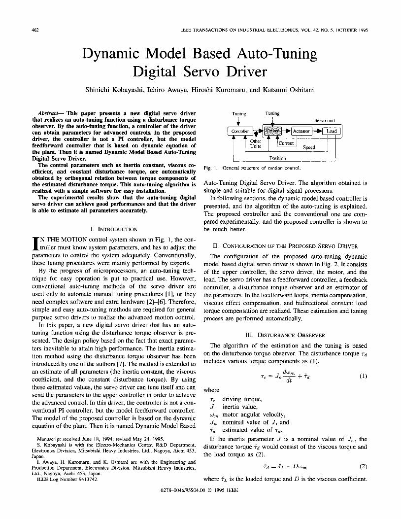
The configuration of the proposed auto-tuning dynamic model based digital servo driver is shown in Fig. 2. It consists of the upper controller, the servo driver, the motor, and the load. The servo driver has a feedforward controller, a feedback controller, a disturbance torque observer and an estimator of the parameters. In the feedforward loops, inertia compensation, viscous effect compensation, and bidirectional constant load torque compensation are realized. These estimation and tuning process are performed automatically.
111. DISTURBANCE OBSERVER The algorithm of the estimation and the tuning is based
on the disturbance torque observer. The disturbance torque 7 d includes various torque components as (1).
where
J W m
Jn
T c
Fd
driving torque, inertia value, motor angular velocity, nominal value of J , and estimated value of Td.
If the inertia parameter J is a nominal value of J n , the disturbance torque ?d would consist of the viscous torque and the load torque as ( 2 ) .
?d = ?A - Dw, ( 2 )
where ?L is the loaded torque and D is the viscous coefficient.
0278-0046/95$04.00 0 1995 IEEE
KOBAYASHI et al.: DYNAMIC MODEL BASED AUTO-TUNING DIGITAL SERVO DRIVER 463
Loaded Torque
1 Speed Feedback Signal
Fig. 2. Configuration of the driver.
In the actual system, the differential of the velocity is
m approximated by subtraction as shown in Fig. 3. A
5 - S t I Iv. ESTIMATION AND TUNING
A. Parameter J Fig. 3. Disturbance torque observer.
In the actual system, if the inertia value J has an error 6 J , the disturbance torque would be expressed as (3). and
+ d ( t ) = sJG,,(t) + Dwm(t) +TO sgn(w,(t)) (3)
where 6 JGm(t) w7n ( t ) Dwm ( t ) viscous torque, and TO sgm(w,,(t)) constant disturbance torque (ex. gravity). Now we assume that the velocity reference is periodical and
positive as (4) and (5); then (3) is multiplied by Gm(t ) and is integrated in the period of T as (6).
torque by inertia difference, differential of w, ( t ) ,
wm(t ) = w m ( t -TI, (4) W m ( f ) > 0, (5)
w,(t)2 d t JkT Td( t )Gm(t ) d t = 6 J ( k - l ) T ( k - 1 ) T
r k T J"'
+TO lkT sgn(w, ( t))bm( t ) dt .
(6) . ( k - 1 ) T
From the following orthogonalities
wm(t )Gm(t ) = 0 (7) Jk= ( k - 1 ) T
&(t) dt = 0. JkT ( k - 1 ) T
The inertia value J ( k ) at time k T is obtained as
where Jo is the initial inertia value.
B. Parameter D
(9)
The new inertia parameter J ( k ) is set in the feedfonvard controller, the feedback controller, and the observer. There- fore, the servo driver can compensate the inertia effect. After tuning the inertia, the output +d of the disturbance torque observer includes only the viscous coefficient D and the load torque as (10). So the viscous coefficient D can be derived from differences of and wm as (11).
?dt) = Dwm(t) + Tc sgn(w,(t)),
where
464
TABLE I PARAMETERS OF THE TESTED INDUCTION MOTOR
2.2kW
? < j ( t k ) is the estimated disturbance torque at t k and w m ( t k ) is the angular velocity at t k .
C. Parameter T,,, and Tdc After these estimations and renewals of the inertia and
the viscous coefficient, the output of the disturbance torque observer represents the constant disturbance torque. In some applications, the constant disturbance torque is different be- tween upward and downward, because of an effect of gravity. So the disturbance torque observer output is set as the upward- disturbance-parameter T,,, in upward velocity, and is set as the downward-one T d r in downward velocity.
IEEE TRANSACTIONS ON INDUSTRIAL ELECTRONICS, VOL. 42, NO. 5, OCTOBER 1995
V. EXPERIMENTAL RESULTS In order to show the feasibility of the digital servo driver, the
proposed algorithm is implemented in the digital servo driver for a 2.2-kW induction motor. The system configuration is explained as follows.
The current control, speed control, disturbance torque ob- server, and auto-tuning are executed by DSP (TMS320C25). The cycle time of the current control is 100 ps on DSP (40-MHz clock). The 12-b A/D converter is used for analog data acquisition. The PWM controller for the IGBT inverter and the encoder interface are realized with a Gate Array. Parameters of the tested induction servo motor are listed in Table I.
A. Inertia Estimation
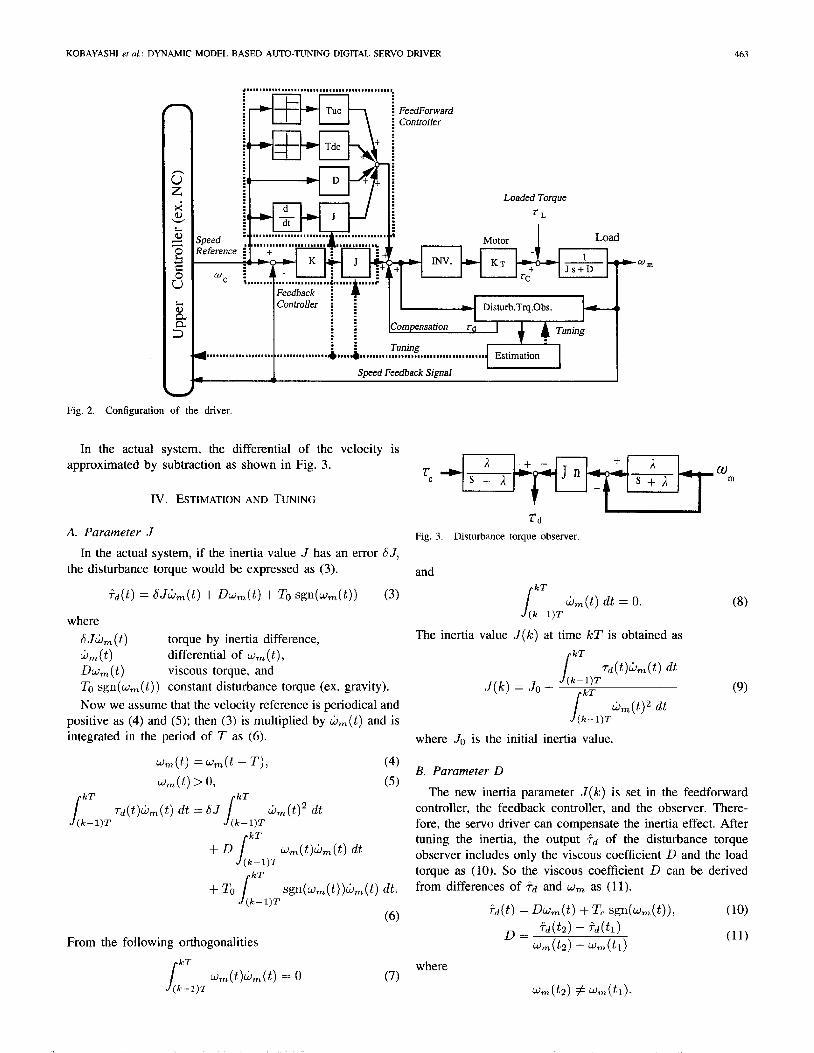
First, the inertia estimation error is shown in Fig. 4. In this figure, the largest estimation error is less than 5%. The estimation of the data acquisition error is due to hardware performance, the round off error, and the accuracy of period- icity. In the larger inertia, the estimation error is influenced by degradation of the orthogonality condition.
B. Auto-Tuning Procedure
Fig. 5 shows the output of the disturbance torque observer during the tuning interval. After the reset sequence of the DSP, the test signal is automatically generated during five cycles. The first cycle is used to produce the periodic signal condition for the orthogonality. The second cycle is used for the estimation and the tuning of the inertia.
In this figure, the sinusoidal component of the output due to the inertia variation is diminished after the second cycle.
L
The inertia values [kgm 2]
Fig. 4. Estimation error of the inertia.
1st 2nd 3rd 4th 5th
+ rotation cw
rotation ccw
Tuning Signal Extemal Command
Fig. 5. Actual spl,cd and observer output.
Third and forth cycles are used for the estimation and the tuning of the viscous coefficient. Fourth and fifth cycles are for upward and downward constant disturbance torque. After the test signals, even with the sinusoidal speed command, the output of the disturbance torque observer is nearly zero. The experimentdl result shows that the auto-tuning of model parameters has been completed successfully.
C. Tuning Performance
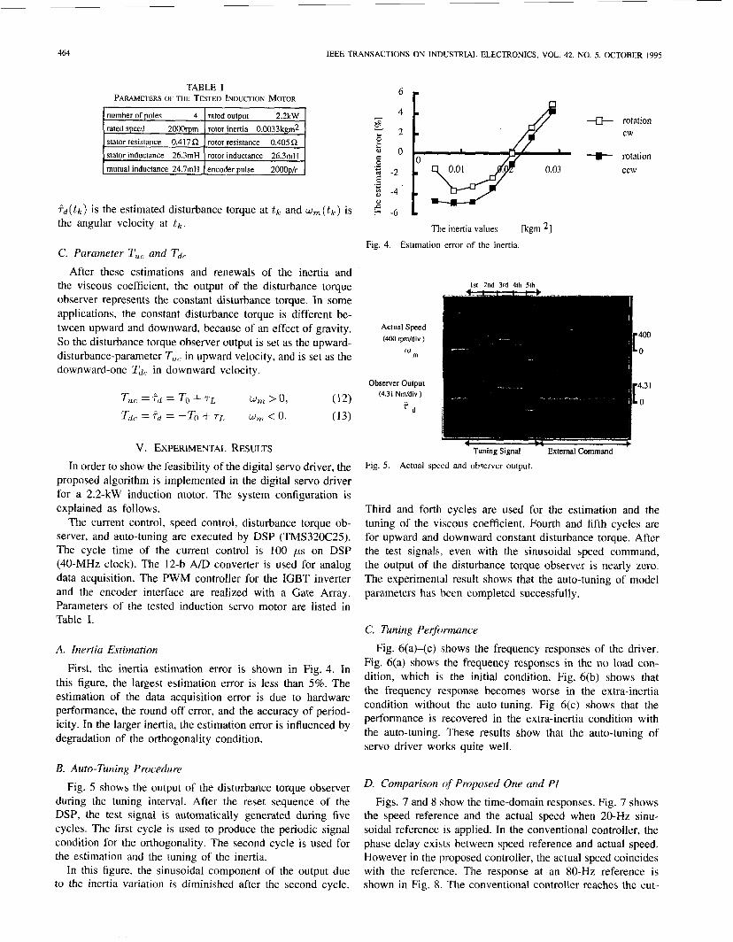
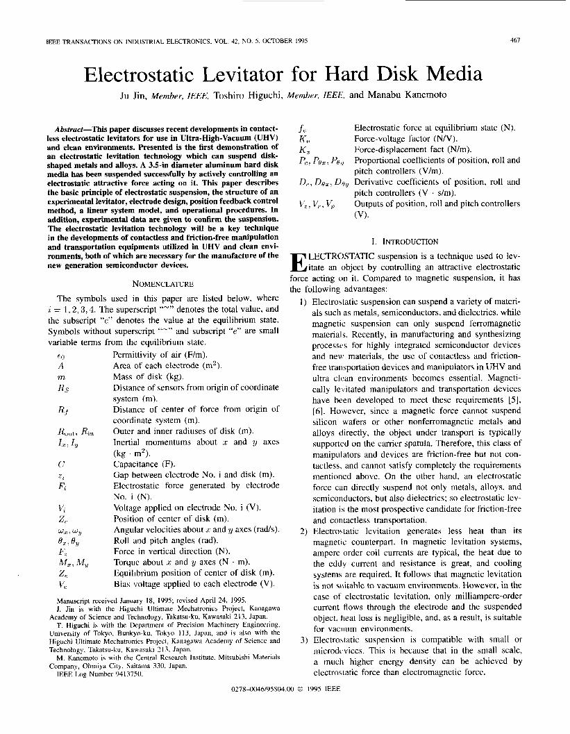
Fig. 6(a)-(c) 5hows the frequency responses of the driver. Fig. 6(a) shows the frequency responses in the no load con- dition, which i\ the initial condition. Fig. 6(b) shows that the frequency response becomes worse in the extra-inertia condition without the auto-tuning. Fig 6(c) shows that the performance is recovered in the extra-inertia condition with the auto-tuning. These results show that the auto-tuning of servo driver works quite well.
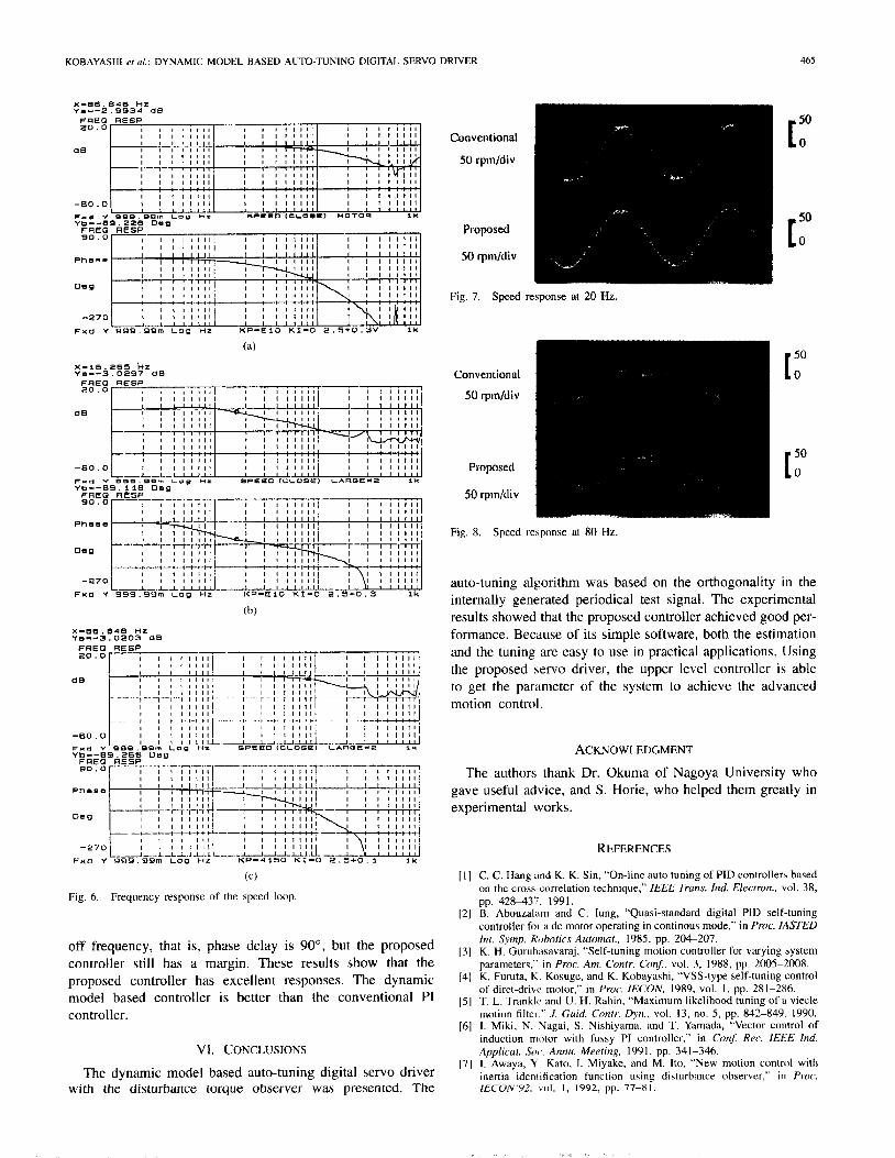
D. Comparison of Proposed One and PI Figs. 7 and 8 hhow the time-domain responses. Fig. 7 shows
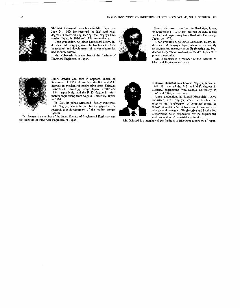
the speed reference and the actual speed when 20-Hz sinu- soidal reference is applied. In the conventional controller, the phase delay exists between speed reference and actual speed. However in the proposed controller, the actual speed coincides with the reference. The response at an 80-Hz reference is shown in Fig. 8. The conventional controller reaches the cut-
KOBAYASHI et al.: DYNAMIC MODEL BASED AUTO-TUNING DIGITAL SERVO DRIVER 465
X - 8 6 . 8 4 6 H Z Y . - - 2 . 9 9 3 4 d 0
I 1 1 1 1 1 1 1 I I I I I I I I
I I I I I I l l I I 1 1 1 1 1 1 I I I I l l 1 1
I I I I I I l l I I I 1 , 1 1 1 1 --*::
I I I I I I l l I I I I I I l l I I I I 1 1 1 1 I I 1 1 1 1 1 1 -60.0
F x d Y 9 o m . P Q r n Low U1 =PLED fCL0.C) M O T O R I* Yb---BS. 228 Dag
U
FREQ - 90.0- I I I I I I I I : I I I 1 l l l l I I I I I I l l
I I 1 1 1 1 1 1 / I I 1 1 1 1 1 1 I I I I I I t I
RESP
Ph0-C I 1 1 1 1 1 1 1
ueg
I I I I I I l l I I I I I I l l I I 1 1 1 1 1 1
I . - - l -J - l . I I I I I -270
I I I I I I I I
F x d Y 9 9 9 . 9 9 m L o g HZ K P - € 1 0 KI-0 2 . 5 + 0 . Y V l k
(a)
X - 1 6 . 2 6 i hz Y a - - - 3 . 0 2 9 7 d 0
(c )
Fig. 6. Frequency response of the speed loop.
off frequency, that is, phase delay is 90°, but the proposed controller still has a margin. These results show that the proposed controller has excellent responses. The dynamic model based controller is better than the conventional PI controller.
VI. CONCLUSIONS
The dynamic model based auto-tuning digital servo driver with the disturbance torque observer was presented. The
Fig. 7. Speed response at 20 Hz.
~ -
Fig. 8 Speed re*,ponse at 80 Hz.
auto-tuning algorithm was based on the orthogonality in the intemally generated periodical test signal. The experimental results showed that the proposed controller achieved good per- formance. Because of its simple software, both the estimation and the tuning are easy to use in practical applications. Using the proposed servo driver, the upper level controller is able to get the parameter of the system to achieve the advanced motion control.
ACKNOWLEDGMENT
The authors thank Dr. Okuma of Nagoya University who gave useful advice, and S. Horie, who helped them greatly in experimental works.
REFERENCES
C. C. Hang m d K. K. Sin, “On-line auto tuning of PID controllers based on the cross correlation techniaue.” IEEE Trans. Ind. Electron., vol. 38, pp. 428437. 1991. B. Abouzal‘im and C. lune, “Quasi-standard digital PID self-tuning
I _
controller foi a dc motor operating in continous mode,” in Proc. IASTED Int. Symp. Kohorics Automar., 1985, pp. 204-207. K. H. Guruhasavaraj, “Self-tuning motion controller for varying system parameters,” in Pror. Am. Conrr. Con$, vol. 3, 1988, pp. 2005-2008. K. Furuta, K Kosuge, and K. Kobayashi, “VSS-type self-tuning control of diret-drive motor,” in Proc. IECON, 1989, vol. I , pp. 281-286. T. L. Tranklc and U. H. Rabin, “Maximum likelihood tuning of a viecle motion tiltet.” J. Guid. Contr. Dw. , vol. 13, no. 5 , pp. 842-849, 1990. I . Miki, N. Nagai, S. Nishiyama, and T. Ydmada, “Vector control of induction motor with fussy PI controller,” in Conj: Rec. IEEE Ind. Applicar. So,. Annu. Meeting, 1991, pp. 341-346. I. Awaya, Y . Kato, I. Miyake, and M. [to, “New motion control with inertia iden! itication function using disturbance observer,” in Pror. [ECVN’YZ, Vol. I , 1992, pp. 77-81.
466 IEEE TRANSACTIONS ON INDUSTRIAL ELECTRONICS, VOL. 42, NO. 5, OCTOBER 1995
Shinichi Kobayashi was born in Mie, Japan, on June 24, 1960. He received the B.S. and M.S. degrees in electrical engineering from Nagoya Uni- versity, Japan, in 1984 and 1986, respectively.
Upon graduation, he joined Mitsubishi Heavy In- dustries, Ltd., Nagoya, where he has been involved in research and development of power electronics and motion control.
Mr. Kobayashi is a member of the Institute of Electrical Engineers of Japan.
Hiroshi Kuromaru was born in Hokkaido, Japan, on December 17, 1949. He received the B.E. degree in electrical engineering from Hokkaido University, Japan, in 1973
Upon graduation, he joined Mitsubishi Heavy In- dustries, Ltd., Nagoya, Japan, where he is currently an engineering manager in the Engineering and Pro- duction Department, working on the development of power electronics.
Mr. Kuromaru is a member of the Institute of Electncal Engineers of Japan.
Ichiro Awaya was born in Sapporo, Japan, on September 1 I, 1958. He received the B.E. and M.E. degrees in mechanical engineering from Shibaura Institute of Technology, Tokyo, Japan, in 1982 and 1984, respectively, and the Ph.D. degree in infor- mation engineering from Nagoya University, Japan, in 1994.
In 1984, he joined Mitsubishi Heavy Industries, Ltd., Nagoya, where he has been engaged in the research and development of the motion control system.
Dr Awaya is a member of the Japan Society of Mechanical Engineers and the Institute of Electrical Engineers ot Japan. Mr. Oshitani is ii me
Katsumi Oshitani was born in Nagoya, Japan, in 1943. He received the B.E. and M.E. degrees in electrical engineering from Nagoya University, in 1966 and 1968, respectively.
Upon graduation, he joined Mitsubishi Heavy Industries, Ltd., Nagoya, where he has been in research and development of computer control of industrial machinery. In his current position as a vice general manager of Engineering and Production Department, he is responsible for the engineering and production of industrial electronics.
:mber of the Institute of Electrical Engineers of Japan.
IEEE TRANSACTIONS ON INDUSTRIAL ELECTRONICS, VOL. 42, NO. 5. OCTOBEK 1995 467
Electrostatic Levitator for Hard Disk Media Ju Jin, Member, IEEE, Toshiro Higuchi, Member, IEEh:, and Manabu Kanemoto
Abstract-This paper discusses recent developments in contact- less electrostatic levitators for use in Ultra-High-Vacuum (UHV) and clean environments. Presented is the first demonstration of an electrostatic levitation technology which can suspend disk- shaped metals and alloys. A 3.5-in diameter aluminum hard disk media has been suspended successfully by actively controlling an electrostatic attractive force acting on it. This paper describes the basic principle of electrostatic suspension, the structure of an experimental levitator, electrode design, position feedback control method, a linear system model, and operational procedures. In addition, experimental data are given to confirm the suspension. The electrostatic levitation technology will be a key technique in the developments of contactless and friction-free manipulation and transportation equipments utilized in UHV and clean envi- ronments, both of which are necessary for the manufacture of the new generation semiconductor devices.
NOMENCLATURE
The symbols used in this paper are listed below, where i = 1 . 2 , 3 , 4 . The superscript ‘“” denotes the total value, and the subscript “e” denotes the value at the equilibrium state. Symbols without superscript ‘“” and subscript “e” are small variable terms from the equilibrium state.
Permittivity of air (F/m). Area of each electrode (m’). Mass of disk (kg). Distance of sensors from origin of coordinate system (m). Distance of center of force from origin of coordinate system (m). Outer and inner radiuses of disk (m). Inertial momentums about x and y axes (kg . m2). Capacitance (F). Gap between electrode No. i and disk (m). Electrostatic force generated by electrode No. i (N). Voltage applied on electrode No. i (V). Position of center of disk (m). Angular velocities about z and y axes (rads). Roll and pitch angles (rad). Force in vertical direction (N). Torque about .r and y axes (N . m). Equilibrium position of center of disk (m). Bias voltage applied to each electrode (V).
Manuscript received January 18, 19%; revised April 24, 1995. J. Jin is with the Higuchi Ultimate Mechatronics Project, Kanagawa
Academy of Science and Technology, Takatsu-ku, Kawasaki 213, Japan. T. Higuchi is with the Department of Precision Machinery Engineering,
University of Tokyo, Bunkyo-ku, Tokyo 113, Japan, and is also with the Higuchi Ultimate Mechatronics Project, Kanagawa Academy of Science and Technology, Takatsu-ku, Kawasaki 2 13, Japan.
M. Kanemoto is with the Central Research Institute, Mitsubishi Materials Company, Ohmiya City, Saitama 330, Japan.
IEEE Log Number 9413750.
.fe h‘, Force-voltage factor ( N N ) . Kz Force-displacement fact (N/m). Pc, Po,. Po(, Proportional coefficients of position, roll and
pitch controllers (Vim). Dc, Doz; U+, Derivative coefficients of position, roll and
pitch controllers (V . s/m). Vz , V,, V, Outputs of position, roll and pitch controllers
(V).
Electrostatic force at equilibrium state (N).
I. INTRODUCTION LECTROSTATIC suspension is a technique used to lev- E itate an object by controlling an attractive electrostatic
force acting cm it. Compared to magnetic suspension, it has the following advantages:
Electrostatic suspension can suspend a variety of materi- als such as metals, semiconductors, and dielectrics. while magnetic suspension can only suspend ferromagnetic materials. Recently, in manufacturing and synthesizing processvs for highly integrated semiconductor devices and new materials, the use of contactless and friction- free transportation devices and manipulators in UHV and ultra clcan environments becomes essential. Magneti- cally levitated manipulators and transportation devices have been developed to meet these requirements [ 5 ] , [6]. However, since a magnetic force cannot suspend silicon wafers or other nonferromagnetic metals and alloys directly, the object under transport is typically supported on the carrier spatula. Therefore, this class of manipulators and devices are friction-free but not con- tactless, and cannot satisfy completely the requirements mentioned above. On the other hand, an electrostatic force can directly suspend not only metals, alloys, and semiconductors, but also dielectrics; so electrostatic lev- itation is the most prospective candidate for friction-free and contactless transportation. Electrostatic levitation generates less heat than its magnetic counterpart. In magnetic levitation systems, ampere-order coil currents are typical, the heat due to the eddy current and resistance is great, and cooling systems are required. It follows that magnetic levitation is not suitable to vacuum environments. However, in the case of electrostatic levitation, only milliampere-order current flows through the electrode and the suspended object, heat loss is negligible, and, as a result, is suitable for vacuum environments. Electrostatic suspension is compatible with small or microdwices. This is because that in the small scale, a muclb higher energy density can be achieved by electrostatic force than electromagnetic force.
02784046/95$04.00 0 1995 IEEE
468 IEEE TRANSACTIONS ON IhDUSTRIAL ELECTRONICS, VOL. 42, NO. 5 , OCTOBER 1995
The main drawbacks of electrostatic suspension are: High voltage levels are required to achieve suspension, and the suspension stiffness is weaker than that of magnetic suspension for large device sizes, since the electrostatic force itself is weak. Consequently, electrostatic levitation techniques have not been studied extensively. Early research on electrostatic suspension was in relation to “electric vacuum gyros,” which were used as an inertial reference in the navigation system for Polaris submarines [ I ] . In recent years, this technique seems to have made a revival. Electrostatic suspension has been experimentally studied to eliminate the friction and physical contact i n microactuators and micromotors 121. During pre- liminary research towards the development of contactless and friction-free wafer manipulators for use in UHV and ultra clean environments, the authors have also succeeded in suspending a 4-in silicon wafer using electrostatic force [3].
In this paper, we describe an experimental electrostatic suspension system for hard disk media. A brief review of the basic principle of electrostatic suspension is given, followed by a description of the structure of the experimental suspension system, electrode design, position feedback control method, linear model of the system, and the experimental procedure. Experimental data are also presented to confirm the completely contactless suspension. Experimental investigations about the passive restrict force in the longitudinal and lateral direc- tions are also provided. Finally, problems which need to be addressed in future research are discussed.
11. PR1NCIPI.E OF ELECTROSTATIC SUSPENSION
A. Equation of Electrostatic Force
When the overlapping area of the electrode and the sus- pended object is large enough compared with the gap, to a close degree of approximation, the capacitance can be represented as
- E O A C = -
2
and the electrostatic attractive force is
B. Sparking Problem
When using electrostatic forces, care must be taken to avoid the occurrence of sparking. When the intensity of the electric field, V / Z in (2), is greater than a certain value, an electric discharge arises. For example, in the atmospheric environment, when the intensity of the electric field is greater than 3 kV/mm, sparking discharges occur. With this constraint, the avail- able maximum electrostatic force intensity is approximately 4.0 mN/cm2 in the atmospheric environment. By comparison, the discharge intensity is much higher in high vacuum. For instance, in an environment of pressure of lo-’ Torr, it has been reported that a field intensity as high as 15 kV/mm can be achieved at a field emission current less than 0.5 /LA [ 11. Therefore, in vacuum environments, greater electrostatic forces and higher suspension stiffnesses can be obtained.
Amp. Reference
I Electrode I I Electrode I ++++++++ + - _ _ - _ _ - _ _ - -
T T IT”+ r r r r Attractive Force
Position
Sensor - - - - - - - - * + + + + + +
Suspended Body
Fig. 1. Principle of electrostatic suspension.
C. Principle 01 Electrostatic Suspension
From ( 2 ) , we can easily find that the attractive electrostatic force is inversely proportional to the square of the gap between the electrode and the suspended object, so it is impossible to achieve a stable suspension without controlling the voltage applied to the clectrode. Fig. I is a schematic diagram of an electrostatic suspension system with one degree-of-freedom. It actively controls the movement of the suspended object in the vertical direction. The vertical position information from a displacement sensor is fed into a controller as feedback signal, and is compared to the reference position to generate an error signal. Then, the error signal is processed by a Proportional-Derivative (PD) controller to generate a control signal. The control signal is amplified by a high-voltage amplifier and applied to the electrode. The effect of this is to modify the force-gap characteristics such that the voltage, and thus the attractive force, increases as the gap increases, and vice versa. In the equilibrium position, the attractive iorce is balanced against that of gravity, the suspended object is stably suspended under the electrode at the desired air gap.
111. EXPERIMENTAL SYSTEM The experimental system we have developed for suspending
a hard disk media is shown in Fig. 2. The four copper electrodes, as shown in Fig. 3, are formed on a glass epoxy plate by etching process to 30-pm thicknesses. Each individual area is 14.5 cm’. The four electrodes together form the ring shape pattem, the outer and inner diameters of the ring are same as those oT the hard disk at 95 and 25 mm, respectively. The total electrode plate is supported and leveled by the three upper micrometer positioning screws. The suspended object, shown i i i Fig. 3, is a hard disk drive aluminum disk, with 95-mm outer diameter, 25-mm inner diameter, 0.775-mm thickness, and 13.6-g mass. The disk media is initially placed on the tops of three lower position screws under the electrodes. By adjusting thc height of each position screw, the disk can be leveled and the initial gap between the electrodes and the disk can be set. I‘o measure the position and orientation of the disk, four KEYElNCE eddy current displacement sensors, with sensitivity of 5 rnV/pm, are mounted on the electrode plate. The sensors are located at the corners of a square which can be circumscribed by a circle of radius 30 mm. From the outputs of four sensors, the position information in the vertical direction, and the rolling and pitching angles are calculated. They are fed into controllors as feedback signals. After going through
469 JIN rf 01.: ELECTROSTATIC‘ LEVITATOR FOR HARD DISK MEDIA
1 Lower I I I 1
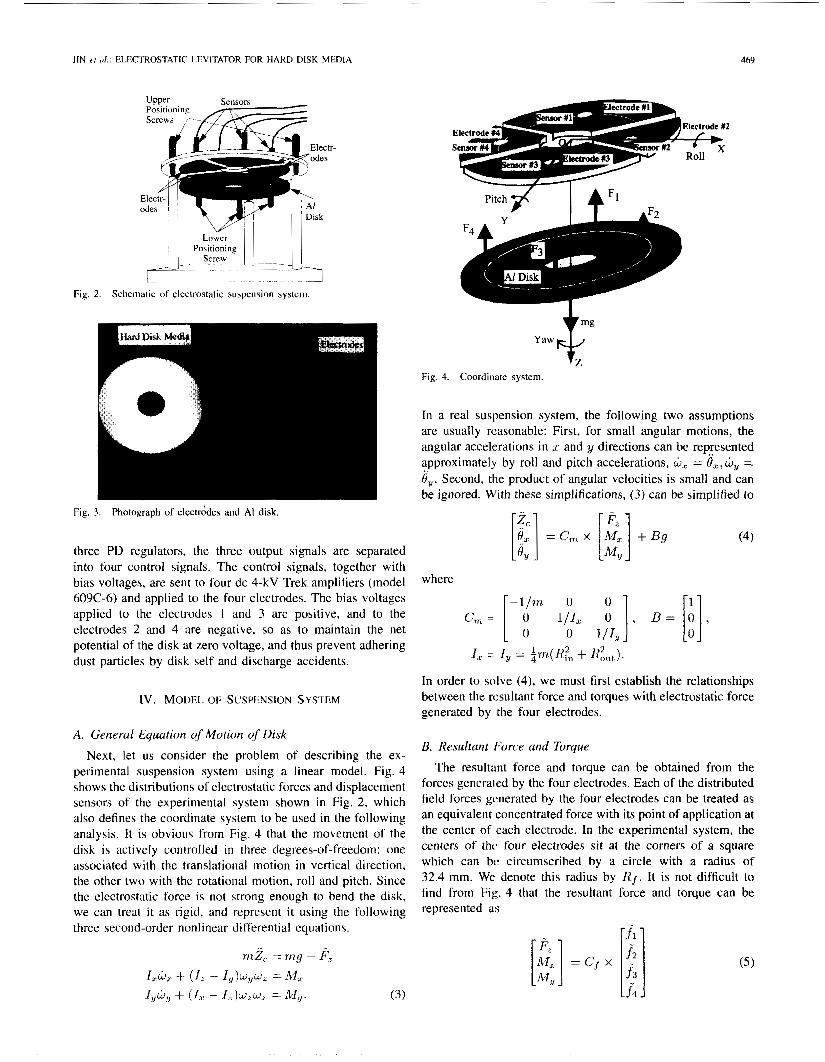
Fig. 2. Schematic of electrostatic suspension system.
Fig. 3. Photograph of electrddes and A1 disk.
three PD regulators, the three output signals are separated into four control signals. The control signals, together with bias voltages, are sent to four dc 4-kV Trek amplifiers (model 609C-6) and applied to the four electrodes. The bias voltages applied to the electrodes 1 and 3 are positive, and to the electrodes 2 and 4 are negative, so as to maintain the net potential of the disk at zero voltage, and thus prevent adhering dust particles by disk self and discharge accidents.
Iv. MODEL OF SUSPENSION SYSTEM
A. General Equation qf Motion of Disk Next, let us consider the problem of describing the ex-
perimental suspension system using a linear model. Fig. 4 shows the distributions of electrostatic forces and displacement sensors of the experimental system shown in Fig. 2 , which also defines the coordinate system to be used in the following analysis. It is obvious from Fig. 4 that the movement of the disk is actively controlled in three degrees-of-freedom: one associated with the translational motion in vertical direction, the other two with the rotational motion, roll and pitch. Since the electrostatic force is not strong enough to bend the disk, we can treat i t as rigid, and represent it using the following three second-order nonlinear differential equations.
yawF Fig. 4. Coordin‘ite system.
In a real suspension system, the following two assumptions are usually reasonable: First, for small angular motions, the angular accelerations in L and y directions can be represented approximately by roll and pitch accelerations, Ljd = Or, by = 8,. Second, the product of angular velocities is small and can be ignored. With these simplifications, (3) can be simplified to
where
- l /m 0
0 I , = I Y - 1 - 4 “*I + %“t 1.
In order to solve (4), we must first establish the relationships between the rcsultant force and torques with electrostatic force generated by the four electrodes.
E. Resultant Force and Torque
The resultant force and torque can be obtained from the forces generaced by the four electrodes. Each of the distributed field forces gvnerated by the four electrodes can be treated as an equivalent concentrated force with its point of application at the center of each electrode. In the experimental system, the centers of thc four electrodes sit at the comers of a square which can be circumscribed by a circle with a radius of 32.4 mm. We denote this radius by R f . It is not difficult to find from Fig. 4 that the rewltant force and torque can be represented a\
~
470 IEEE TRANSACTIONS ON INIXJSTKIAL ELECTRONICS, VOL. 42. NO. 5 , OCTOBEK 1995
where or
C. Linearized Equation of Motion
of motion of the disk as 113 114 114
where By inserting ( 5 ) into (4), we have the simplified equation
C, = [-1/2R,- 114 1 0
J I
Inserting (7)-( 10) into (6), we get the open-loop model of the suspension system
D. Linear Model of Suspension System
Equation (6) is still nonlinear because the four attractive forces are nonlinear, as shown in (2). Now let us linearize the force equations near the equilibrium state. When the suspension system is at the equilibrium state, the disk is stably suspended under the electrode plate at the equilibrium gap z p . Positive bias voltages of level 1; are applied to the electrodes 1 and 3; and negative bias voltage, -Ve. is applied to the electrodes 2 and 4. Additionally, the equilibrium attractive force balances against the weight of the disk
where
Each of the variables in ( 2 ) can be represented as a sum of we can see from ( 1 1 ) that the suspension system is ef- the value at the equilibrium state, plus a variable term which fectively a quadruple input and triple output system with is small compared with the equilibrium magnitudes. [VI V; v~ I.j]' as inputs and [Z,. O,c O?,]" as outputs.
By controlling ihe voltages applied to the four electrodes, it is possible to control the position and orientation of the disk.
2; = z , + z;. e. z= ((-1)(%-1) ( V e + v;), (1; = I, 2 , 3 , 4 ) . (8)
With these formulae, we can simplify the force equation ( 2 ) as v. INTEGRATED CONTROL STRATEGY
K,, 0 0 0 In our experiment, an integrated control method, one in which the position and orientation of the disk are controlled, is utilized as shown in Fig. 5. The variations of the position and orientation signals of the disk, calculated from the outputs of four displacemont sensors according to (IO) , are respectively
K , 0 0 0 fed into three compensators as feedback signals. The com- 0 K Z 0 (9) pensators compare each signal with the reference value and
regulate them using a PD algorithm. Then, the three outputs of the compensator are divided into four control voltage signals using (12). These control voltage signals are amplified by dc high-voltage amplifiers, and then applied to the respective
0 K,,,
where
&oAV,2 &- &OAK K, = -, EOAV; electrodes. fe = - 3 1' - 2 z," z: ' z:
(12) The vector [z l z2 z3 z4]* in (9) can be rewritten in
the form of [Z,. 8, O!, IT . In the experimental system, the sensor positions sit at the corners of a square which can be circumscribed by a circle with a radius 30 rnm, denoted by R s . From Fig. 4, it is not difficult to find the following relationship: where
L1/4 0
0
0 112
-112
JIN et al.: ELECTROSTATIC LEVITATOR FOR HARD DISK MEDIA 47 I
LC
*x
%
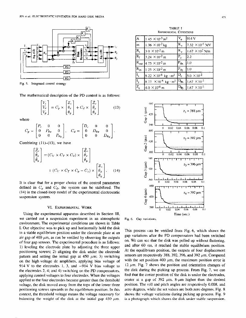
Fig. 5. Integrated control strategy.
The mathematical description of the PD control is as follows:
[;] = c p x [i:] + c d x
where
P, 0 0 C, = 0 Po,
Combining ( 1 1)-( 13), we have
f:] (13) OY
+ (C,. x cy x c, - C,) x [t]. (14)
It is clear that for a proper choice of the control parameters defined in C, and C d , the system can be stabilized. The (14) is the closed-loop model of the experimental electrostatic suspension system.
VI. EXPERIMENTAL WORK Using the experimental apparatus described in Section 111,
we carried out a suspension experiment in an atmospheric environment. The experimental conditions are shown in Table I. Our objective was to pick up and horizontally hold the disk in a stable equilibrium position under the electrode plate at an air gap of 400 pm, as can be verified by observing the outputs of four gap sensors. The experimental procedure is as follows: 1 ) leveling the electrode plate by adjusting the three upper positioning screws; 2) aligning the disk under the electrode pattern and setting the initial gap at 450 pm; 3) switching on the high-voltage dc amplifiers, applying bias voltage of 914 V to the electrodes 1, 3, and -914 V bias voltage to the electrodes 2, 4; and 4) switching on the PD compensators, applying control voltages to four electrodes. When the voltages applied to the four electrodes became greater than the threshold voltage, the disk moved away from the tops of the lower three positioning screws upwards to the equilibrium position. In this context, the threshold voltage means the voltage necessary for balancing the weight of the disk at the initial gap 450 pm.
TABLE I EXPERIMENTAL CONDITIONS
m 1.36 X 1 0 - 2 k g Kv 7.32 X N/V
I .67 X IO2 N/m Kz
460 I I I I I I
h
E 2. - 120 n -
3 80 d
z1 = 388 pn
0 0.02 0.04 0.06 0.08 0.1
460 - z2 = 392 pm
N
4 " 380 ,
0 0.02 0.04 0.06 0.08 0.1
z3 = 396 km ," 420
4 0
380 0 0.02 0.04 0.06 0.08 0.1
460
3
6
z. 420
P
z4 = 392 km
Time (sec.) Fig. 6. Gap variations.
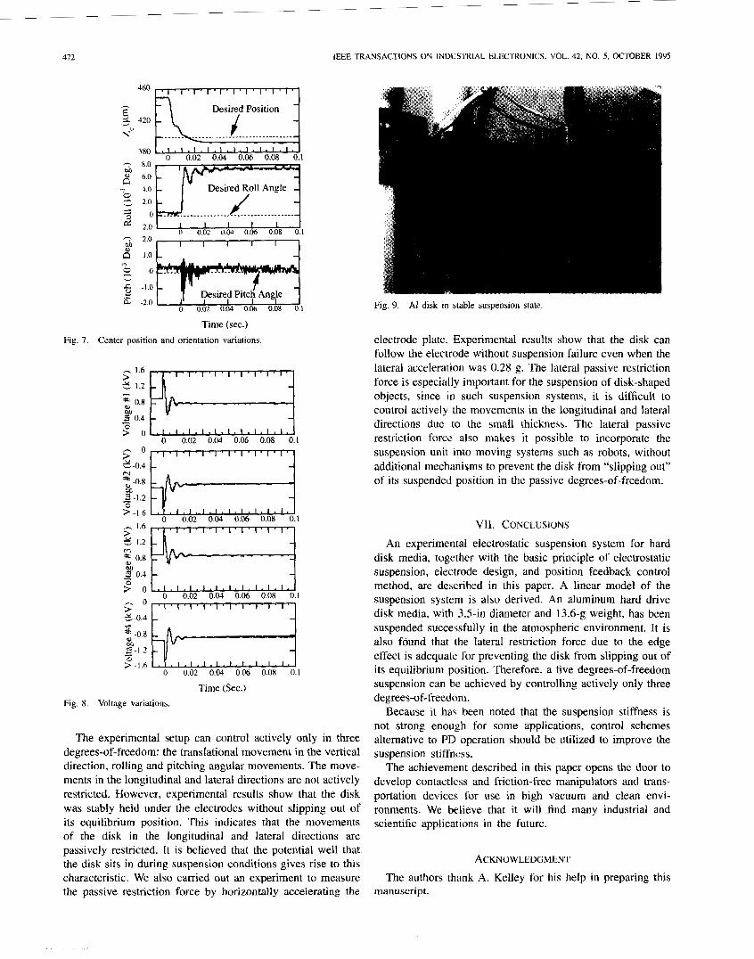
This process can be verified from Fig. 6, which shows the gap variations after the PD compensators had been switched on. We can see that the disk was pulled up without fluttering, and after 60 tns, it reached the stable equilibrium position. At the equilibrium position, the outputs of four displacement sensors are respectively 388,392, 396, and 392 pm. Compared with the set position 400 pm, the maximum position error is 12 pm. Fig. 7 shows the position and orientation changes of the disk during the picking up process. From Fig. 7, we can find that the center position of the disk is under the electrodes, center at a gap of 392 pm, 8-pm higher than the desired position. The I 011 and pitch angles are respectively 0.008, and zero degrees, while the set values are both zero degrees. Fig. 8 shows the vollage variations during picking up process. Fig. 9 is a photograph which shows the disk under stable suspension.
412 IEEE TRANSACTIONS ON INDUSTRIAL ELECTRONICS. VOL. 42, NO. 5 , OCTOBER 1995
380 0 0.02 0.04 0.06 0.08 0.1
&? -2.0
B 1.0 -
0 0.02 0.04 0.06 0.08 0.1 - 2.0 w I I I I I
0 0.02 0.W 0.06 0.08 0.1
Time (sec.) Fig. 7. Center position and orientation variations
ir! 0.4 ’ 0 0.02 0.04 0.06 0.08 0.1 s o . : t-1
Time (Sec.) Fig. 8. Voltage variations.
The experimental setup can control actively only in three degrees-of-freedom: the translational movement in the vertical direction, rolling and pitching angular movements. The move- ments in the longitudinal and lateral directions are not actively restricted. However, experimental results show that the disk was stably held under the electrodes without slipping out of its equilibrium position. This indicates that the movements of the disk in the longitudinal and lateral directions are passively restricted. It is believed that the potential well that the disk sits in during suspension conditions gives rise to this characteristic. We also carried out an experiment to measure the passive restriction force by horizontally accelerating the
Fig. 9. Al disk in stable suspension state
electrode plate. Experimental results show that the disk can follow the electrode without suspension failure even when the lateral acceleration was 0.28 g. The lateral passive restriction force is especially important for the suspension of disk-shaped objects, since in such suspension systems, it is difficult to control actively the movements in the longitudinal and lateral directions due to the small thickness. The lateral passive restriction force also makes it possible to incorporate the suspension unit into moving systems such as robots, without additional mechanisms to prevent the disk from “slipping out” of its suspended position in the passive degrees-of-freedom.
VII. CONCLUSIONS An experimental electrostatic suspension system for hard
disk media, together with the basic principle of electrostatic suspension, electrode design, and position feedback control method, are described in this paper. A linear model of the suspension system is also derived. An aluminum hard drive disk media, with 3.5-in diameter and 13.6-g weight, has been suspended successfully in the atmospheric environment. It is also found that the lateral restriction force due to the edge effect is adequate for preventing the disk from slipping out of its equilibrium position. Therefore, a five degrees-of-freedom suspension can he achieved by controlling actively only three degrees-of-freedom.
Because it ha\ been noted that the suspension stiffness is not strong enough for some applications, control schemes alternative to PD operation should be utilized to improve the suspension stiffness.
The achievement described in this paper opens the door to develop contactless and friction-free manipulators and trans- portation devices for use in high vacuum and clean envi- ronments. We believe that it will find many industrial and scientific applications in the future.
ACKNOWLEDGMENT
The authors thank A. Kelley for his help in preparing this manuscript.
SIN et al.: ELECTROSTATIC LEVITATOR FOR HARD DISK MEDIA 413
REFERENCES
[ I ] H. W. Knoehel, “The electric vacuum gyro,” Conrr. Eng., vol. 1 I , pp. 70-73, 1964.
[21 S. Kumar and D. Cho, et al., “Experimental study of electric suspension for microbearings,” J . Microelecrromechanical Sysf., vol. 1, no. I , pp. 23-30, 1992.
131 J. Jin, T. Higuchi, and M. Kanemoto, “Electrostatic silicon wafer suspension,” in Proc. 4th Int. Symp. Magnetic Bearings, 1994, pp. 343-348.
(41 W. K. Rhim, et al., “An electrostatic levitator for high-temperature containerless materials processing in I-g,” Rev. Sci. Insfrum., vol. 64, no. 10, pp. 2961-2970, 1993.
(51 K. Tamagawa, et al., “The future of ultra-high-vacuum,’’ ULVAC Tech- nical J . , no. 39, pp. 79-83, 1992 (in Japanese).
[6] M. Ota et al., “Mag-lev semiconductor wafer transporter for ultra-high- vacuum environment,” in Pmc. 2nd Int. Symp. Mugn. Bearings, 1990, pp. 109-114.
[7] B. V. Jayawant, Electromagnetic Levitation and Suspension Techniques. London: Edward Amold, 198 I .
[8] R. H. Frazier, P. J. Gillinson, and G. A. Oberheck, Magnetic and Electric Suspensions.
[9] E. H. Brandt, “Levitation in physics,” Sci., vol. 243, pp. 349-354, 1989. [ I O ] W. S. Griffin, H. H. Richardson, and S. Yamanami, ‘*A study of fluid
squeeze film damping,” ASME J. Basic Eng., pp. 451-456, 1966. [ I 11 J. Jin and T. Higuchi, “Self-sensing electrostatic suspension,” in Proc.
Int. ISEM Symp. Simulation and Design of Appl. Electromagn. Syst.,
[I21 J. Jin, “Magnetic suspension using tuned LC circuit,” Doctoral thesis,
Cambridge, MA: MIT Press, 1974.
1993, pp. 607-610.
Univ. of Tokyo, 1992.
Ju Jin (M’91) was hom in Shanxi, P.R.C., in December 1964. He received the B.S. degree in power engineering from Xi’an Jiao Tong University, P.R.C., in 1985, the M.S. degree in control systems from the Technology University of NagaOkd, Japan, 1989, and the Ph.D. degree in precision machinery engineering from the University of Tokyo, Japan, in 1992.
In 1992, he joined the Higuchi Ultimate Mecha- tronics Project, Kanagawa Academy of Science and Technology, where he is currently a researcher.
His primary research interests are concerned with electrostatic suspension, electrostatic propulsion, magnetic suspension, suspension using ac circuits, and superconductor levitation.
Dr. Jin is a member of the Society of Instrument and Control Engineers and the lnstitute of Electrical Engineers of Japan.
Toshiro Higuchi (M’87) was born in Ehime, Japan, in February 1950. He received the BS, M.S., and Ph.D. degrees in precision engineering from University of Tokyo, Japan, in 1972, 1974, and t977, respectively.
He was a lecturer at the Institute of Industrial Science, University of Tokyo, from April 1977 to March 1978, and an Associate Professor from April 1978 to November 1991 Since November 199 I , he has been a Professor in the Department of Precision Engmeenng, University of Tokyo. He also is the
leader of the Higuchi Ultimate Mechatronics Project, Kanagawa Academy of Science and Technology, Japan. His research interests include mechatronics, magnetic bearingr, electrostatic actuator, stepping motors, robotics, and man- ufacturing.
Dr. Higuchi is a member of the Japan Society for Precision Engineering, the Japan Society of Mechanical Engineers, and the Society of Instrument and Control Engineers.
Manabu Kanemoto was bom in Hyogo, Japan, in February 1967. He received the B.S. and M.S. degrees in materials engineering from Hokkaido University, Japan, in 1989 and 1991, respectively.
In 1991, he joined the Central Research Institute, Mitsubishi Materials Company, Saitama, Japan, where he is currently a researcher. He worked at the Higuchi Ultimate Mechatronics Project, Kanagawa Academy of Science and Technology from 1992 to 1994. His primary research interests are in electrostatic suspension, electrostatic propulsion,
and micromachines.
Engineers. Mr. Kanemoto is a member of the Society of Instrument and C lontrol