Chapter 5: Tuning - AutomationDirect
20
Page 5–1 SureServo2 User Manual – 1st Ed, Rev A – 08/09/2021 Chapter 5: Tuning 5 5 5 Chapter Chapter Chapter Table of Contents Chapter 5: Tuning � � � � � � � � � � � � � � � � � � � � � � � � � � � � � � � � � � � � � � � � � � 5–1 Introduction � � � � � � � � � � � � � � � � � � � � � � � � � � � � � � � � � � � � � � � � � � � � 5–2 5�1 - Tuning procedure and the applied mode � � � � � � � � � � � � � � � � � � � � � � � � � � � 5–2 5�1�1 - Flow chart for the tuning procedure � � � � � � � � � � � � � � � � � � � � � � � � � 5–2 5�1�2 - Tuning Modes � � � � � � � � � � � � � � � � � � � � � � � � � � � � � � � � � � � � � 5–3 5�2 - Auto tuning� � � � � � � � � � � � � � � � � � � � � � � � � � � � � � � � � � � � � � � � � � � � 5–4 5�2�1 - Flow chart for auto tuning � � � � � � � � � � � � � � � � � � � � � � � � � � � � � � 5–4 5�2�2 - Auto tuning through the drive keypad � � � � � � � � � � � � � � � � � � � � � � � � 5–6 5�2�3 - Auto tuning with SureServo2 (software) � � � � � � � � � � � � � � � � � � � � � � � 5–7 5�2�4 - Alarms related to auto tuning� � � � � � � � � � � � � � � � � � � � � � � � � � � � �5–13 5�3 - Tuning mode � � � � � � � � � � � � � � � � � � � � � � � � � � � � � � � � � � � � � � � � � � 5–14 5�3�1 - Flow chart of Tuning mode � � � � � � � � � � � � � � � � � � � � � � � � � � � � � � 5–14 5�3�2 - Gain Adjustment mode 1 � � � � � � � � � � � � � � � � � � � � � � � � � � � � � � � 5–15 5�3�3 - Gain Adjustment mode 2 � � � � � � � � � � � � � � � � � � � � � � � � � � � � � � � 5–15 5�3�4 - Gain Adjustment mode 3 � � � � � � � � � � � � � � � � � � � � � � � � � � � � � � � 5–15 5�3�5 - Setting the frequency response bandwidth (stiffness) � � � � � � � � � � � � � � � 5–16 5�3�6 - Gain response� � � � � � � � � � � � � � � � � � � � � � � � � � � � � � � � � � � � � �5–17 5�4 - Tuning in Manual mode � � � � � � � � � � � � � � � � � � � � � � � � � � � � � � � � � � � � 5–18 5�5 - Mechanical resonance suppression� � � � � � � � � � � � � � � � � � � � � � � � � � � � � � 5–20
-
Upload
khangminh22 -
Category
Documents
-
view
1 -
download
0
Transcript of Chapter 5: Tuning - AutomationDirect

Page 5–1SureServo2 User Manual – 1st Ed, Rev A – 08/09/2021
Chapter 5: Tuning 555ChapterChapterChapter
Table of ContentsChapter 5: Tuning � � � � � � � � � � � � � � � � � � � � � � � � � � � � � � � � � � � � � � � � � � 5–1
Introduction � � � � � � � � � � � � � � � � � � � � � � � � � � � � � � � � � � � � � � � � � � � � 5–25�1 - Tuning procedure and the applied mode � � � � � � � � � � � � � � � � � � � � � � � � � � � 5–2
5�1�1 - Flow chart for the tuning procedure � � � � � � � � � � � � � � � � � � � � � � � � � 5–25�1�2 - Tuning Modes � � � � � � � � � � � � � � � � � � � � � � � � � � � � � � � � � � � � � 5–3
5�2 - Auto tuning � � � � � � � � � � � � � � � � � � � � � � � � � � � � � � � � � � � � � � � � � � � � 5–45�2�1 - Flow chart for auto tuning � � � � � � � � � � � � � � � � � � � � � � � � � � � � � � 5–45�2�2 - Auto tuning through the drive keypad � � � � � � � � � � � � � � � � � � � � � � � � 5–65�2�3 - Auto tuning with SureServo2 (software) � � � � � � � � � � � � � � � � � � � � � � � 5–75�2�4 - Alarms related to auto tuning � � � � � � � � � � � � � � � � � � � � � � � � � � � � � 5–13
5�3 - Tuning mode � � � � � � � � � � � � � � � � � � � � � � � � � � � � � � � � � � � � � � � � � � 5–145�3�1 - Flow chart of Tuning mode � � � � � � � � � � � � � � � � � � � � � � � � � � � � � � 5–145�3�2 - Gain Adjustment mode 1 � � � � � � � � � � � � � � � � � � � � � � � � � � � � � � � 5–155�3�3 - Gain Adjustment mode 2 � � � � � � � � � � � � � � � � � � � � � � � � � � � � � � � 5–155�3�4 - Gain Adjustment mode 3 � � � � � � � � � � � � � � � � � � � � � � � � � � � � � � � 5–155�3�5 - Setting the frequency response bandwidth (stiffness) � � � � � � � � � � � � � � � 5–165�3�6 - Gain response� � � � � � � � � � � � � � � � � � � � � � � � � � � � � � � � � � � � � � 5–17
5�4 - Tuning in Manual mode � � � � � � � � � � � � � � � � � � � � � � � � � � � � � � � � � � � � 5–185�5 - Mechanical resonance suppression � � � � � � � � � � � � � � � � � � � � � � � � � � � � � � 5–20

Page 5–2 SureServo2 User Manual – 1st Ed, Rev A – 08/09/2021
Chapter 5: TuningM
onito
ring
DI/D
O C
odes
Para
met
ers
Alar
ms
Wiri
ng
IntroductionThis chapter contains information about the auto tuning procedure and the three tuning modes. Advanced users can also tune the servo system using the manual mode.
5.1 - Tuning procedure and the applied mode5.1.1 - Flow chart for the tuning procedure
You can tune the servo drive by following the flow chart below. First, start from the Auto Tuning mode. If you are not satisfied with the system’s performance, you can use Tuning modes 1, 2, 3 or Manual mode for tuning the servo system.
Motor runs smoothly without load
Enter Auto Tuning mode
Enter Tuning mode1, 2, or 3
Enter Manual mode
Complete
No
Yes
No
Yes
Yes
Yes
No
No
Satisfactoryperformance?
Satisfactoryperformance?
Satisfactoryperformance?
Satisfactoryperformance?

Chapter 5: Tuning
Page 5–3SureServo2 User Manual – 1st Ed, Rev A – 08/09/2021
Parameters
DI/D
O C
odesM
onitoringW
iringAlarm
s
5.1.2 - Tuning ModesP2.032 Setting
Value Adjustment Mode Inertia Estimation
ParameterManually Set Auto Tuning
0 Manual mode Value of P1�037
P1�037, P2�000, P2�004, P2�006, P2�023, P2�024, P2�025, P2�043, P2�044, P2�045, P2�046, P2�049, P2�089, P2�098, P2�099,
P2�101, P2�102
N/A
1 Gain adjustment mode 1
Real-time estimation P2�031
P1�037, P2�000, P2�004, P2�006, P2�023, P2�024, P2�025, P2�043, P2�044, P2�045, P2�046, P2�049, P2�089, P2�098, P2�099, P2�101,
P2�102
2 Gain adjustment mode 2 Value of P1�037 P1�037
P2�031
P2�000, P2�004, P2�006, P2�023, P2�024, P2�025, P2�043, P2�044, P2�045, P2�046, P2�049, P2�089, P2�098, P2�099, P2�101, P2�102
3 Gain adjustment mode 3 Value of P1�037
P1�037 P2�031 P2�089
P2�000, P2�004, P2�006, P2�023, P2�024, P2�025, P2�043, P2�044, P2�045, P2�046, P2�049, P2�098, P2�099, P2�101,
P2�102
4 Gain adjustment mode 4
Restore default gain settings - -
Note: Please refer to the parameters list in Section 5.3 Auto tuning.

Page 5–4 SureServo2 User Manual – 1st Ed, Rev A – 08/09/2021
Chapter 5: TuningM
onito
ring
DI/D
O C
odes
Para
met
ers
Alar
ms
Wiri
ng
5.2 - Auto tuningThe Auto Tuning function provided by the servo drive enables the system to perform real-time machine inertia estimation and upload the corresponding tuning parameters to the servo drive. You can start auto tuning with SureServo2 Pro (software) or at the drive panel. In general, Auto Tuning works best when the speed is set to at least 200 RPMs (500 preferred) during the tuning process. An inertia ratio of more than 50:1 can very easily cause the auto tuning algorithms to not succeed. It is highly recommended to add some sort of gear reduction between the motor and the load in order to reduce high inertia mismatches. The following table lists the parameters that change according to the results of auto tuning.
Gain Related Parameters Filter and Resonance Suppression Parameters
Parameter # Function Parameter # Function
P1�037 Inertia ratio and load weight ratio of servo motor P1�025 Low-frequency vibration
suppression (1)
P2�000 Position control gain P1�026 Low-frequency vibration suppression gain (1)
P2�004 Speed control gain P1�027 Low-frequency vibration suppression (2)
P2�006 Speed integral compensation P1�028 Low-frequency vibration suppression gain (2)
P2�031 Level of frequency response P2�023 Notch filter frequency (1)P2�032 Gain adjustment mode P2�024 Notch filter attenuation level (1)
P2�089 Command response gain P2�025 Low-pass filter of resonance suppression
- - P2�043 Notch filter frequency (2)- - P2�044 Notch filter attenuation level (2)- - P2�045 Notch filter frequency (3)- - P2�046 Notch filter attenuation level (3)
- - P2�049 Speed detection and jitter suppression
- - P2�098 Notch filter frequency (4)- - P2�099 Notch filter attenuation level (4)- - P2�101 Notch filter frequency (5)- - P2�102 Notch filter attenuation level (5)
5.2.1 - Flow chart for auto tuning You can perform the auto tuning using the drive keypad or SureServo2 Pro software. The Auto Tuning function in the SureServo2 servo drive helps you to find the most suitable parameters for your system according to the machine characteristics.
Auto tuning
Without the host controller: the back and forth path is set by
the servo drive.
Complete
Automatically estimates the inertia and starts to tune the system.
With the PLC or host controller: the path is planned by the host contoller.

Chapter 5: Tuning
Page 5–5SureServo2 User Manual – 1st Ed, Rev A – 08/09/2021
Parameters
DI/D
O C
odesM
onitoringW
iringAlarm
s
Note: when the running distance is configured by the host controller, make sure the delay time is added to the operation time. Otherwise, AL08C (Auto-tuning function - Pause time is too short) occurs and the servo drive cannot complete auto tuning.
You can use P2.105 (Auto-tuning Adjustment Bandwidth Level) and P2.106 (Auto-tuning Adjustment Overshoot Level) to adjust the responsiveness and rigidity in Auto Tuning mode. See the flow chart below.
Start
Enter Auto Tuning mode with SureServo2Pro or the drive panel
Change the setting of P2.106
Change the setting of P2.105
No
Yes
No
Yes
Complete
Satisfied with the responsiveness?
Satisfied with the rigidity?
Page 5–6 SureServo2 User Manual – 1st Ed, Rev A – 08/09/2021
Chapter 5: TuningM
onito
ring
DI/D
O C
odes
Para
met
ers
Alar
ms
Wiri
ng
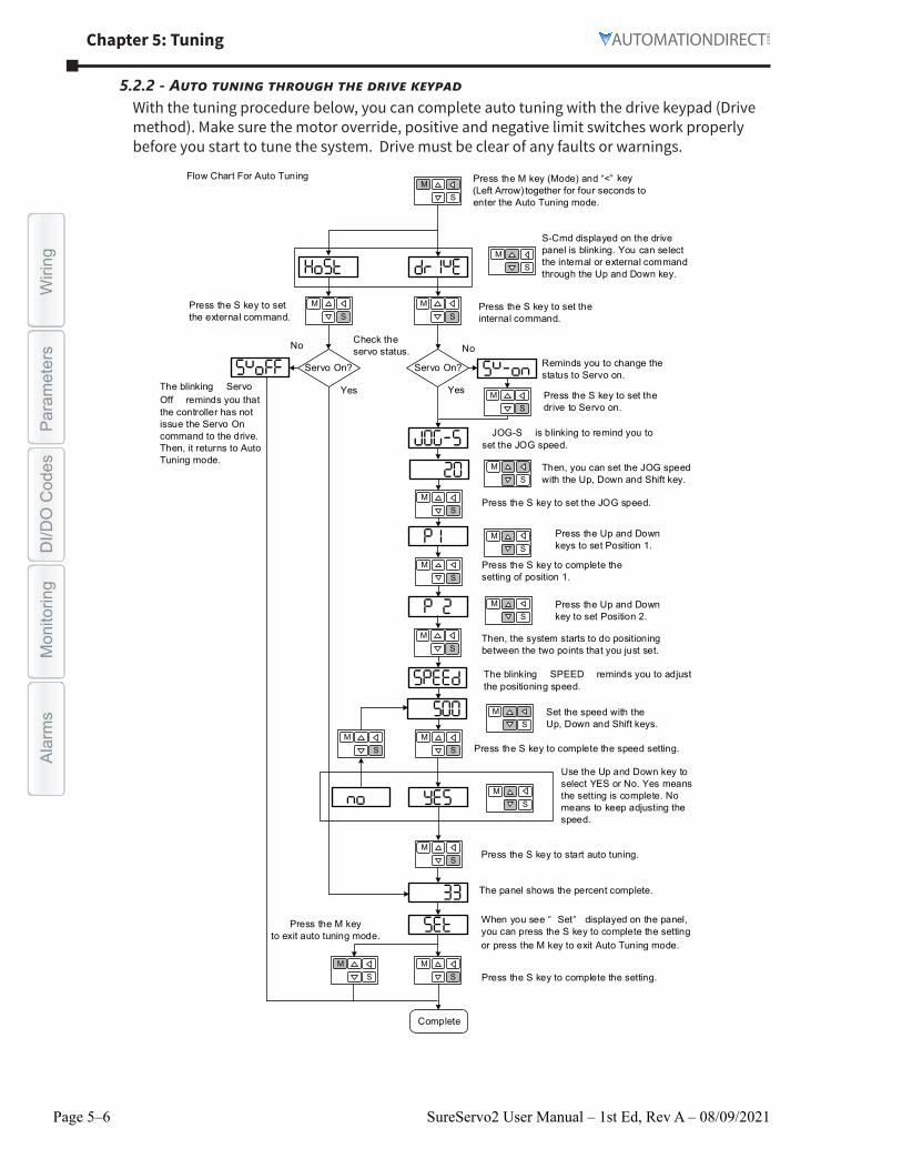
5.2.2 - Auto tuning through the drive keypadWith the tuning procedure below, you can complete auto tuning with the drive keypad (Drive method). Make sure the motor override, positive and negative limit switches work properly before you start to tune the system. Drive must be clear of any faults or warnings.
Press the M key (Mode) and “<” key (Left Arrow) together for four seconds to enter the Auto Tuning mode.S
M
S-Cmd displayed on the drive panel is blinking. You can select the internal or external command through the Up and Down key.
Press the S key to set the internal command.
Servo On? Servo On?
Check the servo status.No
YesYes
No
Complete
Reminds you to change the status to Servo on.
Press the S key to set the drive to Servo on.
JOG-S is blinking to remind you to set the JOG speed.
Then, you can set the JOG speed with the Up, Down and Shift key.
Press the S key to set the JOG speed.
Press the Up and Downkeys to set Position 1.
Press the S key to complete the setting of position 1.
Press the Up and Downkey to set Position 2.
Then, the system starts to do positioning between the two points that you just set.
The blinking SPEED reminds you to adjust the positioning speed.
Set the speed with the Up, Down and Shift keys.
Press the S key to complete the speed setting.
Use the Up and Down key to select YES or No. Yes means the setting is complete. No means to keep adjusting the speed.
Press the S key to start auto tuning.
The panel shows the percent complete.
Press the S key to complete the setting.
When you see “ Set” displayed on the panel, you can press the S key to complete the setting or press the M key to exit Auto Tuning mode.
Press the M keyto exit auto tuning mode.
Press the S key to set the external command.
The blinking Servo Off reminds you that the controller has not issue the Servo On command to the drive. Then, it returns to Auto Tuning mode.
Flow Chart For Auto Tuning
SM
SM
SM
SM
SM
SM
SM
SM
SM
SM
SM
SM
SM
SM
SM
SM
SM

Chapter 5: Tuning
Page 5–7SureServo2 User Manual – 1st Ed, Rev A – 08/09/2021
Parameters
DI/D
O C
odesM
onitoringW
iringAlarm
s
5.2.3 - Auto tuning with SureServo2 (software)Instead of using the drive keypad, you can use SureServo2 Pro to complete auto tuning. Please go to go2adc.com/sureservo2 to download SureServo2 Pro for free. Install the software and open the executable file (.exe). You will see the screen shown below.
Make sure the servo drive, servo motor and power are all properly connected. Then click Add to connect to the servo drive with SureServo2.There are two types of auto-tuning procedure, one uses a host controller such as a PLC and one using the servo drive keypad. Both procedures are described below.
Auto-tuning with host controllerThe host controller sends the commands to drive the motor.Step 1: When the computer is connected to the controller, the program window appears as below. Click Auto Tuning in the Function List tree view.

Page 5–8 SureServo2 User Manual – 1st Ed, Rev A – 08/09/2021
Chapter 5: TuningM
onito
ring
DI/D
O C
odes
Para
met
ers
Alar
ms
Wiri
ng
Step 2: Click Controller: Motion Command From Controller and make sure the motion/machining path is set correctly.
Suggestions: you should set the motor to operate at least one cycle in both forward and backward directions. It should reach the positions (in both forward and backward directions) in 1000 ms or less with the running speed not less than 500 rpm.

Chapter 5: Tuning
Page 5–9SureServo2 User Manual – 1st Ed, Rev A – 08/09/2021
Parameters
DI/D
O C
odesM
onitoringW
iringAlarm
s
Step 3: Enable the servo (Servo ON), then repeatedly start and run the motor with the path you just set. Before running the motor, make sure no one is standing close to the machinery. Then, click Next.
Wait until the tuning progress bar reaches 100%, after which a window with “Auto tuning completed” appears. Click OK to continue.

Page 5–10 SureServo2 User Manual – 1st Ed, Rev A – 08/09/2021
Chapter 5: TuningM
onito
ring
DI/D
O C
odes
Para
met
ers
Alar
ms
Wiri
ng
The screen shows a table comparing the parameters before and after being changed by auto tuning.
Click Update to save the new tuning parameters and complete auto tuning.Auto-tuning with servo drive
The servo drive sends the commands to drive the motor.Step 1:When the computer is connected to the servo drive, the program window appears as below. Click Auto Tuning in the Function List tree view.

Chapter 5: Tuning
Page 5–11SureServo2 User Manual – 1st Ed, Rev A – 08/09/2021
Parameters
DI/D
O C
odesM
onitoringW
iringAlarm
s
Step 2: Click Drive: Motion Command From Drive to start the Auto Tuning procedure.
Please follow the steps below to set the motor running path on the screen below:1) Set the system to Servo On state.2) Set the acceleration/deceleration time and jog speed. The default setting for
acceleration/deceleration time is 200 ms. Set the jog speed to no less than 500 rpm. The Jog speed in this field is also the tuning speed. Then click Download.
3) After you set the motor’s jog definition parameters, you can use the Left or Right button to jog the motor to position 1 and 2 (example: jog to the pick point and the place point on a pick and place application). Click on the Left or Right buttons to jog the motor into the machine’s starting position and click the Position 1 button. If the motor is connected to a belt or there is no “machine starting position”, simply click Position 1. Next, use the Left and Right buttons to move to the machine’s end-of-move position and press the Position 2 button. If there is no defined end-of-move position, simply move the motor some distance from position 1 so the Auto Tune feature can properly function. Then, click Start Moving to run between two positions. The motor moves to position 1 and 2 in the forward and backward directions.
Before running the motor, make sure no one is standing close to the machinery. After ensuring the motor is cycling back and forth between position 1 and position 2, press Next to start the Auto Tuning process.
Note: If AL007 (Position Deviation) appears when you attempt to jog the motor, you will need to increase the ACC/DEC time and/or decrease the Jog Speed. Press the Prev button to return to the previous screen and restart the procedure (this will re-Enable the servo).

Page 5–12 SureServo2 User Manual – 1st Ed, Rev A – 08/09/2021
Chapter 5: TuningM
onito
ring
DI/D
O C
odes
Para
met
ers
Alar
ms
Wiri
ng
Step 3: Wait until the tuning progress bar reaches 100%, after which a window with “Auto tuning completed” appears. Click OK to continue.
The screen shows a table comparing the parameters before and after being changed by auto tuning.

Chapter 5: Tuning
Page 5–13SureServo2 User Manual – 1st Ed, Rev A – 08/09/2021
Parameters
DI/D
O C
odesM
onitoringW
iringAlarm
s
Please click Update to complete auto tuning or Exit to discard the new settings.
5.2.4 - Alarms related to auto tuningIn Auto Tuning mode, it is vital that you program the command path, including the operation cycle (such as acceleration, constant speed and deceleration) and dwell time. See the figure below. When any of the settings are incorrect, the servo drive stops and displays an alarm. Please check the alarm causes and take corrective action.
Acc. time
Max. speed
Dwell
Operation cycle
Operation cycle
Speed
Time
Display Alarm name
AL007 Excessive Position Deviation
AL08A Auto-tuning function - Command error
AL08B Auto-tuning function - Inertia estimation error
AL08C Auto-tuning function - Pause time is too short

Page 5–14 SureServo2 User Manual – 1st Ed, Rev A – 08/09/2021
Chapter 5: TuningM
onito
ring
DI/D
O C
odes
Para
met
ers
Alar
ms
Wiri
ng
5.3 - Tuning modeApart from the Auto Tuning function described above, there are three other tuning modes you can use to fine tune the system. You can then easily complete tuning by increasing or decreasing the frequency response bandwidth level (P2.031). Please follow the tuning procedure in Section 5.1.
5.3.1 - Flow chart of Tuning mode
Start
Adjustment mode 1P2.032 = 1
Complete
No
Yes
No
Yes
Yes
Yes
No
No
Keep estimating the inertia ratio (P1.037)
Adjust P2.031 (Bandwidth level)
Adjust P2.031 (Bandwidth level), P1.037 (Inertia ratio)
Adjust P2.031 (Bandwidth level), P1.037 (Inertia ratio),P2.089 (Command response gain)
All parameters
can be adjusted in
Manual mode
Satisfactoryperformance?
Satisfactoryperformance?
Satisfactoryperformance?
P2.032 = 2
P2.032 = 3
Satisfactoryperformance?
Enter Manual modeP2.032 = 0
Adjustment mode 2
Adjustment mode 3

Chapter 5: Tuning
Page 5–15SureServo2 User Manual – 1st Ed, Rev A – 08/09/2021
Parameters
DI/D
O C
odesM
onitoringW
iringAlarm
s
5.3.2 - Gain Adjustment mode 1In this mode, the servo drive continues to estimate the system’s inertia and updates the value of parameter P1.037.
P2.032 Setting Value
Adjustment Mode Inertia EstimationParameter
Manual Tuning Auto Tuning
1 Gain adjustment mode 1 Real-time estimation P2�031
P1�037, P2�000, P2�004, P2�006, P2�023, P2�024, P2�025, P2�043, P2�044, P2�045, P2�046, P2�049, P2�089, P2�098, P2�099,
P2�101, P2�102
Requirements for inertia estimation:1) Motor speed increases from 0 rpm to 3000 rpm within 1.5 seconds.2) It is suggested to set the speed to 500 rpm or higher. The lowest speed should be no less
than 200 rpm.3) The load inertia should be less than 50 times the motor inertia.4) The change in the external force or inertia ratio cannot be too great.
5.3.3 - Gain Adjustment mode 2When gain adjustment mode 1 cannot meet your need, you can try gain adjustment mode 2 to tune the servo system. In gain adjustment mode 2, the system does not automatically estimate the inertia. You must set the correct mechanical inertia in parameter P1.037.
P2.032 Setting Value
Adjustment Mode Inertia EstimationParameter
Manual Tuning Auto Tuning
2 Gain adjustment mode 2 Value of P1�037 P1�037
P2�031
P2�000, P2�004, P2�006, P2�023, P2�024, P2�025, P2�043, P2�044, P2�045, P2�046, P2�049, P2�089, P2�098, P2�099, P2�101,
P2�102
Inertia estimation is applicable to most applications. However, when the machine does not comply with the requirements for inertia estimation, you have to set the correct inertia ratio in parameter P1.037.
5.3.4 - Gain Adjustment mode 3If your need cannot be met by gain adjustment mode 1 or 2, please select gain adjustment mode 3. Parameter P2.089 (Command Response Gain) is available in this mode. You can increase the gain value to shorten the response and settling time for the position command. However, if you set the parameter value too high, it might cause overshoot and machinery vibration. This function is only available when changing the command, such as the acceleration / deceleration application.
P2.032 Setting Value
Adjustment Mode Inertia EstimationParameter
Manual Tuning Auto Tuning
3 Gain adjustment mode 3 Value of P1�037
P1�037P2�031P2�089
P2�000, P2�004, P2�006, P2�023, P2�024, P2�025, P2�043, P2�044, P2�045, P2�046, P2�049, P2�098,
P2�099, P2�101, P2�102

Page 5–16 SureServo2 User Manual – 1st Ed, Rev A – 08/09/2021
Chapter 5: TuningM
onito
ring
DI/D
O C
odes
Para
met
ers
Alar
ms
Wiri
ng
5.3.5 - Setting the frequency response bandwidth (stiffness)You can use parameter P2.031 (frequency response bandwidth level) to tune the servo system in an easier and user-friendly way. With a fixed inertia ratio, when increasing the bandwidth level (P2.031), the servo’s bandwidth increases as well. If resonance occurs, please lower the parameter value by one or two bandwidth levels (you should adjust the bandwidth level according to the actual situation). For instance, if the value of P2.031 is 30, you can reduce the bandwidth level to 28. When adjusting the value of this parameter, the servo system automatically adjusts the corresponding parameters, such as P2.000 and P2.004.
Inertia ratio(P1.037)
Servo bandwidth
Level increases
5
26 Hz
84 Hz
28
Figure 5-1 Adjust the bandwidth level

Chapter 5: Tuning
Page 5–17SureServo2 User Manual – 1st Ed, Rev A – 08/09/2021
Parameters
DI/D
O C
odesM
onitoringW
iringAlarm
s
5.3.6 - Gain responseYou can use parameter P2.089 (Command responsiveness gain) to adjust the response. Increasing the gain can minimize the deviation between the position command and command response in intermittent duty zone. When adjusting the value of P2.089, please enable the function for two degrees of freedom (two dimensional control)(set P2.094 to 0x1000).
Figure 5-2 Adjust the gain response

Page 5–18 SureServo2 User Manual – 1st Ed, Rev A – 08/09/2021
Chapter 5: TuningM
onito
ring
DI/D
O C
odes
Para
met
ers
Alar
ms
Wiri
ng
5.4 - Tuning in Manual modeThe selection of the position and speed response frequency should be determined by the machinery stiffness and the application. Generally, for applications or machines that require high speed and high precision, higher frequency response bandwidth is required. However, increasing the response bandwidth might cause resonance. Thus, machinery with higher stiffness is used to solve this problem. When the resonance frequency is unknown, you can gradually increase the gain parameter values to increase the frequency resonance bandwidth. Then, decrease the gain parameter values until you hear the sound of the resonance. The following are the descriptions of the gain adjustment parameters.
Position control gain (KPP, parameter P2.000)This parameter determines the response of the position loop. The bigger the KPP value, the higher the response frequency of the position loop. This lowers following error and position error, and shortens the settling time. However, if you set the value too high, it can cause the machinery to vibrate or cause overshoot when positioning. The calculation of position loop frequency response is as follows:
Frequency response bandwidth of position loop (Hz) = KPP2π
Speed control gain (KVP, parameter P2.004)This parameter determines the response of speed loop. The bigger the KVP value, the higher the response frequency of the speed loop and the lower the following error. However, if you set the value too high, it could cause machinery resonance. The response frequency of the speed loop must be 4–6 times higher than the response frequency of the position loop; otherwise, the machinery might vibrate or it might cause overshoot when positioning. The calculation of speed loop frequency response is as follows:
Frequency response bandwidth of speed loop
fv = ( KVP2π ) × [ (1 + P1 − 37/10)
(1 + JL/JM) ] Hz
JM: Motor Inertia; JL: Load Inertia; P1.037: 0.1 (times)
When P1.037 (auto estimation or manually set value) is equal to the real inertia ratio (JL / JM), the real speed loop frequency response is:
fv = ( KVP2π ) Hz
Speed integral compensation (KVI, parameter P2.006)The higher the KVI value, the better the elimination of the deviation. However, if you set the value too high, it can cause the machinery to vibrate. It is suggested that you set the value as follows:
KVI ( P2.006 ) ≤ 1.5 × Speed loop frequency response

Chapter 5: Tuning
Page 5–19SureServo2 User Manual – 1st Ed, Rev A – 08/09/2021
Parameters
DI/D
O C
odesM
onitoringW
iringAlarm
s
Low-pass filter for resonance suppression (NLP, parameter P2.025)A high inertial value ratio reduces the frequency response of the speed loop. Therefore, you must increase the KVP value to maintain the response frequency. Increasing KVP value might cause machinery resonance. Please use this parameter to eliminate the noise from resonance. The higher the value, the better the capability for reducing high-frequency noise. However, if you set the value too high, it can cause instability in the speed loop and overshoot in positioning. It is suggested that you set the value as follows:
NLP (P2.025) ≤ 10000
6 × Speed loop frequency response (Hz)
Anti-interference gain (DST, parameter P2.026)Use this parameter to increase the ability to resist external force and eliminate overshoot during acceleration / deceleration. The default value is 0. Adjusting this value in Manual mode is not suggested unless it is for fine-tuning.
Position feed forward gain (PFG, parameter P2.002)This parameter can reduce the position error and shorten the settling time. However, if you set the value too high, it might cause overshoot in positioning. If the setting of the e-gear ratio is larger than 10, it might cause noise as well.

Page 5–20 SureServo2 User Manual – 1st Ed, Rev A – 08/09/2021
Chapter 5: TuningM
onito
ring
DI/D
O C
odes
Para
met
ers
Alar
ms
Wiri
ng
5.5 - Mechanical resonance suppressionFive sets of notch filters are provided to suppress mechanical resonance. You can set all five to the auto resonance suppression parameter (P2.047) with manual adjustment.Please see the following flowchart for manual adjustment.
Yes
No
No
Use the system analysis tool in SureServo2 Pro to display the point of resonance.
Save the value of resonance frequency toP2.023 and set P2.024 to 4.
Increase the value of P2.024
Complete
Tuning completed
Yes
High-frequencyresonance?
Resonanceeliminated?
The servo issues the command to accelerate and decelerate the
motor alternatively.