
Chapter 5 - Renishaw resource centre
18
UNDERSTANDING NON-CONTACT TOOL SETTING PD-4114-9043-02-C Issue: 2 Date: 25.10.2003 Understanding non-contact tool setting
-
Upload
khangminh22 -
Category
Documents
-
view
1 -
download
0
Transcript of Chapter 5 - Renishaw resource centre

UNDERSTANDING NON-CONTACT TOOL SETTINGPD-4114-9043-02-C
Issue: 2 Date: 25.10.2003
Understanding non-contact tool setting

© 2003 Renishaw plc. All rights reserved.
Renishaw® is a registered trademark of Renishaw plc.
This document may not be copied or reproduced in whole or in part, or transferred to any other media orlanguage, by any means, without the prior written permission of Renishaw.
The publication of material within this document does not imply freedom from the patent rights ofRenishaw plc.
Disclaimer
Considerable effort has been made to ensure that the contents of this document are free frominaccuracies and omissions. However, Renishaw makes no warranties with respect to the contents of thisdocument and specifically disclaims any implied warranties. Renishaw reserves the right to make changesto this document and to the product described herein without obligation to notify any person of suchchanges.
Trademarks
All brand names and product names used in this document are trade names, service marks, trademarks,or registered trademarks of their respective owners.

3
Contents1 FACTORS AFFECTING ACCURACY................................................................ 4
1.1 Alignment of the laser beam with the machine’s axis .......................... 4X/Y-Axis Error ........................................................................................................... 4Z-Axis error – Measuring on the tool centreline ........................................................ 5Z-Axis error – Measuring with a radial offset ............................................................ 5
1.2 Measuring anywhere in the beam ....................................................... 61.3 Effective beam diameter...................................................................... 61.4 Minimum tool size................................................................................ 61.5 Spindle speed / speed of response ..................................................... 71.6 Tool profile........................................................................................... 81.7 Feed per revolution.............................................................................. 81.8 Cleanliness of tool ............................................................................... 91.9 Geometrical changes during operation................................................ 91.10 Spindle pull-up................................................................................... 101.11 Turbulence within the laser beam...................................................... 10
2 BEST PRACTICES TO REDUCE MEASUREMENT ERRORS ....................... 112.1 System alignment – separate systems.............................................. 112.2 Optimal method of achieving machining accuracy ............................ 122.3 Setting tools using single standard reference.................................... 142.4 Establishing the length of a calibration tool ....................................... 152.5 Case study......................................................................................... 162.6 Product Performance ........................................................................ 17

4
Issue 2 pd-4114-9043-02-c understanding non-contact tool setting
1 FACTORS AFFECTING ACCURACY
1.1 Alignment of the laser beam with the machine’s axisA poorly aligned system will result in measurement errors when setting tools. Whenconsidering a VMC, the error relative to the X/Y and Z-axes are of importance. The errorrelative to the X/Y-axis is of importance when measuring tools of different diameter. The errorrelative to the Z-axis is of importance when measuring the length of tools of different diameterson the tool’s centreline. The following diagrams show how to estimate these errors.
1.1.1 X/Y-Axis Error
Figure 1.1a
It is recommended that X/Y-axis alignment should be better than 1 mm per 100 mm.
For example if the maximum tool diameter being used were 100 mm, the respective errorwould be:
� ��CosRtRtEr *��
� �Er Cos� �50 50 0573* .mEr �5.2�
Key :� = Laser Beam miss-alignment Angle with
iR = Tool RadiusEl = LengthE
Rm
�
�
Rt
Er
Key :� = Laser beam misalignment angle with machine X/Y axisRt = Tool radiusRm = Measured radiusEr = Tool radius error
�
�
CosRtRmRtRmCos
���
�
)*( �CosRtRtErRmRtEr���
��
Cutting tool
Laser beam
Laser beam
Cutting tool
Rm Rt

5
Issue 2 pd-4114-9043-02-c understanding non-contact tool setting
1.1.2 Z-Axis error – Measuring on the tool centreline
It is recommended that Z-axis alignment should be better than 10 µm per 100 mm. Forexample if the maximum tool diameter being used were 100 mm, the respective errorwould be:
�TanRtEl *�
El Tan� 50 0 006* .mEl �5�
In reality both the X/Y & Z-axis errors are less than this due to the fact that the individualtool errors are relative to the calibration tool.
1.1.3 Z-Axis error – Measuring with a radial offset
From earlier calculations, Ref Fig1.1b, the length error when measuring on centre wasexpressed as:
�TanRtEl *�
When using a radial offset, Rt is substituted for R, where: 22 RoffsetRtR ��
Thus 22 RoffsetRtTanEl �� �
It can be seen that as Roffset tends to Rt, the error in length, El tends to zero. Therefore wherepossible tools to be measured for length should incorporate a radial offset. The radial offsetshould be slightly inside the tool tip radius. i.e. tool radius –1.0 mm
Key :� = Laser beam misalignment angle with machine Z axisRt = Tool radiusEl = length error
Rt
El�
�
�
TanRtElRtElTan
���
�
Cutting tool
Laser beam
Laser beam
Rt RoffsetR
Cutting tool
Key :� = Laser beam misalignment angle with machine Z axis, Fig 1.1bRt = Tool radiusRoffset = Tool radius offset relative to laser beamEl = Length error
Figure 1.1b
Figure 1.1c

6
Issue 2 pd-4114-9043-02-c understanding non-contact tool setting
1.2 Measuring anywhere in the beamA tool can be measured anywhere along the laser beambetween the transmitter and receiver as the system isrepeatable at any position. Accuracy will vary if tools aremeasured at positions other than at the point ofcalibration. This variation is due to diffraction of light asthe tool obscures the laser beam.
It is recommended that the user should choose a position at which all measurements will beconducted, and then calibrate the system at this measurement point.
1.3 Effective beam diameterRenishaw’s non-contact tool setters use a MicroHoleTM to provide continual protection to theoptics and to control the profile / size of the laser beam. As the laser beam passes through thetransmitter MicroHoleTM the beam diverges slightly due to diffraction. The laser beam thereforeprogressively increases in size until it reaches the receiver MicroHoleTM. At this point a smallsection of the centre of the laser beam falls incident upon the receiver photodiode. For an NC1system this is 0.4mm in diameter. Therefore the size of the laser beam that can be seen withthe human eye is not representative of the part of the laser beam used to measure / detect thetool.
1.4 Minimum tool sizePrecise calculation of this is complex and needs to consider the geometry of the tool as wellas the convergence / divergence of the transmitter beam. There are two main factors thataffect the minimum tool size that can be measured with Renishaw non-contact tools setting/ detection systems.
The receiver will issue a trigger when its incident power drops by 50%. This can be achievedby a small tool either:
i) Close to the transmitter and obscuring 50% of the beam width, Or
ii) Close enough to the receiver to produce a crisp shadow 50% of the width of thereceiver MicroHoleTM.
See Section 2.5 detailing the results of a case study determining the minimum tool size thatcan be measured / detected for different Renishaw non-contact systems and operatingseparations.
7
Issue 2 pd-4114-9043-02-c understanding non-contact tool setting
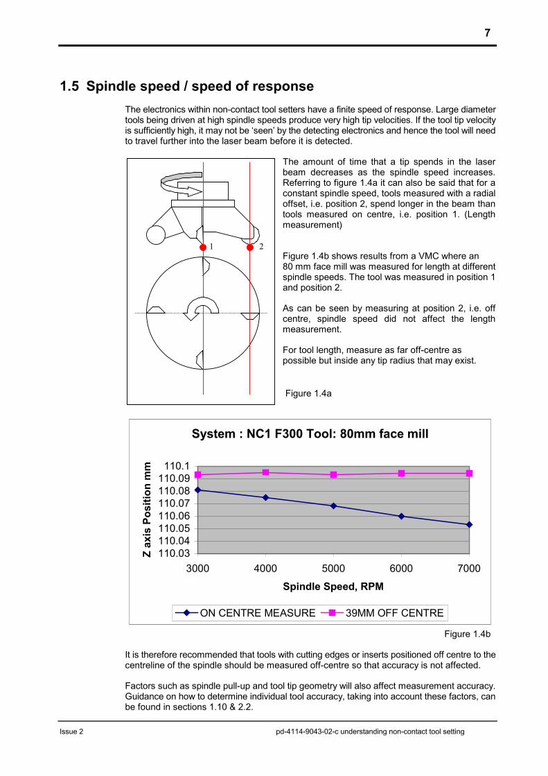
1.5 Spindle speed / speed of responseThe electronics within non-contact tool setters have a finite speed of response. Large diametertools being driven at high spindle speeds produce very high tip velocities. If the tool tip velocityis sufficiently high, it may not be ‘seen’ by the detecting electronics and hence the tool will needto travel further into the laser beam before it is detected.
The amount of time that a tip spends in the laserbeam decreases as the spindle speed increases.Referring to figure 1.4a it can also be said that for aconstant spindle speed, tools measured with a radialoffset, i.e. position 2, spend longer in the beam thantools measured on centre, i.e. position 1. (Lengthmeasurement)
Figure 1.4b shows results from a VMC where an 80 mm face mill was measured for length at differentspindle speeds. The tool was measured in position 1and position 2.
As can be seen by measuring at position 2, i.e. offcentre, spindle speed did not affect the lengthmeasurement.
For tool length, measure as far off-centre aspossible but inside any tip radius that may exist.
System : NC1 F300 Tool: 80mm face mill
110.03110.04110.05110.06110.07110.08110.09
110.1
3000 4000 5000 6000 7000
Spindle Speed, RPM
Z ax
is P
ositi
on m
m
ON CENTRE MEASURE 39MM OFF CENTRE
Figure 1.4b
It is therefore recommended that tools with cutting edges or inserts positioned off centre to thecentreline of the spindle should be measured off-centre so that accuracy is not affected.
Factors such as spindle pull-up and tool tip geometry will also affect measurement accuracy.Guidance on how to determine individual tool accuracy, taking into account these factors, canbe found in sections 1.10 & 2.2.
Figure 1.4a
1 2
8
Issu
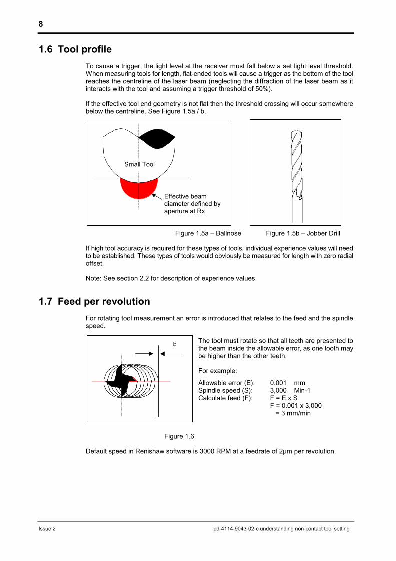
1.6 Tool profileTo cause a trigger, the light level at the receiver must fall below a set light level threshold.When measuring tools for length, flat-ended tools will cause a trigger as the bottom of the toolreaches the centreline of the laser beam (neglecting the diffraction of the laser beam as itinteracts with the tool and assuming a trigger threshold of 50%).
If the effective tool end geometry is not flat then the threshold crossing will occur somewherebelow the centreline. See Figure 1.5a / b.
1.
Small Tool
e 2
7 F
Effective beamdiameter defined by
pd-4114-9043-02-c underst
Figure 1.5a – Ballnose Figu
If high tool accuracy is required for these types of tools, individual eto be established. These types of tools would obviously be measureoffset.
Note: See section 2.2 for description of experience values.
eed per revolutionFor rotating tool measurement an error is introduced that relates tspeed.
The tool must rotate so thatthe beam inside the allowabbe higher than the other tee
For example:
Allowable error (E): 0.0Spindle speed (S): 3,0Calculate feed (F): F =
F = =
Figure 1.6
Default speed in Renishaw software is 3000 RPM at a feedrate of
aperture at Rx
E
anding non-contact tool setting
re 1.5b – Jobber Drill
xperience values will needd for length with zero radial
o the feed and the spindle
all teeth are presented tole error, as one tooth mayth.
01 mm00 Min-1 E x S 0.001 x 3,000 3 mm/min
2µm per revolution.

9
Issue 2
1.8 Cleanliness of toolIf there is any debris or coolant on the end of the tool, measurement accuracy / repeatabilitycan be affected. The difference in length between a dry and wet tool can vary up to 100microns. This length variation is due to the coolant film on the tool itself. Diameter can also beaffected.
Tools should be free of debris and dry prior to conducting a measuring routine. StandardRenishaw non-contact probing routines spin the tool prior to a probing cycle to reduce thechances of obtaining a false measurement. Some applications benefit from fitting an air blastto clean the tool prior to a probing routing.
1.9 Geometrical changes during operationThermal growth of the machine tool is an important factor when looking for consistency ofmeasurements over a period of time. Consider the following:
� Environmental stability – Opening doors, windows or climatic changes will affect thestability of the system.
� Machine growth – Heat generated within the ball screws and spindle can affect themeasurement accuracy and stability. Ensure that the machine has undergone a warm-upcycle prior to conducting measurements if it has been left idle for a while.
� Machine bed deflection – When clamping work pieces to the bed of the machine,deflections can occur due to the introduction of stresses.
Figure 1.8 shows how the z-axis position varied over a period of a couple of minutes, due tothermal growth of the spindle. A 10mm slot drill was measured for length on a VMC machinetool using a non-contact tool setter
pd-4114-9043-02-c understanding non-contact tool setting
Figure 1.8
If diameter measurements are taken from both sides of the tool, the effects of any smallmovement is not seen. This assumes that both Y+ and Y- probing measurements move by thesame amount resulting in the diameter staying constant.
Spindle growth over 30 readings
96.020
96.022
96.024
96.026
96.028
96.030
96.032
96.034
1 3 5 7 9 11 13 15 17 19 21 23 25 27 29
Reading
Z A
xis
Posi
tion,
mm

10
Issue 2 pd-4114-9043-02-c understanding non-contact tool setting
1.10 Spindle pull-upCertain spindle / shank designs are prone to an effect known as spindle pull-up. This effectis due to the centripetal forces affecting the position of the tool tip. I.e. At high spindle speedsthe tool retracts further up into the spindle. There are two known reasons for this: firstly theISO taper can expand and the forces from the pull stud cause the shank to move deeper intothe spindle. The second is due to the spindle cartridge moving. Where possible the tool shouldbe measured at a similar speed to that at which the tool will be used.
For tools being used at very high spindle speeds, the magnitude of spindle pull-up may requiredetermining. As explained earlier, the speed of response should be considered when runningat high spindle speeds. The following procedure may be adopted which determines themagnitude of pull-up:
� Load a solid, flat-bottomed pin into the spindle. The tool needs to be flat bottomed so thatthe speed of response is not a factor.
� Measure the length of the pin at the speed at which all tools will be measured by the non-contact tool setter, approx. 3000 RPM. Then measure the pin at the speed at which thetool will be used at when cutting material. I.e. higher than 3000 RPM.
� The difference in the two values is the amount of spindle pull-up, i.e. the difference in theZ axis position of the tool tip. This also includes factors such as tool tip geometry andspeed of response of the system. Tools that are used at this cutting speed will need theirexperience values corrected by this amount.
Figure 1.9 shows the spindle Z movement for a particular VMC when calibrating using a solidtool over a range of spindle speeds. Both taper and face & taper tool locations are shown.Each machine will require characterising, do not use the values shown below.
RPM Taper only Error, mm Face & Taper Error, mm3000 137.292 N/A 137.293 N/A5000 137.289 -0.003 137.290 -0.0037000 137.287 -0.004 137.290 -0.0039000 137.287 -0.005 137.287 -0.006
11000 137.282 -0.010 137.287 -0.00613000 137.277 -0.015 137.286 -0.00715000 137.276 -0.016 137.288 -0.00517000 137.268 -0.024 137.288 -0.00519000 137.265 -0.027 137.287 -0.006
Figure 1.9
1.11 Turbulence within the laser beamExcess turbulence within the laser beam can affect the repeatability of the tool setter. Any airblasts should be directed perpendicular to the laser beam and not along the length of thebeam. The air exiting the transmitter and receiver units should be allowed to escape freely andnot directed back into the path of the laser.

11
Issue 2 pd-4114-9043-02-c understanding non-contact tool setting
2 BEST PRACTICES TO REDUCE MEASUREMENTERRORS
2.1 System alignment – separate systemsA poorly aligned system will not give optimum results. The following method should beemployed when aligning a separate system:
1. Loosely mount the transmitter and receiver units on the machineand set the non-contact system into “set-up” mode.
2. Prepare a paper target marked up with crosshairs, see drawing
3. Using blu-tack or tape, fix a paper target onto a tool with the crosshairs facing the transmitter
4. Starting as close to thetransmitter as possible, centrethe target with the centre of thelaser beam.
5. Move the target towards thereceiver.
6. Correct the laser beam bypivoting the laser in both thevertical and horizontal axis,and repeat the procedure until the laser spot stays on the centre of the target as ittraverses along the measuring gap. Finally lock the transmitter in place.
7. If possible, clock the top and side of the receiver unit so that the front face is perpendicularto the laser beam. A mirror mounted flat against the front of the receiver unit can also beused. Pivot the receiver unit until the laser spot projects back onto the middle of thetransmitter air cap. Removemirror.
8. Translate the receiver unitvertically and horizontally suchthat the laser spot is in thecentre of the MircoHoleTM / aircap and the maximum signalstrength is achieved. Lock theunit in position.
9. Set system into “normal”operation mode.
10. Run the Renishaw beam alignment macro and check the results against the limitscalculated as in chapter 1.1.
If any slight adjustments were required, then calculate the required correction movebased on the output of the alignment cycle and the system separation. Start withmoving the receiver because this defines the effective beam path. A dial indicator onthe receiver housing can be used to control the correction.
Put the system into “set-up” mode and check the signal strength. Re-adjust thetransmitter to the maximum signal strength as before. Return to step 9.
Example Target
Translate Rx tomaximise signal
Centre laser beamonto target
Traverse target betweenTx and Rx

12
Issue 2 pd-4114-9043-02-c understanding non-contact tool setting
2.2 Optimal method of achieving machining accuracyThe best method of achieving tool setting accuracy is to measure the tool and a representativepiece of material to obtain the individual experience value for that specific tool.
The experience value is the difference between the measured size (length or diameter) of thetool and the effective cutting size. Broadly speaking, it can be equated to the accuracy errorand is used to refine the measured size, based on previous experience of how the effectivecutting size differs from the measured size when the tool is being used. One or more of thefactors that are detailed in this report could contribute to the difference as well as other factorssuch as material type / condition, spindle speed, feed rate, spindle loading, tool type etc.
Use the following method
1. Install the laser tool setter on the machine and align the laser beam with the axis of themachine, checking with the Renishaw beam alignment macro. Alignment should be within10 µm per 100 mm in the z-axis and within 1 mm per 100 mm in the X/Y-axes (axes basedon VMC configuration). The alignment macro should ideally be used with a solid, flat-bottomed, cylinder-type calibration tool having minimal run-out. The approximate settinglength and diameter of this tool must be known.
2. Determine the position along the laser beam at which all calibrated measurement cycleswill be conducted. Using the Renishaw calibrating macro, calibrate the positions of thebeam in the X, Y and Z-axes. The calibration tool could be the same as the one used instep 1 above. Where possible calibrate at the cutting speed.
3. Closely inspect and ensure that all tools are free of debris and dry.
4. Clamp a piece of material that is representative of a typical part on the machine bed.
5. Renishaw non-contact software allow a number of parameters to be varied to optimiseprobing cycles. The following bracketed numbers are typical only. Please refer to theappropriate programming manual. Set the scatter tolerance (5), sample size (5), numberof re-tries (3) and feed per rev (2 µm per rev) to low values. Run the machine through awarm-up cycle to reduce thermal drift.
6. Choose a master or base tool, then measure the tool on the non-contact tool setter. Note,where possible always measure tools for length, off-centre.
7. Cut a datum surface on the material to establish a reference surface at the same speedsand feeds to which the tool will be used.
8. Taking each tool in turn:� Machine a feature into the datum surface� Measure the feature (spindle probe, gauges, CMM, etc)� Update the experience value of the tool – Refer to next section for guidance
9. The non-contact tool setter is now calibrated and ready for use.
13
Issue 2 pd-4114-9043-02-c understanding non-contact tool setting
Experience values
Once the experience value has been determined, it must be entered into the appropriate toolsetting macro. When the tool is measured by the non-contact system, the experience valuewill be added to the measured value and the effective cutting tool size will be written into thetool offset register.
Fanuc - a typical input in a Renishaw macro for a Fanuc control, in this case tool lengthsetting, is as follows:
G65P9862 B1. H.5 J0.036 M1. Q5. S2500. T20. Y3.
(In this example J is the experience value input.)
For more details refer to the Renishaw non-contact Programming guide (Fanuc) H-2000-6187.
Siemens - a typical input in a Renishaw subroutine for a Siemens 810D / 840D control, in thiscase tool length setting, is as follows:
R02=1. R11=0.5 R05=0.0036 R13=1. R14=2. R17=5. R19=2500 R25=3.L9862
(In this example R05 is the experience value input.)
For more details refer to the Renishaw non-contact Programming guide (Siemens 810D /840D) H-2000-6199.
Heidenhain – to input the experience value for tool length into a Heidenhain iTNC530 control,the following sequence is used:
a) Call the tool that is to be measured using a TOOL CALL.
b) Select cycle 503, which is situated below the RENISHAW soft key within the Touch Probemenu.
c) Enter the prompted Q parameters (Q366 is the parameter for experience value) and tooltable data.
A similar sequence is followed for the experience value for tool radius. For more details referto the Renishaw non-contact Programming guide (Heidenhain iTNC 530) H-2000-6247.

14
Issue 2 pd-4114-9043-02-c understanding non-contact tool setting
2.3 Setting tools using single standard referenceThis method uses a single reference or calibration master such as a plain flat-ended pin. Thetool measurement errors and minimum tool that can be measured / detected is dependantupon the non-contact system used and separation distance between the transmitter andreceiver units.
Use the following method
1. Install the laser tool setter on the machine and align the laser beam with the axis of themachine using the Renishaw beam alignment macro. Alignment should be within 10 µmper 100 mm in the z-axis and within 1 mm per 100 mm in the X/Y axes (axis based onVMC configuration). The alignment macro should ideally be used with a solid, flat-bottomed, cylinder-type calibration tool having minimal run-out. The approximate settinglength and diameter of this tool must be known.
2. Determine the position along the laser beam at which all calibrated measurement cycleswill be conducted. Using the Renishaw calibrating macro, calibrate the positions of thebeam in the X, Y and Z-axes. The calibration tool could be the same one as used in step1 above, however at this point the actual size and length must be known. This data is usedto establish the calibration of the laser.
3. The non-contact tool setter is now calibrated and ready for use.

15
Issue 2 pd-4114-9043-02-c understanding non-contact tool setting
2.4 Establishing the length of a calibration toolIn order to use the non-contact tool setter to measure tool lengths and diameters it isnecessary to provide some form of master or calibrated tool. The selection of tool should bebased on the target accuracy expected of the system.
Whilst it is the case that in certain applications, absolute accuracy is not required, Renishawrecommends establishing the actual calibration tool dimensions.
This can be achieved in a number of ways:
Traditional Methods Other MethodsSlip gauge between tool and table Off line tool pre-setter
Contact table probeDial Test Indicator
Slip gauge between tool and workpiece
CMM
Calibration tool examples
� Dedicated master complete with calibration certificate such as master arbour for ISO 230measurement.
� A cutting tool mounted into a tool holder that has been measured as above providinglength and diameter information.
� Purpose made pin of known diameter, mounted into a tool holder that has been measuredas above providing length information.

16
Issue 2 pd-4114-9043-02-c understanding non-contact tool setting
2.5 Case studyThe following section details results obtained from a machine tool fitted with the following non-contact tool setting systems: NC1, NC3 and NC4. The machine used was a BridgeportVMC100022 Digital with Heidenhain controller running standard Renishaw non-contactsoftware. The calibration tool used was a 6 mm diameter ground pin with a flat bottom. Theresults do not include factors such as tool push-off, spindle pull-up, etc. All measurementswere conducted in the middle of the system separation, i.e. mid way between the transmitterand receiver units. Note: This study was conducted using the single standard reference asdetailed in Section 2.3. Tool experience values are not included
The tooling suite consisted of the following� 6 mm Calibration Pin � 3, 6 & 10 mm Ballnose� 0.03 to 0.9 mm Micro Drills � 3, 6, 10 & 25 mm Slot� 1, 3, 6 & 10 mm Jobber Drills � 80 mm Face Mill
The absolute length of each tool was determined using a slip gauge on the bed of themachine. The micro drills were measured for length using an optical camera providing amagnification factor of approximately X180.
ResultsThe following table details the tool length errors that can be expected for different systemsand separations when using a single standard reference.
Range of tool length errors80mm face mill measured with radial offset down to 1mm drill
Separation, m NC1 NC4 NC30.09 - - 0.0120.5 0.019 0.019 -1.0 0.033 0.019 -2.0 0.031 0.025 -3.0 0.031 0.037 -4.0 0.036 0.036 -5.0 - 0.042 -
Table 2.5a
The following two tables detail the minimum tool that can be measured / detected fordifferent systems and separations
Min tool – Measure (mm) Min tool – Detect (mm)Separation, m NC1 NC4 NC3 Separation, m NC1 NC4 NC3
0.04 0.15 0.05 - 0.04 0.10 0.03 -0.09 0.20 0.10 0.20 0.09 0.10 0.05 0.100.19 0.20 0.15 - 0.19 0.10 0.10 -0.5 0.40 0.30 - 0.5 0.20 0.10 -1.0 0.60 0.40 - 1.0 0.20 0.20 -2.0 0.60 0.50 - 2.0 0.30 0.20 -3.0 1.00 0.60 - 3.0 0.30 0.30 -4.0 1.00 1.00 - 4.0 0.30 0.30 -5.0 - 1.00 - 5.0 - 0.30 -
Table 2.5b Table 2.5c
The figures detailed in Table 2.5b are based upon being able to measure the tool withlength error of less than 50 µm from the calibration pin.
The figures detailed in Table 2.5c are based upon being able to measure the tool with a lengtherror of less than 3 times the tool diameter. Tools of smaller diameter may be detected but willhave unknown measurement error.

17
Issue 2 pd-4114-9043-02-c understanding non-contact tool setting
2.6 Product PerformanceThis section provides typical repeatability values that can be expected from NC1, NC3 andNC4 probes under ideal conditions. Values are based upon an average 2 sigma repeatabilityfor a sample of results taken from the NC1, NC3 and NC4 production test rigs. These rigspass a solid pin of known diameter through the laser beam a set number of times. A triggeris issued as the pin passes into the laser beam and an average 2 sigma result recorded.
Repeatability specification figures for each system are also shown.
NC1 2 Sigma edge repeatability, ±µm
System Typical Specification
Fixed F150, F200, F300 0.5 1.0
S700 0.6
S1000 0.9
S1400 1.0Sepa
rate
S2000 1.2
2.0
2 Sigma edge repeatability, ±µm
Typical Specification
NC3
0.07 0.15
NC4 typical repeatability
0
1
2
3
4
0 1 2 3 4 5System Separation (m)
2 si
gma
Rep
eata
bilit
y (±
µm)
Note: Chart show s trend line calculated from the average 2 sigma repeatability for 20 systems
Specification : ±1.0 µm @ 1.0 m

UNDERSTANDING NON-CONTACT TOOL SETTINGPD-4114-9043-02-C
For worldwide contact details, pleasevisit our main website at
www.renishaw.com/contact
Renishaw Plc T +44 (0) 1453 524524New Mills, Wotton-Under-Edge F +49 (0) 1453 524901Gloucestershire, GL12 8JR E [email protected] Kingdom www.renishaw.com