Solvation Stokes-Shift Dynamics Studied by Chirped Femtosecond Laser Pulses
Upload
independentCategory
view
3download
0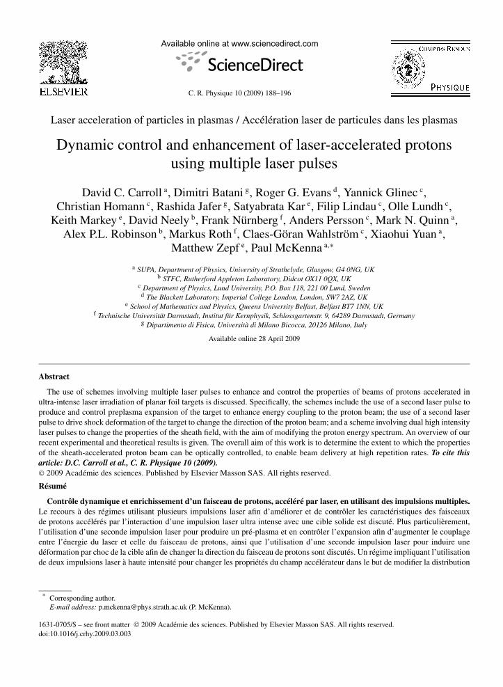
C. R. Physique 10 (2009) 188–196
Laser acceleration of particles in plasmas / Accélération laser de particules dans les plasmas
Dynamic control and enhancement of laser-accelerated protonsusing multiple laser pulses
David C. Carroll a, Dimitri Batani g, Roger G. Evans d, Yannick Glinec c,Christian Homann c, Rashida Jafer g, Satyabrata Kar e, Filip Lindau c, Olle Lundh c,
Keith Markey e, David Neely b, Frank Nürnberg f, Anders Persson c, Mark N. Quinn a,Alex P.L. Robinson b, Markus Roth f, Claes-Göran Wahlström c, Xiaohui Yuan a,
Matthew Zepf e, Paul McKenna a,∗
a SUPA, Department of Physics, University of Strathclyde, Glasgow, G4 0NG, UKb STFC, Rutherford Appleton Laboratory, Didcot OX11 0QX, UK
c Department of Physics, Lund University, P.O. Box 118, 221 00 Lund, Swedend The Blackett Laboratory, Imperial College London, London, SW7 2AZ, UK
e School of Mathematics and Physics, Queens University Belfast, Belfast BT7 1NN, UKf Technische Universität Darmstadt, Institut für Kernphysik, Schlossgartenstr. 9, 64289 Darmstadt, Germany
g Dipartimento di Fisica, Università di Milano Bicocca, 20126 Milano, Italy
Available online 28 April 2009
Abstract
The use of schemes involving multiple laser pulses to enhance and control the properties of beams of protons accelerated inultra-intense laser irradiation of planar foil targets is discussed. Specifically, the schemes include the use of a second laser pulse toproduce and control preplasma expansion of the target to enhance energy coupling to the proton beam; the use of a second laserpulse to drive shock deformation of the target to change the direction of the proton beam; and a scheme involving dual high intensitylaser pulses to change the properties of the sheath field, with the aim of modifying the proton energy spectrum. An overview of ourrecent experimental and theoretical results is given. The overall aim of this work is to determine the extent to which the propertiesof the sheath-accelerated proton beam can be optically controlled, to enable beam delivery at high repetition rates. To cite thisarticle: D.C. Carroll et al., C. R. Physique 10 (2009).© 2009 Académie des sciences. Published by Elsevier Masson SAS. All rights reserved.
Résumé
Contrôle dynamique et enrichissement d’un faisceau de protons, accéléré par laser, en utilisant des impulsions multiples.Le recours à des régimes utilisant plusieurs impulsions laser afin d’améliorer et de contrôler les caractéristiques des faisceauxde protons accélérés par l’interaction d’une impulsion laser ultra intense avec une cible solide est discuté. Plus particulièrement,l’utilisation d’une seconde impulsion laser pour produire un pré-plasma et en contrôler l’expansion afin d’augmenter le couplageentre l’énergie du laser et celle du faisceau de protons, ainsi que l’utilisation d’une seconde impulsion laser pour induire unedéformation par choc de la cible afin de changer la direction du faisceau de protons sont discutés. Un régime impliquant l’utilisationde deux impulsions laser à haute intensité pour changer les propriétés du champ accélérateur dans le but de modifier la distribution
* Corresponding author.E-mail address: [email protected] (P. McKenna).
1631-0705/$ – see front matter © 2009 Académie des sciences. Published by Elsevier Masson SAS. All rights reserved.doi:10.1016/j.crhy.2009.03.003

D.C. Carroll et al. / C. R. Physique 10 (2009) 188–196 189
énergétique des protons sont également discuté. Nos derniers résultats expérimentaux et théoriques sont présentés. Ces travauxont été réalisés afin de déterminer jusqu’où il est possible de contrôler les propriétés des faisceaux d’ions accélérés par interactionlaser–plasma en s’appuyant sur des méthodes optiques, ceci afin de pouvoir fournir ces faisceaux à un taux de répétition élevée.Pour citer cet article : D.C. Carroll et al., C. R. Physique 10 (2009).© 2009 Académie des sciences. Published by Elsevier Masson SAS. All rights reserved.
Keywords: Laser–particle acceleration; Proton beam; Laser–plasma interactions
Mots-clés : Accélération laser de particules ; Faisceau de protons ; Interactions laser–plasma
1. Introduction
Multi-MeV ion acceleration driven by ultrashort, high power laser pulse interactions with thin metallic foil targetscontinues to attract considerable interest, due to the unique properties of the ion beam (short pulse, high brightnessand ultralow emittance) and the compact nature of the source [1]. At the laser intensities presently available, thepredominant ion acceleration mechanism is Target Normal Sheath Acceleration (TNSA) [2], which occurs at the rearof the target and is driven by fast electrons transported through the target from the laser-irradiated front surface. Dueto it’s high charge-to-mass ratio and the presence of hydrogenated contamination layers on the target surfaces, theproton is the most efficiently accelerated ion species.
Many potential applications of laser-accelerated proton beams have been proposed, including ion radiotherapy[3–5], isotope production for medical imaging techniques [6,7], nuclear activation studies [8,9], injectors for the nextgeneration of ion accelerators [10,11] and laser-ion driven fast ignition [12,13]. The successful realisation of manyof these applications requires the development of techniques to enhance and control the source and beam properties.One method to achieve this involves the use of specialised targets. Using multi-layered targets, ‘dot’ targets andmicrodroplet targets, changes to the proton energy spectra have been demonstrated, including the production of aquasi-monoenergetic spectrum [14–16]. Curved targets and separate cylindrical targets have been used to demonstrateproton beam focusing [17,18] and defocusing [19], targets with a cylindrical (‘washer’) structure attached to the rearsurface have been used to change the beam divergence [20] and targets with micro- and nano-structured front surfaceshave been used to enhance energy coupling to protons [21]. However, the reliance on complex or specialised targets isnot always compatible with the requirement of high repetition rate ion beam delivery for many applications. Dynamiccontrol of the beam properties, using optical techniques involving one or more laser pulses (operating at high repetitionrate) and simple planar target foils is desirable.
In this article we discuss several schemes incorporating the use of a second laser pulse to enhance and controlproperties of the beam of protons accelerated by an ultrahigh intensity laser pulse. We begin with a report on a firstexperiment into the effects of controlled and well-characterised plasma expansion on the energy, flux and uniformityof beams of accelerated protons. The plasma expansion is controlled using a low intensity pulse synchronised to themain proton acceleration driver pulse. A scheme involving a similar beam arrangement to induce dynamic controlof the curvature of the target using laser-driven shock waves is presented next. Finally the use of dual high intensitypulses to control the proton energy spectrum is discussed.
2. Enhancing beam energy, flux and uniformity
During the interaction of a high power laser pulse with a thin foil target, prepulses or Amplified SpontaneousEmission (ASE) at the leading edge of the pulse typically produces plasma expansion at the front, irradiated surfaceof the target. Even if the target rear surface is unperturbed by the preheating, the properties of the ion beam producedat the rear surface are affected by the change to the laser energy absorption and fast electron generation at the frontsurface. Recent theoretical studies have shown that laser absorption efficiency (and therefore proton acceleration)can be enhanced by controlling the scale length of the front surface preplasma [22,23]. This effect has also been ex-perimentally observed at laser intensities of between 1018 and 1019 W cm−2 using ultrashort (tens of femtosecond)laser pulses [24,25]. In these experiments, changes to the preplasma expansion was produced by changing the inten-sity contrast (ratio of the peak laser intensity to the intensity of the ASE). We recently performed a controlled andwell-characterised experiment using the Vulcan laser at the Rutherford Appleton Laboratory to investigate to what
190 D.C. Carroll et al. / C. R. Physique 10 (2009) 188–196
Fig. 1. (a) Schematic of the experiment showing the laser beam arrangement and primary diagnostics: RCF stack and transverse interferometricprobe. (b) The relative temporal position of the low intensity ablation pulse (‘long pulse’) and the main CPA beam.
extent preplasma expansion, controlled using a separate synchronised laser pulse, can be used to enhance laser energycoupling to protons, in the ultraintense (3 × 10²⁰ W cm−2) picosecond laser pulse regime [26,27].
The details of the experiment are described elsewhere [27], and the arrangement is shown in Fig. 1. In brief,we use two beams from the Vulcan laser, one to produce controlled preplasma expansion and one to drive protonacceleration. A third beam is used to characterise the plasma expansion. Proton acceleration is driven by the mainChirped Pulse Amplified (CPA) pulse with wavelength (λ) equal to 1054 nm and pulse duration equal to 1 ps (FWHM).The intensity contrast of this beam is enhanced using a plasma mirror [28,29] to suppress the intensity of the ASEpedestal to <1011 W cm−2. The mirror has a measured reflectivity of 32%, resulting in a maximum on-target pulseenergy equal to 115 J. The CPA pulses are incident on target at 10◦ and focused to a peak intensity, ICPA, equal to 3 ×10²⁰ W cm−2. Plasma expansion is produced using low energy laser pulses of 6 ns duration (rise time equal to 0.2 ns)and wavelength equal to 1054 nm. The pulses are focused to an approximately flat-top intensity distribution, diameterequal to 450 µm, on the front surface of the target. The CPA beam is focused into the centre of this distribution. Thepreplasma expansion is varied by changing the intensity of the ‘ablation pulse’, Iabl, in the range 0.5 to 5 TW cm−2,and the temporal separation of the two pulses, �t , in the range 0.5 to 3.6 ns, with 0.2 ns precision. The plasmaexpansion is characterised using a frequency doubled (527 nm) interferometric probe beam. Interferograms of theplasma expansion are recorded 5 ps after the arrival of the CPA pulse and with a spatial resolution of 5 µm.
The targets are 25 µm-thick planar Cu or Au foils. The Au foils have a periodic groove structure (lines) on the rearsurface to enable determination of the proton source size and beam emittance [30,31]. Passive stacks of dosimetry film(RCF, Gafchromic© HD-810 and MD-V2-55) are used to measure the spatial and energy distributions of the protonbeam.
The plasma expansion is systematically changed in two ways: by varying Iabl for fixed �t = 0.5 ns, and by varying�t for fixed Iabl = 1 TW cm−2. The resulting electron density profiles at the target front surface are measured using theinterferometric probe. Example results are shown in Fig. 2, for �t = 0.5 ns and 3.6 ns. 2-D hydrodynamic simulationsare performed for the parameters of the experiment, and the results included for comparison in Fig. 2. The details of thesimulation, using the POLLUX code [32], are provided elsewhere [27]. Two distinct regions of preplasma expansionare clearly observed. Hereafter, we refer to the scale length of the underdense outer part of the preplasma as LO, and werefer to the density scale length in the inner region, in the region of the critical density, as LI. Experimental values ofLO are determined by fitting the equation ne(x) = n0 ×exp(−x/LO), where ne(x) is the electron density as a functionof distance from the target surface, to the density profile extracted from the interferometric probe measurements.Typically measured values of LO range from 50 ± 10 µm to 200 ± 40 µm for an increase in �t from 0.5 ns to 3.5 ns.For comparison, the simulation results predict increases in LO from 31 µm to 182 µm and in LI from ∼0.6 µm to∼0.9 µm. An upper estimate of LO = 5 µm for the plasma expansion due to the ASE is measured from interferometricprobe images.
It should be noted that the range of Iabl and �t parameters experimentally investigated is limited by the requirementthat the shock wave launched into the target by the ablation pressure at the front surface should not reach the rearsurface of the targets before the arrival of the CPA pulse. The calculated position of the shock front, using the approachand parameters given in Lundh et al. [33], as a function of Iabl and for given �t is shown in Fig. 2. The absence of targetrear surface expansion is confirmed by the hydrodynamic simulation results and experimentally in the interferograms.

D.C. Carroll et al. / C. R. Physique 10 (2009) 188–196 191
Fig. 2. (a) Calculated shock front positions in Cu and Au, as a function of Iabl at given �t ; (b) Density profile at the front surface of a Cu target asa function of expansion time, calculated using the POLLUX hydrodynamic code. The dashed line corresponds to the initial target surface. A dualexponential density profile is observed and is characterised with two density scale lengths. These correspond to an underdense, outer region (LO)and an overdense, inner region (LI). Corresponding experimental measurements of the electron density in the LO region are also shown in (b).
Fig. 3. (a) The measured maximum proton energy (Emax) as a function of experimentally measured LO for the Iabl and �t parameter scans.(b) The conversion efficiency (η) of laser energy into protons as a function of LO. (c) and (d): Representative examples of the measured 9.5 MeVproton spatial intensity distributions for (c) no ablation pulse and (d) Iabl = 5.0 TW cm−2.
Fig. 3 summarises some of the measured changes to the proton beam. As LO is increased up to ∼60 µm, significantincreases are measured in both the maximum proton energy, Emax, and the efficiency of conversion, η, of laser energyto protons. The conversion efficiency is the total proton beam energy for proton energies above 2 MeV as a percentageof the laser energy on target. These beam parameters are found to decrease again as LO is increased up to ∼100 µm,to values smaller than achieved with a sharp density gradient (no ablation pulse). The same optimum scale lengthis observed by changing Iabl or �t . Notable improvements are also observed in the spatial intensity profile of theproton beam, for all cases in which a preplasma expansion is produced. Example measurements are shown in Fig. 3.Improvements in both the beam uniformity and circularity, over the full proton energy range, are quantified andreported in Refs. [26,27].
From interferometric probe measurements made 5 ps after the CPA pulse, we determine that many of the measuredchanges to the proton beam parameters are likely to result from changes to the CPA pulse propagation in the expandingunderdense plasma. This is discussed in Ref. [27]. For the conditions of optimum Emax and η there is evidence ofchannelling or self-focusing of the CPA beam, whereas the longer scale preplasma is shown to result in break up of thepropagating CPA pulse, resulting in energy deposition over a larger area than the nominal focal spot size of the CPAlaser [27]. The resulting changes to the laser intensity qualitatively explain the changes to the proton beam parameters.
To gain further insight into the effects of the preplasma expansion on the CPA absorption and electron accelerationnear the critical density, we perform OSIRIS [34] particle-in-cell (PIC) simulations. A 40 µm by 20 µm grid with

192 D.C. Carroll et al. / C. R. Physique 10 (2009) 188–196
Fig. 4. Electron density, ne , maps from 2D OSIRIS simulations as a function of the initial density profile (output from POLLUX). (a) The case ofa sharp density gradient where there is little preplasma expansion. (b) and (c): The results for the initial electron density profiles provided by thePOLLUX simulation for �t = 0.5 ns and 3.5 ns, respectively. (d) Integrated electron energy distributions for the various initial ne profiles. Thesharp density gradient profile is two linear ramps: a density decrease from solid to 10× critical over 1 µm and from 10× critical to zero over 5 µm.
8000 by 4000 cells, and 4 electrons and 4 ions per cell, is used. The laser is linearly polarised with the E-vector in thesimulation plane. The focal spot is 10 µm and pulse rise time is 15 fs, with measurements made 40 fs after the startof the pulse. The laser pulse duration is limited to 60 fs due to available computing resources. Three example resultsare shown in Fig. 4 for three different initial density profiles: the two density profiles calculated using POLLUXfor �t = 0.5 ns and 3.5 ns (Fig. 2) and a steeper density gradient. In qualitative agreement with our experimentalobservations, evidence of self-focusing is observed for �t = 0.5 ns (compared to the steeper density gradient) andbeam disruption is observed for �t = 3.5 ns. A significant increase in electron flux is observed at all energies in thepresence of preplasma expansion, but little difference is observed for the two cases �t = 0.5 ns and 3.5 ns.
The results from this investigation highlight that an optimal preplasma expansion exists for enhanced proton fluxand energy, and that this can be controlled using a separate low intensity laser pulse. The findings also demonstratethe importance of understanding the effects of variable density scale length plasmas on the coupling of laser energyinto fast electrons for applications such as the fast ignition scheme for fusion energy.
3. Control of beam direction and divergence
Ions accelerated by the TNSA mechanism are directed along the localised target normal at the rear surface of thetarget. It has been shown that a low temperature shock wave launched into the target can, upon reaching the rearsurface, deform the rear surface and alter the direction of proton acceleration [33,35,36]. The use of a separate lowintensity laser pulse to control the spatial and temporal properties of the low temperature shock, and thereby controlthe direction of the proton beam, is reported by Lundh et al. [37] and discussed here.
The investigation is conducted at the Lund Laser Centre using the multi-Terawatt laser system. The main CPA laserbeam is focused onto target to a spot size of 5 µm (FWHM) giving a peak intensity of ∼4 × 10¹⁹ W cm−2 (600 mJ in45 fs (FWHM)). A 3 µm thick planar Al foil target is irradiated by the p-polarised main laser pulse at a 30◦ incidenceangle. Care is taken to ensure good laser pulse contrast [37] and is measured to be 1010 at 1 ns and 109 at 50 psbefore the main CPA pulse. A 11 ns low intensity (∼3 × 10¹⁰ W cm−2) long pulse synchronised with the main CPAbeam is used to drive a low temperature shock wave into the target. This pulse is focused with a tilted 200 mm focallength doublet lens to produce a horizontal line focus (230 µm long and 14 µm wide). The delay, �t , between the half-maximum of the rising edge of the low intensity pulse and the peak of the main CPA pulse is controlled. �t is variedfrom 3 to 12 ns with an error of 0.2 ns, while keeping all other laser parameters constant (relative line focus positionof −15 µm). The position of the low intensity line focus, relative to the focal spot of the main CPA beam is variedfrom −30 µm (below CPA spot) to +30 µm (above CPA spot), whilst �t is kept constant at 7.5 ns. The intensity ofthe ablation pulse Iabl (which drives the shock wave) is varied for �t = 7.5 ns at −15 µm relative position. The spatialdistribution of the proton beam is measured using CR39 covered by filter stripes of Al foil of varying thickness [35].
D.C. Carroll et al. / C. R. Physique 10 (2009) 188–196 193
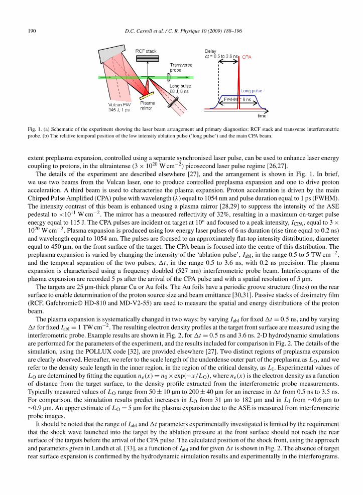
Fig. 5. (a) Illustration of proton beam steering by shock deformation of target. (b)–(d) Measured angular deflection of the proton beam as a functionof: (b) the relative position of the line focus (fixed intensity of 2.5 × 10¹⁰ W cm−2 and �t = 7.5 ns); (c) �t (fixed intensity of 2.5 × 10¹⁰ W cm−2
and relative position of −15 µm); and (d) the intensity of the line focus (fixed �t = 7.5 ns and relative position of +10 µm). The angular shiftpredicted by the rear surface shock deformation model reported in Ref. [37] is shown (black line). The relative position of the line and spot foci isshown schematically for (c) and (d). The proton energies are: blue squares 0.9 MeV, green triangles 1.4 MeV and red circles 2.8 MeV.
The low temperature shock, initiated by the low intensity pulse, propagates through the target and upon reachingthe rear surface causes it to deform and expand outwards, as illustrated in Fig. 5(a), while retaining the steep densitygradient required for ion acceleration. A shift of the entire proton beam implies that the rear surface deformation islarge enough to encompass the entire accelerating sheath. The measured proton beam deflection as a function of �t ,Iabl and line focus position are shown in Fig. 5(b). Simple calculations of the shock transport and breakout using aquasi-two-dimensional scheme, described elsewhere [33,37], support the interpretation of shock-induced proton beamsteering (Fig. 5(b)).
Optical steering of the proton beam accelerated from a thin target foil is demonstrated using low temperature shockwaves produced by a separate low intensity laser pulse. The use of a separate shock driving laser enables the beamto be steered in any direction. A simple analytical model for shock deformation of the target rear surface is in goodagreement with the experimental data. The results presented here demonstrate that an optically controlled shock canbe used to manipulate the proton beam acceleration direction and offers the possibility that an annular ring inducedshock wave could be used to induce a concave curvature of the target rear surface leading to dynamic control of protonbeam focusing.
4. Spectral control
In addition to the beam characteristics discussed in the preceding sections, the actual energy spectrum of the beamis of critical importance to many applications. The vast majority of experiments have measured quasi-Maxwellianenergy spectra, which are not suitable for certain applications. Some progress has been made in producing narrow-band energy spectra using carefully controlled target preparation [14,15]. Despite this, controlling the energy spectrumis still one of the biggest challenges in laser-driven ion acceleration.
Recently we proposed a radically different approach to the target engineering methods [38]. Independent researchby Kumar and Pukhov [39] largely agrees with our findings. It was proposed that irradiating a foil target with twohigh intensity laser pulses in rapid succession could result in a modified energy spectrum that contained narrow peaks.This idea was studied using both one dimensional Vlasov simulations and PIC simulations. The full details of thenumerical study are given in [38].
The scheme can be summarised as follows: The first laser pulse interacts with the foil and generates fast electronswith temperature T1. These fast electrons drive proton acceleration at the rear surface of the foil. After a delay,a second pulse arrives and generates fast electrons with a higher temperature T2. The sudden increase in the fastelectron temperature does not merely provide a scalar enhancement to the electric field at the rear surface, it also
194 D.C. Carroll et al. / C. R. Physique 10 (2009) 188–196
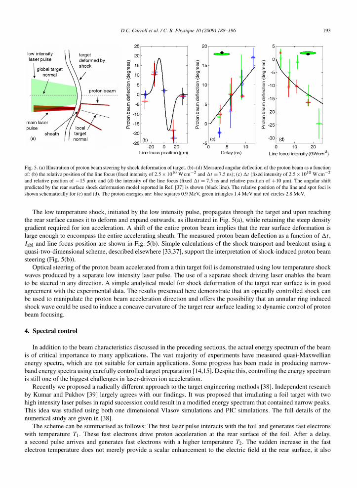
Fig. 6. (a) The proton spectra generated for single (black) and double (red) pulse regimes at 350 fs. (b) The electric field at the rear surface of thetarget at 240 fs (black) and 340 fs (red) for the double pulse regime. (c) The electric field at the rear surface of the target at 140 fs (black) and 240 fs(red) for the single pulse regime. The corresponding electron (solid line) and ion (dashed line) densities for (d) double and (e) single pulse regimes.
causes a massive spiking in the electric field inside the fast rarefaction wave. This is normally associated with theheavy ion front, but it also occurs in simulations without any heavy ions. This spiking in the electric field leads togeneration of a peak in the proton density. Once this is formed, the mechanism moves into a second stage where thepeak in the proton density maintains a positive-going and negative-going spike in the electric field. The positive-goingspike accelerates a bunch of protons to higher energy. This bunch then constitutes the peak that is seen in the energyspectrum.
In the PIC simulations that were carried out to test this concept, a scenario where two 40 fs pulses separated by a100 fs delay was considered. The second pulse had a peak intensity of 4 × 10¹⁹ W cm−2, and the peak intensity ofthe first pulse was varied between 7 × 10¹⁷ and 1 × 10¹⁹ W cm−2. Fig. 6(a) shows the differences between single anddouble pulse simulations. In Fig. 6(b) we show the electric field and ion densities at representative times in both singleand double pulse simulations. This illustrates the strong spiking in the electric field and the peaking in the protondensity that is seen in the double pulse simulations.
As Fig. 6(a) shows, strong spectral peaks are generated. Future studies of this concept will need to improve uponthis further and to develop an understanding of how the energy of the peak can be ‘set’ by controlling the laserparameters.
5. Summary and future challenges
We have shown that proton acceleration from thin foil targets irradiated by ultrashort high intensity laser pulsescan be manipulated and controlled optically by the use of secondary laser pulses in a variety of schemes. The protonbeam uniformity and flux have been shown to be enhanced by the creation of an optimum plasma density gradientusing a separate low intensity laser pulse. It has been shown that the direction of proton beam acceleration can besteered using a controlled low temperature shock wave launched by a separate low intensity laser pulse. A scheme forcontrolling the spectral distribution of the accelerated proton beams through the use of an ultrashort prepulse has alsobeen proposed and demonstrated in PIC simulations.
These techniques for optical control of the properties of laser-accelerated ion beams could be an important part ofthe strategy for developing applications which require dynamic control of ion pulses delivered at high repetition rate.
Acknowledgements
We acknowledge the expert support of the Vulcan laser team at the Central Laser Facility. This work was supportedby the UK Engineering and Physical Sciences Research Council (EPSRC, grant number EP/E048668/1) and theSwedish Research Council.
D.C. Carroll et al. / C. R. Physique 10 (2009) 188–196 195
References
[1] M. Borghesi, J. Fuchs, S.V. Bulanov, A.J. MacKinnon, P.K. Patel, M. Roth, Fusion Sci. Technol. 49 (2006) 412–439.[2] S.C. Wilks, A.B. Langdon, T.E. Cowan, M. Roth, M. Singh, S. Hatchett, M.H. Key, D. Pennington, A. MacKinnon, R.A. Snavely, Phys.
Plasmas 8 (2001) 542–549.[3] S.V. Bulanov, T.Zh. Esirkepov, V.S. Khoroshkov, A.V. Kuznetsov, F. Pegoraro, Phys. Lett. A 299 (2002) 240–247.[4] E. Fourkal, B. Shahine, M. Ding, J.S. Li, T. Tajima, C.-M. Ma, Med. Phys. 29 (2002) 2788–2798.[5] V. Malka, S. Fritzler, E. Lefebvre, E. d’Humières, R. Ferrand, G. Grillon, C. Albaret, S. Meyroneinc, J.-P. Chambaret, A. Antonetti, D. Hulin,
Med. Phys. 31 (2004) 1587–1592.[6] S. Fritzler, V. Malka, G. Grillon, J.P. Rousseau, F. Burgy, E. Lefebvre, E. d’Humières, P. McKenna, K.W.D. Ledingham, Appl. Phys. Lett. 83
(2003) 3039–3041.[7] K.W.D. Ledingham, P. McKenna, T. McCanny, S. Shimizu, J.M. Yang, L. Robson, J. Zweit, J.M. Gillies, J. Bailey, G.N. Chimon, R.J. Clarke,
D. Neely, P.A. Norreys, J.L. Collier, R.P. Singhal, M.S. Wei, S.P.D. Mangles, P. Nilson, K. Krushelnick, M. Zepf, J. Phys. D 37 (2004)2341–2345.
[8] P. McKenna, K.W.D. Ledingham, T. McCanny, R.P. Singhal, I. Spencer, M.I.K. Santala, F.N. Beg, K. Krushelnick, M. Tatarakis, M.S. Wei,E.L. Clark, R.J. Clarke, K.L. Lancaster, P.A. Norreys, K. Spohr, R. Chapman, M. Zepf, Phys. Rev. Lett. 91 (2003) 075006.
[9] P. McKenna, K.W.D. Ledingham, S. Shimizu, J.M. Yang, L. Robson, T. McCanny, J. Galy, J. Magill, R.J. Clarke, D. Neely, P.A. Norreys,R.P. Singhal, K. Krushelnick, M.S. Wei, Phys. Rev. Lett. 94 (2005) 084801.
[10] M. Schollmeier, S. Becker, M. Geissel, K.A. Flippo, A. Blaževic, S.A. Gaillard, D.C. Gautier, F. Grüner, K. Harres, M. Kimmel, F. Nürnberg,P. Rambo, U. Schramm, J. Schreiber, J. Schütrumpf, J. Schwarz, N.A. Tahir, B. Atherton, D. Habs, B.M. Hegelich, M. Roth, Phys. Rev.Lett. 101 (2008) 055004.
[11] P. Antici, M. Fazi, A. Lombardi, M. Migliorati, L. Palumbo, P. Audebert, J. Fuchs, J. Appl. Phys. 104 (2008) 124901.[12] M. Roth, T.E. Cowan, M.H. Key, S.P. Hatchett, C. Brown, W. Fountain, J. Johnson, D.M. Pennington, R.A. Snavely, S.C. Wilks, K. Yasuike,
H. Ruhl, F. Pegoraro, S.V. Bulanov, E.M. Campbell, M.D. Perry, H. Powell, Phys. Rev. Lett. 86 (2001) 436–439.[13] M. Temporal, J.J. Honrubia, S. Atzeni, Phys. Plasmas 9 (2002) 3098–3107.[14] B.M. Hegelich, B.J. Albright, J. Cobble, K. Flippo, S. Letzring, M. Paffett, H. Ruhl, J. Schreiber, R.K. Schulze, J.C. Fernández, Nature 439
(2006) 441–444.[15] H. Schwoerer, S. Pfotenhauer, O. Jäckel, K.-U. Amthor, B. Liesfeld, W. Ziegler, R. Sauerbrey, K.W.D. Ledingham, T. Esirkepov, Nature 439
(2006) 445–448.[16] S. Ter-Avetisyan, M. Schnürer, P.V. Nickles, M. Kalashnikov, E. Risse, T. Sokollik, W. Sandner, A. Andreev, V. Tikhonchuk, Phys. Rev.
Lett. 96 (2006) 145006.[17] P.K. Patel, A.J. Mackinnon, M.H. Key, T.E. Cowan, M.E. Foord, M. Allen, D.F. Price, H. Ruhl, P.T. Springer, R. Stephens, Phys. Rev. Lett. 91
(2003) 125004.[18] T. Toncian, M. Borghesi, J. Fuchs, E. d’Humières, P. Antici, P. Audebert, E. Brambrink, C.A. Cecchetti, A. Pipahl, L. Romagnani, O. Willi,
Science 312 (2006) 410–413.[19] M. Roth, A. Blaževic, M. Geissel, T. Schlegel, T.E. Cowan, M. Allen, J.-C. Gauthier, P. Audebert, J. Fuchs, J. Meyer-ter-Vehn, M. Hegelich,
S. Karsch, A. Pukhov, Phys. Rev. ST Accel. Beams 5 (2002) 061301.[20] S. Kar, K. Markey, P.T. Simpson, C. Bellei, J.S. Green, S.R. Nagel, S. Kneip, D.C. Carroll, B. Dromey, L. Willingale, E.L. Clark, P. McKenna,
Z. Najmudin, K. Krushelnick, P. Norreys, R.J. Clarke, D. Neely, M. Borghesi, M. Zepf, Phys. Rev. Lett. 100 (2008) 105004.[21] S. Kahaly, S.K. Yadav, W.M. Wang, S. Sengupta, Z.M. Sheng, A. Das, P.K. Kaw, G.R. Kumar, Phys. Rev. Lett. 101 (2008) 145001.[22] Y. Sentoku, V.Y. Bychenkov, K. Flippo, A. Maksimchuk, K. Mima, G. Mourou, Z.M. Sheng, D. Umstadter, Appl. Phys. B 74 (2002) 207–215.[23] J.T. Seo, S.H. Yoo, S.J. Hahn, J. Phys. Soc. Jpn. 76 (2007) 114501.[24] A. Maksimchuk, S. Gu, K. Flippo, D. Umstadter, V.Yu. Bychenkov, Phys. Rev. Lett. 84 (2000) 4108–4111.[25] A. Yogo, H. Daido, A. Fukumi, Z. Li, K. Ogura, A. Sagisaka, A.S. Pirozhkov, S. Nakamura, Y. Iwashita, T. Shirai, A. Noda, Y. Oishi, T.
Nayuki, T. Fujii, K. Nemoto, I.W. Choi, J.H. Sung, D.-K. Ko, J. Lee, M. Kaneda, A. Itoh, Phys. Plasmas 14 (2007) 043104.[26] D.C. Carroll, P. McKenna, O. Lundh, F. Lindau, C.-G. Wahlström, S. Bandyopadhyay, D. Pepler, D. Neely, S. Kar, P.T. Simpson, K. Markey,
M. Zepf, C. Bellei, R.G. Evans, R. Redaelli, D. Batani, M.H. Xu, Y.T. Li, Phys. Rev. E 76 (2007) 065401.[27] P. McKenna, D.C. Carroll, O. Lundh, F. Nürnberg, K. Markey, S. Bandyopadhyay, D. Batani, R.G. Evans, R. Jafer, S. Kar, D. Neely, D.
Pepler, M.N. Quinn, R. Redaelli, M. Roth, C.-G. Wahlström, X.H. Yuan, M. Zepf, Laser Part. Beams 26 (2008) 591–596.[28] B. Dromey, S. Kar, M. Zepf, P. Foster, Rev. Sci. Instrum. 75 (2004) 645–649.[29] G. Doumy, F. Quéré, O. Gobert, M. Perdrix, Ph. Martin, P. Audebert, J.C. Gauthier, J.-P. Geindre, T. Wittmann, Phys. Rev. E (2004) 026402.[30] T.E. Cowan, J. Fuchs, H. Ruhl, A. Kemp, P. Audebert, M. Roth, R. Stephens, I. Barton, A. Blaževic, E. Brambrink, J. Cobble, J. Fernández,
J.-C. Gauthier, M. Geissel, M. Hegelich, J. Kaae, S. Karsch, G.P. Le Sage, S. Letzring, M. Manclossi, S. Meyroneinc, A. Newkirk, H. Pépin,N. Renard-LeGalloudec, Phys. Rev. Lett. 92 (2004) 204801.
[31] F. Nürnberg, M. Schollmeier, E. Brambrink, A. Blaževic, D.C. Carroll, K. Flippo, D.C. Gautier, M. Gessel, K. Harres, B.M. Hegelich, O.Lundh, K. Markey, P. McKenna, D. Neely, J. Schreiber, M. Roth, Rev. Sci. Instrum. (2009), in press.
[32] G.J. Pert, J. Comput. Phys. 43 (1981) 111–163.[33] O. Lundh, F. Lindau, A. Persson, C.-G. Wahlström, P. McKenna, D. Batani, Phys. Rev. E 76 (2007) 026404.[34] R. Fonseca, L. Silva, F. Tsung, V. Decyk, W. Lu, C. Ren, W. Mori, S. Deng, S. Lee, T. Katsouleas, J. Adam, in: P.M.A. Sloot, et al. (Eds.),
Lecture Notes in Computer Science, vol. 2331, Springer, Heidelberg, 2002, pp. 342–351.[35] F. Lindau, O. Lundh, A. Persson, P. McKenna, K. Osvay, D. Batani, C.-G. Wahlström, Phys. Rev. Lett. 95 (2005) 175002.[36] P. McKenna, F. Lindau, O. Lundh, D. Neely, A. Persson, C.-G. Wahlström, Philos. Trans. R. Soc. A 364 (2006) 711–723.

196 D.C. Carroll et al. / C. R. Physique 10 (2009) 188–196
[37] O. Lundh, Y. Glinec, C. Homann, F. Lindau, A. Persson, C.-G. Wahlström, D.C. Carroll, P. McKenna, Appl. Phys. Lett. 92 (2008) 011504.[38] A.P.L. Robinson, D. Neely, P. McKenna, R.G. Evans, Plasma Phys. Controlled Fusion 49 (2007) 373–384.[39] N. Kumar, A. Pukhov, Phys. Plasmas 15 (2008) 053103.
Copyright © 2022 FDOKUMEN