Time–space transformation of femtosecond free-electron laser pulses by periodical multilayers
7
research papers J. Synchrotron Rad. (2008). 15, 19–25 doi:10.1107/S090904950704753X 19 Journal of Synchrotron Radiation ISSN 0909-0495 Received 14 September 2007 Accepted 27 September 2007 # 2008 International Union of Crystallography Printed in Singapore – all rights reserved Time–space transformation of femtosecond free-electron laser pulses by periodical multilayers Dmitriy Ksenzov, Souren Grigorian* and Ullrich Pietsch University of Siegen, Germany. E-mail: [email protected] A scattering scheme to probe the time evolution of femtosecond pulses of a soft X-ray free-electron laser (FEL) in a multilayer structure is presented. The response of periodic multilayers (MLs) with low and high absorption and various numbers of bi-layers to a pulse train of Gaussian-shaped sub-pulses is calculated. During the passage of the incident pulse the interaction length increases and the scattering profile changes as a function of the spatial position of the pulse within the sample. Owing to stretching of the reflected pulse compared with the incident pulse, the time-dependent scattering evolution in the ML can be visualized along a spatial coordinate of a position-sensitive detector. Using a scattering geometry where the mean energy of the incident pulse train is slightly detuned from the energy of maximum reflectivity at the first-order peak, the response of the ML shows an oscillator behaviour along this spatial coordinate at the detector. For a FEL wavelength of 6.4 nm this effect is promising for MLs with low absorption, such as La/C for example. On the other hand, the oscillations will not be present for MLs with high absorption. Therefore a low-absorbing ML is a sensitive tool for studying the possible change of sample absorption caused by femtosecond-pulse interaction with matter. Keywords: multilayers; femtosecond pulses; free-electron laser. 1. Introduction Motivated by current projects to build X-ray free-electron lasers (XFEL) in several places in the world, there is a growing interest in the fundamental physics of X-ray diffraction from crystals on femtosecond (fs) time scales. In the case of pulse generation in the self-amplified spontaneous-emission (SASE) regime the XFEL will produce a pulse train of duration a few hundred fs which is almost fully coherent in the transverse direction. The pulse train consists of a substructure of single spikes with sub-fs duration and slightly different energy (DESY Report, 2006a). High-resolution diffraction experi- ments require the selection of a certain mode from an XFEL pulse using the X-ray diffraction profile by a single (mono- chromator) crystal. This appears to be difficult because each sub-pulse of a pulse train additionally becomes transformed by the crystal. The response of a perfect crystal to fs-XFEL radiation has been studied by Shastri et al. (2001) and Graeff (2004). Neglecting the time- and/or intensity-dependence of crystal absorption, these calculations show that each indivi- dual sub-pulse becomes stretched in time owing to the dura- tion of radiation propagation through the crystal. The general properties of crystal diffraction by fs X-ray pulses have been derived from time-dependent Takagi–Taupin equations (Chukovskii & Fo ¨rster, 1995; Wark & He, 1994). By consid- ering X-ray absorption from unperturbed crystals, time- dependent features were found in the diffraction curve such as the evolution of Pendello ¨sung fringes. The possible influence of high intensity was studied on ‘laser-heated’ crystals by Wark & Lee (1999). Unfortunately, these theoretical studies cannot be verified until installation of an XFEL is completed. However, FLASH (a free-electron laser in Hamburg) at DESY is in operation in the soft X-ray regime (Ackermann et al., 2007). First experiments have been performed which verify the expected time structure (Ayvazyan et al., 2002) and the excellent coherent properties (see, for example, Chapman et al., 2006). In addition, the crystal becomes destroyed by the highly intense beam (Stojanovic et al., 2006). Extensive cooling strategies are proposed to avoid destruction in order to use crystals as monochromators (DESY Report, 2006a), neglecting phenomena which may modify absorption and heat dissipation. Hau-Riege et al. (2006) have shown recently that on a fs time scale the reflectivity of a Si/C multilayer excited by FLASH pulses of wavelength 32 nm can still be described by Parratt’s formalism. An X-ray diffraction experiment where the single crystals are replaced by a multilayer mirror can already be performed using VUV FEL radiation wavelengths of a few nanometres. FLASH, for example, will generate FEL pulses with 20–50 fs pulse length and a sub-pulse duration of about 2–3 fs at an average wavelength of 6.4 nm (DESY Report, 2006b). Moreover, the performance of specially designed multilayers
-
Upload
uni-siegen -
Category
Documents
-
view
1 -
download
0
Transcript of Time–space transformation of femtosecond free-electron laser pulses by periodical multilayers
research papers
J. Synchrotron Rad. (2008). 15, 19–25 doi:10.1107/S090904950704753X 19
Journal of
SynchrotronRadiation
ISSN 0909-0495
Received 14 September 2007
Accepted 27 September 2007
# 2008 International Union of Crystallography
Printed in Singapore – all rights reserved
Time–space transformation of femtosecondfree-electron laser pulses by periodical multilayers
Dmitriy Ksenzov, Souren Grigorian* and Ullrich Pietsch
University of Siegen, Germany. E-mail: [email protected]
A scattering scheme to probe the time evolution of femtosecond pulses of a soft
X-ray free-electron laser (FEL) in a multilayer structure is presented. The
response of periodic multilayers (MLs) with low and high absorption and
various numbers of bi-layers to a pulse train of Gaussian-shaped sub-pulses is
calculated. During the passage of the incident pulse the interaction length
increases and the scattering profile changes as a function of the spatial position
of the pulse within the sample. Owing to stretching of the reflected pulse
compared with the incident pulse, the time-dependent scattering evolution in
the ML can be visualized along a spatial coordinate of a position-sensitive
detector. Using a scattering geometry where the mean energy of the incident
pulse train is slightly detuned from the energy of maximum reflectivity at the
first-order peak, the response of the ML shows an oscillator behaviour along this
spatial coordinate at the detector. For a FEL wavelength of 6.4 nm this effect is
promising for MLs with low absorption, such as La/C for example. On the other
hand, the oscillations will not be present for MLs with high absorption.
Therefore a low-absorbing ML is a sensitive tool for studying the possible
change of sample absorption caused by femtosecond-pulse interaction with
matter.
Keywords: multilayers; femtosecond pulses; free-electron laser.
1. Introduction
Motivated by current projects to build X-ray free-electron
lasers (XFEL) in several places in the world, there is a growing
interest in the fundamental physics of X-ray diffraction from
crystals on femtosecond (fs) time scales. In the case of pulse
generation in the self-amplified spontaneous-emission (SASE)
regime the XFEL will produce a pulse train of duration a few
hundred fs which is almost fully coherent in the transverse
direction. The pulse train consists of a substructure of single
spikes with sub-fs duration and slightly different energy
(DESY Report, 2006a). High-resolution diffraction experi-
ments require the selection of a certain mode from an XFEL
pulse using the X-ray diffraction profile by a single (mono-
chromator) crystal. This appears to be difficult because each
sub-pulse of a pulse train additionally becomes transformed
by the crystal. The response of a perfect crystal to fs-XFEL
radiation has been studied by Shastri et al. (2001) and Graeff
(2004). Neglecting the time- and/or intensity-dependence of
crystal absorption, these calculations show that each indivi-
dual sub-pulse becomes stretched in time owing to the dura-
tion of radiation propagation through the crystal. The general
properties of crystal diffraction by fs X-ray pulses have
been derived from time-dependent Takagi–Taupin equations
(Chukovskii & Forster, 1995; Wark & He, 1994). By consid-
ering X-ray absorption from unperturbed crystals, time-
dependent features were found in the diffraction curve such as
the evolution of Pendellosung fringes. The possible influence
of high intensity was studied on ‘laser-heated’ crystals by Wark
& Lee (1999). Unfortunately, these theoretical studies cannot
be verified until installation of an XFEL is completed.
However, FLASH (a free-electron laser in Hamburg) at
DESY is in operation in the soft X-ray regime (Ackermann et
al., 2007). First experiments have been performed which verify
the expected time structure (Ayvazyan et al., 2002) and the
excellent coherent properties (see, for example, Chapman et
al., 2006). In addition, the crystal becomes destroyed by the
highly intense beam (Stojanovic et al., 2006). Extensive
cooling strategies are proposed to avoid destruction in order
to use crystals as monochromators (DESY Report, 2006a),
neglecting phenomena which may modify absorption and heat
dissipation. Hau-Riege et al. (2006) have shown recently that
on a fs time scale the reflectivity of a Si/C multilayer excited by
FLASH pulses of wavelength 32 nm can still be described by
Parratt’s formalism.
An X-ray diffraction experiment where the single crystals
are replaced by a multilayer mirror can already be performed
using VUV FEL radiation wavelengths of a few nanometres.
FLASH, for example, will generate FEL pulses with 20–50 fs
pulse length and a sub-pulse duration of about 2–3 fs at
an average wavelength of 6.4 nm (DESY Report, 2006b).
Moreover, the performance of specially designed multilayers
as beam chopper systems of hard XFEL pulses has been
reported by Krenza & Meyer-ter-Vehn (2005). The response
of a multilayer (ML) to hard X-ray XFEL pulses has been
simulated by Tatchyn & Bionta (2001). Similar to crystals
(Shastri et al., 2001; Graeff, 2004), there is a certain time delay
of the reflected pulse relative to the incident pulse. Hence the
delay time depends on absorption; it subsequently determines
the effective penetration depth of the FEL pulse into the
material. For a ML the effective penetration depth corre-
sponds to a certain number of layers probed by the incident
radiation. The shape of the reflection curve will change during
the propagation of the pulse through the ML structure owing
to the interaction of the beam with an increasing number of bi-
layers. Study of the time-dependent response of the ML to the
X-ray pulse can provide insight into the process of interaction
of highly intense FEL radiation with matter. Using an
appropriate geometrical set-up of the experiment the time
structure of the reflected pulse can be transformed into a
spatial coordinate of a position-sensitive detector (Lindenberg
et al., 2005).
The current paper is organized as follows. First we calculate
the general ML response to Gaussian-shaped fs pulses for low-
and high-absorbing materials depending on the number of ML
periods. We show the evolution of the reflected signals as a
function of penetration depth into the ML. The response of
the ML will be analyzed for exact Bragg or slightly detuned
conditions. Finally the possibility of visualizing pulsed sub-
structure from the integrated signal of the spatial detector side
will be discussed.
2. Basic calculations
The calculations were performed for a wavelength of 6.4 nm as
provided by FLASH. This wavelength requires a scattering
object with lattice parameters in the range of a few nano-
metres. Such an object can be a ML structure prepared by
repetitions of thin layers of two different materials. In the case
of a FEL the incident radiation is a pulse train composed of
ultrashort pulses of a few fs duration. The simulation of the
ML response to such a pulse requires a certain approximation
of its shape.
Usually ultrashort pulses are described in time or frequency
space by either � or Gaussian functions. The use of � functions
leads to simple analytical solutions, and the frequency range of
the incident pulses is not limited (Shastri et al., 2001). For
VUV radiation the assumption of a Gaussian shape for an
incident pulse is a more realistic model (Hau-Riege et al., 2007;
Ayvazyan et al., 2006) which also allows Fourier transforma-
tion to be performed in a simple way.
An experiment with fs pulses has to be performed at fixed
scattering geometry. Therefore the first step of the simulation
consists of calculating the complex amplitude of reflection as
a function of frequency for a fixed angle of incidence with
respect to the ML normal and using symmetric scattering
geometry. We consider a stack of N bi-layers consisting of
two layers of different thicknesses. The complex dielectric
constants of each sub-layer are expressed in terms of complex
X-ray refraction coefficients considering the energy-depen-
dent X-ray absorption. The reflectivity of the periodical ML is
calculated using Parratt’s recursive method (Parratt, 1954;
Kohn, 1995). Using a linear-optics reflection theory (Eilbeck,
1972), the calculation of the ML response to an incident pulse
train is performed using the following steps. First, each inci-
dent pulse is described by a single Gaussian and subsequently
the pulse train by a combination of several Gaussian functions
of the same width. Next, the time structure of an incident pulse
train is spectrally decomposed by use of Fourier transforma-
tion. Finally, within the spectral range of emission, each
Fourier component of the incident pulse amplitude is multi-
plied by the complex reflection amplitude of the ML followed
by inverse Fourier transformation in order to find the time
response of the reflected pulses.
3. Reflectivity of periodical multilayers
Typical multilayer mirrors for soft X-rays consist of a periodic
stacking of high-refracting (Mo, Ni, Cr, Ru, Fe, V) and low-
refracting (C, Si, B4C) materials. By using various combina-
tions of these materials the optical properties of the respective
optical element can be tuned in terms of transmission,
absorption and reflection. The shape and the total scattering
power at fundamental Bragg reflections are influenced by the
number of stacked bi-layers (for example, Born & Wolf, 1999;
Vinogradov et al., 1989).
For a FEL wavelength of 6.4 nm the ML reflectivity is
generally low for a few reasons. First, the optical constants for
this wavelength are very similar (see Table 1) and a combi-
nation of two materials does not provide a large scattering
contrast. Second, the absorption coefficient is large for most of
the materials. Both peculiarities limit the effective penetration
depth into the ML. Third, in order to tune the first-order
Bragg peak of the ML to a scattering angle 2�, the bi-layer
period must be smaller than 10 nm. Under these circumstances
an interface roughness of a few atomic layers can significantly
reduce the reflectivity (Takenaka et al., 2005).
research papers
20 Dmitriy Ksenzov et al. � Femtosecond free-electron laser pulses J. Synchrotron Rad. (2008). 15, 19–25
Table 1Correction to refraction index (n = 1 � � + i�) for different materials at193.75 eV with increasing absorption coefficient.
Element/compound � �
C 0.0079 0.00063La 0.0138 0.00097Sc 0.0065 0.00232Nb 0.0084 0.00252Mo 0.0113 0.00278Ru 0.0167 0.00378RhRu 0.0170 0.00393Y 0.0016 0.00541V 0.0159 0.00579Cr 0.0197 0.00761Si 0.0077 0.00838B4C 0.0028 0.00855Al2O3 0.0169 0.00892B 0.0010 0.00996Fe 0.0222 0.01165CrB2 0.0148 0.01436Ni 0.0237 0.01694

In the follow we consider the combination of La and C, and
Ni and C, as materials with high scattering contrast. However,
La and Ni have different absorption properties in this energy
range. For � = 6.4 nm (193.75 eV) the bi-layer spacing has to
be d = 4.62 nm for these MLs so that the first-order diffraction
maximum is appearing at 2� = 90�. The variations in the
reflectivity spectra for both MLs are shown in Fig. 1 as a
function of the number of bi-layers. Calculations were
performed by using Parratt’s recurrent formalism considering
a thickness ratio of 0.5 and continuous strictly parallel VUV
radiation. Owing to the high absorption of Ni layers the
reflectivity curve of the Ni/C sample saturates after penetra-
tion of about 40 bi-layers at a maximum reflectivity of about
18% and does not show any internal structure. The response
of the low-absorbing La/C ML is shown in Fig. 1 (right). Here
the intensity increases with the number of bi-layers, reaching
a maximum of about 40% for a ML with more than 120 bi-
layers. In addition, thickness oscillations decrease with
increasing number of bi-layers. The energy width of the central
maximum is about 6 eV for Ni/C and about 1.5 eV for La/C
MLs with large numbers of bi-layers.
4. Numerical simulation of fs-pulse responses frommultilayers
FLASH emits a pulse train of duration 20–50 fs consisting of
sub-pulses of about 2–3 fs in length. For this source the shape
of such pulses has been experimentally verified for a wave-
length of 33 nm (Ayvzyan et al., 2006) and recently for 13 nm
(Ackermann et al., 2007). A similar pulse structure is proposed
for a wavelength of 6.4 nm.
First let us consider the ML response to a single Gaussian
pulse of duration 2 fs (one sub-pulse of a VUV FEL pulse
train) for La/C and Ni/C MLs as a function of the number of
bi-layers N at a fixed incidence angle of � = 45�. The low- and
high-absorbing ML responses are
shown in Fig. 2. As in Fig. 1, essential
differences in the responses of these
MLs may be seen (Figs. 2b and 2c).
When the initial pulse strikes the ML
with different numbers of bi-layers, only
the first N ’ 40 bi-layers strongly
contribute to the scattering process for
the high-absorbing Ni/C ML. Owing to
almost complete absorption of the pulse
within the first few layers, the duration
of the reflected pulse is approximately
the same as that of the initial one
(Figs. 2a and 2b). In contrast, the
reflected pulse is expanded to 2 fs
compared with the initial pulse for the
low-absorbing La/C ML. The pulse
expansion increases with the number of
bi-layers N, reaching certain saturation
at N = 120 for the La/C ML. A
maximum reflectivity of about 28% is
reached at N’ 100 (Fig. 2c). In all three
cases shown in Fig. 2 the energy of the incident pulses coin-
cides with the maximum of the first ML Bragg peak of the
reflection curve at a given angle of incidence. Changing the
scattering angle or/and the energy of the incident pulse, Ei,
differs from the energy of the central maximum of reflectivity,
Emax, by �E = Ei � Emax. Fig. 2(d) shows the time-dependent
response of the La/C multilayer for �E ’ 3 eV. Now the
reflectivity of the La/C ML is reduced (by a few percent) but
reveals a certain variation of intensity as a function of N, which
is not visible for Ni/C. This asymmetry increases for increasing
�E (not shown). Moreover, for the longer pulses (4 fs and
more) one finds an oscillatory behaviour of reflection intensity
as a function of N (see later). These features can be explained
by the fine structure of the scattering curves as schematically
shown in Fig. 3. By changing Ei relative to Emax one can excite
different spectra, from continuous to oscillating features as a
functionn of N. The ML response to a pulse is an integration of
the scattering curve within a certain energy window. If �E ’
0, i.e. Ei ’ 193.75 eV as in the present example (Fig. 3c), the
scattering phases between different interfaces is always
constructive and the response is a smooth function for
increasing N (see Fig. 3a). If the energy shift �E is larger than
the energy width of the total reflection curve (Fig. 3d), the
phase shift might be constructive at certain N but destructive
for another N + �N. This oscillatory behaviour of scattering as
a function of N is shown in Fig. 3(b). Such an effect can be
used to identify the energy offset of the incident pulse with
respect to the central reflection maximum fixed by a certain
geometric set-up.
For simulation of an incident pulse train, every pulse is
composed of several sub-pulses of duration 2–3 fs. Consid-
ering the SASE principle, each of these sub-pulses (spikes) is
spatially separated from each other and described by Gaussian
functions with varying amplitude. Additionally the spikes
differ in energy within a certain energy window of about 2 eV
research papers
J. Synchrotron Rad. (2008). 15, 19–25 Dmitriy Ksenzov et al. � Femtosecond free-electron laser pulses 21
Figure 1Calculated reflectivity of MLs as a function of energy and number of bi-layers. High-absorbing Ni/C(left) and low-absorbing La/C (right).

as expected for FEL radiation. Using this approach one can
change the shape of any incident pulse train by changing the
spike parameters, e.g. the amplitude, frequency, location and
duration of the Gaussian-shaped sub-pulses, as shown in
Fig. 4(a). The results of numerical calculation for both MLs
are illustrated in Figs. 4(b)–4(d). Since the mean energy of the
incident pulse train coincides with the energy of maximum
reflectivity of the ML the diffraction curves for both MLs show
research papers
22 Dmitriy Ksenzov et al. � Femtosecond free-electron laser pulses J. Synchrotron Rad. (2008). 15, 19–25
Figure 3Transition of the energy spectra from continuous to oscillatory depending on energy shift �E (a) without energy shift, �E = 0, and (b) with energy shift�E ’ 3 eV. The energy relation between the incident pulse train and the reflection curve is shown in (c) and (d).
Figure 2Incident single pulse (a) and time responses from various periodical Ni/C (b) and La/C (c, d) MLs. The duration of the incident single Gaussian pulse is2 fs and the energies are 193.75 eV (b, c) and 191 eV (d).
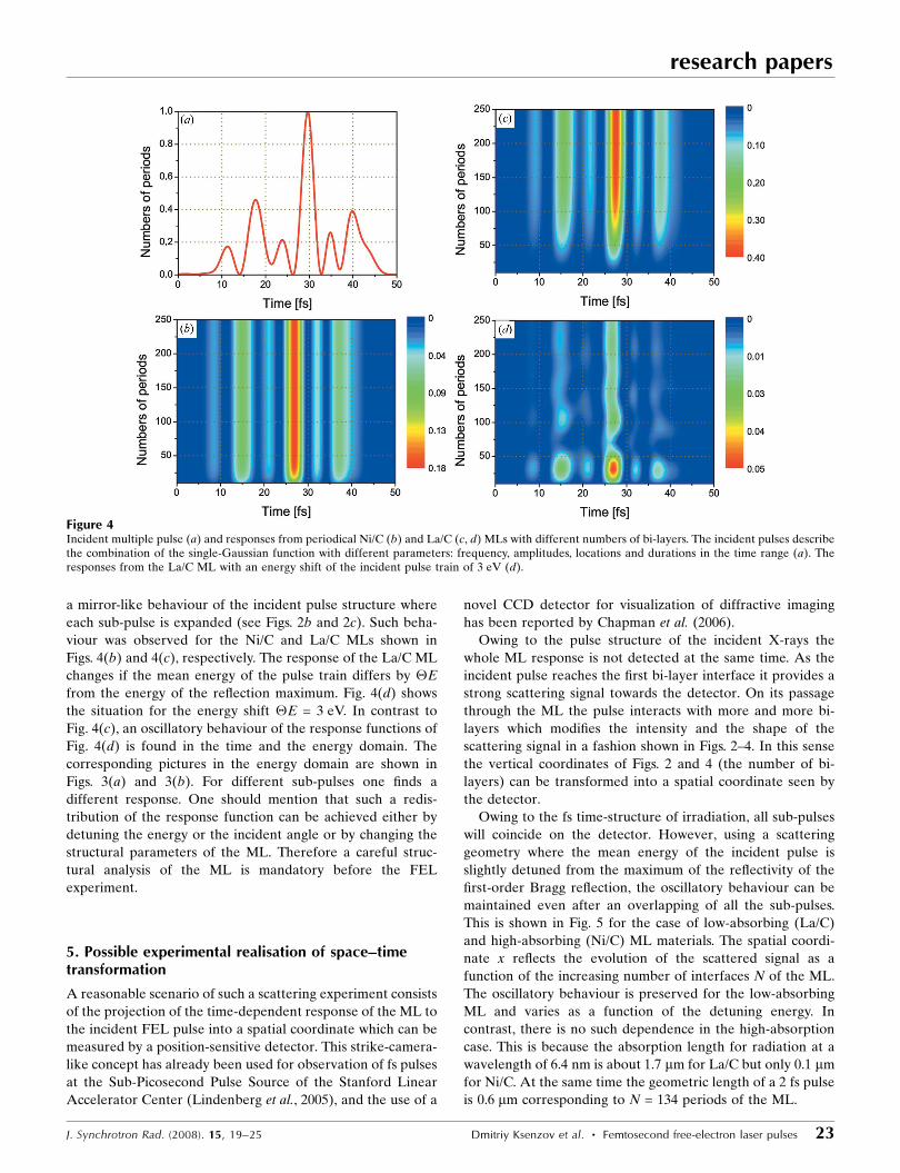
a mirror-like behaviour of the incident pulse structure where
each sub-pulse is expanded (see Figs. 2b and 2c). Such beha-
viour was observed for the Ni/C and La/C MLs shown in
Figs. 4(b) and 4(c), respectively. The response of the La/C ML
changes if the mean energy of the pulse train differs by �E
from the energy of the reflection maximum. Fig. 4(d) shows
the situation for the energy shift �E = 3 eV. In contrast to
Fig. 4(c), an oscillatory behaviour of the response functions of
Fig. 4(d) is found in the time and the energy domain. The
corresponding pictures in the energy domain are shown in
Figs. 3(a) and 3(b). For different sub-pulses one finds a
different response. One should mention that such a redis-
tribution of the response function can be achieved either by
detuning the energy or the incident angle or by changing the
structural parameters of the ML. Therefore a careful struc-
tural analysis of the ML is mandatory before the FEL
experiment.
5. Possible experimental realisation of space–timetransformation
A reasonable scenario of such a scattering experiment consists
of the projection of the time-dependent response of the ML to
the incident FEL pulse into a spatial coordinate which can be
measured by a position-sensitive detector. This strike-camera-
like concept has already been used for observation of fs pulses
at the Sub-Picosecond Pulse Source of the Stanford Linear
Accelerator Center (Lindenberg et al., 2005), and the use of a
novel CCD detector for visualization of diffractive imaging
has been reported by Chapman et al. (2006).
Owing to the pulse structure of the incident X-rays the
whole ML response is not detected at the same time. As the
incident pulse reaches the first bi-layer interface it provides a
strong scattering signal towards the detector. On its passage
through the ML the pulse interacts with more and more bi-
layers which modifies the intensity and the shape of the
scattering signal in a fashion shown in Figs. 2–4. In this sense
the vertical coordinates of Figs. 2 and 4 (the number of bi-
layers) can be transformed into a spatial coordinate seen by
the detector.
Owing to the fs time-structure of irradiation, all sub-pulses
will coincide on the detector. However, using a scattering
geometry where the mean energy of the incident pulse is
slightly detuned from the maximum of the reflectivity of the
first-order Bragg reflection, the oscillatory behaviour can be
maintained even after an overlapping of all the sub-pulses.
This is shown in Fig. 5 for the case of low-absorbing (La/C)
and high-absorbing (Ni/C) ML materials. The spatial coordi-
nate x reflects the evolution of the scattered signal as a
function of the increasing number of interfaces N of the ML.
The oscillatory behaviour is preserved for the low-absorbing
ML and varies as a function of the detuning energy. In
contrast, there is no such dependence in the high-absorption
case. This is because the absorption length for radiation at a
wavelength of 6.4 nm is about 1.7 mm for La/C but only 0.1 mm
for Ni/C. At the same time the geometric length of a 2 fs pulse
is 0.6 mm corresponding to N = 134 periods of the ML.
research papers
J. Synchrotron Rad. (2008). 15, 19–25 Dmitriy Ksenzov et al. � Femtosecond free-electron laser pulses 23
Figure 4Incident multiple pulse (a) and responses from periodical Ni/C (b) and La/C (c, d) MLs with different numbers of bi-layers. The incident pulses describethe combination of the single-Gaussian function with different parameters: frequency, amplitudes, locations and durations in the time range (a). Theresponses from the La/C ML with an energy shift of the incident pulse train of 3 eV (d).

Considering a ML with N = 400, for example, the interaction
length within the ML and subsequently the length of the
diffraction spot in the detector plane, xM, is 2.5 mm. This length
can be stretched in space by use of a ML where the surface has
a sliced angle � with respect to the multilayer normal. If the
incident pulse hits the ML interfaces at a scattering angle � ’45�, a grazing incident angle with respect to the ML surface
of � � � will enlarge the effective size of the reflected beam
by 1/sin(� � �). An additional enlargement of xM can be
achieved by oblique setting of the detector with respect to the
reflected beam by an angle � of the detector normal with
respect to the reflected beam. For a La/C ML and using
�� �’ 2� and �’ 5�, one can reach a stretching factor larger
than 300 for the detector coordinate xM which corresponds to
137 pixels of a CCD with pixel size 6 mm (Gerth et al., 2001).
This might be sufficient to detect the appearance or dis-
appearance of the oscillations shown in Fig. 5.
To exploit the effect of La/C film the number of ML periods
should be very large (N > 1000). Sliced multilayer gratings
(SMGs) are well suited to this task and give rise to surface
gratings in addition to the strong Bragg reflection. Whereas
the Bragg reflection probes the bulk scattering of the ML, the
grating peaks are created by scattering at the surface relief.
The latter ones can be used as an independent probe of the
energy of the sub-pulses without interaction with the bulk of
the ML.
The complete theory of reflection and transmission from
sliced ML gratings was derived by Kogelnick (1969) in terms
of coupled wave equations and further developed by Leva-
shov & Vinogradov (1993) and Fechtchenko et al. (2002). For
these structures the energy width of the diffraction pattern
increases with increasing sliced angle � and using grazing-
incidence geometry. The evolution of diffraction efficiency as
a function of � and � (both parameters are coupling for the
resonance case) for La/C with d = 4.7 nm and a thickness ratio
of 0.5 is shown in Fig. 6. As shown on the right-hand side of
research papers
24 Dmitriy Ksenzov et al. � Femtosecond free-electron laser pulses J. Synchrotron Rad. (2008). 15, 19–25
Figure 5Spatial variation of the reflected intensity for La/C and Ni/C MLs as afunction of the detuning energy Emax � �E. The energy of the centralmaximum reflection Emax is 193.75 eV.
Figure 6Calculated diffraction efficiency as a function of wavelength, incident angle and slicing angle. Cases 1 and 2 correspond to relatively small and largeslicing angle and reveal different broadening of the diffraction efficiency curves.
Fig. 6, the FWHM of the diffraction maximum increases by a
factor [sin(� + �)/sin(� � �)]1/2, increasing the sliced angle �,
and the energy position of the scattering maximum is shifted
to a lower wavelength accompanied by a reduction in the total
scattering power, known from X-ray dynamical theory. For
comparison, shown at � = 0 the FWHM is increased by factors
of 1.32 and 2.38 for cases 1 and 2, respectively, in Fig. 6.
For d = 4.7 nm and � = 35� (and grazing angle = 10�) (case 2
in Fig. 6) the effective grating spacing D = d/sin� = 8.2 nm,
which gives the first-order grating peak at �m = 10�. However,
owing to the finite length of the incident sub-pulse (duration
50 fs), the number of illuminated grating periods is large (here
about 1600) resulting in a narrow grating peak. Therefore
measurement of the angular position and angular width of the
grating peak is an independent and precise probe of the
energy and the energy spread of the incident pulse.
6. Conclusions
We have analyzed the interaction of VUV FEL pulses with a
multilayer. Owing to the finite length of a pulse the evolution
of the multilayer response can be studied as a function of the
penetration depth of the incident pulse into the ML. For this
purpose MLs with low absorption and high reflectivity, such as
La/C MLs, are promising candidates. The behaviour of the
interaction of the incident pulse with the ML can be varied by
setting the angle of incidence with respect to the ML surface at
certain values. The evolution of ML reflectivity as a function
of the number of interfaces becomes visible if the mean energy
of the incident pulse differs by a small amount �E from the
energy of the maximum reflectivity at the first-order Bragg
peak. Using the ML as a monochromator for the following
experiment, such a detuned scattering geometry can be an
option for tailoring the reflection intensity. The time–space
transformation can be improved using sliced MLs and an
asymmetric scattering geometry. Here the length of the
reflected pulse at the detector is a direct measure of the
absorption length within the sample. Any effect of a modified
interaction, owing to non-linear absorption or electronic
excitation, which would result in a reduction of the effective
absorption length, becomes directly measurable by such a
scattering experiment.
It is important to note that all effects that are linked with
the high intensity of FEL radiation are not considered in this
work. Various excitation phenomena can play an important
role in the process of the interaction of FEL radiation with
materials and may eventually alter the rocking curve and its
time structure.
The authors thank W. Graeff (DESY, Hamburg) and V.
Holy (Charles University, Prague) for critical comments on
the manuscript.
References
Ackermann, W. et al. (2007). Nat. Photon. 1, 336–342.Ayvazyan, V. et al. (2002). Eur. Phys. J. D, 20, 149–156.Ayvazyan, V. et al. (2006). Eur. Phys. J. D, 37, 297–303.Born, M. & Wolf, E. (1999). Principles of Optics: Electromagnetic
Theory of Propagation, Interference and Diffraction of Light.Cambridge University Press.
Chapman, H. et al. (2006). Nat. Phys. 2, 839–843.Chukhovskii, F. N. & Forster, E. (1995). Acta Cryst. A51, 668–672.DESY Report (2006a). The European X-ray Free-Electron Laser.
DESY, Hamburg, Germany.DESY Report (2006b). SASE FEL at the TESLA Facility Phase 2.
DESY, Hamburg, Germany.Eilbeck, J. C. (1972). J. Phys. 5, 1355.Fechtchenko, R. M., Vinogradov, A. V. & Voronov, D. L. (2002). Opt.
Commun. 210, 179–186.Gerth, Ch., Faatz, B., Lokajczyk, T., Treusch, R. & Feldhaus, J. (2001).
Nucl. Instrum. Methods A, 475, 481–486.Graeff, W. (2004). J. Synchrotron Rad. 11, 261–265.Hau-Riege, S. P. et al. (2007). Phys. Rev. Lett. 98, 145502.Kogelnick, H. (1969). Bell Syst. Tech. J. 48, 2909–2947.Kohn, V. G. (1995). Phys. Status Solidi B, 187, 61–70.Krenza, A. & Meyer-ter-Vehn, J. (2005). Eur. Phys. J. D, 36, 199–202.Levashov, V. E. & Vinogradov, A. V. (1993). Appl. Opt. 32, 1130–
1135.Lindenberg, A. M. et al. (2005). Science, 308, 392–395.Parratt, L. G. (1954). Phys. Rev. 95, 359–369.Shastri, S. D., Zambianchi, P. & Mills, D. M. (2001). J. Synchrotron
Rad. 8, 1131–1135.Stojanovic, N. et al. (2006). Appl. Phys. Lett, 89, 241909.Takenaka, H., Ichimaru, S., Nagai, K., Ohchi, T., Ito, H. & Gullikson,
E. M. (2005). Surf. Interface Anal. 37, 181–184.Tatchyn, R. & Bionta, R. (2001). Proc. SPIE, 4143, 89–97.Vinogradov, A. V., Brytov, I., Grudskii, A., Kogan, M. T. &
Kozhevnikov, I. V. (1989). X-ray Mirror Optics. Leningrad:Mashinostroenie. (In Russian.)
Wark, J. S. & He, H. (1994). Laser Part. Beams, 12, 507–513.Wark, J. S. & Lee, R. W. (1999). J. Appl. Cryst. 32, 692–703.
research papers
J. Synchrotron Rad. (2008). 15, 19–25 Dmitriy Ksenzov et al. � Femtosecond free-electron laser pulses 25