Dynamic Characteristics of a New Jetting Dispenser Driven by Piezostack Actuator
12
248 IEEE TRANSACTIONS ON ELECTRONICS PACKAGING MANUFACTURING, VOL. 31, NO. 3, JULY 2008 Dynamic Characteristics of a New Jetting Dispenser Driven by Piezostack Actuator Quoc Hung Nguyen, Young-Min Han, Seung-Bok Choi, and Seung-Min Hong Abstract—This paper proposes a new type of jetting dispenser driven by a piezostack actuator. After describing structural com- ponents of the dispensing mechanism and operating principle, a dynamic model of the dispenser is analytically formulated by con- sidering dynamic behaviors of the piezostack-piston head and the ball-needle. The inelastic impact between the ball-needle and the ball-seat during dispensing process is also considered in the mod- eling. An analytical fluid–solid interaction model is then derived by integrating the dynamic behavior of the dispensing fluid. Dis- pensing performances such as dot size and flow rate are evaluated under various frequencies and amplitudes of the sinusoidal driving voltage applied to the piezostack actuator. Index Terms—Dispensing system, dynamic analysis, fluid-solid interaction, jetting dispenser, piezostack actuator. I. INTRODUCTION F LUID dispensing is a method by which fluid materials such as epoxy, adhesive, encapsulant, and hydrogel are de- livered in a precisely controlled manner. It has been widely used in many applications such as electronics assembly [1]–[3], mi- croelectromechanical systems (MEMS) assembly [4], and fab- rication of soft tissues engineering scaffolds [5]. In these ap- plications, small volumes typically varying from microliters to nanoliters must be delivered accurately. So far, numerous types of dispensing approaches have been developed and successfully implemented in the real field. These approaches can be clas- sified into four types of dispenser by considering the driving mechanism. These are time–pressure, rotary screw, positive-dis- placement, and jetting type, respectively. Among these the first three approaches belong to the contact-based dispensing tech- nique in which the dispenser nozzle is required to contact with a substrate or printed circuit board (PCB) via dispensed adhe- sive during dispensing process. In the contact-based dispensing method, repeatable and good quality dots require the dispense gap (the distance between the needle and the substrate or PCB) be the same from dispense to dispense. Maintaining such a con- sistent dispense gap requires contact with the board, increases cycle time, and complicates the process. It also requires a po- sitioning system that can make accurate moves in the axis. Manuscript received December 26, 2006; revised July 18, 2007February 20, 2008. First published June 24, 2008; last published July 7, 2008 (projected). This work was supported by the Korean Industrial and Technology Foundation (KOTEF) through the Laboratory of Excellency Program. This work was rec- ommended for publication by Associate Editor M. Ramkumar upon evaluation of the reviewers comments. The authors are with the Department of Mechanical Engineering, Inha Uni- versity, Incheon 402751, Korea (e-mail: [email protected]). Color versions of one or more of the figures in this paper are available online at http://ieeexplore.ieee.org. Digital Object Identifier 10.1109/TEPM.2008.926292 Thus, the jetting type has been proposed which is a noncontact dispensing method [6]. Essentially, jet dispensing utilizes a closed-loop, positive shutoff piston to dispense adhesive. The fluid is pressurized at the syringe to ensure a constant flow of material throughout the fluid path of the dispenser. The chamber at the end of the fluid path is heated and the temperature controlled to achieve optimal and consistent viscosity. Using a ball and seat design, adhesive fills the void left by the ball as it retracts from the seat. As the ball returns, the force due to acceleration breaks the stream of adhesive, which is jetted through the nozzle. The broken stream of adhesive strikes the substrate from a distance of 1.0 to 3.5 mm above the board and forms an adhesive dot. The uniformity and shape of the adhesive dots are unaffected by variances in the PCB planarity or discrepancies in the needle surface and board surface tension since it never comes in contact with the board. Since there is no motion in the axis, the cycle time from dispense to dispense is significantly reduced. Despite these benefits, the modern semiconductor process needs an advanced dispensing system because pack- aging processes become increasingly dense, such as flip-chip, and requires dispensing nanoliter-volume of adhesives in a high flow rate. Furthermore, the reduction of noise/vibration and the dispensing of high viscous fluids are also important issues to be resolved. Consequently, the main contribution of this research work is to propose a new jetting mechanism and dynamic characteris- tics to resolve the aforementioned limitations of traditional jet- ting dispensers. In order to achieve this goal, a piezostack is introduced as an actuator to drive the jetting dispenser and its displacement is magnified by adopting a hydraulic magnifica- tion device. The optimal values of significant dimensions are then evaluated to maximize the resulting displacement of the dispensing needle. In order to derive dynamic characteristics of the dispenser, the dynamic behaviors of the piezostack-piston head and the needle are analytically described. The inelastic impact between the ball-needle and the ball-seat during dis- pensing process is also considered in the modeling. An analyt- ical fluid-solid interaction (FSI) model is then derived by in- tegrating the dynamic motion of the dispensing fluid. In the analysis of the proposed analytical model, the finite-element (FE) analysis is used to estimate the damping coefficients. Dis- pensing performances such as dot size, needle displacement, and flow rate are evaluated under various frequencies and ampli- tudes of the sinusoidal driving voltage applied to the piezostack actuator. II. JETTING DISPENSER DRIVEN BY PIEZOSTACK ACTUATOR In this paper, a configuration of the jetting dispenser driven by a piezostack is proposed and its working principle is pre- 1521-334X/$25.00 © 2008 IEEE
-
Upload
independent -
Category
Documents
-
view
0 -
download
0
Transcript of Dynamic Characteristics of a New Jetting Dispenser Driven by Piezostack Actuator

248 IEEE TRANSACTIONS ON ELECTRONICS PACKAGING MANUFACTURING, VOL. 31, NO. 3, JULY 2008
Dynamic Characteristics of a New Jetting DispenserDriven by Piezostack Actuator
Quoc Hung Nguyen, Young-Min Han, Seung-Bok Choi, and Seung-Min Hong
Abstract—This paper proposes a new type of jetting dispenserdriven by a piezostack actuator. After describing structural com-ponents of the dispensing mechanism and operating principle, adynamic model of the dispenser is analytically formulated by con-sidering dynamic behaviors of the piezostack-piston head and theball-needle. The inelastic impact between the ball-needle and theball-seat during dispensing process is also considered in the mod-eling. An analytical fluid–solid interaction model is then derivedby integrating the dynamic behavior of the dispensing fluid. Dis-pensing performances such as dot size and flow rate are evaluatedunder various frequencies and amplitudes of the sinusoidal drivingvoltage applied to the piezostack actuator.
Index Terms—Dispensing system, dynamic analysis, fluid-solidinteraction, jetting dispenser, piezostack actuator.
I. INTRODUCTION
F LUID dispensing is a method by which fluid materialssuch as epoxy, adhesive, encapsulant, and hydrogel are de-
livered in a precisely controlled manner. It has been widely usedin many applications such as electronics assembly [1]–[3], mi-croelectromechanical systems (MEMS) assembly [4], and fab-rication of soft tissues engineering scaffolds [5]. In these ap-plications, small volumes typically varying from microliters tonanoliters must be delivered accurately. So far, numerous typesof dispensing approaches have been developed and successfullyimplemented in the real field. These approaches can be clas-sified into four types of dispenser by considering the drivingmechanism. These are time–pressure, rotary screw, positive-dis-placement, and jetting type, respectively. Among these the firstthree approaches belong to the contact-based dispensing tech-nique in which the dispenser nozzle is required to contact witha substrate or printed circuit board (PCB) via dispensed adhe-sive during dispensing process. In the contact-based dispensingmethod, repeatable and good quality dots require the dispensegap (the distance between the needle and the substrate or PCB)be the same from dispense to dispense. Maintaining such a con-sistent dispense gap requires contact with the board, increasescycle time, and complicates the process. It also requires a po-sitioning system that can make accurate moves in the axis.
Manuscript received December 26, 2006; revised July 18, 2007February 20,2008. First published June 24, 2008; last published July 7, 2008 (projected).This work was supported by the Korean Industrial and Technology Foundation(KOTEF) through the Laboratory of Excellency Program. This work was rec-ommended for publication by Associate Editor M. Ramkumar upon evaluationof the reviewers comments.
The authors are with the Department of Mechanical Engineering, Inha Uni-versity, Incheon 402751, Korea (e-mail: [email protected]).
Color versions of one or more of the figures in this paper are available onlineat http://ieeexplore.ieee.org.
Digital Object Identifier 10.1109/TEPM.2008.926292
Thus, the jetting type has been proposed which is a noncontactdispensing method [6].
Essentially, jet dispensing utilizes a closed-loop, positiveshutoff piston to dispense adhesive. The fluid is pressurized atthe syringe to ensure a constant flow of material throughoutthe fluid path of the dispenser. The chamber at the end of thefluid path is heated and the temperature controlled to achieveoptimal and consistent viscosity. Using a ball and seat design,adhesive fills the void left by the ball as it retracts from theseat. As the ball returns, the force due to acceleration breaksthe stream of adhesive, which is jetted through the nozzle. Thebroken stream of adhesive strikes the substrate from a distanceof 1.0 to 3.5 mm above the board and forms an adhesive dot.The uniformity and shape of the adhesive dots are unaffectedby variances in the PCB planarity or discrepancies in theneedle surface and board surface tension since it never comesin contact with the board. Since there is no motion in theaxis, the cycle time from dispense to dispense is significantlyreduced. Despite these benefits, the modern semiconductorprocess needs an advanced dispensing system because pack-aging processes become increasingly dense, such as flip-chip,and requires dispensing nanoliter-volume of adhesives in a highflow rate. Furthermore, the reduction of noise/vibration and thedispensing of high viscous fluids are also important issues tobe resolved.
Consequently, the main contribution of this research work isto propose a new jetting mechanism and dynamic characteris-tics to resolve the aforementioned limitations of traditional jet-ting dispensers. In order to achieve this goal, a piezostack isintroduced as an actuator to drive the jetting dispenser and itsdisplacement is magnified by adopting a hydraulic magnifica-tion device. The optimal values of significant dimensions arethen evaluated to maximize the resulting displacement of thedispensing needle. In order to derive dynamic characteristics ofthe dispenser, the dynamic behaviors of the piezostack-pistonhead and the needle are analytically described. The inelasticimpact between the ball-needle and the ball-seat during dis-pensing process is also considered in the modeling. An analyt-ical fluid-solid interaction (FSI) model is then derived by in-tegrating the dynamic motion of the dispensing fluid. In theanalysis of the proposed analytical model, the finite-element(FE) analysis is used to estimate the damping coefficients. Dis-pensing performances such as dot size, needle displacement,and flow rate are evaluated under various frequencies and ampli-tudes of the sinusoidal driving voltage applied to the piezostackactuator.
II. JETTING DISPENSER DRIVEN BY PIEZOSTACK ACTUATOR
In this paper, a configuration of the jetting dispenser drivenby a piezostack is proposed and its working principle is pre-
1521-334X/$25.00 © 2008 IEEE
NGUYEN et al.: DYNAMIC CHARACTERISTICS OF A NEW JETTING DISPENSER DRIVEN BY PIEZOSTACK ACTUATOR 249
Fig. 1. Configuration of the proposed dispenser.
sented. As is well known, the piezoelectric actuator is one ofsmart materials which can offer large force, fast response, andhigh operating frequency. The primary limitation of the piezo-electric material is its small strain, the output displacement ofthe piezostack is generally less than 100 m. For dispensing ad-hesive material, however, a displacement of the ball-needle upto 0.5 mm or above is required. Thus, the output displacementshould be magnified via a magnification mechanism [8], [9]. Inthis paper, a hydraulic magnification mechanism is adopted inorder to magnify the resulting displacement of the needle fromthe output displacement of the piezostack.
Fig. 1 shows the schematic configuration of the proposed jet-ting dispenser driven by the piezostack actuator. As shown in thefigure, the piston head , connected to the piezostack ac-tuator , functions as a driving piston of the dispenser. In orderto avoid mechanical friction and fluid leak, a membrane isemployed between the piston head and the housing .When a voltage is applied to the piezostack, it causes a dis-placement of the piston head, and the resulting displacement ofthe ball-needle is magnified via the hydraulic magnificationto such a value that can make a dispensing of adhesive mate-rial. A periodic motion of the needle causes the adhesive in theball-seat to flow through the nozzle . If velocity of the adhe-sive flow in the nozzle is large enough, the flow will be brokenand form dots striking the substrate. The dispenser is expectedto be able to provide smaller dots than traditional ones becauseit can work at much higher frequency. Adhesive material is con-stantly pressurized at the syringe to ensure a constant flowthroughout the fluid path of the dispenser. The dispensing dotsize and flow rate can be changed by the frequency and ampli-tude of the voltage applied to the piezostack. Another advantage
of the dispenser is that there are no frictional contacts of the dis-penser’s components which cause wear of the components andreduce the dispenser’s performance.
In order to obtain high performance of the dispenser, sig-nificant geometric dimensions were optimized to maximize theneedle displacement while the stress in each structural compo-nent does not exceed the material yield stress. The optimizeddesign parameters are the radius of piston head , thewidth of piston membrane , and the width of needle capmembrane . If the piston radius is large, the volume dis-placed by the piston is large while the piston stiffness is less.Furthermore, the large resulting force from the piston reducesthe displacement of the piezostack. For a certain thickness ofthe membrane, the larger the thickness of the membrane, thestiffer it is. The stiff membranes impede the motion of the pistonhead and the needle. In contrast, the slender membranes causea large swept volume which decreases the magnification ratio.Thus, there exists an optimal value that maximizes the needledisplacement. In order to obtain the optimal solution, a finite-el-ement method (FEM) combining with an optimization tool isemployed. In this paper, the ANSYS optimization tool with sub-variable method is used. In the subvariable method, the programestablishes the relationship between the objective and the de-sign parameters by curve fitting. This is done by calculating theneedle displacement for several sets of design values (that is, forseveral designs), and the data points are fitted by a least squaremethod. Each optimization loop generates a new data point, andthe resulting curve is updated. The optimization procedure stopswhen a new data point converges to the previous data point. Themechanical properties of the dispenser components are summa-rized in Table I, and the optimal solution with initial values ofthe piston radius, the piston membrane width, and the needlemembrane width are, respectively, 15, 1, and 1 mm is shown inFig. 2. It is shown that the solution is converged after 15 itera-tions, and the optimal values are 22.7, 0.41, and 1.79 mm, re-spectively. The needle displacement at the optimal parametersis 0.51 mm, which is about 169% as large as that at initial pa-rameters. The optimized geometric dimensions of the dispenserare shown in Fig. 3.
III. DYNAMIC MODELING
A. Structural Dynamic Modeling
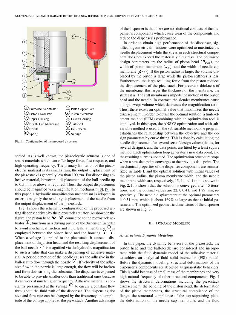
In this paper, the dynamic behaviors of the piezostack, thepiston head and the ball-needle are considered and incorpo-rated with the fluid dynamic model of the adhesive materialto achieve an analytical fluid–solid interaction (FSI) model.Before the dynamic modeling, structural deformations of thedispenser’s components are depicted as quasi-static behaviors.This is valid because of small mass of the membranes and veryhigh natural frequency of other structural components. Fig. 4shows the structural deformations including the piezostackdisplacement, the bending of the piston head, the deformationof the piston membranes, the structural compliance of theflange, the structural compliance of the top supporting plate,the deformation of the needle cap membrane, and the fluid

250 IEEE TRANSACTIONS ON ELECTRONICS PACKAGING MANUFACTURING, VOL. 31, NO. 3, JULY 2008
TABLE IMECHANICAL PROPERTIES OF THE STRUCTURAL
COMPONENTS AND ADHESIVE FLUID
Fig. 2. Optimized solution for geometric parameters of the dispenser.
compressibility. The deflections at piston part satisfy the fol-lowing geometric relation:
(1)
where
(2)
(3)
Fig. 3. Dimensional specifications of the proposed dispenser.
(4)
In the above, is the output displacement of the piezostack., , and are the deflections of the top supporting
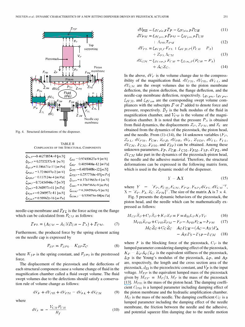
structure, the piston membrane, and the piston head, respec-tively. , , and are the force compliancesof the top supporting plate, the piston membrane and the pistonhead, respectively. and are the pressure compli-ances of the piston membrane and the piston head, respectively.With structural properties and geometric dimensions given inTable I and Fig. 3, the compliances are calculated from the lineartheory of plates and presented in Table II [7]. , , and
are the produced force by the piezostack, the force actingon the piston membrane and the pressure in the magnificationchamber, respectively.
The deflections at the needle-cap part can be derived asfollows:
(5)
(6)
where is the deflection of the flange structure, and isthe deflection of the needle-cap membrane which is the same asdisplacement of the needle . This is valid since the needle isassumed rigid. and are force compliances of thehousing flange and needle-cap membrane, respectively.and are pressure compliances of the housing flange andneedle membrane, respectively. is the pressure of the adhe-sive in the dispensing chamber. is the force acting on the
NGUYEN et al.: DYNAMIC CHARACTERISTICS OF A NEW JETTING DISPENSER DRIVEN BY PIEZOSTACK ACTUATOR 251
Fig. 4. Structural deformations of the dispenser.
TABLE IICOMPLIANCES OF THE STRUCTURAL COMPONENTS
needle-cap membrane and is the force acting on the flangewhich can be calculated from as follows:
(7)
Furthermore, the produced force by the spring element actingon the needle cap is expressed by
(8)
where is the spring constant, and is the prestressedforce.
The displacement of the piezostack and the deflections ofeach structural component cause a volume change of fluid in themagnification chamber called a fluid swept volume. The fluidswept volumes due to the defections should satisfy a conserva-tion rule of volume change as follows:
(9)
where
(10)
(11)
(12)
(13)
(14)
In the above, is the volume change due to the compress-ibility of the magnification fluid. , , , and
are the swept volumes due to the piston membranedeflection, the piston deflection, the flange deflection, and theneedle-cap membrane deflection, respectively. , ,
, and are the corresponding swept volume com-pliances with the subscripts or added to denote force andpressure, respectively. is the bulk modulus of the fluid inmagnification chamber, and is the volume of the magni-fication chamber. It is noted that the pressure is obtainedfrom fluid dynamics, the displacements , , and areobtained from the dynamics of the piezostack, the piston head,and the needle. From (1)–(14), the 14 unknown variables ( ,
, , , , , , , , ,, , , and ) can be obtained. Among these
unknown parameters, , , , , , , andtake part in the dynamics of the piezostack-piston head,
the needle and the adhesive material. Therefore, the structuraldeformations can be expressed in the following matrix form,which is used in the dynamic model of the dispenser.
(15)
where ,. The size of the matrix is 7 4.
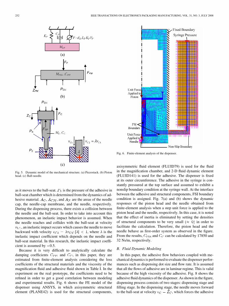
Fig. 5 presents the dynamic behaviors of the piezostack, thepiston head, and the needle which can be mathematically ex-pressed as follows:
(16)
(17)
(18)
where is the blocking force of the piezostack, is thelumped parameter considering damping effect of the piezostack,
is the equivalent stiffness of the piezostack,is the Young’s modulus of the piezostack, , and
are, respectively, the length and the cross section area of thepiezostack, is the piezoelectric constant, and is the inputvoltage. is the equivalent lumped mass of the piezostackgiven by , is the mass of the piezostack[13]. is the mass of the piston head. The damping coeffi-cient is a lumped parameter including damping effect ofthe piston membrane and the hydraulic amplification chamber.
is the mass of the needle. The damping coefficient is alumped parameter including the damping effect of the needlemembrane, the friction between the needle and the adhesive,and potential squeeze film damping due to the needle motion
252 IEEE TRANSACTIONS ON ELECTRONICS PACKAGING MANUFACTURING, VOL. 31, NO. 3, JULY 2008
Fig. 5. Dynamic model of the mechanical structure. (a) Piezostack. (b) Pistonhead. (c) Ball-needle.
as it moves to the ball-seat. is the pressure of the adhesive inball-seat chamber which is determined from the dynamics of ad-hesive material. , , and are the areas of the needlecap, the needle-cap membrane, and the needle, respectively.During the dispensing process, there exists a collision betweenthe needle and the ball-seat. In order to take into account thisphenomenon, an inelastic impact behavior is assumed. Whenthe needle reaches and collides with the ball-seat at velocity
, an inelastic impact occurs which causes the needle to movebackward with velocity , where is theinelastic impact coefficient which depends on the needle andball-seat material. In this research, the inelastic impact coeffi-cient is assumed by 0.5.
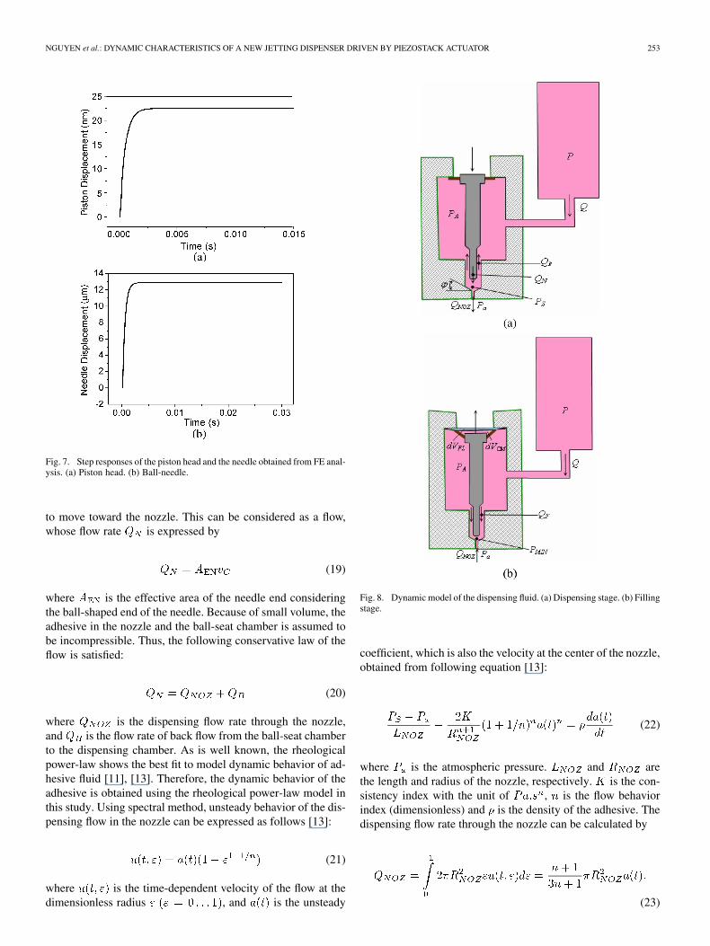
Because it is very difficult to analytically calculate thedamping coefficients and , in this paper, they areestimated from finite-element analysis considering the losscoefficients of the structural materials and the viscosity of themagnification fluid and adhesive fluid shown in Table I. In theexperiment on the real prototype, the coefficients need to berefined in order to get a good correlation between modelingand experimental results. Fig. 6 shows the FE model of thedispenser using ANSYS, in which axisymmetric structuralelement (PLANE42) is used for the structural components,
Fig. 6. Finite-element analysis of the dispenser.
axisymmetric fluid element (FLUID79) is used for the fluidin the magnification chamber, and 2-D fluid dynamic element(FLUID141) is used for the adhesive. The dispenser is fixedat its outer circumference. The adhesive in the syringe is con-stantly pressured at the top surface and assumed to exhibit anonslip boundary condition at the syringe wall. At the interfacebetween the adhesive and structural components, FSI boundarycondition is assigned. Fig. 7(a) and (b) shows the dynamicresponses of the piston head and the needle obtained fromfinite-element analysis when a step unit force is applied to thepiston head and the needle, respectively. In this case, it is notedthat the effect of inertia is eliminated by setting the densitiesof structural components to be very small in order tofacilitate the calculation. Therefore, the piston head and theneedle behave as first-order system as observed in the figure.From the results, and can be calculated by 17850 and32 Ns/m, respectively.
B. Fluid Dynamic Modeling
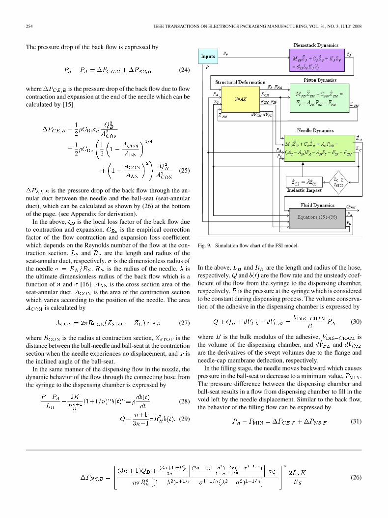
In this paper, the adhesive flow behaviors coupled with me-chanical dynamics is performed to evaluate the dispenser perfor-mances such as dispensing dot size and flow rate. It is assumedthat all the flows of adhesive are in laminar regime. This is validbecause of the high viscosity of the adhesive. Fig. 8 shows theadhesive fluid dynamics of the dispenser. As shown in the figure,dispensing process consists of two stages: dispensing stage andfilling stage. In the dispensing stage, the needle moves forwardto the ball-seat at velocity , which forces the adhesive
NGUYEN et al.: DYNAMIC CHARACTERISTICS OF A NEW JETTING DISPENSER DRIVEN BY PIEZOSTACK ACTUATOR 253
Fig. 7. Step responses of the piston head and the needle obtained from FE anal-ysis. (a) Piston head. (b) Ball-needle.
to move toward the nozzle. This can be considered as a flow,whose flow rate is expressed by
(19)
where is the effective area of the needle end consideringthe ball-shaped end of the needle. Because of small volume, theadhesive in the nozzle and the ball-seat chamber is assumed tobe incompressible. Thus, the following conservative law of theflow is satisfied:
(20)
where is the dispensing flow rate through the nozzle,and is the flow rate of back flow from the ball-seat chamberto the dispensing chamber. As is well known, the rheologicalpower-law shows the best fit to model dynamic behavior of ad-hesive fluid [11], [13]. Therefore, the dynamic behavior of theadhesive is obtained using the rheological power-law model inthis study. Using spectral method, unsteady behavior of the dis-pensing flow in the nozzle can be expressed as follows [13]:
(21)
where is the time-dependent velocity of the flow at thedimensionless radius , and is the unsteady
Fig. 8. Dynamic model of the dispensing fluid. (a) Dispensing stage. (b) Fillingstage.
coefficient, which is also the velocity at the center of the nozzle,obtained from following equation [13]:
(22)
where is the atmospheric pressure. and arethe length and radius of the nozzle, respectively. is the con-sistency index with the unit of , is the flow behaviorindex (dimensionless) and is the density of the adhesive. Thedispensing flow rate through the nozzle can be calculated by
(23)
254 IEEE TRANSACTIONS ON ELECTRONICS PACKAGING MANUFACTURING, VOL. 31, NO. 3, JULY 2008
The pressure drop of the back flow is expressed by
(24)
where is the pressure drop of the back flow due to flowcontraction and expansion at the end of the needle which can becalculated by [15]
(25)
is the pressure drop of the back flow through the an-nular duct between the needle and the ball-seat (seat-annularduct), which can be calculated as shown by (26) at the bottomof the page. (see Appendix for derivation).
In the above, is the local loss factor of the back flow dueto contraction and expansion. is the empirical correctionfactor of the flow contraction and expansion loss coefficientwhich depends on the Reynolds number of the flow at the con-traction section. and are the length and radius of theseat-annular duct, respectively. is the dimensionless radius ofthe needle . is the radius of the needle. isthe ultimate dimensionless radius of the back flow which is afunction of and [16]. is the cross section area of theseat-annular duct. is the area of the contraction sectionwhich varies according to the position of the needle. The area
is calculated by
(27)
where is the radius at contraction section, is thedistance between the ball-needle and ball-seat at the contractionsection when the needle experiences no displacement, and isthe inclined angle of the ball-seat.
In the same manner of the dispensing flow in the nozzle, thedynamic behavior of the flow through the connecting hose fromthe syringe to the dispensing chamber is expressed by
(28)
(29)
Fig. 9. Simulation flow chart of the FSI model.
In the above, and are the length and radius of the hose,respectively. and are the flow rate and the unsteady coef-ficient of the flow from the syringe to the dispensing chamber,respectively. is the pressure at the syringe which is consideredto be constant during dispensing process. The volume conserva-tion of the adhesive in the dispensing chamber is expressed by
(30)
where is the bulk modulus of the adhesive, isthe volume of the dispensing chamber, and andare the derivatives of the swept volumes due to the flange andneedle-cap membrane deflection, respectively.
In the filling stage, the needle moves backward which causespressure in the ball-seat to decrease to a minimum value, .The pressure difference between the dispensing chamber andball-seat results in a flow from dispensing chamber to fill in thevoid left by the needle displacement. Similar to the back flow,the behavior of the filling flow can be expressed by
(31)
(26)
NGUYEN et al.: DYNAMIC CHARACTERISTICS OF A NEW JETTING DISPENSER DRIVEN BY PIEZOSTACK ACTUATOR 255
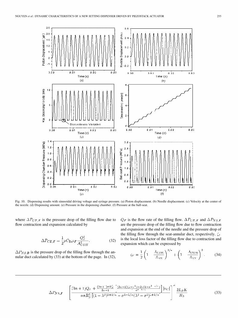
Fig. 10. Dispensing results with sinusoidal driving voltage and syringe pressure. (a) Piston displacement. (b) Needle displacement. (c) Velocity at the center ofthe nozzle. (d) Dispensing amount. (e) Pressure in the dispensing chamber. (f) Pressure at the ball-seat.
where is the pressure drop of the filling flow due toflow contraction and expansion calculated by
(32)
is the pressure drop of the filling flow through the an-nular duct calculated by (33) at the bottom of the page. In (32),
is the flow rate of the filling flow. andare the pressure drop of the filling flow due to flow contractionand expansion at the end of the needle and the pressure drop ofthe filling flow through the seat-annular duct, respectively.is the local loss factor of the filling flow due to contraction andexpansion which can be expressed by
(34)
(33)

256 IEEE TRANSACTIONS ON ELECTRONICS PACKAGING MANUFACTURING, VOL. 31, NO. 3, JULY 2008
Fig. 11. Frequency response of the piston and the needle. (a) Amplitude. (b) Phase angle.
The volume conservation of the adhesive in the dispensingchamber is expressed by
(35)
Whenever the adhesive fills up the void left by the needle dis-placement, the pressure at the ball-seat will increase to satisfythe following conservative law of the flows:
(36)
It is noted that and have negative values in the fillingstage. In the case that the filling flow rate is too small to fill upthe void left by the needle during its backward motion, the fillingstage will continue in the next forward motion of the needle untilthe void is eliminated.
IV. RESULTS AND DISCUSSIONS
In order to evaluate the dispensing performances, a simula-tion code of the proposed FSI model is established, as shownin Fig. 9. The FSI simulation code consists of the structuralcompliance models, the dynamic models of the piezostack, thepiston head, the needle, and the adhesive fluid with two in-puts: the pressure at the syringe and the input voltage of thepiezostack actuator . In this paper, the commercial adhesive,Hysol FP4451, is used. In order to enable the jetting process, theadhesive should be heated by a heating unit to around 60 C,at which the adhesive properties are calculated and shown inTable I [10].
Fig. 10 presents simulation results of the dispenser inresponse to the sinusoidal driving voltage (magnitude:1400 V/mm, frequency: 500 Hz) and pressure at the syringe is8 bar. The time responses of the piston head and the needle areshown in Fig. 10(a) and (b), respectively. As clearly observedfrom the figure, the output displacement of the piezostack isamplified to reach about 0.5 mm. When the needle reachesand contacts with the ball-seat (0.5 mm), the inelastic impactoccurs which results in a discontinuous motion of the needle.The discontinuous motion of the needle causes a discontinuousvariation of dispensing flow as shown in Fig. 10(c). It is alsoshown in Fig. 10(c) that the maximum dispensing velocity(velocity at center of the nozzle) can reach up to 10 m/s
at which a breakup of the adhesive flow is expected to formdispensing dots. Fig. 10(d) shows the dispensed volume duringdispensing process from which the average dispensing flow rate
and dot size are calculated to be 246.1 mm sand 0.4922 mm , respectively. The corresponding pressurechanges in the dispensing chamber and at the ball-seat areshown in Fig. 10(e) and (f), respectively.
Fig. 11 shows frequency responses of the piezostack-pistonhead and the needle of the dispenser to a sinusoidal drivingvoltage (magnitude: 1300 V/mm). At this magnitude, the am-plitude of needle displacement is smaller than 0.5 mm and theinelastic impact does not happen. It is observed that when thedriving frequency is smaller than 500 Hz, the amplitudes ofthe piston and the needle gradually increase with the drivingfrequency as shown in Fig. 11(a). The increase of the ampli-tudes is caused by inertia of the piezostack-piston head and theneedle. When the driving frequency is higher than 500 Hz, arapid increase of the amplitude occurs and maximum values ofthe amplitudes are observed as around 585 Hz which is con-sidered as the first resonant frequency of the dispenser. Higherthan this resonant frequency, an increase of driving frequencyresults in a rapid decrease of the amplitudes. In order to moreclearly explain the frequency responses, the phase angles of thepiezostack-piston head and needle are shown in Fig. 11(b). Asshown from the figure, the phase angles of the piston and needlemotion begin decreasing more rapidly when the driving fre-quency reaches 500 Hz. At around 585 Hz, there is a suddendecrease of the needle phase angle corresponding to the firstresonant frequency of the dispenser.
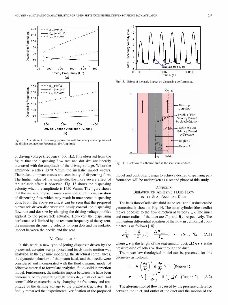
Fig. 12(a) shows the alteration of dispensing flow rate anddot size with the driving frequency when a sinusoidal voltage(magnitude: 1400 V/mm) is applied to the piezostack. Asshown in the figure, the dispensing flow rate is almost increasedlinearly while the dispensing dot size decreased with the fre-quency. However, when the frequency is above 585 Hz (firstresonant frequency), a nonuniform motion of the needle isobserved which results in nonuniform dispensing dots. Whenthe driving frequency is reduced to lower than 150 Hz, themaximum velocity at the center of the nozzle is smaller than4.35 m/s, at which the inertia force is not large enough to breakthe stream of adhesive to form dots. Fig. 12(b) shows the alter-ation of dispensing flow rate and dot size with the amplitude
NGUYEN et al.: DYNAMIC CHARACTERISTICS OF A NEW JETTING DISPENSER DRIVEN BY PIEZOSTACK ACTUATOR 257
Fig. 12. Alteration of dispensing parameters with frequency and amplitude ofthe driving voltage. (a) Frequency. (b) Amplitude.
of driving voltage (frequency: 500 Hz). It is observed from thefigure that the dispensing flow rate and dot size are linearlyincreased with the amplitude of the driving voltage. When theamplitude reaches 1370 V/mm the inelastic impact occurs.The inelastic impact causes a discontinuity of dispensing flow.The higher value of the amplitude, the more severe effect ofthe inelastic effect is observed. Fig. 13 shows the dispensingvelocity when the amplitude is 1450 V/mm. The figure showsthat the inelastic impact causes a severe discontinuous variationof dispensing flow which may result in unexpected dispensingdots. From the above results, it can be seen that the proposedpiezostack driven-dispenser can easily control the dispensingflow rate and dot size by changing the driving voltage profilesapplied to the piezostack actuator. However, the dispensingperformance is limited by the resonant frequency of the system,the minimum dispensing velocity to form dots and the inelasticimpact between the needle and the seat.
V. CONCLUSION
In this work, a new type of jetting dispenser driven by thepiezostack actuator was proposed and its dynamic motion wasanalyzed. In the dynamic modeling, the structural compliances,the dynamic behaviors of the piston head, and the needle wereconsidered and incorporated with the fluid dynamic model ofadhesive material to formulate analytical fluid–solid interactionmodel. Furthermore, the inelastic impact between the have beendemonstrated by presenting high flow rate, small dot size, andcontrollable characteristics by changing the frequency and am-plitude of the driving voltage to the piezostack actuator. It isfinally remarked that experimental verification of the proposed
Fig. 13. Effect of inelastic impact on dispensing performance.
Fig. 14. Backflow of adhesive fluid in the seat-annular duct.
model and controller design to achieve desired dispensing per-formances will be undertaken as a second phase of this study.
APPENDIX
BEHAVIOR OF ADHESIVE FLUID FLOW
IN THE SEAT-ANNULAR DUCT
The back flow of adhesive fluid in the seat-annular duct can begeometrically shown in Fig. 14. The inner cylinder (the needle)moves opposite to the flow direction at velocity . The innerand outer radius of the duct are and , respectively. Themomentum differential equation of the flow in cylindrical coor-dinates is as follows [18]:
(A.1)
where is the length of the seat-annular duct, is thepressure drop of adhesive flow through the duct.
The power-law rheological model can be presented for thisgeometry as follows:
if Region
if Region (A.2)
The aforementioned flow is caused by the pressure differencebetween the inlet and outlet of the duct and the motion of the

258 IEEE TRANSACTIONS ON ELECTRONICS PACKAGING MANUFACTURING, VOL. 31, NO. 3, JULY 2008
(A.10)
needle. The solution of this flow can be obtained by summingthe solution of the flow due to pressure difference with fixedboundary conditions: ;and the solution of the flow due to needle motion, separately. Inthe case of steady-state laminar flow, by integrating (A.1), thestress distribution of the flow is known to be [16]
(A.3)
In the above, is the nondimensional variable which is definedas . The is the constant of integration is chosenso that . In laminar flow, this correspondsto the location of maximum velocity. When (A.2) is combinedwith (A.3) and integrated formally with homogeneous boundarycondition, one obtains
Region
Region (A.4)
and the flow rate of the flow can be calculated as follows [17]:
(A.5)
It is noted that the value of is determined by the conditionwhich results in
(A.6)
By numerically solving (A.6), the values of can be obtainedas a function of and [16].
In the case of the flow due to the needle motion, by neglectingthe inertia effect and substituting into (A.1), thenintegrating twice with boundary conditions:and , one obtains
(A.7)
(A.8)
The total flow rate of back flow is calculated by
(A.9)
From (A.6), (A.8), and (A.9), the pressure drop of the backflowcan be expressed by (A.10), as shown at the top of the page.
REFERENCES
[1] D. Dixon, D. J. Kazalski, F. Murch, and S. Marongelli, “Practical is-sues concerning dispensing pump technologies,” Circuits Assembly,pp. 36–40, 1997.
[2] C. Q. Ness and A. R. Lewis, “Adhesives/epoxies and dispensing,” Surf.Mount Technol. (SMT), pp. 114–122, 1998.
[3] S. Wedekin, “Micro dispensing comes of age,” Surf. Mount Technol.(SMT), pp. 62–71, 2001.
[4] T. R. Hsu, “MEMS packaging,” U.K. INSPEC., London, U.K., 2004.[5] A. P. R. Landers, “Fabrication of soft tissue engineering scaffolds by
means of rapid prototyping techniques,” J. Mater. Sci., vol. 37, pp.3107–3116, 2002.
[6] F. Anthony, “Advantages of non-contact dispensing in SMT assemblyprocesses,” Asymtek, Carlsbad, CA, 2001.
[7] D. C. Roberts, “Design, modeling, fabrication and testing of a piezo-electric microvalve for high pressure, high frequency hydraulic appli-cations,” Ph.D. dissertation, Mass. Inst. of Technol., Cambridge, MA,2002.
[8] S. B. Choi, S. S. Han, and Y. S. Lee, “Fine motion control of a movingstage using piezoactuator associated with displacement amplifier,”Smart Mater. Structures, vol. 14, no. 1, pp. 222–230, 2005.
[9] S. B. Choi, J. K. Yoo, M. S. Cho, and Y. S. Lee, “Position control ofa cylinder system using a piezoactuator-driven pump,” Mechatronics,vol. 15, no. 2, pp. 239–249, 2005.
[10] X. B. Chen and H. Ke, “Effects of fluid properties on dispensingprocesses for electronics packaging,” IEEE Trans. Electron. Packag.Manuf., vol. 29, no. 2, pp. 75–82, Apr. 2006.
[11] X. B. Chen and J. Kai, “Modeling of time-pressure fluid dispensingprocess,” IEEE Trans. Electron. Packag. Manuf., vol. 23, no. 4, pp.300–305, Oct. 2000.
[12] X. B. Chen and J. Kai, “Modeling of time-pressure fluid dispensingprocess,” IEEE Trans. Electron. Packag. Manuf., vol. 23, no. 4, pp.300–305, Oct. 2000.
[13] Y. X. Zhao, H. X. Li, H. Ding, and Y. L. Xiong, “Integrated mod-eling of a time-pressure fluid dispensing system for electronics manu-facturing,” Int. J. Adv. Manuf. Technol., vol. 3, pp. 1978–1982, 2004.
[14] “Designing with piezoelectric transducer: Nanopositioning funda-mental,” Physik Instrument, 2005, PI Products’ Manual.
[15] M. K. Choi, “Design and control of jetting dispenser driven by piezo-electric actuator,” M.S. thesis, Inha Univ., Incheon, Korea, 2007.
[16] A. G. Fredrickson and R. B. Bird, “Non-Newtonian flow in annuli,”Ind. Eng. Chem., vol. 50, no. 5, pp. 347–352, 1958.
[17] W. H. Richard and M. L. Kenneth, “The flow of power-law non-New-tonian fluids in concentric annuli,” Ind. Eng. Chem. Fundam., vol. 18,no. 1, pp. 33–35, 1979.
[18] F. M. White, Fluid Mechanics. New York: McGraw-Hill, Univ. ofRhode Island, 2003.
NGUYEN et al.: DYNAMIC CHARACTERISTICS OF A NEW JETTING DISPENSER DRIVEN BY PIEZOSTACK ACTUATOR 259
Quoc Hung Nguyen received the B.Sc. degreein mechanical engineering from Ho Chi MinhPolytechnic University, Ho Chi Minh City, Vietnam,1997 and the M.S. degree in applied mechanics fromLiege University, Liege, Belgium, in 1999. He iscurrently pursuing the Ph.D. degree in the Depart-ment of Mechanical Engineering, Inha University,Incheon, South Korea.
Prior to the M.S. degree, he was a Lecturer atthe Industrial University of Ho Chi Minh City,Vietnam. His current research interests are in the
fluid dispensing technology and smart materials and structures.
Young-Min Han was born in Changwon, Korea, onDecember 1, 1969. He received the B.S., M.S., andPh.D. degrees in mechanical engineering from InhaUniversity, Incheon, Korea, in 1988, 1997, 2005,respectively.
Since 2006, he has been a Research Professor inthe Department of Mechanical Engineering, InhaUniversity. His current research interests include de-sign and control of functional mechanisms utilizingsmart materials such as human–machine interfaces,force-feedback devices, and shock absorbers.
Seung-Bok Choi received the B.Sc. degree in me-chanical engineering from Inha University, Incheon,Korea, in 1979 and the M.Sc. and Ph.D. degrees fromMichigan State University, East Lansing, in 1986 and1990, respectively.
He is currently a Fellow Professor of MechanicalEngineering at Inha University. His research inter-ests include smart materials and structures, suspen-sion systems, robotic systems, and advanced controltheories. He has published more than 200 interna-tional journal papers.
Seung-Min Hong received the B.Sc. degree in me-chanical engineering from Konkuk University, Seoul,Korea, in 2000 and the M.Sc degree from Inha Uni-versity, Incheon, South Korea, in 2006. He is cur-rently pursuing the Ph.D. degree in the Department ofMechanical Engineering, Inha University, Incheon,Korea.
His current research interests are on the fluiddispensing technology and smart materials andstructures.