DVM Pro : Sales mode Tutorial (Ver.1.2) - Amazon S3
82
DVM Pro : Sales mode Tutorial (Ver.1.2) DVM Pro S/W : Ver.1.0 Tutorial : Ver.1.2
-
Upload
khangminh22 -
Category
Documents
-
view
2 -
download
0
Transcript of DVM Pro : Sales mode Tutorial (Ver.1.2) - Amazon S3

DVM Pro : Sales mode
Tutorial (Ver.1.2)
DVM Pro S/W : Ver.1.0 Tutorial : Ver.1.2

Part1. Introduction 1.1 DVM pro Introduction…………………..………….….…. 6
1.2 Installation…………...………………………………… 7
1.3 SAC Design Process ……….……….………………..… 8
Part2. Basic Design (DVM S HP) 2.1 Modeling Scenario…………………………………....… 10
2.2 Start with DVM Pro …………………………….….…... 11
2.3 Create Project ………………………………….…...….. 12
2.4 Load Design ………………………………………....… 13
2.5 Select Product type…………………………..………... 14
2.6 Select Indoor units ……………………………………... 15
2.7 Select Outdoor unit …………………………………….. 17
2.8 Select Accessory …………………………………….. 19
2.9 Building management ………………...……………….. 24
2.10 Piping ………………………………..……………….….. 26
2.11 System Check ………………………….…………...… 29
2.12 Simulation ………………………………………….….. 30
2.13 Wiring ………………………………………………….. 31
2.14 Controller …………………………………………….... 32
2.15 Report ….…………………………………….………... 35
Contents

Part3. Advanced Design1 (DVM S HR) 3.1 Modeling Scenario…………………………………....… 37
3.2 Start with DVM Pro …………………………….….…... 38
3.3 Create Project ………………………………….…...….. 39
3.4 Load Design ………………………………………....… 40
3.5 Select Product type…………………………..………... 41
3.6 Select Indoor units ……………………………………... 42
3.7 Select Outdoor unit …………………………………….. 43
3.8 Select Accessory …………………………………….. 45
3.9 Building management ………………...……………….. 50
3.10 Piping ………………………………..……………….….. 52
3.11 System Check ………………………….…………...… 54
3.12 Controller …………………………………………….... 55
3.13 Report ….…………………………………….………... 57
Contents

Part4. Advanced Design2 (Hydro Unit) 4.1 Modeling Scenario…………………………………....… 59
4.2 Start with DVM Pro …………………………….….…... 60
4.3 Create Project ………………………………….…...….. 61
4.4 Load Design ………………………………………....… 62
4.5 Select Product type…………………………..………... 63
4.6 Select Indoor units ……………………………………... 64
4.7 Select Outdoor unit …………………………………….. 66
4.8 Select Accessory …………………………………….. 69
4.9 Building management ………………...……………….. 74
4.10 Piping ………………………………..……………….….. 76
4.11 System Check ………………………….…………...… 77
4.12 Report ….…………………………………….………... 78
Contents
Part5. Additional Function 5.1 Pricing Function…..…………………………………....… 80

Part 1. Introduction

Part1. Introduction
What is DVM Pro?
1.1 DVM Pro Introduction
6
- To help users design SAC very quickly and accurately
- DVM Pro is composed of ‘Sales mode” and “CAD mode”.
1. Sales mode : Simple design with generating model list
2. Cad mode : Design SAC on AutoCAD drawing.
※ Auto CAD program must be installed.
Part1. Introduction
Software Installation (Down load)
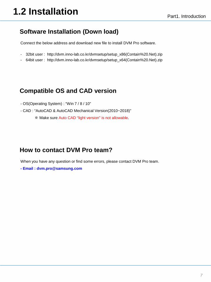
1.2 Installation
7
Connect the below address and download new file to install DVM Pro software.
- 32bit user : http://dvm.inno-lab.co.kr/dvmsetup/setup_x86(Contain%20.Net).zip - 64bit user : http://dvm.inno-lab.co.kr/dvmsetup/setup_x64(Contain%20.Net).zip
Compatible OS and CAD version
How to contact DVM Pro team?
- OS(Operating System) : “Win 7 / 8 / 10”
- CAD : “AutoCAD & AutoCAD Mechanical Version(2010~2018)”
※ Make sure Auto CAD “light version” is not allowable.
When you have any question or find some errors, please contact DVM Pro team.
- Email : [email protected]

Part1. Introduction 1.3 Design Process
8
Flow Chart
1. Create Project
2. Select Product type
3. Load Design
7. Piping
8. System Check
9. Capacity Simulation
4. Select Indoor unit
5. Select Outdoor unit
6. Building management
10. Wiring
11. Select Controller
12. Report

Part 2 : Basic Design
Market with DVM S HP
(Tutorial with 1st Scenario)
Purpose :
1. Understand the design process for SAC.
2. Learn how to use DVM Pro S/W.
3. Part 2 is focused on the basic design.
- DVM S HP with 360 CST
- On-Off Controller, Touch Controller

Part2. SAC Design 2.1 Modeling Scenario
10
Approach - Building type : Supermarket - Area : 400m2 - Indoor unit : 360 CST - Controller : On-Off controller for Each zone and Touch controller - Longest pipe : 180m
System (Outdoor unit) Room/Zone Area (m2)
Load Requirements (KW)
Cooling Heating
TC SHC TC
System 1 Zone1 180 38 27 32
System 2 Zone2 220 46 33 40
Zone 1 Zone 2
- Load Requirements 1. (Example of Zone1) TC = 0.21kW/m2(*Unit load) x 180m2(Area) = 38kW 2. (Example of Zone1) SHC = TC x 0.71 (*Sensible heat ratio)
Design Tip - TC(Total Capacity) = SHC(Sensible Heat Capacity) + LHC(Latent Heat Capacity)
- SHC: Capacity that changes temperature
- LC: Capacity that changes a phase such as the dehumidification.
- Designers need to consider SHC in high humidity places especially near the beach and lake.
Normally, when humidity is higher, air-conditioner more work for LHC(dehumidification).
On the other hand, SHC is smaller so that adjusting temperature may not be enough.
* Unit load (kW/m2) : 0.21 / 0.18 (Cooling TC / Heating TC)

Part2. SAC Design 2.2 Start with DVM Pro
11
Start with DVM Pro
1. To start DVM Pro, double click a icon “New DVM Pro 1.0” on desktop..
2. Click “Sales” button to start Sales mode of DVM Pro.
3. New window popped up.
Usage Tip
Version Information
Design steps
Double Click
①
②

Part2. SAC Design 2.3 Create Project
12
Create Project
1. To create the project, click “New” button, then new window is popped up.
2. Enter the project name: the project name will be saved as a file name.
3. Enter the customer information and designer information (Optional)
: This will be represented on the report.
4. Enter Design condition : Select city “Madrid”
5. Design condition (Weather)
: Firstly weather condition is represented based on your city,
and then user can edit the data manually.
6. Click “OK” button to complete to create a project.
Usage Tip
Saving File extension is “.dvms”.
If user wants to select models from other countries, please request the authorization for the
country to DVM Pro team by email, [email protected].
①
②
③
④
⑤
⑥
Design steps
Part2. SAC Design 2.4 Load Design
13
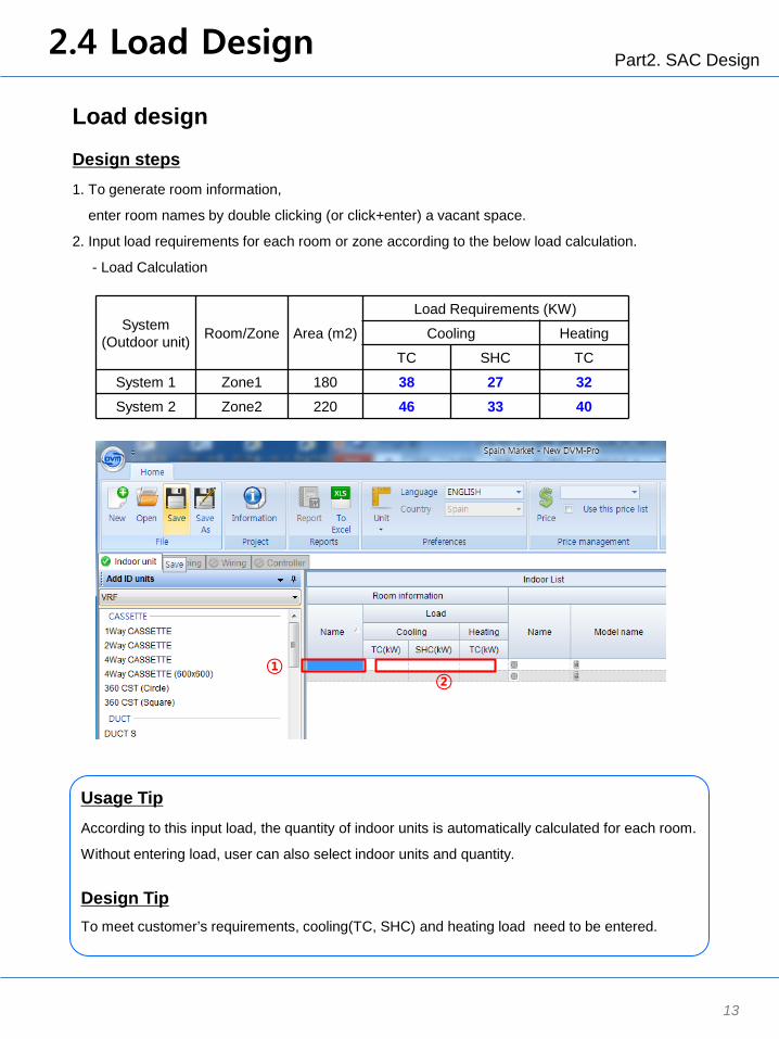
Load design
1. To generate room information,
enter room names by double clicking (or click+enter) a vacant space.
2. Input load requirements for each room or zone according to the below load calculation.
- Load Calculation
Design steps
① ②
Usage Tip
According to this input load, the quantity of indoor units is automatically calculated for each room.
Without entering load, user can also select indoor units and quantity.
Design Tip To meet customer’s requirements, cooling(TC, SHC) and heating load need to be entered.
System (Outdoor unit) Room/Zone Area (m2)
Load Requirements (KW)
Cooling Heating
TC SHC TC
System 1 Zone1 180 38 27 32 System 2 Zone2 220 46 33 40

Part2. SAC Design 2.5 Select Product type
14
Select product type
1. Click the below tap and select a product type on drop/down menu. (Select VRF)
Design steps
Design Tip
For the proper SAC selection, many design factors should be considered such as
the system capacity, pipe length, installation space, the number of indoor units, and so on.
※ To check those design and installation factors, please refer to TDB or installation manual.
①

Part2. SAC Design 2.6 Select Indoor units
15
1) Select indoor units
1. Click each room to select indoor units.
2. Select indoor unit type : 360 CST
3. Select a model (AM090KN4DEH/EU) and check the quantity. (User can change the quantity manually.)
4. Click “Add” button to complete the selection of indoor units
Design steps
②
③
④
①

Part2. SAC Design 2.6 Select Indoor units
16
2) Modification / delete
1. Click the designed indoor units. (two AM112FN4DEH/EU)
2. Select indoor units you want to replace (AM090FN4DEH/EU)
3. Click “Add” button to complete the selection of indoor units
Design steps (Change to other indoor units)
②
③
①
1. Click the designed indoor units or room name. (two AM112FN4DEH/EU)
2. Enter “Delete” key on your keyboard.
3. Click “Yes” button.
Design steps (Delete indoor units)
①
③
Part2. SAC Design 2.7 Select Outdoor units
17
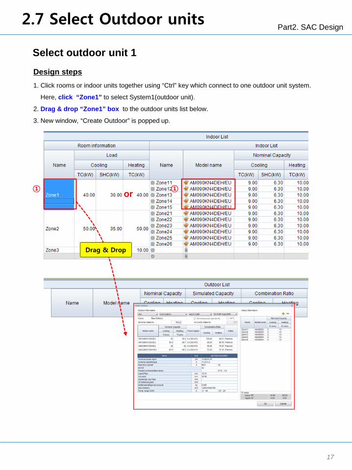
Select outdoor unit 1
1. Click rooms or indoor units together using “Ctrl” key which connect to one outdoor unit system.
Here, click “Zone1” to select System1(outdoor unit).
2. Drag & drop “Zone1” box to the outdoor units list below.
3. New window, “Create Outdoor” is popped up.
Design steps
① or ①
Drag & Drop

Part2. SAC Design 2.7 Select Outdoor units
18
Select outdoor unit 2
1.Select the type of outdoor unit.
Here, select a outdoor type : VRF DVM S HEAT PUMP 2016 HP High EER
2. Enter the combination ratio, 130%.
3. Select the model among the recommendation models. : Select AM140KXVGGH/EU
4. Click “OK” button to complete the selection of outdoor unit.
Design steps
Design Tip
User can enter combination ratio manually under the limitation of it, and models are recommended
based on combination ratio.
※ Combination ratio = Total capacity of indoor units / Capacity of outdoor unit.
※ Limitation of VRF’s combination ratio : 50% ~ 130%
①
②
③
④
5. Select the other outdoor unit for “System 2” with same way from previous page (Select ODU2).

Part2. SAC Design 2.8 Select Accessary
19
Select accessories
1. Click indoor unit models to select accessories.
2. Click “Accessory” tap
3. Select accessories : 360 Circle panel and Wired remote controller
4. When accessories are selected, the related indoor units are marked with the orange color.
Design steps
Design Tip
When you select cassette type indoor units, you should select compatible “Panel”,
otherwise accessory list are not represented on the report.
①
② ④
③
③
Part2. SAC Design
20
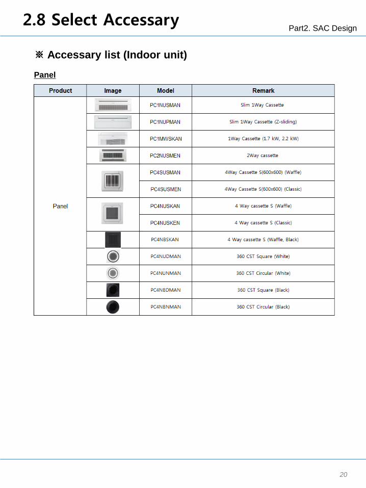
Panel
※ Accessary list (Indoor unit)
2.8 Select Accessary
Part2. SAC Design
21
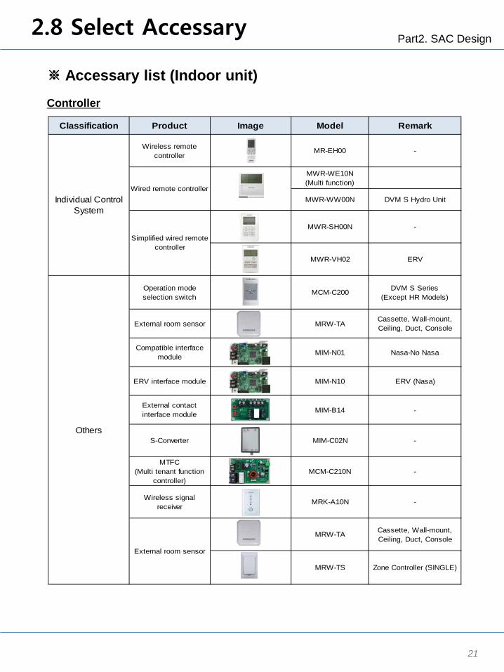
Classification Product Image Model Remark
Wireless remotecontroller
MR-EH00 -
MWR-WE10N(Multi function)
MWR-WW00N DVM S Hydro Unit
MWR-SH00N -
MWR-VH02 ERV
Operation modeselection switch
MCM-C200 DVM S Series(Except HR Models)
External room sensor MRW-TACassette, Wall-mount,Ceiling, Duct, Console
Compatible interfacemodule MIM-N01 Nasa-No Nasa
ERV interface module MIM-N10 ERV (Nasa)
External contactinterface module MIM-B14 -
S-Converter MIM-C02N -
MTFC(Multi tenant function
controller)MCM-C210N -
Wireless signalreceiver
MRK-A10N -
MRW-TA Cassette, Wall-mount,Ceiling, Duct, Console
MRW-TS Zone Controller (SINGLE)
Others
External room sensor
Individual ControlSystem
Wired remote controller
Simplified wired remotecontroller
Controller
※ Accessary list (Indoor unit)
2.8 Select Accessary
Part2. SAC Design
22
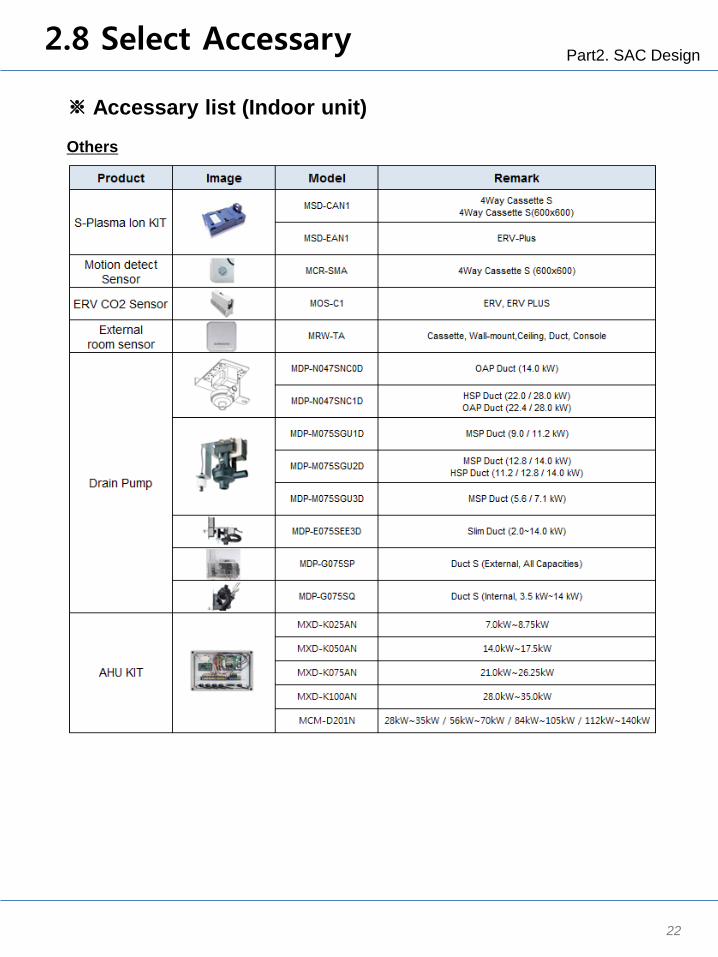
Others
※ Accessary list (Indoor unit)
2.8 Select Accessary

Part2. SAC Design
23
Others
※ Accessary list (Outdoor unit)
2.8 Select Accessary

Part2. SAC Design 2.9 Building Management
24
Building management
1. Click rooms or indoor units to the installation floor on “Building management” by drag & drop.
2. Every indoor units and outdoor units should be placed to the floors on “Building management”.
Design steps
① Drag & Drop
Drag & Drop
3. After placing all of products to spaces on “Building management” ,
“Piping” tap is activated.

Part2. SAC Design 2.9 Building Management
25
※ Generate floors
1. Click “Edit” button.
Design steps
Part2. SAC Design 2.10 Piping
26
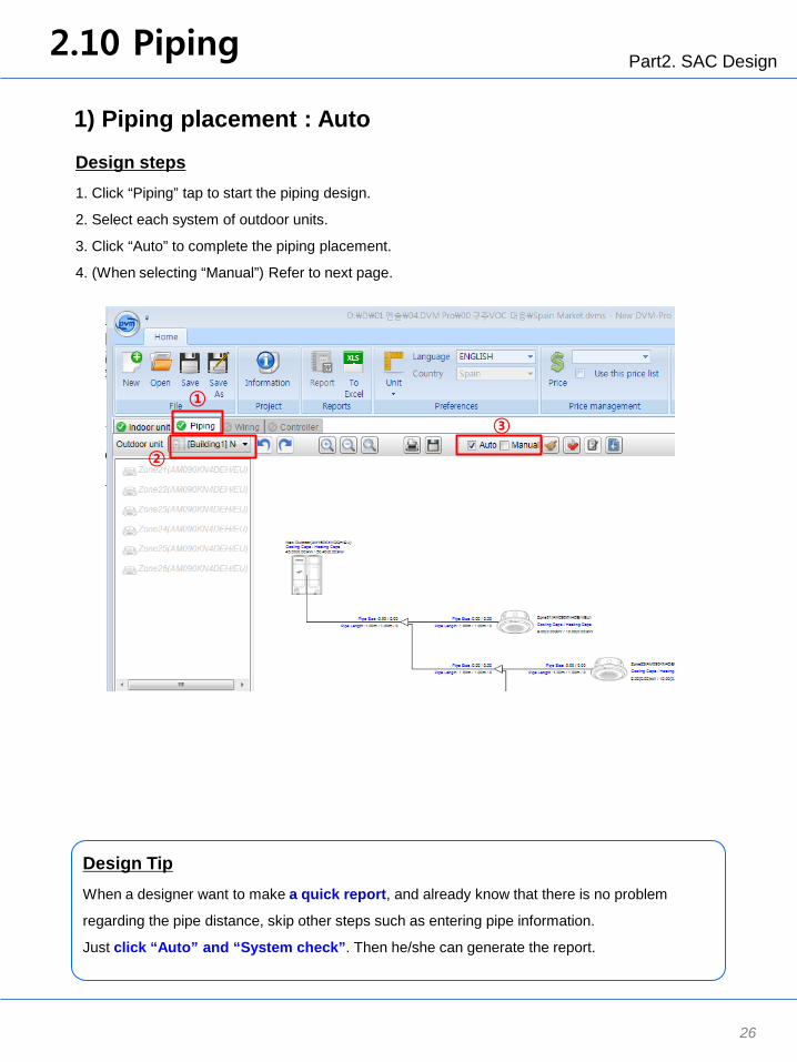
1) Piping placement : Auto
1. Click “Piping” tap to start the piping design.
2. Select each system of outdoor units.
3. Click “Auto” to complete the piping placement.
4. (When selecting “Manual”) Refer to next page.
Design steps
①
②
③
Design Tip
When a designer want to make a quick report, and already know that there is no problem
regarding the pipe distance, skip other steps such as entering pipe information.
Just click “Auto” and “System check”. Then he/she can generate the report.

Part2. SAC Design 2.10 Piping
2) Piping placement : Manual
1. Click “Manual” to start the piping placement.
2. Drag & drop indoor units.
User can select several indoor units and place them together by “Ctrl” key.
3. After placing one indoor unit, place the other indoor units to the piping line.
4. Move all indoor units with same way.
Design steps
27
②
①
③
Drag & Drop
Drag & Drop

Part2. SAC Design 2.10 Piping
28
3) Input piping size
1. Click each pipe line, then input space appears to the right side.
(Input piping data)
2. Enter actual piping length and number of bending.
- Main pipe: 220m, the other pipes: 1m.
Design steps
①
②
Click
Design Tip
Input this piping data as accurate as possible because the result of “System check” and
“Capacity simulation” can differ based on the piping length.
Without entering data, every pipe line has the length of 1m.

Part2. SAC Design 2.11 System Check
29
System Check
1. Click “System check” button.
2. “ERROR” appears.
3. Solve the problem with below RED messages.
Here, Max. piping length exceeds product’s limitation.
Change main pipe from 220m to 180m.
4. Click “System check” again.
5. Without any red comments, system check is completed.
Design steps
①
②
③
Design Tip
This function shows what user make wrong design or mistakes so that help users design SAC
properly.
This S/W includes the variable limitation logics according to an installation manual.
User also can check the amount of additional refrigerant.

Part2. SAC Design 2.12 Simulation
30
Capacity correction
1. Click the button “Capacity correction”, then new window is appeared.
2. Check “design condition and change the data if needed.
3. Click “Capacity correction” button.
Design steps
①
②
③
Part2. SAC Design 2.13 Wiring
31
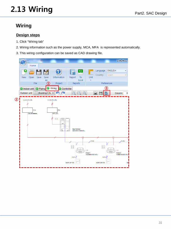
Wiring
1. Click “Wiring tab”
2. Wiring information such as the power supply, MCA, MFA is represented automatically.
3. This wiring configuration can be saved as CAD drawing file.
Design steps
①
②
③
Part2. SAC Design 2.14 Controller
32
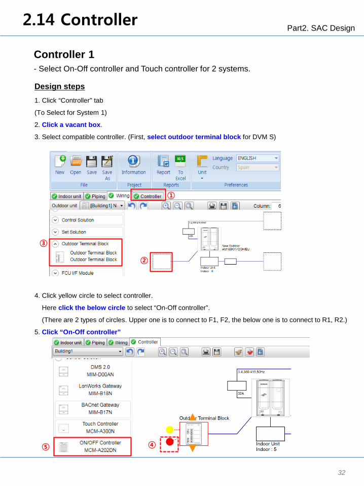
Controller 1 - Select On-Off controller and Touch controller for 2 systems.
1. Click “Controller” tab
(To Select for System 1)
2. Click a vacant box.
3. Select compatible controller. (First, select outdoor terminal block for DVM S)
Design steps
①
③
②
4. Click yellow circle to select controller.
Here click the below circle to select “On-Off controller”.
(There are 2 types of circles. Upper one is to connect to F1, F2, the below one is to connect to R1, R2.)
5. Click “On-Off controller”
④ ⑤
Part2. SAC Design 2.14 Controller
33
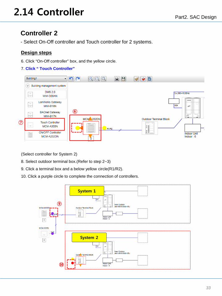
6. Click “On-Off controller” box, and the yellow circle.
7. Click “ Touch Controller”
Design steps
⑥
⑦
System 1
System 2
⑩
⑨
(Select controller for System 2)
8. Select outdoor terminal box.(Refer to step 2~3)
9. Click a terminal box and a below yellow circle(R1/R2).
10. Click a purple circle to complete the connection of controllers.
Controller 2 - Select On-Off controller and Touch controller for 2 systems.
.

Part2. SAC Design
34
Design Tip
When connecting Outdoor unit and controller, there are 2 ways.
- Using F1/F2 : Control one outdoor unit system and connected indoor units.
(On-Off controller, Touch controller, Wi-fi kit)
- Using R1/R2 : Control several outdoor unit system and connected indoor units.
(On-Off controller, Touch controller, DMS, BACnet, Lonworks)
2.14 Controller
※ Controller

Part2. SAC Design 2.15 Report
35
Generate Report
1. Click “Report” button.
2. Enter a file name and click “Save” button.
3. Click “ To Excel” button to generate the designed Product list.
4. Enter a file name and click “Save” button.
Design steps
① ③
②, ④
Usage Tip
There are 2 types of report.
- “Report” button: Includes all of designed information
- “To Excel” button: Includes only designed product list

Part 3 : Advanced Design1
Small Hotel with DVM S HR
(Tutorial with 2st Scenario)
Purpose :
1. Understand the design process for SAC.
2. Learn how to design DVM S HR
3. Part 2 is focused on the advanced design.
- DVM S HR with 1Way CST
- MCU(Mode Control Unit) design
- Control : Key-Tag with DMS2.5
4. Most of design steps are same as Part2: Basic design.
Only big difference is how to design MCU in Piping step.
Part3. Advanced Design1 3.1 Modeling Scenario
37
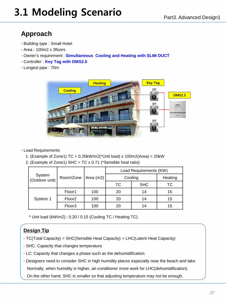
Approach - Building type : Small Hotel - Area : 100m2 x 3floors - Owner’s requirement : Simultaneous Cooling and Heating with SLIM DUCT - Controller : Key Tag with DMS2.5 - Longest pipe : 70m
System (Outdoor unit) Room/Zone Area (m2)
Load Requirements (KW)
Cooling Heating
TC SHC TC
System 1
Floor1 100 20 14 15
Floor2 100 20 14 15
Floor3 100 20 14 15
- Load Requirements 1. (Example of Zone1) TC = 0.20kW/m2(*Unit load) x 100m2(Area) = 20kW 2. (Example of Zone1) SHC = TC x 0.71 (*Sensible heat ratio)
Design Tip - TC(Total Capacity) = SHC(Sensible Heat Capacity) + LHC(Latent Heat Capacity)
- SHC: Capacity that changes temperature
- LC: Capacity that changes a phase such as the dehumidification.
- Designers need to consider SHC in high humidity places especially near the beach and lake.
Normally, when humidity is higher, air-conditioner more work for LHC(dehumidification).
On the other hand, SHC is smaller so that adjusting temperature may not be enough.
* Unit load (kW/m2) : 0.20 / 0.15 (Cooling TC / Heating TC)
Heating
Cooling
Key-Tag
DMS2.5

Part3. Advanced Design1 2.2 Start with DVM Pro
38
Start with DVM Pro
1. To start DVM Pro, double click a icon “New DVM Pro 1.0” on desktop..
2. Click “Sales” button to start Sales mode of DVM Pro.
3. New window popped up.
Usage Tip
Version Information
Design steps
Double Click
①
②

Part3. Advanced Design1 3.3 Create Project
39
Create Project
1. To create the project, click “New” button, then new window is popped up.
2. Enter the project name: the project name will be saved as a file name.
3. Enter the customer information and designer information (Optional)
: This will be represented on the report.
4. Enter Design condition : Select city “Madrid”
5. Design condition (Weather)
: Firstly weather condition is represented based on your city,
and then user can edit the data manually.
6. Click “OK” button to complete to create a project.
Usage Tip
Saving File extension is “.dvms”.
If user wants to select models from other countries, please request the authorization for the
country to DVM Pro team by email, [email protected].
①
②
③
④
⑤
⑥
Design steps

Part3. Advanced Design1 3.4 Load Design
40
Load design
1. To generate room information,
enter room names by double clicking (or click+enter) a vacant space.
2. Input load requirements for each room or zone according to the below load calculation.
- Load Calculation
Design steps
① ②
Usage Tip
According to this input load, the quantity of indoor units is automatically calculated for each room.
Without entering load, user can also select indoor units and quantity.
Design Tip To meet customer’s requirements, cooling(TC, SHC) and heating load need to be entered.
System (Outdoor unit) Room/Zone Area (m2)
Load Requirements (KW)
Cooling Heating
TC SHC TC
System 1
Floor1 100 20 14 15 Floor2 100 20 14 15 Floor3 100 20 14 15

Part3. Advanced Design1 3.5 Select Product type
41
Select product type
1. Click the below tap and select a product type on drop/down menu. (Select VRF)
Design steps
Design Tip
For the proper SAC selection, many design factors should be considered such as
the system capacity, pipe length, installation space, the number of indoor units, and so on.
※ To check those design and installation factors, please refer to TDB or installation manual.
①

Part3. Advanced Design1 3.6 Select Indoor units
42
Select indoor units
1. Click each room to select indoor units.
2. Select indoor unit type : SLIM DUCT
3. Select a model (AM071FNLDEH/EU) and check the quantity. (User can change the quantity manually.)
4. Click “Add” button to complete the selection of indoor units
Design steps
②
③ ④
①
Part3. Advanced Design1 3.7 Select Outdoor units
43
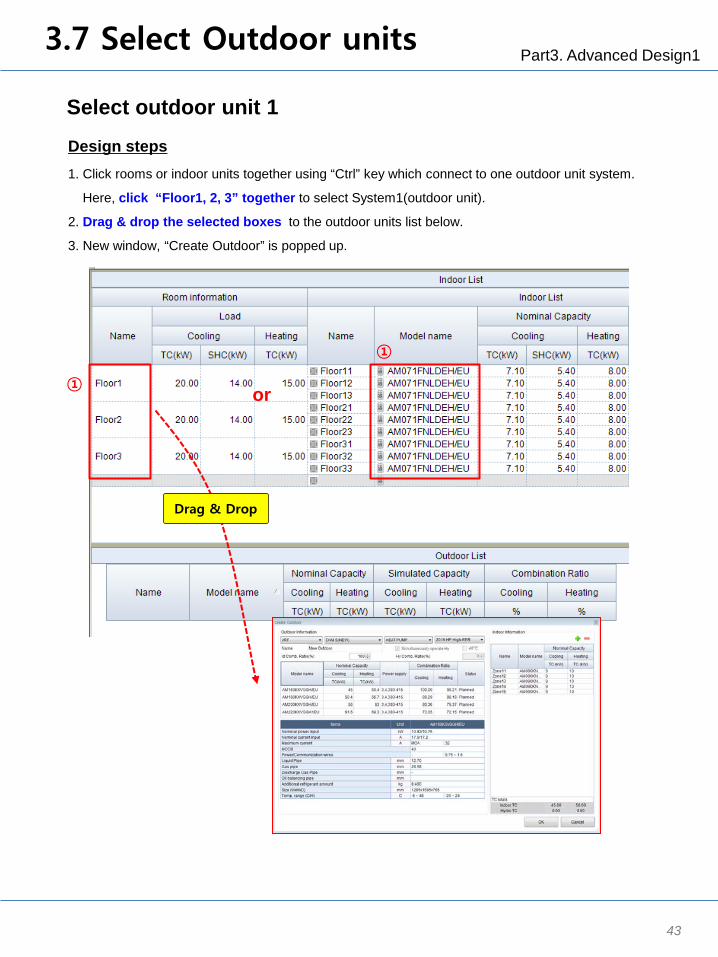
Select outdoor unit 1
1. Click rooms or indoor units together using “Ctrl” key which connect to one outdoor unit system.
Here, click “Floor1, 2, 3” together to select System1(outdoor unit).
2. Drag & drop the selected boxes to the outdoor units list below.
3. New window, “Create Outdoor” is popped up.
Design steps
① or
①
Drag & Drop

Part3. Advanced Design1 3.7 Select Outdoor units
44
Select outdoor unit 2
1.Select the type of outdoor unit.
Here, select a outdoor type : VRF DVM S Heat Recovery 2015 High EER
2. Enter the combination ratio, 130%.
3. Select the model among the recommendation models. : Select AM180JXVHGR/EU
4. Click “OK” button to complete the selection of outdoor unit.
Design steps
Design Tip
User can enter combination ratio manually under the limitation of it, and models are recommended
based on combination ratio.
※ Combination ratio = Total capacity of indoor units / Capacity of outdoor unit.
※ Limitation of VRF’s combination ratio : 50% ~ 130%
①
②
③
④

Part3. Advanced Design1
45
Select accessories
1. Click indoor unit models to select accessories.
2. Click “Accessory” tap
3. Select accessories : MIM-B14(External Contact Controller)
4. When accessories are selected, the related indoor units are marked with the orange color.
Design steps
Design Tip
When designing Duct type IDU, you need to choose drain type and control method considering
customer’s desire.
- Drain type : Drain pump or Drain hose
- Control : Wired-remote controller or Receiver with Wireless remote controller
- External temperature sensor for more accurate temperature control.
To use Key-tag function, MIM-B14(External Contact Controller) is mandatory to be selected.
3.8 Select Accessory
②
①
④
③

Part3. Advanced Design1
46
Panel
※ Accessory list (Indoor unit)
3.8 Select Accessory

Part3. Advanced Design1
47
Classification Product Image Model Remark
Wireless remotecontroller
MR-EH00 -
MWR-WE10N(Multi function)
MWR-WW00N DVM S Hydro Unit
MWR-SH00N -
MWR-VH02 ERV
Operation modeselection switch
MCM-C200 DVM S Series(Except HR Models)
External room sensor MRW-TACassette, Wall-mount,Ceiling, Duct, Console
Compatible interfacemodule MIM-N01 Nasa-No Nasa
ERV interface module MIM-N10 ERV (Nasa)
External contactinterface module MIM-B14 -
S-Converter MIM-C02N -
MTFC(Multi tenant function
controller)MCM-C210N -
Wireless signalreceiver
MRK-A10N -
MRW-TA Cassette, Wall-mount,Ceiling, Duct, Console
MRW-TS Zone Controller (SINGLE)
Others
External room sensor
Individual ControlSystem
Wired remote controller
Simplified wired remotecontroller
Controller
※ Accessory list (Indoor unit)
3.8 Select Accessory

Part3. Advanced Design1
48
Others
※ Accessory list (Indoor unit)
3.8 Select Accessory

Part3. Advanced Design1
49
Others
※ Accessory list (Outdoor unit)
3.8 Select Accessory
Part3. Advanced Design1 3.9 Building Management
50
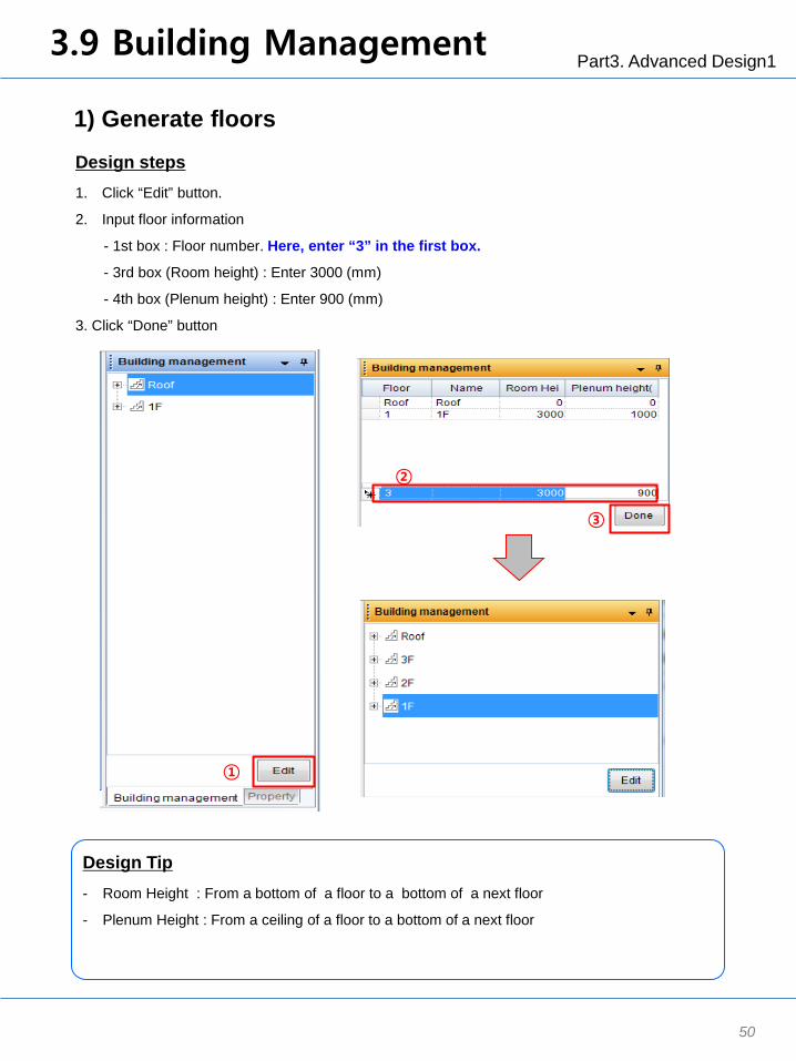
1) Generate floors
1. Click “Edit” button.
2. Input floor information
- 1st box : Floor number. Here, enter “3” in the first box.
- 3rd box (Room height) : Enter 3000 (mm)
- 4th box (Plenum height) : Enter 900 (mm)
3. Click “Done” button
Design steps
①
③
②
Design Tip
- Room Height : From a bottom of a floor to a bottom of a next floor
- Plenum Height : From a ceiling of a floor to a bottom of a next floor
Part3. Advanced Design1 3.9 Building Management
51
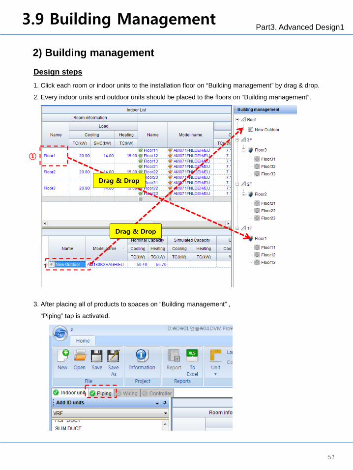
2) Building management
1. Click each room or indoor units to the installation floor on “Building management” by drag & drop.
2. Every indoor units and outdoor units should be placed to the floors on “Building management”.
Design steps
3. After placing all of products to spaces on “Building management” ,
“Piping” tap is activated.
①
Drag & Drop
Drag & Drop
Part3. Advanced Design1 3.10 Piping
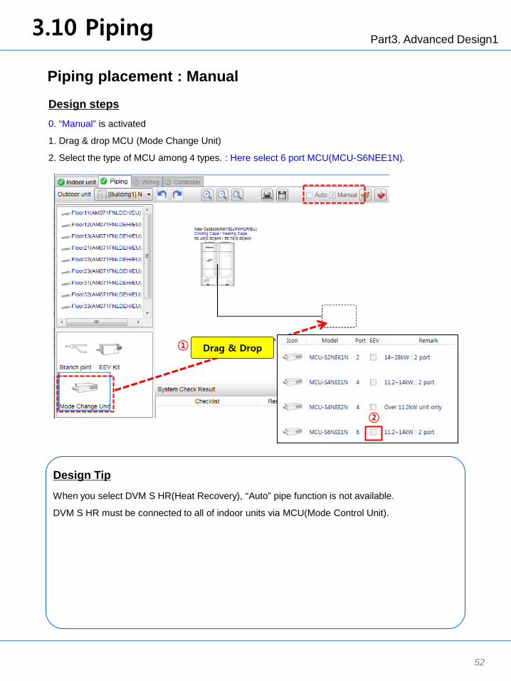
Piping placement : Manual
0. “Manual” is activated
1. Drag & drop MCU (Mode Change Unit)
2. Select the type of MCU among 4 types. : Here select 6 port MCU(MCU-S6NEE1N).
Design steps
52
Design Tip
When you select DVM S HR(Heat Recovery), “Auto” pipe function is not available.
DVM S HR must be connected to all of indoor units via MCU(Mode Control Unit).
① Drag & Drop
②

Part3. Advanced Design1 3.10 Piping
Piping placement : Manual
3. Drag & drop indoor units.
4. After placing one indoor unit, place the other indoor units to the vacant boxes
5. If you need more MCU, Drag & drop MCU to a pipe line
Design steps
53
Design Tip
When you select DVM S HR(Heat Recovery), “Auto” pipe function is not available.
DVM S HR must be connected to all of indoor units via MCU(Mode Control Unit).
Drag & Drop ③
Drag & Drop ⑤

Part3. Advanced Design1 3.11 System Check
54
System Check
1. Click “System check” button.
2. Without any red comments, system check is completed.
Design steps
Design Tip
This function shows what user make wrong design or mistakes so that help users design SAC
properly.
This S/W includes the variable limitation logics according to an installation manual.
User also can check the amount of additional refrigerant.
①
②

Part3. Advanced Design1 3.12 Controller
55
Controller 1 - Select DMS2.5 to use Key-tag
1. Click “Controller” tab
(To Select for System 1)
2. Click a vacant box.
3. Select compatible controller. (First, select outdoor terminal block for DVM S)
Design steps
①
③
②
4. Click yellow circle to select controller.
Here click the below circle to select “On-Off controller”.
(There are 2 types of circles. Upper one is to connect to F1, F2, the below one is to connect to R1, R2.)
5. Click “DMS 2.5”
④ ⑤
Part3. Advanced Design1
56
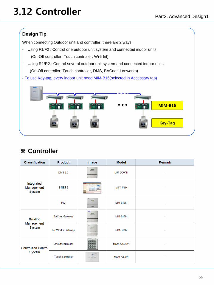
Design Tip
When connecting Outdoor unit and controller, there are 2 ways.
- Using F1/F2 : Control one outdoor unit system and connected indoor units.
(On-Off controller, Touch controller, Wi-fi kit)
- Using R1/R2 : Control several outdoor unit system and connected indoor units.
(On-Off controller, Touch controller, DMS, BACnet, Lonworks)
- To use Key-tag, every indoor unit need MIM-B16(selected in Accessary tap)
3.12 Controller
※ Controller
MIM-B16
Key-Tag

Part3. Advanced Design1 3.13 Report
57
Generate Report
1. Click “Report” button.
2. Enter a file name and click “Save” button.
3. Click “ To Excel” button to generate the designed Product list.
4. Enter a file name and click “Save” button.
Design steps
① ③
②, ④
Usage Tip
There are 2 types of report.
- “Report” button: Includes all of designed information
- “To Excel” button: Includes only designed product list

Part 4 : Advanced Design2
Luxury House with Hydro Unit
(Tutorial with 3st Scenario)
Purpose :
1. Understand the design process for SAC.
2. Learn how to design DVM Hydro unit
3. Part 4 is focused on the advanced design.
- DVM Hydro Unit HE
4. Most of design steps are same as Part2: Basic design.
Big difference is how to design Hydro Unit HE/HT.
Part4. Advanced Design2 4.1 Modeling Scenario
59
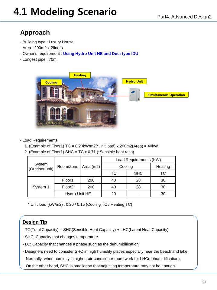
Approach - Building type : Luxury House - Area : 200m2 x 2floors - Owner’s requirement : Using Hydro Unit HE and Duct type IDU - Longest pipe : 70m
System (Outdoor unit) Room/Zone Area (m2)
Load Requirements (KW)
Cooling Heating
TC SHC TC
System 1
Floor1 200 40 28 30
Floor2 200 40 28 30
Hydro Unit HE 20 - 30
- Load Requirements 1. (Example of Floor1) TC = 0.20kW/m2(*Unit load) x 200m2(Area) = 40kW 2. (Example of Floor1) SHC = TC x 0.71 (*Sensible heat ratio)
Design Tip - TC(Total Capacity) = SHC(Sensible Heat Capacity) + LHC(Latent Heat Capacity)
- SHC: Capacity that changes temperature
- LC: Capacity that changes a phase such as the dehumidification.
- Designers need to consider SHC in high humidity places especially near the beach and lake.
Normally, when humidity is higher, air-conditioner more work for LHC(dehumidification).
On the other hand, SHC is smaller so that adjusting temperature may not be enough.
* Unit load (kW/m2) : 0.20 / 0.15 (Cooling TC / Heating TC)
Heating
Cooling Hydro Unit
Simultaneous Operation

Part4. Advanced Design2 4.2 Start with DVM Pro
60
Start with DVM Pro
1. To start DVM Pro, double click a icon “New DVM Pro 1.0” on desktop..
2. Click “Sales” button to start Sales mode of DVM Pro.
3. New window popped up.
Usage Tip
Version Information
Design steps
Double Click
①
②
Part4. Advanced Design2 4.3 Create Project
61
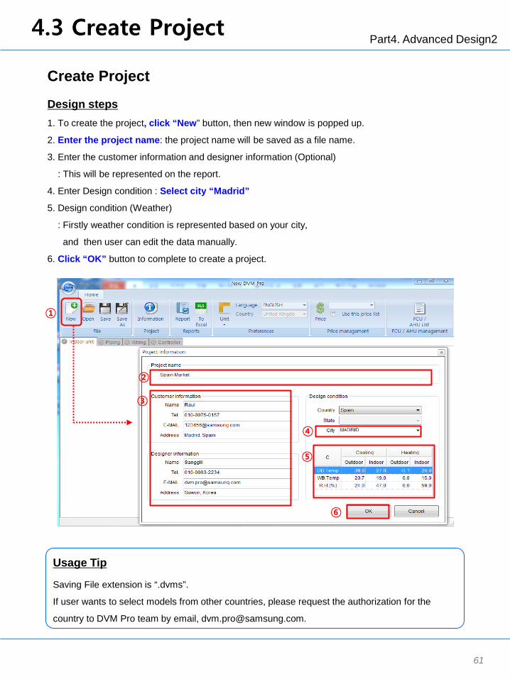
Create Project
1. To create the project, click “New” button, then new window is popped up.
2. Enter the project name: the project name will be saved as a file name.
3. Enter the customer information and designer information (Optional)
: This will be represented on the report.
4. Enter Design condition : Select city “Madrid”
5. Design condition (Weather)
: Firstly weather condition is represented based on your city,
and then user can edit the data manually.
6. Click “OK” button to complete to create a project.
Usage Tip
Saving File extension is “.dvms”.
If user wants to select models from other countries, please request the authorization for the
country to DVM Pro team by email, [email protected].
①
②
③
④
⑤
⑥
Design steps
Part4. Advanced Design2 4.4 Load Design
62
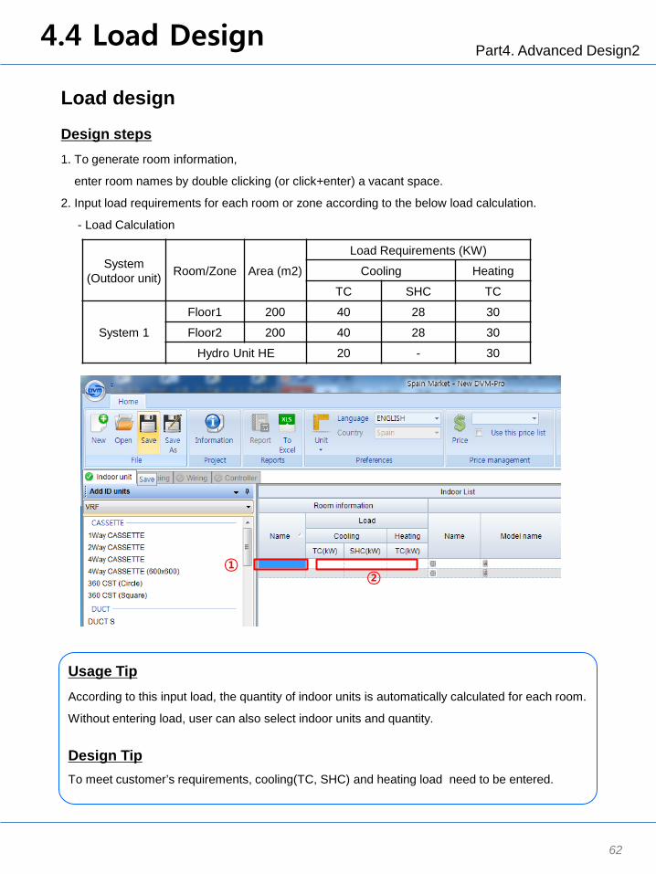
Load design
1. To generate room information,
enter room names by double clicking (or click+enter) a vacant space.
2. Input load requirements for each room or zone according to the below load calculation.
- Load Calculation
Design steps
① ②
Usage Tip
According to this input load, the quantity of indoor units is automatically calculated for each room.
Without entering load, user can also select indoor units and quantity.
Design Tip To meet customer’s requirements, cooling(TC, SHC) and heating load need to be entered.
System (Outdoor unit) Room/Zone Area (m2)
Load Requirements (KW)
Cooling Heating
TC SHC TC
System 1
Floor1 200 40 28 30
Floor2 200 40 28 30
Hydro Unit HE 20 - 30
Part4. Advanced Design2 4.5 Select Product type
63
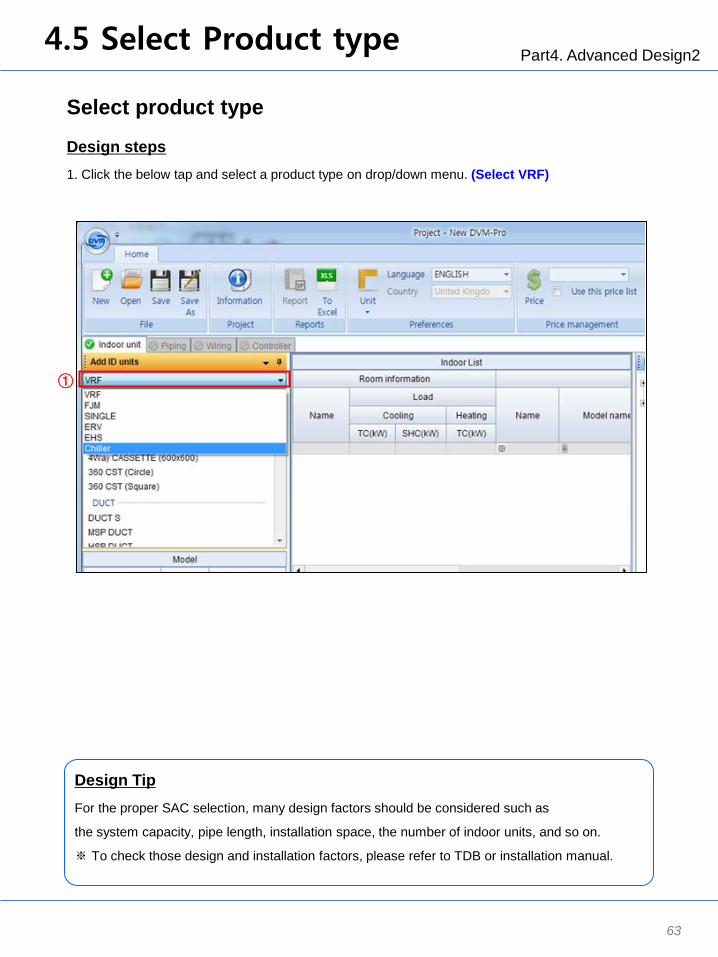
Select product type
1. Click the below tap and select a product type on drop/down menu. (Select VRF)
Design steps
Design Tip
For the proper SAC selection, many design factors should be considered such as
the system capacity, pipe length, installation space, the number of indoor units, and so on.
※ To check those design and installation factors, please refer to TDB or installation manual.
①

Part4. Advanced Design2 4.6 Select Indoor units
64
Select indoor units (MSP Duct)
1. Click each room to select indoor units.
2. Select indoor unit type : MSP duct
3. Select a model (AM140FNMDEH/EU) and check the quantity. (User can change the quantity manually.)
4. Click “Add” button to complete the selection of indoor units.
Design steps
②
③
④
①

Part4. Advanced Design2 4.6 Select Indoor units
65
Select indoor units (Hydro Unit HE)
1. Click each room to select indoor units.
2. Select indoor unit type : Hydro Unit(HE)
3. Select a model (AM320FNBDEH/EU) and check the quantity. (User can change the quantity manually.)
4. Click “Add” button to complete the selection of indoor units
Design steps
②
③
④
①
Part4. Advanced Design2 4.7 Select Outdoor units
66
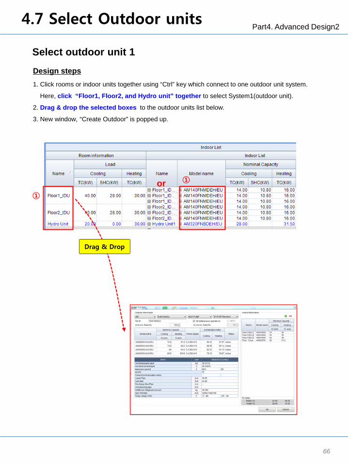
Select outdoor unit 1
1. Click rooms or indoor units together using “Ctrl” key which connect to one outdoor unit system.
Here, click “Floor1, Floor2, and Hydro unit” together to select System1(outdoor unit).
2. Drag & drop the selected boxes to the outdoor units list below.
3. New window, “Create Outdoor” is popped up.
Design steps
① or ①
Drag & Drop

Part4. Advanced Design2 4.7 Select Outdoor units
67
Select outdoor unit 2 - Simultaneous operation
1.Select the type of outdoor unit.
Here, select a outdoor type : VRF DVM S Heat Pump 2016 HP Standard
2. Click “Simultaneously operate Hy”
3. Enter the combination ratio, 130%.
4. Select the model among the recommendation models. : Select AM320JXVAGH/EU
5. Click “OK” button to complete the selection of outdoor unit.
Design steps
Design Tip
When designing Hydro Unit HE, there are 2 ways to select outdoor unit.
① ②
③
④
⑤
Operation Type Combination ratio DVM Pro
Hydro unit & indoor unit 50% ~ 130% Click “Simultaneously operation”
Indoor unit : Cooling only Hydro unit : Heating only
50% ~ 180% Indoor unit’s ratio : under100% Hydro unit’s ratio : under 80%
Do not Click “Simultaneously operation”

Part4. Advanced Design2 4.7 Select Outdoor units
68
※ Separate operation
1.Select the type of outdoor unit.
Here, select a outdoor type : VRF DVM S Heat Pump 2016 HP Standard
2. Do not Click “Simultaneously operate Hy”
3. Enter 100% of combination ratio and 80% of Hydro combination ratio.
4. Select the model among the recommendation models. : Select AM300KXVAGH/EU
5. Click “OK” button to complete the selection of outdoor unit.
Design steps
Design Tip
When designing Hydro Unit HE, there are 2 ways to select outdoor unit.
Operation Type Combination ratio DVM Pro
Hydro unit & indoor unit 50% ~ 130% Click “Simultaneously operation”
Indoor unit : Cooling only Hydro unit : Heating only
50% ~ 180% Indoor unit’s ratio : under100% Hydro unit’s ratio : under 80%
Do not Click “Simultaneously operation”
① ②
③
④
⑤

Part4. Advanced Design2
69
Select accessories
1. Click Hydro Unit model
2. Click “Accessory” tab
3. Select accessories : MRW-WW00N (Wired Remote Controller only for Hydro unit)
4. When accessories are selected, the related indoor units are marked with the orange color.
Design steps
Design Tip
When designing Duct type IDU, you need to choose drain type and control method considering
customer’s desire.
- Drain type : Drain pump or Drain hose
- Control : Wired-remote controller or Receiver with Wireless remote controller
- External temperature sensor for more accurate temperature control.
To control Hydro unit, MRW-WW00N is required. (Wired Remote Controller only for Hydro unit)
4.8 Select Accessory
②
③ ①
④
Part4. Advanced Design2
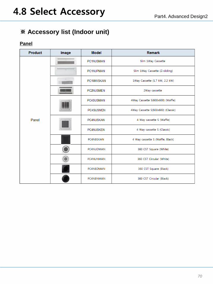
70
Panel
※ Accessory list (Indoor unit)
4.8 Select Accessory

Part4. Advanced Design2
71
Classification Product Image Model Remark
Wireless remotecontroller
MR-EH00 -
MWR-WE10N(Multi function)
MWR-WW00N DVM S Hydro Unit
MWR-SH00N -
MWR-VH02 ERV
Operation modeselection switch
MCM-C200 DVM S Series(Except HR Models)
External room sensor MRW-TACassette, Wall-mount,Ceiling, Duct, Console
Compatible interfacemodule MIM-N01 Nasa-No Nasa
ERV interface module MIM-N10 ERV (Nasa)
External contactinterface module MIM-B14 -
S-Converter MIM-C02N -
MTFC(Multi tenant function
controller)MCM-C210N -
Wireless signalreceiver
MRK-A10N -
MRW-TA Cassette, Wall-mount,Ceiling, Duct, Console
MRW-TS Zone Controller (SINGLE)
Others
External room sensor
Individual ControlSystem
Wired remote controller
Simplified wired remotecontroller
Controller
※ Accessory list (Indoor unit)
4.8 Select Accessory

Part4. Advanced Design2
72
Others
※ Accessory list (Indoor unit)
4.8 Select Accessory

Part4. Advanced Design2
73
Others
※ Accessory list (Outdoor unit)
4.8 Select Accessory
Part4. Advanced Design2 4.9 Building Management
74
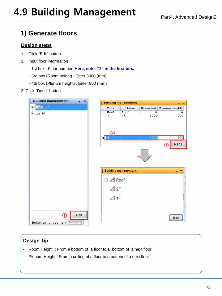
1) Generate floors
1. Click “Edit” button.
2. Input floor information
- 1st box : Floor number. Here, enter “2” in the first box.
- 3rd box (Room height) : Enter 3000 (mm)
- 4th box (Plenum height) : Enter 900 (mm)
3. Click “Done” button
Design steps
①
③
②
Design Tip
- Room Height : From a bottom of a floor to a bottom of a next floor
- Plenum Height : From a ceiling of a floor to a bottom of a next floor
Part4. Advanced Design2 4.9 Building Management
75
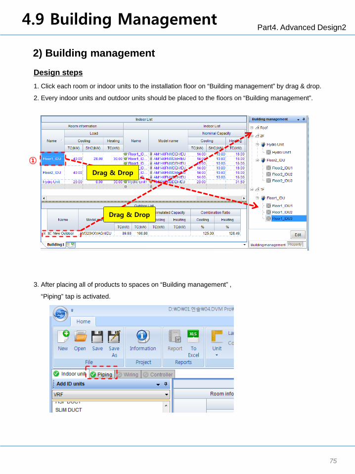
2) Building management
1. Click each room or indoor units to the installation floor on “Building management” by drag & drop.
2. Every indoor units and outdoor units should be placed to the floors on “Building management”.
Design steps
3. After placing all of products to spaces on “Building management” ,
“Piping” tap is activated.
① Drag & Drop
Drag & Drop

Part4. Advanced Design2 4.10 Piping
76
Piping placement : Auto
1. Click “Piping” tap to start the piping design.
2. Select each system of outdoor units.
3. Click “Auto” to complete the piping placement.
4. (When selecting “Manual”) Refer to 2.10.(Piping placement : Manual)
Design steps
①
②
③
Design Tip
When a designer wants to make a quick report, and already know that there is no problem
regarding the pipe distance, skip other steps such as entering pipe information.
Just click “Auto” and “System check”. Then he/she can generate the report.

Part4. Advanced Design2 4.11 System Check
77
System Check
1. Click “System check” button.
2. Without any red comments, system check is completed.
Design steps
Design Tip
This function shows what user make wrong design or mistakes so that help users design SAC
properly.
This S/W includes the variable limitation logics according to an installation manual.
User also can check the amount of additional refrigerant.
②
①

Part4. Advanced Design2 4.12 Report
78
Generate Report
1. Click “Report” button.
2. Enter a file name and click “Save” button.
3. Click “ To Excel” button to generate the designed Product list.
4. Enter a file name and click “Save” button.
Design steps
① ③
②, ④
Usage Tip
There are 2 types of report.
- “Report” button: Includes all of designed information
- “To Excel” button: Includes only designed product list

Part 5 : Additional Function

Part5. Additional Function 5.1 Pricing
80
Pricing function : Using this function, Pricing information can be represented on the report.
(Generate Price List)
1. Click “Price” button.
2. To generate Price List, Enter a Name and Price unit : “Madrid Price” and “$”
3. Click “Update” button.
4. A price list is generated.
Design steps
①
③ ②
④
Report Sample

Part5. Additional Function 5.1 Pricing
81
Pricing function : Using this function, Pricing information can be represented on the report.
(Input Price information – Method1)
5. To enter price information : Here input AM220KXVAGH/EU, 2000
6. Click “Update” button.
Design steps
(Input Price information – Method2: Recommended)
6. At first, make a excel list using the Report excel file.
7. Copy(Ctrl + C) the excel list.
8. Click the below box and Paste(Ctrl + V) it.
9. Click “Update” button.
10. Click “Save” button.
1 AM220KXVAGH/EU 50002 AM100JXVHGH/EU 40003 AM140FNMDEH/EU 30004 AM320FNBDEH/EU 30005 MWR-WW00N 1000
⑥ ⑤
⑥ ④ ⑦
⑤
⑧ ⑨
⑩

Samsung Electronics Co., LTD. B2B PM / SE Head Office (Suwon Korea) 129, Samsung-Ro, Yeongtong-Gu, Suwon City, Gyeonggi-Do, Korea 443-742 Website : www.samsung.com/global/business/system-air-conditioner Email : [email protected] Images and data in this book may subject to change without prior notice.
2016.07 Ver.1.1