Dudley's Handbook of Practical Gear Design and Manufacture
83
Handbook of Practical Gear Design and Manufacture Dudley’s Second Edition Stephen P. Radzevich Stephen P. Radzevich
-
Upload
khangminh22 -
Category
Documents
-
view
1 -
download
0
Transcript of Dudley's Handbook of Practical Gear Design and Manufacture

K12940 Cover 3/5/12 11:47 AM Page 1
H a n d b o o k o f
Practical GearDesign and
Manufacture
Dudley’sS e c o n d E d i t i o n
Stephen P. RadzevichStephen P. Radzevich
H a n d b o o k o f
Practical GearDesign and
Manufacture
Dudley’sS e c o n d E d i t i o n
Stephen P. Radzevich
SecondEdition
Ha
nd
bo
ok
o
f
Pr
ac
tic
al G
ea
r D
esig
n a
nd
Ma
nu
fac
tu
re
Du
dle
y’s
Radzevich
A unique, single-source reference for all aspects of gears, Dudley's Handbookof Practical Gear Design and Manufacture, Second Edition provides
comprehensive and consistent information on the design and manufacture
of gears for the expert and novice alike. The second edition of this industry
standard boasts seven new chapters and appendices as well as a wealth of
updates throughout. New chapters and expanded topics include: Gear Types
and Nomenclature, Gear Tooth Design, Gear Reactions and Mountings,
Gear Vibration, The Evolution of the Gear Art, Novikov Gearing and the
Inadequacy of the Term, and thoroughly referenced Numerical Data Tables.
FEATURES
• Offers a single-source reference for all aspects of the gear industry
• Presents a comprehensive and self-consistent collection of knowledge,
practical methods, and numerical tables
• Discusses optimal design and manufacture of gears of all known designs
for the needs of all industries
• Explains concepts in accessible language and with a logical organization,
making it simple to use even by beginners in the field
• Provides adequate recommendations for gear practitioners in all areas
of gear design, production, inspection, and application
• Includes practical examples of successful use of tools covered in the
Handbook
Logically organized and easily understood, the Handbook requires only a
limited knowledge of mathematics for adequate application to almost any
situation or question. Whether you are a high-volume gear manufacturer or
a relatively small factory, the Handbook and some basic common sense
can direct the sophisticated design of any type of gear, from the selection
of appropriate material, production of gear blanks, cutting gear teeth,
advanced methods of heat treatment, and gear inspection. No other sources
of information are necessary for the gear designer or
manufacturer once they have the Handbook.
Mechanical Engineering
K12940
6000 Broken Sound Parkway, NWSuite 300, Boca Raton, FL 33487711 Third AvenueNew York, NY 100172 Park Square, Milton ParkAbingdon, Oxon OX14 4RN, UK
an informa business

H a n d b o o k o f
Practical GearDesign and
Manufacture
Dudley’sS e c o n d E d i t i o n

This page intentionally left blankThis page intentionally left blank
H a n d b o o k o f
Practical GearDesign and
Manufacture
Dudley’sS e c o n d E d i t i o n
Stephen P. Radzevich
CRC Press is an imprint of theTaylor & Francis Group, an informa business
Boca Raton London New York

CRC PressTaylor & Francis Group6000 Broken Sound Parkway NW, Suite 300Boca Raton, FL 33487-2742
© 2012 by Taylor & Francis Group, LLCCRC Press is an imprint of Taylor & Francis Group, an Informa business
No claim to original U.S. Government worksVersion Date: 2011922
International Standard Book Number-13: 978-1-4398-6602-3 (eBook - PDF)
This book contains information obtained from authentic and highly regarded sources. Reasonable efforts have been made to publish reliable data and information, but the author and publisher cannot assume responsibility for the validity of all materials or the consequences of their use. The authors and publishers have attempted to trace the copyright holders of all material repro-duced in this publication and apologize to copyright holders if permission to publish in this form has not been obtained. If any copyright material has not been acknowledged please write and let us know so we may rectify in any future reprint.
Except as permitted under U.S. Copyright Law, no part of this book may be reprinted, reproduced, transmitted, or utilized in any form by any electronic, mechanical, or other means, now known or hereafter invented, including photocopying, microfilming, and recording, or in any information storage or retrieval system, without written permission from the publishers.
For permission to photocopy or use material electronically from this work, please access www.copyright.com (http://www.copy-right.com/) or contact the Copyright Clearance Center, Inc. (CCC), 222 Rosewood Drive, Danvers, MA 01923, 978-750-8400. CCC is a not-for-profit organization that provides licenses and registration for a variety of users. For organizations that have been granted a photocopy license by the CCC, a separate system of payment has been arranged.
Trademark Notice: Product or corporate names may be trademarks or registered trademarks, and are used only for identifica-tion and explanation without intent to infringe.
Visit the Taylor & Francis Web site athttp://www.taylorandfrancis.com
and the CRC Press Web site athttp://www.crcpress.com

v
Contents
Preface .............................................................................................................................................xvIntroduction ................................................................................................................................. xixAcknowledgments .................................................................................................................... xxiiiAuthor .......................................................................................................................................... xxv
1 Gear Design Trends ...............................................................................................................11.1 Small, Low-Cost Gears for Toys, Gadgets, and Mechanisms .................................41.2 Appliance Gears ............................................................................................................61.3 Machine Tools ................................................................................................................71.4 Control Gears .................................................................................................................81.5 Vehicle Gears ............................................................................................................... 101.6 Transportation Gears .................................................................................................. 121.7 Marine Gears ............................................................................................................... 131.8 Aerospace Gears .......................................................................................................... 151.9 Industrial Gearing ...................................................................................................... 161.10 Gears in the Oil and Gas Industry ........................................................................... 181.11 Mill Gears ..................................................................................................................... 181.12 External Spur Gears .................................................................................................... 201.13 External Helical Gears ................................................................................................231.14 Internal Gears .............................................................................................................. 241.15 Straight Bevel Gears .................................................................................................... 261.16 Zerol Bevel Gears ........................................................................................................281.17 Spiral Bevel Gears ....................................................................................................... 291.18 Hypoid Gears ...............................................................................................................301.19 Face Gears .................................................................................................................... 311.20 Crossed-Helical Gears (Nonenveloping Worm Gears) .......................................... 321.21 Single-Enveloping Worm Gears ................................................................................341.22 Double-Enveloping Worm Gears .............................................................................. 371.23 Spiroid Gears ............................................................................................................... 39
2 Gear Types and Nomenclature .......................................................................................... 412.1 Types of Gears ............................................................................................................. 41
2.1.1 Classi�cations ................................................................................................. 412.1.2 Parallel Axis Gears ........................................................................................44
2.1.2.1 Spur Gears .......................................................................................442.1.2.2 Helical Gears ...................................................................................452.1.2.3 Internal Gears ................................................................................. 47
2.1.3 Nonparallel, Coplanar Gears (Intersecting Axes) .....................................482.1.3.1 Bevel Gears ......................................................................................482.1.3.2 Face Gears (On-Center) ..................................................................532.1.3.3 Conical Involute Gearing ..............................................................54
2.1.4 Nonparallel, Noncoplanar Gears (Nonintersecting Axes) ...................... 552.1.4.1 Crossed-Axis Helical Gears ..........................................................552.1.4.2 Cylindrical Worm Gearing ........................................................... 57

vi Contents
2.1.4.3 Single-Enveloping Worm Gearing ............................................... 572.1.4.4 Double-Enveloping Worm Gearing ............................................. 592.1.4.5 Hypoid Gears ..................................................................................602.1.4.6 Spiroid and Helicon Gearing ........................................................ 612.1.4.7 Face Gears (Off-Center) .................................................................63
2.1.5 Special Gear Types .........................................................................................632.1.5.1 Square or Rectangular Gears........................................................632.1.5.2 Triangular Gears ............................................................................642.1.5.3 Elliptical Gears ...............................................................................642.1.5.4 Scroll Gears .....................................................................................652.1.5.5 Multiple-Sector Gears ....................................................................65
2.2 Nomenclature of Gears ..............................................................................................662.2.1 Spur Gear Nomenclature and Basic Formulas ..........................................682.2.2 Helical Gear Nomenclature and Basic Formulas ......................................682.2.3 Internal Gear Nomenclature and Formulas .............................................. 702.2.4 Crossed Helical Gear Nomenclature and Formulas ................................. 702.2.5 Bevel Gear Nomenclature and Formulas ................................................... 73
2.2.5.1 Straight ............................................................................................. 732.2.5.2 Spiral ................................................................................................ 742.2.5.3 Zerol ................................................................................................. 74
2.2.6 Worm Gear Nomenclature and Formulas.................................................. 782.2.6.1 Cylindrical Worm Gears ...............................................................802.2.6.2 Double-Enveloping Worm Gears ................................................. 81
2.2.7 Face Gears ....................................................................................................... 812.2.8 Spiroid Gear Nomenclature and Formulas ................................................ 812.2.9 Beveloid Gears ................................................................................................83
3 Gear Tooth Design ...............................................................................................................853.1 Basic Requirements for Gear Tooth Design ............................................................85
3.1.1 De�nition of Gear Tooth Elements ..............................................................853.1.2 Basic Considerations for Gear Tooth Design .............................................88
3.1.2.1 Continuity of Action ...................................................................... 893.1.2.2 Conjugate Action ............................................................................ 923.1.2.3 Pitch Diameter ................................................................................ 933.1.2.4 Zones in Which Involute Gear Teeth Exist ................................. 943.1.2.5 Pointed Teeth .................................................................................. 983.1.2.6 Undercut ........................................................................................ 100
3.1.3 Long- and Short-Addendum Gear Design ............................................... 1013.1.3.1 Addendum Modi�cation for Gears Having a Few Teeth ....... 1023.1.3.2 Speed-Increasing Drives ............................................................. 1033.1.3.3 Power Drives (Optimal Design) ................................................. 1033.1.3.4 Low-Friction Gearing .................................................................. 105
3.1.4 Special Design Considerations .................................................................. 1073.1.4.1 Interchangeability ........................................................................ 1073.1.4.2 Tooth Thickness ............................................................................ 1073.1.4.3 Tooth Pro�le Modi�cations ........................................................ 1093.1.4.4 Transverse of Pro�le Modi�cation ............................................. 1093.1.4.5 Allowances for Errors of Gear Manufacture ............................ 1093.1.4.6 Allowances for De�ection under Load ..................................... 109

viiContents
3.1.4.7 Axial Modi�cations ...................................................................... 1103.1.4.8 Root Fillets ..................................................................................... 1113.1.4.9 Effective Outside Diameter ......................................................... 1133.1.4.10 Width of Tip of Tooth ................................................................... 1133.1.4.11 Pointed Tooth Diameter .............................................................. 1143.1.4.12 Purpose of Backlash ..................................................................... 1143.1.4.13 Backlash: Recommended Values ................................................ 115
3.2 Standard Systems of Gear Tooth Proportions ...................................................... 1163.2.1 Standard Systems for Spur Gears .............................................................. 116
3.2.1.1 Limitations in Use of Standard Tables ...................................... 1163.2.1.2 Standard Tooth Forms That Have Become Obsolete .............. 1183.2.1.3 Brown and Sharp System ............................................................ 1193.2.1.4 AGMA 14.5° Composite System ................................................. 1193.2.1.5 Fellows 20° Stub Tooth System ................................................... 1203.2.1.6 AGMA 14.5° Full-Depth System ................................................. 1203.2.1.7 Cycloidal Tooth Pro�les .............................................................. 1213.2.1.8 Clockwork and Timer Tooth Pro�les ........................................ 1213.2.1.9 Speci�c Spur Gear Calculation Procedure ............................... 1223.2.1.10 Explanation and Discussion of Items in Table 3.5 ................... 126
3.2.2 System for Helical Gears ............................................................................. 1283.2.2.1 Selection of Tooth Form ............................................................... 1303.2.2.2 Selection of Helix Angle .............................................................. 1303.2.2.3 Face Width ..................................................................................... 1313.2.2.4 Speci�c Calculation Procedure for Helical Gears ................... 132
3.2.3 System for Internal Gears ........................................................................... 1333.2.3.1 Special Calculations ..................................................................... 1353.2.3.2 Speci�c Calculation Procedure for Internal Gears .................. 136
3.2.4 Standard Systems for Bevel Gears ............................................................. 1363.2.4.1 Discussion of 20° Straight Bevel Gear System ......................... 1373.2.4.2 Discussion of Spiral Bevel Gear System .................................... 1373.2.4.3 Discussion of the Zerol Bevel Gear System .............................. 1383.2.4.4 Special Tooth Forms ..................................................................... 1383.2.4.5 Limitations in 20° Straight Bevel Gear System ........................ 1393.2.4.6 Limitations in Spiral Bevel Gear System .................................. 1413.2.4.7 Limitations in Zerol Bevel Gear System ................................... 1413.2.4.8 General Comments ...................................................................... 141
3.2.5 Standard Systems for Worm Gears ........................................................... 1433.2.5.1 General Practice ............................................................................ 1433.2.5.2 Basic Tooth Forms for Worm Gearing ....................................... 1443.2.5.3 Speci�c Calculations for Worm Gears ...................................... 145
3.2.6 Standard System for Face Gears ................................................................ 1463.2.6.1 Pinion Design ............................................................................... 1483.2.6.2 Face Gear Design .......................................................................... 148
3.2.7 System for Spiroid and Helicon Gears ...................................................... 1493.2.7.1 Spiroid Gearing ............................................................................ 1513.2.7.2 Helicon Gearing ........................................................................... 1543.2.7.3 Detailed Calculations of Spiroid and Helicon Tooth Data ..... 155
3.3 General Equations Relating to Center Distance ................................................... 1563.3.1 Center Distance Equations ......................................................................... 156
viii Contents
3.3.2 Standard Center Distance ........................................................................... 1593.3.3 Standard Pitch Diameters ........................................................................... 1603.3.4 Operating Pitch Diameters ......................................................................... 1603.3.5 Operating Pressure Angle .......................................................................... 1613.3.6 Operating Center Distance ......................................................................... 1623.3.7 Center Distance for Gears Operating on Nonparallel
Nonintersecting Shafts ............................................................................... 1623.3.8 Center Distance for Worm Gearing .......................................................... 1623.3.9 Reasons for Nonstandard Center Distances ............................................ 1633.3.10 Nonstandard Center Distances .................................................................. 163
3.4 Elements of Center Distance .................................................................................... 1653.4.1 Effects of Tolerances on Center Distance ................................................. 1653.4.2 Machine Elements that Require Consideration in Critical Center
Distance Applications ................................................................................. 1683.4.3 Control of Backlash ...................................................................................... 1713.4.4 Effects of Temperature on Center Distance ............................................. 1723.4.5 Mounting Distance ...................................................................................... 174
4 Preliminary Design Considerations ............................................................................... 1774.1 Stress Formulas: Calculation ................................................................................... 177
4.1.1 Calculated Stresses ...................................................................................... 1774.1.2 Gear Design Limits ...................................................................................... 1814.1.3 Gear Strength Calculations ........................................................................ 181
4.1.3.1 Worst Load .................................................................................... 1844.1.3.2 Stress Concentration .................................................................... 1854.1.3.3 Load Distribution ......................................................................... 1864.1.3.4 Dynamic Load .............................................................................. 1864.1.3.5 Finite Element ............................................................................... 187
4.1.4 Gear Surface Durability Calculations ....................................................... 1884.1.4.1 Hertz Derivations ......................................................................... 1894.1.4.2 K-Factor Derivations .................................................................... 1924.1.4.3 Worst-Load Position ..................................................................... 1934.1.4.4 Endurance Limit ........................................................................... 1934.1.4.5 Lubrication Regimens .................................................................. 194
4.1.5 Gear Scoring ................................................................................................. 1984.1.5.1 Hot and Cold Scoring .................................................................. 1984.1.5.2 PVT Formula ................................................................................. 1994.1.5.3 Flash Temperature........................................................................ 2024.1.5.4 Scoring Criterion .......................................................................... 203
4.1.6 Thermal Limits ............................................................................................. 2054.1.6.1 Thermal Limits at Regular Speed .............................................. 2054.1.6.2 Thermal Limits at High Speed ................................................... 206
4.2 Stress Formulas: Special Considerations ............................................................... 2064.2.1 Gear Speci�cations ...................................................................................... 2074.2.2 Size of Spur and Helical Gears by Q-Factor Method ............................. 207
4.2.2.1 Face-Width Considerations ......................................................... 2104.2.2.2 Weight from Volume .................................................................... 211
4.2.3 Indexes of Tooth Loading ........................................................................... 2134.2.4 Estimating Spur and Helical Gear Size by K-Factor ............................... 214

ixContents
4.2.5 Estimating Bevel Gear Size ........................................................................ 2154.2.6 Estimating Worm Gear Size ....................................................................... 2204.2.7 Estimating Spiroid Gear Size .....................................................................223
4.3 Data Needed for Gear Drawings ............................................................................2234.3.1 Gear Dimensional Data ...............................................................................2234.3.2 Gear Tooth Tolerances ................................................................................. 2264.3.3 Gear Material and Heat Treatment Data ..................................................2344.3.4 Enclosed Gear Unit Requirements ............................................................ 241
5 Design Formulas ................................................................................................................. 2435.1 Calculation of Gear Tooth Data .............................................................................. 243
5.1.1 Number of Pinion Teeth ............................................................................. 2435.1.2 Hunting Teeth .............................................................................................. 2485.1.3 Spur Gear Tooth Proportions ..................................................................... 2495.1.4 Root Fillet Radii of Curvature .................................................................... 2515.1.5 Long-Addendum Pinions ...........................................................................2535.1.6 Tooth Thickness ........................................................................................... 257
5.1.6.1 Backlash ......................................................................................... 2575.1.6.2 Tolerances and Tooth Thickness ................................................ 258
5.1.7 Chordal Dimensions ................................................................................... 2585.1.8 Degrees Roll and Limit Diameter.............................................................. 2605.1.9 Form Diameter and Contact Ratio ............................................................264
5.1.9.1 Form Diameter ..............................................................................2645.1.9.2 Contact Ratio ................................................................................. 265
5.1.10 Spur Gear Dimension Sheet ....................................................................... 2665.1.11 Internal Gear Dimension Sheet ................................................................. 2685.1.12 Helical Gear Tooth Proportions ................................................................. 2725.1.13 Helical Gear Dimension Sheet ................................................................... 2775.1.14 Bevel Gear Tooth Proportions .................................................................... 2795.1.15 Straight Bevel Gear Dimension Sheet .......................................................2835.1.16 Spiral Bevel Gear Dimension Sheet...........................................................2855.1.17 Zerol Bevel Gear Dimension Sheet ...........................................................2885.1.18 Hypoid Gear Calculations .......................................................................... 2895.1.19 Face Gear Calculations ................................................................................ 2905.1.20 Crossed-Helical Gear Proportions ............................................................ 2935.1.21 Single-Enveloping Worm Gear Proportions ............................................ 2965.1.22 Single-Enveloping Worm Gears ................................................................ 2975.1.23 Double-Enveloping Worm Gears ............................................................... 299
5.2 Gear Rating Practice .................................................................................................3035.2.1 General Considerations in Rating Calculations ......................................303
5.2.1.1 Calculation Procedure .................................................................3055.2.1.2 Grades of Material Quality .........................................................3065.2.1.3 Reliability of Gears ....................................................................... 307
5.2.2 General Formulas for Tooth Bending Strength and Tooth Surface Durability ...................................................................................................... 3075.2.2.1 Strength Formula .........................................................................3085.2.2.2 Durability Formula ......................................................................3085.2.2.3 Rating Curves of Stress versus Cycles ...................................... 3135.2.2.4 Rating Bevel Gears ....................................................................... 315

x Contents
5.2.3 Geometry Factors for Strength .................................................................. 3165.2.3.1 Lack of Load Sharing ................................................................... 3175.2.3.2 Helical Gears with Narrow Face Width .................................... 3175.2.3.3 Geometry Factors for Strength for Some Standard Designs .... 318
5.2.4 Overall De-Rating Factor for Strength ...................................................... 3195.2.4.1 Application Factor Ka ................................................................... 3225.2.4.2 Load Distribution Factor Km ....................................................... 3225.2.4.3 Effect of Helix Error and Shaft Misalignment ......................... 3245.2.4.4 Aspect Ratio Effects ..................................................................... 3275.2.4.5 Load Distribution Factor Km for Bevel Gears ........................... 3285.2.4.6 Size Factor Ks .................................................................................3305.2.4.7 Dynamic Load Factors Kv and Cv ...............................................330
5.2.5 Geometry Factors for Durability ...............................................................3335.2.6 Overall De-Rating Factor for Surface Durability ....................................335
5.2.6.1 Size Factor Cs .................................................................................3365.2.6.2 Complementary Considerations ................................................338
5.2.7 Load Rating of Worm Gearing .................................................................. 3395.2.7.1 Crossed-Helical Gear Durability ............................................... 3395.2.7.2 Cylindrical Worm Gear Durability............................................ 3415.2.7.3 Double-Enveloping Worm Gear Durability .............................3465.2.7.4 Comparison of Double-Enveloping and Cylindrical
Worm Gear Rating Procedures ..................................................3495.2.8 Design Formulas for Scoring .....................................................................350
5.2.8.1 Hot Scoring....................................................................................3505.2.8.2 Cold Scoring .................................................................................. 3555.2.8.3 Design Practice to Handle Scoring ............................................360
5.2.9 Trade Standards for Rating Gears ............................................................. 3615.2.10 Vehicle Gear Rating Practice ......................................................................3635.2.11 Marine Gear Rating Practice ......................................................................3655.2.12 Oil and Gas Industry Gear Rating ............................................................ 3675.2.13 Aerospace Gear Rating Practice.................................................................368
6 Gear Materials ..................................................................................................................... 3716.1 Steels for Gears .......................................................................................................... 371
6.1.1 Mechanical Properties ................................................................................ 3716.1.2 Heat-Treating Techniques ........................................................................... 3756.1.3 Heat-Treating Data ....................................................................................... 3796.1.4 Hardness Tests ............................................................................................. 381
6.2 Localized Hardening of Gear Teeth .......................................................................3836.2.1 Carburizing...................................................................................................3836.2.2 Nitriding ........................................................................................................ 389
6.2.2.1 Features of Nitriding Process ..................................................... 3896.2.2.2 Nitride Case Depth ...................................................................... 392
6.2.3 Induction Hardening of Steel ..................................................................... 3936.2.3.1 Induction Hardening by Scanning ............................................ 3956.2.3.2 Load-Carrying Capacity of Induction-Hardened Gear Teeth .....398
6.2.4 Flame Hardening of Steel ...........................................................................4006.2.5 Combined Heat Treatments ....................................................................... 4016.2.6 Metallurgical Quality of Steel Gears ......................................................... 402

xiContents
6.2.6.1 Quality Items for Carburized Steel Gears ................................ 4026.2.6.2 Quality Items for Nitrided Gears ...............................................4046.2.6.3 Procedure to Get Grade 2 Quality .............................................405
6.3 Cast Irons for Gears ..................................................................................................4066.3.1 Gray Cast Iron .............................................................................................. 4076.3.2 Ductile Iron ...................................................................................................4086.3.3 Sintered Iron ................................................................................................. 410
6.4 Nonferrous Gear Metals .......................................................................................... 4116.4.1 Kinds of Bronze ............................................................................................ 4116.4.2 Standard Gear Bronzes ............................................................................... 413
6.5 Nonmetallic Gears .................................................................................................... 4146.5.1 Thermosetting Laminates .......................................................................... 4146.5.2 Nylon Gears .................................................................................................. 416
7 Gear-Manufacturing Methods ........................................................................................ 4197.1 Gear Tooth Cutting ................................................................................................... 419
7.1.1 Gear Hobbing ............................................................................................... 4197.1.2 Shaping—Pinion Cutter ..............................................................................4267.1.3 Shaping—Rack Cutter ................................................................................. 4317.1.4 Cutting Bevel Gears .....................................................................................4357.1.5 Gear Milling .................................................................................................4387.1.6 Broaching Gears ...........................................................................................4427.1.7 Punching Gears ............................................................................................4447.1.8 G-TRAC Generating ....................................................................................446
7.2 Gear Grinding ...........................................................................................................4487.2.1 Form Grinding .............................................................................................448
7.2.1.1 Ceramic Form Grinding ..............................................................4497.2.1.2 Borazon Form Grinding .............................................................. 452
7.2.2 Generating Grinding—Disk Wheel ..........................................................4537.2.3 Generating Grinding—Bevel Gears .......................................................... 4567.2.4 Generating Grinding—Threaded Wheel .................................................. 4597.2.5 Thread Grinding .......................................................................................... 462
7.3 Gear Shaving, Rolling, and Honing .......................................................................4657.3.1 Rotary Shaving .............................................................................................4657.3.2 Rack Shaving ................................................................................................ 4707.3.3 Gear Rolling .................................................................................................. 4707.3.4 Gear Honing ................................................................................................. 473
7.4 Gear Measurement.................................................................................................... 4757.4.1 Gear Accuracy Limits .................................................................................. 4767.4.2 Machines to Measure Gears ....................................................................... 481
7.5 Gear Casting and Forming ...................................................................................... 4877.5.1 Cast and Molded Gears ............................................................................... 4877.5.2 Sintered Gears ..............................................................................................4887.5.3 Cold-Drawn Gears and Rolled Worm Threads ....................................... 489
8 Design of Tools to Make Gear Teeth .............................................................................. 4918.1 Shaper Cutters ........................................................................................................... 4918.2 Gear Hobs ................................................................................................................... 5028.3 Spur Gear–Milling Cutters ...................................................................................... 515

xii Contents
8.4 Worm-Milling Cutters and Grinding Wheels ...................................................... 5178.5 Gear-Shaving Cutters ............................................................................................... 5228.6 Punching Tools .......................................................................................................... 5258.7 Sintering Tools ........................................................................................................... 526
9 Kinds and Causes of Gear Failures ................................................................................ 5299.1 Analysis of Gear-System Problems ........................................................................ 529
9.1.1 Determining the Problem ........................................................................... 5299.1.2 Possible Causes of Gear-System Failures ................................................. 5319.1.3 Incompatibility in Gear Systems ...............................................................5339.1.4 Investigation of Gear Systems ....................................................................534
9.2 Analysis of Tooth Failures and Gear-Bearing Failures ....................................... 5359.2.1 Nomenclature of Gear Failure ................................................................... 5369.2.2 Tooth Breakage ............................................................................................. 5369.2.3 Pitting of Gear Teeth ...................................................................................5409.2.4 Scoring Failures ............................................................................................5429.2.5 Wear Failures ................................................................................................5449.2.6 Gearbox Bearings .........................................................................................5479.2.7 Rolling-Element Bearings ...........................................................................5489.2.8 Sliding-Element Bearings ...........................................................................550
9.3 Some Causes of Gear Failure Other than Excess Transmission Load ............... 5529.3.1 Overload Gear Failures ............................................................................... 5539.3.2 Gear-Casing Problems ................................................................................5549.3.3 Lubrication Failures ..................................................................................... 5559.3.4 Thermal Problems in Fast-Running Gears............................................... 561
10 Special Design Problems ..................................................................................................56510.1 Center Distance Problems ........................................................................................56510.2 Pro�le Modi�cation Problems ................................................................................. 57610.3 Load Rating Problem ................................................................................................585
11 Gear Reactions and Mountings ....................................................................................... 59111.1 Mechanics of Gear Reactions .................................................................................. 591
11.1.1 Summation of Forces and Moments ......................................................... 59111.1.2 Application to Gearing ................................................................................ 594
11.2 Basic Gear Reactions, Bearing Loads, and Mounting Types .............................. 59511.2.1 Main Source of Load ................................................................................... 59511.2.2 Gear Reactions to Bearing .......................................................................... 59611.2.3 Directions of Loads ...................................................................................... 59711.2.4 Additional Considerations ......................................................................... 59711.2.5 Types of Mountings ..................................................................................... 59811.2.6 Ef�ciencies ....................................................................................................600
11.3 Basic Mounting Arrangements and Recommendations .....................................60011.3.1 Bearing and Shaft Alignment .................................................................... 60111.3.2 Bearings ......................................................................................................... 60111.3.3 Mounting Gears to the Shaft ...................................................................... 60211.3.4 Housing .........................................................................................................60311.3.5 Inspection Hole ............................................................................................60311.3.6 Break-In .........................................................................................................603

xiiiContents
11.4 Bearing Load Calculations for Spur Gears............................................................60411.4.1 Spur Gears ....................................................................................................60411.4.2 Helical Gears ................................................................................................60611.4.3 Gears in Trains .............................................................................................60611.4.4 Idlers ..............................................................................................................60611.4.5 Intermediate Gears ...................................................................................... 60711.4.6 Planetary Gears ............................................................................................609
11.4.6.1 One Planet .....................................................................................60911.4.6.2 Several Planets ..............................................................................609
11.5 Bearing-Load Calculations for Helicals ................................................................. 61011.5.1 Single Helical Gears..................................................................................... 61011.5.2 Double Helical Gears ................................................................................... 61211.5.3 Skewed- or Crossed-Helical Gears ............................................................ 613
11.6 Mounting Practice for Bevel and Hypoid Gears .................................................. 61511.6.1 Analysis of Forces ........................................................................................ 61511.6.2 Rigid Mountings .......................................................................................... 61611.6.3 Maximum Displacements ........................................................................... 61611.6.4 Rolling-Element Bearings ........................................................................... 61911.6.5 Straddle Mounting ....................................................................................... 61911.6.6 Overhung Mounting ................................................................................... 61911.6.7 Gear Blank Design ....................................................................................... 62211.6.8 Gear and Pinion Adjustments .................................................................... 62511.6.9 Assembly Procedure .................................................................................... 626
11.7 Calculation of Bevel and Hypoid Bearing Loads ................................................. 62711.7.1 Hand of Spiral .............................................................................................. 62711.7.2 Spiral Angle .................................................................................................. 62711.7.3 Tangential Load............................................................................................ 62811.7.4 Axial Thrust .................................................................................................. 62911.7.5 Radial Load ................................................................................................... 62911.7.6 Required Data for Bearing Load Calculations ........................................ 637
11.8 Bearing Load Calculations for Worms .................................................................. 63911.8.1 Calculation of Forces in Worm Gears .......................................................64011.8.2 Mounting Tolerances ...................................................................................64211.8.3 Worm Gear Blank Considerations .............................................................64211.8.4 Run-In of Worm Gears ................................................................................642
11.9 Bearing Load Calculations for Spiroid Gearing ...................................................64411.10 Bearing Load Calculations for Other Gear Types ................................................64811.11 Design of the Body of the Gear ...............................................................................648
12 Gear Vibration ..................................................................................................................... 65112.1 Fundamentals of Vibration ...................................................................................... 65112.2 Measurement of Vibration .......................................................................................654
12.2.1 Examples of Sensing Devices .....................................................................65512.2.2 Practical Problems in Vibration Measurement ........................................ 657
12.3 Some Examples of Vibration in Geared Units ...................................................... 65712.4 Approximate Vibration Limits ................................................................................660
12.4.1 Velocity Limits.............................................................................................. 66112.4.2 Acceleration Limits ...................................................................................... 66212.4.3 Proximity Probes ......................................................................................... 662

xiv Contents
12.4.4 Displacement Limits .................................................................................... 66212.4.5 General Vibration Tendencies ....................................................................66312.4.6 Trade Standard .............................................................................................663
12.5 Control of Vibration in Manufacturing Gears and in the Field .........................66512.5.1 Testing of Gear Units at the Gear Factory ................................................66612.5.2 Tests of Assembled Power Package ...........................................................66612.5.3 Vibration Tests in the Field ......................................................................... 667
12.6 Vibration Analysis Technique .................................................................................668
Appendix A: Evolution of Gear Art ....................................................................................... 671
Appendix B: Complementary Material ................................................................................. 717
Appendix C: Numerical Data Tables .....................................................................................771
Appendix D: On the Concept of Novikov Gearing and the Inadequacy of the Terms “Wildhaber–Novikov Gearing” and “W–N Gearing” .................803
References ...................................................................................................................................835
Index .............................................................................................................................................847
xv
Preface
This publication is dedicated to engineers who work in the �eld of gears and gear production.
Gearing is a speci�c area of mechanical engineering. Gearing encompasses gear design, production, inspection, and implementation, as well as some other supplementary sub-jects. This book is primarily focused on gear design and gear production.
This book is a revised, updated, and enlarged version of the earlier published book by Darle W. Dudley entitled Handbook of Practical Gear Design. The book was �rst published by McGraw-Hill Book Company in 1984, and by CRC Press ten years later in 1994. Both editions originated from an earlier book by the same author entitled Practical Gear Design, which was published by McGraw-Hill Book Company in 1954. The last edition (1984/1994) of the Gear Handbook is highly recognized by the gear community worldwide.
As time passes new knowledge is accumulated by the gear industry, and along with that some of the experiences summarized in the Gear Handbook have become obsolete. Obsolete data should be removed from the book, while novel data in the �eld should be added.
Keeping in mind the importance of the Gear Handbook for practical gear engineers and practitioners, I appreciated and supported the attempt undertaken by CRC Press to revise, update, and enlarge the 1994 edition of the Handbook.
Among the critical problems that arose when working on the new edition of the Gear Handbook were as follows:
• The new edition of the Gear Handbook should ful�ll the current demands of the gear industry. This requires a signi�cant revision of the original text.
• At that same time much effort was undertaken to preserve the original text of the Handbook to retain the tone of Dudley’s text.
This contradiction between the desire to comprehensively update the book and the desire to limit the revisions culminated in the compromise to entitle the book as Dudley’s Handbook of Practical Gear Design and Manufacture.
Two options were considered.The �rst is to make signi�cant changes to the original text of Dudley’s book. By fol-
lowing this path, the charm and philosophy of Dudley’s book would be lost (or it will be largely ruined). In this case Dudley’s book will no longer be Dudley’s book. It will be a different book on gearing having no need for the word “Dudley’s” in the title.
The second option is to keep the original text of Dudley’s book as intact as possible. In this case Dudley’s philosophy and his vision/understanding of gearing can be preserved.
Both options have their own merit, and it was hard to make a decision which way to fol-low. Ultimately, the decision to make reasonable but limited changes to the original text (where appropriate) was made. With that said, some repetitions are inevitable, and the best effort was made to minimize these repetitions.
Before beginning the revision of the Gear Handbook, all earlier editions of Dudley’s book [starting from the 1954 McGraw-Hill edition, and ending with the latest 1994 CRC Press edition (including the 1962 and 1984 McGraw-Hill editions)] were carefully studied. To update the book, obsolete material was removed from the text body where appropriate,

xvi Preface
and several new chapters and new appendices were added. The author appreciates CRC Press for the idea to publish a new revised and updated edition of the Gear Handbook. Personal thanks go to Mr. Jonathan W. Plant, executive editor, Mechanical, Aerospace, Nuclear and Energy Engineering, who has approached the author with the proposal to revise the Gear Handbook, and to prepare this new edition for publication by CRC Press.
Stephen P. RadzevichSterling Heights, Michigan
PRE FAC E ( TO T HE 198 4 / 19 94 EDI T ION )
This is a revision of the book Practical Gear Design, published by the McGraw-Hill Book Company in 1954. This book is now called a “handbook” because of its broader coverage of subjects pertaining to gear design and the recognition that the content of the original book made it a lasting reference that saw constant use in day-to-day gear work.
Although this revision is broader in scope and has more pages, the plan of the book and the way many aspects of the gear art are treated has been kept just the same. Those famil-iar with Practical Gear Design will �nd themselves right at home as they read the Handbook of Practical Gear Design. The main difference is that new things learned in the 1960s and 1970s about how to better design, build, and use gears are included in this book. Gear tech-nology has made rapid progress, just as space technology and computer technology have made rapid progress in the same time period.
This book has been written with the general engineer or technician in mind. It is my hope that alert shop planning engineers, tool engineers, engineering students, cost ana-lysts, shop supervisors, and progressive machine-tool operators will �nd this book of value and assistance when confronted with problems involving gear design or manufac-ture or involving failure in service.
The scope of the work includes the geometry of gear design, manufacturing methods, and causes of gear installation failures. A gear design is not good design unless it is practi-cal and economical to manufacture and unless it is well enough thought out to meet all the hazards of service in the �eld. It has been my aim to show how a practical gear design must be based on the limitations and availability of machine tools and tooling setup.
As in most phases of engineering, there are often divergent methods advocated to gain a given result. The gearing art is no exception. For instance, in Chapter 7, equations are given to calculate the length of time required to make gear teeth by various processes. Several experts in the gear �eld reviewed the data and equations in this chapter. Their comments indicated that the data would be very helpful to most designers, but they also pointed out that some gear designs would be dif�cult to manufacture and a shop might—through no fault of its own—be unable to meet production rates estimated by the material in this chapter.
In spite of all that has been learned about how to design gears, how to rate them for load-carrying capacity, and how to use them properly in service, there is still an urgent need to do more bench testing, to make better analyses of gear-tooth stresses, and to learn more about effects of lubricants, variations in gear material quality, and peculiarities of the environment (corrosion, dirt in the oil, temperature transients, load transients, etc.) in which the gears operate.
This book refers to many standards for gears that are in current use. It can be expected that present standards will be revised and enlarged as gear technology progresses. This book, in several places, advises the reader to expect more and better standards for gear work as the years go by. The book gives practical advice about what to do, but it also

xviiPreface
cautions the reader to always consider the latest rules and data in a constantly changing array of gear trade standards.
AC K NOW LEDGM EN TS
The writing of a technical book covering a whole �eld of work is a very sizable project. The author is faced not only with organizing and writing the text material and equations but also with computing data, preparing tables and �gures, and locating good reference data for a multiplicity of items.
I wish to wholeheartedly thank all of the people who have helped prepare this work.The initial typing and equation work was done by Mrs. M. Irene Galarneau (a long-
time secretary of mine), Mrs. Violet Daughters, and Mrs. Dorothy Dudley (my wife). The �nal typing, proofreading, and preparation of illustrations was done by Mrs. Carolyn Strickland (a technical assistant).
Many of the illustrations in the book have been furnished by companies that have also helped me get items of technical data. (Note the company names given in the �gure leg-ends.) The assistance of all of these companies is greatly appreciated.
The American Gear Manufacturers Association (AGMA) has been most helpful to me. The of�cers and staff are dedicated to the advancement of gear technology and have long provided forums for the decision and evaluation of gear experience. The great body of standards that have been issued by AGMA is of immense reference value. The reader will note that this book has made much use of AGMA standards.
I wish to particularly acknowledge the assistance of a few individuals with unusual knowledge and experience in the gear trade.
Dr. Hans Winter of the Technical University of Munich in Germany (Technische Universität München) has reviewed parts of this book and has helped me obtain data and a better understanding of the many aspects of gear research and gear rating.
Dr. Giovanni Castellani, a gear consultant in Modena, Italy, has helped me in comparing European and American gear rating practices and gear-tooth accuracy limits.
Mr. Eugene Shipley of Mechanical Technology Inc. in Latham, New York, has helped me—on the basis of his worldwide experience with gears in service—in many discussions about gear wear and gear failures.
Dr. Daniel Diesburg of the Climax Molybdenum Company in Ann Arbor, Michigan, was most helpful in reviewing data on gear metals and gear heat-treating procedures.
Mr. Dennis Townsend of the NASA Lewis Research Center in Cleveland, Ohio, has done unusual research work and also has brought together many key people in the gear trade under the auspices of ASME international meetings. The international ASME gear meet-ing in Chicago, Illinois, in 1977 was of much value to me.
Dr. Aizoh Kubo of Kyoto University in Kyoto, Japan, has directly contributed to this book in the section on dynamic loading. Indirectly, he has helped me greatly in getting to know the leading people in gear research in Japan.
While I acknowledge with much thanks the assistance of these and many other experts during this work, I must accept the responsibility for having made the �nal decisions on the technical content of this book. I have tried to present a fair consensus of opinion and the best gear design guidance from all the somewhat divergent theories and practices in the gear �eld.
Darle W. DudleySan Diego, California

This page intentionally left blankThis page intentionally left blank

xix
Introduction
This book (hereafter the Gear Handbook) deals with gears and gearing in both aspects, namely gear design and gear production.
Gears are produced in enormous amounts—billions of gears are produced by indus-tries every year. While the automotive industry ranks as the primary consumer of gears, numerous other industries also require huge amounts of gears: aerospace (helicopter transmission, etc.), construction machinery, and agricultural machinery, to name a few. If we place cost savings in the production of every gear in the range of just 10 cents, the total cost savings could reach hundreds of millions of dollars. This makes it clear that the processes of gear design and gear production require careful treatment.
There is much room for gear engineers and gear practitioners to further improve cost-saving processes. The Gear Handbook can be helpful in solving many of the problems of both areas of gear design and gear production.
Uniqueness of This Book
Many books on gears and gearing, in both the design and manufacture areas, have been published thus far. This second edition of the Gear Handbook is a unique one many reasons.
First, the Gear Handbook is based on practical experience of designing and producing gears. The collection of data in the Gear Handbook is invaluable to practitioners in areas of both gear design and gear production.
Second, this second edition of the Gear Handbook is signi�cantly enlarged in compari-son to the earlier 1994 edition. New chapters and a few more appendices were added. This makes the Gear Handbook a comprehensive source of information for those who are involved in the design and production of gears.
Third, the uniqueness of the Gear Handbook is proven by several earlier editions, starting from the 1954 edition. For decades the earlier editions of the book have been successfully used by gear experts worldwide. It is anticipated that this newly revised, updated, and enlarged edition of the Gear Handbook will be acknowledged by the reader.
Intended Audience
Many readers will bene�t from the Gear Handbook, speci�cally mechanical and manu-facturing engineers involved in continuous design and manufacturing process improve-ment, and those who are active or intend to become active in the �eld. Among them are senior undergraduate and graduate university students of mechanical and manufacturing engineering.
The Gear Handbook is intended to be used as a reference book, as well as an invaluable source of practical data for gear design engineers and gear manufacturers.
xx Introduction
Organization of This Book
The Handbook is organized into twelve chapters followed by four appendices.Gear design trends are considered in Chapter 1. Both manufacturing trends, as well as
selection of the right kind of gear are disclosed.The subsection Manufacturing Trends encompasses small, low-cost gears for toys,
gadgets, and mechanisms, and then the application gears—control gears, vehicle gears, marine gears, aerospace gears, and others—are discussed.
The kinds of external spur and helical gears, straight bevel gears, spiral bevel gears, hyp-oid, and face gears are covered in the subsection Selection of Right Kind of Gear.
Gear types and nomenclature are discussed in Chapter 2. The discussion begins with classi�cation of gears, which includes parallel axis gearing, nonparallel coplanar gears operating on intersecting axes, nonparallel noncoplanar gears operating on nonintersect-ing axes, and special gear types. The discussion is followed by nomenclature of all practi-cal kinds of gears, which includes, but is not limited to, nomenclature of spur and helical gears, both external and internal; crossed helical gear nomenclature and formulas; bevel gear nomenclature and formulas; worm gear nomenclature and formulas; and nomencla-ture of face gears, beveloid gears, and other gear types.
Gear tooth design is discussed in Chapter 3. This includes basic requirements of gear teeth, standard systems of gear tooth proportions, general equations relating to center distance, along with elements of center distance.
Preliminary design considerations are summarized in Chapter 4. Here, stress formula is discussed in detail. This consideration is followed by data needed for gear drawings.
Design formulas are discussed in Chapter 5. Calculation of gear tooth data and gear rat-ing practice are covered in this chapter.
Chapter 6 is devoted to consideration of gear materials. Steel for gears, localized harden-ing of gear teeth, cast irons for gears, as well as nonferrous gear metals and nonmetallic gears are considered in this section of the book.
In parallel to gear design, gear manufacturing methods are considered in the book. Chapter 7 is devoted to a detailed consideration of various methods for producing the gears. This includes gear tooth cutting by hobbing, shaping, milling, broaching, and oth-ers. Gear-grinding methods, such as form grinding, generating grinding, and thread grinding are discussed. This subsection of the chapter is followed by a discussion on gear shaving, rolling, and honing methods. The consideration of the gear manufacturing meth-ods ends with a discussion of gear casting and forming methods.
Design of tools used to make gear teeth is discussed in Chapter 8. Design of shaper cut-ters, gear hobs, spur-gear milling cutter, gear-shaving cutter, punch tools, and sintering tools are considered in this section of the book.
Chapter 9 is devoted to consideration of the kinds and causes of gear failures. This includes an analysis of gear system problems, an analysis of tooth failures and gear-bearing failures, along with the consideration of some causes of gear failure other than excess transmission load.
Special design problems are discussed in Chapter 10. Center distance problems, pro�le modi�cation problems, as well as load rating problems are considered in detail in this sec-tion of the book.
Gear reactions and mountings are outlined in Chapter 11. The discussion begins with an analysis of mechanics of gear reactions, which is then followed by consideration of basic reactions, bearing loads, and mounting types. Then basic mounting arrangements are

xxiIntroduction
considered and corresponding recommendations are given. This subsection of the book is followed by an analysis of bearing load calculations for spur and for helical gears. Then mounting practice for bevel and hypoid gears along with calculation of bevel and hypoid bearing loads is considered. This section of the book ends with an analysis of bearing load calculations for worms, Spiroid, and other gear types, as well as of the design of the gear body.
Finally, gear vibration is discussed in Chapter 12. This section of the book begins with the fundamentals of vibration. Then measurement of vibration is considered. Examples of vibration in geared units are provided. Approximate vibration limits are outlined, and control of vibration in manufacturing gears and in the �eld are discussed.
Four appendices are attached at the very end of the book.
Appendix A: Evolution of Gear ArtAppendix B: Complementary MaterialAppendix C: Numerical Data TablesAppendix D: On the Concept of Novikov Gearing and the Inadequacy of the Terms
“Wildhaber–Novikov Gearing” and “W–N Gearing.”
Stephen P. Radzevich

This page intentionally left blankThis page intentionally left blank

xxiii
Acknowledgments
The author would like to share the credit for any success of the Gear Handbook to the many discussions on the subject with numerous representatives of the gear community, both domestic and international.
The contribution of many friends and colleagues in overwhelming numbers cannot be acknowledged individually, and as much as our benefactors have contributed, their kind-ness and help must go unrecorded.
Special thanks go to Mr. Jonathan W. Plant, senior editor, Mechanical, Aerospace, Nuclear & Energy Engineering, for his idea to revise the 1994 edition of the Gear Handbook, and in this way to make the revised, updated, and enlarged edition available to the gear community worldwide.
Many thanks also to Ms. Jill J. Jurgensen, senior project coordinator, Editorial Project Development, for the comprehensive support during the publication process, as well as to those at CRC Press who took over the �nal stages and who will have to cope with the marketing and sales of the fruit of my efforts.
My special thanks to my wife, Natasha, for her tolerance, support, encouragement, end-less patience, and love.

This page intentionally left blankThis page intentionally left blank

xxv
Author
Dr. Stephen P. Radzevich is a professor of mechanical engineering and a professor of manufacturing engineering. He received the M.Sc. (1976), Ph.D. (1982), and Dr.(Eng)Sc. (1991)—all in mechanical engineering. Dr. Radzevich has extensive industrial experience in gear design and manufacture. He has developed numerous software packages dealing with CAD and CAM of precise gear �nishing for a variety of industrial sponsors. His main research interest is kinematic geometry of surface generation, with a focus on: (a) precision gear design; (b) high power density gear trains; (c) torque share in multi�ow gear trains; (d) design of special purpose gear cutting/�nishing tools; and (e) design and machining (�n-ishing) of precision gears for low-noise/noiseless transmissions of cars, light trucks, and other vehicles. Dr. Radzevich has spent over 35 years developing software, hardware, and other processes for gear design and optimization. Besides his work in industry, he trains engineering students at universities and gear engineers in companies. He has authored and coauthored more than 30 monographs, handbooks, and textbooks, as well as more than 250 scienti�c papers, and holds over 220 patents on inventions in the �eld.

This page intentionally left blankThis page intentionally left blank

1
1Gear Design Trends
Gears are used in most types of machinery. Like nuts and bolts, they are common machine elements that will be needed from time to time by almost all machine designers. Gears have been in use for over 3000 years,* and they are an important element in all machinery used nowadays (see Appendix A).
Gear design is a highly complicated art. The constant pressure to build less expensive, quieter running, lighter, and more powerful machinery has resulted in a steady change in gear designs. At present much is known about gear load-carrying capacity, and many complicated processes for making gears are available.
Industrialized nations are all doing gear research work in university laboratories and in manufacturing companies. Even less-developed countries are doing a certain amount of research work in the mathematics of gears and in gear applications of particular interest. At the 1981 International Symposium on Gearing and Power Transmission in Tokyo, Japan, delegates from 24 nations presented 162 papers. After excellent world gear conferences in Paris, France, in 1977, and Dubrovnik, Yugoslavia, in 1978, the even larger Tokyo gear con-ference in 1981 was the high water mark in the gear art.
Most machine designers do not have the time to keep up with all the developments in the �eld of gear design. This makes it hard for them to quickly design gears that will be com-petitive with the best that are being used in their �eld. There is a great need for information on practical gear design. Even though there is a wealth of published information on gears, gear designers often �nd it hard to quickly locate the information they need. This book is written to help gear designers obtain the vital information they need as easily as possible.
Those who are just starting to learn about gears need to start by learning some basic words that have special meaning in the �eld of gear design. The glossary in Table 1.1 is intended to give simple de�nitions of these terms as they are understood by “gear peo-ple.” Table 1.2 shows the metric and English gear symbols for the terms that are used in this chapter. The glossary in Chapter 5 (Table 5.1) de�nes gear-manufacturing terms. See American Gear Manufacturers Association (AGMA) 1012-G05† for English and metric gear nomenclature.
In Appendix B—Section B.1 gives a simple explanation of some basics of gearing. Beginners will probably �nd it helpful to read Section 9.1 and the tables mentioned above before they continue with this chapter’s text.
M A N U FAC T U R I NG T REN DS: Before plunging into the formulas for calculating gear dimensions, it is desirable to make a brief survey of how gears are presently being made and used in different applications.
* The book The Evolution of the Gear Art, 1969, by D.W. Dudley gives a brief review of the history of gears through the ages (Dudley 1969, Appendix A). Consult the reference section at the end of the book for complete data on this book and on other important references. A slightly edited version of The Evolution of the Gear Art can be found in Appendix A.
† AGMA 1012-G05 refers to a speci�c published standard of AGMA. Complete titles of AGMA standards men-tioned in the text are given in the reference section at the end of the book.
2 Dudley’s Handbook of Practical Gear Design and Manufacture
TABLE 1.1
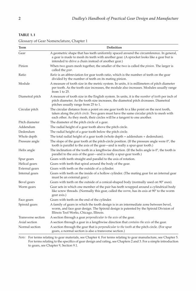
Glossary of Gear Nomenclature, Chapter 1
Term De¡nition
Gear A geometric shape that has teeth uniformly spaced around the circumference. In general, a gear is made to mesh its teeth with another gear. (A sprocket looks like a gear but is intended to drive a chain instead of another gear.)
Pinion When two gears mesh together, the smaller of the two is called the pinion. The larger is called the gear.
Ratio Ratio is an abbreviation for gear tooth ratio, which is the number of teeth on the gear divided by the number of teeth on its mating pinion.
Module A measure of tooth size in the metric system. In units, it is millimeters of pitch diameter per tooth. As the tooth size increases, the module also increases. Modules usually range from 1 to 25.
Diametral pitch A measure of tooth size in the English system. In units, it is the number of teeth per inch of pitch diameter. As the tooth size increases, the diametral pitch decreases. Diametral pitches usually range from 25 to 1.
Circular pitch The circular distance from a point on one gear tooth to a like point on the next tooth, taken along the pitch circle. Two gears must have the same circular pitch to mesh with each other. As they mesh, their circles will be a tangent to one another.
Pitch diameter The diameter of the pitch circle of a gear.Addendum The radial height of a gear tooth above the pitch circle.Dedendum The radial height of a gear tooth below the pitch circle.Whole depth The total radial height of a gear tooth (whole depth = addendum + dedendum).Pressure angle The slope of the gear tooth at the pitch-circle position. (If the pressure angle were 0º, the
tooth is parallel to the axis of the gear—and is really a spur-gear tooth.)Helix angle The inclination of the tooth in a lengthwise direction. (If the helix angle is 0º, the tooth is
parallel to the axis of the gear—and is really a spur-gear tooth.)Spur gears Gears with teeth straight and parallel to the axis of rotation.Helical gears Gears with teeth that spiral around the body of the gear.External gears Gears with teeth on the outside of a cylinder.Internal gears Gears with teeth on the inside of a hollow cylinder. (The mating gear for an internal gear
must be an external gear.)Bevel gears Gears with teeth on the outside of a conical-shaped body (normally used on 90º axes).Worm gears Gear sets in which one member of the pair has teeth wrapped around a cylindrical body
like screw threads. (Normally this gear, called the worm, has its axis at 90º to the worm gear axis.)
Face gears Gears with teeth on the end of the cylinder.Spiroid gears A family of gears in which the tooth design is in an intermediate zone between bevel,
worm, and face gear design. The Spiroid design is patented by the Spiroid Division of Illinois Tool Works, Chicago, Illinois.
Transverse section A section through a gear perpendicular to the axis of the gear.Axial section A section through a gear in a lengthwise direction that contains the axis of the gear.Normal section A section through the gear that is perpendicular to the tooth at the pitch circle. (For spur
gears, a normal section is also a transverse section.)
Note: For terms relating to gear materials, see Chapter 4. For terms relating to gear manufacture, see Chapter 5. For terms relating to the speci�cs of gear design and rating, see Chapters 2 and 3. For a simple introduction to gears, see Chapter 9, Section 9.1.

3Gear Design Trends
TABLE 1.2
Gear Terms, Symbols, and Units, Chapter 1
Term
Metric English
First Reference or De¡nitionSymbol Unitsa Symbol Unitsa
Module m mm – – Equation 1.1Pressure angle α deg ϕ deg Figures 1.18 and 1.33Number of teeth or threads z – N –Number of teeth, pinion z1 – Np or n – Equation 1.7Number of teeth, gear z2 – NG or N – Equation 1.7Ratio (gear or tooth ratio) u – mG – u = z2/z1 (mG = NG/Np)Diametral pitch – – Pd or P in.–1 Equation 1.1Pi π – π – π ≅ 3.1415927Pitch diameter, pinion dp1 mm d in. Figure 1.18, Equation 1.3Pitch diameter, gear dp2 mm D in. Figure 1.18, Equation 1.3Base (circle) diameter, pinion db1 mm db in. Figure 1.18Base (circle) diameter, gear db2 mm Db in. Figure 1.18Outside diameter, pinion da1 mm do in. Figure 1.18 (abbrev. O.D.)Outside diameter, gear da2 mm Do in. Figure 1.18Form diameter d′f mm df in. Figure 1.18Circular pitch p mm p in. Figure 1.18, Equation 1.2Addendum ha mm a in. Figure 1.18Dedendum hf mm b in. Figure 1.18Face width b mm F in. Figure 1.18Whole depth h mm ht in. Figure 1.18Working depth h′ mm hk in. Figure 1.18Clearance c mm c in. Figure 1.18Chordal thickness s mm tc in. Figure 1.18
Chordal addendum ha mm ac in. Figure 1.18
Tooth thickness s mm t in. Figure 1.18Center distance a mm C in. Equation 1.4Circular pitch, normal pn mm pn in. Equation 1.19, Equation 1.5Circular pitch, transverse pt mm pt in. Equation 1.19, Equation 1.5Lead angle γ deg λ deg Equation 1.19, Equation 1.33Helix angle β deg ψ deg Equation 1.19, Equation 1.8Pitch, base or normal pb or pbn mm pb or pN in. Equation 1.19Diametral, base or normal – – pn in.−1 Equation 1.10Axial pitch px mm px in. Equation 1.11Inside (internal) diameter di mm Di in. Figure 1.20 (abbrev. I.D.)Root diameter, pinion df1 mm dR in. Figure 1.29Root diameter, gear df2 mm DR in. Figure 1.20Pitch angle, pinion δ′1 deg γ deg Figure 1.21, Equation 1.16Pitch angle, gear δ′2 deg Γ deg Figure 1.21, Equation 1.16Root angle, pinion δf1 deg γR deg Figure 1.21Root angle, gear δf2 deg ΓR deg Figure 1.21Face angle, pinion δa1 deg γo deg Figure 1.21Face angle, gear δa2 deg Γo deg Figure 1.21
(continued)

4 Dudley’s Handbook of Practical Gear Design and Manufacture
The methods used for manufacturing gears depend on design requirements, available machine tools, quantity required, cost of materials, and tradition. In each particular �eld of gear work, certain methods have become established as the standard way of making gears. These methods tend to change from time to time, but the tradition of the industry tends to act as a brake to restrain any abrupt changes that result from technological developments. The gear designer, studying gears as a whole, can get a good perspective of gear work by reviewing the methods of manufacture in each �eld.
1.1 Small, Low-Cost Gears for Toys, Gadgets, and Mechanisms
There is a large �eld of gear work in which tooth stress is of almost no consequence. Speeds are slow, and life requirements do not amount to much. Almost any type of “cog” wheel that could transmit rotary motion might be used. In this sort of situation, the main thing the designer must look for is low cost and high volume of production.
The simplest type of gear drive—such as those used in toys—frequently uses punched gears. Pinions with a small number of teeth may be die-cast or extruded. If loads are light enough and quietness of operation is desired, injection-molded gears and pinions may be used. Molded-plastic gears from a toy train are shown in Figure 1.1. Things like �lm projec-tors, oscillating fans, cameras, cash registers, and calculators frequently need quiet-running gears to transmit insigni�cant amounts of power. Molded-plastic gears are widely used in such instances. It should be said, though, that the devices just mentioned often need precision-cut gears where loads and speeds become appreciable.
Die-cast gears on zinc alloy, brass, or aluminum are often used to make small, low-cost gears. This process is particularly favored where the gear wheel is integrally attached to some other element, such as a sheave, cam, or clutch member. The gear teeth and the special contours of whatever is attached to the gear may all be �nished to close accuracy merely by die-casting the part in a precision metal mold. Many low-cost gadgets on the market today would be very much more expensive if it were necessary to machine all the complicated gear elements that are in them.
TABLE 1.2 (Continued)
Gear Terms, Symbols, and Units, Chapter 1
Term
Metric English
First Reference or De¡nitionSymbol Unitsa Symbol Unitsa
Dedendum angle θf deg δ deg Figure 1.21Shaft angle Σ deg Σ deg Figure 1.21, Equation 1.18Cone distance R deg A deg Figure 1.21Circular (tooth) thickness s mm t in. Figure 1.21Backlash j mm B in. Figure 1.21Throat diameter of worm dt1 mm dt in. Figure 1.29Throat diameter of worm gear
dt2 mm Dt in. Figure 1.29
Lead of worm pzW mm LW in. Equation 1.32
a Abbreviation for units: mm, millimeters; in., inches; deg, degrees.
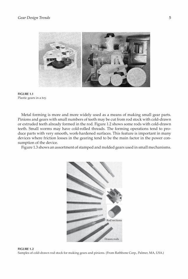
5Gear Design Trends
Metal forming is more and more widely used as a means of making small gear parts. Pinions and gears with small numbers of teeth may be cut from rod stock with cold-drawn or extruded teeth already formed in the rod. Figure 1.2 shows some rods with cold-drawn teeth. Small worms may have cold-rolled threads. The forming operations tend to pro-duce parts with very smooth, work-hardened surfaces. This feature is important in many devices where friction losses in the gearing tend to be the main factor in the power con-sumption of the device.
Figure 1.3 shows an assortment of stamped and molded gears used in small mechanisms.
FIGURE 1.1Plastic gears in a toy.
Rod sections
Drawn rods
FIGURE 1.2Samples of cold-drawn rod stock for making gears and pinions. (From Rathbone Corp., Palmer, MA, USA.)
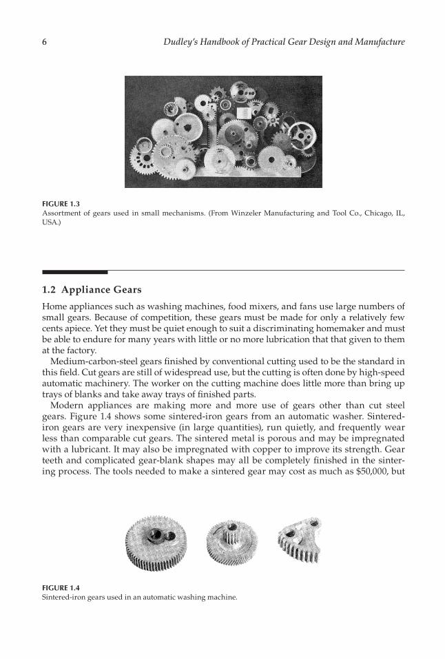
6 Dudley’s Handbook of Practical Gear Design and Manufacture
1.2 Appliance Gears
Home appliances such as washing machines, food mixers, and fans use large numbers of small gears. Because of competition, these gears must be made for only a relatively few cents apiece. Yet they must be quiet enough to suit a discriminating homemaker and must be able to endure for many years with little or no more lubrication that that given to them at the factory.
Medium-carbon-steel gears �nished by conventional cutting used to be the standard in this �eld. Cut gears are still of widespread use, but the cutting is often done by high-speed automatic machinery. The worker on the cutting machine does little more than bring up trays of blanks and take away trays of �nished parts.
Modern appliances are making more and more use of gears other than cut steel gears. Figure 1.4 shows some sintered-iron gears from an automatic washer. Sintered-iron gears are very inexpensive (in large quantities), run quietly, and frequently wear less than comparable cut gears. The sintered metal is porous and may be impregnated with a lubricant. It may also be impregnated with copper to improve its strength. Gear teeth and complicated gear-blank shapes may all be completely �nished in the sinter-ing process. The tools needed to make a sintered gear may cost as much as $50,000, but
FIGURE 1.4Sintered-iron gears used in an automatic washing machine.
FIGURE 1.3Assortment of gears used in small mechanisms. (From Winzeler Manufacturing and Tool Co., Chicago, IL, USA.)

7Gear Design Trends
this does not amount to much if 100,000 or more gears are to be made on semiautomatic machines.
Laminated gears using phenolic resins and cloth or paper have proved very good where noise reduction is a problem. The laminates in general have much more load-carrying capacity than molded-plastic gears. Nonmetallic gears with cut teeth do not suffer nearly so much from tooth inaccuracy as do metal gears. Under the same load, a laminated phenolic-resin gear tooth will bend about 30 times as much as a steel gear tooth. It has often been possible to take a set of steel gears that were wearing excessively because of tooth error effects, replace one member with a nonmetallic gear, and have the set stand up satisfactorily.
Nylon gear parts have worked very well in situations in which wear resulting from high sliding velocity is a problem. The nylon material seems to have some of the characteristics of a solid lubricant. Nylon gearing has been used in some process-ing equipment where the use of a regular lubricant would pollute the material being processed.
1.3 Machine Tools
Accuracy and power-transmitting capacity are important in machine tool gearing. Metal gears are usually used. The teeth are �nished by some precise metal-cutting process.
The machine tool is often literally full of gears. Speed-change gears of the spur or helical type are used to control feed rate and work rotation. Index drives to work or table may be worm or bevel. Sometimes they are spur or helical. Many bevel gears are used at the right-angle intersections between shafts in bases and shafts in columns. Worm gears and spiral gears are also commonly used at these places.
Machine tool gearing is often �nish machined in a medium-hard condition (250–300 HV or 25–30 HRC). Mild-alloy steels are frequently used because of their better machinability and physical properties. Cast iron is often favored for change gears because of the ease in casting the gear blank to shape, its excellent machinability, and its ability to get along with scanty lubrication.
The higher cutting speeds involved in cutting with tungsten carbide tools have forced many machine tool builders to put in harder and more accurate gears. Shaving and grinding are commonly used to �nish machine tool gears to high tooth accuracy. In a few cases, machine tool gears are being made with such top-quality features as full hardness (700 HV or 60 HRC), pro�le modi�cation, and surface �nish of about 0.5 μm or 20 μin.
The machine tool designer has a hard time calculating gear sizes. Loads vary widely depending on feeds, speeds, size of work, and material being cut. It is anybody’s guess what the user will do with the machine. Because machine tools are quite competi-tive in price, an overdesigned machine may be too expensive to sell. In general, the designer is faced with the necessity of putting in gears that have more capacity than the average load, knowing that the machine tool is apt to be neglected or overloaded on occasions.
Figure 1.5 shows an example of machine tool gears.

8 Dudley’s Handbook of Practical Gear Design and Manufacture
1.4 Control Gears
Guns or ships, helicopters, and tanks are controlled by gear trains with the backlash held to the lowest possible limits. The primary job of these gears is to transmit motion. What power they may transmit is secondary to their job of precise control of angular motion. In power gearing, a worn-out gear is one with broken teeth or bad tooth-surface wear. In control gears, a worn-out gear may be one whose thickness has been reduced by as small an amount as 0.01 mm (0.0004 in.)!
Some of the most spectacular control gears are those used to drive radio telescopes and satel-lite tracking antennas. These gears are so large that the only practical way to make them is to cut rack sectors and then bend each section into an arc of a circle. Figure 1.6 shows an example of a very large antenna drive made this way. The teeth on the rack sections are cut so that they will have correct tooth dimensions when they are bent to form part of the circular gear.
The radar units on an aircraft carrier use medium-pitch gears of fairly large size. Radar-unit gearing is generally critical on backlash, must handle rather high momentary loads, and must last for many years with somewhat marginal lubrication. (Radar gears are often somewhat in the open, and therefore can only use grease lubrication.)
Control gears are usually spur, bevel, or worm. Helical gears are used to a limited extent. Control gears are often in the �ne-pitch range—1.25 module (20 diametral pitch) or �ner. Figure 1.7 shows a control device with many small gears.
In few cases, control gears become quite large. Gears that train a main battery must be very rugged. The reaction on the gears when the main battery is �red can be terri�c.
Control gears are usually made of medium-alloy, medium-carbon steels. In many cases, they are hardened to a medium hardness before �nal machining. In other cases, they are hardened to a moderately high hardness after �nal machining. These gears need hardness mainly to limit wear. Any hardening done after �nal �nishing of the teeth must be done in
FIGURE 1.5Example of change gears on a machine tool. (From Warner & Swansea Co., Cleveland, OH, USA.)

9Gear Design Trends
such a way as to give only negligible dimensional change or distortion. To eliminate back-lash, it is necessary to size the gear teeth almost perfectly (or use special “anti-backlash” gear arrangements).
Shaving and/or grinding are used to control tooth thickness to the very close limits needed in control gearing. The inspection of control gears is usually based on checking machines that measure the variation in center distance when a master pinion or rack is
FIGURE 1.6Gears are used to position large radio telescopes. (From Harris Corporation, Melbourne, FL, USA.)
FIGURE 1.7Control device with many small gears.

10 Dudley’s Handbook of Practical Gear Design and Manufacture
rolled through mesh with the gear being checked. A spring constantly holds the mas-ter and the gear being checked in tight mesh. The chart obtained from such a checking machine gives a very clear picture of both the tooth thickness of the gear being checked and the variations in backlash as the gear is rolled through the mesh. If the backlash varia-tion can be held to acceptable limits in control gear sets, there is usually no need to know the exact involute and spacing accuracy. In some types of radar and rocket-tracking equip-ment, control gear teeth must be spaced very accurately with regard to accumulated error. For instance, it may be necessary to have every tooth all the way around a gear wheel within its true position within about 10 seconds of arc. On a 400-mm (15.7-in.) wheel, this would mean that every tooth had to be correctly spaced with respect to every other tooth within 0.01 mm (0.0004 in.). This kind of accuracy can be achieved only by special gear-cutting techniques. Inspection of such gears generally requires the use of gear-checking machines that are equipped to measure accumulated spacing error. The equipment com-monly used will measure any angle to within 1 second of arc or better.
1.5 Vehicle Gears
The automobile normally uses spur and helical gears in the transmission and bevel gears in the rear end. If the car is a front-end drive, bevel gears may still be used or helical gears may be used. Automatic transmissions are now widely used. This does not eliminate gears, however. Most automatic transmissions have more gears than manual transmissions.
Automotive gears are usually cut from low-alloy-steel forgings. At the time of tooth cut-ting, the material is not very hard. After tooth cutting, the gears are case-carburized and quenched. Quenching dies are frequently used to minimize distortion. The composition of heats (batches) of steel is watched carefully, and all steps in manufacture are closely controlled with the aim of having each gear in a lot behave in the same way when it is carburized and quenched. Even if there is some distortion, it can be compensated for in machining, provided that each gear in a lot distorts uniformly and by the same amount. Since most automotive gear teeth are not ground or machined after �nal hardening, it is essential that the teeth be quite accurate in the as-quenched condition. The only work that is done after hardening is the grinding of journal surfaces and sometimes a small amount of lapping. Finished automotive gears usually have a surface hardness of about 700 HV or 60 HRC and a core hardness of 300 HV or 30 HRC.
A variety of machines are used to cut automotive gear teeth. In the past, shapers, hob-bers, and bevel gear generators were conventional machines. New types of these machines are presently favored. For instance, multistation shapers, hobbers, and shaving machines are used. A blank is loaded on the machine at one station. While the worker is loading other stations, the piece is �nished. This means that the worker spends no time waiting for work to be �nished.
There is a wide variety of special-design machines to hob, shape, shave, or grind auto-motive gears. The high production of only one (or two or three) gear design makes it pos-sible to simplify a general-purpose machine tool and then build a kind of processing center where these functions are performed:
• Incoming blank is checked for correct size.• Incoming blank is automatically loaded into the machine.
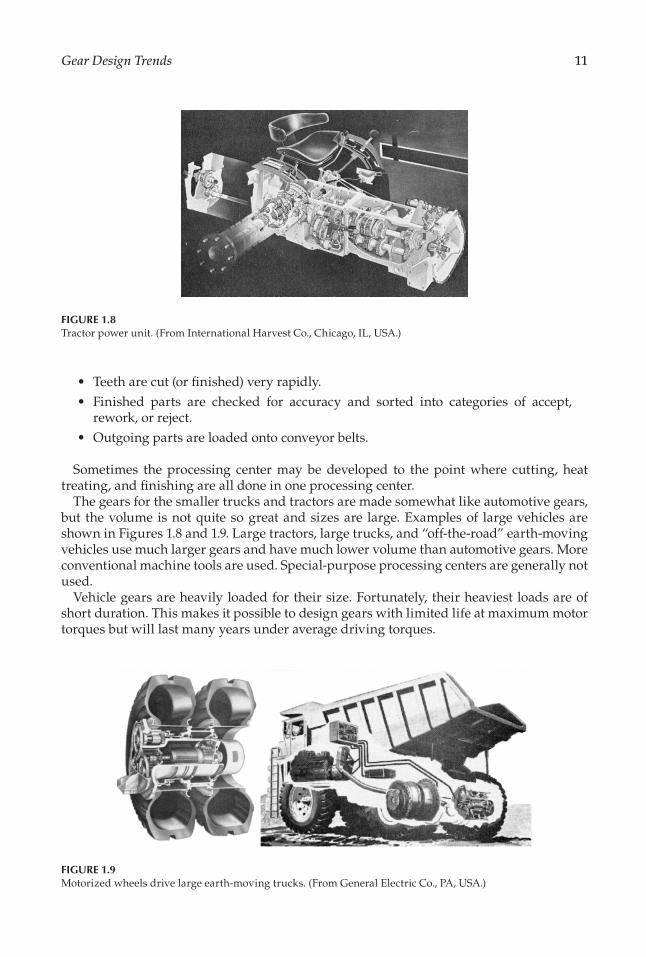
11Gear Design Trends
• Teeth are cut (or �nished) very rapidly.• Finished parts are checked for accuracy and sorted into categories of accept,
rework, or reject.• Outgoing parts are loaded onto conveyor belts.
Sometimes the processing center may be developed to the point where cutting, heat treating, and �nishing are all done in one processing center.
The gears for the smaller trucks and tractors are made somewhat like automotive gears, but the volume is not quite so great and sizes are large. Examples of large vehicles are shown in Figures 1.8 and 1.9. Large tractors, large trucks, and “off-the-road” earth-moving vehicles use much larger gears and have much lower volume than automotive gears. More conventional machine tools are used. Special-purpose processing centers are generally not used.
Vehicle gears are heavily loaded for their size. Fortunately, their heaviest loads are of short duration. This makes it possible to design gears with limited life at maximum motor torques but will last many years under average driving torques.
FIGURE 1.8Tractor power unit. (From International Harvest Co., Chicago, IL, USA.)
FIGURE 1.9Motorized wheels drive large earth-moving trucks. (From General Electric Co., PA, USA.)

12 Dudley’s Handbook of Practical Gear Design and Manufacture
Although carburizing has been widely used as a means of hardening automotive gears, other heat treatments are being used on an increased scale. Combinations of carburizing and nitriding are used. Processes of this type produce a shallower case for the same length of furnace time, but tend to make the gear tooth surface harder and the distortion less. Induction hardening is being used on some �ywheel starter gears as well as on some other gears. Flame hardening is also used to a limited extent.
1.6 Transportation Gears
Buses, subways, mine cars, and railroad diesels all use large quantities of spur and helical gears. The gears range up to 0.75 m (30 in.) or more in diameter (see Figure 1.10). Teeth are sometimes as coarse as 20 module (1.25 diametral pitch). Plain carbon and low-alloy steels are usually used. Much of the gearing is case-carburized and ground. Through hardening is also used extensively. Induction-hardened gears are used limitedly.
Transportation gears are heavily loaded. Frequently their heaviest loads last for a long time. Diesels that pull trains over high mountain ranges have long periods of operation at maximum torque. In some applications, severe but infrequent shock loads are encoun-tered. Shallow-hardening, medium-carbon steels seem to resist shock better than gears with a fully hardened carburized case. Both furnace and induction hardening techniques are used to produce shallow-hardened teeth with high shock resistance.
Gear cutting is done mostly by conventional hobbing or shaping machines. Some gears are shaved and then heat treated, while others are heat treated after cutting and then ground. In this �eld of work, the volume of production is much lower and the size of parts is much larger than in making vehicle gears. Both these conditions make it harder to keep heat treatment distortion so well under control that the teeth may be �nished before hardening.
The machine tools used to make transportation gears are quite conventional in design. The volume of production in this �eld is not large enough to warrant the use of faster and more elaborate types of machine tools used in making vehicle gears.
FIGURE 1.10Railroad wheel drive. (From Electro-Motive Division, General Motors Corp., La Grande, IL, USA.)

13Gear Design Trends
1.7 Marine Gears
Powerful, high-speed, large gears power merchant marine and navy �ghting ships. Propeller drives on cargo ships use bull gears up to 5 m (200 in.) in diameter. First reduc-tion pitch-line speeds on some ships go up to 100 m/s (meters per second) or 20,000 fpm (feet per minute). Single-propeller drives in a navy capital ship go up to ≥40,000 kW (kilo-watts) of power. Some of the new cargo ships now in service have 30,000 kW [40,000 hp (horsepower)] per screw. Figure 1.11 shows a typical marine gear unit.
Marine gears are almost all made by �nishing the teeth after hardening. Extreme accu-racy in tooth spacing is required to enable the gearing to run satisfactorily at high speeds. As many as 6000 pairs of teeth may go through one gear mesh in one second!
There is an increased use of carburized and ground gears in the marine �eld. The fully hard gear is smaller and lighter. This lowers pitch-line velocity and helps keep the engine room reasonably small. Hard gears resist pitting and wear better than medium-hard gears (through-hardened gears).
Single-helical gears have long been used for electric-power-generating equipment. Double-helical gears have generally been used for the main propulsion drive of large ships. Single-helical gears—with special thrust runners on the gears themselves—are becoming fairly commonly used even on large ships.
Spur and bevel gear drives are often used on small ships, but they are seldom used on large turbine-driven ships. (Some slower-speed diesel-driven ships use spur gearing.)
Marine gears generally use medium-alloy carbon steel. It is dif�cult or impossible to heat treat plain carbon and low-alloy carbon steels in large sizes and get hardnesses over about 250 HV (250 HB) and a satisfactory metallurgical structure. Special welding tech-niques for large gear wheels make it possible to use medium-alloy steels and get good through-hardened gears up to 5 m (200 in.) with gear tooth hardness at 320 HV (300 HB) or higher. The smaller pinions are not welded and can usually be made up to 375 HV (350 HB) or higher in sizes up to 0.75 m (30 in.).
FIGURE 1.11Partially assembled double-reduction marine gear unit. (From Transamerica Delaval Inc., Trenton, NJ, USA.)
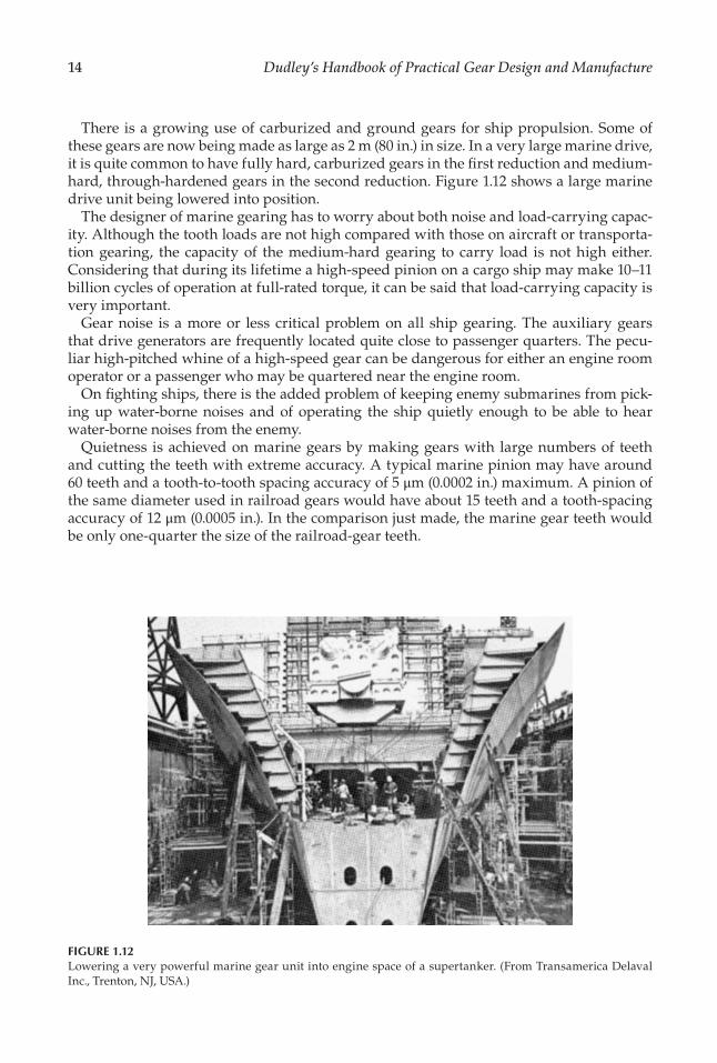
14 Dudley’s Handbook of Practical Gear Design and Manufacture
There is a growing use of carburized and ground gears for ship propulsion. Some of these gears are now being made as large as 2 m (80 in.) in size. In a very large marine drive, it is quite common to have fully hard, carburized gears in the �rst reduction and medium-hard, through-hardened gears in the second reduction. Figure 1.12 shows a large marine drive unit being lowered into position.
The designer of marine gearing has to worry about both noise and load-carrying capac-ity. Although the tooth loads are not high compared with those on aircraft or transporta-tion gearing, the capacity of the medium-hard gearing to carry load is not high either. Considering that during its lifetime a high-speed pinion on a cargo ship may make 10–11 billion cycles of operation at full-rated torque, it can be said that load-carrying capacity is very important.
Gear noise is a more or less critical problem on all ship gearing. The auxiliary gears that drive generators are frequently located quite close to passenger quarters. The pecu-liar high-pitched whine of a high-speed gear can be dangerous for either an engine room operator or a passenger who may be quartered near the engine room.
On �ghting ships, there is the added problem of keeping enemy submarines from pick-ing up water-borne noises and of operating the ship quietly enough to be able to hear water-borne noises from the enemy.
Quietness is achieved on marine gears by making gears with large numbers of teeth and cutting the teeth with extreme accuracy. A typical marine pinion may have around 60 teeth and a tooth-to-tooth spacing accuracy of 5 μm (0.0002 in.) maximum. A pinion of the same diameter used in railroad gears would have about 15 teeth and a tooth-spacing accuracy of 12 μm (0.0005 in.). In the comparison just made, the marine gear teeth would be only one-quarter the size of the railroad-gear teeth.
FIGURE 1.12Lowering a very powerful marine gear unit into engine space of a supertanker. (From Transamerica Delaval Inc., Trenton, NJ, USA.)

15Gear Design Trends
1.8 Aerospace Gears
Gears are used in a wide variety of applications on aircraft. Propellers are usually driven by single- or double-reduction gear trains. Accessories such as generators, pumps, hydrau-lic regulators, and tachometers are gear driven. Many gears are required to drive these kinds of accessories even on jet engines—which have no propellers. Additional gears are used to raise landing wheels, open bomb-bay doors, control guns, operate computers for gun- or bomb-sighting devices, and control the pitch of propellers. Helicopters have a considerable amount of gearing to drive main rotors and tail rotors (see Figure 1.13). Space vehicles often use power gears between the turbine and the booster fuel pumps.
The most distinctive types of aircraft gears are the power gears for propellers, accesso-ries, and helicopter rotors. The control and actuating types of gears are not too different from what would be used for ground applications of a similar nature (except that they are often highly loaded and made of extra hard, high-quality steel).
Aircraft power gears are usually housed in aluminum or magnesium casings. The gears have thin webs and light cross sections in the rim or hub. Accessory gears are frequently made integral with an internally splined hub.
Spur or bevel gears are usually used for accessory drives. Envelope clearance required to mount the accessory driven by the gear often make it necessary to use large center distance but narrow face width. This fact plus the thrust problem tends to rule out helical accessory gears. Propeller-driven gears have wider face widths. Spur, bevel, and helical gear drives are all currently in use. To obtain maximum power capacity with small size and lightweight gearboxes, it is often desirable to use an epicyclic gear train. In this kind of arrangement, there is only one output gear, but several pinions drive against it.
FIGURE 1.13Cutaway view of a helicopter gear unit. Last two stages are epicyclic. First stage is spiral bevel. (From Bell Helicopter Textron, Fort Worth, TX, USA.)

16 Dudley’s Handbook of Practical Gear Design and Manufacture
Aerospace power gears are usually made of high-alloy steel and fully hardened (on the tooth surface) by either case carburizing or nitriding. In some designs it is feasible to cut, shave, case-carburize, and grind only the journals. Many designs have such thin, nonsym-metrical webs as to require grinding after hardening. In general, piston engine gearing runs more slowly than gas turbine gearing. This makes some difference in the required accuracy. Thus far, many more piston engine gears have been successfully �nished before hardening than have gas turbine gears.
The tooth loads and speeds are both very high on modern aircraft gears. The designer must achieve high tooth strength and high wear resistance. In addition, the thin oils used for low-temperature starting of military aircraft make the scoring type of lubrication fail-ure a critical problem. Several special things are done to meet the demands of aircraft gear service. Pinions are often made long addendum and gears short addendum to adjust the tip sliding velocities and to strengthen the pinion. Pinion tooth thicknesses are often increased at the expense of the gear to strengthen the pinion. High pressure angles such as 22.5°, 25°, and 27.5° are often used to reduce the base. Involute pro�le modi�cations are generally used to compensate for bending and to keep the tips from cutting the mating part.
The most highly developed aerospace gears are those used in rocket engines. The American projects Vanguard, Mercury, Gemini, and Apollo succeeded in boosting heavy pay-loads into orbit and eventually putting men on the moon. Unusual aerospace gear capabil-ity was developed to meet the special requirements of power gears and control gears in space vehicles.
Materials and dimensional tolerances must be held under close control. A gear failure can frequently result in the loss of human life. The gear designer and builder both have a grave responsibility to furnish gears that are always sure to work satisfactorily. Extensive ground and �ight testing are required to approve new designs.
The machine tools used to make aircraft gears are conventional hobbers, shapers, bevel gear generators, shavers, and gear grinders. For the close tolerances, the machinery must be in the very best condition and precision tooling must be used. A complete line of check-ing equipment is needed so that involute pro�le, tooth spacing, helix angle, concentricity, and surface �nish can be precisely measured.
1.9 Industrial Gearing
A wide range of types and sizes of gears that are used in homes, factories, and of�ces come under the “industrial” category (see examples in Figures 1.14 and 1.15). In general, these gears involve electric power from a motor used to drive something. The driven device may be a pump, conveyor, or liquid stirring unit. It may also be a garage door opener, an air compressor for of�ce refrigeration, a hoist, a winch, or a drive to mix concrete on a truck hauling the concrete to the job.
Industrial gearing is of relatively low speed and low horsepower. Typical pitch-line speeds range from about 0.5 m/s to somewhat over 20 m/s (100–4000 fpm). The types of gears may be spur, helical, bevel, worm, or Spiroid® (Spiroid Division of the Illinois Tool Works, Chicago, IL, USA). The power may range from less than 1 kW up to a few hundred kW. Typical input speeds are those of the electric motor, like 1800, 1500, 1200, and 100 rpm (revolutions per minute).

17Gear Design Trends
The industrial �eld also includes drives with hydraulic motors. The �eld is characterized more by relatively low pitch-line speeds and power inputs than by the means of making or using the power.
Much of the gearing used in industrial work is made with through-hardened steel used as cut. There is, however, growing use of fully hardened gears where the size of the gearing or the life of the gearing is critical.
FIGURE 1.14Truck-mounted, two-speed gear unit used to drive a piston pump for oil-well fracturing. (From Sier-Bath Gear Co. Inc., North Bergen, NJ, USA.)
FIGURE 1.15Two-stage epicyclic gear, close-coupled to a high-speed gas turbine. This unit is used to drive a generator. (From Solar Turbines Incorporated, San Diego, CA, USA.)
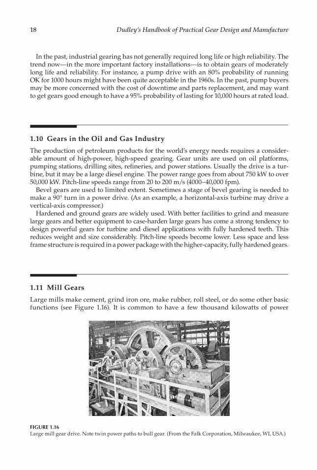
18 Dudley’s Handbook of Practical Gear Design and Manufacture
In the past, industrial gearing has not generally required long life or high reliability. The trend now—in the more important factory installations—is to obtain gears of moderately long life and reliability. For instance, a pump drive with an 80% probability of running OK for 1000 hours might have been quite acceptable in the 1960s. In the past, pump buyers may be more concerned with the cost of downtime and parts replacement, and may want to get gears good enough to have a 95% probability of lasting for 10,000 hours at rated load.
1.10 Gears in the Oil and Gas Industry
The production of petroleum products for the world’s energy needs requires a consider-able amount of high-power, high-speed gearing. Gear units are used on oil platforms, pumping stations, drilling sites, re�neries, and power stations. Usually the drive is a tur-bine, but it may be a large diesel engine. The power range goes from about 750 kW to over 50,000 kW. Pitch-line speeds range from 20 to 200 m/s (4000–40,000 fpm).
Bevel gears are used to limited extent. Sometimes a stage of bevel gearing is needed to make a 90° turn in a power drive. (As an example, a horizontal-axis turbine may drive a vertical-axis compressor.)
Hardened and ground gears are widely used. With better facilities to grind and measure large gears and better equipment to case-harden large gears has come a strong tendency to design powerful gears for turbine and diesel applications with fully hardened teeth. This reduces weight and size considerably. Pitch-line speeds become lower. Less space and less frame structure is required in a power package with the higher-capacity, fully hardened gears.
1.11 Mill Gears
Large mills make cement, grind iron ore, make rubber, roll steel, or do some other basic functions (see Figure 1.16). It is common to have a few thousand kilowatts of power
FIGURE 1.16Large mill gear drive. Note twin power paths to bull gear. (From the Falk Corporation, Milwaukee, WI, USA.)

19Gear Design Trends
going through two or more gear stages to drive some massive processing drum or roll-ing device.
The mill is usually powered by electric motors, but diesel engines or turbines may be used. Mill drives characteristically have high power (and frequently unusually high torques).
A process mill will often run continuously for months at a time. Downtime is critical because the output ceases completely when a mill unit is shut down.
Spur and helical gears are generally used. Pitch-line speeds are usually quite low. A �rst stage may be doing around 20 m/s (4000 fpm), but the �nal stage in a mill may run as slowly as 0.1–1.0 m/s (20–200 fpm). Some bevel gears are also used—where axes must be at 90°.
The larger mill gears are generally made medium hard, but they may even be of low hardness. The very large sizes involved often make it impractical to use the harder gears. There is an increasing use, however, of fully hardened mill gears up to gear pitch diam-eters of about 2 m.
Mill gears are commonly made in sizes up to 11 m. Such giant gears have to be made in two or more segments. Figure 1.17 shows a large two-segment mill gear. The segments are bolted together for cutting and then unbolted for shipping. (It is impractical to ship round pieces of metal over about 5 m in diameter.)
SELEC T ION OF T HE R IGH T K IN D OF GE A R : The preceding section gave some general information on how gears are made and used in different �elds. In this part of the chapter, we shall concentrate on the problem of selecting the right kind of gear. The �rst step in designing a set of gears is to pick the right kind.
FIGURE 1.17Jumbo-size drive gear for a large mill application. (From David Brown Gear Industries, Hudders�eld, UK.)

20 Dudley’s Handbook of Practical Gear Design and Manufacture
In many cases, the geometric arrangement of the apparatus that needs a gear drive will considerably affect the selection. If the gears must be on parallel axes, then spur or helical gears are the ones to use. Bevel and worm gears can be used if the axes are at right angles, but they are not feasible with parallel axes. If the axes are nonintersecting and nonparallel, then crossed-helical gears, hypoid gears, worm gears, or Spiroid gears may be used. Worm gears, however, are seldom used if the axes are not at right angles to each other. Table 1.3 shows in more detail the principal kinds of gears and how they are mounted.
There are no dogmatic rules that tell the designer just which gear to use. Frequently the choice is made after weighing the advantages and disadvantages of two or three kinds of gears. Some generalizations, though, can be made about gear selection.
In general, external helical gears are used when both high speeds and high horsepower are involved. External helical gears have been built to carry as much as 45,000 kW of power on a single pinion and gear. This is not the limit for designing helical gears—bigger ones could be built if anyone needed them. It is doubtful if any other kind of gear could be built and used successfully to carry this much power on a single mesh.
Bevel gears are ordinarily used on right-angle drives when high ef�ciency in needed. These gears can usually be designed to operate with 98% or better ef�ciency. Worm gears often have a hard time obtaining above 90% ef�ciency. Hypoid gears do not have as good ef�ciency as bevel gears, but they make up for this by being able to carry more power in the same space—provided the speeds are not too high.
Worm gears are ordinarily used on right-angle drives when very high ratios are needed. They are also widely used in low-to-medium ratios as packaged speed reducers. Single-thread worms and worm gears are used to provide indexing accuracy on many machine tools. The critical job of indexing hobbing machines and gear shapers is nearly always done by a worm gear drive.
Spur gears are ordinarily thought of slow-speed gears, while helical gears are thought of as high-speed gears. If noise is not a serious design problem, spur gears can be used at almost any speeds that can be handled by other types of gears. Aircraft gas-turbine spur gears sometimes run at pitch-line speeds above 50 m/s (10,000 fpm). In general, though, spur gears are not used much above 20 m/s (4000 fpm).
1.12 External Spur Gears
Spur gears are used to transmit power between parallel shafts. They impose only radial loads on their bearing. The tooth pro�les are ordinarily curved in the shape of an involute. Variations in center distance do not affect the trueness of the gear action unless the change
TABLE 1.3
Kinds of Commonly Used Gears
Parallel Axes Intersecting Axes Nonintersecting Nonparallel Axes
Spur external Straight bevel Crossed-helicalSpur internal Zerol bevel Single-enveloping wormHelical external Spiral bevel Double-enveloping wormHelical internal Face gear Hypoid
Spiroid

21Gear Design Trends
is so great as to either jam the teeth into the root �llets of the mating member or withdraw the teeth almost out of action.
Spur gear teeth may be hobbed, shaped, milled, stamped, drawn, sintered, cast, or shear cut. They may be given a �nishing operation such as grinding, shaving, lapping, rolling, or burnishing. Speaking generally, there are more kinds of machine tools and processes avail-able to make spur gears than to make any other gear type. This favorable situation often makes spur gears the choice where manufacturing cost is a major factor in the gear design.
The standard measure of spur-gear tooth size in the metric system is the module. In the English system, the standard measure of tooth size is diametral pitch. The meanings are as follows:
Module is millimeters of pitch diameter per tooth.Diametral pitch is number of teeth per inch of pitch diameter (a reciprocal function).
Mathematically,
Modulediametral pitch
= 25 400. (1.1)
or
Diametral pitchmodule
= 25 400. (1.2)
Curiously, module and diametral pitch are size dimensions that cannot be directly mea-sured on a gear. They are really reference values used to calculate other size dimensions that are measurable.
Gears can be made to any desired module or diametral pitch, provided that cutting tools are available for that tooth size. To avoid purchasing cutting tools for too many different tooth sizes, it is desirable to pick a progression of modules and design to these except where design requirements force the use of special sizes. The following commonly used modules are recommended as a start for a design series: 25, 20, 15, 12, 10, 8, 6, 5, 4, 3, 2.5, 2.0,
1.5, 1, 0.8, 0.5. Many shops are equipped with English system diametral pitches series: 1,
114
, 112
, 134
, 2, 212
, 3, 4, 5, 6, 8, 10, 12, 16, 20, 24, 32, 48, 64, 128. Considering the trend toward
international trade, is desired to purchase new gear tools in standard metric sizes so that they will be handy for gear work going to any part of the world. (The standard measuring system of the world is the metric system.)
Most designers prefer a 20° pressure angle for spur gears. In the past the 14.5° pressure angle was widely used. It is not popular today because it gets into trouble with undercut-ting much more quickly that the 20° tooth when small numbers of pinion teeth are needed. Also, it does not have the load-carrying capacity of the 20° tooth. A pressure angle of 22.5° or 25° is often used. Pressure angles above 20° give higher load capacity but may not run quite as smoothly or quietly.
Figure 1.18 shows the terminology used with a spur gear or a spur rack (a rack is a sec-tion of a spur gear with an in�nitely large pitch diameter).
The following formulas apply to spur gears in all cases:

22 Dudley’s Handbook of Practical Gear Design and Manufacture
Circular pitch pi module metric
pi diametral pit
= ×= ÷ cch English
(1.2a) (1.2b)
Pitch diameter no. of teeth module metric
no. of
= ×= teeth diametral pitch English÷
(1.3a)
(1.3b)
The nominal center distance is equal to the sum of the pitch diameter of the pinion and the pitch diameter of the gear divided by 2:
Center distance =pinion pitch dia. + gear pitchh dia.
2 (1.4)
Since the center distance is a machined dimension, it may not come out to be exactly what the design calls for. In addition, it is common practice to use a slightly larger center distance to increase the operation pressure angle. For instance, if the actual center distance is made 1.7116% larger, gears cut with 20° hobs or shaper-cutters will run at 22.5° pressure angle. (See Section 8.1 for methods of design for special center distance.)
For the reasons just mentioned, it is possible to have two center distances, a nominal cen-ter distance and an operating center distance. Likewise, there are two pitch diameters. The
Pressureangle Face width
Addendum of mating gearTooth filletWorking depth
Whole depth
Chordalthickness
Chordaladdendum
Addendum
Arc thickness
Rise of arc
Circular pitchTooth thickness
Formdiameter
Outsidediameter
Pitchdiameter
DedendumAddendum
Circular pitch
Clearance
Basecircle
diameter
Spur gear
Spur rack
FIGURE 1.18Spur gear and rack terminology.

23Gear Design Trends
pitch diameter for the tooth-cutting operation is the nominal pitch diameter and is given by Equation 1.3. The operating pitch diameter is
Pitch dia. (operating) of pinion =2 operating× ccent. dist.
ratio + 1 (1.5)
Pitch dia. (operating) of gear = ratio × pitch dia. (operating) of pinion (1.6)
were
Gear (Tooth) Ratio =no. gear teethno. pinion teeth
(1.7)
1.13 External Helical Gears
Helical gears are used to transmit power or motion between parallel shafts. The helix angle must be of the same degree on each member, but the hand of the helix on the pinion is opposite to that on the gear. (An RH pinion meshes with LH gear, and LH pinion meshes with a RH gear.)
Single-helical gears impose both thrust and radial load on their bearings. Double-helical gears develop equal and opposite thrust reactions that have the effect of canceling out the thrust load. Usually, double-helical gears have a gap between helices to permit a runout clearance for the hob, grinding wheel, or other cutting tool. One kind of gear shaper has been developed that permits double-helical teeth to be made continuous (no gap between helices).
Helical-gear teeth are usually made with an involute pro�le in the transverse section (the transverse section is a cross section perpendicular to the gear axis). Small changes in cen-ter distance do not affect the action of helical gears.
Helical-gear teeth may be made by hobbing, shaping, milling, or casting. Sintering has been used with limited success. Helical teeth may be �nished by grinding, shaving, roll-ing, lapping, or burnishing.
The size of helical-gear teeth is speci�ed by module for the metric system and by diametral pitch for the English system. The helical tooth will frequently have some of its dimensions given in the normal section and others given in transverse section. Thus standard cutting tools could be speci�ed for either section—but not for both sections. If the helical gear is small (less than 1 m pitch diameter), most designers will use the same pressure angle and standard tooth size in the normal section of the helical gear as they would use for spur gears. This makes it possible to hob helical gears with standard spur gear hob. (It is not possible, though, to cut helical gears with standard spur-gear shaper-cutters.)
Helical gears often use 20° as the standard pressure angle in the normal section. However, higher pressure angles, such as 22.5° or 25°, may be used to get extra load-carrying capacity.
Figure 1.19 shows terminology of a helical gear and a helical rack. In the transverse plane, the elements of a helical gear are the same as those of a spur gear. Equations 1.1 through 1.7 apply just as well to the transverse plane of a helical gear as they do to a spur gear. Additional general formulas for helical gears are as follows:

24 Dudley’s Handbook of Practical Gear Design and Manufacture
Normal circ. pitch = circ. pitch × cosine helix angle (1.8)
Normal module = transverse module × cosine helix angle (1.9)
Normal diam. pitch = transverse diam. pitch × cosine helix angle (1.10)
Axial pitch = circ. pitch ÷ tangent helix angle (1.11)
= norm. circ. pitch ÷ sine helix angle (1.12)
1.14 Internal Gears
Two internal gears will not mesh with each other, but an external gear may be meshed with an internal gear. The external gear must not be larger than about two-thirds the pitch diameter of the internal gear when full-depth 20° pressure angle teeth are used. The axes on which the gears are mounted must be parallel.
Internal gears may be either spur or helical. Even double-helical internal gears are used occasionally.
An internal gear is a necessary in an epicyclic type of gear arrangement. The short center distance of an internal gear set makes it desirable in some applications where space is very limited. The shape of internal gear forms natural guards over the meshing gear teeth. This is very advantageous for some types of machinery.
Normal circular pitch
Lead angle
Axis of gear
Transversecircular pitch
Base pitch ornormal pitchWholedepth
Formdiameter
Base circlediameter
Helical gear
Outside diameterPitch diameter
Normalplane
Leadangle
Helix angleFront plane
Circular pitch
Normalpitchline
Face width
Helix angle
Dedendum
Addendum
FIGURE 1.19Helical gear and rack terminology.

25Gear Design Trends
Internal gears have the disadvantage that fewer types of machine tool can produce them. Internal gears cannot be hobbed.* They can be shaped, milled, or cast. In small sizes they can be broached. Both helical and spur internals can be �nished by shaving, grinding, lap-ping, or burnishing.
An internal gear has the same helix angle in degrees and the same hand as its mating pinion (right-hand pinion meshes with right-hand gear and vice versa).
Figure 1.20 shows the terminology used for a spur internal gear. All the previously given formulas apply to internal gearing except those involving center distance (Equations 1.4 through 1.6 do not hold for internals). Formulas for internal-gear center distance are
Center distance =pitch dia. of gear pitch dia.− of pinion
2 (1.13)
Pitch dia. (operating) of pinion =2 op. cent.× ddist.
ratio 1− (1.14)
Pitch dia. (operating) of gear =2 op. cent. di× sst. ratio
ratio 1×
− (1.15)
* Some very special hobs and hobbing machines have been used—to a rather limited extent—to hob internal gears.
Circular pitch
ClearanceWorking depth
Chordalthickness
Chordaladdendum
Cutter clearanceWidth of face
AddendumDedendum
Wholedepth
Base circledia.
Pitchdia.
Insidedia.
Rootdia.
Addendum ofmating gear
Center distance
Rise of arcAddendum
Arcthickness
FIGURE 1.20Internal gear terminology.

26 Dudley’s Handbook of Practical Gear Design and Manufacture
1.15 Straight Bevel Gears
Bevel gear blanks are conical in shape. The teeth are tapered in both tooth thickness and tooth height. At one end the tooth is larger, while at the other end it is small. The tooth dimensions are usually speci�ed for the large end of the tooth. However, in calculating bearing loads, central-section dimensions and forces are used.
The simplest type of bevel gear is the straight bevel gear. These gears are commonly used for transmitting power between intersecting shafts. Usually the shaft angle is 90°, but it may be almost any angle. The gears impose both radial and thrust load on their bearing.
Bevel gears must be mounted on axes whose shaft angle is almost exactly the same as the design shaft angle. Also, the axes on which they are mounted must either intersect or come very close to intersecting. In addition to the accuracy required of the axes, bevel gears must be mounted at the right distance from the cone center. The complications involved in mounting bevel gears make it dif�cult to use sleeve bearings with large clearances (which is often done on high-speed, high-power spur, and helical gears). Ball and roller bearings are the kinds commonly used for bevel gears. The limitations of these bearings’ speed and load-carrying capacity indirectly limit the capacity of bevel gears in some high-speed applications.
Straight bevel teeth are usually cut on bevel gear generators. In some cases, where accu-racy is not too important, bevel gear teeth are milled. Bevel teeth may also be cast. Lapping is the process often used to �nish straight bevel teeth. Shaving is not practical for straight bevel gears, but straight bevels may be ground.
The size of bevel gear teeth is de�ned in module for the metric system and in diametral pitch for the English system. The speci�ed size dimensions are given for the large end of the tooth. A bevel gear tooth that is 12 module at the large end may be only around 10 module at the small end. The commonly used modules (or diametral pitches) are the same as those used for spur gears (see Section 1.12). There is no particular advantage to using standard tooth sizes for bevel gears. A set of cutting tools will cut more than a single pitch.
The two views of bevel gears in Figure 1.21 show bevel gear terminology. Bevel gear teeth have pro�les that closely resemble an involute curve. The shape of a straight bevel gear tooth (in a section normal to the tooth) closely approximates that of an involute spur gear with a larger number of teeth. This larger number of teeth, called the virtual number of teeth, is equal to the actual number of teeth divided by the cosine of the pitch angle.
Straight bevel gear teeth have been commonly made with 14.5°, 17.5°, and 20° pressure angles. The 20° design is the most popular.
The pitch angle of a bevel gear is the angle of the pitch cone. It is a measure of the amount of taper in the gear. For instance, as the taper is reduced, the pitch angle approaches zero and the bevel gear approaches a spur gear.
The pitch angles in a set of bevel gears are de�ned by lines meeting at the cone center. The root and face angles are de�ned by lines that do not hit the cone center (or apex). In old-style designs these angles did meet at the apex, but modern designs make the outside cone of one gear parallel to the root cone of its mate. This gives a constant clearance and permits a better cutting tool design and gear tooth design than the old-style design with its tapering clearance.
The circular pitch and the pitch diameters of bevel gears are calculated the same as for spur gears (see Equations 1.1 through 1.3). The pitch-cone angles may be calculated by one of the following sets of equations:

27Gear Design Trends
Tan pitch angle, pinionno. teeth in pinionno.
=tteeth in gear
(1.16)
Tan pitch angle, gearno. teeth in gear
no. teet=
hh in pinion (1.17)
When the shaft angle is less than 90°,
Tan pitch angle, pinionsin shaft angle
ratio co=
+ ss shaft angle (1.18)
Pitch apex to back
Pitchapex
Pitchangle
A
Shaft angleFaceangle
Backangle
Back c
one d
istan
ce
Dedendumangle
Uniform clearance
Face
widthCone d
istance
Pitch apex to crownCrown
Crown to back
A
Whole depth
Top land
Working depth
Tooth filletBottom
land
Chordaladdendum
Circular thicknessChordal thickness
Addendum
DedendumBack con
e dista
nce
BacklashClearance
Toothprofile
Circularpitch
Pinion
Root angle
Frontangle Gear
Pitch diameterOutside diameter
Backcone
FIGURE 1.21Bevel gear terminology.

28 Dudley’s Handbook of Practical Gear Design and Manufacture
Tan pitch angle, gearsin shaft angle
1/ratio co=
+ ss shaft angle (1.19)
When the shaft angle is over than 90°,
Tan pitch angle, pinionsin (180 shaft angle)
r= −°
aatio cos (180 shaft angle)− −° (1.20)
Tan pitch angle, gearsin (180 shaft angle)
1/r= −°
aatio cos (180 shaft angle)− −° (1.21)
In all the above cases,
Pitch angle, pinion + pitch angle, gear = shaft angle (1.22)
1.16 Zerol Bevel Gears
Zerol® (Gleason Works, Rochester, NY, USA) bevel gears are similar to straight bevel gears except that they have a curved tooth in the lengthwise direction (see Figure 1.22). Zerol bevel gears have 0° spiral angle. They are made in a different kind of machine from that used to make straight bevel gears. The machine that generates straight bevel gears has a cutting tool that moves back and forth in a straight line. Zerol is generated by a rotary cutter that is like a face mill. It is the curvature of this cutter that makes the lengthwise curvature in the Zerol tooth.
The Zerol gear has a pro�le that somewhat resembles an involute curve. The pressure angle of the tooth varies slightly in going across the face width. This is caused by the lengthwise curvature of the tooth.
Zerol gear teeth may be �nished by grinding or lapping. Since the Zerol gear can be ground, it is favored over straight bevel gears in applications in which both high accu-racy and full hardness are required. Even in applications in which cut gears of machin-able hardness can be used, Zerol may be the best choice if speeds are high. Because of its lengthwise curvature, the Zerol tooth has s slight overlapping action. This tends to make it
FIGURE 1.22A pair of Zerol bevel gears. (From the Gleason Works, Rochester, NY, USA.)

29Gear Design Trends
run more smoothly than the tooth of straight bevel gears. A cut Zerol bevel gear is usually more accurate than a straight bevel gear.
In making a set of Zerol gears, one member is made �rst, using theoretical machine set-tings. Then a second gear is �nished in such a way that its pro�le and lengthwise curva-ture will give satisfactory contact with the �rst gear. Several trial cuts and adjustments to machine settings may be required to develop a set of gears that will conjugate properly. If a number of identical sets of gears are required, a matching set of test gears is made. Then each production gear is machined so that it will mesh satisfactorily with one or the other of the test gears. In this way a number of sets of interchangeable gears may be made.
Zerol gears are usually made to a 20° pressure angle. In a few ratios where pinion and gear have small numbers of teeth, 22.5° or 25° is used.
The calculations for pitch diameter and pitch-cone angle are the same for Zerol bevel gears as for straight bevel gears.
1.17 Spiral Bevel Gears
Spiral bevel gears have a lengthwise curvature like Zerol gears. However, they differ from Zerol gears in that they have an appreciable angle with the axis of the gear (see Figure 1.23). Although spiral bevel teeth do not have a true helical spiral, a spiral bevel gear looks some-what like a helical bevel gear.
Spiral bevel gears are generated by the same machines that cut or grind Zerol gears. The only difference is that the cutting tool is set at an angle to the axis of the gear instead of being set essentially parallel to the gear axis.
Spiral bevel gears are made in matched sets like Zerol bevel gears. Different sets of the same design are not interchangeable unless they have been purposely built to match a common set of test gears.
Generating types of machines are ordinarily used to cut or grind the teeth of spiral bevel gears. In some high-production jobs, a special kind of machine is used that cuts the teeth without going through a generating motion. Teeth of spiral bevel gears are frequently given a lapping operation to �nish the teeth and obtain the desired tooth bearing.
In high-speed gear work, the spiral bevel is preferred over the Zerol bevel because its spiral angle tends to give the teeth a considerable amount of overlap. This makes the gear run more smoothly, and the load is distributed over more tooth surface. However, the spi-ral bevel gear imposes much more thrust load on its bearings than does a Zerol bevel gear.
FIGURE 1.23A pair of spiral bevel gears. (From the Gleason Works, Rochester, NY, USA.)

30 Dudley’s Handbook of Practical Gear Design and Manufacture
Spiral bevel gears are commonly made of 16°, 17.5°, 20°, and 22.5° pressure angles. The 20° angle has become the most popular. It is the only angle used on aircraft and instrument gears. The most common spiral angle is 35°.
1.18 Hypoid Gears
Hypoid gears resemble bevel gears in some respects. They are used on crossed-axis shafts, and there is a tendency for the parts to taper as do bevel gears. They differ from true bevel gears in that their axes do not intersect. The distance between a hypoid pinion axis and the axis of a hypoid gear is called offset. This distance is measured along the perpendicular common to the two axes. If a set of hypoid gears had no offset, they would simply be spiral bevel gears. See Figure 1.24 for offset and other terms.
Hypoid pinions may have as few as �ve teeth in a high ratio. Since the various kinds of bevel gears do not often go below 100 teeth in a pinion, it can be seen that it is easier to get high ratios with hypoid gears.
Contrary to the general rule with spur, helical, and bevel gears, hypoid pinions and gears do not have pitch diameters that are in proportion to their numbers of teeth. This makes it possible to use a large and strong pinion even with a high ratio and only a few pinion teeth (see Figure 1.25).
Hypoid teeth have unequal pressure angles and unequal pro�le curvatures on the two sides of the teeth. This results from the unusual geometry of the hypoid gear rather than from a nonsymmetrical cutting tool.
Hypoidoffset
Pinion mountingdistance
Pinion mountingdistancePinion mounting
distanceCrossing point
Gearmountingdistance
Gear mountingdistance
FIGURE 1.24Hypoid gear arrangement.

31Gear Design Trends
Hypoid gears are matched to run together, just as Zerol or spiral gear-sets are matched. Interchangeability is obtained by making production gears �t with test masters.
Hypoid gears and pinions are usually cut on a generating type of machine. They may be �nished by either grinding or lapping.
The hypoid gears and pinions are usually cut on a generating type of machine. They may be �nished by either grinding or lapping.
The hypoid gears for passenger cars and for industrial drives usually have a basic pres-sure angle of 21°15′. For tractors and trucks, the average pressure angle is 22°30′. Pinions are frequently made with a spiral angle of 45° or 50°.
In hypoid gearing, module and diametral pitch are used for the gear only. Likewise, the pitch diameter and the pitch angle are �gured for the gear only. If a pitch were used for the pinion, it would be smaller than that of the gear. The size of a hypoid pinion is estab-lished by its outside diameter and the number of its teeth. The geometry of hypoid teeth is de�ned by the various dimensions used to set up the machines to cut the teeth.
1.19 Face Gears
Face gears have teeth cut on the end face of a gear, just as the name “face” implies. They are not ordinarily thought of as bevel gears, but functionally they are more akin to bevel gears than to any other kind.
A spur pinion and a face gear are mounted—like bevel gears—on shafts that intersect and have a shaft angle (usually 90°). The pinion bearing carries mostly radial load, while the gear bearing has both thrust and radial load. The mounting distance of the pinion from the pitch-cone apex is not critical, as it is in bevel or hypoid gears. Figure 1.26 shows the terminology used with face gears.
The pinion that goes with a face gear is usually made spur, but it can be made helical if nec-essary. The formulas for determining the dimensions of a pinion to run with a face gear are no different from those for the dimensions of a pinion to run with a mating gear on parallel axes. The pressure angles and pitches used are similar to spur-gear (or helical gear) practice.
The pinion may be �nished or cut by all the methods previously mentioned for spur and helical pinions. The gear, however, must be �nished with a shaper cutter with almost the same size as the pinion. Equipment to grind face gears is not available. The teeth can be lapped, and they might be shaved without too much dif�culty, although ordinarily they are not shaved.
FIGURE 1.25Pair of hypoid gears. (From the Gleason Works, Rochester, NY, USA.)

32 Dudley’s Handbook of Practical Gear Design and Manufacture
The face-gear tooth changes shape from one end of the tooth to the other. The face width of the gear is limited at the outside end by the radius at which the tooth becomes pointed. At the inside end, the limit is the radius at which undercut becomes excessive. Practical considerations usually make it desirable to make the face width somewhat short of these limits.
The pinion to go with a face gear is usually made with 20° pressure angle.
1.20 Crossed-Helical Gears (Nonenveloping Worm Gears)
The word “spiral” is rather loosely used in the gear trade. The word may be applied to both helical and bevel gears. In this section we shall consider the special kind of worm gear that is often called a “spiral gear.” More correctly, though, it is called a crossed-helical gear.
Crossed-helical gears are essentially nonenveloping worm gears. Both members are cylindrical (see Figure 1.27). In comparison, the single-enveloping worm gear set has a cylin-drical worm, but the gear is throated so that is tends to wrap around the worm. The double-enveloping worm gear set goes still further; both members are throated, and both members wrap around each other.
Crossed-helical gears are mounted on axes that do not intersect and that are at an angle to each other. Frequently the angle between the axes is 90°. The bearings for crossed-helical gears have both thrust and radial load.
A point contact is made between two spiral gear teeth in mesh with each other. As the gears revolve, this point travels across the tooth in a sloping line. After the gears have
Pitch cone apex
Pitchdiameter
Pinion
Gear
Gear axis
Pitch diameterOutside diameter
FIGURE 1.26Face gear terminology.

33Gear Design Trends
worn in for a time, a shallow, sloping line of contact is worn into each member. This makes the original point contact increase to a line as long as the width of the sloping band of con-tact. The load-carrying capacity of crossed-helical gears is quite small when they are new, but if they are worn in carefully, it increases quite appreciably.
Crossed-helical gears are able to stand small changes in center distance and small changes in shaft angle without any impairment in the accuracy with which the set trans-mits motion. This fact, and the fact that shifting either member endwise makes no differ-ence in the amount of contact obtained, makes this the easiest of all gears to mount. There is no need to get close accuracy in center distance, shaft alignment, or axial position—pro-vided the teeth are cut with reasonably generous face width and backlash.
Crossed-helical gears may be made by any of the processes used to make single-helical gear of the same hand. Up to the point of mounting the gear in a gearbox, there is no dif-ference between a crossed-helical gear and a helical gear.
Usually a crossed-helical gear of one hand is meshed with a crossed-helical gear of the same hand. It is not necessary, though, to do this. If the shaft angle is properly set, it is pos-sible to mesh opposite hands together. Thus the range of possibilities is
• RH drive with RH drive• LH drive with LH drive• RH drive with LH drive• LH drive with RH drive
The pitch diameters of crossed-helical gears—like those of hypoid gears—are not in proportion to the tooth ratio. This makes the use of the word pinion for smaller member of the pair inappropriate. In a crossed-helical gear set, the small pinion might easily have more teeth than the gear!
The same helix angle in degrees does not have to be used for each member. Whenever different helix angles are used, the module (or diametral pitch) for two crossed-helical gears that mesh with each other is not the same. The thing that is the same in all cases
FIGURE 1.27Crossed helical gear drive.

34 Dudley’s Handbook of Practical Gear Design and Manufacture
is the normal module (and the normal circular pitch). This makes the normal module (or normal diametral pitch) the most appropriate measure of tooth size.
Designers of crossed-helical gears usually get the best results when there is a contact ratio in the normal section of at least 2. This means that in all positions of tooth engage-ment, the load will be shared by at least two pair of teeth. To get this high contact ratio, a low normal pressure angle and a deep tooth depth are needed. When the helix is 45°, a normal pressure angle of 14.5° gives good results.
Some of the basic formulas for crossed-helical gears are
Shaft angle = helix angle of driver ± helix angle of driven (1.23)
Normal module = normal circ. pitch ÷ pi (1.24)
Normal diam. pitchpi
normal circ. pitch= (1.25)
Pitch dia.no. of teeth normal module
cosine of= ×
hhelix angle (1.26)
Center distancepitch dia. driver pitch dia. dr= + iiven
2 (1.27)
Cosine of helix angle =no. teeth normal circ.× ppitch
pi pitch dia.× (1.28)
1.21 Single-Enveloping Worm Gears
Figure 1.28 shows a single-enveloping worm gear. Worm gears are characterized by one member having a screw thread. Frequently the thread angle (lead angle) is only a few
FIGURE 1.28Single-enveloping worm gear set. (From Transamerica Delaval, Delroyd Worm Gear Division, Trenton, NJ, USA.)

35Gear Design Trends
degrees. The worm in this case has the outward appearance of the thread on a bolt, greatly enlarged. When a worm has multiple threads and a lead angle approaching 45°, it may be (if it has an involute pro�le) geometrically just the same as a helical pinion of the same lead angle. In this case the only difference between a worm and a helical pinion would be in their usage.
Worm gears are usually mounted on nonintersecting shafts that are at a 90° shaft angle. Worm bearings usually have a high thrust load. The worm-gear bearing has a high radial load and a low thrust load (unless the lead angle is high).
The single-enveloping worm gear has a line contact that extends either across the face width or across the part of the tooth that is in the zone of action. As the gear revolves, this line sweeps across the whole width and height of the tooth. The meshing action is quite similar to that of helical gears on parallel shafts, except that much higher sliding velocity is obtained for the same pitch-line velocity. In a helical gear set, the sliding velocity at the tooth tips is usually not more than about one-quarter the pitch-line veloc-ity. In a high-ratio worm gear set, the sliding velocity is greater than the pitch-line veloc-ity of the worm.
Worm gear sets have considerably more load-carrying capacity than crossed-helical gear sets. This is because they have line contact instead of point contact. Worm gear sets must be mounted on shafts that are very close to being correctly aligned and at the correct center distance. The axial position of a single-enveloping worm is not critical, but the worm gear must be in just the right axial position so that it can wrap around worm properly.
Several different kinds of worm-thread shapes are in common use. These are
• Worm thread produced by straight-sided conical milling or grinding wheel• Worm thread straight-sided in the axial section• Worm thread straight-sided in the normal section• Worm thread an involute helicoid shape
The shape of the worm thread de�nes the tooth shape of the worm gear. The worm gear is simply a gear element formed to be “conjugate” to a speci�ed worm thread.
A worm and a worm gear have the same hand of helix. An RH worm, for example, meshes with an RH gear. The helix angles are usually very different for a worm and a worm gear. Usually the worm has a more than 45° helix angle, and the worm gear has a less than 45° helix angle. Customarily the lead angle—which is the complement of the helix angle—is used to specify the angle of the worm thread. See Figure 1.29 for a diagram of the worm gear and its terminology. When the worm gear set has a 90° shaft angle, the worm lead angle is numerically equal to the worm-gear helix angle.
The axial pitch is the dimension that is used to specify the size of worm treads. It is the distance from thread to thread measured in an axial plane. When the shaft angle is 90°, the axial pitch of the worm is numerically equal to the worm-gear circular pitch. In the metric system, popular axial pitch values are 5, 7.5, 10, 15, 20, 30, and 40 mm. In the English system, commonly used values have been 0.250, 0.375, 0.500, 0.750, 1.000, 1.250, and 1.500 in. Fine pitch worm gears are often designed to standard lead and pitch diameter values so as to obtain even lead angle values.
Worm threads are usually milled or cut with a single-point lathe tool. In �ne pitches, some designs can be formed by rolling. Grinding is often employed as a �nishing process for high-hardness worms. In �ne pitches, worm treads are sometimes ground from the solid.

36 Dudley’s Handbook of Practical Gear Design and Manufacture
Worm gear teeth are usually hobbed. The cutting tool is essentially a duplicate of the mating worm in size and threads design. New worm designs should be based on avail-able hobs wherever possible to avoid the need for procuring a special hob for each worm design.
A variety of pressure angles are used for worms. Single-thread worms used for indexing purposes frequently have low axial pressure angles, like 14.5°. Multiple-threaded worms with high lead angles like 30° or 40° are often designed with about 30° axial pressure angles.
The following formulas apply to worm gears that are designed to run on 90° axes:
Axial pitch of worm = circ. pitch of woman gear (1.29)
Pitch dia. of gear =no. of teeth circ. pitch
pi×
(1.30)
Pitch dia. of worm = 2 × center distance − pitch dia. of gear (1.31)
Addendum
Lead angleof worm
Circular pitch
Whole depth
Dedendum
Outside diameter
Pitc
h di
amet
erPi
tch
diam
eter
�ro
at d
iam
eter
Max
imum
dia
met
er
Root diameter
Worm
Linearpitch
Wormwheel
FIGURE 1.29Worm gear terminology. (Linear pitch = Axial pitch).
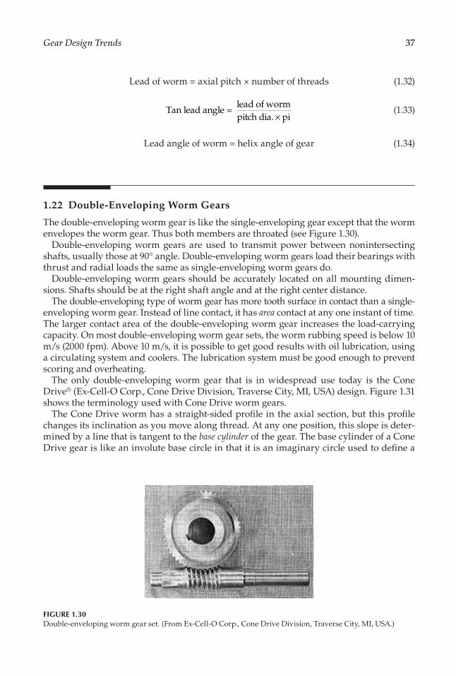
37Gear Design Trends
Lead of worm = axial pitch × number of threads (1.32)
Tan lead angle =lead of wormpitch dia. pi×
(1.33)
Lead angle of worm = helix angle of gear (1.34)
1.22 Double-Enveloping Worm Gears
The double-enveloping worm gear is like the single-enveloping gear except that the worm envelopes the worm gear. Thus both members are throated (see Figure 1.30).
Double-enveloping worm gears are used to transmit power between nonintersecting shafts, usually those at 90° angle. Double-enveloping worm gears load their bearings with thrust and radial loads the same as single-enveloping worm gears do.
Double-enveloping worm gears should be accurately located on all mounting dimen-sions. Shafts should be at the right shaft angle and at the right center distance.
The double-enveloping type of worm gear has more tooth surface in contact than a single-enveloping worm gear. Instead of line contact, it has area contact at any one instant of time. The larger contact area of the double-enveloping worm gear increases the load-carrying capacity. On most double-enveloping worm gear sets, the worm rubbing speed is below 10 m/s (2000 fpm). Above 10 m/s, it is possible to get good results with oil lubrication, using a circulating system and coolers. The lubrication system must be good enough to prevent scoring and overheating.
The only double-enveloping worm gear that is in widespread use today is the Cone Drive® (Ex-Cell-O Corp., Cone Drive Division, Traverse City, MI, USA) design. Figure 1.31 shows the terminology used with Cone Drive worm gears.
The Cone Drive worm has a straight-sided pro�le in the axial section, but this pro�le changes its inclination as you move along thread. At any one position, this slope is deter-mined by a line that is tangent to the base cylinder of the gear. The base cylinder of a Cone Drive gear is like an involute base circle in that it is an imaginary circle used to de�ne a
FIGURE 1.30Double-enveloping worm gear set. (From Ex-Cell-O Corp., Cone Drive Division, Traverse City, MI, USA.)

38 Dudley’s Handbook of Practical Gear Design and Manufacture
pro�le. Geometrically, though, the base circle of a Cone Drive gear is not used in the same way as the base circle of an involute gear.
The size of Cone Drive gear teeth is measured by the circular pitch of the gear.The normal pressure angle is ordinarily 20° to 22°. The Cone Drive worm and gear diam-
eters are not in proportion to the ratio. With low ratios, it is possible (although not recom-mended) to have a worm that is larger than the gear!
Equations 1.30 and 1.31 apply to Cone Drive gears as well as to regular worm gears. The other formulas for single-enveloping worm gears apply only to the center of the Cone Drive worm since it does not have a �xed axial pitch and lead like a cylindrical worm.
In both single-enveloping worm gears and Cone Drive gears, it is generally recom-mended that the worm or pinion diameter be made a function of the center distance. Thus
Pitch dia. of worm =(center distance)
2.2
0.875
(1.35)
Following the recommendation of Equation 1.35 is, of course, not necessary. This formula merely recommends a good proportion of worm to gear diameter for best power capacity. In instrumental and control work, the designer may not be interested in power transmis-sion at all. In such cases, it may be desirable to depart considerably from Equation 1.35 in picking the size of a worm or pinion. In fact, the source shows a whole series of worm diameters for �ne-pitch work that do not agree with Equation 1.35.
Gearface
0.5 Gear face
Gear faceangle
Basecircledia.
CL
Pinion O.D.
Relief
Begin relief
Pinion face
0.5 Pinion face
Pinionthroat dia.
�rustshoulder
90° end
Max. hobrad.
Angularend
Max.hobrad.
Gear widthat O.D.
0.5 Gear widthat O.D.
Gear throatradius
Pinion faceangle
Centerdistance
Gear axis
Gea
r O.D
.
Gea
r thr
oat d
ia.
Pinion axis
FIGURE 1.31Cone Drive worm gear terminology.

39Gear Design Trends
When a worm diameter is picked in accordance with Equation 1.35, the gear diame-ter and the circular pitch may be obtained by working backward through Equation 1.31, Equation 1.30, and Equation 1.29.
The helix angle of a worm gear or a Cone Drive gear may be obtained from the following general formula:
Tan center helix angle of gearpitch dia. of ge= aar
pitch dia. of worm ratio× (1.36)
1.23 Spiroid Gears
The Spiroid® family of gears (Illinois Tool Works Inc., Chicago, IL, USA) operates on nonin-tersecting, nonparallel axes. The most famous family number is called Spiroid. It involves a tapered pinion that somewhat resembles a worm (see Figure 1.32). The gear member is a face gear with teeth curved in a lengthwise direction; the inclination to the tooth is like a helix angle—but not a true helical spiral.
Figure 1.33 shows the schematic relation on the Spiroid type of gear to worm gears, hyp-oid gears, and bevel gears.
The Spiroid family has Helicon® and Planoid® types as well as the Spiroid type. The Helicon is essentially a Spiroid with no taper in the pinion. The Planoid is used for lower ratios than the Spiroid, and its offset is lower—more in the range of the hypoid gear.
The Spiroid pinions may be made by hobbing, milling, rolling, or thread chasing. Spiroid gears are typically made by hobbing, using an especially built (or modi�ed) hob-bing machine and special hobs. The gear may be made with molded or sintered gear teeth using tools (dies or punches) that have teeth resembling hobbed gears. Shaping and mill-ing are not practical to use in making Spiroid gears.
Spiroid gears may be lapped as a �nal �nishing process. Special “shaving” type hobs may also be used in a �nishing operation.
FIGURE 1.32Double-reduction Spiroid linear actuator unit. (From Spiroid Division of Illinois Tool Works Inc., Chicago, IL, USA.)

40 Dudley’s Handbook of Practical Gear Design and Manufacture
Spiroid gears are used in a wide variety of applications, ranging from aerospace actuators to automotive and appliance use. The combination of a high ratio in compact arrangements, low cost when mass produced, and good load-carrying capacity makes the Spiroid-type gear attractive in may situations. The fact that the gearing can be made with lower-cost machine tools and manufacturing processes is also an important consideration.
Pinionmountingdistance
Pinionlength Pinion
O.D.
Gear taperangle
Piniontaperangle
Normal toothpitch
Normaltooththickness
Tipwidth
Addendum
Full depthof tooth
Rootflat
Low-side normalpressure angle
High-side normalpressure angle
Center distance
Pinion taperangle
�readangle
(a)
(b)
Gear I.D.Gear O.D.
FIGURE 1.33Spiroid gear terminology.

References
Appendix A: Evolution of Gear Art
Ball, R. C., Jr. 1963. Newcomen Society Speech.
Buckingham, E. 1922. Involute Spur Gears. New York:Niles-Bement Pond Company.
Buckingham, E. 1931. Dynamic Loads on Gear Teeth. Report ofthe ASME Special Research Committee on the Strength ofGear Teeth. New York: American Society of MechanicalEngineers.
Buckingham, E. 1963. Analytical Mechanics of Gears. NewYork: Dover Publications, Inc.
De Camp, L. S. 1963. The Ancient Engineers. Garden City,NY: Doubleday & Co.
FIGURE A.60
Large gear teeth induction hardened by scanning a tooth ata time with a moving induction coil. (From
Philadelphia Gear Corporation, King of Prussia, PA.)
FIGURE A.61
Induction hardening a large pinion. (From Philadelphia GearCorporation, King of Prussia, PA.)
Dudley, D. W. 1964. Size of gear sets. Product Engineering35(23): 92–102.
Dudley, D. W. 1966. The evolution of the gear art, circa1966. AGMA Paper 990.14 (June).
Dudley, D. W. 1966. The phenomenon growth of aerospace gearart. Power Transmission Design.
Flanders, R. E. 1909. Gear-Cutting Machinery. New York:John Wiley & Sons.
Grant, G. B. 1907. Gear Wheels. Boston, MA: Grant GearWorks.
Manchester, H. H. 1920. Early traces of the toothed wheel.American Machinist 53(25).

Seabrook, J. B., and D. W. Dudley. 1964. Results of a�fteen-year program of �exural fatigue testing of gearteeth. Journal of Engineering for Industry: 221–237.
Smithsonian Institution. 1959. Contributions from theMuseum of History and Technology. Bulletin 218.
Usher, A. P. 1929. A History of Mechanical Inventions.Boston, MA: Beacon Press.
Williams, H. A. 1950. History of power transmission. AGMAPaper 029.02 (June).
Woodbury, R. S. 1959. History of the Gear Cutting Machine.Cambridge: M.I.T. Press. This page intentionally left blank

Appendix D: On the Concept of NovikovGearing and the Inadequacy of the Terms“Wildhaber–Novikov Gearing” and “W–NGearing”
Chironis, N. 1967. New tooth shape taking over? Design ofNovikov gears. Gear Design and Application. Chironis, N.,ed., pp. 124–35. New York: McGraw-Hill Book Company.
Dooner, D. B., and A. A. Seireg. 1995. The KinematicGeometry of Gearing. A Concurrent Engineering Approach.New York: John Wiley & Sons, Inc. 450 p.
Dyson, A., H. P. Evans, and R. W. Snidle. 1986.Wildhaber–Novikov circular arc gears: Geometry andkinematics. Proc R Soc Lond A 403: 313–40.
French, M. J. 1965. Conformity of circular-arc gears.Journal of Mechanical Engineering Science 7(2), 220–223.
Novikov, M. L. 1955. Fundamentals of geometric theory ofpoint meshing for high power density gearing. DoctoralThesis. Moscow: Military Aircraft Engineering Academy(MAEA).
Novikov, M. L. 1957. Gearing and Cam Mechanisms ThatFeature Point Meshing. S.U. Pat. No. 109113. NationalCl. 47b. Filed: April 19, 1956, Published in BI No. 10,1957.
Novikov, M. L. 1958. A Novel System of Gearing. Moscow:Military Aircraft Engineering Academy (MAEA). 186 p.
Pisulin, P. F. 1957. A water sprayer. S.U. Pat. No. 109750.National Cl. 36, d, 28b, 8 01 . Filed: January 2, 1957.
Radzevich, S. P. In press. On the priority of Dr. M.L. Novikov in the development of Novikov gearing. Theory ofMechanisms and Machines, http://tmm.spbstu.ru.
Radzevich, S. P., Theory of Gearing: Kinematics, Geometry,and Synthesis, CRC Press, Boca Raton, Florida, 2012, 743pages.
Wildhaber, E. 1926. Helical gearing. U.S. Pat. No. 1,601,750. Filed: November 2, 1923, Published: October 5,1926.

835
References
Not all of those working in the gear �eld are in agreement on every aspect of designing and building good gears. This book gives the author’s viewpoint, and (of course) the refer-ences given are apt to support the author’s viewpoint. In a number of instances though, the references listed here provide different viewpoints from that of the author. The reader should study this book and other appropriate writings and then make an independent decision on the best course to follow in each situation.
For each reference, the reader will �nd two annotations. The �rst entry is a code that categorizes the reference into one of four groups:
• Code H: A historic paper that provided the �rst* important technical information on some aspect of gear technology.
• Code G: A general reference book, booklet, or paper that provides supplementary data to what is given in this book.
• Code S: A design standard or design guide that may be important in gear design or manufacturing work.
• Code P: A technical paper that provides a viewpoint or speci�c data that is useful as supplemental information to what is given in this book.
Some references are speci�cally cited in the text, while other references provide back-ground material for the text but are not discussed in the text. The second annotation speci-�es which chapter, or chapters, of this text contain material related to the reference.
Source Code Chapter(s)
Ainoura, M. and Younekura, M. 1977. Research on high-speed-precision gear hobbing with the carbide hob and unique high-speed hobbing machine. Presented at the Congrès Mondial Des Engrenages, Paris, France, June 22–24, 1977.
P 8
Akazawa, M., Tejima, T., and Narita, T. 1980. Full scale test of high speed, high powered gear unit—helical gears of 25,000 ps at 200 m/s plv. ASME Paper No. 80-C2/DET-4.
P 5, 9
Alment, J.O. 1941. Facts and fallacies of stress determination. AGMA P225. P 4Alment, J.O. 1948. Surface deterioration of gear teeth, mechanical wear. Proc. MIT Conf., June 1948.
H 9
American Gear Manufacturers Assoc. (AGMA). 1951. Progress report by Automotive Gearing Committee Sec. II, scoring factor (PVT) values of gear teeth, Oct. 1951.
H 4
———. 1974. Design procedure for aircraft engine and power take-off bevel gears. AGMA 411.02.
S 5
———. Rating the strength of spiral bevel gear teeth. AGMA 420.04. S 5———. Rating the strength of spiral bevel gear and Zerol bevel teeth. AGMA 2003-B97. S 5———. Surface durability (pitting) formulas for straight bevel and Zerol bevel gear teeth. AGMA 2003-B97.
S 5
———. Design of general industrial coarse-pitch cylindrical wormgearing. AGMA 6022-C93.
S 5
———. Design of general industrial double-enveloping wormgears. AGMA 6035-A02. S 5
* Concepts of engineering generally evolve from the incomplete to the complete. “First” is used here in a broad sense to denote an early and in�uential publication of a new concept or new technical information.
836 References
———. Gear scoring design guide for aerospace spur and helical power gears. AGMA 2001-D04.
S 4, 5, 11
———. Design procedure for aircraft engine and power take-off spur and helical gears. AGMA 6035-A02.
S 4, 5
———. Rating for the surface durability of spiral bevel gears for enclosed drives. AGMA 420.04.
S 5
———. Surface durability (pitting) of spur, helical, herringbone and bevel gear teeth. AGMA 2001-D04, 908-B89, 2003-B97.
H 4, 5
———. Information sheet for strength of spur, helical, herringbone and bevel gear teeth. AGMA 908-B89.
H 4, 5
———. Surface temper inspection process. AGMA 2007-C00. S 6———. Practice for high-speed helical and herringbone gear units. AGMA 6011-I03. S 5———. Helical and herringbone gearing for rolling mills service. AGMA 6005-B89. S 5———. Design practice for helical and herringbone gears for cylindrical grinding mills, kilns, and dryers. AGMA 6004-F88.
S 5
———. Information sheet, geometry factors for determining the strength of spur, helical, herringbone, and bevel gears. AGMA 908-B89.
S 5
———. Practice for single and double-reduction cylindrical-worm and helical-worm speed reducers. AGMA 6034-A87.
S 5
———. AGMA gear handbook, vol. 1: Gear classi�cation, materials and measuring methods for unassembled gears. AGMA 2000-A88, 2009-B01, 2011-A-98.
S 4, 5, 7
———. Design for �ne-pitch wormgearing. AGMA 374.04. G 5———. Design manual for �ne-pitch gearing. AGMA 917-B97. S 5———. Lubrication of industrial open gearing. AGMA 9005-E02. S 9———. Gear-cutting tools, �ne- and coarse-pitch hobs. S 8———. Practice for enclosed speed reducers or increasers using spur, helical, herringbone and spiral bevel gears. AGMA 6010-F97.
S 5
———. Design guide for vehicle spur and helical gears. AGMA 6002-B93. S 4, 5, 10———. Gear nomenclature (geometry)—terms, de�nitions, symbols, and abbreviations. AGMA 1012-G05.
S 1
———. Information sheet—systems considerations for critical service gear drives. AGMA 6011-H98.
S 9
———. Practice for single, double-, and triple-reduction worm and helical-worm speed reducers. AGMA 6035-A02.
S 5
———. AGMA standard for metric usage. AGMA 904-B89. S 1 to 11———. Nomenclature of gear tooth failure modes. ANSI and AGMA 1010-E95. S 9———. Lubrication of industrial enclosed gear drives. AGMA 9005-E02. S 9———. Rating the pitting resistance and bending strength of spur and helical involute gear teeth. AGMA 2001-D04, 908-B89.
S 4, 5
———. 1964. Nomenclature of Gear-Tooth Wear and Failure: ANSI ASA B6.12-1964, revision of B6.12-1954, UDC 621.83:001.4. AGMA.
S 9
American Society for Metals. 1978. Metals Handbook, Vol. 1: Properties and Selection: Irons and Steels, 9th ed. Metals Park, OH: American Society for Metals.
G 6
American Society of Mechanical Engineers. 1972. Gear Drawing Standards—Part 1 for Spur, Helical, Double Helical and Rack. Y14.7.1. New York: American Society of Mechanical Engineers.
S 4
———. 1972. Gear Drawing Standards—Part 2 for Bevel and Hypoid Gears. Y14.7.2. New York: American Society of Mechanical Engineers.
S 4
———. 1972. Gear Drawing Standards—Part 3 for Crossed Helical, Worm, Spiroid and Helicon Gears. Y14.7.1. New York: American Society of Mechanical Engineers.
S 4
———. 1972. Gear Drawing Standards—Part 4 for Involute Splines. Y14.7.1. New York: American Society of Mechanical Engineers.
S 4

837References
American Petroleum Institute. 1979. Special-Purpose Gear Units for Re�nery Services. American Petroleum Institute.
S 5
Antosiewicz, M. 1981. New techniques for alignment and maintaining large ring gears. AGMA P159.04.
P 9
Archer, C. 1981. Some classi�cation aspects of marine reduction gearing. International Symposium on Gearing and Power Transmissions, Tokyo, Aug. 30 to Sept. 3, 1981, Paper No. d-1.
P 5
Barber-Colman Co. Azumi Skiving Hobs. Rockford, IL: Barber-Colman Co. P 5Barish, T. 1960. How Sliding Affects Life of Rolling Surfaces. Cleveland, OH: Penton Publishing Co.
P 4, 5
Bartz, W.J. 1972. Some investigations of the application of EHD theory to practical gear lubrication. Elastohydrodynamic Lubrication, 1972 Symposium, Sec. I, Mech. E., London, Paper C6/72.
P 4, 5
Benton, M. and Seireg, A. 1980. Factors in�uencing instability and resonance in geared systems. ASME Paper No. 80-C2/DET-8.
P 9
Binder, S. and Mack, J.C. 1980. Experience with advanced high performance gear steel. ASME Paper No. 80-C2/DET-77.
P 6
Bloch, P. 1977. Carbide milling surface hardened gears. Presented at the Congrès Mondial Des Engrenages, Paris, France, June 22–24, 1977.
P 7
———. 1980. Analysis of gear cutting. ASME Paper No. 80-C2/DET-76. P 7, 8Blok, H. 1937. Les Températures de Surface dans les Conditions de Graissage Sous Precision Extreme. 2nd World Petroleum Congress, Paris, 1937.
H 4, 5
Bloom�eld, B. 1947. Designing face gears. Mach Des 19(4): 129–134. H 4, 5Bodensiek, E.J. 1974. A stress-life-reliability rating system for gear and rolling-element bearing compressive stress and gear root bending stress. AGMA P229.19.
P 5
Bohle, R. 1957. Toward more economical gear inspection. AGMA P239.05. P 7Bohle, R. and Saari, O. 1955. Spiroid gears. AGMA P389.01. P 4, 5Boner, C.J. 1964. Gear and Transmission Lubrication. New York: Reinhold Publishing Corp. G 5, 9Borsoff, V.N. 1959. On the mechanism of gear lubrication. J Basic Eng 81(1): 79. P 4, 5———. 1965. Predicting the scoring of gears to establish the limits of load. Mach Des 37: 132. P 4, 5Bosch, M. and Klingelnberg, D. 1977. The Klingelnberg spiral bevel gear system. AGMA P129.23.
P 7
Bowen, C.W. 1977. The practical signi�cance of design of gear pitting fatigue life criteria. Presented at the Sept. 26–30, 1977 meeting in Chicago, Illinois. ASME Paper No. 77-DET-122.
H 4, 5
Breen, D.H. 1974. Fundamental aspects of gear strength requirements. Presented at the AGMA Semi-Annual Meeting in Oak Brook, Illinois, Nov. 3–6, 1974. AGMA 229.17.
P 4, 5
Browlie, K. and Young, I.T. 1969. Research, development and design for marine propulsion geared steam turbines. Presented to the Institution of Mechanical Engineers, London, England.
P 4, 5
Bryant, R.D. and Dudley, D.W. 1960. Which right-angle gear system? Prod Eng (Nov. 7, 1960): 55–6.
P 1
Buckingham, E. 1931. Dynamic loads on gear teeth. Report of the ASME Special Research Committee on the Strength of Gear Teeth, American Society of Mechanical Engineers, New York.
H 4, 11
———. 1949. Analytical Mechanics of Gears. New York: Dover Publications. G 1, 4, 5, 7, 8Candee, A.H. 1941. Geometrical determination of tooth form factor. AGMA P223. H 1, 5———. 1961. Introduction to the Kinematic Geometry of Gear Teeth. Philadelphia: Chilton Company.
G 1, 4, 5
Candee, A.H. and Zamis, A. 1953. Oversize of wormgear hobs. AGMA P129.09. P 8Castelliani, G. 1981. Rating gear life. International Symposium on Gearing and Power Transmission, Tokyo, Aug. 30 to Sept. 3, 1981, Paper No. c-38.
P 5

838 References
———. 1982. 1’IFToMM Gearing Committee e al Riunione di Eindhoven, Organi di Transmissione, Oct. 1982.
P 5
Castelliani, G. and Castelli, V.P. 1980. Rating gear strength. ASME Paper No. 80-C2/DET-88.
P 5
Castellani, G. and Zanotti, V. 1980. La Resistenza Degli Ingranaggi. Milano: Tecniche Nuove.
G 5, 11
Chen, J.H., Juarbe, F.M., and Hanley, M.A. 1980. Factors affecting fatigue strength of nylon gears. ASME Paper No. 80-C2/DET-104.
P 5
Cheng, H.S. and Sternlicht, B. 1965. A numerical solution for the pressure, temperature and �lm thickness between two in�nitely long, lubricated rolling and sliding cylinders under heavy loads. J Basic Eng 87: 695–707.
H 4
Chesters, W.T. 1970. Surface hardening of large gears. J Iron Steel Inst 208: 982. P 6Chironis, N.P., ed. 1967. Gear Design and Applications. New York: McGraw-Hill Book Company.
G 1 to 11
Climax Molybdenum Co. EX Steels. Greenwich, CT: Climax Molybdenum Co. P 6Collins, L.J. 1947. Gears, their application, design and manufacture. AGMA P109.01. P 5, 7———. 1949. Developments in gear design and their lubrication requirements. ASTM Tech Pub 92: 9–13.
P 4, 5
Colvin, F.H. and Stanley, F.A. 1950. Gear Cutting Practice, 3rd ed. New York: McGraw-Hill Book Company.
G 7, 8
Coniglio, J.W. 1982. Economics of CNC gear gashing vs. large D.P. hobbing. Presented at the AGMA Fall Technical Meeting in New Orleans, Louisiana, Oct. 11–13, 1982. AGMA P129.26.
P 7, 8
Coy, J.J., Townsend, D.P., and Zaretsky, E.V. 1975. Dynamic capacity and surface fatigue life for spur and helical gears. ASME Paper No. 75-Lub-19.
P 5
Crook, A.W. 1963. The lubrication of rollers—Part IV. Phil Trans Royal Soc Lond A 255: 281.
H 4
Dawson, P.H. 1962. Effect of metallic contact on the pitting of lubricated rolling surfaces. J Mech Eng Sci 4(1): 16–21.
P 4, 5
Dawson, D. and Higginson, G.R. 1966. Elastohydrodynamic Lubrication. Oxford: Pergamon Press, Ltd.
H 4, 5
DIN. Wälzfräser für Strinrader, DIN 8002, and DIN 3968. S 8DIN. Toleranzen für Strinrädverzahnungen, DIN 3962 and DIN 3963. S 4, 5, 7Dolan, T.J. and Broghammer, E.I. 1942. A photoelastic study of the stresses in gear tooth �llets. Univ Illinois Eng Expt Sta Bull 335.
H 4, 5
Drago, R.J. 1982. An improvement in the conventional analysis of gear tooth bending fatigue strength. AGMA P229.24.
P 4, 5
Drago, R.J. and Brown, F.W. 1980. The analytical and experimental evaluation of resonant response in high-speed, light-weight, highly loaded gearing. ASME Paper No. 80-C2/DET-22.
P 5, 9
Drago, R.J. and Luthans, R.V. 1981. An experimental investigation for the combined effects of rim thickness and pitch diameter on spur gear tooth root and �llet stresses. AGMA P229.22.
P 5
Dudley, D.W. 1948. Graphical determination of gear contact ratios. Prod Eng (March):152–5.
P 5
———. 1949. How to grind medium-pitch gears. Am Mach (March): 94–7. P 7———. 1949. Modi�cation of gear tooth pro�les. Prod Eng 20: 126–31. H 5, 10———. 1950. Estimating the weight of single reduction gear sets. Prod Eng (May): 84–9. H 4———. 1957. How to design involute splines. Prod Eng (Oct): 75. P 4———. 1957. When splines need stress control. Prod Eng (Dec): 56. P 4———, ed. 1962. Gear Handbook. New York: McGraw-Hill Book Co. G 1 to 11

839References
———. 1964. How increased hardness reduces the size of gear sets. Prod Eng (reprinted from the November 9, 1964, issue).
P 5
———. 1964. Successes and failure in space gearing. Presented at the SAE / ASME Air Transport and Space Meeting in New York, April 27–30, 1964.
P 5, 9
———. 1965. Elastohydrodynamic behaviour observed in gear tooth action. Presented to the Institution of Mechanical Engineers, Leeds, England, Sept. 1965.
P 4, 5
———. 1965. How to pick gears for performance. Mech Eng. G 1, 4———. 1969. Proposed application factors for industrial and high speed gearing. Presented at the AGMA Semi-Annual Meeting in Denver, CO, Oct. 26–29, 1969. AGMA 159.02.
G 5
———. 1969. The Evolution of the Gear Art. Washington, D.C.: AGMA. 93 p. P Append. A
———. 1969. The Evolution of the Gear Art. Washington, D.C.: AGMA. H 1, 4———. 1970. The development of long life epicyclic gearing for industrial gas turbines. Presented at the AGMA Semi-Annual Meeting, Oct. 25–28, 1970, St. Louis, MO. AGMA 219.07.
P 5
———. 1972. Vehicle gearing. A panel presentation as part of “The History and Present Status of AGMA Standards.” AGMA P109.31.
P 4, 5
———, ed. 1973. Manual de Engranajes. Mexico: Compania Editorial Continental, S.A. G 1 to 11———. 1974. Design and development of close-coupled, high performance epicyclic gear unit for gas turbines at 4600-HP rating and 10:1 ratio. ASME Paper No. 75-GT-109.
P 5
———. 1975. Load rating practice of carburized and nitrided gears. Presented at the 10th Round Table Conference on Marine Gearing, Brunnen, Switzerland, Sept. 25–26, 1975.
G 6
———. 1977. High speed gear wear and damage. Presented at the 11th Round Table Conference on Marine Gearing, Chatham, MA.
P 5, 9
———. 1977. Load rating of helical gears after wear on the tooth �anks. Presented at the Congrès Mondial Des Engrenages, Paris, France, June 22–24, 1977.
P 5, 9
———. 1978. Characteristics of gear wear. Presented at the World Symposium on Gears and Gear Transmissions, Dubrovnik, Yugoslavia.
G 5, 9
———. 1980. Gear wear. Wear Control Handbook. Peterson, M. and Winer, W., eds. New York: American Society of Mechanical Engineers. p. 755.
G 5, 9
———. 1981. Characteristics of regimes of gear lubrication. International Symposium on Gearing & Power Transmissions, Tokyo, 1981.
G 4, 5, 9
———. 1994. Handbook of Practical Gear Design. Boca Raton FL: CRC Press. P 2, 3Dudley, D.W. and Poritsky, H. 1943. Cutting and hobbing gears and worms. Presented at AGMA Semi-Annual Meeting, Oct. 1943. AGMA P241.
H 7, 8
Dudley, D.W. and Purdy, R.E. 1967. The quest for the ultimate in gear load carrying capacity. Society of Automotive Engineers, Paper No. 670285.
P 5
Dudley, D.W. and Winter, H. 1961. Zahnrader. Berlin: Springer-Verlag. G 1 to 11Dyson, A., Naylor, H., and Wilson, A.R. 1965. The measurement of oil-�lm thickness in
elastohydrodynamic contacts. Elastohydrodynamic lubrication. Mech Eng 180: Part 3B.P 4, 5
Ehrlenspiel, K. 1972. Statistical investigation on high-speed gear failures—Possibilities to reduce failures. ASME Paper No. 72-PTG-32.
P 9
Eler, J. 1966. Cr-Mo and Cr-Mo-V nitriding steels. Met Prog (Dec.): 232. P 6Ernst, C.E., Adair, R.V., and Cox, G.L. 1955. Flame hardened ductile irons. Reprinted
with supplement from Mater Methods (Nov. 1955).P 6
Errichello, R. 1981. An ef�cient algorithm for obtaining the gear strength geometry factor on a programmable calculator. AGMA P139.03.
P 5
Ewert, R.H. 1980. Gearing—Basic Theory and Its Application—A Primer. St. Paul, MN: Sewall Gear Manufacturing Co.
G 1, 4, 5

840 References
Faulstich, H.I. 1977. Actual trend of development and application of large hobbing machines. Presented at the Congrès Mondial Des Engrenages, Paris, France, June 22–24, 1977.
P 7
Fellows Corp. Gear Shaper Cutters. Spring�eld, VT: Fellows Corp. P 8Fowler, T. 1976. Gear lubrication: Relating theory to practice. ASLE Lubr Eng 32(1). P 5, 9Francis, V. and Silvagi, J. 1950. Face gear design factors. Prod Eng (July): 117–21. P 4, 5Frushour, R.H. and Grieb, P.E. 1976. Borazon CDN application technology—Today and tomorrow. Presented at the International Tech. Conference and Exhibition, Abrasive Engineering Society.
P 7, 8
Fujita, K. and Yoshida, A. Surface durability of steel rollers (in the cases of case-hardened and nitrided rollers). Bull JSME 21(154): 761.
P 5, 6
Fujita, K., Yoshida, A., and Akamatsu, K. 1979. A study of strength and failure of induction-hardened chromium-molybdenum steel spur gears. Bull JSME 22(164): 242.
P 5, 6
Fujita, K., Yoshida, A., and Nakase, K. 1979. Surface durability of induction-hardened 0.45 per cent carbon steel and its optimum case depth. Bull JSME 22(169): 994.
P 5, 6
Gates, T.S. and Newman, J.R. 1965. Modern methods of �nishing gears by shaving, honing, and grinding. AGMA P129.16.
P 7
Gauvin, R., Girard, P., and Yelle, Y. 1980. Investigation of the running temperature of plastic/steel gear pairs. ASME Paper No. 80-C2/DET-108.
P 5, 9
Gleason Machine Division. 1980. Straight Bevel Gear Design, Rochester, NY. S 5, 11Gleason Works. 1978. Zerol Bevel Gear System, Rochester, NY. S 5, 11———. 1980. Installation of Bevel Gears. Rochester, NY. P 9———. 1980. Spiral Bevel Gear System, Rochester, NY. S 5, 11Glover, J.H. 1969. How to construct ratio and ef�ciency formulas for planetary gear trains. Presented at AGMA Semi-Annual Meeting, Oct. 26–29, 1969. AGMA 279.01.
P 5
Godfrey, D. 1968. Boundary lubrication. Interdisciplinary approach to friction and wear. NASA SP-181.
P 4, 5
Gowens, B.J.McD. and Porter, F.E. 1970. Naval service experience with surface hardened gears. Proc Inst Mech Engrs 184: Part 3 O, Paper 6.
P 4, 5, 9
Graham, R.C., Olver, A., and Macpherson, P.B. 1980. An investigation into the mechanism of pitting in high-hardness carburized steels. ASME Paper No. 80-C2/DET-118.
P 4, 5, 9
Greening, J.H., Barlow, R.J., and Loveless, W.G. 1980. Load sharing on the teeth of double enveloping worm gears. ASME Paper No. 80-C2/DET-43.
P 5
Haas, L.L. 1980. Latest developments in the manufacture of large spiral bevel and hypoid gears. ASME Paper No. 80-C2/DET-119.
P 7
Haizuka, S., Naruse, C., Nemoto, R., and Nagahama, K. 1981. Studies on limiting load for scoring of crossed helical gears. Bull JSME 24(191): 863.
P 5
Hall, W.F. 1973. Tooth by tooth induction hardening vehicle gearing. Presented at the AGMA Semi-Annual Meeting in New Orleans, LA, Nov. 4–7, 1973. AGMA 109.34.
P 6
Harrison, W.H. 1969–1970. High-speed gears: important features of design and maintenance. Proc Instn Mech Engrs 184: Part 3 O, 68.
P 5, 9
Hartman, M.A. 1962. Fuel additive: A new system and lubricant for rocket engine gearboxes. Lubr Eng (March).
P 5, 9
Henriot, G. 1979. Traité Théorique et Pratique des Engrenages 1. Paris: Dunod. G 1 to 11Henriot, G. 1981. Re�exions on the longitudinal distribution factor KHβ of the I.S.O. procedure. AGMA P209.13.
P 5, 11
Hertz, H. 1881. On the contact of solid elastic bodies and on hardness. J Math 92: 156–71. H 4, 5Hildreth, R.S. 1965. Grinding and honing of gears. AGMA P129.16A. P 7Hirt, M. 1980. German and American quality system of spur, helical and bevel gears—In�uence of gear quality on costs and load capacity. ASME Paper No. 80-C2/DET-18.
P 4, 7

841References
Hirt, M. and Weiss, H. 1981. Increase of load capacity by use of large case-hardened gears. AGMA P219.11.
P 6
Hlebanja, J. Minimale Zähnezahl Bei Doppelseitiger Sondrverzahnungen. Scienti�c Society of Mechanical Engineers, 4th Budapest Conference on Gears.
P 5
Hoffman, B.A. 1982. A comparison of the AGMA and DIN quality systems. AGMA P239.17. P 4, 7Howes, M.A.H. and Sheehan, J.P. 1974. The effect of composition and microstructure on the pitting of carburized steel cases. Society of Automotive Engineers Paper No. 740222.
P 5, 6
Huntress, E.A. 1979. A new way to cut gears. Am Mach (May). P 7, 8Ichimaru, K., Nakajima, A., and Hirano, F. 1980. Effect of asperity interaction on pitting in rollers and gears. ASME Paper No. 80-C2/DET-36.
P 4, 5
Imwalle, D.E. and LaBath, O.A. 1981. Differences between AGMA and ISO rating systems. Presented at the AGMA Semi-Annual Meeting in Toronto, Canada, Oct. 10–14, 1981. AGMA 219.15.
P 5, 11
Imwalle, D.E., LaBath, O.A., and Hutchinson, R.N. 1980. A review of recent gear rating developments ISO/AGMA comparison study. ASME Paper No. 80-C2/DET-25.
P 5, 11
Ishibashi, A. and Hoyashita, S. 1980. Appreciable increase in pitting limit of a through hardened steel. ASME Paper No. 80-C2/DET-28.
P 5
Ishibashi, A. and Tanaka, S. 1980. Effect of hunting gear ratio upon surface durability of gear teeth. ASME Paper No. 80-C2/DET-35.
P 5
ISO/TC 60. 1977. Principles for the Calculation of Load Capacity for Spur and Helical Gears, Part 4, Calculation of Scuf�ng Load Capacity, Nov.
P 4, 5
Jablonowski, J. 1982. Inside Gleason’s new hobber. Am Mach (March): 141. P 7Jones, T.P. 1967. Fifteen years development of high-power epicyclic gears. Trans Inst Marine Engrs 79(8): 273.
P 5
Kelley, B.W. 1952. A new look at the scoring phenomenon of gears. Trans SAE. H 4, 5———. 1974. Gear hob tolerancing system. AGMA P129.19. P 8Kelley, B.W. and Lemanski, A.J. 1967. Lubrication of involute gearing. Conference on Lubrication and Wear, Institute of Mechanical Engineering, London, Sept.
P 5, 9
Khirala, T.W. 1976. On the Geometry of External Involute Spur Gears. North Hollywood: C/I Learning.
G 1, 4, 5
Klimo, V., Pažak, A., and Chrobak, J. 1981. Tribological problems of the mesh of teeth of cylindrical worm gears. International Symposium on Gearing and Power Transmission, Tokyo, Aug. 30 to Sept. 3, 1981, Paper No. a-22.
P 5, 9
Kojima, M. 1977. The geometrical analysis on gear skiving of internal gears. ASME Paper No. 77-DET-133.
P 7, 8
Kojima, M. and Faulstich, H.I. 1980. Computer aided skiving of internal gears. ASME Paper No. 80-C2/DET-72.
P 7, 8
Krishnamurthy, R. and Venkatesh, V.C. 1980. On pitting characteristics of gears. ASME Paper No. 80-C2/DTE-26.
P 4, 5
Kron, H.O. 1977. Gear tooth sub-surface stress analysis. Presented at the Congrès Mondial Des Engrenages, Paris, France, June 22–24, 1977, Paper No. A 10.
H 5
Kubo, A. 1980. On the dynamic factor for gear strength calculation. Kyoto University, Kyoto, Japan, July.
P 5, 11
———. 1981. Estimation of gear performance. International Symposium on Gearing and Gear Transmissions, Tokyo, Aug. 30 to Sept. 3, 1981, Paper No. c-34.
P 9, 10, 11
Kubo, A., Aida, T., and Fukuma, H. 1980. Examination of the dynamic factor Kv for gear strength calculation based on the ISO recommendation ISO TC60/WG6 document 166 and comparison between ISO and AGMA recommendations. Kyoto University, Kyoto, Japan, 1980.
P 5, 11
Kubo, A., Okamoto, T., and Kurokawa, N. 1980. Contact stress between rollers with surface irregularity. ASME Paper No. 80-C2/DET-10.
P 5, 7

842 References
Kuehl, R.J. 1969. Hobbing & Shaping Notes. Rockford, IL: Barber-Colman Co. P 7, 8Kunikazu, H., Aiuchi, S., and Hien, P.V. 1977. Bending fatigue strength of gear teeth under random loading. ASME Paper No. 77-DET-120.
P 5, 10
Kunikazu, H. and Sayama, T. 1962. Load distribution in marine reduction gears. Bull JSME 5(May): 18.
P 5
LaBath, O.A. 1981. Rating trend difference between AGMA and ISO for vehicle gears. Presented at the AGMA Vehicle Gearing Committee Meeting, Rochester, NY, May 5, 1981. AGMA 209.12.
P 11
Laskin, I. 1968. Prediction of gear noise from design data. AGMA P299.03. P 9Leach, E.F. and Kelley, B.W. 1964. Temperature—The key to lubricant capacity. Presented at the ASLE/ASME International Lubrication Conference, Washington, D.C., Oct. 13–16, 1964.
P 5, 9
Lemanski, A.J. 1968. Gear design. Society of Automotive Engineers Paper No. 680381. G 5Lewis, W. 1893. Investigation on the strength of gear teeth. Proc Eng Club Philadelphia: 16–23.
H 4
Leveless, W.G. and Barlow, R.J. 1978. Some applications of advanced instrumentation techniques to double enveloping worm gear testing. Presented at the AGMA Semi-Annual Meeting in Atlanta, GA, Oct. 17, 1978. AGMA 109.40.
P 5, 9
Loy, W.E. 1982. Hard gear processing with azumi skiving hobs. AGMA P129.27. P 8Lutz, C. and Cluff, B.W. 1982. An emerging technology: Form grinding with Borazon. Presented at the SME International Tool & Manufacturing Engineering Conference in Philadelphia, PA, May 19, 1982.
P 7, 8
Lynch, D.W., Snodgrass, T.J., and Woodson, T.T. 1951. Powder metallurgy—A new process for manufacturing gears. AGMA P249.02.
P 6
Lynwander, P. 1981. Gear tooth scoring design considerations. Presented at the AGMA Semi-Annual Meeting in Toronto, Canada, Oct. 12–14, 1981. AGMA P219-10.
P 5, 10
Martinaglia, L. 1972. Thermal behavior of high-speed gears and tooth corrections for such gear. ASME/AGMA International Symposium on Gears & Transmissions, San Francisco, CA, Oct. 11, 1972.
H 5, 9
Maxwell, J.H. 1980. Vibration analysis pinpoints coupling problems. Hydrocarbon Process 59(1): 95–8.
P 9
McCormick, D. 1981. The cost of gear accuracy. Des Eng 52(1): 49. P 9McIntire, W.L., Malott, R.C., and Lyon, T.A. 1967. Bending strength of spur and helical gear teeth. AGMA P229.11.
P 5
Meng, H.R. 1981. On problems of surface pressure in gear load-carrying capacity calculation. International Symposium on Gearing and Power Transmission, Tokyo, Aug. 30 to Sept. 3, 1981, Paper No. b-27.
P 4, 5
Mente, H.-P. 1981. Roughing large gears by form milling or hobbing. Ind Prod Eng 2: 53–61.
P 7
Merritt, H.E. 1965. Contact stress in crossed-axis cylinders and crossed helical gears. The Engineer (March): 543.
P 5
———. 1971. Gear Engineering. London: Pitman Publishing. G 1 to 11Metal Cutting Tool Institute. 1949. Metal Cutting Tool Handbook. New York: Metal Cutting Tool Institute.
G 8
Michalek, K. 1872. Calculation of scoring resistance according to Niemann and Seitzinger for spur and helical gears. ISO 60/6 N126E.
P 4, 5
Milton, R. 1983. Large bearing gears shape up. Mod Mach Shop (Feb.). P 7Mudd, G.C. 1970. A numerical means of predicting the fatigue performance of nitride-hardened gears. Proc Inst Mech Engrs 184: 3 O, Paper 12.
P 5, 6
Mudd, G.C. and Myers, E.J. 1983. Design Considerations in Large Mill Gears. West Yorkshire, England: David Brown Gear Industries Limited.
P 5
———. 1981. Load distribution factors in proposed AGMA and ISO rating procedure. AGMA 219.14.
P 5, 9
843References
Müller, H.W. 1982. Epicyclic Drive Trains. Detroit, Wayne State University Press. G 5Munro, R.G. 1967. Gear transmission error. Presented at the AGMA Aerospace Gearing Committee in Portsmouth, New Hampshire, Aug. 24–25, 1967. AGMA 239.10.
P 7
———. 1968. The interpretation of results from gear measuring instruments. Presented at the British Gear Manufacturers Assoc. Technical Meeting, May 14, 1968.
P 7
Murphy, N. 1975. Diagnosing unsuspected errors in shaved gears. Mach Prod Eng (April).
P 7
Murrell, P.W. 1981. Developments in high powered marine epicyclic gearing 30,000 S.H.P. prototype trials results. International Symposium on Gearing & Power Transmission, Tokyo, 1981.
P 4, 5
Nagano, K. and Ainoura, M. 1980. A research on high speed hobbing with high speed steel hob. ASME Paper No. 80-C2/DET-50.
P 8
———. 1981. The cutting performance of TiN-coated high speed steel hob. International Symposium on Gearing and Power Transmission, Tokyo, Aug. 30 to Sept. 3, 1981, Paper No. a-31.
P 8
Nagorny, G.W. and Stutch�eld, R.A. 1981. Gear noise—The generation of rotational harmonic frequencies in marine propulsion gears. AGMA P2999.06A.
P 9
National Broach and Machine Division/Lear Siegler, Inc. 1972. Modern Methods of Gear Manufacture. Detroit: National Broach and Machine Division/Lear Siegler, Inc.
G 6, 7, 8
Niemann, G., Ratting, H., and Lechner, G. 1962. Some possibilities to increase the load-carrying capacity of gears. Soc. of Automotive Engineers, Paper No. 468A.
P 5
Niemann, G. and Winter, H. 1983. Machinenelemente II. Berlin: Springer-Verlag. G 1 to 11———. 1983. Machinenelemente III. Berlin: Springer-Verlag. G 1 to 11Nityanandan, P.M. 1982. Surface durability of low hardness steel, Gears India. Unpublished paper presented at the IFToMM Gearing Committee Meeting in Eindhoven, Holland, 1982.
P 5
Oda, S. and Shimatomi, J. 1980. Study on bending fatigue strength of helical gears. 1st report, Effect of helix angle on bending fatigue strength. Bull JSME 23(177): Paper No. 177-16.
P 5
Oda, S., Shimatomi, J., and Kawai, N. 1980. Study on bending fatigue strength of helical gears. 2nd report, Bending fatigue strength of casehardened helical gears. Bull JSME 23(177): Paper No. 177-17.
P 5
Oda, S. and Tsubokura, K. 1981. Effects of addendum modi�cation on bending fatigue strength of spur gears. 3rd report, Bending fatigue strength of casehardened helical gears. Bull JSME 24(190): Paper No. 190-15.
P 5
Orcutt, F.K. 1965. Experimental study of elastohydrodynamic lubrication. ASLE Paper presented a the Annual Meeting in Detroit, MI, May 1965.
P 4, 5
Parker, S.C. 1974. Why Borazon? Tool 28(12): 40. P 7Parrish, G. 1980. The In�uence of Microstructure on the Properties of Case-Carburized Components. Metals Park, OH: American Society for Metals.
G 5, 6, 9
Pederson, R. and Rice, R.L. 1961. Case crushing of carburized and hardened gears. Trans SAE: 250.
H 5, 9
Pfenninger, R. and Bartholet, E. 1978. The trend toward gear grinding. Manuf Eng (June).
P 7
Pittion, B. 1977. Problems in induction hardening of gear teeth. Presented at the Congrès Mondial Des Engrenages, Paris, France, June 22–24, 1977.
P 6
Polymer Corp. 1974. Nylatron Nylon Gear Design Manual. Reading, PA: Polymer Corp. P 6Poritsky, H. and Dudley, D.W. 1943. On cutting and hobbing gears and worms. Trans. ASME.
P 7, 8
Poritsky, H. and Dudley, D.W. 1943. On cutting and hobbing gears and worms. Trans. ASME.
G 1, 4
———. 1948. Conjugate action of involute helical gears with parallel or inclined axes. Quar Appl Mech 6(3).
G 1, 4
844 References
Poritsky, H., Sutton, A.D., and Pernick, A. 1945. Distribution of tooth load along a pinion. J Appl Mech 12: A78–6; 13: A246–A249, 1946.
P 5
———. 1946. Distribution of tooth load along a pinion. J Appl Mech 13: A246–9. P 5Radzimovsky, E.I. 1959. How to �nd ef�ciency, speed, and power in planetary gear drives. Mach Des (June): 144.
P 4
Reswick, J.B. 1955. Dynamic loads on spur and helical gear teeth. Trans ASME 77(5): 635.
Rettig, H. and Plewe, H.J. 1977. Lebensdauer und Verschleissverhaltern Langsam Laufender Zahnrader. Antriebstechnik 16(6).
P 4, 5
Rice, C.S. 1977. Gear shaper cutters. AGMA P129.22. P 8———. 1979. Gear production update. Manuf Eng (April). P 7, 8Rieger, N.F. 1968. Gear-excited torsional vibrations of machine drive system. AGMA P109.20.
P 9
Ryder, E.A. 1947. A gear and lubricant tester—Measures tooth strength or surface effects. ASTM Bull 148(Oct.): 69–73.
P 5, 9
Schaffer, G. 1975. Roll-�nishing of large gears. Am Mach (June). P 7, 8Schmidt, G.R., Pinnekamp, W., and Wunder, A. 1980. Optimum tooth pro�le correction on helical gears. ASME Paper No. 80-C2/DET-110.
Scoles, C.A. and Kirk, R. 1969. Gear Metrology. London: Macdonald Technical & Scienti�c.
G 7, 8
Seabrook, J.B. and Dudley, D.W. 1963. Results of a �fteen year program of �exural fatigue testing of gear teeth. Trans ASME.
H 4, 5, 6
Seireg, A. and Conry, T. 1968. Optimum design of gear systems for surface durability. ASLE Trans 11(4): 231.
P 5
Sharma, V.K., Breen, D.H., and Walter, G.H. 1977. An analytical approach for establishing case depth requirements in carburized gears. Presented at the Sept. 26–30, 1977. meeting in Chicago, IL. ASME Paper 77-DET-152.
H 5
Sheehan, J.P. and Howes, M.A.H. 1973. The role of surface �nish in pitting fatigue of carburized steel. Society of Automotive Engineers, Paper No. 730580.
P 5
Shipley, E. 1969. Gear failure. Mach Des 39(28): 152. P 9———. 1973. Failure modes of gears. ASME paper presented at the forum on Gear Manufacture and Performance, Detroit, MI, Oct. 1973.
P 9
———. 1982. Failure analysis of coarse-pitch, hardened and ground gears. Presented at the AGMA Fall Technical Meeting in New Orleans, LA, Oct. 11–13, 1982. AGMA P229.26.
Shotter, B.A. 1958. Experiments with a disc machine to determine the in�uence of surface �nish on gear performance. International Conference on Gearing, London.
P 5, 7
———. 1978. Scuf�ng and pitting, recent observations modify the traditional concepts. World Symposium on Gears and Gear Transmissions, Dubrovnik, Yugoslavia.
P 5
Siebert, C.A., Doane, D.V., and Breen, D.H. 1977. The Hardenability of Steels. Metals Park, OH: American Society for Metals.
G 6
Sigg, H. 1965. Pro�le and longitudinal corrections on involute gears. Presented at the AGMA Semi-Annual Meeting in Chicago, IL, Oct. 24–27, 1965. AGMA 109.16.
P 11
Smith, J.O. 1942. The effect of range of stress on the fatigue strength of metals. Univ Illinois Eng Exp Stn Bull 334.
H 4, 5
Smith, J.O. and Liu, C.K. 1953. Stresses due to tangential and normal loads on an elastic solid with applications to some contact stress problems. J Appl Mech (June): 157.
H 4, 5
Society of Automotive Engineers. 1973. Premium Aircraft-Quality Steel Cleanliness, Aerospace Material Speci�cation AMS 2300B.
S 4, 5, 6
———. 1974. Premium Aircraft-Quality Steel Cleanliness, Aerospace Material Speci�cation AMS 2301E.
S 4, 5, 6
Srikanthan, G. 1981. Synthesis of tooth pro�les for helical gears. International Symposium on Gearing & Power Transmissions, Tokyo.
P 5

845References
Stauffer, R.N. 1982. Gleason’s new gear hobber advances spur and helical gear machining. Manuf Eng (May): 91.
P 7
Stolzle, K., Winter, H., Henriot, G., and Wellauer, E.J. 1970. German, French and AGMA gear rating practices. AGMA P229.15.
P 5
Taber, D.S., Edwards, D.J., Giammaria, J.J., and Commichau, A. 1970. A look to the future in industrial gear lubricants. AGMA P254.30.
P 9
Tarasov, L.P. 1948. Some factors in�uencing the quality of ground gears and worms. AGMA P109.02.
P 7
Terauchi, Y., Nadano, H., and Nohara, M. 1980. Effect of tooth pro�le modi�cation on scoring resistance of spur gears. ASME Paper No. 80-C2/DTE-19.
P 5, 10
Tersch, R.W. 1970. Finishing gear teeth by roll-forming process. SME Paper No. MF70-263.
P 7, 8
The International Nickel Company. 1965. Nickel Alloy Steels Data Book, 3rd ed. New York: The International Nickel Company.
G 6
Theberge, J.E., Arkles, B., Cloud, P.J., and Goodhue, R. 1973. Gear and bearing designs with lubricate and reinforced thermoplastics. 28th Annual Technical Conference of the Society of Plastic Industry, Inc.
P 5, 6, 9
Thoma, F.A. 1965. The load distribution factors as applied to high speed and wide face helical gears. AGMA P229.10.
P 5
———. 1977. Pitting can be caused by inadequate lubrication. Presented at the Sept. 26–30, 1977, meeting in Chicago, IL. ASME Paper 77-DET-122.
P 5, 9
Thomson, A.M. 1980. Testing of �ne pitch gears—Single �ank testing, double �ank testing. Soc. of Manufacturing Engineers, Paper No. IQ80-920.
P 7
Timken Company. 1983. Practical Data for Metallurgists. Canton, OH: Timken Company. G 6Tobe, T. and Inoue, K. 1980. Longitudinal distribution factor for straddle- and overhang-mounted spur gears. ASME Paper No. 80-C2/DET-45.
P 5
Tordion, G.V. 1963. The mechanical impedance approach to the dynamics (torsional vibrations) of geared systems. AGMA P209.04.
P 9
Townsend, D.P. 1971. Lubrication considerations in gear design. Presented at the AGMA meeting in New Orleans, LA, on Feb. 11–12, 1971.
P 4, 5, 9
———. 1992. Dudley’s Gear Handbook. The Design, Manufacture, and Application of Gears. 2nd Edition. New York: McGraw Hill, Inc. 1111 p.
P 1, 4–12
Townsend, D.P. and Akin, L.S. 1980. Analytical and experimental spur gear tooth temperature as affected by operating variables. ASME Paper No. 80-C2/DET-34.
P 5, 9
Townsend, D.P. and Zaretsky, E.V. 1977. Endurance and failure characteristics on modi�ed VASCO X-2, CBS 600 and AISI 9310 spur gears. NASA Lewis Research Center, Cleveland, OH.
P 6
Trapp, H.-J. 1981. Quality achievements in spiral bevel gears by the HPG-method. AGMA P239.16.
G 7
Triemel, J. 1973. Grinding with cubic boron nitride. 14th International Machine Tool Design & Research Conference (MTDC), Manchester, England, Sept. 1973.
P 7
Tucker, A. 1971. Dynamic loads on gear teeth design applications. ASME Paper 71-DE-1. P 5, 11———. 1977. Bevel gears at 203 meters per second (40,000 FPM). ASME Paper No.
77-DET-178.P 5, 9
———. 1980. The gear design process. ASME Paper No. 80-C2/DET-13. P 1, 4Tuplin, W.A. 1953. Dynamic loads on gear teeth. Mach Des 25(Oct.). P 4, 5, 11———. 1962. Gear Design. New York: Industrial Press. G 1 to 11Ueno, T., Ariura, Y., and Nakanishi, T. 1980. Surface durability of case carburized
gears—On a phenomenon of “grey-staining” on tooth surfaces. Presented at the ASME meeting Aug. 18–21, 1980, San Francisco, CA.
P 5, 9
Ueno, T., Terashima, K., and Hidaka, K. 1977. On the corner wear of hob teeth. Presented at the Congrès Mondial Des Engrenages, Paris, France, June 22–24, 1977.
P 8

846 References
Volcy, G.C. 1977. Deterioration of marine gear teeth. Presented at the Congrès Mondial Des Engrenages, Paris, France, June 22–24, 1977.
P 5
———. 1981. Gearing damages and ship structure �exibility. International Symposium on Gearing and Power Transmissions, Tokyo, Aug. 30 to Sept. 3, 1981, Paper No. d-2.
P 9
Wadhwa, S.K. 1964. Computed geometry factor for hobbed spur gears. AGMA P229.08. H 5Walker, H. 1938. Gear tooth de�ection and pro�le modi�cation. Engineer 166: 409–12, 434–6; 170: 102–104, 1940.
H 5, 10
———. 1940. Gear tooth de�ection and pro�le modi�cation. Engineer 170: 102–4. H 5, 10Walter, G.H. 1974. Computer oriented gear steel design procedure. Presented at the AGMA Semi-Annual Meeting in Oak Brook, IL, Nov. 3–6, 1974. AGMA 109.35.
P 6
Way, S. 1935. Pitting due to rolling contact. Trans ASME 57: A49–58. H 4———. 1939. How to reduce surface fatigue. Mach Des 11(March): 42–5. P 4, 5Wellauer, E. and Holloway, G. 1975. Application of EHD oil �lm theory to industrial gear drives. ASLE/ASME Paper No. 75-PTG-1.
P 5, 9
Wente, D.E. 1972. Rear axle noise quality test stand. AGMA P299.05. P 9Wilcox, L.E. 1982. A new method for analyzing gear tooth stress as a function of tooth contact pattern shape and position. AGMA P229.25.
P 5
Willis, R.J. 1963. Lightest-weight gears. Prod Eng ( Jan.). H 4, 5Wiln, J.E. and Love, R.J. 1970. Proportions of automobile change speed gear teeth. Motor Industry Research Assoc., Report No. 1970/7.
G 4, 5, 6
Winter, H. 1982. Calculation of slow speed wear of lubricated gears. AGMA P219.16. P 5Winter, H. and Kojima, M. 1981. A study on the dynamics of geared system—estimation of overload on gears in system. International Symposium on Gearing & Power Transmissions, Tokyo.
P 5, 9, 11
Winter, H. and Weiss, T. 1980. Some factors in�uencing the pitting, micro-pitting (frosted areas) and slow speed wear of surface hardened gears. ASME Paper No. 80-C2/DET-89.
G 4, 5, 9
Winter, H. and Wilkesmann, H. 1980. Calculation of cylindrical worm gear drives of different tooth pro�les. ASME Paper No. 80-C2/DET-23.
P 5, 8
Winter, H. and Wirth, X. 1977. The effect of notches at the tooth root �llet on the endurance strength of gears. ASME Paper No. 77-DET-54.
H 5
Yelle, H. and Burns, D.J. 1980. Calculation of contact ratios for plastic/plastic or plastic/steel spur gear pairs. ASME Paper No.80-C2/DET-105.
P 5
———. 1981. Root bending fatigue strength of acetal spur gears—A design approach to allow for load sharing. AGMA 149.01.
P 5, 6
Yonekura, M. and Ainoura, M. 1980. A research on �nishing hardened gears of large modulus. ASME Paper No. 80-C2/DET62.
P 8
Young, I.T. 1980. A wider scope for nitrided gears. ASME Paper No. 80-C2/DET-46. P 5, 6Yu, D. 1981. The optimizing programming design of the KHV planetary gear driving. International Symposium on Gearing & Power Transmissions, Tokyo.
P 5
Yuruzume, I. and Mizutani, H. 1980. Bending fatigue tests of high speed spur gears. ASME Paper No. 80-C2/DET-87.
P 4, 5
Zamis, A. 1947. Equations for the normal pro�le of helical gears. Am Mach (Sept.): 82–4. P 8Zaretsky, E.V. and Anderson, W.J. 1968. How to use what we know about EHD lubrication. Mach Des 40(26): 167.
P 4, 5, 9
Zrodowski, J.J. and Dudley, D.W. 1950. Modern marine gears. Trans SNAME 58: 788–814.
P 5, 9
Zrodowski, J.J. and Moncrieff, A.D.F. 1953. Advanced precision shaving techniques applied to high speed marine gears. Trans SNAME 61.
P 7, 8

K12940 Cover 3/5/12 11:47 AM Page 1
H a n d b o o k o f
Practical GearDesign and
Manufacture
Dudley’sS e c o n d E d i t i o n
Stephen P. RadzevichStephen P. Radzevich
H a n d b o o k o f
Practical GearDesign and
Manufacture
Dudley’sS e c o n d E d i t i o n
Stephen P. Radzevich
SecondEdition
Ha
nd
bo
ok
o
f
Pr
ac
tic
al G
ear
Desig
n a
nd
Ma
nu
fac
tu
re
Du
dle
y’s
Radzevich
A unique, single-source reference for all aspects of gears, Dudley's Handbookof Practical Gear Design and Manufacture, Second Edition provides
comprehensive and consistent information on the design and manufacture
of gears for the expert and novice alike. The second edition of this industry
standard boasts seven new chapters and appendices as well as a wealth of
updates throughout. New chapters and expanded topics include: Gear Types
and Nomenclature, Gear Tooth Design, Gear Reactions and Mountings,
Gear Vibration, The Evolution of the Gear Art, Novikov Gearing and the
Inadequacy of the Term, and thoroughly referenced Numerical Data Tables.
FEATURES
• Offers a single-source reference for all aspects of the gear industry
• Presents a comprehensive and self-consistent collection of knowledge,
practical methods, and numerical tables
• Discusses optimal design and manufacture of gears of all known designs
for the needs of all industries
• Explains concepts in accessible language and with a logical organization,
making it simple to use even by beginners in the field
• Provides adequate recommendations for gear practitioners in all areas
of gear design, production, inspection, and application
• Includes practical examples of successful use of tools covered in the
Handbook
Logically organized and easily understood, the Handbook requires only a
limited knowledge of mathematics for adequate application to almost any
situation or question. Whether you are a high-volume gear manufacturer or
a relatively small factory, the Handbook and some basic common sense
can direct the sophisticated design of any type of gear, from the selection
of appropriate material, production of gear blanks, cutting gear teeth,
advanced methods of heat treatment, and gear inspection. No other sources
of information are necessary for the gear designer or
manufacturer once they have the Handbook.
Mechanical Engineering
K12940
6000 Broken Sound Parkway, NWSuite 300, Boca Raton, FL 33487711 Third AvenueNew York, NY 100172 Park Square, Milton ParkAbingdon, Oxon OX14 4RN, UK
an informa business