MEMS-BASED 3D CONFOCAL SCANNING MICROENDOSCOPE USING MEMS SCANNERS FOR BOTH LATERAL AND AXIAL SCAN

Computers and Structures xxx (2013) xxx–xxx
Contents lists available at SciVerse ScienceDirect
Computers and Structures
journal homepage: www.elsevier .com/locate /compstruc
Domain decomposition and model order reduction methods appliedto the simulation of multi-physics problems in MEMS
0045-7949/$ - see front matter � 2012 Elsevier Ltd. All rights reserved.http://dx.doi.org/10.1016/j.compstruc.2012.12.012
⇑ Corresponding author. Tel.: +39 0223994244; fax: +39 0223994220.E-mail addresses: [email protected] (A. Corigliano), dossi@stru.
polimi.it (M. Dossi), [email protected] (S. Mariani).
Please cite this article in press as: Corigliano A et al. Domain decomposition and model order reduction methods applied to the simulation of multi-problems in MEMS. Comput Struct (2013), http://dx.doi.org/10.1016/j.compstruc.2012.12.012
Alberto Corigliano ⇑, Martino Dossi, Stefano MarianiPolitecnico di Milano, Dipartimento di Ingegneria Strutturale, Piazza L. da Vinci 32, 20133 Milano, Italy
a r t i c l e i n f o a b s t r a c t
Article history:Available online xxxx
Keywords:MEMSElectro-mechanical problemFinite element methodDomain decompositionProper orthogonal decomposition
Coupled electro-mechanical problems are frequently encountered when dealing with micro electro-mechanical systems (MEMS) with capacitive actuation and/or readout systems; their numerical solutioncan be extremely time consuming, due to the nonlinearity of the coupling terms. Coupled electrostatic –structural dynamic simulations are carried out in this paper through an innovative numerical procedure,based on the combined use of a domain decomposition technique and of a proper orthogonal decompo-sition methodology. The approach is assessed through the analysis of the dynamic response of a doublyclamped beam and of a plane resonator subjected to an electrostatic actuation, showing computationalgains up to 98%.
� 2012 Elsevier Ltd. All rights reserved.
1. Introduction
Design and reliability assessment of Micro Electro MechanicalSystems (MEMS, see e.g. [1,2]) is more and more based on realisticsimulations of complicate multi-physics processes. Many differentphysics are intrinsically coupled in MEMS and it is often impossibleto rely only on simplified, fully decoupled simulations. The increas-ing popularity of MEMS, the necessity to improve their design andto reduce the time to market has forced many researchers and soft-ware companies to produce dedicated methods and codes applica-ble to the solution of typical multi-physics problems in MEMS likee.g. the electro-mechanical, the thermo-mechanical, the magneto-mechanical ones.
The electro-mechanical coupling is of particular interest sincethe interaction between the electrostatic field and the structuralparts is often exploited as sensing or actuation principle, and musttherefore be taken into account. In the case of the electro-elasticproblem, the double coupling arises from the fact that the mechan-ical domain is subjected to the electrostatic forces and from thefact that the deformation of the structural parts changes the shapeof the electrostatic domain, affecting the solution of the electro-static stationary problem. Even assuming a linear elastic behaviorfor the mechanical part, the overall coupled problem is non linear.The study of the response of vibrating structures under the effect ofelectrostatic loading is a typical example of electro-mechanicalproblems often encountered in MEMS design.
Various approaches have been proposed for the solution of cou-pled electro-mechanical problems. We mention here [3] where astaggered iterative procedure was proposed, [4] where a mono-lithic approach was developed, and other contributions specificallyfocused on MEMS applications [5,6]. In [7], two algorithms basedon the use of domain decomposition techniques (see e.g. [8,9])for the solution of electro-mechanical multi-physics problemshave been proposed, which allow for an interesting reduction ofthe computational time.
The purpose of the present paper is to further contribute to theimprovement of computational procedures for the solution ofmulti-physics problems in MEMS and in particular to drasticallyreduce the computing time for the solution of the coupled elec-tro-mechanical problem. The main novelty here concerns the cou-pled use of a domain decomposition methodology and a modelorder reduction based on the use of reduced basis obtained withthe Proper Orthogonal Decomposition (POD) technique (see[10,11]). POD approaches have recently gained popularity and havebeen successfully applied in various problems [12–14]; they usu-ally allow for a drastic reduction of computing time, and deserveparticular attention when applied to the study of nonlinear andirreversible phenomena.
The paper is organized as follows. In Section 2 the formulationof the coupled electro-mechanical problem is discussed togetherwith the relevant finite element formulation. Section 3 is devotedto a brief description of one of the domain decomposition ap-proaches proposed in [7] and also used in this paper. A briefdescription of the adopted POD method is given in Section 4.Numerical examples are presented and discussed in Section 5,while closing remarks are given in Section 6.
physics
2 A. Corigliano et al. / Computers and Structures xxx (2013) xxx–xxx
A matrix notation will be adopted throughout the whole paper;a superposed dot will denote time differentiation, whereas a super-script T will stand for transpose.
2. Formulation of the electro-mechanical problem
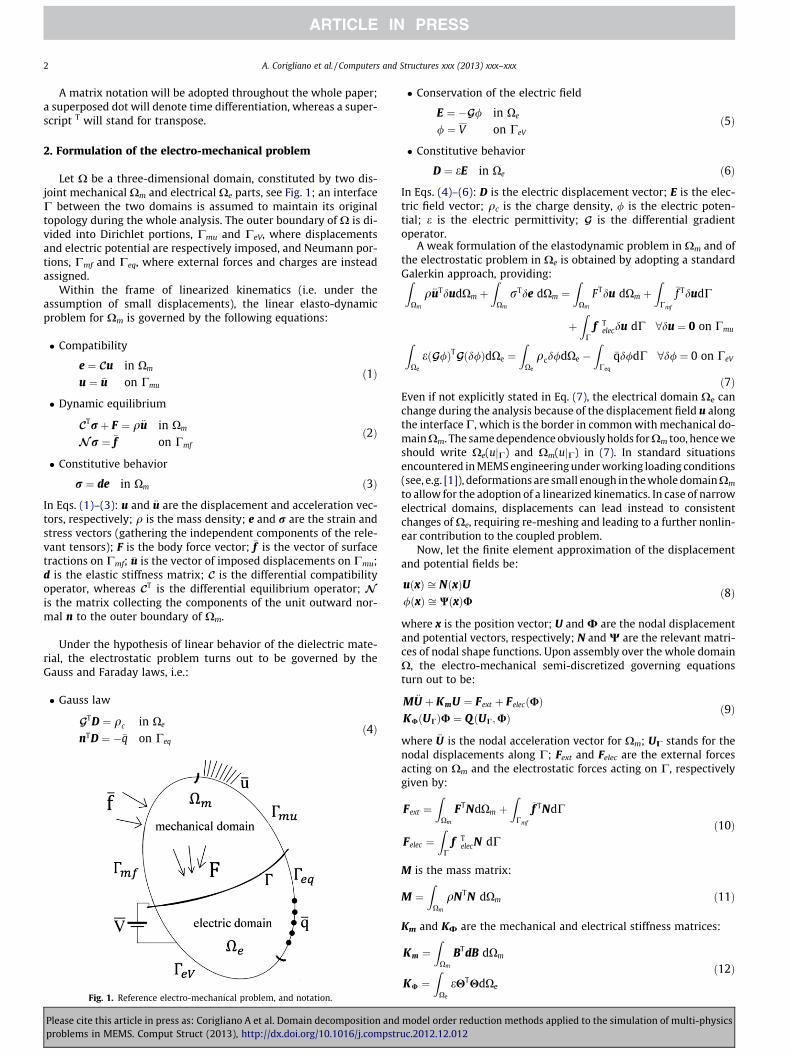
Let X be a three-dimensional domain, constituted by two dis-joint mechanical Xm and electrical Xe parts, see Fig. 1; an interfaceC between the two domains is assumed to maintain its originaltopology during the whole analysis. The outer boundary of X is di-vided into Dirichlet portions, Cmu and CeV, where displacementsand electric potential are respectively imposed, and Neumann por-tions, Cmf and Ceq, where external forces and charges are insteadassigned.
Within the frame of linearized kinematics (i.e. under theassumption of small displacements), the linear elasto-dynamicproblem for Xm is governed by the following equations:
� Compatibility
Pleaseproble
e ¼ Cu in Xm
u ¼ �u on Cmuð1Þ
� Dynamic equilibrium
CTrþ F ¼ q€u in Xm
Nr ¼ �f on Cmf
ð2Þ
� Constitutive behavior
r ¼ de in Xm ð3Þ
In Eqs. (1)–(3): u and €u are the displacement and acceleration vec-tors, respectively; q is the mass density; e and r are the strain andstress vectors (gathering the independent components of the rele-vant tensors); F is the body force vector; �f is the vector of surfacetractions on Cmf; �u is the vector of imposed displacements on Cmu;d is the elastic stiffness matrix; C is the differential compatibilityoperator, whereas CT is the differential equilibrium operator; N
is the matrix collecting the components of the unit outward nor-mal n to the outer boundary of Xm.
Under the hypothesis of linear behavior of the dielectric mate-rial, the electrostatic problem turns out to be governed by theGauss and Faraday laws, i.e.:
� Gauss law
GTD ¼ qc in Xe
nTD ¼ ��q on Ceqð4Þ
Fig. 1. Reference electro-mechanical problem, and notation.
cite this article in press as: Corigliano A et al. Domain decomposition andms in MEMS. Comput Struct (2013), http://dx.doi.org/10.1016/j.compstr
� Conservation of the electric field
modeluc.2012
E ¼ �G/ in Xe
/ ¼ V on CeVð5Þ
� Constitutive behavior
D ¼ eE in Xe ð6Þ
In Eqs. (4)–(6): D is the electric displacement vector; E is the elec-tric field vector; qc is the charge density, / is the electric poten-tial; e is the electric permittivity; G is the differential gradientoperator.
A weak formulation of the elastodynamic problem in Xm and ofthe electrostatic problem in Xe is obtained by adopting a standardGalerkin approach, providing:Z
Xm
q€uTdudXm þZ
Xm
rTde dXm ¼Z
Xm
FTdu dXm þZ
Cmf
�f TdudC
þZ
Cf T
elecdu dC 8du ¼ 0 on CmuZXe
eðG/ÞTGðd/ÞdXe ¼Z
Xe
qcd/dXe �Z
Ceq
�qd/dC 8d/ ¼ 0 on CeV
ð7ÞEven if not explicitly stated in Eq. (7), the electrical domain Xe canchange during the analysis because of the displacement field u alongthe interface C, which is the border in common with mechanical do-mainXm. The same dependence obviously holds for Xm too, hence weshould write Xe(ujC) and Xm(ujC) in (7). In standard situationsencountered in MEMS engineering under working loading conditions(see, e.g. [1]), deformations are small enough in the whole domainXm
to allow for the adoption of a linearized kinematics. In case of narrowelectrical domains, displacements can lead instead to consistentchanges of Xe, requiring re-meshing and leading to a further nonlin-ear contribution to the coupled problem.
Now, let the finite element approximation of the displacementand potential fields be:
uðxÞ ffi NðxÞU/ðxÞ ffi WðxÞU
ð8Þ
where x is the position vector; U and U are the nodal displacementand potential vectors, respectively; N and W are the relevant matri-ces of nodal shape functions. Upon assembly over the whole domainX, the electro-mechanical semi-discretized governing equationsturn out to be:
M €U þ KmU ¼ Fext þ FelecðUÞKUðUCÞU ¼ QðUC;UÞ
ð9Þ
where €U is the nodal acceleration vector for Xm; UC stands for thenodal displacements along C; Fext and Felec are the external forcesacting on Xm and the electrostatic forces acting on C, respectivelygiven by:
Fext ¼Z
Xm
FTNdXm þZ
Cmf
�f TNdC
Felec ¼Z
Cf T
elecN dCð10Þ
M is the mass matrix:
M ¼Z
Xm
qNTN dXm ð11Þ
Km and KU are the mechanical and electrical stiffness matrices:
Km ¼Z
Xm
BTdB dXm
KU ¼Z
Xe
eHTHdXe
ð12Þ
order reduction methods applied to the simulation of multi-physics.12.012

A. Corigliano et al. / Computers and Structures xxx (2013) xxx–xxx 3
being B ¼ CN and H ¼ GW; Q is the electrostatic loading term onXe:
Q ¼Z
Xe
qcW dXe �Z
Ceq
�qW dC ð13Þ
We recall that Xe = Xe(ujC) in Eqs. (12) and (13).Since the constitutive responses of the two domains are not
affected by the solution, we refer to Eq. (9) as the weakly-coupled formulation. Anyway, the solution is said to be stronglycoupled even in the presence of disjoint domains Xm and Xe,since once a potential difference is imposed, an electrical fielddevelops causing electrical forces to act on C; the deformingmechanical domain therefore changes its shape, and the shapeof the electrical domain too. The driving terms of the interactionbetween the two domains are given by the forces Felec, which arecomputed as the rate of change of the electrostatic energy due toa virtual variation of C (see [7,15]), and by the dependence of theelectrical solution on the shape of the domain and, therefore, onUC. An additional source of coupling here stems from the depen-dency of the electrostatic forces on the accumulated chargeson C.
3. A domain decomposition technique for coupled electro-mechanical problems
According to the domain decomposition technique formulatedin [9,16] for dynamic problems and reformulated for the solutionof the electro-mechanical problem in [7], X is partitioned intonon overlapping sub-domains. Each sub-domain is handled as anindependent body, loaded by external and interface forces (the lat-ter ones needed to restore the continuity of the whole domain) andexperiencing a motion constrained by the boundary conditions act-ing on its edges. Time stepping is then decomposed into threephases: a free problem, corresponding to the motion of each uncon-nected sub-domain, subjected only to the external loads and freefrom interface interactions; an interface problem, in which theinterface electrostatic forces are evaluated; a link problem, in whichthe interface forces are applied to the sub-domains to account forthe interactions among contiguous ones. In this last stage, the cou-pling between the mechanical and electrical fields is considered,
Fig. 2. Doubly clamped beam subjected to time-invariant single a
Table 1Values of physical properties adopted in the simulations.
Property Symbol Value Units
Structure Young’s modulus E 1011 Pa
Mass density q 2330 kg/m3
Poisson’s ratio m 0.3 –
Air gap Electric permittivity e 8.854 � 1012 C2/(Nm3)
Please cite this article in press as: Corigliano A et al. Domain decomposition andproblems in MEMS. Comput Struct (2013), http://dx.doi.org/10.1016/j.compstr
and the displacements computed during the free problem stageare corrected to account for such coupling. The degree of nonlin-earity arising from the electro-mechanical coupling (see Section 2)therefore depends on the amplitude of displacements (hence, onthe deformation of the mechanical part) computed in the freeproblem stage.
With the algorithm here adopted, proposed in [7] and theretermed single-level decomposition (SD), the mechanical and theelectrical domains are not further decomposed; hence, we allowfor the multi-physics of the problem at hand to automatically de-fine the topology of the relevant decomposition. Within the de-scribed frame, the mechanical and electrical fields are split intotwo contributions, respectively called free and link. At time instanttn, such splitting of displacement, acceleration and potential vec-tors reads:
Un ¼ Ufreen þ U link
n
€Un ¼ €Ufreen þ €U link
n
Un ¼ Ufreen þUlink
n
ð14Þ
As for the mechanical domain, the interface forces are representedby the electrostatic term along C. Hence, the free problem givesthe dynamics of the body subjected to the external loads, whereasthe link problem provides the corrective terms for the motion ofthe same body under the vector of the electrostatic forces. Accord-ingly, the dynamics of Xm is decomposed as:
� Free problem
ctuatio
modeluc.2012
M €Ufree þ KmUfree ¼ Fext ð15Þ
� Link problem
M €U link þ KmU link ¼ Felec ð16Þ
As for the electrical domain, coupling stems from the change inthe domain shape due to the deformation of Xm. The free problemis therefore related to the undeformed domain, whereas the linkproblem provides the corrective terms due to the varied geometryof Xe. As a consequence, the matrix KU and the charge vector Q inEq. (9)2 are decomposed as:
ðK0 þ DKUðUCÞÞðUfree þUlinkÞ ¼ Q 0 þ DQðUC;UÞ ð17Þ
where K0 and Q0 are the initial values (at t = t0) of KU and Q, i.e.:
K0 ¼Z
Xe jt¼t0
eHTHdXe
Q 0 ¼Z
Xe jt¼t0
qcW dXe �Z
Ceq jt¼t0
�qW dCð18Þ
n: (a) system geometry, and (b) space discretization.
order reduction methods applied to the simulation of multi-physics.12.012

Fig. 3. Doubly clamped beam subjected to time-invariant single actuation: deflection of the symmetry beam cross-section (node 1 in Fig. 2(a)). Comparison between thereference solution obtained with a staggered approach, and outcomes of the proposed methodology.
Table 2Doubly clamped beam subjected to time-invariant single actuation: run times.
Total time Snapshots/Base generation Reduction system Error w.r.t. stag Gain w.r.t. stag. (%)
S (ttot = 5 � 10�6) 37,356 – – – –
SD (ttot = 5 � 10�6) 35374 - - 2,42 � 10�7 �5, 3S-POD (tsnap = 5 � 10�7) 3621 3620, 0 1, 0 3, 0 � 10�3 �90, 3SD-POD (tsnap = 5 � 10�7) 3410 3409, 0 1, 0 3, 0 � 10�3 �90, 9S-POD (tsnap = 2, 5 � 10�7) 2094 2093, 0 1,0 3, 3 � 10�3 �94, 4SD-POD (tsnap = 2, 5 � 10�7) 1806 1805, 0 1, 0 3, 3 � 10�3 �95, 2SD-PODupdated 567 566, 1 0, 9 7, 3 � 10�3 �98, 5
Fig. 4. Doubly clamped beam subjected to time-invariant single actuation: comparison of run times.
4 A. Corigliano et al. / Computers and Structures xxx (2013) xxx–xxx
Please cite this article in press as: Corigliano A et al. Domain decomposition and model order reduction methods applied to the simulation of multi-physicsproblems in MEMS. Comput Struct (2013), http://dx.doi.org/10.1016/j.compstruc.2012.12.012

Fig. 5. Doubly clamped beam subjected to time-varying single actuation (VM = 30 V): deflection of the symmetry beam cross-section (node 1 in Fig. 2(a)). Comparisonbetween the reference solution obtained with a staggered approach, and outcomes of the proposed methodology.
Table 3Doubly clamped beam subjected to time-varying single actuation (VM = 30 V): run times.
Total time Snapshots/Base generation Reduction system Error w.r.t. stag. Gain w.r.t. stag. (%)
S (ttot = 4 � 10�5) 10,647 – – – –SD (ttot = 4 � 10�5) 9382 – – 9, 65 10�11 �11, 9S-POD (tsnap = 5 � 10�6) 1693 1375 318 7, 26 10�4 �84, 1SD-POD (tsnap = 5 � 10�6) 1582 1265 317 7, 26 10�4 �85, 1S-POD (tsnap = 2, 5 � 10�6) 1023 685 338 1, 2 10�3 �90, 4SD-POD (tsnap = 2, 5 � 10�6) 949 612 337 1, 2 10�3 �91, 1S-PODupdated 480 111 369 8, 05 10�4 �95, 5SD-PODupdated 394 96 298 8, 05 10�4 �96, 3
Fig. 6. Doubly clamped beam subjected to time-varying single actuation (VM = 30 V): comparison of run times.
A. Corigliano et al. / Computers and Structures xxx (2013) xxx–xxx 5
Please cite this article in press as: Corigliano A et al. Domain decomposition and model order reduction methods applied to the simulation of multi-physicsproblems in MEMS. Comput Struct (2013), http://dx.doi.org/10.1016/j.compstruc.2012.12.012

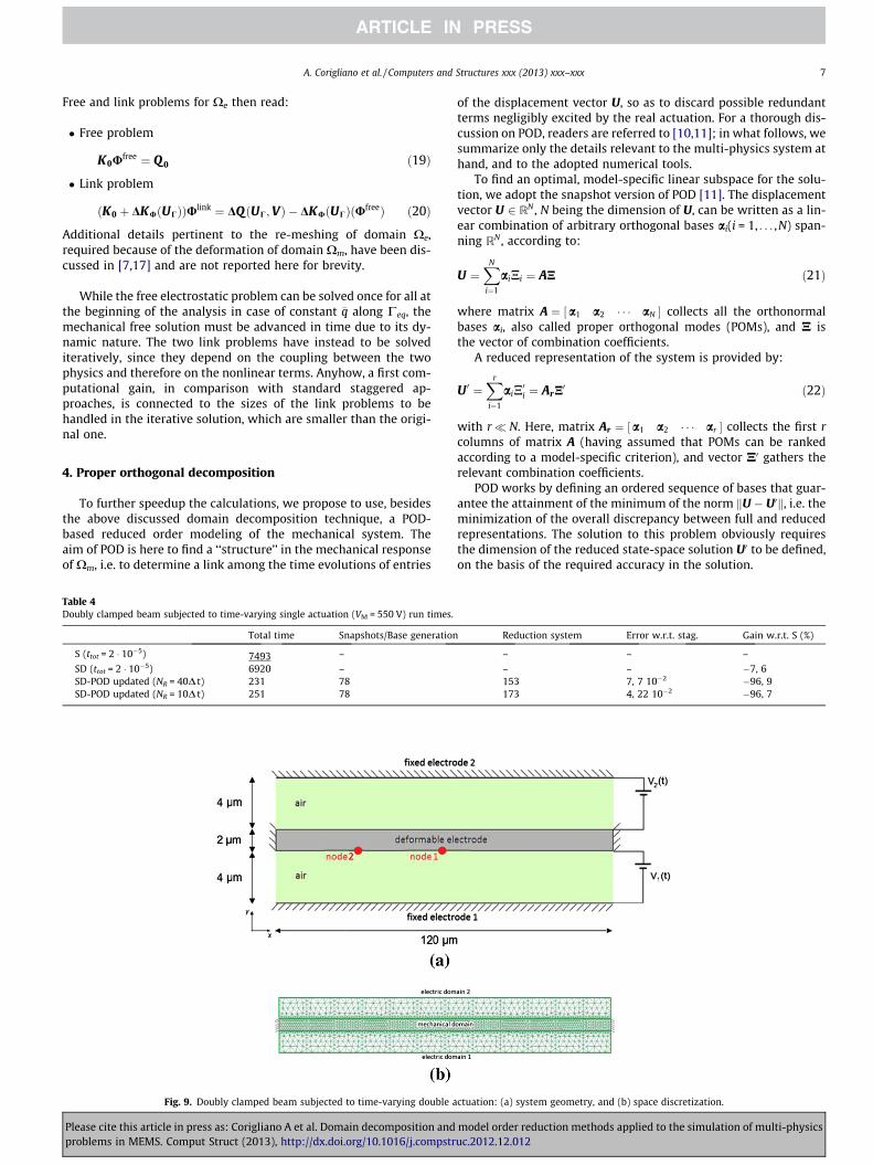
Fig. 7. Doubly clamped beam subjected to time-varying single actuation (VM = 550 V): comparison between the solutions obtained with the staggered approach and theproposed methodology, in terms of electric potential in Xe and deformed shape of the beam (grey region) at t = 2 � 10�6 s.
Fig. 8. Doubly clamped beam subjected to time-varying single actuation (VM = 550 V): deflection (a) of the symmetry beam cross-section (node 1 in Fig. 2(a)), and (b) of thequarter-point beam cross-section (node 2 in Fig. 2(a)). Comparison between the reference solution obtained with a staggered approach, and outcomes of the proposedmethodology.
6 A. Corigliano et al. / Computers and Structures xxx (2013) xxx–xxx
Please cite this article in press as: Corigliano A et al. Domain decomposition and model order reduction methods applied to the simulation of multi-physicsproblems in MEMS. Comput Struct (2013), http://dx.doi.org/10.1016/j.compstruc.2012.12.012
A. Corigliano et al. / Computers and Structures xxx (2013) xxx–xxx 7
Free and link problems for Xe then read:
� Free problem
Table 4Doubly
S (tto
SD (tSD-PSD-P
Pleaseproble
K0Ufree ¼ Q 0 ð19Þ
� Link problem
ðK0 þ DKUðUCÞÞUlink ¼ DQðUC;VÞ � DKUðUCÞðUfreeÞ ð20Þ
Additional details pertinent to the re-meshing of domain Xe,required because of the deformation of domain Xm, have been dis-cussed in [7,17] and are not reported here for brevity.
While the free electrostatic problem can be solved once for all atthe beginning of the analysis in case of constant �q along Ceq, themechanical free solution must be advanced in time due to its dy-namic nature. The two link problems have instead to be solvediteratively, since they depend on the coupling between the twophysics and therefore on the nonlinear terms. Anyhow, a first com-putational gain, in comparison with standard staggered ap-proaches, is connected to the sizes of the link problems to behandled in the iterative solution, which are smaller than the origi-nal one.
4. Proper orthogonal decomposition
To further speedup the calculations, we propose to use, besidesthe above discussed domain decomposition technique, a POD-based reduced order modeling of the mechanical system. Theaim of POD is here to find a ‘‘structure’’ in the mechanical responseof Xm, i.e. to determine a link among the time evolutions of entries
clamped beam subjected to time-varying single actuation (VM = 550 V) run times.
Total time Snapshots/Base generation
t = 2 � 10�5) 7493 –
tot = 2 � 10�5) 6920 –OD updated (NR = 40D t) 231 78OD updated (NR = 10D t) 251 78
Fig. 9. Doubly clamped beam subjected to time-varying double a
cite this article in press as: Corigliano A et al. Domain decomposition andms in MEMS. Comput Struct (2013), http://dx.doi.org/10.1016/j.compstr
of the displacement vector U, so as to discard possible redundantterms negligibly excited by the real actuation. For a thorough dis-cussion on POD, readers are referred to [10,11]; in what follows, wesummarize only the details relevant to the multi-physics system athand, and to the adopted numerical tools.
To find an optimal, model-specific linear subspace for the solu-tion, we adopt the snapshot version of POD [11]. The displacementvector U 2 RN , N being the dimension of U, can be written as a lin-ear combination of arbitrary orthogonal bases ai(i = 1, . . . ,N) span-ning RN , according to:
U ¼XN
i¼1
aiNi ¼ AN ð21Þ
where matrix A ¼ a1 a2 � � � aN½ � collects all the orthonormalbases ai, also called proper orthogonal modes (POMs), and N isthe vector of combination coefficients.
A reduced representation of the system is provided by:
U 0 ¼Xr
i¼1
aiN0i ¼ ArN
0 ð22Þ
with r� N. Here, matrix Ar ¼ a1 a2 � � � ar½ � collects the first rcolumns of matrix A (having assumed that POMs can be rankedaccording to a model-specific criterion), and vector N0 gathers therelevant combination coefficients.
POD works by defining an ordered sequence of bases that guar-antee the attainment of the minimum of the norm kU � U0k, i.e. theminimization of the overall discrepancy between full and reducedrepresentations. The solution to this problem obviously requiresthe dimension of the reduced state-space solution U0 to be defined,on the basis of the required accuracy in the solution.
Reduction system Error w.r.t. stag. Gain w.r.t. S (%)
– – –
– – �7, 6153 7, 7 10�2 �96, 9173 4, 22 10�2 �96, 7
ctuation: (a) system geometry, and (b) space discretization.
model order reduction methods applied to the simulation of multi-physicsuc.2012.12.012
8 A. Corigliano et al. / Computers and Structures xxx (2013) xxx–xxx
POD, in its snapshot version, requires an initial training stage;during this training stage, snapshots (i.e. the response of the sys-tem to the actual excitation at a certain amount of time instants)are collected into the matrix S, according to:
S ¼ U1 U2 � � � Unsnap
� �ð23Þ
where, as said, Ui = U(ti) is the solution at time ti in terms of nodaldisplacements. The snapshot matrix S is thereafter factorized via asingular value decomposition (SVD) procedure, to give:
S ¼ L K RT ð24Þ
where L and R are orthogonal matrices, and K is a pseudo-diagonalone. Matrix L gathers the so-called left singular vectors, whereas Rcollects the right ones. Pivotal entries of K are called singular val-ues, and are non-negative; if they are placed in descending order,and the columns or rows of L and R are accordingly arranged, amethod to sort POMs is obtained. In fact, matrix L was shown in[11,18,19] to collect POMs.
In order to set the number of POMs to furnish as much insightas possible into the original multi-physics system, we adopt a stan-dard energy-like criterion centered around the singular values of
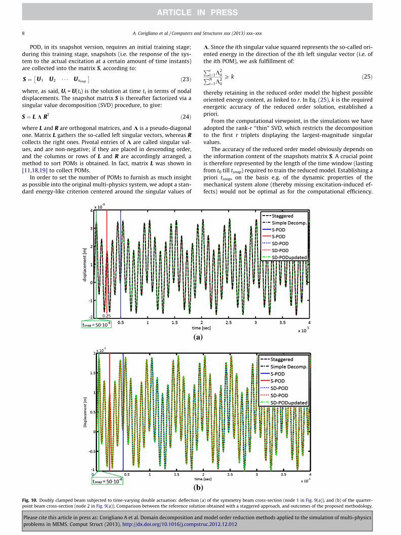
Fig. 10. Doubly clamped beam subjected to time-varying double actuation: deflection (point beam cross-section (node 2 in Fig. 9(a)). Comparison between the reference solutio
Please cite this article in press as: Corigliano A et al. Domain decomposition andproblems in MEMS. Comput Struct (2013), http://dx.doi.org/10.1016/j.compstr
K. Since the ith singular value squared represents the so-called ori-ented energy in the direction of the ith left singular vector (i.e. ofthe ith POM), we ask fulfillment of:Pr
i¼1K2iiPN
i¼1K2ii
P k ð25Þ
thereby retaining in the reduced order model the highest possibleoriented energy content, as linked to r. In Eq. (25), k is the requiredenergetic accuracy of the reduced order solution, established apriori.
From the computational viewpoint, in the simulations we haveadopted the rank-r ‘‘thin’’ SVD, which restricts the decompositionto the first r triplets displaying the largest-magnitude singularvalues.
The accuracy of the reduced order model obviously depends onthe information content of the snapshots matrix S. A crucial pointis therefore represented by the length of the time window (lastingfrom t0 till tsnap) required to train the reduced model. Establishing apriori tsnap, on the basis e.g. of the dynamic properties of themechanical system alone (thereby missing excitation-induced ef-fects) would not be optimal as for the computational efficiency.
a) of the symmetry beam cross-section (node 1 in Fig. 9(a)), and (b) of the quarter-n obtained with a staggered approach, and outcomes of the proposed methodology.
model order reduction methods applied to the simulation of multi-physicsuc.2012.12.012

A. Corigliano et al. / Computers and Structures xxx (2013) xxx–xxx 9
An alternative procedure here adopted, called SVD update [20–22]provides on-the-fly updates of POMs and relevant oriented ener-gies as soon as a new snapshot is collected; the update is stoppedonce convergence is attained. Specifically, in our problem we needa rank-1 update of the SVD, moving from S = LKRT toS þ abT ¼ bL bK bRT, where: bL; bK and bR are the updated singular va-lue matrices; vector a contains the snapshot update; b is a binaryvector, stating which column of S is modified by the newly avail-able snapshot. Practically, to update the SVD when snapshotUnsnapþ1 becomes available, we append a row of zeros to R and weadopt b ¼ 0 0 � � � 1½ �, so as the algorithmic procedure allowsto move from S 0½ � ¼ L K½RT 0 � to ½ S Unsnapþ1 � ¼ bL bK bRT. It isworth noting that the SVD update speedups the calculations, sincea large amount of matrix operations involves array whose maindimension is nsnap+1; on the other hand, a standard SVD algorithmattacks the problem by handling matrices whose main dimensionis N. Such details, and the computation of bL; bK and bR are describedin [20–22]; readers are referred to these papers for all the details.
Convergence is assumed to be attained when:
rtsnapþ1 ¼ rtsnapPrnsnapþ1i¼1
K2iiPN
i¼1K2
ii
� �tsnapþ1
6
Prnsnapi¼1
K2iiPN
i¼1K2
ii
� �tsnap
ð26Þ
i.e. when the estimates of the number of POMs to be retained in thereduced order model, and of the relevant oriented energy contentare not increased by the new snapshot collected at time tsnap+1.
Fig. 11. Doubly clamped beam subjected to time-var
Table 5Doubly clamped beam subjected to time-varying double actuation: run times.
Total time Snapshots/Base generation
S (ttot = 4 � 10�5) 12,867 –
SD (ttot = 4 � 10�5) 9811 –S-POD (tsnap = 5 � 10�6) 1643 1308SD-POD (tsnap = 5 � 10�6) 1600 1282S-POD (tsnap = 2, 5 � 10�6) 1048 690SD-POD (tsnap = 2, 5 � 10�6) 979 640SD-PODupdated 419 131
Please cite this article in press as: Corigliano A et al. Domain decomposition andproblems in MEMS. Comput Struct (2013), http://dx.doi.org/10.1016/j.compstr
Once the reduction matrix Ar (see Eq. (22)) has converged to astationary value, the dynamics of the mechanical system is pro-jected onto the obtained sub-space spanned by the POMs through:
€U � Ar €N0
U � ArN0
UC � Ar jCN0ð27Þ
where we have accounted for the fact that Ar defines the space var-iation only of displacement and acceleration fields. Hence, the pro-jected semi-discretized system evolution equations read:
MAr €N0 þ KmArN0 � Fext þ FelecðUÞ
KUðAr jCN0ÞU � QðArjCN0;UÞð28Þ
As far as the dynamic equilibrium equations are concerned, theapproximation (27) introduces unbalances; by enforcing the result-ing residuals to be orthogonal to the sub-space spanned by POMs,through a Galerkin projection we obtain:
ATr MAr €N0 þ AT
r KmArN0 ¼ AT
r Fext þ ATr FelecðUÞ ð29Þ
Eventually, defining reduced order mass and mechanical stiffnessmatrices according to Mr ¼ AT
r MAr and Kmr ¼ ATr KmAr , we arrive
at the following reduced-order solving system:
Mr €N0 þ KmrN0 ¼ Fr;ext þ Fr;elecðUÞ
KUðAr jCN0ÞU � QðArjCN0;UÞð30Þ
where Fr;ext ¼ ATr Fext and Fr;elec ¼ AT
r Felec.
ying double actuation: comparison of run times.
Reduction system Error w.r.t. stag. Gain w.r.t. stag. (%)
– – –
– 3, 43 10�9 �23, 8335 4, 59 � 10�2 �87, 2318 4, 59 � 10�2 �87, 6358 5, 08 � 10�2 �91, 9339 5, 09 � 10�2 �92, 4288 5, 55 10�2 �96, 7
model order reduction methods applied to the simulation of multi-physicsuc.2012.12.012

10 A. Corigliano et al. / Computers and Structures xxx (2013) xxx–xxx
5. Numerical examples
The proposed numerical approach has been implemented in aresearch-oriented Matlab code. The simulations discussed in whatfollows have been run on a PC featuring an Intel (R) Core™ i7–2600CPU @ 3.4 GHz, with a 64 bit operating system.
In all the simulations analyzes, the mechanical equations of mo-tion have been advanced in time with the Newmark average accel-eration, implicit time integration, adopting a time step sizeDt = 10�9–10�8 s. Concerning POD, we have always adoptedk > 0.9996 to ensure high accuracy of the algorithm. When thestandard SVD has been used in the training stage, 15 snapshotswere collected for the doubly clamped beam and up to around40 snapshots were collected for the plane resonator; when the
Fig. 12. Doubly clamped beam subjected to time-varying single actuation, undergoing st(node 1 in Fig. 2(a)), and (b) of the quarter-point beam cross-section (node 2 in Fig. 2(a)). Coutcomes of the proposed methodology.
Please cite this article in press as: Corigliano A et al. Domain decomposition andproblems in MEMS. Comput Struct (2013), http://dx.doi.org/10.1016/j.compstr
SVD update has been instead adopted, one snapshot was collectedevery 10 time steps, till convergence.
5.1. Doubly clamped beam with single actuation
To start assessing the performance of the method, in terms ofcomputational gain (or speedup) and accuracy with respect to arather standard staggered approach [3], a doubly clamped slenderbeam subjected to an electrostatic actuation has been considered.Under plane strain conditions, the geometry of the beam is fullycharacterized by a span length of 120 lm and a width of 2lm.Having resonating MEMS structures as a target, the beam is as-sumed to be made of single-crystal silicon, whose physical proper-ties are reported in Table 1; allowing for the diamond-like, FCC
iffness reduction at t = 2 � 10�5 s: deflection (a) of the symmetry beam cross-sectionomparison between the reference solution obtained with a staggered approach, and
model order reduction methods applied to the simulation of multi-physicsuc.2012.12.012

A. Corigliano et al. / Computers and Structures xxx (2013) xxx–xxx 11
crystal lattice of silicon, the values of Young’s modulus and Pois-son’s ratio there reported can be considered representative of its[1 0 0] orientation.
The beam shares with the air (electrical domain) its bottom sideonly. Air fills the whole gap between the beam and the fixed elec-trode, representing the substrate. On the vertical sides of the elec-trical domain, Neumann conditions of zero charge are applied. Thepermittivity e of the air has been assumed to be equal to the vac-uum one, see Table 1.
The geometry of the system is depicted in Fig. 2, along with theadopted finite element discretization. Both the beam and the airgap have been meshed with linear triangular elements; themechanical domain has been discretized with 1631 elements(leading to 1944 degrees of freedom), whereas the electrical onehas been discretized with 3386 elements (resulting in 3714 de-grees of freedom).
As reported in Fig. 2(a), the beam is dynamically excited by anelectrostatic actuation provided by a potential difference V = 30 V(representing an Heaviside step function variation of V for t > 0).Such actuation, to be considered as a first benchmarking example,induces very small vibrations of the beam, that negligibly deformthe electrical domain; hence, deviation from linearity is marginalin this case.
Fig. 3 shows the evolution in time of the deflection of the sym-metry cross-section of the beam, i.e. of the vertical displacement ofnode 1 in Fig. 2(a). In the graph, results are collected as provided bythe reference staggered procedure (denoted as S), by a single-level(or simple) domain decomposition (SD), by merging POD reducedorder modeling to both the aforementioned approaches (with re-sults respectively denoted as S-POD and SD-POD in the legend)at varying duration tsnap of the training stage (tsnap being reportedin the plot through vertical lines featuring the same color of thecurve of displacement evolution), and by the offered procedurewhich merges SD and POD with an SVD update. A noteworthy goodagreement among all the outcomes of the enlisted algorithms canbe observed. As expected, the duration tsnap of the time window togenerate the POMs is minimum in the case of SVD update, even if 7POMs are retained by all the reduced order models. Table 2 shows
Table 6Doubly clamped beam subjected to time-varying single actuation, undergoingstiffness reduction at t = 2 � 10�5 s: run times.
Total time Error w.r.t. stag. Gain w.r.t. stag. (%)
S (ttot = 4 � 10�5) 12494 – –
SD (ttot = 4 � 10�5) 9709 7, 25 � 10�11 �22, 3S-POD updated 563 8, 20 10�4 �95, 5SD-POD updated 531 7, 85 10�4 �95, 7
Fig. 13. Plane resonator: (a) schematic and (b) SEM image o
Please cite this article in press as: Corigliano A et al. Domain decomposition andproblems in MEMS. Comput Struct (2013), http://dx.doi.org/10.1016/j.compstr
the relevant results in terms of cumulative discrepancy with re-spect to the staggered solution, of run time required to generatethe reduced sub-space and the POMs, of run time to evolve the re-duced model, and of computational gain (i.e. of reduction of theoverall run time) with respect to the staggered solution. This lastdatum is also shown in the bar charts of Fig. 4, where the tremen-dous gain offered by the use of POD can be neatly appreciated. Asfar as the speedup is concerned, it can be seen that POD alwaysguarantees a computational gain of at least 90%, with a peak valueof 98.5% if the SVD update is adopted.
To prove the overall efficiency of the algorithm, we now con-sider the beam subjected to a sinusoidal variation of the potentialdifference V(t), with maximum amplitude VM = 30 V and naturalperiod TV = 10�5 s. Fig. 5 provides the relevant time evolution ofthe central deflection of the beam: as for the previous analysis,the solutions obtained with the staggered procedure (S) and thesimple domain decomposition (Simple Decomp.), also when com-bined with POD (respectively denoted in the graph as S-POD andSD-POD), and with the proposed procedure which merges SD andPOD with an SVD update are all perfectly overlapping the referenceone. This is also testified by the results reported in Table 3 in termsof cumulative error with respect to the staggered solution, all inthe order of 10�3ku � ustagk/kustagk, ustag being the reference dis-placement values obtained with the staggered approach.
Since POD automatically retains 2–3 POMs in the reducedmodels (depending on tsnap and on whether the SVD update isplugged in), a computational gain amounting to 85–96% is at-tained: this is also graphically reported in Fig. 6. As comparedto the previous case (see Fig. 4), reduced system evolution repre-sents a by far greater portion of the total run time: this is causedby the time-evolving V(t), which requires the potential distribu-tion in the electrical domain to be re-calculated at each timeinstant.
Results are next investigated by increasing the maximumamplitude of the sinusoidal potential difference V(t) toVM = 550 V; such peak value is close to the dynamic pull-in one,which amounts to about 570 V for this configuration. Because ofthe deformation of the electrical domain, as depicted in Fig. 7 attime t = 2 � 10�6 s, the electro-mechanical coupling leads to severenonlinearities in the solution; since the pull-in value representsthe upper bound on the actuation voltage, a higher degree of non-linearity cannot be attained when the dynamics of the beam isstudied. Fig. 8 provides the results of the simulations, once againin terms of time evolution of the deflection of the beam: all thesimulations here shown lead to the same period of oscillations,but a drift in the maximum values can be observed. This discrep-ancy is due to the strong nonlinearity of the electro-mechanicalcoupling near pull-in; to speedup the POD-based simulations, wehave updated the shape of the electrical domain, and thereby
f the microsystem, as reported in [26] (� [2004] IEEE).
model order reduction methods applied to the simulation of multi-physicsuc.2012.12.012

12 A. Corigliano et al. / Computers and Structures xxx (2013) xxx–xxx
re-meshed it, every NR time steps (NR = 10, 40 in the graph).Table 4 shows that the computational gain, amounting to about97%, is not affected much by the re-meshing stage, whereas theoverall error with respect to the reference solution is doubled byincreasing NR from 10 to 40. This is clearly shown graphically inFig. 8.
Fig. 14. Plane resonator subjected to time-in
Fig. 15. Plane resonator subjected to time-invariant actuation: vertical displacement atstaggered approach, and outcomes of the proposed methodology.
Table 7Plane resonator subjected to time-invariant actuation: run times.
Total time Error w.
S (ttot = 10�6) 24370 –S-POD (tsnap = 3 � 10�7) 7121 8,32 10�
SD-POD (tsnap = 3 � 10�7) 5587 7,02 10�
S-POD (tsnap = 2 � 10�7) 4705 8,33 10�
SD-POD (tsnap = 2 � 10�7) 3793 8,32 10�
S-POD (tsnap = 1, 5 � 10�7) 3639 7,25 10�
SD-POD (tsnap = 1, 5 � 10�7) 2826 5,86 10�
SD-PODupdated 2664 9, 98 10
Please cite this article in press as: Corigliano A et al. Domain decomposition andproblems in MEMS. Comput Struct (2013), http://dx.doi.org/10.1016/j.compstr
To check the capability of the reduced order solutions to cap-ture not only the amplitude of the beam deflection but also the de-formed shape of the beam induced by the voltage, results arereported in Fig. 8 in terms of displacements of the central cross-section (node 1 in Fig. 2(a)) and of the quarter-point cross-section(node 2 in Fig. 2(a)). This comparison provides additional insights,
variant actuation: space discretization.
node A (see Fig. 14). Comparison between the reference solution obtained with a
r.t. stag. Gain w.r.t. stag. (%) n� snapshots
– –2 �70, 8 352 �77, 1 352 �80, 7 382 �84, 4 382 �85, 1 342 �88, 4 34�2 �89, 1 31
model order reduction methods applied to the simulation of multi-physicsuc.2012.12.012
A. Corigliano et al. / Computers and Structures xxx (2013) xxx–xxx 13
since the beam does not vibrate according to its first mode, otherwise apurely sinusoidal time evolution of the displacements would be ob-tained and only 1 POM would be retained in the POD-based numericalsolutions. The same level of accuracy shown by displacements at nodes1 and 2 (and also at all the other nodes in the mechanical domain, notreported here for brevity) testifies that the offered procedure wellmatches the time evolution and the space variation of the field.
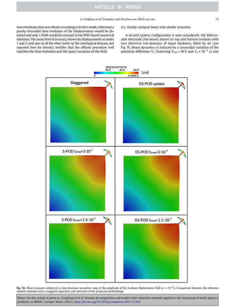
Fig. 16. Plane resonator subjected to time-invariant actuation: map of the amplitude osolution obtained with a staggered approach, and outcomes of the proposed methodolo
Please cite this article in press as: Corigliano A et al. Domain decomposition andproblems in MEMS. Comput Struct (2013), http://dx.doi.org/10.1016/j.compstr
5.2. Doubly clamped beam with double actuation
A second system configuration is now considered: the deform-able electrode (the beam) shares its top and bottom surfaces withtwo electrical sub-domains of equal thickness, filled by air (seeFig. 9). Beam dynamics is induced by a sinusoidal variation of thepotential difference V1 (featuring V1M = 30 V and TV = 10�5 s) and
f the in-plane displacement field at t = 10�6 s. Comparison between the referencegy.
model order reduction methods applied to the simulation of multi-physicsuc.2012.12.012

14 A. Corigliano et al. / Computers and Structures xxx (2013) xxx–xxx
a constant V2 = 30 V (once again representing an Heaviside stepfunction for t > 0). The adopted mesh is shown in Fig. 9(b).
Fig. 10 collects the outcomes of the simulations as for beamdeflection at the central and quarter-point cross-sections: due tothe small amplitude of V1 and V2, nonlinear effects do not have aremarkable impact on the system response, and all the plots lookperfectly superposed at both sections. This can be also appreciatedby considering the overall error values reported in Table 5, whichdo not change much if POD is used in combination with SD oralone. As before, the main effect of POD is instead seen on the com-putational gain, which approaches 97% if the SVD update (whosesmaller tsnap is reported in green inside Fig. 10) is adopted. Gainsare also shown graphically in Fig. 11, to further understand theclear impact of POD on the analysis run time.
5.3. Doubly clamped beam with damage
In this last example relevant to the vibrating beam, we considerthe same geometry and single actuation conditions of Section 5.1(see Fig. 2), but assume that a damage process induces an instan-taneous reduction by 40% of the Young’s modulus in the middlethird of the beam. This reduction has been assumed to take placeat t = 2 � 10�5 s, whereas the total duration of the analysis ist = 4 � 10�5 s.
Fig. 12 shows the evolution of the beam deflection, once againat the central and quarter-point cross-sections, as provided bythe staggered and SD solution procedures and by coupling themto the POD algorithm featuring the SVD update. The shaded regionsin the graph at the beginning of the analysis, and just after the sud-den change of the Young’s modulus in the central portion of thebeam represent the required POD training stages. Since the re-sponse of the beam to the actuation is changed by the reducedbeam characteristics, the collection of snapshots needs in fact tobe re-started at t = 2 � 10�5 s, up to convergence of the new reducedorder model according to conditions (26). The effect of damage istestified in the plot by the increased amplitude of vibrations inthe second half of the analysis; anyway, as for the previous caseswith low actuation voltages, the accuracy of the reduced modelsis so high (see also Table 6) that plots cannot be discerned.
The damaged system dynamics turns out to be accurately de-scribed by 5 POMs only, leading once again to a computational gainof about 96%.
Start collecting new snapshots when damage suddenly occursat t = 2 � 10�5 s represents a drawback of the proposed procedurein case of degrading mechanical properties, since the re-trainingstage is triggered by the damage itself. Aiming to provide a meth-odology not requiring in advance the knowledge of the damageinception time, an observation of system dynamics looks neces-sary. Focussing on purely mechanical systems, in [14] a procedureof this kind was proposed, centred around a rather standard Kal-man filter [23–25]. Such filter was designed to observe possibledrifts of the system dynamics with respect to a reference solutionrelevant to the undamaged structure; once the filter recognizes amismatch (discernible from measurement noise) in the observedstate of the system due to damage, a re-training stage is triggeredor the reduced order sub-space provided by POD is tuned. Theimplementation of a similar procedure for the coupled electro-mechanical problem here considered is beyond the scope of thepresent investigation, and is therefore left for future activities.
5.4. Plane resonator
We move now to a more complicate two-dimensional geometryby considering the MEMS resonator proposed in [26] and depictedin Fig. 13, see also [27]. The movable part of this microsystem isconstituted by a square plate (whose size is 320 320 10 lm),
Please cite this article in press as: Corigliano A et al. Domain decomposition andproblems in MEMS. Comput Struct (2013), http://dx.doi.org/10.1016/j.compstr
connected to the substrate at the corners through four T-shapedsupport beams. Plate and beams are made of single-crystal silicon;accounting for the crystal lattice orientation described in [26], wehave approximately assumed the vibrating structure to be made ofan isotropic material whose mechanical properties are the same ofthe previously studied beam, see Table 1.
The resonator is actuated by four electrodes placed along theedges of the plate (and colored in white in Fig. 13(b)). The actua-tion gives rise to a so-called bulk acoustic vibration mode, mainlycharacterized by the square plate zooming in and out whilepreserving its shape, to be contrasted to standard Lamé-type vibra-tions that instead preserve the plate volume. This shape-preservingvibration mode holds true if the actuation is constant along thewhole length of the plate edges; because of the actual geometry re-ported in the SEM image of Fig. 13(b), an in-plane bending of theplate edges is instead expected.
Accounting for the symmetries of geometry and actuation, onlyone quarter of the microsystem has been modeled; the relevantspace discretization is shown in Fig. 14 with details of the anchorpoint at the end of the T-shaped spring, and of the electrical do-main and surrounding mechanical one close to the vertical symme-try axis. As for the previous beam cases, the fixed electrodesproviding the actuation have not been modeled, since they donot deform; the potential difference V therefore proves sufficientto account for their effect on the plate. It is worth mentioning thatwe have not accounted for the additional symmetry with respect tothe diagonal line through the vertex and the center of the plate;even though in the simulations here reported the potential differ-ence has been assumed the same along the two side electrodes,this does not necessarily holds under more general loading condi-tions destroying such symmetry.
Focusing on node A of Fig. 14, i.e. on the node belonging to thevertical axis of symmetry at the interface between the mechanicaland electrical domains, the time evolution of its vertical displace-ment is reported in Fig. 15, as obtained with the staggered ap-proach and with the proposed procedure at varying assignedduration of the training stage or through the self-tuning trainingdriven by the SVD update. Relevant details are gathered in Table 7.These outcomes show once again that the SVD update algorithmprovides the best speedup with respect to the staggered procedure,with only a slightly larger error if compared to all the other POD-based simulations. Remarkably, also for this geometry a computa-tional gain approaching 90% is attained.
To finally check the accuracy of POD in providing the space evo-lution of the in-plane displacement field, results of the simulationsare compared in Fig. 16 in terms of amplitude of the field itself atthe end of analysis; a similar comparison can be obviously ob-tained for any other intermediate time instant. As for the reducedorder simulations, the relevant outcomes depicted in Fig. 16 havebeen obtained via Eq. (27)2. Besides the good agreement featuredby all the simulations, plots report the aforementioned bendingof the plate sides induced by the mismatch between the side lengthof the plate itself and the length of the fixed electrodes.
6. Concluding remarks
In this paper, we have provided a hybrid domain decomposi-tion, reduced order modeling approach for coupled electro-mechanical systems. First, by accounting for the multi-physics ofthe problem at hand, a domain decomposition technique has beenadopted to handle as much as possible in separate solutions thedisjoint mechanical and electrical domains; coupling terms, arisingfrom the accumulated charges residing on the interface betweenthe two domains, and from the distortion of the electrical domaininduced by the deformation of the mechanical system, have been
model order reduction methods applied to the simulation of multi-physicsuc.2012.12.012

A. Corigliano et al. / Computers and Structures xxx (2013) xxx–xxx 15
appropriately treated to reduce the size of the iterative solutionwithin each time step of an evolutive analysis. Second, to furtherincrease the computational efficiency, a proper orthogonal decom-position-based reduced order modeling of the mechanical systemhas been adopted. With resonating MEMS under working loadingconditions as a target, variations of the configuration of themechanical domain have been assumed small enough to allowthe adoption of linearized kinematics, thereby guaranteeing theeffectiveness of POD too.
To assess the performance of the proposed approach, the vibra-tions of electrostatically actuated clamped–clamped slender beamand plane resonator have been simulated. Results relevant to theslender beam have shown that, even for voltage amplitudes closeto dynamic pull-in, the methodology provides very accuratedescriptions of system evolution, with a computational gain higherthan 95% in comparison to a rather standard staggered approach. Ifthe mechanical system is assumed to undergo a damage processreducing the stiffness of a central portion of the beam, accuracyand efficiency have been proved to be not detrimentally affected,provided that an on-the-fly update (or re-training) of the reducedorder model is plugged-in as soon as damage is triggered. Resultsrelevant to the plane resonator have instead shown that accuracyand computational efficiency of the offered methodology only par-tially (or marginally) depend on the system geometry and loadingconditions. According to the discussion reported here above, it isexpected that overall the provided speedup would increase withthe number of degrees of freedom of the original electro-mechan-ical model.
Among the work in progress we mention here the attempt toapply approaches similar to the one proposed in this paper to non-linear multi-physics problems in the presence of evolving damageor other irreversible phenomena.
Acknowledgments
This work has been developed within the frame of MIUR-PRIN09 project Multi-scale modeling of materials and structures(Grant #2009XWLFKW) and MIUR-PRIN08 project Mechanics ofmicrostructured materials: multi-scale identification, optimizationand active control(Grant #2008KNHF9Y). Partial support from Reg-ione Lombardia and CILEA Consortium through the 2010 LISA Ini-tiative (Laboratory for Interdisciplinary Advanced Simulation),Grant M2-MEMS is also gratefully acknowledged.
References
[1] Korvink JG, Paul O, editors. MEMS: a practical guide to design, analysis, andapplications. William Andrew Inc. and Springer-Verlag; 2006.
[2] Hartzell AL, da Silva MG, Shea HR. MEMS reliability. Springer; 2011.
Please cite this article in press as: Corigliano A et al. Domain decomposition andproblems in MEMS. Comput Struct (2013), http://dx.doi.org/10.1016/j.compstr
[3] Felippa CA, Park KC. Staggered transient analysis procedures for coupledmechanical systems: formulation. Comput Methods Appl M 1980;24:61–111.
[4] Rochus V, Rixen D, Golinval JC. Monolithic modelling of electro-mechanicalcoupling in microstructures. Int J Numer Methods Eng 2006;65:461–93.
[5] Aluru NR, White J. An efficient numerical technique for electro-mechanicalsimulation of complicated micro-electro-mechanical structures. Sensor ActuatA-Phys 1997;58:1–11.
[6] Frangi A, Cercignani C, Mukherjee S, Aluru N. Advances in multiphysicssimulation and experimental testing of MEMS. In: Computational andexperimental methods in structures. Imperial College Press; 2008.
[7] Corigliano A, Confalonieri F, Dossi M, Gornati M. A domain decompositiontechnique applied to the solution of the coupled electro-mechanical problem.Int J Numer Meth Eng, in press, http://dx.doi.org/10.1002/nme.4375.
[8] Farhat C, Roux F. A method of finite element tearing and interconnecting andits parallel solution algorithm. Int J Numer Methods Eng 1991;32:1205–27.
[9] Combescure A, Gravouil A. Multi-time-step explicit–implicit method for non-linear structural dynamics. Int J Numer Methods Eng 2001;50:199–225.
[10] Chatterjee A. An Introduction to the proper orthogonal decomposition. Curr Sci2000;78:808–17.
[11] Kerschen G, Golinval JC, Vakaris A, Bergman LA. The method of properorthogonal decomposition for dynamical characterization and order reductionof mechanical system: an overview. Nonlinear Dynam 2005;41:147–69.
[12] Chen X, Binion D. A Krylov enhanced proper orthogonal decompositionmethod for efficient nonlinear model reduction. Finite Elem Anal Des2011;47:728–38.
[13] Brenner AT, Fortenot RL, Cizmas GAP, O’Brien TJ, Breault RW. A reduced ordermodel for heat transfer in multiphase flow and practical aspects of the properorthogonal decomposition. Comput Chem Eng 2012;43:68–80.
[14] Eftekhar Azam, S. Dual estimation and reduced order modeling of damagingstructures, Ph.D Thesis, Politecnico di Milano 2012.
[15] Ardito R, Baldasarre L, Corigliano A. On the numerical evaluation ofcapacitance and electrostatic forces in MEMS. In: Proceedings of the 10thInternational Conference on Thermal, Mechanical and Multiphysics Simulationand Experiments in Micro-Electronics and Micro-Systems. EuroSimE 2009.Delft, Netherlands, 26–29 April 2009.
[16] Combescure A, Gravouil A, Herry B. An algorithm to solve transient structuralnon-linear problems for non matching time–space domains. Comput Struct2003;81:1211–22.
[17] Hannot, SDA. Modeling strategies for electro-mechanical Microsystems withuncertainty quantification. Ph.D Thesis, TU Delft 2010.
[18] Kerschen G, Golinval JC. Physical interpretation of the proper orthogonalmodes using the singular value decomposition. J Sound Vib 2002;249:845–65.
[19] Feeny BF, Kappagantu R. On the physical interpretation of the properorthogonal modes in vibrations. J Sound Vib 1998;211:607–16.
[20] Brand M. Fast low-rank modifications of the thin singular valuedecomposition. Linear Algebra Appl 2006;415:20–30.
[21] Brand M. Fast online SVD revisions for lightweight recommender systems. In:International Conference of Data Missing; 2003, Melbourne, Florida, USA.
[22] Brand M. Incremental singular value decomposition of uncertain data withmissing value. Lect Notes Comput Sci 2002;2350:707–20.
[23] Kalman RE. A new approach to linear filtering and prediction problems. ASME JBasic Eng 1960;82D:35–45.
[24] Arulampalam M, Maskell S, Gordon N, Clapp T. A tutorial on particle filters foronline nonlinear/non-Gaussian Bayesian tracking. IEEE Trans Signal Process2002;50:174–88.
[25] Eftekhar Azam S, Mariani S. Dual estimation of partially observed nonlinearstructural systems: a particle filter approach. Mech Res Commun2012;46:54–61.
[26] Kaajakari V, Mattila T, Oja A, Kiihamäki J, Seppä H. Square-extensional modesingle-crystal silicon micromechanical resonator for low-phase-noiseoscillator applications. IEEE Electr Device L 2004;25:173–5.
[27] Lin AT-H, Lee JE-Y, Yan J, Seshia AA. Methods for enhanced electricaltransduction and characterization of micromechanical resonators. SensorActuat A-Phys 2010;158:263–72.
model order reduction methods applied to the simulation of multi-physicsuc.2012.12.012
Copyright © 2022 FDOKUMEN