
DOCTORAL THESIS - Universidad Autónoma de Madrid
288
NOVEL SINGLE MOLECULE MAGNETS AND PHOTOSENSITIZERS FOR MOLECULAR PHOTOVOLTAICS BASED ON CUSTOMIZED PHTHALOCYANINES DOCTORAL THESIS CAROLINA R. GANIVET Madrid, 2015
-
Upload
khangminh22 -
Category
Documents
-
view
0 -
download
0
Transcript of DOCTORAL THESIS - Universidad Autónoma de Madrid
NOVEL SINGLE MOLECULE MAGNETS AND
PHOTOSENSITIZERS FOR MOLECULAR
PHOTOVOLTAICS BASED ON CUSTOMIZED
PHTHALOCYANINES
DOCTORAL THESIS
CAROLINA R. GANIVET
Madrid, 2015

Facultad de Ciencias
Departamento de Química Orgánica
NOVEL SINGLE MOLECULE MAGNETS AND
PHOTOSENSITIZERS FOR MOLECULAR
PHOTOVOLTAICS BASED ON CUSTOMIZED
PHTHALOCYANINES
CAROLINA R. GANIVET
Doctoral Thesis
Supervised by Prof. Tomás Torres Cebada and Dr.
Gema de la Torre Ponce
Madrid, 2015


This PhD Thesis has been done at the
Department of Organic Chemistry at
the Universidad Autónoma de Madrid
under the supervisión of Prof. Tomás
Torres Cebada and Dr. Gema de la Torre
Ponce.

To date, the results reported in this thesis have been published in the following
journals and a registered patent:
• Broadening the absorption of conjugated polymers by “click” functionalization
with phthalocyanines. B. J. Campo, J. Duchateau, C. R. Ganivet, B.
Ballesteros, J. Gilot, M. M. Wienk, W. D. Oosterbaan, L. Lutsen, T. J. Cleij, G.
de la Torre, R. A. J. Janssen, D. Vanderzande, T. Torres, Dalton Trans. 2011,
40, 3979-3988.
• Synthesis and characterization of high molecular weight phthalocyanine-PPV
copolymers through post-polimerization functionalization. J. J. Cid, J.
Duchateau, L. Van Severen, C. R. Ganivet, G. de la Torre, P. Vazquez, T. Cleij,
L. Lutsen, D. Vanderzande, T. Torres, J. Porphyrins Phthalocyanines 2011,
15, 659-666.
• Influence of peripheral substitution on the magnetic behavior of single-ion
magnets based on homoh- and heteroleptic TbIII bis(phthalocyaninate). C. R.
Ganivet, B. Ballesteros. G. de la Torre, J. M. Clemente-Juan, E. Coronado, T.
Torres, Chem. Eur. J. 2013, 19, 1475-1465.
• Combining novel electron-accepting phthalocyanines and nanorod-like CuO
electrodes for p-type dye-sensitized solar cells. O. Langmar, C. R. Ganivet, A.
Lennert, R. D. Costa, G. de la Torre, T. Torres, D. M. Guldi, Angew. Chem. Int.
Ed. 2015. DOI: 10.1002/anie.201501550R1.
• Spanish Patent 2 403 734 (issued 02/26/14), "Heteroleptic TbIII
Bis(phthalocyaninate). Synthesis and Application as Single-Molecule
Magnets,” T. Torres, G. de la Torre, C. R. Ganivet, B. Ballesteros, E.
Coronado, J. M. Clemente-Juan.
Other contributions during this thesis have resulted in the following publication:
• Influence of axial and peripheral ligands on the electronic structure of titanium
phthalocyanines. D. F. Pickup, I. Zegkinoglou, B. Ballesteros, C. R. Ganivet, J.
M. Garcia-Lastra, P. L. Cook, P. S. Johnson, C. Rogero, F. de Groot, A. Rubio,
G. de la Torre, J. E. Ortega, F. J. Himpsel, J. Phys. Chem. C 2013, 117, 4410.


Standars abbreviations and acronyms
CB Conduction band
VB Valence band
CNT Carbon nanotube
CS Charge separation
DBU 1,8-Diazabicyclo[5.4.0]undec-7-ene
o-DCB o-Dichlorobenzene
DCM Dichloromethane
DDQ 2,3-Dichloro-5,6-dicyano-1,4-benzoquinone
DMAC N,N-Dimethylacetamide
DMAE N,N-Dimethylaminoethanol
DMF N,N-Dimethylformamide
DMSO Dimethyl sulfoxide
DSS Dye-sensitized solar cell
EA Elemental analysis
EI Electronic impact
EQE External quantum efficiency
FF Fill factor
GPC Gel permeation chromatography
HOMO Highest occupied molecular orbital
IBX 1-Hydroxy-1,2-benziodoxol-3-(1H)-one-1-oxide
IR Infrared
IPCE Incident photon-to-current efficiency
ITO Indiun tin oxide
LUMO Lowest unoccupied molecular orbital
MALDI Matrix-assisted laser desorption/ionization

MDMO-PPV Poly[2-methoxy-5-(3’,7’-dimethyloctyloxy)-1,4-
phenylenevinylene]
MEH-PPV Poly[2-methoxy-5-(2-ethylhexyloxy)-1,4-
phenylenevinylene]
NBS N-Bromosuccinimide
NHE Normal hydrogen electrode
NMR Nuclear magnetic resonance
OPV Organic photovoltaic
OSC Organic solar cell
Pc Phthalocyanine
PCBM [6,6]-phenyl-C61-butyric acid methyl ester
PCE Power conversion efficiency
PD Polidispersity
P3HT Poly(3-hexylthiophene-2,5-diyl)
ppm Parts per million
PPV Poly(p-phenylene vinylene)
PS Polystyrene
PT Polythiophene
QTM Quantum tunneling of magnetization
SEC Size-exclusion chromatography
SEM Scanning electron miscroscope
SMM Single molecule magnet
SOMO Singly occupied molecular orbital
SWNT Single-wall nanotube
TCB Trichlorobenzene
THF Tetrahydrofuran
UV-Vis Ultraviolet-visible spectrophotometry
Index I
Index
Resumen
Introduction to phthalocyanines
V
Organic molecular materials
Properties and applications of organic molecular materials
3
6
Phthalocyanines as organic molecular materials 8
Structure of phthalocyanines
Synthesis of phthalocyanines
Symmetrically substituted phthalocyanines
Unsymmetrically substituted phthalocyanines
Organization of phthalocyanines
Properties and applications of phthalocyanines
Background in our group
General objectives
8
12
12
15
18
23
25
33
Chapter 1. New Zn(II)Pcs for molecular photovoltaics
1.1 Introduction 39
1.1.1 Solar energy 39
1.1.2 Classification of solar cells 41
1.1.3 Characteristic parameters of solar cells 47
1.2 Organic solar cells 50
1.2.1 Architectures and decive operating principles 51
II Index
1.2.1.1 Planar heterojunction devices
1.2.1.2 Bulk heterojunction devices
1.2.2 Advances organic materials for solar cells
1.2.2.1 Small molecules‐based solar cells
52
55
59
60
1.2.2.2 Polymer‐based solar cells 65
1.2.3 Objectives 81
1.2.4 Results and discussion
1.2.4.1 Synthesis of phthalocyanines
1.2.4.2 Synthesis of Pc‐containing conjugated polymers
1.2.4.3 Photovoltaic studies of conjugated Pc‐polymers in BHJ
85
85
99
113
1.3 Dye‐sensitized solar cells 124
1.3.1 p‐type DSSCs: Architecture and operation principle 131
1.3.2 p‐type metal oxide semiconductors
1.3.2.1 Morphology of the photocathode
133
136
1.3.3 Electrolytes 138
1.3.4 Sensitizers 141
1.3.5 Objectives 146
1.3.6 Results and Discussion 148
1.3.6.1 Synthesis of electron‐acceptor Pc sensitizers 148
1.3.6.2 Photovoltaic studies of new electron‐acceptor Pc dyes in p‐
type DSSCs
152
1.4 Summary and conclusions 163
1.5 Experimental section 165
1.5.1 Organic solar cells
1.5.2 Dye‐sensitized solar cells
166
190

Index III
Chapter 2. Single-molecule magnets based on terbium(III) bis(phthalocyaninato) complexes
2.1. Introduction 201
2.1.1 Magnetism
2.1.1.1 Magnetization hysteresis
2.1.1.2 Molecular magnetic materials
201
201
202
2.1.2 Single‐molecule magnets. Concepts
2.1.2.1 Mn12ac
2.1.2.2 Single‐ion magnets
204
207
213
2.1.3 Lanthanide and yttrium Pc compounds 215
2.1.3.1 Synthetic methods
2.1.3.2 Oxidized and reduced bisphthalocyanine
2.1.3.3 Properties and applications
218
219
219
2.1.4 Tb(III) bisphthalocyaninato complexes 221
2.2. Objectives 228
2.3. Results and discussion 230
2.3.1 Tb(III) bisphthalocyaninato complexes 230
2.3.2 Dimeric Tb(III) bisphthalocyaninato complexes 240
2.3.3 Magnetic characterization 243
2.4. Summary and conclusions 249
2.5. Experimental section 251
2.5.1 Tb(III) bisphthalocyaninato complexes 251
2.5.2 Dimeric Tb(III) bisphthalocyaninato complexes 262


Resumen V
Resumen La presente tesis doctoral, que lleva por título “Novel single molecule magnets
and photosensitizers for molecular photovoltaics based on phthalocyanines” está
centrada en el desarrollo y estudio de nuevos materiales funcionales con propiedades
electrónicas y magnéticas para su utilización en fotovoltaica molecular y magnetismo,
respectivamente. Con respecto al primer cometido, se ha logrado sintetizar copolímeros
de poliparafenilenvinileno (PPV) y politiofeno (PT) sustituidos lateralmente con
ftalocianinas (Pcs) mediante reacciones de funcionalización de los copolímeros ya
formados, como propuesta para solucionar el problema del bajo aprovechamiento
energético que supone la nula absorbancia por parte de dichos polímeros en el rango
solar de máximo flujo de fotones, zona en la cuál las Pcs presentan una absorción
intensa. Para ello se emplearon copolímeros de PPV y PT sintetizados en la U. de
Hasselt portadores de un 10% de grupos funcionales reactivos en las cadenas laterales
y Pcs asimétricamente funcionalizadas con cadenas alquílicas y un grupo reactivo. Se
llevaron a cabo dos tipos de reacciones, una esterificación y otra tipo “click”, resultando
ser esta última la más eficaz puesto que es la que mayor número de Pcs incorpora al
esqueleto polimérico. Estos materiales poliméricos se caracterizaron estructural y
electrónicamente, certificando así el porcentaje de Pcs incorporadas, y se probaron en
células de heterounión masiva junto con PCBM ([6,6]-phenyl-C61-butyric acid methyl
ester) como material aceptor de electrones. Se estudió la influencia de los distintos
grosores de capa activa, generada por técnicas de “spin-coating” de una disolución del
material polimérico y PCBM en clorobenceno, así como de las distintas proporciones
entre el material dador - el polímero modificado - y el material aceptor en las eficiencias
de conversión. Aunque los experimentos de eficiencia cuántica externa (EQE)
determinaban que las Pcs contribuyen la generación de fotocorriente en la zona donde
presentan su máximo de absorción, las eficiencias de todos los materiales activos
resultaron ser inferiores a los materiales sin Pcs incorporadas. Tras realizar
experimentos de espectroscopía de ultravioleta-visible en solución y en capa fina, se
concluyó que los malos resultados se deben fundamentalmente a la pobre organización
que presenta el material polimérico en la capa activa como resultado de la incorporación
de los macrociclos. Aunque la organización de este material mejora al cambiar el tipo de
disolvente que se utiliza para realizar la deposición de la capa activa, la utilización de
PCBM como material aceptor limita el empleo de disolventes alternativos dada su escasa
solubilidad en los mismos. Dentro del proyecto también se diseñó la síntesis de Pcs con
grupos atractores de electrones en la periferia para convertirlos en unidades aceptoras,
de tal forma que tras su incorporación covalente lateral a un copolímero de tipo p, como
los derivados de PPV, propiciaría un polímero de “doble-cable”, donde el material dador
y aceptor se encuentran unidos covalentemente, lo que excluye la necesidad de

VI Resumen
adicionar PCBM para formar la fase activa. Para llevar a cabo esta aproximación, es
necesario utilizar copolímeros donde una de cada dos unidades monoméricas incorpore
un grupo funcional para su posterior funcionalización con las Pcs. Sin embargo, tras una
reacción de tipo “click” entre un copolímero PPV portador de grupos azida y una etinilPc
se obtuvo un material altamente insoluble, debido probablemente a la incorporación
masiva de Pcs, por lo que se descartó continuar en esta dirección.
La idea de incorporar Pcs como antena de fotones y unidad activa en el
copolímero también se desarrolló hacía la síntesis de Pcs como unidades monoméricas,
funcionalizadas de tal forma que puedan participar en reacciones de polimerización. El
proyecto se encuentra en los primeros estudios de polimerización tras haberse
sintetizados una de las Pcs propuestas y ensayado las condiciones óptimas para llevar
a cabo la copolimerización de las mismas con otras unidades electroactivas.
Por último, se ha abordado otro proyecto en la área de la fotovoltaica molecular
que consiste en la preparación de Pcs con sustituyentes aceptores que puedan ser
ancladas a materiales semiconductores de tipo p para obtener células fotosensibilizadas
por colorante con una arquitectura “invertida” con respecto a las células Grätzel
tradicionales, es decir, donde el material semiconductor inyecta electrones al cromóforo
fotoexcitado. Una vez sintetizadas las Pcs aceptoras y caracterizadas
convenientemente, se fabricaron las células solares invertidas empleando para ello CuO
en forma de nanovarillas, que no había sido utilizado hasta la fecha en la bibliografía.
Aunque las eficiencias son discretas, este modelo constituye una prueba de concepto
en el campo de las células solares fotosensibilizadas por colorante de tipo p, ya que se
ha mostrado la viabilidad de las Pcs como cromóforos en estas células, así como la
posibilidad de utilizar diferentes nanoformas de CuO como semiconductor alternativo al
comúnmente usado NiO.
La segunda línea investigación de esta tésis está relacionada con el magnetismo
a nivel de una sola molécula que presentan los bis(ftalocianinatos) de terbio(III). Con el
fin de entender la relación entre la estructura de dichos complejos y la respuesta
magnética, se sintetizaron una serie de complejos de Tb(III) tipo “double-decker” en los
que se variaba tanto la cantidad como la naturaleza de los sustituyents periféricos,
aceptores o dadores, así como el carácter radicálico o aniónico de los complejos.
También se estudió la posibilidad de incluir otros macrociclos, como porfirinas o
naftalocianinas, y observar la respuesta magnética. Cabe destacar que se ha preparado
por primera vez derivados heterolépticos de Tb(III), donde cada uno de los anillos de Pc
que forman la estructura de “double-decker” presentan diferente sustitución. Sin
embargo no se pudieron obtener complejos con grupos aceptores en los anillos de
ftalocianina ni “double-deckers” con porfirinas. El comportamiento como SMMs de los
Resumen VII
derivados preparados se estudió para determinar relaciones estructura-actividad de los
mismos, que muestran que para conseguir mejores parámetros magnéticos es preferible
la presencia de una sola Pc sustituida con grupos dadores, frente al complejo que
presenta dichos grupos en ambos anillos. Además, los valores magnéticos fueron
mayores para las especies radicálicas frente a las aniónicas. Por último, la incorporación
de una naftalocianina en vez de una Pc no afecta demasiado al comportamiento
magnético. Cabe destacar que los derivados heterolépticos preparados presentan la
mayor barrera de inversión descrita hasta la fecha para SMMs.
Una vez abordado esta parte del estudio de “double-decker” magnéticos, se
comenzó la síntesis de especies diméricas con la intención de estudiar las interacciones
Tb-Tb en la misma molécula. Estas especies diméricas de complejos de Tb(III)
preparadas en este trabajo presentan una estructura innovadora de gran interés para
determinar el efecto que las interacciones de spin Tb-Tb pueden tener en las
propiedades SMM de los bisftalocianinatos de lantánidos. Los estudios magnéticos
sobre estos sistemas se están realizando actualmente.


Introduction to phthalocyanines


Introduction to phthalocyanines 3
Organic molecular materials
In 1959, the promise of nanotechnology was outlined by Nobel Prize Richard
Feynman in his famous talk, “There´s plenty of room at the bottom”. Since then, the word
“nano” has captured considerable attention from almost all scientific disciplines, as it
shows the way to the nanometer-scale world where the smallest human-made devices
can have a communication with the atoms and molecules of the natural world.1 In general,
nanotechnology and nanoscience refer to the study and manipulation of nanosized
materials, which are characterized by their spatial dimensions, ranging from about 0.1 to
500 nm, and they have demonstrated novel applications in numerous fields.
Nanomaterials exhibit significantly different chemical and physical properties compared
to the bulk materials with the same chemical composition. The unique and
unprecedented structural properties of nanomaterials can lead to new generation of
devices and technologies; however, the synthesis of nanomaterials with controlled sizes
and shapes is a challenging task. For this reason, great efforts have been made by
material chemists to pursue useful synthethic methods to access well-defined
nanomaterials as well as to explore their practical applications.
Within this context, the incorporation of organic or metallorganic molecules as
active components in functional devices has opened the door to a new generation of
materials with revolutionary magnetic,2 optic,3 and electronic properties.4 The molecules
are synthesized and, in a second stage, organized into supramolecular structures to form
the so-called organic molecular materials,2b,5 which are held together through
intermolecular forces, such as hydrogen bonds, van der Waals forces or - interactions,
among others. Typically in a supramolecular assembly, the individual building blocks
retain much of their molecular character, but the overall assembly exhibits new properties
and/or is capable of performing a specific function beyond that possible when using the
individual components. In other words, the properties will be defined by the
1 C. N. R. Rao, A. K. Cheetham (Ed. Y. Gogotsi), Nanomaterials Handbook, chapter 1, Taylor and Francis Group, 2006. 2 a) F. N. Shi, L. Cunha‐Silva, R. A. S. Ferreira, L. Mafra, T. Trindade, L. D. Carlos, F. A. A. Paz, J. Rocha, J. Am. Chem. Soc. 2008, 130, 150; b) D. Grosso, F. Ribot, C. Boissiere, C. Sanchez, Chem. Soc. Rev. 2011, 40, 829; c) I. Ratera, J. Veciana, Chem. Soc. Rev. 2012, 41, 303. 3 P. A. Sullivan, L. R. Dalton, Acc. Chem. Res. 2010, 43, 10. 4 a) J. M. Lupton, Adv. Mater. 2010, 22, 16891; b) D. Beljonne, J. Cornil, L. Muccioli, C. Zannoni, J. L. Bredas, F. Castet, Chem. Mater. 2011, 23, 591. 5 a) T. J. Marks, Science 1985, 227, 881; b) Y. Shirota, J. Mater. Chem. 2000, 10, 1; c) J. Fan, S. W. Boettcher, C. Tsung, Q. Shi, M. Schierhorn, G. D. Stucky, Chem. Mater. 2008, 20, 909; d) E. Gomar‐Nadal, J. Puigmarti‐Luis, D. B. Amabilino, Chem. Soc. Rev. 2008, 37, 490; e) H. B. Liu, J. L. Xu, Y. J. Li, Y. L. Li, Acc. Chem. Res. 2010, 43, 1496; f) R. Mas‐Balleste, J. Gomez‐Herrero, F. Zamora, Chem. Soc. Rev. 2010, 39, 4220; g) D. Gonzalez‐Rodriguez, A. Schenning, Chem. Mater. 2011, 23, 310.

4 Organic molecular materials
physicochemical characteristics of their components and their relative ordering beyond
the molecule (Figure 1).
Figure 1.- Functional molecular materials.
These supramolecular systems may exhibit several advantages over inorganic
materials. First of all, organic synthetic flexibility offers the possibility to introduce
structural modifications on a particular molecule that may considerably change the
macroscopic properties of the molecular material. In addition, organic compounds can be
designed to be able to organize into different kinds of condensed phases (crystals, liquid
crystals,6 thin films7), which facilitates their processing and incorporation into devices. On
the other hand, organic molecular materials still present some negative aspects which
make their application more difficult,8 such as chemical, thermal and electromagnetic
6 a) S. Laschat, A. Baro, N. Steinke, F. Giesselmann, C. Hagele, G. Scalia, R. Judele, E. Kapatsina, S. Sauer, A. Schreivogel, M. Tosoni, Angew. Chem. Int. Ed. 2007, 46, 4832; b) S. Sergeyev, W. Pisula, Y. H. Geerts, Chem. Soc. Rev. 2007, 36, 1902; c) B. R. Kaafarani, Chem. Mater. 2011, 23, 378. 7 a) M. H. Nurmawati, R. Renu, P. K. Ajikumar, S. Sindhu, F. C. Cheong, C. H. Sow, S. Valiyaveettil, Adv. Funct. Mater. 2006, 16, 2340; b) R. U. A. Khan, O. Kwon, A. Tapponnier, A. N. Rashid, P. Günter, Adv. Funct. Mater. 2006, 16, 180; c) Handbook of Nanoestructured Thin Films and Coatings. S. Zhang, 2010, vol 3; d) O. Shekhah, J. Liu, R. A. Fischer, C. Woll, Chem. Soc. Rev. 2011, 40, 1081. 8 J. S. Miller, Adv. Mater. 1990, 2, 98.
Introduction to phthalocyanines 5
instability and low reproducibility of their properties after a given number of operation
cycles. Besides, the correlation between macroscopic properties and molecular structure
is not often very well understood.
The desired final properties and applications of the material will primarily
determine the kind of condensed phase needed, but in most cases they share a common
requirement for stable and highly ordered systems. These condensed phases may be
obtained in the form of engineered crystals, but research in this field has been mainly
focused on the development of liquid crystals, in which molecules are ordered in a quasi-
liquid medium that combines the anisotropy of a crystal and the fluidity of an isotropic
liquid, and thin films. The production of these films can be achieved by different methods,
such as vacuum sublimation or spin-coating (the solvent is evaporated by high-speed
spinning of the sample). In order to attain a better control over the thickness and
homogeneity of the film, the Langmuir-Blodgett (LB)9 technique is a very attractive
method, requiring amphiphilic molecules so as to get them organized over a water
surface and then transferred onto a solid support. Properly functionalized molecular
components may also be arranged into porous inorganic structures10 or over flat surfaces
of gold, silver or glass, giving rise to the so-called self-assembled monolayers.11
9 R. T. Andrea, J. Huang, P. Yang, Acc. Chem. Res. 2008, 41, 166 10 a) A. Stein, B. J. Melde, R. C. Schroden. Adv. Mater. 2000, 12, 1403; b) B. L. Chen, S. C. Xiang, G. D. Qian, Acc. Chem. Res. 2010, 43, 1115. 11 a) S. A. DiBenedetto, A. Facchetti, M. A. Ratner, T. J. Marks, Adv. Mater. 2009, 21, 1407; b) Handbook of Nanophysics. Self‐Assembled Monolayers (Ed. D. K. Sattler) H. Frank, 2011, vol. 7, pp 1‐17.
6 Organic molecular materials
Properties and applications of organic molecular materials
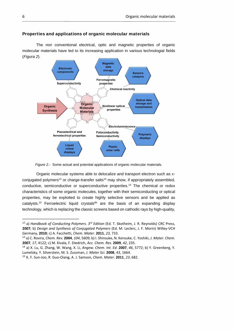
The non conventional electrical, optic and magnetic properties of organic
molecular materials have led to its increasing application in various technologial fields
(Figura 2).
Figure 2.- Some actual and potential applications of organic molecular materials.
Organic molecular systems able to delocalize and transport electron such as -
conjugated polymers12 or charge-transfer salts13 may show, if appropriately assembled,
conductive, semiconductive or superconductive properties.14 The chemical or redox
characteristics of some organic molecules, together with their semiconducting or optical
properties, may be exploited to create highly selective sensors and be applied as
catalysts.15 Ferroelectric liquid crystals6b are the basis of an expanding display
technology, which is replacing the classic screens based on cathodic rays by high-quality,
12 a) Handbook of Conducting Polymers. 3rd Edition (Ed. T. Skotheim, J. R. Reynolds) CRC Press, 2007; b) Design and Synthesis of Conjugated Polymers (Ed. M. Leclerc, J. F. Morin) Willey‐VCH Germany, 2010; c) A. Facchetti, Chem. Mater. 2011, 23, 733. 13 a) C. Rovira, Chem. Rev. 2004, 104, 5609; b) I. Shinsuke, N. Kensuke, C. Yoshiki, J. Mater. Chem. 2007, 17, 4122; c) M. Kivala, F. Diedrich, Acc. Chem. Res. 2009, 42, 235. 14 a) X. Lu, G. Zhang, W. Wang, X. Li, Angew. Chem. Int. Ed. 2007, 46, 5772; b) Y. Greenberg, Y. Lumelsky, Y. Silverstein, M. S. Zussman, J. Mater Sci. 2008, 43, 1664. 15 K. F. Sun‐Joo, R. Guo‐Oiang, A. J. Samson, Chem. Mater. 2011, 23, 682.

Introduction to phthalocyanines 7
less expensive and smaller devices; they are now finding applications in smart
windows.16 For their part, magnetic materials, based on stable radicals (nitroxide
radicals), high-spin metal clusters, or their combination, find applications in the field of
molecular magnets17 and data storage.18 Highly extended -conjugated systems, formed
by cyclocondensation (porphyrins, phthalocyanines) or polymerization (poly(p-phenylene
vinylenes), polytiophenes) of simple organic molecules, which can absorb and emit light
in the visible part of the electromagnetic spectrum, are being intensely studied as active
elements for the conversion of light into electricity (solar cells)19 and viceversa (organic
light emitting diodes).20 Information technology has currently reached the stage where
photons are taking the place of electrons as carriers of information, generating faster and
more efficient transmission systems. Organic materials with nonlinear optical (NLO)
properties,21 able to manipulate and process optical signals, may constitute very
important components in these photonic devices in the handling and processing of optical
signals surpassing inorganic materials. This kind of materials are part of photodiodes,
organic field-effect transistors (OFETs), polymer grid triodes, organic light-emitting
electrochemical cells (OLECs), optocouplers, and lasers.
16 G. M. Debije, Adv. Func. Mater. 2010, 90, 1498. 17 a) J. Lehmann, A. Gaita‐Arino, E. Coronado, D. Loss, J. Mater. Chem. 2009, 19, 1672; b) M. Kurmos, Chem. Soc. Rev. 2009, 38, 1353; c) M. Murrie, Chem. Soc. Rev. 2010, 39, 1986. 18 a) E. Coronado, J. R. Galán‐Mascarós, C. J. Gómez‐García, V. Laukhin, Nature 2000, 408, 447; b) M. Minguet, D. Luneau, E. Lhotel, V. Villar, C. Paulsen, D. B. Amabilino, J. Veciana, Angew. Chem. Int. Ed. 2002, 41, 586; d) E. Coronado, P. Day, Chem. Rev. 2004, 104, 5419; e) Y. Ma, W. Ying, J. Wang, Y. Shang, S. Du, L. Pan, G. Li, L. Yang, H. Gao, Y. Song, J. Phys. Chem. C 2009, 113, 8548. 19 a) N. S. Sariciftci, D. Braun, C. Zhang, V. Srdanov, A. J. Heeger, G. Stucky, F. Wudl, Appl, Phys. Lett. 1993, 62, 585; b) J. J. M. Halls, C. A. Walsh, N. C. Greenham, E. A. Marseglia, R. H. Friend, S. C. Moratti, A. B. Holmes, Nature 1995, 376, 498; c) S. Guenes, H. Neugebauer, N. S. Sariciftci, Chem. Rev. 2007, 107, 1324; d) G. Dennler, C. M. Schaber, C. J. Brabec, Adv Mater. 2009, 19, 1672; e) Y. J. Cheng, S. H. Yang, H. Seng, S. Chain, Chem. Rev. 2009, 19, 5690; f) C. J. Brabec, S. Gowrisanker, J. M. J. Halls, D. Laird, S. Jia, P. S. Williams, Adv. Mater. 2010, 22, 3839. 20 a) J. H. Burroughes, D. D. C. Bradley, A. R. Brown, R. N. Marks, K. Mackay, R. H. Friend, P. L. Burn, A. B. Holmes, Nature 1990, 347, 539; b) Organic Light Emitting Devices: Synthesis, Properties and Applications, (Eds. K. Mullen, U. Scherf), Wiley‐VCH, 2006; c) J. Li, D. Liu, J. Mater. Chem. 2009, 19, 7584; d) Y. Tao, C. Yang, J. Qin, Chem Rev. 2011, 40, 2943. e) L. Xiao, Z. Chen, B. Qu, J. Luo, S. Kong, Q. Gong, J. Kido, Adv. Mater. 2011, 23, 926. 21 a) I. Ledoux, J. Zyss, Chem. Rev. 1994, 94, 77; b) Nonlinear Optics of Organic Molecules and Polymers (Ed. H.S. Nalwa, S. Miyata), CRC Press, 1997; c) G. de la Torre, P. Vázquez, F. Agulló‐López, T. Torres, Chem. Rev. 2004, 104, 3723; d) J. E. Gualteri, M. H. Levi, J. S. Garth, Chem. Phys. Lett. 2008, 133, 467; e) H. C. Parsh, Chem. Rev. 2010, 110, 5332.
8 Phthalocyanines as organic molecular materials
Phthalocyanines as organic molecular materials
Structure of phthalocyanines
Among the huge variety of organic compounds that can give rise to molecular
materials, metallomacrocycles are worth of mention.22 In this group, phthalocyanines
(Pcs)23 (Figure 3) hold a privileged position due to their interesting electronic and
physicochemical characteristics, the possibility of organization into different condensed
systems, and their multiple applications (dyes, gas sensors, catalysts, optoelectronic
devices).
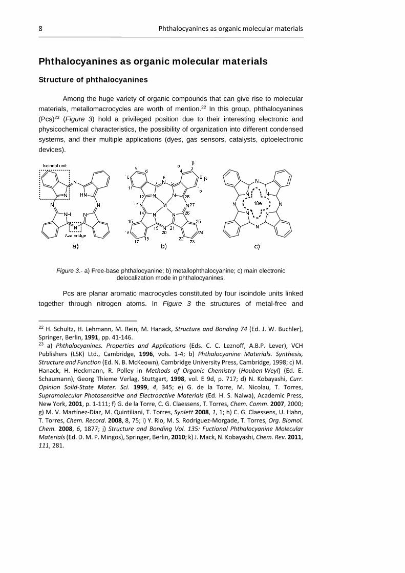
Figure 3.- a) Free-base phthalocyanine; b) metallophthalocyanine; c) main electronic delocalization mode in phthalocyanines.
Pcs are planar aromatic macrocycles constituted by four isoindole units linked
together through nitrogen atoms. In Figure 3 the structures of metal-free and
22 H. Schultz, H. Lehmann, M. Rein, M. Hanack, Structure and Bonding 74 (Ed. J. W. Buchler), Springer, Berlin, 1991, pp. 41‐146. 23 a) Phthalocyanines. Properties and Applications (Eds. C. C. Leznoff, A.B.P. Lever), VCH Publishers (LSK) Ltd., Cambridge, 1996, vols. 1‐4; b) Phthalocyanine Materials. Synthesis, Structure and Function (Ed. N. B. McKeown), Cambridge University Press, Cambridge, 1998; c) M. Hanack, H. Heckmann, R. Polley in Methods of Organic Chemistry (Houben‐Weyl) (Ed. E. Schaumann), Georg Thieme Verlag, Stuttgart, 1998, vol. E 9d, p. 717; d) N. Kobayashi, Curr. Opinion Solid‐State Mater. Sci. 1999, 4, 345; e) G. de la Torre, M. Nicolau, T. Torres, Supramolecular Photosensitive and Electroactive Materials (Ed. H. S. Nalwa), Academic Press, New York, 2001, p. 1‐111; f) G. de la Torre, C. G. Claessens, T. Torres, Chem. Comm. 2007, 2000; g) M. V. Martínez‐Díaz, M. Quintiliani, T. Torres, Synlett 2008, 1, 1; h) C. G. Claessens, U. Hahn, T. Torres, Chem. Record. 2008, 8, 75; i) Y. Rio, M. S. Rodríguez‐Morgade, T. Torres, Org. Biomol. Chem. 2008, 6, 1877; j) Structure and Bonding Vol. 135: Fuctional Phthalocyanine Molecular Materials (Ed. D. M. P. Mingos), Springer, Berlin, 2010; k) J. Mack, N. Kobayashi, Chem. Rev. 2011, 111, 281.

Introduction to phthalocyanines 9
metallophthalocyanines, as well as the numbering scheme traditionally used for their
nomenclature are shown. The internal and external positions of the fused benzene ring
are also commonly known as - and -positions, respectively. Their 42 -electrons are
distributed over 32 carbon and 8 nitrogen atoms, but the electronic delocalization mainly
takes place on the inner ring, which is constituted by 16 atoms and 18 -electrons (Figure
3c), the outer benzene rings maintaining their electronic structure.24
One of the most important attributes of this kind of molecules is their high thermal,
chemical and electromagnetic stability, which is a common requirement for most
technological applications. They can be heated up to 500 ºC under high vacuum without
decomposition, resist the action of non-oxidizing acids and bases, and they are optically
stable, tolerating high intensity electromagnetic radiation. Nevertheless, the most
remarkable feature that makes these molecules play an exceptional role in the area of
material science is their chemical versatility. The hydrogen atoms of the central cavity
can be replaced by more than 70 different elements, generating the
metallophthalocyanines (MPcs; Figure 3b).23a,b However, as the coordination number of
the macrocycle is four, according to the size and oxidation state of the metal, one or two
(in the case of alkalines) can be included into the Pc core. When the metal prefers a
higher coordination number, pyramidal, tetrahedral, or octahedral structures result, with
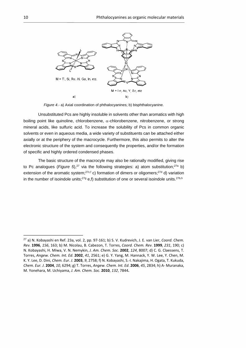
one or two axial ligands (Figure 4a).25 Actinide and lanthanide metals give rise to
sandwich-type structures with octahedral coordination in which the metal is located
between two Pc rings (Figure 4b). 26 This structure will be widely explored in Chapter 2.
24 E. Ortí, J. L. Brédas, J. Chem. Phys. 1988, 89, 1009. 25 a) M. Hanack, S. Deger, A. Lange, Coord. Chem. Rev. 1988, 115. b) M. Brewis, G. J. Clarkson, V. Goddard, M. Helliwell, A. M. Holder, N. B. McKeown, Angew. Chem. Int. Ed. 1998, 37, 1092. c) M. Hanack, H. Heckmann, Eur. J. Inorg. Chem. 1998, 367. d) G. Y. Yang, M. Hanack, Y. W. Lee, Y. Chen, M. K. Y. Lee, D. Dini, Chem. Eur. J. 2003, 9, 2758. e) A. N. Cammidge, G. Berber, I. Chambrier, P. W. Hough, M. J. Cook Tetrahedron, 2005, 61, 4067. f) K. Kameyana, M. Morisue, A. Satake, Y. Kobuke, Angew. Chem. Int. Ed. 2005, 44, 4763. g) B. Ballesteros, G. de la Torre, T. Torres, G. L. Hug, G. M. Aminur Rahman, D. M. Guldi, Tetrahedron 2006, 62, 2097. h) M. S. Rodríguez‐Morgade, T. Torres, C. Atienza‐Castellanos, D. M. Guldi, J. Am. Chem. Soc. 2006, 128, 15145. 26 a) I. S. Kirin, P. N. Moskalev, Russ. J. Inorg. Chem. 1971, 16, 1687. b) J. Silver, P. J. Lukes, P. K. Hey, J. M. O’Connor, Polyhedron, 1989, 8, 1631. c) C. Ercolani, A. M. Paoletti, G. Pennesi, G. Rossi, A. Chiesi‐Villa, C. Rizzoli, J. Chem. Soc., Dalton Trans., 1990, 1971. d) A. Capobianchi, C. Ercolani, A. M. Paoletti, G. Pennesi, G. Rossi, A. Chiesi‐Villa, R. Rizzoli, Inorg. Chem. 1993, 32, 4605. e) I. Chambrier, D. L. Hughes, J. C. Swarts, B. Isare, M. J. Cook, Chem. Comm. 2006, 3504. f) B. Ballesteros, G. de la Torre, A. Shearer, A. Hausman, M. A. Herranz, D. M. Guldi, T‐ Torres, Chem. Eur. J. 2010, 16, 114.
10 Phthalocyanines as organic molecular materials
Figure 4.- a) Axial coordination of phthalocyanines; b) bisphthalocyanine.
Unsubstituted Pcs are highly insoluble in solvents other than aromatics with high
boiling point like quinoline, chlorobenzene, -chlorobenzene, nitrobenzene, or strong
mineral acids, like sulfuric acid. To increase the solubility of Pcs in common organic
solvents or even in aqueous media, a wide variety of substituents can be attached either
axially or at the periphery of the macrocycle. Furthermore, this also permits to alter the
electronic structure of the system and consequently the properties, and/or the formation
of specific and highly ordered condensed phases.
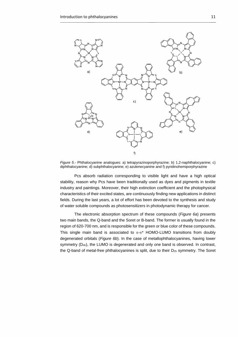
The basic structure of the macrocyle may also be rationally modified, giving rise
to Pc analogues (Figure 5),27 via the following strategies: a) atom substitution;27a b)
extension of the aromatic system;27c,f c) formation of dimers or oligomers;27d d) variation
in the number of isoindole units;27g e,f) substitution of one or several isoindole units.27b,h
27 a) N. Kobayashi en Ref. 23a, vol. 2, pp. 97‐161; b) S. V. Kudrevich, J. E. van Lier, Coord. Chem. Rev. 1996, 156, 163; b) M. Nicolau, B. Cabezon, T. Torres, Coord. Chem. Rev. 1999, 231, 190; c) N. Kobayashi, H. Miwa, V. N. Nemykin, J. Am. Chem. Soc. 2002, 124, 8007; d) C. G. Claessens, T. Torres, Angew. Chem. Int. Ed. 2002, 41, 2561; e) G. Y. Yang, M. Hannack, Y. W. Lee, Y. Chen, M. K. Y. Lee, D. Dini, Chem. Eur. J. 2003, 9, 2758; f) N. Kobayashi, S.‐I. Nakajima, H. Ogata, T. Kukuda, Chem. Eur. J. 2004, 10, 6294; g) T. Torres, Angew. Chem. Int. Ed. 2006, 45, 2834; h) A‐ Muranaka, M. Yonehara, M. Uchiyama, J. Am. Chem. Soc. 2010, 132, 7844.
Introduction to phthalocyanines 11
Figure 5.- Phthalocyanine analogues: a) tetrapyrazinoporphyrazine; b) 1,2-naphthalocyanine; c) diphthalocyanine; d) subphthalocyanine; e) azulenecyanine and f) pyridinohemiporphyrazine
Pcs absorb radiation corresponding to visible light and have a high optical
stability, reason why Pcs have been traditionally used as dyes and pigments in textile
industry and paintings. Moreover, their high extinction coefficient and the photophysical
characteristics of their excited states, are continuously finding new applications in distinct
fields. During the last years, a lot of effort has been devoted to the synthesis and study
of water soluble compounds as photosensitizers in photodynamic therapy for cancer.
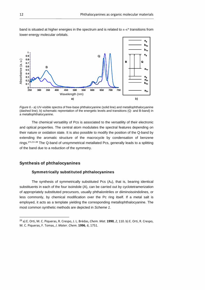
The electronic absorption spectrum of these compounds (Figure 6a) presents
two main bands, the Q-band and the Soret or B-band. The former is usually found in the
region of 620-700 nm, and is responsible for the green or blue color of these compounds.
This single main band is associated to -* HOMO-LUMO transitions from doubly
degenerated orbitals (Figure 6b). In the case of metallophthalocyanines, having lower
symmetry (D4h), the LUMO is degenerated and only one band is observed. In contrast,
the Q-band of metal-free phthalocyanines is split, due to their D2h symmetry. The Soret
12 Phthalocyanines as organic molecular materials
band is situated at higher energies in the spectrum and is related to -* transitions from
lower-energy molecular orbitals.
Figure 6.- a) UV-visible spectra of free-base phthalocyanine (solid line) and metallophthalocyanine (dashed line); b) schematic reprentation of the energetic levels and transitions (Q- and B-band) in a metallophthalocyanine.
The chemical versatility of Pcs is associated to the versatility of their electronic
and optical properties. The central atom modulates the spectral features depending on
their nature or oxidation state. It is also possible to modify the position of the Q-band by
extending the aromatic structure of the macrocycle by condensation of benzene
rings.27c,f,h 28 The Q-band of unsymmetrical metallated Pcs, generally leads to a splitting
of the band due to a reduction of the symmetry.
Synthesis of phthalocyanines
Symmetrically substituted phthalocyanines
The synthesis of symmetrically substituted Pcs (A4), that is, bearing identical
substituents in each of the four isoindole (A), can be carried out by cyclotetramerization
of appropriately substituted precursors, usually phthalonitriles or diiminoisoindolines, or
less commonly, by chemical modification over the Pc ring itself. If a metal salt is
employed, it acts as a template yielding the corresponding metallophthalocyanine. The
most common synthetic methods are depicted in Scheme 1.
28 a) E. Orti, M. C. Piqueras, R. Crespo, J. L. Brédas, Chem. Mat. 1990, 2, 110. b) E. Orti, R. Crespo, M. C. Piqueras, F. Tomas, J. Mater. Chem. 1996, 6, 1751.
Wavelength (nm)
Abs
orb
ance
(a.
u.)
Introduction to phthalocyanines 13
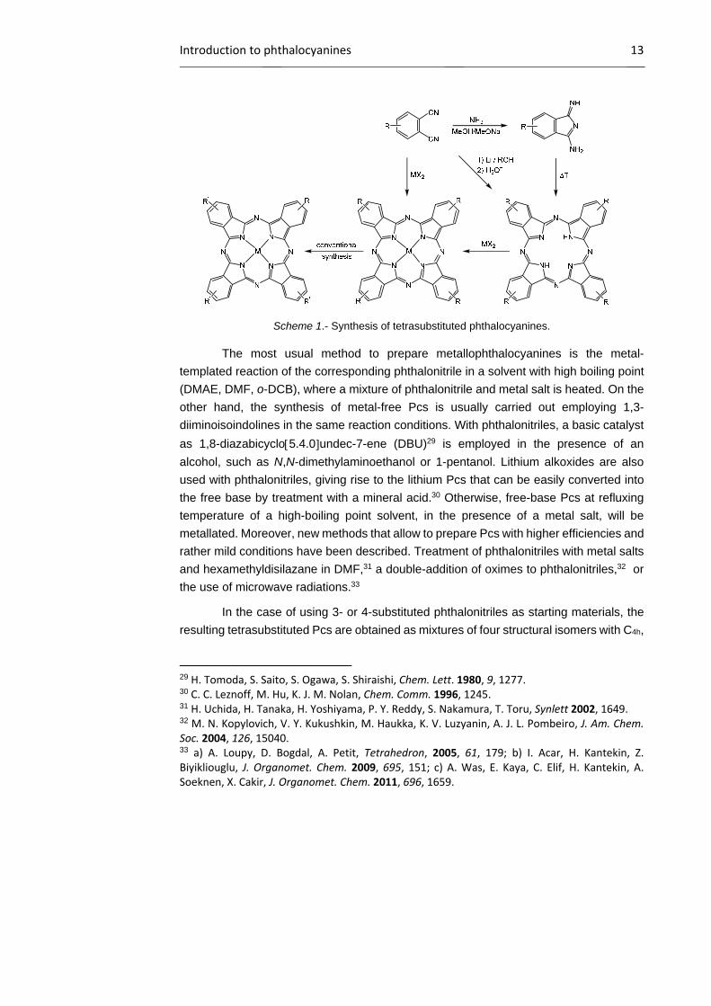
Scheme 1.- Synthesis of tetrasubstituted phthalocyanines.
The most usual method to prepare metallophthalocyanines is the metal-
templated reaction of the corresponding phthalonitrile in a solvent with high boiling point
(DMAE, DMF, o-DCB), where a mixture of phthalonitrile and metal salt is heated. On the
other hand, the synthesis of metal-free Pcs is usually carried out employing 1,3-
diiminoisoindolines in the same reaction conditions. With phthalonitriles, a basic catalyst
as 1,8-diazabicyclo5.4.0undec-7-ene (DBU)29 is employed in the presence of an
alcohol, such as N,N-dimethylaminoethanol or 1-pentanol. Lithium alkoxides are also
used with phthalonitriles, giving rise to the lithium Pcs that can be easily converted into
the free base by treatment with a mineral acid.30 Otherwise, free-base Pcs at refluxing
temperature of a high-boiling point solvent, in the presence of a metal salt, will be
metallated. Moreover, new methods that allow to prepare Pcs with higher efficiencies and
rather mild conditions have been described. Treatment of phthalonitriles with metal salts
and hexamethyldisilazane in DMF,31 a double-addition of oximes to phthalonitriles,32 or
the use of microwave radiations.33
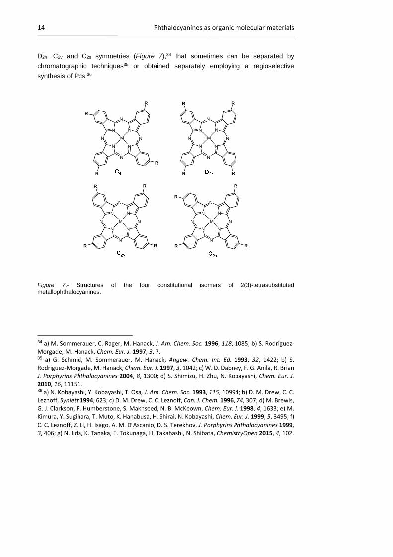
In the case of using 3- or 4-substituted phthalonitriles as starting materials, the
resulting tetrasubstituted Pcs are obtained as mixtures of four structural isomers with C4h,
29 H. Tomoda, S. Saito, S. Ogawa, S. Shiraishi, Chem. Lett. 1980, 9, 1277. 30 C. C. Leznoff, M. Hu, K. J. M. Nolan, Chem. Comm. 1996, 1245. 31 H. Uchida, H. Tanaka, H. Yoshiyama, P. Y. Reddy, S. Nakamura, T. Toru, Synlett 2002, 1649. 32 M. N. Kopylovich, V. Y. Kukushkin, M. Haukka, K. V. Luzyanin, A. J. L. Pombeiro, J. Am. Chem. Soc. 2004, 126, 15040. 33 a) A. Loupy, D. Bogdal, A. Petit, Tetrahedron, 2005, 61, 179; b) I. Acar, H. Kantekin, Z. Biyikliouglu, J. Organomet. Chem. 2009, 695, 151; c) A. Was, E. Kaya, C. Elif, H. Kantekin, A. Soeknen, X. Cakir, J. Organomet. Chem. 2011, 696, 1659.
14 Phthalocyanines as organic molecular materials
D2h, C2v and C2s symmetries (Figure 7),34 that sometimes can be separated by
chromatographic techniques35 or obtained separately employing a regioselective
synthesis of Pcs.36
N N
N
N
N
N
N
N
M
N N
N
N
N
N
N
N
M
N N
N
N
N
N
N
N
M
N N
N
N
N
N
N
N
M
R
R
R
R
R R
R R
R R
RR
R
R
R R
Figure 7.- Structures of the four constitutional isomers of 2(3)-tetrasubstituted metallophthalocyanines.
34 a) M. Sommerauer, C. Rager, M. Hanack, J. Am. Chem. Soc. 1996, 118, 1085; b) S. Rodriguez‐Morgade, M. Hanack, Chem. Eur. J. 1997, 3, 7. 35 a) G. Schmid, M. Sommerauer, M. Hanack, Angew. Chem. Int. Ed. 1993, 32, 1422; b) S. Rodriguez‐Morgade, M. Hanack, Chem. Eur. J. 1997, 3, 1042; c) W. D. Dabney, F. G. Anila, R. Brian J. Porphyrins Phthalocyanines 2004, 8, 1300; d) S. Shimizu, H. Zhu, N. Kobayashi, Chem. Eur. J. 2010, 16, 11151. 36 a) N. Kobayashi, Y. Kobayashi, T. Osa, J. Am. Chem. Soc. 1993, 115, 10994; b) D. M. Drew, C. C. Leznoff, Synlett 1994, 623; c) D. M. Drew, C. C. Leznoff, Can. J. Chem. 1996, 74, 307; d) M. Brewis, G. J. Clarkson, P. Humberstone, S. Makhseed, N. B. McKeown, Chem. Eur. J. 1998, 4, 1633; e) M. Kimura, Y. Sugihara, T. Muto, K. Hanabusa, H. Shirai, N. Kobayashi, Chem. Eur. J. 1999, 5, 3495; f)
C. C. Leznoff, Z. Li, H. Isago, A. M. DAscanio, D. S. Terekhov, J. Porphyrins Phthalocyanines 1999, 3, 406; g) N. Iida, K. Tanaka, E. Tokunaga, H. Takahashi, N. Shibata, ChemistryOpen 2015, 4, 102.

Introduction to phthalocyanines 15
Unsymetrically substituted phthalocyanines
The synthesis of Pcs with two different substitution patterns in the isoindole units
(A and B) is a more difficult task, and the methodology employed will be chosen
depending on the kind of substituents required and on their relative distribution in the final
macrocyle (A3B, A2B2 or ABAB).37 A brief description of the most important methods
follows.
a) Solid-phase synthesis38
In this method, a phthalonitrile or diiminoisoindoline (B), linked to an insoluble
polymer or an inorganic holder, is made to react with an excess of a differently
functionalized phthalonitrile or diiminoisoindoline (A). The A3B phthalocyanine formed is,
in a second step, cleaved from the polymer (Scheme 2).
N
NH2
NHTrOn(H2C)OP
N
NH2
NHN
NH
N
N
N
HN
N
N
O O
OTrOn(H2C)OP
Scheme 2.- Example of solid-phase synthesis of A3B Pcs
b) Ring expansion reaction39
The geometrically constrained subphthalocyanine macrocycle (A3) may be
opened by reaction with a differently substituted diiminoisoindoline (B). Ultimately, the
open tetramer formed self-condenses to selectively give an A3B phthalocyanine, but
usually mixtures of non desired by-products are also formed (Scheme 3).
37 a) T. Torres, J. Porphyrins Phthalocyanines 2000, 4, 325; b) G. de la Torre, C. G. Claessens, T. Torres, Eur. J. Org. Chem. 2000, 2821; c) G. de la Torre, T. Torres, J. Porphyrins Phthalocyanines 2002, 6, 274. 38 a) C. C. Leznoff, T. W. Hall, Tetrahedron Lett. 1982, 23, 3023; b) A. Hirth, A. K. Sobbi, D. Wohrle, J. Porphyrins Phthalocyanines 1997, 1, 275; c) S. S. Erdem, I. V. Nesterova, S. A. Soper, R. P. Hammer, J. Org. Chem. 2008, 73, 5003; d) M. Mudyina, N. M. Ndingury, A. S. Steven, P. R. Hammer, J. Porphyrins Phthalocyanines 2010, 14, 891. 39 a) A. Weitemeyer, H. Kliesch, D. Whorle, J. Org. Chem. 1995, 60, 4900 ; b) A. Sastre, T. Torres, M. Hanack, Tetrahedron Lett. 1995, 36, 8501 ; c) A. Sastre, B. del Rey, T. Torres. J. Org. Chem. 1996, 61, 8591 ; d) A. G. Gurek, O. Bekaroglu, J. Porphyrins Phthalocyanines 1997, 1, 227.
16 Phthalocyanines as organic molecular materials
Scheme 3.- Example of ring expansion reaction.
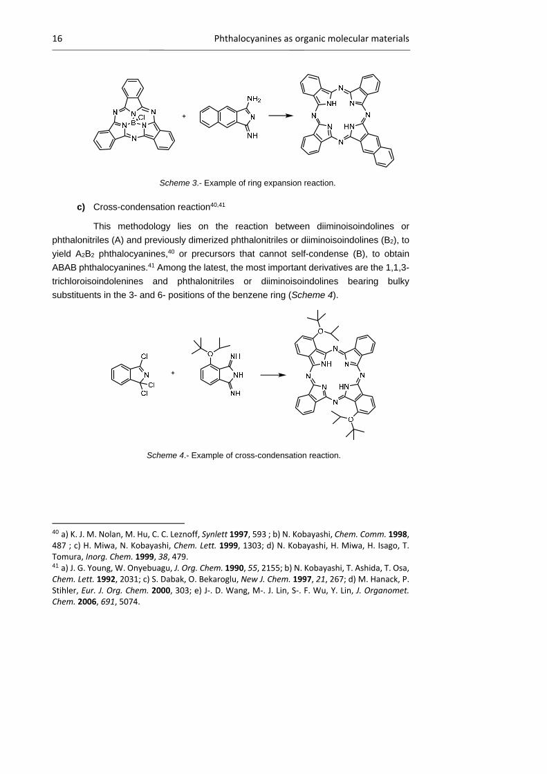
c) Cross-condensation reaction40,41
This methodology lies on the reaction between diiminoisoindolines or
phthalonitriles (A) and previously dimerized phthalonitriles or diiminoisoindolines (B2), to
yield A2B2 phthalocyanines,40 or precursors that cannot self-condense (B), to obtain
ABAB phthalocyanines.41 Among the latest, the most important derivatives are the 1,1,3-
trichloroisoindolenines and phthalonitriles or diiminoisoindolines bearing bulky
substituents in the 3- and 6- positions of the benzene ring (Scheme 4).
Scheme 4.- Example of cross-condensation reaction.
40 a) K. J. M. Nolan, M. Hu, C. C. Leznoff, Synlett 1997, 593 ; b) N. Kobayashi, Chem. Comm. 1998, 487 ; c) H. Miwa, N. Kobayashi, Chem. Lett. 1999, 1303; d) N. Kobayashi, H. Miwa, H. Isago, T. Tomura, Inorg. Chem. 1999, 38, 479. 41 a) J. G. Young, W. Onyebuagu, J. Org. Chem. 1990, 55, 2155; b) N. Kobayashi, T. Ashida, T. Osa, Chem. Lett. 1992, 2031; c) S. Dabak, O. Bekaroglu, New J. Chem. 1997, 21, 267; d) M. Hanack, P. Stihler, Eur. J. Org. Chem. 2000, 303; e) J‐. D. Wang, M‐. J. Lin, S‐. F. Wu, Y. Lin, J. Organomet. Chem. 2006, 691, 5074.

Introduction to phthalocyanines 17
d) Statistical cyclotetramerization37
This is the most utilized methodology, due to its simplicity. It is based on the
mixed condensation of two differently functionalized phthalonitriles or diiminoisoindolines
(A and B) to produce a mixture of Pcs (Figure 8) that, in a second step, are separated by
chromatography. Usually, this approach is widely used to prepare A3B compounds since,
when using statistical means, A2B2 isomers are quite difficult to separate by
chromatographic techniques. Some factors, such as the steric effect of the substituents
(employing bulky groups to supress aggregation), the relative reactivity of the different
precursors and their relative amount in the reaction (employing a 3:1 molar ratio means
that A and B present similar reactivity), have to be taken into account in this case in order
to increase the yield of the desired A3B Pc and facilitate its isolation.
Figure 8.- Mixture of phthalocyanines obtained via statistical cyclotetramerization of two differently functionalized phthalonitriles or diiminoisoindolines, A and B.
Concerning the mechanism of formation of Pcs, several pathways have been
proposed. There are, however, some common features to all these mechanistic
proposals.42 In general, the macrocyclization in the presence of sodium of lithium alkoxide
usually starts with the formation of the corresponding salt of 1-imido-3-alcoxyindoline
(Scheme 5A).43 The next step in the reaction sequence is the nucleophilic attack of this
intermediate to the cyano group of another phthalonitrile molecule. A dimer is formed
42 a) C. R. Rager, G. Schmid, M. Hanack, Chem. Eur. J. 1999, 5, 280; b) C. C. Leznoff, A. M. Castaño, S. Z. Yildiz, J. Porphyrins Phthalocyanines 2000, 4, 103. 43 S. W. Oliver, T. D. Smith, J. Chem. Soc. Perkin Trans. II 1987, 1579.

18 Phthalocyanines as organic molecular materials
(Scheme 5B), which can now either react with another phthalonitrile unit in the same way
to form a trimer (Scheme 5C), or undergo self-condensation (Scheme 5D).
Scheme 5.- Proposed mechanism for the synthesis of metallophthalocyanines by
cyclotetramerization of phthalonitriles in the presence of a metal salt.
Another possibility consists on the metal-mediated formation of the Pc ring,44 that
is, a metal cation acts as a template to which the reacting phthalonitriles coordinate during
the macrocyclization.
Organization of phthalocyanines
Pc molecules exhibit a natural tendency to aggregate through - interactions
between the aromatic rings which, together with the suitable choice of the substituents
44 a) V. W. Day, T. J. Marks, W. A. Wachter, J. Am. Chem. Soc. 1975, 97, 4519; b) D. Bush, N. Stephenson, Coord. Chem. Rev. 1990, 100, 119.
Introduction to phthalocyanines 19
and the central element, assist in the formation of multiple and highly ordered condensed
phases. In many cases, the type of supramolecular architecture formed can be predicted
and it will determine the final properties and applications of the material.45 So far, the
most important organized structures are the following:
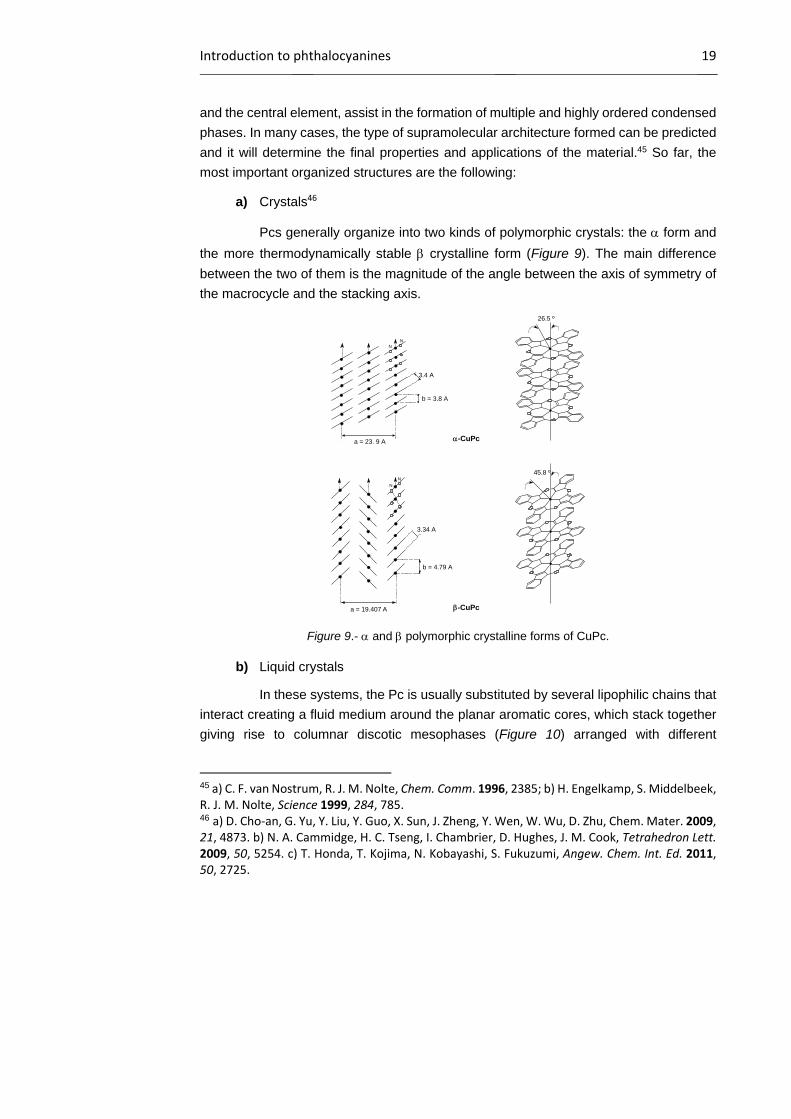
a) Crystals46
Pcs generally organize into two kinds of polymorphic crystals: the form and
the more thermodynamically stable crystalline form (Figure 9). The main difference
between the two of them is the magnitude of the angle between the axis of symmetry of
the macrocycle and the stacking axis.
Figure 9.- and polymorphic crystalline forms of CuPc.
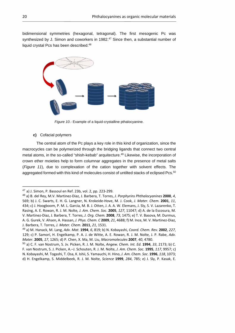
b) Liquid crystals
In these systems, the Pc is usually substituted by several lipophilic chains that
interact creating a fluid medium around the planar aromatic cores, which stack together
giving rise to columnar discotic mesophases (Figure 10) arranged with different
45 a) C. F. van Nostrum, R. J. M. Nolte, Chem. Comm. 1996, 2385; b) H. Engelkamp, S. Middelbeek, R. J. M. Nolte, Science 1999, 284, 785. 46 a) D. Cho‐an, G. Yu, Y. Liu, Y. Guo, X. Sun, J. Zheng, Y. Wen, W. Wu, D. Zhu, Chem. Mater. 2009, 21, 4873. b) N. A. Cammidge, H. C. Tseng, I. Chambrier, D. Hughes, J. M. Cook, Tetrahedron Lett. 2009, 50, 5254. c) T. Honda, T. Kojima, N. Kobayashi, S. Fukuzumi, Angew. Chem. Int. Ed. 2011, 50, 2725.
NN
a = 23. 9 A
b = 3.8 A
3.4 A
N
N
26.5 º
a = 19.407 A
b = 4.79 A
3.34 A
-CuPc
-CuPc
45.8 º
20 Phthalocyanines as organic molecular materials
bidimensional symmetries (hexagonal, tetragonal). The first mesogenic Pc was
synthesized by J. Simon and coworkers in 1982.47 Since then, a substantial number of
liquid crystal Pcs has been described.48
Figure 10.- Example of a liquid-crystalline pthalocyanine.
c) Cofacial polymers
The central atom of the Pc plays a key role in this kind of organization, since the
macrocycles can be polymerized through the bridging ligands that connect two central
metal atoms, in the so-called “shish-kebab” arquitecture.49 Likewise, the incorporation of
crown ether moieties help to form columnar aggregates in the presence of metal salts
(Figure 11), due to complexation of the cation together with solvent effects. The
aggregated formed with this kind of molecules consist of untilted stacks of eclipsed Pcs.50
47 a) J. Simon, P. Bassoul en Ref. 23b, vol. 2, pp. 223‐299. 48 a) B. del Rey, M.V. Martinez‐Diaz, J. Barbera, T. Torres, J. Porphyrins Phthalocyanines 2000, 4, 569; b) J. C. Swarts, E. H. G. Langner, N. Krokeide‐Hove, M. J. Cook, J. Mater. Chem. 2001, 11, 434; c) J. Hoogboom, P. M. L. Garcia, M. B. J. Otten, J. A. A. W. Elemans, J. Sly, S. V. Lazarenko, T. Rasing, A. E. Rowan, R. J. M. Nolte, J. Am. Chem. Soc. 2005, 127, 11047; d) A. de la Escosura, M. V. Martinez‐Diaz, J. Barbera, T. Torres, J. Org. Chem. 2008, 73, 1475; e) T. V. Basova, M. Durmus, A. G. Gurek, V. Ahsen, A. Hassan, J. Phys. Chem. C 2009, 21, 4688; f) M. Ince, M. V. Martinez‐Diaz, J. Barbera, T. Torres, J. Mater. Chem. 2011, 21, 1531. 49 a) M. Hanack, M. Lang, Adv. Mat. 1994, 6, 819; b) N. Kobayashi, Coord. Chem. Rev. 2002, 227, 129; c) P. Samorí, H. Engelkamp, P. A. J. de Witte, A. E. Rowan, R. J. M. Nolte, J. P. Rabe, Adv. Mater. 2005, 17, 1265; d) P. Chen, X. Ma, M. Liu, Macromolecules 2007, 40, 4780. 50 a) C. F. van Nostrum, S. Jv. Picken, R. J. M. Nolte, Angew. Chem. Int. Ed. 1994, 33, 2173; b) C. F. van Nostrum, S. J. Picken, A.–J. Schouten, R. J. M. Nolte, J. Am. Chem. Soc. 1995, 117, 9957; c) N. Kobayashi, M. Togashi, T. Osa, K. Ishii, S. Yamauchi, H. Hino, J. Am. Chem. Soc. 1996, 118, 1073; d) H. Engelkamp, S. Middelbeek, R. J. M. Nolte, Science 1999, 284, 785; e) J. Sly, P. Kasak, E.

Introduction to phthalocyanines 21
Figure 11.- Schematic representation of the complexes formed by a crown ether substituted Pc and potassium picrate.
d) Thin films
The most direct way to incorporate Pcs in electronic devices is probably by
means of thin films, which can be readily prepared by vacuum sublimation,51 polymeric
matrix scattering52 or spin-coating.53 Highly ordered Pc films have been prepared by the
LB technique and by self-assembly of thiol-substituted macrocycles onto a gold surface.
e) Nanostructures on surfaces
Pcs can self-organize giving rise to nanowires and nanoribbon structures,54
among others, by organic vapor-phase deposition. The nature of the nanostructure
Gomar‐Nadal, C. Rovira, L. Gorriz, P. Thordarson, D. B. Amabilino, A. E. Rowan , R. J. M. Nolte, Chem. Comm. 2005, 1255 ; f) N. Sheng, Y. Zhang, H. Xu, M. Bao, X. Sun, J. Jiang, Eur. J. Inorg. Chem. 2007, 3268. 51 a) G. E. Collins, V. S. Williams, L.‐K. Chau, K. W. Nebesny, C. England, P. A. Lee, T. Lowe, Q. Fernando, N. R. Armstrong, Synth. Met. 1993, 54, 351; b) M. Yoon, A. Facchetti, C. E. Stern, T. J. Marks, J. Am. Chem. Soc. 2006, 128, 5792. 52 T. Minami, K. Sasaki, K. Tsuda, J. Appl. Phys. 1983, 54, 6764. 53 a) M. J. Cook, J. Mater. Chem. 1996, 6, 677; b) M. J. Cook, Pure Appl. Chem. 1999, 71, 2145; c) S. Xiao, M. Myers, Q. Miao, S. Sanaur, K. Pang, M. L. Steigerwald, C. Nuckolls, Angew. Chem. Int. Ed. 2005, 44, 7390; c) A. Hirao, T. Akiyama, T. Okujima, H. Yamada, H. Uno, Y. Sakai, A. Yoshimasa, S. Aramaki, N. Ono, Chem. Comm. 2008, 4714. 54 a) W. Y. Tong, A. B. Djurisic, M. H. Xie, A. C. M. Ng, K.Y. Cheung, W. K. Chan, Y. H. Leung, H. W. Lin, S. Gwo, J. Phys. Chem. B, 2006, 110, 17406 ; b) M. V. Martinez‐Diaz, G. Bottari, J. Porphyrins Phthalocyanines 2009, 13, 471.
Metal ion
22 Phthalocyanines as organic molecular materials
depends on the kind of surface and the deposition conditions. In this way, some Pcs have
been deposited on graphite,55 Au(111)56 and Cu(111).57
The utilization of solution-processable techniques for the fabrication of Pc-
based nanoscale systems represents a relatively cheap and technological appealing
methodology, when compared to vacuum techniques, for the preparation of
nanostructured architectures for certain applications. In this context, studies on the
nanostructures formed on surfaces by deposition from solutions are of great relevance.
For instance, octaalkoxy substituted CuPcs drop-casted on silica surfaces give rise to the
formation of highly homogeneous, one-dimensional or two-dimensional aggregates.58
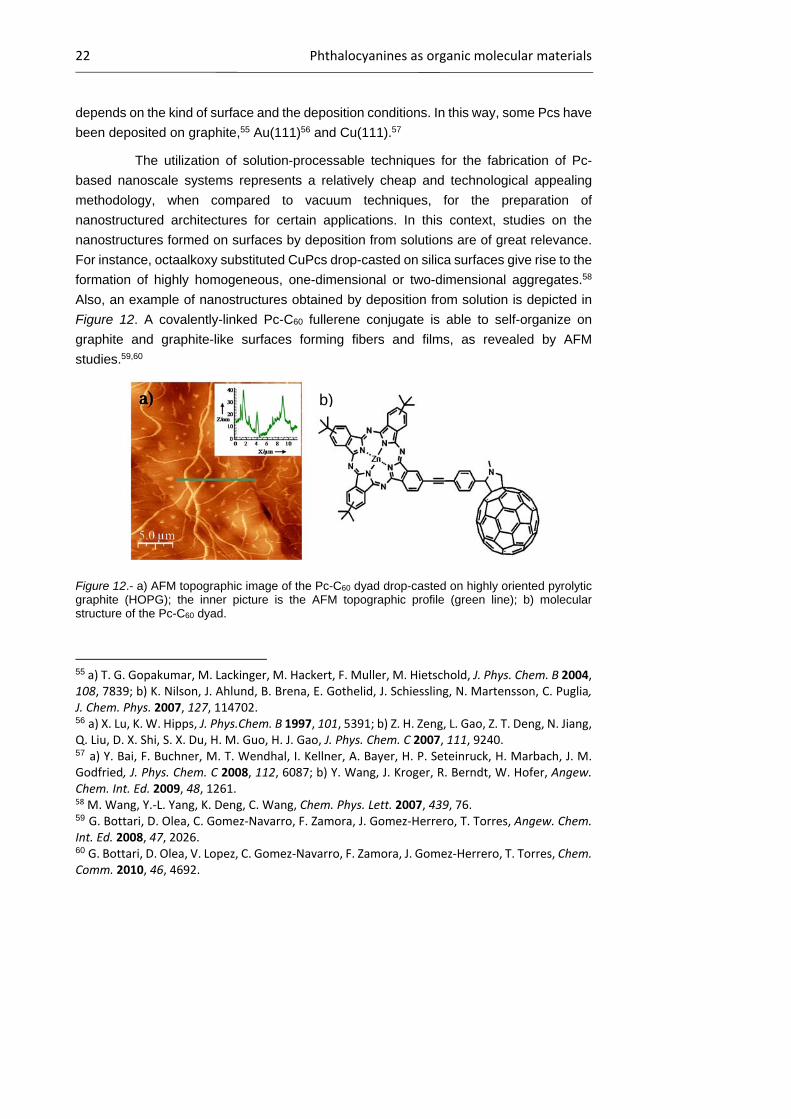
Also, an example of nanostructures obtained by deposition from solution is depicted in
Figure 12. A covalently-linked Pc-C60 fullerene conjugate is able to self-organize on
graphite and graphite-like surfaces forming fibers and films, as revealed by AFM
studies.59,60
Figure 12.- a) AFM topographic image of the Pc-C60 dyad drop-casted on highly oriented pyrolytic graphite (HOPG); the inner picture is the AFM topographic profile (green line); b) molecular structure of the Pc-C60 dyad.
55 a) T. G. Gopakumar, M. Lackinger, M. Hackert, F. Muller, M. Hietschold, J. Phys. Chem. B 2004, 108, 7839; b) K. Nilson, J. Ahlund, B. Brena, E. Gothelid, J. Schiessling, N. Martensson, C. Puglia, J. Chem. Phys. 2007, 127, 114702. 56 a) X. Lu, K. W. Hipps, J. Phys.Chem. B 1997, 101, 5391; b) Z. H. Zeng, L. Gao, Z. T. Deng, N. Jiang, Q. Liu, D. X. Shi, S. X. Du, H. M. Guo, H. J. Gao, J. Phys. Chem. C 2007, 111, 9240. 57 a) Y. Bai, F. Buchner, M. T. Wendhal, I. Kellner, A. Bayer, H. P. Seteinruck, H. Marbach, J. M. Godfried, J. Phys. Chem. C 2008, 112, 6087; b) Y. Wang, J. Kroger, R. Berndt, W. Hofer, Angew. Chem. Int. Ed. 2009, 48, 1261. 58 M. Wang, Y.‐L. Yang, K. Deng, C. Wang, Chem. Phys. Lett. 2007, 439, 76. 59 G. Bottari, D. Olea, C. Gomez‐Navarro, F. Zamora, J. Gomez‐Herrero, T. Torres, Angew. Chem. Int. Ed. 2008, 47, 2026. 60 G. Bottari, D. Olea, V. Lopez, C. Gomez‐Navarro, F. Zamora, J. Gomez‐Herrero, T. Torres, Chem. Comm. 2010, 46, 4692.
b)a)
Introduction to phthalocyanines 23
Properties and applications of phthalocyanines
Since their first synthesis, early in the 20th century, Pcs have established
themselves as blue and green dyestuff par excellence. They are an important industrial
commodity, used primarily in inks (especially ballpoint pens), coloring for plastics and
metal surfaces, and dyes for jeans and other clothing. More recently, the unique
properties of Pcs such as high optical stability, semiconductivity and excellent
photophysical properties have widen their possible applications, and therefore, their
commercial utility. Potential uses of Pcs include sensing elements in chemical sensors,
electrochromic display devices, photodynamic reagents for cancer therapy, information
storage systems (optical computers read/write discs), catalysis and electrocatalysis, and
liquid crystal color display applications.
a) Optical properties
Organic molecules have found strong relevance as NLO materials. Since
Mainman made the first laser in 1960,61 mainly inorganic materials were studied,
however, in the last 30 years organic molecules have found strong relevance in the area
of NLO. Molecular candidates for this field must comprise highly polarizable -systems;
for this reason, Pcs and analogues, which present a delocalized -aromatic cloud, have
been widely studied in this area. Research in this field has mainly focused in the study of
the second harmonic generation (SHG), in which two incident waves of frequency are
combined and emitted by the material in a wave of frequency 2, and the third harmonic
generation (THG), where the emitted wave has a frequency 3. In the specific case of
second order properties, a noncentrosymmetric structure is also required. Pcs are
versatile compounds which can be unsymmetrically substituted with electron-donor and
acceptor groups, and therefore, they are very appealing materials in the generation of
SHG and THG responses for nonlinear optical technologies.62 The electronic structure of
these macrocyclic compounds appears also adequate for optical limiting (OL), a
nonlinear effect consisting on a decrease of the transmittance of the NLO material under
high-intensity illumination.63 This kind of materials can meet different functions, as the
61 T. H. Maiman, Nature 1960, 187, 493. 62 a) G. de la Torre, T. Torres, F. Agullo‐Lopez, Chem. Rev. 2004, 104, 3723; b) M. J. F. Calvete, D. Dini, S. R. Flom, M. Hanack, R. G. S. Pong, J. Shirk, Eur. J. Org. Chem. 2005, 3499; c) M. Drobizhev, M. S. Makarov, A. Rebane, G. De la Torre, T. Torres, J. Phys. Chem. C 2008, 112, 848; d) M. Quintiliani, J. Perez‐Moreno, I. Asselberghs, P. Vazquez, K. Clays, T. Torres, J. Phys. Chem. C 2010, 114, 6309. 63 a) S. M. O’Flaherty, S. V. Hold, M. J. Cook, T. Torres, Y. Chen, M. Hanack, W. J. Blau, Adv. Mater. 2003, 15, 19; b) G. Y. Yang, M. Hanack, Y. W. Lee, D. Dini, J. F. Pan, Adv. Mater. 2005, 17, 875.

24 Phthalocyanines as organic molecular materials
protection of the human eye from intense light sources. SubPc and Pc pigments are
essential components in the manufacturing of CDs and DVDs, being most of them
patented.64 Moreover, an optical information recording method based on Pc analogues,
with two different wavelengths for read and write, has been patented.65
b) Electrical properties
Pcs belong to the group of low-dimensional semiconducting molecular
materials,66 displaying in some cases conductivities in the range of 10-4 to 10-2 -1·cm-1.
Conductivity in metallophthalocyanine systems can be due either to the instrinsic
properties of a particular Pc, or to the organization of the molecules at supramolecular
level. The bis(phthalocyaninato) lutetium (Pc2Lu) and lithium phthalocyanine (PcLi) are
instrinsic molecular semiconductors, due to their radical nature, and have been applied
in some devices such as OFETs.23j,67,68 The supramolecular organization of Pcs can also
be responsible for their conducting properties. The cofacial arrangement of these
macrocycles generates new conducting bands through the overlapping of the -orbitals,
thus obtaining a preferential electronic mobility along the stacking axis. This suitable
assembly may be achieved by different methods, as the formation of columnar
mesophases (see Figure 10), “shish-kebab” polymers, aggregates of crown-ether
substituted Pcs and alkaline metal salts (see Figure 11), or ordered thin films. In many
64 a) A. Zafirov, S. Rakosvski, J. Bakardjieva‐Eneva, L. Prahov, L. Assenova, F. Marrandino (Vivastar Mastering & Materials A.‐G., Switzerland), PCT Int. Appl., WO 2002080158 A1, 2002; b) Y. Usami, T. Kakuta, T. Ishida (Fuji Photo Film Co., Ltd., Japan), Eur. Pat. Appl., EP 1434207 A2, 2004. 65 H. Shimizu, D. Morishita (K. K., Taiyo Yuden) Eur. Pat., EP1622138, 2006. 66 a) H. Schultz, H. Lehmann, M. Rein, M. Hanack, Struct. Bonding 1991, 74, 41; b) D. Schlettwein, D. Wohrle, F. Karmann, U. Melville, Chem. Mater. 1994, 6, 3 ; c) J. Simon, T. Toupance, en Comprehensive Supramolecular Chemistry, vol. 10. Intrinsic molecular semiconductors: electronics and ionoelectronics finalities, (Ed. D. N. Reinhoudt), Pergamon, Exeter, 1996 ; d) M. Hanack, L. Subramanian, en Handbook of Organic Conducting Molecules and Polymers, vol. 1, (Ed. H. S. Nalwa), John Wiley & Sons Ltd, 1997 ; e) M. Hanack, D. Dini, en ref 18, vol. 18, pp. 251‐280, (Eds. K. M. Kadish, K. M. Smith, R. Guilard), Academic Press, San Diego, CA, 2003 ; f) M. F. Craciun, S. Rogge, M.‐J. L. den Boer, S. Margadonna, K. Prassides, Y. Iwasa, A. F. Morpurgo, Adv. Mater. 2006, 18, 320. 67 a) G. Guillaud, J. Simon, J. P. Germain, Coord. Chem. Rev. 1998, 178, 1433; b) The Phorphyrin Handbook, M. Bouvet, vol. 19, (Eds. K. M. Kadish, K. M. Smith, R. Guilard), Academic Press, San Diego, CA, 2003. 68 a) T. Okuda, S. Shintoh, N. Terada, J. Appl. Phys. 2004, 96, 3586; b) J. Zhang, J. Wang, H. Wang, D. Yan, Appl. Phys. Lett. 2004, 84, 142; c) J. Zhang, H. Wang, X. Yan, J. Wang, J. Shi, D. Yan, Adv. Mater. 2005, 17, 1191; d) M. Ofuji, K. Ishikawa, H. Takezoe, Appl. Phys. Lett. 2005, 86, 22103; e) T. Yasuda, T. Tsuitsui, Chem. Phys. Lett. 2005, 402, 395; f) L. Li, Q. Tang, H. Li, W. Hu, X. Yang, Z. Shuai, Y. Liu, D. Zhu, Pure Appl. Chem. 2008, 80, 2231.
Introduction to phthalocyanines 25
instances, however, the doping of these systems with oxidizing or reducing agents is
necessary to increase the conductivity.
The alteration of these semiconducting properties by redox reaction of the Pc
with different gases (nitrogen monoxide and dioxide, ammonia) is an interesting
phenomenon which has been exploited to design molecular sensors,69,70
c) Magnetic properties23j
In general, magnetic properties has been less studied because in many cases,
metallophthalocyanines with one or more unpaired electrons essentially behave as
simple paramagnetic substances. Some complexes, however, can exhibit spontaneous
magnetization: d-metal Pcs (Mn(II), Fe(II), Cr(II), Co(II), Ni(II), Cu(II)); -radical
derivatives (LiPc and -radical bis(Pcs)) and 4f metal Pcs (bis(phthalocyaninato)Tb(III)
and Dy(III)). Regarding bis(phthalocyaninate) complexes, their study as single-molecule
magnets (SMMs) will be described thoroughly in Chapter 2.
Worth mentioning that the application of Pcs in photovoltaic devices, as a result
of their optical and electrical properties, is one of the most relevant fields of research for
these compounds. It will be developed in depth in Chapter 1.
Background in our group
During the last years, our group has been centered in the preparation of Pcs and
structural analogues, as well as in the study of their applications as molecular materials.
In the context of phodynamic therapy (PDT), a lot of effort has been devoted to
the synthesis and study of water soluble zinc and ruthenium phthalocyanines, decorated
with dendrimers as photosensitizers in photodynamic therapy for cancer,71 in which the
active compounds activate molecular oxygen into single oxygen, one of the main reactive
species in this therapy. Regarding denditric Pcs, Pc-SWNT supramolecular hybrids
69 a) J. Souto, M. L. Rodriguez‐Mendez, J. A. de Saja, R. Aroca, Int. J. Electronics 1994, 76, 763; b) V. Parra, A. A. Arrieta, J. A. Fernandez‐Escudero, H. Garcia, C. Apetrei, M. L. Rodriguez‐Mendez, J. A. de Saja, Sensors and Actuactors B 2006, 54. 70 a) F. Armand, H. Perez, S. Fouriaux, O. Araspin, J.‐P. Pradeau, C. G. Claessens, E. M. Maya, P. Vazquez, T. Torres, Synth. Met. 1999, 102, 1476; b) Z. Wang, A.‐M. Nygrd, M. J. Cook, D. A. Russell, Langmuir, 2004, 20, 5850. 71 a) A. R. M. Soares, Joao P. C. Tome, M. G. P. M. S. Neves, A. C. Tome, J. A. S. Cavaleiro, T. Torres, Carbohydrate Res. 2009, 344, 507; b) F. Setaro, M. Brasch, U. Hahn, M. S. T. Koay, J. J. L. M. Cornelissen, A. de la Escosura, T. Torres, Nano Lett. 2015, 15, 1245.

26 Background in our group
based on a series of these dendritic, electron-donor Pcs have been reported (Figure
13).72 In these systems, the presence of branched oligoethylene chains as well as the -
extended aromatic nature of Pcs allow for effective non-covalent interaction of the
molecules with the carbon nanotube sidewalls.
Figure 13.- Schematic representation of the
noncovalent assembly of a dendritic Zn(II)Pc onto a
carbon nanotube.
In connection with this last example, one of the main goals of the group for many
years has been to exploit the formidable photophysical properties of these macrocycles
and their analagues to render photoinduced electron transfer processes in donor-
acceptor systems. Up to date, a large variety of covalent and supramolecular systems
based on Pcs and carbon nanostructures have been described and the photophysical
properties of some of them studied both in solution and in solid state, in order to
understand the interesting electron and energy transfer properties, and thus, mimic
natural photosynthethic systems.23j,73 Accordingly, several dyads in which a Pc has been
coupled to C60 fullerene, or endohedral metallofullerenes have been synthesized. For
example, the synergistic effect of hydrogen bonding and metal-ligand interactions
occurring at two different sites of an amidine-functionalized Zn(II)Pc (Figure 14, A) has
been used to trigger the dissociation of the spontaneously formed Pc dimer (Figure 14,
B) and the concomitant formation of three-component phenothiazine-Pc-C60 system.74
72 U. Hahn, F. Setaro, X. Ragas, A. Gray‐Weale, S. Nonell, T. Torres, Phys. Chem. Chem. Phys. 2011, 13, 3385. 73 a) G. Bottari, G. de la Torre, D. M. Guldi, T. Torres, Chem. Rev. 2010, 110, 6768; b) G. Bottari, J. A. Suanzes, O. Trukhina, T. Torres, J. Phys. Chem. Lett. 2011, 2, 905; c) G. de la Torre, G. Bottari, M. Sekita, A. Hausmann, D. M. Guldi, T. Torres, Chem. Soc. Rev. 2013, 42, 8049; d) G. Bottari, G. de la Torre, T. Torres, Acc. Chem. Res. 2015, 48, 900, and references there in. 74 M. Garcia‐Iglesias, K. Peuntinger, A. Kahnt, J. Krausmann, P. Vazquez, D. Gonzalez‐Rodriguez, D. M. Guldi, T. Torres, J. Am. Chem. Soc. 2013, 135, 19311.
Introduction to phthalocyanines 27
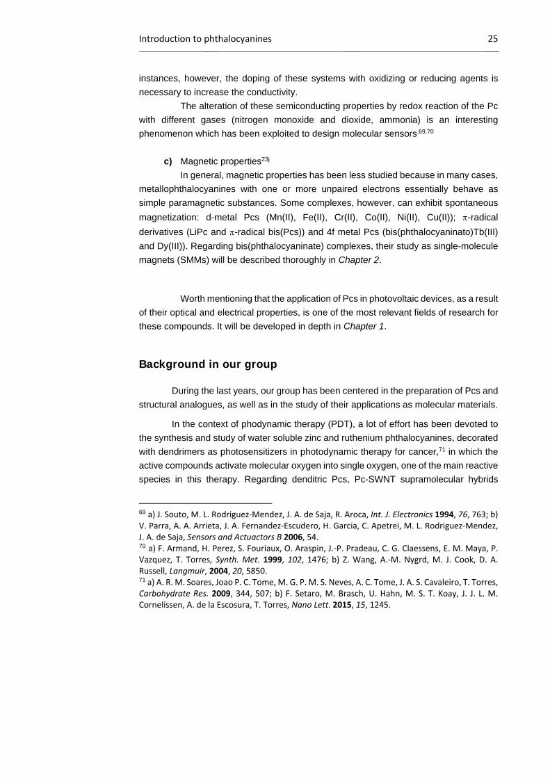
Figure 14.- Self-assembly of photoresponsive, donor-acceptor supramolecular triad B triggered by the disassembly of supramolecular dimer A in the presence of pyridine and benzoic acid derivatives functionalized with a phenothiazine donor and a C60 acceptor moiety, respectively.
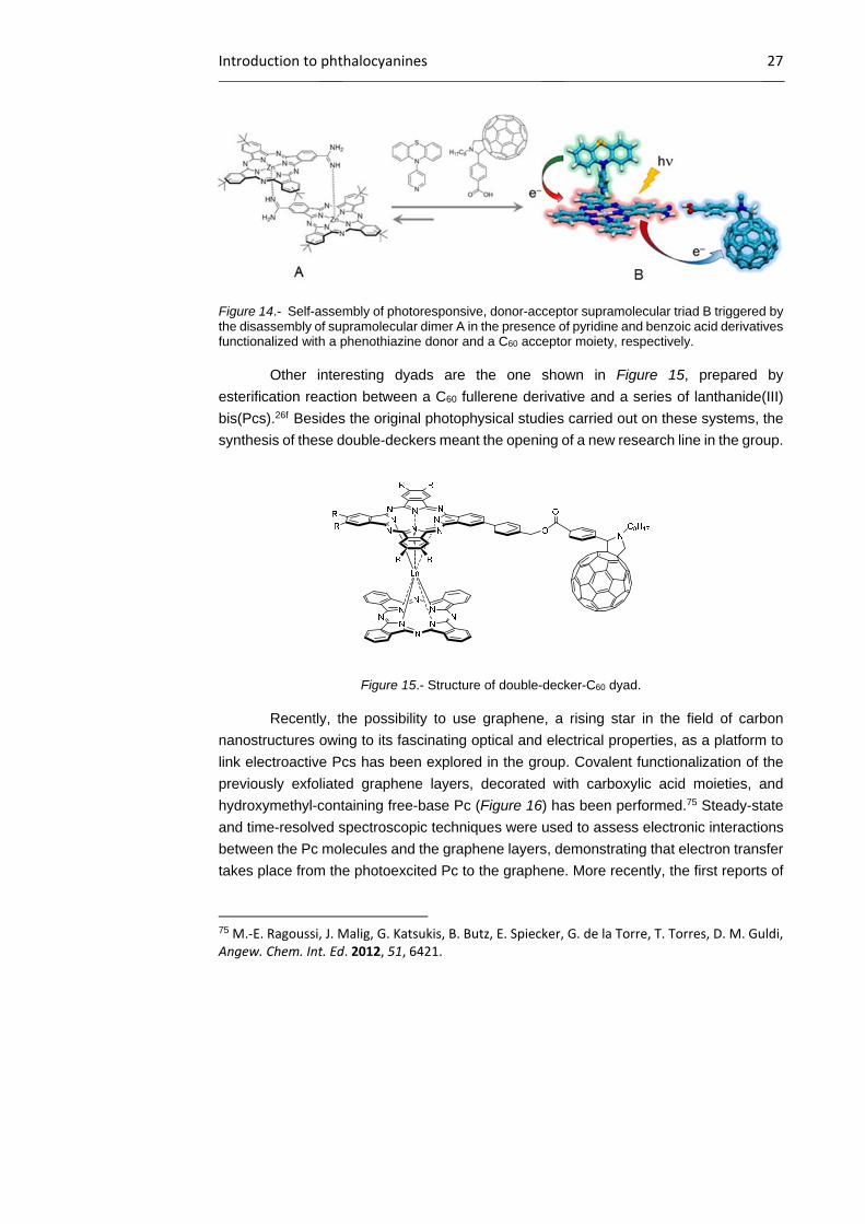
Other interesting dyads are the one shown in Figure 15, prepared by
esterification reaction between a C60 fullerene derivative and a series of lanthanide(III)
bis(Pcs).26f Besides the original photophysical studies carried out on these systems, the
synthesis of these double-deckers meant the opening of a new research line in the group.
Figure 15.- Structure of double-decker-C60 dyad.
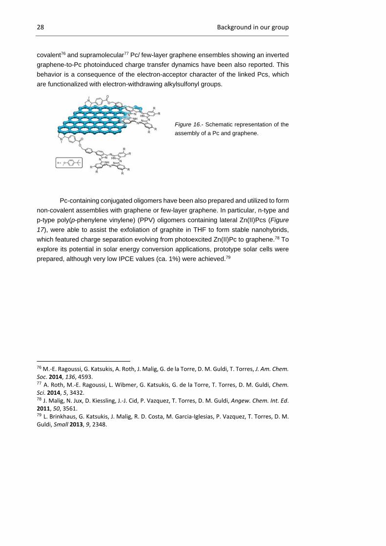
Recently, the possibility to use graphene, a rising star in the field of carbon
nanostructures owing to its fascinating optical and electrical properties, as a platform to
link electroactive Pcs has been explored in the group. Covalent functionalization of the
previously exfoliated graphene layers, decorated with carboxylic acid moieties, and
hydroxymethyl-containing free-base Pc (Figure 16) has been performed.75 Steady-state
and time-resolved spectroscopic techniques were used to assess electronic interactions
between the Pc molecules and the graphene layers, demonstrating that electron transfer
takes place from the photoexcited Pc to the graphene. More recently, the first reports of
75 M.‐E. Ragoussi, J. Malig, G. Katsukis, B. Butz, E. Spiecker, G. de la Torre, T. Torres, D. M. Guldi, Angew. Chem. Int. Ed. 2012, 51, 6421.
28 Background in our group
covalent76 and supramolecular77 Pc/ few-layer graphene ensembles showing an inverted
graphene-to-Pc photoinduced charge transfer dynamics have been also reported. This
behavior is a consequence of the electron-acceptor character of the linked Pcs, which
are functionalized with electron-withdrawing alkylsulfonyl groups.
Figure 16.- Schematic representation of the
assembly of a Pc and graphene.
Pc-containing conjugated oligomers have been also prepared and utilized to form
non-covalent assemblies with graphene or few-layer graphene. In particular, n-type and
p-type poly(p-phenylene vinylene) (PPV) oligomers containing lateral Zn(II)Pcs (Figure
17), were able to assist the exfoliation of graphite in THF to form stable nanohybrids,
which featured charge separation evolving from photoexcited Zn(II)Pc to graphene.78 To
explore its potential in solar energy conversion applications, prototype solar cells were
prepared, although very low IPCE values (ca. 1%) were achieved.79
76 M.‐E. Ragoussi, G. Katsukis, A. Roth, J. Malig, G. de la Torre, D. M. Guldi, T. Torres, J. Am. Chem. Soc. 2014, 136, 4593. 77 A. Roth, M.‐E. Ragoussi, L. Wibmer, G. Katsukis, G. de la Torre, T. Torres, D. M. Guldi, Chem. Sci. 2014, 5, 3432. 78 J. Malig, N. Jux, D. Kiessling, J.‐J. Cid, P. Vazquez, T. Torres, D. M. Guldi, Angew. Chem. Int. Ed. 2011, 50, 3561. 79 L. Brinkhaus, G. Katsukis, J. Malig, R. D. Costa, M. Garcia‐Iglesias, P. Vazquez, T. Torres, D. M. Guldi, Small 2013, 9, 2348.
Introduction to phthalocyanines 29
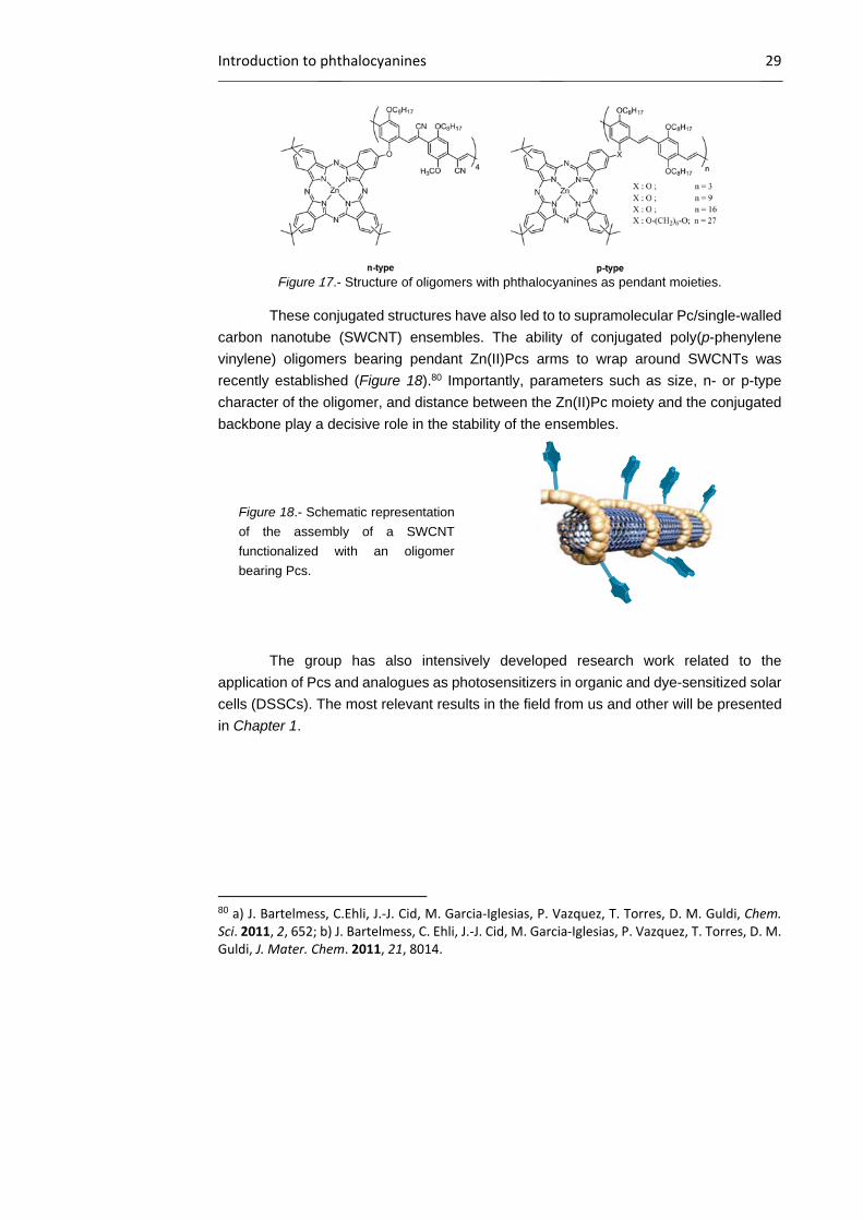
Figure 17.- Structure of oligomers with phthalocyanines as pendant moieties.
These conjugated structures have also led to to supramolecular Pc/single-walled
carbon nanotube (SWCNT) ensembles. The ability of conjugated poly(p-phenylene
vinylene) oligomers bearing pendant Zn(II)Pcs arms to wrap around SWCNTs was
recently established (Figure 18).80 Importantly, parameters such as size, n- or p-type
character of the oligomer, and distance between the Zn(II)Pc moiety and the conjugated
backbone play a decisive role in the stability of the ensembles.
Figure 18.- Schematic representation
of the assembly of a SWCNT
functionalized with an oligomer
bearing Pcs.
The group has also intensively developed research work related to the
application of Pcs and analogues as photosensitizers in organic and dye-sensitized solar
cells (DSSCs). The most relevant results in the field from us and other will be presented
in Chapter 1.
80 a) J. Bartelmess, C.Ehli, J.‐J. Cid, M. Garcia‐Iglesias, P. Vazquez, T. Torres, D. M. Guldi, Chem. Sci. 2011, 2, 652; b) J. Bartelmess, C. Ehli, J.‐J. Cid, M. Garcia‐Iglesias, P. Vazquez, T. Torres, D. M. Guldi, J. Mater. Chem. 2011, 21, 8014.


General objectives

General objectives 33
General objectives
The main goal of this Thesis is the synthesis of new symmetrically and
unsymmetrically substituted metallophthalocyanines, which will be explored either as
photosensitizers in organic solar cells, in combination with semiconducting PPV- and
polythiophene (PT)-polymers, and dye-sensitized solar cells, or as single molecule
magnets. More in detail, the objectives of this work are defined as follows:
Chapter 1. New Zn(II)Pcs for molecular photovoltaics.
The first objective is to synthesize customized, unsymmetrically functionalized
Pc derivatives with different electronic properties as photo- and electroactive components
for molecular photovoltaics, namely for bulk heterojunction (BHJ) and DSSCs. Based on
the broad experience gained by our research group, which has been working in this field
during the last 10 years, the molecular designs of Pcs for photovoltaic applications is
focussed on:
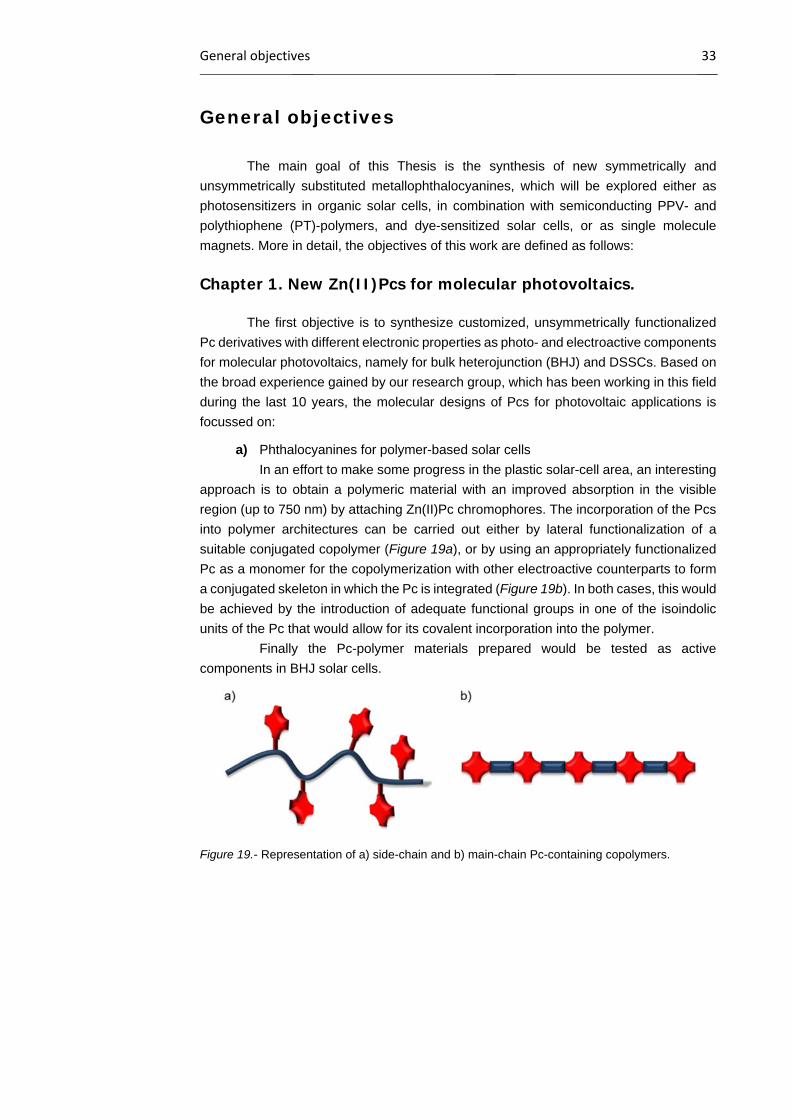
a) Phthalocyanines for polymer-based solar cells
In an effort to make some progress in the plastic solar-cell area, an interesting
approach is to obtain a polymeric material with an improved absorption in the visible
region (up to 750 nm) by attaching Zn(II)Pc chromophores. The incorporation of the Pcs
into polymer architectures can be carried out either by lateral functionalization of a
suitable conjugated copolymer (Figure 19a), or by using an appropriately functionalized
Pc as a monomer for the copolymerization with other electroactive counterparts to form
a conjugated skeleton in which the Pc is integrated (Figure 19b). In both cases, this would
be achieved by the introduction of adequate functional groups in one of the isoindolic
units of the Pc that would allow for its covalent incorporation into the polymer.
Finally the Pc-polymer materials prepared would be tested as active
components in BHJ solar cells.
Figure 19.- Representation of a) side-chain and b) main-chain Pc-containing copolymers.
34 General objectives
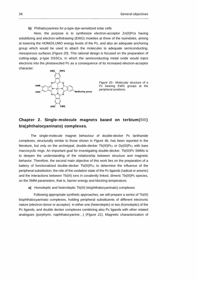
b) Phthalocyanines for p-type dye-sensitized solar cells
Here, the purpose is to synthesize electron-acceptor Zn(II)Pcs having
solubilizing and electron-withdrawing (EWG) moieties at three of the isoindoles, aiming
at lowering the HOMO/LUMO energy levels of the Pc, and also an adequate anchoring
group which would be used to attach the molecules to adequate semiconducting,
mesoporous surfaces (Figure 20). This rational design is focused on the preparation of
cutting-edge, p-type DSSCs, in which the semiconducting metal oxide would inject
electrons into the photoexcited Pc as a consequence of its increased electron-acceptor
character.
Figure 20.- Molecular structure of a Pc bearing EWG groups at the peripheral positions.
Chapter 2. Single-molecule magnets based on terbium(III) bis(phthalocyaninato) complexes.
The single-molecule magnet behaviour of double-decker Pc lanthanide
complexes, structurally similar to those shown in Figure 4b, has been reported in the
literature, but only on the archetypal, double-decker Tb(III)Pc2 or Dy(III)Pc2 with bare
macrocyclic rings. An important goal for investigating double-decker, Tb(III)Pc SMMs is
to deepen the understanding of the relationship between structure and magnetic
behavior. Therefore, the second main objective of this work lies on the preparation of a
battery of functionalized double-decker Tb(III)Pc2 to determine the influence of the
peripheral substitution, the role of the oxidation state of the Pc ligands (radical or anionic)
and the interactions between Tb(III) ions in covalently linked, dimeric Tb(III)Pc species,
on the SMM parameters, that is, barrier energy and blocking temperature.
a) Homoleptic and heteroleptic Tb(III) bis(phthalocyaninato) complexes
Following appropriate synthetic approaches, we will prepare a series of Tb(III)
bisphthalocyaninato complexes, holding peripheral substituents of different electronic
nature (electron-donor or acceptor) in either one (heteroleptic) or two (homoleptic) of the
Pc ligands, and double decker complexes combining also Pc ligands with other related
analogues (porphyrin, naphthalocyanine…) (Figure 21). Magnetic characterization of

General objectives 35
these complexes will allow us to estimate the possible influence of the number and
electronic character of the peripheral substituents, as well as the presence or not of a
different macrocycle on the SMM behaviour of this type of complexes.
Figure 21.- a) Homoleptic and b) heteroleptic terbium(III) bisphthalocyanine complexes. c) Example
of a double-decker complex comprising different macrocyclic ligands.
b) Homoleptic and heteroleptic Tb(III) bis(phthalocyaninato) dimers
To the best of our knowledge, covalently linked Tb(III)Pc2 dimers have been
never reported before. For that reason, we aim to prepare Tb(III)Pc22 complexes
(Figure 22), linked together through short and rigid spacers, to study the spin-spin
interaction between the two paramagnetic nuclei and, therefore, its repercussion in the
SMM parameters with regard to the corresponding monomeric Tb(III)Pc2 units.
Figure 22.- Schematic representation of a heteroleptic dimer.

Chapter 1. New Zn(II)Pcs for molecular photovoltaics

Chapter 1 39
1.1 Introduction
1.1.1 Solar energy
The evolution of mankind before the Industrial Revolution was dependent on the
annual cycle of plant photosynthesis for both heat (burning wood) and mechanical energy
(human and animal muscle power derived from food and fodder). Steam locomotives, the
quintessential machines of the Industrial Revolution, started to use existing energy
resources, such as coal, more efficiently. Ever since, industrial development has
depended on the availability of cheap and reliable energy sources. On an international
scale, the energy required in 2005 was the equivalent of 13 terawatts (TW), which is 13
trillion watts of power. 85% of this energy comes from fossil fuels, which produce large
quantities of greenhouse gases. These emissions turn out catastrophic consequences
for the Earth as a result of global warming. As energy expenses are growing, it has been
estimated that the world’s energy consumption will reach 28 TW in 2050.83 This points
out that the society is facing a dilemma: for further economic development, an increase
in the energy consumption is necessary. However, this leads to unwanted consequences
for the environment due to the emission of pollutants. Therefore, the predicted exhaustion
of fossil energy resources and the pressure of environmental constraints are stimulating
an intensification of the research on renewable energy sources, which play an essential
role in the sustainable development of the environment, economy and society.
Solar, geothermal, ocean, wind, hydropower and biomass are renewable
energies that may meet these energy demands. As a matter of fact, solar energy alone
possesses the potential of becoming the successor of fossil fuels, which will cover the
world’s current energetic needs.84 Sunlight strikes the Earth’s surface with enough energy
every hour to supply world consumption per annum. This is by far the biggest source of
energy available to us, and a great candidate for a transition to a more sustainable
production of energy. Furthermore, this energy source is ubiquitous, and it is expected
that the deployment of solar energy gives political stability to many areas of the planet
because of the more balanced distribution of a primary source of energy.
Solar energy85 can be transformed into electricity either thermodynamically or
electronically. The first method, the solar thermal energy,86 is usually focused in the
83 a) R. F. Service, Science 2005, 309, 548; b) J. Potocnik, Science 2007, 315, 810. 84 Q. Schiermeier, J. Tollefson, T. Scully, A. Witze, O. Morton, Nature 2008, 454, 816. 85 C. Richter, D. Lincot, C. Gueymard (eds.), Solar Energy, Springer, New York, 2013. 86 B. Norton, Harnessing Solar Heat, Lecture in Energy 18, Springer, Dordrecht, 2014.

40 Introduction
design of optical collectors to generate electricity by heating a fluid to drive a turbine
connected to an electrical generator. The second method, instead, converts directly the
solar energy into electricity by opto-electronic devices, called solar cells. This efficient
production of electricity by means of solar cells is nowadays available and photovoltaics
is one of the fastest growing renewable energy technology. In this context, silicon based
solar cells87 are by far the most dominating type of photovoltaic devices with a market
share of about 90% (single crystalline, polycrystalline and amorphous forms).88 Their
broad recognition is attributed to their proven and reliable operational capacities, namely,
good efficiencies and a lifetime of 20 years. Laboratory cell efficiencies have reached
25% (crystalline),89 but commercial module efficiencies are still in the range of 15-18%.90
A combination of an increase in efficiency and a reduction of the production costs of the
photovoltaic panels is still necessary to realistically compete with conventional fossil-fuel
energy conversion systems. Fifty years of research and innovation have significantly
reduced the price of silicon photovoltaics, but, despite this effort, its complex production
hampers a much wider application of it. Another drawback is that silicon panels are very
heavy and rigid in shape. In this regard, both organic photovoltaics and hybrid devices
with active inorganic and organic materials have attracted significant attention as a lower
cost alternative to their purely inorganic relatives.91 Organic materials fulfill many
requirements for solar cells, such as strong optical absorption, easy manufacturing in thin
films, chemical tailoring to tune their properties, and low-cost synthesis,92 as shown in
the next sections. However, long-term stability is still an issue.
87 M. A. Green, Philos. Trans. R. Soc. A 2013, 371, 20110413. 88 IRENA (International Renewable Energy Agency), Renewable Energy Technologies: Cost Analysis Series. Solar Photovoltaics, 2012. Available at: http://www.irena.org/DocumentDownloads/Publications/RE_Technologies_Cost_Analysis‐SOLAR_PV.pdf (Accessed Jan. 2015). 89 M. A. Green, K. Emery, Y. Hishikawa, W. Warta, E. D. Dunlop, Prog. Photovolt: Res. Appl. 2015, 23, 1. 90 T. Saga, NPG Asia Mater. 2010, 2, 96. 91 N. S. Lewis, Science 2007, 315, 798. 92 a) A. W. Hains, Z. Liang, M. A. Woodhouse, B. A. Gregg, Chem. Rev. 2010, 110, 6689; b) J. Roncali, Acc. Chem. Res. 2009, 42, 1719; c) P. M. Beaujuge, J. M. J. Frechet, J. Am. Chem. Soc. 2011, 133, 20009; d) Z. X. Wang, F. J. Zhang, J. Wang, X. W. Xu, J. Wang, Y. Liu, Z. Xu, Chin. Sci. Bull. 2012, 57, 4143; e) M. Pfannmoller, W. Kowalsky, R. R. Schroder, Energy Environ. Sci. 2013, 6, 2871; f) J. Yu, Y. Zheng, J. Huang, Polymers 2014, 6, 2473; g) F. C. Krebs, N. Espinosa, M. Hosel, R. R. Sondergaard, Adv. Mater. 2014, 26, 29; h) T. R. Andersen, H. F. Dam, M. Hosel, M. Helgesen, J. E. Carle, T. T. Larse‐Olsen, S. A. Gevorgyan, J. W. Andreasen, J. Adams, N. Li, F. Machui, G. D. Spyropoulos, T. Ameri, N. Lemaitre, M. Legros, A. Scheel, D. Gaiser, K. Kreul, S. Berny, O. R. Lozman, S. Nordman, M. Valimaki, M. Vilkman, R. R. Sondergaard, M. Jorgensen, C. J. Brabec, F. C. Krebs, Energy Environ. Sci. 2014, 7, 2925.

Chapter 1 41
1.1.2 Classification of solar cells
First reports on photovoltaic concepts date back to the end of the XIX century
with two major contributions; one from Becquerel in 1839, describing photocurrent,93 and
the first real reports on photoconductivity made by Smith and Adams in 1873 and 1876,
respectively, working on selenium.94,95 It was not until the beginning of the XX century
that photoconductivity in an organic compound, namely, anthracene, was observed.96,97
The commercial potential of these photoconductive materials has encouraged the
research in this subject, and the variety of devices has broadened to encompass all fields of development. Solar cells can be broadly classified depending upon the type of active
material used, manufacturing technique, type of junction formed or even the generation.
A classification based on the type of material (inorganic, organic or hybrid when both are
present) is shown below (the record conversion efficiencies for the different technologies
reported in this section are updated until January 2015).
Inorganic solar cells. The technology used to make most of the solar
cells fabricated so far, borrows heavily from the microelectronics industry, where silicon
prevails as semiconductor. The first silicon solar cell was developed by the Bell
Telephone Lab in 1954, showing an efficiency of 6%.98 Much research has followed
because silicon is safe and the second most abundant element on Earth. The crystalline
solar cells, either mono- or polycrystalline, are known as 1st generation solar cells. Their
maximum efficiencies, 25.0% and 20.4% (Figure 23, SunPower, Solibro), respectively,
are close to the Shockley–Queisser theoretical limit, i.e. 33%.99 Crystalline silicon solar
cells dominate the photovoltaic market, despite the fact that an important drawback of
this kind of photovoltaic cells is to get pure silicon. The production costs of such modules
are very high, which motivated engineers and scientists to search for 2nd generation solar
cells by addressing factors such as easy and low-cost production, as well as high
performances.
2nd generation, thin film inorganic solar cells100 appeared in the early 60s
(although they did not raise too much expectations until the 90s), as a consequence of
93 a) A. E. Becquerel, Compt. Rend. Acad. Sci. 1839, 9, 145; b) A. E. Becquerel, Compt. Rend. Acad. Sci. 1839, 9, 561. 94 W. Smith, Nature 1873, 7, 303. 95 W. G. Adams, R. E. Day, Proc. R. Soc. London 1876, 25, 113. 96 A. Pochettino, Acad. Lincei. Rend. 1906, 15, 355. 97 M. Volmer, Ann. Physik 1913, 40, 775. 98 D. M. Chapin, C. S. Fuller, G. L. Pearson, J. Appl. Phys. 1954, 25, 676. 99 W. Shockley, H. J. Queisser, J. Appl. Phys. 1961, 32, 510. 100 L. M. Peter, Phil. Trans. R. Soc. A 2011, 369, 1840.
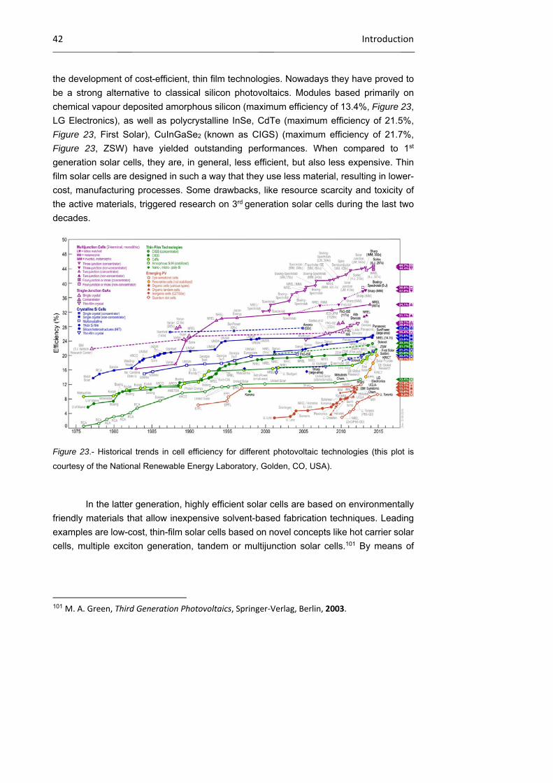
42 Introduction
the development of cost-efficient, thin film technologies. Nowadays they have proved to
be a strong alternative to classical silicon photovoltaics. Modules based primarily on
chemical vapour deposited amorphous silicon (maximum efficiency of 13.4%, Figure 23,
LG Electronics), as well as polycrystalline InSe, CdTe (maximum efficiency of 21.5%,
Figure 23, First Solar), CuInGaSe2 (known as CIGS) (maximum efficiency of 21.7%,
Figure 23, ZSW) have yielded outstanding performances. When compared to 1st
generation solar cells, they are, in general, less efficient, but also less expensive. Thin
film solar cells are designed in such a way that they use less material, resulting in lower-
cost, manufacturing processes. Some drawbacks, like resource scarcity and toxicity of
the active materials, triggered research on 3rd generation solar cells during the last two
decades.
Figure 23.- Historical trends in cell efficiency for different photovoltaic technologies (this plot is
courtesy of the National Renewable Energy Laboratory, Golden, CO, USA).
In the latter generation, highly efficient solar cells are based on environmentally
friendly materials that allow inexpensive solvent-based fabrication techniques. Leading
examples are low-cost, thin-film solar cells based on novel concepts like hot carrier solar
cells, multiple exciton generation, tandem or multijunction solar cells.101 By means of
101 M. A. Green, Third Generation Photovoltaics, Springer‐Verlag, Berlin, 2003.
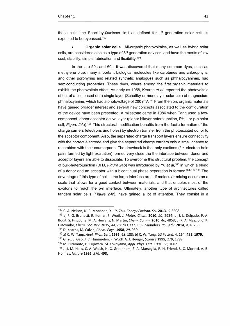
Chapter 1 43
these cells, the Shockley-Queisser limit as defined for 1st generation solar cells is
expected to be bypassed.102
Organic solar cells. All-organic photovoltaics, as well as hybrid solar
cells, are considered also as a type of 3rd generation devices, and have the merits of low
cost, stability, simple fabrication and flexibility.103
In the late 50s and 60s, it was discovered that many common dyes, such as
methylene blue, many important biological molecules like carotenes and chlorophylls,
and other porphyrins and related synthetic analogues such as phthalocyanines, had
semiconducting properties. These dyes, where among the first organic materials to
exhibit the photovoltaic effect. As early as 1958, Kearns et al. reported the photovoltaic
effect of a cell based on a single layer (Schottky or monolayer solar cell) of magnesium
phthalocyanine, which had a photovoltage of 200 mV.104 From then on, organic materials
have gained broader interest and several new concepts associated to the configuration
of the device have been presented. A milestone came in 1986 when Tang used a two-
component, donor:acceptor active layer (planar bilayer heterojunction, PHJ, or p-n solar
cell, Figure 24a).105 This structural modification benefits from the facile formation of the
charge carriers (electrons and holes) by electron transfer from the photoexcited donor to
the acceptor component. Also, the separated charge transport layers ensure connectivity
with the correct electrode and give the separated charge carriers only a small chance to
recombine with their counterparts. The drawback is that only excitons (i.e. electron-hole
pairs formed by light excitation) formed very close tho the interface between donor and
acceptor layers are able to dissociate. To overcome this structural problem, the concept
of bulk-heterojunction (BHJ, Figure 24b) was introduced by Yu et al,106 in which a blend
of a donor and an acceptor with a bicontinual phase separation is formed.92b,107,108 The
advantage of this type of cell is the large interface area, if molecular mixing occurs on a
scale that allows for a good contact between materials, and that enables most of the
excitons to reach the p-n interface. Ultimately, another type of architectures called
tandem solar cells (Figure 24c), have gained a lot of attention. They consist in a
102 C. A. Nelson, N. R. Monahan, X. –Y. Zhu, Energy Environ. Sci. 2013, 6, 3508. 103 a) F. G. Brunetti, R. Kumar, F. Wudl, J. Mater. Chem. 2010, 20, 2934; b) J. L. Delgado, P.‐A. Bouit, S. Filippone, M. A. Herranz, N. Martin, Chem. Comm. 2010, 46, 4853; c) K. A. Mazzio, C. K. Luscombe, Chem. Soc. Rev. 2015, 44, 78; d) J. Yan, B. R. Saunders, RSC Adv. 2014, 4, 43286. 104 D. Kearns, M. Calvin, Chem. Phys. 1958, 29, 950. 105 a) C. W. Tang, Appl. Phys. Lett. 1986, 48, 183; b) C. W. Tang, US Patent, 4, 164, 431, 1979. 106 G. Yu, J. Gao, J. C. Hummelen, F. Wudl, A. J. Heeger, Science 1995, 270, 1789. 107 M. Hiramoto, H. Fujiwara, M. Yokoyama, Appl. Phys. Lett. 1991, 58, 1062. 108 J. J. M. Halls, C. A. Walsh, N. C. Greenham, E. A. Marseglia, R. H. Friend, S. C. Moratti, A. B. Holmes, Nature 1995, 376, 498.
44 Introduction
combination of two or more single junction cells (one on top of the other) that absorb in
different wavelength ranges. Their advantage is that a combination of absorbing
molecules can allow for a large spectral coverage with efficient absorption, which would
be difficult to obtain with a single heterojunction.109,110
Figure 24.- Schematic representation of a) planar bilayer, b) bulk heterojunction and c) tandem
solar cell.
From a different point of view, another classification of the organic solar cells
based on the active material can be established: polymer-based photovoltaic cells, also
known as plastic solar cells,111 which are constituted by conjugated polymers; and small
molecule-based photovoltaic devices, in which discrete chromophores form the active
layer.92b,112
109 a) A. Hadipour, B. de Boer, P. W. M. Blom, Adv. Funct. Mater. 2008, 18, 169; b) T. Ameri, G. Dennler, C. Lungenschmied, C. J. Brabec, Energy Environ. Sci. 2009, 2, 347; c) T. Ameri, N. Li, C. J. Brabec, Energy Environ. Sci. 2013, 6, 2390; d) M. Riede, C. Uhrich, J. Widmer, R. Timmreck, D. Wynands, G. Schwartz, W.‐M. Gnehr, D. Hildebrandt, A. Weiss, J. Hwang, S. Sundarraj, P. Erk, M. Pfeiffer, K. Leo, Adv. Funct. Mater. 2011, 21, 3019. 110 a) J. Y. Kim, K. Lee, N. E. Coates, D. Moses, T.‐Q. Nguyen, M. Dante, A. J. Heeger, Science 2007, 317, 222; b) S. Sista, Z. Hong, L.‐M. Chen, Y. Yang, Energy Environ. Sci. 2011, 4, 1606; c) J. You, L. Dou, Z. Hong, G. Li, Y. Yang, Prog. Polym. Sci. 2013, 38, 1909; d) O. Adebanjo, B. Vaagensmith, Q. Qiao, J. Mater. Chem. A 2014, 2, 10331. 111 a) C. J. Brabec, N. S. Saricifti, J. C. Hummelen, Adv. Funct. Mat. 2001, 11, 15; b) J. Peet, M. L. Senatore, A. J. Heeger, G. C. Bazan, Adv. Mater. 2009, 21, 1521; c) C. J. Brabec, S. Gowrisanker, J. J. M. Halls, D. Laird, S. Jia, S. P. Williams, Adv. Mater. 2010, 22, 3839; d) D. Gendron, M. Leclerc, Energy Environ. Sci. 2011, 4, 1225; e) J. Peet, A. J. Heeger, G. C. Bazan, Acc. Chem. Res. 2009, 42, 1700. 112 a) J. Roncali, P. Frere, P. Blanchard, R. de Bettignies, M. Turbiez, S. Roquet, P. Leriche, Y. Nicolas, Thin Solid Films 2006, 511‐512, 567; b) B. Walker, C. Kim, T.‐Q. Nguyen, Chem. Mater. 2011, 23, 470; c) A. Mishra, P. Bauerle, Angew. Chem. Int. Ed. 2012, 51, 2020; d) M. Wang, F. Wudl, J. Mater. Chem. 2012, 22, 24297; e) Y. Lin, Y. Li, X. Zhan, Chem. Soc. Rev. 2012, 41, 4245; f) W. Hu (ed.), Y. Lin, X. Zhan, Organic Optoelectronics, Wiley‐VCH Verlag GmbH & Co. KGaA,
Chapter 1 45
Regarding efficiencies, while polymeric tandem solar cells have reached a
conversion efficiency of 10.6% (Figure 23, UCLA-Sumitomo Chem.),113 it is worth noting
that the record in multi-junction architectures is held by Heliatek,114 that recently reported
a tandem oligomer-based device with a certified power conversion efficiency of 12%. The
best conversion efficiency for a single junction device has been achieved by Mitsubishi
Chemical, reaching a 11.7% value.115
Hybrid solar cells. Apart from the fully organic solar cells, combinations
of organic-inorganic materials have been of great relevance in recent years. In this sense,
the development of dye-sensitized solar cells (DSSCs) in the 90s opened up new
horizons in the area of photovoltaics, and entered dynamically the race for cost-efficient
devices functioning at the molecular and nanoscale levels.116 The seminal paper by
O’Regan and Grätzel in 1991117 introduced a pioneering architecture, an n-type DSSC,
in which an organic light-absorbing dye is anchored to a mesoporous inorganic n-type
semiconductor film (this semiconductor operates as photoanode) and filled in with a
redox-active electrolyte. This type of DSSCs has shown a tremendous potential and
nowadays is a real alternative to the standard silicon photovoltaics,118 with the obtained
efficiencies growing from 7% in the seminal report,117 using ruthenium complexes as the
dye, to the current 13.0% employing porphyrins as sensitizers and eliminating the need
for rare and costly, ruthenium-based sensitizers as a requirement for high efficiencies.119
Alternatively, p-type DSSCs (an active photocathode) have been also explored but they
have not exhibit yet energy conversion values as high as conventional DSSCs. This has
been ascribed to drawbacks associated with the electrolytes and the p-type
Weinheim, Germany, 2013, Chapter 18. Organic Solar Cells Based on Small Molecules; g) Y. Chen, X. Wan, G. Long, Acc. Chem. Res. 2013, 46, 2645; h) A. F. Eftaiha, J.‐P. Sun, I. G. Hill, G. C. Welch, J. Mater. Chem. A 2014, 2, 1201; i) J. Roncali, P. Leriche, P. Blanchard, Adv. Mater. 2014, 26, 3821. 113 J. You, L. Dou, K. Yoshimura, T. Kato, K. Ohya, T. Moriaty, K. Emery, C.‐C. Chen, J. Gao, G. Li, Y. Yang, Nat. Commun. 2013, 4, 1446. 114 Heliatek GmbH, Heliatek consolidates its technology leadership by establishing a new world record for organic solar technology with a cell efficiency of 12%, 2013. Available at: http://www.heliatek.com/newscenter/latest_news/neuer‐weltrekord‐fur‐organische‐solarzellen‐heliatek‐behauptet‐sich‐mit‐12‐zelleffizienz‐als‐technologiefuhrer/?lang=en (Accessed Jan. 2015). 115 Mitsubishi Chemical Corporation, Achieved power conversion efficiency of 11.7%, the highest in the world!, Available at: http://www.m‐kagaku.co.jp/english/r_td/strategy/technology/topics/opv/index.html (Accessed Jan. 2015). 116 a) A. Hagfeldt, G. Boschloo, L. Sun, L. Kloo, H. Pettersson, Chem. Rev. 2010, 110, 6595; b) M. K. Nazeeruddin, E. Baranoff, M. Gratzel, Solar Energy 2011, 85, 1172. 117 B. O’Regan, M. Gratzel, Nature 1991, 353, 737. 118 H. S. Jung, J.‐K. Lee, J. Phys. Chem. Lett. 2013, 4, 1682. 119 S. Mathew, A. Yella, P. Gao, R. Humphry‐Baker, B. F. E. Curchod, N. Ashari‐Astani, I. Tavernelli, U. Rothlisberger, M. K. Nazeeruddin, M. Gratzel, Nat. Chem. 2014, 6, 242.
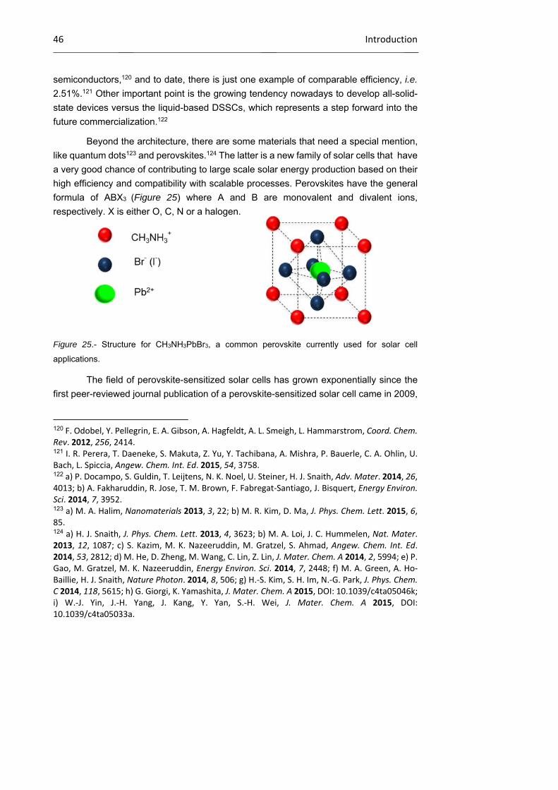
46 Introduction
semiconductors,120 and to date, there is just one example of comparable efficiency, i.e.
2.51%.121 Other important point is the growing tendency nowadays to develop all-solid-
state devices versus the liquid-based DSSCs, which represents a step forward into the
future commercialization.122
Beyond the architecture, there are some materials that need a special mention,
like quantum dots123 and perovskites.124 The latter is a new family of solar cells that have
a very good chance of contributing to large scale solar energy production based on their
high efficiency and compatibility with scalable processes. Perovskites have the general
formula of ABX3 (Figure 25) where A and B are monovalent and divalent ions,
respectively. X is either O, C, N or a halogen.
Figure 25.- Structure for CH3NH3PbBr3, a common perovskite currently used for solar cell
applications.
The field of perovskite-sensitized solar cells has grown exponentially since the
first peer-reviewed journal publication of a perovskite-sensitized solar cell came in 2009,
120 F. Odobel, Y. Pellegrin, E. A. Gibson, A. Hagfeldt, A. L. Smeigh, L. Hammarstrom, Coord. Chem. Rev. 2012, 256, 2414. 121 I. R. Perera, T. Daeneke, S. Makuta, Z. Yu, Y. Tachibana, A. Mishra, P. Bauerle, C. A. Ohlin, U. Bach, L. Spiccia, Angew. Chem. Int. Ed. 2015, 54, 3758. 122 a) P. Docampo, S. Guldin, T. Leijtens, N. K. Noel, U. Steiner, H. J. Snaith, Adv. Mater. 2014, 26, 4013; b) A. Fakharuddin, R. Jose, T. M. Brown, F. Fabregat‐Santiago, J. Bisquert, Energy Environ. Sci. 2014, 7, 3952. 123 a) M. A. Halim, Nanomaterials 2013, 3, 22; b) M. R. Kim, D. Ma, J. Phys. Chem. Lett. 2015, 6, 85. 124 a) H. J. Snaith, J. Phys. Chem. Lett. 2013, 4, 3623; b) M. A. Loi, J. C. Hummelen, Nat. Mater. 2013, 12, 1087; c) S. Kazim, M. K. Nazeeruddin, M. Gratzel, S. Ahmad, Angew. Chem. Int. Ed. 2014, 53, 2812; d) M. He, D. Zheng, M. Wang, C. Lin, Z. Lin, J. Mater. Chem. A 2014, 2, 5994; e) P. Gao, M. Gratzel, M. K. Nazeeruddin, Energy Environ. Sci. 2014, 7, 2448; f) M. A. Green, A. Ho‐Baillie, H. J. Snaith, Nature Photon. 2014, 8, 506; g) H.‐S. Kim, S. H. Im, N.‐G. Park, J. Phys. Chem. C 2014, 118, 5615; h) G. Giorgi, K. Yamashita, J. Mater. Chem. A 2015, DOI: 10.1039/c4ta05046k; i) W.‐J. Yin, J.‐H. Yang, J. Kang, Y. Yan, S.‐H. Wei, J. Mater. Chem. A 2015, DOI: 10.1039/c4ta05033a.
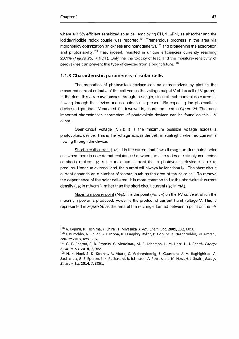
Chapter 1 47
where a 3.5% efficient sensitized solar cell employing CH3NH3PbI3 as absorber and the
iodide/triiodide redox couple was reported.125 Tremendous progress in the area via
morphology optimization (thickness and homogeneity),126 and broadening the absorption
and photostability,127 has, indeed, resulted in unique efficiencies currently reaching
20.1% (Figure 23, KRICT). Only the the toxicity of lead and the moisture-sensitivity of
perovskites can prevent this type of devices from a bright future.128
1.1.3 Characteristic parameters of solar cells
The properties of photovoltaic devices can be characterized by plotting the
measured current output J of the cell versus the voltage output V of the cell (J-V graph).
In the dark, this J-V curve passes through the origin, since at that moment no current is
flowing through the device and no potential is present. By exposing the photovoltaic
device to light, the J-V curve shifts downwards, as can be seen in Figure 26. The most
important characteristic parameters of photovoltaic devices can be found on this J-V
curve.
Open-circuit voltage (VOC): It is the maximum possible voltage across a
photovoltaic device. This is the voltage across the cell, in sunlinght, when no current is
flowing through the device.
Short-circuit current (ISC): It is the current that flows through an illuminated solar
cell when there is no external resistance i.e. when the electrodes are simply connected
or short-circuited. ISC is the maximum current that a photovoltaic device is able to
produce. Under un external load, the current will always be less than ISC. The short-circuit
current depends on a number of factors, such as the area of the solar cell. To remove
the dependence of the solar cell area, it is more common to list the short-circuit current
density (JSC in mA/cm2), rather than the short circuit current (ISC in mA).
Maximum power point (Mpp): It is the point (Vm, Jm) on the I-V curve at which the
maximum power is produced. Power is the product of current I and voltage V. This is
represented in Figure 26 as the area of the rectangle formed between a point on the I-V
125 A. Kojima, K. Teshima, Y. Shirai, T. Miyasaka, J. Am. Chem. Soc. 2009, 131, 6050. 126 J. Burschka, N. Pellet, S.‐J. Moon, R. Humphry‐Baker, P. Gao, M. K. Nazeeruddin, M. Gratzel, Nature 2013, 499, 316. 127 G. E. Eperon, S. D. Stranks, C. Menelaou, M. B. Johnston, L. M. Herz, H. J. Snaith, Energy Environ. Sci. 2014, 7, 982. 128 N. K. Noel, S. D. Stranks, A. Abate, C. Wehrenfennig, S. Guarnera, A.‐A. Haghighirad, A. Sadhanala, G. E. Eperon, S. K. Pathak, M. B. Johnston, A. Petrozza, L. M. Herz, H. J. Snaith, Energy Environ. Sci. 2014, 7, 3061.
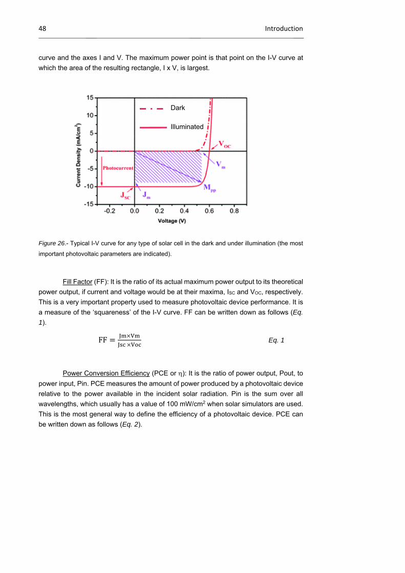
48 Introduction
curve and the axes I and V. The maximum power point is that point on the I-V curve at
which the area of the resulting rectangle, I x V, is largest.
Figure 26.- Typical I-V curve for any type of solar cell in the dark and under illumination (the most
important photovoltaic parameters are indicated).
Fill Factor (FF): It is the ratio of its actual maximum power output to its theoretical
power output, if current and voltage would be at their maxima, ISC and VOC, respectively.
This is a very important property used to measure photovoltaic device performance. It is
a measure of the ‘squareness’ of the I-V curve. FF can be written down as follows (Eq.
1).
FF
Eq. 1
Power Conversion Efficiency (PCE or ): It is the ratio of power output, Pout, to
power input, Pin. PCE measures the amount of power produced by a photovoltaic device
relative to the power available in the incident solar radiation. Pin is the sum over all
wavelengths, which usually has a value of 100 mW/cm2 when solar simulators are used.
This is the most general way to define the efficiency of a photovoltaic device. PCE can
be written down as follows (Eq. 2).
Dark
Illuminated
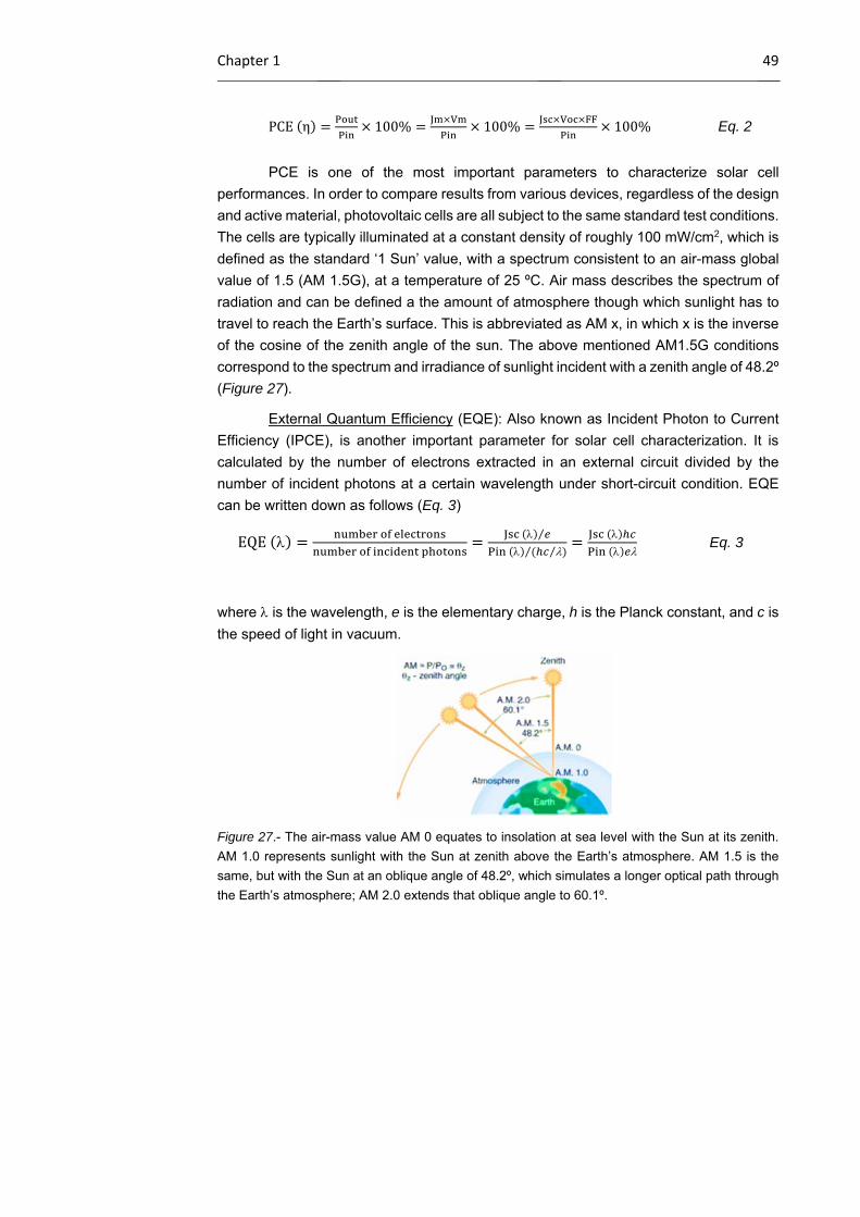
Chapter 1 49
PCE η 100% 100% 100% Eq. 2
PCE is one of the most important parameters to characterize solar cell
performances. In order to compare results from various devices, regardless of the design
and active material, photovoltaic cells are all subject to the same standard test conditions.
The cells are typically illuminated at a constant density of roughly 100 mW/cm2, which is
defined as the standard ‘1 Sun’ value, with a spectrum consistent to an air-mass global
value of 1.5 (AM 1.5G), at a temperature of 25 ºC. Air mass describes the spectrum of
radiation and can be defined a the amount of atmosphere though which sunlight has to
travel to reach the Earth’s surface. This is abbreviated as AM x, in which x is the inverse
of the cosine of the zenith angle of the sun. The above mentioned AM1.5G conditions
correspond to the spectrum and irradiance of sunlight incident with a zenith angle of 48.2º
(Figure 27).
External Quantum Efficiency (EQE): Also known as Incident Photon to Current
Efficiency (IPCE), is another important parameter for solar cell characterization. It is
calculated by the number of electrons extracted in an external circuit divided by the
number of incident photons at a certain wavelength under short-circuit condition. EQE
can be written down as follows (Eq. 3)
EQE
⁄
⁄⁄
Eq. 3
where is the wavelength, e is the elementary charge, h is the Planck constant, and c is
the speed of light in vacuum.
Figure 27.- The air-mass value AM 0 equates to insolation at sea level with the Sun at its zenith.
AM 1.0 represents sunlight with the Sun at zenith above the Earth’s atmosphere. AM 1.5 is the
same, but with the Sun at an oblique angle of 48.2º, which simulates a longer optical path through
the Earth’s atmosphere; AM 2.0 extends that oblique angle to 60.1º.
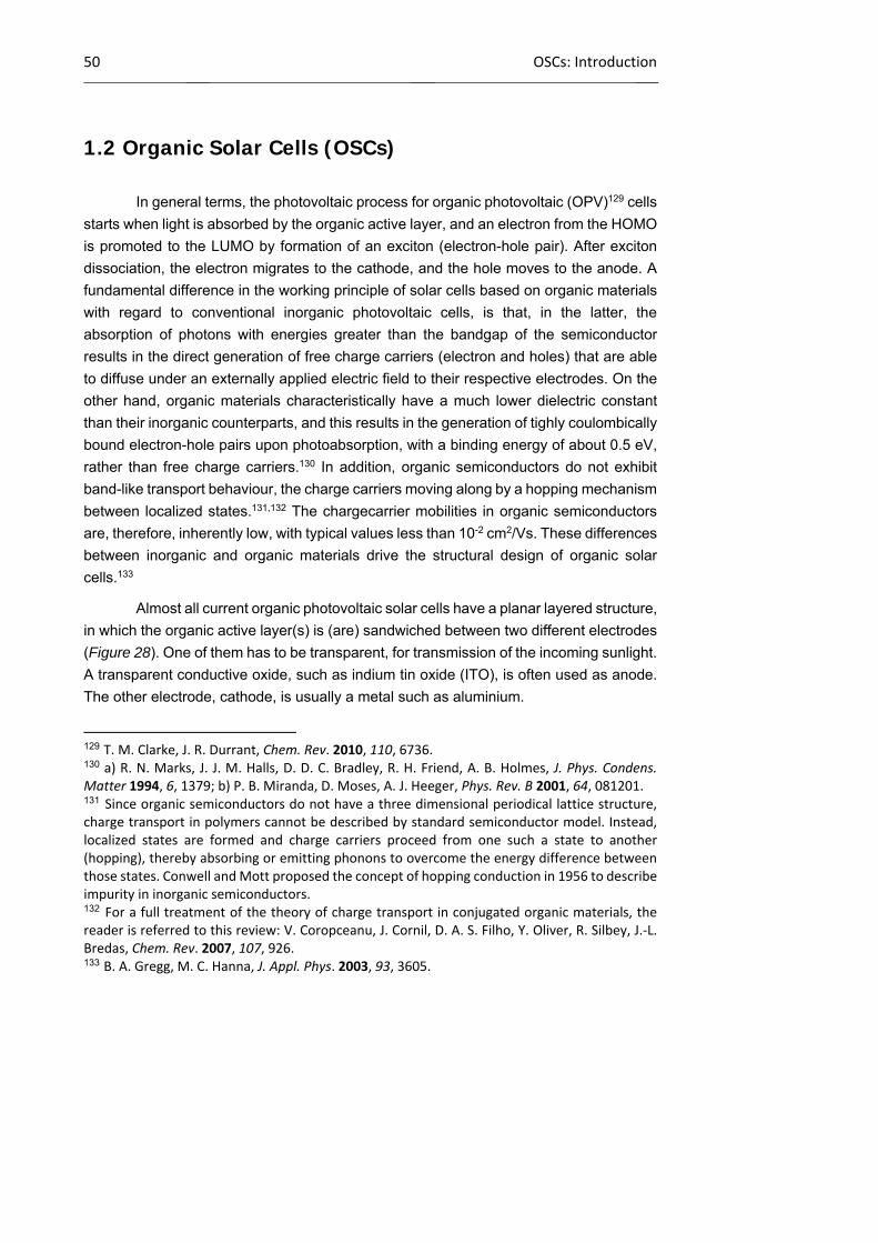
50 OSCs: Introduction
1.2 Organic Solar Cells (OSCs)
In general terms, the photovoltaic process for organic photovoltaic (OPV)129 cells
starts when light is absorbed by the organic active layer, and an electron from the HOMO
is promoted to the LUMO by formation of an exciton (electron-hole pair). After exciton
dissociation, the electron migrates to the cathode, and the hole moves to the anode. A
fundamental difference in the working principle of solar cells based on organic materials
with regard to conventional inorganic photovoltaic cells, is that, in the latter, the
absorption of photons with energies greater than the bandgap of the semiconductor
results in the direct generation of free charge carriers (electron and holes) that are able
to diffuse under an externally applied electric field to their respective electrodes. On the
other hand, organic materials characteristically have a much lower dielectric constant
than their inorganic counterparts, and this results in the generation of tighly coulombically
bound electron-hole pairs upon photoabsorption, with a binding energy of about 0.5 eV,
rather than free charge carriers.130 In addition, organic semiconductors do not exhibit
band-like transport behaviour, the charge carriers moving along by a hopping mechanism
between localized states.131,132 The chargecarrier mobilities in organic semiconductors
are, therefore, inherently low, with typical values less than 10-2 cm2/Vs. These differences
between inorganic and organic materials drive the structural design of organic solar
cells.133
Almost all current organic photovoltaic solar cells have a planar layered structure,
in which the organic active layer(s) is (are) sandwiched between two different electrodes
(Figure 28). One of them has to be transparent, for transmission of the incoming sunlight.
A transparent conductive oxide, such as indium tin oxide (ITO), is often used as anode.
The other electrode, cathode, is usually a metal such as aluminium.
129 T. M. Clarke, J. R. Durrant, Chem. Rev. 2010, 110, 6736. 130 a) R. N. Marks, J. J. M. Halls, D. D. C. Bradley, R. H. Friend, A. B. Holmes, J. Phys. Condens. Matter 1994, 6, 1379; b) P. B. Miranda, D. Moses, A. J. Heeger, Phys. Rev. B 2001, 64, 081201. 131 Since organic semiconductors do not have a three dimensional periodical lattice structure, charge transport in polymers cannot be described by standard semiconductor model. Instead, localized states are formed and charge carriers proceed from one such a state to another (hopping), thereby absorbing or emitting phonons to overcome the energy difference between those states. Conwell and Mott proposed the concept of hopping conduction in 1956 to describe impurity in inorganic semiconductors. 132 For a full treatment of the theory of charge transport in conjugated organic materials, the reader is referred to this review: V. Coropceanu, J. Cornil, D. A. S. Filho, Y. Oliver, R. Silbey, J.‐L. Bredas, Chem. Rev. 2007, 107, 926. 133 B. A. Gregg, M. C. Hanna, J. Appl. Phys. 2003, 93, 3605.
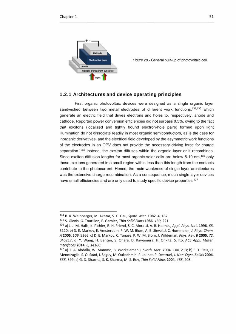
Chapter 1 51
Figure 28.- General built-up of photovoltaic cell.
1.2.1 Architectures and device operating principles
First organic photovoltaic devices were designed as a single organic layer
sandwiched between two metal electrodes of different work functions,134,135 which
generate an electric field that drives electrons and holes to, respectively, anode and
cathode. Reported power conversion efficiencies did not surpass 0.5%, owing to the fact
that excitons (localized and tightly bound electron-hole pairs) formed upon light
illumination do not dissociate readily in most organic semiconductors, as is the case for
inorganic derivatives, and the electrical field developed by the asymmetric work functions
of the electrodes in an OPV does not provide the necessary driving force for charge
separation.103c Instead, the exciton diffuses within the organic layer or it recombines.
Since exciton diffusion lengths for most organic solar cells are below 5-10 nm,136 only
those excitons generated in a small region within less than this length from the contacts
contribute to the photocurrent. Hence, the main weakness of single layer architectures
was the extensive charge recombination. As a consequence, much single layer devices
have small efficiencies and are only used to study specific device properties.137
134 B. R. Weinberger, M. Akhtar, S. C. Gau, Synth. Met. 1982, 4, 187. 135 S. Glenis, G. Tourillon, F. Garnier, Thin Solid Films 1986, 139, 221. 136 a) J. J. M. Halls, K. Pichler, R. H. Friend, S. C. Moratti, A. B. Holmes, Appl. Phys. Lett. 1996, 68, 3120; b) D. E. Markov, E. Amsterdam, P. W. M. Blom, A. B. Sieval, J. C. Hummelen, J. Phys. Chem. A 2005, 109, 5266; c) D. E. Markov, C. Tanase, P. W. M. Blom, J. Wildeman, Phys. Rev. B 2005, 72, 045217; d) Y. Wang, H. Benten, S. Ohara, D. Kawamura, H. Ohkita, S. Ito, ACS Appl. Mater. Interfaces 2014, 6, 14108. 137 a) T. A. Abdalla, W. Mammo, B. Workalemahu, Synth. Met. 2004, 144, 213; b) F. T. Reis, D. Mencaraglia, S. O. Saad, I. Seguy, M. Oukachmih, P. Jolinat, P. Destruel, J. Non‐Cryst. Solids 2004, 338, 599; c) G. D. Sharma, S. K. Sharma, M. S. Roy, Thin Solid Films 2004, 468, 208.
52 OSCs: Introduction
1.2.1.1 Planar heterojunction devices
As outlined above, in 1986 a significant boost in the OPV performance roadmap
came when Tang used a two-component donor:acceptor active layer, consisting of a
copper phthalocyanine (donor) and a perylene derivative (acceptor), in a planar
heterojunction device. A record, for that time, efficiency of 1.0% was reported.105 The
general principle behind heterojunction devices is to use two organic materials with
different electron affinities and ionization potentials. In this manner, exciton (electron and
hole) dissociation at the heterojuntion (interface) of the two components will be favoured,
since the electron will be accepted by the organic material with the largest electron affinity
and the hole by the organic material with the lowest ionization potential.
The schematic structure of a heterojunction photovoltaic device is outlined in
Figure 29. In classical architectures, holes are transported to the anode and electrons
are transported to the cathode (Figure 29a). The anode must be transparent because
through it the light can enter to the solar cell. In this case, the anode, typically consists of
a substrate that is coated with a high work function transparent conducting electrode, and
modified with an interfacial hole selective/electron blocking layer between the electrode
and the active layer. The most common materials in the OPV field used for these
electrodes are indium tin oxide (ITO) on glass substrates modified with a 40 nm thick
poly(3,4-ethylenedioxythiophene):poly(styrenesulfonate) (PEDOT:PSS) interfacial layer.
These materials are favourable due to their large optical transparency and good charge
transport properties. The PEDOT:PSS hole transporting layer smoothens out the ITO
surface, seals the active layer from oxygen and prevents the diffusion of ITO into the
active layer, which can lead to unwanted traps. However, there exist several issues with
the ITO/PEDOT:PSS combination, including the brittleness of both glass and ITO, which
does not allow for roll to roll processing, the rarity and price of indium, and the acidity of
PEDOT:PSS which induces the degradation of devices. The active layers, containing the
donor and acceptor components are deposited on the top of the PEDOT:PSS layer.
There are four roles that need to be filled by the active layer in a heterojunction solar cell:
light absorption, exciton generation, exciton dissociation, and charge separation (the
acceptor material takes the electrons and the donor material, the holes). The conducting
materials must be semiconductors so that the cell can maintain an output voltage and not
just produce photoconductivity. If the charge carriers are generated far from the
electrodes, the materials will also need to be efficient charge conductors (long carrier
lifetimes) so that the charges are not lost before collection (vide infra).
A low work function metal, typically aluminium, is used as the cathode on the top
of the active layer. Most of the time, a very thin layer of lithium fluoride (5-10 Å) is placed
in between the active layer and the cathode, which serves as protecting layer between
Chapter 1 53
the aluminium and the organic components of the device. To a lesser extent, devices
with an inverted structure (Figure 29b), that is with an ITO bottom cathode and a high
work function metal anode, have also been studied.138
Figure 29.- Schematic configuration of an organic photovoltaic system: a) classical (transparent
anode, collecting holes); b) inverted (transparent cathode, collecting electrons).
In a typical heterojunction photovoltaic device four processes occur during the
conversion of solar energy into electrical energy (Figure 30). When light is absorbed by
the donor component, an electron is promoted from the HOMO to the LUMO forming an
exciton (step 1; photoinduced exciton generation). This formed exciton moves towards a
donor/acceptor interface via a chemical potential gradient (step 2; exciton diffusion to the
interface) where the electron can transfer to the LUMO of the acceptor material, forming
a charge transfer complex, which will be favourable to occur when the energy difference
between the LUMO of the donor and the acceptor is greater than the binding energy of
the exciton. This energy difference is typically on the order of a couple hundred meV,
depending on the materials employed, and any absorbed energy in excess of this exciton
binding energy will be lost in these systems. Electron and hole are now on different
materials, but remain strongly bound by coulomb interactions. The charge transfer state
can become a charge separated state, or free charge carriers, (step 3; exciton
dissociation) if the distance between the electron and hole becomes greater than the
coulomb capture radius. Any dissociated charges can be then transported through p-type
or n-type domains to the electrodes, with holes being collected at the anode and electrons
being collected at the cathode (step 4; charge collection), where they can be used to do
work in an external circuit.
138 T. Ameri, G. Dennler, C. Waldauf, H. Azimi, A. Seemann, K. Forberich, J. Hauch, M. Scharber, K. Hingerl, C. J. Brabec, Adv. Mater. 2010, 20, 1592.

54 OSCs: Introduction
Figure 30.- Schematic of the operating principles of OPV, highlighting the desired transport of
charge pairs generated at interface (green) through the donor (red) and acceptor (blue) materials.
Not all the light that is falling onto the photovoltaic device is converted into
photocurrent. There can be a large number of alternative processes, which usually limit
the efficiency of a device.139 For example, not all the incoming photons are absorbed by
the active layer. This is a result of the limited bandgap and thickness of the active layer.
In addition, excitons which are created too far from the donor/acceptor interface (the
exciton diffusion length is limited to 5-10 nm),136 are not able to dissociate into free charge
pairs within the lifetime of the exciton and therefore, by-processes (i.e. fluorescence, non-
radiative) occur, which make the exciton decay back to its ground state. Other loss
mechanisms are the recombination of the geminate electron hole pair across the
donor/acceptor interface (referred to as geminate recombination) and recombination of
free charges during transportation to the electrodes All these energy losses have a direct
bearing on the solar cell efficiency, and obviously characteristic parameters such as JSC,
VOC and FF are also impacted by them. For instance, the EQE, which describes the
overall efficiency of the four main processes of the photovoltaic process in OPVs, can
also be described as follows (Eq. 4).
EQE ηabs ηdiff ηct ηcoll Eq. 5
where ηabs is the photoabsorption efficiency, ηdiff is the exciton diffusion efficiency to the
donor/acceptor interface, ηCT is the charge transfer efficiency, ηcoll is the charge collection
139 a) D. Veldman, S. C. J. Meskers, R. A. J. Janssen, Adv. Funct. Mater. 2009, 19, 1939; b) C. W. Schlenker, M. E. Thompson, Chem. Comm. 2011, 47, 3702; c) U. Hormann, J. Kraus, M. Gruber, C. Schuhmair, T. Linderl, S. Grob, S. Kapfinger, K. Klein, M. Stutzman, H. J. Krenner, W. Brutting, Phys. Rev. B 2013, 88, 235307; d) W. Li, K. H. Hendriks, A. Furlan, M. M. Wienk, R. A. J. Janssen, J. Am. Chem. Soc. 2015, DOI: 10.1021/ja5131897.
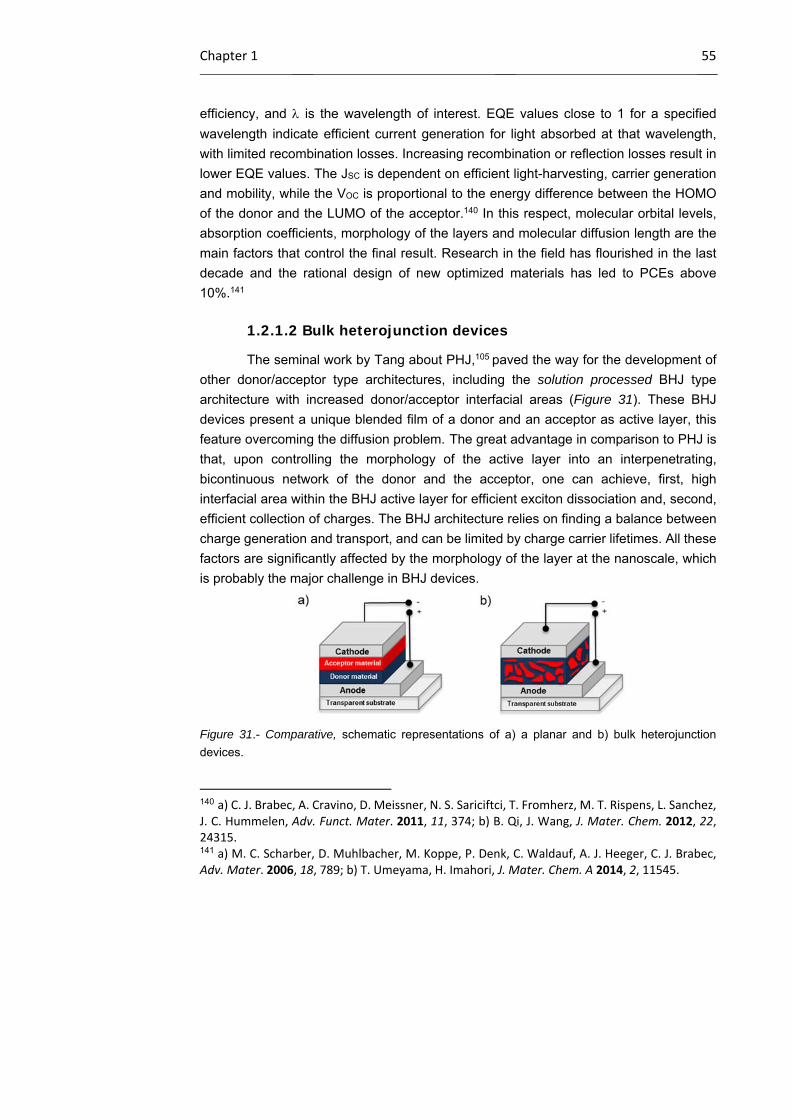
Chapter 1 55
efficiency, and is the wavelength of interest. EQE values close to 1 for a specified
wavelength indicate efficient current generation for light absorbed at that wavelength,
with limited recombination losses. Increasing recombination or reflection losses result in
lower EQE values. The JSC is dependent on efficient light-harvesting, carrier generation
and mobility, while the VOC is proportional to the energy difference between the HOMO
of the donor and the LUMO of the acceptor.140 In this respect, molecular orbital levels,
absorption coefficients, morphology of the layers and molecular diffusion length are the
main factors that control the final result. Research in the field has flourished in the last
decade and the rational design of new optimized materials has led to PCEs above
10%.141
1.2.1.2 Bulk heterojunction devices
The seminal work by Tang about PHJ,105 paved the way for the development of
other donor/acceptor type architectures, including the solution processed BHJ type
architecture with increased donor/acceptor interfacial areas (Figure 31). These BHJ
devices present a unique blended film of a donor and an acceptor as active layer, this
feature overcoming the diffusion problem. The great advantage in comparison to PHJ is
that, upon controlling the morphology of the active layer into an interpenetrating,
bicontinuous network of the donor and the acceptor, one can achieve, first, high
interfacial area within the BHJ active layer for efficient exciton dissociation and, second,
efficient collection of charges. The BHJ architecture relies on finding a balance between
charge generation and transport, and can be limited by charge carrier lifetimes. All these
factors are significantly affected by the morphology of the layer at the nanoscale, which
is probably the major challenge in BHJ devices.
Figure 31.- Comparative, schematic representations of a) a planar and b) bulk heterojunction
devices.
140 a) C. J. Brabec, A. Cravino, D. Meissner, N. S. Sariciftci, T. Fromherz, M. T. Rispens, L. Sanchez, J. C. Hummelen, Adv. Funct. Mater. 2011, 11, 374; b) B. Qi, J. Wang, J. Mater. Chem. 2012, 22, 24315. 141 a) M. C. Scharber, D. Muhlbacher, M. Koppe, P. Denk, C. Waldauf, A. J. Heeger, C. J. Brabec, Adv. Mater. 2006, 18, 789; b) T. Umeyama, H. Imahori, J. Mater. Chem. A 2014, 2, 11545.

56 OSCs: Introduction
This concept has been mainly applied to devices containing semiconducting
polymers as hole-transport materials in combination with C60 fullerene, which holds
unique features for its application in OPVs, for instance, small reorganization energy
associated with charge transfer reactions. In 1995, Yu et al. made the first BHJ
photovoltaic cell,106 in which the active layer consisted of poly[2-methoxy-5-(2’-
ethylhexyloxy)-1,4-phenylenevinylene] (MEH-PPV)142 derivative as donor, and C60 as
acceptor, showing a PCE of 2.9%. One limitation of this approach is the relative low
solubility of fullerenes in normal solvents. This problem was solved by Wudl et al.143 by
synthesizing a number of C60-derivatives with increased solubility (like the well-known
[6,6]-phenyl-C61-butyric acid methyl ester, commonly called PCBM), which allows to
increase the amount of fullerene used for the production of the PV cells. Besides PPV
derivatives, many other types of conjugated polymers, such as polythiophenes, have
been used in fullerene BHJ devices in the search of higher efficiencies. Also in 1995, the
first reports of polymer/polymer bulk heterojunction devices came independently from two
research groups,108,144 both working with the same PPV-derivatives: poly(2,5,2’,5’-
tetrahexyloxy-7,8’-dicyanodi-p-phenylenevinylene) (CN-PPV), as acceptor, and MEH-
PPV as donor. From then on, a large number of studies have been done to find suitable
polymer donor/polymer acceptor (all-polymer) bulk heterojunction devices,145 which
present PCEs reaching 3.0-4.8%.146 More research needs to be done in the search for
good acceptor polymers.147 Hence, the combination of conjugated polymers and
142 F. Wudl, G. Srdanov, 1993, US patent 5,189,136. 143 J. C. Hummelen, B. W. Knight, F. LePeq, F. Wudl, J. Yao, C. L. Wilkins, J. Org. Chem. 1995, 60, 532. 144 G. Yu, A. J. Heeger, J. Appl. Phys. 1995, 78, 4510. 145 A. Facchetti, Mater. Today 2013, 16, 123. 146 a) E. Zhou, J. Cong, Q. Wei, K. Tajima, C. Yang, K. Hashimoto, Angew. Chem Int. Ed. 2011, 50, 2799; b) N. Zhou, H. Lin, S. J. Lou, X. Yu, P. Guo, E. F. Manley, S. Loser, P. Hartnett, H. Huang, M. R. Wasielewski, L. X. Chen, R. P. H. Chang, A. Facchetti, T. J. Marks, Adv. Energy Mater. 2014, 4, 1300785; c) Y. Zhou, T. Kurosawa, W. Ma, Y. Guo, L. Fang, K. Vandewal, Y. Diao, C. Wang, Q. Yan, J. Reinspach, J. Mei, A. L. Appleton, G. I. Koleilat, Y. Gao, S. C. B. Mannsfeld, A. Salleo, H. Ade, D. Zhao, Z. Bao, Adv. Mater. 2014, 26, 3767; d) Y.‐J. Hwang, T. Earmme, S. Subramaniyan, S. A. Jenekhe, Chem. Comm. 2014, 50, 10801; e) T. Earmme, Y.‐J. Hwang, N. M. Murari, S. Subramaniyan, S. A. Jenekhe, J. Am. Chem. Soc. 2013, 135, 14960; f) D. Mori, H. Benten, I. Okada, H. Ohkita, S. Ito, Adv. Energy Mater. 2014, 4, 1301006; g) T. Earmme, Y.‐J. Hwang, S. Subramaniyan, S. A. Jenekhe, Adv. Mater. 2014, 26, 6080. 147 a) J. J. M. Halls, J. Cornil, D. A. dos Santos, R. Silbey, D.‐H. Hwang, A. B. Holmes, J. L. Bredas, R. H. Friend, J. Phys. Rev. B 1999, 60, 5721; b) H. J. Snaith, A. C. Arias, A. C. Morteani, C. Silva, R. H. Friend, Nano Lett. 2002, 2, 1353; c) F. Zhang, M. Jonforsen, D. M. Johansson, M. R. Anderson, O. Inganas, Synth. Met. 2003, 138, 555; d) A. J. Breeze, Z. Schlesinger, S. A. Carter, H. Tillmann, H.‐H. Horhold, Sol. Energ. Mat. Sol. Cells 2004, 83, 263; e) M.‐F. Falzon, M. M. Wienk, R. A. J. Janssen, J. Phys. Chem. C 2011, 115, 3178; f) Y. Kim, E. Lim, Polymers 2014, 6, 382.
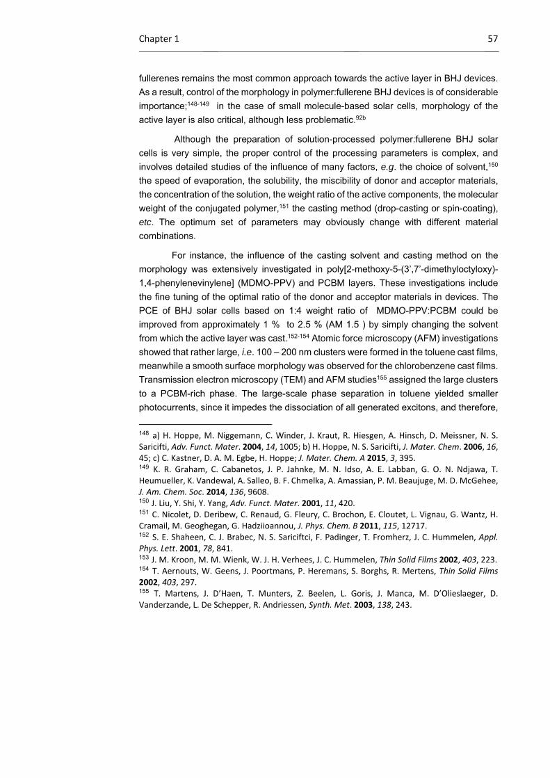
Chapter 1 57
fullerenes remains the most common approach towards the active layer in BHJ devices.
As a result, control of the morphology in polymer:fullerene BHJ devices is of considerable
importance;148-149 in the case of small molecule-based solar cells, morphology of the
active layer is also critical, although less problematic.92b
Although the preparation of solution-processed polymer:fullerene BHJ solar
cells is very simple, the proper control of the processing parameters is complex, and
involves detailed studies of the influence of many factors, e.g. the choice of solvent,150
the speed of evaporation, the solubility, the miscibility of donor and acceptor materials,
the concentration of the solution, the weight ratio of the active components, the molecular
weight of the conjugated polymer,151 the casting method (drop-casting or spin-coating),
etc. The optimum set of parameters may obviously change with different material
combinations.
For instance, the influence of the casting solvent and casting method on the
morphology was extensively investigated in poly[2-methoxy-5-(3’,7’-dimethyloctyloxy)-
1,4-phenylenevinylene] (MDMO-PPV) and PCBM layers. These investigations include
the fine tuning of the optimal ratio of the donor and acceptor materials in devices. The
PCE of BHJ solar cells based on 1:4 weight ratio of MDMO-PPV:PCBM could be
improved from approximately 1 % to 2.5 % (AM 1.5 ) by simply changing the solvent
from which the active layer was cast.152-154 Atomic force microscopy (AFM) investigations
showed that rather large, i.e. 100 – 200 nm clusters were formed in the toluene cast films,
meanwhile a smooth surface morphology was observed for the chlorobenzene cast films.
Transmission electron microscopy (TEM) and AFM studies155 assigned the large clusters
to a PCBM-rich phase. The large-scale phase separation in toluene yielded smaller
photocurrents, since it impedes the dissociation of all generated excitons, and therefore,
148 a) H. Hoppe, M. Niggemann, C. Winder, J. Kraut, R. Hiesgen, A. Hinsch, D. Meissner, N. S. Saricifti, Adv. Funct. Mater. 2004, 14, 1005; b) H. Hoppe, N. S. Saricifti, J. Mater. Chem. 2006, 16, 45; c) C. Kastner, D. A. M. Egbe, H. Hoppe; J. Mater. Chem. A 2015, 3, 395. 149 K. R. Graham, C. Cabanetos, J. P. Jahnke, M. N. Idso, A. E. Labban, G. O. N. Ndjawa, T. Heumueller, K. Vandewal, A. Salleo, B. F. Chmelka, A. Amassian, P. M. Beaujuge, M. D. McGehee, J. Am. Chem. Soc. 2014, 136, 9608. 150 J. Liu, Y. Shi, Y. Yang, Adv. Funct. Mater. 2001, 11, 420. 151 C. Nicolet, D. Deribew, C. Renaud, G. Fleury, C. Brochon, E. Cloutet, L. Vignau, G. Wantz, H. Cramail, M. Geoghegan, G. Hadziioannou, J. Phys. Chem. B 2011, 115, 12717. 152 S. E. Shaheen, C. J. Brabec, N. S. Sariciftci, F. Padinger, T. Fromherz, J. C. Hummelen, Appl. Phys. Lett. 2001, 78, 841. 153 J. M. Kroon, M. M. Wienk, W. J. H. Verhees, J. C. Hummelen, Thin Solid Films 2002, 403, 223. 154 T. Aernouts, W. Geens, J. Poortmans, P. Heremans, S. Borghs, R. Mertens, Thin Solid Films 2002, 403, 297. 155 T. Martens, J. D’Haen, T. Munters, Z. Beelen, L. Goris, J. Manca, M. D’Olieslaeger, D. Vanderzande, L. De Schepper, R. Andriessen, Synth. Met. 2003, 138, 243.

58 OSCs: Introduction
lowers the overall PCE. The high PCBM ratio (MDMO-PPV:PCBM, 1:4) is needed for an
efficient electron transport, which demonstrates that a minimun grain size of PCBM is
necessary to guarantee enough pathways for the electrons. Another interesting finding
was related to the casting method; further investigations have focused on the difference
in the resulting morphology after drop-casting or spin-coating of the films.155 Smaller
PCBM domains are observed in spin-coated films than in drop-cast films due to the faster
evaporation rate during spin-coating which tends to freeze the blend, resulting in smaller
and more dispersed PCBM domains, while the slower evaporation in drop-casting allows
the PCBM to coalesce into larger domains.
Several techniques and a variety of materials have been used to sort out these
morphological problems, like changing the fullerene derivative for other acceptor
molecule or polymer as aforementioned. An alternative approach includes active layers
made of “double cable” polymers (Figure 32). This concept was introduced to have a
control on the morphology at the molecular level by preparing intrinsically bipolar
materials,156 in which the donor and acceptor photoactive units are covalently linked
within the same molecule in order to prevent phase separation. Electrons created by
photoinduced electron transfer are transported by hopping between the pendant acceptor
moieties (n-cable), leaving the remaining holes on the polymer, which are transported
along the conjugated chain (p-cable). In comparison to the bulk-heterojunction, the
effective donor/acceptor interfacial area is maximized within the double-cable design, and
phase separation is prevented. Ideally, the realization of double-cable polymers brings
the p/n-heterojunction to the molecular level. In addition, the interaction between the
donor conjugated backbone and the acceptor moieties may be tuned by varying the
chemical structure (nature and length) of their connecting fragments. In particular, by
introducing an insulating spacer between the n-type and p-type “cable”, the ground state
interaction between the electron donor and acceptor moieties can be prevented, but its
length must be appropriate to facilitate photoinduced electron transfer.
Figure 32.- Ideal representation of “double-cable” polymers. The charge carriers generated by
photoinduced charge transfer can be transported within one molecule, therefore viewed as a
“molecular heterojunction”.
156 A. Cravino, N. S. Saricifti, Nat. Mater. 2003, 2, 360.

Chapter 1 59
In 2001 Ramos et al. reported for the first time the use of a double cable polymer
in an organic solar cell, comprising a PPV derivative with pendant fullerenes.157 and most
of the “double–cable” polymers reported so far contain covalently linked fullerene
moieties.158 Unfortunately, it is difficult to achieve significant load of fullerenes due to
reduced solubility of the “double-cable” polymer. The use of different acceptor molecules
is still much less widespread, although examples can be found emloying anthraquinone
moieties159 or perylene diimide (PDI) as pendant groups.160 As an example of “double-
cable” polymer containing another acceptor unit rather than fullerenes a carbazole-
bithiophene backbone functionalized with PDI units as electron acceptors is depicted in
Figure 33. In general the PCE of organic solar devices employing “double-cable”
materials, is rather low. This indicates the presence of loss mechanisms due to the
recombination of electrons and holes and poor charge transport. Apparently, too intimate
mixing results in the occurrence of too small mean free paths.
Figure 33.- Chemical structure of a carbazole based “double
cable” polymer with pendant PDIs groups.
1.2.2 Advanced organic materials for solar cells
Many material combinations have been tried that fit the necessary requirements
for their use in solar cell devices, namely, intense absorption of light, semiconducting
character, good charge mobility and complementary electron donor/acceptor character.
157 A. M. Ramos, M. T. Rispens, J. K. J. van Duren, J. C. Hummelen, R. A. J. Janssen, J. Am. Chem. Soc. 2001, 123, 6714. 158 a) J. Roncali, Chem. Soc. Rev. 2005, 34, 483; b) F. Giacalone, N. Martin, Chem. Rev. 2006, 106, 5136; c) A. Cravino, N. S. Sariciftci, J. Mater. Chem. 2002, 12, 1931; d) M. Li, P. Xu, J. Yang, S. Yang, J. Mater. Chem. 2010, 20, 3953; e) B. Gholamkhass, T. J. Peckham, S. Holdcroft, Polym. Chem. 2010, 1, 708; f) N. Berton, I. Fabre‐Francke, D. Bourrat, F. Chandezon, S. Sadki, J. Phys. Chem. B 2009, 113, 14087. 159 a) M. Catellani, S. Luzzati, N.‐O. Lupsac, R. Mendichi, R. Consonni, A. Famulari, S. V. Meille, F. Giacalone, J. L. Segura, N. Martin, J. Mater. Chem. 2004, 14, 67; b) D. K. Mohamad, S. S. Chauhan, H. Yi, A. J. Cadby, D. G. Lidzey, A. Iraqi, Sol. Energy Mater. Sol. Cells 2011, 95, 1723. 160 D. K. Mohamad, A. Fischereder, H. Yi, A. J. Cadby, D. G. Lidzey, A. Iraqi, J. Mater. Chem. 2011, 21, 851.
N nS S
N
N
OO
OO
C11H23C11H23

60 OSCs: Introduction
Generally, these materials fall into two main categories depending on their size: polymers
and small molecules. Polymer solar cells, as mentioned above, are processed from
solution in organic solvents to form BHJ devices, whereas small molecule solar cells are
processed mainly using thermal evaporation deposition in a high vacuum environment to
build PHJ cells with a more precise control of the thickness and morphology of the active
layers. Using the solution process to fabricate small molecule solar cells has recently
been gaining momentum, although the film quality and crystallization is expected to be
an issue.
In the following section, the most efficient materials in both small molecule and
polymer solar cells will be described.
1.2.2.1 Small molecules-based solar cells
For some years, small molecule solar cells were built in PHJ arquitectures by
high vacuum evaporation techniques of chromophores such as Pcs, PDIs, C60 fullerenes,
among others, but solution-processed BHJ devices were only reserved for polymers. In
spite of the plentiful advantages of polymers employed as the light harvester and electron
donor in OPVs, limitations related to the reproducibility of their synthesis, purification, and
inherent electronic properties sparked the search for alternatives, the most promising
solution liying in soluble small conjugated molecules. Research in the field was initiated
in 2006,112a and since then the use of many classes of chromophores, such as
oligothiophenes, triphenylamines, borondipyrromethene (BODIPY),
diketopyrrolopyrroles, and other -conjugated molecules in OPVs has been
described.92c,112c,i,161 Solution processing (spin-coating, inkjet printing, dip-coating,
spraying technique) has, been employed, giving rise to a vast number of successful
configurations.112b
Oligothiophenes are among the most-studied organic semiconductors, owing to
their intriguing charge transport characteristics and tunable optoelectronic properties.162
Initial studies in vacuum-deposited OPVs with 3D oligothiophenes, showed low
efficiencies, attributed to the poor absorption characteristics of the material.92b,112i A
number of other oligothiophene analogues and configurations have been prepared and
tested.112c However, a significant boost in performance was observed with oligothiophene
DR3TBDTT, having a benzo[1,2-b:4,5-b′]dithiophene (BDT) unit as the central building
block (Figure 34). This oligothiophene presents improved conjugation and, therefore
improved light-harvesting and JSC, and long alkyl chains to enhance solubility and hence
processability. Solar cells fabricated with the architecture
161 M. V. Martinez‐Diaz, G. de la Torre, T. Torres, Chem. Comm. 2010, 46, 7090. 162 A. Mishra, C.‐Q. Ma, P. Bauerle, Chem. Rev. 2009, 109, 1141.
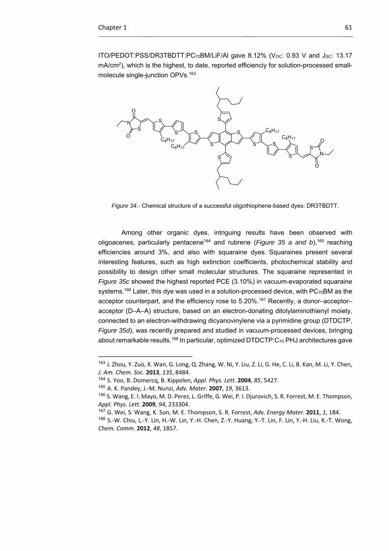
Chapter 1 61
ITO/PEDOT:PSS/DR3TBDTT:PC70BM/LiF/Al gave 8.12% (VOC: 0.93 V and JSC: 13.17
mA/cm2), which is the highest, to date, reported efficienciy for solution-processed small-
molecule single-junction OPVs.163
Figure 34.- Chemical structure of a successful oligothiophene-based dyes: DR3TBDTT.
Among other organic dyes, intriguing results have been observed with
oligoacenes, particularly pentacene164 and rubrene (Figure 35 a and b),165 reaching
efficiencies around 3%, and also with squaraine dyes. Squaraines present several
interesting features, such as high extinction coefficients, photochemical stability and
possibility to design other small molecular structures. The squaraine represented in
Figure 35c showed the highest reported PCE (3.10%) in vacuum-evaporated squaraine
systems.166 Later, this dye was used in a solution-processed device, with PC70BM as the
acceptor counterpart, and the efficiency rose to 5.20%.167 Recently, a donor–acceptor–
acceptor (D–A–A) structure, based on an electron-donating ditolylaminothienyl moiety,
connected to an electron-withdrawing dicyanovinylene via a pyrimidine group (DTDCTP,
Figure 35d), was recently prepared and studied in vacuum-processed devices, bringing
about remarkable results.168 In particular, optimized DTDCTP:C70 PHJ architectures gave
163 J. Zhou, Y. Zuo, X. Wan, G. Long, Q. Zhang, W. Ni, Y. Liu, Z. Li, G. He, C. Li, B. Kan, M. Li, Y. Chen, J. Am. Chem. Soc. 2013, 135, 8484. 164 S. Yoo, B. Domercq, B. Kippelen, Appl. Phys. Lett. 2004, 85, 5427. 165 A. K. Pandey, J.‐M. Nunzi, Adv. Mater. 2007, 19, 3613. 166 S. Wang, E. I. Mayo, M. D. Perez, L. Griffe, G. Wei, P. I. Djurovich, S. R. Forrest, M. E. Thompson, Appl. Phys. Lett. 2009, 94, 233304. 167 G. Wei, S. Wang, K. Sun, M. E. Thompson, S. R. Forrest, Adv. Energy Mater. 2011, 1, 184. 168 S.‐W. Chiu, L.‐Y. Lin, H.‐W. Lin, Y.‐H. Chen, Z.‐Y. Huang, Y.‐T. Lin, F. Lin, Y.‐H. Liu, K.‐T. Wong, Chem. Comm. 2012, 48, 1857.
S
S
S
S
S
S C8H17
C8H17
S
S
S
S
C8H17C8H17
NS
NS
O
O
O
O

62 OSCs: Introduction
a PCE of 6.4% with a VOC of 0.95 V, JSC of 12.1 mA/cm2 and FF of 0.56. The impressive
VOC was attributed to the low-lying HOMO level (-5.46 eV) of the donor material.
Figure 35.- Chemical structure of some successful small molecules used in OPVs: a) pentacene,
b) rubrene, c) squaraine, d) DTDCTP and e) a diketopyrrolopyrrole derivative.
Noteworthy are also the results that have been obtained with
diketopyrrolopyrroles (DPP)169 in solution-processed systems. DPP are attractive
building blocks in terms of synthetic versatility. Modification of the main structure with
benzofuran substituents led to the derivative represented in Figure 35e, which exhibited
increased intermolecular chromophore interaction through high conjugation as well as
stabilized HOMO levels.170 In detail, a deep HOMO of -5.2 eV was observed and when
blended with PC70BM, it gave a VOC higher than 0.9 V, a JSC of 10 mA/cm2 and an overall
efficiency of 4.4%.
From a different angle, notwithstanding the great success of porphyrins in dye-
sensitized solar cells, as this will be discussed further in another section, this class of
compounds has not been as triumphant in OPVs due to their reduced absorption in the
red region of the visible spectrum and the lower charge-carrier mobility and exciton–
169 a) M. Grzybowski, D. T. Gryko, Adv. Optical Mater. 2015, 3, 280; b) B. P. Karsten, J. C. Bijleveld, R. A. J. Janssen, Macromol. Rapid Commun. 2010, 31, 1554; c) D. Chandran, K.‐S. Lee, Macromol. Res. 2013, 21, 272. 170 B. Walker, A. B. Tamayo, X.‐D. Dang, P. Zalar, J.‐H. Seo, A. Garcia, M. Tantiwiwat, T.‐Q. Nguyen, Adv. Funct. Mater. 2009, 19, 3063.
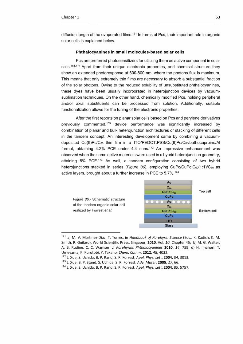
Chapter 1 63
diffusion length of the evaporated films.161 In terms of Pcs, their important role in organic
solar cells is explained below.
Phthalocyanines in small molecules-based solar cells
Pcs are preferred photosensitizers for utilizing them as active component in solar
cells.161,171 Apart from their unique electronic properties, and chemical structure they
show an extended photoresponse at 600-800 nm, where the photons flux is maximum.
This means that only extremely thin films are necessary to absorb a substantial fraction
of the solar photons. Owing to the reduced solubility of unsubstituted phthalocyanines,
these dyes have been usually incorporated in heterojunction devices by vacuum-
sublimation techniques. On the other hand, chemically modified Pcs, holding peripheral
and/or axial substituents can be processed from solution. Additionally, suitable
functionalization allows for the tuning of the electronic properties.
After the first reports on planar solar cells based on Pcs and perylene derivatives
previously commented,105 device performance was significantly increased by
combination of planar and bulk heterojunction architectures or stacking of different cells
in the tandem concept. An interesting development came by combining a vacuum-
deposited Cu(II)Pc/C60 thin film in a ITO/PEDOT:PSS/Cu(II)Pc/C60/bathocuproine/Al
format, obtaining 4.2% PCE under 4.4 suns.172 An impressive enhancement was
observed when the same active materials were used in a hybrid heterojunction geometry,
attaining 5% PCE.173 As well, a tandem configuration consisting of two hybrid
heterojunctions stacked in series (Figure 36), employing CuPc/CuPc:C60(1:1)/C60 as
active layers, brought about a further increase in PCE to 5.7%.174
Figure 36.- Schematic structure
of the tandem organic solar cell
realized by Forrest et al.
171 a) M. V. Martínez‐Diaz, T. Torres, in Handbook of Porphyrin Science (Eds.: K. Kadish, K. M. Smith, R. Guilard), World Scientific Press, Singapur, 2010, Vol. 10, Chapter 45; b) M. G. Walter, A. B. Rudine, C. C. Wamser, J. Porphyrins Phthalocyanines 2010, 14, 759; d) H. Imahori, T. Umeyama, K. Kurotobi, Y. Takano, Chem. Comm. 2012, 48, 4032. 172 J. Xue, S. Uchida, B. P. Rand, S. R. Forrest, Appl. Phys. Lett. 2004, 84, 3013. 173 J. Xue, B. P. Stand, S. Uchida, S. R. Forrest, Adv. Mater. 2005, 17, 66. 174 J. Xue, S. Uchida, B. P. Rand, S. R. Forrest, Appl. Phys. Lett. 2004, 85, 5757.
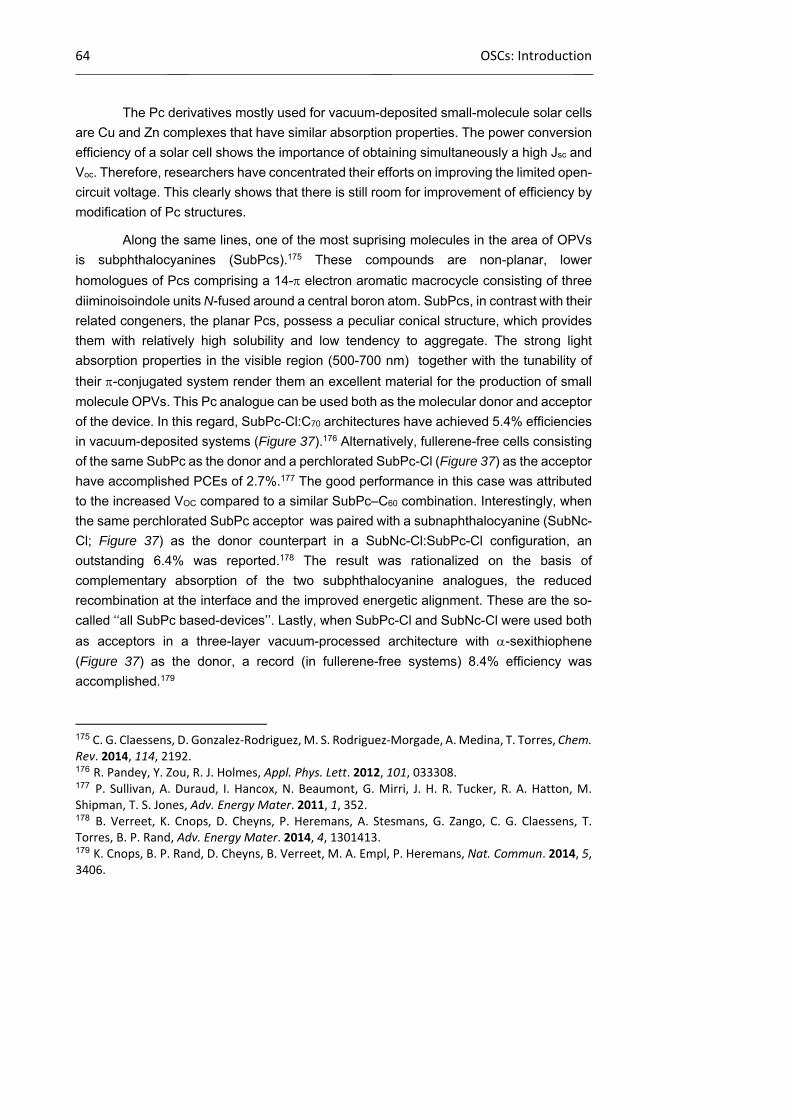
64 OSCs: Introduction
The Pc derivatives mostly used for vacuum-deposited small-molecule solar cells
are Cu and Zn complexes that have similar absorption properties. The power conversion
efficiency of a solar cell shows the importance of obtaining simultaneously a high Jsc and
Voc. Therefore, researchers have concentrated their efforts on improving the limited open-
circuit voltage. This clearly shows that there is still room for improvement of efficiency by
modification of Pc structures.
Along the same lines, one of the most suprising molecules in the area of OPVs
is subphthalocyanines (SubPcs).175 These compounds are non-planar, lower
homologues of Pcs comprising a 14- electron aromatic macrocycle consisting of three
diiminoisoindole units N-fused around a central boron atom. SubPcs, in contrast with their
related congeners, the planar Pcs, possess a peculiar conical structure, which provides
them with relatively high solubility and low tendency to aggregate. The strong light
absorption properties in the visible region (500-700 nm) together with the tunability of
their -conjugated system render them an excellent material for the production of small
molecule OPVs. This Pc analogue can be used both as the molecular donor and acceptor
of the device. In this regard, SubPc-Cl:C70 architectures have achieved 5.4% efficiencies
in vacuum-deposited systems (Figure 37).176 Alternatively, fullerene-free cells consisting
of the same SubPc as the donor and a perchlorated SubPc-Cl (Figure 37) as the acceptor
have accomplished PCEs of 2.7%.177 The good performance in this case was attributed
to the increased VOC compared to a similar SubPc–C60 combination. Interestingly, when
the same perchlorated SubPc acceptor was paired with a subnaphthalocyanine (SubNc-
Cl; Figure 37) as the donor counterpart in a SubNc-Cl:SubPc-Cl configuration, an
outstanding 6.4% was reported.178 The result was rationalized on the basis of
complementary absorption of the two subphthalocyanine analogues, the reduced
recombination at the interface and the improved energetic alignment. These are the so-
called ‘‘all SubPc based-devices’’. Lastly, when SubPc-Cl and SubNc-Cl were used both
as acceptors in a three-layer vacuum-processed architecture with -sexithiophene
(Figure 37) as the donor, a record (in fullerene-free systems) 8.4% efficiency was
accomplished.179
175 C. G. Claessens, D. Gonzalez‐Rodriguez, M. S. Rodriguez‐Morgade, A. Medina, T. Torres, Chem. Rev. 2014, 114, 2192. 176 R. Pandey, Y. Zou, R. J. Holmes, Appl. Phys. Lett. 2012, 101, 033308. 177 P. Sullivan, A. Duraud, I. Hancox, N. Beaumont, G. Mirri, J. H. R. Tucker, R. A. Hatton, M. Shipman, T. S. Jones, Adv. Energy Mater. 2011, 1, 352. 178 B. Verreet, K. Cnops, D. Cheyns, P. Heremans, A. Stesmans, G. Zango, C. G. Claessens, T. Torres, B. P. Rand, Adv. Energy Mater. 2014, 4, 1301413. 179 K. Cnops, B. P. Rand, D. Cheyns, B. Verreet, M. A. Empl, P. Heremans, Nat. Commun. 2014, 5, 3406.
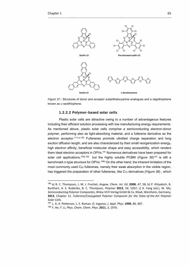
Chapter 1 65
Figure 37.- Structures of donor and acceptor subphthalocyanine analogues and a oligothiophene
known as -sexithiophene.
1.2.2.2 Polymer-based solar cells
Plastic solar cells are attractive owing to a number of advantageous features
including their efficient solution processing with low manufacturing energy requirements.
As mentioned above, plastic solar cells comprise a semiconducting electron-donor
polymer, performing also as light-absorbing material, and a fullerene derivative as the
electron acceptor.111c,e,180 Fullerenes promote ultrafast charge separation and long
exciton diffusion length, and are also characterized by their small reorganization energy,
high electron affinity, beneficial molecular shape and easy accessibility, which renders
them ideal electron acceptors in OPVs.181 Numerous derivatives have been prepared for
solar cell applications,103b,182 but the highly soluble PCBM (Figure 38)143 is still a
benchmark n-type structure for OPVs.108b On the other hand, the inherent limitation of the
most commonly used C60 fullerenes, namely their weak absorption in the visible region,
has triggered the preparation of other fullerenes, like C70 derivatives (Figure 38) , which
180 a) B. C. Thompson, J. M. J. Frechet, Angew. Chem. Int. Ed. 2008, 47, 58; b) P. Khlyabich, B. Burkhart, A. E. Rudenko, B. C. Thompson, Polymer 2013, 54, 5267; c) X. Yang (ed.), W. Ma, Semiconducting Polymer Composites, Wiley‐VCH Verlag GmbH & Co. KGaA, Weinheim, Germany, 2013, Chapter 12. Fullerene/Conjugated Polymer Composite for the State‐of‐the‐Art Polymer Solar Cells. 181 L. A. A. Petterson, L. S. Roman, O. Inganas, J. Appl. Phys. 1999, 86, 487. 182 Y. He, Y. Li, Phys. Chem. Chem. Phys. 2011, 3, 1970.

66 OSCs: Introduction
exhibit significantly stronger absorption over a wider range of the visible spectrum than
C60 derivatives.183 To overcome the scarce bandgap tunability of fuller-based acceptors,
some research has also been devoted to the use of non-fullerene n-type organic
molecules with strong absorption in the visible range and easy-to-modify structures and
electronic leves, such as perylenediimides, diketopyrrolopyrroles,169,184
benzothiadiazoles (BT),185 and dicyanovinylenes,186 among others, as alternative
acceptors for OPVs.112h,187,188 Performances, though, remain consistently poor (less than
3%), with the exception of perylenediimides (Figure 38)189 that have shown intriguing
behaviour and efficiencies up to 6.1%.190 Alternatively, small molecule donor/polymer
183 a) S. Pfuetzner, J. Meiss, A. Petrich, M. Riede, K. Leo, Appl. Phys. Lett. 2009, 94, 223307; b) M. M. Wienk, J. M. Kroon, W. J. H. Verhees, J. Knol, J. C. Hummelen, P. A. van Hal, R. A. J. Janssen, Angew. Chem. Int. Ed. 2003, 42, 3371. 184 a) Y. Lin, P. Cheng, Y. Li, X. Zhan, Chem. Comm. 2012, 48, 4773; b) Y. Lin, Y. Li, X. Zhan, Adv. Energy Mater. 2013, 3, 724; c) H. Patil. W. X. Zu, A. Gupta, V. Chellappan, A. Bilic, P. Sonar, A. Rananaware, S. V. Bhosale, S. V. Bhosale, Phys. Chem. Chem. Phys. 2014, 16, 23837. 185 a) P. E. Schwenn, K. Gui, A. M. Nardes, K. B. Krueger, K. H. Lee, K. Mutkins, H. Rubinstein‐Dunlop, P. E. Shaw, N. Kopidakis, P. L. Burn, P. Meredith, Adv. Energy Mater. 2011, 1, 73; b) J. T. Bloking, X. Han, A. T. Higgs, J. P. Kastrop, L. Pandey, J. E. Norton, C. Risko, C. E. Chen, J.‐L. Bredas, M. D. McGehee, A. Sellinger, Chem. Mater. 2011, 23, 5484; c) J. T. Bloking, T. Giovenzana, A. T. Higgs, A. J. Ponec, E. T. Hoke, K. Vandewal, S. Ko, Z. Bao, A. Sellinger, M. D. McGehee, Adv. Energy Mater. 2014, 4, 1301426. 186 a) T. Zhou, T. Jia, B. Kang, F. Li, M. Fahlman, Y. Wang, Adv. Energy Mater. 2011, 1, 431, b) Y. Fang, A. K. Pandey, A. M. Nardes, N. Kopidakis, P. L. Burn, P. Meredith, Adv. Energy Mater. 2013, 3, 54. 187 a) P. Sonar, J. P. F. Lim, K. L. Chan, Energy Environ. Sci. 2011, 4, 1558; b) C. L. Chochos, N. Tagmatarchis, V. G. Gregoriou, RSC Adv. 2013, 3, 7160; c) Y. Lin, X. Zhan, Mater. Horiz. 2014, 1, 470. 188 a) Y. Zhou, L. Ding, K. Shi, Y.‐Z. Dai, N. Ai, J. Wang, J. Pei, Adv. Mater. 2012, 24, 957; b) T. V. Pho, F. M. Toma, B. J. Tremolet de Villers, S. Wang, N. D. Treat, N. Eisenmenger, G. M. Su, R. C. Coffin, J. D. Douglas, J. M. J. Frechet, G. C. Bazan, F. Wudl, M. L. Chabinyc, Adv. Energy Mater. 2014, 4, 1301007; c) S. Holliday, R. S. Ashraf, C. B. Nielsen, M. Kirkus, J. A. Rohr, C.‐H. Tan, E. Collado‐Fregoso, A.‐C. Knall, J. R. Durrant, J. Nelson, I. McCulloch, J. Am. Chem. Soc. 2015, 137, 898; d) H. Li, T. Earmme, S. Subramaniyan, S. A. Jenekhe, Adv. Energy Mater. 2015, DOI: 10.1002/aenm.201402041. 189 a) E. Kozma, M. Catellani, Dyes Pigments 2013, 98, 160; b) Q. Yan, Y. Zhou, Y.‐Q. Zheng, J. Pei, D. Zhao, Chem. Sci. 2013, 4, 4389. 190 a) G. Ren, E. Ahmed, S. A. Jenekhe, Adv. Energy Mater. 2011, 1, 946; b) S. Rajaram, R. Shivanna, S. K. Kandappa, K. S. Narayan, J. Phys. Chem. Lett. 2012, 3, 2405; c) X. Zhang, Z. Lu, L. Ye, C. Zhan, J. Hou, S. Zhang, B. Jiang, Y. Zhao, J. Huang, S. Zhang, Y. Liu, Q. Shi, Y. Liu, J. Yao, Adv. Mater. 2013, 25, 5791; d) Y. Zang, C.‐Z. Li, C.‐C. Chueh, S. T. Williams, W. Jiang, Z.‐H. Wang, J.‐S. Yu, A. K.‐Y. Jen, Adv. Mater. 2014, 26, 5708; e) Y. Zhong, M. T. Trinh, R. Chen, W. Wang, P. P. Khlyabich, B. Kumar, Q. Xu, C.‐Y. Nam, M. Y. Sfeir, C. Black, M. L. Steigerwald, Y.‐L. Loo, S. Xiao, F. Ng, X.‐Y. Zhu, C. Nuckolls, J. Am. Chem. Soc. 2014, 136, 15215; f) W. Jiang, L. Ye, X. Li, C. Xiao, F. Tan, W. Zhao, J. Hou, Z. Wang, Chem. Comm. 2014, 50, 1024; g) R. Singh, E. Aluicio‐Sarduy, Z.
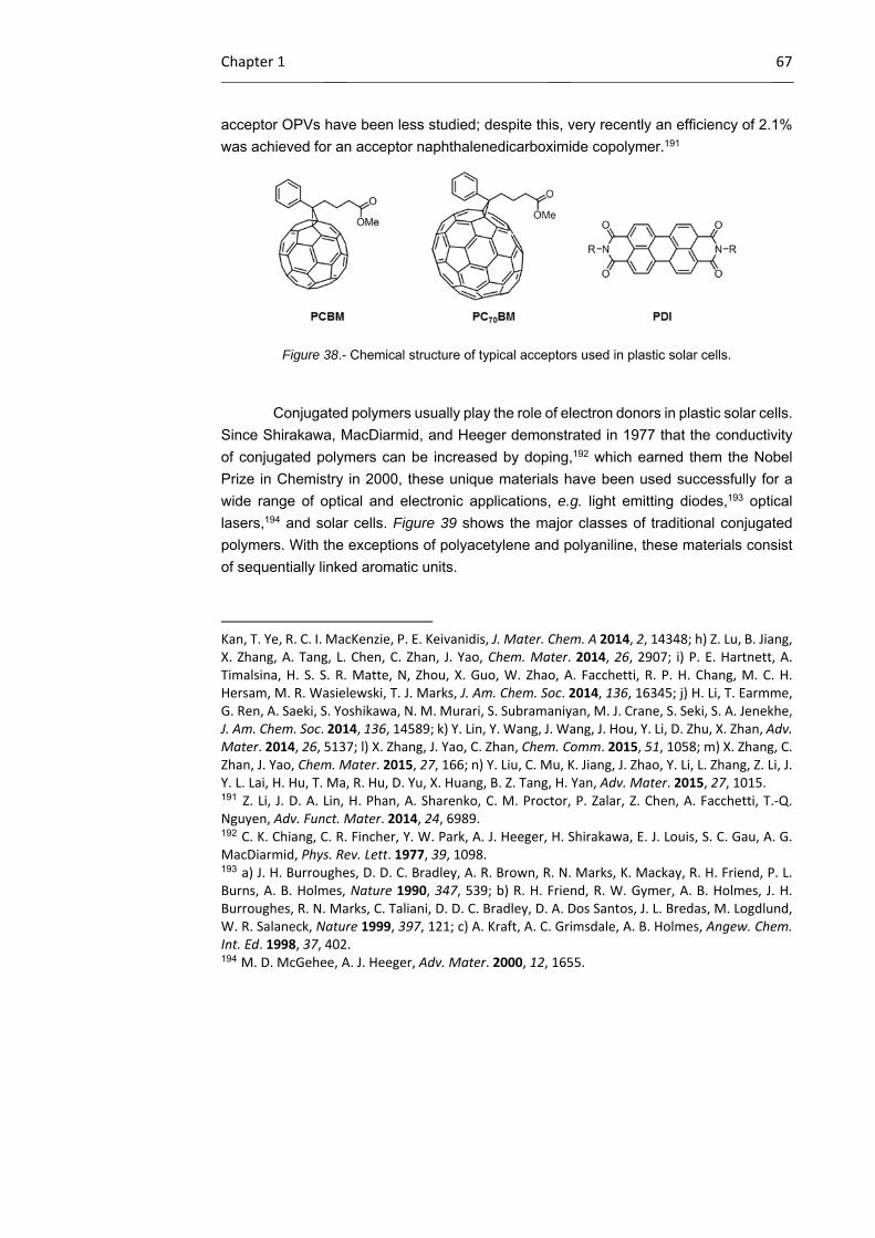
Chapter 1 67
acceptor OPVs have been less studied; despite this, very recently an efficiency of 2.1%
was achieved for an acceptor naphthalenedicarboximide copolymer.191
Figure 38.- Chemical structure of typical acceptors used in plastic solar cells.
Conjugated polymers usually play the role of electron donors in plastic solar cells.
Since Shirakawa, MacDiarmid, and Heeger demonstrated in 1977 that the conductivity
of conjugated polymers can be increased by doping,192 which earned them the Nobel
Prize in Chemistry in 2000, these unique materials have been used successfully for a
wide range of optical and electronic applications, e.g. light emitting diodes,193 optical
lasers,194 and solar cells. Figure 39 shows the major classes of traditional conjugated
polymers. With the exceptions of polyacetylene and polyaniline, these materials consist
of sequentially linked aromatic units.
Kan, T. Ye, R. C. I. MacKenzie, P. E. Keivanidis, J. Mater. Chem. A 2014, 2, 14348; h) Z. Lu, B. Jiang, X. Zhang, A. Tang, L. Chen, C. Zhan, J. Yao, Chem. Mater. 2014, 26, 2907; i) P. E. Hartnett, A. Timalsina, H. S. S. R. Matte, N, Zhou, X. Guo, W. Zhao, A. Facchetti, R. P. H. Chang, M. C. H. Hersam, M. R. Wasielewski, T. J. Marks, J. Am. Chem. Soc. 2014, 136, 16345; j) H. Li, T. Earmme, G. Ren, A. Saeki, S. Yoshikawa, N. M. Murari, S. Subramaniyan, M. J. Crane, S. Seki, S. A. Jenekhe, J. Am. Chem. Soc. 2014, 136, 14589; k) Y. Lin, Y. Wang, J. Wang, J. Hou, Y. Li, D. Zhu, X. Zhan, Adv. Mater. 2014, 26, 5137; l) X. Zhang, J. Yao, C. Zhan, Chem. Comm. 2015, 51, 1058; m) X. Zhang, C. Zhan, J. Yao, Chem. Mater. 2015, 27, 166; n) Y. Liu, C. Mu, K. Jiang, J. Zhao, Y. Li, L. Zhang, Z. Li, J. Y. L. Lai, H. Hu, T. Ma, R. Hu, D. Yu, X. Huang, B. Z. Tang, H. Yan, Adv. Mater. 2015, 27, 1015. 191 Z. Li, J. D. A. Lin, H. Phan, A. Sharenko, C. M. Proctor, P. Zalar, Z. Chen, A. Facchetti, T.‐Q. Nguyen, Adv. Funct. Mater. 2014, 24, 6989. 192 C. K. Chiang, C. R. Fincher, Y. W. Park, A. J. Heeger, H. Shirakawa, E. J. Louis, S. C. Gau, A. G. MacDiarmid, Phys. Rev. Lett. 1977, 39, 1098. 193 a) J. H. Burroughes, D. D. C. Bradley, A. R. Brown, R. N. Marks, K. Mackay, R. H. Friend, P. L. Burns, A. B. Holmes, Nature 1990, 347, 539; b) R. H. Friend, R. W. Gymer, A. B. Holmes, J. H. Burroughes, R. N. Marks, C. Taliani, D. D. C. Bradley, D. A. Dos Santos, J. L. Bredas, M. Logdlund, W. R. Salaneck, Nature 1999, 397, 121; c) A. Kraft, A. C. Grimsdale, A. B. Holmes, Angew. Chem. Int. Ed. 1998, 37, 402. 194 M. D. McGehee, A. J. Heeger, Adv. Mater. 2000, 12, 1655.
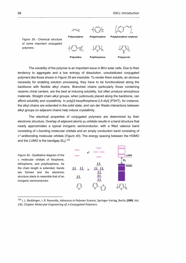
68 OSCs: Introduction
Figure 39.- Chemical structure
of some important conjugated
polymers.
The solubility of the polymer is an important issue in BHJ solar cells. Due to their
tendency to aggregate and a low entropy of dissolution, unsubstituted conjugated
polymers like those shown in Figure 39 are insoluble. To render them soluble, an obvious
necessity for enabling solution processing, they have to be functionalized along the
backbone with flexible alkyl chains. Branched chains particularly those containing
racemic chiral centers, are the best at inducing solubility, but often produce amorphous
materials. Straight chain alkyl groups, when judiciously placed along the backbone, can
afford solubility and crystallinity. In poly[3-hexylthiophene-2,5-diyl] (P3HT), for instance,
the alkyl chains are extended in the solid state, and van der Waals interactions between
alkyl groups on adjacent chains help induce crystallinity.
The electrical properties of conjugated polymers are determined by their
electronic structure. Overlap of adjacent atomic pz-orbitals results in a band structure that
nearly approximates a typical inorganic semiconductor, with a filled valence band
consisting of -bonding molecular orbitals and an empty conduction band consisting of
*-antibonding molecular orbitals (Figure 40). The energy spacing between the HOMO
and the LUMO is the bandgap (Eg).195
Figure 40.- Qualitative diagram of the
molecular orbitals of thiophene,
bithiophene, and polythiophene. As
the chain length is extended, bands
are formed and the electronic
structure starts to resemble that of an
inorganic semiconductor.
195 J. L. Reddinger, J. R. Reynolds, Advances in Polymer Science, Springer‐Verlag, Berlin,1999, Vol.
145, Chapter Molecular Engineering of ‐Conjugated Polymers.
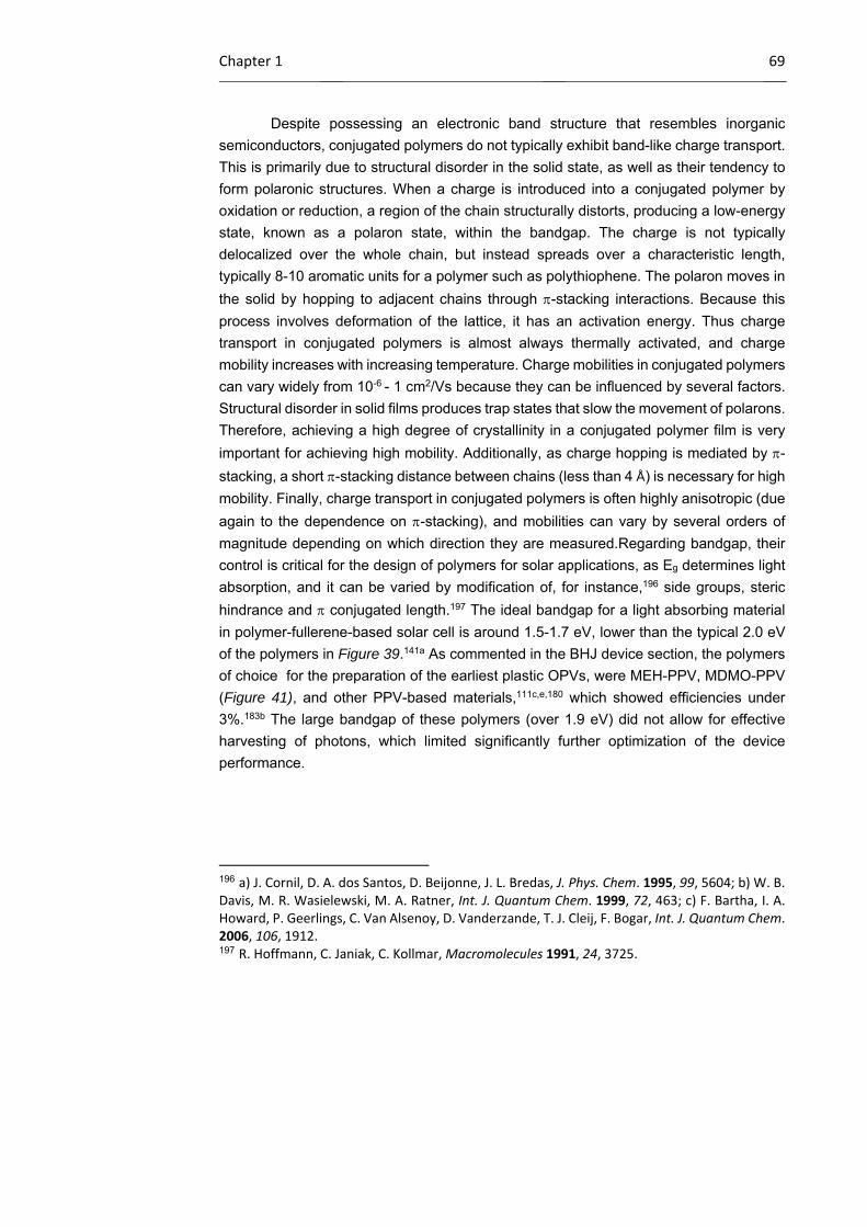
Chapter 1 69
Despite possessing an electronic band structure that resembles inorganic
semiconductors, conjugated polymers do not typically exhibit band-like charge transport.
This is primarily due to structural disorder in the solid state, as well as their tendency to
form polaronic structures. When a charge is introduced into a conjugated polymer by
oxidation or reduction, a region of the chain structurally distorts, producing a low-energy
state, known as a polaron state, within the bandgap. The charge is not typically
delocalized over the whole chain, but instead spreads over a characteristic length,
typically 8-10 aromatic units for a polymer such as polythiophene. The polaron moves in
the solid by hopping to adjacent chains through -stacking interactions. Because this
process involves deformation of the lattice, it has an activation energy. Thus charge
transport in conjugated polymers is almost always thermally activated, and charge
mobility increases with increasing temperature. Charge mobilities in conjugated polymers
can vary widely from 10-6 - 1 cm2/Vs because they can be influenced by several factors.
Structural disorder in solid films produces trap states that slow the movement of polarons.
Therefore, achieving a high degree of crystallinity in a conjugated polymer film is very
important for achieving high mobility. Additionally, as charge hopping is mediated by -
stacking, a short -stacking distance between chains (less than 4 Å) is necessary for high
mobility. Finally, charge transport in conjugated polymers is often highly anisotropic (due
again to the dependence on -stacking), and mobilities can vary by several orders of
magnitude depending on which direction they are measured.Regarding bandgap, their
control is critical for the design of polymers for solar applications, as Eg determines light
absorption, and it can be varied by modification of, for instance,196 side groups, steric
hindrance and conjugated length.197 The ideal bandgap for a light absorbing material
in polymer-fullerene-based solar cell is around 1.5-1.7 eV, lower than the typical 2.0 eV
of the polymers in Figure 39.141a As commented in the BHJ device section, the polymers
of choice for the preparation of the earliest plastic OPVs, were MEH-PPV, MDMO-PPV
(Figure 41), and other PPV-based materials,111c,e,180 which showed efficiencies under
3%.183b The large bandgap of these polymers (over 1.9 eV) did not allow for effective
harvesting of photons, which limited significantly further optimization of the device
performance.
196 a) J. Cornil, D. A. dos Santos, D. Beijonne, J. L. Bredas, J. Phys. Chem. 1995, 99, 5604; b) W. B. Davis, M. R. Wasielewski, M. A. Ratner, Int. J. Quantum Chem. 1999, 72, 463; c) F. Bartha, I. A. Howard, P. Geerlings, C. Van Alsenoy, D. Vanderzande, T. J. Cleij, F. Bogar, Int. J. Quantum Chem. 2006, 106, 1912. 197 R. Hoffmann, C. Janiak, C. Kollmar, Macromolecules 1991, 24, 3725.
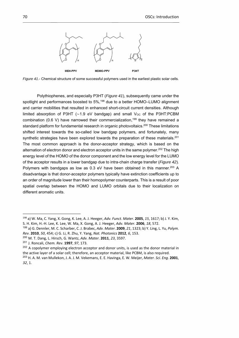
70 OSCs: Introduction
Figure 41.- Chemical structure of some successful polymers used in the earliest plastic solar cells.
Polythiophenes, and especially P3HT (Figure 41), subsequently came under the
spotlight and performances boosted to 5%,198 due to a better HOMO–LUMO alignment
and carrier mobilities that resulted in enhanced short-circuit current densities. Although
limited absorption of P3HT (∼1.9 eV bandgap) and small VOC of the P3HT:PCBM
combination (0.6 V) have narrowed their commercialization,199 they have remained a
standard platform for fundamental research in organic photovoltaics.200 These limitations
shifted interest towards the so-called low bandgap polymers, and fortunately, many
synthetic strategies have been explored towards the preparation of these materials.201
The most common approach is the donor-acceptor strategy, which is based on the
alternation of electron donor and electron acceptor units in the same polymer.202 The high
energy level of the HOMO of the donor component and the low energy level for the LUMO
of the acceptor results in a lower bandgap due to intra-chain charge transfer (Figure 42).
Polymers with bandgaps as low as 0.3 eV have been obtained in this manner.203 A
disadvantage is that donor-acceptor polymers typically have extinction coefficients up to
an order of magnitude lower than their homopolymer counterparts. This is a result of poor
spatial overlap between the HOMO and LUMO orbitals due to their localization on
different aromatic units.
198 a) W. Ma, C. Yang, X. Gong, K. Lee, A. J. Heeger, Adv. Funct. Mater. 2005, 15, 1617; b) J. Y. Kim, S. H. Kim, H.‐H. Lee, K. Lee, W. Ma, X. Gong, A. J. Heeger, Adv. Mater. 2006, 18, 572. 199 a) G. Dennler, M. C. Scharber, C. J. Brabec, Adv. Mater. 2009, 21, 1323; b) Y. Ling, L. Yu, Polym. Rev. 2010, 50, 454; c) G. Li, R. Zhu, Y. Yang, Nat. Photonics 2012, 6, 153. 200 M. T. Dang, L. Hirsch, G. Wantz, Adv. Mater. 2011, 23, 3597. 201 J. Roncali, Chem. Rev. 1997, 97, 173. 202 A copolymer employing electron acceptor and donor units, is used as the donor material in the active layer of a solar cell; therefore, an acceptor material, like PCBM, is also required. 203 H. A. M. van Mullekon, J. A. J. M. Vekemans, E. E. Havinga, E. W. Meijer, Mater. Sci. Eng. 2001, 32, 1.
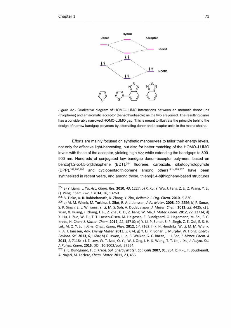
Chapter 1 71
Figure 42.- Qualitative diagram of HOMO-LUMO interactions between an aromatic donor unit
(thiophene) and an aromatic acceptor (benzothiadiazole) as the two are joined. The resulting dimer
has a considerably narrowed HOMO-LUMO gap. This is meant to illustrate the principle behind the
design of narrow bandgap polymers by alternating donor and acceptor units in the mains chains.
Efforts are mainly focused on synthetic manoeuvres to tailor their energy levels,
not only for effective light-harvesting, but also for better matching of the HOMO–LUMO
levels with those of the acceptor, yielding high VOC while extending the bandgaps to 800-
900 nm. Hundreds of conjugated low bandgap donor–acceptor polymers, based on
benzo[1,2-b:4,5-b′]dithiophene (BDT),204 fluorene, carbazole, diketopyrrolopyrrole
(DPP),169,205,206 and cyclopentadithiophene among others141b,199,207 have been
synthesized in recent years, and among those, thieno[3,4-b]thiophene-based structures
204 a) Y. Liang, L. Yu, Acc. Chem. Res. 2010, 43, 1227; b) X. Xu, Y. Wu, J. Fang, Z. Li, Z. Wang, Y. Li, Q. Peng, Chem. Eur. J. 2014, 20, 13259. 205 B. Tieke, A. R. Rabindranath, K. Zhang, Y. Zhu, Beilstein J. Org. Chem. 2010, 6, 830. 206 a) M. M. Wienk, M. Turbiez, J. Gilot, R. A. J. Janssen, Adv. Mater. 2008, 20, 2556; b) P. Sonar, S. P. Singh, E. L. Williams, Y. Li, M. S. Soh, A. Dodabalapur, J. Mater. Chem. 2012, 22, 4425; c) J. Yuan, X. Huang, F. Zhang, J. Lu, Z. Zhai, C. Di, Z. Jiang, W. Ma, J. Mater. Chem. 2012, 22, 22734; d) X. Hu, L. Zuo, W. Fu, T. T. Larsen‐Olsen, M. Helgesen, E. Bundgaard, O. Hagemann, M. Shi, F. C. Krebs, H. Chen, J. Mater. Chem. 2012, 22, 15710; e) Y. Li, P. Sonar, S. P. Singh, Z. E. Ooi, E. S. H. Lek, M. Q. Y. Loh, Phys. Chem. Chem. Phys. 2012, 14, 7162; f) K. H. Hendriks, W. Li, M. M. Wienk, R. A. J. Janssen, Adv. Energy Mater. 2013, 3, 674; g) Y. Li, P. Sonar, L. Murphy, W. Hong, Energy Environ. Sci. 2013, 6, 1684; h) O. Kwon, J. Jo, B. Walker, G. C. Bazan, J. H. Seo, J. Mater. Chem. A 2013, 1, 7118; i) J. Z. Low, W. T. Neo, Q. Ye, W. J. Ong, I. H. K. Wong, T. T. Lin, J. Xu, J. Polym. Sci. A Polym. Chem. 2015, DOI: 10.1002/pola.27564. 207 a) E. Bundgaard, F. C. Krebs, Sol. Energy Mater. Sol. Cells 2007, 91, 954; b) P.‐L. T. Boudreault, A. Najari, M. Leclerc, Chem. Mater. 2011, 23, 456.

72 OSCs: Introduction
have exhibited the most promising behavior, presenting optimally low bandgaps and
efficiencies reaching 7–9%.141b The most successful derivative is polythieno[3,4-b]-
thiophene-co-benzodithiophene (PTB7; Figure 43), which stands out as the most widely
used and best performing polymer in BHJ OPVs,208 due to its optimal bandgap and
morphology. Lately, overall efficiencies of PTB7-containing devices reached 9.2%, with
a VOC of 0.75 V and an exceptional JSC of 17.46 mA/cm2.209 Notably, in two hot-off-the-
press reports, the 10% threshold was just surpassed with devices based on a PTB7
derivative (PTB7-Th) by applying advanced light manipulation and manufacturing
techniques to control photon harvesting and electron mobility.208c,d Attention should also
be drawn to DPP-containing polymers such PDPP3TaltTPT (Figure 43), which alternates
DPP units as the electron deficient unit with electron rich terthiophene and thiophene-
phenylene-thiophene segments and presents remarkable results.210 BHJ solar cells
frabicated from layers comprising this material as electron donor with PC70BM as electron
acceptor, show PCEs up to 8.0%. Another successful low-band gap polymer is the
prototype polycarbazole poly[N-9’-heptadecanyl-2,7-carbazole-alt-5,5-(4’,7’-di-2-thienyl-
2’,1’,3’-benzothiadiazole)] (PCDTBT; Figure 43), which has attained high performances,
in the order of 7.5%, with a VOC of 0.90 V.211 Its exceptional behavior is attributed to its
relatively deep HOMO energy (5.5 eV), which results in the observed high VOC.212
Figure 43.- Chemical
structure of some
successful polymers used
in low bandgap solar cells.
208 a) L. Lu, L. Yu, Adv. Mater. 2014, 26, 4413; b) Z. He, C. Zhong, X. Huang, W. Y. Wong, H. Wu, L. Chen, S. Su, Y. Cao, Adv. Mater. 2011, 23, 4636; c) J.‐D. Chen, C. Cui, Y.‐Q. Li, L. Zhou, Q.‐D. Ou, C. Li, Y. Li, J.‐X. Tang, Adv. Mater. 2015, 27, 1035; d) S.‐H. Liao, H.‐J. Jhuo, P.‐N. Yeh, Y.‐S. Cheng, Y.‐L. Li, Y.‐H. Lee, S. Sharma, S.‐A. Chen, Sci. Rep. 2014, 4, 6813. 209 Z. He, C. Zhong, S. Su, M. Xu, H. Wu, Y. Cao, Nat. Photonics 2012, 6, 591. 210 K. H. Hendriks, G. H. L. Heintges, V. S. Gevaerts, M. M. Wienk, R. A. J. Janssen, Angew. Chem. Int. Ed. 2013, 52, 8341. 211 S. Beaupre, M. Leclerc, J. Mater. Chem. A 2013, 1, 11097. 212 S. H. Park, A. Roy, S. Beaupre, S. Cho, N. Coates, J. S. Moon, D. Moses, M. Leclerc, K. Lee, A. J. Heeger, Nat. Photonics 2009, 3, 297.

Chapter 1 73
Improving the photon harvesting: Phthalocyanine-containing polymers
As mentioned above, a largely explored route to broaden the absorption window
of solution processed plastic solar cell is to use low bandgap polymers. Another plausible
route is adding a chromophore with strong absorption in the visible to a polymer:fullerene
BHJ layer in order to enhance the spectral coverage. This can be visualized in Figure 44,
where the absorption spectra of common conjugated polymers, a dye, and PCBM are
depicted together with the solar AM1.5 irradiance photon flux.
Figure 44.- Absorption spectra of P3HT, PCBM, and a ZnPc, together with the AM1.5 solar photon
flux spectrum.
Recently, photoconversion properties extended more than 150 nm toward longer
wavelengths have been demonstrated on a P3HT/PCBM blend mixed with a peripherally
substituted octabutoxy H2Pc, as compared to a device without such Pc-sensitization.213
Maximum internal quantum efficiencies of ca. 40% were observed in the main absorption
region of the Pc (i.e. around 700 nm) for a 10:10:1 ratio of P3HT, PCBM and H2Pc,
respectively. A similar work employing ring-expanded Pcs fused with fluorene, which
resulted in a narrower band gap of the dye, also shows improved results.214 In 2009, a
work by Ohkita and co-workers reported a PCE of 2.7% of annealed, spin-coated BHJ
devices containing a 10:10:1 ratio of P3HT, PCBM and bis(tri-n-hexylsilyloxide) Si(IV)Pc
(Figure 45), a 20% larger value than the corresponding control device without Pc-
sensitization (i.e. 2.2%).215 By constrast, a device based on the P3HT/PCBM/ZnPc blend
213 E. M. J. Johansson, A. Yartsev, H. Rensmo, V. Sundstrom, J. Phys. Chem. C 2009, 113, 3014. 214 S. Yamamoto, M. Kimura, ACS Appl. Mater. Interfaces 2013, 5, 4367. 215 S. Honda, T. Nogami, H. Ohkita, H. Benten, S. Ito, ACS Appl. Mater. Interfaces 2009, 1, 804.
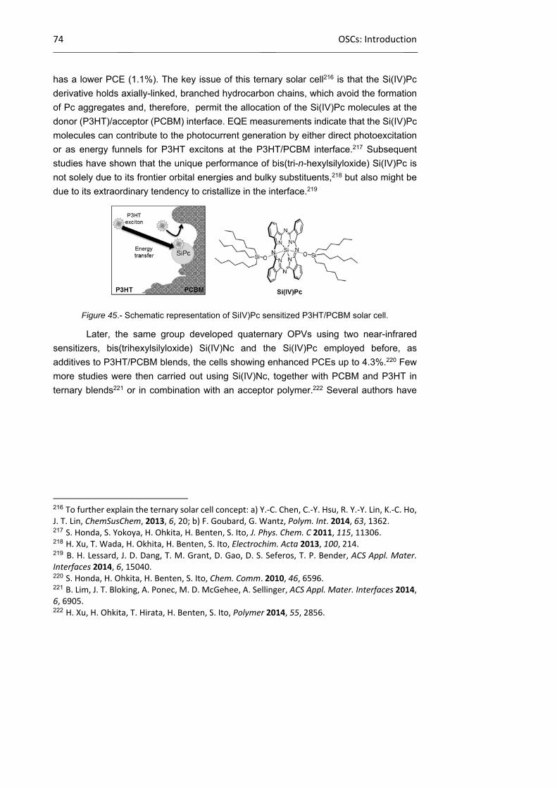
74 OSCs: Introduction
has a lower PCE (1.1%). The key issue of this ternary solar cell216 is that the Si(IV)Pc
derivative holds axially-linked, branched hydrocarbon chains, which avoid the formation
of Pc aggregates and, therefore, permit the allocation of the Si(IV)Pc molecules at the
donor (P3HT)/acceptor (PCBM) interface. EQE measurements indicate that the Si(IV)Pc
molecules can contribute to the photocurrent generation by either direct photoexcitation
or as energy funnels for P3HT excitons at the P3HT/PCBM interface.217 Subsequent
studies have shown that the unique performance of bis(tri-n-hexylsilyloxide) Si(IV)Pc is
not solely due to its frontier orbital energies and bulky substituents,218 but also might be
due to its extraordinary tendency to cristallize in the interface.219
Figure 45.- Schematic representation of SiIV)Pc sensitized P3HT/PCBM solar cell.
Later, the same group developed quaternary OPVs using two near-infrared
sensitizers, bis(trihexylsilyloxide) Si(IV)Nc and the Si(IV)Pc employed before, as
additives to P3HT/PCBM blends, the cells showing enhanced PCEs up to 4.3%.220 Few
more studies were then carried out using Si(IV)Nc, together with PCBM and P3HT in
ternary blends221 or in combination with an acceptor polymer.222 Several authors have
216 To further explain the ternary solar cell concept: a) Y.‐C. Chen, C.‐Y. Hsu, R. Y.‐Y. Lin, K.‐C. Ho, J. T. Lin, ChemSusChem, 2013, 6, 20; b) F. Goubard, G. Wantz, Polym. Int. 2014, 63, 1362. 217 S. Honda, S. Yokoya, H. Ohkita, H. Benten, S. Ito, J. Phys. Chem. C 2011, 115, 11306. 218 H. Xu, T. Wada, H. Okhita, H. Benten, S. Ito, Electrochim. Acta 2013, 100, 214. 219 B. H. Lessard, J. D. Dang, T. M. Grant, D. Gao, D. S. Seferos, T. P. Bender, ACS Appl. Mater. Interfaces 2014, 6, 15040. 220 S. Honda, H. Ohkita, H. Benten, S. Ito, Chem. Comm. 2010, 46, 6596. 221 B. Lim, J. T. Bloking, A. Ponec, M. D. McGehee, A. Sellinger, ACS Appl. Mater. Interfaces 2014, 6, 6905. 222 H. Xu, H. Ohkita, T. Hirata, H. Benten, S. Ito, Polymer 2014, 55, 2856.
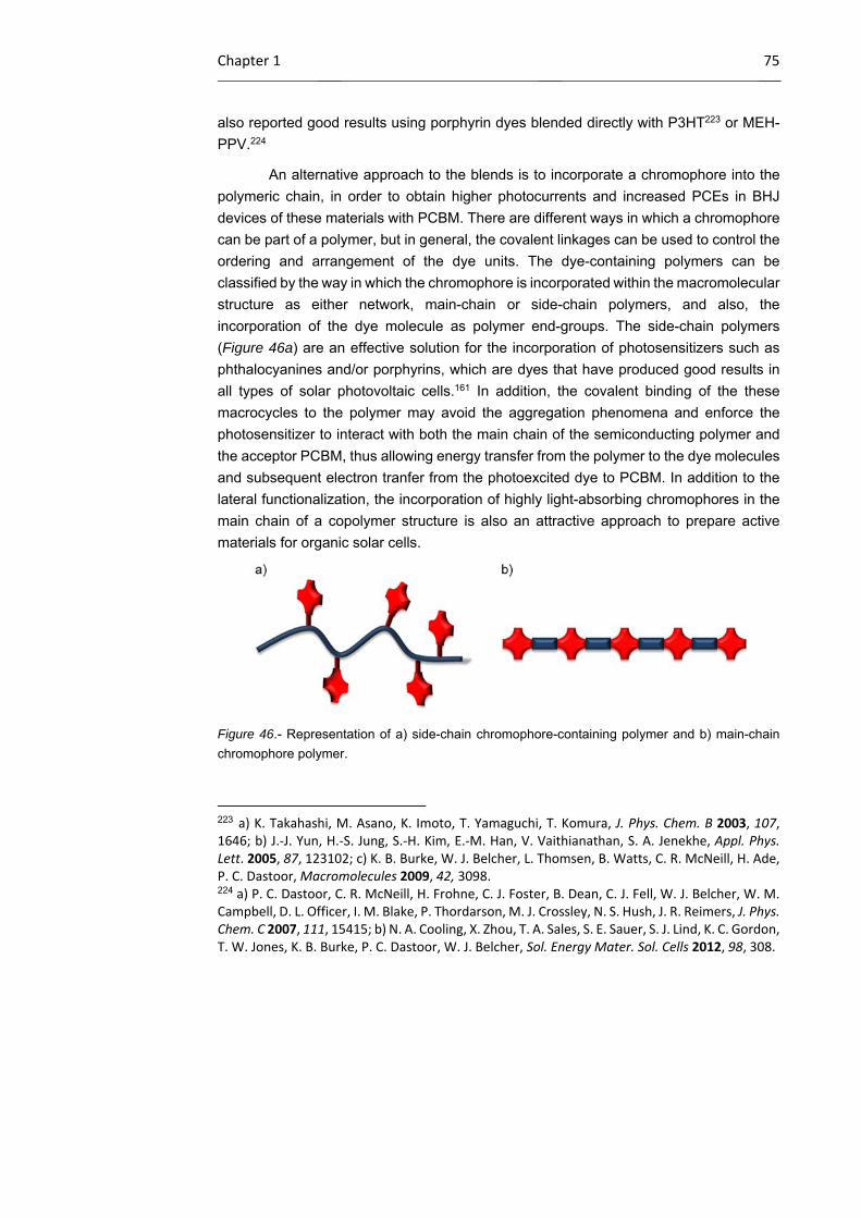
Chapter 1 75
also reported good results using porphyrin dyes blended directly with P3HT223 or MEH-
PPV.224
An alternative approach to the blends is to incorporate a chromophore into the
polymeric chain, in order to obtain higher photocurrents and increased PCEs in BHJ
devices of these materials with PCBM. There are different ways in which a chromophore
can be part of a polymer, but in general, the covalent linkages can be used to control the
ordering and arrangement of the dye units. The dye-containing polymers can be
classified by the way in which the chromophore is incorporated within the macromolecular
structure as either network, main-chain or side-chain polymers, and also, the
incorporation of the dye molecule as polymer end-groups. The side-chain polymers
(Figure 46a) are an effective solution for the incorporation of photosensitizers such as
phthalocyanines and/or porphyrins, which are dyes that have produced good results in
all types of solar photovoltaic cells.161 In addition, the covalent binding of the these
macrocycles to the polymer may avoid the aggregation phenomena and enforce the
photosensitizer to interact with both the main chain of the semiconducting polymer and
the acceptor PCBM, thus allowing energy transfer from the polymer to the dye molecules
and subsequent electron tranfer from the photoexcited dye to PCBM. In addition to the
lateral functionalization, the incorporation of highly light-absorbing chromophores in the
main chain of a copolymer structure is also an attractive approach to prepare active
materials for organic solar cells.
Figure 46.- Representation of a) side-chain chromophore-containing polymer and b) main-chain
chromophore polymer.
223 a) K. Takahashi, M. Asano, K. Imoto, T. Yamaguchi, T. Komura, J. Phys. Chem. B 2003, 107, 1646; b) J.‐J. Yun, H.‐S. Jung, S.‐H. Kim, E.‐M. Han, V. Vaithianathan, S. A. Jenekhe, Appl. Phys. Lett. 2005, 87, 123102; c) K. B. Burke, W. J. Belcher, L. Thomsen, B. Watts, C. R. McNeill, H. Ade, P. C. Dastoor, Macromolecules 2009, 42, 3098. 224 a) P. C. Dastoor, C. R. McNeill, H. Frohne, C. J. Foster, B. Dean, C. J. Fell, W. J. Belcher, W. M. Campbell, D. L. Officer, I. M. Blake, P. Thordarson, M. J. Crossley, N. S. Hush, J. R. Reimers, J. Phys. Chem. C 2007, 111, 15415; b) N. A. Cooling, X. Zhou, T. A. Sales, S. E. Sauer, S. J. Lind, K. C. Gordon, T. W. Jones, K. B. Burke, P. C. Dastoor, W. J. Belcher, Sol. Energy Mater. Sol. Cells 2012, 98, 308.

76 OSCs: Introduction
Tetraphenylporphyrins have been incorporated into polymeric structures and
tested in BHJ solar cells. An example is an organic solar cell device which organized
fullerenes and porphyrins for efficient electron transfer through a polypeptide structure
(Figure 47a), resulting in a PCE of 1.6%.225 More recently a co-polymerization approach
was described, to produce a panchromatic polymer absorber.226 Specifically, introduction
of a porphyrin–pyrene pendant, endowed with 2,6-bis(dodecyloxy)phenyl substituents to
prevent aggregation, in a polythiophene chain exhibited powerful absorption features and
reached an impressive PCE of 8.0% in conjuction with PC70BM (Figure 47b).
Figure 47.- Structure of some successful polymers with lateral porphyrins used in OPV devices.
On the other hand, many more reports exemplify efforts to increase the light-
harvesting properties of the p-type donor phase in a bulk heterojunction solar cell by
incorporating strongly light-absorbing chromophores into the backbone of the conjugated
polymer phase. The first example of the synthesis and polymer solar cell applications of
conjugated polymers with porphyrins as a unit of the main chain was reported by Bo et
al. in 2008,227 employing conjugated alternating porphyrin-dithienothiophene copolymers
(both units are electron-rich) as active materials (Figure 48a). The bad performances
225 T. Hasobe, K. Saito, P. V. Kamat, V. Troiani, H. Qiu, N. Solladie, K. S. Kim, J. K. Park, D. Kim, F. D’Souza, S. Fukuzumi, J. Mater. Chem. 2007, 17, 4160. 226 Y.‐H. Chao, J.‐F Jheng, J.‐S. Wu, K.‐Y. Wu, H.‐H. Peng, M.‐C. Tsai, C.‐L. Wang, Y.‐N. Hsiao, C.‐L. Wang, C.‐Y. Lin, C.‐S. Hsu, Adv. Mater. 2014, 26, 5205. 227 X. Huang, C. Zhu, S. Zhang, W. Li, Y. Guo, X. Zhan, Y. Liu, Z. Bo, Macromolecules 2008, 41, 6895.
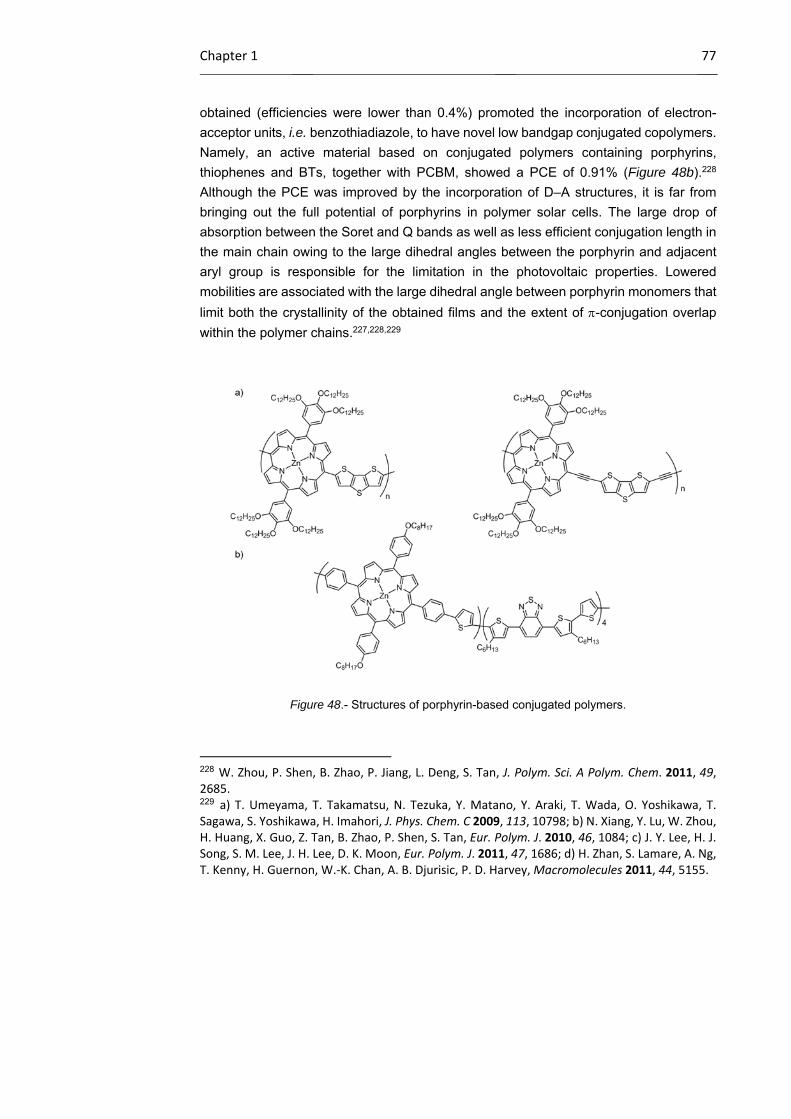
Chapter 1 77
obtained (efficiencies were lower than 0.4%) promoted the incorporation of electron-
acceptor units, i.e. benzothiadiazole, to have novel low bandgap conjugated copolymers.
Namely, an active material based on conjugated polymers containing porphyrins,
thiophenes and BTs, together with PCBM, showed a PCE of 0.91% (Figure 48b).228
Although the PCE was improved by the incorporation of D–A structures, it is far from
bringing out the full potential of porphyrins in polymer solar cells. The large drop of
absorption between the Soret and Q bands as well as less efficient conjugation length in
the main chain owing to the large dihedral angles between the porphyrin and adjacent
aryl group is responsible for the limitation in the photovoltaic properties. Lowered
mobilities are associated with the large dihedral angle between porphyrin monomers that
limit both the crystallinity of the obtained films and the extent of -conjugation overlap
within the polymer chains.227,228,229
Figure 48.- Structures of porphyrin-based conjugated polymers.
228 W. Zhou, P. Shen, B. Zhao, P. Jiang, L. Deng, S. Tan, J. Polym. Sci. A Polym. Chem. 2011, 49, 2685. 229 a) T. Umeyama, T. Takamatsu, N. Tezuka, Y. Matano, Y. Araki, T. Wada, O. Yoshikawa, T. Sagawa, S. Yoshikawa, H. Imahori, J. Phys. Chem. C 2009, 113, 10798; b) N. Xiang, Y. Lu, W. Zhou, H. Huang, X. Guo, Z. Tan, B. Zhao, P. Shen, S. Tan, Eur. Polym. J. 2010, 46, 1084; c) J. Y. Lee, H. J. Song, S. M. Lee, J. H. Lee, D. K. Moon, Eur. Polym. J. 2011, 47, 1686; d) H. Zhan, S. Lamare, A. Ng, T. Kenny, H. Guernon, W.‐K. Chan, A. B. Djurisic, P. D. Harvey, Macromolecules 2011, 44, 5155.
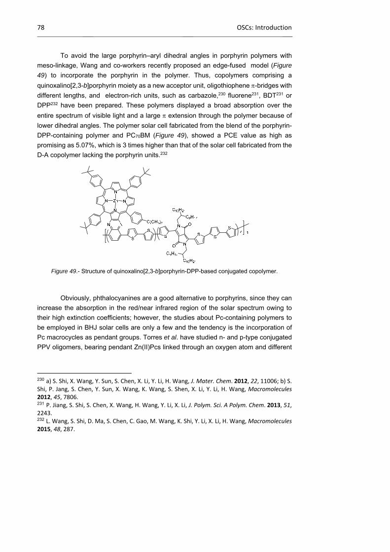
78 OSCs: Introduction
To avoid the large porphyrin–aryl dihedral angles in porphyrin polymers with
meso-linkage, Wang and co-workers recently proposed an edge-fused model (Figure
49) to incorporate the porphyrin in the polymer. Thus, copolymers comprising a
quinoxalino[2,3-b]porphyrin moiety as a new acceptor unit, oligothiophene -bridges with
different lengths, and electron-rich units, such as carbazole,230 fluorene231, BDT231 or
DPP232 have been prepared. These polymers displayed a broad absorption over the
entire spectrum of visible light and a large extension through the polymer because of
lower dihedral angles. The polymer solar cell fabricated from the blend of the porphyrin-
DPP-containing polymer and PC70BM (Figure 49), showed a PCE value as high as
promising as 5.07%, which is 3 times higher than that of the solar cell fabricated from the
D-A copolymer lacking the porphyrin units.232
Figure 49.- Structure of quinoxalino[2,3-b]porphyrin-DPP-based conjugated copolymer.
Obviously, phthalocyanines are a good alternative to porphyrins, since they can
increase the absorption in the red/near infrared region of the solar spectrum owing to
their high extinction coefficients; however, the studies about Pc-containing polymers to
be employed in BHJ solar cells are only a few and the tendency is the incorporation of
Pc macrocycles as pendant groups. Torres et al. have studied n- and p-type conjugated
PPV oligomers, bearing pendant Zn(II)Pcs linked through an oxygen atom and different
230 a) S. Shi, X. Wang, Y. Sun, S. Chen, X. Li, Y. Li, H. Wang, J. Mater. Chem. 2012, 22, 11006; b) S. Shi, P. Jang, S. Chen, Y. Sun, X. Wang, K. Wang, S. Shen, X. Li, Y. Li, H. Wang, Macromolecules 2012, 45, 7806. 231 P. Jiang, S. Shi, S. Chen, X. Wang, H. Wang, Y. Li, X. Li, J. Polym. Sci. A Polym. Chem. 2013, 51, 2243. 232 L. Wang, S. Shi, D. Ma, S. Chen, C. Gao, M. Wang, K. Shi, Y. Li, X. Li, H. Wang, Macromolecules 2015, 48, 287.

Chapter 1 79
linkers, with potential applications in organic solar cells (Figure 50).233 Later, the p-type
oligomers have been employed together with SWCNTs, where the Zn(II)Pc wraps around
the nanotube,82 and graphene.80,81
Figure 50.- Structure of oligomers with phthalocyanines as pendant moieties.
The same research group has also prepared donor-acceptor materials based on
a polynorbornene framework to which both Pcs and C60 electroactive pendant units are
randomly attached (Figure 51a).234 After solar devices were constructed, the good match
between the IPCE and the absorption spectra of thin films of the copolymer confirmed
the ability of the material to create charge carriers from absorbed photons with
wavelengths up to 800 nm. Finally, also the “double-cable” concept was explored.
Polythiophenes bearing electron-acceptor Ni(II)Pc chromophores were studied as donor-
acceptor materials, where the electron-poor Pcs units were appropiately substituted with
electron-withdrawing alkylsulfonyl groups (Figure 51b).235 The photophysical
characterization showed good charge photogeneration arising from the photoinduced
80 J. Malig, N. Jux, D. Kiessling, J.‐J. Cid, P. Vazquez, T. Torres, D. M. Guldi, Angew. Chem. Int. Ed. 2011, 50, 3561. 81 L. Brinkhaus, G. Katsukis, J. Malig, R. D. Costa, M. Garcia‐Iglesias, P. Vazquez, T. Torres, D. M. Guldi, Small 2013, 9, 2348. 82 a) J. Bartelmess, C.Ehli, J.‐J. Cid, M. Garcia‐Iglesias, P. Vazquez, T. Torres, D. M. Guldi, Chem. Sci. 2011, 2, 652; b) J. Bartelmess, C. Ehli, J.‐J. Cid, M. Garcia‐Iglesias, P. Vazquez, T. Torres, D. M. Guldi, J. Mater. Chem. 2011, 21, 8014. 233 J.‐J. Cid, C. Ehli, C. Atienza‐Castellanos, A. Gouloumis, E.‐M. Maya, P. Vazquez, T. Torres, D. M. Guldi, Dalton Trans. 2009, 20, 3955. 234 A. de la Escosura, M. V. Martinez‐Diaz, T. Torres, R. H. Grubbs, D. M. Guldi, H. Neugebauer, C. Winder, M. Drees, N. Serdar Sariciftci, Chem. Asian J. 2006, 1, 148. 235 M. V. Martinez‐Diaz, S. Esperanza, A. de la Escosura, M. Catellani, S. Yunus, S. Luzzati, T. Torres, Tetrahedron Lett. 2003, 44, 8475.

80 OSCs: Introduction
electron transfer from the polythiophene backbone to the Pc moieties. Thereby, Pcs
satisfied two functions in the final material: harvesting light in the lower energy region of
the spectrum and generating charge carriers.
Figure 51.- Structure of a) polynorbornenes bearing Pcs and C60 moieties as pendant groups; b)
polythiophenes bearing electron-acceptor Pcs.
Chapter 1 81
1.2.3 Objectives
The main goal of the present section of chapter 2 is to synthesize Pc derivatives
with different electronic properties as photo- and electroactive components to be
implemented into conjugated polymer chains, with the final aim of building BHJ solar cells
with the prepared materials. The molecular design of Pcs and Pc-containing polymers
has been done taking into account the literature precedents, and also the broad
experience gained by our research group, which has been working in this field during the
last 10 years.
Lateral functionalization of conjugated polymers with phthalocyanines
In an effort to make some progress in the plastic solar-cell area, an interesting
approach is to obtain a polymeric material with an improved absorption in the visible
region (up to 750 nm) by attaching Pcs through a post-polymerization process. Linked
Pcs can also have a prominent role in the charge separation process taking place in the
cell. To achieve this goal, lateral derivatization of conjugated, MDMO-PPV- and P3HT-
type copolymers holding adequate functional groups will be carried out by covalent
reactions with unsymmetrically substituted Pcs, which will hold solubilizing groups to
facilitate purification and solubilization of the final material, and also an adequate
functional group to perform the planned reactions (Figure 52). In order to test the role of
the type of bridge between the Pc and the polymer, two differents reactions will be used:
esterification and “click” MDMO-PPV and P3HT reaction. Zinc is selected as the central
metal owing to the chemical and photochemical stability of the Zn(II)Pc complexes.
On the other hand, preparation of electron-acceptor Pcs for lateral
functionalization of conjugated polymers in a double-cable architecture is also an
objective of this thesis. As mentioned in the previous section, the double-cable approach
has been envisioned as a way to suppress the phase separation phenomena that occurs
in typical polymer/fullerene BHJ devices. Although Pcs have been commonly used as
electron-donors in photovoltaic devices, the introduction of electron-withdrawing
peripheral substituents can make these macrocycles suitable to replace the C60 units in
double-cable polymers.

82 OSCs: Objectives
Figure 52.- Retrosynthetic analysis of polymers with lateral functionalization.
A new donor-acceptor PPV-based material, where the acceptor components are
electron-poor Zn(II)Pc units appropriately substituted with alkylsulfonyl groups (Figure
53), will be synthesized. Substitution of Pc macrocycle with electron withdrawing
groups236,237 usually depressed the HOMO and LUMO levels and renders attractive n-
type semiconductors for application in the field of organic electronic materials. In this
regard, several Pc derivatives with strong electron withdrawing substituents such as,
F,238,239 Cl,238 CN,238 CO2R,240 NO2 and SO2R241 groups, at peripheral or non-peripheral
positions, have been reported for the purpose of fabricating n-type organic
semiconductors. Among them, the alkylsulfonyl group plays an important role, not only
236 E. A. Lukyanets, V. N. Nemykin, J. Porphyrins Phthalocyanines 2010, 14, 1. 237 R. Guo, L. Zhang, Y. Zhang, Y. Bian, J. Jiang, J. Porphyrins Phthalocyanines 2011, 15, 964. 238 a) Q. Tang, H. Li, Y. Liu, W. Hu, J. Am. Chem. Soc. 2006, 128, 14634; b) M.‐M. Ling, Z. Bao, Org. Electron. 2006, 7, 568; c) Y. Oh, S. Pyo, M. H. Yi, S.‐K. Kwon, Org. Electron. 2006, 7, 77; d) M. L. Tang, J. H. Oh, A. D. Reichardt, Z. Bao, J. Am. Chem. Soc. 2009, 131, 3733; e) H. Jiang, J. Ye, P. Hu, F. Wei, K. Du, N. Wang, T. Ba, S. Feng, C. Kloc, Sci. Rep 2014, 4, 7573. 239 Z. Bao, A. J. Lovinger, J. Brown, J. Am. Chem. Soc. 1998, 120, 207. 240 a) S. Sergeyev, E. Pouzet, O. Debever, J. Levin, J. Gierschner, J. Cornil, R. G. Aspe, Y. H. Geerts, J. Mater. Chem. 2007, 17, 1777; b) B. Tylleman, R. Gomez‐Aspe, G. Gbabode, Y. H. Geerts, S. Sergeyev, Tetrahedron 2008, 64, 4155; c) P. Ma, J. Kan, Y. Zhang, C. Hang, Y. Bian, Y. Chen, N. Kobayshi, J. Jiang, J. Mater. Chem. 2011, 21, 18552. 241 a) B. Tylleman, G. Gbabode, C. Amato, C. Buess‐Herman, V. Lemaur, J. Cornil, R. G. Aspe, Y. H. Geertes, S. Sergeyev, Chem. Mater. 2009, 21, 2789; b) Y. Zhang, P. Ma, P. Zhu, X. Zhang, Y. Gao, D. Qi, Y. Bian, N. Kobayashi, J. Jiang, J. Mater. Chem. 2011, 21, 6515.
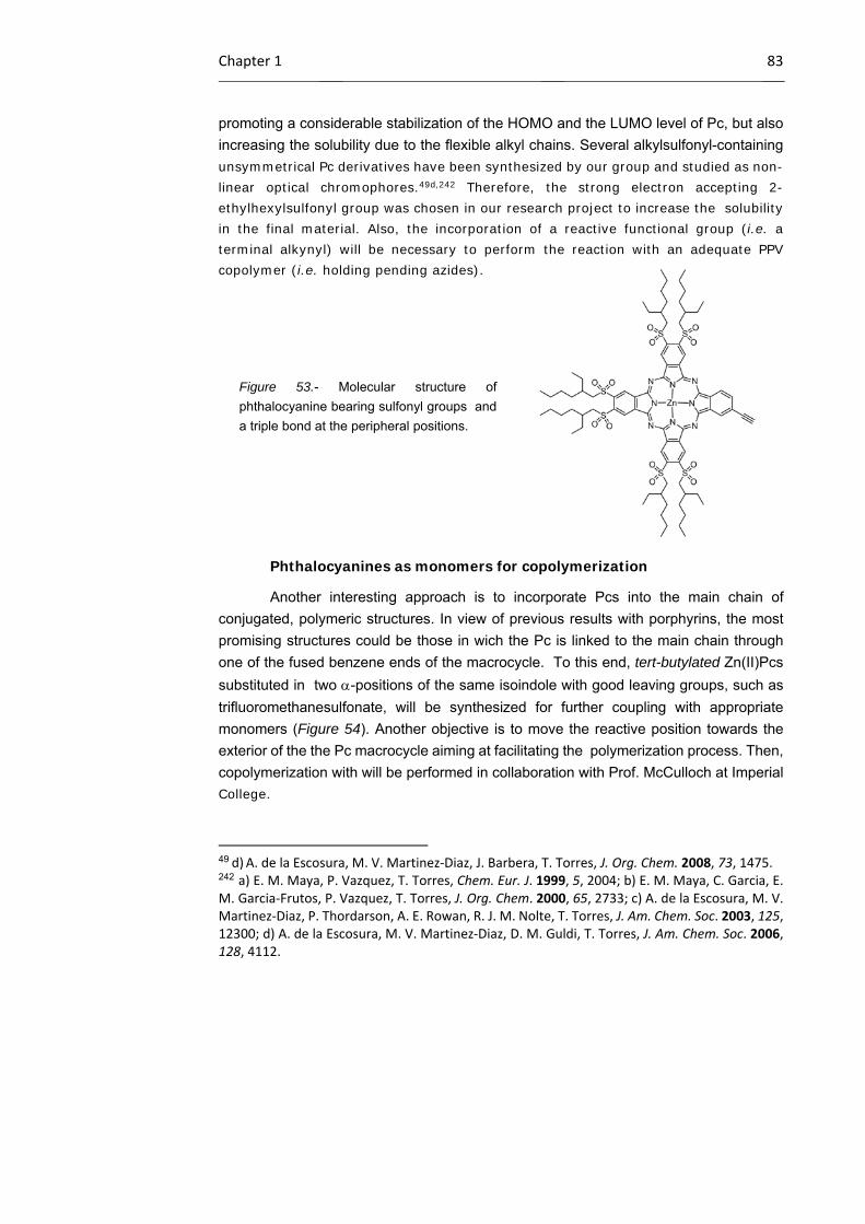
Chapter 1 83
promoting a considerable stabilization of the HOMO and the LUMO level of Pc, but also
increasing the solubility due to the flexible alkyl chains. Several alkylsulfonyl-containing unsymmetrical Pc derivatives have been synthesized by our group and studied as non-linear optical chromophores.49d,242 Therefore, the strong electron accepting 2-ethylhexylsulfonyl group was chosen in our research project to increase the solubility in the final material. Also, the incorporation of a reactive functional group (i.e. a terminal alkynyl) will be necessary to perform the reaction with an adequate PPV copolymer (i.e. holding pending azides).
Figure 53.- Molecular structure of
phthalocyanine bearing sulfonyl groups and
a triple bond at the peripheral positions.
Phthalocyanines as monomers for copolymerization
Another interesting approach is to incorporate Pcs into the main chain of
conjugated, polymeric structures. In view of previous results with porphyrins, the most
promising structures could be those in wich the Pc is linked to the main chain through
one of the fused benzene ends of the macrocycle. To this end, tert-butylated Zn(II)Pcs
substituted in two -positions of the same isoindole with good leaving groups, such as
trifluoromethanesulfonate, will be synthesized for further coupling with appropriate
monomers (Figure 54). Another objective is to move the reactive position towards the
exterior of the the Pc macrocycle aiming at facilitating the polymerization process. Then,
copolymerization with will be performed in collaboration with Prof. McCulloch at Imperial College.
49 d) A. de la Escosura, M. V. Martinez‐Diaz, J. Barbera, T. Torres, J. Org. Chem. 2008, 73, 1475. 242 a) E. M. Maya, P. Vazquez, T. Torres, Chem. Eur. J. 1999, 5, 2004; b) E. M. Maya, C. Garcia, E. M. Garcia‐Frutos, P. Vazquez, T. Torres, J. Org. Chem. 2000, 65, 2733; c) A. de la Escosura, M. V. Martinez‐Diaz, P. Thordarson, A. E. Rowan, R. J. M. Nolte, T. Torres, J. Am. Chem. Soc. 2003, 125, 12300; d) A. de la Escosura, M. V. Martinez‐Diaz, D. M. Guldi, T. Torres, J. Am. Chem. Soc. 2006, 128, 4112.
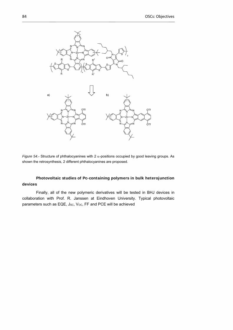
84 OSCs: Objectives
Figure 54.- Structure of phthalocyanines with 2 -positions occupied by good leaving groups. As
shown the retrosynthesis, 2 different phthalocyanines are proposed.
Photovoltaic studies of Pc-containing polymers in bulk heterojunction devices
Finally, all of the new polymeric derivatives will be tested in BHJ devices in
collaboration with Prof. R. Janssen at Eindhoven University. Typical photovoltaic
parameters such as EQE, JSC, VOC, FF and PCE will be achieved

Chapter 1 85
1.2.4 Results and discussion
1.2.4.1 Synthesis of phthalocyanines
Phthalocyanines for lateral functionalization of conjugated polymers
The synthesis of the targeted unsymmetrically -substituted Zn(II)Pcs for the
functionalization of copolymers requires the preparation of appropriately functionalized
precursors, namely substituted phthalonitriles. First, the synthesis of 4-iodophthalonitrile
(2) was carried out according to literature procedures,243 as shown in Scheme 6.
Scheme 6.- Synthesis of 4-iodophthalonitrile (2).
The chemoselective reduction of 4-nitrophthalonitrile with iron in a mixture of
concentrated hydrochloric acid and methanol, gave 4-aminophthalonitrile (1),243a which
was transformed to 4-iodophthalonitrile (2) in 69% yield via diazotization and subsequent
nucleophilic aromatic substitution reactions in the presence of potassium iodide.243b
4-(4’-Hydroxymethyl)phenylphthalonitrile (3) was synthesized in 80% yield by palladium-catalyzed Suzuki-Miyaura cross-coupling reaction,244 employing phthalonitrile 2 and commercially available 4-(hydroxymethy)phenylboronic acid in excess of K2CO3, Pd(PPh3)4 as catalyst and THF/H2O as solvent mixture (Scheme 7).
Scheme 7.- Synthesis of 4-(4’- hydroxymethyl)phenylphthalonitrile (3).
The above mentioned phthalonitriles contain functional groups that will allow the
covalent linkage of the target Pcs to the polymer backbone. However, only one functional group in one isoindole is needed for such a bonding. For that, unsymmetrically
243 a) J. Griffiths, B. Roozpeikar, J. Chem. Soc., Perkin Trans. 1 1976, 42; b) S. M. Marcuccio, P. I. Svirskaya, S. Greenberg, A. B. P. Lever, C. C. Leznoff, K. B. Tomer, Can. J. Chem. 1985, 63, 3057. 244 B. Ballesteros, S. Campidelli, G. de la Torre, C. Ehli, D. M. Guldi, M. Prato, T. Torres, Chem. Comm. 2007, 2950.
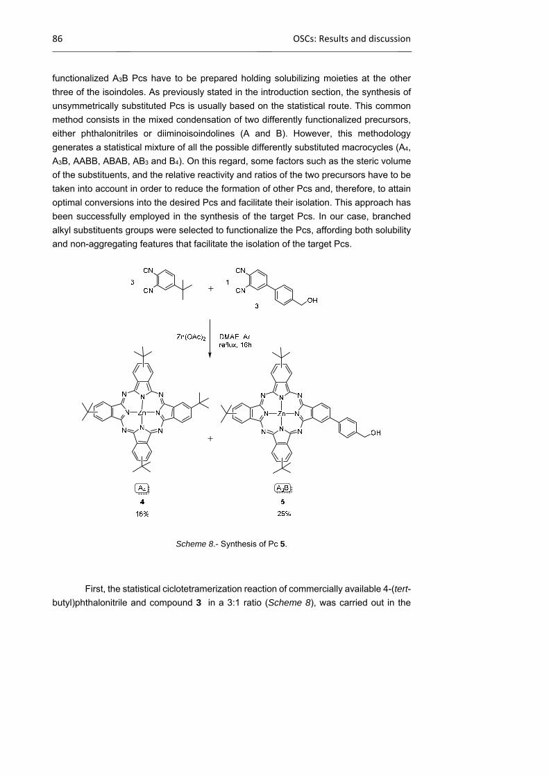
86 OSCs: Results and discussion
functionalized A3B Pcs have to be prepared holding solubilizing moieties at the other
three of the isoindoles. As previously stated in the introduction section, the synthesis of
unsymmetrically substituted Pcs is usually based on the statistical route. This common
method consists in the mixed condensation of two differently functionalized precursors,
either phthalonitriles or diiminoisoindolines (A and B). However, this methodology
generates a statistical mixture of all the possible differently substituted macrocycles (A4,
A3B, AABB, ABAB, AB3 and B4). On this regard, some factors such as the steric volume
of the substituents, and the relative reactivity and ratios of the two precursors have to be
taken into account in order to reduce the formation of other Pcs and, therefore, to attain
optimal conversions into the desired Pcs and facilitate their isolation. This approach has
been successfully employed in the synthesis of the target Pcs. In our case, branched
alkyl substituents groups were selected to functionalize the Pcs, affording both solubility
and non-aggregating features that facilitate the isolation of the target Pcs.
Scheme 8.- Synthesis of Pc 5.
First, the statistical ciclotetramerization reaction of commercially available 4-(tert-
butyl)phthalonitrile and compound 3 in a 3:1 ratio (Scheme 8), was carried out in the

Chapter 1 87
presence of Zn(OAc)2 and DMAE as solvent. The mixture of Pcs was purified by silica
gel column chromatography using hexane/dioxane (2:1) as the eluent, leading to the
isolation of the symmetrical Pc 4 (16%; identified by TLC for comparison with commercial
sources), followed by the desired product 5 (25%). Coloured products with lower Rf,
probably containing other unsymmetrically substituted Pcs were not eluted from the
column. The unsymmetrically functionalized Zn(II)Pc 5 contains one
hydroxymethylphenyl moiety for further linkage to the polymer, and three tert-butyl groups
at the other isoindole positions for providing solubility to the final material. Pc 4 and 5
were obtained as mixtures of inseparable structural isomers (4 and 8 possible
regioisomers, respectively).
Bearing in mind that we aim to connect the Pc to the backbone by means of
effective click chemistry reactios, we proceeded to transform the alcohol function into an
azide moiety. Bromination of Zn(II)Pc 5 employing mild, Appel reaction conditions (using
CBr4 as a halide source and triphenylphosphine as the phosphorus reagent) gave Pc 6
in high yield (Scheme 9). Subsequently, the transformation of this compound into the
azide derivative 7 by a nucleophilic substitution with an excess sodium azide was also
performed in excellent yield (90%).
Scheme 9.- Synthesis of Pcs 6 and 7.
All compounds were completely soluble in organic solvents and fully
characterized by 1H-NMR, FT-IR and UV-Vis spectroscopy, and MALDI-MS. 1H-NMR
spectra of these compounds confirms the successful transformation of the hydroxyl
moiety into the bromo and azide functionalities through the chemical shift of the adjacent methylene signal. Also, FT-IR technique reveals the presence of an azide group. Pc 7
shows the typical N3 stretching band at 2166 cm-1 (Figure 55).
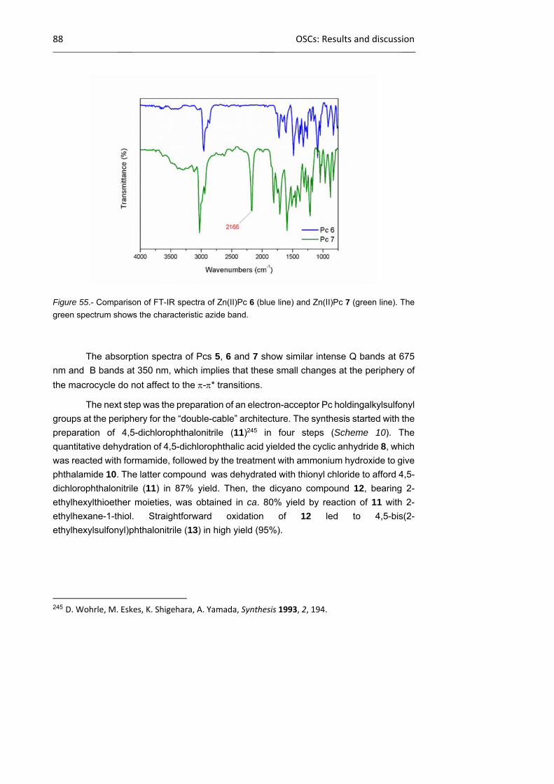
88 OSCs: Results and discussion
Figure 55.- Comparison of FT-IR spectra of Zn(II)Pc 6 (blue line) and Zn(II)Pc 7 (green line). The
green spectrum shows the characteristic azide band.
The absorption spectra of Pcs 5, 6 and 7 show similar intense Q bands at 675
nm and B bands at 350 nm, which implies that these small changes at the periphery of
the macrocycle do not affect to the -* transitions.
The next step was the preparation of an electron-acceptor Pc holdingalkylsulfonyl
groups at the periphery for the “double-cable” architecture. The synthesis started with the
preparation of 4,5-dichlorophthalonitrile (11)245 in four steps (Scheme 10). The
quantitative dehydration of 4,5-dichlorophthalic acid yielded the cyclic anhydride 8, which
was reacted with formamide, followed by the treatment with ammonium hydroxide to give
phthalamide 10. The latter compound was dehydrated with thionyl chloride to afford 4,5-
dichlorophthalonitrile (11) in 87% yield. Then, the dicyano compound 12, bearing 2-
ethylhexylthioether moieties, was obtained in ca. 80% yield by reaction of 11 with 2-
ethylhexane-1-thiol. Straightforward oxidation of 12 led to 4,5-bis(2-
ethylhexylsulfonyl)phthalonitrile (13) in high yield (95%).
245 D. Wohrle, M. Eskes, K. Shigehara, A. Yamada, Synthesis 1993, 2, 194.

Chapter 1 89
Scheme 10.- Synthesis of phthalonitrile 13.
The synthesis of alkylsulfonyl-containing Ni(II), Pd(II) and Zn(II) Pc derivatives
by cyclic tetramerization of the corresponding phthalonitriles or diiminoisoindoles
precursors had been previously reported by our group. Although typical solvents for the
condensation reaction are high-boiling alcohols, (i.e. penthanol), a refluxing mixture of
DMF and o-DCB was used in this case in order to avoid nucleophilic displacement of the
sulfonyl groups by an alcohol solvent.242 Therefore, this procedure has been employed
in the synthesis of the unsymmetrically substituted Zn(II)Pc 15 (Scheme 11, route A),
bearing three branched alkylsulfonyl groups (which play the role of electron-acceptor
moieties and facilitate chromatographic isolation) and one iodine moiety that will be
further converted into the targeted terminal alkyne. Thus, the condensation reaction of a
1:3 molar ratio of phthalonitriles 2 and 13 was carried out in the presence of Zn(OAc)2.
The statistical mixture of Pcs was purified by column chromatography, leading to the
isolation of the symmetrically substituted Pc 14 as the major component, followed by a
small amount of the desired compound iodoPc 15. In order to improve the yield in 15,
other molar ratios were tested, and the best results obtained with a 2:3 molar ratio of
phthalonitriles 2 and 13. This reaction allowed to isolate Pcs 14 and 15 in 20% and 25%
yields, respectively. However, the chromatographic purification was specially arduous in
this case due to the very similar polarities of the two Pcs.
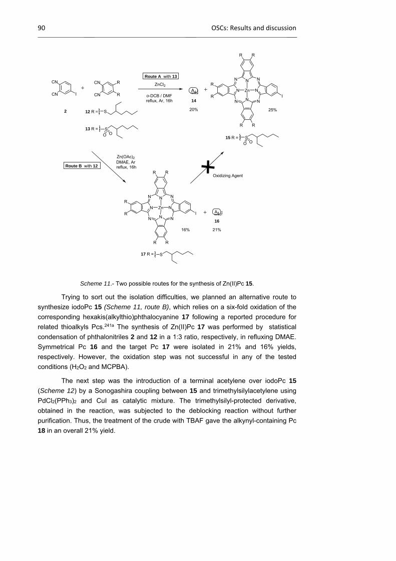
90 OSCs: Results and discussion
Scheme 11.- Two possible routes for the synthesis of Zn(II)Pc 15.
Trying to sort out the isolation difficulties, we planned an alternative route to
synthesize iodoPc 15 (Scheme 11, route B), which relies on a six-fold oxidation of the
corresponding hexakis(alkylthio)phthalocyanine 17 following a reported procedure for
related thioalkyls Pcs.241a The synthesis of Zn(II)Pc 17 was performed by statistical
condensation of phthalonitriles 2 and 12 in a 1:3 ratio, respectively, in refluxing DMAE.
Symmetrical Pc 16 and the target Pc 17 were isolated in 21% and 16% yields,
respectively. However, the oxidation step was not successful in any of the tested
conditions (H2O2 and MCPBA).
The next step was the introduction of a terminal acetylene over iodoPc 15
(Scheme 12) by a Sonogashira coupling between 15 and trimethylsilylacetylene using
PdCl2(PPh3)2 and CuI as catalytic mixture. The trimethylsilyl-protected derivative,
obtained in the reaction, was subjected to the deblocking reaction without further
purification. Thus, the treatment of the crude with TBAF gave the alkynyl-containing Pc
18 in an overall 21% yield.
ICN
CN
12 R =
RCN
CN R
N
NN
N
N
NN N
Zn
RR
R
R
R R
2
13 R =
14
A4
25%S
SO O
15 R =
20%
ZnCl2
o-DCB / DMFreflux, Ar, 16h
N
NN
N
N
NN N
ZnI
RR
R
R
R R
21%
DMAE, Arreflux, 16h
Zn(OAc)2
17 R =
A4
16%
Oxidizing Agent
Route B with 12
16
SO O
S
Route A with 13
I

Chapter 1 91
Scheme 12.- Synthesis of functionalized alkynyl-containing Zn(II)Pc 18.
The absorption spectra of iodo derivative Pcs 15 and 17 in comparison to that of
the alkynyl-containing Pc 18 are depicted in Figure 56. The electronic spectrum of Pc 15
is characterized by a split Q band (701 and 672 nm), as a result of the reduction of
symmetry due to the presence of the alkylsulfonyl groups and the effect of these electron-
acceptor acceptor groups on the electronic levels of the aromatic core. For the analogous
alkylthioether derivative Pc 17, a unique Q band at 697 nm is observed. Pc 18 shows,
however, a main Q band at 697 nm and a shoulder at 675 nm.
Figure 56.- Comparison of absorption spectra of Zn(II)Pc 15 (blue line), Zn(II)Pc 17 (red line) and
Zn(II)Pc 18 ( green line).
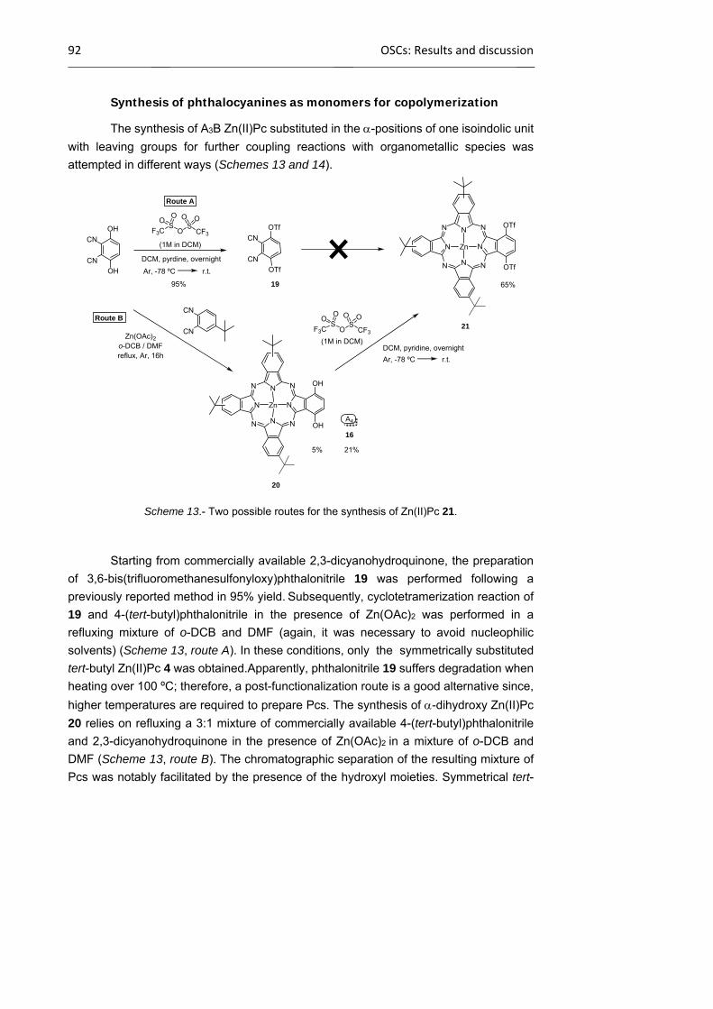
92 OSCs: Results and discussion
Synthesis of phthalocyanines as monomers for copolymerization
The synthesis of A3B Zn(II)Pc substituted in the -positions of one isoindolic unit
with leaving groups for further coupling reactions with organometallic species was
attempted in different ways (Schemes 13 and 14).
Scheme 13.- Two possible routes for the synthesis of Zn(II)Pc 21.
Starting from commercially available 2,3-dicyanohydroquinone, the preparation
of 3,6-bis(trifluoromethanesulfonyloxy)phthalonitrile 19 was performed following a
previously reported method in 95% yield. Subsequently, cyclotetramerization reaction of
19 and 4-(tert-butyl)phthalonitrile in the presence of Zn(OAc)2 was performed in a
refluxing mixture of o-DCB and DMF (again, it was necessary to avoid nucleophilic
solvents) (Scheme 13, route A). In these conditions, only the symmetrically substituted
tert-butyl Zn(II)Pc 4 was obtained.Apparently, phthalonitrile 19 suffers degradation when
heating over 100 ºC; therefore, a post-functionalization route is a good alternative since,
higher temperatures are required to prepare Pcs. The synthesis of -dihydroxy Zn(II)Pc
20 relies on refluxing a 3:1 mixture of commercially available 4-(tert-butyl)phthalonitrile
and 2,3-dicyanohydroquinone in the presence of Zn(OAc)2 in a mixture of o-DCB and
DMF (Scheme 13, route B). The chromatographic separation of the resulting mixture of
Pcs was notably facilitated by the presence of the hydroxyl moieties. Symmetrical tert-
CN
CN
OH
OH
CN
CN
20
N
NN
N
N
NN N
Zn
OH
OH
21
N
NN
N
N
NN N
Zn
OTf
OTf
19
CN
CN
OTf
OTf
Route A
Route B
SO
SF3C CF3
OO O O
(1M in DCM)
DCM, pyrdine, overnight
Ar, -78 ºC r.t.
95%
Zn(OAc)2
o-DCB / DMFreflux, Ar, 16h
21%
A4
16
5%
SO
SF3C CF3
OO O O
(1M in DCM)DCM, pyridine, overnight
65%
Ar, -78 ºC r.t.

Chapter 1 93
butyl Zn(II)Pc 4 was the first one eluted, followed by Pc 20, that was isolated in a
frustrating 5% yield. No improvements were achieved neither by changing the solvent to
1-penthanol, DMAE or o-DCB, nor by modifying the molar ratios. Decomposition of the
starting dicyanohydroquinone seemed to be the reason of the low yield. Eventually,
triflation of 20 afforded Zn(II)Pc 21 in overall 3% yield.
Aiming at increasing the overall yield, a new synthetic strategy employing more
robust phthalonitriles, was developed as depicted in Scheme 14.
Scheme 14.- Reagents and conditions: Methyl route (i) dimethyl sulfate, K2CO3, 2-butanone, heat;
(ii) 4-tert-butylphthalonitrile, Zn(OAc)2, DMAE, DBU. Tosyl route (i) p-toluenesulfonyl chloride,
K2CO3, acetone, heat; (ii) 4-tert-butylphthalonitrile, Zn(OAc)2, o-DCB / DMF.
Phthalonitriles 22 and 23 were synthesized according to procedures previously
described. The reaction for the synthesis of phthalocyanine 24, carried out in the
presence of Zn(OAc)2 in DMAE, led just to the tetra(tert-butyl)Zn(II)Pc 4. The change of
solvent, e.g. 1-penthanol or a mixture of o-DCB and DMF, did not afford better results.
On the other hand, tosylatePc 25 could be isolated in a 8% yield. Partial cleavage of the
tosylate group was detected and, in fact, a Pc holding one deprotected hydroxyl group
and one tosylate in the same isoindole was also isolated in 3% yield. Worth of mention
is that Zn(II)Pc 20 was not detected. The deprotection step was performed over a mixture
of the bis- and monotosylate derivatives in a basic media, giving Zn(II)Pc 20 in a low yield
for the last two steps, and in an overall 3% yield, so that we set aside this approach.
All the compounds were characterized by mass spectrometry, 1H-NMR, UV-Vis
and FT-IR spectroscopy..
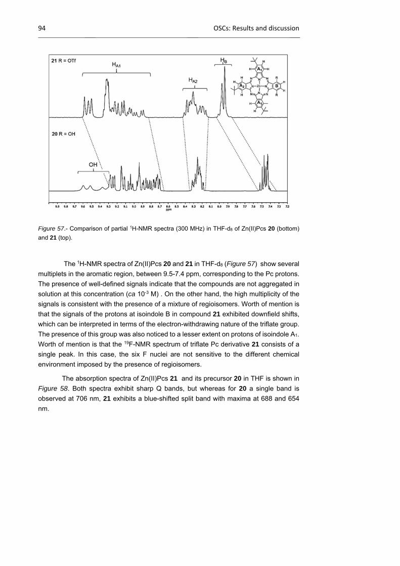
94 OSCs: Results and discussion
Figure 57.- Comparison of partial 1H-NMR spectra (300 MHz) in THF-d8 of Zn(II)Pcs 20 (bottom)
and 21 (top).
The 1H-NMR spectra of Zn(II)Pcs 20 and 21 in THF-d8 (Figure 57) show several
multiplets in the aromatic region, between 9.5-7.4 ppm, corresponding to the Pc protons.
The presence of well-defined signals indicate that the compounds are not aggregated in
solution at this concentration (ca 10-3 M) . On the other hand, the high multiplicity of the
signals is consistent with the presence of a mixture of regioisomers. Worth of mention is
that the signals of the protons at isoindole B in compound 21 exhibited downfield shifts,
which can be interpreted in terms of the electron-withdrawing nature of the triflate group.
The presence of this group was also noticed to a lesser extent on protons of isoindole A1.
Worth of mention is that the 19F-NMR spectrum of triflate Pc derivative 21 consists of a
single peak. In this case, the six F nuclei are not sensitive to the different chemical
environment imposed by the presence of regioisomers.
The absorption spectra of Zn(II)Pcs 21 and its precursor 20 in THF is shown in
Figure 58. Both spectra exhibit sharp Q bands, but whereas for 20 a single band is
observed at 706 nm, 21 exhibits a blue-shifted split band with maxima at 688 and 654
nm.

Chapter 1 95
Figure 58.- Comparison of albsorption spectra of Zn(II)Pcs 20 (solid line) and 21(dashed line) in
THF.
Another objective regarding the preparation of Pc-containing copolymers is to
move the reactive position at the Pc towards the exterior of the macrocycle and thus to
increase its reactivity in metal-catalyzed coupling reactions. For that purpose a
naphthalene dicarbonitrile precursor containing triflate groups at the 5,8 positions has to
be prepared. The most simple approach seemed to be using 2,3-dibromonaphthalene
(A) as building block (Scheme 15). An indirect route to obtain the quinone derivative C
was contemplated using 6,7-dibromo-1-naphthol (B).246 However, the synthesis of this
naphthol requires three steps: treatment of A with a nitric-sulphuric acid mixture for
mononitration of naphthalene, reduction of the nitro compound to the corresponding
amine with hydrazine hydrate, and finally diazotization followed by hydrolysis. An
additional step for the oxidation to quinone C implies an overall four-step route, too many
a priori. On the other hand, the straightforward oxidation of A to quinone C, was
discarded in view of the literature precedents. Finally, routes A and B, based on a Diels-
Alder reaction, were tackled.
246 A. Ashnagar, J. M. Bruce, P. Lloyd‐Williams, J. Chem. Soc., Perkin Trans. 1 1998, 559 and references therein.

96 OSCs: Results and discussion
Scheme 15. Alternatives approaches to
obtain the target naphthalene.
The first methodology, as it is depicted in route A (Scheme 16), includes the
preparation of the ,’-dibrominated compound 27, by -methylation of 2,3-
dimethylhydroquinone followed by double benzylic bromination with NBS. Compound 27
was subjected to reaction with Rieke nickel to generate the o-xylilene derivative, which
shall react with fumaronitrile to give the Diels Alder aduct 28. However, treatment of ,’-dibromo-3,6-dimethoxy-o-xylene (27) with nickel powder prepared in DME, did not lead
to in situ generation of the diene.
Scheme 16.- Attempts to prepare 5,8-dimethoxy-1,2,3,4-tetrahydronaphthalene-2,3-dicarbonitrile
(28).
Route B (Scheme 17) also follows the Diels-Alder cycloaddition, but between
benzoquinone as dienophile and 3,4-dibromothiophene 1,1-dioxide (29) as diene,
according to a literature procedure.247 A large excess (10 equivalents) of benzoquinone
was used to suppress the formation of two unwanted compounds: the symmetrical
anthraquinone derivative and the product from the homodimerization of sulfone 29. Naphthoquinone 30 was subsequently reduced and methylated to avoid addition of the
cyanide ions to the quinonic carbonyl group (C=O) during the formation of the
247 D. Bailey, V. E. Williams, Tetrahedron Lett. 2004, 45, 2511.
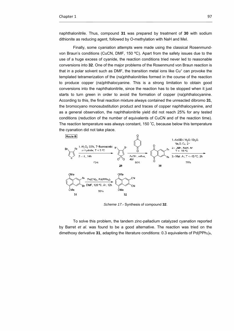
Chapter 1 97
naphthalonitrile. Thus, compound 31 was prepared by treatment of 30 with sodium
dithionite as reducing agent, followed by O-methylation with NaH and MeI.
Finally, some cyaniation attempts were made using the classical Rosenmund-
von Braun’s conditions (CuCN, DMF, 150 ºC). Apart from the safety issues due to the
use of a huge excess of cyanide, the reaction conditions tried never led to reasonable
conversions into 32. One of the major problems of the Rosenmund von Braun reaction is
that in a polar solvent such as DMF, the transition metal ions like Cu+ can provoke the
templated tetramerization of the (na)phthalonitriles formed in the course of the reaction
to produce copper (na)phthalocyanine. This is a strong limitation to obtain good
conversions into the naphthalonitrile, since the reaction has to be stopped when it just
starts to turn green in order to avoid the formation of copper (na)phthalocyanine.
According to this, the final reaction mixture always contained the unreacted dibromo 31,
the bromocyano monosubstitution product and traces of copper naphthalocyanine, and
as a general observation, the naphthalonitrile yield did not reach 25% for any tested
conditions (reduction of the number of equivalents of CuCN and of the reaction time).
The reaction temperature was always constant, 150 ºC, because below this temperature
the cyanation did not take place.
Scheme 17.- Synthesis of compound 32.
To solve this problem, the tandem zinc-palladium catalyzed cyanation reported
by Barret et al. was found to be a good alternative. The reaction was tried on the
dimethoxy derivative 31, adapting the literature conditions: 0.3 equivalents of Pd(PPh3)4,
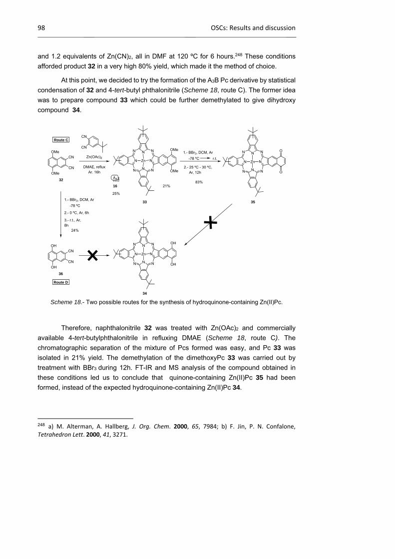
98 OSCs: Results and discussion
and 1.2 equivalents of Zn(CN)2, all in DMF at 120 ºC for 6 hours.248 These conditions
afforded product 32 in a very high 80% yield, which made it the method of choice.
At this point, we decided to try the formation of the A3B Pc derivative by statistical
condensation of 32 and 4-tert-butyl phthalonitrile (Scheme 18, route C). The former idea
was to prepare compound 33 which could be further demethylated to give dihydroxy
compound 34.
Scheme 18.- Two possible routes for the synthesis of hydroquinone-containing Zn(II)Pc.
Therefore, naphthalonitrile 32 was treated with Zn(OAc)2 and commercially
available 4-tert-butylphthalonitrile in refluxing DMAE (Scheme 18, route C). The
chromatographic separation of the mixture of Pcs formed was easy, and Pc 33 was
isolated in 21% yield. The demethylation of the dimethoxyPc 33 was carried out by
treatment with BBr3 during 12h. FT-IR and MS analysis of the compound obtained in
these conditions led us to conclude that quinone-containing Zn(II)Pc 35 had been
formed, instead of the expected hydroquinone-containing Zn(II)Pc 34.
248 a) M. Alterman, A. Hallberg, J. Org. Chem. 2000, 65, 7984; b) F. Jin, P. N. Confalone, Tetrahedron Lett. 2000, 41, 3271.
OMe
OMe
CN
CN
32
N
NN
N
N
NN N
Zn
OMe
OMe
33
N
NN
N
N
NN N
Zn
O
O
35
OH
OH
CN
CN
36
N
NN
N
N
NN N
Zn
OH
OH
Route C
Route D
CN
CN
DMAE, refluxAr. 16h
Zn(OAc)2
21%
1.- BBr3, DCM, Ar
2.- 25 ºC - 30 ºC,Ar, 12h
-78 ºC r.t.
83%
1.- BBr3, DCM, Ar
2.- 0 ºC, Ar, 6h
-78 ºC
24%
3.- r.t., Ar,8h
34
25%
A4
16

Chapter 1 99
At this stage, the use of a mild reducing agent to convert 35 into the desired final
product 34 was considered, in particular the use of sodium dithionite. However,
compound 35 was reluctant to react in any of the tested conditions, and almost all the
starting material was always recovered. This bottleneck led us to consider route D, that
is deprotection of naphthalonitrile 32 to obtain compound 36 which could condensate with
4-tert-butylphthalonitrile to form the target Pc 34. Thus, deprotection of 32 was
accomplished using BBr3 as a reported in the literature, affording 5,8-
dihydroxynaphthalonitrile (36) in low yield. This naphthalonitrile seemed to degradate
under the reaction conditions and, in fact, when it was subjected to the classical
conditions for the synthesis of Pcs together with 4-tert-butylphthalonitrile, a brown tar was
obtained with no traces of Pc 34.
In light of these bad results, the research for new alternatives was desestimated.
On the other hand, it has not escaped our notice that quinone-derivative Zn(II)Pc 35 could
have interesting redox properties, but this is beyond the scope of this thesis.
1.2.4.2 Synthesis of Pc-containing conjugated copolymers
PPV- and PT-type copolymers with phthalocyanines as light –harvesting units
The synthesis of MDMO-PPV copolymers containing pendant Pc units was
performed in collaboration with Dr. Laurence Lutsen and Prof. Dr. Dirk Vanderzande at
Hasselt University in the framework of a EU-RTN project. They prepared copolymer 37
from adequate substituted sulfinyl precursors and subsequent hydrolysis of the ester
group using a basic media, with almost quantitative conversion, as shown in Scheme
19.249 As a result, the copolymer presents one terminal carboxylic acid every ten p-
phenylene vinylene repeating units. Analytical size-exclusion chromatography (SEC)
measurements250 of this copolymer were performed versus polystyrene standards using
249 a) J. Duchateau, L. Lutsen, W. Guedens, T. J. Cleij, D. Vanderzande, Polym. Chem. 2010, 1, 1313; b) L. Lutsen, P. Adriaensens, H. Becker, A. J. Van Breemen, D. Vanderzande, J. Gelan, Macromolecules 1999, 32, 6517. 250 Size‐exclusion chromatography (SEC) is a chromatographic method in which molecules in solution are separated by their size, and it is usually applied to large molecules such as polymers. SEC is widely used polymer characterization method because of its ability to provide good molar mass distribution (MW) results for polymers. This technique involves forcing a polymer solution through a matrix of cross‐linked polymer particles at a pressure of up to several hundred bar. The limited accessibility of stationary phase pore volume for the polymer molecules results in shorter elution times for high‐molecular‐mass species. The use of low dispersity standards allows the user to correlate retention time with molecular mass.

100 OSCs: Results and discussion
THF as the eluent. The observed molecular weight polymer251 is Mw = 2.7·105 g/mol (PDI
x= 3.2),252 which confirms that a high molecular weight polymer was obtained.
Scheme 19.- Synthesis of carboxy copolymer 37.
With this polymer in our hands, the following step towards the preparation of Pc-
containing copolymers was the esterification reaction,249 between carboxy-MDMO-PPV
37 and hydroxymethyl Zn(II)Pc 5. The reaction was carried out in dry DCM under nitrogen
atmosphere and protected from light, using DCC and DMAP as condensation agents
(Scheme 20). The Pc-functionalized copolymer 38 was filtered off and washed
extensively with acetone to remove the excess of unreacted Zn(II)Pc 5.
251 Weight average molecular weight (MW) takes into account the molecular weight of a chain in determining contributions to the molecular weight average. The more massive the chain, the more the chain contributes to MW. Another interesting parameter is the number average molecular weight (Mn), which represents the statistical average molecular weight of all the polymer chains in the sample. Mn is more sensitive to molecules of low molecular mass, while MW is more sensitive to molecules of high molecular mass. 252 The polydispersity index (PDI) is used as a mesure of the broadness of a molecular weight distribution of a polymer and is calculated as MW divided by Mn. It indicates the distribution of individual molecular masses in a batch of polymers. The PDI has a value equal to or greater than 1, but as the polymer chains approach uniform chain length, the PDI approaches unity. The best controlled synthetic polymers (narrow polymers used for calibrations) have a PDI of 1.02 to 1.10. Step polymerization reactions typically yield values of PDI of around 2.0, whereas chain reaction yield values between 1.5 and 20.

Chapter 1 101
Scheme 20.- Synthesis of functionalized Pc-PPV copolymer 38.
The final material, Pc-PPV 38, showed to be quite soluble in THF, which allowed
us to fully characterize it by 1H-NMR, FT-IR and UV-Vis spectroscopy.. Successful
conversion of the conjugated copolymer in Pc-PPV 38 is evidenced by 1H-NMR
spectroscopy (Figure 59). All the characteristics peaks for the attached Zn(II)Pc units –
namely aromatic protons resonating in the 9.8-8.0 range and the CH2OCO- methylene at
5.28 ppm – are present in the spectrum of copolymer Pc-PPV 38. The integration of the
signals is consistent with a high degree of conversion of the carboxylic acid to the
corresponding ester group.
Figure 59.- 1H-NMR spectrum of Pc-PPV 38 in THF-d8.
The lateral functionalization of carboxyl-PPV copolymer 37 with Pc 5 is also
confirmed by FT-IR, where the carbonyl vibration at 1709 cm-1 of the carboxylic acid shifts
to a higher frequency, 1733 cm-1, due to the formation of the ester bond. Analytical SEC
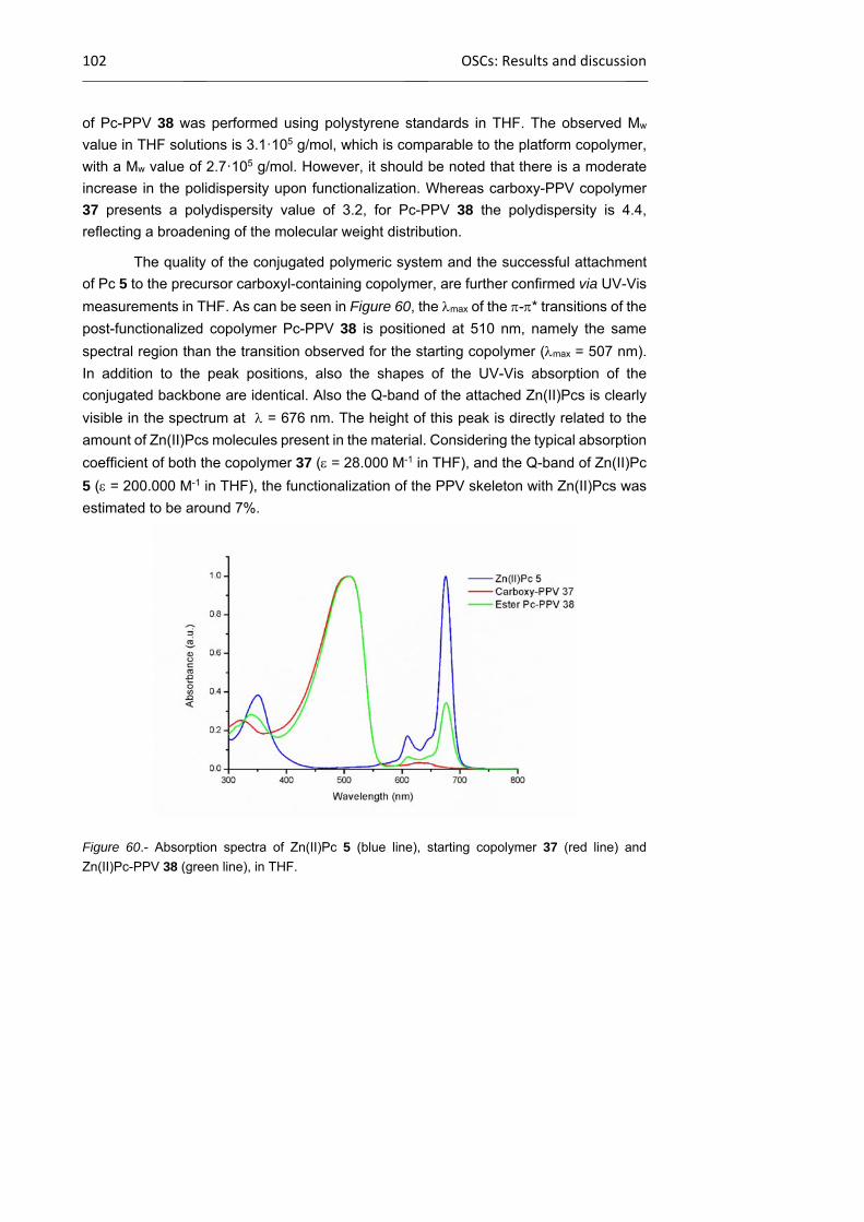
102 OSCs: Results and discussion
of Pc-PPV 38 was performed using polystyrene standards in THF. The observed Mw
value in THF solutions is 3.1·105 g/mol, which is comparable to the platform copolymer,
with a Mw value of 2.7·105 g/mol. However, it should be noted that there is a moderate
increase in the polidispersity upon functionalization. Whereas carboxy-PPV copolymer
37 presents a polydispersity value of 3.2, for Pc-PPV 38 the polydispersity is 4.4,
reflecting a broadening of the molecular weight distribution.
The quality of the conjugated polymeric system and the successful attachment
of Pc 5 to the precursor carboxyl-containing copolymer, are further confirmed via UV-Vis
measurements in THF. As can be seen in Figure 60, the max of the -* transitions of the
post-functionalized copolymer Pc-PPV 38 is positioned at 510 nm, namely the same
spectral region than the transition observed for the starting copolymer (max = 507 nm).
In addition to the peak positions, also the shapes of the UV-Vis absorption of the
conjugated backbone are identical. Also the Q-band of the attached Zn(II)Pcs is clearly
visible in the spectrum at = 676 nm. The height of this peak is directly related to the
amount of Zn(II)Pcs molecules present in the material. Considering the typical absorption
coefficient of both the copolymer 37 ( = 28.000 M-1 in THF), and the Q-band of Zn(II)Pc
5 ( = 200.000 M-1 in THF), the functionalization of the PPV skeleton with Zn(II)Pcs was
estimated to be around 7%.
Figure 60.- Absorption spectra of Zn(II)Pc 5 (blue line), starting copolymer 37 (red line) and
Zn(II)Pc-PPV 38 (green line), in THF.

Chapter 1 103
Since the esterification of the COOH groups in 37 with Pc 5 was not complete,
other chemical approaches were envisioned to improve the incorporation of Pcs into the
polymeric skeleton as pendant moieties. A “click” reaction, which has been largely
applied in materials science for the functionalization of polymers and surfaces, seems to
be a good alternative. The well-known 1,3 Huisgen cycloaddition is one of the most
popular reactions in the “click” chemistry family.253 It is a 1,3-dipolar cycloaddition
between an azide and an alkyne to give a 1,2,3-triazole.254 When using a Cu(I) catalyst,
a 1,4-disubstituted-1,2,3-triazole is selectively obtained from the alkyl or aromatic azide
and the terminal alkyne. This “click” chemistry reaction proceeds with very high yields
and has been largely applied to the side-chain functionalization of polymers and as a
polymerization method,255 and also exploited with success in the preparation of a range
of elaborated mono- and multicomponent, Pc-based architectures.256
In the following cases, the well-known copper(I)-catalyzed 1,3-dipolar
cycloaddition proceeded between an azide, Zn(II)Pc 7, and conjugated copolymers
properly functionalized with terminal triple bonds (39). These copolymers were
synthesized at Hasselt University, from the previously obtained carboxy-MDMO-PPV 37,
through an optimized DCC/DMAP esterification reaction,249 as shown in Scheme 21
(GPC (THF): MW = 3.8·105 g/mol, PDI = 5.2). This copolymer contains 9% of triple bonds,
as determined by 1H-NMR.
Scheme 21.- Synthesis of alkynyl-containing MDMO-PPV-type copolymer 39.
253 H. C. Kolb, M. G. Finn, K. B. Sharpless, Angew. Chem. Int. Ed. 2001, 40, 2004. 254 V. V. Rostovtsev, L. G. Green, V. V. Fokin, K. B. Sharpless, Angew. Chem. Int. Ed. 2002, 41, 2596. 255 a) W. H. Binder, R. Sachsenhofer, Macromol. Rapid Commun. 2008, 29, 952; b) P. L. Golas, K. Matyjaszewski, Chem. Soc. Rev. 2010, 39, 1338; c) K. Kempe, A. Krieg, C. R. Becer, U. S. Schubert, Chem. Soc. Rev. 2012, 41, 176. 256 S. Campidelli, B. Ballesteros, A. Filoramo, D. D. Diaz, G. de la Torre, T. Torres, G. M. A. Rahman, C. Ehli, D. Kiessling, F. Werner, V. Sgobba, D. M. Guldi, C. Cioffi, M. Prato, J.‐P. Bourgoin, J. Am. Chem. Soc. 2008, 130, 11503.
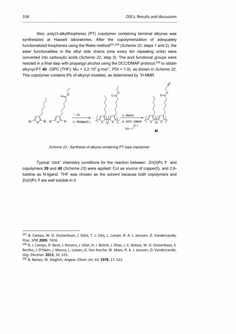
104 OSCs: Results and discussion
Also, poly(3-alkylthiophene) (PT) copolymer containing terminal alkynes was
synthesized at Hasselt laboratories. After the copolymerization of adequately
functionalized thiophenes using the Rieke method257,258 (Scheme 22, steps 1 and 2), the
ester functionalities in the alkyl side chains (one every ten repeating units) were
converted into carboxylic acids (Scheme 22, step 3). The acid functional groups were
reacted in a final step with propargyl alcohol using the DCC/DMAP protocol,259 to obtain
alkynyl-PT 40 (GPC (THF): MW = 3.2·104 g·mol-1, PDI = 1.9), as shown in Scheme 22.
This copolymer contains 8% of alkynyl moieties, as determined by 1H-NMR.
Scheme 22.- Synthesis of alkyne-containing PT-type copolymer.
Typical “click” chemistry conditions for the reaction between Zn(II)Pc 7 and
copolymers 39 and 40 (Scheme 23) were applied: CuI as source of copper(I), and 2,6-
lutidine as N-ligand. THF was chosen as the solvent because both copolymers and
Zn(II)Pc 7 are well soluble in it.
257 B. Campo, W. D. Oosterbaan, J. Gilot, T. J. Cleij, L. Lutsen, R. A. J. Janssen, D. Vanderzande, Proc. SPIE 2009, 7416. 258 B. J. Campo, D. Bevk, J. Kesters, J. Gilot, H. J. Bolink, J. Zhao, J.‐C. Bolsee, W. D. Oosterbaan, S. Bertho, J. D’Haen, J. Manca, L. Lutsen, G. Van Assche, W. Maes, R. A. J. Janssen, D. Vanderzande, Org. Electron. 2013, 14, 523. 259 B. Neises, W. Steglich, Angew. Chem. Int. Ed. 1978, 17, 522.
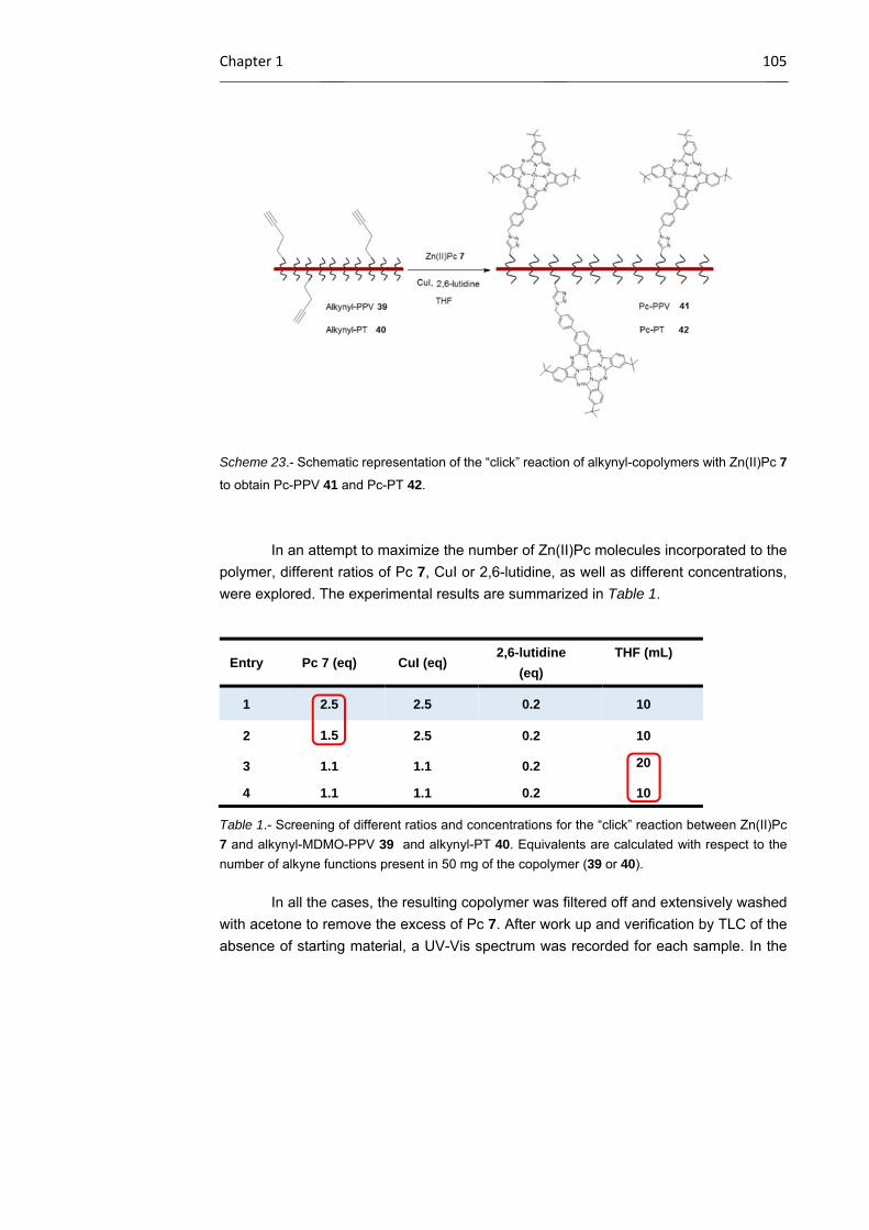
Chapter 1 105
Scheme 23.- Schematic representation of the “click” reaction of alkynyl-copolymers with Zn(II)Pc 7
to obtain Pc-PPV 41 and Pc-PT 42.
In an attempt to maximize the number of Zn(II)Pc molecules incorporated to the
polymer, different ratios of Pc 7, CuI or 2,6-lutidine, as well as different concentrations,
were explored. The experimental results are summarized in Table 1.
Table 1.- Screening of different ratios and concentrations for the “click” reaction between Zn(II)Pc
7 and alkynyl-MDMO-PPV 39 and alkynyl-PT 40. Equivalents are calculated with respect to the
number of alkyne functions present in 50 mg of the copolymer (39 or 40).
In all the cases, the resulting copolymer was filtered off and extensively washed
with acetone to remove the excess of Pc 7. After work up and verification by TLC of the
absence of starting material, a UV-Vis spectrum was recorded for each sample. In the
Entry Pc 7 (eq) CuI (eq) 2,6-lutidine
(eq)
THF (mL)
1 2.5 2.5 0.2 10
2 1.5 2.5 0.2 10
3 1.1 1.1 0.2 20
4 1.1 1.1 0.2 10

106 OSCs: Results and discussion
case of alkynyl-MDMO-PPV 39 as starting copolymer, the UV-Vis spectra of the different
batches of Pc-PPV 41, together with those of the starting materials,are displayed in
Figure 61.
Figure 61.- UV-vis spectra of Pc-PPV 41 obtained under different conditions (entries 1-4) compared
with the spectra of starting materials Zn(II)Pc 7 and alkynyl-MDMO-PPV 39.
As could be deduced from the comparison of the spectra, increasing the
equivalents of Pc 7 (entries 1 and 2) and also the concentrations (entries 3 and 4) led to
a more efficient funcitionalization of the copolymer with Pc 7. Also, sodium ascorbate was
tested as reducing agent in combination with Cu(II) salts under optimized reaction
conditions, but no improvement was observed. Full derivatization of the acetylene groups
in the starting copolymer was archived with conditions depicted in entry 1. According to
these experiments, the use of 2.5 equivalents of Pc 7, CuI (2.5 eq) and 2,6-lutidine (0.2
eq) were found to be the optimum conditions for the proposed reaction. Analytical SEC
of Pc-PPV 41 was performed using polystyrene standards. The observed Mw value in
THF solutions is 3.0·105 g/mol, which is comparable to the platform copolymer alkynyl-
MDMO-PPV 39, with a Mw value of 3.8·105 g/mol. Consequently, no significant increase
in the average molecular weight occurs during the functionalization with Zn(II)Pc 7.
However, it should be observed that there is a moderate decrease in the polidispersity
upon functionalization, in contrast to what we observed in the case of the Pc-PPV polymer
38. Whereas alkynyl-MDMO-PPV 39 copolymer presents a polydispersity value of 5.2,
for Pc-PPV 41 the polydispersity is 4.0, reflecting, in this case, a narrowing of the
molecular weight distribution.
As shown in Figure 61, the quality of the conjugated system and the success of
the “click” reaction of Pc 7 to copolymer alkynyl-MDMO-PPV 39, are further confirmed
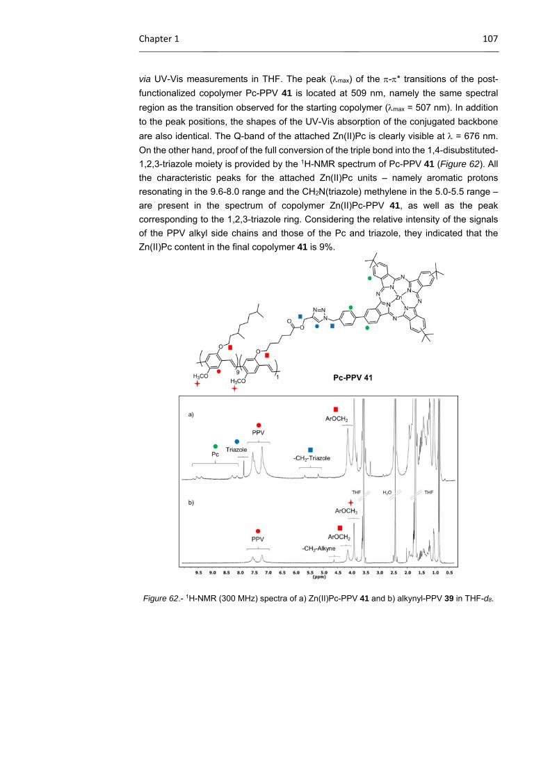
Chapter 1 107
via UV-Vis measurements in THF. The peak (max) of the -* transitions of the post-
functionalized copolymer Pc-PPV 41 is located at 509 nm, namely the same spectral
region as the transition observed for the starting copolymer (max = 507 nm). In addition
to the peak positions, the shapes of the UV-Vis absorption of the conjugated backbone
are also identical. The Q-band of the attached Zn(II)Pc is clearly visible at = 676 nm.
On the other hand, proof of the full conversion of the triple bond into the 1,4-disubstituted-
1,2,3-triazole moiety is provided by the 1H-NMR spectrum of Pc-PPV 41 (Figure 62). All
the characteristic peaks for the attached Zn(II)Pc units – namely aromatic protons
resonating in the 9.6-8.0 range and the CH2N(triazole) methylene in the 5.0-5.5 range –
are present in the spectrum of copolymer Zn(II)Pc-PPV 41, as well as the peak
corresponding to the 1,2,3-triazole ring. Considering the relative intensity of the signals
of the PPV alkyl side chains and those of the Pc and triazole, they indicated that the
Zn(II)Pc content in the final copolymer 41 is 9%.
Figure 62.- 1H-NMR (300 MHz) spectra of a) Zn(II)Pc-PPV 41 and b) alkynyl-PPV 39 in THF-d8.
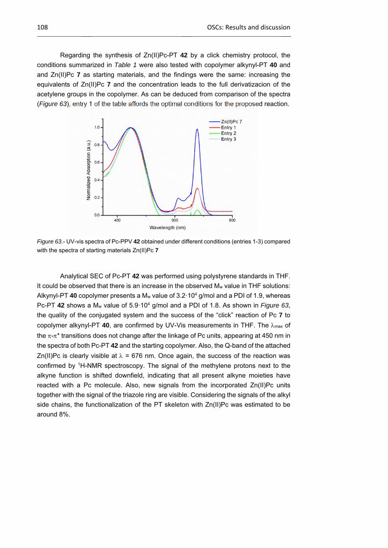
108 OSCs: Results and discussion
Regarding the synthesis of Zn(II)Pc-PT 42 by a click chemistry protocol, the
conditions summarized in Table 1 were also tested with copolymer alkynyl-PT 40 and
and Zn(II)Pc 7 as starting materials, and the findings were the same: increasing the
equivalents of Zn(II)Pc 7 and the concentration leads to the full derivatizacion of the
acetylene groups in the copolymer. As can be deduced from comparison of the spectra
(Figure 63), entry 1 of the table affords the optimal conditions for the proposed reaction.
Figure 63.- UV-vis spectra of Pc-PPV 42 obtained under different conditions (entries 1-3) compared
with the spectra of starting materials Zn(II)Pc 7
Analytical SEC of Pc-PT 42 was performed using polystyrene standards in THF.
It could be observed that there is an increase in the observed Mw value in THF solutions:
Alkynyl-PT 40 copolymer presents a Mw value of 3.2·104 g/mol and a PDI of 1.9, whereas
Pc-PT 42 shows a Mw value of 5.9·104 g/mol and a PDI of 1.8. As shown in Figure 63,
the quality of the conjugated system and the success of the “click” reaction of Pc 7 to
copolymer alkynyl-PT 40, are confirmed by UV-Vis measurements in THF. The max of
the -* transitions does not change after the linkage of Pc units, appearing at 450 nm in
the spectra of both Pc-PT 42 and the starting copolymer. Also, the Q-band of the attached
Zn(II)Pc is clearly visible at = 676 nm. Once again, the success of the reaction was
confirmed by 1H-NMR spectroscopy. The signal of the methylene protons next to the
alkyne function is shifted downfield, indicating that all present alkyne moieties have
reacted with a Pc molecule. Also, new signals from the incorporated Zn(II)Pc units
together with the signal of the triazole ring are visible. Considering the signals of the alkyl
side chains, the functionalization of the PT skeleton with Zn(II)Pc was estimated to be
around 8%.
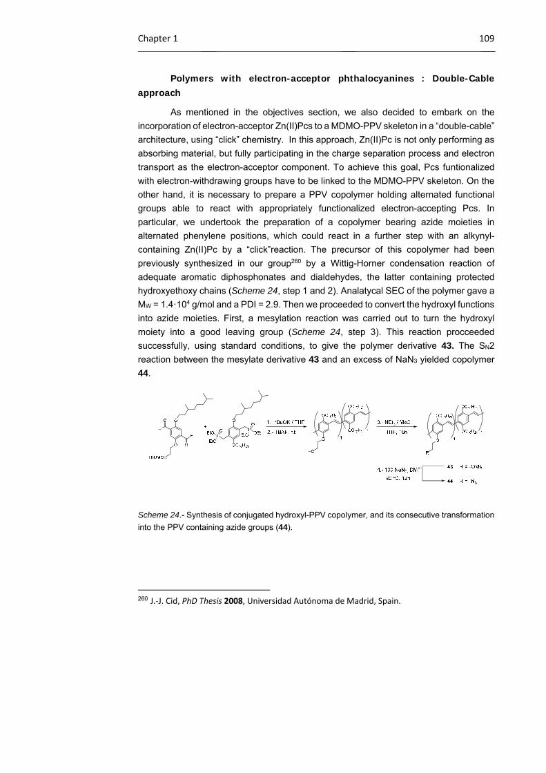
Chapter 1 109
Polymers with electron-acceptor phthalocyanines : Double-Cable approach
As mentioned in the objectives section, we also decided to embark on the
incorporation of electron-acceptor Zn(II)Pcs to a MDMO-PPV skeleton in a “double-cable”
architecture, using “click” chemistry. In this approach, Zn(II)Pc is not only performing as
absorbing material, but fully participating in the charge separation process and electron
transport as the electron-acceptor component. To achieve this goal, Pcs funtionalized
with electron-withdrawing groups have to be linked to the MDMO-PPV skeleton. On the
other hand, it is necessary to prepare a PPV copolymer holding alternated functional
groups able to react with appropriately functionalized electron-accepting Pcs. In
particular, we undertook the preparation of a copolymer bearing azide moieties in
alternated phenylene positions, which could react in a further step with an alkynyl-
containing Zn(II)Pc by a “click”reaction. The precursor of this copolymer had been
previously synthesized in our group260 by a Wittig-Horner condensation reaction of
adequate aromatic diphosphonates and dialdehydes, the latter containing protected
hydroxyethoxy chains (Scheme 24, step 1 and 2). Analatycal SEC of the polymer gave a
MW = 1.4·104 g/mol and a PDI = 2.9. Then we proceeded to convert the hydroxyl functions
into azide moieties. First, a mesylation reaction was carried out to turn the hydroxyl
moiety into a good leaving group (Scheme 24, step 3). This reaction procceeded
successfully, using standard conditions, to give the polymer derivative 43. The SN2
reaction between the mesylate derivative 43 and an excess of NaN3 yielded copolymer
44.
Scheme 24.- Synthesis of conjugated hydroxyl-PPV copolymer, and its consecutive transformation
into the PPV containing azide groups (44).
260 J.‐J. Cid, PhD Thesis 2008, Universidad Autónoma de Madrid, Spain.
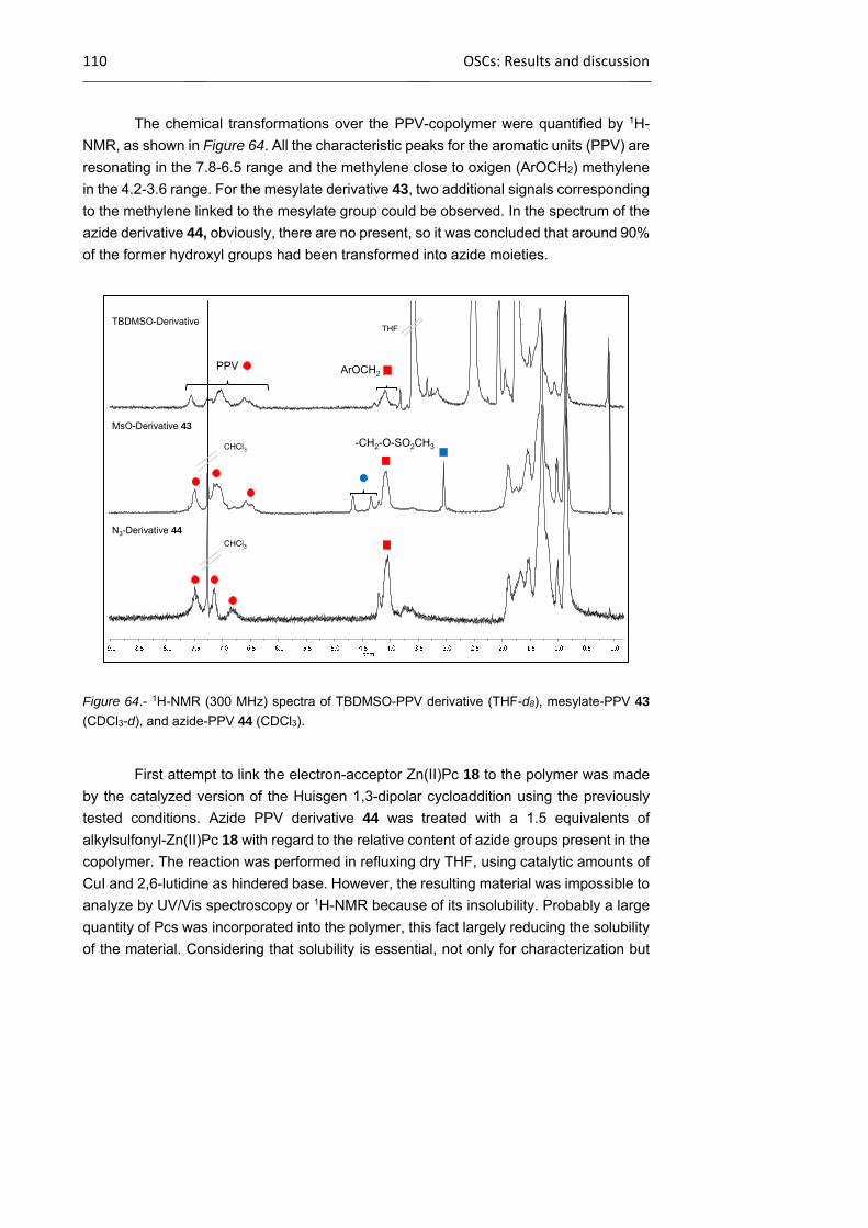
110 OSCs: Results and discussion
The chemical transformations over the PPV-copolymer were quantified by 1H-
NMR, as shown in Figure 64. All the characteristic peaks for the aromatic units (PPV) are
resonating in the 7.8-6.5 range and the methylene close to oxigen (ArOCH2) methylene
in the 4.2-3.6 range. For the mesylate derivative 43, two additional signals corresponding
to the methylene linked to the mesylate group could be observed. In the spectrum of the
azide derivative 44, obviously, there are no present, so it was concluded that around 90%
of the former hydroxyl groups had been transformed into azide moieties.
Figure 64.- 1H-NMR (300 MHz) spectra of TBDMSO-PPV derivative (THF-d8), mesylate-PPV 43
(CDCl3-d), and azide-PPV 44 (CDCl3).
First attempt to link the electron-acceptor Zn(II)Pc 18 to the polymer was made
by the catalyzed version of the Huisgen 1,3-dipolar cycloaddition using the previously
tested conditions. Azide PPV derivative 44 was treated with a 1.5 equivalents of
alkylsulfonyl-Zn(II)Pc 18 with regard to the relative content of azide groups present in the
copolymer. The reaction was performed in refluxing dry THF, using catalytic amounts of
CuI and 2,6-lutidine as hindered base. However, the resulting material was impossible to
analyze by UV/Vis spectroscopy or 1H-NMR because of its insolubility. Probably a large
quantity of Pcs was incorporated into the polymer, this fact largely reducing the solubility
of the material. Considering that solubility is essential, not only for characterization but
THF
CHCl3
CHCl3
PPV
TBDMSO-Derivative
-CH2-O-SO2CH3
MsO-Derivative 43
N3-Derivative 44
ArOCH2

Chapter 1 111
also for the proposed preparation and study of BHJ devices, we decided to rule out the
double cable approach.
Main-chain Pc-copolymers: Testing copolymerization conditions
Another plausible route towards the preparation of conjugated polymers
containing Pc units for BHJ devices is the incorporation of the macrocycle into the main
chain of the polymer. Aiming at keeping as much as possible the conjugation pathways,
we have planned to incorporate the Pc in an edge-fused fashion, considering the
remarkable results obtained with related Por-containing copolymers.230,231,232 For that
reason our final objective is the preparation of a copolymer incorporating Pcs and other
electroactive units such as, for instance, BDT and DPP, which have been succesfully
incorporated in low-band gap polymers and in small-molecule structures for BHJ
(Scheme 25). Following this strategy the Pc units will be incorporated into the main chain,
but connected through the exterior benzene unit.
The copolymerization of Pc monomers with DPP and BDT (or other analogous)
species will be performed by the group of Iain McCulloch at Imperial College in the
framework of EU-funded network, since they have a demonstrated expertise in the
polymerization of different units by metal-catalyzed coupling reactions to obtain low
bandgap polymers. We have provided them with Pc 21 (Scheme 26) to perform
copolymerizations with DPP/BDT organometallic and halogenated derivatives in different
conditions and ratio of the comonomers.
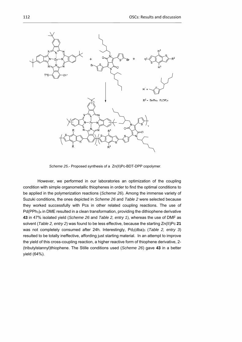
112 OSCs: Results and discussion
Scheme 25.- Proposed synthesis of a Zn(II)Pc-BDT-DPP copolymer.
However, we performed in our laboratories an optimization of the coupling
condition with simple organometallic thiophenes in order to find the optimal conditions to
be applied in the polymerization reactions (Scheme 26). Among the immense variety of
Suzuki conditions, the ones depicted in Scheme 26 and Table 2 were selected because
they worked successfully with Pcs in other related coupling reactions. The use of
Pd(PPh3)4 in DME resulted in a clean transformation, providing the dithiophene derivative
43 in 47% isolated yield (Scheme 26 and Table 2, entry 1), whereas the use of DMF as
solvent (Table 2, entry 2) was found to be less effective, because the starting Zn(II)Pc 21
was not completely consumed after 24h. Interestingly, Pd2(dba)3 (Table 2, entry 3)
resulted to be totally ineffective, affording just starting material. In an attempt to improve
the yield of this cross-coupling reaction, a higher reactive form of thiophene derivative, 2-
(tributylstannyl)thiophene. The Stille conditions used (Scheme 26) gave 43 in a better
yield (64%).

Chapter 1 113
Scheme 26.- Two possible palladium-catalyzed reactions for the synthesis of Zn(II)Pc 43.
With this preliminary conditions in hand, the first attempts to obtain co-polymers
with derivative 21 as building block are currently being done in the laboratories of Iain
McCulloch. Worth mentioning that the coupled tiophene-Pc derivative 43 can also be
used for copolymerization experiments.
Table 2.- Different conditions for the Suzuki reaction Zn(II)Pc 21 and thiophene-2-boronic acid
pinacol ester.
1.2.4.3 Photovoltaic studies of Pc-containing copolymers in bulk heterojunction solar cells
In order to study the effect of built-in Pc macrocycles in PPV and PT conjugated
polymers in the efficiency of polymeric solar cells, BHJ devices based on Pc-PPV 37,
formed by esterification with Pc 5, and Pc-PPV 41 and Pc-PT 42, prepared by click
reaction with Pc 7, were prepared in the group Prof. R. A. J. Janssen (Eindhoven
University of Technology) in the framework of an RTN-collaborative research project.
Before buiding the devices, some optical and electrochemical studies of the active
materials have been performed.
Entry Pd source Base Solvent Others
1 Pd(PPh3)4 Na2CO3 DME -
2 Pd(PPh3)4 Na2CO3 DMF -
3 Pd2(dba)3 K3PO4 Toluene S-Phos

114 OSCs: Results and discussion
Uv-Vis Spectroscopy Measurements. Morphological Study of the Active Layer
First, the optical behaviour of the active Pc-PPV and Pc-PT materials is studied,
both in solution and in film. The UV-vis spectra of the thin films provide valuable
information about their morphology, which may be of help for the interpretation of the
conversion efficiencies of the final devices. Thin films are prepared by drop-casting from
solutions of the compounds in the corresponding solvents.
The UV-Vis absorption spectra of Zn(II)Pc-PPV 41 solutions in THF and CB are
displayed in Figure 65a. In THF and CB, the max of the Q band is at 676 nm and 691 nm,
respectively. Red-sifting of the Q band in solutions of Pcs in aromatic solvents has been
previously observed and rationalized in terms of stabilization of the LUMO level of the Pc
through coordination of the aromatic solvent. In fact, precursor azido-phthalocyanine 7
shows a max of its Q band in CB at 684 nm, whereas this Pc exhibits a max at 675 in
THF solution. A solvent-induced interaction between the Pc moiety and the conjugated
PPV backbone can explain the additional red-shifting observed in CB solution of Zn(II)Pc-
PPV 41 with regard to that of Pc 7.
Figure 65.- UV-Vis absorption of: a) a solution of Pc-PPV 41 in THF (squares) and in CB (triangles);
b) a film of alkynyl-PPV 39 drop-cast from a solution in THF (squares) and films of Pc-PPV 41 drop-
cast from a solution in THF (circles) or CB (triangles).
In Figure 65b, the UV-Vis spectra of alkynyl-PPV 39 and Zn(II)Pc-PPV 41 in film
are given. The absorption of 39 is comparable to the absorption of PPV between 400 and
550 nm with max at 512 nm. In the Pc-PPV 41 film, the Pc absorption is visible with max
at 692 nm, while the max of the PPV decreases to 494 nm. The shift to lower wavelengths
of the PPV absorption in Pc-PPV 41 as compared to alkynyl-PPV 39 indicates that the
presence of the Pc in the side chains disturbs the polymer organization and lowers
effective conjugation length. The max of the Pc Q band in the Pc-PPV 41 film almost
a) b)
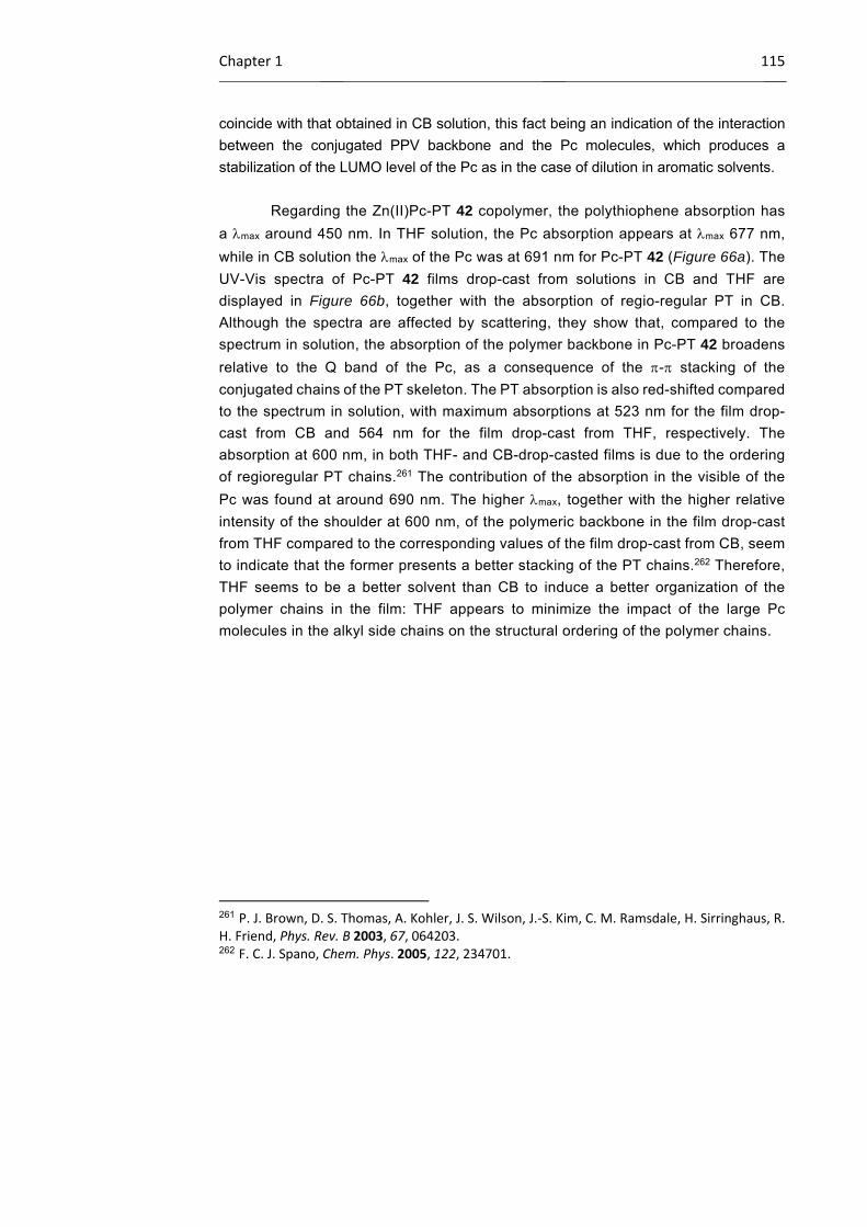
Chapter 1 115
coincide with that obtained in CB solution, this fact being an indication of the interaction
between the conjugated PPV backbone and the Pc molecules, which produces a
stabilization of the LUMO level of the Pc as in the case of dilution in aromatic solvents.
Regarding the Zn(II)Pc-PT 42 copolymer, the polythiophene absorption has
a max around 450 nm. In THF solution, the Pc absorption appears at max 677 nm,
while in CB solution the max of the Pc was at 691 nm for Pc-PT 42 (Figure 66a). The
UV-Vis spectra of Pc-PT 42 films drop-cast from solutions in CB and THF are
displayed in Figure 66b, together with the absorption of regio-regular PT in CB.
Although the spectra are affected by scattering, they show that, compared to the
spectrum in solution, the absorption of the polymer backbone in Pc-PT 42 broadens
relative to the Q band of the Pc, as a consequence of the - stacking of the
conjugated chains of the PT skeleton. The PT absorption is also red-shifted compared
to the spectrum in solution, with maximum absorptions at 523 nm for the film drop-
cast from CB and 564 nm for the film drop-cast from THF, respectively. The
absorption at 600 nm, in both THF- and CB-drop-casted films is due to the ordering
of regioregular PT chains.261 The contribution of the absorption in the visible of the
Pc was found at around 690 nm. The higher max, together with the higher relative
intensity of the shoulder at 600 nm, of the polymeric backbone in the film drop-cast
from THF compared to the corresponding values of the film drop-cast from CB, seem
to indicate that the former presents a better stacking of the PT chains.262 Therefore,
THF seems to be a better solvent than CB to induce a better organization of the
polymer chains in the film: THF appears to minimize the impact of the large Pc
molecules in the alkyl side chains on the structural ordering of the polymer chains.
261 P. J. Brown, D. S. Thomas, A. Kohler, J. S. Wilson, J.‐S. Kim, C. M. Ramsdale, H. Sirringhaus, R. H. Friend, Phys. Rev. B 2003, 67, 064203. 262 F. C. J. Spano, Chem. Phys. 2005, 122, 234701.
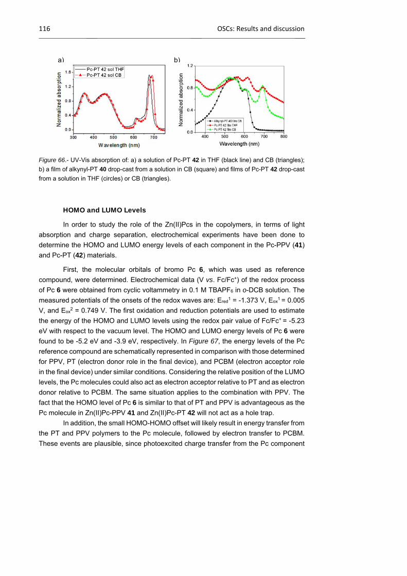
116 OSCs: Results and discussion
Figure 66.- UV-Vis absorption of: a) a solution of Pc-PT 42 in THF (black line) and CB (triangles);
b) a film of alkynyl-PT 40 drop-cast from a solution in CB (square) and films of Pc-PT 42 drop-cast
from a solution in THF (circles) or CB (triangles).
HOMO and LUMO Levels
In order to study the role of the Zn(II)Pcs in the copolymers, in terms of light
absorption and charge separation, electrochemical experiments have been done to
determine the HOMO and LUMO energy levels of each component in the Pc-PPV (41)
and Pc-PT (42) materials.
First, the molecular orbitals of bromo Pc 6, which was used as reference
compound, were determined. Electrochemical data (V vs. Fc/Fc+) of the redox process
of Pc 6 were obtained from cyclic voltammetry in 0.1 M TBAPF6 in o-DCB solution. The
measured potentials of the onsets of the redox waves are: Ered1 = -1.373 V, Eox
1 = 0.005
V, and Eox2 = 0.749 V. The first oxidation and reduction potentials are used to estimate
the energy of the HOMO and LUMO levels using the redox pair value of Fc/Fc+ = -5.23
eV with respect to the vacuum level. The HOMO and LUMO energy levels of Pc 6 were
found to be -5.2 eV and -3.9 eV, respectively. In Figure 67, the energy levels of the Pc
reference compound are schematically represented in comparison with those determined
for PPV, PT (electron donor role in the final device), and PCBM (electron acceptor role
in the final device) under similar conditions. Considering the relative position of the LUMO
levels, the Pc molecules could also act as electron acceptor relative to PT and as electron
donor relative to PCBM. The same situation applies to the combination with PPV. The
fact that the HOMO level of Pc 6 is similar to that of PT and PPV is advantageous as the
Pc molecule in Zn(II)Pc-PPV 41 and Zn(II)Pc-PT 42 will not act as a hole trap.
In addition, the small HOMO-HOMO offset will likely result in energy transfer from
the PT and PPV polymers to the Pc molecule, followed by electron transfer to PCBM. These events are plausible, since photoexcited charge transfer from the Pc component
a) b)
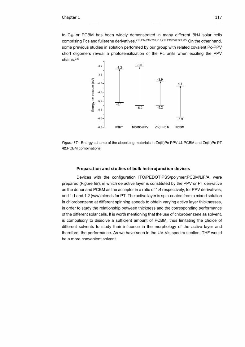
Chapter 1 117
to C60 or PCBM has been widely demonstrated in many different BHJ solar cells
comprising Pcs and fullerene derivatives.213,214,215,216,217,218,219,220,221,222 On the other hand,
some previous studies in solution performed by our group with related covalent Pc-PPV
short oligomers reveal a photosensitization of the Pc units when exciting the PPV
chains.233
Figure 67.- Energy scheme of the absorbing materials in Zn(II)Pc-PPV 41:PCBM and Zn(II)Pc-PT
42:PCBM combinations.
Preparation and studies of bulk heterojunction devices
Devices with the configuration ITO/PEDOT:PSS/polymer:PCBM/LiF/Al were
prepared (Figure 68), in which de active layer is constituted by the PPV or PT derivative
as the donor and PCBM as the acceptor in a ratio of 1:4 respectively, for PPV derivatives,
and 1:1 and 1:2 (w/w) blends for PT. The active layer is spin-coated from a mixed solution
in chlorobenzene at different spinning speeds to obtain varying active layer thicknesses,
in order to study the relationship between thickness and the corresponding performance
of the different solar cells. It is worth mentioning that the use of chlorobenzene as solvent,
is compulsory to dissolve a sufficient amount of PCBM, thus limitating the choice of
different solvents to study their influence in the morphology of the active layer and therefore, the performance. As we have seen in the UV-Vis spectra section, THF would
be a more convenient solvent.
-6.5
-6.0
-5.5
-5.0
-4.5
-4.0
-3.5
-3.0
-5.2
PCBMZn(II)Pc 6MDMO-PPV
En
erg
y vs
. vac
uum
(eV
)
P3HT
-5.1-5.2
-3.2-3.0
-3.9-4.1
-5.9
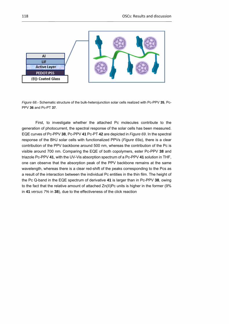
118 OSCs: Results and discussion
Figure 68.- Schematic structure of the bulk-heterojunction solar cells realized with Pc-PPV 35, Pc-
PPV 36 and Pc-PT 37.
First, to investigate whether the attached Pc molecules contribute to the
generation of photocurrent, the spectral response of the solar cells has been measured.
EQE curves of Pc-PPV 38, Pc-PPV 41 Pc-PT 42 are depicted in Figure 69. In the spectral
response of the BHJ solar cells with functionalized PPVs (Figure 69a), there is a clear
contribution of the PPV backbone around 500 nm, whereas the contribution of the Pc is
visible around 700 nm. Comparing the EQE of both copolymers, ester Pc-PPV 38 and
triazole Pc-PPV 41, with the UV-Vis absorption spectrum of a Pc-PPV 41 solution in THF,
one can observe that the absorption peak of the PPV backbone remains at the same
wavelength, whereas there is a clear red-shift of the peaks corresponding to the Pcs as
a result of the interaction between the individual Pc entities in the thin film. The height of
the Pc Q-band in the EQE spectrum of derivative 41 is larger than in Pc-PPV 38, owing
to the fact that the relative amount of attached Zn(II)Pc units is higher in the former (9%
in 41 versus 7% in 38), due to the effectiveness of the click reaction

Chapter 1 119
Figure 69.- EQE of solar cells with a) ester Pc-PPV 38:PCBM (1:4) active layer (circles), triazole
Pc-PPV 41 in blends with PCBM in a (1:4) weight ratio (squares) and UV-Vis absorption of triazole
Pc-PPV 41 in THF (line); b) triazole Pc-PT 42 in blends with PCBM in a (1:1) (squares) and (1:2)
(triangles) weight ratio.
In the spectral response of Pc-PT 42:PCBM solar cells (Figure 69b), the EQE
due to the Pc component is clearly present around 700 nm, indicating that the light
absorbed by the Pc moiety leads to charge transfer, and that generated charges are
extracted. The low values of the EQE between 350-550 nm, also indicates a lack of
crystalline ordering of the PT part in spin-coated films as compared to drop cast films
(see Figure 66), which is important for high conversion efficiencies in PT:PCBM solar
cells.
A clear conclusion which can be obtained from the EQE is that that the absorption
of the synthesized materials matches significantly better with the AM 1.5 solar spectrum
due to the covalent attachment of Zn(II)Pcs. In this way, more sunlight ca be efficiently
absorbed and therefore transformed in an external current by these functionalized
copolymers.
After establishing the contribution of the Pcs to the EQE of the solar cells, the
performance of the solar cells was investigated. The J-V curves of alkynyl-PPV 37:PCBM
(Figure 70a), ester Pc-PPV 38:PCBM, triazole Pc-PPV 41:PCBM (Figure 70a), alkynyl-
PT 40:PCBM (Figure 70b), Pc-PT 42:PCBM (Figure 70b) were obtained, and therefore,
the most important photovoltaic parameters as VOC (V), JSC (mA/cm2), FF (%) and PCE
(%) were determined for devices with different active layer thicknesses (Figure 71; the
results of Pc-PT 42:PCBM are omitted in this graphics, however, their best results are
summarized in Table 3).
a) b)
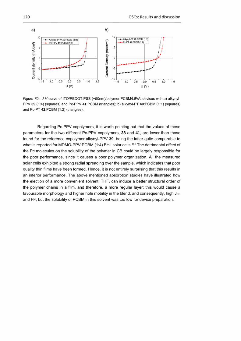
120 OSCs: Results and discussion
Figure 70.- J-V curve of ITO/PEDOT:PSS (~50nm)/polymer:PCBM/LiF/Al devices with a) alkynyl-
PPV 39 (1:4) (squares) and Pc-PPV 41:PCBM (triangles); b) alkynyl-PT 40:PCBM (1:1) (squares)
and Pc-PT 42:PCBM (1:2) (triangles).
Regarding Pc-PPV copolymers, it is worth pointing out that the values of these
parameters for the two different Pc-PPV copolymers, 38 and 41, are lower than those
found for the reference copolymer alkynyl-PPV 39, being the latter quite comparable to
what is reported for MDMO-PPV:PCBM (1:4) BHJ solar cells.152 The detrimental effect of
the Pc molecules on the solubility of the polymer in CB could be largely responsible for
the poor performance, since it causes a poor polymer organization. All the measured
solar cells exhibited a strong radial spreading over the sample, which indicates that poor
quality thin films have been formed. Hence, it is not entirely surprising that this results in
an inferior performance. The above mentioned absorption studies have illustrated how
the election of a more convenient solvent, THF, can induce a better structural order of
the polymer chains in a film, and therefore, a more regular layer; this would cause a
favourable morphology and higher hole mobility in the blend, and consequently, high JSC
and FF, but the solubility of PCBM in this solvent was too low for device preparation.
a) b)
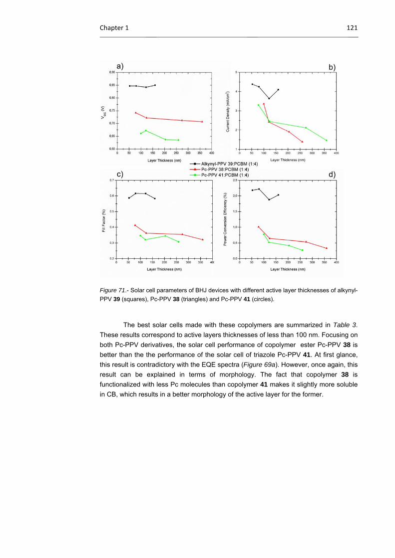
Chapter 1 121
Figure 71.- Solar cell parameters of BHJ devices with different active layer thicknesses of alkynyl-
PPV 39 (squares), Pc-PPV 38 (triangles) and Pc-PPV 41 (circles).
The best solar cells made with these copolymers are summarized in Table 3.
These results correspond to active layers thicknesses of less than 100 nm. Focusing on
both Pc-PPV derivatives, the solar cell performance of copolymer ester Pc-PPV 38 is
better than the the performance of the solar cell of triazole Pc-PPV 41. At first glance,
this result is contradictory with the EQE spectra (Figure 69a). However, once again, this
result can be explained in terms of morphology. The fact that copolymer 38 is
functionalized with less Pc molecules than copolymer 41 makes it slightly more soluble
in CB, which results in a better morphology of the active layer for the former.
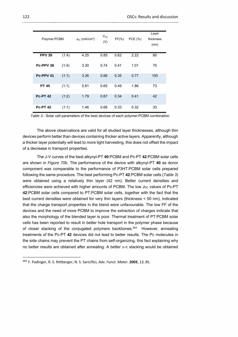
122 OSCs: Results and discussion
Table 3.- Solar cell parameters of the best devices of each polymer:PCBM combination.
The above observations are valid for all studied layer thicknesses, although thin
devices perform better than devices containing thicker active layers. Apparently, although
a thicker layer potentially will lead to more light harvesting, this does not offset the impact
of a decrease in transport properties.
The J-V curves of the best alkynyl-PT 40:PCBM and Pc-PT 42:PCBM solar cells
are shown in Figure 70b. The performance of the device with alkynyl-PT 40 as donor
component was comparable to the performance of P3HT:PCBM solar cells prepared
following the same procedure. The best performing Pc-PT 42:PCBM solar cells (Table 3)
were obtained using a relatively thin layer (42 nm). Better current densities and
efficiencies were achieved with higher amounts of PCBM. The low JSC values of Pc-PT
42:PCBM solar cells compared to PT:PCBM solar cells, together with the fact that the
best current densities were obtained for very thin layers (thickness < 50 nm), indicated
that the charge transport properties in the blend were unfavourable. The low FF of the
devices and the need of more PCBM to improve the extraction of charges indicate that
also the morphology of the blended layer is poor. Thermal treatment of PT:PCBM solar
cells has been reported to result in better hole transport in the polymer phase because
of closer stacking of the conjugated polymers backbones.263 However, annealing
treatments of the Pc-PT 42 devices did not lead to better results. The Pc molecules in
the side chains may prevent the PT chains from self-organizing, this fact explaining why
no better results are obtained after annealing. A better - stacking would be obtained
263 F. Padinger, R. S. Rittberger, N. S. Sariciftci, Adv. Funct. Mater. 2003, 13, 85.
Polymer:PCBM JSC (mA/cm2) VOC
(V) FF(%) PCE (%)
Layer
thickness
(nm)
PPV 39 (1:4) 4.25 0.85 0.62 2.22 80
Pc-PPV 38 (1:4) 3.30 0.74 0.41 1.01 75
Pc-PPV 41 (1:1) 3.36 0.66 0.35 0.77 100
PT 40 (1:1) 5.81 0.65 0.49 1.86 73
Pc-PT 42 (1:2) 1.79 0.67 0.34 0.41 42
Pc-PT 42 (1:1) 1.46 0.68 0.33 0.32 33

Chapter 1 123
by processing from THF, but, as mentioned above the solubility of PCBM in this solvent
was too low for device preparation. A better solubility in the processing solvent might lead
to an enhanced polymer organization in the blend and to an improved morphology, both
increasing the PCE.
124 DSSCs: Introduction
1.3 Dye-sensitized solar cells (DSSCs)
At the moment, dye-sensitized solar cells offer a lower-cost alternative to silicon
photovoltaics because they are based on cheap materials and inexpensive
manufacturing technology. A dye-sensitized solar cell can generally be described as a
photoelectrochemical cell where the working electrode consists of photon-absorbing
dyes (sensitizers) anchored onto mesoporous surfaces of semiconducting nanoparticles.
Depending on the electronic nature of the semiconductor, electron acceptors (n-type) or
donors (p-type), two generations of semiconductors and therefore, of DSSCs
technologies, can be distinguished The first generation, that is the n-type or Grätzel
cells,116,117,264 which is based on the sensitization of a wide-band-gap n-type
semiconductor oxide like ZnO or TiO2, marches ahead of the race with photoconversion
efficiencies over 13.0%.119 A typical n-type cell consists of four main components: 1) A
mesoporous semiconductor layer265 (usually TiO2 anatase,116a,266 but also ZnO,267,268
SnO2268,269
and Nb2O5270) deposited onto a transparent conducting glass substrate, 2) a
dye sensitizer, 3) a redox electrolyte (typically I−/I3− or cobalt complexes)271 and 4) a
counter electrode. Upon photoexcitation, the sensitizer promotes the electron injection in
the TiO2 CB. The oxidized dye is regenerated by the electrolyte, and finally the circuit is
closed at the counter electrode where the reduction of the oxidized mediator occurs. To
further improve the efficiency, much effort has been devoted to the optimization of these
264 M. Gratzel, Inorg. Chem. 2005, 44, 6841. 265 a) R. Jose, V. Thavasi, S. Ramakrishna, J. Am. Ceram. Soc. 2009, 92, 289; b) N. Sharifi, F. Tajabadi, N. Taghavinia, ChemPhysChem 2014, 15, 3902. 266 a) P. M. Sommeling, B. C. O’Regan, R. R. Haswell, H. J. P. Smit, N. J. Bakker, J. J. T. Smits, J. M. Kroon, J. A. M. van Roosmalen, J. Phys. Chem. B 2006, 110, 19191; b) J. M. Kroon, N. J. Bakker, H. J. P. Smit, P. Liska, K. R. Thampi, P. Wang, S. M. Zakeeruddin, M. Gratzel, A. Hinsch, S. Hore, U. Wurfel, R. Sastrawan, J. R. Durrant, E. Palomares, H. Pettersson, T. Gruszecki, J. Walter, K. Skupien, G. E. Tulloch, Prog. Photovoltaics 2007, 15, 1; c) M. Kapilashrami, Y. Zhang, Y.‐S. Liu, A. Hagfeldt, J. Guo, Chem. Rev. 2014, 114, 9662. 267 a) K. Keis, E. Magnusson, H. Lindstrom, S.‐E. Lindquist, A. Hagfeldt, Sol. Energy Mater. Sol. Cells 2002, 73, 51; b) K. Keis, C. Bauer, G. Boschloo, A. Hagfeldt, K. Westermark, H. Rensmo, H. Siegbahn, J. Photochem. Photobiol. A 2002, 148, 57. 268 K. Tennakone, G. R. R. A. Kumara, I. R. M. Kottegoda, V. P. S. Perera, Chem. Comm. 1999, 15. 269 a) B. V. Bergeron, A. Marton, G. Oskam, G. J. Meyer, J. Phys. Chem. B 2005, 109, 937; b) S. Chappel, A. Zaban, Sol. Energy Mater. Sol. Cells 2002, 71, 141; c) A. Y. El‐Etre, S. M. Reda, Appl. Surf. Sci. 2010, 256, 6601. 270 a) K. Sayama, H. Sugihara, H. Arakawa, Chem. Mater. 1998, 10, 3825; b) P. Guo, M. A. Aegerter, Thin Solid Films 1999, 351, 290. 271 J. Wu, Z. Lan, J. Lin, M. Huang, Y. Huang, L. Fan, G. Luo, Chem. Rev. 2015, 115, 2136.
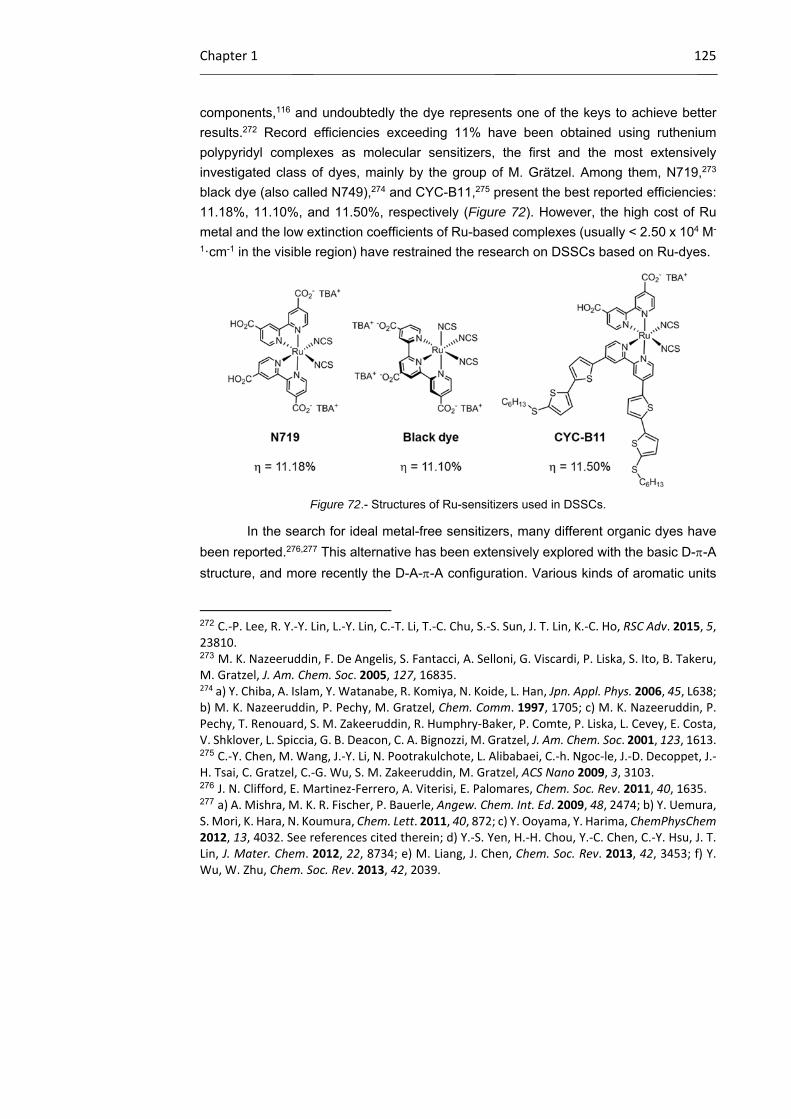
Chapter 1 125
components,116 and undoubtedly the dye represents one of the keys to achieve better
results.272 Record efficiencies exceeding 11% have been obtained using ruthenium
polypyridyl complexes as molecular sensitizers, the first and the most extensively
investigated class of dyes, mainly by the group of M. Grätzel. Among them, N719,273
black dye (also called N749),274 and CYC-B11,275 present the best reported efficiencies:
11.18%, 11.10%, and 11.50%, respectively (Figure 72). However, the high cost of Ru
metal and the low extinction coefficients of Ru-based complexes (usually < 2.50 x 10⁴ M-
1·cm-1 in the visible region) have restrained the research on DSSCs based on Ru-dyes.
Figure 72.- Structures of Ru-sensitizers used in DSSCs.
In the search for ideal metal-free sensitizers, many different organic dyes have
been reported.276,277 This alternative has been extensively explored with the basic D--A
structure, and more recently the D-A--A configuration. Various kinds of aromatic units
272 C.‐P. Lee, R. Y.‐Y. Lin, L.‐Y. Lin, C.‐T. Li, T.‐C. Chu, S.‐S. Sun, J. T. Lin, K.‐C. Ho, RSC Adv. 2015, 5, 23810. 273 M. K. Nazeeruddin, F. De Angelis, S. Fantacci, A. Selloni, G. Viscardi, P. Liska, S. Ito, B. Takeru, M. Gratzel, J. Am. Chem. Soc. 2005, 127, 16835. 274 a) Y. Chiba, A. Islam, Y. Watanabe, R. Komiya, N. Koide, L. Han, Jpn. Appl. Phys. 2006, 45, L638; b) M. K. Nazeeruddin, P. Pechy, M. Gratzel, Chem. Comm. 1997, 1705; c) M. K. Nazeeruddin, P. Pechy, T. Renouard, S. M. Zakeeruddin, R. Humphry‐Baker, P. Comte, P. Liska, L. Cevey, E. Costa, V. Shklover, L. Spiccia, G. B. Deacon, C. A. Bignozzi, M. Gratzel, J. Am. Chem. Soc. 2001, 123, 1613. 275 C.‐Y. Chen, M. Wang, J.‐Y. Li, N. Pootrakulchote, L. Alibabaei, C.‐h. Ngoc‐le, J.‐D. Decoppet, J.‐H. Tsai, C. Gratzel, C.‐G. Wu, S. M. Zakeeruddin, M. Gratzel, ACS Nano 2009, 3, 3103. 276 J. N. Clifford, E. Martinez‐Ferrero, A. Viterisi, E. Palomares, Chem. Soc. Rev. 2011, 40, 1635. 277 a) A. Mishra, M. K. R. Fischer, P. Bauerle, Angew. Chem. Int. Ed. 2009, 48, 2474; b) Y. Uemura, S. Mori, K. Hara, N. Koumura, Chem. Lett. 2011, 40, 872; c) Y. Ooyama, Y. Harima, ChemPhysChem 2012, 13, 4032. See references cited therein; d) Y.‐S. Yen, H.‐H. Chou, Y.‐C. Chen, C.‐Y. Hsu, J. T. Lin, J. Mater. Chem. 2012, 22, 8734; e) M. Liang, J. Chen, Chem. Soc. Rev. 2013, 42, 3453; f) Y. Wu, W. Zhu, Chem. Soc. Rev. 2013, 42, 2039.
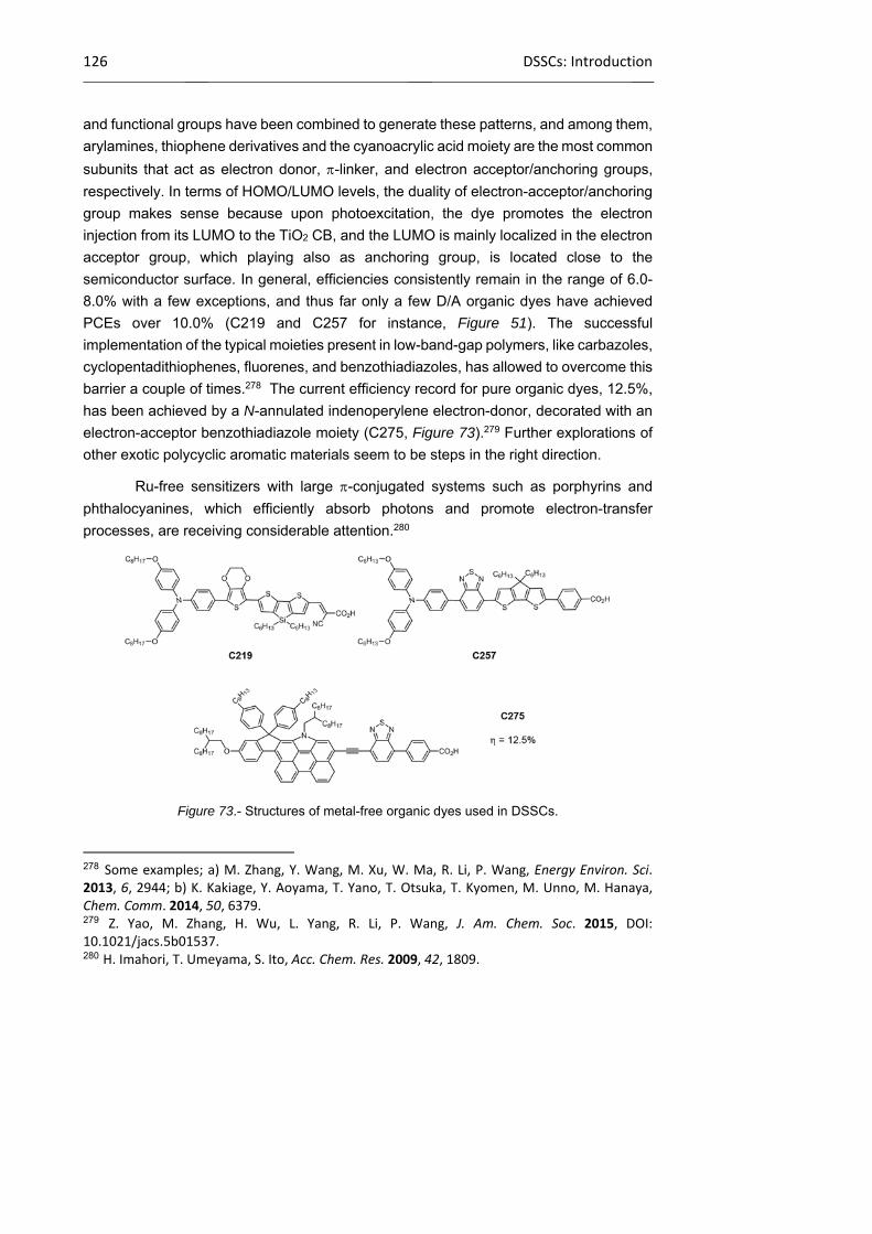
126 DSSCs: Introduction
and functional groups have been combined to generate these patterns, and among them,
arylamines, thiophene derivatives and the cyanoacrylic acid moiety are the most common
subunits that act as electron donor, -linker, and electron acceptor/anchoring groups,
respectively. In terms of HOMO/LUMO levels, the duality of electron-acceptor/anchoring
group makes sense because upon photoexcitation, the dye promotes the electron
injection from its LUMO to the TiO2 CB, and the LUMO is mainly localized in the electron
acceptor group, which playing also as anchoring group, is located close to the
semiconductor surface. In general, efficiencies consistently remain in the range of 6.0-
8.0% with a few exceptions, and thus far only a few D/A organic dyes have achieved
PCEs over 10.0% (C219 and C257 for instance, Figure 51). The successful
implementation of the typical moieties present in low-band-gap polymers, like carbazoles,
cyclopentadithiophenes, fluorenes, and benzothiadiazoles, has allowed to overcome this
barrier a couple of times.278 The current efficiency record for pure organic dyes, 12.5%,
has been achieved by a N-annulated indenoperylene electron-donor, decorated with an
electron-acceptor benzothiadiazole moiety (C275, Figure 73).279 Further explorations of
other exotic polycyclic aromatic materials seem to be steps in the right direction.
Ru-free sensitizers with large -conjugated systems such as porphyrins and
phthalocyanines, which efficiently absorb photons and promote electron-transfer
processes, are receiving considerable attention.280
Figure 73.- Structures of metal-free organic dyes used in DSSCs.
278 Some examples; a) M. Zhang, Y. Wang, M. Xu, W. Ma, R. Li, P. Wang, Energy Environ. Sci. 2013, 6, 2944; b) K. Kakiage, Y. Aoyama, T. Yano, T. Otsuka, T. Kyomen, M. Unno, M. Hanaya, Chem. Comm. 2014, 50, 6379. 279 Z. Yao, M. Zhang, H. Wu, L. Yang, R. Li, P. Wang, J. Am. Chem. Soc. 2015, DOI: 10.1021/jacs.5b01537. 280 H. Imahori, T. Umeyama, S. Ito, Acc. Chem. Res. 2009, 42, 1809.

Chapter 1 127
Porphyrins, in particular, have been successfully used in the past few years due
to their strong absorption in the visible region and excellent flexibility in tuning
photophysical and electrochemical properties through structural changes.281
Furthermore, the D--A configuration of dye molecules has emerged as a premium model
for high-efficient porphyrin dyes. The integration of a porphyrin chromophore as a -
bridge into a D--A structure,282 has provided efficiencies comparable to the best
ruthenium polypyridyl dyes; for instance push-pull porphyrin YD-2 (PCE = 11.0%)283 and
the improved YD2-oC8 (PCE = 11.9%, and 12.3% in co-sensitized cells),284 in which the
3,5-bis(tert-butyl)phenyl substituents in YD-2 are replaced by 2,6-dioctoxyphenyl groups,
as shown in Figure 74. Further structural optimization of porphyrins dyes involved the
introduction of a benzothiadiazole ring between the porphyrin and the anchoring group,
which yielded the porphyrins GY50 (PCE = 12.75%)285 and SM315 (PCE = 13.0%),119
being the latter the figure of merit for state-of-the art devices (Figure 74). The addition of
the benzothiadiazole was successful in filling the gap between the Soret band and the Q
band in the absorption spectrum, giving rise to panchromatic sensitizers.
Figure 74.- Structures of porphyrin dyes used in DSSCs.
281 a) L.‐L. Li, E. W.‐G. Diau, Chem. Soc. Rev. 2013, 42, 291; b) M. Urbani, M. Gratzel, M. K. Nazeeruddin, T. Torres, Chem. Rev. 2014, 114, 12330; c) T. Higashino, H. Imahori, Dalton Trans. 2015, 44, 448. 282 a) H.‐P. Lu, C.‐Y. Tsai, W.‐N. Yen, C.‐P. Hsieh, C.‐W. Lee, C.‐Y. Yeh, E. W.‐G. Diau, J. Phys. Chem. C 2009, 113, 20990; b) C.‐P. Hsieh, H.‐P. Lu, C.‐L. Chiu, C.‐W. Lee, S.‐H. Chuang, C.‐L. Mai, W.‐N. Yen, S.‐J. Hsu, E. W.‐G. Diau, C.‐Y. Yeh, J. Mater. Chem. 2010, 20, 1127. 283 T. Bessho, S. M. Zakeeruddin, C.‐Y. Yeh, E. W.‐G. Diau, M. Gratzel, Angew. Chem. Int. Ed. 2010, 49, 6646. 284 A. Yella, H.‐W. Lee, H. N. Tsao, C. Yi, A. K. Chandiran, M. K. Nazeeruddin, E. W.‐G. Diau, C.‐Y. Yeh, S. M. Zakeeruddin, M. Gratzel, Science 2011, 334, 629. 285 A. Yella, C.‐L. Mai, S. M. Zakeeruddin, S.‐N. Chang, C.‐H. Hsieh, C.‐Y. Yeh, M. Gratzel, Angew. Chem. Int. Ed. 2014, 53, 2973.

128 DSSCs: Introduction
Regarding Pc-sensitized solar cells, performances have not yet achieved the
values of porphyrin-based device. However tremendous progress has taken place, with
the obtained efficiencies growing from 1% in the seminal report286 to the recently
published 6.4%.287 The main advantages of porphyrins in comparison with Pcs are: 1)
Their many reaction sites, i.e. four meso and eight positions, available for
functionalization, and 2) the easy synthesis of highly unsymmetrical structures. For their
part, Pcs are important players in n-type sensitizers due to their impressive light-
harvesting properties (better than porphyrins) in the far red/near IR spectral region and
their extraordinary robustness.288 On the other hand, the flat nature and large -system
induce in these molecules a strong tendency to stack, which dramatically diminishes their
efficiencies when used in DSSCs due to the rapid deactivation of the dye excited state.
In any case, there are strategies to control the formation of molecular aggregates onto
the semiconductor nanoparticles: 1) Introduction of bulky groups in the periphery of the
scaffold; 2) us of axially substituted Pcs, and 3) addition of co-adsorbents,289 that strongly
bind to the surface and displace a certain number of dye molecules from the TiO2,
reducing their probability of aggregation. Chenodeoxycolic acid (CHENO)286 is the most
common and broadly used co-adsorbent in Pc-based DSSCs, but there are also
examples where 1-decylphosphonic (DPA)290 or -guanidinoalkyl acids291 are
successfully used.
Regarding the use of bulky substituents, Grätzel and Torres reported Pc
PCH001292 and TT1,293 which reached 3.05% and 3.50% overall efficiencies,
respectively, employing tert-butyl groups at the positions of the isoindoles (Figure 75).
The utilization of even bulkier diphenylphenoxy substituents, brought about a significant
286 M. K. Nazeeruddin, R. Humphry‐Baker, M. Gratzel, D. Wohrle, G. Schnurpfeil, G. Schneider, A. Hirth, N. Trombach, J. Porphyrins Phthalocyanines 1999, 3, 230. 287 T. Ikeuchi, H. Nomoto, N. Masaki, M. J. Griffith, S. Mori, M. Kimura, Chem. Comm. 2014, 50, 1941. 288 a) M.‐E. Ragoussi, M. Ince, T. Torres, Eur. J. Org. Chem. 2013, 29, 6475; b) L. Martin‐Gomis, F. Fernandez‐Lazaro, A. Sastre‐Santos, J. Mater. Chem. A 2014, 2, 15672; c) V. K. Singh, R. K. Kanaparthi, L. Giribabu, RSC Adv. 2014, 4, 6970. 289 V. S. Manthou, E. K. Pefkianakis, P. Falaras, G. C. Vougioukalakis, ChemSusChem 2015, 8, 588. 290 A. Morandeira, I. Lopez‐Duarte, B. O’Regan, M. V. Martinez‐Diaz, A. Forneli, E. Palomares, T. Torres, J. R. Durrant, J. Mater. Chem. 2009, 19, 5016. 291 Z. Zhang, N. Evans, S. M. Zakeeruddin, R. Humphry‐Baker, M. Gratzel, J. Phys. Chem. C 2007, 111, 398. 292 P. Y. Reddy, L. Giribabu, C. Lyness, H. J. Snaith, C. Vijaykumar, M. Chandrasekharam, M. Lakshmikantam, J.‐H. Yum, K. Kalyanasundaram, M. Gratzel, M. K. Nazeeruddin, Angew. Chem. Int. Ed. 2007, 46, 373. 293 J.‐J. Cid, J.‐H. Yum, S.‐R. Jang, M. K. Nazeeruddin, E. Martinez‐Ferrero, E. Palomares, J. Ko, M. Gratzel, T. Torres, Angew. Chem. Int. Ed. 2007, 46, 8358.
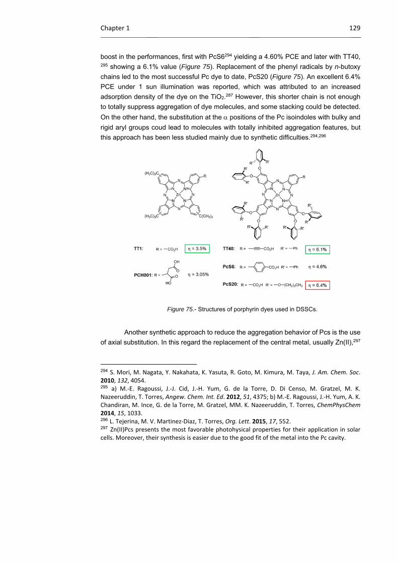
Chapter 1 129
boost in the performances, first with PcS6294 yielding a 4.60% PCE and later with TT40, 295 showing a 6.1% value (Figure 75). Replacement of the phenyl radicals by n-butoxy
chains led to the most successful Pc dye to date, PcS20 (Figure 75). An excellent 6.4%
PCE under 1 sun illumination was reported, which was attributed to an increased
adsorption density of the dye on the TiO2.287 However, this shorter chain is not enough
to totally suppress aggregation of dye molecules, and some stacking could be detected.
On the other hand, the substitution at the positions of the Pc isoindoles with bulky and
rigid aryl groups coud lead to molecules with totally inhibited aggregation features, but
this approach has been less studied mainly due to synthetic difficulties.294,296
Figure 75.- Structures of porphyrin dyes used in DSSCs.
Another synthetic approach to reduce the aggregation behavior of Pcs is the use
of axial substitution. In this regard the replacement of the central metal, usually Zn(II),297
294 S. Mori, M. Nagata, Y. Nakahata, K. Yasuta, R. Goto, M. Kimura, M. Taya, J. Am. Chem. Soc. 2010, 132, 4054. 295 a) M.‐E. Ragoussi, J.‐J. Cid, J.‐H. Yum, G. de la Torre, D. Di Censo, M. Gratzel, M. K. Nazeeruddin, T. Torres, Angew. Chem. Int. Ed. 2012, 51, 4375; b) M.‐E. Ragoussi, J.‐H. Yum, A. K. Chandiran, M. Ince, G. de la Torre, M. Gratzel, MM. K. Nazeeruddin, T. Torres, ChemPhysChem 2014, 15, 1033. 296 L. Tejerina, M. V. Martinez‐Diaz, T. Torres, Org. Lett. 2015, 17, 552. 297 Zn(II)Pcs presents the most favorable photohysical properties for their application in solar cells. Moreover, their synthesis is easier due to the good fit of the metal into the Pc cavity.

130 DSSCs: Introduction
by Ti(IV),298 Ru(II)290,299 or Si(IV) 300 offers this possibility. Our group has explored this
approach, but efficiencies obtained were lower than 1%. An important lesson to be learnt
from these results is that the parallel arrangement of the Pc and the TiO2 surface induced
by the anchoring group in the axial positions leads to unacceptable efficiencies, but even
if the group is located on the peripheral positions, the results are not good enough.
The influence of the anchoring group on the final efficiency is other important
issue in Pc sensitized solar cells. The number (mono and dicarboxy derivatives),301,302
and nature (-cyanoacrylic group301 and phosphinic acid303) of the anchoring groups were
systematically checked and compared with TT1 by Torres' group. Also, the spacers
between the anchoring group and the Pc play a crucial role. An extensive study carried
out by Torres et al. on tri-tert-butylPcs295,301,304 leads to the conclusion that the selected
spacer must be rigid and -conjugated in order to present a directional character and
preserve the electronic coupling between the Pc and the semiconductor surface.
Combining both factors, the nature of the anchoring group and the spacer, a carboxylic
acid directly linked to the Pc through an ethynyl spacer has turned out to be the best
option. More elaborated linkers have been very recently used to prepare efficient Pc-
sensitized cells, borrowed from reported molecular engineering of champion
298 a) E. Palomares, M. V. Martinez‐Diaz, S. A. Haque, T. Torres, J. R. Durrant, Chem. Comm. 2004, 2112; b) E. Seikel, B. Oelkers, J. Sundermeyer, Inorg. Chem. 2012, 51, 2709; c) M. S. Rodriguez‐Morgade, L. Pelleja, T. Torres, E. Palomares, J. Porphyrins Phthalocyanines 2013, 17, 814. 299 a) M. Yanagisawa, F. Korodi, J. Bergquist, A. Holmberg, A. Hagfeldt, B. Akermark, L. Sun, J. Porphyrins Phthalocyanines 2004, 08, 1228; b) A. Morandeira, I. Lopez‐Duarte, M. V. Martinez‐Diaz, B. O’Regan, C. Shuttle, N. A. Haji‐Zainulabidin, T. Torres, E. Palomares, J. R. Durrant, J. Am. Chem. Soc. 2007, 129, 9250; c) B. C. O’Regan, I. Lopez‐Duarte, M. V. Martinez‐Diaz, A. Forneli, J. Albero, A. Morandeira, E. Palomares, T. Torres, J. R. Durrant, J. Am. Chem. Soc. 2008, 130, 2906; d) A. Listorti, I. Lopez‐Duarte, M. V. Martinez‐Diaz, T. Torres, T. DosSantos, P. R. F. Barnes, J. R. Durrant, Energy Environ. Sci. 2010, 3, 1573. 300 a) L. Martin‐Gomis, E. M. Barea, F. Fernandez‐Lazaro, J. Bisquert, A. Sastre‐Santos, J. Porphyrins Phthalocyanines 2011, 15, 1004; b) K.‐C. Lin, T. Doane, L. Wang, P. Li, S. Pejic, M. E. Kenney, C. Burda, Sol. Energy Mater. Sol. Cells 2014, 126, 155. 301 M. Garcia‐Iglesias, J.‐J. Cid, J.‐H. Yum, A. Forneli, P. Vazquez, M. K. Nazeeruddin, E. Palomares, M. Gratzel, T. Torres, Energy Environ. Sci. 2011, 4, 189. 302 D. Sharma, G. Steen, J. P. Korterik, M. Garcia‐Iglesias, P. Vazquez, T. Torres, J. L. Herek, A. Huijser, J. Phys. Chem. C 2013, 117, 25397. 303 I. Lopez‐Duarte, M. Wang, R. Humphry‐Baker, M. Ince, M. V. Martinez‐Diaz, M. K. Nazeeruddin, T. Torres, M. Gratzel, Angew. Chem. Int. Ed. 2012, 51, 1895. 304 a) J.‐J. Cid, M. Garcia‐Iglesias, J.‐H. Yum, A. Forneli, J. Albero, E. Martinez‐Ferrero, P. Vazquez, M. Gratzel, M. K. Nazeeruddin, E. Palomares, T. Torres, Chem. Eur. J. 2009, 15, 5130; b) F. Silvestri, M. Garcia‐Iglesias, J.‐H. Yum, P. Vazquez, M. V. Martinez‐Diaz, M. Gratzel, M. K. Nazeeruddin, T. Torres, J. Porphyrins Phthalocyanines 2009, 13, 369.
Chapter 1 131
porphyrins.305 Thus, a [7-(40-carboxyphenyl)-2,1,3-benzothiadiazole-4-yl]ethynyl-
functionalized analogous of TT40 has been synthesized, with the aim of using the
benzothiadiazole as an electron acceptor and extending the absorption spectral
response. However, only a 3.29% efficiency was recorded, which was attributed to lower
LUMO levels of the former compared to that of TT40.
1.3.1 p-type DSSCs: Architecture and operation principle
The second generation DSSCs uses a p-type metal oxide such as NiO120,306
instead of TiO2, but it has been much less investigated than Grätzel cells, and the
efficiencies are still much lower (nowadays the best efficiency is 2.51%).121 Moreover,
the investigation of p-type DSSCs, besides being important in itself, opens the possibility
to design n-p tandem DSSCs, in which both electrodes are photoactive. The main goal
of these tandem devices is to absorb more photons, thereby increasing the efficiency.
Presently, the best energy conversion efficiency from tandem DSSCs is 2.42%,307 which
is far below the maximum theoretical power-conversion efficiency (~40%) and also from
the record from a single n-type DSSCs mentioned above. For this reason, there is a
strong need for an improvement of appropriate semiconductors and dyes of the p-type
devices.
In 1999, Lindquist and co-workers reported the first model of p-type, NiO-based
DSSC308 and, since then, the architecture and working principle have remained
unchanged. As illustrated in Figure 76, the p-type DSSC is a sandwich- structured device
composed of a photoactive working electrode (cathode), a passive counter electrode
(anode), and a redox electrolyte. The main components are: 1) A fluorine-doped SnO2
(FTO) glass substrate, 2) a nanostructured p-type semiconductor layer, 3) a light-
absorbing layer, normally the dye, 4) a platinized (Pt) conducting glass counter electrode,
and 5) the electrolyte.
305 M. Ince, J.‐H. Yum, Y. Kim, S. Mathew, M. Gratzel, T. Torres, M. K. Nazeeruddin, J. Phys. Chem. C 2014, 118, 17166. 306 F. Odobel, L. Le Pleux, Y. Pellegrin, E. Blart, Acc. Chem. Res. 2010, 43, 1063. 307 A. Nattestad, A. J. Mozer, M. K. R. Fischer, Y.‐B. Cheng, A. Mishra, P. Bauerle, U. Bach, Nat. Mater. 2010, 9, 31. 308 J. He, H. Lindstrom, A. Hagfeldt, S.‐E. Lindquist, J. Phys. Chem. B 1999, 103, 8940.

132 DSSCs: Introduction
Figure 76.- Schematic illustration of a p-type DSSC.
In p-type DSSCs, visible light absorption by the sensitizer promotes an electron
from the HOMO to the LUMO, which triggers a change of the redox potentials of the
excited state, enabling a hole injection into the semiconductor valence band, or in other
words, electron transfer from the valence band of the semiconductor to the dye (process
2 in Figure 77). The hole is transported through the network of nanoparticles in the
semiconductor until it reaches the transparent conducting substrate and passes into the
external electrical circuit through the working electrode. The reduced sensitizer is then
regenerated by the oxidized redox mediator to restore its ground state (process 3 in
Figure 77). The reduced redox mediator diffuses at the counter electrode where it is
oxidized back to its initial state (process 4 in Figure 77). This charge collection gives rise
to cathodic photocurrent in the external circuit.

Chapter 1 133
Figure 77.- Schematic diagram illustrating the key processes (black arrows) and the energy wasting
processes (red dashed arrows) in a p-type DSSC under illumination.
The above operation principle is just the reverse of that occurring in n-DSSCs.
There are some obvious similarities between n-DSSCs and p-DSSCs, but there are also
some fundamental differences making this field of research a specific theme in itself. A
major force that counteracts the electricity production in p-DSSCs is the charge
recombination of electrons at the electrolyte interface (process 5 in Figure 77). The fast
geminate recombination rate constant observed for process 6 is another major hurdle
that needs to be taken into account when optimizing p-DSSCs. These particularities of p-
DSSCs force the chemist to think differently when one aims at designing efficient
photocathodes.
1.3.2 p-Type metal oxide semiconductors
A suitable choice of the p-type semiconductor may have a decisive impact on the
performance of p-type DSSCs. The candidates for the fabrication of photocathodes are
p-type semiconductors that are resistant to photocorrosion. The semiconductor must be
easily synthesized as nanoparticles or other adequate nanostructures, in order to be
transformed into mesoporous films that exhibit large surface area. Also, the surface of
the p-semiconductor must exhibit high chemical affinity to an organic functional group in
order to promote the chemisorption of the sensitizers on its surface by a simple self-
assembling reaction. Finally, the position of the valence band potential is another
fundamental parameter of the semiconductor because it governs the maximum VOC that
the cell can deliver (the theoretical VOC of a p-type DSSC depends on the valence band

134 DSSCs: Introduction
edge of the p-type semiconductor and the redox potential of the electrolyte (Figure 77).
Unlike n-DSSCs, there are fewer metal oxides that exhibit p-type semiconductivity. The
scarcity of p-type semiconducting nature in metal oxides has been explained on the basis
of their electronic band structure.309 Since the upper edge of the valence band in metal
oxides is strongly localized on the oxide ions, the holes created in the valence band
cannot be easily transported through the material. This is reflected in the typical lower
conductivity values of p-type semiconductors than n-type ones.
The most frequently reported semiconductor in p-DSSCs is undoubtedly NiO,120
,310 which has a wide bandgap (3.6-4.0 eV) but a shallow VB potential (around 0.54 V vs
NHE at pH = 7)308 and low hole mobility (between 10−8 and 10−7 cm2/S,311 more than 2
orders of magnitude lower than the electron diffusion coefficient in TiO2), this fact limiting
the performance of the cell. Moreover, the slow diffusion of the injected holes within the
nanoporous network of the NiO film increases the probability of losses by charge
recombination with the reduced sensitizer and/or the reduced redox mediator in the
electrolyte.312 Also, the theoretical maximum VOC is around 150−200 mV when NiO is
combined with the classical iodide/tri-iodide electrolyte. Other drawbacks of NiO are its
low transparency, which limits the thickness of the photocathode, and its ability to
catalyze oxidation reactions. Therefore, it is of high importance to find alternatives to NiO,
that is, materials showing better transparency, deeper VB potentials, higher hole
mobilities and with kinetically blocked capacity to oxidize the reduced form of the redox
mediator.
To sort out some of these problems, the synthesis of binary NiXO
semiconductors, were X is cobalt, have recently evolved. The VB engineering of NiO
upon doping with a cobalt ion was investigated by Wu and co-workers, 311c who found
outthat the VB potentials can be gradually increased with increasing amounts of cobalt
in Ni1−xCoxOy from the value of 0.37 V vs NHE (undoped NiO) to 0.41 V vs NHE with a
6% molar ratio of cobalt, and the VOC of the respective p-DCSSs moves from 118 to 159
mV. However, the photocurrent decreases as the concentration of cobalt is raised
309 H. Kawazoe, M. Yasukawa, H. Hyodo, M. Kurita, H. Yanagi, H. Hosono, Nature 1997, 389, 939. 310 a) G. Boschloo, A. Hagfeldt, J. Phys. Chem. B 2001, 105, 3039; b) I. Hod, Z. Tachan, M. Shalom, A. Zaban, Phys. Chem. Chem. Phys. 2013, 15, 6339; c) F. Odobel, Y. Pellegrin, J. Phys. Chem. Lett. 2013, 4, 2551; d) L. D’Amario, G. Boschloo, A. Hagfeldt, L. Hammarstrom, J. Phys. Chem. C 2014, 118, 19556. 311 a) S. Mori, S. Fukuda, S. Sumikura, Y. Takeda, Y. Tamaki, E. Suzuki, T. Abe, J. Phys. Chem. C 2008, 112, 16134; b) L. Li, E. A. Gibson, P. Qin, G. Boschloo, M. Gorlov, A. Hagfeldt, L. Sun, Adv. Mater. 2010, 22, 1759; c) G. Natu, P. Hasin, Z. Huang, Z. Ji, M. He, Y. Wu, ACS Appl. Mater. Interfaces 2012, 4, 5922. 312 L. D’Amario, L. J. Antila, B. P. Rimgard, G. Boschloo, L. Hammarstrom, J. Phys. Chem. Lett. 2015, 6, 779.
Chapter 1 135
(from.417 to 0.392 mA/cm2) because the cobalt cations in NiO act as scattering centers
and reduce 0the hole mobility. As a result, the overall gain is modest, but this study has
the merit to demonstrate that NiO doping can be used to tune its electronic properties,
suggesting that other dopants may give more satisfactory outputs.
Other emergent materials are delafossite CuMO2 (M = Al, Ga, In, Cr…) which
feature excellent optical transparency in the visible range and high electrical conductivity
owing to the hybridization of the occupied copper 3d states with the oxygen 2p states at
the top of the VB, leading to more delocalized holes and thus higher mobility.309,313,314,315
Moreover, VOC of the reported cells based on delafossites proved 50-150 mV higher than
that of NiO, as a consequence of their deeper valance band edge positions. Cheng and
co-workers316 first reported the fabrication of a p-type DSSC using CuAlO2. The authors
proved that the Fermi level of CuAlO2 lies 0.2 eV above that of NiO, explaining thus the
increase of the VOC of the cells from 218 (with NiO) to 333 mV (with CuAlO2).
Unfortunately, the photocurrent density delivered by the cell was very low (0.33 mA/cm2),
owing to a very weak surface area (1.7 m2/g). One year later, the groups of Wu317 and
Jobic318 independently reported the successful utilization of CuGaO2 in p-DSSCs. The
higher conductivity and transparency of CuGaO2 over CuAlO2 and the possibility to
prepare this material by hydrothermal synthesis represent attractive features to prepare
better-performing semiconductors. However, gallium is much less abundant on the
Earth’s crust than aluminum. Moreover, CuGaO2 tends to form nanoplates rather than
nanoparticles, making it more difficult to obtain large surface areas; however a recent
report describes a way to control the size and nature of CuGaO2 nanoplates.319 In
addition, CuGaO2 presents a significant thermal instability as it decomposes into CuO
and CuGa2O4 upon heating under ambient atmosphere above 350 °C.
More recently, a new delafossite material, CuCrO2, that is thermally stable under
ambient atmosphere up to 400 °C, has been successfully employed to fabricate
313 M. Yu, T. I. Draskovic, Y. Wu, Phys. Chem. Chem. Phys. 2014, 16, 5026. 314 R. Nagarajan, A. D. Draeseke, A. W. Sleight, J. Tate, J. Appl. Phys. 2001, 89, 8022. 315 R. Guillen, J. Robertson, Phys. Rev. B 2011, 84, 035125. 316 A. Nattestad, X. Zhang, U. Bach, Y.‐B. Cheng, J. Photonics Energy 2011, 1, 011103. 317 M. Yu, G. Natu, Z. Ji, Y. Wu, J. Phys. Chem. Lett. 2012, 3, 1074. 318 A. Renaud, B. Chavillon, L. Le Pleux, Y. Pellegrin, E. Blart, M. Boujtita, T. Pauporte, L. Cario, S. Jobic, F. Odobel, J. Mater. Chem. 2012, 22, 14353. 319 a) Z. Xu, D. Xiong, H. Wang, W. Zhang, X. Zeng, L. Ming, W. Chen, X. Xu, J. Cui, M. Wang, S. Powar, U. Bach, Y.‐B. Cheng, J. Mater. Chem. A 2014, 2, 2968; b) M. Yu, T. I. Draskovic, Y. Wu, Inorg. Chem. 2014, 53, 5845.
136 DSSCs: Introduction
photocathodes for p-DSSC.320,321 CuCrO2 was prepared as nanoparticles (12 nm average
particle size) with significantly high surface area (∼90 m2/g). Interestingly, the VB position
of CuCrO2 lies by 280 mV deeper than that of NiO, and the hole diffusion constant is
around 10−5 cm2/S, which is 2 orders of magnitude superior.
Another interesting approach is based on the long overlooked copper(II) oxide,
which has interesting photovoltaic, electrochemical, and catalytic properties. This p-type
semiconductor has a band gap of 1.21–1.51 eV, lying in an acceptable range for solar
energy conversion, and presents several more advantages: 1) Availability and
abundance, 2) non-toxic nature, and 3) low production costs. Moreover CuO films feature
higher conductivity, better charge carrier mobility, and comparable valence band energy
relative to NiO films.322 Still, the most recent report on CuO based p-type DSSCs is dated
from 2008.323 Very likely, state-of-the-art efficiencies as low as 0.011% resulted in a
moderate interest. Other CuO nanostructures like, for example, nanorods (Figure 78),324
nanoplates, etc. have been less explored to date as photocathode in DSSCs.
1.3.2.1 Morphology of the photocathode
The capability to rationally control morphology provides a route for high-efficiency
materials for p-type DSSCs and tandem solar energy devices. Since the effect of
photocathode morphology on the performance of p-type DSSCs is very high, the
nanostructure of the semiconductor should be taken into account in a way that is really
going to serve the needs of the device: have large surface areas, low recombination and
reproducibility. However, the morphology of p-type semiconductors has been much less
studied, including that of NiO.322a,325,326 On the other hand, the lessons learned from n-
320 D. Xiong, Z. Xu, X. Zeng, W. Zhang, W. Chen, X. Xu, M. Wang, Y.‐B. Cheng, J. Mater. Chem. 2012, 22, 24760. 321 S. Powar, D. Xiong, T. Daeneke, M. T. Ma, A. Gupta, G. Lee, S. Makuta, Y. Tachibana, W. Chen, L. Spiccia, Y.‐B. Cheng, G. Gotz, P. Bauerle, U. Bach, J. Phys. Chem. C 2014, 118, 16375. 322 a) S. A. Makhlouf, M. A. Kassem, M. A. Abdel‐Rahim, J. Mater. Sci. 2009, 44, 3438; b) D. M. Jundale, P. B. Joshi, S. Sen, V. B. Patil, J. Mater. Sci. Mater. Electron. 2012, 23, 1492. 323 S. Sumikura, S. Mori, S. Shimizu, H. Usami, E. Suzuki, J. Photochem. Photobiol. A Chem. 2008, 194, 143. 324 a) T. Yu, X. Zhao, Z. X. Shen, Y. H. Wu, W. H. Su, J. Cryst. Growth 2004, 268, 590; b) S. Anandan, X. Wen, S. Yang, Mater. Chem. Phys. 2005, 93, 35. 325 Q. Wu, Y. Shen, L. Li, M. Cao, F. Gu, L. Wang, Appl. Surf. Sci. 2013, 276, 411. 326 a) S. Powar, Q. Wu, M. Weidelener, A. Nattestad, Z. Hu, A. Mishra, P. Bauerle, L. Spiccia, Y.‐B. Cheng, U. Bach, Energy Environ. Sci. 2012, 5, 8896; b) L. X. Song, Z. K. Yang, Y. Teng, J. Xia, P. Du, J. Mater. Chem. A 2013, 1, 8731; c) H. B. Yang, B. Liu, S. Y. Khoo, L. N. Zhu, C. X. Guo, Y. Q. Dong, C. M. Li, Adv. Mater. Interfaces 2014, 1, 1300110; d) C. J. Flynn, E. E. Oh, S. M. McCullough, R. W.

Chapter 1 137
type semiconductors have established an effective basis. The various nanostructures in
DSSCs327 can be classified as 1) nanoparticles,322,327 2) shell structures,328 and 3)
1D329,330,331,332 and 3D nanostructures.333,334,335,336
Figure 78.- Schematic illustration of four typical architectures of photoelectrodes constructed from
different nanoscale building blocks for solar energy conversion devices.
Nanoparticles offer large surface area for dye adsorption but have recombination
problems due to considerable grain boundaries (Figure 78). Shell structures are
nanoparticles coated with a shell to reduce charge recombination, but they have not
proved effective and lack reproducibility. 1D nanostructures327 such as nanowires329,332
and nanotubes,330,331 theoretically provide direct pathways for electron transport but face
the drawback of insufficient internal surface area of the photoelectrode films. 3D
nanostructures consist of structures such as nanotetrapods (Figure 56),333 branched
nanowires or nanotubes,334-336 and oxide aggregates. Among these structures,
aggregates could simultaneously provide high surface area and generate light scattering,
and therefore could allow for thinner photoelectrode films that would reduce charge
recombination in DSSCs.
Call, C. L. Donley, R. Lopez, J. F. Cahoon, J. Phys. Chem. C 2014, 118, 14177; e) X. L. Zhang, Z. Zhang, F. Huang, P. Bauerle, U. Bach, Y.‐B. Cheng, J. Mater. Chem. 2012, 22, 7005. 327 Q. Zhang, G. Cao, Nano Today 2011, 6, 91. 328 Y. Diamant, S. Chappel, S. G. Chen, O. Melamed, A. Zaban, Coord. Chem. Rev. 2004, 248, 1271. 329 H. Wang, Z. Guo, S. Wang, W. Liu, Thin Solid Films 2014, 558, 1. 330 O. K. Varghese, M. Paulose, C. A. Grimes, Nat. Nanotechnol. 2009, 4, 592. 331 K. Shankar, J. Bandara, M. Paulose, H. Wietasch, O. K. Varghese, G. K. Mor, T. J. LaTempa, M. Thelakkat, C. A. Grimes, Nano Lett. 2008, 8, 1654. 332 M. Law, L. E. Greene, J. C. Johnson, R. Saykally, P. Yang, Nat. Mater. 2005, 4, 455. 333 a) Y. F. Hsu, Y. Y. Xi, C. T. Yip, A. B. Djurisic, W. K. Chan, J. Appl. Phys. 2008, 103, 083114; b) W. Chen, Y. Qiu, S. Yang, Phys. Chem. Chem. Phys. 2012, 14, 10872. 334 J. Qiu, X. Li, X. Gao, X. Gan, B. Weng, L. Li, Z. Yuan, Z. Shi, Y.‐H. Hwang, J. Mater. Chem. 2012, 22, 23411. 335 W.‐Q. Wu, H.‐L. Feng, H.‐S. Rao, Y.‐F. Xu, D.‐B. Kuang, C.‐Y. Su, Nat. Commun. 2014, 5, 3968. 336 S. L. Mensah, A. Prasad, J. Wang, Y. K. Yap, J. Nanosci. Nanotechnol. 2008, 8, 233.
138 DSSCs: Introduction
1.3.3 Electrolytes
The electrolyte is a crucial element to ensure the proper operation of the device
because it is implied in many pivotal processes.The role of the redox mediator in p-type
DSSC is to regenerate the reduced sensitizer after the hole injection to the p-type
semiconductor and to transport the electrons to the counter electrode. It should fulfill a
certain number of criteria to be used in p-DSSCs: 1) The redox potential must be more
negative than that of the valance band edge of the semiconductor, to ensure a decent
VOC; 2) the redox mediator must be transparent in the major part of the solar spectrum
(400–800 nm), so that the dye can utilize the sunlight more efficiently; 3) the electron self-
exchange rate and diffusion coefficient of the redox couple must be high, in order to
ensure a quick transport of the charges to the counter electrode. The regeneration of the
photoreduced chemisorbed sensitizer by harvesting its extra electron is crucial, because
the lifetime of the interfacial charge-separated states is usually very short in most p-type
sensitized cathodes. Also, the oxidation reaction of the reduced form of the mediator,
must be slow on the p-semiconductor surface to avoid current losses. This is another
fundamental point in p-DSSCs, as the interfacial charge recombination with the
electrolyte is currently a key issue to raise the PCE of these devices. Finally, the M/M−
couple imposes the equilibrium potential at the counter electrode, following the Nernst
equation. Because the output photopotential is equal to the difference between the
potentials of the photocathode and the counter electrode, it must have the most possible
negative redox potential to obtain the maximum photovoltage. Just from this latter
consideration, the most useful redox couples to attain a large VOC in p-DSSCs may not
be stable under ambient atmosphere, imposing the preparation cells under an inert
atmosphere.
Inherited from its extensive use in classical n-DSSCs, the iodide/triiodide
electrolyte was the first redox couple used in p-DSSCs and still remains the most popular
one. However, its drawbacks are evident and it is certainly not the most suitable redox
shuttle for p-DSSCs. Besides its corrosive nature, tri-iodide is unfortunately a strongly
colored substance, especially in case of a relatively high concentration of iodine, and
displays a complex multielectron electrochemistry.337 But the biggest issue should be
assigned to the close proximity of the redox potential of I- /I3- ( +0.32 V vs NHE; Figure
57), with the VB of most p-semiconductors, which limits the maximal achievable VOC of
the device to 100-200 mV. Another characteristic of triiodide is its propensity to associate
with the sensitizer, which was already proposed in n-DSSCs to explain the important
337 E. A. Gibson, L. Le Pleux, J. Fortage, Y. Pellegrin, E. Blart, F. Odobel, A. Hagfeldt, G. Boschloo, Langmuir 2012, 28, 6485.
Chapter 1 139
interfacial charge recombination sometimes observed.338 The binding of triiodide to the
sensitizer increases it local concentration in the vicinity of the TiO2 surface and enhances
the charge recombination with the injected electrons. Pre-association of tri-iodide with
the sensitizer is one of the most valid explanations to rationalize the effective
photocurrent production in p-DSSCs despite the generally very fast geminate
recombination.339 The lifetime of the charge-separated state in a p-DSSC is usually very
short (less than 1 ns) and faster than diffusion; therefore, the effective interception of the
reduced sensitizer by the redox shuttle is unfavorable. The high IPCE measured with
some simple sensitizers featuring fast charge recombination is strong support for this
interpretation.
Among the few other redox shuttles tested in p-DSSC, cobalt complexes are
certainly the most successful ones. Tris-bipyridine cobalt(III/II) derivatives were first
investigated as alternative redox couples.340,341 Their tunable redox potentials through
modification of the substituents on the bipyridine ligands, and their compatibility with TiO2-
based DSSCs, make them a powerful alternative to their iodine-based analogues. One
example of useful structural modification is the incorporation of bulky moieties e.g. tert-
butyl groups on the bipyridine, which hinder the approach of the redox mediator to the
semiconductor surface, thus decreasing the interfacial charge recombination.340
Boschloo and co-workers reported a series of polypyridyl cobalt complexes with different
substituents, which were applied as redox mediators in p-type DSSC based on PMI-NDI
(Figure 80) dye sensitized NiO.341
Moreover, cobalt(III/II) polypyridyl redox shuttles have lower visible light
absorption and more negative redox potentials than the I3−/I− system (Figure 79). On the
other hand, the two drawbacks of these complexes are due to their large hydrodynamic
volume, which restricts the diffusion coefficient, and their unusually large reorganization
energy, owing to the spin change upon reduction of Co(III) into Co(II), which makes them
slow electron acceptors. As a consequence, the use of these complexes required a
338 a) M. Miyashita, K. Sunahara, T. Nishikawa, Y. Uemura, N. Koumura, K. Hara, A. Mori, T. Abe, E. Suzuki, S. Mori, J. Am. Chem. Soc. 2008, 130, 17874; b) B. C. O’Regan, K. Walley, M. Juozapavicius, A. Anderson, F. Matar, T. Ghaddar, S. M. Zakeeruddin, C. Klein, J. R. Durrant, J. Am. Chem. Soc. 2009, 131, 3541; c) H. Kusama, K. Sayama, J. Phys. Chem. C 2012, 116, 1493. 339 a) A. Morandeira, G. Boschloo, A. Hagfeldt, L. Hammarstrom, J. Phys. Chem. B 2005, 109, 19403; b) A. Morandeira, G. Boschloo, A. Hagfeldt, L. Hammarstrom, J. Phys. Chem. C 2008, 112, 9530. 340 E. A. Gibson, A. L. Smeigh, L. Le Pleux, J. Fortage, G. Boschloo, E. Blart, Y. Pellegrin, F. Odobel, A. Hagfeldt, L. Hammarstrom, Angew. Chem. Int. Ed. 2009, 48, 4402. 341 E. A. Gibson, A. L. Smeigh, L. Le Pleux, L. Hammarstrom, F. Odobel, G. Boschloo, A. Hagfeldt, J. Phys. Chem. C 2011, 115, 9772.
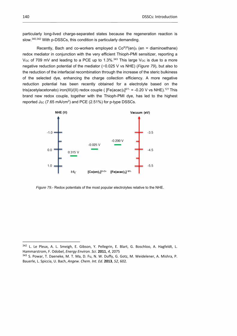
140 DSSCs: Introduction
particularly long-lived charge-separated states because the regeneration reaction is
slow.340,342 With p-DSSCs, this condition is particularly demanding.
Recently, Bach and co-workers employed a CoIII/II(en)3 (en = diaminoethane)
redox mediator in conjunction with the very efficient Thioph-PMI sensitizer, reporting a
VOC of 709 mV and leading to a PCE up to 1.3%.343 This large VOC is due to a more
negative reduction potential of the mediator (−0.025 V vs NHE) (Figure 79), but also to
the reduction of the interfacial recombination through the increase of the steric bulkiness
of the selected dye, enhancing the charge collection efficiency. A more negative
reduction potential has been recently obtained for a electrolyte based on the
tris(acetylacetonato) iron(III)/(II) redox couple ( [Fe(acac)3]0/1- = -0.20 V vs NHE).121 This
brand new redox couple, together with the Thioph-PMI dye, has led to the highest
reported JSC (7.65 mA/cm2) and PCE (2.51%) for p-type DSSCs.
Figure 79.- Redox potentials of the most popular electrolytes relative to the NHE.
342 L. Le Pleux, A. L. Smeigh, E. Gibson, Y. Pellegrin, E. Blart, G. Boschloo, A. Hagfeldt, L. Hammarstrom, F. Odobel, Energy Environ. Sci. 2011, 4, 2075 343 S. Powar, T. Daeneke, M. T. Ma, D. Fu, N. W. Duffy, G. Gotz, M. Weidelener, A. Mishra, P. Bauerle, L. Spiccia, U. Bach, Angew. Chem. Int. Ed. 2013, 52, 602.
Chapter 1 141
1.3.4 Sensitizers
As the field of p-DSSCs is relatively young, the diversity of dyes screened in p-
DSSCs is much less than that tested on TiO2-based Grätzel cells. A myriad of different
organic and inorganic sensitizers, including triphenylamines,311b,344,345,346 perylene
imides,342,347,348 porphycenes,349 ruthenium350 and iridium351 complexes,
coumarins,311a,339 porphyrins308,352 and a combination of the above.121,343,353 A selection of
the best performing sensitizers is given in Figure 80.
344 a) P. Qin, H. Zhu, T. Edvinsson, G. Boschloo, A. Hagfeldt, L. Sun, J. Am. Chem. Soc. 2008, 130, 8570; b) P. Qin, M. Linder, T. Brinck, G. Boschloo, A. Hagfeldt, L. Sun, Adv. Mater. 2009, 21, 2993; c) P. Qin, J. Wiberg, E. A. Gibson, M. Linder, L. Li, T. Brinck, A. Hagfeldt, B. Albinsson, L. Sun, J. Phys. Chem. C 2010, 114, 4738; d) Y.‐S. Yen, W.‐T. Chen, C.‐Y. Hsu, H.‐H. Chou, J. T. Lin, M.‐C. P. Yeh, Org. Lett. 2011, 13, 4930. 345 a) L. Zhu, H. B. Yang, C. Zhong, C. M. Li, Dyes Pigments 2014, 105, 97; b) H.‐B. Li, J. Zhang, Y. Wu, J.‐L. Jin, Y.‐A. Duan, Z.‐M. Su, Y. Geng, Dyes Pigments, 2014, 108, 106. 346 J. Cui, J. Lu, X. Xu, K. Cao, Z. Wang, G. Alemu, H. Yuang, Y. Shen, J. Xu, Y. Cheng, M. Wang, J. Phys. Chem. C 2014, 118, 16433. 347 C. Li, H. Wonneberger, Adv. Mater. 2012, 24, 613. 348 a) A. Morandeira, J. Fortage, T. Edvinsson, L. Le Pleux, E. Blart, G. Boschloo, A. Hagfeldt, L. Hammarstrom, F. Odobel, J. Phys. Chem. C 2008, 112, 1721; b) A. L. Smeigh, L. Le Pleux, J. Fortage, Y. Pellegrin, E. Blart, F. Odobel, L. Hammarstrom, Chem. Comm. 2012, 48, 678; c) S. Feihl, R. D. Costa, S. Pflock, C. Schmidt, J. Schonamsgruber, S. Backes, A. Hirsch, D. M. Guldi, RSC Advances 2012, 2, 11495. 349 S. Feihl, R. D. Costa, W. Brenner, J. T. Margraf, R. Casillas, O. Langmar, A. Browa, T. E. Shubina, T. Clark, N. Jux, D. M. Guldi, Chem. Comm. 2014, 50, 11339. 350 a) Y. Pellegrin, L. Le Pleux, E. Blart, A. Renaud, B. Chavillon, N. Szuwarski, M. Boujtita, L. Cario, S. Jobic, D. Jacquemin, F. Odobel, J. Photochem. Photobiol. A 2011, 219, 235; b) Z. Ji, G. Natu, Z. Huang, O. Kokhan, X. Zhang, Y. Wu, J. Phys. Chem. C 2012, 116, 16854; c) J. C. Freys, J. M. Gardner, L. D’Amario, A. M. Brown, L. Hammarstrom, Dalton Trans. 2012, 41, 13105; d) Z. Ji, Y. Wu, J. Phys. Chem. C 2013, 117, 18315; e) Z. Ji, G. Natu, Y. Wu, ACS Appl. Mater. Interfaces 2013, 5, 8641; f) M. He, Z. Ji, Z. Huang, Y. Wu, J. Phys. Chem. 2014, 118, 16518; g) C. J. Wood, K. C. D. Robson, P. I. P. Elliott, C. P. Berlinguette, E. A. Gibson, RSC Adv. 2014, 4, 5782; h) C. D. Ertl, D. P. Ris, S. C. Meier, E. C. Constable, C. E. Housecroft, M. Neuburger, J. Zampese, Dalton Trans. 2015, 44, 1557. 351 M. Gennari, F. Legalite, L. Zhang, Y. Pellegrin, E. Blart, J. Fortage, A. M. Brown, A. Deronzier, M.‐E. Collomb, M. Boujtita, D. Jacquemin, L. Hammarstrom, F. Odobel, J. Phys. Chem. Lett. 2014, 5, 2254. 352 a) M. Borgstrom, E. Blart, G. Boschloo, E. Mukhtar, A. Hagfeldt, L. Hammarstrom, F. Odobel, J. Phys. Chem. B 2005, 109, 22928; b) H. Tian, J. Oscarsson, E. Gabrielsson, S. K. Eriksson, R. Lindblad, B. Xu, Y. Hao, G. Boschloo, E. M. J. Johansson, J. M. Gardner, A. Hagfeldt, H. Rensmo, L. Sun, Sci. Rep. 2014, 4, 4282; c) A. Maufroy, L. Favereau, F. B. Anne, Y. Pellegrin, E. Blart, M. Hissler, D. Jacquemin, F. Odobel, J. Mater. Chem. A 2015, 3, 3908. 353 a) M. Weidelener, A. Mishra, A. Nattestad, S. Powar, A. J. Mozer, E. Mena‐Osteritz, Y.‐B. Cheng, U. Bach, P. Bauerle, J. Mater. Chem. 2012, 22, 7366; b) J. Warnan, J. Gardner, L. Le Pleux, J. Petersson, Y. Pellegrin, E. Blart, L. Hammarstrom, F. Odobel, J. Phys. Chem. C 2014, 118, 103;

142 DSSCs: Introduction
Figure 80.- Structures of some of the most efficient sensitizers for p-type DSSCs.
Naturally, efficient p-type sensitizers should possess the following features: 1)
Photochemical and electrochemical stability to ensure the durability of the cell over a long
period of time. 2) A broad absorbance to overlap the largest portion of the solar spectrum
(panchromatic dye) in order to harvest the greatest number of photons. 3) High extinction
coefficients to harvest more solar light within a thinner photocathode, allowing the holes
to diffuse a shorter path length to reach the charge collection substrate. The optimal
thickness of the p-semiconductor films (generally around 2−3 μm) is much lower than
c) Z. Liu, W. Li, S. Topa, X. Xu, X. Zeng, Z. Zhao, M. Wang, W. Chen, F. Wang, Y.‐B. Cheng, H. He, ACS Appl. Mater. Interfaces 2014, 6, 10614; d) K. A. Click, D. R. Beauchamp, B. R. Garrett, Z. Huang, C. M. Hadad, Y. Wu, Phys. Chem. Chem. Phys. 2014, 16, 26103; e) C. J. Wood, M. Cheng, C. A. Clark, R. Horvath, I. P. Clark, M. L. Hamilton, M. Towrie, M. W. George, L. Sun, X. Yang, E. A. Gibson, J. Phys. Chem. C 2014, 118, 16536; f) M. Weidelener, S. Powar, H. Kast, Z. Yu, P. P. Boix, C. Li, K. Mullen, T. Geiger, S. Kuster, F. Nuesch, U. Bach, A. Mishra, P. Bauerle, Chem. Asian J. 2014, 9, 3251; g) C. J. Wood, G. H. Summers, E. A. Gibson, Chem. Comm. 2015, 51, 3915.
CO2H
N
S S
NC
CN
CN
NC
CO2H
N
NC CN CNNC
CO2H
N
HO2C
S
CN
NCP1 P2 O2
HO2C
N
HO2C
N
O
O
N
p-SQ2
N N
O
O
Oct
O
O
N
O
O
OAr
OAr
O CO2H
PMI-NDI
Ru
N
N
NN
N
CO2HnRu-cyclomet
Ru
N
N
NN
N
CO2H
CO2H
CO2H
CO2H
N
O
O
O2N
Ru-NMI
NN
CO2H
OAr
OArO
O
PMI-PhC60
N
HO2C
HO2C
S
C6H13
SS
SS
S
N
O
OC6H13
C6H13
C6H13
C6H13
C6H13
Thioph-PMI
Chapter 1 143
that of the TiO2 in Grätzel cells (rarely lower than 10 μm). 4) The dye must as well exhibit
significant oxidizing power in the excited state, in other words, having a HOMO positioned
below the VB of the p-semiconductor to ensure an exergonic hole driving force (Figure
77). 5) The reducing power of the reduced sensitizer must be also significant, especially
when the iodide/tri-iodide electrolyte is used because the redox potential of the couple
I3−/I2−• (−0.08 V vs NHE)354 because I2− is relatively cathodic. The energetics are indeed
essential to achieve both thermodynamically downhill hole injection and dye regeneration
reactions.
A sufficient driving force for charge-transfer reactions is essential; however, the
kinetics are also relevant to the overall performances. Hole injection into the oxide must
be fast compared to ground-state relaxation of the dye excited state. After hole injection,
dye regeneration by the oxidized redox species should be much faster than
recombination with holes in the p-semiconductor. Fast hole injection dynamics require a
strong electronic coupling with the density of the VB states energetically accessible from
the dye excited state. The magnitude of this coupling is primarily determined by the
energy spacing and the overlap between the HOMO orbitals of the dye excited state and
the VB orbitals of the p-type semiconductor. This wave function overlap is dependent on
both the distance of the dye HOMO orbital from the p-semiconductor surface and the
nature of the anchoring group. The attachment of the dye to the surface via a chemical
bond also induces the formation of a new orbital between the dye and the semiconductor
surface. This enables electronic coupling, which is the key to the fast injection rates
observed for many of these dyes. Carboxylic acid groups have been shown to favor
electron injection in TiO2 by draining and localizing the LUMO of the dye close to the TiO2
surface, thereby ensuring a large overlap with the conduction band.116a,350a Accordingly,
carboxylic acid may not be the optimal choice to promote electronic coupling with p-
semiconductors. However, it is a good option as a first step towards a more rational
design. In future, new anchoring groups exhibiting electron-rich character must be tested
because they may better assist hole injection by allowing the delocalization of HOMO
orbital of the dye over the anchoring group towards the metal oxide surface.346,350a
Another essential difference of p-DSSCs stems from the very fast geminate charge
recombination as compared to the rates measured in sensitized TiO2 films. Detailed
ultrafast transient absorption spectroscopy studies have demonstrated that hole injection
in the NiO VB is usually fast (picosecond time scale), but charge recombination is also
very fast too (nanosecond time scale).344c,348a,339a,b,352a
Other parameters being equal, the charge recombination between the injected
hole and the reduced sensitizer depends on the spatial separation of the dye anion (which
354 G. Boschloo, E. A. Gibson, A. Hagfeldt, J. Phys. Chem. Lett. 2011, 2, 3016.
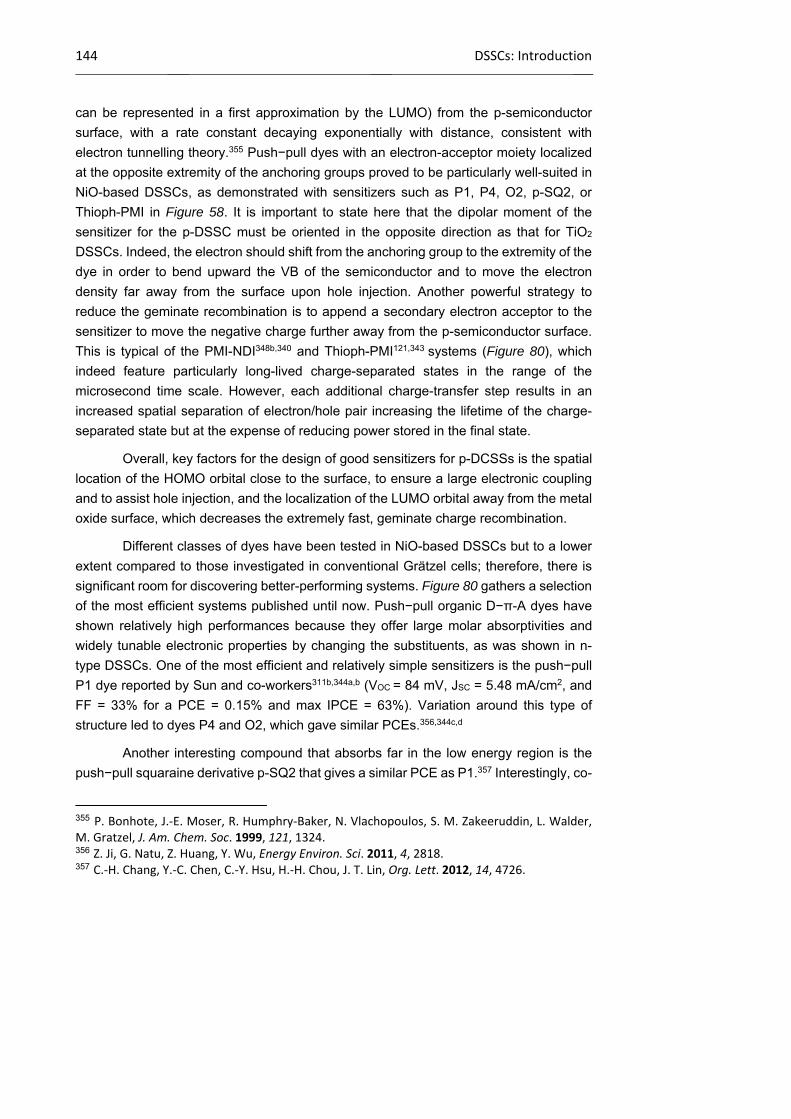
144 DSSCs: Introduction
can be represented in a first approximation by the LUMO) from the p-semiconductor
surface, with a rate constant decaying exponentially with distance, consistent with
electron tunnelling theory.355 Push−pull dyes with an electron-acceptor moiety localized
at the opposite extremity of the anchoring groups proved to be particularly well-suited in
NiO-based DSSCs, as demonstrated with sensitizers such as P1, P4, O2, p-SQ2, or
Thioph-PMI in Figure 58. It is important to state here that the dipolar moment of the
sensitizer for the p-DSSC must be oriented in the opposite direction as that for TiO2
DSSCs. Indeed, the electron should shift from the anchoring group to the extremity of the
dye in order to bend upward the VB of the semiconductor and to move the electron
density far away from the surface upon hole injection. Another powerful strategy to
reduce the geminate recombination is to append a secondary electron acceptor to the
sensitizer to move the negative charge further away from the p-semiconductor surface.
This is typical of the PMI-NDI348b,340 and Thioph-PMI121,343 systems (Figure 80), which
indeed feature particularly long-lived charge-separated states in the range of the
microsecond time scale. However, each additional charge-transfer step results in an
increased spatial separation of electron/hole pair increasing the lifetime of the charge-
separated state but at the expense of reducing power stored in the final state.
Overall, key factors for the design of good sensitizers for p-DCSSs is the spatial
location of the HOMO orbital close to the surface, to ensure a large electronic coupling
and to assist hole injection, and the localization of the LUMO orbital away from the metal
oxide surface, which decreases the extremely fast, geminate charge recombination.
Different classes of dyes have been tested in NiO-based DSSCs but to a lower
extent compared to those investigated in conventional Grätzel cells; therefore, there is
significant room for discovering better-performing systems. Figure 80 gathers a selection
of the most efficient systems published until now. Push−pull organic D−π-A dyes have
shown relatively high performances because they offer large molar absorptivities and
widely tunable electronic properties by changing the substituents, as was shown in n-
type DSSCs. One of the most efficient and relatively simple sensitizers is the push−pull
P1 dye reported by Sun and co-workers311b,344a,b (VOC = 84 mV, JSC = 5.48 mA/cm2, and
FF = 33% for a PCE = 0.15% and max IPCE = 63%). Variation around this type of
structure led to dyes P4 and O2, which gave similar PCEs.356,344c,d
Another interesting compound that absorbs far in the low energy region is the
push−pull squaraine derivative p-SQ2 that gives a similar PCE as P1.357 Interestingly, co-
355 P. Bonhote, J.‐E. Moser, R. Humphry‐Baker, N. Vlachopoulos, S. M. Zakeeruddin, L. Walder, M. Gratzel, J. Am. Chem. Soc. 1999, 121, 1324. 356 Z. Ji, G. Natu, Z. Huang, Y. Wu, Energy Environ. Sci. 2011, 4, 2818. 357 C.‐H. Chang, Y.‐C. Chen, C.‐Y. Hsu, H.‐H. Chou, J. T. Lin, Org. Lett. 2012, 14, 4726.

Chapter 1 145
adsorption of p-SQ2 with P1 yields a slightly higher overall PCE than cells sensitized with
a single chromophore, showing the first implementation of the co-sensitization concept
in p-DSSCs. However, it should be noted that, if the electricity production is extended
toward the red region with the presence of p-SQ2, the IPCE on the absorption band of
P1 is significantly diminished upon coadsorption of p-SQ2. Recently, Hupp and co-
workers proposed an interesting explanation of such phenomenon for n-DSSCs. They
showed that the efficiency of mixed co-sensitization is highly dependent on the effective
electron collection length of the less-performing sensitizer and of the relative disposition
of the sensitizers.358 Similar rules certainly govern cosensitization in p-DSSCs.
Other efficient systems are composed of a sensitizer connected to a secondary
electron acceptor, which pulls the electron far away from the anchoring group to retard
charge recombination. PMI-NDI, PMI-PhC60,348a,b,340, Ru-NMI350c dyads, and Thioph-
PMI,121,326a,e353a,359 (Figure 80) are examples of such systems. On NiO photocathodes,
these sensitizers exhibit a charge separated lifetime of tenths of microseconds owing to
the large electronic decoupling and the long distance between the charge carriers. The
great success of Thioph-PMI probably stems from a combination of several features: first,
a high extinction coefficient, second the presence of alkyl chains on the thienyl units,
which avoid dye aggregation and certainly protect the NiO surface from the approach of
the electrolyte (reducing thus the current leakage), and last but not least, a long-lived
charge-separated state owing to the large distance of the ion pair (the hole in NiO and
electron on PMI).
Another approach to sensitize a wide-band-gap semiconductor is to use
semiconductor nanocrystals, commonly referred as quantum-dot-sensitized solar cells.
There has been intense research activity in the use of quantum dots in classical Grätzel
cells,360,361 and interest is now growing for their utilization in p-DSSCs.362
358 N. C. Jeong, H.‐J. Son, C. Prasittichai, C. Y. Lee, R. A. Jensen, O. K. Farha, J. T. Hupp, J. Am. Chem. Soc. 2012, 134, 19820. 359 X. L. Zhang, Z. Zhang, D. Chen, P. Bauerle, U. Bach, Y.‐B. Cheng, Chem. Comm. 2012, 48, 9885. 360 M. R. Kim, D. Ma, J. Phys. Chem. Lett. 2015, 6, 85. 361 a) P. V. Kamat, Acc. Chem. Res. 2012, 45, 1906; b) F. Hetsch, X. Xu, H. Wang, S. V. Kershaw, A. L. Rogach, J. Phys. Chem. Lett. 2011, 2, 1879. 362 a) X. Wu, E. K. L. Yeow, Chem. Comm. 2010, 46, 4390; b) I. Barcelo, E. Guillen, T. Lana‐Villarreal, R. Gomez, J. Phys. Chem. C 2013, 117, 22509; c) K. Zheng, K. Zidek, M. Abdellah, W. Zhang, P. Chabera, N. Lenngren, A. Yartsev, T. Pullerits, J. Phys. Chem. C 2014, 118, 18462.
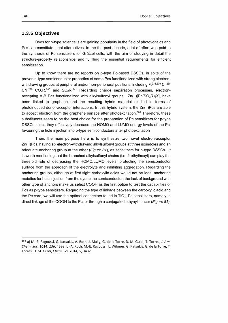
146 DSSCs: Objectives
1.3.5 Objectives
Dyes for p-type solar cells are gaining popularity in the field of photovoltaics and
Pcs can constitute ideal alternatives. In the the past decade, a lot of effort was paid to
the synthesis of Pc-sensitizers for Grätzel cells, with the aim of studying in detail the
structure-property relationships and fulfilling the essential requirements for efficient
sensitization.
Up to know there are no reports on p-type Pc-based DSSCs, in spite of the
proven n-type semiconductor properties of some Pcs functionalized with strong electron-
withdrawing groups at peripheral and/or non-peripheral positions, including F,238,239 Cl,238
CN,238 CO2R,240 and SO2R.241 Regarding charge separation processes, electron-
accepting A3B Pcs functionalized with alkylsulfonyl groups, Zn(II)[Pc(SO2R)6X], have
been linked to graphene and the resulting hybrid material studied in terms of
photoinduced donor-acceptor interactions. In this hybrid system, the Zn(II)Pcs are able
to accept electron from the graphene surface after photoexcitation.363 Therefore, these
substituents seem to be the best choice for the preparation of Pc sensitizers for p-type
DSSCs, since they effectively decrease the HOMO and LUMO energy levels of the Pc,
favouring the hole injection into p-type semiconductors after photoexcitation
Then, the main purpose here is to synthesize two novel electron-acceptor
Zn(II)Pcs, having six electron-withdrawing alkylsulfonyl groups at three isoindoles and an
adequate anchoring group at the other (Figure 81), as sensitizers for p-type DSSCs. It
is worth mentioning that the branched alkylsulfonyl chains (i.e. 2-ethylhexyl) can play the
threefold role of decreasing the HOMO/LUMO levels, protecting the semiconductor
surface from the approach of the electrolyte and inhibiting aggregation. Regarding the
anchoring groups, although at first sight carboxylic acids would not be ideal anchoring
moieties for hole injection from the dye to the semiconductor, the lack of background with
other type of anchors make us select COOH as the first option to test the capabilities of
Pcs as p-type sensitizers. Regarding the type of linkage between the carboxylic acid and
the Pc core, we will use the optimal connectors found in TiO2, Pc-sensitizers, namely, a
direct linkage of the COOH to the Pc, or through a conjugated ethynyl spacer (Figure 81).
363 a) M.‐E. Ragoussi, G. Katsukis, A. Roth, J. Malig, G. de la Torre, D. M. Guldi, T. Torres, J. Am. Chem. Soc. 2014, 136, 4593; b) A. Roth, M.‐E. Ragoussi, L. Wibmer, G. Katsukis, G. de la Torre, T. Torres, D. M. Guldi, Chem. Sci. 2014, 5, 3432.
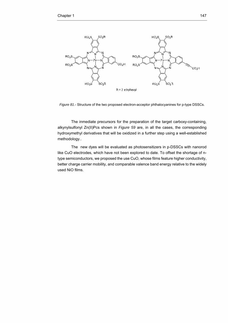
Chapter 1 147
Figure 81.- Structure of the two proposed electron-acceptor phthalocyanines for p-type DSSCs.
The inmediate precursors for the preparation of the target carboxy-containing,
alkynylsulfonyl Zn(II)Pcs shown in Figure 59 are, in all the cases, the corresponding
hydroxymethyl derivatives that will be oxidized in a further step using a well-established
methodology..
The new dyes will be evaluated as photosensitizers in p-DSSCs with nanorod
like CuO electrodes, which have not been explored to date. To offset the shortage of n-
type semiconductors, we proposed the use CuO, whose films feature higher conductivity,
better charge carrier mobility, and comparable valence band energy relative to the widely
used NiO films.
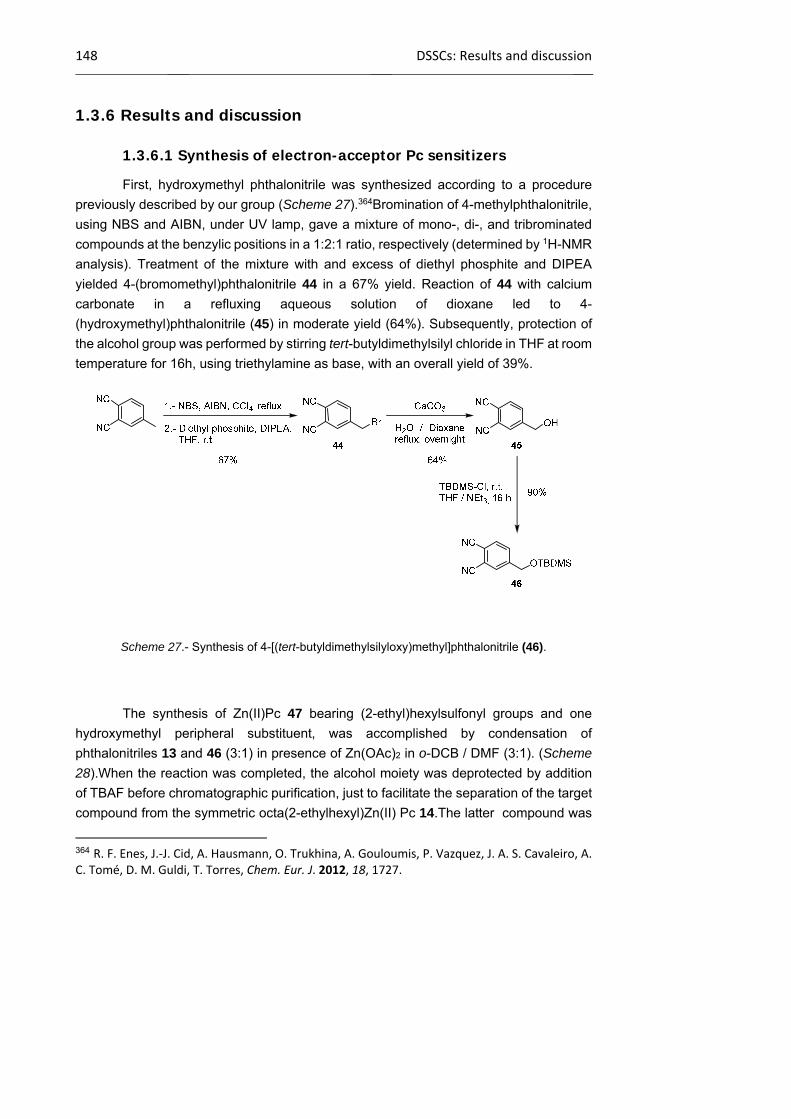
148 DSSCs: Results and discussion
1.3.6 Results and discussion
1.3.6.1 Synthesis of electron-acceptor Pc sensitizers
First, hydroxymethyl phthalonitrile was synthesized according to a procedure
previously described by our group (Scheme 27).364Bromination of 4-methylphthalonitrile,
using NBS and AIBN, under UV lamp, gave a mixture of mono-, di-, and tribrominated
compounds at the benzylic positions in a 1:2:1 ratio, respectively (determined by 1H-NMR
analysis). Treatment of the mixture with and excess of diethyl phosphite and DIPEA
yielded 4-(bromomethyl)phthalonitrile 44 in a 67% yield. Reaction of 44 with calcium
carbonate in a refluxing aqueous solution of dioxane led to 4-
(hydroxymethyl)phthalonitrile (45) in moderate yield (64%). Subsequently, protection of
the alcohol group was performed by stirring tert-butyldimethylsilyl chloride in THF at room
temperature for 16h, using triethylamine as base, with an overall yield of 39%.
Scheme 27.- Synthesis of 4-[(tert-butyldimethylsilyloxy)methyl]phthalonitrile (46).
The synthesis of Zn(II)Pc 47 bearing (2-ethyl)hexylsulfonyl groups and one
hydroxymethyl peripheral substituent, was accomplished by condensation of
phthalonitriles 13 and 46 (3:1) in presence of Zn(OAc)2 in o-DCB / DMF (3:1). (Scheme
28).When the reaction was completed, the alcohol moiety was deprotected by addition
of TBAF before chromatographic purification, just to facilitate the separation of the target
compound from the symmetric octa(2-ethylhexyl)Zn(II) Pc 14.The latter compound was
364 R. F. Enes, J.‐J. Cid, A. Hausmann, O. Trukhina, A. Gouloumis, P. Vazquez, J. A. S. Cavaleiro, A. C. Tomé, D. M. Guldi, T. Torres, Chem. Eur. J. 2012, 18, 1727.
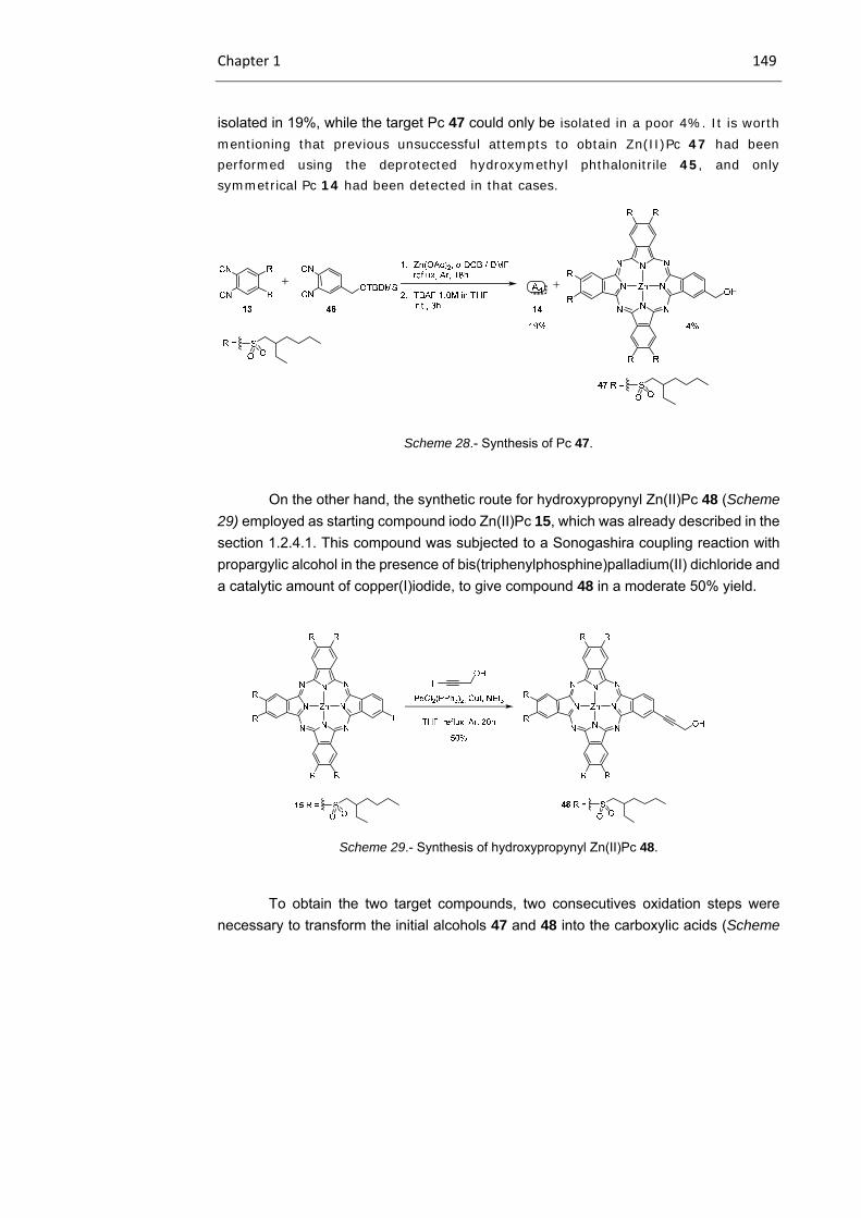
Chapter 1 149
isolated in 19%, while the target Pc 47 could only be isolated in a poor 4%. It is worth mentioning that previous unsuccessful attempts to obtain Zn(II)Pc 47 had been performed using the deprotected hydroxymethyl phthalonitrile 45, and only symmetrical Pc 14 had been detected in that cases.
Scheme 28.- Synthesis of Pc 47.
On the other hand, the synthetic route for hydroxypropynyl Zn(II)Pc 48 (Scheme
29) employed as starting compound iodo Zn(II)Pc 15, which was already described in the
section 1.2.4.1. This compound was subjected to a Sonogashira coupling reaction with
propargylic alcohol in the presence of bis(triphenylphosphine)palladium(II) dichloride and
a catalytic amount of copper(I)iodide, to give compound 48 in a moderate 50% yield.
Scheme 29.- Synthesis of hydroxypropynyl Zn(II)Pc 48.
To obtain the two target compounds, two consecutives oxidation steps were
necessary to transform the initial alcohols 47 and 48 into the carboxylic acids (Scheme
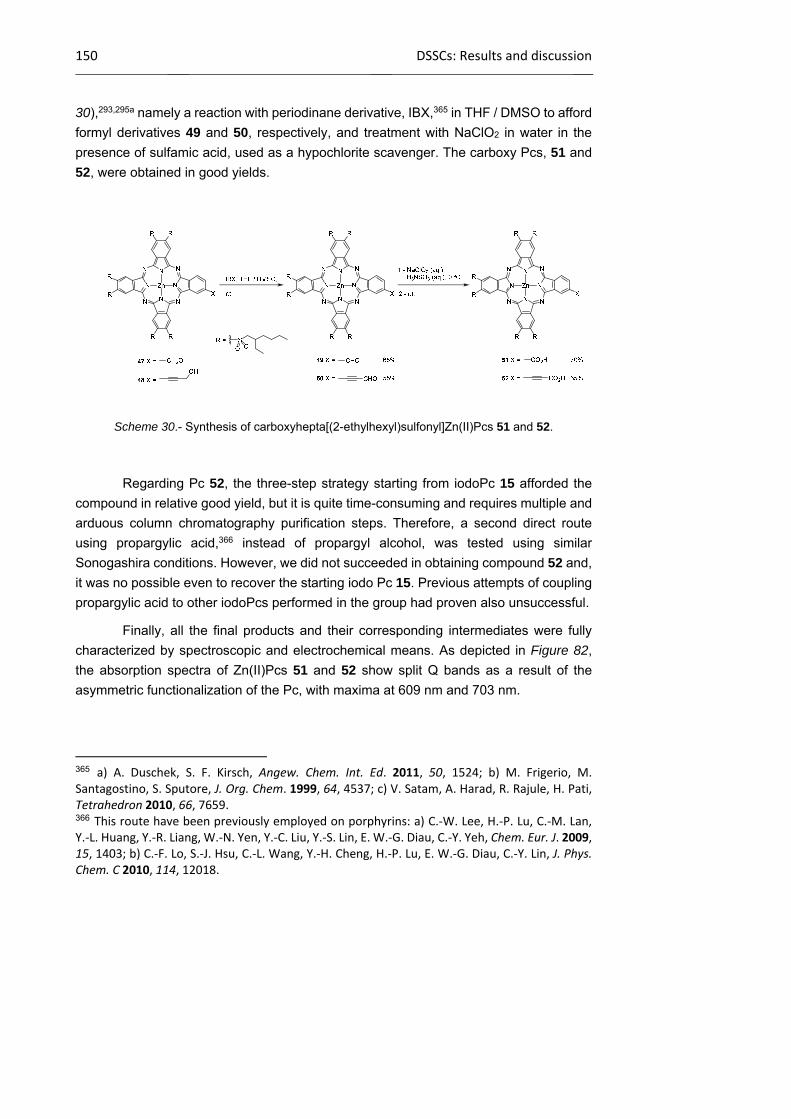
150 DSSCs: Results and discussion
30),293,295a namely a reaction with periodinane derivative, IBX,365 in THF / DMSO to afford
formyl derivatives 49 and 50, respectively, and treatment with NaClO2 in water in the
presence of sulfamic acid, used as a hypochlorite scavenger. The carboxy Pcs, 51 and
52, were obtained in good yields.
Scheme 30.- Synthesis of carboxyhepta[(2-ethylhexyl)sulfonyl]Zn(II)Pcs 51 and 52.
Regarding Pc 52, the three-step strategy starting from iodoPc 15 afforded the
compound in relative good yield, but it is quite time-consuming and requires multiple and
arduous column chromatography purification steps. Therefore, a second direct route
using propargylic acid,366 instead of propargyl alcohol, was tested using similar
Sonogashira conditions. However, we did not succeeded in obtaining compound 52 and,
it was no possible even to recover the starting iodo Pc 15. Previous attempts of coupling
propargylic acid to other iodoPcs performed in the group had proven also unsuccessful.
Finally, all the final products and their corresponding intermediates were fully
characterized by spectroscopic and electrochemical means. As depicted in Figure 82,
the absorption spectra of Zn(II)Pcs 51 and 52 show split Q bands as a result of the
asymmetric functionalization of the Pc, with maxima at 609 nm and 703 nm.
365 a) A. Duschek, S. F. Kirsch, Angew. Chem. Int. Ed. 2011, 50, 1524; b) M. Frigerio, M. Santagostino, S. Sputore, J. Org. Chem. 1999, 64, 4537; c) V. Satam, A. Harad, R. Rajule, H. Pati, Tetrahedron 2010, 66, 7659. 366 This route have been previously employed on porphyrins: a) C.‐W. Lee, H.‐P. Lu, C.‐M. Lan, Y.‐L. Huang, Y.‐R. Liang, W.‐N. Yen, Y.‐C. Liu, Y.‐S. Lin, E. W.‐G. Diau, C.‐Y. Yeh, Chem. Eur. J. 2009, 15, 1403; b) C.‐F. Lo, S.‐J. Hsu, C.‐L. Wang, Y.‐H. Cheng, H.‐P. Lu, E. W.‐G. Diau, C.‐Y. Lin, J. Phys. Chem. C 2010, 114, 12018.
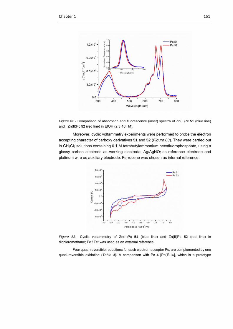
Chapter 1 151
Figure 82.- Comparison of absorption and fluorescence (inset) spectra of Zn(II)Pc 51 (blue line)
and Zn(II)Pc 52 (red line) in EtOH (2.3·10-7 M).
Moreover, cyclic voltammetry experiments were performed to probe the electron
accepting character of carboxy derivatives 51 and 52 (Figure 83). They were carried out
in CH2Cl2 solutions containing 0.1 M tetrabutylammonium hexafluorophosphate, using a
glassy carbon electrode as working electrode, Ag/AgNO3 as reference electrode and
platinum wire as auxiliary electrode. Ferrocene was chosen as internal reference.
Figure 83.- Cyclic voltammetry of Zn(II)Pc 51 (blue line) and Zn(II)Pc 52 (red line) in
dichloromethane; Fc / Fc+ was used as an external reference.
Four quasi-reversible reductions for each electron-acceptor Pc, are complemented by one
quasi-reversible oxidation (Table 4). A comparison with Pc 4 [Pc(tBu)4], which is a prototype
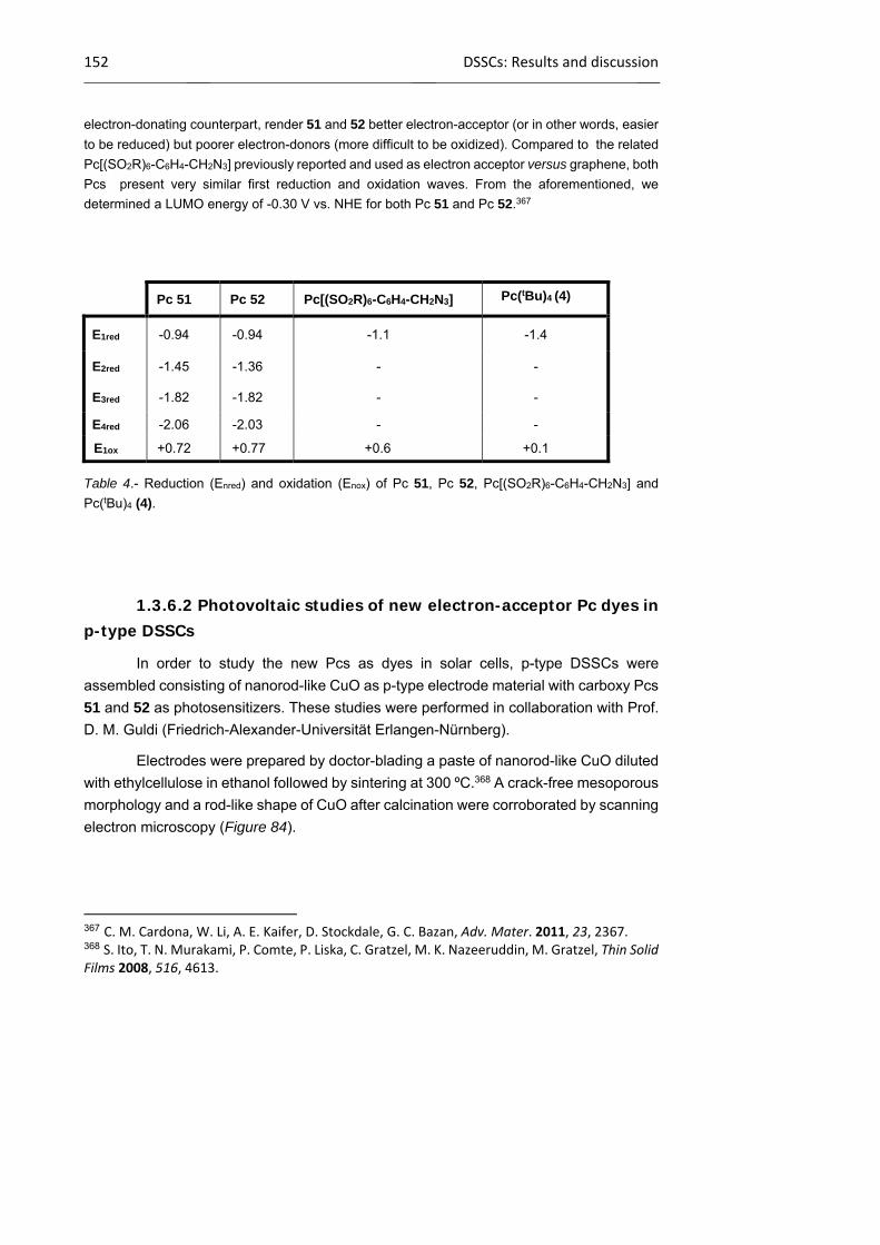
152 DSSCs: Results and discussion
electron-donating counterpart, render 51 and 52 better electron-acceptor (or in other words, easier
to be reduced) but poorer electron-donors (more difficult to be oxidized). Compared to the related
Pc[(SO2R)6-C6H4-CH2N3] previously reported and used as electron acceptor versus graphene, both
Pcs present very similar first reduction and oxidation waves. From the aforementioned, we
determined a LUMO energy of -0.30 V vs. NHE for both Pc 51 and Pc 52.367
Table 4.- Reduction (Enred) and oxidation (Enox) of Pc 51, Pc 52, Pc[(SO2R)6-C6H4-CH2N3] and
Pc(tBu)4 (4).
1.3.6.2 Photovoltaic studies of new electron-acceptor Pc dyes in p-type DSSCs
In order to study the new Pcs as dyes in solar cells, p-type DSSCs were
assembled consisting of nanorod-like CuO as p-type electrode material with carboxy Pcs
51 and 52 as photosensitizers. These studies were performed in collaboration with Prof.
D. M. Guldi (Friedrich-Alexander-Universität Erlangen-Nürnberg).
Electrodes were prepared by doctor-blading a paste of nanorod-like CuO diluted
with ethylcellulose in ethanol followed by sintering at 300 ºC.368 A crack-free mesoporous
morphology and a rod-like shape of CuO after calcination were corroborated by scanning
electron microscopy (Figure 84).
367 C. M. Cardona, W. Li, A. E. Kaifer, D. Stockdale, G. C. Bazan, Adv. Mater. 2011, 23, 2367. 368 S. Ito, T. N. Murakami, P. Comte, P. Liska, C. Gratzel, M. K. Nazeeruddin, M. Gratzel, Thin Solid Films 2008, 516, 4613.
Pc 51 Pc 52 Pc[(SO2R)6-C6H4-CH2N3] Pc(tBu)4 (4)
E1red -0.94 -0.94 -1.1 -1.4
E2red -1.45 -1.36 - -
E3red -1.82 -1.82 - -
E4red -2.06 -2.03 - -
E1ox +0.72 +0.77 +0.6 +0.1
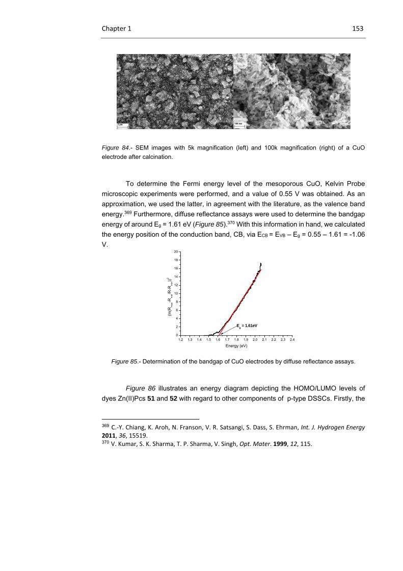
Chapter 1 153
Figure 84.- SEM images with 5k magnification (left) and 100k magnification (right) of a CuO
electrode after calcination.
To determine the Fermi energy level of the mesoporous CuO, Kelvin Probe
microscopic experiments were performed, and a value of 0.55 V was obtained. As an
approximation, we used the latter, in agreement with the literature, as the valence band
energy.369 Furthermore, diffuse reflectance assays were used to determine the bandgap
energy of around Eg = 1.61 eV (Figure 85).370 With this information in hand, we calculated
the energy position of the conduction band, CB, via ECB = EVB – Eg = 0.55 – 1.61 = -1.06
V.
Figure 85.- Determination of the bandgap of CuO electrodes by diffuse reflectance assays.
Figure 86 illustrates an energy diagram depicting the HOMO/LUMO levels of
dyes Zn(II)Pcs 51 and 52 with regard to other components of p-type DSSCs. Firstly, the
369 C.‐Y. Chiang, K. Aroh, N. Franson, V. R. Satsangi, S. Dass, S. Ehrman, Int. J. Hydrogen Energy 2011, 36, 15519. 370 V. Kumar, S. K. Sharma, T. P. Sharma, V. Singh, Opt. Mater. 1999, 12, 115.
1.2 1.3 1.4 1.5 1.6 1.7 1.8 1.9 2.0 2.1 2.2 2.3 2.40
2
4
6
8
10
12
14
16
18
20
(ln(R
ma
x-R
min/R
-Rm
in))
2
Energy (eV)
Eg = 1.61eV
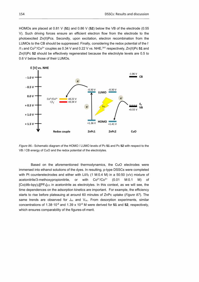
154 DSSCs: Results and discussion
HOMOs are placed at 0.81 V (51) and 0.86 V (52) below the VB of the electrode (0.55
V). Such driving forces ensure an efficient electron flow from the electrode to the
photoexcited Zn(II)Pcs. Secondly, upon excitation, electron recombination from the
LUMOs to the CB should be suppressed. Finally, considering the redox potential of the I-
/I-3 and Co2+/Co3+ couples as 0.34 V and 0.22 V vs. NHE,341 respectively, Zn(II)Pc 51 and
Zn(II)Pc 52 should be effectively regenerated because the electrolyte levels are 0.5 to
0.6 V below those of their LUMOs.
Figure 86.- Schematic diagram of the HOMO / LUMO levels of Pc 51 and Pc 52 with respect to the
VB / CB energy of CuO and the redox potential of the electrolytes.
Based on the aforementioned thermodynamics, the CuO electrodes were
immersed into ethanol solutions of the dyes. In resulting, p-type DSSCs were completed
with Pt counterelectrodes and either with LiI/I2 (1 M:0.4 M) in a 50:50 (v/v) mixture of
acetonitrile/3-methoxypropionitrile, or with Co2+/Co3+ (0.01 M:0.1 M) of
[Co(dtb-bpy)3][PF6]2/3 in acetonitrile as electrolytes. In this context, as we will see, the
time dependences on the adsorption kinetics are important. For example, the efficiency
starts to rise before plateauing at around 60 minutes of ZnPc uptake (Figure 87). The
same trends are observed for Jsc and Voc. From desorption experiments, similar
concentrations of 1.38·10-8 and 1.39 x 10⁻⁸ M were derived for 51 and 52, respectively,
which ensures comparability of the figures-of-merit.
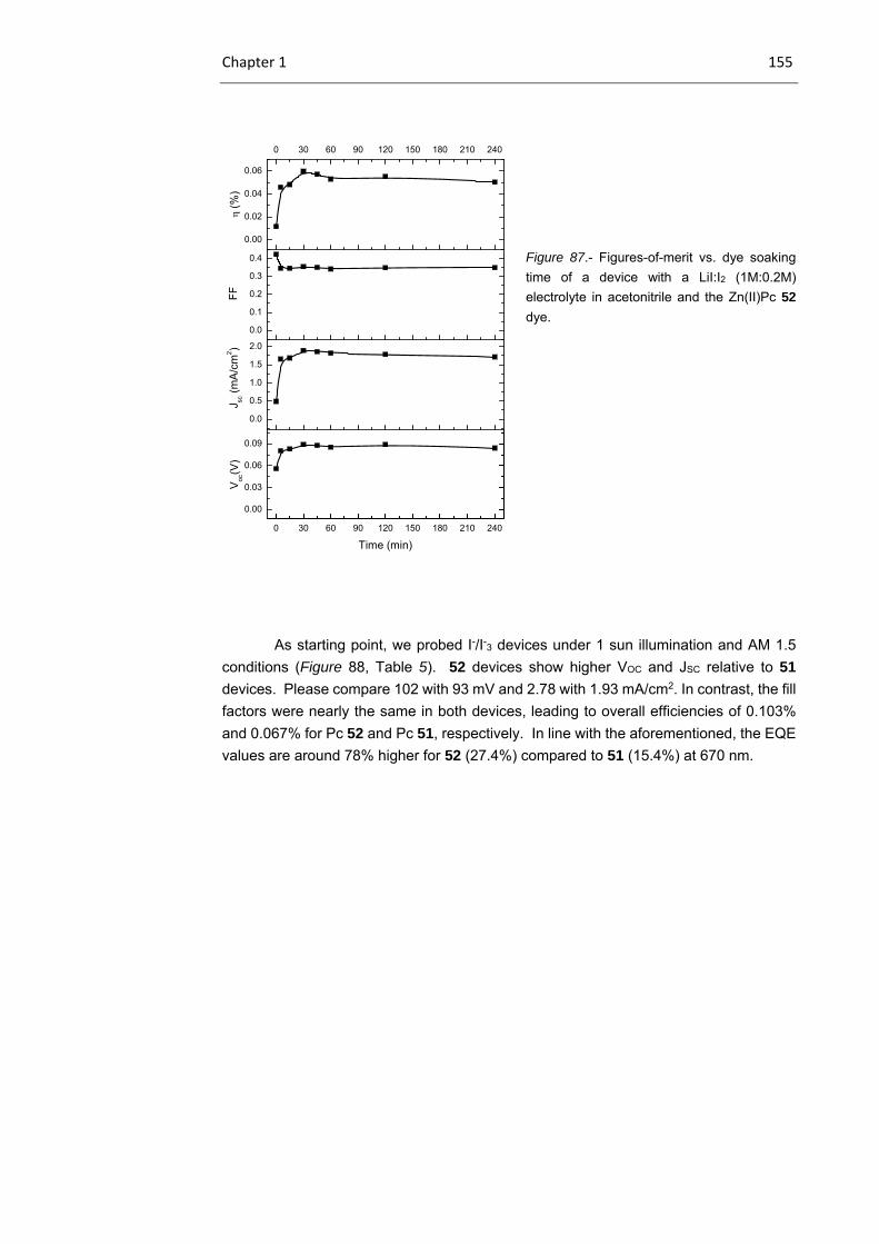
Chapter 1 155
Figure 87.- Figures-of-merit vs. dye soaking
time of a device with a LiI:I2 (1M:0.2M)
electrolyte in acetonitrile and the Zn(II)Pc 52
dye.
As starting point, we probed I-/I-3 devices under 1 sun illumination and AM 1.5
conditions (Figure 88, Table 5). 52 devices show higher VOC and JSC relative to 51
devices. Please compare 102 with 93 mV and 2.78 with 1.93 mA/cm2. In contrast, the fill
factors were nearly the same in both devices, leading to overall efficiencies of 0.103%
and 0.067% for Pc 52 and Pc 51, respectively. In line with the aforementioned, the EQE
values are around 78% higher for 52 (27.4%) compared to 51 (15.4%) at 670 nm.
0 30 60 90 120 150 180 210 240
0.00
0.03
0.06
0.09
0.0
0.5
1.0
1.5
2.0
0.0
0.1
0.2
0.3
0.4
0.00
0.02
0.04
0.06
0 30 60 90 120 150 180 210 240
Voc
(V)
Time (min)
J sc (
mA
/cm
2)
FF
(%
)

156 DSSCs: Results and discussion
Figure 88.- J-V curves under 1 sun and AM 1.5 (line) and dark (dashed) conditions for carboxy
derivatives 51 (blue) and 52 (red) devices with iodine-based electrolyte. Inset – EQE spectra of
both kind of devices compared to a non-sensitized cell (green).
Table 5.- Summarized device performance under 1 sun and AM 1.5 conditions for the iodine-based
devices.
Comparable conditions, in terms of dye loading, electrode thickness, and
electrolyte composition, as well as differences in Jsc and EQE obtained with 51 and 52,
point to a linker-dependent injection and/or recombination processes. 52 features the
carboxylic linker connected to the Pc via a carbon-carbon triple bond, while the linker is
directly connected in the case of 51. In general, the nature of the linker determines both
the dye-electrode distance and the orientation of the dye relative to the surface.371 Both
govern the injection and recombination kinetics, as seen in previous and our own results,
where thermodynamic differences between the dyes are ruled out. Notably, the efficiency
371 a) A. S. Hart, C. B. KC, H. B. Gobeze, L. R. Sequeira, F. D’Souza, ACS Appl. Mater. Interfaces 2013, 5, 5314.
Dye VOC
(mV) JSC (mA/cm2) FF PCE
EQE (%)
at 670nm
51 93 1.93 0.38 0.067 15.4
52 102 2.78 0.36 0.103 27.4
-0.12 -0.10 -0.08 -0.06 -0.04 -0.02 0.00 0.02 0.04-1.0
-0.5
0.0
0.5
1.0
1.5
2.0
2.5
3.0
3.5
4.0
4.5
5.0
Cu
rre
nt D
ensi
ty (
mA
/cm
2 )
Applied Potential (V)
320 400 480 560 640 7200
5
10
15
20
25
30
EQ
E (
%)
Wavelength (nm)
Chapter 1 157
trend found for these compounds in p-type DSSCs is in line with that observed in n-type
devices sensitized by electron-donor Zn(II)Pc dyes featuring the same carboxylic
linkers.295b
Considering that the CuO electrode opaqueness prohibited transient absorption
spectroscopy assays, we turned to electrochemical impedance spectroscopy (EIS).
Applying different voltages to change between short-circuit current density and open-
circuit voltage conditions assists in probing the aforementioned processes in p-type
DSSCs.372,373 As an illustration, the Nyquist plots under Voc and Jsc conditions are shown
in Figure 89. Two semicircles, which relate to the resistance across the
platinum/electrolyte interface in the high frequency region and the
dye/electrode/electrolyte interface in the low frequency region are discernable.372 From
the corresponding electrical circuit model, which is illustrated also in Figure 89, the
resistances and capacitances are derived. EIS measurements under dark conditions give
insights into the electrode to electrolyte recombination.372 To this end, Figure 90
documents that the recombination resistance (Rrec) in both devices increases with
decreasing voltage. Within the voltage range, slightly lower resistances towards
recombination with the I-/I3- redox couple are noted for Zn(II)Pc 52 devices. In the latter,
larger dye to electrode distances facilitate interactions with the redox couple, as the
electrode surface is more exposed to the polyiodide species. A closer look at the EQE
spectra in Figure 88 further substantiates this trend. Here, Zn(II)Pc 52 devices feature in
the high-energy region, which is dominated by excitation of CuO and/or the redox couple,
slightly higher EQEs (≤ 2%) compared to devices made of 51.
372 Z. Huang, G. Natu, Z. Ji, P. Hasin, Y. Wu, J. Phys. Chem. C 2011, 115, 25109. 373 Z. Huang, G. Natu, Z. Ji, M. He, M. Yu, Y. Wu, J. Phys. Chem. C 2012, 116, 26239.

158 DSSCs: Results and discussion
Figure 89.- Nyquist plots (solid squares) with the corresponding circuit model fits (line) for Pc 51
(blue) and Pc 52 (red) devices under VOC (top) and JSC (botton) conditions, as well as under 1 sun
and AM 1.5 (left) and dark (right) conditions for the iodine-based devices. Also, it is represented
the electrical circuit model used to obtain the determined EIS parameter.
20 40 60 80 100 120 1400
10
20
30
40
50
-Z'' (
)
Z' ()
20 40 60 80 100 120 1400
10
20
30
40
50
-Z'' (
)
Z' (
0 100 200 300 400 500 6000
50
100
150
200
250
300
-Z'' (
)
Z' (0 2000 4000 6000 8000 10000 12000 14000
0
1000
2000
3000
4000
5000
6000
7000
8000
-Z'' (
)
Z' ()

Chapter 1 159
Figure 90.-. Resistance vs. applied voltage for Zn(II)Pc 51 (blue) and 52 (red) devices under dark
(open circles) and illumination (closed circles) conditions.
More interesting are the EIS measurements under illumination. Here, several
contributions impact the charge-transfer resistance (RCT). Besides the electrode to redox
couple recombination, charge injection from the electrode to the dye and transport
processes in the electrode play the major roles.374 Again, a linear increase of RCT with
decreasing voltage is noted before it plateaus at around JSC conditions (Figure 90). A
similar trend has recently been reported for NiO-based DSSCs.373
Overall, 52 devices give rise to lower RCT throughout the entire voltage range in
direct comparison to 51 devices, indicating better charge injection and charge transport
in the former. At VOC conditions, the recombination across the electrode/electrolyte
interface is the most prominent process, since no external current flows. Here, in line with
EIS observations in the dark, the resistance towards recombination with I-/I-3 is slightly
lower for Pc 52 (40.0 Ω) than for Pc 51 (61.8 Ω). At JSC and under forward conditions, the
lack of recombination allows the relation of RCT to the charge injection from the electrode
to the dye. From a comparison between 51 (506.3 Ω) and 52 (266.4 Ω), a nearly two
times lower RCT in the latter devices prompts to better charge injection. The EQE spectra
are helpful in this regard, since the photocurrents due to dye excitation at around 670 nm
are nearly twice as high in the case of 52. The lack of photoactivity of the electrolyte in
374 H. Choi, S. O. Kang, J. Ko, G. Gao, H. S. Kang, M.‐S. Kang, M. K. Nazeeruddin, M. Gratzel, Angew. Chem. Int. Ed. 2009, 48, 5938.
20 0 -20 -40 -60 -80 -100
100
1000
10000
Res
ista
nce
(
)
Applied voltage (mV)

160 DSSCs: Results and discussion
the low-energy region only leaves contributions from the charge injection to rationalize
the superior performance of devices featuring Zn(II)Pc 52.
Additional device properties, namely the chemical capacitance (Cµ), the charge
collection efficiency (ηcc), the effective diffusion length (Leff), and the effective diffusion
coefficient (Deff) have been determined for all devices and are summarized in Figure
91.372,374 Briefly, Cµ directly correlates with the density of injected holes at the electrode.
A higher rate of charge injection increases the hole density, affording high Voc and Cµ.375 In agreement with this notion is the fact that higher VOC, higher Cµ, and superior charge
injections were observed for 52. This also explains the improved cc seen in devices with
Zn(II)Pc 52, since charge injection across the electrode/dye interface is twice as efficient
in this kind of devices. This is also reflected in longer Leff and higher Deff compared to
Zn(II)Pc 51 devices.
Figure 91.- Device parameters determined by EIS. Crec (top left), ηcc (top right), Leff (bottom left) and
Deff (bottom right) for Zn(II)Pc 51 (blue) and 52 (red).
375 J. Bisquert, Phys. Chem. Chem. Phys. 2003, 5, 5360.
20 0 -20 -40 -60 -80 -100110
120
130
140
150
160
170
180
190
200
210
220
Cre
c (µ
F)
Applied Voltage (mV)
20 0 -20 -40 -60 -80 -100
30
40
50
60
70
80
90
100
cc (
%)
Applied Voltage (mV)
20 0 -20 -40 -60 -80 -1000
5
10
15
20
25
30
35
40
45
Le
ff (µ
m)
Applied Voltage (mV)
20 0 -20 -40 -60 -80 -100
0.0
1.0x10⁻⁴
2.0x10⁻⁴
3.0x10⁻⁴
4.0x10⁻⁴
5.0x10⁻⁴
6.0x10⁻⁴
De
ff (c
m2/s
)
Applied Voltage (mV)

Chapter 1 161
The major bottleneck of our devices evolves around the low Voc, since JSC values
are comparable to those of CuXO2 based DSSCs.313 Using cobalt di-tert-butyl bipyridine
hexafluorophosphate [Co(dtb-bpy)3][PF6]2/3 as electrolyte is the most efficient way to
overcome this limitation.341 Under 1 sun illumination and AM 1.5 conditions, Pc 52 DSSC
reveal higher VOC and JSC (251 mV and 2.35 mA/cm2) than Pc 51 DSSC (224 mV and
1.99 mA/cm2) (Figure 92, table 6). EQEs for macrocycle 52 at 670 nm are nearly 5.5%
higher than for 51. More importantly, the VOC for both compunds increase by almost 150%
when comparing iodine- and cobalt-based devices. As such, the efficiencies increase
nearly by a factor of two, 0.191% and 0.141%, for dye 52 and derivative 51, respectively.
Figure 92.- J-V curves under 1 sun and AM 1.5 (line) and dark (dashed) conditions for carboxy
derivatives 51 (blue) and 52 (red) devices with cobalt-based electrolyte. Inset – EQE spectra of
both kind of devices. The EQE of the non-sensitized device is not shown, since a maximum of only
0.13% at 400 nm was measured.
Table 6.- Summarized device performance under 1 sun and AM 1.5 conditions for the cobalt-based
devices.
EIS assays under VOC and JSC conditions are also in line with the trends noted
for devices with iodine-based electrolytes (Figure 93). Zn(II)Pc 52 devices reveal, in
Dye VOC
(mV) JSC (mA/cm2) FF PCE
EQE (%)
at 670nm
51 224 1.99 0.32 0.141 14.9
52 251 2.35 0.32 0.191 20.5
-0.35 -0.30 -0.25 -0.20 -0.15 -0.10 -0.05 0.00 0.05-1.0
-0.5
0.0
0.5
1.0
1.5
2.0
2.5
3.0
3.5
4.0
4.5
5.0
Cur
rent
Den
sity
(m
A/c
m2)
Applied Potential (mV)
320 400 480 560 640 7200
5
10
15
20
25
30
EQ
E (
%)
Wavelength (nm)
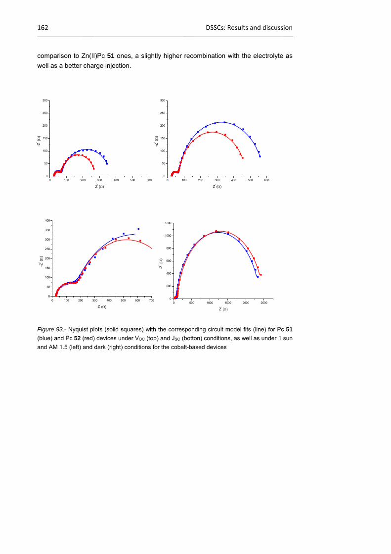
162 DSSCs: Results and discussion
comparison to Zn(II)Pc 51 ones, a slightly higher recombination with the electrolyte as
well as a better charge injection.
Figure 93.- Nyquist plots (solid squares) with the corresponding circuit model fits (line) for Pc 51
(blue) and Pc 52 (red) devices under VOC (top) and JSC (botton) conditions, as well as under 1 sun
and AM 1.5 (left) and dark (right) conditions for the cobalt-based devices
0 100 200 300 400 500 6000
50
100
150
200
250
300
-Z'' (
)
Z' ()
0 100 200 300 400 500 6000
50
100
150
200
250
300
-Z'' (
)
Z' ()
0 100 200 300 400 500 600 7000
50
100
150
200
250
300
350
400
-Z'' (
)
Z' ()0 500 1000 1500 2000 2500
0
200
400
600
800
1000
1200
-Z'' (
)
Z' ()
Chapter 1 163
1.4 Summary and conclusions
Lateral functionalization of conjugated polymers with Pcs have been performed
following two approaches:
- Conjugated polyphenylenevinylene- and polythiophene type copolymers
decorated with Pc molecules (Pc-PPV 38, Pc-PPV 41 and Pc-PT 42) have been
successfully synthesizedd by post-polymerization procedures. Pc-PPV 38 has
been synthesized through esterification of hydroxy Pc 5 and a copolymer
comprising a 10% of CO2H-containing monomers (37), whereas Pc-PPV 41 was
prepared by a “click” 1,3-dipolar cycloaddition reaction between a copolymer
(39) comprising a 10% of terminal alkyne-containing monomers and an azido-
functionalized Pc 7. The latter proved to be more effective than the esterification
reaction and, therefore, the Pc ratio in Pc-PPV 41 was higher (9%) than in Pc-
PPV 38 (7%). “Click” conditions were also applied for the incorporation of Pcs in
a PT skeleton to obtain Pc-PT 42. The Pc-containing polymers were applied in
BHJ solar cells with PCBM. The contribution of the linked Pcs to the photocurrent
was confirmed by EQE. However, solubility of the materials in CB, which use is
compulsory for the solubilization of the PCBM, is not good enough to achieve a
good morphology in the spin-coated film, this fact decreasing the PCE of the
devices with regard to those prepared with the related polymers lacking the
Zn(II)Pc units.
- A conjugated polymer holding electron acceptor Zn(II)Pcs in alternated monomer
units has been prepared, in the search for new polymers with a “double-cable”
architecture, that is, a material in which the donor (polymer) and acceptor (Pc)
components are covalently linked instead of blended. For that purpose, a
conjugated 1:1 PPV copolymer with ca 50% of units containing lateral azide
moieties (44) has been prepared and reacted ethynyl Zn(II)Pc 18, holding
electron-withdrawing alkylsulfonyl groups at the peripheral positions.
Unfortunately, a completely insoluble material was obteined, which make it
impossible to characterize and to use this material for the preparation of devices.
Therefore, the double-cable approach was discarded.
Additionally, polymers containing Pcs in the main chain, in combination with other
high-performing electroactive subunits, have been also envisioned as an approach
towards the preparation of highly-absorbing, active polymers for BHJ devices. For that
purpose, a Pc with good leaving groups in two positions of one isoindole, namely 21,

164 OSCs and DSSCs: Summary and conclusions
has been synthesized and characterized. Then, optimization of coupling conditions for
further co-polymerization with tiophene-containing organometallic species has been
performed. Co-polymerization experiments are currently under study in the group of Prof.
Iain McCulloch at Imperial College
Regarding p-type DSSCs, two new electron accepting Zn(II)Pcs, 51 and 52, have
been synthesized and characterized.Electrochemical measurements address their
electron-acceptor behaviour. These chromophores have been used as photosensitizers
in p-DSSCs based on nanorod-like CuO electrodes, which have been previously
characterized to show their validity as p-type semiconductor. The efficiencies (%) found
were 0.067 and 0.141 for Pc 51, and 0.103 and 0.191 for Pc 52, using iodine or cobalt-
based electrolytes, respectively. The latter values represent the highest ever reported
efficiencies for pure CuO p-type DSSCs. Regarding the dye, it was shown that the
presence of an ethynyl bridge in the dye 52, enhances the electronic coupling between
the Zn(II)Pc dye and the CuO due to an optimum balance between the charge injection
and charge recombination.

Chapter 1 165
1.5 Experimental Section
Unless stated otherwise, all reagents and starting materials were used as
obtained from commercial sources such as SDS, Fluka, Aldrich, Acros Organics and
Merck, without further purification. Most of the solvents employed in this work were
purchased from SDS. Monitoring of the reactions was carried out by thin layer
chromatography (TLC), employing aluminium sheets coated with silica gel 60 F254
(Merck). The purification and isolation of most of the products was performed by column
chromatography using silica gel Merck-60 (230-400 mesh, 0.040-0.063 mm). Size
exclusion chromatography (SEC) was done using swollen Bio-beads S-X1 (200-400
mesh) from Bio-Rad.
Melting points were taken in open-end capillary tubes by using a Büchi 504392-
S apparatus, and are uncorrected. NMR spectra (1H, 13C and 19F) were recorded with a
Bruker AC-300 (300 MHz, 1H) instrument. In each case, the deuterated solvent employed
is indicated in brackets, and its residual peak was used to calibrate the spectra using
literature reference ppm values.376 Infrared spectra were recorded on a Bruker Vector
22 spectrophotometer, in the employing solid samples (KBr pressed disks) or using KBr
plates (films). UV-Vis absorption spectra were collected on a Hewlett-Packard 8453
spectrometer, employing spectroscopic grade solvents, purchased from Fluka Chemie.
The logarithm of the absorption coefficient (, dm3 · cm-1 · mol-1) is indicated in brackets
for each maximum. Mass spectra (MS) were recorded employing Electronic Impact (EI),
Fast Atom Bombardment (FAB-MS) or Matrix Assisted Laser Desorption/Ionization-Time
of Flight (MALDI-TOF), using a VG-AutoSpec spectrometer for EI and FAB-MS and a
Bruker Reflex III spectrometer, with a laser operating at 337 nm, for MALDI-TOF.
Elemental analyses were performed employing a Perkin Elmer 2400 CHNS/O analyzer.
In this Experimental Section, the preparation and characterization of the
compounds has been organised following the order in which they appear in the text.
376 G. R. Fulmer, A. J. M. Miller, N. H. Sherden, H. E. Gottlieb, A. Nudelman, B. M. Stoltz, J. E. Bercaw, K. I. Goldberg, Organometallics 2010, 29, 2176
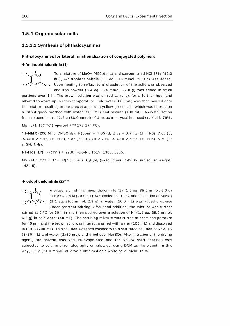
166 OSCs and DSSCs: Experimental Section
1.5.1 Organic solar cells
1.5.1.1 Synthesis of phthalocyanines
Phthalocyanines for lateral functionalization of conjugated polymers
4-Aminophthalonitrile (1)
To a mixture of MeOH (450.0 mL) and concentrated HCl 37% (96.0 mL), 4-nitrophthalonitrile (1.0 eq, 115 mmol, 20.0 g) was added. Upon heating to reflux, total dissolution of the solid was observed and iron powder (3.4 eq, 394 mmol, 22.0 g) was added in small
portions over 1 h. The brown solution was stirred at reflux for a further hour and allowed to warm up to room temperature. Cold water (600 mL) was then poured onto the mixture resulting in the precipitation of a yellow-green solid which was filtered on a fritted glass, washed with water (200 mL) and hexane (100 ml). Recrystallization from toluene led to 12.6 g (88.0 mmol) of 1 as ochre crystalline needles. Yield: 76%.
Mp: 171-173 ºC (reported:164a 172-174 ºC).
1H-NMR (200 MHz, DMSO-d6): (ppm) = 7.65 (d, Jo,5-6 = 8.7 Hz, 1H; H-6), 7.00 (d, Jm,3-5 = 2.5 Hz, 1H; H-3), 6.85 (dd, Jo,5-6 = 8.7 Hz, Jm,3-5 = 2.5 Hz, 1H; H-5), 6.70 (br s, 2H; NH2).
FT-IR (KBr): (cm-1) = 2230 (st CN), 1515, 1380, 1255.
MS (EI): m/z = 143 [M]+ (100%). C8H5N3 (Exact mass: 143.05, molecular weight: 143.15).
4-Iodophthalonitrile (2)164b
A suspension of 4-aminophthalonitrile (1) (1.0 eq, 35.0 mmol, 5.0 g) in H2SO4 2.5 M (70.0 mL) was cooled to -10 ºC and a solution of NaNO2 (1.1 eq, 39.0 mmol, 2.8 g) in water (10.0 mL) was added dropwise under constant stirring. After total addition, the mixture was further
stirred at 0 ºC for 30 min and then poured over a solution of KI (1.1 eq, 39.0 mmol, 6.5 g) in cold water (40 mL). The resulting mixture was stirred at room temperature for 45 min and the brown solid was filtered, washed with water (100 mL) and dissolved in CHCl3 (200 mL). This solution was then washed with a saturated solution of Na2S2O3 (3x30 mL) and water (2x30 mL), and dried over Na2SO4. After filtration of the drying agent, the solvent was vacuum-evaporated and the yellow solid obtained was subjected to column chromatography on silica gel using DCM as the eluent. In this way, 6.1 g (24.0 mmol) of 2 were obtained as a white solid. Yield: 69%.

Chapter 1 167
Mp: 142-143 ºC (reported:164b 142-143 ºC). 1H-NMR (300 MHz, CDCl3): (ppm) = 8.17 (d, Jm,3-5 = 1.6 Hz, 1H; H-3), 8.12 (dd, Jo,5-6 = 8.2 Hz, Jm,3-5 = 1.6 Hz, 1H; H-5), 7.49 (d, Jo,5-6 = 8.6 Hz, 1H; H-6).
13C-NMR (75.5 MHz, CDCl3): (ppm) = 142.6 (C-5), 142.1 (C-3), 133.9 (C-6), 116.7 (2C; CN), 114.9 (C-2), 113.5 (C-1), 99.6 (C-4).
FT-IR (KBr): (cm-1) = 2241 (st CN), 1585, 940, 852.
MS (EI): m/z = 254 [M]+ (84%), 127 [M-I]+ (100%). C8H3IN2 (Exact mass: 253.93, molecular weight: 254.03).
4-(4’-Hydroxymethyl)phenylphthalonitrile (3)
To a solution of 4-iodophthalonitrile (2) (1.0 eq, 3.93 mmol, 1.00 g) in dry THF (40.0 mL), Pd(PPh3)4 (10% mol, 0.39 mmol, 0.46 g) was added. After stirring the reaction mixture under argon for 20 min, K2CO3 (1.0 eq, 3.93 mmol, 0.54 g), 4-(hydroxymethyl)phenylboronic acid
(1.0 eq, 3.93 mmol, 0.60 g) and water (10.0 mL) were added. The mixture was refluxed for 24 h, then cooled to room temperature and the THF evaporated. The suspended solid in water was filtered through a fritted glass funnel and washed with more water (50 mL) and hexane (70 mL). The residue was dissolved in THF and dried over anhydrous Na2SO4. After removing the solvent under reduced pressure, the crude product was purified by column chromatography in silica gel (hexane/THF, 2:1) to give compound 3 (0.74 g, 3.2 mmol) as a white solid. Yield: 80%.
Mp: 129-130 ºC (reported:165 129-130 ºC).
1H-NMR (300 MHz, CDCl3): (ppm) = 8.00 (d, Jm,3-5 = 1.8 Hz, 1H; H-3), 7.93 (dd, Jo,5-6 = 8.6 Hz, Jm,3-5 = 1.8 Hz, 1H; H-5), 7.87 (d, Jo,5-6 = 8.6 Hz, 1H; H-6), 7.59 (d, Jo,2’-3’ = 8.2 Hz, 2H; H-2’, H-6’), 7.53 (d, Jo = 8.2 Hz, 2H; H-3’, H-5’), 4.80 (s, 2H; ArCH2OH), 1.80 (br s, 1H, ArCH2OH).
13C-NMR (75.5 MHz, CDCl3): (ppm) = 146.3 (C-4), 142.9 (C-4’), 136.3 (C-1’), 134.1 (C-6), 132.0 (C-5), 131.5 (C-3), 128.0 (C-3’, C-5’), 127.5 (C-2’, C-6’), 116.7 (C-2), 115.6 (CN), 115.5 (CN), 114.8 (C-1), 64.7 (CH2OH).
FT-IR (KBr): (cm-1) = 3354 (st O-H), 3105, 3072, 3047, 2231 (st CN), 1567, 1382, 1163, 1099, 852, 747.
MS (EI): m/z = 235 [M+H]+ (2%), 234 [M]+ (11%), 233 [M-H]+ (5%), 218 M1 [M-OH]+ (100%). C15H10N2O (Exact mass: 234.08, molecular weight: 234.26).
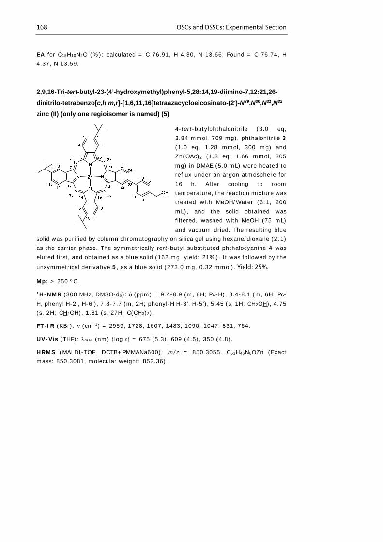
168 OSCs and DSSCs: Experimental Section
EA for C15H10N2O (%): calculated = C 76.91, H 4.30, N 13.66. Found = C 76.74, H 4.37, N 13.59.
2,9,16-Tri-tert-butyl-23-(4’-hydroxymethyl)phenyl-5,28:14,19-diimino-7,12:21,26-
dinitrilo-tetrabenzo[c,h,m,r]-[1,6,11,16]tetraazacycloeicosinato-(2-)-N29,N30,N31,N32
zinc (II) (only one regioisomer is named) (5)
4-tert-butylphthalonitrile (3.0 eq, 3.84 mmol, 709 mg), phthalonitrile 3 (1.0 eq, 1.28 mmol, 300 mg) and Zn(OAc)2 (1.3 eq, 1.66 mmol, 305 mg) in DMAE (5.0 mL) were heated to reflux under an argon atmosphere for 16 h. After cooling to room temperature, the reaction mixture was treated with MeOH/Water (3:1, 200 mL), and the solid obtained was filtered, washed with MeOH (75 mL) and vacuum dried. The resulting blue
solid was purified by column chromatography on silica gel using hexane/dioxane (2:1) as the carrier phase. The symmetrically tert-butyl substituted phthalocyanine 4 was eluted first, and obtained as a blue solid (162 mg, yield: 21%). It was followed by the
unsymmetrical derivative 5, as a blue solid (273.0 mg, 0.32 mmol). Yield: 25%.
Mp: > 250 ºC.
1H-NMR (300 MHz, DMSO-d6): (ppm) = 9.4-8.9 (m, 8H; Pc-H), 8.4-8.1 (m, 6H; Pc-H, phenyl H-2’, H-6’), 7.8-7.7 (m, 2H; phenyl-H H-3’, H-5’), 5.45 (s, 1H; CH2OH), 4.75 (s, 2H; CH2OH), 1.81 (s, 27H; C(CH3)3).
FT-IR (KBr): (cm-1) = 2959, 1728, 1607, 1483, 1090, 1047, 831, 764.
UV-Vis (THF): max (nm) (log ) = 675 (5.3), 609 (4.5), 350 (4.8).
HRMS (MALDI-TOF, DCTB+PMMANa600): m/z = 850.3055. C51H46N8OZn (Exact mass: 850.3081, molecular weight: 852.36).
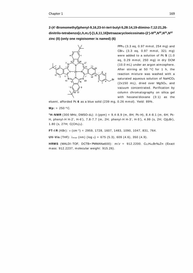
Chapter 1 169
2-(4’-Bromomethyl)phenyl-9,16,23-tri-tert-butyl-5,28:14,19-diimino-7,12:21,26-
dinitrilo-tetrabenzo[c,h,m,r]-[1,6,11,16]tetraazacycloeicosinato-(2-)-N29,N30,N31,N32
zinc (II) (only one regioisomer is named) (6)
PPh3 (3.3 eq, 0.97 mmol, 254 mg) and CBr4 (3.3 eq, 0.97 mmol, 321 mg) were added to a solution of Pc 5 (1.0 eq, 0.29 mmol, 250 mg) in dry DCM (10.0 mL) under an argon atmosphere. After stirring at 50 ºC for 1 h, the reaction mixture was washed with a saturated aqueous solution of NaHCO3
(2x150 mL), dried over MgSO4, and vacuum concentrated. Purification by column chromatography on silica gel with hexane/dioxane (3:1) as the
eluent, afforded Pc 6 as a blue solid (239 mg, 0.26 mmol). Yield: 89%.
Mp: > 250 ºC.
1H-NMR (300 MHz, DMSO-d6): (ppm) = 9.4-8.9 (m, 8H; Pc-H), 8.4-8.1 (m, 6H; Pc-H, phenyl-H H-2’, H-6’), 7.8-7.7 (m, 2H; phenyl-H H-3’, H-5’), 4.99 (s, 2H; CH2Br), 1.80 (s, 27H; C(CH3)3).
FT-IR (KBr): (cm-1) = 2959, 1728, 1607, 1483, 1090, 1047, 831, 764.
UV-Vis (THF): max (nm) (log ) = 675 (5.3), 609 (4.6), 350 (4.9).
HRMS (MALDI-TOF, DCTB+PMMANa600): m/z = 912.2200. C51H45BrN8Zn (Exact mass: 912.2237, molecular weight: 915.26).
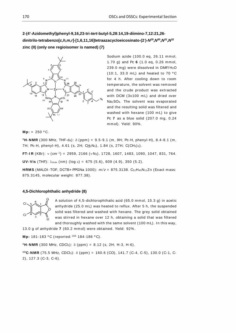
170 OSCs and DSSCs: Experimental Section
2-(4’-Azidomethyl)phenyl-9,16,23-tri-tert-butyl-5,28:14,19-diimino-7,12:21,26-
dinitrilo-tetrabenzo[c,h,m,r]-[1,6,11,16]tetraazacycloeicosinato-(2-)-N29,N30,N31,N32
zinc (II) (only one regioisomer is named) (7)
Sodium azide (100.0 eq, 26.11 mmol, 1.70 g) and Pc 6 (1.0 eq, 0.26 mmol, 239.0 mg) were dissolved in DMF/H2O (10:1, 33.0 mL) and heated to 70 ºC for 4 h. After cooling down to room temperature, the solvent was removed and the crude product was extracted with DCM (3x100 mL) and dried over Na2SO4. The solvent was evaporated and the resulting solid was filtered and washed with hexane (100 mL) to give Pc 7 as a blue solid (207.0 mg, 0.24 mmol). Yield: 90%.
Mp: > 250 ºC.
1H-NMR (300 MHz, THF-d8): (ppm) = 9.5-9.1 (m, 9H; Pc-H, phenyl-H), 8.4-8.1 (m, 7H; Pc-H, phenyl-H), 4.61 (s, 2H; CH2N3), 1.84 (s, 27H; C(CH3)3).
FT-IR (KBr): (cm-1) = 2959, 2166 ( N3), 1728, 1607, 1483, 1090, 1047, 831, 764.
UV-Vis (THF): max (nm) (log ) = 675 (5.6), 609 (4.9), 350 (5.2).
HRMS (MALDI-TOF, DCTB+PPGNa 1000): m/z = 875.3138. C51H45N11Zn (Exact mass: 875.3145, molecular weight: 877.38).
4,5-Dichlorophthalic anhydride (8)
A solution of 4,5-dichlorophthalic acid (65.0 mmol, 15.3 g) in acetic anhydride (25.0 mL) was heated to reflux. After 5 h, the suspended solid was filtered and washed with hexane. The grey solid obtained was stirred in hexane over 12 h, obtaining a solid that was filtered and thoroughly washed with the same solvent (100 mL). In this way,
13.0 g of anhydride 7 (60.2 mmol) were obtained. Yield: 92%.
Mp: 181-183 ºC (reported:166 184-186 ºC).
1H-NMR (300 MHz, CDCl3): (ppm) = 8.12 (s, 2H; H-3, H-6).
13C-NMR (75.5 MHz, CDCl3): (ppm) = 160.6 (CO), 141.7 (C-4, C-5), 130.0 (C-1, C-2), 127.3 (C-3, C-6).
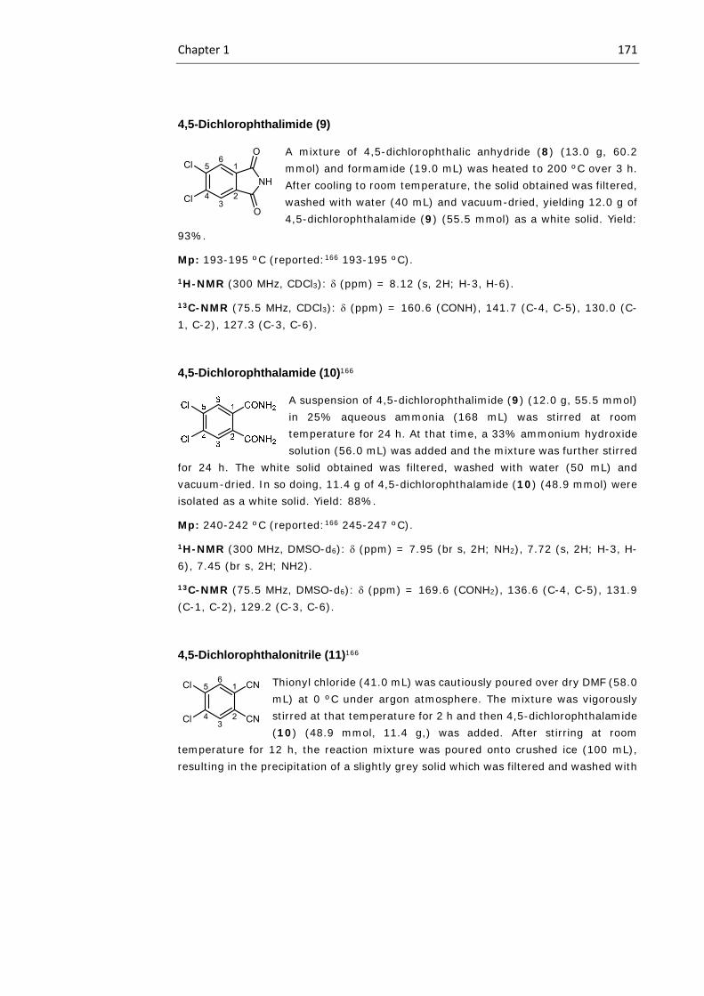
Chapter 1 171
4,5-Dichlorophthalimide (9)
A mixture of 4,5-dichlorophthalic anhydride (8) (13.0 g, 60.2 mmol) and formamide (19.0 mL) was heated to 200 ºC over 3 h. After cooling to room temperature, the solid obtained was filtered, washed with water (40 mL) and vacuum-dried, yielding 12.0 g of 4,5-dichlorophthalamide (9) (55.5 mmol) as a white solid. Yield:
93%.
Mp: 193-195 ºC (reported:166 193-195 ºC).
1H-NMR (300 MHz, CDCl3): (ppm) = 8.12 (s, 2H; H-3, H-6).
13C-NMR (75.5 MHz, CDCl3): (ppm) = 160.6 (CONH), 141.7 (C-4, C-5), 130.0 (C-1, C-2), 127.3 (C-3, C-6).
4,5-Dichlorophthalamide (10)166
A suspension of 4,5-dichlorophthalimide (9) (12.0 g, 55.5 mmol) in 25% aqueous ammonia (168 mL) was stirred at room temperature for 24 h. At that time, a 33% ammonium hydroxide solution (56.0 mL) was added and the mixture was further stirred
for 24 h. The white solid obtained was filtered, washed with water (50 mL) and vacuum-dried. In so doing, 11.4 g of 4,5-dichlorophthalamide (10) (48.9 mmol) were isolated as a white solid. Yield: 88%.
Mp: 240-242 ºC (reported:166 245-247 ºC).
1H-NMR (300 MHz, DMSO-d6): (ppm) = 7.95 (br s, 2H; NH2), 7.72 (s, 2H; H-3, H-6), 7.45 (br s, 2H; NH2).
13C-NMR (75.5 MHz, DMSO-d6): (ppm) = 169.6 (CONH2), 136.6 (C-4, C-5), 131.9 (C-1, C-2), 129.2 (C-3, C-6).
4,5-Dichlorophthalonitrile (11)166
Thionyl chloride (41.0 mL) was cautiously poured over dry DMF (58.0 mL) at 0 ºC under argon atmosphere. The mixture was vigorously stirred at that temperature for 2 h and then 4,5-dichlorophthalamide (10) (48.9 mmol, 11.4 g,) was added. After stirring at room
temperature for 12 h, the reaction mixture was poured onto crushed ice (100 mL), resulting in the precipitation of a slightly grey solid which was filtered and washed with
Cl
Cl3
56
1
24
NH
O
O
Cl
Cl3
56
1
24
CN
CN

172 OSCs and DSSCs: Experimental Section
water (20 mL). Upon recrystallization from methanol, 8.4 g (42.5 mmol) of compound 11 were obtained. Yield: 87%.
Mp: 180-183 ºC (reported:166 182-184 ºC).
1H-NMR (300 MHz, CDCl3): (ppm) = 7.94 (s, 2H; H-3, H-6).
13C-NMR (75.5 MHz, CDCl3): (ppm) = 138.2 (C-4, C-5), 135.7 (C-3, C-6), 115.0, 114.6, 114.0 (C-1, C-2, CN).
MS (EI): m/z = 196 [M]+ (100%). C8H2Cl2N2 (Exact Mass: 195.96, molecular weight: 197.02).
4,5-Bis(2-ethylhexylthio)phthalonitrile (12)
A solution of 4,5-dichlorophthalonitrile (11) (1.0 eq, 1.27 mmol, 0.25 g,) in freshly distilled DMAC (5 mL) was heated to 100ºC, and oven-dry K2CO3 (9.7 eq, 12.3 mmol 1.7 g) was added in five portions over 30 min. Then, 2-ethylhexane-1-thiol (2.4 eq, 3.1 mmol, 0.53 mL) was added, and the resulting mixture was
stirred at 100 ºC for 10h. It was then allowed to reach room temperature, poured in water (15 mL) and extracted with DCM (3x15 mL). Combined organic layers were dried over MgSO4 and evaporated. The residue was purified by column chromatography (SiO2, hexane/DCM 1:1) to give 12 (0.42 g, 1.02 mmol) as a yellowish oil. Yield: 80%.
1H-NMR (300 MHz, CDCl3): (ppm) = 7.41 (s, 2H; H-3, H-6), 2.97 (m, 4H; SCH2), 1.71 (m, 2H; SCH2CH), 1.4-1.3 (m, 16H; SCH2CH (CH2)CH2CH2CH2CH3), 0.94 (m, 12H; CH3).
13C-NMR (75.5 MHz, CDCl3): (ppm) = 145.0 (C-4, C-5), 128.4 (C-3, C-6), 115.9 (CN), 111.01(C-1, C-2), 38.7 (SCH2), 37.4 (SCH2CH), 32.7 (SCH2CHCH2), 28.9 (SCH2CHCH2CH2), 26.0 (SCH2CHCH2CH3), 23.1 (SCH2CHCH2CH2CH2CH3), 14.2 (CH3), 10.9 (CH3).
MS (MALDI-TOF, TCNQ): m/z = 417.3 [M+H]+ (100%). C24H36N2S2 (Exact mass: 416.23, molecular weight: 416.69).
EA for C24H36N2S2 (%): calculated = C 69.18, H 8.71, N 6.72, S, 15.39. Found = C 69.64, H 8.81, N 6.68, S 15.28.
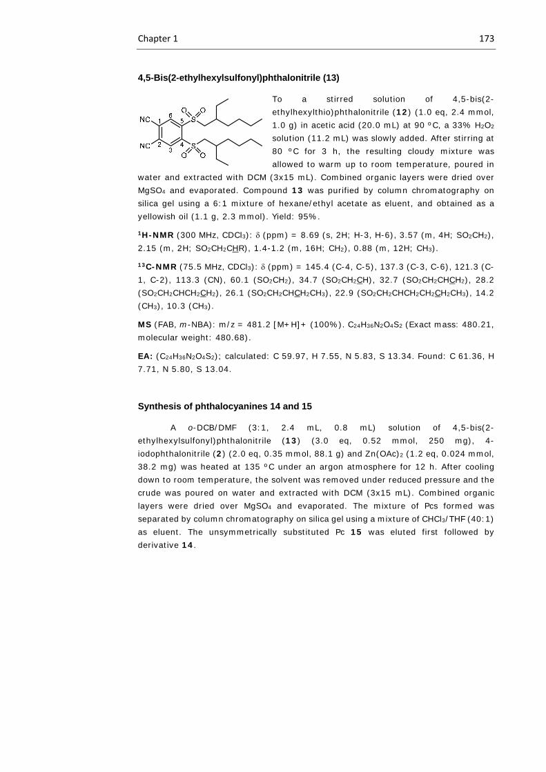
Chapter 1 173
4,5-Bis(2-ethylhexylsulfonyl)phthalonitrile (13)
To a stirred solution of 4,5-bis(2-ethylhexylthio)phthalonitrile (12) (1.0 eq, 2.4 mmol, 1.0 g) in acetic acid (20.0 mL) at 90 ºC, a 33% H2O2 solution (11.2 mL) was slowly added. After stirring at 80 ºC for 3 h, the resulting cloudy mixture was allowed to warm up to room temperature, poured in
water and extracted with DCM (3x15 mL). Combined organic layers were dried over MgSO4 and evaporated. Compound 13 was purified by column chromatography on silica gel using a 6:1 mixture of hexane/ethyl acetate as eluent, and obtained as a yellowish oil (1.1 g, 2.3 mmol). Yield: 95%.
1H-NMR (300 MHz, CDCl3): (ppm) = 8.69 (s, 2H; H-3, H-6), 3.57 (m, 4H; SO2CH2), 2.15 (m, 2H; SO2CH2CHR), 1.4-1.2 (m, 16H; CH2), 0.88 (m, 12H; CH3).
13C-NMR (75.5 MHz, CDCl3): (ppm) = 145.4 (C-4, C-5), 137.3 (C-3, C-6), 121.3 (C-1, C-2), 113.3 (CN), 60.1 (SO2CH2), 34.7 (SO2CH2CH), 32.7 (SO2CH2CHCH2), 28.2 (SO2CH2CHCH2CH2), 26.1 (SO2CH2CHCH2CH3), 22.9 (SO2CH2CHCH2CH2CH2CH3), 14.2 (CH3), 10.3 (CH3).
MS (FAB, m-NBA): m/z = 481.2 [M+H]+ (100%). C24H36N2O4S2 (Exact mass: 480.21, molecular weight: 480.68).
EA: (C24H36N2O4S2); calculated: C 59.97, H 7.55, N 5.83, S 13.34. Found: C 61.36, H 7.71, N 5.80, S 13.04.
Synthesis of phthalocyanines 14 and 15
A o-DCB/DMF (3:1, 2.4 mL, 0.8 mL) solution of 4,5-bis(2-ethylhexylsulfonyl)phthalonitrile (13) (3.0 eq, 0.52 mmol, 250 mg), 4-iodophthalonitrile (2) (2.0 eq, 0.35 mmol, 88.1 g) and Zn(OAc)2 (1.2 eq, 0.024 mmol, 38.2 mg) was heated at 135 ºC under an argon atmosphere for 12 h. After cooling down to room temperature, the solvent was removed under reduced pressure and the crude was poured on water and extracted with DCM (3x15 mL). Combined organic layers were dried over MgSO4 and evaporated. The mixture of Pcs formed was separated by column chromatography on silica gel using a mixture of CHCl3/THF (40:1) as eluent. The unsymmetrically substituted Pc 15 was eluted first followed by derivative 14.
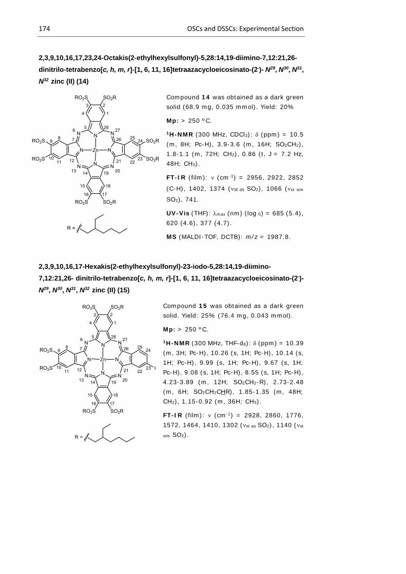
174 OSCs and DSSCs: Experimental Section
2,3,9,10,16,17,23,24-Octakis(2-ethylhexylsulfonyl)-5,28:14,19-diimino-7,12:21,26-
dinitrilo-tetrabenzo[c, h, m, r]-[1, 6, 11, 16]tetraazacycloeicosinato-(2-)- N29, N30, N31,
N32 zinc (II) (14)
Compound 14 was obtained as a dark green solid (68.9 mg, 0.035 mmol). Yield: 20%
Mp: > 250 ºC.
1H-NMR (300 MHz, CDCl3): (ppm) = 10.5 (m, 8H; Pc-H), 3.9-3.6 (m, 16H; SO2CH2), 1.8-1.1 (m, 72H; CH2), 0.86 (t, J = 7.2 Hz, 48H; CH3).
FT-IR (film): (cm-1) = 2956, 2922, 2852
(C-H), 1402, 1374 (st as SO2), 1066 (st sim SO2), 741.
UV-Vis (THF): max (nm) (log ) = 685 (5.4), 620 (4.6), 377 (4.7).
MS (MALDI-TOF, DCTB): m/z = 1987.8.
2,3,9,10,16,17-Hexakis(2-ethylhexylsulfonyl)-23-iodo-5,28:14,19-diimino-
7,12:21,26- dinitrilo-tetrabenzo[c, h, m, r]-[1, 6, 11, 16]tetraazacycloeicosinato-(2-)-
N29, N30, N31, N32 zinc (II) (15)
Compound 15 was obtained as a dark green solid. Yield: 25% (76.4 mg, 0.043 mmol).
Mp: > 250 ºC.
1H-NMR (300 MHz, THF-d8): (ppm) = 10.39 (m, 3H; Pc-H), 10.26 (s, 1H; Pc-H), 10.14 (s, 1H; Pc-H), 9.99 (s, 1H; Pc-H), 9.67 (s, 1H; Pc-H), 9.08 (s, 1H; Pc-H), 8.55 (s, 1H; Pc-H), 4.23-3.89 (m, 12H; SO2CH2-R), 2.73-2.48 (m, 6H; SO2CH2CHR), 1.85-1.35 (m, 48H; CH2), 1.15-0.92 (m, 36H; CH3).
FT-IR (film): (cm-1) = 2928, 2860, 1776, 1572, 1464, 1410, 1302 (st as SO2), 1140 (st
sim SO2).
N
NN
N
N
NN N
Zn
1
3
4
SO2R
2
56
78RO2S 9
1011 12
13 14
15
RO2S
16 17
18
19 20
21 2223
242526
2728
RO2S
SO2R
I
RO2S
R =
N
NN
N
N
NN N
Zn
1
3
4
SO2R
2
56
78RO2S 9
1011 12
13 14
15
RO2S
16 17
18
19 20
21 2223
242526
2728
RO2S
SO2R
SO2R
RO2S
R =
SO2R
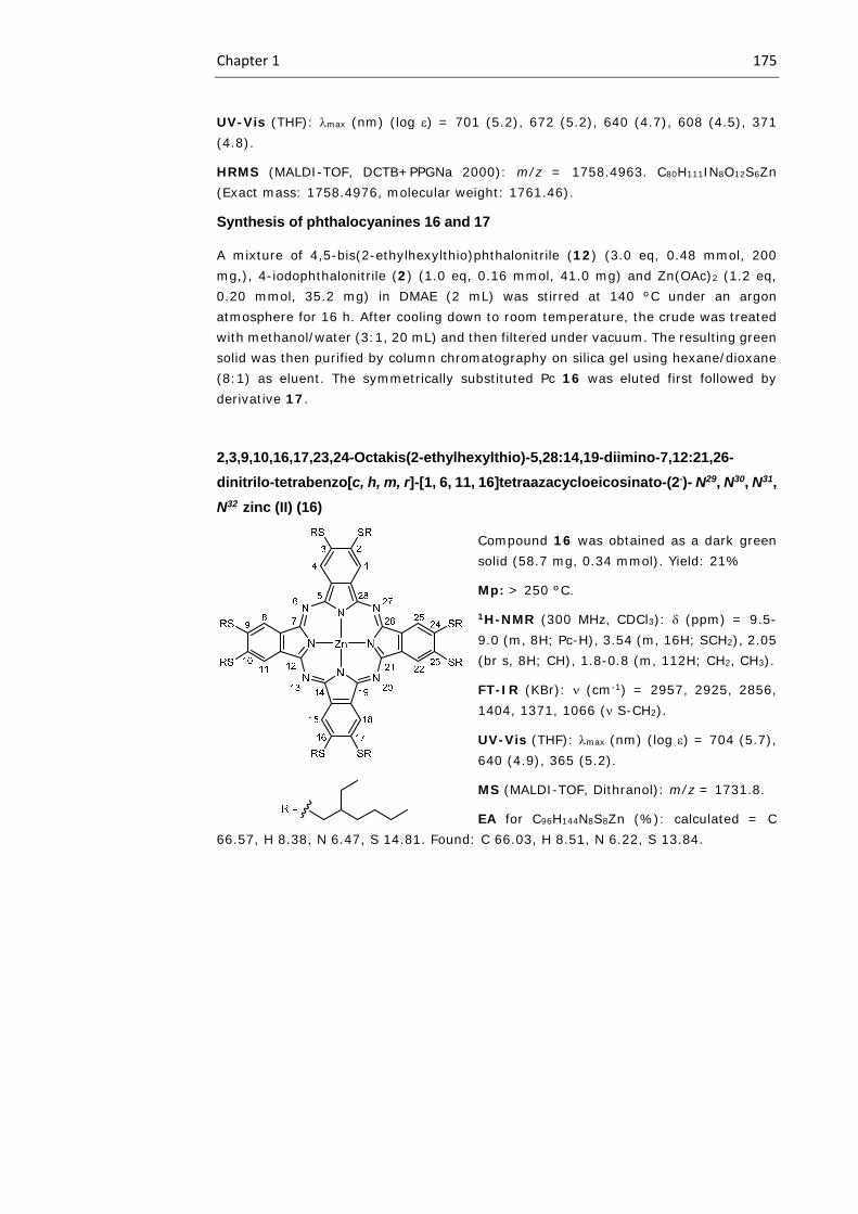
Chapter 1 175
UV-Vis (THF): max (nm) (log ) = 701 (5.2), 672 (5.2), 640 (4.7), 608 (4.5), 371 (4.8).
HRMS (MALDI-TOF, DCTB+PPGNa 2000): m/z = 1758.4963. C80H111IN8O12S6Zn (Exact mass: 1758.4976, molecular weight: 1761.46).
Synthesis of phthalocyanines 16 and 17
A mixture of 4,5-bis(2-ethylhexylthio)phthalonitrile (12) (3.0 eq, 0.48 mmol, 200 mg,), 4-iodophthalonitrile (2) (1.0 eq, 0.16 mmol, 41.0 mg) and Zn(OAc)2 (1.2 eq, 0.20 mmol, 35.2 mg) in DMAE (2 mL) was stirred at 140 ºC under an argon atmosphere for 16 h. After cooling down to room temperature, the crude was treated with methanol/water (3:1, 20 mL) and then filtered under vacuum. The resulting green solid was then purified by column chromatography on silica gel using hexane/dioxane (8:1) as eluent. The symmetrically substituted Pc 16 was eluted first followed by derivative 17.
2,3,9,10,16,17,23,24-Octakis(2-ethylhexylthio)-5,28:14,19-diimino-7,12:21,26-
dinitrilo-tetrabenzo[c, h, m, r]-[1, 6, 11, 16]tetraazacycloeicosinato-(2-)- N29, N30, N31,
N32 zinc (II) (16)
Compound 16 was obtained as a dark green solid (58.7 mg, 0.34 mmol). Yield: 21%
Mp: > 250 ºC.
1H-NMR (300 MHz, CDCl3): (ppm) = 9.5-9.0 (m, 8H; Pc-H), 3.54 (m, 16H; SCH2), 2.05 (br s, 8H; CH), 1.8-0.8 (m, 112H; CH2, CH3).
FT-IR (KBr): (cm-1) = 2957, 2925, 2856, 1404, 1371, 1066 ( S-CH2).
UV-Vis (THF): max (nm) (log ) = 704 (5.7), 640 (4.9), 365 (5.2).
MS (MALDI-TOF, Dithranol): m/z = 1731.8.
EA for C96H144N8S8Zn (%): calculated = C 66.57, H 8.38, N 6.47, S 14.81. Found: C 66.03, H 8.51, N 6.22, S 13.84.

176 OSCs and DSSCs: Experimental Section
2,3,9,10,16,17-Hexakis(2-ethylhexylthio)-23-iodo-5,28:14,19-diimino-7,12:21,26-
dinitrilo-tetrabenzo[c, h, m, r]-[1, 6, 11, 16]tetraazacycloeicosinato-(2-)- N29, N30, N31,
N32 zinc (II) (17)
Compound 17 was obtained as a dark green solid. (40.5 mg, 0.026 mmol). Yield: 16%
Mp: > 250 ºC.
1H-NMR (300 MHz, CDCl3): (ppm) = 8.66 (m, 4H; Pc-H), 8.40 (m, 2H; Pc-H), 8.03 (m, 3H; Pc-H), 3.61 (m, 12H; SCH2), 1.90-0.91 (m, 90H; CH, CH2, CH3).
FT-IR (KBr): (cm-1) = 2960, 2871, 1308, 1143 ( S-CH2).
UV-Vis (THF): max (nm) (log ) = 697 (5.5), 672 (5.4), 643 (4.4), 611 (4.3), 375 (4.5).
MS (MALDI-TOF, Dithranol): m/z = 1762.5.
EA for C80H111IN8S6Zn (%): calculated = C 61.22, H 7.13, N 7.14, S 12.26. Found: C 60.87, H 7.23, N 6.89, S 11.86.
2,3,9,10,16,17-Hexakis(2-ethylhexylsulfonyl)-23-ethynyl-5,28:14,19-diimino-
7,12:21,26- dinitrilo-tetrabenzo[c, h, m, r]-[1, 6, 11, 16]tetraazacycloeicosinato-(2-)-
N29, N30, N31, N32 zinc (II) (18)
Pc 15 (1.0 eq, 0.044 mmol, 77.2 mg), Pd(PPh3)2Cl2 (0.009 mmol, 6.2 mg) and CuI (0.018 mmol, 3.4 mg) were dissolved in a mixture of freshly distilled and deoxygenated NEt3 (5 mL) and dry THF (5 mL), under an argon atmosphere. To this stirred solution, ethynyltrimethylsilane (1.5 eq, 0.066 mmol, 6.2 mg, 0.009 mL,) was added and the reaction was allowed to proceed at 90 ºC during 20 h. After that time, the solvent was removed under vacuum and the green solid obtained was dissolved in DCM (50 mL), washed with water (3 x 30 mL) and dried over Na2SO4.
N
NN
N
N
NN N
Zn
1
3
4
SR
2
56
78RS 9
1011 12
13 14
15
RS
16 17
18
19 20
21 2223
242526
2728
RS
SR
I
RS
R =
N
NN
N
N
NN N
Zn
1
3
4
SO2R
2
56
78RO2S 9
1011 12
13 14
15
RO2S
16 17
18
19 20
21 2223
242526
2728
RO2S
SO2R
RO2S
R =
H
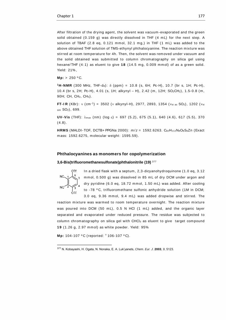
Chapter 1 177
After filtration of the drying agent, the solvent was vacuum-evaporated and the green solid obtained (0.159 g) was directly dissolved in THF (4 mL) for the next step. A solution of TBAF (2.8 eq, 0.121 mmol, 32.1 mg,) in THF (1 mL) was added to the above obtained THF solution of TMS-ethynyl phthalocyanine. The reaction mixture was stirred at room temperature for 4h. Then, the solvent was removed under vacuum and the solid obtained was submitted to column chromatography on silica gel using hexane/THF (4:1) as eluent to give 18 (14.5 mg, 0.009 mmol) of as a green solid. Yield: 21%,
Mp: > 250 ºC.
1H-NMR (300 MHz, THF-d8): (ppm) = 10.8 (s, 6H; Pc-H), 10.7 (br s, 1H; Pc-H), 10.4 (br s, 2H; Pc-H), 4.01 (s, 1H; alkynyl – H), 2.42 (m, 12H; SO2CH2), 1.5-0.8 (m, 90H; CH, CH2, CH3).
FT-IR (KBr): (cm-1) = 3502 ( alkynyl-H), 2977, 2893, 1354 (st as SO2), 1202 (st
sim SO2), 699.
UV-Vis (THF): max (nm) (log ) = 697 (5.2), 675 (5.1), 640 (4.6), 617 (5.5), 370 (4.8).
HRMS (MALDI-TOF, DCTB+PPGNa 2000): m/z = 1592.6263. C82H112N8O8S6Zn (Exact mass: 1592.6275, molecular weight: 1595.59).
Phthalocyanines as monomers for copolymerization
3,6-Bis(trifluoromethanesulfonate)phthalonitrile (19) 377
In a dried flask with a septum, 2,3-dicyanohydroquinone (1.0 eq, 3.12
mmol, 0.500 g) was dissolved in 85 mL of dry DCM under argon and
dry pyridine (6.0 eq, 18.72 mmol, 1.50 mL) was added. After cooling
to -78 ºC, trifluoromethane sulfonic anhydride solution (1M in DCM;
3.0 eq, 9.36 mmol, 9.4 mL) was added dropwise and stirred. The
reaction mixture was warmed to room temperature overnight. The reaction mixture
was poured into DCM (50 mL), 0.5 N HCl (1 mL) added, and the organic layer
separated and evaporated under reduced pressure. The residue was subjected to
column chromatography on silica gel with CHCl3 as eluent to give target compound
19 (1.26 g, 2.97 mmol) as white powder. Yield: 95%
Mp: 104-107 ºC (reported: ? 106-107 ºC).
377 N. Kobayashi, H. Ogata, N. Nonaka, E. A. Luk’yanets, Chem. Eur. J. 2003, 9, 5123.
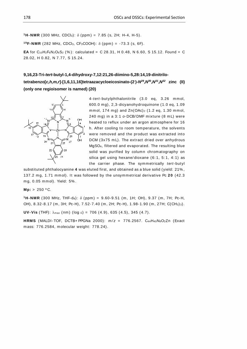
178 OSCs and DSSCs: Experimental Section
1H-NMR (300 MHz, CDCl3): (ppm) = 7.85 (s, 2H; H-4, H-5).
19F-NMR (282 MHz, CDCl3, CF3COOH): (ppm) = -73.3 (s, 6F).
EA for C10H2F6N2O6S2 (%): calculated = C 28.31, H 0.48, N 6.60, S 15.12. Found = C 28.02, H 0.82, N 7.77, S 15.24.
9,16,23-Tri-tert-butyl-1,4-dihydroxy-7,12:21,26-diimino-5,28:14,19-dinitrilo-
tetrabenzo[c,h,m,r]-[1,6,11,16]tetraazacycloeicosinato-(2-)-N29,N30,N31,N32 zinc (II)
(only one regioisomer is named) (20)
4-tert-butylphthalonitrile (3.0 eq, 3.26 mmol, 600.0 mg), 2,3-dicyanohydroquinone (1.0 eq, 1.09 mmol, 174 mg) and Zn(OAc)2 (1.2 eq, 1.30 mmol, 240 mg) in a 3:1 o-DCB/DMF mixture (8 mL) were heated to reflux under an argon atmosphere for 16 h. After cooling to room temperature, the solvents were removed and the product was extracted into DCM (3x75 mL). The extract dried over anhydrous MgSO4, filtered and evaporated. The resulting blue solid was purified by column chromatography on silica gel using hexane/dioxane (6:1, 5:1, 4:1) as the carrier phase. The symmetrically tert-butyl
substituted phthalocyanine 4 was eluted first, and obtained as a blue solid (yield: 21%, 137.2 mg, 1.71 mmol). It was followed by the unsymmetrical derivative Pc 20 (42.3 mg, 0.05 mmol). Yield: 5%.
Mp: > 250 ºC.
1H-NMR (300 MHz, THF-d8): (ppm) = 9.60-9.51 (m, 1H; OH), 9.37 (m, 7H; Pc-H, OH), 8.32-8.17 (m, 3H; Pc-H), 7.52-7.40 (m, 2H; Pc-H), 1.98-1.90 (m, 27H; C(CH3)3).
UV-Vis (THF): max (nm) (log ) = 706 (4.9), 635 (4.5), 345 (4.7).
HRMS (MALDI-TOF, DCTB+PPGNa 2000): m/z = 776.2567. C44H40N8O2Zn (Exact mass: 776.2584, molecular weight: 778.24).

Chapter 1 179
9,16,23-Tri-tert-butyl-1,4-bis(trifluoromethanesulfonate)-7,12:21,26-diimino-
5,28:14,19-dinitrilo-tetrabenzo[c,h,m,r]-[1,6,11,16]tetraazacycloeicosinato-(2-)-
N29,N30,N31,N32 zinc (II) (only one regioisomer is named) (21)
In a dried flask with a septum, Pc 20 (1.0 eq, 0.13 mmol, 100 mg) was dissolved in 2.0 mL of dry DCM under argon, and dry pyridine (6.0 eq, 0.77 mmol, 0.062 mL) was added. After cooling to -78 ºC, trifluoromethane sulfonic anhydride solution (1M in DCM; 3.0 eq, 0.385 mmol, 0.385 mL) was added dropwise. The reaction mixture was warmed to room temperature and stirred overnight. Then, it was poured into DCM (50 mL), 0.5 N HCl (0.1 mL) added, and the organic layer separated and evaporated under reduced pressure. The resulting blue solid was purified by column chromatography
on silica gel using hexane/dioxane (4:1) as the carrier phase. The Pc 21 was obtained as a blue solid (87.1 mg, 0.084 mmol). Yield: 65%.
Mp: > 250 ºC.
1H-NMR (300 MHz, THF-d8): (ppm) = 9.58-9.50 (m, 1H; Pc-H), 9.36-8.89 (m, 5H; Pc-H), 8.41-8.16 (m, 3H; Pc-H), 7.98-7.94 (m, 2H; Pc-H), 1.94-1.88 (m, 27H; C(CH3)3).
19F-NMR (282 MHz, THF-d8, CF3COOH): (ppm) = -73.7 (s, 6F).
UV-Vis (THF): max (nm) (log ) =688 (4.9), 654 (4.8) 593 (4.3), 354 (4.6).
HRMS (MALDI-TOF, DCTB+PPGNa 1000): m/z = 1040.1531. C46H38F6N8O6S2Zn (Exact mass: 1040.1546, molecular weight: 1042.35).
3,6-Dimethoxyphthalonitrile (22)
To a stirred solution of 2,3-dicyanohydroquinone (1.0 eq, 3.12 mmol, 0.50 g) in 2-butanone (15 mL), was added oven-dry potassium carbonate (9.0 eq, 28.1 mmol, 3.80 g). After stirring for 15min at room temperature, dimethyl sulphate (8.0 eq, 25.0 mmol, 2.4 mL) was added. The reaction mixture was refluxed for 18h, cooled to room temperature and the solid was filtered. Recrystallization from acetic acid
gave 22 (0.582 g, 3.09 mmol) as a white solid. Yield: 99%.
Mp: 271-273 ºC (reported: 273-274 ºC).

180 OSCs and DSSCs: Experimental Section
1H-NMR (300 MHz, CDCl3): (ppm) = 7.18 (s, 2H; H-4, H-5), 3.93 (s, 6H; CH3)
13C-NMR (75.5 MHz, CDCl3): (ppm) = 160.6 (C-3, C-6), 118.1 (C-4, C-5), 112.8 (CN), 105.3 (C-1, C-2), 53.5 (OCH3).
MS (EI): m/z = 188 [M]+ (100%). C10H8N2O2 (Exact mass: 188.06, molecular weight: 188.19).
3,6-Bis(4’-methylbenzenesulfonate)phthalonitrile (23)378
2,3-dicyanohydroquinone (1.0 eq, 3.1 mmol, 0.50 g), K2CO3 (4.2 eq, 13.1 mmol, 1.81 g), and tosyl chloride (2.3 eq, 7.13 mmol, 1.36 g) were dissolved in 5 mL of acetone and the mixture was stirred under reflux for 2 h. Then the mixture was poured into water (10 mL) and stirred for 1 h. The residue was filtered, washed with water and dried. The title compound was obtained as a pale brown powder (1.17 g, 2.50
mmol). Yield: 80%
1H-NMR (300 MHz, CDCl3): (ppm) = 7.81 (d, J = 8.0 Hz, 4H; tosyl-H), 7.78 (s, 2H; H-4, H-5), 7.39 (d, J = 8.0 Hz, 4H; tosyl-H) 2.48 (s, 6H; CH3)
13C-NMR (75.5 MHz, CDCl3): (ppm) = 149.0, 147.4, 130.7, 130.5, 129.4, 128.8, 112.1, 110.6, 21.9 (CH3).
FT-IR (KBr): (cm-1) = 3432, 3239, 3085, 2243, 2226 (st CN), 1504, 1449, 1315, 1279, 1204, 1174, 1142, 1021, 1004, 979, 934, 847, 749, 694, 638, 614.
9,16,23-Tri-tert-butyl-1,4-bis(4’-methylbenzenesulfonate)-7,12:21,26-diimino-
5,28:14,19-dinitrilo-tetrabenzo[c,h,m,r]-[1,6,11,16]tetraazacycloeicosinato-(2-)-
N29,N30,N31,N32 zinc (II) (only one regioisomer is named) (25)
4-tert-butylphthalonitrile (3.0 eq, 2.71 mmol, 500 mg), phthalonitrile 23 (1.0 eq, 0.90 mmol, 424 mg) and Zn(OAc)2 (1.2 eq, 1.08 mmol, 199.2 mg) in a 3:1 o-DCB/DMF mixture (8.0 mL) were heated to reflux under an argon atmosphere for 16 h. After cooling to room temperature, the solvents were removed and the product was extracted into DCM (3x75 mL). The extract dried over anhydrous MgSO4, filtered and evaporated. The resulting green solid was purified by column chromatography on silica gel using hexane/dioxane (4:1) as the carrier phase. Pc 25 was obtained as a green solid (78.6 mg, 0.072 mmol). Yield: 8%.
378 G. Mbambisa, P. Tau, E. Antunes, T. Nyokong, Polyhedron 2007, 26, 5355.
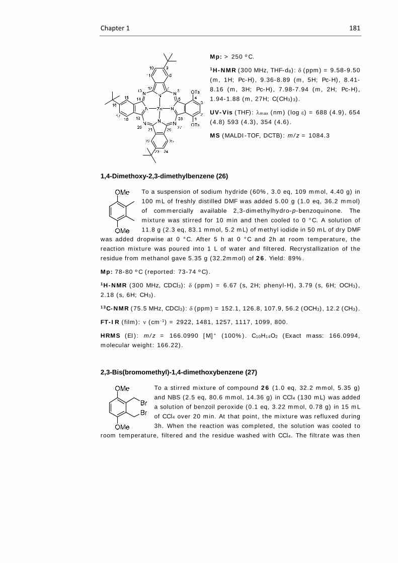
Chapter 1 181
Mp: > 250 ºC.
1H-NMR (300 MHz, THF-d8): (ppm) = 9.58-9.50 (m, 1H; Pc-H), 9.36-8.89 (m, 5H; Pc-H), 8.41-8.16 (m, 3H; Pc-H), 7.98-7.94 (m, 2H; Pc-H), 1.94-1.88 (m, 27H; C(CH3)3).
UV-Vis (THF): max (nm) (log ) = 688 (4.9), 654 (4.8) 593 (4.3), 354 (4.6).
MS (MALDI-TOF, DCTB): m/z = 1084.3
1,4-Dimethoxy-2,3-dimethylbenzene (26)
To a suspension of sodium hydride (60%, 3.0 eq, 109 mmol, 4.40 g) in 100 mL of freshly distilled DMF was added 5.00 g (1.0 eq, 36.2 mmol) of commercially available 2,3-dimethylhydro-p-benzoquinone. The mixture was stirred for 10 min and then cooled to 0 °C. A solution of 11.8 g (2.3 eq, 83.1 mmol, 5.2 mL) of methyl iodide in 50 mL of dry DMF
was added dropwise at 0 °C. After 5 h at 0 °C and 2h at room temperature, the reaction mixture was poured into 1 L of water and filtered. Recrystallization of the residue from methanol gave 5.35 g (32.2mmol) of 26. Yield: 89%. Mp: 78-80 ºC (reported: 73-74 ºC).
1H-NMR (300 MHz, CDCl3): (ppm) = 6.67 (s, 2H; phenyl-H), 3.79 (s, 6H; OCH3), 2.18 (s, 6H; CH3).
13C-NMR (75.5 MHz, CDCl3): (ppm) = 152.1, 126.8, 107.9, 56.2 (OCH3), 12.2 (CH3).
FT-IR (film): (cm-1) = 2922, 1481, 1257, 1117, 1099, 800.
HRMS (EI): m/z = 166.0990 [M]+ (100%). C10H14O2 (Exact mass: 166.0994, molecular weight: 166.22).
2,3-Bis(bromomethyl)-1,4-dimethoxybenzene (27)
To a stirred mixture of compound 26 (1.0 eq, 32.2 mmol, 5.35 g) and NBS (2.5 eq, 80.6 mmol, 14.36 g) in CCl4 (130 mL) was added a solution of benzoil peroxide (0.1 eq, 3.22 mmol, 0.78 g) in 15 mL of CCl4 over 20 min. At that point, the mixture was refluxed during 3h. When the reaction was completed, the solution was cooled to
room temperature, filtered and the residue washed with CCl4. The filtrate was then
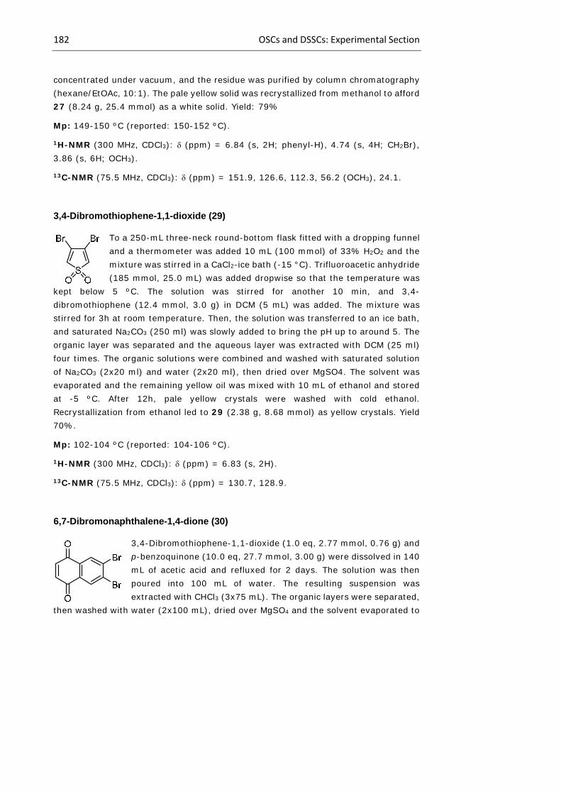
182 OSCs and DSSCs: Experimental Section
concentrated under vacuum, and the residue was purified by column chromatography (hexane/EtOAc, 10:1). The pale yellow solid was recrystallized from methanol to afford 27 (8.24 g, 25.4 mmol) as a white solid. Yield: 79%
Mp: 149-150 ºC (reported: 150-152 ºC).
1H-NMR (300 MHz, CDCl3): (ppm) = 6.84 (s, 2H; phenyl-H), 4.74 (s, 4H; CH2Br), 3.86 (s, 6H; OCH3).
13C-NMR (75.5 MHz, CDCl3): (ppm) = 151.9, 126.6, 112.3, 56.2 (OCH3), 24.1.
3,4-Dibromothiophene-1,1-dioxide (29)
To a 250-mL three-neck round-bottom flask fitted with a dropping funnel and a thermometer was added 10 mL (100 mmol) of 33% H2O2 and the mixture was stirred in a CaCl2-ice bath (-15 °C). Trifluoroacetic anhydride (185 mmol, 25.0 mL) was added dropwise so that the temperature was
kept below 5 ºC. The solution was stirred for another 10 min, and 3,4-dibromothiophene (12.4 mmol, 3.0 g) in DCM (5 mL) was added. The mixture was stirred for 3h at room temperature. Then, the solution was transferred to an ice bath, and saturated Na2CO3 (250 ml) was slowly added to bring the pH up to around 5. The organic layer was separated and the aqueous layer was extracted with DCM (25 ml) four times. The organic solutions were combined and washed with saturated solution of Na2CO3 (2x20 ml) and water (2x20 ml), then dried over MgSO4. The solvent was evaporated and the remaining yellow oil was mixed with 10 mL of ethanol and stored at -5 ºC. After 12h, pale yellow crystals were washed with cold ethanol. Recrystallization from ethanol led to 29 (2.38 g, 8.68 mmol) as yellow crystals. Yield 70%.
Mp: 102-104 ºC (reported: 104-106 ºC).
1H-NMR (300 MHz, CDCl3): (ppm) = 6.83 (s, 2H).
13C-NMR (75.5 MHz, CDCl3): (ppm) = 130.7, 128.9.
6,7-Dibromonaphthalene-1,4-dione (30)
3,4-Dibromothiophene-1,1-dioxide (1.0 eq, 2.77 mmol, 0.76 g) and p-benzoquinone (10.0 eq, 27.7 mmol, 3.00 g) were dissolved in 140 mL of acetic acid and refluxed for 2 days. The solution was then poured into 100 mL of water. The resulting suspension was extracted with CHCl3 (3x75 mL). The organic layers were separated,
then washed with water (2x100 mL), dried over MgSO4 and the solvent evaporated to

Chapter 1 183
obtain the crude product. The product was purified by column chromatography on silica gel (hexane:DCM, 1:1) and recrystallized from ethanol to yield and ivory solid (0.44 g, 1.39 mmol). Yield: 50%
Mp: 171-173 ºC (reported: 171-172 ºC).
1H-NMR (300 MHz, CDCl3): (ppm) = 8.30 (s, 2H), 6.99 (s, 2H)
13C-NMR (75.5 MHz, CDCl3): (ppm) = 183.4 (C=O), 138.8, 132.1, 131.9, 131.2.
FT-IR (film): (cm-1) = 2249, 1655 (st C=O).
MS (EI): m/z = 315 [M+H]+ (100%). C10H4Br2O2 (Exact mass: 313.86, molecular weight: 315.95).
6,7-Dibromo-1,4-dimethoxynaphthalene (31)
To a suspension naphthoquinone 30 (1.0 eq, 0.95 mmol, 300.0 mg) in AcOEt (1.8 mL), Et2O (18.0 mL), and water (18.0 mL) at room temperature was added Na2S2O4 (5.0 eq, 4.75 mmol, 998.0 mg) and the reaction mixture was stirred vigorously for 3h. Upon consumption of starting material (TLC, heptane:DCM), the biphasic
reaction mixture was extracted with AcOEt (3x40 mL), the combined organic layers washed with brine (30 mL), dried (MgSO4), and concentrated. The resulting oil was then dissolved in dry DMF (9 mL) and cooled to -15 ºC. 80.0 mg of sodium hydride (2.1 eq, 3.32 mmol) were added portionwise to the reaction mixture, and then MeI (2.2 eq, 2.08 mmol, 0.09 mL), was added dropwise over 5 min, and the reaction mixture was stirred at -15 ºC for 1h. The reaction mixture was then quenched with sat. aqueous NH4Cl (20 mL) and the biphasic reaction mixture was extracted with AcOEt (3x20 mL), and the combined organic layers washed with brine (40 mL), dried (MgSO4), and concentrated. Flash column chromatography (silica gel, heptane:DCM, 10:1) gave methyl-protected hydronaphtoquinone 31 as an off-white solid. The product was washed with MeOH to afford a white solid (246.4 mg, 0.71 mmol). Yield: 75%.
1H-NMR (300 MHz, CDCl3): (ppm) = 8.46 (s, 2H), 6.69 (s, 2H), 3.93 (s, 6H, OCH3).
13C-NMR (75.5 MHz, CDCl3): (ppm) = 148.5, 127.1, 126.1, 122.4, 104.6, 55.9 (OCH3).

184 OSCs and DSSCs: Experimental Section
5,8-Dimethoxynaphthalene-2,3-dicarbonitrile (32)
In a Schlenk tube under argon, compound 31 (1.0 eq, 0.751 mmol, 260 mg), Pd(PPh3)4 (33% mol, 0.248 mmol, 287 mg) and zinc(II) cyanide (2.0 eq, 1.502 mmol, 177 mg) were introduced. Freshly distilled DMF (8.0 mL) was added and the mixture was deaerated over 30min. After that, the mixture was stirred at 120 ºC during
12h. After this time, concentrated ammonia was added (50 mL), and the solid residues were filtered, dried, and directly purified by column chromatography of silica gel using hexane:DCM 2:1 as eluent, affording 32 (144 mg 0.601 mmol) as a yellow solid. Yied: 80%
Mp: 240-242 ºC.
1H-NMR (300 MHz, CDCl3): (ppm) = 8.59 (s, 2H), 6.98 (s, 2H), 3.99 (s, 6H, OCH3).
13C-NMR (75.5 MHz, CDCl3): (ppm) = 149.1, 130.5, 125.8, 116.4, 109.7, 108.9, 56.2 (OCH3).
MS (GC-EI): m/z = 238.7 [M]+ (13%), 223.05 [M-CH3]+ (100%). C14H10N2O2 (Exact mass: 238.07, molecular weight: 238.25).
11,18,25-Tri-tert-butyl-2,5-dimethoxy-9,14:23,28-diimino-7,30:16,21-dinitrilo-
tribenzo[h,m,r]-naphtho[c]-[1,6,11,16]tetraazacycloeicosinato-(2-)-N29,N30,N31,N32
zinc (II) (only one regioisomer is named) (33)
4-tert-butylphthalonitrile (3.0 eq, 1.76 mmol, 325 mg), compound 32 (1.0 eq, 0.59 mmol, 140 mg) and Zn(OAc)2 (1.2 eq, 0.71 mmol, 130 mg) in DMAE (5.0 mL) and drops of DBU, were heated to reflux under an argon atmosphere for 16 h. After cooling to room temperature, the solvents were removed and the product was extracted into DCM (3x100 mL). The extract dried over anhydrous MgSO4, filtered and evaporated. The resulting blue solid was purified by column chromatography on silica gel using hexane/dioxane (4:1) as the
carrier phase. The symmetrically tert-butyl substituted phthalocyanine 4 was eluted first, and obtained as a green solid (yield: 25%, 88.5 mg, 0.11 mmol). It was followed by the unsymmetrical derivative Pc 33 (104.2 mg, 0.12 mmol). Yield: 21%.
Mp: > 250 ºC.
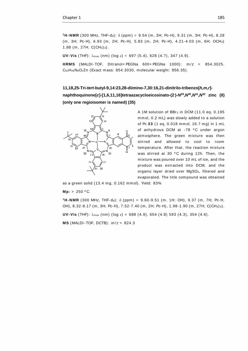
Chapter 1 185
1H-NMR (300 MHz, THF-d8): (ppm) = 9.54 (m, 3H; Pc-H), 9.31 (m, 3H; Pc-H), 8.28 (m, 3H; Pc-H), 6.93 (m, 2H; Pc-H), 5.83 (m, 2H; Pc-H), 4.21-4.03 (m, 6H; OCH3) 1.88 (m, 27H; C(CH3)3).
UV-Vis (THF): max (nm) (log ) = 697 (5.4), 628 (4.7), 347 (4.9).
HRMS (MALDI-TOF, Ditranol+PEGNa 600+PEGNa 1000): m/z = 854.3025. C50H46N8O2Zn (Exact mass: 854.3030, molecular weight: 856.35).
11,18,25-Tri-tert-butyl-9,14:23,28-diimino-7,30:16,21-dinitrilo-tribenzo[h,m,r]-
naphthoquinone[c]-[1,6,11,16]tetraazacycloeicosinato-(2-)-N29,N30,N31,N32 zinc (II)
(only one regioisomer is named) (35)
A 1M solution of BBr3 in DCM (11.0 eq, 0.195 mmol, 0.2 mL) was slowly added to a solution of Pc 33 (1 eq, 0.018 mmol, 16.7 mg) in 1 mL of anhydrous DCM at -78 ºC under argon atmosphere. The green mixture was then stirred and allowed to cool to room temperature. After that, the reaction mixture was stirred at 30 ºC during 12h. Then, the mixture was poured over 10 mL of ice, and the product was extracted into DCM, and the organic layer dried over MgSO4, filtered and evaporated. The title compound was obtained
as a green solid (13.4 mg, 0.162 mmol). Yield: 83%
Mp: > 250 ºC.
1H-NMR (300 MHz, THF-d8): (ppm) = 9.60-9.51 (m, 1H; OH), 9.37 (m, 7H; Pc-H, OH), 8.32-8.17 (m, 3H; Pc-H), 7.52-7.40 (m, 2H; Pc-H), 1.98-1.90 (m, 27H; C(CH3)3).
UV-Vis (THF): max (nm) (log ) = 688 (4.9), 654 (4.8) 593 (4.3), 354 (4.6).
MS (MALDI-TOF, DCTB): m/z = 824.3
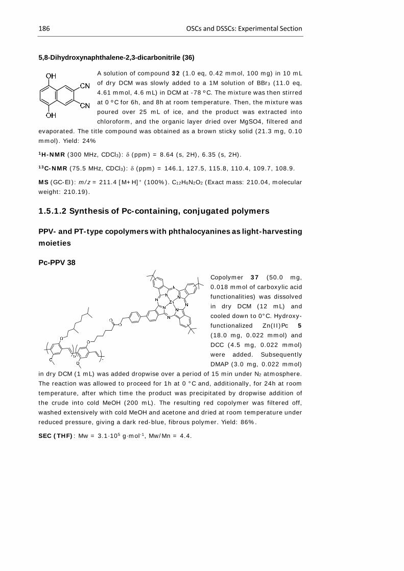
186 OSCs and DSSCs: Experimental Section
5,8-Dihydroxynaphthalene-2,3-dicarbonitrile (36)
A solution of compound 32 (1.0 eq, 0.42 mmol, 100 mg) in 10 mL of dry DCM was slowly added to a 1M solution of BBr3 (11.0 eq, 4.61 mmol, 4.6 mL) in DCM at -78 ºC. The mixture was then stirred at 0 ºC for 6h, and 8h at room temperature. Then, the mixture was poured over 25 mL of ice, and the product was extracted into chloroform, and the organic layer dried over MgSO4, filtered and
evaporated. The title compound was obtained as a brown sticky solid (21.3 mg, 0.10 mmol). Yield: 24%
1H-NMR (300 MHz, CDCl3): (ppm) = 8.64 (s, 2H), 6.35 (s, 2H).
13C-NMR (75.5 MHz, CDCl3): (ppm) = 146.1, 127.5, 115.8, 110.4, 109.7, 108.9.
MS (GC-EI): m/z = 211.4 [M+H]+ (100%). C12H6N2O2 (Exact mass: 210.04, molecular weight: 210.19).
1.5.1.2 Synthesis of Pc-containing, conjugated polymers
PPV- and PT-type copolymers with phthalocyanines as light-harvesting moieties
Pc-PPV 38
Copolymer 37 (50.0 mg, 0.018 mmol of carboxylic acid functionalities) was dissolved in dry DCM (12 mL) and cooled down to 0°C. Hydroxy-functionalized Zn(II)Pc 5 (18.0 mg, 0.022 mmol) and DCC (4.5 mg, 0.022 mmol) were added. Subsequently DMAP (3.0 mg, 0.022 mmol)
in dry DCM (1 mL) was added dropwise over a period of 15 min under N2 atmosphere. The reaction was allowed to proceed for 1h at 0 °C and, additionally, for 24h at room temperature, after which time the product was precipitated by dropwise addition of the crude into cold MeOH (200 mL). The resulting red copolymer was filtered off, washed extensively with cold MeOH and acetone and dried at room temperature under reduced pressure, giving a dark red-blue, fibrous polymer. Yield: 86%.
SEC (THF): Mw = 3.1·105 g·mol-1, Mw/Mn = 4.4.

Chapter 1 187
1H-NMR (300 MHz, THF-d8): (ppm) = 9.6–9.4 (Pc-H), 8.30 (Pc-H), 8.13 (Pc-H), 8.00 (Pc-H), 7.90 (Pc-H), 7.6–7.4 (PPV), 7.3–7.1 (PPV), 5.28 (Pc-CH2O), 4.1–3.8, 2.4–2.3, 1.8-0.7.
UV-Vis (THF): max (nm) = 676, 510 (0.28/1 absorption ratio).
FT-IR: (cm-1) = 3058, 2953, 2926, 2868, 1733 (st C=O), 1503, 1464, 1413, 1384, 1351, 1256, 1204 (as C–O–C), 1092 (s C–O–C), 1038, 968, 920, 860, 801.
Pc-PPV 41
Alkynyl-PPV 39 (50 mg) was dissolved before adding Zn(II)Pc 7 (0.036 mmol, 31.0 mg), distilled PMDETA (0.0017 mmol, 0.3 mg) and CuBr (0.0020 mmol, 0.3 mg). After purification, PPV-Pc 41 (60 mg) was isolated.
GPC (THF): Mw = 3.1·105 g·mol-1, Mw/Mn = 4.0
1H-NMR (300 MHz, THF-d8): (ppm) = 9.58–9.38, 8.30, 8.11, 7.90, 7.55– 7.4, 7.3–7.1, 5.70, 5.21, 4.1–3.8, 2.4–2.3 and 1.8–0.7.
FT-IR: (cm-1) = 3058, 2959, 2927, 2869, 1737, 1504, 1464, 1414, 1385, 1351,
1260, 1205, 1027, 970, 862 and 800.
UV-Vis: max (THF, nm) = 676, 509, 352; max (CB, nm) = 691, 510, 358; max (thin
film, nm) = 692, 494.
Pc-PT 42
Alkynyk-PT 40 (60 mg) was dissolved, and Pc 7 (0.070 mmol, 61 mg), PMDETA (0.0035 mmol, 0.6 mg) and CuBr (0.0035 mmol, 0.5 mg) were subsequently added. After purification, Pc-PT 42 (36 mg) was isolated.
GPC (THF): Iw = 58 600 g·mol-1, Mw/Mn = 1.8
1H-NMR (300 MHz, THF-d8): (ppm) = 8.14, 7.97, 7.76, 7.44, 7.35, 6.96, 6.89, 6.83, 6.79, 5.60, 5.06, 2.80, 2.67, 2.40, 2.04, 1.91, 1.77, 1.34, 1.27, 0.91.
FT-IR: (cm-1) = 2957, 2927, 2856, 1739, 1644, 1511, 1487, 1456, 1390, 1363, 1331, 1261, 1231, 1186, 1152, 1092, 1048, 1024, 920, 820, 800, 748.
UV-Vis: max (THF, nm) = 677, 459, 352; max (CB, nm) = 691, 458, 358; max (thin
film, drop-cast from THF, nm) = 694, 564; max (thin film, drop-cast from CB, nm) =
692, 523.
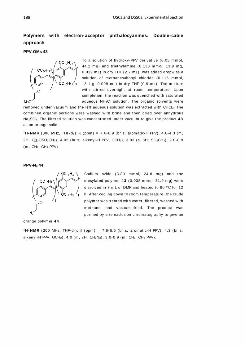
188 OSCs and DSSCs: Experimental Section
Polymers with electron-acceptor phthalocyanines: Double-cable approach
PPV-OMs 43
To a solution of hydroxy-PPV derivative (0.05 mmol, 44.2 mg) and triethylamine (0.138 mmol, 13.9 mg, 0.019 mL) in dry THF (2.7 mL), was added dropwise a solution of methanesulfonyl chloride (0.115 mmol, 13.1 g, 0.009 mL) in dry THF (0.9 mL). The mixture with stirred overnight at room temperature. Upon completion, the reaction was quenched with saturated aqueous NH4Cl solution. The organic solvents were
removed under vacuum and the left aqueous solution was extracted with CHCl3. The combined organic portions were washed with brine and then dried over anhydrous Na2SO4. The filtered solution was concentrated under vacuum to give the product 43 as an orange solid.
1H-NMR (300 MHz, THF-d8): (ppm) = 7.6-6.9 (br s; aromatic-H PPV), 4.6-4.3 (m,
2H; CH2OSO2CH3), 4.05 (br s; alkenyl-H PPV, OCH2), 3.03 (s, 3H; SO2CH3), 2.0-0.9
(m; CH2, CH3 PPV).
PPV-N3 44
Sodium azide (3.80 mmol, 24.8 mg) and the
mesylated polymer 43 (0.038 mmol, 31.0 mg) were
dissolved in 7 mL of DMF and heated to 90 ºC for 12
h. After cooling down to room temperature, the crude
polymer was treated with water, filtered, washed with
methanol and vacuum-dried. The product was
purified by size exclusion chromatography to give an
orange polymer 44.
1H-NMR (300 MHz, THF-d8): (ppm) = 7.6-6.6 (br s; aromatic-H PPV), 4.3 (br s;
alkenyl-H PPV, OCH2), 4.0 (m, 2H; CH2N3), 3.0-0.9 (m; CH2, CH3 PPV).

Chapter 1 189
Main-chain Pc-copolymers: Testing copolymerization conditions
9,16,23-Tri-tert-butyl-1,4-di(thiophen-2-yl)-7,12:21,26-diimino-5,28:14,19-dinitrilo-
tetrabenzo[c,h,m,r]-[1,6,11,16]tetraazacycloeicosinato-(2-)-N29,N30,N31,N32 zinc (II)
(only one regioisomer is named) (43)
In a Schlenk tube under argon were introduced Pc
21 (1.0 eq, 0.029 mmol, 30.0 mg), Pd(PPh3)4 (20%
mol, 0.015 mmol, 13.3 mg), and LiCl (6.0 eq, 0.172
mmol, 7.3 mg). Dry dioxane (1.0 mL) and 2-
(tributylstannyl)thiophene (2.5 eq, 0.072 mmol,
0.023 mL) were added and the reaction mixture was
stirred at 110 ºC during 8h. After cooling to room
temperature, the solvents were removed and the
product was extracted into DCM (3x50 mL). The
extract dried over anhydrous MgSO4, filtered and
evaporated. The resulting blue solid was purified by
column chromatography on silica gel using hexane/dioxane (4:1) as the carrier phase.
The target compound 43 was obtained as a blue solid (16.8 mg, 0.018 mmol). Yield:
64%,
Mp: > 250 ºC.
1H-NMR (300 MHz, THF-d8): (ppm) = 9.53-9.30 (m, 4H), 9.07 (m, 1H), 8.95-8.91 (m, 1H), 8.48-8.15 (m, 7H), 7.93 (m, 2H), 7.72-7.65 (m, 2H), 1.81-1.70 (m, 27H; C(CH3)3 ,
UV-Vis (THF): max (nm) (log ) = 684 (4.9), 613 (4.3), 348 (4.6).
MS (MALDI-TOF, DCTB): m/z = 908.3
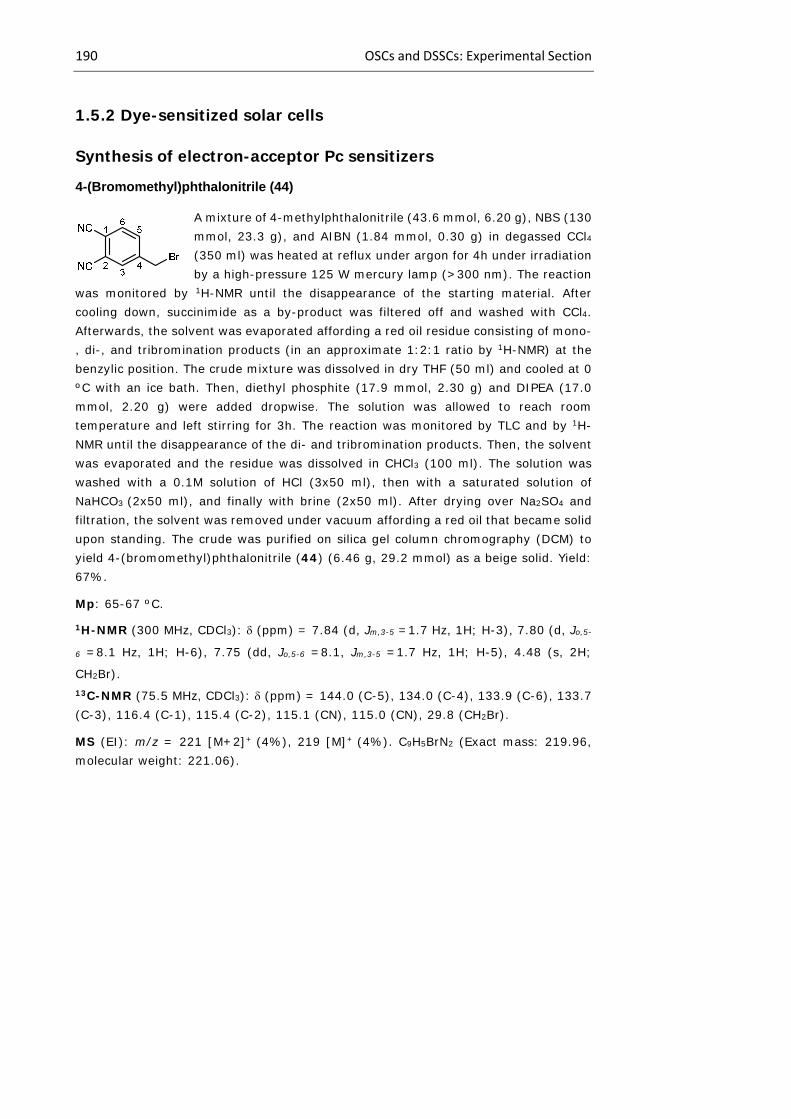
190 OSCs and DSSCs: Experimental Section
1.5.2 Dye-sensitized solar cells
Synthesis of electron-acceptor Pc sensitizers
4-(Bromomethyl)phthalonitrile (44)
A mixture of 4-methylphthalonitrile (43.6 mmol, 6.20 g), NBS (130 mmol, 23.3 g), and AIBN (1.84 mmol, 0.30 g) in degassed CCl4 (350 ml) was heated at reflux under argon for 4h under irradiation by a high-pressure 125 W mercury lamp (>300 nm). The reaction
was monitored by 1H-NMR until the disappearance of the starting material. After cooling down, succinimide as a by-product was filtered off and washed with CCl4. Afterwards, the solvent was evaporated affording a red oil residue consisting of mono-, di-, and tribromination products (in an approximate 1:2:1 ratio by 1H-NMR) at the benzylic position. The crude mixture was dissolved in dry THF (50 ml) and cooled at 0 ºC with an ice bath. Then, diethyl phosphite (17.9 mmol, 2.30 g) and DIPEA (17.0 mmol, 2.20 g) were added dropwise. The solution was allowed to reach room temperature and left stirring for 3h. The reaction was monitored by TLC and by 1H-NMR until the disappearance of the di- and tribromination products. Then, the solvent was evaporated and the residue was dissolved in CHCl3 (100 ml). The solution was washed with a 0.1M solution of HCl (3x50 ml), then with a saturated solution of NaHCO3 (2x50 ml), and finally with brine (2x50 ml). After drying over Na2SO4 and filtration, the solvent was removed under vacuum affording a red oil that became solid upon standing. The crude was purified on silica gel column chromography (DCM) to yield 4-(bromomethyl)phthalonitrile (44) (6.46 g, 29.2 mmol) as a beige solid. Yield: 67%.
Mp: 65-67 ºC.
1H-NMR (300 MHz, CDCl3): (ppm) = 7.84 (d, Jm,3-5 =1.7 Hz, 1H; H-3), 7.80 (d, Jo,5-
6 =8.1 Hz, 1H; H-6), 7.75 (dd, Jo,5-6 =8.1, Jm,3-5 =1.7 Hz, 1H; H-5), 4.48 (s, 2H;
CH2Br). 13C-NMR (75.5 MHz, CDCl3): (ppm) = 144.0 (C-5), 134.0 (C-4), 133.9 (C-6), 133.7 (C-3), 116.4 (C-1), 115.4 (C-2), 115.1 (CN), 115.0 (CN), 29.8 (CH2Br).
MS (EI): m/z = 221 [M+2]+ (4%), 219 [M]+ (4%). C9H5BrN2 (Exact mass: 219.96, molecular weight: 221.06).
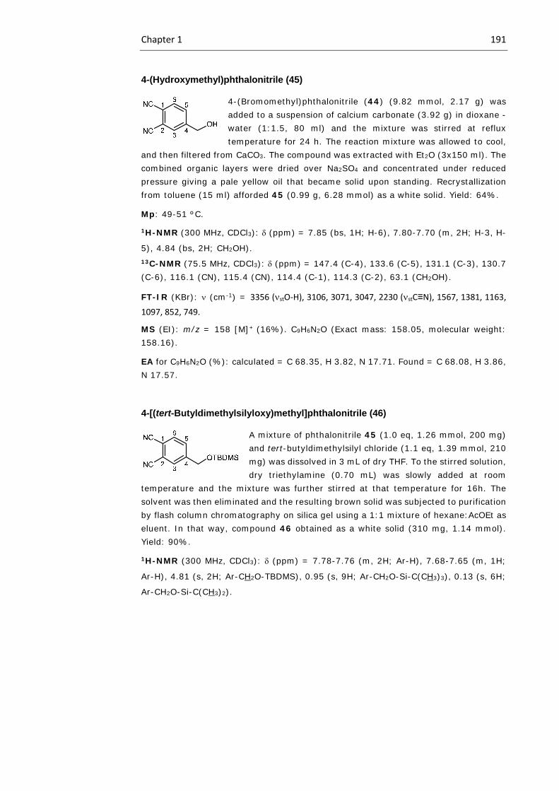
Chapter 1 191
4-(Hydroxymethyl)phthalonitrile (45)
4-(Bromomethyl)phthalonitrile (44) (9.82 mmol, 2.17 g) was added to a suspension of calcium carbonate (3.92 g) in dioxane - water (1:1.5, 80 ml) and the mixture was stirred at reflux temperature for 24 h. The reaction mixture was allowed to cool,
and then filtered from CaCO3. The compound was extracted with Et2O (3x150 ml). The combined organic layers were dried over Na2SO4 and concentrated under reduced pressure giving a pale yellow oil that became solid upon standing. Recrystallization from toluene (15 ml) afforded 45 (0.99 g, 6.28 mmol) as a white solid. Yield: 64%.
Mp: 49-51 ºC.
1H-NMR (300 MHz, CDCl3): (ppm) = 7.85 (bs, 1H; H-6), 7.80-7.70 (m, 2H; H-3, H-
5), 4.84 (bs, 2H; CH2OH). 13C-NMR (75.5 MHz, CDCl3): (ppm) = 147.4 (C-4), 133.6 (C-5), 131.1 (C-3), 130.7 (C-6), 116.1 (CN), 115.4 (CN), 114.4 (C-1), 114.3 (C-2), 63.1 (CH2OH).
FT-IR (KBr): (cm-1) = 3356 (stO‐H), 3106, 3071, 3047, 2230 (stC≡N), 1567, 1381, 1163,
1097, 852, 749.
MS (EI): m/z = 158 [M]+ (16%). C9H6N2O (Exact mass: 158.05, molecular weight: 158.16).
EA for C9H6N2O (%): calculated = C 68.35, H 3.82, N 17.71. Found = C 68.08, H 3.86, N 17.57.
4-[(tert-Butyldimethylsilyloxy)methyl]phthalonitrile (46)
A mixture of phthalonitrile 45 (1.0 eq, 1.26 mmol, 200 mg) and tert-butyldimethylsilyl chloride (1.1 eq, 1.39 mmol, 210 mg) was dissolved in 3 mL of dry THF. To the stirred solution, dry triethylamine (0.70 mL) was slowly added at room
temperature and the mixture was further stirred at that temperature for 16h. The solvent was then eliminated and the resulting brown solid was subjected to purification by flash column chromatography on silica gel using a 1:1 mixture of hexane:AcOEt as eluent. In that way, compound 46 obtained as a white solid (310 mg, 1.14 mmol). Yield: 90%.
1H-NMR (300 MHz, CDCl3): (ppm) = 7.78-7.76 (m, 2H; Ar-H), 7.68-7.65 (m, 1H;
Ar-H), 4.81 (s, 2H; Ar-CH2O-TBDMS), 0.95 (s, 9H; Ar-CH2O-Si-C(CH3)3), 0.13 (s, 6H;
Ar-CH2O-Si-C(CH3)2).
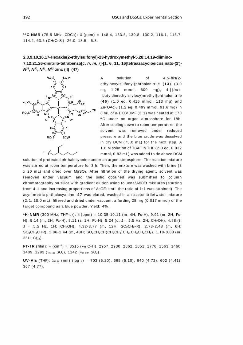
192 OSCs and DSSCs: Experimental Section
13C-NMR (75.5 MHz, CDCl3): (ppm) = 148.4, 133.5, 130.8, 130.2, 116.1, 115.7, 114.2, 63.5 (CH2O-Si), 26.0, 18.5, -5.3.
2,3,9,10,16,17-Hexakis(2-ethylsulfonyl)-23-hydroxymethyl-5,28:14,19-diimino-
7,12:21,26-dinitrilo-tetrabenzo[c, h, m, r]-[1, 6, 11, 16]tetraazacycloeicosinato-(2-)-
N29, N30, N31, N32 zinc (II) (47)
A solution of 4,5-bis(2-ethylhexylsulfonyl)phthalonitrile (13) (3.0 eq, 1.25 mmol, 600 mg), 4-[(tert-butyldimethylsilyloxy)methyl]phthalonitrile
(46) (1.0 eq, 0.416 mmol, 113 mg) and Zn(OAc)2 (1.2 eq, 0.499 mmol, 91.6 mg) in 8 mL of o-DCB/DMF (3:1) was heated at 170 ºC under an argon atmosphere for 18h. After cooling down to room temperature, the solvent was removed under reduced pressure and the blue crude was dissolved in dry DCM (75.0 mL) for the next step. A 1.0 M solution of TBAF in THF (2.0 eq, 0.832 mmol, 0.83 mL) was added to de above DCM
solution of protected phthalocyanine under an argon atmosphere. The reaction mixture was stirred at room temperature for 3 h. Then, the mixture was washed with brine (3 x 20 mL) and dried over MgSO4. After filtration of the drying agent, solvent was removed under vacuum and the solid obtained was submitted to column chromatography on silica with gradient elution using toluene/AcOEt mixtures (starting from 4:1 and increasing proportions of AcOEt until the ratio of 1:1 was attained). The asymmetric phthalocyanine 47 was eluted, washed in an acetonitrile/water mixture (2:1, 10.0 mL), filtered and dried under vacuum, affording 28 mg (0.017 mmol) of the target compound as a blue powder. Yield: 4%.
1H-NMR (300 MHz, THF-d8): (ppm) = 10.35-10.11 (m, 4H; Pc-H), 9.91 (m, 2H; Pc-H), 9.14 (m, 2H; Pc-H), 8.11 (s, 1H; Pc-H), 5.24 (d, J = 5.5 Hz, 2H; CH2OH), 4.88 (t, J = 5.5 Hz, 1H; CH2OH), 4.32-3.77 (m, 12H; SO2CH2-R), 2.73-2.48 (m, 6H; SO2CH2CHR), 1.86-1.44 (m, 48H; SO2CH2CH(CH2CH3)CH2 CH2CH2CH3), 1.18-0.88 (m, 36H, CH3).
FT-IR (film): (cm-1) = 3515 (st O-H), 2957, 2930, 2862, 1851, 1776, 1563, 1460, 1409, 1293 (st as SO2), 1142 (st sim SO2).
UV-Vis (THF): max (nm) (log ) = 703 (5.20), 665 (5.10), 640 (4.72), 602 (4.41), 367 (4.77).

Chapter 1 193
HRMS (MALDI-TOF, DCTB + PEGNa 1500): m/z calculated for C81H114N8O13S6Zn [M+]: 1662.61; found: 1662.6102.
2,3,9,10,16,17-Hexakis(2-ethylsulfonyl)-23-(3’-hydroxypropyn-1-yl)--5,28:14,19-
diimino-7,12:21,26-dinitrilo-tetrabenzo[c, h, m, r]-[1, 6, 11,
16]tetraazacycloeicosinato-(2-)- N29, N30, N31, N32 zinc (II) (48)
To a solution of Zn(II)Pc 15 (1.0 eq, 0.057 mmol, 100 mg), Pd(PPh3)2Cl2 (10% mol, 0.006 mmol, 4.1 mg) and CuI (20% mol, 0.011 mmol, 2.2 mg) in dry THF (4.0 mL), freshly distilled TEA (0.4 mL) was added under an argon atmosphere. The mixture was deoxygenated by bubbling argon through it for 30 min. Propargyl alcohol (2.0 eq, 0.113 mmol, 7.0 L) was subsequently added and the reaction was stirred at reflux for 20 h. The crude solution was then poured into aqueous HCl (0.1 M, 80.0 mL). The precipitate was collected by filtration over
celite, washed with water and dried. The crude was recovered from the filtration agent by using THF, and then concentrated in vacuum. The solid was purified by column chromatography on silica gel (CHCl3/THF, 40:1). The hydroxypropargyl derivative was purified by trituration in acetonitrile/water 2:1 and filtration, obtaining ZnPc 48 as a green solid (0.028 mmol, 48.3 mg). Yield: 50%.
1H-NMR (300 MHz, THF-d8): (ppm) = 10.38 (m, 4H; Pc-H), 9.75 (m, 2H; Pc-H), 9.05 (m, 2H; Pc-H), 7.96 (m, 1H; Pc-H), 4.73 (s, 2H; Pc-CCCH2OH), 4.13 (m, 12H; SO2CH2-R), 2.84-2.34 (m, 6H; SO2CH2CHR), 2.03-1.44 (m, 48H; SO2CH2CH(CH2CH3)CH2 CH2CH2CH3), 1.26-0.90 (m, 36H; CH3).
FT-IR (film): (cm-1) = 3516 (st O-H), 2935, 2868, 1771, 1558, 1464, 1410, 1302 (st as SO2), 1140 (st sim SO2).
UV-Vis (THF): max (nm) (log ) = 700 (5.25), 670 (5.21), 640 (4.68), 608 (4.50), 373 (4.83).
HRMS (MALDI-TOF, DCTB + PPGNa 2000): m/z calculated for C83H114N8O13S6Zn [M+]:
1686.6116; found: 1686.6097.
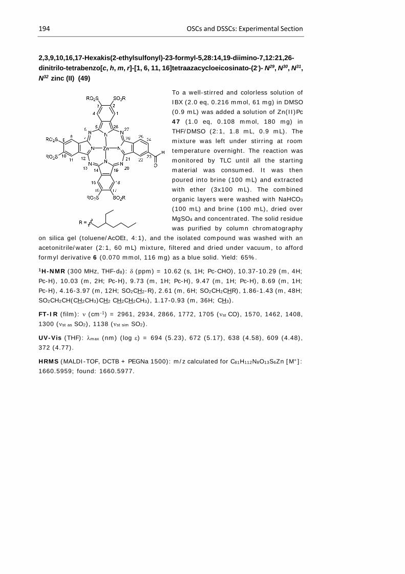
194 OSCs and DSSCs: Experimental Section
2,3,9,10,16,17-Hexakis(2-ethylsulfonyl)-23-formyl-5,28:14,19-diimino-7,12:21,26-
dinitrilo-tetrabenzo[c, h, m, r]-[1, 6, 11, 16]tetraazacycloeicosinato-(2-)- N29, N30, N31,
N32 zinc (II) (49)
To a well-stirred and colorless solution of IBX (2.0 eq, 0.216 mmol, 61 mg) in DMSO (0.9 mL) was added a solution of Zn(II)Pc 47 (1.0 eq, 0.108 mmol, 180 mg) in THF/DMSO (2:1, 1.8 mL, 0.9 mL). The mixture was left under stirring at room temperature overnight. The reaction was monitored by TLC until all the starting material was consumed. It was then poured into brine (100 mL) and extracted with ether (3x100 mL). The combined organic layers were washed with NaHCO3 (100 mL) and brine (100 mL), dried over MgSO4 and concentrated. The solid residue was purified by column chromatography
on silica gel (toluene/AcOEt, 4:1), and the isolated compound was washed with an acetonitrile/water (2:1, 60 mL) mixture, filtered and dried under vacuum, to afford formyl derivative 6 (0.070 mmol, 116 mg) as a blue solid. Yield: 65%.
1H-NMR (300 MHz, THF-d8): (ppm) = 10.62 (s, 1H; Pc-CHO), 10.37-10.29 (m, 4H; Pc-H), 10.03 (m, 2H; Pc-H), 9.73 (m, 1H; Pc-H), 9.47 (m, 1H; Pc-H), 8.69 (m, 1H; Pc-H), 4.16-3.97 (m, 12H; SO2CH2-R), 2.61 (m, 6H; SO2CH2CHR), 1.86-1.43 (m, 48H; SO2CH2CH(CH2CH3)CH2 CH2CH2CH3), 1.17-0.93 (m, 36H; CH3).
FT-IR (film): (cm-1) = 2961, 2934, 2866, 1772, 1705 (st CO), 1570, 1462, 1408, 1300 (st as SO2), 1138 (st sim SO2).
UV-Vis (THF): max (nm) (log ) = 694 (5.23), 672 (5.17), 638 (4.58), 609 (4.48), 372 (4.77).
HRMS (MALDI-TOF, DCTB + PEGNa 1500): m/z calculated for C81H112N8O13S6Zn [M+]: 1660.5959; found: 1660.5977.

Chapter 1 195
2,3,9,10,16,17-Hexakis(2-ethylsulfonyl)-23-formylethynyl-5,28:14,19-diimino-
7,12:21,26-dinitrilo-tetrabenzo[c, h, m, r]-[1, 6, 11, 16]tetraazacycloeicosinato-(2-)-
N29, N30, N31, N32 zinc (II) (50)
To a well-stirred and colorless solution of IBX (4.0 eq, 0.292 mmol, 82 mg) in DMSO (2.0 mL) was added a solution of Zn(II)Pc 48 (1.0 eq, 0.073 mmol, 123 mg) in THF/DMSO (1:1, 2.0 mL, 2.0 mL). The mixture was left under stirring at room temperature overnight. The reaction was monitored by TLC until all the starting material was consumed. It was then poured into brine (100 mL) and extracted with ether (3x100 mL). The combined organic layers were washed with NaHCO3 (100 mL) and brine (100 mL), dried over MgSO4 and concentrated. The solid residue
was purified by column chromatography on silica gel (chloroform/THF, 40:1), and the isolated compound was washed with an acetonitrile/water (2:1, 60 mL) mixture, filtered and dried under vacuum, to afford formylethynyl derivative 8 (0.040 mmol, 68 mg) as a green solid. Yield: 55%.
1H-NMR (300 MHz, THF-d8): (ppm) = 10.40 (m, 5H; Pc-CHO, Pc-H), 9.89-9.76 (m, 2H; Pc-H), 9.51-9.15 (m, 2H; Pc-H), 8.22 (bs, 1H; Pc-H), 4.26-3.82 (m, 12H; SO2CH2-R), 2.87-2.45 (m, 6H; SO2CH2CHR), 1.84-1.30 (m, 48H; SO2CH2CH(CH2CH3)CH2 CH2CH2CH3), 1.19-0.91 (m, 36H; CH3).
FT-IR (film): (cm-1) = 2932, 2864, 2195, 1771, 1661(st CO), 1464, 1302 (st as SO2), 1142 (st sim SO2).
UV-Vis (THF): max (nm) (log ) = 696 (5.25), 675 (5.21), 638 (4.58), 612 (4.51), 374 (4.80).
HRMS (MALDI-TOF, DCTB + PPGNa 2000): m/z calculated for C83H112N8O13S6Zn [M+]: 1684.5959; found: 1684.5980.

196 OSCs and DSSCs: Experimental Section
23-Carboxy-2,3,9,10,16,17-hexakis(2-ethylsulfonyl)-5,28:14,19-diimino-7,12:21,26-
dinitrilo-tetrabenzo[c, h, m, r]-[1, 6, 11, 16]tetraazacycloeicosinato-(2-)- N29, N30, N31,
N32 zinc (II) (51)
To a well-stirred solution of formyl Zn(II)Pc 49 (1.0 eq, 0.096 mmol, 160 mg) in THF (15.0 mL) at 0 ºC was added dropwise a solution of NaClO2 (2.0 eq, 0.192 mmol, 17 mg) in Milli-Q-grade deionized water (1.5 mL). A solution of sulfamic acid (2.5 eq, 0.241 mmol, 23 mg) in water (1.5 mL) was added to the mixture while the reaction mixture was vigorously stirred at 0 ºC. After the addition was complete, the solution was brought to room temperature and left under stirring until the starting material was consumed. The crude solution was then poured into water (70 mL) and
extracted several times with DCM (3x100 mL). The organic extracts were washed with water (100 mL), dried over MgSO4 and concentrated in vacuum. The solid was washed with a mixture an acetonitrile/water (2:1, 60 mL) mixture and filtered and dried under vacuum. In this way, compound 51 was obtained as a dark blue solid (0.067 mmol, 113 mg). Yield: 70%.
1H-NMR (300 MHz, THF-d8): (ppm) = 10.41 (m, 3H; Pc-COOH, Pc-H), 10.26 (m, 1H; Pc-H), 10.06 (m, 2H; Pc-H), 9.88-9.65 (m, 2H; Pc-H), 9.33-9.13 (m, 1H; Pc-H), 8.76-8.64 (m, 1H; Pc-H), 4.25-3.92 (m, 12H; SO2CH2-R), 2.69-2.38 (m, 6H; SO2CH2CHR), 1.88-1.45 (m, 48H; SO2CH2CH(CH2CH3)CH2 CH2CH2CH3), 1.07-0.83 (m, 36H; CH3).
FT-IR (film): (cm-1) = 3433 (st O-H), 2957, 2930, 2862, 1776, 1695 (st CO), 1560, 1466, 1398, 1290 (st as SO2), 1142 (st sim SO2).
UV-Vis (THF): max (nm) (log ) = 697 (4.99), 670 (4.93), 638 (4.43), 607 (4.26), 370 (4.56).
HRMS (MALDI-TOF, DCTB + PPGNa 2000): m/z calculated for C81H112N8O14S6Zn [M+]: 1676.5908; found: 1676.5891.
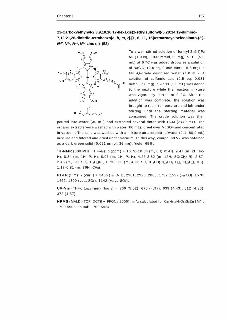
Chapter 1 197
23-Carboxyethynyl-2,3,9,10,16,17-hexakis(2-ethylsulfonyl)-5,28:14,19-diimino-
7,12:21,26-dinitrilo-tetrabenzo[c, h, m, r]-[1, 6, 11, 16]tetraazacycloeicosinato-(2-)-
N29, N30, N31, N32 zinc (II) (52)
To a well-stirred solution of formyl Zn(II)Pc 50 (1.0 eq, 0.032 mmol, 55 mg) in THF (5.0 mL) at 0 ºC was added dropwise a solution of NaClO2 (2.0 eq, 0.065 mmol, 5.8 mg) in Milli-Q-grade deionized water (1.0 mL). A solution of sulfamic acid (2.5 eq, 0.081 mmol, 7.8 mg) in water (1.0 mL) was added to the mixture while the reaction mixture was vigorously stirred at 0 ºC. After the addition was complete, the solution was brought to room temperature and left under stirring until the starting material was consumed. The crude solution was then
poured into water (30 mL) and extracted several times with DCM (3x40 mL). The organic extracts were washed with water (60 mL), dried over MgSO4 and concentrated in vacuum. The solid was washed with a mixture an acetonitrile/water (2:1, 60.0 mL) mixture and filtered and dried under vacuum. In this way, compound 52 was obtained as a dark green solid (0.021 mmol, 36 mg). Yield: 65%.
1H-NMR (300 MHz, THF-d8): (ppm) = 10.76-10.04 (m, 6H; Pc-H), 9.47 (m, 2H; Pc-H), 8.34 (m, 1H; Pc-H), 8.07 (m, 1H; Pc-H), 4.26-3.82 (m, 12H; SO2CH2-R), 2.87-2.45 (m, 6H; SO2CH2CHR), 1.73-1.30 (m, 48H; SO2CH2CH(CH2CH3)CH2 CH2CH2CH3), 1.18-0.81 (m, 36H; CH3).
FT-IR (film): (cm-1) = 3406 (st O-H), 2961, 2920, 2866, 1732, 1597 (st CO), 1570, 1462, 1300 (st as SO2), 1142 (st sim SO2).
UV-Vis (THF): max (nm) (log ) = 700 (5.02), 676 (4.97), 639 (4.43), 612 (4.30), 373 (4.57).
HRMS (MALDI-TOF, DCTB + PPGNa 2000): m/z calculated for C83H112N8O14S6Zn [M+]: 1700.5908; found: 1700.5924.


Chapter 2. New Tb(III) bis(phthalocyanine) as single-molecule magnets


Chapter 2 201
2.1 Introduction
2.1.1 Magnetism
Magnetism is certainly one of the most important physical phenomena in the
universe. It is ubiquitous in both natural and technological matters, from the earth´s
magnetic field to many components of electronic devices which are part of our everyday
life. The history of magnetism dates back to earlier than the 6th century B.C., but it is only
in the twentieth century that scientists have begun to understand it, and develop
technologies based on this understanding. Magnetism was most probably first observed
in a form of the mineral magnetite called lodestone, a naturally magnetized piece of
magnetite (Fe3O4), found in Magnesia, in ancient Thessaly, Greece, which explains the
origin of the word “magnet”.382 The observation of the attraction of lodestone to iron was
repeated over centuries by an incredible number of scientists, but it took centuries for
lodestone to pass from a scientific curiosity to an actual functional material. Indeed, it
was not until the 12th century D.C. that the Chinese used a lodestone based compass for
navigation, which was the first milestone of a long series of scientific discoveries leading
to the exploitation of magnetism as a more general fundamental tool. Ever since the early
example of the compass, magnetic materials have been little by little incorporated in our
everyday life. Permanent magnets can be found in our hard-disk drives and credit cards
as recording media and are also present in electromechanical transductor devices such
as electric motors, audio speakers or microphones.
2.1.1.1 Magnetization hysteresis
A magnet is a material that can be magnetized and can present a permanent
magnetic moment in the absence of any exterior magnetic field. The main characteristics
of a magnet are the parameters of its hysteresis of magnetization, which are its remnant
magnetization and its coercive field (Figure 94). Magnets are in essence bistable systems
which can be magnetized along one particular z direction or the opposite direction –z.
When applying a sufficiently high magnetic field along z, magnets are magnetized at a
saturation magnetization value Ms. When the external magnetic field is removed, hard
magnets maintain a non zero permanent magnetization called remnant magnetization Mr.
If one applies an external magnetic field in the opposite direction, along –z, then the
magnet saturates at a magnetization value of −Ms and when removing the magnetic field,
the remnant magnetization value is now –Mr. For an ideal magnet the magnitude of the
382 G. L. Verschuur, Hidden attraction: The history and mystery of magnetism, Oxford University Press, Oxford, 1993.

202 Introduction
remnant magnetization Mri is equal to the saturation magnetization Ms, nevertheless in a
real hard magnet, the from one magnet to the other. Simply put, the value of Mr is the
relative amount of magnetization that the magnet maintains when in the absence of an
external magnetic field.
Figure 94.- Magnetization hysteresis plots of four model magnets indicating their coercive fields Hc
and remnant magnetizations Mr.
In order to flip the magnetization of a hard magnet from positive to negative value,
it is necessary to apply a magnetic field strong enough to destroy the cohesion of the
magnet. The field at which such a flipping occurs is therefore called the coercive field
(Hc). This is the other important parameter of the magnetization hysteresis curves of hard
magnets. Finally, a soft magnet is a material that can be magnetized but shows no
magnetization hysteresis, which translates into Hc = 0 and Mr = 0. Figure 94 illustrates
the magnetization versus field curves obtained for an ideal magnet (i), two hard magnets
with different values of Hc (1 and 2) and a soft magnet (3).
2.1.1.2 Molecular magnetic materials
Traditionally, magnetic materials are bulk materials based on atoms with d or f
orbital based spin sites and has extended network bonding in three dimensions.
However, a new field of research emerged, around the end of the 20th century, to
Chapter 2 203
investigate the properties of molecular magnetic materials.383,384,385,386,387 In the 80s, a
new research field, the Molecular Magnetism,388 envisaged an essentially
multidisciplinary field that aims at combining the knowledge of chemists with those of
theoretical chemists and physicists in order to design molecular magnetic materials and
predict and rationalize their physical properties. The research activity of the field was
conducted in several directions. While some groups investigated the possibility to obtain
purely organic ferromagnets, others tried to push up the ordering temperatures, which
are typically below the boiling point of liquid nitrogen.
The first examples of molecular ferro- and ferrimagnets were reported in the late
1980s. In 1987, Miller and his team successfully produced ferromagnets using the
tetracyanoethylene (TCNE) anion.389 For instance, they reported that
[Fe(C5Me5)2][TCNE] showed spontaneous ferromagnetic ordering below 4.5 K.390 Only
one year later, Kahn et al. presented a new ferromagnetically ordering system at
approximately the same temperature (4.6 K) based on bimetallic Cu(II)-Mn(II) chains.391
In 1991 two more breakthroughs occurred. On one hand Miller et al. reported the first
room temperature molecular magnet,392 V(TCNE)2, whose structure remains unknown to
date. V(TCNE)2 orders ferrimagnetically above room temperature due to the
antiferromagnetic coupling between the V2+ ions (S = 3/2) and the radical anions TCNE•-
(S = 1/2). On the other hand, Kinoshita and coworkers reported the first all-organic
ferromagnet,393 a compound of the well known nitronyl nitroxide family of stable radicals.
While the compound ordered at only 0.6 K, it demonstrated the possibility to obtain
molecular magnets in which the magnetic orbitals were purely of type s or p and not d or
f as is the case for third and fourth row transition metals (3d or 4d), lanthanides (4f) and
actinides (5f) used in classical bulk magnets. Nevertheless, these magnets are soft
383 J. S. Miller and M. Drillon, Magnetism: Molecules to Materials I, Models and Experiments, Wiley‐VCH, 2001. 384 J. S. Miller and M. Drillon, Magnetism: Molecules to Materials II, Molecule‐based Materials, Wiley‐VCH, 2001. 385 J. S. Miller and M. Drillon, Magnetism: Molecules to Materials III, Nanosized Magnetic Materials, Wiley‐VCH, 2002. 386 J. S. Miller and M. Drillon, Magnetism: Molecules to Materials IV, Wiley‐VCH, 2003. 387 J. S. Miller and M. Drillon, Magnetism: Molecules to Materials V, Wiley‐VCH, 2005. 388 O. Kahn, Molecular Magnetism, VCH Publishers, 1993. 389 J. S. Miller, Inorg. Chem. 2000, 39, 4392. 390 J. S. Miller, J. C. Calabrese, H. Rommelmann, S. R. Chittipeddi, J. H. Zhang, W. M. Reiff, A. J. Epstein, J. Am. Chem. Soc. 1987, 109, 769. 391 O. Kahn, Y. Pei, M. Verdaguer, J. P. Renard, J. Sletten, J. Am. Chem. Soc. 1988, 110, 782. 392 J. M. Manriquez, G. T. Yee, R. S. McLean, A. J. Epstein, J. S. Miller, Science 1991, 252, 1415. 393 M. Tamura, Y. Nakazawa, D. Shiomi, K. Nozawa, Y. Hosokoshi, M. Ishikawa, M. Takahashi, M. Kinoshita, Chem. Phys. Lett. 1991, 186, 401.
204 Introduction
magnets with almost no coercive field due to the lack of anisotropy of the s and p orbitals.
The highest ordering temperature in a purely organic magnet to date is 36 K,394 which is
quite an improvement when compared to the compound by Kinoshita and coworkers, but
is still too low to envisage any practical application as a permanent magnet. The
development of a purely organic molecular magnet provides exciting possibilities
because apart from being magnetic, the molecule would also have properties specific to
the organic compounds.
Despite the novelty of preparing bulk molecular magnets ordering around room
temperature, it was soon realized that one of the great advantages of molecular materials
in magnetism is the possibility to control the dimensionality of the magnetic structure.
Indeed, the control of the reaction conditions and the chemical nature of the compounds
used to prepare molecular magnetic materials allows the preparation of strictly 3D bulk
ferro- or ferrimagnets, but also in lower dimensionalities, with 2D, 1D or strictly 0D
magnetic materials, in which the magnetic interactions are propagated in a plane, in only
one direction, or confined to an independent nanometric magnetic cluster. An extensive
amount of research was done in order to prepare such materials, eventually leading to
the discovery of the first compound behaving as a single-molecule magnet, which is a
compound that, below a blocking temperature, exhibits stable magnetization purely of
molecular origin, and not caused by long-range ordering of magnetic moments in the
bulk.395
Molecular magnets have several potential uses, including the use in high
capacity magnetic storage media396 and quantum bits (qubits) applicable to quantum
computers.397
394 F. Palacio, G. Antorrena, M. Castro, R. Burriel, J. Rawson, J. N. B. Smith, N. Bricklebank, J. Novoa, C. Ritter, Phys. Rev. Lett. 1997, 79, 2336. 395 D. Gatteschi, R. Sessoli, J. Villain, Molecular Nanomagnets, Oxford University Press, Oxford, UK, 2006. 396 a) L. Bogani, W. Wernsdorfer, Nat. Mater. 2008, 7, 179; b) J. J. L. Morton, A. M. Tyryshkin, R. M. Brown, S. Shankar, B. W. Lovett, A. Ardavan, T. Schenkel, E. E. Haller, J. W. Ager, S. A. Lyon, Nature 2008, 455, 1085. 397 a) J. Ahn, T. C. Weinacht, P. H. Bucksbaum, Science 2000, 287, 463; b) M. N. Leuenberger, D. Loss, Nature 2001, 410, 789; c) R. E. P. Winpenny, Angew. Chem. Int. Ed. 2008, 47, 7992; d) J. Lehmann, A. Gaita‐Ariño, E. Coronado, D. Loss, J. Mater. Chem. 2009, 19, 1672.
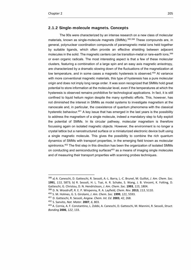
Chapter 2 205
2.1.2 Single-molecule magnets. Concepts
The 90s were characterized by an intense research on a new class of molecular
materials, known as single-molecule magnets (SMMs).395,398 These compounds are, in
general, polynuclear coordination compounds of paramagnetic metal ions held together
by suitable ligands, which often provide an effective shielding between adjacent
molecules in the solid. The magnetic centers can be transition-metal or rare-earth ions,399
or even organic radicals. The most interesting aspect is that a few of these molecular
clusters, featuring a combination of a large spin and an easy axis magnetic anisotropy,
are characterized by a dramatic slowing down of the fluctuations of the magnetization at
low temperature, and in some cases a magnetic hysteresis is observed.400 At variance
with more conventional magnetic materials, this type of hysteresis has a pure molecular
origin and does not imply long range order. It was soon recognized that SMMs hold great
potential to store information at the molecular level, even if the temperatures at which the
hysteresis is observed remains prohibitive for technological applications. In fact, it is still
confined to liquid helium region despite the many synthetic efforts. This, however, has
not diminished the interest in SMMs as model systems to investigate magnetism at the
nanoscale and, in particular, the coexistence of quantum phenomena with the classical
hysteretic behaviour.401 A key issue that has emerged in the last years is the possibility
to address the magnetism of a single molecule, indeed a mandatory step to fully exploit
the potential of SMMs. In its circular pathway, molecular magnetism is therefore
focussing again on isolated magnetic objects. However, the environment is no longer a
crystal lattice but a nanostructured surface or a miniaturized electronic device built using
a single magnetic molecule. This gives the possibility to combine the rich quantum
dynamics of SMMs with transport properties, in the emerging field known as molecular
spintronics.402 The first step in this direction has been the organization of isolated SMMs
on conducting and semiconducting surfaces403 as a means of imaging single molecules
and of measuring their transport properties with scanning probes techniques.
398 a) A. Caneschi, D. Gatteschi, R. Sessoli, A.‐L. Barra, L.‐C. Brunel, M. Guillot, J. Am. Chem. Soc. 1991, 113, 5873; b) R. Sessoli, H. L. Tsai, A. R. Schake, S. Wang, J. B. Vincent, K. Folting, D. Gatteschi, G. Christou, D. N. Hendrickson, J. Am. Chem. Soc. 1993, 115, 1804. 399 D. N. Woodruff, R. E. P. Winpenny, R. A. Layfield, Chem. Rev. 2013, 113, 5110. 400 S. M. Holmes, G. S. Girolami, J. Am. Chem. Soc. 1999, 121, 5593. 401 D. Gatteschi, R. Sessoli, Angew. Chem. Int. Ed. 2003, 42, 268. 402 S. Sanvito, Nat. Mater. 2007, 6, 803. 403 A. Cornia, A. F. Constantino, L. Zobbi, A. Caneschi, D. Gatteschi, M. Mannini, R. Sessoli, Struct. Bonding 2006, 122, 133.

206 Introduction
Single-molecule magnets (SMMs)404 are characterized by high spin ground state
( ), high zero field splitting and an easy axis of the magnetization (which correspond to
high and negative zero field splitting parameter ). If we exclude the case of mononuclear
lanthanide complexes of high symmetry, e.g. double decker compounds, that have been
described in the last part of this introduction, all other molecules presenting slow
relaxation of the magnetization are constituted by polynuclear complexes of
paramagnetic metal ions. Usually in this case only interactions between nearest
neighboring magnetic sites are considered and the effective Spin Hamiltonian (SH) can
be write as:
∑ Eq. 6
where i and j run over all metal sites of the cluster. The energy of the different ST states
can be calculated analytically in some high symmetry cases, in particular when a central
spin exhibits the same exchange interaction with the neighboring ones. This is also
known as the Kambe approach405 and spin systems comprising up to 13 coupled spins
have been handled in this way.406
The spin structure of the SMM is strongly correlated to the dynamics of the
magnetization and can be considered as a sort of fingerprint of the SMM. On the other
hand, the occurrence of a large spin ground state is a necessary, although not sufficient,
condition to observe slow relaxation of the magnetization. The second key ingredient in
SMM is magnetic anisotropy. In traditional magnets, three factors give equally important
contributions to the anisotropy, namely surface, strain, and magnetocrystalline
contributions. In SMM, the only significant role is played by magnetocrystalline anisotropy
and is brought in by a combination of spin-orbit coupling with the low-symmetry
environment around the metal centers constituting the SMM. Dipolar contributions are in
most cases negligible. A quantitative treatment of the magnetic anisotropy is based on
the effective spin-hamiltonian approach where only the spin variables appear, while the
orbital contributions are introduced through parameters. For a system with no symmetry
at all, the SH can be written as:
1 Eq. 7
404 G. Christou, D. Gatteschi, D. N. Hendrickson, R. Sessoli, MRS Bull. 2000, 25, 66. 405 K. Kambe, J. Phys. Soc. Jpn. 1950, 5, 48. 406 J. van Slageren, P. Rosa, A. Caneschi, R. Sessoli, H. Casellas, Y. V. Rakitin, L. Cianchi, F. Del Giallo, G. Spina, A. Bino, A.‐L. Barra, T. Guidi, S. Carretta, R. Caciuffo, Phys. Rev. B 2006, 73, 014422.
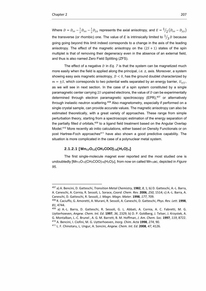
Chapter 2 207
Where represents the axial anisotropy, and 12
the transverse (or rhombic) one. The value of E is intrinsically limited to 1 3 because
going going beyond this limit indeed corresponds to a change in the axis of the leading
anisotropy. The effect of the magnetic anisotropy on the 2 1 states of the spin
multiplet is that of removing their degeneracy even in the absence of an external field,
and thus is also named Zero Field Splitting (ZFS).
The effect of a negative in Eq. 7 is that the system can be magnetized much
more easily when the field is applied along the principal, i.e. z, axis. Moreover, a system
showing easy axis magnetic anisotropy, 0, has the ground doublet characterized by
, which corresponds to two potential wells separated by an energy barrier, ,
as we will see in next section. In the case of a spin system constituted by a single
paramagnetic center carrying 2 unpaired electrons, the value of can be experimentally
determined through electron paramagnetic spectroscopy (EPR),407 or alternatively
through inelastic neutron scattering.408 Also magnetometry, especially if performed on a
single crystal sample, can provide accurate values. The magnetic anisotropy can also be
estimated theoretically, with a great variety of approaches. These range from simple
perturbation theory, starting from a spectroscopic estimation of the energy separation of
the partially filled d orbitals,409 to a ligand field treatment based on the Angular Overlap
Model.410 More recently ab initio calculations, either based on Density Functionals or on
post Hartree-Foch approaches411 have also shown a good predictive capability. The
situation is more complicated in the case of a polynuclear metal system.
2.1.2.1 [Mn12O12(CH3COO)16(H2O)4]
The first single-molecule magnet ever reported and the most studied one is
undoubtedly [Mn12O12(CH3COO)16(H2O)4], from now on called Mn12ac, depicted in Figure
95.
407 a) A. Bencini, D. Gatteschi, Transition Metal Chemistry, 1982, 8, 1; b) D. Gatteschi, A.‐L. Barra, A. Caneschi, A. Cornia, R. Sessoli, L. Sorace, Coord. Chem. Rev. 2006, 250, 1514; c) A.‐L. Barra, A. Caneschi, D. Gatteschi, R. Sessoli, J. Magn. Magn. Mater. 1998, 177, 709. 408 R. Caciuffo, G. Amoretti, A. Murani, R. Sessoli, A. Caneschi, D. Gatteschi, Phys. Rev. Lett. 1998, 81, 4744. 409 a) A.‐L. Barra, D. Gatteschi, R. Sessoli, G. L. Abbati, A. Cornia, A. C. Fabretti, M. G. Uytterhoeven, Angew. Chem. Int. Ed. 1997, 36, 2329; b) D. P. Goldberg, J. Telser, J. Krzystek, A. G. Montalban, L.‐C. Brunel , A. G. M. Barrett, B. M. Hoffman, J. Am. Chem. Soc. 1997, 119, 8722. 410 A. Bencini, I. Ciofini, M. G. Uytterhoeven, Inorg. Chim. Acta 1998, 274, 90. 411 L. F. Chinotaru, L. Ungur, A. Soncini, Angew. Chem. Int. Ed. 2008, 47, 4126.
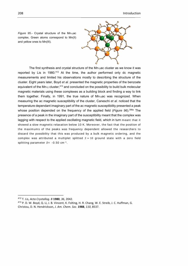
208 Introduction
Figure 95.- Crystal structure of the Mn12ac
complex. Green atoms correspond to Mn(II)
and yellow ones to Mn(III).
The first synthesis and crystal structure of the Mn12ac cluster as we know it was
reported by Lis in 1980.412 At the time, the author performed only dc magnetic
measurements and limited his observations mostly to describing the structure of the
cluster. Eight years later, Boyd et al. presented the magnetic properties of the benzoate
equivalent of the Mn12 cluster,413 and concluded on the possibility to build bulk molecular
magnetic materials using these complexes as a building block and finding a way to link
them together. Finally, in 1991, the true nature of Mn12ac was recognized. When
measuring the ac magnetic susceptibility of the cluster, Caneschi et al. noticed that the
temperature dependant imaginary part of the ac magnetic susceptibility presented a peak
whose position depended on the frequency of the applied field (Figure 96).398a The
presence of a peak in the imaginary part of the susceptibility meant that the complex was
lagging with respect to the applied oscillating magnetic field, which in turn meant that it showed a slow magnetic relaxation below 10 K. Moreover, the fact that the position of the maximums of the peaks was frequency dependent allowed the researchers to discard the possibility that this was produced by a bulk magnetic ordering, and the complex was attributed a multiplet splitted 10 ground state with a zero field splitting parameter = -0.50 cm-1.
412 T. Lis, Acta Crystallog. B 1980, 36, 2042. 413 P. D. W. Boyd, Q. Li, J. B. Vincent, K. Folting, H. R. Chang, W. E. Streib, J. C. Huffman, G. Christou, D. N. Hendrickson, J. Am. Chem. Soc. 1988, 110, 8537.
Chapter 2 209
Figure 96.- First ac magnetic susceptibility data recorded on Mn12ac. The inset shows the imaginary
part of the magnetic susceptibility vs. T measured at 55, 100 and 500 Hz.
These values were confirmed a few years later by Sessoli et al. in an in depth
study of the interactions in the cluster.398b
At the time, the authors pointed out that even though Mn12ac was much smaller
than the previously reported superparamagnets, it presented a similar behavior
(temperature dependent blocking of the magnetic relaxation), and it was tempting to
assume that the reason for its peculiar behavior laid in its high magnetic anisotropy
originating from its high spin ground state and the anisotropy of the component metal
ions.
In 1993, it was shown that the complex shows magnetic hysteresis (Figure 97)
of purely molecular origin since no 3D ordering could be observed in either
magnetization, susceptibility or specific heat measurements.414 The discovery of the
possibility of magnetization hysteresis in a single-molecule, that is of the possibility of
making single-molecule magnets, created quite an excitement, but more was to come
since Mn12ac was soon to provide the experimental observation of a quantum
phenomenon: quantum tunneling of magnetization.
414 R. Sessoli, D. Gatteschi, A. Caneschi, M. A. Novak, Nature 1993, 365, 141.

210 Introduction
Figure 97.- First magnetization hysteresis recorded on a polycristalline sample of Mn12ac.414
Mn12ac, as previously mentioned, is a polynuclear transition metal cluster that
combines a high spin 10 ground state with a strong easy axis of magnetic
anisotropy. In the case of Mn12ac, the complex is made up of an outer ring of eight Mn(III)
ions 2 and a core of four Mn(II) ions 3 2⁄ . The manganese ions of the outer
ring are ferromagnetically coupled together, and so are the core manganese ions.
Nevertheless, the core and the ring are coupled antiferromagnetically which altogether
accounts for the 10 ground state. The complex presents an axial symmetry, and it
was shown that it presents a strong Ising anisotropy, which means that it presents an
easy axis (or hard plane) of magnetization.
In a first approximation, the Mn12ac complexes are described by the following
Hamiltonian, taking into account the axial zero field splitting and the Zeeman splitting:
Eq. 8
where is the axial zero field splitting parameter, is the g-factor of the compound,
is the Bohr magneton, is the applied magnetic field, is the total spin of the system
and is its projection on the easy axis direction. The energies of the different states are therefore given by the following expression:
Eq. 9
where is the projection of the magnetic field on the easy axis direction and are the
spin microstates projected on the same axis. In zero field the Zeeman term is equal to
zero and the energy diagram of the system is given in Figure 98. In this situation the two
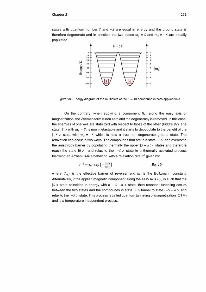
Chapter 2 211
states with quantum number and are equal in energy and the ground state is
therefore degenerate and in principle the two states and are equally
populated.
Figure 98.- Energy diagram of the multiplets of the 10 compound in zero applied field.
On the contrary, when applying a component along the easy axis of
magnetization, the Zeeman term is non zero and the degeneracy is removed. In this case,
the energies of one well are stabilized with respect to those of the other (Figure 99). The
state | with , is now metastable and it starts to depopulate to the benefit of the
| state with which is now a true non degenerate ground state. The
relaxation can occur in two ways. The compounds that are in a state | can overcome
the anisotropy barrier by populating thermally the upper | states and therefore
reach the state |0 and relax to the | state in a thermally activated process
following an Arrhenius-like behavior, with a relaxation rate -1 given by:
Eq. 10
where is the effective barrier of reversal and is the Boltzmann constant.
Alternatively, if the applied magnetic component along the easy axis is such that the
| state coincides in energy with a | state, then resonant tunneling occurs
between the two states and the compounds in state | tunnel to state | and
relax to the | state. This process is called quantum tunneling of magnetization (QTM)
and is a temperature independent process.

212 Introduction
Figure 99.- Energy diagram of the multiplets of the 10 compound applying a non zero magnetic
field component along the easy axis which makes the energy of the | and | states
coincide.
The occurrence of QTM happens at discrete values of magnetic field for
which the energies of | and | are equal. This in turn means that QTM occurs
at evenly spaced values of which depend only on the zero field splitting parameter
and the factor of the compound. QTM provides an alternative route to the thermal
relaxation of the superparamagnetic clusters, which was first evidenced in Mn12ac and
translate in a staircase hysteresis curve of magnetization with a step at the values of
at which resonant tunneling occurs (Figure 100). While the effect of QTM was already
visible in the first recorded magnetization hysteresis of Mn12ac (Figure 97),414 it was not
identified at the time, and only a few years later was it recognized as such.401,415,416,417,418
In Mn12ac the magnetization hysteresis curves (Figure 100) present steps that are evenly
spaced by approximately 0.46 T, which corresponds to ⁄ = 0.21 cm-1 which is in good
agreement with the values of and (0.5 cm-1 and 1.9, respectively) experimentally
determined in an independent way from high field EPR experiments.398b,414 The steps can
clearly be seen in Figure 100, and upon changing the temperature, the position of the
steps is unchanged, but when lowering the temperature the hysteresis loop broadens
and some steps that were so far undetectable can be observed.
415 J. R. Friedman, M. P. Sarachik, J. Tejada, R. Ziolo, Phys. Rev. Lett. 1996, 76, 3830. 416 L. Thomas, F. Lionti, R. Ballou, D. Gatteschi, R. Sessoli, B. Barbara, Nature 1996, 383, 145. 417 J. R. Friedman, M. P. Sarachik, J. Tejada, J. Maciejewski, R. Ziolo, J. Appl. Phys. 1996, 79, 6031. 418 J. Tejada, R. F. Ziolo, X. X. Zhang, Chem. Mater. 1996, 8, 1784.

Chapter 2 213
Figure 100.- Magnetization hysteresis curve measured on a single-crystal of Mn12ac measured at
1.77 K, 2.10 K and 2.64 K.
Following the discovery of the Mn12 clusters, a great number of systems were
prepared and showed SMM behavior. But, while a lot of new compounds have been
synthesized, the general trends are the same, and most SMMs are still metallic clusters
with a high spin ground state and a strong uniaxial anisotropy. In this group of new single-
molecule magnets based on transition metal there are a variety of systems, including
214 Introduction
others manganese clusters419 of various nuclearity (Mn2,420 Mn4,421 Mn6,422 Mn84,423
among others), iron (ferric wheels,424 Fe4,425 Fe8,426 among others), V4,427 and CrNi6.428
2.1.2.2 Single-ion magnets429
As we have seen in the last section, the aim of the scientific community for years
has been to obtain polynuclear transition metal clusters with a high magnetic anisotropy,
and to achieve a high spin ground state by engineering the exchange coupling between
the different metal ions constituting the clusters. Nevertheless, in 2003, this vision of
single-molecule magnet was revised due to the appearance of the first mononuclear
419 a) E. K. Brechin, Chem. Comm. 2005, 5141; b) G. Rogez, B. Donnio, E. Terazzi, J.‐L. Gallani, J.‐P. Kappler, J.‐P. Bucher, M. Drillon, Adv. Mater. 2009, 21, 4323. 420 a) Z. Lu, M. Yuan, F. Pan, S. Gao, D. Zhang, D. Zhu, Inorg. Chem. 2006, 45, 3538; b) H. Miyasaka, R. Clerac, W. Wernsdorfer, L. Lecren, C. Bonhomme, K.‐i. Sugiura, M. Yamashita, Angew. Chem. Int. Ed. 2004, 43, 2801. 421 a) S. M. J. Aubin, N. R. Dilley, L. Pardi, J. Krzystek, M. W. Wemple, L.‐C. Brunel, M. B. Maple, G. Christou, D. N. Hendrickson, J. Am. Chem. Soc. 1998, 120, 4991; b) J. Yoo, E. K. Brechin, A. Yamaguchi, M. Nakano, J. C. Huffman, A. L.. Maniero, L.‐C. Brunel, K. Awaga, H. Ishimoto, G. Christou, D. N. Hendrickson, Inorg. Chem. 2000, 39, 3615; c) A. Bhattacharjee, Y. Miyazaki, M. Nakano, J. Yoo, G. Christou, D. N. Hendrickson, M. Sorai, Polyhedron 2001, 20, 1607. 422 a) C. J. Milios, R. Inglis, R. Bagai, W. Wernsdorfer, A. Collins, S. Moggach, S. Parsons, S. P. Perlepes, G. Christou, E. K. Brenchin, Chem. Comm. 2007, 3476; b) C. J. Milios, A. Vinslava, W. Wernsdorfer, A. Prescimone, P. A. Wood, S. Parsons, S. P. Perlepes, G. Christou, E. K. Brechin, J. Am. Chem. Soc. 2007, 129, 6547; c) C. J. Milios, A. Vinslava, P. A. Wood, S. Parsons, W. Wernsdorfer, G. Christou, S. P. Perlepes, E. K. Brechin, J. Am. Chem. Soc. 2006, 129, 8. 423 A. J. Tasiopoulos, A. Vinslava, W. Wernsdorfer, K. A. Abboud, G. Christou, Angew. Chem. Int. Ed. 2004, 43, 2117. 424 a) A. Caneschi, A. Cornia, A. C. Fabretti, D. Gatteschi, Angew. Chem. Int. Ed. 1996, 34, 2716; b) A. Caneschi, A. Cornia, A. C. Fabretti, D. Gatteschi, Angew. Chem. Int. Ed. 1999, 38, 1295. 425 a) A. L. Barra, A. Caneschi, A. Cornia, F. Fabrizi de Biani, D. Gatteschi, C. Sangregorio, R. Sessoli, L. Sorace, J. Am. Chem. Soc. 1999, 121, 5302; b) A. Cornia, L. Gregoli, C. Danieli, A. Caneschi, R. Sessoli, L. Sorace, A.‐L. Barra, W. Wernsdorfer, Inorg. Chim. Acta 2008, 361, 3481; c) A. Cornia, A. C. Fabretti, P. Garrisi, C. Mortalo, D. Bonacchi, D. Gatteschi, R. Sessoli, L. Sorace, W. Wernsdorfer, A.‐L. Barra, Angew. Chem. Int. Ed. 2004, 43, 1136. 426 a) K. Wieghardt, K. Pohl, I. Jibril, G. Huttner, Angew. Chem. Int. Ed. 1984, 23, 77; b) A.‐L. Barra, P. Debrunner, D. Gatteschi, C. E. Schulz, R. Sessoli, Europhys. Lett. 1996, 35, 133. 427 S. L. Castro, Z. Sun, C. M. Grant, J. C. Bollinger, D. N. Hendrickson, G. Christou, J. Am. Chem. Soc. 1998, 120, 2365. 428 T. Mallah, C. Auberger, M. Verdaguer, P. Veillet, J. Chem. Soc., Chem. Commun. 1995, 61. 429 The term single‐ion magnet is used in this section in order to mark a difference with polynuclear clusters; however, the compounds mentioned here are also called single‐molecule magnets in the literature.

Chapter 2 215
SMM TbPc2 (Figure 101), described by Ishikawa et al.430, in which obviously no
intramolecular exchange coupling between metals could take place.
Figure 101.- Structure of TbPc2, with Pcs in blue and Tb(III) atom in yellow. Nitrogen atoms are in
red to show the square-antiprismatic coordination environment of the lanthanide.
These new systems were first limited to double-decker terbium(III)
phthalocyanine complexes, and were extended recently to erbium polyoxometalates and
to the first mononuclear transition metal SMM, a high spin iron (II) complex.431 In this
section, we will first review briefly the magnetic lanthanide polyoxometalates and we will
then discuss, in more detail, the history and the magnetic behavior of lanthanide
phthalocyanine double-decker complexes.
Magnetic polyoxometalates432
Polyoxometalates (POMs) are robust ligands capable of encapsulating
lanthanides in high-symmetry coordination environments, making them well suited to
SMM applications. Recently, Coronado et al. reported two families of monolanthanide
polyoxometalates compounds433,434 that behave as single-ion magnets: [Ln(W5O18)2]9-
(for Ln3+ = Tb, Dy, Ho, and Er) and [Ln(SiW11O39)2]13- (for Ln3+ = Tb, Dy, Ho, Er, Tm and
Yb). Out of all the prepared complexes, only the Ho and Er complexes of the form
[Ln(W5O18)2]9- and the Dy, Ho, Er and Yb complexes of the form [Ln(SiW11O39)2]13-
presented a slow magnetic relaxation characteristic of SMMs. Finally [Er(W5O18)2]9- was
430 N. Ishikawa, M. Sugita, T. Ishikawa, S.‐y. Koshihara, Y. Kaizu, J. Am. Chem. Soc. 2003, 125, 8694. 431 a) W. H. Harman, C. J. Chang, J. Am. Chem. Soc. 2007, 129, 15128; b) D. E. Freedman, W. H. Harman, T. D. Harris, G. J. Long, C. J. Chang, J. R. Long, J. Am. Chem. Soc. 2010, 132, 1224. 432 J. M. Clemente‐Juan, E. Coronado, A. Gaita‐Ariño, Chem. Soc. Rev. 2012, 41, 7464, and references therein. 433 M. A. AlDamen, J. M. Clemente‐Juan, E. Coronado, C. Martí‐Gastaldo, A. Gaita‐Ariño, J. Am. Chem. Soc. 2008, 130, 8874. 434 M. A. AlDamen, S. Cardona‐Serra, J. M. Clemente‐Juan, E. Coronado, A. Gaita‐Ariño, C. Martí‐Gastaldo, F. Luis, O. Montero, Inorg. Chem. 2009, 48, 3467.
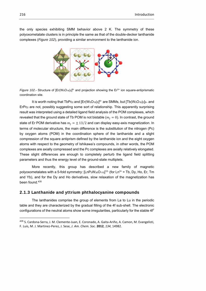
216 Introduction
the only species exhibiting SMM behavior above 2 K. The symmetry of these
polyoxometalate clusters is in principle the same as that of the double-decker lanthanide
complexes (Figure 102), providing a similar environment to the lanthanide ion.
Figure 102.- Structure of [Er(W5O18)2]9- and projection showing the Er3+ ion square-antiprismatic
coordination site.
It is worth noting that TbPc2 and [Er(W5O18)2]9− are SMMs, but [Tb(W5O18)2]9− and
ErPc2 are not, possibly suggesting some sort of relationship. This apparently surprising
result was interpreted using a detailed ligand field analysis of the POM complexes, which
revealed that the ground state of Tb POM is not bistable ( 0). In contrast, the ground
state of Er POM derivative has 13 2⁄ and can display easy-axis magnetization. In
terms of molecular structure, the main difference is the substitution of the nitrogen (Pc)
by oxygen atoms (POM) in the coordination sphere of the lanthanide and a slight
compression of the square antiprism defined by the lanthanide ion and the eight oxygen
atoms with respect to the geometry of Ishikawa’s compounds, in other words, the POM
complexes are axially compressed and the Pc complexes are axially relatively elongated.
These slight differences are enough to completely perturb the ligand field splitting
parameters and thus the energy level of the ground-state multiplets.
More recently, this group has described a new family of magnetic
polyoxometalates with a 5-fold symmetry: [LnP5W30O110]12- (for Ln3+ = Tb, Dy, Ho, Er, Tm
and Yb), and for the Dy and Ho derivatives, slow relaxation of the magnetization has
been found.435
2.1.3 Lanthanide and yttrium phthalocyanine compounds
The lanthanides comprise the group of elements from La to Lu in the periodic
table and they are characterized by the gradual filling of the 4f sub-shell. The electronic
configurations of the neutral atoms show some irregularities, particularly for the stable 4f7
435 S. Cardona‐Serra, J. M. Clemente‐Juan, E. Coronado, A. Gaita‐Ariño, A. Camon, M. Evangelisti, F. Luis, M. J. Martinez‐Perez, J. Sese, J. Am. Chem. Soc. 2012, 134, 14982.
Chapter 2 217
configurations found in Eu and Gd. The trivalent cations of the lanthanides however,
show strict regularity, all having the 4fn5d06s0 electronic configuration.436 The chemistry
of yttrium is usually reported with that of the lanthanides because it lies above lanthanum
in group 3 of the periodic table; it has no 4f electrons, but forms a +3 ion with the Kr noble
gas core and the size of both its atomic and ionic radii are comparable to Tb and Dy. It is
also generally found in nature along with the lanthanides and resembles the Tb(III) and
Dy(III) compounds in its compounds.437 The absence of 4f electrons and the closed shell
of Y(III) ion means the metallic core of its compounds are diamagnetic in nature and they
therefore provide a good comparative study of magnetic phenomena in the lanthanides.
The characteristic oxidation state of the lanthanides is the +3, but the +2 oxidation state
is also important with the Eu+2 and Yb+2 being the most stable of the di-positive ions.
Although higher oxidation states occur, they are not usual. Cerium forms a stable +4
species in aqueous solution. Dy, Tb, Pr, and Nd also form the +4 species.438 There is a
reduction in atomic size with an increase in atomic number in the lanthanides, the so
called lanthanide contraction.439 This trend is even more apparent in the radii of the
trivalent ions. The reduction in size is due to the poor shielding of the 4f electrons as the
nuclear charge increases. The electrons responsible for the properties of the lanthanide
ions are the 4f electrons and the 4f orbitals are effectively shielded from the influence of
external forces by the overlying 5s2 and 5p6 shells.437 The result is that the electronic
states arising from the various 4f n configurations are not significantly affected by
surrounding ions and do not vary much for a given ion in all its compounds.
The Russell-Saunders437,440 coupling gives a good approximation for the
electronic states of the 4f n configurations. Spin-orbit coupling is present in lanthanide
ions with non-zero orbital angular momentum. The spin-orbit couplings are also very
large. This result in most of the lanthanide ions having ground states with well-defined
values of total angular momentum, J, and the next lowest J state at energies many times
the product of Boltzmann constant and temperature ( ). The magnetic susceptibilities
and magnetic moments are for most part calculated from the well defined ground state
and are in good agreement with experiment. For the lanthanides, the external fields do
not either appreciably split the free ion terms or quench orbital angular momentum.437 In
436 J. E. Huheey, Inorganic chemistry: principles of structure and reactivity (2nd ed.), John Wiley and Sons, New York, 1978. 437 F. A. Cotton, G. Wilkinson, Advanced inorganic chemistry: a comprehensive text (4th ed.), John Wiley and Sons, New York, 1980. 438 T. Moeller, J. Chem. Educ. 1970, 47, 417. 439 K. S. Pitzer, Acc. Chem. Res, 1979, 12, 271. 440 J. G. Conway, B. G. Wybourne, Phys. Rev. 1963, 130, 2325.
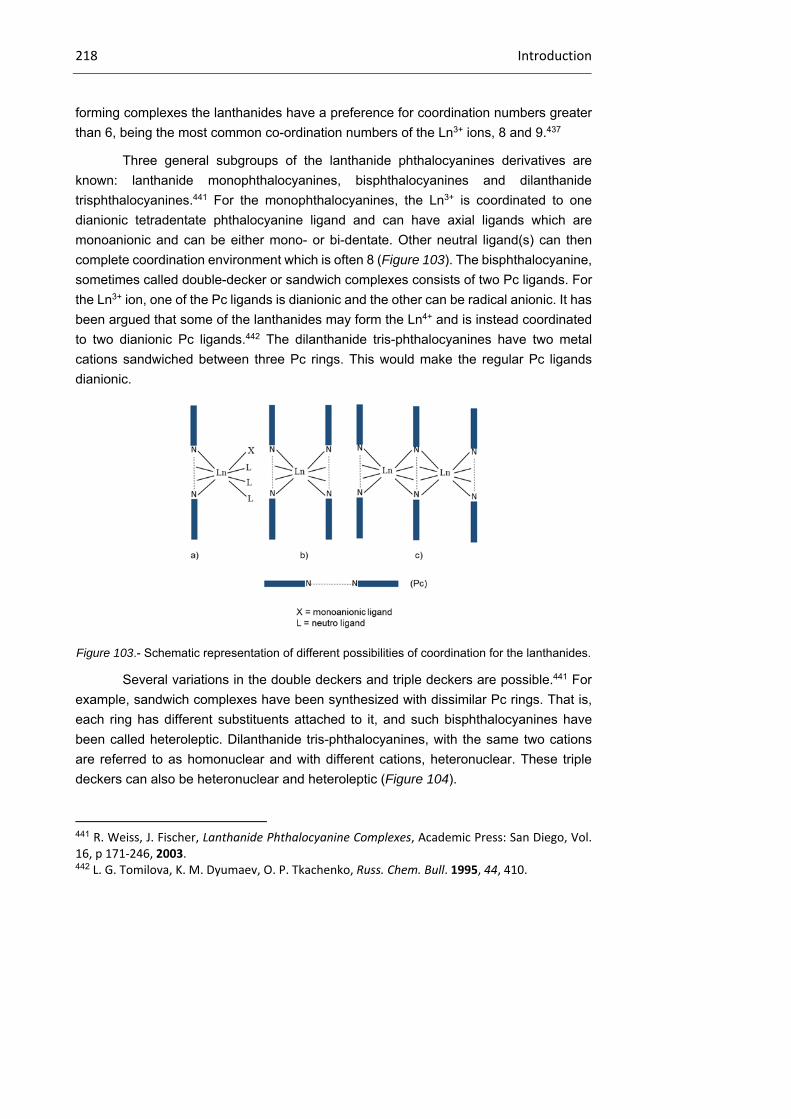
218 Introduction
forming complexes the lanthanides have a preference for coordination numbers greater
than 6, being the most common co-ordination numbers of the Ln3+ ions, 8 and 9.437
Three general subgroups of the lanthanide phthalocyanines derivatives are
known: lanthanide monophthalocyanines, bisphthalocyanines and dilanthanide
trisphthalocyanines.441 For the monophthalocyanines, the Ln3+ is coordinated to one
dianionic tetradentate phthalocyanine ligand and can have axial ligands which are
monoanionic and can be either mono- or bi-dentate. Other neutral ligand(s) can then
complete coordination environment which is often 8 (Figure 103). The bisphthalocyanine,
sometimes called double-decker or sandwich complexes consists of two Pc ligands. For
the Ln3+ ion, one of the Pc ligands is dianionic and the other can be radical anionic. It has
been argued that some of the lanthanides may form the Ln4+ and is instead coordinated
to two dianionic Pc ligands.442 The dilanthanide tris-phthalocyanines have two metal
cations sandwiched between three Pc rings. This would make the regular Pc ligands
dianionic.
Figure 103.- Schematic representation of different possibilities of coordination for the lanthanides.
Several variations in the double deckers and triple deckers are possible.441 For
example, sandwich complexes have been synthesized with dissimilar Pc rings. That is,
each ring has different substituents attached to it, and such bisphthalocyanines have
been called heteroleptic. Dilanthanide tris-phthalocyanines, with the same two cations
are referred to as homonuclear and with different cations, heteronuclear. These triple
deckers can also be heteronuclear and heteroleptic (Figure 104).
441 R. Weiss, J. Fischer, Lanthanide Phthalocyanine Complexes, Academic Press: San Diego, Vol. 16, p 171‐246, 2003. 442 L. G. Tomilova, K. M. Dyumaev, O. P. Tkachenko, Russ. Chem. Bull. 1995, 44, 410.

Chapter 2 219
Figure 104.- a) porphyrin-phthalocyanine double-decker; b) porphyrin-phthalocyanine triple-
decker.
2.1.3.1 Synthesis methods
There have been several reported methods for the preparation of
bisphthalocyanines.443 A popular method of synthesis is the solid state reaction of the
substituted or un-substituted phthalonitriles and the lanthanide salt such as the acetate,
as is shown in Scheme 30.
Scheme 30.- Synthethic procedure to obtain homoleptic compounds.
443 a) V. E. Pushkarev, L. G. Tomilova, Y. V. Tomilov, Russ. Chem. Rev. 2008, 77, 875; b) J. Jiang, D. K. P. Ng, Acc. Chem. Res. 2009, 42, 79.

220 Introduction
These reactions are a template reaction resulting in cyclic tetramerization of the
phthalonitrile using the metal center. Reported difficulties with purifying the products of
the solid state reaction, probably led to the development of solution reactions in which
cyclotetramerization of the phthalonitrile occurred in alcohol with the presence of
DBU444,445 or in dimethylethanolamine.445 The sandwich molecules can also be prepared
from metal insertion into the metal free phthalocyanine analogues.446 There are several
established methods for the synthesis of metal free phthalocyanines. These also involve
the cyclotetramerization of the respective phthalonitrile and include methods such as the
cerium promoted synthesis,447 lithium metal in alcohol (followed by acid work-up),448 and
the use of ionic liquids such as 1,1,3,3-tetramethylguaninidinium trifluoracetate.449 The
synthesis of the heteroleptic double deckers poses a greater challenge. It can be
achieved by the reaction of one LnPc′ and the phthalonitrile necessary for the second
substituted lanthanide phthalocyanine ring (Pc″), forming the (Pc′)Ln( Pc″) complex. The
reaction of an alkali metal salt, with two different macrocycles and the lanthanide salt
produces the heteroleptic as well as homoleptic species.450,451
2.1.3.2 Oxidized and reduced bisphthalocyanines
The lanthanide phthalocyaninate anions, [(LnPc2)]− was first made by Konami et
al.452 This synthesis method used was cyclic tetramerization of phthalonitrile in the
presence of the lanthanide salt and sodium carbonate. Separation of the sodium salts
Na[Pc2Ln] and the addition of NBu4Br yielded the TBA salts NBu4[LnPc2]. The sandwich
compound has been reduced with hydrazine in the presence of tetrabutylammonium
perchlorate and it yielded NBu4[LnPc2].453 The oxidized double decker [LnPc2]+ species
has been reportedly synthesized as the compound [LnPc2]SbCl6.This complex is
444 A. De Cian, M. Moussavi, J. Fischer, R. Weiss, Inorg. Chem. 1985, 24, 3162. 445 J. Sleven, C. Gorller‐Walrand, K. Binnemans, Mat. Sci. Eng. C 2001, 18, 229. 446 M. L´Her, Y. Cozien, J. Courtot‐Coupez, J. Electroanal. Chem. Interfacial Electrochem. 1983, 157, 183. 447 C.‐H. Lee, D. K. P. Ng, Tetrahedron Lett. 2002, 43, 4211. 448 M. J. Cook, A. J. Dunn, S. D. Howe, A. J. Thomson, K. J. Harrison, J. Chem. Soc., Perkin Trans. 1 1988, 8, 2453. 449 A. Shaabani, A. Maleki, J. Porphyrins Phthalocyanines 2006, 10, 1253. 450 W. Liu, J. Jiang, N. Pan, D. P. Arnold, Inorg. Chim. Acta 2000, 310, 140. 451 V. E. Pushkarev, M. O. Breusova, S. E. Nefedov, L. G. Tomilova, Mendeleev Commun. 2007, 17, 220. 452 H. Konami, M. Hatano, A. Taijiri, Chem. Phys. Lett. 1989, 160, 163. 453 M. Moussavi, A. De Cian, J. Fischer, R. Weiss, Inorg. Chem. 1988, 27, 1287.
Chapter 2 221
expected to contain two Pc radical anionic macrocycles.454 The synthesis and
characterization of the SbCl6− precursor has been reported.455,456
2.1.3.3 Properties and applications
While the SMM behavior of double-decker pthalocyanine lanthanide complexes
have been reported only recently, these systems have been known for many years.
Indeed, the first synthesis of a lanthanide double-decker complex dates back to 1965,457
and the lutetium(III) complex was structurally characterized as early as 1985.444 Lu
double-decker phthalocyanine complexes were also among the first molecular compound
behaving as semi-conductors,458 and have even been studied for field effect transistor
applications.459 In 1989, Belarbi et al. obtained a series of alkoxy functionalized double-
decker phthalocyanine complexes and demonstrated their mesomorphic properties.460
The phase behavior of functionalized lanthanide DD phthalocyanine complexes would
later be the subject of many articles, demonstrating the versatility of the property.461
One of the most interesting reported characteristics of functionalized double-
decker complexes towards nanotechnological applications is their ability to form well
packed self-assembled monolayers over a graphite surface. This was demonstrated by
STM experiments performed at the liquid-graphite interface.462 This, combined with the
single-molecule magnet behavior of the complexes, allows in principle to prepare a 2D-
454 S. Takamatsu, N. Ishikawa, Polyhedron 2007, 26, 1859. 455 N. Carnieri, A. Harriman, Inorg. Chim. Acta 1982, 62, 103. 456 P. Gans, G. Buisson, E. Duee, J.‐C. Marchon, B. S. Erler, W. F. Scholz, C. A. Reed, J. Am. Chem. Soc. 1986, 108, 1223. 457 I. S. Kirin, P. N. Moskalev, Y. A. Makashev, Russ. J. Inorg. Chem. 1965, 10, 1065. 458 a) M. Maitrot, G. Guillaud, B. Boudjema, J.‐J. Andre, H. Strzelecka, J. Simon, R. Even, Chem. Phys. Lett. 1987, 133, 59; b) P. Turek, P. Petit, J.‐J. Andre, J. Simon, R. Even, B. Boudjema, G. Guillaud, M. Maitrot, J. Am. Chem. Soc. 1987, 109, 5119; c) A. T. Chang, J.‐C. Marchon, Inorg. Chim. Acta 1981, 53, 241. 459 a) N. B. Chaure, J. L. Sosa‐Sanchez, A. N. Cammidge, M. J. Cook, A. K. Ray, Org. Elec. 2010, 11, 434; b) G. Chaidogiannos, F. Petraki, N. Glezos, S. Kennou, S. Nespurek, Mat. Sci. Eng. B 2008, 152, 105. 460 Z. Belarbi, C. Sirlin, J. Simon, J.‐J. Andre, J. Phys. Chem. 1989, 93, 8105. 461 a) C. F. van Nostrum, S. J. Picken, A.‐J. Schouten, R. J. M. Nolte, J. Am. Chem. Soc. 1995, 117, 9957; b) K. Ban, K. Nishizawa, K. Ohta, A. M. van de Craats, J. M. Warman, I. Yamamoto, H. Shirai, J. Mater. Chem. 2001, 11, 321; c) K. Binnemans, C. Gorller‐Walrand, Chem. Rev. 2002, 102, 2303; d) A. G. Gurek, T. Basova, D. Luneau, C. Lebrun, E. Koltsov, A. K. Hassan, V. Ahsen, Inorg. Chem. 2006, 45, 1667. 462 a) K. Binnemans, J. Sleven, S. De Feyter, F. C. De Schryver, B. Donnio, D. Guillon, Chem. Mater. 2003, 15, 3930; b) A. S. Klymchenko, J. Sleven, K. Binnemans, S. De Feyter, Langmuir 2006, 22, 723.

222 Introduction
array of independent nanometric units, which could represent individual data bits of a
hypothetical ultra high density storage device (albeit at very low temperature).463
Finally, another interesting property of double-decker complexes is their
electroactivity.464,465 Indeed, these complexes can be oxidized or reduced to a variety of
oxidation states ranging from -5 to +2. This is yet another degree of freedom added to
the possibilities of the system in order to study its magnetic behavior, since the magnetic
properties of the different oxidation states are likely to be different from one another. It
has already been shown above that Ishikawa, and coworkers have reported how upon
oxidation to the neutral complex, the magnetic properties of the anionic double-decker
Tb(III) phthalocyanine complex are strongly modified, and present a higher effective
barrier.466
2.1.4 Terbium(III) bisphthalocyaninato complexes
In 2002, after working with double and triple decker phthalocyanine complexes
for several years,467,468,469,470,471 Ishikawa et al. established a new method to determine
the ligand field parameters of a series of neutral triple decker lanthanide complexes by
theoretical analysis of their magnetic susceptibility and their 1H-NMR spectra. Therefore,
they could extract the energy diagram of the ground-state multiplets of the complexes.472
The method was then applied to the determination of the ligand-field parameters of the
closed-shell anionic double-decker lanthanide complexes, extracting again the
groundstate multiplets energy diagram (Figure 105).473
463 J. Gomez‐Segura, I. Diez‐Perez, N. Ishikawa, M. Nakano, J. Veciana, D. Ruiz‐Molina, Chem. Comm. 2006, 2866. 464 P. Zhu, F. Lu, N. Pan, D. P. Arnold, S. Zhang, J. Jiang, Eur. J. Inorg. Chem. 2004, 2004, 510. 465 K. M. Kadish, T. Nakanishi, A. Gurek, V. Ahsen, I. Yilmaz, J. Phys. Chem. B 2001, 105, 9817. 466 N. Ishikawa, M. Sugita, N. Tanaka, T. Ishikawa, S.‐y. Koshihara, Y. Kaizu, Inorg. Chem. 2004, 43, 5498. 467 N. Ishikawa, Y. Kaizu, J. Phys. Chem. 1996, 100, 8722. 468 N. Ishikawa, T. Okubo, Y. Kaizu, Inorg. Chem. 1999, 38, 3173. 469 N. Ishikawa, Y. Kaizu, J. Phys. Chem. A 2000, 104, 10009. 470 N. Ishikawa, J. Porphyrins Phthalocyanines 2001, 5, 87. 471 N. Ishikawa, T. Iino, Y. Kaizu, J. Am. Chem. Soc. 2002, 124, 11440. 472 N. Ishikawa, T. Iino, Y. Kaizu, J. Phys. Chem. A 2002, 106, 9543. 473 N. Ishikawa, M. Sugita, T. Okubo, N. Tanaka, T. Iino, Y. Kaizu, Inorg. Chem. 2003, 42, 2440.
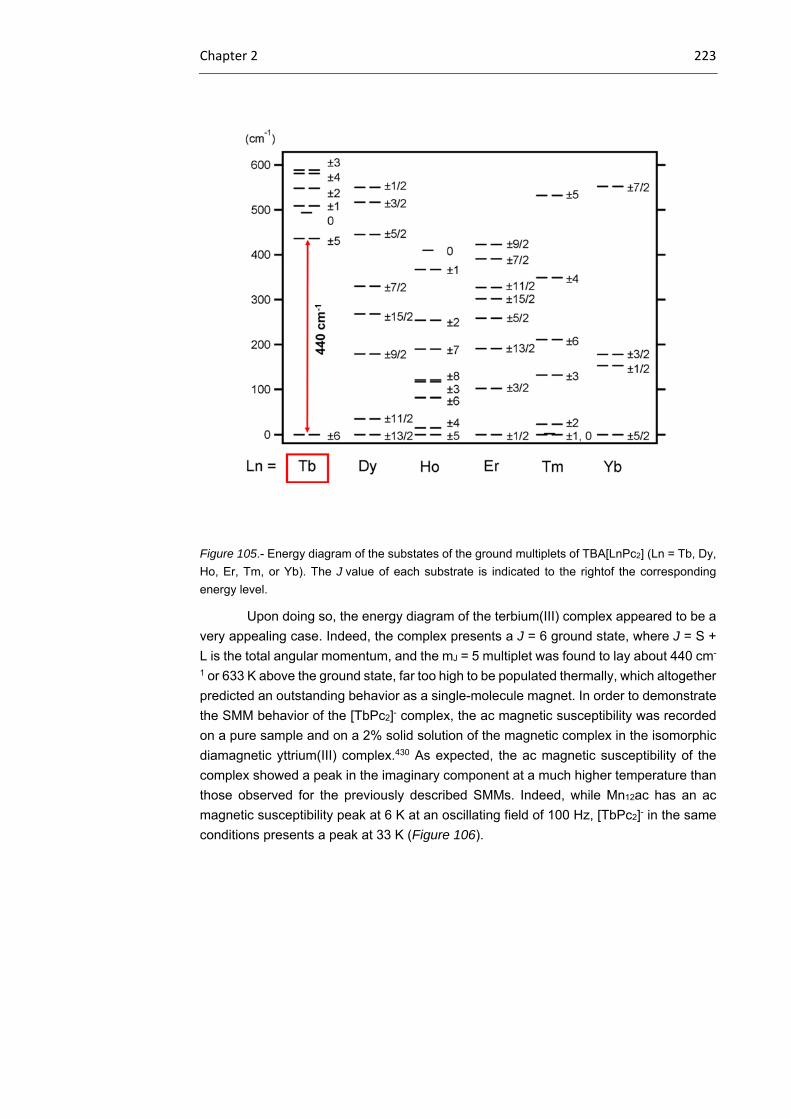
Chapter 2 223
Figure 105.- Energy diagram of the substates of the ground multiplets of TBA[LnPc2] (Ln = Tb, Dy,
Ho, Er, Tm, or Yb). The J value of each substrate is indicated to the rightof the corresponding
energy level.
Upon doing so, the energy diagram of the terbium(III) complex appeared to be a
very appealing case. Indeed, the complex presents a J = 6 ground state, where J = S +
L is the total angular momentum, and the mJ = 5 multiplet was found to lay about 440 cm-
1 or 633 K above the ground state, far too high to be populated thermally, which altogether
predicted an outstanding behavior as a single-molecule magnet. In order to demonstrate
the SMM behavior of the [TbPc2]- complex, the ac magnetic susceptibility was recorded
on a pure sample and on a 2% solid solution of the magnetic complex in the isomorphic
diamagnetic yttrium(III) complex.430 As expected, the ac magnetic susceptibility of the
complex showed a peak in the imaginary component at a much higher temperature than
those observed for the previously described SMMs. Indeed, while Mn12ac has an ac
magnetic susceptibility peak at 6 K at an oscillating field of 100 Hz, [TbPc2]- in the same
conditions presents a peak at 33 K (Figure 106).

224 Introduction
Figure 106.- Real M’ (above) and imaginary M
’’ (middle and below) components of the ac magnetic
susceptibility of [TbPc2]- (open symbols) and of a 2% dilution of the same in the diamagnetic [YPc2]-
complex (solid symbols).
It is also interesting to notice that upon dilution, the characteristics of the complex
were not lessened, but that on the contrary, the blocking temperature observed in the ac
magnetic susceptibility curves were even increased. This was taken as a demonstration
that the magnetic behavior was effectively an intramolecular one and that the weak
intermolecular interactions were actually detrimental.
These data were completed later by magnetic hysteresis measurements done in
the same solid solution conditions (Figure 107).474
474 N. Ishikawa, M. Sugita, T. Ishikawa, S.‐y. Koshihara, Y. Kaizu, J. Phys. Chem. B 2004, 108, 11265.

Chapter 2 225
¡
Figure 107.- Magnetization vs field plot measured at 1.7 K for a powder sample of [TbPc2]-TBA+
diluted at a concentration of 2% in [YPc2]-TBA+.
Despite the very high blocking temperature seen in the ac magnetic susceptibility
of the [TbPc2]- complex, the magnetization hysteresis was observed only at quite a low
temperature (1.7 K), and it proved to be quite narrow close to zero-field (i.e. it presented
a very small coercive field and a very small remnant magnetization). The magnetization
hysteresis of the Dy complex was even narrower close to zero-field than that of the Tb
complex.
The relaxation mechanisms involved in the [TbPc2]- complexes were studied via
Arrhenius analysis of the relaxation rate 1⁄ and the results are shown in Figure 108. In
a non-Kramer system, that is when there is an even number of electrons like in Tb3+ (4f8),
the relaxation time of the paramagnetic ion is given by the spin-lattice relaxation and
obeys:475
coth 2⁄ ∆ ∆⁄ 1 Eq. 11
Figure 108.- Arrhenius plot of
as a function of 1⁄ for the anionic
terbium double-decker phthalocyanine
complex (triangles) and the diluted
sample of the same in the yttrium
diamagnetic equivalent matrix (circles).
475 A. Abragam, B. Bleaney, Electron Paramagnetic Resonance,Chapter 10, Clarandon press, Oxford, 1970.
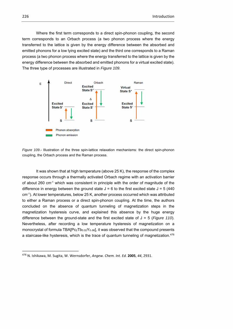
226 Introduction
Where the first term corresponds to a direct spin-phonon coupling, the second
term corresponds to an Orbach process (a two phonon process where the energy
transferred to the lattice is given by the energy difference between the absorbed and
emitted phonons for a low lying excited state) and the third one corresponds to a Raman
process (a two phonon process where the energy transferred to the lattice is given by the
energy difference between the absorbed and emitted phonons for a virtual excited state).
The three type of processes are illustrated in Figure 109.
Figure 109.- Illustration of the three spin-lattice relaxation mechanisms: the direct spin-phonon
coupling, the Orbach process and the Raman process.
It was shown that at high temperature (above 25 K), the response of the complex
response occurs through a thermally activated Orbach regime with an activation barrier
of about 260 cm-1 which was consistent in principle with the order of magnitude of the
difference in energy between the ground state J = 6 to the first excited state J = 5 (440
cm-1). At lower temperatures, below 25 K, another process occurred which was attributed
to either a Raman process or a direct spin-phonon coupling. At the time, the authors
concluded on the absence of quantum tunneling of magnetization steps in the
magnetization hysteresis curve, and explained this absence by the huge energy
difference between the ground-state and the first excited state of J = 5 (Figure 110).
Nevertheless, after recording a low temperature hysteresis of magnetization on a
monocrystal of formula TBA[Pc2Tb0.02Y0.98], it was observed that the compound presents
a staircase-like hysteresis, which is the trace of quantum tunneling of magnetization.476
476 N. Ishikawa, M. Sugita, W. Wernsdorfer, Angew. Chem. Int. Ed. 2005, 44, 2931.

Chapter 2 227
Since the J = 6 and the J = 5 states are too far apart, the observed resonant tunneling
could not be due to a transition between them.
Figure 110.- Zeeman energy diagram for the J = 6 ground-state multiplet.
Instead, it was realized that terbium presents a nucleus with I = 3/2 in 100% natural
abundance. Therefore, taking into account the interaction between the nucleus and the
4f8 system, the appropriate Hamiltonian for the system still contains the ligand field terms
but one should add two additional terms corresponding to the hyperfine interaction AhfJJ
and the nuclear quadrupole interaction. Taking into account all of these parameters, it
was therefore possible to assign the tunneling steps in the magnetization hysteresis
curve to QTM between |±J>|±I> substates of the J = 6 ground-state in the range of a few
mK (Figure 111). This nuclear spin driven quantum tunneling of magnetization was also
demonstrated in a Holmium double-decker phthalocyanine complex.477
477 N. Ishikawa, M. Sugita, W. Wernsdorfer, J. Am. Chem. Soc. 2005, 127, 3650.
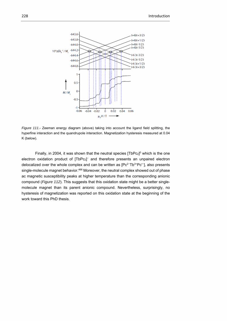
228 Introduction
Figure 111.- Zeeman energy diagram (above) taking into account the ligand field splitting, the
hyperfine interaction and the quandrupole interaction. Magnetization hysteresis measured at 0.04
K (below).
Finally, in 2004, it was shown that the neutral species [TbPc2]0 which is the one
electron oxidation product of [TbPc2]− and therefore presents an unpaired electron
delocalized over the whole complex and can be written as [Pc2−Tb3+Pc•−], also presents
single-molecule magnet behavior.466 Moreover, the neutral complex showed out of phase
ac magnetic susceptibility peaks at higher temperature than the corresponding anionic
compound (Figure 112). This suggests that this oxidation state might be a better single-
molecule magnet than its parent anionic compound. Nevertheless, surprisingly, no
hysteresis of magnetization was reported on this oxidation state at the beginning of the
work toward this PhD thesis.
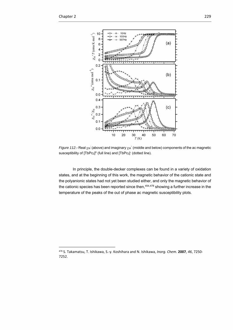
Chapter 2 229
Figure 112.- Real M’ (above) and imaginary M
’’ (middle and below) components of the ac magnetic
susceptibility of [TbPc2]0 (full line) and [TbPc2]- (dotted line).
In principle, the double-decker complexes can be found in a variety of oxidation
states, and at the beginning of this work, the magnetic behavior of the cationic state and
the polyanionic states had not yet been studied either, and only the magnetic behavior of
the cationic species has been reported since then,454,478 showing a further increase in the
temperature of the peaks of the out of phase ac magnetic susceptibility plots.
478 S. Takamatsu, T. Ishikawa, S.‐y. Koshihara and N. Ishikawa, Inorg. Chem. 2007, 46, 7250‐7252.

230 Objectives
2.2 Objectives
The main goal of the present section of chapter 1 is the preparation and in depth
structural and magnetic characterization of a series of Tb(III) bisphthalocyaninato
complexes in their neutral or anionic forms (as tetraalkylammonium salts), holding
different peripheral substituents in either one or two of the Pc ligands. Therefore we aim
to prepare various homoleptic and heteroleptic Tb(III) double-decker complexes, which
will allow us to estimate the possible influence of the number and electronic nature of
the peripheral substituents, as well as the presence or not of an unpaired electron at the
Pc ligands, on the SMM behavior of these type of complexes.
Synthesis of homoleptic and heteroleptic Tb(III) bisphthalocyaninato
The magnetic behavior of lanthanide double-decker has been studied only on the
archetypal LnPc2, without substitution of the macrocyclic rings. By chemical modification
of the phthalocyanine ligands, the objective of this work is to synthesize new
functionalized homoleptic and heteroleptic Tb(III) double-decker (Figure 113), both as
neutral forms as anionic derivatives, in order to produce functional magnetic material.
Figure 113.- Molecular structure of a) homoleptic and b) heteroleptic terbium(III) bisphthalocyanine
complexes.
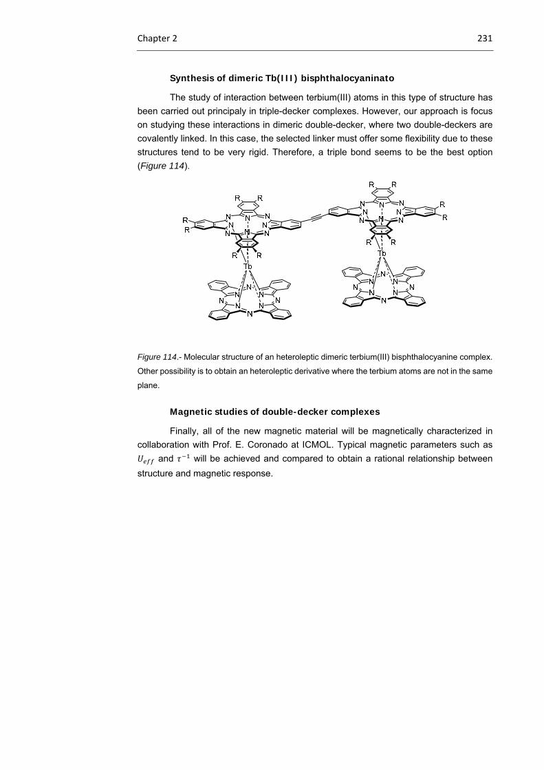
Chapter 2 231
Synthesis of dimeric Tb(III) bisphthalocyaninato
The study of interaction between terbium(III) atoms in this type of structure has
been carried out principaly in triple-decker complexes. However, our approach is focus
on studying these interactions in dimeric double-decker, where two double-deckers are
covalently linked. In this case, the selected linker must offer some flexibility due to these
structures tend to be very rigid. Therefore, a triple bond seems to be the best option
(Figure 114).
Figure 114.- Molecular structure of an heteroleptic dimeric terbium(III) bisphthalocyanine complex.
Other possibility is to obtain an heteroleptic derivative where the terbium atoms are not in the same
plane.
Magnetic studies of double-decker complexes
Finally, all of the new magnetic material will be magnetically characterized in
collaboration with Prof. E. Coronado at ICMOL. Typical magnetic parameters such as
and will be achieved and compared to obtain a rational relationship between
structure and magnetic response.
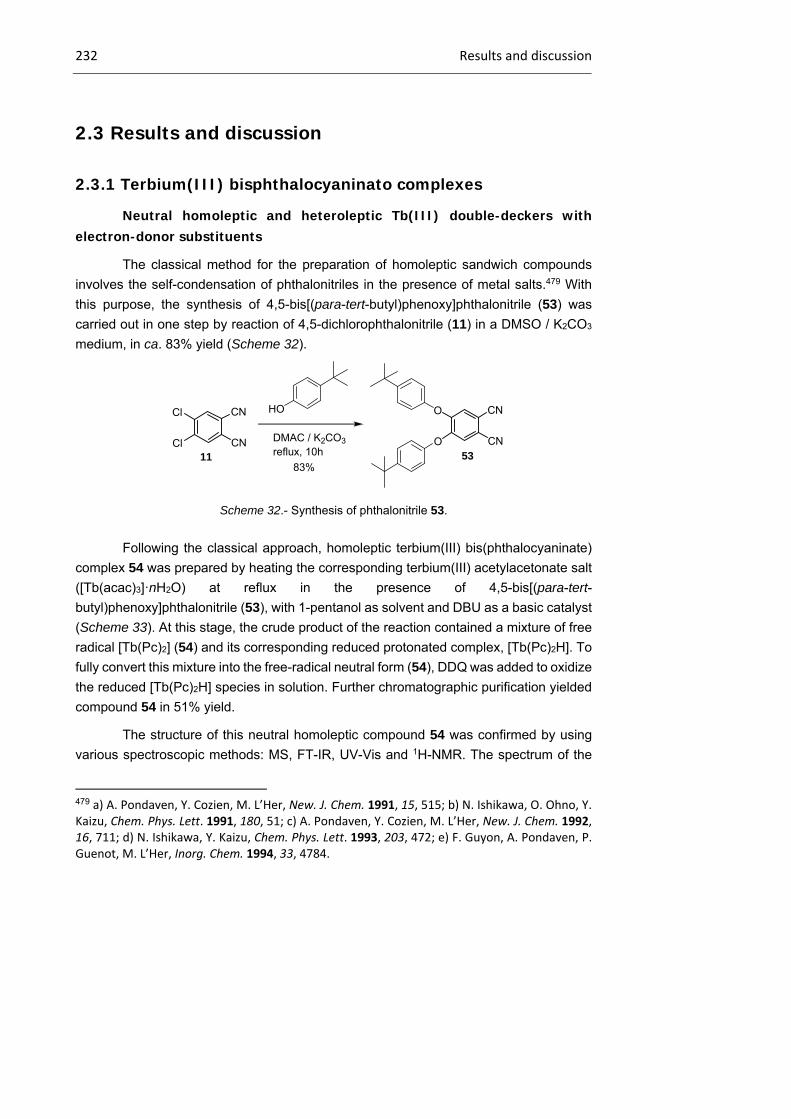
232 Results and discussion
2.3 Results and discussion
2.3.1 Terbium(III) bisphthalocyaninato complexes
Neutral homoleptic and heteroleptic Tb(III) double-deckers with electron-donor substituents
The classical method for the preparation of homoleptic sandwich compounds
involves the self-condensation of phthalonitriles in the presence of metal salts.479 With
this purpose, the synthesis of 4,5-bis[(para-tert-butyl)phenoxy]phthalonitrile (53) was
carried out in one step by reaction of 4,5-dichlorophthalonitrile (11) in a DMSO / K2CO3
medium, in ca. 83% yield (Scheme 32).
Scheme 32.- Synthesis of phthalonitrile 53.
Following the classical approach, homoleptic terbium(III) bis(phthalocyaninate)
complex 54 was prepared by heating the corresponding terbium(III) acetylacetonate salt
([Tb(acac)3]·nH2O) at reflux in the presence of 4,5-bis[(para-tert-
butyl)phenoxy]phthalonitrile (53), with 1-pentanol as solvent and DBU as a basic catalyst
(Scheme 33). At this stage, the crude product of the reaction contained a mixture of free
radical [Tb(Pc)2] (54) and its corresponding reduced protonated complex, [Tb(Pc)2H]. To
fully convert this mixture into the free-radical neutral form (54), DDQ was added to oxidize
the reduced [Tb(Pc)2H] species in solution. Further chromatographic purification yielded
compound 54 in 51% yield.
The structure of this neutral homoleptic compound 54 was confirmed by using
various spectroscopic methods: MS, FT-IR, UV-Vis and 1H-NMR. The spectrum of the
479 a) A. Pondaven, Y. Cozien, M. L’Her, New. J. Chem. 1991, 15, 515; b) N. Ishikawa, O. Ohno, Y. Kaizu, Chem. Phys. Lett. 1991, 180, 51; c) A. Pondaven, Y. Cozien, M. L’Her, New. J. Chem. 1992, 16, 711; d) N. Ishikawa, Y. Kaizu, Chem. Phys. Lett. 1993, 203, 472; e) F. Guyon, A. Pondaven, P. Guenot, M. L’Her, Inorg. Chem. 1994, 33, 4784.
Cl
Cl CN
CN11
DMAC / K2CO3
reflux, 10h
CN
CN53
O
O
83%
HO

Chapter 2 233
latter could be recorded upon the addition of hydrazine hydrate to a solution of this
compound in a mixture of DMF-d7 and CCl4. In this way, the -radical form was
transformed into the reduced form, which is the active specie in NMR.
Scheme 33.- Synthesis of homoleptic double-decker 54 in its neutral form.
In Figure 115 are exhibited the large negative chemical shifts for the aromatic
protons on the Pc ligands of compound 54, as a consequence of the strong, upfield
paramagnetic shifts that are induced by the terbium(III) ion.480
Figure 115.- 1H-NMR spectrum of compound 54 in DMF-d7/CCl4.
480 N. Ishikawa, T. Iino, Y. Kaizu, J. Phys. Chem. A 2003, 107, 7879.

234 Results and discussion
Regarding heteroleptic rare-earth-metal bis(phthalocyaninate) compounds, the
most convenient method in terms of simplicity and product conversion, involves the
formation of an intermediate mononuclear lanthanide(III) Pc complex, starting from the
free-base macrocycle, followed by cyclic tetramerization of the phthalonitrile (or
naphthaloitrile) around the terbium(III) center of the preformed
monophthalocyaninate.481,482 The synthesis of the free-base 55 and 56 was carried out
employing the corresponding phthalonitriles 53 and the commercially available 4-tert-
butylphthalonitrile, respectively:
Scheme 34.- Synthesis of symmetrically substituted metal-free Pc 55 and 56.
Compounds 55 and 56 were obtained following the standard procedure depicted
in Scheme 34. The purified phthalonitrile 53 was cyclized in a refluxing mixture of 1-
pentanol and lithium metal. In these conditions, a dilithium phthalocyaninate (PcLi2) was
obtained, which was further converted in the metal-free Pc 55 by addition of glacial acetic
acid. Purification by column chromatography led to the isolation of metal-free Pc 55 in
33% yield. The same procedure was followed for macrocycle 56 (35%). Afterwards, the
preparation of heteroleptic Tb(III) bis(phthalocyaninatos) compounds 57 and 58 began
with the reaction of their metal-free Pc derivatives (57, 58) and ([Tb(acac)3]·nH2O at ca.
170 ºC in o-DCB. The formation of the corresponding mononuclear
Tb(III)acetylacetonate-Pc intermediates (57 intermediate, 58 intermediate) was
481 a) G. Lu, M. Bai, R. Li, X. Zhang, C. Ma, P.‐C. Lo, D. K. P. Ng, J. Jiang, Eur. J. Inorg. Chem. 2006, 18, 3703; b) J. Jiang, W. Liu, W.‐F. Law, J. Lin, D. K. P. Ng, Inorg. Chim. Acta 1998, 268, 141; c) N. Sheng, R. Li, C.‐F. Choi, W. Su, D. K. P. Ng, X. Cui, K. Yoshida, N. Konayashi, J. Jiang, Inorg. Chem. 2006, 45, 3794. 482 B. Ballesteros, G. de la Torre, A. Shearer, A. Hausmann, M. A. Herranz, D. M. Guldi, T. Torres, Chem. Eur. J. 2010, 16, 14.
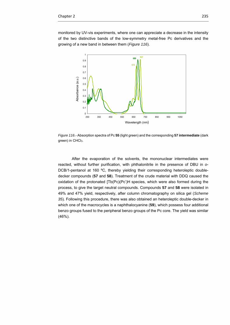
Chapter 2 235
monitored by UV-vis experiments, where one can appreciate a decrease in the intensity
of the two distinctive bands of the low-symmetry metal-free Pc derivatives and the
growing of a new band in between them (Figure 116).
Figure 116.- Absorption spectra of Pc 55 (light green) and the corresponding 57 intermediate (dark
green) in CHCl3.
After the evaporation of the solvents, the mononuclear intermediates were
reacted, without further purification, with phthalonitrile in the presence of DBU in o-
DCB/1-pentanol at 160 ºC, thereby yielding their corresponding heteroleptic double-
decker compounds (57 and 58). Treatment of the crude material with DDQ caused the
oxidation of the protonated [Tb(Pc)(Pc’)H species, which were also formed during the
process, to give the target neutral compounds. Compounds 57 and 58 were isolated in
49% and 47% yield, respectively, after column chromatography on silica gel (Scheme
35). Following this procedure, there was also obtained an heteroleptic double-decker in
which one of the macrocycles is a naphthalocyanine (59), which possess four additional
benzo groups fused to the peripheral benzo groups of the Pc core. The yield was similar
(46%).
0
0.1
0.2
0.3
0.4
0.5
0.6
0.7
0.8
0.9
1
250 350 450 550 650 750 850 950 1050Longitud de onda (nm)
Ab
sorb
an
cia
707
672
643
610
348
686
621
366
Wavelength (nm)
Abs
orba
nce
(a.u
.)
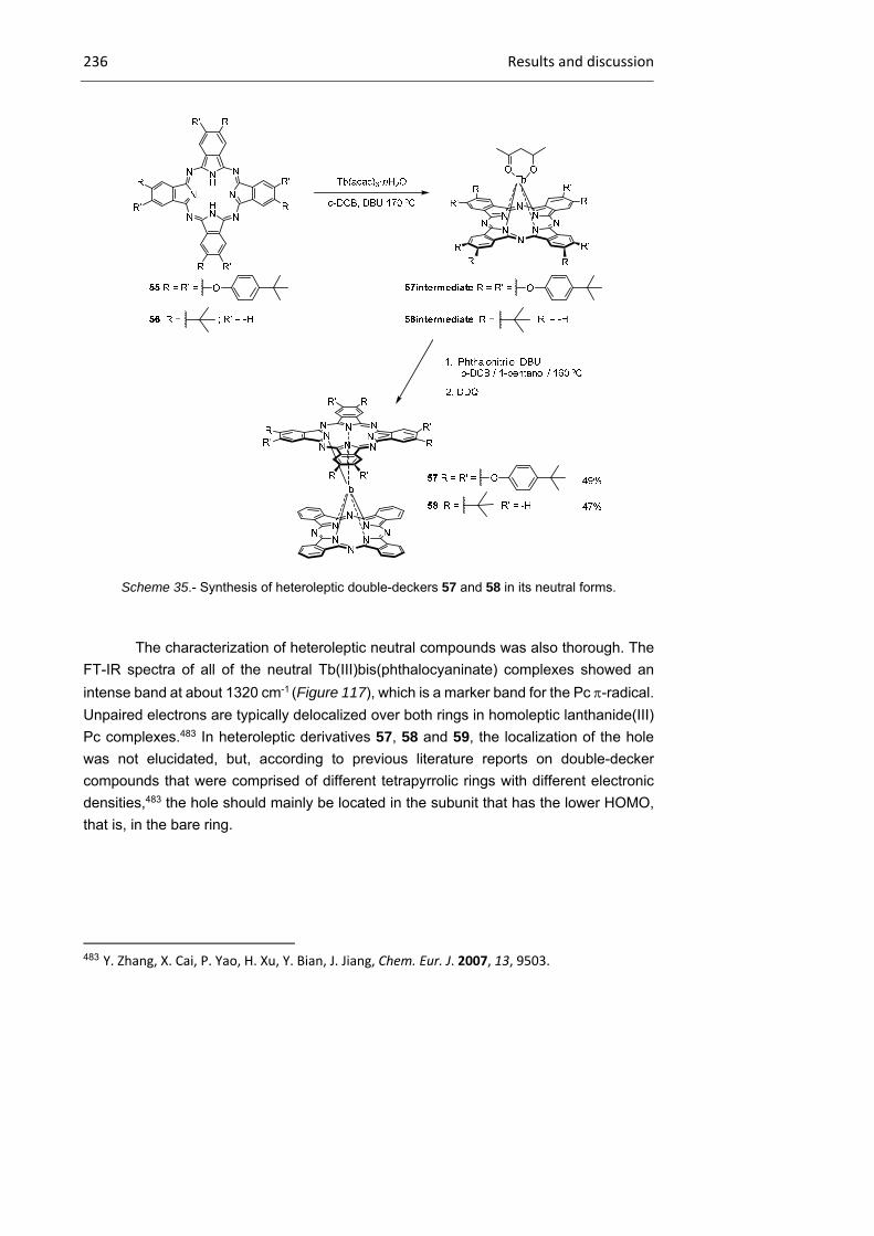
236 Results and discussion
Scheme 35.- Synthesis of heteroleptic double-deckers 57 and 58 in its neutral forms.
The characterization of heteroleptic neutral compounds was also thorough. The
FT-IR spectra of all of the neutral Tb(III)bis(phthalocyaninate) complexes showed an
intense band at about 1320 cm-1 (Figure 117), which is a marker band for the Pc -radical.
Unpaired electrons are typically delocalized over both rings in homoleptic lanthanide(III)
Pc complexes.483 In heteroleptic derivatives 57, 58 and 59, the localization of the hole
was not elucidated, but, according to previous literature reports on double-decker
compounds that were comprised of different tetrapyrrolic rings with different electronic
densities,483 the hole should mainly be located in the subunit that has the lower HOMO,
that is, in the bare ring.
483 Y. Zhang, X. Cai, P. Yao, H. Xu, Y. Bian, J. Jiang, Chem. Eur. J. 2007, 13, 9503.
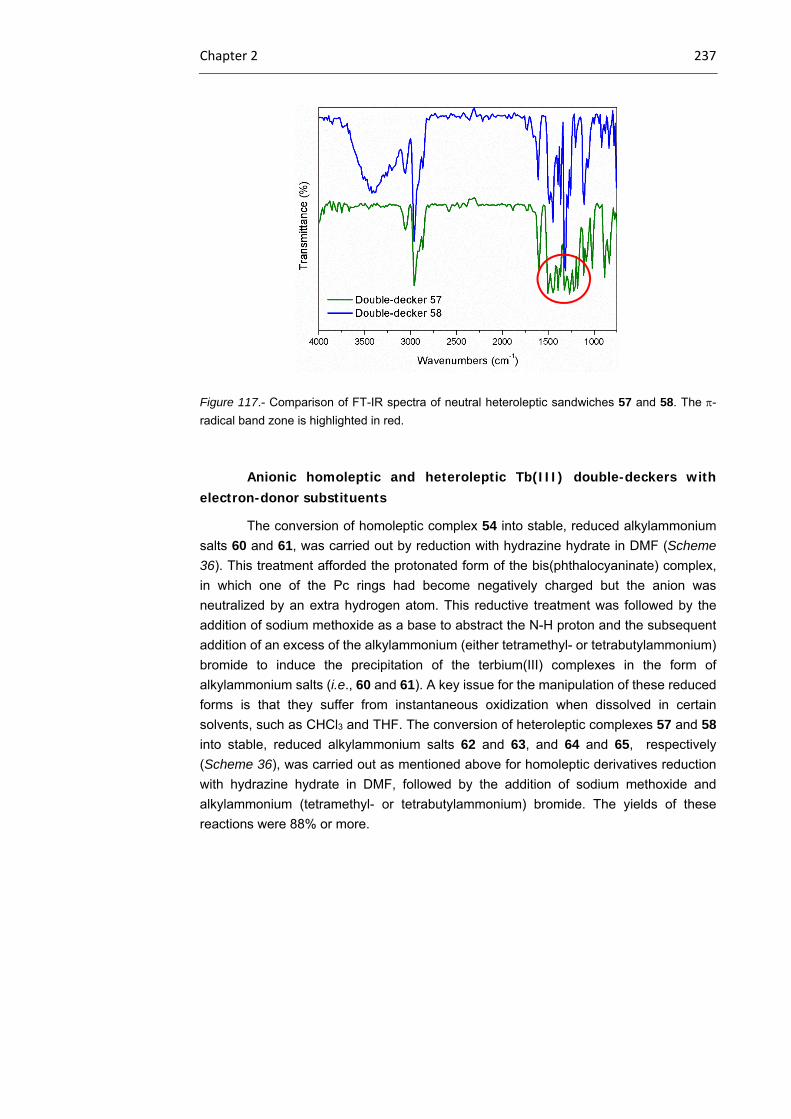
Chapter 2 237
Figure 117.- Comparison of FT-IR spectra of neutral heteroleptic sandwiches 57 and 58. The -
radical band zone is highlighted in red.
Anionic homoleptic and heteroleptic Tb(III) double-deckers with electron-donor substituents
The conversion of homoleptic complex 54 into stable, reduced alkylammonium
salts 60 and 61, was carried out by reduction with hydrazine hydrate in DMF (Scheme
36). This treatment afforded the protonated form of the bis(phthalocyaninate) complex,
in which one of the Pc rings had become negatively charged but the anion was
neutralized by an extra hydrogen atom. This reductive treatment was followed by the
addition of sodium methoxide as a base to abstract the N-H proton and the subsequent
addition of an excess of the alkylammonium (either tetramethyl- or tetrabutylammonium)
bromide to induce the precipitation of the terbium(III) complexes in the form of
alkylammonium salts (i.e., 60 and 61). A key issue for the manipulation of these reduced
forms is that they suffer from instantaneous oxidization when dissolved in certain
solvents, such as CHCl3 and THF. The conversion of heteroleptic complexes 57 and 58
into stable, reduced alkylammonium salts 62 and 63, and 64 and 65, respectively
(Scheme 36), was carried out as mentioned above for homoleptic derivatives reduction
with hydrazine hydrate in DMF, followed by the addition of sodium methoxide and
alkylammonium (tetramethyl- or tetrabutylammonium) bromide. The yields of these
reactions were 88% or more.
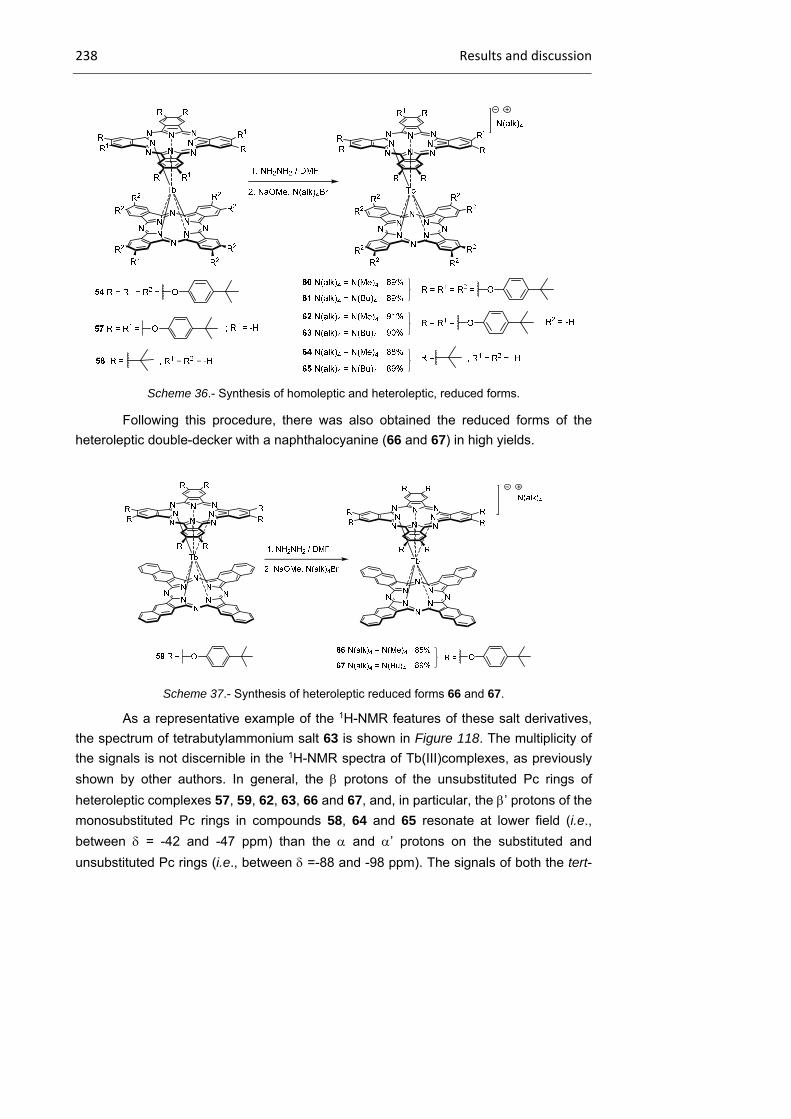
238 Results and discussion
Scheme 36.- Synthesis of homoleptic and heteroleptic, reduced forms.
Following this procedure, there was also obtained the reduced forms of the
heteroleptic double-decker with a naphthalocyanine (66 and 67) in high yields.
Scheme 37.- Synthesis of heteroleptic reduced forms 66 and 67.
As a representative example of the 1H-NMR features of these salt derivatives,
the spectrum of tetrabutylammonium salt 63 is shown in Figure 118. The multiplicity of
the signals is not discernible in the 1H-NMR spectra of Tb(III)complexes, as previously
shown by other authors. In general, the protons of the unsubstituted Pc rings of
heteroleptic complexes 57, 59, 62, 63, 66 and 67, and, in particular, the ’ protons of the
monosubstituted Pc rings in compounds 58, 64 and 65 resonate at lower field (i.e.,
between = -42 and -47 ppm) than the and ’ protons on the substituted and
unsubstituted Pc rings (i.e., between =-88 and -98 ppm). The signals of both the tert-
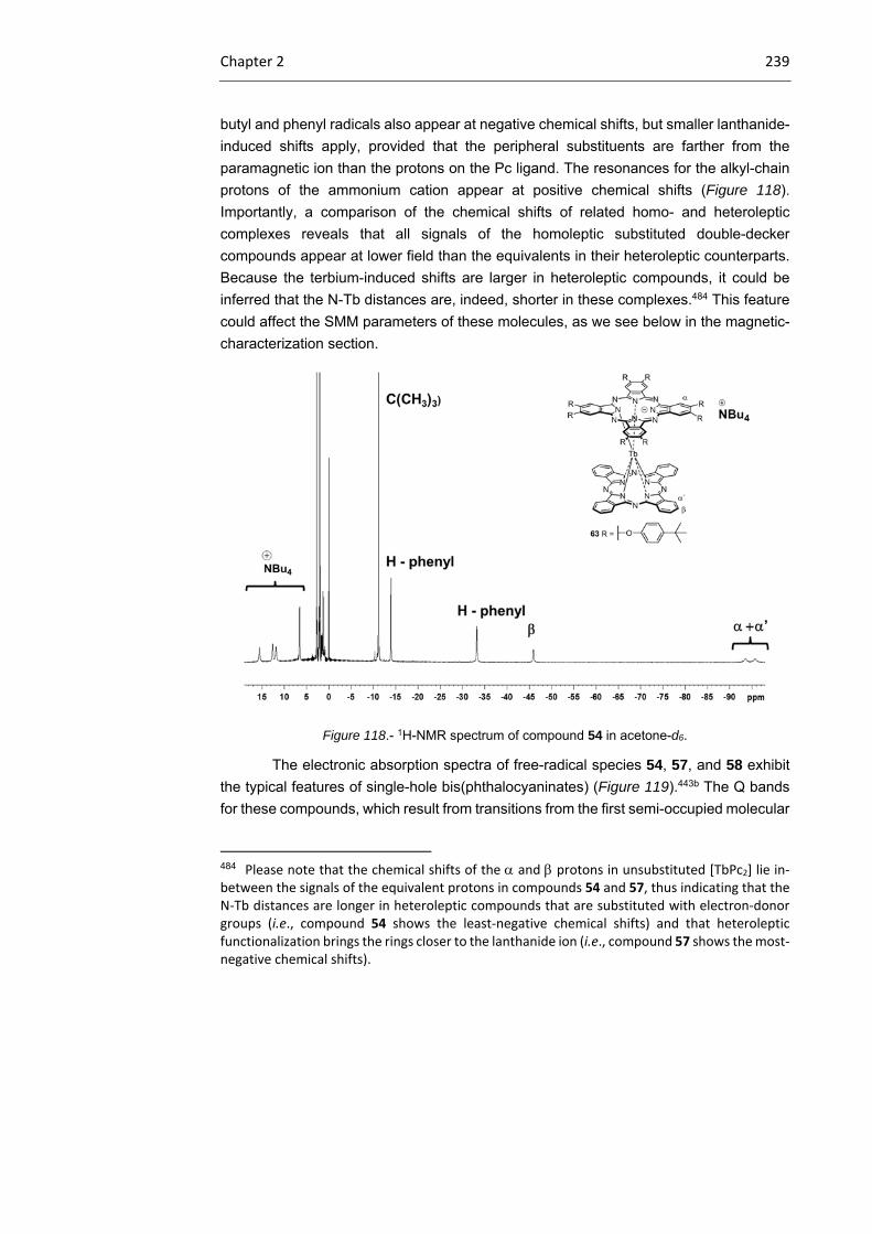
Chapter 2 239
butyl and phenyl radicals also appear at negative chemical shifts, but smaller lanthanide-
induced shifts apply, provided that the peripheral substituents are farther from the
paramagnetic ion than the protons on the Pc ligand. The resonances for the alkyl-chain
protons of the ammonium cation appear at positive chemical shifts (Figure 118).
Importantly, a comparison of the chemical shifts of related homo- and heteroleptic
complexes reveals that all signals of the homoleptic substituted double-decker
compounds appear at lower field than the equivalents in their heteroleptic counterparts.
Because the terbium-induced shifts are larger in heteroleptic compounds, it could be
inferred that the N-Tb distances are, indeed, shorter in these complexes.484 This feature
could affect the SMM parameters of these molecules, as we see below in the magnetic-
characterization section.
Figure 118.- 1H-NMR spectrum of compound 54 in acetone-d6.
The electronic absorption spectra of free-radical species 54, 57, and 58 exhibit
the typical features of single-hole bis(phthalocyaninates) (Figure 119).443b The Q bands
for these compounds, which result from transitions from the first semi-occupied molecular
484 Please note that the chemical shifts of the and protons in unsubstituted [TbPc2] lie in‐between the signals of the equivalent protons in compounds 54 and 57, thus indicating that the N‐Tb distances are longer in heteroleptic compounds that are substituted with electron‐donor groups (i.e., compound 54 shows the least‐negative chemical shifts) and that heteroleptic functionalization brings the rings closer to the lanthanide ion (i.e., compound 57 shows the most‐negative chemical shifts).
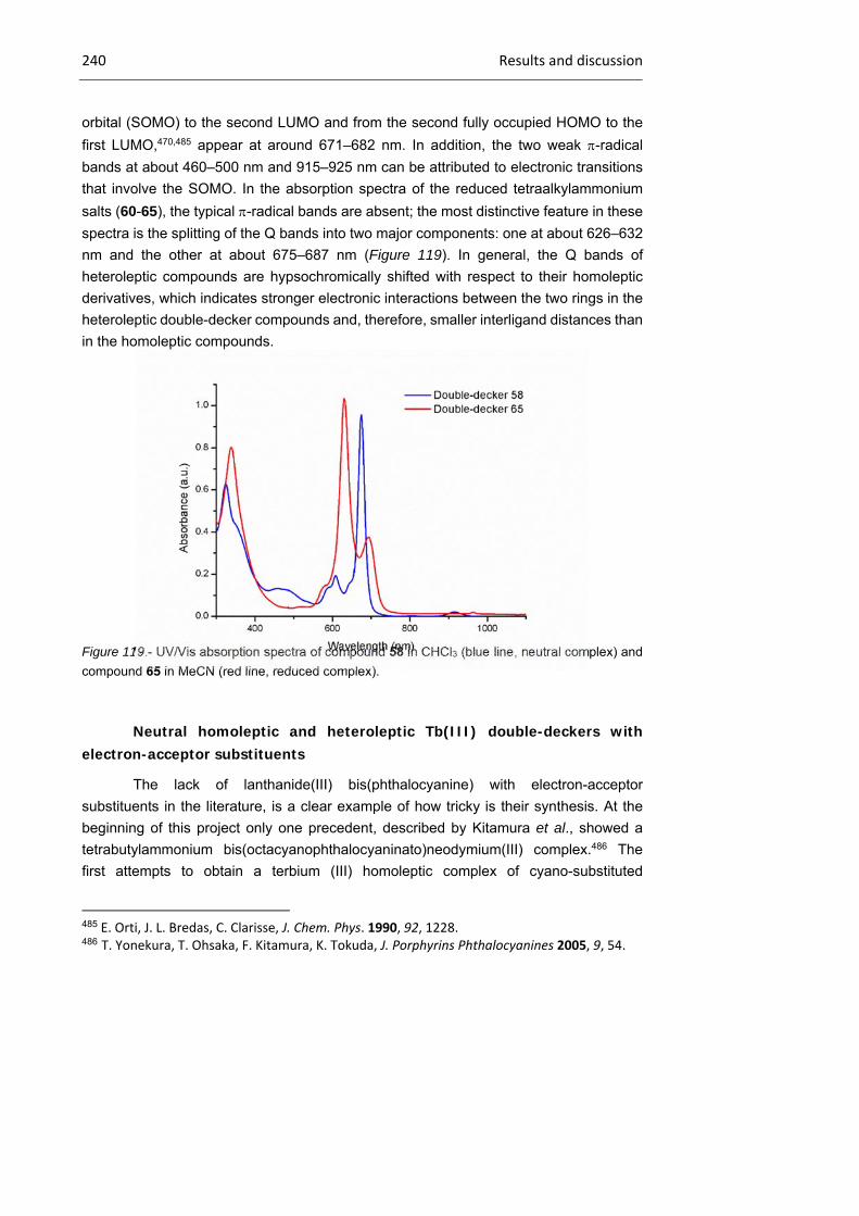
240 Results and discussion
orbital (SOMO) to the second LUMO and from the second fully occupied HOMO to the
first LUMO,470,485 appear at around 671–682 nm. In addition, the two weak -radical
bands at about 460–500 nm and 915–925 nm can be attributed to electronic transitions
that involve the SOMO. In the absorption spectra of the reduced tetraalkylammonium
salts (60-65), the typical -radical bands are absent; the most distinctive feature in these
spectra is the splitting of the Q bands into two major components: one at about 626–632
nm and the other at about 675–687 nm (Figure 119). In general, the Q bands of
heteroleptic compounds are hypsochromically shifted with respect to their homoleptic
derivatives, which indicates stronger electronic interactions between the two rings in the
heteroleptic double-decker compounds and, therefore, smaller interligand distances than
in the homoleptic compounds.
Figure 119.- UV/Vis absorption spectra of compound 58 in CHCl3 (blue line, neutral complex) and
compound 65 in MeCN (red line, reduced complex).
Neutral homoleptic and heteroleptic Tb(III) double-deckers with electron-acceptor substituents
The lack of lanthanide(III) bis(phthalocyanine) with electron-acceptor
substituents in the literature, is a clear example of how tricky is their synthesis. At the
beginning of this project only one precedent, described by Kitamura et al., showed a
tetrabutylammonium bis(octacyanophthalocyaninato)neodymium(III) complex.486 The
first attempts to obtain a terbium (III) homoleptic complex of cyano-substituted
485 E. Orti, J. L. Bredas, C. Clarisse, J. Chem. Phys. 1990, 92, 1228. 486 T. Yonekura, T. Ohsaka, F. Kitamura, K. Tokuda, J. Porphyrins Phthalocyanines 2005, 9, 54.

Chapter 2 241
phthalocyanines followed the procedure described in that article, where a mixture of
1,2,4,5-tetracyanobenzene, terbium(III) salt, tetrabutylammonium hexafluorophosphate,
and DBU in sulfolane was heated at 135 ºC for 3h under a nitrogen atmosphere. The
target compound was synthesized, as can be seen in Figure 120.
Figure 120.- Negative polarity MALDI-TOF mass spectrum of the impure octacyano derivative
terbium (III) complex.
However, it is well-known that the synthesis of octacyanophthalocyanine
complexes is sensitive to many factors, and some oligomers might also be present.487
Even after an intense purification, and seeing the mass spectrum, we cannot believe the
purity of the sample was high enough. Then, more phthalonitriles, such as 4-
nitrophthalonitrile, 3,4,5,6-tetrafluorophthalonitrile, sulfonylphthalonitriles and even their
more reactive 1,3-diiminoisoindoline derivatives were employed in the same conditions,
and with the same disastrous results. All these phthalonitriles and diiminoisoindolines
were tested in o-DCB (to avoid nucleophilic solvents) at 160 ºC, although it was not
detected the presence of any double-decker or monophthalocyaninato. Moreover, the
use of microwave was found unuseful in this type of synthesis. Once the homoleptic
derivatives were dropped, it was easy to decide that the synthesis of heteroleptic
compounds with one phthalocyanine substituted with electron-acceptor moieties must
start with the generation of the monophthalocyaninato with electron-donor substituents.
487 D. Wohrle, U. Marose, R. Knoop, Makromol. Chem. 1985, 186, 2209.
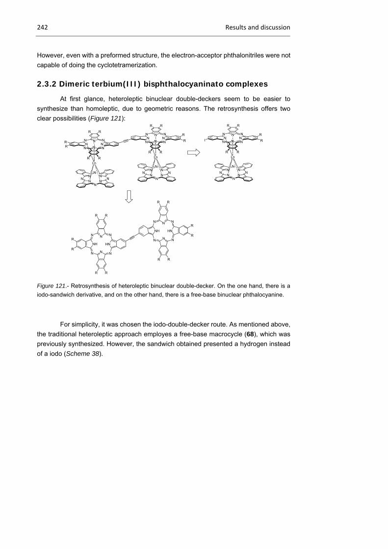
242 Results and discussion
However, even with a preformed structure, the electron-acceptor phthalonitriles were not
capable of doing the cyclotetramerization.
2.3.2 Dimeric terbium(III) bisphthalocyaninato complexes
At first glance, heteroleptic binuclear double-deckers seem to be easier to
synthesize than homoleptic, due to geometric reasons. The retrosynthesis offers two
clear possibilities (Figure 121):
Figure 121.- Retrosynthesis of heteroleptic binuclear double-decker. On the one hand, there is a
iodo-sandwich derivative, and on the other hand, there is a free-base binuclear phthalocyanine.
For simplicity, it was chosen the iodo-double-decker route. As mentioned above,
the traditional heteroleptic approach employes a free-base macrocycle (68), which was
previously synthesized. However, the sandwich obtained presented a hydrogen instead
of a iodo (Scheme 38).
NNN
N NN
N
N
RR
RR
R R
Ln
N NN
NN
NN
N
NNN
N NN
N
N
RR
R R
Ln
R
N NN
NN
NN
N
R NNN
N NN
N
N
RR
I
R R
Ln
R
N NN
NN
NN
N
R
N
HN
N
N N
NH
N
N
R R
R
R
R R
N
NH
N
NN
HN
N
N
RR
R
R
RR
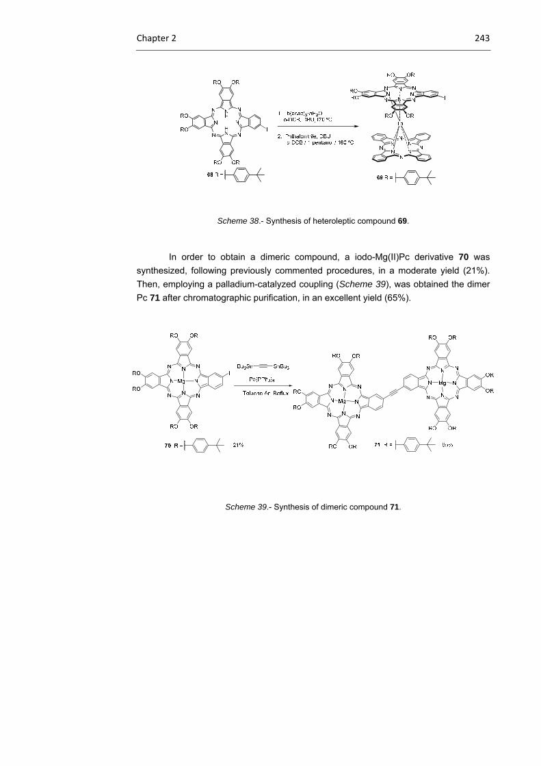
Chapter 2 243
Scheme 38.- Synthesis of heteroleptic compound 69.
In order to obtain a dimeric compound, a iodo-Mg(II)Pc derivative 70 was
synthesized, following previously commented procedures, in a moderate yield (21%).
Then, employing a palladium-catalyzed coupling (Scheme 39), was obtained the dimer
Pc 71 after chromatographic purification, in an excellent yield (65%).
Scheme 39.- Synthesis of dimeric compound 71.

244 Results and discussion
The next step involved trifluoroacetic acid at room temperature to obtain the
demetallated compound 72 after 18h in a quantitative way and without further purification
(Scheme 40).
Scheme 40.- Representation of the synthesis of homoleptic dimeric compound 71.
In order to obtain the homoleptic derivative, the free-base 72, in the presence of
a terbium salt and a catalytic a mount of LiOMe, was refluxed 18h in TCB and
hexadecanol (Scheme 39). After a really ardous purification, it was detected by MALDI-
TOF spectrometry the presence of the homoleptic compound 73. After observing the
complicated 1H-NMR spectrum that this specie presents, we proposed that, there were 3
isomers, as we can see in Figure 122:

Chapter 2 245
Figure 122.- 3 proposed models for the homoleptic compound 73.
The lack of suitable crystals made impossible demonstrating the existence of
these different isomers.
Regarding heteroleptic derivatives, it was not possible to obtain any heteroleptic
derivative after many attempts.

246 Results and discussion
2.3.3 Magnetic characterization
In order to study the magnetic properties of the synthesized
Tb(III)bisphthalocyanine compounds, we participated in a collaboration with Prof.
Coronado at ICMOL. The lack of enough amount of dimeric compounds made impossible
the measure of its magnetism.
AC magnetic-susceptibility measurements were performed on microcrystalline
powders of all the synthesized compounds. In general, the temperature dependence of
the T product of the anionic double-decker Tb(III) compounds (60-67) asymptotically
approaches the corresponding value of a free trivalent terbium ion. This dependence is
very smooth because, as already demonstrated by Ishikawa et al.,473 the ground sub-
state has the maximum MJ value, that is, 6. In the case of the oxidized species
(compounds 54, 57-59), their behavior is very similar and the only difference is in the
proportional increase in the value of the T product, owing to the presence of an unpaired
spin in the rings. As a representative example of the behavior of the neutral TbIII
bis(phthalocyaninate) species, Figure 123 shows the results of AC susceptibility
measurements on a microcrystalline powder of heteroleptic compound 57 in different AC
magnetic-field frequencies. There is a clear frequency-dependent out-of-phase signal
(’’) at low temperatures. At high frequencies (100–10.000 Hz), a maximum (or shoulder)
appears in the out-of-phase signal when the temperature decreases. This maximum has
a notable temperature dependence and varies from 58 K at a frequency of 10.000 Hz to
40 K at 215 Hz. Below this frequency, the maximum becomes a shoulder, owing to a
sharp increase in ’’ at low temperatures, which corresponds to the region in which the
quantum-tunneling effects become dominant. An Arrhenius plot was only performed for
the frequencies with a clear maximum in ’’, which gave rise to a phenomenological
barrier height of 652 cm-1 and a pre-exponential factor 1 of 9.1x10¹⁰ s-1.
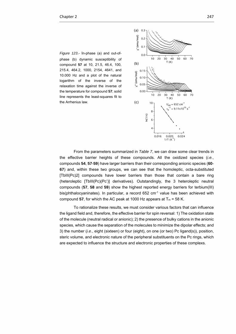
Chapter 2 247
Figure 123.- In-phase (a) and out-of-
phase (b) dynamic susceptibility of
compound 57 at 10, 21.5, 46.4, 100,
215.4, 464.2, 1000, 2154, 4641, and
10.000 Hz and a plot of the natural
logarithm of the inverse of the
relaxation time against the inverse of
the temperature for compound 57; solid
line represents the least-squares fit to
the Arrhenius law.
From the parameters summarized in Table 7, we can draw some clear trends in
the effective barrier heights of these compounds. All the oxidized species (i.e.,
compounds 54, 57-59) have larger barriers than their corresponding anionic species (60-
67) and, within these two groups, we can see that the homoleptic, octa-substituted
[TbIII(Pc)2] compounds have lower barriers than those that contain a bare ring
(heteroleptic [TbIII(Pc)(Pc’)] derivatives). Outstandingly, the 3 heteroleptic neutral
compounds (57, 58 and 59) show the highest reported energy barriers for terbium(III)
bis(phthalocyaninates). In particular, a record 652 cm-1 value has been achieved with
compound 57, for which the AC peak at 1000 Hz appears at Tm = 58 K.
To rationalize these results, we must consider various factors that can influence
the ligand field and, therefore, the effective barrier for spin reversal: 1) The oxidation state
of the molecule (neutral radical or anionic); 2) the presence of bulky cations in the anionic
species, which cause the separation of the molecules to minimize the dipolar effects; and
3) the number (i.e., eight (sixteen) or four (eight), on one (or two) Pc ligand(s)), position,
steric volume, and electronic nature of the peripheral substituents on the Pc rings, which
are expected to influence the structure and electronic properties of these complexs.

248 Results and discussion
Table 7.- Magnetic parameters extracted from the corresponding Arrhenius plots.
The influence of the oxidation state is quite clear from previous experimental
results and DFT calculations on unsubstituted molecules that were oxidized by one or
two electrons. In general, when the anionic terbium(III) bis(phthalocyaninate) molecules
are oxidized, there is a contraction of the Tb-N distances. The final effect is a shortening
of the inter-ligand distances in an isotropic manner; thus, the magnitude of the ligand-
field parameters increases and, consequently, the effective energy barrier also increases.
This effect is mainly responsible for the increase in the blocking temperature and barrier
height when moving from reduced, anionic species to neutral compounds. On the other
hand, the influence of the cation in the anionic species seems to be unclear, but can be
reasonably rationalized if we consider the isolation of the molecules. Thus, the presence
of bulky cations (or bulky substituents) contributes to the dilution of the molecule in a
diamagnetic matrix, which may be the cause of the differences between the barriers in
molecules with NMe4+ and NBu4
+ cations. Within the series of heteroleptic [TbIII(Pc)(Pc’)]
derivatives (62-67) that contain an unsubstituted Pc ring, in which the cations can be
Double-
decker Pcs Cation
(cm-1) 1
Tm (K) at
1000 Hz
54 Homoleptic - 504 4.62x10¹⁰ 46
57 Heteroleptic - 652 9.11x10¹⁰ 58
58 Heteroleptic - 642 4.52x10¹⁰ 52
59 Heteroleptic - 647 4.50x10¹⁰ 53
60 Homoleptic NMe4+ 442 1.22x10¹⁰ 45
61 Homoleptic NBu4+ 394 2.90x10⁹ 44
62 Heteroleptic NMe4+ 450 3.33x10⁹ 50
63 Heteroleptic NBu4+ 487 1.28x10¹⁰ 49
64 Heteroleptic NMe4+ 400 2.00x10¹⁰ 38
65 Heteroleptic NBu4+ 410 2.09x10⁹ 39
66 Heteroleptic NMe4+ 459 2.78x10¹⁰ 43
67 Heteroleptic NBu4+ 478 3.12x10¹⁰ 42
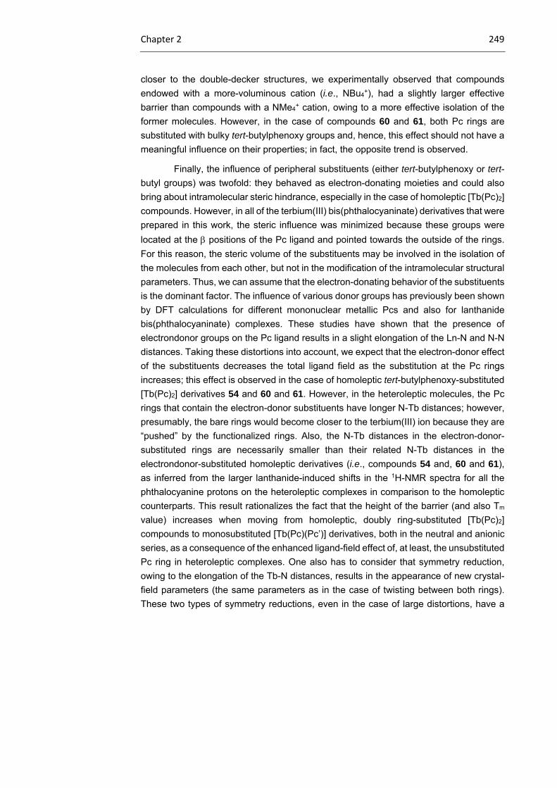
Chapter 2 249
closer to the double-decker structures, we experimentally observed that compounds
endowed with a more-voluminous cation (i.e., NBu4+), had a slightly larger effective
barrier than compounds with a NMe4+ cation, owing to a more effective isolation of the
former molecules. However, in the case of compounds 60 and 61, both Pc rings are
substituted with bulky tert-butylphenoxy groups and, hence, this effect should not have a
meaningful influence on their properties; in fact, the opposite trend is observed.
Finally, the influence of peripheral substituents (either tert-butylphenoxy or tert-
butyl groups) was twofold: they behaved as electron-donating moieties and could also
bring about intramolecular steric hindrance, especially in the case of homoleptic [Tb(Pc)2]
compounds. However, in all of the terbium(III) bis(phthalocyaninate) derivatives that were
prepared in this work, the steric influence was minimized because these groups were
located at the positions of the Pc ligand and pointed towards the outside of the rings.
For this reason, the steric volume of the substituents may be involved in the isolation of
the molecules from each other, but not in the modification of the intramolecular structural
parameters. Thus, we can assume that the electron-donating behavior of the substituents
is the dominant factor. The influence of various donor groups has previously been shown
by DFT calculations for different mononuclear metallic Pcs and also for lanthanide
bis(phthalocyaninate) complexes. These studies have shown that the presence of
electrondonor groups on the Pc ligand results in a slight elongation of the Ln-N and N-N
distances. Taking these distortions into account, we expect that the electron-donor effect
of the substituents decreases the total ligand field as the substitution at the Pc rings
increases; this effect is observed in the case of homoleptic tert-butylphenoxy-substituted
[Tb(Pc)2] derivatives 54 and 60 and 61. However, in the heteroleptic molecules, the Pc
rings that contain the electron-donor substituents have longer N-Tb distances; however,
presumably, the bare rings would become closer to the terbium(III) ion because they are
“pushed” by the functionalized rings. Also, the N-Tb distances in the electron-donor-
substituted rings are necessarily smaller than their related N-Tb distances in the
electrondonor-substituted homoleptic derivatives (i.e., compounds 54 and, 60 and 61),
as inferred from the larger lanthanide-induced shifts in the 1H-NMR spectra for all the
phthalocyanine protons on the heteroleptic complexes in comparison to the homoleptic
counterparts. This result rationalizes the fact that the height of the barrier (and also Tm
value) increases when moving from homoleptic, doubly ring-substituted [Tb(Pc)2]
compounds to monosubstituted [Tb(Pc)(Pc’)] derivatives, both in the neutral and anionic
series, as a consequence of the enhanced ligand-field effect of, at least, the unsubstituted
Pc ring in heteroleptic complexes. One also has to consider that symmetry reduction,
owing to the elongation of the Tb-N distances, results in the appearance of new crystal-
field parameters (the same parameters as in the case of twisting between both rings).
These two types of symmetry reductions, even in the case of large distortions, have a
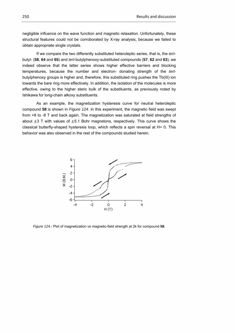
250 Results and discussion
negligible influence on the wave function and magnetic relaxation. Unfortunately, these
structural features could not be corroborated by X-ray analysis, because we failed to
obtain appropriate single crystals.
If we compare the two differently substituted heteroleptic series, that is, the tert-
butyl- (58, 64 and 65) and tert-butylphenoxy-substituted compounds (57, 62 and 63), we
indeed observe that the latter series shows higher effective barriers and blocking
temperatures, because the number and electron- donating strength of the tert-
butylphenoxy groups is higher and, therefore, this substituted ring pushes the Tb(III) ion
towards the bare ring more effectively. In addition, the isolation of the molecules is more
effective, owing to the higher steric bulk of the substituents, as previously noted by
Ishikawa for long-chain alkoxy substituents.
As an example, the magnetization hysteresis curve for neutral heteroleptic
compound 58 is shown in Figure 124. In this experiment, the magnetic field was swept
from +8 to -8 T and back again. The magnetization was saturated at field strengths of
about 3 T with values of 5.1 Bohr magnetons, respectively. This curve shows the
classical butterfly-shaped hysteresis loop, which reflects a spin reversal at H= 0. This
behavior was also observed in the rest of the compounds studied herein.
Figure 124.- Plot of magnetization vs magnetic-field strength at 2k for compound 58.

Chapter 2 251
2.4 Summary and conclusions
We have performed a rigorous structural characterization and systematic
analysis of the SMM behavior of a series of homoleptic and heteroleptic, peripherally
functionalized terbium(III) bis(phthalocyaninates) with different oxidation states and
substitution pattern; from this analysis,several conclusions can be extracted:
- As a general trend, asalso observed by Ishikawa and co-workers, the presence of
an unpaired electron in their neutral forms leads to higher effective barriers than
those in their corresponding anionic species.
- The most-outstanding result of this work is the validation of the effect of the
substitution pattern on the Pc ligands on the SMM behavior of the corresponding
complexes. Heteroleptic [Tb(Pc)(Pc’)] systems, that is, those that are endowed with
electron-donor (tert-butyl or tert-butylphenoxy) substituents on only one of the Pc
ligands, show the best SMM parameters, because they meet two advantageous
structural factors: 1) Even if they are less substituted than their homoleptic
derivatives, the presence of bulky groups facilitates the isolation of the molecules
from each other, thus favoring their behavior as SMMs; 2) the presence of electron-
donating groups on just one of the Pc rings makes the N-Tb distance of the
substituted ring larger and, therefore, pushes the metal ion toward the bare Pc ring,
thereby enhancing the ligand field of the latter ring.
- Record values have been achieved with heteroleptic, tert-butylphenoxy- substituted
derivative 57, which presents a barrier of 652 cm-1 at a Tm=58 K. These parameters
are the highest obtained to date with terbium(III) bis(phthalocyaninate) systems and
much larger than those that have been achieved with other types of SMMs.
On the other hand, we also tried to obtain terbium (III) double-deckers with
electron-withdrawing groups, such as sulfonyl derivatives, nitro or fluor moieties, and
after several attempts, it was impossible. We successfully synthesized a binuclear
homoleptic terbium (III) sandwich, which presents electron-donor groups at the periphery.
252 Experimental section
2.5 Experimental section
2.5.1 Terbium(III) bisphthalocyaninato complexes
Neutral homoleptic and heteroleptic Tb(III) double-deckers with electron-donor substituents
4,5-Bis(p-tert-butyl)phenoxyphthalonitrile (53)
A solution of 4,5-dichlorophthalonitrile (11) (14.3 mmol, 2.8
g) and 4- tert-butylphenol (42.6 mmol, 6.4 mmol) in freshly
distilled DMSO (35 mL) was heated to 100ºC until their
complete dissolution; then, oven-dry K2CO3 (227.2 mmol,
31.4 g) was added in eight portions over 40 min. The resulting
yellow mixture was stirred at 100 ºC for 3 h, allowed to reach
room temperature, poured into crushed ice (500 mL). Cold
water was then poured into the mixture resulting in the precipitation of a yellowish-green
solid which was filtered, washed with water and vacuum-dried. Recrystallization from
methanol left to g (5.3 g) of 47 as a white solid. Yield: 83%.
Mp: 181-183 ºC (reported:164a 182-184 ºC).
1H-NMR (300 MHz, CDCl3): (ppm) = 7.46 (d, J = 8.85 Hz, 4H; H-2’), 7.14 (s, 2H; H-3),
7.03 (d, J = 8.85 Hz, 4H; H-3’), 1.36 (s, 18H; C(CH3)3).
13C-NMR (75.5 MHz, CDCl3): (ppm) =152.3 (C-4), 151.6 (C-1’), 149.2(C-4’), 127.4 (C-
3’), 121.4 (C-3), 119.6 (C-2’), 115.2(CN), 109.8 (C-1), 34.6 (C(CH3)3), 31.4 (C(CH3)3).
MS (C28H28N2O2, exact mass = 424.22, molecular weight = 424.54; EI): m/z = 424 [M]+
(100%).
Bis2,3,9,10,16,17,23,24-octa[(p-tert-butyl)phenoxy]-5,28:14,19-diimino-7,12:21,26-
dinitrilo-tetrabenzo[c,h,m,r]-[1,6,11,16]tetraazacycloeicosinato-(2-)-
N29,N30,N31,N32terbium(III) (54)
A mixture of 4,5-bis-(4’-tertbutylphenoxy)-1,2-dicyanobenzene (53) (500 mg,
1.17 mmol), 1,8-diazabicyclo[5.4.0]undec-7-ene (DBU, 28 mL, 0.19 mmol), and
[Tb(acac)3]·nH2O (67 mg, 0.15 mmol) in 1-pentanol (5 mL) was heated at 150ºC for 8 h
under a slow stream of argon. The resulting green solution was cooled to r.t. and the
volatile compounds were removed under reduced pressure. The residue was re-
dissolved in CHCl3 (5 mL), 2,3-dichloro-5,6-dicyano-1,4-benzoquinone (DDQ, 80 mg,
NC
NC
O
O3
56
1
2 4
1'2'
3'
4'
5'6'
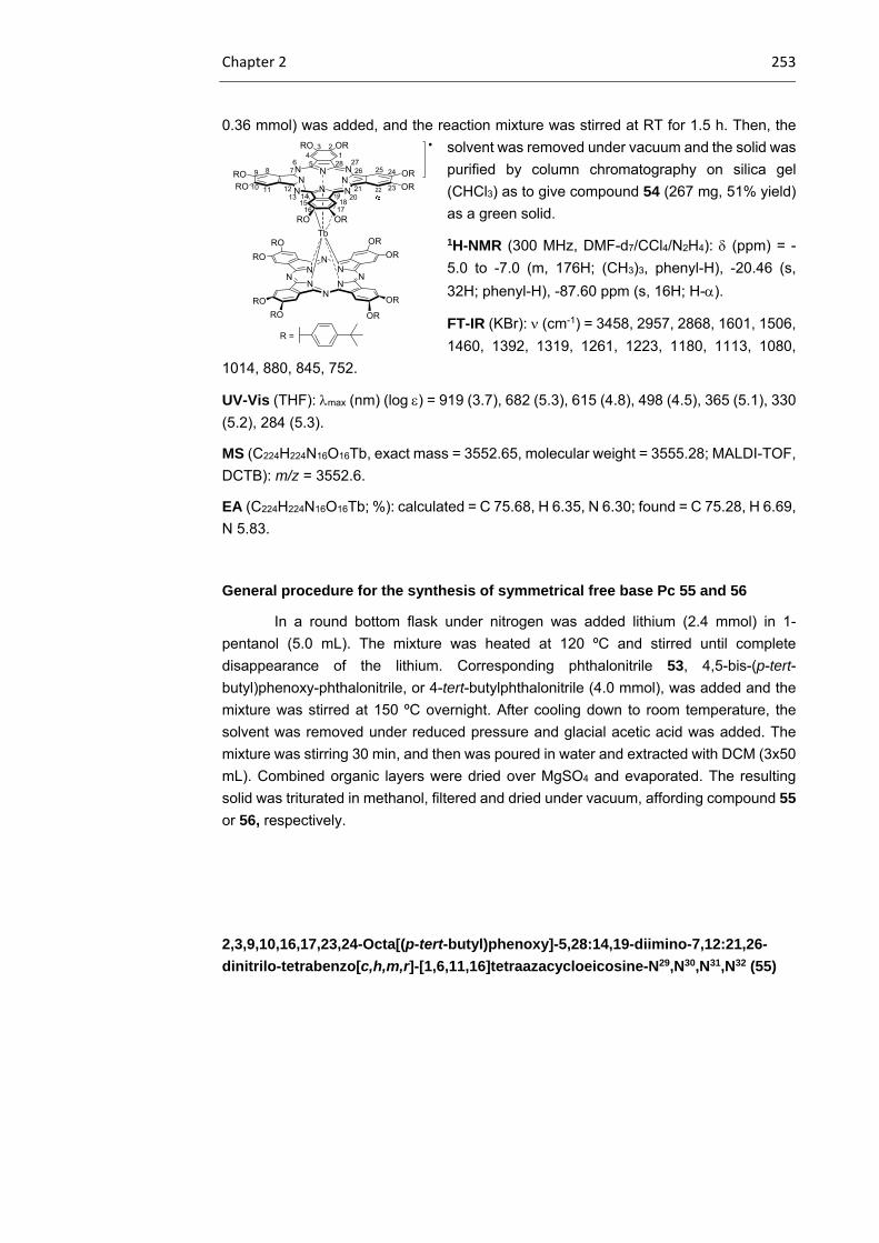
Chapter 2 253
0.36 mmol) was added, and the reaction mixture was stirred at RT for 1.5 h. Then, the
solvent was removed under vacuum and the solid was
purified by column chromatography on silica gel
(CHCl3) as to give compound 54 (267 mg, 51% yield)
as a green solid.
1H-NMR (300 MHz, DMF-d7/CCl4/N2H4): (ppm) = -
5.0 to -7.0 (m, 176H; (CH3)3, phenyl-H), -20.46 (s,
32H; phenyl-H), -87.60 ppm (s, 16H; H-).
FT-IR (KBr): (cm-1) = 3458, 2957, 2868, 1601, 1506,
1460, 1392, 1319, 1261, 1223, 1180, 1113, 1080,
1014, 880, 845, 752.
UV-Vis (THF): max (nm) (log ) = 919 (3.7), 682 (5.3), 615 (4.8), 498 (4.5), 365 (5.1), 330
(5.2), 284 (5.3).
MS (C224H224N16O16Tb, exact mass = 3552.65, molecular weight = 3555.28; MALDI-TOF,
DCTB): m/z = 3552.6.
EA (C224H224N16O16Tb; %): calculated = C 75.68, H 6.35, N 6.30; found = C 75.28, H 6.69,
N 5.83.
General procedure for the synthesis of symmetrical free base Pc 55 and 56
In a round bottom flask under nitrogen was added lithium (2.4 mmol) in 1-
pentanol (5.0 mL). The mixture was heated at 120 ºC and stirred until complete
disappearance of the lithium. Corresponding phthalonitrile 53, 4,5-bis-(p-tert-
butyl)phenoxy-phthalonitrile, or 4-tert-butylphthalonitrile (4.0 mmol), was added and the
mixture was stirred at 150 ºC overnight. After cooling down to room temperature, the
solvent was removed under reduced pressure and glacial acetic acid was added. The
mixture was stirring 30 min, and then was poured in water and extracted with DCM (3x50
mL). Combined organic layers were dried over MgSO4 and evaporated. The resulting
solid was triturated in methanol, filtered and dried under vacuum, affording compound 55
or 56, respectively.
2,3,9,10,16,17,23,24-Octa[(p-tert-butyl)phenoxy]-5,28:14,19-diimino-7,12:21,26-
dinitrilo-tetrabenzo[c,h,m,r]-[1,6,11,16]tetraazacycloeicosine-N29,N30,N31,N32 (55)
NNN
N NN
N
N
ORRO
RORO
RO OR
Tb
OR
N NN
NN
NN
N
OR
OR
ORRO
RO
RO
RO OR
OR
123
456
789
10 11 1213 14
1516 17
1819 20
21 22 23
2425262728
R =

254 Experimental section
Compound 55 was obtained as a green solid. Yield: 33%.
Mp: 300ºC
1H-NMR (300 MHz, CDCl3): (ppm) = 8.96 (s, 8H; Pc-H),
7.42 (d, J = 8.6 Hz, 16H; phenyl-H), 7.17 (d, J = 8.6 Hz,
16H; 16H, phenyl-H), 1.5-1.3 (m, 72H).
FT-IR (KBr): (cm-1) = 3426, 2960, 2866, 1604, 1508,
1460, 1441, 1397, 1363, 1293, 1270, 1218, 1180, 1085,
1012, 878, 827, 751.
UV-Vis (THF): max (nm) (log ) = 703 (5.1), 670 (5.1), 641 (4.7), 609 (4.5), 348 (4.6).
MS (C112H114N8O8, exact mass = 1698.88, molecular weight = 1700.19; MALDI-TOF,
dithranol): m/z = 1698 [M]+ 1699 [M+H]+.
EA (C112H114N8O8; %): calculated = C 79.12, H 6.76, N 6.59; found = C 78.89, H 6.91, N
6.63.
3,10,17,24-Tetra(tert-butyl)-5,28:14,19-diimino-7,12:21,26-dinitrilo-
tetrabenzo[c,h,m,r]-[1,6,11,16]tetraazacycloeicosine-N29,N30,N31,N32 (56) (only one
regioisomer is named)
Compound 56 was obtained as a dark blue solid.
Yield: 35%.
Mp: 300ºC
1H-NMR (300 MHz, CDCl3): (ppm) = 9.12 (s, 8H;
Pc-H), 8.65 (s, 4H; Pc-H), 1.60 (s, 36H; C(CH3)3).
FT-IR (KBr): (cm-1) = 2990, 2758, 1508, 1467,
1390, 1363, 1293, 1265, 1187, 1086, 865, 828, 747.
UV-Vis (THF): max (nm) (log ) = 7 (5.1), 607 (5.1),
641 (4.7), 609 (4.5), 348 (4,6).
General procedure for the synthesis of heteroleptic Tb(III) bisphthalocyaninatos 57
and 58.
N
NH
N
NN
HN
N
N
1
3
4
2
56
789
1011 12
13 14
15
16 17
18
19 20
21 2223
242526
2728
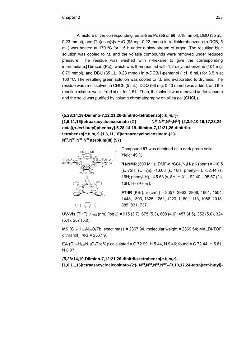
Chapter 2 255
A mixture of the corresponding metal-free Pc (55 or 56, 0.18 mmol), DBU (35 L,
0.23 mmol), and [Tb(acac)3]·nH2O (98 mg, 0.22 mmol) in o-dichlorobenzene (o-DCB, 5
mL) was heated at 170 ºC for 1.5 h under a slow stream of argon. The resulting blue
solution was cooled to r.t. and the volatile compounds were removed under reduced
pressure. The residue was washed with n-hexane to give the corresponding
intermediate,[Tb(acac)(Pc)], which was then reacted with 1,2-dicyanobenzene (101 mg,
0.79 mmol), and DBU (35 L, 0.23 mmol) in o-DCB/1-pentanol (1:1, 8 mL) for 3.5 h at
160 ºC. The resulting green solution was cooled to r.t. and evaporated to dryness. The
residue was re-dissolved in CHCl3 (5 mL), DDQ (96 mg, 0.43 mmol) was added, and the
reaction mixture was stirred at r.t. for 1.5 h. Then, the solvent was removed under vacuum
and the solid was purified by column chromatography on silica gel (CHCl3).
5,28:14,19-Diimino-7,12:21,26-dinitrilo-tetrabenzo[c,h,m,r]-
[1,6,11,16]tetraazacycloeicosinato-(2-)- N29,N30,N31,N32-2,3,9,10,16,17,23,24-
octa[(p-tert-butyl)phenoxy]-5,28:14,19-diimino-7,12:21,26-dinitrilo-
tetrabenzo[c,h,m,r]-[1,6,11,16]tetraazacycloeicosinato-(2-)-
N29,N30,N31,N32terbium(III) (57)
Compound 57 was obtained as a dark green solid.
Yield: 49 %.
1H-NMR (300 MHz, DMF-d7/CCl4/N2H4): (ppm) = -10.5
(s, 72H; (CH3)3), -13.68 (s, 16H; phenyl-H), -32.44 (s,
16H; phenyl-H), - 45.63 (s, 8H; H-), - 92.40, - 95.57 (2s,
16H; H-’+H-).
FT-IR (KBr): (cm-1) = 3057, 2962, 2868, 1601, 1504,
1448, 1393, 1325, 1261, 1223, 1180, 1113, 1086, 1018,
885, 831, 737.
UV-Vis (THF): max (nm) (log ) = 915 (3.7), 675 (5.3), 608 (4.6), 457 (4.5), 352 (5.0), 324
(5.1), 287 (5.0).
MS (C144H128N16O8Tb, exact mass = 2367.94, molecular weight = 2369.64; MALDI-TOF,
dithranol): m/z = 2367.9.
EA (C144H128N16O8Tb; %): calculated = C 72.99, H 5.44, N 9.46; found = C 72.44, H 5.81,
N 8.97.
5,28:14,19-Diimino-7,12:21,26-dinitrilo-tetrabenzo[c,h,m,r]-
[1,6,11,16]tetraazacycloeicosinato-(2-)- N29,N30,N31,N32-3,10,17,24-tetra(tert-butyl)-
NNN
N NN
N
N
ORRO
RORO
RO OR
Tb
OR
N NN
NN
NN
N
OR
123
456
789
10 11 1213 14
1516 17
1819 20
21 22 23
2425262728
R =
'
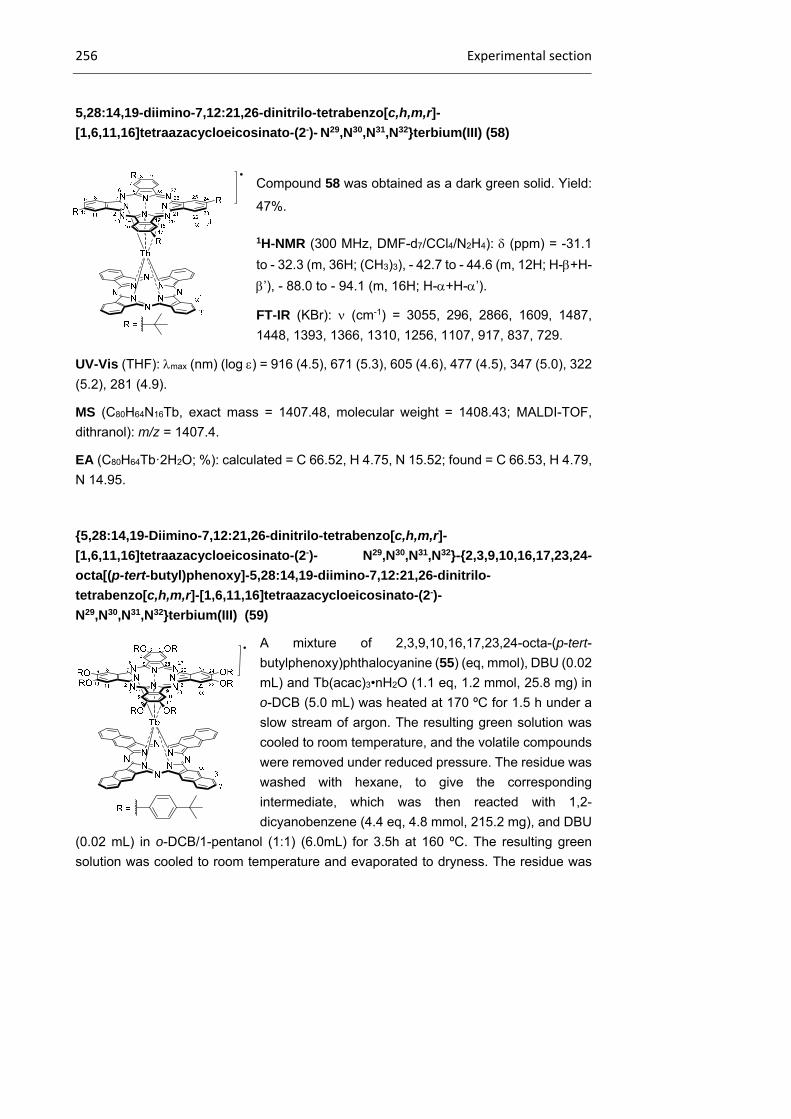
256 Experimental section
5,28:14,19-diimino-7,12:21,26-dinitrilo-tetrabenzo[c,h,m,r]-
[1,6,11,16]tetraazacycloeicosinato-(2-)- N29,N30,N31,N32terbium(III) (58)
Compound 58 was obtained as a dark green solid. Yield:
47%.
1H-NMR (300 MHz, DMF-d7/CCl4/N2H4): (ppm) = -31.1
to - 32.3 (m, 36H; (CH3)3), - 42.7 to - 44.6 (m, 12H; H-+H-
’), - 88.0 to - 94.1 (m, 16H; H-+H-’).
FT-IR (KBr): (cm-1) = 3055, 296, 2866, 1609, 1487,
1448, 1393, 1366, 1310, 1256, 1107, 917, 837, 729.
UV-Vis (THF): max (nm) (log ) = 916 (4.5), 671 (5.3), 605 (4.6), 477 (4.5), 347 (5.0), 322
(5.2), 281 (4.9).
MS (C80H64N16Tb, exact mass = 1407.48, molecular weight = 1408.43; MALDI-TOF,
dithranol): m/z = 1407.4.
EA (C80H64Tb·2H2O; %): calculated = C 66.52, H 4.75, N 15.52; found = C 66.53, H 4.79,
N 14.95.
5,28:14,19-Diimino-7,12:21,26-dinitrilo-tetrabenzo[c,h,m,r]-
[1,6,11,16]tetraazacycloeicosinato-(2-)- N29,N30,N31,N32-2,3,9,10,16,17,23,24-
octa[(p-tert-butyl)phenoxy]-5,28:14,19-diimino-7,12:21,26-dinitrilo-
tetrabenzo[c,h,m,r]-[1,6,11,16]tetraazacycloeicosinato-(2-)-
N29,N30,N31,N32terbium(III) (59)
A mixture of 2,3,9,10,16,17,23,24-octa-(p-tert-
butylphenoxy)phthalocyanine (55) (eq, mmol), DBU (0.02
mL) and Tb(acac)3•nH2O (1.1 eq, 1.2 mmol, 25.8 mg) in
o-DCB (5.0 mL) was heated at 170 ºC for 1.5 h under a
slow stream of argon. The resulting green solution was
cooled to room temperature, and the volatile compounds
were removed under reduced pressure. The residue was
washed with hexane, to give the corresponding
intermediate, which was then reacted with 1,2-
dicyanobenzene (4.4 eq, 4.8 mmol, 215.2 mg), and DBU
(0.02 mL) in o-DCB/1-pentanol (1:1) (6.0mL) for 3.5h at 160 ºC. The resulting green
solution was cooled to room temperature and evaporated to dryness. The residue was

Chapter 2 257
re-dissolved in CHCl3 (50 mL), DDQ (1.1 eq, 1.2 mmol, 54.2 mg) was added, and the
reaction mixture was stirred at room temperature for 1.5h. Then, solvent was removed
under vacuum and the solid obtained was submitted to column chromatography on silica
gel using CHCl3 as the eluent. The resulting solid was triturated in an acetonitrile/water
(2:1, mL) mixture, filtered and dried under vacuum, to give compound 59 (mmol, mg) as
a green solid. Yield: 46 %.
1H-NMR (300 MHz, DMF-d7/CCl4/N2H4): (ppm) = -10.65 (s, 72H; (CH3)3), -13.80 (s, 16H;
phenyl-H), -32.60 (s, 16H; phenyl-H), -40.87 (s, 8H; H-), - 50.71 (s, 8H; H-), - 90.40, -
95.45 ppm (2s, 16H; H-’+H-)
FT-IR (KBr): (cm-1) = 3088, 2950, 2848, 1650, 1534, 1443, 1310, 1284, 1227, 1196,
1111, 1050, 888, 864, 780.
UV-Vis (THF): max (nm) (log ) = 986 (3.7), 719 (5.3), 647 (5.0), 613 (4.7), 446 (4.5).
MS (C160H136N16O8Tb, exact mass = 2568.00, molecular weight = 2569.88; MALDI-TOF,
DCTB): m/z = 2569.0.
EA (C160H136N16O8Tb; %): calculated = C 74.78, H 5.33, N 8.72; found = C 74.44, H 5.21,
N 8.67.
Anionic homoleptic and heteroleptic Tb(III) double-deckers
General procedure for the synthesis of reduced, tetraalkylammonium salts 60, 61,
62, 63, 64, 65, 66 and 67.
Hydrazine hydrate was added to a stirring solution of the corresponding terbium
(III) bis(phthalocyaninate) in DMF. Once the reduction of the double-decker complex was
complete (by UV/Vis spectroscopy), NaOMe was added to give intermediate
[Na][Tb(Pc)(Pc’)]. The addition of tetraalkylammonium bromide ([(alk)4]Br, alk=Me,Bu)
afforded the precipitation of the corresponding salt (60, 61, 62, 63, 64, 65, 66 or 67),
which was filtrated, re-dissolved in acetone, and filtered again to remove the inorganic
residues. The filtrate was concentrated under vacuum, n-hexane was added, and the
solid was filtered off and washed with several portions of n-hexane to afford the pure
tetralkylammonium terbium (III)bis(phthalocyaninate) (61, 62, 63 or 63).
Tetrametylammonium-bis2,3,9,10,16,17,23,24-octa[(p-tert-butyl)phenoxy]-
5,28:14,19-diimino-7,12:21,26-dinitrilo-tetrabenzo[c,h,m,r]-
[1,6,11,16]tetraazacycloeicosinato-(2-)- N29,N30,N31,N32terbium(III) (60)
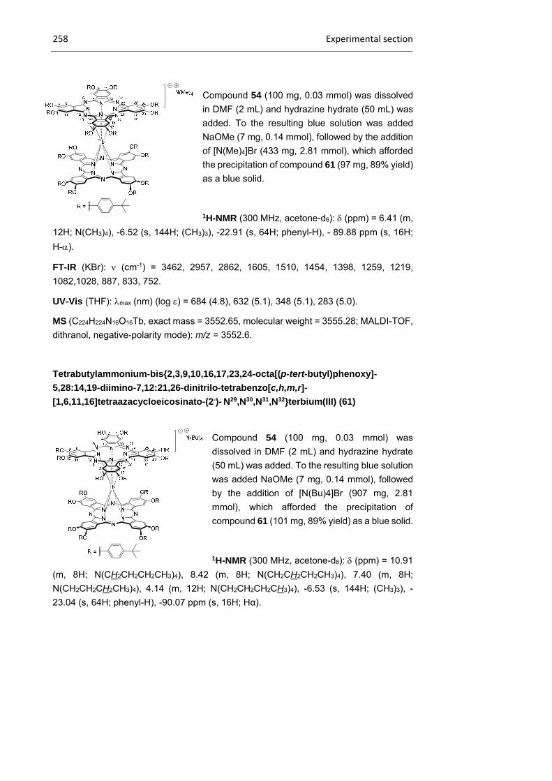
258 Experimental section
Compound 54 (100 mg, 0.03 mmol) was dissolved
in DMF (2 mL) and hydrazine hydrate (50 mL) was
added. To the resulting blue solution was added
NaOMe (7 mg, 0.14 mmol), followed by the addition
of [N(Me)4]Br (433 mg, 2.81 mmol), which afforded
the precipitation of compound 61 (97 mg, 89% yield)
as a blue solid.
1H-NMR (300 MHz, acetone-d6): (ppm) = 6.41 (m,
12H; N(CH3)4), -6.52 (s, 144H; (CH3)3), -22.91 (s, 64H; phenyl-H), - 89.88 ppm (s, 16H;
H-).
FT-IR (KBr): (cm-1) = 3462, 2957, 2862, 1605, 1510, 1454, 1398, 1259, 1219,
1082,1028, 887, 833, 752.
UV-Vis (THF): max (nm) (log ) = 684 (4.8), 632 (5.1), 348 (5.1), 283 (5.0).
MS (C224H224N16O16Tb, exact mass = 3552.65, molecular weight = 3555.28; MALDI-TOF,
dithranol, negative-polarity mode): m/z = 3552.6.
Tetrabutylammonium-bis2,3,9,10,16,17,23,24-octa[(p-tert-butyl)phenoxy]-
5,28:14,19-diimino-7,12:21,26-dinitrilo-tetrabenzo[c,h,m,r]-
[1,6,11,16]tetraazacycloeicosinato-(2-)- N29,N30,N31,N32terbium(III) (61)
Compound 54 (100 mg, 0.03 mmol) was
dissolved in DMF (2 mL) and hydrazine hydrate
(50 mL) was added. To the resulting blue solution
was added NaOMe (7 mg, 0.14 mmol), followed
by the addition of [N(Bu)4]Br (907 mg, 2.81
mmol), which afforded the precipitation of
compound 61 (101 mg, 89% yield) as a blue solid.
1H-NMR (300 MHz, acetone-d6): (ppm) = 10.91
(m, 8H; N(CH2CH2CH2CH3)4), 8.42 (m, 8H; N(CH2CH2CH2CH3)4), 7.40 (m, 8H;
N(CH2CH2CH2CH3)4), 4.14 (m, 12H; N(CH2CH2CH2CH3)4), -6.53 (s, 144H; (CH3)3), -
23.04 (s, 64H; phenyl-H), -90.07 ppm (s, 16H; Hα).
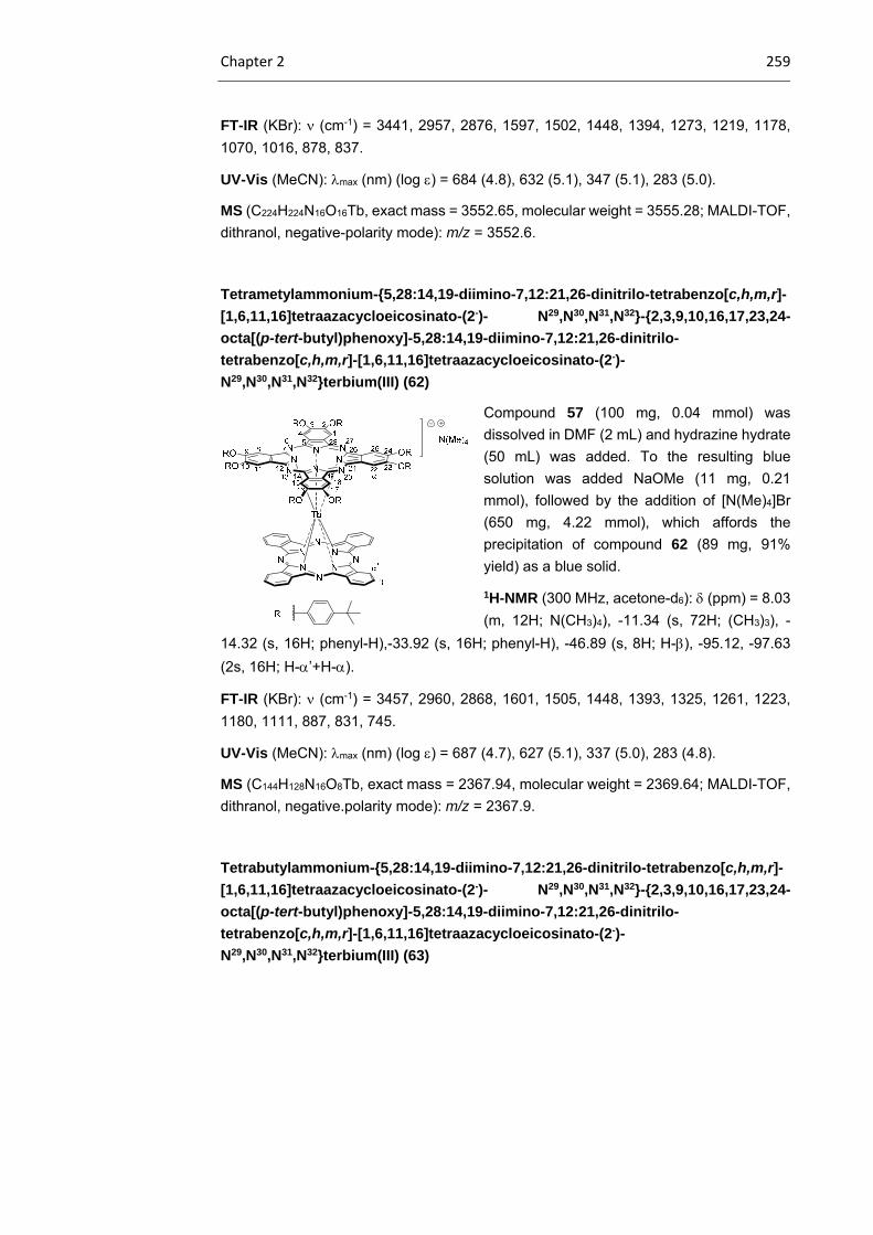
Chapter 2 259
FT-IR (KBr): (cm-1) = 3441, 2957, 2876, 1597, 1502, 1448, 1394, 1273, 1219, 1178,
1070, 1016, 878, 837.
UV-Vis (MeCN): max (nm) (log ) = 684 (4.8), 632 (5.1), 347 (5.1), 283 (5.0).
MS (C224H224N16O16Tb, exact mass = 3552.65, molecular weight = 3555.28; MALDI-TOF,
dithranol, negative-polarity mode): m/z = 3552.6.
Tetrametylammonium-5,28:14,19-diimino-7,12:21,26-dinitrilo-tetrabenzo[c,h,m,r]-
[1,6,11,16]tetraazacycloeicosinato-(2-)- N29,N30,N31,N32-2,3,9,10,16,17,23,24-
octa[(p-tert-butyl)phenoxy]-5,28:14,19-diimino-7,12:21,26-dinitrilo-
tetrabenzo[c,h,m,r]-[1,6,11,16]tetraazacycloeicosinato-(2-)-
N29,N30,N31,N32terbium(III) (62)
Compound 57 (100 mg, 0.04 mmol) was
dissolved in DMF (2 mL) and hydrazine hydrate
(50 mL) was added. To the resulting blue
solution was added NaOMe (11 mg, 0.21
mmol), followed by the addition of [N(Me)4]Br
(650 mg, 4.22 mmol), which affords the
precipitation of compound 62 (89 mg, 91%
yield) as a blue solid.
1H-NMR (300 MHz, acetone-d6): (ppm) = 8.03
(m, 12H; N(CH3)4), -11.34 (s, 72H; (CH3)3), -
14.32 (s, 16H; phenyl-H),-33.92 (s, 16H; phenyl-H), -46.89 (s, 8H; H-), -95.12, -97.63
(2s, 16H; H-’+H-).
FT-IR (KBr): (cm-1) = 3457, 2960, 2868, 1601, 1505, 1448, 1393, 1325, 1261, 1223,
1180, 1111, 887, 831, 745.
UV-Vis (MeCN): max (nm) (log ) = 687 (4.7), 627 (5.1), 337 (5.0), 283 (4.8).
MS (C144H128N16O8Tb, exact mass = 2367.94, molecular weight = 2369.64; MALDI-TOF,
dithranol, negative.polarity mode): m/z = 2367.9.
Tetrabutylammonium-5,28:14,19-diimino-7,12:21,26-dinitrilo-tetrabenzo[c,h,m,r]-
[1,6,11,16]tetraazacycloeicosinato-(2-)- N29,N30,N31,N32-2,3,9,10,16,17,23,24-
octa[(p-tert-butyl)phenoxy]-5,28:14,19-diimino-7,12:21,26-dinitrilo-
tetrabenzo[c,h,m,r]-[1,6,11,16]tetraazacycloeicosinato-(2-)-
N29,N30,N31,N32terbium(III) (63)

260 Experimental section
Compound 57 (100 mg, 0.04 mmol) was
dissolved in DMF (2 mL) and hydrazine hydrate
(50 mL) was added. To the resulting blue
solution was added NaOMe (11 mg, 0.21 mmol),
followed by the addition of [N(Bu)4]Br (1.36 g,
4.22 mmol), which afforded the precipitation of
compound 63 (94 mg, 90% yield) as a blue solid.
1H-NMR (300 MHz, acetone-d6): (ppm) =15.52
(m, 8H; N(CH2CH2CH2CH3)4), 12.62 (m, 8H;
N(CH2CH2CH2CH3)4), 11.86 (m, 8H;
N(CH2CH2CH2CH3)4), 6.56 (m, 12H; N(CH2CH2CH2CH3)4), -11.10 (s, 72H; (CH3)3), -
14.00 (s, 16H; phenyl-H), -33.24 (s, 16H; phenyl-H), -45.95 (s, 8H; H-), -93.53, -95.70
(2s, 16H; H’+ H-).
FT-IR (KBr): (cm-1) = 3489, 2966, 2872, 1612, 1512, 1485, 1445, 1391, 1271, 1217,
1177, 1072, 1020, 885, 831, 727.
UV-Vis (MeCN): max (nm) (log ) = 687 (4.7), 627 (5.1), 336 (5.0), 283 (4.8).
MS (C144H128N16O8Tb, exact mass = 2367.94, molecular weight = 2369.64; MALDI-TOF,
dithranol, negative.polarity mode): m/z = 2367.9.
Tetrametylammonium-5,28:14,19-diimino-7,12:21,26-dinitrilo-tetrabenzo[c,h,m,r]-
[1,6,11,16]tetraazacycloeicosinato-(2-)- N29,N30,N31,N32-3,10,17,24-tetra(tert-butyl)-
5,28:14,19-diimino-7,12:21,26-dinitrilo-tetrabenzo[c,h,m,r]-
[1,6,11,16]tetraazacycloeicosinato-(2-)- N29,N30,N31,N32terbium(III) (64)
Compound 58 (100 mg, 0.07 mmol) was dissolved in DMF (2 mL) and hydrazine
hydrate (50 mL) was added. To the resulting blue solution was added NaOMe (19 mg,
0.36 mmol), followed by the addition of [N(Me)4]Br (1.09 g, 7.11 mmol), which afforded
the precipitation of compound 64 (94 mg, 88% yield) as a blue solid.

Chapter 2 261
1H-NMR (300 MHz, acetone-d6): (ppm) =
8.09 (m, 12H; N(CH3)4), -33.1 to -35.3 (m,
36H; (CH3)3), -44.7 to -48.6 (m, 12H; H-+H-
’), -85.0 to -94.1 ppm (m, 16H; H-+H-’).
FT-IR (KBr): (cm-1) = 3456, 3053, 2961,
2866, 1674, 1607, 1477, 1313, 1259, 1111,
1084, 910, 829, 735.
UV-Vis (MeCN): max (nm) (log ) = 670
(4.7), 626 (5.2), 333 (5.1), 278 (4.8).
MS (C80H64N16Tb, exact mass = 1407.48, molecular weight = 1408.43; MALDI-TOF,
dithranol, negative-polarity mode): m/z = 1407.4.
Tetrabutylammonium-5,28:14,19-diimino-7,12:21,26-dinitrilo-tetrabenzo[c,h,m,r]-
[1,6,11,16]tetraazacycloeicosinato-(2-)- N29,N30,N31,N32-3,10,17,24-tetra(tert-butyl)-
5,28:14,19-diimino-7,12:21,26-dinitrilo-tetrabenzo[c,h,m,r]-
[1,6,11,16]tetraazacycloeicosinato-(2-)- N29,N30,N31,N32terbium(III) (65)
Compound 58 (100 mg, 0.07 mmol) was
dissolved in DMF (2 mL) and hydrazine
hydrate (50 mL) was added. To the resulting
blue solution was added NaOMe (19 mg, 0.36
mmol), followed by the addition of [N(Bu)4]Br
(2.29 g, 7.11 mmol), which afforded the
precipitation of compound 65 (106 mg, 89%
yield) as a blue solid.
1H-NMR (300 MHz, acetone-d6): (ppm) =
11.92 (m, 8H; N(CH2CH2CH2CH3)4), 9.32 (m,
8H; N(CH2CH2CH2CH3)4), 9.09 (m, 8H; N(CH2CH2CH2CH3)4), 5.01 (m, 12H;
N(CH2CH2CH2CH3)4), -33.1 to -35.3 (m, 36H; (CH3)3), -44.7 to -48.6 (m, 12H; H-+H-’),
-85.0 to -94.1 ppm (m, 16H; H-+H-’).
FT-IR (KBr): (cm-1) =3486, 3050, 2969, 2867, 1680, 1605, 1477, 1313, 1259, 1111,
1084, 910, 824, 740.
UV-Vis (MeCN): max (nm) (log ) = 672 (4.7), 626 (5.2), 332 (5.1), 277 (4.8).
MS (C80H64N16Tb, exact mass = 1407.48, molecular weight = 1408.43; MALDI-TOF,
dithranol, negative-polarity mode): m/z = 1407.4.

262 Experimental section
Tetrametylammonium-5,28:14,19-diimino-7,12:21,26-dinitrilo-tetrabenzo[c,h,m,r]-
[1,6,11,16]tetraazacycloeicosinato-(2-)-N29,N30,N31,N32-2,3,9,10,16,17,23,24-
octa[(p-tert-butyl)phenoxy]-5,28:14,19-diimino-7,12:21,26-dinitrilo-
tetrabenzo[c,h,m,r]-[1,6,11,16]tetraazacycloeicosinato-(2-)-
N29,N30,N31,N32terbium(III) (66)
Compound 59 (100.2 mg) was dissolved in
DMF (2ml) and hydrazine hydrate (50 µL) was
added. To the resulting blue solution was added
NaOMe (19.2 mg), followed by the addition of
[N(Me)4]Br ( 2.3 mg), which afforded the
precipitation of compound 66 (mmol, 115.0 mg)
as a blue solid. Yield: 95%.
1H-NMR (300 MHz, acetone-d6): (ppm) = 8.07
(m, 12H; N(CH3)4), -11.70 (s, 72H; (CH3)3), -
14.42 (s, 16H; phenyl-H), -42.03 (s, 16H;
phenyl-H), -40.87 (s, 8H; H-), - 51.37 (s, 8H; H-), - 93.89, - 97.55 ppm (2s, 16H; H-
’+H-)
FT-IR (KBr): (cm-1) = 3433, 2972, 2888, 1651, 1505, 1444, 1372, 1335, 1216, 1201,
1180, 1125, 888, 831, 752.
UV-Vis (MeCN): max (nm) (log ) = 725 (4.7), 665 (5.1), 633 (5.0).
MS (C160H136N16O8Tb, exact mass = 2568.00, molecular weight = 2569.88; MALDI-TOF,
DCTB, negative-polarity mode): m/z = 2569.0.
Tetrabutylammonium-5,28:14,19-diimino-7,12:21,26-dinitrilo-tetrabenzo[c,h,m,r]-
[1,6,11,16]tetraazacycloeicosinato-(2-)-N29,N30,N31,N32-2,3,9,10,16,17,23,24-
octa[(p-tert-butyl)phenoxy]-5,28:14,19-diimino-7,12:21,26-dinitrilo-
tetrabenzo[c,h,m,r]-[1,6,11,16]tetraazacycloeicosinato-(2-)-
N29,N30,N31,N32terbium(III) (67)
Compound 59 (120.2 mg) was dissolved in DMF (2ml) and hydrazine hydrate (50 µL)
was added. To the resulting blue solution was added NaOMe (19.2 mg), followed by the
addition of [N(Me)4]Br ( 2.3 mg), which afforded the precipitation of compound 67 (mmol,
135.0 mg) as a blue solid. Yield: 98%.

Chapter 2 263
1H-NMR (300 MHz, acetone-d6): (ppm) =
15.45 (m, 8H; N(CH2CH2CH2CH3)4), 12.60 (m,
8H; N(CH2CH2CH2CH3)4), 11.80 (m, 8H;
N(CH2CH2CH2CH3)4), 6.45 (m, 12H;
N(CH2CH2CH2CH3)4), -11.60 (s, 72H; (CH3)3),
-14.10 (s, 16H; H-phenyl), -33.29 (s, 16H; H-
phenyl), -41.65 (s, 8H; H-), -51.00 (s, 8H; H-
), -92.35, -95.50 ppm (2s, 16H; H’+ H-).
FT-IR (KBr): (cm-1) = 3499, 3078, 2966, 2866,
1656, 1613, 1445, 1321, 1258, 1101, 1084,
900, 823, 759.
UV-Vis (MeCN): max (nm) (log ) = 725 (4.7), 663 (5.1), 631 (5.0).
MS (C160H136N16O8Tb, exact mass = 2568.00, molecular weight = 2569.88; MALDI-TOF,
DCTB, negative-polarity mode): m/z = 2569.0.
2.5.2 Dimeric terbium(III) bisphthalocyaninato complexes
2,3,9,10,16,17-Hexa[(p-tert-butyl)phenoxy]-23-iodo-5,28:14,19-diimino-7,12:21,26-
dinitrilo-tetrabenzo[c,h,m,r]-[1,6,11,16]tetraazacycloeicosine-N29,N30,N31,N32 (68)
In a round bottom flask under nitrogen was added lithium
(2.4 mmol) in 1-pentanol (5.0 mL). The mixture was heated
at 120 ºC and stirred until complete disappearance of the
lithium. Corresponding phthalonitrile 53, 4,5-bis-(p-tert-
butyl)phenoxy-phthalonitrile, or 4-tert-butylphthalonitrile
(4.0 mmol), was added and the mixture was stirred at 150
ºC overnight. After cooling down to room temperature, the
solvent was removed under reduced pressure and glacial
acetic acid was added. The mixture was stirring 30 min, and
then was poured in water and extracted with DCM (3x50
mL). Combined organic layers were dried over MgSO4 and
evaporated. The resulting solid was triturated in methanol, filtered and dried under
vacuum, affording compound 68.
Mp: 300ºC
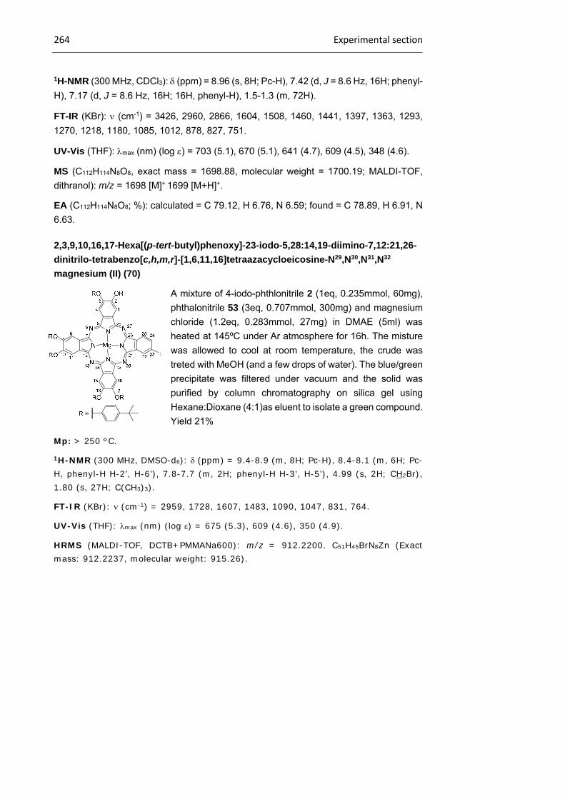
264 Experimental section
1H-NMR (300 MHz, CDCl3): (ppm) = 8.96 (s, 8H; Pc-H), 7.42 (d, J = 8.6 Hz, 16H; phenyl-
H), 7.17 (d, J = 8.6 Hz, 16H; 16H, phenyl-H), 1.5-1.3 (m, 72H).
FT-IR (KBr): (cm-1) = 3426, 2960, 2866, 1604, 1508, 1460, 1441, 1397, 1363, 1293,
1270, 1218, 1180, 1085, 1012, 878, 827, 751.
UV-Vis (THF): max (nm) (log ) = 703 (5.1), 670 (5.1), 641 (4.7), 609 (4.5), 348 (4.6).
MS (C112H114N8O8, exact mass = 1698.88, molecular weight = 1700.19; MALDI-TOF,
dithranol): m/z = 1698 [M]+ 1699 [M+H]+.
EA (C112H114N8O8; %): calculated = C 79.12, H 6.76, N 6.59; found = C 78.89, H 6.91, N
6.63.
2,3,9,10,16,17-Hexa[(p-tert-butyl)phenoxy]-23-iodo-5,28:14,19-diimino-7,12:21,26-
dinitrilo-tetrabenzo[c,h,m,r]-[1,6,11,16]tetraazacycloeicosine-N29,N30,N31,N32
magnesium (II) (70)
A mixture of 4-iodo-phthlonitrile 2 (1eq, 0.235mmol, 60mg),
phthalonitrile 53 (3eq, 0.707mmol, 300mg) and magnesium
chloride (1.2eq, 0.283mmol, 27mg) in DMAE (5ml) was
heated at 145ºC under Ar atmosphere for 16h. The misture
was allowed to cool at room temperature, the crude was
treted with MeOH (and a few drops of water). The blue/green
precipitate was filtered under vacuum and the solid was
purified by column chromatography on silica gel using
Hexane:Dioxane (4:1)as eluent to isolate a green compound.
Yield 21%
Mp: > 250 ºC.
1H-NMR (300 MHz, DMSO-d6): (ppm) = 9.4-8.9 (m, 8H; Pc-H), 8.4-8.1 (m, 6H; Pc-H, phenyl-H H-2’, H-6’), 7.8-7.7 (m, 2H; phenyl-H H-3’, H-5’), 4.99 (s, 2H; CH2Br), 1.80 (s, 27H; C(CH3)3).
FT-IR (KBr): (cm-1) = 2959, 1728, 1607, 1483, 1090, 1047, 831, 764.
UV-Vis (THF): max (nm) (log ) = 675 (5.3), 609 (4.6), 350 (4.9).
HRMS (MALDI-TOF, DCTB+PMMANa600): m/z = 912.2200. C51H45BrN8Zn (Exact mass: 912.2237, molecular weight: 915.26).
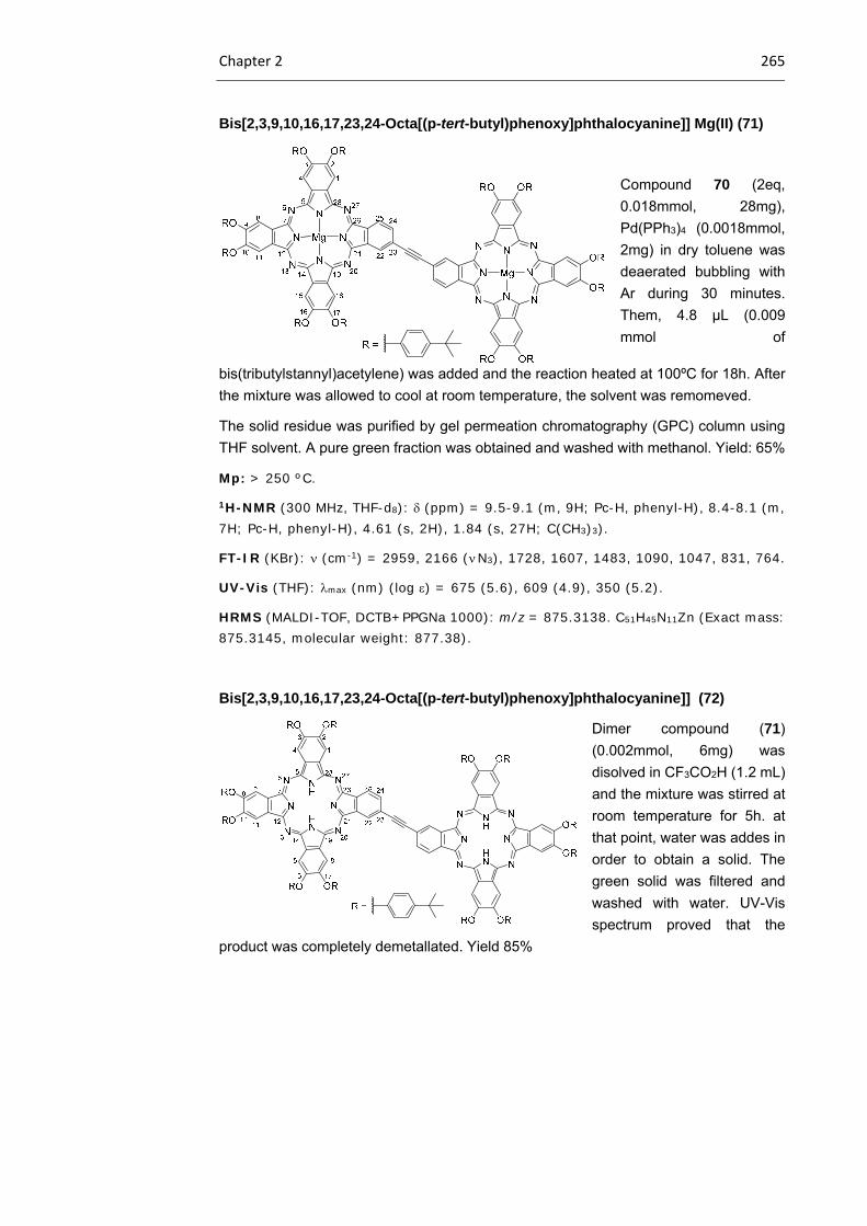
Chapter 2 265
Bis[2,3,9,10,16,17,23,24-Octa[(p-tert-butyl)phenoxy]phthalocyanine]] Mg(II) (71)
Compound 70 (2eq,
0.018mmol, 28mg),
Pd(PPh3)4 (0.0018mmol,
2mg) in dry toluene was
deaerated bubbling with
Ar during 30 minutes.
Them, 4.8 μL (0.009
mmol of
bis(tributylstannyl)acetylene) was added and the reaction heated at 100ºC for 18h. After
the mixture was allowed to cool at room temperature, the solvent was remomeved.
The solid residue was purified by gel permeation chromatography (GPC) column using
THF solvent. A pure green fraction was obtained and washed with methanol. Yield: 65%
Mp: > 250 ºC.
1H-NMR (300 MHz, THF-d8): (ppm) = 9.5-9.1 (m, 9H; Pc-H, phenyl-H), 8.4-8.1 (m, 7H; Pc-H, phenyl-H), 4.61 (s, 2H), 1.84 (s, 27H; C(CH3)3).
FT-IR (KBr): (cm-1) = 2959, 2166 ( N3), 1728, 1607, 1483, 1090, 1047, 831, 764.
UV-Vis (THF): max (nm) (log ) = 675 (5.6), 609 (4.9), 350 (5.2).
HRMS (MALDI-TOF, DCTB+PPGNa 1000): m/z = 875.3138. C51H45N11Zn (Exact mass: 875.3145, molecular weight: 877.38).
Bis[2,3,9,10,16,17,23,24-Octa[(p-tert-butyl)phenoxy]phthalocyanine]] (72)
Dimer compound (71)
(0.002mmol, 6mg) was
disolved in CF3CO2H (1.2 mL)
and the mixture was stirred at
room temperature for 5h. at
that point, water was addes in
order to obtain a solid. The
green solid was filtered and
washed with water. UV-Vis
spectrum proved that the
product was completely demetallated. Yield 85%

266 Experimental section
Mp: 300ºC
1H-NMR (300 MHz, CDCl3): (ppm) = 8.96 (s, J = 8 Hz, H), 7.42 (d, J 8.6 Hz, 16H; H-
AA´BB´), 7.17 (d, J = 8.6 Hz, 16H; 16H, H-AA´BB´).
FT-IR (KBr): (cm-1) = 3426, 2960, 2866, 1604, 1508, 1460, 1441, 1397, 1363, 1293,
1270, 1218, 1180, 1085, 1012, 878, 827, 751.
UV-Vis (THF): max (nm) (log ) = 703 (5.1), 607 (5.1), 641 (4.7), 609 (4.5), 348 (4,6).
MS (MALDI ditranol): m/z = 1698 [M]+,1699 [M+H]+
EA: elemental analysis calcd (%) for C112H114N8O8Tb: C 79.12, H 6.76,N 6.59; found: C
78.89, H 6.91, N 6.63.
Dimeric compound 73
A mixture of dimeric compound 72 (1eq, 0.0053mmol, 15mg) and Tb(acac)3
nH2O (1.2eq, 0.0063mmol, 3mg) was refluxed for 24h under Ar im TCB (2mL) with n-
hexadecanol (30mg) in the presence of catalytic amount of LiOMe. Solvent was
evaporated under reduced pressure and the green solid was diluted with DCM and
washed with washed with water and brine. The resulting dark green powder was
dissolved in DCM and chromatographed using GPC (DCM as eluent) there fraction were
collected as a dark geen solid. Yield: 18% (all isomers).
1H-NMR (300 MHz, [D7]DMF/CCl4/N2H4, 25ºC, TMS): (ppm) = -10.5 (s, 72H; (CH3)3), -
13.68 (s, 16H; H-phenyl), -32.44 (s, 16H; H-phenyl), - 45.63 (s, 8H; H-β), - 92.40, - 95.57
ppm (2s, 16H; H-α’+H-α)

Chapter 2 267
FT-IR (KBr): (cm-1) = 3057 (w), 2962 (s), 2868 (m), 1601 (m), 1504 (vs), 1448 (vs), 1393
(vs), 1325 (vs), 1261 (m), 1223 (vs), 1180 (vs), 1113 (s), 1086 (m), 1018 (m), 885 (m),
831 (w), 737 cm 1 (w)
UV-Vis (THF): max (nm) (log ) = 915 (5000), 675 (200 000), 608 (40 000), 457 (32000),
352 (100 000), 324 (126 000), 287 nm (100 000 mol-1 dm3 cm-1)
MS (MALDI-TOF, dithranol): m/z 5869.