
DMM Working Group P. Camarillo Internet-Draft C. Filsfils ...
215
DMM Working Group P. Camarillo Internet-Draft C. Filsfils Intended status: Informational Cisco Systems, Inc. Expires: October 26, 2019 L. Bertz Sprint A. Akhavain Huawei Canada Research Centre S. Matsushima SoftBank D. Voyer Bell Canada April 24, 2019 Segment Routing IPv6 for mobile user-plane PoCs draft-camarillo-dmm-srv6-mobile-pocs-02 Abstract This document describes the ongoing proof of concepts of [I-D.ietf-dmm-srv6-mobile-uplane] and their progress. Status of This Memo This Internet-Draft is submitted in full conformance with the provisions of BCP 78 and BCP 79. Internet-Drafts are working documents of the Internet Engineering Task Force (IETF). Note that other groups may also distribute working documents as Internet-Drafts. The list of current Internet- Drafts is at https://datatracker.ietf.org/drafts/current/. Internet-Drafts are draft documents valid for a maximum of six months and may be updated, replaced, or obsoleted by other documents at any time. It is inappropriate to use Internet-Drafts as reference material or to cite them other than as "work in progress." This Internet-Draft will expire on October 26, 2019. Copyright Notice Copyright (c) 2019 IETF Trust and the persons identified as the document authors. All rights reserved. This document is subject to BCP 78 and the IETF Trust’s Legal Provisions Relating to IETF Documents (https://trustee.ietf.org/license-info) in effect on the date of publication of this document. Please review these documents Camarillo, et al. Expires October 26, 2019 [Page 1]
-
Upload
khangminh22 -
Category
Documents
-
view
4 -
download
0
Transcript of DMM Working Group P. Camarillo Internet-Draft C. Filsfils ...

DMM Working Group P. CamarilloInternet-Draft C. FilsfilsIntended status: Informational Cisco Systems, Inc.Expires: October 26, 2019 L. Bertz Sprint A. Akhavain Huawei Canada Research Centre S. Matsushima SoftBank D. Voyer Bell Canada April 24, 2019
Segment Routing IPv6 for mobile user-plane PoCs draft-camarillo-dmm-srv6-mobile-pocs-02
Abstract
This document describes the ongoing proof of concepts of [I-D.ietf-dmm-srv6-mobile-uplane] and their progress.
Status of This Memo
This Internet-Draft is submitted in full conformance with the provisions of BCP 78 and BCP 79.
Internet-Drafts are working documents of the Internet Engineering Task Force (IETF). Note that other groups may also distribute working documents as Internet-Drafts. The list of current Internet- Drafts is at https://datatracker.ietf.org/drafts/current/.
Internet-Drafts are draft documents valid for a maximum of six months and may be updated, replaced, or obsoleted by other documents at any time. It is inappropriate to use Internet-Drafts as reference material or to cite them other than as "work in progress."
This Internet-Draft will expire on October 26, 2019.
Copyright Notice
Copyright (c) 2019 IETF Trust and the persons identified as the document authors. All rights reserved.
This document is subject to BCP 78 and the IETF Trust’s Legal Provisions Relating to IETF Documents (https://trustee.ietf.org/license-info) in effect on the date of publication of this document. Please review these documents
Camarillo, et al. Expires October 26, 2019 [Page 1]
Internet-Draft SRv6-mobile-PoCs April 2019
carefully, as they describe your rights and restrictions with respect to this document. Code Components extracted from this document must include Simplified BSD License text as described in Section 4.e of the Trust Legal Provisions and are provided without warranty as described in the Simplified BSD License.
Table of Contents
1. Introduction . . . . . . . . . . . . . . . . . . . . . . . . 2 2. Terminology . . . . . . . . . . . . . . . . . . . . . . . . . 2 3. M-CORD C3PO . . . . . . . . . . . . . . . . . . . . . . . . . 3 3.1. PoC phases . . . . . . . . . . . . . . . . . . . . . . . 3 3.2. Activity report . . . . . . . . . . . . . . . . . . . . . 3 3.2.1. Phase 1 . . . . . . . . . . . . . . . . . . . . . . . 3 4. Open Air Interface . . . . . . . . . . . . . . . . . . . . . 4 4.1. PoC phases . . . . . . . . . . . . . . . . . . . . . . . 4 4.1.1. Phase 1: Mobile Core Migration from IPv4-GTP to SRv6 5 4.2. Activity report . . . . . . . . . . . . . . . . . . . . . 6 5. Contributors . . . . . . . . . . . . . . . . . . . . . . . . 6 6. Informative References . . . . . . . . . . . . . . . . . . . 7 Authors’ Addresses . . . . . . . . . . . . . . . . . . . . . . . 7
1. Introduction
The [I-D.ietf-dmm-srv6-mobile-uplane] proposes SRv6 as userplane protocol for mobile networks. As part of this work we have decided to create a series of PoCs with the objective to prove the viability and feasibility of such proposal.
For this reason we have two ongoing PoCs using M-CORD C3PO and OAI, that are progressing towards a full implementation of the mechanisms described in such I-D.
This I-D contains a formal definition of the PoCs and will summarize it’s findings. Anyone interested in participating in the ongoing PoCs or propose new ones is welcome to join us.
2. Terminology
This document adopts the terminology of [I-D.ietf-dmm-srv6-mobile-uplane].
This document uses the terms N3, N6 and N9 interfaces, as well as UPF and gNB as refered to in [TS.23501].
Camarillo, et al. Expires October 26, 2019 [Page 2]
Internet-Draft SRv6-mobile-PoCs April 2019
3. M-CORD C3PO
M-CORD <https://www.opennetworking.org/m-cord/> is an open-source project from ONF focused on building a cloud-native virtualized and dissagregated RAN and EPC.
As part of the M-CORD project, the C3PO component is part of the NGIC (Next Generation Infrastructure Core) <https://gerrit.opencord.org/#/admin/projects/ngic>.
The scope of this PoC is to extend the C3PO component to support natively SRv6 on the N6 and N9 interfaces and have SRv6-supported UPFs.
3.1. PoC phases
This PoC is divided in several phases:
1. SRv6 in transport network with no impact to EPC 2. SRv6 native in N6 interface (GiLAN) with SRv6 transport network 3. SRv6 native in N6 and N9 interfaces with N3 interworking mechanisms
3.2. Activity report
Phase 1 has been completed. Ongoing development of phase 2.
3.2.1. Phase 1
We used FD.io VPP <https://fd.io/technology/> to simulate an SRv6 transport network with three SRv6 routers in the N9 interface simulating a transport network.
As part of this transport network, we run two simulations:
In the first simulation we steered the IPv4/GTP traffic into an SR policy that encapsulated the packet with an SRv6 header containing two SIDs.
In the second simulation we steered the IPv4/GTP traffic into an SR policy that removed the IPv4/GTP headers and placed the GTP header information (i.e. TEID) into an SRv6 SID. The last SID of the SR policy corresponds to an End.M.GTP4.E function, that decapsulates SRv6 traffic restoring the IPv4/GTP header. The objective of the second simulation is to show the IPv4/GTP interworking mechanism via an uplink classifier behaving as SR-GW, as defined in Section 6.4 of [I-D.ietf-dmm-srv6-mobile-uplane] .
Camarillo, et al. Expires October 26, 2019 [Page 3]
Internet-Draft SRv6-mobile-PoCs April 2019
After Phase 1, we concluded that SRv6 as mobility transport network works fine, with an expected MTU overhead due to the original PDU encapsulation. The IPv4/GTP interworking mechanism in the scope of phase 1 is also fully functional. This mechanism will be further tested as the POC progresses and a native SRv6-based UPF is developed.
4. Open Air Interface
Open Air Interface (OAI) is an open-source software <http://www.openairinterface.org/?page_id=2762> that implements the 3GPP stack. OAI is composed of two major projects: OAI-RAN and OAI- CN.
o OAI-RAN implements the 4G LTE and 5G Radio Access Network. Both the gNB as well as the UE are implemented. o OAI-Core Network implements the 4G LTE Evolved Packet Core (EPC) and 5G Core Network.
The scope of this PoC is to extend the OAI-RAN and OAI-CN components to support natively SRv6 on the N3 and N9 interfaces, and have SRv6-supported gNBs and UPFs.
4.1. PoC phases
The primary goal of this POC is to show SRv6 as a data plane replacement for GTP on both N3 and N9 interfaces. The POC also aims to demonstrate a smooth migration path during deployment and transition period from IPv4-GTP and IPv6-GTP to an end to end SRv6 data plane.
The PoC functions within the existing OAI model. OAI currently doesn’t provide support for S5/S8 interface. The implementation instead provides an integrated SGW and PGW S/PGW module and therefore there is no GTP tunnel between these two entities. This limitation has an impact on the POC strategy and its implementation phases.
This PoC is divided into several phases:
1.- N3 via SRv6 GW VNFs and no impact on 3GPP control plane.
1.1.- Mobile Core Migration from IPv4-GTP to SRv6 1.2.- Mixed IPv4-GTP/IPv6-GTP Mobile Core Over SRv6
2.- N3 via SRv6 eNB and S/PGW integrated modules and no impact on 3GPP control plane.
2.1.- Mobile Core Migration from IPv4-GTP to SRv6
Camarillo, et al. Expires October 26, 2019 [Page 4]
Internet-Draft SRv6-mobile-PoCs April 2019
2.2.- Mixed IPv4-GTP/IPv6-GTP Mobile Core Over SRv6
3.- N3 via SRv6 support of ID-LOC architecture
Important notes:
- The above phases and solution strategy can easily be extended to the N9 interface. However, although the N9 interface is well within the scope of this PoC, the effort required to changes the OAI code base to support S5/S8 and separate SGW and PGW modules will push the project well beyond the timeline of this PoC and as such are not currently part of the PoC. - Support for service programming, TE, QoS, entropy, and other enhanced features are also within the scope of this PoC, but will also fall beyond the time line of this project and are not currently considered in this PoC. - The above items can be pulled back into the project based on demand and assistance from others.
4.1.1. Phase 1: Mobile Core Migration from IPv4-GTP to SRv6
Phase one of this POC focuses on demonstrating a smooth migration path from the existing mobile core networks with IPv4 GTP based user plane to SRv6 user plane with absolutely no impact on 3GPP control plane. The idea is to employ SRv6 gateways between mobile core equipment such as eNB, SGW, and PGW, intercept GTP traffic, and carry UE’s payload through SRv6 newtwork by encoding GTP information into the SIDs.
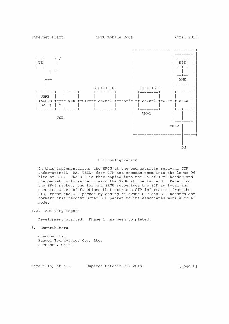
In this POC as it was mentioned earlier we use OAI open source software. OAI implements gNB as an stand alone entitiy, but bundles MME, SGW and PGW into a single package. We employ three Linux PCs in oursetup. Two of these machines run the gNB and one of the SRv6 GWs. The thrid machines employs virtualisation and instantiates two virtual machines. The second SRv6 gateway runs in one of the virtual machine while the other virtual machines executes the code for the combinged MME, SGW, PGW. The code in SRv6 gateways is based on VPP implementation in Linux Foundation. We modified this code to intercept GTP packets, extract GTP information, and encode GTP information into the SIDs. Given that today’s mobile core don’t deal with multiple UPFs, the resulting SRv6 haeader doesn’t require any SRH to carry GTP information across the network. Therefore, in this phase, the resulting SRv6 packets are simply IPv6 packets with their DA set to SIDs. The following diagratm shows the POC configuration.
Camarillo, et al. Expires October 26, 2019 [Page 5]
Internet-Draft SRv6-mobile-PoCs April 2019
+--------------------------+ | +========+| +--+ \|/ | | +---+ || |UE| | | | |HSS| || +--+ | | | +-+-+ || +--+ | | | || | | | +-+-+ || +-+ | | |MME| || | | | +---+ || | GTP<->SID | GTP<->SID | || +---+---+ +-----+ +--------+ | +========+ |+------+|| | USRP | | | | | | | | || ||| |(Ettus +---+ gNB +-GTP--+ SRGW-1 +--SRv6-|-+ SRGW-2 +-GTP-|+ SPGW ||| | B210) | ^ | | | | | | | || ||| +-------+ | +-----+ +--------+ | +========+ |+--+---+|| | | VM-1 | | || USB | | | || | +========+| | VM-2 | | | | | +--------------------|-----+ | | DN
POC Configuration
In this implementation, the SRGW at one end extracts relavant GTP informaton(SA, DA, TEID) from GTP and encodes them into the lower 96 bits of SID. The SID is then copied into the DA of IPv6 header and the packet is forwarded toward the SRGW at the far end. Receiving the SRv6 packet, the far end SRGW recognises the SID as local and executes a set of functions that extracts GTP information from the SID, forms the GTP packet by adding relevant UDP and GTP headers and forward this reconstructed GTP packet to its associated mobile core node.
4.2. Activity report
Development started. Phase 1 has been completed.
5. Contributors
Chenchen Liu Huawei Technolgies Co., Ltd. Shenzhen, China
Camarillo, et al. Expires October 26, 2019 [Page 6]
Internet-Draft SRv6-mobile-PoCs April 2019
Email: [email protected]
Arun Rajagopal Sprint United States of America
Email: [email protected]
Mark Bales Sprint United States of America
Email: [email protected]
Robert Butler Sprint United States of America
Email: [email protected]
6. Informative References
[I-D.filsfils-spring-srv6-network-programming] Filsfils, C., Camarillo, P., Leddy, J., [email protected], d., Matsushima, S., and Z. Li, "SRv6 Network Programming", draft-filsfils-spring-srv6-network- programming-07 (work in progress), February 2019.
[I-D.ietf-dmm-srv6-mobile-uplane] Matsushima, S., Filsfils, C., Kohno, M., Camarillo, P., [email protected], d., and C. Perkins, "Segment Routing IPv6 for Mobile User Plane", draft-ietf-dmm-srv6-mobile- uplane-04 (work in progress), March 2019.
[TS.23501] 3GPP, "System Architecture for the 5G System", 3GPP TS 23.501 15.0.0, November 2017.
Authors’ Addresses
Pablo Camarillo Garvia Cisco Systems, Inc. Spain
Email: [email protected]
Camarillo, et al. Expires October 26, 2019 [Page 7]
Internet-Draft SRv6-mobile-PoCs April 2019
Clarence Filsfils Cisco Systems, Inc. Belgium
Email: [email protected]
Lyle T Bertz Sprint United States of America
Email: [email protected]
Arashmid Akhavain Huawei Canada Research Centre Canada
Email: [email protected]
Satoru Matsushima SoftBank Tokyo Japan
Email: [email protected]
Daniel Voyer Bell Canada Canada
Email: [email protected]
Camarillo, et al. Expires October 26, 2019 [Page 8]
SPRING and DMM P. Camarillo, Ed.
Internet-Draft C. Filsfils
Intended status: Standards Track Cisco Systems, Inc.
Expires: February 16, 2020 H. Elmalky, Ed.
Individual
S. Matsushima
SoftBank
D. Voyer
Bell Canada
A. Cui
AT&T
B. Peirens
Proximus
August 15, 2019
SRv6 Mobility Use-Cases
draft-camarilloelmalky-springdmm-srv6-mob-usecases-02
Abstract
This document describes the SRv6 use-cases in the mobile network in
association with different mobile generations (3G, 4G, and 5G). It
also highlights potential interworking with SR-MPLS in relevant use-
cases.
Requirements Language
The key words "MUST", "MUST NOT", "REQUIRED", "SHALL", "SHALL NOT",
"SHOULD", "SHOULD NOT", "RECOMMENDED", "MAY", and "OPTIONAL" in this
document are to be interpreted as described in RFC 2119 [RFC2119].
Status of This Memo
This Internet-Draft is submitted in full conformance with the
provisions of BCP 78 and BCP 79.
Internet-Drafts are working documents of the Internet Engineering
Task Force (IETF). Note that other groups may also distribute
working documents as Internet-Drafts. The list of current Internet-
Drafts is at https://datatracker.ietf.org/drafts/current/.
Internet-Drafts are draft documents valid for a maximum of six months
and may be updated, replaced, or obsoleted by other documents at any
time. It is inappropriate to use Internet-Drafts as reference
material or to cite them other than as "work in progress."
This Internet-Draft will expire on February 16, 2020.
Camarillo, et al. Expires February 16, 2020 [Page 1]
Internet-Draft SRv6 Mobility Use-Cases August 2019
Copyright Notice
Copyright (c) 2019 IETF Trust and the persons identified as the
document authors. All rights reserved.
This document is subject to BCP 78 and the IETF Trust’s Legal
Provisions Relating to IETF Documents
(https://trustee.ietf.org/license-info) in effect on the date of
publication of this document. Please review these documents
carefully, as they describe your rights and restrictions with respect
to this document. Code Components extracted from this document must
include Simplified BSD License text as described in Section 4.e of
the Trust Legal Provisions and are provided without warranty as
described in the Simplified BSD License.
Table of Contents
1. Introduction . . . . . . . . . . . . . . . . . . . . . . . . 3
2. Terminology . . . . . . . . . . . . . . . . . . . . . . . . . 4
3. Use-cases . . . . . . . . . . . . . . . . . . . . . . . . . . 5
3.1. SP Network Simplification use-cases . . . . . . . . . . . 5
3.1.1. Radio-core Handoff . . . . . . . . . . . . . . . . . 5
3.1.1.1. Radio-transport programmability . . . . . . . . . 5
3.1.1.2. User-plane state transfer, offload, and mutation 6
3.1.1.3. Rip-n-replace of GTP with SRv6 . . . . . . . . . 8
3.1.2. End-to-end network slicing [N3, N9, N6 and transport] 9
3.1.3. GiLAN Service Programming [N6 and N9] . . . . . . . . 9
3.1.3.1. Service Programming on Gi-LAN for 3G/4G [SGi] . . 10
3.1.3.2. Service Programming for 5G [N6 and N9] . . . . . 10
3.1.4. ID-Location Isolation at anchors . . . . . . . . . . 10
3.2. New mobility use-cases . . . . . . . . . . . . . . . . . 10
3.2.1. eMBB (Enhanced Mobile Broadband) . . . . . . . . . . 10
3.2.1.1. Fixed/Mobile Convergence (HA, FWA & WA) . . . . . 10
3.2.1.2. Mobile Enforced SD-WAN . . . . . . . . . . . . . 11
3.2.2. mMTC (massive Machine Type Communications) . . . . . 11
3.2.2.1. Stationary IoT Devices (industrial applications) 11
3.2.3. URLLC (Ultra Reliable Low Latency Communications) . . 12
4. Work in progress . . . . . . . . . . . . . . . . . . . . . . 12
5. Acknowledgements . . . . . . . . . . . . . . . . . . . . . . 12
6. References . . . . . . . . . . . . . . . . . . . . . . . . . 12
6.1. Normative References . . . . . . . . . . . . . . . . . . 12
6.2. Informative References . . . . . . . . . . . . . . . . . 12
Authors’ Addresses . . . . . . . . . . . . . . . . . . . . . . . 13
Camarillo, et al. Expires February 16, 2020 [Page 2]
Internet-Draft SRv6 Mobility Use-Cases August 2019
1. Introduction
4G/LTE mobile networks are complex and the use cases that 5G has been
architected to address, introduce new requirements and additional
complexity to both the RAN and the mobile core. The current
architecture employs the GPRS tunneling protocol (GTP) as the primary
vehicle for user plane interconnect in the RAN and 5GC. GTP is
currently used in two contexts, from the RAN to the first anchor
point; the S-PGW/UPF (S1-U/N3 interface) and for inter S-PGW/UPF
connectivity (S5-S8/N9 interface). While the tunnels themselves do
not impose significant state beyond that needed, they do have a
significant control plane setup component and are a potential target
for network delayering.
Segment Routing [I-D.ietf-spring-segment-routing] is a network
architecture that simplifies networks by removing state from the
network infrastructure, creating a scalable SDN architecture for
overlays (VPNs), underlay (SLA, Traffic Engineering, FRR) and service
programming (GiLAN). The IPv6 instantiation -also known as SRv6
[I-D.ietf-spring-srv6-network-programming]- takes this even further
with the introduction of the Network Programming concept, allowing to
bind segments to any kind of VNF anywhere in the network -from
private DCs to public cloud services.
Segment routing embodies a number of potentially useful properties
for consideration in a 4G/5G mobile networking context:
1.- Direct manipulation of path routing by the head-end
SRv6 provides the ability to direct traffic through an arbitrary path
without the imposition of path state in the network or requiring a
separate signaling system. It does this without signaling by
encoding the path state in the packet header. This means the path
head-end can instantly fulfill changes to a path by simply changing
the header encoded information.
This capability has numerous applications as far as networking in
general (traffic engineering, policy routing etc.), but has
additional applicability to mobile networks:
o The ability of a path head-end to manipulate the intermediate hops
in a path can be exploited for end system mobility, the
penultimate hop simply becomes the "care of" address.
o The ability of path head-end to imply an asymmetric return path
for a specific forwarding equivalence class (FEC).
Camarillo, et al. Expires February 16, 2020 [Page 3]

Internet-Draft SRv6 Mobility Use-Cases August 2019
o Densification in the radio topology embodied in concepts like
coordinated multipoint and multi-connectivity require the
instantaneous redirection of traffic from the coordinating radio
controller to any of several base stations. This is critical to
exploit ephemeral "rich paths" that 4G & 5G radio technologies
depend upon to achieve high rates of information transfer.
2.- Network programmability
The ability to bind segments to network functions provides an
increased level of abstraction in service delivery combined with a
practical realization. This would have applications in the GiLAN/N6,
combined with the ability to specify a path from the head-end as
applications in the GiLAN/N6.
3.- Overall simplification of the control plane
As noted previously SRv6 dispenses with a signaling system. This has
obvious benefits as a simplification to overall network operation,
but may have additional benefits in the "signaling rich" environment
of mobile networks.
This memo serves to critically explore the applicability of SRv6 to
4G/5G mobile networks. It does that via an exploration of how SRv6
can simplify current mobile network architecture to improve the
status quo of eMBB operation, and then delves into the new use cases
that 5G is targeted towards.
2. Terminology
This document focuses on the use-cases, and it’s associated
terminologies. The full list of terminologies exists in
[I-D.ietf-spring-srv6-network-programming].
In this document we focus on the 5G systems architecture, as
specified in [TS.23501]. This document also refers to 3G and 4G
networks as specified in [TS.23002].
The uplink/upstream traffic is the traffic originated at the UE,
while the downlink/downstream traffic is traffic destined towards the
UE.
Camarillo, et al. Expires February 16, 2020 [Page 4]
Internet-Draft SRv6 Mobility Use-Cases August 2019
3. Use-cases
Use-cases have been classified into multiple categories depending on
their fit into the mobile-network domain (Radio, Transport, Core) or
mobile network generation (3G/4G, or 5G).
3.1. SP Network Simplification use-cases
3.1.1. Radio-core Handoff
3.1.1.1. Radio-transport programmability
Advances in radio technology, the deployment of new spectrum for 5G
and the quest for ever increasing spectral efficiency results in
increasingly complex RAN and air interface topologies. The result is
that the RAN end of a GTP tunnel may appear as a single end point to
the core network, but the actual realization is substantially more
complex.
Modern radio scheduling is increasingly focused on using techniques
such as MIMO to multiply the instantaneous bandwidth available for
information transfer for a given unit of spectrum. A "rich path" can
be very ephemeral so any latency between path measurement and
initiating data transfer to a UE can be parasitic in the overall
system efficiency.
3.1.1.1.1. Multi-connectiveity and coordinated multi-point
There are multiple scenarios where a UE can be associated with more
than one antenna and the associated spectrum:
Coordinated multipoint (CoMP) involves a UE associated with multiple
geographically distributed antennas serving a common block of
spectrum, and the radio controller selecting the best antenna at any
given time. The other antennas being quiescent in the sector
occupied by the UE at the time of transmission to avoid overlap.
This can be in the context of an RRC/RLC split (F1-U interface) or a
Phy Hi/Phy Lo split (F2-U interface).
Multi-connectivity can see a UE associated with multiple antennas
each serving different spectral allocations. Applications include
offload from a macro cell to a small cell. The possibility of
simultaneous transfer from multiple antennas also exists. And again
this can be on the basis of an F1 or F2 split in the RAN.
In both cases the radio controller is required to be able to
instantly redirect traffic based on current radio measurements to any
of a constellation of antennas serving a given UE.
Camarillo, et al. Expires February 16, 2020 [Page 5]
Internet-Draft SRv6 Mobility Use-Cases August 2019
3.1.1.1.2. Fronthaul
Modern radio systems have been deconstructed in order to drive
efficiency across a variety of metrics. In essence various stages of
waveform construction have been abstracted and exposed on interfaces
as part of the 5G RAN architecture. In the most simplest form it
allows putting functionality where it is easy to service, such as the
equipment at the bottom of the tower rather than the top. In a rich
radio connectivity context it permits co-location of radio scheduling
and waveform generation which drives spectral efficiency, but where
applied also results in significant multiples of bandwidth, and very
tight jitter and delay requirements. The current specification for
the F2-U or e(CPRI) packet interface has a maximum latency of 75 usec
and correspondingly tight jitter requirements.
3.1.1.2. User-plane state transfer, offload, and mutation
A proper session handoff between radio, transport, and mobile-core
requires storing/recalling user-plane session state on multiple
levels. The use of SRv6 reduces the number of states needed in the
network nodes by mapping the UE session state into IPv6 SID (Segment
IDs) in SRH. Furthermore, mutation of SID-lists shall enable SMF to
program data-paths (handling-state) and policies (serving-state) on
per-subscriber / per-application level.
That session state can be broken down into two categories:
1.- Handling state: Who is the session handler?
o A 1-to-1 mapping between GTP tunnel (TEID) and S-PGW/UPF
o Usually stored at load-balancers deployed ahead of S-PGW/UPF
instances or embedded inside the S-PGW/UPF system.
2.- Serving state: What is the serving-policy associated with this
session?
o A 1-to-1 mapping between the UE and a specific policy to be
enforced on the subscriber traffic.
o The policy may include (but not limited to) the authorization &
accounting profile, one or multiple QoS profiles, one or multiple
service-chaining/programming profiles.
o A 1-to-1 mapping between a UE session and it’s stats-registers at
the S-PGW/UPF.
Camarillo, et al. Expires February 16, 2020 [Page 6]
Internet-Draft SRv6 Mobility Use-Cases August 2019
o It is typical that S-PGW/UPF may break down the service-state into
sub-states reflecting groups of 5-tuple flows, or employ other
techniques (ex. DPI, deep packet inspection) to break down the
serving-state even further within the same 5-tuple flow.
The ability to transfer, offload, or mutate the user-plane state with
no/minimum disruption to end-users is one of the most significant
challenges facing the mobile network’s scalability towards mMTC use-
cases (The current GTP-U mandates a per-session tunnel creation &
handling). Moreover, the direct 1-to-1 binding between UE session ID
and Location affects the optimal-path selection, which is one of the
most significant challenges facing URLLC use-cases in 5G.
The use of SRv6 shall simplify the state storage dramatically where a
single SID-list embedded in the UE session packet can store the
handling-state and the majority of the serving-state. SRv6
programmability and traffic-engineering shall allow an easy way to
transfer, offload, or mutate that state.
3.1.1.2.1. State-offload:
Upstream state-offload:
the use of SRv6 shall allow the S-PGW/UPF anchor(s) to offload the
load-balancing function from a dedicated load-balancer in mobile-core
to be a standard function in packet-forwarding in transport network
where any SR-aware node on the path between eNB and S-PGW/UPF can
forward the UE session to the proper S-PGW/UPF handling instant by
relying on the handling-state stored in the SID-list in each packet.
Downstream state-offload:
The L3 anchor (PGW/UPF) is the first node that handles the subscriber
traffic in the downstream direction, depending on the policy
associated with the subscriber traffic. The PGW/UPF may decide to
hairpin the traffic through multiple application (service chain)
before sending it towards the radio-network. This implies double
packet-processing on PGW/UPF instant (50% penalty on the VNF useful
throughput).
The use of SRv6 shall allow the PGW/UPF to impose a specific data-
path on a group of 5-tuple flows without the need for hairpins all
the traffic through PGW/UPF. Which means the PGW/UPF can offload the
first packet processing towards another none-SR- node earlier in the
downstream path (ex. Service-proxy, or packet inspector) as per
specific service-pipeline policy.
Moreover, that offload-service can be programmed once the S-PGW/UPF
terminate the subs-session on the upstream direction. Alternatively,
Camarillo, et al. Expires February 16, 2020 [Page 7]
Internet-Draft SRv6 Mobility Use-Cases August 2019
the offload-service can be programmed on-demand after the first few
packets been hair-pinned through the PGW/UPF on the downstream path.
3.1.1.2.2. State-transfer:
Handling-state:
SRv6 shall enable the handling-state to be embedded in the data-flow
as metadata (in a form of SID-list). This means that all load-
balancing operations can be performed by any of the SR-aware
intermediate nodes in a stateless fashion with a zero-state transfer
at failure scenarios.
Serving-state:
Depending on the applied policy, a significant portion of the
serving-state can be embedded in the data-flow as metadata (in a form
of SID-list). This means that serving nodes (S-PGW/UPF) have a
smaller amount of data to store/recall to serve the UE session.
3.1.1.2.3. State-mutation:
SRv6 provides a more natural way to mutate the handling-state and
serving-state to follow the optimal data path or fulfill traffic-
engineering constrain(s).
In contrast to the current limitation of mutating the state only at
SGW (session L2-anchor point) or PGW (session L3-anchor point). SRv6
shall allow the state mutation on any authorized SR-aware node
between radio and mobile core.
3.1.1.3. Rip-n-replace of GTP with SRv6
A possible mechanism to do an early-deployment of SRv6 is to keep the
tunnel-nature of GTP but do a simple data-plane replacement of
IP/UDP/GTP-U with SRv6 for specific PDU sessions. In this case,
there is no session aggregation, and the SRv6 segment corresponding
to the overlay creation now carries the TEID, QFI and RQI as part of
the SID arguments.
In this use-case there is no subscriber-traffic integration with the
underlay or service programming. There could be some integration but
it is based on static policies and not configured via the currently
existing mobility management.
This is an interworking mechanism that shall used for an early stage
implementation with no changes to the N4 interface.
Camarillo, et al. Expires February 16, 2020 [Page 8]

Internet-Draft SRv6 Mobility Use-Cases August 2019
3.1.2. End-to-end network slicing [N3, N9, N6 and transport]
One of operator’s main challenges is providing end-to-end network
slicing, taking into consideration the RAN, the S-PGW/UPF and the
VNFs in the GiLAN; but more importantly taking also into
consideration the transport network.
SRv6 can help bridging the gap in between all of these since it
integrates the overlay, underlay and service programming into a
single protocol. End-to-end SR policies can be defined that span
across the RAN, S-PGW/UPF and transport network, without requiring
any stitching configuration at the domain boundaries. From an
overlay perspective, it is clear that SRv6 can provide -if desired-
isolation among different RAN or S-PGW/UPF nodes.
In the transport network, the SRv6 overlay can integrate with an
existing SRv6 or SR-MPLS transport network to provide traffic
engineering in the underlay network infrastructure. SR provides
operators with a stateless mechanism to build network slices with
different optimization objectives or constrains i.e. low-latency
(uRLLC), resource isolation (disjointness), etc...
Also, SR provides mechanisms for in-band performance monitoring.
This implies that the end-to-end network slice can react upon
topology changes -that for example might change the low-latency
path-.
3.1.3. GiLAN Service Programming [N6 and N9]
Service Programming, in coordination with SRv6 can be used for
optimal placement of VNFs in the Gi-LAN of mobile operators for
flawless VNF management and placement -DC resource utilization-.
SRv6 transparently integrates VNFs
[I-D.xuclad-spring-sr-service-programming], in the same SR policy
used for overlay creation and underlay control. The VNFs are cloud-
infrastructure agnostic -can be hosted on a private DC or public
cloud-, and there is no state per-flow or per-chain in the network
infrastructure. This implies a huge flexibility for mobile
operators. Note that VMs can be distributed in different tenants, or
can be migrated while there is live traffic without any major
manageability complexity, state to update in the network
infrastructure or packet loss. Note also that in the case of network
slicing, the VNFs can be shared across multiple slices or can be
restricted to only a particular slice. This can be chosen on a per-
VNF granularity.
Camarillo, et al. Expires February 16, 2020 [Page 9]

Internet-Draft SRv6 Mobility Use-Cases August 2019
In addition, SRv6 offers mechanisms to do VNF load-balancing and to
convey additional flow information to stateless VNFs using the SRv6
SID arguments, by leveraging the network programming concept.
3.1.3.1. Service Programming on Gi-LAN for 3G/4G [SGi]
SRv6-based NFV provides an approach to optimally steer traffic
through Gi-LAN network functions in 3G/4G networks.
The PGW can steer uplink traffic into a specific SR policy that
contains as many segments as VNFs that the packet must traverse. The
packet follows the path specified in the SR policy, traversing the
set of VNFs before getting delivered to the external PDN -i.e.
internet-.
3.1.3.2. Service Programming for 5G [N6 and N9]
In 5G networks SRv6 can offer NFV control, as done in the Gi-LAN for
3G-4G networks (N6 interface), but can also integrate the VNFs within
the N9 interface. This means that we can have more flexibility
regarding the distribution and association of the functions/VNFs/
micro-services, and bring applications closer to the user, where they
might be better located for the operator and improve the overall
customer experience.
3.1.4. ID-Location Isolation at anchors
TBD
3.2. New mobility use-cases
3.2.1. eMBB (Enhanced Mobile Broadband)
3.2.1.1. Fixed/Mobile Convergence (HA, FWA & WA)
The end users of different access networks under control of the same
service provider would obtain significant benefit if there is a tight
integration for service delivery in between the mobile access network
and the fixed network.
This is the example of a residential user that is accessing content
from his mobile phone, and once he arrives home his phone
automatically connects to his home wireless network provided whose
connectivity is provided by the same operator. As per today, these
networks have different architectures, with different control-planes
and data-planes, and with different policy control and service
management.
Camarillo, et al. Expires February 16, 2020 [Page 10]
Internet-Draft SRv6 Mobility Use-Cases August 2019
SRv6 helps uniting the gap in between different access networks by
optimizing the data path in between hierarchical networks and
directly adding an SR policy that spans from the mobile packet core
up to the broadband network BNG. Such capability will simplify the
delivery of fixed-services on top of wireless infrastructure. it will
also enable the simultaneous use of wireless and fixed connections
towards end-user.
3.2.1.2. Mobile Enforced SD-WAN
TBD
3.2.2. mMTC (massive Machine Type Communications)
3.2.2.1. Stationary IoT Devices (industrial applications)
There are many types of IoT devices, ranging from connected cars to
massive machine type devices like meter readers, which are
stationary. One of these examples is electricity meters. These
devices are static and might only attach to other gNBs due to
changing RF conditions.
Massive machine type devices is projected to grow to 10’s of billions
in operator networks in the next few years. However, the traditional
3GPP GTP tunnel/bearer based connection-oriented architecture does
not scale for billions of IoT devices due to the amount of signaling
overhead associated with GTP tunnel setup/tear- down and the UE
context information maintained at various parts of the mobile
network.
Unlike smart devices, electric meters never move and each generates
low RPU for carriers. For this reason, to efficiently support the
massive machine type of stationary IoT devices, a simpler and more
scalable control and user plane architecture is needed that can
reduce the amount of signaling overhead and the UE context
information kept in the network. This new architecture will need to
work across all types of access technologies to improve adaptability
to future RAT networks.
SRv6 can help improve scalability in the RAN, transport, and packet
core networks significantly by removing GTP tunnels for each
individual stationary IoT device, and replacing by the aggregated
SRv6 route information for all the similar stationary IoT devices.
For instance, at the eNB/gNB, only the first electric meter device
for an electric company needs the SRv6 route set up procedure, which
has one SRv6 look up table entry associated with it. No subsequent
SRv6 route set up procedures and no additional SRv6 table entries for
the succeeding electric meters are needed at the same eNB/gNB. This
Camarillo, et al. Expires February 16, 2020 [Page 11]
Internet-Draft SRv6 Mobility Use-Cases August 2019
effectively reduces the signaling overhead and UE context overhead by
(1-1/N)% (where N is the number of the electric company meter readers
in the same eNB/gNB). In the case of RAN virtualization with an
aggregated vBBU for many cell sites, the reduction of the signaling
and UE context overhead will be greater since N is a much bigger
number.
The significant reduction of the signalling overhead and UE context
overhead can be translated to the cost reduction of running
operators’ wireless network. In addition, this new architecture
using SRv6 allows flexible service edge treatment, service chaining,
such as billing, TE or other capabilities.
3.2.3. URLLC (Ultra Reliable Low Latency Communications)
TBD
4. Work in progress
o Use of SRv6 in optimizing interface (reference N4 as defined by
3GPP xxx r16) between control-plane and user-plane.
o Security implications & benefits of SRv6 in mobile networks.
5. Acknowledgements
We would like to thank Francois Clad, Darren Dukes, Zafar Ali, Peter
Bosch, Simon Spraggs and Tom Anschutz for their help.
6. References
6.1. Normative References
[RFC2119] Bradner, S., "Key words for use in RFCs to Indicate
Requirement Levels", BCP 14, RFC 2119,
DOI 10.17487/RFC2119, March 1997,
<https://www.rfc-editor.org/info/rfc2119>.
[TS.23501]
3GPP, "System Architecture for the 5G System", 3GPP TS
23.501 15.2.0, June 2018.
6.2. Informative References
Camarillo, et al. Expires February 16, 2020 [Page 12]

Internet-Draft SRv6 Mobility Use-Cases August 2019
[I-D.ietf-spring-segment-routing]
Filsfils, C., Previdi, S., Ginsberg, L., Decraene, B.,
Litkowski, S., and R. Shakir, "Segment Routing
Architecture", draft-ietf-spring-segment-routing-15 (work
in progress), January 2018.
[I-D.ietf-spring-srv6-network-programming]
Filsfils, C., Camarillo, P., Leddy, J.,
[email protected], d., Matsushima, S., and Z. Li, "SRv6
Network Programming", draft-ietf-spring-srv6-network-
programming-01 (work in progress), July 2019.
[I-D.xuclad-spring-sr-service-programming]
Clad, F., Xu, X., Filsfils, C., [email protected],
d., Li, C., Decraene, B., Ma, S., Yadlapalli, C.,
Henderickx, W., and S. Salsano, "Service Programming with
Segment Routing", draft-xuclad-spring-sr-service-
programming-02 (work in progress), April 2019.
[TS.23002]
3GPP, "Network Architecture", 3GPP TS 23.23002 15.0.0,
March 2018.
Authors’ Addresses
Pablo Camarillo Garvia (editor)
Cisco Systems, Inc.
Spain
Email: [email protected]
Clarence Filsfils
Cisco Systems, Inc.
Belgium
Email: [email protected]
Hani Elmalky (editor)
Individual
United States of America
Email: [email protected]
Camarillo, et al. Expires February 16, 2020 [Page 13]
Internet-Draft SRv6 Mobility Use-Cases August 2019
Satoru Matsushima
SoftBank
1-9-1,Higashi-Shimbashi,Minato-Ku
Tokyo 105-7322
Japan
Email: [email protected]
Daniel Voyer
Bell Canada
Canada
Email: [email protected]
Anna Cui
AT&T
United States of America
Email: [email protected]
Bart Peirens
Proximus
Belgium
Email: [email protected]
Camarillo, et al. Expires February 16, 2020 [Page 14]
DMM Working Group U. Chunduri, Ed.Internet-Draft R. LiIntended status: Informational FutureweiExpires: August 16, 2021 S. Bhaskaran Altiostar J. Kaippallimalil, Ed. Futurewei J. Tantsura Apstra, Inc. L. Contreras Telefonica P. Muley Nokia February 12, 2021
Transport Network aware Mobility for 5G draft-clt-dmm-tn-aware-mobility-09
Abstract
This document specifies a framework and mapping from slices in 5G mobile systems to transport slices in IP, Layer 2 and Layer 1 transport networks. Slices in 5G systems are characterized by latency bounds, reservation guarantees, jitter, data rates, availability, mobility speed, usage density, criticality and priority. These characteristics should be mapped to the transport network slice characteristics that include bandwidth, latency and criteria such as isolation, directionality and disjoint routes. Mobile slice criteria need to be mapped to the appropriate transport slice and capabilities offered in backhaul, midhaul and fronthaul connectivity segments between radio side network functions and user plane function(gateway).
This document describes how mobile network functions map its slice criteria to identifiers in IP and Layer 2 packets that transport network segments use to grant transport layer services during UE mobility scenarios. Applicability of this framework and underlying transport networks, which can enable different slice properties are also discussed. This is based on mapping between mobile and transport underlays (L2, Segment Routing, IPv6, MPLS and IPv4).
Requirements Language
The key words "MUST", "MUST NOT", "REQUIRED", "SHALL", "SHALL NOT", "SHOULD", "SHOULD NOT", "RECOMMENDED", "MAY", and "OPTIONAL" in this document are to be interpreted as described in RFC2119 [RFC2119].
Chunduri, et al. Expires August 16, 2021 [Page 1]
Internet-Draft Transport Network aware Mobility for 5G February 2021
Status of This Memo
This Internet-Draft is submitted in full conformance with the provisions of BCP 78 and BCP 79.
Internet-Drafts are working documents of the Internet Engineering Task Force (IETF). Note that other groups may also distribute working documents as Internet-Drafts. The list of current Internet- Drafts is at https://datatracker.ietf.org/drafts/current/.
Internet-Drafts are draft documents valid for a maximum of six months and may be updated, replaced, or obsoleted by other documents at any time. It is inappropriate to use Internet-Drafts as reference material or to cite them other than as "work in progress."
This Internet-Draft will expire on August 16, 2021.
Copyright Notice
Copyright (c) 2021 IETF Trust and the persons identified as the document authors. All rights reserved.
This document is subject to BCP 78 and the IETF Trust’s Legal Provisions Relating to IETF Documents (https://trustee.ietf.org/license-info) in effect on the date of publication of this document. Please review these documents carefully, as they describe your rights and restrictions with respect to this document. Code Components extracted from this document must include Simplified BSD License text as described in Section 4.e of the Trust Legal Provisions and are provided without warranty as described in the Simplified BSD License.
Table of Contents
1. Introduction . . . . . . . . . . . . . . . . . . . . . . . . 3 1.1. IETF Network Slicing Terminology . . . . . . . . . . . . 4 1.2. Problem Statement . . . . . . . . . . . . . . . . . . . . 4 1.3. Solution Approach . . . . . . . . . . . . . . . . . . . . 5 1.4. Acronyms . . . . . . . . . . . . . . . . . . . . . . . . 5 2. Transport and Slice aware Mobility in 5G Networks . . . . . . 7 2.1. Backhaul and Mid-Haul Transport Network . . . . . . . . . 8 2.1.1. IETF Network Slicing Applicability . . . . . . . . . 10 2.1.2. Front Haul Transport Network . . . . . . . . . . . . 10 2.2. Mobile Transport Network Context (MTNC) and Scalability . 10 2.3. Transport Network Function (TNF) . . . . . . . . . . . . 11 2.4. Transport Provisioning . . . . . . . . . . . . . . . . . 12 2.5. MTNC-ID in the Data Packet . . . . . . . . . . . . . . . 13 2.6. Functionality for E2E Management . . . . . . . . . . . . 14
Chunduri, et al. Expires August 16, 2021 [Page 2]

Internet-Draft Transport Network aware Mobility for 5G February 2021
3. Transport Network Underlays . . . . . . . . . . . . . . . . . 16 3.1. Applicability . . . . . . . . . . . . . . . . . . . . . . 16 3.2. Transport Network Technologies . . . . . . . . . . . . . 18 4. Acknowledgements . . . . . . . . . . . . . . . . . . . . . . 19 5. IANA Considerations . . . . . . . . . . . . . . . . . . . . . 19 6. Security Considerations . . . . . . . . . . . . . . . . . . . 19 7. Contributing Authors . . . . . . . . . . . . . . . . . . . . 19 8. References . . . . . . . . . . . . . . . . . . . . . . . . . 19 8.1. Normative References . . . . . . . . . . . . . . . . . . 19 8.2. Informative References . . . . . . . . . . . . . . . . . 19 Appendix A. New Control Plane and User Planes . . . . . . . . . 22 A.1. Slicing Framework and RAN Aspects . . . . . . . . . . . . 22 A.2. Slice aware Mobility: Discrete Approach . . . . . . . . . 22 Authors’ Addresses . . . . . . . . . . . . . . . . . . . . . . . 23
1. Introduction
The 3GPP architecture for 5GS is defined in [TS.23.501-3GPP], [TS.23.502-3GPP] and [TS.23.503-3GPP]. The architecture defines a comprehensive set of functions for access mobility, session handling and related functions for subscription management, authentication and policy among others. These network functions (NF) are defined using a service-based architecture (SBA) that allows NFs to expose their functions via an API and common service framework.
UPFs are the data forwarding entities in the 5GC architecture. The architecture allows the placement of Branching Point (BP) and Uplink Classifier (ULCL) UPFs closer to the access network (5G-AN). The 5G- AN can be a radio access network or any non-3GPP access network, for example, WLAN. The IP address is anchored by a PDU session anchor UPF (PSA UPF). 3GPP slicing and RAN aspects are further described in Appendix A.1.
5GS allows more than one UPF on the path for a PDU (Protocol Data Unit) session that provides various functionality including session anchoring, uplink classification and branching point for a multihomed IPv6 PDU session. The interface between the BP/ULCL UPF and the PSA UPF is called N9 [TS.23.501-3GPP]. 3GPP has adopted GTP-U for the N9 and N3 interface between the various UPF instances and the (R)AN and also, for the F1-U interface between the DU and the CU in the RAN. 3GPP has specified control and user plane aspects in [TS.23.501-3GPP] to provide slice and QoS support. 3GPP has defined three broad slice types to cover enhanced mobile broadband (eMBB) communications, ultra-reliable low latency communications(URLLC) and massive internet of things (mIoT). ATIS [ATIS075] has defined an additional slice type for V2X services. There may be multiple instances of a slice type to satisfy some characteristics like isolation. The slice details in 3GPP, ATIS or NGMN do not specify how slice
Chunduri, et al. Expires August 16, 2021 [Page 3]
Internet-Draft Transport Network aware Mobility for 5G February 2021
characteristics for QoS, hard /soft isolation, protection and other aspects should be satisfied in IP transport networks.
A transport underlay across each 3GPP segment may have multiple technologies or providers on path and the slice in 3GPP domain should have a corresponding mapping in the transport domain. The document proposes to map a slice in the 3GPP domain to a transport domain slice. The document also proposes to carry this provisioned mapping in an IP packet so that the IP transport domain can classify and provide the requisite service.This is explored further in this document.
1.1. IETF Network Slicing Terminology
[I-D.ietf-teas-ietf-network-slice-definition] draft defines the ’IETF Network slice’, its scope and characteristics. It lists use cases where IETF technologies can be used for slicing solutions, for various connectivity segments. Transport slice terminology as used in this document refers to the connectivity segment between various 5G systems and some of these segments are referred to as IETF Network slices.
[I-D.nsdt-teas-ns-framework] defines a generic framework based on the [I-D.ietf-teas-ietf-network-slice-definition] and how abstract requests to set up slices can be mapped to more specific technologies (e.g., VPN and traffic-engineering technologies). This document is aimed to be specific to 3GPP use case where many such connectivity segments are used in E2E slicing solutions. Some of the terminologies defined in these referred drafts and applicability to this document are further described in Section 2.1.1.
1.2. Problem Statement
5GS defines network slicing as one of the core capabilities of 5GC with slice awareness from Radio and 5G Core (5GC) network. The 5G System (5GS) as defined, does not consider the resources and functionalities needed from the transport network for the selection of UPF. This is seen as independent functionality and currently not part of 5GS.
However, the lack of underlying Transport Network (TN) awareness may lead to selection of sub-optimal UPF(s) and/or 5G-AN during various procedures in 5GS (e.g., session establishment and various mobility scenarios). Meeting the specific slice characteristics on the F1-U, N3, N9 interfaces depends on the IP transport underlay providing these resources and capabilities. This could also lead to the inability in meeting SLAs for real-time, mission-critical or latency sensitive services.
Chunduri, et al. Expires August 16, 2021 [Page 4]
Internet-Draft Transport Network aware Mobility for 5G February 2021
The 5GS provides slices to its clients (UEs). The UE’s PDU session spans the access network (radio network including the F1-U) and N3 and N9 transport segments which have an IP transport underlay. The 5G operator needs to obtain slice capability from the IP transport provider. Several UE sessions that match a slice may be mapped to an IP transport segment. Thus, there needs to be a mapping between the slice capability offered to the UE (S-NSSAI) and what is provided by the IP transport.
1.3. Solution Approach
This document specifies an approach to fulfil the needs of 5GS to transport user plane traffic from 5G-AN to UPF in an optimized fashion. This is done by keeping establishment and mobility procedures aware of the underlying transport network along with slicing requirements.
Section 2 describes in detail on how TN aware mobility can be built irrespective of underlying TN technology used. How other IETF TE technologies applicable for this draft is specified in Section 3.2.
1.4. Acronyms
5QI - 5G QoS Indicator
5G-AN - 5G Access Network
AMF - Access and Mobility Management Function (5G)
BP - Branch Point (5G)
CSR - Cell Site Router
CP - Control Plane (5G)
CU - Centralized Unit (5G, gNB)
DN - Data Network (5G)
DU - Distributed Unit (5G, gNB)
eMBB - enhanced Mobile Broadband (5G)
FRR - Fast ReRoute
gNB - 5G NodeB
GBR - Guaranteed Bit Rate (5G)
Chunduri, et al. Expires August 16, 2021 [Page 5]
Internet-Draft Transport Network aware Mobility for 5G February 2021
GTP-U - GPRS Tunneling Protocol - Userplane (3GPP)
IGP - Interior Gateway Protocols (e.g. IS-IS, OSPFv2, OSPFv3)
LFA - Loop Free Alternatives (IP FRR)
mIOT - Massive IOT (5G)
MPLS - Multi Protocol Label Switching
NSSMF - Network Slice Selection Management Function
QFI - QoS Flow ID (5G)
PPR - Preferred Path Routing
PDU - Protocol Data Unit (5G)
PW - Pseudo Wire
RAN - Radio Access Network
RQI - Reflective QoS Indicator (5G)
SBI - Service Based Interface (5G)
SID - Segment Identifier
SMF - Session Management Function (5G)
SSC - Session and Service Continuity (5G)
SST - Slice and Service Types (5G)
SR - Segment Routing
TE - Traffic Engineering
ULCL - Uplink Classifier (5G)
UP - User Plane(5G)
UPF - User Plane Function (5G)
URLLC - Ultra reliable and low latency communications (5G)
Chunduri, et al. Expires August 16, 2021 [Page 6]
Internet-Draft Transport Network aware Mobility for 5G February 2021
2. Transport and Slice aware Mobility in 5G Networks
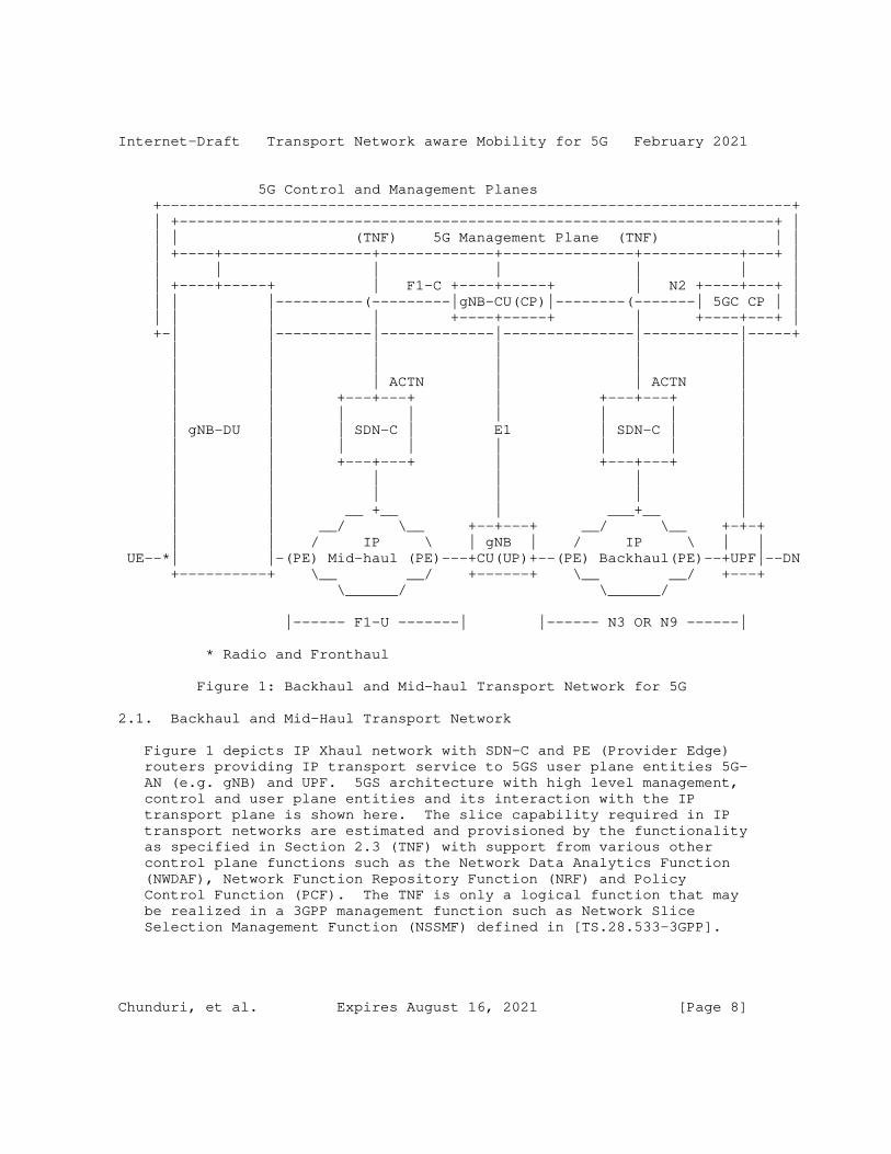
3GPP architecture [TS.23.501-3GPP], [TS.23.502-3GPP] describe slicing in 5GS. However, the application of 5GS slices in transport network for backhaul, mid-haul and front haul are not explicitly covered. To support specific characteristics in backhaul (N3, N9), mid-haul (F1) and front haul, it is necessary to map and provision corresponding resources in the transport domain. This section describes how to provision the mapping information in the transport network and apply it so that user plane packets can be provided the transport resources (QoS, isolation, protection, etc.) expected by the 5GS slices.
The figure shows the entities on path for a 3GPP Network Functions (gNB-DU, gNB-CU, UPF) to obtain slice aware classification from an IP/L2 transport network.
Chunduri, et al. Expires August 16, 2021 [Page 7]
Internet-Draft Transport Network aware Mobility for 5G February 2021
5G Control and Management Planes +------------------------------------------------------------------------+ | +--------------------------------------------------------------------+ | | | (TNF) 5G Management Plane (TNF) | | | +----+-----------------+-------------+---------------+-----------+---+ | | | | | | | | | +----+-----+ | F1-C +----+-----+ | N2 +----+---+ | | | |----------(---------|gNB-CU(CP)|--------(-------| 5GC CP | | | | | | +----+-----+ | +----+---+ | +-| |-----------|-------------|---------------|-----------|-----+ | | | | | | | | | | | | | | | ACTN | | ACTN | | | +---+---+ | +---+---+ | | | | | | | | | | gNB-DU | | SDN-C | E1 | SDN-C | | | | | | | | | | | | +---+---+ | +---+---+ | | | | | | | | | | | | | | | __ +__ | ___+__ | | | __/ \__ +--+---+ __/ \__ +-+-+ | | / IP \ | gNB | / IP \ | | UE--*| |-(PE) Mid-haul (PE)---+CU(UP)+--(PE) Backhaul(PE)--+UPF|--DN +----------+ \__ __/ +------+ \__ __/ +---+ \______/ \______/
|------ F1-U -------| |------ N3 OR N9 ------|
* Radio and Fronthaul
Figure 1: Backhaul and Mid-haul Transport Network for 5G
2.1. Backhaul and Mid-Haul Transport Network
Figure 1 depicts IP Xhaul network with SDN-C and PE (Provider Edge) routers providing IP transport service to 5GS user plane entities 5G- AN (e.g. gNB) and UPF. 5GS architecture with high level management, control and user plane entities and its interaction with the IP transport plane is shown here. The slice capability required in IP transport networks are estimated and provisioned by the functionality as specified in Section 2.3 (TNF) with support from various other control plane functions such as the Network Data Analytics Function (NWDAF), Network Function Repository Function (NRF) and Policy Control Function (PCF). The TNF is only a logical function that may be realized in a 3GPP management function such as Network Slice Selection Management Function (NSSMF) defined in [TS.28.533-3GPP].
Chunduri, et al. Expires August 16, 2021 [Page 8]
Internet-Draft Transport Network aware Mobility for 5G February 2021
The TNF requests the SDN-C to provision the IP XHaul network using ACTN [RFC8453].
The 5G management plane in Figure 1 interacts with the 5G control plane - the 5GC (5G Core), gNB-CU (5G NodeB Centralized Unit) and gNB-DU (5G Node B Distributed Unit). Non-access stratum (NAS) signaling from the UE for session management, mobility is handled by the 5GC. When a UE initiates session establishment, it indicates the desired slice type in the S-NSSAI (Specific Network Slice Selection Assistance Information) field. The AMF uses the S-NSSAI, other subscription information and configuration in the NSSF to select the appropriate SMF and the SMF in turn selects UPFs (User Plane Functions) that are able to provide the specified slice resources and capabilities.
The AMF, SMF, NSSF, PCF, NRF, NWDAF and other control functions in 5GC are described in [TS.23.501-3GPP] Some of the slice capabilities along the user plane path between the (R)AN and UPFs (F1-U, N3, N9 segments) such as a low latency path, jitter, protection and priority needs these to be provided by the IP transport network.
The 5G user plane from UE to DN (Data Network) includes a mid-haul segment (F1-U between gNB DU(UP), gNB CU(UP)) and backhaul (N3 between gNB - UPF; N9 between UPFs). If the RAN uses lower layer split architecture as specified by O-RAN alliance, then the user plane path from UE to DN also includes the fronthaul interface. The fronthaul interface carries the radio frames in the form of In-phase (I) and Quadrature (Q) samples using eCPRI encapsulation over Ethernet or UDP over IP.
The N3, N9 and F1 user planes use GTP-U [TS.29.281-3GPP] to transport UE PDUs (IPv4, IPv6, IPv4v6, Ethernet or Unstructured). For the front haul described further in Section 2.1.2, an Ethernet transport with VLANs can be expected to be the case in many deployments.
Figure 1 also depicts the PE router, where transport paths are initiated/terminated can be deployed separately with UPF or both functionalities can be in the same node. The TNF provisions this in the SDN-C of the IP XHaul network using ACTN [RFC8453]. When a GTP encapsulated user packet from the (R)AN (gNB) or UPF with the slice information traverses the F1-U/N3/N9 segment, the PE router of the IP transport underlay can inspect the slice information and provide the provisioned capabilities. This is elaborated further in Section 2.4.
Chunduri, et al. Expires August 16, 2021 [Page 9]

Internet-Draft Transport Network aware Mobility for 5G February 2021
2.1.1. IETF Network Slicing Applicability
Some of the functional elements depicted in the Figure 1 can be mapped to the terminology set forth in the [I-D.ietf-teas-ietf-network-slice-definition]. From 3GPP perspective, UE and UPF are the network slice endpoints and routers, gNB-DU, gNB-CU, switches, PE nodes are the slice realization endpoints. The TNF represented in the Figure 1 can be seen as IETF Network Slice Controller (NSC) functionality and SDN-C maps to Network Controller (NC). NSC-NBI interface is the interface from 3GPP Management plane (e.g., NSSMF) and NSC-SBI interface is the interface between TNF and SDN-C. Various possibilities for implementation of these interfaces and the relation to ACTN are further described in the [I-D.nsdt-teas-ns-framework].
2.1.2. Front Haul Transport Network
The O-RAN Alliance has specified the fronthaul interface between the O-RU and the O-DU in [ORAN-WG4.CUS-O-RAN]. The radio layer information, in the form of In-phase (I) and Quadrature (Q) samples are transported using Enhanced Common Public Radio Interface (eCPRI) framing over Ethernet or UDP. On the Ethernet based fronthaul interface, the slice information is carried in the Ethernet header through the VLAN tags. The Ethernet switches in the fronthaul transport network can inspect the slice information (VLAN tag) in the Ethernet header and provide the provisioned capabilities. The mapping of I and Q samples of different radio resources (radio resource blocks or carriers etc.,.) to different slices and to their respective VLAN tags on the fronthaul interface is controlled by the O-RAN fronthaul C-Plane and M-Plane interfaces. On a UDP based fronthaul interface, the slice information is carried in the IP or UDP header. The PE routers of the fronthaul transport network can inspect the slice information in the IP or UDP header and provide the provisioned capabilities. The fronthaul transport network is latency and jitter sensitive. The provisioned slice capabilities in the fronthaul transport network MUST take care of the latency and jitter budgets of the specific slice for the fronthaul interface. The provisioning of the fronthaul transport network is handled by the SDN-C pertaining to the fronthaul transport.
2.2. Mobile Transport Network Context (MTNC) and Scalability
The MTNC represents a slice, QoS configuration for a transport path between two 3GPP user plane functions. The Mobile-Transport Network Context Identifier (MTNC-ID) is generated by the TNF to be unique for each path and per traffic class (including QoS and slice aspects). Thus, there may be more than one MTNC-ID for the same QoS and path if there is a need to provide isolation (slice) of the traffic. It
Chunduri, et al. Expires August 16, 2021 [Page 10]
Internet-Draft Transport Network aware Mobility for 5G February 2021
should be noted that MTNC are per class/path and not per user session (nor is it per data path entity). The MTNC-IDs are configured by the TNF to be unique within a provisioning domain.
Since the MTNC-IDs are not generated per user flow or session, there is no need for unique MTNC-IDs per flow/session. In addition, since the traffic estimation is not performed at the time of session establishment, there is no provisioning delay experienced during session setup. The MTNC-ID space scales as a square of the number sites between which 3GPP user plane functions require paths. If there are T traffic classes across N sites, the number of MTNC-IDs in a fully meshed network is (N*(N-1)/2) * T. For example, if there are 3 traffic classes between 25 sites, there would be at most 900 MTNC- IDs required. Multiple slices for the same QoS class that need to be fully isolated, will add to the MTNC provisioning. An MTNC-ID space of 16 bits (65K+ identifiers) can be expected to be sufficient.
2.3. Transport Network Function (TNF)
Figure 1 shows a view of the functions and interfaces for provisioning the MTNC-IDs. The focus is on provisioning between the 3GPP management plane (NSSMF), transport network (SDN-C) and carrying the MTNC-IDs in PDU packets for the transport network to grant the provisioned resources.
In Figure 1, the TNF (logical functionality within the NSSMF) requests the SDN-C in the transport domain to program the TE path using ACTN [RFC8453]. The SDN-C programs the Provider Edge (PE) routers and internal routers according to the underlay transport technology (e.g., MPLS, SR, PPR). The PE router inspects incoming PDU data packets for the UDP SRC port which mirrors the MTNC-ID, classifies and provides the VN service provisioned across the transport network.
The detailed mechanisms by which the NSSMF provides the MTNC-IDs to the control plane and user plane functions are for 3GPP to specify. Two possible options are outlined below for completeness. The NSSMF may provide the MTNC-IDs to the 3GPP control plane by either providing it to the Session Management Function (SMF), and the SMF in turn provisions the user plane functions (UP-NF1, UP-NF2) during PDU session setup. Alternatively, the user plane functions may request the MTNC-IDs directly from the TNF/NSSMF. Figure 1 shows the case where user plane entities request the TNF/NSSMF to translate the Request and get the MTNC-ID. Another alternative is for the TNF to provide a mapping of the 3GPP Network Instance Identifier, described in Section 2.6 and the MTNC-ID to the user plane entities via configuration.
Chunduri, et al. Expires August 16, 2021 [Page 11]

Internet-Draft Transport Network aware Mobility for 5G February 2021
The TNF should be seen as a logical entity that can be part of NSSMF in the 3GPP management plane [TS.28.533-3GPP]. The NSSMF may use network configuration, policies, history, heuristics or some combination of these to derive traffic estimates that the TNF would use. How these estimates are derived are not in the scope of this document. The focus here is only in terms of how the TNF and SDN-C are programmed given that slice and QoS characteristics across a transport path can be represented by an MTNC-ID. The TNF requests the SDN-C in the transport network to provision paths in the transport domain based on the MTNC-ID. The TNF is capable of providing the MTNC-ID provisioned to control and user plane functions in the 3GPP domain. Detailed mechanisms for programming the MTNC-ID should be part of the 3GPP specifications.
2.4. Transport Provisioning
Functionality of transport provisioning for an engineered IP transport that supports 3GPP slicing and QoS requirements in [TS.23.501-3GPP] is described in this section.
During a PDU session setup, the AMF using input from the NSSF selects a network slice and SMF. The SMF with user policy from Policy Control Function (PCF) sets 5QI (QoS parameters) and the UPF on the path of the PDU session. While QoS and slice selection for the PDU session can be applied across the 3GPP control and user plane functions as outlined in Section 2, the IP transport underlay across F1-U, N3 and N9 segments do not have enough information to apply the resource constraints represented by the slicing and QoS classification. Current guidelines for interconnection with transport networks [IR.34-GSMA] provide an application mapping into DSCP. However, these recommendations do not take into consideration other aspects in slicing like isolation, protection and replication.
IP transport networks have their own slice and QoS configuration based on domain policies and the underlying network capability. Transport networks can enter into an agreement for virtual network services (VNS) with client domains using the ACTN [RFC8453] framework. An IP transport network may provide such slice instances to mobile network operators, CDN providers or enterprises for example. The 3GPP mobile network, on the other hand, defines a slice instance for UEs as are the mobile operator’s ’clients’. The Network Slice Selection Management Function (NSSMF) [TS 28.533] that interacts with a TN controller like an SDN-C (that is out of scope of 3GPP).
The ACTN VN service can be used across the IP transport networks to provision and map the slice instance and QoS of the 3GPP domain to the IP transport domain. An abstraction that represents QoS and
Chunduri, et al. Expires August 16, 2021 [Page 12]
Internet-Draft Transport Network aware Mobility for 5G February 2021
slice instances in the mobile domain and mapped to ACTN VN service in the transport domain is represented here as MTNC-IDs. Details of how the MTNC-IDs are derived are up to functions that can estimate the level of traffic demand.
The 3GPP network/5GS provides slices instances to its clients (UE) that include resources for radio and mobile core segments. The UE’s PDU session spans the access network (radio) and F1-U/N3/N9 transport segments which have an IP transport underlay. The 5G operator needs to obtain slice capability from the IP transport provider since these resources are not seen by the 5GS. Several UE sessions that match a slice may be mapped to an IP transport segment. Thus, there needs to be a mapping between the slice capability offered to the UE (NSSAI) and what is provided by the IP transport.
When the 3GPP user plane function (5G-AN, UPF) does not terminate the transport underlay protocol (e.g., MPLS), it needs to be carried in the IP protocol header from end-to-end of the mobile transport connection (N3, N9). [I-D.ietf-dmm-5g-uplane-analysis] discusses these scenarios in detail.
2.5. MTNC-ID in the Data Packet
When the 3GPP user plane function (5G-AN, UPF) and transport provider edge is on different nodes, the PE router needs to have the means by which to classify the PDU packet. The mapping information is provisioned between the 5G provider and IP transport network and corresponding information should be carried in each IP packet on the F1-U, N3, N9 interface. To allow the IP transport edge nodes to inspect the transport context information efficiently, it should be carried in an IP header field that is easy to inspect. It may be noted that the F1-U, N3 and N9 interfaces in 5GS are IP interfaces. Thus, Layer 2 alternatives such as VLAN will fail if there are multiple L2 networks on the F1-U or N3 or N9 path. GTP (F1-U, N3, N9 encapsulation header) field extensions offer a possibility, however these extensions are hard for a transport edge router to parse efficiently on a per packet basis. Other IP header fields like DSCP are not suitable as it only conveys the QoS aspects (but not other aspects like isolation, protection, etc.)
IPv6 extension headers like SRv6 may be options to carry the MTNC-ID when such a mechanism is a viable (if a complete transport network is IPv6 based). To minimise the protocol changes are required and make this underlay transport independent (IPv4/IPv6/MPLS/L2), an option is to provision a mapping of MTNC-ID to a UDP port range of the GTP encapsulated user packet. A simple mapping table between the MTNC-ID and the source UDP port number can be configured to ensure that ECMP /load balancing is not affected adversely by encoding the UDP source
Chunduri, et al. Expires August 16, 2021 [Page 13]
Internet-Draft Transport Network aware Mobility for 5G February 2021
port with an MTNC-ID mapping. This mapping is configured in 3GPP user plane functions (5G-AN, UPF) and Provider Edge (PE) Routers that process MTNC-IDs.
PE routers can thus provision a policy based on the source UDP port number (which reflects the mapped MTNC-ID) to the underlying transport path and then deliver the QoS/slice resource provisioned in the transport network. The source UDP port that is encoded is the outer IP (corresponding to GTP header) while the inner IP packet (UE payload) is unaltered. The source UDP port is encoded by the node that creates the GTP-U encapsulation and therefore, this mechanism has no impact on UDP checksum calculations.
3GPP network operators may use IPSec gateways (SEG) to secure packets between two sites - for example over an F1-U, N3 or N9 segment. The MTNC identifier in the GTP-U packet should be in the outer IP source port even after IPSec encryption for PE transport routers to inspect and provide the level of service provisioned. Tunnel mode - which is the case for SEG/IPSec gateways - adds an outer IP header in both AH (Authenticated Header) and ESP (Encapsulated Security Payload) modes. The GTP-U / UDP source port with encoded MTNC identifier should be copied to the IPSec tunnel ESP header. One option is to use 16 bits from the SPI field of the ESP header to encode the MTNC identifier and use the remaining 16 bits in SPI field to identify an SA. Load balancing entropy for ECMP will not be affected as the MTNC encoding mechanism already accounts for this.
If the RAN uses O-RAN lower layer split architecture, then a fronthaul network is involved. On an Ethernet based fronthaul transport network, VLAN tag may be an option to carry the MTNC-ID. The VLAN ID provides a 12 bit space and is sufficient to support up to 4096 slices on the fronthaul transport network. The mapping of fronthaul traffic to corresponding network slices is based on the radio resource for which the fronthaul carries the I and Q samples. The mapping of fronthaul traffic to the VLAN tag corresponding to the network slice is specified in Section 2.1.2. On the UDP based fronthaul transport network, the UDP source port can be used to carry the MTNC-ID.
2.6. Functionality for E2E Management
With the TNF functionality in 5GS Service Based Interface, the following additional functionalities are required for end-2-end slice management including the transport network:
o The Specific Network Slice Selection Assistance Information (S-NSSAI) of PDU session SHOULD be mapped to the assigned transport VPN and the TE path information for that slice.
Chunduri, et al. Expires August 16, 2021 [Page 14]
Internet-Draft Transport Network aware Mobility for 5G February 2021
o For transport slice assignment for various SSTs (eMBB, URLLC, MIoT) corresponding underlay paths need to be created and monitored from each transport endpoint (CSR and PE@UPF).
o During PDU session creation, apart from radio and 5GC resources, transport network resources needed to be verified matching the characteristics of the PDU session traffic type.
o The TNF MUST provide an API that takes as input the source and destination 3GPP user plane element address, required bandwidth, latency and jitter characteristics between those user plane elements and returns as output a particular TE path’s identifier, that satisfies the requested requirements.
o Mapping of PDU session parameters to underlay SST paths need to be done. One way to do this is to let the SMF install a Forwarding Action Rule (FAR) in the UPF via N4 with the FAR pointing to a "Network Instance" in the UPF. A "Network Instance" is a logical identifier for an underlying network. The "Network Instance" pointed by the FAR can be mapped to a transport path (through L2/ L3 VPN). FARs are associated with Packet Detection Rule (PDR). PDRs are used to classify packets in the uplink (UL) and the downlink (DL) direction. For UL procedures specified in Section 2.4, Section 2.5 can be used for classifying a packet belonging to a particular slice characteristic. For DL, at a PSA UPF, the UE IP address is used to identify the PDU session, and hence the slice a packet belongs to and the IP 5 tuple can be used for identifying the flow and QoS characteristics to be applied on the packet at UPF. If a PE is not co-located at the UPF then mapping to the underlying TE paths at PE happens based on the encapsulated GTP-U packet as specified in Section 2.5.
o In some SSC modes [I-D.chunduri-dmm-5g-mobility-with-ppr], if segmented path (CSR to PE@staging/ULCL/BP-UPF to PE@anchor-point- UPF) is needed, then corresponding path characteristics MUST be used. This includes a path from CSR to PE@UL-CL/BP UPF [TS.23.501-3GPP] and UL-CL/BP UPF to eventual UPF access to DN.
o Continuous monitoring of the underlying transport path characteristics should be enabled at the endpoints (technologies for monitoring depends on traffic engineering technique used as described in Section 3.2). If path characteristics are degraded, reassignment of the paths at the endpoints should be performed. For all the affected PDU sessions, degraded transport paths need to be updated dynamically with similar alternate paths.
o During UE mobility events similar to 4G/LTE i.e., gNB mobility (F1 based, Xn based or N2 based), for target gNB selection, apart from
Chunduri, et al. Expires August 16, 2021 [Page 15]

Internet-Draft Transport Network aware Mobility for 5G February 2021
radio resources, transport resources MUST be factored. This enables handling of all PDU sessions from the UE to target gNB and this require co-ordination of gNB, AMF, SMF with the TNF module.
Integrating the TNF as part of the 5GS Service Based Interfaces, provides the flexibility to control the allocation of required characteristics from the TN during a 5GS signaling procedure (e.g. PDU Session Establishment). If TNF is seen as separate and in a management plane, this real time flexibility is lost. Changes to detailed signaling to integrate the above for various 5GS procedures as defined in [TS.23.502-3GPP] is beyond the scope of this document.
3. Transport Network Underlays
Apart from the various flavors of IETF VPN technologies to share the transport network resources and capacity, TE capabilities in the underlay network is an essential component to realize the 5G TN requirements. This section focuses on various transport underlay technologies (not exhaustive) and their applicability to realize Midhaul/Backhaul transport networks. Focus is on the user/data plane i.e., F1-U/N3/N9 interfaces as laid out in the framework Figure 1.
3.1. Applicability
o For 3 different SSTs, 3 transport TE paths can be signaled from any node in the transport network. For Uplink traffic, the 5G-AN will choose the right underlying TE path of the UPF based on the S-NSSAI the PDU Session belongs to and/or the UDP Source port (corresponds to the MTNC-ID Section 2.4) of the GTP-U encapsulation header. Similarly in the Downlink direction matching Transport TE Path of the 5G-AN is chosen based on the S-NSSAI the PDU Session belongs to. The table below shows a typical mapping:
Chunduri, et al. Expires August 16, 2021 [Page 16]
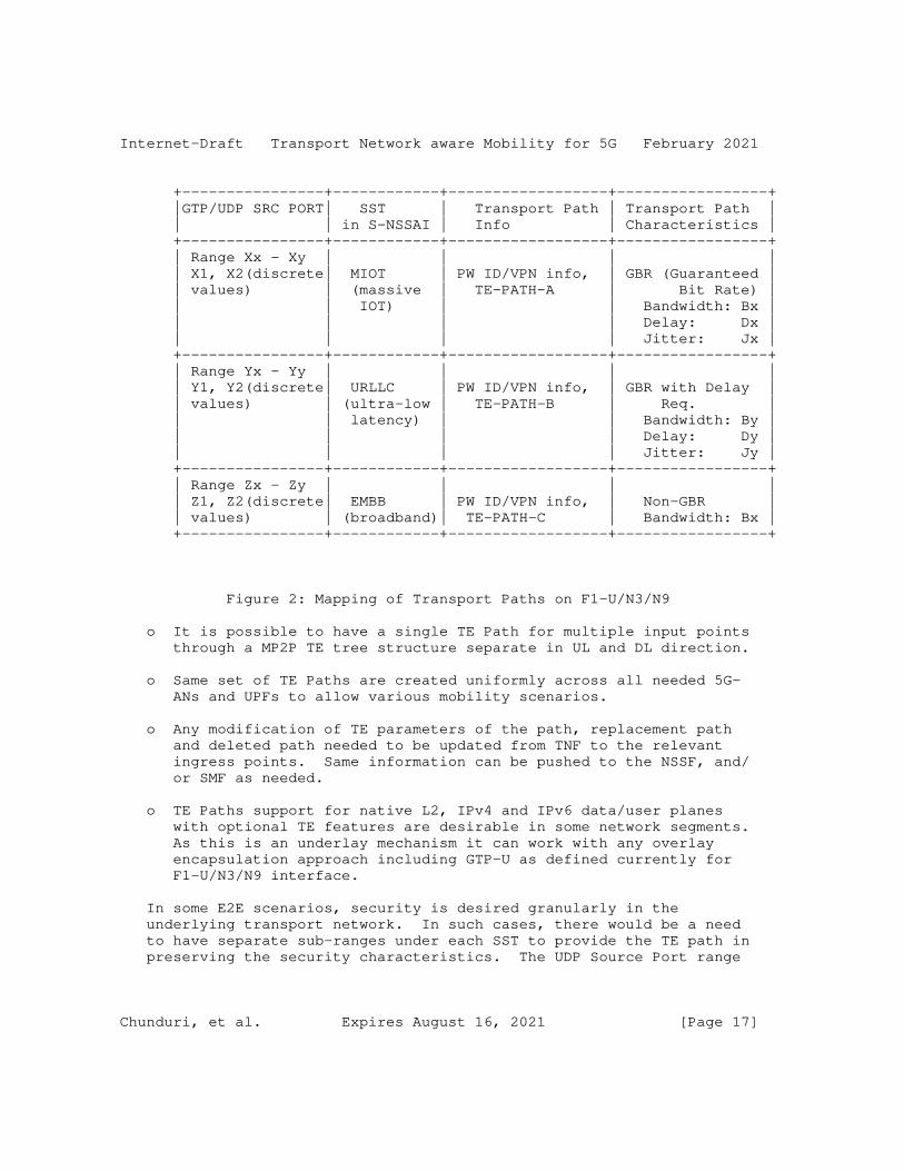
Internet-Draft Transport Network aware Mobility for 5G February 2021
+----------------+------------+------------------+-----------------+ |GTP/UDP SRC PORT| SST | Transport Path | Transport Path | | | in S-NSSAI | Info | Characteristics | +----------------+------------+------------------+-----------------+ | Range Xx - Xy | | | | | X1, X2(discrete| MIOT | PW ID/VPN info, | GBR (Guaranteed | | values) | (massive | TE-PATH-A | Bit Rate) | | | IOT) | | Bandwidth: Bx | | | | | Delay: Dx | | | | | Jitter: Jx | +----------------+------------+------------------+-----------------+ | Range Yx - Yy | | | | | Y1, Y2(discrete| URLLC | PW ID/VPN info, | GBR with Delay | | values) | (ultra-low | TE-PATH-B | Req. | | | latency) | | Bandwidth: By | | | | | Delay: Dy | | | | | Jitter: Jy | +----------------+------------+------------------+-----------------+ | Range Zx - Zy | | | | | Z1, Z2(discrete| EMBB | PW ID/VPN info, | Non-GBR | | values) | (broadband)| TE-PATH-C | Bandwidth: Bx | +----------------+------------+------------------+-----------------+
Figure 2: Mapping of Transport Paths on F1-U/N3/N9
o It is possible to have a single TE Path for multiple input points through a MP2P TE tree structure separate in UL and DL direction.
o Same set of TE Paths are created uniformly across all needed 5G- ANs and UPFs to allow various mobility scenarios.
o Any modification of TE parameters of the path, replacement path and deleted path needed to be updated from TNF to the relevant ingress points. Same information can be pushed to the NSSF, and/ or SMF as needed.
o TE Paths support for native L2, IPv4 and IPv6 data/user planes with optional TE features are desirable in some network segments. As this is an underlay mechanism it can work with any overlay encapsulation approach including GTP-U as defined currently for F1-U/N3/N9 interface.
In some E2E scenarios, security is desired granularly in the underlying transport network. In such cases, there would be a need to have separate sub-ranges under each SST to provide the TE path in preserving the security characteristics. The UDP Source Port range
Chunduri, et al. Expires August 16, 2021 [Page 17]
Internet-Draft Transport Network aware Mobility for 5G February 2021
captured in Figure 2 would be sub-divided to maintain the TE path for the current SSTs with the security. The current solution doesn’t provide any mandate on the UE traffic in selecting the type of security.
3.2. Transport Network Technologies
While there are many Software Defined Networking (SDN) approaches available, this section is not intended to list all the possibilities in this space but merely captures the technologies for various requirements discussed in this document.
RSVP-TE [RFC3209] provides a lean transport overhead for the TE path for MPLS user plane. However, it is perceived as less dynamic in some cases and has some provisioning overhead across all the nodes in N3 and N9 interface nodes. Also, it has another drawback with excessive state refresh overhead across adjacent nodes and this can be mitigated with [RFC8370].
SR-TE [RFC8402] does not explicitly signal bandwidth reservation or mechanism to guarantee latency on the nodes/links on SR path. But SR allows path steering for any flow at the ingress and particular path for a flow can be chosen. Some of the issues and suitability for mobile use plane are documented at Section 5.3 of [I-D.bogineni-dmm-optimized-mobile-user-plane]. However, [I-D.ietf-dmm-srv6-mobile-uplane] presents various options for optimized mobile user plane with SRv6 with or without GTP-U overhead along with traffic engineering capabilities. SR-MPLS allows reduction of the control protocols to one IGP (without needing for LDP and RSVP-TE).
Preferred Path Routing (PPR) is an integrated routing and TE technology and the applicability for this framework is described in [I-D.chunduri-dmm-5g-mobility-with-ppr]. PPR does not remove GTP-U, unlike some other proposals laid out in [I-D.bogineni-dmm-optimized-mobile-user-plane]. Instead, PPR works with the existing cellular user plane (GTP-U) for F1-U/N3 and N9. In this scenario, PPR will only help provide TE benefits needed for 5G slices from a transport domain perspective. It does so for any underlying user/data plane used in the transport network (L2/IPv4/IPv6/MPLS).
As specified with the integrated transport network function (TNF), a particular RSVP-TE path for MPLS or SR path for MPLS and IPv6 with SRH user plane or PPR with PPR-ID [I-D.chunduri-dmm-5g-mobility-with- ppr], can be supplied to SMF for mapping a particular PDU session to the transport path.
Chunduri, et al. Expires August 16, 2021 [Page 18]

Internet-Draft Transport Network aware Mobility for 5G February 2021
4. Acknowledgements
Thanks to Young Lee for discussions on this document including ACTN applicability for the proposed TNF. Thanks to Sri Gundavelli, Kausik Majumdar and 3GPP delegates who provided detailed feedback on this document.
5. IANA Considerations
This document has no requests for any IANA code point allocations.
6. Security Considerations
This document does not introduce any new security issues.
7. Contributing Authors
The following people contributed substantially to the content of this document and should be considered co-authors.
Xavier De Foy InterDigital Communications, LLC 1000 Sherbrooke West Montreal Canada
Email: [email protected]
8. References
8.1. Normative References
[RFC2119] Bradner, S., "Key words for use in RFCs to Indicate Requirement Levels", BCP 14, RFC 2119, DOI 10.17487/RFC2119, March 1997, <https://www.rfc-editor.org/info/rfc2119>.
8.2. Informative References
[ATIS075] Alliance for Telecommunications Industry Solutions (ATIS), "IOT Categorization: Exploring the Need for Standardizing Additional Network Slices ATIS-I-0000075", September 2019.
Chunduri, et al. Expires August 16, 2021 [Page 19]
Internet-Draft Transport Network aware Mobility for 5G February 2021
[I-D.bogineni-dmm-optimized-mobile-user-plane] Bogineni, K., Akhavain, A., Herbert, T., Farinacci, D., Rodriguez-Natal, A., Carofiglio, G., Auge, J., Muscariello, L., Camarillo, P., and S. Homma, "Optimized Mobile User Plane Solutions for 5G", draft-bogineni-dmm- optimized-mobile-user-plane-01 (work in progress), June 2018.
[I-D.ietf-dmm-5g-uplane-analysis] Homma, S., Miyasaka, T., Matsushima, S., and D. Voyer, "User Plane Protocol and Architectural Analysis on 3GPP 5G System", draft-ietf-dmm-5g-uplane-analysis-04 (work in progress), November 2020.
[I-D.ietf-dmm-srv6-mobile-uplane] Matsushima, S., Filsfils, C., Kohno, M., Camarillo, P., Voyer, D., and C. Perkins, "Segment Routing IPv6 for Mobile User Plane", draft-ietf-dmm-srv6-mobile-uplane-09 (work in progress), July 2020.
[I-D.ietf-teas-ietf-network-slice-definition] Rokui, R., Homma, S., Makhijani, K., Contreras, L., and J. Tantsura, "Definition of IETF Network Slices", draft-ietf- teas-ietf-network-slice-definition-00 (work in progress), January 2021.
[I-D.nsdt-teas-ns-framework] Gray, E. and J. Drake, "Framework for Transport Network Slices", draft-nsdt-teas-ns-framework-04 (work in progress), July 2020.
[IR.34-GSMA] GSM Association (GSMA), "Guidelines for IPX Provider Networks (Previously Inter-Service Provider IP Backbone Guidelines, Version 14.0", August 2018.
[ORAN-WG4.CUS-O-RAN] O-RAN Alliance (O-RAN), "O-RAN Fronthaul Working Group; Control, User and Synchronization Plane Specification; v2.0.0", August 2019.
[RFC3209] Awduche, D., Berger, L., Gan, D., Li, T., Srinivasan, V., and G. Swallow, "RSVP-TE: Extensions to RSVP for LSP Tunnels", RFC 3209, DOI 10.17487/RFC3209, December 2001, <https://www.rfc-editor.org/info/rfc3209>.
Chunduri, et al. Expires August 16, 2021 [Page 20]
Internet-Draft Transport Network aware Mobility for 5G February 2021
[RFC8370] Beeram, V., Ed., Minei, I., Shakir, R., Pacella, D., and T. Saad, "Techniques to Improve the Scalability of RSVP-TE Deployments", RFC 8370, DOI 10.17487/RFC8370, May 2018, <https://www.rfc-editor.org/info/rfc8370>.
[RFC8402] Filsfils, C., Ed., Previdi, S., Ed., Ginsberg, L., Decraene, B., Litkowski, S., and R. Shakir, "Segment Routing Architecture", RFC 8402, DOI 10.17487/RFC8402, July 2018, <https://www.rfc-editor.org/info/rfc8402>.
[RFC8453] Ceccarelli, D., Ed. and Y. Lee, Ed., "Framework for Abstraction and Control of TE Networks (ACTN)", RFC 8453, DOI 10.17487/RFC8453, August 2018, <https://www.rfc-editor.org/info/rfc8453>.
[TS.23.501-3GPP] 3rd Generation Partnership Project (3GPP), "System Architecture for 5G System; Stage 2, 3GPP TS 23.501 v2.0.1", December 2017.
[TS.23.502-3GPP] 3rd Generation Partnership Project (3GPP), "Procedures for 5G System; Stage 2, 3GPP TS 23.502, v2.0.0", December 2017.
[TS.23.503-3GPP] 3rd Generation Partnership Project (3GPP), "Policy and Charging Control System for 5G Framework; Stage 2, 3GPP TS 23.503 v1.0.0", December 2017.
[TS.28.533-3GPP] 3rd Generation Partnership Project (3GPP), "Management and Orchestration Architecture Framework (Release 15)", June 2018.
[TS.29.281-3GPP] 3rd Generation Partnership Project (3GPP), "GPRS Tunneling Protocol User Plane (GTPv1-U), 3GPP TS 29.281 v15.1.0", December 2018.
[TS.38.300-3GPP] 3rd Generation Partnership Project (3GPP), "NR; NR and NG- RAN Overall Description; Stage 2; v15.7.0", September 2019.
[TS.38.401-3GPP] 3rd Generation Partnership Project (3GPP), "NG-RAN; Architecture description; v15.7.0", September 2019.
Chunduri, et al. Expires August 16, 2021 [Page 21]
Internet-Draft Transport Network aware Mobility for 5G February 2021
Appendix A. New Control Plane and User Planes
A.1. Slicing Framework and RAN Aspects
The 3GPP architecture defines slicing aspects where the Network Slice Selection Function (NSSF) assists the Access Mobility Manager (AMF) and Session Management Function (SMF) to assist and select the right entities and resources corresponding to the slice requested by the User Equipment (UE). The User Equipment (UE) indicates information regarding the set of slices it wishes to connect, in the Network Slice Selection Assistance Information (NSSAI) field during network registration procedure (Attach) and the specific slice the UE wants to establish an IP session, in the Specific NSSAI (S-NSSAI) field during the session establishment procedure (PDU Session Establishment). The AMF selects the right SMF and the SMF in turn selects the User Plane Functions (UPF) so that the QoS and capabilities requested can be fulfilled.
The architecture for the Radio Access Network (RAN) is defined in [TS.38.300-3GPP] and [TS.38.401-3GPP]. The 5G RAN architecture allows disaggregation of the RAN into a Distributed Unit (DU) and a Centralized Unit (CU). The CU is further split into control plane (CU-CP) and user plane (CU-UP). The interface between CU-UP and the DU for the user plane traffic is called the F1-U and between the CU- CP and DU for the control plane traffic is called the F1-C. The F1-C and the F1-U together are called the mid-haul interfaces. The DU does not have a CP/UP split. Apart from 3GPP, O-RAN Alliance has specified further disaggregation of the RAN at the lower layer (physical layer). The DU is disaggregated into a ORAN DU (O-DU) which runs the upper part of the physical layer, MAC and RLC and the ORAN Radio Unit (O-RU) which runs the lower part of the physical layer. The interface between the O-DU and the O-RU is called the Fronthaul interface and is specified in [ORAN-WG4.CUS-O-RAN].
A.2. Slice aware Mobility: Discrete Approach
In this approach transport network functionality from the 5G-AN to UPF is discrete and 5GS is not aware of the underlying transport network and the resources available. Deployment specific mapping function is used to map the GTP-U encapsulated traffic at the 5G-AN (e.g. gNB) in UL and UPF in DL direction to the appropriate transport slice or transport Traffic Engineered (TE) paths. These TE paths can be established using RSVP-TE [RFC3209] for MPLS underlay, SR [RFC3209] for both MPLS and IPv6 underlay or PPR [I-D.chunduri-dmm- 5g-mobility-with-ppr] with MPLS, IPv6 with SRH, native IPv6 and native IPv4 underlays.
Chunduri, et al. Expires August 16, 2021 [Page 22]
Internet-Draft Transport Network aware Mobility for 5G February 2021
As per [TS.23.501-3GPP] and [TS.23.502-3GPP] the SMF controls the user plane traffic forwarding rules in the UPF. The UPFs have a concept of a "Network Instance" which logically abstracts the underlying transport path. When the SMF creates the packet detection rules (PDR) and forwarding action rules (FAR) for a PDU session at the UPF, the SMF identifies the network instance through which the packet matching the PDR has to be forwarded. A network instance can be mapped to a TE path at the UPF. In this approach, TNF as shown in Figure 1 need not be part of the 5G Service Based Interface (SBI). Only management plane functionality is needed to create, monitor, manage and delete (life cycle management) the transport TE paths/ transport slices from the 5G-AN to the UPF (on N3/N9 interfaces). The management plane functionality also provides the mapping of such TE paths to a network instance identifier to the SMF. The SMF uses this mapping to install appropriate FARs in the UPF. This approach provide partial integration of the transport network into 5GS with some benefits.
One of the limitations of this approach is the inability of the 5GS procedures to know, if underlying transport resources are available for the traffic type being carried in PDU session before making certain decisions in the 5G CP. One example scenario/decision could be, a target 5G-AN selection during a N2 mobility event, without knowing if the target 5G-AN is having a underlay transport slice resource for the S-NSSAI and 5QI of the PDU session. The Integrated approach specified below can mitigate this.
Authors’ Addresses
Uma Chunduri (editor) Futurewei 2330 Central Expressway Santa Clara, CA 95050 USA
Email: [email protected]
Richard Li Futurewei 2330 Central Expressway Santa Clara, CA 95050 USA
Email: [email protected]
Chunduri, et al. Expires August 16, 2021 [Page 23]
Internet-Draft Transport Network aware Mobility for 5G February 2021
Sridhar Bhaskaran Altiostar
Email: [email protected]
John Kaippallimalil (editor) Futurewei
Email: [email protected]
Jeff Tantsura Apstra, Inc.
Email: [email protected]
Luis M. Contreras Telefonica Sur-3 building, 3rd floor Madrid 28050 Spain
Email: [email protected]
Praveen Muley Nokia 440 North Bernardo Ave Mountain View, CA 94043 USA
Email: [email protected]
Chunduri, et al. Expires August 16, 2021 [Page 24]
Distributed Mobility Management (DMM) U. FattoreInternet-Draft M. LiebschIntended status: Standards Track NECExpires: September 12, 2019 March 11, 2019
Control-/Data Plane Aspects for N6 Traffic Steering draft-fattore-dmm-n6-cpdp-trafficsteering-01.txt
Abstract
Current standardization effort on the evolution of the mobile communication system reconsiders the mobile data plane protocol. The IETF DMM Working Group has work that proposes and analyzes various protocols as alternative to the GPRS Tunneling Protocol for User Plane (GTP-U) for an overlay deployment in between the mobile device’s assigned data plane anchor and its current radio base station, which are denoted as N9 and N3 interfaces. In the view of some future deployment and the original intent per the very early DMM WG charter, a mobile device’s data plane anchor may be highly distributed and re-selected for optimization throughout a mobile device’s communication with one or more correspondent services. Such re-configuration has impact on the packet routing in between the mobile device’s data plane anchor and the one or multiple data networks hosting the services, which is denoted as N6 interface. This draft proposes and discusses a solution to control, setup and maintain traffic treatment policy on the cellular communication system’s N6 interface while taking the UE’s PDU session settings per the cellular system’s control plane, such as QoS and locator information, into account.
Status of This Memo
This Internet-Draft is submitted in full conformance with the provisions of BCP 78 and BCP 79.
Internet-Drafts are working documents of the Internet Engineering Task Force (IETF). Note that other groups may also distribute working documents as Internet-Drafts. The list of current Internet- Drafts is at https://datatracker.ietf.org/drafts/current/.
Internet-Drafts are draft documents valid for a maximum of six months and may be updated, replaced, or obsoleted by other documents at any time. It is inappropriate to use Internet-Drafts as reference material or to cite them other than as "work in progress."
This Internet-Draft will expire on September 12, 2019.
Fattore & Liebsch Expires September 12, 2019 [Page 1]

Internet-Draft CPDP for N6 Traffic Steering March 2019
Copyright Notice
Copyright (c) 2019 IETF Trust and the persons identified as the document authors. All rights reserved.
This document is subject to BCP 78 and the IETF Trust’s Legal Provisions Relating to IETF Documents (https://trustee.ietf.org/license-info) in effect on the date of publication of this document. Please review these documents carefully, as they describe your rights and restrictions with respect to this document. Code Components extracted from this document must include Simplified BSD License text as described in Section 4.e of the Trust Legal Provisions and are provided without warranty as described in the Simplified BSD License.
Table of Contents
1. Terminology . . . . . . . . . . . . . . . . . . . . . . . . . 2 2. Introduction . . . . . . . . . . . . . . . . . . . . . . . . 2 3. Positioning of N6 policy control . . . . . . . . . . . . . . 4 3.1. System architecture for mobile access to data networks . 4 3.2. Use cases with demand for N6 traffic treatment policy . . 7 4. N6 traffic treatment - Requirements and policy types . . . . 8 5. Leveraging the mobile control plane for N6 policy control . . 9 6. N6 endpoints - loose and tight coupling options . . . . . . . 11 7. Operations for N6 policy enforcement in a tight coupling scenario . . . . . . . . . . . . . . . . . . . . . . . . . . 13 7.1. AF/NC-initiated N6 policy enforcement . . . . . . . . . . 14 7.2. 3GPP-initiated N6 policy enforcement . . . . . . . . . . 16 8. IANA Considerations . . . . . . . . . . . . . . . . . . . . . 20 9. Security Considerations . . . . . . . . . . . . . . . . . . . 20 10. Acknowledgments . . . . . . . . . . . . . . . . . . . . . . . 20 11. Normative References . . . . . . . . . . . . . . . . . . . . 20 Authors’ Addresses . . . . . . . . . . . . . . . . . . . . . . . 21
1. Terminology
The key words "MUST", "MUST NOT", "REQUIRED", "SHALL", "SHALL NOT", "SHOULD", "SHOULD NOT", "RECOMMENDED", "MAY", and "OPTIONAL" in this document are to be interpreted as described in RFC 2119 [RFC2119].
2. Introduction
Recent releases and deployments of cellular mobile communication systems utilize an overlay on the mobile data plane to forward a mobile device’s data packets in between the mobile device and an anchor point, which serves as first hop router to the mobile device. The overlay is realized by the GPRS Tunneling Protocol for user plane
Fattore & Liebsch Expires September 12, 2019 [Page 2]
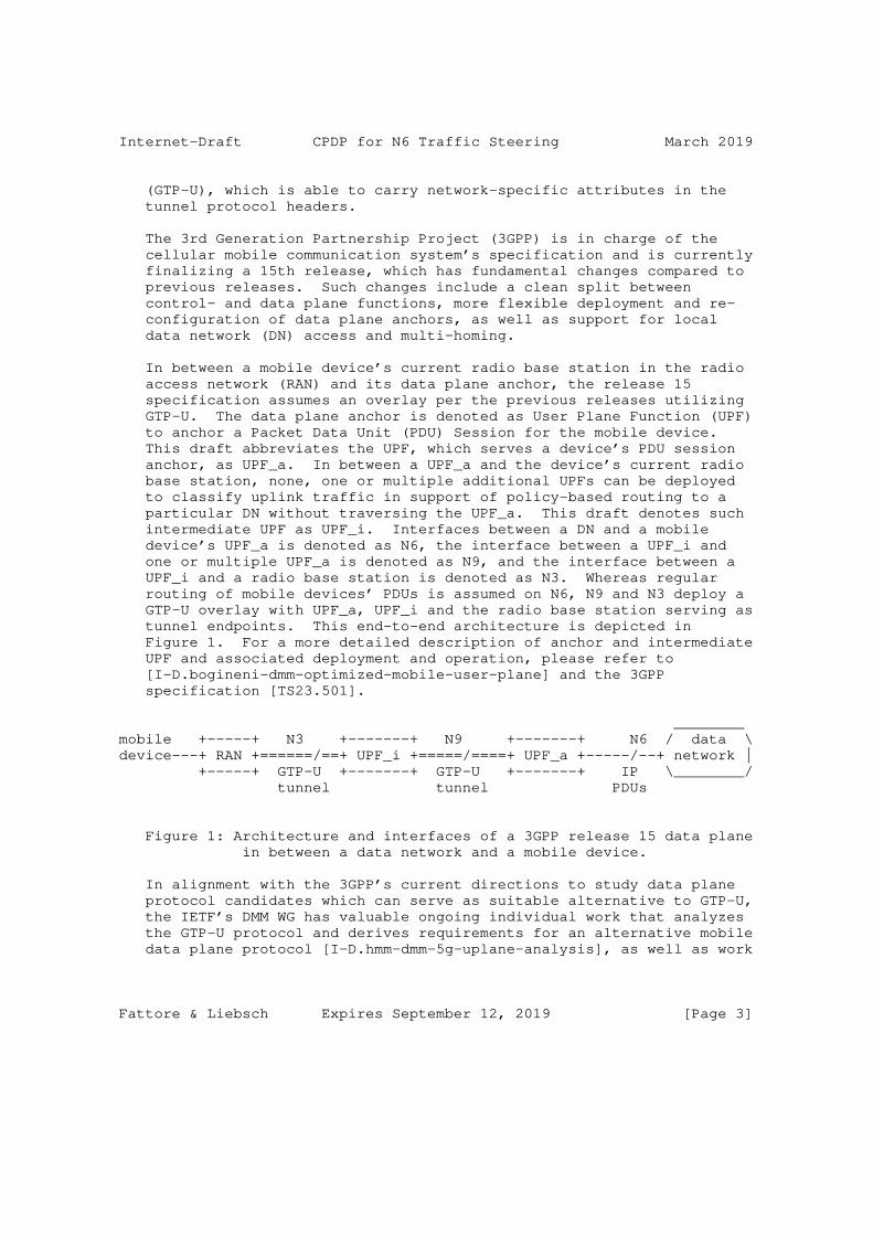
Internet-Draft CPDP for N6 Traffic Steering March 2019
(GTP-U), which is able to carry network-specific attributes in the tunnel protocol headers.
The 3rd Generation Partnership Project (3GPP) is in charge of the cellular mobile communication system’s specification and is currently finalizing a 15th release, which has fundamental changes compared to previous releases. Such changes include a clean split between control- and data plane functions, more flexible deployment and re- configuration of data plane anchors, as well as support for local data network (DN) access and multi-homing.
In between a mobile device’s current radio base station in the radio access network (RAN) and its data plane anchor, the release 15 specification assumes an overlay per the previous releases utilizing GTP-U. The data plane anchor is denoted as User Plane Function (UPF) to anchor a Packet Data Unit (PDU) Session for the mobile device. This draft abbreviates the UPF, which serves a device’s PDU session anchor, as UPF_a. In between a UPF_a and the device’s current radio base station, none, one or multiple additional UPFs can be deployed to classify uplink traffic in support of policy-based routing to a particular DN without traversing the UPF_a. This draft denotes such intermediate UPF as UPF_i. Interfaces between a DN and a mobile device’s UPF_a is denoted as N6, the interface between a UPF_i and one or multiple UPF_a is denoted as N9, and the interface between a UPF_i and a radio base station is denoted as N3. Whereas regular routing of mobile devices’ PDUs is assumed on N6, N9 and N3 deploy a GTP-U overlay with UPF_a, UPF_i and the radio base station serving as tunnel endpoints. This end-to-end architecture is depicted in Figure 1. For a more detailed description of anchor and intermediate UPF and associated deployment and operation, please refer to [I-D.bogineni-dmm-optimized-mobile-user-plane] and the 3GPP specification [TS23.501].
________mobile +-----+ N3 +-------+ N9 +-------+ N6 / data \device---+ RAN +======/==+ UPF_i +=====/====+ UPF_a +-----/--+ network | +-----+ GTP-U +-------+ GTP-U +-------+ IP \________/ tunnel tunnel PDUs
Figure 1: Architecture and interfaces of a 3GPP release 15 data plane in between a data network and a mobile device.
In alignment with the 3GPP’s current directions to study data plane protocol candidates which can serve as suitable alternative to GTP-U, the IETF’s DMM WG has valuable ongoing individual work that analyzes the GTP-U protocol and derives requirements for an alternative mobile data plane protocol [I-D.hmm-dmm-5g-uplane-analysis], as well as work
Fattore & Liebsch Expires September 12, 2019 [Page 3]
Internet-Draft CPDP for N6 Traffic Steering March 2019
that investigates the use of alternative protocol candidates based on SRv6, ID-Locator separation, and locator re-writing in the current release 15 system architecture [I-D.bogineni-dmm-optimized-mobile-user-plane]. The focus of these drafts is on N9 and N3.
In the view of optimization options on the complete end-to-end data plane, [I-D.gundavelli-dmm-mfa] complements other draft and proposes data plane optimization on N6. Such operation is of particular interest when the mobile device’s UPF_a is decentralized and deployed close to the device’s current radio base station. Such deployment may be preferable for some services, such as edge computing and access to associated edge DNs, and mitigates the role of the UPF_i and N9 interfaces. In particular the selection and configuration of UPF_i instances can omitted and associated signaling costs can be saved. However, such deployment strengthens the expectation on IP- based PDU routing on N6, as the serving DN may not be always topologically close to the device and its current UPF_a. Such requirements include QoS support on N6, metering support and traffic steering in case the mobile device’s UPF_a changes while its IP address and associated sessions should continue.
The same requirements on N6 apply for multi-homing per [TS23.501] where the mobile device’s UPF_a is close to a first DN (DN1) whereas a UPF_i is used to enable access to a second DN (DN2), either through a secondary UPF_a close to DN2 or directly from the UPF_i, without the use of a secondary UPF_a. Since services in both DNs address the same IP address of the mobile device (IP_ue) to send downlink traffic, both DNs’ traffic need to be forwarded to the most suitable (e.g. closest) UPF_a or UPF_i respectively.
This draft focuses on a solution to control, setup and maintain such dedicated routes and additional traffic treatment policy on N6, while taking the UE’s PDU session settings per the cellular system’s control plane, such as QoS and locator information, into account.
3. Positioning of N6 policy control
This section briefly introduces the relevant mobile system architecture components and interfaces, and covers some high-level use cases which can benefit from data plane policy control on N6 interface endpoints.
3.1. System architecture for mobile access to data networks
The 3GPP’s 5G system architecture introduces in the core network a clear control-/user plane separation (CUPS), in order to have flexible deployment of the different functions (e.g., user plane
Fattore & Liebsch Expires September 12, 2019 [Page 4]
Internet-Draft CPDP for N6 Traffic Steering March 2019
nodes can scale independently from control plane elements in case of user traffic growth). Again to leverage flexibility and efficiency, the control plane is split in different functions, each offering a specific service, in the so called Service Based Architecture (SBA).
Among all the control plane functions, the Session Management function (SMF) takes care of the session management (session establishment, modification, release), IP allocation and selection of an IP anchor point for the session, as well as traffic steering in between UPFs and radio base stations. In order to manage the user session, the SMF collaborates with other control plane services (e.g., Policy Control Function - PCF - providing policy rules for traffic treatment and monitoring), in particular with the Access and Mobility Management Function (AMF), which manages registration, authentication and authorization and security context. One of the main task of the SMF is to instruct User Plane Functions (UPFs), through N4 interface. When a new session is to be created, the SMF selects one or multiple UPFs for the user traffic and selects one UPF as session anchor (UPF_a). UPF_a acts as a proxy for user traffic, which means all traffic directed to the UE passes through the UPF anchor. Beside the UPF_a, if other UPFs are present (i.e., between the radio base station and the UPF_a), this are deployed as classifiers for user uplink traffic.
In Figure 2 a simplified 5G architecture [TS23.501] is depicted, showing two Data Networks (DN) to whom a user may need a connection. To each Data Network a UPF_a is associated, acting as session anchor and providing to the user an IP address needed for the connection. UPF_a also acts as tunnel termination point, since user traffic is encapsulated on both N3 and N9 interfaces, using the GPRS Tunneling Protocol for User Plane (GTP-U). Whereas, on N6 interface IP PDUs are routed without tunneling.
Fattore & Liebsch Expires September 12, 2019 [Page 5]
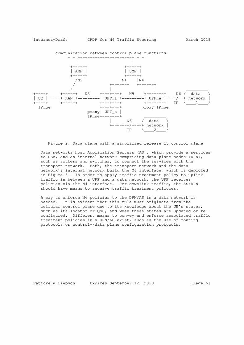
Internet-Draft CPDP for N6 Traffic Steering March 2019
communication between control plane functions - - +---------------------+ - - | | +--+--+ +-----+ | AMF | | SMF | +-----+ +-----+ /N2 N4| |N4 / +------+ +------+ / | | _________+----+ +-----+ N3 +---+---+ N9 +---+---+ N6 / data \| UE |-----+ RAN +=========+ UPF_i +=========+ UPF_a +----/--+ network |+----+ +-----+ +---+---+ +-------+ IP \____1____/ IP_ue +---+---+ proxy IP_ue proxy| UPF_a | IP_ue+-------+ _________ | N6 / data \ +-------/----+ network | IP \____2____/
Figure 2: Data plane with a simplified release 15 control plane
Data networks host Application Servers (AS), which provide a services to UEs, and an internal network comprising data plane nodes (DPN), such as routers and switches, to connect the services with the transport network. Both, the transport network and the data network’s internal network build the N6 interface, which is depicted in Figure 3. In order to apply traffic treatment policy to uplink traffic in between a UPF and a data network, the UPF receives policies via the N4 interface. For downlink traffic, the AS/DPN should have means to receive traffic treatment policies.
A way to enforce N6 policies to the DPN/AS in a data network is needed. It is evident that this rule must originate from the cellular control plane due to its knowledge about the UE’s states, such as its locator or QoS, and when these states are updated or re- configured. Different means to convey and enforce associated traffic treatment policies in a DPN/AS exist, such as the use of routing protocols or control-/data plane configuration protocols.
Fattore & Liebsch Expires September 12, 2019 [Page 6]
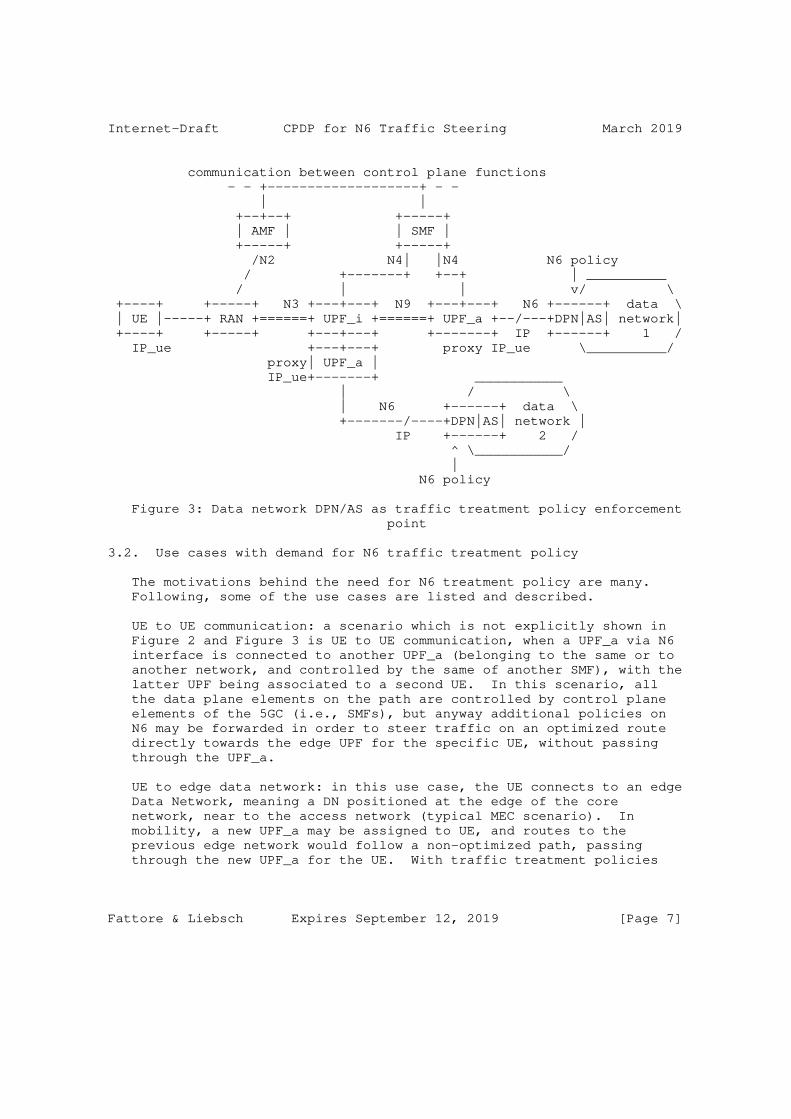
Internet-Draft CPDP for N6 Traffic Steering March 2019
communication between control plane functions - - +-------------------+ - - | | +--+--+ +-----+ | AMF | | SMF | +-----+ +-----+ /N2 N4| |N4 N6 policy / +-------+ +--+ | __________ / | | v/ \ +----+ +-----+ N3 +---+---+ N9 +---+---+ N6 +------+ data \ | UE |-----+ RAN +======+ UPF_i +======+ UPF_a +--/---+DPN|AS| network| +----+ +-----+ +---+---+ +-------+ IP +------+ 1 / IP_ue +---+---+ proxy IP_ue \__________/ proxy| UPF_a | IP_ue+-------+ ___________ | / \ | N6 +------+ data \ +-------/----+DPN|AS| network | IP +------+ 2 / ^ \___________/ | N6 policy
Figure 3: Data network DPN/AS as traffic treatment policy enforcement point
3.2. Use cases with demand for N6 traffic treatment policy
The motivations behind the need for N6 treatment policy are many. Following, some of the use cases are listed and described.
UE to UE communication: a scenario which is not explicitly shown in Figure 2 and Figure 3 is UE to UE communication, when a UPF_a via N6 interface is connected to another UPF_a (belonging to the same or to another network, and controlled by the same of another SMF), with the latter UPF being associated to a second UE. In this scenario, all the data plane elements on the path are controlled by control plane elements of the 5GC (i.e., SMFs), but anyway additional policies on N6 may be forwarded in order to steer traffic on an optimized route directly towards the edge UPF for the specific UE, without passing through the UPF_a.
UE to edge data network: in this use case, the UE connects to an edge Data Network, meaning a DN positioned at the edge of the core network, near to the access network (typical MEC scenario). In mobility, a new UPF_a may be assigned to UE, and routes to the previous edge network would follow a non-optimized path, passing through the new UPF_a for the UE. With traffic treatment policies
Fattore & Liebsch Expires September 12, 2019 [Page 7]
Internet-Draft CPDP for N6 Traffic Steering March 2019
this can be avoid, giving a traffic steering policy to the DPN in charge for the edge DN.
Concurrent use of multiple data networks: a possible scenario is the one in which a UE collects the desired content from different data networks (e.g., because of Content Delivery Networks - CDN). To optimize routing in this scenario, the downlink traffic should traverse for each data network the optimized path through the UE and not be forced through a (central) UPF_a common to all the data networks. Again, this can be done with policies on N6 interface. This particular use case also highlights the importance to consider optimization on N6, whereas other works focus on N9: considering a UPF_a near the data network, as proposed in other solutions, would not allow multiple DN access in an unique user session and so would not allow for content access on different destinations.
4. N6 traffic treatment - Requirements and policy types
Use cases for traffic treatment on N6 per a data plane policy include cases where the UPF_a is deployed closer at the mobile edge, e.g. to not only access a local data network in the proximity of the UE, but also other data networks sharing the single edge UPF_a. In that case the N6 interface may span some distance in the transport network in between the data network(s) and the UPF_a. Dependent on the expected QoE/QoS of the traffic, traffic treatment policies for QoS differentiation, packet labeling, etc. may apply to the UE’s packets on N6. For uplink traffic, the UE’s UPF_a can enforce such traffic treatment policies to uplink traffic, where a DPN associated with the data network(s) (e.g. PE router, transit router, router/switch of the data center transport network, TOR switches of Application Servers, etc.) enforces such policies to downlink traffic.
The same need for traffic treatment policies applies to traffic between a UPF_i, which classifies uplink traffic for forwarding to a local data network, and the data network. Downlink traffic from the local data network to the UE should then be forwarded towards the UPF_i, not via the UE’s UPF_a.
In advanced scenarios, the SMF may decide to reconfigure the UE’s UPFs, e.g. by relocating the UPF_a or a UPF_i while maintaining the UE’s IP address (IP_ue) and data sessions using this IP address. In such case, a DPN associated with the one or multiple data networks, which run correspondent services for the UE, must enforce traffic steering policies to downlink traffic to achieve routing of downlink traffic to the UE’s current UPF_a or UPF_i respectively.
In summary, traffic treatment policies that apply to a UE’s uplink and downlink traffic on N6 include the following types:
Fattore & Liebsch Expires September 12, 2019 [Page 8]
Internet-Draft CPDP for N6 Traffic Steering March 2019
o QoS differentiation and traffic engineering"
o Packet label push/pop"
o Metering
o Traffic steering (e.g. SRv6 rules, locator re-write rules, etc.)
o E dormancy monitoring rules to initiate paging
Requirements for N6 traffic treatment include the following:
o Awareness of UE location information (first hop router accuracy, UPF_a/UPF_i) - Set or update DPN policy for traffic steering
o Awareness of topology - Select and update most suitable UPF (UPF_a/ UPF_i) for the communication with a data network, e.g. after UPF changed
o Availability of initial or updated policies when needed
o No/Low impact on data traffic (packet loss, re-ordering) when policies are updated - DPNs may request/solicit policies or get notified about initial and updated policies
5. Leveraging the mobile control plane for N6 policy control
Methods for N6 policy control consist in instructing the DPNs with rules for traffic steering, QoS policies enforcing, etc. The solution described in this draft is based on leveraging the mobile control plane, in order to introduce some logic to manage and forward policies to DPNs on N6 interface. To do this, the Application Function (AF) defined in 5GS [TS23.501] is used as binding element in between the cellular network control plane and the data network data plane.
Per [TS23.501], the AF is introduced to inter-work with the Policy Control Function (PCF) in order to condition and contribute to some SMF decisions. This happens with the AF sending specific requests to the PCF and the latter translating those requests in policies for the SMF. Depending on the domain in which the AF is located, a Network Exposure Function (NEF) may be in between to enable the AF collaborating with the other control plane elements of the cellular architecture.
In support of the proposed scenario, the AF can solicit data plane policies from the cellular control plane by sending a request. At reception of the policies, the AF can pass the policies on for
Fattore & Liebsch Expires September 12, 2019 [Page 9]
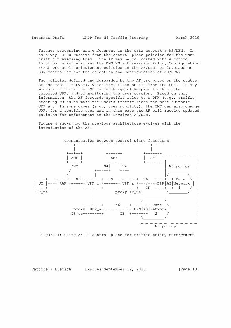
Internet-Draft CPDP for N6 Traffic Steering March 2019
further processing and enfocement in the data network’s AS/DPN. In this way, DPNs receive from the control plane policies for the user traffic traversing them. The AF may be co-located with a control function, which utilizes the DMM WG’s Forwarding Policy Configuration (FPC) protocol to implement policies in the AS/DPN, or leverage an SDN controller for the selection and configuration of AS/DPN.
The policies defined and forwarded by the AF are based on the status of the mobile network, which the AF can obtain from the SMF. In any moment, in fact, the SMF is in charge of keeping track of the selected UPFs and of monitoring the user session. Based on this information, the AF forwards specific rules to a DPN (e.g., traffic steering rules to make the user’s traffic reach the most suitable UPF_a). In some cases (e.g., user mobility), the SMF can also change UPFs for a specific user and in this case the AF will receive updated policies for enforcement in the involved AS/DPN.
Figure 4 shows how the previous architecture evolves with the introduction of the AF.
communication between control plane functions - - +----------------+---------------+ - - | | | +--+--+ +-----+ +------+_ _ _ _ _ _ _ _ | AMF | | SMF | | AF |_ | +-----+ +-----+ +------+ | | /N2 N4| |N4 | N6 policy | / +-----+ +--+ | ________ | / | | |/ \ | +----+ +-----+ N3 +---+---+ N9 +---+---+ N6 +---+--+ Data \ | | UE |---+ RAN +=====+ UPF_i +======+ UPF_a +---/---+DPN|AS|Network | | +----+ +-----+ +---+---+ +-------+ IP +---+--+ 1 / | IP_ue | proxy IP_ue \________/ | | _________ | | / \ | +---+---+ N6 +---+--+ Data \ | proxy| UPF_a +--------/--+DPN|AS|Network | | IP_ue+-------+ IP +---+--+ 2 / | |\_________/ | |_ _ _ _ _ _ _ _ _ _ _ _| N6 policy
Figure 4: Using AF in control plane for traffic policy enforcement
Fattore & Liebsch Expires September 12, 2019 [Page 10]
Internet-Draft CPDP for N6 Traffic Steering March 2019
6. N6 endpoints - loose and tight coupling options
As described in the previous section, we take advantage of the Application Function (AF) to bind the 3GPP’s domain functions with those introduced in this draft for N6 policy enforcement. According to [TS23.501], an Application Function may send requests to influence SMF decisions for User Plane (UP) traffic of PDU Sessions (e.g., based on the relocation of an application on the Data Network side, the AF can notify this to the SMF in order to trigger a relocation of UPF(s) from the SMF, to choose a new UPF more suitable for the new Data Network).
In addition, the AF can subscribe to events from the SMF in order to receive notification about UP management events (e.g., when a PDU Session anchor has been established or released).
As defined in [TS23.502], the AF interacts with the PCF/SMF via the NEF or directly and the PCF then forwards requests from the AF towards the SMF as Session Management (SM) Policies. For the sake of simplicity, in this section all the 3GPP’s functions apart from the AF are collected under the name of "3GPP’s C-PLANE", and the specific service to which the AF interacts in the 3GPP C-PLANE is not relevant for this draft.
In order to forward specific policies to the Data Plane Nodes/ Application Servers (DPNs/ASs) associated with each Data Network, a Network Controller (NC) is considered to be co-located with the AF element. The NC performs the selection of a DPN/AS element based on the received information from the C-PLANE. The AF/NC forwards control messages to a DPN/AS through an AFNC-CPUP interface, giving indications to steer the downlink traffic properly and coherently with the UP updates from the 3GPP’s side.
Forwarding N6 polices to the N6 endpoints involved (i.e., UPF and DPN) can happen in two different ways:
1) Tight coupling scenario: The UPF can enforce policies per the AF/NC decisions. The UPF receives associated policies from the 3GPP’s C-PLANE. The corresponding DPN/AS receives the policy via teh AFNC-CPUP interface.
2) Loose coupling scenario: A separate DPN function is co-located with the UPF. Main policies for N6 traffic treatment do not traverse the 3GPP’s C-PLANE but are controlled at both N6 interface endpoints’ DPN by the AF/NC via the AFNC-CPUP interface.
Fattore & Liebsch Expires September 12, 2019 [Page 11]
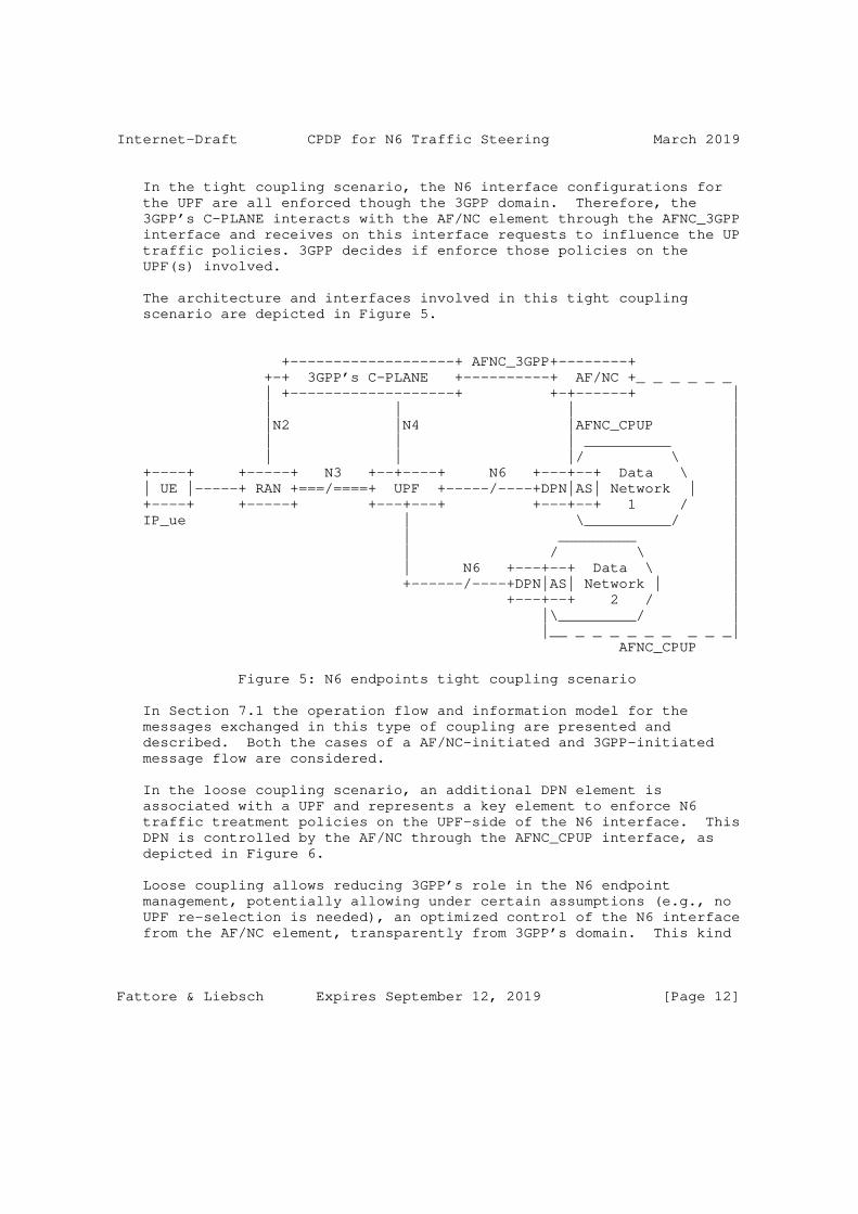
Internet-Draft CPDP for N6 Traffic Steering March 2019
In the tight coupling scenario, the N6 interface configurations for the UPF are all enforced though the 3GPP domain. Therefore, the 3GPP’s C-PLANE interacts with the AF/NC element through the AFNC_3GPP interface and receives on this interface requests to influence the UP traffic policies. 3GPP decides if enforce those policies on the UPF(s) involved.
The architecture and interfaces involved in this tight coupling scenario are depicted in Figure 5.
+-------------------+ AFNC_3GPP+--------+ +-+ 3GPP’s C-PLANE +----------+ AF/NC +_ _ _ _ _ _ | +-------------------+ +-+------+ | | | | | |N2 |N4 |AFNC_CPUP | | | | __________ | | | |/ \ | +----+ +-----+ N3 +--+----+ N6 +---+--+ Data \ | | UE |-----+ RAN +===/====+ UPF +-----/----+DPN|AS| Network | | +----+ +-----+ +---+---+ +---+--+ 1 / | IP_ue | \__________/ | | _________ | | / \ | | N6 +---+--+ Data \ | +------/----+DPN|AS| Network | | +---+--+ 2 / | |\_________/ | |__ _ _ _ _ _ _ _ _ _| AFNC_CPUP
Figure 5: N6 endpoints tight coupling scenario
In Section 7.1 the operation flow and information model for the messages exchanged in this type of coupling are presented and described. Both the cases of a AF/NC-initiated and 3GPP-initiated message flow are considered.
In the loose coupling scenario, an additional DPN element is associated with a UPF and represents a key element to enforce N6 traffic treatment policies on the UPF-side of the N6 interface. This DPN is controlled by the AF/NC through the AFNC_CPUP interface, as depicted in Figure 6.
Loose coupling allows reducing 3GPP’s role in the N6 endpoint management, potentially allowing under certain assumptions (e.g., no UPF re-selection is needed), an optimized control of the N6 interface from the AF/NC element, transparently from 3GPP’s domain. This kind
Fattore & Liebsch Expires September 12, 2019 [Page 12]
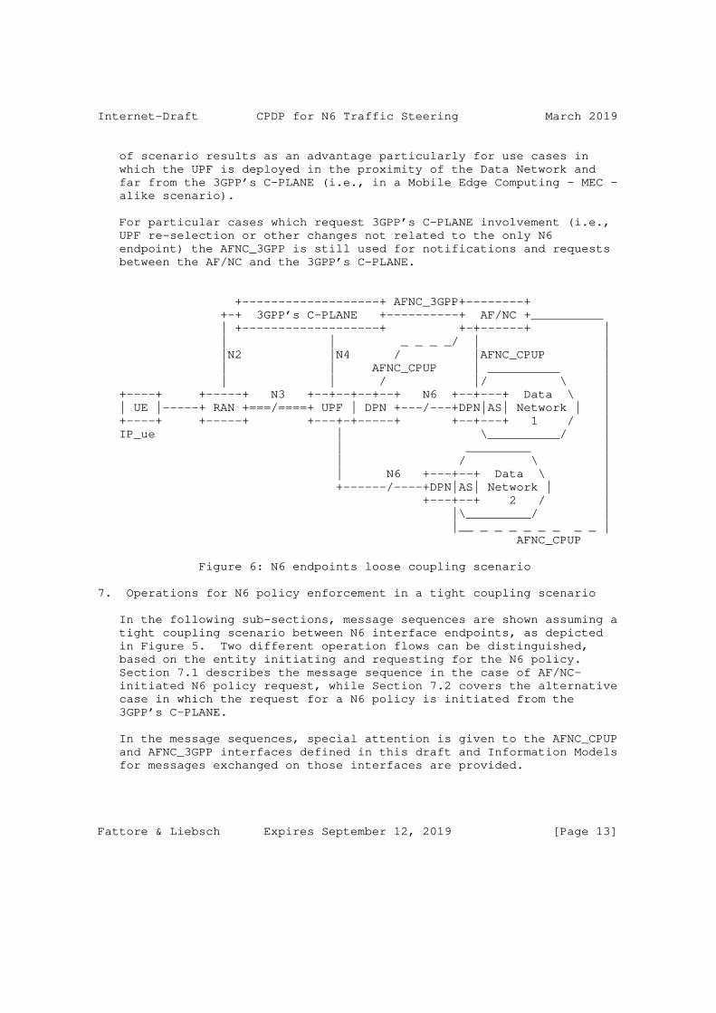
Internet-Draft CPDP for N6 Traffic Steering March 2019
of scenario results as an advantage particularly for use cases in which the UPF is deployed in the proximity of the Data Network and far from the 3GPP’s C-PLANE (i.e., in a Mobile Edge Computing - MEC - alike scenario).
For particular cases which request 3GPP’s C-PLANE involvement (i.e., UPF re-selection or other changes not related to the only N6 endpoint) the AFNC_3GPP is still used for notifications and requests between the AF/NC and the 3GPP’s C-PLANE.
+-------------------+ AFNC_3GPP+--------+ +-+ 3GPP’s C-PLANE +----------+ AF/NC +__________ | +-------------------+ +-+------+ | | | _ _ _ _/ | | |N2 |N4 / |AFNC_CPUP | | | AFNC_CPUP | __________ | | | / |/ \ | +----+ +-----+ N3 +--+--+--+--+ N6 +--+---+ Data \ | | UE |-----+ RAN +===/====+ UPF | DPN +---/---+DPN|AS| Network | | +----+ +-----+ +---+-+-----+ +--+---+ 1 / | IP_ue | \__________/ | | _________ | | / \ | | N6 +---+--+ Data \ | +------/----+DPN|AS| Network | | +---+--+ 2 / | |\_________/ | |__ _ _ _ _ _ _ _ _ | AFNC_CPUP
Figure 6: N6 endpoints loose coupling scenario
7. Operations for N6 policy enforcement in a tight coupling scenario
In the following sub-sections, message sequences are shown assuming a tight coupling scenario between N6 interface endpoints, as depicted in Figure 5. Two different operation flows can be distinguished, based on the entity initiating and requesting for the N6 policy. Section 7.1 describes the message sequence in the case of AF/NC- initiated N6 policy request, while Section 7.2 covers the alternative case in which the request for a N6 policy is initiated from the 3GPP’s C-PLANE.
In the message sequences, special attention is given to the AFNC_CPUP and AFNC_3GPP interfaces defined in this draft and Information Models for messages exchanged on those interfaces are provided.
Fattore & Liebsch Expires September 12, 2019 [Page 13]

Internet-Draft CPDP for N6 Traffic Steering March 2019
7.1. AF/NC-initiated N6 policy enforcement
A N6 policy can be triggered from the AF/NC element and is then forwarded directly to the DPN N6 endpoint (through AFNC_CPUP interface) and indirectly to the UPF N6 endpoint (through AFNC_3GPP interface).
As example, the AF/NC may request updated n6 policies for the following reasons:
o there is the need of a different QoS to be applied to traffic, which is identified in the request.
o there is the need for a re-location of the application to a different Data Network and therefore changes for traffic in uplink on the UPF’s N6 endpoint should be applied.
Figure 7 depicts the AF/NC-initiaed N6 policy enforcement message sequence.
+--------+ +-------+ +--------+ | +-------+ +--------+ |C-PLANE| | UPF(s) |-+ | AF/NC | | DPN/AS | +---+---+ +--+-----+ +---+---+ +---+----+ | | | | | | | | |<-----(1)TRAFFIC------------| | | INFLUENCE REQUEST | | | | | | |---(2a)---->| | | |<----(2b)---| | | | N4 SESSION EST/MOD/REL | | | | | | | | | | |------(3)TRAFFIC----------->| | | INFLUENCE RESPONSE | | | | | | | | |---(4a)---->| | | |<---(4b)----| | | | AFNC_CPUP | | | | CONFIGURATION | | | |
Figure 7: Message flow for AF/NC-initiated N6 policy enforcement
Following, a description for each message is given:
Fattore & Liebsch Expires September 12, 2019 [Page 14]
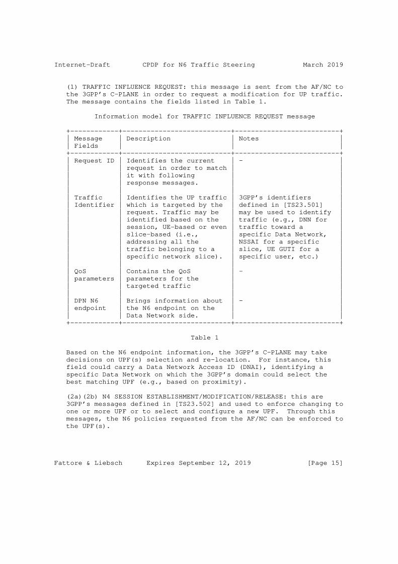
Internet-Draft CPDP for N6 Traffic Steering March 2019
(1) TRAFFIC INFLUENCE REQUEST: this message is sent from the AF/NC to the 3GPP’s C-PLANE in order to request a modification for UP traffic. The message contains the fields listed in Table 1.
Information model for TRAFFIC INFLUENCE REQUEST message
+------------+---------------------------+--------------------------+ | Message | Description | Notes | | Fields | | | +------------+---------------------------+--------------------------+ | Request ID | Identifies the current | - | | | request in order to match | | | | it with following | | | | response messages. | | | | | | | Traffic | Identifies the UP traffic | 3GPP’s identifiers | | Identifier | which is targeted by the | defined in [TS23.501] | | | request. Traffic may be | may be used to identify | | | identified based on the | traffic (e.g., DNN for | | | session, UE-based or even | traffic toward a | | | slice-based (i.e., | specific Data Network, | | | addressing all the | NSSAI for a specific | | | traffic belonging to a | slice, UE GUTI for a | | | specific network slice). | specific user, etc.) | | | | | | QoS | Contains the QoS | - | | parameters | parameters for the | | | | targeted traffic | | | | | | | DPN N6 | Brings information about | - | | endpoint | the N6 endpoint on the | | | | Data Network side. | | +------------+---------------------------+--------------------------+
Table 1
Based on the N6 endpoint information, the 3GPP’s C-PLANE may take decisions on UPF(s) selection and re-location. For instance, this field could carry a Data Network Access ID (DNAI), identifying a specific Data Network on which the 3GPP’s domain could select the best matching UPF (e.g., based on proximity).
(2a)(2b) N4 SESSION ESTABLISHMENT/MODIFICATION/RELEASE: this are 3GPP’s messages defined in [TS23.502] and used to enforce changing to one or more UPF or to select and configure a new UPF. Through this messages, the N6 policies requested from the AF/NC can be enforced to the UPF(s).
Fattore & Liebsch Expires September 12, 2019 [Page 15]

Internet-Draft CPDP for N6 Traffic Steering March 2019
(3) TRAFFIC INFLUENCE RESPONSE: this message is sent from the 3GPP’s C-PLANE to the AF/NC in order to acknowledge the UP changes made based on the previous request message. The message contains the fields listed in Table 2.
Information model for TRAFFIC INFLUENCE RESPONSE message
+------------+-----------------------------------+------------------+ | Message | Description | Notes | | Fields | | | +------------+-----------------------------------+------------------+ | Request ID | Identifies the request message to | - | | | which this response is referred | | | | to. | | | | | | | Traffic | Identifies the UP traffic which | Traffic actually | | Identifier | is targeted by the request. | influenced could | | | Traffic may be identified based | differ from the | | | on the session, UE-based or even | original traffic | | | slice-based (i.e., addressing all | targeted in the | | | the traffic belonging to a | request. | | | specific network slice). | | | | | | | UPF N6 | Brings information about the N6 | - | | endpoint | endpoint on the 3GPP’s side. | | +------------+-----------------------------------+------------------+
Table 2
N6 endpoint information on 3GPP’s side (e.g., IP address of the N6 endpoint UPF) are used from the AF/NC to set the DPN(s) in order to properly route downlink traffic.
(4a)(4b) AFNC_CPUP CONFIGURATION: This message is used to instruct the DPN(s) involved in the UP changes. For instance, in case of UPF re-selection and UPF’s N6 endpoint (e.g., IP address) changing, traffic steering rules for downlink traffic need to be enforced to the DPN. The structure of this message is out of the scope of this draft and candidates for managing this interface are already present (e.g., Forwarding Policy Configuration (FPC) defined in [FPC]).
7.2. 3GPP-initiated N6 policy enforcement
A N6 policy can be triggered by the 3GPP domain. In this case, an initial subscription mechanism is needed, in which one or multiple AF subscribe the 3GPP’s C-PLANE in order to receive notification about the subscribed events. Some of the events, of which a AF/NC could be interested in, are:
Fattore & Liebsch Expires September 12, 2019 [Page 16]
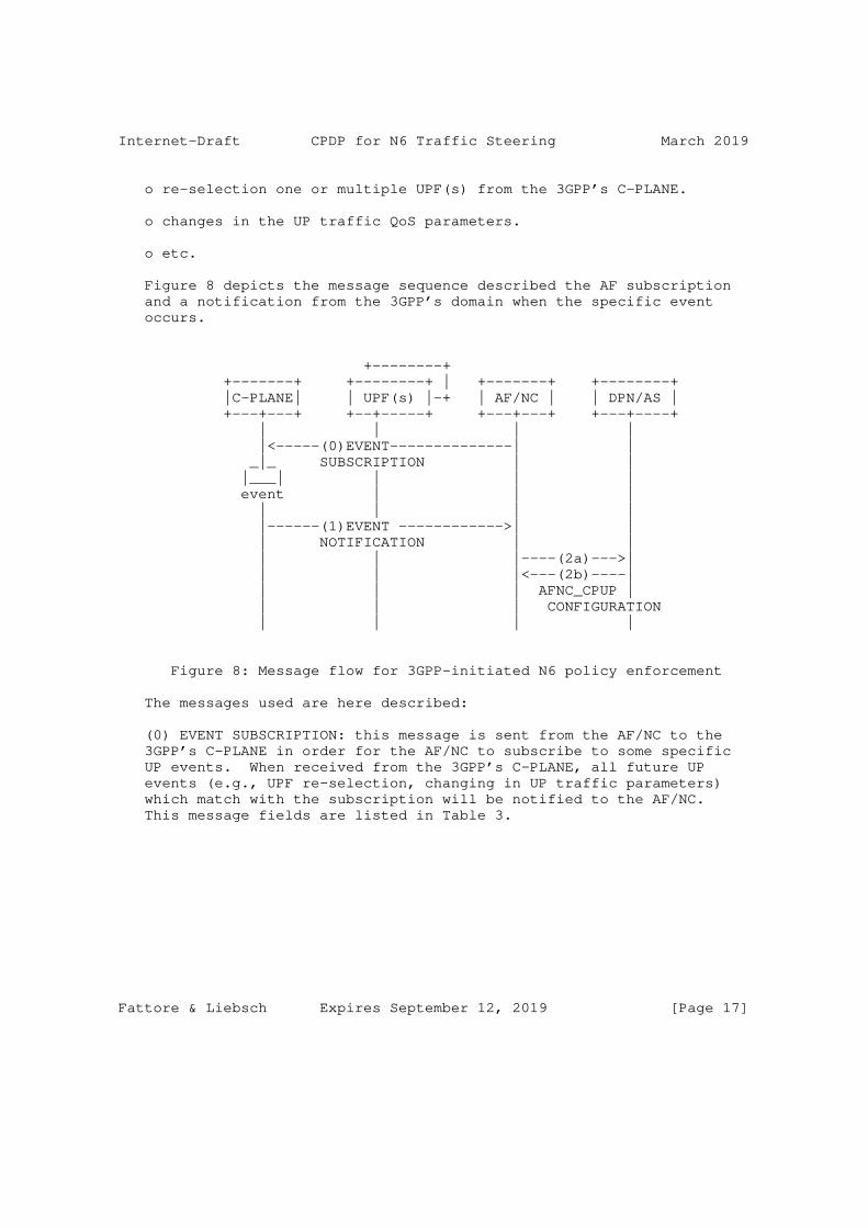
Internet-Draft CPDP for N6 Traffic Steering March 2019
o re-selection one or multiple UPF(s) from the 3GPP’s C-PLANE.
o changes in the UP traffic QoS parameters.
o etc.
Figure 8 depicts the message sequence described the AF subscription and a notification from the 3GPP’s domain when the specific event occurs.
+--------+ +-------+ +--------+ | +-------+ +--------+ |C-PLANE| | UPF(s) |-+ | AF/NC | | DPN/AS | +---+---+ +--+-----+ +---+---+ +---+----+ | | | | |<-----(0)EVENT--------------| | _|_ SUBSCRIPTION | | |___| | | | event | | | | | | | |------(1)EVENT ------------>| | | NOTIFICATION | | | | |----(2a)--->| | | |<---(2b)----| | | | AFNC_CPUP | | | | CONFIGURATION | | | |
Figure 8: Message flow for 3GPP-initiated N6 policy enforcement
The messages used are here described:
(0) EVENT SUBSCRIPTION: this message is sent from the AF/NC to the 3GPP’s C-PLANE in order for the AF/NC to subscribe to some specific UP events. When received from the 3GPP’s C-PLANE, all future UP events (e.g., UPF re-selection, changing in UP traffic parameters) which match with the subscription will be notified to the AF/NC. This message fields are listed in Table 3.
Fattore & Liebsch Expires September 12, 2019 [Page 17]
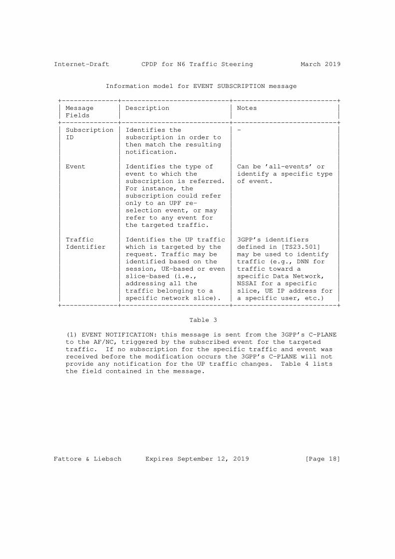
Internet-Draft CPDP for N6 Traffic Steering March 2019
Information model for EVENT SUBSCRIPTION message
+--------------+---------------------------+--------------------------+ | Message | Description | Notes | | Fields | | | +--------------+---------------------------+--------------------------+ | Subscription | Identifies the | - | | ID | subscription in order to | | | | then match the resulting | | | | notification. | | | | | | | Event | Identifies the type of | Can be ’all-events’ or | | | event to which the | identify a specific type | | | subscription is referred. | of event. | | | For instance, the | | | | subscription could refer | | | | only to an UPF re- | | | | selection event, or may | | | | refer to any event for | | | | the targeted traffic. | | | | | | | Traffic | Identifies the UP traffic | 3GPP’s identifiers | | Identifier | which is targeted by the | defined in [TS23.501] | | | request. Traffic may be | may be used to identify | | | identified based on the | traffic (e.g., DNN for | | | session, UE-based or even | traffic toward a | | | slice-based (i.e., | specific Data Network, | | | addressing all the | NSSAI for a specific | | | traffic belonging to a | slice, UE IP address for | | | specific network slice). | a specific user, etc.) | +--------------+---------------------------+--------------------------+
Table 3
(1) EVENT NOTIFICATION: this message is sent from the 3GPP’s C-PLANE to the AF/NC, triggered by the subscribed event for the targeted traffic. If no subscription for the specific traffic and event was received before the modification occurs the 3GPP’s C-PLANE will not provide any notification for the UP traffic changes. Table 4 lists the field contained in the message.
Fattore & Liebsch Expires September 12, 2019 [Page 18]
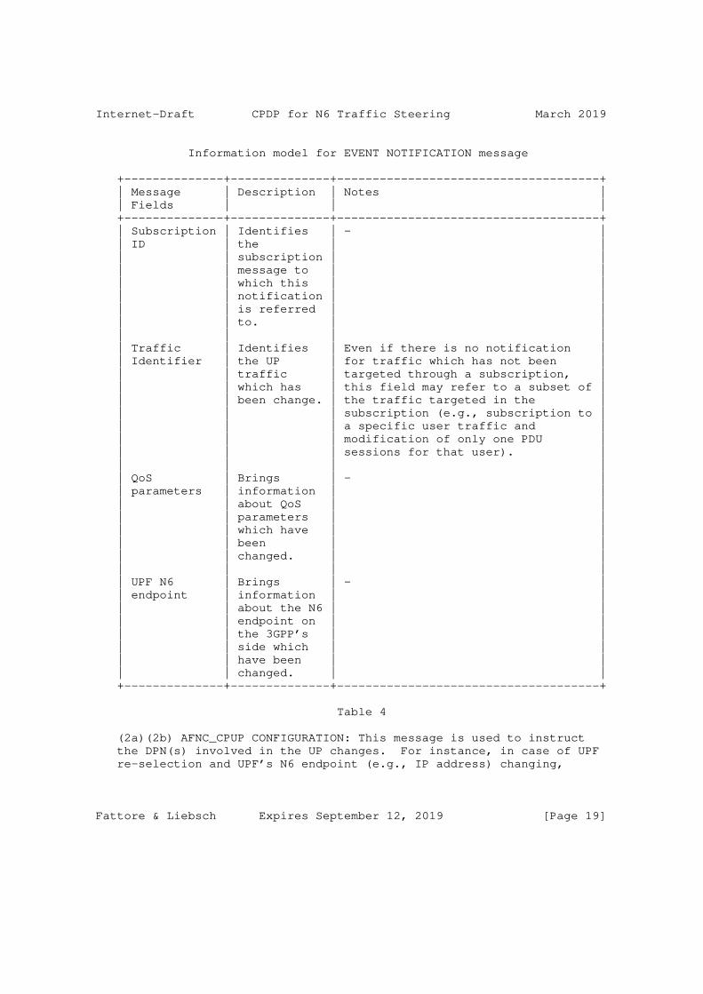
Internet-Draft CPDP for N6 Traffic Steering March 2019
Information model for EVENT NOTIFICATION message
+--------------+--------------+-------------------------------------+ | Message | Description | Notes | | Fields | | | +--------------+--------------+-------------------------------------+ | Subscription | Identifies | - | | ID | the | | | | subscription | | | | message to | | | | which this | | | | notification | | | | is referred | | | | to. | | | | | | | Traffic | Identifies | Even if there is no notification | | Identifier | the UP | for traffic which has not been | | | traffic | targeted through a subscription, | | | which has | this field may refer to a subset of | | | been change. | the traffic targeted in the | | | | subscription (e.g., subscription to | | | | a specific user traffic and | | | | modification of only one PDU | | | | sessions for that user). | | | | | | QoS | Brings | - | | parameters | information | | | | about QoS | | | | parameters | | | | which have | | | | been | | | | changed. | | | | | | | UPF N6 | Brings | - | | endpoint | information | | | | about the N6 | | | | endpoint on | | | | the 3GPP’s | | | | side which | | | | have been | | | | changed. | | +--------------+--------------+-------------------------------------+
Table 4
(2a)(2b) AFNC_CPUP CONFIGURATION: This message is used to instruct the DPN(s) involved in the UP changes. For instance, in case of UPF re-selection and UPF’s N6 endpoint (e.g., IP address) changing,
Fattore & Liebsch Expires September 12, 2019 [Page 19]
Internet-Draft CPDP for N6 Traffic Steering March 2019
traffic steering rules for downlink traffic need to be enforced to the DPN. The structure of this message is anyway out of the scope of this draft and candidates for managing this interface are already present (e.g., Forwarding Polciy Configuration (FPC) defined in [FPC]).
8. IANA Considerations
No IANA action is required for this version of the draft.
9. Security Considerations
Since the solution proposed in this document utilizes the AF to solicit and receive N6 traffic treatment policies from the cellular system’s control plane, the trust relationship between the AF and the cellular system’s domain matters. In case the AF is located in a different administrative domain, the communication from and to the AF may happen via the system’s Network Exposure Functions (NEF). The semantic to request and receive the N6 policy at the AF and in particular the policy types and their descriptions must be aligned to the trust relationship.
Also, the trust relationship between the AF and the DPN/AS matters and a secure direct or indirect (e.g. through an Network Controller) interface, must be ensured.
10. Acknowledgments
The research leading to these results has been partially supported by the H2020-MSCA-ITN-2016 framework under grant agreement number 722788 (SPOTLIGHT).
Authors want to thank Sri Gundavelli, John Kaippallimalil and Shunsuke Homma for their interest and feedback to the use cases and the solution principles for N6 traffic treatment policies.
11. Normative References
[RFC2119] Bradner, S., "Key words for use in RFCs to Indicate Requirement Levels", BCP 14, RFC 2119, DOI 10.17487/RFC2119, March 1997, <https://www.rfc-editor.org/info/rfc2119>.
[I-D.hmm-dmm-5g-uplane-analysis] Homma, S., Miyasaka, T., Matsushima, S., and d. [email protected], "User Plane Protocol and Architectural Analysis on 3GPP 5G System", draft-hmm-dmm- 5g-uplane-analysis-02 (work in progress), October 2018.
Fattore & Liebsch Expires September 12, 2019 [Page 20]
Internet-Draft CPDP for N6 Traffic Steering March 2019
[I-D.gundavelli-dmm-mfa] Gundavelli, S., Liebsch, M., and S. Matsushima, "Mobility- aware Floating Anchor (MFA)", draft-gundavelli-dmm-mfa-01 (work in progress), September 2018.
[I-D.bogineni-dmm-optimized-mobile-user-plane] Bogineni, K., Akhavain, A., Herbert, T., Farinacci, D., Rodriguez-Natal, A., Carofiglio, G., Auge, J., Muscariello, L., Camarillo, P., and S. Homma, "Optimized Mobile User Plane Solutions for 5G", draft-bogineni-dmm- optimized-mobile-user-plane-01 (work in progress), June 2018.
[FPC] S.Matsushima, L.Bertz, M.Liebsch, S.Gundavelli, D.Moses, C. Perkins, "Protocol for Forwarding Policy Configuration (FPC) in DMM.", 3GPPTS 23.501, June 2018.
[TS23.501] 3rd Generation Partnership Project (3GPP), "Technical Specification TS23.501, System Architecture for the 5G System, Release 15.", 3GPPTS 23.501, June 2018.
[TS23.502] 3rd Generation Partnership Project (3GPP), "Technical Specification TS23.502, Procedure for the 5G System, Release 15.", 3GPPTS 23.502, June 2018.
Authors’ Addresses
Umberto Fattore NEC Laboratories Europe GmbH Kurfuersten-Anlage 36 D-69115 Heidelberg Germany
Email: [email protected]
Marco Liebsch NEC Laboratories Europe GmbH Kurfuersten-Anlage 36 D-69115 Heidelberg Germany
Email: [email protected]
Fattore & Liebsch Expires September 12, 2019 [Page 21]

DMM Working Group S. HommaInternet-Draft NTTIntended status: Informational T. MiyasakaExpires: April 25, 2019 KDDI Research S. Matsushima SoftBank D. Voyer Bell Canada October 22, 2018
User Plane Protocol and Architectural Analysis on 3GPP 5G System draft-hmm-dmm-5g-uplane-analysis-02
Abstract
This document analyzes the mobile user plane protocol and the architecture specified in 3GPP 5G documents. The analysis work is to clarify those specifications, extract protocol and architectural requirements and derive evaluation aspects for user plane protocols on IETF side. This work is corresponding to the User Plane Protocol Study work on 3GPP side.
Status of This Memo
This Internet-Draft is submitted in full conformance with the provisions of BCP 78 and BCP 79.
Internet-Drafts are working documents of the Internet Engineering Task Force (IETF). Note that other groups may also distribute working documents as Internet-Drafts. The list of current Internet- Drafts is at https://datatracker.ietf.org/drafts/current/.
Internet-Drafts are draft documents valid for a maximum of six months and may be updated, replaced, or obsoleted by other documents at any time. It is inappropriate to use Internet-Drafts as reference material or to cite them other than as "work in progress."
This Internet-Draft will expire on April 25, 2019.
Copyright Notice
Copyright (c) 2018 IETF Trust and the persons identified as the document authors. All rights reserved.
This document is subject to BCP 78 and the IETF Trust’s Legal Provisions Relating to IETF Documents (https://trustee.ietf.org/license-info) in effect on the date of
Homma, et al. Expires April 25, 2019 [Page 1]
Internet-Draft draft-hmm-dmm-5g-uplane-analysis-02 October 2018
publication of this document. Please review these documents carefully, as they describe your rights and restrictions with respect to this document. Code Components extracted from this document must include Simplified BSD License text as described in Section 4.e of the Trust Legal Provisions and are provided without warranty as described in the Simplified BSD License.
Table of Contents
1. Introduction . . . . . . . . . . . . . . . . . . . . . . . . 2 1.1. Current Status of Mobile User Plane for 5G . . . . . . . 3 1.2. Our Way of Analysis Work . . . . . . . . . . . . . . . . 3 2. Terms and Abbreviations . . . . . . . . . . . . . . . . . . . 4 3. GTP-U Specification and Observation . . . . . . . . . . . . . 5 3.1. GTP-U Tunnel . . . . . . . . . . . . . . . . . . . . . . 6 3.2. GTP-U Header Format . . . . . . . . . . . . . . . . . . . 10 3.3. Control Plane Protocol for GTP-U . . . . . . . . . . . . 12 3.4. GTP-U message . . . . . . . . . . . . . . . . . . . . . . 13 3.5. Packet Format . . . . . . . . . . . . . . . . . . . . . . 14 3.6. Observations Summary . . . . . . . . . . . . . . . . . . 16 4. 5GS Architectural Requirements for User Plane Protocols . . . 16 4.1. Overview of 5G System Architecture . . . . . . . . . . . 16 4.1.1. UPF Functionalities . . . . . . . . . . . . . . . . . 18 4.2. Architectural Requirements for User Plane Protocols . 19 5. Evaluation Aspects . . . . . . . . . . . . . . . . . . . . . 22 5.1. Supporting PDU Session Type Variations . . . . . . . . . 23 5.2. Nature of Data Path . . . . . . . . . . . . . . . . . . . 23 5.3. Supporting Transport Variations . . . . . . . . . . . . . 24 5.4. Data Path Management . . . . . . . . . . . . . . . . . . 24 5.5. QoS Control . . . . . . . . . . . . . . . . . . . . . . . 25 5.6. Traffic Detection and Flow Handling . . . . . . . . . . . 26 5.7. Supporting Network Slicing Diversity . . . . . . . . . . 26 6. Conclusion . . . . . . . . . . . . . . . . . . . . . . . . . 27 7. Security Consideration . . . . . . . . . . . . . . . . . . . 27 8. Acknowledgement . . . . . . . . . . . . . . . . . . . . . . . 28 9. Informative References . . . . . . . . . . . . . . . . . . . 28 Authors’ Addresses . . . . . . . . . . . . . . . . . . . . . . . 32
1. Introduction
This document analyzes the mobile user plane protocol and the architecture specified by 3GPP 5G documents. The background of the work is that 3GPP requests through a liaison statement that the IETF to provide any information for the User Plane Protocol Study work in 3GPP [CP-180116-3GPP]. Justification and the objectives of the study can be found from [CP-173160-3GPP].
Homma, et al. Expires April 25, 2019 [Page 2]
Internet-Draft draft-hmm-dmm-5g-uplane-analysis-02 October 2018
We understand that the current user plane protocol, GTP-U [TS.29.281-3GPP], has been well developed in 3GPP, and deployed very widely as the successor of legacy network technologies, such as TDM circuit, or ATM virtual circuit. That GTP-U success seems based on IP overlay technique that is dramatically scaled compare to the previous ones because it successfully isolates mobile session states from the user plane transport network.
Even after that big success, it is definitely worth that 3GPP has decided to revisit user plane which seems to response to IPv6 deployment growth and [IAB-Statement] that encourages the industry to develop strategies for IPv6-only operation. It can be seen from the justification section in [CP-173160-3GPP].
The study description mentions that the study would be based on Release 16 requirement while only Release 15 specifications has been available now. However we believe that to provide adequate information for 3GPP, we need to clearly understand what the current user plane protocol is in Release 15, and architectural requirements for the user plane.
As the liaison statement indicates 3GPP specifications related to user plane, those documents should be a good start point to clarify their specifications and to extract protocol and architectural requirements from them.
1.1. Current Status of Mobile User Plane for 5G
3GPP RAN and CT4 decided to use GTP-U as the 5G user plane encapsulation protocol over N3 and N9 that respectively described in[TS.38.300-3GPP] and [TR.29.891-3GPP]. N3 is an interface between RAN and UPF and N9 is an interface between different UPFs [TS.23.501-3GPP].
In [TR.29.891-3GPP], it captured user plane requirements and concluded that GTP-U is adopted for the user plane protocol. It seems that GTP-U was only option to be chose and it focused on how to carry 5G specific QoS information between UPF and access networks. That is described in section 5.2 and 11.2 of [TR.29.891-3GPP]. Another aspects of user plane requirements couldn’t be found.
1.2. Our Way of Analysis Work
First, we analyze [TS.29.281-3GPP] for clarifying it as the current user plane protocol in the 5G system. [TR.29.891-3GPP] describes how GTP-U is selected as the user plane protocol for 5G in 3GPP. Clarified characteristics of the protocol are described in Section 3.
Homma, et al. Expires April 25, 2019 [Page 3]
Internet-Draft draft-hmm-dmm-5g-uplane-analysis-02 October 2018
Then, to clarify what are required to the user plane protocol in architecture level, we analyze [TS.23.501-3GPP] as the 5G system architecture specification. [TS.23.502-3GPP] is the specification of system procedures that helps us to understand how the system works in the architecture. [TS.23.503-3GPP] is also helpful to find the role of user plane in the architecture that influences user plane protocol. Extracted architectural requirements are described in Section 4.
Based on the results of above, we identify some aspects where there might be gap between the current user plane protocol and the architectural requirements on which [TR.29.891-3GPP] does not discuss. That aspects are discussed Section 5. That’s what we intend to be as a part of the reply to 3GPP. CT4 WG in 3GPP can utilize it as an input to evaluate the candidate protocols for user plane to the 5G system including the current protocol.
[I-D.bogineni-dmm-optimized-mobile-user-plane] will provide the candidate protocols on IETF side to the 3GPP study.
2. Terms and Abbreviations
This section describes terms of functions and interfaces relevant to user plane protocol which we extract from the 3GPP specifications since this document focuses on user plane.
In those specifications, there are so many unique terms and abbreviations in the 3GPP context which IETF community seems not familiar with. We will try to bring those terms with brief explanations to make sure common understanding for them.
GTP: GPRS Tunneling Protocol
GTP-U: User Plane part of GTP
Noted that GTP version 1 (GTPv1-U) is the user-plane protocol specification which is defined in [TS.29.281-3GPP]. Unless there is no specific annotation, we refer GTP-U to GTPv1-U in this document.
PDU: Protocol Data Unit of end-to-end user protocol packet.
Noted that the PDU in 3GPP includes IP header in case that PDU session type is IPv4 or IPv6. In contrast, in IETF it is supposed that PDU is the payload of IP packet so that it doesn’t include IP/TCP/UDP header in end-to-end.
T-PDU: Transport PDU.
Homma, et al. Expires April 25, 2019 [Page 4]
Internet-Draft draft-hmm-dmm-5g-uplane-analysis-02 October 2018
G-PDU: GTP encapsulated user Plane Data Unit.
GTP-U has above two notions on PDU. T-PDU is a PDU that GTP-U header encapsulates. G-PDU is a PDU that includes GTP-U header. A G-PDU may include a T-PDU. G-PDU can be sent without T-PDU, but just with extension headers or TLV elements. It can be used for OAM related operations.
PDU session: Association between the UE and a Data Network that provides a PDU connectivity service.
Data Network (DN): The network of operator services, Internet access or 3rd party services.
User Plane (UP): Encapsulating user end-to-end PDU.
In fact, we can’t find exact text that defines UP in the architecture specification. However when we see the figure 8.3.1-1 in [TS.23.501-3GPP], we specify UP as the layer right under PDU that directly encapsulates PDU. Underneath layers of UP are UP transport, such as IP/UDP, L2 and L1.
However 3GPP is consistent to use the term user plane when they indicate that layer. In IETF, we can see the terms data plane, or forwarding plane as variations which often makes us tend to be confused in terminology.
QFI: QoS Flow Identifier
UPF: User Plane Function
SMF: Session Management Function
SMF is a control plane function which provides session management service that handling PDU sessions in the control plane. SMF allocates tunnels corresponding to the PDU sessions and configure the tunnel to the UPF.
RAN: Radio Access Network
Noted that UP protocol provides a RAN to connect UPF. But the UP protocol is not appeared on the air in the RAN.
3. GTP-U Specification and Observation
In this section we analyze the GTP-U specification and summarize clarified characteristic of GTP-U to see if GTP-U meets the requirements of 5G architecture for user plane in later section.
Homma, et al. Expires April 25, 2019 [Page 5]
Internet-Draft draft-hmm-dmm-5g-uplane-analysis-02 October 2018
3.1. GTP-U Tunnel
GTP-U is a tunneling protocol between given a pair of GTP-U tunnel endpoint nodes and encapsulates T-PDU from/to UE on top of IP/UDP. A Tunnel Endpoint Identifier (TEID) value allocated on each end point indicates which tunnel a particular T-PDU belongs to.
The receiving endpoint individually allocate a TEID and the sender tunnel endpoint node encapsulates the IP packet from/to UE with the TEID which is present in GTP-U header on top of IPv4 or IPv6, and UDP. That is described in section 4.2.1 of [TS.29.281-3GPP].
[GTP-U-1]: GTP-U is an unidirectional Point-to-Point tunneling protocol.
Figure 1 shows an example of GTP-U protocol stack for uplink (UL) and downlink (DL) traffic flow. Two GTP-U tunnels are required to form one bi-directional tunnel.
UL: From RAN to UPF1 (TEID=1), and from UPF1 to UPF2 (TEID=2)
DL: From UPF2 to UPF1 (TEID=3), and from UPF1 to RAN (TEID=4)
In 5GS, GTP-U tunnel is established at following interfaces to provide PDU Session between UE and 5GC.
N3: Between RAN and UPF
N9: Between different UPFs
GTP-U allows one tunnel endpoint node to send out a G-PDU to be received by multiple tunnel endpoints by utilizing IP multicast capability of underlay IP networks. That is described in section 4.2.6 of [TS.29.281-3GPP]. It looks GTP-U has Point-to-Multipoint (P2MP) tunneling capability. The P2MP tunneling is used for MBMS (Multimedia Broadcast Multicast Service) through GTP-U tunnel.
[GTP-U-2]: GTP-U supports Point-to-Multipoint tunneling.
UDP is utilized for GTP-U encapsulation and UDP destination port is 2152 which is assigned by IANA. Allocation of UDP source port depends on sender tunnel endpoint node and GTP-U supports dynamic allocation of UDP source port for load balancing objective. The specification of this dynamic allocation is described in section 4.4.2.0 of [TS.29.281-3GPP], however specific procedure, e.g., 5-tuple hashing, is not described in the document and depends on the implementation of GTP-U tunnel endpoint node.
Homma, et al. Expires April 25, 2019 [Page 6]

Internet-Draft draft-hmm-dmm-5g-uplane-analysis-02 October 2018
[GTP-U-3]: GTP-U supports load balancing by using dynamic UDP source port allocation.
Homma, et al. Expires April 25, 2019 [Page 7]
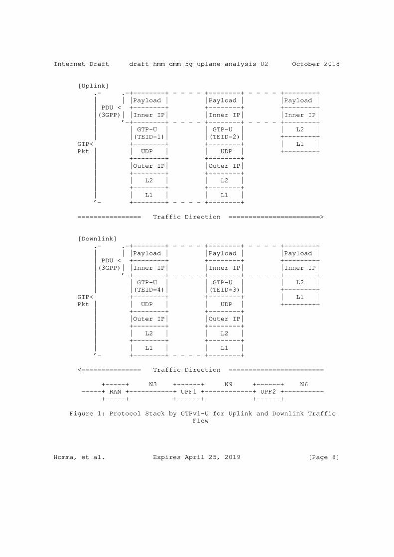
Internet-Draft draft-hmm-dmm-5g-uplane-analysis-02 October 2018
[Uplink] .- .-+--------+ - - - - +--------+ - - - - +--------+ | | |Payload | |Payload | |Payload | | PDU < +--------+ +--------+ +--------+ |(3GPP)| |Inner IP| |Inner IP| |Inner IP| | ’-+--------+ - - - - +--------+ - - - - +--------+ | | GTP-U | | GTP-U | | L2 | | |(TEID=1)| |(TEID=2)| +--------+ GTP< +--------+ +--------+ | L1 | Pkt | | UDP | | UDP | +--------+ | +--------+ +--------+ | |Outer IP| |Outer IP| | +--------+ +--------+ | | L2 | | L2 | | +--------+ +--------+ | | L1 | | L1 | ’- +--------+ - - - - +--------+
================ Traffic Direction =======================>
[Downlink] .- .-+--------+ - - - - +--------+ - - - - +--------+ | | |Payload | |Payload | |Payload | | PDU < +--------+ +--------+ +--------+ |(3GPP)| |Inner IP| |Inner IP| |Inner IP| | ’-+--------+ - - - - +--------+ - - - - +--------+ | | GTP-U | | GTP-U | | L2 | | |(TEID=4)| |(TEID=3)| +--------+ GTP< +--------+ +--------+ | L1 | Pkt | | UDP | | UDP | +--------+ | +--------+ +--------+ | |Outer IP| |Outer IP| | +--------+ +--------+ | | L2 | | L2 | | +--------+ +--------+ | | L1 | | L1 | ’- +--------+ - - - - +--------+
<=============== Traffic Direction ========================
+-----+ N3 +------+ N9 +------+ N6 -----+ RAN +-----------+ UPF1 +------------+ UPF2 +---------- +-----+ +------+ +------+
Figure 1: Protocol Stack by GTPv1-U for Uplink and Downlink Traffic Flow
Homma, et al. Expires April 25, 2019 [Page 8]
Internet-Draft draft-hmm-dmm-5g-uplane-analysis-02 October 2018
IPv6 flow label [RFC6437] is also candidate method for load balancing especially for IP-in-IPv6 tunnel [RFC6438] like GTP-U. However, how to use IPv6 flow label of GTP-U is not described in [TS.29.281-3GPP]. Though this method is limited to a case of IPv6 encapsulated GTP-U tunnel, it is worth to study usage of IPv6 flow label in 3GPP.
[GTP-U-4]: GTP-U does not support IPv6 flow label for load balancing in case of IPv6 transport.
GTP-U supports both IPv4 and IPv6 as underlying transport layer protocol. As for IPv6, GTP-U specification refers [RFC2460], which is described in section 4.2.3 of [TS.29.281-3GPP]. As [RFC2460] does not allow the tunnel protocols on top of UDP to set the checksum value to zero, the GTP-U specification inherits it while the IPv4 transport for GTP-U case allows UDP zero checksum. It is noted that the IPv6 specification in IETF has been updated to [RFC8200] which allows UDP zero checksum for the tunnel. [RFC6935] describes benefits of zero checksum for tunnel protocol over UDP. If GTP-U support UFP zero checksum in future version, possible interoperability issue between previous generations which does not support zero checksum may raise.
[GTP-U-5]: UDP zero checksum is not available in case of IPv6 transport.
"Unnecessary fragmentation should be avoided" is recommended and to avoid the fragmentation operator should configure MTU size at UE [TS.29.281-3GPP]. However, there’s no reference and specification of Path MTU Discovery for IPv6 transport. If encapsulated IPv6 packet is too big on a network link between tunnel endpoint nodes, UE may not receive ICMPv6 Packet Too Big message and causes Path MTU Discovery black hole.
[GTP-U-6]: GTP-U does not support to response ICMP PTB for Path MTU Discovery.
Section 9.3 of [TS.23.060-3GPP] specifies advertisement of inner IPv6 link MTU size for UE by IPv6 RA message [RFC4861]. However, this document doesn’t specify a procedure to measure MTU size in mobile network system and mobile network operator need to calculate MTU size for UE like Annex C of [TS.23.060-3GPP]. If link MTU of a router in a transport network is accidentally modified, UE cannot detect the event and send packet with initial MTU size, which may cause service disruption due to MTU exceed in the router link.
Homma, et al. Expires April 25, 2019 [Page 9]

Internet-Draft draft-hmm-dmm-5g-uplane-analysis-02 October 2018
3.2. GTP-U Header Format
Figure 2 shows general and mandatory GTP-U header and Figure 3 shows extension GTP-U header.
[GTP-U-7]: GTP-U supports sequence number option in the header, but it is not recommended to be used by almost GTP-U entities.
GTP-U header has Sequence Number field to reorder incoming packets based on the sequence number. If Sequence Number Flag is set to ’1’ it indicates that Sequence Number Filed exists in GTP-U header and examined at receiving tunnel endpoint node to reorder incoming packets. However, the sequence number flag is set to ’1’ only for RAT HO procedure and sequence number flag should be set to ’0’ in normal case. Therefore, in normal case receiver tunnel endpoint node doesn’t examine sequence number and can’t reorder GTP-U packets based on the sequence number. This specification is described in section 5.1 of [TS.29.281-3GPP]. In 3GPP, sequential delivery is required only during handover procedure and is used by only RAN entities.
0 1 2 3 0 1 2 3 4 5 6 7 8 9 0 1 2 3 4 5 6 7 8 9 0 1 2 3 4 5 6 7 8 9 0 1 +-+-+-+-+-+-+-+-+-+-+-+-+-+-+-+-+-+-+-+-+-+-+-+-+-+-+-+-+-+-+-+-+ | Ver |P|R|E|S|N| Message Type | Length | +-+-+-+-+-+-+-+-+-+-+-+-+-+-+-+-+-+-+-+-+-+-+-+-+-+-+-+-+-+-+-+-+ | Tunnel Endpoint Identifier | +-+-+-+-+-+-+-+-+-+-+-+-+-+-+-+-+-+-+-+-+-+-+-+-+-+-+-+-+-+-+-+-+ | Sequence Number | N-PDU Number | Next-Ext-Hdr | +-+-+-+-+-+-+-+-+-+-+-+-+-+-+-+-+-+-+-+-+-+-+-+-+-+-+-+-+-+-+-+-+
Figure 2: GTP-U Header
o Ver: Version field (Set to ’1’)
o P: Protocol Type (Set to ’1’)
o R: Reserved bit (Set to ’0’)
o E: Extension Header Flag (Set to ’1’ if extension header exists)
o S: Sequence Number Flag (Set to ’1’ if sequence number exists)
o N: N-PDU Number Flag (Set to ’1’ if N-PDU number exists)
o Message Type: Indicates the type of GTP-U message
o Length: Indicates the length in octets of the payload
Homma, et al. Expires April 25, 2019 [Page 10]
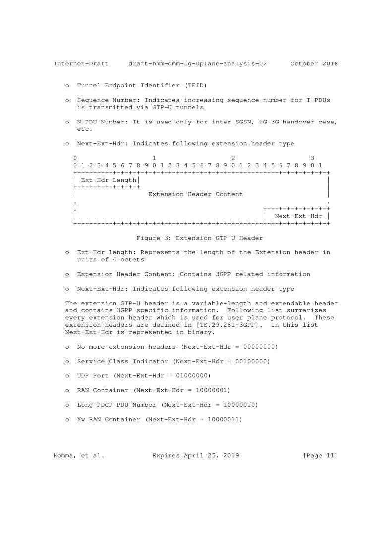
Internet-Draft draft-hmm-dmm-5g-uplane-analysis-02 October 2018
o Tunnel Endpoint Identifier (TEID)
o Sequence Number: Indicates increasing sequence number for T-PDUs is transmitted via GTP-U tunnels
o N-PDU Number: It is used only for inter SGSN, 2G-3G handover case, etc.
o Next-Ext-Hdr: Indicates following extension header type
0 1 2 3 0 1 2 3 4 5 6 7 8 9 0 1 2 3 4 5 6 7 8 9 0 1 2 3 4 5 6 7 8 9 0 1 +-+-+-+-+-+-+-+-+-+-+-+-+-+-+-+-+-+-+-+-+-+-+-+-+-+-+-+-+-+-+-+-+ | Ext-Hdr Length| | +-+-+-+-+-+-+-+-+ | | Extension Header Content | . . . +-+-+-+-+-+-+-+-+ | | Next-Ext-Hdr | +-+-+-+-+-+-+-+-+-+-+-+-+-+-+-+-+-+-+-+-+-+-+-+-+-+-+-+-+-+-+-+-+
Figure 3: Extension GTP-U Header
o Ext-Hdr Length: Represents the length of the Extension header in units of 4 octets
o Extension Header Content: Contains 3GPP related information
o Next-Ext-Hdr: Indicates following extension header type
The extension GTP-U header is a variable-length and extendable header and contains 3GPP specific information. Following list summarizes every extension header which is used for user plane protocol. These extension headers are defined in [TS.29.281-3GPP]. In this list Next-Ext-Hdr is represented in binary.
o No more extension headers (Next-Ext-Hdr = 00000000)
o Service Class Indicator (Next-Ext-Hdr = 00100000)
o UDP Port (Next-Ext-Hdr = 01000000)
o RAN Container (Next-Ext-Hdr = 10000001)
o Long PDCP PDU Number (Next-Ext-Hdr = 10000010)
o Xw RAN Container (Next-Ext-Hdr = 10000011)
Homma, et al. Expires April 25, 2019 [Page 11]
Internet-Draft draft-hmm-dmm-5g-uplane-analysis-02 October 2018
o NR RAN Container (Next-Ext-Hdr = 10000100)
o PDU Session Container (Next-Ext-Hdr = 10000101)
o PDCP PDU Number (Next-Ext-Hdr = 11000000)
[GTP-U-8]: GTP-U supports carrying QoS Identifiers transparently for Access Networks in an extension header.
GTP-U is designed to carry 3GPP specific information with extension headers. 3GPP creates PDU Session Container extension header for NGRAN of 5G to carry QFI. It is described in section 5.2.2.7 of [TS.29.281-3GPP].
[GTP-U-9]: GTP-U supports DSCP marking based on the QFI.
DSCP marking on outer IPv4 or IPv6 shall be set by sender tunnel endpoint node based on the QFI. This specification is described in section 4.4.1 of [TS.29.281-3GPP].
[GTP-U-10]: GTP-U does not specify extension header order.
In general, multiple GTP-U extension headers are able to contained in one GTP-U packet and the order of those extension headers is not specified by [TS.29.281-3GPP]. Thereby the receiving endpoint can’t predict exact position where the target extension headers are. This could impact on header lookup performance on the node.
As for PDU Session Container extension header, there is a note in [TS.29.281-3GPP] as "For a G-PDU with several Extension Headers, the PDU Session Container should be the first Extension Header". This note was added at the version 15.3.0 of [TS.29.281-3GPP] which is published on June 2018 in order to accelerate the processing of GTP-U packet at UPF and RAN. It is only one rule regarding the extension header order.
[GTP-U-11]: GTP-U does not support to indicate next protocol type.
When Next-Ext-Hdr is set to 0x00 it indicates that no more extension headers follow. As GTP is designed to indicate protocol types for T-PDU by control-plane signaling, GTP-U doesn’t have Next-Protocol- Header field to indicate the T-PDU type in the header.
3.3. Control Plane Protocol for GTP-U
Control plane protocol for GTP-U signals TEID between tunnel endpoint nodes. GTPv2-C [TS.29.274-3GPP] is the original control plane
Homma, et al. Expires April 25, 2019 [Page 12]
Internet-Draft draft-hmm-dmm-5g-uplane-analysis-02 October 2018
protocol tied with GTP-U in previous generation architectures before CUPS (Control and User Plane Separation).
3GPP decided to use extended PFCP (Packet Forwarding Control Protocol) [TS.29.244-3GPP] for N4 interface [TR.29.891-3GPP] to signal tunnel states from SMF to UPF.
3.4. GTP-U message
GTP-U supports in-band messaging to signal OAM. Currently GTP-U supports following messages [TS.29.281-3GPP].
o Echo Request
o Echo Response
o Supported Extension Headers Notification
o Error Indication
o End Marker
[GTP-U-12]: GTP-U supports active OAM as a path management message "Echo Request/Response".
A GTP-U tunnel endpoint node sends a Echo Request message to another nodes for keep-alive and received node sends a Echo Response message to sender node as acknowledgment. Echo Request message and Echo Response message are described in section 7.2.1 and section 7.2.2 of [TS.29.281-3GPP] respectively. [TR.29.891-3GPP] recommends not to send Echo Request message more often than 60s on each path.
Supported Extension Headers Notification message indicates a list of supported that tunnel endpoint node can support. This message is sent only in case a tunnel endpoint node receives GTP-U packet with unsupported extension header.
[GTP-U-13]: GTP-U supports tunnel management messages "Error Indication".
GTP-U has Error Indication message to notify that the receiving endpoint discard packets of which no session exist to the sending endpoint. Error Indication message is described in section 7.3.1 of [TS.29.281-3GPP].
[GTP-U-14]: GTP-U supports tunnel management messages "End Marker".
Homma, et al. Expires April 25, 2019 [Page 13]
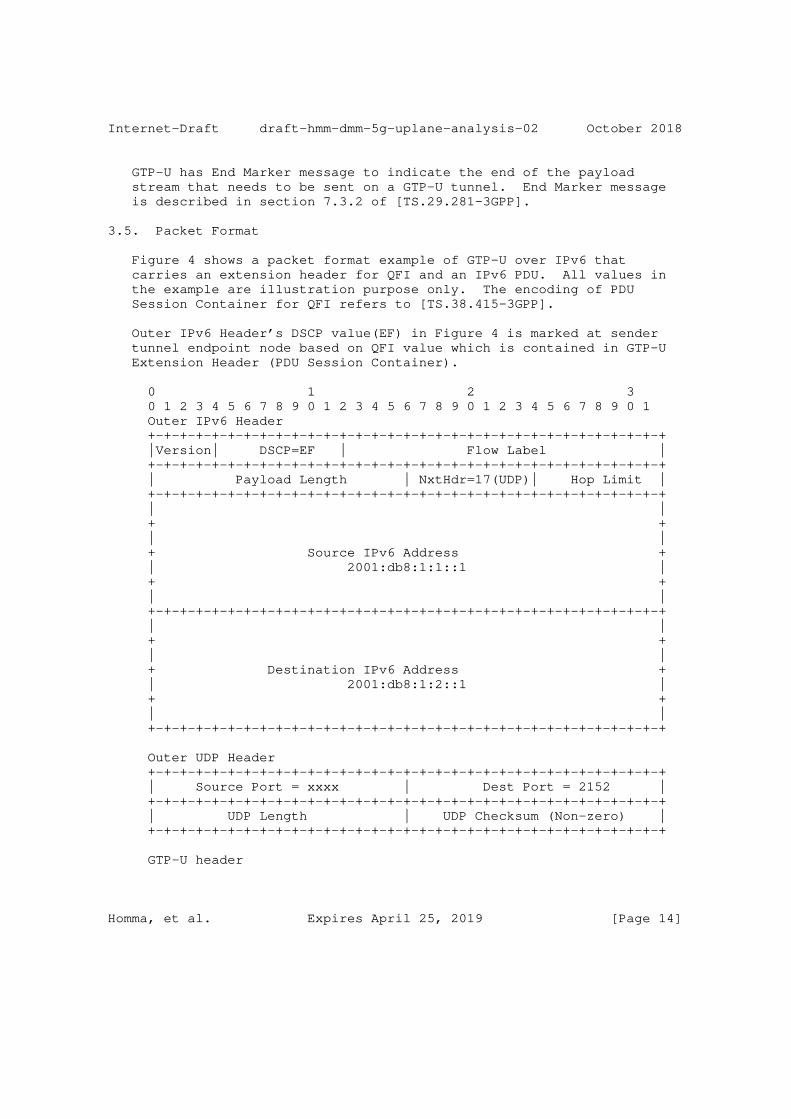
Internet-Draft draft-hmm-dmm-5g-uplane-analysis-02 October 2018
GTP-U has End Marker message to indicate the end of the payload stream that needs to be sent on a GTP-U tunnel. End Marker message is described in section 7.3.2 of [TS.29.281-3GPP].
3.5. Packet Format
Figure 4 shows a packet format example of GTP-U over IPv6 that carries an extension header for QFI and an IPv6 PDU. All values in the example are illustration purpose only. The encoding of PDU Session Container for QFI refers to [TS.38.415-3GPP].
Outer IPv6 Header’s DSCP value(EF) in Figure 4 is marked at sender tunnel endpoint node based on QFI value which is contained in GTP-U Extension Header (PDU Session Container).
0 1 2 3 0 1 2 3 4 5 6 7 8 9 0 1 2 3 4 5 6 7 8 9 0 1 2 3 4 5 6 7 8 9 0 1 Outer IPv6 Header +-+-+-+-+-+-+-+-+-+-+-+-+-+-+-+-+-+-+-+-+-+-+-+-+-+-+-+-+-+-+-+-+ |Version| DSCP=EF | Flow Label | +-+-+-+-+-+-+-+-+-+-+-+-+-+-+-+-+-+-+-+-+-+-+-+-+-+-+-+-+-+-+-+-+ | Payload Length | NxtHdr=17(UDP)| Hop Limit | +-+-+-+-+-+-+-+-+-+-+-+-+-+-+-+-+-+-+-+-+-+-+-+-+-+-+-+-+-+-+-+-+ | | + + | | + Source IPv6 Address + | 2001:db8:1:1::1 | + + | | +-+-+-+-+-+-+-+-+-+-+-+-+-+-+-+-+-+-+-+-+-+-+-+-+-+-+-+-+-+-+-+-+ | | + + | | + Destination IPv6 Address + | 2001:db8:1:2::1 | + + | | +-+-+-+-+-+-+-+-+-+-+-+-+-+-+-+-+-+-+-+-+-+-+-+-+-+-+-+-+-+-+-+-+
Outer UDP Header +-+-+-+-+-+-+-+-+-+-+-+-+-+-+-+-+-+-+-+-+-+-+-+-+-+-+-+-+-+-+-+-+ | Source Port = xxxx | Dest Port = 2152 | +-+-+-+-+-+-+-+-+-+-+-+-+-+-+-+-+-+-+-+-+-+-+-+-+-+-+-+-+-+-+-+-+ | UDP Length | UDP Checksum (Non-zero) | +-+-+-+-+-+-+-+-+-+-+-+-+-+-+-+-+-+-+-+-+-+-+-+-+-+-+-+-+-+-+-+-+
GTP-U header
Homma, et al. Expires April 25, 2019 [Page 14]

Internet-Draft draft-hmm-dmm-5g-uplane-analysis-02 October 2018
+-+-+-+-+-+-+-+-+-+-+-+-+-+-+-+-+-+-+-+-+-+-+-+-+-+-+-+-+-+-+-+-+ | 0x1 |1|0|1|0|0| 0xff | Length | +-+-+-+-+-+-+-+-+-+-+-+-+-+-+-+-+-+-+-+-+-+-+-+-+-+-+-+-+-+-+-+-+ | TEID = 1654 | +-+-+-+-+-+-+-+-+-+-+-+-+-+-+-+-+-+-+-+-+-+-+-+-+-+-+-+-+-+-+-+-+ | Sequence Number = 0 |N-PDU Number=0 |NextExtHdr=0x85| +-+-+-+-+-+-+-+-+-+-+-+-+-+-+-+-+-+-+-+-+-+-+-+-+-+-+-+-+-+-+-+-+
GTP-U Extension Header (PDU Session Container) +-+-+-+-+-+-+-+-+-+-+-+-+-+-+-+-+-+-+-+-+-+-+-+-+-+-+-+-+-+-+-+-+ | ExtHdrLen=2 |Type=0 | Spare |0|0| QFI | PPI | Spare | +-+-+-+-+-+-+-+-+-+-+-+-+-+-+-+-+-+-+-+-+-+-+-+-+-+-+-+-+-+-+-+-+ | Padding |NextExtHdr=0x0 | +-+-+-+-+-+-+-+-+-+-+-+-+-+-+-+-+-+-+-+-+-+-+-+-+-+-+-+-+-+-+-+-+
Inner IPv6 Header +-+-+-+-+-+-+-+-+-+-+-+-+-+-+-+-+-+-+-+-+-+-+-+-+-+-+-+-+-+-+-+-+ |Version| DSCP=0 | Flow Label | +-+-+-+-+-+-+-+-+-+-+-+-+-+-+-+-+-+-+-+-+-+-+-+-+-+-+-+-+-+-+-+-+ | Payload Length | NexttHdr | Hop Limit | +-+-+-+-+-+-+-+-+-+-+-+-+-+-+-+-+-+-+-+-+-+-+-+-+-+-+-+-+-+-+-+-+ | | + + | | + Source IPv6 Address + | 2001:db8:2:1::1 | + + | | +-+-+-+-+-+-+-+-+-+-+-+-+-+-+-+-+-+-+-+-+-+-+-+-+-+-+-+-+-+-+-+-+ | | + + | | + Destination IPv6 Address + | 2001:db8:3:1::1 | + + | | +-+-+-+-+-+-+-+-+-+-+-+-+-+-+-+-+-+-+-+-+-+-+-+-+-+-+-+-+-+-+-+-+
Payload +-+-+-+-+-+-+-+-+-+-+-+-+-+-+-+-+-+-+-+-+-+-+-+-+-+-+-+-+-+-+-+-+ | | | | . TCP/UDP/etc., Data . . . | | | | +-+-+-+-+-+-+-+-+-+-+-+-+-+-+-+-+-+-+-+-+-+-+-+-+-+-+-+-+-+-+-+-+
Homma, et al. Expires April 25, 2019 [Page 15]
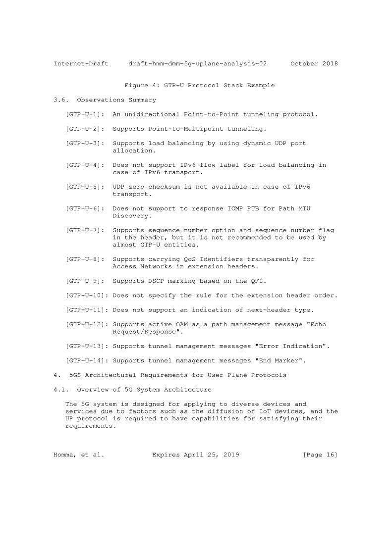
Internet-Draft draft-hmm-dmm-5g-uplane-analysis-02 October 2018
Figure 4: GTP-U Protocol Stack Example
3.6. Observations Summary
[GTP-U-1]: An unidirectional Point-to-Point tunneling protocol.
[GTP-U-2]: Supports Point-to-Multipoint tunneling.
[GTP-U-3]: Supports load balancing by using dynamic UDP port allocation.
[GTP-U-4]: Does not support IPv6 flow label for load balancing in case of IPv6 transport.
[GTP-U-5]: UDP zero checksum is not available in case of IPv6 transport.
[GTP-U-6]: Does not support to response ICMP PTB for Path MTU Discovery.
[GTP-U-7]: Supports sequence number option and sequence number flag in the header, but it is not recommended to be used by almost GTP-U entities.
[GTP-U-8]: Supports carrying QoS Identifiers transparently for Access Networks in extension headers.
[GTP-U-9]: Supports DSCP marking based on the QFI.
[GTP-U-10]: Does not specify the rule for the extension header order.
[GTP-U-11]: Does not support an indication of next-header type.
[GTP-U-12]: Supports active OAM as a path management message "Echo Request/Response".
[GTP-U-13]: Supports tunnel management messages "Error Indication".
[GTP-U-14]: Supports tunnel management messages "End Marker".
4. 5GS Architectural Requirements for User Plane Protocols
4.1. Overview of 5G System Architecture
The 5G system is designed for applying to diverse devices and services due to factors such as the diffusion of IoT devices, and the UP protocol is required to have capabilities for satisfying their requirements.
Homma, et al. Expires April 25, 2019 [Page 16]
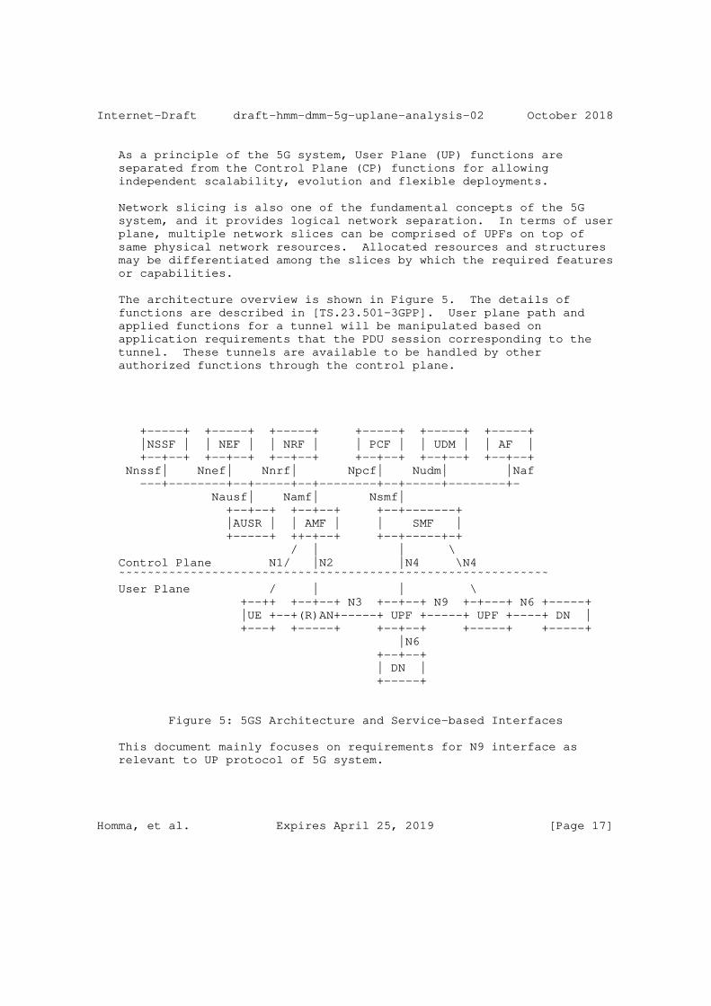
Internet-Draft draft-hmm-dmm-5g-uplane-analysis-02 October 2018
As a principle of the 5G system, User Plane (UP) functions are separated from the Control Plane (CP) functions for allowing independent scalability, evolution and flexible deployments.
Network slicing is also one of the fundamental concepts of the 5G system, and it provides logical network separation. In terms of user plane, multiple network slices can be comprised of UPFs on top of same physical network resources. Allocated resources and structures may be differentiated among the slices by which the required features or capabilities.
The architecture overview is shown in Figure 5. The details of functions are described in [TS.23.501-3GPP]. User plane path and applied functions for a tunnel will be manipulated based on application requirements that the PDU session corresponding to the tunnel. These tunnels are available to be handled by other authorized functions through the control plane.
+-----+ +-----+ +-----+ +-----+ +-----+ +-----+ |NSSF | | NEF | | NRF | | PCF | | UDM | | AF | +--+--+ +--+--+ +--+--+ +--+--+ +--+--+ +--+--+ Nnssf| Nnef| Nnrf| Npcf| Nudm| |Naf ---+--------+--+-----+--+--------+--+-----+--------+- Nausf| Namf| Nsmf| +--+--+ +--+--+ +--+-------+ |AUSR | | AMF | | SMF | +-----+ ++-+--+ +--+-----+-+ / | | \ Control Plane N1/ |N2 |N4 \N4 ˜˜˜˜˜˜˜˜˜˜˜˜˜˜˜˜˜˜˜˜˜˜˜˜˜˜˜˜˜˜˜˜˜˜˜˜˜˜˜˜˜˜˜˜˜˜˜˜˜˜˜˜˜˜˜˜˜˜˜˜ User Plane / | | \ +--++ +--+--+ N3 +--+--+ N9 +-+---+ N6 +-----+ |UE +--+(R)AN+-----+ UPF +-----+ UPF +----+ DN | +---+ +-----+ +--+--+ +-----+ +-----+ |N6 +--+--+ | DN | +-----+
Figure 5: 5GS Architecture and Service-based Interfaces
This document mainly focuses on requirements for N9 interface as relevant to UP protocol of 5G system.
Homma, et al. Expires April 25, 2019 [Page 17]
Internet-Draft draft-hmm-dmm-5g-uplane-analysis-02 October 2018
4.1.1. UPF Functionalities
UPF has a role to handle UP traffic, and provides functionalities to look up user data traffic and enforce the appropriate policies to it.
The followings are defined as UPF functionalities for traffic handling:
o User Plane part of policy rule enforcement, e.g. Gating, Redirection, Traffic steering)
o QoS handling for user plane, e.g. UL/DL rate enforcement, Reflective QoS marking in DL
o Transport level packet marking in the uplink and downlink
Other functionalities are described in the section 6.2.3 of [TS.23.501-3GPP]
UPF shall detect user plane traffic flow depending on information indicated by SMF. User data traffic is detected with combination of the following information:
o For IPv4 or IPv6 PDU Session type
* PDU Session
* QFI
* Application Identifier: The Application ID is an index to a set of application detection rules configured in UPF
o For Ethernet PDU Session type
* PDU Session
* QFI
* Ethernet Packet Filter Set:
+ Source/destination MAC address
+ Ethertype as defined in IEEE 802.3
+ Customer-VLAN tag(C-TAG) and/or Service-VLAN tag(S-TAG) VID fields as defined in IEEE 802.1Q
Homma, et al. Expires April 25, 2019 [Page 18]
Internet-Draft draft-hmm-dmm-5g-uplane-analysis-02 October 2018
+ Customer-VLAN tag(C-TAG) and/or Service-VLAN tag(S-TAG) PCP/ DEI fields as defined in IEEE 802.1Q
+ IP Packet Filter Set, in case Ethertype indicates IPv4/IPv6 payload
+ Packet filter direction
Such information for traffic detection (Traffic Detection Information) is described in the section 5.8.2.4 of [TS.23.501-3GPP].
4.2. Architectural Requirements for User Plane Protocols
This section lists the requirements for the UP protocol on the 5G system. The requirements are picked up from [TS.23.501-3GPP]. In addition, some of service requirements described in [TS.22.261-3GPP] are referred to clarify the originations of architectural requirements.
According to [TS.23.501-3GPP], the specifications potentially have assumptions that the UP protocol is a tunnel representing a single TEID between a pair of UPFs and it is corresponding to a single PDU session. In short, the UP protocol is a tunnel and it is assumed to be managed under per PDU session handling. Also, it should be a stateful tunnel in the UPFs along with the PDU session.
The requirements for UP protocols are described below:
ARCH-Req-1: Supporting IPv4, IPv6, Ethernet and Unstructured PDU
The 5G system defines four types of PDU session as IPv4, IPv6, Ethernet, and Unstructured. Therefore, UP protocol must support to convey all of these PDU session types. This is described in [TS.23.501-3GPP].
Note: In TS 23.501 v15.2.0, IPv4v6 is added as a PDU session type.
ARCH-Req-2: Supporting IP connectivity for N3, N6, and N9 interfaces
The 5G system requires IP connectivity for N3, N6, and N9 interfaces. The IP connectivity is assumed that it comprises of IP routing and L1/L2 transport networks which are outside of 3GPP specifications.
It is desirable that the IP connectivity built on IPv6 networks when it comes to address space for end-to-end user plane coverage. But it is expected to take certain time. During the IPv6 networks are not deployed for all the coverage, UP protocol should support RANs and
Homma, et al. Expires April 25, 2019 [Page 19]
Internet-Draft draft-hmm-dmm-5g-uplane-analysis-02 October 2018
DNs running on IPv4 transport connect to UPF running on IPv6 transport.
Furthermore, on N6 interface, point-to-point tunneling based on UDP/ IPv6 may be used to deliver unstructured PDU type data. Then, the content information of the PDU may be mapped into UDP port number, and the UDP port numbers is pre-configured in the UPF and DN. This is described in the section 9.2 of [TS.29.561-3GPP].
ARCH-Req-3: Supporting deployment of multiple UPFs as anchors for a single PDU session
The 5G system allows to deploy multiple UPFs as anchors for a single PDU session, and supports multihoming of a single PDU session for such anchor UPFs.
Multihoming is provided with Branching Point (BP) or Uplink Classifier (UL CL) which are functionalities of UPF. BP provides forwarding of UL traffic towards the different PDU Session Anchors based on the source IPv6 prefixes and merge of DL traffic to the UE. UL CL provides destination based multihoming for load balancing.
On UL side, multihoming of a single PDU session is achieved by a point-to-point (P2P) tunnel per anchor UPF. It means that multiple P2P paths are established from one source gNB or UPF to the multiple destination anchor UPFs for the PDU session.
On DL side, one single multipoint-to-point (MP2P) path exists from the anchor UPFs to the source gNB or UPF for the PDU session in this multihoming case. It means that the paths from the anchor UPFs are merged into just one tunnel state at the source gNB or UPF for the PDU session.
Multiple P2P paths on DL could also be used for multihoming. However it should be the multiple PDU sessions multihoming case where the destination gNB or UPF needs to maintain multiple tunnel states under the one PDU session to one UP tunnel architectural principle.
However, P2P tunneling could increase explosively the number of states in UPF as the anchor UPF/DN incremented to the PDU session. Thereby single PDU session multihoming with MP2P path should be a better option for multihoming in terms of reducing total number of tunnel states.
SSC mode 3 for session continuity in hand-over case uses a single PDU multihoming with BP to make sure make-before-break. It is described in the section 5.6.4 and 5.6.9 of [TS.23.501-3GPP].
Homma, et al. Expires April 25, 2019 [Page 20]

Internet-Draft draft-hmm-dmm-5g-uplane-analysis-02 October 2018
Multihoming is also assumed to be used for edge computing scenario. Edge computing enables some services to be hosted close to the UE’s access point of attachment, and achieves an efficient service delivery through the reduced end-to-end latency and load on the transport network. In edge computing, local user’s traffic is routed or steered to application in the local DN by UPF. This refers the section 5.13 of [TS.23.501-3GPP].
ARCH-Req-4: Supporting flexible UPF selection for PDU
The appropriate UPFs are selected for a PDU session based on parameters and information such as UPF’s dynamic load or UE location information. Examples of parameters and information are described in the section 6.3.3 of [TS.23.501-3GPP].
This means that its possible to make routing on user plane more efficient in the 5GS. For example, in case that UPFs are distributed geographically, decision of the destination UPF based on locations of end hosts (e.g., UE or NF in DN) enables to forward PDUs with a route connecting between UPFs nearby the hosts directly.
The 5GS allows operators to select parameters used for UPF selection. (In other words, any specific schems on UPF selection are not defined in the current 3GPP documents.)
ARCH-Req-5: No limitation for number of UPFs in a data path
The number of UPF in the data path is not constrained by 3GPP specifications. This specification is described in the section 8.3.1 of [TS.23.501-3GPP].
Putting multiple UPFs, which provides specific function, in a data path enables flexible function deployment to make sure load distribution optimizations, etc.
In addition, deployment of multiple UPFs as anchors closed to UEs’ site and connecting them without extra anchor points enable to make data path more efficient. This usage is described in the section 6.5 of [TS.22.261-3GPP].
Meanwhile, each UPF in a data path shall be controlled by an SMF via N4 interface. Thus putting an excess of UPF for data paths might cause increase of load of an SMF. Pragmatically, the number of UPF put in a data path is one or two (e.g., for MEC or roaming cases), and, at most, it would be three (e.g., for case where UE moves during a session).
Homma, et al. Expires April 25, 2019 [Page 21]
Internet-Draft draft-hmm-dmm-5g-uplane-analysis-02 October 2018
It is expected that multiple UPFs with per session tunnel handling for a PDU session becomes complicated task more and more for a SMF by increasing number of UPFs, and UP protocol shall support to aggregate several PDU sessions into a tunnel or shall be a session-less tunnel.
ARCH-Req-6: Supporting aggregation of multiple QoS Flow indicated with QFI into a PDU Session
Against to the previous generation, 5G enables UPF to multiplex QoS Flows, equivalent with IP-CAN bearers in the previous generation, into one single PDU session. That means that a single tunnel includes multiple QFIs contrast to just one QoS Flow (a bearer) to one tunnel before 5G.
In even the 5GS, each flow is forwarded based on the appropriate QoS rules. QoS rules are configured by SMF as QoS profiles to UP compoents and these components perform QoS controls to PDUs based on rules. In downlink, a UPF pushes QFI into an extension header, and transmits the PDU to RAN or another UPF. Then, such UPF may perform transport level QoS packet marking (e.g., DSCP marking in the outer header). In uplink, each UE obtains the QoS rule from SMF, and transmit PDUs with QFI containing the QoS rules to the RAN. The following RAN and UPFs perform enforcement of QoS control and charging based on the QFI.
This specification is described in 5.7.1 of [TS.23.501-3GPP].
ARCH-Req-7: Supporting network slicing
The 5GS fundamentally supports network slicing for provision the appropriate end-to-end communication to various services. In the relevant documents (e.g., [TS.23.501-3GPP], [TS.28.531-3GPP]), a network slice is defined as virtual network and it is structured with SMF, RANs, UPFs and DNs. Each network slice is independent and its user plane (including network functions and links) should be noninteractive against the others.
Note that 3GPP focuses on only mobility management and specifications to synchronize with other networks including transport networks is not clearly defined.
5. Evaluation Aspects
This section provides UP protocol evaluation aspects that are mainly we derived from the architectural requirements described in Section 4. Those aspects are not prioritized by the order here. Expected deployment scenarios explain the evaluations purpose in the corresponding aspects.
Homma, et al. Expires April 25, 2019 [Page 22]
Internet-Draft draft-hmm-dmm-5g-uplane-analysis-02 October 2018
As we were noticed that the gaps between GTP-U specifications and 5G architectural requirements through the analysis, those each gap are briefly described in the evaluation aspect associated to it.
Since it is obvious that 5G system should be able to interwork with existing previous generation based systems, any aspects from coexisting and interworking point of view are not particularly articulated here. It may be described in a next version.
5.1. Supporting PDU Session Type Variations
Given that UP protocol is required to support all PDU session types: IPv4, IPv6, Ethernet, and Unstructured. However, it is expected that some deployment cases allow candidate protocol to adopt only one or few PDU session type(s) for simplicity of operations. As we can expect that IPv4 connectivity services will be available through IPv6-only PDU session that enabled by bunch of IPv6 transition solutions already available in the field.
For this, the expected evaluation points from this aspect should be whether there is substitutional means to cover other PDU session types. And how much it makes simple the system than deploying original PDU session types.
5.2. Nature of Data Path
As it is described in Section 4.2, the single PDU session multi- homing case requires multipoint-to-point (MP2P) data path. It should be much scalable than multi-homing with multiple PDU sessions because number of required path states in the UPFs are reduced as closed to egress endpoint. Against that point-to-point (P2P) protocol requires same number of states in each UPF throughout the path.
From this point of view, the expected evaluation points from this aspect is whether the nature of candidate UP protocols are to utilize MP2P data path. Supporting MP2P data path by GTP-U could be a gap since GTP-U is a point-to-point tunneling protocol as it is described in Section 3.
Noted that 3GPP CT WG4 pointed out GTP-U was already required to allow one single tunnel endpoint to receive packets from multiple source endpoints ([C4-185491-3GPP]). It was an architectural requirement of 3GPP system from a previous generation. It means that MP2P data path requirement for UP protocol has been existed before the 5G system.
Homma, et al. Expires April 25, 2019 [Page 23]
Internet-Draft draft-hmm-dmm-5g-uplane-analysis-02 October 2018
5.3. Supporting Transport Variations
The 5G system will be expected that the new radio spectrums in high frequency bands require operators to deploy their base stations much dense for much wider areas compare to previous generation footprints. To make sure that density and coverage, all available types of transport in the field must be employed between RAN to UPF, or UPF to UPF.
It is also expected that MTU size of each transport could be varied. Because one could be own fiber which the operator configure the MTU size as they like while others are third-party provided L2/L3 VPN lines which MTU size can’t be controlled by the operators.
The MTU between RAN and UPF can be discovered by offline means and the operator takes into account the MTU that is transferable on the radio interface and based on this the operator configures the right MTU to be used. That is then signaled to the UE either via PCO (for IPv4 case) or the IPv6 RA message (for IPv6 case).
In addition, for cases that third-parties provide VPN lines, it would be recommended MTU size discovery for each data path and dynamic MTU size adjustment mechanisms, while GTP-U does not support those mechanisms.
As the study item in 3GPP mentioned, IPv6 is preferable address family not only for UEs, but also for the UP transport, in terms of size of available address space to support dense and wide footprint of base stations. However it increases header size from 20bytes to 40bytes compare to IPv4. It could be a problem if the MTU size is uncontrollable, or only limited MTU size available to carry committed PDU size on the user plane.
The expected evaluation points from this aspect should be that the candidate protocols are able to dynamically adjust path MTU size with appropriate MTU size discovery mechanism. It also should be that how the candidate protocols leverage IPv6 to deal with header size increasing.
5.4. Data Path Management
As Section 4.2 described, the 5G systems allows user plane that flexible UPF selection, multiple anchor UPFs, and no limit on how many UPFs chained for the data path of the PDU session. UPF deployments in the field will thereby be distributed to be able to optimize the data path based on various logics and service scenarios.
Homma, et al. Expires April 25, 2019 [Page 24]
Internet-Draft draft-hmm-dmm-5g-uplane-analysis-02 October 2018
That powerful user plane capability could affect data path management complicated and difficult to be managed through the control plane, or operation support systems (OSS). Perhaps it could be the case where the UP protocol nature is P2P and it only supports per session base data path handling.
Because it increases data path states by number of sessions, and number of endpoints of UPFs that makes data path handling much hectic and the control plane tend to be overloaded by not only usual attach/detach/hand-over operations, but also existing session manipulation triggered by UPF and transport nodes/paths restoration, etc.,
The expected evaluation points from this aspect should be that how much the candidate protocols can reduce data path management loads both on the control plane NFs and UPFs compare to the per session based handling for P2P paths. It could possibly include N3 and N6 in addition to N9 while it supports flexible user plane data path optimizations for some example scenarios.
5.5. QoS Control
The QoS model is based on QoS flows to which QFI indicates in the 5G system that allows multiple QoS flows are aggregated into a single PDU session. So that it is given that the UP protocol should convey QFIs for a PDU session and the UPF needs to lookup them. It makes sure that reflects QoS policy in the 5G system to corresponding forwarding policy in the user plane IP transports.
The expected evaluation points from this aspect should be whether the candidate protocols can provide stable ID space for QFI which shouldn’t be a big deal since QFI just requires 6-bits space.
As we pointed out in Section 3.2, the lookup process could impact UPF performance if the QFI container position in the header is unpredictable. It could happen many times along the path because the each UPFs should do it again and again in case that various different QoS policies are deployed in the networks under the UP as we discussed in Section 5.3.
As [TS.29.281-3GPP] updated in version 15.3.0, it is recommended that the first extension header is the PDU session container in which QFI is present.
Homma, et al. Expires April 25, 2019 [Page 25]
Internet-Draft draft-hmm-dmm-5g-uplane-analysis-02 October 2018
5.6. Traffic Detection and Flow Handling
As described in Section 4.1.1, UPF need to detect traffic flow specified by SMF within a PDU session, and enforce some processes to the PDU based on the pre-configured policy rule.
As similar with QoS flow lookup described in Section 5.5, UPFs along the path are repeatedly detecting an specified traffic flow in inner PDU. It could increase redundant flow detection load on every UPFs that could be avoided if the upstream UPF put some identifier which abstracts the detected flow into the packets. It enables following UPFs just find the ID to detect the indicated flow from the packet.
The expected evaluation points from this aspect should be whether the candidate protocols can provide means to reduce that redundant flow detection that could be enough bits space on stable ID space to put abstracted detected flow identifier.
5.7. Supporting Network Slicing Diversity
To embody network slicing, it is expected that various means should be available in case by case, or operator by operator, for their 5G systems while it follows the fundamental slicing concept, as described in Section 4.1.
As [TS.28.530-3GPP] described in section 4, UP underlay transport networks and UPFs are shared by network slices. The data model defined in [TS.29.510-3GPP] allows that a Network Instance, a UPF and its interfaces can belong to multiple slices as same as other type of NFs. UP endpoint IP prefix/address of an interface can also be shared with multiple interfaces on the UPF as the model doesn’t make them slice unique.
The assumed slice operation in 5G architecture is that UPFs connect to each other through direct (virtual) link as Section 4.1 describes that UPFs compose a network slice on an UP. So IP routing and transport system underneath the UP are not visible from the 5G system. However some means need to indicate a slice on the shared underlying networks of the UP over the wire.
That’s just one way for network slicing, but it would help to reduce the operational burden. Even it depends on each operator’s policy, sharing network instances, UPFs, and the interfaces among slices makes operators relax and not to be much hustled on slice lifecycle management., such as create, update, and delete operations for slices.
Homma, et al. Expires April 25, 2019 [Page 26]
Internet-Draft draft-hmm-dmm-5g-uplane-analysis-02 October 2018
By the way, the 3GPP specifications for slice lifecycle managements is described in the relevant documents: [TS.28.531-3GPP], [TS.28.532-3GPP], and [TS.28.533-3GPP].
It could also make sense in case that each network slice requires different forwarding policies in the middle of the path. Some identifier in the packets for a slice could be a glue between UP path and its underlying transport networks. For example, if a slice requires certain level of latency with dedicated route, traffic engineering (TE) embodies appropriate forwarding policy through the underlay transport network.
The expected evaluation points from this aspect should be whether the candidate protocols can support to indicate a network slice in the UP packets that could be enough bits space on stable ID space to put slice identifier for the slice, or the forwarding policy within the slice. Since 5G control plane is not designed to handle transport resources, such as VLAN, MPLS Label, Tunnel ID except GTP-U, less impact to the control plane protocol and the APIs should be much preferable.
6. Conclusion
We analyzed the 3GPP specifications of the 5G architecture in terms of user plane and the current protocol adopted to the user plane. After the analysis work, we believe that the results described in this document shows that we reach at certain level of understanding on the 5G systems and ready to provide our inputs to 3GPP.
We clarified GTP-U through the analysis and listed observed characteristics in Section 3.6. We also clarified the architectural requirements for UP protocol described in Section 4.2.
As we identified some potential gaps between the current UP protocol and the architectural requirements even for Release 15, it is worth to study possible candidate UP protocols for the 5G system including current one. Our conclusion here is that we suggest the UP protocol study work in 3GPP takes into account the evaluation aspects described in Section 5.
7. Security Consideration
TBD
Homma, et al. Expires April 25, 2019 [Page 27]

Internet-Draft draft-hmm-dmm-5g-uplane-analysis-02 October 2018
8. Acknowledgement
The authors would like to thank Tom Herbert, Takashi Ito, John Leddy, Pablo Camarillo, Daisuke Yokota, Satoshi Watanabe, Koji Tsubouchi and Miya Kohno for their detailed reviews, comments, and contributions.
A special thank you goes to Arashmid Akhavain for his technical review and feedback.
Lastly, the authors would like to thank 3GPP CT WG4 folks for their review and feedback.
9. Informative References
[C4-185491-3GPP] 3rd Generation Partnership Project (3GPP), "LS OUT on User Plane Analysis", July 2018, <http://www.3gpp.org/ftp/tsg_ct/WG4_protocollars_ex- CN4/TSGCT4_85bis_Sophia_Antipolis/Docs/C4-185491.zip>.
[CP-173160-3GPP] 3rd Generation Partnership Project (3GPP), "New Study Item on User Plane Protocol in 5GC", December 2017, <http://www.3gpp.org/ftp/tsg_ct/TSG_CT/TSGC_78_Lisbon/ Docs/CP-173160.zip>.
[CP-180116-3GPP] 3rd Generation Partnership Project (3GPP), "LS on user plane protocol study", March 2018, <http://www.3gpp.org/ftp/tsg_ct/TSG_CT/TSGC_79_Chennai/ Docs/CP-180116.zip>.
[I-D.bogineni-dmm-optimized-mobile-user-plane] Bogineni, K., Akhavain, A., Herbert, T., Farinacci, D., Rodriguez-Natal, A., Carofiglio, G., Auge, J., Muscariello, L., Camarillo, P., and S. Homma, "Optimized Mobile User Plane Solutions for 5G", draft-bogineni-dmm- optimized-mobile-user-plane-01 (work in progress), June 2018.
[IAB-Statement] Internet Architecture Board (IAB), "IAB Statement on IPv6", November 2016, <https://www.iab.org/2016/11/07/iab-statement-on-ipv6/>.
[RFC2460] Deering, S. and R. Hinden, "Internet Protocol, Version 6 (IPv6) Specification", RFC 2460, DOI 10.17487/RFC2460, December 1998, <https://www.rfc-editor.org/info/rfc2460>.
Homma, et al. Expires April 25, 2019 [Page 28]
Internet-Draft draft-hmm-dmm-5g-uplane-analysis-02 October 2018
[RFC4861] Narten, T., Nordmark, E., Simpson, W., and H. Soliman, "Neighbor Discovery for IP version 6 (IPv6)", RFC 4861, DOI 10.17487/RFC4861, September 2007, <https://www.rfc-editor.org/info/rfc4861>.
[RFC6437] Amante, S., Carpenter, B., Jiang, S., and J. Rajahalme, "IPv6 Flow Label Specification", RFC 6437, DOI 10.17487/RFC6437, November 2011, <https://www.rfc-editor.org/info/rfc6437>.
[RFC6438] Carpenter, B. and S. Amante, "Using the IPv6 Flow Label for Equal Cost Multipath Routing and Link Aggregation in Tunnels", RFC 6438, DOI 10.17487/RFC6438, November 2011, <https://www.rfc-editor.org/info/rfc6438>.
[RFC6935] Eubanks, M., Chimento, P., and M. Westerlund, "IPv6 and UDP Checksums for Tunneled Packets", RFC 6935, DOI 10.17487/RFC6935, April 2013, <https://www.rfc-editor.org/info/rfc6935>.
[RFC8200] Deering, S. and R. Hinden, "Internet Protocol, Version 6 (IPv6) Specification", STD 86, RFC 8200, DOI 10.17487/RFC8200, July 2017, <https://www.rfc-editor.org/info/rfc8200>.
[TR.29.891-3GPP] 3rd Generation Partnership Project (3GPP), "3GPP TR 29.891 (V15.0.0): 5G System Phase 1, CT WG4 Aspects", December 2017, <http://www.3gpp.org/FTP/Specs/2017-12/ Rel-15/29_series/29891-f00.zip>.
[TS.22.261-3GPP] 3rd Generation Partnership Project (3GPP), "3GPP TS 22.261 (V15.4.0): Service requirements for 5G system stage 1", March 2018, <http://www.3gpp.org/FTP/Specs/2018-03/ Rel-15/22_series/22261-f40.zip>.
[TS.23.060-3GPP] 3rd Generation Partnership Project (3GPP), "3GPP TS 23.060 (V15.3.0): General Packet Radio Service (GPRS); Service description; Stage 2", June 2018, <http://www.3gpp.org/ftp//Specs/ archive/23_series/23.060/23060-f30.zip>.
Homma, et al. Expires April 25, 2019 [Page 29]
Internet-Draft draft-hmm-dmm-5g-uplane-analysis-02 October 2018
[TS.23.501-3GPP] 3rd Generation Partnership Project (3GPP), "3GPP TS 23.501 (V15.3.0): System Architecture for 5G System; Stage 2", September 2018, <http://www.3gpp.org/ftp//Specs/ archive/23_series/23.501/23501-f30.zip>.
[TS.23.502-3GPP] 3rd Generation Partnership Project (3GPP), "3GPP TS 23.502 (V15.1.0): Procedures for 5G System; Stage 2", March 2018, <http://www.3gpp.org/FTP/Specs/2018-03/ Rel-15/23_series/23502-f10.zip>.
[TS.23.503-3GPP] 3rd Generation Partnership Project (3GPP), "3GPP TS 23.503 (V15.1.0): Policy and Charging Control System for 5G Framework; Stage 2", March 2018, <http://www.3gpp.org/FTP/ Specs/2018-03/Rel-15/23_series/23503-f10.zip>.
[TS.28.530-3GPP] 3rd Generation Partnership Project (3GPP), "3GPP TS 28.530 (V1.0.0): Management and orchestration of networks and network slicing; Concepts, use cases and requirements (work in progress)", June 2018, <http://ftp.3gpp.org//Specs/ archive/28_series/28.530/28530-100.zip>.
[TS.28.531-3GPP] 3rd Generation Partnership Project (3GPP), "3GPP TS 28.531 (V1.0.0): Management and orchestration of networks and network slicing; Provisioning; Stage 1 (Release 15)", June 2018, <http://ftp.3gpp.org//Specs/ archive/28_series/28.531/28531-100.zip>.
[TS.28.532-3GPP] 3rd Generation Partnership Project (3GPP), "3GPP TS 28.532 (V0.3.0): Management and orchestration of networks and network slicing; Provisioning; Stage 2 and stage 3 (Release 15)", June 2018, <http://www.3gpp.org/ftp//Specs/ archive/28_series/28.532/28532-030.zip>.
[TS.28.533-3GPP] 3rd Generation Partnership Project (3GPP), "3GPP TS 28.533 (V0.3.0): Management and orchestration of networks and network slicing; Management and orchestration architecture (Release 15)", June 2018, <http://www.3gpp.org/ftp//Specs/ archive/28_series/28.533/28533-030.zip>.
Homma, et al. Expires April 25, 2019 [Page 30]
Internet-Draft draft-hmm-dmm-5g-uplane-analysis-02 October 2018
[TS.29.244-3GPP] 3rd Generation Partnership Project (3GPP), "3GPP TS 29.244 (V15.1.0): Interface between the Control Plane and the User Plane Nodes; Stage 3", March 2018, <http://www.3gpp.org/FTP/Specs/2018-03/ Rel-15/29_series/29244-f10.zip>.
[TS.29.274-3GPP] 3rd Generation Partnership Project (3GPP), "3GPP TS 29.274 (V15.4.0): 3GPP Evolved Packet System (EPS); Evolved General Packet Radio Service (GPRS) Tunneling Protocol for Control plane (GTPv2-C); Stage 3", June 2018, <http://www.3gpp.org/ftp//Specs/ archive/29_series/29.274/29274-f40.zip>.
[TS.29.281-3GPP] 3rd Generation Partnership Project (3GPP), "3GPP TS 29.281 (V15.4.0): GPRS Tunneling Protocol User Plane (GTPv1-U)", September 2018, <http://www.3gpp.org/ftp//Specs/ archive/29_series/29.281/29281-f40.zip>.
[TS.29.510-3GPP] 3rd Generation Partnership Project (3GPP), "3GPP TS 29.510 (V15.0.0): 5G System; Network Function Repository Services; Stage 3", June 2018, <http://www.3gpp.org/FTP/ Specs/2018-06/Rel-15/29_series/29510-f00.zip>.
[TS.29.561-3GPP] 3rd Generation Partnership Project (3GPP), "3GPP TS 29.561 (V15.0.0): 5G System; Interworking between 5G Network and external Data Networks; Stage 3", June 2018, <http://www.3gpp.org/FTP/Specs/2018-06/ Rel-15/29_series/29561-f00.zip>.
[TS.38.300-3GPP] 3rd Generation Partnership Project (3GPP), "3GPP TS 38.300 (v15.1.0): NR and NG-RAN Overall Description; Stage 2", March 2018, <http://www.3gpp.org/FTP/Specs/2018-03/ Rel-15/38_series/38300-f10.zip>.
[TS.38.401-3GPP] 3rd Generation Partnership Project (3GPP), "3GPP TS 38.401 (v15.1.0): NG-RAN; Architecture Description", March 2018, <http://www.3gpp.org/FTP/Specs/2018-03/ Rel-15/38_series/38401-f10.zip>.
Homma, et al. Expires April 25, 2019 [Page 31]
Internet-Draft draft-hmm-dmm-5g-uplane-analysis-02 October 2018
[TS.38.415-3GPP] 3rd Generation Partnership Project (3GPP), "3GPP TS 38.415 (v15.1.0): NG-RAN; PDU Session User Plane protocol", September 2018, <http://www.3gpp.org/ftp//Specs/ archive/38_series/38.415/38415-f10.zip>.
Authors’ Addresses
Shunsuke Homma NTT
Email: [email protected]
Takuya Miyasaka KDDI Research
Email: [email protected]
Satoru Matsushima SoftBank
Email: [email protected]
Daniel Voyer Bell Canada
Email: [email protected]
Homma, et al. Expires April 25, 2019 [Page 32]
DMM H. Chan, Ed.Internet-Draft X. WeiIntended status: Informational Huawei TechnologiesExpires: September 8, 2020 J. Lee Sangmyung University S. Jeon Sungkyunkwan University CJ. Bernardos, Ed. UC3M March 7, 2020
Distributed Mobility Anchoring draft-ietf-dmm-distributed-mobility-anchoring-15
Abstract
This document defines distributed mobility anchoring in terms of the different configurations and functions to provide IP mobility support. A network may be configured with distributed mobility anchoring functions for both network-based or host-based mobility support according to the needs of mobility support. In a distributed mobility anchoring environment, multiple anchors are available for mid-session switching of an IP prefix anchor. To start a new flow or to handle a flow not requiring IP session continuity as a mobile node moves to a new network, the flow can be started or re-started using an IP address configured from the new IP prefix anchored to the new network. If the flow needs to survive the change of network, there are solutions that can be used to enable IP address mobility. This document describes different anchoring approaches, depending on the IP mobility needs, and how this IP address mobility is handled by the network.
Status of This Memo
This Internet-Draft is submitted in full conformance with the provisions of BCP 78 and BCP 79.
Internet-Drafts are working documents of the Internet Engineering Task Force (IETF). Note that other groups may also distribute working documents as Internet-Drafts. The list of current Internet- Drafts is at https://datatracker.ietf.org/drafts/current/.
Internet-Drafts are draft documents valid for a maximum of six months and may be updated, replaced, or obsoleted by other documents at any time. It is inappropriate to use Internet-Drafts as reference material or to cite them other than as "work in progress."
Chan, et al. Expires September 8, 2020 [Page 1]
Internet-Draft distributed mobility anchoring March 2020
This Internet-Draft will expire on September 8, 2020.
Copyright Notice
Copyright (c) 2020 IETF Trust and the persons identified as the document authors. All rights reserved.
This document is subject to BCP 78 and the IETF Trust’s Legal Provisions Relating to IETF Documents (https://trustee.ietf.org/license-info) in effect on the date of publication of this document. Please review these documents carefully, as they describe your rights and restrictions with respect to this document. Code Components extracted from this document must include Simplified BSD License text as described in Section 4.e of the Trust Legal Provisions and are provided without warranty as described in the Simplified BSD License.
Table of Contents
1. Introduction . . . . . . . . . . . . . . . . . . . . . . . . 2 2. Conventions and Terminology . . . . . . . . . . . . . . . . . 3 3. Distributed Mobility Anchoring . . . . . . . . . . . . . . . 6 3.1. Configurations for Different Networks . . . . . . . . . . 6 3.1.1. Network-based DMM . . . . . . . . . . . . . . . . . . 7 3.1.2. Client-based DMM . . . . . . . . . . . . . . . . . . 8 4. IP Mobility Handling in Distributed Anchoring Environments - Mobility Support Only When Needed . . . . . . . . . . . . . . 9 4.1. Nomadic case (no need of IP mobility): Changing to new IP prefix/address . . . . . . . . . . . . . . . . . . . . . 10 4.2. Mobility case, traffic redirection . . . . . . . . . . . 12 4.3. Mobility case, anchor relocation . . . . . . . . . . . . 15 5. Security Considerations . . . . . . . . . . . . . . . . . . . 16 6. IANA Considerations . . . . . . . . . . . . . . . . . . . . . 17 7. Contributors . . . . . . . . . . . . . . . . . . . . . . . . 17 8. References . . . . . . . . . . . . . . . . . . . . . . . . . 18 8.1. Normative References . . . . . . . . . . . . . . . . . . 18 8.2. Informative References . . . . . . . . . . . . . . . . . 19 Authors’ Addresses . . . . . . . . . . . . . . . . . . . . . . . 20
1. Introduction
A key requirement in distributed mobility management [RFC7333] is to enable traffic to avoid traversing a single mobility anchor far from an optimal route. This document defines different configurations, functional operations and parameters for distributed mobility anchoring and explains how to use them to avoid unnecessarily long routes when a mobile node moves.
Chan, et al. Expires September 8, 2020 [Page 2]
Internet-Draft distributed mobility anchoring March 2020
Companion distributed mobility management documents are already addressing source address selection [RFC8653], and control-plane data-plane signaling [I-D.ietf-dmm-fpc-cpdp]. A number of distributed mobility solutions have also been proposed, for example, in [I-D.seite-dmm-dma], [I-D.ietf-dmm-pmipv6-dlif], [I-D.sarikaya-dmm-for-wifi], [I-D.yhkim-dmm-enhanced-anchoring], and [I-D.matsushima-stateless-uplane-vepc].
Distributed mobility anchoring employs multiple anchors in the data plane. In general, control plane functions may be separated from data plane functions and be centralized but may also be co-located with the data plane functions at the distributed anchors. Different configurations of distributed mobility anchoring are described in Section 3.1.
As a Mobile Node (MN) attaches to an access router and establishes a link between them, a /64 IPv6 prefix anchored to the router may be assigned to the link for exclusive use by the MN [RFC6459]. The MN may then configure a global IPv6 address from this prefix and use it as the source IP address in a flow to communicate with its Correspondent Node (CN). When there are multiple mobility anchors assigned to the same MN, an address selection for a given flow is first required before the flow is initiated. Using an anchor in a MN’s network of attachment has the advantage that the packets can simply be forwarded according to the forwarding table. However, after the flow has been initiated, the MN may later move to another network which assigns a new mobility anchor to the MN. Since the new anchor is located in a different network, the MN’s assigned prefix does not belong to the network where the MN is currently attached.
When the MN wants to continue using its assigned prefix to complete ongoing data sessions after it has moved to a new network, the network needs to provide support for the MN’s IP address and session continuity, since routing packets to the MN through the new network deviates from applying default routes. The IP session continuity needs of a flow (application) determines how the IP address used by this flow has to be anchored. If the ongoing IP flow can cope with an IP prefix/address change, the flow can be reinitiated with a new IP address anchored in the new network. On the other hand, if the ongoing IP flow cannot cope with such change, mobility support is needed. A network supporting a mix of flows both requiring and not requiring IP mobility support will need to distinguish these flows.
2. Conventions and Terminology
The key words "MUST", "MUST NOT", "REQUIRED", "SHALL", "SHALL NOT", "SHOULD", "SHOULD NOT", "RECOMMENDED", "NOT RECOMMENDED", "MAY", and "OPTIONAL" in this document are to be interpreted as described in BCP
Chan, et al. Expires September 8, 2020 [Page 3]
Internet-Draft distributed mobility anchoring March 2020
14 [RFC2119] [RFC8174] when, and only when, they appear in all capitals, as shown here.
All general mobility-related terms and their acronyms used in this document are to be interpreted as defined in the Mobile IPv6 (MIPv6) base specification [RFC6275], the Proxy Mobile IPv6 (PMIPv6) specification [RFC5213], the "Mobility Related Terminologies" [RFC3753], and the DMM current practices and gap analysis [RFC7429]. These include terms such as Mobile Node (MN), Correspondent Node (CN), Home Agent (HA), Home Address (HoA), Care-of-Address (CoA), Local Mobility Anchor (LMA), and Mobile Access Gateway (MAG).
In addition, this document uses the following terms and definitions:
IP session continuity: The ability to maintain an ongoing transport interaction by keeping the same local endpoint IP address throughout the lifetime of the IP socket despite the mobile host changing its point of attachment within the IP network topology. The IP address of the host may change after closing the IP socket and before opening a new one, but that does not jeopardize the ability of applications using these IP sockets to work flawlessly. Session continuity is essential for mobile hosts to maintain ongoing flows without any interruption [RFC8653].
Higher layer session continuity: The ability to maintain an ongoing transport or higher layer (e.g., application) interaction by keeping the session indentifiers throughout the lifetime of the session despite the mobile host changing its point of attachment within the IP network topology. This can be achieved by using mechanisms at the transport or higher layers.
IP address reachability: The ability to maintain the same IP address for an extended period of time. The IP address stays the same across independent sessions, even in the absence of any session. The IP address may be published in a long-term registry (e.g., DNS) and is made available for serving incoming (e.g., TCP) connections. IP address reachability is essential for mobile hosts to use specific/published IP addresses [RFC8653].
IP mobility: Combination of IP address reachability and session continuity.
Home network of a home address: the network that has assigned the HoA used as the session identifier by the application running in
Chan, et al. Expires September 8, 2020 [Page 4]
Internet-Draft distributed mobility anchoring March 2020
an MN. The MN may be running multiple application sessions, and each of these sessions can have a different home network.
Anchoring (of an IP prefix/address): An IP prefix, i.e., Home Network Prefix (HNP), or address, i.e., HoA, assigned for use by an MN is topologically anchored to an anchor node when the anchor node is able to advertise a route into the routing infrastructure for the assigned IP prefix. The traffic using the assigned IP address/prefix must traverse the anchor node. We can refer to the function performed by IP anchor node as anchoring, which is a data plane function.
Location Management (LM) function: control plane function that keeps and manages the network location information of an MN. The location information may be a binding of the advertised IP address/prefix, e.g., HoA or HNP, to the IP routing address of the MN or of a node that can forward packets destined to the MN.
When the MN is a Mobile Router (MR), the location information will also include the Mobile Network Prefix (MNP), which is the aggregate IP prefix delegated to the MR to assign IP prefixes for use by the Mobile Network Nodes (MNNs) in the mobile network.
In a client-server protocol model, secure (i.e., authenticated and authorized) location query and update messages may be exchanged between a Location Management client (LMc) and a Location Management server (LMs), where the location information can be updated or queried from the LMc. Optionally, there may be a Location Management proxy (LMp) between LMc and LMs.
With separation of control plane and data plane, the LM function is in the control plane. It may be a logical function at the control plane node, control plane anchor, or mobility controller.
It may be distributed or centralized.
Forwarding Management (FM) function: packet interception and forwarding to/from the IP address/prefix assigned for use by the MN, based on the internetwork location information, either to the destination or to some other network element that knows how to forward the packets to their destination.
This function may be used to achieve traffic indirection. With separation of control plane and data plane, the FM function may
Chan, et al. Expires September 8, 2020 [Page 5]

Internet-Draft distributed mobility anchoring March 2020
split into a FM function in the data plane (FM-DP) and a FM function in the control plane (FM-CP).
FM-DP may be distributed with distributed mobility management. It may be a function in a data plane anchor or data plane node.
FM-CP may be distributed or centralized. It may be a function in a control plane node, control plane anchor or mobility controller.
Home Control-Plane Anchor (Home-CPA or H-CPA): The Home-CPA function hosts the mobile node (MN)’s mobility session. There can be more than one mobility session for a mobile node and those sessions may be anchored on the same or different Home-CPA’s. The home-CPA will interface with the home-DPA for managing the forwarding state.
Home Data Plane Anchor (Home-DPA or H-DPA): The Home-DPA is the topological anchor for the MN’s IP address/ prefix(es). The Home- DPA is chosen by the Home-CPA on a session- basis. The Home-DPA is in the forwarding path for all the mobile node’s IP traffic.
Access Control Plane Node (Access-CPN or A-CPN): The Access-CPN is responsible for interfacing with the mobile node’s Home-CPA and with the Access-DPN. The Access-CPN has a protocol interface to the Home-CPA.
Access Data Plane Node (Access-DPN or A-DPN): The Access-DPN function is hosted on the first-hop router where the mobile node is attached. This function is not hosted on a layer-2 bridging device such as a eNode(B) or Access Point.
3. Distributed Mobility Anchoring
3.1. Configurations for Different Networks
We next describe some configurations with multiple distributed anchors. To cover the widest possible spectrum of scenarios, we consider architectures in which the control and data planes are separated. We analyze where LM and FM functions -- which are specific sub-functions involved in mobility management -- can be placed when looking at the different scenarios with distributed anchors.
Chan, et al. Expires September 8, 2020 [Page 6]
Internet-Draft distributed mobility anchoring March 2020
3.1.1. Network-based DMM
Figure 1 shows a general scenario for network-based distributed mobility management.
The main characteristics of a network-based DMM solution are:
o There are multiple data plane anchors, each with a FM-DP function. o The control plane may either be distributed (not shown in the figure) or centralized (as shown in the figure). o The control plane and the data plane (Control Plane Anchor -- CPA -- and Data Plane Anchor -- DPA) may be co-located or not. If the CPA is co-located with the distributed DPAs, then there are multiple co-located CPA-DPA instances (not shown in the figure). o An IP prefix/address IP1 (anchored to the DPA with IP address IPa1) is assigned for use to a MN. The MN uses this IP1 address to communicate with CNs (not shown in the figure). o The location management (LM) function may be co-located or split (as shown in the figure) into a separate server (LMs) and a client (LMc). In this case, the LMs may be centralized whereas the LMc may be distributed or centralized.
Chan, et al. Expires September 8, 2020 [Page 7]
Internet-Draft distributed mobility anchoring March 2020
____________ Network ___/ \___________ / +-----+ \___ ( |LMs | Control \ / +-.---+ plane \ / +--------.---+ functions \ ( |CPA: . | in the ) ( |FM-CP, LMc | network ) ( +------------+ \ / . . \ ( . . ) ( . . ) ( . . \ \ +------------+ +------------+Distributed ) ( |DPA(IPa1): | |DPA(IPa2): |DPAs ) ( |anchors IP1 | |anchors IP2 | _/ \ |FM-DP | |FM-DP | etc. / \ +------------+ +------------+ / \___ Data plane _____/ \______ functions / \__________________/
+------------+ |MN(IP1) | Mobile node attached |flow(IP1,..)| to the network +------------+
Figure 1: Network-based DMM configuration
3.1.2. Client-based DMM
Figure 2 shows a general scenario for client-based distributed mobility management. In this configuration, the mobile node performs Control Plane Node (CPN) and Data Plane Node (DPN) mobility functions, namely the forwarding management and location management (client) roles.
Chan, et al. Expires September 8, 2020 [Page 8]
Internet-Draft distributed mobility anchoring March 2020
+-----+ |LMs | +-.---+ +--------.---+ |CPA: . | |FM-CP, LMp | +------------+ . . . . . . . . +------------+ +------------+ Distributed |DPA(IPa1): | |DPA(IPa2): | DPAs |anchors IP1 | |anchors IP2 | |FM-DP | |FM-DP | etc. +------------+ +------------+
+------------+ |MN(IP1) |Mobile node |flow(IP1,..)|using IP1 |FM, LMc |anchored to +------------+DPA(IPa1)
Figure 2: Client-based DMM configuration
4. IP Mobility Handling in Distributed Anchoring Environments - Mobility Support Only When Needed
IP mobility support may be provided only when needed instead of being provided by default. Three cases can be considered:
o Nomadic case: no address continuity is required. The IP address used by the MN changes after a movement and traffic using the old address is disrupted. If session continuity is required, then it needs to be provided by a solution running at L4 or above. o Mobility case, traffic redirection: address continuity is required. When the MN moves, the previous anchor still anchors the traffic using the old IP address, and forwards it to the new MN’s location. The MN obtains a new IP address anchored to the new location, and preferably uses it for new communications, established while connected at the new location. o Mobility case, anchor relocation: address continuity is required. In this case the route followed by the traffic is optimized, by using some means for traffic indirection to deviate from default routes.
A straightforward choice of mobility anchoring is the following: the MN’s chooses as source IP address for packets belonging to an IP
Chan, et al. Expires September 8, 2020 [Page 9]
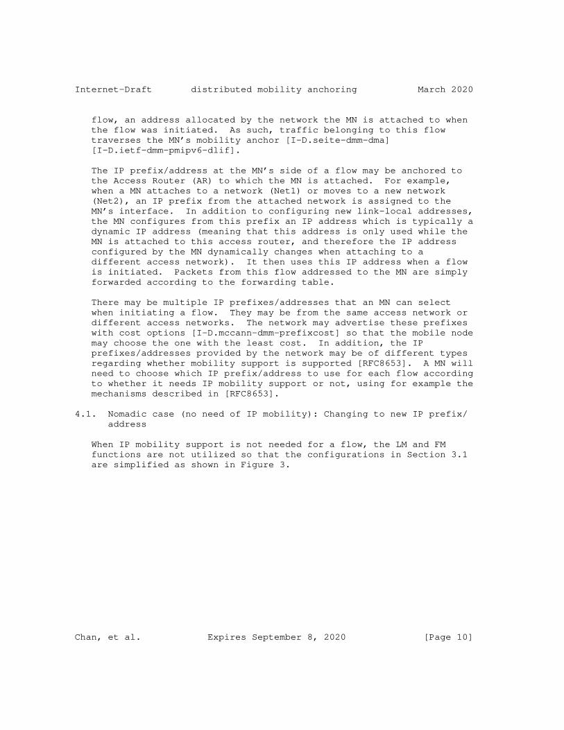
Internet-Draft distributed mobility anchoring March 2020
flow, an address allocated by the network the MN is attached to when the flow was initiated. As such, traffic belonging to this flow traverses the MN’s mobility anchor [I-D.seite-dmm-dma] [I-D.ietf-dmm-pmipv6-dlif].
The IP prefix/address at the MN’s side of a flow may be anchored to the Access Router (AR) to which the MN is attached. For example, when a MN attaches to a network (Net1) or moves to a new network (Net2), an IP prefix from the attached network is assigned to the MN’s interface. In addition to configuring new link-local addresses, the MN configures from this prefix an IP address which is typically a dynamic IP address (meaning that this address is only used while the MN is attached to this access router, and therefore the IP address configured by the MN dynamically changes when attaching to a different access network). It then uses this IP address when a flow is initiated. Packets from this flow addressed to the MN are simply forwarded according to the forwarding table.
There may be multiple IP prefixes/addresses that an MN can select when initiating a flow. They may be from the same access network or different access networks. The network may advertise these prefixes with cost options [I-D.mccann-dmm-prefixcost] so that the mobile node may choose the one with the least cost. In addition, the IP prefixes/addresses provided by the network may be of different types regarding whether mobility support is supported [RFC8653]. A MN will need to choose which IP prefix/address to use for each flow according to whether it needs IP mobility support or not, using for example the mechanisms described in [RFC8653].
4.1. Nomadic case (no need of IP mobility): Changing to new IP prefix/ address
When IP mobility support is not needed for a flow, the LM and FM functions are not utilized so that the configurations in Section 3.1 are simplified as shown in Figure 3.
Chan, et al. Expires September 8, 2020 [Page 10]
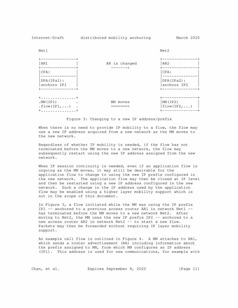
Internet-Draft distributed mobility anchoring March 2020
Net1 Net2
+---------------+ +---------------+ |AR1 | AR is changed |AR2 | +---------------+ -------> +---------------+ |CPA: | |CPA: | |---------------| |---------------| |DPA(IPa1): | |DPA(IPa2): | |anchors IP1 | |anchors IP2 | +---------------+ +---------------+
+...............+ +---------------+ .MN(IP1) . MN moves |MN(IP2) | .flow(IP1,...) . =======> |flow(IP2,...) | +...............+ +---------------+
Figure 3: Changing to a new IP address/prefix
When there is no need to provide IP mobility to a flow, the flow may use a new IP address acquired from a new network as the MN moves to the new network.
Regardless of whether IP mobility is needed, if the flow has not terminated before the MN moves to a new network, the flow may subsequently restart using the new IP address assigned from the new network.
When IP session continuity is needed, even if an application flow is ongoing as the MN moves, it may still be desirable for the application flow to change to using the new IP prefix configured in the new network. The application flow may then be closed at IP level and then be restarted using a new IP address configured in the new network. Such a change in the IP address used by the application flow may be enabled using a higher layer mobility support which is not in the scope of this document.
In Figure 3, a flow initiated while the MN was using the IP prefix IP1 -- anchored to a previous access router AR1 in network Net1 -- has terminated before the MN moves to a new network Net2. After moving to Net2, the MN uses the new IP prefix IP2 -- anchored to a new access router AR2 in network Net2 -- to start a new flow. Packets may then be forwarded without requiring IP layer mobility support.
An example call flow is outlined in Figure 4. A MN attaches to AR1, which sends a router advertisement (RA) including information about the prefix assigned to MN, from which MN configures an IP address (IP1). This address is used for new communications, for example with
Chan, et al. Expires September 8, 2020 [Page 11]
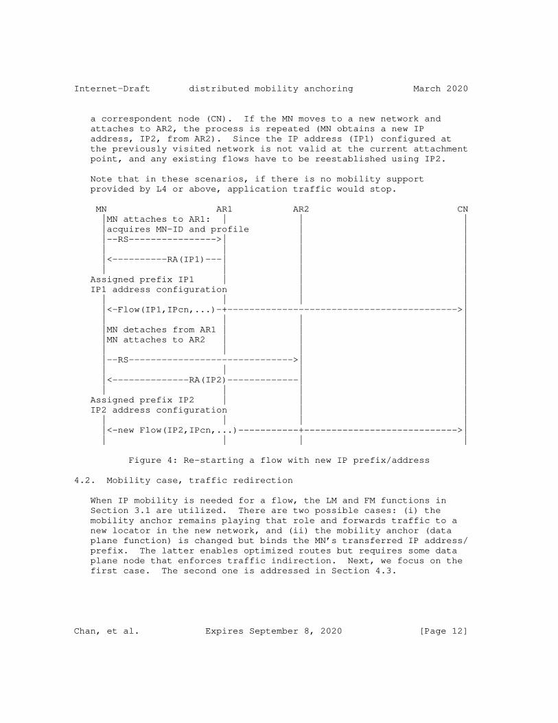
Internet-Draft distributed mobility anchoring March 2020
a correspondent node (CN). If the MN moves to a new network and attaches to AR2, the process is repeated (MN obtains a new IP address, IP2, from AR2). Since the IP address (IP1) configured at the previously visited network is not valid at the current attachment point, and any existing flows have to be reestablished using IP2.
Note that in these scenarios, if there is no mobility support provided by L4 or above, application traffic would stop.
MN AR1 AR2 CN |MN attaches to AR1: | | | |acquires MN-ID and profile | | |--RS---------------->| | | | | | | |<----------RA(IP1)---| | | | | | | Assigned prefix IP1 | | | IP1 address configuration | | | | | | |<-Flow(IP1,IPcn,...)-+------------------------------------------>| | | | | |MN detaches from AR1 | | | |MN attaches to AR2 | | | | | | | |--RS------------------------------>| | | | | | |<--------------RA(IP2)-------------| | | | | | Assigned prefix IP2 | | | IP2 address configuration | | | | | | |<-new Flow(IP2,IPcn,...)-----------+---------------------------->| | | | |
Figure 4: Re-starting a flow with new IP prefix/address
4.2. Mobility case, traffic redirection
When IP mobility is needed for a flow, the LM and FM functions in Section 3.1 are utilized. There are two possible cases: (i) the mobility anchor remains playing that role and forwards traffic to a new locator in the new network, and (ii) the mobility anchor (data plane function) is changed but binds the MN’s transferred IP address/ prefix. The latter enables optimized routes but requires some data plane node that enforces traffic indirection. Next, we focus on the first case. The second one is addressed in Section 4.3.
Chan, et al. Expires September 8, 2020 [Page 12]
Internet-Draft distributed mobility anchoring March 2020
Mobility support can be provided by using mobility management methods, such as the several approaches surveyed in the academic papers ([Paper-Distributed.Mobility], [Paper-Distributed.Mobility.PMIP] and [Paper-Distributed.Mobility.Review]). After moving, a certain MN’s traffic flow may continue using the IP prefix from the prior network of attachment. Yet, some time later, the application generating this traffic flow may be closed. If the application is started again, the new flow may not need to use the prior network’s IP address to avoid having to invoke IP mobility support. This may be the case where a dynamic IP prefix/address, rather than a permanent one, is used. Packets belonging to this flow may then use the new IP prefix (the one allocated in the network where the flow is being initiated). Routing is again kept simpler without employing IP mobility and will remain so as long as the MN which is now in the new network does not move again to another network.
Chan, et al. Expires September 8, 2020 [Page 13]

Internet-Draft distributed mobility anchoring March 2020
MN AR1 AR2 CN |MN attaches to AR1: | | | |acquires MN-ID and profile | | |--RS---------------->| | | | | | | |<----------RA(IP1)---| | | | | | | Assigned prefix IP1 | | | IP1 address configuration | | | | | | |<-Flow(IP1,IPcn,...)-+------------------------------------------>| | | | | |MN detaches from AR1 | | | |MN attaches to AR2 | | | | | | | |--RS------------------------------>| | (some IP mobility support solution) |<--------------RA(IP2,IP1)---------| | | | | | | +<-Flow(IP1,IPcn,...)---------------------->| | +<===========>+ | |<-Flow(IP1,IPcn,...)-------------->+ | | | | | Assigned prefix IP2 | | | IP2 address configuration | | | | | | Flow(IP1,IPcn) terminates | | | | | | |<-new Flow(IP2,IPcn,...)-----------+---------------------------->| | | | |
Figure 5: A flow continues to use the IP prefix from its home network after MN has moved to a new network
An example call flow in this case is outlined in Figure 5. In this example, the AR1 plays the role of FM-DP entity and redirects the traffic (e.g., using an IP tunnel) to AR2. Another solution could be to place an FM-DP entity closer to the CN network to perform traffic steering to deviate from default routes (which will bring the packet to AR1 per default routing). The LM and FM functions are implemented as shown in Figure 6.
Chan, et al. Expires September 8, 2020 [Page 14]
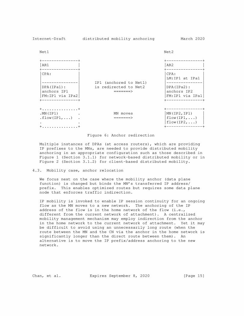
Internet-Draft distributed mobility anchoring March 2020
Net1 Net2
+---------------+ +---------------+ |AR1 | |AR2 | +---------------+ +---------------+ |CPA: | |CPA: | | | |LM:IP1 at IPa1 | |---------------| IP1 (anchored to Net1) |---------------| |DPA(IPa1): | is redirected to Net2 |DPA(IPa2): | |anchors IP1 | =======> |anchors IP2 | |FM:IP1 via IPa2| |FM:IP1 via IPa1| +---------------+ +---------------+
+...............+ +---------------+ .MN(IP1) . MN moves |MN(IP2,IP1) | .flow(IP1,...) . =======> |flow(IP1,...) | . . |flow(IP2,...) | +...............+ +---------------+
Figure 6: Anchor redirection
Multiple instances of DPAs (at access routers), which are providing IP prefixes to the MNs, are needed to provide distributed mobility anchoring in an appropriate configuration such as those described in Figure 1 (Section 3.1.1) for network-based distributed mobility or in Figure 2 (Section 3.1.2) for client-based distributed mobility.
4.3. Mobility case, anchor relocation
We focus next on the case where the mobility anchor (data plane function) is changed but binds the MN’s transferred IP address/ prefix. This enables optimized routes but requires some data plane node that enforces traffic indirection.
IP mobility is invoked to enable IP session continuity for an ongoing flow as the MN moves to a new network. The anchoring of the IP address of the flow is in the home network of the flow (i.e., different from the current network of attachment). A centralized mobility management mechanism may employ indirection from the anchor in the home network to the current network of attachment. Yet it may be difficult to avoid using an unnecessarily long route (when the route between the MN and the CN via the anchor in the home network is significantly longer than the direct route between them). An alternative is to move the IP prefix/address anchoring to the new network.
Chan, et al. Expires September 8, 2020 [Page 15]
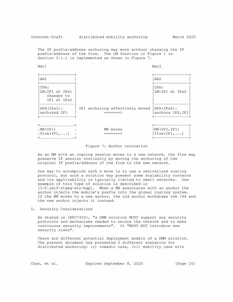
Internet-Draft distributed mobility anchoring March 2020
The IP prefix/address anchoring may move without changing the IP prefix/address of the flow. The LM function in Figure 1 in Section 3.1.1 is implemented as shown in Figure 7.
Net1 Net2
+---------------+ +---------------+ |AR1 | |AR2 | +---------------+ +---------------+ |CPA: | |CPA: | |LM:IP1 at IPa1 | |LM:IP1 at IPa2 | | changes to | | | | IP1 at IPa2 | | | |---------------| |---------------| |DPA(IPa1): | IP1 anchoring effectively moved |DPA(IPa2): | |anchored IP1 | =======> |anchors IP2,IP1| +---------------+ +---------------+
+...............+ +---------------+ .MN(IP1) . MN moves |MN(IP2,IP1) | .flow(IP1,...) . =======> |flow(IP1,...) | +...............+ +---------------+
Figure 7: Anchor relocation
As an MN with an ongoing session moves to a new network, the flow may preserve IP session continuity by moving the anchoring of the original IP prefix/address of the flow to the new network.
One way to accomplish such a move is to use a centralized routing protocol, but such a solution may present some scalability concerns and its applicability is typically limited to small networks. One example of this type of solution is described in [I-D.ietf-rtgwg-atn-bgp]. When a MN associates with an anchor the anchor injects the mobile’s prefix into the global routing system. If the MN moves to a new anchor, the old anchor withdraws the /64 and the new anchor injects it instead.
5. Security Considerations
As stated in [RFC7333], "a DMM solution MUST support any security protocols and mechanisms needed to secure the network and to make continuous security improvements". It "MUST NOT introduce new security risks".
There are different potential deployment models of a DMM solution. The present document has presented 3 different scenarios for distributed anchoring: (i) nomadic case, (ii) mobility case with
Chan, et al. Expires September 8, 2020 [Page 16]
Internet-Draft distributed mobility anchoring March 2020
traffic redirection, and (iii) mobility case with anchor relocation. Each of them has different security requirements, and the actual security mechanisms would depend on the specifics of each solution/ scenario.
As general rules, for the first distributed anchoring scenario (nomadic case), no additional security consideration is needed, as this does not involve any additional mechanism at L3. If session connectivity is required, the L4 or above solution used to provide it MUST also provide the required authentication and security.
The second and third distributed anchoring scenarios (mobility case) involve mobility signalling among the mobile node and the control and data plane anchors. The control-plane messages exchanged between these entitites MUST be protected using end-to-end security associations with data-integrity and data-origination capabilities. IPsec [RFC8221] ESP in transport mode with mandatory integrity protection SHOULD be used for protecting the signaling messages. IKEv2 [RFC8247] SHOULD be used to set up security associations between the data and control plane anchors. Note that in scenarios in which traffic indirection mechanisms are used to relocate an anchor, authentication and authorization mechanisms MUST be used.
Control-plane functionality MUST apply authorization checks to any commands or updates that are made by the control-plane protocol.
6. IANA Considerations
This document presents no IANA considerations.
7. Contributors
Alexandre Petrescu and Fred Templin had contributed to earlier versions of this document regarding distributed anchoring for hierarchical network and for network mobility, although these extensions were removed to keep the document within reasonable length.
This document has benefited from other work on mobility support in SDN network, on providing mobility support only when needed, and on mobility support in enterprise network. These works have been referenced. While some of these authors have taken the work to jointly write this document, others have contributed at least indirectly by writing these drafts. The latter include Philippe Bertin, Dapeng Liu, Satoru Matushima, Pierrick Seite, Jouni Korhonen, and Sri Gundavelli.
Chan, et al. Expires September 8, 2020 [Page 17]
Internet-Draft distributed mobility anchoring March 2020
Some terminology has been incorporated for completeness from draft- ietf-dmm-deployment-models-04 document.
Valuable comments have been received from John Kaippallimalil, ChunShan Xiong, Dapeng Liu, Fred Templin, Paul Kyzivat, Joseph Salowey, Yoshifumi Nishida, Carlos Pignataro, Mirja Kuehlewind, Eric Vyncke, Qin Wu, Warren Kumari, Benjamin Kaduk, Roman Danyliw and Barry Leiba. Dirk von Hugo, Byju Pularikkal, Pierrick Seite have generously provided careful review with helpful corrections and suggestions. Marco Liebsch and Lyle Bertz also performed very detailed and helpful reviews of this document.
8. References
8.1. Normative References
[RFC2119] Bradner, S., "Key words for use in RFCs to Indicate Requirement Levels", BCP 14, RFC 2119, DOI 10.17487/RFC2119, March 1997, <https://www.rfc-editor.org/info/rfc2119>.
[RFC3753] Manner, J., Ed. and M. Kojo, Ed., "Mobility Related Terminology", RFC 3753, DOI 10.17487/RFC3753, June 2004, <https://www.rfc-editor.org/info/rfc3753>.
[RFC5213] Gundavelli, S., Ed., Leung, K., Devarapalli, V., Chowdhury, K., and B. Patil, "Proxy Mobile IPv6", RFC 5213, DOI 10.17487/RFC5213, August 2008, <https://www.rfc-editor.org/info/rfc5213>.
[RFC6275] Perkins, C., Ed., Johnson, D., and J. Arkko, "Mobility Support in IPv6", RFC 6275, DOI 10.17487/RFC6275, July 2011, <https://www.rfc-editor.org/info/rfc6275>.
[RFC7333] Chan, H., Ed., Liu, D., Seite, P., Yokota, H., and J. Korhonen, "Requirements for Distributed Mobility Management", RFC 7333, DOI 10.17487/RFC7333, August 2014, <https://www.rfc-editor.org/info/rfc7333>.
[RFC7429] Liu, D., Ed., Zuniga, JC., Ed., Seite, P., Chan, H., and CJ. Bernardos, "Distributed Mobility Management: Current Practices and Gap Analysis", RFC 7429, DOI 10.17487/RFC7429, January 2015, <https://www.rfc-editor.org/info/rfc7429>.
[RFC8174] Leiba, B., "Ambiguity of Uppercase vs Lowercase in RFC 2119 Key Words", BCP 14, RFC 8174, DOI 10.17487/RFC8174, May 2017, <https://www.rfc-editor.org/info/rfc8174>.
Chan, et al. Expires September 8, 2020 [Page 18]
Internet-Draft distributed mobility anchoring March 2020
[RFC8221] Wouters, P., Migault, D., Mattsson, J., Nir, Y., and T. Kivinen, "Cryptographic Algorithm Implementation Requirements and Usage Guidance for Encapsulating Security Payload (ESP) and Authentication Header (AH)", RFC 8221, DOI 10.17487/RFC8221, October 2017, <https://www.rfc-editor.org/info/rfc8221>.
[RFC8247] Nir, Y., Kivinen, T., Wouters, P., and D. Migault, "Algorithm Implementation Requirements and Usage Guidance for the Internet Key Exchange Protocol Version 2 (IKEv2)", RFC 8247, DOI 10.17487/RFC8247, September 2017, <https://www.rfc-editor.org/info/rfc8247>.
8.2. Informative References
[I-D.ietf-dmm-fpc-cpdp] Matsushima, S., Bertz, L., Liebsch, M., Gundavelli, S., Moses, D., and C. Perkins, "Protocol for Forwarding Policy Configuration (FPC) in DMM", draft-ietf-dmm-fpc-cpdp-12 (work in progress), June 2018.
[I-D.ietf-dmm-pmipv6-dlif] Bernardos, C., Oliva, A., Giust, F., Zuniga, J., and A. Mourad, "Proxy Mobile IPv6 extensions for Distributed Mobility Management", draft-ietf-dmm-pmipv6-dlif-05 (work in progress), November 2019.
[I-D.ietf-rtgwg-atn-bgp] Templin, F., Saccone, G., Dawra, G., Lindem, A., and V. Moreno, "A Simple BGP-based Mobile Routing System for the Aeronautical Telecommunications Network", draft-ietf- rtgwg-atn-bgp-05 (work in progress), January 2020.
[I-D.matsushima-stateless-uplane-vepc] Matsushima, S. and R. Wakikawa, "Stateless user-plane architecture for virtualized EPC (vEPC)", draft- matsushima-stateless-uplane-vepc-06 (work in progress), March 2016.
[I-D.mccann-dmm-prefixcost] McCann, P. and J. Kaippallimalil, "Communicating Prefix Cost to Mobile Nodes", draft-mccann-dmm-prefixcost-03 (work in progress), April 2016.
[I-D.sarikaya-dmm-for-wifi] Sarikaya, B. and L. Li, "Distributed Mobility Management Protocol for WiFi Users in Fixed Network", draft-sarikaya- dmm-for-wifi-05 (work in progress), October 2017.
Chan, et al. Expires September 8, 2020 [Page 19]
Internet-Draft distributed mobility anchoring March 2020
[I-D.seite-dmm-dma] Seite, P., Bertin, P., and J. Lee, "Distributed Mobility Anchoring", draft-seite-dmm-dma-07 (work in progress), February 2014.
[I-D.yhkim-dmm-enhanced-anchoring] Kim, Y. and S. Jeon, "Enhanced Mobility Anchoring in Distributed Mobility Management", draft-yhkim-dmm- enhanced-anchoring-05 (work in progress), July 2016.
[Paper-Distributed.Mobility] Lee, J., Bonnin, J., Seite, P., and H. Chan, "Distributed IP Mobility Management from the Perspective of the IETF: Motivations, Requirements, Approaches, Comparison, and Challenges", IEEE Wireless Communications, October 2013.
[Paper-Distributed.Mobility.PMIP] Chan, H., "Proxy Mobile IP with Distributed Mobility Anchors", Proceedings of GlobeCom Workshop on Seamless Wireless Mobility, December 2010.
[Paper-Distributed.Mobility.Review] Chan, H., Yokota, H., Xie, J., Seite, P., and D. Liu, "Distributed and Dynamic Mobility Management in Mobile Internet: Current Approaches and Issues", February 2011.
[RFC6459] Korhonen, J., Ed., Soininen, J., Patil, B., Savolainen, T., Bajko, G., and K. Iisakkila, "IPv6 in 3rd Generation Partnership Project (3GPP) Evolved Packet System (EPS)", RFC 6459, DOI 10.17487/RFC6459, January 2012, <https://www.rfc-editor.org/info/rfc6459>.
[RFC8653] Yegin, A., Moses, D., and S. Jeon, "On-Demand Mobility Management", RFC 8653, DOI 10.17487/RFC8653, October 2019, <https://www.rfc-editor.org/info/rfc8653>.
Authors’ Addresses
H. Anthony Chan (editor) Huawei Technologies 5340 Legacy Dr. Building 3 Plano, TX 75024 USA
Email: [email protected]
Chan, et al. Expires September 8, 2020 [Page 20]
Internet-Draft distributed mobility anchoring March 2020
Xinpeng Wei Huawei Technologies Xin-Xi Rd. No. 3, Haidian District Beijing, 100095 P. R. China
Email: [email protected]
Jong-Hyouk Lee Sangmyung University 31, Sangmyeongdae-gil, Dongnam-gu Cheonan 31066 Republic of Korea
Email: [email protected]
Seil Jeon Sungkyunkwan University 2066 Seobu-ro, Jangan-gu Suwon, Gyeonggi-do Republic of Korea
Email: [email protected]
Carlos J. Bernardos (editor) Universidad Carlos III de Madrid Av. Universidad, 30 Leganes, Madrid 28911 Spain
Phone: +34 91624 6236 Email: [email protected] URI: http://www.it.uc3m.es/cjbc/
Chan, et al. Expires September 8, 2020 [Page 21]

DMM Working Group S. MatsushimaInternet-Draft SoftBankIntended status: Standards Track L. BertzExpires: 27 March 2021 Sprint M. Liebsch NEC S. Gundavelli Cisco D. Moses Intel Corporation C.E. Perkins Futurewei 23 September 2020
Protocol for Forwarding Policy Configuration (FPC) in DMM draft-ietf-dmm-fpc-cpdp-14
Abstract
This document describes a way, called Forwarding Policy Configuration (FPC) to manage the separation of data-plane and control-plane. FPC defines a flexible mobility management system using FPC agent and FPC client functions. A FPC agent provides an abstract interface to the data-plane. The FPC client configures data-plane nodes by using the functions and abstractions provided by the FPC agent for the data- plane nodes. The data-plane abstractions presented in this document are extensible in order to support many different types of mobility management systems and data-plane functions.
Status of This Memo
This Internet-Draft is submitted in full conformance with the provisions of BCP 78 and BCP 79.
Internet-Drafts are working documents of the Internet Engineering Task Force (IETF). Note that other groups may also distribute working documents as Internet-Drafts. The list of current Internet- Drafts is at https://datatracker.ietf.org/drafts/current/.
Internet-Drafts are draft documents valid for a maximum of six months and may be updated, replaced, or obsoleted by other documents at any time. It is inappropriate to use Internet-Drafts as reference material or to cite them other than as "work in progress."
This Internet-Draft will expire on 27 March 2021.
Matsushima, et al. Expires 27 March 2021 [Page 1]
Internet-Draft DMM FPC Protocol September 2020
Copyright Notice
Copyright (c) 2020 IETF Trust and the persons identified as the document authors. All rights reserved.
This document is subject to BCP 78 and the IETF Trust’s Legal Provisions Relating to IETF Documents (https://trustee.ietf.org/ license-info) in effect on the date of publication of this document. Please review these documents carefully, as they describe your rights and restrictions with respect to this document. Code Components extracted from this document must include Simplified BSD License text as described in Section 4.e of the Trust Legal Provisions and are provided without warranty as described in the Simplified BSD License.
Table of Contents
1. Introduction . . . . . . . . . . . . . . . . . . . . . . . . 3 2. Terminology . . . . . . . . . . . . . . . . . . . . . . . . . 4 3. FPC Design Objectives and Deployment . . . . . . . . . . . . 6 4. FPC Mobility Information Model . . . . . . . . . . . . . . . 9 4.1. Model Notation and Conventions . . . . . . . . . . . . . 10 4.2. Templates and Attributes . . . . . . . . . . . . . . . . 12 4.3. Attribute-Expressions . . . . . . . . . . . . . . . . . . 13 4.4. Attribute Value Types . . . . . . . . . . . . . . . . . . 14 4.5. Namespace and Format . . . . . . . . . . . . . . . . . . 14 4.6. Configuring Attribute Values . . . . . . . . . . . . . . 15 4.7. Entity Configuration Blocks . . . . . . . . . . . . . . . 16 4.8. Information Model Checkpoint . . . . . . . . . . . . . . 17 4.9. Information Model Components . . . . . . . . . . . . . . 18 4.9.1. Topology Information Model . . . . . . . . . . . . . 18 4.9.2. Service-Group . . . . . . . . . . . . . . . . . . . . 18 4.9.3. Domain Information Model . . . . . . . . . . . . . . 20 4.9.4. DPN Information Model . . . . . . . . . . . . . . . . 20 4.9.5. Policy Information Model . . . . . . . . . . . . . . 22 4.9.6. Mobility-Context Information Model . . . . . . . . . 24 4.9.7. Monitor Information Model . . . . . . . . . . . . . . 26 5. Security Considerations . . . . . . . . . . . . . . . . . . . 28 6. IANA Considerations . . . . . . . . . . . . . . . . . . . . . 28 7. Work Team Participants . . . . . . . . . . . . . . . . . . . 28 8. References . . . . . . . . . . . . . . . . . . . . . . . . . 28 8.1. Normative References . . . . . . . . . . . . . . . . . . 28 8.2. Informative References . . . . . . . . . . . . . . . . . 28 Appendix A. Implementation Status . . . . . . . . . . . . . . . 29 Authors’ Addresses . . . . . . . . . . . . . . . . . . . . . . . 33
Matsushima, et al. Expires 27 March 2021 [Page 2]

Internet-Draft DMM FPC Protocol September 2020
1. Introduction
This document describes Forwarding Policy Configuration (FPC), a system for managing the separation of control-plane and data-plane. FPC enables flexible mobility management using FPC client and FPC agent functions. A FPC agent exports an abstract interface representing the data-plane. To configure data-plane nodes and functions, the FPC client uses the interface to the data-plane offered by the FPC agent.
Control planes of mobility management systems, or related applications which require data-plane control, can utilize the FPC client at various levels of abstraction. FPC operations are capable of directly configuring a single Data-Plane Node (DPN), as well as multiple DPNs, as determined by the data-plane models exported by the FPC agent.
A FPC agent represents the data-plane operation according to several basic information models. A FPC agent also provides access to Monitors, which produce reports when triggered by events or FPC Client requests regarding Mobility Contexts, DPNs or the Agent.
To manage mobility sessions, the FPC client assembles applicable sets of forwarding policies from the data model, and configures them on the appropriate FPC Agent. The Agent then renders those policies into specific configurations for each DPN at which mobile nodes are attached. The specific protocols and configurations to configure a DPN from a FPC Agent are outside the scope of this document.
A DPN is a logical entity that performs data-plane operations (packet movement and management). It may represent a physical DPN unit, a sub-function of a physical DPN or a collection of physical DPNs (i.e., a "virtual DPN"). A DPN may be virtual -- it may export the FPC DPN Agent interface, but be implemented as software that controls other data-plane hardware or modules that may or may not be FPC- compliant. In this document, DPNs are specified without regard for whether the implementation is virtual or physical. DPNs are connected to provide mobility management systems such as access networks, anchors and domains. The FPC agent interface enables establishment of a topology for the forwarding plane.
When a DPN is mapped to physical data-plane equipment, the FPC client can have complete knowledge of the DPN architecture, and use that information to perform DPN selection for specific sessions. On the other hand, when a virtual DPN is mapped to a collection of physical DPNs, the FPC client cannot select a specific physical DPN because it is hidden by the abstraction; only the FPC Agent can address the specific associated physical DPNs. Network architects have the
Matsushima, et al. Expires 27 March 2021 [Page 3]
Internet-Draft DMM FPC Protocol September 2020
flexibility to determine which DPN-selection capabilities are performed by the FPC Agent (distributed) and which by the FPC client (centralized). In this way, overlay networks can be configured without disclosing detailed knowledge of the underlying hardware to the FPC client and applications.
The abstractions in this document are designed to support many different mobility management systems and data-plane functions. The architecture and protocol design of FPC is not tied to specific types of access technologies and mobility protocols.
2. Terminology
The key words "MUST", "MUST NOT", "REQUIRED", "SHALL", "SHALL NOT", "SHOULD", "SHOULD NOT", "RECOMMENDED", "MAY", and "OPTIONAL" in this document are to be interpreted as described in [RFC2119].
Attribute Expression: The definition of a template Property. This includes setting the type, current value, default value and if the attribute is static, i.e. can no longer be changed.
Domain: One or more DPNs that form a logical partition of network resources (e.g., a data- plane network under common network administration). A FPC client (e.g., a mobility management system) may utilize a single or multiple domains.
DPN: A data-plane node (DPN) is capable of performing data-plane features. For example, DPNs may be switches or routers, regardless of whether they are realized as hardware or purely in software.
FPC Client: A FPC Client is integrated with a mobility management system or related application, enabling control over forwarding policy, mobility sessions and DPNs via a FPC Agent.
Mobility Context: A Mobility Context contains the data-plane information necessary to efficiently send and receive traffic from a mobile node. This includes policies that are created or modified during the network’s operation - in most cases, on a per-flow or per session basis. A Mobility-Context represents the mobility sessions (or flows) which are active
Matsushima, et al. Expires 27 March 2021 [Page 4]
Internet-Draft DMM FPC Protocol September 2020
on a mobile node. This includes associated runtime attributes, such as tunnel endpoints, tunnel identifiers, delegated prefix(es), routing information, etc. Mobility-Contexts are associated to specific DPNs. Some pre- defined Policies may apply during mobility signaling requests. The Mobility Context supplies information about the policy settings specific to a mobile node and its flows; this information is often quite dynamic.
Mobility Session: Traffic to/from a mobile node that is expected to survive reconnection events.
Monitor: A reporting mechanism for a list of events that trigger notification messages from a FPC Agent to a FPC Client.
Policy: A Policy determines the mechanisms for managing specific traffic flows or packets. Policies specify QoS, rewriting rules for packet processing, etc. A Policy consists of one or more rules. Each rule is composed of a Descriptor and Actions. The Descriptor in a rule identifies packets (e.g., traffic flows), and the Actions apply treatments to packets that match the Descriptor in the rule. Policies can apply to Domains, DPNs, Mobile Nodes, Service-Groups, or particular Flows on a Mobile Node.
Property: An attribute-value pair for an instance of a FPC entity.
Service-Group: A set of DPN interfaces that support a specific data-plane purpose, e.g. inbound/ outbound, roaming, subnetwork with common specific configuration, etc.
Template: A recipe for instantiating FPC entities. Template definitions are accessible (by name or by a key) in an indexed set. A Template is used to create specific instances (e.g., specific policies) by assigning appropriate values into the Template definition via Attribute Expression.
Matsushima, et al. Expires 27 March 2021 [Page 5]
Internet-Draft DMM FPC Protocol September 2020
Template Configuration The process by which a Template is referenced (by name or by key) and Attribute Expressions are created that change the value, default value or static nature of the Attribute, if permitted. If the Template is Extensible, new attributes MAY be added.
Tenant: An operational entity that manages mobility management systems or applications which require data-plane functions. A Tenant defines a global namespace for all entities owned by the Tenant enabling its entities to be used by multiple FPC Clients across multiple FPC Agents.
Topology: The DPNs and the links between them. For example, access nodes may be assigned to a Service-Group which peers to a Service-Group of anchor nodes.
3. FPC Design Objectives and Deployment
Using FPC, mobility control-planes and applications can configure DPNs to perform various mobility management roles as described in [I-D.ietf-dmm-deployment-models]. This fulfills the requirements described in [RFC7333].
This document defines FPC Agent and FPC Client, as well as the information models that they use. The attributes defining those models serve as the protocol elements for the interface between the FPC Agent and the FPC Client.
Mobility control-plane applications integrate features offered by the FPC Client. The FPC Client connects to FPC Agent functions. The Client and the Agent communicate based on information models described in Section 4. The models allow the control-plane to configure forwarding policies on the Agent for data-plane communications with mobile nodes.
Once the Topology of DPN(s) and domains are defined on an Agent for a data plane, the DPNs in the topology are available for further configuration. The FPC Agent connects those DPNs to manage their configurations.
A FPC Agent configures and manages its DPN(s) according to forwarding policies requested and Attributes provided by the FPC Client. Configuration commands used by the FPC agent to configure its DPN node(s) may be specific to the DPN implementation; consequently the
Matsushima, et al. Expires 27 March 2021 [Page 6]
Internet-Draft DMM FPC Protocol September 2020
method by which the FPC Agent carries out the specific configuration for its DPN(s) is out of scope for this document. Along with the data models, the FPC Client (on behalf of control-plane and applications) requests that the Agent configures Policies prior to the time when the DPNs start forwarding data for their mobility sessions.
This architecture is illustrated in Figure 1. A FPC Agent may be implemented in a network controller that handles multiple DPNs, or (more simply) an FPC Agent may itself be integrated into a DPN.
This document does not specify a protocol for the FPC interface; it is out of scope.
Matsushima, et al. Expires 27 March 2021 [Page 7]
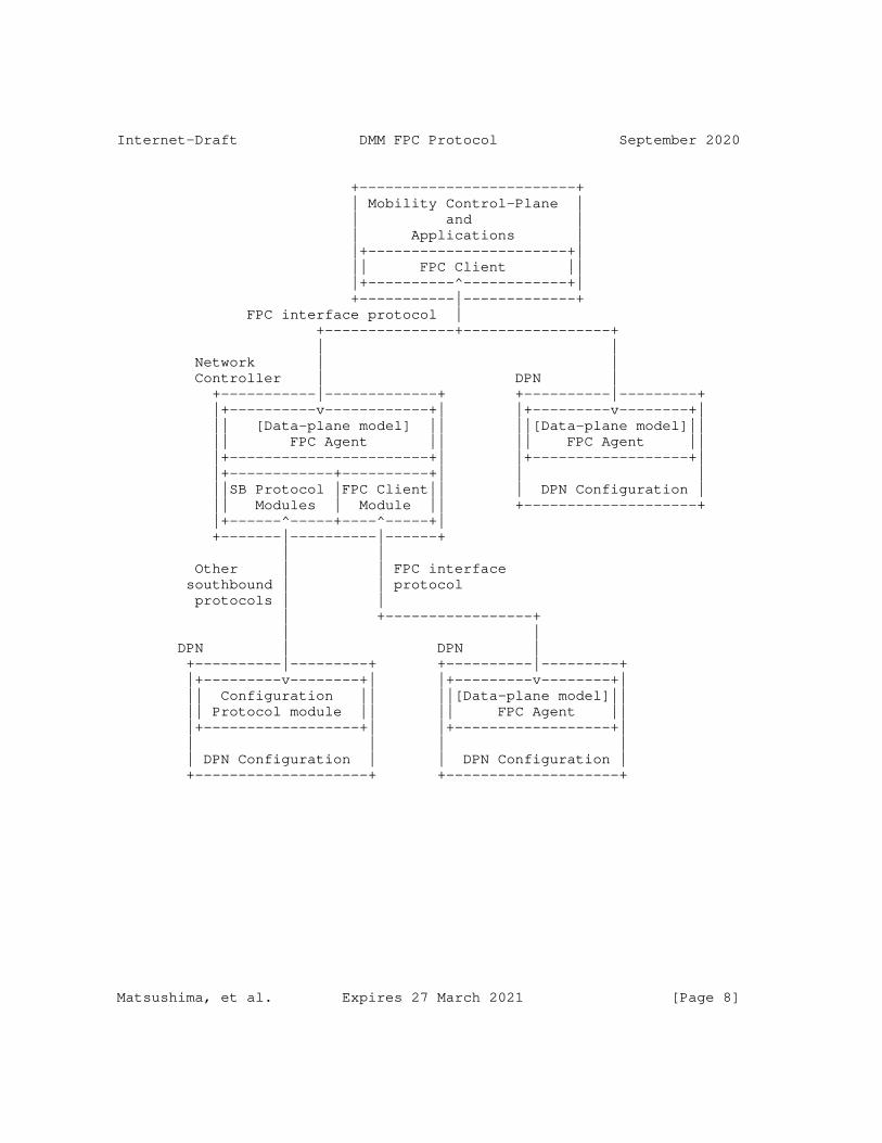
Internet-Draft DMM FPC Protocol September 2020
+-------------------------+ | Mobility Control-Plane | | and | | Applications | |+-----------------------+| || FPC Client || |+----------^------------+| +-----------|-------------+ FPC interface protocol | +---------------+-----------------+ | | Network | | Controller | DPN | +-----------|-------------+ +----------|---------+ |+----------v------------+| |+---------v--------+| || [Data-plane model] || ||[Data-plane model]|| || FPC Agent || || FPC Agent || |+-----------------------+| |+------------------+| |+------------+----------+| | | ||SB Protocol |FPC Client|| | DPN Configuration | || Modules | Module || +--------------------+ |+------^-----+----^-----+| +-------|----------|------+ | | Other | | FPC interface southbound | | protocol protocols | | | +-----------------+ | | DPN | DPN | +----------|---------+ +----------|---------+ |+---------v--------+| |+---------v--------+| || Configuration || ||[Data-plane model]|| || Protocol module || || FPC Agent || |+------------------+| |+------------------+| | | | | | DPN Configuration | | DPN Configuration | +--------------------+ +--------------------+
Matsushima, et al. Expires 27 March 2021 [Page 8]
Internet-Draft DMM FPC Protocol September 2020
Figure 1: Reference Forwarding Policy Configuration (FPC) Architecture
The FPC architecture supports multi-tenancy; a FPC enabled data-plane supports tenants of multiple mobile operator networks and/or applications. It means that the FPC Client of each tenant connects to the FPC Agent and it MUST partition namespace and data for their data-planes. DPNs on the data-plane may fulfill multiple data-plane roles which are defined per session, domain and tenant.
Multi-tenancy permits the paritioning of data-plane entities as well as a common namespace requirement upon FPC Agents and Clients when they use the same Tenant for a common data-plane entity.
FPC information models often configuration to fit the specific needs for DPN management of a mobile node’s traffic. The FPC interfaces in Figure 1 are the only interfaces required to handle runtime data in a Mobility Context. The Topology and some Policy FPC models MAY be pre-configured; in that case real-time protocol exchanges are not required for them.
The information model provides an extensibility mechanism through Templates that permits specialization for the needs of a particular vendor’s equipment or future extension of the model presented in this specification.
4. FPC Mobility Information Model
The FPC information model includes the following components:
DPN Information Model, Topology Information Model, Policy Information Model, Mobility-Context, and Monitor, as illustrated in Figure 2.
Matsushima, et al. Expires 27 March 2021 [Page 9]
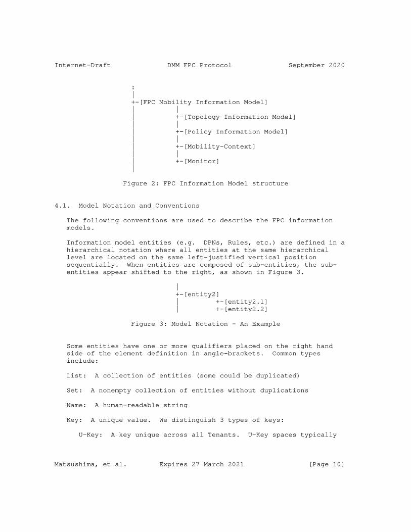
Internet-Draft DMM FPC Protocol September 2020
: | +-[FPC Mobility Information Model] | | | +-[Topology Information Model] | | | +-[Policy Information Model] | | | +-[Mobility-Context] | | | +-[Monitor] |
Figure 2: FPC Information Model structure
4.1. Model Notation and Conventions
The following conventions are used to describe the FPC information models.
Information model entities (e.g. DPNs, Rules, etc.) are defined in a hierarchical notation where all entities at the same hierarchical level are located on the same left-justified vertical position sequentially. When entities are composed of sub-entities, the sub- entities appear shifted to the right, as shown in Figure 3.
| +-[entity2] | +-[entity2.1] | +-[entity2.2]
Figure 3: Model Notation - An Example
Some entities have one or more qualifiers placed on the right hand side of the element definition in angle-brackets. Common types include:
List: A collection of entities (some could be duplicated)
Set: A nonempty collection of entities without duplications
Name: A human-readable string
Key: A unique value. We distinguish 3 types of keys:
U-Key: A key unique across all Tenants. U-Key spaces typically
Matsushima, et al. Expires 27 March 2021 [Page 10]

Internet-Draft DMM FPC Protocol September 2020
involve the use of registries or language specific mechanisms that guarantee universal uniqueness of values.
G-Key: A key unique within a Tenant
L-Key: A key unique within a local namespace. For example, there may exist interfaces with the same name, e.g. "if0", in two different DPNs but there can only be one "if0" within each DPN (i.e. its local Interface-Key L-Key space).
Each entity or attribute may be optional (O) or mandatory (M). Entities that are not marked as optional are mandatory.
The following example shows 3 entities: -- Entity1 is a globally unique key, and optionally can have an associated Name -- Entity2 is a list -- Entity3 is a set and is optional + | +-[entity1] <G-Key> (M), <Name> (O) +-[entity2] <List> +-[entity3] <Set> (O) | +
Figure 4
When expanding entity1 into a modeling language such as YANG it would result in two values: entity1-Key and entity1-Name.
To encourage re-use, FPC defines indexed sets of various entity Templates. Other model elements that need access to an indexed model entity contain an attribute which is always denoted as "entity-Key". When a Key attribute is encountered, the referencing model element may supply attribute values for use when the referenced entity model is instantiated. For example: Figure 5 shows 2 entities:
EntityA definition references an entityB model element.
EntityB model elements are indexed by entityB-Key.
Each EntityB model element has an entityB-Key which allows it to be uniquely identified, and a list of Attributes (or, alternatively, a Type) which specifies its form. This allows a referencing entity to create an instance by supplying entityB-Values to be inserted, in a Settings container.
Matsushima, et al. Expires 27 March 2021 [Page 11]
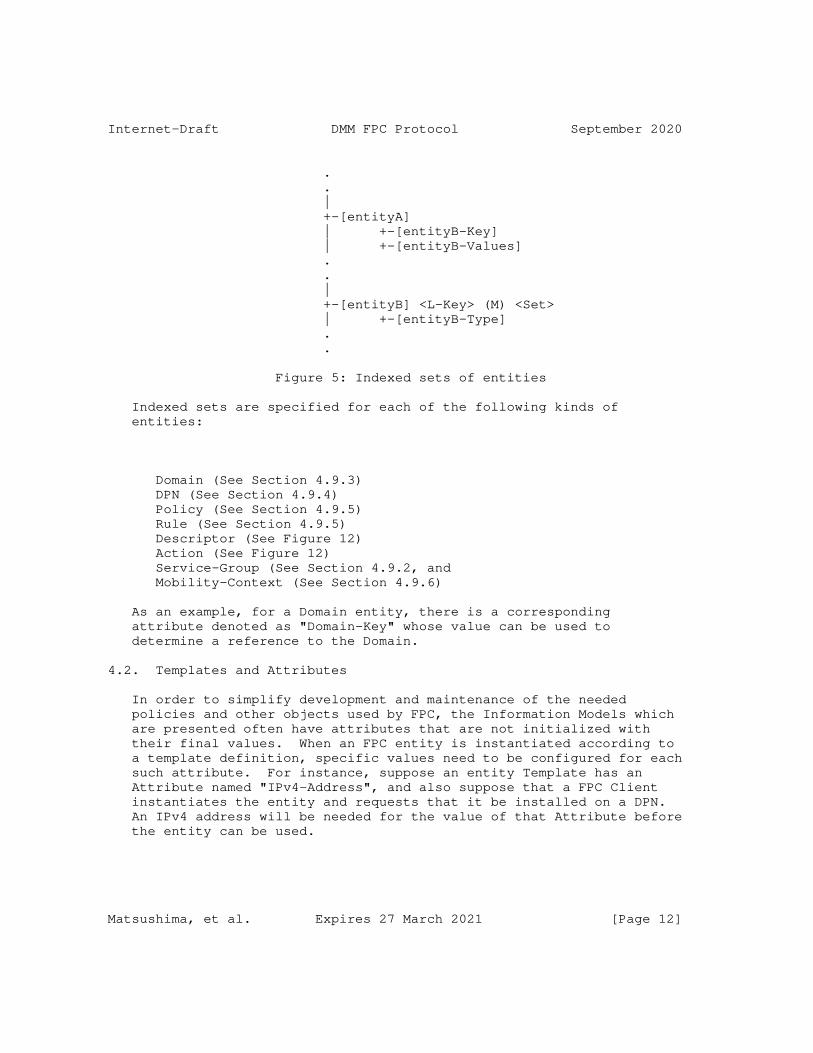
Internet-Draft DMM FPC Protocol September 2020
. . | +-[entityA] | +-[entityB-Key] | +-[entityB-Values] . . | +-[entityB] <L-Key> (M) <Set> | +-[entityB-Type] . .
Figure 5: Indexed sets of entities
Indexed sets are specified for each of the following kinds of entities:
Domain (See Section 4.9.3) DPN (See Section 4.9.4) Policy (See Section 4.9.5) Rule (See Section 4.9.5) Descriptor (See Figure 12) Action (See Figure 12) Service-Group (See Section 4.9.2, and Mobility-Context (See Section 4.9.6)
As an example, for a Domain entity, there is a corresponding attribute denoted as "Domain-Key" whose value can be used to determine a reference to the Domain.
4.2. Templates and Attributes
In order to simplify development and maintenance of the needed policies and other objects used by FPC, the Information Models which are presented often have attributes that are not initialized with their final values. When an FPC entity is instantiated according to a template definition, specific values need to be configured for each such attribute. For instance, suppose an entity Template has an Attribute named "IPv4-Address", and also suppose that a FPC Client instantiates the entity and requests that it be installed on a DPN. An IPv4 address will be needed for the value of that Attribute before the entity can be used.
Matsushima, et al. Expires 27 March 2021 [Page 12]
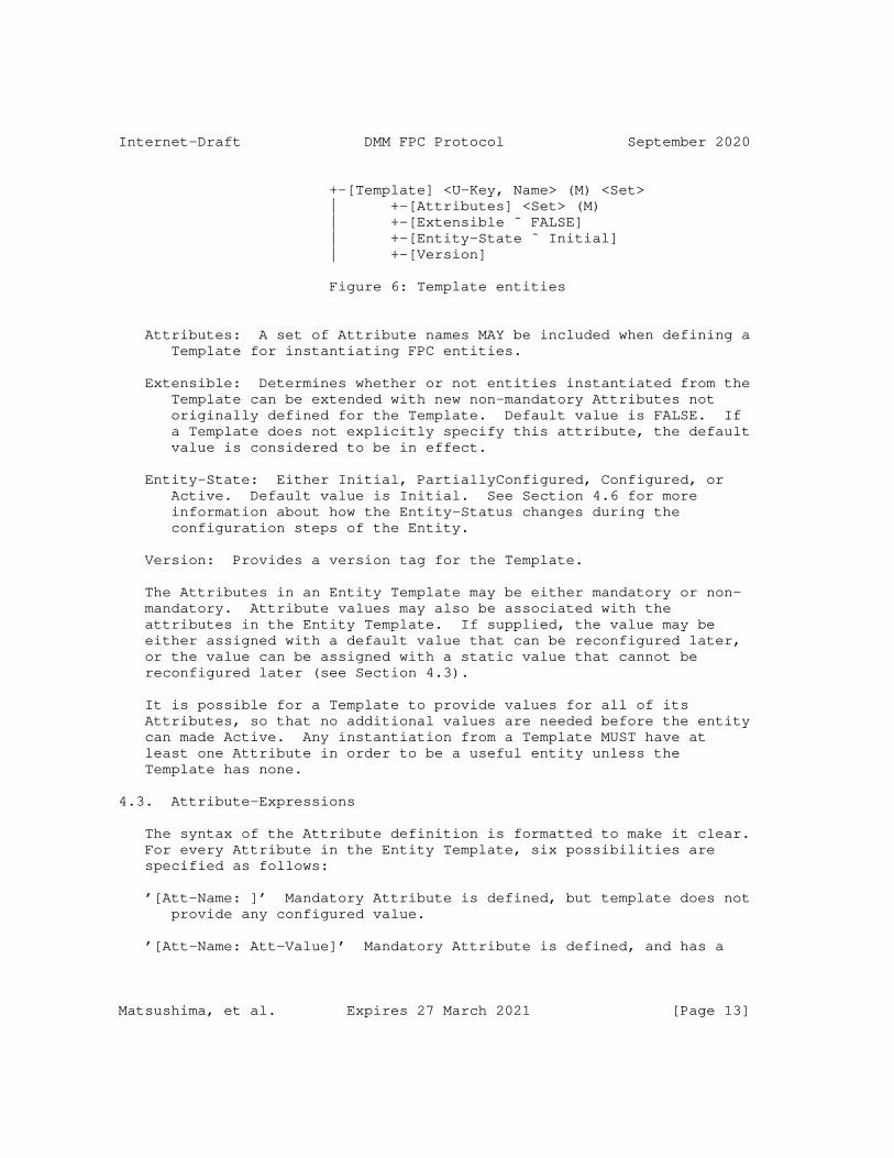
Internet-Draft DMM FPC Protocol September 2020
+-[Template] <U-Key, Name> (M) <Set> | +-[Attributes] <Set> (M) | +-[Extensible ˜ FALSE] | +-[Entity-State ˜ Initial] | +-[Version]
Figure 6: Template entities
Attributes: A set of Attribute names MAY be included when defining a Template for instantiating FPC entities.
Extensible: Determines whether or not entities instantiated from the Template can be extended with new non-mandatory Attributes not originally defined for the Template. Default value is FALSE. If a Template does not explicitly specify this attribute, the default value is considered to be in effect.
Entity-State: Either Initial, PartiallyConfigured, Configured, or Active. Default value is Initial. See Section 4.6 for more information about how the Entity-Status changes during the configuration steps of the Entity.
Version: Provides a version tag for the Template.
The Attributes in an Entity Template may be either mandatory or non- mandatory. Attribute values may also be associated with the attributes in the Entity Template. If supplied, the value may be either assigned with a default value that can be reconfigured later, or the value can be assigned with a static value that cannot be reconfigured later (see Section 4.3).
It is possible for a Template to provide values for all of its Attributes, so that no additional values are needed before the entity can made Active. Any instantiation from a Template MUST have at least one Attribute in order to be a useful entity unless the Template has none.
4.3. Attribute-Expressions
The syntax of the Attribute definition is formatted to make it clear. For every Attribute in the Entity Template, six possibilities are specified as follows:
’[Att-Name: ]’ Mandatory Attribute is defined, but template does not provide any configured value.
’[Att-Name: Att-Value]’ Mandatory Attribute is defined, and has a
Matsushima, et al. Expires 27 March 2021 [Page 13]
Internet-Draft DMM FPC Protocol September 2020
statically configured value.
’[Att-Name: ˜ Att-Value]’ Mandatory Attribute is defined, and has a default value.
’[Att-Name]’ Non-mandatory Attribute may be included but template does not provide any configured value.
’[Att-Name = Att-Value]’ Non-mandatory Attribute may be included and has a statically configured value.
’[Att-Name ˜ Att-Value]’ Non-mandatory Attribute may be included and has a default value.
So, for example, a default value for a non-mandatory IPv4-Address attribute would be denoted by [IPv4-Address ˜ 127.0.0.1].
After a FPC Client identifies which additional Attributes have been configured to be included in an instantiated entity, those configured Attributes MUST NOT be deleted by the FPC Agent. Similarly, any statically configured value for an entity Attribute MUST NOT be changed by the FPC Agent.
Whenever there is danger of confusion, the fully qualified Attribute name MUST be used when supplying needed Attribute Values for a structured Attribute.
4.4. Attribute Value Types
For situations in which the type of an attribute value is required, the following syntax is recommended. To declare than an attribute has data type "foo", typecast the attribute name by using the parenthesized data type (foo). So, for instance, [(float) Max- Latency-in-ms:] would indicate that the mandatory Attribute "Max- Latency-in-ms" requires to be configured with a floating point value before the instantiated entity could be used. Similarly, [(float) Max-Latency-in-ms: 9.5] would statically configure a floating point value of 9.5 to the mandatory Attribute "Max-Latency-in-ms".
4.5. Namespace and Format
The identifiers and names in FPC models which reside in the same Tenant must be unique. That uniqueness must be maintained by all Clients, Agents and DPNs that support the Tenant. The Tenant namespace uniqueness MUST be applied to all elements of the tenant model, i.e. Topology, Policy and Mobility models.
Matsushima, et al. Expires 27 March 2021 [Page 14]
Internet-Draft DMM FPC Protocol September 2020
When a Policy needs to be applied to Mobility-Contexts in all Tenants on an Agent, the Agent SHOULD define that policy to be visible by all Tenants. In this case, the Agent assigns a unique identifier in the Agent namespace and copies the values to each Tenant. This effectively creates a U-Key although only a G-Key is required within the Tenant.
The notation for identifiers can utilize any format with agreement between data-plane agent and client operators. The formats include but are not limited to Globally Unique IDentifiers (GUIDs), Universally Unique IDentifiers (UUIDs), Fully Qualified Domain Names (FQDNs), Fully Qualified Path Names (FQPNs) and Uniform Resource Identifiers (URIs). The FPC model does not limit the format, which could dictate the choice of FPC protocol. Nevertheless, the identifiers which are used in a Mobility model should be considered to efficiently handle runtime parameters.
4.6. Configuring Attribute Values
Attributes of Information Model components such as policy templates are configured with values as part of FPC configuration operations. There may be several such configuration operations before the template instantiation is fully configured.
Entity-Status indicates when an Entity is usable within a DPN. This permits DPN design tradeoffs amongst local storage (or other resources), over the wire request size and the speed of request processing. For example, DPN designers with constrained systems MAY only house entities whose status is Active which may result in sending over all policy information with a Mobility-Context request. Storing information elements with an entity status of "PartiallyConfigured" on the DPN requires more resources but can result in smaller over the wire FPC communication and request processing efficiency.
When the FPC Client instantiates a Policy from a Template, the Policy-Status is "Initial". When the FPC Client sends the policy to a FPC Agent for installation on a DPN, the Client often will configure appropriate attribute values for the installation, and accordingly changes the Policy-Status to "PartiallyConfigured" or "Configured". The FPC Agent will also configure Domain-specific policies and DPN-specific policies on the DPN. When configured to provide particular services for mobile nodes, the FPC Agent will apply whatever service-specific policies are needed on the DPN. When a mobile node attaches to the network data-plane within the topology under the jurisdiction of a FPC Agent, the Agent may apply policies and settings as appropriate for that mobile node. Finally, when the mobile node launches new flows, or quenches existing flows, the FPC
Matsushima, et al. Expires 27 March 2021 [Page 15]
Internet-Draft DMM FPC Protocol September 2020
Agent, on behalf of the FPC Client, applies or deactivates whatever policies and attribute values are appropriate for managing the flows of the mobile node. When a "Configured" policy is de-activated, Policy-Status is changed to be "Active". When an "Active" policy is activated, Policy-Status is changed to be "Configured".
Attribute values in DPN resident Policies may be configured by the FPC Agent as follows:
Domain-Policy-Configuration: Values for Policy attributes that are required for every DPN in the domain.
DPN-Policy-Configuration: Values for Policy attributes that are required for every policy configured on this DPN.
Service-Group-Policy-Configuration: Values for Policy attributes that are required to carry out the intended Service of the Service Group.
MN-Policy-Configuration: Values for Policy attributes that are required for all traffic to/from a particular mobile node.
Service-Data-Flow-Policy-Configuration: Values for Policy attributes that are required for traffic belonging to a particular set of flows on the mobile node.
Any configuration changes MAY also supply updated values for existing default attribute values that may have been previously configured on the DPN resident policy.
Entity blocks describe the format of the policy configurations.
4.7. Entity Configuration Blocks
As described in Section 4.6, a Policy Template may be configured in several stages by configuring default or missing values for Attributes that do not already have statically configured values. A Policy-Configuration is the combination of a Policy-Key (to identify the Policy Template defining the Attributes) and the currently configured Attribute Values to be applied to the Policy Template. Policy-Configurations MAY add attributes to a Template if Extensible is True. They MAY also refine existing attributes by:
assign new values if the Attribute is not static
make attributes static if they were not
make an attribute mandatory
Matsushima, et al. Expires 27 March 2021 [Page 16]
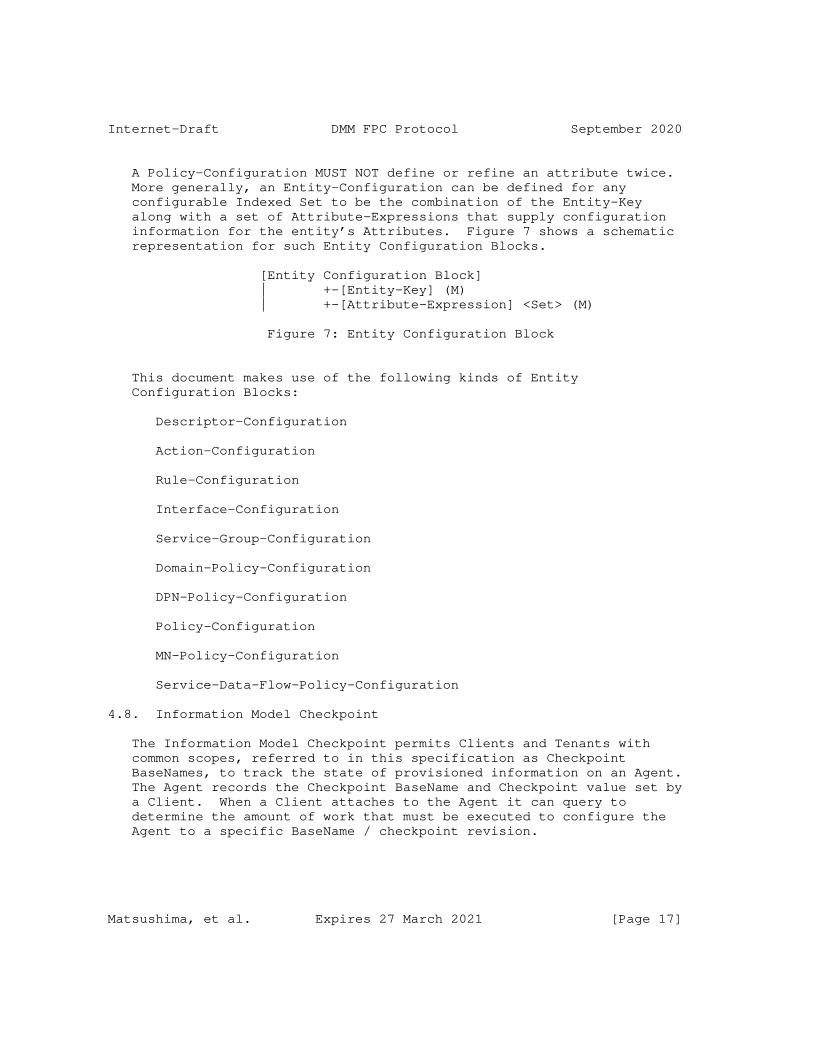
Internet-Draft DMM FPC Protocol September 2020
A Policy-Configuration MUST NOT define or refine an attribute twice. More generally, an Entity-Configuration can be defined for any configurable Indexed Set to be the combination of the Entity-Key along with a set of Attribute-Expressions that supply configuration information for the entity’s Attributes. Figure 7 shows a schematic representation for such Entity Configuration Blocks.
[Entity Configuration Block] | +-[Entity-Key] (M) | +-[Attribute-Expression] <Set> (M)
Figure 7: Entity Configuration Block
This document makes use of the following kinds of Entity Configuration Blocks:
Descriptor-Configuration
Action-Configuration
Rule-Configuration
Interface-Configuration
Service-Group-Configuration
Domain-Policy-Configuration
DPN-Policy-Configuration
Policy-Configuration
MN-Policy-Configuration
Service-Data-Flow-Policy-Configuration
4.8. Information Model Checkpoint
The Information Model Checkpoint permits Clients and Tenants with common scopes, referred to in this specification as Checkpoint BaseNames, to track the state of provisioned information on an Agent. The Agent records the Checkpoint BaseName and Checkpoint value set by a Client. When a Client attaches to the Agent it can query to determine the amount of work that must be executed to configure the Agent to a specific BaseName / checkpoint revision.
Matsushima, et al. Expires 27 March 2021 [Page 17]
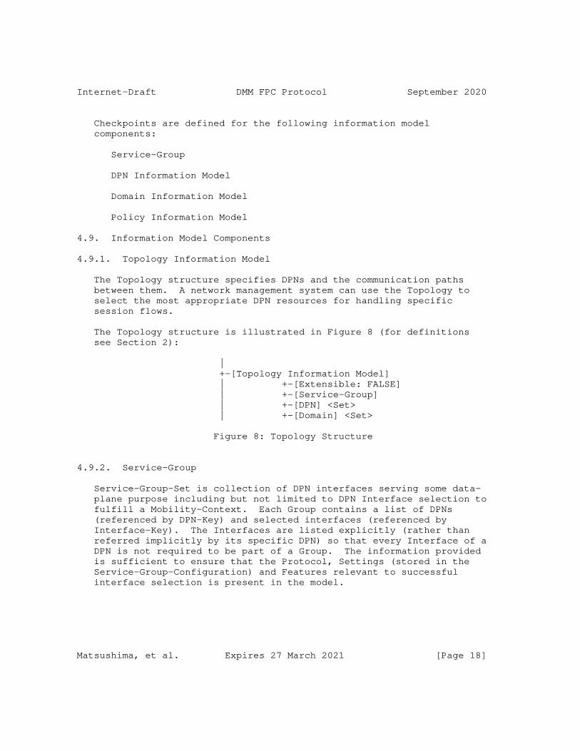
Internet-Draft DMM FPC Protocol September 2020
Checkpoints are defined for the following information model components:
Service-Group
DPN Information Model
Domain Information Model
Policy Information Model
4.9. Information Model Components
4.9.1. Topology Information Model
The Topology structure specifies DPNs and the communication paths between them. A network management system can use the Topology to select the most appropriate DPN resources for handling specific session flows.
The Topology structure is illustrated in Figure 8 (for definitions see Section 2):
| +-[Topology Information Model] | +-[Extensible: FALSE] | +-[Service-Group] | +-[DPN] <Set> | +-[Domain] <Set>
Figure 8: Topology Structure
4.9.2. Service-Group
Service-Group-Set is collection of DPN interfaces serving some data- plane purpose including but not limited to DPN Interface selection to fulfill a Mobility-Context. Each Group contains a list of DPNs (referenced by DPN-Key) and selected interfaces (referenced by Interface-Key). The Interfaces are listed explicitly (rather than referred implicitly by its specific DPN) so that every Interface of a DPN is not required to be part of a Group. The information provided is sufficient to ensure that the Protocol, Settings (stored in the Service-Group-Configuration) and Features relevant to successful interface selection is present in the model.
Matsushima, et al. Expires 27 March 2021 [Page 18]
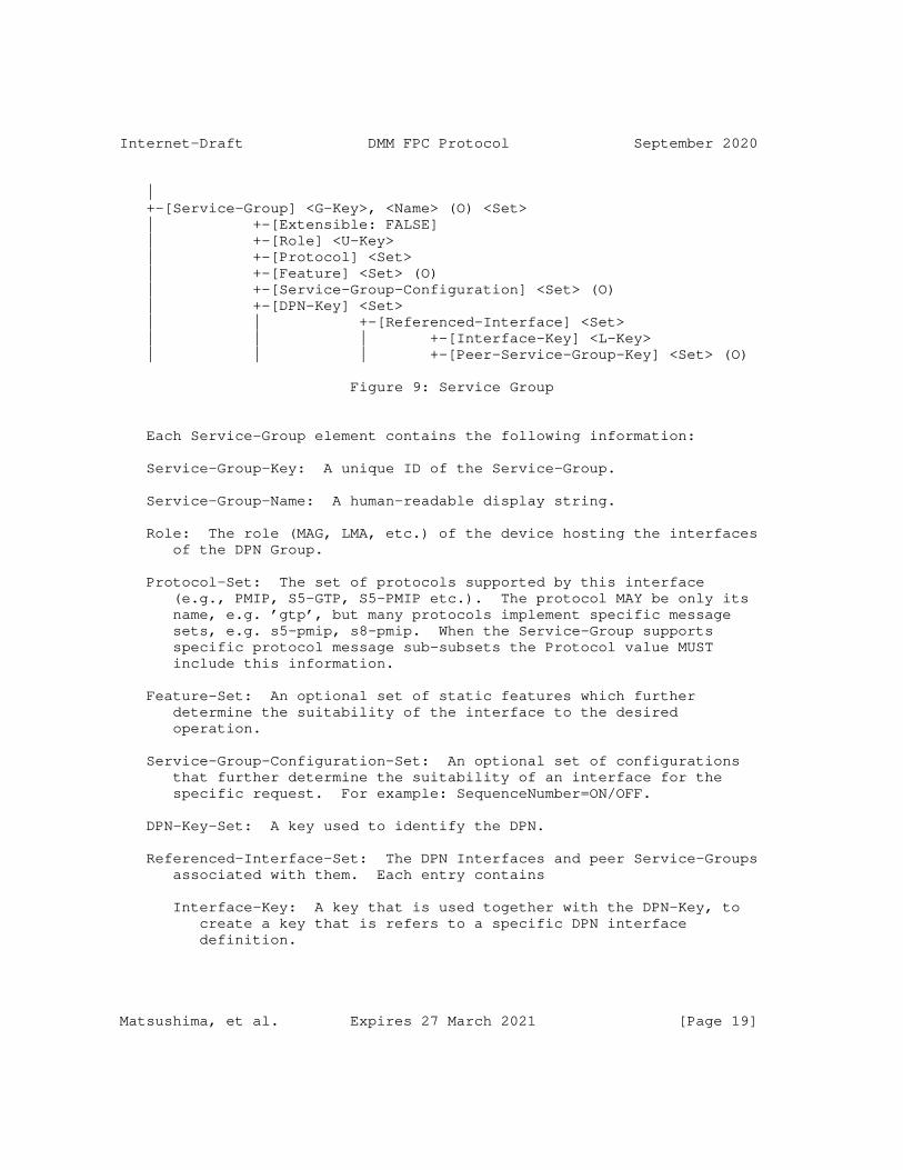
Internet-Draft DMM FPC Protocol September 2020
| +-[Service-Group] <G-Key>, <Name> (O) <Set> | +-[Extensible: FALSE] | +-[Role] <U-Key> | +-[Protocol] <Set> | +-[Feature] <Set> (O) | +-[Service-Group-Configuration] <Set> (O) | +-[DPN-Key] <Set> | | +-[Referenced-Interface] <Set> | | | +-[Interface-Key] <L-Key> | | | +-[Peer-Service-Group-Key] <Set> (O)
Figure 9: Service Group
Each Service-Group element contains the following information:
Service-Group-Key: A unique ID of the Service-Group.
Service-Group-Name: A human-readable display string.
Role: The role (MAG, LMA, etc.) of the device hosting the interfaces of the DPN Group.
Protocol-Set: The set of protocols supported by this interface (e.g., PMIP, S5-GTP, S5-PMIP etc.). The protocol MAY be only its name, e.g. ’gtp’, but many protocols implement specific message sets, e.g. s5-pmip, s8-pmip. When the Service-Group supports specific protocol message sub-subsets the Protocol value MUST include this information.
Feature-Set: An optional set of static features which further determine the suitability of the interface to the desired operation.
Service-Group-Configuration-Set: An optional set of configurations that further determine the suitability of an interface for the specific request. For example: SequenceNumber=ON/OFF.
DPN-Key-Set: A key used to identify the DPN.
Referenced-Interface-Set: The DPN Interfaces and peer Service-Groups associated with them. Each entry contains
Interface-Key: A key that is used together with the DPN-Key, to create a key that is refers to a specific DPN interface definition.
Matsushima, et al. Expires 27 March 2021 [Page 19]
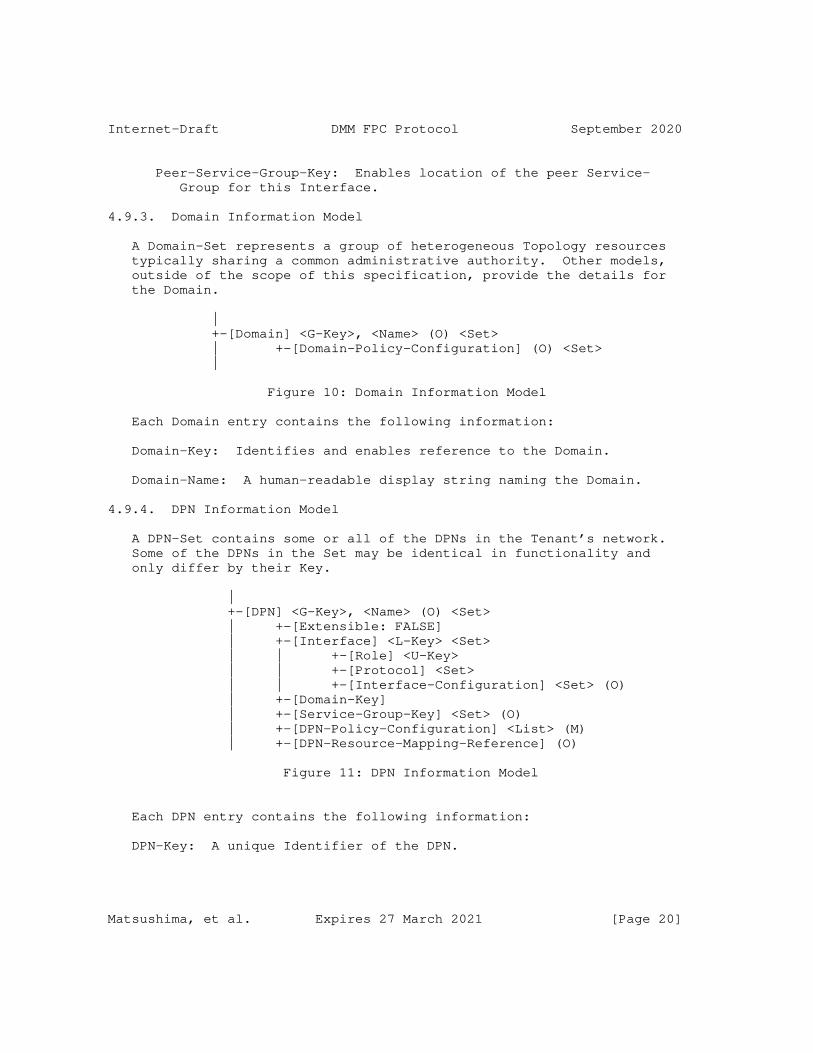
Internet-Draft DMM FPC Protocol September 2020
Peer-Service-Group-Key: Enables location of the peer Service- Group for this Interface.
4.9.3. Domain Information Model
A Domain-Set represents a group of heterogeneous Topology resources typically sharing a common administrative authority. Other models, outside of the scope of this specification, provide the details for the Domain.
| +-[Domain] <G-Key>, <Name> (O) <Set> | +-[Domain-Policy-Configuration] (O) <Set> |
Figure 10: Domain Information Model
Each Domain entry contains the following information:
Domain-Key: Identifies and enables reference to the Domain.
Domain-Name: A human-readable display string naming the Domain.
4.9.4. DPN Information Model
A DPN-Set contains some or all of the DPNs in the Tenant’s network. Some of the DPNs in the Set may be identical in functionality and only differ by their Key.
| +-[DPN] <G-Key>, <Name> (O) <Set> | +-[Extensible: FALSE] | +-[Interface] <L-Key> <Set> | | +-[Role] <U-Key> | | +-[Protocol] <Set> | | +-[Interface-Configuration] <Set> (O) | +-[Domain-Key] | +-[Service-Group-Key] <Set> (O) | +-[DPN-Policy-Configuration] <List> (M) | +-[DPN-Resource-Mapping-Reference] (O)
Figure 11: DPN Information Model
Each DPN entry contains the following information:
DPN-Key: A unique Identifier of the DPN.
Matsushima, et al. Expires 27 March 2021 [Page 20]
Internet-Draft DMM FPC Protocol September 2020
DPN-Name: A human-readable display string.
Domain-Key: A Key providing access to the Domain information about the Domain in which the DPN resides.
Interface-Set: The Interface-Set references all interfaces (through which data packets are received and transmitted) available on the DPN. Each Interface makes use of attribute values that are specific to that interface, for example, the MTU size. These do not affect the DPN selection of active or enabled interfaces. Interfaces contain the following information:
Role: The role (MAG, LMA, PGW, AMF, etc.) of the DPN.
Protocol (Set): The set of protocols supported by this interface (e.g., PMIP, S5-GTP, S5-PMIP etc.). The protocol MAY implement specific message sets, e.g. s5-pmip, s8-pmip. When a protocol implements such message sub-subsets the Protocol value MUST include this information.
Interface-Configuration-Set: Configurable settings that further determine the suitability of an interface for the specific request. For example: SequenceNumber=ON/OFF.
Service-Group-Set: The Service-Group-Set references all of the Service-Groups which have been configured using Interfaces hosted on this DPN. The purpose of a Service-Group is not to describe each interface of each DPN, but rather to indicate interface types for use during the DPN selection process, when a DPN with specific interface capabilities is required.
DPN-Policy-Configuration: A list of Policies that have been configured on this DPN. Some may have values for all attributes, and some may require further configuration. Each Policy- Configuration has a key to enable reference to its Policy- Template. Each Policy-Configuration also has been configured to supply missing and non-default values to the desired Attributes defined within the Policy-Template.
DPN-Resource-Mapping-Reference (O): A reference to the underlying implementation, e.g. physical node, software module, etc. that supports this DPN. Further specification of this attribute is out of scope for this document.
Matsushima, et al. Expires 27 March 2021 [Page 21]

Internet-Draft DMM FPC Protocol September 2020
4.9.5. Policy Information Model
The Policy Information Model defines and identifies Rules for enforcement at DPNs. A Policy is basically a set of Rules that are to be applied to each incoming or outgoing packet at a DPN interface. Rules comprise Descriptors and a set of Actions. The Descriptors, when evaluated, determine whether or not a set of Actions will be performed on the packet. The Policy structure is independent of a policy context.
In addition to the Policy structure, the Information Model (per Section 4.9.6) defines Mobility-Context. Each Mobility-Context may be configured with appropriate Attribute values, for example depending on the identity of a mobile node.
Traffic descriptions are defined in Descriptors, and treatments are defined separately in Actions. A Rule-Set binds Descriptors and associated Actions by reference, using Descriptor-Key and Action-Key. A Rule-Set is bound to a policy in the Policy-Set (using Policy-Key), and the Policy references the Rule definitions (using Rule-Key).
| +-[Policy Information Model] | +-[Extensible:] | +-[Policy-Template] <G-Key> (M) <Set> | | +-[Policy-Configuration] <Set> (O) | | +-[Rule-Template-Key] <List> (M) | | | +-[Precedence] (M) | +-[Rule-Template] <L-Key> (M) <Set> | | +-[Descriptor-Match-Type] (M) | | +-[Descriptor-Configuration] <Set> (M) | | | +-[Direction] (O) | | +-[Action-Configuration] <Set> (M) | | | +-[Action-Order] (M) | | +-[Rule-Configuration] (O) | +-[Descriptor-Template] <L-Key> (M) <Set> | | +-[Descriptor-Type] (O) | | +-[Attribute-Expression] <Set> (M) | +-[Action-Template] <L-Key> (M) <Set> | +-[Action-Type] (O) | | +-[Attribute-Expression] <Set> (M)
Figure 12: Policy Information Model
The Policy structure defines Policy-Set, Rule-Set, Descriptor-Set, and Action-Set, as follows:
Matsushima, et al. Expires 27 March 2021 [Page 22]
Internet-Draft DMM FPC Protocol September 2020
Policy-Template: <Set> A set of Policy structures, indexed by Policy-Key, each of which is determined by a list of Rules referenced by their Rule-Key. Each Policy structure contains the following:
Policy-Key: Identifies and enables reference to this Policy definition.
Rule-Template-Key: Enables reference to a Rule template definition.
Rule-Precedence: For each Rule identified by a Rule-Template-Key in the Policy, specifies the order in which that Rule must be applied. The lower the numerical value of Precedence, the higher the rule precedence. Rules with equal precedence MAY be executed in parallel if supported by the DPN. If this value is absent, the rules SHOULD be applied in the order in which they appear in the Policy.
Rule-Template-Set: A set of Rule Template definitions indexed by Rule-Key. Each Rule is defined by a list of Descriptors (located by Descriptor-Key) and a list of Actions (located by Action-Key) as follows:
Rule-Template-Key: Identifies and enables reference to this Rule definition.
Descriptor-Match-Type Indicates whether the evaluation of the Rule proceeds by using conditional-AND, or conditional-OR, on the list of Descriptors.
Descriptor-Configuration: References a Descriptor template definition, along with an expression which names the Attributes for this instantiation from the Descriptor-Template and also specifies whether each Attribute of the Descriptor has a default value or a statically configured value, according to the syntax specified in Section 4.2.
Direction: Indicates if a rule applies to uplink traffic, to downlink traffic, or to both uplink and downlink traffic. Applying a rule to both uplink and downlink traffic, in case of symmetric rules, eliminates the requirement for a separate entry for each direction. When not present, the direction is implied by the Descriptor’s values.
Action-Configuration: References an Action Template definition,
Matsushima, et al. Expires 27 March 2021 [Page 23]

Internet-Draft DMM FPC Protocol September 2020
along with an expression which names the Attributes for this instantiation from the Action-Template and also specifies whether each Attribute of the Action has a default value or a statically configured value, according to the syntax specified in Section 4.2.
Action-Order: Defines the order in which actions are executed when the associated traffic descriptor selects the packet.
Descriptor-Template-Set: A set of traffic Descriptor Templates, each of which can be evaluated on the incoming or outgoing packet, returning a TRUE or FALSE value, defined as follows:
Descriptor-Template-Key: Identifies and enables reference to this descriptor template definition.
Attribute-Expression: An expression which defines an Attribute in the Descriptor-Template and also specifies whether the Template also defines a default value or a statically configured value for the Attribute of the Descriptor has, according to the syntax specified in Section 4.2.
Descriptor-Type: Identifies the type of descriptor, e.g. an IPv6 traffic selector per [RFC6088].
Action-Template-Set: A set of Action Templates defined as follows:
Action-Template-Key: Identifies and enables reference to this action template definition.
Attribute-Expression: An expression which defines an Attribute in the Action-Template and also specifies whether the Template also defines a default value or a statically configured value for the Attribute of the Action has, according to the syntax specified in Section 4.2.
Action-Type: Identifies the type of an action for unambiguous interpretation of an Action-Value entry.
4.9.6. Mobility-Context Information Model
The Mobility-Context structure holds entries associated with a mobile node and its mobility sessions (flows). It is created on a DPN during the mobile node’s registration to manage the mobile node’s flows. Flow information is added or deleted from the Mobility- Context as needed to support new flows or to deallocate resources for flows that are deactivated. Descriptors are used to characterize the nature and resource requirement for each flow.
Matsushima, et al. Expires 27 March 2021 [Page 24]
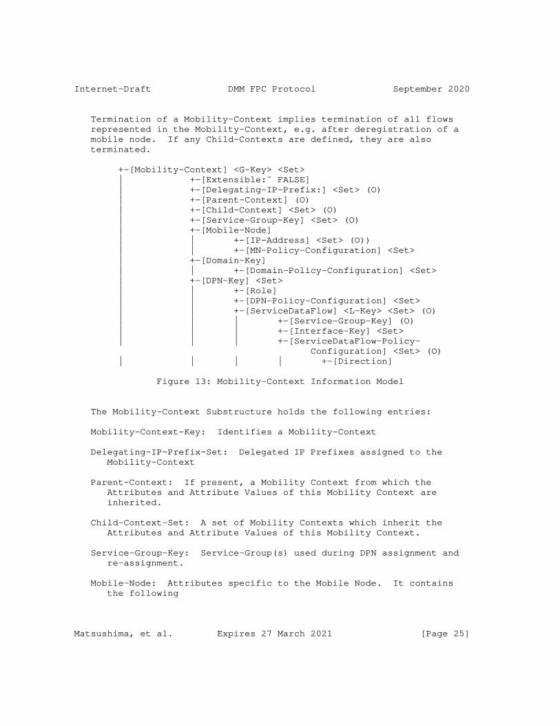
Internet-Draft DMM FPC Protocol September 2020
Termination of a Mobility-Context implies termination of all flows represented in the Mobility-Context, e.g. after deregistration of a mobile node. If any Child-Contexts are defined, they are also terminated.
+-[Mobility-Context] <G-Key> <Set> | +-[Extensible:˜ FALSE] | +-[Delegating-IP-Prefix:] <Set> (O) | +-[Parent-Context] (O) | +-[Child-Context] <Set> (O) | +-[Service-Group-Key] <Set> (O) | +-[Mobile-Node] | | +-[IP-Address] <Set> (O)) | | +-[MN-Policy-Configuration] <Set> | +-[Domain-Key] | | +-[Domain-Policy-Configuration] <Set> | +-[DPN-Key] <Set> | | +-[Role] | | +-[DPN-Policy-Configuration] <Set> | | +-[ServiceDataFlow] <L-Key> <Set> (O) | | | +-[Service-Group-Key] (O) | | | +-[Interface-Key] <Set> | | | +-[ServiceDataFlow-Policy- Configuration] <Set> (O) | | | | +-[Direction]
Figure 13: Mobility-Context Information Model
The Mobility-Context Substructure holds the following entries:
Mobility-Context-Key: Identifies a Mobility-Context
Delegating-IP-Prefix-Set: Delegated IP Prefixes assigned to the Mobility-Context
Parent-Context: If present, a Mobility Context from which the Attributes and Attribute Values of this Mobility Context are inherited.
Child-Context-Set: A set of Mobility Contexts which inherit the Attributes and Attribute Values of this Mobility Context.
Service-Group-Key: Service-Group(s) used during DPN assignment and re-assignment.
Mobile-Node: Attributes specific to the Mobile Node. It contains the following
Matsushima, et al. Expires 27 March 2021 [Page 25]
Internet-Draft DMM FPC Protocol September 2020
IP-Address-Set IP addresses assigned to the Mobile Node.
MN-Policy-Configuration-Set For each MN-Policy in the set, a key and relevant information for the Policy Attributes.
Domain-Key: Enables access to a Domain instance.
Domain-Policy-Configuration-Set: For each Domain-Policy in the set, a key and relevant information for the Policy Attributes.
DPN-Key-Set: Enables access to a DPN instance assigned to a specific role, i.e. this is a Set that uses DPN-Key and Role as a compound key to access specific set instances.
Role: Role this DPN fulfills in the Mobility-Context.
DPN-Policy-Configuration-Set: For each DPN-Policy in the set, a key and relevant information for the Policy Attributes.
ServiceDataFlow-Key-Set: Characterizes a traffic flow that has been configured (and provided resources) on the DPN to support data- plane traffic to and from the mobile device.
Service-Group-Key: Enables access to a Service-Group instance.
Interface-Key-Set: Assigns the selected interface of the DPN.
ServiceDataFlow-Policy-Configuration-Set: For each Policy in the set, a key and relevant information for the Policy Attributes.
Direction: Indicates if the reference Policy applies to uplink or downlink traffic, or to both, uplink- and downlink traffic. Applying a rule to both, uplink- and downlink traffic, in case of symmetric rules, allows omitting a separate entry for each direction. When not present the value is assumed to apply to both directions.
4.9.7. Monitor Information Model
Monitors provide a mechanism to produce reports when events occur. A Monitor will have a target that specifies what is to be watched.
The attribute/entity to be monitored places certain constraints on the configuration that can be specified. For example, a Monitor using a Threshold configuration cannot be applied to a Mobility- Context, because it does not have a threshold. Such a monitor configuration could be applied to a numeric threshold property of a Context.
Matsushima, et al. Expires 27 March 2021 [Page 26]
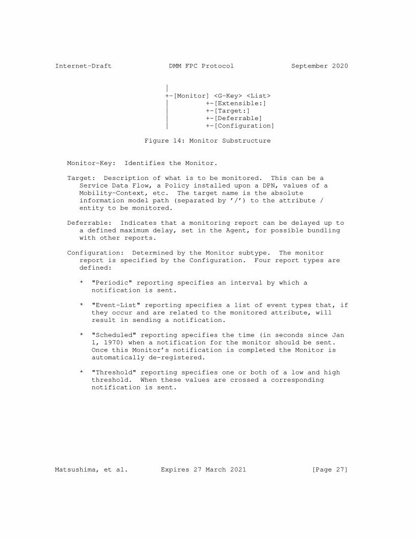
Internet-Draft DMM FPC Protocol September 2020
| +-[Monitor] <G-Key> <List> | +-[Extensible:] | +-[Target:] | +-[Deferrable] | +-[Configuration]
Figure 14: Monitor Substructure
Monitor-Key: Identifies the Monitor.
Target: Description of what is to be monitored. This can be a Service Data Flow, a Policy installed upon a DPN, values of a Mobility-Context, etc. The target name is the absolute information model path (separated by ’/’) to the attribute / entity to be monitored.
Deferrable: Indicates that a monitoring report can be delayed up to a defined maximum delay, set in the Agent, for possible bundling with other reports.
Configuration: Determined by the Monitor subtype. The monitor report is specified by the Configuration. Four report types are defined:
* "Periodic" reporting specifies an interval by which a notification is sent.
* "Event-List" reporting specifies a list of event types that, if they occur and are related to the monitored attribute, will result in sending a notification.
* "Scheduled" reporting specifies the time (in seconds since Jan 1, 1970) when a notification for the monitor should be sent. Once this Monitor’s notification is completed the Monitor is automatically de-registered.
* "Threshold" reporting specifies one or both of a low and high threshold. When these values are crossed a corresponding notification is sent.
Matsushima, et al. Expires 27 March 2021 [Page 27]
Internet-Draft DMM FPC Protocol September 2020
5. Security Considerations
Detailed protocol implementations for DMM Forwarding Policy Configuration must ensure integrity of the information exchanged between a FPC Client and a FPC Agent. Required Security Associations may be derived from co-located functions, which utilize the FPC Client and FPC Agent respectively.
General usage of FPC MUST consider the following:
FPC Naming Section 4.5 permits arbitrary string values but a user MUST avoid placing sensitive or vulnerable information in those values.
Policies that are very narrow and permit the identification of specific traffic, e.g. that of a single user, SHOULD be avoided.
6. IANA Considerations
TBD
7. Work Team Participants
Participants in the FPSM work team discussion include Satoru Matsushima, Danny Moses, Sri Gundavelli, Marco Liebsch, Pierrick Seite, Alper Yegin, Carlos Bernardos, Charles Perkins and Fred Templin.
8. References
8.1. Normative References
[RFC2119] Bradner, S., "Key words for use in RFCs to Indicate Requirement Levels", BCP 14, RFC 2119, DOI 10.17487/RFC2119, March 1997, <https://www.rfc-editor.org/info/rfc2119>.
[RFC6088] Tsirtsis, G., Giarreta, G., Soliman, H., and N. Montavont, "Traffic Selectors for Flow Bindings", RFC 6088, DOI 10.17487/RFC6088, January 2011, <https://www.rfc-editor.org/info/rfc6088>.
8.2. Informative References
Matsushima, et al. Expires 27 March 2021 [Page 28]

Internet-Draft DMM FPC Protocol September 2020
[I-D.bertz-dime-policygroups] Bertz, L. and M. Bales, "Diameter Policy Groups and Sets", Work in Progress, Internet-Draft, draft-bertz-dime- policygroups-06, 18 June 2018, <http://www.ietf.org/ internet-drafts/draft-bertz-dime-policygroups-06.txt>.
[I-D.ietf-dmm-deployment-models] Gundavelli, S. and S. Jeon, "DMM Deployment Models and Architectural Considerations", Work in Progress, Internet- Draft, draft-ietf-dmm-deployment-models-04, 15 May 2018, <http://www.ietf.org/internet-drafts/draft-ietf-dmm- deployment-models-04.txt>.
[RFC7333] Chan, H., Ed., Liu, D., Seite, P., Yokota, H., and J. Korhonen, "Requirements for Distributed Mobility Management", RFC 7333, DOI 10.17487/RFC7333, August 2014, <https://www.rfc-editor.org/info/rfc7333>.
Appendix A. Implementation Status
Three FPC Agent implementations have been made to date. The first was based upon Version 03 of the draft and followed Model 1. The second follows Version 04 of the document. Both implementations were OpenDaylight plug-ins developed in Java by Sprint. Version 04 is now primarily enhanced by GS Labs. Version 03 was known as fpcagent and version 04’s implementation is simply referred to as ’fpc’. A third has been developed on an ONOS Controller for use in MCORD projects.
fpcagent’s intent was to provide a proof of concept for FPC Version 03 Model 1 in January 2016 and research various errors, corrections and optimizations that the Agent could make when supporting multiple DPNs.
As the code developed to support OpenFlow and a proprietary DPN from a 3rd party, several of the advantages of a multi-DPN Agent became obvious including the use of machine learning to reduce the number of Flows and Policy entities placed on the DPN. This work has driven new efforts in the DIME WG, namely Diameter Policy Groups [I-D.bertz-dime-policygroups].
Matsushima, et al. Expires 27 March 2021 [Page 29]

Internet-Draft DMM FPC Protocol September 2020
A throughput performance of tens per second using various NetConf based solutions in OpenDaylight made fpcagent, based on version 03, undesirable for call processing. The RPC implementation improved throughput by an order of magnitude but was not useful based upon FPC’s Version 03 design using two information models. During this time the features of version 04 and its converged model became attractive and the fpcagent project was closed in August 2016. fpcagent will no longer be developed and will remain a proprietary implementation.
The learnings of fpcagent has influenced the second project, fpc. Fpc is also an OpenDaylight project but is an open source release as the Opendaylight FpcAgent plugin (https://wiki.opendaylight.org/view/ Project_Proposals:FpcAgent). This project is scoped to be a fully compliant FPC Agent that supports multiple DPNs including those that communicate via OpenFlow. The following features present in this draft and others developed by the FPC development team have already led to an order of magnitude improvement.
Migration of non-realtime provisioning of entities such as topology and policy allowed the implementation to focus only on the rpc.
Using only 5 messages and 2 notifications has also reduced implementation time.
Command Sets, an optional feature in this specification, have eliminated 80% of the time spent determining what needs to be done with a Context during a Create or Update operation.
Op Reference is an optional feature modeled after video delivery. It has reduced unnecessary cache lookups. It also has the additional benefit of allowing an Agent to become cacheless and effectively act as a FPC protocol adapter remotely with multi-DPN support or co-located on the DPN in a single-DPN support model.
Multi-tenant support allows for Cache searches to be partitioned for clustering and performance improvements. This has not been capitalized upon by the current implementation but is part of the development roadmap.
Use of Contexts to pre-provision policy has also eliminated any processing of Ports for DPNs which permitted the code for CONFIGURE and CONF_BUNDLE to be implemented as a simple nested FOR loops (see below).
Matsushima, et al. Expires 27 March 2021 [Page 30]
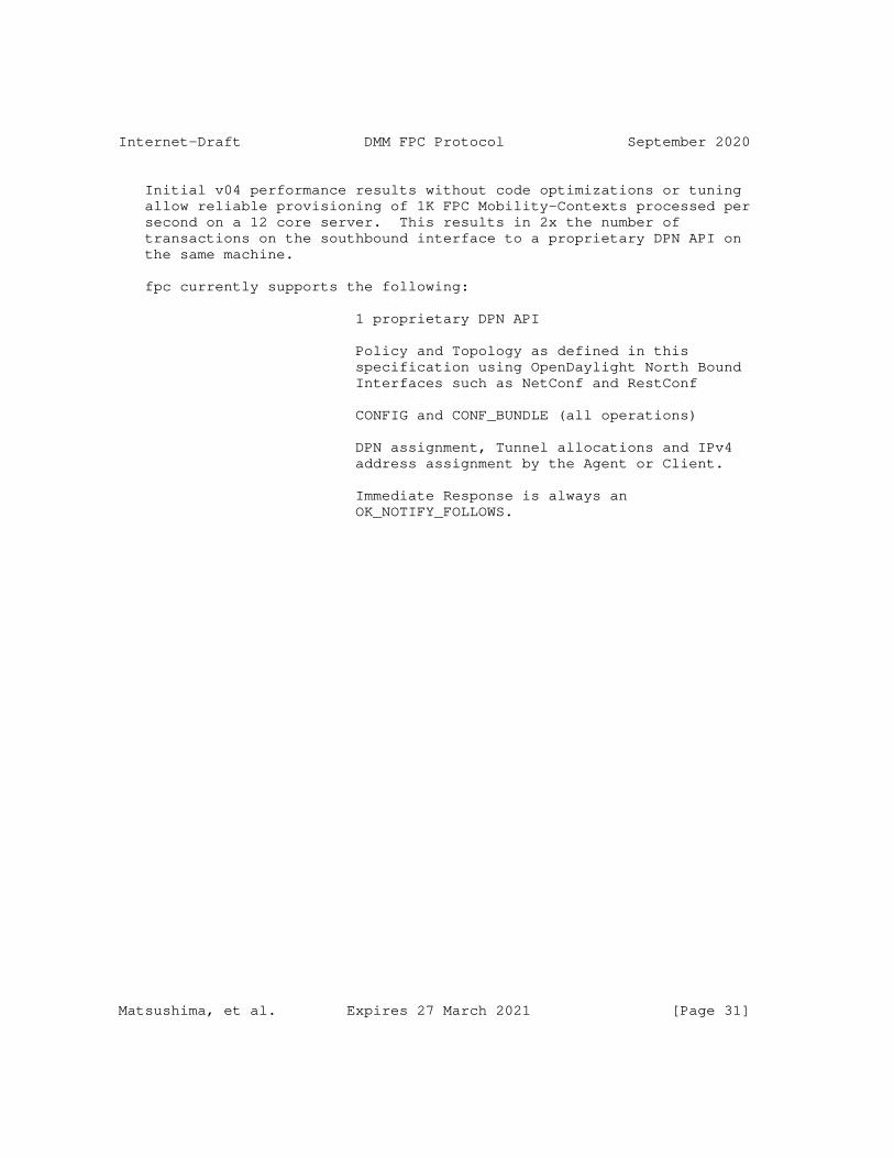
Internet-Draft DMM FPC Protocol September 2020
Initial v04 performance results without code optimizations or tuning allow reliable provisioning of 1K FPC Mobility-Contexts processed per second on a 12 core server. This results in 2x the number of transactions on the southbound interface to a proprietary DPN API on the same machine.
fpc currently supports the following:
1 proprietary DPN API
Policy and Topology as defined in this specification using OpenDaylight North Bound Interfaces such as NetConf and RestConf
CONFIG and CONF_BUNDLE (all operations)
DPN assignment, Tunnel allocations and IPv4 address assignment by the Agent or Client.
Immediate Response is always an OK_NOTIFY_FOLLOWS.
Matsushima, et al. Expires 27 March 2021 [Page 31]
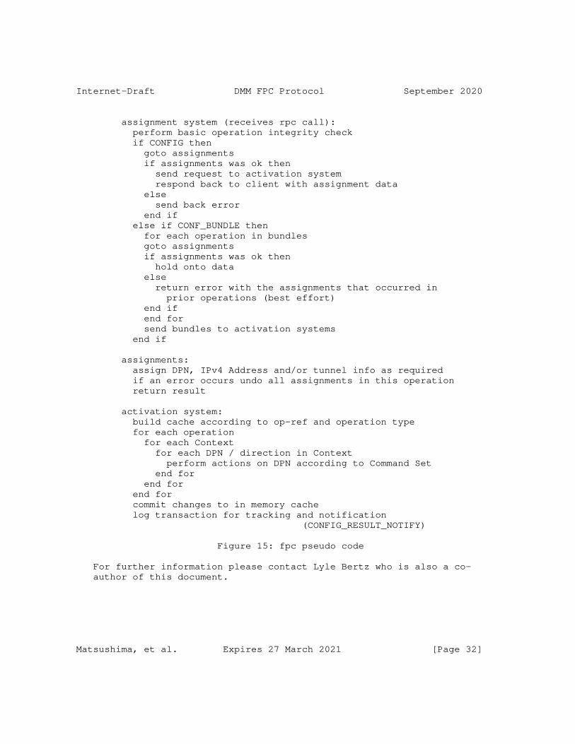
Internet-Draft DMM FPC Protocol September 2020
assignment system (receives rpc call): perform basic operation integrity check if CONFIG then goto assignments if assignments was ok then send request to activation system respond back to client with assignment data else send back error end if else if CONF_BUNDLE then for each operation in bundles goto assignments if assignments was ok then hold onto data else return error with the assignments that occurred in prior operations (best effort) end if end for send bundles to activation systems end if
assignments: assign DPN, IPv4 Address and/or tunnel info as required if an error occurs undo all assignments in this operation return result
activation system: build cache according to op-ref and operation type for each operation for each Context for each DPN / direction in Context perform actions on DPN according to Command Set end for end for end for commit changes to in memory cache log transaction for tracking and notification (CONFIG_RESULT_NOTIFY)
Figure 15: fpc pseudo code
For further information please contact Lyle Bertz who is also a co- author of this document.
Matsushima, et al. Expires 27 March 2021 [Page 32]
Internet-Draft DMM FPC Protocol September 2020
NOTE: Tenant support requires binding a Client ID to a Tenant ID (it is a one to many relation) but that is outside of the scope of this specification. Otherwise, the specification is complete in terms of providing sufficient information to implement an Agent.
Authors’ Addresses
Satoru Matsushima SoftBank 1-9-1,Higashi-Shimbashi,Minato-Ku, Japan
Email: [email protected]
Lyle Bertz 6220 Sprint Parkway Overland Park KS, 66251, United States of America
Email: [email protected]
Marco Liebsch NEC Laboratories Europe NEC Europe Ltd. Kurfuersten-Anlage 36 D-69115 Heidelberg Germany
Phone: +49 6221 4342146 Email: [email protected]
Sri Gundavelli Cisco 170 West Tasman Drive San Jose, CA 95134 United States of America
Email: [email protected]
Danny Moses
Email: [email protected]
Matsushima, et al. Expires 27 March 2021 [Page 33]
Internet-Draft DMM FPC Protocol September 2020
Charles E. Perkins Futurewei Inc. 2330 Central Expressway Santa Clara, CA 95050 United States of America
Phone: +1-408-330-4586 Email: [email protected]
Matsushima, et al. Expires 27 March 2021 [Page 34]
DMM Working Group CJ. BernardosInternet-Draft A. de la OlivaIntended status: Experimental UC3MExpires: September 9, 2020 F. Giust Athonet JC. Zuniga SIGFOX A. Mourad InterDigital March 8, 2020
Proxy Mobile IPv6 extensions for Distributed Mobility Management draft-ietf-dmm-pmipv6-dlif-06
Abstract
Distributed Mobility Management solutions allow for setting up networks so that traffic is distributed in an optimal way and does not rely on centrally deployed anchors to provide IP mobility support.
There are many different approaches to address Distributed Mobility Management, as for example extending network-based mobility protocols (like Proxy Mobile IPv6), or client-based mobility protocols (like Mobile IPv6), among others. This document follows the former approach and proposes a solution based on Proxy Mobile IPv6 in which mobility sessions are anchored at the last IP hop router (called mobility anchor and access router). The mobility anchor and access router is an enhanced access router which is also able to operate as a local mobility anchor or mobility access gateway, on a per prefix basis. The document focuses on the required extensions to effectively support simultaneously anchoring several flows at different distributed gateways.
Requirements Language
The key words "MUST", "MUST NOT", "REQUIRED", "SHALL", "SHALL NOT", "SHOULD", "SHOULD NOT", "RECOMMENDED", "NOT RECOMMENDED", "MAY", and "OPTIONAL" in this document are to be interpreted as described in BCP 14 [RFC2119] [RFC8174] when, and only when, they appear in all capitals, as shown here.
Status of This Memo
This Internet-Draft is submitted in full conformance with the provisions of BCP 78 and BCP 79.
Bernardos, et al. Expires September 9, 2020 [Page 1]
Internet-Draft PMIPv6 DMM and DLIF March 2020
Internet-Drafts are working documents of the Internet Engineering Task Force (IETF). Note that other groups may also distribute working documents as Internet-Drafts. The list of current Internet- Drafts is at https://datatracker.ietf.org/drafts/current/.
Internet-Drafts are draft documents valid for a maximum of six months and may be updated, replaced, or obsoleted by other documents at any time. It is inappropriate to use Internet-Drafts as reference material or to cite them other than as "work in progress."
This Internet-Draft will expire on September 9, 2020.
Copyright Notice
Copyright (c) 2020 IETF Trust and the persons identified as the document authors. All rights reserved.
This document is subject to BCP 78 and the IETF Trust’s Legal Provisions Relating to IETF Documents (https://trustee.ietf.org/license-info) in effect on the date of publication of this document. Please review these documents carefully, as they describe your rights and restrictions with respect to this document. Code Components extracted from this document must include Simplified BSD License text as described in Section 4.e of the Trust Legal Provisions and are provided without warranty as described in the Simplified BSD License.
Table of Contents
1. Introduction . . . . . . . . . . . . . . . . . . . . . . . . 3 2. Terminology . . . . . . . . . . . . . . . . . . . . . . . . . 4 3. PMIPv6 DMM extensions . . . . . . . . . . . . . . . . . . . . 6 3.1. Initial registration . . . . . . . . . . . . . . . . . . 7 3.2. The CMD as PBU/PBA relay . . . . . . . . . . . . . . . . 8 3.3. The CMD as MAAR locator . . . . . . . . . . . . . . . . . 11 3.4. The CMD as MAAR proxy . . . . . . . . . . . . . . . . . . 12 3.5. De-registration . . . . . . . . . . . . . . . . . . . . . 13 3.6. Retransmissions and Rate Limiting . . . . . . . . . . . . 14 3.7. The Distributed Logical Interface (DLIF) concept . . . . 14 4. Message Format . . . . . . . . . . . . . . . . . . . . . . . 18 4.1. Proxy Binding Update . . . . . . . . . . . . . . . . . . 18 4.2. Proxy Binding Acknowledgment . . . . . . . . . . . . . . 19 4.3. Anchored Prefix Option . . . . . . . . . . . . . . . . . 19 4.4. Local Prefix Option . . . . . . . . . . . . . . . . . . . 21 4.5. Previous MAAR Option . . . . . . . . . . . . . . . . . . 22 4.6. Serving MAAR Option . . . . . . . . . . . . . . . . . . . 23 4.7. DLIF Link-local Address Option . . . . . . . . . . . . . 24 4.8. DLIF Link-layer Address Option . . . . . . . . . . . . . 25
Bernardos, et al. Expires September 9, 2020 [Page 2]

Internet-Draft PMIPv6 DMM and DLIF March 2020
5. IANA Considerations . . . . . . . . . . . . . . . . . . . . . 26 6. Security Considerations . . . . . . . . . . . . . . . . . . . 26 7. Acknowledgments . . . . . . . . . . . . . . . . . . . . . . . 27 8. References . . . . . . . . . . . . . . . . . . . . . . . . . 27 8.1. Normative References . . . . . . . . . . . . . . . . . . 27 8.2. Informative References . . . . . . . . . . . . . . . . . 28 Authors’ Addresses . . . . . . . . . . . . . . . . . . . . . . . 28
1. Introduction
The Distributed Mobility Management (DMM) paradigm aims at minimizing the impact of currently standardized mobility management solutions which are centralized (at least to a considerable extent) [RFC7333].
Current IP mobility solutions, standardized with the names of Mobile IPv6 [RFC6275], or Proxy Mobile IPv6 (PMIPv6) [RFC5213], just to cite the two most relevant examples, offer mobility support at the cost of handling operations at a cardinal point, the mobility anchor (i.e., the home agent for Mobile IPv6, and the local mobility anchor for Proxy Mobile IPv6), and burdening it with data forwarding and control mechanisms for a great amount of users. As stated in [RFC7333], centralized mobility solutions are prone to several problems and limitations: longer (sub-optimal) routing paths, scalability problems, signaling overhead (and most likely a longer associated handover latency), more complex network deployment, higher vulnerability due to the existence of a potential single point of failure, and lack of granularity of the mobility management service (i.e., mobility is offered on a per-node basis, not being possible to define finer granularity policies, as for example per-application).
The purpose of Distributed Mobility Management is to overcome the limitations of the traditional centralized mobility management [RFC7333] [RFC7429]; the main concept behind DMM solutions is indeed bringing the mobility anchor closer to the Mobile Node (MN). Following this idea, the central anchor is moved to the edge of the network, being deployed in the default gateway of the mobile node. That is, the first elements that provide IP connectivity to a set of MNs are also the mobility managers for those MNs. In this document, we call these entities Mobility Anchors and Access Routers (MAARs).
This document focuses on network-based DMM, hence the starting point is making PMIPv6 work in a distributed manner [RFC7429]. Mobility is handled by the network without the MNs involvement, but, differently from PMIPv6, when the MN moves from one access network to another, it may also change anchor router, hence requiring signaling between the anchors to retrieve the MN’s previous location(s). Also, a key- aspect of network-based DMM, is that a prefix pool belongs exclusively to each MAAR, in the sense that those prefixes are
Bernardos, et al. Expires September 9, 2020 [Page 3]
Internet-Draft PMIPv6 DMM and DLIF March 2020
assigned by the MAAR to the MNs attached to it, and they are routable at that MAAR. Prefixes are assigned to MNs attached a MAAR at that time, but remain with those MNs as mobility occurs, remaining always routable at that MAAR as well as towards the MN itself.
We consider partially distributed schemes, where only the data plane is distributed among access routers similar to MAGs, whereas the control plane is kept centralized towards a cardinal node used as information store, but relieved from any route management and MN’s data forwarding task.
2. Terminology
The following terms used in this document are defined in the Proxy Mobile IPv6 specification [RFC5213]:
Local Mobility Anchor (LMA)
Mobile Access Gateway (MAG)
Mobile Node (MN)
Binding Cache Entry (BCE)
Proxy Care-of Address (P-CoA)
Proxy Binding Update (PBU)
Proxy Binding Acknowledgement (PBA)
The following terms are used in this document:
Home Control-Plane Anchor (Home-CPA or H-CPA): The Home-CPA function hosts the mobile node (MN)’s mobility session. There can be more than one mobility session for a mobile node and those sessions may be anchored on the same or different Home-CPA’s. The home-CPA will interface with the home-DPA for managing the forwarding state.
Home Data Plane Anchor (Home-DPA or H-DPA): The Home-DPA is the topological anchor for the MN’s IP address/ prefix(es). The Home- DPA is chosen by the Home-CPA on a session- basis. The Home-DPA is in the forwarding path for all the mobile node’s IP traffic.
Bernardos, et al. Expires September 9, 2020 [Page 4]

Internet-Draft PMIPv6 DMM and DLIF March 2020
Access Control Plane Node (Access-CPN or A-CPN): The Access-CPN is responsible for interfacing with the mobile node’s Home-CPA and with the Access-DPN. The Access-CPN has a protocol interface to the Home-CPA.
Access Data Plane Node (Access-DPN or A-DPN): The Access-DPN function is hosted on the first-hop router where the mobile node is attached. This function is not hosted on a layer-2 bridging device such as a eNode(B) or Access Point.
The following terms are defined and used in this document:
MAAR (Mobility Anchor and Access Router). First hop router where the mobile nodes attach to. It also plays the role of mobility manager for the IPv6 prefixes it anchors, running the functionalities of PMIP’s MAG and LMA. Depending on the prefix, it plays the role of Access-DPN, Home-DPA and Access-CPN.
CMD (Central Mobility Database). The node that stores the BCEs allocated for the MNs in the mobility domain. It plays the role of Home-CPA.
P-MAAR (Previous MAAR). When a MN moves to a new point of attachment a new MAAR might be allocated as its anchor point for future IPv6 prefixes. The MAAR that served the MN prior to new attachment becomes the P-MAAR. It is still the anchor point for the IPv6 prefixes it had allocated to the MN in the past and serves as the Home-DPA for flows using these prefixes. There might be several P-MAARs serving a MN when the MN is frequently switching points of attachment while maintaining long-lasting flows.
S-MAAR (Serving MAAR). The MAAR which the MN is currently attached to. Depending on the prefix, it plays the role of Access-DPN, Home-DPA and Access-CPN.
Anchoring MAAR. A MAAR anchoring an IPv6 prefix used by an MN.
DLIF (Distributed Logical Interface). It is a logical interface at the IP stack of the MAAR. For each active prefix used by the MN, the S-MAAR has a DLIF configured (associated to each MAAR still anchoring flows). In this way, an S-MAAR exposes itself towards each MN as multiple routers, one as itself and one per P-MAAR.
Bernardos, et al. Expires September 9, 2020 [Page 5]

Internet-Draft PMIPv6 DMM and DLIF March 2020
3. PMIPv6 DMM extensions
The solution consists of de-coupling the entities that participate in the data and the control planes: the data plane becomes distributed and managed by the MAARs near the edge of the network, while the control plane, besides those on the MAARs, relies on a central entity called Central Mobility Database (CMD). In the proposed architecture, the hierarchy present in PMIPv6 between LMA and MAG is preserved, but with the following substantial variations:
o The LMA is relieved from the data forwarding role, only the Binding Cache and its management operations are maintained. Hence the LMA is renamed into CMD, which is therefore a Home-CPA. Also, the CMD is able to send and parse both PBU and PBA messages.
o The MAG is enriched with the LMA functionalities, hence the name Mobility Anchor and Access Router (MAAR). It maintains a local Binding Cache for the MNs that are attached to it and it is able to send and parse PBU and PBA messages.
o The binding cache will be extended to include information regarding P-MAARs where the mobile node was anchored and still retains active data sessions.
o Each MAAR has a unique set of global prefixes (which are configurable), that can be allocated by the MAAR to the MNs, but must be exclusive to that MAAR, i.e. no other MAAR can allocate the same prefixes.
The MAARs leverage the CMD to access and update information related to the MNs, stored as mobility sessions; hence, a centralized node maintains a global view of the network status. The CMD is queried whenever a MN is detected to join/leave the mobility domain. It might be a fresh attachment, a detachment or a handover, but as MAARs are not aware of past information related to a mobility session, they contact the CMD to retrieve the data of interest and eventually take the appropriate action. The procedure adopted for the query and the message exchange sequence might vary to optimize the update latency and/or the signaling overhead. Here is presented one method for the initial registration, and three different approaches for updating the mobility sessions using PBUs and PBAs. Each approach assigns a different role to the CMD:
o The CMD is a PBU/PBA relay;
o The CMD is only a MAAR locator;
o The CMD is a PBU/PBA proxy.
Bernardos, et al. Expires September 9, 2020 [Page 6]
Internet-Draft PMIPv6 DMM and DLIF March 2020
The solution described in this document allows performing per-prefix anchoring decisions, to support e.g., some flows to be anchored at a central Home-DPA (like a traditional LMA) or to enable an application to switch to the locally anchored prefix to gain route optimization, as indicated in [RFC8563]. This type of per-prefix treatment would potentially require additional extensions to the MAARs and signaling between the MAARs and the MNs to convey the per-flow anchor preference (central, distributed), which are not covered in this document.
Note that a MN may move across different MAARs, which might result in several P-MAARs existing at a given moment of time, each of them anchoring a different prefix used by the MN.
3.1. Initial registration
Initial registration is performed when an MN attaches to a network for the first time (rather than attaching to a new network after moving from a previous one).
In this description (shown in Figure 1), it is assumed that:
1. The MN is attaching to MAAR1.
2. The MN is authorized to attach to the network.
Upon MN attachment, the following operations take place:
1. MAAR1 assigns a global IPv6 prefix from its own prefix pool to the MN (Pref1). It also stores this prefix (Pref1) in the locally allocated temporary Binding Cache Entry (BCE).
2. MAAR1 sends a PBU [RFC5213] with Pref1 and the MN’s MN-ID to the CMD.
3. Since this is an initial registration, the CMD stores a BCE containing as primary fields the MN-ID, Pref1 and MAAR1’s address as a Proxy-CoA.
4. The CMD replies with a PBA with the usual options defined in PMIPv6 [RFC5213], meaning that the MN’s registration is fresh and no past status is available.
5. MAAR1 stores the BCE described in (1) and unicasts a Router Advertisement (RA) to the MN with Pref1.
6. The MN uses Pref1 to configure an IPv6 address (IP1) (e.g., with stateless auto-configuration, SLAAC).
Bernardos, et al. Expires September 9, 2020 [Page 7]
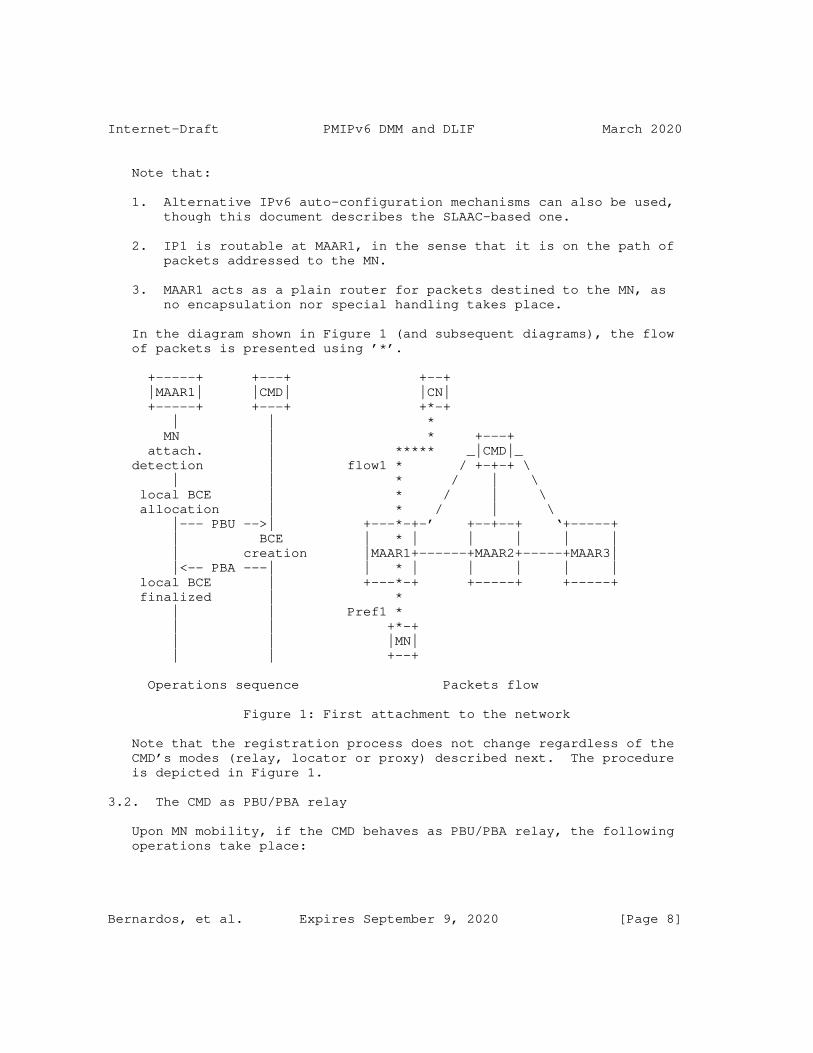
Internet-Draft PMIPv6 DMM and DLIF March 2020
Note that:
1. Alternative IPv6 auto-configuration mechanisms can also be used, though this document describes the SLAAC-based one.
2. IP1 is routable at MAAR1, in the sense that it is on the path of packets addressed to the MN.
3. MAAR1 acts as a plain router for packets destined to the MN, as no encapsulation nor special handling takes place.
In the diagram shown in Figure 1 (and subsequent diagrams), the flow of packets is presented using ’*’.
+-----+ +---+ +--+ |MAAR1| |CMD| |CN| +-----+ +---+ +*-+ | | * MN | * +---+ attach. | ***** _|CMD|_ detection | flow1 * / +-+-+ \ | | * / | \ local BCE | * / | \ allocation | * / | \ |--- PBU -->| +---*-+-’ +--+--+ ‘+-----+ | BCE | * | | | | | | creation |MAAR1+------+MAAR2+-----+MAAR3| |<-- PBA ---| | * | | | | | local BCE | +---*-+ +-----+ +-----+ finalized | * | | Pref1 * | | +*-+ | | |MN| | | +--+
Operations sequence Packets flow
Figure 1: First attachment to the network
Note that the registration process does not change regardless of the CMD’s modes (relay, locator or proxy) described next. The procedure is depicted in Figure 1.
3.2. The CMD as PBU/PBA relay
Upon MN mobility, if the CMD behaves as PBU/PBA relay, the following operations take place:
Bernardos, et al. Expires September 9, 2020 [Page 8]
Internet-Draft PMIPv6 DMM and DLIF March 2020
1. When the MN moves from its current point of attachment and attaches to MAAR2 (now the S-MAAR), MAAR2 reserves an IPv6 prefix (Pref2), it stores a temporary BCE, and it sends a PBU to the CMD for registration.
2. Upon PBU reception and BC lookup, the CMD retrieves an already existing entry for the MN, binding the MN-ID to its former location; thus, the CMD forwards the PBU to the MAAR indicated as Proxy CoA (MAAR1), including a new mobility option to communicate the S-MAAR’s global address to MAAR1, defined as Serving MAAR Option in Section 4.6. The CMD updates the P-CoA field in the BCE related to the MN with the S-MAAR’s address.
3. Upon PBU reception, MAAR1 can install a tunnel on its side towards MAAR2 and the related routes for Pref1. Then MAAR1 replies to the CMD with a PBA (including the option mentioned before) to ensure that the new location has successfully changed, containing the prefix anchored at MAAR1 in the Home Network Prefix option.
4. The CMD, after receiving the PBA, updates the BCE populating an instance of the P-MAAR list. The P-MAAR list is an additional field on the BCE that contains an element for each P-MAAR involved in the MN’s mobility session. The list element contains the P-MAAR’s global address and the prefix it has delegated. Also, the CMD sends a PBA to the new S-MAAR, containing the previous Proxy-CoA and the prefix anchored to it embedded into a new mobility option called Previous MAAR Option (defined in Section 4.5), so that, upon PBA arrival, a bi-directional tunnel can be established between the two MAARs and new routes are set appropriately to recover the IP flow(s) carrying Pref1.
5. Now packets destined to Pref1 are first received by MAAR1, encapsulated into the tunnel and forwarded to MAAR2, which finally delivers them to their destination. In uplink, when the MN transmits packets using Pref1 as source address, they are sent to MAAR2, as it is MN’s new default gateway, then tunneled to MAAR1 which routes them towards the next hop to destination. Conversely, packets carrying Pref2 are routed by MAAR2 without any special packet handling both for uplink and downlink.
Bernardos, et al. Expires September 9, 2020 [Page 9]
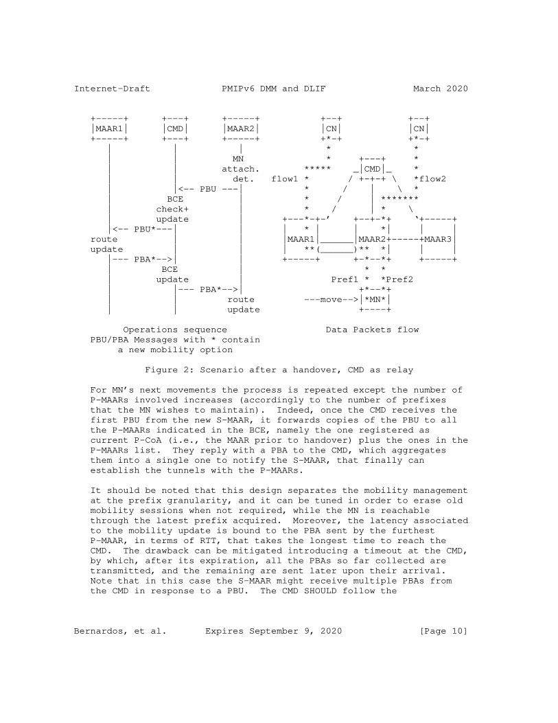
Internet-Draft PMIPv6 DMM and DLIF March 2020
+-----+ +---+ +-----+ +--+ +--+ |MAAR1| |CMD| |MAAR2| |CN| |CN| +-----+ +---+ +-----+ +*-+ +*-+ | | | * * | | MN * +---+ * | | attach. ***** _|CMD|_ * | | det. flow1 * / +-+-+ \ *flow2 | |<-- PBU ---| * / | \ * | BCE | * / | ******* | check+ | * / | * \ | update | +---*-+-’ +--+-*+ ‘+-----+ |<-- PBU*---| | | * | | *| | | route | | |MAAR1|______|MAAR2+-----+MAAR3| update | | | **(______)** *| | | |--- PBA*-->| | +-----+ +-*--*+ +-----+ | BCE | * * | update | Pref1 * *Pref2 | |--- PBA*-->| +*--*+ | | route ---move-->|*MN*| | | update +----+
Operations sequence Data Packets flow PBU/PBA Messages with * contain a new mobility option
Figure 2: Scenario after a handover, CMD as relay
For MN’s next movements the process is repeated except the number of P-MAARs involved increases (accordingly to the number of prefixes that the MN wishes to maintain). Indeed, once the CMD receives the first PBU from the new S-MAAR, it forwards copies of the PBU to all the P-MAARs indicated in the BCE, namely the one registered as current P-CoA (i.e., the MAAR prior to handover) plus the ones in the P-MAARs list. They reply with a PBA to the CMD, which aggregates them into a single one to notify the S-MAAR, that finally can establish the tunnels with the P-MAARs.
It should be noted that this design separates the mobility management at the prefix granularity, and it can be tuned in order to erase old mobility sessions when not required, while the MN is reachable through the latest prefix acquired. Moreover, the latency associated to the mobility update is bound to the PBA sent by the furthest P-MAAR, in terms of RTT, that takes the longest time to reach the CMD. The drawback can be mitigated introducing a timeout at the CMD, by which, after its expiration, all the PBAs so far collected are transmitted, and the remaining are sent later upon their arrival. Note that in this case the S-MAAR might receive multiple PBAs from the CMD in response to a PBU. The CMD SHOULD follow the
Bernardos, et al. Expires September 9, 2020 [Page 10]
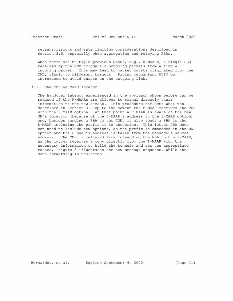
Internet-Draft PMIPv6 DMM and DLIF March 2020
retransmissions and rate limiting considerations described in Section 3.6, especially when aggregating and relaying PBAs.
When there are multiple previous MAARs, e.g., k MAARs, a single PBU received by the CMD triggers k outgoing packets from a single incoming packet. This may lead to packet bursts originated from the CMD, albeit to different targets. Pacing mechanisms MUST be introduced to avoid bursts on the outgoing link.
3.3. The CMD as MAAR locator
The handover latency experienced in the approach shown before can be reduced if the P-MAARs are allowed to signal directly their information to the new S-MAAR. This procedure reflects what was described in Section 3.2 up to the moment the P-MAAR receives the PBU with the S-MAAR option. At that point a P-MAAR is aware of the new MN’s location (because of the S-MAAR’s address in the S-MAAR option), and, besides sending a PBA to the CMD, it also sends a PBA to the S-MAAR including the prefix it is anchoring. This latter PBA does not need to include new options, as the prefix is embedded in the HNP option and the P-MAAR’s address is taken from the message’s source address. The CMD is relieved from forwarding the PBA to the S-MAAR, as the latter receives a copy directly from the P-MAAR with the necessary information to build the tunnels and set the appropriate routes. Figure 3 illustrates the new message sequence, while the data forwarding is unaltered.
Bernardos, et al. Expires September 9, 2020 [Page 11]
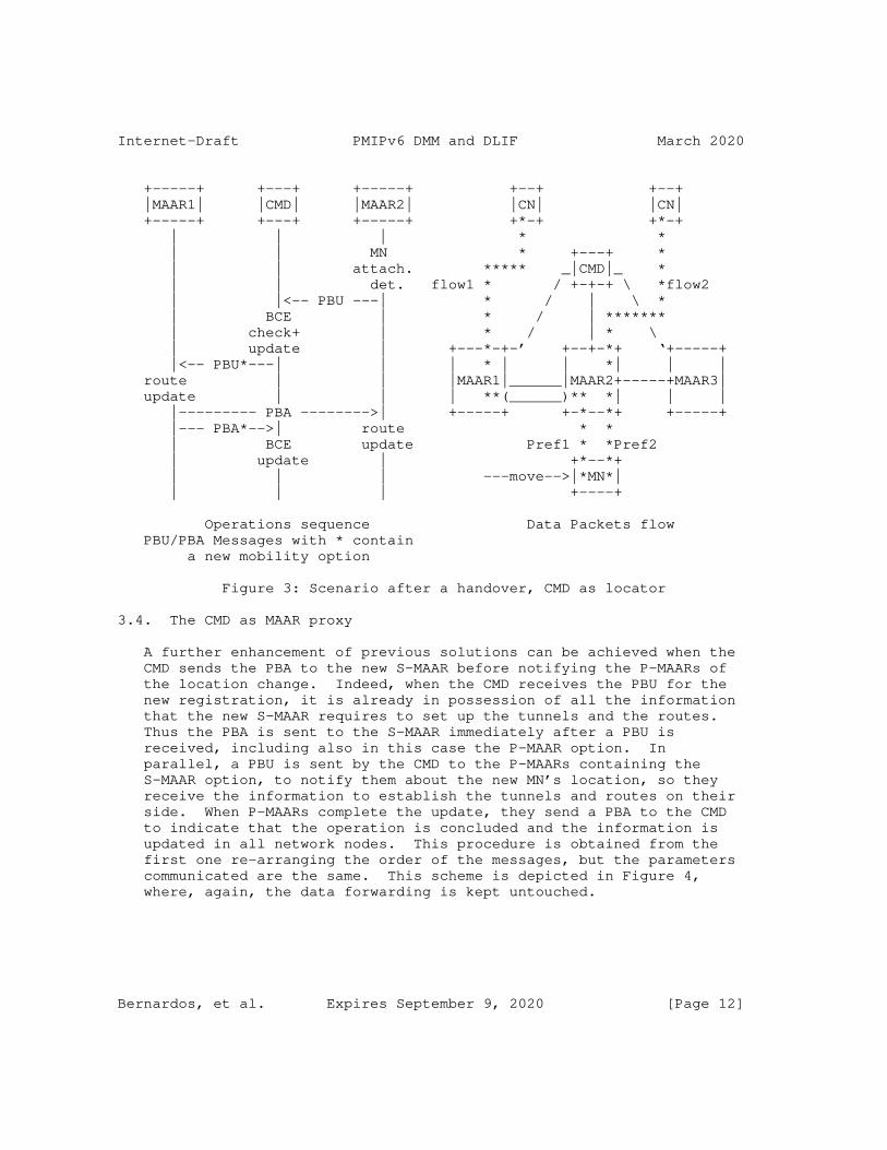
Internet-Draft PMIPv6 DMM and DLIF March 2020
+-----+ +---+ +-----+ +--+ +--+ |MAAR1| |CMD| |MAAR2| |CN| |CN| +-----+ +---+ +-----+ +*-+ +*-+ | | | * * | | MN * +---+ * | | attach. ***** _|CMD|_ * | | det. flow1 * / +-+-+ \ *flow2 | |<-- PBU ---| * / | \ * | BCE | * / | ******* | check+ | * / | * \ | update | +---*-+-’ +--+-*+ ‘+-----+ |<-- PBU*---| | | * | | *| | | route | | |MAAR1|______|MAAR2+-----+MAAR3| update | | | **(______)** *| | | |--------- PBA -------->| +-----+ +-*--*+ +-----+ |--- PBA*-->| route * * | BCE update Pref1 * *Pref2 | update | +*--*+ | | | ---move-->|*MN*| | | | +----+
Operations sequence Data Packets flow PBU/PBA Messages with * contain a new mobility option
Figure 3: Scenario after a handover, CMD as locator
3.4. The CMD as MAAR proxy
A further enhancement of previous solutions can be achieved when the CMD sends the PBA to the new S-MAAR before notifying the P-MAARs of the location change. Indeed, when the CMD receives the PBU for the new registration, it is already in possession of all the information that the new S-MAAR requires to set up the tunnels and the routes. Thus the PBA is sent to the S-MAAR immediately after a PBU is received, including also in this case the P-MAAR option. In parallel, a PBU is sent by the CMD to the P-MAARs containing the S-MAAR option, to notify them about the new MN’s location, so they receive the information to establish the tunnels and routes on their side. When P-MAARs complete the update, they send a PBA to the CMD to indicate that the operation is concluded and the information is updated in all network nodes. This procedure is obtained from the first one re-arranging the order of the messages, but the parameters communicated are the same. This scheme is depicted in Figure 4, where, again, the data forwarding is kept untouched.
Bernardos, et al. Expires September 9, 2020 [Page 12]
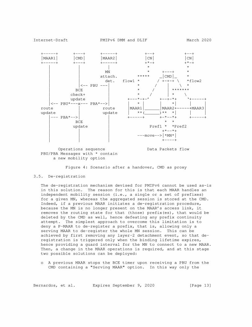
Internet-Draft PMIPv6 DMM and DLIF March 2020
+-----+ +---+ +-----+ +--+ +--+ |MAAR1| |CMD| |MAAR2| |CN| |CN| +-----+ +---+ +-----+ +*-+ +*-+ | | | * * | | MN * +---+ * | | attach. ***** _|CMD|_ * | | det. flow1 * / +-+-+ \ *flow2 | |<-- PBU ---| * / | \ * | BCE | * / | ******* | check+ | * / | * \ | update | +---*-+-’ +--+-*+ ‘+-----+ |<-- PBU*---x--- PBA*-->| | * | | *| | | route | route |MAAR1|______|MAAR2+-----+MAAR3| update | update | **(______)** *| | | |--- PBA*-->| | +-----+ +-*--*+ +-----+ | BCE | * * | update | Pref1 * *Pref2 | | | +*--*+ | | | ---move-->|*MN*| | | | +----+
Operations sequence Data Packets flow PBU/PBA Messages with * contain a new mobility option
Figure 4: Scenario after a handover, CMD as proxy
3.5. De-registration
The de-registration mechanism devised for PMIPv6 cannot be used as-is in this solution. The reason for this is that each MAAR handles an independent mobility session (i.e., a single or a set of prefixes) for a given MN, whereas the aggregated session is stored at the CMD. Indeed, if a previous MAAR initiates a de-registration procedure, because the MN is no longer present on the MAAR’s access link, it removes the routing state for that (those) prefix(es), that would be deleted by the CMD as well, hence defeating any prefix continuity attempt. The simplest approach to overcome this limitation is to deny a P-MAAR to de-register a prefix, that is, allowing only a serving MAAR to de-register the whole MN session. This can be achieved by first removing any layer-2 detachment event, so that de- registration is triggered only when the binding lifetime expires, hence providing a guard interval for the MN to connect to a new MAAR. Then, a change in the MAAR operations is required, and at this stage two possible solutions can be deployed:
o A previous MAAR stops the BCE timer upon receiving a PBU from the CMD containing a "Serving MAAR" option. In this way only the
Bernardos, et al. Expires September 9, 2020 [Page 13]
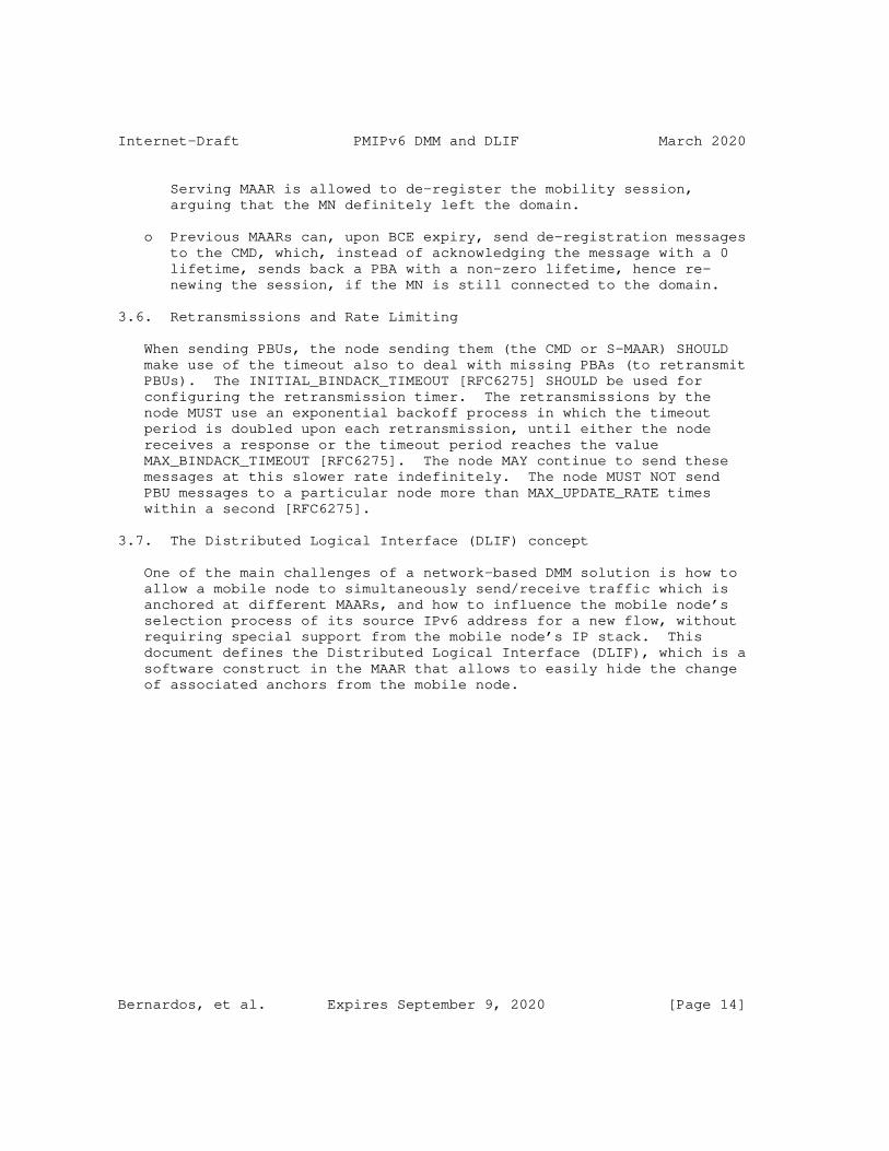
Internet-Draft PMIPv6 DMM and DLIF March 2020
Serving MAAR is allowed to de-register the mobility session, arguing that the MN definitely left the domain.
o Previous MAARs can, upon BCE expiry, send de-registration messages to the CMD, which, instead of acknowledging the message with a 0 lifetime, sends back a PBA with a non-zero lifetime, hence re- newing the session, if the MN is still connected to the domain.
3.6. Retransmissions and Rate Limiting
When sending PBUs, the node sending them (the CMD or S-MAAR) SHOULD make use of the timeout also to deal with missing PBAs (to retransmit PBUs). The INITIAL_BINDACK_TIMEOUT [RFC6275] SHOULD be used for configuring the retransmission timer. The retransmissions by the node MUST use an exponential backoff process in which the timeout period is doubled upon each retransmission, until either the node receives a response or the timeout period reaches the value MAX_BINDACK_TIMEOUT [RFC6275]. The node MAY continue to send these messages at this slower rate indefinitely. The node MUST NOT send PBU messages to a particular node more than MAX_UPDATE_RATE times within a second [RFC6275].
3.7. The Distributed Logical Interface (DLIF) concept
One of the main challenges of a network-based DMM solution is how to allow a mobile node to simultaneously send/receive traffic which is anchored at different MAARs, and how to influence the mobile node’s selection process of its source IPv6 address for a new flow, without requiring special support from the mobile node’s IP stack. This document defines the Distributed Logical Interface (DLIF), which is a software construct in the MAAR that allows to easily hide the change of associated anchors from the mobile node.
Bernardos, et al. Expires September 9, 2020 [Page 14]
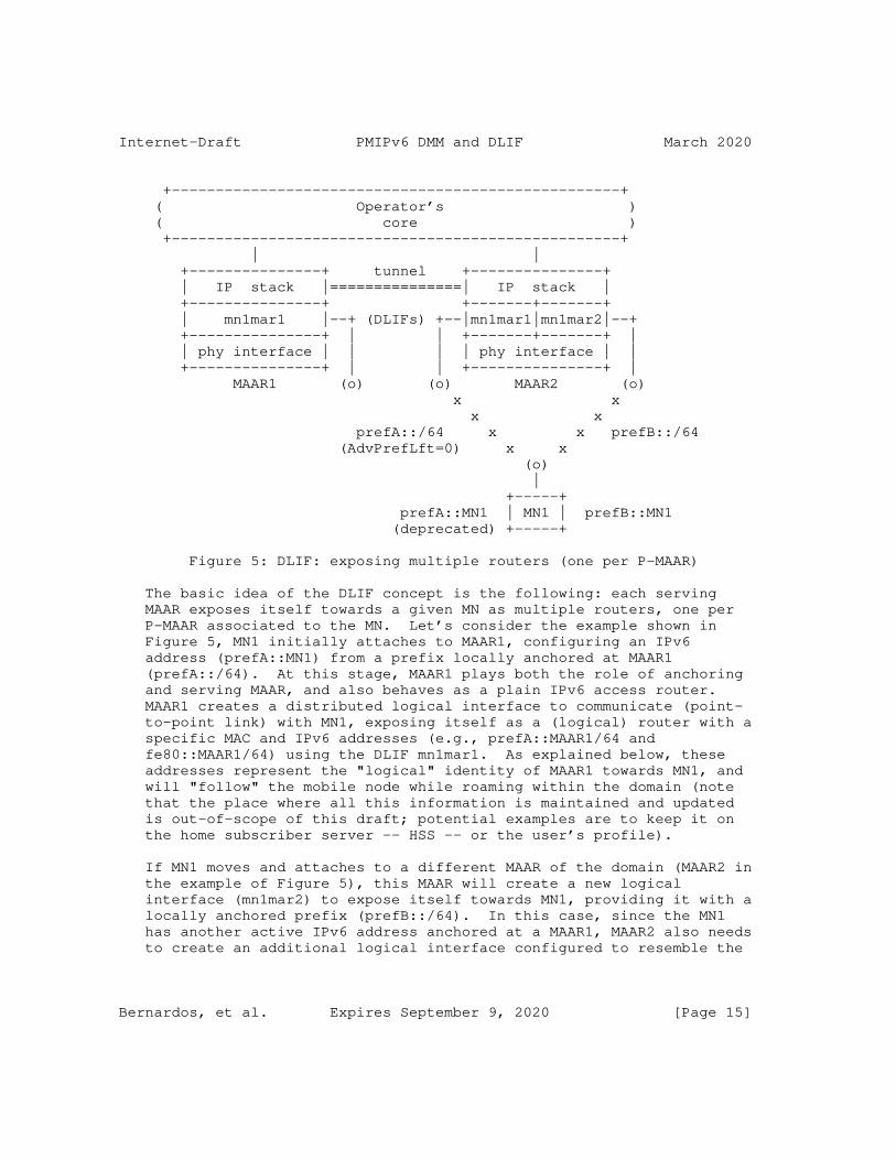
Internet-Draft PMIPv6 DMM and DLIF March 2020
+---------------------------------------------------+ ( Operator’s ) ( core ) +---------------------------------------------------+ | | +---------------+ tunnel +---------------+ | IP stack |===============| IP stack | +---------------+ +-------+-------+ | mn1mar1 |--+ (DLIFs) +--|mn1mar1|mn1mar2|--+ +---------------+ | | +-------+-------+ | | phy interface | | | | phy interface | | +---------------+ | | +---------------+ | MAAR1 (o) (o) MAAR2 (o) x x x x prefA::/64 x x prefB::/64 (AdvPrefLft=0) x x (o) | +-----+ prefA::MN1 | MN1 | prefB::MN1 (deprecated) +-----+
Figure 5: DLIF: exposing multiple routers (one per P-MAAR)
The basic idea of the DLIF concept is the following: each serving MAAR exposes itself towards a given MN as multiple routers, one per P-MAAR associated to the MN. Let’s consider the example shown in Figure 5, MN1 initially attaches to MAAR1, configuring an IPv6 address (prefA::MN1) from a prefix locally anchored at MAAR1 (prefA::/64). At this stage, MAAR1 plays both the role of anchoring and serving MAAR, and also behaves as a plain IPv6 access router. MAAR1 creates a distributed logical interface to communicate (point- to-point link) with MN1, exposing itself as a (logical) router with a specific MAC and IPv6 addresses (e.g., prefA::MAAR1/64 and fe80::MAAR1/64) using the DLIF mn1mar1. As explained below, these addresses represent the "logical" identity of MAAR1 towards MN1, and will "follow" the mobile node while roaming within the domain (note that the place where all this information is maintained and updated is out-of-scope of this draft; potential examples are to keep it on the home subscriber server -- HSS -- or the user’s profile).
If MN1 moves and attaches to a different MAAR of the domain (MAAR2 in the example of Figure 5), this MAAR will create a new logical interface (mn1mar2) to expose itself towards MN1, providing it with a locally anchored prefix (prefB::/64). In this case, since the MN1 has another active IPv6 address anchored at a MAAR1, MAAR2 also needs to create an additional logical interface configured to resemble the
Bernardos, et al. Expires September 9, 2020 [Page 15]
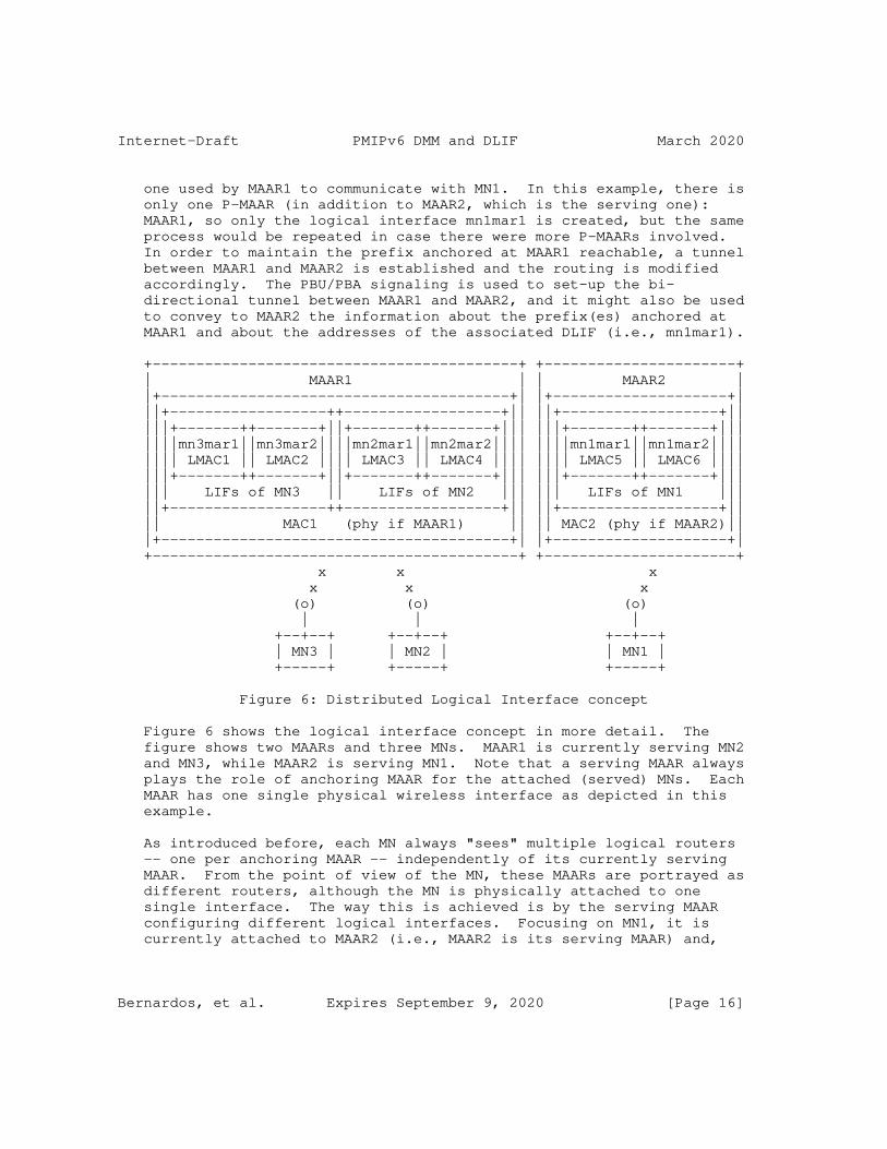
Internet-Draft PMIPv6 DMM and DLIF March 2020
one used by MAAR1 to communicate with MN1. In this example, there is only one P-MAAR (in addition to MAAR2, which is the serving one): MAAR1, so only the logical interface mn1mar1 is created, but the same process would be repeated in case there were more P-MAARs involved. In order to maintain the prefix anchored at MAAR1 reachable, a tunnel between MAAR1 and MAAR2 is established and the routing is modified accordingly. The PBU/PBA signaling is used to set-up the bi- directional tunnel between MAAR1 and MAAR2, and it might also be used to convey to MAAR2 the information about the prefix(es) anchored at MAAR1 and about the addresses of the associated DLIF (i.e., mn1mar1).
+------------------------------------------+ +----------------------+ | MAAR1 | | MAAR2 | |+----------------------------------------+| |+--------------------+| ||+------------------++------------------+|| ||+------------------+|| |||+-------++-------+||+-------++-------+||| |||+-------++-------+||| ||||mn3mar1||mn3mar2||||mn2mar1||mn2mar2|||| ||||mn1mar1||mn1mar2|||| |||| LMAC1 || LMAC2 |||| LMAC3 || LMAC4 |||| |||| LMAC5 || LMAC6 |||| |||+-------++-------+||+-------++-------+||| |||+-------++-------+||| ||| LIFs of MN3 || LIFs of MN2 ||| ||| LIFs of MN1 ||| ||+------------------++------------------+|| ||+------------------+|| || MAC1 (phy if MAAR1) || || MAC2 (phy if MAAR2)|| |+----------------------------------------+| |+--------------------+| +------------------------------------------+ +----------------------+ x x x x x x (o) (o) (o) | | | +--+--+ +--+--+ +--+--+ | MN3 | | MN2 | | MN1 | +-----+ +-----+ +-----+
Figure 6: Distributed Logical Interface concept
Figure 6 shows the logical interface concept in more detail. The figure shows two MAARs and three MNs. MAAR1 is currently serving MN2 and MN3, while MAAR2 is serving MN1. Note that a serving MAAR always plays the role of anchoring MAAR for the attached (served) MNs. Each MAAR has one single physical wireless interface as depicted in this example.
As introduced before, each MN always "sees" multiple logical routers -- one per anchoring MAAR -- independently of its currently serving MAAR. From the point of view of the MN, these MAARs are portrayed as different routers, although the MN is physically attached to one single interface. The way this is achieved is by the serving MAAR configuring different logical interfaces. Focusing on MN1, it is currently attached to MAAR2 (i.e., MAAR2 is its serving MAAR) and,
Bernardos, et al. Expires September 9, 2020 [Page 16]
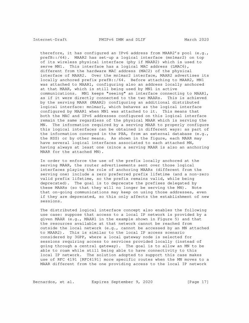
Internet-Draft PMIPv6 DMM and DLIF March 2020
therefore, it has configured an IPv6 address from MAAR2’s pool (e.g., prefB::/64). MAAR2 has set-up a logical interface (mn1mar2) on top of its wireless physical interface (phy if MAAR2) which is used to serve MN1. This interface has a logical MAC address (LMAC6), different from the hardware MAC address (MAC2) of the physical interface of MAAR2. Over the mn1mar2 interface, MAAR2 advertises its locally anchored prefix prefB::/64. Before attaching to MAAR2, MN1 was attached to MAAR1, configuring also an address locally anchored at that MAAR, which is still being used by MN1 in active communications. MN1 keeps "seeing" an interface connecting to MAAR1, as if it were directly connected to the two MAARs. This is achieved by the serving MAAR (MAAR2) configuring an additional distributed logical interface: mn1mar1, which behaves as the logical interface configured by MAAR1 when MN1 was attached to it. This means that both the MAC and IPv6 addresses configured on this logical interface remain the same regardless of the physical MAAR which is serving the MN. The information required by a serving MAAR to properly configure this logical interfaces can be obtained in different ways: as part of the information conveyed in the PBA, from an external database (e.g., the HSS) or by other means. As shown in the figure, each MAAR may have several logical interfaces associated to each attached MN, having always at least one (since a serving MAAR is also an anchoring MAAR for the attached MN).
In order to enforce the use of the prefix locally anchored at the serving MAAR, the router advertisements sent over those logical interfaces playing the role of anchoring MAARs (different from the serving one) include a zero preferred prefix lifetime (and a non-zero valid prefix lifetime, so the prefix remains valid, while being deprecated). The goal is to deprecate the prefixes delegated by these MAARs (so that they will no longer be serving the MN). Note that on-going communications may keep on using those addresses, even if they are deprecated, so this only affects the establishment of new sessions.
The distributed logical interface concept also enables the following use case: suppose that access to a local IP network is provided by a given MAAR (e.g., MAAR1 in the example shown in Figure 5) and that the resources available at that network cannot be reached from outside the local network (e.g., cannot be accessed by an MN attached to MAAR2). This is similar to the local IP access scenario considered by 3GPP, where a local gateway node is selected for sessions requiring access to services provided locally (instead of going through a central gateway). The goal is to allow an MN to be able to roam while still being able to have connectivity to this local IP network. The solution adopted to support this case makes use of RFC 4191 [RFC4191] more specific routes when the MN moves to a MAAR different from the one providing access to the local IP network
Bernardos, et al. Expires September 9, 2020 [Page 17]
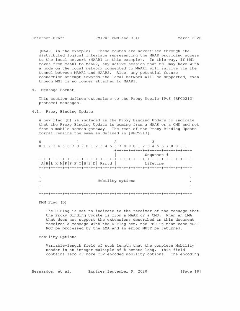
Internet-Draft PMIPv6 DMM and DLIF March 2020
(MAAR1 in the example). These routes are advertised through the distributed logical interface representing the MAAR providing access to the local network (MAAR1 in this example). In this way, if MN1 moves from MAAR1 to MAAR2, any active session that MN1 may have with a node on the local network connected to MAAR1 will survive via the tunnel between MAAR1 and MAAR2. Also, any potential future connection attempt towards the local network will be supported, even though MN1 is no longer attached to MAAR1.
4. Message Format
This section defines extensions to the Proxy Mobile IPv6 [RFC5213] protocol messages.
4.1. Proxy Binding Update
A new flag (D) is included in the Proxy Binding Update to indicate that the Proxy Binding Update is coming from a MAAR or a CMD and not from a mobile access gateway. The rest of the Proxy Binding Update format remains the same as defined in [RFC5213].
0 1 2 3 0 1 2 3 4 5 6 7 8 9 0 1 2 3 4 5 6 7 8 9 0 1 2 3 4 5 6 7 8 9 0 1 +-+-+-+-+-+-+-+-+-+-+-+-+-+-+-+-+ | Sequence # | +-+-+-+-+-+-+-+-+-+-+-+-+-+-+-+-+-+-+-+-+-+-+-+-+-+-+-+-+-+-+-+-+ |A|H|L|K|M|R|P|F|T|B|S|D| Rsrvd | Lifetime | +-+-+-+-+-+-+-+-+-+-+-+-+-+-+-+-+-+-+-+-+-+-+-+-+-+-+-+-+-+-+-+-+ | | . . . Mobility options . . . | | +-+-+-+-+-+-+-+-+-+-+-+-+-+-+-+-+-+-+-+-+-+-+-+-+-+-+-+-+-+-+-+-+
DMM Flag (D)
The D Flag is set to indicate to the receiver of the message that the Proxy Binding Update is from a MAAR or a CMD. When an LMA that does not support the extensions described in this document receives a message with the D-Flag set, the PBU in that case MUST NOT be processed by the LMA and an error MUST be returned.
Mobility Options
Variable-length field of such length that the complete Mobility Header is an integer multiple of 8 octets long. This field contains zero or more TLV-encoded mobility options. The encoding
Bernardos, et al. Expires September 9, 2020 [Page 18]
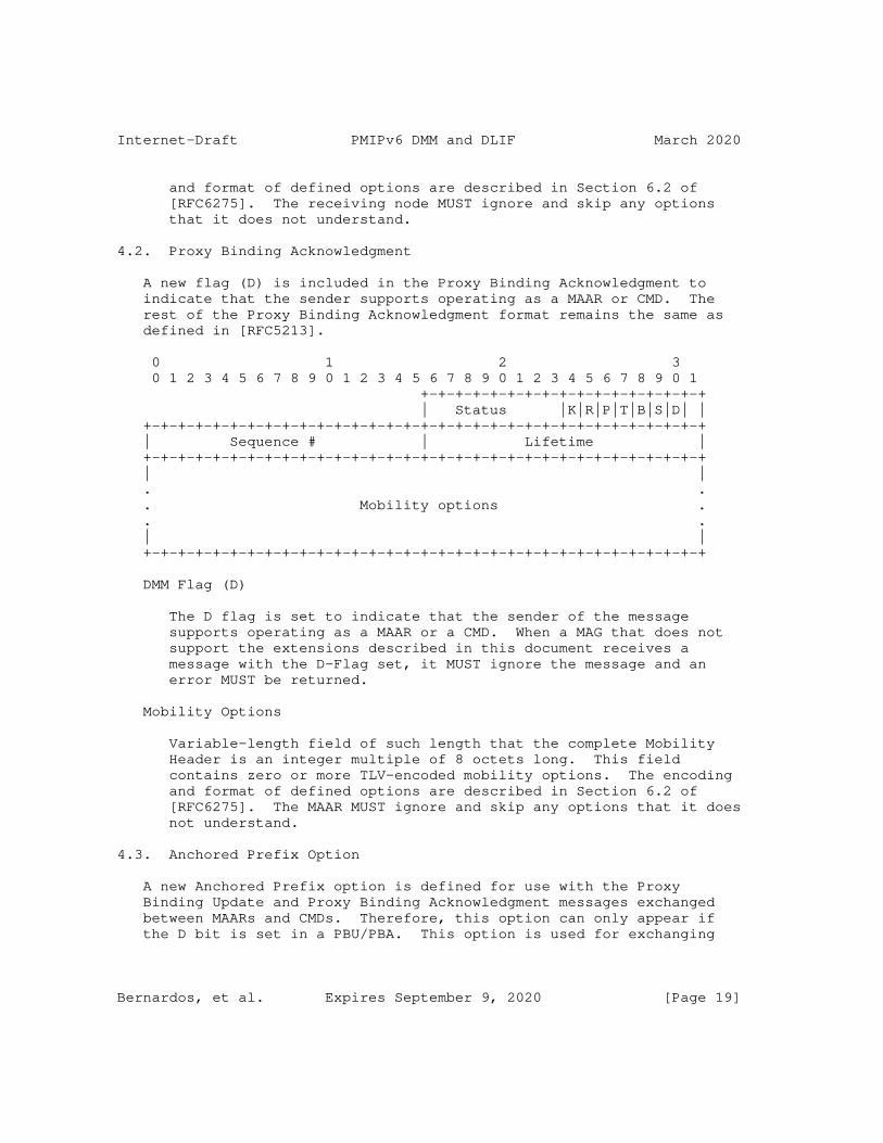
Internet-Draft PMIPv6 DMM and DLIF March 2020
and format of defined options are described in Section 6.2 of [RFC6275]. The receiving node MUST ignore and skip any options that it does not understand.
4.2. Proxy Binding Acknowledgment
A new flag (D) is included in the Proxy Binding Acknowledgment to indicate that the sender supports operating as a MAAR or CMD. The rest of the Proxy Binding Acknowledgment format remains the same as defined in [RFC5213].
0 1 2 3 0 1 2 3 4 5 6 7 8 9 0 1 2 3 4 5 6 7 8 9 0 1 2 3 4 5 6 7 8 9 0 1 +-+-+-+-+-+-+-+-+-+-+-+-+-+-+-+-+ | Status |K|R|P|T|B|S|D| | +-+-+-+-+-+-+-+-+-+-+-+-+-+-+-+-+-+-+-+-+-+-+-+-+-+-+-+-+-+-+-+-+ | Sequence # | Lifetime | +-+-+-+-+-+-+-+-+-+-+-+-+-+-+-+-+-+-+-+-+-+-+-+-+-+-+-+-+-+-+-+-+ | | . . . Mobility options . . . | | +-+-+-+-+-+-+-+-+-+-+-+-+-+-+-+-+-+-+-+-+-+-+-+-+-+-+-+-+-+-+-+-+
DMM Flag (D)
The D flag is set to indicate that the sender of the message supports operating as a MAAR or a CMD. When a MAG that does not support the extensions described in this document receives a message with the D-Flag set, it MUST ignore the message and an error MUST be returned.
Mobility Options
Variable-length field of such length that the complete Mobility Header is an integer multiple of 8 octets long. This field contains zero or more TLV-encoded mobility options. The encoding and format of defined options are described in Section 6.2 of [RFC6275]. The MAAR MUST ignore and skip any options that it does not understand.
4.3. Anchored Prefix Option
A new Anchored Prefix option is defined for use with the Proxy Binding Update and Proxy Binding Acknowledgment messages exchanged between MAARs and CMDs. Therefore, this option can only appear if the D bit is set in a PBU/PBA. This option is used for exchanging
Bernardos, et al. Expires September 9, 2020 [Page 19]

Internet-Draft PMIPv6 DMM and DLIF March 2020
the mobile node’s prefix anchored at the anchoring MAAR. There can be multiple Anchored Prefix options present in the message.
The Anchored Prefix Option has an alignment requirement of 8n+4. Its format is as follows:
0 1 2 3 0 1 2 3 4 5 6 7 8 9 0 1 2 3 4 5 6 7 8 9 0 1 2 3 4 5 6 7 8 9 0 1 +-+-+-+-+-+-+-+-+-+-+-+-+-+-+-+-+-+-+-+-+-+-+-+-+-+-+-+-+-+-+-+-+ | Type | Length | Reserved | Prefix Length | +-+-+-+-+-+-+-+-+-+-+-+-+-+-+-+-+-+-+-+-+-+-+-+-+-+-+-+-+-+-+-+-+ | | + + | | + Anchored Prefix + | | + + | | +-+-+-+-+-+-+-+-+-+-+-+-+-+-+-+-+-+-+-+-+-+-+-+-+-+-+-+-+-+-+-+-+
Type
IANA-1.
Length
8-bit unsigned integer indicating the length of the option in octets, excluding the type and length fields. This field MUST be set to 18.
Reserved
This field is unused for now. The value MUST be initialized to 0 by the sender and MUST be ignored by the receiver.
Prefix Length
8-bit unsigned integer indicating the prefix length in bits of the IPv6 prefix contained in the option.
Anchored Prefix
A sixteen-octet field containing the mobile node’s IPv6 Anchored Prefix. Only the first Prefix Length bits are valid for the Anchored Prefix. The rest of the bits MUST be ignored.
Bernardos, et al. Expires September 9, 2020 [Page 20]
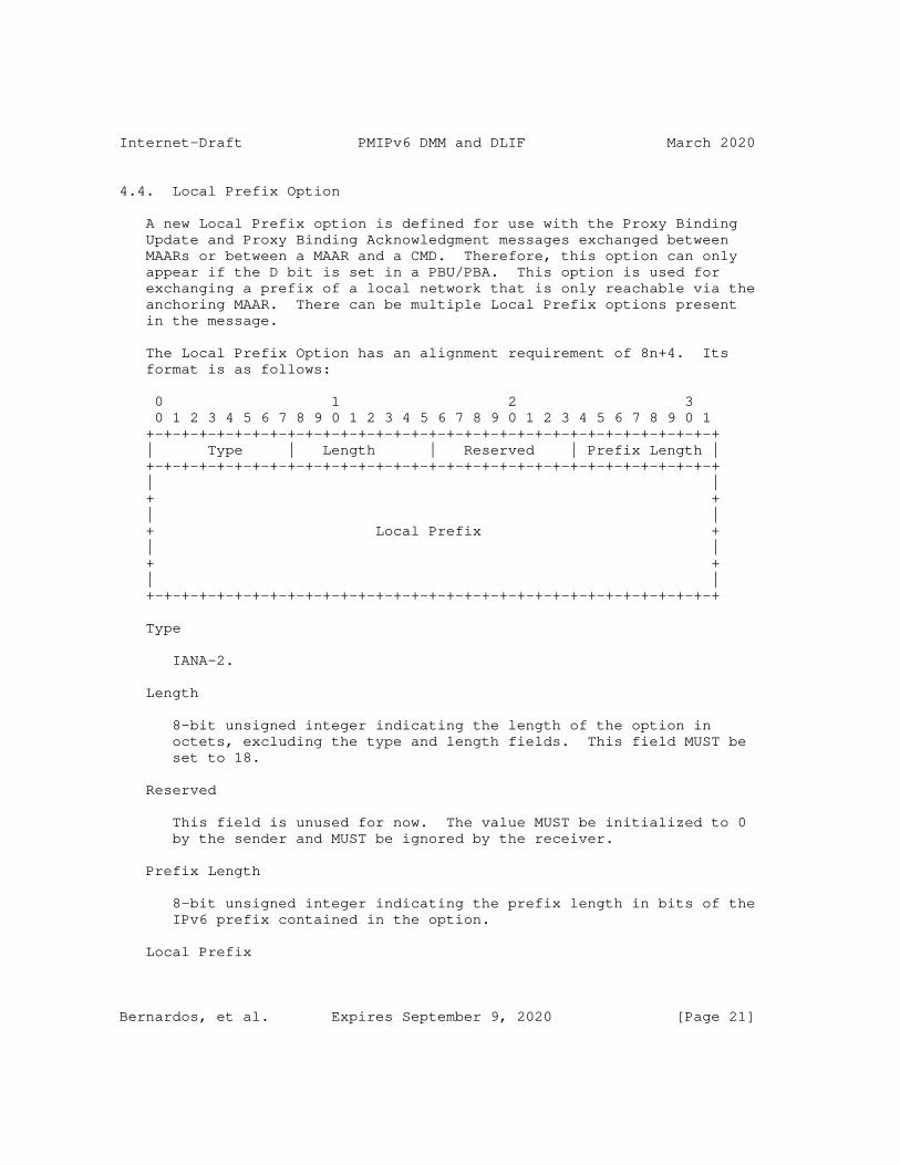
Internet-Draft PMIPv6 DMM and DLIF March 2020
4.4. Local Prefix Option
A new Local Prefix option is defined for use with the Proxy Binding Update and Proxy Binding Acknowledgment messages exchanged between MAARs or between a MAAR and a CMD. Therefore, this option can only appear if the D bit is set in a PBU/PBA. This option is used for exchanging a prefix of a local network that is only reachable via the anchoring MAAR. There can be multiple Local Prefix options present in the message.
The Local Prefix Option has an alignment requirement of 8n+4. Its format is as follows:
0 1 2 3 0 1 2 3 4 5 6 7 8 9 0 1 2 3 4 5 6 7 8 9 0 1 2 3 4 5 6 7 8 9 0 1 +-+-+-+-+-+-+-+-+-+-+-+-+-+-+-+-+-+-+-+-+-+-+-+-+-+-+-+-+-+-+-+-+ | Type | Length | Reserved | Prefix Length | +-+-+-+-+-+-+-+-+-+-+-+-+-+-+-+-+-+-+-+-+-+-+-+-+-+-+-+-+-+-+-+-+ | | + + | | + Local Prefix + | | + + | | +-+-+-+-+-+-+-+-+-+-+-+-+-+-+-+-+-+-+-+-+-+-+-+-+-+-+-+-+-+-+-+-+
Type
IANA-2.
Length
8-bit unsigned integer indicating the length of the option in octets, excluding the type and length fields. This field MUST be set to 18.
Reserved
This field is unused for now. The value MUST be initialized to 0 by the sender and MUST be ignored by the receiver.
Prefix Length
8-bit unsigned integer indicating the prefix length in bits of the IPv6 prefix contained in the option.
Local Prefix
Bernardos, et al. Expires September 9, 2020 [Page 21]
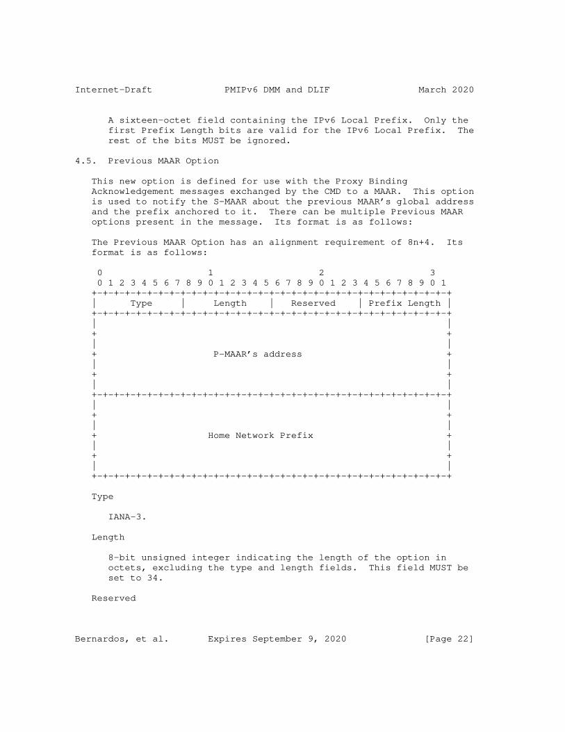
Internet-Draft PMIPv6 DMM and DLIF March 2020
A sixteen-octet field containing the IPv6 Local Prefix. Only the first Prefix Length bits are valid for the IPv6 Local Prefix. The rest of the bits MUST be ignored.
4.5. Previous MAAR Option
This new option is defined for use with the Proxy Binding Acknowledgement messages exchanged by the CMD to a MAAR. This option is used to notify the S-MAAR about the previous MAAR’s global address and the prefix anchored to it. There can be multiple Previous MAAR options present in the message. Its format is as follows:
The Previous MAAR Option has an alignment requirement of 8n+4. Its format is as follows:
0 1 2 3 0 1 2 3 4 5 6 7 8 9 0 1 2 3 4 5 6 7 8 9 0 1 2 3 4 5 6 7 8 9 0 1 +-+-+-+-+-+-+-+-+-+-+-+-+-+-+-+-+-+-+-+-+-+-+-+-+-+-+-+-+-+-+-+-+ | Type | Length | Reserved | Prefix Length | +-+-+-+-+-+-+-+-+-+-+-+-+-+-+-+-+-+-+-+-+-+-+-+-+-+-+-+-+-+-+-+-+ | | + + | | + P-MAAR’s address + | | + + | | +-+-+-+-+-+-+-+-+-+-+-+-+-+-+-+-+-+-+-+-+-+-+-+-+-+-+-+-+-+-+-+-+ | | + + | | + Home Network Prefix + | | + + | | +-+-+-+-+-+-+-+-+-+-+-+-+-+-+-+-+-+-+-+-+-+-+-+-+-+-+-+-+-+-+-+-+
Type
IANA-3.
Length
8-bit unsigned integer indicating the length of the option in octets, excluding the type and length fields. This field MUST be set to 34.
Reserved
Bernardos, et al. Expires September 9, 2020 [Page 22]
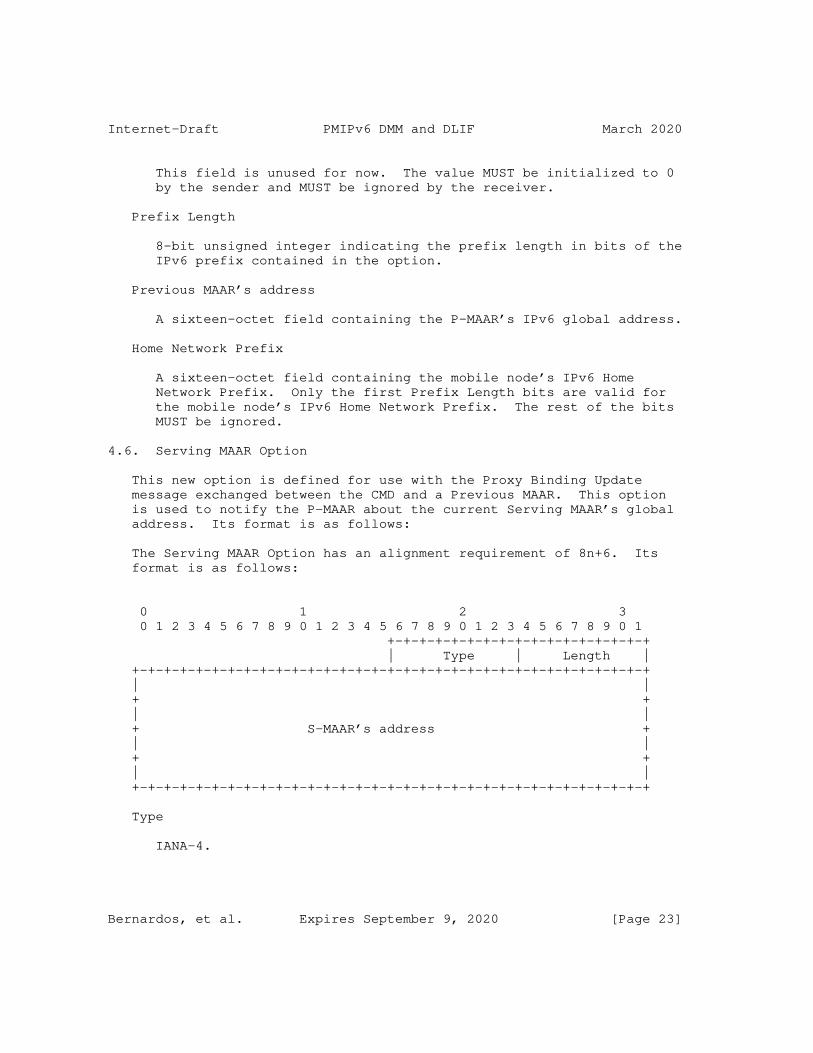
Internet-Draft PMIPv6 DMM and DLIF March 2020
This field is unused for now. The value MUST be initialized to 0 by the sender and MUST be ignored by the receiver.
Prefix Length
8-bit unsigned integer indicating the prefix length in bits of the IPv6 prefix contained in the option.
Previous MAAR’s address
A sixteen-octet field containing the P-MAAR’s IPv6 global address.
Home Network Prefix
A sixteen-octet field containing the mobile node’s IPv6 Home Network Prefix. Only the first Prefix Length bits are valid for the mobile node’s IPv6 Home Network Prefix. The rest of the bits MUST be ignored.
4.6. Serving MAAR Option
This new option is defined for use with the Proxy Binding Update message exchanged between the CMD and a Previous MAAR. This option is used to notify the P-MAAR about the current Serving MAAR’s global address. Its format is as follows:
The Serving MAAR Option has an alignment requirement of 8n+6. Its format is as follows:
0 1 2 3 0 1 2 3 4 5 6 7 8 9 0 1 2 3 4 5 6 7 8 9 0 1 2 3 4 5 6 7 8 9 0 1 +-+-+-+-+-+-+-+-+-+-+-+-+-+-+-+-+ | Type | Length | +-+-+-+-+-+-+-+-+-+-+-+-+-+-+-+-+-+-+-+-+-+-+-+-+-+-+-+-+-+-+-+-+ | | + + | | + S-MAAR’s address + | | + + | | +-+-+-+-+-+-+-+-+-+-+-+-+-+-+-+-+-+-+-+-+-+-+-+-+-+-+-+-+-+-+-+-+
Type
IANA-4.
Bernardos, et al. Expires September 9, 2020 [Page 23]
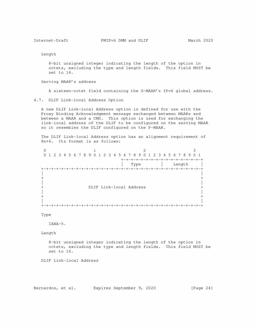
Internet-Draft PMIPv6 DMM and DLIF March 2020
Length
8-bit unsigned integer indicating the length of the option in octets, excluding the type and length fields. This field MUST be set to 16.
Serving MAAR’s address
A sixteen-octet field containing the S-MAAR’s IPv6 global address.
4.7. DLIF Link-local Address Option
A new DLIF Link-local Address option is defined for use with the Proxy Binding Acknowledgment message exchanged between MAARs and between a MAAR and a CMD. This option is used for exchanging the link-local address of the DLIF to be configured on the serving MAAR so it resembles the DLIF configured on the P-MAAR.
The DLIF Link-local Address option has an alignment requirement of 8n+6. Its format is as follows:
0 1 2 3 0 1 2 3 4 5 6 7 8 9 0 1 2 3 4 5 6 7 8 9 0 1 2 3 4 5 6 7 8 9 0 1 +-+-+-+-+-+-+-+-+-+-+-+-+-+-+-+-+ | Type | Length | +-+-+-+-+-+-+-+-+-+-+-+-+-+-+-+-+-+-+-+-+-+-+-+-+-+-+-+-+-+-+-+-+ | | + + | | + DLIF Link-local Address + | | + + | | +-+-+-+-+-+-+-+-+-+-+-+-+-+-+-+-+-+-+-+-+-+-+-+-+-+-+-+-+-+-+-+-+
Type
IANA-5.
Length
8-bit unsigned integer indicating the length of the option in octets, excluding the type and length fields. This field MUST be set to 16.
DLIF Link-local Address
Bernardos, et al. Expires September 9, 2020 [Page 24]
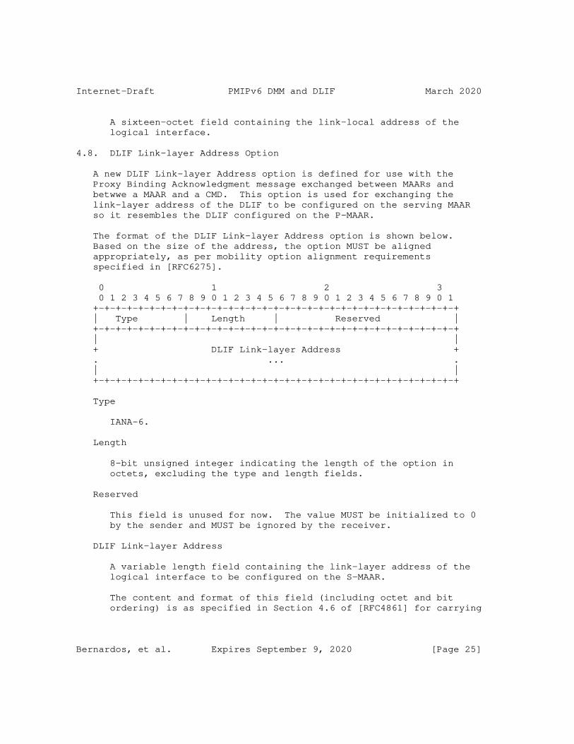
Internet-Draft PMIPv6 DMM and DLIF March 2020
A sixteen-octet field containing the link-local address of the logical interface.
4.8. DLIF Link-layer Address Option
A new DLIF Link-layer Address option is defined for use with the Proxy Binding Acknowledgment message exchanged between MAARs and betwwe a MAAR and a CMD. This option is used for exchanging the link-layer address of the DLIF to be configured on the serving MAAR so it resembles the DLIF configured on the P-MAAR.
The format of the DLIF Link-layer Address option is shown below. Based on the size of the address, the option MUST be aligned appropriately, as per mobility option alignment requirements specified in [RFC6275].
0 1 2 3 0 1 2 3 4 5 6 7 8 9 0 1 2 3 4 5 6 7 8 9 0 1 2 3 4 5 6 7 8 9 0 1 +-+-+-+-+-+-+-+-+-+-+-+-+-+-+-+-+-+-+-+-+-+-+-+-+-+-+-+-+-+-+-+-+ | Type | Length | Reserved | +-+-+-+-+-+-+-+-+-+-+-+-+-+-+-+-+-+-+-+-+-+-+-+-+-+-+-+-+-+-+-+-+ | | + DLIF Link-layer Address + . ... . | | +-+-+-+-+-+-+-+-+-+-+-+-+-+-+-+-+-+-+-+-+-+-+-+-+-+-+-+-+-+-+-+-+
Type
IANA-6.
Length
8-bit unsigned integer indicating the length of the option in octets, excluding the type and length fields.
Reserved
This field is unused for now. The value MUST be initialized to 0 by the sender and MUST be ignored by the receiver.
DLIF Link-layer Address
A variable length field containing the link-layer address of the logical interface to be configured on the S-MAAR.
The content and format of this field (including octet and bit ordering) is as specified in Section 4.6 of [RFC4861] for carrying
Bernardos, et al. Expires September 9, 2020 [Page 25]
Internet-Draft PMIPv6 DMM and DLIF March 2020
link-layer addresses. On certain access links, where the link- layer address is not used or cannot be determined, this option cannot be used.
5. IANA Considerations
This document defines six new mobility options, the Anchored Prefix Option, the Local Prefix Option, the Previous MAAR Option, the Serving MAAR Option, the DLIF Link-local Address Option and the DLIF Link-layer Address Option. The Type value for these options needs to be assigned from the same numbering space as allocated for the other mobility options in the "Mobility Options" registry defined in http://www.iana.org/assignments/mobility-parameters. The required IANA actions are marked as IANA-1 to IANA-6.
This document reserves a new flag (D) in the "Binding Update Flags" and a new flag (D) in the "Binding Acknowledgment Flags" of the "Mobile IPv6 parameters" registry http://www.iana.org/assignments/ mobility-parameters.
6. Security Considerations
The protocol extensions defined in this document share the same security concerns of Proxy Mobile IPv6 [RFC5213]. It is recommended that the signaling messages, Proxy Binding Update and Proxy Binding Acknowledgment, exchanged between the MAARs are protected using IPsec using the established security association between them. This essentially eliminates the threats related to the impersonation of a MAAR.
When the CMD acts as a PBU/PBA relay, the CMD may act as a relay of a single PBU to multiple previous MAARs. In situations of many fast handovers (e.g., with vehicular networks), there may exist multiple previous (e.g., k) MAARs. In this situation, the CMD creates k outgoing packets from a single incoming packet. This bears a certain amplification risk. The CMD MUST use a pacing approach in the outgoing queue to cap the output traffic (i.e., the rate of PBUs sent) to limit this amplification risk.
When the CMD acts as MAAR locator, mobility signaling (PBAs) is exchanged between P-MAARs and current S-MAAR. Hence, security associations are REQUIRED to exist between the involved MAARs (in addition to the ones needed with the CMD).
Since deregistration is performed by timeout, measures SHOULD be implemented to minimize the risks associated to continued resource consumption (DoS attacks), e.g., imposing a limit of the number of P-MAARs associated to a given MN.
Bernardos, et al. Expires September 9, 2020 [Page 26]
Internet-Draft PMIPv6 DMM and DLIF March 2020
The CMD and the participating MAARs MUST be trusted parties, authorized perform all operations relevant to their role.
There are some privacy considerations to consider. While the involved parties trust each other, the signalling involves disclosing information about the previous locations visited by each MN, as well as the active prefixes they are using at a given point of time. Therefore, mechanisms MUST be in place to ensure that MAARs and CMD do not disclose this information to other parties nor use it for other ends that providing the distributed mobility support specified in this document.
7. Acknowledgments
The authors would like to thank Dirk von Hugo, John Kaippallimalil, Ines Robles, Joerg Ott, Carlos Pignataro, Vincent Roca, Mirja Kuehlewind, Eric Vyncke, Adam Roach, Benjamin Kaduk and Roman Danyliw for the comments on this document. The authors would also like to thank Marco Liebsch, Dirk von Hugo, Alex Petrescu, Daniel Corujo, Akbar Rahman, Danny Moses, Xinpeng Wei and Satoru Matsushima for their comments and discussion on the documents [I-D.bernardos-dmm-distributed-anchoring] and [I-D.bernardos-dmm-pmip] on which the present document is based.
The authors would also like to thank Lyle Bertz and Danny Moses for their in-deep review of this document and their very valuable comments and suggestions.
8. References
8.1. Normative References
[RFC2119] Bradner, S., "Key words for use in RFCs to Indicate Requirement Levels", BCP 14, RFC 2119, DOI 10.17487/RFC2119, March 1997, <https://www.rfc-editor.org/info/rfc2119>.
[RFC4191] Draves, R. and D. Thaler, "Default Router Preferences and More-Specific Routes", RFC 4191, DOI 10.17487/RFC4191, November 2005, <https://www.rfc-editor.org/info/rfc4191>.
[RFC4861] Narten, T., Nordmark, E., Simpson, W., and H. Soliman, "Neighbor Discovery for IP version 6 (IPv6)", RFC 4861, DOI 10.17487/RFC4861, September 2007, <https://www.rfc-editor.org/info/rfc4861>.
Bernardos, et al. Expires September 9, 2020 [Page 27]
Internet-Draft PMIPv6 DMM and DLIF March 2020
[RFC5213] Gundavelli, S., Ed., Leung, K., Devarapalli, V., Chowdhury, K., and B. Patil, "Proxy Mobile IPv6", RFC 5213, DOI 10.17487/RFC5213, August 2008, <https://www.rfc-editor.org/info/rfc5213>.
[RFC6275] Perkins, C., Ed., Johnson, D., and J. Arkko, "Mobility Support in IPv6", RFC 6275, DOI 10.17487/RFC6275, July 2011, <https://www.rfc-editor.org/info/rfc6275>.
[RFC7333] Chan, H., Ed., Liu, D., Seite, P., Yokota, H., and J. Korhonen, "Requirements for Distributed Mobility Management", RFC 7333, DOI 10.17487/RFC7333, August 2014, <https://www.rfc-editor.org/info/rfc7333>.
[RFC8174] Leiba, B., "Ambiguity of Uppercase vs Lowercase in RFC 2119 Key Words", BCP 14, RFC 8174, DOI 10.17487/RFC8174, May 2017, <https://www.rfc-editor.org/info/rfc8174>.
8.2. Informative References
[I-D.bernardos-dmm-distributed-anchoring] Bernardos, C. and J. Zuniga, "PMIPv6-based distributed anchoring", draft-bernardos-dmm-distributed-anchoring-09 (work in progress), May 2017.
[I-D.bernardos-dmm-pmip] Bernardos, C., Oliva, A., and F. Giust, "A PMIPv6-based solution for Distributed Mobility Management", draft- bernardos-dmm-pmip-09 (work in progress), September 2017.
[RFC7429] Liu, D., Ed., Zuniga, JC., Ed., Seite, P., Chan, H., and CJ. Bernardos, "Distributed Mobility Management: Current Practices and Gap Analysis", RFC 7429, DOI 10.17487/RFC7429, January 2015, <https://www.rfc-editor.org/info/rfc7429>.
[RFC8563] Katz, D., Ward, D., Pallagatti, S., Ed., and G. Mirsky, Ed., "Bidirectional Forwarding Detection (BFD) Multipoint Active Tails", RFC 8563, DOI 10.17487/RFC8563, April 2019, <https://www.rfc-editor.org/info/rfc8563>.
Authors’ Addresses
Bernardos, et al. Expires September 9, 2020 [Page 28]
Internet-Draft PMIPv6 DMM and DLIF March 2020
Carlos J. Bernardos Universidad Carlos III de Madrid Av. Universidad, 30 Leganes, Madrid 28911 Spain
Phone: +34 91624 6236 Email: [email protected] URI: http://www.it.uc3m.es/cjbc/
Antonio de la Oliva Universidad Carlos III de Madrid Av. Universidad, 30 Leganes, Madrid 28911 Spain
Phone: +34 91624 8803 Email: [email protected] URI: http://www.it.uc3m.es/aoliva/
Fabio Giust Athonet S.r.l.
Email: [email protected]
Juan Carlos Zuniga SIGFOX 425 rue Jean Rostand Labege 31670 France
Email: [email protected] URI: http://www.sigfox.com/
Alain Mourad InterDigital Europe
Email: [email protected] URI: http://www.InterDigital.com/
Bernardos, et al. Expires September 9, 2020 [Page 29]
DMM Working Group S. Matsushima, Ed.Internet-Draft SoftBankIntended status: Standards Track C. FilsfilsExpires: 15 April 2022 M. Kohno P. Camarillo, Ed. Cisco Systems, Inc. D. Voyer Bell Canada C.E. Perkins Lupin Lodge 12 October 2021
Segment Routing IPv6 for Mobile User Plane draft-ietf-dmm-srv6-mobile-uplane-17
Abstract
This document specifies the applicability of SRv6 (Segment Routing IPv6) to the user-plane of mobile networks. The network programming nature of SRv6 accomplishes mobile user-plane functions in a simple manner. The statelessness of SRv6 and its ability to control both service layer path and underlying transport can be beneficial to the mobile user-plane, providing flexibility, end-to-end network slicing, and SLA control for various applications.
Status of This Memo
This Internet-Draft is submitted in full conformance with the provisions of BCP 78 and BCP 79.
Internet-Drafts are working documents of the Internet Engineering Task Force (IETF). Note that other groups may also distribute working documents as Internet-Drafts. The list of current Internet- Drafts is at https://datatracker.ietf.org/drafts/current/.
Internet-Drafts are draft documents valid for a maximum of six months and may be updated, replaced, or obsoleted by other documents at any time. It is inappropriate to use Internet-Drafts as reference material or to cite them other than as "work in progress."
This Internet-Draft will expire on 15 April 2022.
Copyright Notice
Copyright (c) 2021 IETF Trust and the persons identified as the document authors. All rights reserved.
Matsushima, et al. Expires 15 April 2022 [Page 1]

Internet-Draft SRv6 Mobile User-Plane October 2021
This document is subject to BCP 78 and the IETF Trust’s Legal Provisions Relating to IETF Documents (https://trustee.ietf.org/ license-info) in effect on the date of publication of this document. Please review these documents carefully, as they describe your rights and restrictions with respect to this document. Code Components extracted from this document must include Simplified BSD License text as described in Section 4.e of the Trust Legal Provisions and are provided without warranty as described in the Simplified BSD License.
Table of Contents
1. Introduction . . . . . . . . . . . . . . . . . . . . . . . . 3 2. Conventions and Terminology . . . . . . . . . . . . . . . . . 3 2.1. Terminology . . . . . . . . . . . . . . . . . . . . . . . 3 2.2. Conventions . . . . . . . . . . . . . . . . . . . . . . . 4 2.3. Predefined SRv6 Endpoint Behaviors . . . . . . . . . . . 4 3. Motivation . . . . . . . . . . . . . . . . . . . . . . . . . 5 4. 3GPP Reference Architecture . . . . . . . . . . . . . . . . . 5 5. User-plane behaviors . . . . . . . . . . . . . . . . . . . . 6 5.1. Traditional mode . . . . . . . . . . . . . . . . . . . . 7 5.1.1. Packet flow - Uplink . . . . . . . . . . . . . . . . 8 5.1.2. Packet flow - Downlink . . . . . . . . . . . . . . . 9 5.2. Enhanced Mode . . . . . . . . . . . . . . . . . . . . . . 9 5.2.1. Packet flow - Uplink . . . . . . . . . . . . . . . . 10 5.2.2. Packet flow - Downlink . . . . . . . . . . . . . . . 11 5.2.3. Scalability . . . . . . . . . . . . . . . . . . . . . 11 5.3. Enhanced mode with unchanged gNB GTP behavior . . . . . . 12 5.3.1. Interworking with IPv6 GTP . . . . . . . . . . . . . 12 5.3.2. Interworking with IPv4 GTP . . . . . . . . . . . . . 15 5.3.3. Extensions to the interworking mechanisms . . . . . . 17 5.4. SRv6 Drop-in Interworking . . . . . . . . . . . . . . . . 18 6. SRv6 Segment Endpoint Mobility Behaviors . . . . . . . . . . 19 6.1. Args.Mob.Session . . . . . . . . . . . . . . . . . . . . 19 6.2. End.MAP . . . . . . . . . . . . . . . . . . . . . . . . . 20 6.3. End.M.GTP6.D . . . . . . . . . . . . . . . . . . . . . . 20 6.4. End.M.GTP6.D.Di . . . . . . . . . . . . . . . . . . . . . 22 6.5. End.M.GTP6.E . . . . . . . . . . . . . . . . . . . . . . 23 6.6. End.M.GTP4.E . . . . . . . . . . . . . . . . . . . . . . 24 6.7. H.M.GTP4.D . . . . . . . . . . . . . . . . . . . . . . . 25 6.8. End.Limit: Rate Limiting behavior . . . . . . . . . . . . 26 7. SRv6 supported 3GPP PDU session types . . . . . . . . . . . . 26 8. Network Slicing Considerations . . . . . . . . . . . . . . . 26 9. Control Plane Considerations . . . . . . . . . . . . . . . . 27 10. Security Considerations . . . . . . . . . . . . . . . . . . . 27 11. IANA Considerations . . . . . . . . . . . . . . . . . . . . . 27 12. Acknowledgements . . . . . . . . . . . . . . . . . . . . . . 28 13. Contributors . . . . . . . . . . . . . . . . . . . . . . . . 28 14. References . . . . . . . . . . . . . . . . . . . . . . . . . 28
Matsushima, et al. Expires 15 April 2022 [Page 2]
Internet-Draft SRv6 Mobile User-Plane October 2021
14.1. Normative References . . . . . . . . . . . . . . . . . . 28 14.2. Informative References . . . . . . . . . . . . . . . . . 29 Appendix A. Implementations . . . . . . . . . . . . . . . . . . 31 Authors’ Addresses . . . . . . . . . . . . . . . . . . . . . . . 31
1. Introduction
In mobile networks, mobility systems provide connectivity over a wireless link to stationary and non-stationary nodes. The user-plane establishes a tunnel between the mobile node and its anchor node over IP-based backhaul and core networks.
This document specifies the applicability of SRv6 (Segment Routing IPv6) to mobile networks.
Segment Routing [RFC8402] is a source routing architecture: a node steers a packet through an ordered list of instructions called "segments". A segment can represent any instruction, topological or service based.
SRv6 applied to mobile networks enables a source-routing based mobile architecture, where operators can explicitly indicate a route for the packets to and from the mobile node. The SRv6 Endpoint nodes serve as mobile user-plane anchors.
2. Conventions and Terminology
The key words "MUST", "MUST NOT", "REQUIRED", "SHALL", "SHALL NOT", "SHOULD", "SHOULD NOT", "RECOMMENDED", "MAY", and "OPTIONAL" in this document are to be interpreted as described in [RFC2119].
2.1. Terminology
* CNF: Cloud-native Network Function * NFV: Network Function Virtualization * PDU: Packet Data Unit * PDU Session: Context of a UE connects to a mobile network. * UE: User Equipment * UPF: User Plane Function * VNF: Virtual Network Function (including CNFs)
The following terms used within this document are defined in [RFC8402]: Segment Routing, SR Domain, Segment ID (SID), SRv6, SRv6 SID, Active Segment, SR Policy, Prefix SID, Adjacency SID and Binding SID.
Matsushima, et al. Expires 15 April 2022 [Page 3]
Internet-Draft SRv6 Mobile User-Plane October 2021
The following terms used within this document are defined in [RFC8754]: SRH, SR Source Node, Transit Node, SR Segment Endpoint Node and Reduced SRH.
The following terms used within this document are defined in [RFC8986]: NH, SL, FIB, SA, DA, SRv6 SID behavior, SRv6 Segment Endpoint Behavior.
2.2. Conventions
An SR Policy is resolved to a SID list. A SID list is represented as <S1, S2, S3> where S1 is the first SID to visit, S2 is the second SID to visit, and S3 is the last SID to visit along the SR path.
(SA,DA) (S3, S2, S1; SL) represents an IPv6 packet with:
* Source Address is SA, Destination Address is DA, and next-header is SRH * SRH with SID list <S1, S2, S3> with Segments Left = SL * Note the difference between the <> and () symbols: <S1, S2, S3> represents a SID list where S1 is the first SID and S3 is the last SID to traverse. (S3, S2, S1; SL) represents the same SID list but encoded in the SRH format where the rightmost SID in the SRH is the first SID and the leftmost SID in the SRH is the last SID. When referring to an SR policy in a high-level use-case, it is simpler to use the <S1, S2, S3> notation. When referring to an illustration of the detailed packet behavior, the (S3, S2, S1; SL) notation is more convenient. * The payload of the packet is omitted.
SRH[n]: A shorter representation of Segment List[n], as defined in [RFC8754]. SRH[SL] can be different from the DA of the IPv6 header.
* gNB::1 is an IPv6 address (SID) assigned to the gNB. * U1::1 is an IPv6 address (SID) assigned to UPF1. * U2::1 is an IPv6 address (SID) assigned to UPF2. * U2:: is some other IPv6 address (SID) assigned to UPF2.
2.3. Predefined SRv6 Endpoint Behaviors
The following SRv6 Endpoint Behaviors are defined in [RFC8986].
* End.DT4: Decapsulation and Specific IPv4 Table Lookup * End.DT6: Decapsulation and Specific IPv6 Table Lookup * End.DT46: Decapsulation and Specific IP Table Lookup * End.DX4: Decapsulation and IPv4 Cross-Connect * End.DX6: Decapsulation and IPv6 Cross-Connect * End.DX2: Decapsulation and L2 Cross-Connect
Matsushima, et al. Expires 15 April 2022 [Page 4]
Internet-Draft SRv6 Mobile User-Plane October 2021
* End.T: Endpoint with specific IPv6 Table Lookup
This document defines new SRv6 Segment Endpoint Behaviors in Section 6.
3. Motivation
Mobile networks are becoming more challenging to operate. On one hand, traffic is constantly growing, and latency requirements are tighter; on the other-hand, there are new use-cases like distributed NFVi that are also challenging network operations.
The current architecture of mobile networks does not take into account the underlying transport. The user-plane is rigidly fragmented into radio access, core and service networks, connected by tunneling according to user-plane roles such as access and anchor nodes. These factors have made it difficult for the operator to optimize and operate the data-path.
In the meantime, applications have shifted to use IPv6, and network operators have started adopting IPv6 as their IP transport. SRv6, the IPv6 dataplane instantiation of Segment Routing [RFC8402], integrates both the application data-path and the underlying transport layer into a single protocol, allowing operators to optimize the network in a simplified manner and removing forwarding state from the network. It is also suitable for virtualized environments, like VNF/CNF to VNF/CNF networking. SRv6 has been deployed in dozens of networks [I-D.matsushima-spring-srv6-deployment-status].
SRv6 defines the network-programming concept [RFC8986]. Applied to mobility, SRv6 can provide the user-plane behaviors needed for mobility management. SRv6 takes advantage of the underlying transport awareness and flexibility together with the ability to also include services to optimize the end-to-end mobile dataplane.
The use-cases for SRv6 mobility are discussed in [I-D.camarilloelmalky-springdmm-srv6-mob-usecases], and the architetural benefits are discussed in [I-D.kohno-dmm-srv6mob-arch].
4. 3GPP Reference Architecture
This section presents a reference architecture and possible deployment scenarios.
Figure 1 shows a reference diagram from the 5G packet core architecture [TS.23501].
Matsushima, et al. Expires 15 April 2022 [Page 5]
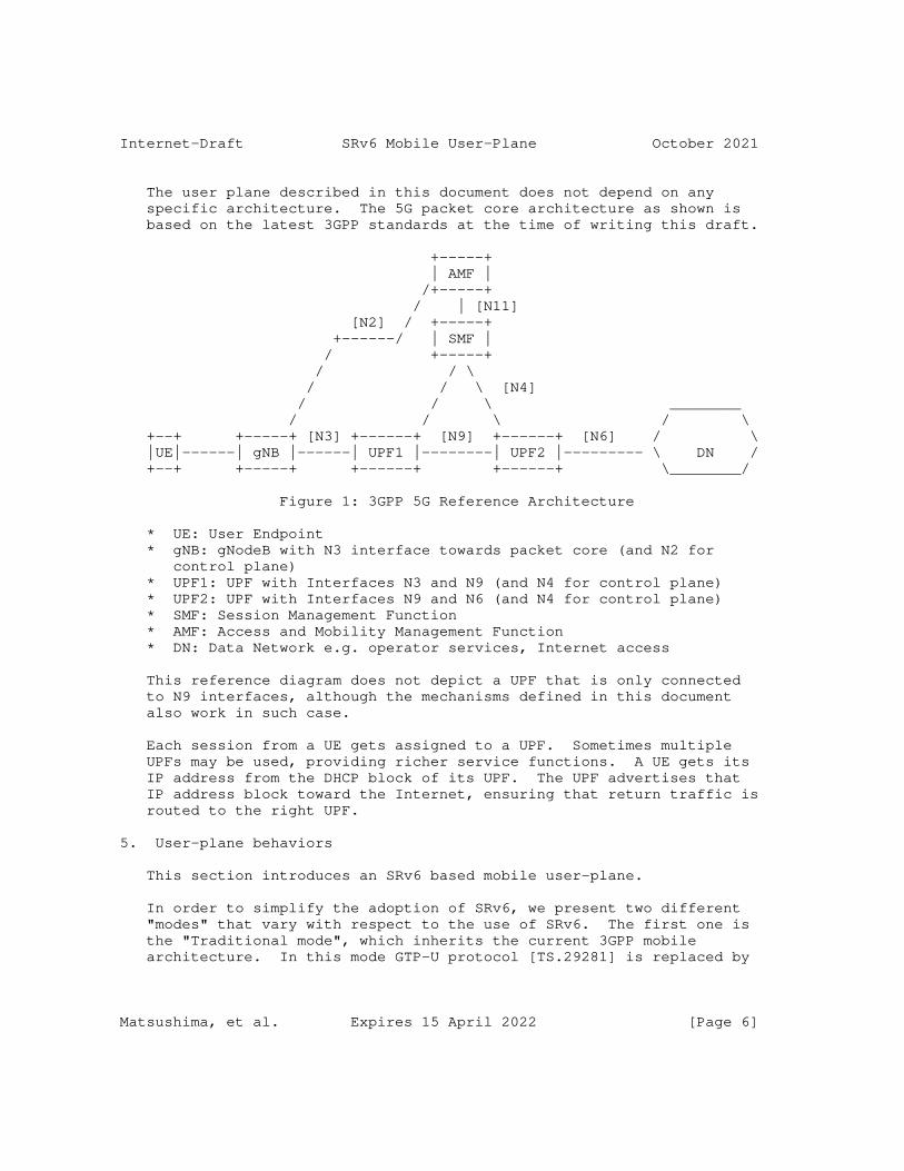
Internet-Draft SRv6 Mobile User-Plane October 2021
The user plane described in this document does not depend on any specific architecture. The 5G packet core architecture as shown is based on the latest 3GPP standards at the time of writing this draft.
+-----+ | AMF | /+-----+ / | [N11] [N2] / +-----+ +------/ | SMF | / +-----+ / / \ / / \ [N4] / / \ ________ / / \ / \ +--+ +-----+ [N3] +------+ [N9] +------+ [N6] / \ |UE|------| gNB |------| UPF1 |--------| UPF2 |--------- \ DN / +--+ +-----+ +------+ +------+ \________/
Figure 1: 3GPP 5G Reference Architecture
* UE: User Endpoint * gNB: gNodeB with N3 interface towards packet core (and N2 for control plane) * UPF1: UPF with Interfaces N3 and N9 (and N4 for control plane) * UPF2: UPF with Interfaces N9 and N6 (and N4 for control plane) * SMF: Session Management Function * AMF: Access and Mobility Management Function * DN: Data Network e.g. operator services, Internet access
This reference diagram does not depict a UPF that is only connected to N9 interfaces, although the mechanisms defined in this document also work in such case.
Each session from a UE gets assigned to a UPF. Sometimes multiple UPFs may be used, providing richer service functions. A UE gets its IP address from the DHCP block of its UPF. The UPF advertises that IP address block toward the Internet, ensuring that return traffic is routed to the right UPF.
5. User-plane behaviors
This section introduces an SRv6 based mobile user-plane.
In order to simplify the adoption of SRv6, we present two different "modes" that vary with respect to the use of SRv6. The first one is the "Traditional mode", which inherits the current 3GPP mobile architecture. In this mode GTP-U protocol [TS.29281] is replaced by
Matsushima, et al. Expires 15 April 2022 [Page 6]
Internet-Draft SRv6 Mobile User-Plane October 2021
SRv6, however the N3, N9 and N6 interfaces are still point-to-point interfaces with no intermediate waypoints as in the current mobile network architecture.
The second mode is the "Enhanced mode". This is an evolution from the "Traditional mode". In this mode the N3, N9 or N6 interfaces have intermediate waypoints -SIDs- that are used for Traffic Engineering or VNF purposes transparent to 3GPP functionalities. This results in optimal end-to-end policies across the mobile network with transport and services awareness.
In both, the Traditional and the Enhanced modes, we assume that the gNB as well as the UPFs are SR-aware (N3, N9 and -potentially- N6 interfaces are SRv6).
In addition to those two modes, we introduce two mechanisms for interworking with legacy access networks (those where the N3 interface is unmodified). In this document we introduce them as a variant to the Enhanced mode, however they are equally applicable to the Traditional mode.
One of these mechanisms is designed to interwork with legacy gNBs using GTP/IPv4. The second mechanism is designed to interwork with legacy gNBs using GTP/IPv6.
This document uses SRv6 Segment Endpoint Behaviors defined in [RFC8986] as well as new SRv6 Segment Endpoint Behaviors designed for the mobile user plane that are defined in this document in Section 6.
5.1. Traditional mode
In the traditional mode, the existing mobile UPFs remain unchanged with the sole exception of the use of SRv6 as the data plane instead of GTP-U. There is no impact to the rest of the mobile system.
In existing 3GPP mobile networks, a PDU Session is mapped 1-for-1 with a specific GTP tunnel (TEID). This 1-for-1 mapping is mirrored here to replace GTP encapsulation with the SRv6 encapsulation, while not changing anything else. There will be a unique SRv6 SID associated with each PDU Session, and the SID list only contains a single SID.
The traditional mode minimizes the changes required to the mobile system; hence it is a good starting point for forming a common ground.
Matsushima, et al. Expires 15 April 2022 [Page 7]
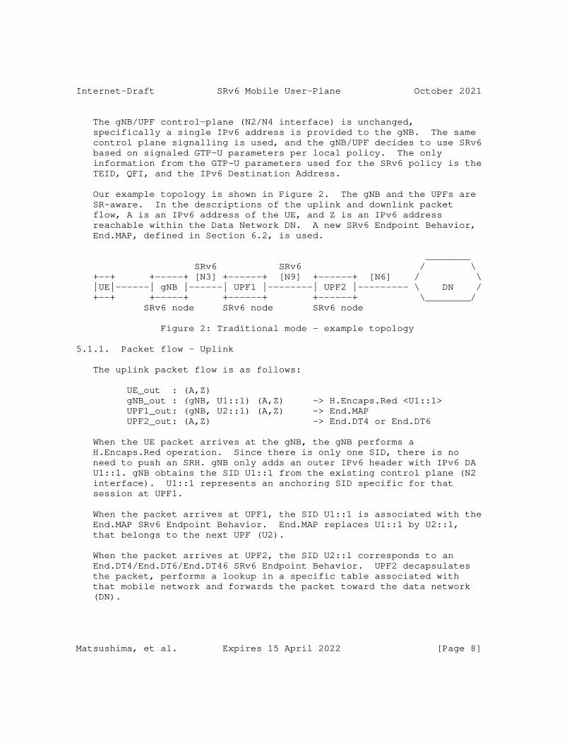
Internet-Draft SRv6 Mobile User-Plane October 2021
The gNB/UPF control-plane (N2/N4 interface) is unchanged, specifically a single IPv6 address is provided to the gNB. The same control plane signalling is used, and the gNB/UPF decides to use SRv6 based on signaled GTP-U parameters per local policy. The only information from the GTP-U parameters used for the SRv6 policy is the TEID, QFI, and the IPv6 Destination Address.
Our example topology is shown in Figure 2. The gNB and the UPFs are SR-aware. In the descriptions of the uplink and downlink packet flow, A is an IPv6 address of the UE, and Z is an IPv6 address reachable within the Data Network DN. A new SRv6 Endpoint Behavior, End.MAP, defined in Section 6.2, is used.
________ SRv6 SRv6 / \ +--+ +-----+ [N3] +------+ [N9] +------+ [N6] / \ |UE|------| gNB |------| UPF1 |--------| UPF2 |--------- \ DN / +--+ +-----+ +------+ +------+ \________/ SRv6 node SRv6 node SRv6 node
Figure 2: Traditional mode - example topology
5.1.1. Packet flow - Uplink
The uplink packet flow is as follows:
UE_out : (A,Z) gNB_out : (gNB, U1::1) (A,Z) -> H.Encaps.Red <U1::1> UPF1_out: (gNB, U2::1) (A,Z) -> End.MAP UPF2_out: (A,Z) -> End.DT4 or End.DT6
When the UE packet arrives at the gNB, the gNB performs a H.Encaps.Red operation. Since there is only one SID, there is no need to push an SRH. gNB only adds an outer IPv6 header with IPv6 DA U1::1. gNB obtains the SID U1::1 from the existing control plane (N2 interface). U1::1 represents an anchoring SID specific for that session at UPF1.
When the packet arrives at UPF1, the SID U1::1 is associated with the End.MAP SRv6 Endpoint Behavior. End.MAP replaces U1::1 by U2::1, that belongs to the next UPF (U2).
When the packet arrives at UPF2, the SID U2::1 corresponds to an End.DT4/End.DT6/End.DT46 SRv6 Endpoint Behavior. UPF2 decapsulates the packet, performs a lookup in a specific table associated with that mobile network and forwards the packet toward the data network (DN).
Matsushima, et al. Expires 15 April 2022 [Page 8]
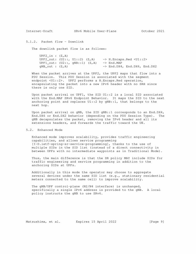
Internet-Draft SRv6 Mobile User-Plane October 2021
5.1.2. Packet flow - Downlink
The downlink packet flow is as follows:
UPF2_in : (Z,A) UPF2_out: (U2::, U1::2) (Z,A) -> H.Encaps.Red <U1::2> UPF1_out: (U2::, gNB::1) (Z,A) -> End.MAP gNB_out : (Z,A) -> End.DX4, End.DX6, End.DX2
When the packet arrives at the UPF2, the UPF2 maps that flow into a PDU Session. This PDU Session is associated with the segment endpoint <U1::2>. UPF2 performs a H.Encaps.Red operation, encapsulating the packet into a new IPv6 header with no SRH since there is only one SID.
Upon packet arrival on UPF1, the SID U1::2 is a local SID associated with the End.MAP SRv6 Endpoint Behavior. It maps the SID to the next anchoring point and replaces U1::2 by gNB::1, that belongs to the next hop.
Upon packet arrival on gNB, the SID gNB::1 corresponds to an End.DX4, End.DX6 or End.DX2 behavior (depending on the PDU Session Type). The gNB decapsulates the packet, removing the IPv6 header and all its extensions headers, and forwards the traffic toward the UE.
5.2. Enhanced Mode
Enhanced mode improves scalability, provides traffic engineering capabilities, and allows service programming [I-D.ietf-spring-sr-service-programming], thanks to the use of multiple SIDs in the SID list (instead of a direct connectivity in between UPFs with no intermediate waypoints as in Traditional Mode).
Thus, the main difference is that the SR policy MAY include SIDs for traffic engineering and service programming in addition to the anchoring SIDs at UPFs.
Additionally in this mode the operator may choose to aggregate several devices under the same SID list (e.g., stationary residential meters connected to the same cell) to improve scalability.
The gNB/UPF control-plane (N2/N4 interface) is unchanged, specifically a single IPv6 address is provided to the gNB. A local policy instructs the gNB to use SRv6.
Matsushima, et al. Expires 15 April 2022 [Page 9]
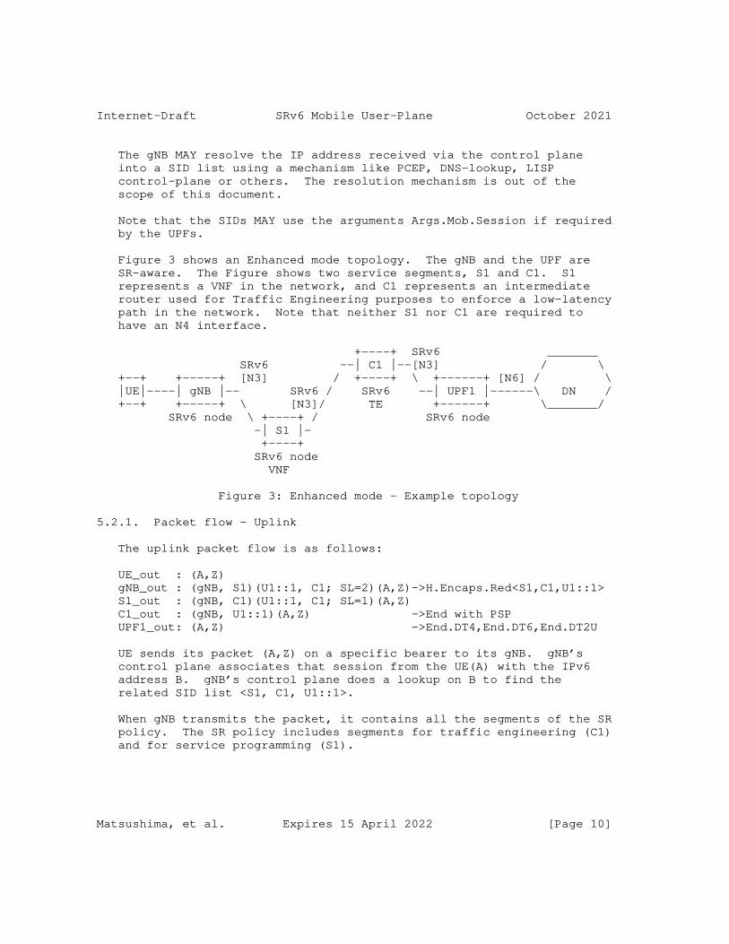
Internet-Draft SRv6 Mobile User-Plane October 2021
The gNB MAY resolve the IP address received via the control plane into a SID list using a mechanism like PCEP, DNS-lookup, LISP control-plane or others. The resolution mechanism is out of the scope of this document.
Note that the SIDs MAY use the arguments Args.Mob.Session if required by the UPFs.
Figure 3 shows an Enhanced mode topology. The gNB and the UPF are SR-aware. The Figure shows two service segments, S1 and C1. S1 represents a VNF in the network, and C1 represents an intermediate router used for Traffic Engineering purposes to enforce a low-latency path in the network. Note that neither S1 nor C1 are required to have an N4 interface.
+----+ SRv6 _______ SRv6 --| C1 |--[N3] / \ +--+ +-----+ [N3] / +----+ \ +------+ [N6] / \ |UE|----| gNB |-- SRv6 / SRv6 --| UPF1 |------\ DN / +--+ +-----+ \ [N3]/ TE +------+ \_______/ SRv6 node \ +----+ / SRv6 node -| S1 |- +----+ SRv6 node VNF
Figure 3: Enhanced mode - Example topology
5.2.1. Packet flow - Uplink
The uplink packet flow is as follows:
UE_out : (A,Z) gNB_out : (gNB, S1)(U1::1, C1; SL=2)(A,Z)->H.Encaps.Red<S1,C1,U1::1> S1_out : (gNB, C1)(U1::1, C1; SL=1)(A,Z) C1_out : (gNB, U1::1)(A,Z) ->End with PSP UPF1_out: (A,Z) ->End.DT4,End.DT6,End.DT2U
UE sends its packet (A,Z) on a specific bearer to its gNB. gNB’s control plane associates that session from the UE(A) with the IPv6 address B. gNB’s control plane does a lookup on B to find the related SID list <S1, C1, U1::1>.
When gNB transmits the packet, it contains all the segments of the SR policy. The SR policy includes segments for traffic engineering (C1) and for service programming (S1).
Matsushima, et al. Expires 15 April 2022 [Page 10]

Internet-Draft SRv6 Mobile User-Plane October 2021
Nodes S1 and C1 perform their related Endpoint functionality and forward the packet.
When the packet arrives at UPF1, the active segment (U1::1) is an End.DT4/End.DT6/End.DT2U which performs the decapsulation (removing the IPv6 header with all its extension headers) and forwards toward the data network.
5.2.2. Packet flow - Downlink
The downlink packet flow is as follows:
UPF1_in : (Z,A) ->UPF1 maps the flow w/ SID list <C1,S1, gNB> UPF1_out: (U1::1, C1)(gNB::1, S1; SL=2)(Z,A)->H.Encaps.Red C1_out : (U1::1, S1)(gNB::1, S1; SL=1)(Z,A) S1_out : (U1::1, gNB::1)(Z,A) ->End with PSP gNB_out : (Z,A) ->End.DX4/End.DX6/End.DX2
When the packet arrives at the UPF1, the UPF1 maps that particular flow into a UE PDU Session. This UE PDU Session is associated with the policy <C1, S1, gNB>. The UPF1 performs a H.Encaps.Red operation, encapsulating the packet into a new IPv6 header with its corresponding SRH.
The nodes C1 and S1 perform their related Endpoint processing.
Once the packet arrives at the gNB, the IPv6 DA corresponds to an End.DX4, End.DX6 or End.DX2 behavior at the gNB (depending on the underlying traffic). The gNB decapsulates the packet, removing the IPv6 header, and forwards the traffic towards the UE. The SID gNB::1 is one example of a SID associated to this service.
Note that there are several means to provide the UE session aggregation. The decision on which one to use is a local decision made by the operator. One option is to use the Args.Mob.Session (Section 6.1). Another option comprises the gNB performing an IP lookup on the inner packet by using the End.DT4, End.DT6, and End.DT2 behaviors.
5.2.3. Scalability
The Enhanced Mode improves since it allows the aggregation of several UEs under the same SID list. For example, in the case of stationary residential meters that are connected to the same cell, all such devices can share the same SID list. This improves scalability compared to Traditional Mode (unique SID per UE) and compared to GTP-U (dedicated TEID per UE).
Matsushima, et al. Expires 15 April 2022 [Page 11]

Internet-Draft SRv6 Mobile User-Plane October 2021
5.3. Enhanced mode with unchanged gNB GTP behavior
This section describes two mechanisms for interworking with legacy gNBs that still use GTP: one for IPv4, and another for IPv6.
In the interworking scenarios as illustrated in Figure 4, the gNB does not support SRv6. The gNB supports GTP encapsulation over IPv4 or IPv6. To achieve interworking, an SR Gateway (SRGW) entity is added. The SRGW maps the GTP traffic into SRv6.
The SRGW is not an anchor point and maintains very little state. For this reason, both IPv4 and IPv6 methods scale to millions of UEs.
_______ IP GTP SRv6 / \ +--+ +-----+ [N3] +------+ [N9] +------+ [N6] / \ |UE|------| gNB |------| SRGW |--------| UPF |---------\ DN / +--+ +-----+ +------+ +------+ \_______/ SR Gateway SRv6 node
Figure 4: Example topology for interworking
Both of the mechanisms described in this section are applicable to either the Traditional Mode or the Enhanced Mode.
5.3.1. Interworking with IPv6 GTP
In this interworking mode the gNB at the N3 interface uses GTP over IPv6.
Key points:
* The gNB is unchanged (control-plane or user-plane) and encapsulates into GTP (N3 interface is not modified). * The 5G Control-Plane towards the gNB (N2 interface) is unmodified; one IPv6 address is needed per SLA(i.e. a BSID at the SRGW). The SRv6 SID is different depending on the required SLA. * In the uplink, the SRGW removes GTP, finds the SID list related to the IPv6 DA, and adds SRH with the SID list. * There is no state for the downlink at the SRGW. * There is simple state in the uplink at the SRGW; using Enhanced mode results in fewer SR policies on this node. An SR policy is shared across UEs as long as they belong to the same context (i.e., tenant). A set of many different policies (i.e., different SLAs) increases the amount of state required. * When a packet from the UE leaves the gNB, it is SR-routed. This simplifies network slicing [I-D.ietf-lsr-flex-algo].
Matsushima, et al. Expires 15 April 2022 [Page 12]
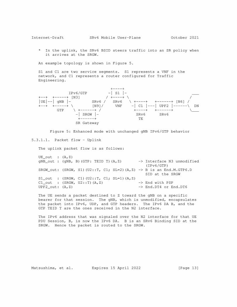
Internet-Draft SRv6 Mobile User-Plane October 2021
* In the uplink, the SRv6 BSID steers traffic into an SR policy when it arrives at the SRGW.
An example topology is shown in Figure 5.
S1 and C1 are two service segments. S1 represents a VNF in the network, and C1 represents a router configured for Traffic Engineering.
+----+ IPv6/GTP -| S1 |- ___ +--+ +-----+ [N3] / +----+ \ / |UE|--| gNB |- SRv6 / SRv6 \ +----+ +------+ [N6] / +--+ +-----+ \ [N9]/ VNF -| C1 |---| UPF2 |------\ DN GTP \ +------+ / +----+ +------+ \___ -| SRGW |- SRv6 SRv6 +------+ TE SR Gateway
Figure 5: Enhanced mode with unchanged gNB IPv6/GTP behavior
5.3.1.1. Packet flow - Uplink
The uplink packet flow is as follows:
UE_out : (A,Z) gNB_out : (gNB, B)(GTP: TEID T)(A,Z) -> Interface N3 unmodified (IPv6/GTP) SRGW_out: (SRGW, S1)(U2::T, C1; SL=2)(A,Z) -> B is an End.M.GTP6.D SID at the SRGW S1_out : (SRGW, C1)(U2::T, C1; SL=1)(A,Z) C1_out : (SRGW, U2::T)(A,Z) -> End with PSP UPF2_out: (A,Z) -> End.DT4 or End.DT6
The UE sends a packet destined to Z toward the gNB on a specific bearer for that session. The gNB, which is unmodified, encapsulates the packet into IPv6, UDP, and GTP headers. The IPv6 DA B, and the GTP TEID T are the ones received in the N2 interface.
The IPv6 address that was signaled over the N2 interface for that UE PDU Session, B, is now the IPv6 DA. B is an SRv6 Binding SID at the SRGW. Hence the packet is routed to the SRGW.
Matsushima, et al. Expires 15 April 2022 [Page 13]
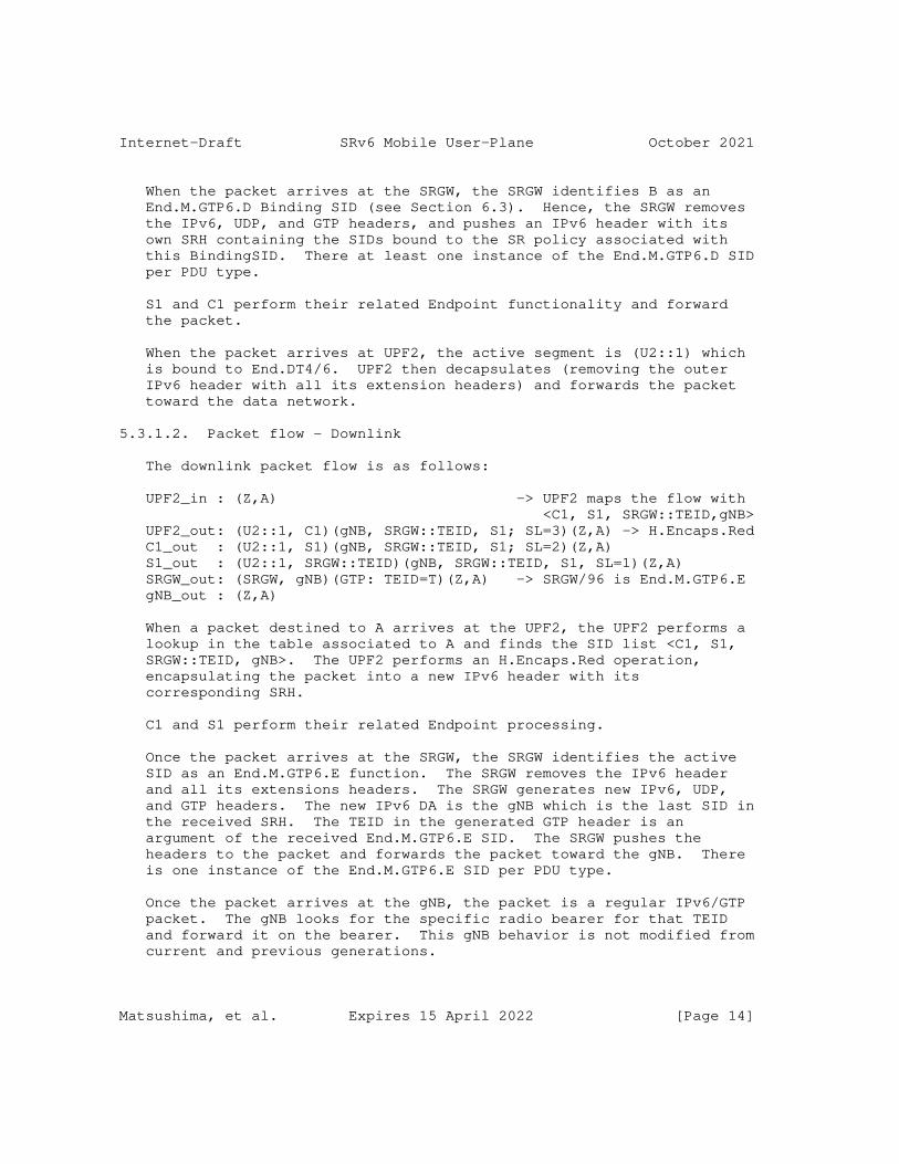
Internet-Draft SRv6 Mobile User-Plane October 2021
When the packet arrives at the SRGW, the SRGW identifies B as an End.M.GTP6.D Binding SID (see Section 6.3). Hence, the SRGW removes the IPv6, UDP, and GTP headers, and pushes an IPv6 header with its own SRH containing the SIDs bound to the SR policy associated with this BindingSID. There at least one instance of the End.M.GTP6.D SID per PDU type.
S1 and C1 perform their related Endpoint functionality and forward the packet.
When the packet arrives at UPF2, the active segment is (U2::1) which is bound to End.DT4/6. UPF2 then decapsulates (removing the outer IPv6 header with all its extension headers) and forwards the packet toward the data network.
5.3.1.2. Packet flow - Downlink
The downlink packet flow is as follows:
UPF2_in : (Z,A) -> UPF2 maps the flow with <C1, S1, SRGW::TEID,gNB> UPF2_out: (U2::1, C1)(gNB, SRGW::TEID, S1; SL=3)(Z,A) -> H.Encaps.Red C1_out : (U2::1, S1)(gNB, SRGW::TEID, S1; SL=2)(Z,A) S1_out : (U2::1, SRGW::TEID)(gNB, SRGW::TEID, S1, SL=1)(Z,A) SRGW_out: (SRGW, gNB)(GTP: TEID=T)(Z,A) -> SRGW/96 is End.M.GTP6.E gNB_out : (Z,A)
When a packet destined to A arrives at the UPF2, the UPF2 performs a lookup in the table associated to A and finds the SID list <C1, S1, SRGW::TEID, gNB>. The UPF2 performs an H.Encaps.Red operation, encapsulating the packet into a new IPv6 header with its corresponding SRH.
C1 and S1 perform their related Endpoint processing.
Once the packet arrives at the SRGW, the SRGW identifies the active SID as an End.M.GTP6.E function. The SRGW removes the IPv6 header and all its extensions headers. The SRGW generates new IPv6, UDP, and GTP headers. The new IPv6 DA is the gNB which is the last SID in the received SRH. The TEID in the generated GTP header is an argument of the received End.M.GTP6.E SID. The SRGW pushes the headers to the packet and forwards the packet toward the gNB. There is one instance of the End.M.GTP6.E SID per PDU type.
Once the packet arrives at the gNB, the packet is a regular IPv6/GTP packet. The gNB looks for the specific radio bearer for that TEID and forward it on the bearer. This gNB behavior is not modified from current and previous generations.
Matsushima, et al. Expires 15 April 2022 [Page 14]

Internet-Draft SRv6 Mobile User-Plane October 2021
5.3.1.3. Scalability
For the downlink traffic, the SRGW is stateless. All the state is in the SRH pushed by the UPF2. The UPF2 must have the UE states since it is the UE’s session anchor point.
For the uplink traffic, the state at the SRGW does not necessarily need to be unique per PDU Session; the SR policy can be shared among UEs. This enables more scalable SRGW deployments compared to a solution holding millions of states, one or more per UE.
5.3.2. Interworking with IPv4 GTP
In this interworking mode the gNB uses GTP over IPv4 in the N3 interface
Key points:
* The gNB is unchanged and encapsulates packets into GTP (the N3 interface is not modified). * In the uplink, traffic is classified by SRGW’s classification engine and steered into an SR policy. The SRGW may be implemented in a UPF or as a separate entity. * SRGW removes GTP, finds the SID list related to DA, and adds an SRH with the SID list.
An example topology is shown in Figure 6. In this mode the gNB is an unmodified gNB using IPv4/GTP. The UPFs are SR-aware. As before, the SRGW maps the IPv4/GTP traffic to SRv6.
S1 and C1 are two service segment endpoints. S1 represents a VNF in the network, and C1 represents a router configured for Traffic Engineering.
+----+ IPv4/GTP -| S1 |- ___ +--+ +-----+ [N3] / +----+ \ / |UE|--| gNB |- SRv6 / SRv6 \ +----+ +------+ [N6] / +--+ +-----+ \ [N9]/ VNF -| C1 |---| UPF2 |------\ DN GTP \ +------+ / +----+ +------+ \___ -| UPF1 |- SRv6 SRv6 +------+ TE SR Gateway
Figure 6: Enhanced mode with unchanged gNB IPv4/GTP behavior
Matsushima, et al. Expires 15 April 2022 [Page 15]
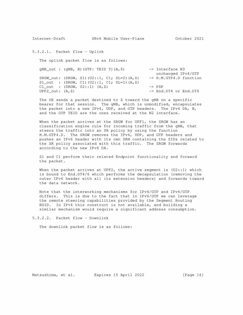
Internet-Draft SRv6 Mobile User-Plane October 2021
5.3.2.1. Packet flow - Uplink
The uplink packet flow is as follows:
gNB_out : (gNB, B)(GTP: TEID T)(A,Z) -> Interface N3 unchanged IPv4/GTP SRGW_out: (SRGW, S1)(U2::1, C1; SL=2)(A,Z) -> H.M.GTP4.D function S1_out : (SRGW, C1)(U2::1, C1; SL=1)(A,Z) C1_out : (SRGW, U2::1) (A,Z) -> PSP UPF2_out: (A,Z) -> End.DT4 or End.DT6
The UE sends a packet destined to Z toward the gNB on a specific bearer for that session. The gNB, which is unmodified, encapsulates the packet into a new IPv4, UDP, and GTP headers. The IPv4 DA, B, and the GTP TEID are the ones received at the N2 interface.
When the packet arrives at the SRGW for UPF1, the SRGW has an classification engine rule for incoming traffic from the gNB, that steers the traffic into an SR policy by using the function H.M.GTP4.D. The SRGW removes the IPv4, UDP, and GTP headers and pushes an IPv6 header with its own SRH containing the SIDs related to the SR policy associated with this traffic. The SRGW forwards according to the new IPv6 DA.
S1 and C1 perform their related Endpoint functionality and forward the packet.
When the packet arrives at UPF2, the active segment is (U2::1) which is bound to End.DT4/6 which performs the decapsulation (removing the outer IPv6 header with all its extension headers) and forwards toward the data network.
Note that the interworking mechanisms for IPv4/GTP and IPv6/GTP differs. This is due to the fact that in IPv6/GTP we can leverage the remote steering capabilities provided by the Segment Routing BSID. In IPv4 this construct is not available, and building a similar mechanism would require a significant address consumption.
5.3.2.2. Packet flow - Downlink
The downlink packet flow is as follows:
Matsushima, et al. Expires 15 April 2022 [Page 16]
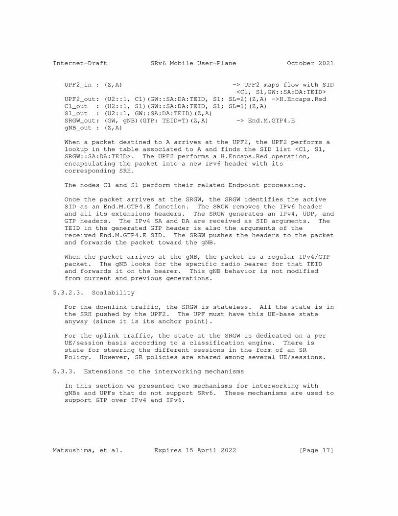
Internet-Draft SRv6 Mobile User-Plane October 2021
UPF2_in : (Z,A) -> UPF2 maps flow with SID <C1, S1,GW::SA:DA:TEID> UPF2_out: (U2::1, C1)(GW::SA:DA:TEID, S1; SL=2)(Z,A) ->H.Encaps.Red C1_out : (U2::1, S1)(GW::SA:DA:TEID, S1; SL=1)(Z,A) S1_out : (U2::1, GW::SA:DA:TEID)(Z,A) SRGW_out: (GW, gNB)(GTP: TEID=T)(Z,A) -> End.M.GTP4.E gNB_out : (Z,A)
When a packet destined to A arrives at the UPF2, the UPF2 performs a lookup in the table associated to A and finds the SID list <C1, S1, SRGW::SA:DA:TEID>. The UPF2 performs a H.Encaps.Red operation, encapsulating the packet into a new IPv6 header with its corresponding SRH.
The nodes C1 and S1 perform their related Endpoint processing.
Once the packet arrives at the SRGW, the SRGW identifies the active SID as an End.M.GTP4.E function. The SRGW removes the IPv6 header and all its extensions headers. The SRGW generates an IPv4, UDP, and GTP headers. The IPv4 SA and DA are received as SID arguments. The TEID in the generated GTP header is also the arguments of the received End.M.GTP4.E SID. The SRGW pushes the headers to the packet and forwards the packet toward the gNB.
When the packet arrives at the gNB, the packet is a regular IPv4/GTP packet. The gNB looks for the specific radio bearer for that TEID and forwards it on the bearer. This gNB behavior is not modified from current and previous generations.
5.3.2.3. Scalability
For the downlink traffic, the SRGW is stateless. All the state is in the SRH pushed by the UPF2. The UPF must have this UE-base state anyway (since it is its anchor point).
For the uplink traffic, the state at the SRGW is dedicated on a per UE/session basis according to a classification engine. There is state for steering the different sessions in the form of an SR Policy. However, SR policies are shared among several UE/sessions.
5.3.3. Extensions to the interworking mechanisms
In this section we presented two mechanisms for interworking with gNBs and UPFs that do not support SRv6. These mechanisms are used to support GTP over IPv4 and IPv6.
Matsushima, et al. Expires 15 April 2022 [Page 17]

Internet-Draft SRv6 Mobile User-Plane October 2021
Even though we have presented these methods as an extension to the "Enhanced mode", it is straightforward in its applicability to the "Traditional mode".
5.4. SRv6 Drop-in Interworking
In this section we introduce another mode useful for legacy gNB and UPFs that still operate with GTP-U. This mode provides an SRv6-enabled user plane in between two GTP-U tunnel endpoints.
In this mode we employ two SRGWs that map GTP-U traffic to SRv6 and vice-versa.
Unlike other interworking modes, in this mode both of the mobility overlay endpoints use GTP-U. Two SRGWs are deployed in either N3 or N9 interface to realize an intermediate SR policy.
+----+ -| S1 |- +-----+ / +----+ \ | gNB |- SRv6 / SRv6 \ +----+ +--------+ +-----+ +-----+ \ / VNF -| C1 |---| SRGW-B |----| UPF | GTP[N3]\ +--------+ / +----+ +--------+ +-----+ -| SRGW-A |- SRv6 SR Gateway-B GTP +--------+ TE SR Gateway-A
Figure 7: Example topology for SRv6 Drop-in mode
The packet flow of Figure 7 is as follows:
gNB_out : (gNB, U::1)(GTP: TEID T)(A,Z) GW-A_out: (GW-A, S1)(U::1, SGB::TEID, C1; SL=3)(A,Z)->U::1 is an End.M.GTP6.D.Di SID at SRGW-A S1_out : (GW-A, C1)(U::1, SGB::TEID, C1; SL=2)(A,Z) C1_out : (GW-A, SGB::TEID)(U::1, SGB::TEID, C1; SL=1)(A,Z) GW-B_out: (GW-B, U::1)(GTP: TEID T)(A,Z) ->SGB::TEID is an End.M.GTP6.E SID at SRGW-B UPF_out : (A,Z)
When a packet destined to Z is sent to the gNB, which is unmodified (control-plane and user-plane remain GTP-U), gNB performs encapsulation into a new IP, UDP, and GTP headers. The IPv6 DA, U::1, and the GTP TEID are the ones received at the N2 interface.
Matsushima, et al. Expires 15 April 2022 [Page 18]

Internet-Draft SRv6 Mobile User-Plane October 2021
The IPv6 address that was signaled over the N2 interface for that PDU Session, U::1, is now the IPv6 DA. U::1 is an SRv6 Binding SID at SRGW-A. Hence the packet is routed to the SRGW.
When the packet arrives at SRGW-A, the SRGW identifies U::1 as an End.M.GTP6.D.Di Binding SID (see Section 6.4). Hence, the SRGW removes the IPv6, UDP, and GTP headers, and pushes an IPv6 header with its own SRH containing the SIDs bound to the SR policy associated with this Binding SID. There is one instance of the End.M.GTP6.D.Di SID per PDU type.
S1 and C1 perform their related Endpoint functionality and forward the packet.
Once the packet arrives at SRGW-B, the SRGW identifies the active SID as an End.M.GTP6.E function. The SRGW removes the IPv6 header and all its extensions headers. The SRGW generates new IPv6, UDP, and GTP headers. The new IPv6 DA is U::1 which is the last SID in the received SRH. The TEID in the generated GTP header is an argument of the received End.M.GTP6.E SID. The SRGW pushes the headers to the packet and forwards the packet toward UPF. There is one instance of the End.M.GTP6.E SID per PDU type.
Once the packet arrives at UPF, the packet is a regular IPv6/GTP packet. The UPF looks for the specific rule for that TEID to forward the packet. This UPF behavior is not modified from current and previous generations.
6. SRv6 Segment Endpoint Mobility Behaviors
6.1. Args.Mob.Session
Args.Mob.Session provide per-session information for charging, buffering and lawful intercept (among others) required by some mobile nodes. The Args.Mob.Session argument format is used in combination with End.Map, End.DT4/End.DT6/End.DT46 and End.DX4/End.DX6/End.DX2 behaviors. Note that proposed format is applicable for 5G networks, while similar formats could be used for legacy networks.
0 1 2 3 0 1 2 3 4 5 6 7 8 9 0 1 2 3 4 5 6 7 8 9 0 1 2 3 4 5 6 7 8 9 0 1 +-+-+-+-+-+-+-+-+-+-+-+-+-+-+-+-+-+-+-+-+-+-+-+-+-+-+-+-+-+-+-+-+ | QFI |R|U| PDU Session ID | +-+-+-+-+-+-+-+-+-+-+-+-+-+-+-+-+-+-+-+-+-+-+-+-+-+-+-+-+-+-+-+-+ |PDU Sess(cont’)| +-+-+-+-+-+-+-+-+
Figure 8: Args.Mob.Session format
Matsushima, et al. Expires 15 April 2022 [Page 19]
Internet-Draft SRv6 Mobile User-Plane October 2021
* QFI: QoS Flow Identifier [TS.38415] * R: Reflective QoS Indication [TS.23501]. This parameter indicates the activation of reflective QoS towards the UE for the transferred packet. Reflective QoS enables the UE to map UL User Plane traffic to QoS Flows without SMF provided QoS rules. * U: Unused and for future use. MUST be 0 on transmission and ignored on receipt. * PDU Session ID: Identifier of PDU Session. The GTP-U equivalent is TEID.
Arg.Mob.Session is required in case that one SID aggregates multiple PDU Sessions. Since the SRv6 SID is likely NOT to be instantiated per PDU session, Args.Mob.Session helps the UPF to perform the behaviors which require per QFI and/or per PDU Session granularity.
Note that the encoding of user-plane messages (e.g., Echo Request, Echo Reply, Error Indication and End Marker) is out of the scope of this draft. [I-D.murakami-dmm-user-plane-message-encoding] defines one possible encoding.
6.2. End.MAP
The "Endpoint behavior with SID mapping" behavior (End.MAP for short) is used in several scenarios. Particularly in mobility, End.MAP is used by the intermediate UPFs.
When node N receives a packet whose IPv6 DA is S and S is a local End.MAP SID, N does:
S01. If (IPv6 Hop Limit <= 1) { S02. Send an ICMP Time Exceeded message to the Source Address, Code 0 (Hop limit exceeded in transit), interrupt packet processing, and discard the packet. S03. } S04. Decrement IPv6 Hop Limit by 1 S05. Update the IPv6 DA with the new mapped SID S06. Submit the packet to the egress IPv6 FIB lookup for transmission to the new destination
Notes: The SIDs in the SRH are not modified.
6.3. End.M.GTP6.D
The "Endpoint behavior with IPv6/GTP decapsulation into SR policy" behavior (End.M.GTP6.D for short) is used in interworking scenario for the uplink towards SRGW from the legacy gNB using IPv6/GTP. Any SID instance of this behavior is associated with an SR Policy B and an IPv6 Source Address A.
Matsushima, et al. Expires 15 April 2022 [Page 20]
Internet-Draft SRv6 Mobile User-Plane October 2021
When the SR Gateway node N receives a packet destined to S and S is a local End.M.GTP6.D SID, N does:
S01. When an SRH is processed { S02. If (Segments Left != 0) { S03. Send an ICMP Parameter Problem to the Source Address, Code 0 (Erroneous header field encountered), Pointer set to the Segments Left field, interrupt packet processing, and discard the packet. S04. } S05. Proceed to process the next header in the packet S06. }
When processing the Upper-layer header of a packet matching a FIB entry locally instantiated as an End.M.GTP6.D SID, N does:
S01. If (Next Header (NH) == UDP & UDP_Dest_port == GTP) { S02. Copy the GTP TEID and QFI to buffer memory S03. Pop the IPv6, UDP, and GTP Headers S04. Push a new IPv6 header with its own SRH containing B S05. Set the outer IPv6 SA to A S06. Set the outer IPv6 DA to the first SID of B S07. Set the outer Payload Length, Traffic Class, Flow Label, Hop Limit, and Next-Header (NH) fields S08. Write in the last SID of the SRH the Args.Mob.Session based on the information of buffer memory S09. Submit the packet to the egress IPv6 FIB lookup and transmission to the new destination S10. } Else { S11. Process as per [RFC8986] Section 4.1.1 S12. }
Notes: The NH is set based on the SID parameter. There is one instantiation of the End.M.GTP6.D SID per PDU Session Type, hence the NH is already known in advance. For the IPv4v6 PDU Session Type, in addition we inspect the first nibble of the PDU to know the NH value.
The prefix of last segment (S3 in above example) SHOULD be followed by an Arg.Mob.Session argument space which is used to provide the session identifiers.
Matsushima, et al. Expires 15 April 2022 [Page 21]
Internet-Draft SRv6 Mobile User-Plane October 2021
6.4. End.M.GTP6.D.Di
The "Endpoint behavior with IPv6/GTP decapsulation into SR policy for Drop-in Mode" behavior (End.M.GTP6.D.Di for short) is used in SRv6 drop-in interworking scenario described in Section 5.4. The difference between End.M.GTP6.D as another variant of IPv6/GTP decapsulation function is that the original IPv6 DA of GTP packet is preserved as the last SID in SRH.
Any SID instance of this behavior is associated with an SR Policy B and an IPv6 Source Address A.
When the SR Gateway node N receives a packet destined to S and S is a local End.M.GTP6.D.Di SID, N does:
S01. When an SRH is processed { S02. If (Segments Left != 0) { S03. Send an ICMP Parameter Problem to the Source Address, Code 0 (Erroneous header field encountered), Pointer set to the Segments Left field, interrupt packet processing, and discard the packet. S04. } S05. Proceed to process the next header in the packet S06. }
When processing the Upper-layer header of a packet matching a FIB entry locally instantiated as an End.M.GTP6.Di SID, N does:
S01. If (Next Header = UDP & UDP_Dest_port = GTP) { S02. Copy S to buffer memory S03. Pop the IPv6, UDP, and GTP Headers S04. Push a new IPv6 header with its own SRH containing B S05. Set the outer IPv6 SA to A S06. Set the outer IPv6 DA to the first SID of B S07. Set the outer Payload Length, Traffic Class, Flow Label, Hop Limit, and Next-Header fields S08. Write S to the SRH S09. Submit the packet to the egress IPv6 FIB lookup and transmission to the new destination S10. } Else { S11. Process as per [RFC8986] Section 4.1.1 S12. }
Notes: The NH is set based on the SID parameter. There is one instantiation of the End.M.GTP6.D SID per PDU Session Type, hence the NH is already known in advance. For the IPv4v6 PDU Session Type, in addition we inspect the first nibble of the PDU to know the NH value.
Matsushima, et al. Expires 15 April 2022 [Page 22]
Internet-Draft SRv6 Mobile User-Plane October 2021
The prefix of A SHOULD be an End.M.GTP6.E SID instantiated at an SR gateway.
6.5. End.M.GTP6.E
The "Endpoint behavior with encapsulation for IPv6/GTP tunnel" behavior (End.M.GTP6.E for short) is used among others in the interworking scenario for the downlink toward the legacy gNB using IPv6/GTP.
The prefix of End.M.GTP6.E SID MUST be followed by the Arg.Mob.Session argument space which is used to provide the session identifiers.
When the SR Gateway node N receives a packet destined to S, and S is a local End.M.GTP6.E SID, N does the following:
S01. When an SRH is processed { S02. If (Segments Left != 1) { S03. Send an ICMP Parameter Problem to the Source Address, Code 0 (Erroneous header field encountered), Pointer set to the Segments Left field, interrupt packet processing, and discard the packet. S04. } S05. Proceed to process the next header in the packet S06. }
When processing the Upper-layer header of a packet matching a FIB entry locally instantiated as an End.M.GTP6.E SID, N does:
S01. Copy SRH[0] and S to buffer memory S02. Pop the IPv6 header and all its extension headers S03. Push a new IPv6 header with a UDP/GTP Header S04. Set the outer IPv6 SA to A S05. Set the outer IPv6 DA from buffer memory S06. Set the outer Payload Length, Traffic Class, Flow Label, Hop Limit, and Next-Header fields S07. Set the GTP TEID (from buffer memory) S08. Submit the packet to the egress IPv6 FIB lookup and transmission to the new destination S09. }
Notes: An End.M.GTP6.E SID MUST always be the penultimate SID. The TEID is extracted from the argument space of the current SID.
The source address A SHOULD be an End.M.GTP6.D SID instantiated at an SR gateway.
Matsushima, et al. Expires 15 April 2022 [Page 23]
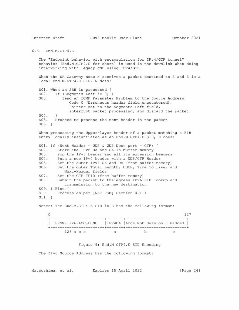
Internet-Draft SRv6 Mobile User-Plane October 2021
6.6. End.M.GTP4.E
The "Endpoint behavior with encapsulation for IPv4/GTP tunnel" behavior (End.M.GTP4.E for short) is used in the downlink when doing interworking with legacy gNB using IPv4/GTP.
When the SR Gateway node N receives a packet destined to S and S is a local End.M.GTP4.E SID, N does:
S01. When an SRH is processed { S02. If (Segments Left != 0) { S03. Send an ICMP Parameter Problem to the Source Address, Code 0 (Erroneous header field encountered), Pointer set to the Segments Left field, interrupt packet processing, and discard the packet. S04. } S05. Proceed to process the next header in the packet S06. }
When processing the Upper-layer header of a packet matching a FIB entry locally instantiated as an End.M.GTP4.E SID, N does:
S01. If (Next Header = UDP & UDP_Dest_port = GTP) { S02. Store the IPv6 DA and SA in buffer memory S03. Pop the IPv6 header and all its extension headers S04. Push a new IPv4 header with a UDP/GTP Header S05. Set the outer IPv4 SA and DA (from buffer memory) S06. Set the outer Total Length, DSCP, Time To Live, and Next-Header fields S07. Set the GTP TEID (from buffer memory) S08. Submit the packet to the egress IPv6 FIB lookup and transmission to the new destination S09. } Else { S10. Process as per [NET-PGM] Section 4.1.1 S11. }
Notes: The End.M.GTP4.E SID in S has the following format:
0 127 +-----------------------+-------+----------------+---------+ | SRGW-IPv6-LOC-FUNC |IPv4DA |Args.Mob.Session|0 Padded | +-----------------------+-------+----------------+---------+ 128-a-b-c a b c
Figure 9: End.M.GTP4.E SID Encoding
The IPv6 Source Address has the following format:
Matsushima, et al. Expires 15 April 2022 [Page 24]

Internet-Draft SRv6 Mobile User-Plane October 2021
0 127 +----------------------+--------+--------------------------+ | Source UPF Prefix |IPv4 SA | any bit pattern(ignored) | +----------------------+--------+--------------------------+ 128-a-b a b
Figure 10: IPv6 SA Encoding for End.M.GTP4.E
6.7. H.M.GTP4.D
The "SR Policy Headend with tunnel decapsulation and map to an SRv6 policy" behavior (H.M.GTP4.D for short) is used in the direction from legacy IPv4 user-plane to SRv6 user-plane network.
When the SR Gateway node N receives a packet destined to a IW- IPv4-Prefix, N does:
S01. IF Payload == UDP/GTP THEN S02. Pop the outer IPv4 header and UDP/GTP headers S03. Copy IPv4 DA, TEID to form SID B S04. Copy IPv4 SA to form IPv6 SA B’ S05. Encapsulate the packet into a new IPv6 header ;;Ref1 S06. Set the IPv6 DA = B S07. Forward along the shortest path to B S08. ELSE S09. Drop the packet
Ref1: The NH value is identified by inspecting the first nibble of the inner payload.
The SID B has the following format:
0 127 +-----------------------+-------+----------------+---------+ |Destination UPF Prefix |IPv4DA |Args.Mob.Session|0 Padded | +-----------------------+-------+----------------+---------+ 128-a-b-c a b c
Figure 11: H.M.GTP4.D SID Encoding
The SID B MAY be an SRv6 Binding SID instantiated at the first UPF (U1) to bind an SR policy [I-D.ietf-spring-segment-routing-policy].
Matsushima, et al. Expires 15 April 2022 [Page 25]
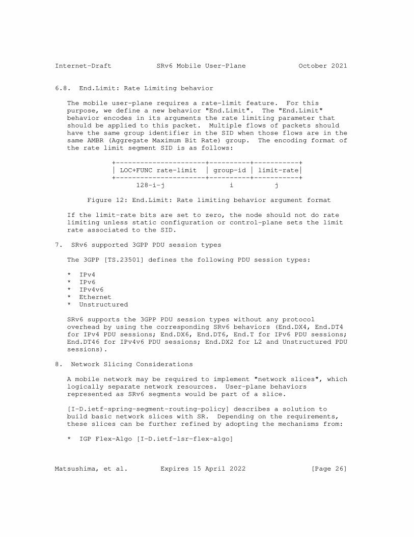
Internet-Draft SRv6 Mobile User-Plane October 2021
6.8. End.Limit: Rate Limiting behavior
The mobile user-plane requires a rate-limit feature. For this purpose, we define a new behavior "End.Limit". The "End.Limit" behavior encodes in its arguments the rate limiting parameter that should be applied to this packet. Multiple flows of packets should have the same group identifier in the SID when those flows are in the same AMBR (Aggregate Maximum Bit Rate) group. The encoding format of the rate limit segment SID is as follows:
+----------------------+----------+-----------+ | LOC+FUNC rate-limit | group-id | limit-rate| +----------------------+----------+-----------+ 128-i-j i j
Figure 12: End.Limit: Rate limiting behavior argument format
If the limit-rate bits are set to zero, the node should not do rate limiting unless static configuration or control-plane sets the limit rate associated to the SID.
7. SRv6 supported 3GPP PDU session types
The 3GPP [TS.23501] defines the following PDU session types:
* IPv4 * IPv6 * IPv4v6 * Ethernet * Unstructured
SRv6 supports the 3GPP PDU session types without any protocol overhead by using the corresponding SRv6 behaviors (End.DX4, End.DT4 for IPv4 PDU sessions; End.DX6, End.DT6, End.T for IPv6 PDU sessions; End.DT46 for IPv4v6 PDU sessions; End.DX2 for L2 and Unstructured PDU sessions).
8. Network Slicing Considerations
A mobile network may be required to implement "network slices", which logically separate network resources. User-plane behaviors represented as SRv6 segments would be part of a slice.
[I-D.ietf-spring-segment-routing-policy] describes a solution to build basic network slices with SR. Depending on the requirements, these slices can be further refined by adopting the mechanisms from:
* IGP Flex-Algo [I-D.ietf-lsr-flex-algo]
Matsushima, et al. Expires 15 April 2022 [Page 26]
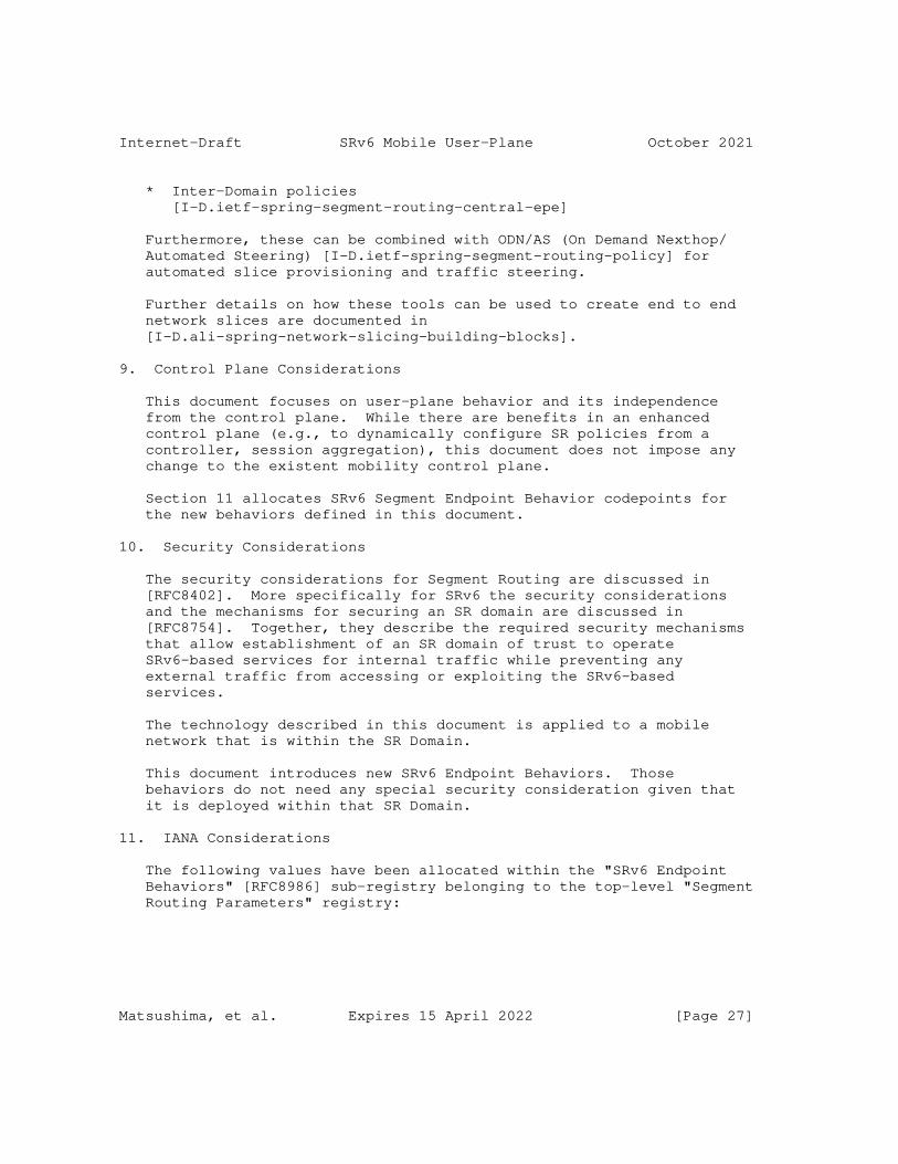
Internet-Draft SRv6 Mobile User-Plane October 2021
* Inter-Domain policies [I-D.ietf-spring-segment-routing-central-epe]
Furthermore, these can be combined with ODN/AS (On Demand Nexthop/ Automated Steering) [I-D.ietf-spring-segment-routing-policy] for automated slice provisioning and traffic steering.
Further details on how these tools can be used to create end to end network slices are documented in [I-D.ali-spring-network-slicing-building-blocks].
9. Control Plane Considerations
This document focuses on user-plane behavior and its independence from the control plane. While there are benefits in an enhanced control plane (e.g., to dynamically configure SR policies from a controller, session aggregation), this document does not impose any change to the existent mobility control plane.
Section 11 allocates SRv6 Segment Endpoint Behavior codepoints for the new behaviors defined in this document.
10. Security Considerations
The security considerations for Segment Routing are discussed in [RFC8402]. More specifically for SRv6 the security considerations and the mechanisms for securing an SR domain are discussed in [RFC8754]. Together, they describe the required security mechanisms that allow establishment of an SR domain of trust to operate SRv6-based services for internal traffic while preventing any external traffic from accessing or exploiting the SRv6-based services.
The technology described in this document is applied to a mobile network that is within the SR Domain.
This document introduces new SRv6 Endpoint Behaviors. Those behaviors do not need any special security consideration given that it is deployed within that SR Domain.
11. IANA Considerations
The following values have been allocated within the "SRv6 Endpoint Behaviors" [RFC8986] sub-registry belonging to the top-level "Segment Routing Parameters" registry:
Matsushima, et al. Expires 15 April 2022 [Page 27]
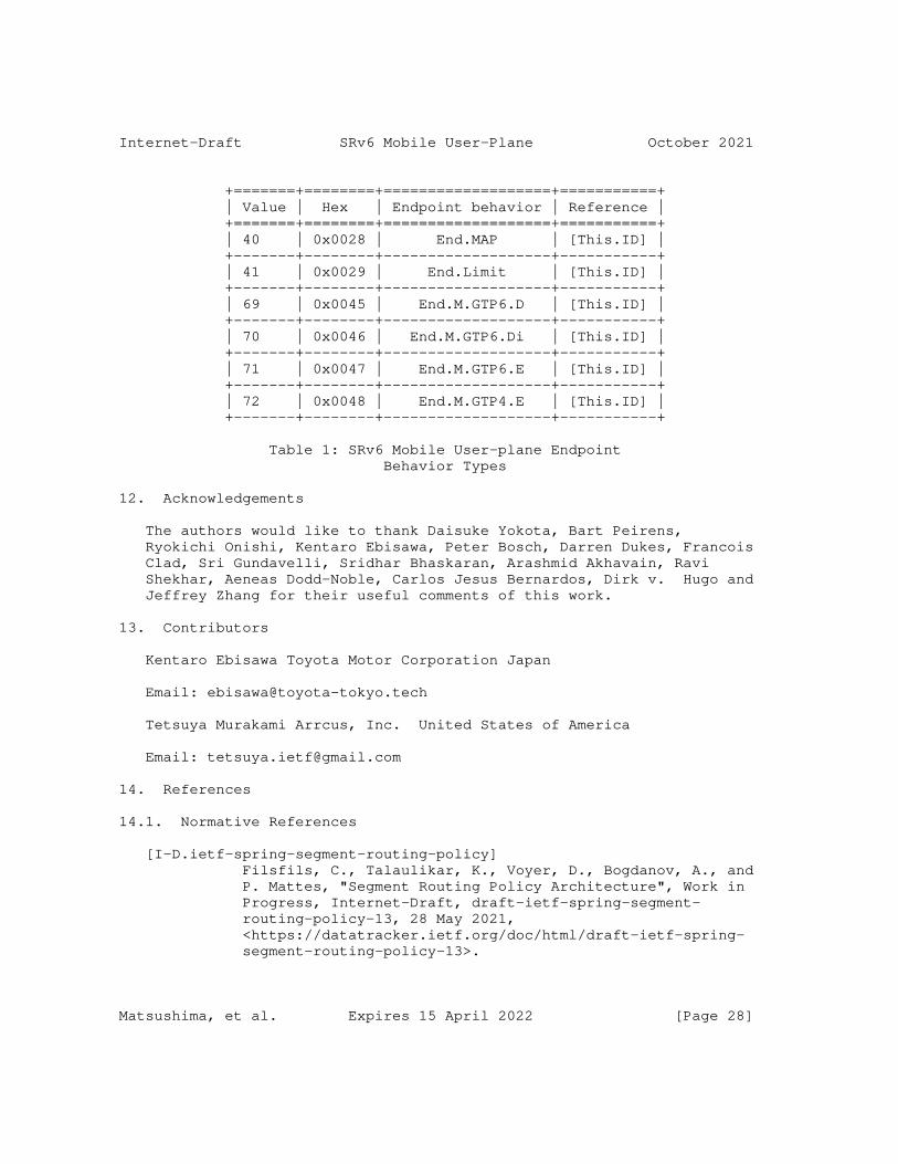
Internet-Draft SRv6 Mobile User-Plane October 2021
+=======+========+===================+===========+ | Value | Hex | Endpoint behavior | Reference | +=======+========+===================+===========+ | 40 | 0x0028 | End.MAP | [This.ID] | +-------+--------+-------------------+-----------+ | 41 | 0x0029 | End.Limit | [This.ID] | +-------+--------+-------------------+-----------+ | 69 | 0x0045 | End.M.GTP6.D | [This.ID] | +-------+--------+-------------------+-----------+ | 70 | 0x0046 | End.M.GTP6.Di | [This.ID] | +-------+--------+-------------------+-----------+ | 71 | 0x0047 | End.M.GTP6.E | [This.ID] | +-------+--------+-------------------+-----------+ | 72 | 0x0048 | End.M.GTP4.E | [This.ID] | +-------+--------+-------------------+-----------+
Table 1: SRv6 Mobile User-plane Endpoint Behavior Types
12. Acknowledgements
The authors would like to thank Daisuke Yokota, Bart Peirens, Ryokichi Onishi, Kentaro Ebisawa, Peter Bosch, Darren Dukes, Francois Clad, Sri Gundavelli, Sridhar Bhaskaran, Arashmid Akhavain, Ravi Shekhar, Aeneas Dodd-Noble, Carlos Jesus Bernardos, Dirk v. Hugo and Jeffrey Zhang for their useful comments of this work.
13. Contributors
Kentaro Ebisawa Toyota Motor Corporation Japan
Email: [email protected]
Tetsuya Murakami Arrcus, Inc. United States of America
Email: [email protected]
14. References
14.1. Normative References
[I-D.ietf-spring-segment-routing-policy] Filsfils, C., Talaulikar, K., Voyer, D., Bogdanov, A., and P. Mattes, "Segment Routing Policy Architecture", Work in Progress, Internet-Draft, draft-ietf-spring-segment- routing-policy-13, 28 May 2021, <https://datatracker.ietf.org/doc/html/draft-ietf-spring- segment-routing-policy-13>.
Matsushima, et al. Expires 15 April 2022 [Page 28]

Internet-Draft SRv6 Mobile User-Plane October 2021
[RFC2119] Bradner, S., "Key words for use in RFCs to Indicate Requirement Levels", BCP 14, RFC 2119, DOI 10.17487/RFC2119, March 1997, <https://www.rfc-editor.org/info/rfc2119>.
[RFC8402] Filsfils, C., Ed., Previdi, S., Ed., Ginsberg, L., Decraene, B., Litkowski, S., and R. Shakir, "Segment Routing Architecture", RFC 8402, DOI 10.17487/RFC8402, July 2018, <https://www.rfc-editor.org/info/rfc8402>.
[RFC8754] Filsfils, C., Ed., Dukes, D., Ed., Previdi, S., Leddy, J., Matsushima, S., and D. Voyer, "IPv6 Segment Routing Header (SRH)", RFC 8754, DOI 10.17487/RFC8754, March 2020, <https://www.rfc-editor.org/info/rfc8754>.
[RFC8986] Filsfils, C., Ed., Camarillo, P., Ed., Leddy, J., Voyer, D., Matsushima, S., and Z. Li, "Segment Routing over IPv6 (SRv6) Network Programming", RFC 8986, DOI 10.17487/RFC8986, February 2021, <https://www.rfc-editor.org/info/rfc8986>.
[TS.23501] 3GPP, "System Architecture for the 5G System", 3GPP TS 23.501 15.0.0, November 2017.
14.2. Informative References
[I-D.ali-spring-network-slicing-building-blocks] Ali, Z., Filsfils, C., Camarillo, P., and D. Voyer, "Building blocks for Slicing in Segment Routing Network", Work in Progress, Internet-Draft, draft-ali-spring- network-slicing-building-blocks-04, 21 February 2021, <https://datatracker.ietf.org/doc/html/draft-ali-spring- network-slicing-building-blocks-04>.
[I-D.camarilloelmalky-springdmm-srv6-mob-usecases] Garvia, P. C., Filsfils, C., Elmalky, H., Matsushima, S., Voyer, D., Cui, A., and B. Peirens, "SRv6 Mobility Use- Cases", Work in Progress, Internet-Draft, draft- camarilloelmalky-springdmm-srv6-mob-usecases-02, 15 August 2019, <https://datatracker.ietf.org/doc/html/draft- camarilloelmalky-springdmm-srv6-mob-usecases-02>.
[I-D.ietf-lsr-flex-algo] Psenak, P., Hegde, S., Filsfils, C., Talaulikar, K., and A. Gulko, "IGP Flexible Algorithm", Work in Progress, Internet-Draft, draft-ietf-lsr-flex-algo-17, 6 July 2021, <https://datatracker.ietf.org/doc/html/draft-ietf-lsr- flex-algo-17>.
Matsushima, et al. Expires 15 April 2022 [Page 29]
Internet-Draft SRv6 Mobile User-Plane October 2021
[I-D.ietf-spring-segment-routing-central-epe] Filsfils, C., Previdi, S., Dawra, G., Aries, E., and D. Afanasiev, "Segment Routing Centralized BGP Egress Peer Engineering", Work in Progress, Internet-Draft, draft- ietf-spring-segment-routing-central-epe-10, 21 December 2017, <https://datatracker.ietf.org/doc/html/draft-ietf- spring-segment-routing-central-epe-10>.
[I-D.ietf-spring-sr-service-programming] Clad, F., Xu, X., Filsfils, C., Bernier, D., Li, C., Decraene, B., Ma, S., Yadlapalli, C., Henderickx, W., and S. Salsano, "Service Programming with Segment Routing", Work in Progress, Internet-Draft, draft-ietf-spring-sr- service-programming-05, 10 September 2021, <https://datatracker.ietf.org/doc/html/draft-ietf-spring- sr-service-programming-05>.
[I-D.kohno-dmm-srv6mob-arch] Kohno, M., Clad, F., Camarillo, P., and Z. Ali, "Architecture Discussion on SRv6 Mobile User plane", Work in Progress, Internet-Draft, draft-kohno-dmm-srv6mob-arch- 04, 6 May 2021, <https://datatracker.ietf.org/doc/html/ draft-kohno-dmm-srv6mob-arch-04>.
[I-D.matsushima-spring-srv6-deployment-status] Matsushima, S., Filsfils, C., Ali, Z., Li, Z., and K. Rajaraman, "SRv6 Implementation and Deployment Status", Work in Progress, Internet-Draft, draft-matsushima-spring- srv6-deployment-status-11, 17 February 2021, <https://datatracker.ietf.org/doc/html/draft-matsushima- spring-srv6-deployment-status-11>.
[I-D.murakami-dmm-user-plane-message-encoding] Murakami, T., Matsushima, S., Ebisawa, K., Camarillo, P., and R. Shekhar, "User Plane Message Encoding", Work in Progress, Internet-Draft, draft-murakami-dmm-user-plane- message-encoding-04, 2 September 2021, <https://datatracker.ietf.org/doc/html/draft-murakami-dmm- user-plane-message-encoding-04>.
[TS.29281] 3GPP, "General Packet Radio System (GPRS) Tunnelling Protocol User Plane (GTPv1-U)", 3GPP TS 29.281 15.1.0, December 2017.
[TS.38415] 3GPP, "Draft Specification for 5GS container (TS 38.415)", 3GPP R3-174510 0.0.0, August 2017.
Matsushima, et al. Expires 15 April 2022 [Page 30]
Internet-Draft SRv6 Mobile User-Plane October 2021
Appendix A. Implementations
This document introduces new SRv6 Endpoint Behaviors. These behaviors have an open-source P4 implementation available in https://github.com/ebiken/p4srv6.
Additionally, a full implementation of this document is available in Linux Foundation FD.io VPP project since release 20.05. More information available here: https://docs.fd.io/vpp/20.05/d7/d3c/ srv6_mobile_plugin_doc.html.
There are also experimental implementations in M-CORD NGIC and Open Air Interface (OAI).
Authors’ Addresses
Satoru Matsushima (editor) SoftBank Japan
Email: [email protected]
Clarence Filsfils Cisco Systems, Inc. Belgium
Email: [email protected]
Miya Kohno Cisco Systems, Inc. Japan
Email: [email protected]
Pablo Camarillo Garvia (editor) Cisco Systems, Inc. Spain
Email: [email protected]
Daniel Voyer Bell Canada Canada
Matsushima, et al. Expires 15 April 2022 [Page 31]
Internet-Draft SRv6 Mobile User-Plane October 2021
Email: [email protected]
Charles E. Perkins Lupin Lodge 20600 Aldercroft Heights Rd. Los Gatos, CA 95033 United States of America
Email: [email protected]
Matsushima, et al. Expires 15 April 2022 [Page 32]


![PURSUING SUSTAINABILITY: FRAMEWORKS, KNOWLEDGE, PLANNING AND PROGRESS [Sinclair Working Draft]](https://static.fdokumen.com/doc/165x107/632198d663847156ac063ad8/pursuing-sustainability-frameworks-knowledge-planning-and-progress-sinclair.jpg)