Transport Area working group (tsvwg) K. De Schepper Internet ...
489
Transport Area working group (tsvwg) K. De Schepper Internet-Draft Nokia Bell Labs Intended status: Experimental B. Briscoe, Ed. Expires: 8 January 2023 Independent G. White CableLabs 7 July 2022 DualQ Coupled AQMs for Low Latency, Low Loss and Scalable Throughput (L4S) draft-ietf-tsvwg-aqm-dualq-coupled-24 Abstract This specification defines a framework for coupling the Active Queue Management (AQM) algorithms in two queues intended for flows with different responses to congestion. This provides a way for the Internet to transition from the scaling problems of standard TCP Reno-friendly (’Classic’) congestion controls to the family of ’Scalable’ congestion controls. These are designed for consistently very Low queuing Latency, very Low congestion Loss and Scaling of per-flow throughput (L4S) by using Explicit Congestion Notification (ECN) in a modified way. Until the Coupled DualQ, these L4S senders could only be deployed where a clean-slate environment could be arranged, such as in private data centres. The coupling acts like a semi-permeable membrane: isolating the sub-millisecond average queuing delay and zero congestion loss of L4S from Classic latency and loss; but pooling the capacity between any combination of Scalable and Classic flows with roughly equivalent throughput per flow. The DualQ achieves this indirectly, without having to inspect transport layer flow identifiers and without compromising the performance of the Classic traffic, relative to a single queue. The DualQ design has low complexity and requires no configuration for the public Internet. Status of This Memo This Internet-Draft is submitted in full conformance with the provisions of BCP 78 and BCP 79. Internet-Drafts are working documents of the Internet Engineering Task Force (IETF). Note that other groups may also distribute working documents as Internet-Drafts. The list of current Internet- Drafts is at https://datatracker.ietf.org/drafts/current/. De Schepper, et al. Expires 8 January 2023 [Page 1]
-
Upload
khangminh22 -
Category
Documents
-
view
5 -
download
0
Transcript of Transport Area working group (tsvwg) K. De Schepper Internet ...
Transport Area working group (tsvwg) K. De SchepperInternet-Draft Nokia Bell LabsIntended status: Experimental B. Briscoe, Ed.Expires: 8 January 2023 Independent G. White CableLabs 7 July 2022
DualQ Coupled AQMs for Low Latency, Low Loss and Scalable Throughput (L4S) draft-ietf-tsvwg-aqm-dualq-coupled-24
Abstract
This specification defines a framework for coupling the Active Queue Management (AQM) algorithms in two queues intended for flows with different responses to congestion. This provides a way for the Internet to transition from the scaling problems of standard TCP Reno-friendly (’Classic’) congestion controls to the family of ’Scalable’ congestion controls. These are designed for consistently very Low queuing Latency, very Low congestion Loss and Scaling of per-flow throughput (L4S) by using Explicit Congestion Notification (ECN) in a modified way. Until the Coupled DualQ, these L4S senders could only be deployed where a clean-slate environment could be arranged, such as in private data centres. The coupling acts like a semi-permeable membrane: isolating the sub-millisecond average queuing delay and zero congestion loss of L4S from Classic latency and loss; but pooling the capacity between any combination of Scalable and Classic flows with roughly equivalent throughput per flow. The DualQ achieves this indirectly, without having to inspect transport layer flow identifiers and without compromising the performance of the Classic traffic, relative to a single queue. The DualQ design has low complexity and requires no configuration for the public Internet.
Status of This Memo
This Internet-Draft is submitted in full conformance with the provisions of BCP 78 and BCP 79.
Internet-Drafts are working documents of the Internet Engineering Task Force (IETF). Note that other groups may also distribute working documents as Internet-Drafts. The list of current Internet- Drafts is at https://datatracker.ietf.org/drafts/current/.
De Schepper, et al. Expires 8 January 2023 [Page 1]
Internet-Draft DualQ Coupled AQMs July 2022
Internet-Drafts are draft documents valid for a maximum of six months and may be updated, replaced, or obsoleted by other documents at any time. It is inappropriate to use Internet-Drafts as reference material or to cite them other than as "work in progress."
This Internet-Draft will expire on 8 January 2023.
Copyright Notice
Copyright (c) 2022 IETF Trust and the persons identified as the document authors. All rights reserved.
This document is subject to BCP 78 and the IETF Trust’s Legal Provisions Relating to IETF Documents (https://trustee.ietf.org/ license-info) in effect on the date of publication of this document. Please review these documents carefully, as they describe your rights and restrictions with respect to this document. Code Components extracted from this document must include Revised BSD License text as described in Section 4.e of the Trust Legal Provisions and are provided without warranty as described in the Revised BSD License.
Table of Contents
1. Introduction . . . . . . . . . . . . . . . . . . . . . . . . 3 1.1. Outline of the Problem . . . . . . . . . . . . . . . . . 3 1.2. Scope . . . . . . . . . . . . . . . . . . . . . . . . . . 6 1.3. Terminology . . . . . . . . . . . . . . . . . . . . . . . 7 1.4. Features . . . . . . . . . . . . . . . . . . . . . . . . 9 2. DualQ Coupled AQM . . . . . . . . . . . . . . . . . . . . . . 11 2.1. Coupled AQM . . . . . . . . . . . . . . . . . . . . . . . 11 2.2. Dual Queue . . . . . . . . . . . . . . . . . . . . . . . 13 2.3. Traffic Classification . . . . . . . . . . . . . . . . . 13 2.4. Overall DualQ Coupled AQM Structure . . . . . . . . . . . 14 2.5. Normative Requirements for a DualQ Coupled AQM . . . . . 17 2.5.1. Functional Requirements . . . . . . . . . . . . . . . 17 2.5.1.1. Requirements in Unexpected Cases . . . . . . . . 18 2.5.2. Management Requirements . . . . . . . . . . . . . . . 19 2.5.2.1. Configuration . . . . . . . . . . . . . . . . . . 20 2.5.2.2. Monitoring . . . . . . . . . . . . . . . . . . . 21 2.5.2.3. Anomaly Detection . . . . . . . . . . . . . . . . 22 2.5.2.4. Deployment, Coexistence and Scaling . . . . . . . 22 3. IANA Considerations (to be removed by RFC Editor) . . . . . . 22 4. Security Considerations . . . . . . . . . . . . . . . . . . . 22 4.1. Low Delay without Requiring Per-Flow Processing . . . . . 22 4.2. Handling Unresponsive Flows and Overload . . . . . . . . 23 4.2.1. Unresponsive Traffic without Overload . . . . . . . . 24 4.2.2. Avoiding Short-Term Classic Starvation: Sacrifice L4S Throughput or Delay? . . . . . . . . . . . . . . . . 25
De Schepper, et al. Expires 8 January 2023 [Page 2]
Internet-Draft DualQ Coupled AQMs July 2022
4.2.3. L4S ECN Saturation: Introduce Drop or Delay? . . . . 26 4.2.3.1. Protecting against Overload by Unresponsive ECN-Capable Traffic . . . . . . . . . . . . . . . . 28 5. Acknowledgements . . . . . . . . . . . . . . . . . . . . . . 28 6. Contributors . . . . . . . . . . . . . . . . . . . . . . . . 29 7. References . . . . . . . . . . . . . . . . . . . . . . . . . 29 7.1. Normative References . . . . . . . . . . . . . . . . . . 29 7.2. Informative References . . . . . . . . . . . . . . . . . 30 Appendix A. Example DualQ Coupled PI2 Algorithm . . . . . . . . 35 A.1. Pass #1: Core Concepts . . . . . . . . . . . . . . . . . 36 A.2. Pass #2: Edge-Case Details . . . . . . . . . . . . . . . 47 Appendix B. Example DualQ Coupled Curvy RED Algorithm . . . . . 52 B.1. Curvy RED in Pseudocode . . . . . . . . . . . . . . . . . 52 B.2. Efficient Implementation of Curvy RED . . . . . . . . . . 58 Appendix C. Choice of Coupling Factor, k . . . . . . . . . . . . 60 C.1. RTT-Dependence . . . . . . . . . . . . . . . . . . . . . 60 C.2. Guidance on Controlling Throughput Equivalence . . . . . 61 Authors’ Addresses . . . . . . . . . . . . . . . . . . . . . . . 65
1. Introduction
This document specifies a framework for DualQ Coupled AQMs, which is the network part of the L4S architecture [I-D.ietf-tsvwg-l4s-arch]. L4S enables both very low queuing latency (sub-millisecond on average) and high throughput at the same time, for ad hoc numbers of capacity-seeking applications all sharing the same capacity.
1.1. Outline of the Problem
Latency is becoming the critical performance factor for many (most?) applications on the public Internet, e.g. interactive Web, Web services, voice, conversational video, interactive video, interactive remote presence, instant messaging, online gaming, remote desktop, cloud-based applications, and video-assisted remote control of machinery and industrial processes. In the developed world, further increases in access network bit-rate offer diminishing returns, whereas latency is still a multi-faceted problem. In the last decade or so, much has been done to reduce propagation time by placing caches or servers closer to users. However, queuing remains a major intermittent component of latency.
De Schepper, et al. Expires 8 January 2023 [Page 3]

Internet-Draft DualQ Coupled AQMs July 2022
Traditionally very low latency has only been available for a few selected low rate applications, that confine their sending rate within a specially carved-off portion of capacity, which is prioritized over other traffic, e.g. Diffserv EF [RFC3246]. Up to now it has not been possible to allow any number of low latency, high throughput applications to seek to fully utilize available capacity, because the capacity-seeking process itself causes too much queuing delay.
To reduce this queuing delay caused by the capacity seeking process, changes either to the network alone or to end-systems alone are in progress. L4S involves a recognition that both approaches are yielding diminishing returns:
* Recent state-of-the-art active queue management (AQM) in the network, e.g. FQ-CoDel [RFC8290], PIE [RFC8033], Adaptive RED [ARED01] ) has reduced queuing delay for all traffic, not just a select few applications. However, no matter how good the AQM, the capacity-seeking (sawtoothing) rate of TCP-like congestion controls represents a lower limit that will either cause queuing delay to vary or cause the link to be under-utilized. These AQMs are tuned to allow a typical capacity-seeking Reno-friendly flow to induce an average queue that roughly doubles the base RTT, adding 5-15 ms of queuing on average (cf. 500 microseconds with L4S for the same mix of long-running and web traffic). However, for many applications low delay is not useful unless it is consistently low. With these AQMs, 99th percentile queuing delay is 20-30 ms (cf. 2 ms with the same traffic over L4S).
* Similarly, recent research into using e2e congestion control without needing an AQM in the network (e.g. BBR [I-D.cardwell-iccrg-bbr-congestion-control]) seems to have hit a similar lower limit to queuing delay of about 20ms on average but there are also regular 25ms delay spikes due to bandwidth probes and 60ms spikes due to flow-starts.
L4S learns from the experience of Data Center TCP [RFC8257], which shows the power of complementary changes both in the network and on end-systems. DCTCP teaches us that two small but radical changes to congestion control are needed to cut the two major outstanding causes of queuing delay variability:
1. Far smaller rate variations (sawteeth) than Reno-friendly congestion controls;
2. A shift of smoothing and hence smoothing delay from network to sender.
De Schepper, et al. Expires 8 January 2023 [Page 4]

Internet-Draft DualQ Coupled AQMs July 2022
Without the former, a ’Classic’ (e.g. Reno-friendly) flow’s round trip time (RTT) varies between roughly 1 and 2 times the base RTT between the machines in question. Without the latter a ’Classic’ flow’s response to changing events is delayed by a worst-case (transcontinental) RTT, which could be hundreds of times the actual smoothing delay needed for the RTT of typical traffic from localized CDNs.
These changes are the two main features of the family of so-called ’Scalable’ congestion controls (which includes DCTCP, TCP Prague and SCReAM). Both these changes only reduce delay in combination with a complementary change in the network and they are both only feasible with ECN, not drop, for the signalling:
1. The smaller sawteeth allow an extremely shallow ECN packet- marking threshold in the queue.
2. And no smoothing in the network means that every fluctuation of the queue is signalled immediately.
Without ECN, either of these would lead to very high loss levels. But, with ECN, the resulting high marking levels are just signals, not impairments. BBRv2 combines the best of both worlds - it works as a scalable congestion control when ECN is available, but also aims to minimize delay when it isn’t.
However, until now, Scalable congestion controls (like DCTCP) did not co-exist well in a shared ECN-capable queue with existing ECN-capable TCP Reno [RFC5681] or Cubic [RFC8312] congestion controls -- Scalable controls are so aggressive that these ’Classic’ algorithms would drive themselves to a small capacity share. Therefore, until now, L4S controls could only be deployed where a clean-slate environment could be arranged, such as in private data centres (hence the name DCTCP).
This document specifies a ‘DualQ Coupled AQM’ extension that solves the problem of coexistence between Scalable and Classic flows, without having to inspect flow identifiers. It is not like flow- queuing approaches [RFC8290] that classify packets by flow identifier into separate queues in order to isolate sparse flows from the higher latency in the queues assigned to heavier flows. If a flow needs both low delay and high throughput, having a queue to itself does not isolate it from the harm it causes to itself. In contrast, DualQ Coupled AQMs address the root cause of the latency problem -- they are an enabler for the smooth low latency scalable behaviour of Scalable congestion controls, so that every packet in every flow can potentially enjoy very low latency, then there would be no need to isolate each flow into a separate queue.
De Schepper, et al. Expires 8 January 2023 [Page 5]
Internet-Draft DualQ Coupled AQMs July 2022
1.2. Scope
L4S involves complementary changes in the network and on end-systems:
Network: A DualQ Coupled AQM (defined in the present document) or a modification to flow-queue AQMs (described in section 4.2.b of the L4S architecture [I-D.ietf-tsvwg-l4s-arch]);
End-system: A Scalable congestion control (defined in section 4 of the L4S ECN protocol [I-D.ietf-tsvwg-ecn-l4s-id]).
Packet identifier: The network and end-system parts of L4S can be deployed incrementally, because they both identify L4S packets using the experimentally assigned explicit congestion notification (ECN) codepoints in the IP header: ECT(1) and CE [RFC8311] [I-D.ietf-tsvwg-ecn-l4s-id].
Data Center TCP (DCTCP [RFC8257]) is an example of a Scalable congestion control for controlled environments that has been deployed for some time in Linux, Windows and FreeBSD operating systems. During the progress of this document through the IETF a number of other Scalable congestion controls were implemented, e.g. TCP Prague [I-D.briscoe-iccrg-prague-congestion-control] [PragueLinux], BBRv2 [BBRv2], [I-D.cardwell-iccrg-bbr-congestion-control], QUIC Prague and the L4S variant of SCREAM for real-time media [RFC8298].
The focus of this specification is to enable deployment of the network part of the L4S service. Then, without any management intervention, applications can exploit this new network capability as their operating systems migrate to Scalable congestion controls, which can then evolve _while_ their benefits are being enjoyed by everyone on the Internet.
The DualQ Coupled AQM framework can incorporate any AQM designed for a single queue that generates a statistical or deterministic mark/ drop probability driven by the queue dynamics. Pseudocode examples of two different DualQ Coupled AQMs are given in the appendices. In many cases the framework simplifies the basic control algorithm, and requires little extra processing. Therefore it is believed the Coupled AQM would be applicable and easy to deploy in all types of buffers; buffers in cost-reduced mass-market residential equipment; buffers in end-system stacks; buffers in carrier-scale equipment including remote access servers, routers, firewalls and Ethernet switches; buffers in network interface cards, buffers in virtualized network appliances, hypervisors, and so on.
De Schepper, et al. Expires 8 January 2023 [Page 6]

Internet-Draft DualQ Coupled AQMs July 2022
For the public Internet, nearly all the benefit will typically be achieved by deploying the Coupled AQM into either end of the access link between a ’site’ and the Internet, which is invariably the bottleneck (see section 6.4 of[I-D.ietf-tsvwg-l4s-arch] about deployment, which also defines the term ’site’ to mean a home, an office, a campus or mobile user equipment).
Latency is not the only concern of L4S:
* The "Low Loss" part of the name denotes that L4S generally achieves zero congestion loss (which would otherwise cause retransmission delays), due to its use of ECN.
* The "Scalable throughput" part of the name denotes that the per- flow throughput of Scalable congestion controls should scale indefinitely, avoiding the imminent scaling problems with ’TCP- Friendly’ congestion control algorithms [RFC3649].
The former is clearly in scope of this AQM document. However, the latter is an outcome of the end-system behaviour, and therefore outside the scope of this AQM document, even though the AQM is an enabler.
The overall L4S architecture [I-D.ietf-tsvwg-l4s-arch] gives more detail, including on wider deployment aspects such as backwards compatibility of Scalable congestion controls in bottlenecks where a DualQ Coupled AQM has not been deployed. The supporting papers [DualPI2Linux], [PI2], [DCttH19] and [PI2param] give the full rationale for the AQM’s design, both discursively and in more precise mathematical form, as well as the results of performance evaluations. The main results have been validated independently when using the Prague congestion control [Boru20] (experiments are run using Prague and DCTCP, but only the former are relevant for validation, because Prague fixes a number of problems with the Linux DCTCP code that make it unsuitable for the public Internet).
1.3. Terminology
The key words "MUST", "MUST NOT", "REQUIRED", "SHALL", "SHALL NOT", "SHOULD", "SHOULD NOT", "RECOMMENDED", "MAY", and "OPTIONAL" in this document are to be interpreted as described in [RFC2119] when, and only when, they appear in all capitals, as shown here.
The DualQ Coupled AQM uses two queues for two services. Each of the following terms identifies both the service and the queue that provides the service:
Classic service/queue: The Classic service is intended for all the
De Schepper, et al. Expires 8 January 2023 [Page 7]

Internet-Draft DualQ Coupled AQMs July 2022
congestion control behaviours that co-exist with Reno [RFC5681] (e.g. Reno itself, Cubic [RFC8312], TFRC [RFC5348]).
Low-Latency, Low-Loss Scalable throughput (L4S) service/queue: The ’L4S’ service is intended for traffic from scalable congestion control algorithms, such as TCP Prague [I-D.briscoe-iccrg-prague-congestion-control], which was derived from Data Center TCP [RFC8257]. The L4S service is for more general traffic than just TCP Prague -- it allows the set of congestion controls with similar scaling properties to Prague to evolve, such as the examples listed earlier (Relentless, SCReAM, etc.).
Classic Congestion Control: A congestion control behaviour that can co-exist with standard TCP Reno [RFC5681] without causing significantly negative impact on its flow rate [RFC5033]. With Classic congestion controls, such as Reno or Cubic, because flow rate has scaled since TCP congestion control was first designed in 1988, it now takes hundreds of round trips (and growing) to recover after a congestion signal (whether a loss or an ECN mark) as shown in the examples in section 5.1 of the L4S architecture [I-D.ietf-tsvwg-l4s-arch] and in [RFC3649]. Therefore control of queuing and utilization becomes very slack, and the slightest disturbances (e.g. from new flows starting) prevent a high rate from being attained.
Scalable Congestion Control: A congestion control where the average time from one congestion signal to the next (the recovery time) remains invariant as the flow rate scales, all other factors being equal. This maintains the same degree of control over queueing and utilization whatever the flow rate, as well as ensuring that high throughput is robust to disturbances. For instance, DCTCP averages 2 congestion signals per round-trip whatever the flow rate, as do other recently developed scalable congestion controls, e.g. Relentless TCP [Mathis09], TCP Prague [I-D.briscoe-iccrg-prague-congestion-control], [PragueLinux], BBRv2 [BBRv2], [I-D.cardwell-iccrg-bbr-congestion-control] and the L4S variant of SCREAM for real-time media [SCReAM], [RFC8298]). For the public Internet a Scalable transport has to comply with the requirements in Section 4 of [I-D.ietf-tsvwg-ecn-l4s-id] (aka. the ’Prague L4S requirements’).
C: Abbreviation for Classic, e.g. when used as a subscript.
L: Abbreviation for L4S, e.g. when used as a subscript.
De Schepper, et al. Expires 8 January 2023 [Page 8]

Internet-Draft DualQ Coupled AQMs July 2022
The terms Classic or L4S can also qualify other nouns, such as ’codepoint’, ’identifier’, ’classification’, ’packet’, ’flow’. For example: an L4S packet means a packet with an L4S identifier sent from an L4S congestion control.
Both Classic and L4S services can cope with a proportion of unresponsive or less-responsive traffic as well, but in the L4S case its rate has to be smooth enough or low enough not to build a queue (e.g. DNS, VoIP, game sync datagrams, etc). The DualQ Coupled AQM behaviour is defined to be similar to a single FIFO queue with respect to unresponsive and overload traffic.
Reno-friendly: The subset of Classic traffic that is friendly to the standard Reno congestion control defined for TCP in [RFC5681]. Reno-friendly is used in place of ’TCP-friendly’, given the latter has become imprecise, because the TCP protocol is now used with so many different congestion control behaviours, and Reno is used in non-TCP transports such as QUIC.
Classic ECN: The original Explicit Congestion Notification (ECN) protocol [RFC3168], which requires ECN signals to be treated the same as drops, both when generated in the network and when responded to by the sender.
For L4S, the names used for the four codepoints of the 2-bit IP- ECN field are unchanged from those defined in [RFC3168]: Not ECT, ECT(0), ECT(1) and CE, where ECT stands for ECN-Capable Transport and CE stands for Congestion Experienced. A packet marked with the CE codepoint is termed ’ECN-marked’ or sometimes just ’marked’ where the context makes ECN obvious.
1.4. Features
The AQM couples marking and/or dropping from the Classic queue to the L4S queue in such a way that a flow will get roughly the same throughput whichever it uses. Therefore both queues can feed into the full capacity of a link and no rates need to be configured for the queues. The L4S queue enables Scalable congestion controls like DCTCP or TCP Prague to give very low and predictably low latency, without compromising the performance of competing ’Classic’ Internet traffic.
Thousands of tests have been conducted in a typical fixed residential broadband setting. Experiments used a range of base round trip delays up to 100ms and link rates up to 200 Mb/s between the data centre and home network, with varying amounts of background traffic in both queues. For every L4S packet, the AQM kept the average queuing delay below 1ms (or 2 packets where serialization delay
De Schepper, et al. Expires 8 January 2023 [Page 9]

Internet-Draft DualQ Coupled AQMs July 2022
exceeded 1ms on slower links), with 99th percentile no worse than 2ms. No losses at all were introduced by the L4S AQM. Details of the extensive experiments are available [DualPI2Linux], [PI2], [DCttH19].
In all these experiments, the host was connected to the home network by fixed Ethernet, in order to quantify the queuing delay that can be achieved by a user who cares about delay. It should be emphasized that L4S support at the bottleneck link cannot ’undelay’ bursts introduced by another link on the path, for instance by legacy WiFi equipment. However, if L4S support is added to the queue feeding the _outgoing_ WAN link of a home gateway, it would be counterproductive not to also reduce the burstiness of the _incoming_ WiFi. Also, trials of WiFi equipment with an L4S DualQ Coupled AQM on the _outgoing_ WiFi interface are in progress, and early results of an L4S DualQ Coupled AQM in a 5G radio access network testbed with emulated outdoor cell edge radio fading are given in [L4S_5G].
Subjective testing has also been conducted by multiple people all simultaneously using very demanding high bandwidth low latency applications over a single shared access link [L4Sdemo16]. In one application, each user could use finger gestures to pan or zoom their own high definition (HD) sub-window of a larger video scene generated on the fly in ’the cloud’ from a football match. Another user wearing VR goggles was remotely receiving a feed from a 360-degree camera in a racing car, again with the sub-window in their field of vision generated on the fly in ’the cloud’ dependent on their head movements. Even though other users were also downloading large amounts of L4S and Classic data, playing a gaming benchmark and watchings videos over the same 40Mb/s downstream broadband link, latency was so low that the football picture appeared to stick to the user’s finger on the touch pad and the experience fed from the remote camera did not noticeably lag head movements. All the L4S data (even including the downloads) achieved the same very low latency. With an alternative AQM, the video noticeably lagged behind the finger gestures and head movements.
Unlike Diffserv Expedited Forwarding, the L4S queue does not have to be limited to a small proportion of the link capacity in order to achieve low delay. The L4S queue can be filled with a heavy load of capacity-seeking flows (TCP Prague etc.) and still achieve low delay. The L4S queue does not rely on the presence of other traffic in the Classic queue that can be ’overtaken’. It gives low latency to L4S traffic whether or not there is Classic traffic. The tail latency of traffic served by the Classic AQM is sometimes a little better sometimes a little worse, when a proportion of the traffic is L4S.
The two queues are only necessary because:
De Schepper, et al. Expires 8 January 2023 [Page 10]

Internet-Draft DualQ Coupled AQMs July 2022
* the large variations (sawteeth) of Classic flows need roughly a base RTT of queuing delay to ensure full utilization
* Scalable flows do not need a queue to keep utilization high, but they cannot keep latency predictably low if they are mixed with Classic traffic,
The L4S queue has latency priority within sub-round trip timescales, but over longer periods the coupling from the Classic to the L4S AQM (explained below) ensures that it does not have bandwidth priority over the Classic queue.
2. DualQ Coupled AQM
There are two main aspects to the approach:
* The Coupled AQM that addresses throughput equivalence between Classic (e.g. Reno, Cubic) flows and L4S flows (that satisfy the Prague L4S requirements).
* The Dual Queue structure that provides latency separation for L4S flows to isolate them from the typically large Classic queue.
2.1. Coupled AQM
In the 1990s, the ‘TCP formula’ was derived for the relationship between the steady-state congestion window, cwnd, and the drop probability, p of standard Reno congestion control [RFC5681]. To a first order approximation, the steady-state cwnd of Reno is inversely proportional to the square root of p.
The design focuses on Reno as the worst case, because if it does no harm to Reno, it will not harm Cubic or any traffic designed to be friendly to Reno. TCP Cubic implements a Reno-compatibility mode, which is relevant for typical RTTs under 20ms as long as the throughput of a single flow is less than about 350Mb/s. In such cases it can be assumed that Cubic traffic behaves similarly to Reno. The term ’Classic’ will be used for the collection of Reno-friendly traffic including Cubic and potentially other experimental congestion controls intended not to significantly impact the flow rate of Reno.
De Schepper, et al. Expires 8 January 2023 [Page 11]

Internet-Draft DualQ Coupled AQMs July 2022
A supporting paper [PI2] includes the derivation of the equivalent rate equation for DCTCP, for which cwnd is inversely proportional to p (not the square root), where in this case p is the ECN marking probability. DCTCP is not the only congestion control that behaves like this, so the term ’Scalable’ will be used for all similar congestion control behaviours (see examples in Section 1.2). The term ’L4S’ is used for traffic driven by a Scalable congestion control that also complies with the additional ’Prague L4S’ requirements [I-D.ietf-tsvwg-ecn-l4s-id].
For safe co-existence, under stationary conditions, a Scalable flow has to run at roughly the same rate as a Reno TCP flow (all other factors being equal). So the drop or marking probability for Classic traffic, p_C has to be distinct from the marking probability for L4S traffic, p_L. The original ECN specification [RFC3168] required these probabilities to be the same, but [RFC8311] updates RFC 3168 to enable experiments in which these probabilities are different.
Also, to remain stable, Classic sources need the network to smooth p_C so it changes relatively slowly. It is hard for a network node to know the RTTs of all the flows, so a Classic AQM adds a _worst- case_ RTT of smoothing delay (about 100-200 ms). In contrast, L4S shifts responsibility for smoothing ECN feedback to the sender, which only delays its response by its _own_ RTT, as well as allowing a more immediate response if necessary.
The Coupled AQM achieves safe coexistence by making the Classic drop probability p_C proportional to the square of the coupled L4S probability p_CL. p_CL is an input to the instantaneous L4S marking probability p_L but it changes as slowly as p_C. This makes the Reno flow rate roughly equal the DCTCP flow rate, because the squaring of p_CL counterbalances the square root of p_C in the ’TCP formula’ of Classic Reno congestion control.
Stating this as a formula, the relation between Classic drop probability, p_C, and the coupled L4S probability p_CL needs to take the form:
p_C = ( p_CL / k )^2 (1)
where k is the constant of proportionality, which is termed the coupling factor.
De Schepper, et al. Expires 8 January 2023 [Page 12]

Internet-Draft DualQ Coupled AQMs July 2022
2.2. Dual Queue
Classic traffic needs to build a large queue to prevent under- utilization. Therefore a separate queue is provided for L4S traffic, and it is scheduled with priority over the Classic queue. Priority is conditional to prevent starvation of Classic traffic in certain conditions (see Section 2.4).
Nonetheless, coupled marking ensures that giving priority to L4S traffic still leaves the right amount of spare scheduling time for Classic flows to each get equivalent throughput to DCTCP flows (all other factors such as RTT being equal).
2.3. Traffic Classification
Both the Coupled AQM and DualQ mechanisms need an identifier to distinguish L4S (L) and Classic (C) packets. Then the coupling algorithm can achieve coexistence without having to inspect flow identifiers, because it can apply the appropriate marking or dropping probability to all flows of each type. A separate specification [I-D.ietf-tsvwg-ecn-l4s-id] requires the network to treat the ECT(1) and CE codepoints of the ECN field as this identifier. An additional process document has proved necessary to make the ECT(1) codepoint available for experimentation [RFC8311].
For policy reasons, an operator might choose to steer certain packets (e.g. from certain flows or with certain addresses) out of the L queue, even though they identify themselves as L4S by their ECN codepoints. In such cases, the L4S ECN protocol [I-D.ietf-tsvwg-ecn-l4s-id] says that the device "MUST NOT alter the end-to-end L4S ECN identifier", so that it is preserved end-to-end. The aim is that each operator can choose how it treats L4S traffic locally, but an individual operator does not alter the identification of L4S packets, which would prevent other operators downstream from making their own choices on how to treat L4S traffic.
In addition, an operator could use other identifiers to classify certain additional packet types into the L queue that it deems will not risk harm to the L4S service. For instance addresses of specific applications or hosts; specific Diffserv codepoints such as EF (Expedited Forwarding), Voice-Admit or the Non-Queue-Building (NQB) per-hop behaviour; or certain protocols (e.g. ARP, DNS) (see Section 5.4.1 of [I-D.ietf-tsvwg-ecn-l4s-id]). Note that the mechanism only reads these identifiers. [I-D.ietf-tsvwg-ecn-l4s-id] says it "MUST NOT alter these non-ECN identifiers". Thus, the L queue is not solely an L4S queue, it can be considered more generally as a low latency queue.
De Schepper, et al. Expires 8 January 2023 [Page 13]

Internet-Draft DualQ Coupled AQMs July 2022
2.4. Overall DualQ Coupled AQM Structure
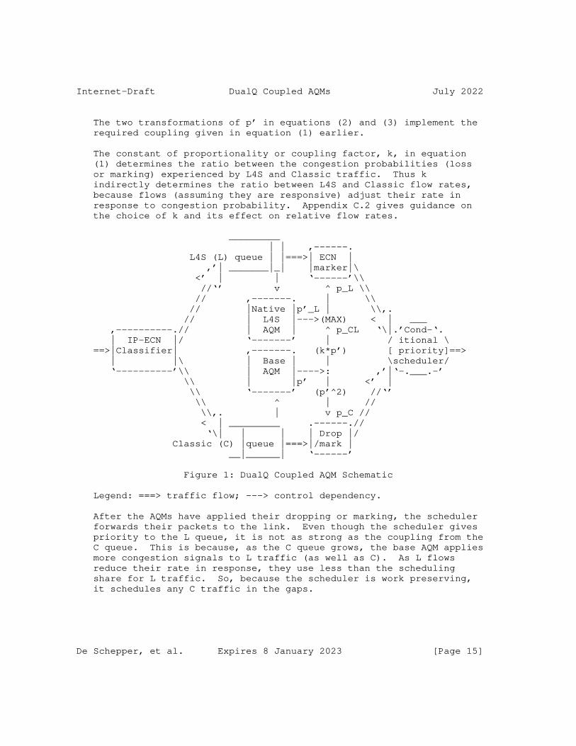
Figure 1 shows the overall structure that any DualQ Coupled AQM is likely to have. This schematic is intended to aid understanding of the current designs of DualQ Coupled AQMs. However, it is not intended to preclude other innovative ways of satisfying the normative requirements in Section 2.5 that minimally define a DualQ Coupled AQM. Also, the schematic only illustrates operation under normally expected circumstances; behaviour under overload or with operator-specific classifiers is deferred to Section 2.5.1.1.
The classifier on the left separates incoming traffic between the two queues (L and C). Each queue has its own AQM that determines the likelihood of marking or dropping (p_L and p_C). It has been proved [PI2] that it is preferable to control load with a linear controller, then square the output before applying it as a drop probability to Reno-friendly traffic (because Reno congestion control decreases its load proportional to the square-root of the increase in drop). So, the AQM for Classic traffic needs to be implemented in two stages: i) a base stage that outputs an internal probability p’ (pronounced p-prime); and ii) a squaring stage that outputs p_C, where
p_C = (p’)^2. (2)
Substituting for p_C in Eqn (1) gives:
p’ = p_CL / k
So the slow-moving input to ECN marking in the L queue (the coupled L4S probability) is:
p_CL = k*p’. (3)
The actual ECN marking probability p_L that is applied to the L queue needs to track the immediate L queue delay under L-only congestion conditions, as well as track p_CL under coupled congestion conditions. So the L queue uses a native AQM that calculates a probability p’_L as a function of the instantaneous L queue delay. And, given the L queue has conditional priority over the C queue, whenever the L queue grows, the AQM ought to apply marking probability p’_L, but p_L ought not to fall below p_CL. This suggests:
p_L = max(p’_L, p_CL), (4)
which has also been found to work very well in practice.
De Schepper, et al. Expires 8 January 2023 [Page 14]
Internet-Draft DualQ Coupled AQMs July 2022
The two transformations of p’ in equations (2) and (3) implement the required coupling given in equation (1) earlier.
The constant of proportionality or coupling factor, k, in equation (1) determines the ratio between the congestion probabilities (loss or marking) experienced by L4S and Classic traffic. Thus k indirectly determines the ratio between L4S and Classic flow rates, because flows (assuming they are responsive) adjust their rate in response to congestion probability. Appendix C.2 gives guidance on the choice of k and its effect on relative flow rates.
_________ | | ,------. L4S (L) queue | |===>| ECN | ,’| _______|_| |marker|\ <’ | | ‘------’\\ //‘’ v ^ p_L \\ // ,-------. | \\ // |Native |p’_L | \\,. // | L4S |--->(MAX) < | ___ ,----------.// | AQM | ^ p_CL ‘\|.’Cond-‘. | IP-ECN |/ ‘-------’ | / itional \ ==>|Classifier| ,-------. (k*p’) [ priority]==> | |\ | Base | | \scheduler/ ‘----------’\\ | AQM |---->: ,’|‘-.___.-’ \\ | |p’ | <’ | \\ ‘-------’ (p’^2) //‘’ \\ ^ | // \\,. | v p_C // < | _________ .------.// ‘\| | | | Drop |/ Classic (C) |queue |===>|/mark | __|______| ‘------’
Figure 1: DualQ Coupled AQM Schematic
Legend: ===> traffic flow; ---> control dependency.
After the AQMs have applied their dropping or marking, the scheduler forwards their packets to the link. Even though the scheduler gives priority to the L queue, it is not as strong as the coupling from the C queue. This is because, as the C queue grows, the base AQM applies more congestion signals to L traffic (as well as C). As L flows reduce their rate in response, they use less than the scheduling share for L traffic. So, because the scheduler is work preserving, it schedules any C traffic in the gaps.
De Schepper, et al. Expires 8 January 2023 [Page 15]

Internet-Draft DualQ Coupled AQMs July 2022
Giving priority to the L queue has the benefit of very low L queue delay, because the L queue is kept empty whenever L traffic is controlled by the coupling. Also there only has to be a coupling in one direction - from Classic to L4S. Priority has to be conditional in some way to prevent the C queue being starved in the short-term (see Section 4.2.2) to give C traffic a means to push in, as explained next. With normal responsive L traffic, the coupled ECN marking gives C traffic the ability to push back against even strict priority, by congestion marking the L traffic to make it yield some space. However, if there is just a small finite set of C packets (e.g. a DNS request or an initial window of data) some Classic AQMs will not induce enough ECN marking in the L queue, no matter how long the small set of C packets waits. Then, if the L queue happens to remain busy, the C traffic would never get a scheduling opportunity from a strict priority scheduler. Ideally the Classic AQM would be designed to increase the coupled marking the longer that C packets have been waiting, but this is not always practical - hence the need for L priority to be conditional. Giving a small weight or limited waiting time for C traffic improves response times for short Classic messages, such as DNS requests, and improves Classic flow startup because immediate capacity is available.
Example DualQ Coupled AQM algorithms called DualPI2 and Curvy RED are given in Appendix A and Appendix B. Either example AQM can be used to couple packet marking and dropping across a dual Q.
DualPI2 uses a Proportional-Integral (PI) controller as the Base AQM. Indeed, this Base AQM with just the squared output and no L4S queue can be used as a drop-in replacement for PIE [RFC8033], in which case it is just called PI2 [PI2]. PI2 is a principled simplification of PIE that is both more responsive and more stable in the face of dynamically varying load.
Curvy RED is derived from RED [RFC2309], except its configuration parameters are delay-based to make them insensitive to link rate and it requires less operations per packet than RED. However, DualPI2 is more responsive and stable over a wider range of RTTs than Curvy RED. As a consequence, at the time of writing, DualPI2 has attracted more development and evaluation attention than Curvy RED, leaving the Curvy RED design not so fully evaluated.
Both AQMs regulate their queue against targets configured in units of time rather than bytes. As already explained, this ensures configuration can be invariant for different drain rates. With AQMs in a dualQ structure this is particularly important because the drain rate of each queue can vary rapidly as flows for the two queues arrive and depart, even if the combined link rate is constant.
De Schepper, et al. Expires 8 January 2023 [Page 16]

Internet-Draft DualQ Coupled AQMs July 2022
It would be possible to control the queues with other alternative AQMs, as long as the normative requirements (those expressed in capitals) in Section 2.5 are observed.
The two queues could optionally be part of a larger queuing hierarchy, such as the initial example ideas in [I-D.briscoe-tsvwg-l4s-diffserv].
2.5. Normative Requirements for a DualQ Coupled AQM
The following requirements are intended to capture only the essential aspects of a DualQ Coupled AQM. They are intended to be independent of the particular AQMs used for each queue.
2.5.1. Functional Requirements
A Dual Queue Coupled AQM implementation MUST comply with the prerequisite L4S behaviours for any L4S network node (not just a DualQ) as specified in section 5 of [I-D.ietf-tsvwg-ecn-l4s-id]. These primarily concern classification and remarking as briefly summarized in Section 2.3 earlier. But there is also a subsection (5.5) giving guidance on reducing the burstiness of the link technology underlying any L4S AQM.
A Dual Queue Coupled AQM implementation MUST utilize two queues, each with an AQM algorithm.
The AQM algorithm for the low latency (L) queue MUST be able to apply ECN marking to ECN-capable packets.
The scheduler draining the two queues MUST give L4S packets priority over Classic, although priority MUST be bounded in order not to starve Classic traffic (see Section 4.2.2). The scheduler SHOULD be work-conserving, or otherwise close to work-conserving. This is because Classic traffic needs to be able to efficiently fill any space left by L4S traffic even though the scheduler would otherwise allocate it to L4S.
[I-D.ietf-tsvwg-ecn-l4s-id] defines the meaning of an ECN marking on L4S traffic, relative to drop of Classic traffic. In order to ensure coexistence of Classic and Scalable L4S traffic, it says, "The likelihood that an AQM drops a Not-ECT Classic packet (p_C) MUST be roughly proportional to the square of the likelihood that it would have marked it if it had been an L4S packet (p_L)." The term ’likelihood’ is used to allow for marking and dropping to be either probabilistic or deterministic.
De Schepper, et al. Expires 8 January 2023 [Page 17]

Internet-Draft DualQ Coupled AQMs July 2022
For the current specification, this translates into the following requirement. A DualQ Coupled AQM MUST apply ECN marking to traffic in the L queue that is no lower than that derived from the likelihood of drop (or ECN marking) in the Classic queue using Eqn. (1).
The constant of proportionality, k, in Eqn (1) determines the relative flow rates of Classic and L4S flows when the AQM concerned is the bottleneck (all other factors being equal). The L4S ECN protocol [I-D.ietf-tsvwg-ecn-l4s-id] says, "The constant of proportionality (k) does not have to be standardised for interoperability, but a value of 2 is RECOMMENDED."
Assuming Scalable congestion controls for the Internet will be as aggressive as DCTCP, this will ensure their congestion window will be roughly the same as that of a standards track TCP Reno congestion control (Reno) [RFC5681] and other Reno-friendly controls, such as TCP Cubic in its Reno-compatibility mode.
The choice of k is a matter of operator policy, and operators MAY choose a different value using the guidelines in Appendix C.2.
If multiple customers or users share capacity at a bottleneck (e.g. in the Internet access link of a campus network), the operator’s choice of k will determine capacity sharing between the flows of different customers. However, on the public Internet, access network operators typically isolate customers from each other with some form of layer-2 multiplexing (OFDM(A) in DOCSIS3.1, CDMA in 3G, SC-FDMA in LTE) or L3 scheduling (WRR in DSL), rather than relying on host congestion controls to share capacity between customers [RFC0970]. In such cases, the choice of k will solely affect relative flow rates within each customer’s access capacity, not between customers. Also, k will not affect relative flow rates at any times when all flows are Classic or all flows are L4S, and it will not affect the relative throughput of small flows.
2.5.1.1. Requirements in Unexpected Cases
The flexibility to allow operator-specific classifiers (Section 2.3) leads to the need to specify what the AQM in each queue ought to do with packets that do not carry the ECN field expected for that queue. It is expected that the AQM in each queue will inspect the ECN field to determine what sort of congestion notification to signal, then it will decide whether to apply congestion notification to this particular packet, as follows:
* If a packet that does not carry an ECT(1) or CE codepoint is classified into the L queue:
De Schepper, et al. Expires 8 January 2023 [Page 18]

Internet-Draft DualQ Coupled AQMs July 2022
- if the packet is ECT(0), the L AQM SHOULD apply CE-marking using a probability appropriate to Classic congestion control and appropriate to the target delay in the L queue
- if the packet is Not-ECT, the appropriate action depends on whether some other function is protecting the L queue from misbehaving flows (e.g. per-flow queue protection [I-D.briscoe-docsis-q-protection] or latency policing):
o If separate queue protection is provided, the L AQM SHOULD ignore the packet and forward it unchanged, meaning it should not calculate whether to apply congestion notification and it should neither drop nor CE-mark the packet (for instance, the operator might classify EF traffic that is unresponsive to drop into the L queue, alongside responsive L4S-ECN traffic)
o if separate queue protection is not provided, the L AQM SHOULD apply drop using a drop probability appropriate to Classic congestion control and appropriate to the target delay in the L queue
* If a packet that carries an ECT(1) codepoint is classified into the C queue:
- the C AQM SHOULD apply CE-marking using the coupled AQM probability p_CL (= k*p’).
The above requirements are worded as "SHOULDs", because operator- specific classifiers are for flexibility, by definition. Therefore, alternative actions might be appropriate in the operator’s specific circumstances. An example would be where the operator knows that certain legacy traffic marked with one codepoint actually has a congestion response associated with another codepoint.
If the DualQ Coupled AQM has detected overload, it MUST introduce Classic drop to both types of ECN-capable traffic until the overload episode has subsided. Introducing drop if ECN marking is persistently high is recommended by Section 7 of the ECN specification [RFC3168] and Section 4.2.1 of the AQM Recommendations [RFC7567].
2.5.2. Management Requirements
De Schepper, et al. Expires 8 January 2023 [Page 19]
Internet-Draft DualQ Coupled AQMs July 2022
2.5.2.1. Configuration
By default, a DualQ Coupled AQM SHOULD NOT need any configuration for use at a bottleneck on the public Internet [RFC7567]. The following parameters MAY be operator-configurable, e.g. to tune for non- Internet settings:
* Optional packet classifier(s) to use in addition to the ECN field (see Section 2.3);
* Expected typical RTT, which can be used to determine the queuing delay of the Classic AQM at its operating point, in order to prevent typical lone flows from under-utilizing capacity. For example:
- for the PI2 algorithm (Appendix A) the queuing delay target is dependent on the typical RTT;
- for the Curvy RED algorithm (Appendix B) the queuing delay at the desired operating point of the curvy ramp is configured to encompass a typical RTT;
- if another Classic AQM was used, it would be likely to need an operating point for the queue based on the typical RTT, and if so it SHOULD be expressed in units of time.
An operating point that is manually calculated might be directly configurable instead, e.g. for links with large numbers of flows where under-utilization by a single flow would be unlikely.
* Expected maximum RTT, which can be used to set the stability parameter(s) of the Classic AQM. For example:
- for the PI2 algorithm (Appendix A), the gain parameters of the PI algorithm depend on the maximum RTT.
- for the Curvy RED algorithm (Appendix B) the smoothing parameter is chosen to filter out transients in the queue within a maximum RTT.
Stability parameter(s) that are manually calculated assuming a maximum RTT might be directly configurable instead.
* Coupling factor, k (see Appendix C.2);
* A limit to the conditional priority of L4S. This is scheduler- dependent, but it SHOULD be expressed as a relation between the max delay of a C packet and an L packet. For example:
De Schepper, et al. Expires 8 January 2023 [Page 20]

Internet-Draft DualQ Coupled AQMs July 2022
- for a WRR scheduler a weight ratio between L and C of w:1 means that the maximum delay to a C packet is w times that of an L packet.
- for a time-shifted FIFO (TS-FIFO) scheduler (see Section 4.2.2) a time-shift of tshift means that the maximum delay to a C packet is tshift greater than that of an L packet. tshift could be expressed as a multiple of the typical RTT rather than as an absolute delay.
* The maximum Classic ECN marking probability, p_Cmax, before introducing drop.
2.5.2.2. Monitoring
An experimental DualQ Coupled AQM SHOULD allow the operator to monitor each of the following operational statistics on demand, per queue and per configurable sample interval, for performance monitoring and perhaps also for accounting in some cases:
* Bits forwarded, from which utilization can be calculated;
* Total packets in the three categories: arrived, presented to the AQM, and forwarded. The difference between the first two will measure any non-AQM tail discard. The difference between the last two will measure proactive AQM discard;
* ECN packets marked, non-ECN packets dropped, ECN packets dropped, which can be combined with the three total packet counts above to calculate marking and dropping probabilities;
* Queue delay (not including serialization delay of the head packet or medium acquisition delay) - see further notes below.
Unlike the other statistics, queue delay cannot be captured in a simple accumulating counter. Therefore the type of queue delay statistics produced (mean, percentiles, etc.) will depend on implementation constraints. To facilitate comparative evaluation of different implementations and approaches, an implementation SHOULD allow mean and 99th percentile queue delay to be derived (per queue per sample interval). A relatively simple way to do this would be to store a coarse-grained histogram of queue delay. This could be done with a small number of bins with configurable edges that represent contiguous ranges of queue delay. Then, over a sample interval, each bin would accumulate a count of the number of packets that had fallen within each range. The maximum queue delay per queue per interval MAY also be recorded, to aid diagnosis of faults and anomalous events.
De Schepper, et al. Expires 8 January 2023 [Page 21]
Internet-Draft DualQ Coupled AQMs July 2022
2.5.2.3. Anomaly Detection
An experimental DualQ Coupled AQM SHOULD asynchronously report the following data about anomalous conditions:
* Start-time and duration of overload state.
A hysteresis mechanism SHOULD be used to prevent flapping in and out of overload causing an event storm. For instance, exit from overload state could trigger one report, but also latch a timer. Then, during that time, if the AQM enters and exits overload state any number of times, the duration in overload state is accumulated but no new report is generated until the first time the AQM is out of overload once the timer has expired.
2.5.2.4. Deployment, Coexistence and Scaling
[RFC5706] suggests that deployment, coexistence and scaling should also be covered as management requirements. The raison d’etre of the DualQ Coupled AQM is to enable deployment and coexistence of Scalable congestion controls - as incremental replacements for today’s Reno- friendly controls that do not scale with bandwidth-delay product. Therefore there is no need to repeat these motivating issues here given they are already explained in the Introduction and detailed in the L4S architecture [I-D.ietf-tsvwg-l4s-arch].
The descriptions of specific DualQ Coupled AQM algorithms in the appendices cover scaling of their configuration parameters, e.g. with respect to RTT and sampling frequency.
3. IANA Considerations (to be removed by RFC Editor)
This specification contains no IANA considerations.
4. Security Considerations
4.1. Low Delay without Requiring Per-Flow Processing
The L4S architecture [I-D.ietf-tsvwg-l4s-arch] compares the DualQ and per-flow-queuing (FQ) approaches to L4S. The privacy considerations section in that document motivates the DualQ on the grounds that users who want to encrypt application flow identifiers, e.g. in IPSec or other encrypted VPN tunnels, don’t have to sacrifice low delay ([RFC8404] encourages avoidance of such privacy compromises).
De Schepper, et al. Expires 8 January 2023 [Page 22]

Internet-Draft DualQ Coupled AQMs July 2022
The security considerations section of the L4S architecture also includes subsections on policing of relative flow-rates (section 8.1) and on policing of flows that cause excessive queuing delay (section 8.2). It explains that the interests of users do not collide in the same way for delay as they do for bandwidth. For someone to get more of the bandwidth of a shared link, someone else necessarily gets less (a ’zero-sum game’), whereas queuing delay can be reduced for everyone, without any need for someone else to lose out. It also explains that, on the current Internet, scheduling usually enforces separation between ’sites’ (e.g. households, businesses or mobile users), but it is not common to need to schedule or police individual application flows.
By the above arguments, per-flow policing might not be necessary and in trusted environments it is certainly unlikely to be needed. Therefore, because it is hard to avoid complexity and unintended side-effects with per-flow policing, it needs to be separable from a basic AQM, as an option, under policy control. On this basis, the DualQ Coupled AQM provides low delay without prejudging the question of per-flow policing.
Nonetheless, the interests of users or flows might conflict, e.g. in case of accident or malice. Then per-flow control could be necessary. If flow-rate control is needed, it can be provided as a modular addition to a DualQ. And similarly, if protection against excessive queue delay is needed, a per-flow queue protection option can be added to a DualQ (e.g. [I-D.briscoe-docsis-q-protection]).
4.2. Handling Unresponsive Flows and Overload
In the absence of any per-flow control, it is important that the basic DualQ Coupled AQM gives unresponsive flows no more throughput advantage than a single-queue AQM would, and that it at least handles overload situations. Overload means that incoming load significantly or persistently exceeds output capacity, but it is not intended to be a precise term -- significant and persistent are matters of degree.
A trade-off needs to be made between complexity and the risk of either traffic class harming the other. In overloaded conditions the higher priority L4S service will have to sacrifice some aspect of its performance. Depending on the degree of overload, alternative solutions may relax a different factor: e.g. throughput, delay, drop. These choices need to be made either by the developer or by operator policy, rather than by the IETF. Subsequent subsections discuss aspects relating to handling of different degrees of overload:
De Schepper, et al. Expires 8 January 2023 [Page 23]

Internet-Draft DualQ Coupled AQMs July 2022
* Unresponsive flows (L and/or C) but not overloaded, i.e. the sum of unresponsive load before adding any responsive traffic is below capacity;
This case is handled by the regular Coupled DualQ (Section 2.1) but not discussed there. So below, Section 4.2.1 explains the design goal, and how it is achieved in practice;
* Unresponsive flows (L and/or C) causing persistent overload, i.e. the sum of unresponsive load even before adding any responsive traffic persistently exceeds capacity;
This case is not covered by the regular Coupled DualQ mechanism (Section 2.1) but the last para in Section 2.5.1.1 sets out a requirement to handle the case where ECN-capable traffic could starve non-ECN-capable traffic. Section 4.2.3 below discusses the general options and gives specific examples.
* Short-term overload that lies between the ’not overloaded’ and ’persistently overloaded’ cases.
For the period before overload is deemed persistent, Section 4.2.2 discusses options for more immediate mechanisms at the scheduler timescale. These prevent short-term starvation of the C queue by making the priority of the L queue conditional, as required in Section 2.5.1.
4.2.1. Unresponsive Traffic without Overload
When one or more L flows and/or C flows are unresponsive, but their total load is within the link capacity so that they do not saturate the coupled marking (below 100%), the goal of a DualQ AQM is to behave no worse than a single-queue AQM.
Tests have shown that this is indeed the case with no additional mechanism beyond the regular Coupled DualQ of Section 2.1 (see the results of ’overload experiments’ in [DCttH19]). Perhaps counter- intuitively, whether the unresponsive flow classifies itself into the L or the C queue, the DualQ system behaves as if it has subtracted from the overall link capacity. Then, the coupling shares out the remaining capacity between any competing responsive flows (in either queue). See also Section 4.2.2, which discusses scheduler-specific details.
De Schepper, et al. Expires 8 January 2023 [Page 24]

Internet-Draft DualQ Coupled AQMs July 2022
4.2.2. Avoiding Short-Term Classic Starvation: Sacrifice L4S Throughput or Delay?
Priority of L4S is required to be conditional (see Section 2.4 & Section 2.5.1) to avoid short-term starvation of Classic. Otherwise, as explained in Section 2.4, even a lone responsive L4S flow could temporarily block a small finite set of C packets (e.g. an initial window or DNS request). The blockage would only be brief, but it could be longer for certain AQM implementations that can only increase the congestion signal coupled from the C queue when C packets are actually being dequeued. There is then the question of whether to sacrifice L4S throughput or L4S delay (or some other policy) to make the priority conditional:
Sacrifice L4S throughput: By using weighted round robin as the conditional priority scheduler, the L4S service can sacrifice some throughput during overload. This can either be thought of as guaranteeing a minimum throughput service for Classic traffic, or as guaranteeing a maximum delay for a packet at the head of the Classic queue.
Cautionary note: a WRR scheduler can only guarantee Classic throughput if Classic sources are sending enough to use it -- congestion signals can undermine scheduling because they determine how much responsive traffic of each class arrives for scheduling in the first place. This is why scheduling is only relied on to handle short-term starvation; until congestion signals build up and the sources react. Even during long-term overload (discussed more fully in Section 4.2.3), it’s pragmatic to discard packets from both queues, which again thins the traffic before it reaches the scheduler. This is because a scheduler cannot be relied on to handle long-term overload since the right scheduler weight cannot be known for every scenario.
The scheduling weight of the Classic queue should be small (e.g. 1/16). In most traffic scenarios the scheduler will not interfere and it will not need to, because the coupling mechanism and the end-systems will determine the share of capacity across both queues as if it were a single pool. However, if L4S traffic is over-aggressive or unresponsive, the scheduler weight for Classic traffic will at least be large enough to ensure it does not starve in the short-term.
Although WRR scheduling is only expected to address short-term overload, there are (somewhat rare) cases when WRR has an effect on capacity shares over longer time-scales. But its effect is minor, and it certainly does no harm. Specifically, in cases where the ratio of L4S to Classic flows (e.g. 19:1) is greater
De Schepper, et al. Expires 8 January 2023 [Page 25]

Internet-Draft DualQ Coupled AQMs July 2022
than the ratio of their scheduler weights (e.g. 15:1), the L4S flows will get less than an equal share of the capacity, but only slightly. For instance, with the example numbers given, each L4S flow will get (15/16)/19 = 4.9% when ideally each would get 1/20=5%. In the rather specific case of an unresponsive flow taking up just less than the capacity set aside for L4S (e.g. 14/16 in the above example), using WRR could significantly reduce the capacity left for any responsive L4S flows.
The scheduling weight of the Classic queue should not be too small, otherwise a C packet at the head of the queue could be excessively delayed by a continually busy L queue. For instance if the Classic weight is 1/16, the maximum that a Classic packet at the head of the queue can be delayed by L traffic is the serialization delay of 15 MTU-sized packets.
Sacrifice L4S Delay: The operator could choose to control overload of the Classic queue by allowing some delay to ’leak’ across to the L4S queue. The scheduler can be made to behave like a single First-In First-Out (FIFO) queue with different service times by implementing a very simple conditional priority scheduler that could be called a "time-shifted FIFO" (see the Modifier Earliest Deadline First (MEDF) scheduler [MEDF]). This scheduler adds tshift to the queue delay of the next L4S packet, before comparing it with the queue delay of the next Classic packet, then it selects the packet with the greater adjusted queue delay.
Under regular conditions, this time-shifted FIFO scheduler behaves just like a strict priority scheduler. But under moderate or high overload it prevents starvation of the Classic queue, because the time-shift (tshift) defines the maximum extra queuing delay of Classic packets relative to L4S. This would control milder overload of responsive traffic by introducing delay to defer invoking the overload mechanisms in Section 4.2.3, particularly when close to the maximum congestion signal.
The example implementations in Appendix A and Appendix B could both be implemented with either policy.
4.2.3. L4S ECN Saturation: Introduce Drop or Delay?
This section concerns persistent overload caused by unresponsive L and/or C flows. To keep the throughput of both L4S and Classic flows roughly equal over the full load range, a different control strategy needs to be defined above the point where the L4S AQM persistently saturates to an ECN marking probability of 100% leaving no room to push back the load any harder. L4S ECN marking will saturate first (assuming the coupling factor k>1), even though saturation could be
De Schepper, et al. Expires 8 January 2023 [Page 26]

Internet-Draft DualQ Coupled AQMs July 2022
caused by the sum of unresponsive traffic in either or both queues exceeding the link capacity.
The term ’unresponsive’ includes cases where a flow becomes temporarily unresponsive, for instance, a real-time flow that takes a while to adapt its rate in response to congestion, or a standard Reno flow that is normally responsive, but above a certain congestion level it will not be able to reduce its congestion window below the allowed minimum of 2 segments [RFC5681], effectively becoming unresponsive. (Note that L4S traffic ought to remain responsive below a window of 2 segments (see the L4S requirements [I-D.ietf-tsvwg-ecn-l4s-id]).
Saturation raises the question of whether to relieve congestion by introducing some drop into the L4S queue or by allowing delay to grow in both queues (which could eventually lead to drop due to buffer exhaustion anyway):
Drop on Saturation: Persistent saturation can be defined by a maximum threshold for coupled L4S ECN marking (assuming k>1) before saturation starts to make the flow rates of the different traffic types diverge. Above that, the drop probability of Classic traffic is applied to all packets of all traffic types. Then experiments have shown that queueing delay can be kept at the target in any overload situation, including with unresponsive traffic, and no further measures are required (Section 4.2.3.1).
Delay on Saturation: When L4S marking saturates, instead of introducing L4S drop, the drop and marking probabilities of both queues could be capped. Beyond that, delay will grow either solely in the queue with unresponsive traffic (if WRR is used), or in both queues (if time-shifted FIFO is used). In either case, the higher delay ought to control temporary high congestion. If the overload is more persistent, eventually the combined DualQ will overflow and tail drop will control congestion.
The example implementation in Appendix A solely applies the "drop on saturation" policy. The DOCSIS specification of a DualQ Coupled AQM [DOCSIS3.1] also implements the ’drop on saturation’ policy with a very shallow L buffer. However, the addition of DOCSIS per-flow Queue Protection [I-D.briscoe-docsis-q-protection] turns this into ’delay on saturation’ by redirecting some packets of the flow(s) most responsible for L queue overload into the C queue, which has a higher delay target. If overload continues, this again becomes ’drop on saturation’ as the level of drop in the C queue rises to maintain the target delay of the C queue.
De Schepper, et al. Expires 8 January 2023 [Page 27]

Internet-Draft DualQ Coupled AQMs July 2022
4.2.3.1. Protecting against Overload by Unresponsive ECN-Capable Traffic
Without a specific overload mechanism, unresponsive traffic would have a greater advantage if it were also ECN-capable. The advantage is undetectable at normal low levels of marking. However, it would become significant with the higher levels of marking typical during overload, when it could evade a significant degree of drop. This is an issue whether the ECN-capable traffic is L4S or Classic.
This raises the question of whether and when to introduce drop of ECN-capable traffic, as required by both Section 7 of the ECN spec [RFC3168] and Section 4.2.1 of the AQM recommendations [RFC7567].
As an example, experiments with the DualPI2 AQM (Appendix A) have shown that introducing ’drop on saturation’ at 100% coupled L4S marking addresses this problem with unresponsive ECN as well as addressing the saturation problem. At saturation, DualPI2 switches into overload mode, where the base AQM is driven by the max delay of both queues and it introduces probabilistic drop to both queues equally. It leaves only a small range of congestion levels just below saturation where unresponsive traffic gains any advantage from using the ECN capability (relative to being unresponsive without ECN), and the advantage is hardly detectable (see [DualQ-Test] and section IV-E of [DCttH19]. Also overload with an unresponsive ECT(1) flow gets no more bandwidth advantage than with ECT(0).
5. Acknowledgements
Thanks to Anil Agarwal, Sowmini Varadhan’s, Gabi Bracha, Nicolas Kuhn, Greg Skinner, Tom Henderson, David Pullen, Mirja Kuehlewind, Gorry Fairhurst, Pete Heist, Ermin Sakic and Martin Duke for detailed review comments particularly of the appendices and suggestions on how to make the explanations clearer. Thanks also to Tom Henderson for insights on the choice of schedulers and queue delay measurement techniques.
The early contributions of Koen De Schepper, Bob Briscoe, Olga Bondarenko and Inton Tsang were part-funded by the European Community under its Seventh Framework Programme through the Reducing Internet Transport Latency (RITE) project (ICT-317700). Contributions of Koen De Schepper and Olivier Tilmans were also part-funded by the 5Growth and DAEMON EU H2020 projects. Bob Briscoe’s contribution was also part-funded by the Comcast Innovation Fund and the Research Council of Norway through the TimeIn project. The views expressed here are solely those of the authors.
De Schepper, et al. Expires 8 January 2023 [Page 28]
Internet-Draft DualQ Coupled AQMs July 2022
6. Contributors
The following contributed implementations and evaluations that validated and helped to improve this specification:
Olga Albisser <[email protected]> of Simula Research Lab, Norway (Olga Bondarenko during early drafts) implemented the prototype DualPI2 AQM for Linux with Koen De Schepper and conducted extensive evaluations as well as implementing the live performance visualization GUI [L4Sdemo16].
Olivier Tilmans <[email protected]> of Nokia Bell Labs, Belgium prepared and maintains the Linux implementation of DualPI2 for upstreaming.
Shravya K.S. wrote a model for the ns-3 simulator based on the -01 version of this Internet-Draft. Based on this initial work, Tom Henderson <[email protected]> updated that earlier model and created a model for the DualQ variant specified as part of the Low Latency DOCSIS specification, as well as conducting extensive evaluations.
Ing Jyh (Inton) Tsang of Nokia, Belgium built the End-to-End Data Centre to the Home broadband testbed on which DualQ Coupled AQM implementations were tested.
7. References
7.1. Normative References
[I-D.ietf-tsvwg-ecn-l4s-id] Schepper, K. D. and B. Briscoe, "Explicit Congestion Notification (ECN) Protocol for Very Low Queuing Delay (L4S)", Work in Progress, Internet-Draft, draft-ietf- tsvwg-ecn-l4s-id-25, 4 March 2022, <https://datatracker.ietf.org/doc/html/draft-ietf-tsvwg- ecn-l4s-id-25>.
[RFC2119] Bradner, S., "Key words for use in RFCs to Indicate Requirement Levels", BCP 14, RFC 2119, DOI 10.17487/RFC2119, March 1997, <https://www.rfc-editor.org/info/rfc2119>.
[RFC3168] Ramakrishnan, K., Floyd, S., and D. Black, "The Addition of Explicit Congestion Notification (ECN) to IP", RFC 3168, DOI 10.17487/RFC3168, September 2001, <https://www.rfc-editor.org/info/rfc3168>.
De Schepper, et al. Expires 8 January 2023 [Page 29]
Internet-Draft DualQ Coupled AQMs July 2022
[RFC8311] Black, D., "Relaxing Restrictions on Explicit Congestion Notification (ECN) Experimentation", RFC 8311, DOI 10.17487/RFC8311, January 2018, <https://www.rfc-editor.org/info/rfc8311>.
7.2. Informative References
[Alizadeh-stability] Alizadeh, M., Javanmard, A., and B. Prabhakar, "Analysis of DCTCP: Stability, Convergence, and Fairness", ACM SIGMETRICS 2011 , June 2011, <https://dl.acm.org/citation.cfm?id=1993753>.
[AQMmetrics] Kwon, M. and S. Fahmy, "A Comparison of Load-based and Queue- based Active Queue Management Algorithms", Proc. Int’l Soc. for Optical Engineering (SPIE) 4866:35--46 DOI: 10.1117/12.473021, 2002, <https://www.cs.purdue.edu/homes/fahmy/papers/ldc.pdf>.
[ARED01] Floyd, S., Gummadi, R., and S. Shenker, "Adaptive RED: An Algorithm for Increasing the Robustness of RED’s Active Queue Management", ACIRI Technical Report , August 2001, <http://www.icir.org/floyd/red.html>.
[BBRv2] Cardwell, N., "BRTCP BBR v2 Alpha/Preview Release", github repository; Linux congestion control module, <https://github.com/google/bbr/blob/v2alpha/README.md>.
[Boru20] Boru Oljira, D., Grinnemo, K-J., Brunstrom, A., and J. Taheri, "Validating the Sharing Behavior and Latency Characteristics of the L4S Architecture", ACM CCR 50(2):37--44, May 2020, <https://dl.acm.org/doi/abs/10.1145/3402413.3402419>.
[CCcensus19] Mishra, A., Sun, X., Jain, A., Pande, S., Joshi, R., and B. Leong, "The Great Internet TCP Congestion Control Census", Proc. ACM on Measurement and Analysis of Computing Systems 3(3), December 2019, <https://doi.org/10.1145/3366693>.
[CoDel] Nichols, K. and V. Jacobson, "Controlling Queue Delay", ACM Queue 10(5), May 2012, <http://queue.acm.org/issuedetail.cfm?issue=2208917>.
De Schepper, et al. Expires 8 January 2023 [Page 30]
Internet-Draft DualQ Coupled AQMs July 2022
[CRED_Insights] Briscoe, B., "Insights from Curvy RED (Random Early Detection)", BT Technical Report TR-TUB8-2015-003 arXiv:1904.07339 [cs.NI], July 2015, <https://arxiv.org/abs/1904.07339>.
[DCttH19] De Schepper, K., Bondarenko, O., Tilmans, O., and B. Briscoe, "‘Data Centre to the Home’: Ultra-Low Latency for All", Updated RITE project Technical Report , July 2019, <https://bobbriscoe.net/pubs.html#DCttH_TR>.
[DOCSIS3.1] CableLabs, "MAC and Upper Layer Protocols Interface (MULPI) Specification, CM-SP-MULPIv3.1", Data-Over-Cable Service Interface Specifications DOCSIS® 3.1 Version i17 or later, 21 January 2019, <https://specification- search.cablelabs.com/CM-SP-MULPIv3.1>.
[DualPI2Linux] Albisser, O., De Schepper, K., Briscoe, B., Tilmans, O., and H. Steen, "DUALPI2 - Low Latency, Low Loss and Scalable (L4S) AQM", Proc. Linux Netdev 0x13 , March 2019, <https://www.netdevconf.org/0x13/session.html?talk- DUALPI2-AQM>.
[DualQ-Test] Steen, H., "Destruction Testing: Ultra-Low Delay using Dual Queue Coupled Active Queue Management", Masters Thesis, Dept of Informatics, Uni Oslo , May 2017, <https://www.duo.uio.no/bitstream/handle/10852/57424/ thesis-henrste.pdf?sequence=1>.
[Heist21] Heist, P. and J. Morton, "L4S Tests", github README, August 2021, <https://github.com/heistp/l4s- tests/#underutilization-with-bursty-traffic>.
[I-D.briscoe-docsis-q-protection] Briscoe, B. and G. White, "The DOCSIS(r) Queue Protection Algorithm to Preserve Low Latency", Work in Progress, Internet-Draft, draft-briscoe-docsis-q-protection-06, 13 May 2022, <https://datatracker.ietf.org/doc/html/draft- briscoe-docsis-q-protection-06>.
De Schepper, et al. Expires 8 January 2023 [Page 31]

Internet-Draft DualQ Coupled AQMs July 2022
[I-D.briscoe-iccrg-prague-congestion-control] Schepper, K. D., Tilmans, O., and B. Briscoe, "Prague Congestion Control", Work in Progress, Internet-Draft, draft-briscoe-iccrg-prague-congestion-control-00, 9 March 2021, <https://datatracker.ietf.org/doc/html/draft- briscoe-iccrg-prague-congestion-control-00>.
[I-D.briscoe-tsvwg-l4s-diffserv] Briscoe, B., "Interactions between Low Latency, Low Loss, Scalable Throughput (L4S) and Differentiated Services", Work in Progress, Internet-Draft, draft-briscoe-tsvwg-l4s- diffserv-02, 4 November 2018, <https://datatracker.ietf.org/doc/html/draft-briscoe- tsvwg-l4s-diffserv-02>.
[I-D.cardwell-iccrg-bbr-congestion-control] Cardwell, N., Cheng, Y., Yeganeh, S. H., Swett, I., and V. Jacobson, "BBR Congestion Control", Work in Progress, Internet-Draft, draft-cardwell-iccrg-bbr-congestion- control-02, 7 March 2022, <https://datatracker.ietf.org/doc/html/draft-cardwell- iccrg-bbr-congestion-control-02>.
[I-D.ietf-tsvwg-l4s-arch] Briscoe, B., Schepper, K. D., Bagnulo, M., and G. White, "Low Latency, Low Loss, Scalable Throughput (L4S) Internet Service: Architecture", Work in Progress, Internet-Draft, draft-ietf-tsvwg-l4s-arch-18, 7 July 2022, <https://datatracker.ietf.org/doc/html/draft-ietf-tsvwg- l4s-arch-18>.
[L4Sdemo16] Bondarenko, O., De Schepper, K., Tsang, I., and B. Briscoe, "Ultra-Low Delay for All: Live Experience, Live Analysis", Proc. MMSYS’16 pp33:1--33:4, May 2016, <http://dl.acm.org/citation.cfm?doid=2910017.2910633 (videos of demos: https://riteproject.eu/dctth/#1511dispatchwg )>.
[L4S_5G] Willars, P., Wittenmark, E., Ronkainen, H., Östberg, C., Johansson, I., Strand, J., Lédl, P., and D. Schnieders, "Enabling time-critical applications over 5G with rate adaptation", Ericsson - Deutsche Telekom White Paper BNEW- 21:025455 Uen, May 2021, <https://www.ericsson.com/en/ reports-and-papers/white-papers/enabling-time-critical- applications-over-5g-with-rate-adaptation>.
De Schepper, et al. Expires 8 January 2023 [Page 32]

Internet-Draft DualQ Coupled AQMs July 2022
[Labovitz10] Labovitz, C., Iekel-Johnson, S., McPherson, D., Oberheide, J., and F. Jahanian, "Internet Inter-Domain Traffic", Proc ACM SIGCOMM; ACM CCR 40(4):75--86, August 2010, <https://doi.org/10.1145/1851275.1851194>.
[LLD] White, G., Sundaresan, K., and B. Briscoe, "Low Latency DOCSIS: Technology Overview", CableLabs White Paper , February 2019, <https://cablela.bs/low-latency-docsis- technology-overview-february-2019>.
[Mathis09] Mathis, M., "Relentless Congestion Control", PFLDNeT’09 , May 2009, <http://www.hpcc.jp/pfldnet2009/ Program_files/1569198525.pdf>.
[MEDF] Menth, M., Schmid, M., Heiss, H., and T. Reim, "MEDF - a simple scheduling algorithm for two real-time transport service classes with application in the UTRAN", Proc. IEEE Conference on Computer Communications (INFOCOM’03) Vol.2 pp.1116-1122, March 2003, <http://infocom2003.ieee-infocom.org/papers/27_04.PDF>.
[PI2] De Schepper, K., Bondarenko, O., Briscoe, B., and I. Tsang, "PI2: A Linearized AQM for both Classic and Scalable TCP", ACM CoNEXT’16 , December 2016, <https://riteproject.files.wordpress.com/2015/10/ pi2_conext.pdf>.
[PI2param] Briscoe, B., "PI2 Parameters", Technical Report TR-BB- 2021-001 arXiv:2107.01003 [cs.NI], July 2021, <https://arxiv.org/abs/2107.01003>.
[PragueLinux] Briscoe, B., De Schepper, K., Albisser, O., Misund, J., Tilmans, O., Kühlewind, M., and A.S. Ahmed, "Implementing the ‘TCP Prague’ Requirements for Low Latency Low Loss Scalable Throughput (L4S)", Proc. Linux Netdev 0x13 , March 2019, <https://www.netdevconf.org/0x13/ session.html?talk-tcp-prague-l4s>.
[RFC0970] Nagle, J., "On Packet Switches With Infinite Storage", RFC 970, DOI 10.17487/RFC0970, December 1985, <https://www.rfc-editor.org/info/rfc970>.
[RFC2309] Braden, B., Clark, D., Crowcroft, J., Davie, B., Deering, S., Estrin, D., Floyd, S., Jacobson, V., Minshall, G., Partridge, C., Peterson, L., Ramakrishnan, K., Shenker, S., Wroclawski, J., and L. Zhang, "Recommendations on
De Schepper, et al. Expires 8 January 2023 [Page 33]
Internet-Draft DualQ Coupled AQMs July 2022
Queue Management and Congestion Avoidance in the Internet", RFC 2309, DOI 10.17487/RFC2309, April 1998, <https://www.rfc-editor.org/info/rfc2309>.
[RFC2914] Floyd, S., "Congestion Control Principles", BCP 41, RFC 2914, DOI 10.17487/RFC2914, September 2000, <https://www.rfc-editor.org/info/rfc2914>.
[RFC3246] Davie, B., Charny, A., Bennet, J.C.R., Benson, K., Le Boudec, J.Y., Courtney, W., Davari, S., Firoiu, V., and D. Stiliadis, "An Expedited Forwarding PHB (Per-Hop Behavior)", RFC 3246, DOI 10.17487/RFC3246, March 2002, <https://www.rfc-editor.org/info/rfc3246>.
[RFC3649] Floyd, S., "HighSpeed TCP for Large Congestion Windows", RFC 3649, DOI 10.17487/RFC3649, December 2003, <https://www.rfc-editor.org/info/rfc3649>.
[RFC5033] Floyd, S. and M. Allman, "Specifying New Congestion Control Algorithms", BCP 133, RFC 5033, DOI 10.17487/RFC5033, August 2007, <https://www.rfc-editor.org/info/rfc5033>.
[RFC5348] Floyd, S., Handley, M., Padhye, J., and J. Widmer, "TCP Friendly Rate Control (TFRC): Protocol Specification", RFC 5348, DOI 10.17487/RFC5348, September 2008, <https://www.rfc-editor.org/info/rfc5348>.
[RFC5681] Allman, M., Paxson, V., and E. Blanton, "TCP Congestion Control", RFC 5681, DOI 10.17487/RFC5681, September 2009, <https://www.rfc-editor.org/info/rfc5681>.
[RFC5706] Harrington, D., "Guidelines for Considering Operations and Management of New Protocols and Protocol Extensions", RFC 5706, DOI 10.17487/RFC5706, November 2009, <https://www.rfc-editor.org/info/rfc5706>.
[RFC7567] Baker, F., Ed. and G. Fairhurst, Ed., "IETF Recommendations Regarding Active Queue Management", BCP 197, RFC 7567, DOI 10.17487/RFC7567, July 2015, <https://www.rfc-editor.org/info/rfc7567>.
[RFC8033] Pan, R., Natarajan, P., Baker, F., and G. White, "Proportional Integral Controller Enhanced (PIE): A Lightweight Control Scheme to Address the Bufferbloat Problem", RFC 8033, DOI 10.17487/RFC8033, February 2017, <https://www.rfc-editor.org/info/rfc8033>.
De Schepper, et al. Expires 8 January 2023 [Page 34]
Internet-Draft DualQ Coupled AQMs July 2022
[RFC8034] White, G. and R. Pan, "Active Queue Management (AQM) Based on Proportional Integral Controller Enhanced PIE) for Data-Over-Cable Service Interface Specifications (DOCSIS) Cable Modems", RFC 8034, DOI 10.17487/RFC8034, February 2017, <https://www.rfc-editor.org/info/rfc8034>.
[RFC8257] Bensley, S., Thaler, D., Balasubramanian, P., Eggert, L., and G. Judd, "Data Center TCP (DCTCP): TCP Congestion Control for Data Centers", RFC 8257, DOI 10.17487/RFC8257, October 2017, <https://www.rfc-editor.org/info/rfc8257>.
[RFC8290] Hoeiland-Joergensen, T., McKenney, P., Taht, D., Gettys, J., and E. Dumazet, "The Flow Queue CoDel Packet Scheduler and Active Queue Management Algorithm", RFC 8290, DOI 10.17487/RFC8290, January 2018, <https://www.rfc-editor.org/info/rfc8290>.
[RFC8298] Johansson, I. and Z. Sarker, "Self-Clocked Rate Adaptation for Multimedia", RFC 8298, DOI 10.17487/RFC8298, December 2017, <https://www.rfc-editor.org/info/rfc8298>.
[RFC8312] Rhee, I., Xu, L., Ha, S., Zimmermann, A., Eggert, L., and R. Scheffenegger, "CUBIC for Fast Long-Distance Networks", RFC 8312, DOI 10.17487/RFC8312, February 2018, <https://www.rfc-editor.org/info/rfc8312>.
[RFC8404] Moriarty, K., Ed. and A. Morton, Ed., "Effects of Pervasive Encryption on Operators", RFC 8404, DOI 10.17487/RFC8404, July 2018, <https://www.rfc-editor.org/info/rfc8404>.
[SCReAM] Johansson, I., "SCReAM", github repository; , <https://github.com/EricssonResearch/scream/blob/master/ README.md>.
[SigQ-Dyn] Briscoe, B., "Rapid Signalling of Queue Dynamics", Technical Report TR-BB-2017-001 arXiv:1904.07044 [cs.NI], September 2017, <https://arxiv.org/abs/1904.07044>.
Appendix A. Example DualQ Coupled PI2 Algorithm
As a first concrete example, the pseudocode below gives the DualPI2 algorithm. DualPI2 follows the structure of the DualQ Coupled AQM framework in Figure 1. A simple ramp function (configured in units of queuing time) with unsmoothed ECN marking is used for the Native L4S AQM. The ramp can also be configured as a step function. The PI2 algorithm [PI2] is used for the Classic AQM. PI2 is an improved variant of the PIE AQM [RFC8033].
De Schepper, et al. Expires 8 January 2023 [Page 35]

Internet-Draft DualQ Coupled AQMs July 2022
The pseudocode will be introduced in two passes. The first pass explains the core concepts, deferring handling of edge-cases like overload to the second pass. To aid comparison, line numbers are kept in step between the two passes by using letter suffixes where the longer code needs extra lines.
All variables are assumed to be floating point in their basic units (size in bytes, time in seconds, rates in bytes/second, alpha and beta in Hz, and probabilities from 0 to 1. Constants expressed in k (kilo), M (mega), G (giga), u (micro), m (milli) , %, ... are assumed to be converted to their appropriate multiple or fraction to represent the basic units. A real implementation that wants to use integer values needs to handle appropriate scaling factors and allow accordingly appropriate resolution of its integer types (including temporary internal values during calculations).
A full open source implementation for Linux is available at: https://github.com/L4STeam/sch_dualpi2_upstream and explained in [DualPI2Linux]. The specification of the DualQ Coupled AQM for DOCSIS cable modems and CMTSs is available in [DOCSIS3.1] and explained in [LLD].
A.1. Pass #1: Core Concepts
The pseudocode manipulates three main structures of variables: the packet (pkt), the L4S queue (lq) and the Classic queue (cq). The pseudocode consists of the following six functions:
* The initialization function dualpi2_params_init(...) (Figure 2) that sets parameter defaults (the API for setting non-default values is omitted for brevity)
* The enqueue function dualpi2_enqueue(lq, cq, pkt) (Figure 3)
* The dequeue function dualpi2_dequeue(lq, cq, pkt) (Figure 4)
* The recurrence function recur(q, likelihood) for de-randomized ECN marking (shown at the end of Figure 4).
* The L4S AQM function laqm(qdelay) (Figure 5) used to calculate the ECN-marking probability for the L4S queue
* The base AQM function that implements the PI algorithm dualpi2_update(lq, cq) (Figure 6) used to regularly update the base probability (p’), which is squared for the Classic AQM as well as being coupled across to the L4S queue.
It also uses the following functions that are not shown in full here:
De Schepper, et al. Expires 8 January 2023 [Page 36]

Internet-Draft DualQ Coupled AQMs July 2022
* scheduler(), which selects between the head packets of the two queues; the choice of scheduler technology is discussed later;
* cq.byt() or lq.byt() returns the current length (aka. backlog) of the relevant queue in bytes;
* cq.len() or lq.len() returns the current length of the relevant queue in packets;
* cq.time() or lq.time() returns the current queuing delay of the relevant queue in units of time (see Note a);
* mark(pkt) and drop(pkt) for ECN-marking and dropping a packet;
In experiments so far (building on experiments with PIE) on broadband access links ranging from 4 Mb/s to 200 Mb/s with base RTTs from 5 ms to 100 ms, DualPI2 achieves good results with the default parameters in Figure 2. The parameters are categorised by whether they relate to the Base PI2 AQM, the L4S AQM or the framework coupling them together. Constants and variables derived from these parameters are also included at the end of each category. Each parameter is explained as it is encountered in the walk-through of the pseudocode below, and the rationale for the chosen defaults are given so that sensible values can be used in scenarios other than the regular public Internet.
1: dualpi2_params_init(...) { % Set input parameter defaults 2: % DualQ Coupled framework parameters 5: limit = MAX_LINK_RATE * 250 ms % Dual buffer size 3: k = 2 % Coupling factor 4: % NOT SHOWN % scheduler-dependent weight or equival’t parameter 6: 7: % PI2 Classic AQM parameters 8: target = 15 ms % Queue delay target 9: RTT_max = 100 ms % Worst case RTT expected 10: % PI2 constants derived from above PI2 parameters 11: p_Cmax = min(1/k^2, 1) % Max Classic drop/mark prob 12: Tupdate = min(target, RTT_max/3) % PI sampling interval 13: alpha = 0.1 * Tupdate / RTT_max^2 % PI integral gain in Hz 14: beta = 0.3 / RTT_max % PI proportional gain in Hz 15: 16: % L4S ramp AQM parameters 17: minTh = 800 us % L4S min marking threshold in time units 18: range = 400 us % Range of L4S ramp in time units 19: Th_len = 1 pkt % Min L4S marking threshold in packets 20: % L4S constants 21: p_Lmax = 1 % Max L4S marking prob 22: }
De Schepper, et al. Expires 8 January 2023 [Page 37]

Internet-Draft DualQ Coupled AQMs July 2022
Figure 2: Example Header Pseudocode for DualQ Coupled PI2 AQM
The overall goal of the code is to apply the marking and dropping probabilities for L4S and Classic traffic (p_L and p_C). These are derived from the underlying base probabilities p’_L and p’ driven respectively by the traffic in the L and C queues. The marking probability for the L queue (p_L) depends on both the base probability in its own queue (p’_L) and a probability called p_CL, which is coupled across from p’ in the C queue (see Section 2.4 for the derivation of the specific equations and dependencies).
The probabilities p_CL and p_C are derived in lines 4 and 5 of the dualpi2_update() function (Figure 6) then used in the dualpi2_dequeue() function where p_L is also derived from p_CL at line 6 (Figure 4). The code walk-through below builds up to explaining that part of the code eventually, but it starts from packet arrival.
1: dualpi2_enqueue(lq, cq, pkt) { % Test limit and classify lq or cq 2: if ( lq.byt() + cq.byt() + MTU > limit) 3: drop(pkt) % drop packet if buffer is full 4: timestamp(pkt) % only needed if using the sojourn technique 5: % Packet classifier 6: if ( ecn(pkt) modulo 2 == 1 ) % ECN bits = ECT(1) or CE 7: lq.enqueue(pkt) 8: else % ECN bits = not-ECT or ECT(0) 9: cq.enqueue(pkt) 10: }
Figure 3: Example Enqueue Pseudocode for DualQ Coupled PI2 AQM
De Schepper, et al. Expires 8 January 2023 [Page 38]

Internet-Draft DualQ Coupled AQMs July 2022
1: dualpi2_dequeue(lq, cq, pkt) { % Couples L4S & Classic queues 2: while ( lq.byt() + cq.byt() > 0 ) { 3: if ( scheduler() == lq ) { 4: lq.dequeue(pkt) % Scheduler chooses lq 5: p’_L = laqm(lq.time()) % Native LAQM 6: p_L = max(p’_L, p_CL) % Combining function 7: if ( recur(lq, p_L) ) % Linear marking 8: mark(pkt) 9: } else { 10: cq.dequeue(pkt) % Scheduler chooses cq 11: if ( recur(cq, p_C) ) { % probability p_C = p’^2 12: if ( ecn(pkt) == 0 ) { % if ECN field = not-ECT 13: drop(pkt) % squared drop 14: continue % continue to the top of the while loop 15: } 16: mark(pkt) % squared mark 17: } 18: } 19: return(pkt) % return the packet and stop 20: } 21: return(NULL) % no packet to dequeue 22: }
23: recur(q, likelihood) { % Returns TRUE with a certain likelihood 24: q.count += likelihood 25: if (q.count > 1) { 26: q.count -= 1 27: return TRUE 28: } 29: return FALSE 30: }
Figure 4: Example Dequeue Pseudocode for DualQ Coupled PI2 AQM
When packets arrive, first a common queue limit is checked as shown in line 2 of the enqueuing pseudocode in Figure 3. This assumes a shared buffer for the two queues (Note b discusses the merits of separate buffers). In order to avoid any bias against larger packets, 1 MTU of space is always allowed and the limit is deliberately tested before enqueue.
If limit is not exceeded, the packet is timestamped in line 4 (only if the sojourn time technique is being used to measure queue delay; see Note a for alternatives).
At lines 5-9, the packet is classified and enqueued to the Classic or L4S queue dependent on the least significant bit of the ECN field in the IP header (line 6). Packets with a codepoint having an LSB of 0
De Schepper, et al. Expires 8 January 2023 [Page 39]
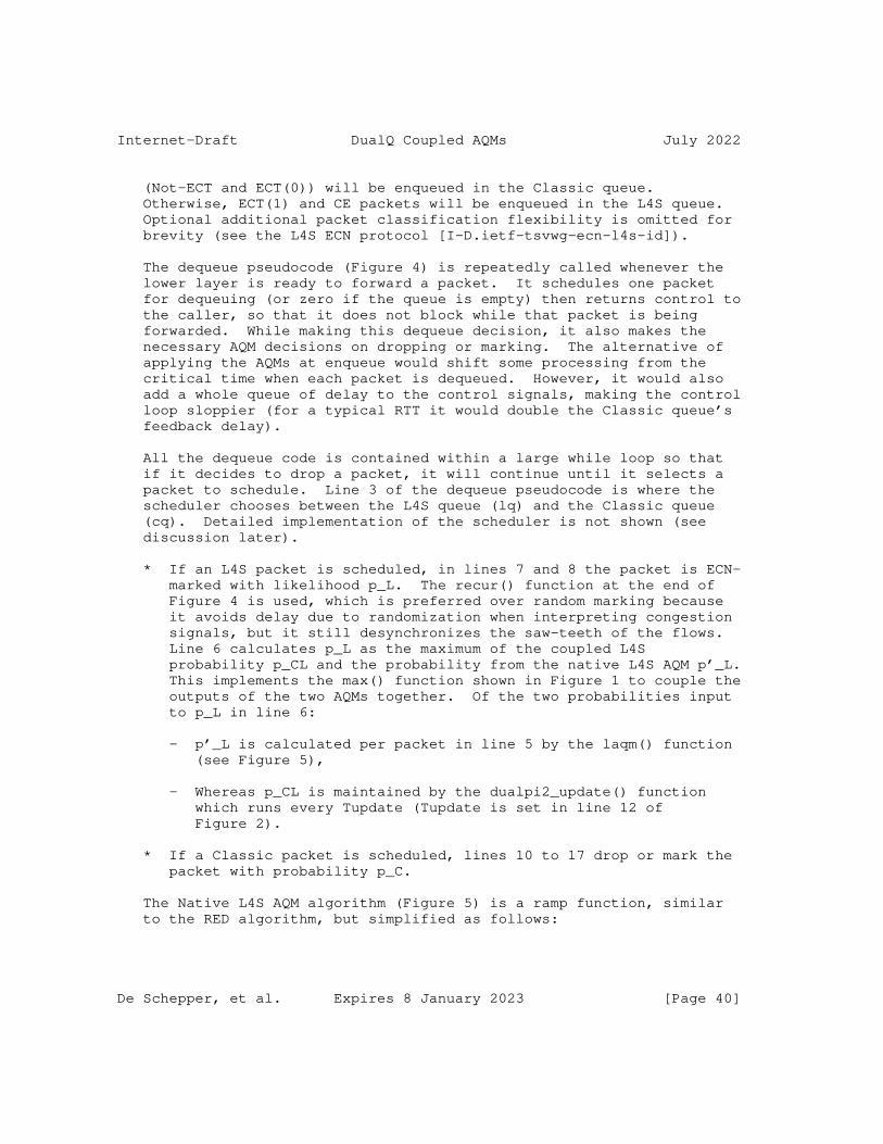
Internet-Draft DualQ Coupled AQMs July 2022
(Not-ECT and ECT(0)) will be enqueued in the Classic queue. Otherwise, ECT(1) and CE packets will be enqueued in the L4S queue. Optional additional packet classification flexibility is omitted for brevity (see the L4S ECN protocol [I-D.ietf-tsvwg-ecn-l4s-id]).
The dequeue pseudocode (Figure 4) is repeatedly called whenever the lower layer is ready to forward a packet. It schedules one packet for dequeuing (or zero if the queue is empty) then returns control to the caller, so that it does not block while that packet is being forwarded. While making this dequeue decision, it also makes the necessary AQM decisions on dropping or marking. The alternative of applying the AQMs at enqueue would shift some processing from the critical time when each packet is dequeued. However, it would also add a whole queue of delay to the control signals, making the control loop sloppier (for a typical RTT it would double the Classic queue’s feedback delay).
All the dequeue code is contained within a large while loop so that if it decides to drop a packet, it will continue until it selects a packet to schedule. Line 3 of the dequeue pseudocode is where the scheduler chooses between the L4S queue (lq) and the Classic queue (cq). Detailed implementation of the scheduler is not shown (see discussion later).
* If an L4S packet is scheduled, in lines 7 and 8 the packet is ECN- marked with likelihood p_L. The recur() function at the end of Figure 4 is used, which is preferred over random marking because it avoids delay due to randomization when interpreting congestion signals, but it still desynchronizes the saw-teeth of the flows. Line 6 calculates p_L as the maximum of the coupled L4S probability p_CL and the probability from the native L4S AQM p’_L. This implements the max() function shown in Figure 1 to couple the outputs of the two AQMs together. Of the two probabilities input to p_L in line 6:
- p’_L is calculated per packet in line 5 by the laqm() function (see Figure 5),
- Whereas p_CL is maintained by the dualpi2_update() function which runs every Tupdate (Tupdate is set in line 12 of Figure 2).
* If a Classic packet is scheduled, lines 10 to 17 drop or mark the packet with probability p_C.
The Native L4S AQM algorithm (Figure 5) is a ramp function, similar to the RED algorithm, but simplified as follows:
De Schepper, et al. Expires 8 January 2023 [Page 40]

Internet-Draft DualQ Coupled AQMs July 2022
* The extent of the ramp is defined in units of queuing delay, not bytes, so that configuration remains invariant as the queue departure rate varies.
* It uses instantaneous queueing delay, which avoids the complexity of smoothing, but also avoids embedding a worst-case RTT of smoothing delay in the network (see Section 2.1).
* The ramp rises linearly directly from 0 to 1, not to an intermediate value of p’_L as RED would, because there is no need to keep ECN marking probability low.
* Marking does not have to be randomized. Determinism is used instead of randomness; to reduce the delay necessary to smooth out the noise of randomness from the signal.
The ramp function requires two configuration parameters, the minimum threshold (minTh) and the width of the ramp (range), both in units of queuing time, as shown in lines 17 & 18 of the initialization function in Figure 2. The ramp function can be configured as a step (see Note c).
Although the DCTCP paper [Alizadeh-stability] recommends an ECN marking threshold of 0.17*RTT_typ, it also shows that the threshold can be much shallower with hardly any worse under-utilization of the link (because the amplitude of DCTCP’s sawteeth is so small). Based on extensive experiments, for the public Internet the default minimum ECN marking threshold (target) in Figure 2 is considered a good compromise, even though it is significantly smaller fraction of RTT_typ.
1: laqm(qdelay) { % Returns native L4S AQM probability 2: if (qdelay >= maxTh) 3: return 1 4: else if (qdelay > minTh) 5: return (qdelay - minTh)/range % Divide could use a bit-shift 6: else 7: return 0 8: }
Figure 5: Example Pseudocode for the Native L4S AQM
De Schepper, et al. Expires 8 January 2023 [Page 41]

Internet-Draft DualQ Coupled AQMs July 2022
1: dualpi2_update(lq, cq) { % Update p’ every Tupdate 2: curq = cq.time() % use queuing time of first-in Classic packet 3: p’ = p’ + alpha * (curq - target) + beta * (curq - prevq) 4: p_CL = k * p’ % Coupled L4S prob = base prob * coupling factor 5: p_C = p’^2 % Classic prob = (base prob)^2 6: prevq = curq 7: }
Figure 6: Example PI-Update Pseudocode for DualQ Coupled PI2 AQM
(Clamping p’ within the range [0,1] omitted for clarity - see text)
The coupled marking probability, p_CL depends on the base probability (p’), which is kept up to date by the core PI algorithm in Figure 6 executed every Tupdate.
Note that p’ solely depends on the queuing time in the Classic queue. In line 2, the current queuing delay (curq) is evaluated from how long the head packet was in the Classic queue (cq). The function cq.time() (not shown) subtracts the time stamped at enqueue from the current time (see Note a) and implicitly takes the current queuing delay as 0 if the queue is empty.
The algorithm centres on line 3, which is a classical Proportional- Integral (PI) controller that alters p’ dependent on: a) the error between the current queuing delay (curq) and the target queuing delay, ’target’; and b) the change in queuing delay since the last sample. The name ’PI’ represents the fact that the second factor (how fast the queue is growing) is _P_roportional to load while the first is the _I_ntegral of the load (so it removes any standing queue in excess of the target).
The target parameter can be set based on local knowledge, but the aim is for the default to be a good compromise for anywhere in the intended deployment environment -- the public Internet. According to [PI2param], the target queuing delay on line 9 of Figure 2 is related to the typical base RTT worldwide, RTT_typ, by two factors: target = RTT_typ * g * f. Below we summarize the rationale behind these factors and introduce a further adjustment. The two factors ensure that, in a large proportion of cases (say 90%), the sawtooth variations in RTT of a single flow will fit within the buffer without underutilizing the link. Frankly, these factors are educated guesses, but with the emphasis closer to ’educated’ than to ’guess’ (see [PI2param] for full background):
* RTT_typ is taken as 25 ms. This is based on an average CDN latency measured in each country weighted by the number of Internet users in that country to produce an overall weighted
De Schepper, et al. Expires 8 January 2023 [Page 42]

Internet-Draft DualQ Coupled AQMs July 2022
average for the Internet [PI2param]. Countries were ranked by number of Internet users, and once 90% of Internet users were covered, smaller countries were excluded to avoid unrepresentatively small sample sizes. Also, importantly, the data for the average CDN latency in China (with the largest number of Internet users) has been removed, because the CDN latency was a significant outlier and, on reflection, the experimental technique seemed inappropriate to the CDN market in China.
* g is taken as 0.38. The factor g is a geometry factor that characterizes the shape of the sawteeth of prevalent Classic congestion controllers. The geometry factor is the fraction of the amplitude of the sawtooth variability in queue delay that lies below the AQM’s target. For instance, at low bit rate, the geometry factor of standard Reno is 0.5, but at higher rates it tends to just under 1. According to the census of congestion controllers conducted by Mishra _et al_ in Jul-Oct 2019 [CCcensus19], most Classic TCP traffic uses Cubic. And, according to the analysis in [PI2param], if running over a PI2 AQM, a large proportion of this Cubic traffic would be in its Reno-Friendly mode, which has a geometry factor of ˜0.39 (all known implementations). The rest of the Cubic traffic would be in true Cubic mode, which has a geometry factor of ˜0.36. Without modelling the sawtooth profiles from all the other less prevalent congestion controllers, we estimate a 7:3 weighted average of these two, resulting in an average geometry factor of 0.38.
* f is taken as 2. The factor f is a safety factor that increases the target queue to allow for the distribution of RTT_typ around its mean. Otherwise the target queue would only avoid underutilization for those users below the mean. It also provides a safety margin for the proportion of paths in use that span beyond the distance between a user and their local CDN. Currently no data is available on the variance of queue delay around the mean in each region, so there is plenty of room for this guess to become more educated.
* [PI2param] recommends target = RTT_typ * g * f = 25ms * 0.38 * 2 = 19 ms. However a further adjustment is warranted, because target is moving year on year. The paper is based on data collected in 2019, and it mentions evidence from speedtest.net that suggests RTT_typ reduced by 17% (fixed) or 12% (mobile) between 2020 and 2021. Therefore we recommend a default of target = 15 ms at the time of writing (2021).
Operators can always use the data and discussion in [PI2param] to configure a more appropriate target for their environment. For instance, an operator might wish to question the assumptions called
De Schepper, et al. Expires 8 January 2023 [Page 43]

Internet-Draft DualQ Coupled AQMs July 2022
out in that paper, such as the goal of no underutilization for a large majority of single flow transfers (given many large transfers use multiple flows to avoid the scaling limitations of Classic flows).
The two ’gain factors’ in line 3 of Figure 6, alpha and beta, respectively weight how strongly each of the two elements (Integral and Proportional) alters p’. They are in units of ’per second of delay’ or Hz, because they transform differences in queueing delay into changes in probability (assuming probability has a value from 0 to 1).
Alpha and beta determine how much p’ ought to change after each update interval (Tupdate). For smaller Tupdate, p’ should change by the same amount per second, but in finer more frequent steps. So alpha depends on Tupdate (see line 13 of the initialization function in Figure 2). It is best to update p’ as frequently as possible, but Tupdate will probably be constrained by hardware performance. As shown in line 13, the update interval should be frequent enough to update at least once in the time taken for the target queue to drain (’target’) as long as it updates at least three times per maximum RTT. Tupdate defaults to 16 ms in the reference Linux implementation because it has to be rounded to a multiple of 4 ms. For link rates from 4 to 200 Mb/s and a maximum RTT of 100ms, it has been verified through extensive testing that Tupdate=16ms (as also recommended in the PIE spec [RFC8033]) is sufficient.
The choice of alpha and beta also determines the AQM’s stable operating range. The AQM ought to change p’ as fast as possible in response to changes in load without over-compensating and therefore causing oscillations in the queue. Therefore, the values of alpha and beta also depend on the RTT of the expected worst-case flow (RTT_max).
The maximum RTT of a PI controller (RTT_max in line 10 of Figure 2) is not an absolute maximum, but more instability (more queue variability) sets in for long-running flows with an RTT above this value. The propagation delay half way round the planet and back in glass fibre is 200 ms. However, hardly any traffic traverses such extreme paths and, since the significant consolidation of Internet traffic between 2007 and 2009 [Labovitz10], a high and growing proportion of all Internet traffic (roughly two-thirds at the time of writing) has been served from content distribution networks (CDNs) or ’cloud’ services distributed close to end-users. The Internet might change again, but for now, designing for a maximum RTT of 100ms is a good compromise between faster queue control at low RTT and some instability on the occasions when a longer path is necessary.
De Schepper, et al. Expires 8 January 2023 [Page 44]

Internet-Draft DualQ Coupled AQMs July 2022
Recommended derivations of the gain constants alpha and beta can be approximated for Reno over a PI2 AQM as: alpha = 0.1 * Tupdate / RTT_max^2; beta = 0.3 / RTT_max, as shown in lines 14 & 15 of Figure 2. These are derived from the stability analysis in [PI2]. For the default values of Tupdate=16 ms and RTT_max = 100 ms, they result in alpha = 0.16; beta = 3.2 (discrepancies are due to rounding). These defaults have been verified with a wide range of link rates, target delays and a range of traffic models with mixed and similar RTTs, short and long flows, etc.
In corner cases, p’ can overflow the range [0,1] so the resulting value of p’ has to be bounded (omitted from the pseudocode). Then, as already explained, the coupled and Classic probabilities are derived from the new p’ in lines 4 and 5 of Figure 6 as p_CL = k*p’ and p_C = p’^2.
Because the coupled L4S marking probability (p_CL) is factored up by k, the dynamic gain parameters alpha and beta are also inherently factored up by k for the L4S queue. So, the effective gain factor for the L4S queue is k*alpha (with defaults alpha = 0.16 Hz and k=2, effective L4S alpha = 0.32 Hz).
Unlike in PIE [RFC8033], alpha and beta do not need to be tuned every Tupdate dependent on p’. Instead, in PI2, alpha and beta are independent of p’ because the squaring applied to Classic traffic tunes them inherently. This is explained in [PI2], which also explains why this more principled approach removes the need for most of the heuristics that had to be added to PIE.
Nonetheless, an implementer might wish to add selected details to either AQM. For instance the Linux reference DualPI2 implementation includes the following (not shown in the pseudocode above):
* Classic and coupled marking or dropping (i.e. based on p_C and p_CL from the PI controller) is not applied to a packet if the aggregate queue length in bytes is < 2 MTU (prior to enqueuing the packet or dequeuing it, depending on whether the AQM is configured to be applied at enqueue or dequeue);
* In the WRR scheduler, the ’credit’ indicating which queue should transmit is only changed if there are packets in both queues (i.e. if there is actual resource contention). This means that a properly paced L flow might never be delayed by the WRR. The WRR credit is reset in favour of the L queue when the link is idle.
An implementer might also wish to add other heuristics, e.g. burst protection [RFC8033] or enhanced burst protection [RFC8034].
De Schepper, et al. Expires 8 January 2023 [Page 45]
Internet-Draft DualQ Coupled AQMs July 2022
Notes:
a. The drain rate of the queue can vary if it is scheduled relative to other queues, or to cater for fluctuations in a wireless medium. To auto-adjust to changes in drain rate, the queue needs to be measured in time, not bytes or packets [AQMmetrics], [CoDel]. Queuing delay could be measured directly as the sojourn time (aka. service time) of the queue, by storing a per-packet time-stamp as each packet is enqueued, and subtracting this from the system time when the packet is dequeued. If time- stamping is not easy to introduce with certain hardware, queuing delay could be predicted indirectly by dividing the size of the queue by the predicted departure rate, which might be known precisely for some link technologies (see for example in DOCSIS PIE [RFC8034]).
However, sojourn time is slow to detect bursts. For instance, if a burst arrives at an empty queue, the sojourn time only fully measures the burst’s delay when its last packet is dequeued, even though the queue has known the size of the burst since its last packet was enqueued - so it could have signalled congestion earlier. To remedy this, each head packet can be marked when it is dequeued based on the expected delay of the tail packet behind it, as explained below, rather than based on the head packet’s own delay due to the packets in front of it. [Heist21] identifies a specific scenario where bursty traffic significantly hits utilization of the L queue. If this effect proves to be more widely applicable, it is believed that using the delay behind the head would improve performance.
The delay behind the head can be implemented by dividing the backlog at dequeue by the link rate or equivalently multiplying the backlog by the delay per unit of backlog. The implementation details will depend on whether the link rate is known; if it is not, a moving average of the delay per unit backlog can be maintained. This delay consists of serialization as well as media acquisition for shared media. So the details will depend strongly on the specific link technology, This approach should be less sensitive to timing errors and cost less in operations and memory than the otherwise equivalent ’scaled sojourn time’ metric, which is the sojourn time of a packet scaled by the ratio of the queue sizes when the packet departed and arrived [SigQ-Dyn].
b. Line 2 of the dualpi2_enqueue() function (Figure 3) assumes an implementation where lq and cq share common buffer memory. An alternative implementation could use separate buffers for each queue, in which case the arriving packet would have to be
De Schepper, et al. Expires 8 January 2023 [Page 46]

Internet-Draft DualQ Coupled AQMs July 2022
classified first to determine which buffer to check for available space. The choice is a trade off; a shared buffer can use less memory whereas separate buffers isolate the L4S queue from tail- drop due to large bursts of Classic traffic (e.g. a Classic Reno TCP during slow-start over a long RTT).
c. There has been some concern that using the step function of DCTCP for the Native L4S AQM requires end-systems to smooth the signal for an unnecessarily large number of round trips to ensure sufficient fidelity. A ramp is no worse than a step in initial experiments with existing DCTCP. Therefore, it is recommended that a ramp is configured in place of a step, which will allow congestion control algorithms to investigate faster smoothing algorithms.
A ramp is more general that a step, because an operator can effectively turn the ramp into a step function, as used by DCTCP, by setting the range to zero. There will not be a divide by zero problem at line 5 of Figure 5 because, if minTh is equal to maxTh, the condition for this ramp calculation cannot arise.
A.2. Pass #2: Edge-Case Details
This section takes a second pass through the pseudocode adding details of two edge-cases: low link rate and overload. Figure 7 repeats the dequeue function of Figure 4, but with details of both edge-cases added. Similarly Figure 8 repeats the core PI algorithm of Figure 6, but with overload details added. The initialization, enqueue, L4S AQM and recur functions are unchanged.
The link rate can be so low that it takes a single packet queue longer to serialize than the threshold delay at which ECN marking starts to be applied in the L queue. Therefore, a minimum marking threshold parameter in units of packets rather than time is necessary (Th_len, default 1 packet in line 19 of Figure 2) to ensure that the ramp does not trigger excessive marking on slow links. Where an implementation knows the link rate, it can set up this minimum at the time it is configured. For instance, it would divide 1 MTU by the link rate to convert it into a serialization time, then if the lower threshold of the Native L AQM ramp was lower than this serialization time, it could increase the thresholds to shift the bottom of the ramp to 2 MTU. This is the approach used in DOCSIS [DOCSIS3.1], because the configured link rate is dedicated to the DualQ.
De Schepper, et al. Expires 8 January 2023 [Page 47]

Internet-Draft DualQ Coupled AQMs July 2022
The pseudocode given here applies where the link rate is unknown, which is more common for software implementations that might be deployed in scenarios where the link is shared with other queues. In lines 5a to 5d in Figure 7 the native L4S marking probability, p’_L, is zeroed if the queue is only 1 packet (in the default configuration).
Linux implementation note:
* In Linux, the check that the queue exceeds Th_len before marking with the native L4S AQM is actually at enqueue, not dequeue, otherwise it would exempt the last packet of a burst from being marked. The result of the check is conveyed from enqueue to the dequeue function via a boolean in the packet metadata.
Persistent overload is deemed to have occurred when Classic drop/ marking probability reaches p_Cmax. Above this point, the Classic drop probability is applied to both L and C queues, irrespective of whether any packet is ECN-capable. ECT packets that are not dropped can still be ECN-marked.
In line 10 of the initialization function (Figure 2), the maximum Classic drop probability p_Cmax = min(1/k^2, 1) or 1/4 for the default coupling factor k=2. In practice, 25% has been found to be a good threshold to preserve fairness between ECN capable and non ECN capable traffic. This protects the queues against both temporary overload from responsive flows and more persistent overload from any unresponsive traffic that falsely claims to be responsive to ECN.
When the Classic ECN marking probability reaches the p_Cmax threshold (1/k^2), the marking probability coupled to the L4S queue, p_CL will always be 100% for any k (by equation (1) in Section 2). So, for readability, the constant p_Lmax is defined as 1 in line 22 of the initialization function (Figure 2). This is intended to ensure that the L4S queue starts to introduce dropping once ECN-marking saturates at 100% and can rise no further. The ’Prague L4S’ requirements [I-D.ietf-tsvwg-ecn-l4s-id] state that, when an L4S congestion control detects a drop, it falls back to a response that coexists with ’Classic’ Reno congestion control. So it is correct that, when the L4S queue drops packets, it drops them proportional to p’^2, as if they are Classic packets.
The two queues each test for overload in lines 4b and 12b of the dequeue function (Figure 7). Lines 8c to 8g drop L4S packets with probability p’^2. Lines 8h to 8i mark the remaining packets with probability p_CL. Given p_Lmax = 1, all remaining packets will be marked because, to have reached the else block at line 8b, p_CL >= 1.
De Schepper, et al. Expires 8 January 2023 [Page 48]

Internet-Draft DualQ Coupled AQMs July 2022
Line 2a in the core PI algorithm (Figure 8) deals with overload of the L4S queue when there is little or no Classic traffic. This is necessary, because the core PI algorithm maintains the appropriate drop probability to regulate overload, but it depends on the length of the Classic queue. If there is little or no Classic queue the naive PI update function in Figure 6 would drop nothing, even if the L4S queue were overloaded - so tail drop would have to take over (lines 2 and 3 of Figure 3).
Instead, line 2a of the full PI update function in Figure 8 ensures that the base PI AQM in line 3 is driven by whichever of the two queue delays is greater, but line 3 still always uses the same Classic target (default 15 ms). If L queue delay is greater just because there is little or no Classic traffic, normally it will still be well below the base AQM target. This is because L4S traffic is also governed by the shallow threshold of its own native AQM (lines 5 and 6 of the dequeue algorithm in Figure 7). So the base AQM will be driven to zero and not contribute. However, if the L queue is overloaded by traffic that is unresponsive to its marking, the max() in line 2 enables the L queue to smoothly take over driving the base AQM into overload mode even if there is little or no Classic traffic. Then the base AQM will keep the L queue to the Classic target (default 15 ms) by shedding L packets.
De Schepper, et al. Expires 8 January 2023 [Page 49]
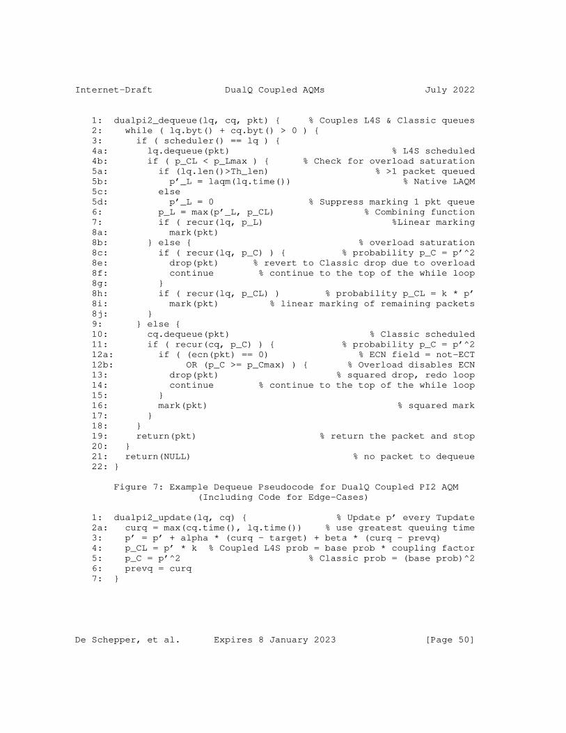
Internet-Draft DualQ Coupled AQMs July 2022
1: dualpi2_dequeue(lq, cq, pkt) { % Couples L4S & Classic queues 2: while ( lq.byt() + cq.byt() > 0 ) { 3: if ( scheduler() == lq ) { 4a: lq.dequeue(pkt) % L4S scheduled 4b: if ( p_CL < p_Lmax ) { % Check for overload saturation 5a: if (lq.len()>Th_len) % >1 packet queued 5b: p’_L = laqm(lq.time()) % Native LAQM 5c: else 5d: p’_L = 0 % Suppress marking 1 pkt queue 6: p_L = max(p’_L, p_CL) % Combining function 7: if ( recur(lq, p_L) %Linear marking 8a: mark(pkt) 8b: } else { % overload saturation 8c: if ( recur(lq, p_C) ) { % probability p_C = p’^2 8e: drop(pkt) % revert to Classic drop due to overload 8f: continue % continue to the top of the while loop 8g: } 8h: if ( recur(lq, p_CL) ) % probability p_CL = k * p’ 8i: mark(pkt) % linear marking of remaining packets 8j: } 9: } else { 10: cq.dequeue(pkt) % Classic scheduled 11: if ( recur(cq, p_C) ) { % probability p_C = p’^2 12a: if ( (ecn(pkt) == 0) % ECN field = not-ECT 12b: OR (p_C >= p_Cmax) ) { % Overload disables ECN 13: drop(pkt) % squared drop, redo loop 14: continue % continue to the top of the while loop 15: } 16: mark(pkt) % squared mark 17: } 18: } 19: return(pkt) % return the packet and stop 20: } 21: return(NULL) % no packet to dequeue 22: }
Figure 7: Example Dequeue Pseudocode for DualQ Coupled PI2 AQM (Including Code for Edge-Cases)
1: dualpi2_update(lq, cq) { % Update p’ every Tupdate 2a: curq = max(cq.time(), lq.time()) % use greatest queuing time 3: p’ = p’ + alpha * (curq - target) + beta * (curq - prevq) 4: p_CL = p’ * k % Coupled L4S prob = base prob * coupling factor 5: p_C = p’^2 % Classic prob = (base prob)^2 6: prevq = curq 7: }
De Schepper, et al. Expires 8 January 2023 [Page 50]

Internet-Draft DualQ Coupled AQMs July 2022
Figure 8: Example PI-Update Pseudocode for DualQ Coupled PI2 AQM (Including Overload Code)
The choice of scheduler technology is critical to overload protection (see Section 4.2.2).
* A well-understood weighted scheduler such as weighted round robin (WRR) is recommended. As long as the scheduler weight for Classic is small (e.g. 1/16), its exact value is unimportant because it does not normally determine capacity shares. The weight is only important to prevent unresponsive L4S traffic starving Classic traffic in the short term (see Section 4.2.2). This is because capacity sharing between the queues is normally determined by the coupled congestion signal, which overrides the scheduler, by making L4S sources leave roughly equal per-flow capacity available for Classic flows.
* Alternatively, a time-shifted FIFO (TS-FIFO) could be used. It works by selecting the head packet that has waited the longest, biased against the Classic traffic by a time-shift of tshift. To implement time-shifted FIFO, the scheduler() function in line 3 of the dequeue code would simply be implemented as the scheduler() function at the bottom of Figure 10 in Appendix B. For the public Internet a good value for tshift is 50ms. For private networks with smaller diameter, about 4*target would be reasonable. TS- FIFO is a very simple scheduler, but complexity might need to be added to address some deficiencies (which is why it is not recommended over WRR):
- TS-FIFO does not fully isolate latency in the L4S queue from uncontrolled bursts in the Classic queue;
- Using sojourn time for TS-FIFO is only appropriate if time- stamping of packets is feasible;
- Even if time-stamping is supported, the sojourn time of the head packet is always stale, so a more instantaneous measure of queue delay could be used (see Note a in Appendix A.1).
* A strict priority scheduler would be inappropriate as discussed in Section 4.2.2.
De Schepper, et al. Expires 8 January 2023 [Page 51]

Internet-Draft DualQ Coupled AQMs July 2022
Appendix B. Example DualQ Coupled Curvy RED Algorithm
As another example of a DualQ Coupled AQM algorithm, the pseudocode below gives the Curvy RED based algorithm. Although the AQM was designed to be efficient in integer arithmetic, to aid understanding it is first given using floating point arithmetic (Figure 10). Then, one possible optimization for integer arithmetic is given, also in pseudocode (Figure 11). To aid comparison, the line numbers are kept in step between the two by using letter suffixes where the longer code needs extra lines.
B.1. Curvy RED in Pseudocode
The pseudocode manipulates three main structures of variables: the packet (pkt), the L4S queue (lq) and the Classic queue (cq) and consists of the following five functions:
* The initialization function cred_params_init(...) (Figure 2) that sets parameter defaults (the API for setting non-default values is omitted for brevity);
* The dequeue function cred_dequeue(lq, cq, pkt) (Figure 4);
* The scheduling function scheduler(), which selects between the head packets of the two queues.
It also uses the following functions that are either shown elsewhere, or not shown in full here:
* The enqueue function, which is identical to that used for DualPI2, dualpi2_enqueue(lq, cq, pkt) in Figure 3;
* mark(pkt) and drop(pkt) for ECN-marking and dropping a packet;
* cq.byt() or lq.byt() returns the current length (aka. backlog) of the relevant queue in bytes;
* cq.time() or lq.time() returns the current queuing delay of the relevant queue in units of time (see Note a in Appendix A.1).
De Schepper, et al. Expires 8 January 2023 [Page 52]

Internet-Draft DualQ Coupled AQMs July 2022
Because Curvy RED was evaluated before DualPI2, certain improvements introduced for DualPI2 were not evaluated for Curvy RED. In the pseudocode below, the straightforward improvements have been added on the assumption they will provide similar benefits, but that has not been proven experimentally. They are: i) a conditional priority scheduler instead of strict priority ii) a time-based threshold for the native L4S AQM; iii) ECN support for the Classic AQM. A recent evaluation has proved that a minimum ECN-marking threshold (minTh) greatly improves performance, so this is also included in the pseudocode.
Overload protection has not been added to the Curvy RED pseudocode below so as not to detract from the main features. It would be added in exactly the same way as in Appendix A.2 for the DualPI2 pseudocode. The native L4S AQM uses a step threshold, but a ramp like that described for DualPI2 could be used instead. The scheduler uses the simple TS-FIFO algorithm, but it could be replaced with WRR.
The Curvy RED algorithm has not been maintained or evaluated to the same degree as the DualPI2 algorithm. In initial experiments on broadband access links ranging from 4 Mb/s to 200 Mb/s with base RTTs from 5 ms to 100 ms, Curvy RED achieved good results with the default parameters in Figure 9.
The parameters are categorised by whether they relate to the Classic AQM, the L4S AQM or the framework coupling them together. Constants and variables derived from these parameters are also included at the end of each category. These are the raw input parameters for the algorithm. A configuration front-end could accept more meaningful parameters (e.g. RTT_max and RTT_typ) and convert them into these raw parameters, as has been done for DualPI2 in Appendix A. Where necessary, parameters are explained further in the walk-through of the pseudocode below.
De Schepper, et al. Expires 8 January 2023 [Page 53]

Internet-Draft DualQ Coupled AQMs July 2022
1: cred_params_init(...) { % Set input parameter defaults 2: % DualQ Coupled framework parameters 3: limit = MAX_LINK_RATE * 250 ms % Dual buffer size 4: k’ = 1 % Coupling factor as a power of 2 5: tshift = 50 ms % Time shift of TS-FIFO scheduler 6: % Constants derived from Classic AQM parameters 7: k = 2^k’ % Coupling factor from Equation (1) 6: 7: % Classic AQM parameters 8: g_C = 5 % EWMA smoothing parameter as a power of 1/2 9: S_C = -1 % Classic ramp scaling factor as a power of 2 10: minTh = 500 ms % No Classic drop/mark below this queue delay 11: % Constants derived from Classic AQM parameters 12: gamma = 2^(-g_C) % EWMA smoothing parameter 13: range_C = 2^S_C % Range of Classic ramp 14: 15: % L4S AQM parameters 16: T = 1 ms % Queue delay threshold for native L4S AQM 17: % Constants derived from above parameters 18: S_L = S_C - k’ % L4S ramp scaling factor as a power of 2 19: range_L = 2^S_L % Range of L4S ramp 20: }
Figure 9: Example Header Pseudocode for DualQ Coupled Curvy RED AQM
De Schepper, et al. Expires 8 January 2023 [Page 54]
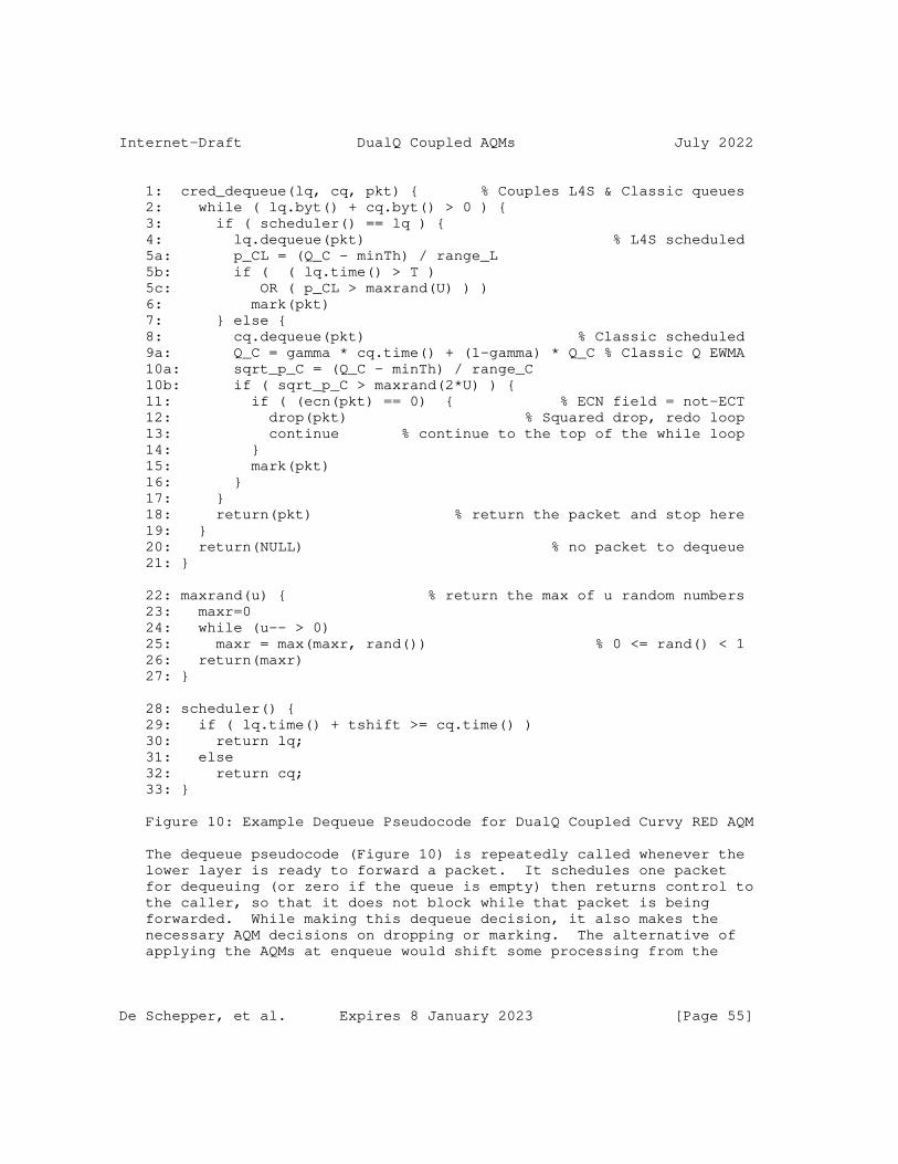
Internet-Draft DualQ Coupled AQMs July 2022
1: cred_dequeue(lq, cq, pkt) { % Couples L4S & Classic queues 2: while ( lq.byt() + cq.byt() > 0 ) { 3: if ( scheduler() == lq ) { 4: lq.dequeue(pkt) % L4S scheduled 5a: p_CL = (Q_C - minTh) / range_L 5b: if ( ( lq.time() > T ) 5c: OR ( p_CL > maxrand(U) ) ) 6: mark(pkt) 7: } else { 8: cq.dequeue(pkt) % Classic scheduled 9a: Q_C = gamma * cq.time() + (1-gamma) * Q_C % Classic Q EWMA 10a: sqrt_p_C = (Q_C - minTh) / range_C 10b: if ( sqrt_p_C > maxrand(2*U) ) { 11: if ( (ecn(pkt) == 0) { % ECN field = not-ECT 12: drop(pkt) % Squared drop, redo loop 13: continue % continue to the top of the while loop 14: } 15: mark(pkt) 16: } 17: } 18: return(pkt) % return the packet and stop here 19: } 20: return(NULL) % no packet to dequeue 21: }
22: maxrand(u) { % return the max of u random numbers 23: maxr=0 24: while (u-- > 0) 25: maxr = max(maxr, rand()) % 0 <= rand() < 1 26: return(maxr) 27: }
28: scheduler() { 29: if ( lq.time() + tshift >= cq.time() ) 30: return lq; 31: else 32: return cq; 33: }
Figure 10: Example Dequeue Pseudocode for DualQ Coupled Curvy RED AQM
The dequeue pseudocode (Figure 10) is repeatedly called whenever the lower layer is ready to forward a packet. It schedules one packet for dequeuing (or zero if the queue is empty) then returns control to the caller, so that it does not block while that packet is being forwarded. While making this dequeue decision, it also makes the necessary AQM decisions on dropping or marking. The alternative of applying the AQMs at enqueue would shift some processing from the
De Schepper, et al. Expires 8 January 2023 [Page 55]

Internet-Draft DualQ Coupled AQMs July 2022
critical time when each packet is dequeued. However, it would also add a whole queue of delay to the control signals, making the control loop very sloppy.
The code is written assuming the AQMs are applied on dequeue (Note 1). All the dequeue code is contained within a large while loop so that if it decides to drop a packet, it will continue until it selects a packet to schedule. If both queues are empty, the routine returns NULL at line 20. Line 3 of the dequeue pseudocode is where the conditional priority scheduler chooses between the L4S queue (lq) and the Classic queue (cq). The time-shifted FIFO scheduler is shown at lines 28-33, which would be suitable if simplicity is paramount (see Note 2).
Within each queue, the decision whether to forward, drop or mark is taken as follows (to simplify the explanation, it is assumed that U=1):
L4S: If the test at line 3 determines there is an L4S packet to dequeue, the tests at lines 5b and 5c determine whether to mark it. The first is a simple test of whether the L4S queue delay (lq.time()) is greater than a step threshold T (Note 3). The second test is similar to the random ECN marking in RED, but with the following differences: i) marking depends on queuing time, not bytes, in order to scale for any link rate without being reconfigured; ii) marking of the L4S queue depends on a logical OR of two tests; one against its own queuing time and one against the queuing time of the _other_ (Classic) queue; iii) the tests are against the instantaneous queuing time of the L4S queue, but a smoothed average of the other (Classic) queue; iv) the queue is compared with the maximum of U random numbers (but if U=1, this is the same as the single random number used in RED).
Specifically, in line 5a the coupled marking probability p_CL is set to the amount by which the averaged Classic queueing delay Q_C exceeds the minimum queuing delay threshold (minTh) all divided by the L4S scaling parameter range_L. range_L represents the queuing delay (in seconds) added to minTh at which marking probability would hit 100%. Then in line 5c (if U=1) the result is compared with a uniformly distributed random number between 0 and 1, which ensures that, over range_L, marking probability will linearly increase with queueing time.
Classic: If the scheduler at line 3 chooses to dequeue a Classic packet and jumps to line 7, the test at line 10b determines whether to drop or mark it. But before that, line 9a updates Q_C, which is an exponentially weighted moving average (Note 4) of the queuing time of the Classic queue, where cq.time() is the current
De Schepper, et al. Expires 8 January 2023 [Page 56]

Internet-Draft DualQ Coupled AQMs July 2022
instantaneous queueing time of the packet at the head of the Classic queue (zero if empty) and gamma is the EWMA constant (default 1/32, see line 12 of the initialization function).
Lines 10a and 10b implement the Classic AQM. In line 10a the averaged queuing time Q_C is divided by the Classic scaling parameter range_C, in the same way that queuing time was scaled for L4S marking. This scaled queuing time will be squared to compute Classic drop probability so, before it is squared, it is effectively the square root of the drop probability, hence it is given the variable name sqrt_p_C. The squaring is done by comparing it with the maximum out of two random numbers (assuming U=1). Comparing it with the maximum out of two is the same as the logical ‘AND’ of two tests, which ensures drop probability rises with the square of queuing time.
The AQM functions in each queue (lines 5c & 10b) are two cases of a new generalization of RED called Curvy RED, motivated as follows. When the performance of this AQM was compared with FQ-CoDel and PIE, their goal of holding queuing delay to a fixed target seemed misguided [CRED_Insights]. As the number of flows increases, if the AQM does not allow host congestion controllers to increase queuing delay, it has to introduce abnormally high levels of loss. Then loss rather than queuing becomes the dominant cause of delay for short flows, due to timeouts and tail losses.
Curvy RED constrains delay with a softened target that allows some increase in delay as load increases. This is achieved by increasing drop probability on a convex curve relative to queue growth (the square curve in the Classic queue, if U=1). Like RED, the curve hugs the zero axis while the queue is shallow. Then, as load increases, it introduces a growing barrier to higher delay. But, unlike RED, it requires only two parameters, not three. The disadvantage of Curvy RED (compared to a PI controller for example) is that it is not adapted to a wide range of RTTs. Curvy RED can be used as is when the RTT range to be supported is limited, otherwise an adaptation mechanism is needed.
From our limited experiments with Curvy RED so far, recommended values of these parameters are: S_C = -1; g_C = 5; T = 5 * MTU at the link rate (about 1ms at 60Mb/s) for the range of base RTTs typical on the public Internet. [CRED_Insights] explains why these parameters are applicable whatever rate link this AQM implementation is deployed on and how the parameters would need to be adjusted for a scenario with a different range of RTTs (e.g. a data centre). The setting of k depends on policy (see Section 2.5 and Appendix C.2 respectively for its recommended setting and guidance on alternatives).
De Schepper, et al. Expires 8 January 2023 [Page 57]

Internet-Draft DualQ Coupled AQMs July 2022
There is also a cUrviness parameter, U, which is a small positive integer. It is likely to take the same hard-coded value for all implementations, once experiments have determined a good value. Only U=1 has been used in experiments so far, but results might be even better with U=2 or higher.
Notes:
1. The alternative of applying the AQMs at enqueue would shift some processing from the critical time when each packet is dequeued. However, it would also add a whole queue of delay to the control signals, making the control loop sloppier (for a typical RTT it would double the Classic queue’s feedback delay). On a platform where packet timestamping is feasible, e.g. Linux, it is also easiest to apply the AQMs at dequeue because that is where queuing time is also measured.
2. WRR better isolates the L4S queue from large delay bursts in the Classic queue, but it is slightly less simple than TS-FIFO. If WRR were used, a low default Classic weight (e.g. 1/16) would need to be configured in place of the time shift in line 5 of the initialization function (Figure 9).
3. A step function is shown for simplicity. A ramp function (see Figure 5 and the discussion around it in Appendix A.1) is recommended, because it is more general than a step and has the potential to enable L4S congestion controls to converge more rapidly.
4. An EWMA is only one possible way to filter bursts; other more adaptive smoothing methods could be valid and it might be appropriate to decrease the EWMA faster than it increases, e.g. by using the minimum of the smoothed and instantaneous queue delays, min(Q_C, qc.time()).
B.2. Efficient Implementation of Curvy RED
Although code optimization depends on the platform, the following notes explain where the design of Curvy RED was particularly motivated by efficient implementation.
De Schepper, et al. Expires 8 January 2023 [Page 58]

Internet-Draft DualQ Coupled AQMs July 2022
The Classic AQM at line 10b calls maxrand(2*U), which gives twice as much curviness as the call to maxrand(U) in the marking function at line 5c. This is the trick that implements the square rule in equation (1) (Section 2.1). This is based on the fact that, given a number X from 1 to 6, the probability that two dice throws will both be less than X is the square of the probability that one throw will be less than X. So, when U=1, the L4S marking function is linear and the Classic dropping function is squared. If U=2, L4S would be a square function and Classic would be quartic. And so on.
The maxrand(u) function in lines 16-21 simply generates u random numbers and returns the maximum. Typically, maxrand(u) could be run in parallel out of band. For instance, if U=1, the Classic queue would require the maximum of two random numbers. So, instead of calling maxrand(2*U) in-band, the maximum of every pair of values from a pseudorandom number generator could be generated out-of-band, and held in a buffer ready for the Classic queue to consume.
1: cred_dequeue(lq, cq, pkt) { % Couples L4S & Classic queues 2: while ( lq.byt() + cq.byt() > 0 ) { 3: if ( scheduler() == lq ) { 4: lq.dequeue(pkt) % L4S scheduled 5: if ((lq.time() > T) OR (Q_C >> (S_L-2) > maxrand(U))) 6: mark(pkt) 7: } else { 8: cq.dequeue(pkt) % Classic scheduled 9: Q_C += (qc.ns() - Q_C) >> g_C % Classic Q EWMA 10: if ( (Q_C >> (S_C-2) ) > maxrand(2*U) ) { 11: if ( (ecn(pkt) == 0) { % ECN field = not-ECT 12: drop(pkt) % Squared drop, redo loop 13: continue % continue to the top of the while loop 14: } 15: mark(pkt) 16: } 17: } 18: return(pkt) % return the packet and stop here 19: } 20: return(NULL) % no packet to dequeue 21: }
Figure 11: Optimised Example Dequeue Pseudocode for Coupled DualQ AQM using Integer Arithmetic
The two ranges, range_L and range_C are expressed as powers of 2 so that division can be implemented as a right bit-shift (>>) in lines 5 and 10 of the integer variant of the pseudocode (Figure 11).
De Schepper, et al. Expires 8 January 2023 [Page 59]
Internet-Draft DualQ Coupled AQMs July 2022
For the integer variant of the pseudocode, an integer version of the rand() function used at line 25 of the maxrand(function) in Figure 10 would be arranged to return an integer in the range 0 <= maxrand() < 2^32 (not shown). This would scale up all the floating point probabilities in the range [0,1] by 2^32.
Queuing delays are also scaled up by 2^32, but in two stages: i) In line 9 queuing time qc.ns() is returned in integer nanoseconds, making the value about 2^30 times larger than when the units were seconds, ii) then in lines 5 and 10 an adjustment of -2 to the right bit-shift multiplies the result by 2^2, to complete the scaling by 2^32.
In line 8 of the initialization function, the EWMA constant gamma is represented as an integer power of 2, g_C, so that in line 9 of the integer code the division needed to weight the moving average can be implemented by a right bit-shift (>> g_C).
Appendix C. Choice of Coupling Factor, k
C.1. RTT-Dependence
Where Classic flows compete for the same capacity, their relative flow rates depend not only on the congestion probability, but also on their end-to-end RTT (= base RTT + queue delay). The rates of Reno [RFC5681] flows competing over an AQM are roughly inversely proportional to their RTTs. Cubic exhibits similar RTT-dependence when in Reno-compatibility mode, but it is less RTT-dependent otherwise.
Until the early experiments with the DualQ Coupled AQM, the importance of the reasonably large Classic queue in mitigating RTT- dependence when the base RTT is low had not been appreciated. Appendix A.1.6 of the L4S ECN protocol [I-D.ietf-tsvwg-ecn-l4s-id] uses numerical examples to explain why bloated buffers had concealed the RTT-dependence of Classic congestion controls before that time. Then it explains why, the more that queuing delays have reduced, the more that RTT-dependence has surfaced as a potential starvation problem for long RTT flows, when competing against very short RTT flows.
Given that congestion control on end-systems is voluntary, there is no reason why it has to be voluntarily RTT-dependent. The RTT- dependence of existing Classic traffic cannot be ’undeployed’. Therefore, [I-D.ietf-tsvwg-ecn-l4s-id] requires L4S congestion controls to be significantly less RTT-dependent than the standard Reno congestion control [RFC5681], at least at low RTT. Then RTT-
De Schepper, et al. Expires 8 January 2023 [Page 60]

Internet-Draft DualQ Coupled AQMs July 2022
dependence ought to be no worse than it is with appropriately sized Classic buffers. Following this approach means there is no need for network devices to address RTT-dependence, although there would be no harm if they did, which per-flow queuing inherently does.
C.2. Guidance on Controlling Throughput Equivalence
The coupling factor, k, determines the balance between L4S and Classic flow rates (see Section 2.5.2.1 and equation (1)).
For the public Internet, a coupling factor of k=2 is recommended, and justified below. For scenarios other than the public Internet, a good coupling factor can be derived by plugging the appropriate numbers into the same working.
To summarize the maths below, from equation (7) it can be seen that choosing k=1.64 would theoretically make L4S throughput roughly the same as Classic, _if their actual end-to-end RTTs were the same_. However, even if the base RTTs are the same, the actual RTTs are unlikely to be the same, because Classic traffic needs a fairly large queue to avoid under-utilization and excess drop. Whereas L4S does not.
Therefore, to determine the appropriate coupling factor policy, the operator needs to decide at what base RTT it wants L4S and Classic flows to have roughly equal throughput, once the effect of the additional Classic queue on Classic throughput has been taken into account. With this approach, a network operator can determine a good coupling factor without knowing the precise L4S algorithm for reducing RTT-dependence - or even in the absence of any algorithm.
The following additional terminology will be used, with appropriate subscripts:
r: Packet rate [pkt/s]
R: RTT [s/round]
p: ECN marking probability []
On the Classic side, we consider Reno as the most sensitive and therefore worst-case Classic congestion control. We will also consider Cubic in its Reno-friendly mode (’CReno’), as the most prevalent congestion control, according to the references and analysis in [PI2param]. In either case, the Classic packet rate in steady state is given by the well-known square root formula for Reno congestion control:
De Schepper, et al. Expires 8 January 2023 [Page 61]

Internet-Draft DualQ Coupled AQMs July 2022
r_C = 1.22 / (R_C * p_C^0.5) (5)
On the L4S side, we consider the Prague congestion control [I-D.briscoe-iccrg-prague-congestion-control] as the reference for steady-state dependence on congestion. Prague conforms to the same equation as DCTCP, but we do not use the equation derived in the DCTCP paper, which is only appropriate for step marking. The coupled marking, p_CL, is the appropriate one when considering throughput equivalence with Classic flows. Unlike step marking, coupled markings are inherently spaced out, so we use the formula for DCTCP packet rate with probabilistic marking derived in Appendix A of [PI2]. We use the equation without RTT-independence enabled, which will be explained later.
r_L = 2 / (R_L * p_CL) (6)
For packet rate equivalence, we equate the two packet rates and rearrange into the same form as Equation (1), so the two can be equated and simplified to produce a formula for a theoretical coupling factor, which we shall call k*:
r_c = r_L => p_C = (p_CL/1.64 * R_L/R_C)^2
p_C = ( p_CL / k )^2 (1)
k* = 1.64 * (R_C / R_L) (7)
We say that this coupling factor is theoretical, because it is in terms of two RTTs, which raises two practical questions: i) for multiple flows with different RTTs, the RTT for each traffic class would have to be derived from the RTTs of all the flows in that class (actually the harmonic mean would be needed); ii) a network node cannot easily know the RTT of any of the flows anyway.
RTT-dependence is caused by window-based congestion control, so it ought to be reversed there, not in the network. Therefore, we use a fixed coupling factor in the network, and reduce RTT-dependence in L4S senders. We cannot expect Classic senders to all be updated to reduce their RTT-dependence. But solely addressing the problem in L4S senders at least makes RTT-dependence no worse - not just between L4S senders, but also between L4S and Classic senders.
Traditionally, throughput equivalence has been defined for flows under comparable conditions, including with the same base RTT [RFC2914]. So if we assume the same base RTT, R_b, for comparable flows, we can put both R_C and R_L in terms of R_b.
De Schepper, et al. Expires 8 January 2023 [Page 62]

Internet-Draft DualQ Coupled AQMs July 2022
We can approximate the L4S RTT to be hardly greater than the base RTT, i.e. R_L ˜= R_b. And we can replace R_C with (R_b + q_C), where the Classic queue, q_C, depends on the target queue delay that the operator has configured for the Classic AQM.
Taking PI2 as an example Classic AQM, it seems that we could just take R_C = R_b + target (recommended 15 ms by default in Appendix A.1). However, target is roughly the queue depth reached by the tips of the sawteeth of a congestion control, not the average [PI2param]. That is R_max = R_b + target.
The position of the average in relation to the max depends on the amplitude and geometry of the sawteeth. We consider two examples: Reno [RFC5681], as the most sensitive worst-case, and Cubic [RFC8312] in its Reno-friendly mode (’CReno’) as the most prevalent congestion control algorithm on the Internet according to the references in [PI2param]. Both are AIMD, so we will generalize using b as the multiplicative decrease factor (b_r = 0.5 for Reno, b_c = 0.7 for CReno). Then:
R_C = (R_max + b*R_max) / 2 = R_max * (1+b)/2
R_reno = 0.75 * (R_b + target); R_creno = 0.85 * (R_b + target). (8)
Plugging all this into equation (7) we get a fixed coupling factor for each:
k_reno = 1.64*0.75*(R_b+target)/R_b = 1.23*(1 + target/R_b); k_creno = 1.39 * (1 + target/R_b)
An operator can then choose the base RTT at which it wants throughput to be equivalent. For instance, if we recommend that the operator chooses R_b = 25 ms, as a typical base RTT between Internet users and CDNs [PI2param], then these coupling factors become:
k_reno = 1.23 * (1 + 15/25) k_creno = 1.39 * (1 + 15/25) = 1.97 = 2.22 ˜= 2 ˜= 2 (9)
The approximation is relevant to any of the above example DualQ Coupled algorithms, which use a coupling factor that is an integer power of 2 to aid efficient implementation. It also fits best to the worst case (Reno).
De Schepper, et al. Expires 8 January 2023 [Page 63]

Internet-Draft DualQ Coupled AQMs July 2022
To check the outcome of this coupling factor, we can express the ratio of L4S to Classic throughput by substituting from their rate equations (5) and (6), then also substituting for p_C in terms of p_CL, using equation (1) with k=2 as just determined for the Internet:
r_L / r_C = 2 (R_C * p_C^0.5) / 1.22 (R_L * p_CL) = (R_C * p_CL) / (1.22 * R_L * p_CL) = R_C / (1.22 * R_L) (10)
As an example, we can then consider single competing CReno and Prague flows, by expressing both their RTTs in (10) in terms of their base RTTs, R_bC and R_bL. So R_C is replaced by equation (8) for CReno. And R_L is replaced by the max() function below, which represents the effective RTT of the current Prague congestion control [I-D.briscoe-iccrg-prague-congestion-control] in its (default) RTT-independent mode, because it sets a floor to the effective RTT that it uses for additive increase:
˜= 0.85 * (R_bC + target) / (1.22 * max(R_bL, R_typ)) ˜= (R_bC + target) / (1.4 * max(R_bL, R_typ))
It can be seen that, for base RTTs below target (15 ms), both the numerator and the denominator plateau, which has the desired effect of limiting RTT-dependence.
At the start of the above derivations, an explanation was promised for why the L4S throughput equation in equation (6) did not need to model RTT-independence. This is because we only use one point - at the the typical base RTT where the operator chooses to calculate the coupling factor. Then, throughput equivalence will at least hold at that chosen point. Nonetheless, assuming Prague senders implement RTT-independence over a range of RTTs below this, the throughput equivalence will then extend over that range as well.
Congestion control designers can choose different ways to reduce RTT- dependence. And each operator can make a policy choice to decide on a different base RTT, and therefore a different k, at which it wants throughput equivalence. Nonetheless, for the Internet, it makes sense to choose what is believed to be the typical RTT most users experience, because a Classic AQM’s target queuing delay is also derived from a typical RTT for the Internet.
As a non-Internet example, for localized traffic from a particular ISP’s data centre, using the measured RTTs, it was calculated that a value of k = 8 would achieve throughput equivalence, and experiments verified the formula very closely.
De Schepper, et al. Expires 8 January 2023 [Page 64]

Internet-Draft DualQ Coupled AQMs July 2022
But, for a typical mix of RTTs across the general Internet, a value of k=2 is recommended as a good workable compromise.
Authors’ Addresses
Koen De Schepper Nokia Bell Labs Antwerp Belgium Email: [email protected] URI: https://www.bell-labs.com/usr/koen.de_schepper
Bob Briscoe (editor) Independent United Kingdom Email: [email protected] URI: http://bobbriscoe.net/
Greg White CableLabs Louisville, CO, United States of America Email: [email protected]
De Schepper, et al. Expires 8 January 2023 [Page 65]

TSVWG A. CusturaInternet-Draft G. FairhurstIntended status: Informational R. SecchiExpires: 25 January 2023 University of Aberdeen 24 July 2022
Considerations for Assigning a new Recommended DiffServ Codepoint (DSCP) draft-ietf-tsvwg-dscp-considerations-04
Abstract
This document discusses considerations for assigning a new recommended DiffServ Code Point (DSCP) for a new standard Per Hop Behaviour (PHB). It considers the common observed remarking behaviours that the DiffServ field might be subjected to along an Internet path. It also notes some implications of using a specific DSCP.
Status of This Memo
This Internet-Draft is submitted in full conformance with the provisions of BCP 78 and BCP 79.
Internet-Drafts are working documents of the Internet Engineering Task Force (IETF). Note that other groups may also distribute working documents as Internet-Drafts. The list of current Internet- Drafts is at https://datatracker.ietf.org/drafts/current/.
Internet-Drafts are draft documents valid for a maximum of six months and may be updated, replaced, or obsoleted by other documents at any time. It is inappropriate to use Internet-Drafts as reference material or to cite them other than as "work in progress."
This Internet-Draft will expire on 25 January 2023.
Copyright Notice
Copyright (c) 2022 IETF Trust and the persons identified as the document authors. All rights reserved.
Custura, et al. Expires 25 January 2023 [Page 1]
Internet-Draft Considerations for assigning a DSCPs July 2022
This document is subject to BCP 78 and the IETF Trust’s Legal Provisions Relating to IETF Documents (https://trustee.ietf.org/ license-info) in effect on the date of publication of this document. Please review these documents carefully, as they describe your rights and restrictions with respect to this document. Code Components extracted from this document must include Revised BSD License text as described in Section 4.e of the Trust Legal Provisions and are provided without warranty as described in the Revised BSD License.
Table of Contents
1. Introduction . . . . . . . . . . . . . . . . . . . . . . . . 3 2. Terminology . . . . . . . . . . . . . . . . . . . . . . . . . 4 3. Current usage of DSCPs . . . . . . . . . . . . . . . . . . . 4 3.1. IP-Layer Semantics . . . . . . . . . . . . . . . . . . . 4 3.2. Network Control Traffic . . . . . . . . . . . . . . . . . 6 4. Remarking the DSCP . . . . . . . . . . . . . . . . . . . . . 7 4.1. Bleaching the DSCP Field . . . . . . . . . . . . . . . . 8 4.2. IP Type of Service manipulations . . . . . . . . . . . . 8 4.2.1. Impact of ToS Precedence Bleaching . . . . . . . . . 8 4.2.2. Impact of ToS Precedence Remarking . . . . . . . . . 10 4.3. Remarking to a Particular DSCP . . . . . . . . . . . . . 11 5. Interpretation of the IP DSCP at Lower Layers . . . . . . . . 11 5.1. Mapping Specified for IEEE 802 . . . . . . . . . . . . . 11 5.1.1. Mapping Specified for IEEE 802.1 . . . . . . . . . . 11 5.1.2. Mapping Specified for IEEE 802.11 . . . . . . . . . . 12 5.2. DiffServ and MPLS . . . . . . . . . . . . . . . . . . . . 13 5.2.1. Mapping Specified for MPLS . . . . . . . . . . . . . 13 5.2.2. Mapping Specified for MPLS Short Pipe . . . . . . . . 14 5.3. Mapping Specified for Mobile Networks . . . . . . . . . . 15 5.4. Mapping Specified for Carrier Ethernet . . . . . . . . . 16 5.5. Remarking as a Side-effect of Another Policy . . . . . . 17 5.6. Summary . . . . . . . . . . . . . . . . . . . . . . . . . 17 6. Considerations for DSCP Selection . . . . . . . . . . . . . . 17 6.1. Effect of Bleaching . . . . . . . . . . . . . . . . . . . 17 6.2. Where the proposed DSCP > 0x07 (7) . . . . . . . . . . . 17 6.3. Where the proposed DSCP < 0x07 (7) . . . . . . . . . . . 18 6.3.1. Where the proposed DSCP&0x07=0x01 . . . . . . . . . . 18 6.4. Impact on deployed infrastructure . . . . . . . . . . . . 18 6.5. Questions to guide discussion of a proposed new DSCP . . 19 7. Acknowledgments . . . . . . . . . . . . . . . . . . . . . . . 20 8. IANA Considerations . . . . . . . . . . . . . . . . . . . . . 20 9. Security Considerations . . . . . . . . . . . . . . . . . . . 20 10. References . . . . . . . . . . . . . . . . . . . . . . . . . 20 10.1. Normative References . . . . . . . . . . . . . . . . . . 20 10.2. Informative References . . . . . . . . . . . . . . . . . 21 Appendix A. Revision Notes . . . . . . . . . . . . . . . . . . . 24 Authors’ Addresses . . . . . . . . . . . . . . . . . . . . . . . 25
Custura, et al. Expires 25 January 2023 [Page 2]

Internet-Draft Considerations for assigning a DSCPs July 2022
1. Introduction
The Differentiated Services (DiffServ) architecture has been deployed in many networks. It provides differentiated traffic forwarding based on the DiffServ Code Point (DSCP) [RFC2474] carried in the DiffServ field [RFC2474] of the IP packet header.
A DiffServ node associates traffic with a service class [RFC4594], and categorises it into Behavior Aggregates [RFC4594]. Configuration guidelines for service classes are provided in RFC4594 [RFC4594] In IP networks, these are associated with a DSCP. Each DSCP is mapped to a PHB. A Treatment Aggregate (TA) is concerned only with the forwarding treatment of the traffic forming a behaviour aggregate, which could be mapped from a set of DSCP values [RFC5127]. Treatment differentiation can be realised using a variety of schedulers and queues, and also by algorithms that implement access to the physical media. Within a DiffServ domain, operators can specify Service Level Specifications [[RFC3086]], each of which maps to a particular PDB (Per-Domain Behaviour). The PDB defines which DSCP (or set of DSCPs) will be associated with specific TAs as the packets pass through a DiffServ domain, and whether the packets are remarked as they are forwarded.
Application -> Service Traffic Class | Behavior -> DiffServ -> Per Hop Aggregate Codepoint Behavior | Treatment -> Schedule Aggregate Queue, Drop
Figure showing the role of DSCPs in classifying IP traffic for differential network treatment by a DiffServ Node.
This document discusses considerations for assigning a new DSCP for a new standard PHB. It considers some commonly observed DSCP remarking behaviours that might be experienced along an Internet path. It also describes some packet forwarding treatments that a packet with a specific DSCP can expect to receive when forwarded across a link or subnetwork.
The document is motivated by new opportunities to use DiffServ end- to-end across multiple domains, such as [I-D.ietf-tsvwg-nqb], proposals to build mechanisms using DSCPs in other standards-setting organisations, and the desire to use a common set of DSCPs across a range of infrastructure (e.g., [RFC8622], [I-D.ietf-tsvwg-nqb], [I-D.learmonth-rfc1226-bis]).
Custura, et al. Expires 25 January 2023 [Page 3]

Internet-Draft Considerations for assigning a DSCPs July 2022
2. Terminology
The key words "MUST", "MUST NOT", "REQUIRED", "SHALL", "SHALL NOT", "SHOULD", "SHOULD NOT", "RECOMMENDED", "NOT RECOMMENDED", "MAY", and "OPTIONAL" in this document are to be interpreted as described in BCP 14 [RFC2119] [RFC2119] [RFC8174] [RFC8174] when, and only when, they appear in all capitals, as shown here.
DSCPs are specified in the IANA registry [DSCP-registry] where a variety of different formats are described. A DSCP can sometimes be referred to by name, such as "CS1", and sometimes by a decimal, hex, or binary value. Hex values will be represented in text using prefix 0x. Binary values will use prefix 0b.
3. Current usage of DSCPs
This section describes current usage of DSCPs.
3.1. IP-Layer Semantics
The DiffServ architecture specifies use of the DiffServ field in the IPv4 and IPv6 packet headers to carry one of 64 distinct DSCP values. Within a given administrative boundary, each DSCP value can be mapped to a distinct PHB [RFC2474]. When a new PHB is standardized, a recommended DSCP value among those 64 values is normally reserved for that PHB, and is assigned by IANA. An operator is not formally required to use the recommended value; indeed [RFC2474] states that "the mapping of codepoints to PHBs MUST be configurable." However, use of the recommended value is usually convenient and avoids confusion.
The DSCP space is divided into three pools for the purpose of assignment and management [DSCP-registry]. This use of the pools can be summarised in a table (where ’x’ refers to either a bit position with value ’0’ or ’1’).
DSCP Pool 1: A pool of 32 codepoints with a format 0bxxxxx0, to be assigned by IANA Standards Action [RFC8126].
DSCP Pool 2: A pool of 16 codepoints with a format 0bxxxx11, reserved for experimental or local (private) use by network operators (see sections 4.1 and 4.2 of [RFC8126].
DSCP Pool 3: A pool of 16 codepoints with a 0bxxxx01. This was
Custura, et al. Expires 25 January 2023 [Page 4]

Internet-Draft Considerations for assigning a DSCPs July 2022
initially available for experimental or local use, but was originally specified to be preferentially utilised for standardized assignments if Pool 1 is ever exhausted. Pool 3 codepoints are now utilised for standardized assignments and are no longer available for experimental or local use [RFC8436].
The DSCP space is shown in the following Figure.
+---------+-------+----------+-----+----------+-----+----------+-----+ | 56/CS7 | 57 | 58 | 59 | 60 | 61 | 62 | 63 | +---------+-------+----------+-----+----------+-----+----------+-----+ | 48/CS6 | 49 | 50 | 51 | 52 | 53 | 54 | 55 | +---------+-------+----------+-----+----------+-----+----------+-----+ | 40/CS5 | 41 | 42 | 43 | 44/VA | 45 | 46/EF | 47 | +---------+-------+----------+-----+----------+-----+----------+-----+ | 32/CS4 | 33 | 34/AF41 | 35 | 36/AF42 | 37 | 38/AF43 | 39 | +---------+-------+----------+-----+----------+-----+----------+-----+ | 24/CS3 | 25 | 26/AF31 | 27 | 28/AF32 | 29 | 30/AF33 | 31 | +---------+-------+----------+-----+----------+-----+----------+-----+ | 16/CS2 | 17 | 18/AF21 | 19 | 20/AF22 | 21 | 22/AF23 | 23 | +---------+-------+----------+-----+----------+-----+----------+-----+ | 8/CS1 | 9 | 10/AF11 | 11 | 12/AF12 | 13 | 14/AF13 | 15 | +---------+-------+----------+-----+----------+-----+----------+-----+ | 0/CS0 | 1/LE | 2 | 3 | 4 | 5 | 6 | 7 | +---------+-------+----------+-----+----------+-----+----------+-----+
Figure showing the current list of assigned DSCPs and their assigned PHBs.
Custura, et al. Expires 25 January 2023 [Page 5]
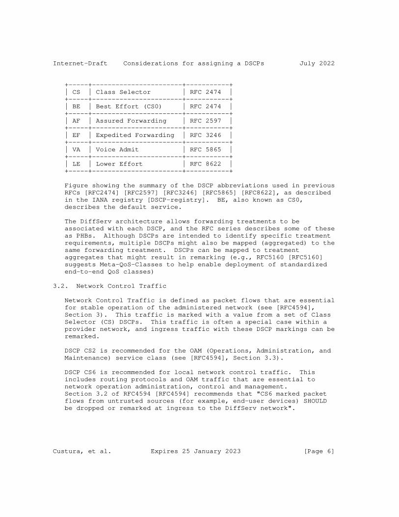
Internet-Draft Considerations for assigning a DSCPs July 2022
+-----+-----------------------+-----------+ | CS | Class Selector | RFC 2474 | +-----+-----------------------+-----------+ | BE | Best Effort (CS0) | RFC 2474 | +-----+-----------------------+-----------+ | AF | Assured Forwarding | RFC 2597 | +-----+-----------------------+-----------+ | EF | Expedited Forwarding | RFC 3246 | +-----+-----------------------+-----------+ | VA | Voice Admit | RFC 5865 | +-----+-----------------------+-----------+ | LE | Lower Effort | RFC 8622 | +-----+-----------------------+-----------+
Figure showing the summary of the DSCP abbreviations used in previous RFCs [RFC2474] [RFC2597] [RFC3246] [RFC5865] [RFC8622], as described in the IANA registry [DSCP-registry]. BE, also known as CS0, describes the default service.
The DiffServ architecture allows forwarding treatments to be associated with each DSCP, and the RFC series describes some of these as PHBs. Although DSCPs are intended to identify specific treatment requirements, multiple DSCPs might also be mapped (aggregated) to the same forwarding treatment. DSCPs can be mapped to treatment aggregates that might result in remarking (e.g., RFC5160 [RFC5160] suggests Meta-QoS-Classes to help enable deployment of standardized end-to-end QoS classes)
3.2. Network Control Traffic
Network Control Traffic is defined as packet flows that are essential for stable operation of the administered network (see [RFC4594], Section 3). This traffic is marked with a value from a set of Class Selector (CS) DSCPs. This traffic is often a special case within a provider network, and ingress traffic with these DSCP markings can be remarked.
DSCP CS2 is recommended for the OAM (Operations, Administration, and Maintenance) service class (see [RFC4594], Section 3.3).
DSCP CS6 is recommended for local network control traffic. This includes routing protocols and OAM traffic that are essential to network operation administration, control and management. Section 3.2 of RFC4594 [RFC4594] recommends that "CS6 marked packet flows from untrusted sources (for example, end-user devices) SHOULD be dropped or remarked at ingress to the DiffServ network".
Custura, et al. Expires 25 January 2023 [Page 6]

Internet-Draft Considerations for assigning a DSCPs July 2022
DSCP CS7 is reserved for future use by network control traffic. "CS7 marked packets SHOULD NOT be sent across peering points" [RFC4594].
RFC2474 [RFC2474] recommends PHBs selected by CS6 and CS7 "MUST give packets preferential forwarding treatment by comparison to the PHB selected by codepoint ’000000’".
At the time of writing, there is evidence to suggest CS6 is actively used by network operators for control traffic. A study of traffic at a large Internet Exchange showed around 40% of ICMP traffic carried this mark [IETF113DSCP]. Similarly, another study found many routers remark all traffic except those packets with a DSCP that sets the higher order bits to 0b11 (see Section 4 of this document).
4. Remarking the DSCP
It is a feature of the DiffServ architecture that the DiffServ field of packets can be remarked at domain boundaries (see section 2.3.4.2 of RFC2475 [RFC2475]). A DSCP can be remarked at the ingress of a DiffServ domain. This remarking can change the DSCP value used on the remainder of an IP path, or the network can restore the initial DSCP marking at the egress of the domain. The DiffServ field can also be remarked based on common semantics and agreements between providers at an exchange point. Furthermore, RFC 2474 [RFC2474] states that remarking must occur when there is a possibility of theft/denial-of-service attack.
If packets are received that are marked with an unknown or an unexpected DSCP, RFC2474 [RFC2474] recommends forwarding the packet using a default (best effort) treatment, but without changing the DSCP. This seeks to support incremental DiffServ deployment in existing networks as well as preserve DSCP markings by routers that have not been configured to support DiffServ. (See also Section 4.3). RFC3260 [RFC3260] clarifies that this remarking specified by RFC2474 is intended for interior nodes within a DiffServ domain. For DiffServ ingress nodes the traffic conditioning required by RFC 2475 applies first.
Reports measuring existing deployments have categorised DSCP remarking [Custura] [Barik] into the following seven observed remarking behaviours:
Bleach: bleaches all traffic (sets the DSCP to zero);
Bleach-ToS-Precedence: set the first three bits of the DSCP field to 0b000 (reset the 3 bits of the former ToS Precedence field) ;
Bleach-some-ToS: set the first three bits of the DSCP field to 0b000
Custura, et al. Expires 25 January 2023 [Page 7]

Internet-Draft Considerations for assigning a DSCPs July 2022
(reset the 3 bits of the former ToS Precedence field), unless the first two bits of the DSCP field are 0b11;
Remark-ToS: set the first three bits of the DSCP field to any value different than 0b000 (replace the 3 bits of the former ToS Precedence field);
Bleach-low: set the last three bits of the DSCP field to 0b000;
Bleach-some-low: set the last three bits of the DSCP field to 0b000, unless the first two bits of the DSCP field are 0b11;
Remark: remarks all traffic to one or more particular (non-zero) DSCP values.
4.1. Bleaching the DSCP Field
A specific form of remarking occurs when the DiffServ field is re- assigned to the default treatment, CS0 (0x00). This results in traffic being forwarded using the BE PHB. For example, AF31 (0x1a) would be bleached to CS0.
A survey reported that resetting all the bits of the DiffServ field to 0 was seen to be more prevalent at the edge of the network, and rather less common in core networks [Custura].
4.2. IP Type of Service manipulations
The IETF first defined ToS precedence for IP packets [RFC0791], updated by specification as a part of the ToS Field RFC1349 [RFC1349]. Since 1998, this practice has been deprecated by RFC2474 [RFC2474]. RFC 2474 defines DSCPs 0bxxx000 as the Class Selector codepoints, where PHBs selected by these codepoints MUST meet the Class Selector PHB Requirements" described in Sec. 4.2.2.2 of that RFC.
However, a recent survey reports practices based on ToS semantics have not yet been eliminated from the Internet, and need to still be considered when making new DSCP assignments [Custura].
4.2.1. Impact of ToS Precedence Bleaching
ToS Precedence Bleaching (/Bleach-ToS-Precedence/) is a practice that resets the first three bits of the DSCP field to zero (the former ToS Precedence field), leaving the last three bits unchanged (see section 4.2.1 of RFC2474 [RFC2474]). This remarking can occur when packets are processed by a router that is not configured with DiffServ (e.g., configured to operate on the former ToS precedence field [RFC0791]).
Custura, et al. Expires 25 January 2023 [Page 8]

Internet-Draft Considerations for assigning a DSCPs July 2022
At the time of writing, this is a common manipulation of the DiffServ field. The following Figure depicts this remarking.
+-+-+-+-+-+-+ |0 0 0|x x x| +-+-+-+-+-+-+
Figure showing the ToS Precedence Bleaching (/Bleach-ToS-Precedence/) observed remarking behaviour, based on Section 3 of RFC1349 [RFC1349]. The bit positions marked "x" are not changed.
+---------+-------+----------+-----+----------+-----+----------+-----+ | 56/CS7 | 57 | 58 | 59 | 60 | 61 | 62 | 63 | +---------+-------+----------+-----+----------+-----+----------+-----+ | 48/CS6 | 49 | 50 | 51 | 52 | 53 | 54 | 55 | +---------+-------+----------+-----+----------+-----+----------+-----+ | 40/CS5 | 41 | 42 | 43 | 44/VA | 45 | 46/EF | 47 | +---------+-------+----------+-----+----------+-----+----------+-----+ | 32/CS4 | 33 | 34/AF41 | 35 | 36/AF42 | 37 | 38/AF43 | 39 | +---------+-------+----------+-----+----------+-----+----------+-----+ | 24/CS3 | 25 | 26/AF31 | 27 | 28/AF32 | 29 | 30/AF33 | 31 | +---------+-------+----------+-----+----------+-----+----------+-----+ | 16/CS2 | 17 | 18/AF21 | 19 | 20/AF22 | 21 | 22/AF23 | 23 | +---------+-------+----------+-----+----------+-----+----------+-----+ | 8/CS1 | 9 | 10/AF11 | 11 | 12/AF12 | 13 | 14/AF13 | 15 | +=========+=======+==========+=====+==========+=====+==========+=====+ | 0/CS0 | 1/LE | 2 | 3 | 4 | 5 | 6 | 7 | +=========+=======+==========+=====+==========+=====+==========+=====+
As a result of ToS Precedence Bleaching, all the DSCPs in each column are remarked to the smallest DSCP in that column. The DSCPs in the bottom row therefore have higher survivability across an end-to-end Internet path.
Custura, et al. Expires 25 January 2023 [Page 9]

Internet-Draft Considerations for assigning a DSCPs July 2022
+=========+=======+============+====+======+======+============+====+ | 0/CS0 | 1/LE | 2 | 3 | 4 | 5 | 6 | 7 | +=========+=======+============+====+======+======+============+====+ |Assigned |ToS Prec Bl.|EXP/|Used |Future|ToS Prec Bl.|Exp/| | |of AF11..41 |LU |by SSH|NQB |of AF13..EF |LU | +=================+============+====+======+======+============+====+
Figure showing 0b000xxx DSCPs, highlighting any current assignments and whether they are affected by any known remarking behaviours. For example, ToS Precedence Bleaching of popular DSCPs AF11,21,31,41 would result in traffic being remarked with DSCP 2 in the Internet core. DSCP 4 has been historically used by the SSH application, following semantics which precede DiffServ[DSCP4].
If ToS Precedence Bleaching occurs, packets with a DSCP ’x’ would be remarked to ’x’ & 0x07and then would be treated according to the corresponding PHB.
A variation of this observed remarking behaviour clears the top three bits of a DSCP, unless these have values 0b110 or 0b111 (corresponding to the CS6 and CS7 DSCPs). As a result, a DSCP value greater than 48 decimal (0x30) is less likely to be impacted by ToS Precedence Bleaching.
4.2.2. Impact of ToS Precedence Remarking
Practices based on ToS Precedence Remarking (/Remark-ToS/) RFC1349 [RFC1349] were deprecated by RFC2474 [RFC2474]. These practices based on ToS semantics have not yet been eliminated from deployed networks.
+-+-+-+-+-+-+ |0 0 1|x x x| +-+-+-+-+-+-+
Figure showing ToS Precedence Remarking (/Remark-ToS/) observed behaviour, based on Section 3 of RFC1349 [RFC1349]. The bit positions marked "x" remain unchanged.
A less common remarking, ToS Precedence Remarking sets the first three bits of the DSCP to a non-zero value corresponding to a CS PHB. This remarking occurs when routers are not configured to perform DiffServ remarking.
Custura, et al. Expires 25 January 2023 [Page 10]

Internet-Draft Considerations for assigning a DSCPs July 2022
If remarking occurs, packets are forwarded using the PHB specified for the resulting DSCP. For example, the AF31 DSCP (0x1a) could be remarked to either AF11 or AF21.
4.3. Remarking to a Particular DSCP
A network device might remark the DiffServ field of an IP packet based on a local policy with a specific (set of) DSCPs, /Remark/.
Both RFC2474 [RFC2474] and RFC8100 [RFC8100] recommend that DiffServ boundary nodes use remarking, if necessary, to avoid theft/denial of service or ensure that appropriate DSCPs are used within a DiffServ domain. Some networks therefore may not follow the earlier recommendation in RFC2474 [RFC2474] to carry unknown or unexpected DSCPs without modification, and instead remark packets with these codepoints to the default class, CS0 (0x00).
Remarking is sometimes performed using a Multi-Field (MF) classifier [RFC2475] [RFC3290] [RFC4594]. For example, a common remarking is to remark all traffic to a single DSCP, thus removing any traffic differentiation (see Section 4.1). Bleaching (/Bleach/) is a specific example of this observed remarking behaviour that remarks to CS0 (0x00).
5. Interpretation of the IP DSCP at Lower Layers
Transmission systems and subnetworks can, and do, utilise the DiffServ field in an IP packet to set a QoS-related field or function at the lower layer. A lower layer could also implement a traffic conditioning function that could remark the DSCP used at the IP layer. In many cases, this use is constrained by designs that utilise fewer than 6 bits to express the service class, and therefore infer mapping to a smaller L2 QoS field, for example, WiFi or Multi- Protocol Label Switching (MPLS).
5.1. Mapping Specified for IEEE 802
The IEEE specifies standards that include mappings for DSCPs to lower layer elements.
5.1.1. Mapping Specified for IEEE 802.1
A 3-bit Priority Code Point (PCP) is specified in the IEEE 802.1Q tag to mark Ethernet frames to one of eight priority values [IEEE-802-1Q]. The value zero indicates the default best effort treatment, and the value one indicates a background traffic class. The remaining values indicate increasing priority. Internet control traffic can be marked as six, and network control is marked as seven.
Custura, et al. Expires 25 January 2023 [Page 11]
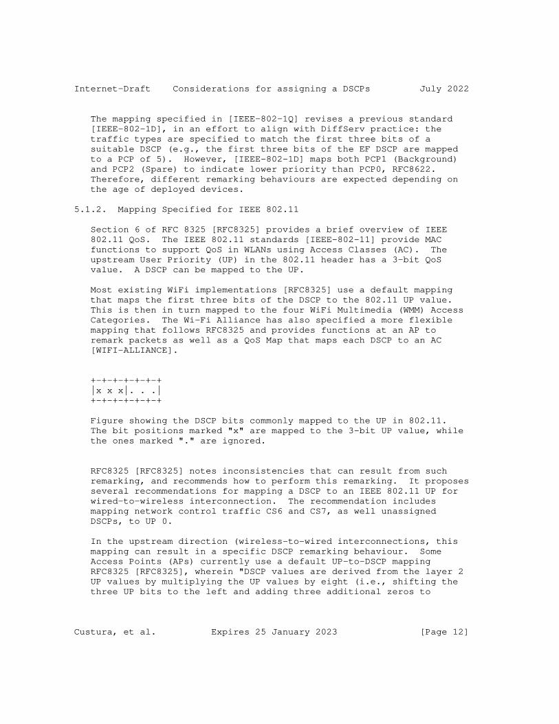
Internet-Draft Considerations for assigning a DSCPs July 2022
The mapping specified in [IEEE-802-1Q] revises a previous standard [IEEE-802-1D], in an effort to align with DiffServ practice: the traffic types are specified to match the first three bits of a suitable DSCP (e.g., the first three bits of the EF DSCP are mapped to a PCP of 5). However, [IEEE-802-1D] maps both PCP1 (Background) and PCP2 (Spare) to indicate lower priority than PCP0, RFC8622. Therefore, different remarking behaviours are expected depending on the age of deployed devices.
5.1.2. Mapping Specified for IEEE 802.11
Section 6 of RFC 8325 [RFC8325] provides a brief overview of IEEE 802.11 QoS. The IEEE 802.11 standards [IEEE-802-11] provide MAC functions to support QoS in WLANs using Access Classes (AC). The upstream User Priority (UP) in the 802.11 header has a 3-bit QoS value. A DSCP can be mapped to the UP.
Most existing WiFi implementations [RFC8325] use a default mapping that maps the first three bits of the DSCP to the 802.11 UP value. This is then in turn mapped to the four WiFi Multimedia (WMM) Access Categories. The Wi-Fi Alliance has also specified a more flexible mapping that follows RFC8325 and provides functions at an AP to remark packets as well as a QoS Map that maps each DSCP to an AC [WIFI-ALLIANCE].
+-+-+-+-+-+-+ |x x x|. . .| +-+-+-+-+-+-+
Figure showing the DSCP bits commonly mapped to the UP in 802.11. The bit positions marked "x" are mapped to the 3-bit UP value, while the ones marked "." are ignored.
RFC8325 [RFC8325] notes inconsistencies that can result from such remarking, and recommends how to perform this remarking. It proposes several recommendations for mapping a DSCP to an IEEE 802.11 UP for wired-to-wireless interconnection. The recommendation includes mapping network control traffic CS6 and CS7, as well unassigned DSCPs, to UP 0.
In the upstream direction (wireless-to-wired interconnections, this mapping can result in a specific DSCP remarking behaviour. Some Access Points (APs) currently use a default UP-to-DSCP mapping RFC8325 [RFC8325], wherein "DSCP values are derived from the layer 2 UP values by multiplying the UP values by eight (i.e., shifting the three UP bits to the left and adding three additional zeros to
Custura, et al. Expires 25 January 2023 [Page 12]

Internet-Draft Considerations for assigning a DSCPs July 2022
generate a 6-bit DSCP value). This derived DSCP value is used for QoS treatment between the wireless AP and the nearest classification and marking policy enforcement point (which may be the centralized wireless LAN controller, relatively deep within the network). Alternatively, in the case where there is no other classification and marking policy enforcement point, then this derived DSCP value will be used on the remainder of the Internet path." This can result in remarking /Bleach-low/.
+-+-+-+-+-+-+ |x x x|0 0 0| +-+-+-+-+-+-+
Figure showing the observed remarking behaviour resulting from deriving from UP-to-DSCP mapping in some 802.11 networks.
An alternative to UP-to-DSCP remapping uses the DSCP value of a downstream IP packet (e.g., the Control And Provisioning of Wireless Access Points (CAPWAP) protocol, RFC5415, maps an IP packet DiffServ field to the DiffServ field of the outer IP header in a CAPWAP tunnel).
Some current constraints of WiFi mapping are discussed in section 2 of [RFC8325]. A QoS profile can be used to limit the maximum DSCP value used for the upstream and downstream traffic.
5.2. DiffServ and MPLS
Multi-Protocol Label Switching (MPLS) specified eight MPLS Traffic Classes (TCs), which restricts the number of different treatments [RFC5129]. RFC 5127 describes aggregation of DiffServ TCs [RFC5127], and introduces four DiffServ Treatment Aggregates. Traffic marked with multiple DSCPs can be forwarded in a single MPLS TC.
There are three Label-Switched Router (LSR) behaviours: the Pipe, the Short Pipe and the Uniform Model [RFC3270]. These only differ when a LSP performs a push or a pop.
5.2.1. Mapping Specified for MPLS
RFC3270 [RFC3270] defines a flexible solution for support of DiffServ over MPLS networks. This allows an MPLS network administrator to select how BAs (marked by DSCPs) are mapped onto Label Switched Paths (LSPs) to best match the DiffServ, Traffic Engineering and protection objectives within their particular network.
Custura, et al. Expires 25 January 2023 [Page 13]

Internet-Draft Considerations for assigning a DSCPs July 2022
Mappings from the IP DSCP to the MPLS header are defined in Section 4.2 of [RFC3270].
The Pipe Model conveys the "LSP Diff-Serv Information" to the LSP Egress so that its forwarding treatment can be based on the IP DSCP.
When Penultimate Hop Popping (PHP) is used, the Penultimate LSR needs to be aware of the encapsulation mapping for a PHB to the label corresponding to the exposed header to perform DiffServ Information Encoding (Section 2.5.2 of RFC3270 [RFC3270]).
5.2.2. Mapping Specified for MPLS Short Pipe
The Short Pipe Model is an optional variation of the Pipe Model [RFC3270].
ITU-T Y.1566 [ITU-T-Y-1566] further defined a set of four common QoS classes and four auxiliary classes to which a DSCP can be mapped when interconnecting Ethernet, IP and MPLS networks. RFC8100 [RFC8100] proposes four treatment aggregates for interconnection with four defined DSCPs. This was motivated by the requirements of MPLS network operators that use Short-Pipe tunnels, but can be applicable to other networks, both MPLS and non-MPLS.
RFC8100 recommends preserving the notion of end-to-end service classes, and recommends a set of standard DSCPs mapped to a small set of standard PHBs at interconnection. The key requirement is that the DSCP at the network ingress is restored at the network egress. The current version of RFC8100 limits the number of DSCPs to 6 and 3 more are suggested for extension. RFC8100 respects the deployment of PHB groups for DS domain internal use, which limits the number of acceptable external DSCPs (and possibilities for their transparent transport or restoration at network boundaries). In this design, packets marked with DSCPs not part of the RFC8100 codepoint scheme are treated as unexpected and will possibly be remarked (a /Remark/ behaviour) or dealt with via an additional agreement(s) among the operators of the interconnected networks. RFC8100 can be extended to support up to 32 DSCPs by future standards. RFC8100 is operated by at least one Tier 1 backbone provider. Use of the MPLS Short Pipe Model favours remarking unexpected DSCP values to zero in the absence of an additional agreement(s), as explained in RFC8100 [RFC8100]. This can result in bleaching (/Bleach/).
Custura, et al. Expires 25 January 2023 [Page 14]

Internet-Draft Considerations for assigning a DSCPs July 2022
+--------------------------------------+--------+ | RFC8100 | DSCP | | Agg. Class | | +--------------------------------------+--------+ |Telephony Service Treatment Aggregate | EF | | | VA | +--------------------------------------+--------+ |Bulk Real-Time Treatment Aggregate | AF41 | | May be added | (AF42) | | May be added | (AF43) | +--------------------------------------+--------+ |Assured Elastic Treatment Aggregate | AF31 | | | AF32 | | Reserved for the extension of PHBs| (AF33) | +--------------------------------------+--------+ |Default / Elastic Treatment Aggregate | BE/CS0 | +--------------------------------------+--------+ |Network Control: Local Use | CS6 | +--------------------------------------+--------+
The short-pipe MPLS mapping from RFC 8100.
5.3. Mapping Specified for Mobile Networks
Mobile LTE and 5G standards have evolved from older UMTS standards, and did not configure support for DiffServ. LTE (4G) and 5G standards [SA-5G] identify traffic classes at the interface between User Equipment (UE) and the mobile Packet Core network by QCI (QoS Class Identifiers) and 5QI (5G QoS Identifier). The 3GPP standards do not define or recommend any specific mapping between each QCI or 5QI and DiffServ (and mobile QCIs are based on several criteria service class definitions). The way packets are mapped at the Packet Gateway (P-GW) boundary is determined by operators. However, TS 23.107 (version 16.0.0, applies to LTE and below) mandates that Differentiated Services, defined by IETF, shall be used to interoperate with IP backbone networks.
Custura, et al. Expires 25 January 2023 [Page 15]

Internet-Draft Considerations for assigning a DSCPs July 2022
The GSM Association (GSMA) has defined four aggregated classes and seven associated PHBs in their guidelines for IPX Provider networks GSMA IR.34 [GSMA-IR-34]. This was previously specified as the Inter- Service Provider IP Backbone Guidelines, and provides a mobile ISP to ISP QoS mapping mechanism, and interconnection with other IP networks in the general Internet. If realised by an IP VPN, the operator is free to apply its DS Domain internal codepoint scheme at outer headers and inner IPX DSCPs may be transported transparently. The guidelines also describe a case where the DSCP marking from a Service Provider cannot be trusted (depending on the agreement between the Service Provider and its IPX Provider), in which situation the IPX Provider can remark the DSCP value to a static default value.
+---------------+-------+ | GSMA IR.34 | PHB | | Agg. Class | | +---------------+-------+ |Conversational | EF | +---------------+-------+ | Streaming | AF41 | +---------------+-------+ | Interactive | AF31 | + +-------+ | (ordered by | AF32 | + priority, +-------+ | AF3 highest) | AF21 | + +-------+ | | AF11 | +---------------+-------+ | Background | CS0 | +---------------+-------+
Figure showing the PHB mapping recommended in the guidelines proposed in GSMA IR.34 [GSMA-IR-34].
5.4. Mapping Specified for Carrier Ethernet
Metro Ethernet Forum (MEF) provides a mapping of DSCPs at the IP layer to quality of service markings in the Ethernet frame headers MEF 23.1 [MEF23.1].
Custura, et al. Expires 25 January 2023 [Page 16]

Internet-Draft Considerations for assigning a DSCPs July 2022
5.5. Remarking as a Side-effect of Another Policy
This includes any other remarking that does not happen as a result of traffic conditioning, such as policies and L2 procedures that result in remarking traffic as a side-effect of other functions (e.g., in response to DDos).
5.6. Summary
This section has discussed the various ways in which DSCP remarking behaviours can arise from interactions with lower layers.
6. Considerations for DSCP Selection
This section provides advice for the assignment of a new DSCP value. It is intended to aid the IETF and IESG in considering a request for a new DSCP. The section identifies known issues that might influence the finally assigned DSCP, and provides a summary of considerations for assignment of a new DSCP.
6.1. Effect of Bleaching
New DSCP assignments should consider the impact of bleaching, which can limit the ability to provide the expected treatment end-to-end. This is particularly important for cases where the codepoint is intended to result in lower than best effort treatment, as was the case when defining the LE PHB [RFC8622]. In this case, bleaching, or remarking to "CS0" would result in elevating the lower effort traffic (LE) to the default class (BE/CS0). This is an example of priority inversion.
6.2. Where the proposed DSCP > 0x07 (7)
Although the IETF specifications require systems to use DSCP marking semantics in place of methods based on the former ToS field, the current recommendation is that any new assignment where the DSCP is greater than 0x07 should consider the semantics associated with the resulting DSCP when ToS Precedence Bleaching is experienced. For example, it can be desirable to avoid choosing a DSCP that could be remarked to LE, Lower Effort [RFC8622], which could otherwise potentially result in a priority inversion in the treatment.
Custura, et al. Expires 25 January 2023 [Page 17]

Internet-Draft Considerations for assigning a DSCPs July 2022
6.3. Where the proposed DSCP < 0x07 (7)
ToS Precedence Bleaching can unintentionally result in extra traffic aggregated to the same DSCP. For example, after experiencing ToS Precedence Bleaching, all traffic marked AF11, AF21, AF31 and AF41 would be aggregated with traffic marked with DSCP 2 (0x02), increasing the volume of traffic which receives the treatment associated with DSCP 2. New DiffServ Codepoint assignments should consider unexpected consequences arising from this observed remarking behaviour.
6.3.1. Where the proposed DSCP&0x07=0x01
As a consequence of assigning the LE PHB [RFC8622], the IETF allocated the DSCP 0b000001 from Pool 3.
When making assignments where the DSCP has a format: 0bxxx001, the case of ToS Precedence Bleaching (/Bleach-ToS-Precedence/) of a DSCP to a value of 0x01 needs to be considered. ToS Precedence Bleaching will result in demoting the traffic to the lower effort traffic class. Care should be taken to consider the implications of remarking when shooing to assign a DSCP with this format.
6.4. Impact on deployed infrastructure
Behaviour of deployed PHBs and conditioning treatments also needs to be considered when assigning a new DSCP. Network operators have choices when it comes to configuring DiffServ support within their domains, and the observed remarking behaviours described in the previous section can result from different configurations and approaches:
Networks not remarking DiffServ: A network that either does not implement PHBs, or implements one or more PHBs whilst restoring the DSCP field at network egress with the value at network ingress. Operators in this category pass all DSCPs transparently.
Networks that condition the DSCP: A network that implements more than one PHB and enforces SLAs with its peers. Operators in this category use conditioning to ensure that only traffic that matches a policy is permitted to use a specific DSCP (see RFC8100 [RFC8100]). This requires operators to choose to support or remark a new DSCP assignment.
Networks that remark in some other way , which includes:
Custura, et al. Expires 25 January 2023 [Page 18]

Internet-Draft Considerations for assigning a DSCPs July 2022
1. Networks containing misconfigured devices that do not comply with the relevant RFCs.
2. Networks containing devices that implement an obsolete specification or contain software bugs.
3. Networks containing devices that remark the DSCP as a result of lower layer interactions.
For example, the ToS Precedence Bleaching (/Bleach-ToS-Precedence/) remarking behaviour cannot be observed in the case of networks not remarking DiffServ, but can arise as a result of traffic conditioning at operator boundaries. It can also arise in the case of misconfiguration or in networks using old equipment which precedes DiffServ.
6.5. Questions to guide discussion of a proposed new DSCP
A series of questions emerge that need to be answered when considering a proposal to the IETF that requests a new assignment. These questions include:
* Is the request for local use within a DiffServ domain that does not require interconnection with other DiffServ domains? This can use DSCPs in Pool 2 for local or experimental use, without any IETF specification for the DSCP or associated PHB.
* How is the proposed service class characterised? What are the characteristics of the traffic to be carried? What are the expectations for treatment?
* Service classes [RFC4594] that can utilise existing PHBs should use assigned DSCPs to mark their traffic: Could the request be met by using an existing IETF DSCP? The proposed new treatment be used to map traffic to a new or existing PHB.
* Is this a request to assign a new DSCP? Specification of a new recommended DSCP requires Standards Action. RFC2474 states: "Each standardized PHB MUST have an associated RECOMMENDED codepoint". If approved, new IETF assignments are normally made by IANA in Pool 1, but the IETF can request assignments to be made from Pool 3 [RFC8436].
* What are the effects of treatment aggregation on the proposed DSCP? Section 5.2 describes examples of treatment aggregation.
Custura, et al. Expires 25 January 2023 [Page 19]
Internet-Draft Considerations for assigning a DSCPs July 2022
* Section Section 5 describes some observed treatments by layers below IP. What are the implications of the treatments and mapping described in Section 5 on the proposed DSCP?
* DSCPs are assigned to PHBs and can be used to enable nodes along an end-to-end path to classify the packet for a suitable PHB. If a new DSCP assignment is requested, then what is the expected effect of currently-deployed remarking on the end-to-end service? Section 4 describes some observed remarking behaviour, and Section 6.4 identifies root causes for why this remarking is observed.
7. Acknowledgments
The authors acknowledge the helpful discussions and analysis by Greg White and Thomas Fossati in a draft concerning NQB. Ruediger Geib and Brian Carpenter contributed comments, along with other members of the TSVWG.
8. IANA Considerations
This memo provides information to assist in considering new assignments to the IANA DSCP registry (https://www.iana.org/assignments/dscp-registry/dscp-registry.xhtml).
This memo includes no request to IANA, or update to the IANA procedures.
9. Security Considerations
The security considerations are discussed in the security considerations of each cited RFC.
10. References
10.1. Normative References
[DSCP-registry] IANA, "Differentiated Services Field Codepoints (DSCP) Registry", https://www.iana.org/assignments/dscp- registry/dscp-registry.xhtml, 2019.
[RFC2119] Bradner, S., "Key words for use in RFCs to Indicate Requirement Levels", BCP 14, RFC 2119, DOI 10.17487/RFC2119, March 1997, <https://www.rfc-editor.org/info/rfc2119>.
Custura, et al. Expires 25 January 2023 [Page 20]
Internet-Draft Considerations for assigning a DSCPs July 2022
[RFC2474] Nichols, K., Blake, S., Baker, F., and D. Black, "Definition of the Differentiated Services Field (DS Field) in the IPv4 and IPv6 Headers", RFC 2474, DOI 10.17487/RFC2474, December 1998, <https://www.rfc-editor.org/info/rfc2474>.
[RFC2475] Blake, S., Black, D., Carlson, M., Davies, E., Wang, Z., and W. Weiss, "An Architecture for Differentiated Services", DOI 10.17487/RFC2475, RFC 2475, December 1998, <https://www.rfc-editor.org/info/rfc2475>.
[RFC3260] Grossman, D., "New Terminology and Clarifications for Diffserv", DOI 10.17487/RFC3260, RFC 3260, April 2002, <https://www.rfc-editor.org/info/rfc3260>.
[RFC3290] Bernet, Y., Blake, S., Grossman, D., and A. Smith, "An Informal Management Model for Diffserv Routers", DOI 10.17487/RFC3290, RFC 3290, May 2002, <https://www.rfc-editor.org/info/rfc3290>.
[RFC4594] Babiarz, J., Chan, K., and F. Baker, "Configuration Guidelines for DiffServ Service Classes", RFC 4594, DOI 10.17487/RFC4594, August 2006, <https://www.rfc-editor.org/info/rfc4594>.
[RFC5129] Davie, B., Briscoe, B., and J. Tay, "Explicit Congestion Marking in MPLS", RFC 5129, DOI 10.17487/RFC5129, January 2008, <https://www.rfc-editor.org/info/rfc5129>.
[RFC8100] Geib, R., Ed. and D. Black, "Diffserv-Interconnection Classes and Practice", RFC 8100, DOI 10.17487/RFC8100, March 2017, <https://www.rfc-editor.org/info/rfc8100>.
[RFC8436] Fairhurst, G., "Update to IANA Registration Procedures for Pool 3 Values in the Differentiated Services Field Codepoints (DSCP) Registry", RFC 8436, DOI 10.17487/RFC8436, August 2018, <https://www.rfc-editor.org/info/rfc8436>.
10.2. Informative References
[Barik] Barik, R., Welzl, M., Elmokashfi, A., Dreibholz, T., and S. Gjessing, "Can WebRTC QoS Work? A DSCP Measurement Study", ITC 30, September 2018.
[Custura] Custura, A., Venne, A., and G. Fairhurst, "Exploring DSCP modification pathologies in mobile edge networks", TMA , 2017.
Custura, et al. Expires 25 January 2023 [Page 21]
Internet-Draft Considerations for assigning a DSCPs July 2022
[DSCP4] Kolu, A., "Bogus DSCP value for SSH", online https://lists.freebsd.org/pipermail/freebsd- stable/2010-July/057710.html, 2010.
[GSMA-IR-34] GSM Association, "IR.34 Guidelines for IPX Provider networks (Previously Inter-Service Provider IP Backbone Guidelines)", IR 34, 2017.
[I-D.ietf-tsvwg-nqb] White, G. and T. Fossati, "A Non-Queue-Building Per-Hop Behavior (NQB PHB) for Differentiated Services", Work in Progress, Internet-Draft, draft-ietf-tsvwg-nqb-04, 22 February 2021, <https://www.ietf.org/archive/id/draft- ietf-tsvwg-nqb-04.txt>.
[I-D.learmonth-rfc1226-bis] Learmonth, I. R., "Internet Protocol Encapsulation of AX.25 Frames", Work in Progress, Internet-Draft, draft- learmonth-rfc1226-bis-03, 19 May 2020, <https://www.ietf.org/archive/id/draft-learmonth-rfc1226- bis-03.txt>.
[IEEE-802-11] IEEE, "Wireless LAN Medium Access Control (MAC) and Physical Layer (PHY) Specifications", IEEE 802.11, 2007.
[IEEE-802-1D] IEEE, "IEEE Standard for Local and Metropolitan Area Network-- Media Access Control (MAC) Bridges", IEEE 802.1D, 2004.
[IEEE-802-1Q] IEEE, "IEEE Standard for Local and Metropolitan Area Network-- Bridges and Bridged Networks", IEEE 802.1Q, 2018.
[IETF113DSCP] Custura, A. and G. Fairhurst, "Considerations for assigning DSCPs", IETF 113 Proceedings https://datatracker.ietf.org/meeting/113/materials/slides- 113-tsvwg-61-dscp-considerations-07, 2022.
[ITU-T-Y-1566] ITU-T, "Quality of Service Mapping and Interconnection Between Ethernet, Internet Protocol and Multiprotocol Label Switching Networks", ITU-T Y.1566, 2012.
Custura, et al. Expires 25 January 2023 [Page 22]
Internet-Draft Considerations for assigning a DSCPs July 2022
[MEF23.1] MEF, "MEF Technical Specification MEF 23.1-- Carrier Ethernet Class of Service ? Phase 2", MEF 23.1, 2012.
[RFC0791] Postel, J., "Internet Protocol", STD 5, DOI 10.17487/RFC0791, RFC 791, September 1981, <https://www.rfc-editor.org/info/rfc791>.
[RFC1349] Almquist, P., "Type of Service in the Internet Protocol Suite", RFC 1349, DOI 10.17487/RFC1349, July 1992, <https://www.rfc-editor.org/info/rfc1349>.
[RFC2597] Heinanen, J., Baker, F., Weiss, W., and J. Wroclawski, "Assured Forwarding PHB Group", RFC 2597, DOI 10.17487/RFC2597, June 1999, <https://www.rfc-editor.org/info/rfc2597>.
[RFC3086] Nichols, K. and B. Carpenter, "Definition of Differentiated Services Per Domain Behaviors and Rules for their Specification", DOI 10.17487/RFC3086, RFC 3086, April 2001, <https://www.rfc-editor.org/info/rfc3086>.
[RFC3246] Davie, B., Charny, A., Bennet, J C R., Benson, K., Le Boudec, J Y., Courtney, W., Davari, S., Firoiu, V., and D. Stiliadis, "An Expedited Forwarding PHB (Per-Hop Behavior)", DOI 10.17487/RFC3246, RFC 3246, March 2002, <https://www.rfc-editor.org/info/rfc3246>.
[RFC3270] Le Faucheur, F., Wu, L., Davie, B., Davari, S., Vaananen, P., Krishnan, R., Cheval, P., and J. Heinanen, "Multi- Protocol Label Switching (MPLS) Support of Differentiated Services", DOI 10.17487/RFC3270, RFC 3270, May 2002, <https://www.rfc-editor.org/info/rfc3270>.
[RFC5127] Chan, K., Babiarz, J., and F. Baker, "Aggregation of Diffserv Service Classes", RFC 5127, DOI 10.17487/RFC5127, February 2008, <https://www.rfc-editor.org/info/rfc5127>.
[RFC5160] Levis, P. and M. Boucadair, "Considerations of Provider- to-Provider Agreements for Internet-Scale Quality of Service (QoS)", DOI 10.17487/RFC5160, RFC 5160, March 2008, <https://www.rfc-editor.org/info/rfc5160>.
[RFC5865] Baker, F., Polk, J., and M. Dolly, "A Differentiated Services Code Point (DSCP) for Capacity-Admitted Traffic", DOI 10.17487/RFC5865, RFC 5865, May 2010, <https://www.rfc-editor.org/info/rfc5865>.
Custura, et al. Expires 25 January 2023 [Page 23]

Internet-Draft Considerations for assigning a DSCPs July 2022
[RFC8126] Cotton, M., Leiba, B., and T. Narten, "Guidelines for Writing an IANA Considerations Section in RFCs", RFC 8126, DOI 10.17487/RFC8126, BCP 26, June 2017, <https://www.rfc-editor.org/info/rfc8126>.
[RFC8174] Leiba, B., "Ambiguity of Uppercase vs Lowercase in RFC 2119 Key Words", BCP 14, RFC 8174, DOI 10.17487/RFC8174, May 2017, <https://www.rfc-editor.org/info/rfc8174>.
[RFC8325] Szigeti, T., Henry, J., and F. Baker, "Mapping Diffserv to IEEE 802.11", DOI 10.17487/RFC8325, RFC 8325, February 2018, <https://www.rfc-editor.org/info/rfc8325>.
[RFC8622] Bless, R., "A Lower-Effort Per-Hop Behavior (LE PHB) for Differentiated Services", DOI 10.17487/RFC8622, RFC 8622, June 2019, <https://www.rfc-editor.org/info/rfc8622>.
[SA-5G] 3GPP, "System Architecture for 5G", TS 23.501, 2019.
[WIFI-ALLIANCE] Wi-Fi Alliance, "Wi-Fi QoS Management Specification Version 2.0", Wi-Fi QoS Management Specification Version 2.0, 2021.
Appendix A. Revision Notes
Note to RFC-Editor: please remove this entire section prior to publication.
* Individual draft -00, initial document.
* Individual draft -01, address comments from Martin Duke; Brian Carpenter; Ruediger Geib, and revisions to improve language consistency.
* Individual draft -02, revise to improve language consistency.
* Working Group -00, replace individual draft.
* Working Group -01, address feedback in preparation for IETF 113 Vienna.
* Working Group -02:
Consolidate terminology after IETF 113 Vienna.
Add clarification to RFC2474 and RFC2475 addressed in RFC3260 (Comments from Ruediger Geib).
Custura, et al. Expires 25 January 2023 [Page 24]
Internet-Draft Considerations for assigning a DSCPs July 2022
Include figures to show the full list of codepoints, their assigned PHBs & impact of ToS Precedence Bleaching.
Add network categories that differentiate between network operator approaches to DiffServ.
Add Terminology section to clarify representations of DSCPs.
* Working Group -03
Add table to explain DSCP abbreviations (comment from Brian Carpenter).
Add some refs, improve language consistency (comments from Brian Carpenter).
Clarify figure captions.
* Working Group -04
Reference RFC3086 (comment from Brian Carpenter).
Improve references (comments from Ruediger Geib).
Clarify intended document audience and scope (comments from Ruediger Geib).
Clarify terms and language around re-marking, DiffServ domains and nodes, RFC8100 (comments from Ruediger Geib).
More in-depth on mappings specified for mobile networks/MPLS short-pipe (comments from Ruediger Geib).
Authors’ Addresses
Ana Custura University of Aberdeen School of Engineering Fraser Noble Building Aberdeen AB24 3UE United Kingdom Email: [email protected]
Godred Fairhurst University of Aberdeen School of Engineering
Custura, et al. Expires 25 January 2023 [Page 25]
Internet-Draft Considerations for assigning a DSCPs July 2022
Fraser Noble Building Aberdeen AB24 3UE United Kingdom Email: [email protected]
Raffaello Secchi University of Aberdeen School of Engineering Fraser Noble Building Aberdeen AB24 3UE United Kingdom Email: [email protected]
Custura, et al. Expires 25 January 2023 [Page 26]
TSVWG M. WesterlundInternet-Draft J. Preuß MattssonIntended status: Standards Track C. PorfiriExpires: 25 December 2022 Ericsson 23 June 2022
Datagram Transport Layer Security (DTLS) over Stream Control Transmission Protocol (SCTP) draft-ietf-tsvwg-dtls-over-sctp-bis-04
Abstract
This document describes the usage of the Datagram Transport Layer Security (DTLS) protocol to protect user messages sent over the Stream Control Transmission Protocol (SCTP). It is an improved alternative to the existing rfc6083.
DTLS over SCTP provides mutual authentication, confidentiality, integrity protection, and replay protection for applications that use SCTP as their transport protocol and allows client/server applications to communicate in a way that is designed to give communications privacy and to prevent eavesdropping and detect tampering or message forgery.
Applications using DTLS over SCTP can use almost all transport features provided by SCTP and its extensions. This document is an improved alternative to RFC 6083 and removes the 16 kB limitation on protected user message size by defining a secure user message fragmentation so that multiple DTLS records can be used to protect a single user message. It further updates the DTLS versions to use, as well as the HMAC algorithms for SCTP-AUTH, and simplifies secure implementation by some stricter requirements on the establishment procedures.
Discussion Venues
This note is to be removed before publishing as an RFC.
Source for this draft and an issue tracker can be found at https://github.com/gloinul/draft-westerlund-tsvwg-dtls-over-sctp-bis.
Status of This Memo
This Internet-Draft is submitted in full conformance with the provisions of BCP 78 and BCP 79.
Westerlund, et al. Expires 25 December 2022 [Page 1]

Internet-Draft DTLS over SCTP June 2022
Internet-Drafts are working documents of the Internet Engineering Task Force (IETF). Note that other groups may also distribute working documents as Internet-Drafts. The list of current Internet- Drafts is at https://datatracker.ietf.org/drafts/current/.
Internet-Drafts are draft documents valid for a maximum of six months and may be updated, replaced, or obsoleted by other documents at any time. It is inappropriate to use Internet-Drafts as reference material or to cite them other than as "work in progress."
This Internet-Draft will expire on 25 December 2022.
Copyright Notice
Copyright (c) 2022 IETF Trust and the persons identified as the document authors. All rights reserved.
This document is subject to BCP 78 and the IETF Trust’s Legal Provisions Relating to IETF Documents (https://trustee.ietf.org/ license-info) in effect on the date of publication of this document. Please review these documents carefully, as they describe your rights and restrictions with respect to this document. Code Components extracted from this document must include Revised BSD License text as described in Section 4.e of the Trust Legal Provisions and are provided without warranty as described in the Revised BSD License.
Table of Contents
1. Introduction . . . . . . . . . . . . . . . . . . . . . . . . 3 1.1. Overview . . . . . . . . . . . . . . . . . . . . . . . . 4 1.1.1. Comparison with TLS over SCTP . . . . . . . . . . . . 5 1.1.2. Changes from RFC 6083 . . . . . . . . . . . . . . . . 5 1.2. DTLS Version . . . . . . . . . . . . . . . . . . . . . . 6 1.3. Terminology . . . . . . . . . . . . . . . . . . . . . . . 7 1.4. Abbreviations . . . . . . . . . . . . . . . . . . . . . . 7 2. Conventions . . . . . . . . . . . . . . . . . . . . . . . . . 8 3. DTLS Considerations . . . . . . . . . . . . . . . . . . . . . 8 3.1. Version of DTLS . . . . . . . . . . . . . . . . . . . . . 8 3.2. Cipher Suites and Cryptographic Parameters . . . . . . . 8 3.3. Message Sizes . . . . . . . . . . . . . . . . . . . . . . 8 3.4. Replay Protection . . . . . . . . . . . . . . . . . . . . 9 3.5. Path MTU Discovery . . . . . . . . . . . . . . . . . . . 10 3.6. Retransmission of Messages . . . . . . . . . . . . . . . 10 4. SCTP Considerations . . . . . . . . . . . . . . . . . . . . . 10 4.1. Mapping of DTLS Records . . . . . . . . . . . . . . . . . 10 4.2. DTLS Connection Handling . . . . . . . . . . . . . . . . 13 4.3. Payload Protocol Identifier Usage . . . . . . . . . . . . 13 4.4. Stream Usage . . . . . . . . . . . . . . . . . . . . . . 14
Westerlund, et al. Expires 25 December 2022 [Page 2]
Internet-Draft DTLS over SCTP June 2022
4.5. Chunk Handling . . . . . . . . . . . . . . . . . . . . . 15 4.6. SCTP-AUTH Hash Function . . . . . . . . . . . . . . . . . 15 4.7. Parallel DTLS connections . . . . . . . . . . . . . . . . 15 4.8. Renegotiation and KeyUpdate . . . . . . . . . . . . . . . 18 4.8.1. DTLS 1.2 Considerations . . . . . . . . . . . . . . . 18 4.8.2. DTLS 1.3 Considerations . . . . . . . . . . . . . . . 19 4.9. Handling of Endpoint-Pair Shared Secrets . . . . . . . . 19 4.9.1. DTLS 1.2 Considerations . . . . . . . . . . . . . . . 19 4.9.2. DTLS 1.3 Considerations . . . . . . . . . . . . . . . 20 4.10. Shutdown . . . . . . . . . . . . . . . . . . . . . . . . 20 5. DTLS/SCTP Control Message . . . . . . . . . . . . . . . . . . 21 5.1. SHUTDOWN-Request . . . . . . . . . . . . . . . . . . . . 22 5.2. Ready To Close Indication . . . . . . . . . . . . . . . . 22 6. DTLS over SCTP Service . . . . . . . . . . . . . . . . . . . 22 6.1. Adaptation Layer Indication in INIT/INIT-ACK . . . . . . 22 6.2. DTLS over SCTP Initialization . . . . . . . . . . . . . . 22 6.3. Client Use Case . . . . . . . . . . . . . . . . . . . . . 23 6.4. Server Use Case . . . . . . . . . . . . . . . . . . . . . 23 6.5. RFC 6083 Fallback . . . . . . . . . . . . . . . . . . . . 24 6.5.1. Client Fallback . . . . . . . . . . . . . . . . . . . 24 6.5.2. Server Fallback . . . . . . . . . . . . . . . . . . . 25 7. SCTP API Consideration . . . . . . . . . . . . . . . . . . . 25 8. IANA Considerations . . . . . . . . . . . . . . . . . . . . . 26 8.1. TLS Exporter Label . . . . . . . . . . . . . . . . . . . 26 8.2. SCTP Adaptation Layer Indication Code Point . . . . . . . 26 8.3. SCTP Payload Protocol Identifiers . . . . . . . . . . . . 26 9. Security Considerations . . . . . . . . . . . . . . . . . . . 26 9.1. Cryptographic Considerations . . . . . . . . . . . . . . 27 9.2. Downgrade Attacks . . . . . . . . . . . . . . . . . . . . 29 9.3. Targeting DTLS Messages . . . . . . . . . . . . . . . . . 29 9.4. Authentication and Policy Decisions . . . . . . . . . . . 29 9.5. Resumption and Tickets . . . . . . . . . . . . . . . . . 30 9.6. Privacy Considerations . . . . . . . . . . . . . . . . . 30 9.7. Pervasive Monitoring . . . . . . . . . . . . . . . . . . 30 10. Contributors . . . . . . . . . . . . . . . . . . . . . . . . 31 11. Acknowledgments . . . . . . . . . . . . . . . . . . . . . . . 31 12. References . . . . . . . . . . . . . . . . . . . . . . . . . 31 12.1. Normative References . . . . . . . . . . . . . . . . . . 31 12.2. Informative References . . . . . . . . . . . . . . . . . 33 Appendix A. Motivation for Changes . . . . . . . . . . . . . . . 35 Authors’ Addresses . . . . . . . . . . . . . . . . . . . . . . . 35
1. Introduction
Westerlund, et al. Expires 25 December 2022 [Page 3]

Internet-Draft DTLS over SCTP June 2022
1.1. Overview
This document describes the usage of the Datagram Transport Layer Security (DTLS) protocol, as defined in DTLS 1.2 [RFC6347], and DTLS 1.3 [RFC9147], over the Stream Control Transmission Protocol (SCTP), as defined in [RFC9260] with Authenticated Chunks for SCTP (SCTP- AUTH) [RFC4895].
This specification provides mutual authentication of endpoints, confidentiality, integrity protection, and replay protection of user messages for applications that use SCTP as their transport protocol. Thus, it allows client/server applications to communicate in a way that is designed to give communications privacy and to prevent eavesdropping and detect tampering or message forgery. DTLS/SCTP uses DTLS for mutual authentication, key exchange with forward secrecy for SCTP-AUTH, and confidentiality of user messages. DTLS/ SCTP use SCTP and SCTP-AUTH for integrity protection and replay protection of all SCTP Chunks that can be authenticated, including user messages.
Applications using DTLS over SCTP can use almost all transport features provided by SCTP and its extensions. DTLS/SCTP supports:
* preservation of message boundaries.
* a large number of unidirectional and bidirectional streams.
* ordered and unordered delivery of SCTP user messages.
* the partial reliability extension as defined in [RFC3758].
* the dynamic address reconfiguration extension as defined in [RFC5061].
* User messages of any size.
The method described in this document requires that the SCTP implementation supports the optional feature of fragmentation of SCTP user messages as defined in [RFC9260]. The implementation is required to have an SCTP API (for example the one described in [RFC6458]) that supports partial user message delivery and also recommended that I-DATA chunks as defined in [RFC8260] is used to efficiently implement and support larger user messages.
To simplify implementation and reduce the risk for security holes, limitations have been defined such that STARTTLS as specified in [RFC3788] is no longer supported.
Westerlund, et al. Expires 25 December 2022 [Page 4]
Internet-Draft DTLS over SCTP June 2022
1.1.1. Comparison with TLS over SCTP
TLS, from which DTLS was derived, is designed to run on top of a byte-stream-oriented transport protocol providing a reliable, in- sequence delivery. TLS over SCTP as described in [RFC3436] has some serious limitations:
* It does not support the unordered delivery of SCTP user messages.
* It does not support partial reliability as defined in [RFC3758].
* It only supports the usage of the same number of streams in both directions.
* It uses a TLS connection for every bidirectional stream, which requires a substantial amount of resources and message exchanges if a large number of streams is used.
1.1.2. Changes from RFC 6083
The DTLS over SCTP solution defined in RFC 6083 had the following limitations:
* The maximum user message size is 2^14 (16384) bytes, which is a single DTLS record limit.
* DTLS 1.0 has been deprecated for RFC 6083 requiring at least DTLS 1.2 [RFC8996]. This creates additional limitation as discussed in Section 1.2.
* DTLS messages that don’t contain protected user message data where limited to only be sent on Stream 0 and requiring that stream to be in-order delivery which could potentially impact applications.
This specification defines the following changes compared with RFC 6083:
* Removes the limitations on user messages sizes by defining a secure fragmentation mechanism. It is optional to support message sizes over 2^64-1 bytes.
* Enable DTLS key-change without requiring draining all inflight user message from SCTP.
* Mandates that more modern DTLS version are used (DTLS 1.2 or 1.3)
* Mandates support of modern HMAC algorithm (SHA-256) in the SCTP authentication extension [RFC4895].
Westerlund, et al. Expires 25 December 2022 [Page 5]

Internet-Draft DTLS over SCTP June 2022
* Recommends support of [RFC8260] to enable interleaving of large SCTP user messages to avoid scheduling issues.
* Applies stricter requirements on always using DTLS for all user messages in the SCTP association.
* Requires that SCTP-AUTH is applied to all SCTP Chunks that can be authenticated.
* Requires support of partial delivery of user messages.
1.2. DTLS Version
Using DTLS 1.2 instead of using DTLS 1.0 limits the lifetime of a DTLS connection and the data volume which can be transferred over a DTLS connection. This is caused by:
* The number of renegotiations in DTLS 1.2 is limited to 65534 compared to unlimited in DTLS 1.0.
* While the AEAD limits in DTLS 1.3 does not formally apply to DTLS 1.2 the mathematical limits apply equally well to DTLS 1.2.
DTLS 1.3 comes with a large number of significant changes.
* Renegotiations are not supported and instead partly replaced by KeyUpdates. The number of KeyUpdates is limited to 2^48.
* Strict AEAD significantly limits on how much many packets can be sent before rekeying.
Many applications using DTLS/SCTP are of semi-permanent nature and use SCTP associations with expected lifetimes of months or even years, and where there is a significant cost of bringing down the SCTP association in order to restart it. Such DTLS/SCTP usages that need:
* Periodic re-authentication and transfer of revocation information of both endpoints (not only the DTLS client).
* Periodic rerunning of Diffie-Hellman key-exchange to provide forward secrecy and mitigate static key exfiltration attacks.
* Perform SCTP-AUTH rekeying.
At the time of publication DTLS 1.3 does not support any of these, where DTLS 1.2 renegotiation functionality can provide this functionality in the context of DTLS/SCTP. To address these
Westerlund, et al. Expires 25 December 2022 [Page 6]

Internet-Draft DTLS over SCTP June 2022
requirements from semi-permanent applications, this document use several overlapping DTLS connections with either DTLS 1.2 or 1.3. Having uniform procedures reduces the impact when upgrading from 1.2 to 1.3 and avoids using the renegotiation mechanism which is disabled by default in many DTLS implementations.
To address known vulnerabilities in DTLS 1.2 this document describes and mandates implementation constraints on ciphers and protocol options. The DTLS 1.2 renegotiation mechanism is forbidden to be used as it creates need for additional mechanism to handle race conditions and interactions between using DTLS connections in parallel.
Secure negotiation of the DTLS version is handled by the DTLS handshake. If the endpoints do not support a common DTLS version the DTLS handshake will be aborted.
In the rest of the document, unless the version of DTLS is specifically called out the text applies to both versions of DTLS.
1.3. Terminology
This document uses the following terms:
Association: An SCTP association.
Connection: An DTLS connection. It is uniquely identified by a connection identifier.
Stream: A unidirectional stream of an SCTP association. It is uniquely identified by a stream identifier.
1.4. Abbreviations
AEAD: Authenticated Encryption with Associated Data
DTLS: Datagram Transport Layer Security
HMAC: Keyed-Hash Message Authentication Code
MTU: Maximum Transmission Unit
PPID: Payload Protocol Identifier
SCTP: Stream Control Transmission Protocol
SCTP-AUTH: Authenticated Chunks for SCTP
Westerlund, et al. Expires 25 December 2022 [Page 7]
Internet-Draft DTLS over SCTP June 2022
TCP: Transmission Control Protocol
TLS: Transport Layer Security
ULP: Upper Layer Protocol
2. Conventions
The key words "MUST", "MUST NOT", "REQUIRED", "SHALL", "SHALL NOT", "SHOULD", "SHOULD NOT", "RECOMMENDED", "NOT RECOMMENDED", "MAY", and "OPTIONAL" in this document are to be interpreted as described in BCP 14 [RFC2119] [RFC8174] when, and only when, they appear in all capitals, as shown here.
3. DTLS Considerations
3.1. Version of DTLS
This document defines the usage of either DTLS 1.3 [RFC9147], or DTLS 1.2 [RFC6347]. Earlier versions of DTLS MUST NOT be used (see [RFC8996]). DTLS 1.3 is RECOMMENDED for security and performance reasons. It is expected that DTLS/SCTP as described in this document will work with future versions of DTLS.
3.2. Cipher Suites and Cryptographic Parameters
For DTLS 1.2, the cipher suites forbidden by [RFC9113] MUST NOT be used. For all versions of DTLS, cryptographic parameters giving confidentiality and forward secrecy MUST be used.
3.3. Message Sizes
DTLS/SCTP, automatically fragments and reassembles user messages. This specification defines how to fragment the user messages into DTLS records, where each DTLS record allows a maximum of 2^14 protected bytes. Each DTLS record adds some overhead, thus using records of maximum possible size are recommended to minimize the transmitted overhead. DTLS 1.3 has much less overhead than DTLS 1.2 per record.
The sequence of DTLS records is then fragmented into DATA or I-DATA Chunks to fit the path MTU by SCTP. These changes ensure that DTLS/ SCTP has the same capability as SCTP to support user messages of any size. However, to simplify implementations it is OPTIONAL to support user messages larger than 2^64-1 bytes. This is to allow implementation to assume that 64-bit length fields and offset pointers will be sufficient.
Westerlund, et al. Expires 25 December 2022 [Page 8]

Internet-Draft DTLS over SCTP June 2022
The SCTP-API defined in [RFC6458] results in an implementation limitation when it comes to support any user message sizes. That API does not allow the changing of the SCTP-AUTH key used to protect the sending of a particular user message. Thus, user messages that will be transmitted over periods of time on the order or longer than the interval between rekeying can’t be supported. Beyond delaying the completion of a rekeying until the message has been transmitted, the session can deadlock if the DTLS connection used to protect this long user message reaches the limit of number of bytes transmitted with a particular key. However, this is not an interoperability issue as it is the sender side’s API that limits what can be sent and thus the sender implementation will have to address this issue.
The security operations and reassembly process requires that the protected user message, i.e., with DTLS record overhead, is stored in the receiver’s buffer. This buffer space will thus put a limit on the largest size of plain text user message that can be transferred securely. However, by mandating the use of the partial delivery of user messages from SCTP and assuming that no two messages received on the same stream are interleaved (as it is the case when using the API defined in [RFC6458]) the minimally required buffering prior to DTLS processing is a single DTLS record per used incoming stream. This enables the DTLS/SCTP implementation to provide the Upper Layer Protocol (ULP) with each DTLS record’s content when it has been decrypted and its integrity been verified enabling partial user message delivery to the ULP. Implementations can trade-off buffer memory requirements in the DTLS layer with transport overhead by using smaller DTLS records. However, for efficient operation and avoiding flow control stalls if user message fragments are not frequently and expiendtly moved to upper layer memory buffers, the receiver buffer needs to be larger.
The DTLS/SCTP implementation is expected to behave very similar to just SCTP when it comes to handling of user messages and dealing with large user messages and their reassembly and processing. Making it the ULP responsible for handling any resource contention related to large user messages.
3.4. Replay Protection
SCTP-AUTH [RFC4895] does not have explicit replay protection. However, the combination of SCTP-AUTH’s protection of DATA or I-DATA chunks and SCTP user message handling will prevent third party attempts to inject or replay SCTP packets resulting in impact on the received protected user message. In fact, this document’s solution is dependent on SCTP-AUTH and SCTP to prevent reordering, duplication, and removal of the DTLS records within each protected user message. This includes detection of changes to what DTLS
Westerlund, et al. Expires 25 December 2022 [Page 9]
Internet-Draft DTLS over SCTP June 2022
records start and end the SCTP user message, and removal of DTLS records before an increment to the epoch. Without SCTP-AUTH, these would all have required explicit handling.
DTLS optionally supports record replay detection. Such replay detection could result in the DTLS layer dropping valid messages received outside of the DTLS replay window. As DTLS/SCTP provides replay protection even without DTLS replay protection, the replay detection of DTLS MUST NOT be used.
3.5. Path MTU Discovery
DTLS Path MTU Discovery MUST NOT be used. Since SCTP provides Path MTU discovery and fragmentation/reassembly for user messages, and specified in Section 3.3, DTLS can send maximum sized DTLS Records.
3.6. Retransmission of Messages
SCTP provides a reliable and in-sequence transport service for DTLS messages that require it. See Section 4.4. Therefore, DTLS procedures for retransmissions MUST NOT be used.
4. SCTP Considerations
4.1. Mapping of DTLS Records
The SCTP implementation MUST support fragmentation of user messages using DATA [RFC9260], and optionally I-DATA [RFC8260] chunks.
DTLS/SCTP works as a shim layer between the user message API and SCTP. On the sender side a user message is split into fragments m0, m1, m2, each no larger than 2^14 = 16384 bytes.
m0 | m1 | m2 | ... = user_message
The resulting fragments are protected with DTLS and the records are concatenated
user_message’ = DTLS( m0 ) | DTLS( m1 ) | DTLS( m2 ) ...
The new user_message’, i.e., the protected user message, is the input to SCTP.
On the receiving side, the length field in each DTLS record can be used to determine the boundaries between DTLS records. DTLS can decrypt individual records or a concatenated sequence of records. The last DTLS record can be found by subtracting the length of individual records from the length of user_message’. Whether to
Westerlund, et al. Expires 25 December 2022 [Page 10]

Internet-Draft DTLS over SCTP June 2022
decrypt individual records, sequences of records, or the whole user_message’ is left to the implementation. The output from the DTLS decryption(s) is the fragments m0, m1, m2 ... The user_message is reassembled from decrypted DTLS records as user_message = m0 | m1 | m2 ... There are three failure cases an implementation needs to detect and then act on:
1. Failure in decryption and integrity verification process of any DTLS record. Due to SCTP-AUTH preventing delivery of injected or corrupt fragments of the protected user message this should only occur in case of implementation errors or internal hardware failures or the necessary security context has been prematurely discarded.
2. In case the SCTP layer indicates an end to a user message, e.g., when receiving a MSG_EOR in a recvmsg() call when using the API described in [RFC6458], and the last buffered DTLS record length field does not match, i.e., the DTLS record is incomplete.
3. Unable to perform the decryption processes due to lack of resources, such as memory, and have to abandon the user message fragment. This specification is defined such that the needed resources for the DTLS/SCTP operations are bounded for a given number of concurrent transmitted SCTP streams or unordered user messages.
The above failure cases all result in the receiver failing to recreate the full user message. This is a failure of the transport service that is not possible to recover from in the DTLS/SCTP layer and the sender could believe the complete message have been delivered. This error MUST NOT be ignored, as SCTP lacks any facility to declare a failure on a specific stream or user message, the DTLS connection and the SCTP association SHOULD be terminated. A valid exception to the termination of the SCTP association is if the receiver is capable of notifying the ULP about the failure in delivery and the ULP is capable of recovering from this failure.
Note that if the SCTP extension for Partial Reliability (PR-SCTP) [RFC3758] is used for a user message, user message may be partially delivered or abandoned. These failures are not a reason for terminating the DTLS connection and SCTP association.
The DTLS Connection ID MUST be negotiated ([RFC9146] or Section 9 of [RFC9147]). If DTLS 1.3 is used, the length field in the record layer MUST be included in all records. A 16-bit sequence number SHOULD be used rather than 8-bit to minimize issues with DTLS record sequence number wrapping.
Westerlund, et al. Expires 25 December 2022 [Page 11]

Internet-Draft DTLS over SCTP June 2022
The ULP may use multiple messages simultaneous, and the progress and delivery of these messages are progressing independently, thus the receiving DTLS/SCTP implementation may not receive records in order in case of packet loss. Assuming that the sender will send the DTLS records in order the DTLS records where created (which may not be certain in some implementations), then there is a risk that DTLS sequence number have wrapped if the amount of data in flight is more than the sequence number covers. Thus, for 8-bit sequence number space with 16384 bytes records the receiver window only needs to be 256*16384 = 4,194,304 bytes for this risk to definitely exist. While a 16-bit sequence number should not have any sequence number wraps for receiver windows up to 1 GB. The DTLS/SCTP may not be tightly integrated and the DTLS records may not be requested to be sent in strict sequence order, in these case additional guard ranges are needed.
Also, if smaller DTLS records are used, this limit will be correspondingly reduced. The DTLS/SCTP Sender needs to choose sequence number length and DTLS Record size so that the product is larger than the used receiver window, preferably twice as large. Receiver implementations that are offering receiver windows larger than the product 65536*16384 bytes MUST be capable of handling sequence number wraps through trial decoding with a lower values in the higher bits of the extended sequence number.
Section 4 of [RFC9146] states "If, however, an implementation chooses to receive different lengths of CID, the assigned CID values must be self-delineating since there is no other mechanism available to determine what connection (and thus, what CID length) is in use.". As this solution requires multiple connection IDs, using a zero- length CID will be highly problematic as it could result in that any DTLS records with a zero length CID ends up in another DTLS connection context, and there fail the decryption and integrity verification. And in that case to avoid losing the DTLS record, it would have to be forwarded to the zero-length CID using DTLS Connection and decryption and validation must be tried. Resulting in higher resource utilization. Thus, it is REQUIRED to use non-zero length CID values, and instead RECOMMENDED to use a single common length for the CID values. A single byte should be sufficient, as reuse of old CIDs is possible as long as the implementation ensure they are not used in near time to the previous usage.
Westerlund, et al. Expires 25 December 2022 [Page 12]

Internet-Draft DTLS over SCTP June 2022
4.2. DTLS Connection Handling
DTLS/SCTP is negotiated on SCTP level as an adaptation layer (Section 6). After a succesful negotiation of the DTLS/SCTP during SCTP association establishment, a DTLS connection MUST be established prior to transmission of any ULP user messages. All DTLS connections are terminated when the SCTP association is terminated. A DTLS connection MUST NOT span multiple SCTP associations.
As it is required to establish the DTLS connection at the beginning of the SCTP association, either of the peers should never send any SCTP user messages that are not protected by DTLS. So, the case that an endpoint receives data that is not either DTLS messages or protected user messages in the form of a sequence of DTLS Records on any stream is a protocol violation. The receiver MAY terminate the SCTP association due to this protocol violation. Implementations that do not have a DTLS endpoint immediately ready on SCTP handshake completion will have to ensure correct caching of the messages until the DTLS endpoint is ready.
Whenever a mutual authentication, updated security parameters, rerun of Diffie-Hellman key-exchange, or SCTP-AUTH rekeying is needed, a new DTLS connection is instead setup in parallel with the old connection (i.e., there may be up to two simultaneous DTLS connections within one association).
4.3. Payload Protocol Identifier Usage
SCTP Payload Protocol Identifiers are assigned by IANA. Application protocols using DTLS over SCTP SHOULD register and use a separate Payload Protocol Identifier (PPID) and SHOULD NOT reuse the PPID that they registered for running directly over SCTP.
Using the same PPID does no harm as DTLS/SCTP requires all user messages being DTLS protected and knows that DTLS is used. However, for protocol analyzers, for example, it is much easier if a separate PPID is used and avoids different behavior from [RFC6083].
Messages that are exchanged between DTLS/SCTP peers not containing ULP user messages shall use PPID = 0 according to section 3.3.1 of [RFC9260] as no application identifier can be specified by the upper layer for this payload data. With the exception for the DTLS/SCTP Control Messagess (Section 5) that uses its own PPID.
Westerlund, et al. Expires 25 December 2022 [Page 13]

Internet-Draft DTLS over SCTP June 2022
4.4. Stream Usage
DTLS 1.3 protects the actual content type of the DTLS record and have therefore omitted the non-protected content type field. Thus, it is not possible to determine which content type the DTLS record has on SCTP level. For DTLS 1.2 ULP user messages will be carried in DTLS records with content type "application_data".
DTLS Records carrying protected user message fragments MUST be sent in the by ULP indicated SCTP stream and user message. The ULP has no limitations in using SCTP facilities for stream and user messages. DTLS records of other types MAY be sent on any stream. It MAY also be sent in its own SCTP user message as well as interleaved with other DTLS records carrying protected user messages. Thus, it is allowed to insert between protected user message fragments DTLS records of other types as the DTLS receiver will process these and not result in any user message data being inserted into the ULP’s user message. However, DTLS messages of other types than protected user message MUST be sent reliable, so the DTLS record can only be interleaved in case the ULP user message is sent as reliable.
DTLS is capable of handling reordering of the DTLS records. However, depending on stream properties and which user message DTLS records of other types are sent in may impact in which order and how quickly they are possible to process. Using the same stream with in-order delivery for the different messages will ensure that the DTLS Records are delivered in the order they are sent in user messages. Thus, ensuring that if there are DTLS records that need to be delivered in particular order it can be ensured. Alternatively, if it is desired that a DTLS record is delivered as early as possible avoiding in- order streams with queued messages and considering stream priorities can result in faster delivery.
A simple solution avoiding any protocol issue are to send all DTLS messages that are not protected user message fragments is to pick a stream not used by the ULP, send the DTLS messages in their own user messages with in order delivery. That mimics the RFC 6083 behavior without impacting the ULP. However, it assumes that there are available streams to be used based on the SCTP association handshake allowed streams (Section 5.1.1 of [RFC9260]).
Westerlund, et al. Expires 25 December 2022 [Page 14]
Internet-Draft DTLS over SCTP June 2022
4.5. Chunk Handling
DATA chunks of SCTP MUST be sent in an authenticated way as described in SCTP-AUTH [RFC4895]. All other chunks that can be authenticated, i.e., all chunk types that can be listed in the Chunk List Parameter [RFC4895], MUST also be sent in an authenticated way. This makes sure that an attacker cannot modify the stream in which a message is sent or affect the ordered/unordered delivery of the message.
If PR-SCTP as defined in [RFC3758] is used, FORWARD-TSN chunks MUST also be sent in an authenticated way as described in [RFC4895]. This makes sure that it is not possible for an attacker to drop messages and use forged FORWARD-TSN, SACK, and/or SHUTDOWN chunks to hide this dropping.
I-DATA chunk type as defined in [RFC8260] is RECOMMENDED to be supported to avoid some of the down sides that large user messages have on blocking transmission of later arriving high priority user messages. However, the support is not mandated and negotiated independently from DTLS/SCTP. If I-DATA chunks are used, then they MUST be sent in an authenticated way as described in [RFC4895].
4.6. SCTP-AUTH Hash Function
When using DTLS/SCTP, the SHA-256 Message Digest Algorithm MUST be supported in the SCTP-AUTH [RFC4895] implementation. SHA-1 MUST NOT be used when using DTLS/SCTP. [RFC4895] requires support and inclusion of SHA-1 in the HMAC-ALGO parameter, thus, to meet both requirements the HMAC-ALGO parameter will include both SHA-256 and SHA-1 with SHA-256 listed prior to SHA-1 to indicate the preference.
4.7. Parallel DTLS connections
To enable SCTP-AUTH rekeying, periodic authentication of both endpoints, and force attackers to dynamic key extraction [RFC7624], DTLS/SCTP per this specification defines the usage of parallel DTLS connections over the same SCTP association. This solution ensures that there are no limitations to the lifetime of the SCTP association due to DTLS, it also avoids dependency on version specific DTLS mechanisms such as renegotiation in DTLS 1.2, which is disabled by default in many DTLS implementations, or post-handshake messages in DTLS 1.3, which does not allow periodic mutual endpoint re- authentication or re-keying of SCTP-AUTH. Parallel DTLS connections enable opening a new DTLS connection performing a handshake, while the existing DTLS connection is kept in place. In DTLS 1.3 the handshake MAY be a full handshake or a resumption handshake and resumption can be done while the original connection is still open. In DTLS 1.2 the handshake MUST be a full handshake. The new parallel
Westerlund, et al. Expires 25 December 2022 [Page 15]

Internet-Draft DTLS over SCTP June 2022
connection MUST use the same DTLS version as the existing connection. On handshake completion switch to the security context of the new DTLS connection for protection of user message and then ensure delivery of all the SCTP chunks using the old DTLS connections security context. When that has been achieved close the old DTLS connection and discard the related security context.
As specified in Section 4.1 the usage of DTLS connection ID is required to ensure that the receiver can correctly identify the DTLS connection and its security context when performing its de-protection operations. There is also only a single SCTP-AUTH key exported per DTLS connection ensuring that there is clear mapping between the DTLS connection ID and the SCTP-AUTH security context for each key-id.
Application writers should be aware that establishing a new DTLS connections may result in changes of security parameters. See Section 9 for security considerations regarding rekeying.
A DTLS/SCTP Endpoint MUST NOT have more than two DTLS connections open at the same time. Either of the endpoints MAY initiate a new DTLS connection by performing a full DTLS handshake. As either endpoint can initiate a DTLS handshake on either side at the same time, either endpoint may receive a DTLS ClientHello when it has sent its own ClientHello. In this case the ClientHello from the endpoint that had the DTLS Client role in the establishment of the existing DTLS connection shall be continued to be processed and the other dropped.
When performing the DTLS handshake the endpoint MUST verify that the peer identifies using the same identity as in the previous DTLS connection.
When the DTLS handshake has been completed, the new DTLS connection MUST be used for the DTLS protection of any new ULP user messages, and SHOULD be switched to for protection of not yet protected user message fragments of partially transmitted user messages. Also after the completion of the DTLS handshake a new SCTP-AUTH key will be exported per Section 4.9. To enable the sender and receiver to correctly identify when the old DTLS connection is no longer in use, the SCTP-AUTH key used to protect a SCTP packet MUST NOT be from a newer DTLS conncetion than produced any included DTLS record fragment.
The SCTP API defined in [RFC6458] has limitation in changing the SCTP-AUTH key until the whole SCTP user message has been delivered. However, the DTLS/SCTP implementation can switch the DTLS connection used to protect the user message fragments to a newever, even if the older DTLS connections exported key is used for the SCTP-AUTH. And
Westerlund, et al. Expires 25 December 2022 [Page 16]
Internet-Draft DTLS over SCTP June 2022
for SCTP implementations where the SCTP-AUTH key can be switched in the middle of a user message the SCTP-AUTH key should be changed as soon as all DTLS record fragments included in an SCTP packet have been protected by the newer DTLS connection. Any SCTP-AUTH receiver implementation is expected to be able to select key on SCTP packet basis.
The DTLS/SCTP endpoint timely indicates to its peer when the previous DTLS connection and its context are no longer needed for receiving any more data from this endpoint. This is done by sending a DTLS/ SCTP Control Message Section 5 of type "Ready_To_Close" Section 5.2 to its peer. The endpoint MUST NOT send the Ready_To_Close until the following two conditions are fulfilled:
1. All SCTP packets containing part of any DTLS record or message protected using the security context of this DTLS connection have been acknowledged in a non-renegable way.
2. All SCTP packets using the SCTP-AUTH key associated with the security context of this DTLS connection have been acknowledged in a non-renegable way.
A DTLS/SCTP endpoint that fulfills the above conditions for the SCTP packets it sends and have received a Ready_To_Close message SHALL immediately initiate closing of this DTLS connection by sending a DTLS close_notify. Then when it have received the peer’s close_notify terminate the DTLS connection and expunge the associated security context and SCTP-AUTH key. Note that it is not required for a DTLS/SCTP implementation that has received a Ready_To_Close messsage to send that message itself when it fulfills the conditions. However, in some situation both endpoints will fulfill the conditions close enough in time that both endpoints will send its Ready_To_Close prior to receiving the indication from its peer, that works as both endpoints will then initiate DTLS close_notify and terminate the DTLS connections upon the reception of the peers close_notify.
SCTP implementations exposing APIs like [RFC6458] fulfilling these conditions require draining the SCTP association of all outstanding data after having completed all the user messages using the previous SCTP-AUTH key identifier. Relying on the SCTP_SENDER_DRY_EVENT to know when delivery has been accomplished. A richer API could also be used that allows user message level tracking of delivery, see Section 7 for API considerations.
For SCTP implementations exposing APIs like [RFC6458] where it is not possible to change the SCTP-AUTH key for a partial SCTP message initiated before the change of security context will be forced to track the SCTP messages and determine when all using the old security
Westerlund, et al. Expires 25 December 2022 [Page 17]
Internet-Draft DTLS over SCTP June 2022
context has been transmitted. This maybe be impossible to do completely reliable without tighter integration between the DTLS/SCTP layer and the SCTP implementation. This type of implementations also has an implicit limitation in how large SCTP messages it can support. Each SCTP message needs have completed delivery and enabling closing of the previous DTLS connection prior to the need to create yet another DTLS connection. Thus, SCTP messages can’t be larger than that the transmission completes in less than the duration between the rekeying or re-authentications needed for this SCTP association.
The consequences of sending a DTLS close_notify alert in the old DTLS connection prior to the receiver having received the data can result in failure case 1 described in Section 4.1, which likely result in SCTP association termination.
4.8. Renegotiation and KeyUpdate
DTLS 1.2 renegotiation enables rekeying (with ephemeral Diffie- Hellman) of DTLS as well as mutual reauthentication and transfer of revocation information inside an DTLS 1.2 connection. Renegotiation has been removed from DTLS 1.3 and partly replaced with post- handshake messages such as KeyUpdate. The parallel DTLS connection solution was specified due to lack of necessary features with DTLS 1.3 considered needed for long lived SCTP associations, such as rekeying (with ephemeral Diffie-Hellman) as well as mutual reauthentication.
This specification does not allow usage of DTLS 1.2 renegotiation to avoid race conditions and corner cases in the interaction between the parallel DTLS connection mechanism and the keying of SCTP-AUTH. In addition renegotiation is also disabled in some implementations, as well as dealing with the epoch change reliable have similar or worse application impact.
This specification also recommends against using DTLS 1.3 KeyUpdate and instead rely on parallel DTLS connections. For DTLS 1.3 there isn’t feature parity. It also has the issue that a DTLS implementation following the RFC may assume a too limited window for SCTP where the previous epoch’s security context is maintained and thus changes to epoch handling would be necessary. Thus, unless the below specified more application impacting draining is used there exist risk of losing data that the sender will have assumed has been reliably delivered.
4.8.1. DTLS 1.2 Considerations
The endpoint MUST NOT use DTLS 1.2 renegotiation.
Westerlund, et al. Expires 25 December 2022 [Page 18]

Internet-Draft DTLS over SCTP June 2022
4.8.2. DTLS 1.3 Considerations
Before sending a KeyUpdate message, the DTLS endpoint MUST ensure that all DTLS messages have been acknowledged by the SCTP peer in a non-revokable way. After sending the KeyUpdate message, it stops sending DTLS messages until the corresponding Ack message has been processed.
Prior to processing a received KeyUpdate message, all other received SCTP user messages that are buffered in the SCTP layer and can be delivered to the DTLS layer MUST be read and processed by DTLS.
4.9. Handling of Endpoint-Pair Shared Secrets
SCTP-AUTH [RFC4895] is keyed using Endpoint-Pair Shared Secrets. In SCTP associations where DTLS is used, DTLS is used to establish these secrets. The endpoints MUST NOT use another mechanism for establishing shared secrets for SCTP-AUTH. The endpoint-pair shared secret for Shared Key Identifier 0 is empty and MUST be used when establishing the first DTLS connection.
The initial DTLS connection will be used to establish a new shared secret as specified per DTLS version below, and which MUST use shared key identifier 1. After sending the DTLS Finished message for the initial DTLS connection, the active SCTP-AUTH key MUST be switched from key identifier 0 to key identifier 1. Once the initial Finished message from the peer has been processed by DTLS, the SCTP-AUTH key with Shared Key Identifier 0 MUST be removed.
When a subsequent DTLS connection is setup, a new a 64-byte shared secret is derived using the TLS-Exporter. The shared secret identifiers form a sequence. If the previous shared secret used Shared Key Identifier n, the new one MUST use Shared Key Identifier n+1, unless n = 65535, in which case the new Shared Key Identifier is 1.
After sending the DTLS Finished message, the new SCTP-AUTH key can be used according to Section 4.7. When the endpoint has both sent and received a close_notify on the old DTLS connection then the endpoint SHALL remove the shared secret and the SCTP-AUTH key related to old DTLS connection.
4.9.1. DTLS 1.2 Considerations
Whenever a new DTLS connection is established, a 64-byte endpoint- pair shared secret is derived using the TLS-Exporter described in [RFC5705].
Westerlund, et al. Expires 25 December 2022 [Page 19]
Internet-Draft DTLS over SCTP June 2022
The 64-byte shared secret MUST be provided to the SCTP stack as soon as the computation is possible. The exporter MUST use the label given in Section 8 and no context.
4.9.2. DTLS 1.3 Considerations
When the exporter_secret can be computed, a 64-byte shared secret is derived from it and provided as a new endpoint-pair shared secret by using the TLS-Exporter described in [RFC8446].
The 64-byte shared secret MUST be provided to the SCTP stack as soon as the computation is possible. The exporter MUST use the label given in Section Section 8 and no context.
4.10. Shutdown
To prevent DTLS from discarding DTLS user messages while it is shutting down, the below procedure has been defined. Its goal is to avoid the need for APIs requiring per user message data level acknowledgments and utilizes existing SCTP protocol behavior to ensure delivery of the protected user messages data.
To support DTLS 1.2 close_notify behavior and avoid any uncertainty related to rekeying, a DTLS/SCTP protocol message (Section 5) sent as protected SCTP user message is defined with it own PPID to enable the DTLS/SCTP layer to know that it is targeting the remote DTLS/SCTP function and act on the request to close in a controlled fashion.
The interaction between peers (local and remote) and protocol stacks is as follows:
1. Local instance of ULP asks for terminating the DTLS/SCTP Association.
2. Local DTLS/SCTP acknowledge the request, from this time on no new data from local instance of ULP will be accepted. In case a DTLS connection handshake is ongoing this needs to be aborted conclusively at this step to ensure that the necessary DTLS message exchange happens prior to draining any outstanding data in the SCTP association from this endpoint.
3. Local DTLS/SCTP finishes any protection operation on buffered user messages and ensures that all protected user message data has been successfully transferred to the remote peer.
4. Local DTLS/SCTP sends a DTLS/SCTP Control Message Section 5 of type "SHUTDOWN_Request" Section 5.1 to its peer.
Westerlund, et al. Expires 25 December 2022 [Page 20]

Internet-Draft DTLS over SCTP June 2022
5. The remote DTLS/SCTP when receiving the SHUTDOWN-Request informs its ULP that shutdown has been initiated. No more ULP user message data to be sent to peer can be accepted by DTLS/SCTP. In case this endpoint has initiated a DTLS connection handshake this MUST be aborted as the peer is unable to respond to avoid additional case of draining.
6. Remote DTLS/SCTP finishes any protection operation on buffered user messages and ensures that all protected user message data has been successfully transferred to the remote ULP.
7. Remote DTLS/SCTP sends DTLS close_notify to Local DTLS/SCTP for each and all DTLS connections. Then it initiates the SCTP shutdown procedure (section 9.2 of [RFC9260]).
8. When the local DTLS/SCTP receives a close_notify on a DTLS connection, in case it is DTLS 1.3 it SHALL send its corresponding DTLS close_notify on each open DTLS connection. When the last open DTLS connection has received close_notify and any if needed corresponding close_notify have been sent the local DTLS/SCTP initiates the SCTP shutdown procedure (section 9.2 of [RFC9260]).
9. Upon receiving the information that SCTP has closed the Association, independently the local and remote DTLS/SCTP entities destroy the DTLS connection completing the shutdown.
The verification in step 3 and 6 that all user data message has been successfully delivered to the remote ULP can be provided by the SCTP stack that implements [RFC6458] by means of SCTP_SENDER_DRY event (section 6.1.9 of [RFC6458]).
A successful SCTP shutdown will indicate successful delivery of all data. However, in cases of communication failures and extensive packet loss the SCTP shutdown procedure can time out and result in SCTP association termination where its unknown if all data has been delivered. The DTLS/SCTP should indicate to ULP successful completion or failure to shutdown gracefully.
5. DTLS/SCTP Control Message
The DTLS/SCTP Control Message is defined as its own upper layer protocol for DTLS/SCTP identified by its own PPID. The control message is single 32-bit unsigned integer value in network byte order. Each message is sent as its own SCTP user message after having been protected by an open DTLS connection on any SCTP stream and MUST be marked with SCTP Payload Protocol Identifier (PPID) value TBD1 Section 8.3.
Westerlund, et al. Expires 25 December 2022 [Page 21]
Internet-Draft DTLS over SCTP June 2022
The DTLS/SCTP implementation MUST consume all SCTP messages received with the PPID value of TBD1. If the message is not 32-bit long the message MUST be discarded and the error SHOULD be logged. In case the message has an unknown value the message is discarded and the event SHOULD be logged.
Two control messages are defined in this specfication.
5.1. SHUTDOWN-Request
The value "1" is defined as a request to the peer to initiate controlled shutdown. This is used per step 4 and 5 in Section 4.10.
5.2. Ready To Close Indication
The value "2" is defined as an indication to the peer that from its perspective all SCTP packets with user message or using the SCTP-AUTH key associated with the oldest DTLS connection has been sent and acknowledged as received in a non-renegable way. This is used per Section 4.7 to initiate the closing of the DTLS connections during rekeying.
6. DTLS over SCTP Service
The adoption of DTLS over SCTP according to the current specification is meant to add to SCTP the option for transferring encrypted data. When DTLS over SCTP is used, all data being transferred MUST be protected by chunk authentication and DTLS encrypted. Chunks that need to be received in an authenticated way will be specified in the CHUNK list parameter according to [RFC4895]. Error handling for authenticated chunks is according to [RFC4895].
6.1. Adaptation Layer Indication in INIT/INIT-ACK
At the initialization of the association, a sender of the INIT or INIT ACK chunk that intends to use DTLS/SCTP as specified in this specification MUST include an Adaptation Layer Indication Parameter [RFC5061] with the IANA assigned value TBD (Section 8.2) to inform its peer that it is able to support DTLS over SCTP per this specification.
6.2. DTLS over SCTP Initialization
Initialization of DTLS/SCTP requires all the following options to be part of the INIT/INIT-ACK handshake:
RANDOM: defined in [RFC4895]
Westerlund, et al. Expires 25 December 2022 [Page 22]
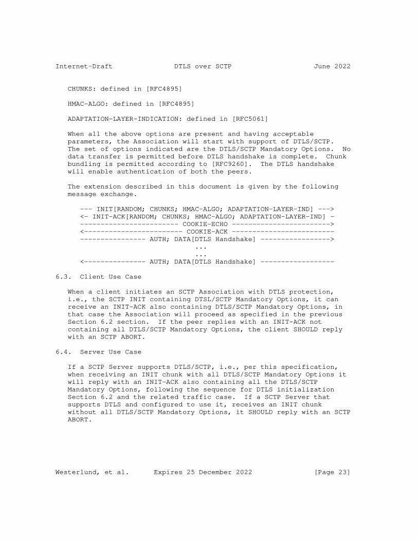
Internet-Draft DTLS over SCTP June 2022
CHUNKS: defined in [RFC4895]
HMAC-ALGO: defined in [RFC4895]
ADAPTATION-LAYER-INDICATION: defined in [RFC5061]
When all the above options are present and having acceptable parameters, the Association will start with support of DTLS/SCTP. The set of options indicated are the DTLS/SCTP Mandatory Options. No data transfer is permitted before DTLS handshake is complete. Chunk bundling is permitted according to [RFC9260]. The DTLS handshake will enable authentication of both the peers.
The extension described in this document is given by the following message exchange.
--- INIT[RANDOM; CHUNKS; HMAC-ALGO; ADAPTATION-LAYER-IND] ---> <- INIT-ACK[RANDOM; CHUNKS; HMAC-ALGO; ADAPTATION-LAYER-IND] - ------------------------ COOKIE-ECHO ------------------------> <------------------------ COOKIE-ACK ------------------------- ---------------- AUTH; DATA[DTLS Handshake] -----------------> ... ... <--------------- AUTH; DATA[DTLS Handshake] ------------------
6.3. Client Use Case
When a client initiates an SCTP Association with DTLS protection, i.e., the SCTP INIT containing DTSL/SCTP Mandatory Options, it can receive an INIT-ACK also containing DTLS/SCTP Mandatory Options, in that case the Association will proceed as specified in the previous Section 6.2 section. If the peer replies with an INIT-ACK not containing all DTLS/SCTP Mandatory Options, the client SHOULD reply with an SCTP ABORT.
6.4. Server Use Case
If a SCTP Server supports DTLS/SCTP, i.e., per this specification, when receiving an INIT chunk with all DTLS/SCTP Mandatory Options it will reply with an INIT-ACK also containing all the DTLS/SCTP Mandatory Options, following the sequence for DTLS initialization Section 6.2 and the related traffic case. If a SCTP Server that supports DTLS and configured to use it, receives an INIT chunk without all DTLS/SCTP Mandatory Options, it SHOULD reply with an SCTP ABORT.
Westerlund, et al. Expires 25 December 2022 [Page 23]

Internet-Draft DTLS over SCTP June 2022
6.5. RFC 6083 Fallback
This section discusses how an endpoint supporting this specification can fallback to follow the DTLS/SCTP behavior in RFC6083. It is recommended to define a setting that represents the policy to allow fallback or not. However, the possibility to use fallback is based on the ULP can operate using user messages that are no longer than 16384 bytes and where the security issues can be mitigated or considered acceptable. Fallback is NOT RECOMMEND to be enabled as it enables downgrade attacks to weaker algorithms and versions of DTLS.
An SCTP endpoint that receives an INIT chunk or an INIT-ACK chunk that does not contain the SCTP-Adaptation-Indication parameter with the DTLS/SCTP adaptation layer codepoint, see Section 8.2, may in certain cases potentially perform a fallback to RFC 6083 behavior. However, the fallback attempt should only be performed if policy says that is acceptable.
If fallback is allowed, it is possible that the client will send plain text user messages prior to DTLS handshake as it is allowed per RFC 6083. So that needs to be part of the consideration for a policy allowing fallback.
6.5.1. Client Fallback
A DTLS/SCTP client supporting this specification encountering an server not compatible with this specification MAY attempt RFC 6083 fallback per this procedure.
1. Fallback procedure, if enabled, is initiated when receiving an SCTP INIT-ACK that does not contain the DTLS/SCTP Adaptation Layer indication. If fallback is not enabled the SCTP handshake is aborted.
2. The client checks that the SCTP INIT-ACK contained the necessary chunks and parameters to establish SCTP-AUTH per RFC 6083 with this endpoint. If not all necessary parameters or support algorithms don’t match the client MUST abort the handshake. Otherwise it completes the SCTP handshake.
3. Client performs DTLS connection handshake per RFC 6083 over established SCTP association. If successful authenticating the targeted server the client has successful fallen back to use RFC 6083. If not terminate the SCTP association.
Westerlund, et al. Expires 25 December 2022 [Page 24]

Internet-Draft DTLS over SCTP June 2022
6.5.2. Server Fallback
A DTLS/SCTP Server that supports both this specification and RFC 6083 and where fallback has been enabled for the ULP can follow this procedure.receiving
1. When receiving an SCTP INIT message without the DTLS/SCTP adaptation layer indication fallback procedure is initiated.
2. Verify that the SCTP INIT contains SCTP-AUTH parameters required by RFC 6083 and compatible with this server. If that is not the case abort the SCTP handshake.
3. Send an SCTP INIT ACK with the required SCTP-AUTH chunks and parameters to the client.
4. Complete the SCTP Handshake. Await DTLS handshake per RFC 6083. Plain text SCTP messages MAY be received.
5. Upon successful completion of DTLS handshake successful fallback to RFC 6083 have been accomplished.
7. SCTP API Consideration
DTLS/SCTP needs certain functionality on the API that the SCTP implementation provide to the ULP to function optimally. A DTLS/SCTP implementation will need to provide its own API to the ULP, while itself using the SCTP API. This discussion is focused on the needed functionality on the SCTP API.
The following functionality is needed:
* Controlling SCPT-AUTH negotiation so that SHA-256 algorithm is inlcluded, and determine that SHA-1 is not selected when the association is established.
* Determine when all SCTP packets that uses an SCTP-auth key or contains DTLS records associated to a particular DTLS connection has been acknowledged non-renegable.
* Determine when all SCTP packets have been acknowledged non- renegable.
* Negotiate the adaptation layer indication that indicates DTLS/SCTP and determine if it was agreed or not.
* Partial user messages transmission and reception.
Westerlund, et al. Expires 25 December 2022 [Page 25]
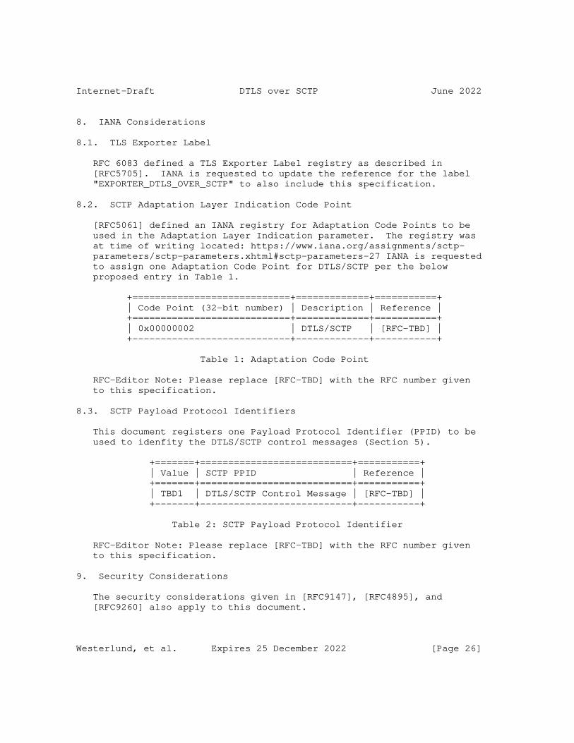
Internet-Draft DTLS over SCTP June 2022
8. IANA Considerations
8.1. TLS Exporter Label
RFC 6083 defined a TLS Exporter Label registry as described in [RFC5705]. IANA is requested to update the reference for the label "EXPORTER_DTLS_OVER_SCTP" to also include this specification.
8.2. SCTP Adaptation Layer Indication Code Point
[RFC5061] defined an IANA registry for Adaptation Code Points to be used in the Adaptation Layer Indication parameter. The registry was at time of writing located: https://www.iana.org/assignments/sctp- parameters/sctp-parameters.xhtml#sctp-parameters-27 IANA is requested to assign one Adaptation Code Point for DTLS/SCTP per the below proposed entry in Table 1.
+============================+=============+===========+ | Code Point (32-bit number) | Description | Reference | +============================+=============+===========+ | 0x00000002 | DTLS/SCTP | [RFC-TBD] | +----------------------------+-------------+-----------+
Table 1: Adaptation Code Point
RFC-Editor Note: Please replace [RFC-TBD] with the RFC number given to this specification.
8.3. SCTP Payload Protocol Identifiers
This document registers one Payload Protocol Identifier (PPID) to be used to idenfity the DTLS/SCTP control messages (Section 5).
+=======+===========================+===========+ | Value | SCTP PPID | Reference | +=======+===========================+===========+ | TBD1 | DTLS/SCTP Control Message | [RFC-TBD] | +-------+---------------------------+-----------+
Table 2: SCTP Payload Protocol Identifier
RFC-Editor Note: Please replace [RFC-TBD] with the RFC number given to this specification.
9. Security Considerations
The security considerations given in [RFC9147], [RFC4895], and [RFC9260] also apply to this document.
Westerlund, et al. Expires 25 December 2022 [Page 26]

Internet-Draft DTLS over SCTP June 2022
9.1. Cryptographic Considerations
Over the years, there have been several serious attacks on earlier versions of Transport Layer Security (TLS), including attacks on its most commonly used ciphers and modes of operation. [RFC7457] summarizes the attacks that were known at the time of publishing and BCP 195 [RFC7525] [RFC8996] provide recommendations for improving the security of deployed services that use TLS.
When DTLS/SCTP is used with DTLS 1.2 [RFC6347], DTLS 1.2 MUST be configured to disable options known to provide insufficient security. HTTP/2 [RFC9113] gives good minimum requirements based on the attacks that where publicly known in 2022. DTLS 1.3 [RFC9147] only define strong algorithms without major weaknesses at the time of publication. Many of the TLS registries have a "Recommended" column. Parameters not marked as "Y" are NOT RECOMMENDED to support. DTLS 1.3 is preferred over DTLS 1.2 being a newer protocol that addresses known vulnerabilities and only defines strong algorithms without known major weaknesses at the time of publication.
DTLS 1.3 requires rekeying before algorithm specific AEAD limits have been reached. The AEAD limits equations are equally valid for DTLS 1.2 and SHOULD be followed for DTLS/SCTP, but are not mandated by the DTLS 1.2 specification.
HMAC-SHA-256 as used in SCTP-AUTH has a very large tag length and very good integrity properties. The SCTP-AUTH key can be used longer than the current algorithms in the TLS record layer. The SCTP-AUTH key is rekeyed when a new DTLS connection is set up at which point a new SCTP-AUTH key is derived using the TLS-Exporter.
(D)TLS 1.3 [RFC8446] discusses forward secrecy from EC(DHE), KeyUpdate, and tickets/resumption. Forward secrecy limits the effect of key leakage in one direction (compromise of a key at time T2 does not compromise some key at time T1 where T1 < T2). Protection in the other direction (compromise at time T1 does not compromise keys at time T2) can be achieved by rerunning EC(DHE). If a long-term authentication key has been compromised, a full handshake with EC(DHE) gives protection against passive attackers. If the resumption_master_secret has been compromised, a resumption handshake with EC(DHE) gives protection against passive attackers and a full handshake with EC(DHE) gives protection against active attackers. If a traffic secret has been compromised, any handshake with EC(DHE) gives protection against active attackers.
The document "Confidentiality in the Face of Pervasive Surveillance: A Threat Model and Problem Statement" [RFC7624] defines key exfiltration as the transmission of cryptographic keying material for
Westerlund, et al. Expires 25 December 2022 [Page 27]

Internet-Draft DTLS over SCTP June 2022
an encrypted communication from a collaborator, deliberately or unwittingly, to an attacker. Using the terms in RFC 7624, forward secrecy without rerunning EC(DHE) still allows an attacker to do static key exfiltration. Rerunning EC(DHE) forces and attacker to dynamic key exfiltration (or content exfiltration).
When using DTLS 1.3 [RFC9147], AEAD limits and forward secrecy can be achieved by sending post-handshake KeyUpdate messages, which triggers rekeying of DTLS. Such symmetric rekeying gives significantly less protection against key leakage than re-running Diffie-Hellman as explained above. After leakage of application_traffic_secret_N, an attacker can passively eavesdrop on all future data sent on the connection including data encrypted with application_traffic_secret_N+1, application_traffic_secret_N+2, etc. Note that KeyUpdate does not update the exporter_secret.
DTLS/SCTP is in many deployments replacing IPsec. For IPsec, NIST (US), BSI (Germany), and ANSSI (France) recommends very frequent re- run of Diffie-Hellman to provide forward secrecy and force attackers to dynamic key extraction [RFC7624]. ANSSI writes "It is recommended to force the periodic renewal of the keys, e.g., every hour and every 100 GB of data, in order to limit the impact of a key compromise." [ANSSI-DAT-NT-003].
For many DTLS/SCTP deployments the SCTP association is expected to have a very long lifetime of months or even years. For associations with such long lifetimes there is a need to frequently re- authenticate both client and server. TLS Certificate lifetimes significantly shorter than a year are common which is shorter than many expected DTLS/SCTP associations.
SCTP-AUTH re-rekeying, periodic authentication of both endpoints, and frequent re-run of Diffie-Hellman to force attackers to dynamic key extraction is in DTLS/SCTP per this specification achieved by setting up new DTLS connections over the same SCTP association. Implementations SHOULD set up new connections frequently to force attackers to dynamic key extraction. Implementations MUST set up new connections before any of the certificates expire. It is RECOMMENDED that all negotiated and exchanged parameters are the same except for the timestamps in the certificates. Clients and servers MUST NOT accept a change of identity during the setup of a new connections, but MAY accept negotiation of stronger algorithms and security parameters, which might be motivated by new attacks.
Allowing new connections can enable denial-of-service attacks. The endpoints SHOULD limit the frequency of new connections.
Westerlund, et al. Expires 25 December 2022 [Page 28]
Internet-Draft DTLS over SCTP June 2022
When DTLS/SCTP is used with DTLS 1.2 [RFC6347], the TLS Session Hash and Extended Master Secret Extension [RFC7627] MUST be used to prevent unknown key-share attacks where an attacker establishes the same key on several connections. DTLS 1.3 always prevents these kinds of attacks. The use of SCTP-AUTH then cryptographically binds new connections to the old connection. This together with mandatory mutual authentication (on the DTLS layer) and a requirement to not accept new identities mitigates MITM attacks that have plagued renegotiation [TRISHAKE].
9.2. Downgrade Attacks
A peer supporting DTLS/SCTP according to this specification, DTLS/ SCTP according to [RFC6083] and/or SCTP without DTLS may be vulnerable to downgrade attacks where on on-path attacker interferes with the protocol setup to lower or disable security. If possible, it is RECOMMENDED that the peers have a policy only allowing DTLS/ SCTP according to this specification.
9.3. Targeting DTLS Messages
The DTLS handshake messages and other control messages, i.e., not application data can easily be identified when using DTLS 1.2 as their content type is not encrypted. With DTLS 1.3 there is no unprotected content type. However, they will be sent with an PPID of 0 if sent in their own SCTP user messages. Section 4.4 proposes a basic behavior that will still make it easily for anyone to detect the DTLS messages that are not protected user messages.
9.4. Authentication and Policy Decisions
DTLS/SCTP MUST be mutually authenticated. Authentication is the process of establishing the identity of a user or system and verifying that the identity is valid. DTLS only provides proof of possession of a key. DTLS/SCTP MUST perform identity authentication. It is RECOMMENDED that DTLS/SCTP is used with certificate-based authentication. When certificates are used the application using DTLS/SCTP is responsible for certificate policies, certificate chain validation, and identity authentication (HTTPS does for example match the hostname with a subjectAltName of type dNSName). The application using DTLS/SCTP MUST define what the identity is and how it is encoded and the client and server MUST use the same identity format. Guidance on server certificate validation can be found in [RFC6125]. DTLS/SCTP enables periodic transfer of mutual revocation information (OSCP stapling) every time a new parallel connection is set up. All security decisions MUST be based on the peer’s authenticated identity, not on its transport layer identity.
Westerlund, et al. Expires 25 December 2022 [Page 29]

Internet-Draft DTLS over SCTP June 2022
It is possible to authenticate DTLS endpoints based on IP addresses in certificates. SCTP associations can use multiple IP addresses per SCTP endpoint. Therefore, it is possible that DTLS records will be sent from a different source IP address or to a different destination IP address than that originally authenticated. This is not a problem provided that no security decisions are made based on the source or destination IP addresses.
9.5. Resumption and Tickets
In DTLS 1.3 any number of tickets can be issued in a connection and the tickets can be used for resumption as long as they are valid, which is up to seven days. The nodes in a resumed connection have the same roles (client or server) as in the connection where the ticket was issued. In DTLS/SCTP, there are no significant performance benefits with resumption and an implementation can chose to never issue any tickets. If tickets and resumption are used it is enough to issue a single ticket per connection.
9.6. Privacy Considerations
[RFC6973] suggests that the privacy considerations of IETF protocols be documented.
For each SCTP user message, the user also provides a stream identifier, a flag to indicate whether the message is sent ordered or unordered, and a payload protocol identifier. Although DTLS/SCTP provides privacy for the actual user message, the other three information fields are not confidentiality protected. They are sent as cleartext because they are part of the SCTP DATA chunk header.
It is RECOMMENDED that DTLS/SCTP is used with certificate based authentication in DTLS 1.3 [RFC9147] to provide identity protection. DTLS/SCTP MUST be used with a key exchange method providing forward secrecy.
9.7. Pervasive Monitoring
As required by [RFC7258], work on IETF protocols needs to consider the effects of pervasive monitoring and mitigate them when possible.
Pervasive Monitoring is widespread surveillance of users. By encrypting more information including user identities, DTLS 1.3 offers much better protection against pervasive monitoring.
Westerlund, et al. Expires 25 December 2022 [Page 30]

Internet-Draft DTLS over SCTP June 2022
Massive pervasive monitoring attacks relying on key exchange without forward secrecy has been reported. By mandating forward secrecy, DTLS/SCTP effectively mitigate many forms of passive pervasive monitoring and limits the amount of compromised data due to key compromise.
An important mitigation of pervasive monitoring is to force attackers to do dynamic key exfiltration instead of static key exfiltration. Dynamic key exfiltration increases the risk of discovery for the attacker [RFC7624]. DTLS/SCTP per this specification encourages implementations to frequently set up new DTLS connections with (EC)DHE over the same SCTP association to force attackers to do dynamic key exfiltration.
In addition to the privacy attacks discussed above, surveillance on a large scale may enable tracking of a user over a wider geographical area and across different access networks. Using information from DTLS/SCTP together with information gathered from other protocols increase the risk of identifying individual users.
10. Contributors
Michael Tuexen contributed as co-author to the intitial versions this draft. Michael’s contributions include:
* The use of the Adaptation Layer Indication.
* Many editorial improvements.
11. Acknowledgments
The authors of RFC 6083 which this document is based on are Michael Tuexen, Eric Rescorla, and Robin Seggelmann.
The RFC 6083 authors thanked Anna Brunstrom, Lars Eggert, Gorry Fairhurst, Ian Goldberg, Alfred Hoenes, Carsten Hohendorf, Stefan Lindskog, Daniel Mentz, and Sean Turner for their invaluable comments.
The authors of this document want to thank Daria Ivanova, Li Yan, and GitHub user vanrein for their contribution.
12. References
12.1. Normative References
Westerlund, et al. Expires 25 December 2022 [Page 31]
Internet-Draft DTLS over SCTP June 2022
[RFC2119] Bradner, S., "Key words for use in RFCs to Indicate Requirement Levels", BCP 14, RFC 2119, DOI 10.17487/RFC2119, March 1997, <https://www.rfc-editor.org/info/rfc2119>.
[RFC3758] Stewart, R., Ramalho, M., Xie, Q., Tuexen, M., and P. Conrad, "Stream Control Transmission Protocol (SCTP) Partial Reliability Extension", RFC 3758, DOI 10.17487/RFC3758, May 2004, <https://www.rfc-editor.org/info/rfc3758>.
[RFC4895] Tuexen, M., Stewart, R., Lei, P., and E. Rescorla, "Authenticated Chunks for the Stream Control Transmission Protocol (SCTP)", RFC 4895, DOI 10.17487/RFC4895, August 2007, <https://www.rfc-editor.org/info/rfc4895>.
[RFC5061] Stewart, R., Xie, Q., Tuexen, M., Maruyama, S., and M. Kozuka, "Stream Control Transmission Protocol (SCTP) Dynamic Address Reconfiguration", RFC 5061, DOI 10.17487/RFC5061, September 2007, <https://www.rfc-editor.org/info/rfc5061>.
[RFC5705] Rescorla, E., "Keying Material Exporters for Transport Layer Security (TLS)", RFC 5705, DOI 10.17487/RFC5705, March 2010, <https://www.rfc-editor.org/info/rfc5705>.
[RFC6347] Rescorla, E. and N. Modadugu, "Datagram Transport Layer Security Version 1.2", RFC 6347, DOI 10.17487/RFC6347, January 2012, <https://www.rfc-editor.org/info/rfc6347>.
[RFC7627] Bhargavan, K., Ed., Delignat-Lavaud, A., Pironti, A., Langley, A., and M. Ray, "Transport Layer Security (TLS) Session Hash and Extended Master Secret Extension", RFC 7627, DOI 10.17487/RFC7627, September 2015, <https://www.rfc-editor.org/info/rfc7627>.
[RFC8174] Leiba, B., "Ambiguity of Uppercase vs Lowercase in RFC 2119 Key Words", BCP 14, RFC 8174, DOI 10.17487/RFC8174, May 2017, <https://www.rfc-editor.org/info/rfc8174>.
[RFC8260] Stewart, R., Tuexen, M., Loreto, S., and R. Seggelmann, "Stream Schedulers and User Message Interleaving for the Stream Control Transmission Protocol", RFC 8260, DOI 10.17487/RFC8260, November 2017, <https://www.rfc-editor.org/info/rfc8260>.
Westerlund, et al. Expires 25 December 2022 [Page 32]
Internet-Draft DTLS over SCTP June 2022
[RFC8446] Rescorla, E., "The Transport Layer Security (TLS) Protocol Version 1.3", RFC 8446, DOI 10.17487/RFC8446, August 2018, <https://www.rfc-editor.org/info/rfc8446>.
[RFC8996] Moriarty, K. and S. Farrell, "Deprecating TLS 1.0 and TLS 1.1", BCP 195, RFC 8996, DOI 10.17487/RFC8996, March 2021, <https://www.rfc-editor.org/info/rfc8996>.
[RFC9113] Thomson, M., Ed. and C. Benfield, Ed., "HTTP/2", RFC 9113, DOI 10.17487/RFC9113, June 2022, <https://www.rfc-editor.org/info/rfc9113>.
[RFC9146] Rescorla, E., Ed., Tschofenig, H., Ed., Fossati, T., and A. Kraus, "Connection Identifier for DTLS 1.2", RFC 9146, DOI 10.17487/RFC9146, March 2022, <https://www.rfc-editor.org/info/rfc9146>.
[RFC9147] Rescorla, E., Tschofenig, H., and N. Modadugu, "The Datagram Transport Layer Security (DTLS) Protocol Version 1.3", RFC 9147, DOI 10.17487/RFC9147, April 2022, <https://www.rfc-editor.org/info/rfc9147>.
[RFC9260] Stewart, R., Tüxen, M., and K. Nielsen, "Stream Control Transmission Protocol", RFC 9260, DOI 10.17487/RFC9260, June 2022, <https://www.rfc-editor.org/info/rfc9260>.
12.2. Informative References
[RFC3436] Jungmaier, A., Rescorla, E., and M. Tuexen, "Transport Layer Security over Stream Control Transmission Protocol", RFC 3436, DOI 10.17487/RFC3436, December 2002, <https://www.rfc-editor.org/info/rfc3436>.
[RFC3788] Loughney, J., Tuexen, M., Ed., and J. Pastor-Balbas, "Security Considerations for Signaling Transport (SIGTRAN) Protocols", RFC 3788, DOI 10.17487/RFC3788, June 2004, <https://www.rfc-editor.org/info/rfc3788>.
[RFC6083] Tuexen, M., Seggelmann, R., and E. Rescorla, "Datagram Transport Layer Security (DTLS) for Stream Control Transmission Protocol (SCTP)", RFC 6083, DOI 10.17487/RFC6083, January 2011, <https://www.rfc-editor.org/info/rfc6083>.
Westerlund, et al. Expires 25 December 2022 [Page 33]
Internet-Draft DTLS over SCTP June 2022
[RFC6125] Saint-Andre, P. and J. Hodges, "Representation and Verification of Domain-Based Application Service Identity within Internet Public Key Infrastructure Using X.509 (PKIX) Certificates in the Context of Transport Layer Security (TLS)", RFC 6125, DOI 10.17487/RFC6125, March 2011, <https://www.rfc-editor.org/info/rfc6125>.
[RFC6458] Stewart, R., Tuexen, M., Poon, K., Lei, P., and V. Yasevich, "Sockets API Extensions for the Stream Control Transmission Protocol (SCTP)", RFC 6458, DOI 10.17487/RFC6458, December 2011, <https://www.rfc-editor.org/info/rfc6458>.
[RFC6973] Cooper, A., Tschofenig, H., Aboba, B., Peterson, J., Morris, J., Hansen, M., and R. Smith, "Privacy Considerations for Internet Protocols", RFC 6973, DOI 10.17487/RFC6973, July 2013, <https://www.rfc-editor.org/info/rfc6973>.
[RFC7258] Farrell, S. and H. Tschofenig, "Pervasive Monitoring Is an Attack", BCP 188, RFC 7258, DOI 10.17487/RFC7258, May 2014, <https://www.rfc-editor.org/info/rfc7258>.
[RFC7457] Sheffer, Y., Holz, R., and P. Saint-Andre, "Summarizing Known Attacks on Transport Layer Security (TLS) and Datagram TLS (DTLS)", RFC 7457, DOI 10.17487/RFC7457, February 2015, <https://www.rfc-editor.org/info/rfc7457>.
[RFC7525] Sheffer, Y., Holz, R., and P. Saint-Andre, "Recommendations for Secure Use of Transport Layer Security (TLS) and Datagram Transport Layer Security (DTLS)", BCP 195, RFC 7525, DOI 10.17487/RFC7525, May 2015, <https://www.rfc-editor.org/info/rfc7525>.
[RFC7624] Barnes, R., Schneier, B., Jennings, C., Hardie, T., Trammell, B., Huitema, C., and D. Borkmann, "Confidentiality in the Face of Pervasive Surveillance: A Threat Model and Problem Statement", RFC 7624, DOI 10.17487/RFC7624, August 2015, <https://www.rfc-editor.org/info/rfc7624>.
[ANSSI-DAT-NT-003] Agence nationale de la sécurité des systèmes d’information, "Recommendations for securing networks with IPsec", ANSSI Technical Report DAT-NT-003 , August 2015, <<https://www.ssi.gouv.fr/uploads/2015/09/ NT_IPsec_EN.pdf>>.
Westerlund, et al. Expires 25 December 2022 [Page 34]
Internet-Draft DTLS over SCTP June 2022
[TRISHAKE] Bhargavan, K., Delignat-Lavaud, A., Fournet, C., Pironti, A., and P. Strub, "Triple Handshakes and Cookie Cutters: Breaking and Fixing Authentication over TLS", IEEE Symposium on Security & Privacy , April 2016, <https://hal.inria.fr/hal-01102259/file/triple-handshakes- and-cookie-cutters-oakland14.pdf>.
Appendix A. Motivation for Changes
This document proposes a number of changes to RFC 6083 that have various different motivations:
Supporting Large User Messages: RFC 6083 allowed only user messages that could fit within a single DTLS record. 3GPP has run into this limitation where they have at least four SCTP using protocols (F1, E1, Xn, NG-C) that can potentially generate messages over the size of 16384 bytes.
New Versions: Almost 10 years has passed since RFC 6083 was written, and significant evolution has happened in the area of DTLS and security algorithms. Thus, DTLS 1.3 is the newest version of DTLS and also the SHA-1 HMAC algorithm of RFC 4895 is getting towards the end of usefulness. Use of DTLS 1.3 with long lived associations require parallel DTLS connections. Thus, this document mandates usage of relevant versions and algorithms.
Allowing DTLS Messages on any stream: RFC6083 requires DTLS messages that are not user message data to be sent on stream 0 and that this stream is used with in-order delivery. That can actually limit the applications that can use DTLS/SCTP. In addition with DTLS 1.3 encrypting the actual message type it is anyway not available. Therefore a more flexible rule set is used that relies on DTLS handling reordering.
Clarifications: Some implementation experiences have been gained that motivates additional clarifications on the specification.
* Avoid unsecured messages prior to DTLS handshake have completed.
* Make clear that all messages are encrypted after DTLS handshake.
Authors’ Addresses
Magnus Westerlund Ericsson Email: [email protected]
Westerlund, et al. Expires 25 December 2022 [Page 35]
Internet-Draft DTLS over SCTP June 2022
John Preuß Mattsson Ericsson Email: [email protected]
Claudio Porfiri Ericsson Email: [email protected]
Westerlund, et al. Expires 25 December 2022 [Page 36]

Transport Area Working Group B. BriscoeInternet-Draft IndependentUpdates: 3819 (if approved) J. KaippallimalilIntended status: Best Current Practice FutureweiExpires: 12 January 2023 11 July 2022
Guidelines for Adding Congestion Notification to Protocols that Encapsulate IP draft-ietf-tsvwg-ecn-encap-guidelines-17
Abstract
The purpose of this document is to guide the design of congestion notification in any lower layer or tunnelling protocol that encapsulates IP. The aim is for explicit congestion signals to propagate consistently from lower layer protocols into IP. Then the IP internetwork layer can act as a portability layer to carry congestion notification from non-IP-aware congested nodes up to the transport layer (L4). Following these guidelines should assure interworking among IP layer and lower layer congestion notification mechanisms, whether specified by the IETF or other standards bodies. This document updates the advice to subnetwork designers about ECN in RFC 3819.
Status of This Memo
This Internet-Draft is submitted in full conformance with the provisions of BCP 78 and BCP 79.
Internet-Drafts are working documents of the Internet Engineering Task Force (IETF). Note that other groups may also distribute working documents as Internet-Drafts. The list of current Internet- Drafts is at https://datatracker.ietf.org/drafts/current/.
Internet-Drafts are draft documents valid for a maximum of six months and may be updated, replaced, or obsoleted by other documents at any time. It is inappropriate to use Internet-Drafts as reference material or to cite them other than as "work in progress."
This Internet-Draft will expire on 12 January 2023.
Copyright Notice
Copyright (c) 2022 IETF Trust and the persons identified as the document authors. All rights reserved.
Briscoe & Kaippallimalil Expires 12 January 2023 [Page 1]
Internet-Draft ECN Encapsulation Guidelines July 2022
This document is subject to BCP 78 and the IETF Trust’s Legal Provisions Relating to IETF Documents (https://trustee.ietf.org/ license-info) in effect on the date of publication of this document. Please review these documents carefully, as they describe your rights and restrictions with respect to this document. Code Components extracted from this document must include Revised BSD License text as described in Section 4.e of the Trust Legal Provisions and are provided without warranty as described in the Revised BSD License.
Table of Contents
1. Introduction . . . . . . . . . . . . . . . . . . . . . . . . 3 1.1. Update to RFC 3819 . . . . . . . . . . . . . . . . . . . 5 1.2. Scope . . . . . . . . . . . . . . . . . . . . . . . . . . 5 2. Terminology . . . . . . . . . . . . . . . . . . . . . . . . . 7 3. Modes of Operation . . . . . . . . . . . . . . . . . . . . . 9 3.1. Feed-Forward-and-Up Mode . . . . . . . . . . . . . . . . 9 3.2. Feed-Up-and-Forward Mode . . . . . . . . . . . . . . . . 11 3.3. Feed-Backward Mode . . . . . . . . . . . . . . . . . . . 12 3.4. Null Mode . . . . . . . . . . . . . . . . . . . . . . . . 14 4. Feed-Forward-and-Up Mode: Guidelines for Adding Congestion Notification . . . . . . . . . . . . . . . . . . . . . . 14 4.1. IP-in-IP Tunnels with Shim Headers . . . . . . . . . . . 15 4.2. Wire Protocol Design: Indication of ECN Support . . . . . 16 4.3. Encapsulation Guidelines . . . . . . . . . . . . . . . . 19 4.4. Decapsulation Guidelines . . . . . . . . . . . . . . . . 20 4.5. Sequences of Similar Tunnels or Subnets . . . . . . . . . 22 4.6. Reframing and Congestion Markings . . . . . . . . . . . . 22 5. Feed-Up-and-Forward Mode: Guidelines for Adding Congestion Notification . . . . . . . . . . . . . . . . . . . . . . 24 6. Feed-Backward Mode: Guidelines for Adding Congestion Notification . . . . . . . . . . . . . . . . . . . . . . 25 7. IANA Considerations . . . . . . . . . . . . . . . . . . . . . 26 8. Security Considerations . . . . . . . . . . . . . . . . . . . 26 9. Conclusions . . . . . . . . . . . . . . . . . . . . . . . . . 27 10. Acknowledgements . . . . . . . . . . . . . . . . . . . . . . 28 11. Contributors . . . . . . . . . . . . . . . . . . . . . . . . 28 12. Comments Solicited . . . . . . . . . . . . . . . . . . . . . 28 13. References . . . . . . . . . . . . . . . . . . . . . . . . . 28 13.1. Normative References . . . . . . . . . . . . . . . . . . 28 13.2. Informative References . . . . . . . . . . . . . . . . . 29 Appendix A. Changes in This Version (to be removed by RFC Editor) . . . . . . . . . . . . . . . . . . . . . . . . . 34 Authors’ Addresses . . . . . . . . . . . . . . . . . . . . . . . 38
Briscoe & Kaippallimalil Expires 12 January 2023 [Page 2]

Internet-Draft ECN Encapsulation Guidelines July 2022
1. Introduction
The benefits of Explicit Congestion Notification (ECN) described in [RFC8087] and summarized below can only be fully realized if support for ECN is added to the relevant subnetwork technology, as well as to IP. When a lower layer buffer drops a packet obviously it does not just drop at that layer; the packet disappears from all layers. In contrast, when active queue management (AQM) at a lower layer marks a packet with ECN, the marking needs to be explicitly propagated up the layers. The same is true if AQM marks the outer header of a packet that encapsulates inner tunnelled headers. Forwarding ECN is not as straightforward as other headers because it has to be assumed ECN may be only partially deployed. If a lower layer header that contains ECN congestion indications is stripped off by a subnet egress that is not ECN-aware, or if the ultimate receiver or sender is not ECN- aware, congestion needs to be indicated by dropping a packet, not marking it.
The purpose of this document is to guide the addition of congestion notification to any subnet technology or tunnelling protocol, so that lower layer AQM algorithms can signal congestion explicitly and it will propagate consistently into encapsulated (higher layer) headers, otherwise the signals will not reach their ultimate destination.
ECN is defined in the IP header (v4 and v6) [RFC3168] to allow a resource to notify the onset of queue build-up without having to drop packets, by explicitly marking a proportion of packets with the congestion experienced (CE) codepoint.
Given a suitable marking scheme, ECN removes nearly all congestion loss and it cuts delays for two main reasons:
* It avoids the delay when recovering from congestion losses, which particularly benefits small flows or real-time flows, making their delivery time predictably short [RFC2884];
* As ECN is used more widely by end-systems, it will gradually remove the need to configure a degree of delay into buffers before they start to notify congestion (the cause of bufferbloat). This is because drop involves a trade-off between sending a timely signal and trying to avoid impairment, whereas ECN is solely a signal not an impairment, so there is no harm triggering it earlier.
Some lower layer technologies (e.g. MPLS, Ethernet) are used to form subnetworks with IP-aware nodes only at the edges. These networks are often sized so that it is rare for interior queues to overflow. However, until recently this was more due to the inability of TCP to
Briscoe & Kaippallimalil Expires 12 January 2023 [Page 3]

Internet-Draft ECN Encapsulation Guidelines July 2022
saturate the links. For many years, fixes such as window scaling [RFC7323] proved hard to deploy. And the Reno variant of TCP has remained in widespread use despite its inability to scale to high flow rates. However, now that modern operating systems are finally capable of saturating interior links, even the buffers of well- provisioned interior switches will need to signal episodes of queuing.
Propagation of ECN is defined for MPLS [RFC5129], and is being defined for TRILL [RFC7780], [I-D.ietf-trill-ecn-support], but it remains to be defined for a number of other subnetwork technologies.
Similarly, ECN propagation is yet to be defined for many tunnelling protocols. [RFC6040] defines how ECN should be propagated for IP-in- IPv4 [RFC2003], IP-in-IPv6 [RFC2473] and IPsec [RFC4301] tunnels, but there are numerous other tunnelling protocols with a shim and/or a layer 2 header between two IP headers (v4 or v6). Some address ECN propagation between the IP headers, but many do not. This document gives guidance on how to address ECN propagation for future tunnelling protocols, and a companion standards track specification [I-D.ietf-tsvwg-rfc6040update-shim] updates those existing IP-shim- (L2)-IP protocols that are under IETF change control and still widely used.
Incremental deployment is the most delicate aspect when adding support for ECN. The original ECN protocol in IP [RFC3168] was carefully designed so that a congested buffer would not mark a packet (rather than drop it) unless both source and destination hosts were ECN-capable. Otherwise its congestion markings would never be detected and congestion would just build up further. However, to support congestion marking below the IP layer or within tunnels, it is not sufficient to only check that the two layer 4 transport end- points support ECN; correct operation also depends on the decapsulator at each subnet or tunnel egress faithfully propagating congestion notifications to the higher layer. Otherwise, a legacy decapsulator might silently fail to propagate any ECN signals from the outer to the forwarded header. Then the lost signals would never be detected and again congestion would build up further. The guidelines given later require protocol designers to carefully consider incremental deployment, and suggest various safe approaches for different circumstances.
Of course, the IETF does not have standards authority over every link layer protocol. So this document gives guidelines for designing propagation of congestion notification across the interface between IP and protocols that may encapsulate IP (i.e. that can be layered beneath IP). Each lower layer technology will exhibit different issues and compromises, so the IETF or the relevant standards body
Briscoe & Kaippallimalil Expires 12 January 2023 [Page 4]

Internet-Draft ECN Encapsulation Guidelines July 2022
must be free to define the specifics of each lower layer congestion notification scheme. Nonetheless, if the guidelines are followed, congestion notification should interwork between different technologies, using IP in its role as a ’portability layer’.
Therefore, the capitalized terms ’SHOULD’ or ’SHOULD NOT’ are often used in preference to ’MUST’ or ’MUST NOT’, because it is difficult to know the compromises that will be necessary in each protocol design. If a particular protocol design chooses not to follow a ’SHOULD (NOT)’ given in the advice below, it MUST include a sound justification.
It has not been possible to give common guidelines for all lower layer technologies, because they do not all fit a common pattern. Instead they have been divided into a few distinct modes of operation: feed-forward-and-upward; feed-upward-and-forward; feed- backward; and null mode. These modes are described in Section 3, then in the subsequent sections separate guidelines are given for each mode.
1.1. Update to RFC 3819
This document updates the brief advice to subnetwork designers about ECN in [RFC3819], by replacing the last two paragraphs of Section 13 with the following sentence:
By following the guidelines in [this document], subnetwork designers can enable a layer-2 protocol to participate in congestion control without dropping packets via propagation of explicit congestion notification (ECN [RFC3168]) to receivers.
and adding [this document] as an informative reference. {RFC Editor: Please replace both instances of [this document] above with the number of the present RFC when published.}
1.2. Scope
This document only concerns wire protocol processing of explicit notification of congestion. It makes no changes or recommendations concerning algorithms for congestion marking or for congestion response, because algorithm issues should be independent of the layer the algorithm operates in.
The default ECN semantics are described in [RFC3168] and updated by [RFC8311]. Also the guidelines for AQM designers [RFC7567] clarify the semantics of both drop and ECN signals from AQM algorithms. [RFC4774] is the appropriate best current practice specification of how algorithms with alternative semantics for the ECN field can be
Briscoe & Kaippallimalil Expires 12 January 2023 [Page 5]

Internet-Draft ECN Encapsulation Guidelines July 2022
partitioned from Internet traffic that uses the default ECN semantics. There are two main examples for how alternative ECN semantics have been defined in practice:
* RFC 4774 suggests using the ECN field in combination with a Diffserv codepoint such as in PCN [RFC6660], Voice over 3G [UTRAN] or Voice over LTE (VoLTE) [LTE-RA];
* RFC 8311 suggests using the ECT(1) codepoint of the ECN field to indicate alternative semantics such as for the experimental Low Latency Low Loss Scalable throughput (L4S) service [I-D.ietf-tsvwg-ecn-l4s-id]).
The aim is that the default rules for encapsulating and decapsulating the ECN field are sufficiently generic that tunnels and subnets will encapsulate and decapsulate packets without regard to how algorithms elsewhere are setting or interpreting the semantics of the ECN field. [RFC6040] updates RFC 4774 to allow alternative encapsulation and decapsulation behaviours to be defined for alternative ECN semantics. However it reinforces the same point - that it is far preferable to try to fit within the common ECN encapsulation and decapsulation behaviours, because expecting all lower layer technologies and tunnels to be updated is likely to be completely impractical.
Alternative semantics for the ECN field can be defined to depend on the traffic class indicated by the DSCP. Therefore correct propagation of congestion signals could depend on correct propagation of the DSCP between the layers and along the path. For instance, if the meaning of the ECN field depends on the DSCP (as in PCN or VoLTE) and if the outer DSCP is stripped on descapsulation, as in the pipe model of [RFC2983], the special semantics of the ECN field would be lost. Similarly, if the DSCP is changed at the boundary between Diffserv domains, the special ECN semantics would also be lost. This is an important implication of the localized scope of most Diffserv arrangements. In this document, correct propagation of traffic class information is assumed, while what ’correct’ means and how it is achieved is covered elsewhere (e.g. RFC 2983) and is outside the scope of the present document.
The guidelines in this document do ensure that common encapsulation and decapsulation rules are sufficiently generic to cover cases where ECT(1) is used instead of ECT(0) to identify alternative ECN semantics (as in L4S [I-D.ietf-tsvwg-ecn-l4s-id]) and where ECN marking algorithms use ECT(1) to encode 3 severity levels into the ECN field (e.g. PCN [RFC6660]) rather than the default of 2. All these different semantics for the ECN field work because it has been possible to define common default decapsulation rules that allow for all cases.
Briscoe & Kaippallimalil Expires 12 January 2023 [Page 6]
Internet-Draft ECN Encapsulation Guidelines July 2022
Note that the guidelines in this document do not necessarily require the subnet wire protocol to be changed to add support for congestion notification. For instance, the Feed-Up-and-Forward Mode (Section 3.2) and the Null Mode (Section 3.4) do not. Another way to add congestion notification without consuming header space in the subnet protocol might be to use a parallel control plane protocol.
This document focuses on the congestion notification interface between IP and lower layer or tunnel protocols that can encapsulate IP, where the term ’IP’ includes v4 or v6, unicast, multicast or anycast. However, it is likely that the guidelines will also be useful when a lower layer protocol or tunnel encapsulates itself, e.g. Ethernet MAC in MAC ([IEEE802.1Q]; previously 802.1ah) or when it encapsulates other protocols. In the feed-backward mode, propagation of congestion signals for multicast and anycast packets is out-of-scope (because the complexity would make it unlikely to be attempted).
2. Terminology
The key words "MUST", "MUST NOT", "REQUIRED", "SHALL", "SHALL NOT", "SHOULD", "SHOULD NOT", "RECOMMENDED", "MAY", and "OPTIONAL" in this document are to be interpreted as described in [RFC2119] [RFC8174] when, and only when, they appear in all capitals, as shown here.
Further terminology used within this document:
Protocol data unit (PDU): Information that is delivered as a unit among peer entities of a layered network consisting of protocol control information (typically a header) and possibly user data (payload) of that layer. The scope of this document includes layer 2 and layer 3 networks, where the PDU is respectively termed a frame or a packet (or a cell in ATM). PDU is a general term for any of these. This definition also includes a payload with a shim header lying somewhere between layer 2 and 3.
Transport: The end-to-end transmission control function, conventionally considered at layer-4 in the OSI reference model. Given the audience for this document will often use the word transport to mean low level bit carriage, whenever the term is used it will be qualified, e.g. ’L4 transport’.
Encapsulator: The link or tunnel endpoint function that adds an outer header to a PDU (also termed the ’link ingress’, the ’subnet ingress’, the ’ingress tunnel endpoint’ or just the ’ingress’ where the context is clear).
Decapsulator: The link or tunnel endpoint function that removes an
Briscoe & Kaippallimalil Expires 12 January 2023 [Page 7]

Internet-Draft ECN Encapsulation Guidelines July 2022
outer header from a PDU (also termed the ’link egress’, the ’subnet egress’, the ’egress tunnel endpoint’ or just the ’egress’ where the context is clear).
Incoming header: The header of an arriving PDU before encapsulation.
Outer header: The header added to encapsulate a PDU.
Inner header: The header encapsulated by the outer header.
Outgoing header: The header forwarded by the decapsulator.
CE: Congestion Experienced [RFC3168]
ECT: ECN-Capable (L4) Transport [RFC3168]
Not-ECT: Not ECN-Capable (L4) Transport [RFC3168]
Load Regulator: For each flow of PDUs, the transport function that is capable of controlling the data rate. Typically located at the data source, but in-path nodes can regulate load in some congestion control arrangements (e.g. admission control, policing nodes or transport circuit-breakers [RFC8084]). Note the term "a function capable of controlling the load" deliberately includes a transport that does not actually control the load responsively but ideally it ought to (e.g. a sending application without congestion control that uses UDP).
ECN-PDU: A PDU at the IP layer or below with a capacity to signal congestion that is part of a congestion control feedback loop within which all the nodes necessary to propagate the signal back to the Load Regulator are capable of doing that propagation. An IP packet with a non-zero ECN field implies that the endpoints are ECN-capable, so this would be an ECN-PDU. However, ECN-PDU is intended to be a general term for a PDU at lower layers, as well as at the IP layer.
Not-ECN-PDU: A PDU at the IP layer or below that is part of a congestion control feedback-loop within which at least one node necessary to propagate any explicit congestion notification signals back to the Load Regulator is not capable of doing that propagation.
Briscoe & Kaippallimalil Expires 12 January 2023 [Page 8]

Internet-Draft ECN Encapsulation Guidelines July 2022
3. Modes of Operation
This section sets down the different modes by which congestion information is passed between the lower layer and the higher one. It acts as a reference framework for the following sections, which give normative guidelines for designers of explicit congestion notification protocols, taking each mode in turn:
Feed-Forward-and-Up: Nodes feed forward congestion notification towards the egress within the lower layer then up and along the layers towards the end-to-end destination at the transport layer. The following local optimisation is possible:
Feed-Up-and-Forward: A lower layer switch feeds-up congestion notification directly into the higher layer (e.g. into the ECN field in the IP header), irrespective of whether the node is at the egress of a subnet.
Feed-Backward: Nodes feed back congestion signals towards the ingress of the lower layer and (optionally) attempt to control congestion within their own layer.
Null: Nodes cannot experience congestion at the lower layer except at ingress nodes (which are IP-aware or equivalently higher-layer- aware).
3.1. Feed-Forward-and-Up Mode
Like IP and MPLS, many subnet technologies are based on self- contained protocol data units (PDUs) or frames sent unreliably. They provide no feedback channel at the subnetwork layer, instead relying on higher layers (e.g. TCP) to feed back loss signals.
In these cases, ECN may best be supported by standardising explicit notification of congestion into the lower layer protocol that carries the data forwards. Then a specification is needed for how the egress of the lower layer subnet propagates this explicit signal into the forwarded upper layer (IP) header. This signal continues forwards until it finally reaches the destination transport (at L4). Then typically the destination will feed this congestion notification back to the source transport using an end-to-end protocol (e.g. TCP). This is the arrangement that has already been used to add ECN to IP- in-IP tunnels [RFC6040], IP-in-MPLS and MPLS-in-MPLS [RFC5129].
This mode is illustrated in Figure 1. Along the middle of the figure, layers 2, 3 and 4 of the protocol stack are shown, and one packet is shown along the bottom as it progresses across the network from source to destination, crossing two subnets connected by a
Briscoe & Kaippallimalil Expires 12 January 2023 [Page 9]
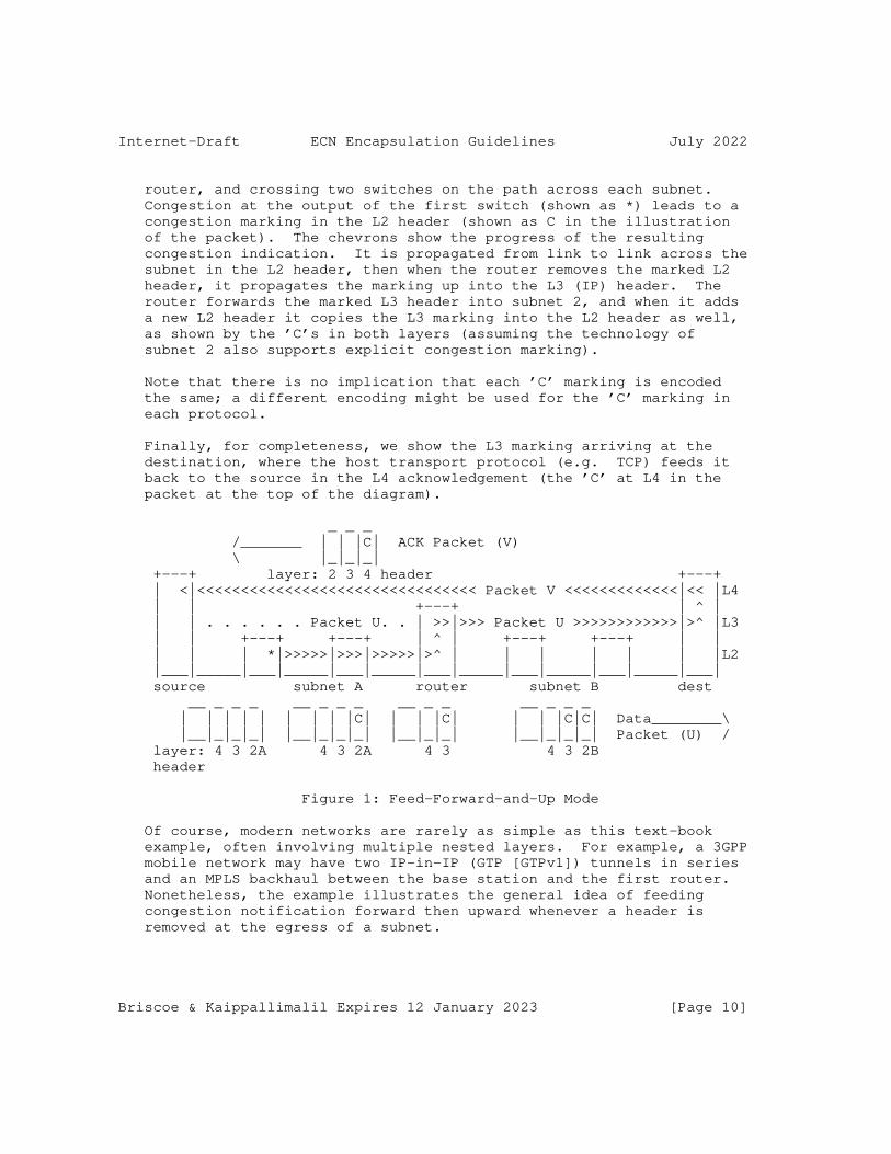
Internet-Draft ECN Encapsulation Guidelines July 2022
router, and crossing two switches on the path across each subnet. Congestion at the output of the first switch (shown as *) leads to a congestion marking in the L2 header (shown as C in the illustration of the packet). The chevrons show the progress of the resulting congestion indication. It is propagated from link to link across the subnet in the L2 header, then when the router removes the marked L2 header, it propagates the marking up into the L3 (IP) header. The router forwards the marked L3 header into subnet 2, and when it adds a new L2 header it copies the L3 marking into the L2 header as well, as shown by the ’C’s in both layers (assuming the technology of subnet 2 also supports explicit congestion marking).
Note that there is no implication that each ’C’ marking is encoded the same; a different encoding might be used for the ’C’ marking in each protocol.
Finally, for completeness, we show the L3 marking arriving at the destination, where the host transport protocol (e.g. TCP) feeds it back to the source in the L4 acknowledgement (the ’C’ at L4 in the packet at the top of the diagram).
_ _ _ /_______ | | |C| ACK Packet (V) \ |_|_|_| +---+ layer: 2 3 4 header +---+ | <|<<<<<<<<<<<<<<<<<<<<<<<<<<<<<<<< Packet V <<<<<<<<<<<<<|<< |L4 | | +---+ | ^ | | | . . . . . . Packet U. . | >>|>>> Packet U >>>>>>>>>>>>|>^ |L3 | | +---+ +---+ | ^ | +---+ +---+ | | | | | *|>>>>>|>>>|>>>>>|>^ | | | | | | |L2 |___|_____|___|_____|___|_____|___|_____|___|_____|___|_____|___| source subnet A router subnet B dest __ _ _ _ __ _ _ _ __ _ _ __ _ _ _ | | | | | | | | |C| | | |C| | | |C|C| Data________\ |__|_|_|_| |__|_|_|_| |__|_|_| |__|_|_|_| Packet (U) / layer: 4 3 2A 4 3 2A 4 3 4 3 2B header
Figure 1: Feed-Forward-and-Up Mode
Of course, modern networks are rarely as simple as this text-book example, often involving multiple nested layers. For example, a 3GPP mobile network may have two IP-in-IP (GTP [GTPv1]) tunnels in series and an MPLS backhaul between the base station and the first router. Nonetheless, the example illustrates the general idea of feeding congestion notification forward then upward whenever a header is removed at the egress of a subnet.
Briscoe & Kaippallimalil Expires 12 January 2023 [Page 10]
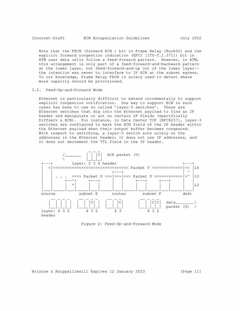
Internet-Draft ECN Encapsulation Guidelines July 2022
Note that the FECN (forward ECN ) bit in Frame Relay [Buck00] and the explicit forward congestion indication (EFCI [ITU-T.I.371]) bit in ATM user data cells follow a feed-forward pattern. However, in ATM, this arrangement is only part of a feed-forward-and-backward pattern at the lower layer, not feed-forward-and-up out of the lower layer-- the intention was never to interface to IP ECN at the subnet egress. To our knowledge, Frame Relay FECN is solely used to detect where more capacity should be provisioned.
3.2. Feed-Up-and-Forward Mode
Ethernet is particularly difficult to extend incrementally to support explicit congestion notification. One way to support ECN in such cases has been to use so called ’layer-3 switches’. These are Ethernet switches that dig into the Ethernet payload to find an IP header and manipulate or act on certain IP fields (specifically Diffserv & ECN). For instance, in Data Center TCP [RFC8257], layer-3 switches are configured to mark the ECN field of the IP header within the Ethernet payload when their output buffer becomes congested. With respect to switching, a layer-3 switch acts solely on the addresses in the Ethernet header; it does not use IP addresses, and it does not decrement the TTL field in the IP header.
_ _ _ /_______ | | |C| ACK packet (V) \ |_|_|_| +---+ layer: 2 3 4 header +---+ | <|<<<<<<<<<<<<<<<<<<<<<<<<<<<<<<<< Packet V <<<<<<<<<<<<<|<< |L4 | | +---+ | ^ | | | . . . >>>> Packet U >>>|>>>|>>> Packet U >>>>>>>>>>>>|>^ |L3 | | +--^+ +---+ | | +---+ +---+ | | | | | *| | | | | | | | | | |L2 |___|_____|___|_____|___|_____|___|_____|___|_____|___|_____|___| source subnet E router subnet F dest __ _ _ _ __ _ _ _ __ _ _ __ _ _ _ | | | | | | | |C| | | | |C| | | |C|C| data________\ |__|_|_|_| |__|_|_|_| |__|_|_| |__|_|_|_| packet (U) / layer: 4 3 2 4 3 2 4 3 4 3 2 header
Figure 2: Feed-Up-and-Forward Mode
Briscoe & Kaippallimalil Expires 12 January 2023 [Page 11]

Internet-Draft ECN Encapsulation Guidelines July 2022
By comparing Figure 2 with Figure 1, it can be seen that subnet E (perhaps a subnet of layer-3 Ethernet switches) works in feed-up-and- forward mode by notifying congestion directly into L3 at the point of congestion, even though the congested switch does not otherwise act at L3. In this example, the technology in subnet F (e.g. MPLS) does support ECN natively, so when the router adds the layer-2 header it copies the ECN marking from L3 to L2 as well.
3.3. Feed-Backward Mode
In some layer 2 technologies, explicit congestion notification has been defined for use internally within the subnet with its own feedback and load regulation, but typically the interface with IP for ECN has not been defined.
For instance, for the available bit-rate (ABR) service in ATM, the relative rate mechanism was one of the more popular mechanisms for managing traffic, tending to supersede earlier designs. In this approach ATM switches send special resource management (RM) cells in both the forward and backward directions to control the ingress rate of user data into a virtual circuit. If a switch buffer is approaching congestion or is congested it sends an RM cell back towards the ingress with respectively the No Increase (NI) or Congestion Indication (CI) bit set in its message type field [ATM-TM-ABR]. The ingress then holds or decreases its sending bit- rate accordingly.
Briscoe & Kaippallimalil Expires 12 January 2023 [Page 12]
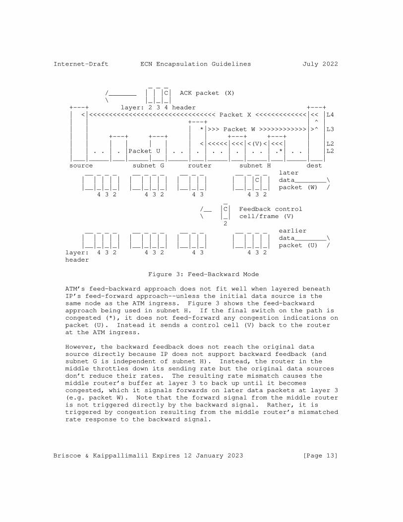
Internet-Draft ECN Encapsulation Guidelines July 2022
_ _ _ /_______ | | |C| ACK packet (X) \ |_|_|_| +---+ layer: 2 3 4 header +---+ | <|<<<<<<<<<<<<<<<<<<<<<<<<<<<<<<<< Packet X <<<<<<<<<<<<<|<< |L4 | | +---+ | ^ | | | | *|>>> Packet W >>>>>>>>>>>>|>^ |L3 | | +---+ +---+ | | +---+ +---+ | | | | | | | | | <|<<<<<|<<<|<(V)<|<<<| | |L2 | | . . | . |Packet U | . . | . | . . | . | . . | .*| . . | |L2 |___|_____|___|_____|___|_____|___|_____|___|_____|___|_____|___| source subnet G router subnet H dest __ _ _ _ __ _ _ _ __ _ _ __ _ _ _ later | | | | | | | | | | | | | | | | |C| | data________\ |__|_|_|_| |__|_|_|_| |__|_|_| |__|_|_|_| packet (W) / 4 3 2 4 3 2 4 3 4 3 2 _ /__ |C| Feedback control \ |_| cell/frame (V) 2 __ _ _ _ __ _ _ _ __ _ _ __ _ _ _ earlier | | | | | | | | | | | | | | | | | | | data________\ |__|_|_|_| |__|_|_|_| |__|_|_| |__|_|_|_| packet (U) / layer: 4 3 2 4 3 2 4 3 4 3 2 header
Figure 3: Feed-Backward Mode
ATM’s feed-backward approach does not fit well when layered beneath IP’s feed-forward approach--unless the initial data source is the same node as the ATM ingress. Figure 3 shows the feed-backward approach being used in subnet H. If the final switch on the path is congested (*), it does not feed-forward any congestion indications on packet (U). Instead it sends a control cell (V) back to the router at the ATM ingress.
However, the backward feedback does not reach the original data source directly because IP does not support backward feedback (and subnet G is independent of subnet H). Instead, the router in the middle throttles down its sending rate but the original data sources don’t reduce their rates. The resulting rate mismatch causes the middle router’s buffer at layer 3 to back up until it becomes congested, which it signals forwards on later data packets at layer 3 (e.g. packet W). Note that the forward signal from the middle router is not triggered directly by the backward signal. Rather, it is triggered by congestion resulting from the middle router’s mismatched rate response to the backward signal.
Briscoe & Kaippallimalil Expires 12 January 2023 [Page 13]

Internet-Draft ECN Encapsulation Guidelines July 2022
In response to this later forward signalling, end-to-end feedback at layer-4 finally completes the tortuous path of congestion indications back to the origin data source, as before.
Quantized congestion notification (QCN [IEEE802.1Q]) would suffer from similar problems if extended to multiple subnets. However, from the start QCN was clearly characterized as solely applicable to a single subnet (see Section 6).
3.4. Null Mode
Often link and physical layer resources are ’non-blocking’ by design. In these cases congestion notification may be implemented but it does not need to be deployed at the lower layer; ECN in IP would be sufficient.
A degenerate example is a point-to-point Ethernet link. Excess loading of the link merely causes the queue from the higher layer to back up, while the lower layer remains immune to congestion. Even a whole meshed subnetwork can be made immune to interior congestion by limiting ingress capacity and sufficient sizing of interior links, e.g. a non-blocking fat-tree network [Leiserson85]. An alternative to fat links near the root is numerous thin links with multi-path routing to ensure even worst-case patterns of load cannot congest any link, e.g. a Clos network [Clos53].
4. Feed-Forward-and-Up Mode: Guidelines for Adding Congestion Notification
Feed-forward-and-up is the mode already used for signalling ECN up the layers through MPLS into IP [RFC5129] and through IP-in-IP tunnels [RFC6040], whether encapsulating with IPv4 [RFC2003], IPv6 [RFC2473] or IPsec [RFC4301]. These RFCs take a consistent approach and the following guidelines are designed to ensure this consistency continues as ECN support is added to other protocols that encapsulate IP. The guidelines are also designed to ensure compliance with the more general best current practice for the design of alternate ECN schemes given in [RFC4774] and extended by [RFC8311].
The rest of this section is structured as follows:
* Section 4.1 addresses the most straightforward cases, where [RFC6040] can be applied directly to add ECN to tunnels that are effectively IP-in-IP tunnels, but with shim header(s) between the IP headers.
Briscoe & Kaippallimalil Expires 12 January 2023 [Page 14]

Internet-Draft ECN Encapsulation Guidelines July 2022
* The subsequent sections give guidelines for adding ECN to a subnet technology that uses feed-forward-and-up mode like IP, but it is not so similar to IP that [RFC6040] rules can be applied directly. Specifically:
- Sections 4.2, 4.3 and 4.4 respectively address how to add ECN support to the wire protocol and to the encapsulators and decapsulators at the ingress and egress of the subnet.
- Section 4.5 deals with the special, but common, case of sequences of tunnels or subnets that all use the same technology
- Section 4.6 deals with the question of reframing when IP packets do not map 1:1 into lower layer frames.
4.1. IP-in-IP Tunnels with Shim Headers
A common pattern for many tunnelling protocols is to encapsulate an inner IP header with shim header(s) then an outer IP header. A shim header is defined as one that is not sufficient alone to forward the packet as an outer header. Another common pattern is for a shim to encapsulate a layer 2 (L2) header, which in turn encapsulates (or might encapsulate) an IP header. [I-D.ietf-tsvwg-rfc6040update-shim] clarifies that RFC 6040 is just as applicable when there are shim(s) and possibly a L2 header between two IP headers.
However, it is not always feasible or necessary to propagate ECN between IP headers when separated by a shim. For instance, it might be too costly to dig to arbitrary depths to find an inner IP header, there may be little or no congestion within the tunnel by design (see null mode in Section 3.4 above), or a legacy implementation might not support ECN. In cases where a tunnel does not support ECN, it is important that the ingress does not copy the ECN field from an inner IP header to an outer. Therefore section 4 of [I-D.ietf-tsvwg-rfc6040update-shim] requires network operators to configure the ingress of a tunnel that does not support ECN so that it zeros the ECN field in the outer IP header.
Nonetheless, in many cases it is feasible to propagate the ECN field between IP headers separated by shim header(s) and/or a L2 header. Particularly in the typical case when the outer IP header and the shim(s) are added (or removed) as part of the same procedure. Even if the shim(s) encapsulate a L2 header, it is often possible to find an inner IP header within the L2 PDU and propagate ECN between that and the outer IP header. This can be thought of as a special case of the feed-up-and-forward mode (Section 3.2), so the guidelines for this mode apply (Section 5).
Briscoe & Kaippallimalil Expires 12 January 2023 [Page 15]

Internet-Draft ECN Encapsulation Guidelines July 2022
Numerous shim protocols have been defined for IP tunnelling. More recent ones e.g. Geneve [RFC8926] and Generic UDP Encapsulation (GUE) [I-D.ietf-intarea-gue] cite and follow RFC 6040. And some earlier ones, e.g. CAPWAP [RFC5415] and LISP [RFC6830], cite RFC 3168, which is compatible with RFC 6040.
However, as Section 9.3 of RFC 3168 pointed out, ECN support needs to be defined for many earlier shim-based tunnelling protocols, e.g. L2TPv2 [RFC2661], L2TPv3 [RFC3931], GRE [RFC2784], PPTP [RFC2637], GTP [GTPv1], [GTPv1-U], [GTPv2-C] and Teredo [RFC4380] as well as some recent ones, e.g. VXLAN [RFC7348], NVGRE [RFC7637] and NSH [RFC8300].
All these IP-based encapsulations can be updated in one shot by simple reference to RFC 6040. However, it would not be appropriate to update all these protocols from within the present guidance document. Instead a companion specification [I-D.ietf-tsvwg-rfc6040update-shim] has been prepared that has the appropriate standards track status to update standards track protocols. For those that are not under IETF change control [I-D.ietf-tsvwg-rfc6040update-shim] can only recommend that the relevant body updates them.
4.2. Wire Protocol Design: Indication of ECN Support
This section is intended to guide the redesign of any lower layer protocol that encapsulate IP to add native ECN support at the lower layer. It reflects the approaches used in [RFC6040] and in [RFC5129]. Therefore IP-in-IP tunnels or IP-in-MPLS or MPLS-in-MPLS encapsulations that already comply with [RFC6040] or [RFC5129] will already satisfy this guidance.
A lower layer (or subnet) congestion notification system:
1. SHOULD NOT apply explicit congestion notifications to PDUs that are destined for legacy layer-4 transport implementations that will not understand ECN, and
2. SHOULD NOT apply explicit congestion notifications to PDUs if the egress of the subnet might not propagate congestion notifications onward into the higher layer.
Briscoe & Kaippallimalil Expires 12 January 2023 [Page 16]

Internet-Draft ECN Encapsulation Guidelines July 2022
We use the term ECN-PDUs for a PDU on a feedback loop that will propagate congestion notification properly because it meets both the above criteria. And a Not-ECN-PDU is a PDU on a feedback loop that does not meet at least one of the criteria, and will therefore not propagate congestion notification properly. A corollary of the above is that a lower layer congestion notification protocol:
3. SHOULD be able to distinguish ECN-PDUs from Not-ECN-PDUs.
Note that there is no need for all interior nodes within a subnet to be able to mark congestion explicitly. A mix of ECN and drop signals from different nodes is fine. However, if _any_ interior nodes might generate ECN markings, guideline 2 above says that all relevant egress node(s) SHOULD be able to propagate those markings up to the higher layer.
In IP, if the ECN field in each PDU is cleared to the Not-ECT (not ECN-capable transport) codepoint, it indicates that the L4 transport will not understand congestion markings. A congested buffer must not mark these Not-ECT PDUs, and therefore drops them instead.
The mechanism a lower layer uses to distinguish the ECN-capability of PDUs need not mimic that of IP. The above guidelines merely say that the lower layer system, as a whole, should achieve the same outcome. For instance, ECN-capable feedback loops might use PDUs that are identified by a particular set of labels or tags. Alternatively, logical link protocols that use flow state might determine whether a PDU can be congestion marked by checking for ECN-support in the flow state. Other protocols might depend on out-of-band control signals.
The per-domain checking of ECN support in MPLS [RFC5129] is a good example of a way to avoid sending congestion markings to L4 transports that will not understand them, without using any header space in the subnet protocol.
In MPLS, header space is extremely limited, therefore RFC5129 does not provide a field in the MPLS header to indicate whether the PDU is an ECN-PDU or a Not-ECN-PDU. Instead, interior nodes in a domain are allowed to set explicit congestion indications without checking whether the PDU is destined for a L4 transport that will understand them. Nonetheless, this is made safe by requiring that the network operator upgrades all decapsulating edges of a whole domain at once, as soon as even one switch within the domain is configured to mark rather than drop during congestion. Therefore, any edge node that might decapsulate a packet will be capable of checking whether the higher layer transport is ECN-capable. When decapsulating a CE- marked packet, if the decapsulator discovers that the higher layer
Briscoe & Kaippallimalil Expires 12 January 2023 [Page 17]

Internet-Draft ECN Encapsulation Guidelines July 2022
(inner header) indicates the transport is not ECN-capable, it drops the packet--effectively on behalf of the earlier congested node (see Decapsulation Guideline 1 in Section 4.4).
It was only appropriate to define such an incremental deployment strategy because MPLS is targeted solely at professional operators, who can be expected to ensure that a whole subnetwork is consistently configured. This strategy might not be appropriate for other link technologies targeted at zero-configuration deployment or deployment by the general public (e.g. Ethernet). For such ’plug-and-play’ environments it will be necessary to invent a failsafe approach that ensures congestion markings will never fall into black holes, no matter how inconsistently a system is put together. Alternatively, congestion notification relying on correct system configuration could be confined to flavours of Ethernet intended only for professional network operators, such as Provider Backbone Bridges (PBB [IEEE802.1Q]; previously 802.1ah).
ECN support in TRILL [I-D.ietf-trill-ecn-support] provides a good example of how to add ECN to a lower layer protocol without relying on careful and consistent operator configuration. TRILL provides an extension header word with space for flags of different categories depending on whether logic to understand the extension is critical. The congestion experienced marking has been defined as a ’critical ingress-to-egress’ flag. So if a transit RBridge sets this flag and an egress RBridge does not have any logic to process it, it will drop it; which is the desired default action anyway. Therefore TRILL RBridges can be updated with support for ECN in no particular order and, at the egress of the TRILL campus, congestion notification will be propagated to IP as ECN whenever ECN logic has been implemented, or as drop otherwise.
QCN [IEEE802.1Q] is not intended to extend beyond a single subnet, or to interoperate with ECN. Nonetheless, the way QCN indicates to lower layer devices that the end-points will not understand QCN provides another example that a lower layer protocol designer might be able to mimic for their scenario. An operator can define certain Priority Code Points (PCPs [IEEE802.1Q]; previously 802.1p) to indicate non-QCN frames and an ingress bridge is required to map arriving not-QCN-capable IP packets to one of these non-QCN PCPs.
Briscoe & Kaippallimalil Expires 12 January 2023 [Page 18]

Internet-Draft ECN Encapsulation Guidelines July 2022
4.3. Encapsulation Guidelines
This section is intended to guide the redesign of any node that encapsulates IP with a lower layer header when adding native ECN support to the lower layer protocol. It reflects the approaches used in [RFC6040] and in [RFC5129]. Therefore IP-in-IP tunnels or IP-in- MPLS or MPLS-in-MPLS encapsulations that already comply with [RFC6040] or [RFC5129] will already satisfy this guidance.
1. Egress Capability Check: A subnet ingress needs to be sure that the corresponding egress of a subnet will propagate any congestion notification added to the outer header across the subnet. This is necessary in addition to checking that an incoming PDU indicates an ECN-capable (L4) transport. Examples of how this guarantee might be provided include:
* by configuration (e.g. if any label switches in a domain support ECN marking, [RFC5129] requires all egress nodes to have been configured to propagate ECN)
* by the ingress explicitly checking that the egress propagates ECN (e.g. an early attempt to add ECN support to TRILL used IS-IS to check path capabilities before adding ECN extension flags to each frame [RFC7780]).
* by inherent design of the protocol (e.g. by encoding ECN marking on the outer header in such a way that a legacy egress that does not understand ECN will consider the PDU corrupt or invalid and discard it, thus at least propagating a form of congestion signal).
2. Egress Fails Capability Check: If the ingress cannot guarantee that the egress will propagate congestion notification, the ingress SHOULD disable ECN at the lower layer when it forwards the PDU. An example of how the ingress might disable ECN at the lower layer would be by setting the outer header of the PDU to identify it as a Not-ECN-PDU, assuming the subnet technology supports such a concept.
3. Standard Congestion Monitoring Baseline: Once the ingress to a subnet has established that the egress will correctly propagate ECN, on encapsulation it SHOULD encode the same level of congestion in outer headers as is arriving in incoming headers. For example it might copy any incoming congestion notification into the outer header of the lower layer protocol.
Briscoe & Kaippallimalil Expires 12 January 2023 [Page 19]

Internet-Draft ECN Encapsulation Guidelines July 2022
This ensures that bulk congestion monitoring of outer headers (e.g. by a network management node monitoring ECN in passing frames) will measure congestion accumulated along the whole upstream path - since the Load Regulator not just since the ingress of the subnet. A node that is not the Load Regulator SHOULD NOT re-initialize the level of CE markings in the outer to zero.
It would still also be possible to measure congestion introduced across one subnet (or tunnel) by subtracting the level of CE markings on inner headers from that on outer headers (see Appendix C of [RFC6040]). For example:
* If this guideline has been followed and if the level of CE markings is 0.4% on the outer and 0.1% on the inner, 0.4% congestion has been introduced across all the networks since the load regulator, and 0.3% (= 0.4% - 0.1%) has been introduced since the ingress to the current subnet (or tunnel);
* Without this guideline, if the subnet ingress had re- initialized the outer congestion level to zero, the outer and inner would measure 0.1% and 0.3%. It would still be possible to infer that the congestion introduced since the Load Regulator was 0.4% (= 0.1% + 0.3%). But only if the monitoring system somehow knows whether the subnet ingress re- initialized the congestion level.
As long as subnet and tunnel technologies use the standard congestion monitoring baseline in this guideline, monitoring systems will know to use the former approach, rather than having to "somehow know" which approach to use.
4.4. Decapsulation Guidelines
This section is intended to guide the redesign of any node that decapsulates IP from within a lower layer header when adding native ECN support to the lower layer protocol. It reflects the approaches used in [RFC6040] and in [RFC5129]. Therefore IP-in-IP tunnels or IP-in-MPLS or MPLS-in-MPLS encapsulations that already comply with [RFC6040] or [RFC5129] will already satisfy this guidance.
A subnet egress SHOULD NOT simply copy congestion notification from outer headers to the forwarded header. It SHOULD calculate the outgoing congestion notification field from the inner and outer headers using the following guidelines. If there is any conflict, rules earlier in the list take precedence over rules later in the list:
Briscoe & Kaippallimalil Expires 12 January 2023 [Page 20]
Internet-Draft ECN Encapsulation Guidelines July 2022
1. If the arriving inner header is a Not-ECN-PDU it implies the L4 transport will not understand explicit congestion markings. Then:
* If the outer header carries an explicit congestion marking, drop is the only indication of congestion that the L4 transport will understand. If the congestion marking is the most severe possible, the packet MUST be dropped. However, if congestion can be marked with multiple levels of severity and the packet’s marking is not the most severe, this requirement can be relaxed to: the packet SHOULD be dropped.
* If the outer is an ECN-PDU that carries no indication of congestion or a Not-ECN-PDU the PDU SHOULD be forwarded, but still as a Not-ECN-PDU.
2. If the outer header does not support explicit congestion notification (a Not-ECN-PDU), but the inner header does (an ECN- PDU), the inner header SHOULD be forwarded unchanged.
3. In some lower layer protocols congestion may be signalled as a numerical level, such as in the control frames of quantized congestion notification (QCN [IEEE802.1Q]). If such a multi-bit encoding encapsulates an ECN-capable IP data packet, a function will be needed to convert the quantized congestion level into the frequency of congestion markings in outgoing IP packets.
4. Congestion indications might be encoded by a severity level. For instance increasing levels of congestion might be encoded by numerically increasing indications, e.g. pre-congestion notification (PCN) can be encoded in each PDU at three severity levels in IP or MPLS [RFC6660] and the default encapsulation and decapsulation rules [RFC6040] are compatible with this interpretation of the ECN field.
If the arriving inner header is an ECN-PDU, where the inner and outer headers carry indications of congestion of different severity, the more severe indication SHOULD be forwarded in preference to the less severe.
5. The inner and outer headers might carry a combination of congestion notification fields that should not be possible given any currently used protocol transitions. For instance, if Encapsulation Guideline 3 in Section 4.3 had been followed, it should not be possible to have a less severe indication of congestion in the outer than in the inner. It MAY be appropriate to log unexpected combinations of headers and possibly raise an alarm.
Briscoe & Kaippallimalil Expires 12 January 2023 [Page 21]
Internet-Draft ECN Encapsulation Guidelines July 2022
If a safe outgoing codepoint can be defined for such a PDU, the PDU SHOULD be forwarded rather than dropped. Some implementers discard PDUs with currently unused combinations of headers just in case they represent an attack. However, an approach using alarms and policy-mediated drop is preferable to hard-coded drop, so that operators can keep track of possible attacks but currently unused combinations are not precluded from future use through new standards actions.
4.5. Sequences of Similar Tunnels or Subnets
In some deployments, particularly in 3GPP networks, an IP packet may traverse two or more IP-in-IP tunnels in sequence that all use identical technology (e.g. GTP).
In such cases, it would be sufficient for every encapsulation and decapsulation in the chain to comply with RFC 6040. Alternatively, as an optimisation, a node that decapsulates a packet and immediately re-encapsulates it for the next tunnel MAY copy the incoming outer ECN field directly to the outgoing outer and the incoming inner ECN field directly to the outgoing inner. Then the overall behavior across the sequence of tunnel segments would still be consistent with RFC 6040.
Appendix C of RFC6040 describes how a tunnel egress can monitor how much congestion has been introduced within a tunnel. A network operator might want to monitor how much congestion had been introduced within a whole sequence of tunnels. Using the technique in Appendix C of RFC6040 at the final egress, the operator could monitor the whole sequence of tunnels, but only if the above optimisation were used consistently along the sequence of tunnels, in order to make it appear as a single tunnel. Therefore, tunnel endpoint implementations SHOULD allow the operator to configure whether this optimisation is enabled.
When ECN support is added to a subnet technology, consideration SHOULD be given to a similar optimisation between subnets in sequence if they all use the same technology.
4.6. Reframing and Congestion Markings
The guidance in this section is worded in terms of framing boundaries, but it applies equally whether the protocol data units are frames, cells or packets.
Where an AQM marks the ECN field of IP packets as they queue into a layer-2 link, there will be no problem with framing boundaries, because the ECN markings would be applied directly to IP packets.
Briscoe & Kaippallimalil Expires 12 January 2023 [Page 22]
Internet-Draft ECN Encapsulation Guidelines July 2022
The guidance in this section is only applicable where an ECN capability is being added to a layer-2 protocol so that layer-2 frames can be ECN-marked by an AQM at layer-2. This would only be necessary where AQM will be applied at pure layer-2 nodes (without IP-awareness).
Where ECN marking has had to be applied at non-IP-aware nodes and framing boundaries do not necessarily align with packet boundaries, the decapsulating IP forwarding node SHOULD propagate ECN markings from layer-2 frame headers to IP packets that may have different boundaries as a consequence of reframing.
Two possible design goals for propagating congestion indications, described in section 5.3 of [RFC3168] and section 2.4 of [RFC7141], are:
1. approximate preservation of the presence of congestion marks on the L2 frames used to construct an IP packet;
2. approximate preservation of the proportion of congestion marks arriving and departing.
In either case, an implementation SHOULD ensure that any new incoming congestion indication is propagated immediately, not held awaiting the possibility of further congestion indications to be sufficient to indicate congestion on an outgoing PDU [RFC7141]. Nonetheless, to facilitate pipelined implementation, it would be acceptable for congestion marks to propagate to a slightly later IP packet.
Concrete example implementations of goal #1 include (but are not limited to):
* Every IP PDU that is constructed, in whole or in part, from an L2 frame that is marked with a congestion signal, has that signal propagated to it;
* Every L2 frame that is marked with a congestion signal, propagates that signal to one IP PDU which is constructed, in whole or in part, from it. If multiple IP PDUs meet this description, the choice can be made arbitrarily but ought to be consistent.
Concrete example implementations of goal #2 include (but are not limited to):
Briscoe & Kaippallimalil Expires 12 January 2023 [Page 23]

Internet-Draft ECN Encapsulation Guidelines July 2022
* A counter (’in’) tracks octets arriving within the payload of marked L2 frames and another (’out’) tracks octets departing in marked IP packets. While ’in’ exceeds ’out’, forwarded IP packets are ECN-marked. If ’out’ exceeds ’in’ for longer than a timeout, both counters are zeroed, to ensure that the start of the next congestion episode propagates immediately;
Generally, the number of L2 frames may be higher (e.g. ATM), similar to, or lower (e.g. 802.11 aggregation at a L2-only station) than the number of IP PDUs, and this distinction may influence the choice of mechanism.
5. Feed-Up-and-Forward Mode: Guidelines for Adding Congestion Notification
The guidance in this section is applicable, for example, when IP packets:
* are encapsulated in Ethernet headers, which have no support for ECN;
* are forwarded by the eNode-B (base station) of a 3GPP radio access network, which is required to apply ECN marking during congestion, [LTE-RA], [UTRAN], but the Packet Data Convergence Protocol (PDCP) that encapsulates the IP header over the radio access has no support for ECN.
This guidance also generalizes to encapsulation by other subnet technologies with no native support for explicit congestion notification at the lower layer, but with support for finding and processing an IP header. It is unlikely to be applicable or necessary for IP-in-IP encapsulation, where feed-forward-and-up mode based on [RFC6040] would be more appropriate.
Marking the IP header while switching at layer-2 (by using a layer-3 switch) or while forwarding in a radio access network seems to represent a layering violation. However, it can be considered as a benign optimisation if the guidelines below are followed. Feed-up- and-forward is certainly not a general alternative to implementing feed-forward congestion notification in the lower layer, because:
* IPv4 and IPv6 are not the only layer-3 protocols that might be encapsulated by lower layer protocols
* Link-layer encryption might be in use, making the layer-2 payload inaccessible
Briscoe & Kaippallimalil Expires 12 January 2023 [Page 24]

Internet-Draft ECN Encapsulation Guidelines July 2022
* Many Ethernet switches do not have ’layer-3 switch’ capabilities so they cannot read or modify an IP payload
* It might be costly to find an IP header (v4 or v6) when it may be encapsulated by more than one lower layer header, e.g. Ethernet MAC in MAC ([IEEE802.1Q]; previously 802.1ah).
Nonetheless, configuring lower layer equipment to look for an ECN field in an encapsulated IP header is a useful optimisation. If the implementation follows the guidelines below, this optimisation does not have to be confined to a controlled environment such as within a data centre; it could usefully be applied on any network--even if the operator is not sure whether the above issues will never apply:
1. If a native lower-layer congestion notification mechanism exists for a subnet technology, it is safe to mix feed-up-and-forward with feed-forward-and-up on other switches in the same subnet. However, it will generally be more efficient to use the native mechanism.
2. The depth of the search for an IP header SHOULD be limited. If an IP header is not found soon enough, or an unrecognized or unreadable header is encountered, the switch SHOULD resort to an alternative means of signalling congestion (e.g. drop, or the native lower layer mechanism if available).
3. It is sufficient to use the first IP header found in the stack; the egress of the relevant tunnel can propagate congestion notification upwards to any more deeply encapsulated IP headers later.
6. Feed-Backward Mode: Guidelines for Adding Congestion Notification
It can be seen from Section 3.3 that congestion notification in a subnet using feed-backward mode has generally not been designed to be directly coupled with IP layer congestion notification. The subnet attempts to minimize congestion internally, and if the incoming load at the ingress exceeds the capacity somewhere through the subnet, the layer 3 buffer into the ingress backs up. Thus, a feed-backward mode subnet is in some sense similar to a null mode subnet, in that there is no need for any direct interaction between the subnet and higher layer congestion notification. Therefore no detailed protocol design guidelines are appropriate. Nonetheless, a more general guideline is appropriate:
Briscoe & Kaippallimalil Expires 12 January 2023 [Page 25]

Internet-Draft ECN Encapsulation Guidelines July 2022
A subnetwork technology intended to eventually interface to IP SHOULD NOT be designed using only the feed-backward mode, which is certainly best for a stand-alone subnet, but would need to be modified to work efficiently as part of the wider Internet, because IP uses feed-forward-and-up mode.
The feed-backward approach at least works beneath IP, where the term ’works’ is used only in a narrow functional sense because feed- backward can result in very inefficient and sluggish congestion control--except if it is confined to the subnet directly connected to the original data source, when it is faster than feed-forward. It would be valid to design a protocol that could work in feed-backward mode for paths that only cross one subnet, and in feed-forward-and-up mode for paths that cross subnets.
In the early days of TCP/IP, a similar feed-backward approach was tried for explicit congestion signalling, using source-quench (SQ) ICMP control packets. However, SQ fell out of favour and is now formally deprecated [RFC6633]. The main problem was that it is hard for a data source to tell the difference between a spoofed SQ message and a quench request from a genuine buffer on the path. It is also hard for a lower layer buffer to address an SQ message to the original source port number, which may be buried within many layers of headers, and possibly encrypted.
QCN (also known as backward congestion notification, BCN; see Sections 30--33 of [IEEE802.1Q]; previously known as 802.1Qau) uses a feed-backward mode structurally similar to ATM’s relative rate mechanism. However, QCN confines its applicability to scenarios such as some data centres where all endpoints are directly attached by the same Ethernet technology. If a QCN subnet were later connected into a wider IP-based internetwork (e.g. when attempting to interconnect multiple data centres) it would suffer the inefficiency shown in Figure 3.
7. IANA Considerations
This memo includes no request to IANA.
8. Security Considerations
If a lower layer wire protocol is redesigned to include explicit congestion signalling in-band in the protocol header, care SHOULD be take to ensure that the field used is specified as mutable during transit. Otherwise interior nodes signalling congestion would invalidate any authentication protocol applied to the lower layer header--by altering a header field that had been assumed as immutable.
Briscoe & Kaippallimalil Expires 12 January 2023 [Page 26]

Internet-Draft ECN Encapsulation Guidelines July 2022
The redesign of protocols that encapsulate IP in order to propagate congestion signals between layers raises potential signal integrity concerns. Experimental or proposed approaches exist for assuring the end-to-end integrity of in-band congestion signals, e.g.:
* Congestion exposure (ConEx ) for networks to audit that their congestion signals are not being suppressed by other networks or by receivers, and for networks to police that senders are responding sufficiently to the signals, irrespective of the L4 transport protocol used [RFC7713].
* A test for a sender to detect whether a network or the receiver is suppressing congestion signals (for example see 2nd para of Section 20.2 of [RFC3168]).
Given these end-to-end approaches are already being specified, it would make little sense to attempt to design hop-by-hop congestion signal integrity into a new lower layer protocol, because end-to-end integrity inherently achieves hop-by-hop integrity.
Section 6 gives vulnerability to spoofing as one of the reasons for deprecating feed-backward mode.
9. Conclusions
Following the guidance in this document enables ECN support to be extended to numerous protocols that encapsulate IP (v4 & v6) in a consistent way, so that IP continues to fulfil its role as an end-to- end interoperability layer. This includes:
* A wide range of tunnelling protocols including those with various forms of shim header between two IP headers, possibly also separated by a L2 header;
* A wide range of subnet technologies, particularly those that work in the same ’feed-forward-and-up’ mode that is used to support ECN in IP and MPLS.
Guidelines have been defined for supporting propagation of ECN between Ethernet and IP on so-called Layer-3 Ethernet switches, using a ’feed-up-and-forward’ mode. This approach could enable other subnet technologies to pass ECN signals into the IP layer, even if they do not support ECN natively.
Finally, attempting to add ECN to a subnet technology in feed- backward mode is deprecated except in special cases, due to its likely sluggish response to congestion.
Briscoe & Kaippallimalil Expires 12 January 2023 [Page 27]
Internet-Draft ECN Encapsulation Guidelines July 2022
10. Acknowledgements
Thanks to Gorry Fairhurst and David Black for extensive reviews. Thanks also to the following reviewers: Joe Touch, Andrew McGregor, Richard Scheffenegger, Ingemar Johansson, Piers O’Hanlon, Donald Eastlake, Jonathan Morton, Markku Kojo and Michael Welzl, who pointed out that lower layer congestion notification signals may have different semantics to those in IP. Thanks are also due to the tsvwg chairs, TSV ADs and IETF liaison people such as Eric Gray, Dan Romascanu and Gonzalo Camarillo for helping with the liaisons with the IEEE and 3GPP. And thanks to Georg Mayer and particularly to Erik Guttman for the extensive search and categorisation of any 3GPP specifications that cite ECN specifications.
Bob Briscoe was part-funded by the European Community under its Seventh Framework Programme through the Trilogy project (ICT-216372) for initial drafts and through the Reducing Internet Transport Latency (RITE) project (ICT-317700) subsequently. The views expressed here are solely those of the authors.
11. Contributors
Pat Thaler Broadcom Corporation (retired) CA USA
Pat was a co-author of this draft, but retired before its publication.
12. Comments Solicited
Comments and questions are encouraged and very welcome. They can be addressed to the IETF Transport Area working group mailing list <[email protected]>, and/or to the authors.
13. References
13.1. Normative References
[RFC2119] Bradner, S., "Key words for use in RFCs to Indicate Requirement Levels", BCP 14, RFC 2119, DOI 10.17487/RFC2119, March 1997, <https://www.rfc-editor.org/info/rfc2119>.
Briscoe & Kaippallimalil Expires 12 January 2023 [Page 28]
Internet-Draft ECN Encapsulation Guidelines July 2022
[RFC3168] Ramakrishnan, K., Floyd, S., and D. Black, "The Addition of Explicit Congestion Notification (ECN) to IP", RFC 3168, DOI 10.17487/RFC3168, September 2001, <https://www.rfc-editor.org/info/rfc3168>.
[RFC3819] Karn, P., Ed., Bormann, C., Fairhurst, G., Grossman, D., Ludwig, R., Mahdavi, J., Montenegro, G., Touch, J., and L. Wood, "Advice for Internet Subnetwork Designers", BCP 89, RFC 3819, DOI 10.17487/RFC3819, July 2004, <https://www.rfc-editor.org/info/rfc3819>.
[RFC4774] Floyd, S., "Specifying Alternate Semantics for the Explicit Congestion Notification (ECN) Field", BCP 124, RFC 4774, DOI 10.17487/RFC4774, November 2006, <https://www.rfc-editor.org/info/rfc4774>.
[RFC5129] Davie, B., Briscoe, B., and J. Tay, "Explicit Congestion Marking in MPLS", RFC 5129, DOI 10.17487/RFC5129, January 2008, <https://www.rfc-editor.org/info/rfc5129>.
[RFC6040] Briscoe, B., "Tunnelling of Explicit Congestion Notification", RFC 6040, DOI 10.17487/RFC6040, November 2010, <https://www.rfc-editor.org/info/rfc6040>.
[RFC7141] Briscoe, B. and J. Manner, "Byte and Packet Congestion Notification", BCP 41, RFC 7141, DOI 10.17487/RFC7141, February 2014, <https://www.rfc-editor.org/info/rfc7141>.
13.2. Informative References
[ATM-TM-ABR] Cisco, "Understanding the Available Bit Rate (ABR) Service Category for ATM VCs", Design Technote 10415, 5 June 2005, <http://www.cisco.com/en/US/tech/tk39/tk51/ technologies_tech_note09186a00800fbc76.shtml>.
[Buck00] Buckwalter, J.T., "Frame Relay: Technology and Practice", Pub. Addison Wesley ISBN-13: 978-0201485240, 2000.
[Clos53] Clos, C., "A Study of Non-Blocking Switching Networks", Bell Systems Technical Journal 32(2):406--424, March 1953.
[GTPv1] 3GPP, "GPRS Tunnelling Protocol (GTP) across the Gn and Gp interface", Technical Specification TS 29.060.
[GTPv1-U] 3GPP, "General Packet Radio System (GPRS) Tunnelling Protocol User Plane (GTPv1-U)", Technical Specification TS 29.281.
Briscoe & Kaippallimalil Expires 12 January 2023 [Page 29]

Internet-Draft ECN Encapsulation Guidelines July 2022
[GTPv2-C] 3GPP, "Evolved General Packet Radio Service (GPRS) Tunnelling Protocol for Control plane (GTPv2-C)", Technical Specification TS 29.274.
[I-D.ietf-intarea-gue] Herbert, T., Yong, L., and O. Zia, "Generic UDP Encapsulation", Work in Progress, Internet-Draft, draft- ietf-intarea-gue-09, 26 October 2019, <https://datatracker.ietf.org/doc/html/draft-ietf-intarea- gue-09>.
[I-D.ietf-trill-ecn-support] Eastlake, D. E. and B. Briscoe, "TRILL (TRansparent Interconnection of Lots of Links): ECN (Explicit Congestion Notification) Support", Work in Progress, Internet-Draft, draft-ietf-trill-ecn-support-07, 25 February 2018, <https://datatracker.ietf.org/doc/html/ draft-ietf-trill-ecn-support-07>.
[I-D.ietf-tsvwg-ecn-l4s-id] Schepper, K. D. and B. Briscoe, "Explicit Congestion Notification (ECN) Protocol for Very Low Queuing Delay (L4S)", Work in Progress, Internet-Draft, draft-ietf- tsvwg-ecn-l4s-id-25, 4 March 2022, <https://datatracker.ietf.org/doc/html/draft-ietf-tsvwg- ecn-l4s-id-25>.
[I-D.ietf-tsvwg-rfc6040update-shim] Briscoe, B., "Propagating Explicit Congestion Notification Across IP Tunnel Headers Separated by a Shim", Work in Progress, Internet-Draft, draft-ietf-tsvwg-rfc6040update- shim-14, 25 May 2021, <https://datatracker.ietf.org/doc/html/draft-ietf-tsvwg- rfc6040update-shim-14>.
[IEEE802.1Q] IEEE, "IEEE Standard for Local and Metropolitan Area NetworksVirtual Bridged Local Area NetworksAmendment 6: Provider Backbone Bridges", IEEE Std 802.1Q-2018, July 2018, <https://ieeexplore.ieee.org/document/8403927>.
[ITU-T.I.371] ITU-T, "Traffic Control and Congestion Control in B-ISDN", ITU-T Rec. I.371 (03/04), March 2004, <http://ieeexplore.ieee.org/xpl/ mostRecentIssue.jsp?punumber=5454061>.
Briscoe & Kaippallimalil Expires 12 January 2023 [Page 30]
Internet-Draft ECN Encapsulation Guidelines July 2022
[Leiserson85] Leiserson, C.E., "Fat-trees: universal networks for hardware-efficient supercomputing", IEEE Transactions on Computers 34(10):892-901, October 1985.
[LTE-RA] 3GPP, "Evolved Universal Terrestrial Radio Access (E-UTRA) and Evolved Universal Terrestrial Radio Access Network (E-UTRAN); Overall description; Stage 2", Technical Specification TS 36.300.
[RFC2003] Perkins, C., "IP Encapsulation within IP", RFC 2003, DOI 10.17487/RFC2003, October 1996, <https://www.rfc-editor.org/info/rfc2003>.
[RFC2473] Conta, A. and S. Deering, "Generic Packet Tunneling in IPv6 Specification", RFC 2473, DOI 10.17487/RFC2473, December 1998, <https://www.rfc-editor.org/info/rfc2473>.
[RFC2637] Hamzeh, K., Pall, G., Verthein, W., Taarud, J., Little, W., and G. Zorn, "Point-to-Point Tunneling Protocol (PPTP)", RFC 2637, DOI 10.17487/RFC2637, July 1999, <https://www.rfc-editor.org/info/rfc2637>.
[RFC2661] Townsley, W., Valencia, A., Rubens, A., Pall, G., Zorn, G., and B. Palter, "Layer Two Tunneling Protocol "L2TP"", RFC 2661, DOI 10.17487/RFC2661, August 1999, <https://www.rfc-editor.org/info/rfc2661>.
[RFC2784] Farinacci, D., Li, T., Hanks, S., Meyer, D., and P. Traina, "Generic Routing Encapsulation (GRE)", RFC 2784, DOI 10.17487/RFC2784, March 2000, <https://www.rfc-editor.org/info/rfc2784>.
[RFC2884] Hadi Salim, J. and U. Ahmed, "Performance Evaluation of Explicit Congestion Notification (ECN) in IP Networks", RFC 2884, DOI 10.17487/RFC2884, July 2000, <https://www.rfc-editor.org/info/rfc2884>.
[RFC2983] Black, D., "Differentiated Services and Tunnels", RFC 2983, DOI 10.17487/RFC2983, October 2000, <https://www.rfc-editor.org/info/rfc2983>.
[RFC3931] Lau, J., Ed., Townsley, M., Ed., and I. Goyret, Ed., "Layer Two Tunneling Protocol - Version 3 (L2TPv3)", RFC 3931, DOI 10.17487/RFC3931, March 2005, <https://www.rfc-editor.org/info/rfc3931>.
Briscoe & Kaippallimalil Expires 12 January 2023 [Page 31]
Internet-Draft ECN Encapsulation Guidelines July 2022
[RFC4301] Kent, S. and K. Seo, "Security Architecture for the Internet Protocol", RFC 4301, DOI 10.17487/RFC4301, December 2005, <https://www.rfc-editor.org/info/rfc4301>.
[RFC4380] Huitema, C., "Teredo: Tunneling IPv6 over UDP through Network Address Translations (NATs)", RFC 4380, DOI 10.17487/RFC4380, February 2006, <https://www.rfc-editor.org/info/rfc4380>.
[RFC5415] Calhoun, P., Ed., Montemurro, M., Ed., and D. Stanley, Ed., "Control And Provisioning of Wireless Access Points (CAPWAP) Protocol Specification", RFC 5415, DOI 10.17487/RFC5415, March 2009, <https://www.rfc-editor.org/info/rfc5415>.
[RFC6633] Gont, F., "Deprecation of ICMP Source Quench Messages", RFC 6633, DOI 10.17487/RFC6633, May 2012, <https://www.rfc-editor.org/info/rfc6633>.
[RFC6660] Briscoe, B., Moncaster, T., and M. Menth, "Encoding Three Pre-Congestion Notification (PCN) States in the IP Header Using a Single Diffserv Codepoint (DSCP)", RFC 6660, DOI 10.17487/RFC6660, July 2012, <https://www.rfc-editor.org/info/rfc6660>.
[RFC6830] Farinacci, D., Fuller, V., Meyer, D., and D. Lewis, "The Locator/ID Separation Protocol (LISP)", RFC 6830, DOI 10.17487/RFC6830, January 2013, <https://www.rfc-editor.org/info/rfc6830>.
[RFC7323] Borman, D., Braden, B., Jacobson, V., and R. Scheffenegger, Ed., "TCP Extensions for High Performance", RFC 7323, DOI 10.17487/RFC7323, September 2014, <https://www.rfc-editor.org/info/rfc7323>.
[RFC7348] Mahalingam, M., Dutt, D., Duda, K., Agarwal, P., Kreeger, L., Sridhar, T., Bursell, M., and C. Wright, "Virtual eXtensible Local Area Network (VXLAN): A Framework for Overlaying Virtualized Layer 2 Networks over Layer 3 Networks", RFC 7348, DOI 10.17487/RFC7348, August 2014, <https://www.rfc-editor.org/info/rfc7348>.
[RFC7567] Baker, F., Ed. and G. Fairhurst, Ed., "IETF Recommendations Regarding Active Queue Management", BCP 197, RFC 7567, DOI 10.17487/RFC7567, July 2015, <https://www.rfc-editor.org/info/rfc7567>.
Briscoe & Kaippallimalil Expires 12 January 2023 [Page 32]
Internet-Draft ECN Encapsulation Guidelines July 2022
[RFC7637] Garg, P., Ed. and Y. Wang, Ed., "NVGRE: Network Virtualization Using Generic Routing Encapsulation", RFC 7637, DOI 10.17487/RFC7637, September 2015, <https://www.rfc-editor.org/info/rfc7637>.
[RFC7713] Mathis, M. and B. Briscoe, "Congestion Exposure (ConEx) Concepts, Abstract Mechanism, and Requirements", RFC 7713, DOI 10.17487/RFC7713, December 2015, <https://www.rfc-editor.org/info/rfc7713>.
[RFC7780] Eastlake 3rd, D., Zhang, M., Perlman, R., Banerjee, A., Ghanwani, A., and S. Gupta, "Transparent Interconnection of Lots of Links (TRILL): Clarifications, Corrections, and Updates", RFC 7780, DOI 10.17487/RFC7780, February 2016, <https://www.rfc-editor.org/info/rfc7780>.
[RFC8084] Fairhurst, G., "Network Transport Circuit Breakers", BCP 208, RFC 8084, DOI 10.17487/RFC8084, March 2017, <https://www.rfc-editor.org/info/rfc8084>.
[RFC8087] Fairhurst, G. and M. Welzl, "The Benefits of Using Explicit Congestion Notification (ECN)", RFC 8087, DOI 10.17487/RFC8087, March 2017, <https://www.rfc-editor.org/info/rfc8087>.
[RFC8174] Leiba, B., "Ambiguity of Uppercase vs Lowercase in RFC 2119 Key Words", BCP 14, RFC 8174, DOI 10.17487/RFC8174, May 2017, <https://www.rfc-editor.org/info/rfc8174>.
[RFC8257] Bensley, S., Thaler, D., Balasubramanian, P., Eggert, L., and G. Judd, "Data Center TCP (DCTCP): TCP Congestion Control for Data Centers", RFC 8257, DOI 10.17487/RFC8257, October 2017, <https://www.rfc-editor.org/info/rfc8257>.
[RFC8300] Quinn, P., Ed., Elzur, U., Ed., and C. Pignataro, Ed., "Network Service Header (NSH)", RFC 8300, DOI 10.17487/RFC8300, January 2018, <https://www.rfc-editor.org/info/rfc8300>.
[RFC8311] Black, D., "Relaxing Restrictions on Explicit Congestion Notification (ECN) Experimentation", RFC 8311, DOI 10.17487/RFC8311, January 2018, <https://www.rfc-editor.org/info/rfc8311>.
[RFC8926] Gross, J., Ed., Ganga, I., Ed., and T. Sridhar, Ed., "Geneve: Generic Network Virtualization Encapsulation", RFC 8926, DOI 10.17487/RFC8926, November 2020, <https://www.rfc-editor.org/info/rfc8926>.
Briscoe & Kaippallimalil Expires 12 January 2023 [Page 33]
Internet-Draft ECN Encapsulation Guidelines July 2022
[UTRAN] 3GPP, "UTRAN Overall Description", Technical Specification TS 25.401.
Appendix A. Changes in This Version (to be removed by RFC Editor)
From ietf-12 to ietf-13 * Following 3rd tsvwg WGLC:
- Formalized update to RFC 3819 in its own subsection (1.1) and referred to it in the abstract
- Scope: Clarified that the specification of alternative ECN semantics using ECT(1) was not in RFC 4774, but rather in RFC 8311, and that the problem with using a DSCP to indicate alternative semantics has issues at domain boundaries as well as tunnels.
- Terminology: tighted up definitions of ECN-PDU and Not-ECN- PDU, and removed definition of Congestion Baseline, given it was only used once.
- Mentioned QCN where feed-backward is first introduced (S.3), referring forward to where it is discussed more deeply (S.4).
- Clarified that IS-IS solution to adding ECN support to TRILL was not pursued
- Completely rewrote the rationale for the guideline about a Standard Congestion Monitoring Baseline, to focus on standardization of the otherwise unknown scenario used, rather than the relative usefulness of the info in each approach
- Explained the re-framing problem better and added fragmentation as another possible cause of the problem
- Acknowledged new reviewers
- Updated references, replaced citations of 802.1Qau and 802.1ah with rolled up 802.1Q, and added citations of Fat trees and Clos Networks
- Numerous other editorial improvements
From ietf-11 to ietf-12 * Updated references
Briscoe & Kaippallimalil Expires 12 January 2023 [Page 34]

Internet-Draft ECN Encapsulation Guidelines July 2022
From ietf-10 to ietf-11 * Removed short section (was 3) ’Guidelines for All Cases’ because it was out of scope, being covered by RFC 4774. Expanded the Scope section (1.2) to explain all this. Explained that the default encap/decap rules already support certain alternative semantics, particularly all three of the alternative semantics for ECT(1): equivalent to ECT(0) , higher severity than ECT(0), and unmarked but implying different marking semantics from ECT(0).
* Clarified why the QCN example was being given even though not about increment deployment of ECN
* Pointed to the spoofing issue with feed-backward mode from the Security Considerations section, to aid security review.
* Removed any ambiguity in the word ’transport’ throughout
From ietf-09 to ietf-10 * Updated section 5.1 on "IP-in-IP tunnels with Shim Headers" to be consistent with updates to draft-ietf-tsvwg-rfc6040update- shim.
* Removed reference to the ECN nonce, which has been made historic by RFC 8311
* Removed "Open Issues" Appendix, given all have been addressed.
From ietf-08 to ietf-09 * Updated para in Intro that listed all the IP-in-IP tunnelling protocols, to instead refer to draft-ietf-tsvwg-rfc6040update- shim
* Updated section 5.1 on "IP-in-IP tunnels with Shim Headers" to summarize guidance that has evolved as rfc6040update-shim has developed.
From ietf-07 to ietf-08: Refreshed to avoid expiry. Updated references.
From ietf-06 to ietf-07: * Added the people involved in liaisons to the acknowledgements.
From ietf-05 to ietf-06: * Introduction: Added GUE and Geneve as examples of tightly coupled shims between IP headers that cite RFC 6040. And added VXLAN to list of those that do not.
Briscoe & Kaippallimalil Expires 12 January 2023 [Page 35]

Internet-Draft ECN Encapsulation Guidelines July 2022
* Replaced normative text about tightly coupled shims between IP headers, with reference to new draft-ietf-tsvwg-rfc6040update- shim
* Wire Protocol Design: Indication of ECN Support: Added TRILL as an example of a well-design protocol that does not need an indication of ECN support in the wire protocol.
* Encapsulation Guidelines: In the case of a Not-ECN-PDU with a CE outer, replaced SHOULD be dropped, with explanations of when SHOULD or MUST are appropriate.
* Feed-Up-and-Forward Mode: Explained examples more carefully, referred to PDCP and cited UTRAN spec as well as E-UTRAN.
* Updated references.
* Marked open issues as resolved, but did not delete Open Issues Appendix (yet).
From ietf-04 to ietf-05: * Explained why tightly coupled shim headers only "SHOULD" comply with RFC 6040, not "MUST".
* Updated references
From ietf-03 to ietf-04: * Addressed Richard Scheffenegger’s review comments: primarily editorial corrections, and addition of examples for clarity.
From ietf-02 to ietf-03: * Updated references, ad cited RFC4774.
From ietf-01 to ietf-02: * Added Section for guidelines that are applicable in all cases.
* Updated references.
From ietf-00 to ietf-01: Updated references.
From briscoe-04 to ietf-00: Changed filename following tsvwg adoption.
From briscoe-03 to 04: * Re-arranged the introduction to describe the purpose of the document first before introducing ECN in more depth. And clarified the introduction throughout.
Briscoe & Kaippallimalil Expires 12 January 2023 [Page 36]

Internet-Draft ECN Encapsulation Guidelines July 2022
* Added applicability to 3GPP TS 36.300.
From briscoe-02 to 03: * Scope section:
- Added dependence on correct propagation of traffic class information
- For the feed-backward mode, deemed multicast and anycast out of scope
* Ensured all guidelines referring to subnet technologies also refer to tunnels and vice versa by adding applicability sentences at the start of sections 4.1, 4.2, 4.3, 4.4, 4.6 and 5.
* Added Security Considerations on ensuring congestion signal fields are classed as immutable and on using end-to-end congestion signal integrity technologies rather than hop-by- hop.
From briscoe-01 to 02: * Added authors: JK & PT
* Added
- Section 4.1 "IP-in-IP Tunnels with Tightly Coupled Shim Headers"
- Section 4.5 "Sequences of Similar Tunnels or Subnets"
- roadmap at the start of Section 4, given the subsections have become quite fragmented.
- Section 9 "Conclusions"
* Clarified why transports are starting to be able to saturate interior links
* Under Section 1.1, addressed the question of alternative signal semantics and included multicast & anycast.
* Under Section 3.1, included a 3GPP example.
* Section 4.2. "Wire Protocol Design":
- Altered guideline 2. to make it clear that it only applies to the immediate subnet egress, not later ones
Briscoe & Kaippallimalil Expires 12 January 2023 [Page 37]

Internet-Draft ECN Encapsulation Guidelines July 2022
- Added a reminder that it is only necessary to check that ECN propagates at the egress, not whether interior nodes mark ECN
- Added example of how QCN uses 802.1p to indicate support for QCN.
* Added references to Appendix C of RFC6040, about monitoring the amount of congestion signals introduced within a tunnel
* Appendix A: Added more issues to be addressed, including plan to produce a standards track update to IP-in-IP tunnel protocols.
* Updated acks and references
From briscoe-00 to 01: * Intended status: BCP (was Informational) & updates 3819 added.
* Briefer Introduction: Introductory para justifying benefits of ECN. Moved all but a brief enumeration of modes of operation to their own new section (from both Intro & Scope). Introduced incr. deployment as most tricky part.
* Tightened & added to terminology section
* Structured with Modes of Operation, then Guidelines section for each mode.
* Tightened up guideline text to remove vagueness / passive voice / ambiguity and highlight main guidelines as numbered items.
* Added Outstanding Document Issues Appendix
* Updated references
Authors’ Addresses
Bob Briscoe Independent United Kingdom Email: [email protected] URI: http://bobbriscoe.net/
Briscoe & Kaippallimalil Expires 12 January 2023 [Page 38]

Internet-Draft ECN Encapsulation Guidelines July 2022
John Kaippallimalil Futurewei 5700 Tennyson Parkway, Suite 600 Plano, Texas 75024 United States of America Email: [email protected]
Briscoe & Kaippallimalil Expires 12 January 2023 [Page 39]
Transport Services (tsv) K. De SchepperInternet-Draft Nokia Bell LabsIntended status: Experimental B. Briscoe, Ed.Expires: 8 January 2023 Independent 7 July 2022
Explicit Congestion Notification (ECN) Protocol for Very Low Queuing Delay (L4S) draft-ietf-tsvwg-ecn-l4s-id-26
Abstract
This specification defines the protocol to be used for a new network service called low latency, low loss and scalable throughput (L4S). L4S uses an Explicit Congestion Notification (ECN) scheme at the IP layer that is similar to the original (or ’Classic’) ECN approach, except as specified within. L4S uses ’scalable’ congestion control, which induces much more frequent control signals from the network and it responds to them with much more fine-grained adjustments, so that very low (typically sub-millisecond on average) and consistently low queuing delay becomes possible for L4S traffic without compromising link utilization. Thus even capacity-seeking (TCP-like) traffic can have high bandwidth and very low delay at the same time, even during periods of high traffic load.
The L4S identifier defined in this document distinguishes L4S from ’Classic’ (e.g. TCP-Reno-friendly) traffic. It gives an incremental migration path so that suitably modified network bottlenecks can distinguish and isolate existing traffic that still follows the Classic behaviour, to prevent it degrading the low queuing delay and low loss of L4S traffic. This specification defines the rules that L4S transports and network elements need to follow with the intention that L4S flows neither harm each other’s performance nor that of Classic traffic. Examples of new active queue management (AQM) marking algorithms and examples of new transports (whether TCP-like or real-time) are specified separately.
Status of This Memo
This Internet-Draft is submitted in full conformance with the provisions of BCP 78 and BCP 79.
Internet-Drafts are working documents of the Internet Engineering Task Force (IETF). Note that other groups may also distribute working documents as Internet-Drafts. The list of current Internet- Drafts is at https://datatracker.ietf.org/drafts/current/.
De Schepper & Briscoe Expires 8 January 2023 [Page 1]
Internet-Draft L4S ECN Protocol for V Low Queuing Delay July 2022
Internet-Drafts are draft documents valid for a maximum of six months and may be updated, replaced, or obsoleted by other documents at any time. It is inappropriate to use Internet-Drafts as reference material or to cite them other than as "work in progress."
This Internet-Draft will expire on 8 January 2023.
Copyright Notice
Copyright (c) 2022 IETF Trust and the persons identified as the document authors. All rights reserved.
This document is subject to BCP 78 and the IETF Trust’s Legal Provisions Relating to IETF Documents (https://trustee.ietf.org/ license-info) in effect on the date of publication of this document. Please review these documents carefully, as they describe your rights and restrictions with respect to this document. Code Components extracted from this document must include Revised BSD License text as described in Section 4.e of the Trust Legal Provisions and are provided without warranty as described in the Revised BSD License.
Table of Contents
1. Introduction . . . . . . . . . . . . . . . . . . . . . . . . 4 1.1. Latency, Loss and Scaling Problems . . . . . . . . . . . 5 1.2. Terminology . . . . . . . . . . . . . . . . . . . . . . . 7 1.3. Scope . . . . . . . . . . . . . . . . . . . . . . . . . . 9 2. Choice of L4S Packet Identifier: Requirements . . . . . . . . 10 3. L4S Packet Identification . . . . . . . . . . . . . . . . . . 11 4. Transport Layer Behaviour (the ’Prague Requirements’) . . . . 11 4.1. Codepoint Setting . . . . . . . . . . . . . . . . . . . . 12 4.2. Prerequisite Transport Feedback . . . . . . . . . . . . . 12 4.3. Prerequisite Congestion Response . . . . . . . . . . . . 13 4.3.1. Guidance on Congestion Response in the RFC Series . . 16 4.4. Filtering or Smoothing of ECN Feedback . . . . . . . . . 19 5. Network Node Behaviour . . . . . . . . . . . . . . . . . . . 19 5.1. Classification and Re-Marking Behaviour . . . . . . . . . 19 5.2. The Strength of L4S CE Marking Relative to Drop . . . . . 21 5.3. Exception for L4S Packet Identification by Network Nodes with Transport-Layer Awareness . . . . . . . . . . . . . 22 5.4. Interaction of the L4S Identifier with other Identifiers . . . . . . . . . . . . . . . . . . . . . . . 22 5.4.1. DualQ Examples of Other Identifiers Complementing L4S Identifiers . . . . . . . . . . . . . . . . . . . . . 22 5.4.1.1. Inclusion of Additional Traffic with L4S . . . . 22 5.4.1.2. Exclusion of Traffic From L4S Treatment . . . . . 24 5.4.1.3. Generalized Combination of L4S and Other Identifiers . . . . . . . . . . . . . . . . . . . . 25
De Schepper & Briscoe Expires 8 January 2023 [Page 2]
Internet-Draft L4S ECN Protocol for V Low Queuing Delay July 2022
5.4.2. Per-Flow Queuing Examples of Other Identifiers Complementing L4S Identifiers . . . . . . . . . . . . 27 5.5. Limiting Packet Bursts from Links . . . . . . . . . . . . 27 5.5.1. Limiting Packet Bursts from Links Fed by an L4S AQM . . . . . . . . . . . . . . . . . . . . . . . . . 27 5.5.2. Limiting Packet Bursts from Links Upstream of an L4S AQM . . . . . . . . . . . . . . . . . . . . . . . . . 28 6. Behaviour of Tunnels and Encapsulations . . . . . . . . . . . 28 6.1. No Change to ECN Tunnels and Encapsulations in General . 28 6.2. VPN Behaviour to Avoid Limitations of Anti-Replay . . . . 29 7. L4S Experiments . . . . . . . . . . . . . . . . . . . . . . . 30 7.1. Open Questions . . . . . . . . . . . . . . . . . . . . . 30 7.2. Open Issues . . . . . . . . . . . . . . . . . . . . . . . 32 7.3. Future Potential . . . . . . . . . . . . . . . . . . . . 32 8. IANA Considerations . . . . . . . . . . . . . . . . . . . . . 33 9. Security Considerations . . . . . . . . . . . . . . . . . . . 33 10. Acknowledgements . . . . . . . . . . . . . . . . . . . . . . 34 11. References . . . . . . . . . . . . . . . . . . . . . . . . . 35 11.1. Normative References . . . . . . . . . . . . . . . . . . 35 11.2. Informative References . . . . . . . . . . . . . . . . . 35 Appendix A. Rationale for the ’Prague L4S Requirements’ . . . . 45 A.1. Rationale for the Requirements for Scalable Transport Protocols . . . . . . . . . . . . . . . . . . . . . . . . 46 A.1.1. Use of L4S Packet Identifier . . . . . . . . . . . . 46 A.1.2. Accurate ECN Feedback . . . . . . . . . . . . . . . . 46 A.1.3. Capable of Replacement by Classic Congestion Control . . . . . . . . . . . . . . . . . . . . . . . 46 A.1.4. Fall back to Classic Congestion Control on Packet Loss . . . . . . . . . . . . . . . . . . . . . . . . 47 A.1.5. Coexistence with Classic Congestion Control at Classic ECN bottlenecks . . . . . . . . . . . . . . . . . . . 48 A.1.6. Reduce RTT dependence . . . . . . . . . . . . . . . . 51 A.1.7. Scaling down to fractional congestion windows . . . . 52 A.1.8. Measuring Reordering Tolerance in Time Units . . . . 53 A.2. Scalable Transport Protocol Optimizations . . . . . . . . 56 A.2.1. Setting ECT in Control Packets and Retransmissions . 56 A.2.2. Faster than Additive Increase . . . . . . . . . . . . 57 A.2.3. Faster Convergence at Flow Start . . . . . . . . . . 57 Appendix B. Compromises in the Choice of L4S Identifier . . . . 58 Appendix C. Potential Competing Uses for the ECT(1) Codepoint . 63 C.1. Integrity of Congestion Feedback . . . . . . . . . . . . 63 C.2. Notification of Less Severe Congestion than CE . . . . . 64 Authors’ Addresses . . . . . . . . . . . . . . . . . . . . . . . 64
De Schepper & Briscoe Expires 8 January 2023 [Page 3]

Internet-Draft L4S ECN Protocol for V Low Queuing Delay July 2022
1. Introduction
This specification defines the protocol to be used for a new network service called low latency, low loss and scalable throughput (L4S). L4S uses an Explicit Congestion Notification (ECN) scheme at the IP layer with the same set of codepoint transitions as the original (or ’Classic’) Explicit Congestion Notification (ECN [RFC3168]). RFC 3168 required an ECN mark to be equivalent to a drop, both when applied in the network and when responded to by a transport. Unlike Classic ECN marking, the network applies L4S marking more immediately and more aggressively than drop, and the transport response to each mark is reduced and smoothed relative to that for drop. The two changes counterbalance each other so that the throughput of an L4S flow will be roughly the same as a comparable non-L4S flow under the same conditions. Nonetheless, the much more frequent ECN control signals and the finer responses to these signals result in very low queuing delay without compromising link utilization, and this low delay can be maintained during high load. For instance, queuing delay under heavy and highly varying load with the example DCTCP/ DualQ solution cited below on a DSL or Ethernet link is sub- millisecond on average and roughly 1 to 2 milliseconds at the 99th percentile without losing link utilization [DualPI2Linux], [DCttH19]. Note that the inherent queuing delay while waiting to acquire a discontinuous medium such as WiFi has to be minimized in its own right, so it would be additional to the above (see section 6.3 of the L4S architecture [I-D.ietf-tsvwg-l4s-arch]).
L4S relies on ’scalable’ congestion controls for these delay properties and for preserving low delay as flow rate scales, hence the name. The congestion control used in Data Center TCP (DCTCP) is an example of a scalable congestion control, but DCTCP is applicable solely to controlled environments like data centres [RFC8257], because it is too aggressive to co-exist with existing TCP-Reno- friendly traffic. The DualQ Coupled AQM, which is defined in a complementary experimental specification [I-D.ietf-tsvwg-aqm-dualq-coupled], is an AQM framework that enables scalable congestion controls derived from DCTCP to co- exist with existing traffic, each getting roughly the same flow rate when they compete under similar conditions. Note that a scalable congestion control is still not safe to deploy on the Internet unless it satisfies the requirements listed in Section 4.
De Schepper & Briscoe Expires 8 January 2023 [Page 4]

Internet-Draft L4S ECN Protocol for V Low Queuing Delay July 2022
L4S is not only for elastic (TCP-like) traffic - there are scalable congestion controls for real-time media, such as the L4S variant of the SCReAM [RFC8298] real-time media congestion avoidance technique (RMCAT). The factor that distinguishes L4S from Classic traffic is its behaviour in response to congestion. The transport wire protocol, e.g. TCP, QUIC, SCTP, DCCP, RTP/RTCP, is orthogonal (and therefore not suitable for distinguishing L4S from Classic packets).
The L4S identifier defined in this document is the key piece that distinguishes L4S from ’Classic’ (e.g. Reno-friendly) traffic. It gives an incremental migration path so that suitably modified network bottlenecks can distinguish and isolate existing Classic traffic from L4S traffic to prevent the former from degrading the very low delay and loss of the new scalable transports, without harming Classic performance at these bottlenecks. Initial implementation of the separate parts of the system has been motivated by the performance benefits.
1.1. Latency, Loss and Scaling Problems
Latency is becoming the critical performance factor for many (most?) applications on the public Internet, e.g. interactive Web, Web services, voice, conversational video, interactive video, interactive remote presence, instant messaging, online gaming, remote desktop, cloud-based applications, and video-assisted remote control of machinery and industrial processes. In the ’developed’ world, further increases in access network bit-rate offer diminishing returns, whereas latency is still a multi-faceted problem. In the last decade or so, much has been done to reduce propagation time by placing caches or servers closer to users. However, queuing remains a major intermittent component of latency.
The Diffserv architecture provides Expedited Forwarding [RFC3246], so that low latency traffic can jump the queue of other traffic. If growth in high-throughput latency-sensitive applications continues, periods with solely latency-sensitive traffic will become increasingly common on links where traffic aggregation is low. For instance, on the access links dedicated to individual sites (homes, small enterprises or mobile devices). These links also tend to become the path bottleneck under load. During these periods, if all the traffic were marked for the same treatment, at these bottlenecks Diffserv would make no difference. Instead, it becomes imperative to remove the underlying causes of any unnecessary delay.
De Schepper & Briscoe Expires 8 January 2023 [Page 5]

Internet-Draft L4S ECN Protocol for V Low Queuing Delay July 2022
The bufferbloat project has shown that excessively-large buffering (’bufferbloat’) has been introducing significantly more delay than the underlying propagation time. These delays appear only intermittently -- only when a capacity-seeking (e.g. TCP) flow is long enough for the queue to fill the buffer, making every packet in other flows sharing the buffer sit through the queue.
Active queue management (AQM) was originally developed to solve this problem (and others). Unlike Diffserv, which gives low latency to some traffic at the expense of others, AQM controls latency for _all_ traffic in a class. In general, AQM methods introduce an increasing level of discard from the buffer the longer the queue persists above a shallow threshold. This gives sufficient signals to capacity- seeking (aka. greedy) flows to keep the buffer empty for its intended purpose: absorbing bursts. However, RED [RFC2309] and other algorithms from the 1990s were sensitive to their configuration and hard to set correctly. So, this form of AQM was not widely deployed.
More recent state-of-the-art AQM methods, e.g. FQ-CoDel [RFC8290], PIE [RFC8033], Adaptive RED [ARED01], are easier to configure, because they define the queuing threshold in time not bytes, so it is invariant for different link rates. However, no matter how good the AQM, the sawtoothing sending window of a Classic congestion control will either cause queuing delay to vary or cause the link to be underutilized. Even with a perfectly tuned AQM, the additional queuing delay will be of the same order as the underlying speed-of- light delay across the network, thereby roughly doubling the total round-trip time.
If a sender’s own behaviour is introducing queuing delay variation, no AQM in the network can ’un-vary’ the delay without significantly compromising link utilization. Even flow-queuing (e.g. [RFC8290]), which isolates one flow from another, cannot isolate a flow from the delay variations it inflicts on itself. Therefore those applications that need to seek out high bandwidth but also need low latency will have to migrate to scalable congestion control.
Altering host behaviour is not enough on its own though. Even if hosts adopt low latency behaviour (scalable congestion controls), they need to be isolated from the behaviour of existing Classic congestion controls that induce large queue variations. L4S enables that migration by providing latency isolation in the network and distinguishing the two types of packets that need to be isolated: L4S and Classic. L4S isolation can be achieved with a queue per flow (e.g. [RFC8290]) but a DualQ [I-D.ietf-tsvwg-aqm-dualq-coupled] is sufficient, and actually gives better tail latency. Both approaches are addressed in this document.
De Schepper & Briscoe Expires 8 January 2023 [Page 6]

Internet-Draft L4S ECN Protocol for V Low Queuing Delay July 2022
The DualQ solution was developed to make very low latency available without requiring per-flow queues at every bottleneck. This was because per-flow-queuing (FQ) has well-known downsides - not least the need to inspect transport layer headers in the network, which makes it incompatible with privacy approaches such as IPSec VPN tunnels, and incompatible with link layer queue management, where transport layer headers can be hidden, e.g. 5G.
Latency is not the only concern addressed by L4S: It was known when TCP congestion avoidance was first developed that it would not scale to high bandwidth-delay products (footnote 6 of Jacobson and Karels [TCP-CA]). Given regular broadband bit-rates over WAN distances are already [RFC3649] beyond the scaling range of Reno congestion control, ’less unscalable’ Cubic [RFC8312] and Compound [I-D.sridharan-tcpm-ctcp] variants of TCP have been successfully deployed. However, these are now approaching their scaling limits. Unfortunately, fully scalable congestion controls such as DCTCP [RFC8257] outcompete Classic ECN congestion controls sharing the same queue, which is why they have been confined to private data centres or research testbeds.
It turns out that these scalable congestion control algorithms that solve the latency problem can also solve the scalability problem of Classic congestion controls. The finer sawteeth in the congestion window have low amplitude, so they cause very little queuing delay variation and the average time to recover from one congestion signal to the next (the average duration of each sawtooth) remains invariant, which maintains constant tight control as flow-rate scales. A background paper [DCttH19] gives the full explanation of why the design solves both the latency and the scaling problems, both in plain English and in more precise mathematical form. The explanation is summarised without the maths in Section 4 of the L4S architecture [I-D.ietf-tsvwg-l4s-arch].
1.2. Terminology
The key words "MUST", "MUST NOT", "REQUIRED", "SHALL", "SHALL NOT", "SHOULD", "SHOULD NOT", "RECOMMENDED", "NOT RECOMMENDED", "MAY", and "OPTIONAL" in this document are to be interpreted as described in [RFC2119]. In this document, these words will appear with that interpretation only when in ALL CAPS. Lower case uses of these words are not to be interpreted as carrying RFC-2119 significance.
Note: The L4S architecture [I-D.ietf-tsvwg-l4s-arch] repeats the following definitions, but if there are accidental differences those below take precedence.
Classic Congestion Control: A congestion control behaviour that can
De Schepper & Briscoe Expires 8 January 2023 [Page 7]
Internet-Draft L4S ECN Protocol for V Low Queuing Delay July 2022
co-exist with standard Reno [RFC5681] without causing significantly negative impact on its flow rate [RFC5033]. With Classic congestion controls, such as Reno or Cubic, because flow rate has scaled since TCP congestion control was first designed in 1988, it now takes hundreds of round trips (and growing) to recover after a congestion signal (whether a loss or an ECN mark) as shown in the examples in section 5.1 of the L4S architecture [I-D.ietf-tsvwg-l4s-arch] and in [RFC3649]. Therefore control of queuing and utilization becomes very slack, and the slightest disturbances (e.g. from new flows starting) prevent a high rate from being attained.
Scalable Congestion Control: A congestion control where the average time from one congestion signal to the next (the recovery time) remains invariant as the flow rate scales, all other factors being equal. This maintains the same degree of control over queueing and utilization whatever the flow rate, as well as ensuring that high throughput is robust to disturbances. For instance, DCTCP averages 2 congestion signals per round-trip whatever the flow rate, as do other recently developed scalable congestion controls, e.g. Relentless TCP [Mathis09], TCP Prague [I-D.briscoe-iccrg-prague-congestion-control], [PragueLinux], BBRv2 [BBRv2], [I-D.cardwell-iccrg-bbr-congestion-control] and the L4S variant of SCREAM for real-time media [SCReAM], [RFC8298]). See Section 4.3 for more explanation.
Classic service: The Classic service is intended for all the congestion control behaviours that co-exist with Reno [RFC5681] (e.g. Reno itself, Cubic [RFC8312], Compound [I-D.sridharan-tcpm-ctcp], TFRC [RFC5348]). The term ’Classic queue’ means a queue providing the Classic service.
Low-Latency, Low-Loss Scalable throughput (L4S) service: The ’L4S’ service is intended for traffic from scalable congestion control algorithms, such as TCP Prague [I-D.briscoe-iccrg-prague-congestion-control], which was derived from DCTCP [RFC8257]. The L4S service is for more general traffic than just TCP Prague -- it allows the set of congestion controls with similar scaling properties to Prague to evolve, such as the examples listed above (Relentless, SCReAM). The term ’L4S queue’ means a queue providing the L4S service.
The terms Classic or L4S can also qualify other nouns, such as ’queue’, ’codepoint’, ’identifier’, ’classification’, ’packet’, ’flow’. For example: an L4S packet means a packet with an L4S identifier sent from an L4S congestion control.
De Schepper & Briscoe Expires 8 January 2023 [Page 8]

Internet-Draft L4S ECN Protocol for V Low Queuing Delay July 2022
Both Classic and L4S services can cope with a proportion of unresponsive or less-responsive traffic as well, but in the L4S case its rate has to be smooth enough or low enough not to build a queue (e.g. DNS, VoIP, game sync datagrams, etc).
Reno-friendly: The subset of Classic traffic that is friendly to the standard Reno congestion control defined for TCP in [RFC5681]. The TFRC spec. [RFC5348] indirectly implies that ’friendly’ is defined as "generally within a factor of two of the sending rate of a TCP flow under the same conditions". Reno-friendly is used here in place of ’TCP-friendly’, given the latter has become imprecise, because the TCP protocol is now used with so many different congestion control behaviours, and Reno is used in non- TCP transports such as QUIC [RFC9000].
Classic ECN: The original Explicit Congestion Notification (ECN) protocol [RFC3168], which requires ECN signals to be treated the same as drops, both when generated in the network and when responded to by the sender. For L4S, the names used for the four codepoints of the 2-bit IP-ECN field are unchanged from those defined in [RFC3168]: Not ECT, ECT(0), ECT(1) and CE, where ECT stands for ECN-Capable Transport and CE stands for Congestion Experienced. A packet marked with the CE codepoint is termed ’ECN-marked’ or sometimes just ’marked’ where the context makes ECN obvious.
Site: A home, mobile device, small enterprise or campus, where the network bottleneck is typically the access link to the site. Not all network arrangements fit this model but it is a useful, widely applicable generalization.
1.3. Scope
The new L4S identifier defined in this specification is applicable for IPv4 and IPv6 packets (as for Classic ECN [RFC3168]). It is applicable for the unicast, multicast and anycast forwarding modes.
The L4S identifier is an orthogonal packet classification to the Differentiated Services Code Point (DSCP) [RFC2474]. Section 5.4 explains what this means in practice.
This document is intended for experimental status, so it does not update any standards track RFCs. Therefore it depends on [RFC8311], which is a standards track specification that:
* updates the ECN proposed standard [RFC3168] to allow experimental track RFCs to relax the requirement that an ECN mark must be equivalent to a drop (when the network applies markings and/or
De Schepper & Briscoe Expires 8 January 2023 [Page 9]

Internet-Draft L4S ECN Protocol for V Low Queuing Delay July 2022
when the sender responds to them). For instance, in the ABE experiment [RFC8511] this permits a sender to respond less to ECN marks than to drops;
* changes the status of the experimental ECN nonce [RFC3540] to historic;
* makes consequent updates to the following additional proposed standard RFCs to reflect the above two bullets:
- ECN for RTP [RFC6679];
- the congestion control specifications of various DCCP congestion control identifier (CCID) profiles [RFC4341], [RFC4342], [RFC5622].
This document is about identifiers that are used for interoperation between hosts and networks. So the audience is broad, covering developers of host transports and network AQMs, as well as covering how operators might wish to combine various identifiers, which would require flexibility from equipment developers.
2. Choice of L4S Packet Identifier: Requirements
This subsection briefly records the process that led to the chosen L4S identifier.
The identifier for packets using the Low Latency, Low Loss, Scalable throughput (L4S) service needs to meet the following requirements:
* it SHOULD survive end-to-end between source and destination end- points: across the boundary between host and network, between interconnected networks, and through middleboxes;
* it SHOULD be visible at the IP layer;
* it SHOULD be common to IPv4 and IPv6 and transport-agnostic;
* it SHOULD be incrementally deployable;
* it SHOULD enable an AQM to classify packets encapsulated by outer IP or lower-layer headers;
* it SHOULD consume minimal extra codepoints;
* it SHOULD be consistent on all the packets of a transport layer flow, so that some packets of a flow are not served by a different queue to others.
De Schepper & Briscoe Expires 8 January 2023 [Page 10]

Internet-Draft L4S ECN Protocol for V Low Queuing Delay July 2022
Whether the identifier would be recoverable if the experiment failed is a factor that could be taken into account. However, this has not been made a requirement, because that would favour schemes that would be easier to fail, rather than those more likely to succeed.
It is recognised that any choice of identifier is unlikely to satisfy all these requirements, particularly given the limited space left in the IP header. Therefore a compromise will always be necessary, which is why all the above requirements are expressed with the word ’SHOULD’ not ’MUST’.
After extensive assessment of alternative schemes, "ECT(1) and CE codepoints" was chosen as the best compromise. Therefore this scheme is defined in detail in the following sections, while Appendix B records its pros and cons against the above requirements.
3. L4S Packet Identification
The L4S treatment is an experimental track alternative packet marking treatment to the Classic ECN treatment in [RFC3168], which has been updated by [RFC8311] to allow experiments such as the one defined in the present specification. [RFC4774] discusses some of the issues and evaluation criteria when defining alternative ECN semantics. Like Classic ECN, L4S ECN identifies both network and host behaviour: it identifies the marking treatment that network nodes are expected to apply to L4S packets, and it identifies packets that have been sent from hosts that are expected to comply with a broad type of sending behaviour.
For a packet to receive L4S treatment as it is forwarded, the sender sets the ECN field in the IP header to the ECT(1) codepoint. See Section 4 for full transport layer behaviour requirements, including feedback and congestion response.
A network node that implements the L4S service always classifies arriving ECT(1) packets for L4S treatment and by default classifies CE packets for L4S treatment unless the heuristics described in Section 5.3 are employed. See Section 5 for full network element behaviour requirements, including classification, ECN-marking and interaction of the L4S identifier with other identifiers and per-hop behaviours.
4. Transport Layer Behaviour (the ’Prague Requirements’)
De Schepper & Briscoe Expires 8 January 2023 [Page 11]
Internet-Draft L4S ECN Protocol for V Low Queuing Delay July 2022
4.1. Codepoint Setting
A sender that wishes a packet to receive L4S treatment as it is forwarded, MUST set the ECN field in the IP header (v4 or v6) to the ECT(1) codepoint.
4.2. Prerequisite Transport Feedback
For a transport protocol to provide scalable congestion control (Section 4.3) it MUST provide feedback of the extent of CE marking on the forward path. When ECN was added to TCP [RFC3168], the feedback method reported no more than one CE mark per round trip. Some transport protocols derived from TCP mimic this behaviour while others report the accurate extent of ECN marking. This means that some transport protocols will need to be updated as a prerequisite for scalable congestion control. The position for a few well-known transport protocols is given below.
TCP: Support for the accurate ECN feedback requirements [RFC7560] (such as that provided by AccECN [I-D.ietf-tcpm-accurate-ecn]) by both ends is a prerequisite for scalable congestion control in TCP. Therefore, the presence of ECT(1) in the IP headers even in one direction of a TCP connection will imply that both ends support accurate ECN feedback. However, the converse does not apply. So even if both ends support AccECN, either of the two ends can choose not to use a scalable congestion control, whatever the other end’s choice.
SCTP: A suitable ECN feedback mechanism for SCTP could add a chunk to report the number of received CE marks (e.g. [I-D.stewart-tsvwg-sctpecn]), and update the ECN feedback protocol sketched out in Appendix A of the original standards track specification of SCTP [RFC4960].
RTP over UDP: A prerequisite for scalable congestion control is for both (all) ends of one media-level hop to signal ECN support [RFC6679] and use the new generic RTCP feedback format of [RFC8888]. The presence of ECT(1) implies that both (all) ends of that media-level hop support ECN. However, the converse does not apply. So each end of a media-level hop can independently choose not to use a scalable congestion control, even if both ends support ECN.
QUIC: Support for sufficiently fine-grained ECN feedback is provided by the v1 IETF QUIC transport [RFC9000].
DCCP: The ACK vector in DCCP [RFC4340] is already sufficient to
De Schepper & Briscoe Expires 8 January 2023 [Page 12]

Internet-Draft L4S ECN Protocol for V Low Queuing Delay July 2022
report the extent of CE marking as needed by a scalable congestion control.
4.3. Prerequisite Congestion Response
As a condition for a host to send packets with the L4S identifier (ECT(1)), it SHOULD implement a congestion control behaviour that ensures that, in steady state, the average duration between induced ECN marks does not increase as flow rate scales up, all other factors being equal. This is termed a scalable congestion control. This invariant duration ensures that, as flow rate scales, the average period with no feedback information about capacity does not become excessive. It also ensures that queue variations remain small, without having to sacrifice utilization.
With a congestion control that sawtooths to probe capacity, this duration is called the recovery time, because each time the sawtooth yields, on average it take this time to recover to its previous high point. A scalable congestion control does not have to sawtooth, but it has to coexist with scalable congestion controls that do.
For instance, for DCTCP [RFC8257], TCP Prague [I-D.briscoe-iccrg-prague-congestion-control], [PragueLinux] and the L4S variant of SCReAM [RFC8298], the average recovery time is always half a round trip (or half a reference round trip), whatever the flow rate.
As with all transport behaviours, a detailed specification (probably an experimental RFC) is expected for each congestion control, following the guidelines for specifying new congestion control algorithms in [RFC5033]. In addition it is expected to document these L4S-specific matters, specifically the timescale over which the proportionality is averaged, and control of burstiness. The recovery time requirement above is worded as a ’SHOULD’ rather than a ’MUST’ to allow reasonable flexibility for such implementations.
The condition ’all other factors being equal’, allows the recovery time to be different for different round trip times, as long as it does not increase with flow rate for any particular RTT.
De Schepper & Briscoe Expires 8 January 2023 [Page 13]

Internet-Draft L4S ECN Protocol for V Low Queuing Delay July 2022
Saying that the recovery time remains roughly invariant is equivalent to saying that the number of ECN CE marks per round trip remains invariant as flow rate scales, all other factors being equal. For instance, an average recovery time of half of 1 RTT is equivalent to 2 ECN marks per round trip. For those familiar with steady-state congestion response functions, it is also equivalent to say that the congestion window is inversely proportional to the proportion of bytes in packets marked with the CE codepoint (see section 2 of [PI2]).
In order to coexist safely with other Internet traffic, a scalable congestion control MUST NOT tag its packets with the ECT(1) codepoint unless it complies with the following bulleted requirements:
1. A scalable congestion control MUST be capable of being replaced by a Classic congestion control (by application and/or by administrative control). If a Classic congestion control is activated, it will not tag its packets with the ECT(1) codepoint (see Appendix A.1.3 for rationale).
2. As well as responding to ECN markings, a scalable congestion control MUST react to packet loss in a way that will coexist safely with Classic congestion controls such as standard Reno [RFC5681], as required by [RFC5033] (see Appendix A.1.4 for rationale).
3. In uncontrolled environments, monitoring MUST be implemented to support detection of problems with an ECN-capable AQM at the path bottleneck that appears not to support L4S and might be in a shared queue. Such monitoring SHOULD be applied to live traffic that is using Scalable congestion control. Alternatively, monitoring need not be applied to live traffic, if monitoring has been arranged to cover the paths that live traffic takes through uncontrolled environments.
A function to detect the above problems with an ECN-capable AQM MUST also be implemented and used. The detection function SHOULD be capable of making the congestion control adapt its ECN-marking response in real-time to coexist safely with Classic congestion controls such as standard Reno [RFC5681], as required by [RFC5033]. This could be complemented by more detailed offline detection of potential problems. If only offline detection is used and potential problems with such an AQM are detected on certain paths, the scalable congestion control MUST be replaced by a Classic congestion control, at least for the problem paths.
See Section 4.3.1, Appendix A.1.5 and the L4S operational guidance [I-D.ietf-tsvwg-l4sops] for rationale.
De Schepper & Briscoe Expires 8 January 2023 [Page 14]

Internet-Draft L4S ECN Protocol for V Low Queuing Delay July 2022
Note that a scalable congestion control is not expected to change to setting ECT(0) while it transiently adapts to coexist with Classic congestion controls, whereas a replacement congestion control that solely behaves in the Classic way will set ECT(0).
4. In the range between the minimum likely RTT and typical RTTs expected in the intended deployment scenario, a scalable congestion control MUST converge towards a rate that is as independent of RTT as is possible without compromising stability or utilization (see Appendix A.1.6 for rationale).
5. A scalable congestion control SHOULD remain responsive to congestion when typical RTTs over the public Internet are significantly smaller because they are no longer inflated by queuing delay. It would be preferable for the minimum window of a scalable congestion control to be lower than 1 segment rather than use the timeout approach described for TCP in S.6.1.2 of the ECN spec [RFC3168] (or an equivalent for other transports). However, a lower minimum is not set as a formal requirement for L4S experiments (see Appendix A.1.7 for rationale).
6. A scalable congestion control’s loss detection SHOULD be resilient to reordering over an adaptive time interval that scales with throughput and adapts to reordering (as in RACK [RFC8985]), as opposed to counting only in fixed units of packets (as in the 3 DupACK rule of New Reno [RFC5681] and [RFC6675], which is not scalable). As data rates increase (e.g., due to new and/or improved technology), congestion controls that detect loss by counting in units of packets become more likely to incorrectly treat reordering events as congestion-caused loss events (see Appendix A.1.8 for further rationale). This requirement does not apply to congestion controls that are solely used in controlled environments where the network introduces hardly any reordering.
7. A scalable congestion control is expected to limit the queue caused by bursts of packets. It would not seem necessary to set the limit any lower than 10% of the minimum RTT expected in a typical deployment (e.g. additional queuing of roughly 250 us for the public Internet). This would be converted to a number of packets by multiplying by the current average packet rate. Then, the queue caused by each burst at the bottleneck link would not exceed 250us (under the worst-case assumption that the flow is filling the capacity). No normative requirement to limit bursts is given here and, until there is more industry experience from the L4S experiment, it is not even known whether one is needed - it seems to be in an L4S sender’s self-interest to limit bursts.
De Schepper & Briscoe Expires 8 January 2023 [Page 15]

Internet-Draft L4S ECN Protocol for V Low Queuing Delay July 2022
Each sender in a session can use a scalable congestion control independently of the congestion control used by the receiver(s) when they send data. Therefore there might be ECT(1) packets in one direction and ECT(0) or Not-ECT in the other.
Later (Section 5.4.1.1) this document discusses the conditions for mixing other "’Safe’ Unresponsive Traffic" (e.g. DNS, LDAP, NTP, voice, game sync packets) with L4S traffic. To be clear, although such traffic can share the same queue as L4S traffic, it is not appropriate for the sender to tag it as ECT(1), except in the (unlikely) case that it satisfies the above conditions.
4.3.1. Guidance on Congestion Response in the RFC Series
RFC 3168 requires the congestion responses to a CE-marked packet and a dropped packet to be the same. RFC 8311 is a standards-track update to RFC 3168 intended to enable experimentation with ECN, including the L4S experiment. RFC 8311 allows an experimental congestion control’s response to a CE-marked packet to differ from the response to a dropped packet, provided that the differences are documented in an experimental RFC, such as the present document.
BCP 124 [RFC4774] gives guidance to protocol designers, when specifying alternative semantics for the ECN field. RFC 8311 explained that it did not need to update the best current practice in BCP 124 in order to relax the ’equivalence with drop’ requirement because, although BCP 124 quotes the same requirement from RFC 3168, the BCP does not impose requirements based on it. BCP 124 describes three options for incremental deployment, with Option 3 (in Section 4.3 of BCP 124) best matching the L4S case. Option 3’s requirement for end-nodes is that they respond to CE marks "in a way that is friendly to flows using IETF-conformant congestion control." This echoes other general congestion control requirements in the RFC series, for example [RFC5033], which says "...congestion controllers that have a significantly negative impact on traffic using standard congestion control may be suspect", or [RFC8085] concerning UDP congestion control says "Bulk-transfer applications that choose not to implement TFRC or TCP-like windowing SHOULD implement a congestion control scheme that results in bandwidth (capacity) use that competes fairly with TCP within an order of magnitude."
The third normative bullet in Section 4.3 above (which concerns L4S response to congestion from a Classic ECN AQM) aims to ensure that these ’coexistence’ requirements are satisfied, but it makes some compromises. This subsection highlights and justifies those compromises and Appendix A.1.5 and the L4S operational guidance [I-D.ietf-tsvwg-l4sops] give detailed analysis, examples and references (the normative text in that bullet takes precedence if any
De Schepper & Briscoe Expires 8 January 2023 [Page 16]

Internet-Draft L4S ECN Protocol for V Low Queuing Delay July 2022
informative elaboration leads to ambiguity). The approach is based on an assessment of the risk of harm, which is a combination of the prevalence of the conditions necessary for harm to occur, and the potential severity of the harm if they do.
Prevalence: There are three cases:
* Drop Tail: Coexistence between L4S and Classic flows is not in doubt where the bottleneck does not support any form of ECN, which has remained by far the most prevalent case since the ECN RFC was published in 2001.
* L4S: Coexistence is not in doubt if the bottleneck supports L4S.
* Classic ECN [RFC3168]: The compromises centre around cases where the bottleneck supports Classic ECN but not L4S. But it depends on which sub-case:
- Shared Queue with Classic ECN: The members of the Transport Working group are not aware of any current deployments of single-queue Classic ECN bottlenecks in the Internet. Nonetheless, at the scale of the Internet, rarity need not imply small numbers, nor that there will be rarity in future.
- Per-Flow-queues with Classic ECN: Most AQMs with per-flow- queuing (FQ) deployed from 2012 onwards had Classic ECN enabled by default, specifically FQ-CoDel [RFC8290] and COBALT [COBALT]. But the compromises only apply to the second of two further sub-cases:
o With per-flow-queuing, co-existence between Classic and L4S flows is not normally a problem, because different flows are not meant to be in the same queue (BCP 124 [RFC4774] did not foresee the introduction of per-flow-queuing, which appeared as a potential isolation technique some eight years after the BCP was published).
o However, the isolation between L4S and Classic flows is not perfect in cases where the hashes of flow IDs collide or where multiple flows within a layer-3 VPN are encapsulated within one flow ID.
To summarize, the coexistence problem is confined to cases of imperfect flow isolation in an FQ, or in potential cases where a Classic ECN AQM has been deployed in a shared queue (see the L4S operational guidance [I-D.ietf-tsvwg-l4sops] for further details
De Schepper & Briscoe Expires 8 January 2023 [Page 17]

Internet-Draft L4S ECN Protocol for V Low Queuing Delay July 2022
including recent surveys attempting to quantify prevalence). Further, if one of these cases does occur, the coexistence problem does not arise unless sources of Classic and L4S flows are simultaneously sharing the same bottleneck queue (e.g. different applications in the same household) and flows of each type have to be large enough to coincide for long enough for any throughput imbalance to have developed.
Severity: Where long-running L4S and Classic flows coincide in a shared queue, testing of one L4S congestion control (TCP Prague) has found that the imbalance in average throughput between an L4S and a Classic flow can reach 25:1 in favour of L4S in the worst case [ecn-fallback]. However, when capacity is most scarce, the Classic flow gets a higher proportion of the link, for instance over a 4 Mb/s link the throughput ratio is below ˜10:1 over paths with a base RTT below 100 ms, and falls below ˜5:1 for base RTTs below 20ms.
These throughput ratios can clearly fall well outside current RFC guidance on coexistence. However, the tendency towards leaving a greater share for Classic flows at lower link rate and the very limited prevalence of the conditions necessary for harm to occur led to the possibility of allowing the RFC requirements to be compromised, albeit briefly:
* The recommended approach is still to detect and adapt to a Classic ECN AQM in real-time, which is fully consistent with all the RFCs on coexistence. In other words, the "SHOULD"s in the third bullet of Section 4.3 above expect the sender to implement something similar to the proof of concept code that detects the presence of a Classic ECN AQM and falls back to a Classic congestion response within a few round trips [ecn-fallback]. However, although this code reliably detects a Classic ECN AQM, the current code can also wrongly categorize an L4S AQM as Classic, most often in cases when link rate is low or RTT is high. Although this is the safe way round, and although implementers are expected to be able to improve on this proof of concept, concerns have been raised that implementers might lose faith in such detection and disable it.
* Therefore the third bullet in Section 4.3 above allows a compromise where coexistence could diverge from the requirements in the RFC Series briefly, but mandatory monitoring is required, in order to detect such cases and trigger remedial action. This approach tolerates a brief divergence from the RFCs given the likely low prevalence and given harm here means a flow progresses more slowly than otherwise, but it does progress. The L4S operational guidance [I-D.ietf-tsvwg-l4sops] outlines a range of example remedial actions that include alterations either to the
De Schepper & Briscoe Expires 8 January 2023 [Page 18]
Internet-Draft L4S ECN Protocol for V Low Queuing Delay July 2022
sender or to the network. However, the final normative requirement in the third bullet of Section 4.3 above places ultimate responsibility for remedial action on the sender. If coexistence problems with a Classic ECN AQM are detected (implying they have not been resolved by the network), it says the sender "MUST" revert to a Classic congestion control."
[I-D.ietf-tsvwg-l4sops] also gives example ways in which L4S congestion controls can be rolled out initially in lower risk scenarios.
4.4. Filtering or Smoothing of ECN Feedback
Section 5.2 below specifies that an L4S AQM is expected to signal L4S ECN immediately, to avoid introducing delay due to filtering or smoothing. This contrasts with a Classic AQM, which filters out variations in the queue before signalling ECN marking or drop. In the L4S architecture [I-D.ietf-tsvwg-l4s-arch], responsibility for smoothing out these variations shifts to the sender’s congestion control.
This shift of responsibility has the advantage that each sender can smooth variations over a timescale proportionate to its own RTT. Whereas, in the Classic approach, the network doesn’t know the RTTs of any of the flows, so it has to smooth out variations for a worst- case RTT to ensure stability. For all the typical flows with shorter RTT than the worst-case, this makes congestion control unnecessarily sluggish.
This also gives an L4S sender the choice not to smooth, depending on its context (start-up, congestion avoidance, etc). Therefore, this document places no requirement on an L4S congestion control to smooth out variations in any particular way. Implementers are encouraged to openly publish the approach they take to smoothing, and the results and experience they gain during the L4S experiment.
5. Network Node Behaviour
5.1. Classification and Re-Marking Behaviour
A network node that implements the L4S service:
* MUST classify arriving ECT(1) packets for L4S treatment, unless overridden by another classifier (e.g., see Section 5.4.1.2);
De Schepper & Briscoe Expires 8 January 2023 [Page 19]

Internet-Draft L4S ECN Protocol for V Low Queuing Delay July 2022
* MUST classify arriving CE packets for L4S treatment as well, unless overridden by a another classifier or unless the exception referred to next applies;
CE packets might have originated as ECT(1) or ECT(0), but the above rule to classify them as if they originated as ECT(1) is the safe choice (see Appendix B for rationale). The exception is where some flow-aware in-network mechanism happens to be available for distinguishing CE packets that originated as ECT(0), as described in Section 5.3, but there is no implication that such a mechanism is necessary.
An L4S AQM treatment follows similar codepoint transition rules to those in RFC 3168. Specifically, the ECT(1) codepoint MUST NOT be changed to any other codepoint than CE, and CE MUST NOT be changed to any other codepoint. An ECT(1) packet is classified as ECN-capable and, if congestion increases, an L4S AQM algorithm will increasingly mark the ECN field as CE, otherwise forwarding packets unchanged as ECT(1). Necessary conditions for an L4S marking treatment are defined in Section 5.2.
Under persistent overload an L4S marking treatment MUST begin applying drop to L4S traffic until the overload episode has subsided, as recommended for all AQM methods in [RFC7567] (Section 4.2.1), which follows the similar advice in RFC 3168 (Section 7). During overload, it MUST apply the same drop probability to L4S traffic as it would to Classic traffic.
Where an L4S AQM is transport-aware, this requirement could be satisfied by using drop in only the most overloaded individual per- flow AQMs. In a DualQ with flow-aware queue protection (e.g. [I-D.briscoe-docsis-q-protection]), this could be achieved by redirecting packets in those flows contributing most to the overload out of the L4S queue so that they are subjected to drop in the Classic queue.
For backward compatibility in uncontrolled environments, a network node that implements the L4S treatment MUST also implement an AQM treatment for the Classic service as defined in Section 1.2. This Classic AQM treatment need not mark ECT(0) packets, but if it does, see Section 5.2 for the strengths of the markings relative to drop. It MUST classify arriving ECT(0) and Not-ECT packets for treatment by this Classic AQM (for the DualQ Coupled AQM, see the extensive discussion on classification in Sections 2.3 and 2.5.1.1 of [I-D.ietf-tsvwg-aqm-dualq-coupled]).
De Schepper & Briscoe Expires 8 January 2023 [Page 20]

Internet-Draft L4S ECN Protocol for V Low Queuing Delay July 2022
In case unforeseen problems arise with the L4S experiment, it MUST be possible to configure an L4S implementation to disable the L4S treatment. Once disabled, all packets of all ECN codepoints will receive Classic treatment and ECT(1) packets MUST be treated as if they were Not-ECT.
5.2. The Strength of L4S CE Marking Relative to Drop
The relative strengths of L4S CE and drop are irrelevant where AQMs are implemented in separate queues per-application-flow, which are then explicitly scheduled (e.g. with an FQ scheduler as in FQ- CoDel [RFC8290]). Nonetheless, the relationship between them needs to be defined for the coupling between L4S and Classic congestion signals in a DualQ Coupled AQM [I-D.ietf-tsvwg-aqm-dualq-coupled], as below.
Unless an AQM node schedules application flows explicitly, the likelihood that the AQM drops a Not-ECT Classic packet (p_C) MUST be roughly proportional to the square of the likelihood that it would have marked it if it had been an L4S packet (p_L). That is
p_C ˜= (p_L / k)^2
The constant of proportionality (k) does not have to be standardised for interoperability, but a value of 2 is RECOMMENDED. The term ’likelihood’ is used above to allow for marking and dropping to be either probabilistic or deterministic.
This formula ensures that Scalable and Classic flows will converge to roughly equal congestion windows, for the worst case of Reno congestion control. This is because the congestion windows of Scalable and Classic congestion controls are inversely proportional to p_L and sqrt(p_C) respectively. So squaring p_C in the above formula counterbalances the square root that characterizes Reno- friendly flows.
Note that, contrary to RFC 3168, an AQM implementing the L4S and Classic treatments does not mark an ECT(1) packet under the same conditions that it would have dropped a Not-ECT packet, as allowed by [RFC8311], which updates RFC 3168. However, if it marks ECT(0) packets, it does so under the same conditions that it would have dropped a Not-ECT packet [RFC3168].
Also, In the L4S architecture [I-D.ietf-tsvwg-l4s-arch], the sender, not the network, is responsible for smoothing out variations in the queue. So, an L4S AQM MUST signal congestion as soon as possible. Then, an L4S sender generally interprets CE marking as an unsmoothed signal.
De Schepper & Briscoe Expires 8 January 2023 [Page 21]

Internet-Draft L4S ECN Protocol for V Low Queuing Delay July 2022
This requirement does not prevent an L4S AQM from mixing in additional congestion signals that are smoothed, such as the signals from a Classic smoothed AQM that are coupled with unsmoothed L4S signals in the coupled DualQ [I-D.ietf-tsvwg-aqm-dualq-coupled]. But only as long as the onset of congestion can be signalled immediately, and can be interpreted by the sender as if it has been signalled immediately, which is important for interoperability
5.3. Exception for L4S Packet Identification by Network Nodes with Transport-Layer Awareness
To implement L4S packet classification, a network node does not need to identify transport-layer flows. Nonetheless, if an L4S network node classifies packets by their transport-layer flow ID and their ECN field, and if all the ECT packets in a flow have been ECT(0), the node MAY classify any CE packets in the same flow as if they were Classic ECT(0) packets. In all other cases, a network node MUST classify all CE packets as if they were ECT(1) packets. Examples of such other cases are: i) if no ECT packets have yet been identified in a flow; ii) if it is not desirable for a network node to identify transport-layer flows; or iii) if some ECT packets in a flow have been ECT(1) (this advice will need to be verified as part of L4S experiments).
5.4. Interaction of the L4S Identifier with other Identifiers
The examples in this section concern how additional identifiers might complement the L4S identifier to classify packets between class-based queues. Firstly Section 5.4.1 considers two queues, L4S and Classic, as in the Coupled DualQ AQM [I-D.ietf-tsvwg-aqm-dualq-coupled], either alone (Section 5.4.1.1) or within a larger queuing hierarchy (Section 5.4.1.2). Then Section 5.4.2 considers schemes that might combine per-flow 5-tuples with other identifiers.
5.4.1. DualQ Examples of Other Identifiers Complementing L4S Identifiers
5.4.1.1. Inclusion of Additional Traffic with L4S
In a typical case for the public Internet a network element that implements L4S in a shared queue might want to classify some low-rate but unresponsive traffic (e.g. DNS, LDAP, NTP, voice, game sync packets) into the low latency queue to mix with L4S traffic. In this case it would not be appropriate to call the queue an L4S queue, because it is shared by L4S and non-L4S traffic. Instead it will be called the low latency or L queue. The L queue then offers two different treatments:
De Schepper & Briscoe Expires 8 January 2023 [Page 22]

Internet-Draft L4S ECN Protocol for V Low Queuing Delay July 2022
* The L4S treatment, which is a combination of the L4S AQM treatment and a priority scheduling treatment;
* The low latency treatment, which is solely the priority scheduling treatment, without ECN-marking by the AQM.
To identify packets for just the scheduling treatment, it would be inappropriate to use the L4S ECT(1) identifier, because such traffic is unresponsive to ECN marking. Examples of relevant non-ECN identifiers are:
* address ranges of specific applications or hosts configured to be, or known to be, safe, e.g. hard-coded IoT devices sending low intensity traffic;
* certain low data-volume applications or protocols (e.g. ARP, DNS);
* specific Diffserv codepoints that indicate traffic with limited burstiness such as the EF (Expedited Forwarding [RFC3246]), Voice- Admit [RFC5865] or proposed NQB (Non-Queue- Building [I-D.ietf-tsvwg-nqb]) service classes or equivalent local-use DSCPs (see [I-D.briscoe-tsvwg-l4s-diffserv]).
In summary, a network element that implements L4S in a shared queue MAY classify additional types of packets into the L queue based on identifiers other than the ECN field, but the types SHOULD be ’safe’ to mix with L4S traffic, where ’safe’ is explained in Section 5.4.1.1.1.
A packet that carries one of these non-ECN identifiers to classify it into the L queue would not be subject to the L4S ECN marking treatment, unless it also carried an ECT(1) or CE codepoint. The specification of an L4S AQM MUST define the behaviour for packets with unexpected combinations of codepoints, e.g. a non-ECN-based classifier for the L queue, but ECT(0) in the ECN field (for examples see section 2.5.1.1 of the DualQ spec [I-D.ietf-tsvwg-aqm-dualq-coupled]).
For clarity, non-ECN identifiers, such as the examples itemized above, might be used by some network operators who believe they identify non-L4S traffic that would be safe to mix with L4S traffic. They are not alternative ways for a host to indicate that it is sending L4S packets. Only the ECT(1) ECN codepoint indicates to a network element that a host is sending L4S packets (and CE indicates that it could have originated as ECT(1)). Specifically ECT(1) indicates that the host claims its behaviour satisfies the prerequisite transport requirements in Section 4.
De Schepper & Briscoe Expires 8 January 2023 [Page 23]
Internet-Draft L4S ECN Protocol for V Low Queuing Delay July 2022
In order to include non-L4S packets in the L queue, a network node MUST NOT alter Not-ECT or ECT(0) in the IP-ECN field to an L4S identifier. This ensures that these codepoints survive for any potential use later on the network path.
5.4.1.1.1. ’Safe’ Unresponsive Traffic
The above section requires unresponsive traffic to be ’safe’ to mix with L4S traffic. Ideally this means that the sender never sends any sequence of packets at a rate that exceeds the available capacity of the bottleneck link. However, typically an unresponsive transport does not even know the bottleneck capacity of the path, let alone its available capacity. Nonetheless, an application can be considered safe enough if it paces packets out (not necessarily completely regularly) such that its maximum instantaneous rate from packet to packet stays well below a typical broadband access rate.
This is a vague but useful definition, because many low latency applications of interest, such as DNS, voice, game sync packets, RPC, ACKs, keep-alives, could match this description.
Low rate streams such as voice and game sync packets, might not use continuously adapting ECN-based congestion control, but they ought to at least use a ’circuit-breaker’ style of congestion response [RFC8083]. If the volume of traffic from unresponsive applications is high enough to overload the link, this will at least protect the capacity available to responsive applications. However, queuing delay in the L queue will probably rise to that controlled by the Classic (drop-based) AQM. If a network operator considers that such self-restraint is not enough, it might want to police the L queue (see Section 8.2 of the L4S architecture [I-D.ietf-tsvwg-l4s-arch]).
5.4.1.2. Exclusion of Traffic From L4S Treatment
To extend the above example, an operator might want to exclude some traffic from the L4S treatment for a policy reason, e.g. security (traffic from malicious sources) or commercial (e.g. initially the operator may wish to confine the benefits of L4S to business customers).
In this exclusion case, the classifier MUST classify on the relevant locally-used identifiers (e.g. source addresses) before classifying the non-matching traffic on the end-to-end L4S ECN identifier.
A network node MUST NOT alter the end-to-end L4S ECN identifier from L4S to Classic, because an operator decision to exclude certain traffic from L4S treatment is local-only. The end-to-end L4S
De Schepper & Briscoe Expires 8 January 2023 [Page 24]

Internet-Draft L4S ECN Protocol for V Low Queuing Delay July 2022
identifier then survives for other operators to use, or indeed, they can apply their own policy, independently based on their own choice of locally-used identifiers. This approach also allows any operator to remove its locally-applied exclusions in future, e.g. if it wishes to widen the benefit of the L4S treatment to all its customers.
A network node that supports L4S but excludes certain packets carrying the L4S identifier from L4S treatment MUST still apply marking or dropping that is compatible with an L4S congestion response. For instance, it could either drop such packets with the same likelihood as Classic packets or it could ECN-mark them with a likelihood appropriate to L4S traffic (e.g. the coupled probability in a DualQ coupled AQM) but aiming for the Classic delay target. It MUST NOT ECN-mark such packets with a Classic marking probability, which could confuse the sender.
5.4.1.3. Generalized Combination of L4S and Other Identifiers
L4S concerns low latency, which it can provide for all traffic without differentiation and without _necessarily_ affecting bandwidth allocation. Diffserv provides for differentiation of both bandwidth and low latency, but its control of latency depends on its control of bandwidth. The two can be combined if a network operator wants to control bandwidth allocation but it also wants to provide low latency - for any amount of traffic within one of these allocations of bandwidth (rather than only providing low latency by limiting bandwidth) [I-D.briscoe-tsvwg-l4s-diffserv].
The DualQ examples so far have been framed in the context of providing the default Best Efforts Per-Hop Behaviour (PHB) using two queues - a Low Latency (L) queue and a Classic (C) Queue. This single DualQ structure is expected to be the most common and useful arrangement. But, more generally, an operator might choose to control bandwidth allocation through a hierarchy of Diffserv PHBs at a node, and to offer one (or more) of these PHBs using a pair of queues for a low latency and a Classic variant of the PHB.
De Schepper & Briscoe Expires 8 January 2023 [Page 25]

Internet-Draft L4S ECN Protocol for V Low Queuing Delay July 2022
In the first case, if we assume that a network element provides no PHBs except the DualQ, if a packet carries ECT(1) or CE, the network element would classify it for the L4S treatment irrespective of its DSCP. And, if a packet carried (say) the EF DSCP, the network element could classify it into the L queue irrespective of its ECN codepoint. However, where the DualQ is in a hierarchy of other PHBs, the classifier would classify some traffic into other PHBs based on DSCP before classifying between the low latency and Classic queues (based on ECT(1), CE and perhaps also the EF DSCP or other identifiers as in the above example). [I-D.briscoe-tsvwg-l4s-diffserv] gives a number of examples of such arrangements to address various requirements.
[I-D.briscoe-tsvwg-l4s-diffserv] describes how an operator might use L4S to offer low latency as well as using Diffserv for bandwidth differentiation. It identifies two main types of approach, which can be combined: the operator might split certain Diffserv PHBs between L4S and a corresponding Classic service. Or it might split the L4S and/or the Classic service into multiple Diffserv PHBs. In either of these cases, a packet would have to be classified on its Diffserv and ECN codepoints.
In summary, there are numerous ways in which the L4S ECN identifier (ECT(1) and CE) could be combined with other identifiers to achieve particular objectives. The following categorization articulates those that are valid, but it is not necessarily exhaustive. Those tagged ’Recommended-standard-use’ could be set by the sending host or a network. Those tagged ’Local-use’ would only be set by a network:
1. Identifiers Complementing the L4S Identifier
a. Including More Traffic in the L Queue
(Could use Recommended-standard-use or Local-use identifiers)
b. Excluding Certain Traffic from the L Queue
(Local-use only)
2. Identifiers to place L4S classification in a PHB Hierarchy
(Could use Recommended-standard-use or Local-use identifiers)
a. PHBs Before L4S ECN Classification
b. PHBs After L4S ECN Classification
De Schepper & Briscoe Expires 8 January 2023 [Page 26]

Internet-Draft L4S ECN Protocol for V Low Queuing Delay July 2022
5.4.2. Per-Flow Queuing Examples of Other Identifiers Complementing L4S Identifiers
At a node with per-flow queueing (e.g. FQ-CoDel [RFC8290]), the L4S identifier could complement the Layer-4 flow ID as a further level of flow granularity (i.e. Not-ECT and ECT(0) queued separately from ECT(1) and CE packets). "Risk of reordering Classic CE packets" in Appendix B discusses the resulting ambiguity if packets originally marked ECT(0) are marked CE by an upstream AQM before they arrive at a node that classifies CE as L4S. It argues that the risk of reordering is vanishingly small and the consequence of such a low level of reordering is minimal.
Alternatively, it could be assumed that it is not in a flow’s own interest to mix Classic and L4S identifiers. Then the AQM could use the ECN field to switch itself between a Classic and an L4S AQM behaviour within one per-flow queue. For instance, for ECN-capable packets, the AQM might consist of a simple marking threshold and an L4S ECN identifier might simply select a shallower threshold than a Classic ECN identifier would.
5.5. Limiting Packet Bursts from Links
As well as senders needing to limit packet bursts (Section 4.3), links need to limit the degree of burstiness they introduce. In both cases (senders and links) this is a tradeoff, because batch-handling of packets is done for good reason, e.g. processing efficiency or to make efficient use of medium acquisition delay. Some take the attitude that there is no point reducing burst delay at the sender below that introduced by links (or vice versa). However, delay reduction proceeds by cutting down ’the longest pole in the tent’, which turns the spotlight on the next longest, and so on.
This document does not set any quantified requirements for links to limit burst delay, primarily because link technologies are outside the remit of L4S specifications. Nonetheless, the following two subsections outline opportunities for addressing bursty links in the process of L4S implementation and deployment.
5.5.1. Limiting Packet Bursts from Links Fed by an L4S AQM
It would not make sense to implement an L4S AQM that feeds into a particular link technology without also reviewing opportunities to reduce any form of burst delay introduced by that link technology. This would at least limit the bursts that the link would otherwise introduce into the onward traffic, which would cause jumpy feedback to the sender as well as potential extra queuing delay downstream. This document does not presume to even give guidance on an
De Schepper & Briscoe Expires 8 January 2023 [Page 27]

Internet-Draft L4S ECN Protocol for V Low Queuing Delay July 2022
appropriate target for such burst delay until there is more industry experience of L4S. However, as suggested in Section 4.3 it would not seem necessary to limit bursts lower than roughly 10% of the minimum base RTT expected in the typical deployment scenario (e.g. 250 us burst duration for links within the public Internet).
5.5.2. Limiting Packet Bursts from Links Upstream of an L4S AQM
The initial scope of the L4S experiment is to deploy L4S AQMs at bottlenecks and L4S congestion controls at senders. This is expected to highlight interactions with the most bursty upstream links and lead operators to tune down the burstiness of those links in their network that are configurable, or failing that, to have to compromise on the delay target of some L4S AQMs. It might also require specific redesign work relevant to the most problematic link types. Such knock-on effects of initial L4S deployment would all be part of the learning from the L4S experiment.
The details of such link changes are beyond the scope of the present document. Nonetheless, where L4S technology is being implemented on an outgoing interface of a device, it would make sense to consider opportunities for reducing bursts arriving at other incoming interface(s). For instance, where an L4S AQM is implemented to feed into the upstream WAN interface of a home gateway, there would be opportunities to alter the WiFi profiles sent out of any WiFi interfaces from the same device, in order to mitigate incoming bursts of aggregated WiFi frames from other WiFi stations.
6. Behaviour of Tunnels and Encapsulations
6.1. No Change to ECN Tunnels and Encapsulations in General
The L4S identifier is expected to work through and within any tunnel without modification, as long as the tunnel propagates the ECN field in any of the ways that have been defined since the first variant in the year 2001 [RFC3168]. L4S will also work with (but does not rely on) any of the more recent updates to ECN propagation in [RFC4301], [RFC6040] or [I-D.ietf-tsvwg-rfc6040update-shim]. However, it is likely that some tunnels still do not implement ECN propagation at all. In these cases, L4S will work through such tunnels, but within them the outer header of L4S traffic will appear as Classic.
AQMs are typically implemented where an IP-layer buffer feeds into a lower layer, so they are agnostic to link layer encapsulations. Where a bottleneck link is not IP-aware, the L4S identifier is still expected to work within any lower layer encapsulation without modification, as long it propagates the ECN field as defined for the link technology, for example for MPLS [RFC5129] or
De Schepper & Briscoe Expires 8 January 2023 [Page 28]

Internet-Draft L4S ECN Protocol for V Low Queuing Delay July 2022
TRILL [I-D.ietf-trill-ecn-support]. In some of these cases, e.g. layer-3 Ethernet switches, the AQM accesses the IP layer header within the outer encapsulation, so again the L4S identifier is expected to work without modification. Nonetheless, the programme to define ECN for other lower layers is still in progress [I-D.ietf-tsvwg-ecn-encap-guidelines].
6.2. VPN Behaviour to Avoid Limitations of Anti-Replay
If a mix of L4S and Classic packets is sent into the same security association (SA) of a virtual private network (VPN), and if the VPN egress is employing the optional anti-replay feature, it could inappropriately discard Classic packets (or discard the records in Classic packets) by mistaking their greater queuing delay for a replay attack (see "Dropped Packets for Tunnels with Replay Protection Enabled" in [Heist21] for the potential performance impact). This known problem is common to both IPsec [RFC4301] and DTLS [RFC6347] VPNs, given they use similar anti-replay window mechanisms. The mechanism used can only check for replay within its window, so if the window is smaller than the degree of reordering, it can only assume there might be a replay attack and discard all the packets behind the trailing edge of the window. The specifications of IPsec AH [RFC4302] and ESP [RFC4303] suggest that an implementer scales the size of the anti-replay window with interface speed, and DTLS 1.3 [I-D.ietf-tls-dtls13] says "The receiver SHOULD pick a window large enough to handle any plausible reordering, which depends on the data rate." However, in practice, the size of a VPN’s anti- replay window is not always scaled appropriately.
If a VPN carrying traffic participating in the L4S experiment experiences inappropriate replay detection, the foremost remedy would be to ensure that the egress is configured to comply with the above window-sizing requirements.
If an implementation of a VPN egress does not support a sufficiently large anti-replay window, e.g. due to hardware limitations, one of the temporary alternatives listed in order of preference below might be feasible instead:
* If the VPN can be configured to classify packets into different SAs indexed by DSCP, apply the appropriate locally defined DSCPs to Classic and L4S packets. The DSCPs could be applied by the network (based on the least significant bit of the ECN field), or by the sending host. Such DSCPs would only need to survive as far as the VPN ingress.
* If the above is not possible and it is necessary to use L4S, either of the following might be appropriate as a last resort:
De Schepper & Briscoe Expires 8 January 2023 [Page 29]

Internet-Draft L4S ECN Protocol for V Low Queuing Delay July 2022
- disable anti-replay protection at the VPN egress, after considering the security implications (optional anti-replay is mandatory in both IPsec and DTLS);
- configure the tunnel ingress not to propagate ECN to the outer, which would lose the benefits of L4S and Classic ECN over the VPN.
Modification to VPN implementations is outside the present scope, which is why this section has so far focused on reconfiguration. Although this document does not define any requirements for VPN implementations, determining whether there is a need for such requirements could be one aspect of L4S experimentation.
7. L4S Experiments
This section describes open questions that L4S Experiments ought to focus on. This section also documents outstanding open issues that will need to be investigated as part of L4S experimentation, given they could not be fully resolved during the WG phase. It also lists metrics that will need to be monitored during experiments (summarizing text elsewhere in L4S documents) and finally lists some potential future directions that researchers might wish to investigate.
In addition to this section, the DualQ spec [I-D.ietf-tsvwg-aqm-dualq-coupled] sets operational and management requirements for experiments with DualQ Coupled AQMs; and General operational and management requirements for experiments with L4S congestion controls are given in Section 4 and Section 5 above, e.g. co-existence and scaling requirements, incremental deployment arrangements.
The specification of each scalable congestion control will need to include protocol-specific requirements for configuration and monitoring performance during experiments. Appendix A of the guidelines in [RFC5706] provides a helpful checklist.
7.1. Open Questions
L4S experiments would be expected to answer the following questions:
* Have all the parts of L4S been deployed, and if so, what proportion of paths support it?
- What types of L4S AQMs were deployed, e.g. FQ, coupled DualQ, uncoupled DualQ, other? And how prevalent was each?
De Schepper & Briscoe Expires 8 January 2023 [Page 30]
Internet-Draft L4S ECN Protocol for V Low Queuing Delay July 2022
- Are the signalling patterns emitted by the deployed AQMs in any way different from those expected when the Prague requirements for endpoints were written?
* Does use of L4S over the Internet result in significantly improved user experience?
* Has L4S enabled novel interactive applications?
* Did use of L4S over the Internet result in improvements to the following metrics:
- queue delay (mean and 99th percentile) under various loads;
- utilization;
- starvation / fairness;
- scaling range of flow rates and RTTs?
* How dependent was the performance of L4S service on the bottleneck bandwidth or the path RTT?
* How much do bursty links in the Internet affect L4S performance (see "Underutilization with Bursty Links" in [Heist21]) and how prevalent are they? How much limitation of burstiness from upstream links was needed and/or was realized - both at senders and at links, especially radio links or how much did L4S target delay have to be increased to accommodate the bursts (see bullet #7 in Section 4.3 and Section 5.5.2)?
* Is the initial experiment with mis-marked bursty traffic at high RTT (see "Underutilization with Bursty Traffic" in [Heist21]) indicative of similar problems at lower RTTs and, if so, how effective is the suggested remedy in Appendix A.1 of the DualQ spec [I-D.ietf-tsvwg-aqm-dualq-coupled] (or possible other remedies)?
* Was per-flow queue protection typically (un)necessary?
- How well did overload protection or queue protection work?
* How well did L4S flows coexist with Classic flows when sharing a bottleneck?
- How frequently did problems arise?
De Schepper & Briscoe Expires 8 January 2023 [Page 31]
Internet-Draft L4S ECN Protocol for V Low Queuing Delay July 2022
- What caused any coexistence problems, and were any problems due to single-queue Classic ECN AQMs (this assumes single-queue Classic ECN AQMs can be distinguished from FQ ones)?
* How prevalent were problems with the L4S service due to tunnels / encapsulations that do not support ECN decapsulation?
* How easy was it to implement a fully compliant L4S congestion control, over various different transport protocols (TCP, QUIC, RMCAT, etc)?
Monitoring for harm to other traffic, specifically bandwidth starvation or excess queuing delay, will need to be conducted alongside all early L4S experiments. It is hard, if not impossible, for an individual flow to measure its impact on other traffic. So such monitoring will need to be conducted using bespoke monitoring across flows and/or across classes of traffic.
7.2. Open Issues
* What is the best way forward to deal with L4S over single-queue Classic ECN AQM bottlenecks, given current problems with misdetecting L4S AQMs as Classic ECN AQMs? See the L4S operational guidance [I-D.ietf-tsvwg-l4sops].
* Fixing the poor Interaction between current L4S congestion controls and CoDel with only Classic ECN support during flow startup. Originally, this was due to a bug in the initialization of the congestion EWMA in the Linux implementation of TCP Prague. That was quickly fixed, which removed the main performance impact, but further improvement would be useful (either by modifying CoDel, Scalable congestion controls, or both).
7.3. Future Potential
Researchers might find that L4S opens up the following interesting areas for investigation:
* Potential for faster convergence time and tracking of available capacity;
* Potential for improvements to particular link technologies, and cross-layer interactions with them;
* Potential for using virtual queues, e.g. to further reduce latency jitter, or to leave headroom for capacity variation in radio networks;
De Schepper & Briscoe Expires 8 January 2023 [Page 32]
Internet-Draft L4S ECN Protocol for V Low Queuing Delay July 2022
* Development and specification of reverse path congestion control using L4S building blocks (e.g. AccECN, QUIC);
* Once queuing delay is cut down, what becomes the ’second longest pole in the tent’ (other than the speed of light)?
* Novel alternatives to the existing set of L4S AQMs;
* Novel applications enabled by L4S.
8. IANA Considerations
The 01 codepoint of the ECN Field of the IP header is specified by the present Experimental RFC. The process for an experimental RFC to assign this codepoint in the IP header (v4 and v6) is documented in Proposed Standard [RFC8311], which updates the Proposed Standard [RFC3168].
When the present document is published as an RFC, IANA is asked to update the 01 entry in the registry, "ECN Field (Bits 6-7)" to the following (see https://www.iana.org/assignments/dscp-registry/dscp- registry.xhtml#ecn-field ):
+========+=====================+=============================+ | Binary | Keyword | References | +========+=====================+=============================+ | 01 | ECT(1) (ECN-Capable | [RFC8311] [RFC Errata 5399] | | | Transport(1))[1] | [RFCXXXX] | +--------+---------------------+-----------------------------+
Table 1
[XXXX is the number that the RFC Editor assigns to the present document (this sentence to be removed by the RFC Editor)].
9. Security Considerations
Approaches to assure the integrity of signals using the new identifier are introduced in Appendix C.1. See the security considerations in the L4S architecture [I-D.ietf-tsvwg-l4s-arch] for further discussion of mis-use of the identifier, as well as extensive discussion of policing rate and latency in regard to L4S.
De Schepper & Briscoe Expires 8 January 2023 [Page 33]

Internet-Draft L4S ECN Protocol for V Low Queuing Delay July 2022
If the anti-replay window of a VPN egress is too small, it will mistake deliberate delay differences as a replay attack, and discard higher delay packets (e.g. Classic) carried within the same security association (SA) as low delay packets (e.g. L4S). Section 6.2 recommends that VPNs used in L4S experiments are configured with a sufficiently large anti-replay window, as required by the relevant specifications. It also discusses other alternatives.
If a user taking part in the L4S experiment sets up a VPN without being aware of the above advice, and if the user allows anyone to send traffic into their VPN, they would open up a DoS vulnerability in which an attacker could induce the VPN’s anti-replay mechanism to discard enough of the user’s Classic (C) traffic (if they are receiving any) to cause a significant rate reduction. While the user is actively downloading C traffic, the attacker sends C traffic into the VPN to fill the remainder of the bottleneck link, then sends intermittent L4S packets to maximize the chance of exceeding the VPN’s replay window. The user can prevent this attack by following the recommendations in Section 6.2.
The recommendation to detect loss in time units prevents the ACK- splitting attacks described in [Savage-TCP].
10. Acknowledgements
Thanks to Richard Scheffenegger, John Leslie, David Taeht, Jonathan Morton, Gorry Fairhurst, Michael Welzl, Mikael Abrahamsson and Andrew McGregor for the discussions that led to this specification. Ing-jyh (Inton) Tsang was a contributor to the early drafts of this document. And thanks to Mikael Abrahamsson, Lloyd Wood, Nicolas Kuhn, Greg White, Tom Henderson, David Black, Gorry Fairhurst, Brian Carpenter, Jake Holland, Rod Grimes, Richard Scheffenegger, Sebastian Moeller, Neal Cardwell, Praveen Balasubramanian, Reza Marandian Hagh, Pete Heist, Stuart Cheshire, Vidhi Goel, Mirja Kuehlewind, Ermin Sakic and Martin Duke for providing help and reviewing this draft and thanks to Ingemar Johansson for reviewing and providing substantial text. Thanks to Sebastian Moeller for identifying the interaction with VPN anti-replay and to Jonathan Morton for identifying the attack based on this. Particular thanks to tsvwg chairs Gorry Fairhurst, David Black and Wes Eddy for patiently helping this and the other L4S drafts through the IETF process. Appendix A listing the Prague L4S Requirements is based on text authored by Marcelo Bagnulo Braun that was originally an appendix to [I-D.ietf-tsvwg-l4s-arch]. That text was in turn based on the collective output of the attendees listed in the minutes of a ’bar BoF’ on DCTCP Evolution during IETF-94 [TCPPrague].
De Schepper & Briscoe Expires 8 January 2023 [Page 34]

Internet-Draft L4S ECN Protocol for V Low Queuing Delay July 2022
The authors’ contributions were part-funded by the European Community under its Seventh Framework Programme through the Reducing Internet Transport Latency (RITE) project (ICT-317700). The contribution of Koen De Schepper was also part-funded by the 5Growth and DAEMON EU H2020 projects. Bob Briscoe was also funded partly by the Research Council of Norway through the TimeIn project, partly by CableLabs and partly by the Comcast Innovation Fund. The views expressed here are solely those of the authors.
11. References
11.1. Normative References
[RFC2119] Bradner, S., "Key words for use in RFCs to Indicate Requirement Levels", BCP 14, RFC 2119, DOI 10.17487/RFC2119, March 1997, <https://www.rfc-editor.org/info/rfc2119>.
[RFC3168] Ramakrishnan, K., Floyd, S., and D. Black, "The Addition of Explicit Congestion Notification (ECN) to IP", RFC 3168, DOI 10.17487/RFC3168, September 2001, <https://www.rfc-editor.org/info/rfc3168>.
[RFC4774] Floyd, S., "Specifying Alternate Semantics for the Explicit Congestion Notification (ECN) Field", BCP 124, RFC 4774, DOI 10.17487/RFC4774, November 2006, <https://www.rfc-editor.org/info/rfc4774>.
[RFC6679] Westerlund, M., Johansson, I., Perkins, C., O’Hanlon, P., and K. Carlberg, "Explicit Congestion Notification (ECN) for RTP over UDP", RFC 6679, DOI 10.17487/RFC6679, August 2012, <https://www.rfc-editor.org/info/rfc6679>.
11.2. Informative References
[A2DTCP] Zhang, T., Wang, J., Huang, J., Huang, Y., Chen, J., and Y. Pan, "Adaptive-Acceleration Data Center TCP", IEEE Transactions on Computers 64(6):1522-1533, June 2015, <http://ieeexplore.ieee.org/xpl/ articleDetails.jsp?arnumber=6871352>.
[Ahmed19] Ahmed, A.S., "Extending TCP for Low Round Trip Delay", Masters Thesis, Uni Oslo , August 2019, <https://www.duo.uio.no/handle/10852/70966>.
[Alizadeh-stability] Alizadeh, M., Javanmard, A., and B. Prabhakar, "Analysis of DCTCP: Stability, Convergence, and Fairness", ACM
De Schepper & Briscoe Expires 8 January 2023 [Page 35]
Internet-Draft L4S ECN Protocol for V Low Queuing Delay July 2022
SIGMETRICS 2011 , June 2011, <https://people.csail.mit.edu/alizadeh/papers/ dctcp_analysis-sigmetrics11.pdf>.
[ARED01] Floyd, S., Gummadi, R., and S. Shenker, "Adaptive RED: An Algorithm for Increasing the Robustness of RED’s Active Queue Management", ACIRI Technical Report , August 2001, <http://www.icir.org/floyd/red.html>.
[BBRv2] Cardwell, N., "BRTCP BBR v2 Alpha/Preview Release", github repository; Linux congestion control module, <https://github.com/google/bbr/blob/v2alpha/README.md>.
[COBALT] Palmei, J., Gupta, S., Imputato, P., Morton, J., Tahiliani, M., Avallone, S., and D. Taht, "Design and Evaluation of COBALT Queue Discipline", In Proc. IEEE Int’l Symp. on Local and Metropolitan Area Networks 2019, pp1--6, 2019, <https://doi.org/10.1109/LANMAN.2019.8847054>.
[DCttH19] De Schepper, K., Bondarenko, O., Tilmans, O., and B. Briscoe, "‘Data Centre to the Home’: Ultra-Low Latency for All", Updated RITE project Technical Report , July 2019, <https://bobbriscoe.net/pubs.html#DCttH_TR>.
[DualPI2Linux] Albisser, O., De Schepper, K., Briscoe, B., Tilmans, O., and H. Steen, "DUALPI2 - Low Latency, Low Loss and Scalable (L4S) AQM", Proc. Linux Netdev 0x13 , March 2019, <https://www.netdevconf.org/0x13/session.html?talk- DUALPI2-AQM>.
[ecn-fallback] Briscoe, B. and A.S. Ahmed, "TCP Prague Fall-back on Detection of a Classic ECN AQM", bobbriscoe.net Technical Report TR-BB-2019-002, April 2020, <https://arxiv.org/abs/1911.00710>.
[Heist21] Heist, P. and J. Morton, "L4S Tests", github README, May 2021, <https://github.com/heistp/l4s-tests/>.
[I-D.briscoe-docsis-q-protection] Briscoe, B. and G. White, "The DOCSIS(r) Queue Protection Algorithm to Preserve Low Latency", Work in Progress, Internet-Draft, draft-briscoe-docsis-q-protection-06, 13 May 2022, <https://datatracker.ietf.org/doc/html/draft- briscoe-docsis-q-protection-06>.
De Schepper & Briscoe Expires 8 January 2023 [Page 36]
Internet-Draft L4S ECN Protocol for V Low Queuing Delay July 2022
[I-D.briscoe-iccrg-prague-congestion-control] Schepper, K. D., Tilmans, O., and B. Briscoe, "Prague Congestion Control", Work in Progress, Internet-Draft, draft-briscoe-iccrg-prague-congestion-control-00, 9 March 2021, <https://datatracker.ietf.org/doc/html/draft- briscoe-iccrg-prague-congestion-control-00>.
[I-D.briscoe-tsvwg-l4s-diffserv] Briscoe, B., "Interactions between Low Latency, Low Loss, Scalable Throughput (L4S) and Differentiated Services", Work in Progress, Internet-Draft, draft-briscoe-tsvwg-l4s- diffserv-02, 4 November 2018, <https://datatracker.ietf.org/doc/html/draft-briscoe- tsvwg-l4s-diffserv-02>.
[I-D.cardwell-iccrg-bbr-congestion-control] Cardwell, N., Cheng, Y., Yeganeh, S. H., Swett, I., and V. Jacobson, "BBR Congestion Control", Work in Progress, Internet-Draft, draft-cardwell-iccrg-bbr-congestion- control-02, 7 March 2022, <https://datatracker.ietf.org/doc/html/draft-cardwell- iccrg-bbr-congestion-control-02>.
[I-D.ietf-tcpm-accurate-ecn] Briscoe, B., Kühlewind, M., and R. Scheffenegger, "More Accurate ECN Feedback in TCP", Work in Progress, Internet- Draft, draft-ietf-tcpm-accurate-ecn-18, 22 March 2022, <https://datatracker.ietf.org/doc/html/draft-ietf-tcpm- accurate-ecn-18>.
[I-D.ietf-tcpm-generalized-ecn] Bagnulo, M. and B. Briscoe, "ECN++: Adding Explicit Congestion Notification (ECN) to TCP Control Packets", Work in Progress, Internet-Draft, draft-ietf-tcpm- generalized-ecn-09, 31 January 2022, <https://datatracker.ietf.org/doc/html/draft-ietf-tcpm- generalized-ecn-09>.
[I-D.ietf-tls-dtls13] Rescorla, E., Tschofenig, H., and N. Modadugu, "The Datagram Transport Layer Security (DTLS) Protocol Version 1.3", Work in Progress, Internet-Draft, draft-ietf-tls- dtls13-43, 30 April 2021, <https://datatracker.ietf.org/doc/html/draft-ietf-tls- dtls13-43>.
De Schepper & Briscoe Expires 8 January 2023 [Page 37]

Internet-Draft L4S ECN Protocol for V Low Queuing Delay July 2022
[I-D.ietf-trill-ecn-support] Eastlake, D. E. and B. Briscoe, "TRILL (TRansparent Interconnection of Lots of Links): ECN (Explicit Congestion Notification) Support", Work in Progress, Internet-Draft, draft-ietf-trill-ecn-support-07, 25 February 2018, <https://datatracker.ietf.org/doc/html/ draft-ietf-trill-ecn-support-07>.
[I-D.ietf-tsvwg-aqm-dualq-coupled] Schepper, K. D., Briscoe, B., and G. White, "DualQ Coupled AQMs for Low Latency, Low Loss and Scalable Throughput (L4S)", Work in Progress, Internet-Draft, draft-ietf- tsvwg-aqm-dualq-coupled-23, 4 May 2022, <https://datatracker.ietf.org/doc/html/draft-ietf-tsvwg- aqm-dualq-coupled-23>.
[I-D.ietf-tsvwg-ecn-encap-guidelines] Briscoe, B. and J. Kaippallimalil, "Guidelines for Adding Congestion Notification to Protocols that Encapsulate IP", Work in Progress, Internet-Draft, draft-ietf-tsvwg-ecn- encap-guidelines-16, 25 May 2021, <https://datatracker.ietf.org/doc/html/draft-ietf-tsvwg- ecn-encap-guidelines-16>.
[I-D.ietf-tsvwg-l4s-arch] Briscoe, B., Schepper, K. D., Bagnulo, M., and G. White, "Low Latency, Low Loss, Scalable Throughput (L4S) Internet Service: Architecture", Work in Progress, Internet-Draft, draft-ietf-tsvwg-l4s-arch-18, 7 July 2022, <https://datatracker.ietf.org/doc/html/draft-ietf-tsvwg- l4s-arch-18>.
[I-D.ietf-tsvwg-l4sops] White, G., "Operational Guidance for Deployment of L4S in the Internet", Work in Progress, Internet-Draft, draft- ietf-tsvwg-l4sops-03, 28 April 2022, <https://datatracker.ietf.org/doc/html/draft-ietf-tsvwg- l4sops-03>.
[I-D.ietf-tsvwg-nqb] White, G. and T. Fossati, "A Non-Queue-Building Per-Hop Behavior (NQB PHB) for Differentiated Services", Work in Progress, Internet-Draft, draft-ietf-tsvwg-nqb-10, 4 March 2022, <https://datatracker.ietf.org/doc/html/draft-ietf- tsvwg-nqb-10>.
De Schepper & Briscoe Expires 8 January 2023 [Page 38]
Internet-Draft L4S ECN Protocol for V Low Queuing Delay July 2022
[I-D.ietf-tsvwg-rfc6040update-shim] Briscoe, B., "Propagating Explicit Congestion Notification Across IP Tunnel Headers Separated by a Shim", Work in Progress, Internet-Draft, draft-ietf-tsvwg-rfc6040update- shim-14, 25 May 2021, <https://datatracker.ietf.org/doc/html/draft-ietf-tsvwg- rfc6040update-shim-14>.
[I-D.sridharan-tcpm-ctcp] Sridharan, M., Tan, K., Bansal, D., and D. Thaler, "Compound TCP: A New TCP Congestion Control for High-Speed and Long Distance Networks", Work in Progress, Internet- Draft, draft-sridharan-tcpm-ctcp-02, 11 November 2008, <https://datatracker.ietf.org/doc/html/draft-sridharan- tcpm-ctcp-02>.
[I-D.stewart-tsvwg-sctpecn] Stewart, R. R., Tuexen, M., and X. Dong, "ECN for Stream Control Transmission Protocol (SCTP)", Work in Progress, Internet-Draft, draft-stewart-tsvwg-sctpecn-05, 15 January 2014, <https://datatracker.ietf.org/doc/html/draft- stewart-tsvwg-sctpecn-05>.
[LinuxPacedChirping] Misund, J. and B. Briscoe, "Paced Chirping - Rethinking TCP start-up", Proc. Linux Netdev 0x13 , March 2019, <https://www.netdevconf.org/0x13/session.html?talk-chirp>.
[Mathis09] Mathis, M., "Relentless Congestion Control", PFLDNeT’09 , May 2009, <http://www.hpcc.jp/pfldnet2009/ Program_files/1569198525.pdf>.
[Paced-Chirping] Misund, J., "Rapid Acceleration in TCP Prague", Masters Thesis , May 2018, <https://riteproject.files.wordpress.com/2018/07/ misundjoakimmastersthesissubmitted180515.pdf>.
[PI2] De Schepper, K., Bondarenko, O., Tsang, I., and B. Briscoe, "PI^2 : A Linearized AQM for both Classic and Scalable TCP", Proc. ACM CoNEXT 2016 pp.105-119, December 2016, <http://dl.acm.org/citation.cfm?doid=2999572.2999578>.
[PragueLinux] Briscoe, B., De Schepper, K., Albisser, O., Misund, J., Tilmans, O., Kühlewind, M., and A.S. Ahmed, "Implementing the ‘TCP Prague’ Requirements for Low Latency Low Loss
De Schepper & Briscoe Expires 8 January 2023 [Page 39]
Internet-Draft L4S ECN Protocol for V Low Queuing Delay July 2022
Scalable Throughput (L4S)", Proc. Linux Netdev 0x13 , March 2019, <https://www.netdevconf.org/0x13/ session.html?talk-tcp-prague-l4s>.
[QV] Briscoe, B. and P. Hurtig, "Up to Speed with Queue View", RITE Technical Report D2.3; Appendix C.2, August 2015, <https://riteproject.files.wordpress.com/2015/12/rite- deliverable-2-3.pdf>.
[RFC2309] Braden, B., Clark, D., Crowcroft, J., Davie, B., Deering, S., Estrin, D., Floyd, S., Jacobson, V., Minshall, G., Partridge, C., Peterson, L., Ramakrishnan, K., Shenker, S., Wroclawski, J., and L. Zhang, "Recommendations on Queue Management and Congestion Avoidance in the Internet", RFC 2309, DOI 10.17487/RFC2309, April 1998, <https://www.rfc-editor.org/info/rfc2309>.
[RFC2474] Nichols, K., Blake, S., Baker, F., and D. Black, "Definition of the Differentiated Services Field (DS Field) in the IPv4 and IPv6 Headers", RFC 2474, DOI 10.17487/RFC2474, December 1998, <https://www.rfc-editor.org/info/rfc2474>.
[RFC3246] Davie, B., Charny, A., Bennet, J.C.R., Benson, K., Le Boudec, J.Y., Courtney, W., Davari, S., Firoiu, V., and D. Stiliadis, "An Expedited Forwarding PHB (Per-Hop Behavior)", RFC 3246, DOI 10.17487/RFC3246, March 2002, <https://www.rfc-editor.org/info/rfc3246>.
[RFC3540] Spring, N., Wetherall, D., and D. Ely, "Robust Explicit Congestion Notification (ECN) Signaling with Nonces", RFC 3540, DOI 10.17487/RFC3540, June 2003, <https://www.rfc-editor.org/info/rfc3540>.
[RFC3649] Floyd, S., "HighSpeed TCP for Large Congestion Windows", RFC 3649, DOI 10.17487/RFC3649, December 2003, <https://www.rfc-editor.org/info/rfc3649>.
[RFC4301] Kent, S. and K. Seo, "Security Architecture for the Internet Protocol", RFC 4301, DOI 10.17487/RFC4301, December 2005, <https://www.rfc-editor.org/info/rfc4301>.
[RFC4302] Kent, S., "IP Authentication Header", RFC 4302, DOI 10.17487/RFC4302, December 2005, <https://www.rfc-editor.org/info/rfc4302>.
De Schepper & Briscoe Expires 8 January 2023 [Page 40]

Internet-Draft L4S ECN Protocol for V Low Queuing Delay July 2022
[RFC4303] Kent, S., "IP Encapsulating Security Payload (ESP)", RFC 4303, DOI 10.17487/RFC4303, December 2005, <https://www.rfc-editor.org/info/rfc4303>.
[RFC4340] Kohler, E., Handley, M., and S. Floyd, "Datagram Congestion Control Protocol (DCCP)", RFC 4340, DOI 10.17487/RFC4340, March 2006, <https://www.rfc-editor.org/info/rfc4340>.
[RFC4341] Floyd, S. and E. Kohler, "Profile for Datagram Congestion Control Protocol (DCCP) Congestion Control ID 2: TCP-like Congestion Control", RFC 4341, DOI 10.17487/RFC4341, March 2006, <https://www.rfc-editor.org/info/rfc4341>.
[RFC4342] Floyd, S., Kohler, E., and J. Padhye, "Profile for Datagram Congestion Control Protocol (DCCP) Congestion Control ID 3: TCP-Friendly Rate Control (TFRC)", RFC 4342, DOI 10.17487/RFC4342, March 2006, <https://www.rfc-editor.org/info/rfc4342>.
[RFC4960] Stewart, R., Ed., "Stream Control Transmission Protocol", RFC 4960, DOI 10.17487/RFC4960, September 2007, <https://www.rfc-editor.org/info/rfc4960>.
[RFC5033] Floyd, S. and M. Allman, "Specifying New Congestion Control Algorithms", BCP 133, RFC 5033, DOI 10.17487/RFC5033, August 2007, <https://www.rfc-editor.org/info/rfc5033>.
[RFC5129] Davie, B., Briscoe, B., and J. Tay, "Explicit Congestion Marking in MPLS", RFC 5129, DOI 10.17487/RFC5129, January 2008, <https://www.rfc-editor.org/info/rfc5129>.
[RFC5348] Floyd, S., Handley, M., Padhye, J., and J. Widmer, "TCP Friendly Rate Control (TFRC): Protocol Specification", RFC 5348, DOI 10.17487/RFC5348, September 2008, <https://www.rfc-editor.org/info/rfc5348>.
[RFC5562] Kuzmanovic, A., Mondal, A., Floyd, S., and K. Ramakrishnan, "Adding Explicit Congestion Notification (ECN) Capability to TCP’s SYN/ACK Packets", RFC 5562, DOI 10.17487/RFC5562, June 2009, <https://www.rfc-editor.org/info/rfc5562>.
De Schepper & Briscoe Expires 8 January 2023 [Page 41]
Internet-Draft L4S ECN Protocol for V Low Queuing Delay July 2022
[RFC5622] Floyd, S. and E. Kohler, "Profile for Datagram Congestion Control Protocol (DCCP) Congestion ID 4: TCP-Friendly Rate Control for Small Packets (TFRC-SP)", RFC 5622, DOI 10.17487/RFC5622, August 2009, <https://www.rfc-editor.org/info/rfc5622>.
[RFC5681] Allman, M., Paxson, V., and E. Blanton, "TCP Congestion Control", RFC 5681, DOI 10.17487/RFC5681, September 2009, <https://www.rfc-editor.org/info/rfc5681>.
[RFC5706] Harrington, D., "Guidelines for Considering Operations and Management of New Protocols and Protocol Extensions", RFC 5706, DOI 10.17487/RFC5706, November 2009, <https://www.rfc-editor.org/info/rfc5706>.
[RFC5865] Baker, F., Polk, J., and M. Dolly, "A Differentiated Services Code Point (DSCP) for Capacity-Admitted Traffic", RFC 5865, DOI 10.17487/RFC5865, May 2010, <https://www.rfc-editor.org/info/rfc5865>.
[RFC5925] Touch, J., Mankin, A., and R. Bonica, "The TCP Authentication Option", RFC 5925, DOI 10.17487/RFC5925, June 2010, <https://www.rfc-editor.org/info/rfc5925>.
[RFC6040] Briscoe, B., "Tunnelling of Explicit Congestion Notification", RFC 6040, DOI 10.17487/RFC6040, November 2010, <https://www.rfc-editor.org/info/rfc6040>.
[RFC6077] Papadimitriou, D., Ed., Welzl, M., Scharf, M., and B. Briscoe, "Open Research Issues in Internet Congestion Control", RFC 6077, DOI 10.17487/RFC6077, February 2011, <https://www.rfc-editor.org/info/rfc6077>.
[RFC6347] Rescorla, E. and N. Modadugu, "Datagram Transport Layer Security Version 1.2", RFC 6347, DOI 10.17487/RFC6347, January 2012, <https://www.rfc-editor.org/info/rfc6347>.
[RFC6660] Briscoe, B., Moncaster, T., and M. Menth, "Encoding Three Pre-Congestion Notification (PCN) States in the IP Header Using a Single Diffserv Codepoint (DSCP)", RFC 6660, DOI 10.17487/RFC6660, July 2012, <https://www.rfc-editor.org/info/rfc6660>.
[RFC6675] Blanton, E., Allman, M., Wang, L., Jarvinen, I., Kojo, M., and Y. Nishida, "A Conservative Loss Recovery Algorithm Based on Selective Acknowledgment (SACK) for TCP", RFC 6675, DOI 10.17487/RFC6675, August 2012, <https://www.rfc-editor.org/info/rfc6675>.
De Schepper & Briscoe Expires 8 January 2023 [Page 42]
Internet-Draft L4S ECN Protocol for V Low Queuing Delay July 2022
[RFC7560] Kuehlewind, M., Ed., Scheffenegger, R., and B. Briscoe, "Problem Statement and Requirements for Increased Accuracy in Explicit Congestion Notification (ECN) Feedback", RFC 7560, DOI 10.17487/RFC7560, August 2015, <https://www.rfc-editor.org/info/rfc7560>.
[RFC7567] Baker, F., Ed. and G. Fairhurst, Ed., "IETF Recommendations Regarding Active Queue Management", BCP 197, RFC 7567, DOI 10.17487/RFC7567, July 2015, <https://www.rfc-editor.org/info/rfc7567>.
[RFC7713] Mathis, M. and B. Briscoe, "Congestion Exposure (ConEx) Concepts, Abstract Mechanism, and Requirements", RFC 7713, DOI 10.17487/RFC7713, December 2015, <https://www.rfc-editor.org/info/rfc7713>.
[RFC8033] Pan, R., Natarajan, P., Baker, F., and G. White, "Proportional Integral Controller Enhanced (PIE): A Lightweight Control Scheme to Address the Bufferbloat Problem", RFC 8033, DOI 10.17487/RFC8033, February 2017, <https://www.rfc-editor.org/info/rfc8033>.
[RFC8083] Perkins, C. and V. Singh, "Multimedia Congestion Control: Circuit Breakers for Unicast RTP Sessions", RFC 8083, DOI 10.17487/RFC8083, March 2017, <https://www.rfc-editor.org/info/rfc8083>.
[RFC8085] Eggert, L., Fairhurst, G., and G. Shepherd, "UDP Usage Guidelines", BCP 145, RFC 8085, DOI 10.17487/RFC8085, March 2017, <https://www.rfc-editor.org/info/rfc8085>.
[RFC8257] Bensley, S., Thaler, D., Balasubramanian, P., Eggert, L., and G. Judd, "Data Center TCP (DCTCP): TCP Congestion Control for Data Centers", RFC 8257, DOI 10.17487/RFC8257, October 2017, <https://www.rfc-editor.org/info/rfc8257>.
[RFC8290] Hoeiland-Joergensen, T., McKenney, P., Taht, D., Gettys, J., and E. Dumazet, "The Flow Queue CoDel Packet Scheduler and Active Queue Management Algorithm", RFC 8290, DOI 10.17487/RFC8290, January 2018, <https://www.rfc-editor.org/info/rfc8290>.
[RFC8298] Johansson, I. and Z. Sarker, "Self-Clocked Rate Adaptation for Multimedia", RFC 8298, DOI 10.17487/RFC8298, December 2017, <https://www.rfc-editor.org/info/rfc8298>.
De Schepper & Briscoe Expires 8 January 2023 [Page 43]
Internet-Draft L4S ECN Protocol for V Low Queuing Delay July 2022
[RFC8311] Black, D., "Relaxing Restrictions on Explicit Congestion Notification (ECN) Experimentation", RFC 8311, DOI 10.17487/RFC8311, January 2018, <https://www.rfc-editor.org/info/rfc8311>.
[RFC8312] Rhee, I., Xu, L., Ha, S., Zimmermann, A., Eggert, L., and R. Scheffenegger, "CUBIC for Fast Long-Distance Networks", RFC 8312, DOI 10.17487/RFC8312, February 2018, <https://www.rfc-editor.org/info/rfc8312>.
[RFC8511] Khademi, N., Welzl, M., Armitage, G., and G. Fairhurst, "TCP Alternative Backoff with ECN (ABE)", RFC 8511, DOI 10.17487/RFC8511, December 2018, <https://www.rfc-editor.org/info/rfc8511>.
[RFC8888] Sarker, Z., Perkins, C., Singh, V., and M. Ramalho, "RTP Control Protocol (RTCP) Feedback for Congestion Control", RFC 8888, DOI 10.17487/RFC8888, January 2021, <https://www.rfc-editor.org/info/rfc8888>.
[RFC8985] Cheng, Y., Cardwell, N., Dukkipati, N., and P. Jha, "The RACK-TLP Loss Detection Algorithm for TCP", RFC 8985, DOI 10.17487/RFC8985, February 2021, <https://www.rfc-editor.org/info/rfc8985>.
[RFC9000] Iyengar, J., Ed. and M. Thomson, Ed., "QUIC: A UDP-Based Multiplexed and Secure Transport", RFC 9000, DOI 10.17487/RFC9000, May 2021, <https://www.rfc-editor.org/info/rfc9000>.
[Savage-TCP] Savage, S., Cardwell, N., Wetherall, D., and T. Anderson, "TCP Congestion Control with a Misbehaving Receiver", ACM SIGCOMM Computer Communication Review 29(5):71--78, October 1999.
[SCReAM] Johansson, I., "SCReAM", github repository; , <https://github.com/EricssonResearch/scream/blob/master/ README.md>.
[sub-mss-prob] Briscoe, B. and K. De Schepper, "Scaling TCP’s Congestion Window for Small Round Trip Times", BT Technical Report TR-TUB8-2015-002, May 2015, <https://arxiv.org/abs/1904.07598>.
De Schepper & Briscoe Expires 8 January 2023 [Page 44]
Internet-Draft L4S ECN Protocol for V Low Queuing Delay July 2022
[TCP-CA] Jacobson, V. and M.J. Karels, "Congestion Avoidance and Control", Laurence Berkeley Labs Technical Report , November 1988, <http://ee.lbl.gov/papers/congavoid.pdf>.
[TCPPrague] Briscoe, B., "Notes: DCTCP evolution ’bar BoF’: Tue 21 Jul 2015, 17:40, Prague", tcpprague mailing list archive , July 2015, <https://www.ietf.org/mail- archive/web/tcpprague/current/msg00001.html>.
[VCP] Xia, Y., Subramanian, L., Stoica, I., and S. Kalyanaraman, "One more bit is enough", Proc. SIGCOMM’05, ACM CCR 35(4)37--48, 2005, <http://doi.acm.org/10.1145/1080091.1080098>.
Appendix A. Rationale for the ’Prague L4S Requirements’
This appendix is informative, not normative. It gives a list of modifications to current scalable congestion controls so that they can be deployed over the public Internet and coexist safely with existing traffic. The list complements the normative requirements in Section 4 that a sender has to comply with before it can set the L4S identifier in packets it sends into the Internet. As well as rationale for safety improvements (the requirements in Section 4) this appendix also includes preferable performance improvements (optimizations).
The requirements and recommendations in Section 4) have become know as the Prague L4S Requirements, because they were originally identified at an ad hoc meeting during IETF-94 in Prague [TCPPrague]. They were originally called the ’TCP Prague Requirements’, but they are not solely applicable to TCP, so the name and wording has been generalized for all transport protocols, and the name ’TCP Prague’ is now used for a specific implementation of the requirements.
At the time of writing, DCTCP [RFC8257] is the most widely used scalable transport protocol. In its current form, DCTCP is specified to be deployable only in controlled environments. Deploying it in the public Internet would lead to a number of issues, both from the safety and the performance perspective. The modifications and additional mechanisms listed in this section will be necessary for its deployment over the global Internet. Where an example is needed, DCTCP is used as a base, but the requirements in Section 4 apply equally to other scalable congestion controls, covering adaptive real-time media, etc., not just capacity-seeking behaviours.
De Schepper & Briscoe Expires 8 January 2023 [Page 45]

Internet-Draft L4S ECN Protocol for V Low Queuing Delay July 2022
A.1. Rationale for the Requirements for Scalable Transport Protocols
A.1.1. Use of L4S Packet Identifier
Description: A scalable congestion control needs to distinguish the packets it sends from those sent by Classic congestion controls (see the precise normative requirement wording in Section 4.1).
Motivation: It needs to be possible for a network node to classify L4S packets without flow state into a queue that applies an L4S ECN marking behaviour and isolates L4S packets from the queuing delay of Classic packets.
A.1.2. Accurate ECN Feedback
Description: The transport protocol for a scalable congestion control needs to provide timely, accurate feedback about the extent of ECN marking experienced by all packets (see the precise normative requirement wording in Section 4.2).
Motivation: Classic congestion controls only need feedback about the existence of a congestion episode within a round trip, not precisely how many packets were marked with ECN or dropped. Therefore, in 2001, when ECN feedback was added to TCP [RFC3168], it could not inform the sender of more than one ECN mark per RTT. Since then, requirements for more accurate ECN feedback in TCP have been defined in [RFC7560] and [I-D.ietf-tcpm-accurate-ecn] specifies a change to the TCP protocol to satisfy these requirements. Most other transport protocols already satisfy this requirement (see Section 4.2).
A.1.3. Capable of Replacement by Classic Congestion Control
Description: It needs to be possible to replace the implementation of a scalable congestion control with a Classic control (see the precise normative requirement wording in Section 4.3).
Motivation: L4S is an experimental protocol, therefore it seems prudent to be able to disable it at source in case of insurmountable problems, perhaps due to some unexpected interaction on a particular sender; over a particular path or network; with a particular receiver or even ultimately an insurmountable problem with the experiment as a whole.
De Schepper & Briscoe Expires 8 January 2023 [Page 46]

Internet-Draft L4S ECN Protocol for V Low Queuing Delay July 2022
A.1.4. Fall back to Classic Congestion Control on Packet Loss
Description: As well as responding to ECN markings in a scalable way, a scalable congestion control needs to react to packet loss in a way that will coexist safely with a Reno congestion control [RFC5681] (see the precise normative requirement wording in Section 4.3).
Motivation: Part of the safety conditions for deploying a scalable congestion control on the public Internet is to make sure that it behaves properly when it builds a queue at a network bottleneck that has not been upgraded to support L4S. Packet loss can have many causes, but it usually has to be conservatively assumed that it is a sign of congestion. Therefore, on detecting packet loss, a scalable congestion control will need to fall back to Classic congestion control behaviour. If it does not comply, it could starve Classic traffic.
A scalable congestion control can be used for different types of transport, e.g. for real-time media or for reliable transport like TCP. Therefore, the particular Classic congestion control behaviour to fall back on will need to be dependent on the specific congestion control implementation. In the particular case of DCTCP, the DCTCP specification [RFC8257] states that "It is RECOMMENDED that an implementation deal with loss episodes in the same way as conventional TCP." For safe deployment, Section 4.3 requires any specification of a scalable congestion control for the public Internet to define the above requirement as a "MUST".
Even though a bottleneck is L4S capable, it might still become overloaded and have to drop packets. In this case, the sender may receive a high proportion of packets marked with the CE bit set and also experience loss. Current DCTCP implementations each react differently to this situation. At least one implementation reacts only to the drop signal (e.g. by halving the CWND) and at least another DCTCP implementation reacts to both signals (e.g. by halving the CWND due to the drop and also further reducing the CWND based on the proportion of marked packet). A third approach for the public Internet has been proposed that adjusts the loss response to result in a halving when combined with the ECN response. We believe that further experimentation is needed to understand what is the best behaviour for the public Internet, which may or not be one of these existing approaches.
De Schepper & Briscoe Expires 8 January 2023 [Page 47]

Internet-Draft L4S ECN Protocol for V Low Queuing Delay July 2022
A.1.5. Coexistence with Classic Congestion Control at Classic ECN bottlenecks
Description: Monitoring has to be in place so that a non-L4S but ECN- capable AQM can be detected at path bottlenecks. This is in case such an AQM has been implemented in a shared queue, in which case any long-running scalable flow would predominate over any simultaneous long-running Classic flow sharing the queue. The precise requirement wording in Section 4.3 is written so that such a problem could either be resolved in real-time, or via administrative intervention.
Motivation: Similarly to the discussion in Appendix A.1.4, this requirement in Section 4.3 is a safety condition to ensure an L4S congestion control coexists well with Classic flows when it builds a queue at a shared network bottleneck that has not been upgraded to support L4S. Nonetheless, if necessary, it is considered reasonable to resolve such problems over management timescales (possibly involving human intervention) because:
* although a Classic flow can considerably reduce its throughput in the face of a competing scalable flow, it still makes progress and does not starve;
* implementations of a Classic ECN AQM in a queue that is intended to be shared are believed to be rare;
* detection of such AQMs is not always clear-cut; so focused out-of- band testing (or even contacting the relevant network operator) would improve certainty.
Therefore, the relevant normative requirement (Section 4.3) is divided into three stages: monitoring, detection and action:
Monitoring: Monitoring involves collection of the measurement data to be analysed. Monitoring is expressed as a ’MUST’ for uncontrolled environments, although the placement of the monitoring function is left open. Whether monitoring has to be applied in real-time is expressed as a ’SHOULD’. This allows for the possibility that the operator of an L4S sender (e.g. a CDN) might prefer to test out-of-band for signs of Classic ECN AQMs, perhaps to avoid continually consuming resources to monitor live traffic.
Detection: Detection involves analysis of the monitored data to detect the likelihood of a Classic ECN AQM. Detection can either directly detect actual coexistence problems between flows, or it can aim to identify AQM technologies that are likely to present coexistence problems, based on knowledge of AQMs deployed at the
De Schepper & Briscoe Expires 8 January 2023 [Page 48]

Internet-Draft L4S ECN Protocol for V Low Queuing Delay July 2022
time. The requirements recommend that detection occurs live in real-time. However, detection is allowed to be deferred (e.g. it might involve further testing targeted at candidate AQMs);
Action: This involves the act of switching the sender to a Classic congestion control. This might occur in real-time within the congestion control for the subsequent duration of a flow, or it might involve administrative action to switch to Classic congestion control for a specific interface or for a certain set of destination addresses.
Instead of the sender taking action itself, the operator of the sender (e.g. a CDN) might prefer to ask the network operator to modify the Classic AQM’s treatment of L4S packets; or to ensure L4S packets bypass the AQM; or to upgrade the AQM to support L4S (see the L4S operational guidance [I-D.ietf-tsvwg-l4sops]). Once L4S flows no longer shared the Classic ECN AQM they would obviously no longer detect it, and the requirement to act on it would no longer apply.
The whole set of normative requirements concerning Classic ECN AQMs in Section 4.3 is worded so that it does not apply in controlled environments, such as private networks or data centre networks. CDN servers placed within an access ISP’s network can be considered as a single controlled environment, but any onward networks served by the access network, including all the attached customer networks, would be unlikely to fall under the same degree of coordinated control. Monitoring is expressed as a ’MUST’ for these uncontrolled segments of paths (e.g. beyond the access ISP in a home network), because there is a possibility that there might be a shared queue Classic ECN AQM in that segment. Nonetheless, the intent of the wording is to only require occasional monitoring of these uncontrolled regions, and not to burden CDN operators if monitoring never uncovers any potential problems.
More detailed discussion of all the above options and alternatives can be found in the L4S operational guidance [I-D.ietf-tsvwg-l4sops].
Having said all the above, the approach recommended in Section 4.3 is to monitor, detect and act in real-time on live traffic. A passive monitoring algorithm to detect a Classic ECN AQM at the bottleneck and fall back to Classic congestion control is described in an extensive technical report [ecn-fallback], which also provides a link to Linux source code, and a large online visualization of its evaluation results. Very briefly, the algorithm primarily monitors RTT variation using the same algorithm that maintains the mean deviation of TCP’s smoothed RTT, but it smooths over a duration of the order of a Classic sawtooth. The outcome is also conditioned on
De Schepper & Briscoe Expires 8 January 2023 [Page 49]

Internet-Draft L4S ECN Protocol for V Low Queuing Delay July 2022
other metrics such as the presence of CE marking and congestion avoidance phase having stabilized. The report also identifies further work to improve the approach, for instance improvements with low capacity links and combining the measurements with a cache of what had been learned about a path in previous connections. The report also suggests alternative approaches.
Although using passive measurements within live traffic (as above) can detect a Classic ECN AQM, it is much harder (perhaps impossible) to determine whether or not the AQM is in a shared queue. Nonetheless, this is much easier using active test traffic out-of- band, because two flows can be used. Section 4 of the same report [ecn-fallback] describes a simple technique to detect a Classic ECN AQM and determine whether it is in a shared queue, summarized here.
An L4S-enabled test server could be set up so that, when a test client accesses it, it serves a script that gets the client to open two parallel long-running flows. It could serve one with a Classic congestion control (C, that sets ECT(0)) and one with a scalable CC (L, that sets ECT(1)). If neither flow induces any ECN marks, it can be presumed the path does not contain a Classic ECN AQM. If either flow induces some ECN marks, the server could measure the relative flow rates and round trip times of the two flows. Table 2 shows the AQM that can be inferred for various cases (presuming the AQM behaviours known at the time of writing).
+========+=======+========================+ | Rate | RTT | Inferred AQM | +========+=======+========================+ | L > C | L = C | Classic ECN AQM (FIFO) | +--------+-------+------------------------+ | L = C | L = C | Classic ECN AQM (FQ) | +--------+-------+------------------------+ | L = C | L < C | FQ-L4S AQM | +--------+-------+------------------------+ | L ˜= C | L < C | Coupled DualQ AQM | +--------+-------+------------------------+
Table 2: Out-of-band testing with two parallel flows. L:=L4S, C:=Classic.
Finally, we motivate the recommendation in Section 4.3 that a scalable congestion control is not expected to change to setting ECT(0) while it adapts its behaviour to coexist with Classic flows. This is because the sender needs to continue to check whether it made the right decision - and switch back if it was wrong, or if a different link becomes the bottleneck:
De Schepper & Briscoe Expires 8 January 2023 [Page 50]

Internet-Draft L4S ECN Protocol for V Low Queuing Delay July 2022
* If, as recommended, the sender changes only its behaviour but not its codepoint to Classic, its codepoint will still be compatible with either an L4S or a Classic AQM. If the bottleneck does actually support both, it will still classify ECT(1) into the same L4S queue, where the sender can measure that switching to Classic behaviour was wrong, so that it can switch back.
* In contrast, if the sender changes both its behaviour and its codepoint to Classic, even if the bottleneck supports both, it will classify ECT(0) into the Classic queue, reinforcing the sender’s incorrect decision so that it never switches back.
* Also, not changing codepoint avoids the risk of being flipped to a different path by a load balancer or multipath routing that hashes on the whole of the ex-ToS byte (unfortunately still a common pathology).
Note that if a flow is configured to _only_ use a Classic congestion control, it is then entirely appropriate not to use ECT(1).
A.1.6. Reduce RTT dependence
Description: A scalable congestion control needs to reduce RTT bias as much as possible at least over the low to typical range of RTTs that will interact in the intended deployment scenario (see the precise normative requirement wording in Section 4.3).
Motivation: The throughput of Classic congestion controls is known to be inversely proportional to RTT, so one would expect flows over very low RTT paths to nearly starve flows over larger RTTs. However, Classic congestion controls have never allowed a very low RTT path to exist because they induce a large queue. For instance, consider two paths with base RTT 1 ms and 100 ms. If a Classic congestion control induces a 100 ms queue, it turns these RTTs into 101 ms and 200 ms leading to a throughput ratio of about 2:1. Whereas if a scalable congestion control induces only a 1 ms queue, the ratio is 2:101, leading to a throughput ratio of about 50:1.
Therefore, with very small queues, long RTT flows will essentially starve, unless scalable congestion controls comply with this requirement in Section 4.3.
Over higher than typical RTTs, L4S flows can use the same RTT bias as in current Classic congestion controls and still work satisfactorily. So, there is no additional requirement in Section 4.3 for high RTT L4S flows to remove RTT bias - they can but they don’t have to.
De Schepper & Briscoe Expires 8 January 2023 [Page 51]
Internet-Draft L4S ECN Protocol for V Low Queuing Delay July 2022
One way for a Scalable congestion control to satisfy these requirements is to make its additive increase behave as if it were a standard Reno flow but over a larger RTT by using a virtual RTT (rtt_virt) that is a function of the actual RTT (rtt). Example functions might be:
rtt_virt = max(rtt, 25ms)
rtt_virt = rtt + 10ms
These example functions are chosen so that, as the actual RTT reduces from high to low, the virtual RTT reduces less (see [I-D.briscoe-iccrg-prague-congestion-control] for details).
However, short RTT flows can more rapidly respond to changes in available capacity, whether due to other flows arriving and departing or radio capacity varying. So it would wrong to require short RTT flows to be as sluggish as long-RTT flows, which would unnecessarily under-utilize capacity and result in unnecessary overshoots and undershoots (instability). Therefore, rather than requiring strict RTT-independence, the wording says "as independent of RTT as possible without compromising stability or utilization". This allows shorter RTT flows to exploit their agility advantage.
A.1.7. Scaling down to fractional congestion windows
Description: A scalable congestion control needs to remain responsive to congestion when typical RTTs over the public Internet are significantly smaller because they are no longer inflated by queuing delay (see the precise normative requirement wording in Section 4.3).
Motivation: As currently specified, the minimum congestion window of ECN-capable TCP (and its derivatives) is expected to be 2 sender maximum segment sizes (SMSS), or 1 SMSS after a retransmission timeout. Once the congestion window reaches this minimum, if there is further ECN-marking, TCP is meant to wait for a retransmission timeout before sending another segment (see section 6.1.2 of the ECN spec [RFC3168]). In practice, most known window-based congestion control algorithms become unresponsive to ECN congestion signals at this point. No matter how much ECN marking, the congestion window no longer reduces. Instead, the sender’s lack of any further congestion response forces the queue to grow, overriding any AQM and increasing queuing delay (making the window large enough to become responsive again). This can result in a stable but deeper queue, or it might drive the queue to loss, then the retransmission timeout mechanism acts as a backstop.
De Schepper & Briscoe Expires 8 January 2023 [Page 52]

Internet-Draft L4S ECN Protocol for V Low Queuing Delay July 2022
Most window-based congestion controls for other transport protocols have a similar minimum window, albeit when measured in bytes for those that use smaller packets.
L4S mechanisms significantly reduce queueing delay so, over the same path, the RTT becomes lower. Then this problem becomes surprisingly common [sub-mss-prob]. This is because, for the same link capacity, smaller RTT implies a smaller window. For instance, consider a residential setting with an upstream broadband Internet access of 8 Mb/s, assuming a max segment size of 1500 B. Two upstream flows will each have the minimum window of 2 SMSS if the RTT is 6 ms or less, which is quite common when accessing a nearby data centre. So, any more than two such parallel TCP flows will become unresponsive to ECN and increase queuing delay.
Unless scalable congestion controls address the requirement in Section 4.3 from the start, they will frequently become unresponsive to ECN, negating the low latency benefit of L4S, for themselves and for others.
That would seem to imply that scalable congestion controllers ought to be required to be able work with a congestion window less than 1 SMSS. For instance, if an ECN-capable TCP gets an ECN-mark when it is already sitting at a window of 1 SMSS, RFC 3168 requires it to defer sending for a retransmission timeout. A less drastic but more complex mechanism can maintain a congestion window less than 1 SMSS (significantly less if necessary), as described in [Ahmed19]. Other approaches are likely to be feasible.
However, the requirement in Section 4.3 is worded as a "SHOULD" because it is believed that the existence of a minimum window is not all bad. When competing with an unresponsive flow, a minimum window naturally protects the flow from starvation by at least keeping some data flowing.
By stating the requirement to go lower than 1 SMSS as a "SHOULD", while the requirement in RFC 3168 still stands as well, we shall be able to watch the choices of minimum window evolve in different scalable congestion controllers.
A.1.8. Measuring Reordering Tolerance in Time Units
Description: When detecting loss, a scalable congestion control needs to be tolerant to reordering over an adaptive time interval, which scales with throughput, rather than counting only in fixed units of packets, which does not scale (see the precise normative requirement wording in Section 4.3).
De Schepper & Briscoe Expires 8 January 2023 [Page 53]

Internet-Draft L4S ECN Protocol for V Low Queuing Delay July 2022
Motivation: A primary purpose of L4S is scalable throughput (it’s in the name). Scalability in all dimensions is, of course, also a goal of all IETF technology. The inverse linear congestion response in Section 4.3 is necessary, but not sufficient, to solve the congestion control scalability problem identified in [RFC3649]. As well as maintaining frequent ECN signals as rate scales, it is also important to ensure that a potentially false perception of loss does not limit throughput scaling.
End-systems cannot know whether a missing packet is due to loss or reordering, except in hindsight - if it appears later. So they can only deem that there has been a loss if a gap in the sequence space has not been filled, either after a certain number of subsequent packets has arrived (e.g. the 3 DupACK rule of standard TCP congestion control [RFC5681]) or after a certain amount of time (e.g. the RACK approach [RFC8985]).
As we attempt to scale packet rate over the years:
* Even if only _some_ sending hosts still deem that loss has occurred by counting reordered packets, _all_ networks will have to keep reducing the time over which they keep packets in order. If some link technologies keep the time within which reordering occurs roughly unchanged, then loss over these links, as perceived by these hosts, will appear to continually rise over the years.
* In contrast, if all senders detect loss in units of time, the time over which the network has to keep packets in order stays roughly invariant.
Therefore hosts have an incentive to detect loss in time units (so as not to fool themselves too often into detecting losses when there are none). And for hosts that are changing their congestion control implementation to L4S, there is no downside to including time-based loss detection code in the change (loss recovery implemented in hardware is an exception, covered later). Therefore requiring L4S hosts to detect loss in time-based units would not be a burden.
If the requirement in Section 4.3 were not placed on L4S hosts, even though it would be no burden on hosts to comply, all networks would face unnecessary uncertainty over whether some L4S hosts might be detecting loss by counting packets. Then _all_ link technologies will have to unnecessarily keep reducing the time within which reordering occurs. That is not a problem for some link technologies, but it becomes increasingly challenging for other link technologies to continue to scale, particularly those relying on channel bonding for scaling, such as LTE, 5G and DOCSIS.
De Schepper & Briscoe Expires 8 January 2023 [Page 54]

Internet-Draft L4S ECN Protocol for V Low Queuing Delay July 2022
Given Internet paths traverse many link technologies, any scaling limit for these more challenging access link technologies would become a scaling limit for the Internet as a whole.
It might be asked how it helps to place this loss detection requirement only on L4S hosts, because networks will still face uncertainty over whether non-L4S flows are detecting loss by counting DupACKs. The answer is that those link technologies for which it is challenging to keep squeezing the reordering time will only need to do so for non-L4S traffic (which they can do because the L4S identifier is visible at the IP layer). Therefore, they can focus their processing and memory resources into scaling non-L4S (Classic) traffic. Then, the higher the proportion of L4S traffic, the less of a scaling challenge they will have.
To summarize, there is no reason for L4S hosts not to be part of the solution instead of part of the problem.
Requirement ("MUST") or recommendation ("SHOULD")? As explained above, this is a subtle interoperability issue between hosts and networks, which seems to need a "MUST". Unless networks can be certain that all L4S hosts follow the time-based approach, they still have to cater for the worst case - continually squeeze reordering into a smaller and smaller duration - just for hosts that might be using the counting approach. However, it was decided to express this as a recommendation, using "SHOULD". The main justification was that networks can still be fairly certain that L4S hosts will follow this recommendation, because following it offers only gain and no pain.
Details:
The speed of loss recovery is much more significant for short flows than long, therefore a good compromise is to adapt the reordering window; from a small fraction of the RTT at the start of a flow, to a larger fraction of the RTT for flows that continue for many round trips.
This is broadly the approach adopted by TCP RACK (Recent ACKnowledgements) [RFC8985]. However, RACK starts with the 3 DupACK approach, because the RTT estimate is not necessarily stable. As long as the initial window is paced, such initial use of 3 DupACK counting would amount to time-based loss detection and therefore would satisfy the time-based loss detection recommendation of Section 4.3. This is because pacing of the initial window would ensure that 3 DupACKs early in the connection would be spread over a small fraction of the round trip.
De Schepper & Briscoe Expires 8 January 2023 [Page 55]

Internet-Draft L4S ECN Protocol for V Low Queuing Delay July 2022
As mentioned above, hardware implementations of loss recovery using DupACK counting exist (e.g. some implementations of RoCEv2 for RDMA). For low latency, these implementations can change their congestion control to implement L4S, because the congestion control (as distinct from loss recovery) is implemented in software. But they cannot easily satisfy this loss recovery requirement. However, it is believed they do not need to, because such implementations are believed to solely exist in controlled environments, where the network technology keeps reordering extremely low anyway. This is why controlled environments with hardly any reordering are excluded from the scope of the normative recommendation in Section 4.3.
Detecting loss in time units also prevents the ACK-splitting attacks described in [Savage-TCP].
A.2. Scalable Transport Protocol Optimizations
A.2.1. Setting ECT in Control Packets and Retransmissions
Description: This item concerns TCP and its derivatives (e.g. SCTP) as well as RTP/RTCP [RFC6679]. The original specification of ECN for TCP precluded the use of ECN on control packets and retransmissions. Similarly RFC 6679 precludes the use of ECT on RTCP datagrams, in case the path changes after it has been checked for ECN traversal. To improve performance, scalable transport protocols ought to enable ECN at the IP layer in TCP control packets (SYN, SYN-ACK, pure ACKs, etc.) and in retransmitted packets. The same is true for other transports, e.g. SCTP, RTCP.
Motivation (TCP): RFC 3168 prohibits the use of ECN on these types of TCP packet, based on a number of arguments. This means these packets are not protected from congestion loss by ECN, which considerably harms performance, particularly for short flows. ECN++ [I-D.ietf-tcpm-generalized-ecn] proposes experimental use of ECN on all types of TCP packet as long as AccECN feedback [I-D.ietf-tcpm-accurate-ecn] is available (which itself satisfies the accurate feedback requirement in Section 4.2 for using a scalable congestion control).
Motivation (RTCP): L4S experiments in general will need to observe the rule in the RTP ECN spec [RFC6679] that precludes ECT on RTCP datagrams. Nonetheless, as ECN usage becomes more widespread, it would be useful to conduct specific experiments with ECN-capable RTCP to gather data on whether such caution is necessary.
De Schepper & Briscoe Expires 8 January 2023 [Page 56]
Internet-Draft L4S ECN Protocol for V Low Queuing Delay July 2022
A.2.2. Faster than Additive Increase
Description: It would improve performance if scalable congestion controls did not limit their congestion window increase to the standard additive increase of 1 SMSS per round trip [RFC5681] during congestion avoidance. The same is true for derivatives of TCP congestion control, including similar approaches used for real-time media.
Motivation: As currently defined [RFC8257], DCTCP uses the traditional Reno additive increase in congestion avoidance phase. When the available capacity suddenly increases (e.g. when another flow finishes, or if radio capacity increases) it can take very many round trips to take advantage of the new capacity. TCP Cubic [RFC8312] was designed to solve this problem, but as flow rates have continued to increase, the delay accelerating into available capacity has become prohibitive. See, for instance, the examples in Section 5.1 of the L4S architecture [I-D.ietf-tsvwg-l4s-arch]. Even when out of its Reno-compatibility mode, every 8x scaling of Cubic’s flow rate leads to 2x more acceleration delay.
In the steady state, DCTCP induces about 2 ECN marks per round trip, so it is possible to quickly detect when these signals have disappeared and seek available capacity more rapidly, while minimizing the impact on other flows (Classic and scalable) [LinuxPacedChirping]. Alternatively, approaches such as Adaptive Acceleration (A2DTCP [A2DTCP]) have been proposed to address this problem in data centres, which might be deployable over the public Internet.
A.2.3. Faster Convergence at Flow Start
Description: It would improve performance if scalable congestion controls converged (reached their steady-state share of the capacity) faster than Classic congestion controls or at least no slower. This affects the flow start behaviour of any L4S congestion control derived from a Classic transport that uses TCP slow start, including those for real-time media.
Motivation: As an example, a new DCTCP flow takes longer than a Classic congestion control to obtain its share of the capacity of the bottleneck when there are already ongoing flows using the bottleneck capacity. In a data centre environment DCTCP takes about a factor of 1.5 to 2 longer to converge due to the much higher typical level of ECN marking that DCTCP background traffic induces, which causes new flows to exit slow start early [Alizadeh-stability]. In testing for use over the public Internet the convergence time of DCTCP relative to a regular loss-based TCP slow start is even less
De Schepper & Briscoe Expires 8 January 2023 [Page 57]

Internet-Draft L4S ECN Protocol for V Low Queuing Delay July 2022
favourable [Paced-Chirping] due to the shallow ECN marking threshold needed for L4S. It is exacerbated by the typically greater mismatch between the link rate of the sending host and typical Internet access bottlenecks. This problem is detrimental in general, but would particularly harm the performance of short flows relative to Classic congestion controls.
Appendix B. Compromises in the Choice of L4S Identifier
This appendix is informative, not normative. As explained in Section 2, there is insufficient space in the IP header (v4 or v6) to fully accommodate every requirement. So the choice of L4S identifier involves tradeoffs. This appendix records the pros and cons of the choice that was made.
Non-normative recap of the chosen codepoint scheme:
Packets with ECT(1) and conditionally packets with CE signify L4S semantics as an alternative to the semantics of Classic ECN [RFC3168], specifically:
- The ECT(1) codepoint signifies that the packet was sent by an L4S-capable sender.
- Given shortage of codepoints, both L4S and Classic ECN sides of an AQM have to use the same CE codepoint to indicate that a packet has experienced congestion. If a packet that had already been marked CE in an upstream buffer arrived at a subsequent AQM, this AQM would then have to guess whether to classify CE packets as L4S or Classic ECN. Choosing the L4S treatment is a safer choice, because then a few Classic packets might arrive early, rather than a few L4S packets arriving late.
- Additional information might be available if the classifier were transport-aware. Then it could classify a CE packet for Classic ECN treatment if the most recent ECT packet in the same flow had been marked ECT(0). However, the L4S service ought not to need transport-layer awareness.
Cons:
Consumes the last ECN codepoint: The L4S service could potentially supersede the service provided by Classic ECN, therefore using ECT(1) to identify L4S packets could ultimately mean that the ECT(0) codepoint was ’wasted’ purely to distinguish one form of ECN from its successor.
De Schepper & Briscoe Expires 8 January 2023 [Page 58]

Internet-Draft L4S ECN Protocol for V Low Queuing Delay July 2022
ECN hard in some lower layers: It is not always possible to support the equivalent of an IP-ECN field in an AQM acting in a buffer below the IP layer [I-D.ietf-tsvwg-ecn-encap-guidelines]. Then, depending on the lower layer scheme, the L4S service might have to drop rather than mark frames even though they might encapsulate an ECN-capable packet.
Risk of reordering Classic CE packets within a flow: Classifying all CE packets into the L4S queue risks any CE packets that were originally ECT(0) being incorrectly classified as L4S. If there were delay in the Classic queue, these incorrectly classified CE packets would arrive early, which is a form of reordering. Reordering within a microflow can cause TCP senders (and senders of similar transports) to retransmit spuriously. However, the risk of spurious retransmissions would be extremely low for the following reasons:
1. It is quite unusual to experience queuing at more than one bottleneck on the same path (the available capacities have to be identical).
2. In only a subset of these unusual cases would the first bottleneck support Classic ECN marking while the second supported L4S ECN marking, which would be the only scenario where some ECT(0) packets could be CE marked by an AQM supporting Classic ECN then the remainder experienced further delay through the Classic side of a subsequent L4S DualQ AQM.
3. Even then, when a few packets are delivered early, it takes very unusual conditions to cause a spurious retransmission, in contrast to when some packets are delivered late. The first bottleneck has to apply CE-marks to at least N contiguous packets and the second bottleneck has to inject an uninterrupted sequence of at least N of these packets between two packets earlier in the stream (where N is the reordering window that the transport protocol allows before it considers a packet is lost).
De Schepper & Briscoe Expires 8 January 2023 [Page 59]

Internet-Draft L4S ECN Protocol for V Low Queuing Delay July 2022
For example consider N=3, and consider the sequence of packets 100, 101, 102, 103,... and imagine that packets 150,151,152 from later in the flow are injected as follows: 100, 150, 151, 101, 152, 102, 103... If this were late reordering, even one packet arriving out of sequence would trigger a spurious retransmission, but there is no spurious retransmission here with early reordering, because packet 101 moves the cumulative ACK counter forward before 3 packets have arrived out of order. Later, when packets 148, 149, 153... arrive, even though there is a 3-packet hole, there will be no problem, because the packets to fill the hole are already in the receive buffer.
4. Even with the current TCP recommendation of N=3 [RFC5681] spurious retransmissions will be unlikely for all the above reasons. As RACK [RFC8985] is becoming widely deployed, it tends to adapt its reordering window to a larger value of N, which will make the chance of a contiguous sequence of N early arrivals vanishingly small.
5. Even a run of 2 CE marks within a Classic ECN flow is unlikely, given FQ-CoDel is the only known widely deployed AQM that supports Classic ECN marking and it takes great care to separate out flows and to space any markings evenly along each flow.
It is extremely unlikely that the above set of 5 eventualities that are each unusual in themselves would all happen simultaneously. But, even if they did, the consequences would hardly be dire: the odd spurious fast retransmission. Whenever the traffic source (a Classic congestion control) mistakes the reordering of a string of CE marks for a loss, one might think that it will reduce its congestion window as well as emitting a spurious retransmission. However, it would have already reduced its congestion window when the CE markings arrived early. If it is using ABE [RFC8511], it might reduce cwnd a little more for a loss than for a CE mark. But it will revert that reduction once it detects that the retransmission was spurious.
In conclusion, the impact of early reordering on spurious retransmissions due to CE being ambiguous will generally be vanishingly small.
Insufficient anti-replay window in some pre-existing VPNs: If delay is reduced for a subset of the flows within a VPN, the anti-replay feature of some VPNs is known to potentially mistake the difference in delay for a replay attack. Section 6.2 recommends that the anti-replay window at the VPN egress is sufficiently
De Schepper & Briscoe Expires 8 January 2023 [Page 60]

Internet-Draft L4S ECN Protocol for V Low Queuing Delay July 2022
sized, as required by the relevant specifications. However, in some VPN implementations the maximum anti-replay window is insufficient to cater for a large delay difference at prevailing packet rates. Section 6.2 suggests alternative work-rounds for such cases, but end-users using L4S over a VPN will need to be able to recognize the symptoms of this problem, in order to seek out these work-rounds.
Hard to distinguish Classic ECN AQM: With this scheme, when a source receives ECN feedback, it is not explicitly clear which type of AQM generated the CE markings. This is not a problem for Classic ECN sources that send ECT(0) packets, because an L4S AQM will recognize the ECT(0) packets as Classic and apply the appropriate Classic ECN marking behaviour.
However, in the absence of explicit disambiguation of the CE markings, an L4S source needs to use heuristic techniques to work out which type of congestion response to apply (see Appendix A.1.5). Otherwise, if long-running Classic flow(s) are sharing a Classic ECN AQM bottleneck with long-running L4S flow(s), which then apply an L4S response to Classic CE signals, the L4S flows would outcompete the Classic flow(s). Experiments have shown that L4S flows can take about 20 times more capacity share than equivalent Classic flows. Nonetheless, as link capacity reduces (e.g. to 4 Mb/s), the inequality reduces. So Classic flows always make progress and are not starved.
When L4S was first proposed (in 2015, 14 years after the Classic ECN spec [RFC3168] was published), it was believed that Classic ECN AQMs had failed to be deployed, because research measurements had found little or no evidence of CE marking. In subsequent years Classic ECN was included in per-flow-queuing (FQ) deployments, however an FQ scheduler stops an L4S flow outcompeting Classic, because it enforces equality between flow rates. It is not known whether there have been any non-FQ deployments of Classic ECN AQMs in the subsequent years, or whether there will be in future.
An algorithm for detecting a Classic ECN AQM as soon as a flow stabilizes after start-up has been proposed [ecn-fallback] (see Appendix A.1.5 for a brief summary). Testbed evaluations of v2 of the algorithm have shown detection is reasonably good for Classic ECN AQMs, in a wide range of circumstances. However, although it can correctly detect an L4S ECN AQM in many circumstances, its is often incorrect at low link capacities and/or high RTTs. Although this is the safe way round, there is a danger that it will discourage use of the algorithm.
De Schepper & Briscoe Expires 8 January 2023 [Page 61]

Internet-Draft L4S ECN Protocol for V Low Queuing Delay July 2022
Non-L4S service for control packets: Solely for the case of TCP, the Classic ECN RFCs [RFC3168] and [RFC5562] require a sender to clear the ECN field to Not-ECT on retransmissions and on certain control packets specifically pure ACKs, window probes and SYNs. When L4S packets are classified by the ECN field, these TCP control packets would not be classified into an L4S queue, and could therefore be delayed relative to the other packets in the flow. This would not cause reordering (because retransmissions are already out of order, and these control packets typically carry no data). However, it would make critical TCP control packets more vulnerable to loss and delay. To address this problem, ECN++ [I-D.ietf-tcpm-generalized-ecn] proposes an experiment in which all TCP control packets and retransmissions are ECN-capable as long as appropriate ECN feedback is available in each case.
Pros:
Should work e2e: The ECN field generally propagates end-to-end across the Internet without being wiped or mangled, at least over fixed networks. Unlike the DSCP, the setting of the ECN field is at least meant to be forwarded unchanged by networks that do not support ECN.
Should work in tunnels: The L4S identifiers work across and within any tunnel that propagates the ECN field in any of the variant ways it has been defined since ECN-tunneling was first specified in the year 2001 [RFC3168]. However, it is likely that some tunnels still do not implement ECN propagation at all.
Should work for many link technologies: At most, but not all, path bottlenecks there is IP-awareness, so that L4S AQMs can be located where the IP-ECN field can be manipulated. Bottlenecks at lower layer nodes without IP-awareness either have to use drop to signal congestion or a specific congestion notification facility has to be defined for that link technology, including propagation to and from IP-ECN. The programme to define these is progressing and in each case so far the scheme already defined for ECN inherently supports L4S as well (see Section 6.1).
Could migrate to one codepoint: If all Classic ECN senders eventually evolve to use the L4S service, the ECT(0) codepoint could be reused for some future purpose, but only once use of ECT(0) packets had reduced to zero, or near-zero, which might never happen.
L4 not required: Being based on the ECN field, this scheme does not need the network to access transport layer flow identifiers. Nonetheless, it does not preclude solutions that do.
De Schepper & Briscoe Expires 8 January 2023 [Page 62]

Internet-Draft L4S ECN Protocol for V Low Queuing Delay July 2022
Appendix C. Potential Competing Uses for the ECT(1) Codepoint
The ECT(1) codepoint of the ECN field has already been assigned once for the ECN nonce [RFC3540], which has now been categorized as historic [RFC8311]. ECN is probably the only remaining field in the Internet Protocol that is common to IPv4 and IPv6 and still has potential to work end-to-end, with tunnels and with lower layers. Therefore, ECT(1) should not be reassigned to a different experimental use (L4S) without carefully assessing competing potential uses. These fall into the following categories:
C.1. Integrity of Congestion Feedback
Receiving hosts can fool a sender into downloading faster by suppressing feedback of ECN marks (or of losses if retransmissions are not necessary or available otherwise).
The historic ECN nonce protocol [RFC3540] proposed that a TCP sender could set either of ECT(0) or ECT(1) in each packet of a flow and remember the sequence it had set. If any packet was lost or congestion marked, the receiver would miss that bit of the sequence. An ECN Nonce receiver had to feed back the least significant bit of the sum, so it could not suppress feedback of a loss or mark without a 50-50 chance of guessing the sum incorrectly.
It is highly unlikely that ECT(1) will be needed for integrity protection in future. The ECN Nonce RFC [RFC3540] as been reclassified as historic, partly because other ways have been developed to protect feedback integrity of TCP and other transports [RFC8311] that do not consume a codepoint in the IP header. For instance:
* the sender can test the integrity of the receiver’s feedback by occasionally setting the IP-ECN field to a value normally only set by the network. Then it can test whether the receiver’s feedback faithfully reports what it expects (see para 2 of Section 20.2 of the ECN spec [RFC3168]. This works for loss and it will work for the accurate ECN feedback [RFC7560] intended for L4S.
* A network can enforce a congestion response to its ECN markings (or packet losses) by auditing congestion exposure (ConEx) [RFC7713]. Whether the receiver or a downstream network is suppressing congestion feedback or the sender is unresponsive to the feedback, or both, ConEx audit can neutralise any advantage that any of these three parties would otherwise gain.
De Schepper & Briscoe Expires 8 January 2023 [Page 63]
Internet-Draft L4S ECN Protocol for V Low Queuing Delay July 2022
* The TCP authentication option (TCP-AO [RFC5925]) can be used to detect any tampering with TCP congestion feedback (whether malicious or accidental). TCP’s congestion feedback fields are immutable end-to-end, so they are amenable to TCP-AO protection, which covers the main TCP header and TCP options by default. However, TCP-AO is often too brittle to use on many end-to-end paths, where middleboxes can make verification fail in their attempts to improve performance or security, e.g. by resegmentation or shifting the sequence space.
C.2. Notification of Less Severe Congestion than CE
Various researchers have proposed to use ECT(1) as a less severe congestion notification than CE, particularly to enable flows to fill available capacity more quickly after an idle period, when another flow departs or when a flow starts, e.g. VCP [VCP], Queue View (QV) [QV].
Before assigning ECT(1) as an identifier for L4S, we must carefully consider whether it might be better to hold ECT(1) in reserve for future standardisation of rapid flow acceleration, which is an important and enduring problem [RFC6077].
Pre-Congestion Notification (PCN) is another scheme that assigns alternative semantics to the ECN field. It uses ECT(1) to signify a less severe level of pre-congestion notification than CE [RFC6660]. However, the ECN field only takes on the PCN semantics if packets carry a Diffserv codepoint defined to indicate PCN marking within a controlled environment. PCN is required to be applied solely to the outer header of a tunnel across the controlled region in order not to interfere with any end-to-end use of the ECN field. Therefore a PCN region on the path would not interfere with the L4S service identifier defined in Section 3.
Authors’ Addresses
Koen De Schepper Nokia Bell Labs Antwerp Belgium Email: [email protected] URI: https://www.bell-labs.com/usr/koen.de_schepper
Bob Briscoe (editor) Independent United Kingdom Email: [email protected]
De Schepper & Briscoe Expires 8 January 2023 [Page 64]

Internet-Draft L4S ECN Protocol for V Low Queuing Delay July 2022
URI: http://bobbriscoe.net/
De Schepper & Briscoe Expires 8 January 2023 [Page 65]
Transport Area Working Group B. Briscoe, Ed.Internet-Draft IndependentIntended status: Informational K. De SchepperExpires: 8 January 2023 Nokia Bell Labs M. Bagnulo Braun Universidad Carlos III de Madrid G. White CableLabs 7 July 2022
Low Latency, Low Loss, Scalable Throughput (L4S) Internet Service: Architecture draft-ietf-tsvwg-l4s-arch-18
Abstract
This document describes the L4S architecture, which enables Internet applications to achieve Low queuing Latency, Low Loss, and Scalable throughput (L4S). The insight on which L4S is based is that the root cause of queuing delay is in the congestion controllers of senders, not in the queue itself. With the L4S architecture all Internet applications could (but do not have to) transition away from congestion control algorithms that cause substantial queuing delay, to a new class of congestion controls that induce very little queuing, aided by explicit congestion signalling from the network. This new class of congestion controls can provide low latency for capacity-seeking flows, so applications can achieve both high bandwidth and low latency.
The architecture primarily concerns incremental deployment. It defines mechanisms that allow the new class of L4S congestion controls to coexist with ’Classic’ congestion controls in a shared network. These mechanisms aim to ensure that the latency and throughput performance using an L4S-compliant congestion controller is usually much better (and rarely worse) than performance would have been using a ’Classic’ congestion controller, and that competing flows continuing to use ’Classic’ controllers are typically not impacted by the presence of L4S. These characteristics are important to encourage adoption of L4S congestion control algorithms and L4S compliant network elements.
The L4S architecture consists of three components: network support to isolate L4S traffic from classic traffic; protocol features that allow network elements to identify L4S traffic; and host support for L4S congestion controls.
Briscoe, et al. Expires 8 January 2023 [Page 1]
Internet-Draft L4S Architecture July 2022
Status of This Memo
This Internet-Draft is submitted in full conformance with the provisions of BCP 78 and BCP 79.
Internet-Drafts are working documents of the Internet Engineering Task Force (IETF). Note that other groups may also distribute working documents as Internet-Drafts. The list of current Internet- Drafts is at https://datatracker.ietf.org/drafts/current/.
Internet-Drafts are draft documents valid for a maximum of six months and may be updated, replaced, or obsoleted by other documents at any time. It is inappropriate to use Internet-Drafts as reference material or to cite them other than as "work in progress."
This Internet-Draft will expire on 8 January 2023.
Copyright Notice
Copyright (c) 2022 IETF Trust and the persons identified as the document authors. All rights reserved.
This document is subject to BCP 78 and the IETF Trust’s Legal Provisions Relating to IETF Documents (https://trustee.ietf.org/ license-info) in effect on the date of publication of this document. Please review these documents carefully, as they describe your rights and restrictions with respect to this document. Code Components extracted from this document must include Revised BSD License text as described in Section 4.e of the Trust Legal Provisions and are provided without warranty as described in the Revised BSD License.
Table of Contents
1. Introduction . . . . . . . . . . . . . . . . . . . . . . . . 3 1.1. Document Roadmap . . . . . . . . . . . . . . . . . . . . 5 2. L4S Architecture Overview . . . . . . . . . . . . . . . . . . 5 3. Terminology . . . . . . . . . . . . . . . . . . . . . . . . . 7 4. L4S Architecture Components . . . . . . . . . . . . . . . . . 9 4.1. Protocol Mechanisms . . . . . . . . . . . . . . . . . . . 9 4.2. Network Components . . . . . . . . . . . . . . . . . . . 10 4.3. Host Mechanisms . . . . . . . . . . . . . . . . . . . . . 13 5. Rationale . . . . . . . . . . . . . . . . . . . . . . . . . . 15 5.1. Why These Primary Components? . . . . . . . . . . . . . . 15 5.2. What L4S adds to Existing Approaches . . . . . . . . . . 18 6. Applicability . . . . . . . . . . . . . . . . . . . . . . . . 21 6.1. Applications . . . . . . . . . . . . . . . . . . . . . . 21 6.2. Use Cases . . . . . . . . . . . . . . . . . . . . . . . . 22 6.3. Applicability with Specific Link Technologies . . . . . . 24
Briscoe, et al. Expires 8 January 2023 [Page 2]
Internet-Draft L4S Architecture July 2022
6.4. Deployment Considerations . . . . . . . . . . . . . . . . 24 6.4.1. Deployment Topology . . . . . . . . . . . . . . . . . 25 6.4.2. Deployment Sequences . . . . . . . . . . . . . . . . 26 6.4.3. L4S Flow but Non-ECN Bottleneck . . . . . . . . . . . 29 6.4.4. L4S Flow but Classic ECN Bottleneck . . . . . . . . . 30 6.4.5. L4S AQM Deployment within Tunnels . . . . . . . . . . 30 7. IANA Considerations (to be removed by RFC Editor) . . . . . . 30 8. Security Considerations . . . . . . . . . . . . . . . . . . . 30 8.1. Traffic Rate (Non-)Policing . . . . . . . . . . . . . . . 30 8.2. ’Latency Friendliness’ . . . . . . . . . . . . . . . . . 32 8.3. Interaction between Rate Policing and L4S . . . . . . . . 34 8.4. ECN Integrity . . . . . . . . . . . . . . . . . . . . . . 34 8.5. Privacy Considerations . . . . . . . . . . . . . . . . . 35 9. Acknowledgements . . . . . . . . . . . . . . . . . . . . . . 36 10. Informative References . . . . . . . . . . . . . . . . . . . 36 Authors’ Addresses . . . . . . . . . . . . . . . . . . . . . . . 45
1. Introduction
At any one time, it is increasingly common for all of the traffic in a bottleneck link (e.g. a household’s Internet access) to come from applications that prefer low delay: interactive Web, Web services, voice, conversational video, interactive video, interactive remote presence, instant messaging, online gaming, remote desktop, cloud- based applications and video-assisted remote control of machinery and industrial processes. In the last decade or so, much has been done to reduce propagation delay by placing caches or servers closer to users. However, queuing remains a major, albeit intermittent, component of latency. For instance spikes of hundreds of milliseconds are not uncommon, even with state-of-the-art active queue management (AQM) [COBALT], [DOCSIS3AQM]. Queuing in access network bottlenecks is typically configured to cause overall network delay to roughly double during a long-running flow, relative to expected base (unloaded) path delay [BufferSize]. Low loss is also important because, for interactive applications, losses translate into even longer retransmission delays.
It has been demonstrated that, once access network bit rates reach levels now common in the developed world, increasing capacity offers diminishing returns if latency (delay) is not addressed [Dukkipati06], [Rajiullah15]. Therefore, the goal is an Internet service with very Low queueing Latency, very Low Loss and Scalable throughput (L4S). Very low queuing latency means less than 1 millisecond (ms) on average and less than about 2 ms at the 99th percentile. This document describes the L4S architecture for achieving these goals.
Briscoe, et al. Expires 8 January 2023 [Page 3]

Internet-Draft L4S Architecture July 2022
Differentiated services (Diffserv) offers Expedited Forwarding (EF [RFC3246]) for some packets at the expense of others, but this makes no difference when all (or most) of the traffic at a bottleneck at any one time requires low latency. In contrast, L4S still works well when all traffic is L4S - a service that gives without taking needs none of the configuration or management baggage (traffic policing, traffic contracts) associated with favouring some traffic flows over others.
Queuing delay degrades performance intermittently [Hohlfeld14]. It occurs when a large enough capacity-seeking (e.g. TCP) flow is running alongside the user’s traffic in the bottleneck link, which is typically in the access network. Or when the low latency application is itself a large capacity-seeking or adaptive rate (e.g. interactive video) flow. At these times, the performance improvement from L4S must be sufficient that network operators will be motivated to deploy it.
Active Queue Management (AQM) is part of the solution to queuing under load. AQM improves performance for all traffic, but there is a limit to how much queuing delay can be reduced by solely changing the network; without addressing the root of the problem.
The root of the problem is the presence of standard TCP congestion control (Reno [RFC5681]) or compatible variants (e.g. TCP Cubic [RFC8312]). We shall use the term ’Classic’ for these Reno- friendly congestion controls. Classic congestion controls induce relatively large saw-tooth-shaped excursions up the queue and down again, which have been growing as flow rate scales [RFC3649]. So if a network operator naively attempts to reduce queuing delay by configuring an AQM to operate at a shallower queue, a Classic congestion control will significantly underutilize the link at the bottom of every saw-tooth.
It has been demonstrated that if the sending host replaces a Classic congestion control with a ’Scalable’ alternative, when a suitable AQM is deployed in the network the performance under load of all the above interactive applications can be significantly improved. For instance, queuing delay under heavy load with the example DCTCP/DualQ solution cited below on a DSL or Ethernet link is roughly 1 to 2 milliseconds at the 99th percentile without losing link utilization [DualPI2Linux], [DCttH19] (for other link types, see Section 6.3). This compares with 5-20 ms on _average_ with a Classic congestion control and current state-of-the-art AQMs such as FQ-CoDel [RFC8290], PIE [RFC8033] or DOCSIS PIE [RFC8034] and about 20-30 ms at the 99th percentile [DualPI2Linux].
Briscoe, et al. Expires 8 January 2023 [Page 4]

Internet-Draft L4S Architecture July 2022
L4S is designed for incremental deployment. It is possible to deploy the L4S service at a bottleneck link alongside the existing best efforts service [DualPI2Linux] so that unmodified applications can start using it as soon as the sender’s stack is updated. Access networks are typically designed with one link as the bottleneck for each site (which might be a home, small enterprise or mobile device), so deployment at either or both ends of this link should give nearly all the benefit in the respective direction. With some transport protocols, namely TCP and SCTP, the sender has to check for suitably updated receiver feedback, whereas with more recent transport protocols such as QUIC and DCCP, all receivers have always been suitable.
This document presents the L4S architecture, by describing and justifying the component parts and how they interact to provide the scalable, low latency, low loss Internet service. It also details the approach to incremental deployment, as briefly summarized above.
1.1. Document Roadmap
This document describes the L4S architecture in three passes. First this brief overview gives the very high level idea and states the main components with minimal rationale. This is only intended to give some context for the terminology definitions that follow in Section 3, and to explain the structure of the rest of the document. Then Section 4 goes into more detail on each component with some rationale, but still mostly stating what the architecture is, rather than why. Finally Section 5 justifies why each element of the solution was chosen (Section 5.1) and why these choices were different from other solutions (Section 5.2).
Having described the architecture, Section 6 clarifies its applicability; that is, the applications and use-cases that motivated the design, the challenges applying the architecture to various link technologies, and various incremental deployment models: including the two main deployment topologies, different sequences for incremental deployment and various interactions with pre-existing approaches. The document ends with the usual tail pieces, including extensive discussion of traffic policing and other security considerations in Section 8.
2. L4S Architecture Overview
Below we outline the three main components to the L4S architecture; 1) the scalable congestion control on the sending host; 2) the AQM at the network bottleneck; and 3) the protocol between them.
Briscoe, et al. Expires 8 January 2023 [Page 5]

Internet-Draft L4S Architecture July 2022
But first, the main point to grasp is that low latency is not provided by the network - low latency results from the careful behaviour of the scalable congestion controllers used by L4S senders. The network does have a role - primarily to isolate the low latency of the carefully behaving L4S traffic from the higher queuing delay needed by traffic with pre-existing Classic behaviour. The network also alters the way it signals queue growth to the transport - It uses the Explicit Congestion Notification (ECN) protocol, but it signals the very start of queue growth - immediately without the smoothing delay typical of Classic AQMs. Because ECN support is essential for L4S, senders use the ECN field as the protocol to identify to the network which packets are L4S and which are Classic.
1) Host: Scalable congestion controls already exist. They solve the scaling problem with Classic congestion controls, such as Reno or Cubic. Because flow rate has scaled since TCP congestion control was first designed in 1988, assuming the flow lasts long enough, it now takes hundreds of round trips (and growing) to recover after a congestion signal (whether a loss or an ECN mark) as shown in the examples in Section 5.1 and [RFC3649]. Therefore control of queuing and utilization becomes very slack, and the slightest disturbances (e.g. from new flows starting) prevent a high rate from being attained.
With a scalable congestion control, the average time from one congestion signal to the next (the recovery time) remains invariant as the flow rate scales, all other factors being equal. This maintains the same degree of control over queueing and utilization whatever the flow rate, as well as ensuring that high throughput is more robust to disturbances. The scalable control used most widely (in controlled environments) is Data Center TCP (DCTCP [RFC8257]), which has been implemented and deployed in Windows Server Editions (since 2012), in Linux and in FreeBSD. Although DCTCP as-is functions well over wide-area round trip times, most implementations lack certain safety features that would be necessary for use outside controlled environments like data centres (see Section 6.4.3). So scalable congestion control needs to be implemented in TCP and other transport protocols (QUIC, SCTP, RTP/RTCP, RMCAT, etc.). Indeed, between the present document being drafted and published, the following scalable congestion controls were implemented: TCP Prague [PragueLinux], QUIC Prague, an L4S variant of the RMCAT SCReAM controller [SCReAM] and the L4S ECN part of BBRv2 [BBRv2] intended for TCP and QUIC transports.
2) Network: L4S traffic needs to be isolated from the queuing
Briscoe, et al. Expires 8 January 2023 [Page 6]
Internet-Draft L4S Architecture July 2022
latency of Classic traffic. One queue per application flow (FQ) is one way to achieve this, e.g. FQ-CoDel [RFC8290]. However, just two queues is sufficient and does not require inspection of transport layer headers in the network, which is not always possible (see Section 5.2). With just two queues, it might seem impossible to know how much capacity to schedule for each queue without inspecting how many flows at any one time are using each. And it would be undesirable to arbitrarily divide access network capacity into two partitions. The Dual Queue Coupled AQM was developed as a minimal complexity solution to this problem. It acts like a ’semi-permeable’ membrane that partitions latency but not bandwidth. As such, the two queues are for transition from Classic to L4S behaviour, not bandwidth prioritization.
Section 4 gives a high level explanation of how the per-flow-queue (FQ) and DualQ variants of L4S work, and [I-D.ietf-tsvwg-aqm-dualq-coupled] gives a full explanation of the DualQ Coupled AQM framework. A specific marking algorithm is not mandated for L4S AQMs. Appendices of [I-D.ietf-tsvwg-aqm-dualq-coupled] give non-normative examples that have been implemented and evaluated, and give recommended default parameter settings. It is expected that L4S experiments will improve knowledge of parameter settings and whether the set of marking algorithms needs to be limited.
3) Protocol: A host needs to distinguish L4S and Classic packets with an identifier so that the network can classify them into their separate treatments. The L4S identifier spec. [I-D.ietf-tsvwg-ecn-l4s-id] concludes that all alternatives involve compromises, but the ECT(1) and CE codepoints of the ECN field represent a workable solution. As already explained, the network also uses ECN to immediately signal the very start of queue growth to the transport.
3. Terminology
Note: The following definitions are copied from the L4S ECN spec [I-D.ietf-tsvwg-ecn-l4s-id] for convenience. If there are accidental differences, those in [I-D.ietf-tsvwg-ecn-l4s-id] take precedence.
Classic Congestion Control: A congestion control behaviour that can co-exist with standard Reno [RFC5681] without causing significantly negative impact on its flow rate [RFC5033]. The scaling problem with Classic congestion control is explained, with examples, in Section 5.1 and in [RFC3649].
Scalable Congestion Control: A congestion control where the average
Briscoe, et al. Expires 8 January 2023 [Page 7]

Internet-Draft L4S Architecture July 2022
time from one congestion signal to the next (the recovery time) remains invariant as the flow rate scales, all other factors being equal. For instance, DCTCP averages 2 congestion signals per round-trip whatever the flow rate, as do other recently developed scalable congestion controls, e.g. Relentless TCP [Mathis09], TCP Prague [I-D.briscoe-iccrg-prague-congestion-control], [PragueLinux], BBRv2 [BBRv2], [I-D.cardwell-iccrg-bbr-congestion-control] and the L4S variant of SCReAM for real-time media [SCReAM], [RFC8298]). See Section 4.3 of [I-D.ietf-tsvwg-ecn-l4s-id] for more explanation.
Classic service: The Classic service is intended for all the congestion control behaviours that co-exist with Reno [RFC5681] (e.g. Reno itself, Cubic [RFC8312], Compound [I-D.sridharan-tcpm-ctcp], TFRC [RFC5348]). The term ’Classic queue’ means a queue providing the Classic service.
Low-Latency, Low-Loss Scalable throughput (L4S) service: The ’L4S’ service is intended for traffic from scalable congestion control algorithms, such as the Prague congestion control [I-D.briscoe-iccrg-prague-congestion-control], which was derived from DCTCP [RFC8257]. The L4S service is for more general traffic than just TCP Prague -- it allows the set of congestion controls with similar scaling properties to Prague to evolve, such as the examples listed above (Relentless, SCReAM). The term ’L4S queue’ means a queue providing the L4S service.
The terms Classic or L4S can also qualify other nouns, such as ’queue’, ’codepoint’, ’identifier’, ’classification’, ’packet’, ’flow’. For example: an L4S packet means a packet with an L4S identifier sent from an L4S congestion control.
Both Classic and L4S services can cope with a proportion of unresponsive or less-responsive traffic as well, but in the L4S case its rate has to be smooth enough or low enough not build a queue (e.g. DNS, VoIP, game sync datagrams, etc).
Reno-friendly: The subset of Classic traffic that is friendly to the standard Reno congestion control defined for TCP in [RFC5681]. The TFRC spec. [RFC5348] indirectly implies that ’friendly’ is defined as "generally within a factor of two of the sending rate of a TCP flow under the same conditions". Reno-friendly is used here in place of ’TCP-friendly’, given the latter has become imprecise, because the TCP protocol is now used with so many different congestion control behaviours, and Reno is used in non- TCP transports such as QUIC [RFC9000].
Classic ECN: The original Explicit Congestion Notification (ECN)
Briscoe, et al. Expires 8 January 2023 [Page 8]

Internet-Draft L4S Architecture July 2022
protocol [RFC3168], which requires ECN signals to be treated as equivalent to drops, both when generated in the network and when responded to by the sender.
L4S uses the ECN field as an identifier [I-D.ietf-tsvwg-ecn-l4s-id] with the names for the four codepoints of the 2-bit IP-ECN field unchanged from those defined in the ECN spec [RFC3168]: Not ECT, ECT(0), ECT(1) and CE, where ECT stands for ECN-Capable Transport and CE stands for Congestion Experienced. A packet marked with the CE codepoint is termed ’ECN-marked’ or sometimes just ’marked’ where the context makes ECN obvious.
Site: A home, mobile device, small enterprise or campus, where the network bottleneck is typically the access link to the site. Not all network arrangements fit this model but it is a useful, widely applicable generalization.
Traffic policing: Limiting traffic by dropping packets or shifting them to lower service class (as opposed to introducing delay, which is termed traffic shaping). Policing can involve limiting average rate and/or burst size. Policing focused on limiting queuing but not average flow rate is termed congestion policing, latency policing, burst policing or queue protection in this document. Otherwise the term rate policing is used.
4. L4S Architecture Components
The L4S architecture is composed of the elements in the following three subsections.
4.1. Protocol Mechanisms
The L4S architecture involves: a) unassignment of an identifier; b) reassignment of the same identifier; and c) optional further identifiers:
a. An essential aspect of a scalable congestion control is the use of explicit congestion signals. ’Classic’ ECN [RFC3168] requires an ECN signal to be treated as equivalent to drop, both when it is generated in the network and when it is responded to by hosts. L4S needs networks and hosts to support a more fine-grained meaning for each ECN signal that is less severe than a drop, so that the L4S signals:
* can be much more frequent;
Briscoe, et al. Expires 8 January 2023 [Page 9]
Internet-Draft L4S Architecture July 2022
* can be signalled immediately, without the significant delay required to smooth out fluctuations in the queue.
To enable L4S, the standards track Classic ECN spec. [RFC3168] has had to be updated to allow L4S packets to depart from the ’equivalent to drop’ constraint. [RFC8311] is a standards track update to relax specific requirements in RFC 3168 (and certain other standards track RFCs), which clears the way for the experimental changes proposed for L4S. [RFC8311] also reclassifies the original experimental assignment of the ECT(1) codepoint as an ECN nonce [RFC3540] as historic.
b. [I-D.ietf-tsvwg-ecn-l4s-id] specifies that ECT(1) is used as the identifier to classify L4S packets into a separate treatment from Classic packets. This satisfies the requirement for identifying an alternative ECN treatment in [RFC4774].
The CE codepoint is used to indicate Congestion Experienced by both L4S and Classic treatments. This raises the concern that a Classic AQM earlier on the path might have marked some ECT(0) packets as CE. Then these packets will be erroneously classified into the L4S queue. Appendix B of the L4S ECN spec [I-D.ietf-tsvwg-ecn-l4s-id] explains why five unlikely eventualities all have to coincide for this to have any detrimental effect, which even then would only involve a vanishingly small likelihood of a spurious retransmission.
c. A network operator might wish to include certain unresponsive, non-L4S traffic in the L4S queue if it is deemed to be smoothly enough paced and low enough rate not to build a queue. For instance, VoIP, low rate datagrams to sync online games, relatively low rate application-limited traffic, DNS, LDAP, etc. This traffic would need to be tagged with specific identifiers, e.g. a low latency Diffserv Codepoint such as Expedited Forwarding (EF [RFC3246]), Non-Queue-Building (NQB [I-D.ietf-tsvwg-nqb]), or operator-specific identifiers.
4.2. Network Components
The L4S architecture aims to provide low latency without the _need_ for per-flow operations in network components. Nonetheless, the architecture does not preclude per-flow solutions. The following bullets describe the known arrangements: a) the DualQ Coupled AQM with an L4S AQM in one queue coupled from a Classic AQM in the other; b) Per-Flow Queues with an instance of a Classic and an L4S AQM in each queue; c) Dual queues with per-flow AQMs, but no per-flow queues:
Briscoe, et al. Expires 8 January 2023 [Page 10]

Internet-Draft L4S Architecture July 2022
a. The Dual Queue Coupled AQM (illustrated in Figure 1) achieves the ’semi-permeable’ membrane property mentioned earlier as follows:
* Latency isolation: Two separate queues are used to isolate L4S queuing delay from the larger queue that Classic traffic needs to maintain full utilization.
* Bandwidth pooling: The two queues act as if they are a single pool of bandwidth in which flows of either type get roughly equal throughput without the scheduler needing to identify any flows. This is achieved by having an AQM in each queue, but the Classic AQM provides a congestion signal to both queues in a manner that ensures a consistent response from the two classes of congestion control. Specifically, the Classic AQM generates a drop/mark probability based on congestion in its own queue, which it uses both to drop/mark packets in its own queue and to affect the marking probability in the L4S queue. The strength of the coupling of the congestion signalling between the two queues is enough to make the L4S flows slow down to leave the right amount of capacity for the Classic flows (as they would if they were the same type of traffic sharing the same queue).
Then the scheduler can serve the L4S queue with priority (denoted by the ’1’ on the higher priority input), because the L4S traffic isn’t offering up enough traffic to use all the priority that it is given. Therefore:
* for latency isolation on short time-scales (sub-round-trip) the prioritization of the L4S queue protects its low latency by allowing bursts to dissipate quickly;
* but for bandwidth pooling on longer time-scales (round-trip and longer) the Classic queue creates an equal and opposite pressure against the L4S traffic to ensure that neither has priority when it comes to bandwidth - the tension between prioritizing L4S and coupling the marking from the Classic AQM results in approximate per-flow fairness.
To protect against unresponsive traffic taking advantage of the prioritization of the L4S queue and starving the Classic queue, it is advisable for the priority to be conditional, not strict (see Appendix A of the DualQ spec [I-D.ietf-tsvwg-aqm-dualq-coupled]).
When there is no Classic traffic, the L4S queue’s own AQM comes into play. It starts congestion marking with a very shallow queue, so L4S traffic maintains very low queuing delay.
Briscoe, et al. Expires 8 January 2023 [Page 11]
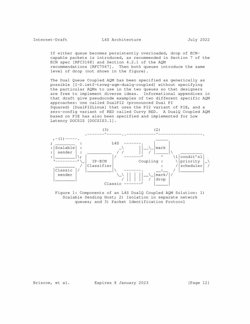
Internet-Draft L4S Architecture July 2022
If either queue becomes persistently overloaded, drop of ECN- capable packets is introduced, as recommended in Section 7 of the ECN spec [RFC3168] and Section 4.2.1 of the AQM recommendations [RFC7567]. Then both queues introduce the same level of drop (not shown in the figure).
The Dual Queue Coupled AQM has been specified as generically as possible [I-D.ietf-tsvwg-aqm-dualq-coupled] without specifying the particular AQMs to use in the two queues so that designers are free to implement diverse ideas. Informational appendices in that draft give pseudocode examples of two different specific AQM approaches: one called DualPI2 (pronounced Dual PI Squared) [DualPI2Linux] that uses the PI2 variant of PIE, and a zero-config variant of RED called Curvy RED. A DualQ Coupled AQM based on PIE has also been specified and implemented for Low Latency DOCSIS [DOCSIS3.1].
(3) (2) .-------^------..------------^------------------. ,-(1)-----. _____ ; ________ : L4S -------. | | :|Scalable| : _\ ||__\_|mark | :| sender | : __________ / / || / |_____|\ _________ :|________|\; | |/ -------’ ^ \1|condit’nl| ‘---------’\_| IP-ECN | Coupling : \|priority |_\ ________ / |Classifier| : /|scheduler| / |Classic |/ |__________|\ -------. __:__ / |_________| | sender | \_\ || | ||__\_|mark/|/ |________| / || | || / |drop | Classic -------’ |_____|
Figure 1: Components of an L4S DualQ Coupled AQM Solution: 1) Scalable Sending Host; 2) Isolation in separate network queues; and 3) Packet Identification Protocol
Briscoe, et al. Expires 8 January 2023 [Page 12]

Internet-Draft L4S Architecture July 2022
b. Per-Flow Queues and AQMs: A scheduler with per-flow queues such as FQ-CoDel or FQ-PIE can be used for L4S. For instance within each queue of an FQ-CoDel system, as well as a CoDel AQM, there is typically also the option of ECN marking at an immediate (unsmoothed) shallow threshold to support use in data centres (see Sec.5.2.7 of the FQ-CoDel spec [RFC8290]). In Linux, this has been modified so that the shallow threshold can be solely applied to ECT(1) packets [FQ_CoDel_Thresh]. Then if there is a flow of non-ECN or ECT(0) packets in the per-flow-queue, the Classic AQM (e.g. CoDel) is applied; while if there is a flow of ECT(1) packets in the queue, the shallower (typically sub- millisecond) threshold is applied. In addition, ECT(0) and not- ECT packets could potentially be classified into a separate flow- queue from ECT(1) and CE packets to avoid them mixing if they share a common flow-identifier (e.g. in a VPN).
c. Dual-queues, but per-flow AQMs: It should also be possible to use dual queues for isolation, but with per-flow marking to control flow-rates (instead of the coupled per-queue marking of the Dual Queue Coupled AQM). One of the two queues would be for isolating L4S packets, which would be classified by the ECN codepoint. Flow rates could be controlled by flow-specific marking. The policy goal of the marking could be to differentiate flow rates (e.g. [Nadas20], which requires additional signalling of a per- flow ’value’), or to equalize flow-rates (perhaps in a similar way to Approx Fair CoDel [AFCD], [I-D.morton-tsvwg-codel-approx-fair], but with two queues not one).
Note that whenever the term ’DualQ’ is used loosely without saying whether marking is per-queue or per-flow, it means a dual queue AQM with per-queue marking.
4.3. Host Mechanisms
The L4S architecture includes two main mechanisms in the end host that we enumerate next:
a. Scalable Congestion Control at the sender: Section 2 defines a scalable congestion control as one where the average time from one congestion signal to the next (the recovery time) remains invariant as the flow rate scales, all other factors being equal. Data Center TCP is the most widely used example. It has been documented as an informational record of the protocol currently in use in controlled environments [RFC8257]. A draft list of safety and performance improvements for a scalable congestion control to be usable on the public Internet has been drawn up (the so-called ’Prague L4S requirements’ in Appendix A of
Briscoe, et al. Expires 8 January 2023 [Page 13]
Internet-Draft L4S Architecture July 2022
[I-D.ietf-tsvwg-ecn-l4s-id]). The subset that involve risk of harm to others have been captured as normative requirements in Section 4 of [I-D.ietf-tsvwg-ecn-l4s-id]. TCP Prague [I-D.briscoe-iccrg-prague-congestion-control] has been implemented in Linux as a reference implementation to address these requirements [PragueLinux].
Transport protocols other than TCP use various congestion controls that are designed to be friendly with Reno. Before they can use the L4S service, they will need to be updated to implement a scalable congestion response, which they will have to indicate by using the ECT(1) codepoint. Scalable variants are under consideration for more recent transport protocols, e.g. QUIC, and the L4S ECN part of BBRv2 [BBRv2], [I-D.cardwell-iccrg-bbr-congestion-control] is a scalable congestion control intended for the TCP and QUIC transports, amongst others. Also an L4S variant of the RMCAT SCReAM controller [RFC8298] has been implemented [SCReAM] for media transported over RTP.
Section 4.3 of the L4S ECN spec [I-D.ietf-tsvwg-ecn-l4s-id] defines scalable congestion control in more detail, and specifies that requirements that an L4S scalable congestion control has to comply with.
b. The ECN feedback in some transport protocols is already sufficiently fine-grained for L4S (specifically DCCP [RFC4340] and QUIC [RFC9000]). But others either require update or are in the process of being updated:
* For the case of TCP, the feedback protocol for ECN embeds the assumption from Classic ECN [RFC3168] that an ECN mark is equivalent to a drop, making it unusable for a scalable TCP. Therefore, the implementation of TCP receivers will have to be upgraded [RFC7560]. Work to standardize and implement more accurate ECN feedback for TCP (AccECN) is in progress [I-D.ietf-tcpm-accurate-ecn], [PragueLinux].
* ECN feedback is only roughly sketched in an appendix of the SCTP specification [RFC4960]. A fuller specification has been proposed in a long-expired draft [I-D.stewart-tsvwg-sctpecn], which would need to be implemented and deployed before SCTP could support L4S.
* For RTP, sufficient ECN feedback was defined in [RFC6679], but [RFC8888] defines the latest standards track improvements.
Briscoe, et al. Expires 8 January 2023 [Page 14]
Internet-Draft L4S Architecture July 2022
5. Rationale
5.1. Why These Primary Components?
Explicit congestion signalling (protocol): Explicit congestion signalling is a key part of the L4S approach. In contrast, use of drop as a congestion signal creates a tension because drop is both an impairment (less would be better) and a useful signal (more would be better):
* Explicit congestion signals can be used many times per round trip, to keep tight control, without any impairment. Under heavy load, even more explicit signals can be applied so the queue can be kept short whatever the load. In contrast, Classic AQMs have to introduce very high packet drop at high load to keep the queue short. By using ECN, an L4S congestion control’s sawtooth reduction can be smaller and therefore return to the operating point more often, without worrying that more sawteeth will cause more signals. The consequent smaller amplitude sawteeth fit between an empty queue and a very shallow marking threshold (˜1 ms in the public Internet), so queue delay variation can be very low, without risk of under- utilization.
* Explicit congestion signals can be emitted immediately to track fluctuations of the queue. L4S shifts smoothing from the network to the host. The network doesn’t know the round trip times of any of the flows. So if the network is responsible for smoothing (as in the Classic approach), it has to assume a worst case RTT, otherwise long RTT flows would become unstable. This delays Classic congestion signals by 100-200 ms. In contrast, each host knows its own round trip time. So, in the L4S approach, the host can smooth each flow over its own RTT, introducing no more smoothing delay than strictly necessary (usually only a few milliseconds). A host can also choose not to introduce any smoothing delay if appropriate, e.g. during flow start-up.
Neither of the above are feasible if explicit congestion signalling has to be considered ’equivalent to drop’ (as was required with Classic ECN [RFC3168]), because drop is an impairment as well as a signal. So drop cannot be excessively frequent, and drop cannot be immediate, otherwise too many drops would turn out to have been due to only a transient fluctuation in the queue that would not have warranted dropping a packet in hindsight. Therefore, in an L4S AQM, the L4S queue uses a new L4S variant of ECN that is not equivalent to drop (see section 5.2 of
Briscoe, et al. Expires 8 January 2023 [Page 15]

Internet-Draft L4S Architecture July 2022
the L4S ECN spec [I-D.ietf-tsvwg-ecn-l4s-id]), while the Classic queue uses either Classic ECN [RFC3168] or drop, which are equivalent to each other.
Before Classic ECN was standardized, there were various proposals to give an ECN mark a different meaning from drop. However, there was no particular reason to agree on any one of the alternative meanings, so ’equivalent to drop’ was the only compromise that could be reached. RFC 3168 contains a statement that:
"An environment where all end nodes were ECN-Capable could allow new criteria to be developed for setting the CE codepoint, and new congestion control mechanisms for end-node reaction to CE packets. However, this is a research issue, and as such is not addressed in this document."
Latency isolation (network): L4S congestion controls keep queue delay low whereas Classic congestion controls need a queue of the order of the RTT to avoid under-utilization. One queue cannot have two lengths, therefore L4S traffic needs to be isolated in a separate queue (e.g. DualQ) or queues (e.g. FQ).
Coupled congestion notification: Coupling the congestion notification between two queues as in the DualQ Coupled AQM is not necessarily essential, but it is a simple way to allow senders to determine their rate, packet by packet, rather than be overridden by a network scheduler. An alternative is for a network scheduler to control the rate of each application flow (see discussion in Section 5.2).
L4S packet identifier (protocol): Once there are at least two treatments in the network, hosts need an identifier at the IP layer to distinguish which treatment they intend to use.
Scalable congestion notification: A scalable congestion control in the host keeps the signalling frequency from the network high whatever the flow rate, so that queue delay variations can be small when conditions are stable, and rate can track variations in available capacity as rapidly as possible otherwise.
Low loss: Latency is not the only concern of L4S. The ’Low Loss’ part of the name denotes that L4S generally achieves zero congestion loss due to its use of ECN. Otherwise, loss would itself cause delay, particularly for short flows, due to retransmission delay [RFC2884].
Scalable throughput: The "Scalable throughput" part of the name
Briscoe, et al. Expires 8 January 2023 [Page 16]

Internet-Draft L4S Architecture July 2022
denotes that the per-flow throughput of scalable congestion controls should scale indefinitely, avoiding the imminent scaling problems with Reno-friendly congestion control algorithms [RFC3649]. It was known when TCP congestion avoidance was first developed in 1988 that it would not scale to high bandwidth-delay products (see footnote 6 in [TCP-CA]). Today, regular broadband flow rates over WAN distances are already beyond the scaling range of Classic Reno congestion control. So ‘less unscalable’ Cubic [RFC8312] and Compound [I-D.sridharan-tcpm-ctcp] variants of TCP have been successfully deployed. However, these are now approaching their scaling limits.
For instance, we will consider a scenario with a maximum RTT of 30 ms at the peak of each sawtooth. As Reno packet rate scales 8x from 1,250 to 10,000 packet/s (from 15 to 120 Mb/s with 1500 B packets), the time to recover from a congestion event rises proportionately by 8x as well, from 422 ms to 3.38 s. It is clearly problematic for a congestion control to take multiple seconds to recover from each congestion event. Cubic [RFC8312] was developed to be less unscalable, but it is approaching its scaling limit; with the same max RTT of 30 ms, at 120 Mb/s Cubic is still fully in its Reno-friendly mode, so it takes about 4.3 s to recover. However, once the flow rate scales by 8x again to 960 Mb/s it enters true Cubic mode, with a recovery time of 12.2 s. From then on, each further scaling by 8x doubles Cubic’s recovery time (because the cube root of 8 is 2), e.g. at 7.68 Gb/s the recovery time is 24.3 s. In contrast a scalable congestion control like DCTCP or TCP Prague induces 2 congestion signals per round trip on average, which remains invariant for any flow rate, keeping dynamic control very tight.
For a feel of where the global average lone-flow download sits on this scale at the time of writing (2021), according to [BDPdata] globally averaged fixed access capacity was 103 Mb/s in 2020 and averaged base RTT to a CDN was 25-34ms in 2019. Averaging of per- country data was weighted by Internet user population (data collected globally is necessarily of variable quality, but the paper does double-check that the outcome compares well against a second source). So a lone CUBIC flow would at best take about 200 round trips (5 s) to recover from each of its sawtooth reductions, if the flow even lasted that long. This is described as ’at best’ because it assume everyone uses an AQM, whereas in reality most users still have a (probably bloated) tail-drop buffer. In the tail-drop case, likely average recovery time would be at least 4x 5 s, if not more, because RTT under load would be at least double that of an AQM, and recovery time depends on the square of RTT.
Briscoe, et al. Expires 8 January 2023 [Page 17]

Internet-Draft L4S Architecture July 2022
Although work on scaling congestion controls tends to start with TCP as the transport, the above is not intended to exclude other transports (e.g. SCTP, QUIC) or less elastic algorithms (e.g. RMCAT), which all tend to adopt the same or similar developments.
5.2. What L4S adds to Existing Approaches
All the following approaches address some part of the same problem space as L4S. In each case, it is shown that L4S complements them or improves on them, rather than being a mutually exclusive alternative:
Diffserv: Diffserv addresses the problem of bandwidth apportionment for important traffic as well as queuing latency for delay- sensitive traffic. Of these, L4S solely addresses the problem of queuing latency. Diffserv will still be necessary where important traffic requires priority (e.g. for commercial reasons, or for protection of critical infrastructure traffic) - see [I-D.briscoe-tsvwg-l4s-diffserv]. Nonetheless, the L4S approach can provide low latency for all traffic within each Diffserv class (including the case where there is only the one default Diffserv class).
Also, Diffserv can only provide a latency benefit if a small subset of the traffic on a bottleneck link requests low latency. As already explained, it has no effect when all the applications in use at one time at a single site (home, small business or mobile device) require low latency. In contrast, because L4S works for all traffic, it needs none of the management baggage (traffic policing, traffic contracts) associated with favouring some packets over others. This lack of management baggage ought to give L4S a better chance of end-to-end deployment.
In particular, because networks tend not to trust end systems to identify which packets should be favoured over others, where networks assign packets to Diffserv classes they tend to use packet inspection of application flow identifiers or deeper inspection of application signatures. Thus, nowadays, Diffserv doesn’t always sit well with encryption of the layers above IP [RFC8404]. So users have to choose between privacy and QoS.
As with Diffserv, the L4S identifier is in the IP header. But, in contrast to Diffserv, the L4S identifier does not convey a want or a need for a certain level of quality. Rather, it promises a certain behaviour (scalable congestion response), which networks can objectively verify if they need to. This is because low delay depends on collective host behaviour, whereas bandwidth priority depends on network behaviour.
Briscoe, et al. Expires 8 January 2023 [Page 18]

Internet-Draft L4S Architecture July 2022
State-of-the-art AQMs: AQMs such as PIE and FQ-CoDel give a significant reduction in queuing delay relative to no AQM at all. L4S is intended to complement these AQMs, and should not distract from the need to deploy them as widely as possible. Nonetheless, AQMs alone cannot reduce queuing delay too far without significantly reducing link utilization, because the root cause of the problem is on the host - where Classic congestion controls use large saw-toothing rate variations. The L4S approach resolves this tension between delay and utilization by enabling hosts to minimize the amplitude of their sawteeth. A single-queue Classic AQM is not sufficient to allow hosts to use small sawteeth for two reasons: i) smaller sawteeth would not get lower delay in an AQM designed for larger amplitude Classic sawteeth, because a queue can only have one length at a time; and ii) much smaller sawteeth implies much more frequent sawteeth, so L4S flows would drive a Classic AQM into a high level of ECN-marking, which would appear as heavy congestion to Classic flows, which in turn would greatly reduce their rate as a result (see Section 6.4.4).
Per-flow queuing or marking: Similarly, per-flow approaches such as FQ-CoDel or Approx Fair CoDel [AFCD] are not incompatible with the L4S approach. However, per-flow queuing alone is not enough - it only isolates the queuing of one flow from others; not from itself. Per-flow implementations need to have support for scalable congestion control added, which has already been done for FQ-CoDel in Linux (see Sec.5.2.7 of [RFC8290] and [FQ_CoDel_Thresh]). Without this simple modification, per-flow AQMs like FQ-CoDel would still not be able to support applications that need both very low delay and high bandwidth, e.g. video-based control of remote procedures, or interactive cloud-based video (see Note 1 below).
Although per-flow techniques are not incompatible with L4S, it is important to have the DualQ alternative. This is because handling end-to-end (layer 4) flows in the network (layer 3 or 2) precludes some important end-to-end functions. For instance:
a. Per-flow forms of L4S like FQ-CoDel are incompatible with full end-to-end encryption of transport layer identifiers for privacy and confidentiality (e.g. IPSec or encrypted VPN tunnels, as opposed to TLS over UDP), because they require packet inspection to access the end-to-end transport flow identifiers.
In contrast, the DualQ form of L4S requires no deeper inspection than the IP layer. So, as long as operators take the DualQ approach, their users can have both very low queuing delay and full end-to-end encryption [RFC8404].
Briscoe, et al. Expires 8 January 2023 [Page 19]

Internet-Draft L4S Architecture July 2022
b. With per-flow forms of L4S, the network takes over control of the relative rates of each application flow. Some see it as an advantage that the network will prevent some flows running faster than others. Others consider it an inherent part of the Internet’s appeal that applications can control their rate while taking account of the needs of others via congestion signals. They maintain that this has allowed applications with interesting rate behaviours to evolve, for instance, variable bit-rate video that varies around an equal share rather than being forced to remain equal at every instant, or e2e scavenger behaviours [RFC6817] that use less than an equal share of capacity [LEDBAT_AQM].
The L4S architecture does not require the IETF to commit to one approach over the other, because it supports both, so that the ’market’ can decide. Nonetheless, in the spirit of ’Do one thing and do it well’ [McIlroy78], the DualQ option provides low delay without prejudging the issue of flow-rate control. Then, flow rate policing can be added separately if desired. This allows application control up to a point, but the network can still choose to set the point at which it intervenes to prevent one flow completely starving another.
Note:
1. It might seem that self-inflicted queuing delay within a per- flow queue should not be counted, because if the delay wasn’t in the network it would just shift to the sender. However, modern adaptive applications, e.g. HTTP/2 [RFC7540] or some interactive media applications (see Section 6.1), can keep low latency objects at the front of their local send queue by shuffling priorities of other objects dependent on the progress of other transfers (for example see [lowat]). They cannot shuffle objects once they have released them into the network.
Alternative Back-off ECN (ABE): Here again, L4S is not an alternative to ABE but a complement that introduces much lower queuing delay. ABE [RFC8511] alters the host behaviour in response to ECN marking to utilize a link better and give ECN flows faster throughput. It uses ECT(0) and assumes the network still treats ECN and drop the same. Therefore ABE exploits any lower queuing delay that AQMs can provide. But as explained above, AQMs still cannot reduce queuing delay too far without losing link utilization (to allow for other, non-ABE, flows).
BBR: Bottleneck Bandwidth and Round-trip propagation time
Briscoe, et al. Expires 8 January 2023 [Page 20]

Internet-Draft L4S Architecture July 2022
(BBR [I-D.cardwell-iccrg-bbr-congestion-control]) controls queuing delay end-to-end without needing any special logic in the network, such as an AQM. So it works pretty-much on any path. BBR keeps queuing delay reasonably low, but perhaps not quite as low as with state-of-the-art AQMs such as PIE or FQ-CoDel, and certainly nowhere near as low as with L4S. Queuing delay is also not consistently low, due to BBR’s regular bandwidth probing spikes and its aggressive flow start-up phase.
L4S complements BBR. Indeed BBRv2 can use L4S ECN where available and a scalable L4S congestion control behaviour in response to any ECN signalling from the path [BBRv2]. The L4S ECN signal complements the delay based congestion control aspects of BBR with an explicit indication that hosts can use, both to converge on a fair rate and to keep below a shallow queue target set by the network. Without L4S ECN, both these aspects need to be assumed or estimated.
6. Applicability
6.1. Applications
A transport layer that solves the current latency issues will provide new service, product and application opportunities.
With the L4S approach, the following existing applications also experience significantly better quality of experience under load:
* Gaming, including cloud based gaming;
* VoIP;
* Video conferencing;
* Web browsing;
* (Adaptive) video streaming;
* Instant messaging.
The significantly lower queuing latency also enables some interactive application functions to be offloaded to the cloud that would hardly even be usable today:
* Cloud based interactive video;
* Cloud based virtual and augmented reality.
Briscoe, et al. Expires 8 January 2023 [Page 21]

Internet-Draft L4S Architecture July 2022
The above two applications have been successfully demonstrated with L4S, both running together over a 40 Mb/s broadband access link loaded up with the numerous other latency sensitive applications in the previous list as well as numerous downloads - all sharing the same bottleneck queue simultaneously [L4Sdemo16]. For the former, a panoramic video of a football stadium could be swiped and pinched so that, on the fly, a proxy in the cloud could generate a sub-window of the match video under the finger-gesture control of each user. For the latter, a virtual reality headset displayed a viewport taken from a 360 degree camera in a racing car. The user’s head movements controlled the viewport extracted by a cloud-based proxy. In both cases, with 7 ms end-to-end base delay, the additional queuing delay of roughly 1 ms was so low that it seemed the video was generated locally.
Using a swiping finger gesture or head movement to pan a video are extremely latency-demanding actions -- far more demanding than VoIP. Because human vision can detect extremely low delays of the order of single milliseconds when delay is translated into a visual lag between a video and a reference point (the finger or the orientation of the head sensed by the balance system in the inner ear -- the vestibular system).
Without the low queuing delay of L4S, cloud-based applications like these would not be credible without significantly more access bandwidth (to deliver all possible video that might be viewed) and more local processing, which would increase the weight and power consumption of head-mounted displays. When all interactive processing can be done in the cloud, only the data to be rendered for the end user needs to be sent.
Other low latency high bandwidth applications such as:
* Interactive remote presence;
* Video-assisted remote control of machinery or industrial processes.
are not credible at all without very low queuing delay. No amount of extra access bandwidth or local processing can make up for lost time.
6.2. Use Cases
The following use-cases for L4S are being considered by various interested parties:
Briscoe, et al. Expires 8 January 2023 [Page 22]

Internet-Draft L4S Architecture July 2022
* Where the bottleneck is one of various types of access network: e.g. DSL, Passive Optical Networks (PON), DOCSIS cable, mobile, satellite (see Section 6.3 for some technology-specific details)
* Private networks of heterogeneous data centres, where there is no single administrator that can arrange for all the simultaneous changes to senders, receivers and network needed to deploy DCTCP:
- a set of private data centres interconnected over a wide area with separate administrations, but within the same company
- a set of data centres operated by separate companies interconnected by a community of interest network (e.g. for the finance sector)
- multi-tenant (cloud) data centres where tenants choose their operating system stack (Infrastructure as a Service - IaaS)
* Different types of transport (or application) congestion control:
- elastic (TCP/SCTP);
- real-time (RTP, RMCAT);
- query (DNS/LDAP).
* Where low delay quality of service is required, but without inspecting or intervening above the IP layer [RFC8404]:
- mobile and other networks have tended to inspect higher layers in order to guess application QoS requirements. However, with growing demand for support of privacy and encryption, L4S offers an alternative. There is no need to select which traffic to favour for queuing, when L4S can give favourable queuing to all traffic.
* If queuing delay is minimized, applications with a fixed delay budget can communicate over longer distances, or via a longer chain of service functions [RFC7665] or onion routers.
* If delay jitter is minimized, it is possible to reduce the dejitter buffers on the receive end of video streaming, which should improve the interactive experience
Briscoe, et al. Expires 8 January 2023 [Page 23]
Internet-Draft L4S Architecture July 2022
6.3. Applicability with Specific Link Technologies
Certain link technologies aggregate data from multiple packets into bursts, and buffer incoming packets while building each burst. WiFi, PON and cable all involve such packet aggregation, whereas fixed Ethernet and DSL do not. No sender, whether L4S or not, can do anything to reduce the buffering needed for packet aggregation. So an AQM should not count this buffering as part of the queue that it controls, given no amount of congestion signals will reduce it.
Certain link technologies also add buffering for other reasons, specifically:
* Radio links (cellular, WiFi, satellite) that are distant from the source are particularly challenging. The radio link capacity can vary rapidly by orders of magnitude, so it is considered desirable to hold a standing queue that can utilize sudden increases of capacity;
* Cellular networks are further complicated by a perceived need to buffer in order to make hand-overs imperceptible;
L4S cannot remove the need for all these different forms of buffering. However, by removing ’the longest pole in the tent’ (buffering for the large sawteeth of Classic congestion controls), L4S exposes all these ’shorter poles’ to greater scrutiny.
Until now, the buffering needed for these additional reasons tended to be over-specified - with the excuse that none were ’the longest pole in the tent’. But having removed the ’longest pole’, it becomes worthwhile to minimize them, for instance reducing packet aggregation burst sizes and MAC scheduling intervals.
6.4. Deployment Considerations
L4S AQMs, whether DualQ [I-D.ietf-tsvwg-aqm-dualq-coupled] or FQ, e.g. [RFC8290] are, in themselves, an incremental deployment mechanism for L4S - so that L4S traffic can coexist with existing Classic (Reno-friendly) traffic. Section 6.4.1 explains why only deploying an L4S AQM in one node at each end of the access link will realize nearly all the benefit of L4S.
L4S involves both end systems and the network, so Section 6.4.2 suggests some typical sequences to deploy each part, and why there will be an immediate and significant benefit after deploying just one part.
Briscoe, et al. Expires 8 January 2023 [Page 24]
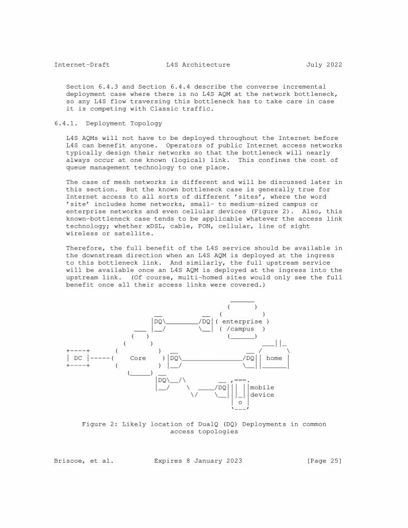
Internet-Draft L4S Architecture July 2022
Section 6.4.3 and Section 6.4.4 describe the converse incremental deployment case where there is no L4S AQM at the network bottleneck, so any L4S flow traversing this bottleneck has to take care in case it is competing with Classic traffic.
6.4.1. Deployment Topology
L4S AQMs will not have to be deployed throughout the Internet before L4S can benefit anyone. Operators of public Internet access networks typically design their networks so that the bottleneck will nearly always occur at one known (logical) link. This confines the cost of queue management technology to one place.
The case of mesh networks is different and will be discussed later in this section. But the known bottleneck case is generally true for Internet access to all sorts of different ’sites’, where the word ’site’ includes home networks, small- to medium-sized campus or enterprise networks and even cellular devices (Figure 2). Also, this known-bottleneck case tends to be applicable whatever the access link technology; whether xDSL, cable, PON, cellular, line of sight wireless or satellite.
Therefore, the full benefit of the L4S service should be available in the downstream direction when an L4S AQM is deployed at the ingress to this bottleneck link. And similarly, the full upstream service will be available once an L4S AQM is deployed at the ingress into the upstream link. (Of course, multi-homed sites would only see the full benefit once all their access links were covered.)
______ ( ) __ __ ( ) |DQ\________/DQ|( enterprise ) ___ |__/ \__| ( /campus ) ( ) (______) ( ) ___||_ +----+ ( ) __ __ / \ | DC |-----( Core )|DQ\_______________/DQ|| home | +----+ ( ) |__/ \__||______| (_____) __ |DQ\__/\ __ ,===. |__/ \ ____/DQ||| ||mobile \/ \__|||_||device | o | ‘---’
Figure 2: Likely location of DualQ (DQ) Deployments in common access topologies
Briscoe, et al. Expires 8 January 2023 [Page 25]

Internet-Draft L4S Architecture July 2022
Deployment in mesh topologies depends on how overbooked the core is. If the core is non-blocking, or at least generously provisioned so that the edges are nearly always the bottlenecks, it would only be necessary to deploy an L4S AQM at the edge bottlenecks. For example, some data-centre networks are designed with the bottleneck in the hypervisor or host NICs, while others bottleneck at the top-of-rack switch (both the output ports facing hosts and those facing the core).
An L4S AQM would often next be needed where the WiFi links in a home sometimes become the bottleneck. And an L4S AQM would eventually also need to be deployed at any other persistent bottlenecks such as network interconnections, e.g. some public Internet exchange points and the ingress and egress to WAN links interconnecting data-centres.
6.4.2. Deployment Sequences
For any one L4S flow to provide benefit, it requires three (or sometimes two) parts to have been deployed: i) the congestion control at the sender; ii) the AQM at the bottleneck; and iii) older transports (namely TCP) need upgraded receiver feedback too. This was the same deployment problem that ECN faced [RFC8170] so we have learned from that experience.
Firstly, L4S deployment exploits the fact that DCTCP already exists on many Internet hosts (Windows, FreeBSD and Linux); both servers and clients. Therefore, an L4S AQM can be deployed at a network bottleneck to immediately give a working deployment of all the L4S parts for testing, as long as the ECT(0) codepoint is switched to ECT(1). DCTCP needs some safety concerns to be fixed for general use over the public Internet (see Section 4.3 of the L4S ECN spec [I-D.ietf-tsvwg-ecn-l4s-id]), but DCTCP is not on by default, so these issues can be managed within controlled deployments or controlled trials.
Secondly, the performance improvement with L4S is so significant that it enables new interactive services and products that were not previously possible. It is much easier for companies to initiate new work on deployment if there is budget for a new product trial. If, in contrast, there were only an incremental performance improvement (as with Classic ECN), spending on deployment tends to be much harder to justify.
Thirdly, the L4S identifier is defined so that initially network operators can enable L4S exclusively for certain customers or certain applications. But this is carefully defined so that it does not compromise future evolution towards L4S as an Internet-wide service. This is because the L4S identifier is defined not only as the end-to-
Briscoe, et al. Expires 8 January 2023 [Page 26]
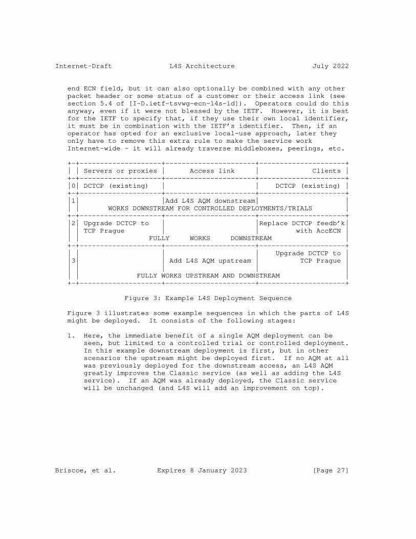
Internet-Draft L4S Architecture July 2022
end ECN field, but it can also optionally be combined with any other packet header or some status of a customer or their access link (see section 5.4 of [I-D.ietf-tsvwg-ecn-l4s-id]). Operators could do this anyway, even if it were not blessed by the IETF. However, it is best for the IETF to specify that, if they use their own local identifier, it must be in combination with the IETF’s identifier. Then, if an operator has opted for an exclusive local-use approach, later they only have to remove this extra rule to make the service work Internet-wide - it will already traverse middleboxes, peerings, etc.
+-+--------------------+----------------------+---------------------+ | | Servers or proxies | Access link | Clients | +-+--------------------+----------------------+---------------------+ |0| DCTCP (existing) | | DCTCP (existing) | +-+--------------------+----------------------+---------------------+ |1| |Add L4S AQM downstream| | | | WORKS DOWNSTREAM FOR CONTROLLED DEPLOYMENTS/TRIALS | +-+--------------------+----------------------+---------------------+ |2| Upgrade DCTCP to | |Replace DCTCP feedb’k| | | TCP Prague | | with AccECN | | | FULLY WORKS DOWNSTREAM | +-+--------------------+----------------------+---------------------+ | | | | Upgrade DCTCP to | |3| | Add L4S AQM upstream | TCP Prague | | | | | | | | FULLY WORKS UPSTREAM AND DOWNSTREAM | +-+--------------------+----------------------+---------------------+
Figure 3: Example L4S Deployment Sequence
Figure 3 illustrates some example sequences in which the parts of L4S might be deployed. It consists of the following stages:
1. Here, the immediate benefit of a single AQM deployment can be seen, but limited to a controlled trial or controlled deployment. In this example downstream deployment is first, but in other scenarios the upstream might be deployed first. If no AQM at all was previously deployed for the downstream access, an L4S AQM greatly improves the Classic service (as well as adding the L4S service). If an AQM was already deployed, the Classic service will be unchanged (and L4S will add an improvement on top).
Briscoe, et al. Expires 8 January 2023 [Page 27]

Internet-Draft L4S Architecture July 2022
2. In this stage, the name ’TCP Prague’ [I-D.briscoe-iccrg-prague-congestion-control] is used to represent a variant of DCTCP that is designed to be used in a production Internet environment (assuming it complies with the requirements in Section 4 of the L4S ECN spec [I-D.ietf-tsvwg-ecn-l4s-id]). If the application is primarily unidirectional, ’TCP Prague’ at one end will provide all the benefit needed.
For TCP transports, Accurate ECN feedback (AccECN) [I-D.ietf-tcpm-accurate-ecn] is needed at the other end, but it is a generic ECN feedback facility that is already planned to be deployed for other purposes, e.g. DCTCP, BBR. The two ends can be deployed in either order, because, in TCP, an L4S congestion control only enables itself if it has negotiated the use of AccECN feedback with the other end during the connection handshake. Thus, deployment of TCP Prague on a server enables L4S trials to move to a production service in one direction, wherever AccECN is deployed at the other end. This stage might be further motivated by the performance improvements of TCP Prague relative to DCTCP (see Appendix A.2 of the L4S ECN spec [I-D.ietf-tsvwg-ecn-l4s-id]).
Unlike TCP, from the outset, QUIC ECN feedback [RFC9000] has supported L4S. Therefore, if the transport is QUIC, one-ended deployment of a Prague congestion control at this stage is simple and sufficient.
For QUIC, if a proxy sits in the path between multiple origin servers and the access bottlenecks to multiple clients, then upgrading the proxy to a Scalable CC would provide the benefits of L4S over all the clients’ downstream bottlenecks in one go --- whether or not all the origin servers were upgraded. Conversely, where a proxy has not been upgraded, the clients served by it will not benefit from L4S at all in the downstream, even when any origin server behind the proxy has been upgraded to support L4S.
For TCP, a proxy upgraded to support ’TCP Prague’ would provide the benefits of L4S downstream to all clients that support AccECN (whether or not they support L4S as well). And in the upstream, the proxy would also support AccECN as a receiver, so that any client deploying its own L4S support would benefit in the upstream direction, irrespective of whether any origin server beyond the proxy supported AccECN.
3. This is a two-move stage to enable L4S upstream. An L4S AQM or TCP Prague can be deployed in either order as already explained. To motivate the first of two independent moves, the deferred
Briscoe, et al. Expires 8 January 2023 [Page 28]

Internet-Draft L4S Architecture July 2022
benefit of enabling new services after the second move has to be worth it to cover the first mover’s investment risk. As explained already, the potential for new interactive services provides this motivation. An L4S AQM also improves the upstream Classic service - significantly if no other AQM has already been deployed.
Note that other deployment sequences might occur. For instance: the upstream might be deployed first; a non-TCP protocol might be used end-to-end, e.g. QUIC, RTP; a body such as the 3GPP might require L4S to be implemented in 5G user equipment, or other random acts of kindness.
6.4.3. L4S Flow but Non-ECN Bottleneck
If L4S is enabled between two hosts, the L4S sender is required to coexist safely with Reno in response to any drop (see Section 4.3 of the L4S ECN spec [I-D.ietf-tsvwg-ecn-l4s-id]).
Unfortunately, as well as protecting Classic traffic, this rule degrades the L4S service whenever there is any loss, even if the cause is not persistent congestion at a bottleneck, e.g.:
* congestion loss at other transient bottlenecks, e.g. due to bursts in shallower queues;
* transmission errors, e.g. due to electrical interference;
* rate policing.
Three complementary approaches are in progress to address this issue, but they are all currently research:
* In Prague congestion control, ignore certain losses deemed unlikely to be due to congestion (using some ideas from BBR [I-D.cardwell-iccrg-bbr-congestion-control] regarding isolated losses). This could mask any of the above types of loss while still coexisting with drop-based congestion controls.
* A combination of RACK, L4S and link retransmission without resequencing could repair transmission errors without the head of line blocking delay usually associated with link-layer retransmission [UnorderedLTE], [I-D.ietf-tsvwg-ecn-l4s-id];
* Hybrid ECN/drop rate policers (see Section 8.3).
Briscoe, et al. Expires 8 January 2023 [Page 29]

Internet-Draft L4S Architecture July 2022
L4S deployment scenarios that minimize these issues (e.g. over wireline networks) can proceed in parallel to this research, in the expectation that research success could continually widen L4S applicability.
6.4.4. L4S Flow but Classic ECN Bottleneck
Classic ECN support is starting to materialize on the Internet as an increased level of CE marking. It is hard to detect whether this is all due to the addition of support for ECN in implementations of FQ- CoDel and/or FQ-COBALT, which is not generally problematic, because flow-queue (FQ) scheduling inherently prevents a flow from exceeding the ’fair’ rate irrespective of its aggressiveness. However, some of this Classic ECN marking might be due to single-queue ECN deployment. This case is discussed in Section 4.3 of the L4S ECN spec [I-D.ietf-tsvwg-ecn-l4s-id].
6.4.5. L4S AQM Deployment within Tunnels
An L4S AQM uses the ECN field to signal congestion. So, in common with Classic ECN, if the AQM is within a tunnel or at a lower layer, correct functioning of ECN signalling requires correct propagation of the ECN field up the layers [RFC6040], [I-D.ietf-tsvwg-rfc6040update-shim], [I-D.ietf-tsvwg-ecn-encap-guidelines].
7. IANA Considerations (to be removed by RFC Editor)
This specification contains no IANA considerations.
8. Security Considerations
8.1. Traffic Rate (Non-)Policing
In the current Internet, scheduling usually enforces separation between ’sites’ (e.g. households, businesses or mobile users [RFC0970]) and various techniques like redirection to traffic scrubbing facilities deal with flooding attacks. However, there has never been a universal need to police the rate of individual application flows - the Internet has generally always relied on self- restraint of congestion controls at senders for sharing intra-’site’ capacity.
As explained in Section 5.2, the DualQ variant of L4S provides low delay without prejudging the issue of flow-rate control. Then, if flow-rate control is needed, per-flow-queuing (FQ) can be used instead, or flow rate policing can be added as a modular addition to a DualQ.
Briscoe, et al. Expires 8 January 2023 [Page 30]

Internet-Draft L4S Architecture July 2022
Because the L4S service reduces delay without increasing the delay of Classic traffic, it should not be necessary to rate-police access to the L4S service. In contrast, Section 5.2 explains how Diffserv only makes a difference if some packets get less favourable treatment than others, which typically requires traffic rate policing, which can, in turn, lead to further complexity such as traffic contracts at trust boundaries. Because L4S avoids this management complexity, it is more likely to work end-to-end.
During early deployment (and perhaps always), some networks will not offer the L4S service. In general, these networks should not need to police L4S traffic. They are required (by both the ECN spec [RFC3168] and the L4S ECN spec [I-D.ietf-tsvwg-ecn-l4s-id]) not to change the L4S identifier, which would interfere with end-to-end congestion control. If they already treat ECN traffic as Not-ECT, they can merely treat L4S traffic as Not-ECT too. At a bottleneck, such networks will introduce some queuing and dropping. When a scalable congestion control detects a drop it will have to respond safely with respect to Classic congestion controls (as required in Section 4.3 of [I-D.ietf-tsvwg-ecn-l4s-id]). This will degrade the L4S service to be no better (but never worse) than Classic best efforts, whenever a non-ECN bottleneck is encountered on a path (see Section 6.4.3).
In cases that are expected to be rare, networks that solely support Classic ECN [RFC3168] in a single queue bottleneck might opt to police L4S traffic so as to protect competing Classic ECN traffic (for instance, see Section 6.1.3 of the L4S operational guidance [I-D.ietf-tsvwg-l4sops]). However, Section 4.3 of the L4S ECN spec [I-D.ietf-tsvwg-ecn-l4s-id] recommends that the sender adapts its congestion response to properly coexist with Classic ECN flows, i.e. reverting to the self-restraint approach.
Briscoe, et al. Expires 8 January 2023 [Page 31]

Internet-Draft L4S Architecture July 2022
Certain network operators might choose to restrict access to the L4S class, perhaps only to selected premium customers as a value-added service. Their packet classifier (item 2 in Figure 1) could identify such customers against some other field (e.g. source address range) as well as classifying on the ECN field. If only the ECN L4S identifier matched, but not the source address (say), the classifier could direct these packets (from non-premium customers) into the Classic queue. Explaining clearly how operators can use an additional local classifiers (see section 5.4 of the L4S ECN spec [I-D.ietf-tsvwg-ecn-l4s-id]) is intended to remove any motivation to clear the L4S identifier. Then at least the L4S ECN identifier will be more likely to survive end-to-end even though the service may not be supported at every hop. Such local arrangements would only require simple registered/not-registered packet classification, rather than the managed, application-specific traffic policing against customer-specific traffic contracts that Diffserv uses.
8.2. ’Latency Friendliness’
Like the Classic service, the L4S service relies on self-restraint - limiting rate in response to congestion. In addition, the L4S service requires self-restraint in terms of limiting latency (burstiness). It is hoped that self-interest and guidance on dynamic behaviour (especially flow start-up, which might need to be standardized) will be sufficient to prevent transports from sending excessive bursts of L4S traffic, given the application’s own latency will suffer most from such behaviour.
Whether burst policing becomes necessary remains to be seen. Without it, there will be potential for attacks on the low latency of the L4S service.
If needed, various arrangements could be used to address this concern:
Local bottleneck queue protection: A per-flow (5-tuple) queue protection function [I-D.briscoe-docsis-q-protection] has been developed for the low latency queue in DOCSIS, which has adopted the DualQ L4S architecture. It protects the low latency service from any queue-building flows that accidentally or maliciously classify themselves into the low latency queue. It is designed to score flows based solely on their contribution to queuing (not flow rate in itself). Then, if the shared low latency queue is at risk of exceeding a threshold, the function redirects enough packets of the highest scoring flow(s) into the Classic queue to preserve low latency.
Briscoe, et al. Expires 8 January 2023 [Page 32]

Internet-Draft L4S Architecture July 2022
Distributed traffic scrubbing: Rather than policing locally at each bottleneck, it may only be necessary to address problems reactively, e.g. punitively target any deployments of new bursty malware, in a similar way to how traffic from flooding attack sources is rerouted via scrubbing facilities.
Local bottleneck per-flow scheduling: Per-flow scheduling should inherently isolate non-bursty flows from bursty (see Section 5.2 for discussion of the merits of per-flow scheduling relative to per-flow policing).
Distributed access subnet queue protection: Per-flow queue protection could be arranged for a queue structure distributed across a subnet inter-communicating using lower layer control messages (see Section 2.1.4 of [QDyn]). For instance, in a radio access network, user equipment already sends regular buffer status reports to a radio network controller, which could use this information to remotely police individual flows.
Distributed Congestion Exposure to Ingress Policers: The Congestion Exposure (ConEx) architecture [RFC7713] uses egress audit to motivate senders to truthfully signal path congestion in-band where it can be used by ingress policers. An edge-to-edge variant of this architecture is also possible.
Distributed Domain-edge traffic conditioning: An architecture similar to Diffserv [RFC2475] may be preferred, where traffic is proactively conditioned on entry to a domain, rather than reactively policed only if it leads to queuing once combined with other traffic at a bottleneck.
Distributed core network queue protection: The policing function could be divided between per-flow mechanisms at the network ingress that characterize the burstiness of each flow into a signal carried with the traffic, and per-class mechanisms at bottlenecks that act on these signals if queuing actually occurs once the traffic converges. This would be somewhat similar to [Nadas20], which is in turn similar to the idea behind core stateless fair queuing.
None of these possible queue protection capabilities are considered a necessary part of the L4S architecture, which works without them (in a similar way to how the Internet works without per-flow rate policing). Indeed, even where latency policers are deployed, under normal circumstances they would not intervene, and if operators found they were not necessary they could disable them. Part of the L4S experiment will be to see whether such a function is necessary, and which arrangements are most appropriate to the size of the problem.
Briscoe, et al. Expires 8 January 2023 [Page 33]

Internet-Draft L4S Architecture July 2022
8.3. Interaction between Rate Policing and L4S
As mentioned in Section 5.2, L4S should remove the need for low latency Diffserv classes. However, those Diffserv classes that give certain applications or users priority over capacity, would still be applicable in certain scenarios (e.g. corporate networks). Then, within such Diffserv classes, L4S would often be applicable to give traffic low latency and low loss as well. Within such a Diffserv class, the bandwidth available to a user or application is often limited by a rate policer. Similarly, in the default Diffserv class, rate policers are used to partition shared capacity.
A classic rate policer drops any packets exceeding a set rate, usually also giving a burst allowance (variants exist where the policer re-marks non-compliant traffic to a discard-eligible Diffserv codepoint, so they can be dropped elsewhere during contention). Whenever L4S traffic encounters one of these rate policers, it will experience drops and the source will have to fall back to a Classic congestion control, thus losing the benefits of L4S (Section 6.4.3). So, in networks that already use rate policers and plan to deploy L4S, it will be preferable to redesign these rate policers to be more friendly to the L4S service.
L4S-friendly rate policing is currently a research area (note that this is not the same as latency policing). It might be achieved by setting a threshold where ECN marking is introduced, such that it is just under the policed rate or just under the burst allowance where drop is introduced. For instance the two-rate three-colour marker [RFC2698] or a PCN threshold and excess-rate marker [RFC5670] could mark ECN at the lower rate and drop at the higher. Or an existing rate policer could have congestion-rate policing added, e.g. using the ’local’ (non-ConEx) variant of the ConEx aggregate congestion policer [I-D.briscoe-conex-policing]. It might also be possible to design scalable congestion controls to respond less catastrophically to loss that has not been preceded by a period of increasing delay.
The design of L4S-friendly rate policers will require a separate dedicated document. For further discussion of the interaction between L4S and Diffserv, see [I-D.briscoe-tsvwg-l4s-diffserv].
8.4. ECN Integrity
Receiving hosts can fool a sender into downloading faster by suppressing feedback of ECN marks (or of losses if retransmissions are not necessary or available otherwise). Various ways to protect transport feedback integrity have been developed. For instance:
Briscoe, et al. Expires 8 January 2023 [Page 34]

Internet-Draft L4S Architecture July 2022
* The sender can test the integrity of the receiver’s feedback by occasionally setting the IP-ECN field to the congestion experienced (CE) codepoint, which is normally only set by a congested link. Then the sender can test whether the receiver’s feedback faithfully reports what it expects (see 2nd para of Section 20.2 of the Classic ECN spec [RFC3168]).
* A network can enforce a congestion response to its ECN markings (or packet losses) by auditing congestion exposure (ConEx) [RFC7713].
* Transport layer authentication such as the TCP authentication option (TCP-AO [RFC5925]) or QUIC’s use of TLS [RFC9001] can detect any tampering with congestion feedback.
* The ECN Nonce [RFC3540] was proposed to detect tampering with congestion feedback, but it has been reclassified as historic [RFC8311].
Appendix C.1 of the L4S ECN spec [I-D.ietf-tsvwg-ecn-l4s-id] gives more details of these techniques including their applicability and pros and cons.
8.5. Privacy Considerations
As discussed in Section 5.2, the L4S architecture does not preclude approaches that inspect end-to-end transport layer identifiers. For instance, L4S support has been added to FQ-CoDel, which classifies by application flow ID in the network. However, the main innovation of L4S is the DualQ AQM framework that does not need to inspect any deeper than the outermost IP header, because the L4S identifier is in the IP-ECN field.
Thus, the L4S architecture enables very low queuing delay without _requiring_ inspection of information above the IP layer. This means that users who want to encrypt application flow identifiers, e.g. in IPSec or other encrypted VPN tunnels, don’t have to sacrifice low delay [RFC8404].
Because L4S can provide low delay for a broad set of applications that choose to use it, there is no need for individual applications or classes within that broad set to be distinguishable in any way while traversing networks. This removes much of the ability to correlate between the delay requirements of traffic and other identifying features [RFC6973]. There may be some types of traffic that prefer not to use L4S, but the coarse binary categorization of traffic reveals very little that could be exploited to compromise privacy.
Briscoe, et al. Expires 8 January 2023 [Page 35]
Internet-Draft L4S Architecture July 2022
9. Acknowledgements
Thanks to Richard Scheffenegger, Wes Eddy, Karen Nielsen, David Black, Jake Holland, Vidhi Goel, Ermin Sakic, Praveen Balasubramanian, Gorry Fairhurst, Mirja Kuehlewind, Philip Eardley, Neal Cardwell, Pete Heist and Martin Duke for their useful review comments.
Bob Briscoe and Koen De Schepper were part-funded by the European Community under its Seventh Framework Programme through the Reducing Internet Transport Latency (RITE) project (ICT-317700). The contribution of Koen De Schepper was also part-funded by the 5Growth and DAEMON EU H2020 projects. Bob Briscoe was also part-funded by the Research Council of Norway through the TimeIn project, partly by CableLabs and partly by the Comcast Innovation Fund. The views expressed here are solely those of the authors.
10. Informative References
[AFCD] Xue, L., Kumar, S., Cui, C., Kondikoppa, P., Chiu, C-H., and S-J. Park, "Towards fair and low latency next generation high speed networks: AFCD queuing", Journal of Network and Computer Applications 70:183--193, July 2016, <https://doi.org/10.1016/j.jnca.2016.03.021>.
[BBRv2] Cardwell, N., "TCP BBR v2 Alpha/Preview Release", github repository; Linux congestion control module, <https://github.com/google/bbr/blob/v2alpha/README.md>.
[BDPdata] Briscoe, B., "PI2 Parameters", Technical Report TR-BB- 2021-001 arXiv:2107.01003 [cs.NI], July 2021, <https://arxiv.org/abs/2107.01003>.
[BufferSize] Appenzeller, G., Keslassy, I., and N. McKeown, "Sizing Router Buffers", In Proc. SIGCOMM’04 34(4):281--292, September 2004, <https://doi.org/10.1145/1015467.1015499>.
[COBALT] Palmei, J., Gupta, S., Imputato, P., Morton, J., Tahiliani, M. P., Avallone, S., and D. Täht, "Design and Evaluation of COBALT Queue Discipline", In Proc. IEEE Int’l Symp. Local and Metropolitan Area Networks (LANMAN’19) 2019:1-6, July 2019, <https://ieeexplore.ieee.org/abstract/document/8847054>.
Briscoe, et al. Expires 8 January 2023 [Page 36]
Internet-Draft L4S Architecture July 2022
[DCttH19] De Schepper, K., Bondarenko, O., Tilmans, O., and B. Briscoe, "‘Data Centre to the Home’: Ultra-Low Latency for All", Updated RITE project Technical Report , July 2019, <https://bobbriscoe.net/pubs.html#DCttH_TR>.
[DOCSIS3.1] CableLabs, "MAC and Upper Layer Protocols Interface (MULPI) Specification, CM-SP-MULPIv3.1", Data-Over-Cable Service Interface Specifications DOCSIS® 3.1 Version i17 or later, 21 January 2019, <https://specification- search.cablelabs.com/CM-SP-MULPIv3.1>.
[DOCSIS3AQM] White, G., "Active Queue Management Algorithms for DOCSIS 3.0; A Simulation Study of CoDel, SFQ-CoDel and PIE in DOCSIS 3.0 Networks", CableLabs Technical Report , April 2013, <{http://www.cablelabs.com/wp- content/uploads/2013/11/ Active_Queue_Management_Algorithms_DOCSIS_3_0.pdf>.
[DualPI2Linux] Albisser, O., De Schepper, K., Briscoe, B., Tilmans, O., and H. Steen, "DUALPI2 - Low Latency, Low Loss and Scalable (L4S) AQM", Proc. Linux Netdev 0x13 , March 2019, <https://www.netdevconf.org/0x13/session.html?talk- DUALPI2-AQM>.
[Dukkipati06] Dukkipati, N. and N. McKeown, "Why Flow-Completion Time is the Right Metric for Congestion Control", ACM CCR 36(1):59--62, January 2006, <https://dl.acm.org/doi/10.1145/1111322.1111336>.
[FQ_CoDel_Thresh] Høiland-Jørgensen, T., "fq_codel: generalise ce_threshold marking for subset of traffic", Linux Patch Commit ID: dfcb63ce1de6b10b, 20 October 2021, <https://git.kernel.org/pub/scm/linux/kernel/git/netdev/ net-next.git/commit/?id=dfcb63ce1de6b10b>.
[Hohlfeld14] Hohlfeld, O., Pujol, E., Ciucu, F., Feldmann, A., and P. Barford, "A QoE Perspective on Sizing Network Buffers", Proc. ACM Internet Measurement Conf (IMC’14) hmm, November 2014, <http://doi.acm.org/10.1145/2663716.2663730>.
Briscoe, et al. Expires 8 January 2023 [Page 37]
Internet-Draft L4S Architecture July 2022
[I-D.briscoe-conex-policing] Briscoe, B., "Network Performance Isolation using Congestion Policing", Work in Progress, Internet-Draft, draft-briscoe-conex-policing-01, 14 February 2014, <https://datatracker.ietf.org/doc/html/draft-briscoe- conex-policing-01>.
[I-D.briscoe-docsis-q-protection] Briscoe, B. and G. White, "The DOCSIS(r) Queue Protection Algorithm to Preserve Low Latency", Work in Progress, Internet-Draft, draft-briscoe-docsis-q-protection-06, 13 May 2022, <https://datatracker.ietf.org/doc/html/draft- briscoe-docsis-q-protection-06>.
[I-D.briscoe-iccrg-prague-congestion-control] Schepper, K. D., Tilmans, O., and B. Briscoe, "Prague Congestion Control", Work in Progress, Internet-Draft, draft-briscoe-iccrg-prague-congestion-control-00, 9 March 2021, <https://datatracker.ietf.org/doc/html/draft- briscoe-iccrg-prague-congestion-control-00>.
[I-D.briscoe-tsvwg-l4s-diffserv] Briscoe, B., "Interactions between Low Latency, Low Loss, Scalable Throughput (L4S) and Differentiated Services", Work in Progress, Internet-Draft, draft-briscoe-tsvwg-l4s- diffserv-02, 4 November 2018, <https://datatracker.ietf.org/doc/html/draft-briscoe- tsvwg-l4s-diffserv-02>.
[I-D.cardwell-iccrg-bbr-congestion-control] Cardwell, N., Cheng, Y., Yeganeh, S. H., Swett, I., and V. Jacobson, "BBR Congestion Control", Work in Progress, Internet-Draft, draft-cardwell-iccrg-bbr-congestion- control-02, 7 March 2022, <https://datatracker.ietf.org/doc/html/draft-cardwell- iccrg-bbr-congestion-control-02>.
[I-D.ietf-tcpm-accurate-ecn] Briscoe, B., Kühlewind, M., and R. Scheffenegger, "More Accurate ECN Feedback in TCP", Work in Progress, Internet- Draft, draft-ietf-tcpm-accurate-ecn-18, 22 March 2022, <https://datatracker.ietf.org/doc/html/draft-ietf-tcpm- accurate-ecn-18>.
[I-D.ietf-tsvwg-aqm-dualq-coupled] Schepper, K. D., Briscoe, B., and G. White, "DualQ Coupled AQMs for Low Latency, Low Loss and Scalable Throughput (L4S)", Work in Progress, Internet-Draft, draft-ietf-
Briscoe, et al. Expires 8 January 2023 [Page 38]

Internet-Draft L4S Architecture July 2022
tsvwg-aqm-dualq-coupled-23, 4 May 2022, <https://datatracker.ietf.org/doc/html/draft-ietf-tsvwg- aqm-dualq-coupled-23>.
[I-D.ietf-tsvwg-ecn-encap-guidelines] Briscoe, B. and J. Kaippallimalil, "Guidelines for Adding Congestion Notification to Protocols that Encapsulate IP", Work in Progress, Internet-Draft, draft-ietf-tsvwg-ecn- encap-guidelines-16, 25 May 2021, <https://datatracker.ietf.org/doc/html/draft-ietf-tsvwg- ecn-encap-guidelines-16>.
[I-D.ietf-tsvwg-ecn-l4s-id] Schepper, K. D. and B. Briscoe, "Explicit Congestion Notification (ECN) Protocol for Very Low Queuing Delay (L4S)", Work in Progress, Internet-Draft, draft-ietf- tsvwg-ecn-l4s-id-25, 4 March 2022, <https://datatracker.ietf.org/doc/html/draft-ietf-tsvwg- ecn-l4s-id-25>.
[I-D.ietf-tsvwg-l4sops] White, G., "Operational Guidance for Deployment of L4S in the Internet", Work in Progress, Internet-Draft, draft- ietf-tsvwg-l4sops-03, 28 April 2022, <https://datatracker.ietf.org/doc/html/draft-ietf-tsvwg- l4sops-03>.
[I-D.ietf-tsvwg-nqb] White, G. and T. Fossati, "A Non-Queue-Building Per-Hop Behavior (NQB PHB) for Differentiated Services", Work in Progress, Internet-Draft, draft-ietf-tsvwg-nqb-10, 4 March 2022, <https://datatracker.ietf.org/doc/html/draft-ietf- tsvwg-nqb-10>.
[I-D.ietf-tsvwg-rfc6040update-shim] Briscoe, B., "Propagating Explicit Congestion Notification Across IP Tunnel Headers Separated by a Shim", Work in Progress, Internet-Draft, draft-ietf-tsvwg-rfc6040update- shim-14, 25 May 2021, <https://datatracker.ietf.org/doc/html/draft-ietf-tsvwg- rfc6040update-shim-14>.
[I-D.morton-tsvwg-codel-approx-fair] Morton, J. and P. G. Heist, "Controlled Delay Approximate Fairness AQM", Work in Progress, Internet-Draft, draft- morton-tsvwg-codel-approx-fair-01, 9 March 2020, <https://datatracker.ietf.org/doc/html/draft-morton-tsvwg- codel-approx-fair-01>.
Briscoe, et al. Expires 8 January 2023 [Page 39]
Internet-Draft L4S Architecture July 2022
[I-D.sridharan-tcpm-ctcp] Sridharan, M., Tan, K., Bansal, D., and D. Thaler, "Compound TCP: A New TCP Congestion Control for High-Speed and Long Distance Networks", Work in Progress, Internet- Draft, draft-sridharan-tcpm-ctcp-02, 11 November 2008, <https://datatracker.ietf.org/doc/html/draft-sridharan- tcpm-ctcp-02>.
[I-D.stewart-tsvwg-sctpecn] Stewart, R. R., Tuexen, M., and X. Dong, "ECN for Stream Control Transmission Protocol (SCTP)", Work in Progress, Internet-Draft, draft-stewart-tsvwg-sctpecn-05, 15 January 2014, <https://datatracker.ietf.org/doc/html/draft- stewart-tsvwg-sctpecn-05>.
[L4Sdemo16] Bondarenko, O., De Schepper, K., Tsang, I., and B. Briscoe, "Ultra-Low Delay for All: Live Experience, Live Analysis", Proc. MMSYS’16 pp33:1--33:4, May 2016, <http://dl.acm.org/citation.cfm?doid=2910017.2910633 (videos of demos: https://riteproject.eu/dctth/#1511dispatchwg )>.
[LEDBAT_AQM] Al-Saadi, R., Armitage, G., and J. But, "Characterising LEDBAT Performance Through Bottlenecks Using PIE, FQ-CoDel and FQ-PIE Active Queue Management", Proc. IEEE 42nd Conference on Local Computer Networks (LCN) 278--285, 2017, <https://ieeexplore.ieee.org/document/8109367>.
[lowat] Meenan, P., "Optimizing HTTP/2 prioritization with BBR and tcp_notsent_lowat", Cloudflare Blog , 12 October 2018, <https://blog.cloudflare.com/http-2-prioritization-with- nginx/>.
[Mathis09] Mathis, M., "Relentless Congestion Control", PFLDNeT’09 , May 2009, <https://www.gdt.id.au/˜gdt/ presentations/2010-07-06-questnet-tcp/reference- materials/papers/mathis-relentless-congestion- control.pdf>.
[McIlroy78] McIlroy, M.D., Pinson, E. N., and B. A. Tague, "UNIX Time- Sharing System: Foreword", The Bell System Technical Journal 57:6(1902--1903), July 1978, <https://archive.org/details/bstj57-6-1899>.
Briscoe, et al. Expires 8 January 2023 [Page 40]
Internet-Draft L4S Architecture July 2022
[Nadas20] Nádas, S., Gombos, G., Fejes, F., and S. Laki, "A Congestion Control Independent L4S Scheduler", Proc. Applied Networking Research Workshop (ANRW ’20) 45--51, July 2020, <https://doi.org/10.1145/3404868.3406669>.
[PragueLinux] Briscoe, B., De Schepper, K., Albisser, O., Misund, J., Tilmans, O., Kühlewind, M., and A.S. Ahmed, "Implementing the ‘TCP Prague’ Requirements for Low Latency Low Loss Scalable Throughput (L4S)", Proc. Linux Netdev 0x13 , March 2019, <https://www.netdevconf.org/0x13/ session.html?talk-tcp-prague-l4s>.
[QDyn] Briscoe, B., "Rapid Signalling of Queue Dynamics", bobbriscoe.net Technical Report TR-BB-2017-001; arXiv:1904.07044 [cs.NI], September 2017, <https://arxiv.org/abs/1904.07044>.
[Rajiullah15] Rajiullah, M., "Towards a Low Latency Internet: Understanding and Solutions", Masters Thesis; Karlstad Uni, Dept of Maths & CS 2015:41, 2015, <https://www.diva- portal.org/smash/get/diva2:846109/FULLTEXT01.pdf>.
[RFC0970] Nagle, J., "On Packet Switches With Infinite Storage", RFC 970, DOI 10.17487/RFC0970, December 1985, <https://www.rfc-editor.org/info/rfc970>.
[RFC2475] Blake, S., Black, D., Carlson, M., Davies, E., Wang, Z., and W. Weiss, "An Architecture for Differentiated Services", RFC 2475, DOI 10.17487/RFC2475, December 1998, <https://www.rfc-editor.org/info/rfc2475>.
[RFC2698] Heinanen, J. and R. Guerin, "A Two Rate Three Color Marker", RFC 2698, DOI 10.17487/RFC2698, September 1999, <https://www.rfc-editor.org/info/rfc2698>.
[RFC2884] Hadi Salim, J. and U. Ahmed, "Performance Evaluation of Explicit Congestion Notification (ECN) in IP Networks", RFC 2884, DOI 10.17487/RFC2884, July 2000, <https://www.rfc-editor.org/info/rfc2884>.
[RFC3168] Ramakrishnan, K., Floyd, S., and D. Black, "The Addition of Explicit Congestion Notification (ECN) to IP", RFC 3168, DOI 10.17487/RFC3168, September 2001, <https://www.rfc-editor.org/info/rfc3168>.
Briscoe, et al. Expires 8 January 2023 [Page 41]
Internet-Draft L4S Architecture July 2022
[RFC3246] Davie, B., Charny, A., Bennet, J.C.R., Benson, K., Le Boudec, J.Y., Courtney, W., Davari, S., Firoiu, V., and D. Stiliadis, "An Expedited Forwarding PHB (Per-Hop Behavior)", RFC 3246, DOI 10.17487/RFC3246, March 2002, <https://www.rfc-editor.org/info/rfc3246>.
[RFC3540] Spring, N., Wetherall, D., and D. Ely, "Robust Explicit Congestion Notification (ECN) Signaling with Nonces", RFC 3540, DOI 10.17487/RFC3540, June 2003, <https://www.rfc-editor.org/info/rfc3540>.
[RFC3649] Floyd, S., "HighSpeed TCP for Large Congestion Windows", RFC 3649, DOI 10.17487/RFC3649, December 2003, <https://www.rfc-editor.org/info/rfc3649>.
[RFC4340] Kohler, E., Handley, M., and S. Floyd, "Datagram Congestion Control Protocol (DCCP)", RFC 4340, DOI 10.17487/RFC4340, March 2006, <https://www.rfc-editor.org/info/rfc4340>.
[RFC4774] Floyd, S., "Specifying Alternate Semantics for the Explicit Congestion Notification (ECN) Field", BCP 124, RFC 4774, DOI 10.17487/RFC4774, November 2006, <https://www.rfc-editor.org/info/rfc4774>.
[RFC4960] Stewart, R., Ed., "Stream Control Transmission Protocol", RFC 4960, DOI 10.17487/RFC4960, September 2007, <https://www.rfc-editor.org/info/rfc4960>.
[RFC5033] Floyd, S. and M. Allman, "Specifying New Congestion Control Algorithms", BCP 133, RFC 5033, DOI 10.17487/RFC5033, August 2007, <https://www.rfc-editor.org/info/rfc5033>.
[RFC5348] Floyd, S., Handley, M., Padhye, J., and J. Widmer, "TCP Friendly Rate Control (TFRC): Protocol Specification", RFC 5348, DOI 10.17487/RFC5348, September 2008, <https://www.rfc-editor.org/info/rfc5348>.
[RFC5670] Eardley, P., Ed., "Metering and Marking Behaviour of PCN- Nodes", RFC 5670, DOI 10.17487/RFC5670, November 2009, <https://www.rfc-editor.org/info/rfc5670>.
[RFC5681] Allman, M., Paxson, V., and E. Blanton, "TCP Congestion Control", RFC 5681, DOI 10.17487/RFC5681, September 2009, <https://www.rfc-editor.org/info/rfc5681>.
Briscoe, et al. Expires 8 January 2023 [Page 42]
Internet-Draft L4S Architecture July 2022
[RFC5925] Touch, J., Mankin, A., and R. Bonica, "The TCP Authentication Option", RFC 5925, DOI 10.17487/RFC5925, June 2010, <https://www.rfc-editor.org/info/rfc5925>.
[RFC6040] Briscoe, B., "Tunnelling of Explicit Congestion Notification", RFC 6040, DOI 10.17487/RFC6040, November 2010, <https://www.rfc-editor.org/info/rfc6040>.
[RFC6679] Westerlund, M., Johansson, I., Perkins, C., O’Hanlon, P., and K. Carlberg, "Explicit Congestion Notification (ECN) for RTP over UDP", RFC 6679, DOI 10.17487/RFC6679, August 2012, <https://www.rfc-editor.org/info/rfc6679>.
[RFC6817] Shalunov, S., Hazel, G., Iyengar, J., and M. Kuehlewind, "Low Extra Delay Background Transport (LEDBAT)", RFC 6817, DOI 10.17487/RFC6817, December 2012, <https://www.rfc-editor.org/info/rfc6817>.
[RFC6973] Cooper, A., Tschofenig, H., Aboba, B., Peterson, J., Morris, J., Hansen, M., and R. Smith, "Privacy Considerations for Internet Protocols", RFC 6973, DOI 10.17487/RFC6973, July 2013, <https://www.rfc-editor.org/info/rfc6973>.
[RFC7540] Belshe, M., Peon, R., and M. Thomson, Ed., "Hypertext Transfer Protocol Version 2 (HTTP/2)", RFC 7540, DOI 10.17487/RFC7540, May 2015, <https://www.rfc-editor.org/info/rfc7540>.
[RFC7560] Kuehlewind, M., Ed., Scheffenegger, R., and B. Briscoe, "Problem Statement and Requirements for Increased Accuracy in Explicit Congestion Notification (ECN) Feedback", RFC 7560, DOI 10.17487/RFC7560, August 2015, <https://www.rfc-editor.org/info/rfc7560>.
[RFC7567] Baker, F., Ed. and G. Fairhurst, Ed., "IETF Recommendations Regarding Active Queue Management", BCP 197, RFC 7567, DOI 10.17487/RFC7567, July 2015, <https://www.rfc-editor.org/info/rfc7567>.
[RFC7665] Halpern, J., Ed. and C. Pignataro, Ed., "Service Function Chaining (SFC) Architecture", RFC 7665, DOI 10.17487/RFC7665, October 2015, <https://www.rfc-editor.org/info/rfc7665>.
Briscoe, et al. Expires 8 January 2023 [Page 43]
Internet-Draft L4S Architecture July 2022
[RFC7713] Mathis, M. and B. Briscoe, "Congestion Exposure (ConEx) Concepts, Abstract Mechanism, and Requirements", RFC 7713, DOI 10.17487/RFC7713, December 2015, <https://www.rfc-editor.org/info/rfc7713>.
[RFC8033] Pan, R., Natarajan, P., Baker, F., and G. White, "Proportional Integral Controller Enhanced (PIE): A Lightweight Control Scheme to Address the Bufferbloat Problem", RFC 8033, DOI 10.17487/RFC8033, February 2017, <https://www.rfc-editor.org/info/rfc8033>.
[RFC8034] White, G. and R. Pan, "Active Queue Management (AQM) Based on Proportional Integral Controller Enhanced PIE) for Data-Over-Cable Service Interface Specifications (DOCSIS) Cable Modems", RFC 8034, DOI 10.17487/RFC8034, February 2017, <https://www.rfc-editor.org/info/rfc8034>.
[RFC8170] Thaler, D., Ed., "Planning for Protocol Adoption and Subsequent Transitions", RFC 8170, DOI 10.17487/RFC8170, May 2017, <https://www.rfc-editor.org/info/rfc8170>.
[RFC8257] Bensley, S., Thaler, D., Balasubramanian, P., Eggert, L., and G. Judd, "Data Center TCP (DCTCP): TCP Congestion Control for Data Centers", RFC 8257, DOI 10.17487/RFC8257, October 2017, <https://www.rfc-editor.org/info/rfc8257>.
[RFC8290] Hoeiland-Joergensen, T., McKenney, P., Taht, D., Gettys, J., and E. Dumazet, "The Flow Queue CoDel Packet Scheduler and Active Queue Management Algorithm", RFC 8290, DOI 10.17487/RFC8290, January 2018, <https://www.rfc-editor.org/info/rfc8290>.
[RFC8298] Johansson, I. and Z. Sarker, "Self-Clocked Rate Adaptation for Multimedia", RFC 8298, DOI 10.17487/RFC8298, December 2017, <https://www.rfc-editor.org/info/rfc8298>.
[RFC8311] Black, D., "Relaxing Restrictions on Explicit Congestion Notification (ECN) Experimentation", RFC 8311, DOI 10.17487/RFC8311, January 2018, <https://www.rfc-editor.org/info/rfc8311>.
[RFC8312] Rhee, I., Xu, L., Ha, S., Zimmermann, A., Eggert, L., and R. Scheffenegger, "CUBIC for Fast Long-Distance Networks", RFC 8312, DOI 10.17487/RFC8312, February 2018, <https://www.rfc-editor.org/info/rfc8312>.
Briscoe, et al. Expires 8 January 2023 [Page 44]
Internet-Draft L4S Architecture July 2022
[RFC8404] Moriarty, K., Ed. and A. Morton, Ed., "Effects of Pervasive Encryption on Operators", RFC 8404, DOI 10.17487/RFC8404, July 2018, <https://www.rfc-editor.org/info/rfc8404>.
[RFC8511] Khademi, N., Welzl, M., Armitage, G., and G. Fairhurst, "TCP Alternative Backoff with ECN (ABE)", RFC 8511, DOI 10.17487/RFC8511, December 2018, <https://www.rfc-editor.org/info/rfc8511>.
[RFC8888] Sarker, Z., Perkins, C., Singh, V., and M. Ramalho, "RTP Control Protocol (RTCP) Feedback for Congestion Control", RFC 8888, DOI 10.17487/RFC8888, January 2021, <https://www.rfc-editor.org/info/rfc8888>.
[RFC9000] Iyengar, J., Ed. and M. Thomson, Ed., "QUIC: A UDP-Based Multiplexed and Secure Transport", RFC 9000, DOI 10.17487/RFC9000, May 2021, <https://www.rfc-editor.org/info/rfc9000>.
[RFC9001] Thomson, M., Ed. and S. Turner, Ed., "Using TLS to Secure QUIC", RFC 9001, DOI 10.17487/RFC9001, May 2021, <https://www.rfc-editor.org/info/rfc9001>.
[SCReAM] Johansson, I., "SCReAM", github repository; , <https://github.com/EricssonResearch/scream/blob/master/ README.md>.
[TCP-CA] Jacobson, V. and M.J. Karels, "Congestion Avoidance and Control", Laurence Berkeley Labs Technical Report , November 1988, <http://ee.lbl.gov/papers/congavoid.pdf>.
[UnorderedLTE] Austrheim, M.V., "Implementing immediate forwarding for 4G in a network simulator", Masters Thesis, Uni Oslo , June 2019.
Authors’ Addresses
Bob Briscoe (editor) Independent United Kingdom Email: [email protected] URI: http://bobbriscoe.net/
Briscoe, et al. Expires 8 January 2023 [Page 45]
Internet-Draft L4S Architecture July 2022
Koen De Schepper Nokia Bell Labs Antwerp Belgium Email: [email protected] URI: https://www.bell-labs.com/usr/koen.de_schepper
Marcelo Bagnulo Universidad Carlos III de Madrid Av. Universidad 30 Leganes, Madrid 28911 Spain Phone: 34 91 6249500 Email: [email protected] URI: http://www.it.uc3m.es
Greg White CableLabs United States of America Email: [email protected]
Briscoe, et al. Expires 8 January 2023 [Page 46]
Transport Area Working Group M. Amend, Ed.Internet-Draft DTIntended status: Experimental A. BrunstromExpires: 9 January 2023 A. Kassler Karlstad University V. Rakocevic City University of London S. Johnson BT 8 July 2022
DCCP Extensions for Multipath Operation with Multiple Addresses draft-ietf-tsvwg-multipath-dccp-05
Abstract
DCCP communication as defined in [RFC4340] is restricted to a single path per connection, yet multiple paths often exist between peers. The simultaneous use of these multiple paths for a DCCP session could improve resource usage within the network and, thus, improve user experience through higher throughput and improved resilience to network failures. Use cases for a Multipath DCCP (MP-DCCP) are mobile devices (handsets, vehicles) and residential home gateways simultaneously connected to distinct paths as, e.g., a cellular link and a WiFi link or to a mobile radio station and a fixed access network. Compared to existing multipath protocols such as MPTCP, MP- DCCP provides specific support for non-TCP user traffic as UDP or plain IP. More details on potential use cases are provided in [website], [slide], and [paper]. All these use cases profit from an Open Source Linux reference implementation provided under [website].
This document presents a set of extensions to traditional DCCP to support multipath operation. Multipath DCCP provides the ability to simultaneously use multiple paths between peers. The protocol offers the same type of service to applications as DCCP and it provides the components necessary to establish and use multiple DCCP subflows across potentially disjoint paths.
Status of This Memo
This Internet-Draft is submitted in full conformance with the provisions of BCP 78 and BCP 79.
Internet-Drafts are working documents of the Internet Engineering Task Force (IETF). Note that other groups may also distribute working documents as Internet-Drafts. The list of current Internet- Drafts is at https://datatracker.ietf.org/drafts/current/.
Amend, et al. Expires 9 January 2023 [Page 1]

Internet-Draft Multipath DCCP July 2022
Internet-Drafts are draft documents valid for a maximum of six months and may be updated, replaced, or obsoleted by other documents at any time. It is inappropriate to use Internet-Drafts as reference material or to cite them other than as "work in progress."
This Internet-Draft will expire on 9 January 2023.
Copyright Notice
Copyright (c) 2022 IETF Trust and the persons identified as the document authors. All rights reserved.
This document is subject to BCP 78 and the IETF Trust’s Legal Provisions Relating to IETF Documents (https://trustee.ietf.org/ license-info) in effect on the date of publication of this document. Please review these documents carefully, as they describe your rights and restrictions with respect to this document. Code Components extracted from this document must include Revised BSD License text as described in Section 4.e of the Trust Legal Provisions and are provided without warranty as described in the Revised BSD License.
Table of Contents
1. Introduction . . . . . . . . . . . . . . . . . . . . . . . . 3 1.1. Multipath DCCP in the Networking Stack . . . . . . . . . 4 1.2. Terminology . . . . . . . . . . . . . . . . . . . . . . . 4 1.3. MP-DCCP Concept . . . . . . . . . . . . . . . . . . . . . 5 1.4. Requirements Language . . . . . . . . . . . . . . . . . . 6 2. Operation Overview . . . . . . . . . . . . . . . . . . . . . 6 3. MP-DCCP Protocol . . . . . . . . . . . . . . . . . . . . . . 7 3.1. Multipath Capable Feature . . . . . . . . . . . . . . . . 11 3.2. Multipath Option . . . . . . . . . . . . . . . . . . . . 12 3.2.1. MP_CONFIRM . . . . . . . . . . . . . . . . . . . . . 13 3.2.2. MP_JOIN . . . . . . . . . . . . . . . . . . . . . . . 14 3.2.3. MP_FAST_CLOSE . . . . . . . . . . . . . . . . . . . . 15 3.2.4. MP_KEY . . . . . . . . . . . . . . . . . . . . . . . 16 3.2.5. MP_SEQ . . . . . . . . . . . . . . . . . . . . . . . 17 3.2.6. MP_HMAC . . . . . . . . . . . . . . . . . . . . . . . 17 3.2.7. MP_RTT . . . . . . . . . . . . . . . . . . . . . . . 18 3.2.8. MP_ADDADDR . . . . . . . . . . . . . . . . . . . . . 19 3.2.9. MP_REMOVEADDR . . . . . . . . . . . . . . . . . . . . 21 3.2.10. MP_PRIO . . . . . . . . . . . . . . . . . . . . . . . 23 3.2.11. MP_CLOSE . . . . . . . . . . . . . . . . . . . . . . 24 3.3. MP-DCCP Handshaking Procedure . . . . . . . . . . . . . . 25 3.4. Close a MP-DCCP connection . . . . . . . . . . . . . . . 27 3.5. Fallback . . . . . . . . . . . . . . . . . . . . . . . . 27 3.6. Congestion Control Considerations . . . . . . . . . . . . 28 3.7. Maximum Packet Size Considerations . . . . . . . . . . . 29
Amend, et al. Expires 9 January 2023 [Page 2]

Internet-Draft Multipath DCCP July 2022
4. Security Considerations . . . . . . . . . . . . . . . . . . . 29 5. Interactions with Middleboxes . . . . . . . . . . . . . . . . 30 6. Implementation . . . . . . . . . . . . . . . . . . . . . . . 31 7. Acknowledgments . . . . . . . . . . . . . . . . . . . . . . . 31 8. IANA Considerations . . . . . . . . . . . . . . . . . . . . . 31 9. Informative References . . . . . . . . . . . . . . . . . . . 33 Appendix A. Differences from Multipath TCP . . . . . . . . . . . 37 Authors’ Addresses . . . . . . . . . . . . . . . . . . . . . . . 39
1. Introduction
Multipath DCCP (MP-DCCP) is a set of extensions to regular DCCP [RFC4340], i.e., the Datagram Congestion Control Protocol denoting a transport protocol that provides bidirectional unicast connections of congestion-controlled unreliable datagrams. A multipath extension to DCCP enables the transport of user data across multiple paths simultaneously. This is beneficial to applications that transfer fairly large amounts of data, due to the possibility to aggregate capacity of the multiple paths. In addition, it enables to tradeoff timeliness and reliability, which is important for low latency applications that do not require guaranteed delivery services such as Audio/Video streaming. DCCP multipath operation has been suggested in the context of 3GPP work on 5G multi-access solutions [I-D.amend-tsvwg-multipath-framework-mpdccp] and for hybrid access networks [I-D.lhwxz-hybrid-access-network-architecture][I-D.muley-net work-based-bonding-hybrid-access]. It can be applied for load- balancing, seamless session handover, and aggregation purposes (referred to as ATSSS; Access steering, switching, and splitting in 3GPP terminology [TS23.501]).
This document presents the protocol changes required to add multipath capability to DCCP; specifically, those for signaling and setting up multiple paths ("subflows"), managing these subflows, reordering of data, and termination of sessions. DCCP, as stated in [RFC4340] does not provide reliable and ordered delivery. Consequently, multiple application subflows may be multiplexed over a single DCCP connection with no inherent performance penalty for application subflows that do not require in-ordered delivery. DCCP does not provide built-in support for those multiple application subflows.
Amend, et al. Expires 9 January 2023 [Page 3]
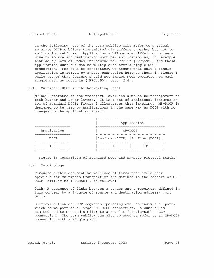
Internet-Draft Multipath DCCP July 2022
In the following, use of the term subflow will refer to physical separate DCCP subflows transmitted via different paths, but not to application subflows. Application subflows are differing content- wise by source and destination port per application as, for example, enabled by Service Codes introduced to DCCP in [RFC5595], and those application subflows can be multiplexed over a single DCCP connection. For sake of consistency we assume that only a single application is served by a DCCP connection here as shown in Figure 1 while use of that feature should not impact DCCP operation on each single path as noted in ([RFC5595], sect. 2.4).
1.1. Multipath DCCP in the Networking Stack
MP-DCCP operates at the transport layer and aims to be transparent to both higher and lower layers. It is a set of additional features on top of standard DCCP; Figure 1 illustrates this layering. MP-DCCP is designed to be used by applications in the same way as DCCP with no changes to the application itself.
+-------------------------------+ | Application | +---------------+ +-------------------------------+ | Application | | MP-DCCP | +---------------+ + - - - - - - - + - - - - - - - + | DCCP | |Subflow (DCCP) |Subflow (DCCP) | +---------------+ +-------------------------------+ | IP | | IP | IP | +---------------+ +-------------------------------+
Figure 1: Comparison of Standard DCCP and MP-DCCP Protocol Stacks
1.2. Terminology
Throughout this document we make use of terms that are either specific for multipath transport or are defined in the context of MP- DCCP, similar to [RFC8684], as follows:
Path: A sequence of links between a sender and a receiver, defined in this context by a 4-tuple of source and destination address/ port pairs.
Subflow: A flow of DCCP segments operating over an individual path, which forms part of a larger MP-DCCP connection. A subflow is started and terminated similar to a regular (single-path) DCCP connection. The term subflow can also be used to refer to an MP-DCCP connection with a single path.
Amend, et al. Expires 9 January 2023 [Page 4]
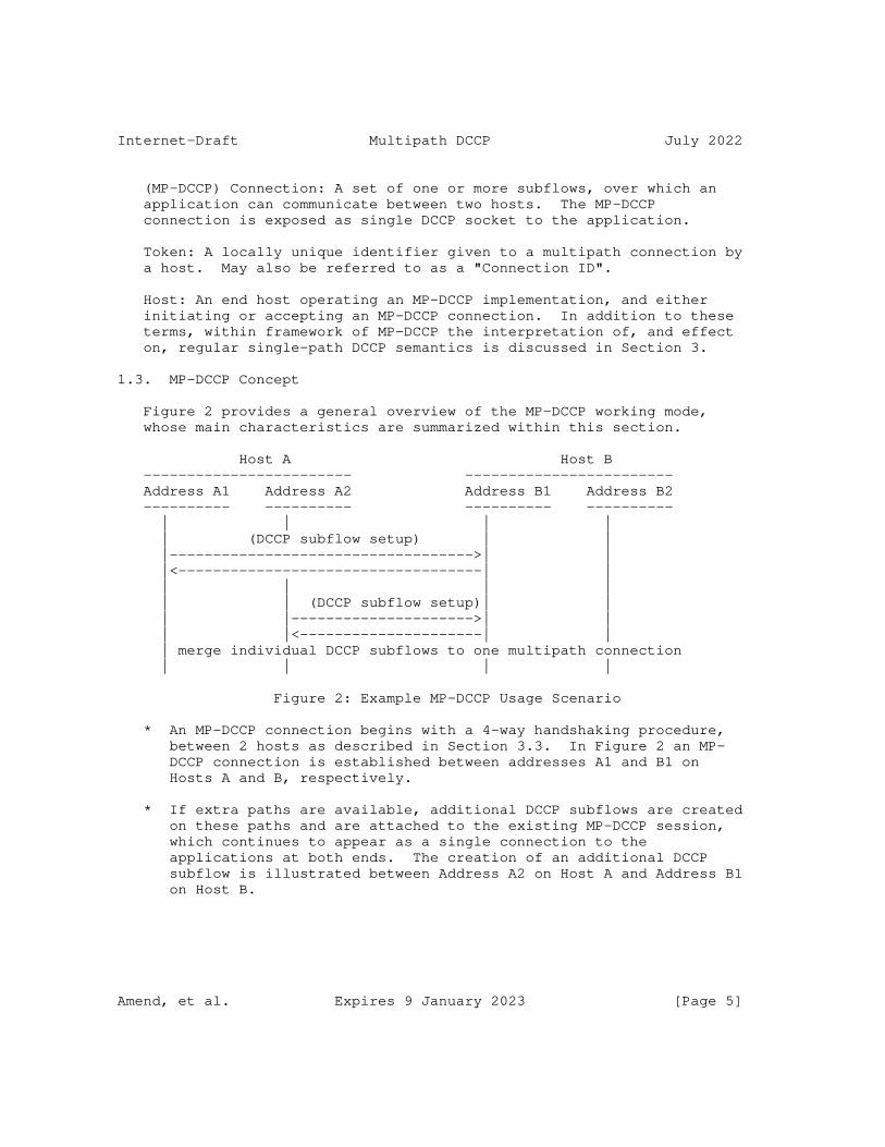
Internet-Draft Multipath DCCP July 2022
(MP-DCCP) Connection: A set of one or more subflows, over which an application can communicate between two hosts. The MP-DCCP connection is exposed as single DCCP socket to the application.
Token: A locally unique identifier given to a multipath connection by a host. May also be referred to as a "Connection ID".
Host: An end host operating an MP-DCCP implementation, and either initiating or accepting an MP-DCCP connection. In addition to these terms, within framework of MP-DCCP the interpretation of, and effect on, regular single-path DCCP semantics is discussed in Section 3.
1.3. MP-DCCP Concept
Figure 2 provides a general overview of the MP-DCCP working mode, whose main characteristics are summarized within this section.
Host A Host B ------------------------ ------------------------ Address A1 Address A2 Address B1 Address B2 ---------- ---------- ---------- ---------- | | | | | (DCCP subflow setup) | | |----------------------------------->| | |<-----------------------------------| | | | | | | | (DCCP subflow setup)| | | |--------------------->| | | |<---------------------| | | merge individual DCCP subflows to one multipath connection | | | |
Figure 2: Example MP-DCCP Usage Scenario
* An MP-DCCP connection begins with a 4-way handshaking procedure, between 2 hosts as described in Section 3.3. In Figure 2 an MP- DCCP connection is established between addresses A1 and B1 on Hosts A and B, respectively.
* If extra paths are available, additional DCCP subflows are created on these paths and are attached to the existing MP-DCCP session, which continues to appear as a single connection to the applications at both ends. The creation of an additional DCCP subflow is illustrated between Address A2 on Host A and Address B1 on Host B.
Amend, et al. Expires 9 January 2023 [Page 5]

Internet-Draft Multipath DCCP July 2022
* MP-DCCP identifies multiple paths by the presence of multiple addresses at hosts. Combinations of these multiple addresses equate to the additional paths. In the example, other potential paths that could be set up are A1<->B2 and A2<->B2. Although this additional session is shown as being initiated from A2, it could equally have been initiated from B1 or B2.
* The discovery and setup of additional subflows will be achieved through a path management method; this document describes supportive measures by which a host can initiate new subflows and available addresses can be signaled between peers. The definition of a path management method is however out of scope of this document.
* MP-DCCP adds connection-level sequence numbers and exchange of RTT information to enable optional reordering functionalities.
* Subflows are terminated as regular DCCP connections, as described in ([RFC4340] section 8.3). The MP-DCCP connection is terminated by a connection-level DCCP-CloseReq or DCCP-Close message.
1.4. Requirements Language
The key words "MUST", "MUST NOT", "REQUIRED", "SHALL", "SHALL NOT", "SHOULD", "SHOULD NOT", "RECOMMENDED", "MAY", and "OPTIONAL" in this document are to be interpreted as described in [RFC2119].
2. Operation Overview
DCCP according to RFC 4340 [RFC4340] allows multiple application subflows to be multiplexed over a single DCCP connection with potentially same performance. However, DCCP does not provide built- in support for multiple subflows and the Congestion Manager (CM) [RFC3124], as a generic multiplexing facility, can not fully support multiple congestion control mechanisms for multiple DCCP flows between same source and destination addresses.
The proposed extension of DCCP towards Multipath-DCCP (MP-DCCP) is described in detail in Section 3.
Amend, et al. Expires 9 January 2023 [Page 6]

Internet-Draft Multipath DCCP July 2022
As a high level overview on the key functionality of MP-DCCP, the data stream from a DCCP application is split by MP-DCCP operation into one or more subflows which can be transmitted via different also physically isolated paths. The corresponding control information allows the receiver to optionally re-assemble and deliver the received data in the right order to the recipient application. The details of the transmission scheduling mechanism and optional reordering mechanism are up to the sender and receiver, respectively, and are outside the scope of the MP-DCCP protocol. The following sections define MP-DCCP behavior in detail.
The Multipath Capability for MP-DCCP can be negotiated with a new DCCP feature, as described and fully specified in Section 3. Once negotiated, all subsequent MP-DCCP operations are signalled with a variable length multipath-related option, as described in Section 3.1.
A Multipath DCCP connection provides a bidirectional byte-stream between two hosts exchanging data as in standard DCCP manner thus not requiring any change to the applications. However, Multipath DCCP enables the hosts to use different paths with different IP addresses to transport the packets of the MP-DCCP connection. MP-DCCP manages the request, set-up, authentication, prioritization, modification, and removal of the DCCP subflows on different paths as well as exchange of performance parameters. The number of concurrent DCCP subflows can vary during the lifetime of the Multipath DCCP connection. All MP-DCCP operations are signaled with MP-DCCP options described in detail in {#MP_OPT}.
3. MP-DCCP Protocol
The DCCP protocol feature list ([RFC4340] section 6.4) will be enhanced by a new Multipath related feature with Feature number 10, as shown in Table 1.
Amend, et al. Expires 9 January 2023 [Page 7]
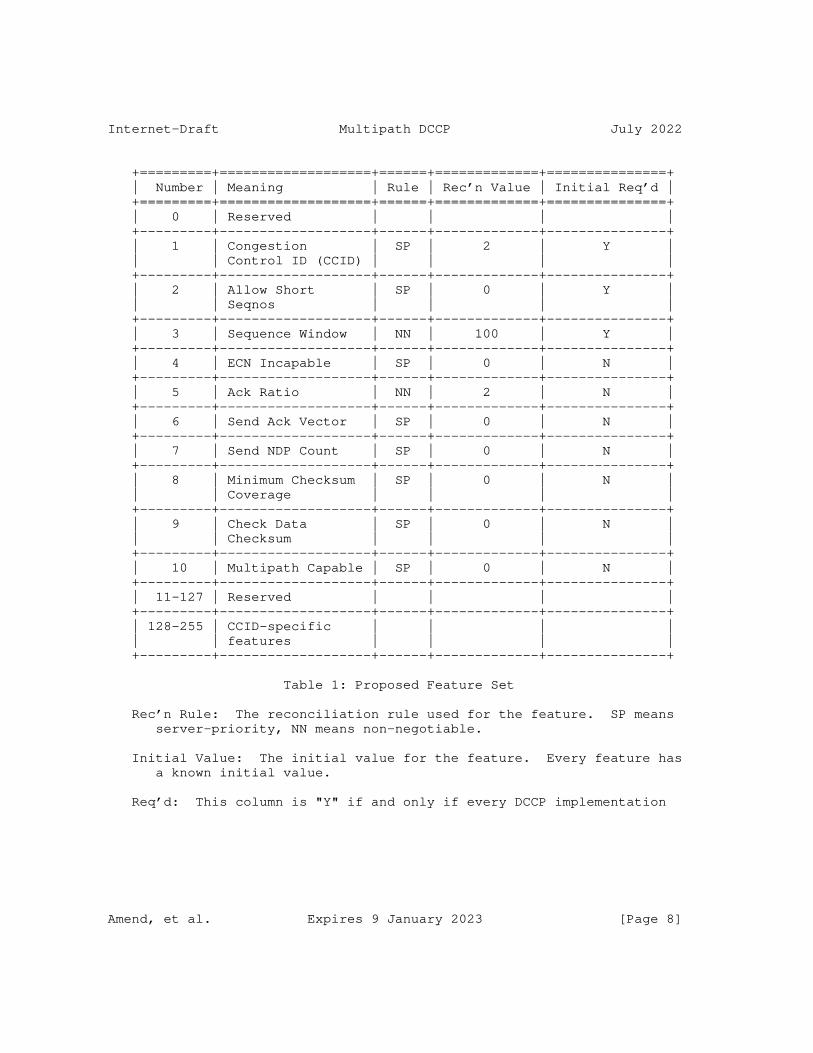
Internet-Draft Multipath DCCP July 2022
+=========+===================+======+=============+===============+ | Number | Meaning | Rule | Rec’n Value | Initial Req’d | +=========+===================+======+=============+===============+ | 0 | Reserved | | | | +---------+-------------------+------+-------------+---------------+ | 1 | Congestion | SP | 2 | Y | | | Control ID (CCID) | | | | +---------+-------------------+------+-------------+---------------+ | 2 | Allow Short | SP | 0 | Y | | | Seqnos | | | | +---------+-------------------+------+-------------+---------------+ | 3 | Sequence Window | NN | 100 | Y | +---------+-------------------+------+-------------+---------------+ | 4 | ECN Incapable | SP | 0 | N | +---------+-------------------+------+-------------+---------------+ | 5 | Ack Ratio | NN | 2 | N | +---------+-------------------+------+-------------+---------------+ | 6 | Send Ack Vector | SP | 0 | N | +---------+-------------------+------+-------------+---------------+ | 7 | Send NDP Count | SP | 0 | N | +---------+-------------------+------+-------------+---------------+ | 8 | Minimum Checksum | SP | 0 | N | | | Coverage | | | | +---------+-------------------+------+-------------+---------------+ | 9 | Check Data | SP | 0 | N | | | Checksum | | | | +---------+-------------------+------+-------------+---------------+ | 10 | Multipath Capable | SP | 0 | N | +---------+-------------------+------+-------------+---------------+ | 11-127 | Reserved | | | | +---------+-------------------+------+-------------+---------------+ | 128-255 | CCID-specific | | | | | | features | | | | +---------+-------------------+------+-------------+---------------+
Table 1: Proposed Feature Set
Rec’n Rule: The reconciliation rule used for the feature. SP means server-priority, NN means non-negotiable.
Initial Value: The initial value for the feature. Every feature has a known initial value.
Req’d: This column is "Y" if and only if every DCCP implementation
Amend, et al. Expires 9 January 2023 [Page 8]

Internet-Draft Multipath DCCP July 2022
MUST understand the feature. If it is "N", then the feature behaves like an extension (see Section 15), and it is safe to respond to Change options for the feature with empty Confirm options. Of course, a CCID might require the feature; a DCCP that implements CCID 2 MUST support Ack Ratio and Send Ack Vector, for example.
The DCCP protocol options as defined in ([RFC4340] section 5.8) and ([RFC5634] section 2.2.1) will be enhanced by a new Multipath related variable-length option with option type 46, as shown in Table 2.
Amend, et al. Expires 9 January 2023 [Page 9]
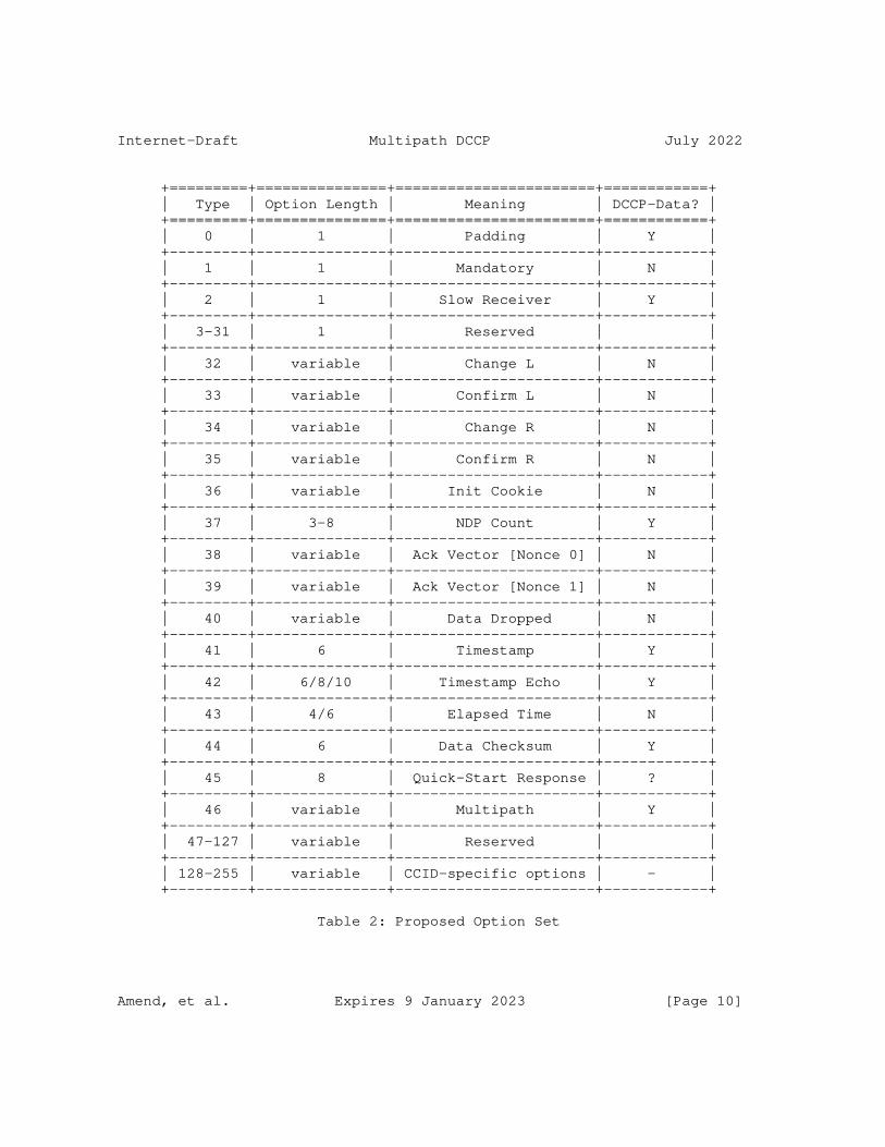
Internet-Draft Multipath DCCP July 2022
+=========+===============+=======================+============+ | Type | Option Length | Meaning | DCCP-Data? | +=========+===============+=======================+============+ | 0 | 1 | Padding | Y | +---------+---------------+-----------------------+------------+ | 1 | 1 | Mandatory | N | +---------+---------------+-----------------------+------------+ | 2 | 1 | Slow Receiver | Y | +---------+---------------+-----------------------+------------+ | 3-31 | 1 | Reserved | | +---------+---------------+-----------------------+------------+ | 32 | variable | Change L | N | +---------+---------------+-----------------------+------------+ | 33 | variable | Confirm L | N | +---------+---------------+-----------------------+------------+ | 34 | variable | Change R | N | +---------+---------------+-----------------------+------------+ | 35 | variable | Confirm R | N | +---------+---------------+-----------------------+------------+ | 36 | variable | Init Cookie | N | +---------+---------------+-----------------------+------------+ | 37 | 3-8 | NDP Count | Y | +---------+---------------+-----------------------+------------+ | 38 | variable | Ack Vector [Nonce 0] | N | +---------+---------------+-----------------------+------------+ | 39 | variable | Ack Vector [Nonce 1] | N | +---------+---------------+-----------------------+------------+ | 40 | variable | Data Dropped | N | +---------+---------------+-----------------------+------------+ | 41 | 6 | Timestamp | Y | +---------+---------------+-----------------------+------------+ | 42 | 6/8/10 | Timestamp Echo | Y | +---------+---------------+-----------------------+------------+ | 43 | 4/6 | Elapsed Time | N | +---------+---------------+-----------------------+------------+ | 44 | 6 | Data Checksum | Y | +---------+---------------+-----------------------+------------+ | 45 | 8 | Quick-Start Response | ? | +---------+---------------+-----------------------+------------+ | 46 | variable | Multipath | Y | +---------+---------------+-----------------------+------------+ | 47-127 | variable | Reserved | | +---------+---------------+-----------------------+------------+ | 128-255 | variable | CCID-specific options | - | +---------+---------------+-----------------------+------------+
Table 2: Proposed Option Set
Amend, et al. Expires 9 January 2023 [Page 10]
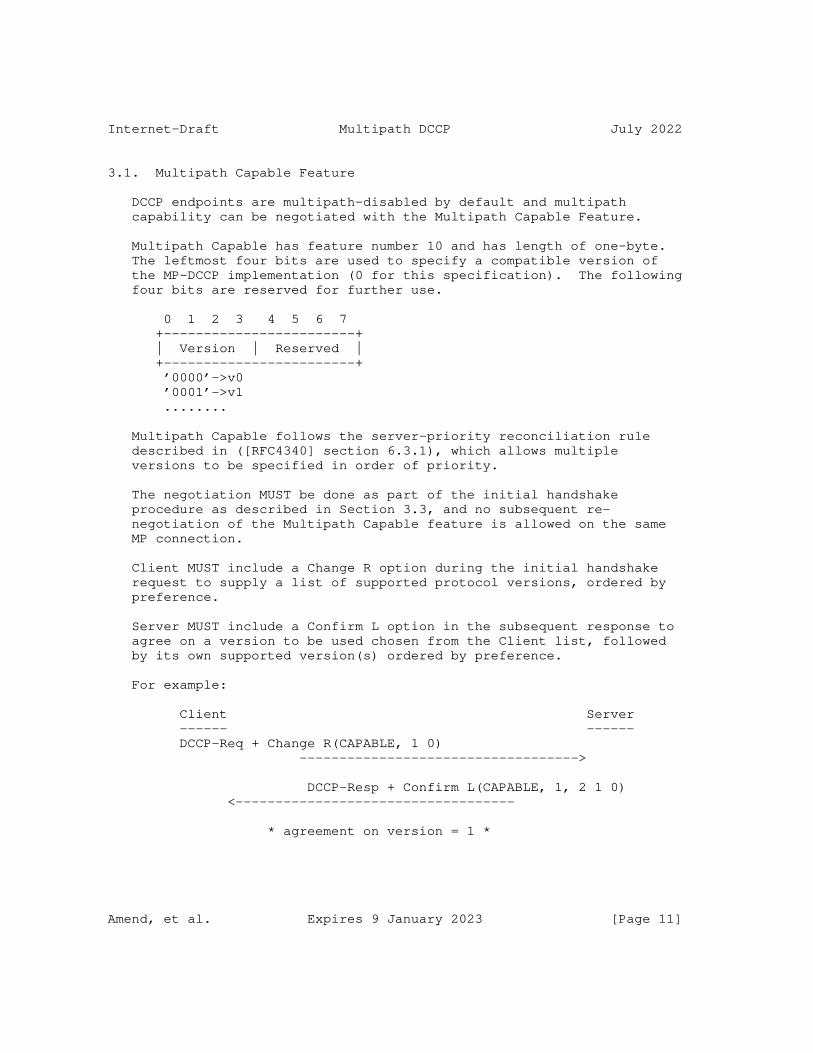
Internet-Draft Multipath DCCP July 2022
3.1. Multipath Capable Feature
DCCP endpoints are multipath-disabled by default and multipath capability can be negotiated with the Multipath Capable Feature.
Multipath Capable has feature number 10 and has length of one-byte. The leftmost four bits are used to specify a compatible version of the MP-DCCP implementation (0 for this specification). The following four bits are reserved for further use.
0 1 2 3 4 5 6 7 +------------------------+ | Version | Reserved | +------------------------+ ’0000’->v0 ’0001’->v1 ........
Multipath Capable follows the server-priority reconciliation rule described in ([RFC4340] section 6.3.1), which allows multiple versions to be specified in order of priority.
The negotiation MUST be done as part of the initial handshake procedure as described in Section 3.3, and no subsequent re- negotiation of the Multipath Capable feature is allowed on the same MP connection.
Client MUST include a Change R option during the initial handshake request to supply a list of supported protocol versions, ordered by preference.
Server MUST include a Confirm L option in the subsequent response to agree on a version to be used chosen from the Client list, followed by its own supported version(s) ordered by preference.
For example:
Client Server ------ ------ DCCP-Req + Change R(CAPABLE, 1 0) ----------------------------------->
DCCP-Resp + Confirm L(CAPABLE, 1, 2 1 0) <-----------------------------------
* agreement on version = 1 *
Amend, et al. Expires 9 January 2023 [Page 11]

Internet-Draft Multipath DCCP July 2022
1. Client indicates support for both versions 1 and 0, with preference for version 1
2. Server agrees on using version 1, and supply its own preference list.
If no agreement can be found, the Server MUST reply with an empty Confirm L option with feature number 10 and no values.
Any subflow addition to an existing MP connection MUST use the same version negotiated for the first subflow.
3.2. Multipath Option
1 2 3 01234567 89012345 67890123 45678901 23456789 +--------+--------+--------+--------+--------+ |00101110| Length | MP_OPT | Value(s) ... +--------+--------+--------+--------+--------+ Type=46
Amend, et al. Expires 9 January 2023 [Page 12]
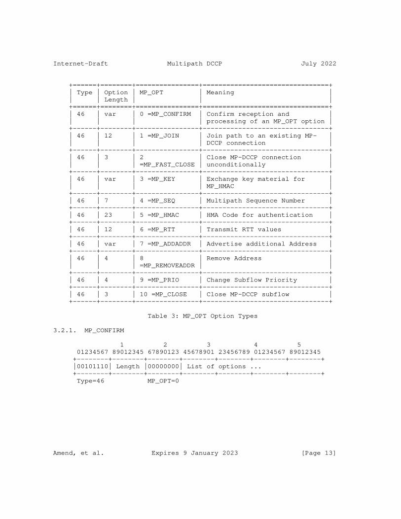
Internet-Draft Multipath DCCP July 2022
+======+========+================+================================+ | Type | Option | MP_OPT | Meaning | | | Length | | | +======+========+================+================================+ | 46 | var | 0 =MP_CONFIRM | Confirm reception and | | | | | processing of an MP_OPT option | +------+--------+----------------+--------------------------------+ | 46 | 12 | 1 =MP_JOIN | Join path to an existing MP- | | | | | DCCP connection | +------+--------+----------------+--------------------------------+ | 46 | 3 | 2 | Close MP-DCCP connection | | | | =MP_FAST_CLOSE | unconditionally | +------+--------+----------------+--------------------------------+ | 46 | var | 3 =MP_KEY | Exchange key material for | | | | | MP_HMAC | +------+--------+----------------+--------------------------------+ | 46 | 7 | 4 =MP_SEQ | Multipath Sequence Number | +------+--------+----------------+--------------------------------+ | 46 | 23 | 5 =MP_HMAC | HMA Code for authentication | +------+--------+----------------+--------------------------------+ | 46 | 12 | 6 =MP_RTT | Transmit RTT values | +------+--------+----------------+--------------------------------+ | 46 | var | 7 =MP_ADDADDR | Advertise additional Address | +------+--------+----------------+--------------------------------+ | 46 | 4 | 8 | Remove Address | | | | =MP_REMOVEADDR | | +------+--------+----------------+--------------------------------+ | 46 | 4 | 9 =MP_PRIO | Change Subflow Priority | +------+--------+----------------+--------------------------------+ | 46 | 3 | 10 =MP_CLOSE | Close MP-DCCP subflow | +------+--------+----------------+--------------------------------+
Table 3: MP_OPT Option Types
3.2.1. MP_CONFIRM
1 2 3 4 5 01234567 89012345 67890123 45678901 23456789 01234567 89012345 +--------+--------+--------+--------+--------+--------+--------+ |00101110| Length |00000000| List of options ... +--------+--------+--------+--------+--------+--------+--------+ Type=46 MP_OPT=0
Amend, et al. Expires 9 January 2023 [Page 13]

Internet-Draft Multipath DCCP July 2022
MP_CONFIRM is used to send confirmation of reception and processing of the multipath options that require it (see Table 4). Such options will be retransmitted by the sender until this receives the corresponding MP_CONFIRM. The length and sending path of the MP_CONFIRM are dependent on the confirmed options, which will be copied verbatim and appended as list of options.
+======+===============+==================+=========================+ | Type | Option Length | MP_OPT | MP_CONFIRM Sending path | +======+===============+==================+=========================+ | 46 | var | 7 =MP_ADDADDR | Any available | +------+---------------+------------------+-------------------------+ | 46 | var | 8 | Any available | | | | =MP_REMOVEADDR | | +------+---------------+------------------+-------------------------+ | 46 | 4 | 9 =MP_PRIO | Any available | +------+---------------+------------------+-------------------------+
Table 4: Multipath options requiring confirmation
3.2.2. MP_JOIN
1 2 3 01234567 89012345 67890123 45678901 +--------+--------+--------+--------+ |00101110|00001100|00000001| Addr ID| +--------+--------+--------+--------+ | Path Token | +--------+--------+--------+--------+ | Nonce | +--------+--------+--------+--------+ Type=46 Length=12 MP_OPT=1
The MP_JOIN option is used to add a new subflow to an existing MP- DCCP connection. The Path Token is the SHA256 hash of the derived key (d-key), which was previously exchanged with the MP_KEY option. MP_HMAC MUST be set when using MP_JOIN to provide authentication (See MP_HMAC for details). Also MP_KEY MUST be set to provide key material for authentication purposes.
The MP_JOIN option includes an "Address ID". This is an identifier generated by the sender of the option, used to identify the source address of this packet, even if the IP header has been changed in transit by a middlebox. The numeric value of this field is generated by the sender and must map uniquely to a source IP address for the sending host. The Address ID allows address removal (Section 3.2.9) without needing to know what the source address at the receiver is, thus allowing address removal through NATs. The Address ID also
Amend, et al. Expires 9 January 2023 [Page 14]

Internet-Draft Multipath DCCP July 2022
allows correlation between new subflow setup attempts and address signaling (Section 3.2.8), to prevent setting up duplicate subflows on the same path, if an MP_JOIN and MP_ADDADDR are sent at the same time.
The Address IDs of the subflow used in the initial DCCP Request/ Response exchange of the first subflow in the connection are implicit, and have the value zero. A host MUST store the mappings between Address IDs and addresses both for itself and the remote host. An implementation will also need to know which local and remote Address IDs are associated with which established subflows, for when addresses are removed from a local or remote host. An Address ID always has to be unique over the lifetime of a subflow and can only be re-assigned if sender and receiver no longer have them in use.
The Nonce is a 32-bit random value locally generated for every MP_JOIN option. Together with the Token, the Nonce value builds the basis to calculate the HMAC used in the handshaking process as described in Section 3.3.
3.2.3. MP_FAST_CLOSE
Regular DCCP has the means of sending a Close or Reset signal to abruptly close a connection. With MP-DCCP, a regular Close or Reset only has the scope of the subflow; it will only close the applicable subflow and will not affect the remaining subflows concurrently in use on other paths. MP-DCCP’s connection will stay alive at the data level, in order to permit break-before-make handover between subflows. It is therefore necessary to provide an MP-DCCP-level "Reset" to allow the abrupt closure of the whole MP-DCCP connection; this is done via the MP_FAST_CLOSE option.
1 2 3 01234567 89012345 67890123 45678901 23456789 +--------+--------+--------+--------+--------+ |00101110| Length |00000010| Key Data ... +--------+--------+--------+--------+--------+ Type=46 MP_OPT=2
For being effective, the MP_FAST_CLOSE must be sent from an initiating host on all subflows as part of a DCCP-Reset packet with Reset Code 13. To protect unauthorized shutdown of a multi-path connection, the selected Key Data of the peer host during the handshaking procedure is carried by the MP_FAST_CLOSE option. With completion of this step, the initiating host can tear down the subflows and the multi-path connection immediately terminates. Upon reception of the MP_FAST_CLOSE and validation of the Key Data at the
Amend, et al. Expires 9 January 2023 [Page 15]
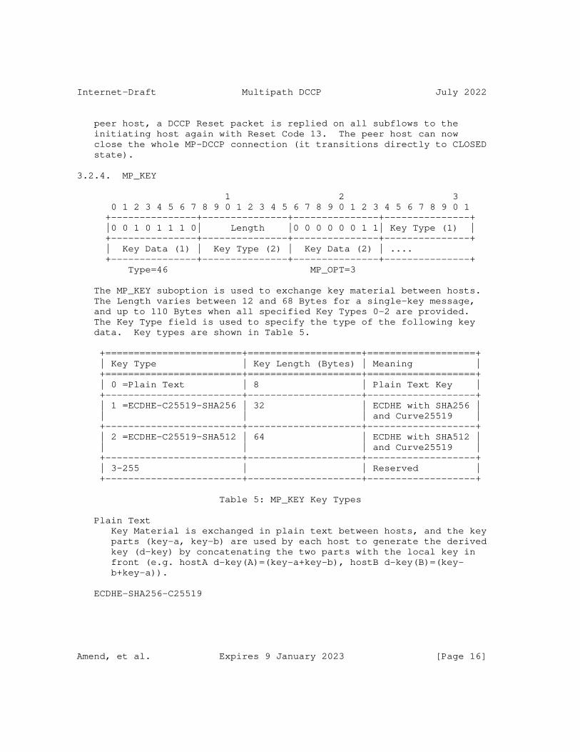
Internet-Draft Multipath DCCP July 2022
peer host, a DCCP Reset packet is replied on all subflows to the initiating host again with Reset Code 13. The peer host can now close the whole MP-DCCP connection (it transitions directly to CLOSED state).
3.2.4. MP_KEY
1 2 3 0 1 2 3 4 5 6 7 8 9 0 1 2 3 4 5 6 7 8 9 0 1 2 3 4 5 6 7 8 9 0 1 +---------------+---------------+---------------+---------------+ |0 0 1 0 1 1 1 0| Length |0 0 0 0 0 0 1 1| Key Type (1) | +---------------+---------------+---------------+---------------+ | Key Data (1) | Key Type (2) | Key Data (2) | .... +---------------+---------------+---------------+---------------+ Type=46 MP_OPT=3
The MP_KEY suboption is used to exchange key material between hosts. The Length varies between 12 and 68 Bytes for a single-key message, and up to 110 Bytes when all specified Key Types 0-2 are provided. The Key Type field is used to specify the type of the following key data. Key types are shown in Table 5.
+========================+====================+===================+ | Key Type | Key Length (Bytes) | Meaning | +========================+====================+===================+ | 0 =Plain Text | 8 | Plain Text Key | +------------------------+--------------------+-------------------+ | 1 =ECDHE-C25519-SHA256 | 32 | ECDHE with SHA256 | | | | and Curve25519 | +------------------------+--------------------+-------------------+ | 2 =ECDHE-C25519-SHA512 | 64 | ECDHE with SHA512 | | | | and Curve25519 | +------------------------+--------------------+-------------------+ | 3-255 | | Reserved | +------------------------+--------------------+-------------------+
Table 5: MP_KEY Key Types
Plain Text Key Material is exchanged in plain text between hosts, and the key parts (key-a, key-b) are used by each host to generate the derived key (d-key) by concatenating the two parts with the local key in front (e.g. hostA d-key(A)=(key-a+key-b), hostB d-key(B)=(key- b+key-a)).
ECDHE-SHA256-C25519
Amend, et al. Expires 9 January 2023 [Page 16]

Internet-Draft Multipath DCCP July 2022
Public Key Material is exchanged via ECDHE key exchange with SHA256 and Curve 25519 to generate the derived key (d-key) from the shared secret.
ECDHE-SHA512-C25519 Public Key Material is exchanged via ECDHE key exchange with SHA512 and Curve 25519 to generate the derived key (d-key) from the shared secret.
Providing multiple keys is only permitted in the DCCP-Request message of the handshake procedure for the first subflow, and allows the hosts to agree on a single key type to be used as described in Section 3.3
3.2.5. MP_SEQ
1 2 3 4 5 01234567 89012345 67890123 45678901 23456789 01234567 89012345 +--------+--------+--------+--------+--------+--------+--------+ |00101110|00001001|00000100| Multipath Sequence Number +--------+--------+--------+--------+--------+--------+--------+ | | +--------+--------+ Type=46 Length=9 MP_OPT=4
The MP_SEQ option is used for end-to-end datagram-based sequence numbers of an MP-DCCP connection. The initial data sequence number (IDSN) SHOULD be set randomly. The MP_SEQ number space is different from the path individual sequence number space and MUST be sent with any DCCP-Data and DCCP-DataACK packet.
3.2.6. MP_HMAC
1 2 3 4 01234567 89012345 67890123 45678901 23456789 01234567 +--------+--------+--------+--------+--------+--------+ |00101110|00010111|00000101| HMAC-SHA256 (20 bytes) ... +--------+--------+--------+--------+--------+--------+ Type=46 Length=23 MP_OPT=5
The MP_HMAC option is used to provide authentication for the MP_JOIN, MP_ADDADDR and MP_REMOVEADDR option. The HMAC code is generated according to [RFC2104] in combination with the SHA256 hash algorithm described in [RFC6234], with the output truncated to the leftmost 160 bits (20 bytes).
Amend, et al. Expires 9 January 2023 [Page 17]

Internet-Draft Multipath DCCP July 2022
The "Key" used for the HMAC computation is the derived key (d-key) described in Section 3.2.4, while the HMAC "Message" is a concatenation of
* MP_JOIN: The token and nonce of the MP_JOIN for which authentication shall be performed.
* MP_ADDADDR: The Address ID with associated IP address and if defined port, otherwise two octets of value 0.
* MP_REMOVEADDR: Solely the Address ID.
3.2.7. MP_RTT
1 2 3 4 5 01234567 89012345 67890123 45678901 23456789 01234567 89012345 +--------+--------+--------+--------+--------+--------+--------+ |00101110|00001100|00000110|RTT Type| RTT +--------+--------+--------+--------+--------+--------+--------+ | | Age | +--------+--------+--------+--------+--------+ Type=46 Length=12 MP_OPT=6
The MP_RTT option is used to transmit RTT values in milliseconds and MUST belong to the path over which this information is transmitted. Additionally, the age of the measurement is specified in milliseconds.
The RTT and Age information is a 32-bit integer, which allows to cover a period of approximately 1193 hours.
Raw RTT (=0) Raw RTT value of the last Datagram Round-Trip preferably provided by the CCID in use.
Min RTT (=1) Min RTT value over a given period preferably provided by the CCID in use.
Max RTT (=2) Max RTT value over a given period preferably provided by the CCID in use.
Smooth RTT (=3) Averaged RTT value over a given period preferably provided by the CCID in use.
Age
Amend, et al. Expires 9 January 2023 [Page 18]

Internet-Draft Multipath DCCP July 2022
The Age parameter defines the time difference between now - creation of the MP_RTT option - and the conducted RTT measurement in milliseconds. If no previous measurement exists, e.g., when initialized, the value is 0.
3.2.8. MP_ADDADDR
The MP_ADDADDR option announces additional addresses (and, optionally, ports) on which a host can be reached. This option can be used at any time during an existing DCCP connection, when the sender wishes to enable multiple paths and/or when additional paths become available. Multiple instances of this option within a packet advertise simultaneously new addresses.
Length is variable depending on IPv4 or IPv6 and whether port number is used and is in range between 8 and 22 bytes.
The presence of the final 2 octets, specifying the DCCP port number to use, are optional and can be inferred from the length of the option. Although it is expected that the majority of use cases will use the same port pairs as used for the initial subflow (e.g., port 80 remains port 80 on all subflows, as does the ephemeral port at the client), there may be cases (such as port-based load balancing) where the explicit specification of a different port is required. If no port is specified, MP-DCCP SHOULD attempt to connect to the specified address on the same port as is already in use by the subflow on which the MP_ADDADDR signal was sent.
Along with the MP_ADDADDR option a MP_HMAC option MUST be sent for authentication. The truncated HMAC parameter present in this MP_HMAC option is the leftmost 20 bytes of an HMAC, negotiated and calculated as described in Section 3.2.6. In the same way as for MP_JOIN, the key for the HMAC algorithm, in the case of the message transmitted by Host A, will be Key-A followed by Key-B, and in the case of Host B, Key-B followed by Key-A. These are the keys that were exchanged and selected in the original MP_KEY handshake. The message for the HMAC is the Address ID, IP address, and port that precede the HMAC in the MP_ADDADDR option. If the port is not present in the MP_ADDADDR option, the HMAC message will nevertheless include 2 octets of value zero. The rationale for the HMAC is to prevent unauthorized entities from injecting MP_ADDADDR signals in an attempt to hijack a connection. Note that, additionally, the presence of this HMAC prevents the address from being changed in flight unless the key is known by an intermediary. If a host receives an MP_ADDADDR option for which it cannot validate the HMAC, it SHOULD silently ignore the option.
Amend, et al. Expires 9 January 2023 [Page 19]
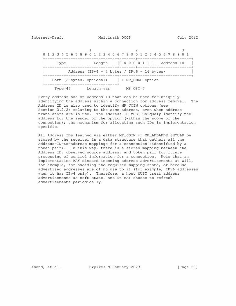
Internet-Draft Multipath DCCP July 2022
1 2 3 0 1 2 3 4 5 6 7 8 9 0 1 2 3 4 5 6 7 8 9 0 1 2 3 4 5 6 7 8 9 0 1 +---------------+---------------+-------+-------+---------------+ | Type | Length |0 0 0 0 0 1 1 1| Address ID | +---------------+---------------+-------+-------+---------------+ | Address (IPv4 - 4 bytes / IPv6 - 16 bytes) | +-------------------------------+-------------------------------+ | Port (2 bytes, optional) | + MP_HMAC option +-------------------------------+ Type=46 Length=var MP_OPT=7
Every address has an Address ID that can be used for uniquely identifying the address within a connection for address removal. The Address ID is also used to identify MP_JOIN options (see Section 3.2.2) relating to the same address, even when address translators are in use. The Address ID MUST uniquely identify the address for the sender of the option (within the scope of the connection); the mechanism for allocating such IDs is implementation specific.
All Address IDs learned via either MP_JOIN or MP_ADDADDR SHOULD be stored by the receiver in a data structure that gathers all the Address-ID-to-address mappings for a connection (identified by a token pair). In this way, there is a stored mapping between the Address ID, observed source address, and token pair for future processing of control information for a connection. Note that an implementation MAY discard incoming address advertisements at will, for example, for avoiding the required mapping state, or because advertised addresses are of no use to it (for example, IPv6 addresses when it has IPv4 only). Therefore, a host MUST treat address advertisements as soft state, and it MAY choose to refresh advertisements periodically.
Amend, et al. Expires 9 January 2023 [Page 20]

Internet-Draft Multipath DCCP July 2022
Due to the proliferation of NATs, it is reasonably likely that one host may attempt to advertise private addresses. It is not desirable to prohibit this, since there may be cases where both hosts have additional interfaces on the same private network, and a host MAY want to advertise such addresses. The MP_JOIN handshake to create a new subflow (Section 3.2.2) provides mechanisms to minimize security risks. The MP_JOIN message contains a 32-bit token that uniquely identifies the connection to the receiving host. If the token is unknown, the host will return with a DCCP-Reset. In the unlikely event that the token is known, subflow setup will continue, but the HMAC exchange must occur for authentication. This will fail, and will provide sufficient protection against two unconnected hosts accidentally setting up a new subflow upon the signal of a private address. Further security considerations around the issue of MP_ADDADDR messages that accidentally misdirect, or maliciously direct, new MP_JOIN attempts are discussed in Section 4.
The reception of an MP_ADDADDR message is acknowledged using MP_CONFIRM (Section 3.2.1). Using this mechanism reliable exchange of address information is ensured.
A host can send an MP_ADDADDR message with an already assigned Address ID, but the Address MUST be the same as previously assigned to this Address ID, and the Port MUST be different from one already in use for this Address ID. If these conditions are not met, the receiver SHOULD silently ignore the MP_ADDADDR. A host wishing to replace an existing Address ID MUST first remove the existing one (Section 3.2.9).
A host that receives an MP_ADDADDR but finds a connection set up to that IP address and port number is unsuccessful SHOULD NOT perform further connection attempts to this address/port combination for this connection. However, a sender that wants to trigger a new incoming connection attempt on a previously advertised address/port combination can therefore refresh MP_ADDADDR information by sending the option again.
3.2.9. MP_REMOVEADDR
If, during the lifetime of an MP-DCCP connection, a previously announced address becomes invalid (e.g., if the interface disappears), the affected host SHOULD announce this so that the peer can remove subflows related to this address.
This is achieved through the Remove Address (MP_REMOVEADDR) option which will remove a previously added address with an Address ID from a connection and terminate any subflows currently using that address.
Amend, et al. Expires 9 January 2023 [Page 21]

Internet-Draft Multipath DCCP July 2022
Along with the MP_REMOVEADDR option a MP_HMAC option MUST be sent for authentication. The truncated HMAC parameter present in this MP_HMAC option is the leftmost 20 bytes of an HMAC, negotiated and calculated as described in Section 3.2.6. In the same way as for MP_JOIN, the key for the HMAC algorithm, in the case of the message transmitted by Host A, will be Key-A followed by Key-B, and in the case of Host B, Key-B followed by Key-A. These are the keys that were exchanged and selected in the original MP_KEY handshake. The message for the HMAC is the Address ID. The rationale for the HMAC is to prevent unauthorized entities from injecting MP_REMOVEADDR signals in an attempt to hijack a connection. Note that, additionally, the presence of this HMAC prevents the address from being removed in flight unless the key is known by an intermediary. If a host receives an MP_REMOVEADDR option for which it cannot validate the HMAC, it SHOULD silently ignore the option.
The reception of an MP_REMOVEADDR message is acknowledged using MP_CONFIRM (Section 3.2.1). Using this mechanism reliable exchange of address information is ensured.
The sending and receipt of this message SHOULD trigger the sending of DCCP-Close and DCCP-Reset by client and server, respectively on the affected subflow(s) (if possible), as a courtesy to cleaning up middlebox state, before cleaning up any local state.
Address removal is undertaken by ID, so as to permit the use of NATs and other middleboxes that rewrite source addresses. If there is no address at the requested ID, the receiver will silently ignore the request.
1 2 3 0 1 2 3 4 5 6 7 8 9 0 1 2 3 4 5 6 7 8 9 0 1 2 3 4 5 6 7 8 9 0 1 +---------------+---------------+-------+-------+---------------+ | Type = 46 | Length = 4 | MP_OPT = 8 | Address ID | +---------------+---------------+-------+-------+---------------+ + MP_HMAC option
A subflow that is still functioning MUST be closed with a DCCP-Close or exchange as in regular DCCP, rather than using this option. For more information, see Section Section 3.4.
Amend, et al. Expires 9 January 2023 [Page 22]

Internet-Draft Multipath DCCP July 2022
3.2.10. MP_PRIO
In the event that a single specific path out of the set of available paths shall be treated with higher priority compared to the others when making scheduling decisions for user plane traffic, a host may wish to signal such change in priority to the peer. One reason for such behavior is due to the different costs involved in using different paths (e.g., WiFi is free while cellular has limit on volume, 5G has higher energy consumption). Also, the priority of a path may be subject to dynamic changes, for example when the mobile runs out of battery, the usage of only a single path may be the preferred choice of the user. Therefore, the path priority should be considered as hints for the packet scheduler when making decisions which path to use for user plane traffic.
The MP_PRIO option, shown below, can be used to set a priority flag for the path which is specified by the AddrID field that uniquely identifies the path. The option can be sent over any path.
1 2 3 0 1 2 3 4 5 6 7 8 9 0 1 2 3 4 5 6 7 8 9 0 1 2 3 4 5 6 7 8 9 0 1 +---------------+---------------+-------+-------+--------------+ | Type = 46 | Length = 4 | MP_OPT = 9 | AddrID | +---------------+---------------+-------+-------+--------------+ |(resvd)| Prio | +---------------+
The following values are available for Prio field:
* 0: Do not use. The path is not available.
* 1: Standby: do not use this path for traffic scheduling, if another path (secondary or primary) is available. The path will only be used if other secondary or primary paths are not established.
* 2: Secondary: do not use this path for traffic scheduling, if the other paths are good enough. The path will be used occasionally for increasing temporarily the available capacity, e.g. when primary paths are congested or are not available. This is the recommended setting for paths that have costs or data caps as these paths will be used less frequently then primary paths.
* 3 - 15: Primary: can use the path in any way deemed reasonable by peer. The path will always be used for packet scheduling decisions. The priority number indicates the relative priority of one path over the other for primary paths. Higher numbers indicate higher priority. The peer should consider sending more
Amend, et al. Expires 9 January 2023 [Page 23]

Internet-Draft Multipath DCCP July 2022
traffic over higher priority paths. This is the recommended setting for paths that do not have a cost or data caps associated with them as these paths will be frequently used.
Example use cases include: 1) Setting Wi-Fi path to Primary and Cellular paths to Secondary. In this case Wi-Fi will be used and Cellular only if the Wi-Fi path is congested or not available. Such setting results in using the Cellular path only temporally, if more capacity is needed than the WiFi path can provide, indicating a clear priority of the Wi-Fi path over the Cellular due to e.g. cost reasons. 2) Setting Wi-Fi path to Primary and Cellular to Standby. In this case Wi-Fi will be used and Cellular only, if the Wi-Fi path is not available. 3) Setting Wi-Fi path to Primary and Cellular path to Primary. In this case, all packets can be scheduled over all paths at all time.
If not specified, the default behavior is, that a path can always be used for packet scheduling decisions (MP_PRIO=3), if the path has been established and added to an existing MP-DCCP connection. At least one path should have a MP_PRIO value greater or equal to one for it to be allowed to send on the connection. MP_PRIO is assumed to be exchanged reliably using the MP_CONFIRM mechanisms (see Table 4).
3.2.11. MP_CLOSE
1 2 3 01234567 89012345 67890123 45678901 23456789 +--------+--------+--------+--------+--------+ |00101110| Length |00001010| Key Data ... +--------+--------+--------+--------+--------+ Type=46 MP_OPT=10
For a graceful shutdown of a MP-DCCP connection, MP_CLOSE is used to communicate this to a peer host. On all subflows, the regular termination procedure as described in [RFC4340] MUST be initiated using MP_CLOSE in the initial packet (either a DCCP-CloseReq or a DCCP-Close). In the case where a DCCP-CloseReq is used, the following DCCP-Close MUST carry the MP_CLOSE as well. At the initiator of the DCCP-CloseReq all sockets, including the MP-DCCP connection socket, transition to CLOSEREQ state. To protect unauthorized shutdown of a multi-path connection, the selected Key Data of the peer host during the handshaking procedure MUST be carried by the MP_CLOSE option and validated by the peer host. Note, Key Data is different between MP_CLOSE option carried by DCCP- CloseReq or DCCP-Close.
Amend, et al. Expires 9 January 2023 [Page 24]
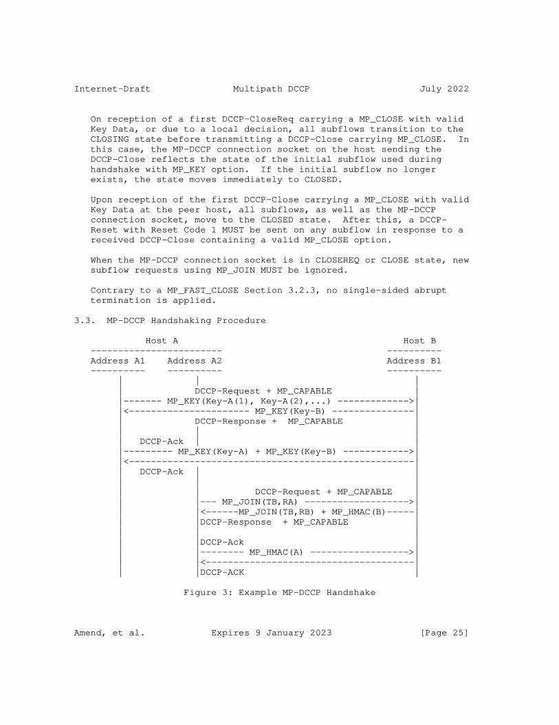
Internet-Draft Multipath DCCP July 2022
On reception of a first DCCP-CloseReq carrying a MP_CLOSE with valid Key Data, or due to a local decision, all subflows transition to the CLOSING state before transmitting a DCCP-Close carrying MP_CLOSE. In this case, the MP-DCCP connection socket on the host sending the DCCP-Close reflects the state of the initial subflow used during handshake with MP_KEY option. If the initial subflow no longer exists, the state moves immediately to CLOSED.
Upon reception of the first DCCP-Close carrying a MP_CLOSE with valid Key Data at the peer host, all subflows, as well as the MP-DCCP connection socket, move to the CLOSED state. After this, a DCCP- Reset with Reset Code 1 MUST be sent on any subflow in response to a received DCCP-Close containing a valid MP_CLOSE option.
When the MP-DCCP connection socket is in CLOSEREQ or CLOSE state, new subflow requests using MP_JOIN MUST be ignored.
Contrary to a MP_FAST_CLOSE Section 3.2.3, no single-sided abrupt termination is applied.
3.3. MP-DCCP Handshaking Procedure
Host A Host B ------------------------ ---------- Address A1 Address A2 Address B1 ---------- ---------- ---------- | | | | DCCP-Request + MP_CAPABLE | |------- MP_KEY(Key-A(1), Key-A(2),...) ------------->| |<---------------------- MP_KEY(Key-B) ---------------| | DCCP-Response + MP_CAPABLE | | | | | DCCP-Ack | | |--------- MP_KEY(Key-A) + MP_KEY(Key-B) ------------>| |<----------------------------------------------------| | DCCP-Ack | | | | | | | DCCP-Request + MP_CAPABLE | | |--- MP_JOIN(TB,RA) ------------------->| | |<------MP_JOIN(TB,RB) + MP_HMAC(B)-----| | |DCCP-Response + MP_CAPABLE | | | | | |DCCP-Ack | | |-------- MP_HMAC(A) ------------------>| | |<--------------------------------------| | |DCCP-ACK |
Figure 3: Example MP-DCCP Handshake
Amend, et al. Expires 9 January 2023 [Page 25]

Internet-Draft Multipath DCCP July 2022
The basic initial handshake for the first subflow is as follows:
* Host A sends a DCCP-Request with the MP-Capable feature Change request and the MP_KEY option with an Host-specific Key-A for each of supported types as described in Section 3.2.4
* Host B sends a DCCP-Response with Confirm feature for MP-Capable and the MP_Key option with a single Host-specific Key-B. The type of the key MUST be chosen from the list of supported types from the previous request
* Host A sends a DCCP-Ack with both Keys echoed to Host B.
* Host B sends a DCCP-Ack to confirm both keys and conclude the handshaking.
Host A MUST wait the final DCCP-Ack from host B before starting any establishment of additional subflow connections.
The handshake for subsequent subflows based on a successful initial handshake is as follows:
* Host A sends a DCCP-Request with the MP-Capable feature Change request and the MP_JOIN option with Host B’s Token TB, generated from the derived key by applying a SHA256 hash and truncating to the first 32 bits. Additionally, an own random nonce RA is transmitted with the MP_JOIN.
* Host B computes the HMAC of the DCCP-Request and sends a DCCP- Response with Confirm feature option for MP-Capable and the MP_JOIN option with the Token TB and a random nonce RB together with the computed MP_HMAC. The HMAC is calculated by taking the leftmost 20 bytes from the SHA256 hash of a HMAC code created by using token and nonce received with MP_JOIN(A) as message and the derived key described in Section 3.2.4 as key:
MP_HMAC(B) = HMAC-SHA256(Key=d-key(B), Msg=RB+RA)
* Host A sends a DCCP-Ack with the HMAC computed for the DCCP- Response. The HMAC is calculated by taking the leftmost 20 bytes from the SHA256 hash of a HMAC code created by using token and nonce received with MP_JOIN(B) as message and the derived key described in Section 3.2.4 as key:
MP_HMAC(A) = HMAC-SHA256(Key=d-key(A), Msg=RA+RB)
* Host B sends a DCCP-Ack to confirm the HMAC and to conclude the handshaking.
Amend, et al. Expires 9 January 2023 [Page 26]
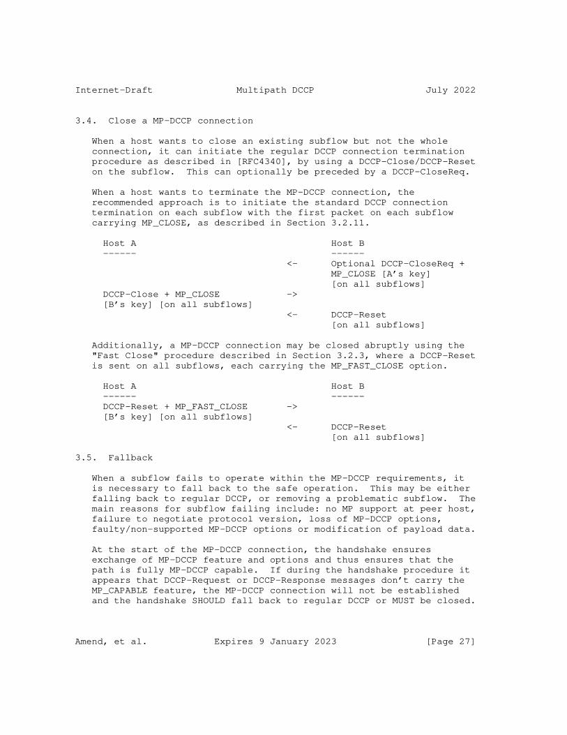
Internet-Draft Multipath DCCP July 2022
3.4. Close a MP-DCCP connection
When a host wants to close an existing subflow but not the whole connection, it can initiate the regular DCCP connection termination procedure as described in [RFC4340], by using a DCCP-Close/DCCP-Reset on the subflow. This can optionally be preceded by a DCCP-CloseReq.
When a host wants to terminate the MP-DCCP connection, the recommended approach is to initiate the standard DCCP connection termination on each subflow with the first packet on each subflow carrying MP_CLOSE, as described in Section 3.2.11.
Host A Host B ------ ------ <- Optional DCCP-CloseReq + MP_CLOSE [A’s key] [on all subflows] DCCP-Close + MP_CLOSE -> [B’s key] [on all subflows] <- DCCP-Reset [on all subflows]
Additionally, a MP-DCCP connection may be closed abruptly using the "Fast Close" procedure described in Section 3.2.3, where a DCCP-Reset is sent on all subflows, each carrying the MP_FAST_CLOSE option.
Host A Host B ------ ------ DCCP-Reset + MP_FAST_CLOSE -> [B’s key] [on all subflows] <- DCCP-Reset [on all subflows]
3.5. Fallback
When a subflow fails to operate within the MP-DCCP requirements, it is necessary to fall back to the safe operation. This may be either falling back to regular DCCP, or removing a problematic subflow. The main reasons for subflow failing include: no MP support at peer host, failure to negotiate protocol version, loss of MP-DCCP options, faulty/non-supported MP-DCCP options or modification of payload data.
At the start of the MP-DCCP connection, the handshake ensures exchange of MP-DCCP feature and options and thus ensures that the path is fully MP-DCCP capable. If during the handshake procedure it appears that DCCP-Request or DCCP-Response messages don’t carry the MP_CAPABLE feature, the MP-DCCP connection will not be established and the handshake SHOULD fall back to regular DCCP or MUST be closed.
Amend, et al. Expires 9 January 2023 [Page 27]

Internet-Draft Multipath DCCP July 2022
The same fallback SHOULD take place if the endpoints fail to agree on a protocol version to use during the Multipath Capable feature negotiation, which is described in Section 3.1. The protocol version negotiation distinguishes between negotiation for the initial connection establishment, and addition of subsequent subflows. If protocol version negotiation is not successful during the initial connection establishment, MP-DCCP connection will fall back to regular DCCP.
Similar procedure MUST be applied if the MP_KEY Section 3.2.4 Key Type cannot be negotiated, a final ACK carrying MP_KEY with wrong Key-A/Key-B is received or MP_KEY option is malformed.
If a subflow attempts to join an existing MP-DCCP connection, but MP- DCCP options or MP_CAPABLE feature are not present or are faulty in the handshake procedure, that subflow MUST be closed. This is especially the case if a different MP_CAPABLE version than the originally negotiated version is used. Also non-verifiable MP_HMAC Section 3.2.6 or MP_JOIN Path Token Section 3.2.2 MUST lead to a subflow closing.
Another relevant case is when payload data is modified by middleboxes. DCCP uses checksum to protect the data, as described in section 9 of [RFC4340]. A checksum will fail if the data has been changed in any way. All data from the start of the segment that failed the checksum onwards cannot be considered trustworthy. DCCP defines that if the checksum fails, the receiving endpoint MUST drop the application data and report that data as dropped due to corruption using a Data Dropped option (Drop Code 3, Corrupt). If this happens in an MP-DCCP connection, the affected subflow can either be closed or other action can be taken.
3.6. Congestion Control Considerations
Senders MUST manage per-path congestion status, and SHOULD avoid to send more data on a given path than congestion control on that path allows.
Amend, et al. Expires 9 January 2023 [Page 28]
Internet-Draft Multipath DCCP July 2022
When a Multipath DCCP connection uses two or more paths, there is no guarantee that these paths are fully disjoint. When two (or more paths) share the same bottleneck, using a standard congestion control scheme could result in an unfair distribution of the bandwidth with the multipath connection getting more bandwidth than competing single path connections. Multipath TCP uses the coupled congestion control Linked Increases Algorithm (LIA) specified in [RFC6356] to solve this problem. This scheme can be adapted also for Multipath DCCP. The same applies to other coupled congestion control schemes, which have been proposed for Multipath TCP such as Opportunistic Linked Increases Algorithm [OLIA].
3.7. Maximum Packet Size Considerations
A DCCP implementation MUST maintain the maximum packet size (MPS) during operation of a DCCP session. This procedure is specified for single-path DCCP in [RFC4340], Section 14. Without any restrictions, this is adopted for MP-DCCP operations, in particular the PMTU measurement and the Sender Behaviour. As per this definition a DCCP application interface SHOULD let the application discover the current MPS, this is subject to ambiguity with potential different path MPS in a multi-path system. For compatibility reasons, a MP-DCCP implementation SHOULD always announce the minimum MPS across all paths.
4. Security Considerations
Similar to DCCP, MP-DCCP does not provide cryptographic security guarantees inherently. Thus, if applications need cryptographic security (integrity, authentication, confidentiality, access control, and anti-replay protection) the use of IPsec or some other kind of end-to-end security is recommended; Secure Real-time Transport Protocol (SRTP) [RFC3711] is one candidate protocol for authentication. Together with Encryption of Header Extensions in SRTP, as provided by [RFC6904], also integrity would be provided.
As described in [RFC4340], DCCP provides protection against hijacking and limits the potential impact of some denial-of-service attacks, but DCCP provides no inherent protection against attackers’ snooping on data packets. Regarding the security of MP-DCCP no additional risks should be introduced compared to regular DCCP. Thereof derived are the following key security requirements to be fulfilled by MP- DCCP:
* Provide a mechanism to confirm that parties involved in a subflow handshake are identical to those in the original connection setup.
Amend, et al. Expires 9 January 2023 [Page 29]

Internet-Draft Multipath DCCP July 2022
* Provide verification that the new address to be included in a MP connection is valid for a peer to receive traffic at before using it.
* Provide replay protection, i.e., ensure that a request to add/ remove a subflow is ’fresh’.
In order to achieve these goals, MP-DCCP includes a hash-based handshake algorithm documented in Sections Section 3.2.4 and Section 3.3. The security of the MP-DCCP connection depends on the use of keys that are shared once at the start of the first subflow and are never sent again over the network. To ease demultiplexing while not giving away any cryptographic material, future subflows use a truncated cryptographic hash of this key as the connection identification "token". The keys are concatenated and used as keys for creating Hash-based Message Authentication Codes (HMACs) used on subflow setup, in order to verify that the parties in the handshake are the same as in the original connection setup. It also provides verification that the peer can receive traffic at this new address. Replay attacks would still be possible when only keys are used; therefore, the handshakes use single-use random numbers (nonces) at both ends -- this ensures that the HMAC will never be the same on two handshakes. Guidance on generating random numbers suitable for use as keys is given in [RFC4086]. During normal operation, regular DCCP protection mechanisms (such as header checksum to protect DCCP headers against corruption) will provide the same level of protection against attacks on individual DCCP subflows as exists for regular DCCP.
As discussed in Section 3.2.8, a host may advertise its private addresses, but these might point to different hosts in the receiver’s network. The MP_JOIN handshake (Section 3.2.2) will ensure that this does not succeed in setting up a subflow to the incorrect host. However, it could still create unwanted DCCP handshake traffic. This feature of MP-DCCP could be a target for denial-of-service exploits, with malicious participants in MP-DCCP connections encouraging the recipient to target other hosts in the network. Therefore, implementations should consider heuristics at both the sender and receiver to reduce the impact of this.
5. Interactions with Middleboxes
Issues from interaction with on-path middleboxes such as NATs, firewalls, proxies, intrusion detection systems (IDSs), and others have to be considered for all extensions to standard protocols since otherwise unexpected reactions of middleboxes may hinder its deployment. DCCP already provides means to mitigate the potential impact of middleboxes, also in comparison to TCP (see [RFC4043],
Amend, et al. Expires 9 January 2023 [Page 30]
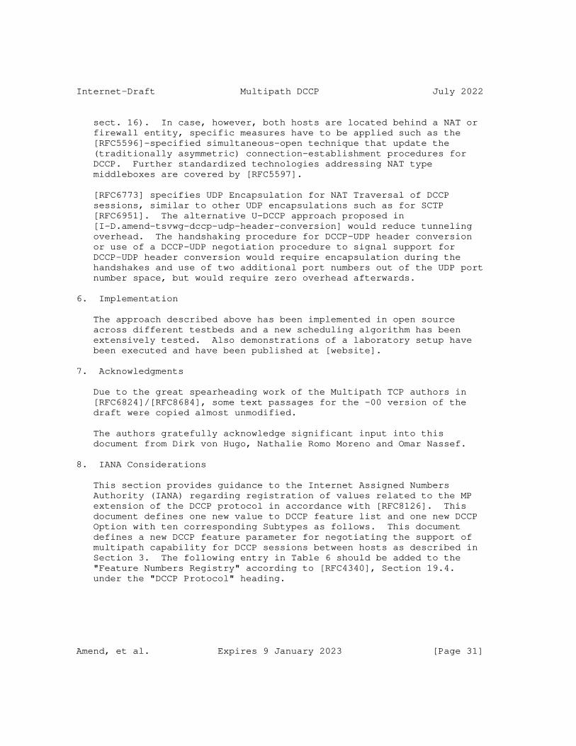
Internet-Draft Multipath DCCP July 2022
sect. 16). In case, however, both hosts are located behind a NAT or firewall entity, specific measures have to be applied such as the [RFC5596]-specified simultaneous-open technique that update the (traditionally asymmetric) connection-establishment procedures for DCCP. Further standardized technologies addressing NAT type middleboxes are covered by [RFC5597].
[RFC6773] specifies UDP Encapsulation for NAT Traversal of DCCP sessions, similar to other UDP encapsulations such as for SCTP [RFC6951]. The alternative U-DCCP approach proposed in [I-D.amend-tsvwg-dccp-udp-header-conversion] would reduce tunneling overhead. The handshaking procedure for DCCP-UDP header conversion or use of a DCCP-UDP negotiation procedure to signal support for DCCP-UDP header conversion would require encapsulation during the handshakes and use of two additional port numbers out of the UDP port number space, but would require zero overhead afterwards.
6. Implementation
The approach described above has been implemented in open source across different testbeds and a new scheduling algorithm has been extensively tested. Also demonstrations of a laboratory setup have been executed and have been published at [website].
7. Acknowledgments
Due to the great spearheading work of the Multipath TCP authors in [RFC6824]/[RFC8684], some text passages for the -00 version of the draft were copied almost unmodified.
The authors gratefully acknowledge significant input into this document from Dirk von Hugo, Nathalie Romo Moreno and Omar Nassef.
8. IANA Considerations
This section provides guidance to the Internet Assigned Numbers Authority (IANA) regarding registration of values related to the MP extension of the DCCP protocol in accordance with [RFC8126]. This document defines one new value to DCCP feature list and one new DCCP Option with ten corresponding Subtypes as follows. This document defines a new DCCP feature parameter for negotiating the support of multipath capability for DCCP sessions between hosts as described in Section 3. The following entry in Table 6 should be added to the "Feature Numbers Registry" according to [RFC4340], Section 19.4. under the "DCCP Protocol" heading.
Amend, et al. Expires 9 January 2023 [Page 31]
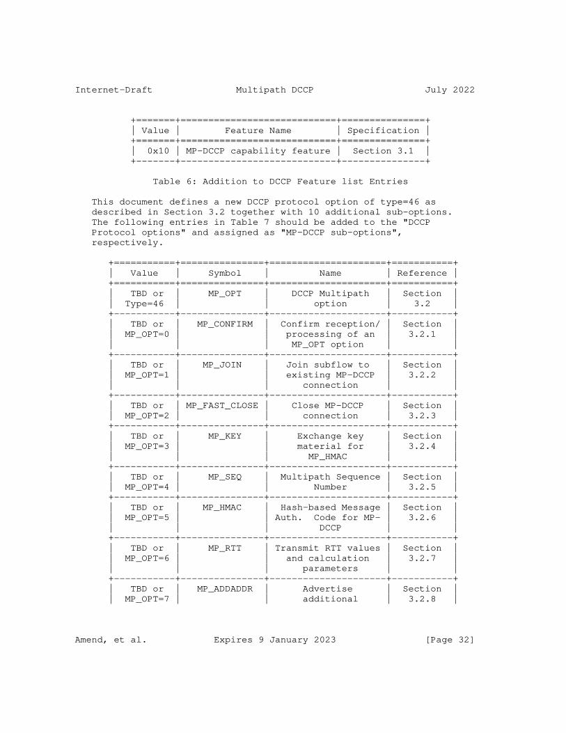
Internet-Draft Multipath DCCP July 2022
+=======+============================+===============+ | Value | Feature Name | Specification | +=======+============================+===============+ | 0x10 | MP-DCCP capability feature | Section 3.1 | +-------+----------------------------+---------------+
Table 6: Addition to DCCP Feature list Entries
This document defines a new DCCP protocol option of type=46 as described in Section 3.2 together with 10 additional sub-options. The following entries in Table 7 should be added to the "DCCP Protocol options" and assigned as "MP-DCCP sub-options", respectively.
+===========+===============+=====================+===========+ | Value | Symbol | Name | Reference | +===========+===============+=====================+===========+ | TBD or | MP_OPT | DCCP Multipath | Section | | Type=46 | | option | 3.2 | +-----------+---------------+---------------------+-----------+ | TBD or | MP_CONFIRM | Confirm reception/ | Section | | MP_OPT=0 | | processing of an | 3.2.1 | | | | MP_OPT option | | +-----------+---------------+---------------------+-----------+ | TBD or | MP_JOIN | Join subflow to | Section | | MP_OPT=1 | | existing MP-DCCP | 3.2.2 | | | | connection | | +-----------+---------------+---------------------+-----------+ | TBD or | MP_FAST_CLOSE | Close MP-DCCP | Section | | MP_OPT=2 | | connection | 3.2.3 | +-----------+---------------+---------------------+-----------+ | TBD or | MP_KEY | Exchange key | Section | | MP_OPT=3 | | material for | 3.2.4 | | | | MP_HMAC | | +-----------+---------------+---------------------+-----------+ | TBD or | MP_SEQ | Multipath Sequence | Section | | MP_OPT=4 | | Number | 3.2.5 | +-----------+---------------+---------------------+-----------+ | TBD or | MP_HMAC | Hash-based Message | Section | | MP_OPT=5 | | Auth. Code for MP- | 3.2.6 | | | | DCCP | | +-----------+---------------+---------------------+-----------+ | TBD or | MP_RTT | Transmit RTT values | Section | | MP_OPT=6 | | and calculation | 3.2.7 | | | | parameters | | +-----------+---------------+---------------------+-----------+ | TBD or | MP_ADDADDR | Advertise | Section | | MP_OPT=7 | | additional | 3.2.8 |
Amend, et al. Expires 9 January 2023 [Page 32]

Internet-Draft Multipath DCCP July 2022
| | | Address(es)/Port(s) | | +-----------+---------------+---------------------+-----------+ | TBD or | MP_REMOVEADDR | Remove Address(es)/ | Section | | MP_OPT=8 | | Port(s) | 3.2.9 | +-----------+---------------+---------------------+-----------+ | TBD or | MP_PRIO | Change Subflow | Section | | MP_OPT=9 | | Priority | 3.2.10 | +-----------+---------------+---------------------+-----------+ | TBD or | MP_CLOSE | Close MP-DCCP | Section | | MP_OPT=10 | | subflow | 3.2 | +-----------+---------------+---------------------+-----------+
Table 7: Addition to DCCP Protocol options and corresponding sub-options
In addition IANA is requested to assign a new DCCP Reset Code value 13 (or TBD) in the DCCP Reset Codes Registry, with the short description "Abrupt MP termination". Use of this reset code is defined in section Section 3.2.3.
In addition IANA is requested to assign for this version of the MP- DCCP protocol three different sub options to the MP-KEY option to identify the MP_KEY Key types in terms of 8-bit values as specified in Section 3.2.4 according to the entries in Table 8 below. Values in range 3-255 remain unspecified and are reserved for use in potential future versions of the MP-DCCP protocol.
+==========+=====================+===================+===========+ | Value | Key Type | Name or Meaning | Reference | +==========+=====================+===================+===========+ | TBD or 0 | Plain Text | Plain Text Key | Section | | | | | 3.2.4 | +----------+---------------------+-------------------+-----------+ | TBD or 1 | ECDHE-C25519-SHA256 | ECDHE with SHA256 | Section | | | | and Curve25519 | 3.2.4 | +----------+---------------------+-------------------+-----------+ | TBD or 2 | ECDHE-C25519-SHA512 | ECDHE with SHA512 | Section | | | | and Curve25519 | 3.2.4 | +----------+---------------------+-------------------+-----------+
Table 8: MP_KEY Key type sub-options for key data exchange on different paths
9. Informative References
[I-D.amend-iccrg-multipath-reordering] Amend, M. and D. V. Hugo, "Multipath sequence maintenance", Work in Progress, Internet-Draft, draft-
Amend, et al. Expires 9 January 2023 [Page 33]

Internet-Draft Multipath DCCP July 2022
amend-iccrg-multipath-reordering-03, 25 October 2021, <https://www.ietf.org/archive/id/draft-amend-iccrg- multipath-reordering-03.txt>.
[I-D.amend-tsvwg-dccp-udp-header-conversion] Amend, M., Brunstrom, A., Kassler, A., and V. Rakocevic, "Lossless and overhead free DCCP - UDP header conversion (U-DCCP)", Work in Progress, Internet-Draft, draft-amend- tsvwg-dccp-udp-header-conversion-01, 8 July 2019, <https://www.ietf.org/archive/id/draft-amend-tsvwg-dccp- udp-header-conversion-01.txt>.
[I-D.amend-tsvwg-multipath-framework-mpdccp] Amend, M., Bogenfeld, E., Brunstrom, A., Kassler, A., and V. Rakocevic, "A multipath framework for UDP traffic over heterogeneous access networks", Work in Progress, Internet-Draft, draft-amend-tsvwg-multipath-framework- mpdccp-01, 8 July 2019, <https://www.ietf.org/archive/id/ draft-amend-tsvwg-multipath-framework-mpdccp-01.txt>.
[I-D.lhwxz-hybrid-access-network-architecture] Leymann, N., Heidemann, C., Wesserman, M., Xue, L., and M. Zhang, "Hybrid Access Network Architecture", Work in Progress, Internet-Draft, draft-lhwxz-hybrid-access- network-architecture-02, 13 January 2015, <https://www.ietf.org/archive/id/draft-lhwxz-hybrid- access-network-architecture-02.txt>.
[I-D.muley-network-based-bonding-hybrid-access] Muley, P., Henderickx, W., Liang, G., Liu, H., Cardullo, L., Newton, J., Seo, S., Draznin, S., and B. Patil, "Network based Bonding solution for Hybrid Access", Work in Progress, Internet-Draft, draft-muley-network-based- bonding-hybrid-access-03, 22 October 2018, <https://www.ietf.org/archive/id/draft-muley-network- based-bonding-hybrid-access-03.txt>.
[OLIA] Khalili, R., Gast, N., Popovic, M., Upadhyay, U., and J.- Y. Le Boudec, "MPTCP is not pareto-optimal: performance issues and a possible solution", Proceedings of the 8th international conference on Emerging networking experiments and technologies, ACM , 2012.
Amend, et al. Expires 9 January 2023 [Page 34]
Internet-Draft Multipath DCCP July 2022
[paper] Amend, M., Bogenfeld, E., Cvjetkovic, M., Rakocevic, V., Pieska, M., Kassler, A., and A. Brunstrom, "A Framework for Multiaccess Support for Unreliable Internet Traffic using Multipath DCCP", DOI 10.1109/LCN44214.2019.8990746, October 2019, <https://doi.org/10.1109/LCN44214.2019.8990746>.
[RFC0793] Postel, J., "Transmission Control Protocol", STD 7, RFC 793, DOI 10.17487/RFC0793, September 1981, <https://www.rfc-editor.org/info/rfc793>.
[RFC2104] Krawczyk, H., Bellare, M., and R. Canetti, "HMAC: Keyed- Hashing for Message Authentication", RFC 2104, DOI 10.17487/RFC2104, February 1997, <https://www.rfc-editor.org/info/rfc2104>.
[RFC2119] Bradner, S., "Key words for use in RFCs to Indicate Requirement Levels", BCP 14, RFC 2119, DOI 10.17487/RFC2119, March 1997, <https://www.rfc-editor.org/info/rfc2119>.
[RFC3124] Balakrishnan, H. and S. Seshan, "The Congestion Manager", RFC 3124, DOI 10.17487/RFC3124, June 2001, <https://www.rfc-editor.org/info/rfc3124>.
[RFC3711] Baugher, M., McGrew, D., Naslund, M., Carrara, E., and K. Norrman, "The Secure Real-time Transport Protocol (SRTP)", RFC 3711, DOI 10.17487/RFC3711, March 2004, <https://www.rfc-editor.org/info/rfc3711>.
[RFC4043] Pinkas, D. and T. Gindin, "Internet X.509 Public Key Infrastructure Permanent Identifier", RFC 4043, DOI 10.17487/RFC4043, May 2005, <https://www.rfc-editor.org/info/rfc4043>.
[RFC4086] Eastlake 3rd, D., Schiller, J., and S. Crocker, "Randomness Requirements for Security", BCP 106, RFC 4086, DOI 10.17487/RFC4086, June 2005, <https://www.rfc-editor.org/info/rfc4086>.
[RFC4340] Kohler, E., Handley, M., and S. Floyd, "Datagram Congestion Control Protocol (DCCP)", RFC 4340, DOI 10.17487/RFC4340, March 2006, <https://www.rfc-editor.org/info/rfc4340>.
[RFC5595] Fairhurst, G., "The Datagram Congestion Control Protocol (DCCP) Service Codes", RFC 5595, DOI 10.17487/RFC5595, September 2009, <https://www.rfc-editor.org/info/rfc5595>.
Amend, et al. Expires 9 January 2023 [Page 35]
Internet-Draft Multipath DCCP July 2022
[RFC5596] Fairhurst, G., "Datagram Congestion Control Protocol (DCCP) Simultaneous-Open Technique to Facilitate NAT/ Middlebox Traversal", RFC 5596, DOI 10.17487/RFC5596, September 2009, <https://www.rfc-editor.org/info/rfc5596>.
[RFC5597] Denis-Courmont, R., "Network Address Translation (NAT) Behavioral Requirements for the Datagram Congestion Control Protocol", BCP 150, RFC 5597, DOI 10.17487/RFC5597, September 2009, <https://www.rfc-editor.org/info/rfc5597>.
[RFC5634] Fairhurst, G. and A. Sathiaseelan, "Quick-Start for the Datagram Congestion Control Protocol (DCCP)", RFC 5634, DOI 10.17487/RFC5634, August 2009, <https://www.rfc-editor.org/info/rfc5634>.
[RFC6234] Eastlake 3rd, D. and T. Hansen, "US Secure Hash Algorithms (SHA and SHA-based HMAC and HKDF)", RFC 6234, DOI 10.17487/RFC6234, May 2011, <https://www.rfc-editor.org/info/rfc6234>.
[RFC6356] Raiciu, C., Handley, M., and D. Wischik, "Coupled Congestion Control for Multipath Transport Protocols", RFC 6356, DOI 10.17487/RFC6356, October 2011, <https://www.rfc-editor.org/info/rfc6356>.
[RFC6773] Phelan, T., Fairhurst, G., and C. Perkins, "DCCP-UDP: A Datagram Congestion Control Protocol UDP Encapsulation for NAT Traversal", RFC 6773, DOI 10.17487/RFC6773, November 2012, <https://www.rfc-editor.org/info/rfc6773>.
[RFC6824] Ford, A., Raiciu, C., Handley, M., and O. Bonaventure, "TCP Extensions for Multipath Operation with Multiple Addresses", RFC 6824, DOI 10.17487/RFC6824, January 2013, <https://www.rfc-editor.org/info/rfc6824>.
[RFC6904] Lennox, J., "Encryption of Header Extensions in the Secure Real-time Transport Protocol (SRTP)", RFC 6904, DOI 10.17487/RFC6904, April 2013, <https://www.rfc-editor.org/info/rfc6904>.
[RFC6951] Tuexen, M. and R. Stewart, "UDP Encapsulation of Stream Control Transmission Protocol (SCTP) Packets for End-Host to End-Host Communication", RFC 6951, DOI 10.17487/RFC6951, May 2013, <https://www.rfc-editor.org/info/rfc6951>.
Amend, et al. Expires 9 January 2023 [Page 36]
Internet-Draft Multipath DCCP July 2022
[RFC8126] Cotton, M., Leiba, B., and T. Narten, "Guidelines for Writing an IANA Considerations Section in RFCs", BCP 26, RFC 8126, DOI 10.17487/RFC8126, June 2017, <https://www.rfc-editor.org/info/rfc8126>.
[RFC8684] Ford, A., Raiciu, C., Handley, M., Bonaventure, O., and C. Paasch, "TCP Extensions for Multipath Operation with Multiple Addresses", RFC 8684, DOI 10.17487/RFC8684, March 2020, <https://www.rfc-editor.org/info/rfc8684>.
[slide] Amend, M., "MP-DCCP for enabling transfer of UDP/IP traffic over multiple data paths in multi-connectivity networks", IETF105 , n.d., <https://datatracker.ietf.org/meeting/105/materials/ slides-105-tsvwg-sessa-62-dccp-extensions-for-multipath- operation-00>.
[TS23.501] 3GPP, "System architecture for the 5G System; Stage 2; Release 16", December 2020, <https://www.3gpp.org/ftp//Specs/ archive/23_series/23.501/23501-g70.zip>.
[website] "Multipath extension for DCCP", n.d., <https://multipath-dccp.org/>.
Appendix A. Differences from Multipath TCP
Multipath DCCP is similar to Multipath TCP [RFC8684], in that it extends the related basic DCCP transport protocol [RFC4340] with multipath capabilities in the same way as Multipath TCP extends TCP [RFC0793]. However, because of the differences between the underlying TCP and DCCP protocols, the transport characteristics of MPTCP and MP-DCCP are different.
Table 9 compares the protocol characteristics of TCP and DCCP, which are by nature inherited by their respective multipath extensions. A major difference lies in the delivery of payload, which is for TCP an exact copy of the generated byte-stream. DCCP behaves in a different way and does not guarantee to deliver any payload nor the order of delivery. Since this is mainly affecting the receiving endpoint of a TCP or DCCP communication, many similarities on the sender side can be identified. Both transport protocols share the 3-way initiation of a communication and both employ congestion control to adapt the sending rate to the path characteristics.
Amend, et al. Expires 9 January 2023 [Page 37]
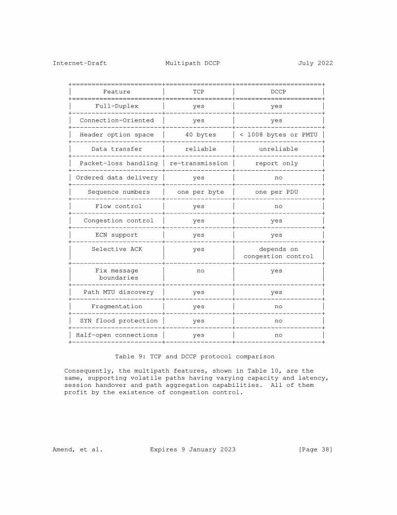
Internet-Draft Multipath DCCP July 2022
+=======================+=================+======================+ | Feature | TCP | DCCP | +=======================+=================+======================+ | Full-Duplex | yes | yes | +-----------------------+-----------------+----------------------+ | Connection-Oriented | yes | yes | +-----------------------+-----------------+----------------------+ | Header option space | 40 bytes | < 1008 bytes or PMTU | +-----------------------+-----------------+----------------------+ | Data transfer | reliable | unreliable | +-----------------------+-----------------+----------------------+ | Packet-loss handling | re-transmission | report only | +-----------------------+-----------------+----------------------+ | Ordered data delivery | yes | no | +-----------------------+-----------------+----------------------+ | Sequence numbers | one per byte | one per PDU | +-----------------------+-----------------+----------------------+ | Flow control | yes | no | +-----------------------+-----------------+----------------------+ | Congestion control | yes | yes | +-----------------------+-----------------+----------------------+ | ECN support | yes | yes | +-----------------------+-----------------+----------------------+ | Selective ACK | yes | depends on | | | | congestion control | +-----------------------+-----------------+----------------------+ | Fix message | no | yes | | boundaries | | | +-----------------------+-----------------+----------------------+ | Path MTU discovery | yes | yes | +-----------------------+-----------------+----------------------+ | Fragmentation | yes | no | +-----------------------+-----------------+----------------------+ | SYN flood protection | yes | no | +-----------------------+-----------------+----------------------+ | Half-open connections | yes | no | +-----------------------+-----------------+----------------------+
Table 9: TCP and DCCP protocol comparison
Consequently, the multipath features, shown in Table 10, are the same, supporting volatile paths having varying capacity and latency, session handover and path aggregation capabilities. All of them profit by the existence of congestion control.
Amend, et al. Expires 9 January 2023 [Page 38]
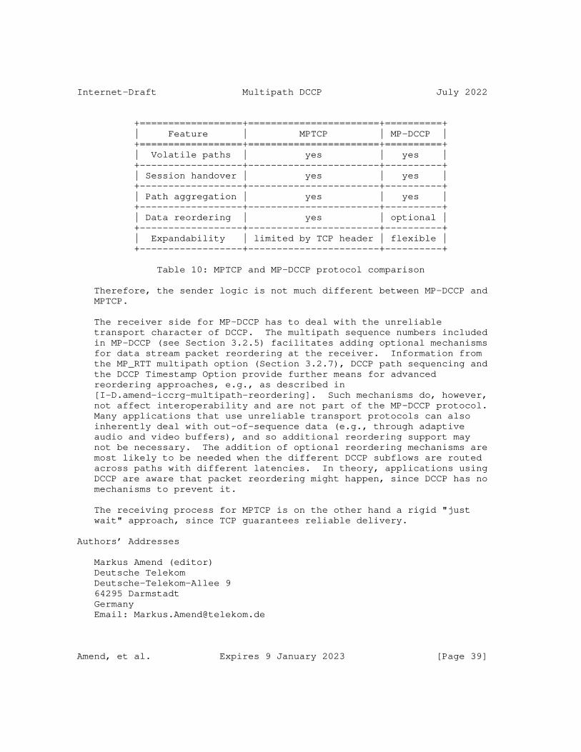
Internet-Draft Multipath DCCP July 2022
+==================+=======================+==========+ | Feature | MPTCP | MP-DCCP | +==================+=======================+==========+ | Volatile paths | yes | yes | +------------------+-----------------------+----------+ | Session handover | yes | yes | +------------------+-----------------------+----------+ | Path aggregation | yes | yes | +------------------+-----------------------+----------+ | Data reordering | yes | optional | +------------------+-----------------------+----------+ | Expandability | limited by TCP header | flexible | +------------------+-----------------------+----------+
Table 10: MPTCP and MP-DCCP protocol comparison
Therefore, the sender logic is not much different between MP-DCCP and MPTCP.
The receiver side for MP-DCCP has to deal with the unreliable transport character of DCCP. The multipath sequence numbers included in MP-DCCP (see Section 3.2.5) facilitates adding optional mechanisms for data stream packet reordering at the receiver. Information from the MP_RTT multipath option (Section 3.2.7), DCCP path sequencing and the DCCP Timestamp Option provide further means for advanced reordering approaches, e.g., as described in [I-D.amend-iccrg-multipath-reordering]. Such mechanisms do, however, not affect interoperability and are not part of the MP-DCCP protocol. Many applications that use unreliable transport protocols can also inherently deal with out-of-sequence data (e.g., through adaptive audio and video buffers), and so additional reordering support may not be necessary. The addition of optional reordering mechanisms are most likely to be needed when the different DCCP subflows are routed across paths with different latencies. In theory, applications using DCCP are aware that packet reordering might happen, since DCCP has no mechanisms to prevent it.
The receiving process for MPTCP is on the other hand a rigid "just wait" approach, since TCP guarantees reliable delivery.
Authors’ Addresses
Markus Amend (editor) Deutsche Telekom Deutsche-Telekom-Allee 9 64295 Darmstadt Germany Email: [email protected]
Amend, et al. Expires 9 January 2023 [Page 39]
Internet-Draft Multipath DCCP July 2022
Anna Brunstrom Karlstad University Universitetsgatan 2 SE-651 88 Karlstad Sweden Email: [email protected]
Andreas Kassler Karlstad University Universitetsgatan 2 SE-651 88 Karlstad Sweden Email: [email protected]
Veselin Rakocevic City University of London Northampton Square London United Kingdom Email: [email protected]
Stephen Johnson BT Adastral Park Martlesham Heath IP5 3RE United Kingdom Email: [email protected]
Amend, et al. Expires 9 January 2023 [Page 40]

Network Working Group R. R. StewartInternet-Draft Netflix, Inc.Intended status: Standards Track M. TüxenExpires: 28 April 2022 I. Rüngeler Münster Univ. of Appl. Sciences 25 October 2021
Stream Control Transmission Protocol (SCTP) Network Address Translation Support draft-ietf-tsvwg-natsupp-23
Abstract
The Stream Control Transmission Protocol (SCTP) provides a reliable communications channel between two end-hosts in many ways similar to the Transmission Control Protocol (TCP). With the widespread deployment of Network Address Translators (NAT), specialized code has been added to NAT functions for TCP that allows multiple hosts to reside behind a NAT function and yet share a single IPv4 address, even when two hosts (behind a NAT function) choose the same port numbers for their connection. This additional code is sometimes classified as Network Address and Port Translation (NAPT).
This document describes the protocol extensions needed for the SCTP endpoints and the mechanisms for NAT functions necessary to provide similar features of NAPT in the single point and multipoint traversal scenario.
Finally, a YANG module for SCTP NAT is defined.
Status of This Memo
This Internet-Draft is submitted in full conformance with the provisions of BCP 78 and BCP 79.
Internet-Drafts are working documents of the Internet Engineering Task Force (IETF). Note that other groups may also distribute working documents as Internet-Drafts. The list of current Internet- Drafts is at https://datatracker.ietf.org/drafts/current/.
Internet-Drafts are draft documents valid for a maximum of six months and may be updated, replaced, or obsoleted by other documents at any time. It is inappropriate to use Internet-Drafts as reference material or to cite them other than as "work in progress."
This Internet-Draft will expire on 28 April 2022.
Stewart, et al. Expires 28 April 2022 [Page 1]

Internet-Draft SCTP NAT Support October 2021
Copyright Notice
Copyright (c) 2021 IETF Trust and the persons identified as the document authors. All rights reserved.
This document is subject to BCP 78 and the IETF Trust’s Legal Provisions Relating to IETF Documents (https://trustee.ietf.org/ license-info) in effect on the date of publication of this document. Please review these documents carefully, as they describe your rights and restrictions with respect to this document. Code Components extracted from this document must include Simplified BSD License text as described in Section 4.e of the Trust Legal Provisions and are provided without warranty as described in the Simplified BSD License.
Table of Contents
1. Introduction . . . . . . . . . . . . . . . . . . . . . . . . 3 2. Conventions . . . . . . . . . . . . . . . . . . . . . . . . . 5 3. Terminology . . . . . . . . . . . . . . . . . . . . . . . . . 5 4. Motivation and Overview . . . . . . . . . . . . . . . . . . . 6 4.1. SCTP NAT Traversal Scenarios . . . . . . . . . . . . . . 6 4.1.1. Single Point Traversal . . . . . . . . . . . . . . . 7 4.1.2. Multipoint Traversal . . . . . . . . . . . . . . . . 7 4.2. Limitations of Classical NAPT for SCTP . . . . . . . . . 8 4.3. The SCTP-Specific Variant of NAT . . . . . . . . . . . . 8 5. Data Formats . . . . . . . . . . . . . . . . . . . . . . . . 13 5.1. Modified Chunks . . . . . . . . . . . . . . . . . . . . . 13 5.1.1. Extended ABORT Chunk . . . . . . . . . . . . . . . . 13 5.1.2. Extended ERROR Chunk . . . . . . . . . . . . . . . . 14 5.2. New Error Causes . . . . . . . . . . . . . . . . . . . . 14 5.2.1. VTag and Port Number Collision Error Cause . . . . . 14 5.2.2. Missing State Error Cause . . . . . . . . . . . . . . 15 5.2.3. Port Number Collision Error Cause . . . . . . . . . . 15 5.3. New Parameters . . . . . . . . . . . . . . . . . . . . . 16 5.3.1. Disable Restart Parameter . . . . . . . . . . . . . . 16 5.3.2. VTags Parameter . . . . . . . . . . . . . . . . . . . 17 6. Procedures for SCTP Endpoints and NAT Functions . . . . . . . 18 6.1. Association Setup Considerations for Endpoints . . . . . 19 6.2. Handling of Internal Port Number and Verification Tag Collisions . . . . . . . . . . . . . . . . . . . . . . . 19 6.2.1. NAT Function Considerations . . . . . . . . . . . . . 19 6.2.2. Endpoint Considerations . . . . . . . . . . . . . . . 20 6.3. Handling of Internal Port Number Collisions . . . . . . . 20 6.3.1. NAT Function Considerations . . . . . . . . . . . . . 20 6.3.2. Endpoint Considerations . . . . . . . . . . . . . . . 21 6.4. Handling of Missing State . . . . . . . . . . . . . . . . 21 6.4.1. NAT Function Considerations . . . . . . . . . . . . . 22 6.4.2. Endpoint Considerations . . . . . . . . . . . . . . . 22
Stewart, et al. Expires 28 April 2022 [Page 2]
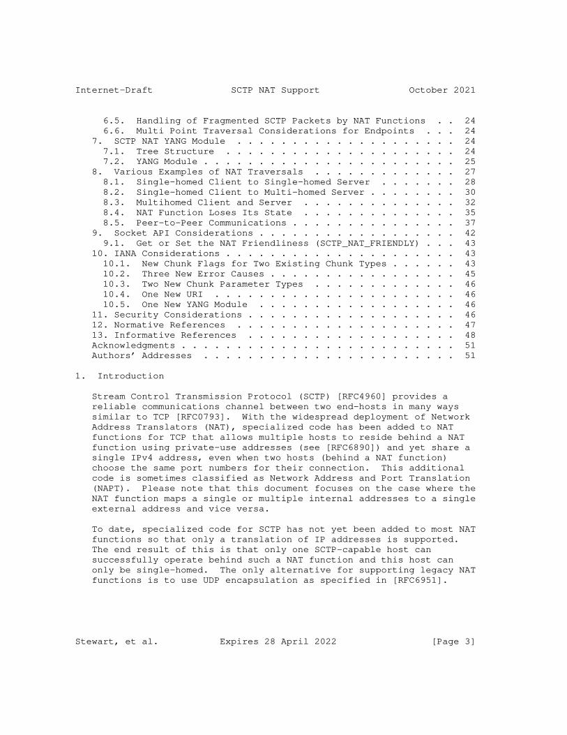
Internet-Draft SCTP NAT Support October 2021
6.5. Handling of Fragmented SCTP Packets by NAT Functions . . 24 6.6. Multi Point Traversal Considerations for Endpoints . . . 24 7. SCTP NAT YANG Module . . . . . . . . . . . . . . . . . . . . 24 7.1. Tree Structure . . . . . . . . . . . . . . . . . . . . . 24 7.2. YANG Module . . . . . . . . . . . . . . . . . . . . . . . 25 8. Various Examples of NAT Traversals . . . . . . . . . . . . . 27 8.1. Single-homed Client to Single-homed Server . . . . . . . 28 8.2. Single-homed Client to Multi-homed Server . . . . . . . . 30 8.3. Multihomed Client and Server . . . . . . . . . . . . . . 32 8.4. NAT Function Loses Its State . . . . . . . . . . . . . . 35 8.5. Peer-to-Peer Communications . . . . . . . . . . . . . . . 37 9. Socket API Considerations . . . . . . . . . . . . . . . . . . 42 9.1. Get or Set the NAT Friendliness (SCTP_NAT_FRIENDLY) . . . 43 10. IANA Considerations . . . . . . . . . . . . . . . . . . . . . 43 10.1. New Chunk Flags for Two Existing Chunk Types . . . . . . 43 10.2. Three New Error Causes . . . . . . . . . . . . . . . . . 45 10.3. Two New Chunk Parameter Types . . . . . . . . . . . . . 46 10.4. One New URI . . . . . . . . . . . . . . . . . . . . . . 46 10.5. One New YANG Module . . . . . . . . . . . . . . . . . . 46 11. Security Considerations . . . . . . . . . . . . . . . . . . . 46 12. Normative References . . . . . . . . . . . . . . . . . . . . 47 13. Informative References . . . . . . . . . . . . . . . . . . . 48 Acknowledgments . . . . . . . . . . . . . . . . . . . . . . . . . 51 Authors’ Addresses . . . . . . . . . . . . . . . . . . . . . . . 51
1. Introduction
Stream Control Transmission Protocol (SCTP) [RFC4960] provides a reliable communications channel between two end-hosts in many ways similar to TCP [RFC0793]. With the widespread deployment of Network Address Translators (NAT), specialized code has been added to NAT functions for TCP that allows multiple hosts to reside behind a NAT function using private-use addresses (see [RFC6890]) and yet share a single IPv4 address, even when two hosts (behind a NAT function) choose the same port numbers for their connection. This additional code is sometimes classified as Network Address and Port Translation (NAPT). Please note that this document focuses on the case where the NAT function maps a single or multiple internal addresses to a single external address and vice versa.
To date, specialized code for SCTP has not yet been added to most NAT functions so that only a translation of IP addresses is supported. The end result of this is that only one SCTP-capable host can successfully operate behind such a NAT function and this host can only be single-homed. The only alternative for supporting legacy NAT functions is to use UDP encapsulation as specified in [RFC6951].
Stewart, et al. Expires 28 April 2022 [Page 3]

Internet-Draft SCTP NAT Support October 2021
The NAT function in the document refers to NAPT functions described in Section 2.2 of [RFC3022], NAT64 [RFC6146], or DS-Lite AFTR [RFC6333].
This document specifies procedures allowing a NAT function to support SCTP by providing similar features to those provided by a NAPT for TCP (see [RFC5382] and [RFC7857]), UDP (see [RFC4787] and [RFC7857]), and ICMP (see [RFC5508] and [RFC7857]). This document also specifies a set of data formats for SCTP packets and a set of SCTP endpoint procedures to support NAT traversal. An SCTP implementation supporting these procedures can assure that in both single-homed and multi-homed cases a NAT function will maintain the appropriate state without the NAT function needing to change port numbers.
It is possible and desirable to make these changes for a number of reasons:
* It is desirable for SCTP internal end-hosts on multiple platforms to be able to share a NAT function’s external IP address in the same way that a TCP session can use a NAT function.
* If a NAT function does not need to change any data within an SCTP packet, it will reduce the processing burden of NAT’ing SCTP by not needing to execute the CRC32c checksum used by SCTP.
* Not having to touch the IP payload makes the processing of ICMP messages by NAT functions easier.
An SCTP-aware NAT function will need to follow these procedures for generating appropriate SCTP packet formats.
When considering SCTP-aware NAT it is possible to have multiple levels of support. At each level, the Internal Host, Remote Host, and NAT function does or does not support the procedures described in this document. The following table illustrates the results of the various combinations of support and if communications can occur between two endpoints.
Stewart, et al. Expires 28 April 2022 [Page 4]
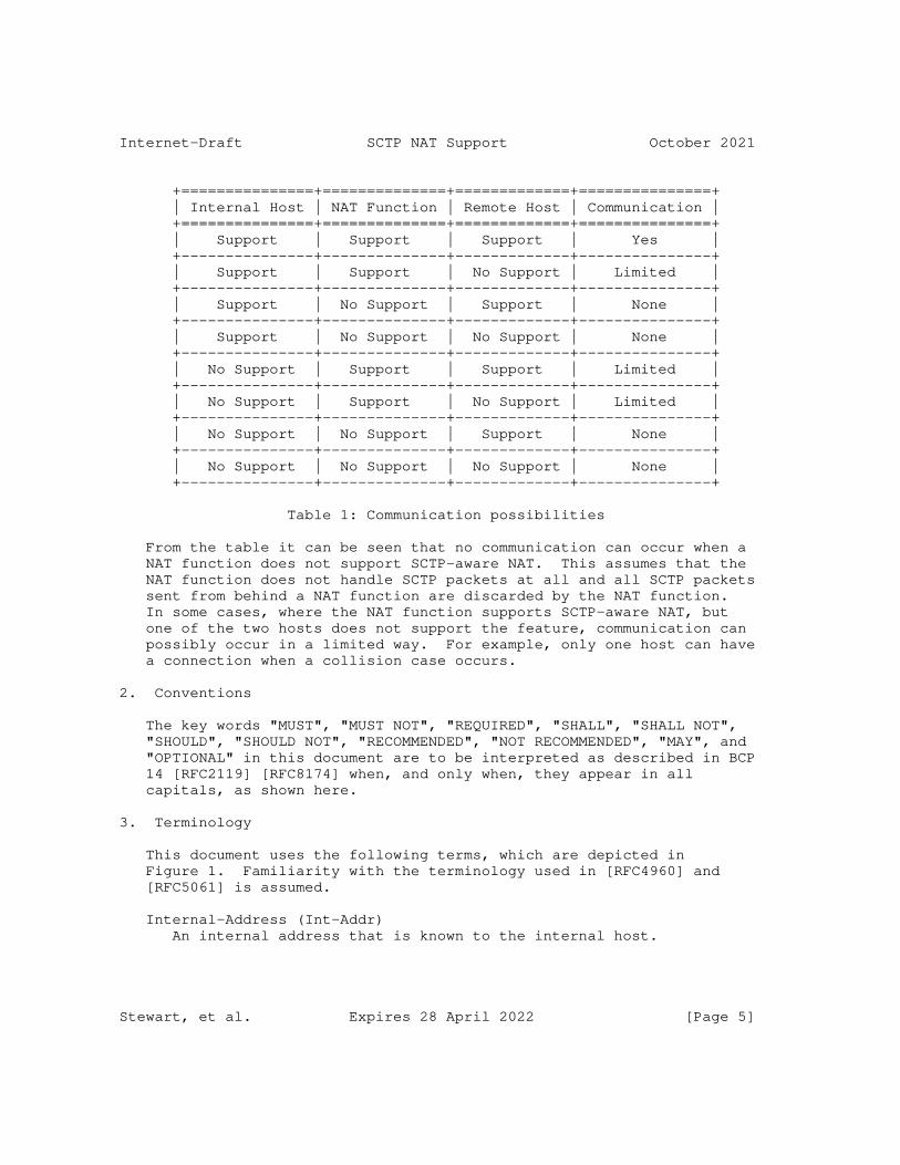
Internet-Draft SCTP NAT Support October 2021
+===============+==============+=============+===============+ | Internal Host | NAT Function | Remote Host | Communication | +===============+==============+=============+===============+ | Support | Support | Support | Yes | +---------------+--------------+-------------+---------------+ | Support | Support | No Support | Limited | +---------------+--------------+-------------+---------------+ | Support | No Support | Support | None | +---------------+--------------+-------------+---------------+ | Support | No Support | No Support | None | +---------------+--------------+-------------+---------------+ | No Support | Support | Support | Limited | +---------------+--------------+-------------+---------------+ | No Support | Support | No Support | Limited | +---------------+--------------+-------------+---------------+ | No Support | No Support | Support | None | +---------------+--------------+-------------+---------------+ | No Support | No Support | No Support | None | +---------------+--------------+-------------+---------------+
Table 1: Communication possibilities
From the table it can be seen that no communication can occur when a NAT function does not support SCTP-aware NAT. This assumes that the NAT function does not handle SCTP packets at all and all SCTP packets sent from behind a NAT function are discarded by the NAT function. In some cases, where the NAT function supports SCTP-aware NAT, but one of the two hosts does not support the feature, communication can possibly occur in a limited way. For example, only one host can have a connection when a collision case occurs.
2. Conventions
The key words "MUST", "MUST NOT", "REQUIRED", "SHALL", "SHALL NOT", "SHOULD", "SHOULD NOT", "RECOMMENDED", "NOT RECOMMENDED", "MAY", and "OPTIONAL" in this document are to be interpreted as described in BCP 14 [RFC2119] [RFC8174] when, and only when, they appear in all capitals, as shown here.
3. Terminology
This document uses the following terms, which are depicted in Figure 1. Familiarity with the terminology used in [RFC4960] and [RFC5061] is assumed.
Internal-Address (Int-Addr) An internal address that is known to the internal host.
Stewart, et al. Expires 28 April 2022 [Page 5]
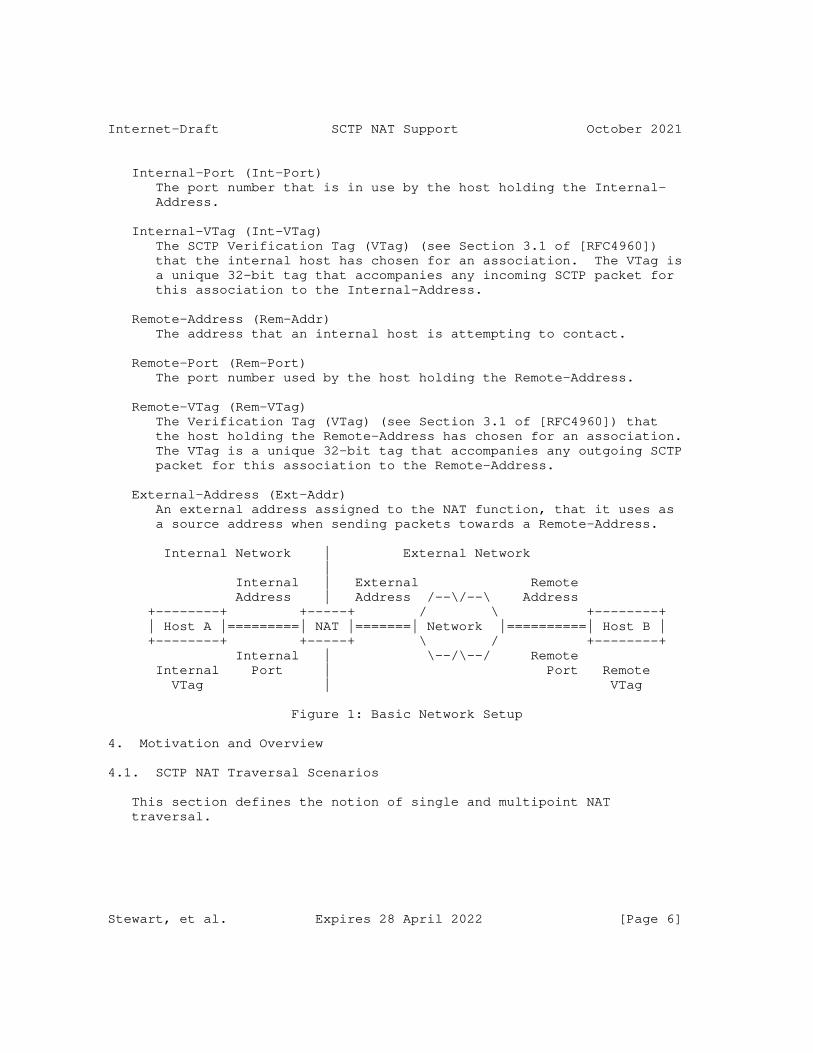
Internet-Draft SCTP NAT Support October 2021
Internal-Port (Int-Port) The port number that is in use by the host holding the Internal- Address.
Internal-VTag (Int-VTag) The SCTP Verification Tag (VTag) (see Section 3.1 of [RFC4960]) that the internal host has chosen for an association. The VTag is a unique 32-bit tag that accompanies any incoming SCTP packet for this association to the Internal-Address.
Remote-Address (Rem-Addr) The address that an internal host is attempting to contact.
Remote-Port (Rem-Port) The port number used by the host holding the Remote-Address.
Remote-VTag (Rem-VTag) The Verification Tag (VTag) (see Section 3.1 of [RFC4960]) that the host holding the Remote-Address has chosen for an association. The VTag is a unique 32-bit tag that accompanies any outgoing SCTP packet for this association to the Remote-Address.
External-Address (Ext-Addr) An external address assigned to the NAT function, that it uses as a source address when sending packets towards a Remote-Address.
Internal Network | External Network | Internal | External Remote Address | Address /--\/--\ Address +--------+ +-----+ / \ +--------+ | Host A |=========| NAT |=======| Network |==========| Host B | +--------+ +-----+ \ / +--------+ Internal | \--/\--/ Remote Internal Port | Port Remote VTag | VTag
Figure 1: Basic Network Setup
4. Motivation and Overview
4.1. SCTP NAT Traversal Scenarios
This section defines the notion of single and multipoint NAT traversal.
Stewart, et al. Expires 28 April 2022 [Page 6]
Internet-Draft SCTP NAT Support October 2021
4.1.1. Single Point Traversal
In this case, all packets in the SCTP association go through a single NAT function, as shown in Figure 2.
Internal Network | External Network | | /--\/--\ +--------+ +-----+ / \ +--------+ | Host A |=========| NAT |========= | Network | ========| Host B | +--------+ +-----+ \ / +--------+ | \--/\--/ |
Figure 2: Single NAT Function Scenario
A variation of this case is shown in Figure 3, i.e., multiple NAT functions in the forwarding path between two endpoints.
Internal | External : Internal | External | : | | : | /--\/--\ +--------+ +-----+ : +-----+ / \ +--------+ | Host A |==| NAT |=======:=======| NAT |==| Network |==| Host B | +--------+ +-----+ : +-----+ \ / +--------+ | : | \--/\--/ | : |
Figure 3: Serial NAT Functions Scenario
Although one of the main benefits of SCTP multi-homing is redundant paths, in the single point traversal scenario the NAT function represents a single point of failure in the path of the SCTP multi- homed association. However, the rest of the path can still benefit from path diversity provided by SCTP multi-homing.
The two SCTP endpoints in this case can be either single-homed or multi-homed. However, the important thing is that the NAT function in this case sees all the packets of the SCTP association.
4.1.2. Multipoint Traversal
This case involves multiple NAT functions and each NAT function only sees some of the packets in the SCTP association. An example is shown in Figure 4.
Stewart, et al. Expires 28 April 2022 [Page 7]

Internet-Draft SCTP NAT Support October 2021
Internal | External +------+ /---\/---\ /=======|NAT A |=========\ / \ +--------+ / +------+ \/ \ +--------+ | Host A |/ | | Network |===| Host B | +--------+\ | \ / +--------+ \ +------+ / \ / \=======|NAT B |=========/ \---\/---/ +------+ |
Figure 4: Parallel NAT Functions Scenario
This case does not apply to a single-homed SCTP association (i.e., both endpoints in the association use only one IP address). The advantage here is that the existence of multiple NAT traversal points can preserve the path diversity of a multi-homed association for the entire path. This in turn can improve the robustness of the communication.
4.2. Limitations of Classical NAPT for SCTP
Using classical NAPT possibly results in changing one of the SCTP port numbers during the processing, which requires the recomputation of the transport layer checksum by the NAPT function. Whereas for UDP and TCP this can be done very efficiently, for SCTP the checksum (CRC32c) over the entire packet needs to be recomputed (see Appendix B of [RFC4960] for details of the CRC32c computation). This would considerably add to the NAT computational burden, however hardware support can mitigate this in some implementations.
An SCTP endpoint can have multiple addresses but only has a single port number to use. To make multipoint traversal work, all the NAT functions involved need to recognize the packets they see as belonging to the same SCTP association and perform port number translation in a consistent way. One possible way of doing this is to use a pre-defined table of port numbers and addresses configured within each NAT function. Other mechanisms could make use of NAT to NAT communication. Such mechanisms have not been deployed on a wide scale base and thus are not a preferred solution. Therefore an SCTP variant of NAT function has been developed (see Section 4.3).
4.3. The SCTP-Specific Variant of NAT
In this section it is allowed that there are multiple SCTP capable hosts behind a NAT function that share one External-Address. Furthermore, this section focuses on the single point traversal scenario (see Section 4.1.1).
Stewart, et al. Expires 28 April 2022 [Page 8]

Internet-Draft SCTP NAT Support October 2021
The modification of outgoing SCTP packets sent from an internal host is simple: the source address of the packets has to be replaced with the External-Address. It might also be necessary to establish some state in the NAT function to later handle incoming packets.
Typically, the NAT function has to maintain a NAT binding table of Internal-VTag, Internal-Port, Remote-VTag, Remote-Port, Internal- Address, and whether the restart procedure is disabled or not. An entry in that NAT binding table is called a NAT-State control block. The function Create() obtains the just mentioned parameters and returns a NAT-State control block. A NAT function MAY allow creating NAT-State control blocks via a management interface.
For SCTP packets coming from the external realm of the NAT function the destination address of the packets has to be replaced with the Internal-Address of the host to which the packet has to be delivered, if a NAT state entry is found. The lookup of the Internal-Address is based on the Remote-VTag, Remote-Port, Internal-VTag and the Internal-Port.
The entries in the NAT binding table need to fulfill some uniqueness conditions. There can not be more than one entry NAT binding table with the same pair of Internal-Port and Remote-Port. This rule can be relaxed, if all NAT binding table entries with the same Internal- Port and Remote-Port have the support for the restart procedure disabled (see Section 5.3.1). In this case there can not be no more than one entry with the same Internal-Port, Remote-Port and Remote- VTag and no more than one NAT binding table entry with the same Internal-Port, Remote-Port, and Int-VTag.
The processing of outgoing SCTP packets containing an INIT chunk is illustrated in the following figure. This scenario is valid for all message flows in this section.
Stewart, et al. Expires 28 April 2022 [Page 9]

Internet-Draft SCTP NAT Support October 2021
/--\/--\ +--------+ +-----+ / \ +--------+ | Host A | <------> | NAT | <------> | Network | <------> | Host B | +--------+ +-----+ \ / +--------+ \--/\---/
INIT[Initiate-Tag] Int-Addr:Int-Port ------> Rem-Addr:Rem-Port Rem-VTag=0
Create(Initiate-Tag, Int-Port, 0, Rem-Port, Int-Addr, IsRestartDisabled) Returns(NAT-State control block)
Translate To:
INIT[Initiate-Tag] Ext-Addr:Int-Port ------> Rem-Addr:Rem-Port Rem-VTag=0
Normally a NAT binding table entry will be created.
However, it is possible that there is already a NAT binding table entry with the same Remote-Port, Internal-Port, and Internal-VTag but different Internal-Address and the restart procedure is disabled. In this case the packet containing the INIT chunk MUST be dropped by the NAT and a packet containing an ABORT chunk SHOULD be sent to the SCTP host that originated the packet with the M bit set and ’VTag and Port Number Collision’ error cause (see Section 5.1.1 for the format). The source address of the packet containing the ABORT chunk MUST be the destination address of the packet containing the INIT chunk.
If an outgoing SCTP packet contains an INIT or ASCONF chunk and a matching NAT binding table entry is found, the packet is processed as a normal outgoing packet.
It is also possible that a NAT binding table entry with the same Remote-Port and Internal-Port exists without an Internal-VTag conflict but there exists a NAT binding table entry with the same port numbers but a different Internal-Address and the restart procedure is not disabled. In such a case the packet containing the INIT chunk MUST be dropped by the NAT function and a packet containing an ABORT chunk SHOULD be sent to the SCTP host that originated the packet with the M bit set and ’Port Number Collision’ error cause (see Section 5.1.1 for the format).
Stewart, et al. Expires 28 April 2022 [Page 10]
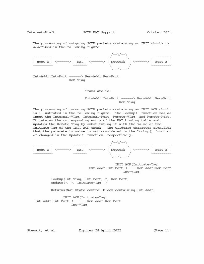
Internet-Draft SCTP NAT Support October 2021
The processing of outgoing SCTP packets containing no INIT chunks is described in the following figure.
/--\/--\ +--------+ +-----+ / \ +--------+ | Host A | <------> | NAT | <------> | Network | <------> | Host B | +--------+ +-----+ \ / +--------+ \--/\---/
Int-Addr:Int-Port ------> Rem-Addr:Rem-Port Rem-VTag
Translate To:
Ext-Addr:Int-Port ------> Rem-Addr:Rem-Port Rem-VTag
The processing of incoming SCTP packets containing an INIT ACK chunk is illustrated in the following figure. The Lookup() function has as input the Internal-VTag, Internal-Port, Remote-VTag, and Remote-Port. It returns the corresponding entry of the NAT binding table and updates the Remote-VTag by substituting it with the value of the Initiate-Tag of the INIT ACK chunk. The wildcard character signifies that the parameter’s value is not considered in the Lookup() function or changed in the Update() function, respectively.
/--\/--\ +--------+ +-----+ / \ +--------+ | Host A | <------> | NAT | <------> | Network | <------> | Host B | +--------+ +-----+ \ / +--------+ \--/\---/
INIT ACK[Initiate-Tag] Ext-Addr:Int-Port <---- Rem-Addr:Rem-Port Int-VTag
Lookup(Int-VTag, Int-Port, *, Rem-Port) Update(*, *, Initiate-Tag, *)
Returns(NAT-State control block containing Int-Addr)
INIT ACK[Initiate-Tag] Int-Addr:Int-Port <------ Rem-Addr:Rem-Port Int-VTag
Stewart, et al. Expires 28 April 2022 [Page 11]

Internet-Draft SCTP NAT Support October 2021
In the case where the Lookup function fails because it does not find an entry, the SCTP packet is dropped. If it succeeds, the Update routine inserts the Remote-VTag (the Initiate-Tag of the INIT ACK chunk) in the NAT-State control block.
The processing of incoming SCTP packets containing an ABORT or SHUTDOWN COMPLETE chunk with the T bit set is illustrated in the following figure.
/--\/--\ +--------+ +-----+ / \ +--------+ | Host A | <------> | NAT | <------> | Network | <------> | Host B | +--------+ +-----+ \ / +--------+ \--/\---/
Ext-Addr:Int-Port <------ Rem-Addr:Rem-Port Rem-VTag
Lookup(*, Int-Port, Rem-VTag, Rem-Port)
Returns(NAT-State control block containing Int-Addr)
Int-Addr:Int-Port <------ Rem-Addr:Rem-Port Rem-VTag
For an incoming packet containing an INIT chunk a table lookup is made only based on the addresses and port numbers. If an entry with a Remote-VTag of zero is found, it is considered a match and the Remote-VTag is updated. If an entry with a non-matching Remote-VTag is found or no entry is found, the incoming packet is silently dropped. If an entry with a matching Remote-VTag is found, the incoming packet is forwarded. This allows the handling of INIT collision through NAT functions.
The processing of other incoming SCTP packets is described in the following figure.
Stewart, et al. Expires 28 April 2022 [Page 12]
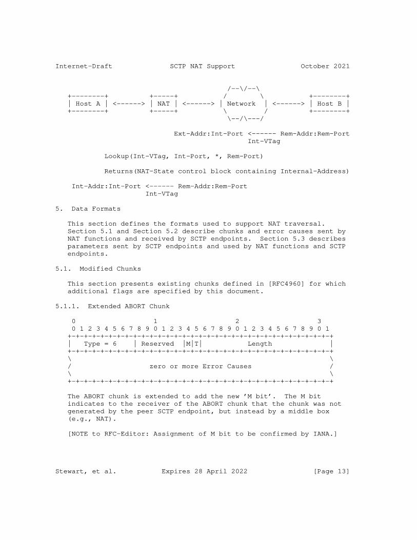
Internet-Draft SCTP NAT Support October 2021
/--\/--\ +--------+ +-----+ / \ +--------+ | Host A | <------> | NAT | <------> | Network | <------> | Host B | +--------+ +-----+ \ / +--------+ \--/\---/
Ext-Addr:Int-Port <------ Rem-Addr:Rem-Port Int-VTag
Lookup(Int-VTag, Int-Port, *, Rem-Port)
Returns(NAT-State control block containing Internal-Address)
Int-Addr:Int-Port <------ Rem-Addr:Rem-Port Int-VTag
5. Data Formats
This section defines the formats used to support NAT traversal. Section 5.1 and Section 5.2 describe chunks and error causes sent by NAT functions and received by SCTP endpoints. Section 5.3 describes parameters sent by SCTP endpoints and used by NAT functions and SCTP endpoints.
5.1. Modified Chunks
This section presents existing chunks defined in [RFC4960] for which additional flags are specified by this document.
5.1.1. Extended ABORT Chunk
0 1 2 3 0 1 2 3 4 5 6 7 8 9 0 1 2 3 4 5 6 7 8 9 0 1 2 3 4 5 6 7 8 9 0 1 +-+-+-+-+-+-+-+-+-+-+-+-+-+-+-+-+-+-+-+-+-+-+-+-+-+-+-+-+-+-+-+-+ | Type = 6 | Reserved |M|T| Length | +-+-+-+-+-+-+-+-+-+-+-+-+-+-+-+-+-+-+-+-+-+-+-+-+-+-+-+-+-+-+-+-+ \ \ / zero or more Error Causes / \ \ +-+-+-+-+-+-+-+-+-+-+-+-+-+-+-+-+-+-+-+-+-+-+-+-+-+-+-+-+-+-+-+-+
The ABORT chunk is extended to add the new ’M bit’. The M bit indicates to the receiver of the ABORT chunk that the chunk was not generated by the peer SCTP endpoint, but instead by a middle box (e.g., NAT).
[NOTE to RFC-Editor: Assignment of M bit to be confirmed by IANA.]
Stewart, et al. Expires 28 April 2022 [Page 13]
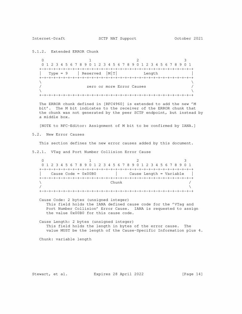
Internet-Draft SCTP NAT Support October 2021
5.1.2. Extended ERROR Chunk
0 1 2 3 0 1 2 3 4 5 6 7 8 9 0 1 2 3 4 5 6 7 8 9 0 1 2 3 4 5 6 7 8 9 0 1 +-+-+-+-+-+-+-+-+-+-+-+-+-+-+-+-+-+-+-+-+-+-+-+-+-+-+-+-+-+-+-+-+ | Type = 9 | Reserved |M|T| Length | +-+-+-+-+-+-+-+-+-+-+-+-+-+-+-+-+-+-+-+-+-+-+-+-+-+-+-+-+-+-+-+-+ \ \ / zero or more Error Causes / \ \ +-+-+-+-+-+-+-+-+-+-+-+-+-+-+-+-+-+-+-+-+-+-+-+-+-+-+-+-+-+-+-+-+
The ERROR chunk defined in [RFC4960] is extended to add the new ’M bit’. The M bit indicates to the receiver of the ERROR chunk that the chunk was not generated by the peer SCTP endpoint, but instead by a middle box.
[NOTE to RFC-Editor: Assignment of M bit to be confirmed by IANA.]
5.2. New Error Causes
This section defines the new error causes added by this document.
5.2.1. VTag and Port Number Collision Error Cause
0 1 2 3 0 1 2 3 4 5 6 7 8 9 0 1 2 3 4 5 6 7 8 9 0 1 2 3 4 5 6 7 8 9 0 1 +-+-+-+-+-+-+-+-+-+-+-+-+-+-+-+-+-+-+-+-+-+-+-+-+-+-+-+-+-+-+-+-+ | Cause Code = 0x00B0 | Cause Length = Variable | +-+-+-+-+-+-+-+-+-+-+-+-+-+-+-+-+-+-+-+-+-+-+-+-+-+-+-+-+-+-+-+-+ \ Chunk / / \ +-+-+-+-+-+-+-+-+-+-+-+-+-+-+-+-+-+-+-+-+-+-+-+-+-+-+-+-+-+-+-+-+
Cause Code: 2 bytes (unsigned integer) This field holds the IANA defined cause code for the ’VTag and Port Number Collision’ Error Cause. IANA is requested to assign the value 0x00B0 for this cause code.
Cause Length: 2 bytes (unsigned integer) This field holds the length in bytes of the error cause. The value MUST be the length of the Cause-Specific Information plus 4.
Chunk: variable length
Stewart, et al. Expires 28 April 2022 [Page 14]

Internet-Draft SCTP NAT Support October 2021
The Cause-Specific Information is filled with the chunk that caused this error. This can be an INIT, INIT ACK, or ASCONF chunk. Note that if the entire chunk will not fit in the ERROR chunk or ABORT chunk being sent then the bytes that do not fit are truncated.
[NOTE to RFC-Editor: Assignment of cause code to be confirmed by IANA.]
5.2.2. Missing State Error Cause
0 1 2 3 0 1 2 3 4 5 6 7 8 9 0 1 2 3 4 5 6 7 8 9 0 1 2 3 4 5 6 7 8 9 0 1 +-+-+-+-+-+-+-+-+-+-+-+-+-+-+-+-+-+-+-+-+-+-+-+-+-+-+-+-+-+-+-+-+ | Cause Code = 0x00B1 | Cause Length = Variable | +-+-+-+-+-+-+-+-+-+-+-+-+-+-+-+-+-+-+-+-+-+-+-+-+-+-+-+-+-+-+-+-+ \ Original Packet / / \ +-+-+-+-+-+-+-+-+-+-+-+-+-+-+-+-+-+-+-+-+-+-+-+-+-+-+-+-+-+-+-+-+
Cause Code: 2 bytes (unsigned integer) This field holds the IANA defined cause code for the ’Missing State’ Error Cause. IANA is requested to assign the value 0x00B1 for this cause code.
Cause Length: 2 bytes (unsigned integer) This field holds the length in bytes of the error cause. The value MUST be the length of the Cause-Specific Information plus 4.
Original Packet: variable length The Cause-Specific Information is filled with the IPv4 or IPv6 packet that caused this error. The IPv4 or IPv6 header MUST be included. Note that if the packet will not fit in the ERROR chunk or ABORT chunk being sent then the bytes that do not fit are truncated.
[NOTE to RFC-Editor: Assignment of cause code to be confirmed by IANA.]
5.2.3. Port Number Collision Error Cause
Stewart, et al. Expires 28 April 2022 [Page 15]
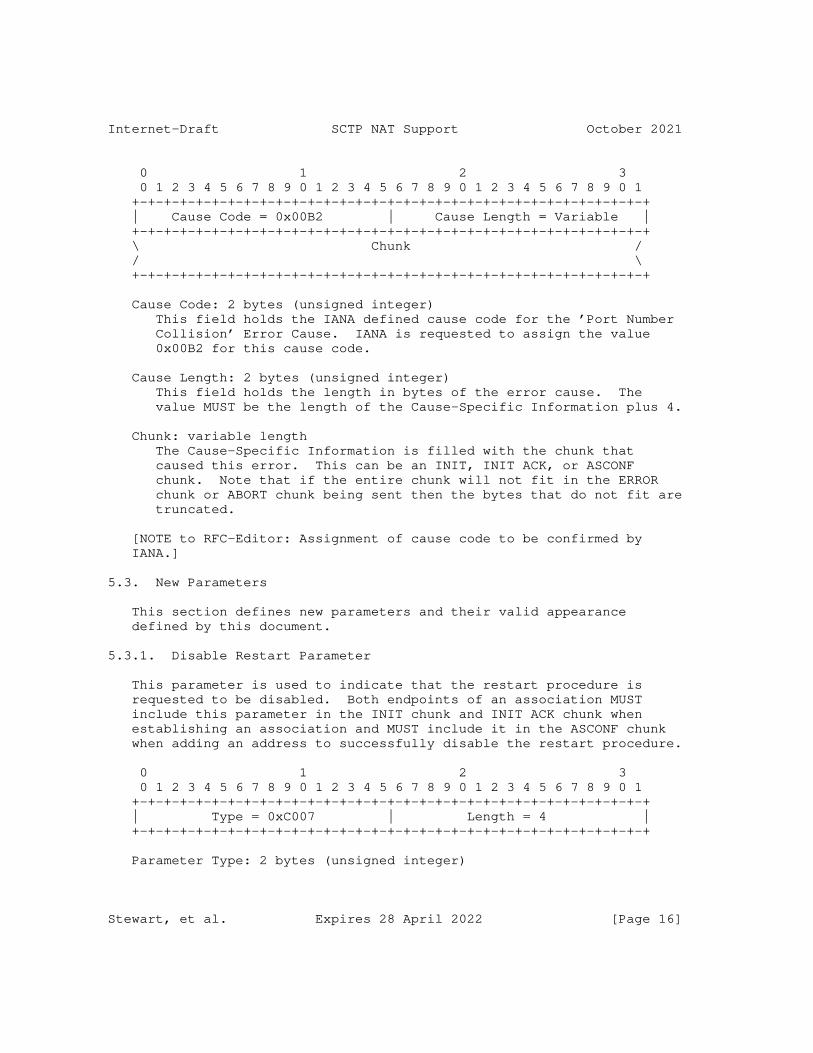
Internet-Draft SCTP NAT Support October 2021
0 1 2 3 0 1 2 3 4 5 6 7 8 9 0 1 2 3 4 5 6 7 8 9 0 1 2 3 4 5 6 7 8 9 0 1 +-+-+-+-+-+-+-+-+-+-+-+-+-+-+-+-+-+-+-+-+-+-+-+-+-+-+-+-+-+-+-+-+ | Cause Code = 0x00B2 | Cause Length = Variable | +-+-+-+-+-+-+-+-+-+-+-+-+-+-+-+-+-+-+-+-+-+-+-+-+-+-+-+-+-+-+-+-+ \ Chunk / / \ +-+-+-+-+-+-+-+-+-+-+-+-+-+-+-+-+-+-+-+-+-+-+-+-+-+-+-+-+-+-+-+-+
Cause Code: 2 bytes (unsigned integer) This field holds the IANA defined cause code for the ’Port Number Collision’ Error Cause. IANA is requested to assign the value 0x00B2 for this cause code.
Cause Length: 2 bytes (unsigned integer) This field holds the length in bytes of the error cause. The value MUST be the length of the Cause-Specific Information plus 4.
Chunk: variable length The Cause-Specific Information is filled with the chunk that caused this error. This can be an INIT, INIT ACK, or ASCONF chunk. Note that if the entire chunk will not fit in the ERROR chunk or ABORT chunk being sent then the bytes that do not fit are truncated.
[NOTE to RFC-Editor: Assignment of cause code to be confirmed by IANA.]
5.3. New Parameters
This section defines new parameters and their valid appearance defined by this document.
5.3.1. Disable Restart Parameter
This parameter is used to indicate that the restart procedure is requested to be disabled. Both endpoints of an association MUST include this parameter in the INIT chunk and INIT ACK chunk when establishing an association and MUST include it in the ASCONF chunk when adding an address to successfully disable the restart procedure.
0 1 2 3 0 1 2 3 4 5 6 7 8 9 0 1 2 3 4 5 6 7 8 9 0 1 2 3 4 5 6 7 8 9 0 1 +-+-+-+-+-+-+-+-+-+-+-+-+-+-+-+-+-+-+-+-+-+-+-+-+-+-+-+-+-+-+-+-+ | Type = 0xC007 | Length = 4 | +-+-+-+-+-+-+-+-+-+-+-+-+-+-+-+-+-+-+-+-+-+-+-+-+-+-+-+-+-+-+-+-+
Parameter Type: 2 bytes (unsigned integer)
Stewart, et al. Expires 28 April 2022 [Page 16]
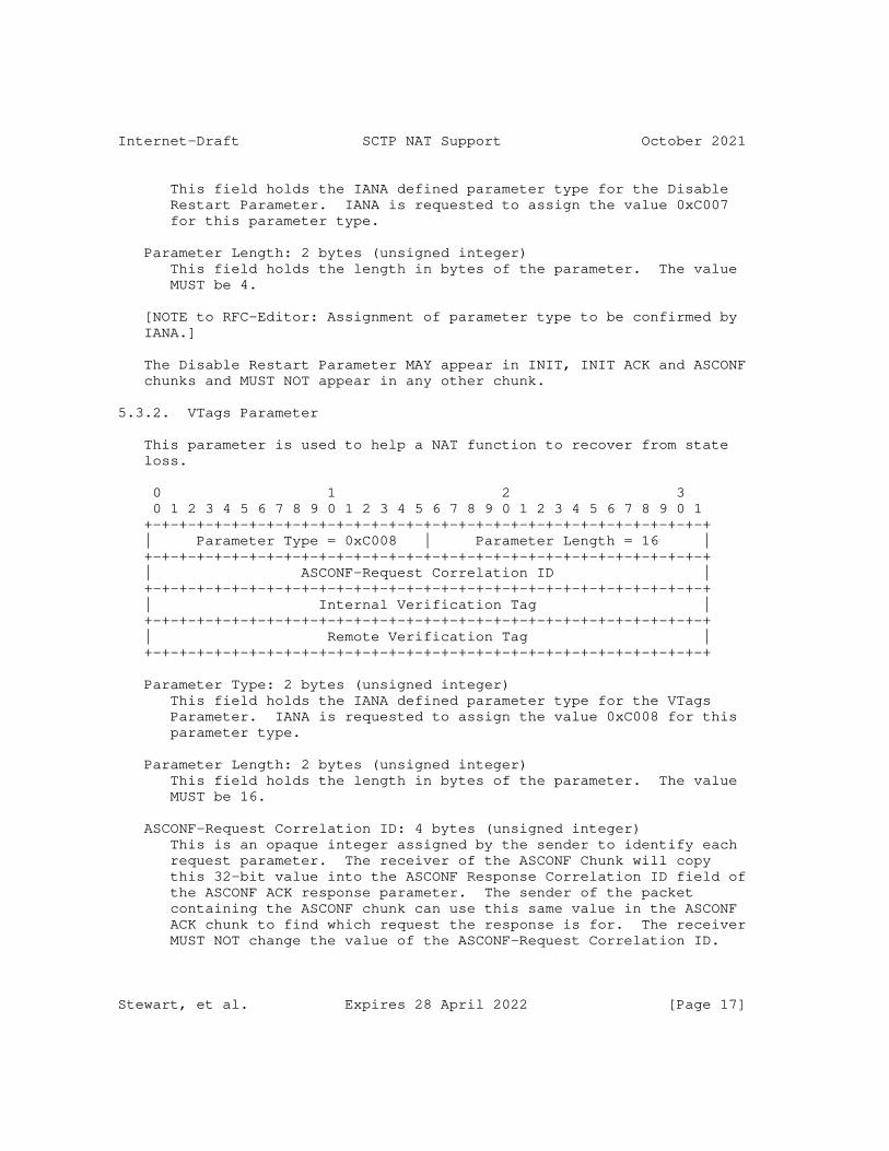
Internet-Draft SCTP NAT Support October 2021
This field holds the IANA defined parameter type for the Disable Restart Parameter. IANA is requested to assign the value 0xC007 for this parameter type.
Parameter Length: 2 bytes (unsigned integer) This field holds the length in bytes of the parameter. The value MUST be 4.
[NOTE to RFC-Editor: Assignment of parameter type to be confirmed by IANA.]
The Disable Restart Parameter MAY appear in INIT, INIT ACK and ASCONF chunks and MUST NOT appear in any other chunk.
5.3.2. VTags Parameter
This parameter is used to help a NAT function to recover from state loss.
0 1 2 3 0 1 2 3 4 5 6 7 8 9 0 1 2 3 4 5 6 7 8 9 0 1 2 3 4 5 6 7 8 9 0 1 +-+-+-+-+-+-+-+-+-+-+-+-+-+-+-+-+-+-+-+-+-+-+-+-+-+-+-+-+-+-+-+-+ | Parameter Type = 0xC008 | Parameter Length = 16 | +-+-+-+-+-+-+-+-+-+-+-+-+-+-+-+-+-+-+-+-+-+-+-+-+-+-+-+-+-+-+-+-+ | ASCONF-Request Correlation ID | +-+-+-+-+-+-+-+-+-+-+-+-+-+-+-+-+-+-+-+-+-+-+-+-+-+-+-+-+-+-+-+-+ | Internal Verification Tag | +-+-+-+-+-+-+-+-+-+-+-+-+-+-+-+-+-+-+-+-+-+-+-+-+-+-+-+-+-+-+-+-+ | Remote Verification Tag | +-+-+-+-+-+-+-+-+-+-+-+-+-+-+-+-+-+-+-+-+-+-+-+-+-+-+-+-+-+-+-+-+
Parameter Type: 2 bytes (unsigned integer) This field holds the IANA defined parameter type for the VTags Parameter. IANA is requested to assign the value 0xC008 for this parameter type.
Parameter Length: 2 bytes (unsigned integer) This field holds the length in bytes of the parameter. The value MUST be 16.
ASCONF-Request Correlation ID: 4 bytes (unsigned integer) This is an opaque integer assigned by the sender to identify each request parameter. The receiver of the ASCONF Chunk will copy this 32-bit value into the ASCONF Response Correlation ID field of the ASCONF ACK response parameter. The sender of the packet containing the ASCONF chunk can use this same value in the ASCONF ACK chunk to find which request the response is for. The receiver MUST NOT change the value of the ASCONF-Request Correlation ID.
Stewart, et al. Expires 28 April 2022 [Page 17]
Internet-Draft SCTP NAT Support October 2021
Internal Verification Tag: 4 bytes (unsigned integer) The Verification Tag that the internal host has chosen for the association. The Verification Tag is a unique 32-bit tag that accompanies any incoming SCTP packet for this association to the Internal-Address.
Remote Verification Tag: 4 bytes (unsigned integer) The Verification Tag that the host holding the Remote-Address has chosen for the association. The VTag is a unique 32-bit tag that accompanies any outgoing SCTP packet for this association to the Remote-Address.
[NOTE to RFC-Editor: Assignment of parameter type to be confirmed by IANA.]
The VTags Parameter MAY appear in ASCONF chunks and MUST NOT appear in any other chunk.
6. Procedures for SCTP Endpoints and NAT Functions
If an SCTP endpoint is behind an SCTP-aware NAT, a number of problems can arise as it tries to communicate with its peers:
* IP addresses can not be included in the SCTP packet. This is discussed in Section 6.1.
* More than one host behind a NAT function could select the same VTag and source port number when communicating with the same peer server. This creates a situation where the NAT function will not be able to tell the two associations apart. This situation is discussed in Section 6.2.
* If an SCTP endpoint is a server communicating with multiple peers and the peers are behind the same NAT function, then the these peers cannot be distinguished by the server. This case is discussed in Section 6.3.
* A restart of a NAT function during a conversation could cause a loss of its state. This problem and its solution is discussed in Section 6.4.
* NAT functions need to deal with SCTP packets being fragmented at the IP layer. This is discussed in Section 6.5.
* An SCTP endpoint can be behind two NAT functions in parallel providing redundancy. The method to set up this scenario is discussed in Section 6.6.
Stewart, et al. Expires 28 April 2022 [Page 18]

Internet-Draft SCTP NAT Support October 2021
The mechanisms to solve these problems require additional chunks and parameters, defined in this document, and modified handling procedures from those specified in [RFC4960] as described below.
6.1. Association Setup Considerations for Endpoints
The association setup procedure defined in [RFC4960] allows multi- homed SCTP endpoints to exchange its IP-addresses by using IPv4 or IPv6 address parameters in the INIT and INIT ACK chunks. However, this does not work when NAT functions are present.
Every association setup from a host behind a NAT function MUST NOT use multiple internal addresses. The INIT chunk MUST NOT contain an IPv4 Address parameter, IPv6 Address parameter, or Supported Address Types parameter. The INIT ACK chunk MUST NOT contain any IPv4 Address parameter or IPv6 Address parameter using non-global addresses. The INIT chunk and the INIT ACK chunk MUST NOT contain any Host Name parameters.
If the association is intended to be finally multi-homed, the procedure in Section 6.6 MUST be used.
The INIT and INIT ACK chunk SHOULD contain the Disable Restart parameter defined in Section 5.3.1.
6.2. Handling of Internal Port Number and Verification Tag Collisions
Consider the case where two hosts in the Internal-Address space want to set up an SCTP association with the same service provided by some remote hosts. This means that the Remote-Port is the same. If they both choose the same Internal-Port and Internal-VTag, the NAT function cannot distinguish between incoming packets anymore. However, this is unlikely. The Internal-VTags are chosen at random and if the Internal-Ports are also chosen from the ephemeral port range at random (see [RFC6056]) this gives a 46-bit random number that has to match.
The same can happen with the Remote-VTag when a packet containing an INIT ACK chunk or an ASCONF chunk is processed by the NAT function.
6.2.1. NAT Function Considerations
If the NAT function detects a collision of internal port numbers and verification tags, it SHOULD send a packet containing an ABORT chunk with the M bit set if the collision is triggered by a packet containing an INIT or INIT ACK chunk. If such a collision is triggered by a packet containing an ASCONF chunk, it SHOULD send a packet containing an ERROR chunk with the M bit. The M bit is a new
Stewart, et al. Expires 28 April 2022 [Page 19]
Internet-Draft SCTP NAT Support October 2021
bit defined by this document to express to SCTP that the source of this packet is a "middle" box, not the peer SCTP endpoint (see Section 5.1.1). If a packet containing an INIT ACK chunk triggers the collision, the corresponding packet containing the ABORT chunk MUST contain the same source and destination address and port numbers as the packet containing the INIT ACK chunk. If a packet containing an INIT chunk or an ASCONF chunk, the source and destination address and port numbers MUST be swapped.
The sender of the packet containing an ERROR or ABORT chunk MUST include the error cause with cause code ’VTag and Port Number Collision’ (see Section 5.2.1).
6.2.2. Endpoint Considerations
The sender of the packet containing the INIT chunk or the receiver of a packet containing the INIT ACK chunk, upon reception of a packet containing an ABORT chunk with M bit set and the appropriate error cause code for colliding NAT binding table state is included, SHOULD reinitiate the association setup procedure after choosing a new initiate tag, if the association is in COOKIE-WAIT state. In any other state, the SCTP endpoint MUST NOT respond.
The sender of the packet containing the ASCONF chunk, upon reception of a packet containing an ERROR chunk with M bit set, MUST stop adding the path to the association.
6.3. Handling of Internal Port Number Collisions
When two SCTP hosts are behind an SCTP-aware NAT it is possible that two SCTP hosts in the Internal-Address space will want to set up an SCTP association with the same server running on the same remote host. If the two hosts choose the same internal port, this is considered an internal port number collision.
For the NAT function, appropriate tracking can be performed by assuring that the VTags are unique between the two hosts.
6.3.1. NAT Function Considerations
The NAT function, when processing the packet containing the INIT ACK chunk, SHOULD note in its NAT binding table if the association supports the disable restart extension. This note is used when establishing future associations (i.e. when processing a packet containing an INIT chunk from an internal host) to decide if the connection can be allowed. The NAT function does the following when processing a packet containing an INIT chunk:
Stewart, et al. Expires 28 April 2022 [Page 20]

Internet-Draft SCTP NAT Support October 2021
* If the packet containing the INIT chunk is originating from an internal port to a remote port for which the NAT function has no matching NAT binding table entry, it MUST allow the packet containing the INIT chunk creating an NAT binding table entry.
* If the packet containing the INIT chunk matches an existing NAT binding table entry, it MUST validate that the disable restart feature is supported and, if it does, allow the packet containing the INIT chunk to be forwarded.
* If the disable restart feature is not supported, the NAT function SHOULD send a packet containing an ABORT chunk with the M bit set.
The ’Port Number Collision’ error cause (see Section 5.2.3) MUST be included in the ABORT chunk sent in response to the packet containing an INIT chunk.
If the collision is triggered by a packet containing an ASCONF chunk, a packet containing an ERROR chunk with the ’Port Number Collision’ error cause SHOULD be sent in response to the packet containing the ASCONF chunk.
6.3.2. Endpoint Considerations
For the remote SCTP server this means that the Remote-Port and the Remote-Address are the same. If they both have chosen the same Internal-Port the server cannot distinguish between both associations based on the address and port numbers. For the server it looks like the association is being restarted. To overcome this limitation the client sends a Disable Restart parameter in the INIT chunk.
When the server receives this parameter it does the following:
* It MUST include a Disable Restart parameter in the INIT ACK to inform the client that it will support the feature.
* It MUST disable the restart procedures defined in [RFC4960] for this association.
Servers that support this feature will need to be capable of maintaining multiple connections to what appears to be the same peer (behind the NAT function) differentiated only by the VTags.
6.4. Handling of Missing State
Stewart, et al. Expires 28 April 2022 [Page 21]
Internet-Draft SCTP NAT Support October 2021
6.4.1. NAT Function Considerations
If the NAT function receives a packet from the internal network for which the lookup procedure does not find an entry in the NAT binding table, a packet containing an ERROR chunk SHOULD be sent back with the M bit set. The source address of the packet containing the ERROR chunk MUST be the destination address of the packet received from the internal network. The verification tag is reflected and the T bit is set. Such a packet containing an ERROR chunk SHOULD NOT be sent if the received packet contains an ASCONF chunk with the VTags parameter or an ABORT, SHUTDOWN COMPLETE or INIT ACK chunk. A packet containing an ERROR chunk MUST NOT be sent if the received packet contains an ERROR chunk with the M bit set. In any case, the packet SHOULD NOT be forwarded to the remote address.
If the NAT function receives a packet from the internal network for which it has no NAT binding table entry and the packet contains an ASCONF chunk with the VTags parameter, the NAT function MUST update its NAT binding table according to the verification tags in the VTags parameter and, if present, the Disable Restart parameter.
When sending a packet containing an ERROR chunk, the error cause ’Missing State’ (see Section 5.2.2) MUST be included and the M bit of the ERROR chunk MUST be set (see Section 5.1.2).
6.4.2. Endpoint Considerations
Upon reception of this packet containing the ERROR chunk by an SCTP endpoint the receiver takes the following actions:
* It SHOULD validate that the verification tag is reflected by looking at the VTag that would have been included in an outgoing packet. If the validation fails, discard the received packet containing the ERROR chunk.
* It SHOULD validate that the peer of the SCTP association supports the dynamic address extension. If the validation fails, discard the received packet containing the ERROR chunk.
* It SHOULD generate a packet containing a new ASCONF chunk containing the VTags parameter (see Section 5.3.2) and the Disable Restart parameter (see Section 5.3.1) if the association is using the disable restart feature. By processing this packet the NAT function can recover the appropriate state. The procedures for generating an ASCONF chunk can be found in [RFC5061].
Stewart, et al. Expires 28 April 2022 [Page 22]

Internet-Draft SCTP NAT Support October 2021
The peer SCTP endpoint receiving such a packet containing an ASCONF chunk SHOULD add the address and respond with an acknowledgment if the address is new to the association (following all procedures defined in [RFC5061]). If the address is already part of the association, the SCTP endpoint MUST NOT respond with an error, but instead SHOULD respond with a packet containing an ASCONF ACK chunk acknowledging the address and take no action (since the address is already in the association).
Note that it is possible that upon receiving a packet containing an ASCONF chunk containing the VTags parameter the NAT function will realize that it has an ’Internal Port Number and Verification Tag collision’. In such a case the NAT function SHOULD send a packet containing an ERROR chunk with the error cause code set to ’VTag and Port Number Collision’ (see Section 5.2.1).
If an SCTP endpoint receives a packet containing an ERROR chunk with ’Internal Port Number and Verification Tag collision’ as the error cause and the packet in the Error Chunk contains an ASCONF with the VTags parameter, careful examination of the association is necessary. The endpoint does the following:
* It MUST validate that the verification tag is reflected by looking at the VTag that would have been included in the outgoing packet. If the validation fails, it MUST discard the packet.
* It MUST validate that the peer of the SCTP association supports the dynamic address extension. If the peer does not support this extension, it MUST discard the received packet containing the ERROR chunk.
* If the association is attempting to add an address (i.e. following the procedures in Section 6.6) then the endpoint MUST NOT consider the address part of the association and SHOULD make no further attempt to add the address (i.e. cancel any ASCONF timers and remove any record of the path), since the NAT function has a VTag collision and the association cannot easily create a new VTag (as it would if the error occurred when sending a packet containing an INIT chunk).
* If the endpoint has no other path, i.e. the procedure was executed due to missing a state in the NAT function, then the endpoint MUST abort the association. This would occur only if the local NAT function restarted and accepted a new association before attempting to repair the missing state (Note that this is no different than what happens to all TCP connections when a NAT function looses its state).
Stewart, et al. Expires 28 April 2022 [Page 23]
Internet-Draft SCTP NAT Support October 2021
6.5. Handling of Fragmented SCTP Packets by NAT Functions
SCTP minimizes the use of IP-level fragmentation. However, it can happen that using IP-level fragmentation is needed to continue an SCTP association. For example, if the path MTU is reduced and there are still some DATA chunk in flight, which require packets larger than the new path MTU. If IP-level fragmentation can not be used, the SCTP association will be terminated in a non-graceful way. See [RFC8900] for more information about IP fragmentation.
Therefore, a NAT function MUST be able to handle IP-level fragmented SCTP packets. The fragments MAY arrive in any order.
When an SCTP packet can not be forwarded by the NAT function due to MTU issues and the IP header forbids fragmentation, the NAT MUST send back a "Fragmentation needed and DF set" ICMPv4 or PTB ICMPv6 message to the internal host. This allows for a faster recovery from this packet drop.
6.6. Multi Point Traversal Considerations for Endpoints
If a multi-homed SCTP endpoint behind a NAT function connects to a peer, it MUST first set up the association single-homed with only one address causing the first NAT function to populate its state. Then it SHOULD add each IP address using packets containing ASCONF chunks sent via their respective NAT functions. The address used in the Add IP address parameter is the wildcard address (0.0.0.0 or ::0) and the address parameter in the ASCONF chunk SHOULD also contain the VTags parameter and optionally the Disable Restart parameter.
7. SCTP NAT YANG Module
This section defines a YANG module for SCTP NAT.
The terminology for describing YANG data models is defined in [RFC7950]. The meaning of the symbols in tree diagrams is defined in [RFC8340].
7.1. Tree Structure
This module augments NAT YANG module [RFC8512] with SCTP specifics. The module supports both classical SCTP NAT (that is, rewrite port numbers) and SCTP-specific variant where the ports numbers are not altered. The YANG "feature" is used to indicate whether SCTP- specific variant is supported.
The tree structure of the SCTP NAT YANG module is provided below:
Stewart, et al. Expires 28 April 2022 [Page 24]
Internet-Draft SCTP NAT Support October 2021
module: ietf-nat-sctp augment /nat:nat/nat:instances/nat:instance /nat:policy/nat:timers: +--rw sctp-timeout? uint32 augment /nat:nat/nat:instances/nat:instance /nat:mapping-table/nat:mapping-entry: +--rw int-VTag? uint32 {sctp-nat}? +--rw rem-VTag? uint32 {sctp-nat}?
Concretely, the SCTP NAT YANG module augments the NAT YANG module (policy, in particular) with the following:
* The sctp-timeout is used to control the SCTP inactivity timeout. That is, the time an SCTP mapping will stay active without SCTP packets traversing the NAT. This timeout can be set only for SCTP. Hence, "/nat:nat/nat:instances/nat:instance/nat:policy/ nat:transport-protocols/nat:protocol-id" MUST be set to ’132’ (SCTP).
In addition, the SCTP NAT YANG module augments the mapping entry with the following parameters defined in Section 3. These parameters apply only for SCTP NAT mapping entries (i.e., "/nat/instances/instance/mapping-table/mapping-entry/transport- protocol" MUST be set to ’132’);
* The Internal Verification Tag (Int-VTag)
* The Remote Verification Tag (Rem-VTag)
7.2. YANG Module
<CODE BEGINS> file "[email protected]" module ietf-nat-sctp { yang-version 1.1; namespace "urn:ietf:params:xml:ns:yang:ietf-nat-sctp"; prefix nat-sctp;
import ietf-nat { prefix nat; reference "RFC 8512: A YANG Module for Network Address Translation (NAT) and Network Prefix Translation (NPT)"; }
organization "IETF TSVWG Working Group"; contact "WG Web: <https://datatracker.ietf.org/wg/tsvwg/>
Stewart, et al. Expires 28 April 2022 [Page 25]
Internet-Draft SCTP NAT Support October 2021
WG List: <mailto:[email protected]>
Author: Mohamed Boucadair <mailto:[email protected]>"; description "This module augments NAT YANG module with Stream Control Transmission Protocol (SCTP) specifics. The extension supports both a classical SCTP NAT (that is, rewrite port numbers) and a, SCTP-specific variant where the ports numbers are not altered.
Copyright (c) 2020 IETF Trust and the persons identified as authors of the code. All rights reserved.
Redistribution and use in source and binary forms, with or without modification, is permitted pursuant to, and subject to the license terms contained in, the Simplified BSD License set forth in Section 4.c of the IETF Trust’s Legal Provisions Relating to IETF Documents (http://trustee.ietf.org/license-info).
This version of this YANG module is part of RFC XXXX; see the RFC itself for full legal notices.";
revision 2019-11-18 { description "Initial revision."; reference "RFC XXXX: Stream Control Transmission Protocol (SCTP) Network Address Translation Support"; }
feature sctp-nat { description "This feature means that SCTP-specific variant of NAT is supported. That is, avoid rewriting port numbers."; reference "Section 4.3 of RFC XXXX."; }
augment "/nat:nat/nat:instances/nat:instance" + "/nat:policy/nat:timers" { when "/nat:nat/nat:instances/nat:instance" + "/nat:policy/nat:transport-protocols" + "/nat:protocol-id = 132"; description "Extends NAT policy with a timeout for SCTP mapping entries.";
Stewart, et al. Expires 28 April 2022 [Page 26]
Internet-Draft SCTP NAT Support October 2021
leaf sctp-timeout { type uint32; units "seconds"; description "SCTP inactivity timeout. That is, the time an SCTP mapping entry will stay active without packets traversing the NAT."; } }
augment "/nat:nat/nat:instances/nat:instance" + "/nat:mapping-table/nat:mapping-entry" { when "nat:transport-protocol = 132"; if-feature "sctp-nat"; description "Extends the mapping entry with SCTP specifics.";
leaf int-VTag { type uint32; description "The Internal Verification Tag that the internal host has chosen for this communication."; } leaf rem-VTag { type uint32; description "The Remote Verification Tag that the remote peer has chosen for this communication."; } } } <CODE ENDS>
8. Various Examples of NAT Traversals
Please note that this section is informational only.
The addresses being used in the following examples are IPv4 addresses for private-use networks and for documentation as specified in [RFC6890]. However, the method described here is not limited to this NAT44 case.
The NAT binding table entries shown in the following examples do not include the flag indicating whether the restart procedure is supported or not. This flag is not relevant for these examples.
Stewart, et al. Expires 28 April 2022 [Page 27]
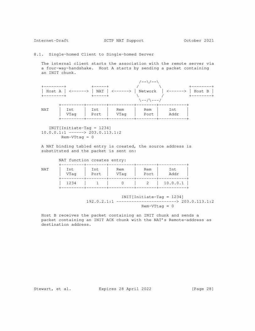
Internet-Draft SCTP NAT Support October 2021
8.1. Single-homed Client to Single-homed Server
The internal client starts the association with the remote server via a four-way-handshake. Host A starts by sending a packet containing an INIT chunk.
/--\/--\ +--------+ +-----+ / \ +--------+ | Host A | <------> | NAT | <------> | Network | <------> | Host B | +--------+ +-----+ \ / +--------+ \--/\---/ +---------+--------+----------+--------+-----------+ NAT | Int | Int | Rem | Rem | Int | | VTag | Port | VTag | Port | Addr | +---------+--------+----------+--------+-----------+
INIT[Initiate-Tag = 1234] 10.0.0.1:1 ------> 203.0.113.1:2 Rem-VTtag = 0
A NAT binding tabled entry is created, the source address is substituted and the packet is sent on:
NAT function creates entry: +---------+--------+----------+--------+-----------+ NAT | Int | Int | Rem | Rem | Int | | VTag | Port | VTag | Port | Addr | +---------+--------+----------+--------+-----------+ | 1234 | 1 | 0 | 2 | 10.0.0.1 | +---------+--------+----------+--------+-----------+
INIT[Initiate-Tag = 1234] 192.0.2.1:1 ------------------------> 203.0.113.1:2 Rem-VTtag = 0
Host B receives the packet containing an INIT chunk and sends a packet containing an INIT ACK chunk with the NAT’s Remote-address as destination address.
Stewart, et al. Expires 28 April 2022 [Page 28]
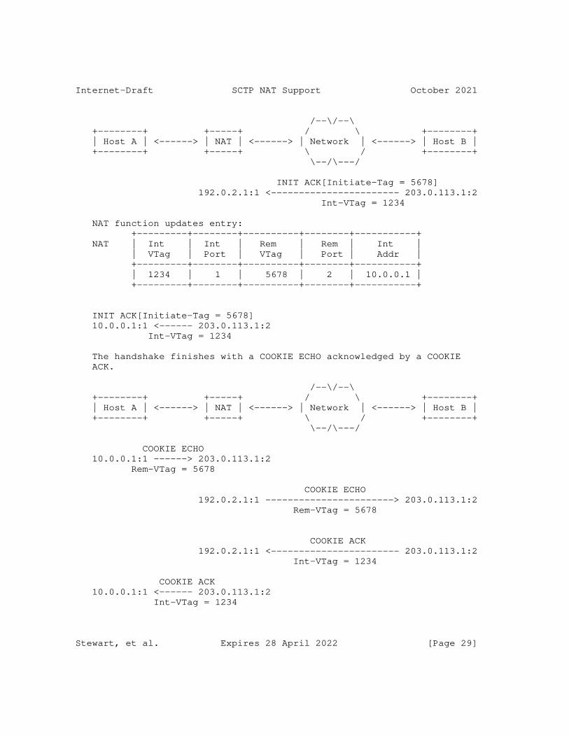
Internet-Draft SCTP NAT Support October 2021
/--\/--\ +--------+ +-----+ / \ +--------+ | Host A | <------> | NAT | <------> | Network | <------> | Host B | +--------+ +-----+ \ / +--------+ \--/\---/
INIT ACK[Initiate-Tag = 5678] 192.0.2.1:1 <----------------------- 203.0.113.1:2 Int-VTag = 1234
NAT function updates entry: +---------+--------+----------+--------+-----------+ NAT | Int | Int | Rem | Rem | Int | | VTag | Port | VTag | Port | Addr | +---------+--------+----------+--------+-----------+ | 1234 | 1 | 5678 | 2 | 10.0.0.1 | +---------+--------+----------+--------+-----------+
INIT ACK[Initiate-Tag = 5678] 10.0.0.1:1 <------ 203.0.113.1:2 Int-VTag = 1234
The handshake finishes with a COOKIE ECHO acknowledged by a COOKIE ACK.
/--\/--\ +--------+ +-----+ / \ +--------+ | Host A | <------> | NAT | <------> | Network | <------> | Host B | +--------+ +-----+ \ / +--------+ \--/\---/
COOKIE ECHO 10.0.0.1:1 ------> 203.0.113.1:2 Rem-VTag = 5678
COOKIE ECHO 192.0.2.1:1 -----------------------> 203.0.113.1:2 Rem-VTag = 5678
COOKIE ACK 192.0.2.1:1 <----------------------- 203.0.113.1:2 Int-VTag = 1234
COOKIE ACK 10.0.0.1:1 <------ 203.0.113.1:2 Int-VTag = 1234
Stewart, et al. Expires 28 April 2022 [Page 29]
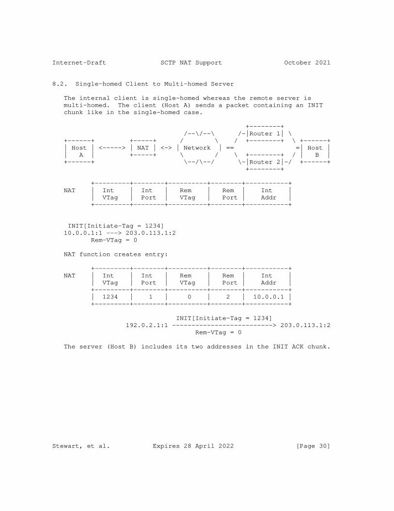
Internet-Draft SCTP NAT Support October 2021
8.2. Single-homed Client to Multi-homed Server
The internal client is single-homed whereas the remote server is multi-homed. The client (Host A) sends a packet containing an INIT chunk like in the single-homed case.
+--------+ /--\/--\ /-|Router 1| \ +------+ +-----+ / \ / +--------+ \ +------+ | Host | <-----> | NAT | <-> | Network | == =| Host | | A | +-----+ \ / \ +--------+ / | B | +------+ \--/\--/ \-|Router 2|-/ +------+ +--------+
+---------+--------+----------+--------+-----------+ NAT | Int | Int | Rem | Rem | Int | | VTag | Port | VTag | Port | Addr | +---------+--------+----------+--------+-----------+
INIT[Initiate-Tag = 1234] 10.0.0.1:1 ---> 203.0.113.1:2 Rem-VTag = 0
NAT function creates entry:
+---------+--------+----------+--------+-----------+ NAT | Int | Int | Rem | Rem | Int | | VTag | Port | VTag | Port | Addr | +---------+--------+----------+--------+-----------+ | 1234 | 1 | 0 | 2 | 10.0.0.1 | +---------+--------+----------+--------+-----------+
INIT[Initiate-Tag = 1234] 192.0.2.1:1 --------------------------> 203.0.113.1:2 Rem-VTag = 0
The server (Host B) includes its two addresses in the INIT ACK chunk.
Stewart, et al. Expires 28 April 2022 [Page 30]
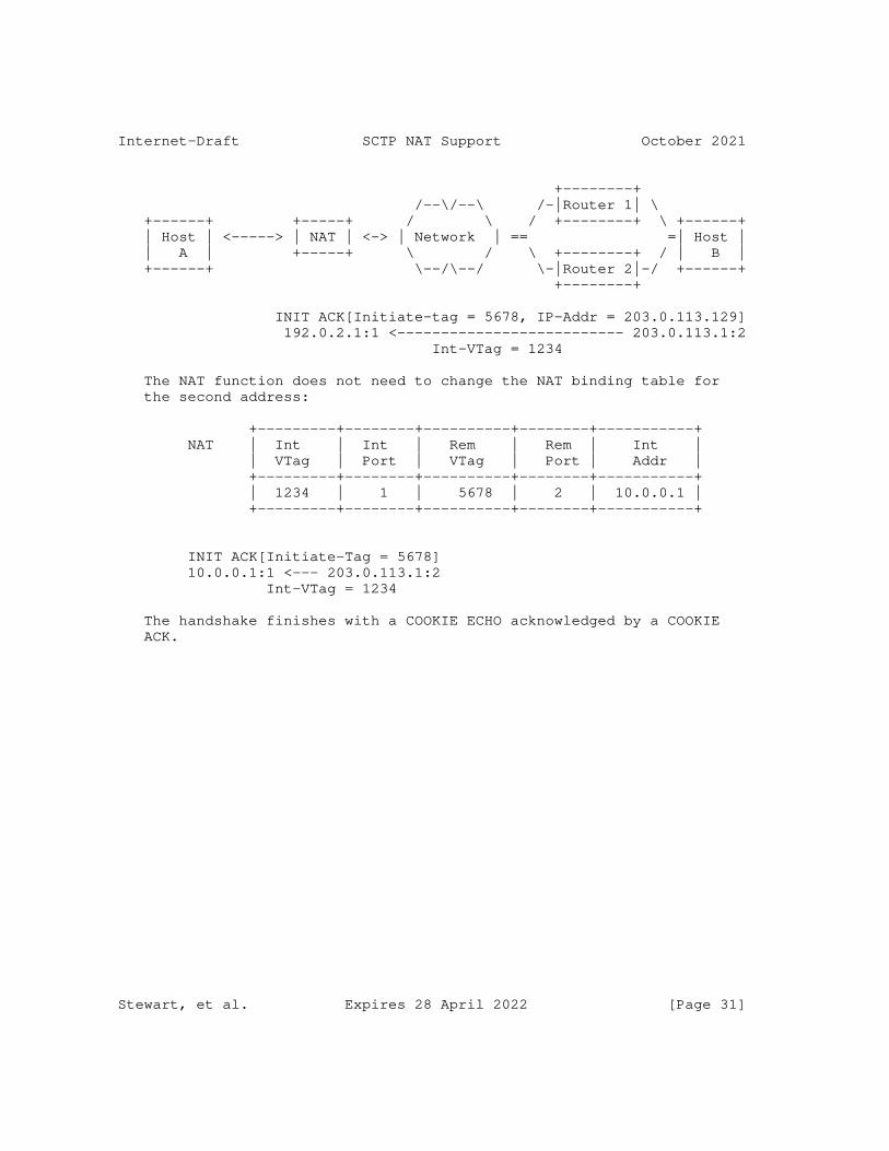
Internet-Draft SCTP NAT Support October 2021
+--------+ /--\/--\ /-|Router 1| \ +------+ +-----+ / \ / +--------+ \ +------+ | Host | <-----> | NAT | <-> | Network | == =| Host | | A | +-----+ \ / \ +--------+ / | B | +------+ \--/\--/ \-|Router 2|-/ +------+ +--------+
INIT ACK[Initiate-tag = 5678, IP-Addr = 203.0.113.129] 192.0.2.1:1 <-------------------------- 203.0.113.1:2 Int-VTag = 1234
The NAT function does not need to change the NAT binding table for the second address:
+---------+--------+----------+--------+-----------+ NAT | Int | Int | Rem | Rem | Int | | VTag | Port | VTag | Port | Addr | +---------+--------+----------+--------+-----------+ | 1234 | 1 | 5678 | 2 | 10.0.0.1 | +---------+--------+----------+--------+-----------+
INIT ACK[Initiate-Tag = 5678] 10.0.0.1:1 <--- 203.0.113.1:2 Int-VTag = 1234
The handshake finishes with a COOKIE ECHO acknowledged by a COOKIE ACK.
Stewart, et al. Expires 28 April 2022 [Page 31]
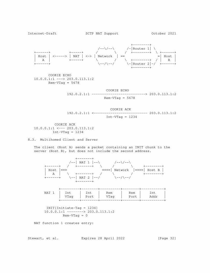
Internet-Draft SCTP NAT Support October 2021
+--------+ /--\/--\ /-|Router 1| \ +------+ +-----+ / \ / +--------+ \ +------+ | Host | <-----> | NAT | <-> | Network | == =| Host | | A | +-----+ \ / \ +--------+ / | B | +------+ \--/\--/ \-|Router 2|-/ +------+ +--------+
COOKIE ECHO 10.0.0.1:1 ---> 203.0.113.1:2 Rem-VTag = 5678
COOKIE ECHO 192.0.2.1:1 --------------------------> 203.0.113.1:2 Rem-VTag = 5678
COOKIE ACK 192.0.2.1:1 <-------------------------- 203.0.113.1:2 Int-VTag = 1234
COOKIE ACK 10.0.0.1:1 <--- 203.0.113.1:2 Int-VTag = 1234
8.3. Multihomed Client and Server
The client (Host A) sends a packet containing an INIT chunk to the server (Host B), but does not include the second address.
+-------+ /--| NAT 1 |--\ /--\/--\ +------+ / +-------+ \ / \ +--------+ | Host |=== ====| Network |====| Host B | | A | \ +-------+ / \ / +--------+ +------+ \--| NAT 2 |--/ \--/\--/ +-------+
+---------+--------+----------+--------+-----------+ NAT 1 | Int | Int | Rem | Rem | Int | | VTag | Port | VTag | Port | Addr | +---------+--------+----------+--------+-----------+
INIT[Initiate-Tag = 1234] 10.0.0.1:1 --------> 203.0.113.1:2 Rem-VTag = 0
NAT function 1 creates entry:
Stewart, et al. Expires 28 April 2022 [Page 32]
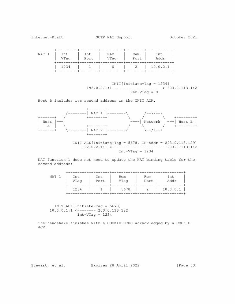
Internet-Draft SCTP NAT Support October 2021
+---------+--------+----------+--------+-----------+ NAT 1 | Int | Int | Rem | Rem | Int | | VTag | Port | VTag | Port | Addr | +---------+--------+----------+--------+-----------+ | 1234 | 1 | 0 | 2 | 10.0.0.1 | +---------+--------+----------+--------+-----------+
INIT[Initiate-Tag = 1234] 192.0.2.1:1 ---------------------> 203.0.113.1:2 Rem-VTag = 0
Host B includes its second address in the INIT ACK.
+-------+ /--------| NAT 1 |--------\ /--\/--\ +------+ / +-------+ \ / \ +--------+ | Host |=== ====| Network |===| Host B | | A | \ +-------+ / \ / +--------+ +------+ \--------| NAT 2 |--------/ \--/\--/ +-------+
INIT ACK[Initiate-Tag = 5678, IP-Addr = 203.0.113.129] 192.0.2.1:1 <----------------------- 203.0.113.1:2 Int-VTag = 1234
NAT function 1 does not need to update the NAT binding table for the second address:
+---------+--------+----------+--------+-----------+ NAT 1 | Int | Int | Rem | Rem | Int | | VTag | Port | VTag | Port | Addr | +---------+--------+----------+--------+-----------+ | 1234 | 1 | 5678 | 2 | 10.0.0.1 | +---------+--------+----------+--------+-----------+
INIT ACK[Initiate-Tag = 5678] 10.0.0.1:1 <-------- 203.0.113.1:2 Int-VTag = 1234
The handshake finishes with a COOKIE ECHO acknowledged by a COOKIE ACK.
Stewart, et al. Expires 28 April 2022 [Page 33]
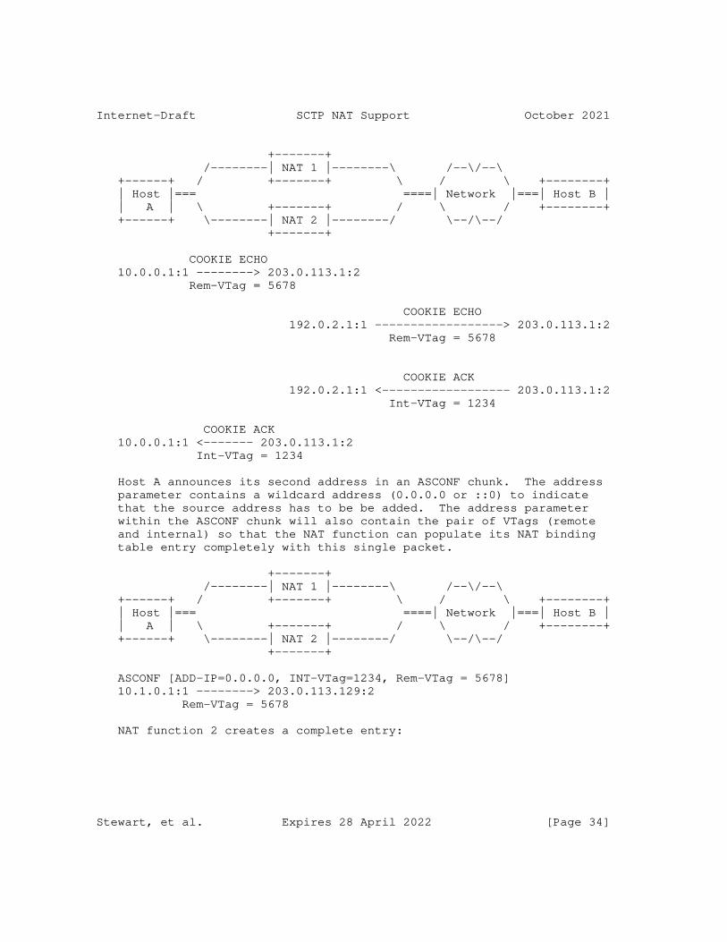
Internet-Draft SCTP NAT Support October 2021
+-------+ /--------| NAT 1 |--------\ /--\/--\ +------+ / +-------+ \ / \ +--------+ | Host |=== ====| Network |===| Host B | | A | \ +-------+ / \ / +--------+ +------+ \--------| NAT 2 |--------/ \--/\--/ +-------+
COOKIE ECHO 10.0.0.1:1 --------> 203.0.113.1:2 Rem-VTag = 5678
COOKIE ECHO 192.0.2.1:1 ------------------> 203.0.113.1:2 Rem-VTag = 5678
COOKIE ACK 192.0.2.1:1 <------------------ 203.0.113.1:2 Int-VTag = 1234
COOKIE ACK 10.0.0.1:1 <------- 203.0.113.1:2 Int-VTag = 1234
Host A announces its second address in an ASCONF chunk. The address parameter contains a wildcard address (0.0.0.0 or ::0) to indicate that the source address has to be be added. The address parameter within the ASCONF chunk will also contain the pair of VTags (remote and internal) so that the NAT function can populate its NAT binding table entry completely with this single packet.
+-------+ /--------| NAT 1 |--------\ /--\/--\ +------+ / +-------+ \ / \ +--------+ | Host |=== ====| Network |===| Host B | | A | \ +-------+ / \ / +--------+ +------+ \--------| NAT 2 |--------/ \--/\--/ +-------+
ASCONF [ADD-IP=0.0.0.0, INT-VTag=1234, Rem-VTag = 5678] 10.1.0.1:1 --------> 203.0.113.129:2 Rem-VTag = 5678
NAT function 2 creates a complete entry:
Stewart, et al. Expires 28 April 2022 [Page 34]
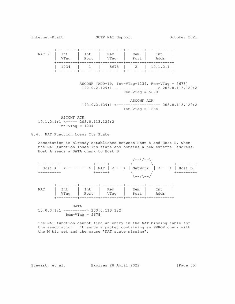
Internet-Draft SCTP NAT Support October 2021
+---------+--------+----------+--------+-----------+ NAT 2 | Int | Int | Rem | Rem | Int | | VTag | Port | VTag | Port | Addr | +---------+--------+----------+--------+-----------+ | 1234 | 1 | 5678 | 2 | 10.1.0.1 | +---------+--------+----------+--------+-----------+
ASCONF [ADD-IP, Int-VTag=1234, Rem-VTag = 5678] 192.0.2.129:1 -------------------> 203.0.113.129:2 Rem-VTag = 5678
ASCONF ACK 192.0.2.129:1 <------------------- 203.0.113.129:2 Int-VTag = 1234
ASCONF ACK 10.1.0.1:1 <----- 203.0.113.129:2 Int-VTag = 1234
8.4. NAT Function Loses Its State
Association is already established between Host A and Host B, when the NAT function loses its state and obtains a new external address. Host A sends a DATA chunk to Host B.
/--\/--\ +--------+ +-----+ / \ +--------+ | Host A | <----------> | NAT | <----> | Network | <----> | Host B | +--------+ +-----+ \ / +--------+ \--/\--/
+---------+--------+----------+--------+-----------+ NAT | Int | Int | Rem | Rem | Int | | VTag | Port | VTag | Port | Addr | +---------+--------+----------+--------+-----------+
DATA 10.0.0.1:1 ----------> 203.0.113.1:2 Rem-VTag = 5678
The NAT function cannot find an entry in the NAT binding table for the association. It sends a packet containing an ERROR chunk with the M bit set and the cause "NAT state missing".
Stewart, et al. Expires 28 April 2022 [Page 35]

Internet-Draft SCTP NAT Support October 2021
/--\/--\ +--------+ +-----+ / \ +--------+ | Host A | <----------> | NAT | <----> | Network | <----> | Host B | +--------+ +-----+ \ / +--------+ \--/\--/
ERROR [M bit, NAT state missing] 10.0.0.1:1 <---------- 203.0.113.1:2 Rem-VTag = 5678
On reception of the packet containing the ERROR chunk, Host A sends a packet containing an ASCONF chunk indicating that the former information has to be deleted and the source address of the actual packet added.
/--\/--\ +--------+ +-----+ / \ +--------+ | Host A | <----------> | NAT | <----> | Network | <----> | Host B | +--------+ +-----+ \ / +--------+ \--/\--/
ASCONF [ADD-IP, DELETE-IP, Int-VTag=1234, Rem-VTag = 5678] 10.0.0.1:1 ----------> 203.0.113.129:2 Rem-VTag = 5678
+---------+--------+----------+--------+-----------+ NAT | Int | Int | Rem | Rem | Int | | VTag | Port | VTag | Port | Addr | +---------+--------+----------+--------+-----------+ | 1234 | 1 | 5678 | 2 | 10.0.0.1 | +---------+--------+----------+--------+-----------+
ASCONF [ADD-IP, DELETE-IP, Int-VTag=1234, Rem-VTag = 5678] 192.0.2.2:1 -----------------> 203.0.113.129:2 Rem-VTag = 5678
Host B adds the new source address to this association and deletes all other addresses from this association.
Stewart, et al. Expires 28 April 2022 [Page 36]
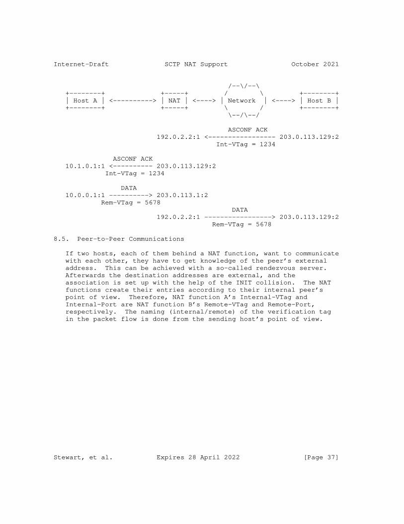
Internet-Draft SCTP NAT Support October 2021
/--\/--\ +--------+ +-----+ / \ +--------+ | Host A | <----------> | NAT | <----> | Network | <----> | Host B | +--------+ +-----+ \ / +--------+ \--/\--/
ASCONF ACK 192.0.2.2:1 <----------------- 203.0.113.129:2 Int-VTag = 1234
ASCONF ACK 10.1.0.1:1 <---------- 203.0.113.129:2 Int-VTag = 1234
DATA 10.0.0.1:1 ----------> 203.0.113.1:2 Rem-VTag = 5678 DATA 192.0.2.2:1 -----------------> 203.0.113.129:2 Rem-VTag = 5678
8.5. Peer-to-Peer Communications
If two hosts, each of them behind a NAT function, want to communicate with each other, they have to get knowledge of the peer’s external address. This can be achieved with a so-called rendezvous server. Afterwards the destination addresses are external, and the association is set up with the help of the INIT collision. The NAT functions create their entries according to their internal peer’s point of view. Therefore, NAT function A’s Internal-VTag and Internal-Port are NAT function B’s Remote-VTag and Remote-Port, respectively. The naming (internal/remote) of the verification tag in the packet flow is done from the sending host’s point of view.
Stewart, et al. Expires 28 April 2022 [Page 37]
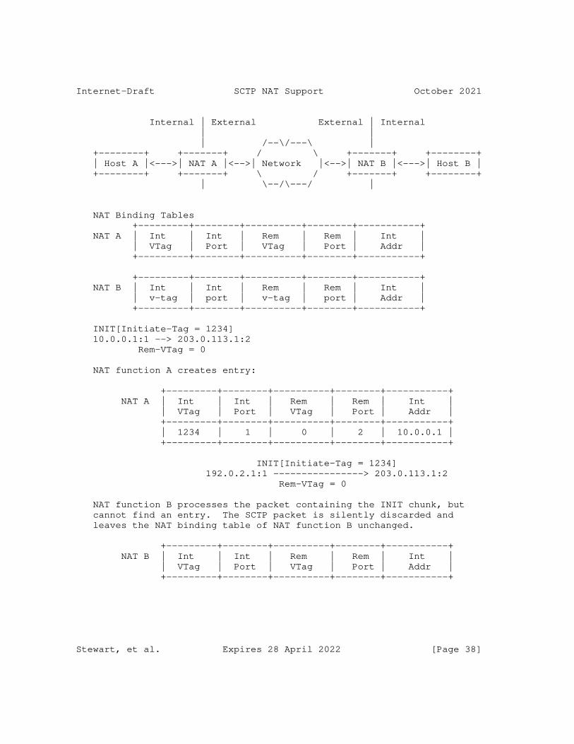
Internet-Draft SCTP NAT Support October 2021
Internal | External External | Internal | | | /--\/---\ | +--------+ +-------+ / \ +-------+ +--------+ | Host A |<--->| NAT A |<-->| Network |<-->| NAT B |<--->| Host B | +--------+ +-------+ \ / +-------+ +--------+ | \--/\---/ |
NAT Binding Tables +---------+--------+----------+--------+-----------+ NAT A | Int | Int | Rem | Rem | Int | | VTag | Port | VTag | Port | Addr | +---------+--------+----------+--------+-----------+
+---------+--------+----------+--------+-----------+ NAT B | Int | Int | Rem | Rem | Int | | v-tag | port | v-tag | port | Addr | +---------+--------+----------+--------+-----------+
INIT[Initiate-Tag = 1234] 10.0.0.1:1 --> 203.0.113.1:2 Rem-VTag = 0
NAT function A creates entry:
+---------+--------+----------+--------+-----------+ NAT A | Int | Int | Rem | Rem | Int | | VTag | Port | VTag | Port | Addr | +---------+--------+----------+--------+-----------+ | 1234 | 1 | 0 | 2 | 10.0.0.1 | +---------+--------+----------+--------+-----------+
INIT[Initiate-Tag = 1234] 192.0.2.1:1 ----------------> 203.0.113.1:2 Rem-VTag = 0
NAT function B processes the packet containing the INIT chunk, but cannot find an entry. The SCTP packet is silently discarded and leaves the NAT binding table of NAT function B unchanged.
+---------+--------+----------+--------+-----------+ NAT B | Int | Int | Rem | Rem | Int | | VTag | Port | VTag | Port | Addr | +---------+--------+----------+--------+-----------+
Stewart, et al. Expires 28 April 2022 [Page 38]
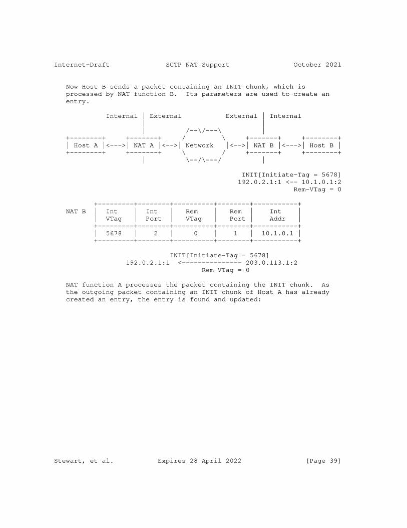
Internet-Draft SCTP NAT Support October 2021
Now Host B sends a packet containing an INIT chunk, which is processed by NAT function B. Its parameters are used to create an entry.
Internal | External External | Internal | | | /--\/---\ | +--------+ +-------+ / \ +-------+ +--------+ | Host A |<--->| NAT A |<-->| Network |<-->| NAT B |<--->| Host B | +--------+ +-------+ \ / +-------+ +--------+ | \--/\---/ |
INIT[Initiate-Tag = 5678] 192.0.2.1:1 <-- 10.1.0.1:2 Rem-VTag = 0
+---------+--------+----------+--------+-----------+ NAT B | Int | Int | Rem | Rem | Int | | VTag | Port | VTag | Port | Addr | +---------+--------+----------+--------+-----------+ | 5678 | 2 | 0 | 1 | 10.1.0.1 | +---------+--------+----------+--------+-----------+
INIT[Initiate-Tag = 5678] 192.0.2.1:1 <--------------- 203.0.113.1:2 Rem-VTag = 0
NAT function A processes the packet containing the INIT chunk. As the outgoing packet containing an INIT chunk of Host A has already created an entry, the entry is found and updated:
Stewart, et al. Expires 28 April 2022 [Page 39]
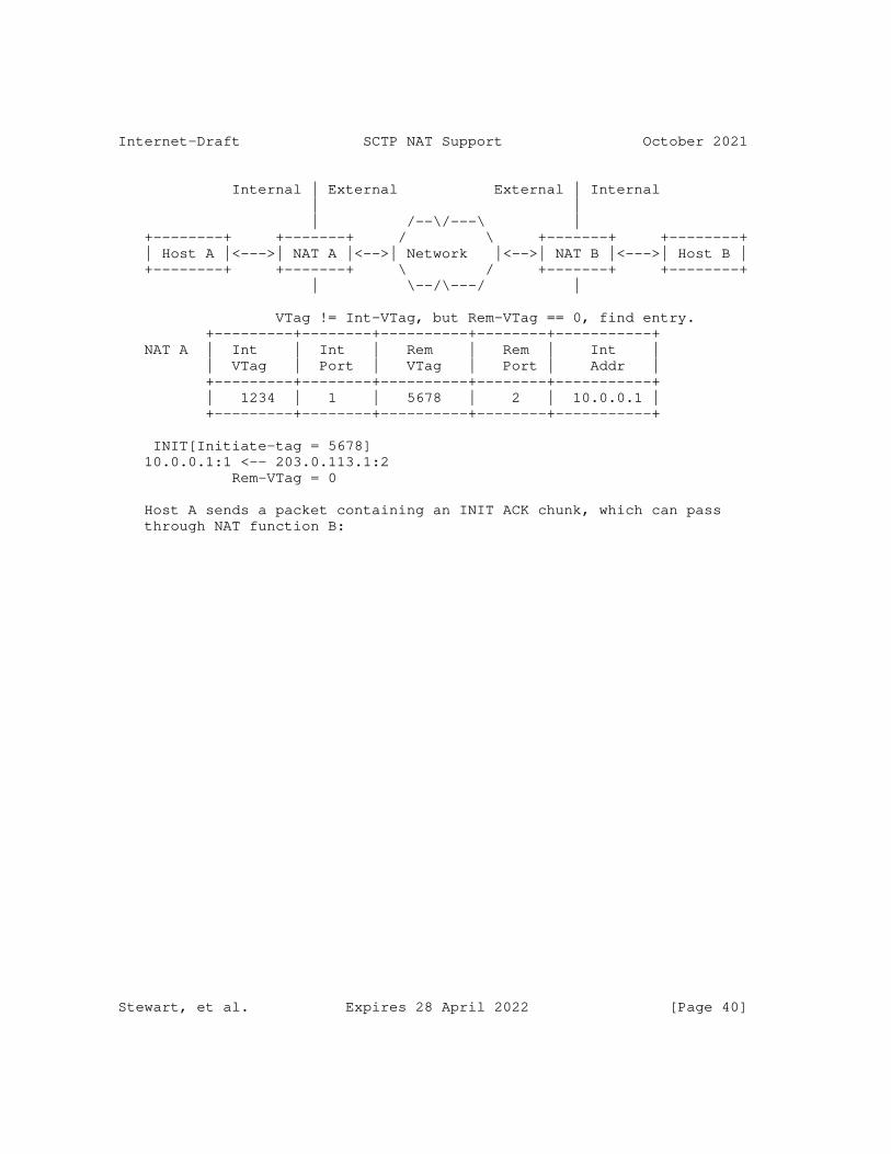
Internet-Draft SCTP NAT Support October 2021
Internal | External External | Internal | | | /--\/---\ | +--------+ +-------+ / \ +-------+ +--------+ | Host A |<--->| NAT A |<-->| Network |<-->| NAT B |<--->| Host B | +--------+ +-------+ \ / +-------+ +--------+ | \--/\---/ |
VTag != Int-VTag, but Rem-VTag == 0, find entry. +---------+--------+----------+--------+-----------+ NAT A | Int | Int | Rem | Rem | Int | | VTag | Port | VTag | Port | Addr | +---------+--------+----------+--------+-----------+ | 1234 | 1 | 5678 | 2 | 10.0.0.1 | +---------+--------+----------+--------+-----------+
INIT[Initiate-tag = 5678] 10.0.0.1:1 <-- 203.0.113.1:2 Rem-VTag = 0
Host A sends a packet containing an INIT ACK chunk, which can pass through NAT function B:
Stewart, et al. Expires 28 April 2022 [Page 40]
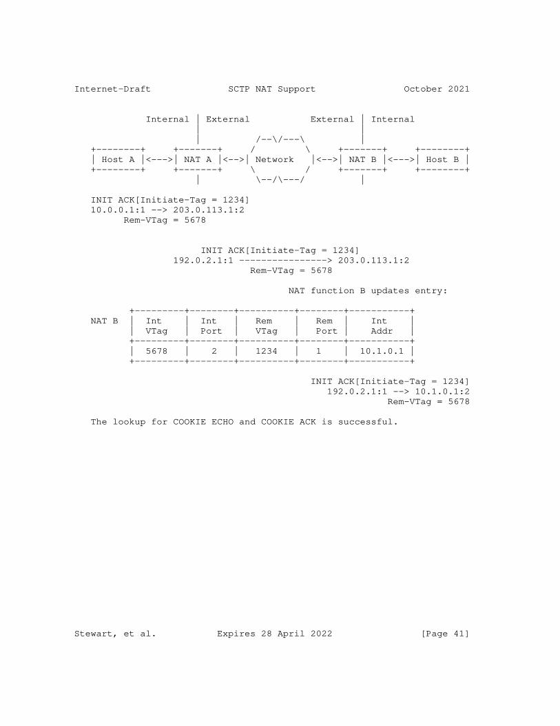
Internet-Draft SCTP NAT Support October 2021
Internal | External External | Internal | | | /--\/---\ | +--------+ +-------+ / \ +-------+ +--------+ | Host A |<--->| NAT A |<-->| Network |<-->| NAT B |<--->| Host B | +--------+ +-------+ \ / +-------+ +--------+ | \--/\---/ |
INIT ACK[Initiate-Tag = 1234] 10.0.0.1:1 --> 203.0.113.1:2 Rem-VTag = 5678
INIT ACK[Initiate-Tag = 1234] 192.0.2.1:1 ----------------> 203.0.113.1:2 Rem-VTag = 5678
NAT function B updates entry:
+---------+--------+----------+--------+-----------+ NAT B | Int | Int | Rem | Rem | Int | | VTag | Port | VTag | Port | Addr | +---------+--------+----------+--------+-----------+ | 5678 | 2 | 1234 | 1 | 10.1.0.1 | +---------+--------+----------+--------+-----------+
INIT ACK[Initiate-Tag = 1234] 192.0.2.1:1 --> 10.1.0.1:2 Rem-VTag = 5678
The lookup for COOKIE ECHO and COOKIE ACK is successful.
Stewart, et al. Expires 28 April 2022 [Page 41]
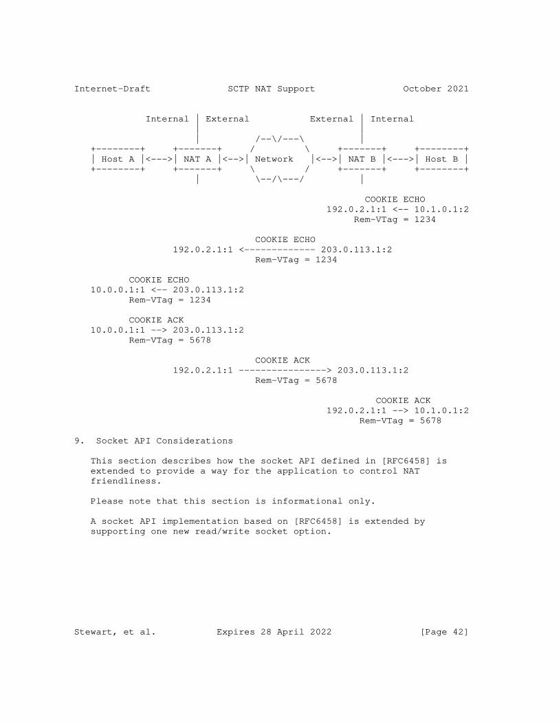
Internet-Draft SCTP NAT Support October 2021
Internal | External External | Internal | | | /--\/---\ | +--------+ +-------+ / \ +-------+ +--------+ | Host A |<--->| NAT A |<-->| Network |<-->| NAT B |<--->| Host B | +--------+ +-------+ \ / +-------+ +--------+ | \--/\---/ |
COOKIE ECHO 192.0.2.1:1 <-- 10.1.0.1:2 Rem-VTag = 1234
COOKIE ECHO 192.0.2.1:1 <------------- 203.0.113.1:2 Rem-VTag = 1234
COOKIE ECHO 10.0.0.1:1 <-- 203.0.113.1:2 Rem-VTag = 1234
COOKIE ACK 10.0.0.1:1 --> 203.0.113.1:2 Rem-VTag = 5678
COOKIE ACK 192.0.2.1:1 ----------------> 203.0.113.1:2 Rem-VTag = 5678
COOKIE ACK 192.0.2.1:1 --> 10.1.0.1:2 Rem-VTag = 5678
9. Socket API Considerations
This section describes how the socket API defined in [RFC6458] is extended to provide a way for the application to control NAT friendliness.
Please note that this section is informational only.
A socket API implementation based on [RFC6458] is extended by supporting one new read/write socket option.
Stewart, et al. Expires 28 April 2022 [Page 42]
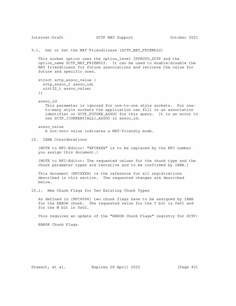
Internet-Draft SCTP NAT Support October 2021
9.1. Get or Set the NAT Friendliness (SCTP_NAT_FRIENDLY)
This socket option uses the option_level IPPROTO_SCTP and the option_name SCTP_NAT_FRIENDLY. It can be used to enable/disable the NAT friendliness for future associations and retrieve the value for future and specific ones.
struct sctp_assoc_value { sctp_assoc_t assoc_id; uint32_t assoc_value; };
assoc_id This parameter is ignored for one-to-one style sockets. For one- to-many style sockets the application can fill in an association identifier or SCTP_FUTURE_ASSOC for this query. It is an error to use SCTP_{CURRENT|ALL}_ASSOC in assoc_id.
assoc_value A non-zero value indicates a NAT-friendly mode.
10. IANA Considerations
[NOTE to RFC-Editor: "RFCXXXX" is to be replaced by the RFC number you assign this document.]
[NOTE to RFC-Editor: The requested values for the chunk type and the chunk parameter types are tentative and to be confirmed by IANA.]
This document (RFCXXXX) is the reference for all registrations described in this section. The requested changes are described below.
10.1. New Chunk Flags for Two Existing Chunk Types
As defined in [RFC6096] two chunk flags have to be assigned by IANA for the ERROR chunk. The requested value for the T bit is 0x01 and for the M bit is 0x02.
This requires an update of the "ERROR Chunk Flags" registry for SCTP:
ERROR Chunk Flags
Stewart, et al. Expires 28 April 2022 [Page 43]
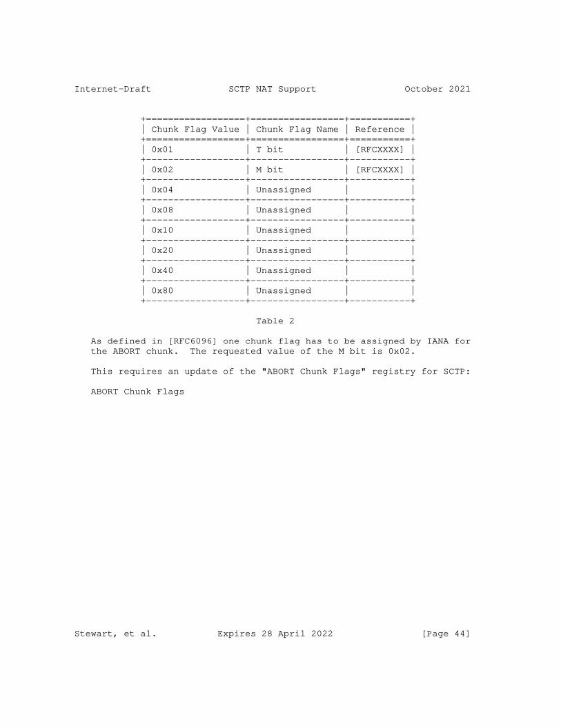
Internet-Draft SCTP NAT Support October 2021
+==================+=================+===========+ | Chunk Flag Value | Chunk Flag Name | Reference | +==================+=================+===========+ | 0x01 | T bit | [RFCXXXX] | +------------------+-----------------+-----------+ | 0x02 | M bit | [RFCXXXX] | +------------------+-----------------+-----------+ | 0x04 | Unassigned | | +------------------+-----------------+-----------+ | 0x08 | Unassigned | | +------------------+-----------------+-----------+ | 0x10 | Unassigned | | +------------------+-----------------+-----------+ | 0x20 | Unassigned | | +------------------+-----------------+-----------+ | 0x40 | Unassigned | | +------------------+-----------------+-----------+ | 0x80 | Unassigned | | +------------------+-----------------+-----------+
Table 2
As defined in [RFC6096] one chunk flag has to be assigned by IANA for the ABORT chunk. The requested value of the M bit is 0x02.
This requires an update of the "ABORT Chunk Flags" registry for SCTP:
ABORT Chunk Flags
Stewart, et al. Expires 28 April 2022 [Page 44]
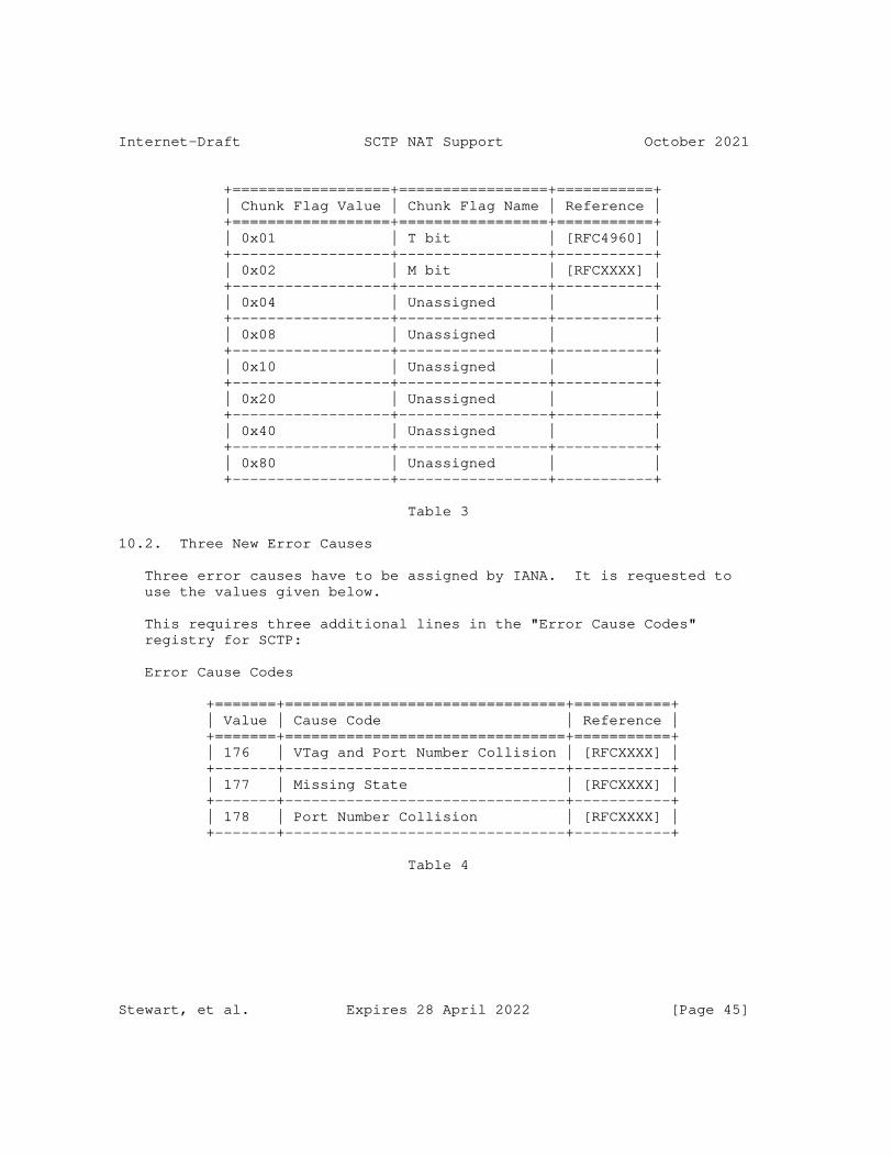
Internet-Draft SCTP NAT Support October 2021
+==================+=================+===========+ | Chunk Flag Value | Chunk Flag Name | Reference | +==================+=================+===========+ | 0x01 | T bit | [RFC4960] | +------------------+-----------------+-----------+ | 0x02 | M bit | [RFCXXXX] | +------------------+-----------------+-----------+ | 0x04 | Unassigned | | +------------------+-----------------+-----------+ | 0x08 | Unassigned | | +------------------+-----------------+-----------+ | 0x10 | Unassigned | | +------------------+-----------------+-----------+ | 0x20 | Unassigned | | +------------------+-----------------+-----------+ | 0x40 | Unassigned | | +------------------+-----------------+-----------+ | 0x80 | Unassigned | | +------------------+-----------------+-----------+
Table 3
10.2. Three New Error Causes
Three error causes have to be assigned by IANA. It is requested to use the values given below.
This requires three additional lines in the "Error Cause Codes" registry for SCTP:
Error Cause Codes
+=======+================================+===========+ | Value | Cause Code | Reference | +=======+================================+===========+ | 176 | VTag and Port Number Collision | [RFCXXXX] | +-------+--------------------------------+-----------+ | 177 | Missing State | [RFCXXXX] | +-------+--------------------------------+-----------+ | 178 | Port Number Collision | [RFCXXXX] | +-------+--------------------------------+-----------+
Table 4
Stewart, et al. Expires 28 April 2022 [Page 45]
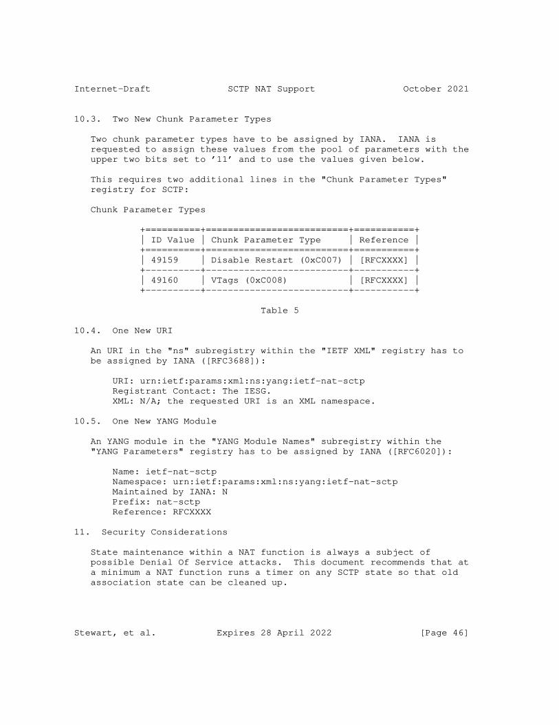
Internet-Draft SCTP NAT Support October 2021
10.3. Two New Chunk Parameter Types
Two chunk parameter types have to be assigned by IANA. IANA is requested to assign these values from the pool of parameters with the upper two bits set to ’11’ and to use the values given below.
This requires two additional lines in the "Chunk Parameter Types" registry for SCTP:
Chunk Parameter Types
+==========+==========================+===========+ | ID Value | Chunk Parameter Type | Reference | +==========+==========================+===========+ | 49159 | Disable Restart (0xC007) | [RFCXXXX] | +----------+--------------------------+-----------+ | 49160 | VTags (0xC008) | [RFCXXXX] | +----------+--------------------------+-----------+
Table 5
10.4. One New URI
An URI in the "ns" subregistry within the "IETF XML" registry has to be assigned by IANA ([RFC3688]):
URI: urn:ietf:params:xml:ns:yang:ietf-nat-sctp Registrant Contact: The IESG. XML: N/A; the requested URI is an XML namespace.
10.5. One New YANG Module
An YANG module in the "YANG Module Names" subregistry within the "YANG Parameters" registry has to be assigned by IANA ([RFC6020]):
Name: ietf-nat-sctp Namespace: urn:ietf:params:xml:ns:yang:ietf-nat-sctp Maintained by IANA: N Prefix: nat-sctp Reference: RFCXXXX
11. Security Considerations
State maintenance within a NAT function is always a subject of possible Denial Of Service attacks. This document recommends that at a minimum a NAT function runs a timer on any SCTP state so that old association state can be cleaned up.
Stewart, et al. Expires 28 April 2022 [Page 46]

Internet-Draft SCTP NAT Support October 2021
Generic issues related to address sharing are discussed in [RFC6269] and apply to SCTP as well.
For SCTP endpoints not disabling the restart procedure, this document does not add any additional security considerations to the ones given in [RFC4960], [RFC4895], and [RFC5061].
SCTP endpoints disabling the restart procedure, need to monitor the status of all associations to mitigate resource exhaustion attacks by establishing a lot of associations sharing the same IP addresses and port numbers.
In any case, SCTP is protected by the verification tags and the usage of [RFC4895] against off-path attackers.
For IP-level fragmentation and reassembly related issues see [RFC4963].
The YANG module specified in this document defines a schema for data that is designed to be accessed via network management protocols such as NETCONF [RFC6241] or RESTCONF [RFC8040]. The lowest NETCONF layer is the secure transport layer, and the mandatory-to-implement secure transport is Secure Shell (SSH) [RFC6242]. The lowest RESTCONF layer is HTTPS, and the mandatory-to-implement secure transport is TLS [RFC8446].
The Network Configuration Access Control Model (NACM) [RFC8341] provides the means to restrict access for particular NETCONF or RESTCONF users to a preconfigured subset of all available NETCONF or RESTCONF protocol operations and content.
All data nodes defined in the YANG module that can be created, modified, and deleted (i.e., config true, which is the default) are considered sensitive. Write operations (e.g., edit-config) applied to these data nodes without proper protection can negatively affect network operations. An attacker who is able to access the SCTP NAT function can undertake various attacks, such as:
* Setting a low timeout for SCTP mapping entries to cause failures to deliver incoming SCTP packets.
* Instantiating mapping entries to cause NAT collision.
12. Normative References
Stewart, et al. Expires 28 April 2022 [Page 47]
Internet-Draft SCTP NAT Support October 2021
[RFC2119] Bradner, S., "Key words for use in RFCs to Indicate Requirement Levels", BCP 14, RFC 2119, DOI 10.17487/RFC2119, March 1997, <https://www.rfc-editor.org/info/rfc2119>.
[RFC3688] Mealling, M., "The IETF XML Registry", BCP 81, RFC 3688, DOI 10.17487/RFC3688, January 2004, <https://www.rfc-editor.org/info/rfc3688>.
[RFC4895] Tuexen, M., Stewart, R., Lei, P., and E. Rescorla, "Authenticated Chunks for the Stream Control Transmission Protocol (SCTP)", RFC 4895, DOI 10.17487/RFC4895, August 2007, <https://www.rfc-editor.org/info/rfc4895>.
[RFC4960] Stewart, R., Ed., "Stream Control Transmission Protocol", RFC 4960, DOI 10.17487/RFC4960, September 2007, <https://www.rfc-editor.org/info/rfc4960>.
[RFC5061] Stewart, R., Xie, Q., Tuexen, M., Maruyama, S., and M. Kozuka, "Stream Control Transmission Protocol (SCTP) Dynamic Address Reconfiguration", RFC 5061, DOI 10.17487/RFC5061, September 2007, <https://www.rfc-editor.org/info/rfc5061>.
[RFC6020] Bjorklund, M., Ed., "YANG - A Data Modeling Language for the Network Configuration Protocol (NETCONF)", RFC 6020, DOI 10.17487/RFC6020, October 2010, <https://www.rfc-editor.org/info/rfc6020>.
[RFC6096] Tuexen, M. and R. Stewart, "Stream Control Transmission Protocol (SCTP) Chunk Flags Registration", RFC 6096, DOI 10.17487/RFC6096, January 2011, <https://www.rfc-editor.org/info/rfc6096>.
[RFC8174] Leiba, B., "Ambiguity of Uppercase vs Lowercase in RFC 2119 Key Words", BCP 14, RFC 8174, DOI 10.17487/RFC8174, May 2017, <https://www.rfc-editor.org/info/rfc8174>.
[RFC8512] Boucadair, M., Ed., Sivakumar, S., Jacquenet, C., Vinapamula, S., and Q. Wu, "A YANG Module for Network Address Translation (NAT) and Network Prefix Translation (NPT)", RFC 8512, DOI 10.17487/RFC8512, January 2019, <https://www.rfc-editor.org/info/rfc8512>.
13. Informative References
Stewart, et al. Expires 28 April 2022 [Page 48]
Internet-Draft SCTP NAT Support October 2021
[DOI_10.1145_1496091.1496095] Hayes, D., But, J., and G. Armitage, "Issues with network address translation for SCTP", ACM SIGCOMM Computer Communication Review Vol. 39, pp. 23-33, DOI 10.1145/1496091.1496095, December 2008, <https://doi.org/10.1145/1496091.1496095>.
[RFC0793] Postel, J., "Transmission Control Protocol", STD 7, RFC 793, DOI 10.17487/RFC0793, September 1981, <https://www.rfc-editor.org/info/rfc793>.
[RFC3022] Srisuresh, P. and K. Egevang, "Traditional IP Network Address Translator (Traditional NAT)", RFC 3022, DOI 10.17487/RFC3022, January 2001, <https://www.rfc-editor.org/info/rfc3022>.
[RFC4787] Audet, F., Ed. and C. Jennings, "Network Address Translation (NAT) Behavioral Requirements for Unicast UDP", BCP 127, RFC 4787, DOI 10.17487/RFC4787, January 2007, <https://www.rfc-editor.org/info/rfc4787>.
[RFC4963] Heffner, J., Mathis, M., and B. Chandler, "IPv4 Reassembly Errors at High Data Rates", RFC 4963, DOI 10.17487/RFC4963, July 2007, <https://www.rfc-editor.org/info/rfc4963>.
[RFC5382] Guha, S., Ed., Biswas, K., Ford, B., Sivakumar, S., and P. Srisuresh, "NAT Behavioral Requirements for TCP", BCP 142, RFC 5382, DOI 10.17487/RFC5382, October 2008, <https://www.rfc-editor.org/info/rfc5382>.
[RFC5508] Srisuresh, P., Ford, B., Sivakumar, S., and S. Guha, "NAT Behavioral Requirements for ICMP", BCP 148, RFC 5508, DOI 10.17487/RFC5508, April 2009, <https://www.rfc-editor.org/info/rfc5508>.
[RFC6056] Larsen, M. and F. Gont, "Recommendations for Transport- Protocol Port Randomization", BCP 156, RFC 6056, DOI 10.17487/RFC6056, January 2011, <https://www.rfc-editor.org/info/rfc6056>.
[RFC6146] Bagnulo, M., Matthews, P., and I. van Beijnum, "Stateful NAT64: Network Address and Protocol Translation from IPv6 Clients to IPv4 Servers", RFC 6146, DOI 10.17487/RFC6146, April 2011, <https://www.rfc-editor.org/info/rfc6146>.
Stewart, et al. Expires 28 April 2022 [Page 49]
Internet-Draft SCTP NAT Support October 2021
[RFC6241] Enns, R., Ed., Bjorklund, M., Ed., Schoenwaelder, J., Ed., and A. Bierman, Ed., "Network Configuration Protocol (NETCONF)", RFC 6241, DOI 10.17487/RFC6241, June 2011, <https://www.rfc-editor.org/info/rfc6241>.
[RFC6242] Wasserman, M., "Using the NETCONF Protocol over Secure Shell (SSH)", RFC 6242, DOI 10.17487/RFC6242, June 2011, <https://www.rfc-editor.org/info/rfc6242>.
[RFC6269] Ford, M., Ed., Boucadair, M., Durand, A., Levis, P., and P. Roberts, "Issues with IP Address Sharing", RFC 6269, DOI 10.17487/RFC6269, June 2011, <https://www.rfc-editor.org/info/rfc6269>.
[RFC6333] Durand, A., Droms, R., Woodyatt, J., and Y. Lee, "Dual- Stack Lite Broadband Deployments Following IPv4 Exhaustion", RFC 6333, DOI 10.17487/RFC6333, August 2011, <https://www.rfc-editor.org/info/rfc6333>.
[RFC6458] Stewart, R., Tuexen, M., Poon, K., Lei, P., and V. Yasevich, "Sockets API Extensions for the Stream Control Transmission Protocol (SCTP)", RFC 6458, DOI 10.17487/RFC6458, December 2011, <https://www.rfc-editor.org/info/rfc6458>.
[RFC6890] Cotton, M., Vegoda, L., Bonica, R., Ed., and B. Haberman, "Special-Purpose IP Address Registries", BCP 153, RFC 6890, DOI 10.17487/RFC6890, April 2013, <https://www.rfc-editor.org/info/rfc6890>.
[RFC6951] Tuexen, M. and R. Stewart, "UDP Encapsulation of Stream Control Transmission Protocol (SCTP) Packets for End-Host to End-Host Communication", RFC 6951, DOI 10.17487/RFC6951, May 2013, <https://www.rfc-editor.org/info/rfc6951>.
[RFC7950] Bjorklund, M., Ed., "The YANG 1.1 Data Modeling Language", RFC 7950, DOI 10.17487/RFC7950, August 2016, <https://www.rfc-editor.org/info/rfc7950>.
[RFC7857] Penno, R., Perreault, S., Boucadair, M., Ed., Sivakumar, S., and K. Naito, "Updates to Network Address Translation (NAT) Behavioral Requirements", BCP 127, RFC 7857, DOI 10.17487/RFC7857, April 2016, <https://www.rfc-editor.org/info/rfc7857>.
Stewart, et al. Expires 28 April 2022 [Page 50]
Internet-Draft SCTP NAT Support October 2021
[RFC8040] Bierman, A., Bjorklund, M., and K. Watsen, "RESTCONF Protocol", RFC 8040, DOI 10.17487/RFC8040, January 2017, <https://www.rfc-editor.org/info/rfc8040>.
[RFC8340] Bjorklund, M. and L. Berger, Ed., "YANG Tree Diagrams", BCP 215, RFC 8340, DOI 10.17487/RFC8340, March 2018, <https://www.rfc-editor.org/info/rfc8340>.
[RFC8341] Bierman, A. and M. Bjorklund, "Network Configuration Access Control Model", STD 91, RFC 8341, DOI 10.17487/RFC8341, March 2018, <https://www.rfc-editor.org/info/rfc8341>.
[RFC8446] Rescorla, E., "The Transport Layer Security (TLS) Protocol Version 1.3", RFC 8446, DOI 10.17487/RFC8446, August 2018, <https://www.rfc-editor.org/info/rfc8446>.
[RFC8900] Bonica, R., Baker, F., Huston, G., Hinden, R., Troan, O., and F. Gont, "IP Fragmentation Considered Fragile", BCP 230, RFC 8900, DOI 10.17487/RFC8900, September 2020, <https://www.rfc-editor.org/info/rfc8900>.
Acknowledgments
The authors wish to thank Mohamed Boucadair, Gorry Fairhurst, Bryan Ford, David Hayes, Alfred Hines, Karen E. E. Nielsen, Henning Peters, Maksim Proshin, Timo Völker, Dan Wing, and Qiaobing Xie for their invaluable comments.
In addition, the authors wish to thank David Hayes, Jason But, and Grenville Armitage, the authors of [DOI_10.1145_1496091.1496095], for their suggestions.
The authors also wish to thank Mohamed Boucadair for contributing the text related to the YANG module.
Authors’ Addresses
Randall R. Stewart Netflix, Inc. Chapin, SC 29036 United States of America
Email: [email protected]
Stewart, et al. Expires 28 April 2022 [Page 51]
Internet-Draft SCTP NAT Support October 2021
Michael Tüxen Münster University of Applied Sciences Stegerwaldstrasse 39 48565 Steinfurt Germany
Email: [email protected]
Irene Rüngeler Münster University of Applied Sciences Stegerwaldstrasse 39 48565 Steinfurt Germany
Email: [email protected]
Stewart, et al. Expires 28 April 2022 [Page 52]
Transport Area Working Group G. White
Internet-Draft CableLabs
Updates: rfc8325 (if approved) T. Fossati
Intended status: Standards Track ARM
Expires: 5 September 2022 4 March 2022
A Non-Queue-Building Per-Hop Behavior (NQB PHB) for Differentiated
Services
draft-ietf-tsvwg-nqb-10
Abstract
This document specifies properties and characteristics of a Non-
Queue-Building Per-Hop Behavior (NQB PHB). The purpose of this NQB
PHB is to provide a separate queue that enables smooth, low-data-
rate, application-limited traffic flows, which would ordinarily share
a queue with bursty and capacity-seeking traffic, to avoid the
latency, latency variation and loss caused by such traffic. This PHB
is implemented without prioritization and without rate policing,
making it suitable for environments where the use of either these
features may be restricted. The NQB PHB has been developed primarily
for use by access network segments, where queuing delays and queuing
loss caused by Queue-Building protocols are manifested, but its use
is not limited to such segments. In particular, applications to
cable broadband links, Wi-Fi links, and mobile network radio and core
segments are discussed. This document recommends a specific
Differentiated Services Code Point (DSCP) to identify Non-Queue-
Building flows.
Status of This Memo
This Internet-Draft is submitted in full conformance with the
provisions of BCP 78 and BCP 79.
Internet-Drafts are working documents of the Internet Engineering
Task Force (IETF). Note that other groups may also distribute
working documents as Internet-Drafts. The list of current Internet-
Drafts is at https://datatracker.ietf.org/drafts/current/.
Internet-Drafts are draft documents valid for a maximum of six months
and may be updated, replaced, or obsoleted by other documents at any
time. It is inappropriate to use Internet-Drafts as reference
material or to cite them other than as "work in progress."
This Internet-Draft will expire on 5 September 2022.
White & Fossati Expires 5 September 2022 [Page 1]
Internet-Draft Non-Queue-Building PHB March 2022
Copyright Notice
Copyright (c) 2022 IETF Trust and the persons identified as the
document authors. All rights reserved.
This document is subject to BCP 78 and the IETF Trust’s Legal
Provisions Relating to IETF Documents (https://trustee.ietf.org/
license-info) in effect on the date of publication of this document.
Please review these documents carefully, as they describe your rights
and restrictions with respect to this document. Code Components
extracted from this document must include Revised BSD License text as
described in Section 4.e of the Trust Legal Provisions and are
provided without warranty as described in the Revised BSD License.
Table of Contents
1. Introduction . . . . . . . . . . . . . . . . . . . . . . . . 3
2. Requirements Language . . . . . . . . . . . . . . . . . . . . 4
3. Context . . . . . . . . . . . . . . . . . . . . . . . . . . . 4
3.1. Non-Queue-Building Behavior . . . . . . . . . . . . . . . 4
3.2. Relationship to the Diffserv Architecture . . . . . . . . 4
3.3. Relationship to L4S . . . . . . . . . . . . . . . . . . . 6
4. DSCP Marking of NQB Traffic . . . . . . . . . . . . . . . . . 6
4.1. Non-Queue-Building Sender Requirements . . . . . . . . . 6
4.2. Aggregation of the NQB DSCP with other Diffserv PHBs . . 7
4.3. End-to-end usage and DSCP Re-marking . . . . . . . . . . 9
4.3.1. Unmanaged Networks . . . . . . . . . . . . . . . . . 10
4.4. The NQB DSCP and Tunnels . . . . . . . . . . . . . . . . 10
5. Non-Queue-Building PHB Requirements . . . . . . . . . . . . . 11
5.1. Primary Requirements . . . . . . . . . . . . . . . . . . 11
5.2. Traffic Protection . . . . . . . . . . . . . . . . . . . 12
5.3. Guidance for Very Low Rate Links . . . . . . . . . . . . 13
6. Impact on Higher Layer Protocols . . . . . . . . . . . . . . 13
7. Configuration and Management . . . . . . . . . . . . . . . . 14
8. Example Use Cases . . . . . . . . . . . . . . . . . . . . . . 14
8.1. DOCSIS Access Networks . . . . . . . . . . . . . . . . . 14
8.2. Mobile Networks . . . . . . . . . . . . . . . . . . . . . 14
8.3. WiFi Networks . . . . . . . . . . . . . . . . . . . . . . 15
8.3.1. Interoperability with Existing WiFi Networks . . . . 15
9. Acknowledgements . . . . . . . . . . . . . . . . . . . . . . 16
10. IANA Considerations . . . . . . . . . . . . . . . . . . . . . 16
11. Security Considerations . . . . . . . . . . . . . . . . . . . 17
12. References . . . . . . . . . . . . . . . . . . . . . . . . . 18
12.1. Normative References . . . . . . . . . . . . . . . . . . 18
12.2. Informative References . . . . . . . . . . . . . . . . . 18
Appendix A. DSCP Remarking Pathologies . . . . . . . . . . . . . 21
Authors’ Addresses . . . . . . . . . . . . . . . . . . . . . . . 22
White & Fossati Expires 5 September 2022 [Page 2]

Internet-Draft Non-Queue-Building PHB March 2022
1. Introduction
This document defines a Differentiated Services per-hop behavior
(PHB) called "Non-Queue-Building Per-Hop Behavior" (NQB PHB), which
isolates traffic flows that are relatively low data rate and that do
not themselves materially contribute to queueing delay and loss,
allowing them to avoid the queuing delays and losses caused by other
traffic. Such Non-Queue-Building flows (for example: interactive
voice, gaming, machine-to-machine applications) are application
limited flows that are distinguished from traffic flows managed by an
end-to-end congestion control algorithm.
The vast majority of packets that are carried by broadband access
networks are managed by an end-to-end congestion control algorithm,
such as Reno, Cubic or BBR. These congestion control algorithms
attempt to seek the available capacity of the end-to-end path (which
can frequently be the access network link capacity), and in doing so
generally overshoot the available capacity, causing a queue to build-
up at the bottleneck link. This queue build up results in queuing
delay (variable latency) and possibly packet loss that can affect all
of the applications that are sharing the bottleneck link.
In contrast to traditional congestion-controlled applications, there
are a variety of relatively low data rate applications that do not
materially contribute to queueing delay and loss, but are nonetheless
subjected to it by sharing the same bottleneck link in the access
network. Many of these applications may be sensitive to latency or
latency variation, as well as packet loss, and thus produce a poor
quality of experience in such conditions.
Active Queue Management (AQM) mechanisms (such as PIE [RFC8033],
DOCSIS-PIE [RFC8034], or CoDel [RFC8289]) can improve the quality of
experience for latency sensitive applications, but there are
practical limits to the amount of improvement that can be achieved
without impacting the throughput of capacity-seeking applications.
For example, AQMs generally allow a significant amount of queue depth
variation in order to accommodate the behaviors of congestion control
algorithms such as Reno and Cubic. If the AQM attempted to control
the queue much more tightly, applications using those algorithms
would not perform well. Alternatively, flow queueuing systems, such
as fq_codel [RFC8290] can be employed to isolate flows from one
another, but these are not appropriate for all bottleneck links, due
to complexity or other reasons.
The NQB PHB supports differentiating between these two classes of
traffic in bottleneck links and queuing them separately in order that
both classes can deliver satisfactory quality of experience for their
applications.
White & Fossati Expires 5 September 2022 [Page 3]
Internet-Draft Non-Queue-Building PHB March 2022
To be clear, a network implementing the NQB PHB solely provides
isolation for traffic classified as behaving in conformance with the
NQB DSCP (and optionally enforces that behavior). It is the NQB
senders’ behavior itself which results in low latency and low loss.
2. Requirements Language
The key words "MUST", "MUST NOT", "REQUIRED", "SHALL", "SHALL NOT",
"SHOULD", "SHOULD NOT", "RECOMMENDED", "NOT RECOMMENDED", "MAY", and
"OPTIONAL" in this document are to be interpreted as described in BCP
14 [RFC2119] [RFC8174] when, and only when, they appear in all
capitals, as shown here.
3. Context
3.1. Non-Queue-Building Behavior
There are many applications that send traffic at relatively low data
rates and/or in a fairly smooth and consistent manner such that they
are highly unlikely to exceed the available capacity of the network
path between source and sink. These applications may themselves only
cause very small, transient queues to form in network buffers, but
nonetheless they can be subjected to packet delay and delay variation
as a result of sharing a network buffer with applications that tend
to cause large and/or standing queues to form. Many of these
applications are negatively affected by excessive packet delay and
delay variation. Such applications are ideal candidates to be queued
separately from the applications that are the cause of queue buildup,
latency and loss.
In contrast, Queue-building (QB) flows include those that use TCP or
QUIC, with Cubic, Reno or other TCP congestion control algorithms
that probe for the link capacity and induce latency and loss as a
result. Other types of QB flows include those that frequently send
at a high burst rate (e.g. several consecutive packets sent well in
excess of 1 Mbps) even if the long-term average data rate is much
lower.
3.2. Relationship to the Diffserv Architecture
The IETF has defined the Differentiated Services architecture
[RFC2475] with the intention that it allows traffic to be marked in a
manner that conveys the performance requirements of that traffic
either quantitatively or in a relative sense (i.e. priority). The
architecture defines the use of the Diffserv field [RFC2474] for this
purpose, and numerous RFCs have been written that describe
recommended interpretations of the values (Diffserv Code Points) of
the field, and standardized treatments (traffic conditioning and per-
White & Fossati Expires 5 September 2022 [Page 4]

Internet-Draft Non-Queue-Building PHB March 2022
hop-behaviors) that can be implemented to satisfy the performance
requirements of traffic so marked.
While this architecture is powerful, and can be configured to meet
the performance requirements of a variety of applications and traffic
categories, or to achieve differentiated service offerings, it has
proven problematic to enable its use for these purposes end-to-end
across the Internet.
This difficulty is in part due to the fact that meeting (in an end-
to-end context) the performance requirements of an application
involves all of the networks in the path agreeing on what those
requirements are, and sharing an interest in meeting them. In many
cases this is made more difficult due to the fact that the
performance "requirements" are not strict ones (e.g. applications
will degrade in some manner as loss/latency/jitter increase), so the
importance of meeting them for any particular application in some
cases involves a judgment as to the value of avoiding some amount of
degradation in quality for that application in exchange for an
increase in the degradation of another application.
Further, in many cases the implementation of Diffserv PHBs has
historically involved prioritization of service classes with respect
to one another, which sets up the zero-sum game alluded to in the
previous paragraph, and results in the need to limit access to higher
priority classes via mechanisms such as access control, admission
control, traffic conditioning and rate policing, and/or to meter and
bill for carriage of such traffic. These mechanisms can be difficult
or impossible to implement in an end-to-end context.
Finally, some jurisdictions impose regulations that limit the ability
of networks to provide differentiation of services, in large part
based on the belief that doing so necessarily involves prioritization
or privileged access to bandwidth, and thus a benefit to one class of
traffic always comes at the expense of another.
In contrast, the NQB PHB has been designed with the goal that it
avoids many of these issues, and thus could conceivably be deployed
end-to-end across the Internet. The intent of the NQB DSCP is that
it signals verifiable behavior that permits the sender to request
differentiated treatment. Also, the NQB traffic is to be given a
separate queue with priority equal to default traffic, and given no
reserved bandwidth other than the bandwidth that it shares with
default traffic. As a result, the NQB PHB does not aim to meet
specific application performance requirements. Instead the goal of
the NQB PHB is to provide statistically better loss, latency, and
jitter performance for traffic that is itself only an insignificant
contributor to those degradations. The PHB is also designed to
White & Fossati Expires 5 September 2022 [Page 5]
Internet-Draft Non-Queue-Building PHB March 2022
minimize any incentives for a sender to mismark its traffic, since
neither higher priority nor reserved bandwith are being offered.
These attributes eliminate many of the tradeoffs that underlie the
handling of differentiated service classes in the Diffserv
architecture as it has traditionally been defined. They also
significantly simplify access control and admission control
functions, reducing them to simple verification of behavior.
3.3. Relationship to L4S
The NQB DSCP and PHB described in this draft have been defined to
operate independently of the experimental L4S Architecture
[I-D.ietf-tsvwg-l4s-arch]. Nonetheless, the NQB traffic flows are
intended to be compatible with [I-D.ietf-tsvwg-l4s-arch], with the
result being that NQB traffic and L4S traffic can share the low-
latency queue in an L4S DualQ node
[I-D.ietf-tsvwg-aqm-dualq-coupled]. Compliance with the DualQ
Coupled AQM requirements (Section 2.5 of
[I-D.ietf-tsvwg-aqm-dualq-coupled]) is considered sufficient to
support the NQB PHB requirement of fair allocation of bandwidth
between the QB and NQB queues (Section 5).
4. DSCP Marking of NQB Traffic
4.1. Non-Queue-Building Sender Requirements
Non-queue-building (NQB) flows are typically UDP flows that don’t
seek the maximum capacity of the link (examples: online games, voice
chat, DNS lookups, real-time IoT analytics data). Here the data rate
is limited by the application itself rather than by network capacity
- these applications send, at most, the equivalent of a few well-
spaced packets per RTT, even if the packets are not actually RTT-
clocked. In today’s network this corresponds to an instantaneous
data rate (packet size divided by packet inter-arrival time) of no
more than about 1 Mbps (e.g. no more than one 1250 B packet every 10
ms), but there is no precise bound since it depends on the conditions
in which the application is operating.
Note that, while such flows ordinarily don’t implement a traditional
congestion control mechanism, they nonetheless are expected to comply
with existing guidance for safe deployment on the Internet, for
example the requirements in [RFC8085] and Section 2 of [RFC3551]
(also see the circuit breaker limits in Section 4.3 of [RFC8083] and
the description of inelastic pseudowires in Section 4 of [RFC7893]).
To be clear, the description of NQB flows in this document should not
be interpreted as suggesting that such flows are in any way exempt
from this responsibility.
White & Fossati Expires 5 September 2022 [Page 6]
Internet-Draft Non-Queue-Building PHB March 2022
Applications that align with the description of NQB behavior in the
preceding paragraphs SHOULD identify themselves to the network using
a Diffserv Code Point (DSCP) of 45 (decimal) so that their packets
can be queued separately from QB flows. The choice of the value 45
is motivated in part by the desire to achieve separate queuing in
existing WiFi networks (see Section 8.3) and by the desire to make
implementation of the PHB simpler in network gear that has the
ability to classify traffic based on ranges of DSCP value (see
Section 4.2 for further discussion). In networks where another (e.g.
a local-use) codepoint is designated for NQB traffic, or where
specialized PHBs are available that can meet specific application
requirements (e.g. a guaranteed-latency path for voice traffic), it
may be preferred to use another DSCP. In end systems where the
choice of using DSCP 45 is not available to the application, the CS5
DSCP (40 decimal) could be used as a fallback. See Section 4.2 for
rationale as to why this choice could be fruitful.
If the application’s traffic exceeds more than a few packets per RTT,
or exceeds a fairly small fraction of the expected path capacity on
an instantaneous (e.g. inter-packet or a suitably short time
interval) basis, the application SHOULD NOT mark its traffic with the
NQB DSCP. In such a case, the application could instead consider
implementing a low latency congestion control mechanism as described
in [I-D.ietf-tsvwg-ecn-l4s-id]. At the time of writing, it is
believed that 1 Mbps is a reasonable upper bound on instantaneous
traffic rate for an NQB-marked application, but this value is of
course subject to the context in which the application is expected to
be deployed.
An application that marks its traffic as NQB but happens to exceed
the available path capacity (even on an instantaneous basis) runs the
risk of being subjected to a Traffic Protection algorithm (see
Section 5.2), which could result in the excess traffic being
discarded or queued separately as default traffic (and thus
potentially delivered out of order). As a result, applications that
aren’t clearly beneath the threshold described above would need to
weigh the risk of additional loss or out-of-order delivery against
the expected latency benefits of NQB treatment in determining whether
or not to mark their packets as NQB.
4.2. Aggregation of the NQB DSCP with other Diffserv PHBs
It is RECOMMENDED that networks and nodes that do not support the NQB
PHB be configured to treat NQB marked traffic the same as traffic
marked "Default". It is additionally RECOMMENDED that such networks
and nodes simply classify the NQB DSCP into the same treatment
aggregate as Default traffic, or encapsulate the NQB marked packet,
rather than re-marking NQB traffic as Default. This preservation of
White & Fossati Expires 5 September 2022 [Page 7]

Internet-Draft Non-Queue-Building PHB March 2022
the NQB marking enables hops further along the path to provide the
NQB PHB successfully. Section 4.3 discusses re-marking of NQB
traffic to an alternate DSCP value of 5 within core networks as a
means to facilitate this for networks where this behavior can be more
readily implemented for such a value.
In backbone and core network switches (particularly if shallow-
buffered), and nodes that do not typically experience congestion,
treating NQB marked traffic the same as Default may be sufficient to
preserve loss/latency/jitter performance for NQB traffic. In other
nodes, treating NQB marked traffic as Default could result in
degradation of loss/latency/jitter performance but is recommended
nonetheless in order to preserve the incentives described in
Section 5. An alternative, in controlled environments where there is
no risk of mismarking of traffic, would be to aggregate NQB marked
traffic with real-time, latency sensitive traffic. Similarly,
networks and nodes that aggregate service classes as discussed in
[RFC5127] and [RFC8100] may not be able to provide a PDB/PHB that
meets the requirements of this document. In these cases it is
RECOMMENDED that NQB-marked traffic be aggregated into the Elastic
Treatment Aggregate (for [RFC5127] networks) or the Default / Elastic
Treatment Aggregate (for [RFC8100] networks), although in some cases
a network operator may instead choose to aggregate NQB traffic into
the (Bulk) Real-Time Treatment Aggregate. Either approach comes with
trade-offs: when the aggregated traffic encounters a bottleneck,
aggregating with Default/Elastic traffic could result in a
degradation of loss/latency/jitter performance for NQB traffic, while
aggregating with Real-Time (assuming such traffic is provided a
prioritized PHB) risks creating an incentive for mismarking of non-
compliant traffic as NQB (except in controlled environments). In
either case, the NQB DSCP SHOULD be preserved (possibly via
encapsulation) in order to limit the negative impact that such
networks would have on end-to-end performance for NQB traffic. This
aligns with recommendations in [RFC5127].
White & Fossati Expires 5 September 2022 [Page 8]

Internet-Draft Non-Queue-Building PHB March 2022
Nodes that support the NQB PHB may choose to aggregate other service
classes into the NQB queue. This is particularly useful in cases
where specialized PHBs for these other service classes are not
provided. Candidate service classes for this aggregation would
include those that carry inelastic traffic that has low to very-low
tolerance for loss, latency and/or jitter as discussed in [RFC4594].
These could include Telephony (EF/VA), Signaling (CS5), Real-Time
Interactive (CS4) and Broadcast Video (CS3). Or, in some networks,
equipment limitations may necessitate aggregating all traffic marked
with DSCPs 40-47 (i.e., whose three MSBs are 0b101). As noted in
Section 4.1, the choice of the value 45 is motivated in part by the
desire to make this aggregation simpler in network equipment that can
classify packets via comparing the DSCP value to a range of
configured values.
4.3. End-to-end usage and DSCP Re-marking
In contrast to some existing standard PHBs, many of which are
typically only meaningful within a Diffserv Domain (e.g. an AS or an
enterprise network), this PHB is expected to be used end-to-end
across the Internet, wherever suitable operator agreements apply.
Under the [RFC2474] model, this requires that the corresponding DSCP
is recognized by all operators and mapped across their boundaries
accordingly.
To support NQB, networks MUST preserve a DSCP marking distinction
between NQB traffic and Default traffic when forwarding via an
interconnect from or to another network. To facilitate the default
treatment of NQB traffic in backbones and core networks discussed in
the previous section (where IP Precedence may be deployed), networks
that support NQB SHOULD NOT use the value 45 for NQB at network
interconnects unless that usage is explicitly documented in the TCA
(Traffic Conditioning Agreement, see [RFC2475]) for that
interconnection. Rather, networks SHOULD remap NQB traffic to DSCP 5
prior to interconnection, unless agreed otherwise between the
interconnecting partners. To be clear, interconnecting networks are
not precluded from negotiating (via an SLA, TCA, or some other
agreement) a different DSCP to use to signal NQB across an
interconnect. Additionally, the fact that this PHB is intended for
end-to-end usage does not preclude networks from mapping the NQB DSCP
to a value other than 45 or 5 for internal usage, as long as the
appropriate NQB DSCP is restored when forwarding to another network.
Furthermore, in other network environments where IP Precedence
([RFC0791]) is deployed, it is RECOMMENDED that the network operator
re-mark NQB traffic to DSCP 5 in order to ensure that it is
aggregated with Default traffic.
White & Fossati Expires 5 September 2022 [Page 9]

Internet-Draft Non-Queue-Building PHB March 2022
In order to enable interoperability with WiFi equipment as described
in Section 8.3.1, networks SHOULD re-mark NQB traffic (e.g. DSCP 5)
to DSCP 45 prior to a customer access link, subject to the safeguards
described below and in that section.
Thus, this document recommends two DSCPs to designate NQB, the value
45 for use by hosts and in WiFi networks, and the value 5 for use
across network interconnections.
4.3.1. Unmanaged Networks
In cases where a network operator is delivering traffic into an
unmanaged network outside of their control (e.g. a residential ISP
delivering traffic to a customer’s home network), the network
operator should presume that the existing network equipment in the
user network supports the WiFi default DSCP mapping (see Section 8.3)
and/or IP Precedence, and does not support the safeguards that are
provided by the NQB PHB requirements. As a result, the network
operator should take precautions to prevent issues. When the data
rate of the access network segment is less than the expected data
rate of the user network, this is unlikely to be an issue. However,
if the access network rate exceeds the expected rate of the user
network, the operator SHOULD deploy a policing function on NQB marked
traffic that minimizes the potential for negative impacts on traffic
marked Default, for example by limiting the rate of such traffic to a
set fraction of the customer’s service rate, with excess traffic
either dropped or re-marked as Default.
As an additional safeguard, and to prevent the inadvertent
introduction of problematic traffic into unmanaged user networks,
network equipment that is intended to deliver traffic into unmanaged
user networks (e.g. an access network gateway for a residential ISP)
MUST by default ensure that NQB traffic is marked with a DSCP that
selects the WiFi "Best Effort" Access Category and the "Routine" IP
Precedence level (i.e. DSCP 0-7). Such equipment MUST support the
ability to configure the remapping, so that (when appropriate
safeguards are in place) traffic can be delivered as NQB-marked.
4.4. The NQB DSCP and Tunnels
[RFC2983] discusses tunnel models that support Diffserv. It
describes a "uniform model" in which the inner DSCP is copied to the
outer header at encapsulation, and the outer DSCP is copied to the
inner header at decapsulation. It also describes a "pipe model" in
which the outer DSCP is not copied to the inner header at
decapsulation. Both models can be used in conjunction with the NQB
PHB. In the case of the pipe model, any DSCP manipulation (re-
marking) of the outer header by intermediate nodes would be discarded
White & Fossati Expires 5 September 2022 [Page 10]
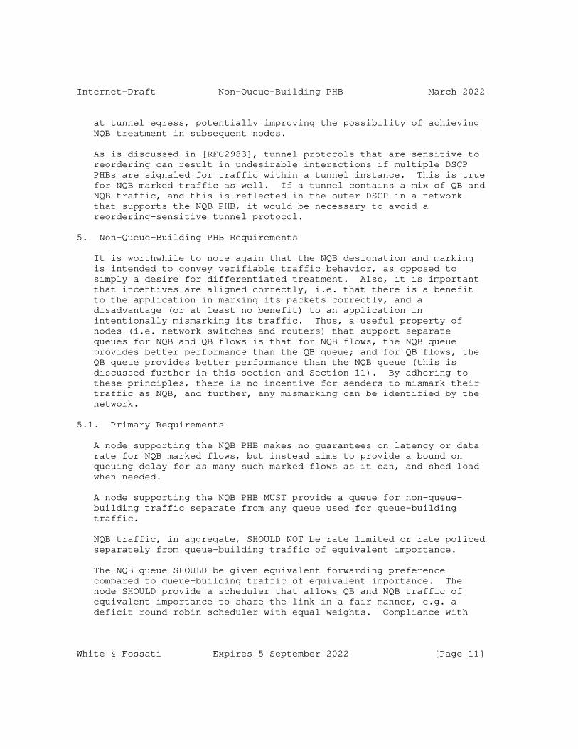
Internet-Draft Non-Queue-Building PHB March 2022
at tunnel egress, potentially improving the possibility of achieving
NQB treatment in subsequent nodes.
As is discussed in [RFC2983], tunnel protocols that are sensitive to
reordering can result in undesirable interactions if multiple DSCP
PHBs are signaled for traffic within a tunnel instance. This is true
for NQB marked traffic as well. If a tunnel contains a mix of QB and
NQB traffic, and this is reflected in the outer DSCP in a network
that supports the NQB PHB, it would be necessary to avoid a
reordering-sensitive tunnel protocol.
5. Non-Queue-Building PHB Requirements
It is worthwhile to note again that the NQB designation and marking
is intended to convey verifiable traffic behavior, as opposed to
simply a desire for differentiated treatment. Also, it is important
that incentives are aligned correctly, i.e. that there is a benefit
to the application in marking its packets correctly, and a
disadvantage (or at least no benefit) to an application in
intentionally mismarking its traffic. Thus, a useful property of
nodes (i.e. network switches and routers) that support separate
queues for NQB and QB flows is that for NQB flows, the NQB queue
provides better performance than the QB queue; and for QB flows, the
QB queue provides better performance than the NQB queue (this is
discussed further in this section and Section 11). By adhering to
these principles, there is no incentive for senders to mismark their
traffic as NQB, and further, any mismarking can be identified by the
network.
5.1. Primary Requirements
A node supporting the NQB PHB makes no guarantees on latency or data
rate for NQB marked flows, but instead aims to provide a bound on
queuing delay for as many such marked flows as it can, and shed load
when needed.
A node supporting the NQB PHB MUST provide a queue for non-queue-
building traffic separate from any queue used for queue-building
traffic.
NQB traffic, in aggregate, SHOULD NOT be rate limited or rate policed
separately from queue-building traffic of equivalent importance.
The NQB queue SHOULD be given equivalent forwarding preference
compared to queue-building traffic of equivalent importance. The
node SHOULD provide a scheduler that allows QB and NQB traffic of
equivalent importance to share the link in a fair manner, e.g. a
deficit round-robin scheduler with equal weights. Compliance with
White & Fossati Expires 5 September 2022 [Page 11]

Internet-Draft Non-Queue-Building PHB March 2022
these recommendations helps to ensure that there are no incentives
for QB traffic to be mismarked as NQB. In environments where
mismarking is not a potential issue (e.g. a network where a marking
policy is enforced by other means), these requirements may not be
necessary.
A node supporting the NQB PHB SHOULD treat traffic marked as Default
(DSCP=0) as QB traffic having equivalent importance to the NQB marked
traffic. A node supporting the NQB DSCP MUST support the ability to
configure the classification criteria that are used to identify QB
and NQB traffic of equivalent importance.
The NQB queue SHOULD have a buffer size that is significantly smaller
than the buffer provided for QB traffic (e.g. single-digit
milliseconds). It is expected that most QB traffic is engineered to
work well when the network provides a relatively deep buffer (e.g. on
the order of tens or hundreds of ms) in nodes where support for the
NQB PHB is advantageous (i.e. bottleneck nodes). Providing a
similarly deep buffer for the NQB queue would be at cross purposes to
providing very low queueing delay, and would erode the incentives for
QB traffic to be marked correctly.
5.2. Traffic Protection
It is possible that due to an implementation error or
misconfiguration, a QB flow would end up getting mismarked as NQB, or
vice versa. In the case of an NQB flow that isn’t marked as NQB and
ends up in the QB queue, it would only impact its own quality of
service, and so it seems to be of lesser concern. However, a QB flow
that is mismarked as NQB would cause queuing delays and/or loss for
all of the other flows that are sharing the NQB queue.
To prevent this situation from harming the performance of the real
NQB flows, network elements that support differentiating NQB traffic
SHOULD support a "traffic protection" function that can identify QB
flows that are mismarked as NQB, and either reclassify those flows/
packets to the QB queue or discard the offending traffic. Such a
function SHOULD be implemented in an objective and verifiable manner,
basing its decisions upon the behavior of the flow rather than on
application-layer constructs. It is RECOMMENDED that traffic
protection algorithms base their decisions on the detection of actual
queuing, as opposed to simply packet arrival rates. It may be
advantageous for a traffic protection function to employ hysteresis
to prevent borderline flows from being reclassified capriciously.
One example traffic protection algorithm can be found in
[I-D.briscoe-docsis-q-protection].
White & Fossati Expires 5 September 2022 [Page 12]

Internet-Draft Non-Queue-Building PHB March 2022
There are some situations where such function may not be necessary.
For example, a network element designed for use in controlled
environments (e.g. enterprise LAN) may not require a traffic
protection function. Additionally, some networks may prefer to
police the application of the NQB DSCP at the ingress edge, so that
in-network traffic protection is not needed.
5.3. Guidance for Very Low Rate Links
The NQB sender requirements in Section 4.1 place responsibility in
the hands of the application developer to determine the likelihood
that the application’s sending behavior could result in a queue
forming along the path. These requirements rely on application
developers having a reasonable sense for the network context in which
their application is to be deployed. Even so, there will undoubtedly
be networks that contain links having a data rate that is below the
lower end of what is considered "typical", and some of these links
may even be below the instantaneous sending rate of some NQB-marked
applications.
To limit the consequences of this scenario, operators of such
networks SHOULD utilize a traffic protection function that is more
tolerant of burstiness (i.e. a temporary queue). Alternatively,
operators of such networks MAY choose to disable NQB support on these
low speed links. In particular, for links that are far below
"typical" path rates, it is RECOMMENDED that NQB support be disabled.
6. Impact on Higher Layer Protocols
Network elements that support the NQB PHB and that support traffic
protection as discussed in the previous section introduce the
possibility that flows classified into the NQB queue could experience
out of order delivery or packet loss if their behavior is not
consistent with NQB. This is particularly true if the traffic
protection algorithm makes decisions on a packet-by-packet basis. In
this scenario, a flow that is (mis)marked as NQB and that causes a
queue to form in this bottleneck link could see some of its packets
forwarded by the NQB queue, and some of them either discarded or
redirected to the QB queue. In the case of redirection, depending on
the queueing latency and scheduling within the network element, this
could result in packets being delivered out of order. As a result,
the use of the NQB DSCP by a higher layer protocol carries some risk
that an increased amount of out of order delivery or packet loss will
be experienced. This characteristic provides one disincentive for
mis-marking of traffic.
White & Fossati Expires 5 September 2022 [Page 13]

Internet-Draft Non-Queue-Building PHB March 2022
7. Configuration and Management
As required above, nodes supporting the NQB PHB provide for the
configuration of classifiers that can be used to differentiate
between QB and NQB traffic of equivalent importance. The default for
such classifiers is recommended to be the assigned NQB DSCP (to
identify NQB traffic) and the Default (0) DSCP (to identify QB
traffic).
8. Example Use Cases
8.1. DOCSIS Access Networks
Residential cable broadband Internet services are commonly configured
with a single bottleneck link (the access network link) upon which
the service definition is applied. The service definition, typically
an upstream/downstream data rate tuple, is implemented as a
configured pair of rate shapers that are applied to the user’s
traffic. In such networks, the quality of service that each
application receives, and as a result, the quality of experience that
it generates for the user is influenced by the characteristics of the
access network link.
To support the NQB PHB, cable broadband services MUST be configured
to provide a separate queue for NQB marked traffic. The NQB queue
MUST be configured to share the service’s rate shaped bandwidth with
the queue for QB traffic.
8.2. Mobile Networks
Historically, 3GPP mobile networks have utilised "bearers" to
encapsulate each user’s user plane traffic through the radio and core
networks. A "dedicated bearer" may be allocated a Quality of Service
(QoS) to apply any prioritisation to its flows at queues and radio
schedulers. Typically an LTE operator provides a dedicated bearer
for IMS VoLTE (Voice over LTE) traffic, which is prioritised in order
to meet regulatory obligations for call completion rates; and a "best
effort" default bearer, for Internet traffic. The "best effort"
bearer provides no guarantees, and hence its buffering
characteristics are not compatible with low-latency traffic. The 5G
radio and core systems offer more flexibility over bearer allocation,
meaning bearers can be allocated per traffic type (e.g. loss-
tolerant, low-latency etc.) and hence support more suitable treatment
of Internet real-time flows.
White & Fossati Expires 5 September 2022 [Page 14]
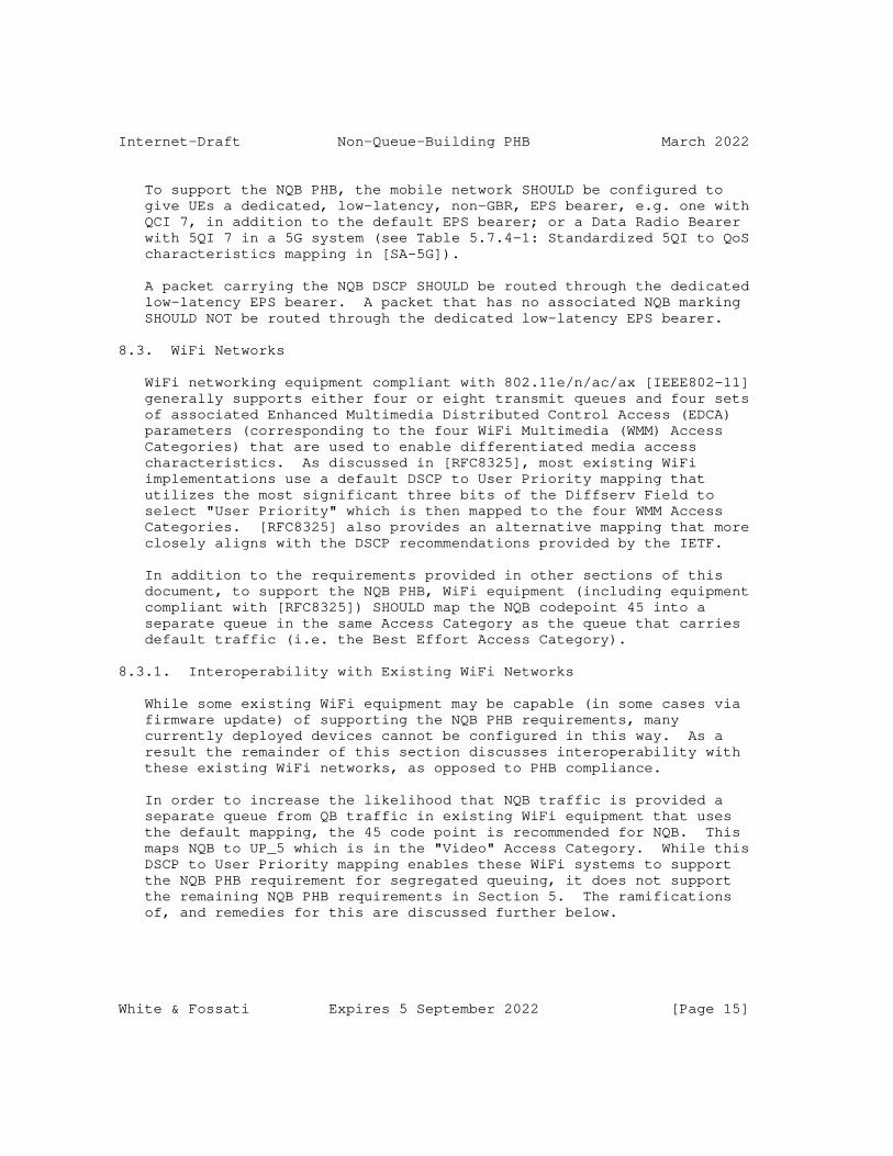
Internet-Draft Non-Queue-Building PHB March 2022
To support the NQB PHB, the mobile network SHOULD be configured to
give UEs a dedicated, low-latency, non-GBR, EPS bearer, e.g. one with
QCI 7, in addition to the default EPS bearer; or a Data Radio Bearer
with 5QI 7 in a 5G system (see Table 5.7.4-1: Standardized 5QI to QoS
characteristics mapping in [SA-5G]).
A packet carrying the NQB DSCP SHOULD be routed through the dedicated
low-latency EPS bearer. A packet that has no associated NQB marking
SHOULD NOT be routed through the dedicated low-latency EPS bearer.
8.3. WiFi Networks
WiFi networking equipment compliant with 802.11e/n/ac/ax [IEEE802-11]
generally supports either four or eight transmit queues and four sets
of associated Enhanced Multimedia Distributed Control Access (EDCA)
parameters (corresponding to the four WiFi Multimedia (WMM) Access
Categories) that are used to enable differentiated media access
characteristics. As discussed in [RFC8325], most existing WiFi
implementations use a default DSCP to User Priority mapping that
utilizes the most significant three bits of the Diffserv Field to
select "User Priority" which is then mapped to the four WMM Access
Categories. [RFC8325] also provides an alternative mapping that more
closely aligns with the DSCP recommendations provided by the IETF.
In addition to the requirements provided in other sections of this
document, to support the NQB PHB, WiFi equipment (including equipment
compliant with [RFC8325]) SHOULD map the NQB codepoint 45 into a
separate queue in the same Access Category as the queue that carries
default traffic (i.e. the Best Effort Access Category).
8.3.1. Interoperability with Existing WiFi Networks
While some existing WiFi equipment may be capable (in some cases via
firmware update) of supporting the NQB PHB requirements, many
currently deployed devices cannot be configured in this way. As a
result the remainder of this section discusses interoperability with
these existing WiFi networks, as opposed to PHB compliance.
In order to increase the likelihood that NQB traffic is provided a
separate queue from QB traffic in existing WiFi equipment that uses
the default mapping, the 45 code point is recommended for NQB. This
maps NQB to UP_5 which is in the "Video" Access Category. While this
DSCP to User Priority mapping enables these WiFi systems to support
the NQB PHB requirement for segregated queuing, it does not support
the remaining NQB PHB requirements in Section 5. The ramifications
of, and remedies for this are discussed further below.
White & Fossati Expires 5 September 2022 [Page 15]

Internet-Draft Non-Queue-Building PHB March 2022
Existing WiFi devices are unlikely to support a traffic protection
algorithm, so traffic mismarked as NQB is not likely to be detected
and remedied by such devices.
Furthermore, in their default configuration, existing WiFi devices
utilize EDCA parameters that result in statistical prioritization of
the "Video" Access Category above the "Best Effort" Access Category.
If left unchanged, this would violate the NQB PHB requirement for
equal prioritization, and could erode the principle of alignment of
incentives. In order to preserve the incentives principle for NQB,
WiFi systems SHOULD be configured such that the EDCA parameters for
the Video Access Category match those of the Best Effort Access
Category. This recommendation is primarily applicable to WiFi
systems deployed in a managed environment or those deployed by an
ISP, and is intended for situations when the vast majority of traffic
that would use AC_VI is NQB. In other situations (e.g. consumer-
grade WiFi gear deployed by an ISP’s customer) this configuration may
not be possible, and the requirements and recommendations in
Section 4.3.1 would apply.
Similarly, systems that utilize [RFC8325] but that are unable to
fully support the PHB requirements, SHOULD map the recommended NQB
code point 45 (or the locally determined alternative) to UP_5 in the
"Video" Access Category.
9. Acknowledgements
Thanks to Diego Lopez, Stuart Cheshire, Brian Carpenter, Bob Briscoe,
Greg Skinner, Toke Hoeiland-Joergensen, Luca Muscariello, David
Black, Sebastian Moeller, Ruediger Geib, Jerome Henry, Steven Blake,
Jonathan Morton, Roland Bless, Kevin Smith, Martin Dolly, and Kyle
Rose for their review comments. Thanks also to Gorry Fairhurst, Ana
Custura, and Ruediger Geib for their input on selection of
appropriate DSCPs.
10. IANA Considerations
This document requests that IANA assign the Differentiated Services
Field Codepoint (DSCP) 45 (’0b101101’, 0x2D) from the "Differentiated
Services Field Codepoints (DSCP)" registry
(https://www.iana.org/assignments/dscp-registry/) ("DSCP Pool 3
Codepoints", Codepoint Space xxxx01, Standards Action) as the
RECOMMENDED codepoint for Non-Queue-Building behavior for end-systems
and in edge networks.
IANA should update this registry as follows:
* Name: NQB-EDGE
White & Fossati Expires 5 September 2022 [Page 16]

Internet-Draft Non-Queue-Building PHB March 2022
* Value (Binary): 101101
* Value (Decimal): 45
* Reference: this document
This document requests that IANA assign the Differentiated Services
Field Codepoint (DSCP) 5 (’0b000101’, 0x05) from the "Differentiated
Services Field Codepoints (DSCP)" registry
(https://www.iana.org/assignments/dscp-registry/) ("DSCP Pool 3
Codepoints", Codepoint Space xxxx01, Standards Action) as the
RECOMMENDED codepoint for Non-Queue-Building behavior in core
networks and interconnections.
IANA should update this registry as follows:
* Name: NQB-CORE
* Value (Binary): 000101
* Value (Decimal): 5
* Reference: this document
11. Security Considerations
When the NQB PHB is fully supported in bottleneck links, there is no
incentive for a queue-building application to mismark its packets as
NQB (or vice versa). If a queue-building flow were to mark its
packets as NQB, it would be unlikely to receive a benefit by doing
so, and it could experience excessive packet loss, excessive latency
variation and/or excessive out-of-order delivery (depending on the
nature of the traffic protection function). If a non-queue-building
flow were to fail to mark its packets as NQB, it could suffer the
latency and loss typical of sharing a queue with capacity seeking
traffic.
In order to preserve low latency performance for NQB traffic,
networks that support the NQB PHB will need to ensure that mechanisms
are in place to prevent malicious NQB-marked traffic from causing
excessive queue delays. This document recommends the implementation
of a traffic protection mechanism to achieve this goal, but
recognizes that other options may be more desirable in certain
situations.
Notwithstanding the above, the choice of DSCP for NQB does allow
existing WiFi networks to readily (and by default) support some of
the PHB requirements, but without a traffic protection function, and
White & Fossati Expires 5 September 2022 [Page 17]
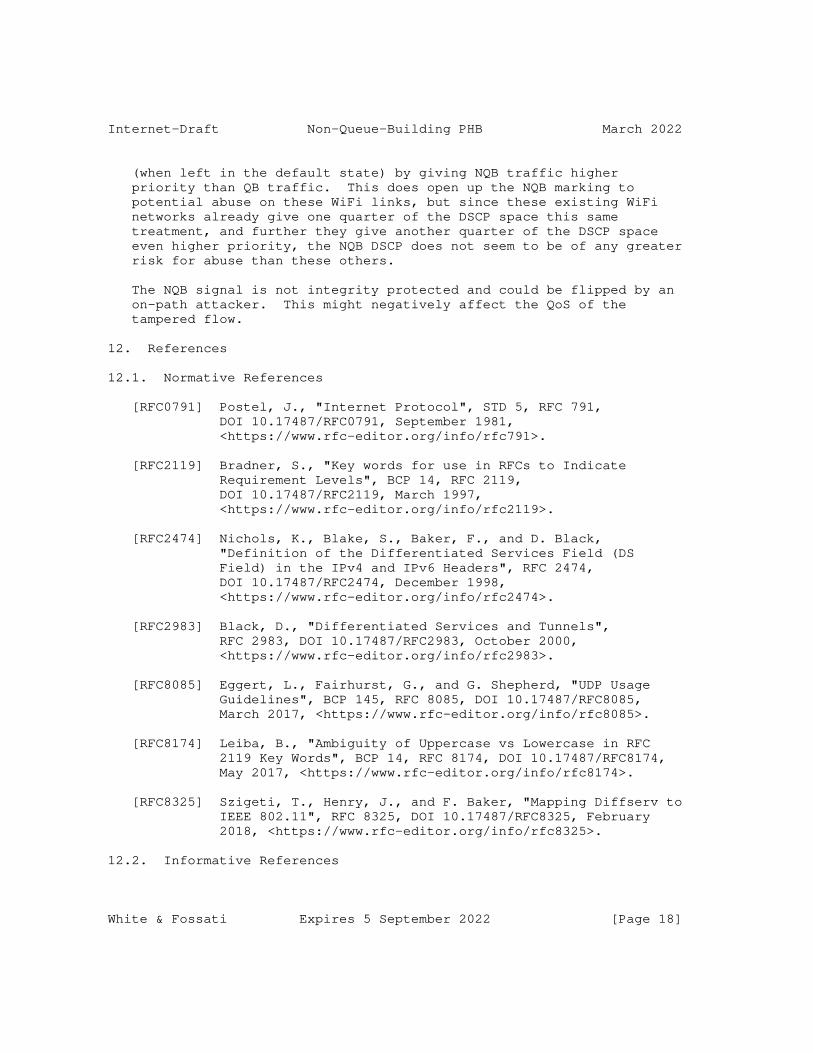
Internet-Draft Non-Queue-Building PHB March 2022
(when left in the default state) by giving NQB traffic higher
priority than QB traffic. This does open up the NQB marking to
potential abuse on these WiFi links, but since these existing WiFi
networks already give one quarter of the DSCP space this same
treatment, and further they give another quarter of the DSCP space
even higher priority, the NQB DSCP does not seem to be of any greater
risk for abuse than these others.
The NQB signal is not integrity protected and could be flipped by an
on-path attacker. This might negatively affect the QoS of the
tampered flow.
12. References
12.1. Normative References
[RFC0791] Postel, J., "Internet Protocol", STD 5, RFC 791,
DOI 10.17487/RFC0791, September 1981,
<https://www.rfc-editor.org/info/rfc791>.
[RFC2119] Bradner, S., "Key words for use in RFCs to Indicate
Requirement Levels", BCP 14, RFC 2119,
DOI 10.17487/RFC2119, March 1997,
<https://www.rfc-editor.org/info/rfc2119>.
[RFC2474] Nichols, K., Blake, S., Baker, F., and D. Black,
"Definition of the Differentiated Services Field (DS
Field) in the IPv4 and IPv6 Headers", RFC 2474,
DOI 10.17487/RFC2474, December 1998,
<https://www.rfc-editor.org/info/rfc2474>.
[RFC2983] Black, D., "Differentiated Services and Tunnels",
RFC 2983, DOI 10.17487/RFC2983, October 2000,
<https://www.rfc-editor.org/info/rfc2983>.
[RFC8085] Eggert, L., Fairhurst, G., and G. Shepherd, "UDP Usage
Guidelines", BCP 145, RFC 8085, DOI 10.17487/RFC8085,
March 2017, <https://www.rfc-editor.org/info/rfc8085>.
[RFC8174] Leiba, B., "Ambiguity of Uppercase vs Lowercase in RFC
2119 Key Words", BCP 14, RFC 8174, DOI 10.17487/RFC8174,
May 2017, <https://www.rfc-editor.org/info/rfc8174>.
[RFC8325] Szigeti, T., Henry, J., and F. Baker, "Mapping Diffserv to
IEEE 802.11", RFC 8325, DOI 10.17487/RFC8325, February
2018, <https://www.rfc-editor.org/info/rfc8325>.
12.2. Informative References
White & Fossati Expires 5 September 2022 [Page 18]

Internet-Draft Non-Queue-Building PHB March 2022
[Barik] Barik, R., Welzl, M., Elmokashfi, A., Dreibholz, T., and
S. Gjessing, "Can WebRTC QoS Work? A DSCP Measurement
Study", ITC 30, September 2018.
[Custura] Custura, A., Venne, A., and G. Fairhurst, "Exploring DSCP
modification pathologies in mobile edge networks", TMA ,
2017.
[I-D.briscoe-docsis-q-protection]
Briscoe, B. and G. White, "The DOCSIS(r) Queue Protection
Algorithm to Preserve Low Latency", Work in Progress,
Internet-Draft, draft-briscoe-docsis-q-protection-02, 31
January 2022, <https://datatracker.ietf.org/doc/html/
draft-briscoe-docsis-q-protection-02>.
[I-D.ietf-tsvwg-aqm-dualq-coupled]
Schepper, K. D., Briscoe, B., and G. White, "DualQ Coupled
AQMs for Low Latency, Low Loss and Scalable Throughput
(L4S)", Work in Progress, Internet-Draft, draft-ietf-
tsvwg-aqm-dualq-coupled-21, 1 February 2022,
<https://datatracker.ietf.org/doc/html/draft-ietf-tsvwg-
aqm-dualq-coupled-21>.
[I-D.ietf-tsvwg-dscp-considerations]
Custura, A., Fairhurst, G., and R. Secchi, "Considerations
for Assigning a new Recommended DiffServ Codepoint
(DSCP)", Work in Progress, Internet-Draft, draft-ietf-
tsvwg-dscp-considerations-01, 24 January 2022,
<https://datatracker.ietf.org/doc/html/draft-ietf-tsvwg-
dscp-considerations-01>.
[I-D.ietf-tsvwg-ecn-l4s-id]
Schepper, K. D. and B. Briscoe, "Explicit Congestion
Notification (ECN) Protocol for Very Low Queuing Delay
(L4S)", Work in Progress, Internet-Draft, draft-ietf-
tsvwg-ecn-l4s-id-24, 1 February 2022,
<https://datatracker.ietf.org/doc/html/draft-ietf-tsvwg-
ecn-l4s-id-24>.
[I-D.ietf-tsvwg-l4s-arch]
Briscoe, B., Schepper, K. D., Bagnulo, M., and G. White,
"Low Latency, Low Loss, Scalable Throughput (L4S) Internet
Service: Architecture", Work in Progress, Internet-Draft,
draft-ietf-tsvwg-l4s-arch-16, 1 February 2022,
<https://datatracker.ietf.org/doc/html/draft-ietf-tsvwg-
l4s-arch-16>.
White & Fossati Expires 5 September 2022 [Page 19]

Internet-Draft Non-Queue-Building PHB March 2022
[IEEE802-11]
IEEE-SA, "IEEE 802.11-2020", IEEE 802, December 2020,
<https://standards.ieee.org/standard/802_11-2020.html>.
[RFC2475] Blake, S., Black, D., Carlson, M., Davies, E., Wang, Z.,
and W. Weiss, "An Architecture for Differentiated
Services", RFC 2475, DOI 10.17487/RFC2475, December 1998,
<https://www.rfc-editor.org/info/rfc2475>.
[RFC3551] Schulzrinne, H. and S. Casner, "RTP Profile for Audio and
Video Conferences with Minimal Control", STD 65, RFC 3551,
DOI 10.17487/RFC3551, July 2003,
<https://www.rfc-editor.org/info/rfc3551>.
[RFC4594] Babiarz, J., Chan, K., and F. Baker, "Configuration
Guidelines for DiffServ Service Classes", RFC 4594,
DOI 10.17487/RFC4594, August 2006,
<https://www.rfc-editor.org/info/rfc4594>.
[RFC5127] Chan, K., Babiarz, J., and F. Baker, "Aggregation of
Diffserv Service Classes", RFC 5127, DOI 10.17487/RFC5127,
February 2008, <https://www.rfc-editor.org/info/rfc5127>.
[RFC7893] Stein, Y(J)., Black, D., and B. Briscoe, "Pseudowire
Congestion Considerations", RFC 7893,
DOI 10.17487/RFC7893, June 2016,
<https://www.rfc-editor.org/info/rfc7893>.
[RFC8033] Pan, R., Natarajan, P., Baker, F., and G. White,
"Proportional Integral Controller Enhanced (PIE): A
Lightweight Control Scheme to Address the Bufferbloat
Problem", RFC 8033, DOI 10.17487/RFC8033, February 2017,
<https://www.rfc-editor.org/info/rfc8033>.
[RFC8034] White, G. and R. Pan, "Active Queue Management (AQM) Based
on Proportional Integral Controller Enhanced PIE) for
Data-Over-Cable Service Interface Specifications (DOCSIS)
Cable Modems", RFC 8034, DOI 10.17487/RFC8034, February
2017, <https://www.rfc-editor.org/info/rfc8034>.
[RFC8083] Perkins, C. and V. Singh, "Multimedia Congestion Control:
Circuit Breakers for Unicast RTP Sessions", RFC 8083,
DOI 10.17487/RFC8083, March 2017,
<https://www.rfc-editor.org/info/rfc8083>.
[RFC8100] Geib, R., Ed. and D. Black, "Diffserv-Interconnection
Classes and Practice", RFC 8100, DOI 10.17487/RFC8100,
March 2017, <https://www.rfc-editor.org/info/rfc8100>.
White & Fossati Expires 5 September 2022 [Page 20]

Internet-Draft Non-Queue-Building PHB March 2022
[RFC8289] Nichols, K., Jacobson, V., McGregor, A., Ed., and J.
Iyengar, Ed., "Controlled Delay Active Queue Management",
RFC 8289, DOI 10.17487/RFC8289, January 2018,
<https://www.rfc-editor.org/info/rfc8289>.
[RFC8290] Hoeiland-Joergensen, T., McKenney, P., Taht, D., Gettys,
J., and E. Dumazet, "The Flow Queue CoDel Packet Scheduler
and Active Queue Management Algorithm", RFC 8290,
DOI 10.17487/RFC8290, January 2018,
<https://www.rfc-editor.org/info/rfc8290>.
[SA-5G] 3GPP, "System Architecture for 5G", TS 23.501, 2019.
Appendix A. DSCP Remarking Pathologies
Some network operators typically bleach (zero out) the Diffserv field
on ingress into their network
[I-D.ietf-tsvwg-dscp-considerations][Custura][Barik], and in some
cases apply their own DSCP for internal usage. Bleaching the NQB
DSCP is not expected to cause harm to default traffic, but it will
severely limit the ability to provide NQB treatment end-to-end.
Reports on existing deployments of DSCP manipulation [Custura][Barik]
categorize the re-marking behaviors into the following six policies:
bleach all traffic (set DSCP to zero), set the top three bits (the
former Precedence bits) on all traffic to 0b000, 0b001, or 0b010, set
the low three bits on all traffic to 0b000, or remark all traffic to
a particular (non-zero) DSCP value.
Regarding the DSCP values of 5 & 45, there were no observations of
DSCP manipulation reported in which traffic was marked 5 or 45 by any
of these policies. Thus it appears that these re-marking policies
would be unlikely to result in QB traffic being marked as NQB (45).
In terms of the fate of NQB-marked traffic that is subjected to one
of these policies, the result would be that NQB marked traffic would
be indistinguishable from some subset (possibly all) of other
traffic. In the policies where all traffic is remarked using the
same (zero or non-zero) DSCP, the ability for a subsequent network
hop to differentiate NQB traffic via DSCP would clearly be lost
entirely.
In the policies where the top three bits are overwritten, both NQB
values (5 & 45) would receive the same marking as would the currently
unassigned Pool 3 DSCPs 13,21,29,37,53,61, with all of these code
points getting mapped to DSCP=5, 13 or 21 (depending on the overwrite
value used). Since none of the DSCPs in the preceding lists are
currently assigned by IANA, and they all are set aside for Standards
Action, it is believed that they are not widely used currently, but
this may vary based on local-usage.
White & Fossati Expires 5 September 2022 [Page 21]

Internet-Draft Non-Queue-Building PHB March 2022
For the policy in which the low three bits are set to 0b000, the NQB
(45) value would be mapped to CS5 and would be indistinguishable from
CS5, VA, EF (and the unassigned DSCPs 41, 42, 43). Traffic marked
using the existing standardized DSCPs in this list are likely to
share the same general properties as NQB traffic (non capacity-
seeking, very low data rate or relatively low and consistent data
rate). Similarly, any future recommended usage for DSCPs 41, 42, 43
would likely be somewhat compatible with NQB treatment, assuming that
IP Precedence compatibility (see Section 1.5.4 of [RFC4594]) is
maintained in the future. Here there may be an opportunity for a
node to provide the NQB PHB or the CS5 PHB to CS5-marked traffic and
retain some of the benefits of NQB marking. This could be another
motivation to (as discussed in Section 4.2) classify CS5-marked
traffic into NQB queue. For this same re-marking policy, the NQB (5)
value would be mapped to CS0/default and would be indistinguishable
from CS0, LE (and the unassigned DSCPs 2,3,4,6,7). In this case, NQB
traffic is likely to be given default treatment in all subsequent
nodes, which would eliminate the ability to provide NQB treatment in
those nodes, but would be relatively harmless otherwise.
Authors’ Addresses
Greg White
CableLabs
Email: [email protected]
Thomas Fossati
ARM
Email: [email protected]
White & Fossati Expires 5 September 2022 [Page 22]

Transport Area Working Group B. BriscoeInternet-Draft IndependentUpdates: 6040, 2661, 2784, 3931, 4380, 7450 (if 11 July 2022 approved)Intended status: Standards TrackExpires: 12 January 2023
Propagating Explicit Congestion Notification Across IP Tunnel Headers Separated by a Shim draft-ietf-tsvwg-rfc6040update-shim-15
Abstract
RFC 6040 on "Tunnelling of Explicit Congestion Notification" made the rules for propagation of ECN consistent for all forms of IP in IP tunnel. This specification updates RFC 6040 to clarify that its scope includes tunnels where two IP headers are separated by at least one shim header that is not sufficient on its own for wide area packet forwarding. It surveys widely deployed IP tunnelling protocols that use such shim header(s) and updates the specifications of those that do not mention ECN propagation (L2TPv2, L2TPv3, GRE, Teredo and AMT). This specification also updates RFC 6040 with configuration requirements needed to make any legacy tunnel ingress safe.
Status of This Memo
This Internet-Draft is submitted in full conformance with the provisions of BCP 78 and BCP 79.
Internet-Drafts are working documents of the Internet Engineering Task Force (IETF). Note that other groups may also distribute working documents as Internet-Drafts. The list of current Internet- Drafts is at https://datatracker.ietf.org/drafts/current/.
Internet-Drafts are draft documents valid for a maximum of six months and may be updated, replaced, or obsoleted by other documents at any time. It is inappropriate to use Internet-Drafts as reference material or to cite them other than as "work in progress."
This Internet-Draft will expire on 12 January 2023.
Copyright Notice
Copyright (c) 2022 IETF Trust and the persons identified as the document authors. All rights reserved.
Briscoe Expires 12 January 2023 [Page 1]
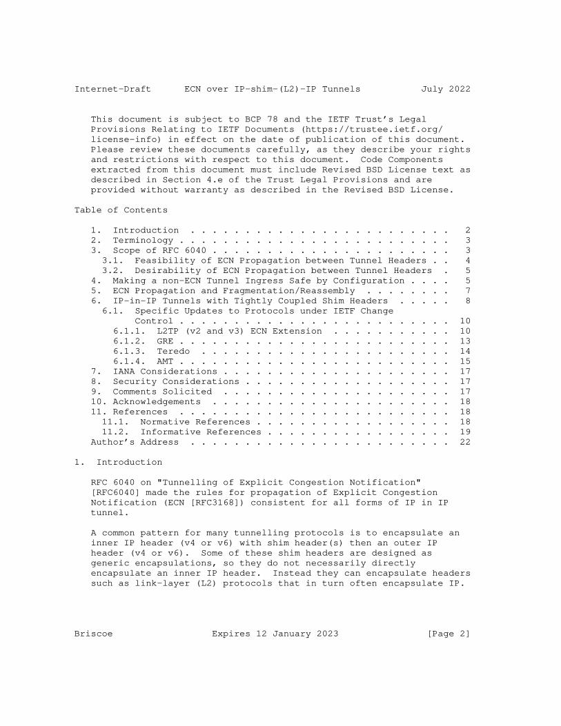
Internet-Draft ECN over IP-shim-(L2)-IP Tunnels July 2022
This document is subject to BCP 78 and the IETF Trust’s Legal Provisions Relating to IETF Documents (https://trustee.ietf.org/ license-info) in effect on the date of publication of this document. Please review these documents carefully, as they describe your rights and restrictions with respect to this document. Code Components extracted from this document must include Revised BSD License text as described in Section 4.e of the Trust Legal Provisions and are provided without warranty as described in the Revised BSD License.
Table of Contents
1. Introduction . . . . . . . . . . . . . . . . . . . . . . . . 2 2. Terminology . . . . . . . . . . . . . . . . . . . . . . . . . 3 3. Scope of RFC 6040 . . . . . . . . . . . . . . . . . . . . . . 3 3.1. Feasibility of ECN Propagation between Tunnel Headers . . 4 3.2. Desirability of ECN Propagation between Tunnel Headers . 5 4. Making a non-ECN Tunnel Ingress Safe by Configuration . . . . 5 5. ECN Propagation and Fragmentation/Reassembly . . . . . . . . 7 6. IP-in-IP Tunnels with Tightly Coupled Shim Headers . . . . . 8 6.1. Specific Updates to Protocols under IETF Change Control . . . . . . . . . . . . . . . . . . . . . . . . . 10 6.1.1. L2TP (v2 and v3) ECN Extension . . . . . . . . . . . 10 6.1.2. GRE . . . . . . . . . . . . . . . . . . . . . . . . . 13 6.1.3. Teredo . . . . . . . . . . . . . . . . . . . . . . . 14 6.1.4. AMT . . . . . . . . . . . . . . . . . . . . . . . . . 15 7. IANA Considerations . . . . . . . . . . . . . . . . . . . . . 17 8. Security Considerations . . . . . . . . . . . . . . . . . . . 17 9. Comments Solicited . . . . . . . . . . . . . . . . . . . . . 17 10. Acknowledgements . . . . . . . . . . . . . . . . . . . . . . 18 11. References . . . . . . . . . . . . . . . . . . . . . . . . . 18 11.1. Normative References . . . . . . . . . . . . . . . . . . 18 11.2. Informative References . . . . . . . . . . . . . . . . . 19 Author’s Address . . . . . . . . . . . . . . . . . . . . . . . . 22
1. Introduction
RFC 6040 on "Tunnelling of Explicit Congestion Notification" [RFC6040] made the rules for propagation of Explicit Congestion Notification (ECN [RFC3168]) consistent for all forms of IP in IP tunnel.
A common pattern for many tunnelling protocols is to encapsulate an inner IP header (v4 or v6) with shim header(s) then an outer IP header (v4 or v6). Some of these shim headers are designed as generic encapsulations, so they do not necessarily directly encapsulate an inner IP header. Instead they can encapsulate headers such as link-layer (L2) protocols that in turn often encapsulate IP.
Briscoe Expires 12 January 2023 [Page 2]

Internet-Draft ECN over IP-shim-(L2)-IP Tunnels July 2022
To clear up confusion, this specification clarifies that the scope of RFC 6040 includes any IP-in-IP tunnel, including those with shim header(s) and other encapsulations between the IP headers. Where necessary, it updates the specifications of the relevant encapsulation protocols with the specific text necessary to comply with RFC 6040.
This specification also updates RFC 6040 to state how operators ought to configure a legacy tunnel ingress to avoid unsafe system configurations.
2. Terminology
The key words "MUST", "MUST NOT", "REQUIRED", "SHALL", "SHALL NOT", "SHOULD", "SHOULD NOT", "RECOMMENDED", "MAY", and "OPTIONAL" in this document are to be interpreted as described in RFC 2119 [RFC2119] when, and only when, they appear in all capitals, as shown here.
This specification uses the terminology defined in RFC 6040 [RFC6040].
3. Scope of RFC 6040
In section 1.1 of RFC 6040, its scope is defined as:
"...ECN field processing at encapsulation and decapsulation for any IP-in-IP tunnelling, whether IPsec or non-IPsec tunnels. It applies irrespective of whether IPv4 or IPv6 is used for either the inner or outer headers. ..."
This was intended to include cases where shim header(s) sit between the IP headers. Many tunnelling implementers have interpreted the scope of RFC 6040 as it was intended, but it is ambiguous. Therefore, this specification updates RFC 6040 by adding the following scoping text after the sentences quoted above:
It applies in cases where an outer IP header encapsulates an inner IP header either directly or indirectly by encapsulating other headers that in turn encapsulate (or might encapsulate) an inner IP header.
There is another problem with the scope of RFC 6040. Like many IETF specifications, RFC 6040 is written as a specification that implementations can choose to claim compliance with. This means it does not cover two important cases:
Briscoe Expires 12 January 2023 [Page 3]

Internet-Draft ECN over IP-shim-(L2)-IP Tunnels July 2022
1. those cases where it is infeasible for an implementation to access an inner IP header when adding or removing an outer IP header;
2. those implementations that choose not to propagate ECN between IP headers.
However, the ECN field is a non-optional part of the IP header (v4 and v6). So any implementation that creates an outer IP header has to give the ECN field some value. There is only one safe value a tunnel ingress can use if it does not know whether the egress supports propagation of the ECN field; it has to clear the ECN field in any outer IP header to 0b00.
However, an RFC has no jurisdiction over implementations that choose not to comply with it or cannot comply with it, including all those implementations that pre-dated the RFC. Therefore it would have been unreasonable to add such a requirement to RFC 6040. Nonetheless, to ensure safe propagation of the ECN field over tunnels, it is reasonable to add requirements on operators, to ensure they configure their tunnels safely (where possible). Before stating these configuration requirements in Section 4, the factors that determine whether propagating ECN is feasible or desirable will be briefly introduced.
3.1. Feasibility of ECN Propagation between Tunnel Headers
In many cases shim header(s) and an outer IP header are always added to (or removed from) an inner IP packet as part of the same procedure. We call this a tightly coupled shim header. Processing the shim and outer together is often necessary because the shim(s) are not sufficient for packet forwarding in their own right; not unless complemented by an outer header. In these cases it will often be feasible for an implementation to propagate the ECN field between the IP headers.
In some cases a tunnel adds an outer IP header and a tightly coupled shim header to an inner header that is not an IP header, but that in turn encapsulates an IP header (or might encapsulate an IP header). For instance an inner Ethernet (or other link layer) header might encapsulate an inner IP header as its payload. We call this a tightly coupled shim over an encapsulating header.
Digging to arbitrary depths to find an inner IP header within an encapsulation is strictly a layering violation so it cannot be a required behaviour. Nonetheless, some tunnel endpoints already look within a L2 header for an IP header, for instance to map the Diffserv codepoint between an encapsulated IP header and an outer IP header
Briscoe Expires 12 January 2023 [Page 4]

Internet-Draft ECN over IP-shim-(L2)-IP Tunnels July 2022
[RFC2983]. In such cases at least, it should be feasible to also (independently) propagate the ECN field between the same IP headers. Thus, access to the ECN field within an encapsulating header can be a useful and benign optimization. The guidelines in section 5 of [I-D.ietf-tsvwg-ecn-encap-guidelines] give the conditions for this layering violation to be benign.
3.2. Desirability of ECN Propagation between Tunnel Headers
Developers and network operators are encouraged to implement and deploy tunnel endpoints compliant with RFC 6040 (as updated by the present specification) in order to provide the benefits of wider ECN deployment [RFC8087]. Nonetheless, propagation of ECN between IP headers, whether separated by shim headers or not, has to be optional to implement and to use, because:
* Legacy implementations of tunnels without any ECN support already exist
* A network might be designed so that there is usually no bottleneck within the tunnel
* If the tunnel endpoints would have to search within an L2 header to find an encapsulated IP header, it might not be worth the potential performance hit
4. Making a non-ECN Tunnel Ingress Safe by Configuration
Even when no specific attempt has been made to implement propagation of the ECN field at a tunnel ingress, it ought to be possible for the operator to render a tunnel ingress safe by configuration. The main safety concern is to disable (clear to zero) the ECN capability in the outer IP header at the ingress if the egress of the tunnel does not implement ECN logic to propagate any ECN markings into the packet forwarded beyond the tunnel. Otherwise the non-ECN egress could discard any ECN marking introduced within the tunnel, which would break all the ECN-based control loops that regulate the traffic load over the tunnel.
Therefore this specification updates RFC 6040 by inserting the following text at the end of section 4.3:
"
Whether or not an ingress implementation claims compliance with RFC 6040, RFC 4301 or RFC3168, when the outer tunnel header is IP (v4 or v6), if possible, the operator MUST configure the ingress to zero the outer ECN field in any of the following cases:
Briscoe Expires 12 January 2023 [Page 5]

Internet-Draft ECN over IP-shim-(L2)-IP Tunnels July 2022
- if it is known that the tunnel egress does not support any of the RFCs that define propagation of the ECN field (RFC 6040, RFC 4301 or the full functionality mode of RFC 3168)
- or if the behaviour of the egress is not known or an egress with unknown behaviour might be dynamically paired with the ingress.
- or if an IP header might be encapsulated within a non-IP header that the tunnel ingress is encapsulating, but the ingress does not inspect within the encapsulation.
For the avoidance of doubt, the above only concerns the outer IP header. The ingress MUST NOT alter the ECN field of the arriving IP header that will become the inner IP header.
In order that the network operator can comply with the above safety rules, even if an implementation of a tunnel ingress does not claim to support RFC 6040, RFC 4301 or the full functionality mode of RFC 3168:
- it MUST NOT treat the former ToS octet (IPv4) or the former Traffic Class octet (IPv6) as a single 8-bit field, as the resulting linkage of ECN and Diffserv field propagation between inner and outer is not consistent with the definition of the 6-bit Diffserv field in [RFC2474] and [RFC3260];
- it SHOULD be able to be configured to zero the ECN field of the outer header.
"
For instance, if a tunnel ingress with no ECN-specific logic had a configuration capability to refer to the last 2 bits of the old ToS Byte of the outer (e.g. with a 0x3 mask) and set them to zero, while also being able to allow the DSCP to be re-mapped independently, that would be sufficient to satisfy both the above implementation requirements.
Briscoe Expires 12 January 2023 [Page 6]

Internet-Draft ECN over IP-shim-(L2)-IP Tunnels July 2022
There might be concern that the above "MUST NOT" makes compliant implementations non-compliant at a stroke. However, by definition it solely applies to equipment that provides Diffserv configuration. Any such Diffserv equipment that is configuring treatment of the former ToS octet (IPv4) or the former Traffic Class octet (IPv6) as a single 8-bit field must have always been non-compliant with the definition of the 6-bit Diffserv field in [RFC2474] and [RFC3260]. If a tunnel ingress does not have any ECN logic, copying the ECN field as a side-effect of copying the DSCP is a seriously unsafe bug that risks breaking the feedback loops that regulate load on a tunnel.
Zeroing the outer ECN field of all packets in all circumstances would be safe, but it would not be sufficient to claim compliance with RFC 6040 because it would not meet the aim of introducing ECN support to tunnels (see Section 4.3 of [RFC6040]).
5. ECN Propagation and Fragmentation/Reassembly
The following requirements update RFC6040, which omitted handling of the ECN field during fragmentation or reassembly. These changes might alter how many ECN-marked packets are propagated by a tunnel that fragments packets, but this would not raise any backward compatibility issues:
If a tunnel ingress fragments a packet, it MUST set the outer ECN field of all the fragments to the same value as it would have set if it had not fragmented the packet.
Section 5.3 of [RFC3168] specifies ECN requirements for reassembly of sets of outer fragments [I-D.ietf-intarea-tunnels] into packets. The following two additional requirements apply at a tunnel egress:
* During reassembly of outer fragments [I-D.ietf-intarea-tunnels], if the ECN fields of the outer headers being reassembled into a single packet consist of a mixture of Not-ECT and other ECN codepoints, the packet MUST be discarded.
* If there is mix of ECT(0) and ECT(1) fragments, then the reassembled packet MUST be set to either ECT(0) or ECT(1). In this case, reassembly SHOULD take into account that the RFC series has so far ensured that ECT(0) and ECT(1) can either be considered equivalent, or they can provide 2 levels of congestion severity, where the ranking of severity from highest to lowest is CE, ECT(1), ECT(0) [RFC6040].
Briscoe Expires 12 January 2023 [Page 7]

Internet-Draft ECN over IP-shim-(L2)-IP Tunnels July 2022
6. IP-in-IP Tunnels with Tightly Coupled Shim Headers
There follows a list of specifications of encapsulations with tightly coupled shim header(s), in rough chronological order. The list is confined to standards track or widely deployed protocols. The list is not necessarily exhaustive so, for the avoidance of doubt, the scope of RFC 6040 is defined in Section 3 and is not limited to this list.
* PPTP (Point-to-Point Tunneling Protocol) [RFC2637];
* L2TP (Layer 2 Tunnelling Protocol), specifically L2TPv2 [RFC2661] and L2TPv3 [RFC3931], which not only includes all the L2-specific specializations of L2TP, but also derivatives such as the Keyed IPv6 Tunnel [RFC8159];
* GRE (Generic Routing Encapsulation) [RFC2784] and NVGRE (Network Virtualization using GRE) [RFC7637];
* GTP (GPRS Tunnelling Protocol), specifically GTPv1 [GTPv1], GTP v1 User Plane [GTPv1-U], GTP v2 Control Plane [GTPv2-C];
* Teredo [RFC4380];
* CAPWAP (Control And Provisioning of Wireless Access Points) [RFC5415];
* LISP (Locator/Identifier Separation Protocol) [RFC6830];
* AMT (Automatic Multicast Tunneling) [RFC7450];
* VXLAN (Virtual eXtensible Local Area Network) [RFC7348] and VXLAN- GPE [I-D.ietf-nvo3-vxlan-gpe];
* The Network Service Header (NSH [RFC8300]) for Service Function Chaining (SFC);
* Geneve [RFC8926];
* GUE (Generic UDP Encapsulation) [I-D.ietf-intarea-gue];
* Direct tunnelling of an IP packet within a UDP/IP datagram (see Section 3.1.11 of [RFC8085]);
* TCP Encapsulation of IKE and IPsec Packets (see Section 12.5 of [RFC8229]).
Briscoe Expires 12 January 2023 [Page 8]

Internet-Draft ECN over IP-shim-(L2)-IP Tunnels July 2022
Some of the listed protocols enable encapsulation of a variety of network layer protocols as inner and/or outer. This specification applies in the cases where there is an inner and outer IP header as described in Section 3. Otherwise [I-D.ietf-tsvwg-ecn-encap-guidelines] gives guidance on how to design propagation of ECN into other protocols that might encapsulate IP.
Where protocols in the above list need to be updated to specify ECN propagation and they are under IETF change control, update text is given in the following subsections. For those not under IETF control, it is RECOMMENDED that implementations of encapsulation and decapsulation comply with RFC 6040. It is also RECOMMENDED that their specifications are updated to add a requirement to comply with RFC 6040 (as updated by the present document).
PPTP is not under the change control of the IETF, but it has been documented in an informational RFC [RFC2637]. However, there is no need for the present specification to update PPTP because L2TP has been developed as a standardized replacement.
NVGRE is not under the change control of the IETF, but it has been documented in an informational RFC [RFC7637]. NVGRE is a specific use-case of GRE (it re-purposes the key field from the initial specification of GRE [RFC1701] as a Virtual Subnet ID). Therefore the text that updates GRE in Section 6.1.2 below is also intended to update NVGRE.
Although the definition of the various GTP shim headers is under the control of the 3GPP, it is hard to determine whether the 3GPP or the IETF controls standardization of the _process_ of adding both a GTP and an IP header to an inner IP header. Nonetheless, the present specification is provided so that the 3GPP can refer to it from any of its own specifications of GTP and IP header processing.
The specification of CAPWAP already specifies RFC 3168 ECN propagation and ECN capability negotiation. Without modification the CAPWAP specification already interworks with the backward compatible updates to RFC 3168 in RFC 6040.
LISP made the ECN propagation procedures in RFC 3168 mandatory from the start. RFC 3168 has since been updated by RFC 6040, but the changes are backwards compatible so there is still no need for LISP tunnel endpoints to negotiate their ECN capabilities.
VXLAN is not under the change control of the IETF but it has been documented in an informational RFC. In contrast, VXLAN-GPE (Generic Protocol Extension) is being documented under IETF change control. It is RECOMMENDED that VXLAN and VXLAN-GPE implementations comply
Briscoe Expires 12 January 2023 [Page 9]

Internet-Draft ECN over IP-shim-(L2)-IP Tunnels July 2022
with RFC 6040 when the VXLAN header is inserted between (or removed from between) IP headers. The authors of any future update to these specifications are encouraged to add a requirement to comply with RFC 6040 as updated by the present specification.
The Network Service Header (NSH [RFC8300]) has been defined as a shim-based encapsulation to identify the Service Function Path (SFP) in the Service Function Chaining (SFC) architecture [RFC7665]. A proposal has been made for the processing of ECN when handling transport encapsulation [I-D.ietf-sfc-nsh-ecn-support].
The specifications of Geneve and GUE already refer to RFC 6040 for ECN encapsulation.
Section 3.1.11 of RFC 8085 already explains that a tunnel that encapsulates an IP header within a UDP/IP datagram needs to follow RFC 6040 when propagating the ECN field between inner and outer IP headers. The requirements in Section 4 update RFC 6040, and hence implicitly update the UDP usage guidelines in RFC 8085 to add the important but previously unstated requirement that, if the UDP tunnel egress does not, or might not, support ECN propagation, a UDP tunnel ingress has to clear the outer IP ECN field to 0b00, e.g. by configuration.
Section 12.5 of TCP Encapsulation of IKE and IPsec Packets [RFC8229] already recommends the compatibility mode of RFC 6040 in this case, because there is not a one-to-one mapping between inner and outer packets.
6.1. Specific Updates to Protocols under IETF Change Control
6.1.1. L2TP (v2 and v3) ECN Extension
The L2TP terminology used here is defined in [RFC2661] and [RFC3931].
L2TPv3 [RFC3931] is used as a shim header between any packet-switched network (PSN) header (e.g. IPv4, IPv6, MPLS) and many types of layer 2 (L2) header. The L2TPv3 shim header encapsulates an L2-specific sub-layer then an L2 header that is likely to contain an inner IP header (v4 or v6). Then this whole stack of headers can be encapsulated optionally within an outer UDP header then an outer PSN header that is typically IP (v4 or v6).
L2TPv2 is used as a shim header between any PSN header and a PPP header, which is in turn likely to encapsulate an IP header.
Briscoe Expires 12 January 2023 [Page 10]

Internet-Draft ECN over IP-shim-(L2)-IP Tunnels July 2022
Even though these shims are rather fat (particularly in the case of L2TPv3), they still fit the definition of a tightly coupled shim header over an encapsulating header (Section 3.1), because all the headers encapsulating the L2 header are added (or removed) together. L2TPv2 and L2TPv3 are therefore within the scope of RFC 6040, as updated by Section 3 above.
L2TP maintainers are RECOMMENDED to implement the ECN extension to L2TPv2 and L2TPv3 defined in Section 6.1.1.2 below, in order to provide the benefits of ECN [RFC8087], whenever a node within an L2TP tunnel becomes the bottleneck for an end-to-end traffic flow.
6.1.1.1. Safe Configuration of a ’Non-ECN’ Ingress LCCE
The following text is appended to both Section 5.3 of [RFC2661] and Section 4.5 of [RFC3931] as an update to the base L2TPv2 and L2TPv3 specifications:
The operator of an LCCE that does not support the ECN Extension in Section 6.1.1.2 of RFCXXXX MUST follow the configuration requirements in Section 4 of RFCXXXX to ensure it clears the outer IP ECN field to 0b00 when the outer PSN header is IP (v4 or v6). {RFCXXXX refers to the present document so it will need to be inserted by the RFC Editor}
In particular, for an LCCE implementation that does not support the ECN Extension, this means that configuration of how it propagates the ECN field between inner and outer IP headers MUST be independent of any configuration of the Diffserv extension of L2TP [RFC3308].
6.1.1.2. ECN Extension for L2TP (v2 or v3)
When the outer PSN header and the payload inside the L2 header are both IP (v4 or v6), to comply with RFC 6040, an LCCE will follow the rules for propagation of the ECN field at ingress and egress in Section 4 of RFC 6040 [RFC6040].
Before encapsulating any data packets, RFC 6040 requires an ingress LCCE to check that the egress LCCE supports ECN propagation as defined in RFC 6040 or one of its compatible predecessors ([RFC4301] or the full functionality mode of [RFC3168]). If the egress supports ECN propagation, the ingress LCCE can use the normal mode of encapsulation (copying the ECN field from inner to outer). Otherwise, the ingress LCCE has to use compatibility mode [RFC6040] (clearing the outer IP ECN field to 0b00).
Briscoe Expires 12 January 2023 [Page 11]

Internet-Draft ECN over IP-shim-(L2)-IP Tunnels July 2022
An LCCE can determine the remote LCCE’s support for ECN either statically (by configuration) or by dynamic discovery during setup of each control connection between the LCCEs, using the Capability AVP defined in Section 6.1.1.2.1 below.
Where the outer PSN header is some protocol other than IP that supports ECN, the appropriate ECN propagation specification will need to be followed, e.g. "Explicit Congestion Marking in MPLS" [RFC5129]. Where no specification exists for ECN propagation by a particular PSN, [I-D.ietf-tsvwg-ecn-encap-guidelines] gives general guidance on how to design ECN propagation into a protocol that encapsulates IP.
6.1.1.2.1. LCCE Capability AVP for ECN Capability Negotiation
The LCCE Capability Attribute-Value Pair (AVP) defined here has Attribute Type ZZ. The Attribute Value field for this AVP is a bit- mask with the following 16-bit format:
0 1 0 1 2 3 4 5 6 7 8 9 0 1 2 3 4 5 +-+-+-+-+-+-+-+-+-+-+-+-+-+-+-+-+ |X X X X X X X X X X X X X X X E| +-+-+-+-+-+-+-+-+-+-+-+-+-+-+-+-+
Figure 1: Value Field for the LCCE Capability Attribute
This AVP MAY be present in the following message types: SCCRQ and SCCRP (Start-Control-Connection-Request and Start-Control-Connection- Reply). This AVP MAY be hidden (the H-bit set to 0 or 1) and is optional (M-bit not set). The length (before hiding) of this AVP MUST be 8 octets. The Vendor ID is the IETF Vendor ID of 0.
Bit 15 of the Value field of the LCCE Capability AVP is defined as the ECN Capability flag (E). When the ECN Capability flag is set to 1, it indicates that the sender supports ECN propagation. When the ECN Capability flag is cleared to zero, or when no LCCE Capabiliy AVP is present, it indicates that the sender does not support ECN propagation. All the other bits are reserved. They MUST be cleared to zero when sent and ignored when received or forwarded.
Briscoe Expires 12 January 2023 [Page 12]

Internet-Draft ECN over IP-shim-(L2)-IP Tunnels July 2022
An LCCE initiating a control connection will send a Start-Control- Connection-Request (SCCRQ) containing an LCCE Capability AVP with the ECN Capability flag set to 1. If the tunnel terminator supports ECN, it will return a Start-Control-Connection-Reply (SCCRP) that also includes an LCCE Capability AVP with the ECN Capability flag set to 1. Then, for any sessions created by that control connection, both ends of the tunnel can use the normal mode of RFC 6040, i.e. it can copy the IP ECN field from inner to outer when encapsulating data packets.
If, on the other hand, the tunnel terminator does not support ECN it will ignore the ECN flag in the LCCE Capability AVP and send an SCCRP to the tunnel initiator without a Capability AVP (or with a Capability AVP but with the ECN Capability flag cleared to zero). The tunnel initiator interprets the absence of the ECN Capability flag in the SCCRP as an indication that the tunnel terminator is incapable of supporting ECN. When encapsulating data packets for any sessions created by that control connection, the tunnel initiator will then use the compatibility mode of RFC 6040 to clear the ECN field of the outer IP header to 0b00.
If the tunnel terminator does not support this ECN extension, the network operator is still expected to configure it to comply with the safety provisions set out in Section 6.1.1.1 above, when it acts as an ingress LCCE.
6.1.2. GRE
The GRE terminology used here is defined in [RFC2784]. GRE is often used as a tightly coupled shim header between IP headers. Sometimes the GRE shim header encapsulates an L2 header, which might in turn encapsulate an IP header. Therefore GRE is within the scope of RFC 6040 as updated by Section 3 above.
GRE tunnel endpoint maintainers are RECOMMENDED to support [RFC6040] as updated by the present specification, in order to provide the benefits of ECN [RFC8087] whenever a node within a GRE tunnel becomes the bottleneck for an end-to-end IP traffic flow tunnelled over GRE using IP as the delivery protocol (outer header).
GRE itself does not support dynamic set-up and configuration of tunnels. However, control plane protocols such as Mobile IPv4 (MIP4) [RFC5944], Mobile IPv6 (MIP6) [RFC6275], Proxy Mobile IP (PMIP) [RFC5845] and IKEv2 [RFC7296] are sometimes used to set up GRE tunnels dynamically.
Briscoe Expires 12 January 2023 [Page 13]

Internet-Draft ECN over IP-shim-(L2)-IP Tunnels July 2022
When these control protocols set up IP-in-IP or IPSec tunnels, it is likely that they propagate the ECN field as defined in RFC 6040 or one of its compatible predecessors (RFC 4301 or the full functionality mode of RFC 3168). However, if they use a GRE encapsulation, this presumption is less sound.
Therefore, If the outer delivery protocol is IP (v4 or v6) the operator is obliged to follow the safe configuration requirements in Section 4 above. Section 6.1.2.1 below updates the base GRE specification with this requirement, to emphasize its importance.
Where the delivery protocol is some protocol other than IP that supports ECN, the appropriate ECN propagation specification will need to be followed, e.g Explicit Congestion Marking in MPLS [RFC5129]. Where no specification exists for ECN propagation by a particular PSN, [I-D.ietf-tsvwg-ecn-encap-guidelines] gives more general guidance on how to propagate ECN to and from protocols that encapsulate IP.
6.1.2.1. Safe Configuration of a ’Non-ECN’ GRE Ingress
The following text is appended to Section 3 of [RFC2784] as an update to the base GRE specification:
The operator of a GRE tunnel ingress MUST follow the configuration requirements in Section 4 of RFCXXXX when the outer delivery protocol is IP (v4 or v6). {RFCXXXX refers to the present document so it will need to be inserted by the RFC Editor}
6.1.3. Teredo
Teredo [RFC4380] provides a way to tunnel IPv6 over an IPv4 network, with a UDP-based shim header between the two.
For Teredo tunnel endpoints to provide the benefits of ECN, the Teredo specification would have to be updated to include negotiation of the ECN capability between Teredo tunnel endpoints. Otherwise it would be unsafe for a Teredo tunnel ingress to copy the ECN field to the IPv6 outer.
It is believed that current implementations do not support propagation of ECN, but that they do safely zero the ECN field in the outer IPv6 header. However the specification does not mention anything about this.
To make existing Teredo deployments safe, it would be possible to add ECN capability negotiation to those that are subject to remote OS update. However, for those implementations not subject to remote OS
Briscoe Expires 12 January 2023 [Page 14]

Internet-Draft ECN over IP-shim-(L2)-IP Tunnels July 2022
update, it will not be feasible to require them to be configured correctly, because Teredo tunnel endpoints are generally deployed on hosts.
Therefore, until ECN support is added to the specification of Teredo, the only feasible further safety precaution available here is to update the specification of Teredo implementations with the following text, as a new section 5.1.3:
"5.1.3 Safe ’Non-ECN’ Teredo Encapsulation
A Teredo tunnel ingress implementation that does not support ECN propagation as defined in RFC 6040 or one of its compatible predecessors (RFC 4301 or the full functionality mode of RFC 3168) MUST zero the ECN field in the outer IPv6 header."
6.1.4. AMT
Automatic Multicast Tunneling (AMT [RFC7450]) is a tightly coupled shim header that encapsulates an IP packet and is itself encapsulated within a UDP/IP datagram. Therefore AMT is within the scope of RFC 6040 as updated by Section 3 above.
AMT tunnel endpoint maintainers are RECOMMENDED to support [RFC6040] as updated by the present specification, in order to provide the benefits of ECN [RFC8087] whenever a node within an AMT tunnel becomes the bottleneck for an IP traffic flow tunnelled over AMT.
To comply with RFC 6040, an AMT relay and gateway will follow the rules for propagation of the ECN field at ingress and egress respectively, as described in Section 4 of RFC 6040 [RFC6040].
Before encapsulating any data packets, RFC 6040 requires an ingress AMT relay to check that the egress AMT gateway supports ECN propagation as defined in RFC 6040 or one of its compatible predecessors (RFC 4301 or the full functionality mode of RFC 3168). If the egress gateway supports ECN, the ingress relay can use the normal mode of encapsulation (copying the IP ECN field from inner to outer). Otherwise, the ingress relay has to use compatibility mode, which means it has to clear the outer ECN field to zero [RFC6040].
An AMT tunnel is created dynamically (not manually), so the relay will need to determine the remote gateway’s support for ECN using the ECN capability declaration defined in Section 6.1.4.2 below.
Briscoe Expires 12 January 2023 [Page 15]
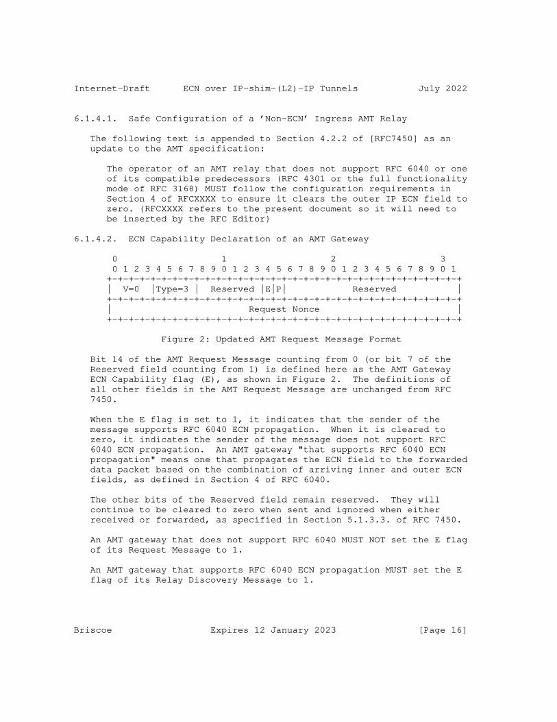
Internet-Draft ECN over IP-shim-(L2)-IP Tunnels July 2022
6.1.4.1. Safe Configuration of a ’Non-ECN’ Ingress AMT Relay
The following text is appended to Section 4.2.2 of [RFC7450] as an update to the AMT specification:
The operator of an AMT relay that does not support RFC 6040 or one of its compatible predecessors (RFC 4301 or the full functionality mode of RFC 3168) MUST follow the configuration requirements in Section 4 of RFCXXXX to ensure it clears the outer IP ECN field to zero. {RFCXXXX refers to the present document so it will need to be inserted by the RFC Editor}
6.1.4.2. ECN Capability Declaration of an AMT Gateway
0 1 2 3 0 1 2 3 4 5 6 7 8 9 0 1 2 3 4 5 6 7 8 9 0 1 2 3 4 5 6 7 8 9 0 1 +-+-+-+-+-+-+-+-+-+-+-+-+-+-+-+-+-+-+-+-+-+-+-+-+-+-+-+-+-+-+-+-+ | V=0 |Type=3 | Reserved |E|P| Reserved | +-+-+-+-+-+-+-+-+-+-+-+-+-+-+-+-+-+-+-+-+-+-+-+-+-+-+-+-+-+-+-+-+ | Request Nonce | +-+-+-+-+-+-+-+-+-+-+-+-+-+-+-+-+-+-+-+-+-+-+-+-+-+-+-+-+-+-+-+-+
Figure 2: Updated AMT Request Message Format
Bit 14 of the AMT Request Message counting from 0 (or bit 7 of the Reserved field counting from 1) is defined here as the AMT Gateway ECN Capability flag (E), as shown in Figure 2. The definitions of all other fields in the AMT Request Message are unchanged from RFC 7450.
When the E flag is set to 1, it indicates that the sender of the message supports RFC 6040 ECN propagation. When it is cleared to zero, it indicates the sender of the message does not support RFC 6040 ECN propagation. An AMT gateway "that supports RFC 6040 ECN propagation" means one that propagates the ECN field to the forwarded data packet based on the combination of arriving inner and outer ECN fields, as defined in Section 4 of RFC 6040.
The other bits of the Reserved field remain reserved. They will continue to be cleared to zero when sent and ignored when either received or forwarded, as specified in Section 5.1.3.3. of RFC 7450.
An AMT gateway that does not support RFC 6040 MUST NOT set the E flag of its Request Message to 1.
An AMT gateway that supports RFC 6040 ECN propagation MUST set the E flag of its Relay Discovery Message to 1.
Briscoe Expires 12 January 2023 [Page 16]
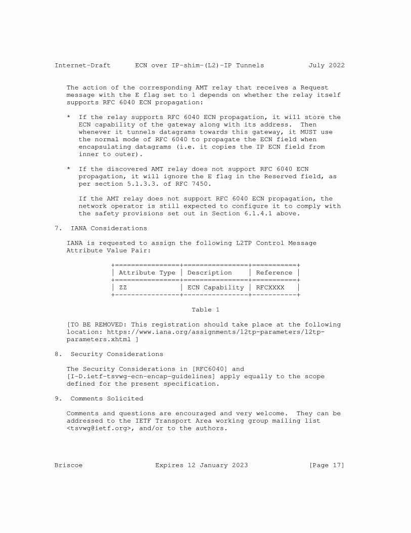
Internet-Draft ECN over IP-shim-(L2)-IP Tunnels July 2022
The action of the corresponding AMT relay that receives a Request message with the E flag set to 1 depends on whether the relay itself supports RFC 6040 ECN propagation:
* If the relay supports RFC 6040 ECN propagation, it will store the ECN capability of the gateway along with its address. Then whenever it tunnels datagrams towards this gateway, it MUST use the normal mode of RFC 6040 to propagate the ECN field when encapsulating datagrams (i.e. it copies the IP ECN field from inner to outer).
* If the discovered AMT relay does not support RFC 6040 ECN propagation, it will ignore the E flag in the Reserved field, as per section 5.1.3.3. of RFC 7450.
If the AMT relay does not support RFC 6040 ECN propagation, the network operator is still expected to configure it to comply with the safety provisions set out in Section 6.1.4.1 above.
7. IANA Considerations
IANA is requested to assign the following L2TP Control Message Attribute Value Pair:
+================+================+===========+ | Attribute Type | Description | Reference | +================+================+===========+ | ZZ | ECN Capability | RFCXXXX | +----------------+----------------+-----------+
Table 1
[TO BE REMOVED: This registration should take place at the following location: https://www.iana.org/assignments/l2tp-parameters/l2tp- parameters.xhtml ]
8. Security Considerations
The Security Considerations in [RFC6040] and [I-D.ietf-tsvwg-ecn-encap-guidelines] apply equally to the scope defined for the present specification.
9. Comments Solicited
Comments and questions are encouraged and very welcome. They can be addressed to the IETF Transport Area working group mailing list <[email protected]>, and/or to the authors.
Briscoe Expires 12 January 2023 [Page 17]

Internet-Draft ECN over IP-shim-(L2)-IP Tunnels July 2022
10. Acknowledgements
Thanks to Ing-jyh (Inton) Tsang for initial discussions on the need for ECN propagation in L2TP and its applicability. Thanks also to Carlos Pignataro, Tom Herbert, Ignacio Goyret, Alia Atlas, Praveen Balasubramanian, Joe Touch, Mohamed Boucadair, David Black, Jake Holland and Sri Gundavelli for helpful advice and comments. "A Comparison of IPv6-over-IPv4 Tunnel Mechanisms" [RFC7059] helped to identify a number of tunnelling protocols to include within the scope of this document.
Bob Briscoe was part-funded by the Research Council of Norway through the TimeIn project. The views expressed here are solely those of the authors.
11. References
11.1. Normative References
[I-D.ietf-tsvwg-ecn-encap-guidelines] Briscoe, B. and J. Kaippallimalil, "Guidelines for Adding Congestion Notification to Protocols that Encapsulate IP", Work in Progress, Internet-Draft, draft-ietf-tsvwg-ecn- encap-guidelines-16, 25 May 2021, <https://datatracker.ietf.org/doc/html/draft-ietf-tsvwg- ecn-encap-guidelines-16>.
[RFC2119] Bradner, S., "Key words for use in RFCs to Indicate Requirement Levels", BCP 14, RFC 2119, DOI 10.17487/RFC2119, March 1997, <https://www.rfc-editor.org/info/rfc2119>.
[RFC2474] Nichols, K., Blake, S., Baker, F., and D. Black, "Definition of the Differentiated Services Field (DS Field) in the IPv4 and IPv6 Headers", RFC 2474, DOI 10.17487/RFC2474, December 1998, <https://www.rfc-editor.org/info/rfc2474>.
[RFC2661] Townsley, W., Valencia, A., Rubens, A., Pall, G., Zorn, G., and B. Palter, "Layer Two Tunneling Protocol "L2TP"", RFC 2661, DOI 10.17487/RFC2661, August 1999, <https://www.rfc-editor.org/info/rfc2661>.
[RFC2784] Farinacci, D., Li, T., Hanks, S., Meyer, D., and P. Traina, "Generic Routing Encapsulation (GRE)", RFC 2784, DOI 10.17487/RFC2784, March 2000, <https://www.rfc-editor.org/info/rfc2784>.
Briscoe Expires 12 January 2023 [Page 18]

Internet-Draft ECN over IP-shim-(L2)-IP Tunnels July 2022
[RFC3168] Ramakrishnan, K., Floyd, S., and D. Black, "The Addition of Explicit Congestion Notification (ECN) to IP", RFC 3168, DOI 10.17487/RFC3168, September 2001, <https://www.rfc-editor.org/info/rfc3168>.
[RFC3931] Lau, J., Ed., Townsley, M., Ed., and I. Goyret, Ed., "Layer Two Tunneling Protocol - Version 3 (L2TPv3)", RFC 3931, DOI 10.17487/RFC3931, March 2005, <https://www.rfc-editor.org/info/rfc3931>.
[RFC4301] Kent, S. and K. Seo, "Security Architecture for the Internet Protocol", RFC 4301, DOI 10.17487/RFC4301, December 2005, <https://www.rfc-editor.org/info/rfc4301>.
[RFC4380] Huitema, C., "Teredo: Tunneling IPv6 over UDP through Network Address Translations (NATs)", RFC 4380, DOI 10.17487/RFC4380, February 2006, <https://www.rfc-editor.org/info/rfc4380>.
[RFC5129] Davie, B., Briscoe, B., and J. Tay, "Explicit Congestion Marking in MPLS", RFC 5129, DOI 10.17487/RFC5129, January 2008, <https://www.rfc-editor.org/info/rfc5129>.
[RFC6040] Briscoe, B., "Tunnelling of Explicit Congestion Notification", RFC 6040, DOI 10.17487/RFC6040, November 2010, <https://www.rfc-editor.org/info/rfc6040>.
11.2. Informative References
[GTPv1] 3GPP, "GPRS Tunnelling Protocol (GTP) across the Gn and Gp interface", Technical Specification TS 29.060.
[GTPv1-U] 3GPP, "General Packet Radio System (GPRS) Tunnelling Protocol User Plane (GTPv1-U)", Technical Specification TS 29.281.
[GTPv2-C] 3GPP, "Evolved General Packet Radio Service (GPRS) Tunnelling Protocol for Control plane (GTPv2-C)", Technical Specification TS 29.274.
[I-D.ietf-intarea-gue] Herbert, T., Yong, L., and O. Zia, "Generic UDP Encapsulation", Work in Progress, Internet-Draft, draft- ietf-intarea-gue-09, 26 October 2019, <https://datatracker.ietf.org/doc/html/draft-ietf-intarea- gue-09>.
Briscoe Expires 12 January 2023 [Page 19]
Internet-Draft ECN over IP-shim-(L2)-IP Tunnels July 2022
[I-D.ietf-intarea-tunnels] Touch, J. and M. Townsley, "IP Tunnels in the Internet Architecture", Work in Progress, Internet-Draft, draft- ietf-intarea-tunnels-10, 12 September 2019, <https://datatracker.ietf.org/doc/html/draft-ietf-intarea- tunnels-10>.
[I-D.ietf-nvo3-vxlan-gpe] (Editor), F. M., (editor), L. K., and U. E. (editor), "Generic Protocol Extension for VXLAN (VXLAN-GPE)", Work in Progress, Internet-Draft, draft-ietf-nvo3-vxlan-gpe-12, 22 September 2021, <https://datatracker.ietf.org/doc/html/ draft-ietf-nvo3-vxlan-gpe-12>.
[I-D.ietf-sfc-nsh-ecn-support] Eastlake, D. E., Briscoe, B., Li, Y., Malis, A. G., and X. Wei, "Explicit Congestion Notification (ECN) and Congestion Feedback Using the Network Service Header (NSH) and IPFIX", Work in Progress, Internet-Draft, draft-ietf- sfc-nsh-ecn-support-09, 18 April 2022, <https://datatracker.ietf.org/doc/html/draft-ietf-sfc-nsh- ecn-support-09>.
[RFC1701] Hanks, S., Li, T., Farinacci, D., and P. Traina, "Generic Routing Encapsulation (GRE)", RFC 1701, DOI 10.17487/RFC1701, October 1994, <https://www.rfc-editor.org/info/rfc1701>.
[RFC2637] Hamzeh, K., Pall, G., Verthein, W., Taarud, J., Little, W., and G. Zorn, "Point-to-Point Tunneling Protocol (PPTP)", RFC 2637, DOI 10.17487/RFC2637, July 1999, <https://www.rfc-editor.org/info/rfc2637>.
[RFC2983] Black, D., "Differentiated Services and Tunnels", RFC 2983, DOI 10.17487/RFC2983, October 2000, <https://www.rfc-editor.org/info/rfc2983>.
[RFC3260] Grossman, D., "New Terminology and Clarifications for Diffserv", RFC 3260, DOI 10.17487/RFC3260, April 2002, <https://www.rfc-editor.org/info/rfc3260>.
[RFC3308] Calhoun, P., Luo, W., McPherson, D., and K. Peirce, "Layer Two Tunneling Protocol (L2TP) Differentiated Services Extension", RFC 3308, DOI 10.17487/RFC3308, November 2002, <https://www.rfc-editor.org/info/rfc3308>.
Briscoe Expires 12 January 2023 [Page 20]
Internet-Draft ECN over IP-shim-(L2)-IP Tunnels July 2022
[RFC5415] Calhoun, P., Ed., Montemurro, M., Ed., and D. Stanley, Ed., "Control And Provisioning of Wireless Access Points (CAPWAP) Protocol Specification", RFC 5415, DOI 10.17487/RFC5415, March 2009, <https://www.rfc-editor.org/info/rfc5415>.
[RFC5845] Muhanna, A., Khalil, M., Gundavelli, S., and K. Leung, "Generic Routing Encapsulation (GRE) Key Option for Proxy Mobile IPv6", RFC 5845, DOI 10.17487/RFC5845, June 2010, <https://www.rfc-editor.org/info/rfc5845>.
[RFC5944] Perkins, C., Ed., "IP Mobility Support for IPv4, Revised", RFC 5944, DOI 10.17487/RFC5944, November 2010, <https://www.rfc-editor.org/info/rfc5944>.
[RFC6275] Perkins, C., Ed., Johnson, D., and J. Arkko, "Mobility Support in IPv6", RFC 6275, DOI 10.17487/RFC6275, July 2011, <https://www.rfc-editor.org/info/rfc6275>.
[RFC6830] Farinacci, D., Fuller, V., Meyer, D., and D. Lewis, "The Locator/ID Separation Protocol (LISP)", RFC 6830, DOI 10.17487/RFC6830, January 2013, <https://www.rfc-editor.org/info/rfc6830>.
[RFC7059] Steffann, S., van Beijnum, I., and R. van Rein, "A Comparison of IPv6-over-IPv4 Tunnel Mechanisms", RFC 7059, DOI 10.17487/RFC7059, November 2013, <https://www.rfc-editor.org/info/rfc7059>.
[RFC7296] Kaufman, C., Hoffman, P., Nir, Y., Eronen, P., and T. Kivinen, "Internet Key Exchange Protocol Version 2 (IKEv2)", STD 79, RFC 7296, DOI 10.17487/RFC7296, October 2014, <https://www.rfc-editor.org/info/rfc7296>.
[RFC7348] Mahalingam, M., Dutt, D., Duda, K., Agarwal, P., Kreeger, L., Sridhar, T., Bursell, M., and C. Wright, "Virtual eXtensible Local Area Network (VXLAN): A Framework for Overlaying Virtualized Layer 2 Networks over Layer 3 Networks", RFC 7348, DOI 10.17487/RFC7348, August 2014, <https://www.rfc-editor.org/info/rfc7348>.
[RFC7450] Bumgardner, G., "Automatic Multicast Tunneling", RFC 7450, DOI 10.17487/RFC7450, February 2015, <https://www.rfc-editor.org/info/rfc7450>.
Briscoe Expires 12 January 2023 [Page 21]
Internet-Draft ECN over IP-shim-(L2)-IP Tunnels July 2022
[RFC7637] Garg, P., Ed. and Y. Wang, Ed., "NVGRE: Network Virtualization Using Generic Routing Encapsulation", RFC 7637, DOI 10.17487/RFC7637, September 2015, <https://www.rfc-editor.org/info/rfc7637>.
[RFC7665] Halpern, J., Ed. and C. Pignataro, Ed., "Service Function Chaining (SFC) Architecture", RFC 7665, DOI 10.17487/RFC7665, October 2015, <https://www.rfc-editor.org/info/rfc7665>.
[RFC8085] Eggert, L., Fairhurst, G., and G. Shepherd, "UDP Usage Guidelines", BCP 145, RFC 8085, DOI 10.17487/RFC8085, March 2017, <https://www.rfc-editor.org/info/rfc8085>.
[RFC8087] Fairhurst, G. and M. Welzl, "The Benefits of Using Explicit Congestion Notification (ECN)", RFC 8087, DOI 10.17487/RFC8087, March 2017, <https://www.rfc-editor.org/info/rfc8087>.
[RFC8159] Konstantynowicz, M., Ed., Heron, G., Ed., Schatzmayr, R., and W. Henderickx, "Keyed IPv6 Tunnel", RFC 8159, DOI 10.17487/RFC8159, May 2017, <https://www.rfc-editor.org/info/rfc8159>.
[RFC8229] Pauly, T., Touati, S., and R. Mantha, "TCP Encapsulation of IKE and IPsec Packets", RFC 8229, DOI 10.17487/RFC8229, August 2017, <https://www.rfc-editor.org/info/rfc8229>.
[RFC8300] Quinn, P., Ed., Elzur, U., Ed., and C. Pignataro, Ed., "Network Service Header (NSH)", RFC 8300, DOI 10.17487/RFC8300, January 2018, <https://www.rfc-editor.org/info/rfc8300>.
[RFC8926] Gross, J., Ed., Ganga, I., Ed., and T. Sridhar, Ed., "Geneve: Generic Network Virtualization Encapsulation", RFC 8926, DOI 10.17487/RFC8926, November 2020, <https://www.rfc-editor.org/info/rfc8926>.
Author’s Address
Bob Briscoe Independent United Kingdom Email: [email protected] URI: http://bobbriscoe.net/
Briscoe Expires 12 January 2023 [Page 22]
TSVWG J. TouchInternet Draft Independent ConsultantIntended status: Standards Track March 26, 2022Intended updates: 768Expires: September 2022
Transport Options for UDP draft-ietf-tsvwg-udp-options-18.txt
Abstract
Transport protocols are extended through the use of transport header options. This document extends UDP by indicating the location, syntax, and semantics for UDP transport layer options.
Status of this Memo
This Internet-Draft is submitted in full conformance with the provisions of BCP 78 and BCP 79.
Internet-Drafts are working documents of the Internet Engineering Task Force (IETF), its areas, and its working groups. Note that other groups may also distribute working documents as Internet- Drafts.
The list of current Internet-Drafts can be accessed at http://www.ietf.org/ietf/1id-abstracts.txt
The list of Internet-Draft Shadow Directories can be accessed at https://www.ietf.org/shadow.html
Internet-Drafts are draft documents valid for a maximum of six months and may be updated, replaced, or obsoleted by other documents at any time. It is inappropriate to use Internet-Drafts as reference material or to cite them other than as "work in progress."
This Internet-Draft will expire on September 26, 2022.
Copyright Notice
Copyright (c) 2022 IETF Trust and the persons identified as the document authors. All rights reserved.
This document is subject to BCP 78 and the IETF Trust’s Legal Provisions Relating to IETF Documents (http://trustee.ietf.org/license-info) in effect on the date of
Touch Expires September 26, 2022 [Page 1]
Internet-Draft Transport Options for UDP March 2022
publication of this document. Please review these documents carefully, as they describe your rights and restrictions with respect to this document. Code Components extracted from this document must include Revised BSD License text as described in Section 4.e of the Trust Legal Provisions and are provided without warranty as described in the Revised BSD License.
Table of Contents
1. Introduction...................................................3 2. Conventions used in this document..............................3 3. Terminology....................................................3 4. Background.....................................................4 5. The UDP Option Area............................................5 6. The UDP Surplus Area Structure.................................8 7. The Option Checksum (OCS)......................................8 8. UDP Options...................................................10 9. Safe UDP Options..............................................13 9.1. End of Options List (EOL)................................13 9.2. No Operation (NOP).......................................14 9.3. Alternate Payload Checksum (APC).........................14 9.4. Fragmentation (FRAG).....................................16 9.5. Maximum Datagram Size (MDS)..............................19 9.6. Maximum Reassembled Datagram Size (MRDS).................20 9.7. Echo request (REQ) and echo response (RES)...............21 9.8. Timestamps (TIME)........................................21 9.9. Authentication (AUTH)....................................22 9.10. Experimental (EXP)......................................23 10. UNSAFE Options...............................................24 10.1. UNSAFE Encryption (UENC)................................25 10.2. UNSAFE Experimental (UEXP)..............................25 11. Rules for designing new options..............................25 12. Option inclusion and processing..............................26 13. UDP API Extensions...........................................28 14. UDP Options are for Transport, Not Transit...................29 15. UDP options vs. UDP-Lite.....................................29 16. Interactions with Legacy Devices.............................30 17. Options in a Stateless, Unreliable Transport Protocol........30 18. UDP Option State Caching.....................................31 19. Updates to RFC 768...........................................31 20. Interactions with other RFCs (and drafts)....................32 21. Multicast Considerations.....................................33 22. Security Considerations......................................33 23. IANA Considerations..........................................34 24. References...................................................35 24.1. Normative References....................................35
Touch Expires September 26, 2022 [Page 2]
Internet-Draft Transport Options for UDP March 2022
24.2. Informative References..................................35 25. Acknowledgments..............................................38 Appendix A. Implementation Information...........................39
1. Introduction
Transport protocols use options as a way to extend their capabilities. TCP [RFC793], SCTP [RFC4960], and DCCP [RFC4340] include space for these options but UDP [RFC768] currently does not. This document defines an extension to UDP that provides space for transport options including their generic syntax and semantics for their use in UDP’s stateless, unreliable message protocol.
2. Conventions used in this document
The key words "MUST", "MUST NOT", "REQUIRED", "SHALL", "SHALL NOT", "SHOULD", "SHOULD NOT", "RECOMMENDED", "NOT RECOMMENDED", "MAY", and "OPTIONAL" in this document are to be interpreted as described in BCP 14 [RFC2119] [RFC8174] when, and only when, they appear in all capitals, as shown here.
In this document, the characters ">>" preceding an indented line(s) indicates a statement using the key words listed above. This convention aids reviewers in quickly identifying or finding the portions of this RFC covered by these key words.
3. Terminology
The following terminology is used in this document:
o IP datagram [RFC791][RFC8200] - an IP packet, composed of the IP header and an IP payload area
o User datagram - a UDP packet, composed of a UDP header and UDP payload; as discussed herein, that payload need not extend to the end of the IP datagram
o UDP packet - the more contemporary term used herein to refer to a user datagram [RFC768]
o Surplus area - the area of an IP payload that follows a UDP packet; this area is used for UDP options in this document
Touch Expires September 26, 2022 [Page 3]
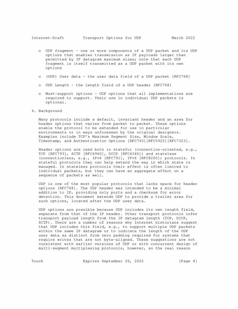
Internet-Draft Transport Options for UDP March 2022
o UDP fragment - one or more components of a UDP packet and its UDP options that enables transmission as IP payloads larger than permitted by IP datagram maximum sizes; note that each UDP fragment is itself transmitted as a UDP packet with its own options
o (UDP) User data - the user data field of a UDP packet [RFC768]
o UDP Length - the length field of a UDP header [RFC768]
o Must-support options - UDP options that all implementations are required to support. Their use in individual UDP packets is optional.
4. Background
Many protocols include a default, invariant header and an area for header options that varies from packet to packet. These options enable the protocol to be extended for use in particular environments or in ways unforeseen by the original designers. Examples include TCP’s Maximum Segment Size, Window Scale, Timestamp, and Authentication Options [RFC793][RFC5925][RFC7323].
Header options are used both in stateful (connection-oriented, e.g., TCP [RFC793], SCTP [RFC4960], DCCP [RFC4340]) and stateless (connectionless, e.g., IPv4 [RFC791], IPv6 [RFC8200]) protocols. In stateful protocols they can help extend the way in which state is managed. In stateless protocols their effect is often limited to individual packets, but they can have an aggregate effect on a sequence of packets as well.
UDP is one of the most popular protocols that lacks space for header options [RFC768]. The UDP header was intended to be a minimal addition to IP, providing only ports and a checksum for error detection. This document extends UDP to provide a trailer area for such options, located after the UDP user data.
UDP options are possible because UDP includes its own length field, separate from that of the IP header. Other transport protocols infer transport payload length from the IP datagram length (TCP, DCCP, SCTP). There are a number of reasons why Internet historians suggest that UDP includes this field, e.g., to support multiple UDP packets within the same IP datagram or to indicate the length of the UDP user data as distinct from zero padding required for systems that require writes that are not byte-aligned. These suggestions are not consistent with earlier versions of UDP or with concurrent design of multi-segment multiplexing protocols, however, so the real reason
Touch Expires September 26, 2022 [Page 4]

Internet-Draft Transport Options for UDP March 2022
remains unknown. Regardless, this field presents an opportunity to differentiate the UDP user data from the implied transport payload length, which this document leverages to support a trailer options field.
There are other ways to include additional header fields or options in protocols that otherwise are not extensible. In particular, in- band encoding can be used to differentiate transport payload from additional fields, such as was proposed in [Hi15]. This approach can cause complications for interactions with legacy devices, and is thus not considered further in this document.
IPv6 Teredo [RFC6081] uses values of the UDP Length that are larger than the IP payload as an additional type of signal, as noted in Section 20. UDP options uses a value smaller than the IP payload to enable backwards compatibility with existing UDP implementations, i.e., to deliver the UDP Length of UDP user data to the application and silently ignore the additional surplus area data. Using a value larger than the IP payload could either be considered malformed (and ought to be silently dropped by UDP processing) or could cause buffer overruns, and so is not considered silently and safely backward compatible.
5. The UDP Option Area
The UDP transport header includes demultiplexing and service identification (port numbers), an error detection checksum, and a field that indicates the UDP datagram length (including UDP header). The UDP Length field is typically redundant with the size of the maximum space available as a transport protocol payload, as determined by the IP header (see detail in Section 16). The UDP Option area is created when the UDP Length indicates a smaller transport payload than implied by the IP header.
For IPv4, IP Total Length field indicates the total IP datagram length (including IP header) and the size of the IP options is indicated in the IP header (in 4-byte words) as the "Internet Header Length" (IHL), as shown in Figure 1 [RFC791]. As a result, the typical (and largest valid) value for UDP Length is:
UDP_Length = IPv4_Total_Length - IPv4_IHL * 4
Touch Expires September 26, 2022 [Page 5]
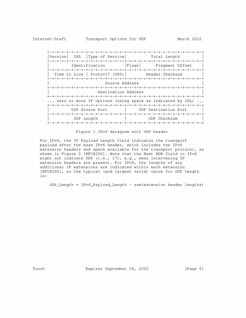
Internet-Draft Transport Options for UDP March 2022
+-+-+-+-+-+-+-+-+-+-+-+-+-+-+-+-+-+-+-+-+-+-+-+-+-+-+-+-+-+-+-+-+ |Version| IHL |Type of Service| Total Length | +-+-+-+-+-+-+-+-+-+-+-+-+-+-+-+-+-+-+-+-+-+-+-+-+-+-+-+-+-+-+-+-+ | Identification |Flags| Fragment Offset | +-+-+-+-+-+-+-+-+-+-+-+-+-+-+-+-+-+-+-+-+-+-+-+-+-+-+-+-+-+-+-+-+ | Time to Live | Proto=17 (UDP)| Header Checksum | +-+-+-+-+-+-+-+-+-+-+-+-+-+-+-+-+-+-+-+-+-+-+-+-+-+-+-+-+-+-+-+-+ | Source Address | +-+-+-+-+-+-+-+-+-+-+-+-+-+-+-+-+-+-+-+-+-+-+-+-+-+-+-+-+-+-+-+-+ | Destination Address | +-+-+-+-+-+-+-+-+-+-+-+-+-+-+-+-+-+-+-+-+-+-+-+-+-+-+-+-+-+-+-+-+ ... zero or more IP Options (using space as indicated by IHL) ... +-+-+-+-+-+-+-+-+-+-+-+-+-+-+-+-+-+-+-+-+-+-+-+-+-+-+-+-+-+-+-+-+ | UDP Source Port | UDP Destination Port | +-+-+-+-+-+-+-+-+-+-+-+-+-+-+-+-+-+-+-+-+-+-+-+-+-+-+-+-+-+-+-+-+ | UDP Length | UDP Checksum | +-+-+-+-+-+-+-+-+-+-+-+-+-+-+-+-+-+-+-+-+-+-+-+-+-+-+-+-+-+-+-+-+
Figure 1 IPv4 datagram with UDP header
For IPv6, the IP Payload Length field indicates the transport payload after the base IPv6 header, which includes the IPv6 extension headers and space available for the transport protocol, as shown in Figure 2 [RFC8200]. Note that the Next HDR field in IPv6 might not indicate UDP (i.e., 17), e.g., when intervening IP extension headers are present. For IPv6, the lengths of any additional IP extensions are indicated within each extension [RFC8200], so the typical (and largest valid) value for UDP Length is:
UDP_Length = IPv6_Payload_Length - sum(extension header lengths)
Touch Expires September 26, 2022 [Page 6]
Internet-Draft Transport Options for UDP March 2022
+-+-+-+-+-+-+-+-+-+-+-+-+-+-+-+-+-+-+-+-+-+-+-+-+-+-+-+-+-+-+-+-+ |Version| Traffic Class | Flow Label | +-+-+-+-+-+-+-+-+-+-+-+-+-+-+-+-+-+-+-+-+-+-+-+-+-+-+-+-+-+-+-+-+ | Payload Length | Next Hdr | Hop Limit | +-+-+-+-+-+-+-+-+-+-+-+-+-+-+-+-+-+-+-+-+-+-+-+-+-+-+-+-+-+-+-+-+ ... | Source Address (128 bits) | ... +-+-+-+-+-+-+-+-+-+-+-+-+-+-+-+-+-+-+-+-+-+-+-+-+-+-+-+-+-+-+-+-+ ... | Destination Address (128 bits) | ... +-+-+-+-+-+-+-+-+-+-+-+-+-+-+-+-+-+-+-+-+-+-+-+-+-+-+-+-+-+-+-+-+ ... zero or more IP Extension headers (each indicating size) ... +-+-+-+-+-+-+-+-+-+-+-+-+-+-+-+-+-+-+-+-+-+-+-+-+-+-+-+-+-+-+-+-+ | UDP Source Port | UDP Destination Port | +-+-+-+-+-+-+-+-+-+-+-+-+-+-+-+-+-+-+-+-+-+-+-+-+-+-+-+-+-+-+-+-+ | UDP Length | UDP Checksum | +-+-+-+-+-+-+-+-+-+-+-+-+-+-+-+-+-+-+-+-+-+-+-+-+-+-+-+-+-+-+-+-+
Figure 2 IPv6 datagram with UDP header
In both cases, the space available for the UDP packet is indicated by IP, either directly in the base header (for IPv4) or by adding information in the extensions (for IPv6). In either case, this document will refer to this available space as the "IP transport payload".
As a result of this redundancy, there is an opportunity to use the UDP Length field as a way to break up the IP transport payload into two areas - that intended as UDP user data and an additional "surplus area" (as shown in Figure 3).
IP transport payload <-------------------------------------------------> +--------+---------+----------------------+------------------+ | IP Hdr | UDP Hdr | UDP user data | surplus area | +--------+---------+----------------------+------------------+ <------------------------------> UDP Length
Figure 3 IP transport payload vs. UDP Length
In most cases, the IP transport payload and UDP Length point to the same location, indicating that there is no surplus area. This is not
Touch Expires September 26, 2022 [Page 7]

Internet-Draft Transport Options for UDP March 2022
a requirement of UDP [RFC768] (discussed further in Section 16). This document uses the surplus area for UDP options.
The surplus area can commence at any valid byte offset, i.e., it need not be 16-bit or 32-bit aligned. In effect, this document redefines the UDP "Length" field as a "trailer options offset".
6. The UDP Surplus Area Structure
UDP options use the entire surplus area, i.e., the contents of the IP payload after the last byte of the UDP payload. They commence with a 2-byte Option Checksum (OCS) field aligned to the first 2- byte boundary (relative to the start of the IP datagram) of that area, using zeroes for alignment. The UDP option area can be used with any UDP payload length (including zero), as long as there remains enough space for the aligned OCS and the options used.
>> UDP options MAY begin at any UDP length offset.
>> Option area bytes used for alignment before the OCS MUST be zero.
The OCS contains an optional ones-complement sum that detects errors in the surplus area, which is not otherwise covered by the UDP checksum, as detailed in Section 7.
The remainder of the surplus area consists of options defined using a TLV (type, length, and optional value) syntax similar to that of TCP [RFC793], as detailed in Section 8. These options continue until the end of the surplus area or can end earlier using the EOL (end of list) option, followed by zeroes.
7. The Option Checksum (OCS)
The Option Checksum (OCS) option is conventional Internet checksum [RFC791] that detects errors in the surplus area. The OCS option contains a 16-bit checksum that is aligned to the first 2-byte boundary, preceded by zeroes for padding (if needed), as shown in Figure 4.
+--------+--------+--------+--------+ | UDP data | 0 | +--------+--------+--------+--------+ | OCS | UDP options... | +--------+--------+--------+--------+
Figure 4 UDP OCS format, here using one zero for alignment
Touch Expires September 26, 2022 [Page 8]

Internet-Draft Transport Options for UDP March 2022
The OCS consists of a 16-bit Internet checksum [RFC1071], computed over the surplus area and including the length of the surplus area as an unsigned 16-bit value. The OCS protects the surplus area from errors in a similar way that the UDP checksum protects the UDP user data (when not zero).
The primary purpose of the OCS is to detect non-standard (i.e., non- option) uses of that area and accidental errors. It is not intended to detect attacks, as discussed further in Section 22.
The design enables traversal of errant middleboxes that incorrectly compute the UDP checksum over the entire IP payload [Fa18], rather than only the UDP header and UDP payload (as indicated by the UDP header length). Because the OCS is computed over the surplus area and its length and then inverted, OCS effectively negates the effect that incorrectly including the surplus has on the UDP checksum. As a result, when OCS is non-zero, the UDP checksum is the same in either case.
>> OCS MUST be non-zero when the UDP checksum is non-zero.
>> When the UDP checksum is zero, the OCS MAY be unused, and is then indicated by a zero OCS value.
Like the UDP checksum, the OCS is optional under certain circumstances and contains zero when not used. UDP checksums can be zero for IPv4 [RFC791] and for IPv6 [RFC8200] when UDP payload already covered by another checksum, as might occur for tunnels [RFC6935]. The same exceptions apply to the OCS when used to detect bit errors; an additional exception occurs for its use in the UDP datagram prior to fragmentation or after reassembly (see Section 9.4).
The OCS covers the surplus area as formatted for transmission and is processed immediately upon reception.
>> If the OCS fails, all options MUST be ignored and the surplus area silently discarded.
>> UDP user data that is validated by a correct UDP checksum MUST be delivered to the application layer, even if the OCS fails, unless the endpoints have negotiated otherwise for this UDP packet’s socket pair.
When not used (i.e., containing zero), the OCS is assumed to be "correct" for the purpose of accepting UDP datagrams at a receiver (see Section 12).
Touch Expires September 26, 2022 [Page 9]
Internet-Draft Transport Options for UDP March 2022
8. UDP Options
UDP options are typically a minimum of two bytes in length as shown in Figure 5, excepting only the one byte options "No Operation" (NOP) and "End of Options List" (EOL) described below.
+--------+--------+------- | Kind | Length | (remainder of option...) +--------+--------+-------
Figure 5 UDP option default format
The Kind field is always one byte. The Length field is one byte for all lengths below 255 (including the Kind and Length bytes). A Length of 255 indicates use of the UDP option extended format shown in Figure 6. The Extended Length field is a 16-bit field in network standard byte order.
+--------+--------+--------+--------+ | Kind | 255 | Extended Length | +--------+--------+--------+--------+ | (remainder of option...) +--------+--------+--------+--------+
Figure 6 UDP option extended format
>> The UDP length MUST be at least as large as the UDP header (8) and no larger than the IP transport payload. Datagrams with length values outside this range MUST be silently dropped as invalid and logged where rate-limiting permits.
>> Option Lengths (or Extended Lengths, where applicable) smaller than the minimum for the corresponding Kind MUST be treated as an error. Such errors call into question the remainder of the surplus area and thus MUST result in all UDP options being silently discarded.
>> Any UDP option other than EOL and NOP MAY use either the default or extended option formats.
>> Any UDP option whose length is larger than 254 MUST use the UDP option extended format shown in Figure 6.
>> For compactness, UDP options SHOULD use the smallest option format possible.
Touch Expires September 26, 2022 [Page 10]

Internet-Draft Transport Options for UDP March 2022
>> UDP options MUST be interpreted in the order in which they occur in the surplus area.
The following UDP options are currently defined:
Kind Length Meaning ---------------------------------------------- 0* - End of Options List (EOL) 1* - No operation (NOP) 2* 6 Alternate payload checksum (APC) 3* 10/12 Fragmentation (FRAG) 4* 4 Maximum datagram size (MDS) 5* 4 Maximum reassembled datagram size (MRDS) 6* 6 Request (REQ) 7* 6 Response (RES) 8 10 Timestamps (TIME) 9 (varies) Authentication (AUTH) 10-126 (varies) UNASSIGNED (assignable by IANA) 127 (varies) RFC 3692-style experiments (EXP) 128-191 RESERVED
192 (varies) Encryption (UENC) 193-253 UNASSIGNED-UNSAFE (assignable by IANA) 254 (varies) RFC 3692-style experiments (UEXP) 255 RESERVED
Options indicated by Kind values in the range 0..127 are known as SAFE options because they do not alter the UDP data payload and thus do not interfere with use of that data by legacy endpoints. Options indicated by Kind values in the range 192..254 are known as UNSAFE options because they do alter the UDP data payload and thus would interfere with legacy endpoints. UNSAFE option nicknames are expected to begin with "U", which should be avoided for safe option nicknames (see Section 23). Kind values 128-191 and 255 are RESERVED and not otherwise defined at this time.
>> RESERVED Kind values MUST NOT be assumed to be either SAFE nor UNSAFE until defined.
Although the FRAG option modifies the original UDP payload contents (i.e., is UNSAFE with respect to the original UDP payload), it is used only in subsequent fragments with zero UDP payloads, thus is SAFE in actual use, as discussed further in Section 9.4.
These options are defined in the following subsections. Options 0 and 1 use the same values as for TCP.
Touch Expires September 26, 2022 [Page 11]

Internet-Draft Transport Options for UDP March 2022
>> An endpoint supporting UDP options MUST support those marked with a "*" above: EOL, NOP, APC, FRAG, MDS, MRDS, REQ, and RES. This includes both recognizing and being able to generate these options if configured to do so. These are called "must-support" options.
>> An endpoint supporting UDP options MUST treat unsupported options in the UNSAFE range as terminating all option processing.
>> All other SAFE options (without a "*") MAY be implemented, and their use SHOULD be determined either out-of-band or negotiated, notably if needed to detect when options are silently ignored by legacy receivers.
>> Receivers supporting UDP options MUST silently ignore unknown SAFE options (i.e., in the same way a legacy receiver would). That includes options whose length does not indicate the specified value(s), as long as the length is not inherently invalid (i.e., smaller than 2 for the default and 4 for the extended formats).
>> UNSAFE options are used only in with the FRAG option, in a manner that prevents them from being silently ignored but passing the UDP payload to the user when not supported. This ensures their safe use in environments that might include legacy receivers (See Section 10).
>> Receivers supporting UDP options MUST silently drop all UDP options in a datagram containing an UNSAFE option when any UNSAFE option it contains is unknown. See Section 10 for further discussion of UNSAFE options.
>> Except for NOP, EXP, and UEXP, each option SHOULD NOT occur more than once in a single UDP datagram. If an option other than these occurs more than once, a receiver MUST interpret only the first instance of that option and MUST ignore all others.
>> EXP and UEXP MAY occur more than once, but SHOULD NOT occur more than once using the same ExID (see Sections 9.10 and 10.2).
>> Only the OCS and the AUTH and UENC options depend on the contents of the surplus area. AUTH and UENC are never used together, as UENC would serve both purposes. AUTH and UENC are always computed as if their hash and the OCS are zero; the OCS is always computed as if its contents are zero and after the AUTH or UENC hash has been computed. Future options MUST NOT be defined as having a value dependent on the contents of the surplus area. Otherwise, interactions between those values, the OCS, and the AUTH and UENC options could be unpredictable.
Touch Expires September 26, 2022 [Page 12]

Internet-Draft Transport Options for UDP March 2022
Receivers cannot generally treat unexpected option lengths as invalid, as this would unnecessarily limit future revision of options (e.g., defining a new APC that is defined by having a different length). The exception is only for lengths that imply a physical impossibility, e.g., smaller than two for conventional options and four for extended length options. Impossible lengths should indicate a malformed surplus area and all options silently discarded. Lengths other than those expected should result in safe options being ignored and skipped over, as with any other unknown safe option.
>> Option lengths MUST NOT exceed the IP length of the overall IP datagram. If this occurs, the options MUST be treated as malformed and all options dropped, and the event MAY be logged for diagnostics (logging SHOULD be rate limited).
>> "Must-support" options other than NOP and EOL MUST come before other options.
The requirement that must-support options come before others is intended to allow for endpoints to implement DOS protection, as discussed further in Section 22.
9. Safe UDP Options
Safe UDP options can be silently ignored by legacy receivers without affecting the meaning of the UDP user data. They stand in contrast to Unsafe options, which modify UDP user data in ways that render it unusable by legacy receivers (Section 10). The following subsections describe safe options defined in this document.
9.1. End of Options List (EOL)
The End of Options List (EOL, Kind=0) option indicates that there are no more options. It is used to indicate the end of the list of options without needing to use NOP options (see the following section) as padding to fill all available option space.
+--------+ | Kind=0 | +--------+
Figure 7 UDP EOL option format
>> When the UDP options do not consume the entire surplus area, the last non-NOP option MUST be EOL.
Touch Expires September 26, 2022 [Page 13]
Internet-Draft Transport Options for UDP March 2022
>> NOPs SHOULD NOT be used as padding before the EOL option. As a one byte option, it need not be otherwise aligned.
>> All bytes in the surplus area after EOL MUST be set to zero on transmit.
>> Bytes after EOL in the surplus area MAY be checked as being zero on receipt but MUST be treated as zero regardless of their content and are not passed to the user (e.g., as part of the surplus area).
Requiring the post-option surplus area to be zero prevents side- channel uses of this area, requiring instead that all use of the surplus area be UDP options supported by both endpoints. It is useful to allow this area to be used for zero padding to increase the UDP datagram length without affecting the UDP user data length, e.g., for UDP DPLPMTUD (Section 4.1 of [Fa22]).
9.2. No Operation (NOP)
The No Operation (NOP, Kind=1) option is a one-byte placeholder, intended to be used as padding, e.g., to align multi-byte options along 16-bit, 32-bit, or 64-bit boundaries.
+--------+ | Kind=1 | +--------+
Figure 8 UDP NOP option format
>> UDP packets SHOULD NOT use more than seven consecutive NOPs, i.e., to support alignment up to 8-byte boundaries. UDP packets SHOULD NOT use NOPs at the end of the options area as a substitute for EOL followed by zero-fill. NOPs are intended to assist with alignment, not as other padding or fill.
This issue is discussed further in Section 22.
9.3. Alternate Payload Checksum (APC)
The Alternate Payload Checksum (APC, Kind=2) option provides a stronger alternative to the checksum in the UDP header, using a 32- bit CRC of the conventional UDP user data payload only (excluding the IP pseudoheader, UDP header, and surplus area). It is an "alternate" to the UDP checksum that covers the user data - not to the OCS (the latter covers the surplus area only). Unlike the UDP checksum, APC does not include the IP pseudoheader or UDP header, thus it does not need to be updated by NATs when IP addresses or UDP
Touch Expires September 26, 2022 [Page 14]
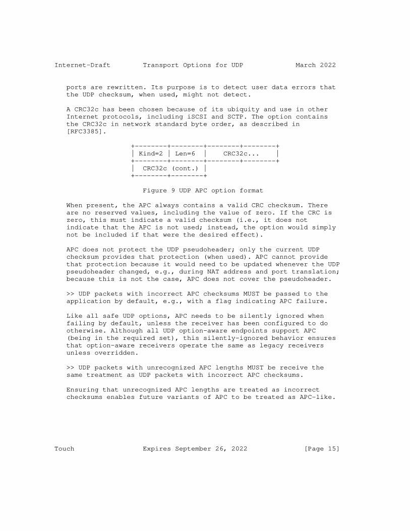
Internet-Draft Transport Options for UDP March 2022
ports are rewritten. Its purpose is to detect user data errors that the UDP checksum, when used, might not detect.
A CRC32c has been chosen because of its ubiquity and use in other Internet protocols, including iSCSI and SCTP. The option contains the CRC32c in network standard byte order, as described in [RFC3385].
+--------+--------+--------+--------+ | Kind=2 | Len=6 | CRC32c... | +--------+--------+--------+--------+ | CRC32c (cont.) | +--------+--------+
Figure 9 UDP APC option format
When present, the APC always contains a valid CRC checksum. There are no reserved values, including the value of zero. If the CRC is zero, this must indicate a valid checksum (i.e., it does not indicate that the APC is not used; instead, the option would simply not be included if that were the desired effect).
APC does not protect the UDP pseudoheader; only the current UDP checksum provides that protection (when used). APC cannot provide that protection because it would need to be updated whenever the UDP pseudoheader changed, e.g., during NAT address and port translation; because this is not the case, APC does not cover the pseudoheader.
>> UDP packets with incorrect APC checksums MUST be passed to the application by default, e.g., with a flag indicating APC failure.
Like all safe UDP options, APC needs to be silently ignored when failing by default, unless the receiver has been configured to do otherwise. Although all UDP option-aware endpoints support APC (being in the required set), this silently-ignored behavior ensures that option-aware receivers operate the same as legacy receivers unless overridden.
>> UDP packets with unrecognized APC lengths MUST be receive the same treatment as UDP packets with incorrect APC checksums.
Ensuring that unrecognized APC lengths are treated as incorrect checksums enables future variants of APC to be treated as APC-like.
Touch Expires September 26, 2022 [Page 15]
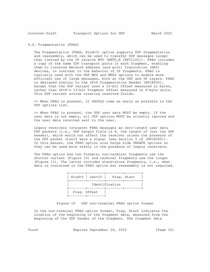
Internet-Draft Transport Options for UDP March 2022
9.4. Fragmentation (FRAG)
The Fragmentation (FRAG, Kind=3) option supports UDP fragmentation and reassembly, which can be used to transfer UDP messages larger than limited by the IP receive MTU (EMTU_R [RFC1122]). FRAG includes a copy of the same UDP transport ports in each fragment, enabling them to traverse Network Address (and port) Translation (NAT) devices, in contrast to the behavior of IP fragments. FRAG is typically used with the UDP MDS and MRDS options to enable more efficient use of large messages, both at the UDP and IP layers. FRAG is designed similar to the IPv6 Fragmentation Header [RFC8200], except that the UDP variant uses a 16-bit Offset measured in bytes, rather than IPv6’s 13-bit Fragment Offset measured in 8-byte units. This UDP variant avoids creating reserved fields.
>> When FRAG is present, it SHOULD come as early as possible in the UDP options list.
>> When FRAG is present, the UDP user data MUST be empty. If the user data is not empty, all UDP options MUST be silently ignored and the user data received sent to the user.
Legacy receivers interpret FRAG messages as zero-length user data UDP packets (i.e., UDP Length field is 8, the length of just the UDP header), which would not affect the receiver unless the presence of the UDP packet itself were a signal (see Section 5 of [RFC8085]). In this manner, the FRAG option also helps hide UNSAFE options so they can be used more safely in the presence of legacy receivers.
The FRAG option has two formats; non-terminal fragments use the shorter variant (Figure 10) and terminal fragments use the longer (Figure 11). The latter includes stand-alone fragments, i.e., when data is contained in the FRAG option but reassembly is not required.
+--------+--------+--------+--------+ | Kind=3 | Len=10 | Frag. Start | +--------+--------+--------+--------+ | Identification | +--------+--------+--------+--------+ | Frag. Offset | +--------+--------+
Figure 10 UDP non-terminal FRAG option format
In the non-terminal FRAG option format, Frag. Start indicates the location of the beginning of the fragment data, measured from the beginning of the UDP header of the fragment. The fragment data
Touch Expires September 26, 2022 [Page 16]
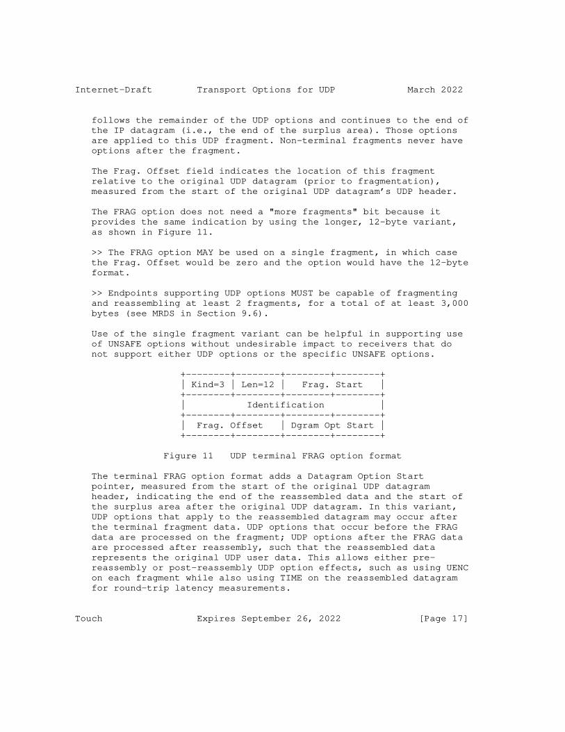
Internet-Draft Transport Options for UDP March 2022
follows the remainder of the UDP options and continues to the end of the IP datagram (i.e., the end of the surplus area). Those options are applied to this UDP fragment. Non-terminal fragments never have options after the fragment.
The Frag. Offset field indicates the location of this fragment relative to the original UDP datagram (prior to fragmentation), measured from the start of the original UDP datagram’s UDP header.
The FRAG option does not need a "more fragments" bit because it provides the same indication by using the longer, 12-byte variant, as shown in Figure 11.
>> The FRAG option MAY be used on a single fragment, in which case the Frag. Offset would be zero and the option would have the 12-byte format.
>> Endpoints supporting UDP options MUST be capable of fragmenting and reassembling at least 2 fragments, for a total of at least 3,000 bytes (see MRDS in Section 9.6).
Use of the single fragment variant can be helpful in supporting use of UNSAFE options without undesirable impact to receivers that do not support either UDP options or the specific UNSAFE options.
+--------+--------+--------+--------+ | Kind=3 | Len=12 | Frag. Start | +--------+--------+--------+--------+ | Identification | +--------+--------+--------+--------+ | Frag. Offset | Dgram Opt Start | +--------+--------+--------+--------+
Figure 11 UDP terminal FRAG option format
The terminal FRAG option format adds a Datagram Option Start pointer, measured from the start of the original UDP datagram header, indicating the end of the reassembled data and the start of the surplus area after the original UDP datagram. In this variant, UDP options that apply to the reassembled datagram may occur after the terminal fragment data. UDP options that occur before the FRAG data are processed on the fragment; UDP options after the FRAG data are processed after reassembly, such that the reassembled data represents the original UDP user data. This allows either pre- reassembly or post-reassembly UDP option effects, such as using UENC on each fragment while also using TIME on the reassembled datagram for round-trip latency measurements.
Touch Expires September 26, 2022 [Page 17]

Internet-Draft Transport Options for UDP March 2022
>> During fragmentation, the UDP header checksum of each fragment remains constant and does not depend on the fragment data (which appears in the surplus area), because all fragments have a zero- length user data field.
The Fragment Offset is 16 bits and indicates the location of the UDP payload fragment in bytes from the beginning of the original unfragmented payload. The option Len field indicates whether there are more fragments (Len=10) or no more fragments (Len=12).
>> The Identification field is a 32-bit value that MUST be unique over the expected fragment reassembly timeout.
>> The Identification field SHOULD be generated in a manner similar to that of the IPv6 Fragment ID [RFC8200].
>> UDP fragments MUST NOT overlap.
Similar to IPv6 reassembly [RFC8200], if any of the fragments being reassembled overlap with any other fragments being reassembled for the same UDP packet, reassembly of that UDP packet must be abandoned and all the fragments that have been received for that UDP packet must be discarded, and no ICMP error messages should be sent.
It should be noted that fragments may be duplicated in the network. Instead of treating these exact duplicate fragments as overlapping fragments, an implementation may choose to detect this case and drop exact duplicate fragments while keeping the other fragments belonging to the same UDP packet.
UDP fragmentation relies on a fragment expiration timer, which can be preset or could use a value computed using the UDP Timestamp option.
>> The default UDP reassembly SHOULD be no more than 2 minutes.
>> UDP reassembly space SHOULD be limited to reduce the impact of DOS attacks on resource use.
>> UDP reassembly space limits SHOULD NOT be computed as a shared resource across multiple sockets, to avoid cross-socketpair DOS attacks.
>> Individual UDP fragments MUST NOT be forwarded to the user. The reassembled datagram is received only after complete reassembly, checksum validation, and continued processing of the remaining UDP options.
Touch Expires September 26, 2022 [Page 18]

Internet-Draft Transport Options for UDP March 2022
Any per-datagram UDP options, if used, follow the FRAG option in the final fragment and would be included in the reassembled UDP packet. Processing of those options would commence after reassembly. This is especially important for UNSAFE options, which are interpreted only after FRAG.
In general, UDP packets are fragmented as follows:
1. Create a UDP packet with data and UDP options, which we will call "D". Note that the UDP options treat the data area as UDP user data and thus must follow that data.
Process these UDP options before the rest of the fragmentation steps below. Note that the OCS value of the original packet SHOULD be zero if each fragment will have a non-zero OCS value (as will be the case if the UDP checksum is non-zero).
2. Identify the desired fragment size, which we will call "S". This value should take into account the path MTU (if known) and allow space for per-fragment options.
3. Fragment "D" into chunks of size no larger than "S"-10 each, with one final chunk no larger than "S"-12. Note that all the non-FRAG options in step #1 need not be limited to the terminal fragment, i.e., the Dgram Opt. Start pointer can indicate the start of the original surplus area anywhere in the reassembled data.
4. For each chunk of "D" in step #3, create a zero-data UDP packet followed by the word-aligned OCS, the FRAG option, and any additional UDP options, followed by the FRAG data chunk.
The last chunk includes the non-FRAG options noted in step #1 after the end of the FRAG data. These UDP options apply to the reassembled user data as a whole when received.
5. Process the pre-reassembly UDP options of each fragment.
Receivers reverse the above sequence. They process all received options in each fragment. When the FRAG option is encountered, the FRAG data is used in reassembly. After all fragments are received, the entire UDP packet is processed with any trailing UDP options applying to the reassembled user data.
9.5. Maximum Datagram Size (MDS)
The Maximum Datagram Size (MDS, Kind=4) option is a 16-bit hint of the largest unfragmented UDP packet that an endpoint believes can be
Touch Expires September 26, 2022 [Page 19]

Internet-Draft Transport Options for UDP March 2022
received. As with the TCP Maximum Segment Size (MSS) option [RFC793], the size indicated is the IP layer MTU decreased by the fixed IP and UDP headers only [RFC6691]. The space needed for IP and UDP options need to be adjusted by the sender when using the value indicated. The value transmitted is based on EMTU_R, the largest IP datagram that can be received (i.e., reassembled at the receiver) [RFC1122]. However, as with TCP, this value is only a hint at what the receiver believes; it does not indicate a known path MTU and thus MUST NOT be used to limit transmissions.
+--------+--------+--------+--------+ | Kind=4 | Len=4 | MDS size | +--------+--------+--------+--------+
Figure 12 UDP MDS option format
The UDP MDS option MAY be used as a hint for path MTU discovery [RFC1191][RFC8201], but this may be difficult because of known issues with ICMP blocking [RFC2923] as well as UDP lacking automatic retransmission. It is more likely to be useful when coupled with IP source fragmentation or UDP fragmentation to limit the largest reassembled UDP message as indicated by MRDS (see Section 9.6), e.g., when EMTU_R is larger than the required minimums (576 for IPv4 [RFC791] and 1500 for IPv6 [RFC8200]). It can also be used with DPLPMTUD [RFC8899] to provide a hint to maximum DPLPMTU, though it MUST NOT prohibit transmission of larger UDP packets (or fragments) used as DPLPMTU probes.
9.6. Maximum Reassembled Datagram Size (MRDS)
The Maximum Reassembled Segment Size (MRDS, Kind=5) option is a 16- bit indicator of the largest reassembled UDP segment that can be received. MRDS is the UDP equivalent of IP’s EMTU_R but the two are not related [RFC1122]. Using the FRAG option (Section 9.4), UDP packets can be transmitted as transport fragments, each in their own (presumably not fragmented) IP datagram and be reassembled at the UDP layer.
+--------+--------+--------+--------+ | Kind=5 | Len=4 | MRDS size | +--------+--------+--------+--------+
Figure 13 UDP MRDS option format
>> Endpoints supporting UDP options MUST support a local MRDS of at least 3,000 bytes.
Touch Expires September 26, 2022 [Page 20]
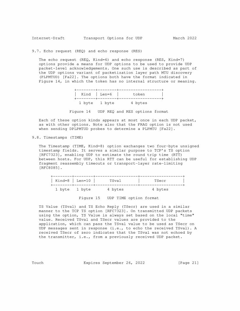
Internet-Draft Transport Options for UDP March 2022
9.7. Echo request (REQ) and echo response (RES)
The echo request (REQ, Kind=6) and echo response (RES, Kind=7) options provide a means for UDP options to be used to provide UDP packet-level acknowledgements. One such use is described as part of the UDP options variant of packetization layer path MTU discovery (PLPMTUD) [Fa22]. The options both have the format indicated in Figure 14, in which the token has no internal structure or meaning.
+--------+--------+------------------+ | Kind | Len=6 | token | +--------+--------+------------------+ 1 byte 1 byte 4 bytes
Figure 14 UDP REQ and RES options format
Each of these option kinds appears at most once in each UDP packet, as with other options. Note also that the FRAG option is not used when sending DPLPMTUD probes to determine a PLPMTU [Fa22].
9.8. Timestamps (TIME)
The Timestamp (TIME, Kind=8) option exchanges two four-byte unsigned timestamp fields. It serves a similar purpose to TCP’s TS option [RFC7323], enabling UDP to estimate the round trip time (RTT) between hosts. For UDP, this RTT can be useful for establishing UDP fragment reassembly timeouts or transport-layer rate-limiting [RFC8085].
+--------+--------+------------------+------------------+ | Kind=8 | Len=10 | TSval | TSecr | +--------+--------+------------------+------------------+ 1 byte 1 byte 4 bytes 4 bytes
Figure 15 UDP TIME option format
TS Value (TSval) and TS Echo Reply (TSecr) are used in a similar manner to the TCP TS option [RFC7323]. On transmitted UDP packets using the option, TS Value is always set based on the local "time" value. Received TSval and TSecr values are provided to the application, which can pass the TSval value to be used as TSecr on UDP messages sent in response (i.e., to echo the received TSval). A received TSecr of zero indicates that the TSval was not echoed by the transmitter, i.e., from a previously received UDP packet.
Touch Expires September 26, 2022 [Page 21]

Internet-Draft Transport Options for UDP March 2022
>> TIME MAY use an RTT estimate based on nonzero Timestamp values as a hint for fragmentation reassembly, rate limiting, or other mechanisms that benefit from such an estimate.
>> an application MAY use TIME to compute this RTT estimate for further use by the user.
UDP timestamps are modeled after TCP timestamps and have similar expectations. In particular, they are expected to be:
o Values are monotonic and non-decreasing except for anticipated number-space rollover events
o Values should "increase" (allowing for rollover) according to a typical ’tick’ time
o A request is defined as TSval being non-zero and a reply is defined as TSecr being non-zero.
o A receiver should always respond to a request with the highest TSval received (allowing for rollover), which is not necessarily the most recently received.
Rollover can be handled as a special case or more completely using sequence number extension [RFC9187], however zero values need to be avoided explicitly.
>> TIME values MUST NOT use zeros as valid time values, because they are used as indicators of requests and responses.
9.9. Authentication (AUTH)
The Authentication (AUTH, Kind=9) option is intended to allow UDP to provide a similar type of authentication as the TCP Authentication Option (TCP-AO) [RFC5925]. AUTH covers the UDP user data. AUTH supports NAT traversal in a similar manner as TCP-AO [RFC6978]. Figure 16 shows the UDP AUTH format, whose contents are identical to that of the TCP-AO option.
+--------+--------+--------+--------+ | Kind=9 | Len | TCP-AO fields...| +--------+--------+--------+--------+ | TCP-AO fields (con’t)... | +--------+--------+--------+--------+
Figure 16 UDP AUTH option format
Touch Expires September 26, 2022 [Page 22]
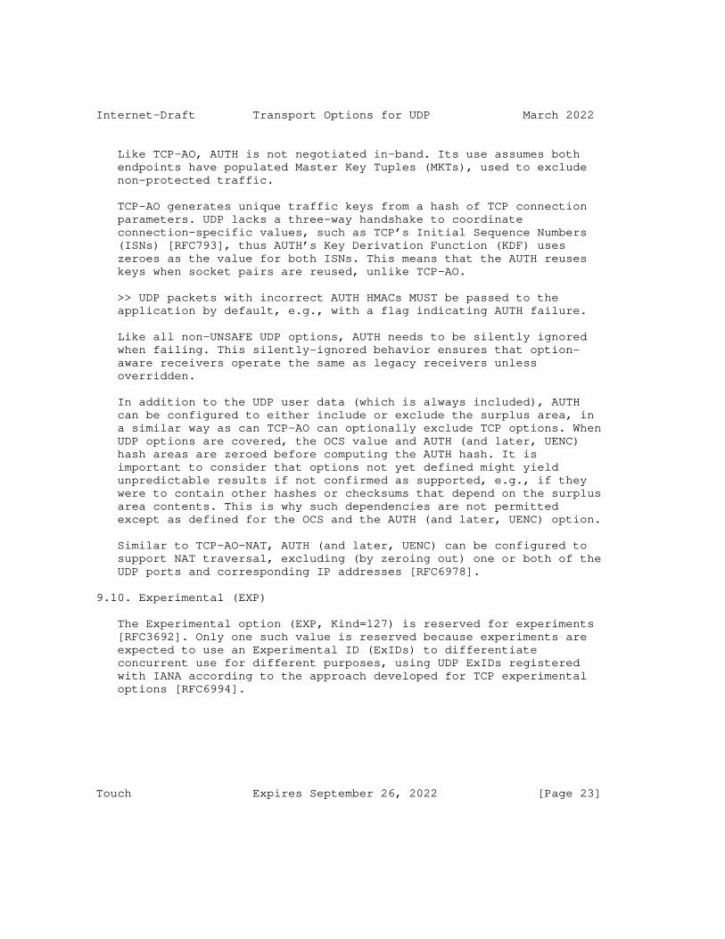
Internet-Draft Transport Options for UDP March 2022
Like TCP-AO, AUTH is not negotiated in-band. Its use assumes both endpoints have populated Master Key Tuples (MKTs), used to exclude non-protected traffic.
TCP-AO generates unique traffic keys from a hash of TCP connection parameters. UDP lacks a three-way handshake to coordinate connection-specific values, such as TCP’s Initial Sequence Numbers (ISNs) [RFC793], thus AUTH’s Key Derivation Function (KDF) uses zeroes as the value for both ISNs. This means that the AUTH reuses keys when socket pairs are reused, unlike TCP-AO.
>> UDP packets with incorrect AUTH HMACs MUST be passed to the application by default, e.g., with a flag indicating AUTH failure.
Like all non-UNSAFE UDP options, AUTH needs to be silently ignored when failing. This silently-ignored behavior ensures that option- aware receivers operate the same as legacy receivers unless overridden.
In addition to the UDP user data (which is always included), AUTH can be configured to either include or exclude the surplus area, in a similar way as can TCP-AO can optionally exclude TCP options. When UDP options are covered, the OCS value and AUTH (and later, UENC) hash areas are zeroed before computing the AUTH hash. It is important to consider that options not yet defined might yield unpredictable results if not confirmed as supported, e.g., if they were to contain other hashes or checksums that depend on the surplus area contents. This is why such dependencies are not permitted except as defined for the OCS and the AUTH (and later, UENC) option.
Similar to TCP-AO-NAT, AUTH (and later, UENC) can be configured to support NAT traversal, excluding (by zeroing out) one or both of the UDP ports and corresponding IP addresses [RFC6978].
9.10. Experimental (EXP)
The Experimental option (EXP, Kind=127) is reserved for experiments [RFC3692]. Only one such value is reserved because experiments are expected to use an Experimental ID (ExIDs) to differentiate concurrent use for different purposes, using UDP ExIDs registered with IANA according to the approach developed for TCP experimental options [RFC6994].
Touch Expires September 26, 2022 [Page 23]
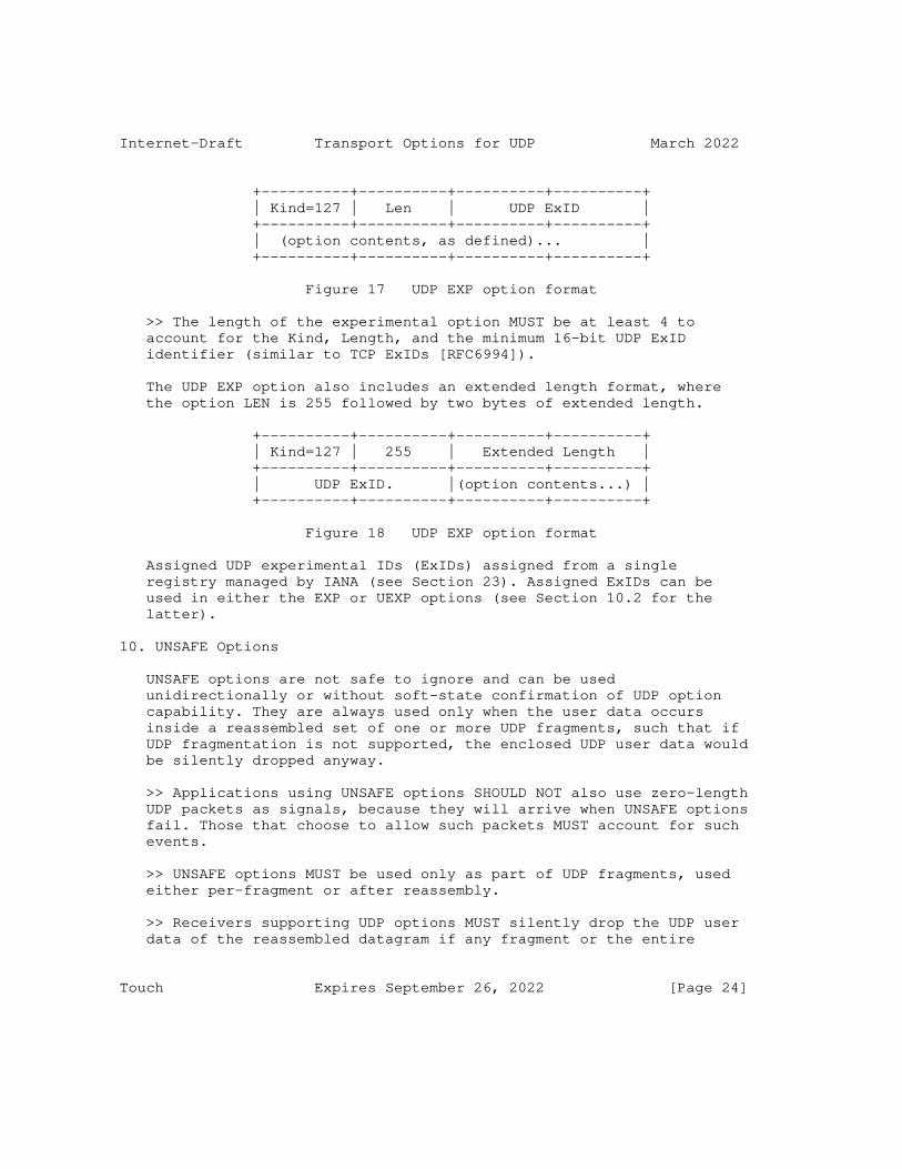
Internet-Draft Transport Options for UDP March 2022
+----------+----------+----------+----------+ | Kind=127 | Len | UDP ExID | +----------+----------+----------+----------+ | (option contents, as defined)... | +----------+----------+----------+----------+
Figure 17 UDP EXP option format
>> The length of the experimental option MUST be at least 4 to account for the Kind, Length, and the minimum 16-bit UDP ExID identifier (similar to TCP ExIDs [RFC6994]).
The UDP EXP option also includes an extended length format, where the option LEN is 255 followed by two bytes of extended length.
+----------+----------+----------+----------+ | Kind=127 | 255 | Extended Length | +----------+----------+----------+----------+ | UDP ExID. |(option contents...) | +----------+----------+----------+----------+
Figure 18 UDP EXP option format
Assigned UDP experimental IDs (ExIDs) assigned from a single registry managed by IANA (see Section 23). Assigned ExIDs can be used in either the EXP or UEXP options (see Section 10.2 for the latter).
10. UNSAFE Options
UNSAFE options are not safe to ignore and can be used unidirectionally or without soft-state confirmation of UDP option capability. They are always used only when the user data occurs inside a reassembled set of one or more UDP fragments, such that if UDP fragmentation is not supported, the enclosed UDP user data would be silently dropped anyway.
>> Applications using UNSAFE options SHOULD NOT also use zero-length UDP packets as signals, because they will arrive when UNSAFE options fail. Those that choose to allow such packets MUST account for such events.
>> UNSAFE options MUST be used only as part of UDP fragments, used either per-fragment or after reassembly.
>> Receivers supporting UDP options MUST silently drop the UDP user data of the reassembled datagram if any fragment or the entire
Touch Expires September 26, 2022 [Page 24]
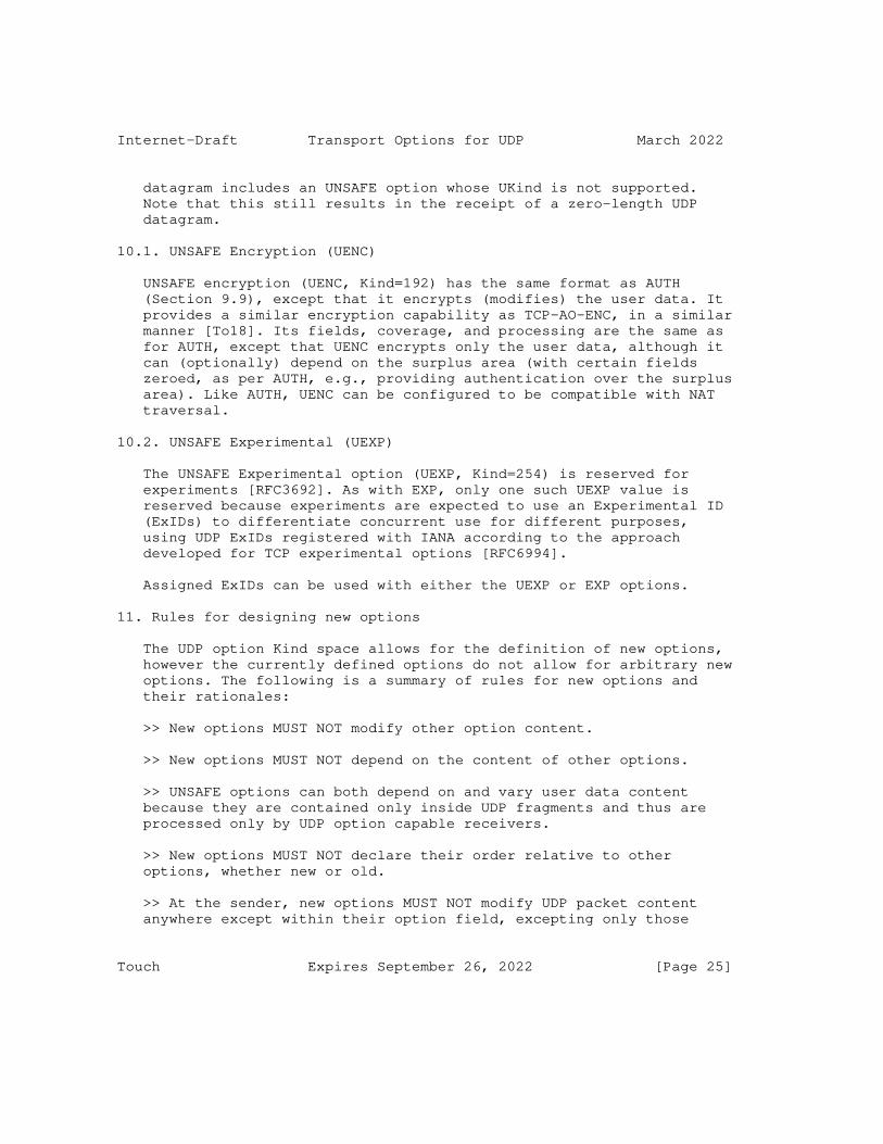
Internet-Draft Transport Options for UDP March 2022
datagram includes an UNSAFE option whose UKind is not supported. Note that this still results in the receipt of a zero-length UDP datagram.
10.1. UNSAFE Encryption (UENC)
UNSAFE encryption (UENC, Kind=192) has the same format as AUTH (Section 9.9), except that it encrypts (modifies) the user data. It provides a similar encryption capability as TCP-AO-ENC, in a similar manner [To18]. Its fields, coverage, and processing are the same as for AUTH, except that UENC encrypts only the user data, although it can (optionally) depend on the surplus area (with certain fields zeroed, as per AUTH, e.g., providing authentication over the surplus area). Like AUTH, UENC can be configured to be compatible with NAT traversal.
10.2. UNSAFE Experimental (UEXP)
The UNSAFE Experimental option (UEXP, Kind=254) is reserved for experiments [RFC3692]. As with EXP, only one such UEXP value is reserved because experiments are expected to use an Experimental ID (ExIDs) to differentiate concurrent use for different purposes, using UDP ExIDs registered with IANA according to the approach developed for TCP experimental options [RFC6994].
Assigned ExIDs can be used with either the UEXP or EXP options.
11. Rules for designing new options
The UDP option Kind space allows for the definition of new options, however the currently defined options do not allow for arbitrary new options. The following is a summary of rules for new options and their rationales:
>> New options MUST NOT modify other option content.
>> New options MUST NOT depend on the content of other options.
>> UNSAFE options can both depend on and vary user data content because they are contained only inside UDP fragments and thus are processed only by UDP option capable receivers.
>> New options MUST NOT declare their order relative to other options, whether new or old.
>> At the sender, new options MUST NOT modify UDP packet content anywhere except within their option field, excepting only those
Touch Expires September 26, 2022 [Page 25]
Internet-Draft Transport Options for UDP March 2022
contained within the UNSAFE option; areas that need to remain unmodified include the IP header, IP options, the UDP user data, and the surplus area (i.e., other options).
>> Options MUST NOT be modified in transit. This includes those already defined as well as new options.
>> New options MUST NOT require or intend optionally for modification of any UDP options, including their new areas, in transit.
Note that only certain of the initially defined options violate these rules:
o >> Only FRAG and UNSAFE options are permitted to modify the UDP body.
The following recommendation helps enable efficient zero-copy processing:
o >> FRAG SHOULD be the first option, when present.
12. Option inclusion and processing
The following rules apply to option inclusion by senders and processing by receivers.
>> Senders MAY add any option, as configured by the API.
>> All "must-support" options MUST be processed by receivers, if present (presuming UDP options are supported at that receiver).
>> Non-"must-support" options MAY be ignored by receivers, if present, e.g., based on API settings.
>> All options MUST be processed by receivers in the order encountered in the options area.
>> All options except UNSAFE options MUST result in the UDP user data being passed to the application layer, regardless of whether all options are processed, supported, or succeed.
The basic premise is that, for options-aware endpoints, the sender decides what options to add and the receiver decides what options to handle. Simply adding an option does not force work upon a receiver, with the exception of the "must-support" options.
Touch Expires September 26, 2022 [Page 26]

Internet-Draft Transport Options for UDP March 2022
Upon receipt, the receiver checks various properties of the UDP packet and its options to decide whether to accept or drop the UDP packet and whether to accept or ignore some its options as follows (in order):
if the UDP checksum fails then silently drop the entire UDP packet (per RFC1122) if the UDP checksum passes then if OCS != 0 and fails or is zero when UDP CS != 0 then deliver the UDP user data but ignore other options (this is required to emulate legacy behavior) if OCS is nonzero and passes or is zero then deliver the UDP user data after parsing and processing the rest of the options, regardless of whether each is supported or succeeds (again, this is required to emulate legacy behavior)
The design of the UNSAFE options as used only inside the FRAG area ensures that the resulting UDP data will be silently dropped in both legacy and options-aware receivers. Again, note that this still results in the delivery of a zero-length UDP packet.
Options-aware receivers can drop UDP packets with option processing errors via either an override of the default UDP processing or at the application layer.
I.e., all options are treated the same, in that the transmitter can add it as desired and the receiver has the option to require it or not. Only if it is required (e.g., by API configuration) should the receiver require it being present and correct.
I.e., for all options:
o if the option is not required by the receiver, then UDP packets missing the option are accepted.
o if the option is required (e.g., by override of the default behavior at the receiver) and missing or incorrectly formed, silently drop the UDP packet.
o if the UDP packet is accepted (either because the option is not required or because it was required and correct), then pass the option with the UDP packet via the API.
Touch Expires September 26, 2022 [Page 27]

Internet-Draft Transport Options for UDP March 2022
Any options whose length exceeds that of the UDP packet (i.e., intending to use data that would have been beyond the surplus area) should be silently ignored (again to model legacy behavior).
13. UDP API Extensions
UDP currently specifies an application programmer interface (API), summarized as follows (with Unix-style command as an example) [RFC768]:
o Method to create new receive ports
o E.g., bind(handle, recvaddr(optional), recvport)
o Receive, which returns data octets, source port, and source address
o E.g., recvfrom(handle, srcaddr, srcport, data)
o Send, which specifies data, source and destination addresses, and source and destination ports
o E.g., sendto(handle, destaddr, destport, data)
This API is extended to support options as follows:
o Extend the method to create receive ports to include per-packet and per-fragment receive options that are required as indicated by the application. Datagrams not containing these required options MUST be silently dropped and MAY be logged. This includes a minimum datagram length, such that the options list ends in EOL and additional space is zero-filled as needed.
o WG QUESTION: DO WE ALSO WANT A MIN FRAG SIZE? OR MAX?
o Extend the receive function to indicate the per-packet options and their parameters as received with the corresponding received datagram. Note that per-fragment options are handled within the processing of each fragment.
o WG QUESTION: SHOULD WE ACCUMULATE THOSE OPTIONS? OR DISCARD THEM?
o Extend the send function to indicate the options to be added to the corresponding sent datagram. This includes indicating which options apply to individual fragments vs. which apply to the UDP packet prior to fragmentation, if fragmentation is enabled.
Touch Expires September 26, 2022 [Page 28]
Internet-Draft Transport Options for UDP March 2022
Examples of API instances for Linux and FreeBSD are provided in Appendix A, to encourage uniform cross-platform implementations.
14. UDP Options are for Transport, Not Transit
UDP options are indicated in the surplus area of the IP payload that is not used by UDP. That area is really part of the IP payload, not the UDP payload, and as such, it might be tempting to consider whether this is a generally useful approach to extending IP.
Unfortunately, the surplus area exists only for transports that include their own transport layer payload length indicator. TCP and SCTP include header length fields that already provide space for transport options by indicating the total length of the header area, such that the entire remaining area indicated in the network layer (IP) is transport payload. UDP-Lite already uses the UDP Length field to indicate the boundary between data covered by the transport checksum and data not covered, and so there is no remaining area where the length of the UDP-Lite payload as a whole can be indicated [RFC3828].
UDP options are intended for use only by the transport endpoints. They are no more (or less) appropriate to be modified in-transit than any other portion of the transport datagram.
UDP options are transport options. Generally, transport headers, options, and data re not intended to be modified in-transit. UDP options are no exception and here are specified as "MUST NOT" be altered in transit. However, the UDP option mechanism provides no specific protection against in-transit modification of the UDP header, UDP payload, or surplus area, except as provided by the OCS or the options selected (e.g., AUTH, or UENC).
15. UDP options vs. UDP-Lite
UDP-Lite provides partial checksum coverage, so that UDP packets with errors in some locations can be delivered to the user [RFC3828]. It uses a different transport protocol number (136) than UDP (17) to interpret the UDP Length field as the prefix covered by the UDP checksum.
UDP (protocol 17) already defines the UDP Length field as the limit of the UDP checksum, but by default also limits the data provided to the application as that which precedes the UDP Length. A goal of UDP-Lite is to deliver data beyond UDP Length as a default, which is why a separate transport protocol number was required.
Touch Expires September 26, 2022 [Page 29]

Internet-Draft Transport Options for UDP March 2022
UDP options do not use or need a separate transport protocol number because the data beyond the UDP Length offset (surplus data) is not provided to the application by default. That data is interpreted exclusively within the UDP transport layer.
UDP-Lite cannot support UDP options, either as proposed here or in any other form, because the entire payload of the UDP packet is already defined as user data and there is no additional field in which to indicate a surplus area for options. The UDP Length field in UDP-Lite is already used to indicate the boundary between user data covered by the checksum and user data not covered.
16. Interactions with Legacy Devices
It has always been permissible for the UDP Length to be inconsistent with the IP transport payload length [RFC768]. Such inconsistency has been utilized in UDP-Lite using a different transport number. There are no known systems that use this inconsistency for UDP [RFC3828]. It is possible that such use might interact with UDP options, i.e., where legacy systems might generate UDP datagrams that appear to have UDP options. The OCS provides protection against such events and is stronger than a static "magic number".
UDP options have been tested as interoperable with Linux, macOS, and Windows Cygwin, and worked through NAT devices. These systems successfully delivered only the user data indicated by the UDP Length field and silently discarded the surplus area.
One reported embedded device passes the entire IP datagram to the UDP application layer. Although this feature could enable application-layer UDP option processing, it would require that conventional UDP user applications examine only the UDP user data. This feature is also inconsistent with the UDP application interface [RFC768] [RFC1122].
It has been reported that Alcatel-Lucent’s "Brick" Intrusion Detection System has a default configuration that interprets inconsistencies between UDP Length and IP Length as an attack to be reported. Note that other firewall systems, e.g., CheckPoint, use a default "relaxed UDP length verification" to avoid falsely interpreting this inconsistency as an attack.
17. Options in a Stateless, Unreliable Transport Protocol
There are two ways to interpret options for a stateless, unreliable protocol -- an option is either local to the message or intended to
Touch Expires September 26, 2022 [Page 30]
Internet-Draft Transport Options for UDP March 2022
affect a stream of messages in a soft-state manner. Either interpretation is valid for defined UDP options.
It is impossible to know in advance whether an endpoint supports a UDP option.
>> All UDP options other than UNSAFE ones MUST be ignored if not supported or upon failure (e.g., APC).
>> All UDP options that fail MUST result in the UDP data still being sent to the application layer by default, to ensure equivalence with legacy devices.
>> UDP options that rely on soft-state exchange MUST allow for message reordering and loss.
The above requirements prevent using any option that cannot be safely ignored unless it is hidden inside the FRAG area (i.e., UNSAFE options). Legacy systems also always need to be able to interpret the transport fragments as individual UDP packets.
18. UDP Option State Caching
Some TCP connection parameters, stored in the TCP Control Block, can be usefully shared either among concurrent connections or between connections in sequence, known as TCP Sharing [RFC9040]. Although UDP is stateless, some of the options proposed herein may have similar benefit in being shared or cached. We call this UCB Sharing, or UDP Control Block Sharing, by analogy. Just as TCB sharing is not a standard because it is consistent with existing TCP specifications, UCB sharing would be consistent with existing UDP specifications, including this one. Both are implementation issues that are outside the scope of their respective specifications, and so UCB sharing is outside the scope of this document.
19. Updates to RFC 768
This document updates RFC 768 as follows:
o This document defines the meaning of the IP payload area beyond the UDP length but within the IP length as the surplus area used herein for UDP options.
o This document extends the UDP API to support the use of UDP options.
Touch Expires September 26, 2022 [Page 31]

Internet-Draft Transport Options for UDP March 2022
20. Interactions with other RFCs (and drafts)
This document clarifies the interaction between UDP Length and IP length that is not explicitly constrained in either UDP or the host requirements [RFC768] [RFC1122].
Teredo extensions (TE) define use of a similar difference between these lengths for trailers [RFC6081]. TE defines the UDP length pointing beyond (larger) than the location indicated by the IP length rather than shorter (as used herein):
"..the IPv6 packet length (i.e., the Payload Length value in the IPv6 header plus the IPv6 header size) is less than or equal to the UDP payload length (i.e., the Length value in the UDP header minus the UDP header size)"
As a result, UDP options are not compatible with TE, but that is also why this document does not update TE. Additionally, it is not at all clear how TE operates, as it requires network processing of the UDP length field to understand the total message including TE trailers.
TE updates Teredo NAT traversal [RFC4380]. The NAT traversal document defined "consistency" of UDP length and IP length as:
"An IPv6 packet is deemed valid if it conforms to [RFC2460]: the protocol identifier should indicate an IPv6 packet and the payload length should be consistent with the length of the UDP datagram in which the packet is encapsulated."
IPv6 is clear on the meaning of this consistency, in which the pseudoheader used for UDP checksums is based on the UDP length, not inferred from the IP length, using the same text in the current specification [RFC8200]:
"The Upper-Layer Packet Length in the pseudo-header is the length of the upper-layer header and data (e.g., TCP header plus TCP data). Some upper-layer protocols carry their own length information (e.g., the Length field in the UDP header); for such protocols, that is the length used in the pseudo- header."
This document is consistent the UDP profile for Robust Header Compression (ROHC)[RFC3095], noted here:
"The Length field of the UDP header MUST match the Length field(s) of the preceding subheaders, i.e., there must not
Touch Expires September 26, 2022 [Page 32]
Internet-Draft Transport Options for UDP March 2022
be any padding after the UDP payload that is covered by the IP Length."
ROHC compresses UDP headers only when this match succeeds. It does not prohibit UDP headers where the match fails; in those cases, ROHC default rules (Section 5.10) would cause the UDP header to remain uncompressed. Upon receipt of a compressed UDP header, Section A.1.3 of that document indicates that the UDP length is "INFERRED"; in uncompressed packets, it would simply be explicitly provided.
This issue of handling UDP header compression is more explicitly described in more recent specifications, e.g., Sec. 10.10 of Static Context Header Compression [RFC8724].
21. Multicast Considerations
UDP options are primarily intended for unicast use. Using these options over multicast IP requires careful consideration, e.g., to ensure that the options used are safe for different endpoints to interpret differently (e.g., either to support or silently ignore) or to ensure that all receivers of a multicast group confirm support for the options in use.
22. Security Considerations
There are a number of security issues raised by the introduction of options to UDP. Some are specific to this variant, but others are associated with any packet processing mechanism; all are discussed in this section further.
The use of UDP packets with inconsistent IP and UDP Length fields has the potential to trigger a buffer overflow error if not properly handled, e.g., if space is allocated based on the smaller field and copying is based on the larger. However, there have been no reports of such vulnerability and it would rely on inconsistent use of the two fields for memory allocation and copying.
UDP options are not covered by DTLS (datagram transport-layer security). Despite the name, neither TLS [RFC8446] (transport layer security, for TCP) nor DTLS [RFC6347] (TLS for UDP) protect the transport layer. Both operate as a shim layer solely on the user data of transport packets, protecting only their contents. Just as TLS does not protect the TCP header or its options, DTLS does not protect the UDP header or the new options introduced by this document. Transport security is provided in TCP by the TCP Authentication Option (TCP-AO [RFC5925]) or in UDP by the Authentication (AUTH) option (Section 9.9) and UNSAFE Encryption
Touch Expires September 26, 2022 [Page 33]

Internet-Draft Transport Options for UDP March 2022
(UENC) option (Section 10). Transport headers are also protected as payload when using IP security (IPsec) [RFC4301].
UDP options use the TLV syntax similar to that of TCP. This syntax is known to require serial processing and may pose a DOS risk, e.g., if an attacker adds large numbers of unknown options that must be parsed in their entirety, as is the case for IPv6 [RFC8504].
>> Implementations concerned with the potential for this vulnerability MAY implement only the required UDP options and MAY also limit processing of TLVs, either in number of non-padding options or total length, or both. The number of non-zero TLVs allowed in such cases MUST be at least 8.
Because required options come first and at most once each (with the exception of NOPs, which should never need to come in sequences of more than seven in a row), this limits their DOS impact. Note that TLV formats for options does require serial processing, but any format that allows future options, whether ignored or not, could introduce a similar DOS vulnerability.
UDP security should never rely solely on transport layer processing of options. UNSAFE options are the only type that share fate with the UDP data, because of the way that data is hidden in the surplus area until after those options are processed. All other options default to being silently ignored at the transport layer but may be dropped either if that default is overridden (e.g., by configuration) or discarded at the application layer (e.g., using information about the options processed that are passed along with the UDP packet).
UDP fragmentation introduces its own set of security concerns, which can be handled in a manner similar to IP reassembly or TCP segment reordering [CERT18]. In particular, the number of UDP packets pending reassembly and effort used for reassembly is typically limited. In addition, it may be useful to assume a reasonable minimum fragment size, e.g., that non-terminal fragments should never be smaller than 500 bytes.
23. IANA Considerations
Upon publication, IANA is hereby requested to create a new registry for UDP Option Kind numbers, similar to that for TCP Option Kinds. Initial values of this registry are as listed in Section 8. Additional values in this registry are to be assigned from the UNASSIGNED values in Section 8 by IESG Approval or Standards Action
Touch Expires September 26, 2022 [Page 34]
Internet-Draft Transport Options for UDP March 2022
[RFC8126]. Those assignments are subject to the conditions set forth in this document, particularly (but not limited to) those in Section 11.
Although option nicknames are not used in-band, IANA should require UNSAFE safe option values to commence with the letter "U" and avoid that letter as commencing safe options.
Upon publication, IANA is hereby requested to create a new registry for UDP Experimental Option Experiment Identifiers (UDP ExIDs) for use in a similar manner as TCP ExIDs [RFC6994]. UDP ExIDs can be used in either (or both) the EXP or UEXP options. This registry is initially empty. Values in this registry are to be assigned by IANA using first-come, first-served (FCFS) rules [RFC8126]. Options using these ExIDs are subject to the same conditions as new options, i.e., they too are subject to the conditions set forth in this document, particularly (but not limited to) those in Section 11.
24. References
24.1. Normative References
[Fa22] Fairhurst, G., T. Jones, "Datagram PLPMTUD for UDP Options," draft-ietf-tsvwg-udp-options-dplpmtud, Feb. 2022.
[RFC768] Postel, J., "User Datagram Protocol," RFC 768, August 1980.
[RFC791] Postel, J., "Internet Protocol," RFC 791, Sept. 1981.
[RFC1122] Braden, R., Ed., "Requirements for Internet Hosts -- Communication Layers," RFC 1122, Oct. 1989.
[RFC2119] Bradner, S., "Key words for use in RFCs to Indicate Requirement Levels," BCP 14, RFC 2119, March 1997.
[RFC8174] Leiba, B., "Ambiguity of Uppercase vs Lowercase in RFC 2119 Key Words," RFC 2119, May 2017.
24.2. Informative References
[Fa18] Fairhurst, G., T. Jones, R. Zullo, "Checksum Compensation Options for UDP Options", draft-fairhurst-udp-options-cco, Oct. 2018.
Touch Expires September 26, 2022 [Page 35]
Internet-Draft Transport Options for UDP March 2022
[Hi15] Hildebrand, J., B. Trammel, "Substrate Protocol for User Datagrams (SPUD) Prototype," draft-hildebrand-spud- prototype-03, Mar. 2015.
[RFC793] Postel, J., "Transmission Control Protocol" RFC 793, September 1981.
[RFC1071] Braden, R., D. Borman, C. Partridge, "Computing the Internet Checksum," RFC 1071, Sept. 1988.
[RFC1191] Mogul, J., S. Deering, "Path MTU discovery," RFC 1191, November 1990.
[RFC2923] Lahey, K., "TCP Problems with Path MTU Discovery," RFC 2923, September 2000.
[RFC3095] Bormann, C. (Ed), et al., "RObust Header Compression (ROHC): Framework and four profiles: RTP, UDP, ESP, and uncompressed," RFC 3095, July 2001.
[RFC3385] Sheinwald, D., J. Satran, P. Thaler, V. Cavanna, "Internet Protocol Small Computer System Interface (iSCSI) Cyclic Redundancy Check (CRC)/Checksum Considerations," RFC 3385, Sep. 2002.
[RFC3692] Narten, T., "Assigning Experimental and Testing Numbers Considered Useful," RFC 3692, Jan. 2004.
[RFC3828] Larzon, L-A., M. Degermark, S. Pink, L-E. Jonsson (Ed.), G. Fairhurst (Ed.), "The Lightweight User Datagram Protocol (UDP-Lite)," RFC 3828, July 2004.
[RFC4301] Kent, S. and K. Seo, "Security Architecture for the Internet Protocol", RFC 4301, Dec. 2005.
[RFC4340] Kohler, E., M. Handley, and S. Floyd, "Datagram Congestion Control Protocol (DCCP)", RFC 4340, March 2006.
[RFC4380] Huitema, C., "Teredo: Tunneling IPv6 over UDP through Network Address Translations (NATs)," RFC 4380, Feb. 2006.
[RFC4960] Stewart, R. (Ed.), "Stream Control Transmission Protocol", RFC 4960, September 2007.
[RFC5925] Touch, J., A. Mankin, R. Bonica, "The TCP Authentication Option," RFC 5925, June 2010.
Touch Expires September 26, 2022 [Page 36]

Internet-Draft Transport Options for UDP March 2022
[RFC6081] Thaler, D., "Teredo Extensions," RFC 6081, Jan 2011.
[RFC6347] Rescorla, E., N. Modadugu, "Datagram Transport Layer Security Version 1.2," RFC 6347, Jan. 2012.
[RFC6691] Borman, D., "TCP Options and Maximum Segment Size (MSS)," RFC 6691, July 2012.
[RFC6935] Eubanks, M., P. Chimento, M. Westerlund, "IPv6 and UDP Checksums for Tunneled Packets," RFC 6935, April 2013.
[RFC6978] Touch, J., "A TCP Authentication Option Extension for NAT Traversal", RFC 6978, July 2013.
[RFC6994] Touch, J., "Shared Use of Experimental TCP Options," RFC 6994, Aug. 2013.
[RFC7323] Borman, D., R. Braden, V. Jacobson, R. Scheffenegger (Ed.), "TCP Extensions for High Performance," RFC 7323, Sep. 2014.
[RFC8085] Eggert, L., G. Fairhurst, G. Shepherd, "UDP Usage Guidelines," RFC 8085, Feb. 2017.
[RFC8126] Cotton, M., B. Leiba, T. Narten, "Guidelines for Writing an IANA Considerations Section in RFCs," RFC 8126, June 2017.
[RFC8200] Deering, S., R. Hinden, "Internet Protocol Version 6 (IPv6) Specification," RFC 8200, Jul. 2017.
[RFC8201] McCann, J., S. Deering, J. Mogul, R. Hinden (Ed.), "Path MTU Discovery for IP version 6," RFC 8201, Jul. 2017.
[RFC8446] Rescorla, E., "The Transport Layer Security (TLS) Protocol Version 1.3," RFC 8446, Aug. 2018.
[RFC8504] Chown, T., J. Loughney, T. Winters, "IPv6 Node Requirements," RFC 8504, Jan. 2019.
[RFC8724] Minaburo, A., L. Toutain, C. Gomez, D. Barthel, JC., "SCHC: Generic Framework for Static Context Header Compression and Fragmentation," RFC 8724, Apr. 2020.
[RFC8899] Fairhurst, G., T. Jones, M. Tuxen, I. Rungeler, T. Volker, "Packetization Layer Path MTU Discovery for Datagram Transports," RFC 8899, Sep. 2020.
Touch Expires September 26, 2022 [Page 37]
Internet-Draft Transport Options for UDP March 2022
[RFC9040] Touch, J., M. Welzl, S. Islam, "TCP Control Block Interdependence," RFC 9040, Jul. 2021.
[RFC9187] Touch, J., "Sequence Number Extension for Windowed Protocols," RFC 9187, Jan. 2022.
[CERT18] CERT Coordination Center, "TCP implementations vulnerable to Denial of Service,", Vulnerability Note VU 962459, Software Engineering Institute, CMU, 2018, https://www.kb.cert.org/vuls/id/962459.
[To18] Touch, J., "A TCP Authentication Option Extension for Payload Encryption," draft-touch-tcp-ao-encrypt, Jul. 2018.
25. Acknowledgments
This work benefitted from feedback from Erik Auerswald, Bob Briscoe, Ken Calvert, Ted Faber, Gorry Fairhurst (including OCS for misbehaving middlebox traversal), C. M. Heard (including combining previous FRAG and LITE options into the new FRAG), Tom Herbert, Mark Smith, and Raffaele Zullo, as well as discussions on the IETF TSVWG and SPUD email lists.
This work was partly supported by USC/ISI’s Postel Center.
This document was prepared using 2-Word-v2.0.template.dot.
Authors’ Addresses
Joe Touch Manhattan Beach, CA 90266 USA
Phone: +1 (310) 560-0334 Email: [email protected]
Touch Expires September 26, 2022 [Page 38]
Internet-Draft Transport Options for UDP March 2022
Appendix A. Implementation Information
The following information is provided to encourage interoperable API implementations.
System-level variables (sysctl):
Name default meaning ---------------------------------------------------- net.ipv4.udp_opt 0 UDP options available net.ipv4.udp_opt_ocs 1 Default use OCS net.ipv4.udp_opt_apc 0 Default include APC net.ipv4.udp_opt_frag 0 Default fragment net.ipv4.udp_opt_mds 0 Default include MDS net.ipv4.udp_opt_mrds 0 Default include MRDS net.ipv4.udp_opt_req 0 Default include REQ net.ipv4.udp_opt_resp 0 Default include RES net.ipv4.udp_opt_time 0 Default include TIME net.ipv4.udp_opt_auth 0 Default include AUTH net.ipv4.udp_opt_exp 0 Default include EXP net.ipv4.udp_opt_uenc 0 Default include UENC net.ipv4.udp_opt_uexp 0 Default include UEXP
Socket options (sockopt), cached for outgoing datagrams:
Name meaning ---------------------------------------------------- UDP_OPT Enable UDP options (at all) UDP_OPT_OCS Use UDP OCS UDP_OPT_APC Enable UDP APC option UDP_OPT_FRAG Enable UDP fragmentation UDP OPT MDS Enable UDP MDS option UDP OPT MRDS Enable UDP MRDS option UDP OPT REQ Enable UDP REQ option UDP OPT RES Enable UDP RES option UDP_OPT_TIME Enable UDP TIME option UDP OPT AUTH Enable UDP AUTH option UDP OPT EXP Enable UDP EXP option UDP_OPT_UENC Enable UDP UENC option UDP OPT UEXP Enable UDP UEXP option
Send/sendto parameters:
Connection parameters (per-socketpair cached state, part UCB):
Touch Expires September 26, 2022 [Page 39]
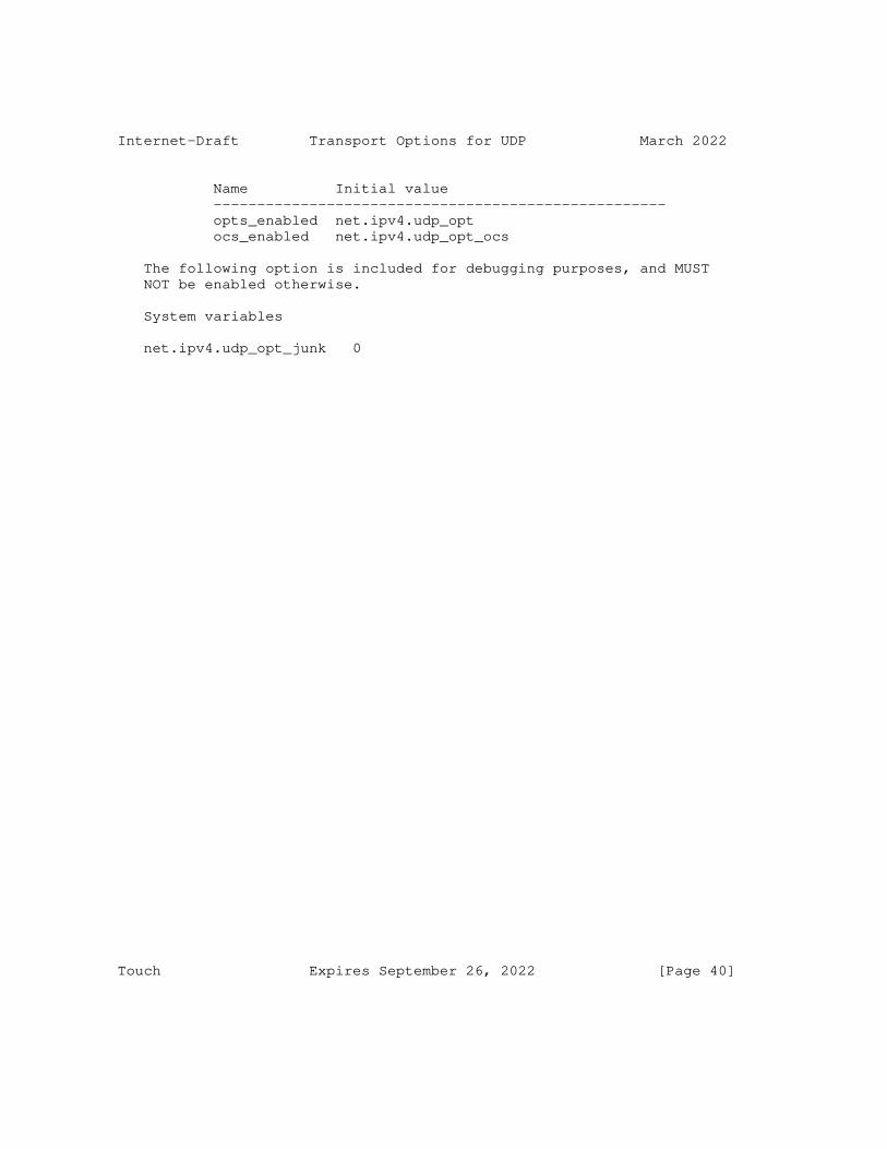
Internet-Draft Transport Options for UDP March 2022
Name Initial value ---------------------------------------------------- opts_enabled net.ipv4.udp_opt ocs_enabled net.ipv4.udp_opt_ocs
The following option is included for debugging purposes, and MUST NOT be enabled otherwise.
System variables
net.ipv4.udp_opt_junk 0
Touch Expires September 26, 2022 [Page 40]
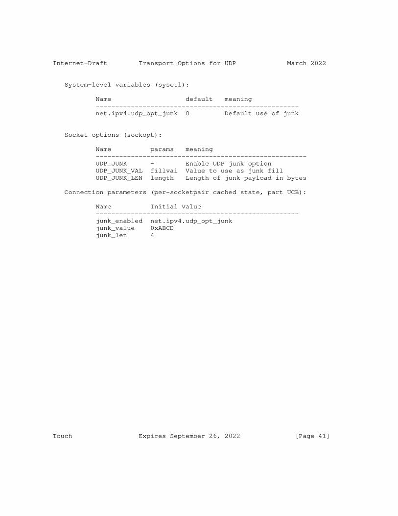
Internet-Draft Transport Options for UDP March 2022
System-level variables (sysctl):
Name default meaning ---------------------------------------------------- net.ipv4.udp_opt_junk 0 Default use of junk
Socket options (sockopt):
Name params meaning ------------------------------------------------------ UDP_JUNK - Enable UDP junk option UDP_JUNK_VAL fillval Value to use as junk fill UDP_JUNK_LEN length Length of junk payload in bytes
Connection parameters (per-socketpair cached state, part UCB):
Name Initial value ---------------------------------------------------- junk_enabled net.ipv4.udp_opt_junk junk_value 0xABCD junk_len 4
Touch Expires September 26, 2022 [Page 41]


Internet Engineering Task Force G. Fairhurst
Internet-Draft T. Jones
Intended status: Standards Track University of Aberdeen
Expires: 29 August 2022 25 February 2022
Datagram PLPMTUD for UDP Options
draft-ietf-tsvwg-udp-options-dplpmtud-03
Abstract
This document specifies how a UDP Options sender implements Datagram
Packetization Layer Path Maximum Transmission Unit Discovery
(DPLPMTUD) as a robust method for Path Maximum Transmission Unit
discovery. This method uses the UDP Options packetization layer. It
allows a datagram application to discover the largest size of
datagram that can be sent across a specific network path.
Status of This Memo
This Internet-Draft is submitted in full conformance with the
provisions of BCP 78 and BCP 79.
Internet-Drafts are working documents of the Internet Engineering
Task Force (IETF). Note that other groups may also distribute
working documents as Internet-Drafts. The list of current Internet-
Drafts is at https://datatracker.ietf.org/drafts/current/.
Internet-Drafts are draft documents valid for a maximum of six months
and may be updated, replaced, or obsoleted by other documents at any
time. It is inappropriate to use Internet-Drafts as reference
material or to cite them other than as "work in progress."
This Internet-Draft will expire on 29 August 2022.
Copyright Notice
Copyright (c) 2022 IETF Trust and the persons identified as the
document authors. All rights reserved.
This document is subject to BCP 78 and the IETF Trust’s Legal
Provisions Relating to IETF Documents (https://trustee.ietf.org/
license-info) in effect on the date of publication of this document.
Please review these documents carefully, as they describe your rights
and restrictions with respect to this document. Code Components
extracted from this document must include Revised BSD License text as
described in Section 4.e of the Trust Legal Provisions and are
provided without warranty as described in the Revised BSD License.
Fairhurst & Jones Expires 29 August 2022 [Page 1]

Internet-Draft UDPO DPLPMTUD February 2022
Table of Contents
1. Introduction . . . . . . . . . . . . . . . . . . . . . . . . 2
2. Terminology . . . . . . . . . . . . . . . . . . . . . . . . . 3
3. DPLPMTUD for UDP Options . . . . . . . . . . . . . . . . . . 3
4. Sending UDP-Options Probe Packets . . . . . . . . . . . . . . 4
4.1. Sending Probe Packets using the Echo Request and Response
Options . . . . . . . . . . . . . . . . . . . . . . . . . 4
4.2. DPLPMTUD Procedures for UDP Options . . . . . . . . . . . 5
4.2.1. Confirmation of Connectivity across a Path . . . . . 5
4.2.2. Sending Probe Packets to Increase the PLPMTU . . . . 6
4.2.3. Validating the Path with UDP Options . . . . . . . . 6
4.2.4. Probe Packets that do not include Application Data . 7
4.2.5. Probe Packets that include Application Data . . . . . 7
4.2.6. Changes in the Path . . . . . . . . . . . . . . . . . 7
4.3. PTB Message Handling for this Method . . . . . . . . . . 8
5. Acknowledgements . . . . . . . . . . . . . . . . . . . . . . 8
6. IANA Considerations . . . . . . . . . . . . . . . . . . . . . 8
7. Security Considerations . . . . . . . . . . . . . . . . . . . 8
8. References . . . . . . . . . . . . . . . . . . . . . . . . . 9
8.1. Normative References . . . . . . . . . . . . . . . . . . 9
8.2. Informative References . . . . . . . . . . . . . . . . . 9
Appendix A. Revision Notes . . . . . . . . . . . . . . . . . . . 10
Authors’ Addresses . . . . . . . . . . . . . . . . . . . . . . . 12
1. Introduction
The User Datagram Protocol [RFC0768] offers a minimal transport
service on top of IP and is frequently used as a substrate for other
protocols. Section 3.5 of UDP Guidelines [RFC8085] recommends that
applications implement some form of Path MTU discovery to avoid the
generation of IP fragments:
"Consequently, an application SHOULD either use the path MTU
information provided by the IP layer or implement Path MTU Discovery
(PMTUD)".
The UDP API [RFC8304] offers calls for applications to receive ICMP
Packet Too Big (PTB) messages and to control the maximum size of
datagrams that are sent, but does not offer any automated mechanisms
for an application to discover the maximum packet size supported by a
path. Upper layer protocols (which can include applications)
implement mechanisms for Path MTU discovery above the UDP API.
Packetization Layer Path MTU Discovery (PLPMTUD) [RFC4821] describes
a method for a Packetization Layer (PL) (such as UDP Options) to
search for the largest Packetization Layer PMTU (PLPMTU) supported on
a path. Datagram PLPMTUD (DPLPMTUD) [RFC8899] specifies this support
Fairhurst & Jones Expires 29 August 2022 [Page 2]
Internet-Draft UDPO DPLPMTUD February 2022
for datagram transports. PLPMTUD and DPLPMTUD gain robustness by
using a probing mechanism that does not solely rely on ICMP PTB
messages and works on paths that drop ICMP PTB messages.
This document specifies how UDP Options [I-D.ietf-tsvwg-udp-options]
can be used as a PL to implement DPLPMTUD (see Section 6.1 of
[RFC8899]). In summary, UDP Options [I-D.ietf-tsvwg-udp-options]
supplies functionality that can be used to implement DPLPMTUD within
the UDP transport service. Implementing DPLPMTUD using UDP Options
avoids the need for each upper layer protocol or application to
implement the DPLPMTUD method. This provides a standard method for
applications to discover the current maximum packet size for a path
and to detect when this changes.
2. Terminology
The key words "MUST", "MUST NOT", "REQUIRED", "SHALL", "SHALL NOT",
"SHOULD", "SHOULD NOT", "RECOMMENDED", "MAY", and "OPTIONAL" in this
document are to be interpreted as described in BCP 14 [RFC2119]
[RFC8174] when, and only when, they appear in all capitals, as shown
here.
This document uses the terms defined for DPLPMTUD (see Sections 2 and
5 of [RFC8899]
3. DPLPMTUD for UDP Options
There are two ways an upper PL can perform DPLPMTUD:
* The UDP Options sender implementing DPLPMTUD uses the method
specified in [RFC8899] and the upper PL (or application) does not
perform PMTU discovery. In this case, UDP Options processing is
responsible for sending probes to determine a PLPMTU, as described
in this document. "An application SHOULD avoid using DPLPMTUD
when the underlying transport system provides this capability"
(Section 6.1 of [RFC8899]). This discovered PLPMTU can be used by
UDP Options to either:
- set the maximum datagram size for the current path (based on
the discovered largest IP packet that can be received across
the current path).
- set the maximum fragment size when a sender uses the UDP
Fragmentation Option to divide a datagram into multiple UDP
fragments for transmission. Each UDP fragment is then less
than the discovered largest IP packet that can be received
across the current path.
Fairhurst & Jones Expires 29 August 2022 [Page 3]

Internet-Draft UDPO DPLPMTUD February 2022
* An upper PL (or application) performs DPLPMTUD (e.g., QUIC
[RFC9000]). This upper PL then uses probes to determine a safe
PLPMTU for the datagrams that it sends. The format and content of
any probe is determined by the upper PL. Such a design should
avoid performing discovery at multiple levels, so, when
configurable, this upper PL SHOULD disable DPLPMTUD by UDP
Options.
The packet formats and procedures for DPLPMTUD using UDP Options are
described in this document.
4. Sending UDP-Options Probe Packets
DPLPMTUD relies upon the ability of a UDP Options sender to generate
a probe with a specific size, up to the maximum for the size
supported by a local interface. This MUST NOT be constrained by the
maximum PMTU set by network layer mechanisms (such as PMTUD
[RFC1191][RFC8201] or the PMTU size held in the IP- layer cache), as
noted in bullet 2 of Section 3 in [RFC8899]).
Probe packets consume network capacity and incur endpoint processing
(see Section 4.1 of [RFC8899]). Implementations ought to send a
probe with an REQ Option only when required by their local DPLPMTUD
state machine, i.e., when confirming the base PMTU for the path,
probing to increase the PLPMTU or to confirm the current PLPMTU.
4.1. Sending Probe Packets using the Echo Request and Response Options
A UDP Options node that supports DPLPMTUD MUST support sending and
receiving of the REQ Option and the RES Option. When not supported,
DPLPMTUD will be unable to confirm the Path or to discover the PMTU.
[RFC8899] (Section 3, item 2) requires the network interface below
the PL to provide a way to transmit a probe packet that is larger
than the PLPMTU without network layer endpoint fragmentation. This
document adds to this: UDP datagrams used as DPLPMTUD probes as
described in this document MUST NOT be fragmented at the UDP layer.
This section describes a format of probe consisting of an empty UDP
datagram, UDP Options area and Padding.
A Probe Packet includes the UDP Options area containing a RES Option
and any other required options concluded with an EOL Option followed
by any padding needed to inflate to the required probe size.
The UDP Options used in this document are described in Section 5.11
of [I-D.ietf-tsvwg-udp-options]:
Fairhurst & Jones Expires 29 August 2022 [Page 4]

Internet-Draft UDPO DPLPMTUD February 2022
* The REQ Option is set by a sending PL to solicit a response from a
remote UDP Options receiver. A four-byte token identifies each
request.
* The RES Option is generated by the UDP Options receiver in
response to a previously received REQ Option. Each RES Option
echoes a previously received four-byte token.
* Reception of a RES Option confirms that a specific probe has been
received by the remote UDP Options receiver.
The token allows a sender to distinguish between acknowledgements for
initial probes and acknowledgements confirming receipt of subsequent
probes (e.g., travelling along alternate paths with a larger round
trip time). This needs each probe to be uniquely identifiable by the
UDP Options sender within the Maximum Segment Lifetime (MSL). The
UDP Options sender therefore MUST NOT recycle token values until they
have expired or have been acknowledged. A four byte value for the
token field provides sufficient space for multiple unique probes to
be made within the MSL. Since UDP Options operates over UDP, the
token values only need to be unique for the specific 5-tuple over
which DPLPMTUD is operating.
The value of the four byte token field SHOULD be initialised to a
randomised value to enhance protection from off-path attacks, as
described in Section 5.1 of [RFC8085]).
Like other UDP options, each of the two option kinds MUST NOT appear
more than once in each UDP datagram.
4.2. DPLPMTUD Procedures for UDP Options
DPLPMTUD utilises three types of probes. These are described in the
following sections:
* A probe to confirm the path can support the BASE_PLPMTU (see
Section 5.1.4 of [RFC8899]).
* A probe to detect whether the path can support a larger PLPMTU.
* A probe to validate the path supports the current PLPMTU.
4.2.1. Confirmation of Connectivity across a Path
The DPLPMTUD method requires a PL to confirm connectivity over the
path using the BASE_PLPMTU (see Section 5.1.4 of [RFC8899]), but UDP
does not offer a mechanism for this.
Fairhurst & Jones Expires 29 August 2022 [Page 5]

Internet-Draft UDPO DPLPMTUD February 2022
UDP Options can provide this required functionality. A UDP Options
sender implementing this specification MUST elicit a positive
confirmation of connectivity for the path, by sending a probe, padded
to size BASE_PLPMTU. This confirmation probe MUST include a UDP
option that elicits a response from the remote endpoint (e.g., by
including the RES and REQ Options) to confirm that a packet of the
size traversed the path. This also confirms that the remote receiver
supports use of the RES and REQ Options.
4.2.2. Sending Probe Packets to Increase the PLPMTU
From time to time, DPLPMTUD enters the SEARCHING state [RFC8899]
(e.g., after expiry of the PMTU_RAISE_TIMER) to detect whether the
current path can support a larger PLPMTU. When the remote endpoint
advertises a UDP Maximum Segment Size (MSS) option, this value can be
used as a hint to initialise this search to increase the PLPMTU.
Probe packets seeking to increase the PLPMTU SHOULD NOT carry
application data (see "Probing using padding data" in Section 4.1 of
[RFC8899]), since they will be lost whenever their size exceeds the
actual PMTU.
A probe seeking to increase the PLPMTU needs to elicit a positive
acknowledgment that the path has delivered a datagram of the specific
probed size and, therefore, MUST include the REQ Option.
Received probes that do not carry application data do not form a part
of the end-to-end transport data and are not delivered to the upper
layer protocol.
4.2.3. Validating the Path with UDP Options
A PL using DPLPMTUD needs to validate that a path continues to
support the PLPMTU discovered in a previous search for a suitable
PLPMTU value (see Section 6.1.4 of [RFC8899]). This validation sends
probes in the DPLPMTUD SEARCH_COMPLETE state to detect black-holing
of data (see Section 4.2 of [RFC8899]).
This function can be implemented within UDP Options, by generating a
probe of size PLPMTU, which MUST include a REQ Option to elicit a
positive confirmation whether the path has delivered the probe. This
confirmation probe MAY use "Probing using padding data" or "Probing
using application data and padding data" (see Section 4.1 of
[RFC8899]) or can construct a probe packet that does not carry any
application data, as described in a previous section.
Fairhurst & Jones Expires 29 August 2022 [Page 6]

Internet-Draft UDPO DPLPMTUD February 2022
4.2.4. Probe Packets that do not include Application Data
A simple implementation of the method might be designed to only probe
packets formed of a UDP datagram that include no application data.
Each probe packet is padded to the required probe size including the
REQ Option. This implements "Probing using padding data"(Section 4.1
of [RFC8899]), and avoids having to retransmit application data when
a probe fails. In this use, the probe packets do not form a part of
the end-to-end transport data and a receiver does not deliver them to
the upper layer protocol.
4.2.5. Probe Packets that include Application Data
An implementation always uses the format in the previous section when
DPLPMTUD searches to increase the PLPMTU.
An alternative format is permitted for a probe that confirms
connectivity or that validates the path. These probes are permitted
to carry application data. (The data is permitted because these
probes perform blackhole detection and will therefore usually have a
higher probability of successful transmission, similar to other
packets sent by the upper layer protocol.) Section 4.1 of [RFC8899]
provides a discussion of the merits and demerits of including
application data. For example, this reduces the need to send
additional datagrams.
The probe could utilise a control message format defined by the upper
layer protocol that does not need to be delivered reliably. The RES
and REQ Options need to be included by the sending upper layer
protocol and the values of the tokens need to be coordinated with
values used for other DPLPMTUD probe packets. The DPLPMTUD method
tracks the transmission and reception of these probe packets. Probes
with this format form a part of the end-to-end transport data and a
receiver needs to deliver the RES and REQ Options to the upper layer
protocol.
4.2.6. Changes in the Path
A change in the path or the loss of probe packets can result in a
change of the PLPMTU. DPLPMTUD [RFC8899] recommends that methods are
robust to path changes that could have occurred since the path
characteristics were last confirmed and to the possibility of
inconsistent path information being received. For example, a
notification that a path could have changed could trigger path
validation to provide black hole protection Section 4.3 of
[RFC8899]).
Fairhurst & Jones Expires 29 August 2022 [Page 7]
Internet-Draft UDPO DPLPMTUD February 2022
Section 3 of [RFC8899] requires any methods designed to share the
PLPMTU between PLs (such as updating the IP cache PMTU for an
interface/destination) to be robust to the wide variety of underlying
network forwarding behaviors. For example, an implementation could
avoid sharing PMTU information that could potentially relate to
packets sent with the same address over a different interface.
4.3. PTB Message Handling for this Method
Support for receiving ICMP PTB messages is OPTIONAL for use with
DPLPMTUD. A UDP Options sender can therefore ignore received ICMP
PTB messages.
A UDP Options sender that utilises ICMP PTB messages received in
response to a probe packet MUST use the quoted packet to validate the
UDP port information in combination with the token contained in the
UDP Option, before processing the packet using the DPLPMTUD method.
Section 4.6.1 of [RFC8899] specifies this validation procedure. An
implementation unable to support this validation needs to ignore
received ICMP PTB messages.
5. Acknowledgements
Gorry Fairhurst and Tom Jones are supported by funding provided by
the University of Aberdeen.
6. IANA Considerations
This memo includes no requests to IANA.
7. Security Considerations
The security considerations for using UDP Options are described in
[I-D.ietf-tsvwg-udp-options]. The proposed new method does not
change the integrity protection offered by the UDP options method.
The security considerations for using DPLPMTUD are described in
[RFC8899]. On path attackers could maliciously drop or modify probe
packets to seek to decrease the PMTU, or to maliciously modify probe
packets in an attempt to blackhole traffic.
The specification recommends that the nonce value in the REQ Option
is initialised to a randomised value. This is designed to enhance
protection from off-path attacks. If subsequent probes use a nonce
value that is easily derived from the initial value, (e.g.,
incrementing the value) then a misbehaving on-path node could then
determine the nonce for subsequent probes from that sender, even if
these probes are not transiting via the misbehaving node. This would
Fairhurst & Jones Expires 29 August 2022 [Page 8]
Internet-Draft UDPO DPLPMTUD February 2022
allow probe packets to be forged, with an impact similar to other on-
path attacks against probe packets. This attack could be mitigated
by using an unpredictable nonce value for each probe.
The proposed new method does not change the ICMP PTB message
validation method described by DPLPMTUD: A UDP Options sender that
utilities ICMP PTB messages received to a probe packet MUST use the
quoted packet to validate the UDP port information in combination
with the token contained in the UDP Option, before processing the
packet using the DPLPMTUD method.
8. References
8.1. Normative References
[I-D.ietf-tsvwg-udp-options]
Touch, J. D., "Transport Options for UDP", Work in
Progress, Internet-Draft, draft-ietf-tsvwg-udp-options-13,
19 June 2021, <https://www.ietf.org/archive/id/draft-ietf-
tsvwg-udp-options-13.txt>.
[RFC0768] Postel, J., "User Datagram Protocol", STD 6, RFC 768,
DOI 10.17487/RFC0768, August 1980,
<https://www.rfc-editor.org/info/rfc768>.
[RFC2119] Bradner, S., "Key words for use in RFCs to Indicate
Requirement Levels", BCP 14, RFC 2119,
DOI 10.17487/RFC2119, March 1997,
<https://www.rfc-editor.org/info/rfc2119>.
[RFC8174] Leiba, B., "Ambiguity of Uppercase vs Lowercase in RFC
2119 Key Words", BCP 14, RFC 8174, DOI 10.17487/RFC8174,
May 2017, <https://www.rfc-editor.org/info/rfc8174>.
[RFC8899] Fairhurst, G., Jones, T., Tüxen, M., Rüngeler, I., and T.
Völker, "Packetization Layer Path MTU Discovery for
Datagram Transports", RFC 8899, DOI 10.17487/RFC8899,
September 2020, <https://www.rfc-editor.org/info/rfc8899>.
8.2. Informative References
[RFC1191] Mogul, J. and S. Deering, "Path MTU discovery", RFC 1191,
DOI 10.17487/RFC1191, November 1990,
<https://www.rfc-editor.org/info/rfc1191>.
[RFC4821] Mathis, M. and J. Heffner, "Packetization Layer Path MTU
Discovery", RFC 4821, DOI 10.17487/RFC4821, March 2007,
<https://www.rfc-editor.org/info/rfc4821>.
Fairhurst & Jones Expires 29 August 2022 [Page 9]

Internet-Draft UDPO DPLPMTUD February 2022
[RFC8085] Eggert, L., Fairhurst, G., and G. Shepherd, "UDP Usage
Guidelines", BCP 145, RFC 8085, DOI 10.17487/RFC8085,
March 2017, <https://www.rfc-editor.org/info/rfc8085>.
[RFC8201] McCann, J., Deering, S., Mogul, J., and R. Hinden, Ed.,
"Path MTU Discovery for IP version 6", STD 87, RFC 8201,
DOI 10.17487/RFC8201, July 2017,
<https://www.rfc-editor.org/info/rfc8201>.
[RFC8304] Fairhurst, G. and T. Jones, "Transport Features of the
User Datagram Protocol (UDP) and Lightweight UDP (UDP-
Lite)", RFC 8304, DOI 10.17487/RFC8304, February 2018,
<https://www.rfc-editor.org/info/rfc8304>.
[RFC9000] Iyengar, J., Ed. and M. Thomson, Ed., "QUIC: A UDP-Based
Multiplexed and Secure Transport", RFC 9000,
DOI 10.17487/RFC9000, May 2021,
<https://www.rfc-editor.org/info/rfc9000>.
Appendix A. Revision Notes
XXX Note to RFC-Editor: please remove this entire section prior to
publication. XXX
Individual draft-00.
* This version contains a description for consideration and comment
by the TSVWG.
Individual draft-01.
* Address Nits
* Change Probe Request and Probe Reponse options to Echo to align
names with draft-ietf-tsvwg-udp-options
* Remove Appendix B, Informative Description of new UDP Options
* Add additional sections around Probe Packet generation
Individual draft-02.
* Address Nits
Individual draft-03.
* Referenced DPLPMTUD RFC.
Fairhurst & Jones Expires 29 August 2022 [Page 10]

Internet-Draft UDPO DPLPMTUD February 2022
* Tidied language to clarify the method.
Individual draft-04
* Reworded text on probing with data a little
* Removed paragraph on suspending ICMP PTB suspension.
Working group draft-00
* -00 First Working Group Version
* RFC8899 call search_done SEARCH_COMPLETE, fix
Working group draft -01
* Update to reflect new fragmentation design in UDP Options.
* Add a description of uses of DPLPMTUD with UDP Options.
* Add a description on how to form probe packets with padding.
* Say that MSS options can be used to initialise the search
algorithm.
* Say that the recommended approach is to not use user data for
probes.
* Attempts to clarify and improve wording throughout.
* Remove text saying you can respond to multiple probes in a single
packet.
* Simplified text by removing options that don’t yield benefit.
Working group draft -02
* Update to reflect comments from MED.
* More consistent description of DPLPMTUD with UDP Options.
* Clarify the nonce value (token) is intended per 5-tuple, not
interface.
* BASE_PLPMTU related to RFC8899.
* Probes with user data can carry application control data.
Fairhurst & Jones Expires 29 August 2022 [Page 11]

Internet-Draft UDPO DPLPMTUD February 2022
* Added that application data uses RES and REQ nonce (token) values
from the app.
* QUIC was intended as an informational reference to an example of
RFC8899.
Working group draft -03
* Update to reflect more comments from MED.
* Again more consistent description of DPLPMTUD with UDP Options.
* Clarify token/nonce to use "token".
* Clarify any use of application data for blackhole detection.
* Minor changes to reflect update to UDP Options base spec.
Authors’ Addresses
Godred Fairhurst
University of Aberdeen
School of Engineering
Fraser Noble Building
Aberdeen
AB24 3UE
United Kingdom
Email: [email protected]
Tom Jones
University of Aberdeen
School of Engineering
Fraser Noble Building
Aberdeen
AB24 3UE
United Kingdom
Email: [email protected]
Fairhurst & Jones Expires 29 August 2022 [Page 12]

ICCRG Working Group N. RomoInternet-Draft J. KimIntended status: Experimental M. AmendExpires: 28 April 2022 DT 25 October 2021
Profile for Datagram Congestion Control Protocol (DCCP) Congestion Control ID 5 draft-romo-iccrg-ccid5-00
Abstract
This document contains the profile for Congestion Control Identifier 5 (CCID 5), BBR-like Congestion Control, in the Datagram Congestion Control Protocol (DCCP). CCID 5 is meant to be used by senders who have a strong demand on low latency and require a steady throughput behavior.
Status of This Memo
This Internet-Draft is submitted in full conformance with the provisions of BCP 78 and BCP 79.
Internet-Drafts are working documents of the Internet Engineering Task Force (IETF). Note that other groups may also distribute working documents as Internet-Drafts. The list of current Internet- Drafts is at https://datatracker.ietf.org/drafts/current/.
Internet-Drafts are draft documents valid for a maximum of six months and may be updated, replaced, or obsoleted by other documents at any time. It is inappropriate to use Internet-Drafts as reference material or to cite them other than as "work in progress."
This Internet-Draft will expire on 28 April 2022.
Copyright Notice
Copyright (c) 2021 IETF Trust and the persons identified as the document authors. All rights reserved.
Romo, et al. Expires 28 April 2022 [Page 1]

Internet-Draft CCID5 October 2021
This document is subject to BCP 78 and the IETF Trust’s Legal Provisions Relating to IETF Documents (https://trustee.ietf.org/ license-info) in effect on the date of publication of this document. Please review these documents carefully, as they describe your rights and restrictions with respect to this document. Code Components extracted from this document must include Simplified BSD License text as described in Section 4.e of the Trust Legal Provisions and are provided without warranty as described in the Simplified BSD License.
Table of Contents
1. Introduction . . . . . . . . . . . . . . . . . . . . . . . . 2 2. Convention and Notation . . . . . . . . . . . . . . . . . . . 3 3. Usage . . . . . . . . . . . . . . . . . . . . . . . . . . . . 3 3.1. Relationship with TCP BBR and CCID2 . . . . . . . . . . . 3 3.2. Multiple-path communications . . . . . . . . . . . . . . 4 3.3. Half-Connection Example . . . . . . . . . . . . . . . . . 4 4. Connection Establishment . . . . . . . . . . . . . . . . . . 5 5. Congestion Control on Data Packets . . . . . . . . . . . . . 5 5.1. State machine . . . . . . . . . . . . . . . . . . . . . . 6 5.2. Response to Idle and Application-Limited Periods . . . . 7 6. Acknowledgements . . . . . . . . . . . . . . . . . . . . . . 7 7. Discussion . . . . . . . . . . . . . . . . . . . . . . . . . 7 7.1. ProbeRTT phase transitions . . . . . . . . . . . . . . . 7 8. IANA Considerations . . . . . . . . . . . . . . . . . . . . . 8 9. Acknowledgment . . . . . . . . . . . . . . . . . . . . . . . 8 10. Informative References . . . . . . . . . . . . . . . . . . . 8 Authors’ Addresses . . . . . . . . . . . . . . . . . . . . . . . 9
1. Introduction
This document contains the profile for Congestion Control Identifier 5, BBR-like Congestion Control, in the Datagram Congestion Control Protocol (DCCP) [RFC4340]. DCCP uses Congestion Control Identifiers, or CCIDs, to specify the congestion control mechanism in use on a half-connection.
The BBR-like Congestion Control CCID5 sends data following the guidelines and principles of TCP BBR [I-D.cardwell-iccrg-bbr-congestion-control]. i.e, it estimates the path characteristics, to later update accordingly the sending data behavior. It achieves an optimal point of operation by keeping the amount of data in flight at the BDP (Bandwidth Delay Product) level, avoiding the abrupt Bandwidth changes typical of loss based congestion control algorithms.
Romo, et al. Expires 28 April 2022 [Page 2]

Internet-Draft CCID5 October 2021
2. Convention and Notation
The key words "MUST", "MUST NOT", "REQUIRED", "SHALL", "SHALL NOT", "SHOULD", "SHOULD NOT", "RECOMMENDED", "MAY", and "OPTIONAL" in this document are to be interpreted as described in [RFC2119].
A DCCP half-connection consists of the application data sent by one endpoint and the corresponding acknowledgements sent by the other endpoint. The terms "HC-Sender" and "HC-Receiver" denote the endpoints sending application data and acknowledgements, respectively. Since CCIDs apply at the level of half-connections, we abbreviate HC-Sender to "sender" and HC-Receiver to "receiver" in this document. See [RFC4340] for more discussion
3. Usage
CCID5 congestion control algorithm is aimed to achieve a high bandwidth and low latency by the active probe of the end-to-end link capacity. The active probe helps hosts to adjust their sending rates before a packet loss happens at a buffer on the path. As a result, the communication path experiences a consistent and low latency by avoiding unnecessary packet drops at buffers.
Since CCID5 effectively avoids unnecessary packet losses, the spiky traffic behavior, that is commonly caused by traditional TCP congestion control mechanisms, is suppressed. This leads to a stable throughput throughout the connection period and thus yields a higher throughput than that with a loss-based congestion control mechanism.
Therefore, CCID5 suits applications that require consistent low latencies and stable high bandwidth. This includes multimedia streaming, online video gaming, video conferencing, and latency- sensitive industry applications such as industrial robots and autonomous vehicles are usage examples of CCID5.
3.1. Relationship with TCP BBR and CCID2
The CCID5 congestion control mechanism closely follows TCP’s [I-D.cardwell-iccrg-bbr-congestion-control]|BBR congestion control algorithm, replicating the functions intended to estimate the path characteristics and to determine the pace and the amount of data to send. However, CCID5 must also comply with the DCCP requirements for a CCID profile ([RFC4340] Section 10.4) and define how the data is going to be acknowledged.
Romo, et al. Expires 28 April 2022 [Page 3]

Internet-Draft CCID5 October 2021
For this purpose, CCID5 implements the format of the ACK packets, the timing of their generation, and how they are congestion controlled. CCID5 uses the same ACK format as CCID2, including ACK vectors containing the same information that can be found in SACK options, and implements the ACK ratio as ACK congestion control mechanism.
In addition, the different variables and functions used to track packets in flight, packets acknowledged, and their corresponding sending and arrival times as well as the function to detect application-limited periods are replicated from the CCID2 implementation
3.2. Multiple-path communications
CCID 5 congestion control algorithm is adopted from TCP’s BBR congestion control algorithm with a multiple-path communication as a representative use-case example. Multiple-path communications do not only target to maximize the link capacity, but also are aimed to improve the availability on critical situations such as a link failure. With that regard, MP-DCCP has been proposed. MP-DCCP extends capabilities of DCCP into multiple concurrent connections. A study [paper] has shown that CCID5 improves the overall bandwidth and the end-to-end latency compared to loss-based congestion control algorithms in an MP-DCCP enabled network. The study has also shown that the latency difference among multiple paths has an influence on the overall performance of the communication. A smaller gap among available paths leads to a higher aggregation performance of the link capacity. CCID5 is designed to provide a low and stable latency over each of the available paths and thus has a potential to improve the multi-path communication performance.
3.3. Half-Connection Example
This example shows the typical progress of a half-connection using CCID 5’s BBR-like Congestion Control, not including connection initiation and termination. The example is informative, not normative.
1. The sender transmits DCCP-Data packets, each one of them identified with a sequence number. The sending behavior is governed by two control parameters: congestion window and pacing rate. The congestion window limits the amount of packets in flight and the pacing rate limits the sending rate.
Romo, et al. Expires 28 April 2022 [Page 4]

Internet-Draft CCID5 October 2021
2. The Acknowledgment mechanism replicates CCID2 specifications. Thus, The sender sends an Ack Ratio feature option specifying the number of data packets to be covered by an Ack packet from the receiver and consequently, the receiver sends a DCCP-Ack packet acknowledging the data packets for every Ack Ratio data packets transmitted by the sender.
3. The sender continues sending DCCP-Data packets. Upon receiving DCCP-Ack packets, the sender examines their Ack Vectors to learn about acknowledged and marked or dropped data packets. With the information of the acknowledged packets, it proceeds to estimate round-trip times (as TCP does) and the delivery rate, following the algorithm described in [I-D.cheng-iccrg-delivery-rate-estimation].
4. The sender uses the round-trip time and delivery rate estimations to calculate the round-trip propagation delay (RTprop) and the bottleneck bandwidth (BtlBw) of the path, following the specifications in ([I-D.cardwell-iccrg-bbr-congestion-control] Section 4.1) The RTprop and BtlBw are then used to update the values of the congestion window and pacing rate.
5. As in CCID2, the sender responds to lost or marked DCCP-Ack packets by modifying the Ack Ratio sent to the receiver and acknowledges the receiver’s acknowledgements at least once per congestion window.
4. Connection Establishment
The connection establishment is as specified in ([RFC4341] Section 4)
5. Congestion Control on Data Packets
CCID 5 is based on the BBR congestion control mechanisms described in [I-D.cardwell-iccrg-bbr-congestion-control]. The subsequent sections, present a general description of such mechanisms and discuss the considerations to be addressed when used within the DCCP protocol.
BBR proposes an algorithm based on the characterization of the network path made through the estimation of the Bottleneck Bandwidth (BtlBW) and the Round Trip propagation time (RTProp) defined respectively as the maximum delivered rate and minimum RTT seen by the sender. The algorithm aims to achieve an optimal point of operation by fulfilling two conditions
Romo, et al. Expires 28 April 2022 [Page 5]

Internet-Draft CCID5 October 2021
1. The amount of data inflight must be equal to the Bandwidth Delay Product (BDP), guaranteeing that buffers are not being filled and therefore avoiding long delay generation
2. The bottleneck packet arrival must match the BtlBw to ensure its full utilization.
To match those conditions, the sending data behavior is updated, by using three control variables: Congestion window (which limits the amount of data in flight), pacing rate, and send quantum (which limits the amount of aggregated packets in case of segmentation offload). The calculation of the control parameters uses as input the estimated values of BtlBW and RTprop along with two dynamic gain factors named pacing_gain and cwnd_gain.
The estimation of the path parameters Rtprop and BtlBw follow the guidelines and pseudo-code described in [I-D.cheng-iccrg-delivery-rate-estimation] and [I-D.cardwell-iccrg-bbr-congestion-control]
5.1. State machine
The way the control parameters are updated is governed by the BBR state machine Illustrated in Figure 1. In the initial Startup state, the sending rate will increase rapidly until the pipe is detected to be full. Afterwards, the data rate will be reduced so any possible queue can be drained, to finally enter into the ProbeBW state, where the amount of data in flight is slightly increased to probe for more possible bandwidth available. From any of these states, the algorithm can jump into the ProbeRTT phase. Here the data inflight is reduced to probe for lower RTTs. Each state defines specific values for two dynamic gains: cwnd_gain and pacing_gain, which will finally be used in the calculation of the aforementioned control variables.
Romo, et al. Expires 28 April 2022 [Page 6]
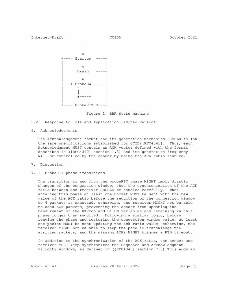
Internet-Draft CCID5 October 2021
| V +---> Startup ----+ | | | | V | | Drain ----+ | | | | V | +---> ProbeBW -----+ | ^ | | | | | | | +----+ | | | +---- ProbeRTT <---+
Figure 1: BBR State machine
5.2. Response to Idle and Application-Limited Periods
6. Acknowledgements
The Acknowledgement format and its generation mechanism SHOULD follow the same specifications established for CCID2[RFC4341]. Thus, each Acknowledgment MUST contain an ACK vector defined with the format described in ([RFC4340] section 1.3) And its generation frequency will be controlled by the sender by using the ACK ratio feature.
7. Discussion
7.1. ProbeRTT phase transitions
The transition to and from the probeRTT phase MIGHT imply drastic changes of the congestion window, thus the synchronization of the ACK ratio between and receiver SHOULD be handled carefully. When entering this phase at least one Packet MUST be sent with the new value of the ACK ratio before the reduction of the congestion window to 4 packets is executed, otherwise, the receiver MIGHT not be able to send ACK packets, preventing the sender from updating the measurement of the RTProp and BtlBW variables and remaining in this phase longer than required. Following a similar logic, before leaving the phase and restoring the congestion window value, at least one packet MUST be sent updating the ack ratio value, otherwise, the receiver MIGHT not be able to keep the pace to acknowledge the arriving packets, and the missing ACKs MIGHT trigger a RTO timeout.
In addition to the synchronization of the ACK ratio, the sender and receiver MUST keep synchronized the Sequence and Acknowledgment validity windows, as defined in ([RFC4340] section 7.5) This adds an
Romo, et al. Expires 28 April 2022 [Page 7]

Internet-Draft CCID5 October 2021
additional constraint to the BBR algorithm when leaving the ProbeRTT phase, as at least one RTT is necessary for the sender to ensure the synchronization before restoring the congestion window value, causing again a longer duration of the probeRTT phase. Thus, it might be necessary to consider the possibility of restoring the congestion window even if this synchronization has not yet been confirmed by the arrival of the last Acknowledgement sent by the receiver.
8. IANA Considerations
9. Acknowledgment
10. Informative References
[I-D.cardwell-iccrg-bbr-congestion-control] Cardwell, N., Cheng, Y., Yeganeh, S. H., and V. Jacobson, "BBR Congestion Control", Work in Progress, Internet- Draft, draft-cardwell-iccrg-bbr-congestion-control-00, 3 July 2017, <https://www.ietf.org/archive/id/draft- cardwell-iccrg-bbr-congestion-control-00.txt>.
[I-D.cheng-iccrg-delivery-rate-estimation] Cheng, Y., Cardwell, N., Yeganeh, S. H., and V. Jacobson, "Delivery Rate Estimation", Work in Progress, Internet- Draft, draft-cheng-iccrg-delivery-rate-estimation-00, 3 July 2017, <https://www.ietf.org/archive/id/draft-cheng- iccrg-delivery-rate-estimation-00.txt>.
[paper] Romo Moreno, N., Amend, M., Rakocevic, V., Kassler, A., and A. Brunstrom, "CCID5 An implementation of the BBR Congestion Control algorithm for DCCP and its impact over multi-path scenarios", DOI 10.1145/3472305.3472322, June 2021, <https://doi.org/10.1145/3472305.3472322>.
[RFC2119] Bradner, S., "Key words for use in RFCs to Indicate Requirement Levels", BCP 14, RFC 2119, DOI 10.17487/RFC2119, March 1997, <https://www.rfc-editor.org/info/rfc2119>.
[RFC4340] Kohler, E., Handley, M., and S. Floyd, "Datagram Congestion Control Protocol (DCCP)", RFC 4340, DOI 10.17487/RFC4340, March 2006, <https://www.rfc-editor.org/info/rfc4340>.
[RFC4341] Floyd, S. and E. Kohler, "Profile for Datagram Congestion Control Protocol (DCCP) Congestion Control ID 2: TCP-like Congestion Control", RFC 4341, DOI 10.17487/RFC4341, March 2006, <https://www.rfc-editor.org/info/rfc4341>.
Romo, et al. Expires 28 April 2022 [Page 8]
Internet-Draft CCID5 October 2021
Authors’ Addresses
Nathalie Romo Moreno Deutsche Telekom Deutsche-Telekom-Allee 9 64295 Darmstadt Germany
Email: [email protected]
Juhoon Kim Deutsche Telekom Winterfeldstr. 21 10781 Berlin Germany
Email: [email protected]
Markus Amend Deutsche Telekom Deutsche-Telekom-Allee 9 64295 Darmstadt Germany
Email: [email protected]
Romo, et al. Expires 28 April 2022 [Page 9]
Transport Area Working Group G. White, Ed.
Internet-Draft CableLabs
Intended status: Informational February 22, 2021
Expires: August 26, 2021
Operational Guidance for Deployment of L4S in the Internet
draft-white-tsvwg-l4sops-02
Abstract
This document is intended to provide additional guidance to operators
of end-systems, operators of networks, and researchers beyond that
provided in [I-D.ietf-tsvwg-ecn-l4s-id] and
[I-D.ietf-tsvwg-aqm-dualq-coupled] in order to ensure successful
deployment of L4S [I-D.ietf-tsvwg-l4s-arch] in the Internet. The
focus of this document is on potential interactions between L4S flows
and Classic ECN ([RFC3168]) flows in Classic ECN bottleneck links.
The document discusses the potential outcomes of these interactions,
describes mechanisms to detect the presence of [RFC3168] bottlenecks,
and identifies opportunites to prevent and/or detect and resolve
fairness problems in such networks.
Status of This Memo
This Internet-Draft is submitted in full conformance with the
provisions of BCP 78 and BCP 79.
Internet-Drafts are working documents of the Internet Engineering
Task Force (IETF). Note that other groups may also distribute
working documents as Internet-Drafts. The list of current Internet-
Drafts is at https://datatracker.ietf.org/drafts/current/.
Internet-Drafts are draft documents valid for a maximum of six months
and may be updated, replaced, or obsoleted by other documents at any
time. It is inappropriate to use Internet-Drafts as reference
material or to cite them other than as "work in progress."
This Internet-Draft will expire on August 26, 2021.
Copyright Notice
Copyright (c) 2021 IETF Trust and the persons identified as the
document authors. All rights reserved.
This document is subject to BCP 78 and the IETF Trust’s Legal
Provisions Relating to IETF Documents
(https://trustee.ietf.org/license-info) in effect on the date of
White Expires August 26, 2021 [Page 1]
Internet-Draft L4S Operational Guidance February 2021
publication of this document. Please review these documents
carefully, as they describe your rights and restrictions with respect
to this document. Code Components extracted from this document must
include Simplified BSD License text as described in Section 4.e of
the Trust Legal Provisions and are provided without warranty as
described in the Simplified BSD License.
Table of Contents
1. Introduction . . . . . . . . . . . . . . . . . . . . . . . . 2
2. Per-Flow Fairness . . . . . . . . . . . . . . . . . . . . . . 4
3. Detection of Classic ECN Bottlenecks . . . . . . . . . . . . 6
4. Operator of an L4S host . . . . . . . . . . . . . . . . . . . 6
4.1. Edge Servers . . . . . . . . . . . . . . . . . . . . . . 8
4.2. Other hosts . . . . . . . . . . . . . . . . . . . . . . . 9
5. Operator of a Network Employing RFC3168 FIFO Bottlenecks . . 9
5.1. Configure AQM to treat ECT(1) as NotECT . . . . . . . . . 9
5.2. ECT(1) Tunnel Bypass . . . . . . . . . . . . . . . . . . 10
5.3. Configure Non-Coupled Dual Queue . . . . . . . . . . . . 10
5.4. WRED with ECT(1) Differentation . . . . . . . . . . . . . 11
5.5. Disable RFC3168 ECN Marking . . . . . . . . . . . . . . . 11
5.6. Re-mark ECT(1) to NotECT Prior to AQM . . . . . . . . . . 11
6. Contributors . . . . . . . . . . . . . . . . . . . . . . . . 11
7. IANA Considerations . . . . . . . . . . . . . . . . . . . . . 12
8. Security Considerations . . . . . . . . . . . . . . . . . . . 12
9. Informative References . . . . . . . . . . . . . . . . . . . 12
Author’s Address . . . . . . . . . . . . . . . . . . . . . . . . 13
1. Introduction
Low-latency, low-loss, scalable throughput (L4S)
[I-D.ietf-tsvwg-l4s-arch] traffic is designed to provide lower
queuing delay than conventional traffic via a new network service
based on a modified Explicit Congestion Notification (ECN) response
from the network. L4S traffic is identified by the ECT(1) codepoint,
and network bottlenecks that support L4S should congestion-mark
ECT(1) packets to enable L4S congestion feedback. However, L4S
traffic is also expected to coexist well with classic congestion
controlled traffic even if the bottleneck queue does not support L4S.
This includes paths where the bottleneck link utilizes packet drops
in response to congestion (either due to buffer overrun or active
queue management), as well as paths that implement a ’flow-queuing’
scheduler such as fq_codel [RFC8290]. A potential area of poor
interoperability lies in network bottlenecks employing a shared queue
that implements an Active Queue Management (AQM) algorithm that
provides Explicit Congestion Notification signaling according to
[RFC3168]. Although RFC3168 has been updated (via [RFC8311]) to
reserve ECT(1) for experimental use only (also see [IANA-ECN]), and
White Expires August 26, 2021 [Page 2]

Internet-Draft L4S Operational Guidance February 2021
its use for L4S has been specified in [I-D.ietf-tsvwg-ecn-l4s-id],
not all deployed queues have been updated accordingly. It has been
demonstrated ([Fallback]) that when a set of long-running flows
comprising both classic congestion controlled flows and L4S-compliant
congestion controlled flows compete for bandwidth in such a legacy
shared RFC3168 queue, the classic congestion controlled flows may
achieve lower throughput than they would have if all of the flows had
been classic congestion controlled flows. This ’unfairness’ between
the two classes is more pronounced on longer RTT paths (e.g. 50ms and
above) and/or at higher link rates (e.g. 50 Mbps and above). The
lower the capacity per flow, the less pronounced the problem becomes.
Thus the imbalance is most significant when the slowest flow rate is
still high in absolute terms.
The root cause of the unfairness is that a legacy RFC3168 queue does
not differentiate between packets marked ECT(0) (used by classic
senders) and those marked ECT(1) (used by L4S senders), and provides
an identical congestion signal (CE marks) to both types, while the
L4S architecture redefines the CE mark and congestion response in the
case of ECT(1) marked packets. The result is that the two classes
respond differently to the CE congestion signal. The classic senders
expect that CE marks are sent very rarely (e.g. approximately 1 CE
mark every 200 round trips on a 50 Mbps x 50ms path) while the L4S
senders expect very frequent CE marking (e.g. approximately 2 CE
marks per round trip). The result is that the classic senders
respond to the CE marks provided by the bottleneck by yielding
capacity to the L4S flows. The resulting rate imbalance can be
demonstrated, and could be a cause of concern in some cases.
This concern primarily relates to single-queue (FIFO) bottleneck
links that implement legacy RFC3168 ECN, but the situation can also
potentially occur in fq_codel [RFC8290] bottlenecks when flow
isolation is imperfect due to hash collisions or VPN tunnels.
While the above mentioned unfairness has been demonstrated in
laboratory testing, it has not been observed in operational networks,
in part because members of the Transport Working group are not aware
of any deployments of single-queue Classic ECN bottlenecks in the
Internet. Additionally, this issue was considered and is discussed
in Appendix B.1 of [I-D.ietf-tsvwg-ecn-l4s-id]. It was recognized
that compromises would have to be made because IP header space is
extremely limited. A number of alternative codepoint schemes were
compared for their ability to traverse most Internet paths, to work
over tunnels, to work at lower layers, to work with TCP, etc. It was
decided to progress on the basis that robust performance in presence
of these single-queue RFC3168 bottlenecks is not the most critical
issue, since it was believed that they are rare. Nonetheless, there
is the possibility that such deployments exist, and hence an interest
White Expires August 26, 2021 [Page 3]

Internet-Draft L4S Operational Guidance February 2021
in providing guidance to ensure that measures can be taken to address
the potential issues, should they arise in practice.
2. Per-Flow Fairness
There are a number of factors that influence the relative rates
achieved by a set of users or a set of applications sharing a queue
in a bottleneck link. Notably the response that each application has
to congestion signals (whether loss or explicit signaling) can play a
large role in determining whether the applications share the
bandwidth in an equitable manner. In the Internet, ISPs typically
control capacity sharing between their customers using a scheduler at
the access bottleneck rather than relying on the congestion responses
of end-systems. So in that context this question primarily concerns
capacity sharing between the applications used by one customer.
Nonetheless, there are many networks on the Internet where capacity
sharing relies, at least to some extent, on congestion control in the
end-systems. The traditional norm for congestion response has been
that it is handled on a per-connection basis, and that (all else
being equal) it results in each connection in the bottleneck
achieving a data rate inversely proportional to the average RTT of
the connection. The end result (in the case of steady-state behavior
of a set of like connections) is that each user or application
achieves a data rate proportional to N/RTT, where N is the number of
simultaneous connections that the user or application creates, and
RTT is the harmonic mean of the average round-trip-times for those
connections. Thus, users or applications that create a larger number
of connections and/or that have a lower RTT achieve a larger share of
the bottleneck link rate than others.
While this may not be considered fair by many, it nonetheless has
been the typical starting point for discussions around fairness. In
fact it has been common when evaluating new congestion responses to
actually set aside N & RTT as variables in the equation, and just
compare per-flow rates between flows with the same RTT. For example
[RFC5348] defines the congestion response for a flow to be
’"reasonably fair" if its sending rate is generally within a factor
of two of the sending rate of a [Reno] TCP flow under the same
conditions.’ Given that RTTs can vary by roughly two orders of
magnitude and flow counts can vary by at least an order of magnitude
between applications, it seems that the accepted definition of
reasonable fairness leaves quite a bit of room for different levels
of performance between users or applications, and so perhaps isn’t
the gold standard, but is rather a metric that is used because of its
convenience.
In practice, the effect of this RTT dependence has historically been
muted by the fact that many networks were deployed with very large
White Expires August 26, 2021 [Page 4]

Internet-Draft L4S Operational Guidance February 2021
("bloated") drop-tail buffers that would introduce queuing delays
well in excess of the base RTT of the flows utilizing the link, thus
equalizing (to some degree) the effective RTTs of those flows.
Recently, as network equipment suppliers and operators have worked to
improve the latency performance of the network by the use of smaller
buffers and/or AQM algorithms, this has had the side-effect of
uncovering the inherent RTT bias in classic congestion control
algorithms.
The L4S architecture aims to significantly improve this situation, by
requiring senders to adopt a congestion response that eliminates RTT
bias as much as possible (see [I-D.ietf-tsvwg-ecn-l4s-id]). As a
result, L4S promotes a level of per-flow fairness beyond what is
ordinarily considered for classic senders, the legacy RFC3168 issue
notwithstanding.
It is also worth noting that the congestion control algorithms
deployed currently on the internet tend toward (RTT-weighted)
fairness only over long timescales. For example, the cubic algorithm
can take minutes to converge to fairness when a new flow joins an
existing flow on a link [Cubic]. Since the vast majority of TCP
connections don’t last for minutes, it is unclear to what degree per-
flow, same-RTT fairness, even when demonstrated in the lab,
translates to the real world.
So, in real networks, where per-application, per-end-host or per-
customer fairness may be more important than long-term, same-RTT,
per-flow fairness, it may not be that instructive to focus on the
latter as being a necessary end goal.
Nonetheless, situations in which the presence of an L4S flow has the
potential to cause harm [Harm] to classic flows need to be
understood. Most importantly, if there are situations in which the
introduction of L4S traffic would degrade classic traffic performance
significantly, i.e. to the point that it would be considered
starvation, these situations need to be understood and either
remedied or avoided.
Aligned with this context, the guidance provided in this document is
aimed not at monitoring the relative performance of L4S senders
compared against classic senders on a per-flow basis, but rather at
identifying instances where RFC3168 bottlenecks are deployed so that
operators of L4S senders can have the opportunity to assess whether
any actions need to be taken. Additionally this document provides
guidance for network operators around configuring any RFC3168
bottlenecks to minimize the potential for negative interactions
between L4S and classic senders.
White Expires August 26, 2021 [Page 5]
Internet-Draft L4S Operational Guidance February 2021
3. Detection of Classic ECN Bottlenecks
The IETF encourages researchers, end system deployers and network
operators to conduct experiments to identify to what degree legacy
RFC3168 bottlecks exist in networks. These types of measurement
campaigns, even if each is conducted over a limited set of paths,
could be useful to further understand the scope of any potential
issues, to guide end system deployers on where to examine performance
more closely (or possibly delay L4S deployment), and to help network
operators identify nodes where remediation may be necessary to
provide the best performance.
The design of such experiments should consider not only the detection
of RFC3168 ECN marking, but also the determination whether the
bottleneck AQM is a single queue (FIFO) or a flow-queuing system. It
is believed that the vast majority, if not all, of the RFC3168 AQMs
in use at bottleneck links are flow-queuing systems (e.g. fq_codel
[RFC8290] or [COBALT]). When flow isolation is successful, the FQ
scheduling of such queues isolates classic congestion control traffic
from L4S traffic, and thus eliminates the potential for unfairness.
But, these systems are known to sometimes result in imperfect
isolation, either due to hash collisions (see Section 5.3 of
[RFC8290]) or because of VPN tunneling (see Section 6.2 of
[RFC8290]). It is believed that the majority of fq_codel deployments
in bottleneck links today (e.g. [Cake]) employ hashing algorithms
that virtually eliminate the possibility of collisions, making this a
non-issue for those deployments. But, VPN tunnels remain an issue
for fq_codel deployments, and the introduction of L4S traffic raises
the possibility that tunnels containing mixed classic and L4S traffic
would exist, in which case fq_codel implementations that have not
been updated to be L4S-aware could exhibit similar unfairness
properties as single queue AQMs. Until such queues are upgraded to
support L4S or treat ECT(1) as not-ECT traffic, end-host mitigations
such as separating L4S and Classic traffic into distinct VPN tunnels
could be employed.
[Fallback] contains recommendations on some of the mechanisms that
can be used to detect legacy RFC3168 bottlenecks. TODO: summarize
the main ones here.
4. Operator of an L4S host
From a host’s perspective, support for L4S involves both endpoints:
ECT(1) marking & L4S-compatible congestion control at the sender, and
ECN feedback at the receiver. Between these two entities, it is
primarily incumbent upon the sender to evaluate the potential for
presence of legacy RFC3168 FIFO bottlenecks and make decisions
whether or not to use L4S congestion control. A general purpose
White Expires August 26, 2021 [Page 6]
Internet-Draft L4S Operational Guidance February 2021
receiver is not expected to perform any testing or monitoring for
RFC3168, and is also not expected to invoke any active response in
the case that such a bottleneck exists. That said, it is certainly
possible for receivers to disable L4S functionality by not
negotiating ECN support with the sender.
Prior to deployment of any new technology, it is commonplace for the
parties involved in the deployment to validate the performance of the
new technology, via lab testing, limited field testing, large scale
field testing, etc. The same is expected for deployers of L4S
technology. As part of that validation, it is recommended that
deployers consider the issue of RFC3168 FIFO bottlenecks and conduct
experiments as described in the previous section, or otherwise assess
the impact that the L4S technology will have in the networks in which
it is to be deployed, and take action as is described further in this
section.
If pre-deployment testing raises concerns about issues with RFC3168
bottlenecks, the actions taken may depend on the server type:
o General purpose servers (e.g. web servers)
* Active testing could be performed by the server. For example,
a javascript application could run simultaneous downloads
during page reading time in order to survey for presence of
legacy RFC3168 FIFO bottlenecks on paths to users.
* Passive testing could be built in to the transport protocol
implementation at the sender in order to perform detection (see
[Fallback]).
* Taking action based on the detection of RFC3168 FIFO
bottlenecks is likely not needed for short transactional
transfers (e.g. sub 10 seconds) since these are unlikely to
achieve the steady-state conditions where unfairness has been
observed.
* For longer file transfers, it may be possible to fall-back to
Classic behavior in real-time, or to simply disable L4S for
future long file transfers to clients where legacy RFC3168 has
been detected.
o Specialized servers handling long-running sessions (e.g. cloud
gaming)
* Active testing could be performed at each session startup
White Expires August 26, 2021 [Page 7]

Internet-Draft L4S Operational Guidance February 2021
* Active testing could be integrated into a "pre-validation" of
the service, done when the user signs up, and periodically
thereafter
* In-band detection as described in [Fallback] could be performed
during the session
In addition, the responsibilities of and actions taken by a sender
may depend on the environment in which it is deployed. The following
sub-sections discuss two scenarios: senders serving a limited known
target audience and those that serve an unknown target audience.
4.1. Edge Servers
Some hosts (such as CDN leaf nodes and servers internal to an ISP)
are deployed in environments in which they serve content to a
constrained set of networks or clients. The operator of such hosts
may be able to determine whether there is the possibility of
[RFC3168] FIFO bottlenecks being present, and utilize this
information to make decisions on selectively deploying L4S and/or
disabling it (e.g. bleaching ECN). Furthermore, such an operator may
be able to determine the likelihood of an L4S bottleneck being
present, and use this information as well.
For example, if a particular network is known to have deployed legacy
[RFC3168] FIFO bottlenecks, deployment of L4S for that network should
be delayed until those bottlenecks can be upgraded to mitigate any
potential issues as discussed in the next section.
Prior to deploying L4S on edge servers a server operator should:
o Consult with network operators on presence of legacy [RFC3168]
FIFO bottlenecks
o Consult with network operators on presence of L4S bottlenecks
o Perform pre-deployment testing per network
If a particular network offers connectivity to other networks (e.g.
in the case of an ISP offering service to their customer’s networks),
the lack of RFC3168 FIFO bottleneck deployment in the ISP network
can’t be taken as evidence that RFC3168 FIFO bottlenecks don’t exist
end-to-end (because one may have been deployed by the end-user
network). In these cases, deployment of L4S will need to take
appropriate steps to detect the presence of such bottlenecks. At
present, it is believed that the vast majority of RFC3168 bottlenecks
in end-user networks are implementations that utilize fq_codel or
Cake, where the unfairness problem is less likely to be a concern.
White Expires August 26, 2021 [Page 8]

Internet-Draft L4S Operational Guidance February 2021
While this doesn’t completely eliminate the possibility that a legacy
[RFC3168] FIFO bottleneck could exist, it nonetheless provides useful
information that can be utilized in the decision making around the
potential risk for any unfairness to be experienced by end users.
4.2. Other hosts
Hosts that are deployed in locations that serve a wide variety of
networks face a more difficult prospect in terms of handling the
potential presence of RFC3168 FIFO bottlenecks. Nonetheless, the
steps listed in the ealier section (based on server type) can be
taken to minimize the risk of unfairness.
Since existing studies have hinted that RFC3168 FIFO bottlenecks are
rare, detections using these techniques may also prove to be rare.
Therefore, it may be possible for a host to cache a list of end host
ip addresses where a RFC3168 bottleneck has been detected. Entries
in such a cache would need to age-out after a period of time to
account for IP address changes, path changes, equipment upgrades,
etc.
It has been suggested that a public blacklist of domains that
implement RFC3168 FIFO bottlenecks or a public whitelist of domains
that are participating in the L4S experiment could be maintained.
There are a number of significant issues that would seem to make this
idea infeasible, not the least of which is the fact that presence of
RFC3168 FIFO bottlenecks or L4S bottlenecks is not a property of a
domain, it is the property of a path between two endpoints.
5. Operator of a Network Employing RFC3168 FIFO Bottlenecks
While it is, of course, preferred for networks to deploy L4S-capable
high fidelity congestion signaling, and while it is more preferable
for L4S senders to detect problems themselves, a network operator who
has deployed equipment in a likely bottleneck link location (i.e. a
link that is expected to be fully saturated) that is configured with
a leagcy [RFC3168] FIFO AQM can take certain steps in order to
improve rate fairness between classic traffic and L4S traffic, and
thus enable L4S to be deployed in a greater number of paths.
Some of the options listed in this section may not be feasible in all
networking equipment.
5.1. Configure AQM to treat ECT(1) as NotECT
If equipment is configurable in such as way as to only supply CE
marks to ECT(0) packets, and treat ECT(1) packets identically to
White Expires August 26, 2021 [Page 9]

Internet-Draft L4S Operational Guidance February 2021
NotECT, or is upgradable to support this capability, doing so will
eliminate the risk of unfairness.
5.2. ECT(1) Tunnel Bypass
Using an [RFC6040] compatibility mode tunnel, tunnel ECT(1) traffic
through the [RFC3168] bottleneck with the outer header indicating
Not-ECT.
Two variants exist for this approach
1. per-domain: tunnel ECT(1) pkts to domain edge towards dst
2. per-dst: tunnel ECT(1) pkts to dst
5.3. Configure Non-Coupled Dual Queue
Equipment supporting [RFC3168] may be configurable to enable two
parallel queues for the same traffic class, with classification done
based on the ECN field.
Option 1:
o Configure 2 queues, both with ECN; 50:50 WRR scheduler
* Queue #1: ECT(1) & CE packets - Shallow immediate AQM target
* Queue #2: ECT(0) & NotECT packets - Classic AQM target
o Outcome in the case of n L4S flows and m long-running Classic
flows
* if m & n are non-zero, flows get 1/2n and 1/2m of the capacity,
otherwise 1/n or 1/m
* never < 1/2 each flow’s rate if all had been Classic
This option would allow L4S flows to achieve low latency, low loss
and scalable throughput, but would sacrifice the more precise flow
balance offered by [I-D.ietf-tsvwg-aqm-dualq-coupled]. This option
would be expected to result in some reordering of previously CE
marked packets sent by Classic ECN senders, which is a trait shared
with [I-D.ietf-tsvwg-aqm-dualq-coupled]. As is discussed in
[I-D.ietf-tsvwg-ecn-l4s-id], this reordering would be either zero
risk or very low risk.
Option 2:
White Expires August 26, 2021 [Page 10]
Internet-Draft L4S Operational Guidance February 2021
o Configure 2 queues, both with AQM; 50:50 WRR scheduler
* Queue #1: ECT(1) & NotECT packets - ECN disabled
* Queue #2: ECT(0) & CE packets - ECN enabled
o Outcome
* ECT(1) treated as NotECT
* Flow balance for the 2 queues the same as in option 1
This option would not allow L4S flows to achieve low latency, low
loss and scalable throughput in this bottleneck link. As a result it
is a less prefered option.
5.4. WRED with ECT(1) Differentation
This configuration is similar to Option 2 in the previous section,
but uses a single queue with WRED functionality.
o Configure the queue with two WRED classes
o Class #1: ECT(1) & NotECT packets - ECN disabled
o Class #2: ECT(0) & CE packets - ECN enabled
5.5. Disable RFC3168 ECN Marking
Disabling [RFC3168] ECN marking eliminates the unfairness issue.
Clearly a downside to this approach is that classic senders will no
longer get the benefits of Explict Congestion Notification.
5.6. Re-mark ECT(1) to NotECT Prior to AQM
While not a recommended alternative, remarking ECT(1) packets as
NotECT (i.e. bleaching ECT(1)) ensures that they are treated
identically to classic NotECT senders. However, this also eliminates
the possibility of downstream L4S bottlenecks providing high fidelity
congestion signals.
6. Contributors
Thanks to Bob Briscoe, Jake Holland, Koen De Schepper, Olivier
Tilmans, Tom Henderson, Asad Ahmed, and members of the TSVWG mailing
list for their contributions to this document.
White Expires August 26, 2021 [Page 11]
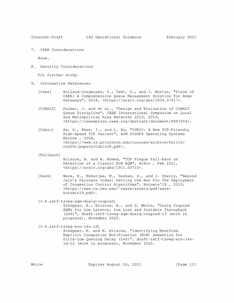
Internet-Draft L4S Operational Guidance February 2021
7. IANA Considerations
None.
8. Security Considerations
For further study.
9. Informative References
[Cake] Hoiland-Jorgensen, T., Taht, D., and J. Morton, "Piece of
CAKE: A Comprehensive Queue Management Solution for Home
Gateways", 2018, <https://arxiv.org/abs/1804.07617>.
[COBALT] Palmei, J. and et al., "Design and Evaluation of COBALT
Queue Discipline", IEEE International Symposium on Local
and Metropolitan Area Networks 2019, 2019,
<https://ieeexplore.ieee.org/abstract/document/8847054>.
[Cubic] Ha, S., Rhee, I., and L. Xu, "CUBIC: A New TCP-Friendly
High-Speed TCP Variant", ACM SIGOPS Operating Systems
Review , 2008,
<https://www.cs.princeton.edu/courses/archive/fall16/
cos561/papers/Cubic08.pdf>.
[Fallback]
Briscoe, B. and A. Ahmed, "TCP Prague Fall-back on
Detection of a Classic ECN AQM", ArXiv , Feb 2021,
<https://arxiv.org/abs/1911.00710>.
[Harm] Ware, R., Mukerjee, M., Seshan, S., and J. Sherry, "Beyond
Jain’s Fairness Index: Setting the Bar For The Deployment
of Congestion Control Algorithms", Hotnets’19 , 2019,
<https://www.cs.cmu.edu/˜rware/assets/pdf/ware-
hotnets19.pdf>.
[I-D.ietf-tsvwg-aqm-dualq-coupled]
Schepper, K., Briscoe, B., and G. White, "DualQ Coupled
AQMs for Low Latency, Low Loss and Scalable Throughput
(L4S)", draft-ietf-tsvwg-aqm-dualq-coupled-13 (work in
progress), November 2020.
[I-D.ietf-tsvwg-ecn-l4s-id]
Schepper, K. and B. Briscoe, "Identifying Modified
Explicit Congestion Notification (ECN) Semantics for
Ultra-Low Queuing Delay (L4S)", draft-ietf-tsvwg-ecn-l4s-
id-12 (work in progress), November 2020.
White Expires August 26, 2021 [Page 12]

Internet-Draft L4S Operational Guidance February 2021
[I-D.ietf-tsvwg-l4s-arch]
Briscoe, B., Schepper, K., Bagnulo, M., and G. White, "Low
Latency, Low Loss, Scalable Throughput (L4S) Internet
Service: Architecture", draft-ietf-tsvwg-l4s-arch-08 (work
in progress), November 2020.
[IANA-ECN]
Internet Assigned Numbers Authority, "IANA ECN Field
Assignments", 2018, <https://www.iana.org/assignments/
dscp-registry/dscp-registry.xhtml#ecn-field>.
[RFC3168] Ramakrishnan, K., Floyd, S., and D. Black, "The Addition
of Explicit Congestion Notification (ECN) to IP",
RFC 3168, DOI 10.17487/RFC3168, September 2001,
<https://www.rfc-editor.org/info/rfc3168>.
[RFC5348] Floyd, S., Handley, M., Padhye, J., and J. Widmer, "TCP
Friendly Rate Control (TFRC): Protocol Specification",
RFC 5348, DOI 10.17487/RFC5348, September 2008,
<https://www.rfc-editor.org/info/rfc5348>.
[RFC6040] Briscoe, B., "Tunnelling of Explicit Congestion
Notification", RFC 6040, DOI 10.17487/RFC6040, November
2010, <https://www.rfc-editor.org/info/rfc6040>.
[RFC8290] Hoeiland-Joergensen, T., McKenney, P., Taht, D., Gettys,
J., and E. Dumazet, "The Flow Queue CoDel Packet Scheduler
and Active Queue Management Algorithm", RFC 8290,
DOI 10.17487/RFC8290, January 2018,
<https://www.rfc-editor.org/info/rfc8290>.
[RFC8311] Black, D., "Relaxing Restrictions on Explicit Congestion
Notification (ECN) Experimentation", RFC 8311,
DOI 10.17487/RFC8311, January 2018,
<https://www.rfc-editor.org/info/rfc8311>.
Author’s Address
Greg White (editor)
CableLabs
Email: [email protected]
White Expires August 26, 2021 [Page 13]