IPPM Working Group M. Cociglio Internet-Draft Telecom Italia ...
303
IPPM Working Group M. Cociglio Internet-Draft Telecom Italia Intended status: Experimental G. Fioccola Expires: January 2, 2020 Huawei Technologies F. Bulgarella R. Sisto Politecnico di Torino July 1, 2019 New Spin bit enabled measurements with one or two more bits draft-cfb-ippm-spinbit-new-measurements-01 Abstract This document introduces additional measurements by using the same spin bit signal as defined in [I-D.trammell-ippm-spin]. The spin bit signal alone is not enough to evaluate correctly in every network condition the RTT of a flow. In order to solve this problem, it is theorized the possibility of introducing an additional validation signal called delay bit, similar to what is done done by the Valid Edge Counter (VEC), but using just one bit instead of two. An alternative with two bits is also introduced with a so called loss bit. Requirements Language The key words "MUST", "MUST NOT", "REQUIRED", "SHALL", "SHALL NOT", "SHOULD", "SHOULD NOT", "RECOMMENDED", "MAY", and "OPTIONAL" in this document are to be interpreted as described in RFC 2119 [RFC2119]. Status of This Memo This Internet-Draft is submitted in full conformance with the provisions of BCP 78 and BCP 79. Internet-Drafts are working documents of the Internet Engineering Task Force (IETF). Note that other groups may also distribute working documents as Internet-Drafts. The list of current Internet- Drafts is at https://datatracker.ietf.org/drafts/current/. Internet-Drafts are draft documents valid for a maximum of six months and may be updated, replaced, or obsoleted by other documents at any time. It is inappropriate to use Internet-Drafts as reference material or to cite them other than as "work in progress." This Internet-Draft will expire on January 2, 2020. Cociglio, et al. Expires January 2, 2020 [Page 1]
-
Upload
khangminh22 -
Category
Documents
-
view
3 -
download
0
Transcript of IPPM Working Group M. Cociglio Internet-Draft Telecom Italia ...

IPPM Working Group M. CociglioInternet-Draft Telecom ItaliaIntended status: Experimental G. FioccolaExpires: January 2, 2020 Huawei Technologies F. Bulgarella R. Sisto Politecnico di Torino July 1, 2019
New Spin bit enabled measurements with one or two more bits draft-cfb-ippm-spinbit-new-measurements-01
Abstract
This document introduces additional measurements by using the same spin bit signal as defined in [I-D.trammell-ippm-spin]. The spin bit signal alone is not enough to evaluate correctly in every network condition the RTT of a flow. In order to solve this problem, it is theorized the possibility of introducing an additional validation signal called delay bit, similar to what is done done by the Valid Edge Counter (VEC), but using just one bit instead of two. An alternative with two bits is also introduced with a so called loss bit.
Requirements Language
The key words "MUST", "MUST NOT", "REQUIRED", "SHALL", "SHALL NOT", "SHOULD", "SHOULD NOT", "RECOMMENDED", "MAY", and "OPTIONAL" in this document are to be interpreted as described in RFC 2119 [RFC2119].
Status of This Memo
This Internet-Draft is submitted in full conformance with the provisions of BCP 78 and BCP 79.
Internet-Drafts are working documents of the Internet Engineering Task Force (IETF). Note that other groups may also distribute working documents as Internet-Drafts. The list of current Internet- Drafts is at https://datatracker.ietf.org/drafts/current/.
Internet-Drafts are draft documents valid for a maximum of six months and may be updated, replaced, or obsoleted by other documents at any time. It is inappropriate to use Internet-Drafts as reference material or to cite them other than as "work in progress."
This Internet-Draft will expire on January 2, 2020.
Cociglio, et al. Expires January 2, 2020 [Page 1]

Internet-Draft July 2019
Copyright Notice
Copyright (c) 2019 IETF Trust and the persons identified as the document authors. All rights reserved.
This document is subject to BCP 78 and the IETF Trust’s Legal Provisions Relating to IETF Documents (https://trustee.ietf.org/license-info) in effect on the date of publication of this document. Please review these documents carefully, as they describe your rights and restrictions with respect to this document. Code Components extracted from this document must include Simplified BSD License text as described in Section 4.e of the Trust Legal Provisions and are provided without warranty as described in the Simplified BSD License.
Table of Contents
1. Introduction . . . . . . . . . . . . . . . . . . . . . . . . 2 2. Spin bit and Delay bit mechanism . . . . . . . . . . . . . . 3 2.1. Delay Sample generation . . . . . . . . . . . . . . . . . 5 2.1.1. The recovery process . . . . . . . . . . . . . . . . 5 2.2. Delay Sample reflection . . . . . . . . . . . . . . . . . 6 3. Using the Spin bit and Delay bit for Hybrid RTT Measurement . 7 3.1. End-to-end RTT measurement . . . . . . . . . . . . . . . 7 3.2. Half-RTT measurement . . . . . . . . . . . . . . . . . . 7 3.3. Intra-domain RTT measurement . . . . . . . . . . . . . . 7 4. Observer’s algorithm and Waiting Interval . . . . . . . . . . 8 5. Adding a Loss bit to Delay bit and Spin bit . . . . . . . . . 9 6. Round Trip Packet Loss measurement . . . . . . . . . . . . . 9 6.1. RTT dependent Packet Loss using one bit . . . . . . . . . 10 6.2. RTT independent Packet Loss using two bits . . . . . . . 10 7. Protocols . . . . . . . . . . . . . . . . . . . . . . . . . . 11 7.1. QUIC . . . . . . . . . . . . . . . . . . . . . . . . . . 11 7.2. TCP . . . . . . . . . . . . . . . . . . . . . . . . . . . 11 8. Security Considerations . . . . . . . . . . . . . . . . . . . 11 9. Acknowledgements . . . . . . . . . . . . . . . . . . . . . . 11 10. IANA Considerations . . . . . . . . . . . . . . . . . . . . . 11 11. References . . . . . . . . . . . . . . . . . . . . . . . . . 11 11.1. Normative References . . . . . . . . . . . . . . . . . . 11 11.2. Informative References . . . . . . . . . . . . . . . . . 12 Authors’ Addresses . . . . . . . . . . . . . . . . . . . . . . . 12
1. Introduction
[I-D.trammell-ippm-spin] defines an explicit per-flow transport-layer signal for hybrid measurement of end-to-end RTT. This signal consists of three bits: a spin bit, which oscillates once per end-to- end RTT, and a two-bit Valid Edge Counter (VEC), which compensates
Cociglio, et al. Expires January 2, 2020 [Page 2]

Internet-Draft July 2019
for loss and reordering of the spin bit to increase fidelity of the signal in less than ideal network conditions.
In this document it is introduced the delay bit, that is a single bit signal that can be used together with the spin bit by passive observers to measure the RTT of a network flow, avoiding the spin bit ambiguities that arise as soon as network conditions deteriorate. Unlike the spin bit, which is actually set in every packet transmitted on the network, the delay bit is set only once per round trip.
This document defines a hybrid measurement RFC 7799 [RFC7799] path signal to be embedded into a transport layer protocol, explicitly intended for exposing end-to-end RTT to measurement devices on path.
The document introduces a mechanism applicable to any transport-layer protocol, then explains how to bind the signal to a variety of IETF transport protocols, and in particular to QUIC and TCP.
The application of the Spin bit to QUIC is described in [I-D.ietf-quic-spin-exp] which adds the spin bit only (without the VEC) to QUIC for experimentation purposes.
Note that both the spin bit and the delay bit are inspired by RFC 8321 [RFC8321]. This is also mentioned in [I-D.trammell-quic-spin].
2. Spin bit and Delay bit mechanism
The main idea is to have a single packet, with a second marked bit (the delay bit), that bounces between client and server during the entire connection life. This single packet is called Delay Sample.
A simple observer placed in an intermediate point, tracking the delay sample and the relative timestamp in every spin bit period, can measure the end-to-end round trip delay of the connection. In the same way as seen with the spin bit and the VEC, it is possible to carry out other types of measurements. The next paragraphs give an overview of the observer capabilities.
In order to describe the delay sample working mechanism in detail, we have to distinguish two different phases which take part in the delay bit lifetime: initialization and reflection. The initialization is the generation of the delay sample, while the reflection realizes the bounce behavior of this single packet between the two endpoints.
The next figure describes the Delay bit mechanism: the first bit is the spin bit and the second one is the delay bit.
Cociglio, et al. Expires January 2, 2020 [Page 3]

Internet-Draft July 2019
+--------+ -- -- -- -- -- +--------+ | | -----------> | | | Client | | Server | | | <----------- | | +--------+ -- -- -- -- -- +--------+
(a) No traffic at beginning.
+--------+ 00 00 01 -- -- +--------+ | | -----------> | | | Client | | Server | | | <----------- | | +--------+ -- -- -- -- -- +--------+
(b) The Client starts sending data and sets the first packet as Delay Sample.
+--------+ 00 00 00 00 00 +--------+ | | -----------> | | | Client | | Server | | | <----------- | | +--------+ -- -- 01 00 00 +--------+
(c) The Server starts sending data and reflects the Delay Sample.
+--------+ 10 10 11 00 00 +--------+ | | -----------> | | | Client | | Server | | | <----------- | | +--------+ 00 00 00 00 00 +--------+
(d) The Client inverts the spin bit and reflects the Delay Sample.
+--------+ 10 10 10 10 10 +--------+ | | -----------> | | | Client | | Server | | | <----------- | | +--------+ 00 00 11 10 10 +--------+
(e) The Server reflects the Delay Sample.
+--------+ 00 00 01 10 10 +--------+ | | -----------> | | | Client | | Server | | | <----------- | | +--------+ 10 10 10 10 10 +--------+
Cociglio, et al. Expires January 2, 2020 [Page 4]

Internet-Draft July 2019
(f) The client reverts the spin bit and reflects the Delay Sample.
Figure 1: Spin bit and Delay bit
2.1. Delay Sample generation
During this first phase, endpoints play different roles. First of all a single delay sample must be bouncing per round trip period (and so per spin bit period). According to that statement and in order to simplify the general algorithm, the delay sample generation is in charge of just one of the two endpoints:
o the Client, when connection starts and spin bit is set to 0, initializes the delay bit of the first packet to 1, so it becomes the delay sample for that marking period. Only this packet is marked with the delay bit set to 1 for this round trip period; the other ones will carry only the spin bit;
o the server never initializes the delay bit to 1; its only task is to reflect the incoming delay bit into the next outgoing packet only if certain conditions occur.
Theoretically, in absence of network impairments, the delay sample should bounce between client and server continuously, for the entire duration of the connection. Actually, that is highly unlikely mainly for two different reasons:
1) the packet carrying the delay bit might be lost during its journey on the network which is unreliable by definition;
2) one of the two endpoints could stop or delay sending data because the application is limiting the amount of traffic transmitted;
To deal with these problems, the algorithm provides a procedure to regenerate the delay sample and to inform a possible observer that a problem has occurred, and then the measurement has to be restarted.
2.1.1. The recovery process
In order to relieve the server from tasks that go beyond the mere reflection of the sample, even in this case the recovery process belongs to the client. A fundamental assumption is that a delay sample is strictly related to its spin bit period. Considering this rule, the client verifies that every spin bit period ends with its delay sample. If that does not happen and a marking period
Cociglio, et al. Expires January 2, 2020 [Page 5]

Internet-Draft July 2019
terminates without a delay sample, the client waits a further empty period; then, in the following period, it reinitializes the mechanism by setting the delay bit of the first outgoing packet to 1, making it the new delay sample. The empty period is needed to inform the intermediate points that there was an issue and a new delay measurement session is starting.
2.2. Delay Sample reflection
The reflection is the process that enables the bouncing of the delay sample between client and server. The behavior of the two endpoints is slightly different. With the exception of the client that, as previously exposed, generates a new delay sample, by default the delay bit is set to 0.
Server side reflection: when a packet with the delay bit set to 1 arrives, the server marks the first packet in the opposite direction as the delay sample, if it has the same spin bit value. While if it has the opposite spin bit value this sample is considered lost.
Client side reflection: when a packet with delay bit set to 1 arrives, the client marks the first packet in the opposite direction as the delay sample, if it has the opposite spin bit value. While if it has the same spin bit value this sample is considered lost.
In both cases, if the outgoing marked packet is transmitted with a delay greater than a predetermined threshold after the reception of the incoming delay sample (1ms by default), reflection is aborted and this sample is considered lost.
It is noteworthy that differently from what happens with the VEC for which the reflection always concerns the edge of the period, in this case reflection takes place for the packet that is carrying the delay bit regardless of its position within the period. For this reason it is necessary to introduce that condition of validation in order to identify and discard those samples that, due to reordering, might move to a contiguous period. Furthermore, by introducing a threshold for the retransmission delay of the sample, it is possible to eliminate all those measurements which, due to lack of traffic on the endpoints, would be overestimated and not true. Thus, the maximum estimation error, without considering any other delays due to flow control, would amount to twice the threshold (e.g. 2ms) per measurement, in the worst case.
Cociglio, et al. Expires January 2, 2020 [Page 6]

Internet-Draft July 2019
3. Using the Spin bit and Delay bit for Hybrid RTT Measurement
Unlike what happens with the spin bit for which it is necessary to validate or at least heuristically evaluate the goodness of an edge, the delay sample can be used by an intermediate observer as a simple demarcator between a period and the following one eliminating the ambiguities on the calculation of the RTT found with the analysis of the spin-bit only. The measurement types, that can be done from the observation of the delay sample, are exactly the same achievable with the spin bit only (with or without the VEC).
3.1. End-to-end RTT measurement
The delay sample generation process ensures that only one packet marked with the delay bit set to 1 runs back and forth on the wire between two endpoints per round trip time. Therefore, in order to determine the end-to-end RTT measurement of a QUIC flow, an on-path passive observer can simply compute the time difference between two delay samples observed in a single direction. Note that a measurement, to be valid, must take into account the difference in time between the timestamps of two consecutive delay samples belonging to adjacent spin-bit periods. For this reason, an observer, in addition to intercepting and analyzing the packets containing the delay bit set to 1, must maintain awareness of each spin period in such a way as to be able to assign each delay sample to its period and, at the same time, identifying those periods that do not contain it.
3.2. Half-RTT measurement
An on-path passive observer that is sniffing traffic in both directions -- from client to server and from server to client -- can also use the delay sample to measure "upstream" and "downstream" RTT components. Also known as the half-RTT measurement, it represents the components of the end-to-end RTT concerning the paths between the client and the observer (upstream), and the observer and the server (downstream). It does this by measuring the delay between a delay sample observed in the downstream direction and the one observed in the upstream direction, and vice versa. Also in this case, it should verify that the two delay samples belong to two adjacent periods, for the upstream component, or to the same period for the downstream component.
3.3. Intra-domain RTT measurement
Taking advantage of the half-RTT measurements it is also possible to calculate the intra-domain RTT which is the portion of the entire RTT used by a QUIC flow to traverse the network of a provider (or part of
Cociglio, et al. Expires January 2, 2020 [Page 7]

Internet-Draft July 2019
it). To achieve this result two observers, able to watch traffic in both directions, must be employed simultaneously at ingress and egress of the network to be measured. At this point, to determine the delay between the two observers, it is enough to subtract the two computed upstream (or downstream) RTT components.
The spin bit is an alternate marking generated signal and the only difference than RFC 8321 [RFC8321] is the size of the alternation that will change with the flight size each RTT. So it can be useful to segment the RTT and deduce the contribution to the RTT of the portion of the network between two on-path observers and it can be easily performed by calculating the delay between two or more measurement points on a single direction by applying RFC 8321 [RFC8321].
4. Observer’s algorithm and Waiting Interval
Given below is a formal summary of the functioning of the observer every time a delay sample is detected. A packet containing the delay bit set to 1:
o if it has the same spin bit value of the current period and no delay sample was detected in the previous period, then it can be used as a left edge (i.e., to start measuring an RTT sample), but not as a right edge (i.e., to complete and RTT measurement since the last edge). If the observation point is symmetric (i.e., it can see both upstream and downstream packets in the flow) and in the current period a delay sample was detected in the opposite direction (i.e., in the upstream direction), the packet can also be used to compute the downstream RTT component.
o if it has the same spin bit value of the current period and a delay sample was detected in the previous period, then it can be used at the same time as a left or right edge, and to compute RTT component in both directions.
Like stated previously, every time an empty period is detected, the observer must restart the measurement process and consider the next delay sample that will come as the beginning of a new measure, then as a left edge. As a result, being able to assign the delay sample to the corresponding spin period becomes a crucial factor for the proper functioning of the entire algorithm.
Considering that the division into periods is realized by exploiting the spin bit square wave, it is easy to understand that the presence of spurious spin edges -- caused by packet reordering -- would inevitably lead the observer to overestimate the amount of periods actually present in the transmission. This results in a greater
Cociglio, et al. Expires January 2, 2020 [Page 8]

Internet-Draft July 2019
number of empty periods detected and the consequent decrease of the actual RTT samples achievable. Therefore, in order to maximize the performance of the whole algorithm, the observer must implement a mechanism to filter out spurious spin edges.
To face this problem the waiting interval has to be introduced. Basically, every time a spin bit edge is detected, the observer sets a time interval during which it rejects every potential spurious edges observed on the wire. While, at the end of the interval it starts again to accept changes in the spin bit value. This guarantees a proper protection against the spurious edges in relation to the size of the interval itself. For instance, an interval of 5ms is able to filter out edges that have been reordered by a maximum of 5ms. Clearly, the mechanism does its job for intervals smaller than the RTT of the observed connection (if RTT is smaller than the waiting interval the observer can’t measure the RTT).
5. Adding a Loss bit to Delay bit and Spin bit
It is possible to introduce a mechanism to evaluate also the packet loss together with the delay measurement. In particular, the Client can select and mark a train of packets for this purpose, by using a loss bit, additionally to the spin bit and delay bit.
These packets bounce between Client and Server to complete two rounds and an Observer counts the marked packets during the two rounds and compares the counters to find Round Trip(RT) losses.
The problem to be solved is to choose the right number of packets to mark to avoid marked packets congestion on the slowest traffic direction. But the solution is simple, because it is enough to choose the number of packets that transit on the slowest direction during an RTT.
6. Round Trip Packet Loss measurement
The Client generates a train of marked packets (Packet Loss Samples) by using the additional bit called Loss bit. The marked packets are generated at the slowest direction rate (only when a packet arrives the Client marks an outgoing packet). The Server reflects these packets accordingly and, as a consequence, it could insert some not- marked packets. Then the client reflects the marked packets and the server reflects the marked packets again. The Client generates a new train of marked packets and so on.
The Packet Loss calculation can be made after the comparison of counters taken by the on-path passive observer. Indeed the Observer in the middle (upstream or downstream) sees the packet train twice
Cociglio, et al. Expires January 2, 2020 [Page 9]

Internet-Draft July 2019
and so it calculates the Observer Round Trip Packet Loss that, statistically, will be equal to the end-to-end Round Trip Packet Loss. So this measurement can be simply referred as Round Trip Packet Loss (RTPL).
In addition, this methodology allows Half-RTPL measurement and Intra- domain RTPL measurement, in the same way as described in the previous Sections for RTT measurement.
The method allows the packet loss calculation for a portion of the traffic but it is useful to perform RT Packet Loss measurement that gives useful information coupled with RTT.
6.1. RTT dependent Packet Loss using one bit
Using a single bit in addition to the spin bit and delay bit enables passive measurability of the end-to-end round-trip loss rate.
The algorithm requires a mechanism to individually identify each train of packets in order to enable the observer to distinguish between trains belonging to different rounds. This is achieved by introducing a temporal pause of 2*RTT duration during which no marked packets are forwarded. Marked packets are generated by the client for the duration of an RTT in order to be synchronized with the spin bit algorithm and to have a sufficient numbers of marked packets.
However, this single bit methodology replies and exposes the RTT of the connection in any case, when the spin bit and the delay bit are used and when these are disabled.
6.2. RTT independent Packet Loss using two bits
An RTT independent version of this algorithm requires two bits and can be used when both spin bit and delay bit are disabled.This implies that an observer must be able to determine whether the spin bit is active and correctly spinning or not (choosing, accordingly, the right version of packet loss measurement to be used).
Without using the spin bit, it is difficult to find the right pause duration but, with a two bits packet loss field, the temporal pause necessary to distinguish the different train of packets is no longer needed. That’s because packets generated and reflected by the client are marked using two different marking values. Furthermore, instead of generating marked packets for the duration of an RTT, a fixed duration for the generation phase can be used (e.g. 100ms).
In this way, no information related to the RTT of the connection is transmitted on the wire.
Cociglio, et al. Expires January 2, 2020 [Page 10]
Internet-Draft July 2019
7. Protocols
7.1. QUIC
The binding of this signal to QUIC is partially described in [I-D.ietf-quic-spin-exp], which adds the spin bit only to QUIC.
From an implementation point of view, the delay bit is placed in the partially unencrypted (but authenticated) QUIC header, alongside the spin bit, occupying one of the two bits left reserved for future experiments. As things stand, according to [I-D.ietf-quic-transport], the proposed scheme of the first header’s byte would be 01SDRKPP.
7.2. TCP
The signal can be added to TCP by defining bit 4 of bytes 13-14 of the TCP header to carry the spin bit, and eventually bits 5 and 6 to carry additional information, like the delay bit and the loss bit.
8. Security Considerations
The privacy considerations for the hybrid RTT measurement signal are essentially the same as those for passive RTT measurement in general.
9. Acknowledgements
tbc
10. IANA Considerations
tbc
11. References
11.1. Normative References
[I-D.ietf-quic-spin-exp] Trammell, B. and M. Kuehlewind, "The QUIC Latency Spin Bit", draft-ietf-quic-spin-exp-01 (work in progress), October 2018.
[I-D.ietf-quic-transport] Iyengar, J. and M. Thomson, "QUIC: A UDP-Based Multiplexed and Secure Transport", draft-ietf-quic-transport-20 (work in progress), April 2019.
Cociglio, et al. Expires January 2, 2020 [Page 11]

Internet-Draft July 2019
[RFC2119] Bradner, S., "Key words for use in RFCs to Indicate Requirement Levels", BCP 14, RFC 2119, DOI 10.17487/RFC2119, March 1997, <https://www.rfc-editor.org/info/rfc2119>.
[RFC7799] Morton, A., "Active and Passive Metrics and Methods (with Hybrid Types In-Between)", RFC 7799, DOI 10.17487/RFC7799, May 2016, <https://www.rfc-editor.org/info/rfc7799>.
[RFC8321] Fioccola, G., Ed., Capello, A., Cociglio, M., Castaldelli, L., Chen, M., Zheng, L., Mirsky, G., and T. Mizrahi, "Alternate-Marking Method for Passive and Hybrid Performance Monitoring", RFC 8321, DOI 10.17487/RFC8321, January 2018, <https://www.rfc-editor.org/info/rfc8321>.
11.2. Informative References
[I-D.trammell-ippm-spin] Trammell, B., "An Explicit Transport-Layer Signal for Hybrid RTT Measurement", draft-trammell-ippm-spin-00 (work in progress), January 2019.
[I-D.trammell-quic-spin] Trammell, B., Vaere, P., Even, R., Fioccola, G., Fossati, T., Ihlar, M., Morton, A., and S. Emile, "Adding Explicit Passive Measurability of Two-Way Latency to the QUIC Transport Protocol", draft-trammell-quic-spin-03 (work in progress), May 2018.
Authors’ Addresses
Mauro Cociglio Telecom Italia Via Reiss Romoli, 274 Torino 10148 Italy
Email: [email protected]
Giuseppe Fioccola Huawei Technologies Riesstrasse, 25 Munich 80992 Germany
Email: [email protected]
Cociglio, et al. Expires January 2, 2020 [Page 12]

Internet-Draft July 2019
Fabio Bulgarella Politecnico di Torino
Email: [email protected]
Riccardo Sisto Politecnico di Torino Corso Duca degli Abruzzi, 24 Torino 10129 Italy
Email: [email protected]
Cociglio, et al. Expires January 2, 2020 [Page 13]

SPRING Working Group R. Gandhi, Ed.Internet-Draft C. FilsfilsIntended status: Standards Track Cisco Systems, Inc.Expires: April 24, 2021 D. Voyer Bell Canada M. Chen Huawei B. Janssens Colt October 21, 2020
Performance Measurement Using TWAMP Light for Segment Routing Networks draft-gandhi-spring-twamp-srpm-11
Abstract
Segment Routing (SR) leverages the source routing paradigm. SR is applicable to both Multiprotocol Label Switching (SR-MPLS) and IPv6 (SRv6) data planes. This document specifies procedure for sending and processing probe query and response messages for Performance Measurement (PM) in Segment Routing networks. The procedure uses the mechanisms defined in RFC 5357 (Two-Way Active Measurement Protocol (TWAMP) Light) and its extensions for Performance Measurement. The procedure specified is applicable to SR-MPLS and SRv6 data planes and is used for both Links and end-to-end SR Paths including SR Policies.
Status of This Memo
This Internet-Draft is submitted in full conformance with the provisions of BCP 78 and BCP 79.
Internet-Drafts are working documents of the Internet Engineering Task Force (IETF). Note that other groups may also distribute working documents as Internet-Drafts. The list of current Internet- Drafts is at https://datatracker.ietf.org/drafts/current/.
Internet-Drafts are draft documents valid for a maximum of six months and may be updated, replaced, or obsoleted by other documents at any time. It is inappropriate to use Internet-Drafts as reference material or to cite them other than as "work in progress."
This Internet-Draft will expire on April 24, 2021.
Gandhi, et al. Expires April 24, 2021 [Page 1]

Internet-Draft Using TWAMP Light for Segment Routing October 2020
Copyright Notice
Copyright (c) 2020 IETF Trust and the persons identified as the document authors. All rights reserved.
This document is subject to BCP 78 and the IETF Trust’s Legal Provisions Relating to IETF Documents (https://trustee.ietf.org/license-info) in effect on the date of publication of this document. Please review these documents carefully, as they describe your rights and restrictions with respect to this document. Code Components extracted from this document must include Simplified BSD License text as described in Section 4.e of the Trust Legal Provisions and are provided without warranty as described in the Simplified BSD License.
Table of Contents
1. Introduction . . . . . . . . . . . . . . . . . . . . . . . . 3 2. Conventions Used in This Document . . . . . . . . . . . . . . 3 2.1. Requirements Language . . . . . . . . . . . . . . . . . . 3 2.2. Abbreviations . . . . . . . . . . . . . . . . . . . . . . 3 2.3. Reference Topology . . . . . . . . . . . . . . . . . . . 4 3. Overview . . . . . . . . . . . . . . . . . . . . . . . . . . 5 3.1. Example Provisioning Model . . . . . . . . . . . . . . . 6 4. Probe Messages . . . . . . . . . . . . . . . . . . . . . . . 7 4.1. Probe Query Message . . . . . . . . . . . . . . . . . . . 7 4.1.1. Delay Measurement Query Message . . . . . . . . . . . 7 4.1.2. Loss Measurement Query Message . . . . . . . . . . . 8 4.1.3. Probe Query for Links . . . . . . . . . . . . . . . . 9 4.1.4. Probe Query for SR Policy . . . . . . . . . . . . . . 9 4.2. Probe Response Message . . . . . . . . . . . . . . . . . 11 4.2.1. One-way Measurement Mode . . . . . . . . . . . . . . 11 4.2.2. Two-way Measurement Mode . . . . . . . . . . . . . . 11 4.2.3. Loopback Measurement Mode . . . . . . . . . . . . . . 13 4.3. Additional Probe Message Processing Rules . . . . . . . . 14 4.3.1. TTL and Hop Limit . . . . . . . . . . . . . . . . . . 14 4.3.2. Router Alert Option . . . . . . . . . . . . . . . . . 14 4.3.3. UDP Checksum . . . . . . . . . . . . . . . . . . . . 14 5. Performance Measurement for P2MP SR Policies . . . . . . . . 14 6. ECMP Support for SR Policies . . . . . . . . . . . . . . . . 16 7. Performance Delay and Liveness Monitoring . . . . . . . . . . 16 8. Security Considerations . . . . . . . . . . . . . . . . . . . 16 9. IANA Considerations . . . . . . . . . . . . . . . . . . . . . 17 10. References . . . . . . . . . . . . . . . . . . . . . . . . . 17 10.1. Normative References . . . . . . . . . . . . . . . . . . 17 10.2. Informative References . . . . . . . . . . . . . . . . . 17 Acknowledgments . . . . . . . . . . . . . . . . . . . . . . . . . 20 Authors’ Addresses . . . . . . . . . . . . . . . . . . . . . . . 21
Gandhi, et al. Expires April 24, 2021 [Page 2]

Internet-Draft Using TWAMP Light for Segment Routing October 2020
1. Introduction
Segment Routing (SR) leverages the source routing paradigm and greatly simplifies network operations for Software Defined Networks (SDNs). SR is applicable to both Multiprotocol Label Switching (SR- MPLS) and IPv6 (SRv6) data planes. SR takes advantage of the Equal- Cost Multipaths (ECMPs) between source and transit nodes, between transit nodes and between transit and destination nodes. SR Policies as defined in [I-D.ietf-spring-segment-routing-policy] are used to steer traffic through a specific, user-defined paths using a stack of Segments. Built-in SR Performance Measurement (PM) is one of the essential requirements to provide Service Level Agreements (SLAs).
The One-Way Active Measurement Protocol (OWAMP) defined in [RFC4656] and Two-Way Active Measurement Protocol (TWAMP) defined in [RFC5357] provide capabilities for the measurement of various performance metrics in IP networks using probe messages. These protocols rely on control-channel signaling to establish a test-channel over an UDP path. The TWAMP Light [Appendix I in RFC5357] [BBF.TR-390] provides simplified mechanisms for active performance measurement in Customer IP networks by provisioning UDP paths and eliminates the need for control-channel signaling.
This document specifies procedures for sending and processing probe query and response messages for Performance Measurement in SR networks. The procedure uses the mechanisms defined in [RFC5357] (TWAMP Light) and its extensions for Performance Measurement. The procedure specified is applicable to SR-MPLS and SRv6 data planes and is used for both Links and end-to-end SR Paths including SR Policies and Flex-Algo IGP Paths. Unless otherwise specified, the mechanisms defined in [RFC5357] are not modified by this document.
2. Conventions Used in This Document
2.1. Requirements Language
The key words "MUST", "MUST NOT", "REQUIRED", "SHALL", "SHALL NOT", "SHOULD", "SHOULD NOT", "RECOMMENDED", "MAY", and "OPTIONAL" in this document are to be interpreted as described in [RFC2119] [RFC8174] when, and only when, they appear in all capitals, as shown here.
2.2. Abbreviations
BSID: Binding Segment ID.
DM: Delay Measurement.
ECMP: Equal Cost Multi-Path.
Gandhi, et al. Expires April 24, 2021 [Page 3]
Internet-Draft Using TWAMP Light for Segment Routing October 2020
HMAC: Hashed Message Authentication Code.
LM: Loss Measurement.
MPLS: Multiprotocol Label Switching.
NTP: Network Time Protocol.
OWAMP: One-Way Active Measurement Protocol.
PM: Performance Measurement.
PSID: Path Segment Identifier.
PTP: Precision Time Protocol.
SID: Segment ID.
SL: Segment List.
SR: Segment Routing.
SRH: Segment Routing Header.
SR-MPLS: Segment Routing with MPLS data plane.
SRv6: Segment Routing with IPv6 data plane.
TC: Traffic Class.
TWAMP: Two-Way Active Measurement Protocol.
2.3. Reference Topology
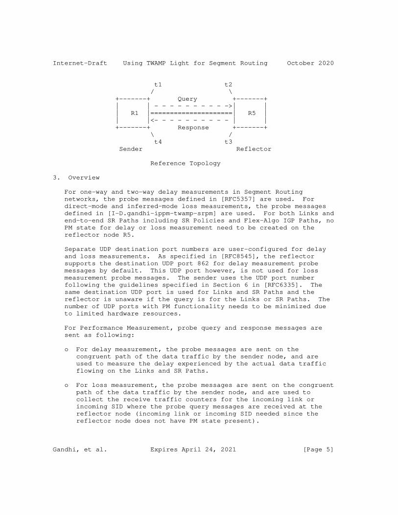
In the reference topology shown below, the sender node R1 initiates a performance measurement probe query message and the reflector node R5 sends a probe response message for the query message received. The probe response message is typically sent to the sender node R1.
SR is enabled on nodes R1 and R5. The nodes R1 and R5 may be directly connected via a Link or there exists a Point-to-Point (P2P) SR Path e.g. SR Policy [I-D.ietf-spring-segment-routing-policy] on node R1 (called head-end) with destination to node R5 (called tail- end).
Gandhi, et al. Expires April 24, 2021 [Page 4]
Internet-Draft Using TWAMP Light for Segment Routing October 2020
t1 t2 / \ +-------+ Query +-------+ | | - - - - - - - - - ->| | | R1 |=====================| R5 | | |<- - - - - - - - - - | | +-------+ Response +-------+ \ / t4 t3 Sender Reflector
Reference Topology
3. Overview
For one-way and two-way delay measurements in Segment Routing networks, the probe messages defined in [RFC5357] are used. For direct-mode and inferred-mode loss measurements, the probe messages defined in [I-D.gandhi-ippm-twamp-srpm] are used. For both Links and end-to-end SR Paths including SR Policies and Flex-Algo IGP Paths, no PM state for delay or loss measurement need to be created on the reflector node R5.
Separate UDP destination port numbers are user-configured for delay and loss measurements. As specified in [RFC8545], the reflector supports the destination UDP port 862 for delay measurement probe messages by default. This UDP port however, is not used for loss measurement probe messages. The sender uses the UDP port number following the guidelines specified in Section 6 in [RFC6335]. The same destination UDP port is used for Links and SR Paths and the reflector is unaware if the query is for the Links or SR Paths. The number of UDP ports with PM functionality needs to be minimized due to limited hardware resources.
For Performance Measurement, probe query and response messages are sent as following:
o For delay measurement, the probe messages are sent on the congruent path of the data traffic by the sender node, and are used to measure the delay experienced by the actual data traffic flowing on the Links and SR Paths.
o For loss measurement, the probe messages are sent on the congruent path of the data traffic by the sender node, and are used to collect the receive traffic counters for the incoming link or incoming SID where the probe query messages are received at the reflector node (incoming link or incoming SID needed since the reflector node does not have PM state present).
Gandhi, et al. Expires April 24, 2021 [Page 5]
Internet-Draft Using TWAMP Light for Segment Routing October 2020
The In-Situ Operations, Administration, and Maintenance (IOAM) mechanisms for SR-MPLS defined in [I-D.gandhi-mpls-ioam-sr] and for SRv6 defined in [I-D.ali-spring-ioam-srv6] are used to carry PM information such as timestamp in-band as part of the data packets, and are outside the scope of this document.
3.1. Example Provisioning Model
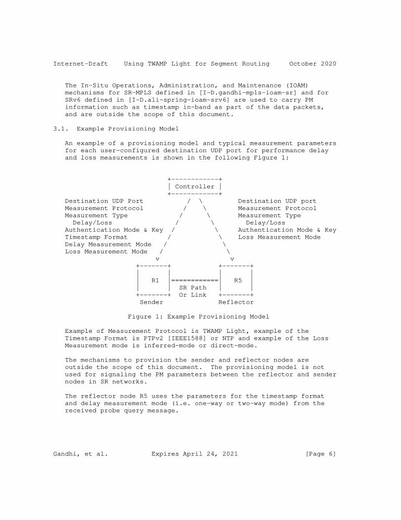
An example of a provisioning model and typical measurement parameters for each user-configured destination UDP port for performance delay and loss measurements is shown in the following Figure 1:
+------------+ | Controller | +------------+ Destination UDP Port / \ Destination UDP port Measurement Protocol / \ Measurement Protocol Measurement Type / \ Measurement Type Delay/Loss / \ Delay/Loss Authentication Mode & Key / \ Authentication Mode & Key Timestamp Format / \ Loss Measurement Mode Delay Measurement Mode / \ Loss Measurement Mode / \ v v +-------+ +-------+ | | | | | R1 |============| R5 | | | SR Path | | +-------+ Or Link +-------+ Sender Reflector
Figure 1: Example Provisioning Model
Example of Measurement Protocol is TWAMP Light, example of the Timestamp Format is PTPv2 [IEEE1588] or NTP and example of the Loss Measurement mode is inferred-mode or direct-mode.
The mechanisms to provision the sender and reflector nodes are outside the scope of this document. The provisioning model is not used for signaling the PM parameters between the reflector and sender nodes in SR networks.
The reflector node R5 uses the parameters for the timestamp format and delay measurement mode (i.e. one-way or two-way mode) from the received probe query message.
Gandhi, et al. Expires April 24, 2021 [Page 6]
Internet-Draft Using TWAMP Light for Segment Routing October 2020
4. Probe Messages
4.1. Probe Query Message
The probe messages defined in [RFC5357] are used for delay measurement for Links and end-to-end SR Paths including SR Policies. For loss measurement, the probe messages defined in [I-D.gandhi-ippm- twamp-srpm] are used.
4.1.1. Delay Measurement Query Message
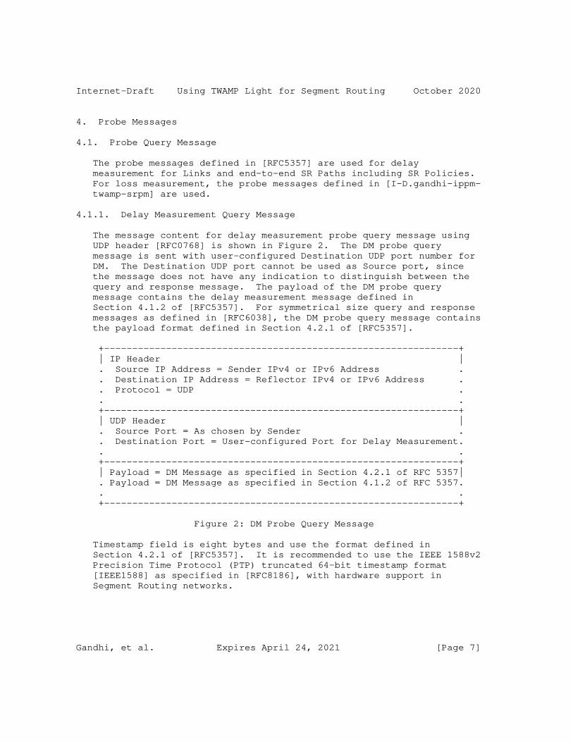
The message content for delay measurement probe query message using UDP header [RFC0768] is shown in Figure 2. The DM probe query message is sent with user-configured Destination UDP port number for DM. The Destination UDP port cannot be used as Source port, since the message does not have any indication to distinguish between the query and response message. The payload of the DM probe query message contains the delay measurement message defined in Section 4.1.2 of [RFC5357]. For symmetrical size query and response messages as defined in [RFC6038], the DM probe query message contains the payload format defined in Section 4.2.1 of [RFC5357].
+---------------------------------------------------------------+ | IP Header | . Source IP Address = Sender IPv4 or IPv6 Address . . Destination IP Address = Reflector IPv4 or IPv6 Address . . Protocol = UDP . . . +---------------------------------------------------------------+ | UDP Header | . Source Port = As chosen by Sender . . Destination Port = User-configured Port for Delay Measurement. . . +---------------------------------------------------------------+ | Payload = DM Message as specified in Section 4.2.1 of RFC 5357| . Payload = DM Message as specified in Section 4.1.2 of RFC 5357. . . +---------------------------------------------------------------+
Figure 2: DM Probe Query Message
Timestamp field is eight bytes and use the format defined in Section 4.2.1 of [RFC5357]. It is recommended to use the IEEE 1588v2 Precision Time Protocol (PTP) truncated 64-bit timestamp format [IEEE1588] as specified in [RFC8186], with hardware support in Segment Routing networks.
Gandhi, et al. Expires April 24, 2021 [Page 7]
Internet-Draft Using TWAMP Light for Segment Routing October 2020
4.1.1.1. Delay Measurement Authentication Mode
When using the authenticated mode for delay measurement, the matching authentication type (e.g. HMAC-SHA-256) and key are user-configured on both the sender and reflector nodes. A separate user-configured destination UDP port is used for the delay measurement in authentication mode due to the different probe message format.
4.1.2. Loss Measurement Query Message
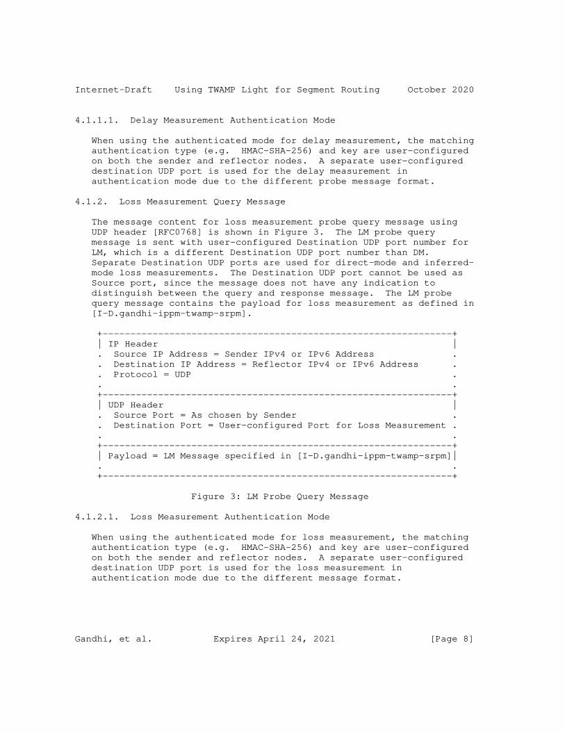
The message content for loss measurement probe query message using UDP header [RFC0768] is shown in Figure 3. The LM probe query message is sent with user-configured Destination UDP port number for LM, which is a different Destination UDP port number than DM. Separate Destination UDP ports are used for direct-mode and inferred- mode loss measurements. The Destination UDP port cannot be used as Source port, since the message does not have any indication to distinguish between the query and response message. The LM probe query message contains the payload for loss measurement as defined in [I-D.gandhi-ippm-twamp-srpm].
+---------------------------------------------------------------+ | IP Header | . Source IP Address = Sender IPv4 or IPv6 Address . . Destination IP Address = Reflector IPv4 or IPv6 Address . . Protocol = UDP . . . +---------------------------------------------------------------+ | UDP Header | . Source Port = As chosen by Sender . . Destination Port = User-configured Port for Loss Measurement . . . +---------------------------------------------------------------+ | Payload = LM Message specified in [I-D.gandhi-ippm-twamp-srpm]| . . +---------------------------------------------------------------+
Figure 3: LM Probe Query Message
4.1.2.1. Loss Measurement Authentication Mode
When using the authenticated mode for loss measurement, the matching authentication type (e.g. HMAC-SHA-256) and key are user-configured on both the sender and reflector nodes. A separate user-configured destination UDP port is used for the loss measurement in authentication mode due to the different message format.
Gandhi, et al. Expires April 24, 2021 [Page 8]

Internet-Draft Using TWAMP Light for Segment Routing October 2020
4.1.3. Probe Query for Links
The probe query message as defined in Figure 2 for delay measurement and Figure 3 for loss measurement are used for Links which may be physical, virtual or LAG (bundle), LAG (bundle) member, numbered/ unnumbered Links. The probe messages are pre-routed over the Link for both delay and loss measurement. The local and remote IP addresses of the link are used as Source and Destination Addresses. They can also be IPv6 link local address as probe messages are pre- routed.
4.1.4. Probe Query for SR Policy
The performance delay and loss measurement for segment routing is applicable to both end-to-end SR-MPLS and SRv6 Policies.
The sender IPv4 or IPv6 address is used as the source address. The endpoint IPv4 or IPv6 address is used as the destination address. In the case of SR Policy with IPv4 endpoint of 0.0.0.0 or IPv6 endpoint of ::0 [I-D.ietf-spring-segment-routing-policy], the loopback address from range 127/8 for IPv4, or the loopback address ::1/128 for IPv6 is used as the destination address, respectively.
4.1.4.1. Probe Query Message for SR-MPLS Policy
The probe query messages for performance measurement of an end-to-end SR-MPLS Policy is sent using its SR-MPLS header containing the MPLS segment list as shown in Figure 4.
0 1 2 3 0 1 2 3 4 5 6 7 8 9 0 1 2 3 4 5 6 7 8 9 0 1 2 3 4 5 6 7 8 9 0 1 +-+-+-+-+-+-+-+-+-+-+-+-+-+-+-+-+-+-+-+-+-+-+-+-+-+-+-+-+-+-+-+-+ | Segment(1) | TC |S| TTL | +-+-+-+-+-+-+-+-+-+-+-+-+-+-+-+-+-+-+-+-+-+-+-+-+-+-+-+-+-+-+-+-+ . . . . . . +-+-+-+-+-+-+-+-+-+-+-+-+-+-+-+-+-+-+-+-+-+-+-+-+-+-+-+-+-+-+-+-+ | Segment(n) | TC |S| TTL | +-+-+-+-+-+-+-+-+-+-+-+-+-+-+-+-+-+-+-+-+-+-+-+-+-+-+-+-+-+-+-+-+ | PSID | TC |S| TTL | +-+-+-+-+-+-+-+-+-+-+-+-+-+-+-+-+-+-+-+-+-+-+-+-+-+-+-+-+-+-+-+-+ | Message as shown in Figure 2 for DM or Figure 3 for LM | . . +---------------------------------------------------------------+
Figure 4: Example Probe Query Message for SR-MPLS Policy
Gandhi, et al. Expires April 24, 2021 [Page 9]

Internet-Draft Using TWAMP Light for Segment Routing October 2020
The Segment List (SL) can be empty to indicate Implicit NULL label case for a single-hop SR Policy.
The Path Segment Identifier (PSID) [I-D.ietf-spring-mpls-path-segment] of the SR-MPLS Policy is used for accounting received traffic on the egress node for loss measurement.
4.1.4.2. Probe Query Message for SRv6 Policy
An SRv6 Policy setup using the SRv6 Segment Routing Header (SRH) and a Segment List as defined in [RFC8754]. The SRv6 network programming is defined in [I-D.ietf-spring-srv6-network-programming]. The probe query messages for performance measurement of an end-to-end SRv6 Policy is sent using its SRH with Segment List as shown in Figure 5. The procedure defined for upper-layer header processing for SRv6 SIDs in [I-D.ietf-spring-srv6-network-programming] is used to process the UDP header in the received probe query messages.
+---------------------------------------------------------------+ | IP Header | . Source IP Address = Sender IPv6 Address . . Destination IP Address = Destination IPv6 Address . . . +---------------------------------------------------------------+ | SRH as specified in RFC 8754 | . <Segment List> . . . +---------------------------------------------------------------+ | IP Header (as needed) | . Source IP Address = Sender IPv6 Address . . Destination IP Address = Reflector IPv6 Address . . . +---------------------------------------------------------------+ | UDP Header | . Source Port = As chosen by Sender . . Destination Port = User-configured Port . . . +---------------------------------------------------------------+ | Payload = DM Message as specified in Section 4.2.1 of RFC 5357| . Payload = DM Message as specified in Section 4.1.2 of RFC 5357. . Payload = LM Message specified in [I-D.gandhi-ippm-twamp-srpm]. . . +---------------------------------------------------------------+
Figure 5: Example Probe Query Message for SRv6 Policy
Gandhi, et al. Expires April 24, 2021 [Page 10]
Internet-Draft Using TWAMP Light for Segment Routing October 2020
4.2. Probe Response Message
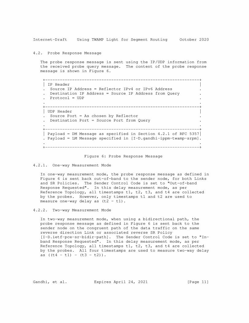
The probe response message is sent using the IP/UDP information from the received probe query message. The content of the probe response message is shown in Figure 6.
+---------------------------------------------------------------+ | IP Header | . Source IP Address = Reflector IPv4 or IPv6 Address . . Destination IP Address = Source IP Address from Query . . Protocol = UDP . . . +---------------------------------------------------------------+ | UDP Header | . Source Port = As chosen by Reflector . . Destination Port = Source Port from Query . . . +---------------------------------------------------------------+ | Payload = DM Message as specified in Section 4.2.1 of RFC 5357| . Payload = LM Message specified in [I-D.gandhi-ippm-twamp-srpm]. . . +---------------------------------------------------------------+
Figure 6: Probe Response Message
4.2.1. One-way Measurement Mode
In one-way measurement mode, the probe response message as defined in Figure 6 is sent back out-of-band to the sender node, for both Links and SR Policies. The Sender Control Code is set to "Out-of-band Response Requested". In this delay measurement mode, as per Reference Topology, all timestamps t1, t2, t3, and t4 are collected by the probes. However, only timestamps t1 and t2 are used to measure one-way delay as (t2 - t1).
4.2.2. Two-way Measurement Mode
In two-way measurement mode, when using a bidirectional path, the probe response message as defined in Figure 6 is sent back to the sender node on the congruent path of the data traffic on the same reverse direction Link or associated reverse SR Policy [I-D.ietf-pce-sr-bidir-path]. The Sender Control Code is set to "In- band Response Requested". In this delay measurement mode, as per Reference Topology, all timestamps t1, t2, t3, and t4 are collected by the probes. All four timestamps are used to measure two-way delay as ((t4 - t1) - (t3 - t2)).
Gandhi, et al. Expires April 24, 2021 [Page 11]
Internet-Draft Using TWAMP Light for Segment Routing October 2020
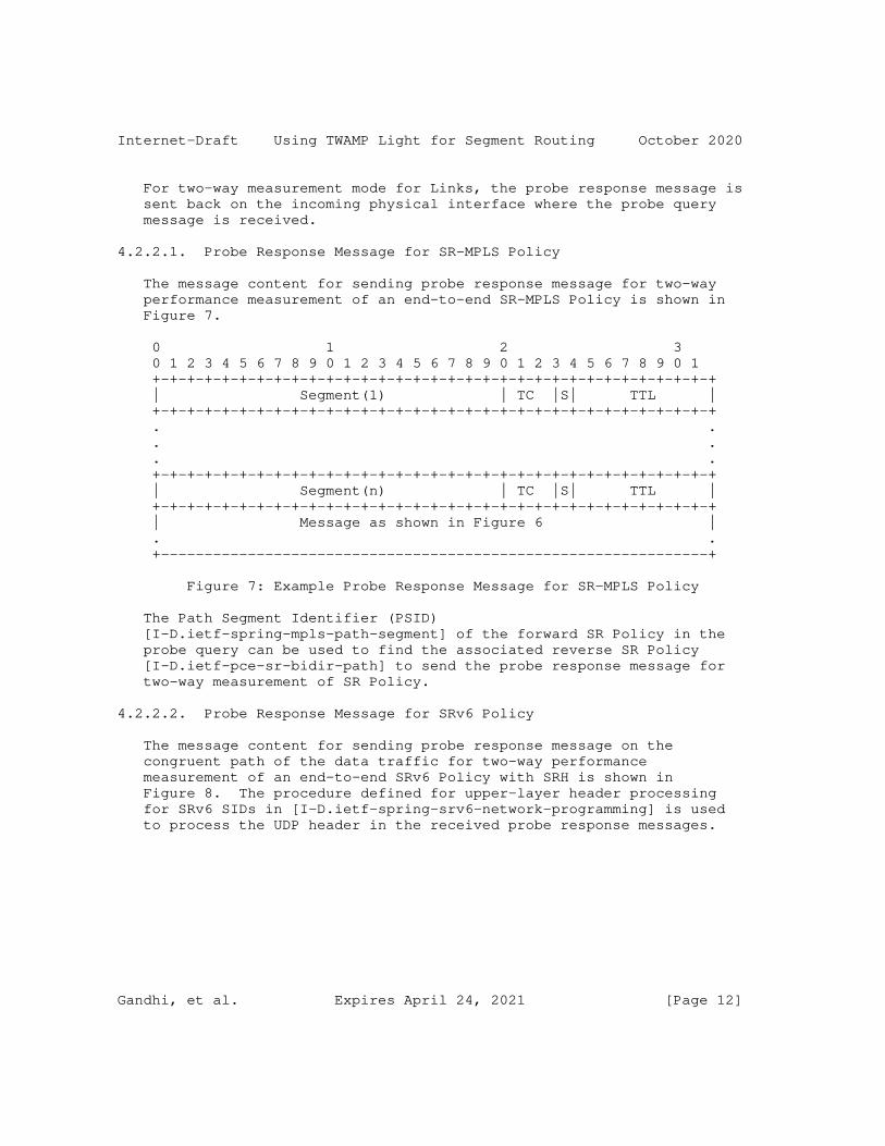
For two-way measurement mode for Links, the probe response message is sent back on the incoming physical interface where the probe query message is received.
4.2.2.1. Probe Response Message for SR-MPLS Policy
The message content for sending probe response message for two-way performance measurement of an end-to-end SR-MPLS Policy is shown in Figure 7.
0 1 2 3 0 1 2 3 4 5 6 7 8 9 0 1 2 3 4 5 6 7 8 9 0 1 2 3 4 5 6 7 8 9 0 1 +-+-+-+-+-+-+-+-+-+-+-+-+-+-+-+-+-+-+-+-+-+-+-+-+-+-+-+-+-+-+-+-+ | Segment(1) | TC |S| TTL | +-+-+-+-+-+-+-+-+-+-+-+-+-+-+-+-+-+-+-+-+-+-+-+-+-+-+-+-+-+-+-+-+ . . . . . . +-+-+-+-+-+-+-+-+-+-+-+-+-+-+-+-+-+-+-+-+-+-+-+-+-+-+-+-+-+-+-+-+ | Segment(n) | TC |S| TTL | +-+-+-+-+-+-+-+-+-+-+-+-+-+-+-+-+-+-+-+-+-+-+-+-+-+-+-+-+-+-+-+-+ | Message as shown in Figure 6 | . . +---------------------------------------------------------------+
Figure 7: Example Probe Response Message for SR-MPLS Policy
The Path Segment Identifier (PSID) [I-D.ietf-spring-mpls-path-segment] of the forward SR Policy in the probe query can be used to find the associated reverse SR Policy [I-D.ietf-pce-sr-bidir-path] to send the probe response message for two-way measurement of SR Policy.
4.2.2.2. Probe Response Message for SRv6 Policy
The message content for sending probe response message on the congruent path of the data traffic for two-way performance measurement of an end-to-end SRv6 Policy with SRH is shown in Figure 8. The procedure defined for upper-layer header processing for SRv6 SIDs in [I-D.ietf-spring-srv6-network-programming] is used to process the UDP header in the received probe response messages.
Gandhi, et al. Expires April 24, 2021 [Page 12]
Internet-Draft Using TWAMP Light for Segment Routing October 2020
+---------------------------------------------------------------+ | IP Header | . Source IP Address = Reflector IPv6 Address . . Destination IP Address = Destination IPv6 Address . . . +---------------------------------------------------------------+ | SRH as specified in RFC 8754 | . <Segment List> . . . +---------------------------------------------------------------+ | IP Header (as needed) | . Source IP Address = Reflector IPv6 Address . . Destination IP Address = Source IPv6 Address from Query . . . +---------------------------------------------------------------+ | UDP Header | . Source Port = As chosen by Sender . . Destination Port = User-configured Port . . . +---------------------------------------------------------------+ | Payload = DM Message as specified in Section 4.2.1 of RFC 5357| . Payload = LM Message specified in [I-D.gandhi-ippm-twamp-srpm]. . . +---------------------------------------------------------------+
Figure 8: Example Probe Response Message for SRv6 Policy
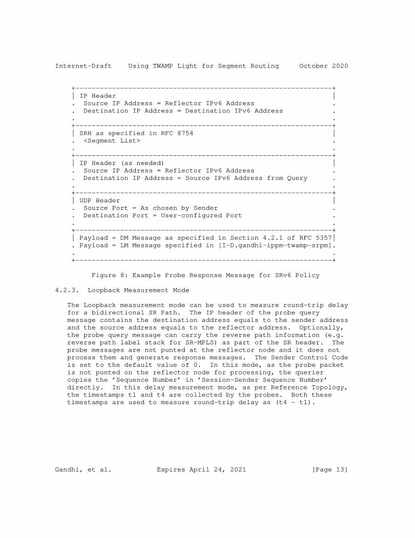
4.2.3. Loopback Measurement Mode
The Loopback measurement mode can be used to measure round-trip delay for a bidirectional SR Path. The IP header of the probe query message contains the destination address equals to the sender address and the source address equals to the reflector address. Optionally, the probe query message can carry the reverse path information (e.g. reverse path label stack for SR-MPLS) as part of the SR header. The probe messages are not punted at the reflector node and it does not process them and generate response messages. The Sender Control Code is set to the default value of 0. In this mode, as the probe packet is not punted on the reflector node for processing, the querier copies the ’Sequence Number’ in ’Session-Sender Sequence Number’ directly. In this delay measurement mode, as per Reference Topology, the timestamps t1 and t4 are collected by the probes. Both these timestamps are used to measure round-trip delay as (t4 - t1).
Gandhi, et al. Expires April 24, 2021 [Page 13]

Internet-Draft Using TWAMP Light for Segment Routing October 2020
4.3. Additional Probe Message Processing Rules
The processing rules defined in this section are applicable to TWAMP Light messages for delay and loss measurement for Links and end-to- end SR Paths including SR Policies.
4.3.1. TTL and Hop Limit
The TTL field in the IPv4 and MPLS headers of the probe query messages is set to 255 [RFC5357]. Similarly, the Hop Limit field in the IPv6 and SRH headers of the probe query messages is set to 255 [RFC5357].
When using the Destination IPv4 Address from range 127/8, the TTL field in the IPv4 header is set to 1 [RFC8029]. Similarly, when using the Destination IPv6 Address from the ::FFFF:127/104 range, the Hop Limit field in the IPv6 header is set to 1.
For Link performance delay and loss measurements, the TTL or Hop Limit field in the probe message is set to 1 in both one-way and two- way measurement modes.
4.3.2. Router Alert Option
The Router Alert IP option (RAO) [RFC2113] is not set in the probe messages.
4.3.3. UDP Checksum
The UDP Checksum Complement for delay and loss measurement messages follows the procedure defined in [RFC7820] and can be optionally used with the procedures defined in this document.
For IPv4 and IPv6 probe messages, where the hardware is not capable of re-computing the UDP checksum or adding checksum complement [RFC7820], the sender node sets the UDP checksum to 0 [RFC6936] [RFC8085]. The receiving node bypasses the checksum validation and accepts the packets with UDP checksum value 0 for the UDP port being used for delay and loss measurements.
5. Performance Measurement for P2MP SR Policies
The Point-to-Multipoint (P2MP) SR Path that originates from a root node terminates on multiple destinations called leaf nodes (e.g. P2MP SR Policy [I-D.ietf-pim-sr-p2mp-policy] or P2MP Transport [I-D.shen-spring-p2mp-transport-chain]).
Gandhi, et al. Expires April 24, 2021 [Page 14]

Internet-Draft Using TWAMP Light for Segment Routing October 2020
The procedures for delay and loss measurement described in this document for P2P SR Policies are also equally applicable to the P2MP SR Policies. The procedure for one-way measurement is defined as following:
o The sender root node sends probe query messages using the Tree-SID defined in [I-D.ietf-pim-sr-p2mp-policy] for the P2MP SR-MPLS Policy as shown in Figure 9.
o The probe query messages can contain the replication SID as defined in [I-D.ietf-spring-sr-replication-segment].
o The Destination Address is set to the loopback address from range 127/8 for IPv4, or the loopback address ::1/128 for IPv6 address.
o Each reflector leaf node sends its IP address in the Source Address of the probe response messages as shown in Figure 9. This allows the sender root node to identify the reflector leaf nodes of the P2MP SR Policy.
o The P2MP root node measures the delay and loss performance for each P2MP leaf node of the end-to-end P2MP SR Policy.
0 1 2 3 0 1 2 3 4 5 6 7 8 9 0 1 2 3 4 5 6 7 8 9 0 1 2 3 4 5 6 7 8 9 0 1 +-+-+-+-+-+-+-+-+-+-+-+-+-+-+-+-+-+-+-+-+-+-+-+-+-+-+-+-+-+-+-+-+ | Tree-SID | TC |S| TTL | +-+-+-+-+-+-+-+-+-+-+-+-+-+-+-+-+-+-+-+-+-+-+-+-+-+-+-+-+-+-+-+-+ . . . . . . +-+-+-+-+-+-+-+-+-+-+-+-+-+-+-+-+-+-+-+-+-+-+-+-+-+-+-+-+-+-+-+-+ | Message as shown in Figure 2 for DM or Figure 3 for LM | . . +-+-+-+-+-+-+-+-+-+-+-+-+-+-+-+-+-+-+-+-+-+-+-+-+-+-+-+-+-+-+-+-+
Figure 9: Example Probe Query with Tree-SID for SR-MPLS Policy
The probe query messages can also be sent using the scheme defined for P2MP Transport using Chain Replication that may contain Bud SID as defined in [I-D.shen-spring-p2mp-transport-chain].
The considerations for two-way mode for performance measurement for P2MP SR Policy (e.g. for bidirectional SR Path) are outside the scope of this document.
Gandhi, et al. Expires April 24, 2021 [Page 15]

Internet-Draft Using TWAMP Light for Segment Routing October 2020
6. ECMP Support for SR Policies
An SR Policy can have ECMPs between the source and transit nodes, between transit nodes and between transit and destination nodes. Usage of Anycast SID [RFC8402] by an SR Policy can result in ECMP paths via transit nodes part of that Anycast group. The probe messages need to be sent to traverse different ECMP paths to measure performance delay of an SR Policy.
Forwarding plane has various hashing functions available to forward packets on specific ECMP paths. The mechanisms described in [RFC8029] and [RFC5884] for handling ECMPs are also applicable to the performance measurement. In IPv4 header of the probe messages, sweeping of Destination Address from range 127/8 can be used to exercise particular ECMP paths. As specified in [RFC6437], Flow Label field in the outer IPv6 header can also be used for sweeping.
The considerations for performance loss measurement for different ECMP paths of an SR Policy are outside the scope of this document.
7. Performance Delay and Liveness Monitoring
Liveness monitoring is required for connectivity verification and continuity check in an SR network. The procedure defined in this document for delay measurement using the TWAMP Light probe messages can also be applied to liveness monitoring of Links and SR Paths. The one-way or two-way measurement mode can be used for liveness monitoring. Liveness failure is notified when consecutive N number of probe response messages are not received back at the sender node, where N is locally provisioned value. Note that for one-way and two- way modes, the failure detection interval and scale for number of probe messages need to account for the processing of the probe query messages which need to be punted from the forwarding fast path (to slow path or control plane) and response messages need to be injected on the reflector node. This is improved by using the probes in loopback mode.
8. Security Considerations
The performance measurement is intended for deployment in well- managed private and service provider networks. As such, it assumes that a node involved in a measurement operation has previously verified the integrity of the path and the identity of the far-end reflector node.
If desired, attacks can be mitigated by performing basic validation and sanity checks, at the sender, of the counter or timestamp fields in received measurement response messages. The minimal state
Gandhi, et al. Expires April 24, 2021 [Page 16]

Internet-Draft Using TWAMP Light for Segment Routing October 2020
associated with these protocols also limits the extent of measurement disruption that can be caused by a corrupt or invalid message to a single query/response cycle.
Use of HMAC-SHA-256 in the authenticated mode protects the data integrity of the probe messages. SRv6 has HMAC protection authentication defined for SRH [RFC8754]. Hence, probe messages for SRv6 may not need authentication mode. Cryptographic measures may be enhanced by the correct configuration of access-control lists and firewalls.
9. IANA Considerations
This document does not require any IANA action.
10. References
10.1. Normative References
[RFC0768] Postel, J., "User Datagram Protocol", STD 6, RFC 768, DOI 10.17487/RFC0768, August 1980, <https://www.rfc-editor.org/info/rfc768>.
[RFC2119] Bradner, S., "Key words for use in RFCs to Indicate Requirement Levels", BCP 14, RFC 2119, DOI 10.17487/RFC2119, March 1997, <https://www.rfc-editor.org/info/rfc2119>.
[RFC4656] Shalunov, S., Teitelbaum, B., Karp, A., Boote, J., and M. Zekauskas, "A One-way Active Measurement Protocol (OWAMP)", RFC 4656, DOI 10.17487/RFC4656, September 2006, <https://www.rfc-editor.org/info/rfc4656>.
[RFC5357] Hedayat, K., Krzanowski, R., Morton, A., Yum, K., and J. Babiarz, "A Two-Way Active Measurement Protocol (TWAMP)", RFC 5357, DOI 10.17487/RFC5357, October 2008, <https://www.rfc-editor.org/info/rfc5357>.
[RFC8174] Leiba, B., "Ambiguity of Uppercase vs Lowercase in RFC 2119 Key Words", BCP 14, RFC 8174, DOI 10.17487/RFC8174, May 2017, <https://www.rfc-editor.org/info/rfc8174>.
[I-D.gandhi-ippm-twamp-srpm] Gandhi, R., Filsfils, C., Voyer, D., Chen, M., and B. Janssens, "TWAMP Light Extensions for Segment Routing", draft-gandhi-ippm-twamp-srpm-00 (work in progress), October 2020.
10.2. Informative References
[IEEE1588] IEEE, "1588-2008 IEEE Standard for a Precision Clock Synchronization Protocol for Networked Measurement and Control Systems", March 2008.

Gandhi, et al. Expires April 24, 2021 [Page 17]

Internet-Draft Using TWAMP Light for Segment Routing October 2020
[RFC2113] Katz, D., "IP Router Alert Option", RFC 2113, DOI 10.17487/RFC2113, February 1997, <https://www.rfc-editor.org/info/rfc2113>.
[RFC5884] Aggarwal, R., Kompella, K., Nadeau, T., and G. Swallow, "Bidirectional Forwarding Detection (BFD) for MPLS Label Switched Paths (LSPs)", RFC 5884, DOI 10.17487/RFC5884, June 2010, <https://www.rfc-editor.org/info/rfc5884>.
[RFC6038] Morton, A. and L. Ciavattone, "Two-Way Active Measurement Protocol (TWAMP) Reflect Octets and Symmetrical Size Features", RFC 6038, DOI 10.17487/RFC6038, October 2010, <https://www.rfc-editor.org/info/rfc6038>.
[RFC6335] Cotton, M., Eggert, L., Touch, J., Westerlund, M., and S. Cheshire, "Internet Assigned Numbers Authority (IANA) Procedures for the Management of the Service Name and Transport Protocol Port Number Registry", BCP 165, RFC 6335, DOI 10.17487/RFC6335, August 2011, <https://www.rfc-editor.org/info/rfc6335>.
[RFC6437] Amante, S., Carpenter, B., Jiang, S., and J. Rajahalme, "IPv6 Flow Label Specification", RFC 6437, DOI 10.17487/RFC6437, November 2011, <https://www.rfc-editor.org/info/rfc6437>.
[RFC6936] Fairhurst, G. and M. Westerlund, "Applicability Statement for the Use of IPv6 UDP Datagrams with Zero Checksums", RFC 6936, DOI 10.17487/RFC6936, April 2013, <https://www.rfc-editor.org/info/rfc6936>.
[RFC7820] Mizrahi, T., "UDP Checksum Complement in the One-Way Active Measurement Protocol (OWAMP) and Two-Way Active Measurement Protocol (TWAMP)", RFC 7820, DOI 10.17487/RFC7820, March 2016, <https://www.rfc-editor.org/info/rfc7820>.
[RFC8029] Kompella, K., Swallow, G., Pignataro, C., Ed., Kumar, N., Aldrin, S., and M. Chen, "Detecting Multiprotocol Label Switched (MPLS) Data-Plane Failures", RFC 8029, DOI 10.17487/RFC8029, March 2017, <https://www.rfc-editor.org/info/rfc8029>.
[RFC8085] Eggert, L., Fairhurst, G., and G. Shepherd, "UDP Usage Guidelines", BCP 145, RFC 8085, DOI 10.17487/RFC8085, March 2017, <https://www.rfc-editor.org/info/rfc8085>.
Gandhi, et al. Expires April 24, 2021 [Page 18]

Internet-Draft Using TWAMP Light for Segment Routing October 2020
[RFC8186] Mirsky, G. and I. Meilik, "Support of the IEEE 1588 Timestamp Format in a Two-Way Active Measurement Protocol (TWAMP)", RFC 8186, DOI 10.17487/RFC8186, June 2017, <https://www.rfc-editor.org/info/rfc8186>.
[RFC8402] Filsfils, C., Ed., Previdi, S., Ed., Ginsberg, L., Decraene, B., Litkowski, S., and R. Shakir, "Segment Routing Architecture", RFC 8402, DOI 10.17487/RFC8402, July 2018, <https://www.rfc-editor.org/info/rfc8402>.
[RFC8545] Morton, A., Ed. and G. Mirsky, Ed., "Well-Known Port Assignments for the One-Way Active Measurement Protocol (OWAMP) and the Two-Way Active Measurement Protocol (TWAMP)", RFC 8545, DOI 10.17487/RFC8545, March 2019, <https://www.rfc-editor.org/info/rfc8545>.
[RFC8754] Filsfils, C., Ed., Dukes, D., Ed., Previdi, S., Leddy, J., Matsushima, S., and D. Voyer, "IPv6 Segment Routing Header (SRH)", RFC 8754, DOI 10.17487/RFC8754, March 2020, <https://www.rfc-editor.org/info/rfc8754>.
[I-D.ietf-spring-segment-routing-policy] Filsfils, C., Talaulikar, K., Voyer, D., Bogdanov, A., and P. Mattes, "Segment Routing Policy Architecture", draft- ietf-spring-segment-routing-policy-08 (work in progress), July 2020.
[I-D.ietf-spring-sr-replication-segment] Voyer, D., Filsfils, C., Parekh, R., Bidgoli, H., and Z. Zhang, "SR Replication Segment for Multi-point Service Delivery", draft-ietf-spring-sr-replication-segment-00 (work in progress), July 2020.
[I-D.shen-spring-p2mp-transport-chain] Shen, Y., Zhang, Z., Parekh, R., Bidgoli, H., and Y. Kamite, "Point-to-Multipoint Transport Using Chain Replication in Segment Routing", draft-shen-spring-p2mp- transport-chain-02 (work in progress), April 2020.
[I-D.ietf-pim-sr-p2mp-policy] Voyer, D., Filsfils, C., Parekh, R., Bidgoli, H., and Z. Zhang, "Segment Routing Point-to-Multipoint Policy", draft-ietf-pim-sr-p2mp-policy-00 (work in progress), July 2020.
Gandhi, et al. Expires April 24, 2021 [Page 19]

Internet-Draft Using TWAMP Light for Segment Routing October 2020
[I-D.ietf-spring-mpls-path-segment] Cheng, W., Li, H., Chen, M., Gandhi, R., and R. Zigler, "Path Segment in MPLS Based Segment Routing Network", draft-ietf-spring-mpls-path-segment-03 (work in progress), September 2020.
[I-D.ietf-spring-srv6-network-programming] Filsfils, C., Camarillo, P., Leddy, J., Voyer, D., Matsushima, S., and Z. Li, "SRv6 Network Programming", draft-ietf-spring-srv6-network-programming-24 (work in progress), October 2020.
[BBF.TR-390] "Performance Measurement from IP Edge to Customer Equipment using TWAMP Light", BBF TR-390, May 2017.
[I-D.gandhi-mpls-ioam-sr] Gandhi, R., Ali, Z., Filsfils, C., Brockners, F., Wen, B., and V. Kozak, "MPLS Data Plane Encapsulation for In-situ OAM Data", draft-gandhi-mpls-ioam-sr-03 (work in progress), September 2020.
[I-D.ali-spring-ioam-srv6] Ali, Z., Gandhi, R., Filsfils, C., Brockners, F., Kumar, N., Pignataro, C., Li, C., Chen, M., and G. Dawra, "Segment Routing Header encapsulation for In-situ OAM Data", draft-ali-spring-ioam-srv6-02 (work in progress), November 2019.
[I-D.ietf-pce-sr-bidir-path] Li, C., Chen, M., Cheng, W., Gandhi, R., and Q. Xiong, "PCEP Extensions for Associated Bidirectional Segment Routing (SR) Paths", draft-ietf-pce-sr-bidir-path-03 (work in progress), September 2020.
Acknowledgments
The authors would like to thank Thierry Couture for the discussions on the use-cases for Performance Measurement in Segment Routing. The authors would also like to thank Greg Mirsky for reviewing this document and providing useful comments and suggestions. Patrick Khordoc and Radu Valceanu, both from Cisco Systems have helped significantly improve the mechanisms defined in this document.
Gandhi, et al. Expires April 24, 2021 [Page 20]

Internet-Draft Using TWAMP Light for Segment Routing October 2020
Authors’ Addresses
Rakesh Gandhi (editor) Cisco Systems, Inc. Canada
Email: [email protected]
Clarence Filsfils Cisco Systems, Inc.
Email: [email protected]
Daniel Voyer Bell Canada
Email: [email protected]
Mach(Guoyi) Chen Huawei
Email: [email protected]
Bart Janssens Colt
Email: [email protected]
Gandhi, et al. Expires April 24, 2021 [Page 21]

ippm R. Geib, Ed.Internet-Draft Deutsche TelekomIntended status: Standards Track July 3, 2020Expires: January 4, 2021
A Connectivity Monitoring Metric for IPPM draft-geib-ippm-connectivity-monitoring-03
Abstract
Within a Segment Routing domain, segment routed measurement packets can be sent along pre-determined paths. This enables new kinds of measurements. Connectivity monitoring allows to supervise the state and performance of a connection or a (sub)path from one or a few central monitoring systems. This document specifies a suitable type-P connectivity monitoring metric.
Status of This Memo
This Internet-Draft is submitted in full conformance with the provisions of BCP 78 and BCP 79.
Internet-Drafts are working documents of the Internet Engineering Task Force (IETF). Note that other groups may also distribute working documents as Internet-Drafts. The list of current Internet- Drafts is at https://datatracker.ietf.org/drafts/current/.
Internet-Drafts are draft documents valid for a maximum of six months and may be updated, replaced, or obsoleted by other documents at any time. It is inappropriate to use Internet-Drafts as reference material or to cite them other than as "work in progress."
This Internet-Draft will expire on January 4, 2021.
Copyright Notice
Copyright (c) 2020 IETF Trust and the persons identified as the document authors. All rights reserved.
This document is subject to BCP 78 and the IETF Trust’s Legal Provisions Relating to IETF Documents (https://trustee.ietf.org/license-info) in effect on the date of publication of this document. Please review these documents carefully, as they describe your rights and restrictions with respect to this document. Code Components extracted from this document must include Simplified BSD License text as described in Section 4.e of
Geib Expires January 4, 2021 [Page 1]

Internet-Draft Abbreviated Title July 2020
the Trust Legal Provisions and are provided without warranty as described in the Simplified BSD License.
Table of Contents
1. Introduction . . . . . . . . . . . . . . . . . . . . . . . . 2 1.1. Requirements Language . . . . . . . . . . . . . . . . . . 4 2. A brief segment routing connectivity monitoring framework . . 4 3. Singleton Definition for Type-P-SR-Path-Connectivity-and- Congestion . . . . . . . . . . . . . . . . . . . . . . . . . 7 3.1. Metric Name . . . . . . . . . . . . . . . . . . . . . . . 7 3.2. Metric Parameters . . . . . . . . . . . . . . . . . . . . 7 3.3. Metric Units . . . . . . . . . . . . . . . . . . . . . . 8 3.4. Definition . . . . . . . . . . . . . . . . . . . . . . . 8 3.5. Discussion . . . . . . . . . . . . . . . . . . . . . . . 8 3.6. Methodologies . . . . . . . . . . . . . . . . . . . . . . 9 3.7. Errors and Uncertainties . . . . . . . . . . . . . . . . 10 3.8. Reporting the Metric . . . . . . . . . . . . . . . . . . 11 4. Singleton Definition for Type-P-SR-Path-Round-Trip-Delay- Estimate . . . . . . . . . . . . . . . . . . . . . . . . . . 11 5. IANA Considerations . . . . . . . . . . . . . . . . . . . . . 12 6. Security Considerations . . . . . . . . . . . . . . . . . . . 12 7. References . . . . . . . . . . . . . . . . . . . . . . . . . 12 7.1. Normative References . . . . . . . . . . . . . . . . . . 12 7.2. Informative References . . . . . . . . . . . . . . . . . 13 Author’s Address . . . . . . . . . . . . . . . . . . . . . . . . 13
1. Introduction
Within a Segment Routing domain, measurement packets can be sent along pre-determined segment routed paths [RFC8402]. A segment routed path may consist of pre-determined sub paths, specific router- interfaces or a combination of both. A measurement path may also consist of sub paths spanning multiple routers, given that all segments to address a desired path are available and known at the SR domain edge interface.
A Path Monitoring System or PMS (see [RFC8403]) is a dedicated central Segment Routing (SR) domain monitoring device (as compared to a distributed monitoring approach based on router-data and -functions only). Monitoring individual sub-paths or point-to-point connections is executed for different purposes. IGP exchanges hello messages between neighbors to keep alive routing and swiftly adapt routing to topology changes. Network Operators may be interested in monitoring connectivity and congestion of interfaces or sub-paths at a timescale of seconds, minutes or hours. In both cases, the periodicity is significantly smaller than commodity interface monitoring based on
Geib Expires January 4, 2021 [Page 2]

Internet-Draft Abbreviated Title July 2020
router counters, which may be collected on a minute timescale to keep the processor- or monitoring data-load low.
The IPPM architecture was a first step to that direction [RFC2330]. Commodity IPPM solutions require dedicated measurement systems, a large number of measurement agents and synchronised clocks. Monitoring a domain from edge to edge by commodity IPPM solutions increases scalability of the monitoring system. But localising the site of a detected change in network behaviour may then require network tomography methods.
The IPPM Metrics for Measuring Connectivity offer generic connectivity metrics [RFC2678]. These metrics allow to measure connectivity between end nodes without making any assumption on the paths between them. The metric and the type-p packet specified by this document follow a different approach: they are designed to monitor connectivity and performance of a specific single link or a path segment. The underlying definition of connectivity is partially the same: a packet not reaching a destination indicates a loss of connectivity. An IGP re-route may indicate a loss of a link, while it might not cause loss of connectivity between end systems. The metric specified here enables link-loss detection, if the change in end-to-end delay along a new route is differing from that of the original path.
A Segment Routing PMS which is part of an SR domain is IGP topology aware, covering the IP and (if present) the MPLS layer topology [RFC8402]. This allows to steer PMS measurement packets along arbitrary pre-determined concatenated sub-paths, identified by suitable segments. Basically, a number of overlaid measurement paths is set up. The delays of packets sent along each on of these paths is measured. Single changes in topology cause correlated changes in the measurement packet delay (or packet loss) of different measurement paths. By a suitable set up, the number of measurement paths may be limited to one per connection (or sub-path) to be monitored. In addition to information revealed by a commodity ICMP ping measurement, the metric and method specified here identify the location of a congested interface. To do so, tomography assumptions and methods are combined to first plan the overlaid SR measurement path set up and later on to evaluate the captured delay measurements.
This document specifies a type-p metric determining properties of an SR path which allows to monitor connectivity and congestion of interfaces and further allows to locate the path or interface which caused a change in the reported type-p metric. This document is focussed on the MPLS layer, but the methodology may be applied within SR domains or MPLS domains in general.
Geib Expires January 4, 2021 [Page 3]

Internet-Draft Abbreviated Title July 2020
1.1. Requirements Language
The key words "MUST", "MUST NOT", "REQUIRED", "SHALL", "SHALL NOT", "SHOULD", "SHOULD NOT", "RECOMMENDED", "MAY", and "OPTIONAL" in this document are to be interpreted as described in RFC 2119 [RFC2119].
2. A brief segment routing connectivity monitoring framework
The Segment Routing IGP topology information consists of the IP and (if present) the MPLS layer topology. The minimum SR topology information consists of Node-Segment-Identifiers (Node-SID), identifying an SR router. The IGP exchange of Adjacency-SIDs [I- D.draft-ietf-isis-segment-routing-extensions], which identify local interfaces to adjacent nodes, is optional. It is RECOMMENDED to distribute Adj-SIDs in a domain operating a PMS to monitor connectivity as specified below. If Adj-SIDs aren’t availbale, [RFC8029] provides methods how to steer packets along desired paths by the proper choice of an MPLS Echo-request IP-destination address. A detailed description of [RFC8029] methods as a replacement of Adj- SIDs is out of scope of this document.
A round trip measurement between two adjacent nodes is a simple method to monitor connectivity of a connecting link. If multiple links are operational between two adjacent nodes and only a single one fails, a single plain round trip measurement may fail to identify which link has failed. A round trip measurement also fails to identify which interface is congested, even if only a single link connects two adjacent nodes.
Segment Routing enables the set-up of extended measurement loops. Several different measurement loops can be set up. If these form a partial overlay, any change in the network properties impacts more than a single loop’s round trip time (or causes drops of packets of more than one loop). Randomly chosen loop paths including the interfaces or paths to be monitored may fail to produce unique result patterns. The approach picked here uses specified measurement loop and path overlay design. A centralised monitoring approach benefits from keeping the number of required measurement loops low. This improves scalability by minimising the number of measurement loops. This also keeps the number of required packets and results to be evaluated and correlated low.
An additional property of the measurement path set-up specified below is that it allows to estimate the packet round trip and the one way delay of a monitored link (or path). The delay along a single link is not perfectly symmetric. Packet processing causes small delay differences per interface and direction. These cause an error, which can’t be quantified or removed by the specified method. Quantifying
Geib Expires January 4, 2021 [Page 4]
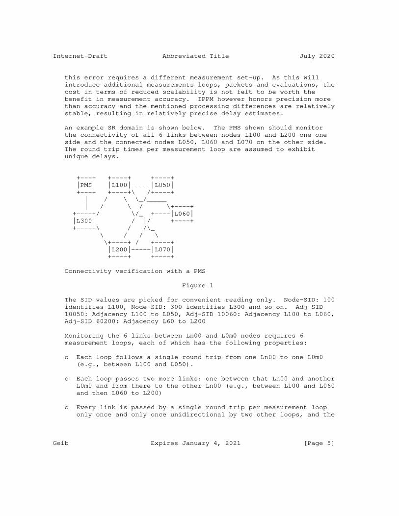
Internet-Draft Abbreviated Title July 2020
this error requires a different measurement set-up. As this will introduce additional measurements loops, packets and evaluations, the cost in terms of reduced scalability is not felt to be worth the benefit in measurement accuracy. IPPM however honors precision more than accuracy and the mentioned processing differences are relatively stable, resulting in relatively precise delay estimates.
An example SR domain is shown below. The PMS shown should monitor the connectivity of all 6 links between nodes L100 and L200 one one side and the connected nodes L050, L060 and L070 on the other side. The round trip times per measurement loop are assumed to exhibit unique delays.
+---+ +----+ +----+ |PMS| |L100|-----|L050| +---+ +----+\ /+----+ | / \ \_/_____ | / \ / \+----+ +----+/ \/_ +----|L060| |L300| / |/ +----+ +----+\ / /\_ \ / / \ \+----+ / +----+ |L200|-----|L070| +----+ +----+
Connectivity verification with a PMS
Figure 1
The SID values are picked for convenient reading only. Node-SID: 100 identifies L100, Node-SID: 300 identifies L300 and so on. Adj-SID 10050: Adjacency L100 to L050, Adj-SID 10060: Adjacency L100 to L060, Adj-SID 60200: Adjacency L60 to L200
Monitoring the 6 links between Ln00 and L0m0 nodes requires 6 measurement loops, each of which has the following properties:
o Each loop follows a single round trip from one Ln00 to one L0m0 (e.g., between L100 and L050).
o Each loop passes two more links: one between that Ln00 and another L0m0 and from there to the other Ln00 (e.g., between L100 and L060 and then L060 to L200)
o Every link is passed by a single round trip per measurement loop only once and only once unidirectional by two other loops, and the
Geib Expires January 4, 2021 [Page 5]

Internet-Draft Abbreviated Title July 2020
latter two pass along opposing directions (that’s three loops passing each single link, e.g., one having a round trip L100 to L050 and back, a second passing L100 to L050 only and a third loop passing L050 to L100 only).
Note that any 6 links between two to six nodes can be monitored that way too (if multiple parallel links between two nodes are monitored, the differences in delay may require a sufficiently high clock resulotion, if applicable).
This results in 6 measurement loops for the given example (the start and end of each measurement loop is PMS to L300 to L100 or L200 and a similar sub-path on the return leg. It is ommitted here for brevity):
1. M1 is the delay along L100 -> L050 -> L100 -> L060 -> L200
2. M2 is the delay along L100 -> L060 -> L100 -> L070 -> L200
3. M3 is the delay along L100 -> L070 -> L100 -> L050 -> L200
4. M4 is the delay along L200 -> L050 -> L200 -> L060 -> L100
5. M5 is the delay along L200 -> L060 -> L200 -> L070 -> L100
6. M6 is the delay along L200 -> L070 -> L200 -> L050 -> L100
An example for a stack of a loop consisting of Node-SID segments allowing to caprture M1 is (top to bottom): 100 | 050 | 100 | 060 | 200 | PMS.
An example for a stack of Adj-SID segments the loop resulting in M1 is (top to bottom): 100 | 10050 | 50100 | 10060 | 60200 | PMS. As can be seen, the Node-SIDs 100 and PMS are present at top and bottom of the segment stack. Their purpose is to transport the packet from the PMS to the start of the measurement loop at L100 and return it to the PMS from its end.
The measurement loops set up as shown have the following properties:
o If the loops are set up using Node-SIDs only, any single complete loss of connectivity caused by a failing single link between any Ln00 and any L0m0 node briefly disturbs (and changes the measured delay) of three loops. Traffic to Node-SIDs is rerouted.
o If the loops are set up using Adj-SIDs only (and Node-SIDs only to send the packet from PMS to the loop starting point and from the loop end back to the PMS), any single complete loss of
Geib Expires January 4, 2021 [Page 6]

Internet-Draft Abbreviated Title July 2020
connectivity caused by a failing single link between any Ln00 and any L0m0 node terminates the traffic along three loops. The packets of these loops will be dropped, until the link gets back into service. Traffic to Adj-SIDs is not rerouted.
o Any congested single interface between any Ln00 and any L0m0 node only impacts the measured delay of two measurement loops.
o As an example, the formula for a single Round Trip Delay (RTD) is shown here 4 * RTD_L100-L050-L100 = 3 * M1 + M3 + M6 - M2 - M4 - M5
A closer look reveals that each single event of interest for the proposed metric, which are a loss of connectivity or a case of congestion, uniquely only impacts a single a-priori determinable set of measurement loops. If, e.g., connectivity is lost between L200 and L050, measurement loops (3), (4) and (6) indicate a change in the measured delay.
As a second example, if the interface L070 to L100 is congested, measurement loops (3) and (5) indicate a change in the measured delay. Without listing all events, all cases of single losses of connectivity or single events of congestion influence only delay measurements of a unique set of measurement loops.
A congestion event adding latency to two specific measurement loops allows calculation of the delay added by the queue at the congested interface. Thus, the resulting RTD increase can be assigned to a single interface.
3. Singleton Definition for Type-P-SR-Path-Connectivity-and-Congestion
3.1. Metric Name
Type-P-SR-Path-Connectivity-and-Congestion
3.2. Metric Parameters
o Src, the IP address of a source host
o Dst, the IP address of a destination host if IP routing is applicable; in the case of MPLS routing, a diagnostic address as specified by [RFC8029]
o T, a time
o lambda, a rate in reciprocal seconds
Geib Expires January 4, 2021 [Page 7]

Internet-Draft Abbreviated Title July 2020
o L, a packet length in bits. The packets of a Type P packet stream from which the sample Path-Connectivity-and-Congestion metric is taken MUST all be of the same length.
o MLA, a Monitoring Loop Address information ensuring that a singleton passes a single sub-path_a to be monitored bidirectional, a sub-path_b to be monitored unidirectional and a sub-path_c to be monitored unidirectional, where sub-path_a, -_b and -_c MUST NOT be identical.
o P, the specification of the packet type, over and above the source and destination addresses
o DS, a constant time interval between two type-P packets
3.3. Metric Units
A sequence of consecutive time values.
3.4. Definition
A moving average of AV time values per measurement path is compared by a change point detection algorithm. The temporal packet spacing value DS represents the smallest period within which a change in connectivity or congestion may be detected.
A single loss of connectivity of a sub-path between two nodes affects three different measurement paths. Depending on the value chosen for DS, packet loss might occur (note that the moving average evaluation needs to span a longer period than convergence time; alternatively, packet-loss visible along the three measurement paths may serve as an evaluation criterium). After routing convergence the type-p packets along the three measurement paths show a change in delay.
A congestion of a single interface of a sub-path connecting two nodes affects two different measurement paths. The the type-p packets along the two congested measurement paths show an additional change in delay.
3.5. Discussion
Detection of a multiple losses of monitored sub-path connectivity or congestion of a multiple monitored sub-paths may be possible. These cases have not been investigated, but may occur in the case of Shared Risk Link Groups. Monitoring Shared Risk LinkGroups and sub-paths with multiple failures abd congestion is not within scope of this document.
Geib Expires January 4, 2021 [Page 8]

Internet-Draft Abbreviated Title July 2020
3.6. Methodologies
For the given type-p, the methodology is as follows:
o The set of measurement paths MUST be routed in a way that each single loss of connectivity and each case of single interface congestion of one of the sub-paths passed by a type-p packet creates a unique pattern of type-p packets belonging to a subset of all configured measurement paths indicate a change in the measured delay. As a minimum, each sub-path to be monitored MUST be passed
o
* by one measurement_path_1 and its type-p packet in bidirectional direction
* by one measurement_path_2 and its type-p packet in "downlink" direction
* by one measurement_path_3 and its type-p packet in "uplink" direction
o "Uplink" and "Downlink" have no architectural relevance. The terms are chosen to express, that the packets of measurement_path_2 and measuremnt_path_3 pass the monitored sub- path unidirectional in opposing direction. Measuremnt_path_1, measurement_path_2 and measurement_path_3 MUST NOT be identical.
o All measurement paths SHOULD terminate between identical sender and receiver interfaces. It is recommended to connect the sender and receiver as closely to the paths to be monitored as possible. Each intermediate sub-path between sender and receiver one one hand and sub-paths to be monitored is an additional source of errors requiring separate monitoring.
o Segment Routed domains supporting Node- and Adj-SIDs should enable the monitoring path set-up as specified. Other routing protocols may be used as well, but the monitoring path set up might be complex or impossible.
o Pre-compute how the two and three measurement path delay changes correlate to sub-path connectivity and congestion patterns. Absolute change valaues aren’t required, a simultaneous change of two or three particular measurement paths is.
o Ensure that the temporal resolution of the measurement clock allows to reliably capture a unique delay value for each
Geib Expires January 4, 2021 [Page 9]

Internet-Draft Abbreviated Title July 2020
configured measurement path while sub-path connectivity is complete and no congestion is present.
o Synchronised clocks are not strictly required, as the metric is evaluating differences in delay. Changes in clock synchronisation SHOULD NOT be close to the time interval within which changes in connectivity or congestion should be monitored.
o At the Src host, select Src and Dst IP addresses, and address information to route the type-p packet along one of the configured measurement path. Form a test packet of Type-P with these addresses.
o Configure the Dst host access to receive the packet.
o At the Src host, place a timestamp, a sequence number and a unique identifier of the measurement path in the prepared Type-P packet, and send it towards Dst.
o Capture the one-way delay and determine packet-loss by the metrics specified by [RFC7679] and [RFC7680] respectively and store the result for the path.
o If two or three subpaths indicate a change in delay, report a change in connectivity or congestion status as pre-computed above.
o If two or three sub paths indicate a change in delay, report a change in connectivity or congestion status as pre-computed above.
Note that monitoring 6 sub paths requires setting up 6 monitoring paths as shown in the figure above.
3.7. Errors and Uncertainties
Sources of error are:
o Measurement paths whose delays don’t indicate a change after sub- path connectivity changed.
o A timestamps whose resolution is missing or inacurrate at the delays measured for the different monitoring paths.
o Multiple occurrences of sub path connectivity and congestion.
o Loss of connectivity and congestion along sub-paths connecting the measurement device(s) with the sub-paths to be monitored.
Geib Expires January 4, 2021 [Page 10]

Internet-Draft Abbreviated Title July 2020
3.8. Reporting the Metric
The metric reports loss of connectivity of monitored sub-path or congestion of an interface and identifies the sub-path and the direction of traffic in the case of congestion.
The temporal resolution of the detected events depends on the spacing interval of packets transmitted per measurement path. An identical sending interval is chosen for every measurement path. As a rule of thumb, an event is reliably detected if a sample consists of at least 5 probes indicating the same underlying change in behavior. Depending on the underlying event either two or three measurement paths are impacted. At least two consecutively received measurement packets per measurement path should suffice to indicate a change. The values chosen for an operational network will have to reflect scalability constraints of a PMS measurement interface. As an example, a PMS may work reliable if no more than one measurement packet is transmitted per millisecond. Further, measurement is configured so that the measurement packets return to the sender interface. Assume always groups of 6 links to be monitored as described above by 6 measurements paths. If one packet is sent per measurement path within 500 ms, up to 498 links can be monitored with a reliable temporal resolution of roughly one second per detected event.
Note that per group measurement packet spacing, measurement loop delay difference and latency caused by congestion impact the reporting interval. If each measurement path of a single 6 link monitoring group is addressed in consecutive milliseconds (within the 500 ms interval) and the sum of maximum physical delay of the per group measurement paths and latency possibly added by congestion is below 490 ms, the one second reports reliably capture 4 packets of two different measurement paths, if two measurement paths are congested, or 6 packets of three different measurement paths, if a link is lost.
A variety of reporting options exist, if scalability issues and network properties are respected.
4. Singleton Definition for Type-P-SR-Path-Round-Trip-Delay-Estimate
This section will be added in a later version, if there’s interest in picking up this work.
Geib Expires January 4, 2021 [Page 11]

Internet-Draft Abbreviated Title July 2020
5. IANA Considerations
If standardised, the metric will require an entry in the IPPM metric registry.
6. Security Considerations
This draft specifies how to use methods specified or described within [RFC8402] and [RFC8403]. It does not introduce new or additional SR features. The security considerations of both references apply here too.
7. References
7.1. Normative References
[RFC2119] Bradner, S., "Key words for use in RFCs to Indicate Requirement Levels", BCP 14, RFC 2119, DOI 10.17487/RFC2119, March 1997, <https://www.rfc-editor.org/info/rfc2119>.
[RFC2678] Mahdavi, J. and V. Paxson, "IPPM Metrics for Measuring Connectivity", RFC 2678, DOI 10.17487/RFC2678, September 1999, <https://www.rfc-editor.org/info/rfc2678>.
[RFC7679] Almes, G., Kalidindi, S., Zekauskas, M., and A. Morton, Ed., "A One-Way Delay Metric for IP Performance Metrics (IPPM)", STD 81, RFC 7679, DOI 10.17487/RFC7679, January 2016, <https://www.rfc-editor.org/info/rfc7679>.
[RFC7680] Almes, G., Kalidindi, S., Zekauskas, M., and A. Morton, Ed., "A One-Way Loss Metric for IP Performance Metrics (IPPM)", STD 82, RFC 7680, DOI 10.17487/RFC7680, January 2016, <https://www.rfc-editor.org/info/rfc7680>.
[RFC8029] Kompella, K., Swallow, G., Pignataro, C., Ed., Kumar, N., Aldrin, S., and M. Chen, "Detecting Multiprotocol Label Switched (MPLS) Data-Plane Failures", RFC 8029, DOI 10.17487/RFC8029, March 2017, <https://www.rfc-editor.org/info/rfc8029>.
[RFC8402] Filsfils, C., Ed., Previdi, S., Ed., Ginsberg, L., Decraene, B., Litkowski, S., and R. Shakir, "Segment Routing Architecture", RFC 8402, DOI 10.17487/RFC8402, July 2018, <https://www.rfc-editor.org/info/rfc8402>.
Geib Expires January 4, 2021 [Page 12]

Internet-Draft Abbreviated Title July 2020
7.2. Informative References
[RFC2330] Paxson, V., Almes, G., Mahdavi, J., and M. Mathis, "Framework for IP Performance Metrics", RFC 2330, DOI 10.17487/RFC2330, May 1998, <https://www.rfc-editor.org/info/rfc2330>.
[RFC8403] Geib, R., Ed., Filsfils, C., Pignataro, C., Ed., and N. Kumar, "A Scalable and Topology-Aware MPLS Data-Plane Monitoring System", RFC 8403, DOI 10.17487/RFC8403, July 2018, <https://www.rfc-editor.org/info/rfc8403>.
Author’s Address
Ruediger Geib (editor) Deutsche Telekom Heinrich Hertz Str. 3-7 Darmstadt 64295 Germany
Phone: +49 6151 5812747 Email: [email protected]
Geib Expires January 4, 2021 [Page 13]

ippm F. Brockners, Ed.Internet-Draft CiscoIntended status: Standards Track S. Bhandari, Ed.Expires: June 16, 2022 Thoughtspot T. Mizrahi, Ed. Huawei December 13, 2021
Data Fields for In-situ OAM draft-ietf-ippm-ioam-data-17
Abstract
In-situ Operations, Administration, and Maintenance (IOAM) records operational and telemetry information in the packet while the packet traverses a path in the network. This document discusses the data fields and associated data types for in-situ OAM. In-situ OAM data fields can be encapsulated into a variety of protocols such as NSH, Segment Routing, Geneve, or IPv6. In-situ OAM can be used to complement OAM mechanisms based on, e.g., ICMP or other types of probe packets.
Status of This Memo
This Internet-Draft is submitted in full conformance with the provisions of BCP 78 and BCP 79.
Internet-Drafts are working documents of the Internet Engineering Task Force (IETF). Note that other groups may also distribute working documents as Internet-Drafts. The list of current Internet- Drafts is at https://datatracker.ietf.org/drafts/current/.
Internet-Drafts are draft documents valid for a maximum of six months and may be updated, replaced, or obsoleted by other documents at any time. It is inappropriate to use Internet-Drafts as reference material or to cite them other than as "work in progress."
This Internet-Draft will expire on June 16, 2022.
Copyright Notice
Copyright (c) 2021 IETF Trust and the persons identified as the document authors. All rights reserved.
This document is subject to BCP 78 and the IETF Trust’s Legal Provisions Relating to IETF Documents (https://trustee.ietf.org/license-info) in effect on the date of
Brockners, et al. Expires June 16, 2022 [Page 1]

Internet-Draft In-situ OAM Data Fields December 2021
publication of this document. Please review these documents carefully, as they describe your rights and restrictions with respect to this document. Code Components extracted from this document must include Simplified BSD License text as described in Section 4.e of the Trust Legal Provisions and are provided without warranty as described in the Simplified BSD License.
Table of Contents
1. Introduction . . . . . . . . . . . . . . . . . . . . . . . . 3 2. Contributors . . . . . . . . . . . . . . . . . . . . . . . . 3 3. Conventions . . . . . . . . . . . . . . . . . . . . . . . . . 4 4. Scope, Applicability, and Assumptions . . . . . . . . . . . . 5 5. IOAM Data-Fields, Types, Nodes . . . . . . . . . . . . . . . 6 5.1. IOAM Data-Fields and Option-Types . . . . . . . . . . . . 7 5.2. IOAM-Domains and types of IOAM Nodes . . . . . . . . . . 7 5.3. IOAM-Namespaces . . . . . . . . . . . . . . . . . . . . . 8 5.4. IOAM Trace Option-Types . . . . . . . . . . . . . . . . . 11 5.4.1. Pre-allocated and Incremental Trace Option-Types . . 13 5.4.2. IOAM node data fields and associated formats . . . . 17 5.4.2.1. Hop_Lim and node_id short format . . . . . . . . 18 5.4.2.2. ingress_if_id and egress_if_id . . . . . . . . . 19 5.4.2.3. timestamp seconds . . . . . . . . . . . . . . . . 19 5.4.2.4. timestamp fraction . . . . . . . . . . . . . . . 20 5.4.2.5. transit delay . . . . . . . . . . . . . . . . . . 20 5.4.2.6. namespace specific data . . . . . . . . . . . . . 20 5.4.2.7. queue depth . . . . . . . . . . . . . . . . . . . 21 5.4.2.8. Checksum Complement . . . . . . . . . . . . . . . 21 5.4.2.9. Hop_Lim and node_id wide . . . . . . . . . . . . 22 5.4.2.10. ingress_if_id and egress_if_id wide . . . . . . . 22 5.4.2.11. namespace specific data wide . . . . . . . . . . 22 5.4.2.12. buffer occupancy . . . . . . . . . . . . . . . . 23 5.4.2.13. Opaque State Snapshot . . . . . . . . . . . . . . 23 5.4.3. Examples of IOAM node data . . . . . . . . . . . . . 24 5.5. IOAM Proof of Transit Option-Type . . . . . . . . . . . . 26 5.5.1. IOAM Proof of Transit Type 0 . . . . . . . . . . . . 28 5.6. IOAM Edge-to-Edge Option-Type . . . . . . . . . . . . . . 28 6. Timestamp Formats . . . . . . . . . . . . . . . . . . . . . . 31 6.1. PTP Truncated Timestamp Format . . . . . . . . . . . . . 31 6.2. NTP 64-bit Timestamp Format . . . . . . . . . . . . . . . 32 6.3. POSIX-based Timestamp Format . . . . . . . . . . . . . . 33 7. IOAM Data Export . . . . . . . . . . . . . . . . . . . . . . 34 8. IANA Considerations . . . . . . . . . . . . . . . . . . . . . 35 8.1. IOAM Option-Type Registry . . . . . . . . . . . . . . . . 35 8.2. IOAM Trace-Type Registry . . . . . . . . . . . . . . . . 36 8.3. IOAM Trace-Flags Registry . . . . . . . . . . . . . . . . 37 8.4. IOAM POT-Type Registry . . . . . . . . . . . . . . . . . 37 8.5. IOAM POT-Flags Registry . . . . . . . . . . . . . . . . . 38
Brockners, et al. Expires June 16, 2022 [Page 2]

Internet-Draft In-situ OAM Data Fields December 2021
8.6. IOAM E2E-Type Registry . . . . . . . . . . . . . . . . . 38 8.7. IOAM Namespace-ID Registry . . . . . . . . . . . . . . . 39 9. Management and Deployment Considerations . . . . . . . . . . 40 10. Security Considerations . . . . . . . . . . . . . . . . . . . 40 11. Acknowledgements . . . . . . . . . . . . . . . . . . . . . . 43 12. References . . . . . . . . . . . . . . . . . . . . . . . . . 43 12.1. Normative References . . . . . . . . . . . . . . . . . . 43 12.2. Informative References . . . . . . . . . . . . . . . . . 44 Contributors’ Addresses . . . . . . . . . . . . . . . . . . . . . 45 Authors’ Addresses . . . . . . . . . . . . . . . . . . . . . . . 47
1. Introduction
This document defines data fields for "in-situ" Operations, Administration, and Maintenance (IOAM). In-situ OAM records OAM information within the packet while the packet traverses a particular network domain. The term "in-situ" refers to the fact that the OAM data is added to the data packets rather than being sent within packets specifically dedicated to OAM. IOAM is to complement mechanisms such as Ping or Traceroute. In terms of "active" or "passive" OAM, "in-situ" OAM can be considered a hybrid OAM type. "In-situ" mechanisms do not require extra packets to be sent. IOAM adds information to the already available data packets and therefore cannot be considered passive. In terms of the classification given in [RFC7799], IOAM could be portrayed as Hybrid Type I. IOAM mechanisms can be leveraged where mechanisms using, e.g., ICMP do not apply or do not offer the desired results, such as proving that a certain traffic flow takes a pre-defined path, SLA verification for the data traffic, detailed statistics on traffic distribution paths in networks that distribute traffic across multiple paths, or scenarios in which probe traffic is potentially handled differently from regular data traffic by the network devices.
The term "in situ OAM" was originally motivated by the use of OAM related mechanisms that add information into a packet. This document uses IOAM as a term defining the IOAM technology. IOAM includes "in- situ" mechanisms, but also mechanisms that could trigger the creation of additional packets dedicated to OAM.
2. Contributors
This document was the collective effort of several authors. The text and content were contributed by the editors and the co-authors listed below. The contact information of the co-authors appears at the end of this document.
o Carlos Pignataro
Brockners, et al. Expires June 16, 2022 [Page 3]

Internet-Draft In-situ OAM Data Fields December 2021
o Mickey Spiegel
o Barak Gafni
o Jennifer Lemon
o Hannes Gredler
o John Leddy
o Stephen Youell
o David Mozes
o Petr Lapukhov
o Remy Chang
o Daniel Bernier
3. Conventions
The key words "MUST", "MUST NOT", "REQUIRED", "SHALL", "SHALL NOT", "SHOULD", "SHOULD NOT", "RECOMMENDED", "NOT RECOMMENDED", "MAY", and "OPTIONAL" in this document are to be interpreted as described in BCP 14 [RFC2119] [RFC8174] when, and only when, they appear in all capitals, as shown here.
Abbreviations and definitions used in this document:
E2E: Edge to Edge
Geneve: Generic Network Virtualization Encapsulation [RFC8926]
IOAM: In-situ Operations, Administration, and Maintenance
MTU: Maximum Transmit Unit
NSH: Network Service Header [RFC8300]
OAM: Operations, Administration, and Maintenance
PMTU: Path MTU
POT: Proof of Transit
Short format: "Short format" refers to an IOAM-Data-Field which comprises 4 octets.
Brockners, et al. Expires June 16, 2022 [Page 4]

Internet-Draft In-situ OAM Data Fields December 2021
SID: Segment Identifier
SR: Segment Routing
VXLAN-GPE: Virtual eXtensible Local Area Network, Generic Protocol Extension [I-D.ietf-nvo3-vxlan-gpe]
Wide format: "Wide format" refers to an IOAM-Data-Field which comprises 8 octets.
4. Scope, Applicability, and Assumptions
IOAM assumes a set of constraints as well as guiding principles and concepts that go hand in hand with the definition of the IOAM data fields. These constraints, guiding principles, and concepts are described in this section. A discussion of how IOAM data fields and the associated concepts are applied to an IOAM deployment are out of scope for this document. Please refer to [I-D.ietf-ippm-ioam-deployment] for IOAM deployment considerations.
Scope: This document defines the data fields and associated data types for in-situ OAM. The in-situ OAM data fields can be encapsulated in a variety of protocols, including NSH, Segment Routing, Geneve, and IPv6. Specification details for these different protocols are outside the scope of this document. It is expected that each such encapsulation would be specified by an RFC, jointly designed by the working group that develops or maintains the encapsulation protocol and the IETF IPPM working group.
Deployment domain (or scope) of in-situ OAM deployment: IOAM is focused on "limited domains" as defined in [RFC8799]. For IOAM, a limited domain could for example be an enterprise campus using physical connections between devices or an overlay network using virtual connections / tunnels for connectivity between said devices. A limited domain which uses IOAM may constitute one or multiple "IOAM-domains", each disambiguated through separate namespace identifiers. An IOAM-domain is bounded by its perimeter or edge. IOAM-domains may overlap inside the limited domain. Designers of protocol encapsulations for IOAM specify mechanisms to ensure that IOAM data stays within an IOAM-domain. In addition, the operator of such a domain is expected to put provisions in place to ensure that IOAM data does not leak beyond the edge of an IOAM-domain using, for example, packet filtering methods. The operator SHOULD consider the potential operational impact of IOAM to mechanisms such as ECMP processing (e.g., load-balancing schemes based on packet length could be impacted by the increased packet size due to IOAM), path MTU (i.e., ensure that the MTU of all links within a domain is sufficiently large to support the increased packet size due to IOAM)
Brockners, et al. Expires June 16, 2022 [Page 5]

Internet-Draft In-situ OAM Data Fields December 2021
and ICMP message handling (i.e., in case of IPv6, IOAM support for ICMPv6 Echo Request/Reply is desired which would translate into ICMPv6 extensions to enable IOAM-Data-Fields to be copied from an Echo Request message to an Echo Reply message).
IOAM control points: IOAM-Data-Fields are added to or removed from the user traffic by the devices which form the edge of a domain. Devices which form an IOAM-Domain can add, update or remove IOAM- Data-Fields. Edge devices of an IOAM-Domain can be hosts or network devices.
Traffic-sets that IOAM is applied to: IOAM can be deployed on all or only on subsets of the user traffic. Using IOAM on a selected set of traffic (e.g., per interface, based on an access control list or flow specification defining a specific set of traffic, etc.) could be useful in deployments where the cost of processing IOAM-Data-Fields by encapsulating, transit, or decapsulating node(s) might be a concern from a performance or operational perspective. Thus limiting the amount of traffic IOAM is applied to could be beneficial in some deployments.
Encapsulation independence: The definition of IOAM-Data-Fields is independent from the protocols the IOAM-Data-Fields are encapsulated into. IOAM-Data-Fields can be encapsulated into several encapsulating protocols.
Layering: If several encapsulation protocols (e.g., in case of tunneling) are stacked on top of each other, IOAM-Data-Fields could be present at multiple layers. The behavior follows the ships-in- the-night model, i.e., IOAM-Data-Fields in one layer are independent from IOAM-Data-Fields in another layer. Layering allows operators to instrument the protocol layer they want to measure. The different layers could, but do not have to, share the same IOAM encapsulation mechanisms.
IOAM implementation: The definition of the IOAM-Data-Fields take the specifics of devices with hardware data planes and software data planes into account.
5. IOAM Data-Fields, Types, Nodes
This section details IOAM-related nomenclature and describes data types such as IOAM-Data-Fields, IOAM-Types, IOAM-Namespaces as well as the different types of IOAM nodes.
Brockners, et al. Expires June 16, 2022 [Page 6]

Internet-Draft In-situ OAM Data Fields December 2021
5.1. IOAM Data-Fields and Option-Types
An IOAM-Data-Field is a set of bits with a defined format and meaning, which can be stored at a certain place in a packet for the purpose of IOAM.
To accommodate the different uses of IOAM, IOAM-Data-Fields fall into different categories. In IOAM, these categories are referred to as IOAM-Option-Types. A common registry is maintained for IOAM-Option- Types, see Section 8.1 for details. Corresponding to these IOAM- Option-Types, different IOAM-Data-Fields are defined.
This document defines four IOAM-Option-Types:
o Pre-allocated Trace Option-Type
o Incremental Trace Option-Type
o Proof of Transit (POT) Option-Type
o Edge-to-Edge (E2E) Option-Type
Future IOAM-Option-Types can be allocated by IANA, as described in Section 8.1.
5.2. IOAM-Domains and types of IOAM Nodes
Section 4 already mentioned that IOAM is expected to be deployed in a limited domain [RFC8799]. One or more IOAM-Option-Types are added to a packet upon entering an IOAM-Domain and are removed from the packet when exiting the domain. Within the IOAM-Domain, the IOAM-Data- Fields MAY be updated by network nodes that the packet traverses. An IOAM-Domain consists of "IOAM encapsulating nodes", "IOAM decapsulating nodes" and "IOAM transit nodes". The role of a node (i.e., encapsulating, transit, decapsulating) is defined within an IOAM-Namespace (see below). A node can have different roles in different IOAM-Namespaces.
A device which adds at least one IOAM-Option-Type to the packet is called an "IOAM encapsulating node", whereas a device which removes an IOAM-Option-Type is referred to as an "IOAM decapsulating node". Nodes within the domain which are aware of IOAM data and read and/or write and/or process IOAM data are called "IOAM transit nodes". IOAM nodes which add or remove the IOAM-Data-Fields can also update the IOAM-Data-Fields at the same time. Or in other words, IOAM encapsulating or decapsulating nodes can also serve as IOAM transit nodes at the same time. Note that not every node in an IOAM-domain needs to be an IOAM transit node. For example, a deployment might
Brockners, et al. Expires June 16, 2022 [Page 7]

Internet-Draft In-situ OAM Data Fields December 2021
require that packets traverse a set of firewalls which support IOAM. In that case, only the set of firewall nodes would be IOAM transit nodes rather than all nodes.
An "IOAM encapsulating node" incorporates one or more IOAM-Option- Types (from the list of IOAM-Types, see Section 8.1) into packets that IOAM is enabled for. If IOAM is enabled for a selected subset of the traffic, the IOAM encapsulating node is responsible for applying the IOAM functionality to the selected subset.
An "IOAM transit node" reads and/or writes and/or processes one or more of the IOAM-Data-Fields. If both the Pre-allocated and the Incremental Trace Option-Types are present in the packet, each IOAM transit node based on configuration and available implementation of IOAM might populate IOAM trace data in either Pre-allocated or Incremental Trace Option-Type but not both. Note that not populating any of the Trace Option-Types is also valid behavior for an IOAM transit node. A transit node MUST ignore IOAM-Option-Types that it does not understand. A transit node MUST NOT add new IOAM-Option- Types to a packet, MUST NOT remove IOAM-Option-Types from a packet, and MUST NOT change the IOAM-Data-Fields of an IOAM Edge-to-Edge Option-Type.
An "IOAM decapsulating node" removes IOAM-Option-Type(s) from packets.
The role of an IOAM-encapsulating, IOAM-transit or IOAM-decapsulating node is always performed within a specific IOAM-Namespace. This means that an IOAM node which is, e.g., an IOAM-decapsulating node for IOAM-Namespace "A" but not for IOAM-Namespace "B" will only remove the IOAM-Option-Types for IOAM-Namespace "A" from the packet. Note that this applies even for IOAM-Option-Types that the node does not understand, for example an IOAM-Option-Type other than the four described above, that is added in a future revision.
IOAM-Namespaces allow for a namespace-specific definition and interpretation of IOAM-Data-Fields. An interface-id could for example point to a physical interface (e.g., to understand which physical interface of an aggregated link is used when receiving or transmitting a packet) whereas in another case it could refer to a logical interface (e.g., in case of tunnels). Please refer to Section 5.3 for details on IOAM-Namespaces.
5.3. IOAM-Namespaces
IOAM-Namespaces add further context to IOAM-Option-Types and associated IOAM-Data-Fields. The IOAM-Option-Types and associated IOAM-Data-Fields are interpreted as defined in this document,
Brockners, et al. Expires June 16, 2022 [Page 8]

Internet-Draft In-situ OAM Data Fields December 2021
regardless of the value of the IOAM-Namespace. However, IOAM- Namespaces provide a way to group nodes to support different deployment approaches of IOAM (see a few example use-cases below). IOAM-Namespaces also help to resolve potential issues which can occur due to IOAM-Data-Fields not being globally unique (e.g., IOAM node identifiers do not have to be globally unique). IOAM-Data-Fields significance is always within a particular IOAM-Namespace. Given that IOAM-Data-Fields are always interpreted the context of a specific namespace, the namespace-id field always needs to be carried along with the IOAM data-fields themselves.
An IOAM-Namespace is identified by a 16-bit namespace identifier (Namespace-ID). The IOAM-Namespace field is included in all the IOAM-Option-Types defined in this document, and MUST be included in all future IOAM-Option-Types. The Namespace-ID value is divided into two sub-ranges:
o An operator-assigned range from 0x0001 to 0x7FFF
o An IANA-assigned range from 0x8000 to 0xFFFF
The IANA-assigned range is intended to allow future extensions to have new and interoperable IOAM functionality, while the operator- assigned range is intended to be domain-specific, and managed by the network operator. The Namespace-ID value of 0x0000 is the "Default- Namespace-ID". The Default-Namespace-ID indicates that no specific namespace is associated with the IOAM data fields in the packet. The Default-Namespace-ID MUST be supported by all nodes implementing IOAM. A use-case for the Default-Namespace-ID are deployments which do not leverage specific namespaces for some or all of their packets that carry IOAM data fields.
Namespace identifiers allow devices which are IOAM capable to determine:
o whether IOAM-Option-Type(s) need to be processed by a device: If the Namespace-ID contained in a packet does not match any Namespace-ID the node is configured to operate on, then the node MUST NOT change the contents of the IOAM-Data-Fields.
o which IOAM-Option-Type needs to be processed/updated in case there are multiple IOAM-Option-Types present in the packet. Multiple IOAM-Option-Types can be present in a packet in case of overlapping IOAM-Domains or in case of a layered IOAM deployment.
o whether IOAM-Option-Type(s) have to be removed from the packet, e.g., at a domain edge or domain boundary.
Brockners, et al. Expires June 16, 2022 [Page 9]

Internet-Draft In-situ OAM Data Fields December 2021
IOAM-Namespaces support several different uses:
o IOAM-Namespaces can be used by an operator to distinguish different IOAM-domains. Devices at edges of an IOAM-domain can filter on Namespace-IDs to provide for proper IOAM-domain isolation.
o IOAM-Namespaces provide additional context for IOAM-Data-Fields and thus can be used to ensure that IOAM-Data-Fields are unique and are interpreted properly by management stations or network controllers. The node identifier field (node_id, see below) does not need to be unique in a deployment. This could be the case if an operator wishes to use different node identifiers for different IOAM layers, even within the same device or node identifiers might not be unique for other organizational reasons, such as after a merger of two formerly separated organizations. The Namespace-ID can be used as a context identifier, such that the combination of node_id and Namespace-ID will always be unique.
o Similarly, IOAM-Namespaces can be used to define how certain IOAM- Data-Fields are interpreted: IOAM offers three different timestamp format options. The Namespace-ID can be used to determine the timestamp format. IOAM-Data-Fields (e.g., buffer occupancy) which do not have a unit associated are to be interpreted within the context of a IOAM-Namespace.
o IOAM-Namespaces can be used to identify different sets of devices (e.g., different types of devices) in a deployment: If an operator desires to insert different IOAM-Data-Fields based on the device, the devices could be grouped into multiple IOAM-Namespaces. This could be due to the fact that the IOAM feature set differs between different sets of devices, or it could be for reasons of optimized space usage in the packet header. It could also stem from hardware or operational limitations on the size of the trace data that can be added and processed, preventing collection of a full trace for a flow.
o By assigning different IOAM Namespace-IDs to different sets of nodes or network partitions and using a separate instance of an IOAM-Option-Type for each Namespace-ID, a full trace for a flow could be collected and constructed via partial traces from each IOAM-Option-Type in each of the packets in the flow. Example: An operator could choose to group the devices of a domain into two IOAM-Namespaces, in a way that each IOAM-Namespace is represented by one of two IOAM-Option-Types in the packet. Each node would record data only for the IOAM-Namespace that it belongs to, ignoring the other IOAM-Option-Type with a IOAM-Namespace to which it doesn’t belong. To retrieve a full view of the deployment, the
Brockners, et al. Expires June 16, 2022 [Page 10]

Internet-Draft In-situ OAM Data Fields December 2021
captured IOAM-Data-Fields of the two IOAM-Namespaces need to be correlated.
5.4. IOAM Trace Option-Types
In a typical deployment, all nodes in an IOAM-Domain would participate in IOAM and thus be IOAM transit nodes, IOAM encapsulating or IOAM decapsulating nodes. If not all nodes within a domain support IOAM functionality as defined in this document, IOAM tracing information (i.e., node data, see below) can only be collected on those nodes which support IOAM functionality as defined in this document. Nodes which do not support IOAM functionality as defined in this document will forward the packet without any changes to the IOAM-Data-Fields. The maximum number of hops and the minimum path MTU of the IOAM-domain is assumed to be known. An overflow indicator (O-bit) is defined as one of the ways to deal with situations where the PMTU was underestimated, i.e., where the number of hops which are IOAM capable exceeds the available space in the packet.
To optimize hardware and software implementations, IOAM tracing is defined as two separate options. A deployment can choose to configure and support one or both of the following options.
Pre-allocated Trace-Option: This trace option is defined as a container of node data fields (see below) with pre-allocated space for each node to populate its information. This option is useful for implementations where it is efficient to allocate the space once and index into the array to populate the data during transit (e.g., software forwarders often fall into this class). The IOAM encapsulating node allocates space for Pre-allocated Trace Option- Type in the packet and sets corresponding fields in this IOAM- Option-Type. The IOAM encapsulating node allocates an array which is used to store operational data retrieved from every node while the packet traverses the domain. IOAM transit nodes update the content of the array, and possibly update the checksums of outer headers. A pointer which is part of the IOAM trace data, points to the next empty slot in the array. An IOAM transit node that updates the content of the pre-allocated option also updates the value of the pointer, which specifies where the next IOAM transit node fills in its data. The "node data list" array (see below) in the packet is populated iteratively as the packet traverses the network, starting with the last entry of the array, i.e., "node data list [n]" is the first entry to be populated, "node data list [n-1]" is the second one, etc.
Incremental Trace-Option: This trace option is defined as a container of node data fields where each node allocates and pushes
Brockners, et al. Expires June 16, 2022 [Page 11]

Internet-Draft In-situ OAM Data Fields December 2021
its node data immediately following the option header. This type of trace recording is useful for some of the hardware implementations as it eliminates the need for the transit network elements to read the full array in the option and allows for arbitrarily long packets as the MTU allows. The IOAM encapsulating node allocates space for the Incremental Trace Option-Type. Based on operational state and configuration, the IOAM encapsulating node sets the fields in the Option-Type that control what IOAM-Data-Fields have to be collected and how large the node data list can grow. IOAM transit nodes push their node data to the node data list subject to any protocol constraints of the encapsulating layer. They then decrease the remaining length available to subsequent nodes and adjust the lengths and possibly checksums in outer headers.
IOAM encapsulating nodes and IOAM decapsulating nodes which support tracing MUST support both Trace-Option-Types. For IOAM transit nodes it is sufficient to support one of the Trace-Option-Types. In the event that both options are utilized in a deployment at the same time, the Incremental Trace-Option MUST be placed before the Pre- allocated Trace-Option. Deployments which mix devices with either the Incremental Trace-Option or the Pre-allocated Trace-Option could result in both Option-Types being present in a packet. Given that the operator knows which equipment is deployed in a particular IOAM- domain, the operator will decide by means of configuration which type(s) of trace options will be used for a particular domain.
Every node data entry holds information for a particular IOAM transit node that is traversed by a packet. The IOAM decapsulating node removes the IOAM-Option-Type(s) and processes and/or exports the associated data. Like all IOAM-Data-Fields, the IOAM-Data-Fields of the IOAM-Trace-Option-Types are defined in the context of an IOAM- Namespace.
IOAM tracing can collect the following types of information:
o Identification of the IOAM node. An IOAM node identifier can match to a device identifier or a particular control point or subsystem within a device.
o Identification of the interface that a packet was received on, i.e., ingress interface.
o Identification of the interface that a packet was sent out on, i.e., egress interface.
o Time of day when the packet was processed by the node as well as the transit delay. Different definitions of processing time are
Brockners, et al. Expires June 16, 2022 [Page 12]

Internet-Draft In-situ OAM Data Fields December 2021
feasible and expected, though it is important that all devices of an IOAM-domain follow the same definition.
o Generic data: Format-free information where syntax and semantic of the information is defined by the operator in a specific deployment. For a specific IOAM-Namespace, all IOAM nodes have to interpret the generic data the same way. Examples for generic IOAM data include geo-location information (location of the node at the time the packet was processed), buffer queue fill level or cache fill level at the time the packet was processed, or even a battery charge level.
o Information to detect whether IOAM trace data was added at every hop or whether certain hops in the domain weren’t IOAM transit nodes.
It should be noted that the semantics of some of the node data fields that are defined below, such as the queue depth and buffer occupancy, are implementation specific. This approach is intended to allow IOAM nodes with various different architectures.
5.4.1. Pre-allocated and Incremental Trace Option-Types
The IOAM Pre-allocated Trace-Option and the IOAM Incremental Trace- Option have similar formats. Except where noted below, the internal formats and fields of the two trace options are identical. Both Trace-Options consist of a fixed size "trace option header" and a variable data space to store gathered data, the "node data list". An IOAM transit node (that is not an IOAM encapsulating node or IOAM decapsulating node) MUST NOT modify any of the fields in the fixed size "trace option header", other than "flags" and "RemainingLen", i.e., an IOAM transit node MUST NOT modify the Namespace-ID, NodeLen, IOAM-Trace-Type, or Reserved fields.
Brockners, et al. Expires June 16, 2022 [Page 13]
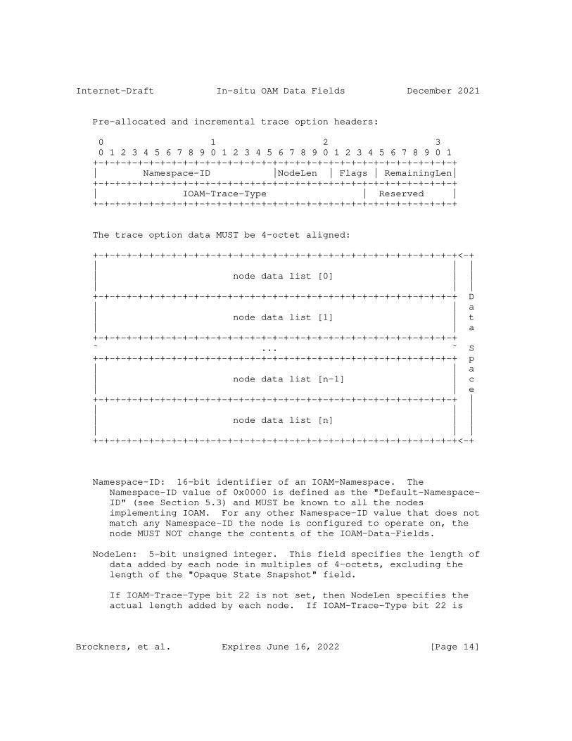
Internet-Draft In-situ OAM Data Fields December 2021
Pre-allocated and incremental trace option headers:
0 1 2 3 0 1 2 3 4 5 6 7 8 9 0 1 2 3 4 5 6 7 8 9 0 1 2 3 4 5 6 7 8 9 0 1 +-+-+-+-+-+-+-+-+-+-+-+-+-+-+-+-+-+-+-+-+-+-+-+-+-+-+-+-+-+-+-+-+ | Namespace-ID |NodeLen | Flags | RemainingLen| +-+-+-+-+-+-+-+-+-+-+-+-+-+-+-+-+-+-+-+-+-+-+-+-+-+-+-+-+-+-+-+-+ | IOAM-Trace-Type | Reserved | +-+-+-+-+-+-+-+-+-+-+-+-+-+-+-+-+-+-+-+-+-+-+-+-+-+-+-+-+-+-+-+-+
The trace option data MUST be 4-octet aligned:
+-+-+-+-+-+-+-+-+-+-+-+-+-+-+-+-+-+-+-+-+-+-+-+-+-+-+-+-+-+-+-+-+<-+ | | | | node data list [0] | | | | | +-+-+-+-+-+-+-+-+-+-+-+-+-+-+-+-+-+-+-+-+-+-+-+-+-+-+-+-+-+-+-+-+ D | | a | node data list [1] | t | | a +-+-+-+-+-+-+-+-+-+-+-+-+-+-+-+-+-+-+-+-+-+-+-+-+-+-+-+-+-+-+-+-+ ˜ ... ˜ S +-+-+-+-+-+-+-+-+-+-+-+-+-+-+-+-+-+-+-+-+-+-+-+-+-+-+-+-+-+-+-+-+ p | | a | node data list [n-1] | c | | e +-+-+-+-+-+-+-+-+-+-+-+-+-+-+-+-+-+-+-+-+-+-+-+-+-+-+-+-+-+-+-+-+ | | | | | node data list [n] | | | | | +-+-+-+-+-+-+-+-+-+-+-+-+-+-+-+-+-+-+-+-+-+-+-+-+-+-+-+-+-+-+-+-+<-+
Namespace-ID: 16-bit identifier of an IOAM-Namespace. The Namespace-ID value of 0x0000 is defined as the "Default-Namespace- ID" (see Section 5.3) and MUST be known to all the nodes implementing IOAM. For any other Namespace-ID value that does not match any Namespace-ID the node is configured to operate on, the node MUST NOT change the contents of the IOAM-Data-Fields.
NodeLen: 5-bit unsigned integer. This field specifies the length of data added by each node in multiples of 4-octets, excluding the length of the "Opaque State Snapshot" field.
If IOAM-Trace-Type bit 22 is not set, then NodeLen specifies the actual length added by each node. If IOAM-Trace-Type bit 22 is
Brockners, et al. Expires June 16, 2022 [Page 14]

Internet-Draft In-situ OAM Data Fields December 2021
set, then the actual length added by a node would be (NodeLen + length of the "Opaque State Snapshot" field) in 4 octet units.
For example, if 3 IOAM-Trace-Type bits are set and none of them are in wide format, then NodeLen would be 3. If 3 IOAM-Trace-Type bits are set and 2 of them are wide, then NodeLen would be 5.
An IOAM encapsulating node MUST set NodeLen.
A node receiving an IOAM Pre-allocated or Incremental Trace-Option relies on the NodeLen value.
Flags 4-bit field. Flags are allocated by IANA, as specified in Section 8.3. This document allocates a single flag as follows:
Bit 0 "Overflow" (O-bit) (most significant bit). In case a network element is supposed to add node data to a packet, but detects that there are not enough octets left to record the node data, the network element MUST NOT add any fields and MUST set the overflow "O-bit" to "1" in the IOAM-Trace-Option header. This is useful for transit nodes to ignore further processing of the option.
RemainingLen: 7-bit unsigned integer. This field specifies the data space in multiples of 4-octets remaining for recording the node data, before the node data list is considered to have overflowed. The sender MUST assign the initial value of the RemainingLen field. The sender MAY calculate the value of the RemainingLen field by computing the number of node data bytes allowed before exceeding the path MTU (PMTU), given that the PMTU is known to the sender. Subsequent nodes can carry out a simple comparison between RemainingLen and NodeLen, along with the length of the "Opaque State Snapshot" if applicable, to determine whether or not data can be added by this node. When node data is added, the node MUST decrease RemainingLen by the amount of data added. In the pre-allocated trace option, RemainingLen is used to derive the offset in data space to record the node data element. Specifically, the recording of the node data element would start from RemainingLen - NodeLen - sizeof(opaque snapshot) in 4 octet units. If RemainingLen in a pre-allocated trace option exceeds the length of the option, as specified in the lower layer header (which is not within the scope of this document), then the node MUST NOT add any fields.
IOAM-Trace-Type: A 24-bit identifier which specifies which data types are used in this node data list.
Brockners, et al. Expires June 16, 2022 [Page 15]

Internet-Draft In-situ OAM Data Fields December 2021
The IOAM-Trace-Type value is a bit field. The following bits are defined in this document, with details on each bit described in the Section 5.4.2. The order of packing the data fields in each node data element follows the bit order of the IOAM-Trace-Type field, as follows:
Bit 0 (Most significant bit) When set, indicates presence of Hop_Lim and node_id (short format) in the node data.
Bit 1 When set, indicates presence of ingress_if_id and egress_if_id (short format) in the node data.
Bit 2 When set, indicates presence of timestamp seconds in the node data.
Bit 3 When set, indicates presence of timestamp fraction in the node data.
Bit 4 When set, indicates presence of transit delay in the node data.
Bit 5 When set, indicates presence of IOAM-Namespace specific data (short format) in the node data.
Bit 6 When set, indicates presence of queue depth in the node data.
Bit 7 When set, indicates presence of the Checksum Complement node data.
Bit 8 When set, indicates presence of Hop_Lim and node_id in wide format in the node data.
Bit 9 When set, indicates presence of ingress_if_id and egress_if_id in wide format in the node data.
Bit 10 When set, indicates presence of IOAM-Namespace specific data in wide format in the node data.
Bit 11 When set, indicates presence of buffer occupancy in the node data.
Bit 12-21 Undefined. These values are available for future assignment in the IOAM Trace-Type Registry (Section 8.2). Every future node data field corresponding to one of these bits MUST be 4-octets long. An IOAM encapsulating node MUST set the value of each undefined bit to 0. If
Brockners, et al. Expires June 16, 2022 [Page 16]

Internet-Draft In-situ OAM Data Fields December 2021
an IOAM transit node receives a packet with one or more of these bits set to 1, it MUST either:
1. Add corresponding node data filled with the reserved value 0xFFFFFFFF, after the node data fields for the IOAM-Trace-Type bits defined above, such that the total node data added by this node in units of 4-octets is equal to NodeLen, or
2. Not add any node data fields to the packet, even for the IOAM-Trace-Type bits defined above.
Bit 22 When set, indicates presence of variable length Opaque State Snapshot field.
Bit 23 Reserved: MUST be set to zero upon transmission and ignored upon receipt. This bit is reserved to allow for future extensions of the IOAM-Trace-Type bit field.
Section 5.4.2 describes the IOAM-Data-Types and their formats. Within an IOAM-Domain possible combinations of these bits making the IOAM-Trace-Type can be restricted by configuration knobs.
Reserved: 8-bits. An IOAM encapsulating node MUST set the value to zero upon transmission. IOAM transit nodes MUST ignore the received value.
Node data List [n]: Variable-length field. This is a list of node data elements where the content of each node data element is determined by the IOAM-Trace-Type. The order of packing the data fields in each node data element follows the bit order of the IOAM-Trace-Type field. Each node MUST prepend its node data element in front of the node data elements that it received, such that the transmitted node data list begins with this node’s data element as the first populated element in the list. The last node data element in this list is the node data of the first IOAM capable node in the path. Populating the node data list in this way ensures that the order of node data list is the same for incremental and pre-allocated trace options. In the pre-allocated trace option, the index contained in RemainingLen identifies the offset for current active node data to be populated.
5.4.2. IOAM node data fields and associated formats
All the IOAM-Data-Fields MUST be 4-octet aligned. If a node which is supposed to update an IOAM-Data-Field is not capable of populating the value of a field set in the IOAM-Trace-Type, the field value MUST be set to 0xFFFFFFFF for 4-octet fields or 0xFFFFFFFFFFFFFFFF for
Brockners, et al. Expires June 16, 2022 [Page 17]

Internet-Draft In-situ OAM Data Fields December 2021
8-octet fields, indicating that the value is not populated, except when explicitly specified in the field description below.
Some IOAM-Data-Fields defined below, such as interface identifiers or IOAM-Namespace specific data, are defined in both "short format" as well as "wide format". The use of "short format" or "wide format" is not mutually exclusive. A deployment could choose to leverage both. For example, ingress_if_id_(short format) could be an identifier for the physical interface, whereas ingress_if_id_(wide format) could be an identifier for a logical sub-interface of that physical interface.
Data fields and associated data types for each of the IOAM-Data- Fields are specified in the following sections. The definition of IOAM-Data-Fields focuses on the syntax of the data-fields and avoids specifying the semantics where feasible. This is why no units are defined for data-fields like e.g., "buffer occupancy" or "queue depth". With this approach, nodes can supply the information in their native format and are not required to perform unit or format conversions. Systems that further process IOAM information, like e.g., a network management system are assumed to also handle unit conversions as part of their IOAM data-fields processing. The combination of a particular data-field and the namespace-id provides for the context to interpret the provided data appropriately.
5.4.2.1. Hop_Lim and node_id short format
The "Hop_Lim and node_id short format" field is a 4-octet field that is defined as follows:
0 1 2 3 4 5 6 7 8 9 0 1 2 3 4 5 6 7 8 9 0 1 2 3 4 5 6 7 8 9 0 1 +-+-+-+-+-+-+-+-+-+-+-+-+-+-+-+-+-+-+-+-+-+-+-+-+-+-+-+-+-+-+-+-+ | Hop_Lim | node_id | +-+-+-+-+-+-+-+-+-+-+-+-+-+-+-+-+-+-+-+-+-+-+-+-+-+-+-+-+-+-+-+-+
Hop_Lim: 1-octet unsigned integer. It is set to the Hop Limit value in the packet at egress from the node that records this data. Hop Limit information is used to identify the location of the node in the communication path. This is copied from the lower layer, e.g., TTL value in IPv4 header or hop limit field from IPv6 header of the packet when the packet is ready for transmission. The semantics of the Hop_Lim field depend on the lower layer protocol that IOAM is encapsulated into, and therefore its specific semantics are outside the scope of this memo. The value of this field MUST be set to 0xff when the lower level does not have a TTL/Hop limit equivalent field.
node_id: 3-octet unsigned integer. Node identifier field to uniquely identify a node within the IOAM-Namespace and associated
Brockners, et al. Expires June 16, 2022 [Page 18]

Internet-Draft In-situ OAM Data Fields December 2021
IOAM-Domain. The procedure to allocate, manage and map the node_ids is beyond the scope of this document. See [I-D.ietf-ippm-ioam-deployment] for a discussion of deployment related aspects of the node_id.
5.4.2.2. ingress_if_id and egress_if_id
The "ingress_if_id and egress_if_id" field is a 4-octet field that is defined as follows:
0 1 2 3 4 5 6 7 8 9 0 1 2 3 4 5 6 7 8 9 0 1 2 3 4 5 6 7 8 9 0 1 +-+-+-+-+-+-+-+-+-+-+-+-+-+-+-+-+-+-+-+-+-+-+-+-+-+-+-+-+-+-+-+-+ | ingress_if_id | egress_if_id | +-+-+-+-+-+-+-+-+-+-+-+-+-+-+-+-+-+-+-+-+-+-+-+-+-+-+-+-+-+-+-+-+
ingress_if_id: 2-octet unsigned integer. Interface identifier to record the ingress interface the packet was received on.
egress_if_id: 2-octet unsigned integer. Interface identifier to record the egress interface the packet is forwarded out of.
Note that due to the fact that IOAM uses its own IOAM-Namespaces for IOAM-Data-Fields, data fields like interface identifiers can be used in a flexible way to represent system resources that are associated with ingressing or egressing packets, i.e., ingress_if_id could represent a physical interface, a virtual or logical interface, or even a queue.
5.4.2.3. timestamp seconds
The "timestamp seconds" field is a 4-octet unsigned integer field. It contains the absolute timestamp in seconds that specifies the time at which the packet was received by the node. This field has three possible formats; based on either PTP (see e.g., [RFC8877]), NTP [RFC5905], or POSIX [POSIX]. The three timestamp formats are specified in Section 6. In all three cases, the Timestamp Seconds field contains the 32 most significant bits of the timestamp format that is specified in Section 6. If a node is not capable of populating this field, it assigns the value 0xFFFFFFFF. Note that this is a legitimate value that is valid for 1 second in approximately 136 years; the analyzer has to correlate several packets or compare the timestamp value to its own time-of-day in order to detect the error indication.
Brockners, et al. Expires June 16, 2022 [Page 19]

Internet-Draft In-situ OAM Data Fields December 2021
5.4.2.4. timestamp fraction
The "timestamp fraction" field is a 4-octet unsigned integer field. Fraction specifies the fractional portion of the number of seconds since the NTP epoch [RFC8877]. The field specifies the time at which the packet was received by the node. This field has three possible formats; based on either PTP (see e.g., [RFC8877]), NTP [RFC5905], or POSIX [POSIX]. The three timestamp formats are specified in Section 6. In all three cases, the Timestamp fraction field contains the 32 least significant bits of the timestamp format that is specified in Section 6. If a node is not capable of populating this field, it assigns the value 0xFFFFFFFF. Note that this is a legitimate value in the NTP format, valid for approximately 233 picoseconds in every second. If the NTP format is used the analyzer has to correlate several packets in order to detect the error indication.
5.4.2.5. transit delay
The "transit delay" field is a 4-octet unsigned integer in the range 0 to 2^31-1. It is the time in nanoseconds the packet spent in the transit node. This can serve as an indication of the queuing delay at the node. If the transit delay exceeds 2^31-1 nanoseconds then the top bit ’O’ is set to indicate overflow and value set to 0x80000000. When this field is part of the data field but a node populating the field is not able to fill it, the field position in the field MUST be filled with value 0xFFFFFFFF to mean not populated.
0 1 2 3 4 5 6 7 8 9 0 1 2 3 4 5 6 7 8 9 0 1 2 3 4 5 6 7 8 9 0 1 +-+-+-+-+-+-+-+-+-+-+-+-+-+-+-+-+-+-+-+-+-+-+-+-+-+-+-+-+-+-+-+-+ |O| transit delay | +-+-+-+-+-+-+-+-+-+-+-+-+-+-+-+-+-+-+-+-+-+-+-+-+-+-+-+-+-+-+-+-+
5.4.2.6. namespace specific data
The "namespace specific data" field is a 4-octet field which can be used by the node to add IOAM-Namespace specific data. This represents a "free-format" 4-octet bit field with its semantics defined in the context of a specific IOAM-Namespace.
0 1 2 3 4 5 6 7 8 9 0 1 2 3 4 5 6 7 8 9 0 1 2 3 4 5 6 7 8 9 0 1 +-+-+-+-+-+-+-+-+-+-+-+-+-+-+-+-+-+-+-+-+-+-+-+-+-+-+-+-+-+-+-+-+ | namespace specific data | +-+-+-+-+-+-+-+-+-+-+-+-+-+-+-+-+-+-+-+-+-+-+-+-+-+-+-+-+-+-+-+-+
Brockners, et al. Expires June 16, 2022 [Page 20]

Internet-Draft In-situ OAM Data Fields December 2021
5.4.2.7. queue depth
The "queue depth" field is a 4-octet unsigned integer field. This field indicates the current length of the egress interface queue of the interface from where the packet is forwarded out. The queue depth is expressed as the current amount of memory buffers used by the queue (a packet could consume one or more memory buffers, depending on its size).
0 1 2 3 4 5 6 7 8 9 0 1 2 3 4 5 6 7 8 9 0 1 2 3 4 5 6 7 8 9 0 1 +-+-+-+-+-+-+-+-+-+-+-+-+-+-+-+-+-+-+-+-+-+-+-+-+-+-+-+-+-+-+-+-+ | queue depth | +-+-+-+-+-+-+-+-+-+-+-+-+-+-+-+-+-+-+-+-+-+-+-+-+-+-+-+-+-+-+-+-+
5.4.2.8. Checksum Complement
The "Checksum Complement" field is a 4-octet node data which contains a 4-octet Checksum Complement field. The Checksum Complement is useful when IOAM is transported over encapsulations that make use of a UDP transport, such as VXLAN-GPE or Geneve. Without the Checksum Complement, nodes adding IOAM node data update the UDP Checksum field following the recommendation of the encapsulation protocols. When the Checksum Complement is present, an IOAM encapsulating node or IOAM transit node adding node data MUST carry out one of the following two alternatives in order to maintain the correctness of the UDP Checksum value:
1. Recompute the UDP Checksum field.
2. Use the Checksum Complement to make a checksum-neutral update in the UDP payload; the Checksum Complement is assigned a value that complements the rest of the node data fields that were added by the current node, causing the existing UDP Checksum field to remain correct.
IOAM decapsulating nodes MUST recompute the UDP Checksum field, since they do not know whether previous hops modified the UDP Checksum field or the Checksum Complement field.
Checksum Complement fields are used in a similar manner in [RFC7820] and [RFC7821].
0 1 2 3 4 5 6 7 8 9 0 1 2 3 4 5 6 7 8 9 0 1 2 3 4 5 6 7 8 9 0 1 +-+-+-+-+-+-+-+-+-+-+-+-+-+-+-+-+-+-+-+-+-+-+-+-+-+-+-+-+-+-+-+-+ | Checksum Complement | +-+-+-+-+-+-+-+-+-+-+-+-+-+-+-+-+-+-+-+-+-+-+-+-+-+-+-+-+-+-+-+-+
Brockners, et al. Expires June 16, 2022 [Page 21]

Internet-Draft In-situ OAM Data Fields December 2021
5.4.2.9. Hop_Lim and node_id wide
The "Hop_Lim and node_id wide" field is an 8-octet field defined as follows:
0 1 2 3 4 5 6 7 8 9 0 1 2 3 4 5 6 7 8 9 0 1 2 3 4 5 6 7 8 9 0 1 +-+-+-+-+-+-+-+-+-+-+-+-+-+-+-+-+-+-+-+-+-+-+-+-+-+-+-+-+-+-+-+-+ | Hop_Lim | node_id ˜ +-+-+-+-+-+-+-+-+-+-+-+-+-+-+-+-+-+-+-+-+-+-+-+-+-+-+-+-+-+-+-+-+ ˜ node_id (contd) | +-+-+-+-+-+-+-+-+-+-+-+-+-+-+-+-+-+-+-+-+-+-+-+-+-+-+-+-+-+-+-+-+
Hop_Lim: 1-octet unsigned integer. See Section 5.4.2.1 for the definition of the field.
node_id: 7-octet unsigned integer. Node identifier field to uniquely identify a node within the IOAM-Namespace and associated IOAM-Domain. The procedure to allocate, manage and map the node_ids is beyond the scope of this document.
5.4.2.10. ingress_if_id and egress_if_id wide
The "ingress_if_id and egress_if_id wide" field is an 8-octet field which is defined as follows:
0 1 2 3 4 5 6 7 8 9 0 1 2 3 4 5 6 7 8 9 0 1 2 3 4 5 6 7 8 9 0 1 +-+-+-+-+-+-+-+-+-+-+-+-+-+-+-+-+-+-+-+-+-+-+-+-+-+-+-+-+-+-+-+-+ | ingress_if_id | +-+-+-+-+-+-+-+-+-+-+-+-+-+-+-+-+-+-+-+-+-+-+-+-+-+-+-+-+-+-+-+-+ | egress_if_id | +-+-+-+-+-+-+-+-+-+-+-+-+-+-+-+-+-+-+-+-+-+-+-+-+-+-+-+-+-+-+-+-+
ingress_if_id: 4-octet unsigned integer. Interface identifier to record the ingress interface the packet was received on.
egress_if_id: 4-octet unsigned integer. Interface identifier to record the egress interface the packet is forwarded out of.
5.4.2.11. namespace specific data wide
The "namespace specific data wide" field is an 8-octet field which can be used by the node to add IOAM-Namespace specific data. This represents a "free-format" 8-octet bit field with its semantics defined in the context of a specific IOAM-Namespace.
Brockners, et al. Expires June 16, 2022 [Page 22]

Internet-Draft In-situ OAM Data Fields December 2021
0 1 2 3 4 5 6 7 8 9 0 1 2 3 4 5 6 7 8 9 0 1 2 3 4 5 6 7 8 9 0 1 +-+-+-+-+-+-+-+-+-+-+-+-+-+-+-+-+-+-+-+-+-+-+-+-+-+-+-+-+-+-+-+-+ | namespace specific data ˜ +-+-+-+-+-+-+-+-+-+-+-+-+-+-+-+-+-+-+-+-+-+-+-+-+-+-+-+-+-+-+-+-+ ˜ namespace specific data (contd) | +-+-+-+-+-+-+-+-+-+-+-+-+-+-+-+-+-+-+-+-+-+-+-+-+-+-+-+-+-+-+-+-+
5.4.2.12. buffer occupancy
The "buffer occupancy" field is a 4-octet unsigned integer field. This field indicates the current status of the occupancy of the common buffer pool used by a set of queues. The units of this field are implementation specific. Hence, the units are interpreted within the context of an IOAM-Namespace and/or node-id if used. The authors acknowledge that in some operational cases there is a need for the units to be consistent across a packet path through the network, hence it is recommended for implementations to use standard units such as Bytes.
0 1 2 3 4 5 6 7 8 9 0 1 2 3 4 5 6 7 8 9 0 1 2 3 4 5 6 7 8 9 0 1 +-+-+-+-+-+-+-+-+-+-+-+-+-+-+-+-+-+-+-+-+-+-+-+-+-+-+-+-+-+-+-+-+ | buffer occupancy | +-+-+-+-+-+-+-+-+-+-+-+-+-+-+-+-+-+-+-+-+-+-+-+-+-+-+-+-+-+-+-+-+
5.4.2.13. Opaque State Snapshot
The "Opaque State Snapshot" is a variable length field and follows the fixed length IOAM-Data-Fields defined above. It allows the network element to store an arbitrary state in the node data field, without a pre-defined schema. The schema is to be defined within the context of an IOAM-Namespace. The schema needs to be made known to the analyzer by some out-of-band mechanism. The specification of this mechanism is beyond the scope of this document. A 24-bit "Schema Id" field, interpreted within the context of an IOAM- Namespace, indicates which particular schema is used, and has to be configured on the network element by the operator.
Brockners, et al. Expires June 16, 2022 [Page 23]

Internet-Draft In-situ OAM Data Fields December 2021
0 1 2 3 0 1 2 3 4 5 6 7 8 9 0 1 2 3 4 5 6 7 8 9 0 1 2 3 4 5 6 7 8 9 0 1 +-+-+-+-+-+-+-+-+-+-+-+-+-+-+-+-+-+-+-+-+-+-+-+-+-+-+-+-+-+-+-+-+ | Length | Schema ID | +-+-+-+-+-+-+-+-+-+-+-+-+-+-+-+-+-+-+-+-+-+-+-+-+-+-+-+-+-+-+-+-+ | | | | | Opaque data | ˜ ˜ . . . . +-+-+-+-+-+-+-+-+-+-+-+-+-+-+-+-+-+-+-+-+-+-+-+-+-+-+-+-+-+-+-+-+
Length: 1-octet unsigned integer. It is the length in multiples of 4-octets of the Opaque data field that follows Schema Id.
Schema ID: 3-octet unsigned integer identifying the schema of Opaque data.
Opaque data: Variable length field. This field is interpreted as specified by the schema identified by the Schema ID.
When this field is part of the data field but a node populating the field has no opaque state data to report, the Length MUST be set to 0 and the Schema ID MUST be set to 0xFFFFFF to mean no schema.
5.4.3. Examples of IOAM node data
The format used for the entries in a packet’s "node data list" array can vary from packet to packet and deployment to deployment". Some deployments might only be interested in recording the node identifiers, whereas others might be interested in recording node identifiers and timestamps. This section provides example entries of the "node data list".
0xD40000: IOAM-Trace-Type is 0xD40000 (0b110101000000000000000000) then the format of node data is:
Brockners, et al. Expires June 16, 2022 [Page 24]
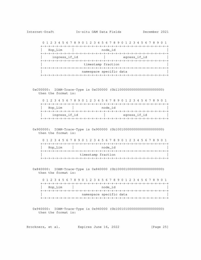
Internet-Draft In-situ OAM Data Fields December 2021
0 1 2 3 4 5 6 7 8 9 0 1 2 3 4 5 6 7 8 9 0 1 2 3 4 5 6 7 8 9 0 1 +-+-+-+-+-+-+-+-+-+-+-+-+-+-+-+-+-+-+-+-+-+-+-+-+-+-+-+-+-+-+-+-+ | Hop_Lim | node_id | +-+-+-+-+-+-+-+-+-+-+-+-+-+-+-+-+-+-+-+-+-+-+-+-+-+-+-+-+-+-+-+-+ | ingress_if_id | egress_if_id | +-+-+-+-+-+-+-+-+-+-+-+-+-+-+-+-+-+-+-+-+-+-+-+-+-+-+-+-+-+-+-+-+ | timestamp fraction | +-+-+-+-+-+-+-+-+-+-+-+-+-+-+-+-+-+-+-+-+-+-+-+-+-+-+-+-+-+-+-+-+ | namespace specific data | +-+-+-+-+-+-+-+-+-+-+-+-+-+-+-+-+-+-+-+-+-+-+-+-+-+-+-+-+-+-+-+-+
0xC00000: IOAM-Trace-Type is 0xC00000 (0b110000000000000000000000) then the format is:
0 1 2 3 4 5 6 7 8 9 0 1 2 3 4 5 6 7 8 9 0 1 2 3 4 5 6 7 8 9 0 1 +-+-+-+-+-+-+-+-+-+-+-+-+-+-+-+-+-+-+-+-+-+-+-+-+-+-+-+-+-+-+-+-+ | Hop_Lim | node_id | +-+-+-+-+-+-+-+-+-+-+-+-+-+-+-+-+-+-+-+-+-+-+-+-+-+-+-+-+-+-+-+-+ | ingress_if_id | egress_if_id | +-+-+-+-+-+-+-+-+-+-+-+-+-+-+-+-+-+-+-+-+-+-+-+-+-+-+-+-+-+-+-+-+
0x900000: IOAM-Trace-Type is 0x900000 (0b100100000000000000000000) then the format is:
0 1 2 3 4 5 6 7 8 9 0 1 2 3 4 5 6 7 8 9 0 1 2 3 4 5 6 7 8 9 0 1 +-+-+-+-+-+-+-+-+-+-+-+-+-+-+-+-+-+-+-+-+-+-+-+-+-+-+-+-+-+-+-+-+ | Hop_Lim | node_id | +-+-+-+-+-+-+-+-+-+-+-+-+-+-+-+-+-+-+-+-+-+-+-+-+-+-+-+-+-+-+-+-+ | timestamp fraction | +-+-+-+-+-+-+-+-+-+-+-+-+-+-+-+-+-+-+-+-+-+-+-+-+-+-+-+-+-+-+-+-+
0x840000: IOAM-Trace-Type is 0x840000 (0b100001000000000000000000) then the format is:
0 1 2 3 4 5 6 7 8 9 0 1 2 3 4 5 6 7 8 9 0 1 2 3 4 5 6 7 8 9 0 1 +-+-+-+-+-+-+-+-+-+-+-+-+-+-+-+-+-+-+-+-+-+-+-+-+-+-+-+-+-+-+-+-+ | Hop_Lim | node_id | +-+-+-+-+-+-+-+-+-+-+-+-+-+-+-+-+-+-+-+-+-+-+-+-+-+-+-+-+-+-+-+-+ | namespace specific data | +-+-+-+-+-+-+-+-+-+-+-+-+-+-+-+-+-+-+-+-+-+-+-+-+-+-+-+-+-+-+-+-+
0x940000: IOAM-Trace-Type is 0x940000 (0b100101000000000000000000) then the format is:
Brockners, et al. Expires June 16, 2022 [Page 25]
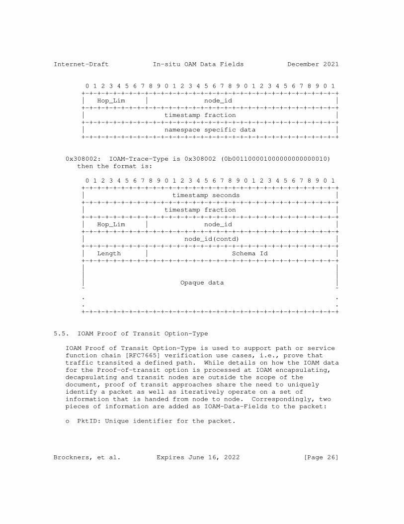
Internet-Draft In-situ OAM Data Fields December 2021
0 1 2 3 4 5 6 7 8 9 0 1 2 3 4 5 6 7 8 9 0 1 2 3 4 5 6 7 8 9 0 1 +-+-+-+-+-+-+-+-+-+-+-+-+-+-+-+-+-+-+-+-+-+-+-+-+-+-+-+-+-+-+-+-+ | Hop_Lim | node_id | +-+-+-+-+-+-+-+-+-+-+-+-+-+-+-+-+-+-+-+-+-+-+-+-+-+-+-+-+-+-+-+-+ | timestamp fraction | +-+-+-+-+-+-+-+-+-+-+-+-+-+-+-+-+-+-+-+-+-+-+-+-+-+-+-+-+-+-+-+-+ | namespace specific data | +-+-+-+-+-+-+-+-+-+-+-+-+-+-+-+-+-+-+-+-+-+-+-+-+-+-+-+-+-+-+-+-+
0x308002: IOAM-Trace-Type is 0x308002 (0b001100001000000000000010) then the format is:
0 1 2 3 4 5 6 7 8 9 0 1 2 3 4 5 6 7 8 9 0 1 2 3 4 5 6 7 8 9 0 1 +-+-+-+-+-+-+-+-+-+-+-+-+-+-+-+-+-+-+-+-+-+-+-+-+-+-+-+-+-+-+-+-+ | timestamp seconds | +-+-+-+-+-+-+-+-+-+-+-+-+-+-+-+-+-+-+-+-+-+-+-+-+-+-+-+-+-+-+-+-+ | timestamp fraction | +-+-+-+-+-+-+-+-+-+-+-+-+-+-+-+-+-+-+-+-+-+-+-+-+-+-+-+-+-+-+-+-+ | Hop_Lim | node_id | +-+-+-+-+-+-+-+-+-+-+-+-+-+-+-+-+-+-+-+-+-+-+-+-+-+-+-+-+-+-+-+-+ | node_id(contd) | +-+-+-+-+-+-+-+-+-+-+-+-+-+-+-+-+-+-+-+-+-+-+-+-+-+-+-+-+-+-+-+-+ | Length | Schema Id | +-+-+-+-+-+-+-+-+-+-+-+-+-+-+-+-+-+-+-+-+-+-+-+-+-+-+-+-+-+-+-+-+ | | | | | Opaque data | ˜ ˜ . . . . +-+-+-+-+-+-+-+-+-+-+-+-+-+-+-+-+-+-+-+-+-+-+-+-+-+-+-+-+-+-+-+-+
5.5. IOAM Proof of Transit Option-Type
IOAM Proof of Transit Option-Type is used to support path or service function chain [RFC7665] verification use cases, i.e., prove that traffic transited a defined path. While details on how the IOAM data for the Proof-of-transit option is processed at IOAM encapsulating, decapsulating and transit nodes are outside the scope of the document, proof of transit approaches share the need to uniquely identify a packet as well as iteratively operate on a set of information that is handed from node to node. Correspondingly, two pieces of information are added as IOAM-Data-Fields to the packet:
o PktID: Unique identifier for the packet.
Brockners, et al. Expires June 16, 2022 [Page 26]

Internet-Draft In-situ OAM Data Fields December 2021
o Cumulative: Information which is handed from node to node and updated by every node according to a verification algorithm.
The IOAM Proof-of-Transit Option-Type consist of a fixed size "IOAM proof of transit option header" and "IOAM proof of transit option data fields":
IOAM proof of transit option header:
0 1 2 3 0 1 2 3 4 5 6 7 8 9 0 1 2 3 4 5 6 7 8 9 0 1 2 3 4 5 6 7 8 9 0 1 +-+-+-+-+-+-+-+-+-+-+-+-+-+-+-+-+-+-+-+-+-+-+-+-+-+-+-+-+-+-+-+-+ | Namespace-ID |IOAM POT Type | IOAM POT flags| +-+-+-+-+-+-+-+-+-+-+-+-+-+-+-+-+-+-+-+-+-+-+-+-+-+-+-+-+-+-+-+-+
IOAM proof of transit Option-Type IOAM-Data-Fields MUST be 4-octet aligned:
0 1 2 3 0 1 2 3 4 5 6 7 8 9 0 1 2 3 4 5 6 7 8 9 0 1 2 3 4 5 6 7 8 9 0 1 +-+-+-+-+-+-+-+-+-+-+-+-+-+-+-+-+-+-+-+-+-+-+-+-+-+-+-+-+-+-+-+-+ | POT Option data field determined by IOAM-POT-Type | +-+-+-+-+-+-+-+-+-+-+-+-+-+-+-+-+-+-+-+-+-+-+-+-+-+-+-+-+-+-+-+-+
Namespace-ID: 16-bit identifier of an IOAM-Namespace. The Namespace-ID value of 0x0000 is defined as the "Default-Namespace- ID" (see Section 5.3) and MUST be known to all the nodes implementing IOAM. For any other Namespace-ID value that does not match any Namespace-ID the node is configured to operate on, the node MUST NOT change the contents of the IOAM-Data-Fields.
IOAM POT Type: 8-bit identifier of a particular POT variant that specifies the POT data that is included. This document defines POT Type 0:
0: POT data is a 16 Octet field to carry data associated to POT procedures.
If a node receives an IOAM POT Type value that it does not understand, the node MUST NOT change, add to, or remove the contents of the OAM-Data-Fields.
IOAM POT flags: 8-bit. This document does not define any flags. Bits 0-7 These bits are available for assignment, see Section 8.5. Bits which have not been assigned MUST be set to zero upon transmission and ignored upon receipt.
Brockners, et al. Expires June 16, 2022 [Page 27]
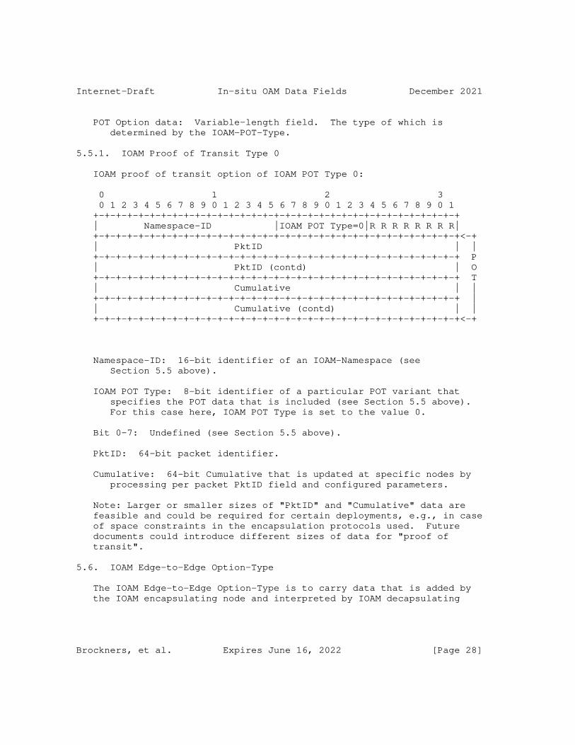
Internet-Draft In-situ OAM Data Fields December 2021
POT Option data: Variable-length field. The type of which is determined by the IOAM-POT-Type.
5.5.1. IOAM Proof of Transit Type 0
IOAM proof of transit option of IOAM POT Type 0:
0 1 2 3 0 1 2 3 4 5 6 7 8 9 0 1 2 3 4 5 6 7 8 9 0 1 2 3 4 5 6 7 8 9 0 1 +-+-+-+-+-+-+-+-+-+-+-+-+-+-+-+-+-+-+-+-+-+-+-+-+-+-+-+-+-+-+-+-+ | Namespace-ID |IOAM POT Type=0|R R R R R R R R| +-+-+-+-+-+-+-+-+-+-+-+-+-+-+-+-+-+-+-+-+-+-+-+-+-+-+-+-+-+-+-+-+<-+ | PktID | | +-+-+-+-+-+-+-+-+-+-+-+-+-+-+-+-+-+-+-+-+-+-+-+-+-+-+-+-+-+-+-+-+ P | PktID (contd) | O +-+-+-+-+-+-+-+-+-+-+-+-+-+-+-+-+-+-+-+-+-+-+-+-+-+-+-+-+-+-+-+-+ T | Cumulative | | +-+-+-+-+-+-+-+-+-+-+-+-+-+-+-+-+-+-+-+-+-+-+-+-+-+-+-+-+-+-+-+-+ | | Cumulative (contd) | | +-+-+-+-+-+-+-+-+-+-+-+-+-+-+-+-+-+-+-+-+-+-+-+-+-+-+-+-+-+-+-+-+<-+
Namespace-ID: 16-bit identifier of an IOAM-Namespace (see Section 5.5 above).
IOAM POT Type: 8-bit identifier of a particular POT variant that specifies the POT data that is included (see Section 5.5 above). For this case here, IOAM POT Type is set to the value 0.
Bit 0-7: Undefined (see Section 5.5 above).
PktID: 64-bit packet identifier.
Cumulative: 64-bit Cumulative that is updated at specific nodes by processing per packet PktID field and configured parameters.
Note: Larger or smaller sizes of "PktID" and "Cumulative" data are feasible and could be required for certain deployments, e.g., in case of space constraints in the encapsulation protocols used. Future documents could introduce different sizes of data for "proof of transit".
5.6. IOAM Edge-to-Edge Option-Type
The IOAM Edge-to-Edge Option-Type is to carry data that is added by the IOAM encapsulating node and interpreted by IOAM decapsulating
Brockners, et al. Expires June 16, 2022 [Page 28]

Internet-Draft In-situ OAM Data Fields December 2021
node. The IOAM transit nodes MAY process the data but MUST NOT modify it.
The IOAM Edge-to-Edge Option-Type consist of a fixed size "IOAM Edge- to-Edge Option-Type header" and "IOAM Edge-to-Edge Option-Type data fields":
IOAM Edge-to-Edge Option-Type header:
0 1 2 3 0 1 2 3 4 5 6 7 8 9 0 1 2 3 4 5 6 7 8 9 0 1 2 3 4 5 6 7 8 9 0 1 +-+-+-+-+-+-+-+-+-+-+-+-+-+-+-+-+-+-+-+-+-+-+-+-+-+-+-+-+-+-+-+-+ | Namespace-ID | IOAM-E2E-Type | +-+-+-+-+-+-+-+-+-+-+-+-+-+-+-+-+-+-+-+-+-+-+-+-+-+-+-+-+-+-+-+-+
IOAM Edge-to-Edge Option-Type IOAM-Data-Fields MUST be 4-octet aligned:
0 1 2 3 0 1 2 3 4 5 6 7 8 9 0 1 2 3 4 5 6 7 8 9 0 1 2 3 4 5 6 7 8 9 0 1 +-+-+-+-+-+-+-+-+-+-+-+-+-+-+-+-+-+-+-+-+-+-+-+-+-+-+-+-+-+-+-+-+ | E2E Option data field determined by IOAM-E2E-Type | +-+-+-+-+-+-+-+-+-+-+-+-+-+-+-+-+-+-+-+-+-+-+-+-+-+-+-+-+-+-+-+-+
Namespace-ID: 16-bit identifier of an IOAM-Namespace. The Namespace-ID value of 0x0000 is defined as the "Default-Namespace- ID" (see Section 5.3) and MUST be known to all the nodes implementing IOAM. For any other Namespace-ID value that does not match any Namespace-ID the node is configured to operate on, then the node MUST NOT change the contents of the IOAM-Data-Fields.
IOAM-E2E-Type: A 16-bit identifier which specifies which data types are used in the E2E option data. The IOAM-E2E-Type value is a bit field. The order of packing the E2E option data field elements follows the bit order of the IOAM-E2E-Type field, as follows:
Bit 0 (Most significant bit) When set indicates presence of a 64-bit sequence number added to a specific "packet group" which is used to detect packet loss, packet reordering, or packet duplication within the group. The "packet group" is deployment dependent and defined at the IOAM encapsulating node, e.g., by n-tuple based classification of packets. When this bit is set, "Bit 1" (for 32-bit sequence number, see below) MUST be zero.
Bit 1 When set indicates presence of a 32-bit sequence number added to a specific "packet group" which is used to
Brockners, et al. Expires June 16, 2022 [Page 29]

Internet-Draft In-situ OAM Data Fields December 2021
detect packet loss, packet reordering, or packet duplication within that group. The "packet group" is deployment dependent and defined at the IOAM encapsulating node, e.g., by n-tuple based classification of packets. When this bit is set, "Bit 0" (for 64-bit sequence number, see above) MUST be zero.
Bit 2 When set indicates presence of timestamp seconds, representing the time at which the packet entered the IOAM-domain. Within the IOAM encapsulating node, the time that the timestamp is retrieved can depend on the implementation. Some possibilities are: 1) the time at which the packet was received by the node, 2) the time at which the packet was transmitted by the node, 3) when a tunnel encapsulation is used, the point at which the packet is encapsulated into the tunnel. Each implementation has to document when the E2E timestamp that is going to be put in the packet is retrieved. This 4-octet field has three possible formats; based on either PTP (see e.g., [RFC8877]), NTP [RFC5905], or POSIX [POSIX]. The three timestamp formats are specified in Section 6. In all three cases, the Timestamp Seconds field contains the 32 most significant bits of the timestamp format that is specified in Section 6. If a node is not capable of populating this field, it assigns the value 0xFFFFFFFF. Note that this is a legitimate value that is valid for 1 second in approximately 136 years; the analyzer has to correlate several packets or compare the timestamp value to its own time-of-day in order to detect the error indication.
Bit 3 When set indicates presence of timestamp fraction, representing the time at which the packet entered the IOAM-domain. This 4-octet field has three possible formats; based on either PTP (see e.g., [RFC8877]), NTP [RFC5905], or POSIX [POSIX]. The three timestamp formats are specified in Section 6. In all three cases, the Timestamp fraction field contains the 32 least significant bits of the timestamp format that is specified in Section 6. If a node is not capable of populating this field, it assigns the value 0xFFFFFFFF. Note that this is a legitimate value in the NTP format, valid for approximately 233 picoseconds in every second. If the NTP format is used the analyzer has to correlate several packets in order to detect the error indication.
Brockners, et al. Expires June 16, 2022 [Page 30]
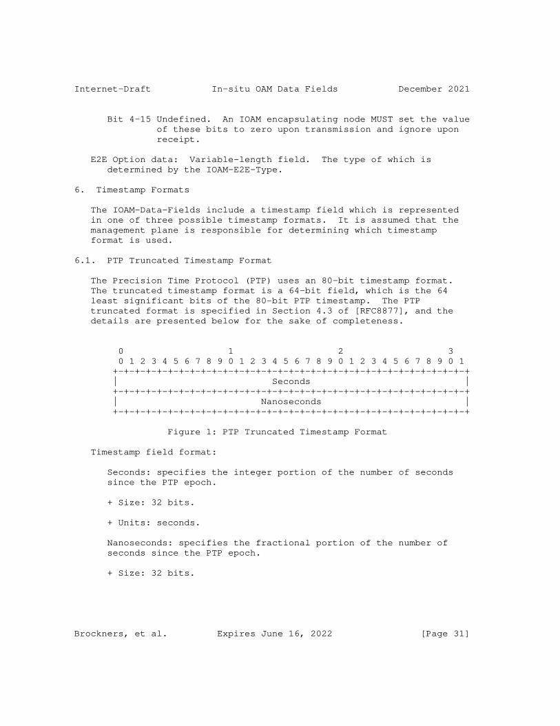
Internet-Draft In-situ OAM Data Fields December 2021
Bit 4-15 Undefined. An IOAM encapsulating node MUST set the value of these bits to zero upon transmission and ignore upon receipt.
E2E Option data: Variable-length field. The type of which is determined by the IOAM-E2E-Type.
6. Timestamp Formats
The IOAM-Data-Fields include a timestamp field which is represented in one of three possible timestamp formats. It is assumed that the management plane is responsible for determining which timestamp format is used.
6.1. PTP Truncated Timestamp Format
The Precision Time Protocol (PTP) uses an 80-bit timestamp format. The truncated timestamp format is a 64-bit field, which is the 64 least significant bits of the 80-bit PTP timestamp. The PTP truncated format is specified in Section 4.3 of [RFC8877], and the details are presented below for the sake of completeness.
0 1 2 3 0 1 2 3 4 5 6 7 8 9 0 1 2 3 4 5 6 7 8 9 0 1 2 3 4 5 6 7 8 9 0 1 +-+-+-+-+-+-+-+-+-+-+-+-+-+-+-+-+-+-+-+-+-+-+-+-+-+-+-+-+-+-+-+-+ | Seconds | +-+-+-+-+-+-+-+-+-+-+-+-+-+-+-+-+-+-+-+-+-+-+-+-+-+-+-+-+-+-+-+-+ | Nanoseconds | +-+-+-+-+-+-+-+-+-+-+-+-+-+-+-+-+-+-+-+-+-+-+-+-+-+-+-+-+-+-+-+-+
Figure 1: PTP Truncated Timestamp Format
Timestamp field format:
Seconds: specifies the integer portion of the number of seconds since the PTP epoch.
+ Size: 32 bits.
+ Units: seconds.
Nanoseconds: specifies the fractional portion of the number of seconds since the PTP epoch.
+ Size: 32 bits.
Brockners, et al. Expires June 16, 2022 [Page 31]

Internet-Draft In-situ OAM Data Fields December 2021
+ Units: nanoseconds. The value of this field is in the range 0 to (10^9)-1.
Epoch:
PTP epoch. For details see e.g., [RFC8877].
Resolution:
The resolution is 1 nanosecond.
Wraparound:
This time format wraps around every 2^32 seconds, which is roughly 136 years. The next wraparound will occur in the year 2106.
Synchronization Aspects:
It is assumed that nodes that run this protocol are synchronized among themselves. Nodes MAY be synchronized to a global reference time. Note that if PTP is used for synchronization, the timestamp MAY be derived from the PTP-synchronized clock, allowing the timestamp to be measured with respect to the clock of an PTP Grandmaster clock.
6.2. NTP 64-bit Timestamp Format
The Network Time Protocol (NTP) [RFC5905] timestamp format is 64 bits long. This specification uses the NTP timestamp format that is specified in Section 4.2.1 of [RFC8877], and the details are presented below for the sake of completeness.
0 1 2 3 0 1 2 3 4 5 6 7 8 9 0 1 2 3 4 5 6 7 8 9 0 1 2 3 4 5 6 7 8 9 0 1 +-+-+-+-+-+-+-+-+-+-+-+-+-+-+-+-+-+-+-+-+-+-+-+-+-+-+-+-+-+-+-+-+ | Seconds | +-+-+-+-+-+-+-+-+-+-+-+-+-+-+-+-+-+-+-+-+-+-+-+-+-+-+-+-+-+-+-+-+ | Fraction | +-+-+-+-+-+-+-+-+-+-+-+-+-+-+-+-+-+-+-+-+-+-+-+-+-+-+-+-+-+-+-+-+
Figure 2: NTP [RFC5905] 64-bit Timestamp Format
Timestamp field format:
Seconds: specifies the integer portion of the number of seconds since the NTP epoch.
Brockners, et al. Expires June 16, 2022 [Page 32]

Internet-Draft In-situ OAM Data Fields December 2021
+ Size: 32 bits.
+ Units: seconds.
Fraction: specifies the fractional portion of the number of seconds since the NTP epoch.
+ Size: 32 bits.
+ Units: the unit is 2^(-32) seconds, which is roughly equal to 233 picoseconds.
Epoch:
NTP Epoch. For details see [RFC5905].
Resolution:
The resolution is 2^(-32) seconds.
Wraparound:
This time format wraps around every 2^32 seconds, which is roughly 136 years. The next wraparound will occur in the year 2036.
Synchronization Aspects:
Nodes that use this timestamp format will typically be synchronized to UTC using NTP [RFC5905]. Thus, the timestamp MAY be derived from the NTP-synchronized clock, allowing the timestamp to be measured with respect to the clock of an NTP server.
6.3. POSIX-based Timestamp Format
This timestamp format is based on the POSIX time format [POSIX]. The detailed specification of the timestamp format used in this document is presented below.
0 1 2 3 0 1 2 3 4 5 6 7 8 9 0 1 2 3 4 5 6 7 8 9 0 1 2 3 4 5 6 7 8 9 0 1 +-+-+-+-+-+-+-+-+-+-+-+-+-+-+-+-+-+-+-+-+-+-+-+-+-+-+-+-+-+-+-+-+ | Seconds | +-+-+-+-+-+-+-+-+-+-+-+-+-+-+-+-+-+-+-+-+-+-+-+-+-+-+-+-+-+-+-+-+ | Microseconds | +-+-+-+-+-+-+-+-+-+-+-+-+-+-+-+-+-+-+-+-+-+-+-+-+-+-+-+-+-+-+-+-+
Figure 3: POSIX-based Timestamp Format
Brockners, et al. Expires June 16, 2022 [Page 33]

Internet-Draft In-situ OAM Data Fields December 2021
Timestamp field format:
Seconds: specifies the integer portion of the number of seconds since the POSIX epoch.
+ Size: 32 bits.
+ Units: seconds.
Microseconds: specifies the fractional portion of the number of seconds since the POSIX epoch.
+ Size: 32 bits.
+ Units: the unit is microseconds. The value of this field is in the range 0 to (10^6)-1.
Epoch:
POSIX epoch. For details, see [POSIX], appendix A.4.16.
Resolution:
The resolution is 1 microsecond.
Wraparound:
This time format wraps around every 2^32 seconds, which is roughly 136 years. The next wraparound will occur in the year 2106.
Synchronization Aspects:
It is assumed that nodes that use this timestamp format run the Linux operating system, and hence use the POSIX time. In some cases nodes MAY be synchronized to UTC using a synchronization mechanism that is outside the scope of this document, such as NTP [RFC5905]. Thus, the timestamp MAY be derived from the NTP- synchronized clock, allowing the timestamp to be measured with respect to the clock of an NTP server.
7. IOAM Data Export
IOAM nodes collect information for packets traversing a domain that supports IOAM. IOAM decapsulating nodes as well as IOAM transit nodes can choose to retrieve IOAM information from the packet, process the information further and export the information using e.g., IPFIX. The mechanisms and associated data formats for exporting IOAM data is outside the scope of this document.
Brockners, et al. Expires June 16, 2022 [Page 34]
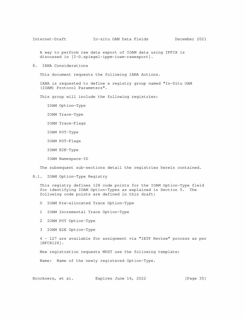
Internet-Draft In-situ OAM Data Fields December 2021
A way to perform raw data export of IOAM data using IPFIX is discussed in [I-D.spiegel-ippm-ioam-rawexport].
8. IANA Considerations
This document requests the following IANA Actions.
IANA is requested to define a registry group named "In-Situ OAM (IOAM) Protocol Parameters".
This group will include the following registries:
IOAM Option-Type
IOAM Trace-Type
IOAM Trace-Flags
IOAM POT-Type
IOAM POT-Flags
IOAM E2E-Type
IOAM Namespace-ID
The subsequent sub-sections detail the registries herein contained.
8.1. IOAM Option-Type Registry
This registry defines 128 code points for the IOAM Option-Type field for identifying IOAM Option-Types as explained in Section 5. The following code points are defined in this draft:
0 IOAM Pre-allocated Trace Option-Type
1 IOAM Incremental Trace Option-Type
2 IOAM POT Option-Type
3 IOAM E2E Option-Type
4 - 127 are available for assignment via "IETF Review" process as per [RFC8126].
New registration requests MUST use the following template:
Name: Name of the newly registered Option-Type.
Brockners, et al. Expires June 16, 2022 [Page 35]

Internet-Draft In-situ OAM Data Fields December 2021
Code point: Desired value of the requested code point.
Description: Brief description of the newly registered Option-Type.
Reference: Reference to the document that defines the new Option- Type.
The evaluation of a new registration request MUST also include checking whether the new IOAM Option-Type includes an IOAM-Namespace field and that the IOAM-Namespace field is the first field in the newly defined header of the new Option-Type.
8.2. IOAM Trace-Type Registry
This registry defines code point for each bit in the 24-bit IOAM- Trace-Type field for Pre-allocated Trace-Option-Type and Incremental Trace-Option-Type defined in Section 5.4. The meaning of Bits 0 - 11 is defined in this document in Paragraph 5 of Section 5.4.1:
Bit 0 hop_Lim and node_id in short format
Bit 1 ingress_if_id and egress_if_id in short format
Bit 2 timestamp seconds
Bit 3 timestamp fraction
Bit 4 transit delay
Bit 5 namespace specific data in short format
Bit 6 queue depth
Bit 7 checksum complement
Bit 8 hop_Lim and node_id in wide format
Bit 9 ingress_if_id and egress_if_id in wide format
Bit 10 namespace specific data in wide format
Bit 11 buffer occupancy
Bit 22 variable length Opaque State Snapshot
Bit 23 reserved
Brockners, et al. Expires June 16, 2022 [Page 36]

Internet-Draft In-situ OAM Data Fields December 2021
The meaning for Bits 12 - 21 are available for assignment via "IETF Review" process as per [RFC8126].
New registration requests MUST use the following template:
Bit: Desired bit to be allocated in the 24-bit IOAM Trace-Option- Type field for Pre-allocated Trace-Option-Type and Incremental Trace-Option-Type.
Description: Brief description of the newly registered bit.
Reference: Reference to the document that defines the new bit.
8.3. IOAM Trace-Flags Registry
This registry defines code points for each bit in the 4 bit flags for the Pre-allocated trace option and for the Incremental trace option defined in Section 5.4. The meaning of Bit 0 (the most significant bit) for trace flags is defined in this document in Paragraph 3 of Section 5.4.1:
Bit 0 "Overflow" (O-bit)
Bit 1 - 3 are available for assignment via "IETF Review" process as per [RFC8126].
New registration requests MUST use the following template:
Bit: Desired bit to be allocated in the 8 bit flags field of the Pre-allocated Trace-Option-Type and for the Incremental Trace- Option-Type.
Description: Brief description of the newly registered bit.
Reference: Reference to the document that defines the new bit.
8.4. IOAM POT-Type Registry
This registry defines 256 code points to define IOAM POT Type for IOAM proof of transit option Section 5.5. The code point value 0 is defined in this document:
0: 16 Octet POT data
1 - 255 are available for assignment via "IETF Review" process as per [RFC8126].
New registration requests MUST use the following template:
Brockners, et al. Expires June 16, 2022 [Page 37]

Internet-Draft In-situ OAM Data Fields December 2021
Name: Name of the newly registered POT-Type.
Code point: Desired value of the requested code point.
Description: Brief description of the newly registered POT-Type.
Reference: Reference to the document that defines the new POT-Type.
8.5. IOAM POT-Flags Registry
This registry defines code points for each bit in the 8 bit flags for IOAM POT Option-Type defined in Section 5.5.
The meaning for Bits 0 - 7 are available for assignment via "IETF Review" process as per [RFC8126].
New registration requests MUST use the following template:
Bit: Desired bit to be allocated in the 8 bit flags field of the IOAM POT Option-Type.
Description: Brief description of the newly registered bit.
Reference: Reference to the document that defines the new bit.
8.6. IOAM E2E-Type Registry
This registry defines code points for each bit in the 16 bit IOAM- E2E-Type field for IOAM E2E option Section 5.6. The meaning of Bit 0 - 3 are defined in this document:
Bit 0 64-bit sequence number
Bit 1 32-bit sequence number
Bit 2 timestamp seconds
Bit 3 timestamp fraction
The meaning of Bits 4 - 15 are available for assignment via "IETF Review" process as per [RFC8126].
New registration requests MUST use the following template:
Bit: Desired bit to be allocated in the 16 bit IOAM-E2E-Type field.
Description: Brief description of the newly registered bit.
Brockners, et al. Expires June 16, 2022 [Page 38]

Internet-Draft In-situ OAM Data Fields December 2021
Reference: Reference to the document that defines the new bit.
8.7. IOAM Namespace-ID Registry
IANA is requested to set up an "IOAM Namespace-ID Registry", containing 16-bit values and following the template for requests shown below. The meaning of 0x0000 is defined in this document. IANA is requested to reserve the values 0x0001 to 0x7FFF for private use (managed by operators), as specified in Section 5.3 of the current document. Registry entries for the values 0x8000 to 0xFFFF are to be assigned via the "Expert Review" policy defined in [RFC8126].
Upon receiving a new allocation request, a designated expert will perform the following:
o Review whether the request is complete, i.e., the registration template has been filled in. The expert will send incomplete requests back to the requestor.
o Check whether the request is neither a duplicate of nor conflicting with either an already existing allocation or a pending allocation. In case of duplicates or conflicts, the expert will ask the requestor to update the allocation request accordingly.
o Solicit feedback from relevant working groups and communities to ensure that the new allocation request has been properly reviewed and that rough consensus on the request exists. At a minimum, the expert will solicit feedback from the IPPM working group in the IETF by posting the request to the [email protected] mailing list. The expert will allow for a 3-week review period on the mailing lists. If the feedback received from the relevant working groups and communities within the review period indicates rough consensus on the request, the expert will approve the request and ask IANA for allocating the new Namespace-ID. In case the expert senses a lack of consensus from the feedback received, the expert will ask the requestor to engage with the corresponding working groups and communities to further review and refine the request.
It is intended that any allocation will be accompanied by a published RFC. In order to allow for the allocation of code points prior to the RFC being approved for publication, the designated expert can approve allocations once it seems clear that an RFC will be published.
0x0000: default namespace (known to all IOAM nodes)
Brockners, et al. Expires June 16, 2022 [Page 39]

Internet-Draft In-situ OAM Data Fields December 2021
0x0001 - 0x7FFF: reserved for private use
0x8000 - 0xFFFF: unassigned
New registration requests MUST use the following template:
Name: Name of the newly registered Namespace-ID.
Code point: Desired value of the requested Namespace-ID.
Description: Brief description of the newly registered Namespace-ID.
Reference: Reference to the document that defines the new Namespace- ID.
Status of the registration: Status can be either "permanent" or "provisional". Namespace-ID registrations following a successful expert review will have the status "provisional". Once the RFC, which defines the new Namespace-ID is published, the status is changed to "permanent".
9. Management and Deployment Considerations
This document defines the structure and use of IOAM data fields. This document does not define the encapsulation of IOAM data fields into different protocols. Management and deployment aspects for IOAM have to be considered within the context of the protocol IOAM data fields are encapsulated into and as such, are out of scope for this document. For a discussion of IOAM deployment, please also refer to [I-D.ietf-ippm-ioam-deployment], which outlines a framework for IOAM deployment and provides best current practices.
10. Security Considerations
As discussed in [RFC7276], a successful attack on an OAM protocol in general, and specifically on IOAM, can prevent the detection of failures or anomalies, or create a false illusion of nonexistent ones. In particular, these threats are applicable by compromising the integrity of IOAM data, either by maliciously modifying IOAM options in transit, or by injecting packets with maliciously generated IOAM options. All nodes in the path of a IOAM carrying packet can perform such an attack.
The Proof of Transit Option-Type (see Section 5.5) is used for verifying the path of data packets, i.e., proving that packets transited through a defined set of nodes.
Brockners, et al. Expires June 16, 2022 [Page 40]

Internet-Draft In-situ OAM Data Fields December 2021
In case an attacker gains access to several nodes in a network and would be able to change the system software of these nodes, IOAM data fields could be misused and repurposed for a use different from what is specified in this document. One type of misuse is the implementation of a covert channel between network nodes.
From a confidentiality perspective, although IOAM options are not expected to contain user data, they can be used for network reconnaissance, allowing attackers to collect information about network paths, performance, queue states, buffer occupancy and other information. Moreover, if IOAM data leaks from the IOAM-domain it could enable reconnaissance beyond the scope of the IOAM-domain. One possible application of such reconnaissance is to gauge the effectiveness of an ongoing attack, e.g., if buffers and queues are overflowing.
IOAM can be used as a means for implementing Denial of Service (DoS) attacks, or for amplifying them. For example, a malicious attacker can add an IOAM header to packets in order to consume the resources of network devices that take part in IOAM or entities that receive, collect or analyze the IOAM data. Another example is a packet length attack, in which an attacker pushes headers associated with IOAM Option-Types into data packets, causing these packets to be increased beyond the MTU size, resulting in fragmentation or in packet drops. In case POT is used, an attacker could corrupt the POT data fields in the packet, resulting in a verification failure of the POT data, even if the packet followed the correct path.
Since IOAM options can include timestamps, if network devices use synchronization protocols then any attack on the time protocol [RFC7384] can compromise the integrity of the timestamp-related data fields.
At the management plane, attacks can be set up by misconfiguring or by maliciously configuring IOAM-enabled nodes in a way that enables other attacks. IOAM configuration should only managed by authorized processes or users.
IETF protocols require features to ensure their security. While IOAM data fields don’t represent a protocol by themselves, the IOAM data fields add to the protocol that the IOAM data fields are encapsulated into. Any specification that defines how IOAM data fields carried in an encapsulating protocol MUST provide for a mechanism for cryptographic integrity protection of the IOAM data fields. Cryptographic integrity protection could be either achieved through a mechanism of the encapsulating protocol or it could incorporate the mechanisms specified in [I-D.ietf-ippm-ioam-data-integrity].
Brockners, et al. Expires June 16, 2022 [Page 41]

Internet-Draft In-situ OAM Data Fields December 2021
The current document does not define a specific IOAM encapsulation. It has to be noted that some IOAM encapsulation types can introduce specific security considerations. A specification that defines an IOAM encapsulation is expected to address the respective encapsulation-specific security considerations.
Notably, IOAM is expected to be deployed in limited domains, thus confining the potential attack vectors to within the limited domain. A limited administrative domain provides the operator with the means to select, monitor, and control the access of all the network devices, making these devices trusted by the operator. Indeed, in order to limit the scope of threats mentioned above to within the current limited domain the network operator is expected to enforce policies that prevent IOAM traffic from leaking outside of the IOAM domain, and prevent IOAM data from outside the domain to be processed and used within the domain.
This document does not define the data contents of custom fields like "Opaque State Snapshot" and "namespace specific data" IOAM data fields. These custom data fields will have security considerations corresponding to their defined data contents that need to be described where those formats are defined.
IOAM deployments which leverage both IOAM Trace Option-Types, i.e., the Pre-allocated Trace Option-Type and Incremental Trace Option-Type can suffer from incomplete visibility if the information gathered via the two Trace Option-Types is not correlated and aggregated appropriately. If IOAM transit nodes leverage the IOAM data fields in the packet for further actions or insights, then IOAM transit nodes which only support one IOAM Trace Option-Type in an IOAM deployment which leverages both Trace Option-Types, have limited visibility and thus can draw inappropriate conclusions or take wrong actions.
The security considerations of a system that deploys IOAM, much like any system, has to be reviewed on a per-deployment-scenario basis, based on a systems-specific threat analysis, which can lead to specific security solutions that are beyond the scope of the current document. Specifically, in an IOAM deployment that is not confined to a single LAN, but spans multiple inter-connected sites (for example, using an overlay network), the inter-site links can be secured (e.g., by IPsec) in order to avoid external threats.
IOAM deployment considerations, including approaches to mitigate the above discussed threads and potential attacks are outside the scope of this document. IOAM deployment considerations are discussed in [I-D.ietf-ippm-ioam-deployment].
Brockners, et al. Expires June 16, 2022 [Page 42]

Internet-Draft In-situ OAM Data Fields December 2021
11. Acknowledgements
The authors would like to thank Eric Vyncke, Nalini Elkins, Srihari Raghavan, Ranganathan T S, Karthik Babu Harichandra Babu, Akshaya Nadahalli, LJ Wobker, Erik Nordmark, Vengada Prasad Govindan, Andrew Yourtchenko, Aviv Kfir, Tianran Zhou, Zhenbin (Robin) and Greg Mirsky for the comments and advice.
This document leverages and builds on top of several concepts described in [I-D.kitamura-ipv6-record-route]. The authors would like to acknowledge the work done by the author Hiroshi Kitamura and people involved in writing it.
The authors would like to gracefully acknowledge useful review and insightful comments received from Joe Clarke, Al Morton, Tom Herbert, Carlos Bernardos, Haoyu Song, Mickey Spiegel, Roman Danyliw, Benjamin Kaduk, Murray S. Kucherawy, Ian Swett, Martin Duke, Francesca Palombini, Lars Eggert, Alvaro Retana, Erik Kline, Robert Wilton, Zaheduzzaman Sarker, Dan Romascanu and Barak Gafni.
12. References
12.1. Normative References
[POSIX] Institute of Electrical and Electronics Engineers, "IEEE Std 1003.1-2017 (Revision of IEEE Std 1003.1-2017) - IEEE Standard for Information Technology - Portable Operating System Interface (POSIX(TM) Base Specifications, Issue 7)", IEEE Std 1003.1-2017, 2017, <https://standards.ieee.org/findstds/ standard/1003.1-2017.html>.
[RFC2119] Bradner, S., "Key words for use in RFCs to Indicate Requirement Levels", BCP 14, RFC 2119, DOI 10.17487/RFC2119, March 1997, <https://www.rfc-editor.org/info/rfc2119>.
[RFC5905] Mills, D., Martin, J., Ed., Burbank, J., and W. Kasch, "Network Time Protocol Version 4: Protocol and Algorithms Specification", RFC 5905, DOI 10.17487/RFC5905, June 2010, <https://www.rfc-editor.org/info/rfc5905>.
[RFC8126] Cotton, M., Leiba, B., and T. Narten, "Guidelines for Writing an IANA Considerations Section in RFCs", BCP 26, RFC 8126, DOI 10.17487/RFC8126, June 2017, <https://www.rfc-editor.org/info/rfc8126>.
Brockners, et al. Expires June 16, 2022 [Page 43]

Internet-Draft In-situ OAM Data Fields December 2021
[RFC8174] Leiba, B., "Ambiguity of Uppercase vs Lowercase in RFC 2119 Key Words", BCP 14, RFC 8174, DOI 10.17487/RFC8174, May 2017, <https://www.rfc-editor.org/info/rfc8174>.
12.2. Informative References
[I-D.ietf-ippm-ioam-data-integrity] Brockners, F., Bhandari, S., and T. Mizrahi, "Integrity of In-situ OAM Data Fields", draft-ietf-ippm-ioam-data- integrity-00 (work in progress), October 2021.
[I-D.ietf-ippm-ioam-deployment] Brockners, F., Bhandari, S., Bernier, D., and T. Mizrahi, "In-situ OAM Deployment", draft-ietf-ippm-ioam- deployment-00 (work in progress), October 2021.
[I-D.ietf-nvo3-vxlan-gpe] (Editor), F. M., (editor), L. K., and U. E. (editor), "Generic Protocol Extension for VXLAN (VXLAN-GPE)", draft- ietf-nvo3-vxlan-gpe-12 (work in progress), September 2021.
[I-D.kitamura-ipv6-record-route] Kitamura, H., "Record Route for IPv6 (PR6) Hop-by-Hop Option Extension", draft-kitamura-ipv6-record-route-00 (work in progress), November 2000.
[I-D.spiegel-ippm-ioam-rawexport] Spiegel, M., Brockners, F., Bhandari, S., and R. Sivakolundu, "In-situ OAM raw data export with IPFIX", draft-spiegel-ippm-ioam-rawexport-05 (work in progress), July 2021.
[RFC7276] Mizrahi, T., Sprecher, N., Bellagamba, E., and Y. Weingarten, "An Overview of Operations, Administration, and Maintenance (OAM) Tools", RFC 7276, DOI 10.17487/RFC7276, June 2014, <https://www.rfc-editor.org/info/rfc7276>.
[RFC7384] Mizrahi, T., "Security Requirements of Time Protocols in Packet Switched Networks", RFC 7384, DOI 10.17487/RFC7384, October 2014, <https://www.rfc-editor.org/info/rfc7384>.
[RFC7665] Halpern, J., Ed. and C. Pignataro, Ed., "Service Function Chaining (SFC) Architecture", RFC 7665, DOI 10.17487/RFC7665, October 2015, <https://www.rfc-editor.org/info/rfc7665>.
Brockners, et al. Expires June 16, 2022 [Page 44]

Internet-Draft In-situ OAM Data Fields December 2021
[RFC7799] Morton, A., "Active and Passive Metrics and Methods (with Hybrid Types In-Between)", RFC 7799, DOI 10.17487/RFC7799, May 2016, <https://www.rfc-editor.org/info/rfc7799>.
[RFC7820] Mizrahi, T., "UDP Checksum Complement in the One-Way Active Measurement Protocol (OWAMP) and Two-Way Active Measurement Protocol (TWAMP)", RFC 7820, DOI 10.17487/RFC7820, March 2016, <https://www.rfc-editor.org/info/rfc7820>.
[RFC7821] Mizrahi, T., "UDP Checksum Complement in the Network Time Protocol (NTP)", RFC 7821, DOI 10.17487/RFC7821, March 2016, <https://www.rfc-editor.org/info/rfc7821>.
[RFC8300] Quinn, P., Ed., Elzur, U., Ed., and C. Pignataro, Ed., "Network Service Header (NSH)", RFC 8300, DOI 10.17487/RFC8300, January 2018, <https://www.rfc-editor.org/info/rfc8300>.
[RFC8799] Carpenter, B. and B. Liu, "Limited Domains and Internet Protocols", RFC 8799, DOI 10.17487/RFC8799, July 2020, <https://www.rfc-editor.org/info/rfc8799>.
[RFC8877] Mizrahi, T., Fabini, J., and A. Morton, "Guidelines for Defining Packet Timestamps", RFC 8877, DOI 10.17487/RFC8877, September 2020, <https://www.rfc-editor.org/info/rfc8877>.
[RFC8926] Gross, J., Ed., Ganga, I., Ed., and T. Sridhar, Ed., "Geneve: Generic Network Virtualization Encapsulation", RFC 8926, DOI 10.17487/RFC8926, November 2020, <https://www.rfc-editor.org/info/rfc8926>.
Contributors’ Addresses
Carlos Pignataro Cisco Systems, Inc. 7200-11 Kit Creek Road Research Triangle Park, NC 27709 United States
Email: [email protected]
Mickey Spiegel Barefoot Networks, an Intel company 4750 Patrick Henry Drive Santa Clara, CA 95054
Brockners, et al. Expires June 16, 2022 [Page 45]

Internet-Draft In-situ OAM Data Fields December 2021
US
Email: [email protected]
Barak Gafni Nvidia 350 Oakmead Parkway, Suite 100 Sunnyvale, CA 94085 U.S.A.
Email: [email protected]
Jennifer Lemon Broadcom 270 Innovation Drive San Jose, CA 95134 US
Email: [email protected]
Hannes Gredler RtBrick Inc.
Email: [email protected]
John Leddy United States
Email: [email protected]
Stephen Youell JP Morgan Chase 25 Bank Street London E14 5JP United Kingdom
Email: [email protected]
David Mozes
Email: [email protected]
Brockners, et al. Expires June 16, 2022 [Page 46]

Internet-Draft In-situ OAM Data Fields December 2021
Petr Lapukhov Facebook 1 Hacker Way Menlo Park, CA 94025 US
Email: [email protected]
Remy Chang Barefoot Networks 4750 Patrick Henry Drive Santa Clara, CA 95054 US
Email: [email protected]
Daniel Bernier Bell Canada Canada
Email: [email protected]
Authors’ Addresses
Frank Brockners (editor) Cisco Systems, Inc. Hansaallee 249, 3rd Floor DUESSELDORF, NORDRHEIN-WESTFALEN 40549 Germany
Email: [email protected]
Shwetha Bhandari (editor) Thoughtspot 3rd Floor, Indiqube Orion, 24th Main Rd, Garden Layout, HSR Layout Bangalore, KARNATAKA 560 102 India
Email: [email protected]
Brockners, et al. Expires June 16, 2022 [Page 47]

Internet-Draft In-situ OAM Data Fields December 2021
Tal Mizrahi (editor) Huawei 8-2 Matam Haifa 3190501 Israel
Email: [email protected]
Brockners, et al. Expires June 16, 2022 [Page 48]

Network Working Group M. BagnuloInternet-Draft UC3MIntended status: Standards Track B. ClaiseExpires: September 10, 2020 Cisco Systems, Inc. P. Eardley BT A. Morton AT&T Labs A. Akhter Consultant March 9, 2020
Registry for Performance Metrics draft-ietf-ippm-metric-registry-24
Abstract
This document defines the format for the IANA Performance Metrics Registry. This document also gives a set of guidelines for Registered Performance Metric requesters and reviewers.
Status of This Memo
This Internet-Draft is submitted in full conformance with the provisions of BCP 78 and BCP 79.
Internet-Drafts are working documents of the Internet Engineering Task Force (IETF). Note that other groups may also distribute working documents as Internet-Drafts. The list of current Internet- Drafts is at https://datatracker.ietf.org/drafts/current/.
Internet-Drafts are draft documents valid for a maximum of six months and may be updated, replaced, or obsoleted by other documents at any time. It is inappropriate to use Internet-Drafts as reference material or to cite them other than as "work in progress."
This Internet-Draft will expire on September 10, 2020.
Copyright Notice
Copyright (c) 2020 IETF Trust and the persons identified as the document authors. All rights reserved.
This document is subject to BCP 78 and the IETF Trust’s Legal Provisions Relating to IETF Documents (https://trustee.ietf.org/license-info) in effect on the date of publication of this document. Please review these documents
Bagnulo, et al. Expires September 10, 2020 [Page 1]

Internet-Draft Registry for Performance Metrics March 2020
carefully, as they describe your rights and restrictions with respect to this document. Code Components extracted from this document must include Simplified BSD License text as described in Section 4.e of the Trust Legal Provisions and are provided without warranty as described in the Simplified BSD License.
Table of Contents
1. Introduction . . . . . . . . . . . . . . . . . . . . . . . . 4 2. Terminology . . . . . . . . . . . . . . . . . . . . . . . . . 5 3. Scope . . . . . . . . . . . . . . . . . . . . . . . . . . . . 7 4. Motivation for a Performance Metrics Registry . . . . . . . . 8 4.1. Interoperability . . . . . . . . . . . . . . . . . . . . 8 4.2. Single point of reference for Performance Metrics . . . . 9 4.3. Side benefits . . . . . . . . . . . . . . . . . . . . . . 9 5. Criteria for Performance Metrics Registration . . . . . . . . 9 6. Performance Metric Registry: Prior attempt . . . . . . . . . 10 6.1. Why this Attempt Should Succeed . . . . . . . . . . . . . 11 7. Definition of the Performance Metric Registry . . . . . . . . 11 7.1. Summary Category . . . . . . . . . . . . . . . . . . . . 13 7.1.1. Identifier . . . . . . . . . . . . . . . . . . . . . 13 7.1.2. Name . . . . . . . . . . . . . . . . . . . . . . . . 13 7.1.3. URI . . . . . . . . . . . . . . . . . . . . . . . . . 17 7.1.4. Description . . . . . . . . . . . . . . . . . . . . . 17 7.1.5. Reference . . . . . . . . . . . . . . . . . . . . . . 17 7.1.6. Change Controller . . . . . . . . . . . . . . . . . . 17 7.1.7. Version (of Registry Format) . . . . . . . . . . . . 18 7.2. Metric Definition Category . . . . . . . . . . . . . . . 18 7.2.1. Reference Definition . . . . . . . . . . . . . . . . 18 7.2.2. Fixed Parameters . . . . . . . . . . . . . . . . . . 18 7.3. Method of Measurement Category . . . . . . . . . . . . . 19 7.3.1. Reference Method . . . . . . . . . . . . . . . . . . 19 7.3.2. Packet Stream Generation . . . . . . . . . . . . . . 19 7.3.3. Traffic Filter . . . . . . . . . . . . . . . . . . . 20 7.3.4. Sampling Distribution . . . . . . . . . . . . . . . . 20 7.3.5. Run-time Parameters . . . . . . . . . . . . . . . . . 21 7.3.6. Role . . . . . . . . . . . . . . . . . . . . . . . . 22 7.4. Output Category . . . . . . . . . . . . . . . . . . . . . 22 7.4.1. Type . . . . . . . . . . . . . . . . . . . . . . . . 22 7.4.2. Reference Definition . . . . . . . . . . . . . . . . 23 7.4.3. Metric Units . . . . . . . . . . . . . . . . . . . . 23 7.4.4. Calibration . . . . . . . . . . . . . . . . . . . . . 23 7.5. Administrative information . . . . . . . . . . . . . . . 24 7.5.1. Status . . . . . . . . . . . . . . . . . . . . . . . 24 7.5.2. Requester . . . . . . . . . . . . . . . . . . . . . . 24 7.5.3. Revision . . . . . . . . . . . . . . . . . . . . . . 24 7.5.4. Revision Date . . . . . . . . . . . . . . . . . . . . 24 7.6. Comments and Remarks . . . . . . . . . . . . . . . . . . 24
Bagnulo, et al. Expires September 10, 2020 [Page 2]

Internet-Draft Registry for Performance Metrics March 2020
8. Processes for Managing the Performance Metric Registry Group 24 8.1. Adding new Performance Metrics to the Performance Metrics Registry . . . . . . . . . . . . . . . . . . . . . . . . 25 8.2. Revising Registered Performance Metrics . . . . . . . . . 26 8.3. Deprecating Registered Performance Metrics . . . . . . . 28 9. Security considerations . . . . . . . . . . . . . . . . . . . 28 10. IANA Considerations . . . . . . . . . . . . . . . . . . . . . 29 10.1. Registry Group . . . . . . . . . . . . . . . . . . . . . 29 10.2. Performance Metric Name Elements . . . . . . . . . . . . 29 10.3. New Performance Metrics Registry . . . . . . . . . . . . 30 11. Blank Registry Template . . . . . . . . . . . . . . . . . . . 32 11.1. Summary . . . . . . . . . . . . . . . . . . . . . . . . 32 11.1.1. ID (Identifier) . . . . . . . . . . . . . . . . . . 32 11.1.2. Name . . . . . . . . . . . . . . . . . . . . . . . . 32 11.1.3. URI . . . . . . . . . . . . . . . . . . . . . . . . 32 11.1.4. Description . . . . . . . . . . . . . . . . . . . . 32 11.1.5. Change Controller . . . . . . . . . . . . . . . . . 32 11.1.6. Version (of Registry Format) . . . . . . . . . . . . 32 11.2. Metric Definition . . . . . . . . . . . . . . . . . . . 32 11.2.1. Reference Definition . . . . . . . . . . . . . . . . 32 11.2.2. Fixed Parameters . . . . . . . . . . . . . . . . . . 32 11.3. Method of Measurement . . . . . . . . . . . . . . . . . 33 11.3.1. Reference Method . . . . . . . . . . . . . . . . . . 33 11.3.2. Packet Stream Generation . . . . . . . . . . . . . . 33 11.3.3. Traffic Filtering (observation) Details . . . . . . 33 11.3.4. Sampling Distribution . . . . . . . . . . . . . . . 33 11.3.5. Run-time Parameters and Data Format . . . . . . . . 33 11.3.6. Roles . . . . . . . . . . . . . . . . . . . . . . . 33 11.4. Output . . . . . . . . . . . . . . . . . . . . . . . . . 33 11.4.1. Type . . . . . . . . . . . . . . . . . . . . . . . . 34 11.4.2. Reference Definition . . . . . . . . . . . . . . . . 34 11.4.3. Metric Units . . . . . . . . . . . . . . . . . . . . 34 11.4.4. Calibration . . . . . . . . . . . . . . . . . . . . 34 11.5. Administrative items . . . . . . . . . . . . . . . . . . 34 11.5.1. Status . . . . . . . . . . . . . . . . . . . . . . . 34 11.5.2. Requester . . . . . . . . . . . . . . . . . . . . . 34 11.5.3. Revision . . . . . . . . . . . . . . . . . . . . . . 34 11.5.4. Revision Date . . . . . . . . . . . . . . . . . . . 34 11.6. Comments and Remarks . . . . . . . . . . . . . . . . . . 34 12. Acknowledgments . . . . . . . . . . . . . . . . . . . . . . . 34 13. References . . . . . . . . . . . . . . . . . . . . . . . . . 35 13.1. Normative References . . . . . . . . . . . . . . . . . . 35 13.2. Informative References . . . . . . . . . . . . . . . . . 36 Authors’ Addresses . . . . . . . . . . . . . . . . . . . . . . . 37
Bagnulo, et al. Expires September 10, 2020 [Page 3]
Internet-Draft Registry for Performance Metrics March 2020
1. Introduction
The IETF specifies and uses Performance Metrics of protocols and applications transported over its protocols. Performance metrics are important part of network operations using IETF protocols, and [RFC6390] specifies guidelines for their development.
The definition and use of Performance Metrics in the IETF has been fostered in various working groups (WG), most notably:
The "IP Performance Metrics" (IPPM) WG is the WG primarily focusing on Performance Metrics definition at the IETF.
The "Benchmarking Methodology" WG (BMWG) defines many Performance Metrics for use in laboratory benchmarking of inter-networking technologies.
The "Metric Blocks for use with RTCP’s Extended Report Framework" (XRBLOCK) WG (concluded) specified many Performance Metrics related to "RTP Control Protocol Extended Reports (RTCP XR)" [RFC3611], which establishes a framework to allow new information to be conveyed in RTCP, supplementing the original report blocks defined in "RTP: A Transport Protocol for Real-Time Applications", [RFC3550].
The "IP Flow Information eXport" (IPFIX) concluded WG specified an IANA process for new Information Elements. Some Performance Metrics related Information Elements are proposed on regular basis.
The "Performance Metrics for Other Layers" (PMOL) a concluded WG defined some Performance Metrics related to Session Initiation Protocol (SIP) voice quality [RFC6035].
It is expected that more Performance Metrics will be defined in the future, not only IP-based metrics, but also metrics which are protocol-specific and application-specific.
Despite the importance of Performance Metrics, there are two related problems for the industry. First, ensuring that when one party requests another party to measure (or report or in some way act on) a particular Performance Metric, then both parties have exactly the same understanding of what Performance Metric is being referred to. Second, discovering which Performance Metrics have been specified, to avoid developing a new Performance Metric that is very similar, but not quite inter-operable. These problems can be addressed by creating a registry of performance metrics. The usual way in which the IETF organizes registries is with Internet Assigned Numbers
Bagnulo, et al. Expires September 10, 2020 [Page 4]

Internet-Draft Registry for Performance Metrics March 2020
Authority (IANA), and there is currently no Performance Metrics Registry maintained by the IANA.
This document requests that IANA create and maintain a Performance Metrics Registry, according to the maintenance procedures and the Performance Metrics Registry format defined in this memo. The resulting Performance Metrics Registry is for use by the IETF and others. Although the Registry formatting specifications herein are primarily for registry creation by IANA, any other organization that wishes to create a performance metrics registry may use the same formatting specifications for their purposes. The authors make no guarantee of the registry format’s applicability to any possible set of Performance Metrics envisaged by other organizations, but encourage others to apply it. In the remainder of this document, unless we explicitly say otherwise, we will refer to the IANA- maintained Performance Metrics Registry as simply the Performance Metrics Registry.
2. Terminology
The key words "MUST", "MUST NOT", "REQUIRED", "SHALL", "SHALL NOT", "SHOULD", "SHOULD NOT", "RECOMMENDED", "NOT RECOMMENDED", "MAY", and "OPTIONAL" in this document are to be interpreted as described in BCP 14 [RFC2119] [RFC8174] when, and only when, they appear in all capitals, as shown here.
Performance Metric: A Performance Metric is a quantitative measure of performance, targeted to an IETF-specified protocol or targeted to an application transported over an IETF-specified protocol. Examples of Performance Metrics are the FTP response time for a complete file download, the DNS response time to resolve the IP address(es), a database logging time, etc. This definition is consistent with the definition of metric in [RFC2330] and broader than the definition of performance metric in [RFC6390].
Registered Performance Metric: A Registered Performance Metric is a Performance Metric expressed as an entry in the Performance Metrics Registry, administered by IANA. Such a performance metric has met all the registry review criteria defined in this document in order to be included in the registry.
Performance Metrics Registry: The IANA registry containing Registered Performance Metrics.
Proprietary Registry: A set of metrics that are registered in a proprietary registry, as opposed to Performance Metrics Registry.
Bagnulo, et al. Expires September 10, 2020 [Page 5]

Internet-Draft Registry for Performance Metrics March 2020
Performance Metrics Experts: The Performance Metrics Experts is a group of designated experts [RFC8126] selected by the IESG to validate the Performance Metrics before updating the Performance Metrics Registry. The Performance Metrics Experts work closely with IANA.
Parameter: A Parameter is an input factor defined as a variable in the definition of a Performance Metric. A Parameter is a numerical or other specified factor forming one of a set that defines a metric or sets the conditions of its operation. All Parameters must be known in order to make a measurement using a metric and interpret the results. There are two types of Parameters: Fixed and Run-time parameters. For the Fixed Parameters, the value of the variable is specified in the Performance Metrics Registry entry and different Fixed Parameter values results in different Registered Performance Metrics. For the Run-time Parameters, the value of the variable is defined when the metric measurement method is executed and a given Registered Performance Metric supports multiple values for the parameter. Although Run-time Parameters do not change the fundamental nature of the Performance Metric’s definition, some have substantial influence on the network property being assessed and interpretation of the results.
Note: Consider the case of packet loss in the following two Active Measurement Method cases. The first case is packet loss as background loss where the Run-time Parameter set includes a very sparse Poisson stream, and only characterizes the times when packets were lost. Actual user streams likely see much higher loss at these times, due to tail drop or radio errors. The second case is packet loss as inverse of throughput where the Run-time Parameter set includes a very dense, bursty stream, and characterizes the loss experienced by a stream that approximates a user stream. These are both "loss metrics", but the difference in interpretation of the results is highly dependent on the Run-time Parameters (at least), to the extreme where we are actually using loss to infer its compliment: delivered throughput.
Active Measurement Method: Methods of Measurement conducted on traffic which serves only the purpose of measurement and is generated for that reason alone, and whose traffic characteristics are known a priori. The complete definition of Active Methods is specified in section 3.4 of[RFC7799]. Examples of Active Measurement Methods are the measurement methods for the One way delay metric defined in [RFC7679] and the one for round trip delay defined in [RFC2681].
Bagnulo, et al. Expires September 10, 2020 [Page 6]

Internet-Draft Registry for Performance Metrics March 2020
Passive Measurement Method: Methods of Measurement conducted on network traffic, generated either from the end users or from network elements that would exist regardless whether the measurement was being conducted or not. The complete definition of Passive Methods is specified in section 3.6 of [RFC7799]. One characteristic of Passive Measurement Methods is that sensitive information may be observed, and as a consequence, stored in the measurement system.
Hybrid Measurement Method: Hybrid Methods are Methods of Measurement that use a combination of Active Methods and Passive Methods, to assess Active Metrics, Passive Metrics, or new metrics derived from the a priori knowledge and observations of the stream of interest. The complete definition of Hybrid Methods is specified in section 3.8 of [RFC7799].
3. Scope
This document is intended for two different audiences:
1. For those defining new Registered Performance Metrics, it provides specifications and best practices to be used in deciding which Registered Performance Metrics are useful for a measurement study, instructions for writing the text for each column of the Registered Performance Metrics, and information on the supporting documentation required for the new Performance Metrics Registry entry (up to and including the publication of one or more immutable documents such as an RFC).
2. For the appointed Performance Metrics Experts and for IANA personnel administering the new IANA Performance Metrics Registry, it defines a set of acceptance criteria against which these proposed Registered Performance Metrics should be evaluated.
In addition, this document may be useful for other organizations who are defining a Performance Metric registry of their own, and may re- use the features of the Performance Metrics Registry defined in this document.
This Performance Metrics Registry is applicable to Performance Metrics issued from Active Measurement, Passive Measurement, and any other form of Performance Metric. This registry is designed to encompass Performance Metrics developed throughout the IETF and especially for the technologies specified in the following working groups: IPPM, XRBLOCK, IPFIX, and BMWG. This document analyzes a prior attempt to set up a Performance Metrics Registry, and the reasons why this design was inadequate [RFC6248]. Finally, this
Bagnulo, et al. Expires September 10, 2020 [Page 7]

Internet-Draft Registry for Performance Metrics March 2020
document gives a set of guidelines for requesters and expert reviewers of candidate Registered Performance Metrics.
This document makes no attempt to populate the Performance Metrics Registry with initial entries; the related memo [I-D.ietf-ippm-initial-registry] proposes the initial set of regsitry entries.
4. Motivation for a Performance Metrics Registry
In this section, we detail several motivations for the Performance Metrics Registry.
4.1. Interoperability
As with any IETF registry, the primary intention is to manage registration of identifiers for use within one or more protocols. In the particular case of the Performance Metrics Registry, there are two types of protocols that will use the Performance Metrics in the Performance Metrics Registry during their operation (by referring to the Index values):
o Control protocol: This type of protocol used to allow one entity to request another entity to perform a measurement using a specific metric defined by the Performance Metrics Registry. One particular example is the LMAP framework [RFC7594]. Using the LMAP terminology, the Performance Metrics Registry is used in the LMAP Control protocol to allow a Controller to schedule a measurement task for one or more Measurement Agents. In order to enable this use case, the entries of the Performance Metrics Registry must be sufficiently defined to allow a Measurement Agent implementation to trigger a specific measurement task upon the reception of a control protocol message. This requirement heavily constrains the type of entries that are acceptable for the Performance Metrics Registry.
o Report protocol: This type of protocol is used to allow an entity to report measurement results to another entity. By referencing to a specific Performance Metrics Registry, it is possible to properly characterize the measurement result data being reported. Using the LMAP terminology, the Performance Metrics Registry is used in the Report protocol to allow a Measurement Agent to report measurement results to a Collector.
It should be noted that the LMAP framework explicitly allows for using not only the IANA-maintained Performance Metrics Registry but also other registries containing Performance Metrics, either defined by other organizations or private ones. However, others who are
Bagnulo, et al. Expires September 10, 2020 [Page 8]

Internet-Draft Registry for Performance Metrics March 2020
creating Registries to be used in the context of an LMAP framework are encouraged to use the Registry format defined in this document, because this makes it easier for developers of LMAP Measurement Agents (MAs) to programmatically use information found in those other Registries’ entries.
4.2. Single point of reference for Performance Metrics
A Performance Metrics Registry serves as a single point of reference for Performance Metrics defined in different working groups in the IETF. As we mentioned earlier, there are several WGs that define Performance Metrics in the IETF and it is hard to keep track of all them. This results in multiple definitions of similar Performance Metrics that attempt to measure the same phenomena but in slightly different (and incompatible) ways. Having a registry would allow the IETF community and others to have a single list of relevant Performance Metrics defined by the IETF (and others, where appropriate). The single list is also an essential aspect of communication about Performance Metrics, where different entities that request measurements, execute measurements, and report the results can benefit from a common understanding of the referenced Performance Metric.
4.3. Side benefits
There are a couple of side benefits of having such a registry. First, the Performance Metrics Registry could serve as an inventory of useful and used Performance Metrics, that are normally supported by different implementations of measurement agents. Second, the results of measurements using the Performance Metrics should be comparable even if they are performed by different implementations and in different networks, as the Performance Metric is properly defined. BCP 176 [RFC6576] examines whether the results produced by independent implementations are equivalent in the context of evaluating the completeness and clarity of metric specifications. This BCP defines the standards track advancement testing for (active) IPPM metrics, and the same process will likely suffice to determine whether Registered Performance Metrics are sufficiently well specified to result in comparable (or equivalent) results. Registered Performance Metrics which have undergone such testing SHOULD be noted, with a reference to the test results.
5. Criteria for Performance Metrics Registration
It is neither possible nor desirable to populate the Performance Metrics Registry with all combinations of Parameters of all Performance Metrics. The Registered Performance Metrics SHOULD be:
Bagnulo, et al. Expires September 10, 2020 [Page 9]

Internet-Draft Registry for Performance Metrics March 2020
1. interpretable by the user.
2. implementable by the software or hardware designer,
3. deployable by network operators,
4. accurate in terms of producing equivalent results, and for interoperability and deployment across vendors,
5. Operationally useful, so that it has significant industry interest and/or has seen deployment,
6. Sufficiently tightly defined, so that different values for the Run-time Parameters does not change the fundamental nature of the measurement, nor change the practicality of its implementation.
In essence, there needs to be evidence that a candidate Registered Performance Metric has significant industry interest, or has seen deployment, and there is agreement that the candidate Registered Performance Metric serves its intended purpose.
6. Performance Metric Registry: Prior attempt
There was a previous attempt to define a metric registry RFC 4148 [RFC4148]. However, it was obsoleted by RFC 6248 [RFC6248] because it was "found to be insufficiently detailed to uniquely identify IPPM metrics... [there was too much] variability possible when characterizing a metric exactly" which led to the RFC4148 registry having "very few users, if any".
A couple of interesting additional quotes from RFC 6248 [RFC6248] might help to understand the issues related to that registry.
1. "It is not believed to be feasible or even useful to register every possible combination of Type P, metric parameters, and Stream parameters using the current structure of the IPPM Metrics Registry."
2. "The registry structure has been found to be insufficiently detailed to uniquely identify IPPM metrics."
3. "Despite apparent efforts to find current or even future users, no one responded to the call for interest in the RFC 4148 registry during the second half of 2010."
The current approach learns from this by tightly defining each Registered Performance Metric with only a few variable (Run-time) Parameters to be specified by the measurement designer, if any. The
Bagnulo, et al. Expires September 10, 2020 [Page 10]

Internet-Draft Registry for Performance Metrics March 2020
idea is that entries in the Performance Metrics Registry stem from different measurement methods which require input (Run-time) parameters to set factors like source and destination addresses (which do not change the fundamental nature of the measurement). The downside of this approach is that it could result in a large number of entries in the Performance Metrics Registry. There is agreement that less is more in this context - it is better to have a reduced set of useful metrics rather than a large set of metrics, some with with questionable usefulness.
6.1. Why this Attempt Should Succeed
As mentioned in the previous section, one of the main issues with the previous registry was that the metrics contained in the registry were too generic to be useful. This document specifies stricter criteria for performance metric registration (see section 5), and imposes a group of Performance Metrics Experts that will provide guidelines to assess if a Performance Metric is properly specified.
Another key difference between this attempt and the previous one is that in this case there is at least one clear user for the Performance Metrics Registry: the LMAP framework and protocol. Because the LMAP protocol will use the Performance Metrics Registry values in its operation, this actually helps to determine if a metric is properly defined. In particular, since we expect that the LMAP control protocol will enable a controller to request a measurement agent to perform a measurement using a given metric by embedding the Performance Metrics Registry identifier in the protocol. Such a metric and method are properly specified if they are defined well- enough so that it is possible (and practical) to implement them in the measurement agent. This was the failure of the previous attempt: a registry entry with an undefined Type-P (section 13 of RFC 2330 [RFC2330]) allows implementation to be ambiguous.
7. Definition of the Performance Metric Registry
This Performance Metrics Registry is applicable to Performance Metrics used for Active Measurement, Passive Measurement, and any other form of Performance Measurement. Each category of measurement has unique properties, so some of the columns defined below are not applicable for a given metric category. In this case, the column(s) SHOULD be populated with the "NA" value (Non Applicable). However, the "NA" value MUST NOT be used by any metric in the following columns: Identifier, Name, URI, Status, Requester, Revision, Revision Date, Description. In the future, a new category of metrics could require additional columns, and adding new columns is a recognized form of registry extension. The specification defining the new
Bagnulo, et al. Expires September 10, 2020 [Page 11]

Internet-Draft Registry for Performance Metrics March 2020
column(s) MUST give general guidelines for populating the new column(s) for existing entries.
The columns of the Performance Metrics Registry are defined below. The columns are grouped into "Categories" to facilitate the use of the registry. Categories are described at the 7.x heading level, and columns are at the 7.x.y heading level. The Figure below illustrates this organization. An entry (row) therefore gives a complete description of a Registered Performance Metric.
Each column serves as a check-list item and helps to avoid omissions during registration and expert review.
=======================================================================Legend: Registry Categories and Columns are shown below as: Category ------------------... Column | Column |...=======================================================================Summary------------------------------------------------------------------------Identifier | Name | URI | Desc. | Reference | Change Controller | Ver |
Metric Definition-----------------------------------------Reference Definition | Fixed Parameters |
Method of Measurement---------------------------------------------------------------------Reference | Packet | Traffic | Sampling | Run-time | Role |Method | Stream | Filter | Distribution | Parameters | | | Generation |Output-----------------------------------------Type | Reference | Units | Calibration | | Definition | | |
Administrative Information------------------------------------Status |Requester | Rev | Rev.Date |
Comments and Remarks--------------------
There is a blank template of the Registry template provided in Section 11 of this memo.
Bagnulo, et al. Expires September 10, 2020 [Page 12]

Internet-Draft Registry for Performance Metrics March 2020
7.1. Summary Category
7.1.1. Identifier
A numeric identifier for the Registered Performance Metric. This identifier MUST be unique within the Performance Metrics Registry.
The Registered Performance Metric unique identifier is an unbounded integer (range 0 to infinity).
The Identifier 0 should be Reserved. The Identifier values from 64512 to 65536 are reserved for private or experimental use, and the user may encounter overlapping uses.
When adding newly Registered Performance Metrics to the Performance Metrics Registry, IANA SHOULD assign the lowest available identifier to the new Registered Performance Metric.
If a Performance Metrics Expert providing review determines that there is a reason to assign a specific numeric identifier, possibly leaving a temporary gap in the numbering, then the Performance Expert SHALL inform IANA of this decision.
7.1.2. Name
As the name of a Registered Performance Metric is the first thing a potential human implementor will use when determining whether it is suitable for their measurement study, it is important to be as precise and descriptive as possible. In future, users will review the names to determine if the metric they want to measure has already been registered, or if a similar entry is available as a basis for creating a new entry.
Names are composed of the following elements, separated by an underscore character "_":
MetricType_Method_SubTypeMethod_... Spec_Units_Output
o MetricType: a combination of the directional properties and the metric measured, such as and not limited to:
RTDelay (Round Trip Delay)
RTDNS (Response Time Domain Name Service)
RLDNS (Response Loss Domain Name Service)
OWDelay (One Way Delay)
Bagnulo, et al. Expires September 10, 2020 [Page 13]

Internet-Draft Registry for Performance Metrics March 2020
RTLoss (Round Trip Loss)
OWLoss (One Way Loss)
OWPDV (One Way Packet Delay Variation)
OWIPDV (One Way Inter-Packet Delay Variation)
OWReorder (One Way Packet Reordering)
OWDuplic (One Way Packet Duplication)
OWBTC (One Way Bulk Transport Capacity)
OWMBM (One Way Model Based Metric)
SPMonitor (Single Point Monitor)
MPMonitor (Multi-Point Monitor)
o Method: One of the methods defined in [RFC7799], such as and not limited to:
Active (depends on a dedicated measurement packet stream and observations of the stream)
Passive (depends *solely* on observation of one or more existing packet streams)
HybridType1 (observations on one stream that combine both active and passive methods)
HybridType2 (observations on two or more streams that combine both active and passive methods)
Spatial (Spatial Metric of RFC5644)
o SubTypeMethod: One or more sub-types to further describe the features of the entry, such as and not limited to:
ICMP (Internet Control Message Protocol)
IP (Internet Protocol)
DSCPxx (where xx is replaced by a Diffserv code point)
UDP (User Datagram Protocol)
Bagnulo, et al. Expires September 10, 2020 [Page 14]

Internet-Draft Registry for Performance Metrics March 2020
TCP (Transport Control Protocol)
QUIC (QUIC transport protocol)
HS (Hand-Shake, such as TCP’s 3-way HS)
Poisson (Packet generation using Poisson distribution)
Periodic (Periodic packet generation)
SendOnRcv (Sender keeps one packet in-transit by sending when previous packet arrives)
PayloadxxxxB (where xxxx is replaced by an integer, the number of octets in the Payload))
SustainedBurst (Capacity test, worst case)
StandingQueue (test of bottleneck queue behavior)
SubTypeMethod values are separated by a hyphen "-" character, which indicates that they belong to this element, and that their order is unimportant when considering name uniqueness.
o Spec: An immutable document identifier combined with a document section identifier. For RFCs, this consists of the RFC number and major section number that specifies this Registry entry in the form RFCXXXXsecY, such as RFC7799sec3. Note: the RFC number is not the Primary Reference specification for the metric definition, such as [RFC7679] for One-way Delay; it will contain the placeholder "RFCXXXXsecY" until the RFC number is assigned to the specifying document, and would remain blank in private registry entries without a corresponding RFC. Anticipating the "RFC10K" problem, the number of the RFC continues to replace RFCXXXX regardless of the number of digits in the RFC number. Anticipating Registry Entries from other standards bodies, the form of this Name Element MUST be proposed and reviewed for consistency and uniqueness by the Expert Reviewer.
o Units: The units of measurement for the output, such as and not limited to:
Seconds
Ratio (unitless)
Bagnulo, et al. Expires September 10, 2020 [Page 15]

Internet-Draft Registry for Performance Metrics March 2020
Percent (value multiplied by 100%)
Logical (1 or 0)
Packets
BPS (Bits per Second)
PPS (Packets per Second)
EventTotal (for unit-less counts)
Multiple (more than one type of unit)
Enumerated (a list of outcomes)
Unitless
o Output: The type of output resulting from measurement, such as and not limited to:
Singleton
Raw (multiple Singletons)
Count
Minimum
Maximum
Median
Mean
95Percentile (95th Percentile)
99Percentile (99th Percentile)
StdDev (Standard Deviation)
Variance
PFI (Pass, Fail, Inconclusive)
FlowRecords (descriptions of flows observed)
LossRatio (lost packets to total packets, <=1)
Bagnulo, et al. Expires September 10, 2020 [Page 16]
Internet-Draft Registry for Performance Metrics March 2020
An example is:
RTDelay_Active_IP-UDP-Periodic_RFCXXXXsecY_Seconds_95Percentile
as described in section 4 of [I-D.ietf-ippm-initial-registry].
Note that private registries following the format described here SHOULD use the prefix "Priv_" on any name to avoid unintended conflicts (further considerations are described in section 10). Private registry entries usually have no specifying RFC, thus the Spec: element has no clear interpretation.
7.1.3. URI
The URIs column MUST contain a URL [RFC3986] that uniquely identifies and locates the metric entry so it is accessible through the Internet. The URL points to a file containing all the human-readable information for one registry entry. The URL SHALL reference a target file that is preferably HTML-formatted and contains URLs to referenced sections of HTML-ized RFCs, or other reference specifications. These target files for different entries can be more easily edited and re-used when preparing new entries. The exact form of the URL for each target file, and the target file itself, will be determined by IANA and reside on "iana.org". The major sections of [I-D.ietf-ippm-initial-registry] provide an example of a target file in HTML form (sections 4 and higher).
7.1.4. Description
A Registered Performance Metric description is a written representation of a particular Performance Metrics Registry entry. It supplements the Registered Performance Metric name to help Performance Metrics Registry users select relevant Registered Performance Metrics.
7.1.5. Reference
This entry gives the specification containing the candidate registry entry which was reviewed and agreed, if such an RFC or other specification exists.
7.1.6. Change Controller
This entry names the entity responsible for approving revisions to the registry entry, and SHALL provide contact information (for an individual, where appropriate).
Bagnulo, et al. Expires September 10, 2020 [Page 17]

Internet-Draft Registry for Performance Metrics March 2020
7.1.7. Version (of Registry Format)
This entry gives the version number for the registry format used. Formats complying with this memo MUST use 1.0. The version number SHALL NOT change unless a new RFC is published that changes the registry format. The version number of registry entries SHALL NOT change unless the registry entry is updated (following procedures in section 8).
7.2. Metric Definition Category
This category includes columns to prompt all necessary details related to the metric definition, including the immutable document reference and values of input factors, called fixed parameters, which are left open in the immutable document, but have a particular value defined by the performance metric.
7.2.1. Reference Definition
This entry provides a reference (or references) to the relevant section(s) of the document(s) that define the metric, as well as any supplemental information needed to ensure an unambiguous definition for implementations. The reference needs to be an immutable document, such as an RFC; for other standards bodies, it is likely to be necessary to reference a specific, dated version of a specification.
7.2.2. Fixed Parameters
Fixed Parameters are Parameters whose value must be specified in the Performance Metrics Registry. The measurement system uses these values.
Where referenced metrics supply a list of Parameters as part of their descriptive template, a sub-set of the Parameters will be designated as Fixed Parameters. As an example for active metrics, Fixed Parameters determine most or all of the IPPM Framework convention "packets of Type-P" as described in [RFC2330], such as transport protocol, payload length, TTL, etc. An example for passive metrics is for RTP packet loss calculation that relies on the validation of a packet as RTP which is a multi-packet validation controlled by MIN_SEQUENTIAL as defined by [RFC3550]. Varying MIN_SEQUENTIAL values can alter the loss report and this value could be set as a Fixed Parameter.
Parameters MUST have well-defined names. For human readers, the hanging indent style is preferred, and any Parameter names and
Bagnulo, et al. Expires September 10, 2020 [Page 18]

Internet-Draft Registry for Performance Metrics March 2020
definitions that do not appear in the Reference Method Specification MUST appear in this column (or Run-time Parameters column).
Parameters MUST have a well-specified data format.
A Parameter which is a Fixed Parameter for one Performance Metrics Registry entry may be designated as a Run-time Parameter for another Performance Metrics Registry entry.
7.3. Method of Measurement Category
This category includes columns for references to relevant sections of the immutable document(s) and any supplemental information needed to ensure an unambiguous method for implementations.
7.3.1. Reference Method
This entry provides references to relevant sections of immutable documents, such as RFC(s) (for other standards bodies, it is likely to be necessary to reference a specific, dated version of a specification) describing the method of measurement, as well as any supplemental information needed to ensure unambiguous interpretation for implementations referring to the immutable document text.
Specifically, this section should include pointers to pseudocode or actual code that could be used for an unambiguous implementation.
7.3.2. Packet Stream Generation
This column applies to Performance Metrics that generate traffic as part of their Measurement Method, including but not necessarily limited to Active metrics. The generated traffic is referred as a stream and this column describes its characteristics.
Each entry for this column contains the following information:
o Value: The name of the packet stream scheduling discipline
o Reference: the specification where the parameters of the stream are defined
The packet generation stream may require parameters such as the average packet rate and distribution truncation value for streams with Poisson-distributed inter-packet sending times. In case such parameters are needed, they should be included either in the Fixed parameter column or in the run time parameter column, depending on whether they will be fixed or will be an input for the metric.
Bagnulo, et al. Expires September 10, 2020 [Page 19]

Internet-Draft Registry for Performance Metrics March 2020
The simplest example of stream specification is Singleton scheduling (see [RFC2330]), where a single atomic measurement is conducted. Each atomic measurement could consist of sending a single packet (such as a DNS request) or sending several packets (for example, to request a webpage). Other streams support a series of atomic measurements in a "sample", with a schedule defining the timing between each transmitted packet and subsequent measurement. Principally, two different streams are used in IPPM metrics, Poisson distributed as described in [RFC2330] and Periodic as described in [RFC3432]. Both Poisson and Periodic have their own unique parameters, and the relevant set of parameters names and values should be included either in the Fixed Parameters column or in the Run-time parameter column.
7.3.3. Traffic Filter
This column applies to Performance Metrics that observe packets flowing through (the device with) the measurement agent i.e. that is not necessarily addressed to the measurement agent. This includes but is not limited to Passive Metrics. The filter specifies the traffic that is measured. This includes protocol field values/ ranges, such as address ranges, and flow or session identifiers.
The traffic filter itself depends on needs of the metric itself and a balance of an operator’s measurement needs and a user’s need for privacy. Mechanics for conveying the filter criteria might be the BPF (Berkley Packet Filter) or PSAMP [RFC5475] Property Match Filtering which reuses IPFIX [RFC7012]. An example BPF string for matching TCP/80 traffic to remote destination net 192.0.2.0/24 would be "dst net 192.0.2.0/24 and tcp dst port 80". More complex filter engines might be supported by the implementation that might allow for matching using Deep Packet Inspection (DPI) technology.
The traffic filter includes the following information:
Type: the type of traffic filter used, e.g. BPF, PSAMP, OpenFlow rule, etc. as defined by a normative reference
Value: the actual set of rules expressed
7.3.4. Sampling Distribution
The sampling distribution defines out of all the packets that match the traffic filter, which one of those are actually used for the measurement. One possibility is "all" which implies that all packets matching the Traffic filter are considered, but there may be other sampling strategies. It includes the following information:
Bagnulo, et al. Expires September 10, 2020 [Page 20]

Internet-Draft Registry for Performance Metrics March 2020
Value: the name of the sampling distribution
Reference definition: pointer to the specification where the sampling distribution is properly defined.
The sampling distribution may require parameters. In case such parameters are needed, they should be included either in the Fixed parameter column or in the run time parameter column, depending on whether they will be fixed or will be an input for the metric.
Sampling and Filtering Techniques for IP Packet Selection are documented in the PSAMP (Packet Sampling) [RFC5475], while the Framework for Packet Selection and Reporting, [RFC5474] provides more background information. The sampling distribution parameters might be expressed in terms of the Information Model for Packet Sampling Exports, [RFC5477], and the Flow Selection Techniques, [RFC7014].
7.3.5. Run-time Parameters
Run-Time Parameters are Parameters that must be determined, configured into the measurement system, and reported with the results for the context to be complete. However, the values of these parameters is not specified in the Performance Metrics Registry (like the Fixed Parameters), rather these parameters are listed as an aid to the measurement system implementer or user (they must be left as variables, and supplied on execution).
Where metrics supply a list of Parameters as part of their descriptive template, a sub-set of the Parameters will be designated as Run-Time Parameters.
Parameters MUST have well defined names. For human readers, the hanging indent style is preferred, and the names and definitions that do not appear in the Reference Method Specification MUST appear in this column.
A Data Format for each Run-time Parameter MUST be specified in this column, to simplify the control and implementation of measurement devices. For example, parameters that include an IPv4 address can be encoded as a 32 bit integer (i.e. binary base64 encoded value) or ip- address as defined in [RFC6991]. The actual encoding(s) used must be explicitly defined for each Run-time parameter. IPv6 addresses and options MUST be accommodated, allowing Registered Metrics to be used in that address family. Other address families are permissable.
Examples of Run-time Parameters include IP addresses, measurement point designations, start times and end times for measurement, and other information essential to the method of measurement.
Bagnulo, et al. Expires September 10, 2020 [Page 21]

Internet-Draft Registry for Performance Metrics March 2020
7.3.6. Role
In some methods of measurement, there may be several roles defined, e.g., for a one-way packet delay active measurement there is one measurement agent that generates the packets and another agent that receives the packets. This column contains the name of the Role(s) for this particular entry. In the one-way delay example above, there should be two entries in the Role registry column, one for each Role (Source and Destination). When a measurement agent is instructed to perform the "Source" Role for one-way delay metric, the agent knows that it is required to generate packets. The values for this field are defined in the reference method of measurement (and this frequently results in abbreviated role names such as "Src").
When the Role column of a registry entry defines more than one Role, then the Role SHALL be treated as a Run-time Parameter and supplied for execution. It should be noted that the LMAP framework [RFC7594] distinguishes the Role from other Run-time Parameters, and defines a special parameter "Roles" inside the registry-grouping function list in the LMAP YANG model[RFC8194].
7.4. Output Category
For entries which involve a stream and many singleton measurements, a statistic may be specified in this column to summarize the results to a single value. If the complete set of measured singletons is output, this will be specified here.
Some metrics embed one specific statistic in the reference metric definition, while others allow several output types or statistics.
7.4.1. Type
This column contains the name of the output type. The output type defines a single type of result that the metric produces. It can be the raw results (packet send times and singleton metrics), or it can be a summary statistic. The specification of the output type MUST define the format of the output. In some systems, format specifications will simplify both measurement implementation and collection/storage tasks. Note that if two different statistics are required from a single measurement (for example, both "Xth percentile mean" and "Raw"), then a new output type must be defined ("Xth percentile mean AND Raw"). See the Naming section above for a list of Output Types.
Bagnulo, et al. Expires September 10, 2020 [Page 22]

Internet-Draft Registry for Performance Metrics March 2020
7.4.2. Reference Definition
This column contains a pointer to the specification(s) where the output type and format are defined.
7.4.3. Metric Units
The measured results must be expressed using some standard dimension or units of measure. This column provides the units.
When a sample of singletons (see Section 11 of[RFC2330] for definitions of these terms) is collected, this entry will specify the units for each measured value.
7.4.4. Calibration
Some specifications for Methods of Measurement include the possibility to perform an error calibration. Section 3.7.3 of [RFC7679] is one example. In the registry entry, this field will identify a method of calibration for the metric, and when available, the measurement system SHOULD perform the calibration when requested and produce the output with an indication that it is the result of a calibration method. In-situ calibration could be enabled with an internal loopback that includes as much of the measurement system as possible, performs address manipulation as needed, and provides some form of isolation (e.g., deterministic delay) to avoid send-receive interface contention. Some portion of the random and systematic error can be characterized this way.
For one-way delay measurements, the error calibration must include an assessment of the internal clock synchronization with its external reference (this internal clock is supplying timestamps for measurement). In practice, the time offsets of clocks at both the source and destination are needed to estimate the systematic error due to imperfect clock synchronization (the time offsets are smoothed, thus the random variation is not usually represented in the results).
Both internal loopback calibration and clock synchronization can be used to estimate the *available accuracy* of the Output Metric Units. For example, repeated loopback delay measurements will reveal the portion of the Output result resolution which is the result of system noise, and thus inaccurate.
Bagnulo, et al. Expires September 10, 2020 [Page 23]

Internet-Draft Registry for Performance Metrics March 2020
7.5. Administrative information
7.5.1. Status
The status of the specification of this Registered Performance Metric. Allowed values are ’current’ and ’deprecated’. All newly defined Information Elements have ’current’ status.
7.5.2. Requester
The requester for the Registered Performance Metric. The requester MAY be a document, such as RFC, or person.
7.5.3. Revision
The revision number of a Registered Performance Metric, starting at 0 for Registered Performance Metrics at time of definition and incremented by one for each revision.
7.5.4. Revision Date
The date of acceptance or the most recent revision for the Registered Performance Metric. The date SHALL be determined by IANA and the reviewing Performance Metrics Expert.
7.6. Comments and Remarks
Besides providing additional details which do not appear in other categories, this open Category (single column) allows for unforeseen issues to be addressed by simply updating this informational entry.
8. Processes for Managing the Performance Metric Registry Group
Once a Performance Metric or set of Performance Metrics has been identified for a given application, candidate Performance Metrics Registry entry specifications prepared in accordance with Section 7 should be submitted to IANA to follow the process for review by the Performance Metric Experts, as defined below. This process is also used for other changes to the Performance Metrics Registry, such as deprecation or revision, as described later in this section.
It is desirable that the author(s) of a candidate Performance Metrics Registry entry seek review in the relevant IETF working group, or offer the opportunity for review on the working group mailing list.
Bagnulo, et al. Expires September 10, 2020 [Page 24]

Internet-Draft Registry for Performance Metrics March 2020
8.1. Adding new Performance Metrics to the Performance Metrics Registry
Requests to add Registered Performance Metrics in the Performance Metrics Registry SHALL be submitted to IANA, which forwards the request to a designated group of experts (Performance Metric Experts) appointed by the IESG; these are the reviewers called for by the Specification Required [RFC8126] policy defined for the Performance Metrics Registry. The Performance Metric Experts review the request for such things as compliance with this document, compliance with other applicable Performance Metric-related RFCs, and consistency with the currently defined set of Registered Performance Metrics. The most efficient path for submission begins with preparation of an Internet Draft containing the proposed Performance Metrics Registry entry using the template in Section 11, so that the submission formatting will benefit from the normal IETF Internet Draft submission processing (including HTML-ization).
Submission to IANA may be during IESG review (leading to IETF Standards Action), where an Internet Draft proposes one or more Registered Performance Metrics to be added to the Performance Metrics Registry, including the text of the proposed Registered Performance Metric(s).
If an RFC-to-be includes a Performance Metric and a proposed Performance Metrics Registry entry, but the Performance Metric Expert review determines that one or more of the Section 5 criteria have not been met, then the proposed Performance Metrics Registry entry MUST be removed from the text. Once evidence exists that the Performance Metric meets the criteria in section 5, the proposed Performance Metrics Registry entry SHOULD be submitted to IANA to be evaluated in consultation with the Performance Metric Experts for registration at that time.
Authors of proposed Registered Performance Metrics SHOULD review compliance with the specifications in this document to check their submissions before sending them to IANA.
At least one Performance Metric Expert should endeavor to complete referred reviews in a timely manner. If the request is acceptable, the Performance Metric Experts signify their approval to IANA, and IANA updates the Performance Metrics Registry. If the request is not acceptable, the Performance Metric Experts MAY coordinate with the requester to change the request to be compliant, otherwise IANA SHALL coordinate resolution of issues on behalf of the expert. The Performance Metric Experts MAY choose to reject clearly frivolous or inappropriate change requests outright, but such exceptional circumstances should be rare.
Bagnulo, et al. Expires September 10, 2020 [Page 25]

Internet-Draft Registry for Performance Metrics March 2020
This process should not in any way be construed as allowing the Performance Metric Experts to overrule IETF consensus. Specifically, any Registered Performance Metrics that were added to the Performance Metrics Registry with IETF consensus require IETF consensus for revision or deprecation.
Decisions by the Performance Metric Experts may be appealed as in Section 7 of [RFC8126].
8.2. Revising Registered Performance Metrics
A request for Revision is only permitted when the requested changes maintain backward-compatibility with implementations of the prior Performance Metrics Registry entry describing a Registered Performance Metric (entries with lower revision numbers, but the same Identifier and Name).
The purpose of the Status field in the Performance Metrics Registry is to indicate whether the entry for a Registered Performance Metric is ’current’ or ’deprecated’.
In addition, no policy is defined for revising the Performance Metric entries in the IANA Registry or addressing errors therein. To be clear, changes and deprecations within the Performance Metrics Registry are not encouraged, and should be avoided to the extent possible. However, in recognition that change is inevitable, the provisions of this section address the need for revisions.
Revisions are initiated by sending a candidate Registered Performance Metric definition to IANA, as in Section 8.1, identifying the existing Performance Metrics Registry entry, and explaining how and why the existing entry should be revised.
The primary requirement in the definition of procedures for managing changes to existing Registered Performance Metrics is avoidance of measurement interoperability problems; the Performance Metric Experts must work to maintain interoperability above all else. Changes to Registered Performance Metrics may only be done in an interoperable way; necessary changes that cannot be done in a way to allow interoperability with unchanged implementations MUST result in the creation of a new Registered Performance Metric (with a new Name, replacing the RFCXXXXsecY portion of the name) and possibly the deprecation of the earlier metric.
A change to a Registered Performance Metric SHALL be determined to be backward-compatible when:
Bagnulo, et al. Expires September 10, 2020 [Page 26]

Internet-Draft Registry for Performance Metrics March 2020
1. it involves the correction of an error that is obviously only editorial; or
2. it corrects an ambiguity in the Registered Performance Metric’s definition, which itself leads to issues severe enough to prevent the Registered Performance Metric’s usage as originally defined; or
3. it corrects missing information in the metric definition without changing its meaning (e.g., the explicit definition of ’quantity’ semantics for numeric fields without a Data Type Semantics value); or
4. it harmonizes with an external reference that was itself corrected.
If a Performance Metric revision is deemed permissible and backward- compatible by the Performance Metric Experts, according to the rules in this document, IANA SHOULD execute the change(s) in the Performance Metrics Registry. The requester of the change is appended to the original requester in the Performance Metrics Registry. The Name of the revised Registered Performance Metric, including the RFCXXXXsecY portion of the name, SHALL remain unchanged (even when the change is the result of IETF Standards Action; the revised registry entry SHOULD reference the new immutable document, such as an RFC or for other standards bodies, it is likely to be necessary to reference a specific, dated version of a specification, in an appropriate category and column).
Each Registered Performance Metric in the Performance Metrics Registry has a revision number, starting at zero. Each change to a Registered Performance Metric following this process increments the revision number by one.
When a revised Registered Performance Metric is accepted into the Performance Metrics Registry, the date of acceptance of the most recent revision is placed into the revision Date column of the registry for that Registered Performance Metric.
Where applicable, additions to Registered Performance Metrics in the form of text Comments or Remarks should include the date, but such additions may not constitute a revision according to this process.
Older version(s) of the updated metric entries are kept in the registry for archival purposes. The older entries are kept with all fields unmodified (version, revision date) except for the status field that SHALL be changed to "Deprecated".
Bagnulo, et al. Expires September 10, 2020 [Page 27]

Internet-Draft Registry for Performance Metrics March 2020
8.3. Deprecating Registered Performance Metrics
Changes that are not permissible by the above criteria for Registered Performance Metric’s revision may only be handled by deprecation. A Registered Performance Metric MAY be deprecated and replaced when:
1. the Registered Performance Metric definition has an error or shortcoming that cannot be permissibly changed as in Section 8.2 Revising Registered Performance Metrics; or
2. the deprecation harmonizes with an external reference that was itself deprecated through that reference’s accepted deprecation method.
A request for deprecation is sent to IANA, which passes it to the Performance Metric Experts for review. When deprecating an Performance Metric, the Performance Metric description in the Performance Metrics Registry must be updated to explain the deprecation, as well as to refer to any new Performance Metrics created to replace the deprecated Performance Metric.
The revision number of a Registered Performance Metric is incremented upon deprecation, and the revision Date updated, as with any revision.
The intentional use of deprecated Registered Performance Metrics should result in a log entry or human-readable warning by the respective application.
Names and Metric IDs of deprecated Registered Performance Metrics must not be reused.
The deprecated entries are kept with all fields unmodified, except the version, revision date, and the status field (changed to "Deprecated").
9. Security considerations
This draft defines a registry structure, and does not itself introduce any new security considerations for the Internet. The definition of Performance Metrics for this registry may introduce some security concerns, but the mandatory references should have their own considerations for security, and such definitions should be reviewed with security in mind if the security considerations are not covered by one or more reference standards.
The aggregated results of the performance metrics described in this registry might reveal network topology information that may be
Bagnulo, et al. Expires September 10, 2020 [Page 28]

Internet-Draft Registry for Performance Metrics March 2020
considered sensitive. If such cases are found, then access control mechanisms should be applied.
10. IANA Considerations
With the background and processes described in earlier sections, this document requests the following IANA Actions.
Editor’s Note: Mock-ups of the implementation of this set of requests have been prepared with IANA’s help during development of this memo, and have been captured in the Proceedings of IPPM working group sessions. IANA is currently preparing a mock-up. A recent version is available here: http://encrypted.net/IETFMetricsRegistry-106.html
10.1. Registry Group
The new registry group SHALL be named, "PERFORMANCE METRICS Group".
Registration Procedure: Specification Required
Reference: <This RFC>
Experts: Performance Metrics Experts
Note: TBD
10.2. Performance Metric Name Elements
This document specifies the procedure for Performance Metrics Name Element Registry setup. IANA is requested to create a new set of registries for Performance Metric Name Elements called "Registered Performance Metric Name Elements". Each Registry, whose names are listed below:
MetricType:
Method:
SubTypeMethod:
Spec:
Units:
Output:
will contain the current set of possibilities for Performance Metrics Registry Entry Names.
Bagnulo, et al. Expires September 10, 2020 [Page 29]

Internet-Draft Registry for Performance Metrics March 2020
To populate the Registered Performance Metric Name Elements at creation, the IANA is asked to use the lists of values for each name element listed in Section 7.1.2. The Name Elements in each registry are case-sensitive.
When preparing a Metric entry for Registration, the developer SHOULD choose Name elements from among the registered elements. However, if the proposed metric is unique in a significant way, it may be necessary to propose a new Name element to properly describe the metric, as described below.
A candidate Metric Entry RFC or immutable document for IANA and Expert Review would propose one or more new element values required to describe the unique entry, and the new name element(s) would be reviewed along with the metric entry. New assignments for Registered Performance Metric Name Elements will be administered by IANA through Specification Required policy (which includes Expert Review) [RFC8126], i.e., review by one of a group of experts, the Performance Metric Experts, who are appointed by the IESG upon recommendation of the Transport Area Directors.
10.3. New Performance Metrics Registry
This document specifies the procedure for Performance Metrics Registry setup. IANA is requested to create a new registry for Performance Metrics called "Performance Metrics Registry". This Registry will contain the following Summary columns:
Identifier:
Name:
URI:
Description:
Reference:
Change Controller:
Version:
Descriptions of these columns and additional information found in the template for registry entries (categories and columns) are further defined in section Section 7.
The Identifier 0 should be Reserved. The Registered Performance Metric unique identifier is an unbounded integer (range 0 to
Bagnulo, et al. Expires September 10, 2020 [Page 30]

Internet-Draft Registry for Performance Metrics March 2020
infinity). The Identifier values from 64512 to 65536 are reserved for private or experimental use, and the user may encounter overlapping uses. When adding newly Registered Performance Metrics to the Performance Metrics Registry, IANA SHOULD assign the lowest available identifier to the new Registered Performance Metric. If a Performance Metrics Expert providing review determines that there is a reason to assign a specific numeric identifier, possibly leaving a temporary gap in the numbering, then the Performance Expert SHALL inform IANA of this decision.
Names starting with the prefix Priv_ are reserved for private use, and are not considered for registration. The "Name" column entries are further defined in section Section 7.
The "URI" column will have a URL to the full template of each registry entry. The Registry Entry text SHALL be HTML-ized to aid the reader, with links to reference RFCs (similar to the way that Internet Drafts are HTML-ized, the same tool can perform the function) or immutable document.
The "Reference" column will include an RFC number, an approved specification designator from another standards body, or other immutable document.
New assignments for Performance Metrics Registry will be administered by IANA through Specification Required policty (which includes Expert Review) [RFC8126], i.e., review by one of a group of experts, the Performance Metric Experts, who are appointed by the IESG upon recommendation of the Transport Area Directors, or by Standards Action. The experts can be initially drawn from the Working Group Chairs, document editors, and members of the Performance Metrics Directorate, among other sources of experts.
Extensions of the Performance Metrics Registry require IETF Standards Action. Only one form of registry extension is envisaged:
1. Adding columns, or both categories and columns, to accommodate unanticipated aspects of new measurements and metric categories.
If the Performance Metrics Registry is extended in this way, the Version number of future entries complying with the extension SHALL be incremented (either in the unit or tenths digit, depending on the degree of extension.
Bagnulo, et al. Expires September 10, 2020 [Page 31]

Internet-Draft Registry for Performance Metrics March 2020
11. Blank Registry Template
This section provides a blank template to help IANA and registry entry writers.
11.1. Summary
This category includes multiple indexes to the registry entry: the element ID and metric name.
11.1.1. ID (Identifier)
<insert a numeric identifier, an integer, TBD>
11.1.2. Name
<insert name according to metric naming convention>
11.1.3. URI
URL: https://www.iana.org/ ... <name>
11.1.4. Description
<provide a description>
11.1.5. Change Controller
11.1.6. Version (of Registry Format)
11.2. Metric Definition
This category includes columns to prompt the entry of all necessary details related to the metric definition, including the immutable document reference and values of input factors, called fixed parameters.
11.2.1. Reference Definition
<Full bibliographic reference to an immutable doc.>
<specific section reference and additional clarifications, if needed>
11.2.2. Fixed Parameters
<list and specify Fixed Parameters, input factors that must be determined and embedded in the measurement system for use when needed>
Bagnulo, et al. Expires September 10, 2020 [Page 32]

Internet-Draft Registry for Performance Metrics March 2020
11.3. Method of Measurement
This category includes columns for references to relevant sections of the immutable documents(s) and any supplemental information needed to ensure an unambiguous methods for implementations.
11.3.1. Reference Method
<for metric, insert relevant section references and supplemental info>
11.3.2. Packet Stream Generation
<list of generation parameters and section/spec references if needed>
11.3.3. Traffic Filtering (observation) Details
The measured results based on a filtered version of the packets observed, and this section provides the filter details (when present).
<section reference>.
11.3.4. Sampling Distribution
<insert time distribution details, or how this is diff from the filter>
11.3.5. Run-time Parameters and Data Format
Run-time Parameters are input factors that must be determined, configured into the measurement system, and reported with the results for the context to be complete.
<list of run-time parameters, and their data formats>
11.3.6. Roles
<lists the names of the different roles from the measurement method>
11.4. Output
This category specifies all details of the Output of measurements using the metric.
Bagnulo, et al. Expires September 10, 2020 [Page 33]

Internet-Draft Registry for Performance Metrics March 2020
11.4.1. Type
<insert name of the output type, raw or a selected summary statistic>
11.4.2. Reference Definition
<describe the reference data format for each type of result>
11.4.3. Metric Units
<insert units for the measured results, and the reference specification>.
11.4.4. Calibration
<insert information on calibration>
11.5. Administrative items
11.5.1. Status
<current or deprecated>
11.5.2. Requester
<name or RFC, etc.>
11.5.3. Revision
<1.0>
11.5.4. Revision Date
<format YYYY-MM-DD>
11.6. Comments and Remarks
<Additional (Informational) details for this entry>
12. Acknowledgments
Thanks to Brian Trammell and Bill Cerveny, IPPM chairs, for leading some brainstorming sessions on this topic. Thanks to Barbara Stark and Juergen Schoenwaelder for the detailed feedback and suggestions. Thanks to Andrew McGregor for suggestions on metric naming. Thanks to Michelle Cotton for her early IANA review, and to Amanda Barber for answering questions related to the presentation of the registry and accessibility of the complete template via URL. Thanks to Roni
Bagnulo, et al. Expires September 10, 2020 [Page 34]

Internet-Draft Registry for Performance Metrics March 2020
Even for his review and suggestions to generalize the procedures. Thanks to ˜all the Area Directors for their reviews.
13. References
13.1. Normative References
[RFC2026] Bradner, S., "The Internet Standards Process -- Revision 3", BCP 9, RFC 2026, DOI 10.17487/RFC2026, October 1996, <https://www.rfc-editor.org/info/rfc2026>.
[RFC2119] Bradner, S., "Key words for use in RFCs to Indicate Requirement Levels", BCP 14, RFC 2119, DOI 10.17487/RFC2119, March 1997, <https://www.rfc-editor.org/info/rfc2119>.
[RFC2330] Paxson, V., Almes, G., Mahdavi, J., and M. Mathis, "Framework for IP Performance Metrics", RFC 2330, DOI 10.17487/RFC2330, May 1998, <https://www.rfc-editor.org/info/rfc2330>.
[RFC3986] Berners-Lee, T., Fielding, R., and L. Masinter, "Uniform Resource Identifier (URI): Generic Syntax", STD 66, RFC 3986, DOI 10.17487/RFC3986, January 2005, <https://www.rfc-editor.org/info/rfc3986>.
[RFC6390] Clark, A. and B. Claise, "Guidelines for Considering New Performance Metric Development", BCP 170, RFC 6390, DOI 10.17487/RFC6390, October 2011, <https://www.rfc-editor.org/info/rfc6390>.
[RFC6576] Geib, R., Ed., Morton, A., Fardid, R., and A. Steinmitz, "IP Performance Metrics (IPPM) Standard Advancement Testing", BCP 176, RFC 6576, DOI 10.17487/RFC6576, March 2012, <https://www.rfc-editor.org/info/rfc6576>.
[RFC7799] Morton, A., "Active and Passive Metrics and Methods (with Hybrid Types In-Between)", RFC 7799, DOI 10.17487/RFC7799, May 2016, <https://www.rfc-editor.org/info/rfc7799>.
[RFC8126] Cotton, M., Leiba, B., and T. Narten, "Guidelines for Writing an IANA Considerations Section in RFCs", BCP 26, RFC 8126, DOI 10.17487/RFC8126, June 2017, <https://www.rfc-editor.org/info/rfc8126>.
[RFC8174] Leiba, B., "Ambiguity of Uppercase vs Lowercase in RFC 2119 Key Words", BCP 14, RFC 8174, DOI 10.17487/RFC8174, May 2017, <https://www.rfc-editor.org/info/rfc8174>.
Bagnulo, et al. Expires September 10, 2020 [Page 35]

Internet-Draft Registry for Performance Metrics March 2020
13.2. Informative References
[I-D.ietf-ippm-initial-registry] Morton, A., Bagnulo, M., Eardley, P., and K. D’Souza, "Initial Performance Metrics Registry Entries", draft- ietf-ippm-initial-registry-15 (work in progress), December 2019.
[RFC2681] Almes, G., Kalidindi, S., and M. Zekauskas, "A Round-trip Delay Metric for IPPM", RFC 2681, DOI 10.17487/RFC2681, September 1999, <https://www.rfc-editor.org/info/rfc2681>.
[RFC3432] Raisanen, V., Grotefeld, G., and A. Morton, "Network performance measurement with periodic streams", RFC 3432, DOI 10.17487/RFC3432, November 2002, <https://www.rfc-editor.org/info/rfc3432>.
[RFC3550] Schulzrinne, H., Casner, S., Frederick, R., and V. Jacobson, "RTP: A Transport Protocol for Real-Time Applications", STD 64, RFC 3550, DOI 10.17487/RFC3550, July 2003, <https://www.rfc-editor.org/info/rfc3550>.
[RFC3611] Friedman, T., Ed., Caceres, R., Ed., and A. Clark, Ed., "RTP Control Protocol Extended Reports (RTCP XR)", RFC 3611, DOI 10.17487/RFC3611, November 2003, <https://www.rfc-editor.org/info/rfc3611>.
[RFC4148] Stephan, E., "IP Performance Metrics (IPPM) Metrics Registry", BCP 108, RFC 4148, DOI 10.17487/RFC4148, August 2005, <https://www.rfc-editor.org/info/rfc4148>.
[RFC5474] Duffield, N., Ed., Chiou, D., Claise, B., Greenberg, A., Grossglauser, M., and J. Rexford, "A Framework for Packet Selection and Reporting", RFC 5474, DOI 10.17487/RFC5474, March 2009, <https://www.rfc-editor.org/info/rfc5474>.
[RFC5475] Zseby, T., Molina, M., Duffield, N., Niccolini, S., and F. Raspall, "Sampling and Filtering Techniques for IP Packet Selection", RFC 5475, DOI 10.17487/RFC5475, March 2009, <https://www.rfc-editor.org/info/rfc5475>.
[RFC5477] Dietz, T., Claise, B., Aitken, P., Dressler, F., and G. Carle, "Information Model for Packet Sampling Exports", RFC 5477, DOI 10.17487/RFC5477, March 2009, <https://www.rfc-editor.org/info/rfc5477>.
Bagnulo, et al. Expires September 10, 2020 [Page 36]

Internet-Draft Registry for Performance Metrics March 2020
[RFC6035] Pendleton, A., Clark, A., Johnston, A., and H. Sinnreich, "Session Initiation Protocol Event Package for Voice Quality Reporting", RFC 6035, DOI 10.17487/RFC6035, November 2010, <https://www.rfc-editor.org/info/rfc6035>.
[RFC6248] Morton, A., "RFC 4148 and the IP Performance Metrics (IPPM) Registry of Metrics Are Obsolete", RFC 6248, DOI 10.17487/RFC6248, April 2011, <https://www.rfc-editor.org/info/rfc6248>.
[RFC6991] Schoenwaelder, J., Ed., "Common YANG Data Types", RFC 6991, DOI 10.17487/RFC6991, July 2013, <https://www.rfc-editor.org/info/rfc6991>.
[RFC7012] Claise, B., Ed. and B. Trammell, Ed., "Information Model for IP Flow Information Export (IPFIX)", RFC 7012, DOI 10.17487/RFC7012, September 2013, <https://www.rfc-editor.org/info/rfc7012>.
[RFC7014] D’Antonio, S., Zseby, T., Henke, C., and L. Peluso, "Flow Selection Techniques", RFC 7014, DOI 10.17487/RFC7014, September 2013, <https://www.rfc-editor.org/info/rfc7014>.
[RFC7594] Eardley, P., Morton, A., Bagnulo, M., Burbridge, T., Aitken, P., and A. Akhter, "A Framework for Large-Scale Measurement of Broadband Performance (LMAP)", RFC 7594, DOI 10.17487/RFC7594, September 2015, <https://www.rfc-editor.org/info/rfc7594>.
[RFC7679] Almes, G., Kalidindi, S., Zekauskas, M., and A. Morton, Ed., "A One-Way Delay Metric for IP Performance Metrics (IPPM)", STD 81, RFC 7679, DOI 10.17487/RFC7679, January 2016, <https://www.rfc-editor.org/info/rfc7679>.
[RFC8194] Schoenwaelder, J. and V. Bajpai, "A YANG Data Model for LMAP Measurement Agents", RFC 8194, DOI 10.17487/RFC8194, August 2017, <https://www.rfc-editor.org/info/rfc8194>.
Authors’ Addresses
Bagnulo, et al. Expires September 10, 2020 [Page 37]

Internet-Draft Registry for Performance Metrics March 2020
Marcelo Bagnulo Universidad Carlos III de Madrid Av. Universidad 30 Leganes, Madrid 28911 SPAIN
Phone: 34 91 6249500 Email: [email protected] URI: http://www.it.uc3m.es
Benoit Claise Cisco Systems, Inc. De Kleetlaan 6a b1 1831 Diegem Belgium
Email: [email protected]
Philip Eardley BT Adastral Park, Martlesham Heath Ipswich ENGLAND
Email: [email protected]
Al Morton AT&T Labs 200 Laurel Avenue South Middletown, NJ USA
Email: [email protected]
Aamer Akhter Consultant 118 Timber Hitch Cary, NC USA
Email: [email protected]
Bagnulo, et al. Expires September 10, 2020 [Page 38]

IPPM Working Group G. Fioccola, Ed.Internet-Draft Huawei TechnologiesIntended status: Experimental M. CociglioExpires: September 24, 2020 Telecom Italia A. Sapio R. Sisto Politecnico di Torino March 23, 2020
Multipoint Alternate Marking method for passive and hybrid performance monitoring draft-ietf-ippm-multipoint-alt-mark-09
Abstract
The Alternate Marking method, as presented in RFC 8321, can be applied only to point-to-point flows because it assumes that all the packets of the flow measured on one node are measured again by a single second node. This document generalizes and expands this methodology to measure any kind of unicast flows, whose packets can follow several different paths in the network, in wider terms a multipoint-to-multipoint network. For this reason the technique here described is called Multipoint Alternate Marking.
Status of This Memo
This Internet-Draft is submitted in full conformance with the provisions of BCP 78 and BCP 79.
Internet-Drafts are working documents of the Internet Engineering Task Force (IETF). Note that other groups may also distribute working documents as Internet-Drafts. The list of current Internet- Drafts is at https://datatracker.ietf.org/drafts/current/.
Internet-Drafts are draft documents valid for a maximum of six months and may be updated, replaced, or obsoleted by other documents at any time. It is inappropriate to use Internet-Drafts as reference material or to cite them other than as "work in progress."
This Internet-Draft will expire on September 24, 2020.
Copyright Notice
Copyright (c) 2020 IETF Trust and the persons identified as the document authors. All rights reserved.
Fioccola, et al. Expires September 24, 2020 [Page 1]

Internet-Draft Multipoint AM March 2020
This document is subject to BCP 78 and the IETF Trust’s Legal Provisions Relating to IETF Documents (https://trustee.ietf.org/license-info) in effect on the date of publication of this document. Please review these documents carefully, as they describe your rights and restrictions with respect to this document. Code Components extracted from this document must include Simplified BSD License text as described in Section 4.e of the Trust Legal Provisions and are provided without warranty as described in the Simplified BSD License.
Table of Contents
1. Introduction . . . . . . . . . . . . . . . . . . . . . . . . 2 2. Terminology . . . . . . . . . . . . . . . . . . . . . . . . . 4 2.1. Correlation with RFC5644 . . . . . . . . . . . . . . . . 5 3. Flow classification . . . . . . . . . . . . . . . . . . . . . 5 4. Multipoint Performance Measurement . . . . . . . . . . . . . 8 4.1. Monitoring Network . . . . . . . . . . . . . . . . . . . 8 5. Multipoint Packet Loss . . . . . . . . . . . . . . . . . . . 10 6. Network Clustering . . . . . . . . . . . . . . . . . . . . . 11 6.1. Algorithm for Cluster partition . . . . . . . . . . . . . 11 7. Timing Aspects . . . . . . . . . . . . . . . . . . . . . . . 15 8. Multipoint Delay and Delay Variation . . . . . . . . . . . . 17 8.1. Delay measurements on multipoint paths basis . . . . . . 17 8.1.1. Single Marking measurement . . . . . . . . . . . . . 17 8.2. Delay measurements on single packets basis . . . . . . . 17 8.2.1. Single and Double Marking measurement . . . . . . . . 17 8.2.2. Hashing selection method . . . . . . . . . . . . . . 18 9. A Closed Loop Performance Management approach . . . . . . . . 20 10. Examples of application . . . . . . . . . . . . . . . . . . . 21 11. Security Considerations . . . . . . . . . . . . . . . . . . . 22 12. Acknowledgements . . . . . . . . . . . . . . . . . . . . . . 22 13. IANA Considerations . . . . . . . . . . . . . . . . . . . . . 22 14. References . . . . . . . . . . . . . . . . . . . . . . . . . 22 14.1. Normative References . . . . . . . . . . . . . . . . . . 22 14.2. Informative References . . . . . . . . . . . . . . . . . 23 Authors’ Addresses . . . . . . . . . . . . . . . . . . . . . . . 24
1. Introduction
The Alternate Marking method, as described in RFC 8321 [RFC8321], is applicable to a point-to-point path. The extension proposed in this document applies to the most general case of multipoint-to-multipoint path and enables flexible and adaptive performance measurements in a managed network.
The Alternate Marking methodology described in RFC 8321 [RFC8321] allows the synchronization of the measurements in different points by
Fioccola, et al. Expires September 24, 2020 [Page 2]

Internet-Draft Multipoint AM March 2020
dividing the packet flow into batches. So it is possible to get coherent counters and show what is happening in every marking period for each monitored flow. The monitoring parameters are the packet counter and timestamps of a flow for each marking period. Note that additional details about the applicability of the Alternate Marking methodology are described both in RFC 8321 [RFC8321] and in the paper [IEEE-Network-PNPM].
There are some applications of the Alternate Marking method where there are a lot of monitored flows and nodes. Multipoint Alternate Marking aims to reduce these values and makes the performance monitoring more flexible in case a detailed analysis is not needed. For instance, by considering n measurement points and m monitored flows,the order of magnitude of the packet counters for each time interval is n*m*2 (1 per color). The number of measurement points and monitored flows may vary and depends on the portion of the network we are monitoring (core network, metro network, access network) and on the granularity (for each service, each customer). So if both n and m are high values the packet counters increase a lot and Multipoint Alternate Marking offers a tool to control these parameters.
The approach presented in this document is applied only to unicast flows and not to multicast. Broadcast, Unknown-unicast, and Multicast (BUM) traffic is not considered here, because traffic replication is not covered by the Multipoint Alternate Marking method. Furthermore it can be applicable to anycast flows and Equal- Cost MultiPath (ECMP) paths can also be easily monitored with this technique.
In short, RFC 8321 [RFC8321] applies to point-to-point unicast flows and BUM traffic while this document and its Clustered Alternate Marking method is valid for multipoint-to-multipoint unicast flows, anycast and ECMP flows.
The Alternate Marking method can therefore be extended to any kind of multipoint to multipoint paths, and the network clustering approach presented in this document is the formalization of how to implement this property and allow a flexible and optimized performance measurement support for network management in every situation.
Without network clustering, it is possible to apply Alternate Marking only for all the network or per single flow. Instead, with network clustering, it is possible to use the partition of the network into clusters at different levels in order to perform the needed degree of detail. In some circumstances it is possible to monitor a Multipoint Network by analysing the Network Clustering, without examining in depth. In case of problems (packet loss is measured or the delay is
Fioccola, et al. Expires September 24, 2020 [Page 3]

Internet-Draft Multipoint AM March 2020
too high) the filtering criteria could be specified more in order to perform a detailed analysis by using a different combination of clusters up to a per-flow measurement as described in RFC 8321 [RFC8321].
This approach fits very well with the Closed Loop Network and Software Defined Network (SDN) paradigm where the SDN Orchestrator and the SDN Controllers are the brains of the network and can manage flow control to the switches and routers and, in the same way, can calibrate the performance measurements depending on the desired accuracy. An SDN Controller Application can orchestrate how accurate the network performance monitoring is setup by applying the Multipoint Alternate Marking as described in this document.
It is important to underline that, as extension of RFC 8321 [RFC8321], this is a methodology draft, so the mechanism that can be used to transmit the counters and the timestamps is out of scope here and the implementation is open. Several options are possible, e.g. [I-D.zhou-ippm-enhanced-alternate-marking].
Note that, as for RFC 8321 [RFC8321], the fragmented packets case can be managed with this methodology if fragmentation happens outside the portion of the monitored network.
2. Terminology
The definitions of the basic terms are identical to those found in Alternate Marking (RFC 8321 [RFC8321]). It is to be remembered that RFC 8321 [RFC8321] is valid for point-to-point unicast flows and BUM traffic.
The important new terms that need to be explained are listed below:
Multipoint Alternate Marking: Extension to RFC 8321 [RFC8321], valid for multipoint-to-multipoint unicast flows, anycast and ECMP flows. It can also be referred as Clustered Alternate Marking;
Flow definition: The concept of flow is generalized in this document. The identification fields are selected without any constraints and, in general, the flow can be a multipoint-to- multipoint flow, as a result of aggregate point-to-point flows;
Monitoring Network: it is identified with the nodes of the network that are the measurement points (MPs) and the links that are the connections between MPs. The Monitoring Network graph depends on the flow definition, so it can represent a specific flow or the the entire network topology as aggregate of all the flows;
Fioccola, et al. Expires September 24, 2020 [Page 4]

Internet-Draft Multipoint AM March 2020
Cluster: smallest identifiable subnetwork of the entire Monitoring Network graph that still satisfies the condition that the number of packets that goes in is the same that goes out;
Multipoint metrics: packet loss, delay and delay variation are extended to the case of multipoint flows. It is possible to compute these metrics on multipoint paths basis in order to associate the measurements to a cluster, to a combination of clusters or to the entire monitored network. For delay and delay variation, it is also possible to define the metrics on a single packet basis and it means that the multipoint path is used to easily couple packets between input and output nodes of a multipoint path.
The next section highlights the correlation with the terms used in RFC 5644 [RFC5644].
2.1. Correlation with RFC5644
RFC 5644 [RFC5644] is limited to active measurements using a single source packet or stream, and observations of corresponding packets along the path (spatial), at one or more destinations (one-to-group), or both.
Instead, the scope of this memo is to define multiparty metrics for passive and hybrid measurements in a group-to-group topology with multiple sources and destinations.
RFC 5644 [RFC5644] introduces metric names that can be reused also here but have to be extended and rephrased to be applied to the Alternate Marking schema:
a. the multiparty metrics are not only one-to-group metrics but can be also group-to-group metrics;
b. the spatial metrics, used for measuring the performance of segments of a source to destination path, are applied here to group-to-group segments (called Clusters).
3. Flow classification
An unicast flow is identified by all the packets having a set of common characteristics. This definition is inspired by RFC 7011 [RFC7011].
As an example, by considering a flow as all the packets sharing the same source IP address or the same destination IP address, it is easy to understand that the resulting pattern will not be a point-to-point
Fioccola, et al. Expires September 24, 2020 [Page 5]

Internet-Draft Multipoint AM March 2020
connection, but a point-to-multipoint or multipoint-to-point connection.
In general a flow can be defined by a set of selection rules used to match a subset of the packets processed by the network device. These rules specify a set of layer-3 and layer-4 headers fields (Identification Fields) and the relative values that must be found in matching packets.
The choice of the identification fields directly affects the type of paths that the flow would follow in the network. In fact, it is possible to relate a set of identification fields with the pattern of the resulting graphs, as listed in Figure 1.
A TCP 5-tuple usually identifies flows following either a single path or a point-to-point multipath (in case of load balancing). On the contrary, a single source address selects aggregate flows following a point-to-multipoint, while a multipoint-to-point can be the result of a matching on a single destination address. In case a selection rule and its reverse are used for bidirectional measurements, they can correspond to a point-to-multipoint in one direction and a multipoint-to-point in the opposite direction.
So the flows to be monitored are selected into the monitoring points using packet selection rules, that can also change the pattern of the monitored network.
Note that, more in general, the flow can be defined at different levels based on the encapsulation considered and additional conditions that are not in the packet header can also be included as part of matching criteria.
The Alternate Marking method is applicable only to a single path (and partially to a one-to-one multipath), so the extension proposed in this document is suitable also for the most general case of multipoint-to-multipoint, which embraces all the other patterns of Figure 1.
point-to-point single path +------+ +------+ +------+ ---<> R1 <>----<> R2 <>----<> R3 <>--- +------+ +------+ +------+
Fioccola, et al. Expires September 24, 2020 [Page 6]
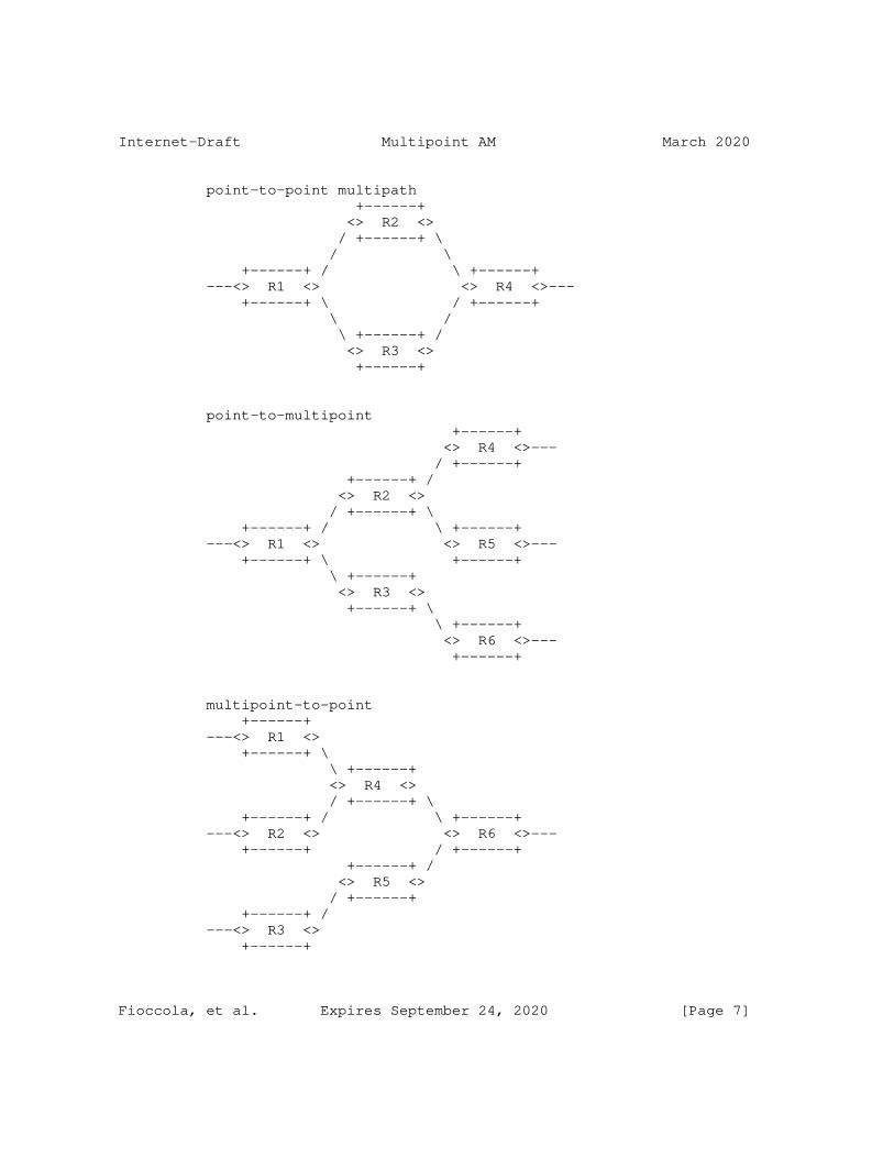
Internet-Draft Multipoint AM March 2020
point-to-point multipath +------+ <> R2 <> / +------+ \ / \ +------+ / \ +------+ ---<> R1 <> <> R4 <>--- +------+ \ / +------+ \ / \ +------+ / <> R3 <> +------+
point-to-multipoint +------+ <> R4 <>--- / +------+ +------+ / <> R2 <> / +------+ \ +------+ / \ +------+ ---<> R1 <> <> R5 <>--- +------+ \ +------+ \ +------+ <> R3 <> +------+ \ \ +------+ <> R6 <>--- +------+
multipoint-to-point +------+ ---<> R1 <> +------+ \ \ +------+ <> R4 <> / +------+ \ +------+ / \ +------+ ---<> R2 <> <> R6 <>--- +------+ / +------+ +------+ / <> R5 <> / +------+ +------+ / ---<> R3 <> +------+
Fioccola, et al. Expires September 24, 2020 [Page 7]

Internet-Draft Multipoint AM March 2020
multipoint-to-multipoint +------+ +------+ ---<> R1 <> <> R6 <>--- +------+ \ / +------+ \ +------+ / <> R4 <> +------+ \ +------+ \ +------+ ---<> R2 <> <> R7 <>--- +------+ \ / +------+ \ +------+ / <> R5 <> / +------+ \ +------+ / \ +------+ ---<> R3 <> <> R8 <>--- +------+ +------+
Figure 1: Flow classification
The case of unicast flow is considered in the previous figure. Anyway the anycast flow is also in scope because there is no replication and only a single node from the anycast group receives the traffic, so it can be viewed as a special case of unicast flow. Furthermore, an ECMP flow is in scope by definition, since it is a point-to-multipoint unicast flow.
4. Multipoint Performance Measurement
By Using the Alternate Marking method only point-to-point paths can be monitored. To have an IP (TCP/UDP) flow that follows a point-to- point path we have to define, with a specific value, 5 identification fields (IP Source, IP Destination, Transport Protocol, Source Port, Destination Port).
Multipoint Alternate Marking enables the performance measurement for multipoint flows selected by identification fields without any constraints (even the entire network production traffic). It is also possible to use multiple marking points for the same monitored flow.
4.1. Monitoring Network
The Monitoring Network is deduced from the Production Network, by identifying the nodes of the graph that are the measurement points, and the links that are the connections between measurement points.
There are some techniques that can help with the building of the monitoring network (as an example it is possible to mention
Fioccola, et al. Expires September 24, 2020 [Page 8]

Internet-Draft Multipoint AM March 2020
[I-D.ietf-ippm-route]). In general there are different options: the monitoring network can be obtained by considering all the possible paths for the traffic or also by periodically checking the traffic (e.g. daily, weekly, monthly) and update the graph as appropriate, but this is up to the Network Management System (NMS) configuration.
So a graph model of the monitoring network can be built according to the Alternate Marking method: the monitored interfaces and links are identified. Only the measurement points and links where the traffic has flowed have to be represented in the graph.
The following figure shows a simple example of a Monitoring Network graph:
+------+ <> R6 <>--- / +------+ +------+ +------+ / <> R2 <>---<> R4 <> / +------+ \ +------+ \ / \ \ +------+ +------+ / +------+ \ +------+ <> R7 <>--- ---<> R1 <>---<> R3 <>---<> R5 <> +------+ +------+ \ +------+ \ +------+ \ \ \ \ +------+ \ \ <> R8 <>--- \ \ +------+ \ \ \ \ +------+ \ <> R9 <>--- \ +------+ \ \ +------+ <> R10 <>--- +------+
Figure 2: Monitoring Network Graph
Each monitoring point is characterized by the packet counter that refers only to a marking period of the monitored flow.
The same is applicable also for the delay but it will be described in the following sections.
Fioccola, et al. Expires September 24, 2020 [Page 9]

Internet-Draft Multipoint AM March 2020
5. Multipoint Packet Loss
Since all the packets of the considered flow leaving the network have previously entered the network, the number of packets counted by all the input nodes is always greater or equal than the number of packets counted by all the output nodes. Non-initial fragments are not considered here.
The assumption is the use of the Alternate Marking method. And in case of no packet loss occurring in the marking period, if all the input and output points of the network domain to be monitored are measurement points, the sum of the number of packets on all the ingress interfaces equals the number on egress interfaces for the monitored flow. In this circumstance, if no packet loss occurs, the intermediate measurement points have only the task to split the measurement.
It is possible to define the Network Packet Loss of one monitored flow for a single period: <<In a packet network, the number of lost packets is the number of packets counted by the input nodes minus the number of packets counted by the output nodes>>. This is true for every packet flow in each marking period.
The Monitored Network Packet Loss with n input nodes and m output nodes is given by:
PL = (PI1 + PI2 +...+ PIn) - (PO1 + PO2 +...+ POm)
where:
PL is the Network Packet Loss (number of lost packets)
PIi is the Number of packets flowed through the i-th Input node in this period
POj is the Number of packets flowed through the j-th Output node in this period
The equation is applied on a per-time-interval basis and on an per- flow basis:
The reference interval is the Alternate Marking period as defined in RFC 8321 [RFC8321].
The flow definition is generalized here, indeed, as described before, a multipoint packet flow is considered and the identification fields can be selected without any constraints.
Fioccola, et al. Expires September 24, 2020 [Page 10]

Internet-Draft Multipoint AM March 2020
6. Network Clustering
The previous Equation can determine the number of packets lost globally in the monitored network, exploiting only the data provided by the counters in the input and output nodes.
In addition it is also possible to leverage the data provided by the other counters in the network to converge on the smallest identifiable subnetworks where the losses occur. These subnetworks are named Clusters.
A Cluster graph is a subnetwork of the entire Monitoring Network graph that still satisfies the packet loss equation (introduced in the previous section) where PL in this case is the number of packets lost in the Cluster. As for the entire Monitoring Network graph, the Cluster is defined on a per-flow basis.
For this reason a Cluster should contain all the arcs emanating from its input nodes and all the arcs terminating at its output nodes. This ensures that we can count all the packets (and only those) exiting an input node again at the output node, whatever path they follow.
In a completely monitored unidirectional network (a network where every network interface is monitored), each network device corresponds to a Cluster and each physical link corresponds to two Clusters (one for each device).
Clusters can have different sizes depending on flow filtering criteria adopted.
Moreover, sometimes Clusters can be optionally simplified. For example when two monitored interfaces are divided by a single router (one is the input interface and the other is the output interface and the router has only these two interfaces), instead of counting exactly twice, upon entering and leaving, it is possible to consider a single measurement point (in this case we do not care of the internal packet loss of the router).
It is worth highlighting that it might also be convenient to define Clusters based on the topological information and applicable to all the possible flows in the monitored network.
6.1. Algorithm for Cluster partition
A simple algorithm can be applied in order to split our monitoring network into Clusters. This can be done for each direction separately. The Cluster partition is based on the Monitoring Network
Fioccola, et al. Expires September 24, 2020 [Page 11]

Internet-Draft Multipoint AM March 2020
Graph that can be valid for a specific flow or can also be general and valid for the entire network topology.
It is a two-step algorithm:
o Group the links where there is the same starting node;
o Join the grouped links with at least one ending node in common.
Considering that the links are unidirectional, the first step implies to list all the links as connection between two nodes and to group the different links if they have the same starting node. Note that it is possible to start from any link and the procedure works anyway. Following this classification, the second step implies to eventually join the groups classified in the first step by looking at the ending nodes. If different groups have at least one common ending node, they are put together and belong to the same set. After the application of the two steps of the algorithm, each one of the composed sets of links together with the endpoint nodes constitutes a Cluster.
In our monitoring network graph example it is possible to identify the Clusters partition by applying this two-step algorithm.
The first step identifies the following groups:
1. Group 1: (R1-R2), (R1-R3), (R1-R10)
2. Group 2: (R2-R4), (R2-R5)
3. Group 3: (R3-R5), (R3-R9)
4. Group 4: (R4-R6), (R4-R7)
5. Group 5: (R5-R8)
And then, the second step builds the Clusters partition (in particular we can underline that Group 2 and Group 3 connect together, since R5 is in common):
1. Cluster 1: (R1-R2), (R1-R3), (R1-R10)
2. Cluster 2: (R2-R4), (R2-R5), (R3-R5), (R3-R9)
3. Cluster 3: (R4-R6), (R4-R7)
4. Cluster 4: (R5-R8)
Fioccola, et al. Expires September 24, 2020 [Page 12]
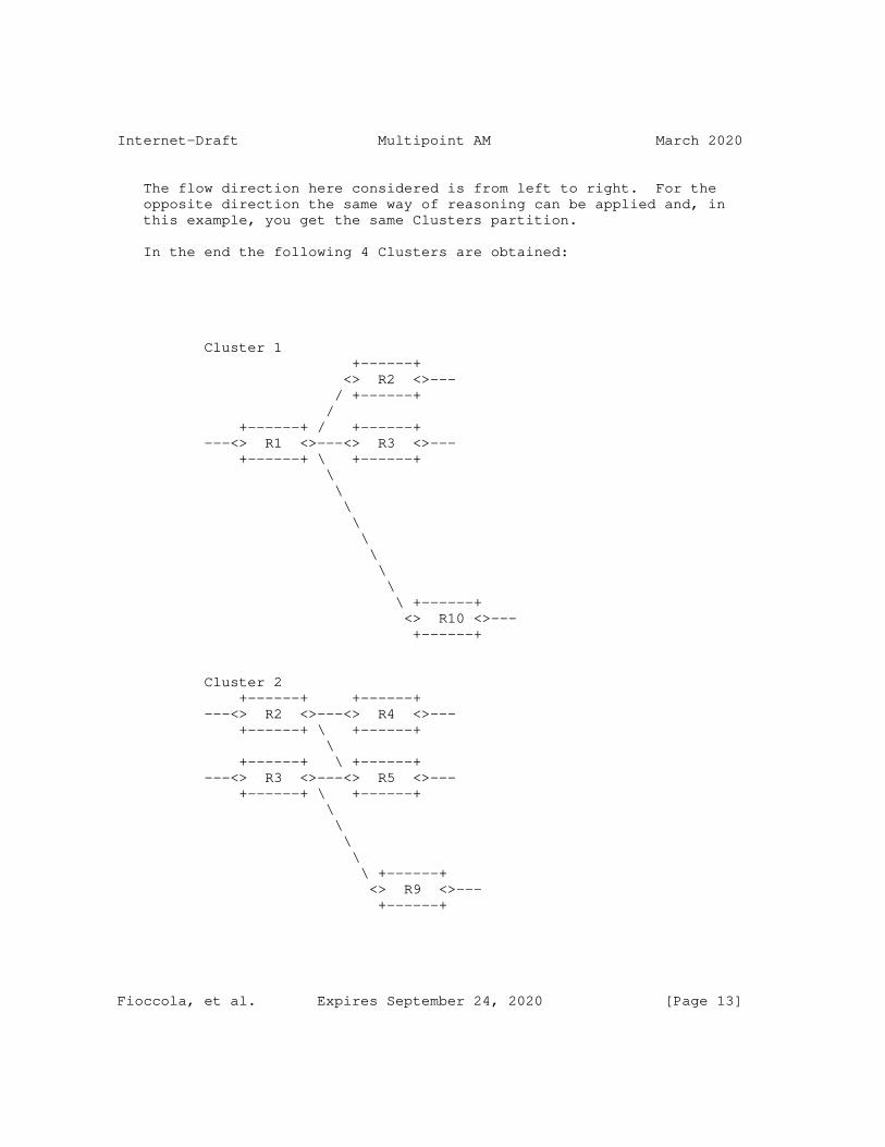
Internet-Draft Multipoint AM March 2020
The flow direction here considered is from left to right. For the opposite direction the same way of reasoning can be applied and, in this example, you get the same Clusters partition.
In the end the following 4 Clusters are obtained:
Cluster 1 +------+ <> R2 <>--- / +------+ / +------+ / +------+ ---<> R1 <>---<> R3 <>--- +------+ \ +------+ \ \ \ \ \ \ \ \ \ +------+ <> R10 <>--- +------+
Cluster 2 +------+ +------+ ---<> R2 <>---<> R4 <>--- +------+ \ +------+ \ +------+ \ +------+ ---<> R3 <>---<> R5 <>--- +------+ \ +------+ \ \ \ \ \ +------+ <> R9 <>--- +------+
Fioccola, et al. Expires September 24, 2020 [Page 13]

Internet-Draft Multipoint AM March 2020
Cluster 3 +------+ <> R6 <>--- / +------+ +------+ / ---<> R4 <> +------+ \ \ +------+ <> R7 <>--- +------+
Cluster 4 +------+ ---<> R5 <> +------+ \ \ +------+ <> R8 <>--- +------+
Figure 3: Clusters example
There are Clusters with more than 2 nodes and two-nodes Clusters. In the two-nodes Clusters the loss is on the link (Cluster 4). In more- than-2-nodes Clusters the loss is on the Cluster but we cannot know in which link (Cluster 1, 2, 3).
In this way the calculation of packet loss can be made on Cluster basis. Note that the packet counters for each marking period permit to calculate the packet rate on Cluster basis, so Committed Information Rate (CIR) and Excess Information Rate (EIR) could also be deduced on Cluster basis.
Obviously, by combining some Clusters in a new connected subnetwork (called Super Cluster) the Packet Loss Rule is still true.
In this way, in a very large network there is no need to configure detailed filter criteria to inspect the traffic. You can check a multipoint network and, in case of problems, you can go deep with a step-by-step cluster analysis, but only for the cluster or combination of clusters where the problem happens.
In summary, once defined a flow, the algorithm to build the Cluster Partition considers all the possible links and nodes crossed by the given flow, even if there is no traffic. It is based on topological information. So, if the flow does not enter or traverse all the nodes, the counters have a non-zero value for the involved nodes,
Fioccola, et al. Expires September 24, 2020 [Page 14]
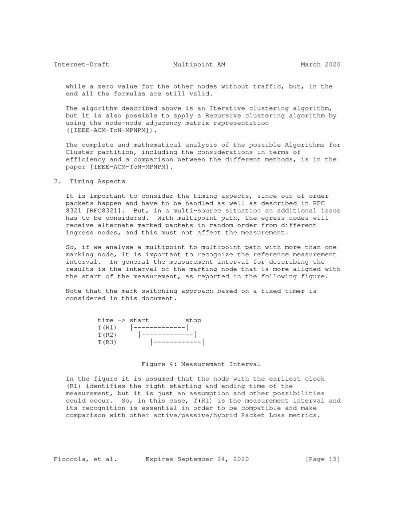
Internet-Draft Multipoint AM March 2020
while a zero value for the other nodes without traffic, but, in the end all the formulas are still valid.
The algorithm described above is an Iterative clustering algorithm, but it is also possible to apply a Recursive clustering algorithm by using the node-node adjacency matrix representation ([IEEE-ACM-ToN-MPNPM]).
The complete and mathematical analysis of the possible Algorithms for Cluster partition, including the considerations in terms of efficiency and a comparison between the different methods, is in the paper [IEEE-ACM-ToN-MPNPM].
7. Timing Aspects
It is important to consider the timing aspects, since out of order packets happen and have to be handled as well as described in RFC 8321 [RFC8321]. But, in a multi-source situation an additional issue has to be considered. With multipoint path, the egress nodes will receive alternate marked packets in random order from different ingress nodes, and this must not affect the measurement.
So, if we analyse a multipoint-to-multipoint path with more than one marking node, it is important to recognize the reference measurement interval. In general the measurement interval for describing the results is the interval of the marking node that is more aligned with the start of the measurement, as reported in the following figure.
Note that the mark switching approach based on a fixed timer is considered in this document.
time -> start stop T(R1) |-------------| T(R2) |-------------| T(R3) |------------|
Figure 4: Measurement Interval
In the figure it is assumed that the node with the earliest clock (R1) identifies the right starting and ending time of the measurement, but it is just an assumption and other possibilities could occur. So, in this case, T(R1) is the measurement interval and its recognition is essential in order to be compatible and make comparison with other active/passive/hybrid Packet Loss metrics.
Fioccola, et al. Expires September 24, 2020 [Page 15]

Internet-Draft Multipoint AM March 2020
When we expand to multipoint-to-multipoint flows, we have to consider that all source nodes mark the traffic and this adds more complexity.
Regarding the timing aspects of the methodology, RFC 8321 [RFC8321] already describes two contributions that are taken into account: the clock error between network devices and the network delay between measurement points.
But we should now consider an additional contribution. Since all source nodes mark the traffic, the source measurement intervals can be of different lengths and with different offsets and this mismatch m can be added to d, as shown in figure.
...BBBBBBBBB | AAAAAAAAAAAAAAAAAAAAAAAAAAAAAAAAAAAAAA | BBBBBBBBB... |<======================================>| | L | ...=========>|<==================><==================>|<==========... | L/2 L/2 | |<=><===>| |<===><=>| m d | | d m |<====================>| available counting interval
Figure 5: Timing Aspects for Multipoint paths
So the misalignment between the marking source routers gives an additional constraint and the value of m is added to d (that already includes clock error and network delay).
Thus, three different possible contributions are considered: clock error between network devices, network delay between measurement points and the misalignment between the marking source routers.
In the end, the condition that must be satisfied to enable the method to function properly is that the available counting interval must be > 0, and that means:
L - 2m - 2d > 0.
This formula needs to be verified for each measurement point on the multipoint path, where m is misalignment between the marking source routers, while d, already introduced in RFC 8321 [RFC8321], takes into account clock error and network delay between network nodes. Therefore, the mismatch between measurement intervals must satisfy this condition.
Fioccola, et al. Expires September 24, 2020 [Page 16]

Internet-Draft Multipoint AM March 2020
Note that the timing considerations are valid for both packet loss and delay measurements.
8. Multipoint Delay and Delay Variation
The same line of reasoning can be applied to Delay and Delay Variation. Similarly to the delay measurements defined in RFC 8321 [RFC8321], the marking batches anchor the samples to a particular period and this is the time reference that can be used. It is important to highlight that both delay and delay variation measurements make sense in a multipoint path. The Delay Variation is calculated by considering the same packets selected for measuring the Delay.
In general, it is possible to perform delay and delay variation measurements on multipoint paths basis or on single packets basis:
o Delay measurements on multipoint paths basis means that the delay value is representative of an entire multipoint path (e.g. whole multipoint network, a cluster or a combination of clusters).
o Delay measurements on a single packet basis means that you can use multipoint path just to easily couple packets between input and output nodes of a multipoint path, as it is described in the following sections.
8.1. Delay measurements on multipoint paths basis
8.1.1. Single Marking measurement
Mean delay and mean delay variation measurements can also be generalized to the case of multipoint flows. It is possible to compute the average one-way delay of packets, in one block, in a cluster or in the entire monitored network.
The average latency can be measured as the difference between the weighted averages of the mean timestamps of the sets of output and input nodes. This means that, in the calculation, it is possible to weigh the timestamps by considering the number of packets for each endpoints.
8.2. Delay measurements on single packets basis
8.2.1. Single and Double Marking measurement
Delay and delay variation measurements relative to only one picked packet per period (both single and double marked) can be performed in the Multipoint scenario with some limitations:
Fioccola, et al. Expires September 24, 2020 [Page 17]

Internet-Draft Multipoint AM March 2020
Single marking based on the first/last packet of the interval would not work, because it would not be possible to agree on the first packet of the interval.
Double marking or multiplexed marking would work, but each measurement would only give information about the delay of a single path. However, by repeating the measurement multiple times, it is possible to get information about all the paths in the multipoint flow. This can be done in case of point-to- multipoint path but it is more difficult to achieve in case of multipoint-to-multipoint path because of the multiple source routers.
If we would perform a delay measurement for more than one picked packet in the same marking period and, especially, if we want to get delay measurements on multipoint-to-multipoint basis, both single and double marking method are not useful in the Multipoint scenario, since they would not be representative of the entire flow. The packets can follow different paths with various delays, and in general it can be very difficult to recognize marked packets in a multipoint-to-multipoint path especially in the case when there is more than one per period.
A desirable option is to monitor simultaneously all the paths of a multipoint path in the same marking period and, for this purpose, hashing can be used as reported in the next Section.
8.2.2. Hashing selection method
RFC 5474 [RFC5474] and RFC 5475 [RFC5475] introduce sampling and filtering techniques for IP Packet Selection.
The hash-based selection methodologies for delay measurement can work in a multipoint-to-multipoint path and can be used both coupled to mean delay or stand alone.
[I-D.mizrahi-ippm-compact-alternate-marking] introduces how to use the Hash method (RFC 5474 [RFC5474] and RFC 5475 [RFC5475]) combined with Alternate Marking method for point-to-point flows. It is also called Mixed Hashed Marking: the coupling of marking method and hashing technique is very useful because the marking batches anchor the samples selected with hashing and this simplifies the correlation of the hashing packets along the path.
It is possible to use a basic hash or a dynamic hash method. One of the challenges of the basic approach is that the frequency of the sampled packets may vary considerably. For this reason the dynamic approach has been introduced for point-to-point flow in order to have
Fioccola, et al. Expires September 24, 2020 [Page 18]

Internet-Draft Multipoint AM March 2020
the desired and almost fixed number of samples for each measurement period. In the hash-based sampling, Alternate Marking is used to create periods, so that hash-based samples are divided into batches, allowing to anchor the selected samples to their period. Moreover in the dynamic hash-based sampling, by dynamically adapting the length of the hash value, the number of samples is bounded in each marking period. This can be realized by choosing the maximum number of samples (NMAX) to be caught in a marking period. The algorithm starts with only few hash bits, that permit to select a greater percentage of packets (e.g. with 0 bit of hash all the packets are sampled, with 1 bit of hash half of the packets are sampled, and so on). When the number of selected packets reaches NMAX, a hashing bit is added. As a consequence, the sampling proceeds at half of the original rate and also the packets already selected that do not match the new hash are discarded. This step can be repeated iteratively. It is assumed that each sample includes the timestamp (used for delay measurement) and the hash value, allowing the management system to match the samples received from the two measurement points. The dynamic process statistically converges at the end of a marking period and the final number of selected samples is between NMAX/2 and NMAX. Therefore, the dynamic approach paces the sampling rate, allowing to bound the number of sampled packets per sampling period.
In a multipoint environment the behaviour is similar to a point-to point flow. In particular, in the context of a multipoint-to- multipoint flow, the dynamic hash could be the solution to perform delay measurements on specific packets and to overcome the single and double marking limitations.
The management system receives the samples including the timestamps and the hash value from all the MPs, and this happens both for point- to-point and for multipoint-to-multipoint flows. Then the longest hash used by MPs is deduced and it is applied to couple timestamps of the same packets of 2 MPs of a point-to-point path or of input and output MPs of a Cluster (or a Super Cluster or the entire network). But some considerations are needed: if there isn’t packet loss the set of input samples is always equal to the set of output samples. In case of packet loss the set of output samples can be a subset of input samples but the method still works because, at the end, it is easy to couple the input and output timestamps of each caught packet using the hash (in particular the "unused part of the hash" that should be different for each packet).
Therefore, the basic hash is logically similar to the double marking method, and in case of point-to-point path double marking and basic hash selection are equivalent. The dynamic approach scales the number of measurements per interval, and it would seem that double marking would also work well if we reduced the interval length, but
Fioccola, et al. Expires September 24, 2020 [Page 19]

Internet-Draft Multipoint AM March 2020
this can be done only for point-to-point path and not for multipoint path, where we cannot couple the picked packets in a multipoint paths. So, in general, if we want to get delay measurements on multipoint-to-multipoint path basis and want to select more than one packet per period, double marking cannot be used because we could not be able to couple the picked packets between input and output nodes. On the other hand we can do that by using hashing selection.
9. A Closed Loop Performance Management approach
The Multipoint Alternate Marking framework that is introduced in this document adds flexibility to Performance Management (PM) because it can reduce the order of magnitude of the packet counters. This allows an SDN Orchestrator to supervise, control and manage PM in large networks.
The monitoring network can be considered as a whole or can be split in Clusters, that are the smallest subnetworks (group-to-group segments), maintaining the packet loss property for each subnetwork. They can also be combined in new connected subnetworks at different levels depending on the detail we want to achieve.
An SDN Controller or a Network Management System (NMS) can calibrate Performance Measurements since they are aware of the network topology. They can start without examining in depth. In case of necessity (packet loss is measured or the delay is too high), the filtering criteria could be immediately reconfigured in order to perform a partition of the network by using Clusters and/or different combinations of Clusters. In this way the problem can be localized in a specific Cluster or in a single combination of Clusters and a more detailed analysis can be performed step-by-step by successive approximation up to a point-to-point flow detailed analysis. This is the so called Closed Loop.
This approach can be called Network Zooming and can be performed in two different ways:
1) change the traffic filter and select more detailed flows;
2) activate new measurement points by defining more specified clusters.
The Network Zooming approach implies that the some filters or rules are changed and there is a transient time to wait once the new network configuration takes effect and it can be determined by the Network Orchestrator/Controller, based on the network conditions.
Fioccola, et al. Expires September 24, 2020 [Page 20]

Internet-Draft Multipoint AM March 2020
For example, if the Network Zooming identifies the performance problem for the traffic coming from a specific source, we need to recognize the marked signal from this specific source node and its relative path. For this purpose we can activate all the available measurement points and specify better the flow filter criteria (i.e. 5-tuple). As an alternative, it can be enough to select packets from the specific source for delay measurements, and in this case it is possible to apply the hashing technique as mentioned in the previous sections.
[I-D.song-opsawg-ifit-framework] defines an architecture where the centralized Data Collector and Network Management can apply the intelligent and flexible Alternate Marking algorithm as previously described.
As for RFC 8321 [RFC8321], it is possible to classify the traffic and mark a portion of the total traffic. For each period the packet rate and bandwidth are calculated from the number of packets. In this way the Network Orchestrator becomes aware if the traffic rate overcomes limits. In addition more precision can be obtained by reducing the marking period, indeed some implementations use a marking period of 1 sec and less.
In addition an SDN Controller could also collect the measurement history.
It is important to mention that the Multipoint Alternate Marking framework also helps Traffic Visualization. Indeed this methodology is very useful to identify which path or which cluster is crossed by the flow.
10. Examples of application
There are application fields where it may be useful to take into consideration the Multipoint Alternate Marking:
o VPN: The IP traffic is selected on IP source basis in both directions. At the endpoint WAN interface all the output traffic is counted in a single flow. The input traffic is composed by all the other flows aggregated for source address. So, by considering n end-points, the monitored flows are n (each flow with 1 ingress point and (n-1) egress points) instead of n*(n-1) flows (each flow, with 1 ingress point and 1 egress point);
o Mobile Backhaul: LTE traffic is selected, in the Up direction, by the EnodeB source address and, in Down direction, by the EnodeB destination address because the packets are sent from the Mobile
Fioccola, et al. Expires September 24, 2020 [Page 21]

Internet-Draft Multipoint AM March 2020
Packet Core to the EnodeB. So the monitored flow is only one per EnodeB in both directions;
o Over The Top (OTT) services: The traffic is selected, in the Down direction by the source addresses of the packets sent by OTT Servers. In the opposite direction (Up) by the destination IP addresses of the same Servers. So the monitoring is based on a single flow per OTT Servers in both directions.
o Enterprise SD-WAN: SD-WAN allows to connect remote branch offices to Data Centers and build higher-performance WANs. A centralized controller is used to set policies and prioritize traffic. The SD-WAN takes into account these policies and the availability of network bandwidth to route traffic. This helps ensure that application performance meets service level agreements (SLAs). This methodology can also help the path selection for the WAN connection based on per Cluster and per flow performance.
Note that the list is just an example and it is not exhaustive. More applications are possible.
11. Security Considerations
This document specifies a method to perform measurements that does not directly affect Internet security nor applications that run on the Internet. However, implementation of this method must be mindful of security and privacy concerns, as explained in RFC 8321 [RFC8321].
12. Acknowledgements
The authors would like to thank Al Morton, Tal Mizrahi, Rachel Huang for the precious contribution.
13. IANA Considerations
This memo makes no requests of IANA.
14. References
14.1. Normative References
[RFC5474] Duffield, N., Ed., Chiou, D., Claise, B., Greenberg, A., Grossglauser, M., and J. Rexford, "A Framework for Packet Selection and Reporting", RFC 5474, DOI 10.17487/RFC5474, March 2009, <https://www.rfc-editor.org/info/rfc5474>.
Fioccola, et al. Expires September 24, 2020 [Page 22]

Internet-Draft Multipoint AM March 2020
[RFC5475] Zseby, T., Molina, M., Duffield, N., Niccolini, S., and F. Raspall, "Sampling and Filtering Techniques for IP Packet Selection", RFC 5475, DOI 10.17487/RFC5475, March 2009, <https://www.rfc-editor.org/info/rfc5475>.
[RFC5644] Stephan, E., Liang, L., and A. Morton, "IP Performance Metrics (IPPM): Spatial and Multicast", RFC 5644, DOI 10.17487/RFC5644, October 2009, <https://www.rfc-editor.org/info/rfc5644>.
[RFC8321] Fioccola, G., Ed., Capello, A., Cociglio, M., Castaldelli, L., Chen, M., Zheng, L., Mirsky, G., and T. Mizrahi, "Alternate-Marking Method for Passive and Hybrid Performance Monitoring", RFC 8321, DOI 10.17487/RFC8321, January 2018, <https://www.rfc-editor.org/info/rfc8321>.
14.2. Informative References
[I-D.ietf-ippm-route] Alvarez-Hamelin, J., Morton, A., Fabini, J., Pignataro, C., and R. Geib, "Advanced Unidirectional Route Assessment (AURA)", draft-ietf-ippm-route-07 (work in progress), December 2019.
[I-D.mizrahi-ippm-compact-alternate-marking] Mizrahi, T., Arad, C., Fioccola, G., Cociglio, M., Chen, M., Zheng, L., and G. Mirsky, "Compact Alternate Marking Methods for Passive and Hybrid Performance Monitoring", draft-mizrahi-ippm-compact-alternate-marking-05 (work in progress), July 2019.
[I-D.song-opsawg-ifit-framework] Song, H., Qin, F., Chen, H., Jin, J., and J. Shin, "In- situ Flow Information Telemetry", draft-song-opsawg-ifit- framework-11 (work in progress), March 2020.
[I-D.zhou-ippm-enhanced-alternate-marking] Zhou, T., Fioccola, G., Li, Z., Lee, S., and M. Cociglio, "Enhanced Alternate Marking Method", draft-zhou-ippm- enhanced-alternate-marking-04 (work in progress), October 2019.
[IEEE-ACM-ToN-MPNPM] IEEE/ACM TRANSACTION ON NETWORKING, "Multipoint Passive Monitoring in Packet Networks", DOI 10.1109/TNET.2019.2950157, 2019.
Fioccola, et al. Expires September 24, 2020 [Page 23]

Internet-Draft Multipoint AM March 2020
[IEEE-Network-PNPM] IEEE Network, "AM-PM: Efficient Network Telemetry using Alternate Marking", DOI 10.1109/MNET.2019.1800152, 2019.
[RFC7011] Claise, B., Ed., Trammell, B., Ed., and P. Aitken, "Specification of the IP Flow Information Export (IPFIX) Protocol for the Exchange of Flow Information", STD 77, RFC 7011, DOI 10.17487/RFC7011, September 2013, <https://www.rfc-editor.org/info/rfc7011>.
Authors’ Addresses
Giuseppe Fioccola (editor) Huawei Technologies Riesstrasse, 25 Munich 80992 Germany
Email: [email protected]
Mauro Cociglio Telecom Italia Via Reiss Romoli, 274 Torino 10148 Italy
Email: [email protected]
Amedeo Sapio Politecnico di Torino Corso Duca degli Abruzzi, 24 Torino 10129 Italy
Email: [email protected]
Riccardo Sisto Politecnico di Torino Corso Duca degli Abruzzi, 24 Torino 10129 Italy
Email: [email protected]
Fioccola, et al. Expires September 24, 2020 [Page 24]

Network Working Group J. Alvarez-HamelinInternet-Draft Universidad de Buenos AiresUpdates: 2330 (if approved) A. MortonIntended status: Standards Track AT&T LabsExpires: February 14, 2021 J. Fabini TU Wien C. Pignataro Cisco Systems, Inc. R. Geib Deutsche Telekom August 13, 2020
Advanced Unidirectional Route Assessment (AURA) draft-ietf-ippm-route-10
Abstract
This memo introduces an advanced unidirectional route assessment (AURA) metric and associated measurement methodology, based on the IP Performance Metrics (IPPM) Framework RFC 2330. This memo updates RFC 2330 in the areas of path-related terminology and path description, primarily to include the possibility of parallel subpaths between a given Source and Destination pair, owing to the presence of multi- path technologies.
Status of This Memo
This Internet-Draft is submitted in full conformance with the provisions of BCP 78 and BCP 79.
Internet-Drafts are working documents of the Internet Engineering Task Force (IETF). Note that other groups may also distribute working documents as Internet-Drafts. The list of current Internet- Drafts is at https://datatracker.ietf.org/drafts/current/.
Internet-Drafts are draft documents valid for a maximum of six months and may be updated, replaced, or obsoleted by other documents at any time. It is inappropriate to use Internet-Drafts as reference material or to cite them other than as "work in progress."
This Internet-Draft will expire on February 14, 2021.
Copyright Notice
Copyright (c) 2020 IETF Trust and the persons identified as the document authors. All rights reserved.
Alvarez-Hamelin, et al. Expires February 14, 2021 [Page 1]

Internet-Draft AURA Metrics & Methods August 2020
This document is subject to BCP 78 and the IETF Trust’s Legal Provisions Relating to IETF Documents (https://trustee.ietf.org/license-info) in effect on the date of publication of this document. Please review these documents carefully, as they describe your rights and restrictions with respect to this document. Code Components extracted from this document must include Simplified BSD License text as described in Section 4.e of the Trust Legal Provisions and are provided without warranty as described in the Simplified BSD License.
Table of Contents
1. Introduction . . . . . . . . . . . . . . . . . . . . . . . . 2 1.1. Issues with Earlier Work to Define a Route Metric . . . . 3 1.2. Requirements Language . . . . . . . . . . . . . . . . . . 4 2. Scope . . . . . . . . . . . . . . . . . . . . . . . . . . . . 4 3. Route Metric Specifications . . . . . . . . . . . . . . . . . 5 3.1. Terms and Definitions . . . . . . . . . . . . . . . . . . 5 3.2. Formal Name . . . . . . . . . . . . . . . . . . . . . . . 6 3.3. Parameters . . . . . . . . . . . . . . . . . . . . . . . 6 3.4. Metric Definitions . . . . . . . . . . . . . . . . . . . 7 3.5. Related Round-Trip Delay and Loss Definitions . . . . . . 9 3.6. Discussion . . . . . . . . . . . . . . . . . . . . . . . 10 3.7. Reporting the Metric . . . . . . . . . . . . . . . . . . 10 4. Route Assessment Methodologies . . . . . . . . . . . . . . . 11 4.1. Active Methodologies . . . . . . . . . . . . . . . . . . 11 4.1.1. Temporal Composition for Route Metrics . . . . . . . 13 4.1.2. Routing Class Identification . . . . . . . . . . . . 15 4.1.3. Intermediate Observation Point Route Measurement . . 16 4.2. Hybrid Methodologies . . . . . . . . . . . . . . . . . . 16 4.3. Combining Different Methods . . . . . . . . . . . . . . . 17 5. Background on Round-Trip Delay Measurement Goals . . . . . . 17 6. RTD Measurements Statistics . . . . . . . . . . . . . . . . . 18 7. Security Considerations . . . . . . . . . . . . . . . . . . . 20 8. IANA Considerations . . . . . . . . . . . . . . . . . . . . . 21 9. Acknowledgements . . . . . . . . . . . . . . . . . . . . . . 21 10. Appendix I MPLS Methods for Route Assessment . . . . . . . . 21 11. References . . . . . . . . . . . . . . . . . . . . . . . . . 22 11.1. Normative References . . . . . . . . . . . . . . . . . . 22 11.2. Informative References . . . . . . . . . . . . . . . . . 24 Authors’ Addresses . . . . . . . . . . . . . . . . . . . . . . . 26
1. Introduction
The IETF IP Performance Metrics (IPPM) working group first created a framework for metric development in [RFC2330]. This framework has stood the test of time and enabled development of many fundamental metrics. It has been updated in the area of metric composition
Alvarez-Hamelin, et al. Expires February 14, 2021 [Page 2]

Internet-Draft AURA Metrics & Methods August 2020
[RFC5835], and in several areas related to active stream measurement of modern networks with reactive properties [RFC7312].
The [RFC2330] framework motivated the development of "performance and reliability metrics for paths through the Internet," and Section 5 of [RFC2330] defines terms that support description of a path under test. However, metrics for assessment of paths and related performance aspects had not been attempted in IPPM when the [RFC2330] framework was written.
This memo takes up the route measurement challenge and specifies a new route metric, two practical frameworks for methods of measurement (using either active or hybrid active-passive methods [RFC7799]), and Round-Trip Delay and link information discovery using the results of measurements. All route measurements are limited by the willingness of hosts along the path to be discovered, to cooperate with the methods used, or to recognize that the measurement operation is taking place (such as when tunnels are present).
1.1. Issues with Earlier Work to Define a Route Metric
Section 7 of [RFC2330] presented a simple example of a "route" metric along with several other examples. The example is reproduced below (where the reference is to Section 5 of [RFC2330]):
"route: The path, as defined in Section 5, from A to B at a given time."
This example provides a starting point to develop a more complete definition of route. Areas needing clarification include:
Time: In practice, the route will be assessed over a time interval, because active path detection methods like Paris Traceroute [PT] rely on hop limits for their operation and cannot accomplish discovery of all hosts using a single packet.
Type-P: The legacy route definition lacks the option to cater for packet-dependent routing. In this memo, we assess the route for a specific packet of Type-P, and reflect this in the metric definition. The methods of measurement determine the specific Type-P used.
Parallel Paths: Parallel paths are a reality of the Internet and a strength of advanced route assessment methods, so the metric must acknowledge this possibility. Use of Equal Cost Multi-Path (ECMP) and Unequal Cost Multi-Path (UCMP) technologies are common sources of parallel subpaths.
Alvarez-Hamelin, et al. Expires February 14, 2021 [Page 3]

Internet-Draft AURA Metrics & Methods August 2020
Cloud Subpath: May contain hosts that do not decrement hop limit, but may have two or more exchange links connecting "discoverable" hosts or routers. Parallel subpaths contained within clouds cannot be discovered. The assessment methods only discover hosts or routers on the path that decrement hop limit, or cooperate with interrogation protocols. The presence of tunnels and nested tunnels further complicate assessment by hiding hops.
Hop: Although the [RFC2330] definition of a hop was a link-host pair, only hosts that are discoverable or have the capability to cooperate with interrogation protocols where link information may be exposed.
The refined definition of Route metrics begins in the sections that follow.
1.2. Requirements Language
The key words "MUST", "MUST NOT", "REQUIRED", "SHALL", "SHALL NOT", "SHOULD", "SHOULD NOT", "RECOMMENDED", "NOT RECOMMENDED", "MAY", and "OPTIONAL" in this document are to be interpreted as described in BCP 14[RFC2119] [RFC8174] when, and only when, they appear in all capitals, as shown here.
2. Scope
The purpose of this memo is to add new route metrics and methods of measurement to the existing set of IPPM metrics.
The scope is to define route metrics that can identify the path taken by a packet or a flow traversing the Internet between two hosts. Although primarily intended for hosts communicating on the Internet, the definitions and metrics are constructed to be applicable to other network domains, if desired. The methods of measurement to assess the path may not be able to discover all hosts comprising the path, but such omissions are often deterministic and explainable sources of error.
This memo also specifies a framework for active methods of measurement which uses the techniques described in [PT], as well as a framework for hybrid active-passive methods of measurement such as the Hybrid Type I method [RFC7799] described in [I-D.ietf-ippm-ioam-data]. Methods using [I-D.ietf-ippm-ioam-data] are intended only for single administrative domains that provide a protocol for explicit interrogation of nodes on a path. Combinations of active methods and hybrid active-passive methods are also in- scope.
Alvarez-Hamelin, et al. Expires February 14, 2021 [Page 4]

Internet-Draft AURA Metrics & Methods August 2020
Further, this memo provides additional analysis of the round-trip delay measurements made possible by the methods, in an effort to discover more details about the path, such as the link technology in use.
This memo updates Section 5 of [RFC2330] in the areas of path-related terminology and path description, primarily to include the possibility of parallel subpaths between a given Source and Destination address pair (possibly resulting from Equal Cost Multi- Path (ECMP) and Unequal Cost Multi-Path (UCMP) technologies).
There are several simple non-goals of this memo. There is no attempt to assess the reverse path from any host on the path to the host attempting the path measurement. The reverse path contribution to delay will be that experienced by ICMP packets (in active methods), and may be different from delays experienced by UDP or TCP packets. Also, the round trip delay will include an unknown contribution of processing time at the host that generates the ICMP response. Therefore, the ICMP-based active methods are not supposed to yield accurate, reproducible estimations of the Round-Trip Delay that UDP or TCP packets will experience.
3. Route Metric Specifications
This section sets requirements for the components of the Route Metric.
3.1. Terms and Definitions
Host A Host as defined in [RFC2330] (a computer capable of IP communication, includes routers), a.k.a. RFC 2330 Host.
Node A Node is any network function on the path capable of IP-layer Communication, includes RFC 2330 Hosts.
Node Identity The unique address for Nodes communicating within the network domain. For Nodes communicating on the Internet with IP, it is the globally routable IP address which the Node uses when communicating with other Nodes under normal or error conditions. The Node Identity revealed (and its connection to a Node Name through reverse DNS) determines whether interfaces to parallel links can be associated with a single Node, or appear to identify unique Nodes.
Discoverable Node Nodes that convey their Node Identity according to the requirements of their network domain, such as when error conditions are detected by that Node. For Nodes communicating with IP packets, compliance with Section 3.2.2.4 of [RFC1122] when
Alvarez-Hamelin, et al. Expires February 14, 2021 [Page 5]

Internet-Draft AURA Metrics & Methods August 2020
discarding a packet due to TTL or Hop Limit Exceeded condition, MUST result in sending the corresponding Time Exceeded message (containing a form of Node identity) to the source. This requirement is also consistent with section 5.3.1 of [RFC1812] for routers.
Cooperating Node Nodes that respond to direct queries for their Node identity as part of a previously agreed and established interrogation protocol. Nodes SHOULD also provide information such as arrival/departure interface identification, arrival timestamp, and any relevant information about the Node or specific link which delivered the query to the Node.
Hop specification A Hop specification MUST contain a Node Identity, and MAY contain arrival and/or departure interface identification, round trip delay, and an arrival timestamp.
Routing Class A route that treats equally a class of different types of packets, designated "C" (unrelated to address classes of the past) [RFC2330] [RFC8468]. Knowledge of such a class allows any one of the types of packets within that class to be used for subsequent measurement of the route. The designator "class C" is used for historical reasons, see [RFC2330].
3.2. Formal Name
The formal name of the metric is:
Type-P-Route-Ensemble-Method-Variant
abbreviated as Route Ensemble.
Note that Type-P depends heavily on the chosen method and variant.
3.3. Parameters
This section lists the REQUIRED input factors to define and measure a Route metric, as specified in this memo.
o Src, the address of a Node (such as the globally routable IP address).
o Dst, the address of a Node (such as the globally routable IP address).
o i, the limit on the number of Hops a specific packet may visit as it traverses from the Node at Src to the Node at Dst (such as the TTL or Hop Limit).
Alvarez-Hamelin, et al. Expires February 14, 2021 [Page 6]

Internet-Draft AURA Metrics & Methods August 2020
o MaxHops, the maximum value of i used, (i=1,2,3,...MaxHops).
o T0, a time (start of measurement interval)
o Tf, a time (end of measurement interval)
o MP(address), Measurement Point at address, such as Src or Dst, usually at the same node stack layer as "address".
o T, the Node time of a packet as measured at MP(Src), meaning Measurement Point at the Source.
o Ta, the Node time of a reply packet’s *arrival* as measured at MP(Src), assigned to packets that arrive within a "reasonable" time (see parameter below).
o Tmax, a maximum waiting time for reply packets to return to the source, set sufficiently long to disambiguate packets with long delays from packets that are discarded (lost), such that the distribution of Round-Trip Delay is not truncated.
o F, the number of different flows simulated by the method and variant.
o flow, the stream of packets with the same n-tuple of designated header fields that (when held constant) result in identical treatment in a multi-path decision (such as the decision taken in load balancing). Note: The IPv6 flow label MAY be included in the flow definition if the MP(Src) is a Tunnel End Point (TEP) complying with [RFC6438] guidelines.
o Type-P, the complete description of the packets for which this assessment applies (including the flow-defining fields).
3.4. Metric Definitions
This section defines the REQUIRED measurement components of the Route metrics (unless otherwise indicated):
M, the total number of packets sent between T0 and Tf.
N, the smallest value of i needed for a packet to be received at Dst (sent between T0 and Tf).
Nmax, the largest value of i needed for a packet to be received at Dst (sent between T0 and Tf). Nmax may be equal to N.
Alvarez-Hamelin, et al. Expires February 14, 2021 [Page 7]

Internet-Draft AURA Metrics & Methods August 2020
Next define a *singleton* definition for a Node on the path, with sufficient indexes to identify all Nodes identified in a measurement interval (where *singleton* is part of the IPPM Framework [RFC2330]).
A Hop Specification, designated h(i,j), the IP address and/or identity of Discoverable Nodes (or Cooperating Nodes) that are i hops away from the Node with address = Src and part of Route j during the measurement interval, T0 to Tf. As defined here, a Hop singleton measurement MUST contain a Node Identity, hid(i,j), and MAY contain one or more of the following attributes:
o a(i,j) Arrival Interface ID (e.g., when [RFC5837] is supported)
o d(i,j) Departure Interface ID (e.g., when [RFC5837] is supported)
o t(i,j) Arrival Timestamp, where t(i,j) is ideally supplied by the Hop. (Note that t(i,j) might be approximated from the sending time of the packet that revealed the Hop, e.g., when the round trip response time is available and divided by 2.)
o Measurements of Round-Trip Delay (for each packet that reveals the same Node Identity and flow attributes, then this attribute is computed, see next section)
Node Identities and related information can be ordered by their distance from the Node with address Src in Hops h(i,j). Based on this, two forms of Routes are distinguished:
A Route Ensemble is defined as the combination of all routes traversed by different flows from the Node at Src address to the Node at Dst address. A single Route traversed by a single flow (determined by an unambiguous tuple of addresses Src and Dst, and other identical flow criteria) is a member of the Route Ensemble and called a Member Route.
Using h(i,j) and components and parameters, further define:
When considering the set of Hops in the context of a single flow, a Member Route j is an ordered list {h(1,j), ... h(Nj, j)} where h(i-1, j) and h(i, j) are 1 hop away from each other and Nj satisfying h(Nj,j)=Dst is the minimum count of Hops needed by the packet on Member Route j to reach Dst. Member Routes must be unique. The uniqueness property requires that any two Member routes j and k that are part of the same Route Ensemble differ either in terms of minimum hop count Nj and Nk to reach the destination Dst, or, in the case of identical hop count Nj=Nk, they have at least one distinct Hop: h(i,j) != h(i,k) for at least one i (i=1..Nj).
Alvarez-Hamelin, et al. Expires February 14, 2021 [Page 8]

Internet-Draft AURA Metrics & Methods August 2020
All the optional information collected to describe a Member Route, such as the arrival interface, departure interface, and Round Trip Delay at each Hop, turns each list item into a rich structure. There may be information on the links between Hops, possibly information on the routing (arrival interface and departure interface), an estimate of distance between Hops based on Round-Trip Delay measurements and calculations, and a time stamp indicating when all these additional details were valid.
The Route Ensemble from Src to Dst, during the measurement interval T0 to Tf, is the aggregate of all m distinct Member Routes discovered between the two Nodes with Src and Dst addresses. More formally, with the Node having address Src omitted:
Route Ensemble = { {h(1,1), h(2,1), h(3,1), ... h(N1,1)=Dst}, {h(1,2), h(2,2), h(3,2),..., h(N2,2)=Dst}, ... {h(1,m), h(2,m), h(3,m), ....h(Nm,m)=Dst} }
where the following conditions apply: i <= Nj <= Nmax (j=1..m)
Note that some h(i,j) may be empty (null) in the case that systems do not reply (not discoverable, or not cooperating).
h(i-1,j) and h(i,j) are the Hops on the same Member Route one hop away from each other.
Hop h(i,j) may be identical with h(k,l) for i!=k and j!=l ; which means there may be portions shared among different Member Routes (parts of Member Routes may overlap).
3.5. Related Round-Trip Delay and Loss Definitions
RTD(i,j,T) is defined as a singleton of the [RFC2681] Round-Trip Delay between the Node with address = Src and the Node at Hop h(i,j) at time T.
RTL(i,j,T) is defined as a singleton of the [RFC6673] Round-trip Loss between the Node with address = Src and the Node at Hop h(i,j) at time T.
Alvarez-Hamelin, et al. Expires February 14, 2021 [Page 9]

Internet-Draft AURA Metrics & Methods August 2020
3.6. Discussion
Depending on the way that Node Identity is revealed, it may be difficult to determine parallel subpaths between the same pair of Nodes (i.e. multiple parallel links). It is easier to detect parallel subpaths involving different Nodes.
o If a pair of discovered Nodes identify two different addresses (IP or not), then they will appear to be different Nodes. See item below.
o If a pair of discovered Nodes identify two different IP addresses, and the IP addresses resolve to the same Node name (in the DNS), then they will appear to be the same Nodes.
o If a discovered Node always replies using the same network address, regardless of the interface a packet arrives on, then multiple parallel links cannot be detected in that network domain. This condition may apply to traceroute-style methods, but may not apply to other hybrid methods based on In-situ Operations, Administration, and Maintenance (IOAM). For example, if the [RFC5837] ICMP extension mechanism is implemented, then parallel links can be detected with the discovery traceroute-style methods.
o If parallel links between routers are aggregated below the IP layer, then from Node point of view, all these links share the same pair of IP addresses. The existence of these parallel links can’t be detected at the IP layer. This applies to other network domains with layers below them, as well. This condition may apply to traceroute-style methods, but may not apply to other hybrid methods based on IOAM.
When a route assessment employs IP packets (for example), the reality of flow assignment to parallel subpaths involves layers above IP. Thus, the measured Route Ensemble is applicable to IP and higher layers (as described in the methodology’s packet of Type-P and flow parameters).
3.7. Reporting the Metric
An Information Model and an XML Data Model for Storing Traceroute Measurements is available in [RFC5388]. The measured information at each hop includes four pieces of information: a one-dimensional hop index, Node symbolic address, Node IP address, and RTD for each response.
The description of Hop information that may be collected according to this memo covers more dimensions, as defined in Section 3.4 above.
Alvarez-Hamelin, et al. Expires February 14, 2021 [Page 10]

Internet-Draft AURA Metrics & Methods August 2020
For example, the Hop index is two-dimensional to capture the complexity of a Route Ensemble, and it contains corresponding Node identities at a minimum. The models need to be expanded to include these features, as well as Arrival Interface ID, Departure Interface ID, and Arrival Timestamp, when available. The original sending Timestamp from the Src Node anchors a particular measurement in time.
4. Route Assessment Methodologies
There are two classes of methods described in this section, active methods relying on the reaction to TTL or Hop Limit Exceeded condition to discover Nodes on a path, and Hybrid active-passive methods that involve direct interrogation of cooperating Nodes (usually within a single domain). Description of these methods follow.
4.1. Active Methodologies
This section describes the method employed by current open source tools, thereby providing a practical framework for further advanced techniques to be included as method variants. This method is applicable for use across multiple administrative domains.
Internet routing is complex because it depends on the policies of thousands of Autonomous Systems (AS). Most routers perform load balancing on flows using a form of Equal Cost Multiple Path (ECMP). [RFC2991] describes a number of flow-based or hashed approaches (e.g., Modulo-N Hash, Hash-Threshold, Highest Random Weight (HRW)), and makes some good suggestions. Flow-based ECMP avoids increased packet delay variation and possibly overwhelming levels of packet reordering in flows.
A few routers still divide the workload through packet-based techniques, such as a round-robin scheme to distribute every new outgoing packet to multiple links, as explained in [RFC2991]. The methods described in this section assume flow-based ECMP.
Taking into account that Internet protocol was designed under the "end-to-end" principle, the IP payload and its header do not provide any information about the routes or path necessary to reach some destination. For this reason, the popular tool traceroute was developed to gather the IP addresses of each hop along a path using the ICMP protocol [RFC0792]. Traceroute also measures RTD from each hop. However, the growing complexity of the Internet makes it more challenging to develop an accurate traceroute implementation. For instance, the early traceroute tools would be inaccurate in the current network, mainly because they were not designed to retain a flow state. However, evolved traceroute tools, such as Paris-
Alvarez-Hamelin, et al. Expires February 14, 2021 [Page 11]

Internet-Draft AURA Metrics & Methods August 2020
traceroute [PT] [MLB] and Scamper [SCAMPER], expect to encounter ECMP and achieve more accurate results when they do, where Scamper ensures traceroute packets will follow the same path in 98% of cases[SCAMPER].
Today’s traceroute tools send Type-P of packets, either ICMP, UDP, or TCP. UDP and TCP are used when a particular characteristic needs to be verified, such as filtering or traffic shaping on specific ports (i.e., services). UDP and TCP traceroute are also used when ICMP responses are not received. [SCAMPER] supports IPv6 traceroute measurements, keeping the FlowLabel constant in all packets.
Paris-traceroute allows its users to measure the RTD to every Node of the path for a particular flow. Furthermore, either Paris-traceroute or Scamper is capable of unveiling the many available paths between a source and destination (which are visible to active methods). This task is accomplished by repeating complete traceroute measurements with different flow parameters for each measurement; Paris-traceroute provides "exhaustive" mode while scamper provides "tracelb" (stands for traceroute load balance). The Framework for IP Performance Metrics (IPPM) ([RFC2330] updated by[RFC7312]) has the flexibility to require that the Round-Trip Delay measurement [RFC2681] uses packets with the constraints to assure that all packets in a single measurement appear as the same flow. This flexibility covers ICMP, UDP, and TCP. The accompanying methodology of [RFC2681] needs to be expanded to report the sequential hop identifiers along with RTD measurements, but no new metric definition is needed.
The advanced route assessment methods used in Paris-traceroute [PT] keep the critical fields constant for every packet to maintain the appearance of the same flow. When considering IPv6 headers, it is necessary to ensure that the IP source and destination addresses and the FlowLabel are constant (but note that many routers ignore the FlowLabel field at this time), see [RFC6437]. Use of IPv6 Extension Headers may add critical fields, and SHOULD be avoided. In IPv4, certain fields of the IP header and the first four bytes of the IP payload should remain constant in a flow. In the IPv4 header, the IP source and destination addresses, protocol number, and Diffserv fields identify flows. The first four payload bytes include the UDP and TCP ports, and the ICMP type, code, and checksum fields.
Maintaining a constant ICMP checksum in IPv4 is most challenging, as the ICMP sequence number or identifier fields will usually change for different probes of the same path. Probes should use arbitrary bytes in the ICMP data field to offset changes to sequence number and identifier, thus keeping the checksum constant.
Alvarez-Hamelin, et al. Expires February 14, 2021 [Page 12]

Internet-Draft AURA Metrics & Methods August 2020
Finally, it is also essential to route the resulting ICMP Time Exceeded messages along a consistent path. In IPv6, the fields above are sufficient. In IPv4, the ICMP Time Exceeded message will contain the IP header and the first eight bytes of the IP payload, which affects its ICMP checksum. The TCP sequence number, UDP Length, and UDP checksum will affect this value, and should remain constant.
Formally, to maintain the same flow in the measurements to a particular hop, the Type-P-Route-Ensemble-Method-Variant packets should be[PT]:
o TCP case: For IPv4, the fields Src, Dst, port-Src, port_Dst, sequence number, and Diffserv Field SHOULD be the same. For IPv6, the field FlowLabel, Src and Dst SHOULD be the same.
o UDP case: For IPv4, the fields Src, Dst, port-Src, port-Dst, Diffserv should be the same, and the UDP-checksum SHOULD change to keep the IP checksum of the ICMP time exceeded reply constant. Then, the data length should be fixed, and the data field is used to make it so (consider that ICMP checksum uses its data field, which contains the original IP header plus 8 bytes of UDP, where TTL, IP identification, IP checksum, and UDP checksum changes). For IPv6, the field FlowLabel, and Source and Destination addresses SHOULD be the same.
o ICMP case: For IPv4, the Data field SHOULD compensate variations on TTL or Hop Limit, IP identification, and IP checksum for every packet. There is no need to consider ICMPv6 because only FlowLabel of IPv6 and Source and Destination addresses are used, and all of them SHOULD be constant.
Then, the way to identify different hops and attempts of the same IPv4 flow is:
o TCP case: The IP identification field.
o UDP case: The IP identification field.
o ICMP case: The IP identification field, and ICMP Sequence number.
4.1.1. Temporal Composition for Route Metrics
The Active Route Assessment Methods described above have the ability to discover portions of a path where ECMP load balancing is present, observed as two or more unique Member Routes having one or more distinct Hops which are part of the Route Ensemble. Likewise, attempts to deliberately vary the flow characteristics to discover
Alvarez-Hamelin, et al. Expires February 14, 2021 [Page 13]

Internet-Draft AURA Metrics & Methods August 2020
all Member Routes will reveal portions of the path which are flow- invariant.
Section 9.2 of [RFC2330] describes Temporal Composition of metrics, and introduces the possibility of a relationship between earlier measurement results and the results for measurement at the current time (for a given metric). There is value in establishing a Temporal Composition relationship for Route Metrics. However, this relationship does not represent a forecast of future route conditions in any way.
For Route Metric measurements, the value of Temporal Composition is to reduce the measurement iterations required with repeated measurements. Reduced iterations are possible by inferring that current measurements using fixed and previously measured flow characteristics:
o will have many common hops with previous measurements.
o will have relatively time-stable results at the ingress and egress portions of the path when measured from user locations, as opposed to measurements of backbone networks and across inter-domain gateways.
o may have greater potential for time-variation in path portions where ECMP load balancing is observed (because increasing or decreasing the pool of links changes the hash calculations).
Optionally, measurement systems may take advantage of the inferences above when seeking to reduce measurement iterations, after exhaustive measurements indicate that the time-stable properties are present. Repetitive Active Route measurement systems:
1. SHOULD occasionally check path portions which have exhibited stable results over time, particularly ingress and egress portions of the path (e.g., daily checks if measuring many times during a day).
2. SHOULD continue testing portions of the path that have previously exhibited ECMP load balancing.
3. SHALL trigger re-assessment of the complete path and Route Ensemble, if any change in hops is observed for a specific (and previously tested) flow.
Alvarez-Hamelin, et al. Expires February 14, 2021 [Page 14]

Internet-Draft AURA Metrics & Methods August 2020
4.1.2. Routing Class Identification
There is an opportunity to apply the [RFC2330] notion of equal treatment for a class of packets, "...very useful to know if a given Internet component treats equally a class C of different types of packets", as it applies to Route measurements. The notion of class C was examined further in [RFC8468] as it applied to load-balancing flows over parallel paths, which is the case we develop here. Knowledge of class C parameters (unrelated to address classes of the past) on a path potentially reduces the number of flows required for a given method to assess a Route Ensemble over time.
First, recognize that each Member Route of a Route Ensemble will have a corresponding class C. Class C can be discovered by testing with multiple flows, all of which traverse the unique set of hops that comprise a specific Member Route.
Second, recognize that the different classes depend primarily on the hash functions used at each instance of ECMP load balancing on the path.
Third, recognize the synergy with Temporal Composition methods (described above), where evaluation intends to discover time-stable portions of each Member Route, so that more emphasis can be placed on ECMP portions that also determine class C.
The methods to assess the various class C characteristics benefit from the following measurement capabilities:
o flows designed to determine which n-tuple header fields are considered by a given hash function and ECMP hop on the path, and which are not. This operation immediately narrows the search space, where possible, and partially defines a class C.
o a priori knowledge of the possible types of hash functions in use also helps to design the flows for testing (major router vendors publish information about these hash functions, examples are here [LOAD_BALANCE].
o ability to direct the emphasis of current measurements on ECMP portions of the path, based on recent past measurement results (the Routing Class of some portions of the path is essentially "all packets").
Alvarez-Hamelin, et al. Expires February 14, 2021 [Page 15]

Internet-Draft AURA Metrics & Methods August 2020
4.1.3. Intermediate Observation Point Route Measurement
There are many examples where passive monitoring of a flow at an Observation Point within the network can detect unexpected Round Trip Delay or Delay Variation. But how can the cause of the anomalous delay be investigated further *from the Observation Point* possibly located at an intermediate point on the path?
In this case, knowledge that the flow of interest belongs to a specific Routing Class C will enable measurement of the route where anomalous delay has been observed. Specifically, Round-Trip Delay assessment to each Hop on the path between the Observation Point and the Destination for the flow of interest may discover high or variable delay on a specific link and Hop combination.
The determination of a Routing Class C which includes the flow of interest is as described in the section above, aided by computation of the relevant hash function output as the target.
4.2. Hybrid Methodologies
The Hybrid Type I methods provide an alternative method for Route Member assessment. As mentioned in the Scope section, [I-D.ietf-ippm-ioam-data] provides a possible set of data fields that would support route identification.
In general, nodes in the measured domain would be equipped with specific abilities:
o Store the identity of nodes that a packet has visited in header data fields, in the order the packet visited the nodes.
o Support of a "Loopback" capability, where a copy of the packet is returned to the encapsulating node, and the packet is processed like any other IOAM packet on the return transfer.
In addition to node identity, nodes may also identify the ingress and egress interfaces utilized by the tracing packet, the absolute time when the packet was processed, and other generic data (as described in section 4 of [I-D.ietf-ippm-ioam-data]). Interface identification isn’t necessarily limited to IP, i.e. different links in a bundle (LACP) could be identified. Equally well, links without explicit IP addresses can be identified (like with unnumbered interfaces in an IGP deployment).
Note that the Type-P packet specification for this method will likely be a partial specification, because most of the packet fields are determined by the user traffic. The packet (encapsulation) header(s)
Alvarez-Hamelin, et al. Expires February 14, 2021 [Page 16]

Internet-Draft AURA Metrics & Methods August 2020
added by the Hybrid method can certainly be specified in Type-P, in unpopulated form.
4.3. Combining Different Methods
In principle, there are advantages if the entity conducting Route measurements can utilize both forms of advanced methods (active and hybrid), and combine the results. For example, if there are Nodes involved in the path that qualify as Cooperating Nodes, but not as Discoverable Nodes, then a more complete view of Hops on the path is possible when a hybrid method (or interrogation protocol) is applied and the results are combined with the active method results collected across all other domains.
In order to combine the results of active and hybrid/interrogation methods, the network Nodes that are part of a domain supporting an interrogation protocol have the following attributes:
1. Nodes at the ingress to the domain SHOULD be both Discoverable and Cooperating.
2. Any Nodes within the domain that are both Discoverable and Cooperating SHOULD reveal the same Node Identity in response to both active and hybrid methods.
3. Nodes at the egress to the domain SHOULD be both Discoverable and Cooperating, and SHOULD reveal the same Node Identity in response to both active and hybrid methods.
When Nodes follow these requirements, it becomes a simple matter to match single domain measurements with the overlapping results from a multidomain measurement.
In practice, Internet users do not typically have the ability to utilize the OAM capabilities of networks that their packets traverse, so the results from a remote domain supporting an interrogation protocol would not normally be accessible. However, a network operator could combine interrogation results from their access domain with other measurements revealing the path outside their domain.
5. Background on Round-Trip Delay Measurement Goals
The aim of this method is to use packet probes to unveil the paths between any two end-Nodes of the network. Moreover, information derived from RTD measurements might be meaningful to identify:
1. Intercontinental submarine links
Alvarez-Hamelin, et al. Expires February 14, 2021 [Page 17]

Internet-Draft AURA Metrics & Methods August 2020
2. Satellite communications
3. Congestion
4. Inter-domain paths
This categorization is widely accepted in the literature and among operators alike, and it can be trusted with empirical data and several sources as ground of truth (e.g., [RTTSub] ) but it is an inference measurement nonetheless [bdrmap][IDCong].
The first two categories correspond to the physical distance dependency on Round-Trip Delay (RTD), the next one binds RTD with queuing delay on routers, and the last one helps to identify different ASes using traceroutes. Due to the significant contribution of propagation delay in long-distance hops, RTD will be on the order of 100ms on transatlantic hops, depending on the geolocation of the vantage points. Moreover, RTD is typically higher than 480ms when two hops are connected using geostationary satellite technology (i.e., their orbit is at 36000km). Detecting congestion with latency implies deeper mathematical understanding since network traffic load is not stationary. Nonetheless, as the first approach, a link seems to be congested if observing different/varying statistical results after sending several traceroute probes (e.g., see [IDCong]). Finally, to recognize distinctive ASes in the same traceroute path is challenging, because more data is needed, like AS relationships and RIR delegations among other (for more detail, please consult [bdrmap]).
6. RTD Measurements Statistics
Several articles have shown that network traffic presents a self- similar nature [SSNT] [MLRM] which is accountable for filling the queues of the routers. Moreover, router queues are designed to handle traffic bursts, which is one of the most remarkable features of self-similarity. Naturally, while queue length increases, the delay to traverse the queue increases as well and leads to an increase on RTD. Due to traffic bursts generating short-term overflow on buffers (spiky patterns), every RTD only depicts the queueing status on the instant when that packet probe was in transit. For this reason, several RTD measurements during a time window could begin to describe the random behavior of latency. Loss must also be accounted for in the methodology.
To understand the ongoing process, examining the quartiles provides a non-parametric way of analysis. Quartiles are defined by five values: minimum RTD (m), RTD value of the 25% of the Empirical Cumulative Distribution Function (ECDF) (Q1), the median value (Q2),
Alvarez-Hamelin, et al. Expires February 14, 2021 [Page 18]

Internet-Draft AURA Metrics & Methods August 2020
the RTD value of the 75% of the ECDF (Q3) and the maximum RTD (M). Congestion can be inferred when RTD measurements are spread apart, and consequently, the Inter-Quartile Range (IQR), the distance between Q3 and Q1, increases its value.
This procedure requires the algorithm presented in [P2] to compute quartile values "on the fly".
This procedure allows us to update the quartiles value whenever a new measurement arrives, which is radically different from classic methods of computing quartiles because they need to use the whole dataset to compute the values. This way of calculus provides savings in memory and computing time.
To sum up, the proposed measurement procedure consists of performing traceroutes several times to obtain samples of the RTD in every hop from a path, during a time window (W), and compute the quartiles for every hop. This procedure could be done for a single Member Route flow, a non-exhaustive search with parameter E (defined below) set as False, or for every detected Route Ensemble flow (E=True).
The identification of a specific Hop in traceroute is based on the IP origin address of the returned ICMP Time Exceeded packet, and on the distance identified by the value set in the TTL (or Hop Limit) field inserted by traceroute. As this specific Hop can be reached by different paths, also the IP source and destination addresses of the traceroute packet need to be recorded. Finally, different return paths are distinguished by evaluating the ICMP Time Exceeded TTL (or Hop Limit) of the reply message: if this TTL (or Hop Limit) is constant for different paths containing the same Hop, the return paths have the same distance. Moreover, this distance can be estimated considering that the TTL (or Hop Limit) value is normally initialized with values 64, 128, or 255. The 5-tuple (origin IP, destination IP, reply IP, distance, response TTL or Hop Limit) unequivocally identifies every measurement.
This algorithm below runs in the origin of the traceroute. It returns the Qs quartiles for every Hop and Alt (alternative paths because of balancing). Notice that the "Alt" parameter condenses the parameters of the 5-tuple (origin IP, destination IP, reply IP, distance, response TTL), i.e., one for each possible combination.
Alvarez-Hamelin, et al. Expires February 14, 2021 [Page 19]

Internet-Draft AURA Metrics & Methods August 2020
================================================================ 0 input: W (window time of the measurement) 1 i_t (time between two measurements, set the i_t time 2 long enough to avoid incomplete results) 3 E (True: exhaustive, False: a single path) 4 Dst (destination IP address) 5 output: Qs (quartiles for every Hop and Alt) ---------------------------------------------------------------- 6 T := start_timer(W) 7 while T is not finished do: 8 | start_timer(i_t) 9 | RTD(Hop,Alt) = advanced-traceroute(Dst,E) 10 | for each Hop and Alt in RTD do: 11 | | Qs[Dst,Hop,Alt] := ComputeQs(RTD(Hop,Alt)) 12 | done 13 | wait until i_t timer is expired 14 done 15 return (Qs) ================================================================
During the time W, lines 6 and 7 assure that the measurement loop is made. Line 8 and 13 set a timer for each cycle of measurements. A cycle comprises the traceroutes packets, considering every possible Hop and the alternatives paths in the Alt variable (ensured in lines 9-12). In line 9, the advance-traceroute could be either Paris- traceroute or Scamper, which will use the "exhaustive" mode or "tracelb" option if E is set True, respectively. The procedure returns a list of tuples (m,Q1,Q2,Q3,M) for each intermediate hop, or "Alt" in as a function of the 5-tuple, in the path towards the Dst. Finally, lines 10 through 12 stores each measurement into the real- time quartiles computation.
Notice there are cases where the even having a unique hop at distance h from the Src to Dst, the returning path could have several possibilities, yielding in different total paths. In this situation, the algorithm will return more "Alt" for this particular hop.
7. Security Considerations
The security considerations that apply to any active measurement of live paths are relevant here as well. See [RFC4656] and [RFC5357].
The active measurement process of "changing several fields to keep the checksum of different packets identical" does not require special security considerations because it is part of synthetic traffic generation, and is designed to have minimal to zero impact on network processing (to process the packets for ECMP).
Alvarez-Hamelin, et al. Expires February 14, 2021 [Page 20]

Internet-Draft AURA Metrics & Methods August 2020
Some of the protocols used (e.g., ICMP) do not provide cryptographic protection for the requested/returned data, and there are risks of processing untrusted data in general, but these are limitations of the existing protocols where we are applying new methods.
For applicable Hybrid methods, the security considerations in[I-D.ietf-ippm-ioam-data] apply.
When considering privacy of those involved in measurement or those whose traffic is measured, the sensitive information available to potential observers is greatly reduced when using active techniques which are within this scope of work. Passive observations of user traffic for measurement purposes raise many privacy issues. We refer the reader to the privacy considerations described in the Large Scale Measurement of Broadband Performance (LMAP) Framework [RFC7594], which covers active and passive techniques.
8. IANA Considerations
This memo makes no requests of IANA. We thank the good folks at IANA for having checked this section anyway.
9. Acknowledgements
The original 3 authors (Ignacio, Al, Joachim) acknowledge Ruediger Geib, for his penetrating comments on the initial draft, and his initial text for the Appendix on MPLS. Carlos Pignataro challenged the authors to consider a wider scope, and applied his substantial expertise with many technologies and their measurement features in his extensive comments. Frank Brockners also shared useful comments, so did Footer Foote. We thank them all!
10. Appendix I MPLS Methods for Route Assessment
A Node assessing an MPLS path must be part of the MPLS domain where the path is implemented. When this condition is met, RFC 8029 provides a powerful set of mechanisms to detect "correct operation of the data plane, as well as a mechanism to verify the data plane against the control plane" [RFC8029].
MPLS routing is based on the presence of a Forwarding Equivalence Class (FEC) Stack in all visited Nodes. Selecting one of several Equal Cost Multi Path (ECMP) is however based on information hidden deeper in the stack. Late deployments may support a so called "Entropy label" for this purpose. State of the art deployments base their choice of an ECMP member interface on the complete MPLS label stack and on IP addresses up to the complete 5 tuple IP header information (see Section 2.4 of [RFC7325]). Load Sharing based on IP
Alvarez-Hamelin, et al. Expires February 14, 2021 [Page 21]

Internet-Draft AURA Metrics & Methods August 2020
information decouples this function from the actual MPLS routing information. Thus, an MPLS traceroute is able to check how packets with a contiguous number of ECMP relevant IP addresses (and an identical MPLS label stack) are forwarded by a particular router. The minimum number of equivalent MPLS paths traceable at a router should be 32. Implementations supporting more paths are available.
The MPLS echo request and reply messages offering this feature must support the Downstream Detailed Mapping TLV (was Downstream Mapping initially, but the latter has been deprecated). The MPLS echo response includes the incoming interface where a router received the MPLS Echo request. The MPLS Echo reply further informs which of the n addresses relevant for the load sharing decision results in a particular next hop interface and contains the next hop’s interface address (if available). This ensures that the next hop will receive a properly coded MPLS Echo request in the next step route of assessment.
[RFC8403] explains how a central Path Monitoring System could be used to detect arbitrary MPLS paths between any routers within a single MPLS domain. The combination of MPLS forwarding, Segment Routing and MPLS traceroute offers a simple architecture and a powerful mechanism to detect and validate (segment routed) MPLS paths.
11. References
11.1. Normative References
[I-D.ietf-ippm-ioam-data] Brockners, F., Bhandari, S., and T. Mizrahi, "Data Fields for In-situ OAM", draft-ietf-ippm-ioam-data-10 (work in progress), July 2020.
[RFC0792] Postel, J., "Internet Control Message Protocol", STD 5, RFC 792, DOI 10.17487/RFC0792, September 1981, <https://www.rfc-editor.org/info/rfc792>.
[RFC1122] Braden, R., Ed., "Requirements for Internet Hosts - Communication Layers", STD 3, RFC 1122, DOI 10.17487/RFC1122, October 1989, <https://www.rfc-editor.org/info/rfc1122>.
[RFC1812] Baker, F., Ed., "Requirements for IP Version 4 Routers", RFC 1812, DOI 10.17487/RFC1812, June 1995, <https://www.rfc-editor.org/info/rfc1812>.
Alvarez-Hamelin, et al. Expires February 14, 2021 [Page 22]

Internet-Draft AURA Metrics & Methods August 2020
[RFC2119] Bradner, S., "Key words for use in RFCs to Indicate Requirement Levels", BCP 14, RFC 2119, DOI 10.17487/RFC2119, March 1997, <https://www.rfc-editor.org/info/rfc2119>.
[RFC2330] Paxson, V., Almes, G., Mahdavi, J., and M. Mathis, "Framework for IP Performance Metrics", RFC 2330, DOI 10.17487/RFC2330, May 1998, <https://www.rfc-editor.org/info/rfc2330>.
[RFC2681] Almes, G., Kalidindi, S., and M. Zekauskas, "A Round-trip Delay Metric for IPPM", RFC 2681, DOI 10.17487/RFC2681, September 1999, <https://www.rfc-editor.org/info/rfc2681>.
[RFC4656] Shalunov, S., Teitelbaum, B., Karp, A., Boote, J., and M. Zekauskas, "A One-way Active Measurement Protocol (OWAMP)", RFC 4656, DOI 10.17487/RFC4656, September 2006, <https://www.rfc-editor.org/info/rfc4656>.
[RFC5388] Niccolini, S., Tartarelli, S., Quittek, J., Dietz, T., and M. Swany, "Information Model and XML Data Model for Traceroute Measurements", RFC 5388, DOI 10.17487/RFC5388, December 2008, <https://www.rfc-editor.org/info/rfc5388>.
[RFC6438] Carpenter, B. and S. Amante, "Using the IPv6 Flow Label for Equal Cost Multipath Routing and Link Aggregation in Tunnels", RFC 6438, DOI 10.17487/RFC6438, November 2011, <https://www.rfc-editor.org/info/rfc6438>.
[RFC6673] Morton, A., "Round-Trip Packet Loss Metrics", RFC 6673, DOI 10.17487/RFC6673, August 2012, <https://www.rfc-editor.org/info/rfc6673>.
[RFC7799] Morton, A., "Active and Passive Metrics and Methods (with Hybrid Types In-Between)", RFC 7799, DOI 10.17487/RFC7799, May 2016, <https://www.rfc-editor.org/info/rfc7799>.
[RFC8029] Kompella, K., Swallow, G., Pignataro, C., Ed., Kumar, N., Aldrin, S., and M. Chen, "Detecting Multiprotocol Label Switched (MPLS) Data-Plane Failures", RFC 8029, DOI 10.17487/RFC8029, March 2017, <https://www.rfc-editor.org/info/rfc8029>.
[RFC8174] Leiba, B., "Ambiguity of Uppercase vs Lowercase in RFC 2119 Key Words", BCP 14, RFC 8174, DOI 10.17487/RFC8174, May 2017, <https://www.rfc-editor.org/info/rfc8174>.
Alvarez-Hamelin, et al. Expires February 14, 2021 [Page 23]

Internet-Draft AURA Metrics & Methods August 2020
[RFC8468] Morton, A., Fabini, J., Elkins, N., Ackermann, M., and V. Hegde, "IPv4, IPv6, and IPv4-IPv6 Coexistence: Updates for the IP Performance Metrics (IPPM) Framework", RFC 8468, DOI 10.17487/RFC8468, November 2018, <https://www.rfc-editor.org/info/rfc8468>.
11.2. Informative References
[bdrmap] Luckie, M., Dhamdhere, A., Huffaker, B., Clark, D., and KC. Claffy, "bdrmap: Inference of Borders Between IP Networks", In Proceedings of the 2016 ACM on Internet Measurement Conference, pp. 381-396. ACM, 2016.
[IDCong] Luckie, M., Dhamdhere, A., Clark, D., and B. Huffaker, "Challenges in inferring Internet interdomain congestion", In Proceedings of the 2014 Conference on Internet Measurement Conference, pp. 15-22. ACM, 2014.
[LOAD_BALANCE] Sanguanpong, S., Pittayapitak, W., and K. Kasom Koht-Arsa, "COMPARISON OF HASH STRATEGIES FOR FLOW-BASED LOAD BALANCING", International Journal of Electronic Commerce Studies, Vol.6, No.2, pp.259-268. http://dx.doi.org/10.7903/ijecs.1346, 2015.
[MLB] Augustin, B., Friedman, T., and R. Teixeira, "Measuring load-balanced paths in the Internet", Proceedings of the 7th ACM SIGCOMM conference on Internet measurement, pp. 149-160. ACM, 2007., 2007.
[MLRM] Fontugne, R., Mazel, J., and K. Fukuda, "An empirical mixture model for large-scale RTT measurements", 2015 IEEE Conference on Computer Communications (INFOCOM), pp. 2470-2478. IEEE, 2015., 2015.
[P2] Jain, R. and I. Chlamtac, "The P 2 algorithm for dynamic calculation of quartiles and histograms without storing observations", Communications of the ACM 28.10 (1985): 1076-1085, 2015.
[PT] Augustin, B., Cuvellier, X., Orgogozo, B., Viger, F., Friedman, T., Latapy, M., Magnien, C., and R. Teixeira, "Avoiding traceroute anomalies with Paris traceroute", Proceedings of the 6th ACM SIGCOMM conference on Internet measurement, pp. 153-158. ACM, 2006., 2006.
Alvarez-Hamelin, et al. Expires February 14, 2021 [Page 24]

Internet-Draft AURA Metrics & Methods August 2020
[RFC2991] Thaler, D. and C. Hopps, "Multipath Issues in Unicast and Multicast Next-Hop Selection", RFC 2991, DOI 10.17487/RFC2991, November 2000, <https://www.rfc-editor.org/info/rfc2991>.
[RFC5357] Hedayat, K., Krzanowski, R., Morton, A., Yum, K., and J. Babiarz, "A Two-Way Active Measurement Protocol (TWAMP)", RFC 5357, DOI 10.17487/RFC5357, October 2008, <https://www.rfc-editor.org/info/rfc5357>.
[RFC5835] Morton, A., Ed. and S. Van den Berghe, Ed., "Framework for Metric Composition", RFC 5835, DOI 10.17487/RFC5835, April 2010, <https://www.rfc-editor.org/info/rfc5835>.
[RFC5837] Atlas, A., Ed., Bonica, R., Ed., Pignataro, C., Ed., Shen, N., and JR. Rivers, "Extending ICMP for Interface and Next-Hop Identification", RFC 5837, DOI 10.17487/RFC5837, April 2010, <https://www.rfc-editor.org/info/rfc5837>.
[RFC6437] Amante, S., Carpenter, B., Jiang, S., and J. Rajahalme, "IPv6 Flow Label Specification", RFC 6437, DOI 10.17487/RFC6437, November 2011, <https://www.rfc-editor.org/info/rfc6437>.
[RFC7312] Fabini, J. and A. Morton, "Advanced Stream and Sampling Framework for IP Performance Metrics (IPPM)", RFC 7312, DOI 10.17487/RFC7312, August 2014, <https://www.rfc-editor.org/info/rfc7312>.
[RFC7325] Villamizar, C., Ed., Kompella, K., Amante, S., Malis, A., and C. Pignataro, "MPLS Forwarding Compliance and Performance Requirements", RFC 7325, DOI 10.17487/RFC7325, August 2014, <https://www.rfc-editor.org/info/rfc7325>.
[RFC7594] Eardley, P., Morton, A., Bagnulo, M., Burbridge, T., Aitken, P., and A. Akhter, "A Framework for Large-Scale Measurement of Broadband Performance (LMAP)", RFC 7594, DOI 10.17487/RFC7594, September 2015, <https://www.rfc-editor.org/info/rfc7594>.
[RFC8403] Geib, R., Ed., Filsfils, C., Pignataro, C., Ed., and N. Kumar, "A Scalable and Topology-Aware MPLS Data-Plane Monitoring System", RFC 8403, DOI 10.17487/RFC8403, July 2018, <https://www.rfc-editor.org/info/rfc8403>.
Alvarez-Hamelin, et al. Expires February 14, 2021 [Page 25]

Internet-Draft AURA Metrics & Methods August 2020
[RTTSub] Bischof, Z., Rula, J., and F. Bustamante, "In and out of Cuba: Characterizing Cuba’s connectivity", In Proceedings of the 2015 ACM Conference on Internet Measurement Conference, pp. 487-493. ACM, 2015.
[SCAMPER] Matthew Luckie, M., "Scamper: a scalable and extensible packet prober for active measurement of the Internet", Proceedings of the 10th ACM SIGCOMM conference on Internet measurement, pp. 239-245. ACM, 2010., 2010.
[SSNT] Park, K. and W. Willinger, "Self-Similar Network Traffic and Performance Evaluation (1st ed.)", John Wiley & Sons, Inc., New York, NY, USA, 2000.
Authors’ Addresses
J. Ignacio Alvarez-Hamelin Universidad de Buenos Aires Av. Paseo Colon 850 Buenos Aires C1063ACV Argentina
Phone: +54 11 5285-0716 Email: [email protected] URI: http://cnet.fi.uba.ar/ignacio.alvarez-hamelin/
Al Morton AT&T Labs 200 Laurel Avenue South Middletown, NJ 07748 USA
Phone: +1 732 420 1571 Fax: +1 732 368 1192 Email: [email protected]
Joachim Fabini TU Wien Gusshausstrasse 25/E389 Vienna 1040 Austria
Phone: +43 1 58801 38813 Fax: +43 1 58801 38898 Email: [email protected] URI: http://www.tc.tuwien.ac.at/about-us/staff/joachim-fabini/
Alvarez-Hamelin, et al. Expires February 14, 2021 [Page 26]

Internet-Draft AURA Metrics & Methods August 2020
Carlos Pignataro Cisco Systems, Inc. 7200-11 Kit Creek Road Research Triangle Park, NC 27709 USA
Email: [email protected]
Ruediger Geib Deutsche Telekom Heinrich Hertz Str. 3-7 Darmstadt 64295 Germany
Phone: +49 6151 5812747 Email: [email protected]
Alvarez-Hamelin, et al. Expires February 14, 2021 [Page 27]

Network Working Group G. MirskyInternet-Draft ZTE Corp.Intended status: Standards Track G. JunExpires: May 3, 2020 ZTE Corporation H. Nydell Accedian Networks R. Foote Nokia October 31, 2019
Simple Two-way Active Measurement Protocol draft-ietf-ippm-stamp-10
Abstract
This document describes a Simple Two-way Active Measurement Protocol which enables the measurement of both one-way and round-trip performance metrics like delay, delay variation, and packet loss.
Status of This Memo
This Internet-Draft is submitted in full conformance with the provisions of BCP 78 and BCP 79.
Internet-Drafts are working documents of the Internet Engineering Task Force (IETF). Note that other groups may also distribute working documents as Internet-Drafts. The list of current Internet- Drafts is at https://datatracker.ietf.org/drafts/current/.
Internet-Drafts are draft documents valid for a maximum of six months and may be updated, replaced, or obsoleted by other documents at any time. It is inappropriate to use Internet-Drafts as reference material or to cite them other than as "work in progress."
This Internet-Draft will expire on May 3, 2020.
Copyright Notice
Copyright (c) 2019 IETF Trust and the persons identified as the document authors. All rights reserved.
This document is subject to BCP 78 and the IETF Trust’s Legal Provisions Relating to IETF Documents (https://trustee.ietf.org/license-info) in effect on the date of publication of this document. Please review these documents carefully, as they describe your rights and restrictions with respect to this document. Code Components extracted from this document must
Mirsky, et al. Expires May 3, 2020 [Page 1]

Internet-Draft STAMP October 2019
include Simplified BSD License text as described in Section 4.e of the Trust Legal Provisions and are provided without warranty as described in the Simplified BSD License.
Table of Contents
1. Introduction . . . . . . . . . . . . . . . . . . . . . . . . 2 2. Conventions used in this document . . . . . . . . . . . . . . 3 2.1. Terminology . . . . . . . . . . . . . . . . . . . . . . . 3 2.2. Requirements Language . . . . . . . . . . . . . . . . . . 3 3. Operation and Management of Performance Measurement Based on STAMP . . . . . . . . . . . . . . . . . . . . . . . . . . . . 3 4. Theory of Operation . . . . . . . . . . . . . . . . . . . . . 4 4.1. UDP Port Numbers in STAMP Testing . . . . . . . . . . . . 5 4.2. Session-Sender Behavior and Packet Format . . . . . . . . 5 4.2.1. Session-Sender Packet Format in Unauthenticated Mode 5 4.2.2. Session-Sender Packet Format in Authenticated Mode . 7 4.3. Session-Reflector Behavior and Packet Format . . . . . . 8 4.3.1. Session-Reflector Packet Format in Unauthenticated Mode . . . . . . . . . . . . . . . . . . . . . . . . 9 4.3.2. Session-Reflector Packet Format in Authenticated Mode 10 4.4. Integrity Protection in STAMP . . . . . . . . . . . . . . 11 4.5. Confidentiality Protection in STAMP . . . . . . . . . . . 12 4.6. Interoperability with TWAMP Light . . . . . . . . . . . . 12 5. Operational Considerations . . . . . . . . . . . . . . . . . 13 6. IANA Considerations . . . . . . . . . . . . . . . . . . . . . 13 7. Security Considerations . . . . . . . . . . . . . . . . . . . 13 8. Acknowledgments . . . . . . . . . . . . . . . . . . . . . . . 14 9. References . . . . . . . . . . . . . . . . . . . . . . . . . 14 9.1. Normative References . . . . . . . . . . . . . . . . . . 14 9.2. Informative References . . . . . . . . . . . . . . . . . 15 Authors’ Addresses . . . . . . . . . . . . . . . . . . . . . . . 16
1. Introduction
Development and deployment of the Two-Way Active Measurement Protocol (TWAMP) [RFC5357] and its extensions, e.g., [RFC6038] that defined Symmetrical Size for TWAMP, provided invaluable experience. Several independent implementations of both TWAMP and TWAMP Light exist, have been deployed, and provide important operational performance measurements.
At the same time, there has been noticeable interest in using a more straightforward mechanism for active performance monitoring that can provide deterministic behavior and inherent separation of control (vendor-specific configuration or orchestration) and test functions. Recent work on IP Edge to Customer Equipment using TWAMP Light from Broadband Forum [BBF.TR-390] demonstrated that interoperability among
Mirsky, et al. Expires May 3, 2020 [Page 2]

Internet-Draft STAMP October 2019
implementations of TWAMP Light is difficult because the composition and operation of TWAMP Light were not sufficiently specified in [RFC5357]. According to [RFC8545], TWAMP Light includes a sub-set of TWAMP-Test functions. Thus, to have a comprehensive tool to measure packet loss and delay requires support by other applications that provide, for example, control and security.
This document defines an active performance measurement test protocol, Simple Two-way Active Measurement Protocol (STAMP), that enables measurement of both one-way and round-trip performance metrics like delay, delay variation, and packet loss. Some TWAMP extensions, e.g., [RFC7750] are supported by the extensions to STAMP base specification in [I-D.ietf-ippm-stamp-option-tlv].
2. Conventions used in this document
2.1. Terminology
STAMP - Simple Two-way Active Measurement Protocol
NTP - Network Time Protocol
PTP - Precision Time Protocol
HMAC Hashed Message Authentication Code
OWAMP One-Way Active Measurement Protocol
TWAMP Two-Way Active Measurement Protocol
MBZ Must be Zero
2.2. Requirements Language
The key words "MUST", "MUST NOT", "REQUIRED", "SHALL", "SHALL NOT", "SHOULD", "SHOULD NOT", "RECOMMENDED", "NOT RECOMMENDED", "MAY", and "OPTIONAL" in this document are to be interpreted as described in BCP 14 [RFC2119] [RFC8174] when, and only when, they appear in all capitals, as shown here.
3. Operation and Management of Performance Measurement Based on STAMP
Figure 1 presents the Simple Two-way Active Measurement Protocol (STAMP) Session-Sender, and Session-Reflector with a measurement session. In this document, a measurement session also referred to as STAMP session, is the bi-directional packet flow between one specific Session-Sender and one particular Session-Reflector for a time duration. The configuration and management of the STAMP Session-
Mirsky, et al. Expires May 3, 2020 [Page 3]
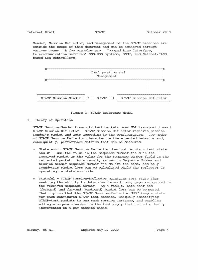
Internet-Draft STAMP October 2019
Sender, Session-Reflector, and management of the STAMP sessions are outside the scope of this document and can be achieved through various means. A few examples are: Command Line Interface, telecommunication services’ OSS/BSS systems, SNMP, and Netconf/YANG- based SDN controllers.
o----------------------------------------------------------o | Configuration and | | Management | o----------------------------------------------------------o || || || || || || +----------------------+ +-------------------------+ | STAMP Session-Sender | <--- STAMP---> | STAMP Session-Reflector | +----------------------+ +-------------------------+
Figure 1: STAMP Reference Model
4. Theory of Operation
STAMP Session-Sender transmits test packets over UDP transport toward STAMP Session-Reflector. STAMP Session-Reflector receives Session- Sender’s packet and acts according to the configuration. Two modes of STAMP Session-Reflector characterize the expected behavior and, consequently, performance metrics that can be measured:
o Stateless - STAMP Session-Reflector does not maintain test state and will use the value in the Sequence Number field in the received packet as the value for the Sequence Number field in the reflected packet. As a result, values in Sequence Number and Session-Sender Sequence Number fields are the same, and only round-trip packet loss can be calculated while the reflector is operating in stateless mode.
o Stateful - STAMP Session-Reflector maintains test state thus enabling the ability to determine forward loss, gaps recognized in the received sequence number. As a result, both near-end (forward) and far-end (backward) packet loss can be computed. That implies that the STAMP Session-Reflector MUST keep a state for each configured STAMP-test session, uniquely identifying STAMP-test packets to one such session instance, and enabling adding a sequence number in the test reply that is individually incremented on a per-session basis.
Mirsky, et al. Expires May 3, 2020 [Page 4]
Internet-Draft STAMP October 2019
STAMP supports two authentication modes: unauthenticated and authenticated. Unauthenticated STAMP test packets, defined in Section 4.2.1 and Section 4.3.1, ensure interworking between STAMP and TWAMP Light as described in Section 4.6 packet formats.
By default, STAMP uses symmetrical packets, i.e., size of the packet transmitted by Session-Reflector equals the size of the packet received by the Session-Reflector.
4.1. UDP Port Numbers in STAMP Testing
A STAMP Session-Sender MUST use UDP port 862 (TWAMP-Test Receiver Port) as the default destination UDP port number. A STAMP implementation of Session-Sender MUST be able to use as the destination UDP port numbers from User, a.k.a. Registered, Ports and Dynamic, a.k.a. Private or Ephemeral, Ports ranges defined in [RFC6335]. Before using numbers from the User Ports range, the possible impact on the network MUST be carefully studied and agreed by all users of the network domain where the test has been planned.
An implementation of STAMP Session-Reflector by default MUST receive STAMP test packets on UDP port 862. An implementation of Session- Reflector that supports this specification MUST be able to define the port number to receive STAMP test packets from User Ports and Dynamic Ports ranges that are defined in [RFC6335]. STAMP defines two different test packet formats, one for packets transmitted by the STAMP-Session-Sender and one for packets transmitted by the STAMP- Session-Reflector.
4.2. Session-Sender Behavior and Packet Format
A STAMP Session-Reflector supports the symmetrical size of test packets, as defined in Section 3 [RFC6038], as the default behavior. A reflected test packet includes more information and thus is larger. Because of that, the base STAMP Session-Sender packet is padded to match the size of a reflected STAMP test packet. Hence, the base STAMP Session-Sender packet has a minimum size of 44 octets in unauthenticated mode, see Figure 2, and 112 octets in the authenticated mode, see Figure 4. The variable length of a test packet in STAMP is supported by using Extra Padding TLV defined in [I-D.ietf-ippm-stamp-option-tlv].
4.2.1. Session-Sender Packet Format in Unauthenticated Mode
STAMP Session-Sender packet format in unauthenticated mode:
Mirsky, et al. Expires May 3, 2020 [Page 5]

Internet-Draft STAMP October 2019
0 1 2 3 0 1 2 3 4 5 6 7 8 9 0 1 2 3 4 5 6 7 8 9 0 1 2 3 4 5 6 7 8 9 0 1 +-+-+-+-+-+-+-+-+-+-+-+-+-+-+-+-+-+-+-+-+-+-+-+-+-+-+-+-+-+-+-+-+ | Sequence Number | +-+-+-+-+-+-+-+-+-+-+-+-+-+-+-+-+-+-+-+-+-+-+-+-+-+-+-+-+-+-+-+-+ | Timestamp | | | +-+-+-+-+-+-+-+-+-+-+-+-+-+-+-+-+-+-+-+-+-+-+-+-+-+-+-+-+-+-+-+-+ | Error Estimate | | +-+-+-+-+-+-+-+-+-+-+-+-+-+-+-+-+ + | | | | | Reserved (30 octets) | | | | | | | | | +-+-+-+-+-+-+-+-+-+-+-+-+-+-+-+-+-+-+-+-+-+-+-+-+-+-+-+-+-+-+-+-+
Figure 2: STAMP Session-Sender test packet format in unauthenticated mode
where fields are defined as the following:
o Sequence Number is four octets long field. For each new session its value starts at zero and is incremented with each transmitted packet.
o Timestamp is eight octets long field. STAMP node MUST support Network Time Protocol (NTP) version 4 64-bit timestamp format [RFC5905], the format used in [RFC5357]. STAMP node MAY support IEEE 1588v2 Precision Time Protocol (PTP) truncated 64-bit timestamp format [IEEE.1588.2008], the format used in [RFC8186]. The use of the specific format, NTP or PTP, is part of configuration of the Session-Sender or the particular test session.
o Error Estimate is two octets long field with format displayed in Figure 3
0 1 0 1 2 3 4 5 6 7 8 9 0 1 2 3 4 5 +-+-+-+-+-+-+-+-+-+-+-+-+-+-+-+-+ |S|Z| Scale | Multiplier | +-+-+-+-+-+-+-+-+-+-+-+-+-+-+-+-+
Figure 3: Error Estimate Format
Mirsky, et al. Expires May 3, 2020 [Page 6]

Internet-Draft STAMP October 2019
where S, Scale, and Multiplier fields are interpreted as they have been defined in section 4.1.2 [RFC4656]; and Z field - as has been defined in section 2.3 [RFC8186]:
* 0 - NTP 64 bit format of a timestamp;
* 1 - PTPv2 truncated format of a timestamp.
The default behavior of the STAMP Session-Sender and Session- Reflector is to use the NTP 64-bit timestamp format (Z field value of 0) An operator, using configuration/management function, MAY configure STAMP Session-Sender and Session-Reflector to using the PTPv2 truncated format of a timestamp (Z field value of 1). Note, that an implementation of a Session-Sender that supports this specification MAY be configured to use PTPv2 format of a timestamp even though the Session-Reflector is configured to use NTP format.
o Reserved field in the Session-Sender unauthenticated packet is 30 octets long. It MUST be all zeroed on the transmission and MUST be ignored on receipt.
4.2.2. Session-Sender Packet Format in Authenticated Mode
STAMP Session-Sender packet format in authenticated mode:
Mirsky, et al. Expires May 3, 2020 [Page 7]
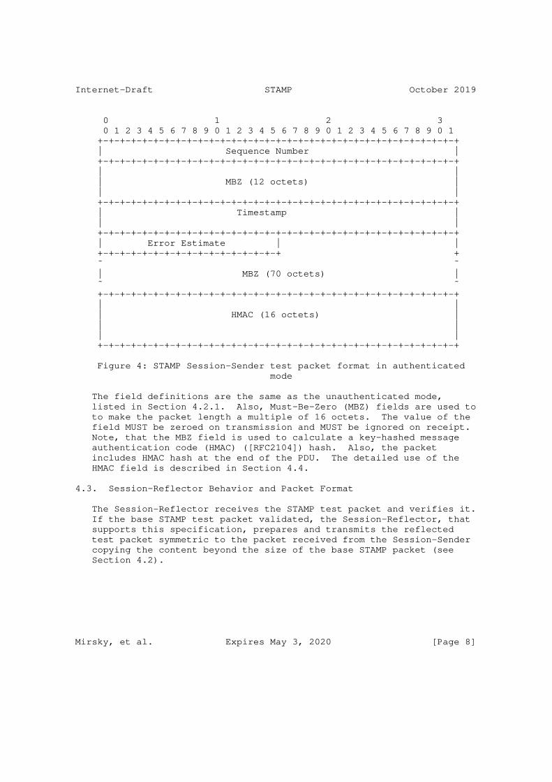
Internet-Draft STAMP October 2019
0 1 2 3 0 1 2 3 4 5 6 7 8 9 0 1 2 3 4 5 6 7 8 9 0 1 2 3 4 5 6 7 8 9 0 1 +-+-+-+-+-+-+-+-+-+-+-+-+-+-+-+-+-+-+-+-+-+-+-+-+-+-+-+-+-+-+-+-+ | Sequence Number | +-+-+-+-+-+-+-+-+-+-+-+-+-+-+-+-+-+-+-+-+-+-+-+-+-+-+-+-+-+-+-+-+ | | | MBZ (12 octets) | | | +-+-+-+-+-+-+-+-+-+-+-+-+-+-+-+-+-+-+-+-+-+-+-+-+-+-+-+-+-+-+-+-+ | Timestamp | | | +-+-+-+-+-+-+-+-+-+-+-+-+-+-+-+-+-+-+-+-+-+-+-+-+-+-+-+-+-+-+-+-+ | Error Estimate | | +-+-+-+-+-+-+-+-+-+-+-+-+-+-+-+-+ + ˜ ˜ | MBZ (70 octets) | ˜ ˜ +-+-+-+-+-+-+-+-+-+-+-+-+-+-+-+-+-+-+-+-+-+-+-+-+-+-+-+-+-+-+-+-+ | | | HMAC (16 octets) | | | | | +-+-+-+-+-+-+-+-+-+-+-+-+-+-+-+-+-+-+-+-+-+-+-+-+-+-+-+-+-+-+-+-+
Figure 4: STAMP Session-Sender test packet format in authenticated mode
The field definitions are the same as the unauthenticated mode, listed in Section 4.2.1. Also, Must-Be-Zero (MBZ) fields are used to to make the packet length a multiple of 16 octets. The value of the field MUST be zeroed on transmission and MUST be ignored on receipt. Note, that the MBZ field is used to calculate a key-hashed message authentication code (HMAC) ([RFC2104]) hash. Also, the packet includes HMAC hash at the end of the PDU. The detailed use of the HMAC field is described in Section 4.4.
4.3. Session-Reflector Behavior and Packet Format
The Session-Reflector receives the STAMP test packet and verifies it. If the base STAMP test packet validated, the Session-Reflector, that supports this specification, prepares and transmits the reflected test packet symmetric to the packet received from the Session-Sender copying the content beyond the size of the base STAMP packet (see Section 4.2).
Mirsky, et al. Expires May 3, 2020 [Page 8]
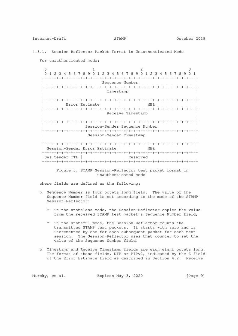
Internet-Draft STAMP October 2019
4.3.1. Session-Reflector Packet Format in Unauthenticated Mode
For unauthenticated mode:
0 1 2 3 0 1 2 3 4 5 6 7 8 9 0 1 2 3 4 5 6 7 8 9 0 1 2 3 4 5 6 7 8 9 0 1 +-+-+-+-+-+-+-+-+-+-+-+-+-+-+-+-+-+-+-+-+-+-+-+-+-+-+-+-+-+-+-+-+ | Sequence Number | +-+-+-+-+-+-+-+-+-+-+-+-+-+-+-+-+-+-+-+-+-+-+-+-+-+-+-+-+-+-+-+-+ | Timestamp | | | +-+-+-+-+-+-+-+-+-+-+-+-+-+-+-+-+-+-+-+-+-+-+-+-+-+-+-+-+-+-+-+-+ | Error Estimate | MBZ | +-+-+-+-+-+-+-+-+-+-+-+-+-+-+-+-+-+-+-+-+-+-+-+-+-+-+-+-+-+-+-+-+ | Receive Timestamp | | | +-+-+-+-+-+-+-+-+-+-+-+-+-+-+-+-+-+-+-+-+-+-+-+-+-+-+-+-+-+-+-+-+ | Session-Sender Sequence Number | +-+-+-+-+-+-+-+-+-+-+-+-+-+-+-+-+-+-+-+-+-+-+-+-+-+-+-+-+-+-+-+-+ | Session-Sender Timestamp | | | +-+-+-+-+-+-+-+-+-+-+-+-+-+-+-+-+-+-+-+-+-+-+-+-+-+-+-+-+-+-+-+-+ | Session-Sender Error Estimate | MBZ | +-+-+-+-+-+-+-+-+-+-+-+-+-+-+-+-+-+-+-+-+-+-+-+-+-+-+-+-+-+-+-+-+ |Ses-Sender TTL | Reserved | +-+-+-+-+-+-+-+-+-+-+-+-+-+-+-+-+-+-+-+-+-+-+-+-+-+-+-+-+-+-+-+-+
Figure 5: STAMP Session-Reflector test packet format in unauthenticated mode
where fields are defined as the following:
o Sequence Number is four octets long field. The value of the Sequence Number field is set according to the mode of the STAMP Session-Reflector:
* in the stateless mode, the Session-Reflector copies the value from the received STAMP test packet’s Sequence Number field;
* in the stateful mode, the Session-Reflector counts the transmitted STAMP test packets. It starts with zero and is incremented by one for each subsequent packet for each test session. The Session-Reflector uses that counter to set the value of the Sequence Number field.
o Timestamp and Receive Timestamp fields are each eight octets long. The format of these fields, NTP or PTPv2, indicated by the Z field of the Error Estimate field as described in Section 4.2. Receive
Mirsky, et al. Expires May 3, 2020 [Page 9]

Internet-Draft STAMP October 2019
Timestamp is the time the test packet was received by the Session- Reflector. Timestamp - the time taken by the Session-Reflector at the start of transmitting the test packet.
o Error Estimate has the same size and interpretation as described in Section 4.2. It is applicable to both Timestamp and Receive Timestamp.
o Session-Sender Sequence Number, Session-Sender Timestamp, and Session-Sender Error Estimate are copies of the corresponding fields in the STAMP test packet sent by the Session-Sender.
o Session-Sender TTL is one octet long field, and its value is the copy of the TTL field in IPv4 (or Hop Limit in IPv6) from the received STAMP test packet.
o MBZ is used to achieve alignment of fields within the packet on a four octets boundary. The value of the field MUST be zeroed on transmission and MUST be ignored on receipt.
o Reserved field in the Session-Reflector unauthenticated packet is three octets long. It MUST be all zeroed on the transmission and MUST be ignored on receipt.
4.3.2. Session-Reflector Packet Format in Authenticated Mode
For the authenticated mode:
0 1 2 3 0 1 2 3 4 5 6 7 8 9 0 1 2 3 4 5 6 7 8 9 0 1 2 3 4 5 6 7 8 9 0 1 +-+-+-+-+-+-+-+-+-+-+-+-+-+-+-+-+-+-+-+-+-+-+-+-+-+-+-+-+-+-+-+-+ | Sequence Number | +-+-+-+-+-+-+-+-+-+-+-+-+-+-+-+-+-+-+-+-+-+-+-+-+-+-+-+-+-+-+-+-+ | MBZ (12 octets) | | | | | +-+-+-+-+-+-+-+-+-+-+-+-+-+-+-+-+-+-+-+-+-+-+-+-+-+-+-+-+-+-+-+-+ | Timestamp | | | +-+-+-+-+-+-+-+-+-+-+-+-+-+-+-+-+-+-+-+-+-+-+-+-+-+-+-+-+-+-+-+-+ | Error Estimate | | +-+-+-+-+-+-+-+-+-+-+-+-+-+-+-+-+ + | MBZ (6 octets) | +-+-+-+-+-+-+-+-+-+-+-+-+-+-+-+-+-+-+-+-+-+-+-+-+-+-+-+-+-+-+-+-+ | Receive Timestamp | | | +-+-+-+-+-+-+-+-+-+-+-+-+-+-+-+-+-+-+-+-+-+-+-+-+-+-+-+-+-+-+-+-+ | MBZ (8 octets) |
Mirsky, et al. Expires May 3, 2020 [Page 10]
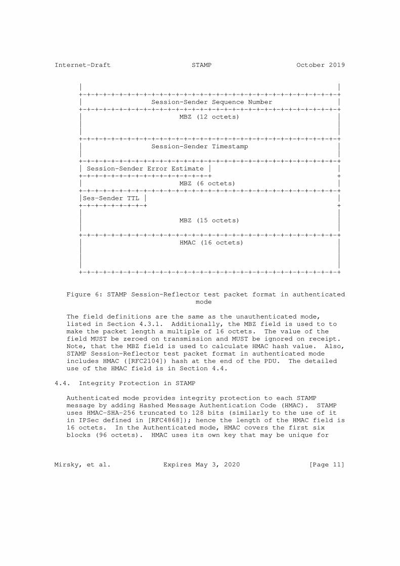
Internet-Draft STAMP October 2019
| | +-+-+-+-+-+-+-+-+-+-+-+-+-+-+-+-+-+-+-+-+-+-+-+-+-+-+-+-+-+-+-+-+ | Session-Sender Sequence Number | +-+-+-+-+-+-+-+-+-+-+-+-+-+-+-+-+-+-+-+-+-+-+-+-+-+-+-+-+-+-+-+-+ | MBZ (12 octets) | | | | | +-+-+-+-+-+-+-+-+-+-+-+-+-+-+-+-+-+-+-+-+-+-+-+-+-+-+-+-+-+-+-+-+ | Session-Sender Timestamp | | | +-+-+-+-+-+-+-+-+-+-+-+-+-+-+-+-+-+-+-+-+-+-+-+-+-+-+-+-+-+-+-+-+ | Session-Sender Error Estimate | | +-+-+-+-+-+-+-+-+-+-+-+-+-+-+-+-+ + | MBZ (6 octets) | +-+-+-+-+-+-+-+-+-+-+-+-+-+-+-+-+-+-+-+-+-+-+-+-+-+-+-+-+-+-+-+-+ |Ses-Sender TTL | | +-+-+-+-+-+-+-+-+ + | | | MBZ (15 octets) | | | +-+-+-+-+-+-+-+-+-+-+-+-+-+-+-+-+-+-+-+-+-+-+-+-+-+-+-+-+-+-+-+-+ | HMAC (16 octets) | | | | | | | +-+-+-+-+-+-+-+-+-+-+-+-+-+-+-+-+-+-+-+-+-+-+-+-+-+-+-+-+-+-+-+-+
Figure 6: STAMP Session-Reflector test packet format in authenticated mode
The field definitions are the same as the unauthenticated mode, listed in Section 4.3.1. Additionally, the MBZ field is used to to make the packet length a multiple of 16 octets. The value of the field MUST be zeroed on transmission and MUST be ignored on receipt. Note, that the MBZ field is used to calculate HMAC hash value. Also, STAMP Session-Reflector test packet format in authenticated mode includes HMAC ([RFC2104]) hash at the end of the PDU. The detailed use of the HMAC field is in Section 4.4.
4.4. Integrity Protection in STAMP
Authenticated mode provides integrity protection to each STAMP message by adding Hashed Message Authentication Code (HMAC). STAMP uses HMAC-SHA-256 truncated to 128 bits (similarly to the use of it in IPSec defined in [RFC4868]); hence the length of the HMAC field is 16 octets. In the Authenticated mode, HMAC covers the first six blocks (96 octets). HMAC uses its own key that may be unique for
Mirsky, et al. Expires May 3, 2020 [Page 11]
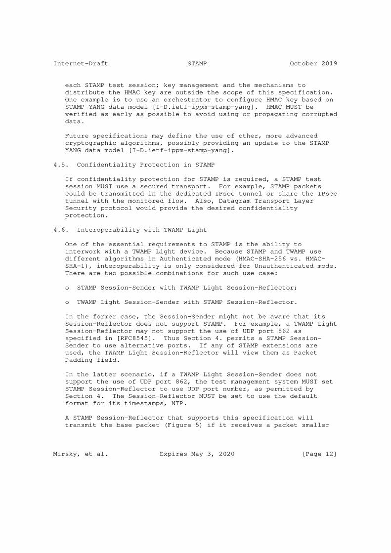
Internet-Draft STAMP October 2019
each STAMP test session; key management and the mechanisms to distribute the HMAC key are outside the scope of this specification. One example is to use an orchestrator to configure HMAC key based on STAMP YANG data model [I-D.ietf-ippm-stamp-yang]. HMAC MUST be verified as early as possible to avoid using or propagating corrupted data.
Future specifications may define the use of other, more advanced cryptographic algorithms, possibly providing an update to the STAMP YANG data model [I-D.ietf-ippm-stamp-yang].
4.5. Confidentiality Protection in STAMP
If confidentiality protection for STAMP is required, a STAMP test session MUST use a secured transport. For example, STAMP packets could be transmitted in the dedicated IPsec tunnel or share the IPsec tunnel with the monitored flow. Also, Datagram Transport Layer Security protocol would provide the desired confidentiality protection.
4.6. Interoperability with TWAMP Light
One of the essential requirements to STAMP is the ability to interwork with a TWAMP Light device. Because STAMP and TWAMP use different algorithms in Authenticated mode (HMAC-SHA-256 vs. HMAC- SHA-1), interoperability is only considered for Unauthenticated mode. There are two possible combinations for such use case:
o STAMP Session-Sender with TWAMP Light Session-Reflector;
o TWAMP Light Session-Sender with STAMP Session-Reflector.
In the former case, the Session-Sender might not be aware that its Session-Reflector does not support STAMP. For example, a TWAMP Light Session-Reflector may not support the use of UDP port 862 as specified in [RFC8545]. Thus Section 4. permits a STAMP Session- Sender to use alternative ports. If any of STAMP extensions are used, the TWAMP Light Session-Reflector will view them as Packet Padding field.
In the latter scenario, if a TWAMP Light Session-Sender does not support the use of UDP port 862, the test management system MUST set STAMP Session-Reflector to use UDP port number, as permitted by Section 4. The Session-Reflector MUST be set to use the default format for its timestamps, NTP.
A STAMP Session-Reflector that supports this specification will transmit the base packet (Figure 5) if it receives a packet smaller
Mirsky, et al. Expires May 3, 2020 [Page 12]

Internet-Draft STAMP October 2019
than the STAMP base packet. If the packet received from TWAMP Session-Sender is larger than the STAMP base packet, the STAMP Session-Reflector that supports this specification will copy the content of the remainder of the received packet to transmit reflected packet of symmetrical size.
5. Operational Considerations
STAMP is intended to be used on production networks to enable the operator to assess service level agreements based on packet delay, delay variation, and loss. When using STAMP over the Internet, especially when STAMP test packets are transmitted with the destination UDP port number from the User Ports range, the possible impact of the STAMP test packets MUST be thoroughly analyzed. The use of STAMP for each case MUST be agreed by users of nodes hosting the Session-Sender and Session-Reflector before starting the STAMP test session.
Also, the use of the well-known port number as the destination UDP port number in STAMP test packets transmitted by a Session-Sender would not impede the ability to measure performance in an Equal Cost Multipath environment and analysis in Section 5.3 [RFC8545] fully applies to STAMP.
6. IANA Considerations
This document doesn’t have any IANA action. This section may be removed before the publication.
7. Security Considerations
[RFC5357] does not identify security considerations specific to TWAMP-Test but refers to security considerations identified for OWAMP in [RFC4656]. Since both OWAMP and TWAMP include control plane and data plane components, only security considerations related to OWAMP- Test, discussed in Sections 6.2, 6.3 [RFC4656] apply to STAMP.
STAMP uses the well-known UDP port number allocated for the OWAMP- Test/TWAMP-Test Receiver port. Thus the security considerations and measures to mitigate the risk of the attack using the registered port number documented in Section 6 [RFC8545] equally apply to STAMP. Because of the control and management of a STAMP test being outside the scope of this specification only the more general requirement is set:
To mitigate the possible attack vector, the control, and management of a STAMP test session MUST use the secured transport.
Mirsky, et al. Expires May 3, 2020 [Page 13]

Internet-Draft STAMP October 2019
The load of the STAMP test packets offered to a network MUST be carefully estimated, and the possible impact on the existing services MUST be thoroughly analyzed before launching the test session. [RFC8085] section 3.1.5 provides guidance on handling network load for UDP-based protocol. While the characteristic of test traffic depends on the test objective, it is highly recommended to stay in the limits as provided in [RFC8085].
Use of HMAC-SHA-256 in the authenticated mode protects the data integrity of the STAMP test packets.
8. Acknowledgments
Authors express their appreciation to Jose Ignacio Alvarez-Hamelin and Brian Weis for their great insights into the security and identity protection, and the most helpful and practical suggestions. Also, our sincere thanks to David Ball and Rakesh Gandhi or their thorough reviews and helpful comments.
9. References
9.1. Normative References
[I-D.ietf-ippm-stamp-option-tlv] Mirsky, G., Xiao, M., Jun, G., Nydell, H., Foote, R., and A. Masputra, "Simple Two-way Active Measurement Protocol Optional Extensions", draft-ietf-ippm-stamp-option-tlv-01 (work in progress), September 2019.
[IEEE.1588.2008] "Standard for a Precision Clock Synchronization Protocol for Networked Measurement and Control Systems", IEEE Standard 1588, March 2008.
[RFC2104] Krawczyk, H., Bellare, M., and R. Canetti, "HMAC: Keyed- Hashing for Message Authentication", RFC 2104, DOI 10.17487/RFC2104, February 1997, <https://www.rfc-editor.org/info/rfc2104>.
[RFC2119] Bradner, S., "Key words for use in RFCs to Indicate Requirement Levels", BCP 14, RFC 2119, DOI 10.17487/RFC2119, March 1997, <https://www.rfc-editor.org/info/rfc2119>.
[RFC4656] Shalunov, S., Teitelbaum, B., Karp, A., Boote, J., and M. Zekauskas, "A One-way Active Measurement Protocol (OWAMP)", RFC 4656, DOI 10.17487/RFC4656, September 2006, <https://www.rfc-editor.org/info/rfc4656>.
Mirsky, et al. Expires May 3, 2020 [Page 14]

Internet-Draft STAMP October 2019
[RFC5357] Hedayat, K., Krzanowski, R., Morton, A., Yum, K., and J. Babiarz, "A Two-Way Active Measurement Protocol (TWAMP)", RFC 5357, DOI 10.17487/RFC5357, October 2008, <https://www.rfc-editor.org/info/rfc5357>.
[RFC5905] Mills, D., Martin, J., Ed., Burbank, J., and W. Kasch, "Network Time Protocol Version 4: Protocol and Algorithms Specification", RFC 5905, DOI 10.17487/RFC5905, June 2010, <https://www.rfc-editor.org/info/rfc5905>.
[RFC6038] Morton, A. and L. Ciavattone, "Two-Way Active Measurement Protocol (TWAMP) Reflect Octets and Symmetrical Size Features", RFC 6038, DOI 10.17487/RFC6038, October 2010, <https://www.rfc-editor.org/info/rfc6038>.
[RFC6335] Cotton, M., Eggert, L., Touch, J., Westerlund, M., and S. Cheshire, "Internet Assigned Numbers Authority (IANA) Procedures for the Management of the Service Name and Transport Protocol Port Number Registry", BCP 165, RFC 6335, DOI 10.17487/RFC6335, August 2011, <https://www.rfc-editor.org/info/rfc6335>.
[RFC8174] Leiba, B., "Ambiguity of Uppercase vs Lowercase in RFC 2119 Key Words", BCP 14, RFC 8174, DOI 10.17487/RFC8174, May 2017, <https://www.rfc-editor.org/info/rfc8174>.
[RFC8186] Mirsky, G. and I. Meilik, "Support of the IEEE 1588 Timestamp Format in a Two-Way Active Measurement Protocol (TWAMP)", RFC 8186, DOI 10.17487/RFC8186, June 2017, <https://www.rfc-editor.org/info/rfc8186>.
[RFC8545] Morton, A., Ed. and G. Mirsky, Ed., "Well-Known Port Assignments for the One-Way Active Measurement Protocol (OWAMP) and the Two-Way Active Measurement Protocol (TWAMP)", RFC 8545, DOI 10.17487/RFC8545, March 2019, <https://www.rfc-editor.org/info/rfc8545>.
9.2. Informative References
[BBF.TR-390] "Performance Measurement from IP Edge to Customer Equipment using TWAMP Light", BBF TR-390, May 2017.
[I-D.ietf-ippm-stamp-yang] Mirsky, G., Xiao, M., and W. Luo, "Simple Two-way Active Measurement Protocol (STAMP) Data Model", draft-ietf-ippm- stamp-yang-05 (work in progress), October 2019.
Mirsky, et al. Expires May 3, 2020 [Page 15]

Internet-Draft STAMP October 2019
[RFC4868] Kelly, S. and S. Frankel, "Using HMAC-SHA-256, HMAC-SHA- 384, and HMAC-SHA-512 with IPsec", RFC 4868, DOI 10.17487/RFC4868, May 2007, <https://www.rfc-editor.org/info/rfc4868>.
[RFC7750] Hedin, J., Mirsky, G., and S. Baillargeon, "Differentiated Service Code Point and Explicit Congestion Notification Monitoring in the Two-Way Active Measurement Protocol (TWAMP)", RFC 7750, DOI 10.17487/RFC7750, February 2016, <https://www.rfc-editor.org/info/rfc7750>.
[RFC8085] Eggert, L., Fairhurst, G., and G. Shepherd, "UDP Usage Guidelines", BCP 145, RFC 8085, DOI 10.17487/RFC8085, March 2017, <https://www.rfc-editor.org/info/rfc8085>.
Authors’ Addresses
Greg Mirsky ZTE Corp.
Email: [email protected]
Guo Jun ZTE Corporation 68# Zijinghua Road Nanjing, Jiangsu 210012 P.R.China
Phone: +86 18105183663 Email: [email protected]
Henrik Nydell Accedian Networks
Email: [email protected]
Richard Foote Nokia
Email: [email protected]
Mirsky, et al. Expires May 3, 2020 [Page 16]

Network Working Group Z. LiInternet-Draft S. PengIntended status: Standards Track Huawei TechnologiesExpires: March 13, 2020 K. LEE LG U+ September 10, 2019
IPv6 Encapsulation for SFC and IFIT draft-li-6man-ipv6-sfc-ifit-02
Abstract
Service Function Chaining (SFC) and In-situ Flow Information Telemetry (IFIT) are important path services along with the packets. In order to support these services, several encapsulations have been defined. The document analyzes the problems of these encapsulations in the IPv6 scenario and proposes the possible optimized encapsulation for IPv6.
Requirements Language
The key words "MUST", "MUST NOT", "REQUIRED", "SHALL", "SHALL NOT", "SHOULD", "SHOULD NOT", "RECOMMENDED", "MAY", and "OPTIONAL" in this document are to be interpreted as described in RFC 2119 [RFC2119].
Status of This Memo
This Internet-Draft is submitted in full conformance with the provisions of BCP 78 and BCP 79.
Internet-Drafts are working documents of the Internet Engineering Task Force (IETF). Note that other groups may also distribute working documents as Internet-Drafts. The list of current Internet- Drafts is at https://datatracker.ietf.org/drafts/current/.
Internet-Drafts are draft documents valid for a maximum of six months and may be updated, replaced, or obsoleted by other documents at any time. It is inappropriate to use Internet-Drafts as reference material or to cite them other than as "work in progress."
This Internet-Draft will expire on March 13, 2020.
Copyright Notice
Copyright (c) 2019 IETF Trust and the persons identified as the document authors. All rights reserved.
Li, et al. Expires March 13, 2020 [Page 1]

Internet-Draft IPv6 Encaps for SFC and IFIT September 2019
This document is subject to BCP 78 and the IETF Trust’s Legal Provisions Relating to IETF Documents (https://trustee.ietf.org/license-info) in effect on the date of publication of this document. Please review these documents carefully, as they describe your rights and restrictions with respect to this document. Code Components extracted from this document must include Simplified BSD License text as described in Section 4.e of the Trust Legal Provisions and are provided without warranty as described in the Simplified BSD License.
Table of Contents
1. Introduction . . . . . . . . . . . . . . . . . . . . . . . . 2 2. Terminology . . . . . . . . . . . . . . . . . . . . . . . . . 3 3. Problem Statement . . . . . . . . . . . . . . . . . . . . . . 3 4. Design Consideration . . . . . . . . . . . . . . . . . . . . 4 4.1. Service Options . . . . . . . . . . . . . . . . . . . . . 4 4.2. IPv6 Service Metadata Options . . . . . . . . . . . . . . 7 4.2.1. SFC Service Metadata Option . . . . . . . . . . . . . 7 4.2.2. IOAM Service Metadata Option . . . . . . . . . . . . 8 4.2.3. IFA Service Metadata Option . . . . . . . . . . . . . 8 5. IANA Considerations . . . . . . . . . . . . . . . . . . . . . 9 6. Security Considerations . . . . . . . . . . . . . . . . . . . 9 7. References . . . . . . . . . . . . . . . . . . . . . . . . . 9 7.1. Normative References . . . . . . . . . . . . . . . . . . 9 7.2. Informative References . . . . . . . . . . . . . . . . . 11 Authors’ Addresses . . . . . . . . . . . . . . . . . . . . . . . 11
1. Introduction
Service Function Chaining (SFC) [RFC7665] and In-situ Flow Information Telemetry (IFIT) [I-D.song-opsawg-ifit-framework] are important path services along with the packets. In order to support these services, several encapsulations have been defined. Network Service Header (NSH) is defined in [RFC8300] as the encapsulation for SFC. For IFIT encapsulations, In-situ OAM (iOAM) Header is defined in [I-D.ietf-ippm-ioam-data] and Postcard-Based Telemetry (PBT) Header is defined in [I-D.song-ippm-postcard-based-telemetry]. Inband Flow Analyzer (IFA) is also defined in [I-D.kumar-ippm-ifa] to record flow specific information from an end station and/or switches across a network. In the application scenario of IPv6, these encapsulations propose challenges for the data plane. The document analyzes the problems and proposes the possible optimized encapsulation for IPv6.
Li, et al. Expires March 13, 2020 [Page 2]

Internet-Draft IPv6 Encaps for SFC and IFIT September 2019
2. Terminology
SFC: Service Function Chaining
IFIT: In-situ Flow Information Telemetry
IOAM: In-situ OAM
PBT: Postcard-Based Telemetry
IFA: Inband Flow Analyzer
SRH: Segment Routing Header
3. Problem Statement
The problems posed by the current encapsulations for SFC and IFIT in the application scenarios of IPv6 and SRv6 include:
1. According to the encapsulation order recommended in [RFC8200], if the IOAM is encapsulated in the IPv6 Hop-by-Hop options header, in the incremental trace mode of IOAM as the number of nodes traversed by the IPv6 packets increases, the recorded IOAM information will increase accordingly. This will increase the length of the Hop-by- Hop options header and cause increasing difficulties in reading the subsequent Segment Routing Extension Header (SRH) [I-D.ietf-6man-segment-routing-header] and thereby reduce the forwarding performance of the data plane greatly.
2. With the introduction of SRv6 network programming [I-D.ietf-spring-srv6-network-programming], the path services along with the IPv6 packets can be processed at all the IPv6 network nodes or only at the SRv6 enabled network nodes along the path. It is necessary to distinguish the encapsulations for the specific path service which should be processed by the IPv6 path or the SRv6 path.
3. Both NSH and IOAM need the Metadata field to record metadata information. However currently these metadata has to be recorded separately which may generate redundant metadata information or increase the cost of process.
4. There is unnecessary inconsistency in the current encapsulations for IOAM, IFA and PBT in the IPv6 scenario. Especially it seems unnecessary to define a new specific IPv6 header for IFA, i.e. IFA header.
Li, et al. Expires March 13, 2020 [Page 3]

Internet-Draft IPv6 Encaps for SFC and IFIT September 2019
4. Design Consideration
To solve the problems stated above, in the application scenarios of IPv6 and SRv6, the encapsulations of SFC and IFIT can be optimized with the following design considerations:
o To separate the SFC/IFIT path service into two parts, i.e. instruction and recording parts. The instruction part (normally with fixed length) can be placed in the front IPv6 extension headers including Hop-by-Hop options header, Destination options header, Routing header, etc. while the recording part can be placed in the back IPv6 extension headers such as being placed after IPv6 Routing Header. In this way the path service instruction in the IPv6 extension headers can be fixed as much as possible to facilitate hardware process to keep forwarding performance while the SFC/IFIT metadata recording part is placed afterwards which enables to stop recording when too much recording information has to be carried to reach the limitation of hardware process.
o To define SFC/IFIT path service instructions as IPv6 options uniformly whichs can be placed either in the Hop-by-hop options which indicates the path service processed by all IPv6 enabled nodes along the path or in the SRH option TLVs which indicates the path service processed only by the SRv6 nodes along the SRv6 path indicated by the Segment List in the SRH.
o To define a unified IPv6 metadata header which can be used as a container to record the service metadata of SFC, IFIT and other possible path services.
According to the above design optimization consideration, in the application scenarios of IPv6 and SRv6 the encapsulations for SFC and IFIT can be defined as below.
4.1. Service Options
1. NSH Service Option
Li, et al. Expires March 13, 2020 [Page 4]
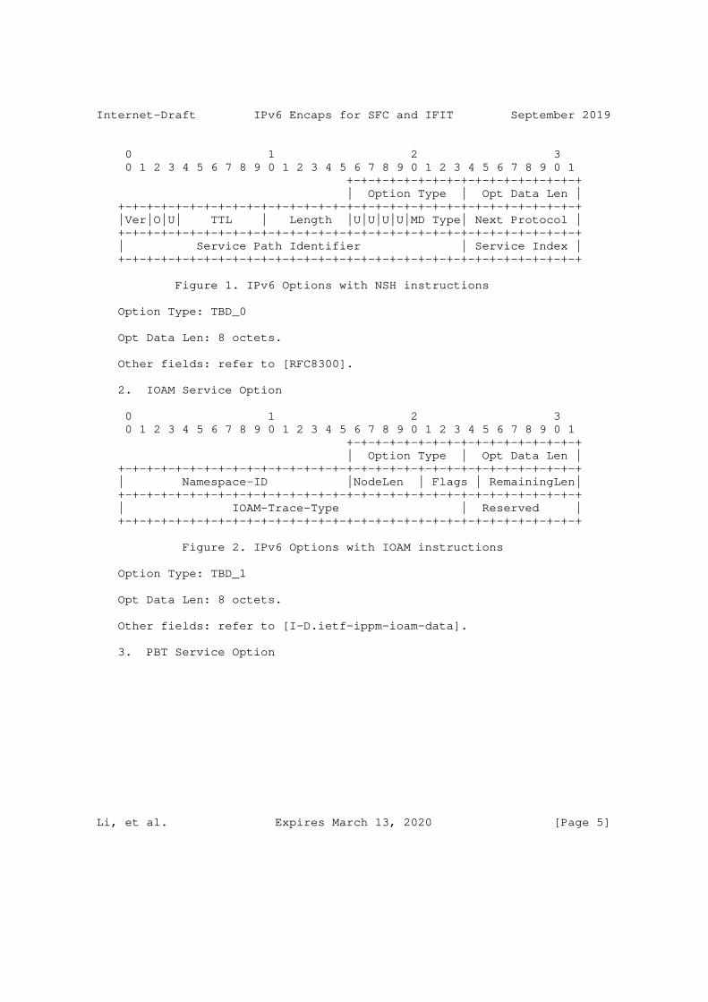
Internet-Draft IPv6 Encaps for SFC and IFIT September 2019
0 1 2 3 0 1 2 3 4 5 6 7 8 9 0 1 2 3 4 5 6 7 8 9 0 1 2 3 4 5 6 7 8 9 0 1 +-+-+-+-+-+-+-+-+-+-+-+-+-+-+-+-+ | Option Type | Opt Data Len | +-+-+-+-+-+-+-+-+-+-+-+-+-+-+-+-+-+-+-+-+-+-+-+-+-+-+-+-+-+-+-+-+ |Ver|O|U| TTL | Length |U|U|U|U|MD Type| Next Protocol | +-+-+-+-+-+-+-+-+-+-+-+-+-+-+-+-+-+-+-+-+-+-+-+-+-+-+-+-+-+-+-+-+ | Service Path Identifier | Service Index | +-+-+-+-+-+-+-+-+-+-+-+-+-+-+-+-+-+-+-+-+-+-+-+-+-+-+-+-+-+-+-+-+
Figure 1. IPv6 Options with NSH instructions
Option Type: TBD_0
Opt Data Len: 8 octets.
Other fields: refer to [RFC8300].
2. IOAM Service Option
0 1 2 3 0 1 2 3 4 5 6 7 8 9 0 1 2 3 4 5 6 7 8 9 0 1 2 3 4 5 6 7 8 9 0 1 +-+-+-+-+-+-+-+-+-+-+-+-+-+-+-+-+ | Option Type | Opt Data Len | +-+-+-+-+-+-+-+-+-+-+-+-+-+-+-+-+-+-+-+-+-+-+-+-+-+-+-+-+-+-+-+-+ | Namespace-ID |NodeLen | Flags | RemainingLen| +-+-+-+-+-+-+-+-+-+-+-+-+-+-+-+-+-+-+-+-+-+-+-+-+-+-+-+-+-+-+-+-+ | IOAM-Trace-Type | Reserved | +-+-+-+-+-+-+-+-+-+-+-+-+-+-+-+-+-+-+-+-+-+-+-+-+-+-+-+-+-+-+-+-+
Figure 2. IPv6 Options with IOAM instructions
Option Type: TBD_1
Opt Data Len: 8 octets.
Other fields: refer to [I-D.ietf-ippm-ioam-data].
3. PBT Service Option
Li, et al. Expires March 13, 2020 [Page 5]
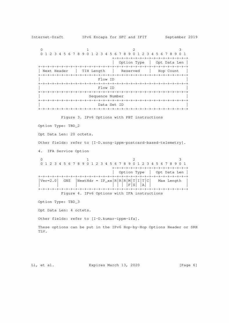
Internet-Draft IPv6 Encaps for SFC and IFIT September 2019
0 1 2 3 0 1 2 3 4 5 6 7 8 9 0 1 2 3 4 5 6 7 8 9 0 1 2 3 4 5 6 7 8 9 0 1 +-+-+-+-+-+-+-+-+-+-+-+-+-+-+-+-+ | Option Type | Opt Data Len | +-+-+-+-+-+-+-+-+-+-+-+-+-+-+-+-+-+-+-+-+-+-+-+-+-+-+-+-+-+-+-+-+ | Next Header | TIH Length | Reserved | Hop Count | +-+-+-+-+-+-+-+-+-+-+-+-+-+-+-+-+-+-+-+-+-+-+-+-+-+-+-+-+-+-+-+-+ | Flow ID | +-+-+-+-+-+-+-+-+-+-+-+-+-+-+-+-+-+-+-+-+-+-+-+-+-+-+-+-+-+-+-+-+ | Flow ID | +-+-+-+-+-+-+-+-+-+-+-+-+-+-+-+-+-+-+-+-+-+-+-+-+-+-+-+-+-+-+-+-+ | Sequence Number | +-+-+-+-+-+-+-+-+-+-+-+-+-+-+-+-+-+-+-+-+-+-+-+-+-+-+-+-+-+-+-+-+ | Data Set ID | +-+-+-+-+-+-+-+-+-+-+-+-+-+-+-+-+-+-+-+-+-+-+-+-+-+-+-+-+-+-+-+-+
Figure 3. IPv6 Options with PBT instructions
Option Type: TBD_2
Opt Data Len: 20 octets.
Other fields: refer to [I-D.song-ippm-postcard-based-telemetry].
4. IFA Service Option
0 1 2 3 0 1 2 3 4 5 6 7 8 9 0 1 2 3 4 5 6 7 8 9 0 1 2 3 4 5 6 7 8 9 0 1 +-+-+-+-+-+-+-+-+-+-+-+-+-+-+-+-+ | Option Type | Opt Data Len | +-+-+-+-+-+-+-+-+-+-+-+-+-+-+-+-+-+-+-+-+-+-+-+-+-+-+-+-+-+-+-+-+ |Ver=2.0| GNS |NextHdr = IP_xx|R|R|R|M|T|I|T|C| Max Length | | | | | | | |F|S| |A| | | +-+-+-+-+-+-+-+-+-+-+-+-+-+-+-+-+-+-+-+-+-+-+-+-+-+-+-+-+-+-+-+-+ Figure 4. IPv6 Options with IFA instructions
Option Type: TBD_3
Opt Data Len: 4 octets.
Other fields: refer to [I-D.kumar-ippm-ifa].
These options can be put in the IPv6 Hop-by-Hop Options Header or SRH TLV.
Li, et al. Expires March 13, 2020 [Page 6]

Internet-Draft IPv6 Encaps for SFC and IFIT September 2019
4.2. IPv6 Service Metadata Options
As introduced in [I-D.li-6man-enhanced-extension-header], IPv6 Metadata Header is defined as a new type of IPv6 extension header. The metadata is the information recorded by each hop for specific path services, and carried in corresponding service metadata options. The length of the metadata is variable.
4.2.1. SFC Service Metadata Option
For the SFC service, the corresponding SFC service metadata option is defined as shown in Figure 5.
0 1 2 3 0 1 2 3 4 5 6 7 8 9 0 1 2 3 4 5 6 7 8 9 0 1 2 3 4 5 6 7 8 9 0 1 +-+-+-+-+-+-+-+-+-+-+-+-+-+-+-+-+-+-+-+-+-+-+-+-+-+-+-+-+-+-+-+-+ | SFC Type | Length | Reserved | +-+-+-+-+-+-+-+-+-+-+-+-+-+-+-+-+-+-+-+-+-+-+-+-+-+-+-+-+-+-+-+-+ | SFC Metadata Class | Type |U| Length | +-+-+-+-+-+-+-+-+-+-+-+-+-+-+-+-+-+-+-+-+-+-+-+-+-+-+-+-+-+-+-+-+ | Variable-Length Metadata | +-+-+-+-+-+-+-+-+-+-+-+-+-+-+-+-+-+-+-+-+-+-+-+-+-+-+-+-+-+-+-+-+
Figure 5. SFC Service Metadata
SFC Type 8-bit identifier of the service type, i.e. SFC. The value is TBD-4.
Length 8-bit unsigned integer. Length of the Service Metadata field, in octets.
Metadata Class Defines the scope of the Type field to provide a hierarchical namespace. IANA has set up the "NSH MD Class" registry, which contains 16-bit values [RFC8300].
Type Indicates the explicit type of metadata being carried. The definition of the Type is the responsibility of the MD Class owner.
Unassigned bit One unassigned bit is available for future use. This bit MUST NOT be set, and it MUST be ignored on receipt.
Length Indicates the length of the variable-length metadata, in bytes. Detailed specification in [RFC8300].
Li, et al. Expires March 13, 2020 [Page 7]

Internet-Draft IPv6 Encaps for SFC and IFIT September 2019
4.2.2. IOAM Service Metadata Option
For the IOAM service, the corresponding IOAM service metadata option is defined as shown in Figure 6.
0 1 2 3 0 1 2 3 4 5 6 7 8 9 0 1 2 3 4 5 6 7 8 9 0 1 2 3 4 5 6 7 8 9 0 1 +-+-+-+-+-+-+-+-+-+-+-+-+-+-+-+-+-+-+-+-+-+-+-+-+-+-+-+-+-+-+-+-+ | IOAM Type | Length | Reserved | +-+-+-+-+-+-+-+-+-+-+-+-+-+-+-+-+-+-+-+-+-+-+-+-+-+-+-+-+-+-+-+-+ ˜ ˜ | IOAM Service Metadata Options (variable) | ˜ ˜ +-+-+-+-+-+-+-+-+-+-+-+-+-+-+-+-+-+-+-+-+-+-+-+-+-+-+-+-+-+-+-+-+
Figure 6. IOAM Service Metadata
IOAM Type 8-bit identifier of the IOAM Service Metadata type. The value is TBD-5.
Length 8-bit unsigned integer. Length of the IOAM Service Metadata field, in octets.
RESERVED 8-bit reserved field MUST be set to zero upon transmission and ignored upon receipt.
IOAM Service IOAM option data is present as specified by the Metadata Options IOAM Type field, and is defined in Section 4 of [I-D.ietf-ippm-ioam-data].
All the IOAM IPv6 options require 4n alignment. This ensures that 4 octet fields specified in [I-D.ietf-ippm-ioam-data] such as transit delay are aligned at a multiple-of-4 offset from the start of the IPv6 Metadata header.
In addition, to maintain IPv6 extension header 8-octet alignment and avoid the need to add or remove padding at every hop, the Trace-Type for Incremental Tracing Option in IPv6 MUST be selected such that the IOAM node data length is a multiple of 8-octets.
4.2.3. IFA Service Metadata Option
For the IOAM service, the corresponding IOAM service metadata option is defined as shown in Figure 6.
Li, et al. Expires March 13, 2020 [Page 8]
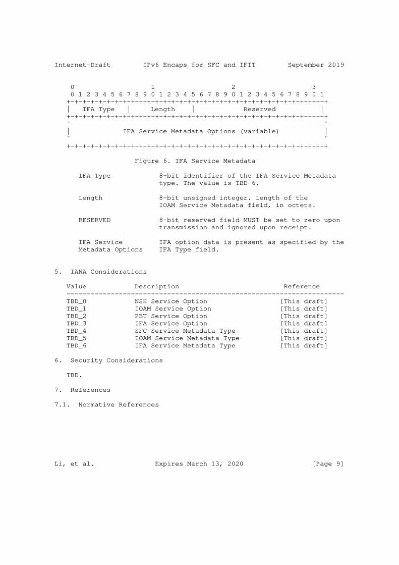
Internet-Draft IPv6 Encaps for SFC and IFIT September 2019
0 1 2 3 0 1 2 3 4 5 6 7 8 9 0 1 2 3 4 5 6 7 8 9 0 1 2 3 4 5 6 7 8 9 0 1 +-+-+-+-+-+-+-+-+-+-+-+-+-+-+-+-+-+-+-+-+-+-+-+-+-+-+-+-+-+-+-+-+ | IFA Type | Length | Reserved | +-+-+-+-+-+-+-+-+-+-+-+-+-+-+-+-+-+-+-+-+-+-+-+-+-+-+-+-+-+-+-+-+ ˜ ˜ | IFA Service Metadata Options (variable) | ˜ ˜ +-+-+-+-+-+-+-+-+-+-+-+-+-+-+-+-+-+-+-+-+-+-+-+-+-+-+-+-+-+-+-+-+
Figure 6. IFA Service Metadata
IFA Type 8-bit identifier of the IFA Service Metadata type. The value is TBD-6.
Length 8-bit unsigned integer. Length of the IOAM Service Metadata field, in octets.
RESERVED 8-bit reserved field MUST be set to zero upon transmission and ignored upon receipt.
IFA Service IFA option data is present as specified by the Metadata Options IFA Type field.
5. IANA Considerations
Value Description Reference --------------------------------------------------------------------- TBD_0 NSH Service Option [This draft] TBD_1 IOAM Service Option [This draft] TBD_2 PBT Service Option [This draft] TBD_3 IFA Service Option [This draft] TBD_4 SFC Service Metadata Type [This draft] TBD_5 IOAM Service Metadata Type [This draft] TBD_6 IFA Service Metadata Type [This draft]
6. Security Considerations
TBD.
7. References
7.1. Normative References
Li, et al. Expires March 13, 2020 [Page 9]

Internet-Draft IPv6 Encaps for SFC and IFIT September 2019
[I-D.guichard-spring-nsh-sr] Guichard, J., Song, H., Tantsura, J., Halpern, J., Henderickx, W., Boucadair, M., and S. Hassan, "NSH and Segment Routing Integration for Service Function Chaining (SFC)", draft-guichard-spring-nsh-sr-01 (work in progress), March 2019.
[I-D.ietf-6man-segment-routing-header] Filsfils, C., Dukes, D., Previdi, S., Leddy, J., Matsushima, S., and d. [email protected], "IPv6 Segment Routing Header (SRH)", draft-ietf-6man-segment-routing- header-22 (work in progress), August 2019.
[I-D.ietf-ippm-ioam-data] Brockners, F., Bhandari, S., Pignataro, C., Gredler, H., Leddy, J., Youell, S., Mizrahi, T., Mozes, D., Lapukhov, P., Chang, R., [email protected], d., and J. Lemon, "Data Fields for In-situ OAM", draft-ietf-ippm-ioam- data-06 (work in progress), July 2019.
[I-D.ietf-spring-srv6-network-programming] Filsfils, C., Camarillo, P., Leddy, J., [email protected], d., Matsushima, S., and Z. Li, "SRv6 Network Programming", draft-ietf-spring-srv6-network- programming-01 (work in progress), July 2019.
[I-D.kumar-ippm-ifa] Kumar, J., Anubolu, S., Lemon, J., Manur, R., Holbrook, H., Ghanwani, A., Cai, D., Ou, H., and L. Yizhou, "Inband Flow Analyzer", draft-kumar-ippm-ifa-01 (work in progress), February 2019.
[I-D.song-ippm-postcard-based-telemetry] Song, H., Zhou, T., Li, Z., Shin, J., and K. Lee, "Postcard-based On-Path Flow Data Telemetry", draft-song- ippm-postcard-based-telemetry-04 (work in progress), June 2019.
[I-D.song-opsawg-ifit-framework] Song, H., Li, Z., Zhou, T., Qin, F., Shin, J., and J. Jin, "In-situ Flow Information Telemetry Framework", draft- song-opsawg-ifit-framework-04 (work in progress), September 2019.
[RFC2119] Bradner, S., "Key words for use in RFCs to Indicate Requirement Levels", BCP 14, RFC 2119, DOI 10.17487/RFC2119, March 1997, <https://www.rfc-editor.org/info/rfc2119>.
Li, et al. Expires March 13, 2020 [Page 10]

Internet-Draft IPv6 Encaps for SFC and IFIT September 2019
[RFC8126] Cotton, M., Leiba, B., and T. Narten, "Guidelines for Writing an IANA Considerations Section in RFCs", BCP 26, RFC 8126, DOI 10.17487/RFC8126, June 2017, <https://www.rfc-editor.org/info/rfc8126>.
[RFC8200] Deering, S. and R. Hinden, "Internet Protocol, Version 6 (IPv6) Specification", STD 86, RFC 8200, DOI 10.17487/RFC8200, July 2017, <https://www.rfc-editor.org/info/rfc8200>.
[RFC8300] Quinn, P., Ed., Elzur, U., Ed., and C. Pignataro, Ed., "Network Service Header (NSH)", RFC 8300, DOI 10.17487/RFC8300, January 2018, <https://www.rfc-editor.org/info/rfc8300>.
7.2. Informative References
[RFC7665] Halpern, J., Ed. and C. Pignataro, Ed., "Service Function Chaining (SFC) Architecture", RFC 7665, DOI 10.17487/RFC7665, October 2015, <https://www.rfc-editor.org/info/rfc7665>.
Authors’ Addresses
Zhenbin Li Huawei Technologies Huawei Bld., No.156 Beiqing Rd. Beijing 100095 China
Email: [email protected]
Shuping Peng Huawei Technologies Huawei Bld., No.156 Beiqing Rd. Beijing 100095 China
Email: [email protected]
Li, et al. Expires March 13, 2020 [Page 11]

Internet-Draft IPv6 Encaps for SFC and IFIT September 2019
Kihoon LEE LG U+ 71, Magokjungang 8-ro, Gangseo-gu Seoul Republic of Korea
Email: [email protected]
Li, et al. Expires March 13, 2020 [Page 12]

Network Working Group G. MirskyInternet-Draft X. MinIntended status: Standards Track ZTE Corp.Expires: January 7, 2020 G. Jun ZTE Corporation H. Nydell Accedian Networks R. Foote Nokia July 6, 2019
Simple Two-way Active Measurement Protocol Optional Extensions draft-mirsky-ippm-stamp-option-tlv-05
Abstract
This document describes optional extensions to Simple Two-way Active Measurement Protocol (STAMP) which enable measurement performance metrics in addition to ones supported by the STAMP base specification.
Status of This Memo
This Internet-Draft is submitted in full conformance with the provisions of BCP 78 and BCP 79.
Internet-Drafts are working documents of the Internet Engineering Task Force (IETF). Note that other groups may also distribute working documents as Internet-Drafts. The list of current Internet- Drafts is at https://datatracker.ietf.org/drafts/current/.
Internet-Drafts are draft documents valid for a maximum of six months and may be updated, replaced, or obsoleted by other documents at any time. It is inappropriate to use Internet-Drafts as reference material or to cite them other than as "work in progress."
This Internet-Draft will expire on January 7, 2020.
Copyright Notice
Copyright (c) 2019 IETF Trust and the persons identified as the document authors. All rights reserved.
This document is subject to BCP 78 and the IETF Trust’s Legal Provisions Relating to IETF Documents (https://trustee.ietf.org/license-info) in effect on the date of publication of this document. Please review these documents
Mirsky, et al. Expires January 7, 2020 [Page 1]

Internet-Draft STAMP Extensions July 2019
carefully, as they describe your rights and restrictions with respect to this document. Code Components extracted from this document must include Simplified BSD License text as described in Section 4.e of the Trust Legal Provisions and are provided without warranty as described in the Simplified BSD License.
Table of Contents
1. Introduction . . . . . . . . . . . . . . . . . . . . . . . . 2 2. Conventions used in this document . . . . . . . . . . . . . . 2 2.1. Terminology . . . . . . . . . . . . . . . . . . . . . . . 2 2.2. Requirements Language . . . . . . . . . . . . . . . . . . 3 3. Theory of Operation . . . . . . . . . . . . . . . . . . . . . 3 4. TLV Extensions to STAMP . . . . . . . . . . . . . . . . . . . 4 4.1. Extra Padding TLV . . . . . . . . . . . . . . . . . . . . 6 4.2. Location TLV . . . . . . . . . . . . . . . . . . . . . . 6 4.3. Timestamp Information TLV . . . . . . . . . . . . . . . . 8 4.4. Class of Service TLV . . . . . . . . . . . . . . . . . . 9 4.5. Direct Measurement TLV . . . . . . . . . . . . . . . . . 10 5. IANA Considerations . . . . . . . . . . . . . . . . . . . . . 11 5.1. STAMP TLV Registry . . . . . . . . . . . . . . . . . . . 11 5.2. Synchronization Source Sub-registry . . . . . . . . . . . 12 5.3. Timestamping Method Sub-registry . . . . . . . . . . . . 13 6. Security Considerations . . . . . . . . . . . . . . . . . . . 14 7. Acknowledgments . . . . . . . . . . . . . . . . . . . . . . . 14 8. References . . . . . . . . . . . . . . . . . . . . . . . . . 14 8.1. Normative References . . . . . . . . . . . . . . . . . . 14 8.2. Informative References . . . . . . . . . . . . . . . . . 15 Authors’ Addresses . . . . . . . . . . . . . . . . . . . . . . . 15
1. Introduction
Simple Two-way Active Measurement Protocol (STAMP) [I-D.ietf-ippm-stamp] supports the use of optional extensions that use Type-Length-Value (TLV) encoding. Such extensions are to enhance the STAMP base functions, such as measurement of one-way and round- trip delay, latency, packet loss, as well as ability to detect packet duplication and out-of-order delivery of the test packets. This specification provides definitions of optional STAMP extensions, their formats, and theory of operation.
2. Conventions used in this document
2.1. Terminology
STAMP - Simple Two-way Active Measurement Protocol
DSCP - Differentiated Services Code Point
Mirsky, et al. Expires January 7, 2020 [Page 2]

Internet-Draft STAMP Extensions July 2019
ECN - Explicit Congestion Notification
NTP - Network Time Protocol
PTP - Precision Time Protocol
HMAC Hashed Message Authentication Code
TLV Type-Length-Value
BITS Building Integrated Timing Supply
SSU Synchronization Supply Unit
GPS Global Positioning System
GLONASS Global Orbiting Navigation Satellite System
LORAN-C Long Range Navigation System Version C
MBZ Must Be Zeroed
CoS Class of Service
2.2. Requirements Language
The key words "MUST", "MUST NOT", "REQUIRED", "SHALL", "SHALL NOT", "SHOULD", "SHOULD NOT", "RECOMMENDED", "NOT RECOMMENDED", "MAY", and "OPTIONAL" in this document are to be interpreted as described in BCP 14 [RFC2119] [RFC8174] when, and only when, they appear in all capitals, as shown here.
3. Theory of Operation
STAMP Session-Sender transmits test packets to STAMP Session- Reflector. STAMP Session-Reflector receives Session-Sender’s packet and acts according to the configuration and optional control information communicated in the Session-Sender’s test packet. STAMP defines two different test packet formats, one for packets transmitted by the STAMP-Session-Sender and one for packets transmitted by the STAMP-Session-Reflector. STAMP supports two modes: unauthenticated and authenticated. Unauthenticated STAMP test packets are compatible on the wire with unauthenticated TWAMP-Test [RFC5357] packet formats.
By default, STAMP uses symmetrical packets, i.e., the size of the packet transmitted by Session-Reflector equals the size of the packet received by the Session-Reflector.
Mirsky, et al. Expires January 7, 2020 [Page 3]

Internet-Draft STAMP Extensions July 2019
4. TLV Extensions to STAMP
Figure 1 displays the format of STAMP Session-Sender test packet in unauthenticated mode that includes a TLV.
0 1 2 3 0 1 2 3 4 5 6 7 8 9 0 1 2 3 4 5 6 7 8 9 0 1 2 3 4 5 6 7 8 9 0 1 +-+-+-+-+-+-+-+-+-+-+-+-+-+-+-+-+-+-+-+-+-+-+-+-+-+-+-+-+-+-+-+-+ | Sequence Number | +-+-+-+-+-+-+-+-+-+-+-+-+-+-+-+-+-+-+-+-+-+-+-+-+-+-+-+-+-+-+-+-+ | Timestamp | | | +-+-+-+-+-+-+-+-+-+-+-+-+-+-+-+-+-+-+-+-+-+-+-+-+-+-+-+-+-+-+-+-+ | Error Estimate | | +-+-+-+-+-+-+-+-+-+-+-+-+-+-+-+-+ | | | | | | MBZ (30 octets) | | | | | | | | | +-+-+-+-+-+-+-+-+-+-+-+-+-+-+-+-+-+-+-+-+-+-+-+-+-+-+-+-+-+-+-+-+ | Type | Length | +-+-+-+-+-+-+-+-+-+-+-+-+-+-+-+-+-+-+-+-+-+-+-+-+-+-+-+-+-+-+-+-+ ˜ Value ˜ +-+-+-+-+-+-+-+-+-+-+-+-+-+-+-+-+-+-+-+-+-+-+-+-+-+-+-+-+-+-+-+-+
Figure 1: STAMP Session-Sender test packet format with TLV in unauthenticated mode
The MBZ (Must Be Zeroed) field of a test packet transmitted by a STAMP Session-Sender MUST be 30 octets long. A STAMP Session-Sender test packet MUST NOT use the Reflect Octets capability defined in [RFC6038].
TLVs (Type-Length-Value tuples) have the two octets long Type field, two octets long Length field that is the length of the Value field in octets. Type values, see Section 5.1, less than 32768 identify mandatory TLVs that MUST be supported by an implementation. Type values greater than or equal to 32768 identify optional TLVs that SHOULD be ignored if the implementation does not understand or support them. If a Type value for TLV or sub-TLV is in the range for Vendor Private Use, the Length MUST be at least 4, and the first four octets MUST be that vendor’s the Structure of Management Information (SMI) Private Enterprise Number, in network octet order. The rest of the Value field is private to the vendor. Following sections
Mirsky, et al. Expires January 7, 2020 [Page 4]
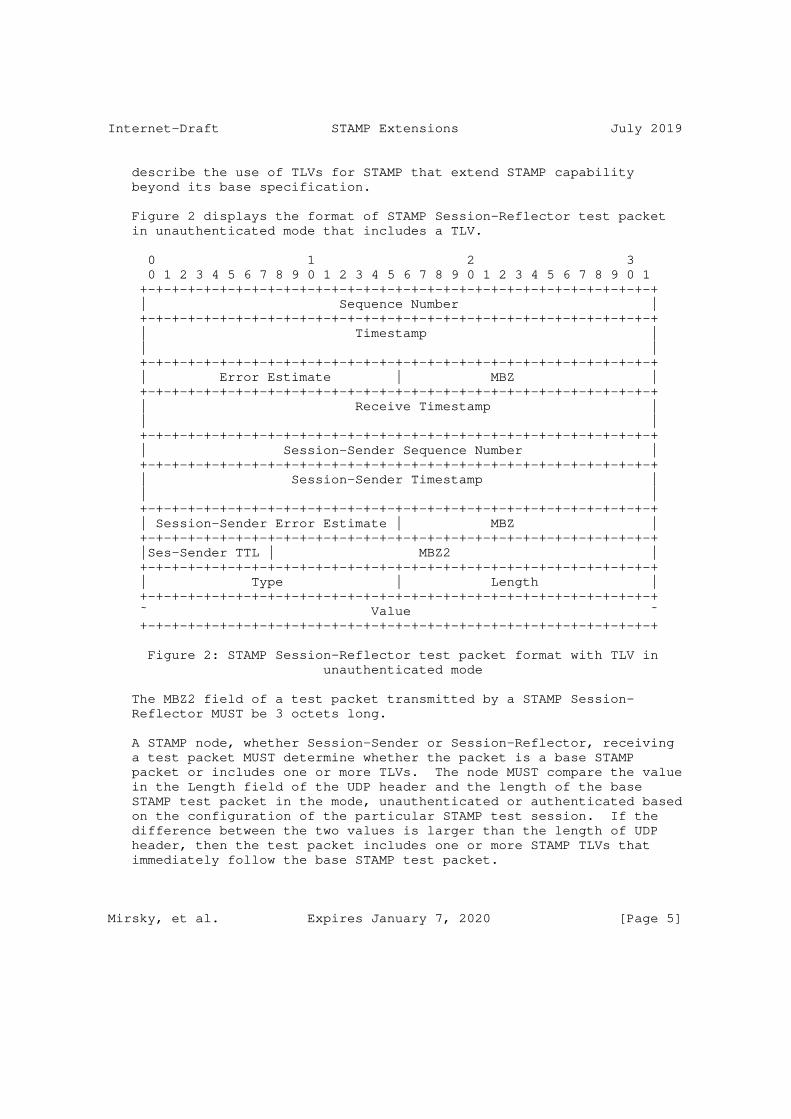
Internet-Draft STAMP Extensions July 2019
describe the use of TLVs for STAMP that extend STAMP capability beyond its base specification.
Figure 2 displays the format of STAMP Session-Reflector test packet in unauthenticated mode that includes a TLV.
0 1 2 3 0 1 2 3 4 5 6 7 8 9 0 1 2 3 4 5 6 7 8 9 0 1 2 3 4 5 6 7 8 9 0 1 +-+-+-+-+-+-+-+-+-+-+-+-+-+-+-+-+-+-+-+-+-+-+-+-+-+-+-+-+-+-+-+-+ | Sequence Number | +-+-+-+-+-+-+-+-+-+-+-+-+-+-+-+-+-+-+-+-+-+-+-+-+-+-+-+-+-+-+-+-+ | Timestamp | | | +-+-+-+-+-+-+-+-+-+-+-+-+-+-+-+-+-+-+-+-+-+-+-+-+-+-+-+-+-+-+-+-+ | Error Estimate | MBZ | +-+-+-+-+-+-+-+-+-+-+-+-+-+-+-+-+-+-+-+-+-+-+-+-+-+-+-+-+-+-+-+-+ | Receive Timestamp | | | +-+-+-+-+-+-+-+-+-+-+-+-+-+-+-+-+-+-+-+-+-+-+-+-+-+-+-+-+-+-+-+-+ | Session-Sender Sequence Number | +-+-+-+-+-+-+-+-+-+-+-+-+-+-+-+-+-+-+-+-+-+-+-+-+-+-+-+-+-+-+-+-+ | Session-Sender Timestamp | | | +-+-+-+-+-+-+-+-+-+-+-+-+-+-+-+-+-+-+-+-+-+-+-+-+-+-+-+-+-+-+-+-+ | Session-Sender Error Estimate | MBZ | +-+-+-+-+-+-+-+-+-+-+-+-+-+-+-+-+-+-+-+-+-+-+-+-+-+-+-+-+-+-+-+-+ |Ses-Sender TTL | MBZ2 | +-+-+-+-+-+-+-+-+-+-+-+-+-+-+-+-+-+-+-+-+-+-+-+-+-+-+-+-+-+-+-+-+ | Type | Length | +-+-+-+-+-+-+-+-+-+-+-+-+-+-+-+-+-+-+-+-+-+-+-+-+-+-+-+-+-+-+-+-+ ˜ Value ˜ +-+-+-+-+-+-+-+-+-+-+-+-+-+-+-+-+-+-+-+-+-+-+-+-+-+-+-+-+-+-+-+-+
Figure 2: STAMP Session-Reflector test packet format with TLV in unauthenticated mode
The MBZ2 field of a test packet transmitted by a STAMP Session- Reflector MUST be 3 octets long.
A STAMP node, whether Session-Sender or Session-Reflector, receiving a test packet MUST determine whether the packet is a base STAMP packet or includes one or more TLVs. The node MUST compare the value in the Length field of the UDP header and the length of the base STAMP test packet in the mode, unauthenticated or authenticated based on the configuration of the particular STAMP test session. If the difference between the two values is larger than the length of UDP header, then the test packet includes one or more STAMP TLVs that immediately follow the base STAMP test packet.
Mirsky, et al. Expires January 7, 2020 [Page 5]

Internet-Draft STAMP Extensions July 2019
4.1. Extra Padding TLV
0 1 2 3 0 1 2 3 4 5 6 7 8 9 0 1 2 3 4 5 6 7 8 9 0 1 2 3 4 5 6 7 8 9 0 1 +-+-+-+-+-+-+-+-+-+-+-+-+-+-+-+-+-+-+-+-+-+-+-+-+-+-+-+-+-+-+-+-+ | Extra Padding Type | Length | +-+-+-+-+-+-+-+-+-+-+-+-+-+-+-+-+-+-+-+-+-+-+-+-+-+-+-+-+-+-+-+-+ | | ˜ Extra Padding ˜ | | +-+-+-+-+-+-+-+-+-+-+-+-+-+-+-+-+-+-+-+-+-+-+-+-+-+-+-+-+-+-+-+-+
Figure 3: Extra Padding TLV
where fields are defined as the following:
o Extra Padding Type - TBA1 allocated by IANA Section 5.1
o Length - 2 octets long field equals length on the Extra Padding field in octets.
o Extra Padding - a pseudo-random sequence of numbers. The field MAY be filled with all zeroes.
The Extra Padding TLV is similar to the Packet Padding field in TWAMP-Test packet [RFC5357]. The in STAMP the Packet Padding field is used to ensure symmetrical size between Session-Sender and Session-Reflector test packets. Extra Padding TLV MUST be used to create STAMP test packets of larger size.
4.2. Location TLV
STAMP session-sender MAY include the Location TLV to request information from the session-reflector. The session-sender SHOULD NOT fill any information fields except for Type and Length. The session-reflector MUST validate the Length value against the address family of the transport encapsulating the STAMP test packet. If the value of the Length field is invalid, the session-reflector MUST zero all fields and MUST NOT return any information to the session-sender. The session-reflector MUST ignore all other fields of the received Location TLV.
Mirsky, et al. Expires January 7, 2020 [Page 6]

Internet-Draft STAMP Extensions July 2019
0 1 2 3 0 1 2 3 4 5 6 7 8 9 0 1 2 3 4 5 6 7 8 9 0 1 2 3 4 5 6 7 8 9 0 1 +-+-+-+-+-+-+-+-+-+-+-+-+-+-+-+-+-+-+-+-+-+-+-+-+-+-+-+-+-+-+-+-+ | Location Type | Length | +-+-+-+-+-+-+-+-+-+-+-+-+-+-+-+-+-+-+-+-+-+-+-+-+-+-+-+-+-+-+-+-+ | Source MAC | + +-+-+-+-+-+-+-+-+-+-+-+-+-+-+-+-+ | | Reserved A | +-+-+-+-+-+-+-+-+-+-+-+-+-+-+-+-+-+-+-+-+-+-+-+-+-+-+-+-+-+-+-+-+ ˜ Destination IP Address ˜ +-+-+-+-+-+-+-+-+-+-+-+-+-+-+-+-+-+-+-+-+-+-+-+-+-+-+-+-+-+-+-+-+ ˜ Source IP Address ˜ +-+-+-+-+-+-+-+-+-+-+-+-+-+-+-+-+-+-+-+-+-+-+-+-+-+-+-+-+-+-+-+-+ | Dest.port | Src.Port | Reserved B | +-+-+-+-+-+-+-+-+-+-+-+-+-+-+-+-+-+-+-+-+-+-+-+-+-+-+-+-+-+-+-+-+
Figure 4: Session-Reflector Location TLV
where fields are defined as the following:
o Location Type - TBA2 allocated by IANA Section 5.1
o Length - 2 octets long field equals length on the Value field in octets. Length field value MUST be 20 octets for the IPv4 address family. For the IPv6 address family value of the Length field MUST be 44 octets. All other values are invalid.
o Source MAC - 6 octets 48 bits long field. The session-reflector MUST copy Source MAC of received STAMP packet into this field.
o Reserved A - two octets long field. MUST be zeroed on transmission and ignored on reception.
o Destination IP Address - IPv4 or IPv6 destination address of the received by the session-reflector STAMP packet.
o Source IP Address - IPv4 or IPv6 source address of the received by the session-reflector STAMP packet.
o Dest.port - one octet long UDP destination port number of the received STAMP packet.
o Src.port - one octet long UDP source port number of the received STAMP packet.
o Reserved B - two octets long field. MUST be zeroed on transmission and ignored on reception.
Mirsky, et al. Expires January 7, 2020 [Page 7]
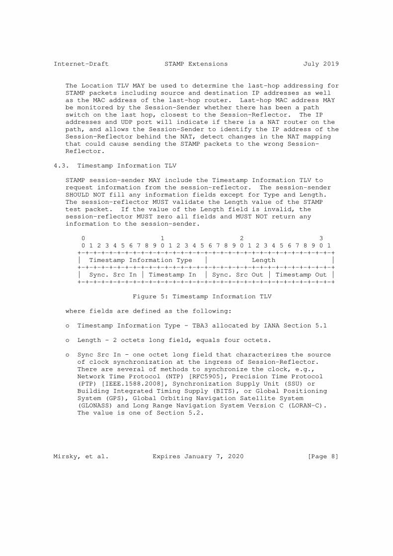
Internet-Draft STAMP Extensions July 2019
The Location TLV MAY be used to determine the last-hop addressing for STAMP packets including source and destination IP addresses as well as the MAC address of the last-hop router. Last-hop MAC address MAY be monitored by the Session-Sender whether there has been a path switch on the last hop, closest to the Session-Reflector. The IP addresses and UDP port will indicate if there is a NAT router on the path, and allows the Session-Sender to identify the IP address of the Session-Reflector behind the NAT, detect changes in the NAT mapping that could cause sending the STAMP packets to the wrong Session- Reflector.
4.3. Timestamp Information TLV
STAMP session-sender MAY include the Timestamp Information TLV to request information from the session-reflector. The session-sender SHOULD NOT fill any information fields except for Type and Length. The session-reflector MUST validate the Length value of the STAMP test packet. If the value of the Length field is invalid, the session-reflector MUST zero all fields and MUST NOT return any information to the session-sender.
0 1 2 3 0 1 2 3 4 5 6 7 8 9 0 1 2 3 4 5 6 7 8 9 0 1 2 3 4 5 6 7 8 9 0 1 +-+-+-+-+-+-+-+-+-+-+-+-+-+-+-+-+-+-+-+-+-+-+-+-+-+-+-+-+-+-+-+-+ | Timestamp Information Type | Length | +-+-+-+-+-+-+-+-+-+-+-+-+-+-+-+-+-+-+-+-+-+-+-+-+-+-+-+-+-+-+-+-+ | Sync. Src In | Timestamp In | Sync. Src Out | Timestamp Out | +-+-+-+-+-+-+-+-+-+-+-+-+-+-+-+-+-+-+-+-+-+-+-+-+-+-+-+-+-+-+-+-+
Figure 5: Timestamp Information TLV
where fields are defined as the following:
o Timestamp Information Type - TBA3 allocated by IANA Section 5.1
o Length - 2 octets long field, equals four octets.
o Sync Src In - one octet long field that characterizes the source of clock synchronization at the ingress of Session-Reflector. There are several of methods to synchronize the clock, e.g., Network Time Protocol (NTP) [RFC5905], Precision Time Protocol (PTP) [IEEE.1588.2008], Synchronization Supply Unit (SSU) or Building Integrated Timing Supply (BITS), or Global Positioning System (GPS), Global Orbiting Navigation Satellite System (GLONASS) and Long Range Navigation System Version C (LORAN-C). The value is one of Section 5.2.
Mirsky, et al. Expires January 7, 2020 [Page 8]

Internet-Draft STAMP Extensions July 2019
o Timestamp In - one octet long field that characterizes the method by which the ingress of Session-Reflector obtained the timestamp T2. A timestamp may be obtained with hardware assist, via software API from a local wall clock, or from a remote clock (the latter referred to as "control plane"). The value is one of Section 5.3.
o Sync Src Out - one octet long field that characterizes the source of clock synchronization at the egress of Session-Reflector. The value is one of Section 5.2.
o Timestamp Out - one octet long field that characterizes the method by which the egress of Session-Reflector obtained the timestamp T3. The value is one of Section 5.3.
4.4. Class of Service TLV
The STAMP session-sender MAY include Class of Service (CoS) TLV in the STAMP test packet. If the CoS TLV is present in the STAMP test packet and the value of the DSCP1 field is zero, then the STAMP session-reflector MUST copy the values of Differentiated Services Code Point (DSCP) ECN fields from the received STAMP test packet into DSCP2 and ECN fields respectively of the CoS TLV of the reflected STAMP test packet. If the value of the DSCP1 field is non-zero, then the STAMP session-reflector MUST use DSCP1 value from the CoS TLV in the received STAMP test packet as DSCP value of STAMP reflected test packet and MUST copy DSCP and ECN values of the received STAMP test packet into DSCP2 and ECN fields of Class of Service TLV in the STAMP reflected a packet. The Session-Sender, upon receiving the reflected packet, will save the DSCP and ECN values for analysis of the CoS in the reverse direction.
0 1 2 3 0 1 2 3 4 5 6 7 8 9 0 1 2 3 4 5 6 7 8 9 0 1 2 3 4 5 6 7 8 9 0 1 +-+-+-+-+-+-+-+-+-+-+-+-+-+-+-+-+-+-+-+-+-+-+-+-+-+-+-+-+-+-+-+-+ | Class of Service Type | Length | +-+-+-+-+-+-+-+-+-+-+-+-+-+-+-+-+-+-+-+-+-+-+-+-+-+-+-+-+-+-+-+-+ | DSCP1 | DSCP2 |ECN| Reserved | +-+-+-+-+-+-+-+-+-+-+-+-+-+-+-+-+-+-+-+-+-+-+-+-+-+-+-+-+-+-+-+-+
Figure 6: Class of Service TLV
where fields are defined as the following:
o Class of Service Type - TBA4 allocated by IANA Section 5.1
o Length - 2 octets long field, equals four octets.
Mirsky, et al. Expires January 7, 2020 [Page 9]

Internet-Draft STAMP Extensions July 2019
o DSCP1 - The Differentiated Services Code Point (DSCP) intended by the Session-Sender. To be used as the return DSCP from the Session-Reflector.
o DSCP2 - The received value in the DSCP field at the Session- Reflector in the forward direction.
o ECN - The received value in the ECN field at the Session-Reflector in the forward direction.
o Reserved - 18 bits long field, must be zeroed in transmission and ignored on receipt.
A STAMP Session-Sender that includes the CoS TLV sets the value of the DSCP1 field and zeroes the value of the DSCP2 field. A STAMP Session-Reflector that received the test packet with the CoS TLV MUST include the CoS TLV in the reflected test packet. Also, the Session- Reflector MUST copy the value of the DSCP field of the IP header of the received STAMP test packet into the DSCP2 field in the reflected test packet. And, at last, the Session-Reflector MUST set the value of the DSCP field in the IP header of the reflected test packet equal to the value of the DSCP1 field of the test packet it has received.
Re-mapping of CoS in some use cases, for example, in mobile backhaul networks is used to provide multiple services, i.e., 2G, 3G, LTE, over the same network. But if it is misconfigured, then it is often difficult to diagnose the root cause of the problem that is viewed as an excessive packet drop of higher level service while packet drop for lower service packets is at a normal level. Using CoS TLV in STAMP test helps to troubleshoot the existing problem and also verify whether DiffServ policies are processing CoS as required by the configuration.
4.5. Direct Measurement TLV
The Direct Measurement TLV enables collection of "in profile" IP packets that had been transmitted and received by the Session-Sender and Session-Reflector respectfully. The definition of "in-profile packet" is outside the scope of this document.
Mirsky, et al. Expires January 7, 2020 [Page 10]
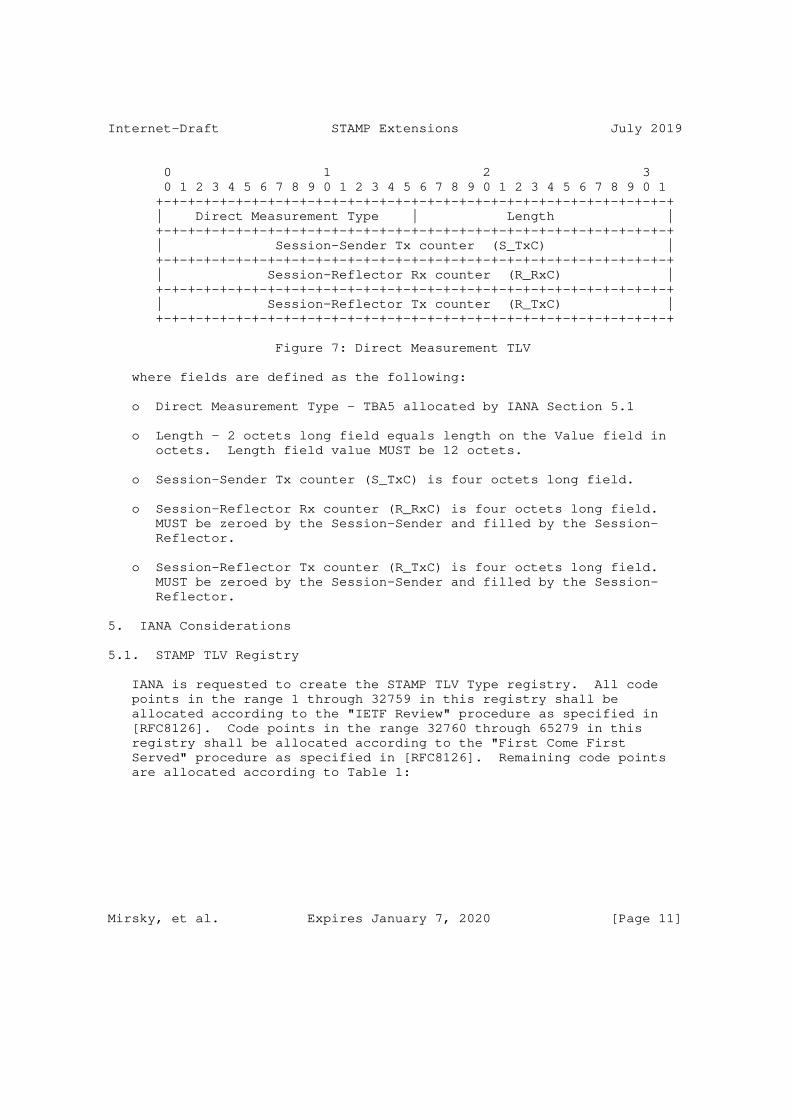
Internet-Draft STAMP Extensions July 2019
0 1 2 3 0 1 2 3 4 5 6 7 8 9 0 1 2 3 4 5 6 7 8 9 0 1 2 3 4 5 6 7 8 9 0 1 +-+-+-+-+-+-+-+-+-+-+-+-+-+-+-+-+-+-+-+-+-+-+-+-+-+-+-+-+-+-+-+-+ | Direct Measurement Type | Length | +-+-+-+-+-+-+-+-+-+-+-+-+-+-+-+-+-+-+-+-+-+-+-+-+-+-+-+-+-+-+-+-+ | Session-Sender Tx counter (S_TxC) | +-+-+-+-+-+-+-+-+-+-+-+-+-+-+-+-+-+-+-+-+-+-+-+-+-+-+-+-+-+-+-+-+ | Session-Reflector Rx counter (R_RxC) | +-+-+-+-+-+-+-+-+-+-+-+-+-+-+-+-+-+-+-+-+-+-+-+-+-+-+-+-+-+-+-+-+ | Session-Reflector Tx counter (R_TxC) | +-+-+-+-+-+-+-+-+-+-+-+-+-+-+-+-+-+-+-+-+-+-+-+-+-+-+-+-+-+-+-+-+
Figure 7: Direct Measurement TLV
where fields are defined as the following:
o Direct Measurement Type - TBA5 allocated by IANA Section 5.1
o Length - 2 octets long field equals length on the Value field in octets. Length field value MUST be 12 octets.
o Session-Sender Tx counter (S_TxC) is four octets long field.
o Session-Reflector Rx counter (R_RxC) is four octets long field. MUST be zeroed by the Session-Sender and filled by the Session- Reflector.
o Session-Reflector Tx counter (R_TxC) is four octets long field. MUST be zeroed by the Session-Sender and filled by the Session- Reflector.
5. IANA Considerations
5.1. STAMP TLV Registry
IANA is requested to create the STAMP TLV Type registry. All code points in the range 1 through 32759 in this registry shall be allocated according to the "IETF Review" procedure as specified in [RFC8126]. Code points in the range 32760 through 65279 in this registry shall be allocated according to the "First Come First Served" procedure as specified in [RFC8126]. Remaining code points are allocated according to Table 1:
Mirsky, et al. Expires January 7, 2020 [Page 11]
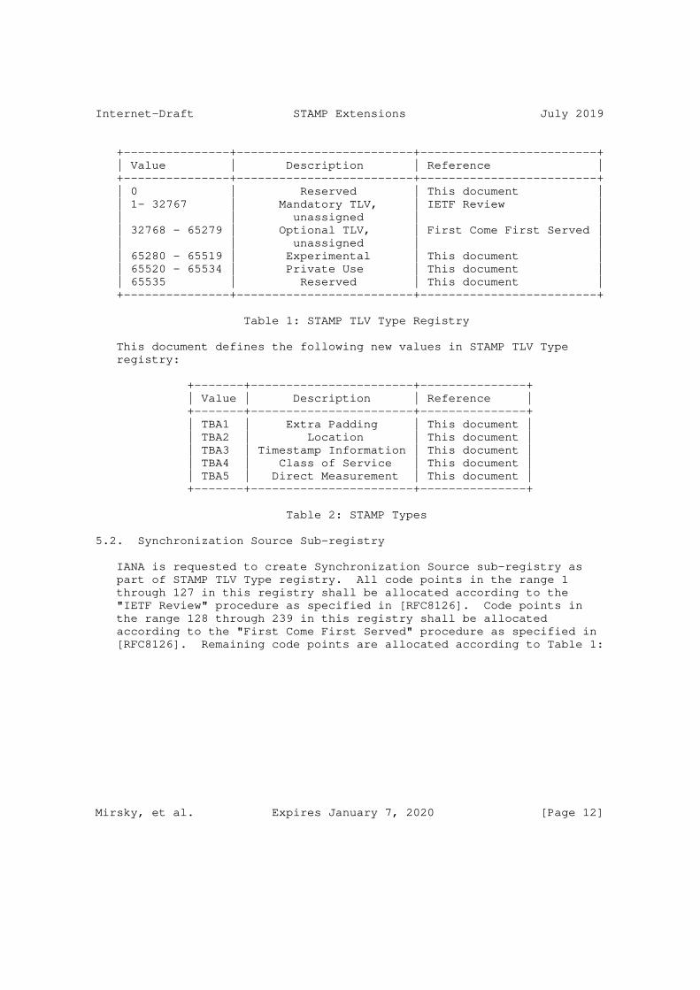
Internet-Draft STAMP Extensions July 2019
+---------------+-------------------------+-------------------------+ | Value | Description | Reference | +---------------+-------------------------+-------------------------+ | 0 | Reserved | This document | | 1- 32767 | Mandatory TLV, | IETF Review | | | unassigned | | | 32768 - 65279 | Optional TLV, | First Come First Served | | | unassigned | | | 65280 - 65519 | Experimental | This document | | 65520 - 65534 | Private Use | This document | | 65535 | Reserved | This document | +---------------+-------------------------+-------------------------+
Table 1: STAMP TLV Type Registry
This document defines the following new values in STAMP TLV Type registry:
+-------+-----------------------+---------------+ | Value | Description | Reference | +-------+-----------------------+---------------+ | TBA1 | Extra Padding | This document | | TBA2 | Location | This document | | TBA3 | Timestamp Information | This document | | TBA4 | Class of Service | This document | | TBA5 | Direct Measurement | This document | +-------+-----------------------+---------------+
Table 2: STAMP Types
5.2. Synchronization Source Sub-registry
IANA is requested to create Synchronization Source sub-registry as part of STAMP TLV Type registry. All code points in the range 1 through 127 in this registry shall be allocated according to the "IETF Review" procedure as specified in [RFC8126]. Code points in the range 128 through 239 in this registry shall be allocated according to the "First Come First Served" procedure as specified in [RFC8126]. Remaining code points are allocated according to Table 1:
Mirsky, et al. Expires January 7, 2020 [Page 12]
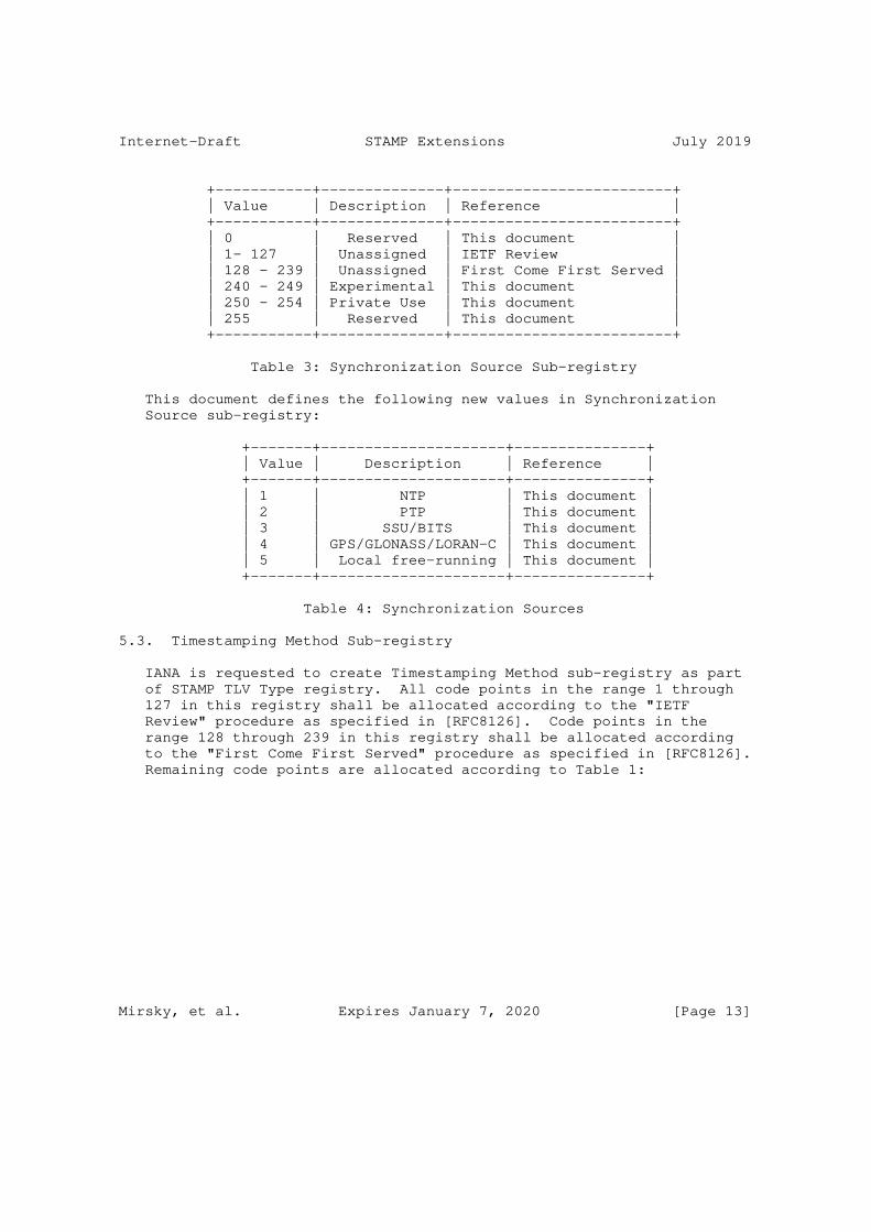
Internet-Draft STAMP Extensions July 2019
+-----------+--------------+-------------------------+ | Value | Description | Reference | +-----------+--------------+-------------------------+ | 0 | Reserved | This document | | 1- 127 | Unassigned | IETF Review | | 128 - 239 | Unassigned | First Come First Served | | 240 - 249 | Experimental | This document | | 250 - 254 | Private Use | This document | | 255 | Reserved | This document | +-----------+--------------+-------------------------+
Table 3: Synchronization Source Sub-registry
This document defines the following new values in Synchronization Source sub-registry:
+-------+---------------------+---------------+ | Value | Description | Reference | +-------+---------------------+---------------+ | 1 | NTP | This document | | 2 | PTP | This document | | 3 | SSU/BITS | This document | | 4 | GPS/GLONASS/LORAN-C | This document | | 5 | Local free-running | This document | +-------+---------------------+---------------+
Table 4: Synchronization Sources
5.3. Timestamping Method Sub-registry
IANA is requested to create Timestamping Method sub-registry as part of STAMP TLV Type registry. All code points in the range 1 through 127 in this registry shall be allocated according to the "IETF Review" procedure as specified in [RFC8126]. Code points in the range 128 through 239 in this registry shall be allocated according to the "First Come First Served" procedure as specified in [RFC8126]. Remaining code points are allocated according to Table 1:
Mirsky, et al. Expires January 7, 2020 [Page 13]

Internet-Draft STAMP Extensions July 2019
+-----------+--------------+-------------------------+ | Value | Description | Reference | +-----------+--------------+-------------------------+ | 0 | Reserved | This document | | 1- 127 | Unassigned | IETF Review | | 128 - 239 | Unassigned | First Come First Served | | 240 - 249 | Experimental | This document | | 250 - 254 | Private Use | This document | | 255 | Reserved | This document | +-----------+--------------+-------------------------+
Table 5: Timestamping Method Sub-registry
This document defines the following new values in Timestamping Methods sub-registry:
+-------+---------------+---------------+ | Value | Description | Reference | +-------+---------------+---------------+ | 1 | HW assist | This document | | 2 | SW local | This document | | 3 | Control plane | This document | +-------+---------------+---------------+
Table 6: Timestamping Methods
6. Security Considerations
Use of HMAC in authenticated mode may be used to simultaneously verify both the data integrity and the authentication of the STAMP test packets.
7. Acknowledgments
Authors much appreciate the thorough review and thoughful comments received from Tianran Zhou.
8. References
8.1. Normative References
[I-D.ietf-ippm-stamp] Mirsky, G., Jun, G., Nydell, H., and R. Foote, "Simple Two-way Active Measurement Protocol", draft-ietf-ippm- stamp-06 (work in progress), April 2019.
Mirsky, et al. Expires January 7, 2020 [Page 14]

Internet-Draft STAMP Extensions July 2019
[RFC2119] Bradner, S., "Key words for use in RFCs to Indicate Requirement Levels", BCP 14, RFC 2119, DOI 10.17487/RFC2119, March 1997, <https://www.rfc-editor.org/info/rfc2119>.
[RFC5357] Hedayat, K., Krzanowski, R., Morton, A., Yum, K., and J. Babiarz, "A Two-Way Active Measurement Protocol (TWAMP)", RFC 5357, DOI 10.17487/RFC5357, October 2008, <https://www.rfc-editor.org/info/rfc5357>.
[RFC6038] Morton, A. and L. Ciavattone, "Two-Way Active Measurement Protocol (TWAMP) Reflect Octets and Symmetrical Size Features", RFC 6038, DOI 10.17487/RFC6038, October 2010, <https://www.rfc-editor.org/info/rfc6038>.
[RFC8126] Cotton, M., Leiba, B., and T. Narten, "Guidelines for Writing an IANA Considerations Section in RFCs", BCP 26, RFC 8126, DOI 10.17487/RFC8126, June 2017, <https://www.rfc-editor.org/info/rfc8126>.
[RFC8174] Leiba, B., "Ambiguity of Uppercase vs Lowercase in RFC 2119 Key Words", BCP 14, RFC 8174, DOI 10.17487/RFC8174, May 2017, <https://www.rfc-editor.org/info/rfc8174>.
8.2. Informative References
[IEEE.1588.2008] "Standard for a Precision Clock Synchronization Protocol for Networked Measurement and Control Systems", IEEE Standard 1588, March 2008.
[RFC5905] Mills, D., Martin, J., Ed., Burbank, J., and W. Kasch, "Network Time Protocol Version 4: Protocol and Algorithms Specification", RFC 5905, DOI 10.17487/RFC5905, June 2010, <https://www.rfc-editor.org/info/rfc5905>.
Authors’ Addresses
Greg Mirsky ZTE Corp.
Email: [email protected]
Xiao Min ZTE Corp.
Email: [email protected]
Mirsky, et al. Expires January 7, 2020 [Page 15]

Internet-Draft STAMP Extensions July 2019
Guo Jun ZTE Corporation 68# Zijinghua Road Nanjing, Jiangsu 210012 P.R.China
Phone: +86 18105183663 Email: [email protected]
Henrik Nydell Accedian Networks
Email: [email protected]
Richard Foote Nokia
Email: [email protected]
Mirsky, et al. Expires January 7, 2020 [Page 16]

Network Working Group T. MizrahiInternet-Draft Huawei Network.IO Innovation LabIntended status: Informational C. AradExpires: January 7, 2020 G. Fioccola Huawei Technologies M. Cociglio Telecom Italia M. Chen L. Zheng Huawei Technologies G. Mirsky ZTE Corp. July 6, 2019
Compact Alternate Marking Methods for Passive and Hybrid Performance Monitoring draft-mizrahi-ippm-compact-alternate-marking-05
Abstract
This memo introduces new alternate marking methods that require a compact overhead of either a single bit per packet, or zero bits per packet. This memo also presents a summary of alternate marking methods, and discusses the tradeoffs among them. The target audience of this document is network protocol designers; this document is intended to help protocol designers choose the best alternate marking method(s) based on the protocol’s constraints and requirements.
Status of This Memo
This Internet-Draft is submitted in full conformance with the provisions of BCP 78 and BCP 79.
Internet-Drafts are working documents of the Internet Engineering Task Force (IETF). Note that other groups may also distribute working documents as Internet-Drafts. The list of current Internet- Drafts is at https://datatracker.ietf.org/drafts/current/.
Internet-Drafts are draft documents valid for a maximum of six months and may be updated, replaced, or obsoleted by other documents at any time. It is inappropriate to use Internet-Drafts as reference material or to cite them other than as "work in progress."
This Internet-Draft will expire on January 7, 2020.
Mizrahi, et al. Expires January 7, 2020 [Page 1]

Internet-Draft Compact Alternate Marking July 2019
Copyright Notice
Copyright (c) 2019 IETF Trust and the persons identified as the document authors. All rights reserved.
This document is subject to BCP 78 and the IETF Trust’s Legal Provisions Relating to IETF Documents (https://trustee.ietf.org/license-info) in effect on the date of publication of this document. Please review these documents carefully, as they describe your rights and restrictions with respect to this document. Code Components extracted from this document must include Simplified BSD License text as described in Section 4.e of the Trust Legal Provisions and are provided without warranty as described in the Simplified BSD License.
Table of Contents
1. Introduction . . . . . . . . . . . . . . . . . . . . . . . . 3 1.1. Background . . . . . . . . . . . . . . . . . . . . . . . 3 1.2. The Scope of This Document . . . . . . . . . . . . . . . 4 2. Terminology . . . . . . . . . . . . . . . . . . . . . . . . . 5 2.1. Requirements Language . . . . . . . . . . . . . . . . . . 5 2.2. Abbreviations . . . . . . . . . . . . . . . . . . . . . . 5 3. Marking Abstractions . . . . . . . . . . . . . . . . . . . . 5 4. Double Marking . . . . . . . . . . . . . . . . . . . . . . . 7 5. Single-bit Marking . . . . . . . . . . . . . . . . . . . . . 8 5.1. Single Marking Using the First Packet . . . . . . . . . . 8 5.2. Single Marking using the Mean Delay . . . . . . . . . . . 8 5.3. Single Marking using a Multiplexed Marking Bit . . . . . 8 5.3.1. Overview . . . . . . . . . . . . . . . . . . . . . . 8 5.4. Pulse Marking . . . . . . . . . . . . . . . . . . . . . . 9 6. Zero Marking Hashed . . . . . . . . . . . . . . . . . . . . . 10 6.1. Hash-based Sampling . . . . . . . . . . . . . . . . . . . 10 6.1.1. Hashed Pulse Marking . . . . . . . . . . . . . . . . 11 6.1.2. Hashed Step Marking . . . . . . . . . . . . . . . . . 11 7. Single Marking Hashed . . . . . . . . . . . . . . . . . . . . 11 8. Timing and Synchronization Aspects . . . . . . . . . . . . . 12 8.1. Synchronization Aspects in Multiplexed Marking . . . . . 13 9. Multipoint Marking Methods . . . . . . . . . . . . . . . . . 14 10. Summary of Marking Methods . . . . . . . . . . . . . . . . . 15 11. Alternate Marking using Reserved Values . . . . . . . . . . . 19 12. IANA Considerations . . . . . . . . . . . . . . . . . . . . . 20 13. Security Considerations . . . . . . . . . . . . . . . . . . . 20 14. References . . . . . . . . . . . . . . . . . . . . . . . . . 20 14.1. Normative References . . . . . . . . . . . . . . . . . . 20 14.2. Informative References . . . . . . . . . . . . . . . . . 20 Authors’ Addresses . . . . . . . . . . . . . . . . . . . . . . . 21
Mizrahi, et al. Expires January 7, 2020 [Page 2]

Internet-Draft Compact Alternate Marking July 2019
1. Introduction
1.1. Background
Alternate marking, defined in [RFC8321], is a method for measuring packet loss, packet delay, and packet delay variation. Typical delay measurement protocols require the two measurement points (MPs) to exchange timestamped test packets. In contrast, the alternate marking method does not require control packets to be exchanged. Instead, every data packet carries a marking bit, which is used for triggering measurement events. Note that the frequency of these measurement events is dependent on the users’ application(s) and the node characteristics.
The marking bit can be used as a color indication, as defined in [RFC8321], which is toggled periodically. This approach is illustrated in Figure 1.
A: packet with color 0 B: packet with color 1
Packets AAAAAAAAAA BBBBBBBBBB AAAAAAAAAA BBBBBBBBBB AAAAAAAAAA Time ----------------------------------------------------------> | | | | | | Block 1 | Block 2 | Block 3 | Block 4 | Block 5 ... | | | | | Color 0000000000 1111111111 0000000000 1111111111 0000000000
Figure 1: Alternate marking: packets are monitored on a per-color basis.
Alternate marking is used between two MPs, the initiating MP, and the monitoring MP. The initiating MP incorporates the marking field into en-route packets, allowing the monitoring MP to use the marking field in order to bind each packet to the corresponding block.
Each of the MPs maintains two counters, one per color. At the end of each block the counter values can be collected by a central management system, and analyzed; the packet loss can be computed by comparing the counter values of the two MPs.
When using alternate marking delay measurement can be performed in one of three ways (as per [RFC8321]):
o Single marking using the first packet: in this method each packet uses a single marking bit, used as a color indicator. The first packet of each block is used by both MPs as a reference for delay
Mizrahi, et al. Expires January 7, 2020 [Page 3]

Internet-Draft Compact Alternate Marking July 2019
measurement. The timestamp of this packet is measured by the two measurement points, and can be collected by the mangement system from each of the measurement points, which can compute the path delay by comparing the two timestamps. The drawback of this approach is that it is not accurate when packets arrive out-of- order, as the two MPs may have a different view of which packet was the first in the block.
o Single marking using the mean delay: as in the previous method, each packet uses a single marking method, indicating the color. Each of the MPs computes the average packet timestamp of each block. The management system can then compute the delay by comparing the average times of the two MPs. The drawback of this approach is that it may be computationally heavy, or difficult to implement at the data plane.
o Double marking: each packet uses two marking bits. One bit is used as a color indicator, and one is used as a timestamping indicator. This method resolves the drawbacks raised for the two previous methods, at the expense of an extra bit in the packet header.
The double marking method is the most straightforward approach. It allows for accurate measurement without incurring expensive computational load. However, in some cases allocating two bits for passive measurement is not possible. For example, if alternate marking is implemented over IPv4, allocating 2 marking bits in the IPv4 header is challenging, as every bit in the 20-octet header is costly; one of the possible approaches discussed in [RFC8321] is to reserve one or two bits from the DSCP field for remarking. In this case every marking bit comes at the expense of reducing the DSCP range by a factor of two.
1.2. The Scope of This Document
This memo extends the marking methods of [RFC8321], and introduces methods that require a single marking bit, or zero marking bits.
Two single-bit marking methods are proposed, multiplexed marking and pulse marking. In multiplexed marking the color indicator and the timestamp indicator are multiplexed into a single bit, providing the advantages of the double marking method while using a single bit in the packet header. In pulse marking both delay and loss measurement are triggered by a ’pulse’ value in a single marking field.
This document also discusses zero-bit marking methods that leverage well-known hash-based selection approaches ([RFC5474], [RFC5475]).
Mizrahi, et al. Expires January 7, 2020 [Page 4]

Internet-Draft Compact Alternate Marking July 2019
Alternate marking is discussed in this memo as a single-bit or a two- bit marking method. However, these methods can similarly be applied to larger fields, such as an IPv6 Flow Label or an MPLS Label; single-bit marking can be applied using two reserved values, and two- bit marking can be applied using four reserved values. Marking based on reserved values is further discussed in this document, including its application to MPLS and IPv6.
Finally, this memo summarizes the alternate marking methods, and discusses the tradeoffs among them. It is expected that different network protocols will have different constraints, and therefore may choose to use different alternate marking methods. In some cases it may be preferable to support more than one marking method; in this case the particular marking method may be signaled through the control plane.
2. Terminology
2.1. Requirements Language
The key words "MUST", "MUST NOT", "REQUIRED", "SHALL", "SHALL NOT", "SHOULD", "SHOULD NOT", "RECOMMENDED", "MAY", and "OPTIONAL" in this document are to be interpreted as described in RFC 2119 [RFC2119].
2.2. Abbreviations
The following abbreviations are used in this document:
DSCP Differentiated Services Code Point
DM Delay Measurement
LM Loss Measurement
LSP Label Switched Path
MP Measurement Point
MPLS Multiprotocol Label Switching
SFL Synonymous Flow Label [I-D.ietf-mpls-sfl-framework]
3. Marking Abstractions
The marking methods that were discussed in Section 1, as well as the methods introduced in this document, use two basic abstractions, pulse detection, and step detection.
Mizrahi, et al. Expires January 7, 2020 [Page 5]

Internet-Draft Compact Alternate Marking July 2019
The common thread along the various marking methods is that one or two marking bits are used by the MPs to signal a measurement event. The value of the marking bit indicates when the event takes place, in one of two ways:
Pulse An event is detected when the value of the marking bit is toggled in a single packet.
Step An event is detected when the value of the marking bit is toggled, and remains at the new value.
The double marking method (Section 1) uses pulse-based detection for DM, and step-based detection for LM.
Pulse-based detection affects the processing of a single packet; the packet that indicates the pulse is processed differently than the packets around it. For example, in the double marking method, the marked packet is timestamped for DM, without affecting the packets before or after it. Note that if the marked packet is lost, no pulse is detected, yielding a missing measurement (see Figure 2).
P: indicates a packet
Packets PPPPPPPPPP PPPPPPPPPP PPPPPPPPPP PPPPPPPPPP PPPPPPPPPP Time ----------------------------------------------------------> Marking bit 0000010000 0000010000 0000010000 0000010000 00000 0000 ^ ^ ^ ^ ^ Pulse-based | | | | | detection | | | | | Dropped packet: no detection
Figure 2: Pulse-based Detection.
In step-based detection the event is detected by observing a value change in stream of packets. Specifically, when the step approach is used for LM (as in the double marking method), two counters are used per flow; each MP decides which counter to use based on the value of the marking bit. Thus, the step-based approach allows accurate counting even when packets arrive out-of-order (see Figure 3). When the step approach is used for DM (e.g., single marking using the first packet), out-of-order causes the delay measurement to be false, without any indication to the management system.
Mizrahi, et al. Expires January 7, 2020 [Page 6]

Internet-Draft Compact Alternate Marking July 2019
P: indicates a packet
Packets PPPPPPPPPP PPPPPPPPPP PPPPPPPPPP PPPPPPPPPP PPPPPPPPPP Time ----------------------------------------------------------> Marking bit 0000000000 1111111111 000000000 10111111111 0000000000 ^ ^ ^ ^ Step-based | | | | detection | | | | out-of-order
Figure 3: Step-based Detection.
4. Double Marking
The two-bit marking method of [RFC8321] uses two marking bits: a color indicator, and a delay measurement indicator. The color bit is used for step-based LM, while the delay bit is used as a pulse-based DM trigger. This double marking approach is the most straightforward of the approaches discussed in this memo, as it allows accurate measurement, it is resilient to out-of-order delivery, and is relatively simple to implement. The main drawback is that it requires two bits, which are not always available.
Figure 4 illustrates the double marking method: each block of packets includes a packet that is marked for timestamping, and therefore has its delay bit set.
A: packet with color 0 B: packet with color 1
Packets AAAAAAAAAA BBBBBBBBBB AAAAAAAAAA BBBBBBBBBB AAAAAAAAAA Time ----------------------------------------------------------> | | | | | | Block 1 | Block 2 | Block 3 | Block 4 | Block 5 ... | | | | | Color bit 0000000000 1111111111 0000000000 1111111111 0000000000 Delay bit 0000100000 0000100000 0000100000 0000100000 0001000000 ^ ^ ^ ^ ^ Packets | | | | | marked for | | | | | timestamping | | | | |
Figure 4: The double marking method.
Mizrahi, et al. Expires January 7, 2020 [Page 7]

Internet-Draft Compact Alternate Marking July 2019
5. Single-bit Marking
5.1. Single Marking Using the First Packet
This method uses a single marking bit that indicates the color, as described in [RFC8321]. Both LM and DM are implemented using a step- based approach; LM is implemented using two color-based counters per flow. The first packet of every period is used by the two MPs as the reference for measuring the delay. As denoted above, the delay computed in this method may be erroneous when packets are delivered out-of-order.
A: packet with color 0 B: packet with color 1
Packets AAAAAAAAAA BBBBBBBBBB AAAAAAAAAA BBBBBBBBBB AAAAAAAAAA Time ----------------------------------------------------------> | | | | | | Block 1 | Block 2 | Block 3 | Block 4 | Block 5 ... | | | | | Color bit 0000000000 1111111111 0000000000 1111111111 0000000000 ^ ^ ^ ^ ^ Packets | | | | | used for DM | | | | |
Figure 5: Single marking using the first packet of the block.
5.2. Single Marking using the Mean Delay
As in the first-packet approach, in the mean delay approach ([RFC8321]) a single marking bit is used to indicate the color, enabling step-based loss measurement. Delay is measured in each period by averaging the measured delay over all the packets in the period. As discussed above, this approach is not sensitive to out- of-order delivery, but may be heavy from a computational perspective.
5.3. Single Marking using a Multiplexed Marking Bit
5.3.1. Overview
This section introduces a method that uses a single marking bit that serves two purposes: a color indicator, and a timestamp indicator. The double marking method that was discussed in the previous section uses two 1-bit values: a color indicator C, and a timestamp indicator T. The multiplexed marking bit, denoted by M, is an exclusive or between these two values: M = C XOR T.
Mizrahi, et al. Expires January 7, 2020 [Page 8]

Internet-Draft Compact Alternate Marking July 2019
An example of the use of the multiplexed marking bit is depicted in Figure 6. The example considers two routers, R1 and R2, that use the multiplexed bit method to measure traffic from R1 to R2. In each block R1 designates one of the packets for delay measurement. In each of these designated packets the value of the multiplexed bit is reversed compared to the other packets in the same block, allowing R2 to distinguish the designated packets from the other packets.
A: packet with color 0 B: packet with color 1
Packets AAAAAAAAAA BBBBBBBBBB AAAAAAAAAA BBBBBBBBBB AAAAAAAAAA Time ----------------------------------------------------------> | | | | | | Block 1 | Block 2 | Block 3 | Block 4 | Block 5 ... | | | | | Color 0000000000 1111111111 0000000000 1111111111 0000000000 ^ ^ ^ ^ ^ Packets | | | | | marked for | | | | | timestamping | | | | | v v v v v Muxed bit 0000100000 1111011111 0000100000 1111101111 0001000000
Figure 6: Alternate marking with multiplexed bit.
5.4. Pulse Marking
Pulse marking uses a single marking bit that is used as a trigger for both LM and DM. In this method the two MPs maintain a single per- flow counter for LM, in contrast to the color-based methods which require two counters per flow. In each block one of the packets is marked. The marked packet triggers two actions in each of MPs:
o The timestamp is captured for DM.
o The value of the counter is captured for LM.
In each period, each of the MPs exports the timestamp and counter- stamp to the management system, which can then compute the loss and delay in that period. It should be noted that as in [RFC8321], if the length of the measurement period is L time units, then all network devices must be synchronized to the same clock reference with an accuracy of +/- L/2 time units.
Mizrahi, et al. Expires January 7, 2020 [Page 9]

Internet-Draft Compact Alternate Marking July 2019
The pulse marking approach is illustrated in Figure 7. Since both LM and DM use a pulse-based trigger, if the marked packet is lost then no measurement is available in this period. Moreover, the LM accuracy may be affected by out-of-order delivery.
P: packet - all packets have the same color
Packets PPPPPPPPPP PPPPPPPPP PPPPPPPPPP PPPPPPPPPP PPPPPPPPPP Time ----------------------------------------------------------> | | | | | | Block 1 | Block 2 | Block 3 | Block 4 | Block 5 ... | | | | | ^ ^ ^ ^ ^ Packets | | | | | marked for | | | | | DM and LM | | | | | v v v v v Marking bit 0000100000 0000100000 0000100000 0000010000 0001000000
Figure 7: Pulse marking method.
6. Zero Marking Hashed
6.1. Hash-based Sampling
Hash based selection [RFC5475] is a well-known method for sampling a subset of packets. As defined in [RFC5475]:
A Hash Function h maps the Packet Content c, or some portion of it, onto a Hash Range R. The packet is selected if h(c) is an element of S, which is a subset of R called the Hash Selection Range.
Hash-based selection can be leveraged as a marking method, allowing a zero-bit marking approach. Specifically, the pulse and step abstractions can be implemented using hashed selection:
o Hashed pulse-based trigger: in this approach, a packet is selected if h(c) is an element of S, which is a strict subset of the hash range R. When |S|<<|R|, the average sampling period is long, reducing the probability of ambiguity between consecutive packets. |S| and |R| denote the number of elements in S and R, respectively.
o Hashed step-based trigger: the hash values of a given traffic flow are said to be monotonically increasing if for two packets p1 and
Mizrahi, et al. Expires January 7, 2020 [Page 10]

Internet-Draft Compact Alternate Marking July 2019
p2, if p1 is sent before p2 then h(p1)<=h(p2). If it is guaranteed that the hash values of a flow are monotonically increasing, then a step-based approach can be used on the range R. For example, in an IPv4 flow the Identification field can be used as the hash value of each packet. Since the Identification field is monotonically increasing, the step-based trigger can be implemented using consecutive ranges of the Identification value. For example, the fourth bit of the Identification field is toggled every 8 packets. Thus, a possible hash function simply takes the fourth bit of the Identification field as the hash value. This hash value is toggled every 8 packets, simulating the alternate marking behavior of Section 4.
Note that as opposed to the double marking and single marking methods, hashed sampling is not based on fixed time intervals, as the duration between sampled packets depends only on the hash value.
It is also important to note that all methods that use hash-based marking require the hash function and the set S to be configured consistently across the MPs.
6.1.1. Hashed Pulse Marking
In this approach a hash is computed over the packet content, and both LM and DM are triggered based on the pulse-based trigger (Section 6.1). A pulse is detected when the hash value h(c) is equal to one of the values in S. The hash function h and the set S determine the probability (or frequency) of the pulse event.
6.1.2. Hashed Step Marking
As in the previous approach, hashed step marking also uses a hash that is computed over the packet content. In this approach DM is performed using a pulse-based trigger, whereas the LM trigger is step-based (Section 6.1). The main drawback of this method is that the step-based trigger is possible only under the assumption that the hash function is monotonically increasing, which is not necessarily possible in all cases. Specifically, a measured flow is not necessarily an IPv4 5-tuple. For example, a measured flow may include multiple IPv4 5-tuple flows, and in this case the Identification field is not monotonically increasing.
7. Single Marking Hashed
Mixed hashed marking combines the single marking approach with hash- based sampling. A single marking bit is used in the packet header as a color indicator, while a hash-based pulse is used to trigger DM. Although this method requires a single bit, it is described in this
Mizrahi, et al. Expires January 7, 2020 [Page 11]

Internet-Draft Compact Alternate Marking July 2019
section as it is closely related to the other hash-based methods that require zero marking bits.
The hash-based selection for DM can be applied in one of two possible approaches: the basic approach, and the dynamic approach. In the basic approach, packets forwarded between two MPs, MP1 and MP2, are selected using a hash function, as described above. One of the challenges is that the frequency of the sampled packets may vary considerably, making it difficult for the management system to correlate samples from the two MPs. Thus, the dynamic approach can be used.
In the dynamic hash-based sampling, alternate marking is used to create divide time into periods, so that hash-based samples are divided into batches, allowing to anchor the selected samples to their period. Moreover, by dynamically adapting the length of the hash value, the number of samples is bounded in each marking period. This can be realized by choosing first the maximum number of samples (NMAX) to be used with the initial hash length. The algorithm starts with only few hash bits, that permit to select a greater percentage of packets (e.g. with 1 bit of hash half of the packets are sampled). When the number of selected packets reaches NMAX, a hashing bit is added. As a consequence, the sampling proceeds at half of the original rate and the packets already selected that do not match the new hash are discarded. This step can be repeated iteratively. It is assumed that each sample includes the timestamp (used for DM) and the hash value, allowing the management system to match the samples received from the two MPs.
The dynamic process statistically converges at the end of a marking period and the number of selected samples beyond the initial NMAX samples mentioned above is between NMAX/2 and NMAX. Therefore, the dynamic approach paces the sampling rate, allowing to bound the number of sampled packets per sampling period.
8. Timing and Synchronization Aspects
As pointed out in [RFC8321], it is assumed that all MPs are synchronized to a common reference time with an accuracy of +/- L/2, where L is the periodic measurement interval. Thus, the difference between the clock values of any two MPs is bounded by L. Note that this is a relatively relaxed synchronization requirement that does not require complex means of synchronization. Clocks can be synchronized for example using NTP [RFC5905], PTP [IEEE1588], or by other means.
In the step-based approaches the common reference time is used for dividing the time domain into equal-sized measurement periods, such
Mizrahi, et al. Expires January 7, 2020 [Page 12]

Internet-Draft Compact Alternate Marking July 2019
that all packets forwarded during a measurement period have the same color, and consecutive periods have alternating colors. In the pulse-based approaches the synchronization helps the management system to correlate measurements from multiple measurement points without ambiguity.
8.1. Synchronization Aspects in Multiplexed Marking
The single marking bit incorporates two multiplexed values. From the monitoring MP’s perspective, the two values are Time-Division Multiplexed (TDM), as depicted in Figure 8. It is assumed that the start time of every measurement period is known to both the initiating MP and the monitoring MP. If the measurement period is L, then during the first and the last L/4 time units of each block the marking bit is interpreted by the monitoring MP as a color indicator. During the middle part of the block, the marking bit is interpreted as a timestamp indicator; if the value of this bit is different than the color value, the corresponding packet is used as a reference for delay measurement.
+--- Beginning of measurement period | v
...BBBBBBBBB | AAAAAAAAAAAAAAAAAAAAAAAAAAAAAAAAAAAAAA | BBBBBBBBB... |<======================================>| | L | <========>|<========><==================><========>|<========> L/4 L/4 L/2 L/4 L/4
<===================><==================><===================> Detect color Detect timestamping Detect color change indication change
Figure 8: Multiplexed marking field interpretation at the receiving measurement point.
In order to prevent ambiguity in the receiver’s interpretation of the marking field, the initiating MP is permitted to set the timestamp indication only during a specific interval, as depicted in Figure 9. Since the receiver is willing to receive the timestamp indication during the middle L/2 time units of the block, the sender refrains from sending the timestamp indication during a guardband interval of d time units at the beginning and end of the L/2-period.
Mizrahi, et al. Expires January 7, 2020 [Page 13]

Internet-Draft Compact Alternate Marking July 2019
+--- Beginning of measurement period | v
...BBBBBBBBB | AAAAAAAAAAAAAAAAAAAAAAAAAAAAAAAAAAAAAA | BBBBBBBBB... |<======================================>| | L | <========>|<========>|<================>|<========>| L/4 L/4 | L/2 | L/4 <=>|<=> <=>|<=> d d d d <==========> permissible timestamping indication interval
Figure 9: A time domain view.
The guardband d is given by d = A + D_max - D_min, where A is the clock accuracy, D_max is an upper bound on the network delay between the MPs, and D_min is a lower bound on the delay. It is straightforward from Figure 9 that d < L/4 must be satisfied. The latter implies a minimal requirement on the synchronization accuracy.
All MPs must be synchronized to the same reference time with an accuracy of +/- L/8. Depending on the system topology, in some systems the accuracy requirement will be even more stringent, subject to d < L/4. Note that the accuracy requirement of the conventional alternate marking method [RFC8321] is +/- L/2, while the multiplexed marking method requires an accuracy of +/- L/8.
Note that we assume that the middle L/2-period is designated as the timestamp indication period, allowing a sufficiently long guardband between the transitions. However, a system may be configured to use a longer timestamp indication period or a shorter one, if it is guaranteed that the synchronization accuracy meets the guardband requirements (i.e., the constraints on d).
9. Multipoint Marking Methods
It should be noted that most of the marking methods that were presented in this memo are intended for point-to-point measurements, e.g., from MP1 to MP2 in Figure 10. In point-to-multipoint measurements, the mean delay method can be used to measure the loss and delay of the entire point-to-multipoint flow (which includes all the traffic from MP3 to either MP4 or MP5), while other methods such as double marking can be used to measure the point-to-point
Mizrahi, et al. Expires January 7, 2020 [Page 14]
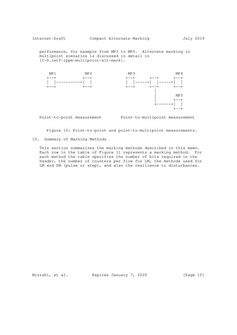
Internet-Draft Compact Alternate Marking July 2019
performance, for example from MP3 to MP5. Alternate marking in multipoint scenarios is discussed in detail in [I-D.ietf-ippm-multipoint-alt-mark].
MP1 MP2 MP3 MP4 +--+ +--+ +--+ +--+ +--+ | |---------->| | | |----->| |----->| | +--+ +--+ +--+ +--+ +--+ | | MP5 | +--+ +------>| | +--+
Point-to-point measurement Point-to-multipoint measurement
Figure 10: Point-to-point and point-to-multipoint measurements.
10. Summary of Marking Methods
This section summarizes the marking methods described in this memo. Each row in the table of Figure 11 represents a marking method. For each method the table specifies the number of bits required in the header, the number of counters per flow for LM, the methods used for LM and DM (pulse or step), and also the resilience to disturbances.
Mizrahi, et al. Expires January 7, 2020 [Page 15]
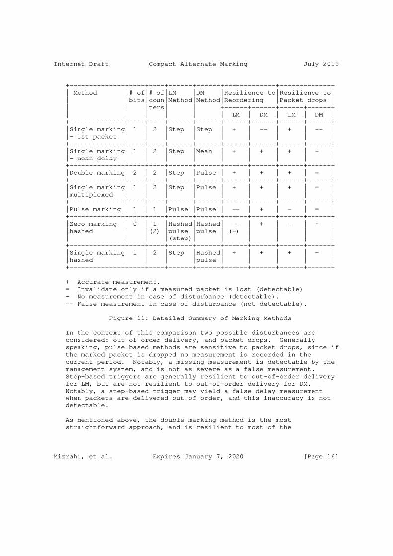
Internet-Draft Compact Alternate Marking July 2019
+--------------+----+----+------+------+-------------+-------------+ | Method |# of|# of|LM |DM |Resilience to|Resilience to| | |bits|coun|Method|Method|Reordering |Packet drops | | | |ters| | +------+------+------+------+ | | | | | | LM | DM | LM | DM | +--------------+----+----+------+------+------+------+------+------+ |Single marking| 1 | 2 |Step |Step | + | -- | + | -- | |- 1st packet | | | | | | | | | +--------------+----+----+------+------+------+------+------+------+ |Single marking| 1 | 2 |Step |Mean | + | + | + | - | |- mean delay | | | | | | | | | +--------------+----+----+------+------+------+------+------+------+ |Double marking| 2 | 2 |Step |Pulse | + | + | + | = | +--------------+----+----+------+------+------+------+------+------+ |Single marking| 1 | 2 |Step |Pulse | + | + | + | = | |multiplexed | | | | | | | | | +--------------+----+----+------+------+------+------+------+------+ |Pulse marking | 1 | 1 |Pulse |Pulse | -- | + | - | = | +--------------+----+----+------+------+------+------+------+------+ |Zero marking | 0 | 1 |Hashed|Hashed| -- | + | - | + | |hashed | |(2) |pulse |pulse | (-) | | | | | | | |(step)| | | | | | +--------------+----+----+------+------+------+------+------+------+ |Single marking| 1 | 2 |Step |Hashed| + | + | + | + | |hashed | | | |pulse | | | | | +--------------+----+----+------+------+------+------+------+------+
+ Accurate measurement. = Invalidate only if a measured packet is lost (detectable) - No measurement in case of disturbance (detectable). -- False measurement in case of disturbance (not detectable).
Figure 11: Detailed Summary of Marking Methods
In the context of this comparison two possible disturbances are considered: out-of-order delivery, and packet drops. Generally speaking, pulse based methods are sensitive to packet drops, since if the marked packet is dropped no measurement is recorded in the current period. Notably, a missing measurement is detectable by the management system, and is not as severe as a false measurement. Step-based triggers are generally resilient to out-of-order delivery for LM, but are not resilient to out-of-order delivery for DM. Notably, a step-based trigger may yield a false delay measurement when packets are delivered out-of-order, and this inaccuracy is not detectable.
As mentioned above, the double marking method is the most straightforward approach, and is resilient to most of the
Mizrahi, et al. Expires January 7, 2020 [Page 16]

Internet-Draft Compact Alternate Marking July 2019
disturbances that were analyzed. Its obvious drawback is that it requires two marking bits.
Several single marking methods are discussed in this memo. In this case there is no clear verdict which method is the optimal one. The first packet method may be simple to implement, but may present erroneous delay measurements in case of dropped or reordered packets. Arguably, the mean delay approach and the multiplexed approach may be more difficult to implement (depending on the underlying platform), but are more resilient to the disturbances that were considered here. Note that the computational complexity of the mean delay approach can be reduced by combining it with a hashed approach, i.e., by computing the mean delay over a hash-based subset of the packets. The pulse marking method requires only a single counter per flow, while the other methods require two counters per flow.
The hash-based sampling approaches reduce the overhead to zero bits, which is a significant advantage. However, the sampling period in these approaches is not associated with a fixed time interval. Therefore, in some cases adjacent packets may be selected for the sampling, potentially causing measurement errors. Furthermore, when the traffic rate is low, measurements may become signifcantly infrequent.
It is clear from the previous table that packet loss measurement can be considered resilient to both reordering and packet drops if at least one bit is used with a step-based approach. Thus, since the packet loss can be considered obvious, the previous table can be simplified into Figure 12, where only the characteristics of delay measurements are highlighted. This more compact table allows room for an additional column referring to multipoint-to-multipoint (Section 9) delay measurement compatibility.
Mizrahi, et al. Expires January 7, 2020 [Page 17]
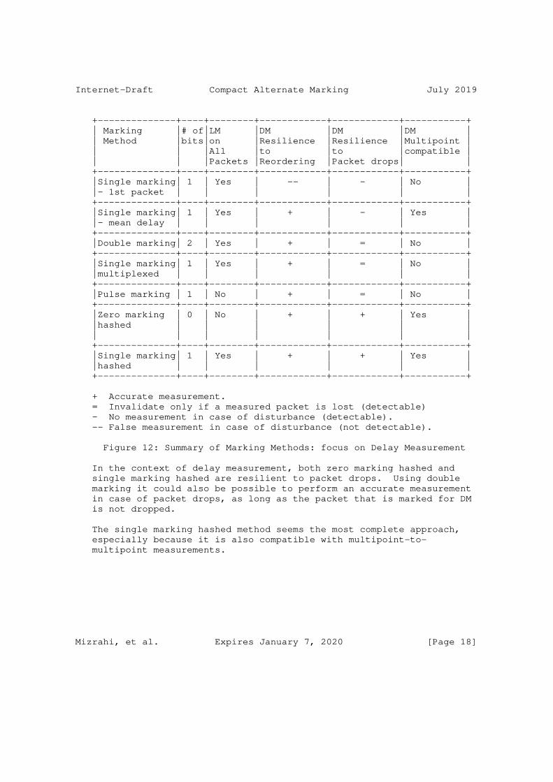
Internet-Draft Compact Alternate Marking July 2019
+--------------+----+--------+------------+------------+-----------+ | Marking |# of|LM |DM |DM |DM | | Method |bits|on |Resilience |Resilience |Multipoint | | | |All |to |to |compatible | | | |Packets |Reordering |Packet drops| | +--------------+----+--------+------------+------------+-----------+ |Single marking| 1 | Yes | -- | - | No | |- 1st packet | | | | | | +--------------+----+--------+------------+------------+-----------+ |Single marking| 1 | Yes | + | - | Yes | |- mean delay | | | | | | +--------------+----+--------+------------+------------+-----------+ |Double marking| 2 | Yes | + | = | No | +--------------+----+--------+------------+------------+-----------+ |Single marking| 1 | Yes | + | = | No | |multiplexed | | | | | | +--------------+----+--------+------------+------------+-----------+ |Pulse marking | 1 | No | + | = | No | +--------------+----+--------+------------+------------+-----------+ |Zero marking | 0 | No | + | + | Yes | |hashed | | | | | | | | | | | | | +--------------+----+--------+------------+------------+-----------+ |Single marking| 1 | Yes | + | + | Yes | |hashed | | | | | | +--------------+----+--------+------------+------------+-----------+
+ Accurate measurement. = Invalidate only if a measured packet is lost (detectable) - No measurement in case of disturbance (detectable). -- False measurement in case of disturbance (not detectable).
Figure 12: Summary of Marking Methods: focus on Delay Measurement
In the context of delay measurement, both zero marking hashed and single marking hashed are resilient to packet drops. Using double marking it could also be possible to perform an accurate measurement in case of packet drops, as long as the packet that is marked for DM is not dropped.
The single marking hashed method seems the most complete approach, especially because it is also compatible with multipoint-to- multipoint measurements.
Mizrahi, et al. Expires January 7, 2020 [Page 18]

Internet-Draft Compact Alternate Marking July 2019
11. Alternate Marking using Reserved Values
As mentioned in Section 1, a marking bit is not necessarily a single bit, but may be implemented by using two well-known values in one of the header fields. Similarly, two-bit marking can be implemented using four reserved values.
A notable example is MPLS Synonymous Flow Labels (SFL), as defined in [I-D.ietf-mpls-rfc6374-sfl]. Two MPLS Label values can be used to indicate the two colors of a given LSP: the original Label value, and an SFL value. A similar approach can be applied to IPv6 using the Flow Label field.
The following example illustrates how alternate marking can be implemented using reserved values. The bit multiplexing approach of Section 5.3 is applicable not only to single-bit color indicators, but also to two-value indicators; instead of using a single bit that is toggled between ’0’ and ’1’, two values of the indicator field, U and W, can be used in the same manner, allowing both loss and delay measurement to be performed using only two reserved values. Thus, the multiplexing approach of Figure 6 can be illustrated more generally with two values, U and W, as depicted in Figure 13.
A: packet with color 0 B: packet with color 1
Packets AAAAAAAAAA BBBBBBBBBB AAAAAAAAAA BBBBBBBBBB AAAAAAAAAA Time ----------------------------------------------------------> | | | | | | Block 1 | Block 2 | Block 3 | Block 4 | Block 5 ... | | | | | Color 0000000000 1111111111 0000000000 1111111111 0000000000 ^ ^ ^ ^ ^ Packets | | | | | marked for | | | | | timestamping | | | | | v v v v v Muxed UUUUWUUUUU WWWWUWWWWW UUUUWUUUUU WWWWWUWWWW UUUWUUUUUU marking values
Figure 13: Alternate marking with two multiplexed marking values, U and W.
Mizrahi, et al. Expires January 7, 2020 [Page 19]

Internet-Draft Compact Alternate Marking July 2019
12. IANA Considerations
This memo includes no requests from IANA.
13. Security Considerations
The security considerations of the alternate marking method are discussed in [RFC8321]. The analysis of Section 10 emphasizes the sensitivity of some of the alternate marking methods to packet drops and to packet reordering. Thus, a malicious attacker may attempt to tamper with the measurements by either selectively dropping packets, or by selectively reordering specific packets. The multiplexed marking method Section 5.3 that is defined in this document requires slightly more stringent synchronization than the conventional marking method, potentially making the method more vulnerable to attacks on the time synchronization protocol. A detailed discussion about the threats against time protocols and how to mitigate them is presented in [RFC7384].
14. References
14.1. Normative References
[RFC2119] Bradner, S., "Key words for use in RFCs to Indicate Requirement Levels", BCP 14, RFC 2119, DOI 10.17487/RFC2119, March 1997, <https://www.rfc-editor.org/info/rfc2119>.
[RFC8321] Fioccola, G., Ed., Capello, A., Cociglio, M., Castaldelli, L., Chen, M., Zheng, L., Mirsky, G., and T. Mizrahi, "Alternate-Marking Method for Passive and Hybrid Performance Monitoring", RFC 8321, DOI 10.17487/RFC8321, January 2018, <https://www.rfc-editor.org/info/rfc8321>.
14.2. Informative References
[I-D.ietf-ippm-multipoint-alt-mark] Fioccola, G., Cociglio, M., Sapio, A., and R. Sisto, "Multipoint Alternate Marking method for passive and hybrid performance monitoring", draft-ietf-ippm- multipoint-alt-mark-02 (work in progress), July 2019.
[I-D.ietf-mpls-rfc6374-sfl] Bryant, S., Chen, M., Li, Z., Swallow, G., Sivabalan, S., Mirsky, G., and G. Fioccola, "RFC6374 Synonymous Flow Labels", draft-ietf-mpls-rfc6374-sfl-03 (work in progress), December 2018.
Mizrahi, et al. Expires January 7, 2020 [Page 20]

Internet-Draft Compact Alternate Marking July 2019
[I-D.ietf-mpls-sfl-framework] Bryant, S., Chen, M., Li, Z., Swallow, G., Sivabalan, S., and G. Mirsky, "Synonymous Flow Label Framework", draft- ietf-mpls-sfl-framework-04 (work in progress), December 2018.
[IEEE1588] IEEE, "IEEE 1588 Standard for a Precision Clock Synchronization Protocol for Networked Measurement and Control Systems Version 2", 2008.
[RFC5474] Duffield, N., Ed., Chiou, D., Claise, B., Greenberg, A., Grossglauser, M., and J. Rexford, "A Framework for Packet Selection and Reporting", RFC 5474, DOI 10.17487/RFC5474, March 2009, <https://www.rfc-editor.org/info/rfc5474>.
[RFC5475] Zseby, T., Molina, M., Duffield, N., Niccolini, S., and F. Raspall, "Sampling and Filtering Techniques for IP Packet Selection", RFC 5475, DOI 10.17487/RFC5475, March 2009, <https://www.rfc-editor.org/info/rfc5475>.
[RFC5905] Mills, D., Martin, J., Ed., Burbank, J., and W. Kasch, "Network Time Protocol Version 4: Protocol and Algorithms Specification", RFC 5905, DOI 10.17487/RFC5905, June 2010, <https://www.rfc-editor.org/info/rfc5905>.
[RFC7384] Mizrahi, T., "Security Requirements of Time Protocols in Packet Switched Networks", RFC 7384, DOI 10.17487/RFC7384, October 2014, <https://www.rfc-editor.org/info/rfc7384>.
Authors’ Addresses
Tal Mizrahi Huawei Network.IO Innovation Lab Israel
Email: [email protected]
Carmi Arad
Email: [email protected]
Giuseppe Fioccola Huawei Technologies
Email: [email protected]
Mizrahi, et al. Expires January 7, 2020 [Page 21]

Internet-Draft Compact Alternate Marking July 2019
Mauro Cociglio Telecom Italia Via Reiss Romoli, 274 Torino 10148 Italy
Email: [email protected]
Mach(Guoyi) Chen Huawei Technologies
Email: [email protected]
Lianshu Zheng Huawei Technologies
Email: [email protected]
Greg Mirsky ZTE Corp.
Email: [email protected]
Mizrahi, et al. Expires January 7, 2020 [Page 22]

Network Working Group A. MortonInternet-Draft AT&T LabsUpdates: ???? (if approved) R. GeibIntended status: Standards Track Deutsche TelekomExpires: January 9, 2020 L. Ciavattone AT&T Labs July 8, 2019
Metrics and Methods for IP Capacity draft-morton-ippm-capcity-metric-method-00
Abstract
This memo revisits the problem of Network Capacity metrics first examined in RFC 5136. The memo specifies a more practical Maximum IP-layer Capacity metric definition catering for measurement purposes, and outlines the corresponding methods of measurement.
Requirements Language
The key words "MUST", "MUST NOT", "REQUIRED", "SHALL", "SHALL NOT", "SHOULD", "SHOULD NOT", "RECOMMENDED", "NOT RECOMMENDED", "MAY", and "OPTIONAL" in this document are to be interpreted as described in BCP 14[RFC2119] [RFC8174] when, and only when, they appear in all capitals, as shown here.
Status of This Memo
This Internet-Draft is submitted in full conformance with the provisions of BCP 78 and BCP 79.
Internet-Drafts are working documents of the Internet Engineering Task Force (IETF). Note that other groups may also distribute working documents as Internet-Drafts. The list of current Internet- Drafts is at https://datatracker.ietf.org/drafts/current/.
Internet-Drafts are draft documents valid for a maximum of six months and may be updated, replaced, or obsoleted by other documents at any time. It is inappropriate to use Internet-Drafts as reference material or to cite them other than as "work in progress."
This Internet-Draft will expire on January 9, 2020.
Morton, et al. Expires January 9, 2020 [Page 1]
Internet-Draft IP Capacity Metrics/Methods July 2019
Copyright Notice
Copyright (c) 2019 IETF Trust and the persons identified as the document authors. All rights reserved.
This document is subject to BCP 78 and the IETF Trust’s Legal Provisions Relating to IETF Documents (https://trustee.ietf.org/license-info) in effect on the date of publication of this document. Please review these documents carefully, as they describe your rights and restrictions with respect to this document. Code Components extracted from this document must include Simplified BSD License text as described in Section 4.e of the Trust Legal Provisions and are provided without warranty as described in the Simplified BSD License.
Table of Contents
1. Introduction . . . . . . . . . . . . . . . . . . . . . . . . 2 2. Scope and Goals . . . . . . . . . . . . . . . . . . . . . . . 3 3. Motivation . . . . . . . . . . . . . . . . . . . . . . . . . 3 4. Metric Definitions . . . . . . . . . . . . . . . . . . . . . 4 4.1. Formal Name . . . . . . . . . . . . . . . . . . . . . . . 4 4.2. Parameters . . . . . . . . . . . . . . . . . . . . . . . 4 4.3. Metric Definitions . . . . . . . . . . . . . . . . . . . 5 4.4. Related Round-Trip Delay and Loss Definitions . . . . . . 7 4.5. Discussion . . . . . . . . . . . . . . . . . . . . . . . 7 4.6. Reporting the Metric . . . . . . . . . . . . . . . . . . 8 5. Method of Measurement . . . . . . . . . . . . . . . . . . . . 8 5.1. Load Rate Adjustment Algorithm (from udpst) . . . . . . . 8 6. Reporting . . . . . . . . . . . . . . . . . . . . . . . . . . 9 7. Security Considerations . . . . . . . . . . . . . . . . . . . 10 8. IANA Considerations . . . . . . . . . . . . . . . . . . . . . 10 9. Acknowledgements . . . . . . . . . . . . . . . . . . . . . . 10 10. References . . . . . . . . . . . . . . . . . . . . . . . . . 10 10.1. Normative References . . . . . . . . . . . . . . . . . . 10 10.2. Informative References . . . . . . . . . . . . . . . . . 12 Authors’ Addresses . . . . . . . . . . . . . . . . . . . . . . . 13
1. Introduction
The IETF’s efforts to define Network and Bulk Transport Capacity have been chartered and progressed for over twenty years. Over that time, the performance community has seen development of Informative definitions in RFC 3148 for Framework for Bulk Transport Capacity (BTC), RFC 5136 for Network Capacity and Maximum IP-layer Capacity, and the Experimental metric definitions and methods in [RFC8337], Model-Based Metrics for BTC.
Morton, et al. Expires January 9, 2020 [Page 2]

Internet-Draft IP Capacity Metrics/Methods July 2019
This memo recognizes the importance of a definition of a Maximum IP- layer Capacity Metric at this time, a definition that is both practical and effective for the performance community’s needs, including Internet users. The metric definition is intended for Active Methods of Measurement [RFC7799], and a method of measurement is included here.
The most direct active measurement of IP-layer Capacity would use IP packets, but in practice a transport header is needed to traverse address and port translators. UDP offeres the most direct assessment possibility, and in the [copycat][copycat] measurement study to investigate whether UDP is viable as a general Internet transport protocol, the authors found that a high percentage of paths tested support UDP transport. A number of liaisons have been exchanged on this topic [ refs to ITU-T SG12, ETSI STQ, BBF liaisons ], discussing the laboratory and field tests that support the UDP-based approach to IP-layer Capacity measurement.
This memo also recognizes the many updates to the IP Performance Metrics Framework [RFC2330] published over twenty years, and makes use of [RFC7312] for Advanced Stream and Sampling Framework, and RFC 8468 [RFC8468]IPv4, IPv6, and IPv4-IPv6 Coexistence Updates.
NOTE: The text contains Author comments, in brackets [RG: , acm: ]
2. Scope and Goals
The scope of this memo is to define a metric and corresponding method to unambiguously perform Active measurements of Maximum IP-Layer Capacity.
The main goal is to harmonize the specified metric and method across the industry, and this memo is the vehicle through which working group (and eventually, IETF) consensus will be captured and communicated to achieve broad agreement, and possibly changes in other Standards Development Organizations (SDO).
A local goal is provide efficient test procedures where possible, and to recommend reporting with additional interpretation of the results. Also, to foster the development of protocol support for this metric and method of measurement.
3. Motivation
As with any problem that has been worked for many years in various SDOs without any special attempts at coordination, various solutions for metrics and methods have emerged.
Morton, et al. Expires January 9, 2020 [Page 3]

Internet-Draft IP Capacity Metrics/Methods July 2019
There are five factors that have changed (or begun to change) in the last 5 years, and the presence of any one of them on the path requires features in the measurement design to account for the changes:
1. Internet access is no longer the bottleneck for many users
2. Both speed and latency are important to user’s satisfaction
3. UDP’s growing role in Transport, in areas where TCP once dominated.
4. Content and applications moving closer to users.
5. Possibly less traffic crossing ISP gateways in future.
4. Metric Definitions
This section sets requirements for the following components to support the Maximum IP-layer Capacity Metric.
4.1. Formal Name
Type-P-Max-IP-Capacity, or informally called Maximum IP-layer Capacity.
Note that Type-P depends on the chosen method.
4.2. Parameters
This section lists the REQUIRED input factors to specify a Route metric.
o Src, the address of a host (such as the globally routable IP address).
o Dst, the address of a host (such as the globally routable IP address).
o i, the limit on the number of Hops a specific packet may visit as it traverses from the host at Src to the host at Dst (such as the TTL or Hop Limit).
o MaxHops, the maximum value of i used, (i=1,2,3,...MaxHops).
o T, the time at the start of measurement interval
o I, the duration of measurement interval
Morton, et al. Expires January 9, 2020 [Page 4]

Internet-Draft IP Capacity Metrics/Methods July 2019
o dt, the duration of N equal sub-intervals in I
o Ts, the host time of a transmitted test packet as measured at MP(Src), meaning Measurement Point at the Source.
o Ta, the host time of a test packet’s *arrival* as measured at MP(Dst), assigned to packets that arrive within a "reasonable" time (see parameter below).
o Tmax, a maximum waiting time for test packets to arrive at the destination, set sufficiently long to disambiguate packets with long delays from packets that are discarded (lost), such that the distribution of one-way delay is not truncated.
o F, the number of different flows synthesized by the method.
o flow, the stream of packets with the same n-tuple of designated header fields that (when held constant) result in identical treatment in a multi-path decision (such as the decision taken in load balancing). Note: The IPv6 flow label MAY be included in the flow definition when routers have complied with [RFC6438] guidelines at the Tunnel End Points (TEP), and the source of the measurement is a TEP.
o Type-P, the complete description of the packets for which this assessment applies (including the flow-defining fields). Note that the UDP transport layer is one requirement specified below.
o PM, a list of fundamental metrics, such as loss, delay, and reordering, and corresponding Target performance threshold. At least one fundamental metric and Target performance threshold MUST be supplied (such as One-way IP Packet Loss [RFC7680] equal to zero).
4.3. Metric Definitions
This section defines the REQUIRED aspects of the measureable Maximum IP-layer Capacity metric (unless otherwise indicated) for measurements between specified Source and Destination hosts:
Define the IP-layer capacity, Maximum_C(T,I,PM), to be the maximum number of IP-layer bits (including header and data fields) that can be transmitted from the Src host and correctly received by the Dst host during one contiguous sub-interval, dt in length, during the interval [T, T+I], and where the packet count of that single sub- interval dtn in [T, T+I] indicates the maximum number of IP-layer bits n0[dtn-1,dtn] which was captured as part of all packet counts n for all dt in [T, T+I]. The interval dt SHOULD be set to a natural
Morton, et al. Expires January 9, 2020 [Page 5]

Internet-Draft IP Capacity Metrics/Methods July 2019
number m so that T+I = T + m*dt with dtn - dtn-1 = dt and with 0 < n <= m. Parameter PM represents the other performance metrics [see section Related Round-Trip Delay and Loss Definitions below] and their measurement results for the maximum IP-layer capacity. At least one target performance threshold MUST be defined. If more than one target performance threshold is defined, then the sub-interval with maximum number of bits transmitted MUST meet all the target performance thresholds.
[RG: this requires more explanation. Do you mean that all results must hit the target performance level? Or is a one / two / k times hit out of x trials [T, T+I] a criterium indicating that a target has been reached? Or do you look for the maximum capacity without packet loss and queuing or added RTD latency, respectively? acm: I think I’ve clarified this in the text above... ]
Mathematically, this definition can be represented as:
max ( n0[dtn-1,dtn] ) [T,T+I] Maximum_C(T,I,PM) = ------------------------- dt where: T T+I _________________________________________ | | | | | | | | | | | dtn=0 1 2 3 4 5 6 7 8 9 m=10
Equation for Maximum Capacity
and:
o n0 is the total number of IP-layer header and payload bits that can be transmitted in Standard Formed packets from the Src host and correctly received by the Dst host during one contiguous sub- interval, dt in length, during the interval [T, T+I],
o Maximum _C(T,I,PM) corresponds to the maximum value of n0 measured in any sub-interval ending at dtn (meaning T + n*dt), divided by the constant length of all sub-intervals, dt.
o all sub-intervals SHOULD be of equal duration. Choosing dt as non-overlapping consecutive time intervals allows for a simple implementation. [RG: a sliding window of dt has its charme too, why exclude it? acm: seems less practical for real-time feedback.]
Morton, et al. Expires January 9, 2020 [Page 6]

Internet-Draft IP Capacity Metrics/Methods July 2019
o [acm: I think this is a discussion point, not essential to the definition] If traffic conditioning applies along a path for which Maximum _C(T,I,PM) is to be determined, different values for dt SHOULD be picked and measurements be executed during multiple intervals [T, T+I]. Any single interval dt SHOULD be chosen so that is an integer multiple of increasing values k times serialisation delay of a path MTU at the physical interface speed where traffic conditioning is expected. This should avoid taking configured burst tolerance singletons as a valid Maximum _C(T,I,PM) result.
o The bandwidth of the physical interface of the measurement device must be higher than that of the interface whose Maximum _C(T,I,PM) is to be measured.
In this definition, the m sub-intervals can be viewed as trials when the Src host varies the transmitted packet rate, searching for the maximum n0 that meets the PM criteria measured at the Dst host in a test of duration, I. When the transmitted packet rate is held constant at the Src host, the m sub-intervals may also be viewed as trials to evaluate the stability of n0 and metric(s) in the PM list over all dt-length intervals in I.
Measurements according to these definitions SHALL use UDP transport layer. [RG: don’t we need loss free transmission without added latency as criteria and add that UDP without closed loop flow control needs to be applied ? acm: I don’t think we should require loss-free transmission, because most networks allow a small loss ratio which would likely appear to be zero loss in most trials. Methods may use feedback, let’s talk about how to diffentiate from flow-control]
4.4. Related Round-Trip Delay and Loss Definitions
RTD[dtn-1,dtn] is defined as a sample of the [RFC2681] Round-trip Delay between the Src host and the Dst host over the interval [T,T+I]. The statistics used to to summarize RTD[dtn-1,dtn] MAY include the minimum, maximum, and mean.
RTL[dtn-1,dtn] is defined as a sample of the [RFC6673] Round-trip Loss between the Src host and the Dst host over the interval [T,T+I]. The statistics used to to summarize RTL[dtn-1,dtn] MAY include the lost packet count and the lost packet ratio.
4.5. Discussion
Depending on the
Morton, et al. Expires January 9, 2020 [Page 7]

Internet-Draft IP Capacity Metrics/Methods July 2019
4.6. Reporting the Metric
@@@@ not yet addressed,
5. Method of Measurement
This section needs development, based on Annex A of Y.1540.
The duration of a test, I, MUST be constrained in a production network, since this is an active test method and it will likely cause congestion on the Src to Dst host path during a test.
Additional Test methods and configurations may be provided in this section, after review.
5.1. Load Rate Adjustment Algorithm (from udpst)
A table is pre-built defining all the offered load rates that will be supported (R1 - Rn, in ascending order). Each rate is defined as datagrams of size S, sent as a burst of count C, every time interval T. While it is advantageous to use datagrams of as large a size as possible, it may be prudent to use a slightly smaller maximum that allows for secondary protocol headers and/or tunneling without resulting in IP-layer fragmentation.
At the beginning of a test, the sender begins sending at rate R1 and the receiver starts a feedback timer at interval F (while awaiting inbound datagrams). As datagrams are received they are checked for sequence number anomalies (loss, out-of-order, duplication, etc.) and the delay variation is measured (one-way or round-trip). This information is accumulated until the feedback timer F expires and a status feedback message is sent from the receiver back to the sender, to communicate this information. The accumulated statistics are then reset by the receiver for the next feedback interval. As feedback messages are received back at the sender, they are evaluated to determine how to adjust the current offered load rate (Rx).
If the feedback indicates that there were no sequence number anomalies AND the delay variation was below the lower threshold, the offered load rate is increased. If congestion has not been confirmed up to this point, the offered load rate is increased by more than one rate (e.g., Rx+10). This allows the offered load to quickly reach a near-maximum rate. Conversely, if congestion has been previously confirmed, the offered load rate is only increased by one (Rx+1).
If the feedback indicates that sequence number anomalies were detected OR the delay variation was above the upper threshold, the offered load rate is decreased. If congestion has not been confirmed
Morton, et al. Expires January 9, 2020 [Page 8]
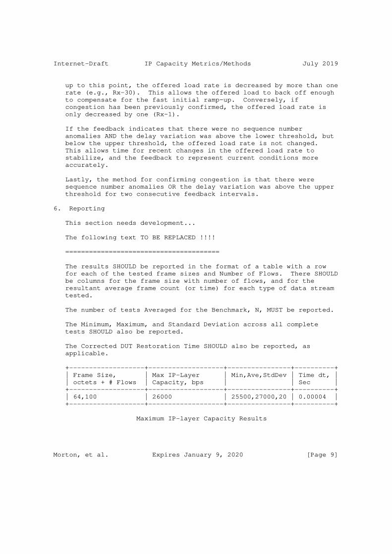
Internet-Draft IP Capacity Metrics/Methods July 2019
up to this point, the offered load rate is decreased by more than one rate (e.g., Rx-30). This allows the offered load to back off enough to compensate for the fast initial ramp-up. Conversely, if congestion has been previously confirmed, the offered load rate is only decreased by one (Rx-1).
If the feedback indicates that there were no sequence number anomalies AND the delay variation was above the lower threshold, but below the upper threshold, the offered load rate is not changed. This allows time for recent changes in the offered load rate to stabilize, and the feedback to represent current conditions more accurately.
Lastly, the method for confirming congestion is that there were sequence number anomalies OR the delay variation was above the upper threshold for two consecutive feedback intervals.
6. Reporting
This section needs development...
The following text TO BE REPLACED !!!!
=======================================
The results SHOULD be reported in the format of a table with a row for each of the tested frame sizes and Number of Flows. There SHOULD be columns for the frame size with number of flows, and for the resultant average frame count (or time) for each type of data stream tested.
The number of tests Averaged for the Benchmark, N, MUST be reported.
The Minimum, Maximum, and Standard Deviation across all complete tests SHOULD also be reported.
The Corrected DUT Restoration Time SHOULD also be reported, as applicable.
+-------------------+-------------------+----------------+----------+ | Frame Size, | Max IP-Layer | Min,Ave,StdDev | Time dt, | | octets + # Flows | Capacity, bps | | Sec | +-------------------+-------------------+----------------+----------+ | 64,100 | 26000 | 25500,27000,20 | 0.00004 | +-------------------+-------------------+----------------+----------+
Maximum IP-layer Capacity Results
Morton, et al. Expires January 9, 2020 [Page 9]

Internet-Draft IP Capacity Metrics/Methods July 2019
Static and configuration parameters:
Number of test repetitions, N
Minimum Step Size (during searches), in frames.
7. Security Considerations
Active metrics and measurements have a long history of security considerations [add references to LMAP Framework, etc.].
<There are certainly some new ones for Capacity testing>
8. IANA Considerations
This memo makes no requests of IANA.
9. Acknowledgements
Thanks to
10. References
10.1. Normative References
[RFC1242] Bradner, S., "Benchmarking Terminology for Network Interconnection Devices", RFC 1242, DOI 10.17487/RFC1242, July 1991, <https://www.rfc-editor.org/info/rfc1242>.
[RFC2119] Bradner, S., "Key words for use in RFCs to Indicate Requirement Levels", BCP 14, RFC 2119, DOI 10.17487/RFC2119, March 1997, <https://www.rfc-editor.org/info/rfc2119>.
[RFC2330] Paxson, V., Almes, G., Mahdavi, J., and M. Mathis, "Framework for IP Performance Metrics", RFC 2330, DOI 10.17487/RFC2330, May 1998, <https://www.rfc-editor.org/info/rfc2330>.
[RFC2544] Bradner, S. and J. McQuaid, "Benchmarking Methodology for Network Interconnect Devices", RFC 2544, DOI 10.17487/RFC2544, March 1999, <https://www.rfc-editor.org/info/rfc2544>.
[RFC2681] Almes, G., Kalidindi, S., and M. Zekauskas, "A Round-trip Delay Metric for IPPM", RFC 2681, DOI 10.17487/RFC2681, September 1999, <https://www.rfc-editor.org/info/rfc2681>.
Morton, et al. Expires January 9, 2020 [Page 10]

Internet-Draft IP Capacity Metrics/Methods July 2019
[RFC2889] Mandeville, R. and J. Perser, "Benchmarking Methodology for LAN Switching Devices", RFC 2889, DOI 10.17487/RFC2889, August 2000, <https://www.rfc-editor.org/info/rfc2889>.
[RFC5136] Chimento, P. and J. Ishac, "Defining Network Capacity", RFC 5136, DOI 10.17487/RFC5136, February 2008, <https://www.rfc-editor.org/info/rfc5136>.
[RFC5180] Popoviciu, C., Hamza, A., Van de Velde, G., and D. Dugatkin, "IPv6 Benchmarking Methodology for Network Interconnect Devices", RFC 5180, DOI 10.17487/RFC5180, May 2008, <https://www.rfc-editor.org/info/rfc5180>.
[RFC6201] Asati, R., Pignataro, C., Calabria, F., and C. Olvera, "Device Reset Characterization", RFC 6201, DOI 10.17487/RFC6201, March 2011, <https://www.rfc-editor.org/info/rfc6201>.
[RFC6412] Poretsky, S., Imhoff, B., and K. Michielsen, "Terminology for Benchmarking Link-State IGP Data-Plane Route Convergence", RFC 6412, DOI 10.17487/RFC6412, November 2011, <https://www.rfc-editor.org/info/rfc6412>.
[RFC6438] Carpenter, B. and S. Amante, "Using the IPv6 Flow Label for Equal Cost Multipath Routing and Link Aggregation in Tunnels", RFC 6438, DOI 10.17487/RFC6438, November 2011, <https://www.rfc-editor.org/info/rfc6438>.
[RFC6673] Morton, A., "Round-Trip Packet Loss Metrics", RFC 6673, DOI 10.17487/RFC6673, August 2012, <https://www.rfc-editor.org/info/rfc6673>.
[RFC6815] Bradner, S., Dubray, K., McQuaid, J., and A. Morton, "Applicability Statement for RFC 2544: Use on Production Networks Considered Harmful", RFC 6815, DOI 10.17487/RFC6815, November 2012, <https://www.rfc-editor.org/info/rfc6815>.
[RFC6985] Morton, A., "IMIX Genome: Specification of Variable Packet Sizes for Additional Testing", RFC 6985, DOI 10.17487/RFC6985, July 2013, <https://www.rfc-editor.org/info/rfc6985>.
[RFC7312] Fabini, J. and A. Morton, "Advanced Stream and Sampling Framework for IP Performance Metrics (IPPM)", RFC 7312, DOI 10.17487/RFC7312, August 2014, <https://www.rfc-editor.org/info/rfc7312>.
Morton, et al. Expires January 9, 2020 [Page 11]

Internet-Draft IP Capacity Metrics/Methods July 2019
[RFC7799] Morton, A., "Active and Passive Metrics and Methods (with Hybrid Types In-Between)", RFC 7799, DOI 10.17487/RFC7799, May 2016, <https://www.rfc-editor.org/info/rfc7799>.
[RFC8174] Leiba, B., "Ambiguity of Uppercase vs Lowercase in RFC 2119 Key Words", BCP 14, RFC 8174, DOI 10.17487/RFC8174, May 2017, <https://www.rfc-editor.org/info/rfc8174>.
[RFC8337] Mathis, M. and A. Morton, "Model-Based Metrics for Bulk Transport Capacity", RFC 8337, DOI 10.17487/RFC8337, March 2018, <https://www.rfc-editor.org/info/rfc8337>.
[RFC8468] Morton, A., Fabini, J., Elkins, N., Ackermann, M., and V. Hegde, "IPv4, IPv6, and IPv4-IPv6 Coexistence: Updates for the IP Performance Metrics (IPPM) Framework", RFC 8468, DOI 10.17487/RFC8468, November 2018, <https://www.rfc-editor.org/info/rfc8468>.
10.2. Informative References
[copycat] Edleine, K., Kuhlewind, K., Trammell, B., and B. Donnet, "copycat: Testing Differential Treatment of New Transport Protocols in the Wild (ANRW ’17)", July 2017, <https://irtf.org/anrw/2017/anrw17-final5.pdf>.
[RFC8239] Avramov, L. and J. Rapp, "Data Center Benchmarking Methodology", RFC 8239, DOI 10.17487/RFC8239, August 2017, <https://www.rfc-editor.org/info/rfc8239>.
[TST009] Morton, R. A., "ETSI GS NFV-TST 009 V3.1.1 (2018-10), "Network Functions Virtualisation (NFV) Release 3; Testing; Specification of Networking Benchmarks and Measurement Methods for NFVI"", October 2018, <https://www.etsi.org/deliver/etsi_gs/NFV- TST/001_099/009/03.01.01_60/gs_NFV-TST009v030101p.pdf>.
[VSPERF-b2b] Morton, A., "Back2Back Testing Time Series (from CI)", June 2017, <https://wiki.opnfv.org/display/vsperf/ Traffic+Generator+Testing#TrafficGeneratorTesting- AppendixB:Back2BackTestingTimeSeries(fromCI)>.
Morton, et al. Expires January 9, 2020 [Page 12]

Internet-Draft IP Capacity Metrics/Methods July 2019
[VSPERF-BSLV] Morton, A. and S. Rao, "Evolution of Repeatability in Benchmarking: Fraser Plugfest (Summary for IETF BMWG)", July 2018, <https://datatracker.ietf.org/meeting/102/materials/ slides-102-bmwg-evolution-of-repeatability-in- benchmarking-fraser-plugfest-summary-for-ietf-bmwg-00>.
Authors’ Addresses
Al Morton AT&T Labs 200 Laurel Avenue South Middletown,, NJ 07748 USA
Phone: +1 732 420 1571 Fax: +1 732 368 1192 Email: [email protected]
Ruediger Geib Deutsche Telekom Heinrich Hertz Str. 3-7 Darmstadt 64295 Germany
Phone: +49 6151 5812747 Email: [email protected]
Len Ciavattone AT&T Labs 200 Laurel Avenue South Middletown,, NJ 07748 USA
Email: [email protected]
Morton, et al. Expires January 9, 2020 [Page 13]

IPPM H. SongInternet-Draft Futurewei TechnologiesIntended status: Informational G. MirskyExpires: 19 May 2022 Ericsson C. Filsfils A. Abdelsalam Cisco Systems, Inc. T. Zhou Z. Li Huawei J. Shin SK Telecom K. Lee LG U+ 15 November 2021
In-Situ OAM Marking-based Direct Export draft-song-ippm-postcard-based-telemetry-11
Abstract
The document describes a packet-marking variation of the IOAM DEX option, referred to as IOAM Marking. Similar to IOAM DEX, IOAM Marking does not carry the telemetry data in user packets but send the telemetry data through a dedicated packet. Unlike IOAM DEX, IOAM Marking does not require an extra instruction header. IOAM Marking raises some unique issues that need to be considered. This document formally describes the high level scheme and cover the common requirements and issues when applying IOAM Marking in different networks. IOAM Marking is complementary to the other on-path telemetry schemes such as IOAM trace and E2E options.
Status of This Memo
This Internet-Draft is submitted in full conformance with the provisions of BCP 78 and BCP 79.
Internet-Drafts are working documents of the Internet Engineering Task Force (IETF). Note that other groups may also distribute working documents as Internet-Drafts. The list of current Internet- Drafts is at https://datatracker.ietf.org/drafts/current/.
Internet-Drafts are draft documents valid for a maximum of six months and may be updated, replaced, or obsoleted by other documents at any time. It is inappropriate to use Internet-Drafts as reference material or to cite them other than as "work in progress."
Song, et al. Expires 19 May 2022 [Page 1]

Internet-Draft IOAM with Packet Marking November 2021
This Internet-Draft will expire on 19 May 2022.
Copyright Notice
Copyright (c) 2021 IETF Trust and the persons identified as the document authors. All rights reserved.
This document is subject to BCP 78 and the IETF Trust’s Legal Provisions Relating to IETF Documents (https://trustee.ietf.org/ license-info) in effect on the date of publication of this document. Please review these documents carefully, as they describe your rights and restrictions with respect to this document. Code Components extracted from this document must include Simplified BSD License text as described in Section 4.e of the Trust Legal Provisions and are provided without warranty as described in the Simplified BSD License.
Table of Contents
1. Motivation . . . . . . . . . . . . . . . . . . . . . . . . . 2 2. IOAM Marking: Marking-based IOAM Direct Export . . . . . . . 3 3. New Challenges . . . . . . . . . . . . . . . . . . . . . . . 5 4. IOAM Marking Design Considerations . . . . . . . . . . . . . 6 4.1. Packet Marking . . . . . . . . . . . . . . . . . . . . . 6 4.2. Flow Path Discovery . . . . . . . . . . . . . . . . . . . 6 4.3. Packet Identity for Export Data Correlation . . . . . . . 7 4.4. Control the Load . . . . . . . . . . . . . . . . . . . . 8 5. Implementation Recommendation . . . . . . . . . . . . . . . . 8 5.1. Configuration . . . . . . . . . . . . . . . . . . . . . . 8 5.2. Postcard Format . . . . . . . . . . . . . . . . . . . . . 8 5.3. Data Correlation . . . . . . . . . . . . . . . . . . . . 9 6. Security Considerations . . . . . . . . . . . . . . . . . . . 9 7. IANA Considerations . . . . . . . . . . . . . . . . . . . . . 9 8. Contributors . . . . . . . . . . . . . . . . . . . . . . . . 9 9. Acknowledgments . . . . . . . . . . . . . . . . . . . . . . . 9 10. Informative References . . . . . . . . . . . . . . . . . . . 9 Authors’ Addresses . . . . . . . . . . . . . . . . . . . . . . . 11
1. Motivation
To gain detailed data plane visibility to support effective network OAM, it is essential to be able to examine the trace of user packets along their forwarding paths. Such on-path flow data reflect the state and status of each user packet’s real-time experience and provide valuable information for network monitoring, measurement, and diagnosis.
Song, et al. Expires 19 May 2022 [Page 2]

Internet-Draft IOAM with Packet Marking November 2021
The telemetry data include but not limited to the detailed forwarding path, the timestamp/latency at each network node, and, in case of packet drop, the drop location, and the reason. The emerging programmable data plane devices allow user-defined data collection or conditional data collection based on trigger events. Such on-path flow data are from and about the live user traffic, which complements the data acquired through other passive and active OAM mechanisms such as IPFIX [RFC7011] and ICMP [RFC2925].
On-path telemetry was developed to cater to the need of collecting on-path flow data. There are two basic modes for on-path telemetry: the passport mode and the postcard mode. In the passport mode which is represented by IOAM trace option [I-D.ietf-ippm-ioam-data], each node on the path adds the telemetry data to the user packets (i.e., stamp the passport). The accumulated data-trace carried by user packets are exported at a configured end node. In the postcard mode which is represented by IOAM direct export option (DEX) [I-D.ietf-ippm-ioam-direct-export], each node directly exports the telemetry data using an independent packet (i.e., send a postcard) to avoid carrying the data with user packets. The postcard mode is complementary to the passport mode.
IOAM DEX uses an instruction header to explicitly instruct the telemetry data to be collected. This document describes another variation of the postcard mode on-path telemetry, IOAM Marking. Unlike IOAM DEX, IOAM Marking does not require a telemetry instruction header. However, IOAM Marking has unique issues that need to be considered. This document discusses the challenges and their solutions which are common to the high-level scheme of IOAM Marking.
2. IOAM Marking: Marking-based IOAM Direct Export
As the name suggests, IOAM Marking only needs a marking-bit in the existing headers of user packets to trigger the telemetry data collection and export. The sketch of IOAM Marking is as follows. If on-path data need to be collected, the user packet is marked at the path head node. At each IOAM Marking-aware node, if the mark is detected, a postcard (i.e., the dedicated OAM packet triggered by a marked user packet) is generated and sent to a collector. The postcard contains the data requested by the management plane. The requested data are configured by the management plane. Once the collector receives all the postcards for a single user packet, it can infer the packet’s forwarding path and analyze the data set. The path end node is configured to unmark the packets to its original format if necessary.
The overall architecture of IOAM Marking is depicted in Figure 1.
Song, et al. Expires 19 May 2022 [Page 3]
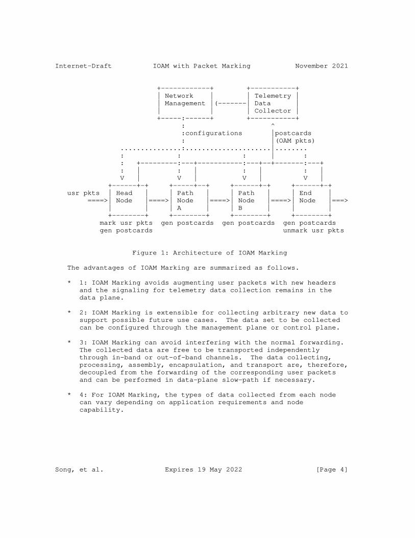
Internet-Draft IOAM with Packet Marking November 2021
+------------+ +-----------+ | Network | | Telemetry | | Management |(-------| Data | | | | Collector | +-----:------+ +-----------+ : ^ :configurations |postcards : |(OAM pkts) ...............:.....................|........ : : : | : : +---------:---+-----------:---+--+-------:---+ : | : | : | : | V | V | V | V | +------+-+ +-----+--+ +------+-+ +------+-+ usr pkts | Head | | Path | | Path | | End | ====>| Node |====>| Node |====>| Node |====>| Node |===> | | | A | | B | | | +--------+ +--------+ +--------+ +--------+ mark usr pkts gen postcards gen postcards gen postcards gen postcards unmark usr pkts
Figure 1: Architecture of IOAM Marking
The advantages of IOAM Marking are summarized as follows.
* 1: IOAM Marking avoids augmenting user packets with new headers and the signaling for telemetry data collection remains in the data plane.
* 2: IOAM Marking is extensible for collecting arbitrary new data to support possible future use cases. The data set to be collected can be configured through the management plane or control plane.
* 3: IOAM Marking can avoid interfering with the normal forwarding. The collected data are free to be transported independently through in-band or out-of-band channels. The data collecting, processing, assembly, encapsulation, and transport are, therefore, decoupled from the forwarding of the corresponding user packets and can be performed in data-plane slow-path if necessary.
* 4: For IOAM Marking, the types of data collected from each node can vary depending on application requirements and node capability.
Song, et al. Expires 19 May 2022 [Page 4]

Internet-Draft IOAM with Packet Marking November 2021
* 5: IOAM Marking makes it easy to secure the collected data without exposing it to unnecessary entities. For example, both the configuration and the telemetry data can be encrypted and/or authenticated before being transported, so passive eavesdropping and a man-in-the-middle attack can both be deterred.
* 6: Even if a user packet under inspection is dropped at some node in the network, the postcards collected from the preceding nodes are still valid and can be used to diagnose the packet drop location and reason.
3. New Challenges
Although IOAM Marking has some unique features compared to the passport mode telemetry and the instruction-based IOAM DEX, it introduces a few new challenges.
* Challenge 1 (Packet Marking): A user packet needs to be marked to trigger the path-associated data collection. Since IOAM Marking does not augment user packets with any new header fields, it needs to reserve or reuse bits from the existing header fields. This raises a similar issue as in the Alternate Marking Scheme [RFC8321]
* Challenge 2 (Configuration): Since the packet header will not carry IOAM instructions anymore, the data plane devices need to be configured to know what data to collect. However, in general, the forwarding path of a flow packet (due to ECMP or dynamic routing) is unknown beforehand (note that there are some notable exceptions, such as segment routing). If the per-flow customized data collection is required, configuring the data set for each flow at all data plane devices might be expensive in terms of configuration load and data plane resources.
* Challenge 3 (Data Correlation): Due to the variable transport latency, the dedicated postcard packets for a single packet may arrive at the collector out of order or be dropped in networks for some reason. In order to infer the packet forwarding path, the collector needs some information from the postcard packets to identify the user packet affiliation and the order of path node traversal.
* Challenge 4 (Load Overhead): Since each postcard packet has its header, the overall network bandwidth overhead of IOAM Marking can be high. A large number of postcards could add processing pressure on data collecting servers. That can be used as an attack vector for DoS.
Song, et al. Expires 19 May 2022 [Page 5]

Internet-Draft IOAM with Packet Marking November 2021
4. IOAM Marking Design Considerations
To address the above challenges, we propose several design details of IOAM Marking.
4.1. Packet Marking
To trigger the path-associated data collection, usually, a single bit from some header field is sufficient. While no such bit is available, other packet-marking techniques are needed. We discuss several possible application scenarios.
* IPv4. Alternate Marking (AM) [RFC8321] is an IP flow performance measurement framework that also requires a single bit for packet coloring. The difference is that AM does in-network measurement while IOAM Marking only collects and exports data at network nodes (i.e., the data analysis is done at the collector rather than in the network nodes). AM suggests to use some reserved bit of the Flag field or some unused bit of the TOS field. Actually, AM can be considered a sub-case of IOAM Marking, so that the same bit can be used for IOAM Marking. The management plane is responsible for configuring the actual operation mode.
* SFC NSH. The OAM bit in the NSH header can be used to trigger the on-path data collection [RFC8300]. IOAM Marking does not add any other metadata to NSH.
* MPLS. Instead of choosing a header bit, we take advantage of the synonymous flow label [I-D.bryant-mpls-synonymous-flow-labels] approach to mark the packets. A synonymous flow label indicates the on-path data should be collected and forwarded through a postcard.
* SRv6: A flag bit in SRH can be reserved to trigger the on-path data collection [I-D.song-6man-srv6-pbt]. SRv6 OAM [I-D.ietf-6man-spring-srv6-oam] has adopted the O-bit in SRH flags as the marking bit to trigger the telemetry.
4.2. Flow Path Discovery
In case the path that a flow traverses is unknown in advance, all IOAM Marking-aware nodes should be configured to react to the marked packets by exporting some basic data, such as node ID and TTL before a data set template for that flow is configured. This way, the management plane can learn the flow path dynamically.
Song, et al. Expires 19 May 2022 [Page 6]

Internet-Draft IOAM with Packet Marking November 2021
If the management plane wants to collect the on-path data for some flow, it configures the head node(s) with a probability or time interval for the flow packet marking. When the first marked packet is forwarded in the network, the IOAM Marking-aware nodes will export the basic data set to the collector. Hence, the flow path is identified. If other data types need to be collected, the management plane can further configure the data set’s template to the target nodes on the flow’s path. The IOAM Marking-aware nodes collect and export data accordingly if the packet is marked and a data set template is present.
If the flow path is changed for any reason, the new path can be quickly learned by the collector. Consequently, the management plane controller can be directed to configure the nodes on the new path. The outdated configuration can be automatically timed out or explicitly revoked by the management plane controller.
4.3. Packet Identity for Export Data Correlation
The collector needs to correlate all the postcard packets for a single user packet. Once this is done, the TTL (or the timestamp, if the network time is synchronized) can be used to infer the flow forwarding path. The key issue here is to correlate all the postcards for the same user packet.
The first possible approach includes the flow ID plus the user packet ID in the OAM packets. For example, the flow ID can be the 5-tuple IP header of the user traffic, and the user packet ID can be some unique information pertaining to a user packet (e.g., the sequence number of a TCP packet).
If the packet marking interval is large enough, the flow ID is enough to identify a user packet. As a result, it can be assumed that all the exported postcard packets for the same flow during a short time interval belong to the same user packet.
Alternatively, if the network is synchronized, then the flow ID plus the timestamp at each node can also infer the postcard affiliation. However, some errors may occur under some circumstances. For example, two consecutive user packets from the same flows are marked, but one exported postcard from a node is lost. It is difficult for the collector to decide to which user packet the remaining postcard is related. In many cases, such a rare error has no catastrophic consequence. Therefore it is tolerable.
Song, et al. Expires 19 May 2022 [Page 7]

Internet-Draft IOAM with Packet Marking November 2021
4.4. Control the Load
IOAM Marking should not be applied to all the packets all the time. It is better to be used in an interactive environment where the network telemetry applications dynamically decide which subset of traffic is under scrutiny. The network devices can limit the packet marking rate through sampling and metering. The postcard packets can be distributed to different servers to balance the processing load.
It is important to understand that the total amount of data exported by IOAM Marking is identical to that of IOAM trace option. The only extra overhead is the packet header of the postcards. In the case of IOAM trace option, it carries the data from each node throughout the path to the end node before exporting the aggregated data. On the other hand, IOAM Marking directly exports local data. The overall network bandwidth impact depends on the network topology and scale, and in some cases IOAM Marking could be more bandwidth efficient.
5. Implementation Recommendation
5.1. Configuration
The head node’s ACL should be configured to filter out the target flows for telemetry data collection. Optionally, a flow packet sampling rate or probability could be configured to monitor a subset of the flow packets.
The telemetry data set that should be exported by postcards at each path node could be configured using the data set templates specified, for example, in IPFIX [RFC7011]. In future revisions, we will provide more details.
The IOAM Marking-aware path nodes could be configured to respond or ignore the marked packets.
5.2. Postcard Format
The postcard should use the same data export format as that used by IOAM. [I-D.spiegel-ippm-ioam-rawexport] proposes a raw format that can be interpreted by IPFIX. In future revisions, we will provide more details.
Song, et al. Expires 19 May 2022 [Page 8]
Internet-Draft IOAM with Packet Marking November 2021
5.3. Data Correlation
Enough information should be included to help the collector to correlate and order the postcards for a single user packet. Section 4.3 provides several possible means. The application scenario and network protocol are important factors to determine the means to use. In future revisions, we will provide details for representative applications.
6. Security Considerations
Several security issues need to be considered.
* Eavesdrop and tamper: the postcards can be encrypted and authenticated to avoid such security threats.
* DoS attack: IOAM Marking can be limited to a single administrative domain. The mark must be removed at the egress domain edge. The node can rate-limit the extra traffic incurred by postcards.
7. IANA Considerations
No requirement for IANA is identified.
8. Contributors
We thank Alfred Morton who provided valuable suggestions and comments helping improve this draft.
9. Acknowledgments
TBD.
10. Informative References
[I-D.bryant-mpls-synonymous-flow-labels] Bryant, S., Swallow, G., Sivabalan, S., Mirsky, G., Chen, M., and Z. Li, "RFC6374 Synonymous Flow Labels", Work in Progress, Internet-Draft, draft-bryant-mpls-synonymous- flow-labels-01, 4 July 2015, <https://www.ietf.org/archive/id/draft-bryant-mpls- synonymous-flow-labels-01.txt>.
[I-D.ietf-6man-spring-srv6-oam] Ali, Z., Filsfils, C., Matsushima, S., Voyer, D., and M. Chen, "Operations, Administration, and Maintenance (OAM) in Segment Routing Networks with IPv6 Data plane (SRv6)", Work in Progress, Internet-Draft, draft-ietf-6man-spring-
Song, et al. Expires 19 May 2022 [Page 9]

Internet-Draft IOAM with Packet Marking November 2021
srv6-oam-11, 2 June 2021, <https://www.ietf.org/archive/id/draft-ietf-6man-spring- srv6-oam-11.txt>.
[I-D.ietf-ippm-ioam-data] Brockners, F., Bhandari, S., and T. Mizrahi, "Data Fields for In-situ OAM", Work in Progress, Internet-Draft, draft- ietf-ippm-ioam-data-16, 8 November 2021, <https://www.ietf.org/archive/id/draft-ietf-ippm-ioam- data-16.txt>.
[I-D.ietf-ippm-ioam-direct-export] Song, H., Gafni, B., Zhou, T., Li, Z., Brockners, F., Bhandari, S., Sivakolundu, R., and T. Mizrahi, "In-situ OAM Direct Exporting", Work in Progress, Internet-Draft, draft-ietf-ippm-ioam-direct-export-07, 13 October 2021, <https://www.ietf.org/archive/id/draft-ietf-ippm-ioam- direct-export-07.txt>.
[I-D.song-6man-srv6-pbt] Song, H., "Support Postcard-Based Telemetry for SRv6 OAM", Work in Progress, Internet-Draft, draft-song-6man-srv6- pbt-01, 14 October 2019, <https://www.ietf.org/archive/id/ draft-song-6man-srv6-pbt-01.txt>.
[I-D.spiegel-ippm-ioam-rawexport] Spiegel, M., Brockners, F., Bhandari, S., and R. Sivakolundu, "In-situ OAM raw data export with IPFIX", Work in Progress, Internet-Draft, draft-spiegel-ippm-ioam- rawexport-05, 12 July 2021, <https://www.ietf.org/archive/id/draft-spiegel-ippm-ioam- rawexport-05.txt>.
[RFC2925] White, K., "Definitions of Managed Objects for Remote Ping, Traceroute, and Lookup Operations", RFC 2925, DOI 10.17487/RFC2925, September 2000, <https://www.rfc-editor.org/info/rfc2925>.
[RFC7011] Claise, B., Ed., Trammell, B., Ed., and P. Aitken, "Specification of the IP Flow Information Export (IPFIX) Protocol for the Exchange of Flow Information", STD 77, RFC 7011, DOI 10.17487/RFC7011, September 2013, <https://www.rfc-editor.org/info/rfc7011>.
[RFC8300] Quinn, P., Ed., Elzur, U., Ed., and C. Pignataro, Ed., "Network Service Header (NSH)", RFC 8300, DOI 10.17487/RFC8300, January 2018, <https://www.rfc-editor.org/info/rfc8300>.
Song, et al. Expires 19 May 2022 [Page 10]

Internet-Draft IOAM with Packet Marking November 2021
[RFC8321] Fioccola, G., Ed., Capello, A., Cociglio, M., Castaldelli, L., Chen, M., Zheng, L., Mirsky, G., and T. Mizrahi, "Alternate-Marking Method for Passive and Hybrid Performance Monitoring", RFC 8321, DOI 10.17487/RFC8321, January 2018, <https://www.rfc-editor.org/info/rfc8321>.
Authors’ Addresses
Haoyu Song Futurewei Technologies 2330 Central Expressway Santa Clara, 95050, United States of America
Email: [email protected]
Greg Mirsky Ericsson
Email: [email protected]
Clarence Filsfils Cisco Systems, Inc. Belgium
Email: [email protected]
Ahmed Abdelsalam Cisco Systems, Inc. Italy
Email: [email protected]
Tianran Zhou Huawei 156 Beiqing Road Beijing, 100095 P.R. China
Email: [email protected]
Song, et al. Expires 19 May 2022 [Page 11]

Internet-Draft IOAM with Packet Marking November 2021
Zhenbin Li Huawei 156 Beiqing Road Beijing, 100095 P.R. China
Email: [email protected]
Jongyoon Shin SK Telecom South Korea
Email: [email protected]
Kyungtae Lee LG U+ South Korea
Email: [email protected]
Song, et al. Expires 19 May 2022 [Page 12]
IPPM Working Group X. MinInternet-Draft G. MirskyIntended status: Standards Track ZTE Corp.Expires: December 9, 2021 L. Bo China Telecom June 7, 2021
Echo Request/Reply for Enabled In-situ OAM Capabilities draft-xiao-ippm-ioam-conf-state-10
Abstract
This document describes an extension to the echo request/reply mechanisms used in IPv6, MPLS, SFC and BIER environments, which can be used within an IOAM domain, allowing the IOAM encapsulating node to acquire the enabled IOAM capabilities of each IOAM transit node and/or IOAM decapsulating node.
Status of This Memo
This Internet-Draft is submitted in full conformance with the provisions of BCP 78 and BCP 79.
Internet-Drafts are working documents of the Internet Engineering Task Force (IETF). Note that other groups may also distribute working documents as Internet-Drafts. The list of current Internet- Drafts is at https://datatracker.ietf.org/drafts/current/.
Internet-Drafts are draft documents valid for a maximum of six months and may be updated, replaced, or obsoleted by other documents at any time. It is inappropriate to use Internet-Drafts as reference material or to cite them other than as "work in progress."
This Internet-Draft will expire on December 9, 2021.
Copyright Notice
Copyright (c) 2021 IETF Trust and the persons identified as the document authors. All rights reserved.
This document is subject to BCP 78 and the IETF Trust’s Legal Provisions Relating to IETF Documents (https://trustee.ietf.org/license-info) in effect on the date of publication of this document. Please review these documents carefully, as they describe your rights and restrictions with respect to this document. Code Components extracted from this document must include Simplified BSD License text as described in Section 4.e of
Min, et al. Expires December 9, 2021 [Page 1]

Internet-Draft Ping Enabled IOAM Capabilities June 2021
the Trust Legal Provisions and are provided without warranty as described in the Simplified BSD License.
Table of Contents
1. Introduction . . . . . . . . . . . . . . . . . . . . . . . . 2 2. Conventions . . . . . . . . . . . . . . . . . . . . . . . . . 4 2.1. Requirements Language . . . . . . . . . . . . . . . . . . 4 2.2. Abbreviations . . . . . . . . . . . . . . . . . . . . . . 4 3. IOAM Capabilities Formats . . . . . . . . . . . . . . . . . . 5 3.1. IOAM Capabilities Query TLV in the Echo Request . . . . . 5 3.2. IOAM Capabilities Response TLV in the Echo Reply . . . . 6 3.2.1. IOAM Pre-allocated Tracing Capabilities sub-TLV . . . 7 3.2.2. IOAM Incremental Tracing Capabilities sub-TLV . . . . 8 3.2.3. IOAM Proof of Transit Capabilities sub-TLV . . . . . 9 3.2.4. IOAM Edge-to-Edge Capabilities sub-TLV . . . . . . . 10 3.2.5. IOAM DEX Capabilities sub-TLV . . . . . . . . . . . . 11 3.2.6. IOAM End-of-Domain sub-TLV . . . . . . . . . . . . . 12 4. Operational Guide . . . . . . . . . . . . . . . . . . . . . . 13 5. Security Considerations . . . . . . . . . . . . . . . . . . . 13 6. IANA Considerations . . . . . . . . . . . . . . . . . . . . . 14 6.1. IOAM SoR Capability Registry . . . . . . . . . . . . . . 14 6.2. IOAM TSF+TSL Capability Registry . . . . . . . . . . . . 15 7. Acknowledgements . . . . . . . . . . . . . . . . . . . . . . 15 8. References . . . . . . . . . . . . . . . . . . . . . . . . . 16 8.1. Normative References . . . . . . . . . . . . . . . . . . 16 8.2. Informative References . . . . . . . . . . . . . . . . . 16 Authors’ Addresses . . . . . . . . . . . . . . . . . . . . . . . 17
1. Introduction
The Data Fields for In-situ OAM (IOAM) [I-D.ietf-ippm-ioam-data] defines data fields that record OAM information within the packet while the packet traverses a particular network domain, which is called an IOAM domain. IOAM can be used to complement OAM mechanisms based on, e.g., ICMP or other types of probe packets, and IOAM mechanisms can be leveraged where mechanisms using, e.g., ICMP do not apply or do not offer the desired results.
As specified in [I-D.ietf-ippm-ioam-data], within the IOAM-domain, the IOAM data may be updated by network nodes that the packet traverses. The device which adds an IOAM data container to the packet to capture IOAM data is called the "IOAM encapsulating node". In contrast, the device which removes the IOAM data container is referred to as the "IOAM decapsulating node". Nodes within the domain that are aware of IOAM data and read and/or write or process the IOAM data are called "IOAM transit nodes". Both the IOAM
Min, et al. Expires December 9, 2021 [Page 2]

Internet-Draft Ping Enabled IOAM Capabilities June 2021
encapsulating node and the decapsulating node are referred to as domain edge devices, which can be hosts or network devices.
In order to add the correct IOAM data container to the packet, the IOAM encapsulating node needs to know the enabled IOAM capabilities at the IOAM transit nodes and/or the IOAM decapsulating node as a whole, e.g., how many IOAM transit nodes will add tracing data, and what kinds of data fields will be added. A centralized controller could be used in some IOAM deployments. The IOAM encapsulating node can acquire these IOAM capabilities info from the centralized controller, through, e.g., NETCONF/YANG, PCEP, or BGP. In the IOAM deployment scenario where there is no centralized controller, NETCONF/YANG or IGP may be used for the IOAM encapsulating node to acquire these IOAM capabilities info, however, whether NETCONF/YANG or IGP has some limitations as follows.
o When NETCONF/YANG is used in this scenario, each IOAM encapsulating node (including the host when it takes the role of an IOAM encapsulating node) needs to implement a NETCONF Client, each IOAM transit node and IOAM decapsulating node (including the host when it takes the role of an IOAM decapsulating node) needs to implement a NETCONF Server, the complexity can be an issue. Furthermore, each IOAM encapsulating node needs to establish NETCONF Connection with each IOAM transit node and IOAM decapsulating node, the scalability can be an issue.
o When IGP is used in this scenario, the IGP domain and an IOAM domain don’t always have the same coverage. For example, when the IOAM encapsulating node or the IOAM decapsulating node is a host, the availability can be an issue. Furthermore, it might be too challenging to reflect IOAM capabilities at the IOAM transit node and/or the IOAM decapsulating node if these are controlled by a local policy depending on the identity of the IOAM encapsulating node.
This document describes an extension to the echo request/reply mechanisms used in IPv6, MPLS, SFC and BIER environments, which can be used within an IOAM domain where no Centralized Controller exists, allowing the IOAM encapsulating node to acquire the enabled IOAM capabilities of each IOAM transit node and/or IOAM decapsulating node.
The following documents contain references to the echo request/reply mechanisms used in IPv6, MPLS, SFC and BIER environments:
o [RFC4443] ("Internet Control Message Protocol (ICMPv6) for the Internet Protocol Version 6 (IPv6) Specification"), [RFC4884]
Min, et al. Expires December 9, 2021 [Page 3]

Internet-Draft Ping Enabled IOAM Capabilities June 2021
("Extended ICMP to Support Multi-Part Messages") and [RFC8335] ("PROBE: A Utility for Probing Interfaces")
o [RFC8029] ("Detecting Multiprotocol Label Switched (MPLS) Data- Plane Failures")
o [I-D.ietf-sfc-multi-layer-oam] ("Active OAM for Service Function Chains in Networks")
o [I-D.ietf-bier-ping] ("BIER Ping and Trace")
This feature described in this document is assumedly applied to explicit path (strict or loose), because the precondition for this feature to work is that the echo request reaches each IOAM transit node as live traffic traverses.
2. Conventions
2.1. Requirements Language
The key words "MUST", "MUST NOT", "REQUIRED", "SHALL", "SHALL NOT", "SHOULD", "SHOULD NOT", "RECOMMENDED", "NOT RECOMMENDED", "MAY", and "OPTIONAL" in this document are to be interpreted as described in BCP 14 [RFC2119] [RFC8174] when, and only when, they appear in all capitals, as shown here.
2.2. Abbreviations
BIER: Bit Index Explicit Replication
BGP: Border Gateway Protocol
E2E: Edge to Edge
ICMP: Internet Control Message Protocol
IGP: Interior Gateway Protocol
IOAM: In-situ Operations, Administration, and Maintenance
LSP: Label Switched Path
MPLS: Multi-Protocol Label Switching
MBZ: Must Be Zero
MTU: Maximum Transmission Unit
Min, et al. Expires December 9, 2021 [Page 4]
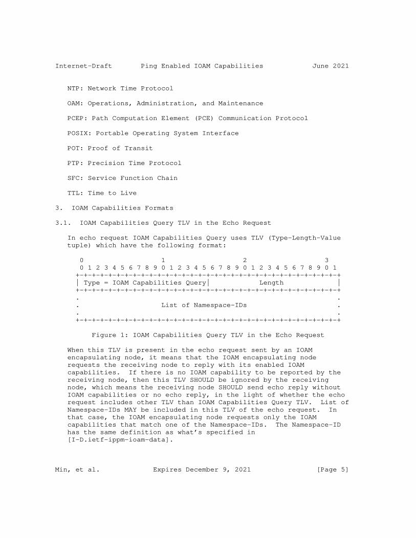
Internet-Draft Ping Enabled IOAM Capabilities June 2021
NTP: Network Time Protocol
OAM: Operations, Administration, and Maintenance
PCEP: Path Computation Element (PCE) Communication Protocol
POSIX: Portable Operating System Interface
POT: Proof of Transit
PTP: Precision Time Protocol
SFC: Service Function Chain
TTL: Time to Live
3. IOAM Capabilities Formats
3.1. IOAM Capabilities Query TLV in the Echo Request
In echo request IOAM Capabilities Query uses TLV (Type-Length-Value tuple) which have the following format:
0 1 2 3 0 1 2 3 4 5 6 7 8 9 0 1 2 3 4 5 6 7 8 9 0 1 2 3 4 5 6 7 8 9 0 1 +-+-+-+-+-+-+-+-+-+-+-+-+-+-+-+-+-+-+-+-+-+-+-+-+-+-+-+-+-+-+-+-+ | Type = IOAM Capabilities Query| Length | +-+-+-+-+-+-+-+-+-+-+-+-+-+-+-+-+-+-+-+-+-+-+-+-+-+-+-+-+-+-+-+-+ . . . List of Namespace-IDs . . . +-+-+-+-+-+-+-+-+-+-+-+-+-+-+-+-+-+-+-+-+-+-+-+-+-+-+-+-+-+-+-+-+
Figure 1: IOAM Capabilities Query TLV in the Echo Request
When this TLV is present in the echo request sent by an IOAM encapsulating node, it means that the IOAM encapsulating node requests the receiving node to reply with its enabled IOAM capabilities. If there is no IOAM capability to be reported by the receiving node, then this TLV SHOULD be ignored by the receiving node, which means the receiving node SHOULD send echo reply without IOAM capabilities or no echo reply, in the light of whether the echo request includes other TLV than IOAM Capabilities Query TLV. List of Namespace-IDs MAY be included in this TLV of the echo request. In that case, the IOAM encapsulating node requests only the IOAM capabilities that match one of the Namespace-IDs. The Namespace-ID has the same definition as what’s specified in [I-D.ietf-ippm-ioam-data].
Min, et al. Expires December 9, 2021 [Page 5]
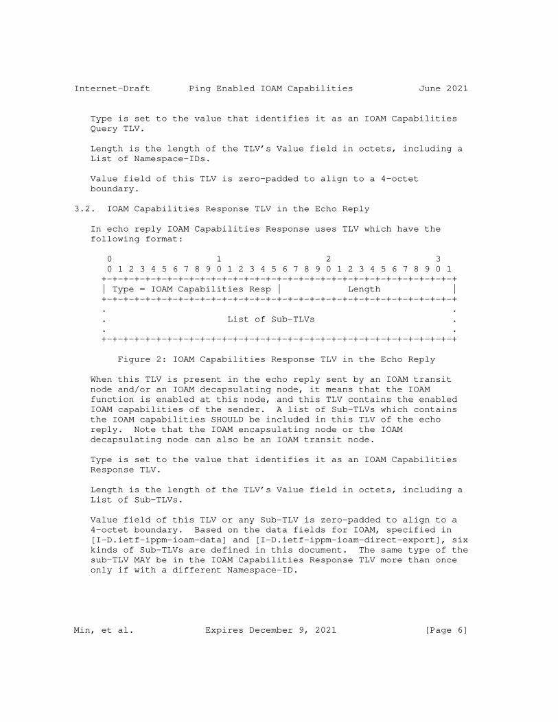
Internet-Draft Ping Enabled IOAM Capabilities June 2021
Type is set to the value that identifies it as an IOAM Capabilities Query TLV.
Length is the length of the TLV’s Value field in octets, including a List of Namespace-IDs.
Value field of this TLV is zero-padded to align to a 4-octet boundary.
3.2. IOAM Capabilities Response TLV in the Echo Reply
In echo reply IOAM Capabilities Response uses TLV which have the following format:
0 1 2 3 0 1 2 3 4 5 6 7 8 9 0 1 2 3 4 5 6 7 8 9 0 1 2 3 4 5 6 7 8 9 0 1 +-+-+-+-+-+-+-+-+-+-+-+-+-+-+-+-+-+-+-+-+-+-+-+-+-+-+-+-+-+-+-+-+ | Type = IOAM Capabilities Resp | Length | +-+-+-+-+-+-+-+-+-+-+-+-+-+-+-+-+-+-+-+-+-+-+-+-+-+-+-+-+-+-+-+-+ . . . List of Sub-TLVs . . . +-+-+-+-+-+-+-+-+-+-+-+-+-+-+-+-+-+-+-+-+-+-+-+-+-+-+-+-+-+-+-+-+
Figure 2: IOAM Capabilities Response TLV in the Echo Reply
When this TLV is present in the echo reply sent by an IOAM transit node and/or an IOAM decapsulating node, it means that the IOAM function is enabled at this node, and this TLV contains the enabled IOAM capabilities of the sender. A list of Sub-TLVs which contains the IOAM capabilities SHOULD be included in this TLV of the echo reply. Note that the IOAM encapsulating node or the IOAM decapsulating node can also be an IOAM transit node.
Type is set to the value that identifies it as an IOAM Capabilities Response TLV.
Length is the length of the TLV’s Value field in octets, including a List of Sub-TLVs.
Value field of this TLV or any Sub-TLV is zero-padded to align to a 4-octet boundary. Based on the data fields for IOAM, specified in [I-D.ietf-ippm-ioam-data] and [I-D.ietf-ippm-ioam-direct-export], six kinds of Sub-TLVs are defined in this document. The same type of the sub-TLV MAY be in the IOAM Capabilities Response TLV more than once only if with a different Namespace-ID.
Min, et al. Expires December 9, 2021 [Page 6]

Internet-Draft Ping Enabled IOAM Capabilities June 2021
3.2.1. IOAM Pre-allocated Tracing Capabilities sub-TLV
0 1 2 3 0 1 2 3 4 5 6 7 8 9 0 1 2 3 4 5 6 7 8 9 0 1 2 3 4 5 6 7 8 9 0 1 +-+-+-+-+-+-+-+-+-+-+-+-+-+-+-+-+-+-+-+-+-+-+-+-+-+-+-+-+-+-+-+-+ |Sub-type = Pre-allocated trace | Length | +-+-+-+-+-+-+-+-+-+-+-+-+-+-+-+-+-+-+-+-+-+-+-+-+-+-+-+-+-+-+-+-+ | IOAM-Trace-Type | Reserved | +-+-+-+-+-+-+-+-+-+-+-+-+-+-+-+-+-+-+-+-+-+-+-+-+-+-+-+-+-+-+-+-+ | Namespace-ID | Egress_MTU | +-+-+-+-+-+-+-+-+-+-+-+-+-+-+-+-+-+-+-+-+-+-+-+-+-+-+-+-+-+-+-+-+ | Egress_if_id (short or wide format) ...... | +-+-+-+-+-+-+-+-+-+-+-+-+-+-+-+-+-+-+-+-+-+-+-+-+-+-+-+-+-+-+-+-+
Figure 3: IOAM Pre-allocated Tracing Capabilities Sub-TLV
When this sub-TLV is present in the IOAM Capabilities Response TLV, it means that the sending node is an IOAM transit node and IOAM pre- allocated tracing function is enabled at this IOAM transit node.
Sub-type is set to the value that identifies it as an IOAM Pre- allocated Tracing Capabilities sub-TLV.
Length is the length of the sub-TLV’s Value field in octets. If Egress_if_id is in the short format, which is 16 bits long, it MUST be set to 10. If Egress_if_id is in the wide format, which is 32 bits long, it MUST be set to 12.
IOAM-Trace-Type field has the same definition as what’s specified in section 5.4 of [I-D.ietf-ippm-ioam-data].
Reserved field is reserved for future use and MUST be set to zero.
Namespace-ID field has the same definition as what’s specified in section 5.3 of [I-D.ietf-ippm-ioam-data], it should be one of the Namespace-IDs listed in the IOAM Capabilities Query TLV of echo request.
Egress_MTU field has 16 bits and specifies the MTU of the egress direction out of which the sending node would forward the received echo request, it should be the MTU of the egress interface or the MTU between the sending node and the downstream IOAM transit node.
Egress_if_id field has 16 bits (in short format) or 32 bits (in wide format) and specifies the identifier of the egress interface out of which the sending node would forward the received echo request.
Min, et al. Expires December 9, 2021 [Page 7]
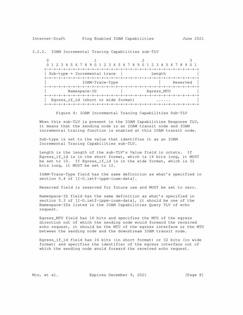
Internet-Draft Ping Enabled IOAM Capabilities June 2021
3.2.2. IOAM Incremental Tracing Capabilities sub-TLV
0 1 2 3 0 1 2 3 4 5 6 7 8 9 0 1 2 3 4 5 6 7 8 9 0 1 2 3 4 5 6 7 8 9 0 1 +-+-+-+-+-+-+-+-+-+-+-+-+-+-+-+-+-+-+-+-+-+-+-+-+-+-+-+-+-+-+-+-+ | Sub-type = Incremental trace | Length | +-+-+-+-+-+-+-+-+-+-+-+-+-+-+-+-+-+-+-+-+-+-+-+-+-+-+-+-+-+-+-+-+ | IOAM-Trace-Type | Reserved | +-+-+-+-+-+-+-+-+-+-+-+-+-+-+-+-+-+-+-+-+-+-+-+-+-+-+-+-+-+-+-+-+ | Namespace-ID | Egress_MTU | +-+-+-+-+-+-+-+-+-+-+-+-+-+-+-+-+-+-+-+-+-+-+-+-+-+-+-+-+-+-+-+-+ | Egress_if_id (short or wide format) ...... | +-+-+-+-+-+-+-+-+-+-+-+-+-+-+-+-+-+-+-+-+-+-+-+-+-+-+-+-+-+-+-+-+
Figure 4: IOAM Incremental Tracing Capabilities Sub-TLV
When this sub-TLV is present in the IOAM Capabilities Response TLV, it means that the sending node is an IOAM transit node and IOAM incremental tracing function is enabled at this IOAM transit node.
Sub-type is set to the value that identifies it as an IOAM Incremental Tracing Capabilities sub-TLV.
Length is the length of the sub-TLV’s Value field in octets. If Egress_if_id is in the short format, which is 16 bits long, it MUST be set to 10. If Egress_if_id is in the wide format, which is 32 bits long, it MUST be set to 12.
IOAM-Trace-Type field has the same definition as what’s specified in section 5.4 of [I-D.ietf-ippm-ioam-data].
Reserved field is reserved for future use and MUST be set to zero.
Namespace-ID field has the same definition as what’s specified in section 5.3 of [I-D.ietf-ippm-ioam-data], it should be one of the Namespace-IDs listed in the IOAM Capabilities Query TLV of echo request.
Egress_MTU field has 16 bits and specifies the MTU of the egress direction out of which the sending node would forward the received echo request, it should be the MTU of the egress interface or the MTU between the sending node and the downstream IOAM transit node.
Egress_if_id field has 16 bits (in short format) or 32 bits (in wide format) and specifies the identifier of the egress interface out of which the sending node would forward the received echo request.
Min, et al. Expires December 9, 2021 [Page 8]

Internet-Draft Ping Enabled IOAM Capabilities June 2021
3.2.3. IOAM Proof of Transit Capabilities sub-TLV
0 1 2 3 0 1 2 3 4 5 6 7 8 9 0 1 2 3 4 5 6 7 8 9 0 1 2 3 4 5 6 7 8 9 0 1 +-+-+-+-+-+-+-+-+-+-+-+-+-+-+-+-+-+-+-+-+-+-+-+-+-+-+-+-+-+-+-+-+ | Sub-type = POT Capabilities | Length | +-+-+-+-+-+-+-+-+-+-+-+-+-+-+-+-+-+-+-+-+-+-+-+-+-+-+-+-+-+-+-+-+ | Namespace-ID | IOAM-POT-Type |P|SoR|Reserved | +-+-+-+-+-+-+-+-+-+-+-+-+-+-+-+-+-+-+-+-+-+-+-+-+-+-+-+-+-+-+-+-+
Figure 5: IOAM Proof of Transit Capabilities Sub-TLV
When this sub-TLV is present in the IOAM Capabilities Response TLV, it means that the sending node is an IOAM transit node and IOAM proof of transit function is enabled at this IOAM transit node.
Sub-type is set to the value that identifies it as an IOAM Proof of Transit Capabilities sub-TLV.
Length is the length of the sub-TLV’s Value field in octets and MUST be set to 4.
Namespace-ID field has the same definition as what’s specified in section 5.3 of [I-D.ietf-ippm-ioam-data], it should be one of the Namespace-IDs listed in the IOAM Capabilities Query TLV of echo request.
IOAM-POT-Type field and P bit have the same definition as what’s specified in section 5.5 of [I-D.ietf-ippm-ioam-data]. If the IOAM encapsulating node receives IOAM-POT-Type and/or P bit values from an IOAM transit node that are different from its own, then the IOAM encapsulating node MAY choose to abandon the proof of transit function or to select one kind of IOAM-POT-Type and P bit, it’s based on the policy applied to the IOAM encapsulating node.
SoR field has two bits, which means the size of "Random" and "Cumulative" data that are specified in section 5.5 of [I-D.ietf-ippm-ioam-data]. This document defines SoR as follow:
0b00 means 64-bit "Random" and 64-bit "Cumulative" data.
0b01˜0b11: Reserved for future standardization
Reserved field is reserved for future use and MUST be set to zero.
Min, et al. Expires December 9, 2021 [Page 9]
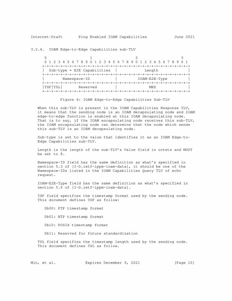
Internet-Draft Ping Enabled IOAM Capabilities June 2021
3.2.4. IOAM Edge-to-Edge Capabilities sub-TLV
0 1 2 3 0 1 2 3 4 5 6 7 8 9 0 1 2 3 4 5 6 7 8 9 0 1 2 3 4 5 6 7 8 9 0 1 +-+-+-+-+-+-+-+-+-+-+-+-+-+-+-+-+-+-+-+-+-+-+-+-+-+-+-+-+-+-+-+-+ | Sub-type = E2E Capabilities | Length | +-+-+-+-+-+-+-+-+-+-+-+-+-+-+-+-+-+-+-+-+-+-+-+-+-+-+-+-+-+-+-+-+ | Namespace-ID | IOAM-E2E-Type | +-+-+-+-+-+-+-+-+-+-+-+-+-+-+-+-+-+-+-+-+-+-+-+-+-+-+-+-+-+-+-+-+ |TSF|TSL| Reserved | MBZ | +-+-+-+-+-+-+-+-+-+-+-+-+-+-+-+-+-+-+-+-+-+-+-+-+-+-+-+-+-+-+-+-+
Figure 6: IOAM Edge-to-Edge Capabilities Sub-TLV
When this sub-TLV is present in the IOAM Capabilities Response TLV, it means that the sending node is an IOAM decapsulating node and IOAM edge-to-edge function is enabled at this IOAM decapsulating node. That is to say, if the IOAM encapsulating node receives this sub-TLV, the IOAM encapsulating node can determine that the node which sends this sub-TLV is an IOAM decapsulating node.
Sub-type is set to the value that identifies it as an IOAM Edge-to- Edge Capabilities sub-TLV.
Length is the length of the sub-TLV’s Value field in octets and MUST be set to 8.
Namespace-ID field has the same definition as what’s specified in section 5.3 of [I-D.ietf-ippm-ioam-data], it should be one of the Namespace-IDs listed in the IOAM Capabilities Query TLV of echo request.
IOAM-E2E-Type field has the same definition as what’s specified in section 5.6 of [I-D.ietf-ippm-ioam-data].
TSF field specifies the timestamp format used by the sending node. This document defines TSF as follow:
0b00: PTP timestamp format
0b01: NTP timestamp format
0b10: POSIX timestamp format
0b11: Reserved for future standardization
TSL field specifies the timestamp length used by the sending node. This document defines TSL as follow.
Min, et al. Expires December 9, 2021 [Page 10]
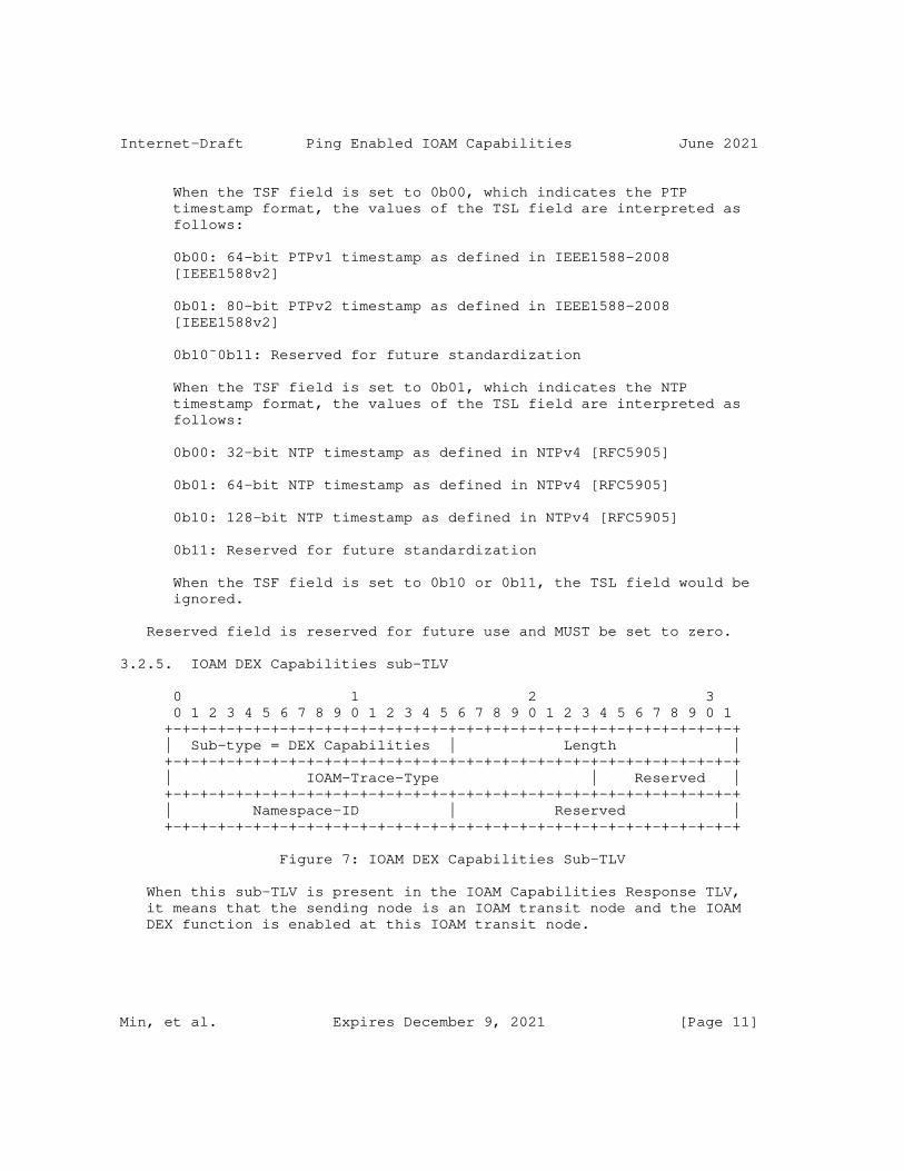
Internet-Draft Ping Enabled IOAM Capabilities June 2021
When the TSF field is set to 0b00, which indicates the PTP timestamp format, the values of the TSL field are interpreted as follows:
0b00: 64-bit PTPv1 timestamp as defined in IEEE1588-2008 [IEEE1588v2]
0b01: 80-bit PTPv2 timestamp as defined in IEEE1588-2008 [IEEE1588v2]
0b10˜0b11: Reserved for future standardization
When the TSF field is set to 0b01, which indicates the NTP timestamp format, the values of the TSL field are interpreted as follows:
0b00: 32-bit NTP timestamp as defined in NTPv4 [RFC5905]
0b01: 64-bit NTP timestamp as defined in NTPv4 [RFC5905]
0b10: 128-bit NTP timestamp as defined in NTPv4 [RFC5905]
0b11: Reserved for future standardization
When the TSF field is set to 0b10 or 0b11, the TSL field would be ignored.
Reserved field is reserved for future use and MUST be set to zero.
3.2.5. IOAM DEX Capabilities sub-TLV
0 1 2 3 0 1 2 3 4 5 6 7 8 9 0 1 2 3 4 5 6 7 8 9 0 1 2 3 4 5 6 7 8 9 0 1 +-+-+-+-+-+-+-+-+-+-+-+-+-+-+-+-+-+-+-+-+-+-+-+-+-+-+-+-+-+-+-+-+ | Sub-type = DEX Capabilities | Length | +-+-+-+-+-+-+-+-+-+-+-+-+-+-+-+-+-+-+-+-+-+-+-+-+-+-+-+-+-+-+-+-+ | IOAM-Trace-Type | Reserved | +-+-+-+-+-+-+-+-+-+-+-+-+-+-+-+-+-+-+-+-+-+-+-+-+-+-+-+-+-+-+-+-+ | Namespace-ID | Reserved | +-+-+-+-+-+-+-+-+-+-+-+-+-+-+-+-+-+-+-+-+-+-+-+-+-+-+-+-+-+-+-+-+
Figure 7: IOAM DEX Capabilities Sub-TLV
When this sub-TLV is present in the IOAM Capabilities Response TLV, it means that the sending node is an IOAM transit node and the IOAM DEX function is enabled at this IOAM transit node.
Min, et al. Expires December 9, 2021 [Page 11]

Internet-Draft Ping Enabled IOAM Capabilities June 2021
Sub-type is set to the value that identifies it as an IOAM DEX Capabilities sub-TLV.
Length is the length of the sub-TLV’s Value field in octets and MUST be set to 8.
IOAM-Trace-Type field has the same definition as what’s specified in section 3.2 of [I-D.ietf-ippm-ioam-direct-export].
Namespace-ID field has the same definition as what’s specified in section 3.2 of [I-D.ietf-ippm-ioam-direct-export], it should be one of the Namespace-IDs listed in the IOAM Capabilities Query TLV of echo request.
Reserved field is reserved for future use and MUST be set to zero.
3.2.6. IOAM End-of-Domain sub-TLV
0 1 2 3 0 1 2 3 4 5 6 7 8 9 0 1 2 3 4 5 6 7 8 9 0 1 2 3 4 5 6 7 8 9 0 1 +-+-+-+-+-+-+-+-+-+-+-+-+-+-+-+-+-+-+-+-+-+-+-+-+-+-+-+-+-+-+-+-+ | Sub-type = End of Domain | Length | +-+-+-+-+-+-+-+-+-+-+-+-+-+-+-+-+-+-+-+-+-+-+-+-+-+-+-+-+-+-+-+-+ | Namespace-ID | MBZ | +-+-+-+-+-+-+-+-+-+-+-+-+-+-+-+-+-+-+-+-+-+-+-+-+-+-+-+-+-+-+-+-+
Figure 8: IOAM End of Domain Sub-TLV
When this sub-TLV is present in the IOAM Capabilities Response TLV, it means that the sending node is an IOAM decapsulating node. That is to say, if the IOAM encapsulating node receives this sub-TLV, the IOAM encapsulating node can determine that the node which sends this sub-TLV is an IOAM decapsulating node. When the IOAM Edge-to-Edge Capabilities sub-TLV is present in the IOAM Capabilities Response TLV sent by the IOAM decapsulating node, the IOAM End-of-Domain sub-TLV doesn’t need to be present in the same IOAM Capabilities Response TLV, otherwise the End-of-Domain sub-TLV MUST be present in the IOAM Capabilities Response TLV sent by the IOAM decapsulating node. Both the IOAM Edge-to-Edge Capabilities sub-TLV and the IOAM End-of-Domain sub-TLV can be used to indicate that the sending node is an IOAM decapsulating node. It’s recommended to include only the IOAM Edge- to-Edge Capabilities sub-TLV if IOAM edge-to-edge function is enabled at this IOAM decapsulating node.
Sub-type is set to the value that identifies it as an IOAM End of Domain sub-TLV.
Min, et al. Expires December 9, 2021 [Page 12]
Internet-Draft Ping Enabled IOAM Capabilities June 2021
Length is the length of the sub-TLV’s Value field in octets and MUST be set to 4.
Namespace-ID field has the same definition as what’s specified in section 5.3 of [I-D.ietf-ippm-ioam-data], it should be one of the Namespace-IDs listed in the IOAM Capabilities Query TLV of echo request.
4. Operational Guide
Once the IOAM encapsulating node is triggered to acquire the enabled IOAM capabilities of each IOAM transit node and/or IOAM decapsulating node, the IOAM encapsulating node will send echo requests that include the IOAM Capabilities Query TLV. First with TTL equal to 1 to reach the nearest node, which may be an IOAM transit node or not. Then with TTL equal to 2 to reach the second nearest node, which also may be an IOAM transit node or not. And further, increasing by 1 the TTL every time the IOAM encapsulating node sends a new echo request, until the IOAM encapsulating node receives an echo reply sent by the IOAM decapsulating node, which should contain the IOAM Capabilities Response TLV including the IOAM Edge-to-Edge Capabilities sub-TLV or the IOAM End-of-Domain sub-TLV. Alternatively, if the IOAM encapsulating node knows exactly all the IOAM transit nodes and/or IOAM decapsulating node beforehand, once the IOAM encapsulating node is triggered to acquire the enabled IOAM capabilities, it can send an echo request to each IOAM transit node and/or IOAM decapsulating node directly, without TTL expiration.
The IOAM encapsulating node may be triggered by the device administrator, the network management system, the network controller, or even the live user traffic. The specific triggering mechanisms are outside the scope of this document.
Each IOAM transit node and/or IOAM decapsulating node that receives an echo request containing the IOAM Capabilities Query TLV will send an echo reply to the IOAM encapsulating node, and within the echo reply, there should be an IOAM Capabilities Response TLV containing one or more sub-TLVs. The IOAM Capabilities Query TLV contained in the echo request would be ignored by the receiving node that is unaware of IOAM.
5. Security Considerations
Queries and responses about the state of an IOAM domain should be processed only from a trusted source. An unauthorized query MUST be discarded by an implementation that supports this specification. Similarly, unsolicited echo response with the IOAM Capabilities TLV MUST be discarded. Authentication of echo request/reply that
Min, et al. Expires December 9, 2021 [Page 13]

Internet-Draft Ping Enabled IOAM Capabilities June 2021
includes the IOAM Capabilities TLV is one of methods of the integrity protection. Implementations could also provide a means of filtering based on the source address of the received echo request/reply. The integrity protection for IOAM capabilities information collection can also be achieved using mechanisms in the underlay data plane. For example, if the underlay is an IPv6 network, IP Authentication Header [RFC4302] or IP Encapsulating Security Payload Header [RFC4303] can be used to provide integrity protection.
Information about the state of the IOAM domain collected in the IAOM Capabilities TLV is confidential. An implementation can use secure transport to provide privacy protection. For example, if the underlay is an IPv6 network, confidentiality can be achieved using the IP Encapsulating Security Payload Header [RFC4303].
6. IANA Considerations
This document requests the following IANA Actions.
IANA is requested to create a registry group named "In-Situ OAM (IOAM) Capabilities Parameters".
This group will include the following registries:
o IOAM SoR Capability
o IOAM TSF+TSL Capability
New registries in this group can be created via RFC Required process as per [RFC8126].
The subsequent sub-sections detail the registries herein contained.
Considering the TLVs/sub-TLVs defined in this document would be carried in different kinds of Echo Request/Reply message, such as ICMPv6 or LSP Ping, it is intended that the registries for Type and sub-Type would be requested in subsequent documents.
6.1. IOAM SoR Capability Registry
This registry defines 4 code points for the IOAM SoR Capability field for identifying the size of "Random" and "Cumulative" data as explained in section 5.5 of [I-D.ietf-ippm-ioam-data]. The following code points are defined in this draft:
SoR Description ---- ----------- 0b00 64-bit "Random" and 64-bit "Cumulative" data
Min, et al. Expires December 9, 2021 [Page 14]

Internet-Draft Ping Enabled IOAM Capabilities June 2021
0b01 - 0b11 are available for assignment via RFC Required process as per [RFC8126].
6.2. IOAM TSF+TSL Capability Registry
This registry defines 3 code points for the IOAM TSF Capability field for identifying the timestamp format as explained in section 6 of [I-D.ietf-ippm-ioam-data].
o When the code point for the IOAM TSF Capability field equals 0b00 which means PTP timestamp format, this registry defines 2 code points for the IOAM TSL Capability field for identifying the timestamp length.
o When the code point for the IOAM TSF Capability field equals 0b01 which means NTP timestamp format, this registry defines 3 code points for the IOAM TSL Capability field for identifying the timestamp length.
The following code points are defined in this draft:
TSF TSL Description ---- ---- ----------- 0b00 PTP Timestamp Format 0b00 64-bit PTPv1 timestamp 0b01 80-bit PTPv2 timestamp 0b01 NTP Timestamp Format 0b00 32-bit NTP timestamp 0b01 64-bit NTP timestamp 0b10 128-bit NTP timestamp 0b10 POSIX Timestamp Format
Unassigned code points of TSF+TSL are available for assignment via RFC Required process as per [RFC8126].
7. Acknowledgements
The authors would like to acknowledge Tianran Zhou, Dhruv Dhody, Frank Brockners and Cheng Li for their careful review and helpful comments.
The authors appreciate the f2f discussion with Frank Brockners on this document.
The authors would like to acknowledge Tommy Pauly and Ian Swett for their good suggestion and guidance.
Min, et al. Expires December 9, 2021 [Page 15]

Internet-Draft Ping Enabled IOAM Capabilities June 2021
8. References
8.1. Normative References
[I-D.ietf-ippm-ioam-data] Brockners, F., Bhandari, S., and T. Mizrahi, "Data Fields for In-situ OAM", draft-ietf-ippm-ioam-data-12 (work in progress), February 2021.
[I-D.ietf-ippm-ioam-direct-export] Song, H., Gafni, B., Zhou, T., Li, Z., Brockners, F., Bhandari, S., Sivakolundu, R., and T. Mizrahi, "In-situ OAM Direct Exporting", draft-ietf-ippm-ioam-direct- export-03 (work in progress), February 2021.
[IEEE1588v2] IEEE, "IEEE Std 1588-2008 - IEEE Standard for a Precision Clock Synchronization Protocol for Networked Measurement and Control Systems", IEEE Std 1588-2008, 2008, <http://standards.ieee.org/findstds/ standard/1588-2008.html>.
[RFC2119] Bradner, S., "Key words for use in RFCs to Indicate Requirement Levels", BCP 14, RFC 2119, DOI 10.17487/RFC2119, March 1997, <https://www.rfc-editor.org/info/rfc2119>.
[RFC5905] Mills, D., Martin, J., Ed., Burbank, J., and W. Kasch, "Network Time Protocol Version 4: Protocol and Algorithms Specification", RFC 5905, DOI 10.17487/RFC5905, June 2010, <https://www.rfc-editor.org/info/rfc5905>.
[RFC8126] Cotton, M., Leiba, B., and T. Narten, "Guidelines for Writing an IANA Considerations Section in RFCs", BCP 26, RFC 8126, DOI 10.17487/RFC8126, June 2017, <https://www.rfc-editor.org/info/rfc8126>.
[RFC8174] Leiba, B., "Ambiguity of Uppercase vs Lowercase in RFC 2119 Key Words", BCP 14, RFC 8174, DOI 10.17487/RFC8174, May 2017, <https://www.rfc-editor.org/info/rfc8174>.
8.2. Informative References
[I-D.ietf-bier-ping] Kumar, N., Pignataro, C., Akiya, N., Zheng, L., Chen, M., and G. Mirsky, "BIER Ping and Trace", draft-ietf-bier- ping-07 (work in progress), May 2020.
Min, et al. Expires December 9, 2021 [Page 16]

Internet-Draft Ping Enabled IOAM Capabilities June 2021
[I-D.ietf-sfc-multi-layer-oam] Mirsky, G., Meng, W., Khasnabish, B., and C. Wang, "Active OAM for Service Function Chaining", draft-ietf-sfc-multi- layer-oam-10 (work in progress), March 2021.
[RFC4302] Kent, S., "IP Authentication Header", RFC 4302, DOI 10.17487/RFC4302, December 2005, <https://www.rfc-editor.org/info/rfc4302>.
[RFC4303] Kent, S., "IP Encapsulating Security Payload (ESP)", RFC 4303, DOI 10.17487/RFC4303, December 2005, <https://www.rfc-editor.org/info/rfc4303>.
[RFC4443] Conta, A., Deering, S., and M. Gupta, Ed., "Internet Control Message Protocol (ICMPv6) for the Internet Protocol Version 6 (IPv6) Specification", STD 89, RFC 4443, DOI 10.17487/RFC4443, March 2006, <https://www.rfc-editor.org/info/rfc4443>.
[RFC4884] Bonica, R., Gan, D., Tappan, D., and C. Pignataro, "Extended ICMP to Support Multi-Part Messages", RFC 4884, DOI 10.17487/RFC4884, April 2007, <https://www.rfc-editor.org/info/rfc4884>.
[RFC8029] Kompella, K., Swallow, G., Pignataro, C., Ed., Kumar, N., Aldrin, S., and M. Chen, "Detecting Multiprotocol Label Switched (MPLS) Data-Plane Failures", RFC 8029, DOI 10.17487/RFC8029, March 2017, <https://www.rfc-editor.org/info/rfc8029>.
[RFC8335] Bonica, R., Thomas, R., Linkova, J., Lenart, C., and M. Boucadair, "PROBE: A Utility for Probing Interfaces", RFC 8335, DOI 10.17487/RFC8335, February 2018, <https://www.rfc-editor.org/info/rfc8335>.
Authors’ Addresses
Xiao Min ZTE Corp. Nanjing China
Phone: +86 25 88013062 Email: [email protected]
Min, et al. Expires December 9, 2021 [Page 17]

Internet-Draft Ping Enabled IOAM Capabilities June 2021
Greg Mirsky ZTE Corp. USA
Email: [email protected]
Lei Bo China Telecom Beijing China
Phone: +86 10 50902903 Email: [email protected]
Min, et al. Expires December 9, 2021 [Page 18]

IPPM T. Zhou, Ed.Internet-Draft G. FioccolaIntended status: Standards Track HuaweiExpires: September 1, 2022 Y. Liu China Mobile M. Cociglio Telecom Italia S. Lee LG U+ W. Li Huawei February 28, 2022
Enhanced Alternate Marking Method draft-zhou-ippm-enhanced-alternate-marking-09
Abstract
This document extends the IPv6 Alternate Marking Option to provide enhanced capabilities and allow advanced functionalities. With this extension, it can be possible to perform thicker packet loss measurements and more dense delay measurements with no limitation for the number of concurrent flows under monitoring.
Status of This Memo
This Internet-Draft is submitted in full conformance with the provisions of BCP 78 and BCP 79.
Internet-Drafts are working documents of the Internet Engineering Task Force (IETF). Note that other groups may also distribute working documents as Internet-Drafts. The list of current Internet- Drafts is at https://datatracker.ietf.org/drafts/current/.
Internet-Drafts are draft documents valid for a maximum of six months and may be updated, replaced, or obsoleted by other documents at any time. It is inappropriate to use Internet-Drafts as reference material or to cite them other than as "work in progress."
This Internet-Draft will expire on September 1, 2022.
Copyright Notice
Copyright (c) 2022 IETF Trust and the persons identified as the document authors. All rights reserved.
Zhou, Ed., et al. Expires September 1, 2022 [Page 1]

Internet-Draft enhanced-alternate-marking February 2022
This document is subject to BCP 78 and the IETF Trust’s Legal Provisions Relating to IETF Documents (https://trustee.ietf.org/license-info) in effect on the date of publication of this document. Please review these documents carefully, as they describe your rights and restrictions with respect to this document. Code Components extracted from this document must include Simplified BSD License text as described in Section 4.e of the Trust Legal Provisions and are provided without warranty as described in the Simplified BSD License.
Table of Contents
1. Introduction . . . . . . . . . . . . . . . . . . . . . . . . 2 1.1. Requirements Language . . . . . . . . . . . . . . . . . . 3 2. Data Fields Format . . . . . . . . . . . . . . . . . . . . . 3 3. Security Considerations . . . . . . . . . . . . . . . . . . . 6 4. IANA Considerations . . . . . . . . . . . . . . . . . . . . . 6 5. References . . . . . . . . . . . . . . . . . . . . . . . . . 7 5.1. Normative References . . . . . . . . . . . . . . . . . . 7 5.2. Informative References . . . . . . . . . . . . . . . . . 7 Authors’ Addresses . . . . . . . . . . . . . . . . . . . . . . . 8
1. Introduction
The Alternate Marking [RFC8321] and Multipoint Alternate Marking [RFC8889] define the Alternate Marking technique that is a hybrid performance measurement method, per [RFC7799] classification of measurement methods. This method is based on marking consecutive batches of packets and it can be used to measure packet loss, latency, and jitter on live traffic.
The IPv6 AltMark Option [I-D.ietf-6man-ipv6-alt-mark] applies the Alternate Marking Method to IPv6, and defines an Extension Header Option to encode the Alternate Marking Method for both the Hop-by-Hop Options Header and the Destination Options Header. Similarly, SRv6 AltMark [I-D.fz-spring-srv6-alt-mark] defines how Alternate Marking data is carried as a TLV in the Segment Routing Header.
While the IPv6 AltMark Option implements the basic alternate marking methodology, this document defines extended data fields for the AltMark Option and provides enhanced capabilities to overcome some challenges and enable future proof applications.
It is worth mentioning that the enhanced capabilities are intended for further use and are optional.
Some possible enhanced applications MAY be:
Zhou, Ed., et al. Expires September 1, 2022 [Page 2]

Internet-Draft enhanced-alternate-marking February 2022
1. thicker packet loss measurements: the single marking method of the base AltMark Option can be extended with additional marking bits in order to get shortest marking periods under the same timing conditions.
2. more dense delay measurements: than double marking method of the base AltMark Option can be extended with additional marking bits in order to identify down to each packet as delay sample.
3. increase the number of concurrent flows under monitoring: if the 20-bit FlowMonID is set independently and pseudo randomly, there is a 50% chance of collision for 1206 flows. The size of FlowMonIDcan can be extended to raise the entropy and therefore to increase the number of concurrent flows that can be monitored.
1.1. Requirements Language
The key words "MUST", "MUST NOT", "REQUIRED", "SHALL", "SHALL NOT", "SHOULD", "SHOULD NOT", "RECOMMENDED", "NOT RECOMMENDED", "MAY", and "OPTIONAL" in this document are to be interpreted as described in BCP 14 [RFC2119] [RFC8174] when, and only when, they appear in all capitals, as shown here.
2. Data Fields Format
The Data Fields format is represented in Figure 1. A 4-bit NH(NextHeader) field is allocated from the Reserved field of IPv6 AltMark Option [I-D.ietf-6man-ipv6-alt-mark]. It is worth highlighting that remaining bits of the former Reserved field continue to be reserved.
0 1 2 3 0 1 2 3 4 5 6 7 8 9 0 1 2 3 4 5 6 7 8 9 0 1 2 3 4 5 6 7 8 9 0 1 +---------------------------------------+-+-+-----------+-------+ | FlowMonID |L|D| Reserved | NH | +---------------------------------------+-+-+-----------+-------+
Figure 1: Data fields indicator for enhanced capabilities
The NH (NextHeader) field is used to indicate the extended data fields which are used for enhanced capabilities:
NextHeader value of 0x00 is reserved for backward compatibility. It means that there is no extended data field attached.
NextHeader values of 0x01-0x08 are reserved for private use or for experimentation.
Zhou, Ed., et al. Expires September 1, 2022 [Page 3]

Internet-Draft enhanced-alternate-marking February 2022
NextHeader value of 0x09 indicates the extended data fields. The format is showed in Figure 2.
0 1 2 3 0 1 2 3 4 5 6 7 8 9 0 1 2 3 4 5 6 7 8 9 0 1 2 3 4 5 6 7 8 9 0 1 +---------------------------------------+-------+-------+-------+ | FlowMonID Ext | Flag | Len | R | +-------------------------------+-------+-------+-------+-------+ | MetaInfo | Padding (variable) | +-------------------------------+-------------------------------+ // Padding (variable) // +-------------------------------+-------------------------------+
Figure 2: Data fields extension for enhanced alternate marking
where:
o FlowMonID Ext - 20 bits unsigned integer. This is used to extend the FlowMonID in order to reduce the conflict when random allocation is applied. The disambiguation of the FlowMonID field is discussed in IPv6 AltMark Option [I-D.ietf-6man-ipv6-alt-mark].
o Flag - A 4-bit flag to indicate the special purpose usage (see below).
o Len - Length. It indicates the length of the enhanced alternate marking extension in bytes.
o R - Reserved for further use. These bits MUST be set to zero on transmission and ignored on receipt.
o MetaInfo - A 16-bit Bitmap to indicate more meta data attached for the enhanced function (see below).
o Padding - These bits MUST be set to zero when not being used.
The Flag is defined in Figure 3 as:
o bit 0 - Measurement mode, M bit. If M=0, it indicates that it is for hop-by-hop monitoring. If M=1, it indicates that it is for end-to-end monitoring.
o bit 2 - Flow direction identification, F bit. This flag is used in the case backward direction flow monitoring is requested to be set up automatically. If F=1, it indicates that the flow direction is forward. If F=0, it indicates that the flow direction is backward.
Zhou, Ed., et al. Expires September 1, 2022 [Page 4]

Internet-Draft enhanced-alternate-marking February 2022
o others (shown as R) - Reserved. These bits MUST be set to zero and ignored on receipt.
0 1 2 3 +-------+ |M|R|F|R| +-------+
Figure 3: Flag data field
The MetaInfo is defined in the following Figure 4 as a bit map:
0 1 2 3 4 5 6 7 +---------------+ | MetaInfo | +---------------+
Figure 4: MetaInfo data field
o bit 0: it indicates a 6 bytes Timestamp that is attached as Padding after the MetaInfo. Timestamp(s) stands for the number of seconds in the timestamp. It will overwrite the Padding after MetaInfo. Timestamp(ns) stands for the number of sub-seconds in the timestamp with the unit of nano second. This Timestamp is filled by the encapsulation node, and is taken all the way to the decapsulation node. So that all the intermediate nodes could compare it with its local time, and measure the one way delay.
0 1 2 3 0 1 2 3 4 5 6 7 8 9 0 1 2 3 4 5 6 7 8 9 0 1 2 3 4 5 6 7 8 9 0 1 +-------------------------------+ | Timestamp(s) | +-------------------------------+-------------------------------+ | Timestamp(ns) | +---------------------------------------------------------------+
Figure 5: Timestamp data field
o bit 1: it indicates the control information with the following data format that is attached as Padding after the MetaInfo:
0 1 2 3 0 1 2 3 4 5 6 7 8 9 0 1 2 3 4 5 6 7 8 9 0 1 2 3 4 5 6 7 8 9 0 1 +---------------+---------------+-----------+-------------------+ | DIP Mask | SIP Mask | Control | Period | +---------------+---------------+-----------+-------------------+
Figure 6: Control words for backward direction flow monitoring
Zhou, Ed., et al. Expires September 1, 2022 [Page 5]

Internet-Draft enhanced-alternate-marking February 2022
This is used to set up the backward direction flow monitoring. Where:
* DIP Mask: it is the length of the destination IP prefix.
* SIP Mask: it is the length of the source IP prefix.
* Control: it indicates more match fields to set up the backward direction flow monitoring.
* Period: it indicates the alternate marking period with the unit of second.
o bit 2: it indicates a 4 bytes Sequence number with the following data format that is attached as Padding after the MetaInfo. The unique Sequence could be used to detect the out-of-order packets, in addition to the normal loss measurement. More over, the Sequence can be used together with the latency measurement, so as to get the per packet timestamp.
0 1 2 3 0 1 2 3 4 5 6 7 8 9 0 1 2 3 4 5 6 7 8 9 0 1 2 3 4 5 6 7 8 9 0 1 +---------------------------------------------------------------+ | Sequence | +---------------------------------------------------------------+
Figure 7: Sequence number data field
It is worth noting that the meta data information forming the Padding and specified above in Figure 5, Figure 6 and Figure 7 must be ordered according to the order of the MetaInfo bits.
3. Security Considerations
IPv6 AltMark Option [I-D.ietf-6man-ipv6-alt-mark] analyzes different security concerns and related solutions. These aspects are valid and applicable also to this document. In particular the fundamental security requirement is that Alternate Marking MUST only be applied in a specific limited domain, as also mentioned in [RFC8799].
4. IANA Considerations
This document has no request to IANA.
Zhou, Ed., et al. Expires September 1, 2022 [Page 6]

Internet-Draft enhanced-alternate-marking February 2022
5. References
5.1. Normative References
[I-D.fz-spring-srv6-alt-mark] Fioccola, G., Zhou, T., and M. Cociglio, "Segment Routing Header encapsulation for Alternate Marking Method", draft- fz-spring-srv6-alt-mark-02 (work in progress), February 2022.
[I-D.ietf-6man-ipv6-alt-mark] Fioccola, G., Zhou, T., Cociglio, M., Qin, F., and R. Pang, "IPv6 Application of the Alternate Marking Method", draft-ietf-6man-ipv6-alt-mark-12 (work in progress), October 2021.
[RFC2119] Bradner, S., "Key words for use in RFCs to Indicate Requirement Levels", BCP 14, RFC 2119, DOI 10.17487/RFC2119, March 1997, <https://www.rfc-editor.org/info/rfc2119>.
[RFC7799] Morton, A., "Active and Passive Metrics and Methods (with Hybrid Types In-Between)", RFC 7799, DOI 10.17487/RFC7799, May 2016, <https://www.rfc-editor.org/info/rfc7799>.
[RFC8174] Leiba, B., "Ambiguity of Uppercase vs Lowercase in RFC 2119 Key Words", BCP 14, RFC 8174, DOI 10.17487/RFC8174, May 2017, <https://www.rfc-editor.org/info/rfc8174>.
5.2. Informative References
[RFC8321] Fioccola, G., Ed., Capello, A., Cociglio, M., Castaldelli, L., Chen, M., Zheng, L., Mirsky, G., and T. Mizrahi, "Alternate-Marking Method for Passive and Hybrid Performance Monitoring", RFC 8321, DOI 10.17487/RFC8321, January 2018, <https://www.rfc-editor.org/info/rfc8321>.
[RFC8799] Carpenter, B. and B. Liu, "Limited Domains and Internet Protocols", RFC 8799, DOI 10.17487/RFC8799, July 2020, <https://www.rfc-editor.org/info/rfc8799>.
[RFC8889] Fioccola, G., Ed., Cociglio, M., Sapio, A., and R. Sisto, "Multipoint Alternate-Marking Method for Passive and Hybrid Performance Monitoring", RFC 8889, DOI 10.17487/RFC8889, August 2020, <https://www.rfc-editor.org/info/rfc8889>.
Zhou, Ed., et al. Expires September 1, 2022 [Page 7]

Internet-Draft enhanced-alternate-marking February 2022
Authors’ Addresses
Tianran Zhou Huawei 156 Beiqing Rd. Beijing 100095 China
Email: [email protected]
Giuseppe Fioccola Huawei Riesstrasse, 25 Munich 80992 Germany
Email: [email protected]
Yisong Liu China Mobile Beijing China
Email: [email protected]
Mauro Cociglio Telecom Italia Via Reiss Romoli, 274 Torino 10148 Italy
Email: [email protected]
Shinyoung Lee LG U+ 71, Magokjungang 8-ro, Gangseo-gu Seoul Republic of Korea
Email: [email protected]
Zhou, Ed., et al. Expires September 1, 2022 [Page 8]

Internet-Draft enhanced-alternate-marking February 2022
Weidong Li Huawei 156 Beiqing Rd. Beijing 100095 China
Email: [email protected]
Zhou, Ed., et al. Expires September 1, 2022 [Page 9]