
DOUGLAS ITALIA S.p.A
371
DOUGLAS ITALIA S.p.A DOUGLAS ITALIA S.p.A COMPANY PRESENTATION
-
Upload
khangminh22 -
Category
Documents
-
view
0 -
download
0
Transcript of DOUGLAS ITALIA S.p.A

DOUGLAS ITALIA S.p.ADOUGLAS ITALIA S.p.A
COMPANY PRESENTATION

PART OF THEDOUGLAS GROUP

THE COMPANY

INTRODUCTION
DOUGLAS ITALIA is a complete, ISO 9001 certified manufacturer of steam traps,manifolds, strainers/filters and sight flow indicators supplying world wide into thePetrochemical, Chemical, Power , Nuclear and OnShore/Offshore industries sinceits establishment in 1970.
DOUGLAS ITALIA is one of only a few companies worldwide who ismanufacturering a complete range of steam traps and consequently able to offer thebest type and style suited to meet the requirements of our customers specificationsand applications. DOUGLAS ITALIA also includes in its range compressed air trapsand air eliminators for liquid systems.
In addition to our steam trap range DOUGLAS ITALIA has developed over the yearsan extensive range of pipeline anxillaries specializing in the design and manufactureof Sight flow indicators, Conical , Y and Tee type Strainers, and more recentlySimplex / Duplex strainers, Steam Separators and other products for specialapplications designed and developed within our in-house engineering productsdivison.
DOUGLAS ITALIA is a flexible and continously developing company. Within ourengineering department part of the staff are dedicated to research and development,enabling us to improve our standard range of products and at the same time developcompletely new ones to meet the every growing requests of our customers.
We hope that you will find our range of products of interest and you should requireany further details or additonal information concerning DOUGLAS ITALIA or itsproducts please do not hesitate to contact us, as we remain at your completedisposal.

PRODUCT RANGE
• STEAM TRAPS• THERMODYNAMIC• BALANCED PRESSURE
THERMOSTATIC• THERMOSTATIC
BIMETALLIC• FLOATING BALL• INVERTED BUCKET
• COMPRESSED AIRTRAPS
• AIR & GAS VENTS• STEAM MANIFOLDS
• Y-TYPE STRAINERS• CONICAL
STRAINERS• TEE- STRAINERS• SIMPLEX / DUPLEX
STRAINERS• SIGHT FLOW
INDICATORS• STEAM SEPARATORS• STEAM SILENCERS• EXHAUST HEADS
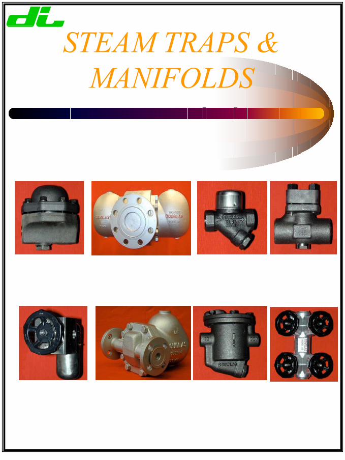
STEAM TRAPS &MANIFOLDS
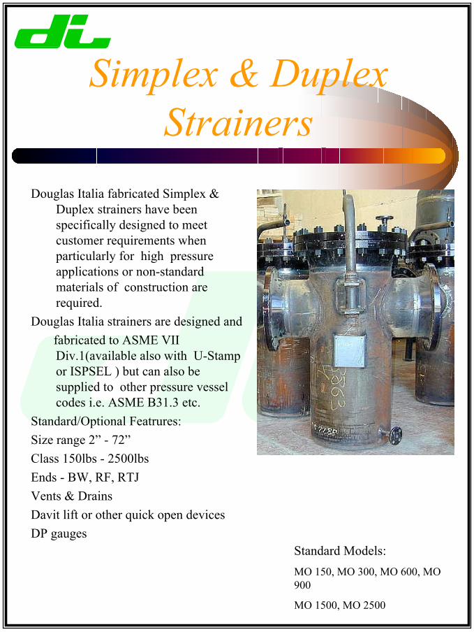
Simplex & DuplexStrainers
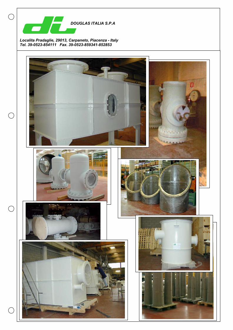
Douglas Italia fabricated Simplex &Duplex strainers have beenspecifically designed to meetcustomer requirements whenparticularly for high pressureapplications or non-standardmaterials of construction arerequired.
Douglas Italia strainers are designed and fabricated to ASME VII
Div.1(available also with U-Stampor ISPSEL ) but can also besupplied to other pressure vesselcodes i.e. ASME B31.3 etc.
Standard/Optional Featrures:Size range 2” - 72”Class 150lbs - 2500lbsEnds - BW, RF, RTJVents & DrainsDavit lift or other quick open devicesDP gauges
Standard Models:MO 150, MO 300, MO 600, MO900
MO 1500, MO 2500
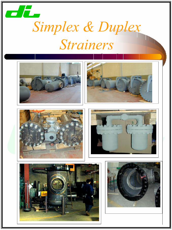
Simplex & DuplexStrainers
Tee - Strainers
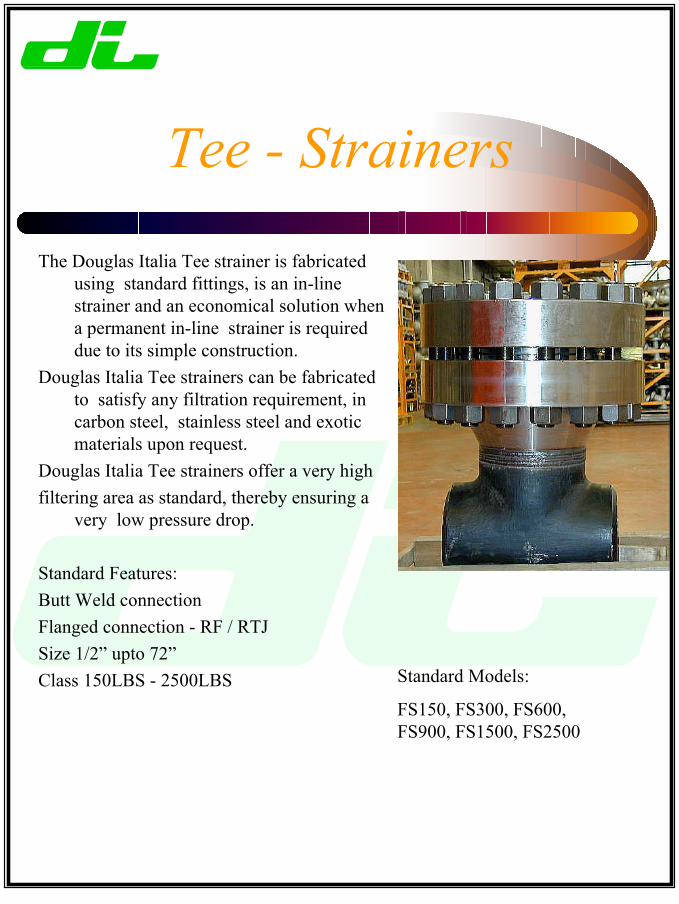
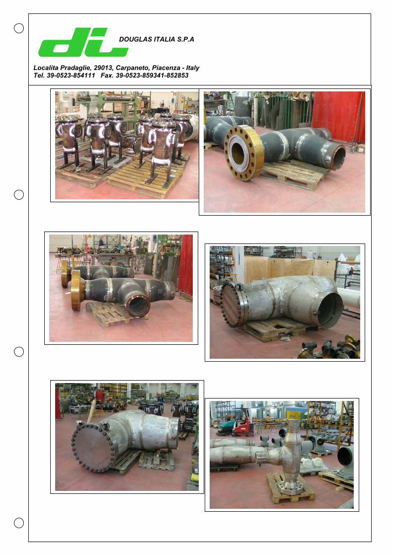
The Douglas Italia Tee strainer is fabricatedusing standard fittings, is an in-linestrainer and an economical solution whena permanent in-line strainer is requireddue to its simple construction.
Douglas Italia Tee strainers can be fabricatedto satisfy any filtration requirement, incarbon steel, stainless steel and exoticmaterials upon request.
Douglas Italia Tee strainers offer a very highfiltering area as standard, thereby ensuring a
very low pressure drop.
Standard Features:Butt Weld connectionFlanged connection - RF / RTJSize 1/2” upto 72”Class 150LBS - 2500LBS Standard Models:
FS150, FS300, FS600,FS900, FS1500, FS2500
Y- Strainers
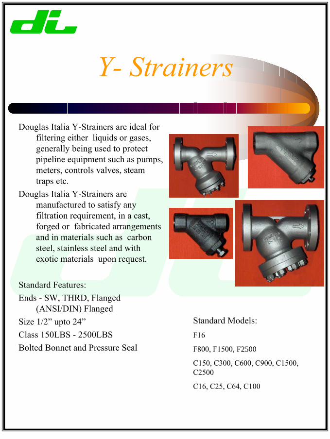
Standard Models:F16
F800, F1500, F2500
C150, C300, C600, C900, C1500,C2500
C16, C25, C64, C100
Douglas Italia Y-Strainers are ideal forfiltering either liquids or gases,generally being used to protectpipeline equipment such as pumps,meters, controls valves, steamtraps etc.
Douglas Italia Y-Strainers aremanufactured to satisfy anyfiltration requirement, in a cast,forged or fabricated arrangementsand in materials such as carbonsteel, stainless steel and withexotic materials upon request.
Standard Features:Ends - SW, THRD, Flanged
(ANSI/DIN) FlangedSize 1/2” upto 24”Class 150LBS - 2500LBSBolted Bonnet and Pressure Seal
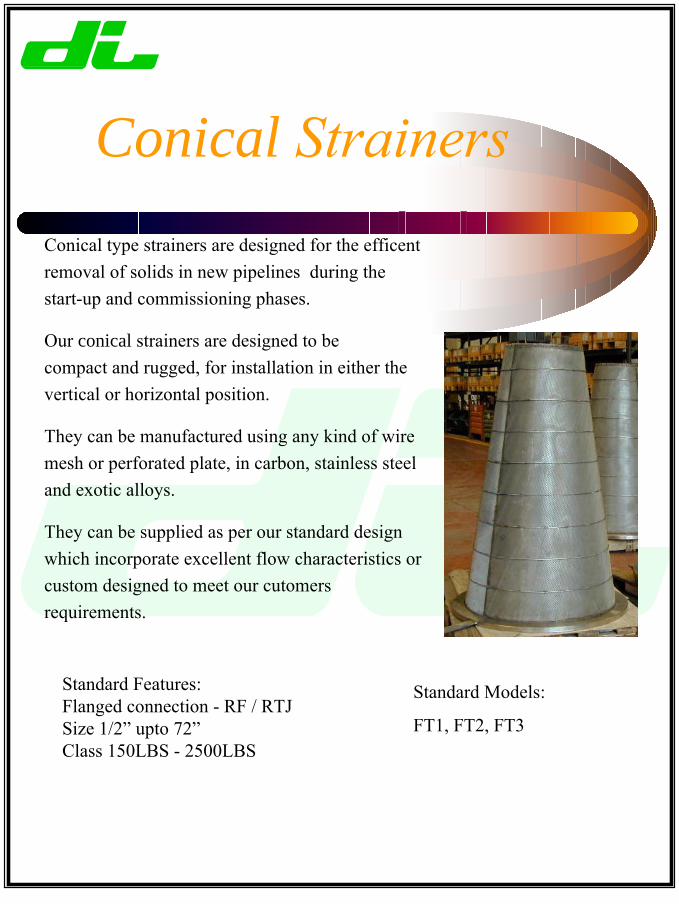
Conical StrainersConical type strainers are designed for the efficentremoval of solids in new pipelines during thestart-up and commissioning phases.
Our conical strainers are designed to becompact and rugged, for installation in either thevertical or horizontal position.
They can be manufactured using any kind of wiremesh or perforated plate, in carbon, stainless steeland exotic alloys.
They can be supplied as per our standard designwhich incorporate excellent flow characteristics orcustom designed to meet our cutomersrequirements.
Standard Features:Flanged connection - RF / RTJSize 1/2” upto 72” Class 150LBS - 2500LBS
Standard Models:
FT1, FT2, FT3

Sight Flow Indicators
Douglas Italia sight flow indicators aredesigned to give maximum visibility duringinspection of gas or liquid flowing in thepipeline.
Our sight flow indicators are available in awide range of materials including bronze,carbon steel, stainless, alloy steel as standardwith end connections and pressure ratingssuitable for all applications.
We also are able to supply various internalflow indciators based on our customersrequirements i.e.flappers, balls, spinners etc.
Standard Features:Size 1/4” - 12”Ends - SW, THRD, Flanged (ANSI/DIN)Tempered / Borosilicate GlassesInternal Indicators - Flappers, Balls, Chains, Spinners
Standard Models:
S158, S159, S160S300
S150
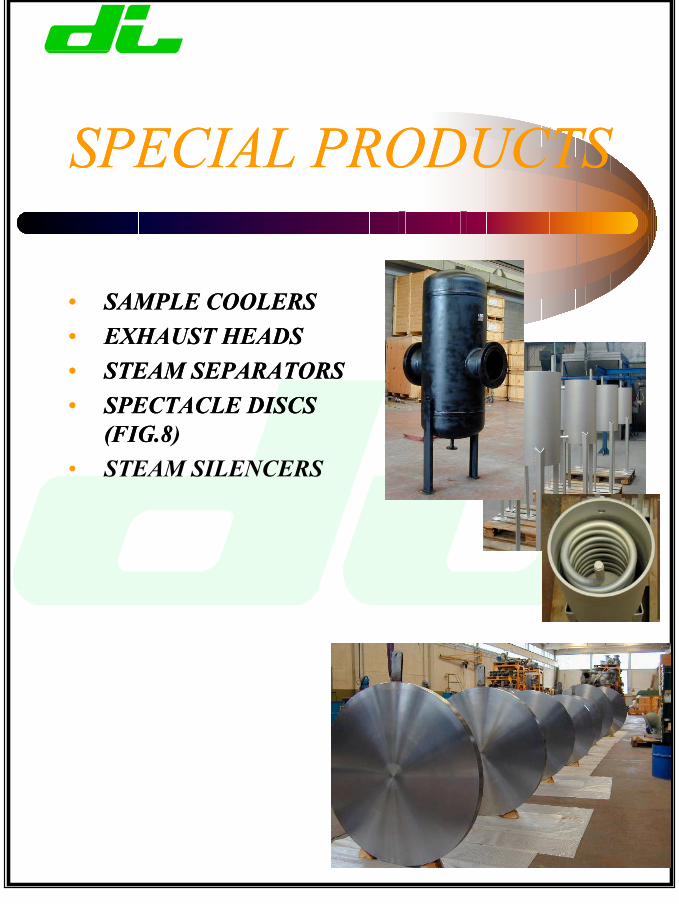
SPECIAL PRODUCTS
• SAMPLE COOLERS• EXHAUST HEADS• STEAM SEPARATORS• SPECTACLE DISCS
(FIG.8)• STEAM SILENCERS
SPECIAL PRODUCTS
• SAMPLE COOLERS• EXHAUST HEADS• STEAM SEPARATORS• SPECTACLE DISCS
(FIG.8
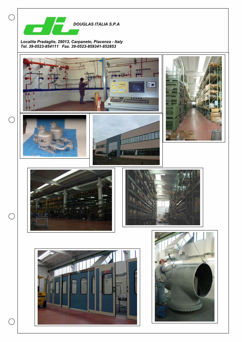
DOUGLAS ITALIA S.P.A
Localita Pradaglie, 29013, Carpaneto, Piacenza - ItalyTel. 39-0523-854111 Fax. 39-0523-859341-852853
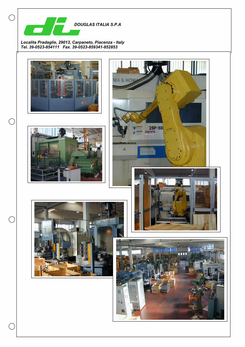
DOUGLAS ITALIA S.P.A
Localita Pradaglie, 29013, Carpaneto, Piacenza - ItalyTel. 39-0523-854111 Fax. 39-0523-859341-852853
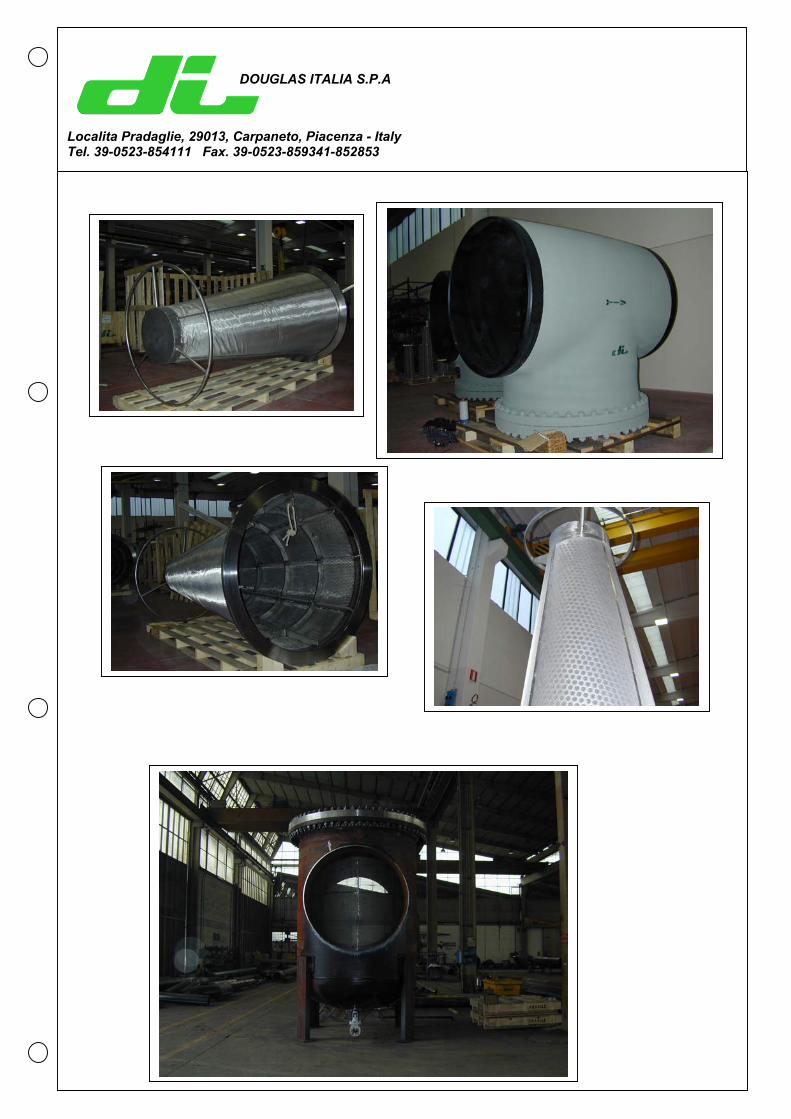
DOUGLAS ITALIA S.P.A
Localita Pradaglie, 29013, Carpaneto, Piacenza - ItalyTel. 39-0523-854111 Fax. 39-0523-859341-852853
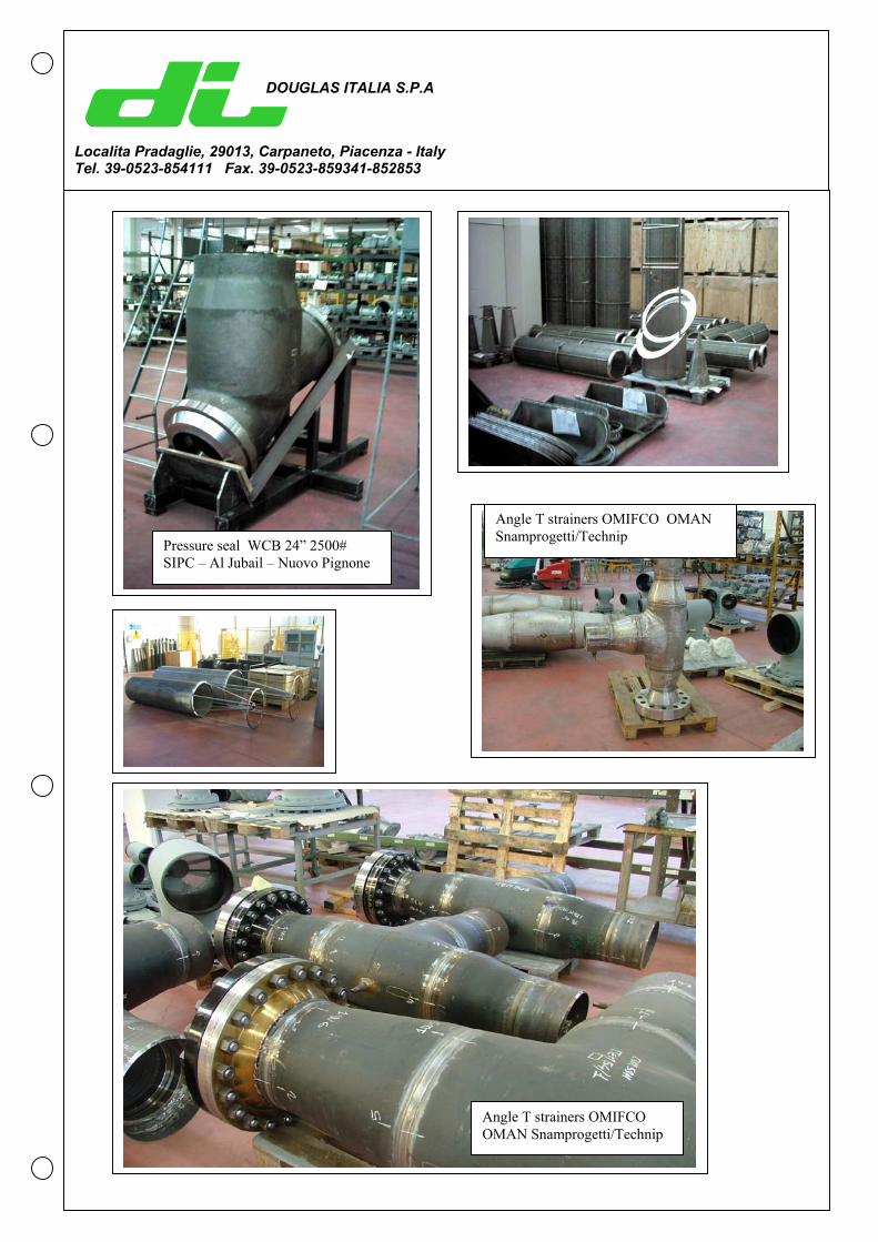
Pressure seal WCB 24” 2500# SIPC – Al Jubail – Nuovo Pignone
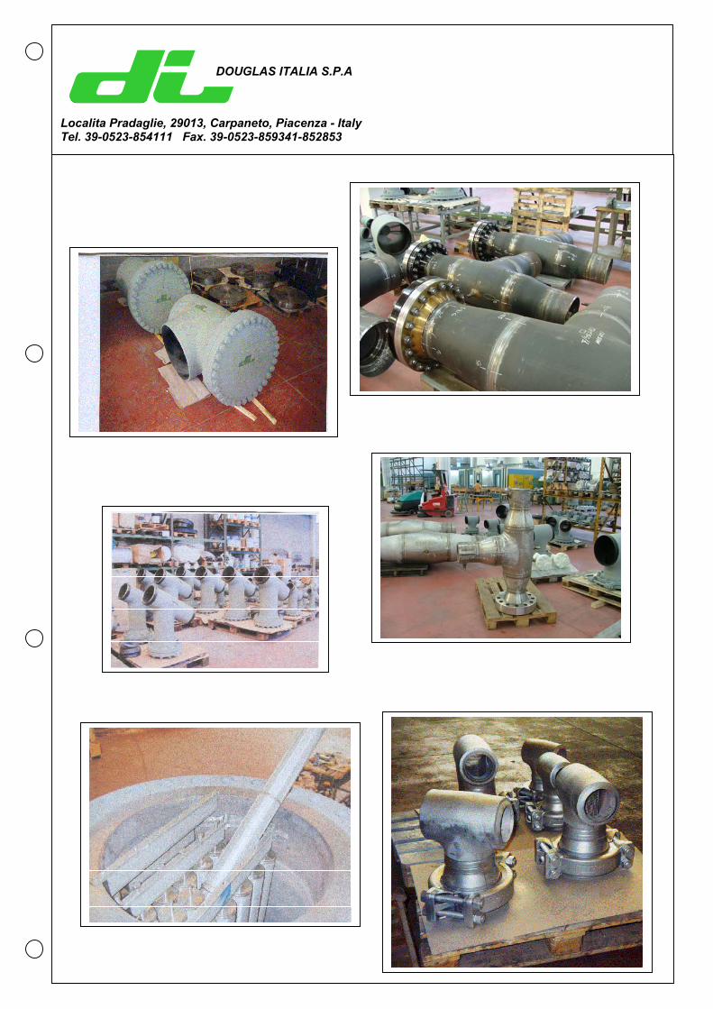
Angle T strainers OMIFCO OMAN Snamprogetti/Technip
Angle T strainers OMIFCO OMAN Snamprogetti/Technip
DOUGLAS ITALIA S.P.A
Localita Pradaglie, 29013, Carpaneto, Piacenza - ItalyTel. 39-0523-854111 Fax. 39-0523-859341-852853
DOUGLAS ITALIA S.P.A
Localita Pradaglie, 29013, Carpaneto, Piacenza - ItalyTel. 39-0523-854111 Fax. 39-0523-859341-852853
DOUGLAS ITALIA S.P.A
Localita Pradaglie, 29013, Carpaneto, Piacenza - ItalyTel. 39-0523-854111 Fax. 39-0523-859341-852853
DOUGLAS ITALIA S.P.A
Localita Pradaglie, 29013, Carpaneto, Piacenza - ItalyTel. 39-0523-854111 Fax. 39-0523-859341-852853
DOUGLAS ITALIA S.P.A
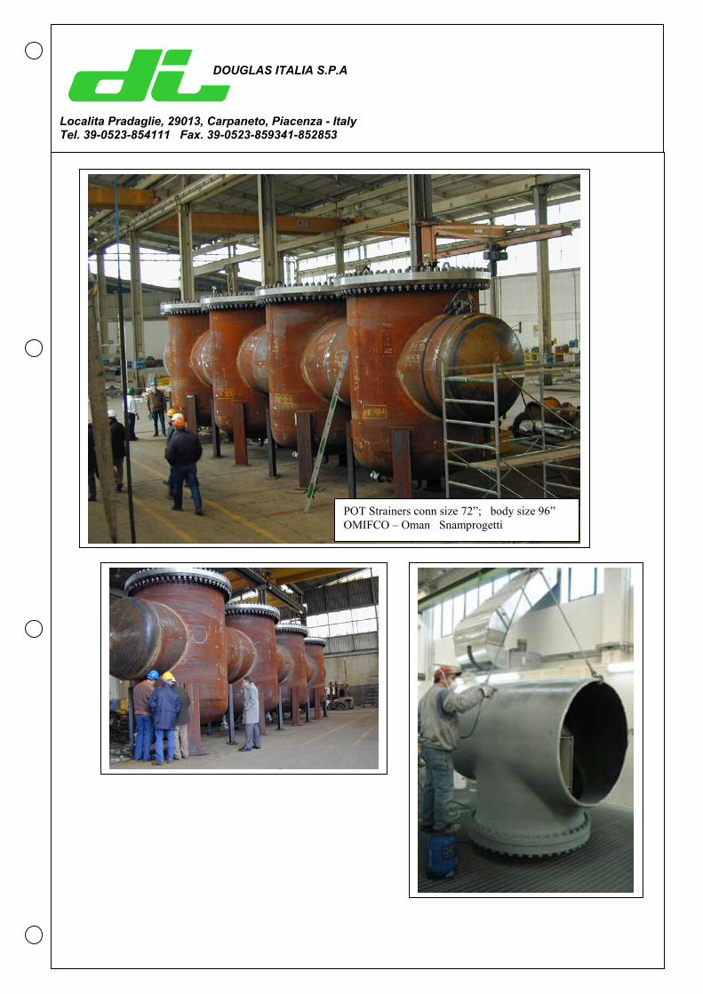
Localita Pradaglie, 29013, Carpaneto, Piacenza - ItalyTel. 39-0523-854111 Fax. 39-0523-859341-852853
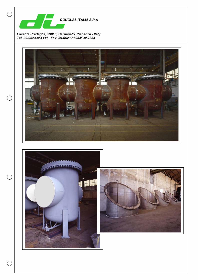
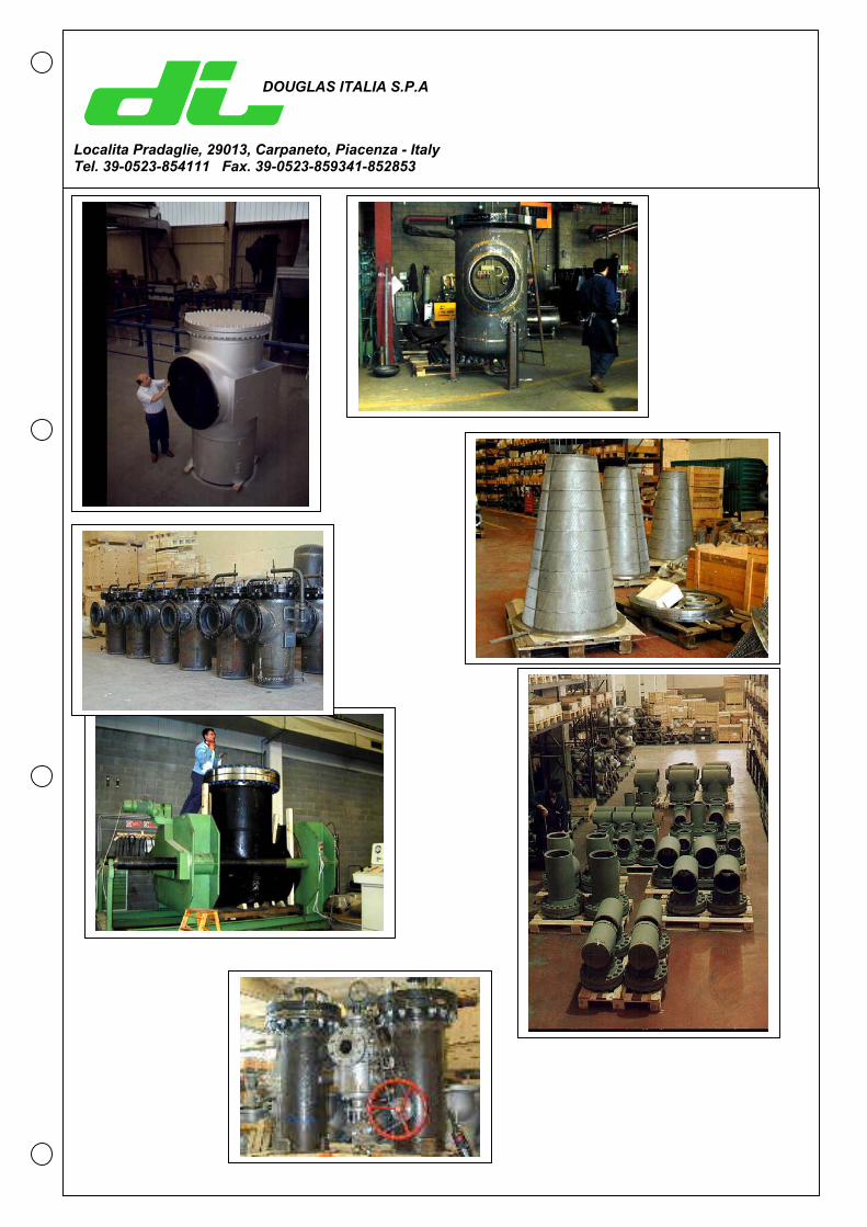
POT Strainers conn size 72”; body size 96” OMIFCO – Oman Snamprogetti
DOUGLAS ITALIA S.P.A
Localita Pradaglie, 29013, Carpaneto, Piacenza - ItalyTel. 39-0523-854111 Fax. 39-0523-859341-852853
DOUGLAS ITALIA S.P.A
Localita Pradaglie, 29013, Carpaneto, Piacenza - ItalyTel. 39-0523-854111 Fax. 39-0523-859341-852853
DOUGLAS ITALIA S.P.A
Localita Pradaglie, 29013, Carpaneto, Piacenza - ItalyTel. 39-0523-854111 Fax. 39-0523-859341-852853
DOUGLAS ITALIA S.P.A
Localita Pradaglie, 29013, Carpaneto, Piacenza - ItalyTel. 39-0523-854111 Fax. 39-0523-859341-852853
DOUGLAS ITALIA S.P.A
Localita Pradaglie, 29013, Carpaneto, Piacenza - ItalyTel. 39-0523-854111 Fax. 39-0523-859341-852853
DOUGLAS ITALIA S.P.A
Localita Pradaglie, 29013, Carpaneto, Piacenza - ItalyTel. 39-0523-854111 Fax. 39-0523-859341-852853
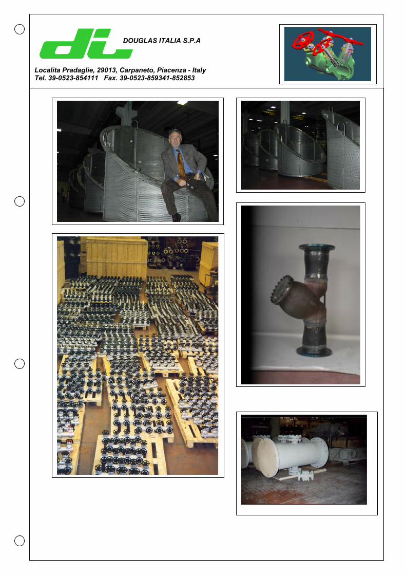
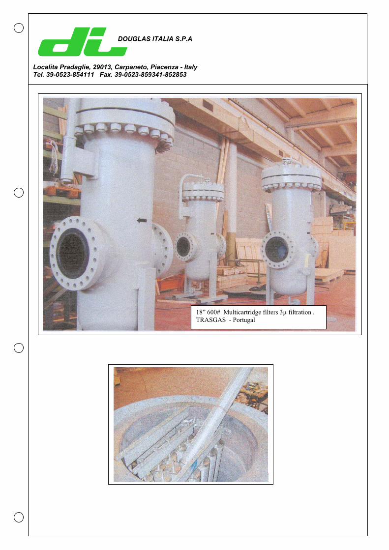
18” 600# Multicartridge filters 3µ filtration . TRASGAS - Portugal
DOUGLAS ITALIA S.P.A
Localita Pradaglie, 29013, Carpaneto, Piacenza - Italy Tel. 39-0523-854111 Fax. 39-0523-859341-852853
DOUGLAS ITALIA S.P.A
Localita Pradaglie, 29013, Carpaneto, Piacenza - Italy Tel. 39-0523-854111 Fax. 39-0523-859341-852853
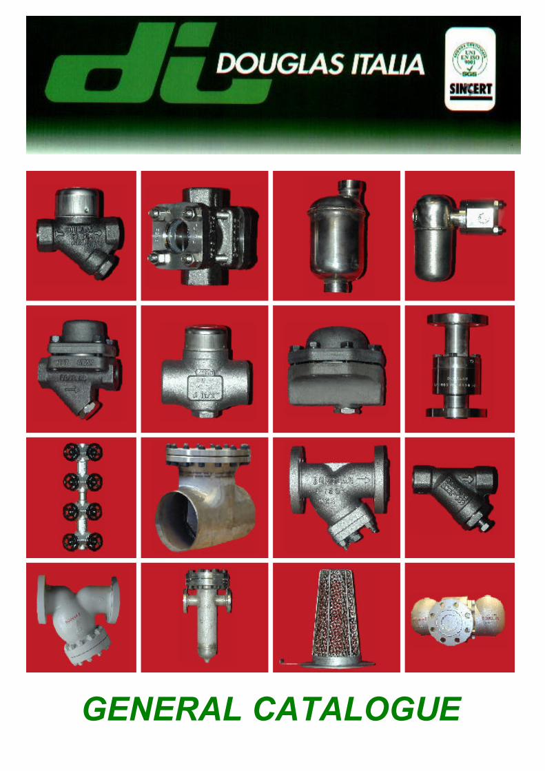
GENERAL CATALOGUE
INDEX
STEAM TRAPS
COMPRESSED AIR TRAPS
AIR AND GAS VENTS FOR LIQUID SYSTEM
MANIFOLDS
INTRODUCTION
FLOW INDICATORS
STRAINERS
SPECIAL PRODUCTS
TECHNICAL DATA

INTRODUCTION
GO BACK

INTRODUCTIONWe would like to take this opportunity to introduce our company DOUGLAS ITALIA as a complete manufacture of steam traps , manifolds , strainers and sight flow indicators supplying world wide into the Petrochemical , Chemical , Power , Nuclear and Onshore / Offshore industries since establishment in 1970 . DOUGLAS ITALIA is part of douglas group of companies which includes DOUGLAS CHERO for forged valves , CHERO PIPING for fittings , valve / piping packages and LCM for pipeline ball valves giving us the advantage of being able to supply all our customers project piping requirements. Our current manufacturing facilities , factory and workshop , are built over an area of 19.000 m2 of which 5.000 m2 are covered. DOUGLAS ITALIA’s current production capacity is approximately 10.000 pieces per month which covers our whole production range . DOUGLAS ITALIA is one of the very few companies worldwide who actually produces a complete range of steam traps and is therefore able to offer the best type and style of suited to meet the requirements of our customer specifications and applications . DOUGLAS ITALIA also manufacture compressed air traps and air eliminators for liquid system . In addition to our steam trap range DOUGLAS ITALIA has developed over the years an extensive range of pipeline ancillaries in the manufacture of Sight Flow indicators , Conical , Y and Tee type Strainers , Bucket strainers and through our special engineering division strainers for special applications . All material can be supplied in carbon steel and stainless steel which in most cases can be supplied in very short delivery times directly from our stock. The manufacturing execution can be forged , cast or welded fabricated depending on the type and size . DOUGLAS ITALIA can supply strainers from ½” to 72” for ratings up to 4500 lbs .

Whenever additional ancillaries ( especially for steam plants ) are required , DOUGLAS ITALIA will be able to complete the package supplying also all the other products manufactured within the Douglas group , such as Ansi valves , Ansi fittings , ball valves as well as steam separator , condensate recovery pumps , vacuum breakers . DOUGLAS ITALIA is a flexible and continuously developing company . Within our technical department part of staff is dedicated to research and development , to enable our company to introduce improvements or complete new products on a regular basis . DOUGLAS ITALIA’ s quality system is certified according to ISO 9001 . Our quality assurance department , is an independent body , ensuring that our quality assurance procedures are followed and implemented throughout the entire cycle of the manufacturing process . We hope that you will find our range of products of interest and in the event you should require any further details or additional information concerning either DOUGLAS ITALIA or the DOUGLAS group of companies please do not hesitate to contact us , as we remain at your complete disposal .
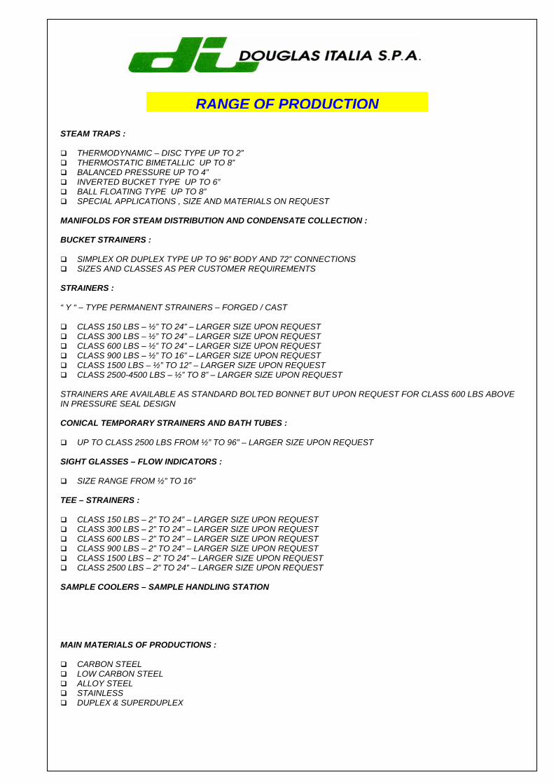
STEAM TRAPS :
THERMODYNAMIC – DISC TYPE UP TO 2” THERMOSTATIC BIMETALLIC UP TO 8” BALANCED PRESSURE UP TO 4” INVERTED BUCKET TYPE UP TO 6” BALL FLOATING TYPE UP TO 8” SPECIAL APPLICATIONS , SIZE AND MATERIALS ON REQUEST
MANIFOLDS FOR STEAM DISTRIBUTION AND CONDENSATE COLLECTION : BUCKET STRAINERS :
SIMPLEX OR DUPLEX TYPE UP TO 96” BODY AND 72” CONNECTIONS SIZES AND CLASSES AS PER CUSTOMER REQUIREMENTS
STRAINERS : “ Y “ – TYPE PERMANENT STRAINERS – FORGED / CAST
CLASS 150 LBS – ½” TO 24” – LARGER SIZE UPON REQUEST CLASS 300 LBS – ½” TO 24” – LARGER SIZE UPON REQUEST CLASS 600 LBS – ½” TO 24” – LARGER SIZE UPON REQUEST CLASS 900 LBS – ½” TO 16” – LARGER SIZE UPON REQUEST CLASS 1500 LBS – ½” TO 12” – LARGER SIZE UPON REQUEST CLASS 2500-4500 LBS – ½” TO 8” – LARGER SIZE UPON REQUEST
STRAINERS ARE AVAILABLE AS STANDARD BOLTED BONNET BUT UPON REQUEST FOR CLASS 600 LBS ABOVE IN PRESSURE SEAL DESIGN CONICAL TEMPORARY STRAINERS AND BATH TUBES :
UP TO CLASS 2500 LBS FROM ½” TO 96” – LARGER SIZE UPON REQUEST SIGHT GLASSES – FLOW INDICATORS :
SIZE RANGE FROM ½” TO 16” TEE – STRAINERS :
CLASS 150 LBS – 2” TO 24” – LARGER SIZE UPON REQUEST CLASS 300 LBS – 2” TO 24” – LARGER SIZE UPON REQUEST CLASS 600 LBS – 2” TO 24” – LARGER SIZE UPON REQUEST CLASS 900 LBS – 2” TO 24” – LARGER SIZE UPON REQUEST CLASS 1500 LBS – 2” TO 24” – LARGER SIZE UPON REQUEST CLASS 2500 LBS – 2” TO 24” – LARGER SIZE UPON REQUEST
SAMPLE COOLERS – SAMPLE HANDLING STATION MAIN MATERIALS OF PRODUCTIONS :
CARBON STEEL LOW CARBON STEEL ALLOY STEEL STAINLESS DUPLEX & SUPERDUPLEX
RANGE OF PRODUCTION
STEAM TRAP OPERATING PRINCIPLES
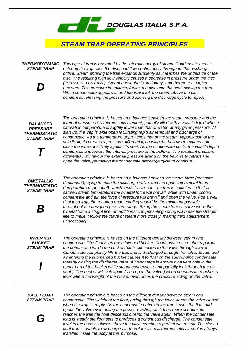
THERMODYNAMIC STEAM TRAP
D
This type of trap is operated by the internal energy of steam. Condensate and air entering the trap raise the disc, and flow continuously throughout the discharge orifice. Steam entering the trap expands suddenly as it reaches the underside of the disc. The resulting high flow velocity causes a decrease in pressure under the disc ( BERNOULLI’S LAW ). Steam above the is stationary, and therefore at higher pressure. This pressure imbalance, forces the disc onto the seat, closing the trap. When condensate appears at and the trap inlet, the steam above the disc condenses releasing the pressure and allowing the discharge cycle to repeat .
BALANCED PRESSURE
THERMOSTATIC STEAM TRAP
T
The operating principle is based on a balance between the steam pressure and the internal pressure of a thermostatic element, partially filled with a volatile liquid whose saturation temperature is sligthly lower than that of water, at any given pressure. At start up, the trap is wide open facilitating rapid air removal and discharge of condensate. As the temperature approaches that of the steam, vaporization of the volatile liquid creates a pressure differential, causing the bellows to expand and close the valve positively against its seat. As the condensate cools, the volatile liquid condenses and lowers the internal pressure of the bellows. The resultant pressure differential, will favour the external pressure acting on the bellows to retract and open the valve, permitting the condensate discharge cycle to continue .
BIMETALLIC THERMOSTATIC
STEAM TRAP
B
The operating principle is based on a balance between the steam force (pressure dependent), trying to open the discharge valve, and the opposing bimetal force (temperature dependent), which tends to close it. The trap is adjusted so that at satured steam temperature the bimetal force will prevail, while with under cooled condensate and air, the force of pressure will prevail and open the valve. Foe a well designed trap, the required under cooling should be the minimum possible throughout the designed pressure range. Being the steam force a curve while the bimetal force a stright line, an additional compensating spring will break the straight line to make it follow the curve of steam more closely, making field adjustement unnecessary .
INVERTED BUCKET
STEAM TRAP
I
The operating principle is based on the different density between steam and condensate. The float is an open inverted bucket. Condensate enters the trap from the bottom and inside the bucket that is connected to the valve through a lever. Condensate completely fills the trap and is discharged through the valve. Steam and air entering the submerged bucket causes it to float on the surrounding condensate thereby closing the discharge valve. Air discharge is ensure by a vent hole in the upper part of the bucket while steam condenses ( and partially leak through the air vent ). The bucket will sink again ( and open the valve ) when condensate reaches a level where the weight of the bucket overcomes the pressure acting on the valve.
BALL FLOAT STEAM TRAP
G
The operating principle is based on the different density between steam and condensate. The weight of the float, acting through the lever, keeps the valve closed when the trap is empty. As the condensate enters in the trap it rises the float and opens the valve overcoming the pressure acting on it. If no more condensate reaches the trap the float descends closing the valve again. When the condensate load is steady the float sets to produces a continuous discharge. The condensate level in the body is always above the valve creating a perfect water seal. The closed float trap is unable to discharge air, therefore a small thermostatic air vent is always installed inside the body at this purpose.
SELECTION OF STEAM TRAP
The selection of steam traps for specific applications is made in two steps : A. Choice of type B. Choice of size Before discussing these steps it is necessary to make a general comment from the economic point of view. Giving as granted that the condensate must be discharged , it is highly important not to loose live steam in this process. Assuming that today’s cost of steam is approximately 0.02 U.S. $ to a kilogram ( and this is very conservative ) it follows that a trap , sized for 200 Kg / hour losing 10% of its steam , in a refinery onstream 24 hour / day , costs in one year ( 200 x 0.1 x 365 x 0.02 ) U.S. $ 146 . If this refinery has 1000 traps incorrectly sized and therefore in such conditions , the loss will be 146000 U.S. $ per year ! One can easily calculate what happens if the trap has failed in the open position instead of just losing some steam. The choice of the type and size to a steam trap is a matter of great importance . A. CHOICE OF TYPE The main criteria for the selection of the type are ( they cannot be listed in order of importance since it varies from application to application ) :
Resistance to freezing Installation versatility Air venting Resistance to water hammer Cold condition ( if water logging is not allowed the trap must be the open type ) Type of discharge ( with temperature regulating control valves , the modulating type is preferable ) Heat exchange efficiency ( traps discharging sub cooled condensate do not allow an efficient heat
exchange ) Sensitive to back pressure Reaction to load changes Pressure variations ( types requiring changes of orifices for different pressure are unfit for wide variations ) Dimension and weight
For specific suggestion see “ steam traps applications and selection “ table . B. CHOICE OF SIZE There are 3 parameters to take into account for a correct sizing : 1. Differential pressure 2. Condensate load to be discharged 3. Safety factor
1 – DIFFERENTIAL PRESSURE The differential pressure is simply the difference between the pressure upstream and downstream of the trap. When a trap discharges at the atmosphere the downstream pressure is zero ( we always refer to relative and not absolute pressure ) and the differential pressure is the same of the line. When there is a condensate return system , there is always some pressure inside it due to friction and line lifting. The best way to know the value of downstream pressure ( also called backpressure ) is to install a pressure gouge just after the trap. If this is not practical one should calculate the amount of backpressure by formulas of pressure drop in water ducts adding approx. 0.1 bar for each meter of rise . 2 – CONDENSATE LOAD This is the second parameter to be introduced into the capacity tables. For draining of steam mains the quantity of condensate is related to the size of the pipe , to the steam pressure , to the efficiency of thermal insulation , to the outside temperate , to the wind force if any and to the temperature of the line ( cold start – up or running conditions ). In all the other applications traps are used to drains machines utilizing steam as a heating medium. In these cases the quantity of condensate to be removed will be equal to the amount of steam used by the machines to give the desired performance . 3 – SAFETY FACTOR For many reasons the steam trap will be not able to handle on field the condensate loads given in the capacity tables. These reasons are :
Type of discharge ( intermittent or continuous ) How the condensate reaches the trap Presence of large quantities of air Influence of other traps discharging in the same return line
Moreover there may be incorrect assumptions in the condensate load calculation and it is necessary to take into account that at cold start – up the quantity of condensate to be discharged is a lot more than at running conditions. To summarize , the size of the trap is selected entering the capacity tables with the differential pressure and with the condensate load multiplied by the safety factor. A minimum safety factor 1.2 / 1.5 must be always taken into consideration. Higher safety factors 2 / 4 are required for certain applications . INSTALLATION Specific suggestions for a correct installation depend on the application and on the type of select trap. The following are some general comments :
The trap should always be installed below the drain point Try to avoid condensate lifting. If this is necessary install a check valve just after the trap Always install “ Y “ type strainer upstream, unless the trap has a built in “ Y “ type strainer Mechanical and thermodynamic traps should be installed as close as possible to the drain point Thermostatic traps should be installed at 1 – 2 mt from drain point. Do not insulate this cooling leg It is advisable to install a check valve up stream of an inverted bucket trap to prevent water seal loss A sight glass fitted down stream the trap allows a continuous check of the trap operation Always install isolating valves upstream and downstream for maintenance purposes
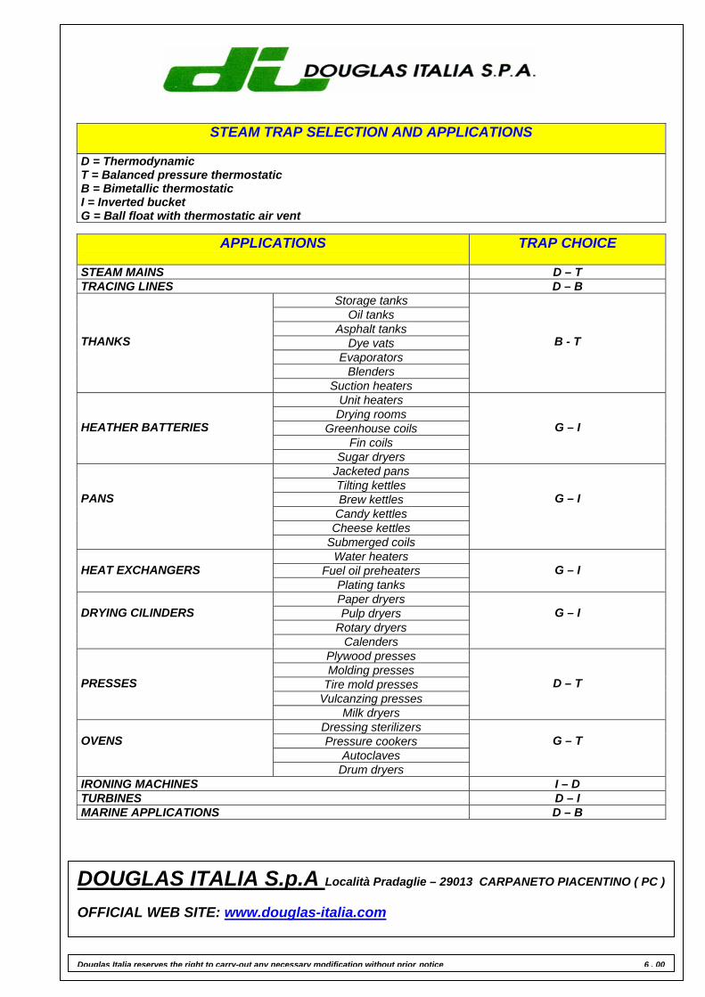
STEAM TRAP SELECTION AND APPLICATIONS D = Thermodynamic T = Balanced pressure thermostatic B = Bimetallic thermostatic I = Inverted bucket G = Ball float with thermostatic air vent
APPLICATIONS
TRAP CHOICE
STEAM MAINS D – T TRACING LINES D – B
Storage tanks Oil tanks
Asphalt tanks Dye vats
Evaporators Blenders
THANKS
Suction heaters
B - T
Unit heaters Drying rooms
Greenhouse coils Fin coils
HEATHER BATTERIES
Sugar dryers
G – I
Jacketed pans Tilting kettles Brew kettles
Candy kettles Cheese kettles
PANS
Submerged coils
G – I
Water heaters Fuel oil preheaters
HEAT EXCHANGERS
Plating tanks
G – I
Paper dryers Pulp dryers
Rotary dryers
DRYING CILINDERS
Calenders
G – I
Plywood presses Molding presses
Tire mold presses Vulcanzing presses
PRESSES
Milk dryers
D – T
Dressing sterilizers Pressure cookers
Autoclaves
OVENS
Drum dryers
G – T
IRONING MACHINES I – D TURBINES D – I MARINE APPLICATIONS D – B
Douglas Italia reserves the right to carry-out any necessary modification without prior notice 6 . 00
DOUGLAS ITALIA S.p.A Località Pradaglie – 29013 CARPANETO PIACENTINO ( PC ) OFFICIAL WEB SITE: www.douglas-italia.com
NEW
THERMODYNAMICSTEAM TRAPS
GO BACK
DA
DAA F6
DF
DC 50 A105
DC 50 A105 11⁄2”
DC 50 A105 2”
DC 50 L A105
DC 50 A A105
DC 50 F304
DC 50 F304 11⁄2”
DC 50 F304 2”
DC 50 L F304
DC 50 A F304
DK 100 A105
DK 100 F11 - F22
DK 150 A105
DK 150 F11-F22
THERMODYNAMICSTEAM TRAPS
DA
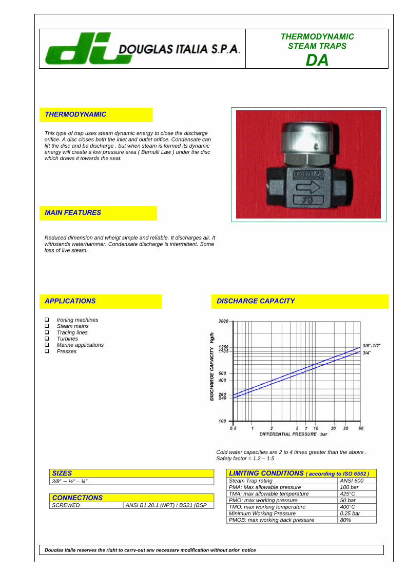
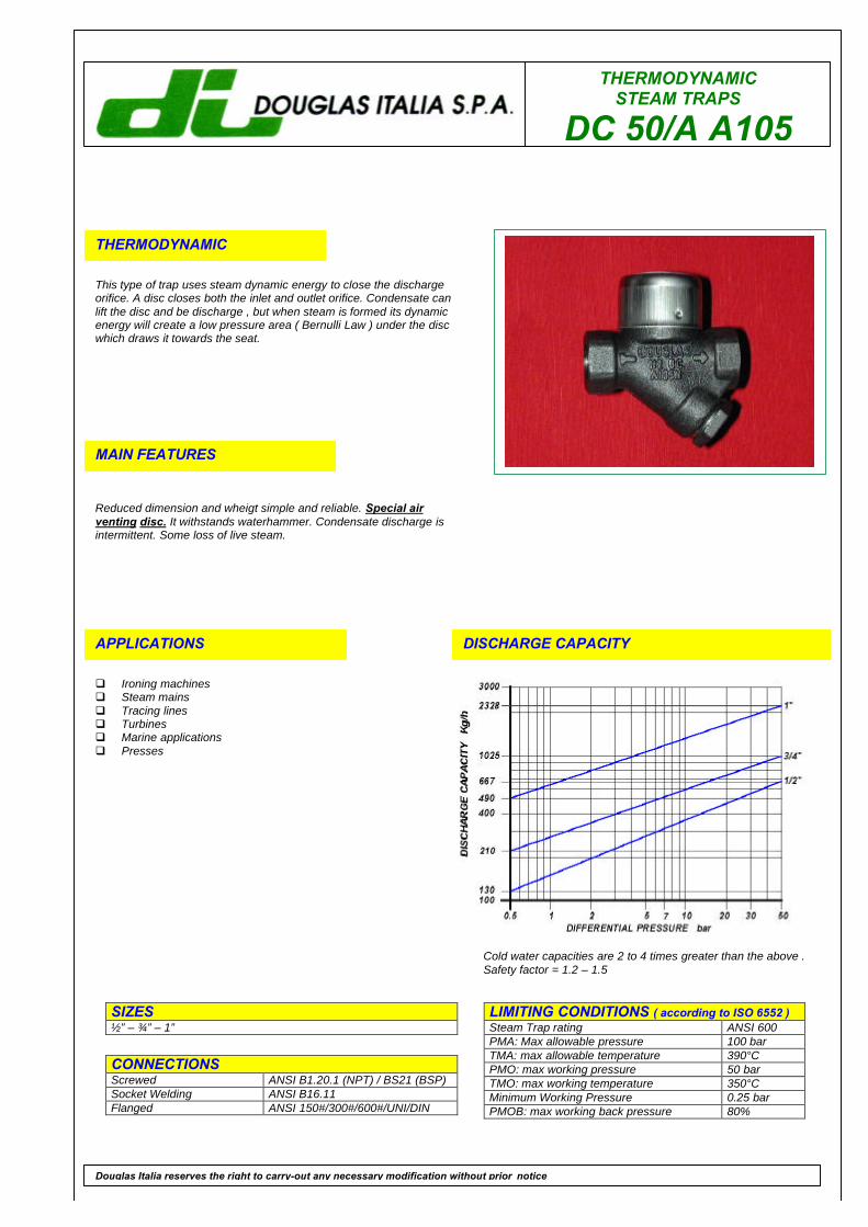
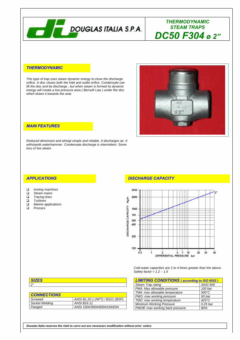
THERMODYNAMIC
This type of trap uses steam dynamic energy to close the dischargeorifice. A disc closes both the inlet and outlet orifice. Condensate canlift the disc and be discharge , but when steam is formed its dynamicenergy will create a low pressure area ( Bernulli Law ) under the discwhich draws it towards the seat.
MAIN FEATURES
Reduced dimension and wheigt simple and reliable. It discharges air. Itwithstands waterhammer. Condensate discharge is intermittent. Someloss of live steam.
APPLICATIONS
q Ironing machinesq Steam mainsq Tracing linesq Turbinesq Marine applicationsq Presses
DISCHARGE CAPACITY
LIMITING CONDITIONS ( according to ISO 6552 )Steam Trap rating ANSI 600PMA: Max allowable pressure 100 barTMA: max allowable temperature 425°CPMO: max working pressure 50 barTMO: max working temperature 400°CMinimum Working Pressure 0.25 barPMOB: max working back pressure 80%
SIZES3/8” – ½” – ¾”
CONNECTIONSSCREWED ANSI B1.20.1 (NPT) / BS21 (BSP
Douglas Italia reserves the right to carry-out any necessary modification without prior notice
Cold water capacities are 2 to 4 times greater than the above .Safety factor = 1.2 – 1.5
THERMODYNAMIC STEAM TRAPS
DA
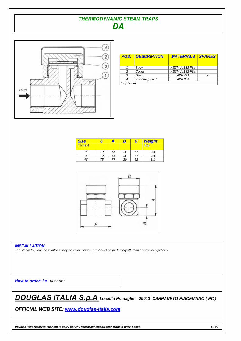
POS. DESCRIPTION MATERIALS SPARES
1 Body ASTM A 182 F6a2 Cover ASTM A 182 F6a3 Disc AISI 431 X4 Insulating cap* AISI 304
* optional
Size(inches)
S A B C Weight(Kg)
3/8” 70 65 16 47 0.6½” 70 65 16 47 0.6¾” 75 77 20 52 1.1
INSTALLATIONThe steam trap can be istalled in any position, however it should be preferably fitted on horizontal pipelines.
How to order: i.e. DA ½” NPT
DOUGLAS ITALIA S.p.A Località Pradaglie – 29013 CARPANETO PIACENTINO ( PC )
OFFICIAL WEB SITE: www.douglas-italia.com
Douglas Italia reserves the right to carry-out any necessary modification without prior notice 6 . 00
THERMODYNAMICSTEAM TRAPS
DAA F6
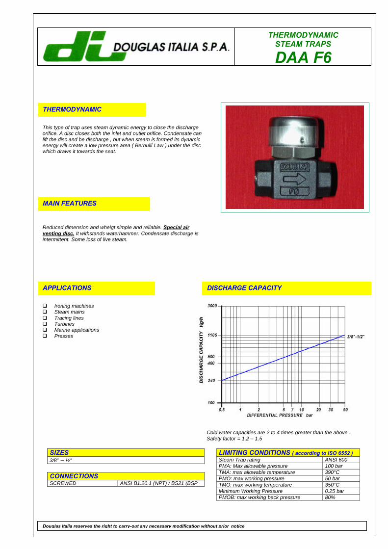
THERMODYNAMIC
This type of trap uses steam dynamic energy to close the dischargeorifice. A disc closes both the inlet and outlet orifice. Condensate canlift the disc and be discharge , but when steam is formed its dynamicenergy will create a low pressure area ( Bernulli Law ) under the discwhich draws it towards the seat.
MAIN FEATURES
Reduced dimension and wheigt simple and reliable. Special airventing disc. It withstands waterhammer. Condensate discharge isintermittent. Some loss of live steam.
APPLICATIONS
q Ironing machinesq Steam mainsq Tracing linesq Turbinesq Marine applicationsq Presses
DISCHARGE CAPACITY
LIMITING CONDITIONS ( according to ISO 6552 )Steam Trap rating ANSI 600PMA: Max allowable pressure 100 barTMA: max allowable temperature 390°CPMO: max working pressure 50 barTMO: max working temperature 350°CMinimum Working Pressure 0.25 barPMOB: max working back pressure 80%
SIZES3/8” – ½”
CONNECTIONSSCREWED ANSI B1.20.1 (NPT) / BS21 (BSP
Douglas Italia reserves the right to carry-out any necessary modification without prior notice
Cold water capacities are 2 to 4 times greater than the above .Safety factor = 1.2 – 1.5

THERMODYNAMIC STEAM TRAPS
DAA F6
POS. DESCRIPTION MATERIALS SPARES
1 Body ASTM A 182 F6a2 Cover AISI 303 X3 Disc AISI 431 X4 Insulating cap* AISI 304
* optional
Size(inches)
S A B C Weight(Kg)
3/8” 70 65 16 47 0.6½” 70 65 16 47 0.6
INSTALLATIONThe steam trap can be istalled in any position, however it should be preferably fitted on horizontal pipelines.
How to order: i.e. DAA F6 ½” NPT
DOUGLAS ITALIA S.p.A Località Pradaglie – 29013 CARPANETO PIACENTINO ( PC )
OFFICIAL WEB SITE: www.douglas-italia.com
Douglas Italia reserves the right to carry-out any necessary modification without prior notice 6 . 00
THERMODYNAMICSTEAM TRAPS
DF
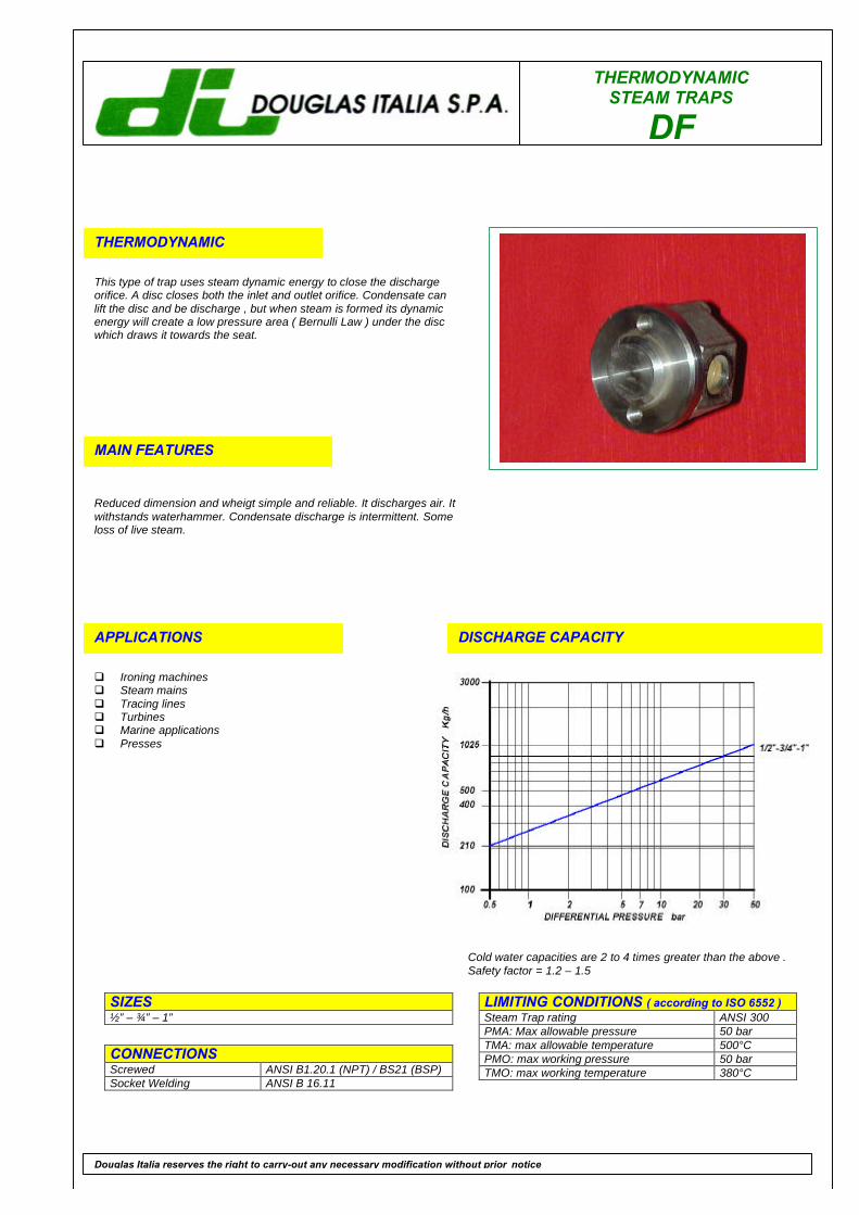
THERMODYNAMIC
This type of trap uses steam dynamic energy to close the dischargeorifice. A disc closes both the inlet and outlet orifice. Condensate canlift the disc and be discharge , but when steam is formed its dynamicenergy will create a low pressure area ( Bernulli Law ) under the discwhich draws it towards the seat.
MAIN FEATURES
Reduced dimension and wheigt simple and reliable. It discharges air. Itwithstands waterhammer. Condensate discharge is intermittent. Someloss of live steam.
APPLICATIONS
q Ironing machinesq Steam mainsq Tracing linesq Turbinesq Marine applicationsq Presses
DISCHARGE CAPACITY
LIMITING CONDITIONS ( according to ISO 6552 )Steam Trap rating ANSI 300PMA: Max allowable pressure 50 barTMA: max allowable temperature 500°CPMO: max working pressure 50 barTMO: max working temperature 380°C
SIZES½” – ¾” – 1”
CONNECTIONSScrewed ANSI B1.20.1 (NPT) / BS21 (BSP)Socket Welding ANSI B 16.11
Douglas Italia reserves the right to carry-out any necessary modification without prior notice
Cold water capacities are 2 to 4 times greater than the above .Safety factor = 1.2 – 1.5
THERMODYNAMIC STEAM TRAPS
DF
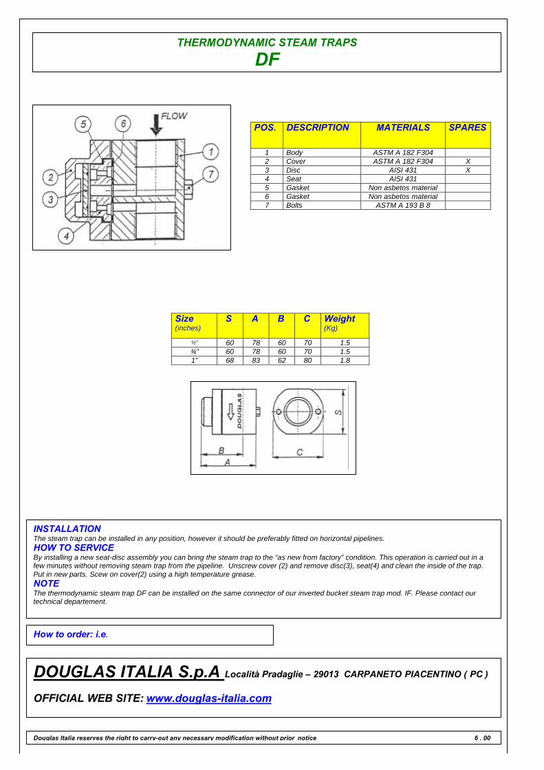
POS. DESCRIPTION MATERIALS SPARES
1 Body ASTM A 182 F3042 Cover ASTM A 182 F304 X3 Disc AISI 431 X4 Seat AISI 4315 Gasket Non asbetos material6 Gasket Non asbetos material7 Bolts ASTM A 193 B 8
Size(inches)
S A B C Weight(Kg)
½” 60 78 60 70 1.5¾” 60 78 60 70 1.51” 68 83 62 80 1.8
INSTALLATIONThe steam trap can be installed in any position, however it should be preferably fitted on horizontal pipelines.HOW TO SERVICEBy installing a new seat-disc assembly you can bring the steam trap to the “as new from factory” condition. This operation is carried out in afew minutes without removing steam trap from the pipeline. Unscrew cover (2) and remove disc(3), seat(4) and clean the inside of the trap.Put in new parts. Scew on cover(2) using a high temperature grease.NOTEThe thermodynamic steam trap DF can be installed on the same connector of our inverted bucket steam trap mod. IF. Please contact ourtechnical departement.
How to order: i.e.
DOUGLAS ITALIA S.p.A Località Pradaglie – 29013 CARPANETO PIACENTINO ( PC )
OFFICIAL WEB SITE: www.douglas-italia.com
Douglas Italia reserves the right to carry-out any necessary modification without prior notice 6 . 00
THERMODYNAMIC STEAM TRAPS
DC 50 A 105
THERMODYNAMIC
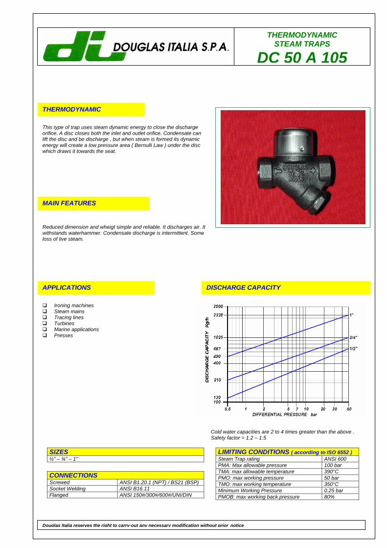
This type of trap uses steam dynamic energy to close the discharge orifice. A disc closes both the inlet and outlet orifice. Condensate can lift the disc and be discharge , but when steam is formed its dynamic energy will create a low pressure area ( Bernulli Law ) under the disc which draws it towards the seat.
MAIN FEATURES
Reduced dimension and wheigt simple and reliable. It discharges air. It withstands waterhammer. Condensate discharge is intermittent. Some loss of live steam.
APPLICATIONS
Ironing machines Steam mains Tracing lines Turbines Marine applications Presses
DISCHARGE CAPACITY
LIMITING CONDITIONS ( according to ISO 6552 ) Steam Trap rating ANSI 600 PMA: Max allowable pressure 100 bar TMA: max allowable temperature 390°C PMO: max working pressure 50 bar TMO: max working temperature 350°C Minimum Working Pressure 0.25 bar PMOB: max working back pressure 80%
SIZES ½” – ¾” – 1”
CONNECTIONS Screwed ANSI B1.20.1 (NPT) / BS21 (BSP) Socket Welding ANSI B16.11 Flanged ANSI 150#/300#/600#/UNI/DIN
Douglas Italia reserves the right to carry-out any necessary modification without prior notice
Cold water capacities are 2 to 4 times greater than the above . Safety factor = 1.2 – 1.5
THERMODYNAMIC STEAM TRAPS
DC 50 A 105
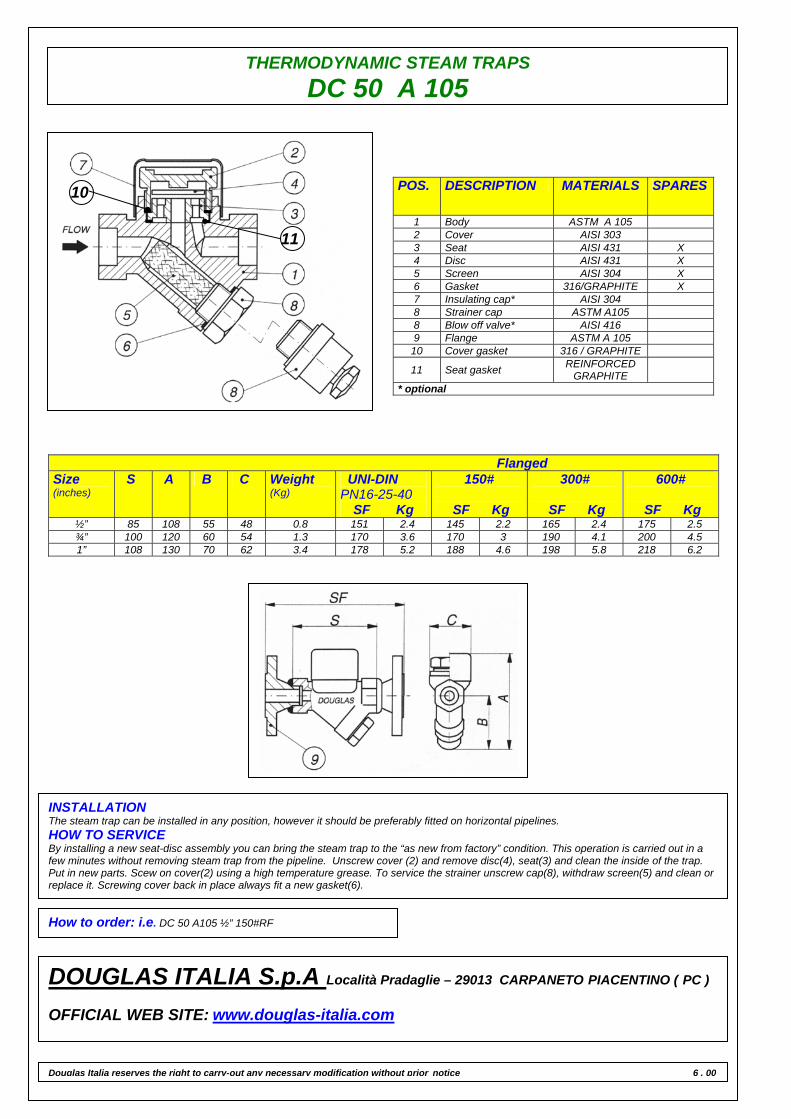
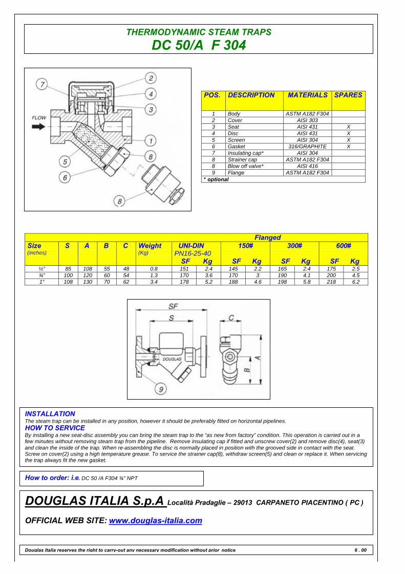
POS. DESCRIPTION MATERIALS SPARES
1 Body ASTM A 105 2 Cover AISI 303 3 Seat AISI 431 X 4 Disc AISI 431 X 5 Screen AISI 304 X 6 Gasket 316/GRAPHITE X 7 Insulating cap* AISI 304 8 Strainer cap ASTM A105 8 Blow off valve* AISI 416 9 Flange ASTM A 105
10 Cover gasket 316 / GRAPHITE
11 Seat gasket REINFORCED GRAPHITE
* optional
Flanged Size (inches)
S A B C Weight (Kg)
UNI-DIN PN16-25-40
SF Kg
150#
SF Kg
300#
SF Kg
600#
SF Kg ½” 85 108 55 48 0.8 151 2.4 145 2.2 165 2.4 175 2.5 ¾” 100 120 60 54 1.3 170 3.6 170 3 190 4.1 200 4.5 1” 108 130 70 62 3.4 178 5.2 188 4.6 198 5.8 218 6.2
INSTALLATION The steam trap can be installed in any position, however it should be preferably fitted on horizontal pipelines. HOW TO SERVICE By installing a new seat-disc assembly you can bring the steam trap to the “as new from factory” condition. This operation is carried out in a few minutes without removing steam trap from the pipeline. Unscrew cover (2) and remove disc(4), seat(3) and clean the inside of the trap. Put in new parts. Scew on cover(2) using a high temperature grease. To service the strainer unscrew cap(8), withdraw screen(5) and clean or replace it. Screwing cover back in place always fit a new gasket(6).
How to order: i.e. DC 50 A105 ½” 150#RF
DOUGLAS ITALIA S.p.A Località Pradaglie – 29013 CARPANETO PIACENTINO ( PC ) OFFICIAL WEB SITE: www.douglas-italia.com
Douglas Italia reserves the right to carry-out any necessary modification without prior notice 6 . 00
10
11
THERMODYNAMICSTEAM TRAPS
DC50 A105 ø 1.1/2”
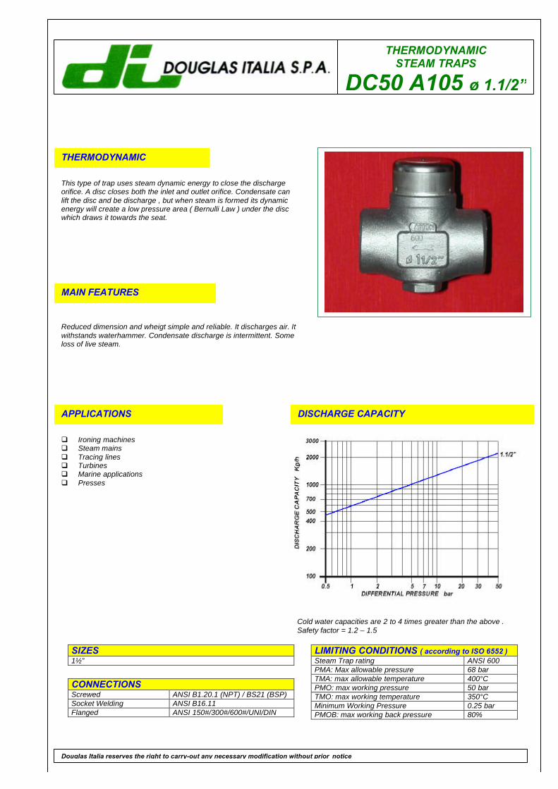
THERMODYNAMIC
This type of trap uses steam dynamic energy to close the dischargeorifice. A disc closes both the inlet and outlet orifice. Condensate canlift the disc and be discharge , but when steam is formed its dynamicenergy will create a low pressure area ( Bernulli Law ) under the discwhich draws it towards the seat.
MAIN FEATURES
Reduced dimension and wheigt simple and reliable. It discharges air. Itwithstands waterhammer. Condensate discharge is intermittent. Someloss of live steam.
APPLICATIONS
q Ironing machinesq Steam mainsq Tracing linesq Turbinesq Marine applicationsq Presses
DISCHARGE CAPACITY
LIMITING CONDITIONS ( according to ISO 6552 )Steam Trap rating ANSI 600PMA: Max allowable pressure 68 barTMA: max allowable temperature 400°CPMO: max working pressure 50 barTMO: max working temperature 350°CMinimum Working Pressure 0.25 barPMOB: max working back pressure 80%
SIZES1½”
CONNECTIONSScrewed ANSI B1.20.1 (NPT) / BS21 (BSP)Socket Welding ANSI B16.11Flanged ANSI 150#/300#/600#/UNI/DIN
Douglas Italia reserves the right to carry-out any necessary modification without prior notice
Cold water capacities are 2 to 4 times greater than the above .Safety factor = 1.2 – 1.5
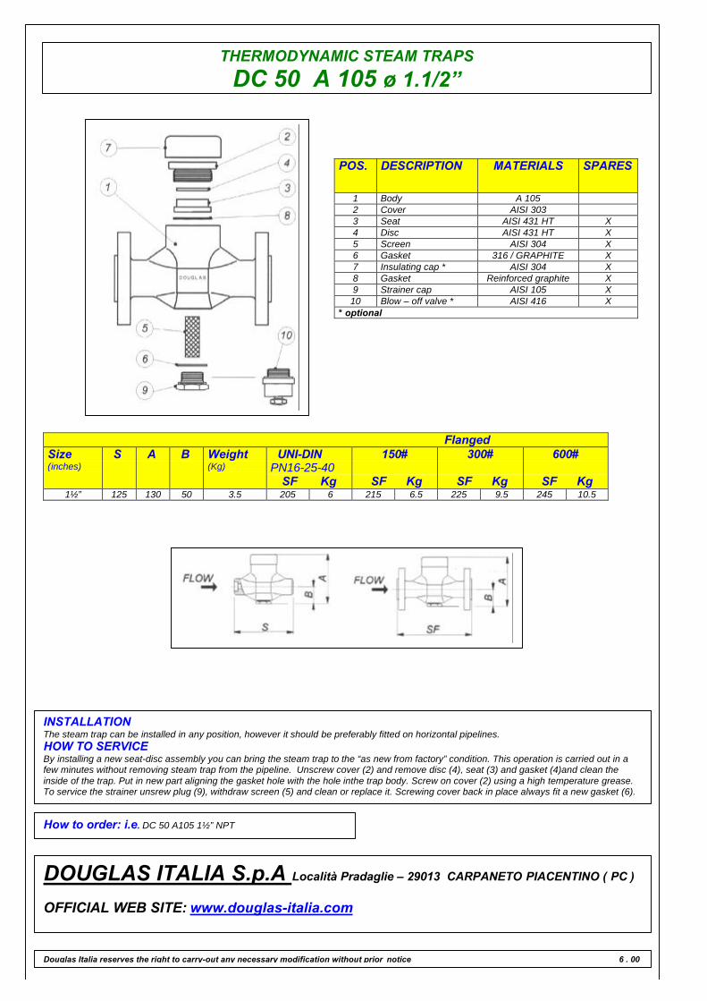
THERMODYNAMIC STEAM TRAPSDC 50 A 105 ø 1.1/2”
POS. DESCRIPTION MATERIALS SPARES
1 Body A 1052 Cover AISI 3033 Seat AISI 431 HT X4 Disc AISI 431 HT X5 Screen AISI 304 X6 Gasket 316 / GRAPHITE X7 Insulating cap * AISI 304 X8 Gasket Reinforced graphite X9 Strainer cap AISI 105 X10 Blow – off valve * AISI 416 X
* optional
FlangedSize(inches)
S A B Weight(Kg)
UNI-DINPN16-25-40
SF Kg
150#
SF Kg
300#
SF Kg
600#
SF Kg1½” 125 130 50 3.5 205 6 215 6.5 225 9.5 245 10.5
INSTALLATIONThe steam trap can be installed in any position, however it should be preferably fitted on horizontal pipelines.HOW TO SERVICEBy installing a new seat-disc assembly you can bring the steam trap to the “as new from factory” condition. This operation is carried out in afew minutes without removing steam trap from the pipeline. Unscrew cover (2) and remove disc (4), seat (3) and gasket (4)and clean theinside of the trap. Put in new part aligning the gasket hole with the hole inthe trap body. Screw on cover (2) using a high temperature grease.To service the strainer unsrew plug (9), withdraw screen (5) and clean or replace it. Screwing cover back in place always fit a new gasket (6).
How to order: i.e. DC 50 A105 1½” NPT
DOUGLAS ITALIA S.p.A Località Pradaglie – 29013 CARPANETO PIACENTINO ( PC )
OFFICIAL WEB SITE: www.douglas-italia.com
Douglas Italia reserves the right to carry-out any necessary modification without prior notice 6 . 00

THERMODYNAMICSTEAM TRAPS
DC50 A105 ø 2”
THERMODYNAMIC
This type of trap uses steam dynamic energy to close the dischargeorifice. A disc closes both the inlet and outlet orifice. Condensate canlift the disc and be discharge , but when steam is formed its dynamicenergy will create a low pressure area ( Bernulli Law ) under the discwhich draws it towards the seat.
MAIN FEATURES
Reduced dimension and wheigt simple and reliable. It discharges air. Itwithstands waterhammer. Condensate discharge is intermittent. Someloss of live steam.
APPLICATIONS
q Ironing machinesq Steam mainsq Tracing linesq Turbinesq Marine applicationsq Presses
DISCHARGE CAPACITY
LIMITING CONDITIONS ( according to ISO 6552 )Steam Trap rating ANSI 600PMA: Max allowable pressure 68 barTMA: max allowable temperature 400°CPMO: max working pressure 50 barTMO: max working temperature 350°CMinimum Working Pressure 0.25 barPMOB: max working back pressure 80%
SIZES2”
CONNECTIONSScrewed ANSI B1.20.1 (NPT) / BS21 (BSP)Socket Welding ANSI B16.11Flanged ANSI 150#/300#/600#/UNI/DIN
Douglas Italia reserves the right to carry-out any necessary modification without prior notice
Cold water capacities are 2 to 4 times greater than the above .Safety factor = 1.2 – 1.5
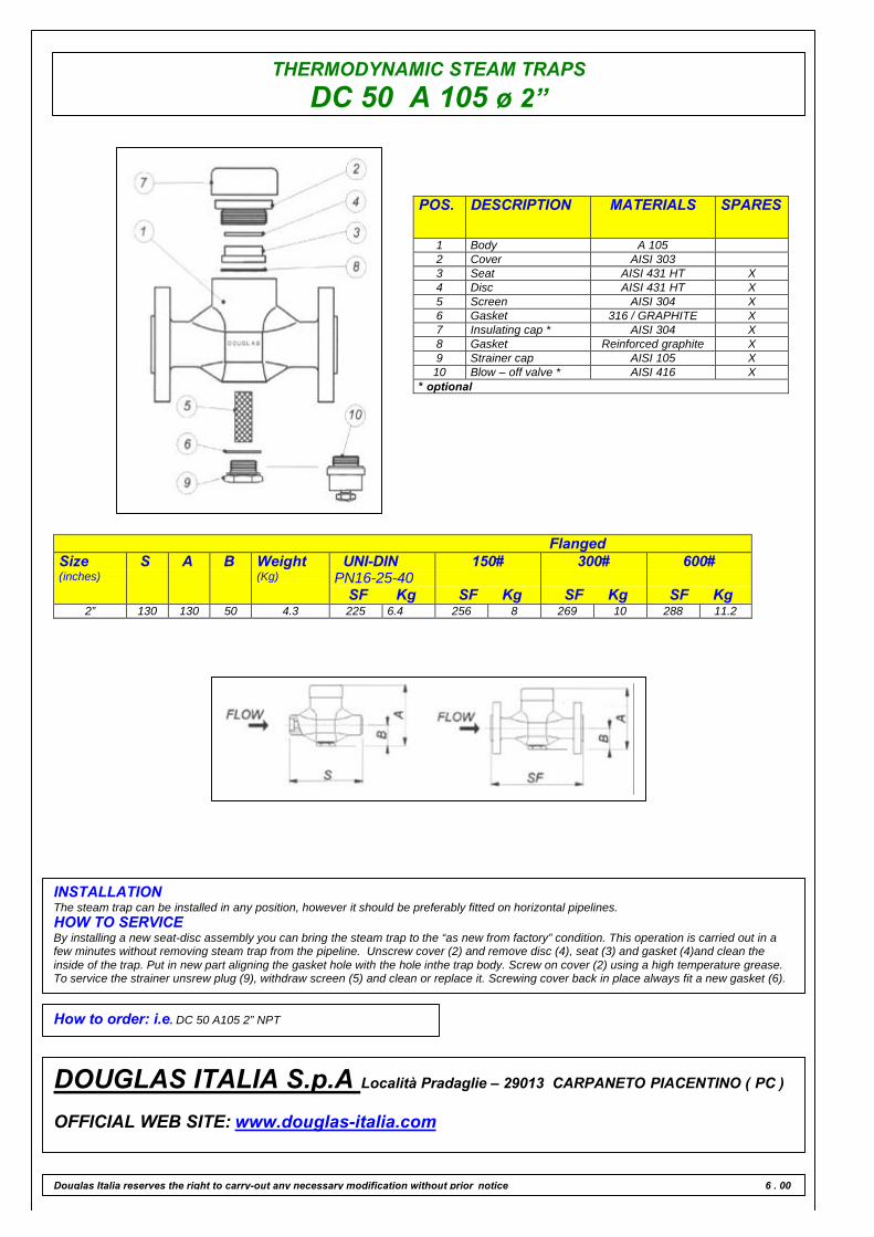
THERMODYNAMIC STEAM TRAPSDC 50 A 105 ø 2”
POS. DESCRIPTION MATERIALS SPARES
1 Body A 1052 Cover AISI 3033 Seat AISI 431 HT X4 Disc AISI 431 HT X5 Screen AISI 304 X6 Gasket 316 / GRAPHITE X7 Insulating cap * AISI 304 X8 Gasket Reinforced graphite X9 Strainer cap AISI 105 X10 Blow – off valve * AISI 416 X
* optional
FlangedSize(inches)
S A B Weight(Kg)
UNI-DINPN16-25-40
SF Kg
150#
SF Kg
300#
SF Kg
600#
SF Kg2” 130 130 50 4.3 225 6.4 256 8 269 10 288 11.2
INSTALLATIONThe steam trap can be installed in any position, however it should be preferably fitted on horizontal pipelines.HOW TO SERVICEBy installing a new seat-disc assembly you can bring the steam trap to the “as new from factory” condition. This operation is carried out in afew minutes without removing steam trap from the pipeline. Unscrew cover (2) and remove disc (4), seat (3) and gasket (4)and clean theinside of the trap. Put in new part aligning the gasket hole with the hole inthe trap body. Screw on cover (2) using a high temperature grease.To service the strainer unsrew plug (9), withdraw screen (5) and clean or replace it. Screwing cover back in place always fit a new gasket (6).
How to order: i.e. DC 50 A105 2” NPT
DOUGLAS ITALIA S.p.A Località Pradaglie – 29013 CARPANETO PIACENTINO ( PC )
OFFICIAL WEB SITE: www.douglas-italia.com
Douglas Italia reserves the right to carry-out any necessary modification without prior notice 6 . 00
THERMODYNAMIC STEAM TRAPSLOW CAPACITIES
DC 50L A 105
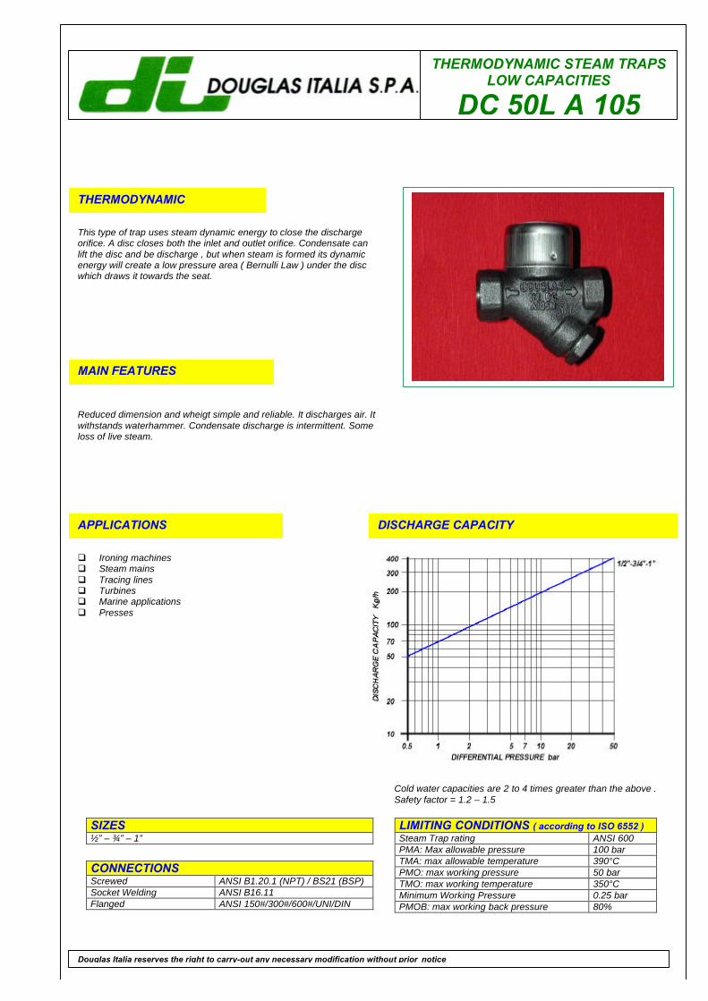
THERMODYNAMIC
This type of trap uses steam dynamic energy to close the dischargeorifice. A disc closes both the inlet and outlet orifice. Condensate canlift the disc and be discharge , but when steam is formed its dynamicenergy will create a low pressure area ( Bernulli Law ) under the discwhich draws it towards the seat.
MAIN FEATURES
Reduced dimension and wheigt simple and reliable. It discharges air. Itwithstands waterhammer. Condensate discharge is intermittent. Someloss of live steam.
APPLICATIONS
q Ironing machinesq Steam mainsq Tracing linesq Turbinesq Marine applicationsq Presses
DISCHARGE CAPACITY
LIMITING CONDITIONS ( according to ISO 6552 )Steam Trap rating ANSI 600PMA: Max allowable pressure 100 barTMA: max allowable temperature 390°CPMO: max working pressure 50 barTMO: max working temperature 350°CMinimum Working Pressure 0.25 barPMOB: max working back pressure 80%
SIZES½” – ¾” – 1”
CONNECTIONSScrewed ANSI B1.20.1 (NPT) / BS21 (BSP)Socket Welding ANSI B16.11Flanged ANSI 150#/300#/600#/UNI/DIN
Douglas Italia reserves the right to carry-out any necessary modification without prior notice
Cold water capacities are 2 to 4 times greater than the above .Safety factor = 1.2 – 1.5
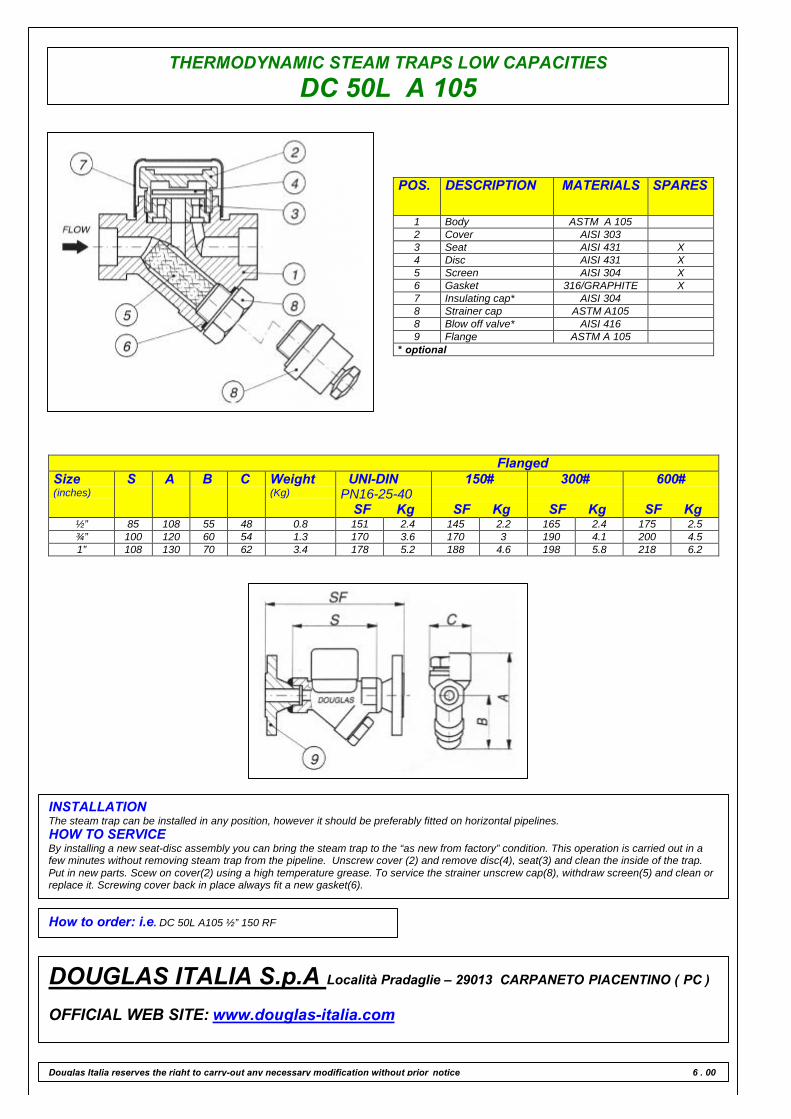
THERMODYNAMIC STEAM TRAPS LOW CAPACITIESDC 50L A 105
POS. DESCRIPTION MATERIALS SPARES
1 Body ASTM A 1052 Cover AISI 3033 Seat AISI 431 X4 Disc AISI 431 X5 Screen AISI 304 X6 Gasket 316/GRAPHITE X7 Insulating cap* AISI 3048 Strainer cap ASTM A1058 Blow off valve* AISI 4169 Flange ASTM A 105
* optional
FlangedSize(inches)
S A B C Weight(Kg)
UNI-DINPN16-25-40
SF Kg
150#
SF Kg
300#
SF Kg
600#
SF Kg½” 85 108 55 48 0.8 151 2.4 145 2.2 165 2.4 175 2.5¾” 100 120 60 54 1.3 170 3.6 170 3 190 4.1 200 4.51” 108 130 70 62 3.4 178 5.2 188 4.6 198 5.8 218 6.2
INSTALLATIONThe steam trap can be installed in any position, however it should be preferably fitted on horizontal pipelines.HOW TO SERVICEBy installing a new seat-disc assembly you can bring the steam trap to the “as new from factory” condition. This operation is carried out in afew minutes without removing steam trap from the pipeline. Unscrew cover (2) and remove disc(4), seat(3) and clean the inside of the trap.Put in new parts. Scew on cover(2) using a high temperature grease. To service the strainer unscrew cap(8), withdraw screen(5) and clean orreplace it. Screwing cover back in place always fit a new gasket(6).
How to order: i.e. DC 50L A105 ½” 150 RF
DOUGLAS ITALIA S.p.A Località Pradaglie – 29013 CARPANETO PIACENTINO ( PC )
OFFICIAL WEB SITE: www.douglas-italia.com
Douglas Italia reserves the right to carry-out any necessary modification without prior notice 6 . 00
THERMODYNAMICSTEAM TRAPS
DC 50/A A105
THERMODYNAMIC
This type of trap uses steam dynamic energy to close the dischargeorifice. A disc closes both the inlet and outlet orifice. Condensate canlift the disc and be discharge , but when steam is formed its dynamicenergy will create a low pressure area ( Bernulli Law ) under the discwhich draws it towards the seat.
MAIN FEATURES
Reduced dimension and wheigt simple and reliable. Special airventing disc. It withstands waterhammer. Condensate discharge isintermittent. Some loss of live steam.
APPLICATIONS
q Ironing machinesq Steam mainsq Tracing linesq Turbinesq Marine applicationsq Presses
DISCHARGE CAPACITY
LIMITING CONDITIONS ( according to ISO 6552 )Steam Trap rating ANSI 600PMA: Max allowable pressure 100 barTMA: max allowable temperature 390°CPMO: max working pressure 50 barTMO: max working temperature 350°CMinimum Working Pressure 0.25 barPMOB: max working back pressure 80%
SIZES½” – ¾” – 1”
CONNECTIONSScrewed ANSI B1.20.1 (NPT) / BS21 (BSP)Socket Welding ANSI B16.11Flanged ANSI 150#/300#/600#/UNI/DIN
Douglas Italia reserves the right to carry-out any necessary modification without prior notice
Cold water capacities are 2 to 4 times greater than the above .Safety factor = 1.2 – 1.5

THERMODYNAMIC STEAM TRAPSDC 50/A A 105
POS. DESCRIPTION MATERIALS SPARES
1 Body ASTM A 1052 Cover AISI 3033 Seat AISI 431 X4 Disc AISI 431 X5 Screen AISI 304 X6 Gasket 316/GRAPHITE X7 Insulating cap* AISI 3048 Strainer cap ASTM A1058 Blow off valve* AISI 4169 Flange ASTM A 105
* optional
FlangedSize(inches)
S A B C Weight(Kg)
UNI-DINPN16-25-40
SF Kg
150#
SF Kg
300#
SF Kg
600#
SF Kg½” 85 108 55 48 0.8 151 2.4 145 2.2 165 2.4 175 2.5¾” 100 120 60 54 1.3 170 3.6 170 3 190 4.1 200 4.51” 108 130 70 62 3.4 178 5.2 188 4.6 198 5.8 218 6.2
INSTALLATIONThe steam trap can be installed in any position, however it should be preferably fitted on horizontal pipelines.HOW TO SERVICEBy installing a new seat-disc assembly you can bring the steam trap to the “as new from factory” condition. This operation is carried out in afew minutes without removing steam trap from the pipeline. Remove insulating cap if fitted and unscrew cover(2) and remove disc(4), seat(3)and clean the inside of the trap. When re-assembling the disc is normally placed in position with the grooved side in contact with the seat.Screw on cover(2) using a high temperature grease. To service the strainer cap(8), withdraw screen(5) and clean or replace it. When servicingthe trap always fit the new gasket.
How to order: i.e. DC 50 /A A 105 ½” 150 RF
DOUGLAS ITALIA S.p.A Località Pradaglie – 29013 CARPANETO PIACENTINO ( PC )
OFFICIAL WEB SITE: www.douglas-italia.com
Douglas Italia reserves the right to carry-out any necessary modification without prior notice 6 . 00

THERMODYNAMICSTEAM TRAPS
DC 50 F 304
THERMODYNAMIC
This type of trap uses steam dynamic energy to close the dischargeorifice. A disc closes both the inlet and outlet orifice. Condensate canlift the disc and be discharge , but when steam is formed its dynamicenergy will create a low pressure area ( Bernulli Law ) under the discwhich draws it towards the seat.
MAIN FEATURES
Reduced dimension and wheigt simple and reliable. It discharges air. Itwithstands waterhammer. Condensate discharge is intermittent. Someloss of live steam.
APPLICATIONS
q Ironing machinesq Steam mainsq Tracing linesq Turbinesq Marine applicationsq Presses
DISCHARGE CAPACITY
LIMITING CONDITIONS ( according to ISO 6552 )Steam Trap rating ANSI 600PMA: Max allowable pressure 100 barTMA: max allowable temperature 500°CPMO: max working pressure 50 barTMO: max working temperature 425°CMinimum Working Pressure 0.25 barPMOB: max working back pressure 80%
SIZES½” – ¾” – 1”
CONNECTIONSScrewed ANSI B1.20.1 (NPT) / BS21 (BSP)Socket Welding ANSI B16.11Flanged ANSI 150#/300#/600#/UNI/DIN
Douglas Italia reserves the right to carry-out any necessary modification without prior notice
Cold water capacities are 2 to 4 times greater than the above .Safety factor = 1.2 – 1.5
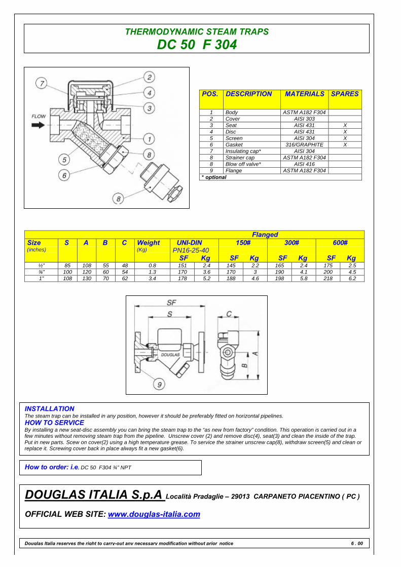
THERMODYNAMIC STEAM TRAPSDC 50 F 304
POS. DESCRIPTION MATERIALS SPARES
1 Body ASTM A182 F3042 Cover AISI 3033 Seat AISI 431 X4 Disc AISI 431 X5 Screen AISI 304 X6 Gasket 316/GRAPHITE X7 Insulating cap* AISI 3048 Strainer cap ASTM A182 F3048 Blow off valve* AISI 4169 Flange ASTM A182 F304
* optional
FlangedSize(inches)
S A B C Weight(Kg)
UNI-DINPN16-25-40
SF Kg
150#
SF Kg
300#
SF Kg
600#
SF Kg½” 85 108 55 48 0.8 151 2.4 145 2.2 165 2.4 175 2.5¾” 100 120 60 54 1.3 170 3.6 170 3 190 4.1 200 4.51” 108 130 70 62 3.4 178 5.2 188 4.6 198 5.8 218 6.2
INSTALLATIONThe steam trap can be installed in any position, however it should be preferably fitted on horizontal pipelines.HOW TO SERVICEBy installing a new seat-disc assembly you can bring the steam trap to the “as new from factory” condition. This operation is carried out in afew minutes without removing steam trap from the pipeline. Unscrew cover (2) and remove disc(4), seat(3) and clean the inside of the trap.Put in new parts. Scew on cover(2) using a high temperature grease. To service the strainer unscrew cap(8), withdraw screen(5) and clean orreplace it. Screwing cover back in place always fit a new gasket(6).
How to order: i.e. DC 50 F304 ¾” NPT
DOUGLAS ITALIA S.p.A Località Pradaglie – 29013 CARPANETO PIACENTINO ( PC )
OFFICIAL WEB SITE: www.douglas-italia.com
Douglas Italia reserves the right to carry-out any necessary modification without prior notice 6 . 00

THERMODYNAMICSTEAM TRAPS
DC50 F304 ø 1.1/2”
THERMODYNAMIC
This type of trap uses steam dynamic energy to close the dischargeorifice. A disc closes both the inlet and outlet orifice. Condensate canlift the disc and be discharge , but when steam is formed its dynamicenergy will create a low pressure area ( Bernulli Law ) under the discwhich draws it towards the seat.
MAIN FEATURES
Reduced dimension and wheigt simple and reliable. It discharges air. Itwithstands waterhammer. Condensate discharge is intermittent. Someloss of live steam.
APPLICATIONS
q Ironing machinesq Steam mainsq Tracing linesq Turbinesq Marine applicationsq Presses
DISCHARGE CAPACITY
LIMITING CONDITIONS ( according to ISO 6552 )Steam Trap rating ANSI 600PMA: Max allowable pressure 100 barTMA: max allowable temperature 500°CPMO: max working pressure 50 barTMO: max working temperature 425°CMinimum Working Pressure 0.25 barPMOB: max working back pressure 80%
SIZES1½”
CONNECTIONSScrewed ANSI B1.20.1 (NPT) / BS21 (BSP)Socket Welding ANSI B16.11Flanged ANSI 150#/300#/600#/UNI/DIN
Douglas Italia reserves the right to carry-out any necessary modification without prior notice
Cold water capacities are 2 to 4 times greater than the above .Safety factor = 1.2 – 1.5
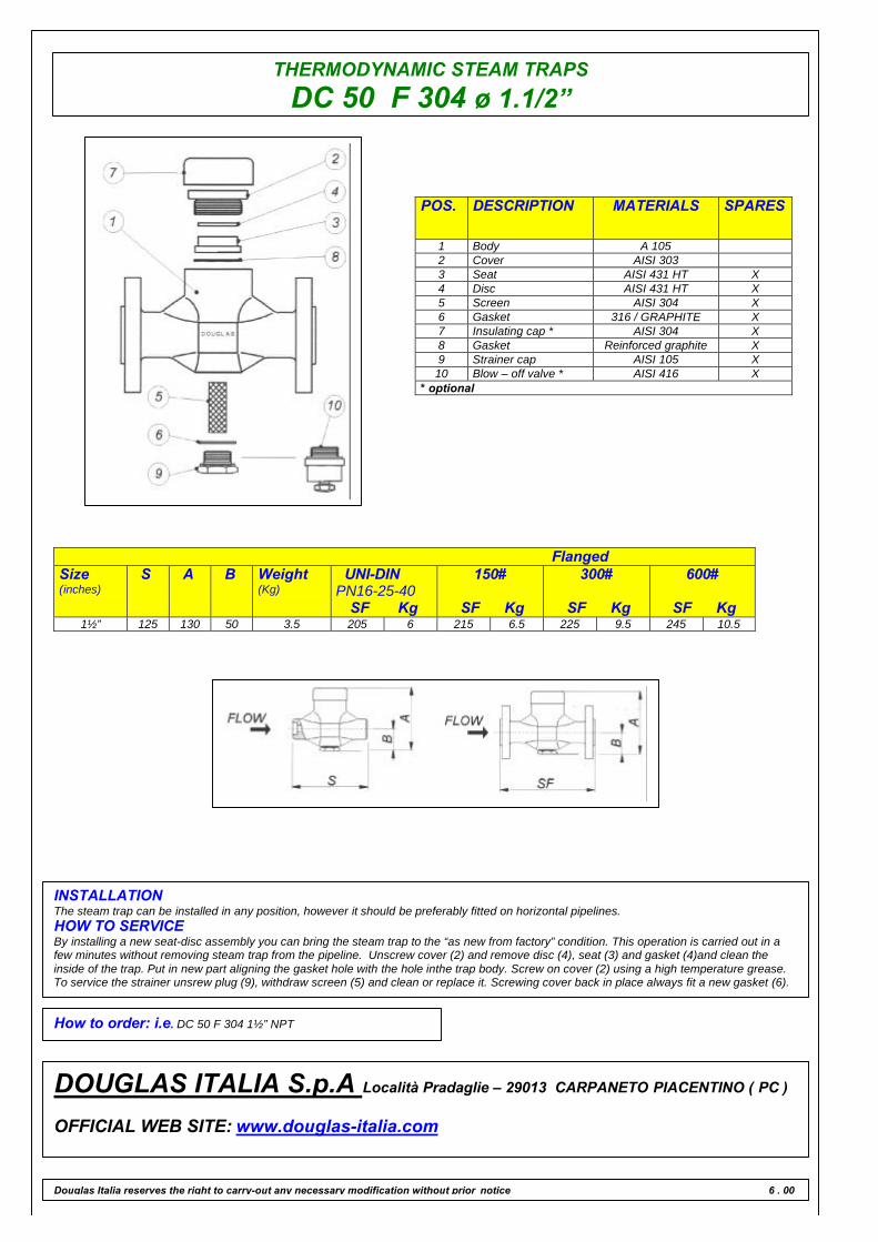
THERMODYNAMIC STEAM TRAPSDC 50 F 304 ø 1.1/2”
POS. DESCRIPTION MATERIALS SPARES
1 Body A 1052 Cover AISI 3033 Seat AISI 431 HT X4 Disc AISI 431 HT X5 Screen AISI 304 X6 Gasket 316 / GRAPHITE X7 Insulating cap * AISI 304 X8 Gasket Reinforced graphite X9 Strainer cap AISI 105 X10 Blow – off valve * AISI 416 X
* optional
FlangedSize(inches)
S A B Weight(Kg)
UNI-DINPN16-25-40
SF Kg
150#
SF Kg
300#
SF Kg
600#
SF Kg1½” 125 130 50 3.5 205 6 215 6.5 225 9.5 245 10.5
INSTALLATIONThe steam trap can be installed in any position, however it should be preferably fitted on horizontal pipelines.HOW TO SERVICEBy installing a new seat-disc assembly you can bring the steam trap to the “as new from factory” condition. This operation is carried out in afew minutes without removing steam trap from the pipeline. Unscrew cover (2) and remove disc (4), seat (3) and gasket (4)and clean theinside of the trap. Put in new part aligning the gasket hole with the hole inthe trap body. Screw on cover (2) using a high temperature grease.To service the strainer unsrew plug (9), withdraw screen (5) and clean or replace it. Screwing cover back in place always fit a new gasket (6).
How to order: i.e. DC 50 F 304 1½” NPT
DOUGLAS ITALIA S.p.A Località Pradaglie – 29013 CARPANETO PIACENTINO ( PC )
OFFICIAL WEB SITE: www.douglas-italia.com
Douglas Italia reserves the right to carry-out any necessary modification without prior notice 6 . 00
THERMODYNAMICSTEAM TRAPS
DC50 F304 ø 2”
THERMODYNAMIC
This type of trap uses steam dynamic energy to close the dischargeorifice. A disc closes both the inlet and outlet orifice. Condensate canlift the disc and be discharge , but when steam is formed its dynamicenergy will create a low pressure area ( Bernulli Law ) under the discwhich draws it towards the seat.
MAIN FEATURES
Reduced dimension and wheigt simple and reliable. It discharges air. Itwithstands waterhammer. Condensate discharge is intermittent. Someloss of live steam.
APPLICATIONS
q Ironing machinesq Steam mainsq Tracing linesq Turbinesq Marine applicationsq Presses
DISCHARGE CAPACITY
LIMITING CONDITIONS ( according to ISO 6552 )Steam Trap rating ANSI 600PMA: Max allowable pressure 100 barTMA: max allowable temperature 500°CPMO: max working pressure 50 barTMO: max working temperature 425°CMinimum Working Pressure 0.25 barPMOB: max working back pressure 80%
SIZES2”
CONNECTIONSScrewed ANSI B1.20.1 (NPT) / BS21 (BSP)Socket Welding ANSI B16.11Flanged ANSI 150#/300#/600#/UNI/DIN
Douglas Italia reserves the right to carry-out any necessary modification without prior notice
Cold water capacities are 2 to 4 times greater than the above .Safety factor = 1.2 – 1.5

THERMODYNAMIC STEAM TRAPSDC 50 F 304 ø 2”
POS. DESCRIPTION MATERIALS SPARES
1 Body A 1052 Cover AISI 3033 Seat AISI 431 HT X4 Disc AISI 431 HT X5 Screen AISI 304 X6 Gasket 316 / GRAPHITE X7 Insulating cap * AISI 304 X8 Gasket Reinforced graphite X9 Strainer cap AISI 105 X10 Blow – off valve * AISI 416 X
* optional
FlangedSize(inches)
S A B Weight(Kg)
UNI-DINPN16-25-40
SF Kg
150#
SF Kg
300#
SF Kg
600#
SF Kg2” 130 130 50 4.3 225 6.4 256 8 269 10 288 11.2
INSTALLATIONThe steam trap can be installed in any position, however it should be preferably fitted on horizontal pipelines.HOW TO SERVICEBy installing a new seat-disc assembly you can bring the steam trap to the “as new from factory” condition. This operation is carried out in afew minutes without removing steam trap from the pipeline. Unscrew cover (2) and remove disc (4), seat (3) and gasket (4)and clean theinside of the trap. Put in new part aligning the gasket hole with the hole inthe trap body. Screw on cover (2) using a high temperature grease.To service the strainer unsrew plug (9), withdraw screen (5) and clean or replace it. Screwing cover back in place always fit a new gasket (6).
How to order: i.e. DC 50 F 304 2” NPT
DOUGLAS ITALIA S.p.A Località Pradaglie – 29013 CARPANETO PIACENTINO ( PC )
OFFICIAL WEB SITE: www.douglas-italia.com
Douglas Italia reserves the right to carry-out any necessary modification without prior notice 6 . 00
THERMODYNAMIC STEAM TRAPSLOW CAPACITIES
DC 50L F 304
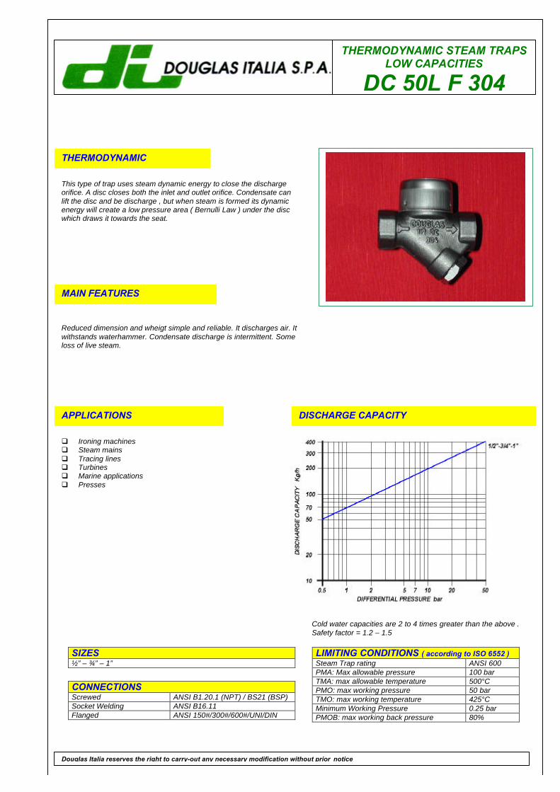
THERMODYNAMIC
This type of trap uses steam dynamic energy to close the dischargeorifice. A disc closes both the inlet and outlet orifice. Condensate canlift the disc and be discharge , but when steam is formed its dynamicenergy will create a low pressure area ( Bernulli Law ) under the discwhich draws it towards the seat.
MAIN FEATURES
Reduced dimension and wheigt simple and reliable. It discharges air. Itwithstands waterhammer. Condensate discharge is intermittent. Someloss of live steam.
APPLICATIONS
q Ironing machinesq Steam mainsq Tracing linesq Turbinesq Marine applicationsq Presses
DISCHARGE CAPACITY
LIMITING CONDITIONS ( according to ISO 6552 )Steam Trap rating ANSI 600PMA: Max allowable pressure 100 barTMA: max allowable temperature 500°CPMO: max working pressure 50 barTMO: max working temperature 425°CMinimum Working Pressure 0.25 barPMOB: max working back pressure 80%
SIZES½” – ¾” – 1”
CONNECTIONSScrewed ANSI B1.20.1 (NPT) / BS21 (BSP)Socket Welding ANSI B16.11Flanged ANSI 150#/300#/600#/UNI/DIN
Douglas Italia reserves the right to carry-out any necessary modification without prior notice
Cold water capacities are 2 to 4 times greater than the above .Safety factor = 1.2 – 1.5
THERMODYNAMIC STEAM TRAPS LOW CAPACITIESDC 50L F 304
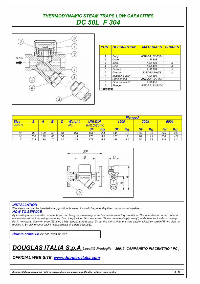
POS. DESCRIPTION MATERIALS SPARES
1 Body ASTM A182 F3042 Cover AISI 3033 Seat AISI 431 X4 Disc AISI 431 X5 Screen AISI 304 X6 Gasket 316/GRAPHITE X7 Insulating cap* AISI 3048 Strainer cap ASTM A182 F3048 Blow off valve* AISI 4169 Flange ASTM A182 F304
* optional
FlangedSize(inches)
S A B C Weight(Kg)
UNI-DINPN16-25-40
SF Kg
150#
SF Kg
300#
SF Kg
600#
SF Kg½” 85 108 55 48 0.8 151 2.4 145 2.2 165 2.4 175 2.5¾” 100 120 60 54 1.3 170 3.6 170 3 190 4.1 200 4.51” 108 130 70 62 3.4 178 5.2 188 4.6 198 5.8 218 6.2
INSTALLATIONThe steam trap can be installed in any position, however it should be preferably fitted on horizontal pipelines.HOW TO SERVICEBy installing a new seat-disc assembly you can bring the steam trap to the “as new from factory” condition. This operation is carried out in afew minutes without removing steam trap from the pipeline. Unscrew cover (2) and remove disc(4), seat(3) and clean the inside of the trap.Put in new parts. Scew on cover(2) using a high temperature grease. To service the strainer unscrew cap(8), withdraw screen(5) and clean orreplace it. Screwing cover back in place always fit a new gasket(6).
How to order: i.e. DC 50L F304 ¾” NPT
DOUGLAS ITALIA S.p.A Località Pradaglie – 29013 CARPANETO PIACENTINO ( PC )
OFFICIAL WEB SITE: www.douglas-italia.com
Douglas Italia reserves the right to carry-out any necessary modification without prior notice 6 . 00
THERMODYNAMICSTEAM TRAPS
DC 50/A F 304
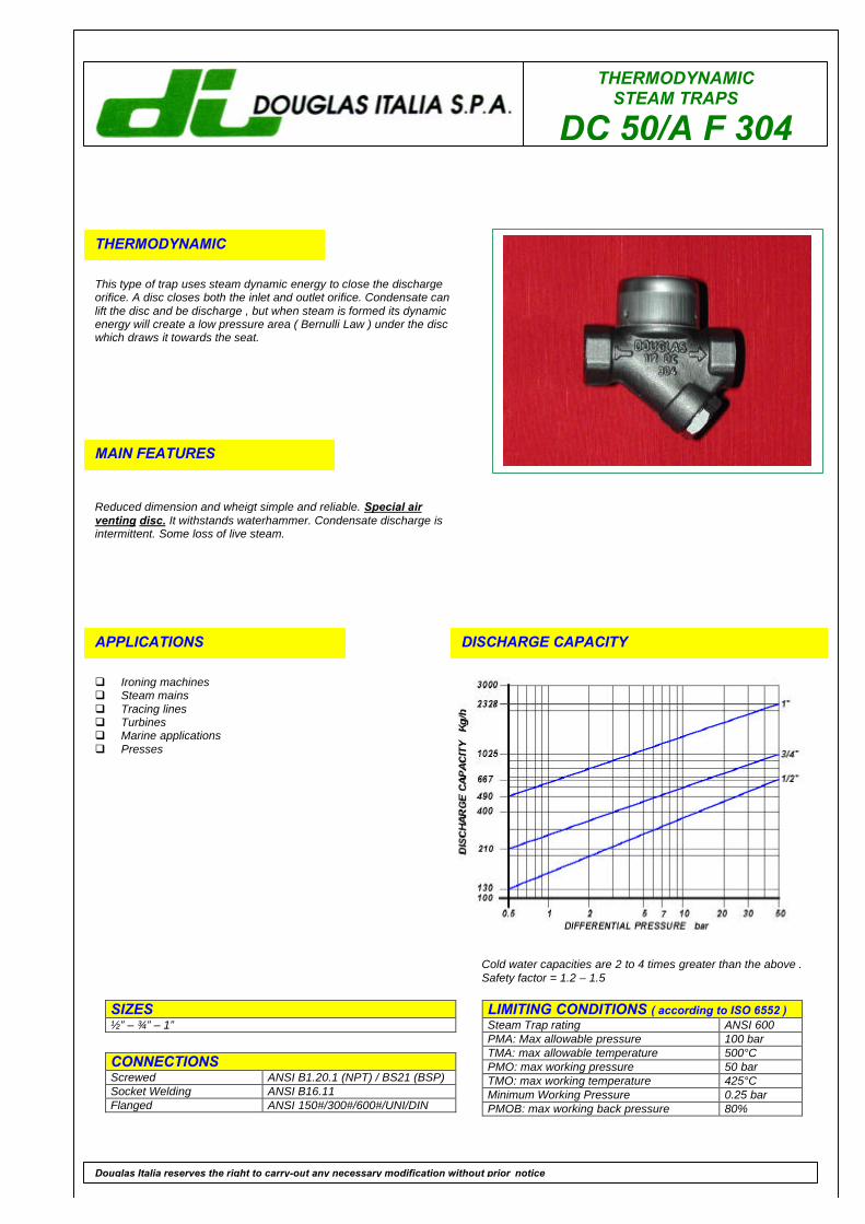
THERMODYNAMIC
This type of trap uses steam dynamic energy to close the dischargeorifice. A disc closes both the inlet and outlet orifice. Condensate canlift the disc and be discharge , but when steam is formed its dynamicenergy will create a low pressure area ( Bernulli Law ) under the discwhich draws it towards the seat.
MAIN FEATURES
Reduced dimension and wheigt simple and reliable. Special airventing disc. It withstands waterhammer. Condensate discharge isintermittent. Some loss of live steam.
APPLICATIONS
q Ironing machinesq Steam mainsq Tracing linesq Turbinesq Marine applicationsq Presses
DISCHARGE CAPACITY
LIMITING CONDITIONS ( according to ISO 6552 )Steam Trap rating ANSI 600PMA: Max allowable pressure 100 barTMA: max allowable temperature 500°CPMO: max working pressure 50 barTMO: max working temperature 425°CMinimum Working Pressure 0.25 barPMOB: max working back pressure 80%
SIZES½” – ¾” – 1”
CONNECTIONSScrewed ANSI B1.20.1 (NPT) / BS21 (BSP)Socket Welding ANSI B16.11Flanged ANSI 150#/300#/600#/UNI/DIN
Douglas Italia reserves the right to carry-out any necessary modification without prior notice
Cold water capacities are 2 to 4 times greater than the above .Safety factor = 1.2 – 1.5
THERMODYNAMIC STEAM TRAPSDC 50/A F 304
POS. DESCRIPTION MATERIALS SPARES
1 Body ASTM A182 F3042 Cover AISI 3033 Seat AISI 431 X4 Disc AISI 431 X5 Screen AISI 304 X6 Gasket 316/GRAPHITE X7 Insulating cap* AISI 3048 Strainer cap ASTM A182 F3048 Blow off valve* AISI 4169 Flange ASTM A182 F304
* optional
FlangedSize(inches)
S A B C Weight(Kg)
UNI-DINPN16-25-40
SF Kg
150#
SF Kg
300#
SF Kg
600#
SF Kg½” 85 108 55 48 0.8 151 2.4 145 2.2 165 2.4 175 2.5¾” 100 120 60 54 1.3 170 3.6 170 3 190 4.1 200 4.51” 108 130 70 62 3.4 178 5.2 188 4.6 198 5.8 218 6.2
INSTALLATIONThe steam trap can be installed in any position, however it should be preferably fitted on horizontal pipelines.HOW TO SERVICEBy installing a new seat-disc assembly you can bring the steam trap to the “as new from factory” condition. This operation is carried out in afew minutes without removing steam trap from the pipeline. Remove insulating cap if fitted and unscrew cover(2) and remove disc(4), seat(3)and clean the inside of the trap. When re-assembling the disc is normally placed in position with the grooved side in contact with the seat.Screw on cover(2) using a high temperature grease. To service the strainer cap(8), withdraw screen(5) and clean or replace it. When servicingthe trap always fit the new gasket.
How to order: i.e. DC 50 /A F304 ¾” NPT
DOUGLAS ITALIA S.p.A Località Pradaglie – 29013 CARPANETO PIACENTINO ( PC )
OFFICIAL WEB SITE: www.douglas-italia.com
Douglas Italia reserves the right to carry-out any necessary modification without prior notice 6 . 00
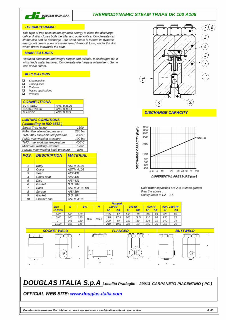
THERMODYNAMIC STEAM TRAPS DK 100 A105
THERMODYNAMIC This type of trap uses steam dynamic energy to close the discharge orifice. A disc closes both the inlet and outlet orifice. Condensate can lift the disc and be discharge , but when steam is formed its dynamic energy will create a low pressure area ( Bernoulli Law ) under the disc which draws it towards the seat. MAIN FEATURES Reduced dimension and weight simple and reliable. It discharges air. It withstands water hammer. Condensate discharge is intermittent. Some loss of live steam. APPLICATIONS
Steam mains Tracing lines Turbines Marine applications Presses
DISCHARGE CAPACITY
LIMITING CONDITIONS ( according to ISO 6552 ) Steam Trap rating 1500 PMA: Max allowable pressure 230 bar TMA: max allowable temperature 400°C PMO: max working pressure 100 bar TMO: max working temperature 400°C Minimum Working Pressure 5 bar PMOB: max working back pressure 80%
Flanged Size (inches)
S BW H 150 RF SF Kg
300 RF SF Kg
600 RF SF Kg
900 / 1500 RF SF Kg
1/2” 105 120 185 17 195 19 205 19 220 20 3/4” 105 120 190 17.5 200 19.5 210 20 235 22 1” 105 120 200 18 212 20 225 21 240 24
1.1/2” 105 116
16.5 186.5
210 19.5 225 23 240 25 265 29
Cold water capacities are 2 to 4 times greater than the above . Safety factor = 1.2 – 1.5
CONNECTIONS BUTTWELD ANSI B 16.25 SOCKET WELD ANSI B 16.11 FLANGED ANSI B 16.5
POS. DESCRIPTION MATERIAL
1 Body ASTM A105 2 Cover ASTM A105 3 Seat AISI 431 4 Cover seat AISI 431 5 Disc AISI 431 6 Gasket S.S. 304 7 Bolts ASTM A193 B8 8 Screen AISI 304 9 Gasket S.S. 304
10 Strainer cap ASTM A105
SOCKET WELD FLANGED BUTTWELD
DOUGLAS ITALIA S.p.A Località Pradaglie – 29013 CARPANETO PIACENTINO ( PC ) OFFICIAL WEB SITE: www.douglas-italia.com
Douglas Italia reserves the right to carry-out any necessary modification without prior notice 6 .00
705040302010 100865
6000500040003000
2000
1000
700600500400
DIFFERENTIAL PRESSURE (bar)
DIS
CHA
RG
E C
APA
CITY
(Kg/
h)DK100
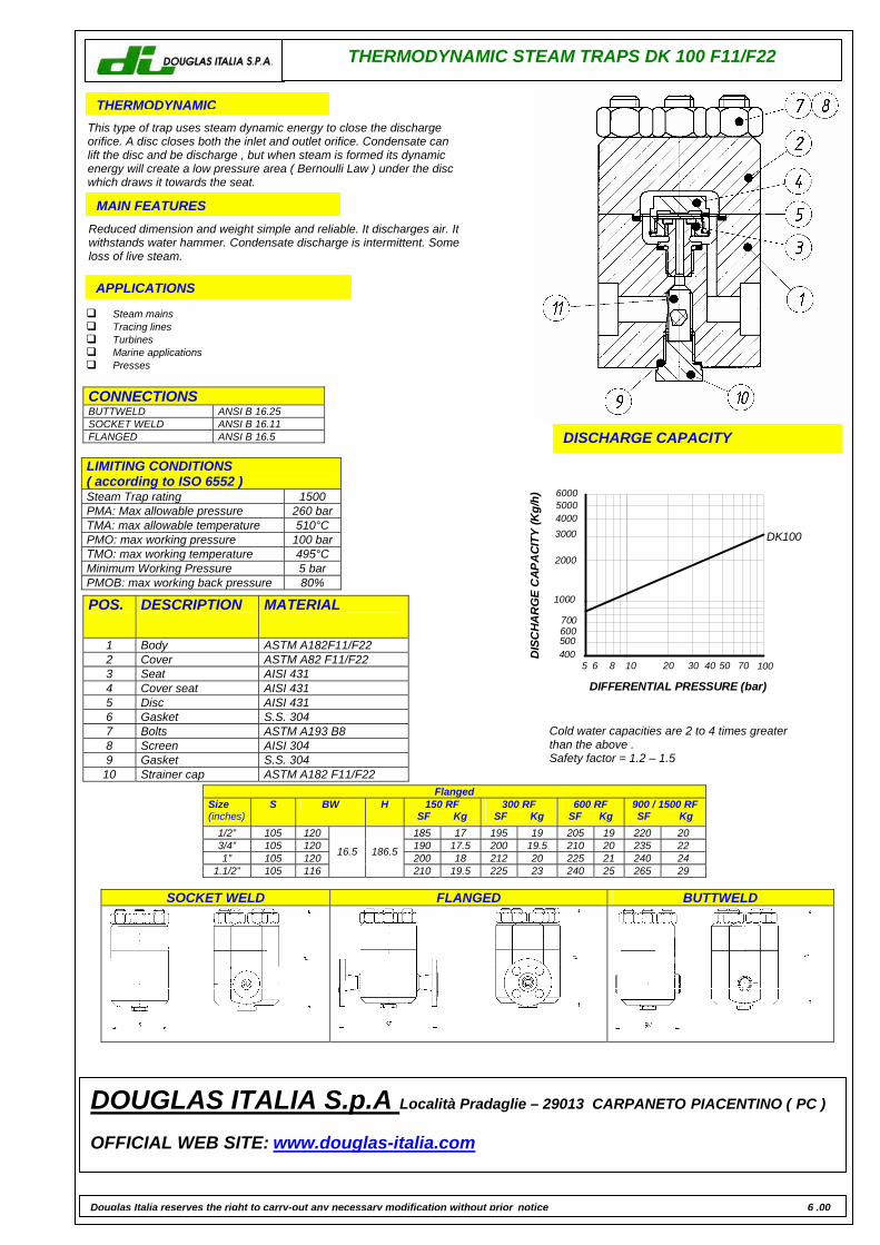
THERMODYNAMIC STEAM TRAPS DK 100 F11/F22
THERMODYNAMIC This type of trap uses steam dynamic energy to close the discharge orifice. A disc closes both the inlet and outlet orifice. Condensate can lift the disc and be discharge , but when steam is formed its dynamic energy will create a low pressure area ( Bernoulli Law ) under the disc which draws it towards the seat. MAIN FEATURES Reduced dimension and weight simple and reliable. It discharges air. It withstands water hammer. Condensate discharge is intermittent. Some loss of live steam. APPLICATIONS
Steam mains Tracing lines Turbines Marine applications Presses
DISCHARGE CAPACITY
LIMITING CONDITIONS ( according to ISO 6552 ) Steam Trap rating 1500 PMA: Max allowable pressure 260 bar TMA: max allowable temperature 510°C PMO: max working pressure 100 bar TMO: max working temperature 495°C Minimum Working Pressure 5 bar PMOB: max working back pressure 80%
Flanged Size (inches)
S BW H 150 RF SF Kg
300 RF SF Kg
600 RF SF Kg
900 / 1500 RF SF Kg
1/2” 105 120 185 17 195 19 205 19 220 20 3/4” 105 120 190 17.5 200 19.5 210 20 235 22 1” 105 120 200 18 212 20 225 21 240 24
1.1/2” 105 116
16.5 186.5
210 19.5 225 23 240 25 265 29
Cold water capacities are 2 to 4 times greater than the above . Safety factor = 1.2 – 1.5
CONNECTIONS BUTTWELD ANSI B 16.25 SOCKET WELD ANSI B 16.11 FLANGED ANSI B 16.5
POS. DESCRIPTION MATERIAL
1 Body ASTM A182F11/F22 2 Cover ASTM A82 F11/F22 3 Seat AISI 431 4 Cover seat AISI 431 5 Disc AISI 431 6 Gasket S.S. 304 7 Bolts ASTM A193 B8 8 Screen AISI 304 9 Gasket S.S. 304
10 Strainer cap ASTM A182 F11/F22
SOCKET WELD FLANGED BUTTWELD
DOUGLAS ITALIA S.p.A Località Pradaglie – 29013 CARPANETO PIACENTINO ( PC ) OFFICIAL WEB SITE: www.douglas-italia.com
Douglas Italia reserves the right to carry-out any necessary modification without prior notice 6 .00
705040302010 100865
6000500040003000
2000
1000
700600500400
DIFFERENTIAL PRESSURE (bar)
DIS
CHA
RG
E C
APA
CITY
(Kg/
h)DK100
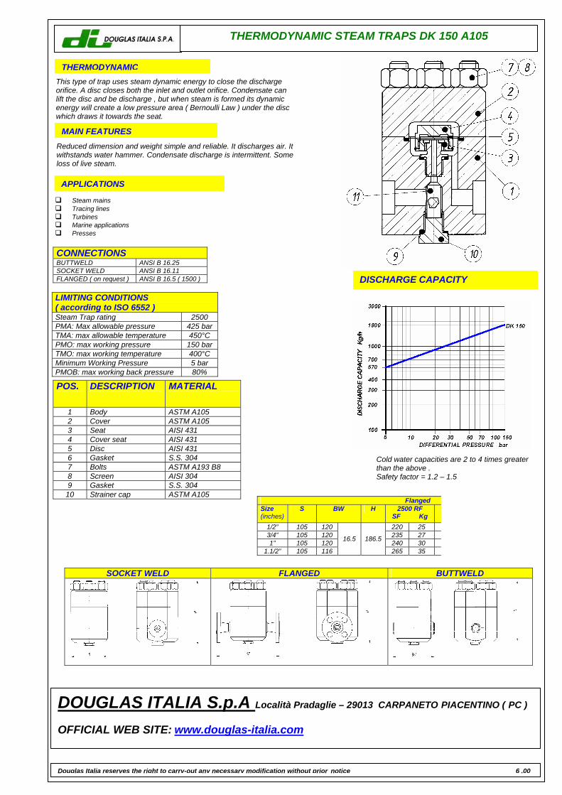
THERMODYNAMIC STEAM TRAPS DK 150 A105
THERMODYNAMIC This type of trap uses steam dynamic energy to close the discharge orifice. A disc closes both the inlet and outlet orifice. Condensate can lift the disc and be discharge , but when steam is formed its dynamic energy will create a low pressure area ( Bernoulli Law ) under the disc which draws it towards the seat. MAIN FEATURES Reduced dimension and weight simple and reliable. It discharges air. It withstands water hammer. Condensate discharge is intermittent. Some loss of live steam. APPLICATIONS
Steam mains Tracing lines Turbines Marine applications Presses
DISCHARGE CAPACITY
LIMITING CONDITIONS ( according to ISO 6552 ) Steam Trap rating 2500 PMA: Max allowable pressure 425 bar TMA: max allowable temperature 450°C PMO: max working pressure 150 bar TMO: max working temperature 400°C Minimum Working Pressure 5 bar PMOB: max working back pressure 80%
Flanged Size (inches)
S BW H 2500 RF SF Kg
1/2” 105 120 220 25 3/4” 105 120 235 27 1” 105 120 240 30
1.1/2” 105 116
16.5 186.5
265 35
Cold water capacities are 2 to 4 times greater than the above . Safety factor = 1.2 – 1.5
CONNECTIONS BUTTWELD ANSI B 16.25 SOCKET WELD ANSI B 16.11 FLANGED ( on request ) ANSI B 16.5 ( 1500 )
POS. DESCRIPTION MATERIAL
1 Body ASTM A105 2 Cover ASTM A105 3 Seat AISI 431 4 Cover seat AISI 431 5 Disc AISI 431 6 Gasket S.S. 304 7 Bolts ASTM A193 B8 8 Screen AISI 304 9 Gasket S.S. 304
10 Strainer cap ASTM A105
SOCKET WELD FLANGED BUTTWELD
DOUGLAS ITALIA S.p.A Località Pradaglie – 29013 CARPANETO PIACENTINO ( PC ) OFFICIAL WEB SITE: www.douglas-italia.com
Douglas Italia reserves the right to carry-out any necessary modification without prior notice 6 .00
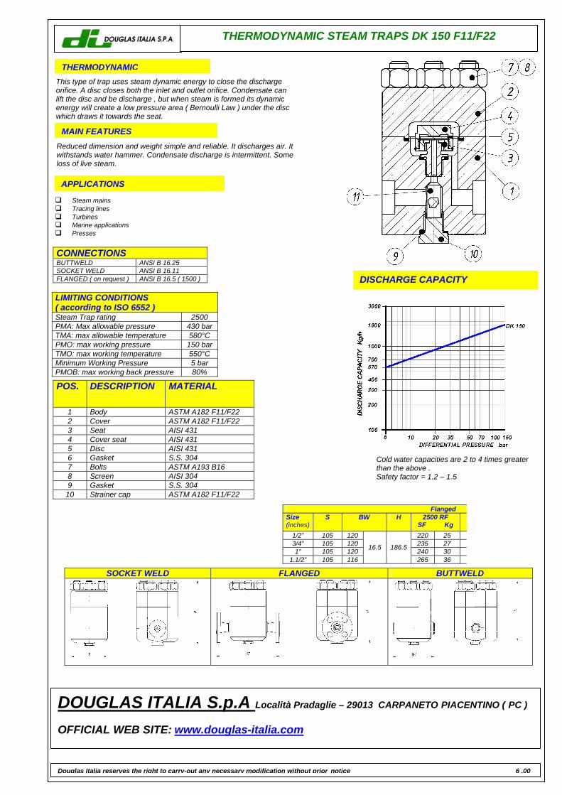
THERMODYNAMIC STEAM TRAPS DK 150 F11/F22
THERMODYNAMIC This type of trap uses steam dynamic energy to close the discharge orifice. A disc closes both the inlet and outlet orifice. Condensate can lift the disc and be discharge , but when steam is formed its dynamic energy will create a low pressure area ( Bernoulli Law ) under the disc which draws it towards the seat. MAIN FEATURES Reduced dimension and weight simple and reliable. It discharges air. It withstands water hammer. Condensate discharge is intermittent. Some loss of live steam. APPLICATIONS
Steam mains Tracing lines Turbines Marine applications Presses
DISCHARGE CAPACITY
LIMITING CONDITIONS ( according to ISO 6552 ) Steam Trap rating 2500 PMA: Max allowable pressure 430 bar TMA: max allowable temperature 580°C PMO: max working pressure 150 bar TMO: max working temperature 550°C Minimum Working Pressure 5 bar PMOB: max working back pressure 80%
Flanged Size (inches)
S BW H 2500 RF SF Kg
1/2” 105 120 220 25 3/4” 105 120 235 27 1” 105 120 240 30
1.1/2” 105 116
16.5 186.5
265 36
Cold water capacities are 2 to 4 times greater than the above . Safety factor = 1.2 – 1.5
CONNECTIONS BUTTWELD ANSI B 16.25 SOCKET WELD ANSI B 16.11 FLANGED ( on request ) ANSI B 16.5 ( 1500 )
POS. DESCRIPTION MATERIAL
1 Body ASTM A182 F11/F22 2 Cover ASTM A182 F11/F22 3 Seat AISI 431 4 Cover seat AISI 431 5 Disc AISI 431 6 Gasket S.S. 304 7 Bolts ASTM A193 B16 8 Screen AISI 304 9 Gasket S.S. 304
10 Strainer cap ASTM A182 F11/F22
SOCKET WELD FLANGED BUTTWELD
DOUGLAS ITALIA S.p.A Località Pradaglie – 29013 CARPANETO PIACENTINO ( PC ) OFFICIAL WEB SITE: www.douglas-italia.com
Douglas Italia reserves the right to carry-out any necessary modification without prior notice 6 .00

BIMETALLIC THERMOSTATICSTEAM TRAPS
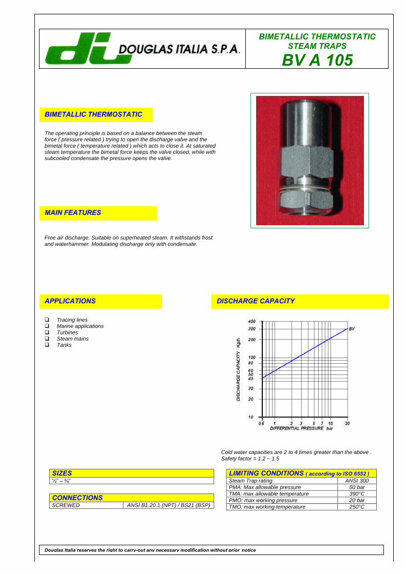
BV A 105
BIMETALLIC THERMOSTATIC
The operating principle is based on a balance between the steamforce ( pressure related ) trying to open the discharge valve and thebimetal force ( temperature related ) which acts to close it. At saturatedsteam temperature the bimetal force keeps the valve closed, while withsubcooled condensate the pressure opens the valve.
MAIN FEATURES
Free air discharge. Suitable on superheated steam. It withstands frostand waterhammer. Modulating discharge only with condensate.
APPLICATIONS
q Tracing linesq Marine applicationsq Turbinesq Steam mainsq Tanks
DISCHARGE CAPACITY
LIMITING CONDITIONS ( according to ISO 6552 )Steam Trap rating ANSI 300PMA: Max allowable pressure 50 barTMA: max allowable temperature 390°CPMO: max working pressure 20 barTMO: max working temperature 250°C
SIZES1⁄2” – 3⁄4”
CONNECTIONSSCREWED ANSI B1.20.1 (NPT) / BS21 (BSP)
Douglas Italia reserves the right to carry-out any necessary modification without prior notice
Cold water capacities are 2 to 4 times greater than the above .Safety factor = 1.2 – 1.5
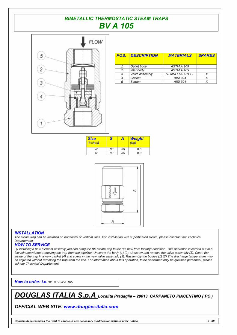
BIMETALLIC THERMOSTATIC STEAM TRAPS
BV A 105
POS. DESCRIPTION MATERIALS SPARES
1 Outlet body ASTM A 1052 Inlet body ASTM A 1053 Valve assembly STAINLESS STEEL X4 Gasket AISI 304 X5 Screen AISI 304 X
Size(inches)
S A Weight(Kg)
½” 80 36 0.6¾” 93 36 0.8
INSTALLATIONThe steam trap can be installed on horizontal or vertical lines. For installation with superheated steam, please conctact our TechnicalDepartementHOW TO SERVICEBy installing a new element assemly you can bring the BV steam trap to the “as new from factory” condition. This operation is carried out in afew minuteswithout removing the trap from the pipeline. Unscrew the body (1) (2). Unscrew and remove the valve assembly (3). Clean theinside of the trap fit a new gasket (4) and screw in the new valve assembly (3). Rassembly the bodies (1) (2).The discharge temperature maybe adjusted without removing the trap from the line. For information about this operation, to be performed only be qualified personnel, pleaseask our Thecnical Departement.
How to order: i.e. BV ¾” SW A 105
DOUGLAS ITALIA S.p.A Località Pradaglie – 29013 CARPANETO PIACENTINO ( PC )
OFFICIAL WEB SITE: www.douglas-italia.com
Douglas Italia reserves the right to carry-out any necessary modification without prior notice 6 . 00
BIMETALLIC THERMOSTATICSTEAM TRAPS
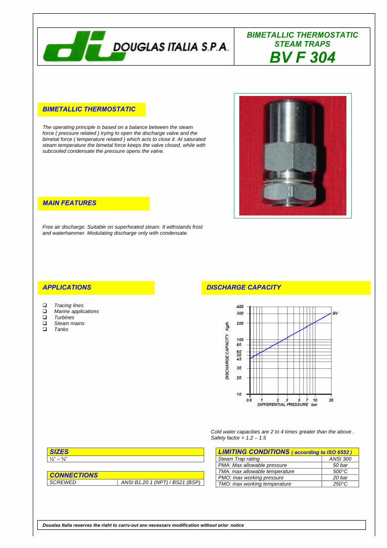
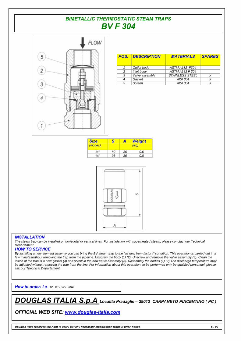
BV F 304
BIMETALLIC THERMOSTATIC
The operating principle is based on a balance between the steamforce ( pressure related ) trying to open the discharge valve and thebimetal force ( temperature related ) which acts to close it. At saturatedsteam temperature the bimetal force keeps the valve closed, while withsubcooled condensate the pressure opens the valve.
MAIN FEATURES
Free air discharge. Suitable on superheated steam. It withstands frostand waterhammer. Modulating discharge only with condensate.
APPLICATIONS
q Tracing linesq Marine applicationsq Turbinesq Steam mainsq Tanks
DISCHARGE CAPACITY
LIMITING CONDITIONS ( according to ISO 6552 )Steam Trap rating ANSI 300PMA: Max allowable pressure 50 barTMA: max allowable temperature 500°CPMO: max working pressure 20 barTMO: max working temperature 250°C
SIZES1⁄2” – 3⁄4”
CONNECTIONSSCREWED ANSI B1.20.1 (NPT) / BS21 (BSP)
Douglas Italia reserves the right to carry-out any necessary modification without prior notice
Cold water capacities are 2 to 4 times greater than the above .Safety factor = 1.2 – 1.5
BIMETALLIC THERMOSTATIC STEAM TRAPS
BV F 304
POS. DESCRIPTION MATERIALS SPARES
1 Outlet body ASTM A182 F3042 Inlet body ASTM A182 F 3043 Valve assembly STAINLESS STEEL X4 Gasket AISI 304 X5 Screen AISI 304 X
Size(inches)
S A Weight(Kg)
½” 80 36 0.6¾” 93 36 0.8
INSTALLATIONThe steam trap can be installed on horizontal or vertical lines. For installation with superheated steam, please conctact our TechnicalDepartementHOW TO SERVICEBy installing a new element assemly you can bring the BV steam trap to the “as new from factory” condition. This operation is carried out in afew minuteswithout removing the trap from the pipeline. Unscrew the body (1) (2). Unscrew and remove the valve assembly (3). Clean theinside of the trap fit a new gasket (4) and screw in the new valve assembly (3). Rassembly the bodies (1) (2).The discharge temperature maybe adjusted without removing the trap from the line. For information about this operation, to be performed only be qualified personnel, pleaseask our Thecnical Departement.
How to order: i.e. BV ¾” SW F 304
DOUGLAS ITALIA S.p.A Località Pradaglie – 29013 CARPANETO PIACENTINO ( PC )
OFFICIAL WEB SITE: www.douglas-italia.com
Douglas Italia reserves the right to carry-out any necessary modification without prior notice 6 . 00
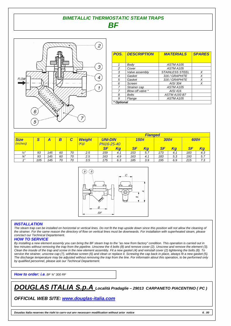
BIMETALLIC THERMOSTATIC STEAM TRAPS
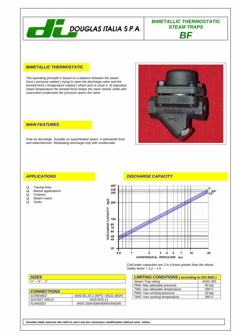
BF
BIMETALLIC THERMOSTATIC
The operating principle is based on a balance between the steam force ( pressure related ) trying to open the discharge valve and the bimetal force ( temperature related ) which acts to close it. At saturated steam temperature the bimetal force keeps the valve closed, while with subcooled condensate the pressure opens the valve.
MAIN FEATURES
Free air discharge. Suitable on superheated steam. It withstands frost and waterhammer. Modulating discharge only with condensate.
APPLICATIONS
Tracing lines Marine applications Turbines Steam mains Tanks
DISCHARGE CAPACITY
LIMITING CONDITIONS ( according to ISO 6552 ) Steam Trap rating ANSI 300 PMA: Max allowable pressure 50 bar TMA: max allowable temperature 390°C PMO: max working pressure 20 bar TMO: max working temperature 350°C
SIZES ½” – ¾” – 1”
CONNECTIONS SCREWED ANSI B1.20.1 (NPT) / BS21 (BSP) SOCKET WELD ANSI B16.11 FLANGED ANSI 150#/300#/600#/UNI/DIN
Douglas Italia reserves the right to carry-out any necessary modification without prior notice
Cold water capacities are 2 to 4 times greater than the above . Safety factor = 1.2 – 1.5
BIMETALLIC THERMOSTATIC STEAM TRAPS
BF
POS. DESCRIPTION MATERIALS SPARES
1 Body ASTM A105 2 Cover ASTM A105 3 Valve assembly STAINLESS STEEL X 4 Gasket 316 / GRAPHITE X 5 Gasket 316 / GRAPHITE X 6 Screen AISI 304 X 7 Strainer cap ASTM A105 7 Blow-off valve * AISI 416 8 Bolts ASTM A193 B7 9 Flange ASTM A105
* Optional
Flanged Size (inches)
S A B C Weight (Kg)
UNI-DIN PN16-25-40
SF Kg
150#
SF Kg
300#
SF Kg
600#
SF Kg ½” 93 145 60 70 2.5 159 4.1 153 5.7 173 4.1 183 4.3 ¾” 93 145 60 70 2.5 163 4.9 163 4.1 183 5.3 193 5.7 1” 105 145 70 70 3.5 175 6.3 185 3.9 195 6.9 215 7.3
INSTALLATION The steam trap can be installed on horizontal or vertical lines. Do not fit the trap upside down since this position will not allow the cleaning of the strainer. For the same reason the directory of flow on vertical lines must be downwards. For installation with superheated steam, please conctact our Technical Departement. HOW TO SERVICE By installing a new element assemly you can bring the BF steam trap to the “as new from factory” condition. This operation is carried out in few minutes without removing the trap from the pipeline. Unscrew the 4 bolts (8) and remove cover (2). Unscrew and remove the element (3). Clean the insede of the trap and screw in the new element assembly. Fit a new gasket (4) and reinstall cover (2) tightening the bolts (8). To service the strainer, unscrew cap (7), withdraw screen (6) and clean or replace it. Screwing the cap back in place, always fit a new gasket (5). The discharge temperature may be adjusted without removing the trap from the line. For informatin about this operation, to be performed only by qualified personnel, please ask our Techincal Departement.
How to order: i.e. BF ¾” 300 RF
DOUGLAS ITALIA S.p.A Località Pradaglie – 29013 CARPANETO PIACENTINO ( PC ) OFFICIAL WEB SITE: www.douglas-italia.com
Douglas Italia reserves the right to carry-out any necessary modification without prior notice 6 . 00
BIMETALLIC THERMOSTATICSTEAM TRAPS
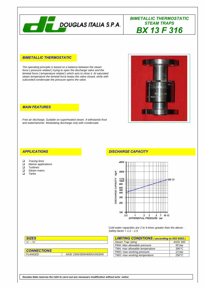
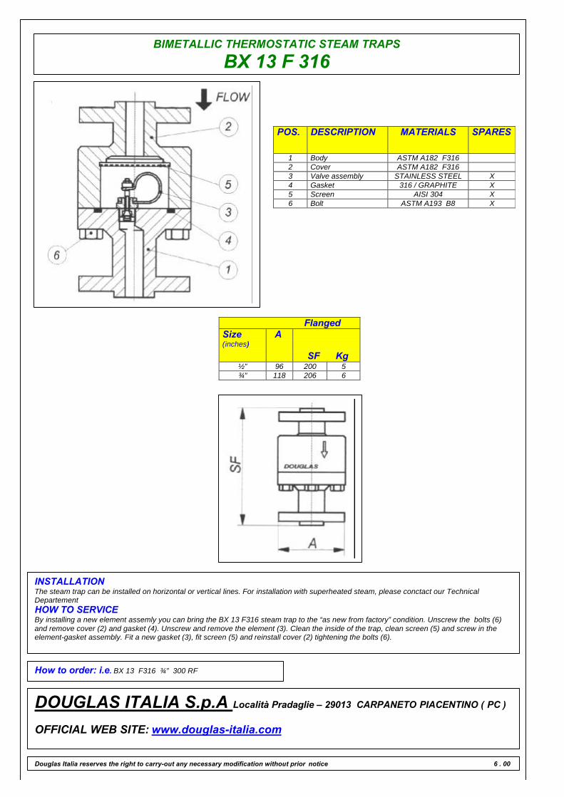
BX 13 F 316
BIMETALLIC THERMOSTATIC
The operating principle is based on a balance between the steamforce ( pressure related ) trying to open the discharge valve and thebimetal force ( temperature related ) which acts to close it. At saturatedsteam temperature the bimetal force keeps the valve closed, while withsubcooled condensate the pressure opens the valve.
MAIN FEATURES
Free air discharge. Suitable on superheated steam. It withstands frostand waterhammer. Modulating discharge only with condensate.
APPLICATIONS
q Tracing linesq Marine applicationsq Turbinesq Steam mainsq Tanks
DISCHARGE CAPACITY
LIMITING CONDITIONS ( according to ISO 6552 )Steam Trap rating ANSI 300PMA: Max allowable pressure 50 barTMA: max allowable temperature 390°CPMO: max working pressure 13 barTMO: max working temperature 250°C
SIZES1⁄2” – 3⁄4”
CONNECTIONSFLANGED ANSI 150#/300#/600#/UNI/DIN
Douglas Italia reserves the right to carry-out any necessary modification without prior notice
Cold water capacities are 2 to 4 times greater than the above .Safety factor = 1.2 – 1.5
BIMETALLIC THERMOSTATIC STEAM TRAPS
BX 13 F 316
POS. DESCRIPTION MATERIALS SPARES
1 Body ASTM A182 F3162 Cover ASTM A182 F3163 Valve assembly STAINLESS STEEL X4 Gasket 316 / GRAPHITE X5 Screen AISI 304 X6 Bolt ASTM A193 B8 X
FlangedSize(inches)
A
SF Kg½” 96 200 5¾” 118 206 6
INSTALLATIONThe steam trap can be installed on horizontal or vertical lines. For installation with superheated steam, please conctact our TechnicalDepartementHOW TO SERVICEBy installing a new element assemly you can bring the BX 13 F316 steam trap to the “as new from factory” condition. Unscrew the bolts (6)and remove cover (2) and gasket (4). Unscrew and remove the element (3). Clean the inside of the trap, clean screen (5) and screw in theelement-gasket assembly. Fit a new gasket (3), fit screen (5) and reinstall cover (2) tightening the bolts (6).
How to order: i.e. BX 13 F316 ¾” 300 RF
DOUGLAS ITALIA S.p.A Località Pradaglie – 29013 CARPANETO PIACENTINO ( PC )
OFFICIAL WEB SITE: www.douglas-italia.com
Douglas Italia reserves the right to carry-out any necessary modification without prior notice 6 . 00

BIMETALLIC THERMOSTATICSTEAM TRAPS
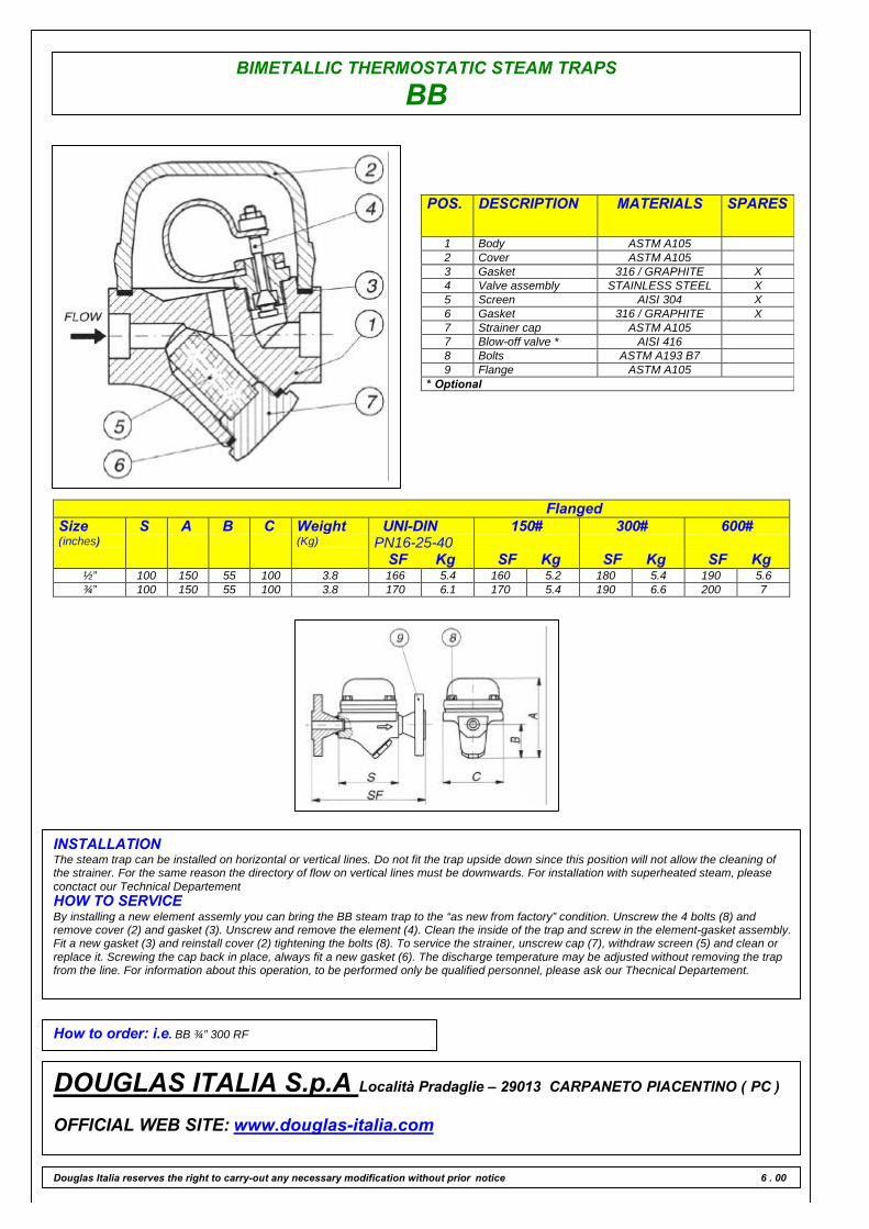
BB
BIMETALLIC THERMOSTATIC
The operating principle is based on a balance between the steamforce ( pressure related ) trying to open the discharge valve and thebimetal force ( temperature related ) which acts to close it. At saturatedsteam temperature the bimetal force keeps the valve closed, while withsubcooled condensate the pressure opens the valve.
MAIN FEATURES
Free air discharge. Suitable on superheated steam. It withstands frostand waterhammer. Modulating discharge only with condensate.
APPLICATIONS
q Tracing linesq Marine applicationsq Turbinesq Steam mainsq Tanks
DISCHARGE CAPACITY
LIMITING CONDITIONS ( according to ISO 6552 )Steam Trap rating ANSI 300PMA: Max allowable pressure 50 barTMA: max allowable temperature 390°CPMO: max working pressure 13 barTMO: max working temperature 250°C
SIZES1⁄2” – 3⁄4”
CONNECTIONSSCREWED ANSI B1.20.1 (NPT) / BS21 (BSP)SOCKET WELD ANSI B16.11FLANGED ANSI 150#/300#/600#/UNI/DIN
Douglas Italia reserves the right to carry-out any necessary modification without prior notice
Cold water capacities are 2 to 4 times greater than the above .Safety factor = 1.2 – 1.5
BIMETALLIC THERMOSTATIC STEAM TRAPS
BB
POS. DESCRIPTION MATERIALS SPARES
1 Body ASTM A1052 Cover ASTM A1053 Gasket 316 / GRAPHITE X4 Valve assembly STAINLESS STEEL X5 Screen AISI 304 X6 Gasket 316 / GRAPHITE X7 Strainer cap ASTM A1057 Blow-off valve * AISI 4168 Bolts ASTM A193 B79 Flange ASTM A105
* Optional
FlangedSize(inches)
S A B C Weight(Kg)
UNI-DINPN16-25-40
SF Kg
150#
SF Kg
300#
SF Kg
600#
SF Kg½” 100 150 55 100 3.8 166 5.4 160 5.2 180 5.4 190 5.6¾” 100 150 55 100 3.8 170 6.1 170 5.4 190 6.6 200 7
INSTALLATIONThe steam trap can be installed on horizontal or vertical lines. Do not fit the trap upside down since this position will not allow the cleaning ofthe strainer. For the same reason the directory of flow on vertical lines must be downwards. For installation with superheated steam, pleaseconctact our Technical DepartementHOW TO SERVICEBy installing a new element assemly you can bring the BB steam trap to the “as new from factory” condition. Unscrew the 4 bolts (8) andremove cover (2) and gasket (3). Unscrew and remove the element (4). Clean the inside of the trap and screw in the element-gasket assembly.Fit a new gasket (3) and reinstall cover (2) tightening the bolts (8). To service the strainer, unscrew cap (7), withdraw screen (5) and clean orreplace it. Screwing the cap back in place, always fit a new gasket (6). The discharge temperature may be adjusted without removing the trapfrom the line. For information about this operation, to be performed only be qualified personnel, please ask our Thecnical Departement.
How to order: i.e. BB ¾” 300 RF
DOUGLAS ITALIA S.p.A Località Pradaglie – 29013 CARPANETO PIACENTINO ( PC )
OFFICIAL WEB SITE: www.douglas-italia.com
Douglas Italia reserves the right to carry-out any necessary modification without prior notice 6 . 00
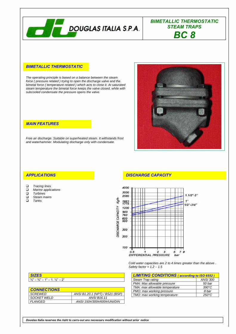
BIMETALLIC THERMOSTATICSTEAM TRAPS
BC 8
BIMETALLIC THERMOSTATIC
The operating principle is based on a balance between the steamforce ( pressure related ) trying to open the discharge valve and thebimetal force ( temperature related ) which acts to close it. At saturatedsteam temperature the bimetal force keeps the valve closed, while withsubcooled condensate the pressure opens the valve.
MAIN FEATURES
Free air discharge. Suitable on superheated steam. It withstands frostand waterhammer. Modulating discharge only with condensate.
APPLICATIONS
q Tracing linesq Marine applicationsq Turbinesq Steam mainsq Tanks
DISCHARGE CAPACITY
LIMITING CONDITIONS ( according to ISO 6552 )Steam Trap rating ANSI 300PMA: Max allowable pressure 50 barTMA: max allowable temperature 390°CPMO: max working pressure 8 barTMO: max working temperature 250°C
SIZES1⁄2” – 3⁄4” – 1” – 1. 1⁄2” – 2”
CONNECTIONSSCREWED ANSI B1.20.1 (NPT) / BS21 (BSP)SOCKET WELD ANSI B16.11FLANGED ANSI 150#/300#/600#/UNI/DIN
Douglas Italia reserves the right to carry-out any necessary modification without prior notice
Cold water capacities are 2 to 4 times greater than the above .Safety factor = 1.2 – 1.5
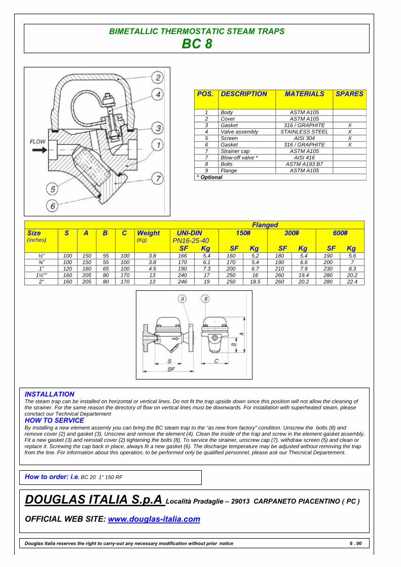
BIMETALLIC THERMOSTATIC STEAM TRAPS
BC 8
POS. DESCRIPTION MATERIALS SPARES
1 Body ASTM A1052 Cover ASTM A1053 Gasket 316 / GRAPHITE X4 Valve assembly STAINLESS STEEL X5 Screen AISI 304 X6 Gasket 316 / GRAPHITE X7 Strainer cap ASTM A1057 Blow-off valve * AISI 4168 Bolts ASTM A193 B79 Flange ASTM A105
* Optional
FlangedSize(inches)
S A B C Weight(Kg)
UNI-DINPN16-25-40
SF Kg
150#
SF Kg
300#
SF Kg
600#
SF Kg½” 100 150 55 100 3.8 166 5.4 160 5.2 180 5.4 190 5.6¾” 100 150 55 100 3.8 170 6.1 170 5.4 190 6.6 200 71” 120 160 65 100 4.5 190 7.3 200 6.7 210 7.9 230 8.3
1½”” 160 205 80 170 13 240 17 250 16 260 19.4 280 20.22” 160 205 80 170 13 246 19 250 18.5 260 20.2 280 22.4
INSTALLATIONThe steam trap can be installed on horizontal or vertical lines. Do not fit the trap upside down since this position will not allow the cleaning ofthe strainer. For the same reason the directory of flow on vertical lines must be downwards. For installation with superheated steam, pleaseconctact our Technical DepartementHOW TO SERVICEBy installing a new element assemly you can bring the BC steam trap to the “as new from factory” condition. Unscrew the bolts (8) andremove cover (2) and gasket (3). Unscrew and remove the element (4). Clean the inside of the trap and screw in the element-gasket assembly.Fit a new gasket (3) and reinstall cover (2) tightening the bolts (8). To service the strainer, unscrew cap (7), withdraw screen (5) and clean orreplace it. Screwing the cap back in place, always fit a new gasket (6). The discharge temperature may be adjusted without removing the trapfrom the line. For information about this operation, to be performed only be qualified personnel, please ask our Thecnical Departement.
How to order: i.e. BC 20 1” 150 RF
DOUGLAS ITALIA S.p.A Località Pradaglie – 29013 CARPANETO PIACENTINO ( PC )
OFFICIAL WEB SITE: www.douglas-italia.com
Douglas Italia reserves the right to carry-out any necessary modification without prior notice 6 . 00

BIMETALLIC THERMOSTATICSTEAM TRAPS
BC 20
BIMETALLIC THERMOSTATIC
The operating principle is based on a balance between the steamforce ( pressure related ) trying to open the discharge valve and thebimetal force ( temperature related ) which acts to close it. At saturatedsteam temperature the bimetal force keeps the valve closed, while withsubcooled condensate the pressure opens the valve.
MAIN FEATURES
Free air discharge. Suitable on superheated steam. It withstands frostand waterhammer. Modulating discharge only with condensate.
APPLICATIONS
q Tracing linesq Marine applicationsq Turbinesq Steam mainsq Tanks
DISCHARGE CAPACITY
LIMITING CONDITIONS ( according to ISO 6552 )Steam Trap rating ANSI 300PMA: Max allowable pressure 50 barTMA: max allowable temperature 390°CPMO: max working pressure 20 barTMO: max working temperature 275°C
SIZES1⁄2” – 3⁄4” – 1” – 1. 1⁄2” – 2”
CONNECTIONSSCREWED ANSI B1.20.1 (NPT) / BS21 (BSP)SOCKET WELD ANSI B16.11FLANGED ANSI 150#/300#/600#/UNI/DIN
Douglas Italia reserves the right to carry-out any necessary modification without prior notice
Cold water capacities are 2 to 4 times greater than the above .Safety factor = 1.2 – 1.5
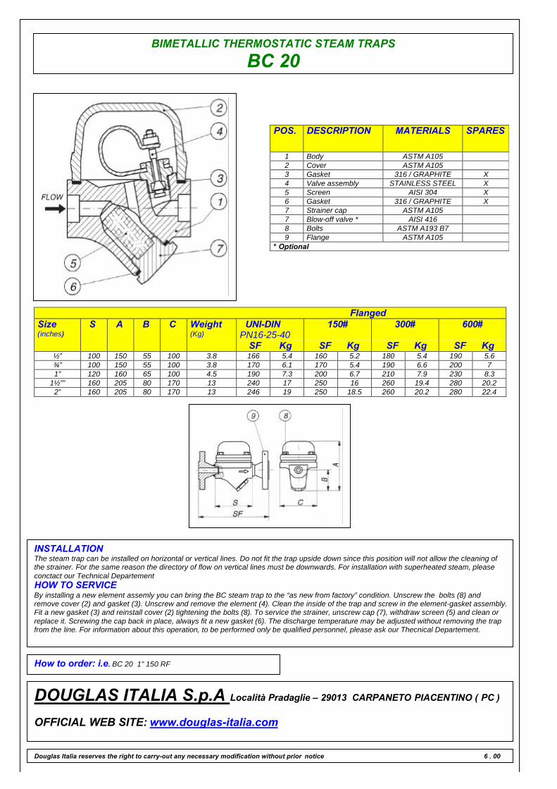
BIMETALLIC THERMOSTATIC STEAM TRAPS
BC 20
POS. DESCRIPTION MATERIALS SPARES
1 Body ASTM A1052 Cover ASTM A1053 Gasket 316 / GRAPHITE X4 Valve assembly STAINLESS STEEL X5 Screen AISI 304 X6 Gasket 316 / GRAPHITE X7 Strainer cap ASTM A1057 Blow-off valve * AISI 4168 Bolts ASTM A193 B79 Flange ASTM A105
* Optional
FlangedSize(inches)
S A B C Weight(Kg)
UNI-DINPN16-25-40
SF Kg
150#
SF Kg
300#
SF Kg
600#
SF Kg½” 100 150 55 100 3.8 166 5.4 160 5.2 180 5.4 190 5.6¾” 100 150 55 100 3.8 170 6.1 170 5.4 190 6.6 200 71” 120 160 65 100 4.5 190 7.3 200 6.7 210 7.9 230 8.3
1½”” 160 205 80 170 13 240 17 250 16 260 19.4 280 20.22” 160 205 80 170 13 246 19 250 18.5 260 20.2 280 22.4
INSTALLATIONThe steam trap can be installed on horizontal or vertical lines. Do not fit the trap upside down since this position will not allow the cleaning ofthe strainer. For the same reason the directory of flow on vertical lines must be downwards. For installation with superheated steam, pleaseconctact our Technical DepartementHOW TO SERVICEBy installing a new element assemly you can bring the BC steam trap to the “as new from factory” condition. Unscrew the bolts (8) andremove cover (2) and gasket (3). Unscrew and remove the element (4). Clean the inside of the trap and screw in the element-gasket assembly.Fit a new gasket (3) and reinstall cover (2) tightening the bolts (8). To service the strainer, unscrew cap (7), withdraw screen (5) and clean orreplace it. Screwing the cap back in place, always fit a new gasket (6). The discharge temperature may be adjusted without removing the trapfrom the line. For information about this operation, to be performed only be qualified personnel, please ask our Thecnical Departement.
How to order: i.e. BC 20 1” 150 RF
DOUGLAS ITALIA S.p.A Località Pradaglie – 29013 CARPANETO PIACENTINO ( PC )
OFFICIAL WEB SITE: www.douglas-italia.com
Douglas Italia reserves the right to carry-out any necessary modification without prior notice 6 . 00
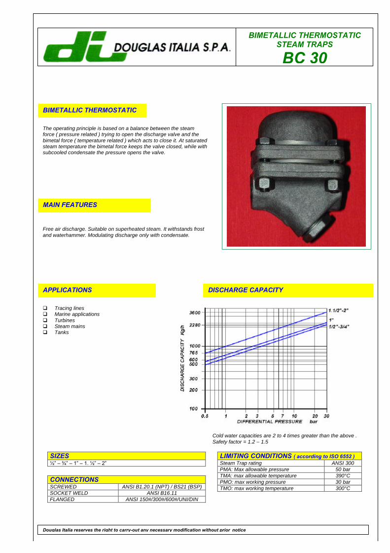
BIMETALLIC THERMOSTATICSTEAM TRAPS
BC 30
BIMETALLIC THERMOSTATIC
The operating principle is based on a balance between the steamforce ( pressure related ) trying to open the discharge valve and thebimetal force ( temperature related ) which acts to close it. At saturatedsteam temperature the bimetal force keeps the valve closed, while withsubcooled condensate the pressure opens the valve.
MAIN FEATURES
Free air discharge. Suitable on superheated steam. It withstands frostand waterhammer. Modulating discharge only with condensate.
APPLICATIONS
q Tracing linesq Marine applicationsq Turbinesq Steam mainsq Tanks
DISCHARGE CAPACITY
LIMITING CONDITIONS ( according to ISO 6552 )Steam Trap rating ANSI 300PMA: Max allowable pressure 50 barTMA: max allowable temperature 390°CPMO: max working pressure 30 barTMO: max working temperature 300°C
SIZES1⁄2” – 3⁄4” – 1” – 1. 1⁄2” – 2”
CONNECTIONSSCREWED ANSI B1.20.1 (NPT) / BS21 (BSP)SOCKET WELD ANSI B16.11FLANGED ANSI 150#/300#/600#/UNI/DIN
Douglas Italia reserves the right to carry-out any necessary modification without prior notice
Cold water capacities are 2 to 4 times greater than the above .Safety factor = 1.2 – 1.5

BIMETALLIC THERMOSTATIC STEAM TRAPS
BC 30
POS. DESCRIPTION MATERIALS SPARES
1 Body ASTM A1052 Cover ASTM A1053 Gasket 316 / GRAPHITE X4 Valve assembly STAINLESS STEEL X5 Screen AISI 304 X6 Gasket 316 / GRAPHITE X7 Strainer cap ASTM A1057 Blow-off valve * AISI 4168 Bolts ASTM A193 B79 Flange ASTM A105
* Optional
FlangedSize(inches)
S A B C Weight(Kg)
UNI-DINPN16-25-40
SF Kg
150#
SF Kg
300#
SF Kg
600#
SF Kg½” 100 150 55 100 3.8 166 5.4 160 5.2 180 5.4 190 5.6¾” 100 150 55 100 3.8 170 6.1 170 5.4 190 6.6 200 71” 120 160 65 100 4.5 190 7.3 200 6.7 210 7.9 230 8.3
1½”” 160 205 80 170 13 240 17 250 16 260 19.4 280 20.22” 160 205 80 170 13 246 19 250 18.5 260 20.2 280 22.4
INSTALLATIONThe steam trap can be installed on horizontal or vertical lines. Do not fit the trap upside down since this position will not allow the cleaning ofthe strainer. For the same reason the directory of flow on vertical lines must be downwards. For installation with superheated steam, pleaseconctact our Technical DepartementHOW TO SERVICEBy installing a new element assemly you can bring the BC steam trap to the “as new from factory” condition. Unscrew the bolts (8) andremove cover (2) and gasket (3). Unscrew and remove the element (4). Clean the inside of the trap and screw in the element-gasket assembly.Fit a new gasket (3) and reinstall cover (2) tightening the bolts (8). To service the strainer, unscrew cap (7), withdraw screen (5) and clean orreplace it. Screwing the cap back in place, always fit a new gasket (6). The discharge temperature may be adjusted without removing the trapfrom the line. For information about this operation, to be performed only be qualified personnel, please ask our Thecnical Departement.
How to order: i.e. BC 20 1” 150 RF
DOUGLAS ITALIA S.p.A Località Pradaglie – 29013 CARPANETO PIACENTINO ( PC )
OFFICIAL WEB SITE: www.douglas-italia.com
Douglas Italia reserves the right to carry-out any necessary modification without prior notice 6 . 00

BIMETALLIC THERMOSTATICSTEAM TRAPS
BC 40
BIMETALLIC THERMOSTATIC
The operating principle is based on a balance between the steamforce ( pressure related ) trying to open the discharge valve and thebimetal force ( temperature related ) which acts to close it. At saturatedsteam temperature the bimetal force keeps the valve closed, while withsubcooled condensate the pressure opens the valve.
MAIN FEATURES
Free air discharge. Suitable on superheated steam. It withstands frostand waterhammer. Modulating discharge only with condensate.
APPLICATIONS
q Tracing linesq Marine applicationsq Turbinesq Steam mainsq Tanks
DISCHARGE CAPACITY
LIMITING CONDITIONS ( according to ISO 6552 )Steam Trap rating ANSI 300PMA: Max allowable pressure 50 barTMA: max allowable temperature 390°CPMO: max working pressure 40 barTMO: max working temperature 300°C
SIZES1⁄2” – 3⁄4” – 1” – 1. 1⁄2” – 2”
CONNECTIONSSCREWED ANSI B1.20.1 (NPT) / BS21 (BSP)SOCKET WELD ANSI B16.11FLANGED ANSI 150#/300#/600#/UNI/DIN
Douglas Italia reserves the right to carry-out any necessary modification without prior notice
Cold water capacities are 2 to 4 times greater than the above .Safety factor = 1.2 – 1.5

BIMETALLIC THERMOSTATIC STEAM TRAPS
BC 40
POS. DESCRIPTION MATERIALS SPARES
1 Body ASTM A1052 Cover ASTM A1053 Gasket 316 / GRAPHITE X4 Valve assembly STAINLESS STEEL X5 Screen AISI 304 X6 Gasket 316 / GRAPHITE X7 Strainer cap ASTM A1057 Blow-off valve * AISI 4168 Bolts ASTM A193 B79 Flange ASTM A105
* Optional
FlangedSize(inches)
S A B C Weight(Kg)
UNI-DINPN16-25-40
SF Kg
150#
SF Kg
300#
SF Kg
600#
SF Kg½” 100 150 55 100 3.8 166 5.4 160 5.2 180 5.4 190 5.6¾” 100 150 55 100 3.8 170 6.1 170 5.4 190 6.6 200 71” 120 160 65 100 4.5 190 7.3 200 6.7 210 7.9 230 8.3
1½”” 160 205 80 170 13 240 17 250 16 260 19.4 280 20.22” 160 205 80 170 13 246 19 250 18.5 260 20.2 280 22.4
INSTALLATIONThe steam trap can be installed on horizontal or vertical lines. Do not fit the trap upside down since this position will not allow the cleaning ofthe strainer. For the same reason the directory of flow on vertical lines must be downwards. For installation with superheated steam, pleaseconctact our Technical DepartementHOW TO SERVICEBy installing a new element assemly you can bring the BC steam trap to the “as new from factory” condition. Unscrew the bolts (8) andremove cover (2) and gasket (3). Unscrew and remove the element (4). Clean the inside of the trap and screw in the element-gasket assembly.Fit a new gasket (3) and reinstall cover (2) tightening the bolts (8). To service the strainer, unscrew cap (7), withdraw screen (5) and clean orreplace it. Screwing the cap back in place, always fit a new gasket (6). The discharge temperature may be adjusted without removing the trapfrom the line. For information about this operation, to be performed only be qualified personnel, please ask our Thecnical Departement.
How to order: i.e. BC 20 1” 150 RF
DOUGLAS ITALIA S.p.A Località Pradaglie – 29013 CARPANETO PIACENTINO ( PC )
OFFICIAL WEB SITE: www.douglas-italia.com
Douglas Italia reserves the right to carry-out any necessary modification without prior notice 6 . 00
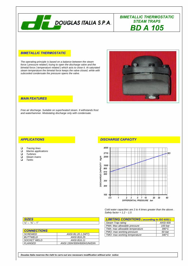
BIMETALLIC THERMOSTATICSTEAM TRAPS
BD A 105
BIMETALLIC THERMOSTATIC
The operating principle is based on a balance between the steamforce ( pressure related ) trying to open the discharge valve and thebimetal force ( temperature related ) which acts to close it. At saturatedsteam temperature the bimetal force keeps the valve closed, while withsubcooled condensate the pressure opens the valve.
MAIN FEATURES
Free air discharge. Suitable on superheated steam. It withstands frostand waterhammer. Modulating discharge only with condensate.
APPLICATIONS
q Tracing linesq Marine applicationsq Turbinesq Steam mainsq Tanks
DISCHARGE CAPACITY
LIMITING CONDITIONS ( according to ISO 6552 )Steam Trap rating ANSI 600PMA: Max allowable pressure 100 barTMA: max allowable temperature 390°CPMO: max working pressure 60 barTMO: max working temperature 340°C
SIZES1⁄2” – 3⁄4” – 1”
CONNECTIONSSCREWED ANSI B1.20.1 (NPT)BUTTWELD ANSI B16.25SOCKET WELD ANSI B16.11FLANGED ANSI 150#/300#/600#/UNI/DIN
Douglas Italia reserves the right to carry-out any necessary modification without prior notice
Cold water capacities are 2 to 4 times greater than the above .Safety factor = 1.2 – 1.5
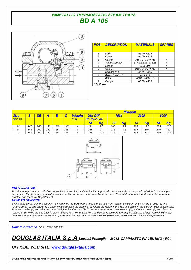
BIMETALLIC THERMOSTATIC STEAM TRAPS
BD A 105
POS. DESCRIPTION MATERIALS SPARES
1 Body ASTM A1052 Cover ASTM A1053 Gasket 316 / GRAPHITE X4 Valve assembly STAINLESS STEEL X5 Screen AISI 304 X6 Gasket 316 / GRAPHITE X7 Strainer cap ASTM A1057 Blow-off valve * AISI 4168 Bolts ASTM A193 B79 Flange ASTM A105
* Optional
FlangedSize(inches)
S SB A B C Weight(Kg)
UNI-DINPN16-25-40
SF Kg
150#
SF Kg
300#
SF Kg
600#
SF Kg½” 145 200 130 35 145 8 211 9.5 205 9.2 225 9.5 235 10.5¾” 145 200 130 35 145 8 215 10 215 9.5 235 10.5 245 111” 145 200 130 35 145 8 215 10.5 225 10 235 11.2 255 11.5
INSTALLATIONThe steam trap can be installed on horizontal or vertical lines. Do not fit the trap upside down since this position will not allow the cleaning ofthe strainer. For the same reason the directory of flow on vertical lines must be downwards. For installation with superheated steam, pleaseconctact our Technical DepartementHOW TO SERVICEBy installing a new element assemly you can bring the BD steam trap to the “as new from factory” condition. Unscrew the 8 bolts (8) andremove cover (2) and gasket (3). Unscrew and remove the element (4). Clean the inside of the trap and screw in the element-gasket assembly.Fit a new gasket (3) and reinstall cover (2) tightening the bolts (8). To service the strainer, unscrew cap (7), withdraw screen (5) and clean orreplace it. Screwing the cap back in place, always fit a new gasket (6). The discharge temperature may be adjusted without removing the trapfrom the line. For information about this operation, to be performed only be qualified personnel, please ask our Thecnical Departement..
How to order: i.e. BD A 105 ¾” 300 RF
DOUGLAS ITALIA S.p.A Località Pradaglie – 29013 CARPANETO PIACENTINO ( PC )
OFFICIAL WEB SITE: www.douglas-italia.com
Douglas Italia reserves the right to carry-out any necessary modification without prior notice 6 . 00
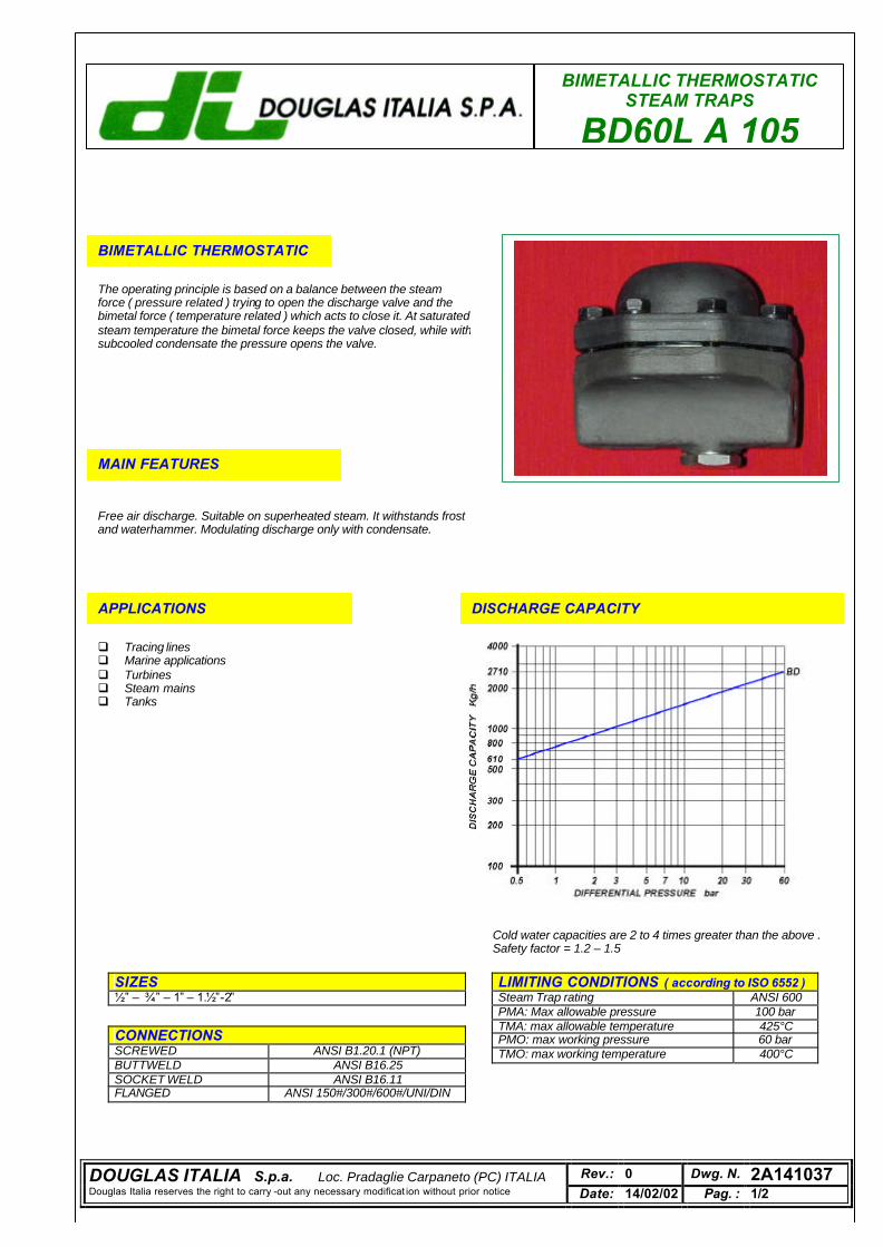
BIMETALLIC THERMOSTATIC STEAM TRAPS
BD60L A 105
BIMETALLIC THERMOSTATIC
The operating principle is based on a balance between the steam force ( pressure related ) trying to open the discharge valve and the bimetal force ( temperature related ) which acts to close it. At saturated steam temperature the bimetal force keeps the valve closed, while with subcooled condensate the pressure opens the valve.
MAIN FEATURES
Free air discharge. Suitable on superheated steam. It withstands frost and waterhammer. Modulating discharge only with condensate.
APPLICATIONS
q Tracing lines q Marine applications q Turbines q Steam mains q Tanks
DISCHARGE CAPACITY
LIMITING CONDITIONS ( according to ISO 6552 ) Steam Trap rating ANSI 600 PMA: Max allowable pressure 100 bar TMA: max allowable temperature 425°C PMO: max working pressure 60 bar TMO: max working temperature 400°C
SIZES 1⁄2” – 3⁄4” – 1” – 1.1⁄2”-2”
CONNECTIONS SCREWED ANSI B1.20.1 (NPT) BUTTWELD ANSI B16.25 SOCKET WELD ANSI B16.11 FLANGED ANSI 150#/300#/600#/UNI/DIN
Cold water capacities are 2 to 4 times greater than the above . Safety factor = 1.2 – 1.5
DOUGLAS ITALIA S.p.a. Loc. Pradaglie Carpaneto (PC) ITALIA Rev.: 0 Dwg. N. 2A141037 Douglas Italia reserves the right to carry -out any necessary modificat ion without prior notice Date: 14/02/02 Pag. : 1/2
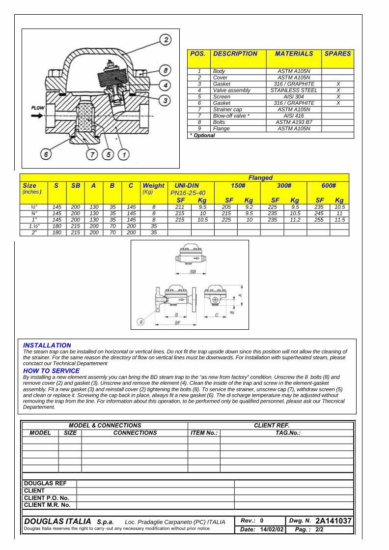
POS. DESCRIPTION MATERIALS SPARES
1 Body ASTM A105N 2 Cover ASTM A105N 3 Gasket 316 / GRAPHITE X 4 Valve assembly STAINLESS STEEL X 5 Screen AISI 304 X 6 Gasket 316 / GRAPHITE X 7 Strainer cap ASTM A105N 7 Blow-off valve * AISI 416 8 Bolts ASTM A193 B7 9 Flange ASTM A105N
* Optional
Flanged Size (inches )
S SB A B C Weight (Kg)
UNI-DIN PN16-25-40
SF Kg
150#
SF Kg
300#
SF Kg
600#
SF Kg ½” 145 200 130 35 145 8 211 9.5 205 9.2 225 9.5 235 10.5 ¾” 145 200 130 35 145 8 215 10 215 9.5 235 10.5 245 11 1” 145 200 130 35 145 8 215 10.5 225 10 235 11.2 255 11.5
1.½” 180 215 200 70 200 35 2” 180 215 200 70 200 35
INSTALLATION The steam trap can be installed on horizontal or vertical lines. Do not fit the trap upside down since this position will not allow the cleaning of the strainer. For the same reason the directory of flow on vertical lines must be downwards. For installation with superheated steam, please conctact our Technical Departement HOW TO SERVICE By installing a new element assemly you can bring the BD steam trap to the “as new from factory” condition. Unscrew the 8 bolts (8) and remove cover (2) and gasket (3). Unscrew and remove the element (4). Clean the inside of the trap and screw in the element-gasket assembly. Fit a new gasket (3) and reinstall cover (2) tightening the bolts (8). To service the strainer, unscrew cap (7), withdraw screen (5) and clean or replace it. Screwing the cap back in place, always fit a new gasket (6). The di scharge temperature may be adjusted without removing the trap from the line. For information about this operation, to be performed only be qualified personnel, please ask our Thecnical Departement. .
MODEL & CONNECTIONS CLIENT REF. MODEL SIZE CONNECTIONS ITEM No.: TAG.No.:
DOUGLAS REF CLIENT CLIENT P.O. No. CLIENT M.R. No.
DOUGLAS ITALIA S.p.a. Loc. Pradaglie Carpaneto (PC) ITALIA Rev.: 0 Dwg. N. 2A141037 Douglas Italia reserves the right to carry -out any necessary modification without prior notice Date: 14/02/02 Pag. : 2/2

BIMETALLIC THERMOSTATICSTEAM TRAPS
BD F 11
BIMETALLIC THERMOSTATIC
The operating principle is based on a balance between the steamforce ( pressure related ) trying to open the discharge valve and thebimetal force ( temperature related ) which acts to close it. At saturatedsteam temperature the bimetal force keeps the valve closed, while withsubcooled condensate the pressure opens the valve.
MAIN FEATURES
Free air discharge. Suitable on superheated steam. It withstands frostand waterhammer. Modulating discharge only with condensate.
APPLICATIONS
q Tracing linesq Marine applicationsq Turbinesq Steam mainsq Tanks
DISCHARGE CAPACITY
LIMITING CONDITIONS ( according to ISO 6552 )Steam Trap rating ANSI 600PMA: Max allowable pressure 100 barTMA: max allowable temperature 510°CPMO: max working pressure 60 barTMO: max working temperature 340°C
SIZES1⁄2” – 3⁄4” – 1”
CONNECTIONSSCREWED ANSI B1.20.1 (NPT)BUTTWELD ANSI B16.25SOCKET WELD ANSI B16.11FLANGED ANSI 150#/300#/600#/UNI/DIN
Douglas Italia reserves the right to carry-out any necessary modification without prior notice
Cold water capacities are 2 to 4 times greater than the above .Safety factor = 1.2 – 1.5
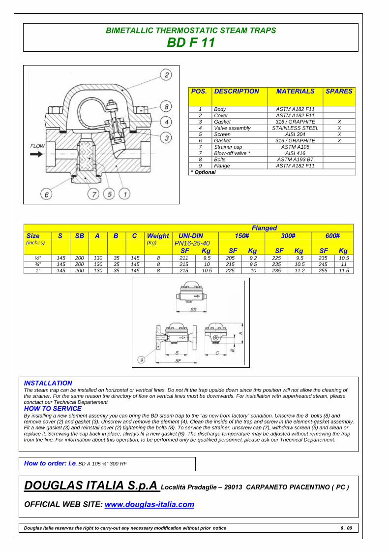
BIMETALLIC THERMOSTATIC STEAM TRAPS
BD F 11
POS. DESCRIPTION MATERIALS SPARES
1 Body ASTM A182 F112 Cover ASTM A182 F113 Gasket 316 / GRAPHITE X4 Valve assembly STAINLESS STEEL X5 Screen AISI 304 X6 Gasket 316 / GRAPHITE X7 Strainer cap ASTM A1057 Blow-off valve * AISI 4168 Bolts ASTM A193 B79 Flange ASTM A182 F11
* Optional
FlangedSize(inches)
S SB A B C Weight(Kg)
UNI-DINPN16-25-40
SF Kg
150#
SF Kg
300#
SF Kg
600#
SF Kg½” 145 200 130 35 145 8 211 9.5 205 9.2 225 9.5 235 10.5¾” 145 200 130 35 145 8 215 10 215 9.5 235 10.5 245 111” 145 200 130 35 145 8 215 10.5 225 10 235 11.2 255 11.5
INSTALLATIONThe steam trap can be installed on horizontal or vertical lines. Do not fit the trap upside down since this position will not allow the cleaning ofthe strainer. For the same reason the directory of flow on vertical lines must be downwards. For installation with superheated steam, pleaseconctact our Technical DepartementHOW TO SERVICEBy installing a new element assemly you can bring the BD steam trap to the “as new from factory” condition. Unscrew the 8 bolts (8) andremove cover (2) and gasket (3). Unscrew and remove the element (4). Clean the inside of the trap and screw in the element-gasket assembly.Fit a new gasket (3) and reinstall cover (2) tightening the bolts (8). To service the strainer, unscrew cap (7), withdraw screen (5) and clean orreplace it. Screwing the cap back in place, always fit a new gasket (6). The discharge temperature may be adjusted without removing the trapfrom the line. For information about this operation, to be performed only be qualified personnel, please ask our Thecnical Departement..
How to order: i.e. BD A 105 ¾” 300 RF
DOUGLAS ITALIA S.p.A Località Pradaglie – 29013 CARPANETO PIACENTINO ( PC )
OFFICIAL WEB SITE: www.douglas-italia.com
Douglas Italia reserves the right to carry-out any necessary modification without prior notice 6 . 00
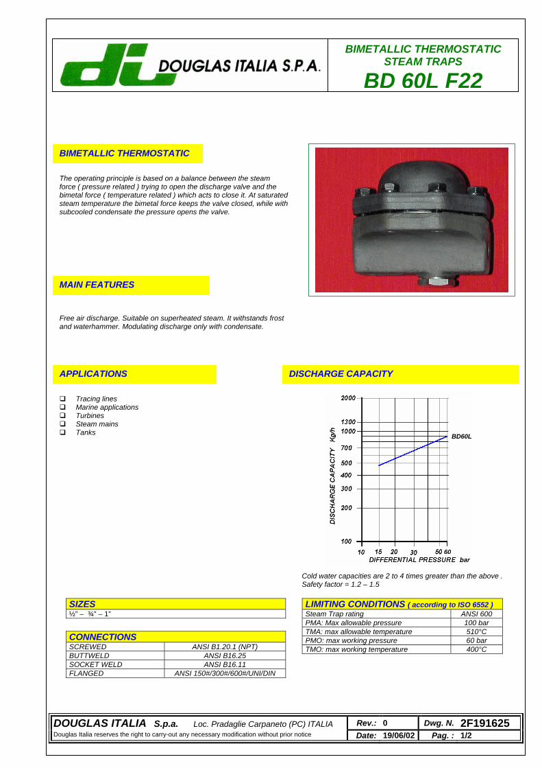
BIMETALLIC THERMOSTATIC STEAM TRAPS
BD 60L F22
BIMETALLIC THERMOSTATIC
The operating principle is based on a balance between the steam force ( pressure related ) trying to open the discharge valve and the bimetal force ( temperature related ) which acts to close it. At saturated steam temperature the bimetal force keeps the valve closed, while with subcooled condensate the pressure opens the valve.
MAIN FEATURES
Free air discharge. Suitable on superheated steam. It withstands frost and waterhammer. Modulating discharge only with condensate.
APPLICATIONS
Tracing lines Marine applications Turbines Steam mains Tanks
DISCHARGE CAPACITY
LIMITING CONDITIONS ( according to ISO 6552 ) Steam Trap rating ANSI 600 PMA: Max allowable pressure 100 bar TMA: max allowable temperature 510°C PMO: max working pressure 60 bar TMO: max working temperature 400°C
SIZES ½” – ¾” – 1”
CONNECTIONS SCREWED ANSI B1.20.1 (NPT) BUTTWELD ANSI B16.25 SOCKET WELD ANSI B16.11 FLANGED ANSI 150#/300#/600#/UNI/DIN
Cold water capacities are 2 to 4 times greater than the above . Safety factor = 1.2 – 1.5
DOUGLAS ITALIA S.p.a. Loc. Pradaglie Carpaneto (PC) ITALIA Rev.: 0 Dwg. N. 2F191625 Douglas Italia reserves the right to carry-out any necessary modification without prior notice Date: 19/06/02 Pag. : 1/2
60
BD60L
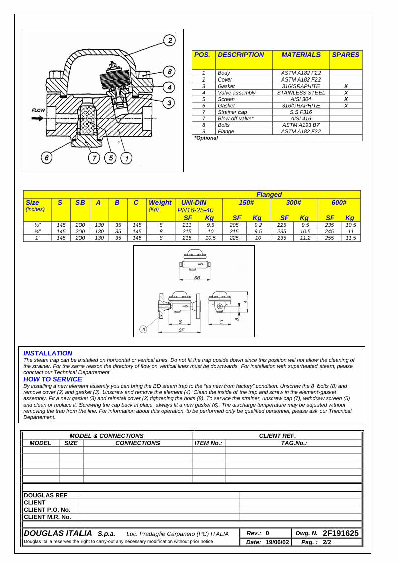
POS. DESCRIPTION MATERIALS SPARES
1 Body ASTM A182 F22 2 Cover ASTM A182 F22 3 Gasket 316/GRAPHITE X 4 Valve assembly STAINLESS STEEL X 5 Screen AISI 304 X 6 Gasket 316/GRAPHITE X 7 Strainer cap S.S.F316 7 Blow-off valve* AISI 416 8 Bolts ASTM A193 B7 9 Flange ASTM A182 F22
*Optional
Flanged Size (inches)
S SB A B C Weight(Kg)
UNI-DIN PN16-25-40
SF Kg
150#
SF Kg
300#
SF Kg
600#
SF Kg ½” 145 200 130 35 145 8 211 9.5 205 9.2 225 9.5 235 10.5 ¾” 145 200 130 35 145 8 215 10 215 9.5 235 10.5 245 11 1” 145 200 130 35 145 8 215 10.5 225 10 235 11.2 255 11.5
INSTALLATION The steam trap can be installed on horizontal or vertical lines. Do not fit the trap upside down since this position will not allow the cleaning of the strainer. For the same reason the directory of flow on vertical lines must be downwards. For installation with superheated steam, please conctact our Technical Departement HOW TO SERVICE By installing a new element assemly you can bring the BD steam trap to the “as new from factory” condition. Unscrew the 8 bolts (8) and remove cover (2) and gasket (3). Unscrew and remove the element (4). Clean the inside of the trap and screw in the element-gasket assembly. Fit a new gasket (3) and reinstall cover (2) tightening the bolts (8). To service the strainer, unscrew cap (7), withdraw screen (5) and clean or replace it. Screwing the cap back in place, always fit a new gasket (6). The discharge temperature may be adjusted without removing the trap from the line. For information about this operation, to be performed only be qualified personnel, please ask our Thecnical Departement.
MODEL & CONNECTIONS CLIENT REF. MODEL SIZE CONNECTIONS ITEM No.: TAG.No.:
DOUGLAS REF CLIENT CLIENT P.O. No. CLIENT M.R. No.
DOUGLAS ITALIA S.p.a. Loc. Pradaglie Carpaneto (PC) ITALIA Rev.: 0 Dwg. N. 2F191625Douglas Italia reserves the right to carry-out any necessary modification without prior notice Date: 19/06/02 Pag. : 2/2
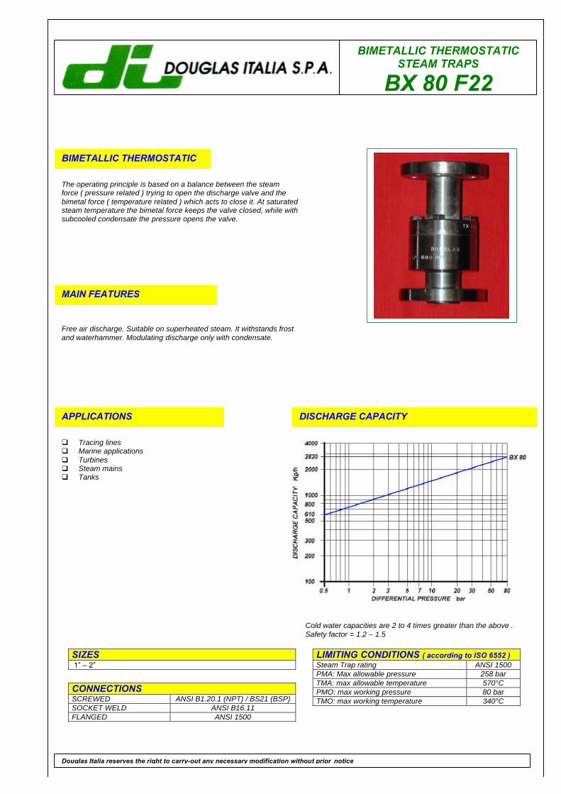
BIMETALLIC THERMOSTATICSTEAM TRAPS
BX 80 F22
BIMETALLIC THERMOSTATIC
The operating principle is based on a balance between the steamforce ( pressure related ) trying to open the discharge valve and thebimetal force ( temperature related ) which acts to close it. At saturatedsteam temperature the bimetal force keeps the valve closed, while withsubcooled condensate the pressure opens the valve.
MAIN FEATURES
Free air discharge. Suitable on superheated steam. It withstands frostand waterhammer. Modulating discharge only with condensate.
APPLICATIONS
q Tracing linesq Marine applicationsq Turbinesq Steam mainsq Tanks
DISCHARGE CAPACITY
LIMITING CONDITIONS ( according to ISO 6552 )Steam Trap rating ANSI 1500PMA: Max allowable pressure 258 barTMA: max allowable temperature 570°CPMO: max working pressure 80 barTMO: max working temperature 340°C
SIZES 1” – 2”
CONNECTIONSSCREWED ANSI B1.20.1 (NPT) / BS21 (BSP)SOCKET WELD ANSI B16.11FLANGED ANSI 1500
Douglas Italia reserves the right to carry-out any necessary modification without prior notice
Cold water capacities are 2 to 4 times greater than the above .Safety factor = 1.2 – 1.5
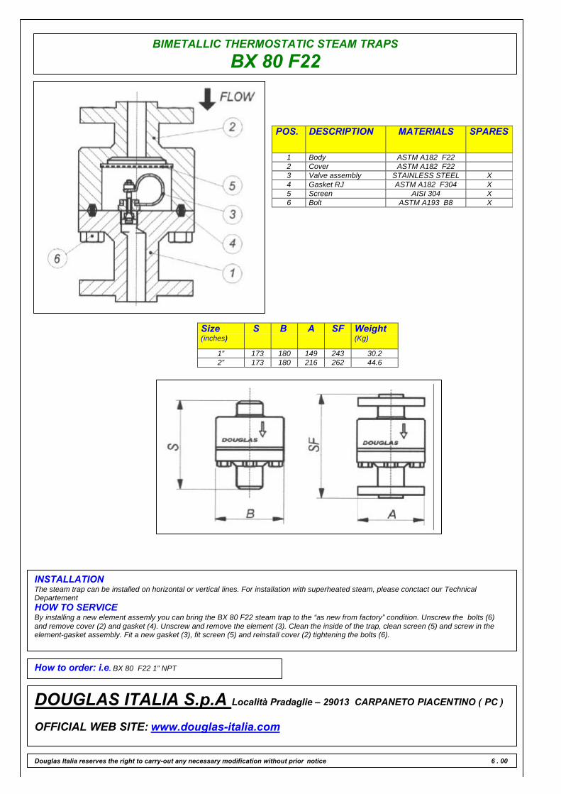
BIMETALLIC THERMOSTATIC STEAM TRAPS
BX 80 F22
POS. DESCRIPTION MATERIALS SPARES
1 Body ASTM A182 F222 Cover ASTM A182 F223 Valve assembly STAINLESS STEEL X4 Gasket RJ ASTM A182 F304 X5 Screen AISI 304 X6 Bolt ASTM A193 B8 X
Size(inches)
S B A SF Weight(Kg)
1” 173 180 149 243 30.22” 173 180 216 262 44.6
INSTALLATIONThe steam trap can be installed on horizontal or vertical lines. For installation with superheated steam, please conctact our TechnicalDepartementHOW TO SERVICEBy installing a new element assemly you can bring the BX 80 F22 steam trap to the “as new from factory” condition. Unscrew the bolts (6)and remove cover (2) and gasket (4). Unscrew and remove the element (3). Clean the inside of the trap, clean screen (5) and screw in theelement-gasket assembly. Fit a new gasket (3), fit screen (5) and reinstall cover (2) tightening the bolts (6).
How to order: i.e. BX 80 F22 1” NPT
DOUGLAS ITALIA S.p.A Località Pradaglie – 29013 CARPANETO PIACENTINO ( PC )
OFFICIAL WEB SITE: www.douglas-italia.com
Douglas Italia reserves the right to carry-out any necessary modification without prior notice 6 . 00

BIMETALLIC THERMOSTATICSTEAM TRAPS
BD 100 F22
BIMETALLIC THERMOSTATIC
The operating principle is based on a balance between the steamforce ( pressure related ) trying to open the discharge valve and thebimetal force ( temperature related ) which acts to close it. At saturatedsteam temperature the bimetal force keeps the valve closed, while withsubcooled condensate the pressure opens the valve.
MAIN FEATURES
Free air discharge. Suitable on superheated steam. It withstands frostand waterhammer. Modulating discharge only with condensate.
APPLICATIONS
q Tracing linesq Marine applicationsq Turbinesq Steam mainsq Tanks
DISCHARGE CAPACITY
LIMITING CONDITIONS ( according to ISO 6552 )Steam Trap rating ANSI 1500PMA: Max allowable pressure 250 barTMA: max allowable temperature 580°CPMO: max working pressure 110 barTMO: max working temperature 550°C
SIZES1⁄2” – 3⁄4” – 1”
CONNECTIONSSOCKET WELD ANSI B16.11FLANGED ANSI B16.5 RF-RJ ( 600 – 1500 )
Douglas Italia reserves the right to carry-out any necessary modification without prior notice
Cold water capacities are 2 to 4 times greater than the above .Safety factor = 1.2 – 1.5
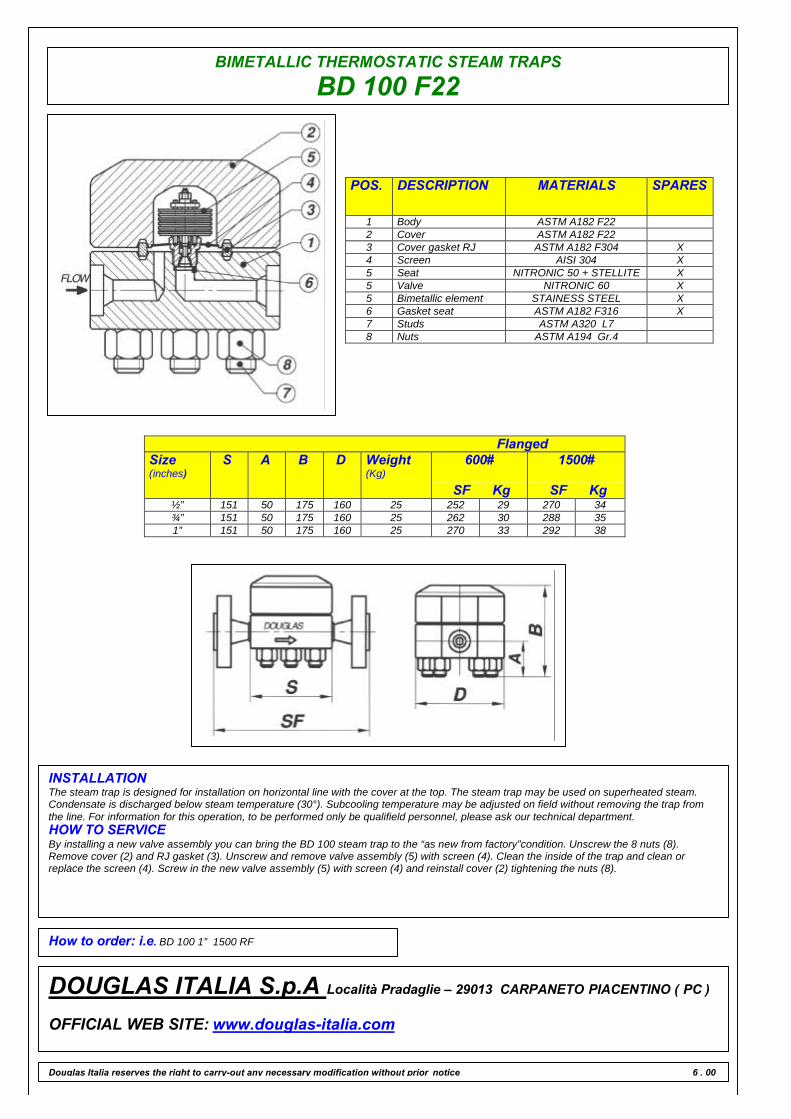
BIMETALLIC THERMOSTATIC STEAM TRAPS
BD 100 F22
POS. DESCRIPTION MATERIALS SPARES
1 Body ASTM A182 F222 Cover ASTM A182 F223 Cover gasket RJ ASTM A182 F304 X4 Screen AISI 304 X5 Seat NITRONIC 50 + STELLITE X5 Valve NITRONIC 60 X5 Bimetallic element STAINESS STEEL X6 Gasket seat ASTM A182 F316 X7 Studs ASTM A320 L78 Nuts ASTM A194 Gr.4
FlangedSize(inches)
S A B D Weight(Kg)
600#
SF Kg
1500#
SF Kg½” 151 50 175 160 25 252 29 270 34¾” 151 50 175 160 25 262 30 288 351” 151 50 175 160 25 270 33 292 38
INSTALLATIONThe steam trap is designed for installation on horizontal line with the cover at the top. The steam trap may be used on superheated steam.Condensate is discharged below steam temperature (30°). Subcooling temperature may be adjusted on field without removing the trap fromthe line. For information for this operation, to be performed only be qualifield personnel, please ask our technical department.HOW TO SERVICEBy installing a new valve assembly you can bring the BD 100 steam trap to the “as new from factory”condition. Unscrew the 8 nuts (8).Remove cover (2) and RJ gasket (3). Unscrew and remove valve assembly (5) with screen (4). Clean the inside of the trap and clean orreplace the screen (4). Screw in the new valve assembly (5) with screen (4) and reinstall cover (2) tightening the nuts (8).
How to order: i.e. BD 100 1” 1500 RF
DOUGLAS ITALIA S.p.A Località Pradaglie – 29013 CARPANETO PIACENTINO ( PC )
OFFICIAL WEB SITE: www.douglas-italia.com
Douglas Italia reserves the right to carry-out any necessary modification without prior notice 6 . 00
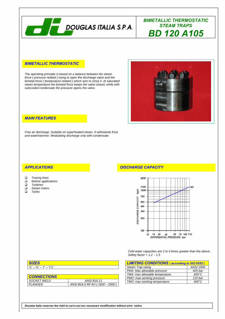
BIMETALLIC THERMOSTATICSTEAM TRAPS
BD 120 A105
BIMETALLIC THERMOSTATIC
The operating principle is based on a balance between the steamforce ( pressure related ) trying to open the discharge valve and thebimetal force ( temperature related ) which acts to close it. At saturatedsteam temperature the bimetal force keeps the valve closed, while withsubcooled condensate the pressure opens the valve.
MAIN FEATURES
Free air discharge. Suitable on superheated steam. It withstands frostand waterhammer. Modulating discharge only with condensate.
APPLICATIONS
q Tracing linesq Marine applicationsq Turbinesq Steam mainsq Tanks
DISCHARGE CAPACITY
LIMITING CONDITIONS ( according to ISO 6552 )Steam Trap rating ANSI 2500PMA: Max allowable pressure 425 barTMA: max allowable temperature 425°CPMO: max working pressure 110 barTMO: max working temperature 400°C
SIZES1⁄2” – 3⁄4” – 1” – 11⁄2”
CONNECTIONSSOCKET WELD ANSI B16.11FLANGED ANSI B16.5 RF-RJ ( 1500 – 2500 )
Douglas Italia reserves the right to carry-out any necessary modification without prior notice
Cold water capacities are 2 to 4 times greater than the above .Safety factor = 1.2 – 1.5
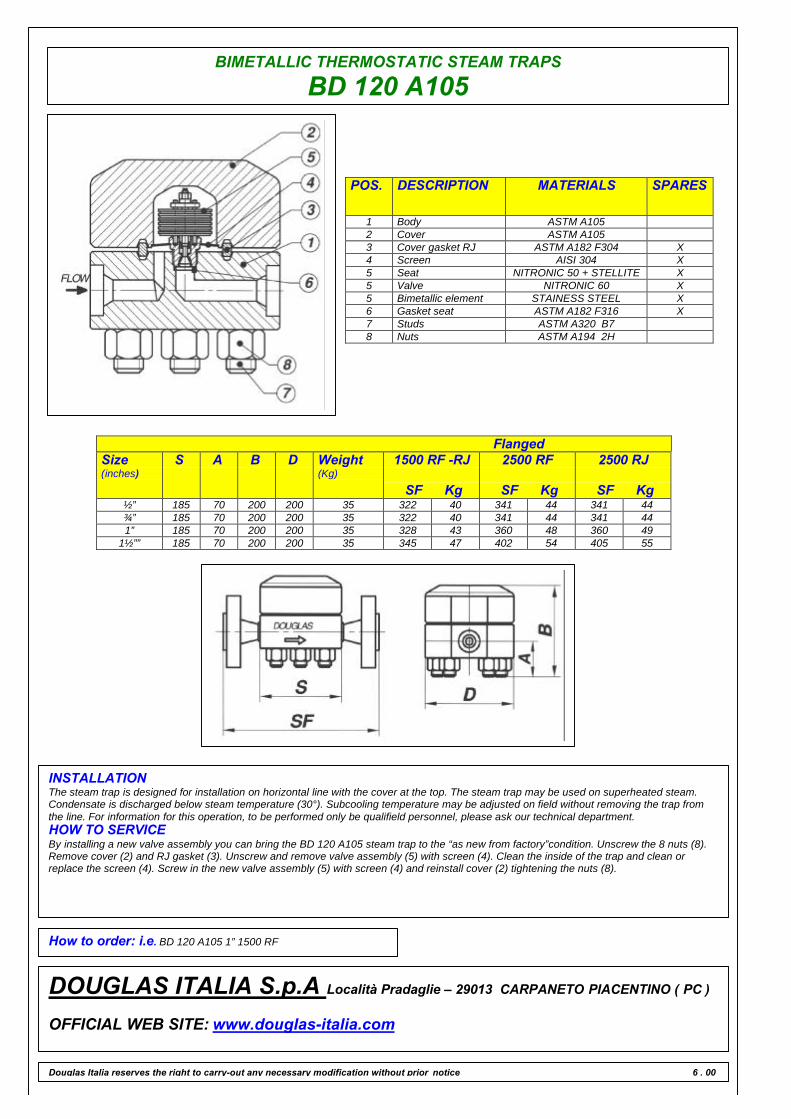
BIMETALLIC THERMOSTATIC STEAM TRAPS
BD 120 A105
POS. DESCRIPTION MATERIALS SPARES
1 Body ASTM A1052 Cover ASTM A1053 Cover gasket RJ ASTM A182 F304 X4 Screen AISI 304 X5 Seat NITRONIC 50 + STELLITE X5 Valve NITRONIC 60 X5 Bimetallic element STAINESS STEEL X6 Gasket seat ASTM A182 F316 X7 Studs ASTM A320 B78 Nuts ASTM A194 2H
FlangedSize(inches)
S A B D Weight(Kg)
1500 RF -RJ
SF Kg
2500 RF
SF Kg
2500 RJ
SF Kg½” 185 70 200 200 35 322 40 341 44 341 44¾” 185 70 200 200 35 322 40 341 44 341 441” 185 70 200 200 35 328 43 360 48 360 49
1½”” 185 70 200 200 35 345 47 402 54 405 55
INSTALLATIONThe steam trap is designed for installation on horizontal line with the cover at the top. The steam trap may be used on superheated steam.Condensate is discharged below steam temperature (30°). Subcooling temperature may be adjusted on field without removing the trap fromthe line. For information for this operation, to be performed only be qualifield personnel, please ask our technical department.HOW TO SERVICEBy installing a new valve assembly you can bring the BD 120 A105 steam trap to the “as new from factory”condition. Unscrew the 8 nuts (8).Remove cover (2) and RJ gasket (3). Unscrew and remove valve assembly (5) with screen (4). Clean the inside of the trap and clean orreplace the screen (4). Screw in the new valve assembly (5) with screen (4) and reinstall cover (2) tightening the nuts (8).
How to order: i.e. BD 120 A105 1” 1500 RF
DOUGLAS ITALIA S.p.A Località Pradaglie – 29013 CARPANETO PIACENTINO ( PC )
OFFICIAL WEB SITE: www.douglas-italia.com
Douglas Italia reserves the right to carry-out any necessary modification without prior notice 6 . 00

BIMETALLIC THERMOSTATICSTEAM TRAPS
BD 120 F22
BIMETALLIC THERMOSTATIC
The operating principle is based on a balance between the steamforce ( pressure related ) trying to open the discharge valve and thebimetal force ( temperature related ) which acts to close it. At saturatedsteam temperature the bimetal force keeps the valve closed, while withsubcooled condensate the pressure opens the valve.
MAIN FEATURES
Free air discharge. Suitable on superheated steam. It withstands frostand waterhammer. Modulating discharge only with condensate.
APPLICATIONS
q Tracing linesq Marine applicationsq Turbinesq Steam mainsq Tanks
DISCHARGE CAPACITY
LIMITING CONDITIONS ( according to ISO 6552 )Steam Trap rating ANSI 2500PMA: Max allowable pressure 430 barTMA: max allowable temperature 580°CPMO: max working pressure 110 barTMO: max working temperature 550°C
SIZES1⁄2” – 3⁄4” – 1” – 11⁄2”
CONNECTIONSSOCKET WELD ANSI B16.11FLANGED ANSI B16.5 RF-RJ ( 1500 – 2500 )
Douglas Italia reserves the right to carry-out any necessary modification without prior notice
Cold water capacities are 2 to 4 times greater than the above .Safety factor = 1.2 – 1.5

BIMETALLIC THERMOSTATIC STEAM TRAPS
BD 120 F22
POS. DESCRIPTION MATERIALS SPARES
1 Body ASTM A182 F222 Cover ASTM A182 F223 Cover gasket RJ ASTM A182 F304 X4 Screen AISI 304 X5 Seat NITRONIC 50 + STELLITE X5 Valve NITRONIC 60 X5 Bimetallic element STAINESS STEEL X6 Gasket seat ASTM A182 F316 X7 Studs ASTM A320 L78 Nuts ASTM A194 Gr.4
FlangedSize(inches)
S A B D Weight(Kg)
1500 RF -RJ
SF Kg
2500 RF
SF Kg
2500 RJ
SF Kg½” 185 70 200 200 35 305 36 331 42 331 42¾” 185 70 200 200 35 322 40 341 44 341 441” 185 70 200 200 35 328 43 360 48 360 49
1½”” 185 70 200 200 35 345 47 402 54 405 55
INSTALLATIONThe steam trap is designed for installation on horizontal line with the cover at the top. The steam trap may be used on superheated steam.Condensate is discharged below steam temperature (30°). Subcooling temperature may be adjusted on field without removing the trap fromthe line. For information for this operation, to be performed only be qualifield personnel, please ask our technical department.HOW TO SERVICEBy installing a new valve assembly you can bring the BD 120 F22 steam trap to the “as new from factory”condition. Unscrew the 8 nuts (8).Remove cover (2) and RJ gasket (3). Unscrew and remove valve assembly (5) with screen (4). Clean the inside of the trap and clean orreplace the screen (4). Screw in the new valve assembly (5) with screen (4) and reinstall cover (2) tightening the nuts (8).
How to order: i.e. BD 120 F22 1” 1500 RF
DOUGLAS ITALIA S.p.A Località Pradaglie – 29013 CARPANETO PIACENTINO ( PC )
OFFICIAL WEB SITE: www.douglas-italia.com
Douglas Italia reserves the right to carry-out any necessary modification without prior notice 6 . 00
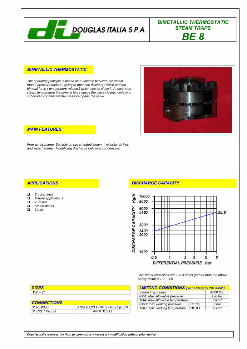
BIMETALLIC THERMOSTATICSTEAM TRAPS
BE 8
BIMETALLIC THERMOSTATIC
The operating principle is based on a balance between the steamforce ( pressure related ) trying to open the discharge valve and thebimetal force ( temperature related ) which acts to close it. At saturatedsteam temperature the bimetal force keeps the valve closed, while withsubcooled condensate the pressure opens the valve.
MAIN FEATURES
Free air discharge. Suitable on superheated steam. It withstands frostand waterhammer. Modulating discharge only with condensate.
APPLICATIONS
q Tracing linesq Marine applicationsq Turbinesq Steam mainsq Tanks
DISCHARGE CAPACITY
LIMITING CONDITIONS ( according to ISO 6552 )Steam Trap rating ANSI 800PMA: Max allowable pressure 136 barTMA: max allowable temperature 390°CPMO: max working pressure ( BE 8 ) 8 barTMO: max working temperature ( BE 8 ) 250°C
SIZES 11⁄2” – 2”
CONNECTIONSSCREWED ANSI B1.20.1 (NPT) / BS21 (BSP)SOCKET WELD ANSI B16.11
Douglas Italia reserves the right to carry-out any necessary modification without prior notice
Cold water capacities are 2 to 4 times greater than the above .Safety factor = 1.2 – 1.5

BIMETALLIC THERMOSTATIC STEAM TRAPS
BE 8
POS. DESCRIPTION MATERIALS SPARES
1 Body ASTM A1052 Cover flange ASTM A1053 Cover ASTM A106 WPB4 Valve assembly N.2 STAINLESS STEEL X5 Gasket 316 / GRAPHITE X6 Bolts ASTM A193 B77 Strainer cap ASTM A1058 Screen AISI 304 X9 Gasket 316 / GRAPHITE X
Size(inches)
S A B C
1½”” 248.5 205 260 1552” 248.5 205 260 155
INSTALLATIONThe steam trap can be installed on horizontal or vertical lines. Do not fit the trap upside down since this position will not allow the cleaning ofthe strainer. For the same reason the directory of flow on vertical lines must be downwards. For installation with superheated steam, pleaseconctact our Technical DepartementHOW TO SERVICEBy installing a new element assemly you can bring the BE steam trap to the “as new from factory” condition. Unscrew the bolts (6) andremove cover (3) and gasket (5). Unscrew and remvoe the element (4). Clean the inside of the trap and screw in the element-gasket assembly.Fit a new gasket (5) and reinstall cover (3) tightening the bolts (6). To service the strainer, unscrew cap (7), withdraw screen (8) and clean orreplace it. Screwing the cap back in place, always fit a new gasket (9). The discharge temperature may be adjusted without removing the trapfrom the line. For information about this operation, to be performed only be qualified personnel, please ask our Thecnical Departement.
How to order: i.e. BE 8 2” NPT
DOUGLAS ITALIA S.p.A Località Pradaglie – 29013 CARPANETO PIACENTINO ( PC )
OFFICIAL WEB SITE: www.douglas-italia.com
Douglas Italia reserves the right to carry-out any necessary modification without prior notice 6 . 00
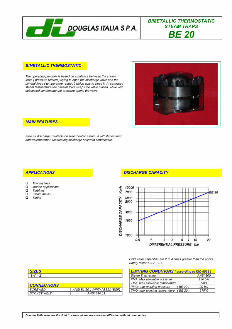
BIMETALLIC THERMOSTATICSTEAM TRAPS
BE 20
BIMETALLIC THERMOSTATIC
The operating principle is based on a balance between the steamforce ( pressure related ) trying to open the discharge valve and thebimetal force ( temperature related ) which acts to close it. At saturatedsteam temperature the bimetal force keeps the valve closed, while withsubcooled condensate the pressure opens the valve.
MAIN FEATURES
Free air discharge. Suitable on superheated steam. It withstands frostand waterhammer. Modulating discharge only with condensate.
APPLICATIONS
q Tracing linesq Marine applicationsq Turbinesq Steam mainsq Tanks
DISCHARGE CAPACITY
LIMITING CONDITIONS ( according to ISO 6552 )Steam Trap rating ANSI 800PMA: Max allowable pressure 136 barTMA: max allowable temperature 390°CPMO: max working pressure ( BE 20 ) 20 barTMO: max working temperature ( BE 20 ) 275°C
SIZES 11⁄2” – 2”
CONNECTIONSSCREWED ANSI B1.20.1 (NPT) / BS21 (BSP)SOCKET WELD ANSI B16.11
Douglas Italia reserves the right to carry-out any necessary modification without prior notice
Cold water capacities are 2 to 4 times greater than the above .Safety factor = 1.2 – 1.5

BIMETALLIC THERMOSTATIC STEAM TRAPS
BE 20
POS. DESCRIPTION MATERIALS SPARES
1 Body ASTM A1052 Cover flange ASTM A1053 Cover ASTM A106 WPB4 Valve assembly N.2 STAINLESS STEEL X5 Gasket 316 / GRAPHITE X6 Bolts ASTM A193 B77 Strainer cap ASTM A1058 Screen AISI 304 X9 Gasket 316 / GRAPHITE X
Size(inches)
S A B C
1½”” 248.5 205 260 1552” 248.5 205 260 155
INSTALLATIONThe steam trap can be installed on horizontal or vertical lines. Do not fit the trap upside down since this position will not allow the cleaning ofthe strainer. For the same reason the directory of flow on vertical lines must be downwards. For installation with superheated steam, pleaseconctact our Technical DepartementHOW TO SERVICEBy installing a new element assemly you can bring the BE steam trap to the “as new from factory” condition. Unscrew the bolts (6) andremove cover (3) and gasket (5). Unscrew and remove the element (4). Clean the inside of the trap and screw in the element-gasket assembly.Fit a new gasket (5) and reinstall cover (3) tightening the bolts (6). To service the strainer, unscrew cap (7), withdraw screen (8) and clean orreplace it. Screwing the cap back in place, always fit a new gasket (9). The discharge temperature may be adjusted without removing the trapfrom the line. For information about this operation, to be performed only be qualified personnel, please ask our Thecnical Departement.
How to order: i.e. BE 20 2” NPT
DOUGLAS ITALIA S.p.A Località Pradaglie – 29013 CARPANETO PIACENTINO ( PC )
OFFICIAL WEB SITE: www.douglas-italia.com
Douglas Italia reserves the right to carry-out any necessary modification without prior notice 6 . 00
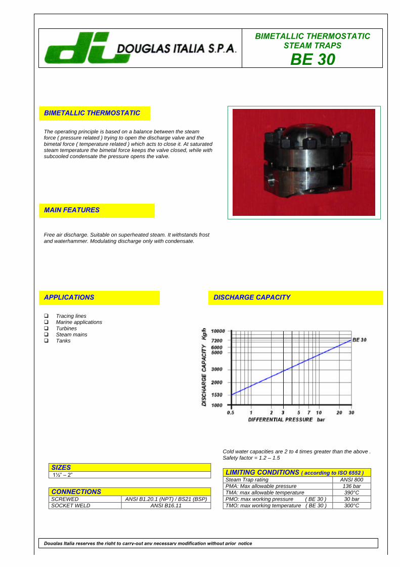
BIMETALLIC THERMOSTATICSTEAM TRAPS
BE 30
BIMETALLIC THERMOSTATIC
The operating principle is based on a balance between the steamforce ( pressure related ) trying to open the discharge valve and thebimetal force ( temperature related ) which acts to close it. At saturatedsteam temperature the bimetal force keeps the valve closed, while withsubcooled condensate the pressure opens the valve.
MAIN FEATURES
Free air discharge. Suitable on superheated steam. It withstands frostand waterhammer. Modulating discharge only with condensate.
APPLICATIONS
q Tracing linesq Marine applicationsq Turbinesq Steam mainsq Tanks
DISCHARGE CAPACITY
LIMITING CONDITIONS ( according to ISO 6552 )Steam Trap rating ANSI 800PMA: Max allowable pressure 136 barTMA: max allowable temperature 390°CPMO: max working pressure ( BE 30 ) 30 barTMO: max working temperature ( BE 30 ) 300°C
SIZES 11⁄2” – 2”
CONNECTIONSSCREWED ANSI B1.20.1 (NPT) / BS21 (BSP)SOCKET WELD ANSI B16.11
Douglas Italia reserves the right to carry-out any necessary modification without prior notice
Cold water capacities are 2 to 4 times greater than the above .Safety factor = 1.2 – 1.5

BIMETALLIC THERMOSTATIC STEAM TRAPS
BE 30
POS. DESCRIPTION MATERIALS SPARES
1 Body ASTM A1052 Cover flange ASTM A1053 Cover ASTM A106 WPB4 Valve assembly N.2 STAINLESS STEEL X5 Gasket 316 / GRAPHITE X6 Bolts ASTM A193 B77 Strainer cap ASTM A1058 Screen AISI 304 X9 Gasket 316 / GRAPHITE X
Size(inches)
S A B C
1½”” 248.5 205 260 1552” 248.5 205 260 155
INSTALLATIONThe steam trap can be installed on horizontal or vertical lines. Do not fit the trap upside down since this position will not allow the cleaning ofthe strainer. For the same reason the directory of flow on vertical lines must be downwards. For installation with superheated steam, pleaseconctact our Technical DepartementHOW TO SERVICEBy installing a new element assemly you can bring the BE steam trap to the “as new from factory” condition. Unscrew the bolts (6) andremove cover (3) and gasket (5). Unscrew and remove the element (4). Clean the inside of the trap and screw in the element-gasket assembly.Fit a new gasket (5) and reinstall cover (3) tightening the bolts (6). To service the strainer, unscrew cap (7), withdraw screen (8) and clean orreplace it. Screwing the cap back in place, always fit a new gasket (9). The discharge temperature may be adjusted without removing the trapfrom the line. For information about this operation, to be performed only be qualified personnel, please ask our Thecnical Departement.
How to order: i.e. BE 30 2” NPT
DOUGLAS ITALIA S.p.A Località Pradaglie – 29013 CARPANETO PIACENTINO ( PC )
OFFICIAL WEB SITE: www.douglas-italia.com
Douglas Italia reserves the right to carry-out any necessary modification without prior notice 6 . 00

BIMETALLIC THERMOSTATICSTEAM TRAPS
BE 40
BIMETALLIC THERMOSTATIC
The operating principle is based on a balance between the steamforce ( pressure related ) trying to open the discharge valve and thebimetal force ( temperature related ) which acts to close it. At saturatedsteam temperature the bimetal force keeps the valve closed, while withsubcooled condensate the pressure opens the valve.
MAIN FEATURES
Free air discharge. Suitable on superheated steam. It withstands frostand waterhammer. Modulating discharge only with condensate.
APPLICATIONS
q Tracing linesq Marine applicationsq Turbinesq Steam mainsq Tanks
DISCHARGE CAPACITY
LIMITING CONDITIONS ( according to ISO 6552 )Steam Trap rating ANSI 800PMA: Max allowable pressure 136 barTMA: max allowable temperature 390°CPMO: max working pressure ( BE 40 ) 40 barTMO: max working temperature ( BE 40 ) 300°C
SIZES 11⁄2” – 2”
CONNECTIONSSCREWED ANSI B1.20.1 (NPT) / BS21 (BSP)SOCKET WELD ANSI B16.11
Douglas Italia reserves the right to carry-out any necessary modification without prior notice
Cold water capacities are 2 to 4 times greater than the above .Safety factor = 1.2 – 1.5
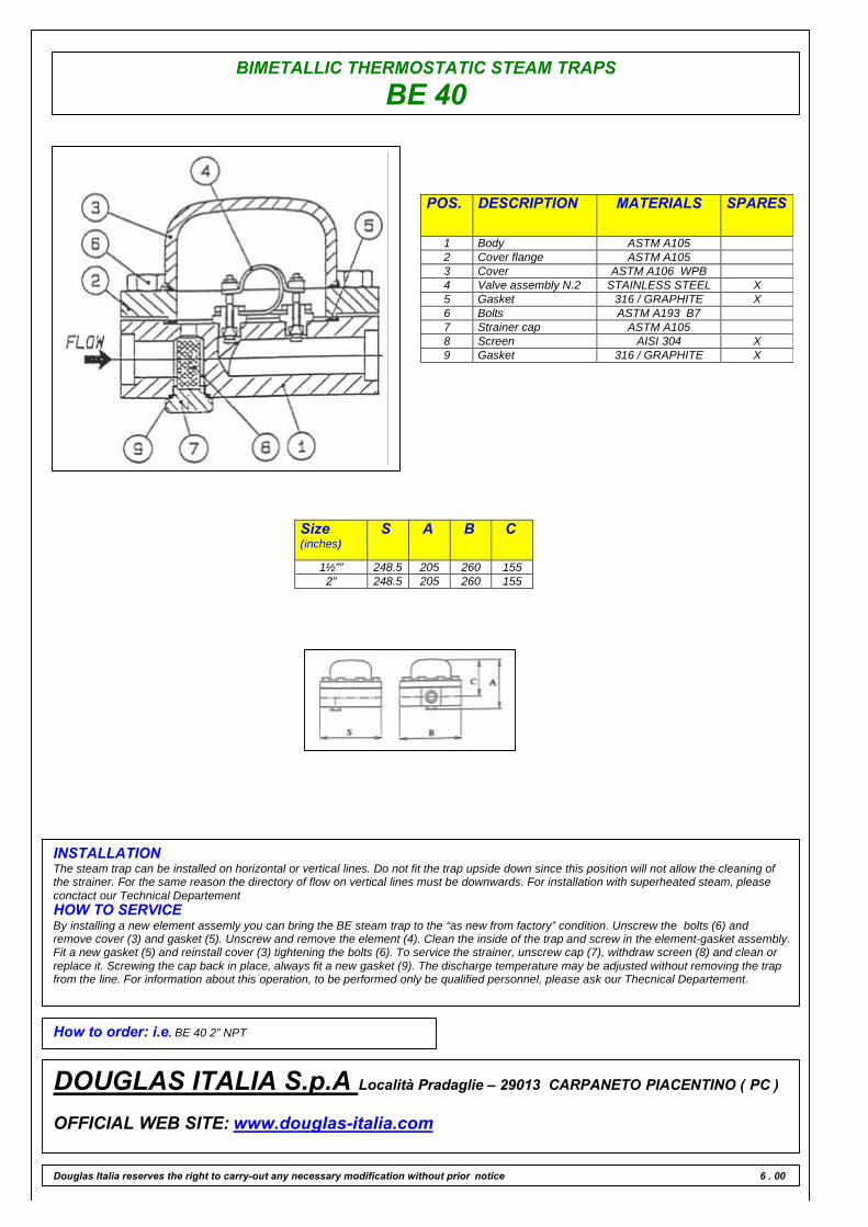
BIMETALLIC THERMOSTATIC STEAM TRAPS
BE 40
POS. DESCRIPTION MATERIALS SPARES
1 Body ASTM A1052 Cover flange ASTM A1053 Cover ASTM A106 WPB4 Valve assembly N.2 STAINLESS STEEL X5 Gasket 316 / GRAPHITE X6 Bolts ASTM A193 B77 Strainer cap ASTM A1058 Screen AISI 304 X9 Gasket 316 / GRAPHITE X
Size(inches)
S A B C
1½”” 248.5 205 260 1552” 248.5 205 260 155
INSTALLATIONThe steam trap can be installed on horizontal or vertical lines. Do not fit the trap upside down since this position will not allow the cleaning ofthe strainer. For the same reason the directory of flow on vertical lines must be downwards. For installation with superheated steam, pleaseconctact our Technical DepartementHOW TO SERVICEBy installing a new element assemly you can bring the BE steam trap to the “as new from factory” condition. Unscrew the bolts (6) andremove cover (3) and gasket (5). Unscrew and remove the element (4). Clean the inside of the trap and screw in the element-gasket assembly.Fit a new gasket (5) and reinstall cover (3) tightening the bolts (6). To service the strainer, unscrew cap (7), withdraw screen (8) and clean orreplace it. Screwing the cap back in place, always fit a new gasket (9). The discharge temperature may be adjusted without removing the trapfrom the line. For information about this operation, to be performed only be qualified personnel, please ask our Thecnical Departement.
How to order: i.e. BE 40 2” NPT
DOUGLAS ITALIA S.p.A Località Pradaglie – 29013 CARPANETO PIACENTINO ( PC )
OFFICIAL WEB SITE: www.douglas-italia.com
Douglas Italia reserves the right to carry-out any necessary modification without prior notice 6 . 00

BIMETALLIC THERMOSTATICSTEAM TRAPS
MP
BIMETALLIC THERMOSTATIC
The operating principle is based on a balance between the steamforce ( pressure related ) trying to open the discharge valve and thebimetal force ( temperature related ) which acts to close it. At saturatedsteam temperature the bimetal force keeps the valve closed, while withsubcooled condensate the pressure opens the valve.
MAIN FEATURES
Free air discharge. Suitable on superheated steam. It withstands frostand waterhammer. Modulating discharge only with condensate.
APPLICATIONS
q Tracing linesq Marine applicationsq Turbinesq Steam mainsq Tanks
DISCHARGE CAPACITY
LIMITING CONDITIONS ( according to ISO 6552 )Steam Trap rating ANSI 800PMA: Max allowable pressure 136 barTMA: max allowable temperature 390°CPMO: max working pressure ( MP 8 ) 8 barTMO: max working temperature ( MP 8 ) 250°CNB: MP model are available for differential pressure upto 40 bar, size up to 8” for high capacity.Please contact our technical departement.
SIZES 11⁄2” – 2”
CONNECTIONSSCREWED ANSI B1.20.1 (NPT) / BS21 (BSP)SOCKET WELD ANSI B16.11FLANGED ANSI 150#/300#/600#/UNI/DIN
Douglas Italia reserves the right to carry-out any necessary modification without prior notice
Cold water capacities are 2 to 4 times greater than the above .Safety factor = 1.2 – 1.5
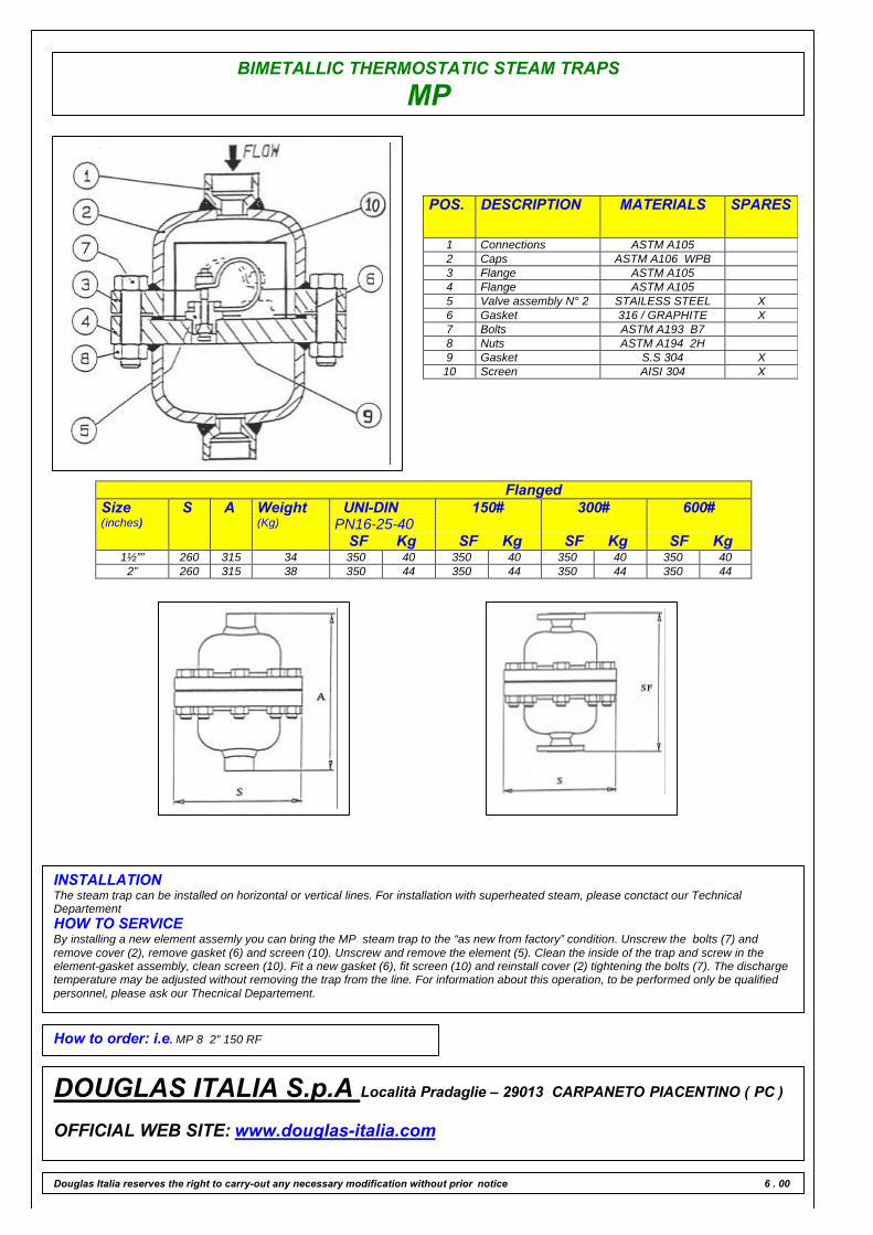
BIMETALLIC THERMOSTATIC STEAM TRAPS
MP
POS. DESCRIPTION MATERIALS SPARES
1 Connections ASTM A1052 Caps ASTM A106 WPB3 Flange ASTM A1054 Flange ASTM A1055 Valve assembly N° 2 STAILESS STEEL X6 Gasket 316 / GRAPHITE X7 Bolts ASTM A193 B78 Nuts ASTM A194 2H9 Gasket S.S 304 X10 Screen AISI 304 X
FlangedSize(inches)
S A Weight(Kg)
UNI-DINPN16-25-40
SF Kg
150#
SF Kg
300#
SF Kg
600#
SF Kg1½”” 260 315 34 350 40 350 40 350 40 350 40
2” 260 315 38 350 44 350 44 350 44 350 44
INSTALLATIONThe steam trap can be installed on horizontal or vertical lines. For installation with superheated steam, please conctact our TechnicalDepartementHOW TO SERVICEBy installing a new element assemly you can bring the MP steam trap to the “as new from factory” condition. Unscrew the bolts (7) andremove cover (2), remove gasket (6) and screen (10). Unscrew and remove the element (5). Clean the inside of the trap and screw in theelement-gasket assembly, clean screen (10). Fit a new gasket (6), fit screen (10) and reinstall cover (2) tightening the bolts (7). The dischargetemperature may be adjusted without removing the trap from the line. For information about this operation, to be performed only be qualifiedpersonnel, please ask our Thecnical Departement.
How to order: i.e. MP 8 2” 150 RF
DOUGLAS ITALIA S.p.A Località Pradaglie – 29013 CARPANETO PIACENTINO ( PC )
OFFICIAL WEB SITE: www.douglas-italia.com
Douglas Italia reserves the right to carry-out any necessary modification without prior notice 6 . 00
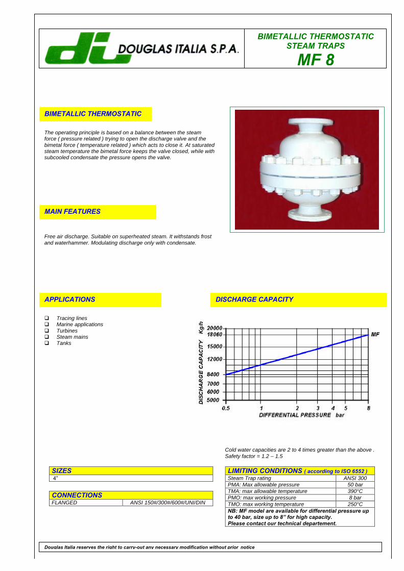
BIMETALLIC THERMOSTATICSTEAM TRAPS
MF 8
BIMETALLIC THERMOSTATIC
The operating principle is based on a balance between the steamforce ( pressure related ) trying to open the discharge valve and thebimetal force ( temperature related ) which acts to close it. At saturatedsteam temperature the bimetal force keeps the valve closed, while withsubcooled condensate the pressure opens the valve.
MAIN FEATURES
Free air discharge. Suitable on superheated steam. It withstands frostand waterhammer. Modulating discharge only with condensate.
APPLICATIONS
q Tracing linesq Marine applicationsq Turbinesq Steam mainsq Tanks
DISCHARGE CAPACITY
LIMITING CONDITIONS ( according to ISO 6552 )Steam Trap rating ANSI 300PMA: Max allowable pressure 50 barTMA: max allowable temperature 390°CPMO: max working pressure 8 barTMO: max working temperature 250°CNB: MF model are available for differential pressure upto 40 bar, size up to 8” for high capacity.Please contact our technical departement.
SIZES 4”
CONNECTIONSFLANGED ANSI 150#/300#/600#/UNI/DIN
Douglas Italia reserves the right to carry-out any necessary modification without prior notice
Cold water capacities are 2 to 4 times greater than the above .Safety factor = 1.2 – 1.5
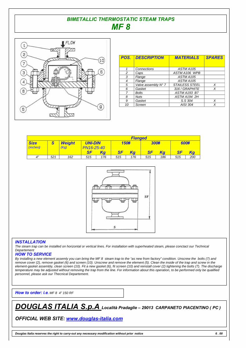
BIMETALLIC THERMOSTATIC STEAM TRAPS
MF 8
POS. DESCRIPTION MATERIALS SPARES
1 Connections ASTM A1052 Caps ASTM A106 WPB3 Flange ASTM A1054 Flange ASTM A1055 Valve assembly N° 7 STAILESS STEEL X6 Gasket 316 / GRAPHITE X7 Bolts ASTM A193 B78 Nuts ASTM A194 2H9 Gasket S.S 304 X10 Screen AISI 304 X
FlangedSize(inches)
S Weight(Kg)
UNI-DINPN16-25-40
SF Kg
150#
SF Kg
300#
SF Kg
600#
SF Kg4” 521 162 515 176 515 176 515 186 515 200
INSTALLATIONThe steam trap can be installed on horizontal or vertical lines. For installation with superheated steam, please conctact our TechnicalDepartementHOW TO SERVICEBy installing a new element assemly you can bring the MF 8 steam trap to the “as new from factory” condition. Unscrew the bolts (7) andremove cover (2), remove gasket (6) and screen (10). Unscrew and remove the element (5). Clean the inside of the trap and screw in theelement-gasket assembly, clean screen (10). Fit a new gasket (6), fit screen (10) and reinstall cover (2) tightening the bolts (7). The dischargetemperature may be adjusted without removing the trap from the line. For information about this operation, to be performed only be qualifiedpersonnel, please ask our Thecnical Departement.
How to order: i.e. MF 8 4” 150 RF
DOUGLAS ITALIA S.p.A Località Pradaglie – 29013 CARPANETO PIACENTINO ( PC )
OFFICIAL WEB SITE: www.douglas-italia.com
Douglas Italia reserves the right to carry-out any necessary modification without prior notice 6 . 00
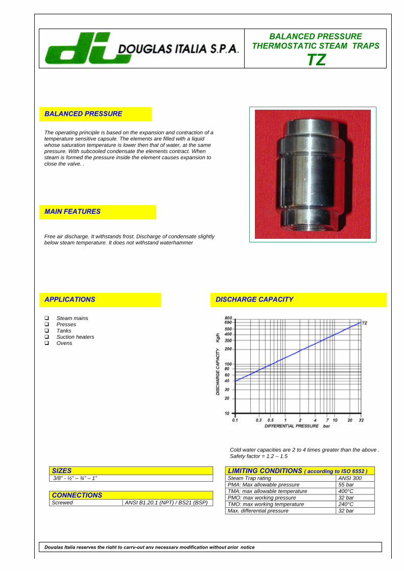
BALANCED PRESSURETHERMOSTATIC STEAM TRAPS
TZ
BALANCED PRESSURE
The operating principle is based on the expansion and contraction of atemperature sensitive capsule. The elements are filled with a liquidwhose saturation temperature is lower then that of water, at the samepressure. With subcooled condensate the elements contract. Whensteam is formed the pressure inside the element causes expansion toclose the valve. .
MAIN FEATURES
Free air discharge. It withstands frost. Discharge of condensate slightlybelow steam temperature. It does not withstand waterhammer
APPLICATIONS
q Steam mainsq Pressesq Tanksq Suction heatersq Ovens
DISCHARGE CAPACITY
LIMITING CONDITIONS ( according to ISO 6552 )Steam Trap rating ANSI 300PMA: Max allowable pressure 55 barTMA: max allowable temperature 400°CPMO: max working pressure 32 barTMO: max working temperature 240°CMax. differential pressure 32 bar
SIZES 3/8” - ½” – ¾” – 1”
CONNECTIONSScrewed ANSI B1.20.1 (NPT) / BS21 (BSP)
Douglas Italia reserves the right to carry-out any necessary modification without prior notice
Cold water capacities are 2 to 4 times greater than the above .Safety factor = 1.2 – 1.5
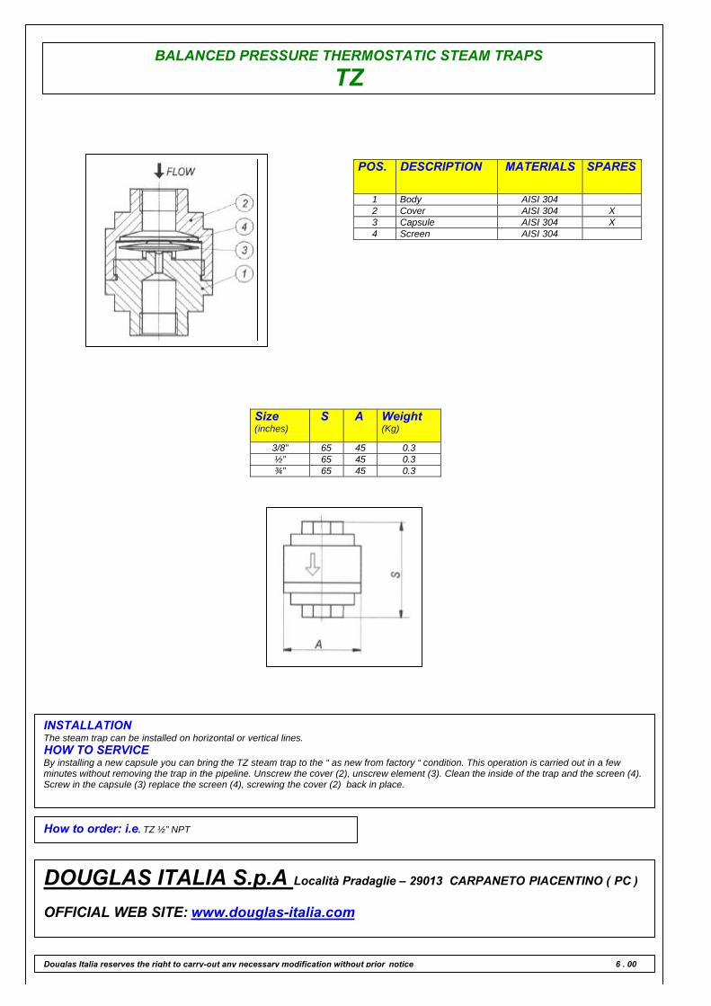
BALANCED PRESSURE THERMOSTATIC STEAM TRAPS
TZ
POS. DESCRIPTION MATERIALS SPARES
1 Body AISI 3042 Cover AISI 304 X3 Capsule AISI 304 X4 Screen AISI 304
Size(inches)
S A Weight(Kg)
3/8” 65 45 0.3½” 65 45 0.3¾” 65 45 0.3
INSTALLATIONThe steam trap can be installed on horizontal or vertical lines.HOW TO SERVICEBy installing a new capsule you can bring the TZ steam trap to the “ as new from factory “ condition. This operation is carried out in a fewminutes without removing the trap in the pipeline. Unscrew the cover (2), unscrew element (3). Clean the inside of the trap and the screen (4).Screw in the capsule (3) replace the screen (4), screwing the cover (2) back in place.
How to order: i.e. TZ ½” NPT
DOUGLAS ITALIA S.p.A Località Pradaglie – 29013 CARPANETO PIACENTINO ( PC )
OFFICIAL WEB SITE: www.douglas-italia.com
Douglas Italia reserves the right to carry-out any necessary modification without prior notice 6 . 00
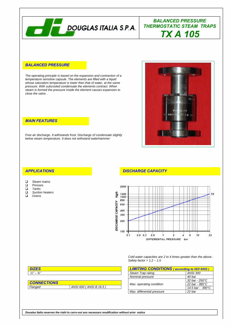
BALANCED PRESSURETHERMOSTATIC STEAM TRAPS
TX A 105
BALANCED PRESSURE
The operating principle is based on the expansion and contraction of atemperature sensitive capsule. The elements are filled with a liquidwhose saturation temperature is lower then that of water, at the samepressure. With subcooled condensate the elements contract. Whensteam is formed the pressure inside the element causes expansion toclose the valve. .
MAIN FEATURES
Free air discharge. It withstands frost. Discharge of condensate slightlybelow steam temperature. It does not withstand waterhammer
APPLICATIONS
q Steam mainsq Pressesq Tanksq Suction heatersq Ovens
DISCHARGE CAPACITY
LIMITING CONDITIONS ( according to ISO 6552 )Steam Trap rating ANSI 300Nominal pressure 40 bar
32 bar - 250°C22 bar - 385°CMax. operating condition14.5 bar - 390°C
Max. differential pressure 22 bar
SIZES ½” – ¾”
CONNECTIONSFlanged ANSI 600 ( ANSI B 16.5 )
Douglas Italia reserves the right to carry-out any necessary modification without prior notice
Cold water capacities are 2 to 4 times greater than the above .Safety factor = 1.2 – 1.5
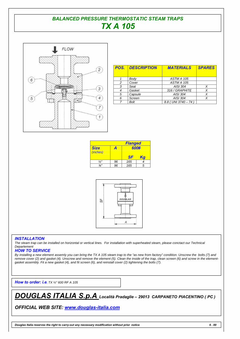
BALANCED PRESSURE THERMOSTATIC STEAM TRAPS
TX A 105
POS. DESCRIPTION MATERIALS SPARES
1 Body ASTM A 1052 Cover ASTM A 1053 Seat AISI 304 X4 Gasket 316 / GRAPHITE X5 Capsule AISI 304 X6 Screen AISI 304 X7 Bolt 8.8 ( UNI 3740 – 74 )
FlangedSize(inches)
A 600#
SF Kg½” 96 165 4¾” 96 165 5
INSTALLATIONThe steam trap can be installed on horizontal or vertical lines. For installation with superheated steam, please conctact our TechnicalDepartementHOW TO SERVICEBy installing a new element assemly you can bring the TX A 105 steam trap to the “as new from factory” condition. Unscrew the bolts (7) andremove cover (2) and gasket (4). Unscrew and remove the element (5). Clean the inside of the trap, clean screen (6) and screw in the element-gasket assembly. Fit a new gasket (4), and fit screen (6), and reinstall cover (2) tightening the bolts (7).
How to order: i.e. TX ½” 600 RF A 105
DOUGLAS ITALIA S.p.A Località Pradaglie – 29013 CARPANETO PIACENTINO ( PC )
OFFICIAL WEB SITE: www.douglas-italia.com
Douglas Italia reserves the right to carry-out any necessary modification without prior notice 6 . 00
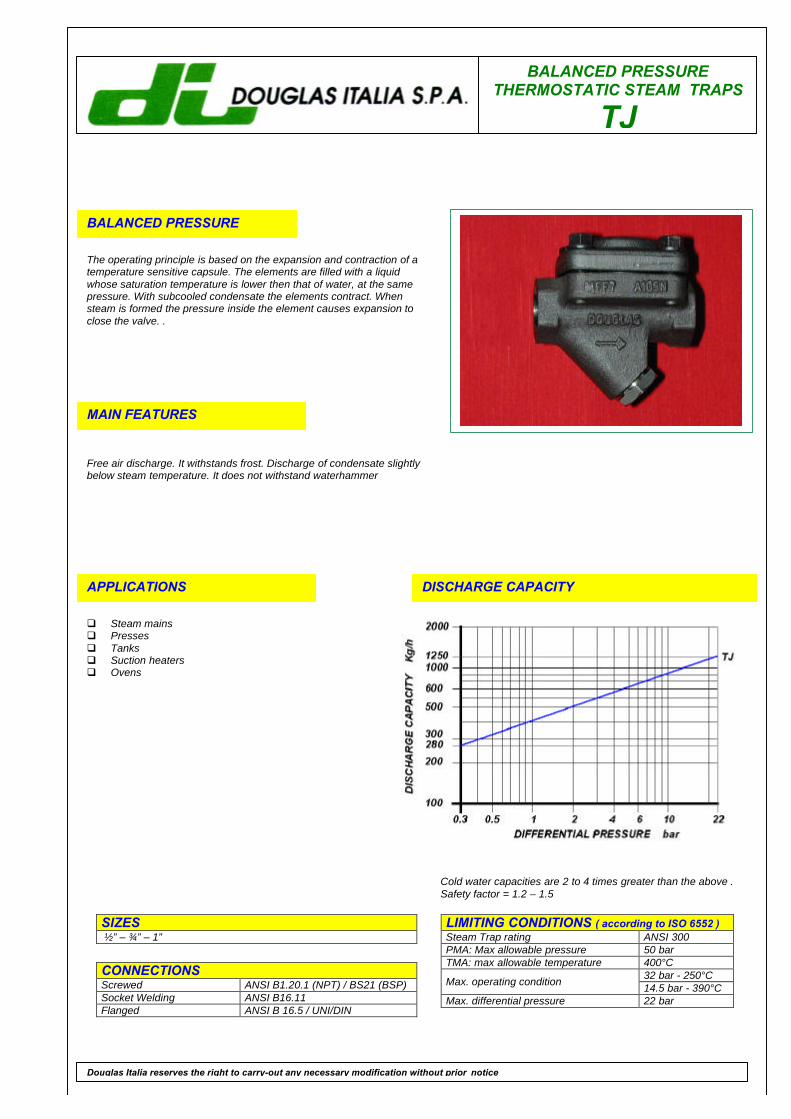
BALANCED PRESSURETHERMOSTATIC STEAM TRAPS
TJ
BALANCED PRESSURE
The operating principle is based on the expansion and contraction of atemperature sensitive capsule. The elements are filled with a liquidwhose saturation temperature is lower then that of water, at the samepressure. With subcooled condensate the elements contract. Whensteam is formed the pressure inside the element causes expansion toclose the valve. .
MAIN FEATURES
Free air discharge. It withstands frost. Discharge of condensate slightlybelow steam temperature. It does not withstand waterhammer
APPLICATIONS
q Steam mainsq Pressesq Tanksq Suction heatersq Ovens
DISCHARGE CAPACITY
LIMITING CONDITIONS ( according to ISO 6552 )Steam Trap rating ANSI 300PMA: Max allowable pressure 50 barTMA: max allowable temperature 400°C
32 bar - 250°CMax. operating condition 14.5 bar - 390°CMax. differential pressure 22 bar
SIZES ½” – ¾” – 1”
CONNECTIONSScrewed ANSI B1.20.1 (NPT) / BS21 (BSP)Socket Welding ANSI B16.11Flanged ANSI B 16.5 / UNI/DIN
Douglas Italia reserves the right to carry-out any necessary modification without prior notice
Cold water capacities are 2 to 4 times greater than the above .Safety factor = 1.2 – 1.5
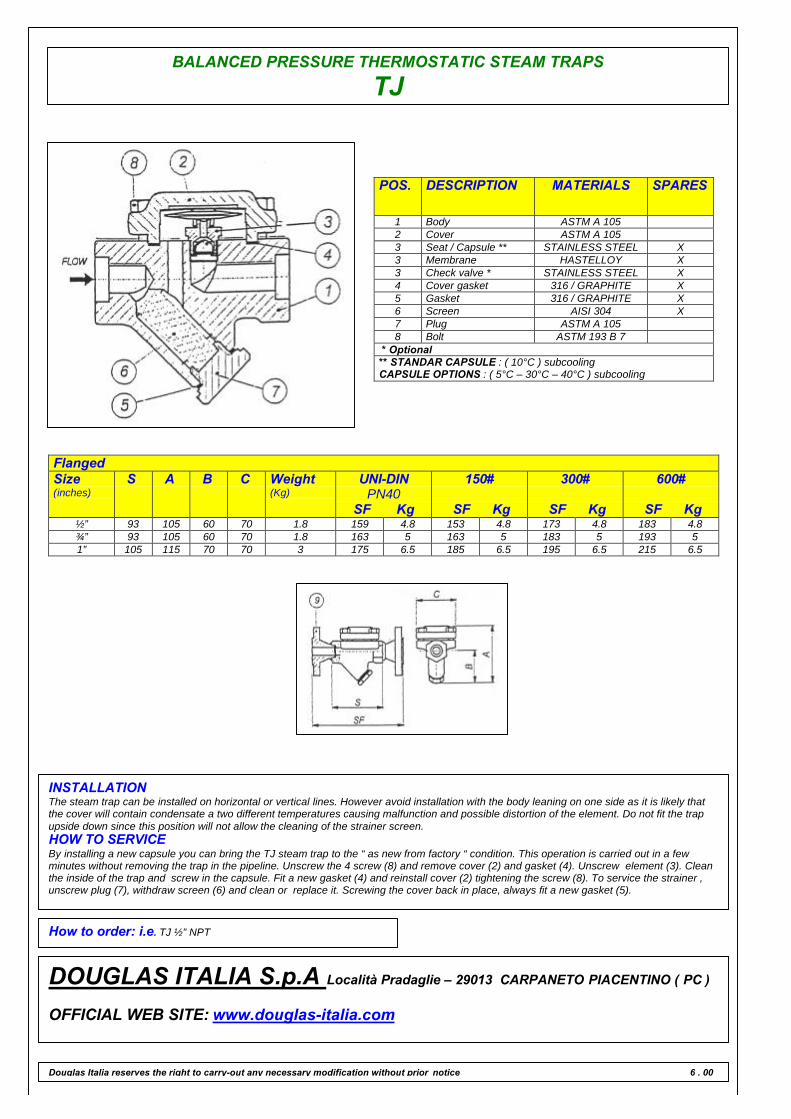
BALANCED PRESSURE THERMOSTATIC STEAM TRAPS
TJ
POS. DESCRIPTION MATERIALS SPARES
1 Body ASTM A 1052 Cover ASTM A 1053 Seat / Capsule ** STAINLESS STEEL X3 Membrane HASTELLOY X3 Check valve * STAINLESS STEEL X4 Cover gasket 316 / GRAPHITE X5 Gasket 316 / GRAPHITE X6 Screen AISI 304 X7 Plug ASTM A 1058 Bolt ASTM 193 B 7
* Optional** STANDAR CAPSULE : ( 10°C ) subcoolingCAPSULE OPTIONS : ( 5°C – 30°C – 40°C ) subcooling
FlangedSize(inches)
S A B C Weight(Kg)
UNI-DINPN40
SF Kg
150#
SF Kg
300#
SF Kg
600#
SF Kg½” 93 105 60 70 1.8 159 4.8 153 4.8 173 4.8 183 4.8¾” 93 105 60 70 1.8 163 5 163 5 183 5 193 51” 105 115 70 70 3 175 6.5 185 6.5 195 6.5 215 6.5
INSTALLATIONThe steam trap can be installed on horizontal or vertical lines. However avoid installation with the body leaning on one side as it is likely thatthe cover will contain condensate a two different temperatures causing malfunction and possible distortion of the element. Do not fit the trapupside down since this position will not allow the cleaning of the strainer screen.HOW TO SERVICEBy installing a new capsule you can bring the TJ steam trap to the “ as new from factory “ condition. This operation is carried out in a fewminutes without removing the trap in the pipeline. Unscrew the 4 screw (8) and remove cover (2) and gasket (4). Unscrew element (3). Cleanthe inside of the trap and screw in the capsule. Fit a new gasket (4) and reinstall cover (2) tightening the screw (8). To service the strainer ,unscrew plug (7), withdraw screen (6) and clean or replace it. Screwing the cover back in place, always fit a new gasket (5).
How to order: i.e. TJ ½” NPT
DOUGLAS ITALIA S.p.A Località Pradaglie – 29013 CARPANETO PIACENTINO ( PC )
OFFICIAL WEB SITE: www.douglas-italia.com
Douglas Italia reserves the right to carry-out any necessary modification without prior notice 6 . 00
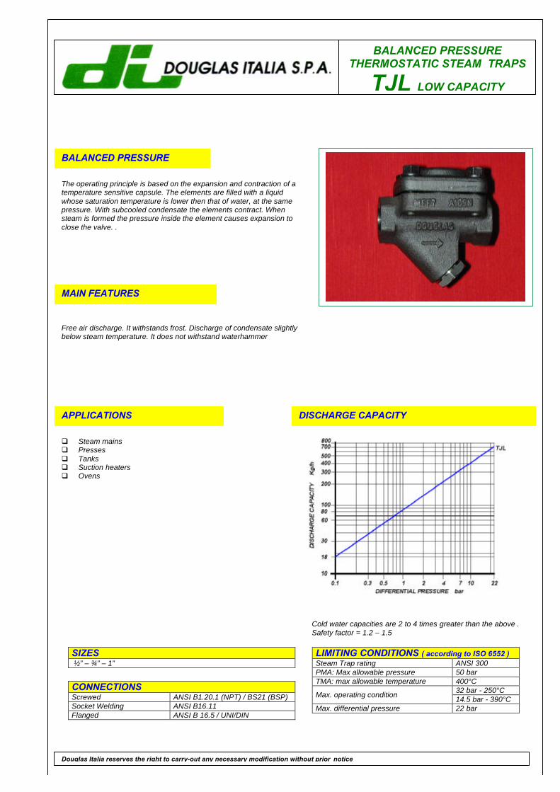
BALANCED PRESSURETHERMOSTATIC STEAM TRAPS
TJL LOW CAPACITY
BALANCED PRESSURE
The operating principle is based on the expansion and contraction of atemperature sensitive capsule. The elements are filled with a liquidwhose saturation temperature is lower then that of water, at the samepressure. With subcooled condensate the elements contract. Whensteam is formed the pressure inside the element causes expansion toclose the valve. .
MAIN FEATURES
Free air discharge. It withstands frost. Discharge of condensate slightlybelow steam temperature. It does not withstand waterhammer
APPLICATIONS
q Steam mainsq Pressesq Tanksq Suction heatersq Ovens
DISCHARGE CAPACITY
LIMITING CONDITIONS ( according to ISO 6552 )Steam Trap rating ANSI 300PMA: Max allowable pressure 50 barTMA: max allowable temperature 400°C
32 bar - 250°CMax. operating condition 14.5 bar - 390°CMax. differential pressure 22 bar
SIZES ½” – ¾” – 1”
CONNECTIONSScrewed ANSI B1.20.1 (NPT) / BS21 (BSP)Socket Welding ANSI B16.11Flanged ANSI B 16.5 / UNI/DIN
Douglas Italia reserves the right to carry-out any necessary modification without prior notice
Cold water capacities are 2 to 4 times greater than the above .Safety factor = 1.2 – 1.5
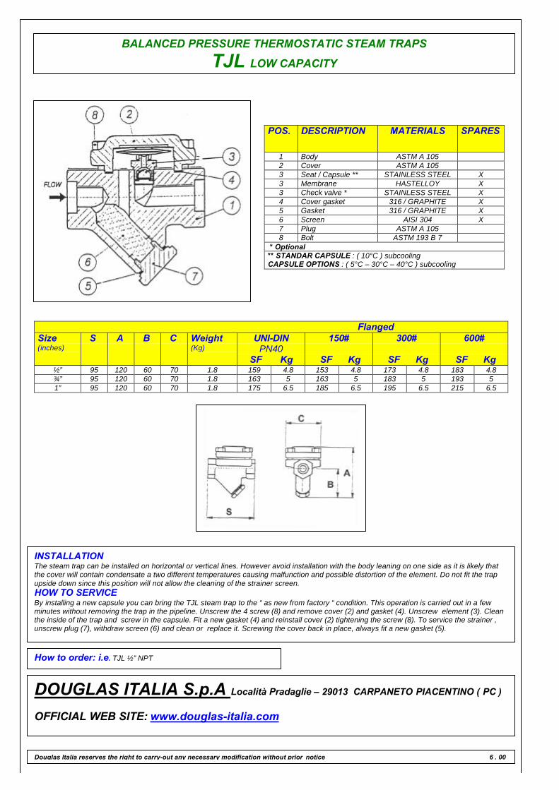
BALANCED PRESSURE THERMOSTATIC STEAM TRAPS
TJL LOW CAPACITY
POS. DESCRIPTION MATERIALS SPARES
1 Body ASTM A 1052 Cover ASTM A 1053 Seat / Capsule ** STAINLESS STEEL X3 Membrane HASTELLOY X3 Check valve * STAINLESS STEEL X4 Cover gasket 316 / GRAPHITE X5 Gasket 316 / GRAPHITE X6 Screen AISI 304 X7 Plug ASTM A 1058 Bolt ASTM 193 B 7
* Optional** STANDAR CAPSULE : ( 10°C ) subcoolingCAPSULE OPTIONS : ( 5°C – 30°C – 40°C ) subcooling
FlangedSize(inches)
S A B C Weight(Kg)
UNI-DINPN40
SF Kg
150#
SF Kg
300#
SF Kg
600#
SF Kg½” 95 120 60 70 1.8 159 4.8 153 4.8 173 4.8 183 4.8¾” 95 120 60 70 1.8 163 5 163 5 183 5 193 51” 95 120 60 70 1.8 175 6.5 185 6.5 195 6.5 215 6.5
INSTALLATIONThe steam trap can be installed on horizontal or vertical lines. However avoid installation with the body leaning on one side as it is likely thatthe cover will contain condensate a two different temperatures causing malfunction and possible distortion of the element. Do not fit the trapupside down since this position will not allow the cleaning of the strainer screen.HOW TO SERVICEBy installing a new capsule you can bring the TJL steam trap to the “ as new from factory “ condition. This operation is carried out in a fewminutes without removing the trap in the pipeline. Unscrew the 4 screw (8) and remove cover (2) and gasket (4). Unscrew element (3). Cleanthe inside of the trap and screw in the capsule. Fit a new gasket (4) and reinstall cover (2) tightening the screw (8). To service the strainer ,unscrew plug (7), withdraw screen (6) and clean or replace it. Screwing the cover back in place, always fit a new gasket (5).
How to order: i.e. TJL ½” NPT
DOUGLAS ITALIA S.p.A Località Pradaglie – 29013 CARPANETO PIACENTINO ( PC )
OFFICIAL WEB SITE: www.douglas-italia.com
Douglas Italia reserves the right to carry-out any necessary modification without prior notice 6 . 00
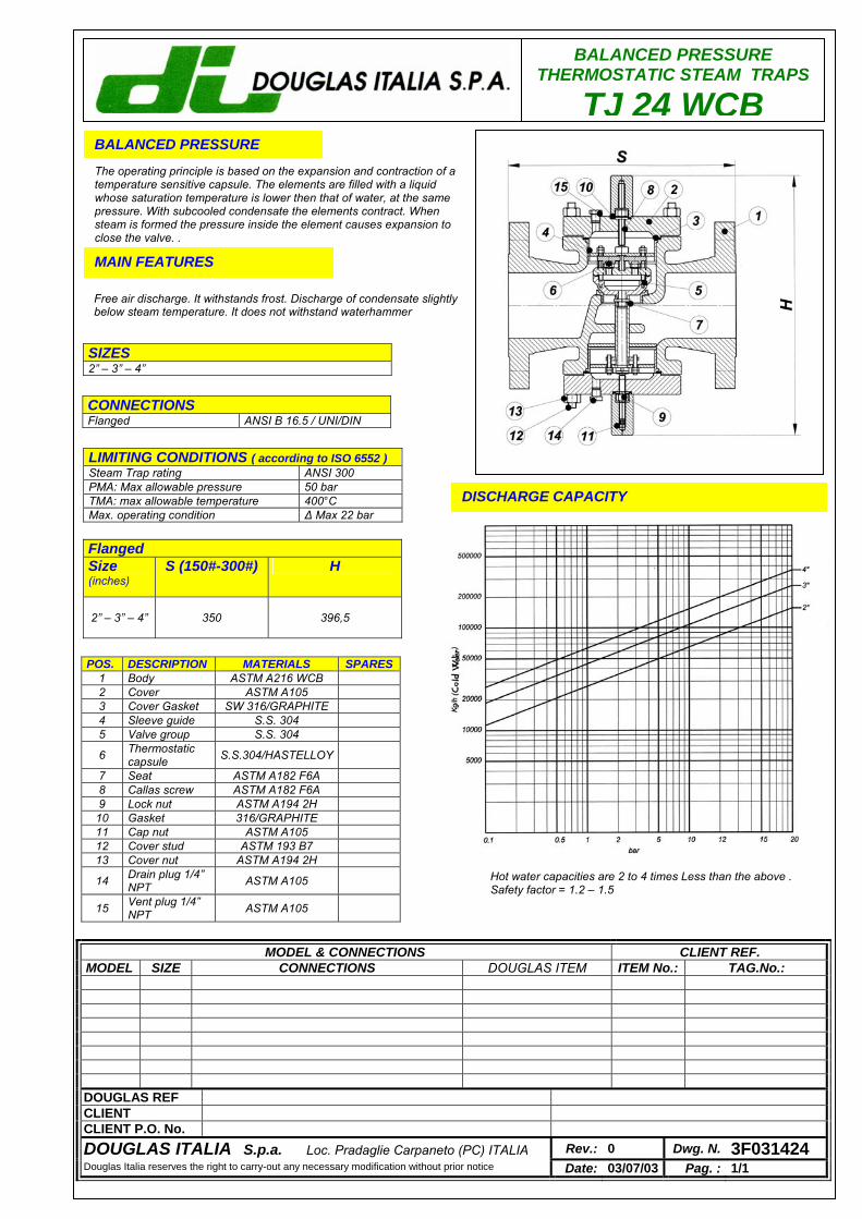
BALANCED PRESSURE THERMOSTATIC STEAM TRAPS
TJ 24 WCBBALANCED PRESSURE
The operating principle is based on the expansion and contraction of a temperature sensitive capsule. The elements are filled with a liquid whose saturation temperature is lower then that of water, at the same pressure. With subcooled condensate the elements contract. When steam is formed the pressure inside the element causes expansion to close the valve. . MAIN FEATURES
Free air discharge. It withstands frost. Discharge of condensate slightly below steam temperature. It does not withstand waterhammer
DISCHARGE CAPACITY
LIMITING CONDITIONS ( according to ISO 6552 ) Steam Trap rating ANSI 300 PMA: Max allowable pressure 50 bar TMA: max allowable temperature 400°C Max. operating condition ∆ Max 22 bar
SIZES 2” – 3” – 4”
CONNECTIONS Flanged ANSI B 16.5 / UNI/DIN
POS. DESCRIPTION MATERIALS SPARES 1 Body ASTM A216 WCB 2 Cover ASTM A105 3 Cover Gasket SW 316/GRAPHITE 4 Sleeve guide S.S. 304 5 Valve group S.S. 304
6 Thermostatic capsule S.S.304/HASTELLOY
7 Seat ASTM A182 F6A 8 Callas screw ASTM A182 F6A 9 Lock nut ASTM A194 2H
10 Gasket 316/GRAPHITE 11 Cap nut ASTM A105 12 Cover stud ASTM 193 B7 13 Cover nut ASTM A194 2H
14 Drain plug 1/4” NPT ASTM A105
15 Vent plug 1/4” NPT ASTM A105
Flanged Size (inches)
S (150#-300#) H
2” – 3” – 4” 350 396,5
Hot water capacities are 2 to 4 times Less than the above . Safety factor = 1.2 – 1.5
MODEL & CONNECTIONS CLIENT REF. MODEL SIZE CONNECTIONS DOUGLAS ITEM ITEM No.: TAG.No.:
DOUGLAS REF CLIENT CLIENT P.O. No. DOUGLAS ITALIA S.p.a. Loc. Pradaglie Carpaneto (PC) ITALIA Rev.: 0 Dwg. N. 3F031424 Douglas Italia reserves the right to carry-out any necessary modification without prior notice Date: 03/07/03 Pag. : 1/1
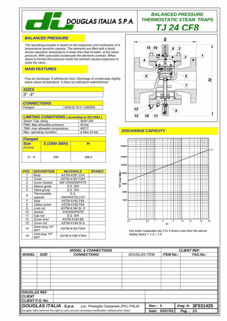
BALANCED PRESSURE THERMOSTATIC STEAM TRAPS
TJ 24 CF8BALANCED PRESSURE
The operating principle is based on the expansion and contraction of a temperature sensitive capsule. The elements are filled with a liquid whose saturation temperature is lower then that of water, at the same pressure. With subcooled condensate the elements contract. When steam is formed the pressure inside the element causes expansion to close the valve. . MAIN FEATURES
Free air discharge. It withstands frost. Discharge of condensate slightly below steam temperature. It does not withstand waterhammer
DISCHARGE CAPACITY
LIMITING CONDITIONS ( according to ISO 6552 ) Steam Trap rating ANSI 300 PMA: Max allowable pressure 50 bar TMA: max allowable temperature 400°C Max. operating condition ∆ Max 22 bar
SIZES 3” -4”
CONNECTIONS Flanged ANSI B 16.5 / UNI/DIN
Flanged Size (inches)
S (150#-300#) H
3”- 4” 350 396,5
MODEL & CONNECTIONS CLIENT REF. MODEL SIZE CONNECTIONS DOUGLAS ITEM ITEM No.: TAG.No.:
DOUGLAS REF CLIENT CLIENT P.O. No. DOUGLAS ITALIA S.p.a. Loc. Pradaglie Carpaneto (PC) ITALIA Rev.: 0 Dwg. N. 3F031425 Douglas Italia reserves the right to carry-out any necessary modification without prior notice Date: 03/07/03 Pag. : 1/1
POS. DESCRIPTION MATERIALS SPARES 1 Body ASTM A351 CF8 2 Cover ASTM A182 F304 3 Cover Gasket SW 316/GRAPHITE 4 Sleeve guide S.S. 304 5 Valve group S.S. 304
6 Thermostatic capsule
S.S. 304/HASTELLOY
7 Seat ASTM A182 F6A 8 Callas screw ASTM A182 F6A 9 Lock nut ASTM A194 Gr. 8
10 Gasket 316/GRAPHITE 11 Cap nut S.S. 304 12 Cover stud ASTM A193 B8 13 Cover nut ASTM A194 Gr.8
14 Drain plug 1/4” NPT ASTM A182 F304
15 Vent plug 1/4” NPT ASTM A1082 F304
Hot water capacities are 2 to 4 times Less than the above . Safety factor = 1.2 – 1.5

BALANCED PRESSURETHERMOSTATIC STEAM TRAPS
TC 2
BALANCED PRESSURE
The operating principle is based on the expansion and contraction of atemperature sensitive capsule. The elements are filled with a liquidwhose saturation temperature is lower then that of water, at the samepressure. With subcooled condensate the elements contract. Whensteam is formed the pressure inside the element causes expansion toclose the valve. .
MAIN FEATURES
Free air discharge. It withstands frost. Discharge of condensate slightlybelow steam temperature. It does not withstand waterhammer
APPLICATIONS
q Steam mainsq Pressesq Tanksq Suction heatersq Ovens
DISCHARGE CAPACITY
LIMITING CONDITIONS ( according to ISO 6552 )Steam Trap rating ANSI 300PMA: Max allowable pressure 50 barTMA: max allowable temperature 400°C
32 bar - 250°CMax. operating condition 14.5 bar - 390°CMax. differential pressure 22 bar
SIZES ½” – ¾” – 1”
CONNECTIONSScrewed ANSI B1.20.1 (NPT) / BS21 (BSP)Socket Welding ANSI B16.11Flanged ANSI B 16.5
Douglas Italia reserves the right to carry-out any necessary modification without prior notice
Cold water capacities are 2 to 4 times greater than the above .Safety factor = 1.2 – 1.5
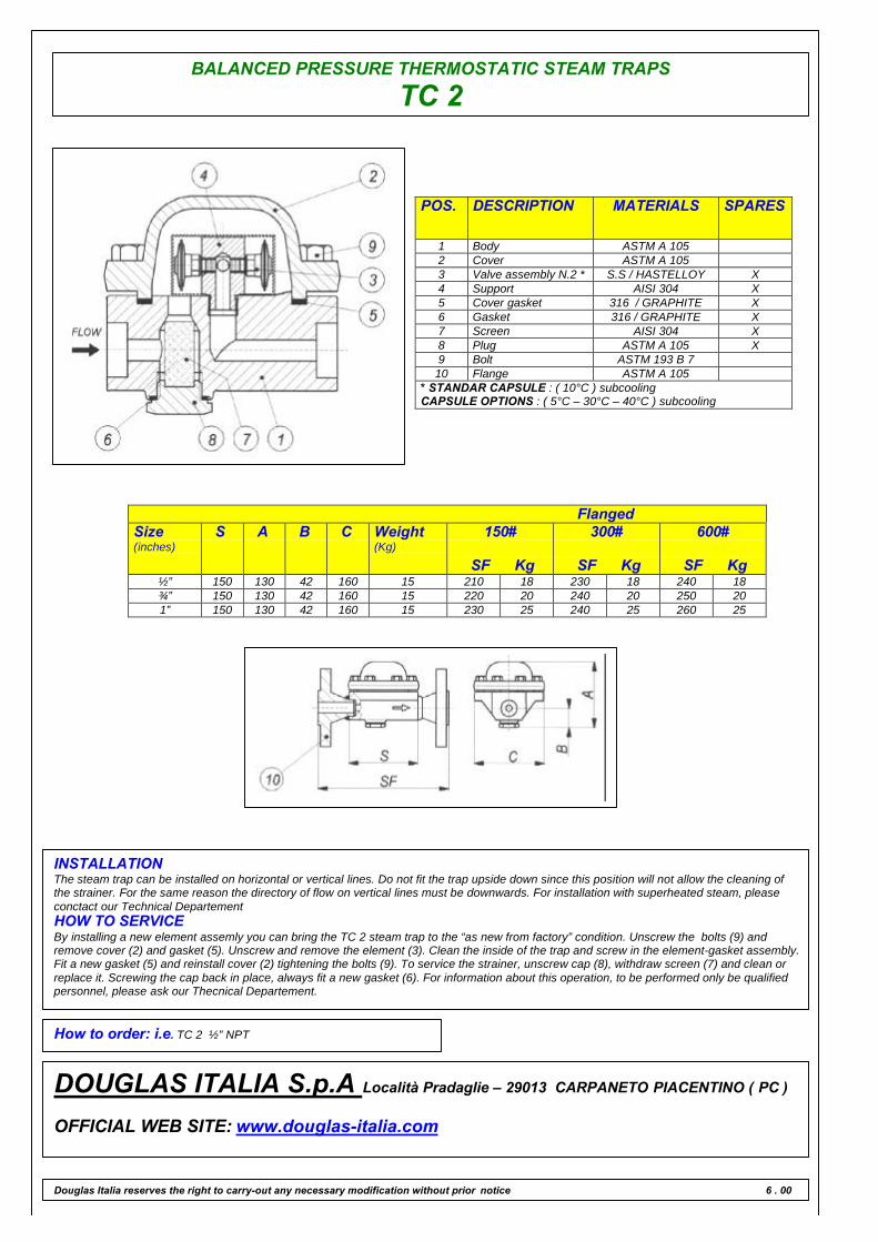
BALANCED PRESSURE THERMOSTATIC STEAM TRAPS
TC 2
POS. DESCRIPTION MATERIALS SPARES
1 Body ASTM A 1052 Cover ASTM A 1053 Valve assembly N.2 * S.S / HASTELLOY X4 Support AISI 304 X5 Cover gasket 316 / GRAPHITE X6 Gasket 316 / GRAPHITE X7 Screen AISI 304 X8 Plug ASTM A 105 X9 Bolt ASTM 193 B 710 Flange ASTM A 105
* STANDAR CAPSULE : ( 10°C ) subcoolingCAPSULE OPTIONS : ( 5°C – 30°C – 40°C ) subcooling
FlangedSize(inches)
S A B C Weight(Kg)
150#
SF Kg
300#
SF Kg
600#
SF Kg½” 150 130 42 160 15 210 18 230 18 240 18¾” 150 130 42 160 15 220 20 240 20 250 201” 150 130 42 160 15 230 25 240 25 260 25
INSTALLATIONThe steam trap can be installed on horizontal or vertical lines. Do not fit the trap upside down since this position will not allow the cleaning ofthe strainer. For the same reason the directory of flow on vertical lines must be downwards. For installation with superheated steam, pleaseconctact our Technical DepartementHOW TO SERVICEBy installing a new element assemly you can bring the TC 2 steam trap to the “as new from factory” condition. Unscrew the bolts (9) andremove cover (2) and gasket (5). Unscrew and remove the element (3). Clean the inside of the trap and screw in the element-gasket assembly.Fit a new gasket (5) and reinstall cover (2) tightening the bolts (9). To service the strainer, unscrew cap (8), withdraw screen (7) and clean orreplace it. Screwing the cap back in place, always fit a new gasket (6). For information about this operation, to be performed only be qualifiedpersonnel, please ask our Thecnical Departement.
How to order: i.e. TC 2 ½” NPT
DOUGLAS ITALIA S.p.A Località Pradaglie – 29013 CARPANETO PIACENTINO ( PC )
OFFICIAL WEB SITE: www.douglas-italia.com
Douglas Italia reserves the right to carry-out any necessary modification without prior notice 6 . 00

BALANCED PRESSURETHERMOSTATIC STEAM TRAPS
TC 4
BALANCED PRESSURE
The operating principle is based on the expansion and contraction of atemperature sensitive capsule. The elements are filled with a liquidwhose saturation temperature is lower then that of water, at the samepressure. With subcooled condensate the elements contract. Whensteam is formed the pressure inside the element causes expansion toclose the valve. .
MAIN FEATURES
Free air discharge. It withstands frost. Discharge of condensate slightlybelow steam temperature. It does not withstand waterhammer
APPLICATIONS
q Steam mainsq Pressesq Tanksq Suction heatersq Ovens
DISCHARGE CAPACITY
LIMITING CONDITIONS ( according to ISO 6552 )Steam Trap rating ANSI 300PMA: Max allowable pressure 50 barTMA: max allowable temperature 400°C
32 bar - 250°CMax. operating condition 14.5 bar - 390°CMax. differential pressure 22 bar
SIZES ½” – ¾” – 1”
CONNECTIONSScrewed ANSI B1.20.1 (NPT) / BS21 (BSP)Socket Welding ANSI B16.11Flanged ANSI B 16.5
Douglas Italia reserves the right to carry-out any necessary modification without prior notice
Cold water capacities are 2 to 4 times greater than the above .Safety factor = 1.2 – 1.5
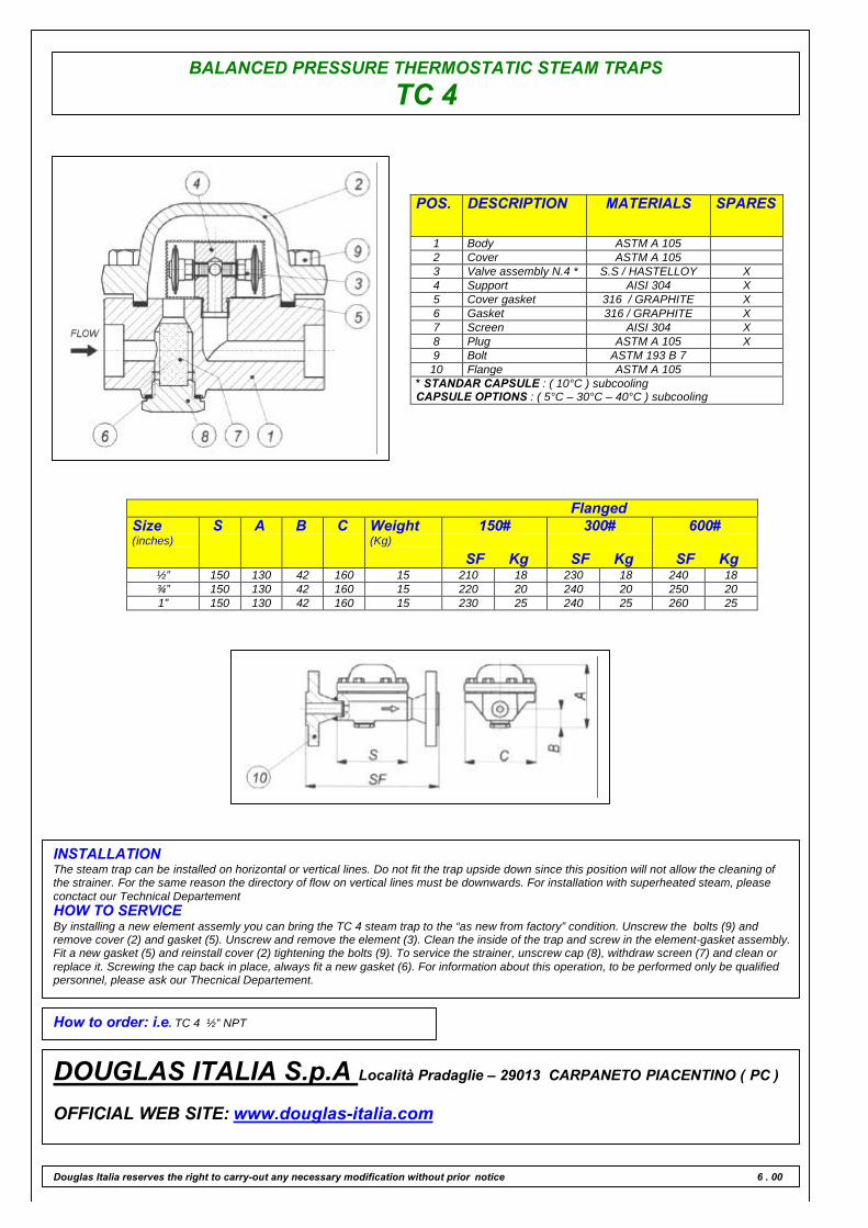
BALANCED PRESSURE THERMOSTATIC STEAM TRAPS
TC 4
POS. DESCRIPTION MATERIALS SPARES
1 Body ASTM A 1052 Cover ASTM A 1053 Valve assembly N.4 * S.S / HASTELLOY X4 Support AISI 304 X5 Cover gasket 316 / GRAPHITE X6 Gasket 316 / GRAPHITE X7 Screen AISI 304 X8 Plug ASTM A 105 X9 Bolt ASTM 193 B 710 Flange ASTM A 105
* STANDAR CAPSULE : ( 10°C ) subcoolingCAPSULE OPTIONS : ( 5°C – 30°C – 40°C ) subcooling
FlangedSize(inches)
S A B C Weight(Kg)
150#
SF Kg
300#
SF Kg
600#
SF Kg½” 150 130 42 160 15 210 18 230 18 240 18¾” 150 130 42 160 15 220 20 240 20 250 201” 150 130 42 160 15 230 25 240 25 260 25
INSTALLATIONThe steam trap can be installed on horizontal or vertical lines. Do not fit the trap upside down since this position will not allow the cleaning ofthe strainer. For the same reason the directory of flow on vertical lines must be downwards. For installation with superheated steam, pleaseconctact our Technical DepartementHOW TO SERVICEBy installing a new element assemly you can bring the TC 4 steam trap to the “as new from factory” condition. Unscrew the bolts (9) andremove cover (2) and gasket (5). Unscrew and remove the element (3). Clean the inside of the trap and screw in the element-gasket assembly.Fit a new gasket (5) and reinstall cover (2) tightening the bolts (9). To service the strainer, unscrew cap (8), withdraw screen (7) and clean orreplace it. Screwing the cap back in place, always fit a new gasket (6). For information about this operation, to be performed only be qualifiedpersonnel, please ask our Thecnical Departement.
How to order: i.e. TC 4 ½” NPT
DOUGLAS ITALIA S.p.A Località Pradaglie – 29013 CARPANETO PIACENTINO ( PC )
OFFICIAL WEB SITE: www.douglas-italia.com
Douglas Italia reserves the right to carry-out any necessary modification without prior notice 6 . 00

BALANCED PRESSURETHERMOSTATIC STEAM TRAPS
TC 6
BALANCED PRESSURE
The operating principle is based on the expansion and contraction of atemperature sensitive capsule. The elements are filled with a liquidwhose saturation temperature is lower then that of water, at the samepressure. With subcooled condensate the elements contract. Whensteam is formed the pressure inside the element causes expansion toclose the valve. .
MAIN FEATURES
Free air discharge. It withstands frost. Discharge of condensate slightlybelow steam temperature. It does not withstand waterhammer
APPLICATIONS
q Steam mainsq Pressesq Tanksq Suction heatersq Ovens
DISCHARGE CAPACITY
LIMITING CONDITIONS ( according to ISO 6552 )Steam Trap rating ANSI 300PMA: Max allowable pressure 50 barTMA: max allowable temperature 400°C
32 bar - 250°CMax. operating condition 14.5 bar - 390°CMax. differential pressure 22 bar
SIZES 2”
CONNECTIONSScrewed ANSI B1.20.1 (NPT) / BS21 (BSP)Socket Welding ANSI B16.11Flanged ANSI B 16.5
Douglas Italia reserves the right to carry-out any necessary modification without prior notice
Cold water capacities are 2 to 4 times greater than the above .Safety factor = 1.2 – 1.5
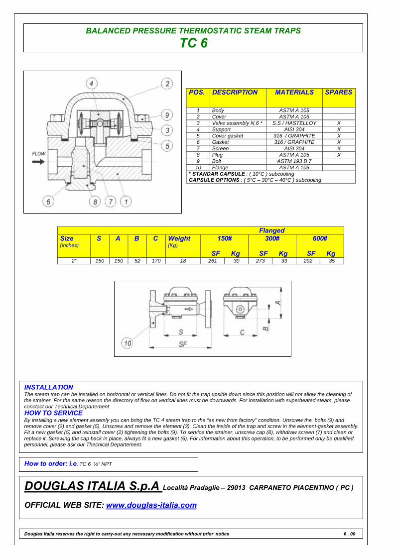
BALANCED PRESSURE THERMOSTATIC STEAM TRAPS
TC 6
POS. DESCRIPTION MATERIALS SPARES
1 Body ASTM A 1052 Cover ASTM A 1053 Valve assembly N.6 * S.S / HASTELLOY X4 Support AISI 304 X5 Cover gasket 316 / GRAPHITE X6 Gasket 316 / GRAPHITE X7 Screen AISI 304 X8 Plug ASTM A 105 X9 Bolt ASTM 193 B 710 Flange ASTM A 105
* STANDAR CAPSULE : ( 10°C ) subcoolingCAPSULE OPTIONS : ( 5°C – 30°C – 40°C ) subcooling
FlangedSize(inches)
S A B C Weight(Kg)
150#
SF Kg
300#
SF Kg
600#
SF Kg2” 150 150 52 170 18 261 30 273 33 292 35
INSTALLATIONThe steam trap can be installed on horizontal or vertical lines. Do not fit the trap upside down since this position will not allow the cleaning ofthe strainer. For the same reason the directory of flow on vertical lines must be downwards. For installation with superheated steam, pleaseconctact our Technical DepartementHOW TO SERVICEBy installing a new element assemly you can bring the TC 4 steam trap to the “as new from factory” condition. Unscrew the bolts (9) andremove cover (2) and gasket (5). Unscrew and remove the element (3). Clean the inside of the trap and screw in the element-gasket assembly.Fit a new gasket (5) and reinstall cover (2) tightening the bolts (9). To service the strainer, unscrew cap (8), withdraw screen (7) and clean orreplace it. Screwing the cap back in place, always fit a new gasket (6). For information about this operation, to be performed only be qualifiedpersonnel, please ask our Thecnical Departement.
How to order: i.e. TC 6 ½” NPT
DOUGLAS ITALIA S.p.A Località Pradaglie – 29013 CARPANETO PIACENTINO ( PC )
OFFICIAL WEB SITE: www.douglas-italia.com
Douglas Italia reserves the right to carry-out any necessary modification without prior notice 6 . 00
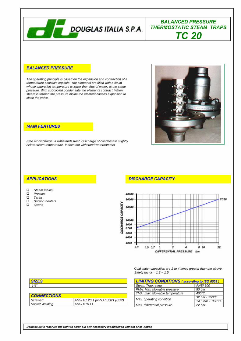
BALANCED PRESSURETHERMOSTATIC STEAM TRAPS
TC 20
BALANCED PRESSURE
The operating principle is based on the expansion and contraction of atemperature sensitive capsule. The elements are filled with a liquidwhose saturation temperature is lower then that of water, at the samepressure. With subcooled condensate the elements contract. Whensteam is formed the pressure inside the element causes expansion toclose the valve. .
MAIN FEATURES
Free air discharge. It withstands frost. Discharge of condensate slightlybelow steam temperature. It does not withstand waterhammer
APPLICATIONS
q Steam mainsq Pressesq Tanksq Suction heatersq Ovens
DISCHARGE CAPACITY
LIMITING CONDITIONS ( according to ISO 6552 )Steam Trap rating ANSI 300PMA: Max allowable pressure 50 barTMA: max allowable temperature 400°C
32 bar - 250°CMax. operating condition 14.5 bar - 390°CMax. differential pressure 22 bar
SIZES 1½”
CONNECTIONSScrewed ANSI B1.20.1 (NPT) / BS21 (BSP)Socket Welding ANSI B16.11
Douglas Italia reserves the right to carry-out any necessary modification without prior notice
Cold water capacities are 2 to 4 times greater than the above .Safety factor = 1.2 – 1.5
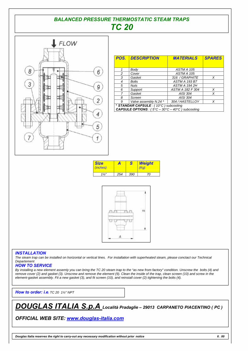
BALANCED PRESSURE THERMOSTATIC STEAM TRAPS
TC 20
POS. DESCRIPTION MATERIALS SPARES
1 Body ASTM A 1052 Cover ASTM A 1053 Gasket 316 / GRAPHITE X4 Bolts ASTM A 193 B75 Nuts ASTM A 194 2H6 Support ASTM A 182 F 304 X7 Gasket AISI 304 X8 Screen AISI 3049 Valve assembly N.24 * 304 / HASTELLOY X
* STANDAR CAPSULE : ( 10°C ) subcoolingCAPSULE OPTIONS : ( 5°C – 30°C – 40°C ) subcooling
Size(inches)
A S Weight(Kg)
1½” 254 390 70
INSTALLATIONThe steam trap can be installed on horizontal or vertical lines. For installation with superheated steam, please conctact our TechnicalDepartementHOW TO SERVICEBy installing a new element assemly you can bring the TC 20 steam trap to the “as new from factory” condition. Unscrew the bolts (4) andremove cover (2) and gasket (3). Unscrew and remove the element (9). Clean the inside of the trap, clean screen (10) and screw in theelement-gasket assembly. Fit a new gasket (3), and fit screen (10), and reinstall cover (2) tightening the bolts (4).
How to order: i.e. TC 20 1½” NPT
DOUGLAS ITALIA S.p.A Località Pradaglie – 29013 CARPANETO PIACENTINO ( PC )
OFFICIAL WEB SITE: www.douglas-italia.com
Douglas Italia reserves the right to carry-out any necessary modification without prior notice 6 . 00

ORIFICE PLATE STEAM TRAPS
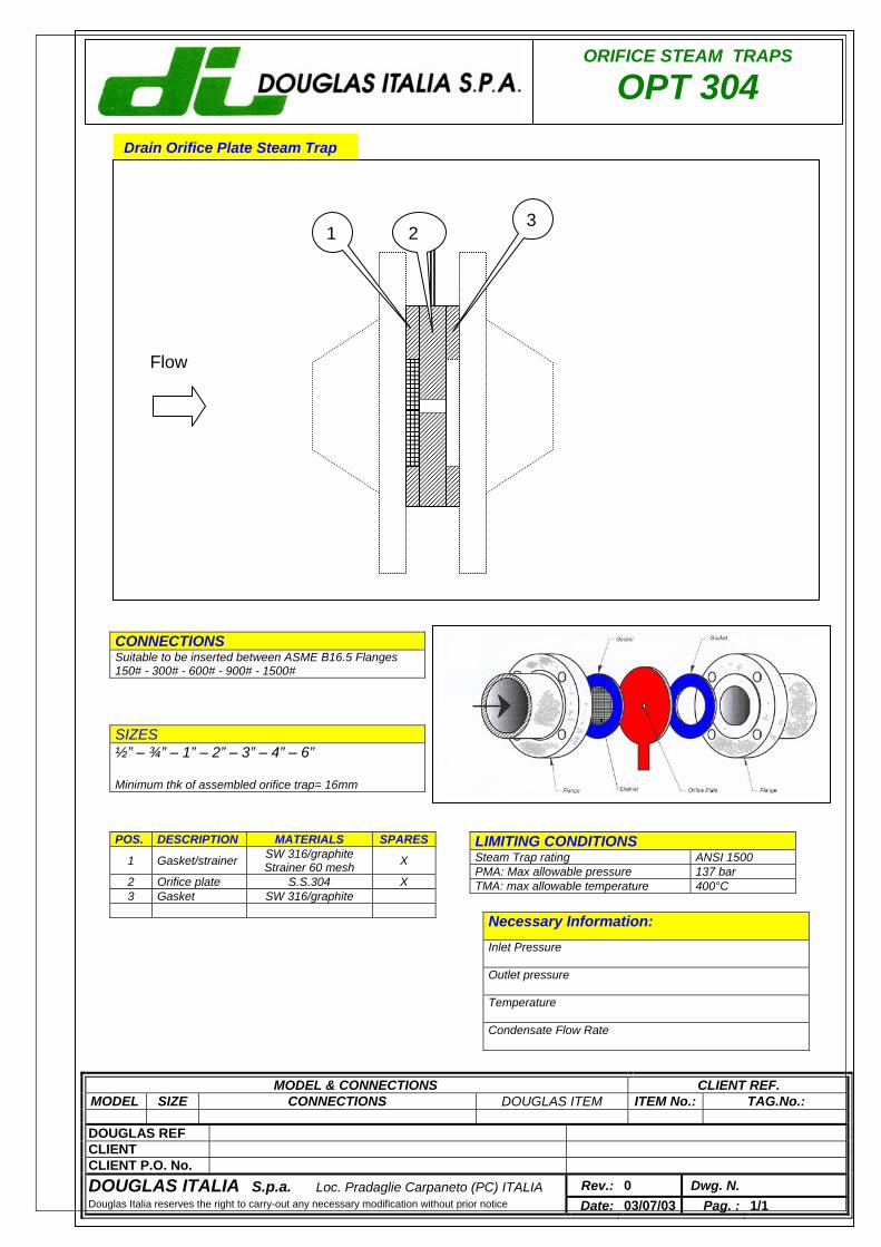
ORIFICE STEAM TRAPS
OPT 304 Drain Orifice Plate Steam Trap
LIMITING CONDITIONS Steam Trap rating ANSI 1500 PMA: Max allowable pressure 137 bar TMA: max allowable temperature 400°C
SIZES ½” – ¾” – 1” – 2” – 3” – 4” – 6” Minimum thk of assembled orifice trap= 16mm
CONNECTIONS Suitable to be inserted between ASME B16.5 Flanges 150# - 300# - 600# - 900# - 1500#
Necessary Information: Inlet Pressure
Outlet pressure
Temperature
Condensate Flow Rate
MODEL & CONNECTIONS CLIENT REF. MODEL SIZE CONNECTIONS DOUGLAS ITEM ITEM No.: TAG.No.:
DOUGLAS REF CLIENT CLIENT P.O. No. DOUGLAS ITALIA S.p.a. Loc. Pradaglie Carpaneto (PC) ITALIA Rev.: 0 Dwg. N. Douglas Italia reserves the right to carry-out any necessary modification without prior notice Date: 03/07/03 Pag. : 1/1
POS. DESCRIPTION MATERIALS SPARES
1 Gasket/strainer SW 316/graphite Strainer 60 mesh X
2 Orifice plate S.S.304 X 3 Gasket SW 316/graphite
321
Flow
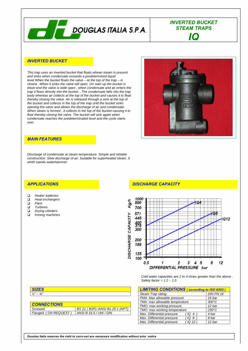
INVERTED BUCKETSTEAM TRAPS
IQ
INVERTED BUCKET
This trap uses an inverted bucket that floats whean steam is presentand sinks when condensate exceeds a predetermined liquidlevel.When the bucket floats the valve – at the top of the trap – isclosed . When it sinks the valve will open. On start up the bucket isdown end the valve is wide open , when condensate and air enters thetrap it flows directly into the bucket…The condensate falls into the trapbody whereas air collects at the top of the bucket and causes it to floatthereby closing the valve. Air is released through a vent at the top ofthe bucket and collects in the top of the trap until the bucket sinksopening the valve and allows the discharge of air and condensate.When steam is formed , it collects in the top of the bucket causing it tofloat thereby closing the valve. The bucket will sink again whencondensate reaches the predeterminated level and the cycle startsover.
MAIN FEATURES
Discharge of condensate at steam temperature. Simple and reliableconstruction. Slow discharge of air. Suitable for superheated steam. Itwhith stands waterhammer.
APPLICATIONS
q Heater batteriesq Heat exchangersq Pansq Turbinesq Drying cilindersq Ironing machines
DISCHARGE CAPACITY
LIMITING CONDITIONS ( according to ISO 6552 )Steam Trap rating DIN PN 16PMA: Max allowable pressure 16 barTMA: max allowable temperature 300°CPMO: max working pressure 12 barTMO: max working temperature 230°CMax. Differential pressure ( IQ 4 ) 4 barMax. Differential pressure ( IQ 8 ) 8 barMax. Differential pressure ( IQ 12 ) 12 bar
SIZES½” – ¾”
CONNECTIONSScrewed BS 21 ( BSP) /ANSI B1.20.1 (NPT)Flanged ( ON REQUEST ) ANSI B 16.5 / UNI / DIN
Douglas Italia reserves the right to carry-out any necessary modification without prior notice
Cold water capacities are 2 to 4 times greater than the above .Safety factor = 1.2 – 1.5
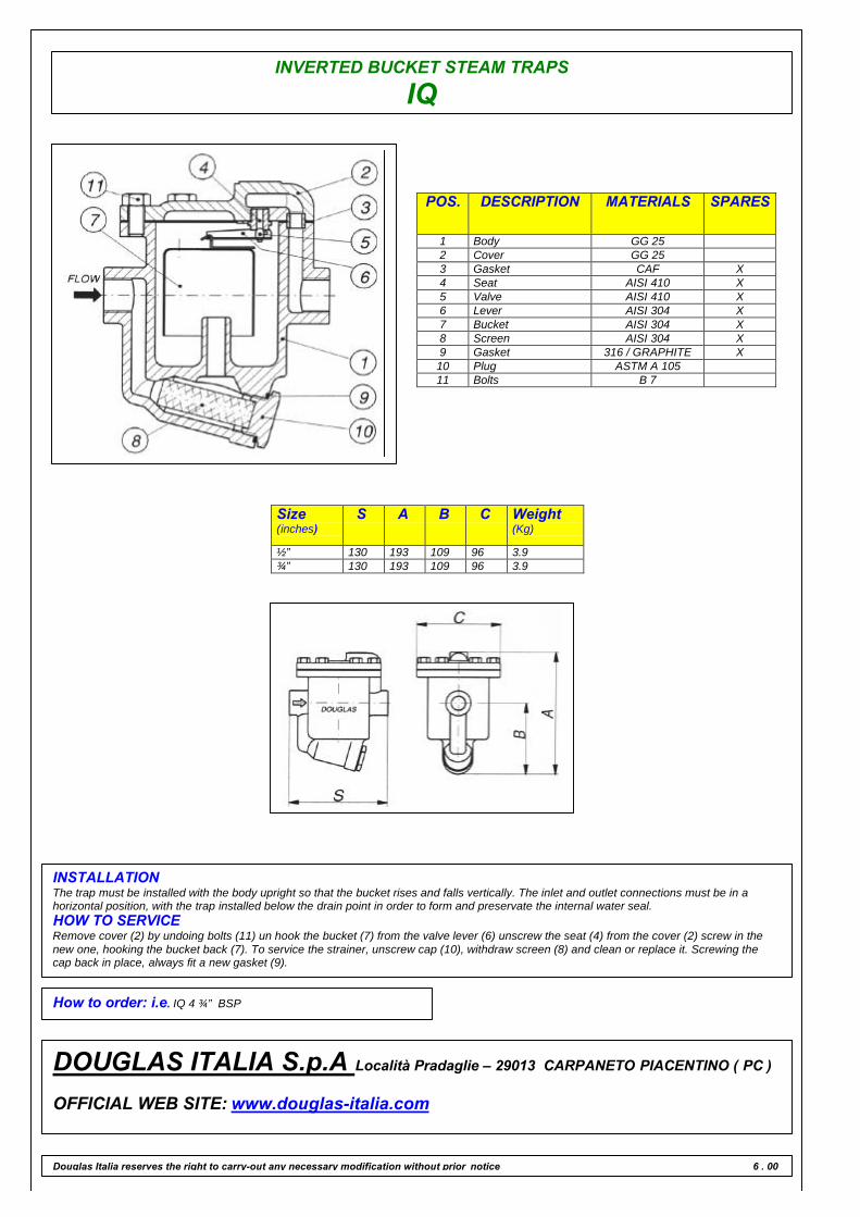
INVERTED BUCKET STEAM TRAPS
IQ
POS. DESCRIPTION MATERIALS SPARES
1 Body GG 252 Cover GG 253 Gasket CAF X4 Seat AISI 410 X5 Valve AISI 410 X6 Lever AISI 304 X7 Bucket AISI 304 X8 Screen AISI 304 X9 Gasket 316 / GRAPHITE X10 Plug ASTM A 10511 Bolts B 7
Size(inches)
S A B C Weight(Kg)
½” 130 193 109 96 3.9¾” 130 193 109 96 3.9
INSTALLATIONThe trap must be installed with the body upright so that the bucket rises and falls vertically. The inlet and outlet connections must be in ahorizontal position, with the trap installed below the drain point in order to form and preservate the internal water seal.HOW TO SERVICERemove cover (2) by undoing bolts (11) un hook the bucket (7) from the valve lever (6) unscrew the seat (4) from the cover (2) screw in thenew one, hooking the bucket back (7). To service the strainer, unscrew cap (10), withdraw screen (8) and clean or replace it. Screwing thecap back in place, always fit a new gasket (9).
How to order: i.e. IQ 4 ¾” BSP
DOUGLAS ITALIA S.p.A Località Pradaglie – 29013 CARPANETO PIACENTINO ( PC )
OFFICIAL WEB SITE: www.douglas-italia.com
Douglas Italia reserves the right to carry-out any necessary modification without prior notice 6 . 00
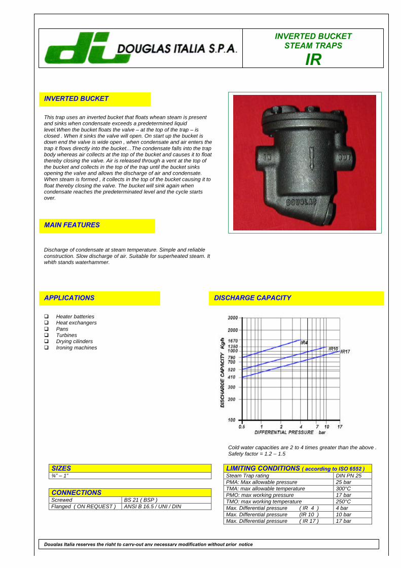
INVERTED BUCKETSTEAM TRAPS
IR
INVERTED BUCKET
This trap uses an inverted bucket that floats whean steam is presentand sinks when condensate exceeds a predetermined liquidlevel.When the bucket floats the valve – at the top of the trap – isclosed . When it sinks the valve will open. On start up the bucket isdown end the valve is wide open , when condensate and air enters thetrap it flows directly into the bucket…The condensate falls into the trapbody whereas air collects at the top of the bucket and causes it to floatthereby closing the valve. Air is released through a vent at the top ofthe bucket and collects in the top of the trap until the bucket sinksopening the valve and allows the discharge of air and condensate.When steam is formed , it collects in the top of the bucket causing it tofloat thereby closing the valve. The bucket will sink again whencondensate reaches the predeterminated level and the cycle startsover.
MAIN FEATURES
Discharge of condensate at steam temperature. Simple and reliableconstruction. Slow discharge of air. Suitable for superheated steam. Itwhith stands waterhammer.
APPLICATIONS
q Heater batteriesq Heat exchangersq Pansq Turbinesq Drying cilindersq Ironing machines
DISCHARGE CAPACITY
LIMITING CONDITIONS ( according to ISO 6552 )Steam Trap rating DIN PN 25PMA: Max allowable pressure 25 barTMA: max allowable temperature 300°CPMO: max working pressure 17 barTMO: max working temperature 250°CMax. Differential pressure ( IR 4 ) 4 barMax. Differential pressure (IR 10 ) 10 barMax. Differential pressure ( IR 17 ) 17 bar
SIZES¾” – 1”
CONNECTIONSScrewed BS 21 ( BSP )Flanged ( ON REQUEST ) ANSI B 16.5 / UNI / DIN
Douglas Italia reserves the right to carry-out any necessary modification without prior notice
Cold water capacities are 2 to 4 times greater than the above .Safety factor = 1.2 – 1.5
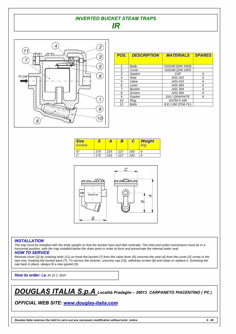
INVERTED BUCKET STEAM TRAPS
IR
POS. DESCRIPTION MATERIALS SPARES
1 Body GGG40 (DIN 1693)2 Cover GGG40 (DIN 16933 Gasket CAF X4 Seat AISI 410 X5 Valve AISI 410 X6 Lever AISI 304 X7 Bucket AISI 304 X8 Screen AISI 304 X9 Gasket 316 / GRAPHITE X10 Plug ASTM A 10511 Bolts 8.8 ( UNI 3704-74 )
Size(inches)
S A B C Weight(Kg)
¾” 175 219 127 150 91” 175 219 127 150 9
INSTALLATIONThe trap must be installed with the body upright so that the bucket rises and falls vertically. The inlet and outlet connections must be in ahorizontal position, with the trap installed below the drain point in order to form and preservate the internal water seal.HOW TO SERVICERemove cover (2) by undoing bolts (11) un hook the bucket (7) from the valve lever (6) unscrew the seat (4) from the cover (2) screw in thenew one, hooking the bucket back (7). To service the strainer, unscrew cap (10), withdraw screen (8) and clean or replace it. Screwing thecap back in place, always fit a new gasket (9).
How to order: i.e. IR 10 1” BSP
DOUGLAS ITALIA S.p.A Località Pradaglie – 29013 CARPANETO PIACENTINO ( PC )
OFFICIAL WEB SITE: www.douglas-italia.com
Douglas Italia reserves the right to carry-out any necessary modification without prior notice 6 . 00
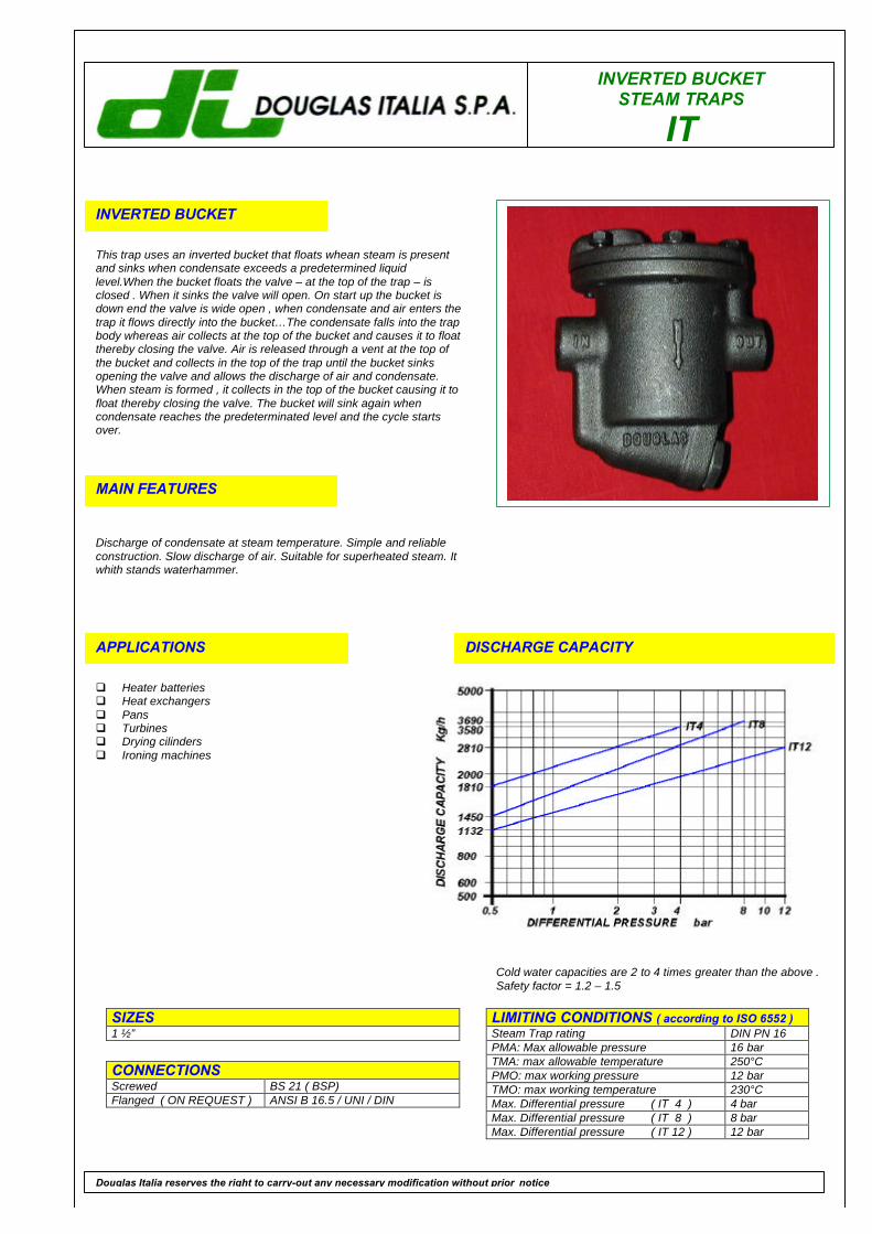
INVERTED BUCKETSTEAM TRAPS
IT
INVERTED BUCKET
This trap uses an inverted bucket that floats whean steam is presentand sinks when condensate exceeds a predetermined liquidlevel.When the bucket floats the valve – at the top of the trap – isclosed . When it sinks the valve will open. On start up the bucket isdown end the valve is wide open , when condensate and air enters thetrap it flows directly into the bucket…The condensate falls into the trapbody whereas air collects at the top of the bucket and causes it to floatthereby closing the valve. Air is released through a vent at the top ofthe bucket and collects in the top of the trap until the bucket sinksopening the valve and allows the discharge of air and condensate.When steam is formed , it collects in the top of the bucket causing it tofloat thereby closing the valve. The bucket will sink again whencondensate reaches the predeterminated level and the cycle startsover.
MAIN FEATURES
Discharge of condensate at steam temperature. Simple and reliableconstruction. Slow discharge of air. Suitable for superheated steam. Itwhith stands waterhammer.
APPLICATIONS
q Heater batteriesq Heat exchangersq Pansq Turbinesq Drying cilindersq Ironing machines
DISCHARGE CAPACITY
LIMITING CONDITIONS ( according to ISO 6552 )Steam Trap rating DIN PN 16PMA: Max allowable pressure 16 barTMA: max allowable temperature 250°CPMO: max working pressure 12 barTMO: max working temperature 230°CMax. Differential pressure ( IT 4 ) 4 barMax. Differential pressure ( IT 8 ) 8 barMax. Differential pressure ( IT 12 ) 12 bar
SIZES1 ½”
CONNECTIONSScrewed BS 21 ( BSP)Flanged ( ON REQUEST ) ANSI B 16.5 / UNI / DIN
Douglas Italia reserves the right to carry-out any necessary modification without prior notice
Cold water capacities are 2 to 4 times greater than the above .Safety factor = 1.2 – 1.5
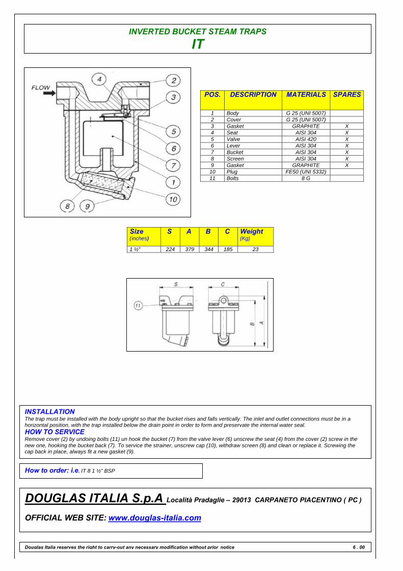
INVERTED BUCKET STEAM TRAPS
IT
POS. DESCRIPTION MATERIALS SPARES
1 Body G 25 (UNI 5007)2 Cover G 25 (UNI 5007)3 Gasket GRAPHITE X4 Seat AISI 304 X5 Valve AISI 420 X6 Lever AISI 304 X7 Bucket AISI 304 X8 Screen AISI 304 X9 Gasket GRAPHITE X10 Plug FE50 (UNI 5332)11 Bolts 8 G
Size(inches)
S A B C Weight(Kg)
1 ½” 224 379 344 185 23
INSTALLATIONThe trap must be installed with the body upright so that the bucket rises and falls vertically. The inlet and outlet connections must be in ahorizontal position, with the trap installed below the drain point in order to form and preservate the internal water seal.HOW TO SERVICERemove cover (2) by undoing bolts (11) un hook the bucket (7) from the valve lever (6) unscrew the seat (4) from the cover (2) screw in thenew one, hooking the bucket back (7). To service the strainer, unscrew cap (10), withdraw screen (8) and clean or replace it. Screwing thecap back in place, always fit a new gasket (9).
How to order: i.e. IT 8 1 ½” BSP
DOUGLAS ITALIA S.p.A Località Pradaglie – 29013 CARPANETO PIACENTINO ( PC )
OFFICIAL WEB SITE: www.douglas-italia.com
Douglas Italia reserves the right to carry-out any necessary modification without prior notice 6 . 00

INVERTED BUCKETSTEAM TRAPS
IA A105
INVERTED BUCKET
This trap uses an inverted bucket that floats whean steam is presentand sinks when condensate exceeds a predetermined liquidlevel.When the bucket floats the valve – at the top of the trap – isclosed . When it sinks the valve will open. On start up the bucket isdown end the valve is wide open , when condensate and air enters thetrap it flows directly into the bucket…The condensate falls into the trapbody whereas air collects at the top of the bucket and causes it to floatthereby closing the valve. Air is released through a vent at the top ofthe bucket and collects in the top of the trap until the bucket sinksopening the valve and allows the discharge of air and condensate.When steam is formed , it collects in the top of the bucket causing it tofloat thereby closing the valve. The bucket will sink again whencondensate reaches the predeterminated level and the cycle startsover.
MAIN FEATURES
Discharge of condensate at steam temperature. Simple and reliableconstruction. Slow discharge of air. Suitable for superheated steam. Itwhith stands waterhammer.
APPLICATIONS
q Heater batteriesq Heat exchangersq Pansq Turbinesq Drying cilindersq Ironing machines
DISCHARGE CAPACITY
LIMITING CONDITIONS ( according to ISO 6552 )Steam Trap rating ANSI 300PMA: Max allowable pressure 50 barTMA: max allowable temperature 400°CPMO: max working pressure 26 barTMO: max working temperature 380°CMax. Differential pressure ( IA 4 ) 4 barMax. Differential pressure (IA 10 ) 10 barMax. Differential pressure ( IA 17 ) 17 barMax. Differential pressure ( IA 26 ) 26 bar
SIZES½” – ¾” – 1”
CONNECTIONSScrewed BS 21 ( BSP) /ANSI B1.20.1 (NPT)Socket weld ANSI B 16.11Flanged ANSI 150#/300#/600#/UNI/DIN
Douglas Italia reserves the right to carry-out any necessary modification without prior notice
Cold water capacities are 2 to 4 times greater than the above .Safety factor = 1.2 – 1.5
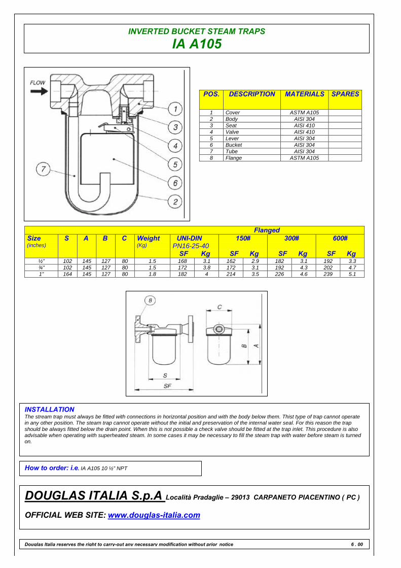
INVERTED BUCKET STEAM TRAPS
IA A105
POS. DESCRIPTION MATERIALS SPARES
1 Cover ASTM A1052 Body AISI 3043 Seat AISI 4104 Valve AISI 4105 Lever AISI 3046 Bucket AISI 3047 Tube AISI 3048 Flange ASTM A105
FlangedSize(inches)
S A B C Weight(Kg)
UNI-DINPN16-25-40
SF Kg
150#
SF Kg
300#
SF Kg
600#
SF Kg½” 102 145 127 80 1.5 168 3.1 162 2.9 182 3.1 192 3.3¾” 102 145 127 80 1.5 172 3.8 172 3.1 192 4.3 202 4.71” 164 145 127 80 1.8 182 4 214 3.5 226 4.6 239 5.1
INSTALLATIONThe stream trap must always be fitted with connections in horizontal position and with the body below them. Thist type of trap cannot operatein any other position. The steam trap cannot operate without the initial and preservation of the internal water seal. For this reason the trapshould be always fitted below the drain point. When this is not possible a check valve should be fitted at the trap inlet. This procedure is alsoadvisable when operating with superheated steam. In some cases it may be necessary to fill the steam trap with water before steam is turnedon.
How to order: i.e. IA A105 10 ½” NPT
DOUGLAS ITALIA S.p.A Località Pradaglie – 29013 CARPANETO PIACENTINO ( PC )
OFFICIAL WEB SITE: www.douglas-italia.com
Douglas Italia reserves the right to carry-out any necessary modification without prior notice 6 . 00
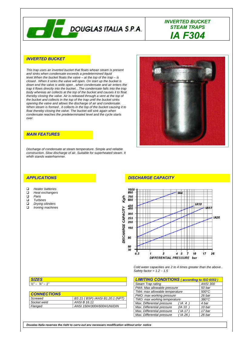
INVERTED BUCKETSTEAM TRAPS
IA F304
INVERTED BUCKET
This trap uses an inverted bucket that floats whean steam is presentand sinks when condensate exceeds a predetermined liquidlevel.When the bucket floats the valve – at the top of the trap – isclosed . When it sinks the valve will open. On start up the bucket isdown end the valve is wide open , when condensate and air enters thetrap it flows directly into the bucket…The condensate falls into the trapbody whereas air collects at the top of the bucket and causes it to floatthereby closing the valve. Air is released through a vent at the top ofthe bucket and collects in the top of the trap until the bucket sinksopening the valve and allows the discharge of air and condensate.When steam is formed , it collects in the top of the bucket causing it tofloat thereby closing the valve. The bucket will sink again whencondensate reaches the predeterminated level and the cycle startsover.
MAIN FEATURES
Discharge of condensate at steam temperature. Simple and reliableconstruction. Slow discharge of air. Suitable for superheated steam. Itwhith stands waterhammer.
APPLICATIONS
q Heater batteriesq Heat exchangersq Pansq Turbinesq Drying cilindersq Ironing machines
DISCHARGE CAPACITY
LIMITING CONDITIONS ( according to ISO 6552 )Steam Trap rating ANSI 300PMA: Max allowable pressure 50 barTMA: max allowable temperature 500°CPMO: max working pressure 26 barTMO: max working temperature 380°CMax. Differential pressure ( IA 4 ) 4 barMax. Differential pressure (IA 10 ) 10 barMax. Differential pressure ( IA 17 ) 17 barMax. Differential pressure ( IA 26 ) 26 bar
SIZES½” – ¾” – 1”
CONNECTIONSScrewed BS 21 ( BSP) /ANSI B1.20.1 (NPT)Socket weld ANSI B 16.11Flanged ANSI 150#/300#/600#/UNI/DIN
Douglas Italia reserves the right to carry-out any necessary modification without prior notice
Cold water capacities are 2 to 4 times greater than the above .Safety factor = 1.2 – 1.5
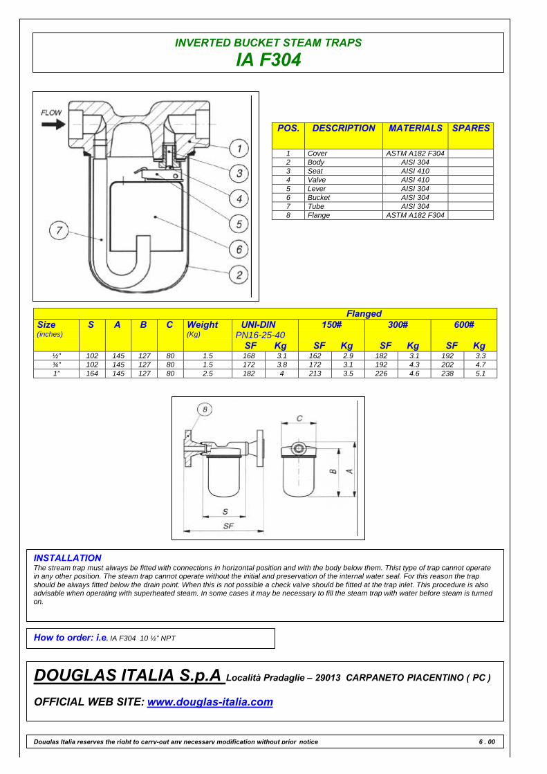
INVERTED BUCKET STEAM TRAPS
IA F304
POS. DESCRIPTION MATERIALS SPARES
1 Cover ASTM A182 F3042 Body AISI 3043 Seat AISI 4104 Valve AISI 4105 Lever AISI 3046 Bucket AISI 3047 Tube AISI 3048 Flange ASTM A182 F304
FlangedSize(inches)
S A B C Weight(Kg)
UNI-DINPN16-25-40
SF Kg
150#
SF Kg
300#
SF Kg
600#
SF Kg½” 102 145 127 80 1.5 168 3.1 162 2.9 182 3.1 192 3.3¾” 102 145 127 80 1.5 172 3.8 172 3.1 192 4.3 202 4.71” 164 145 127 80 2.5 182 4 213 3.5 226 4.6 238 5.1
INSTALLATIONThe stream trap must always be fitted with connections in horizontal position and with the body below them. Thist type of trap cannot operatein any other position. The steam trap cannot operate without the initial and preservation of the internal water seal. For this reason the trapshould be always fitted below the drain point. When this is not possible a check valve should be fitted at the trap inlet. This procedure is alsoadvisable when operating with superheated steam. In some cases it may be necessary to fill the steam trap with water before steam is turnedon.
How to order: i.e. IA F304 10 ½” NPT
DOUGLAS ITALIA S.p.A Località Pradaglie – 29013 CARPANETO PIACENTINO ( PC )
OFFICIAL WEB SITE: www.douglas-italia.com
Douglas Italia reserves the right to carry-out any necessary modification without prior notice 6 . 00
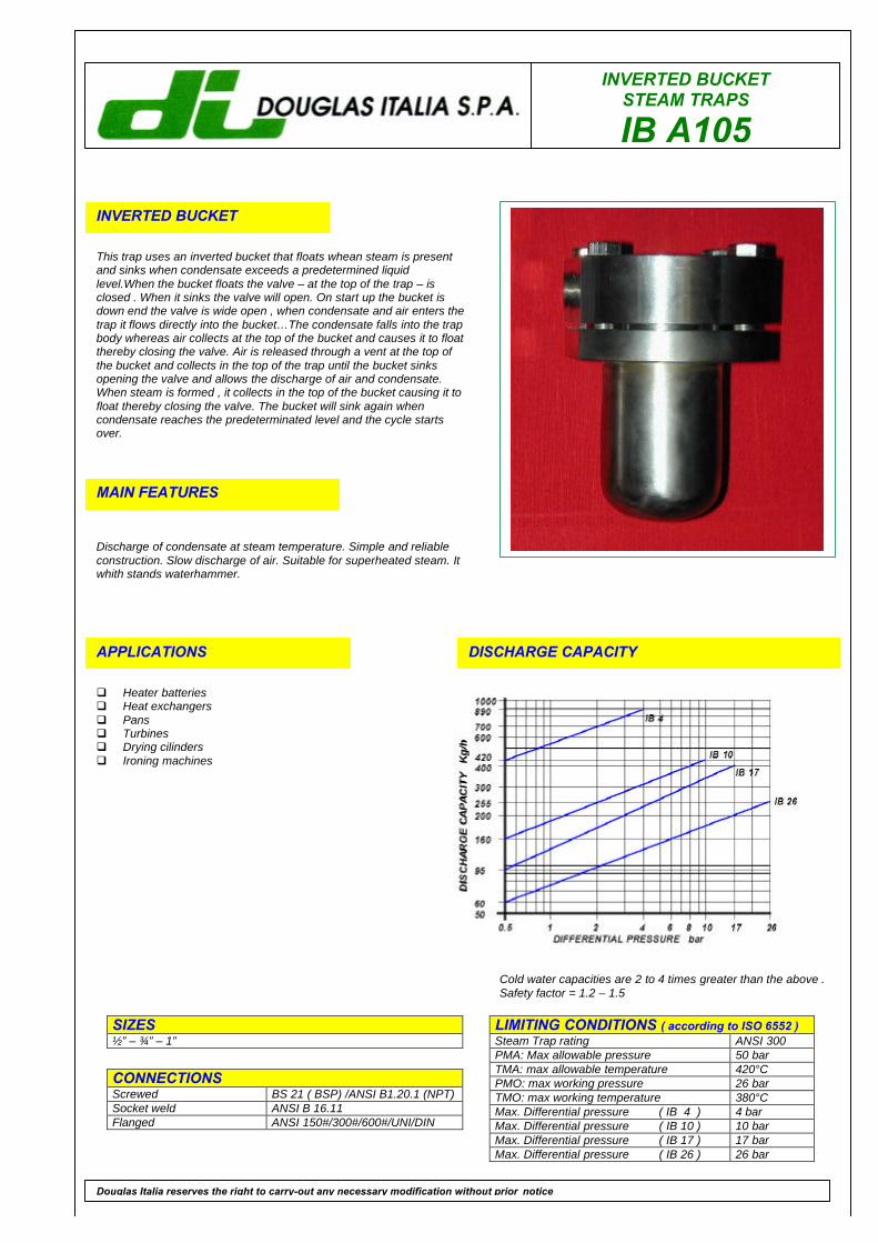
INVERTED BUCKETSTEAM TRAPS
IB A105
INVERTED BUCKET
This trap uses an inverted bucket that floats whean steam is presentand sinks when condensate exceeds a predetermined liquidlevel.When the bucket floats the valve – at the top of the trap – isclosed . When it sinks the valve will open. On start up the bucket isdown end the valve is wide open , when condensate and air enters thetrap it flows directly into the bucket…The condensate falls into the trapbody whereas air collects at the top of the bucket and causes it to floatthereby closing the valve. Air is released through a vent at the top ofthe bucket and collects in the top of the trap until the bucket sinksopening the valve and allows the discharge of air and condensate.When steam is formed , it collects in the top of the bucket causing it tofloat thereby closing the valve. The bucket will sink again whencondensate reaches the predeterminated level and the cycle startsover.
MAIN FEATURES
Discharge of condensate at steam temperature. Simple and reliableconstruction. Slow discharge of air. Suitable for superheated steam. Itwhith stands waterhammer.
APPLICATIONS
q Heater batteriesq Heat exchangersq Pansq Turbinesq Drying cilindersq Ironing machines
DISCHARGE CAPACITY
LIMITING CONDITIONS ( according to ISO 6552 )Steam Trap rating ANSI 300PMA: Max allowable pressure 50 barTMA: max allowable temperature 420°CPMO: max working pressure 26 barTMO: max working temperature 380°CMax. Differential pressure ( IB 4 ) 4 barMax. Differential pressure ( IB 10 ) 10 barMax. Differential pressure ( IB 17 ) 17 barMax. Differential pressure ( IB 26 ) 26 bar
SIZES½” – ¾” – 1”
CONNECTIONSScrewed BS 21 ( BSP) /ANSI B1.20.1 (NPT)Socket weld ANSI B 16.11Flanged ANSI 150#/300#/600#/UNI/DIN
Douglas Italia reserves the right to carry-out any necessary modification without prior notice
Cold water capacities are 2 to 4 times greater than the above .Safety factor = 1.2 – 1.5

INVERTED BUCKET STEAM TRAPS
IB A105
POS. DESCRIPTION MATERIALS SPARES
1 Cover ASTM A 1052 Body AISI 3043 Flange ASTM A 1054 Gasket CAF X5 Seat AISI 410 X6 Valve AISI 410 X7 Lever AISI 304 X8 Bucket AISI 304 X9 Tube AISI 30410 Bolts ASTM A 193 B 711 Flange ASTM A 105
FlangedSize(inches)
S A B C Weight(Kg)
UNI-DINPN16-25-40
SF Kg
150#
SF Kg
300#
SF Kg
600#
SF Kg½” 110 148 128 102 2.5 176 4.1 170 3.9 190 4.1 200 4.3¾” 110 148 128 102 2.5 180 4.8 180 4.1 200 5.3 210 5.71” 172 148 128 102 3 190 5.7 221 5.7 234 7 247 8.2
INSTALLATIONThe trap must be installed with the body upright so that the bucket rises and falls vertically. The inlet and outlet connections must be inhorizontal position, with the trap installed below the drain point in order to form and preservate the internal water seal.HOW TO SERVICERemove cover (1) by undoing bolts (10) un hook the bucket (8) from the valve lever (7) unscrew the seat (5) from the cover (1) screw in rhenew one, hooking the bucket back (8).
How to order: i.e. IB A105 26 ½” 300 RF
DOUGLAS ITALIA S.p.A Località Pradaglie – 29013 CARPANETO PIACENTINO ( PC )
OFFICIAL WEB SITE: www.douglas-italia.com
Douglas Italia reserves the right to carry-out any necessary modification without prior notice 6 . 00
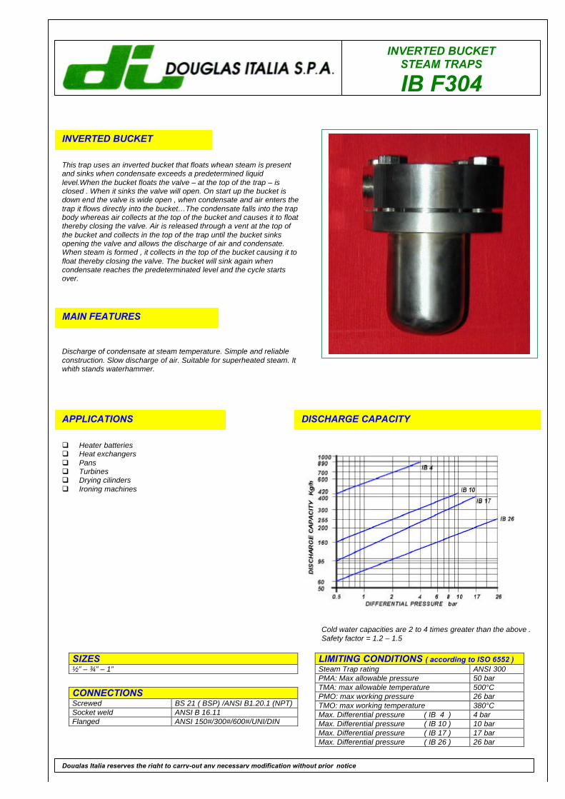
INVERTED BUCKETSTEAM TRAPS
IB F304
INVERTED BUCKET
This trap uses an inverted bucket that floats whean steam is presentand sinks when condensate exceeds a predetermined liquidlevel.When the bucket floats the valve – at the top of the trap – isclosed . When it sinks the valve will open. On start up the bucket isdown end the valve is wide open , when condensate and air enters thetrap it flows directly into the bucket…The condensate falls into the trapbody whereas air collects at the top of the bucket and causes it to floatthereby closing the valve. Air is released through a vent at the top ofthe bucket and collects in the top of the trap until the bucket sinksopening the valve and allows the discharge of air and condensate.When steam is formed , it collects in the top of the bucket causing it tofloat thereby closing the valve. The bucket will sink again whencondensate reaches the predeterminated level and the cycle startsover.
MAIN FEATURES
Discharge of condensate at steam temperature. Simple and reliableconstruction. Slow discharge of air. Suitable for superheated steam. Itwhith stands waterhammer.
APPLICATIONS
q Heater batteriesq Heat exchangersq Pansq Turbinesq Drying cilindersq Ironing machines
DISCHARGE CAPACITY
LIMITING CONDITIONS ( according to ISO 6552 )Steam Trap rating ANSI 300PMA: Max allowable pressure 50 barTMA: max allowable temperature 500°CPMO: max working pressure 26 barTMO: max working temperature 380°CMax. Differential pressure ( IB 4 ) 4 barMax. Differential pressure ( IB 10 ) 10 barMax. Differential pressure ( IB 17 ) 17 barMax. Differential pressure ( IB 26 ) 26 bar
SIZES½” – ¾” – 1”
CONNECTIONSScrewed BS 21 ( BSP) /ANSI B1.20.1 (NPT)Socket weld ANSI B 16.11Flanged ANSI 150#/300#/600#/UNI/DIN
Douglas Italia reserves the right to carry-out any necessary modification without prior notice
Cold water capacities are 2 to 4 times greater than the above .Safety factor = 1.2 – 1.5
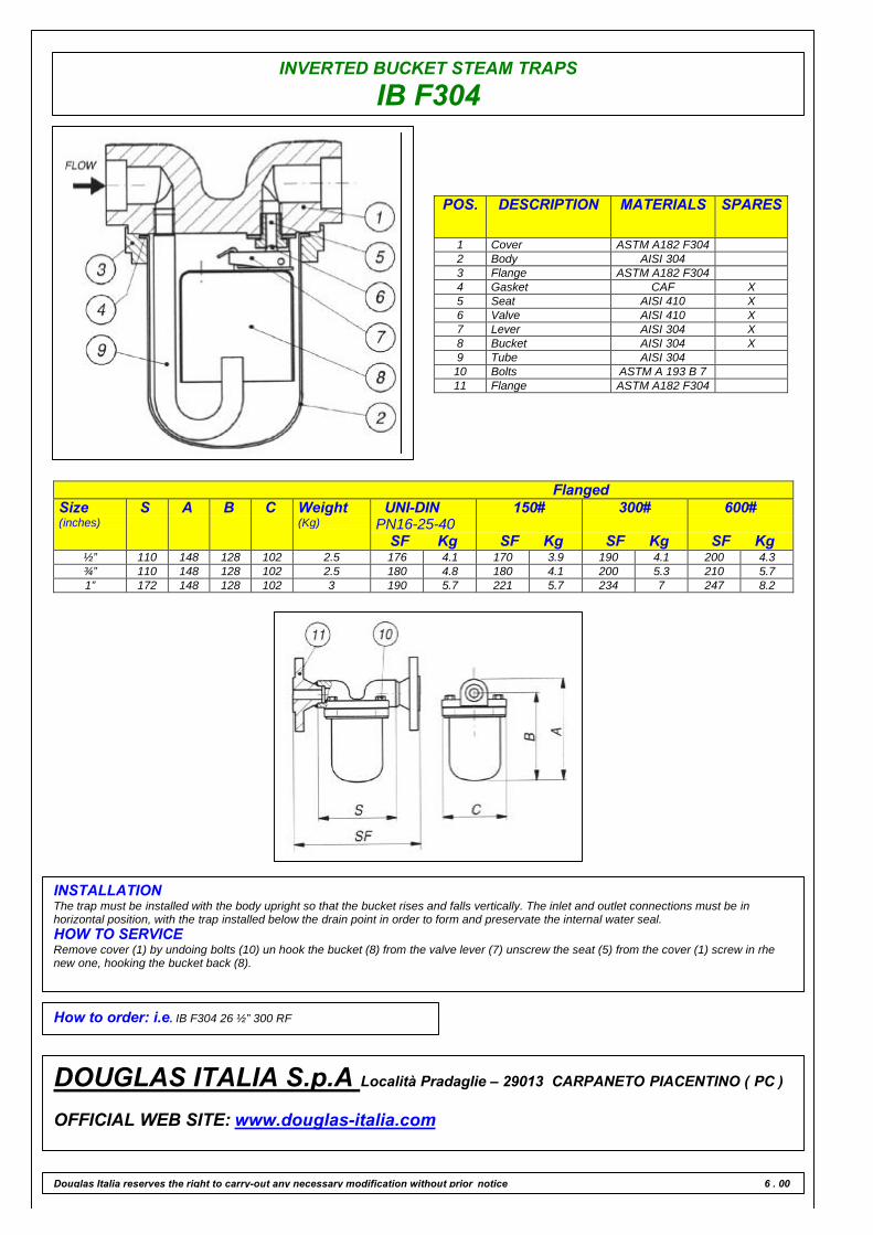
INVERTED BUCKET STEAM TRAPS
IB F304
POS. DESCRIPTION MATERIALS SPARES
1 Cover ASTM A182 F3042 Body AISI 3043 Flange ASTM A182 F3044 Gasket CAF X5 Seat AISI 410 X6 Valve AISI 410 X7 Lever AISI 304 X8 Bucket AISI 304 X9 Tube AISI 30410 Bolts ASTM A 193 B 711 Flange ASTM A182 F304
FlangedSize(inches)
S A B C Weight(Kg)
UNI-DINPN16-25-40
SF Kg
150#
SF Kg
300#
SF Kg
600#
SF Kg½” 110 148 128 102 2.5 176 4.1 170 3.9 190 4.1 200 4.3¾” 110 148 128 102 2.5 180 4.8 180 4.1 200 5.3 210 5.71” 172 148 128 102 3 190 5.7 221 5.7 234 7 247 8.2
INSTALLATIONThe trap must be installed with the body upright so that the bucket rises and falls vertically. The inlet and outlet connections must be inhorizontal position, with the trap installed below the drain point in order to form and preservate the internal water seal.HOW TO SERVICERemove cover (1) by undoing bolts (10) un hook the bucket (8) from the valve lever (7) unscrew the seat (5) from the cover (1) screw in rhenew one, hooking the bucket back (8).
How to order: i.e. IB F304 26 ½” 300 RF
DOUGLAS ITALIA S.p.A Località Pradaglie – 29013 CARPANETO PIACENTINO ( PC )
OFFICIAL WEB SITE: www.douglas-italia.com
Douglas Italia reserves the right to carry-out any necessary modification without prior notice 6 . 00
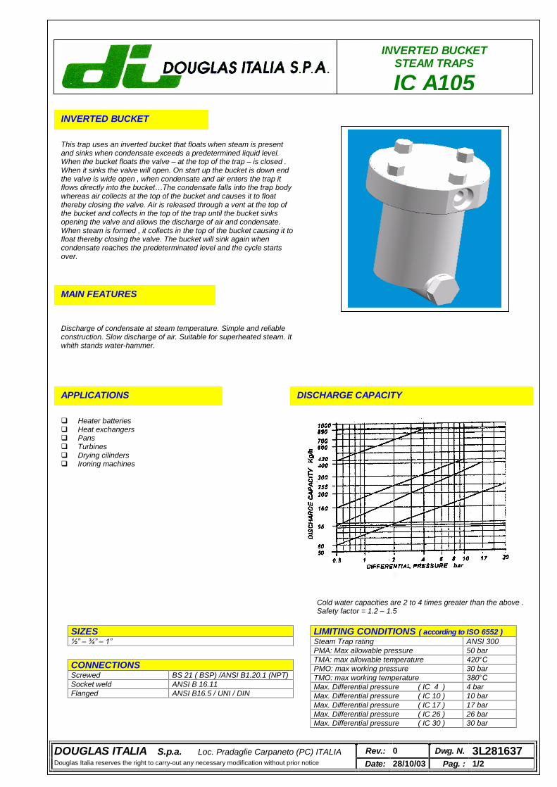
INVERTED BUCKET STEAM TRAPS
IC A105 INVERTED BUCKET
This trap uses an inverted bucket that floats when steam is present and sinks when condensate exceeds a predetermined liquid level. When the bucket floats the valve – at the top of the trap – is closed . When it sinks the valve will open. On start up the bucket is down end the valve is wide open , when condensate and air enters the trap it flows directly into the bucket…The condensate falls into the trap body whereas air collects at the top of the bucket and causes it to float thereby closing the valve. Air is released through a vent at the top of the bucket and collects in the top of the trap until the bucket sinks opening the valve and allows the discharge of air and condensate. When steam is formed , it collects in the top of the bucket causing it to float thereby closing the valve. The bucket will sink again when condensate reaches the predeterminated level and the cycle starts over.
MAIN FEATURES
Discharge of condensate at steam temperature. Simple and reliable construction. Slow discharge of air. Suitable for superheated steam. It whith stands water-hammer.
APPLICATIONS
Heater batteries Heat exchangers Pans Turbines Drying cilinders Ironing machines
DISCHARGE CAPACITY
LIMITING CONDITIONS ( according to ISO 6552 ) Steam Trap rating ANSI 300 PMA: Max allowable pressure 50 bar TMA: max allowable temperature 420°C PMO: max working pressure 30 bar TMO: max working temperature 380°C Max. Differential pressure ( IC 4 ) 4 bar Max. Differential pressure ( IC 10 ) 10 bar Max. Differential pressure ( IC 17 ) 17 bar Max. Differential pressure ( IC 26 ) 26 bar Max. Differential pressure ( IC 30 ) 30 bar
SIZES ½” – ¾” – 1”
CONNECTIONS Screwed BS 21 ( BSP) /ANSI B1.20.1 (NPT) Socket weld ANSI B 16.11 Flanged ANSI B16.5 / UNI / DIN
Cold water capacities are 2 to 4 times greater than the above . Safety factor = 1.2 – 1.5
DOUGLAS ITALIA S.p.a. Loc. Pradaglie Carpaneto (PC) ITALIA Rev.: 0 Dwg. N. 3L281637 Douglas Italia reserves the right to carry-out any necessary modification without prior notice Date: 28/10/03 Pag. : 1/2
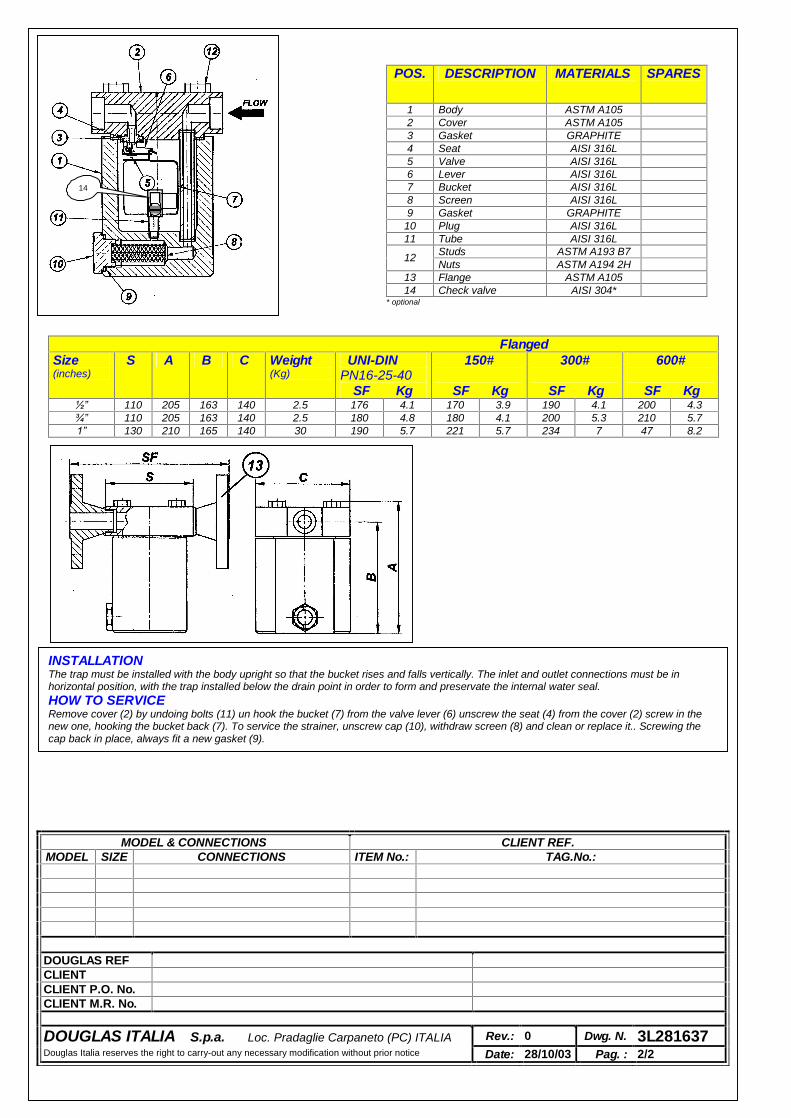
POS. DESCRIPTION MATERIALS SPARES
1 Body ASTM A105 2 Cover ASTM A105 3 Gasket GRAPHITE 4 Seat AISI 316L 5 Valve AISI 316L 6 Lever AISI 316L 7 Bucket AISI 316L 8 Screen AISI 316L 9 Gasket GRAPHITE
10 Plug AISI 316L 11 Tube AISI 316L
Studs ASTM A193 B7 12 Nuts ASTM A194 2H
13 Flange ASTM A105 14 Check valve AISI 304*
* optional
Flanged Size (inches)
S A B C Weight (Kg)
UNI-DIN PN16-25-40
SF Kg
150#
SF Kg
300#
SF Kg
600#
SF Kg ½” 110 205 163 140 2.5 176 4.1 170 3.9 190 4.1 200 4.3 ¾” 110 205 163 140 2.5 180 4.8 180 4.1 200 5.3 210 5.7 1” 130 210 165 140 30 190 5.7 221 5.7 234 7 47 8.2
INSTALLATION The trap must be installed with the body upright so that the bucket rises and falls vertically. The inlet and outlet connections must be in horizontal position, with the trap installed below the drain point in order to form and preservate the internal water seal. HOW TO SERVICE Remove cover (2) by undoing bolts (11) un hook the bucket (7) from the valve lever (6) unscrew the seat (4) from the cover (2) screw in the new one, hooking the bucket back (7). To service the strainer, unscrew cap (10), withdraw screen (8) and clean or replace it.. Screwing the cap back in place, always fit a new gasket (9).
MODEL & CONNECTIONS CLIENT REF. MODEL SIZE CONNECTIONS ITEM No.: TAG.No.:
DOUGLAS REF CLIENT CLIENT P.O. No. CLIENT M.R. No.
DOUGLAS ITALIA S.p.a. Loc. Pradaglie Carpaneto (PC) ITALIA Rev.: 0 Dwg. N. 3L281637 Douglas Italia reserves the right to carry-out any necessary modification without prior notice Date: 28/10/03 Pag. : 2/2
14
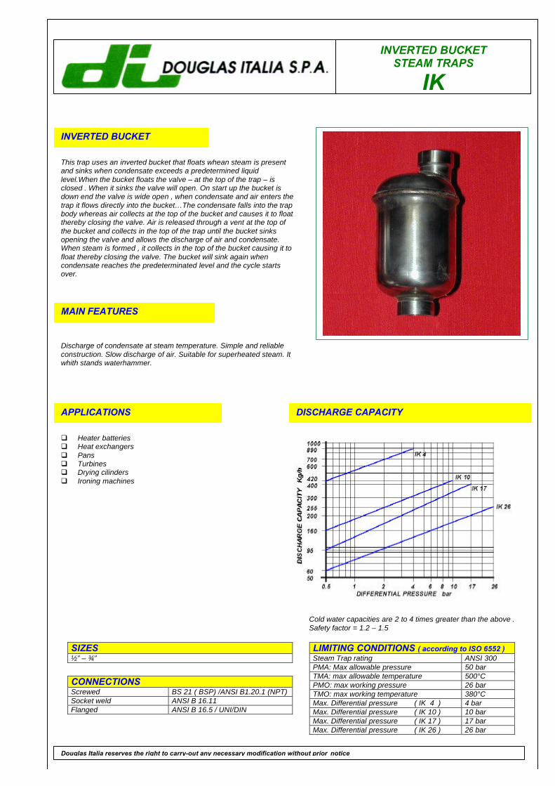
INVERTED BUCKETSTEAM TRAPS
IK
INVERTED BUCKET
This trap uses an inverted bucket that floats whean steam is presentand sinks when condensate exceeds a predetermined liquidlevel.When the bucket floats the valve – at the top of the trap – isclosed . When it sinks the valve will open. On start up the bucket isdown end the valve is wide open , when condensate and air enters thetrap it flows directly into the bucket…The condensate falls into the trapbody whereas air collects at the top of the bucket and causes it to floatthereby closing the valve. Air is released through a vent at the top ofthe bucket and collects in the top of the trap until the bucket sinksopening the valve and allows the discharge of air and condensate.When steam is formed , it collects in the top of the bucket causing it tofloat thereby closing the valve. The bucket will sink again whencondensate reaches the predeterminated level and the cycle startsover.
MAIN FEATURES
Discharge of condensate at steam temperature. Simple and reliableconstruction. Slow discharge of air. Suitable for superheated steam. Itwhith stands waterhammer.
APPLICATIONS
q Heater batteriesq Heat exchangersq Pansq Turbinesq Drying cilindersq Ironing machines
DISCHARGE CAPACITY
LIMITING CONDITIONS ( according to ISO 6552 )Steam Trap rating ANSI 300PMA: Max allowable pressure 50 barTMA: max allowable temperature 500°CPMO: max working pressure 26 barTMO: max working temperature 380°CMax. Differential pressure ( IK 4 ) 4 barMax. Differential pressure ( IK 10 ) 10 barMax. Differential pressure ( IK 17 ) 17 barMax. Differential pressure ( IK 26 ) 26 bar
SIZES½” – ¾”
CONNECTIONSScrewed BS 21 ( BSP) /ANSI B1.20.1 (NPT)Socket weld ANSI B 16.11Flanged ANSI B 16.5 / UNI/DIN
Douglas Italia reserves the right to carry-out any necessary modification without prior notice
Cold water capacities are 2 to 4 times greater than the above .Safety factor = 1.2 – 1.5
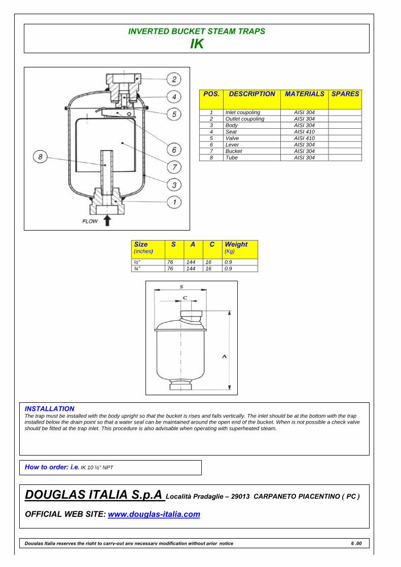
INVERTED BUCKET STEAM TRAPS
IK
POS. DESCRIPTION MATERIALS SPARES
1 Inlet coupoling AISI 3042 Outlet coupoling AISI 3043 Body AISI 3044 Seat AISI 4105 Valve AISI 4106 Lever AISI 3047 Bucket AISI 3048 Tube AISI 304
INSTALLATIONThe trap must be installed with the body upright so that the bucket is rises and falls vertically. The inlet should be at the bottom with the trapinstalled below the drain point so that a water seal can be maintained around the open end of the bucket. When is not possible a check valveshould be fitted at the trap inlet. This procedure is also advisable when operating with superheated steam.
How to order: i.e. IK 10 ½” NPT
DOUGLAS ITALIA S.p.A Località Pradaglie – 29013 CARPANETO PIACENTINO ( PC )
OFFICIAL WEB SITE: www.douglas-italia.com
Douglas Italia reserves the right to carry-out any necessary modification without prior notice 6 .00
Size(inches)
S A C Weight(Kg)
½” 76 144 16 0.9¾” 76 144 16 0.9
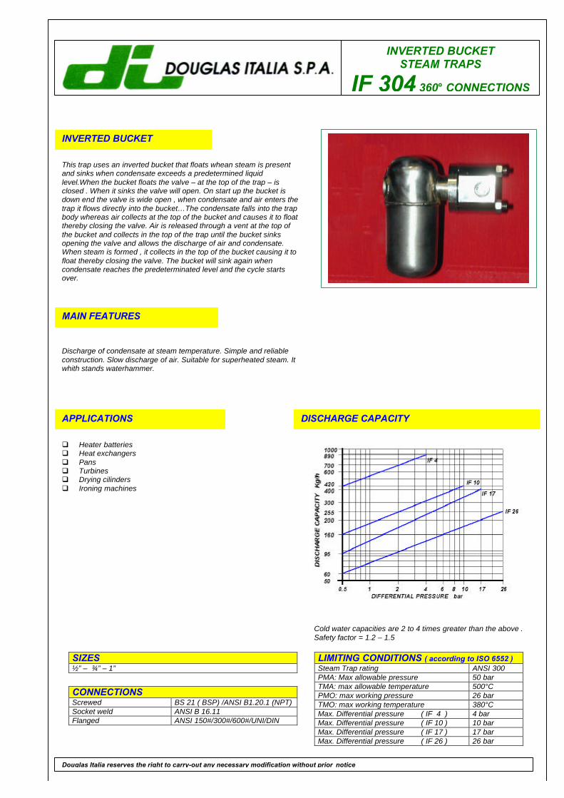
INVERTED BUCKETSTEAM TRAPS
IF 304 360° CONNECTIONS
INVERTED BUCKET
This trap uses an inverted bucket that floats whean steam is presentand sinks when condensate exceeds a predetermined liquidlevel.When the bucket floats the valve – at the top of the trap – isclosed . When it sinks the valve will open. On start up the bucket isdown end the valve is wide open , when condensate and air enters thetrap it flows directly into the bucket…The condensate falls into the trapbody whereas air collects at the top of the bucket and causes it to floatthereby closing the valve. Air is released through a vent at the top ofthe bucket and collects in the top of the trap until the bucket sinksopening the valve and allows the discharge of air and condensate.When steam is formed , it collects in the top of the bucket causing it tofloat thereby closing the valve. The bucket will sink again whencondensate reaches the predeterminated level and the cycle startsover.
MAIN FEATURES
Discharge of condensate at steam temperature. Simple and reliableconstruction. Slow discharge of air. Suitable for superheated steam. Itwhith stands waterhammer.
APPLICATIONS
q Heater batteriesq Heat exchangersq Pansq Turbinesq Drying cilindersq Ironing machines
DISCHARGE CAPACITY
LIMITING CONDITIONS ( according to ISO 6552 )Steam Trap rating ANSI 300PMA: Max allowable pressure 50 barTMA: max allowable temperature 500°CPMO: max working pressure 26 barTMO: max working temperature 380°CMax. Differential pressure ( IF 4 ) 4 barMax. Differential pressure ( IF 10 ) 10 barMax. Differential pressure ( IF 17 ) 17 barMax. Differential pressure ( IF 26 ) 26 bar
SIZES½” – ¾” – 1”
CONNECTIONSScrewed BS 21 ( BSP) /ANSI B1.20.1 (NPT)Socket weld ANSI B 16.11Flanged ANSI 150#/300#/600#/UNI/DIN
Douglas Italia reserves the right to carry-out any necessary modification without prior notice
Cold water capacities are 2 to 4 times greater than the above .Safety factor = 1.2 – 1.5
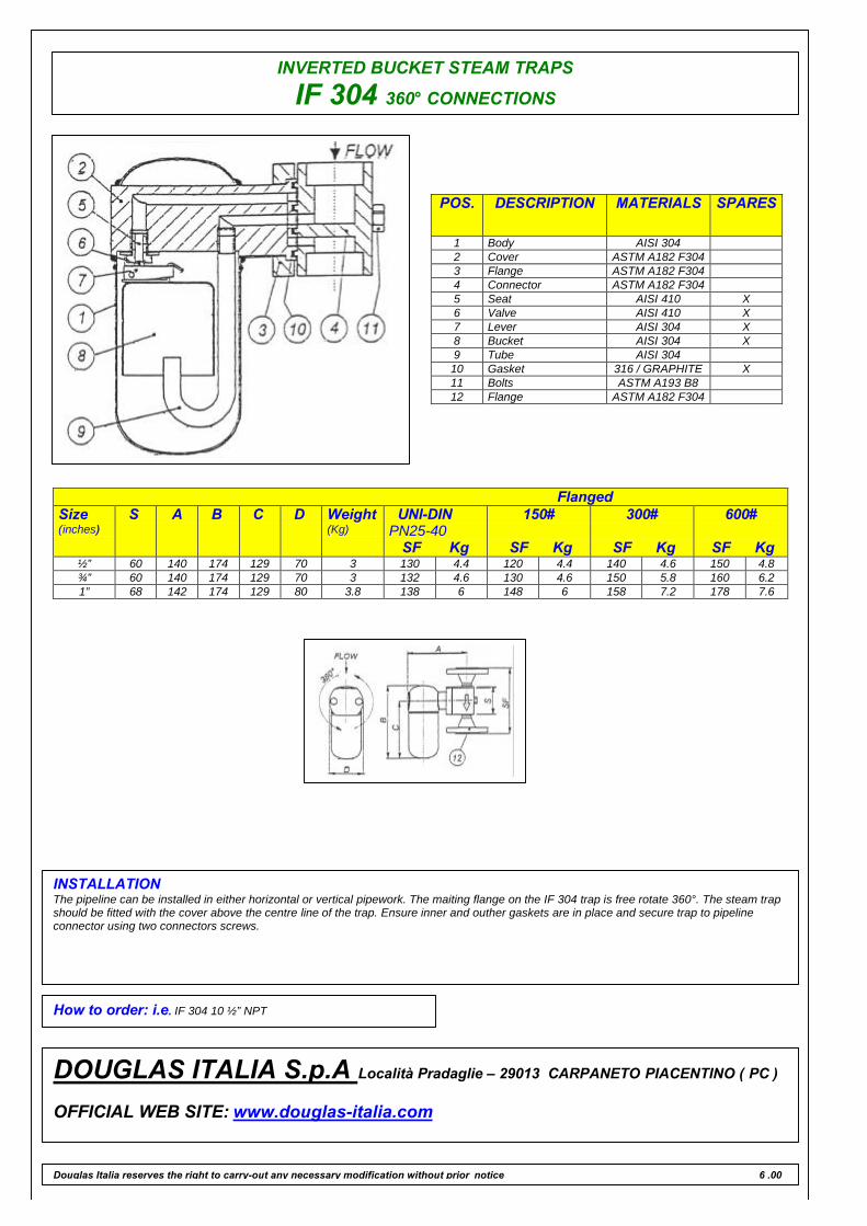
INVERTED BUCKET STEAM TRAPS
IF 304 360° CONNECTIONS
POS. DESCRIPTION MATERIALS SPARES
1 Body AISI 3042 Cover ASTM A182 F3043 Flange ASTM A182 F3044 Connector ASTM A182 F3045 Seat AISI 410 X6 Valve AISI 410 X7 Lever AISI 304 X8 Bucket AISI 304 X9 Tube AISI 30410 Gasket 316 / GRAPHITE X11 Bolts ASTM A193 B812 Flange ASTM A182 F304
FlangedSize(inches)
S A B C D Weight(Kg)
UNI-DINPN25-40
SF Kg
150#
SF Kg
300#
SF Kg
600#
SF Kg½” 60 140 174 129 70 3 130 4.4 120 4.4 140 4.6 150 4.8¾” 60 140 174 129 70 3 132 4.6 130 4.6 150 5.8 160 6.21” 68 142 174 129 80 3.8 138 6 148 6 158 7.2 178 7.6
INSTALLATIONThe pipeline can be installed in either horizontal or vertical pipework. The maiting flange on the IF 304 trap is free rotate 360°. The steam trapshould be fitted with the cover above the centre line of the trap. Ensure inner and outher gaskets are in place and secure trap to pipelineconnector using two connectors screws.
How to order: i.e. IF 304 10 ½” NPT
DOUGLAS ITALIA S.p.A Località Pradaglie – 29013 CARPANETO PIACENTINO ( PC )
OFFICIAL WEB SITE: www.douglas-italia.com
Douglas Italia reserves the right to carry-out any necessary modification without prior notice 6 .00
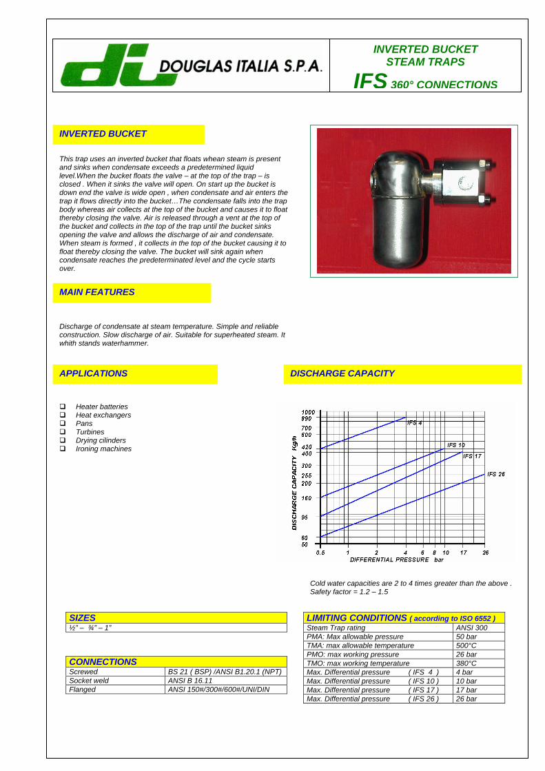
INVERTED BUCKET STEAM TRAPS
IFS 360° CONNECTIONS
INVERTED BUCKET
This trap uses an inverted bucket that floats whean steam is present and sinks when condensate exceeds a predetermined liquid level.When the bucket floats the valve – at the top of the trap – is closed . When it sinks the valve will open. On start up the bucket is down end the valve is wide open , when condensate and air enters the trap it flows directly into the bucket…The condensate falls into the trap body whereas air collects at the top of the bucket and causes it to float thereby closing the valve. Air is released through a vent at the top of the bucket and collects in the top of the trap until the bucket sinks opening the valve and allows the discharge of air and condensate. When steam is formed , it collects in the top of the bucket causing it to float thereby closing the valve. The bucket will sink again when condensate reaches the predeterminated level and the cycle starts over. MAIN FEATURES
Discharge of condensate at steam temperature. Simple and reliable construction. Slow discharge of air. Suitable for superheated steam. It whith stands waterhammer.
APPLICATIONS
Heater batteries Heat exchangers Pans Turbines Drying cilinders Ironing machines
DISCHARGE CAPACITY
LIMITING CONDITIONS ( according to ISO 6552 ) Steam Trap rating ANSI 300 PMA: Max allowable pressure 50 bar TMA: max allowable temperature 500°C PMO: max working pressure 26 bar TMO: max working temperature 380°C Max. Differential pressure ( IFS 4 ) 4 bar Max. Differential pressure ( IFS 10 ) 10 bar Max. Differential pressure ( IFS 17 ) 17 bar Max. Differential pressure ( IFS 26 ) 26 bar
SIZES ½” – ¾” – 1”
CONNECTIONS Screwed BS 21 ( BSP) /ANSI B1.20.1 (NPT) Socket weld ANSI B 16.11 Flanged ANSI 150#/300#/600#/UNI/DIN
Cold water capacities are 2 to 4 times greater than the above . Safety factor = 1.2 – 1.5
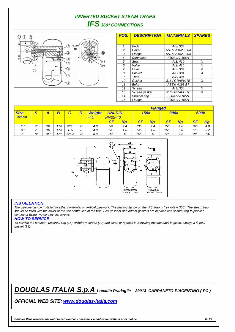
INVERTED BUCKET STEAM TRAPS
IFS 360° CONNECTIONS
POS. DESCRIPTION MATERIALS SPARES
1 Body AISI 304 2 Cover ASTM A182 F304 3 Flange ASTM A182 F304 4 Connector F304 or A105N 5 Seat AISI 410 X 6 Valve AISI 410 X 7 Lever AISI 304 X 8 Bucket AISI 304 X 9 Tube AISI 304
10 Gasket 316 / GRAPHITE X 11 Bolts ASTM A193 B7 12 Screen AISI 304 X 13 Screen gasket 316 / GRAPHITE X 14 Strainer cap F304 or A105N 15 Flange F304 or A105N
Flanged Size (inches)
S A B C D Weight(Kg)
UNI-DIN PN25-40
SF Kg
150#
SF Kg
300#
SF Kg
600#
SF Kg ½” 75 101 174 126,5 73 4,0 141 4.4 135 4.4 155 4.6 165 4.8 ¾” 75 101 174 125 73 4,0 145 4.6 145 4.6 165 5.8 175 6.2 1” 85 103 174 124,5 73 5,0 155 6 165 6 175 7.2 195 7.6
INSTALLATION The pipeline can be installed in either horizontal or vertical pipework. The maiting flange on the IFS trap is free rotate 360°. The steam trap should be fitted with the cover above the centre line of the trap. Ensure inner and outher gaskets are in place and secure trap to pipeline connector using two connectors screws. HOW TO SERVICE To service the strainer , unscrew cap (14), withdraw screen (12) and clean or replace it. Screwing the cap back in place, always a fit new gasket (13)
15
DOUGLAS ITALIA S.p.A Località Pradaglie – 29013 CARPANETO PIACENTINO ( PC ) OFFICIAL WEB SITE: www.douglas-italia.com
Douglas Italia reserves the right to carry-out any necessary modification without prior notice 6 . 00
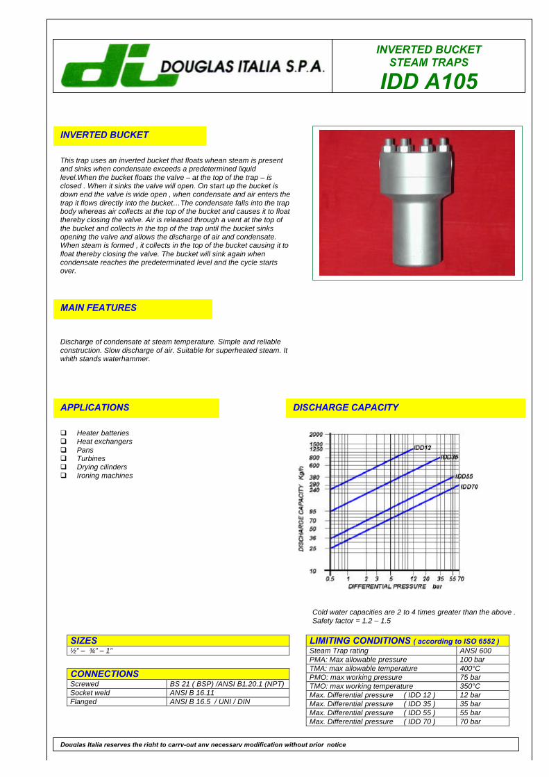
INVERTED BUCKETSTEAM TRAPS
IDD A105
INVERTED BUCKET
This trap uses an inverted bucket that floats whean steam is presentand sinks when condensate exceeds a predetermined liquidlevel.When the bucket floats the valve – at the top of the trap – isclosed . When it sinks the valve will open. On start up the bucket isdown end the valve is wide open , when condensate and air enters thetrap it flows directly into the bucket…The condensate falls into the trapbody whereas air collects at the top of the bucket and causes it to floatthereby closing the valve. Air is released through a vent at the top ofthe bucket and collects in the top of the trap until the bucket sinksopening the valve and allows the discharge of air and condensate.When steam is formed , it collects in the top of the bucket causing it tofloat thereby closing the valve. The bucket will sink again whencondensate reaches the predeterminated level and the cycle startsover.
MAIN FEATURES
Discharge of condensate at steam temperature. Simple and reliableconstruction. Slow discharge of air. Suitable for superheated steam. Itwhith stands waterhammer.
APPLICATIONS
q Heater batteriesq Heat exchangersq Pansq Turbinesq Drying cilindersq Ironing machines
DISCHARGE CAPACITY
LIMITING CONDITIONS ( according to ISO 6552 )Steam Trap rating ANSI 600PMA: Max allowable pressure 100 barTMA: max allowable temperature 400°CPMO: max working pressure 75 barTMO: max working temperature 350°CMax. Differential pressure ( IDD 12 ) 12 barMax. Differential pressure ( IDD 35 ) 35 barMax. Differential pressure ( IDD 55 ) 55 barMax. Differential pressure ( IDD 70 ) 70 bar
SIZES½” – ¾” – 1”
CONNECTIONSScrewed BS 21 ( BSP) /ANSI B1.20.1 (NPT)Socket weld ANSI B 16.11Flanged ANSI B 16.5 / UNI / DIN
Douglas Italia reserves the right to carry-out any necessary modification without prior notice
Cold water capacities are 2 to 4 times greater than the above .Safety factor = 1.2 – 1.5
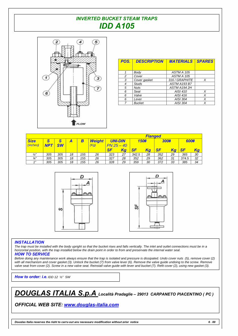
INVERTED BUCKET STEAM TRAPS
IDD A105
POS. DESCRIPTION MATERIALS SPARES
1 Body ASTM A 1052 Cover ASTM A 1053 Cover gasket 316 / GRAPHITE X4 Studs ASTM A193 B75 Nuts ASTM A194 2H6 Seat AISI 410 X6 Valve AISI 416 X6 Lever AISI 304 X7 Bucket AISI 304 X
FlangedSize(inches)
SNPT
SSW
A B Weight(Kg)
UNI-DINPN 25 – 40SF Kg
150#
SF Kg
300#
SF Kg
600#
SF Kg½” 305 305 18 155 26 323 27 342.5 28 352 29 365 30¾” 305 305 18 155 26 327 28 352 29 362 31 374.5 321” 305 305 18 155 26 328 29 359 30 372 33 385 34
INSTALLATIONThe trap must be installed with the body upright so that the bucket rises and falls vertically. The inlet and outlet connections must be in ahorizontal position, with the trap installed below the drain point in order to from and preservate the internal water seal.HOW TO SERVICEBefore doing any maintenance work always ensure that the trap is isolated and pressure is dissipated. Undo cover nuts (5), remove cover (2)with all mechanism and cover gasket (3). Unlock the bucket (7) from valve lever (6). Remove the valve guide undoing to the screw. Removevalve seat from cover (2). Screw in a new valve seat. Reinstall valve guide with lever and bucket (7). Refit cover (2), using new gasket (3).
How to order: i.e. IDD 12 ½” SW
DOUGLAS ITALIA S.p.A Località Pradaglie – 29013 CARPANETO PIACENTINO ( PC )
OFFICIAL WEB SITE: www.douglas-italia.com
Douglas Italia reserves the right to carry-out any necessary modification without prior notice 6 . 00
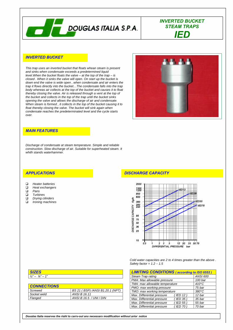
INVERTED BUCKETSTEAM TRAPS
IED
INVERTED BUCKET
This trap uses an inverted bucket that floats whean steam is presentand sinks when condensate exceeds a predetermined liquidlevel.When the bucket floats the valve – at the top of the trap – isclosed . When it sinks the valve will open. On start up the bucket isdown end the valve is wide open , when condensate and air enters thetrap it flows directly into the bucket…The condensate falls into the trapbody whereas air collects at the top of the bucket and causes it to floatthereby closing the valve. Air is released through a vent at the top ofthe bucket and collects in the top of the trap until the bucket sinksopening the valve and allows the discharge of air and condensate.When steam is formed , it collects in the top of the bucket causing it tofloat thereby closing the valve. The bucket will sink again whencondensate reaches the predeterminated level and the cycle startsover.
MAIN FEATURES
Discharge of condensate at steam temperature. Simple and reliableconstruction. Slow discharge of air. Suitable for superheated steam. Itwhith stands waterhammer.
APPLICATIONS
q Heater batteriesq Heat exchangersq Pansq Turbinesq Drying cilindersq Ironing machines
DISCHARGE CAPACITY
LIMITING CONDITIONS ( according to ISO 6552 )Steam Trap rating ANSI 600PMA: Max allowable pressure 100 barTMA: max allowable temperature 410°CPMO: max working pressure 75 barTMO: max working temperature 380°CMax. Differential pressure ( IED 12 ) 12 barMax. Differential pressure ( IED 35 ) 35 barMax. Differential pressure ( IED 55 ) 55 barMax. Differential pressure ( IED 70 ) 70 bar
SIZES½” – ¾” – 1”
CONNECTIONSScrewed BS 21 ( BSP) /ANSI B1.20.1 (NPT)Socket weld ANSI B 16.11Flanged ANSI B 16.5 / UNI / DIN
Douglas Italia reserves the right to carry-out any necessary modification without prior notice
Cold water capacities are 2 to 4 times greater than the above .Safety factor = 1.2 – 1.5
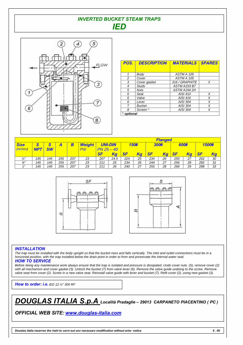
INVERTED BUCKET STEAM TRAPS
IED
POS. DESCRIPTION MATERIALS SPARES
1 Body ASTM A 1052 Cover ASTM A 1053 Cover gasket 316 / GRAPHITE X4 Studs ASTM A193 B75 Nuts ASTM A194 2H6 Seat AISI 410 X6 Valve AISI 416 X6 Lever AISI 304 X7 Bucket AISI 304 X8 Screen * AISI 304 X
* optional
FlangedSize(inches)
SNPT
SSW
A B Weight(Kg)
UNI-DINPN 25 – 40SF Kg
150#
SF Kg
300#
SF Kg
600#
SF Kg
1500#
SF Kg½” 145 145 255 207 23 207 24.5 224 25 234 26 250 27 262 30¾” 145 145 255 207 23 211 25 234 26 244 27 256 28 282 311” 145 145 255 207 23 211 26 240 27 255 28 266 29 288 33
INSTALLATIONThe trap must be installed with the body upright so that the bucket rises and falls vertically. The inlet and outlet connections must be in ahorizontal position, with the trap installed below the drain point in order to from and preservate the internal water seal.HOW TO SERVICEBefore doing any maintenance work always ensure that the trap is isolated and pressure is dissipated. Undo cover nuts (5), remove cover (2)with all mechanism and cover gasket (3). Unlock the bucket (7) from valve lever (6). Remove the valve guide undoing to the screw. Removevalve seat from cover (2). Screw in a new valve seat. Reinstall valve guide with lever and bucket (7). Refit cover (2), using new gasket (3).
How to order: i.e. IED 12 ½” 300 RF
DOUGLAS ITALIA S.p.A Località Pradaglie – 29013 CARPANETO PIACENTINO ( PC )
OFFICIAL WEB SITE: www.douglas-italia.com
Douglas Italia reserves the right to carry-out any necessary modification without prior notice 6 . 00
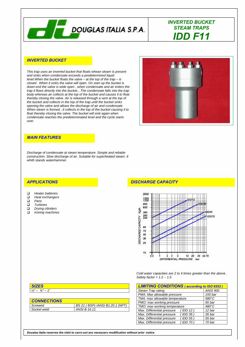
INVERTED BUCKETSTEAM TRAPS
IDD F11
INVERTED BUCKET
This trap uses an inverted bucket that floats whean steam is presentand sinks when condensate exceeds a predetermined liquidlevel.When the bucket floats the valve – at the top of the trap – isclosed . When it sinks the valve will open. On start up the bucket isdown end the valve is wide open , when condensate and air enters thetrap it flows directly into the bucket…The condensate falls into the trapbody whereas air collects at the top of the bucket and causes it to floatthereby closing the valve. Air is released through a vent at the top ofthe bucket and collects in the top of the trap until the bucket sinksopening the valve and allows the discharge of air and condensate.When steam is formed , it collects in the top of the bucket causing it tofloat thereby closing the valve. The bucket will sink again whencondensate reaches the predeterminated level and the cycle startsover.
MAIN FEATURES
Discharge of condensate at steam temperature. Simple and reliableconstruction. Slow discharge of air. Suitable for superheated steam. Itwhith stands waterhammer.
APPLICATIONS
q Heater batteriesq Heat exchangersq Pansq Turbinesq Drying cilindersq Ironing machines
DISCHARGE CAPACITY
LIMITING CONDITIONS ( according to ISO 6552 )Steam Trap rating ANSI 900PMA: Max allowable pressure 155 barTMA: max allowable temperature 580°CPMO: max working pressure 95 barTMO: max working temperature 480°CMax. Differential pressure ( IDD 12 ) 12 barMax. Differential pressure ( IDD 35 ) 35 barMax. Differential pressure ( IDD 55 ) 55 barMax. Differential pressure ( IDD 70 ) 70 bar
SIZES½” – ¾” – 1”
CONNECTIONSScrewed BS 21 ( BSP) /ANSI B1.20.1 (NPT)Socket weld ANSI B 16.11
Douglas Italia reserves the right to carry-out any necessary modification without prior notice
Cold water capacities are 2 to 4 times greater than the above .Safety factor = 1.2 – 1.5
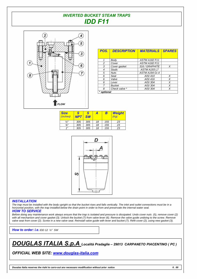
INVERTED BUCKET STEAM TRAPS
IDD F11
POS. DESCRIPTION MATERIALS SPARES
1 Body ASTM A182 F112 Cover ASTM A182 F113 Cover gasket 316 / GRAPHITE X4 Studs ASTM A193 L75 Nuts ASTM A194 Gr.46 Seat AISI 410 X6 Valve AISI 416 X6 Lever AISI 304 X7 Bucket AISI 304 X8 Check valve * AISI 304 X
* optional
Size(inches)
SNPT
SSW
A B Weight(Kg)
½” 305 305 18 155 23¾” 305 305 18 155 231” 305 305 18 155 23
INSTALLATIONThe trap must be installed with the body upright so that the bucket rises and falls vertically. The inlet and outlet connections must be in ahorizontal position, with the trap installed below the drain point in order to from and preservate the internal water seal.HOW TO SERVICEBefore doing any maintenance work always ensure that the trap is isolated and pressure is dissipated. Undo cover nuts (5), remove cover (2)with all mechanism and cover gasket (3). Unlock the bucket (7) from valve lever (6). Remove the valve guide undoing to the screw. Removevalve seat from cover (2). Screw in a new valve seat. Reinstall valve guide with lever and bucket (7). Refit cover (2), using new gasket (3).
How to order: i.e. IDD 12 ½” SW
DOUGLAS ITALIA S.p.A Località Pradaglie – 29013 CARPANETO PIACENTINO ( PC )
OFFICIAL WEB SITE: www.douglas-italia.com
Douglas Italia reserves the right to carry-out any necessary modification without prior notice 6 . 00
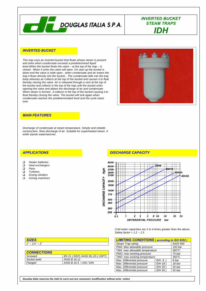
INVERTED BUCKETSTEAM TRAPS
IDH
INVERTED BUCKET
This trap uses an inverted bucket that floats whean steam is presentand sinks when condensate exceeds a predetermined liquidlevel.When the bucket floats the valve – at the top of the trap – isclosed . When it sinks the valve will open. On start up the bucket isdown end the valve is wide open , when condensate and air enters thetrap it flows directly into the bucket…The condensate falls into the trapbody whereas air collects at the top of the bucket and causes it to floatthereby closing the valve. Air is released through a vent at the top ofthe bucket and collects in the top of the trap until the bucket sinksopening the valve and allows the discharge of air and condensate.When steam is formed , it collects in the top of the bucket causing it tofloat thereby closing the valve. The bucket will sink again whencondensate reaches the predeterminated level and the cycle startsover.
MAIN FEATURES
Discharge of condensate at steam temperature. Simple and reliableconstruction. Slow discharge of air. Suitable for superheated steam. Itwhith stands waterhammer.
APPLICATIONS
q Heater batteriesq Heat exchangersq Pansq Turbinesq Drying cilindersq Ironing machines
DISCHARGE CAPACITY
LIMITING CONDITIONS ( according to ISO 6552 )Steam Trap rating ANSI 600PMA: Max allowable pressure 100 barTMA: max allowable temperature 400°CPMO: max working pressure 75 barTMO: max working temperature 350°CMax. Differential pressure ( IDH 8 ) 8 barMax. Differential pressure ( IDH 18 ) 18 barMax. Differential pressure ( IDH 35 ) 35 barMax. Differential pressure ( IDH 55 ) 55 bar
SIZES1” – 1½” – 2”
CONNECTIONSScrewed BS 21 ( BSP) /ANSI B1.20.1 (NPT)Socket weld ANSI B 16.11Flanged ANSI B 16.5 / UNI / DIN
Douglas Italia reserves the right to carry-out any necessary modification without prior notice
Cold water capacities are 2 to 4 times greater than the above .Safety factor = 1.2 – 1.5
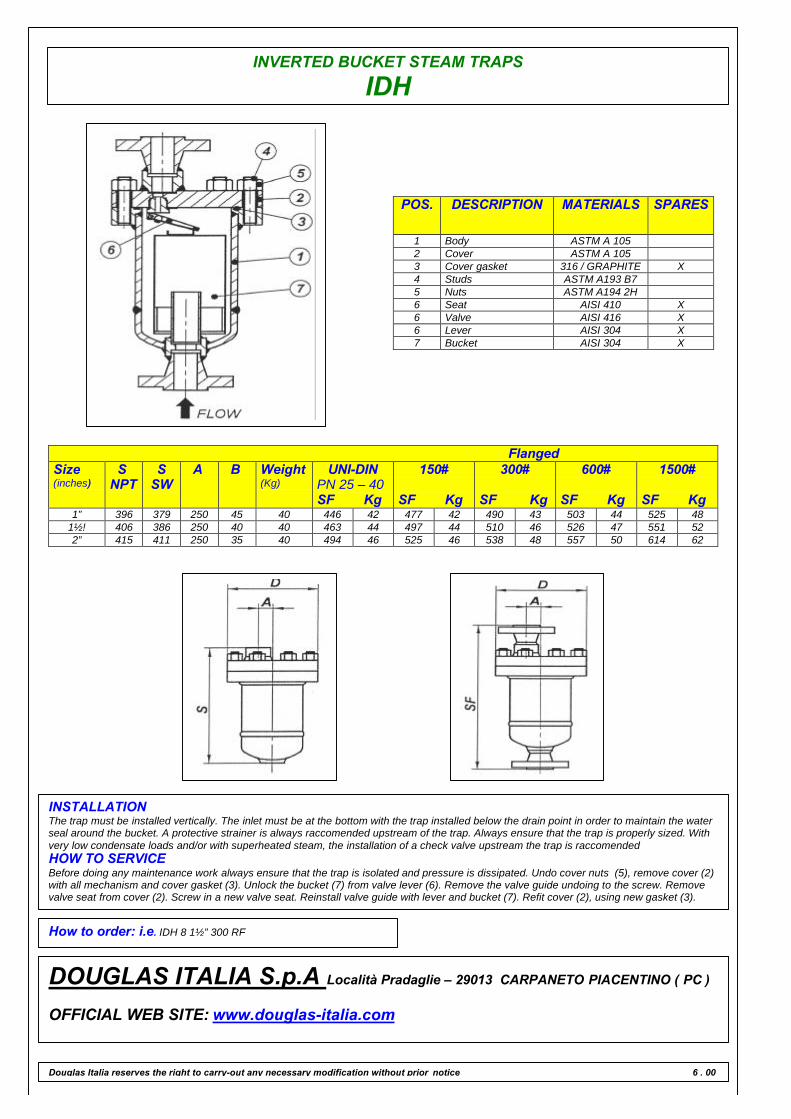
INVERTED BUCKET STEAM TRAPS
IDH
POS. DESCRIPTION MATERIALS SPARES
1 Body ASTM A 1052 Cover ASTM A 1053 Cover gasket 316 / GRAPHITE X4 Studs ASTM A193 B75 Nuts ASTM A194 2H6 Seat AISI 410 X6 Valve AISI 416 X6 Lever AISI 304 X7 Bucket AISI 304 X
FlangedSize(inches)
SNPT
SSW
A B Weight(Kg)
UNI-DINPN 25 – 40SF Kg
150#
SF Kg
300#
SF Kg
600#
SF Kg
1500#
SF Kg1” 396 379 250 45 40 446 42 477 42 490 43 503 44 525 48
1½! 406 386 250 40 40 463 44 497 44 510 46 526 47 551 522” 415 411 250 35 40 494 46 525 46 538 48 557 50 614 62
INSTALLATIONThe trap must be installed vertically. The inlet must be at the bottom with the trap installed below the drain point in order to maintain the waterseal around the bucket. A protective strainer is always raccomended upstream of the trap. Always ensure that the trap is properly sized. Withvery low condensate loads and/or with superheated steam, the installation of a check valve upstream the trap is raccomendedHOW TO SERVICEBefore doing any maintenance work always ensure that the trap is isolated and pressure is dissipated. Undo cover nuts (5), remove cover (2)with all mechanism and cover gasket (3). Unlock the bucket (7) from valve lever (6). Remove the valve guide undoing to the screw. Removevalve seat from cover (2). Screw in a new valve seat. Reinstall valve guide with lever and bucket (7). Refit cover (2), using new gasket (3).
How to order: i.e. IDH 8 1½” 300 RF
DOUGLAS ITALIA S.p.A Località Pradaglie – 29013 CARPANETO PIACENTINO ( PC )
OFFICIAL WEB SITE: www.douglas-italia.com
Douglas Italia reserves the right to carry-out any necessary modification without prior notice 6 . 00
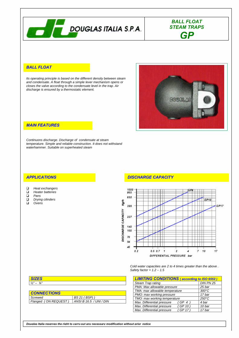
BALL FLOATSTEAM TRAPS
GP
BALL FLOAT
Its operating principle is based on the different density between steamand condensate. A float through a simple lever mechanism opens orcloses the valve according to the condensate level in the trap. Airdischarge is ensured by a thermostatic element.
MAIN FEATURES
Continuons discharge. Discharge of condensate at steamtemperature. Simple and reliable construction. It does not withstandwaterhammer. Suitable on superheated steam
APPLICATIONS
q Heat exchangersq Heater batteriesq Pansq Drying cilindersq Ovens
DISCHARGE CAPACITY
LIMITING CONDITIONS ( according to ISO 6552 )Steam Trap rating DIN PN 25PMA: Max allowable pressure 25 barTMA: max allowable temperature 300°CPMO: max working pressure 17 barTMO: max working temperature 250°CMax. Differential pressure ( GP 4 ) 4 barMax. Differential pressure ( GP 10 ) 10 barMax. Differential pressure ( GP 17 ) 17 bar
SIZES½” – ¾”
CONNECTIONSScrewed BS 21 ( BSP) )Flanged ( ON REQUEST ) ANSI B 16.5 / UNI / DIN
Douglas Italia reserves the right to carry-out any necessary modification without prior notice
Cold water capacities are 2 to 4 times greater than the above .Safety factor = 1.2 – 1.5
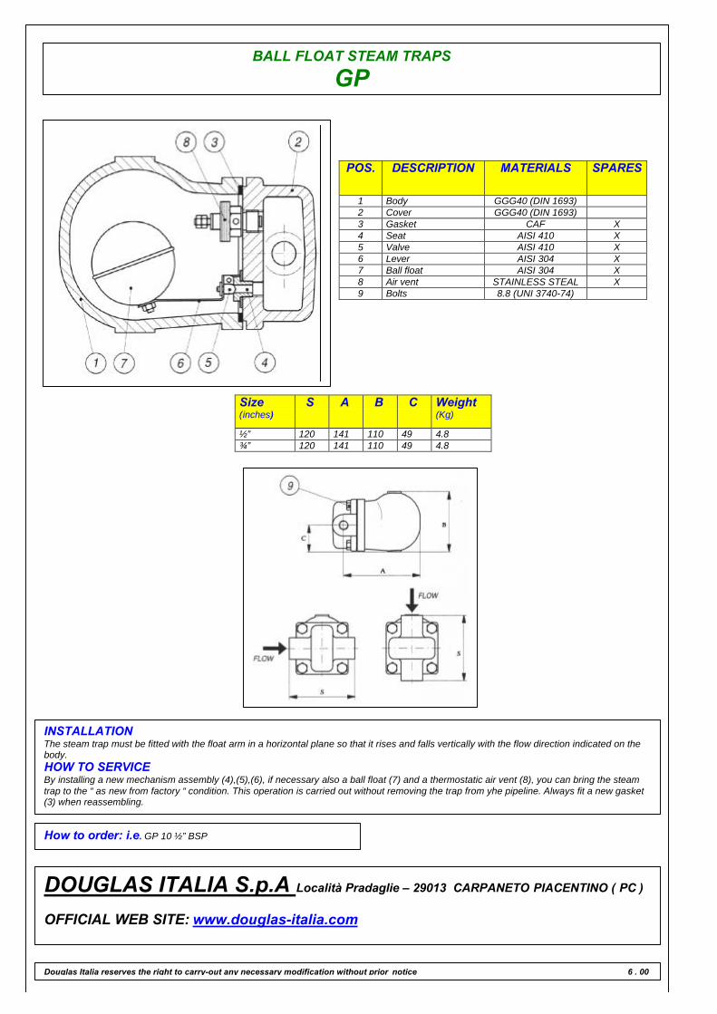
BALL FLOAT STEAM TRAPS
GP
POS. DESCRIPTION MATERIALS SPARES
1 Body GGG40 (DIN 1693)2 Cover GGG40 (DIN 1693)3 Gasket CAF X4 Seat AISI 410 X5 Valve AISI 410 X6 Lever AISI 304 X7 Ball float AISI 304 X8 Air vent STAINLESS STEAL X9 Bolts 8.8 (UNI 3740-74)
Size(inches)
S A B C Weight(Kg)
½” 120 141 110 49 4.8¾” 120 141 110 49 4.8
INSTALLATIONThe steam trap must be fitted with the float arm in a horizontal plane so that it rises and falls vertically with the flow direction indicated on thebody.HOW TO SERVICEBy installing a new mechanism assembly (4),(5),(6), if necessary also a ball float (7) and a thermostatic air vent (8), you can bring the steamtrap to the “ as new from factory “ condition. This operation is carried out without removing the trap from yhe pipeline. Always fit a new gasket(3) when reassembling.
How to order: i.e. GP 10 ½” BSP
DOUGLAS ITALIA S.p.A Località Pradaglie – 29013 CARPANETO PIACENTINO ( PC )
OFFICIAL WEB SITE: www.douglas-italia.com
Douglas Italia reserves the right to carry-out any necessary modification without prior notice 6 . 00
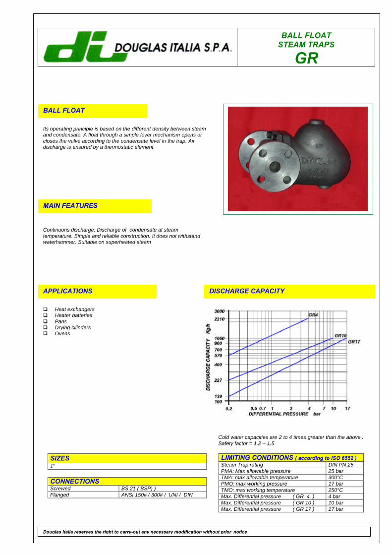
BALL FLOATSTEAM TRAPS
GR
BALL FLOAT
Its operating principle is based on the different density between steamand condensate. A float through a simple lever mechanism opens orcloses the valve according to the condensate level in the trap. Airdischarge is ensured by a thermostatic element.
MAIN FEATURES
Continuons discharge. Discharge of condensate at steamtemperature. Simple and reliable construction. It does not withstandwaterhammer. Suitable on superheated steam
APPLICATIONS
q Heat exchangersq Heater batteriesq Pansq Drying cilindersq Ovens
DISCHARGE CAPACITY
LIMITING CONDITIONS ( according to ISO 6552 )Steam Trap rating DIN PN 25PMA: Max allowable pressure 25 barTMA: max allowable temperature 300°CPMO: max working pressure 17 barTMO: max working temperature 250°CMax. Differential pressure ( GR 4 ) 4 barMax. Differential pressure ( GR 10 ) 10 barMax. Differential pressure ( GR 17 ) 17 bar
SIZES1”
CONNECTIONSScrewed BS 21 ( BSP) )Flanged ANSI 150# / 300# / UNI / DIN
Douglas Italia reserves the right to carry-out any necessary modification without prior notice
Cold water capacities are 2 to 4 times greater than the above .Safety factor = 1.2 – 1.5
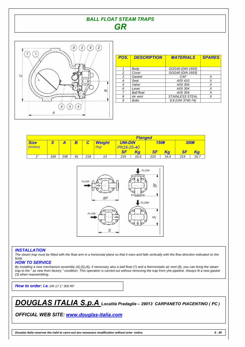
BALL FLOAT STEAM TRAPS
GR
POS. DESCRIPTION MATERIALS SPARES
1 Body GGG40 (DIN 1693)2 Cover GGG40 (DIN 1693)3 Gasket CAF X4 Seat AISI 410 X5 Valve AISI 304 X6 Lever AISI 304 X7 Ball float AISI 304 X8 Air vent STAINLESS STEAL X9 Bolts 8.8 (UNI 3740-74)
FlangedSize(inches)
S A B C Weight(Kg)
UNI-DINPN16-25-40
SF Kg
150#
SF Kg
300#
SF Kg1” 165 238 81 218 13 215 16.5 210 16.5 214 16.7
INSTALLATIONThe steam trap must be fitted with the float arm in a horizontal plane so that it rises and falls vertically with the flow direction indicated on thebody.HOW TO SERVICEBy installing a new mechanism assembly (4),(5),(6), if necessary also a ball float (7) and a thermostatic air vent (8), you can bring the steamtrap to the “ as new from factory “ condition. This operation is carried out without removing the trap from yhe pipeline. Always fit a new gasket(3) when reassembling.
How to order: i.e. GR 17 1” 300 RF
DOUGLAS ITALIA S.p.A Località Pradaglie – 29013 CARPANETO PIACENTINO ( PC )
OFFICIAL WEB SITE: www.douglas-italia.com
Douglas Italia reserves the right to carry-out any necessary modification without prior notice 6 . 00
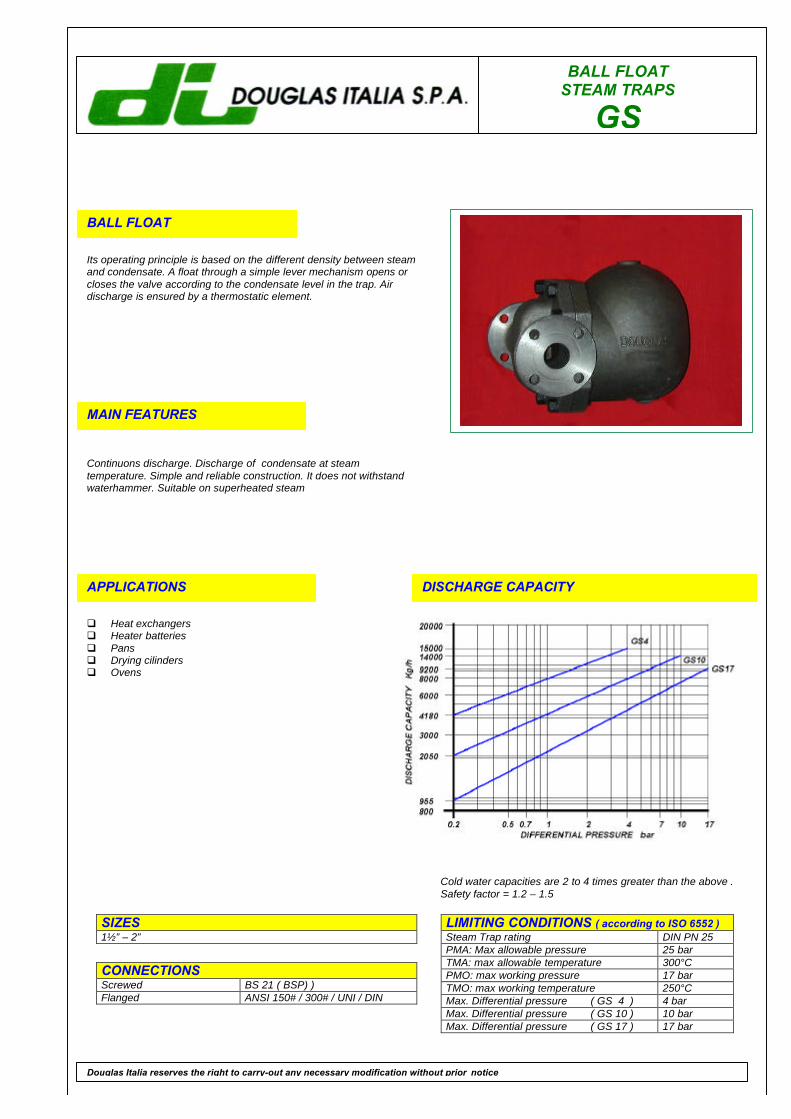
BALL FLOATSTEAM TRAPS
GS
BALL FLOAT
Its operating principle is based on the different density between steamand condensate. A float through a simple lever mechanism opens orcloses the valve according to the condensate level in the trap. Airdischarge is ensured by a thermostatic element.
MAIN FEATURES
Continuons discharge. Discharge of condensate at steamtemperature. Simple and reliable construction. It does not withstandwaterhammer. Suitable on superheated steam
APPLICATIONS
q Heat exchangersq Heater batteriesq Pansq Drying cilindersq Ovens
DISCHARGE CAPACITY
LIMITING CONDITIONS ( according to ISO 6552 )Steam Trap rating DIN PN 25PMA: Max allowable pressure 25 barTMA: max allowable temperature 300°CPMO: max working pressure 17 barTMO: max working temperature 250°CMax. Differential pressure ( GS 4 ) 4 barMax. Differential pressure ( GS 10 ) 10 barMax. Differential pressure ( GS 17 ) 17 bar
SIZES1½” – 2”
CONNECTIONSScrewed BS 21 ( BSP) )Flanged ANSI 150# / 300# / UNI / DIN
Douglas Italia reserves the right to carry-out any necessary modification without prior notice
Cold water capacities are 2 to 4 times greater than the above .Safety factor = 1.2 – 1.5
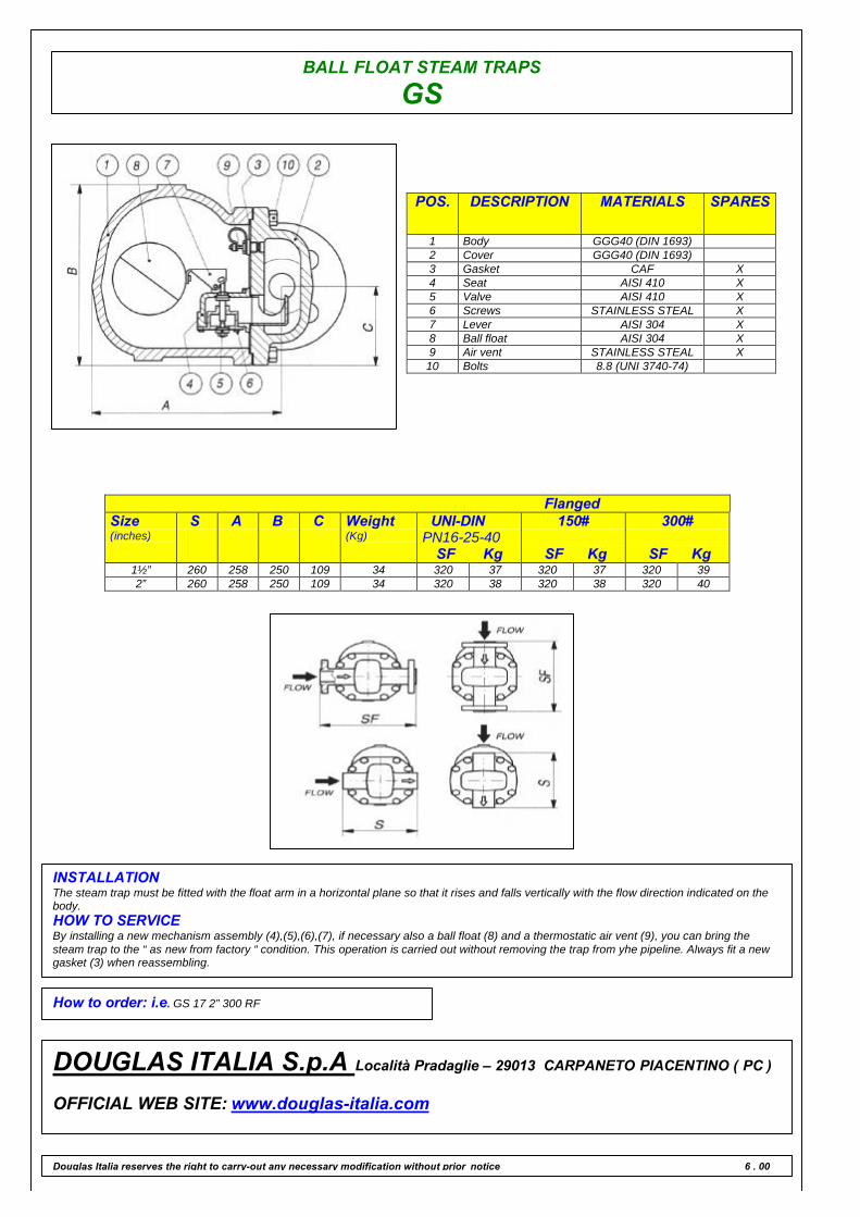
BALL FLOAT STEAM TRAPS
GS
POS. DESCRIPTION MATERIALS SPARES
1 Body GGG40 (DIN 1693)2 Cover GGG40 (DIN 1693)3 Gasket CAF X4 Seat AISI 410 X5 Valve AISI 410 X6 Screws STAINLESS STEAL X7 Lever AISI 304 X8 Ball float AISI 304 X9 Air vent STAINLESS STEAL X10 Bolts 8.8 (UNI 3740-74)
FlangedSize(inches)
S A B C Weight(Kg)
UNI-DINPN16-25-40
SF Kg
150#
SF Kg
300#
SF Kg1½” 260 258 250 109 34 320 37 320 37 320 392” 260 258 250 109 34 320 38 320 38 320 40
INSTALLATIONThe steam trap must be fitted with the float arm in a horizontal plane so that it rises and falls vertically with the flow direction indicated on thebody.HOW TO SERVICEBy installing a new mechanism assembly (4),(5),(6),(7), if necessary also a ball float (8) and a thermostatic air vent (9), you can bring thesteam trap to the “ as new from factory “ condition. This operation is carried out without removing the trap from yhe pipeline. Always fit a newgasket (3) when reassembling.
How to order: i.e. GS 17 2” 300 RF
DOUGLAS ITALIA S.p.A Località Pradaglie – 29013 CARPANETO PIACENTINO ( PC )
OFFICIAL WEB SITE: www.douglas-italia.com
Douglas Italia reserves the right to carry-out any necessary modification without prior notice 6 . 00
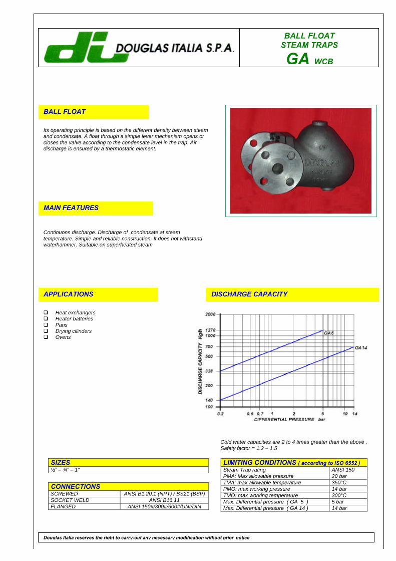
BALL FLOATSTEAM TRAPS
GA WCB
BALL FLOAT
Its operating principle is based on the different density between steamand condensate. A float through a simple lever mechanism opens orcloses the valve according to the condensate level in the trap. Airdischarge is ensured by a thermostatic element.
MAIN FEATURES
Continuons discharge. Discharge of condensate at steamtemperature. Simple and reliable construction. It does not withstandwaterhammer. Suitable on superheated steam
APPLICATIONS
q Heat exchangersq Heater batteriesq Pansq Drying cilindersq Ovens
DISCHARGE CAPACITY
LIMITING CONDITIONS ( according to ISO 6552 )Steam Trap rating ANSI 150PMA: Max allowable pressure 20 barTMA: max allowable temperature 350°CPMO: max working pressure 14 barTMO: max working temperature 300°CMax. Differential pressure ( GA 5 ) 5 barMax. Differential pressure ( GA 14 ) 14 bar
SIZES½” – ¾” – 1”
CONNECTIONSSCREWED ANSI B1.20.1 (NPT) / BS21 (BSP)SOCKET WELD ANSI B16.11FLANGED ANSI 150#/300#/600#/UNI/DIN
Douglas Italia reserves the right to carry-out any necessary modification without prior notice
Cold water capacities are 2 to 4 times greater than the above .Safety factor = 1.2 – 1.5

BALL FLOAT STEAM TRAPS
GA WCB
POS. DESCRIPTION MATERIALS SPARES
1 Body ASTM A216 WCB2 Cover ASTM A216 WCB3 Gasket 316 / GRAPHITE X4 Seat AISI 316 X5 Valve AISI 316 X6 Lever AISI 316 X7 Ball float AISI 316 X8 Air vent STAINLESS STEEL X9 Bolts ASTM A193 B7
FlangedSize(inches)
S A B C Weight(Kg)
UNI-DINPN16-25-40
SF Kg
150#
SF Kg
300#
SF Kg
600#
SF Kg½” 165 213 71 180 11 211 13.3 205 13.3 211 13.5 222 14¾” 165 213 71 180 11 215 13.7 207 13.7 211 14.6 230 151” 165 213 71 180 11 215 14.5 210 14.5 214 15.2 230 15.5
INSTALLATIONThe steam trap must be fitted with the float arm in a horizontal plane so that it rises and falls vertically with the flow direction indicated on thebody.HOW TO SERVICEBy installing a new mechanism assembly (4),(5),(6),if necessary also a ball float (7) and a thermostatic air vent (8), you can bring the steamtrap to the “ as new from factory “ condition. This operation is carried out without removing the trap from yhe pipeline. Always fit a new gasket(3) when reassembling.
How to order: i.e. GA 14 WCB 1” 150 RF
DOUGLAS ITALIA S.p.A Località Pradaglie – 29013 CARPANETO PIACENTINO ( PC )
OFFICIAL WEB SITE: www.douglas-italia.com
Douglas Italia reserves the right to carry-out any necessary modification without prior notice 6 . 00
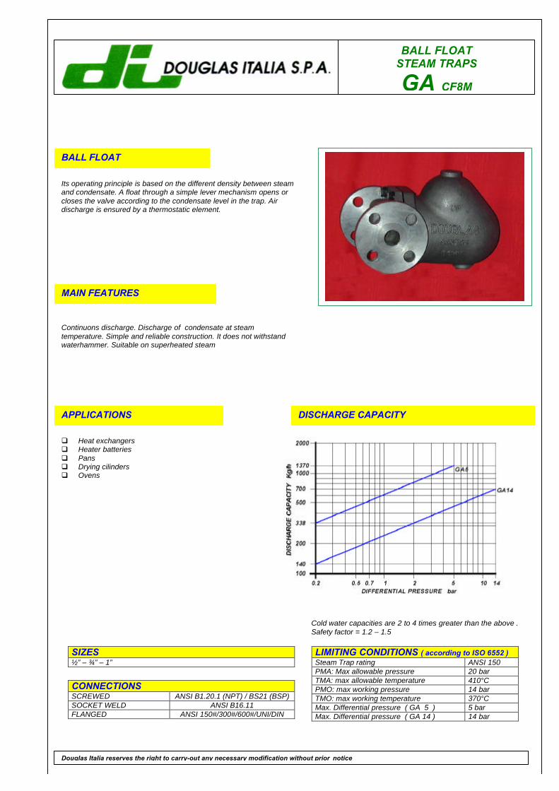
BALL FLOATSTEAM TRAPS
GA CF8M
BALL FLOAT
Its operating principle is based on the different density between steamand condensate. A float through a simple lever mechanism opens orcloses the valve according to the condensate level in the trap. Airdischarge is ensured by a thermostatic element.
MAIN FEATURES
Continuons discharge. Discharge of condensate at steamtemperature. Simple and reliable construction. It does not withstandwaterhammer. Suitable on superheated steam
APPLICATIONS
q Heat exchangersq Heater batteriesq Pansq Drying cilindersq Ovens
DISCHARGE CAPACITY
LIMITING CONDITIONS ( according to ISO 6552 )Steam Trap rating ANSI 150PMA: Max allowable pressure 20 barTMA: max allowable temperature 410°CPMO: max working pressure 14 barTMO: max working temperature 370°CMax. Differential pressure ( GA 5 ) 5 barMax. Differential pressure ( GA 14 ) 14 bar
SIZES½” – ¾” – 1”
CONNECTIONSSCREWED ANSI B1.20.1 (NPT) / BS21 (BSP)SOCKET WELD ANSI B16.11FLANGED ANSI 150#/300#/600#/UNI/DIN
Douglas Italia reserves the right to carry-out any necessary modification without prior notice
Cold water capacities are 2 to 4 times greater than the above .Safety factor = 1.2 – 1.5

BALL FLOAT STEAM TRAPS
GA CF8M
POS. DESCRIPTION MATERIALS SPARES
1 Body ASTM A315 CF8M2 Cover ASTM A315 CF8M3 Gasket 316 / GRAPHITE X4 Seat AISI 316 X5 Valve AISI 316 X6 Lever AISI 316 X7 Ball float AISI 316 X8 Air vent STAINLESS STEEL X9 Bolts ASTM A193 B8
FlangedSize(inches)
S A B C Weight(Kg)
UNI-DINPN16-25-40
SF Kg
150#
SF Kg
300#
SF Kg
600#
SF Kg½” 165 213 71 180 11 211 13.3 205 13.3 211 13.5 222 14¾” 165 213 71 180 11 215 13.7 207 13.7 211 14.6 230 151” 165 213 71 180 11 215 14.5 210 14.5 214 15.2 230 15.5
INSTALLATIONThe steam trap must be fitted with the float arm in a horizontal plane so that it rises and falls vertically with the flow direction indicated on thebody.HOW TO SERVICEBy installing a new mechanism assembly (4),(5),(6),if necessary also a ball float (7) and a thermostatic air vent (8), you can bring the steamtrap to the “ as new from factory “ condition. This operation is carried out without removing the trap from yhe pipeline. Always fit a new gasket(3) when reassembling.
How to order: i.e. GA 14 CF8M 1” 150 RF
DOUGLAS ITALIA S.p.A Località Pradaglie – 29013 CARPANETO PIACENTINO ( PC )
OFFICIAL WEB SITE: www.douglas-italia.com
Douglas Italia reserves the right to carry-out any necessary modification without prior notice 6 . 00
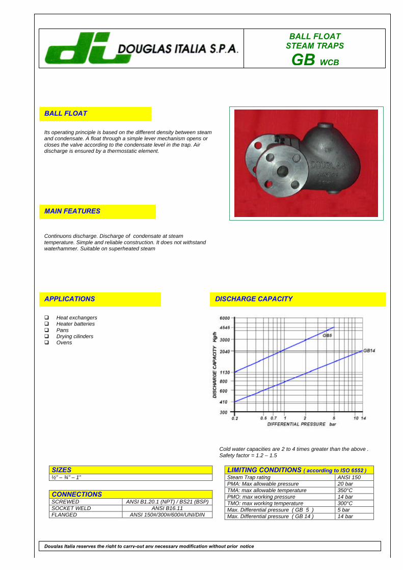
BALL FLOATSTEAM TRAPS
GB WCB
BALL FLOAT
Its operating principle is based on the different density between steamand condensate. A float through a simple lever mechanism opens orcloses the valve according to the condensate level in the trap. Airdischarge is ensured by a thermostatic element.
MAIN FEATURES
Continuons discharge. Discharge of condensate at steamtemperature. Simple and reliable construction. It does not withstandwaterhammer. Suitable on superheated steam
APPLICATIONS
q Heat exchangersq Heater batteriesq Pansq Drying cilindersq Ovens
DISCHARGE CAPACITY
LIMITING CONDITIONS ( according to ISO 6552 )Steam Trap rating ANSI 150PMA: Max allowable pressure 20 barTMA: max allowable temperature 350°CPMO: max working pressure 14 barTMO: max working temperature 300°CMax. Differential pressure ( GB 5 ) 5 barMax. Differential pressure ( GB 14 ) 14 bar
SIZES½” – ¾” – 1”
CONNECTIONSSCREWED ANSI B1.20.1 (NPT) / BS21 (BSP)SOCKET WELD ANSI B16.11FLANGED ANSI 150#/300#/600#/UNI/DIN
Douglas Italia reserves the right to carry-out any necessary modification without prior notice
Cold water capacities are 2 to 4 times greater than the above .Safety factor = 1.2 – 1.5

BALL FLOAT STEAM TRAPS
GB WCB
POS. DESCRIPTION MATERIALS SPARES
1 Body ASTM A216 WCB2 Cover ASTM A216 WCB3 Gasket 316 / GRAPHITE X4 Seat AISI 316 X5 Valve AISI 316 X6 Lever AISI 316 X7 Ball float AISI 316 X8 Air vent STAINLESS STEEL X9 Bolts ASTM A193 B7
FlangedSize(inches)
S A B C Weight(Kg)
UNI-DINPN16-25-40
SF Kg
150#
SF Kg
300#
SF Kg
600#
SF Kg½” 165 238 81 218 13 211 15.2 205 15.2 211 15.5 222 16¾” 165 238 81 218 13 215 15.3 207 15.3 211 15.5 230 16.51” 165 238 81 218 13 215 16.5 210 16.5 214 16.7 230 17.5
INSTALLATIONThe steam trap must be fitted with the float arm in a horizontal plane so that it rises and falls vertically with the flow direction indicated on thebody.HOW TO SERVICEBy installing a new mechanism assembly (4),(5),(6),if necessary also a ball float (7) and a thermostatic air vent (8), you can bring the steamtrap to the “ as new from factory “ condition. This operation is carried out without removing the trap from yhe pipeline. Always fit a new gasket(3) when reassembling.
How to order: i.e. GB 14 WCB ¾” NPT
DOUGLAS ITALIA S.p.A Località Pradaglie – 29013 CARPANETO PIACENTINO ( PC )
OFFICIAL WEB SITE: www.douglas-italia.com
Douglas Italia reserves the right to carry-out any necessary modification without prior notice 6 . 00

BALL FLOATSTEAM TRAPS
GB CF8M
BALL FLOAT
Its operating principle is based on the different density between steamand condensate. A float through a simple lever mechanism opens orcloses the valve according to the condensate level in the trap. Airdischarge is ensured by a thermostatic element.
MAIN FEATURES
Continuons discharge. Discharge of condensate at steamtemperature. Simple and reliable construction. It does not withstandwaterhammer. Suitable on superheated steam
APPLICATIONS
q Heat exchangersq Heater batteriesq Pansq Drying cilindersq Ovens
DISCHARGE CAPACITY
LIMITING CONDITIONS ( according to ISO 6552 )Steam Trap rating ANSI 150PMA: Max allowable pressure 20 barTMA: max allowable temperature 410°CPMO: max working pressure 14 barTMO: max working temperature 370°CMax. Differential pressure ( GB 5 ) 5 barMax. Differential pressure ( GB 14 ) 14 bar
SIZES½” – ¾” – 1”
CONNECTIONSSCREWED ANSI B1.20.1 (NPT) / BS21 (BSP)SOCKET WELD ANSI B16.11FLANGED ANSI 150#/300#/600#/UNI/DIN
Douglas Italia reserves the right to carry-out any necessary modification without prior notice
Cold water capacities are 2 to 4 times greater than the above .Safety factor = 1.2 – 1.5

BALL FLOAT STEAM TRAPS
GB CF8M
POS. DESCRIPTION MATERIALS SPARES
1 Body ASTM A315 CF8M2 Cover ASTM A315 CF8M3 Gasket 316 / GRAPHITE X4 Seat AISI 316 X5 Valve AISI 316 X6 Lever AISI 316 X7 Ball float AISI 316 X8 Air vent STAINLESS STEEL X9 Bolts ASTM A193 B8
FlangedSize(inches)
S A B C Weight(Kg)
UNI-DINPN16-25-40
SF Kg
150#
SF Kg
300#
SF Kg
600#
SF Kg½” 165 238 81 218 13 211 15.2 205 15.2 211 15.5 222 16¾” 165 238 81 218 13 215 15.3 207 15.3 211 15.5 230 16.51” 165 238 81 218 13 215 16.5 210 16.5 214 16.7 230 17.5
INSTALLATIONThe steam trap must be fitted with the float arm in a horizontal plane so that it rises and falls vertically with the flow direction indicated on thebody.HOW TO SERVICEBy installing a new mechanism assembly (4),(5),(6),if necessary also a ball float (7) and a thermostatic air vent (8), you can bring the steamtrap to the “ as new from factory “ condition. This operation is carried out without removing the trap from yhe pipeline. Always fit a new gasket(3) when reassembling.
How to order: i.e. GB 14 CF8M ¾” NPT
DOUGLAS ITALIA S.p.A Località Pradaglie – 29013 CARPANETO PIACENTINO ( PC )
OFFICIAL WEB SITE: www.douglas-italia.com
Douglas Italia reserves the right to carry-out any necessary modification without prior notice 6 . 00

BALL FLOATSTEAM TRAPS
GC WCB
BALL FLOAT
Its operating principle is based on the different density between steamand condensate. A float through a simple lever mechanism opens orcloses the valve according to the condensate level in the trap. Airdischarge is ensured by a thermostatic element.
MAIN FEATURES
Continuons discharge. Discharge of condensate at steamtemperature. Simple and reliable construction. It does not withstandwaterhammer. Suitable on superheated steam
APPLICATIONS
q Heat exchangersq Heater batteriesq Pansq Drying cilindersq Ovens
DISCHARGE CAPACITY
LIMITING CONDITIONS ( according to ISO 6552 )Steam Trap rating ANSI 300PMA: Max allowable pressure 50 barTMA: max allowable temperature 350°CPMO: max working pressure 40 barTMO: max working temperature 300°CMax. Differential pressure ( GC 5 ) 5 barMax. Differential pressure ( GC 14 ) 14 barMax. Differential pressure ( GC 25 ) 25 barMax. Differential pressure ( GC 40 ) 40 bar
SIZES½” – ¾” – 1”
CONNECTIONSSCREWED ANSI B1.20.1 (NPT) / BS21 (BSP)SOCKET WELD ANSI B16.11FLANGED ANSI 150#/300#/600#/UNI/DIN
Douglas Italia reserves the right to carry-out any necessary modification without prior notice
Cold water capacities are 2 to 4 times greater than the above .Safety factor = 1.2 – 1.5

BALL FLOAT STEAM TRAPS
GC WCB
POS. DESCRIPTION MATERIALS SPARES
1 Body ASTM A216 WCB2 Cover ASTM A216 WCB3 Gasket 316 / GRAPHITE X4 Seat AISI 316 X5 Valve AISI 316 X6 Lever AISI 316 X7 Ball float AISI 316 X8 Air vent STAINLESS STEEL X9 Bolts ASTM A193 B7
FlangedSize(inches)
S A B C Weight(Kg)
UNI-DINPN16-25-40
SF Kg
150#
SF Kg
300#
SF Kg
600#
SF Kg½” 165 213 71 180 11 211 13.3 205 13.3 211 13.5 222 14¾” 165 213 71 180 11 215 13.7 207 13.7 211 14.6 230 151” 165 213 71 180 11 215 14.5 210 14.5 214 15.2 230 15.5
INSTALLATIONThe steam trap must be fitted with the float arm in a horizontal plane so that it rises and falls vertically with the flow direction indicated on thebody.HOW TO SERVICEBy installing a new mechanism assembly (4),(5),(6),if necessary also a ball float (7) and a thermostatic air vent (8), you can bring the steamtrap to the “ as new from factory “ condition. This operation is carried out without removing the trap from yhe pipeline. Always fit a new gasket(3) when reassembling.
How to order: i.e. GC 25 WCB 1” 300 RF
DOUGLAS ITALIA S.p.A Località Pradaglie – 29013 CARPANETO PIACENTINO ( PC )
OFFICIAL WEB SITE: www.douglas-italia.com
Douglas Italia reserves the right to carry-out any necessary modification without prior notice 6 . 00
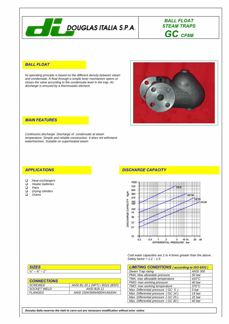
BALL FLOATSTEAM TRAPS
GC CF8M
BALL FLOAT
Its operating principle is based on the different density between steamand condensate. A float through a simple lever mechanism opens orcloses the valve according to the condensate level in the trap. Airdischarge is ensured by a thermostatic element.
MAIN FEATURES
Continuons discharge. Discharge of condensate at steamtemperature. Simple and reliable construction. It does not withstandwaterhammer. Suitable on superheated steam
APPLICATIONS
q Heat exchangersq Heater batteriesq Pansq Drying cilindersq Ovens
DISCHARGE CAPACITY
LIMITING CONDITIONS ( according to ISO 6552 )Steam Trap rating ANSI 300PMA: Max allowable pressure 50 barTMA: max allowable temperature 410°CPMO: max working pressure 40 barTMO: max working temperature 370°CMax. Differential pressure ( GC 5 ) 5 barMax. Differential pressure ( GC 14 ) 14 barMax. Differential pressure ( GC 25 ) 25 barMax. Differential pressure ( GC 40 ) 40 bar
SIZES½” – ¾” – 1”
CONNECTIONSSCREWED ANSI B1.20.1 (NPT) / BS21 (BSP)SOCKET WELD ANSI B16.11FLANGED ANSI 150#/300#/600#/UNI/DIN
Douglas Italia reserves the right to carry-out any necessary modification without prior notice
Cold water capacities are 2 to 4 times greater than the above .Safety factor = 1.2 – 1.5

BALL FLOAT STEAM TRAPS
GC CF8M
POS. DESCRIPTION MATERIALS SPARES
1 Body ASTM A351 CF8M2 Cover ASTM A351 CF8M3 Gasket 316 / GRAPHITE X4 Seat AISI 316 X5 Valve AISI 316 X6 Lever AISI 316 X7 Ball float AISI 316 X8 Air vent STAINLESS STEEL X9 Bolts ASTM A193 B8
FlangedSize(inches)
S A B C Weight(Kg)
UNI-DINPN16-25-40
SF Kg
150#
SF Kg
300#
SF Kg
600#
SF Kg½” 165 213 71 180 11 211 13.3 205 13.3 211 13.5 222 14¾” 165 213 71 180 11 215 13.7 207 13.7 211 14.6 230 151” 165 213 71 180 11 215 14.5 210 14.5 214 15.2 230 15.5
INSTALLATIONThe steam trap must be fitted with the float arm in a horizontal plane so that it rises and falls vertically with the flow direction indicated on thebody.HOW TO SERVICEBy installing a new mechanism assembly (4),(5),(6),if necessary also a ball float (7) and a thermostatic air vent (8), you can bring the steamtrap to the “ as new from factory “ condition. This operation is carried out without removing the trap from yhe pipeline. Always fit a new gasket(3) when reassembling.
How to order: i.e. GC 25 CF8M 1” 300 RF
DOUGLAS ITALIA S.p.A Località Pradaglie – 29013 CARPANETO PIACENTINO ( PC )
OFFICIAL WEB SITE: www.douglas-italia.com
Douglas Italia reserves the right to carry-out any necessary modification without prior notice 6 . 00
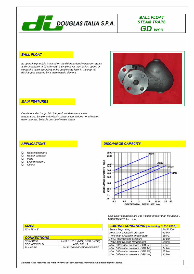
BALL FLOATSTEAM TRAPS
GD WCB
BALL FLOAT
Its operating principle is based on the different density between steamand condensate. A float through a simple lever mechanism opens orcloses the valve according to the condensate level in the trap. Airdischarge is ensured by a thermostatic element.
MAIN FEATURES
Continuons discharge. Discharge of condensate at steamtemperature. Simple and reliable construction. It does not withstandwaterhammer. Suitable on superheated steam
APPLICATIONS
q Heat exchangersq Heater batteriesq Pansq Drying cilindersq Ovens
DISCHARGE CAPACITY
LIMITING CONDITIONS ( according to ISO 6552 )Steam Trap rating ANSI 300PMA: Max allowable pressure 50 barTMA: max allowable temperature 350°CPMO: max working pressure 40 barTMO: max working temperature 300°CMax. Differential pressure ( GD 5 ) 5 barMax. Differential pressure ( GD 14 ) 14 barMax. Differential pressure ( GD 25 ) 25 barMax. Differential pressure ( GD 40 ) 40 bar
SIZES½” – ¾” – 1”
CONNECTIONSSCREWED ANSI B1.20.1 (NPT) / BS21 (BSP)SOCKET WELD ANSI B16.11FLANGED ANSI 150#/300#/600#/UNI/DIN
Douglas Italia reserves the right to carry-out any necessary modification without prior notice
Cold water capacities are 2 to 4 times greater than the above .Safety factor = 1.2 – 1.5

BALL FLOAT STEAM TRAPS
GD WCB
POS. DESCRIPTION MATERIALS SPARES
1 Body ASTM A216 WCB2 Cover ASTM A216 WCB3 Gasket 316 / GRAPHITE X4 Seat AISI 316 X5 Valve AISI 316 X6 Lever AISI 316 X7 Ball float AISI 316 X8 Air vent STAINLESS STEEL X9 Bolts ASTM A193 B7
FlangedSize(inches)
S A B C Weight(Kg)
UNI-DINPN16-25-40
SF Kg
150#
SF Kg
300#
SF Kg
600#
SF Kg½” 165 238 81 218 13 211 15.2 205 15.2 211 15.5 222 16¾” 165 238 81 218 13 215 15.3 207 15.3 211 15.5 230 16.51” 165 238 81 218 13 215 16.5 210 16.5 214 16.7 230 17.5
INSTALLATIONThe steam trap must be fitted with the float arm in a horizontal plane so that it rises and falls vertically with the flow direction indicated on thebody.HOW TO SERVICEBy installing a new mechanism assembly (4),(5),(6),if necessary also a ball float (7) and a thermostatic air vent (8), you can bring the steamtrap to the “ as new from factory “ condition. This operation is carried out without removing the trap from yhe pipeline. Always fit a new gasket(3) when reassembling.
How to order: i.e. GD 40 WCB ¾” PN 40
DOUGLAS ITALIA S.p.A Località Pradaglie – 29013 CARPANETO PIACENTINO ( PC )
OFFICIAL WEB SITE: www.douglas-italia.com
Douglas Italia reserves the right to carry-out any necessary modification without prior notice 6 . 00
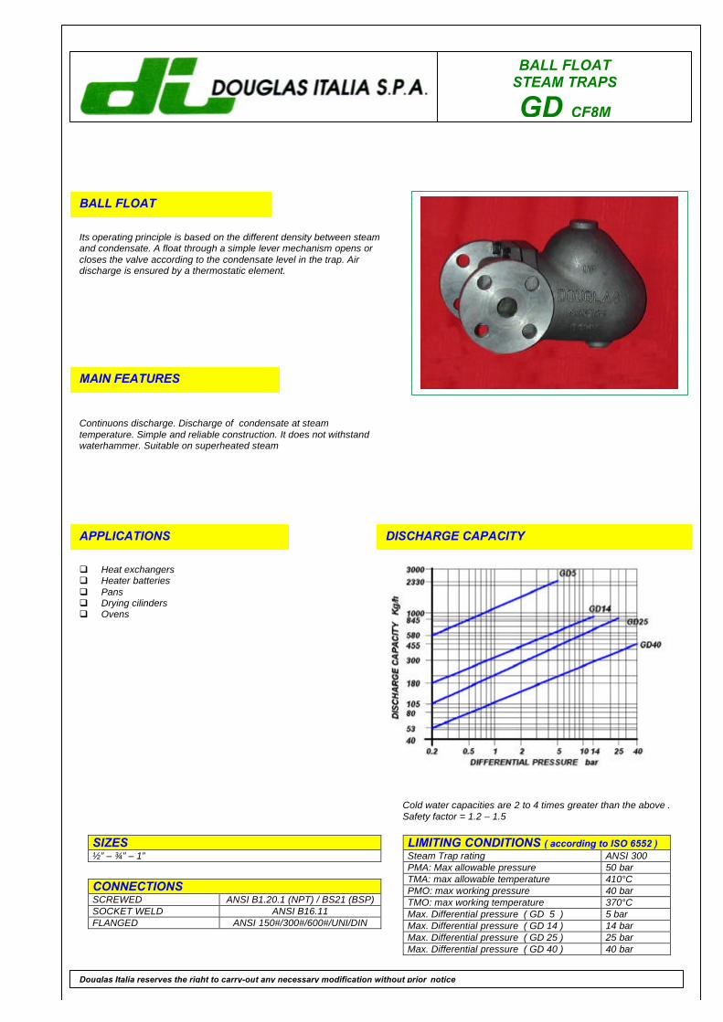
BALL FLOATSTEAM TRAPS
GD CF8M
BALL FLOAT
Its operating principle is based on the different density between steamand condensate. A float through a simple lever mechanism opens orcloses the valve according to the condensate level in the trap. Airdischarge is ensured by a thermostatic element.
MAIN FEATURES
Continuons discharge. Discharge of condensate at steamtemperature. Simple and reliable construction. It does not withstandwaterhammer. Suitable on superheated steam
APPLICATIONS
q Heat exchangersq Heater batteriesq Pansq Drying cilindersq Ovens
DISCHARGE CAPACITY
LIMITING CONDITIONS ( according to ISO 6552 )Steam Trap rating ANSI 300PMA: Max allowable pressure 50 barTMA: max allowable temperature 410°CPMO: max working pressure 40 barTMO: max working temperature 370°CMax. Differential pressure ( GD 5 ) 5 barMax. Differential pressure ( GD 14 ) 14 barMax. Differential pressure ( GD 25 ) 25 barMax. Differential pressure ( GD 40 ) 40 bar
SIZES½” – ¾” – 1”
CONNECTIONSSCREWED ANSI B1.20.1 (NPT) / BS21 (BSP)SOCKET WELD ANSI B16.11FLANGED ANSI 150#/300#/600#/UNI/DIN
Douglas Italia reserves the right to carry-out any necessary modification without prior notice
Cold water capacities are 2 to 4 times greater than the above .Safety factor = 1.2 – 1.5
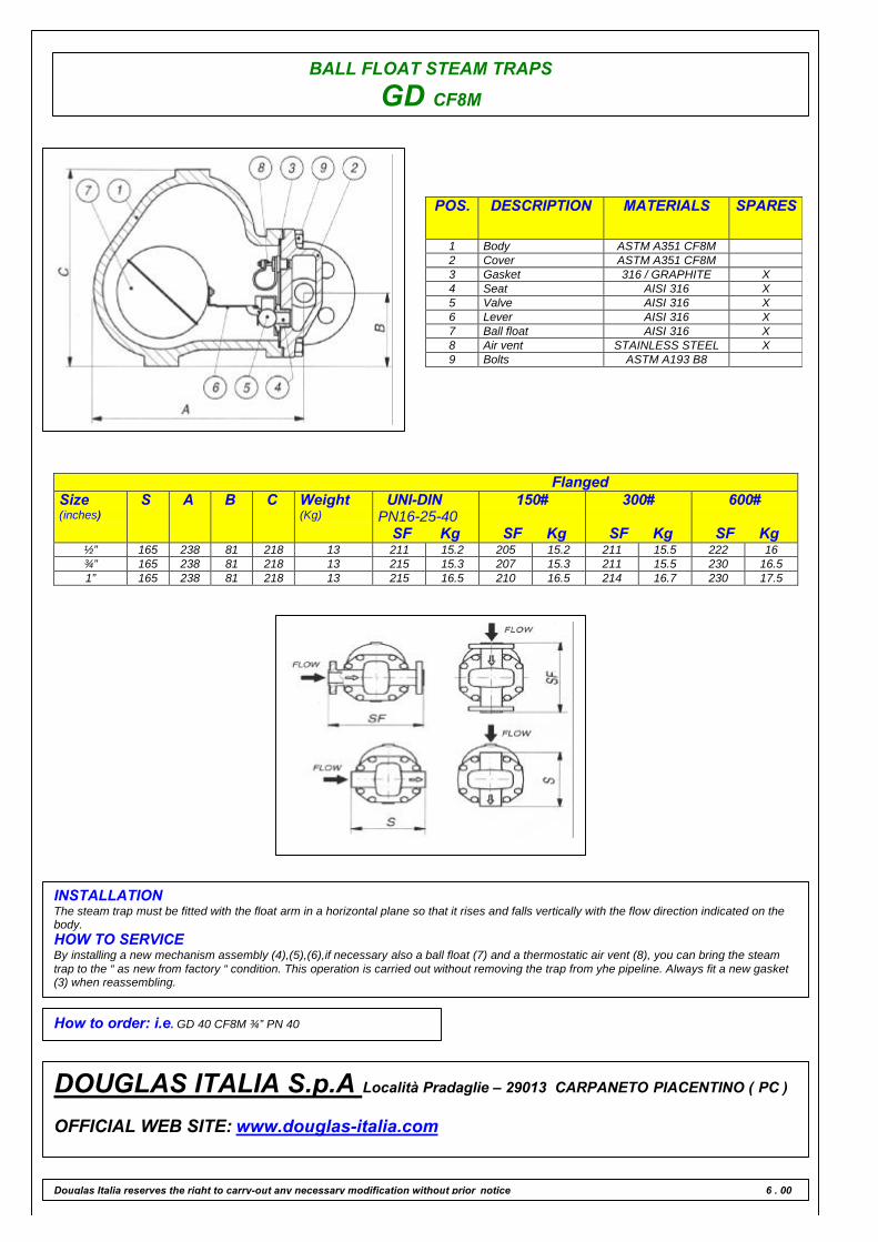
BALL FLOAT STEAM TRAPS
GD CF8M
POS. DESCRIPTION MATERIALS SPARES
1 Body ASTM A351 CF8M2 Cover ASTM A351 CF8M3 Gasket 316 / GRAPHITE X4 Seat AISI 316 X5 Valve AISI 316 X6 Lever AISI 316 X7 Ball float AISI 316 X8 Air vent STAINLESS STEEL X9 Bolts ASTM A193 B8
FlangedSize(inches)
S A B C Weight(Kg)
UNI-DINPN16-25-40
SF Kg
150#
SF Kg
300#
SF Kg
600#
SF Kg½” 165 238 81 218 13 211 15.2 205 15.2 211 15.5 222 16¾” 165 238 81 218 13 215 15.3 207 15.3 211 15.5 230 16.51” 165 238 81 218 13 215 16.5 210 16.5 214 16.7 230 17.5
INSTALLATIONThe steam trap must be fitted with the float arm in a horizontal plane so that it rises and falls vertically with the flow direction indicated on thebody.HOW TO SERVICEBy installing a new mechanism assembly (4),(5),(6),if necessary also a ball float (7) and a thermostatic air vent (8), you can bring the steamtrap to the “ as new from factory “ condition. This operation is carried out without removing the trap from yhe pipeline. Always fit a new gasket(3) when reassembling.
How to order: i.e. GD 40 CF8M ¾” PN 40
DOUGLAS ITALIA S.p.A Località Pradaglie – 29013 CARPANETO PIACENTINO ( PC )
OFFICIAL WEB SITE: www.douglas-italia.com
Douglas Italia reserves the right to carry-out any necessary modification without prior notice 6 . 00
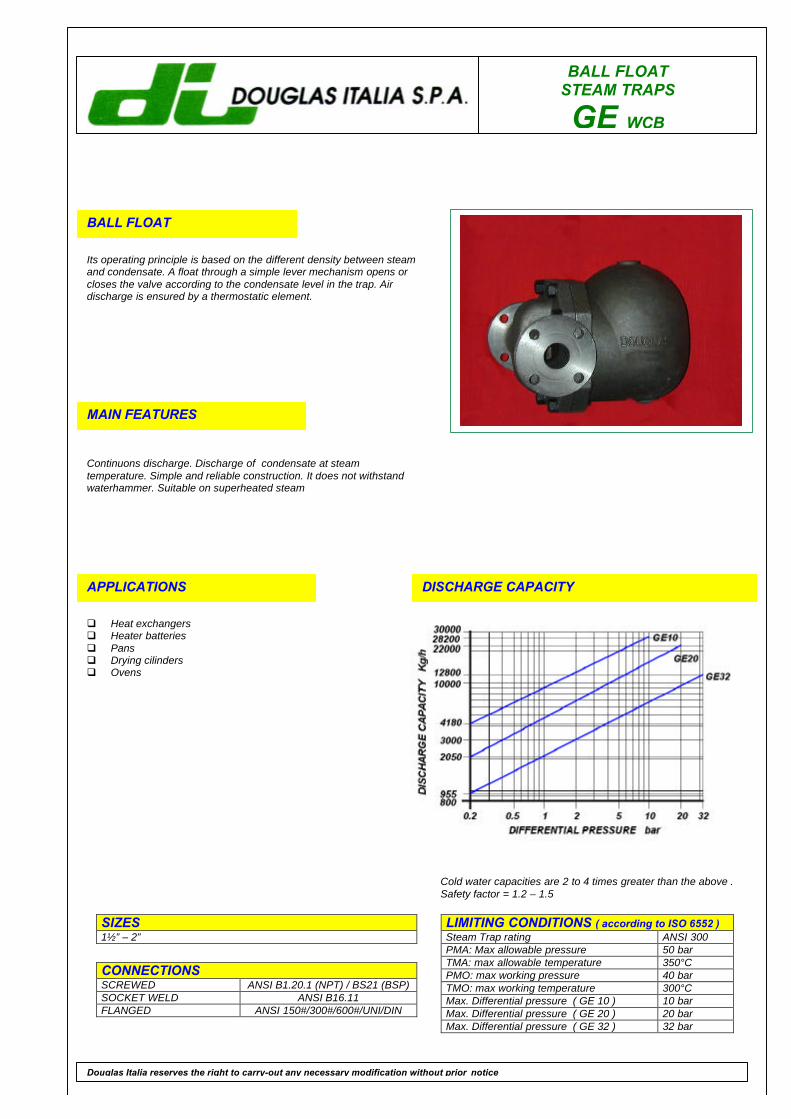
BALL FLOATSTEAM TRAPS
GE WCB
BALL FLOAT
Its operating principle is based on the different density between steamand condensate. A float through a simple lever mechanism opens orcloses the valve according to the condensate level in the trap. Airdischarge is ensured by a thermostatic element.
MAIN FEATURES
Continuons discharge. Discharge of condensate at steamtemperature. Simple and reliable construction. It does not withstandwaterhammer. Suitable on superheated steam
APPLICATIONS
q Heat exchangersq Heater batteriesq Pansq Drying cilindersq Ovens
DISCHARGE CAPACITY
LIMITING CONDITIONS ( according to ISO 6552 )Steam Trap rating ANSI 300PMA: Max allowable pressure 50 barTMA: max allowable temperature 350°CPMO: max working pressure 40 barTMO: max working temperature 300°CMax. Differential pressure ( GE 10 ) 10 barMax. Differential pressure ( GE 20 ) 20 barMax. Differential pressure ( GE 32 ) 32 bar
SIZES1½” – 2”
CONNECTIONSSCREWED ANSI B1.20.1 (NPT) / BS21 (BSP)SOCKET WELD ANSI B16.11FLANGED ANSI 150#/300#/600#/UNI/DIN
Douglas Italia reserves the right to carry-out any necessary modification without prior notice
Cold water capacities are 2 to 4 times greater than the above .Safety factor = 1.2 – 1.5

BALL FLOAT STEAM TRAPS
GE WCB
POS. DESCRIPTION MATERIALS SPARES
1 Body ASTM A216 WCB2 Cover ASTM A216 WCB3 Gasket 316 / GRAPHITE X4 Seat AISI 316 X5 Valve AISI 316 X6 Screws STAINLESS STEEL X7 Lever AISI 316 X8 Ball float AISI 316 X9 Air vent STAINLESS STEEL10 Bolts ASTM A193 B7
FlangedSize(inches)
S A B C Weight(Kg)
UNI-DINPN16-25-40
SF Kg
150#
SF Kg
300#
SF Kg
600#
SF Kg1½” 260 258 250 109 34 320 37 320 37 320 39 320 41”2” 260 258 250 109 34 320 38 320 38 320 40 320 42
INSTALLATIONThe steam trap must be fitted with the float arm in a horizontal plane so that it rises and falls vertically with the flow direction indicated on thebody.HOW TO SERVICEBy installing a new mechanism assembly (4),(5),(6),(7), if necessary also a ball float (8) and a thermostatic air vent (9), you can bring thesteam trap to the “ as new from factory “ condition. This operation is carried out without removing the trap from yhe pipeline. Always fit a newgasket (3) when reassembling.
How to order: i.e. GE 20 WCB 2” 600 RF
DOUGLAS ITALIA S.p.A Località Pradaglie – 29013 CARPANETO PIACENTINO ( PC )
OFFICIAL WEB SITE: www.douglas-italia.com
Douglas Italia reserves the right to carry-out any necessary modification without prior notice 6 . 00

BALL FLOATSTEAM TRAPS
GE CF8M
BALL FLOAT
Its operating principle is based on the different density between steamand condensate. A float through a simple lever mechanism opens orcloses the valve according to the condensate level in the trap. Airdischarge is ensured by a thermostatic element.
MAIN FEATURES
Continuons discharge. Discharge of condensate at steamtemperature. Simple and reliable construction. It does not withstandwaterhammer. Suitable on superheated steam
APPLICATIONS
q Heat exchangersq Heater batteriesq Pansq Drying cilindersq Ovens
DISCHARGE CAPACITY
LIMITING CONDITIONS ( according to ISO 6552 )Steam Trap rating ANSI 300PMA: Max allowable pressure 50 barTMA: max allowable temperature 410°CPMO: max working pressure 40 barTMO: max working temperature 370°CMax. Differential pressure ( GE 10 ) 10 barMax. Differential pressure ( GE 20 ) 20 barMax. Differential pressure ( GE 32 ) 32 bar
SIZES1½” – 2”
CONNECTIONSSCREWED ANSI B1.20.1 (NPT) / BS21 (BSP)SOCKET WELD ANSI B16.11FLANGED ANSI 150#/300#/600#/UNI/DIN
Douglas Italia reserves the right to carry-out any necessary modification without prior notice
Cold water capacities are 2 to 4 times greater than the above .Safety factor = 1.2 – 1.5
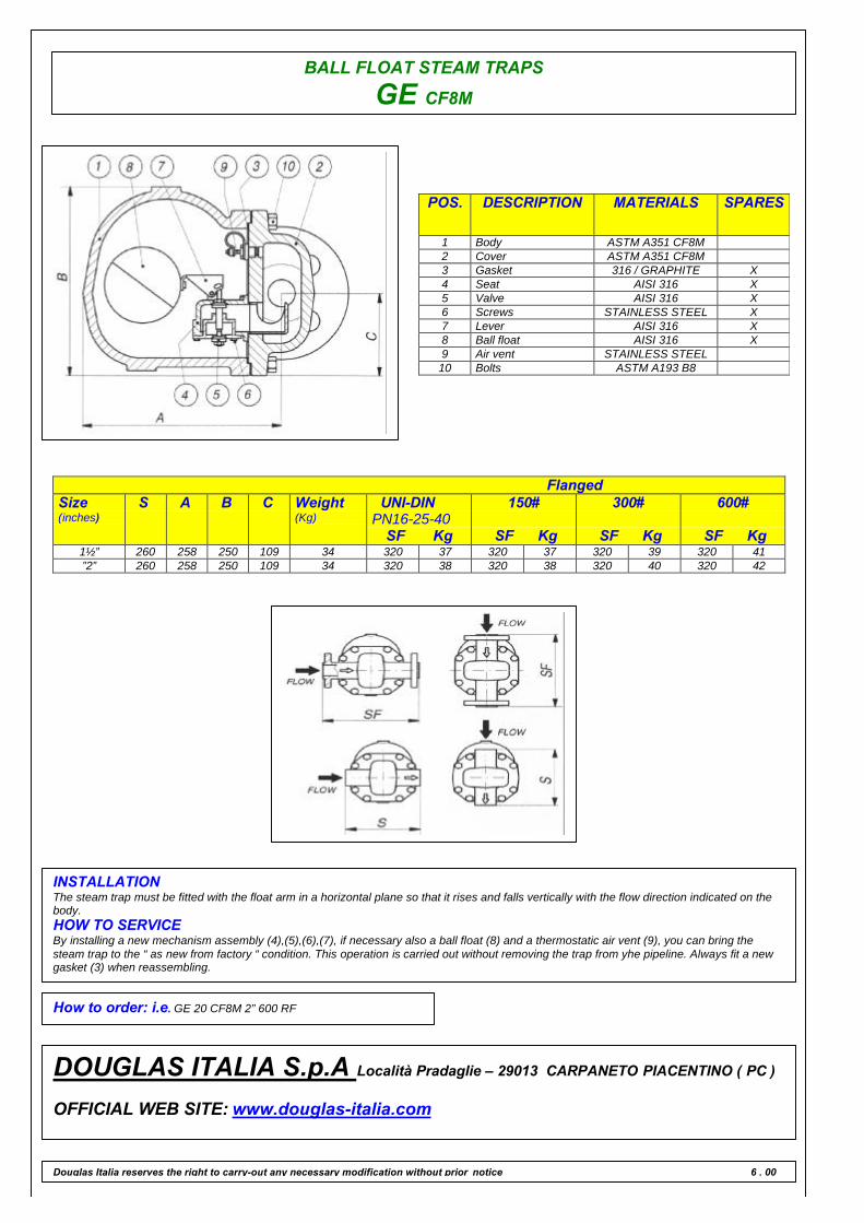
BALL FLOAT STEAM TRAPS
GE CF8M
POS. DESCRIPTION MATERIALS SPARES
1 Body ASTM A351 CF8M2 Cover ASTM A351 CF8M3 Gasket 316 / GRAPHITE X4 Seat AISI 316 X5 Valve AISI 316 X6 Screws STAINLESS STEEL X7 Lever AISI 316 X8 Ball float AISI 316 X9 Air vent STAINLESS STEEL10 Bolts ASTM A193 B8
FlangedSize(inches)
S A B C Weight(Kg)
UNI-DINPN16-25-40
SF Kg
150#
SF Kg
300#
SF Kg
600#
SF Kg1½” 260 258 250 109 34 320 37 320 37 320 39 320 41”2” 260 258 250 109 34 320 38 320 38 320 40 320 42
INSTALLATIONThe steam trap must be fitted with the float arm in a horizontal plane so that it rises and falls vertically with the flow direction indicated on thebody.HOW TO SERVICEBy installing a new mechanism assembly (4),(5),(6),(7), if necessary also a ball float (8) and a thermostatic air vent (9), you can bring thesteam trap to the “ as new from factory “ condition. This operation is carried out without removing the trap from yhe pipeline. Always fit a newgasket (3) when reassembling.
How to order: i.e. GE 20 CF8M 2” 600 RF
DOUGLAS ITALIA S.p.A Località Pradaglie – 29013 CARPANETO PIACENTINO ( PC )
OFFICIAL WEB SITE: www.douglas-italia.com
Douglas Italia reserves the right to carry-out any necessary modification without prior notice 6 . 00
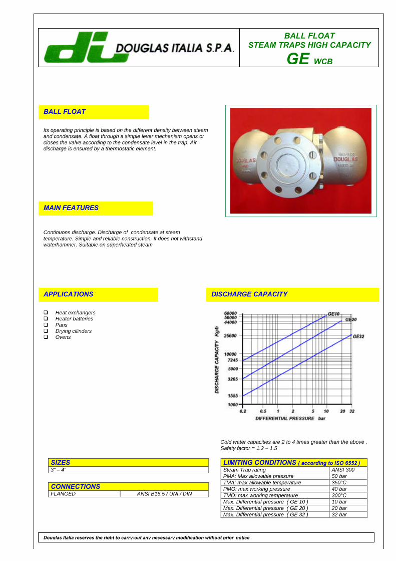
BALL FLOATSTEAM TRAPS HIGH CAPACITY
GE WCB
BALL FLOAT
Its operating principle is based on the different density between steamand condensate. A float through a simple lever mechanism opens orcloses the valve according to the condensate level in the trap. Airdischarge is ensured by a thermostatic element.
MAIN FEATURES
Continuons discharge. Discharge of condensate at steamtemperature. Simple and reliable construction. It does not withstandwaterhammer. Suitable on superheated steam
APPLICATIONS
q Heat exchangersq Heater batteriesq Pansq Drying cilindersq Ovens
DISCHARGE CAPACITY
LIMITING CONDITIONS ( according to ISO 6552 )Steam Trap rating ANSI 300PMA: Max allowable pressure 50 barTMA: max allowable temperature 350°CPMO: max working pressure 40 barTMO: max working temperature 300°CMax. Differential pressure ( GE 10 ) 10 barMax. Differential pressure ( GE 20 ) 20 barMax. Differential pressure ( GE 32 ) 32 bar
SIZES3” – 4”
CONNECTIONSFLANGED ANSI B16.5 / UNI / DIN
Douglas Italia reserves the right to carry-out any necessary modification without prior notice
Cold water capacities are 2 to 4 times greater than the above .Safety factor = 1.2 – 1.5
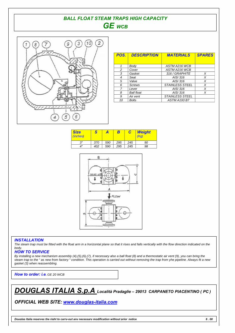
BALL FLOAT STEAM TRAPS HIGH CAPACITY
GE WCB
POS. DESCRIPTION MATERIALS SPARES
1 Body ASTM A216 WCB2 Cover ASTM A216 WCB3 Gasket 316 / GRAPHITE X4 Seat AISI 316 X5 Valve AISI 316 X6 Screws STAINLESS STEEL X7 Lever AISI 316 X8 Ball float AISI 316 X9 Air vent STAINLESS STEEL10 Bolts ASTM A193 B7
Size(inches)
S A B C Weight(Kg)
3” 370 590 295 245 904” 402 590 295 245 98
INSTALLATIONThe steam trap must be fitted with the float arm in a horizontal plane so that it rises and falls vertically with the flow direction indicated on thebody.HOW TO SERVICEBy installing a new mechanism assembly (4),(5),(6),(7), if necessary also a ball float (8) and a thermostatic air vent (9), you can bring thesteam trap to the “ as new from factory “ condition. This operation is carried out without removing the trap from yhe pipeline. Always fit a newgasket (3) when reassembling.
How to order: i.e. GE 20 WCB
DOUGLAS ITALIA S.p.A Località Pradaglie – 29013 CARPANETO PIACENTINO ( PC )
OFFICIAL WEB SITE: www.douglas-italia.com
Douglas Italia reserves the right to carry-out any necessary modification without prior notice 6 . 00

BALL FLOATSTEAM TRAPS HIGH CAPACITY
GE CF8M
BALL FLOAT
Its operating principle is based on the different density between steamand condensate. A float through a simple lever mechanism opens orcloses the valve according to the condensate level in the trap. Airdischarge is ensured by a thermostatic element.
MAIN FEATURES
Continuons discharge. Discharge of condensate at steamtemperature. Simple and reliable construction. It does not withstandwaterhammer. Suitable on superheated steam
APPLICATIONS
q Heat exchangersq Heater batteriesq Pansq Drying cilindersq Ovens
DISCHARGE CAPACITY
LIMITING CONDITIONS ( according to ISO 6552 )Steam Trap rating ANSI 300PMA: Max allowable pressure 50 barTMA: max allowable temperature 410°CPMO: max working pressure 40 barTMO: max working temperature 370°CMax. Differential pressure ( GE 10 ) 10 barMax. Differential pressure ( GE 20 ) 20 barMax. Differential pressure ( GE 32 ) 32 bar
SIZES3” – 4”
CONNECTIONSFLANGED ANSI B16.5 / UNI / DIN
Douglas Italia reserves the right to carry-out any necessary modification without prior notice
Cold water capacities are 2 to 4 times greater than the above .Safety factor = 1.2 – 1.5

BALL FLOAT STEAM TRAPS HIGH CAPACITY
GE CF8M
POS. DESCRIPTION MATERIALS SPARES
1 Body ASTM A351 CF8M2 Cover ASTM A351 CF8M3 Gasket 316 / GRAPHITE X4 Seat AISI 316 X5 Valve AISI 316 X6 Screws STAINLESS STEEL X7 Lever AISI 316 X8 Ball float AISI 316 X9 Air vent STAINLESS STEEL10 Bolts ASTM A193 B8
Size(inches)
S A B C Weight(Kg)
3” 370 590 295 245 904” 402 590 295 245 98
INSTALLATIONThe steam trap must be fitted with the float arm in a horizontal plane so that it rises and falls vertically with the flow direction indicated on thebody.HOW TO SERVICEBy installing a new mechanism assembly (4),(5),(6),(7), if necessary also a ball float (8) and a thermostatic air vent (9), you can bring thesteam trap to the “ as new from factory “ condition. This operation is carried out without removing the trap from yhe pipeline. Always fit a newgasket (3) when reassembling.
How to order: i.e. GE 20 CF8M
DOUGLAS ITALIA S.p.A Località Pradaglie – 29013 CARPANETO PIACENTINO ( PC )
OFFICIAL WEB SITE: www.douglas-italia.com
Douglas Italia reserves the right to carry-out any necessary modification without prior notice 6 . 00
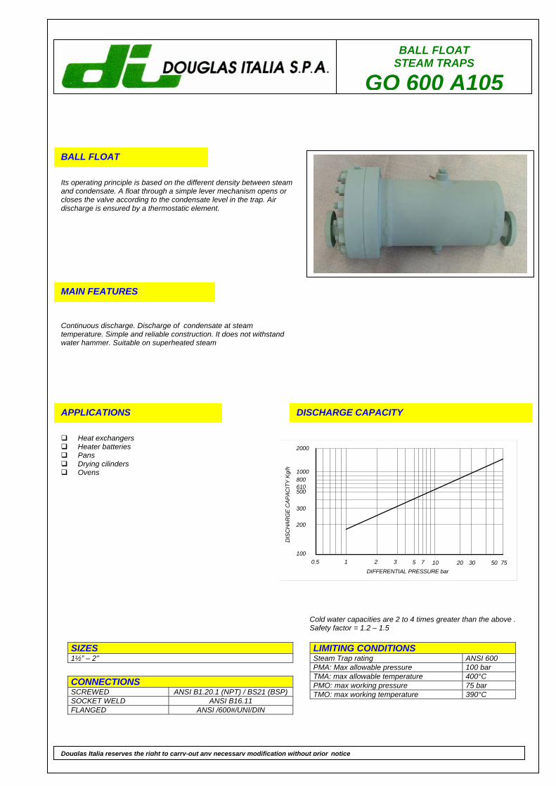
BALL FLOAT STEAM TRAPS
GO 600 A105
BALL FLOAT
Its operating principle is based on the different density between steam and condensate. A float through a simple lever mechanism opens or closes the valve according to the condensate level in the trap. Air discharge is ensured by a thermostatic element.
MAIN FEATURES
Continuous discharge. Discharge of condensate at steam temperature. Simple and reliable construction. It does not withstand water hammer. Suitable on superheated steam
APPLICATIONS
Heat exchangers Heater batteries Pans Drying cilinders Ovens
DISCHARGE CAPACITY
LIMITING CONDITIONS Steam Trap rating ANSI 600 PMA: Max allowable pressure 100 bar TMA: max allowable temperature 400°C PMO: max working pressure 75 bar TMO: max working temperature 390°C
SIZES 1½” – 2”
CONNECTIONS SCREWED ANSI B1.20.1 (NPT) / BS21 (BSP) SOCKET WELD ANSI B16.11 FLANGED ANSI /600#/UNI/DIN
Douglas Italia reserves the right to carry-out any necessary modification without prior notice
Cold water capacities are 2 to 4 times greater than the above . Safety factor = 1.2 – 1.5
0.5 1 2 3 5 7 10 20 30 50 75100
200
300
5006108001000
2000
DIS
CH
ARG
E C
APAC
ITY
Kg/h
DIFFERENTIAL PRESSURE bar

BALL FLOAT STEAM TRAPS
GO 600 A105
POS. DESCRIPTION MATERIALS SPARES
1 Cover snd body flgs ASTM A105N 2 Connections pipe ASTM A106-B 3 Connections flanged ASTM A105 4 Body pipe ASTM A105 5 Cover gasket 316/graphite X 6 Studs ASTM A193 B7 X 7 Nuts ASTM A194 2H X 8 Valve seat AISI 410 X 8 Levere AISI 304 9 Ball Float AISI 304
10 Screen AISI 304 11 Vent plug ASTM A105N 12 Drain plug ASTM A105N
Size (inches) Connections SF D
1½” 600#RF 635 300 1½” SW 450 300 2” 600#RF 640 300 2” SW 450 300
INSTALLATION The steam trap must be fitted with the float arm in a horizontal plane so that it rises and falls vertically with the flow direction indicated on the body. HOW TO SERVICE By installing a new mechanism assembly (8), if necessary also a ball float (9) and a thermostatic air vent (13), you can bring the steam trap to the “ as new from factory “ condition. This operation is carried out without removing the trap from the pipeline. Always fit a new gasket (5) when reassembling.
How to order: i.e. GE 20 WCB 2” 600 RF
DOUGLAS ITALIA S.p.A Località Pradaglie – 29013 CARPANETO PIACENTINO ( PC ) OFFICIAL WEB SITE: www.douglas-italia.com
Douglas Italia reserves the right to carry-out any necessary modification without prior notice 6 . 00

BALL FLOAT STEAM TRAPS
GO 600 F316
BALL FLOAT
Its operating principle is based on the different density between steam and condensate. A float through a simple lever mechanism opens or closes the valve according to the condensate level in the trap. Air discharge is ensured by a thermostatic element.
MAIN FEATURES
Continuous discharge. Discharge of condensate at steam temperature. Simple and reliable construction. It does not withstand water hammer. Suitable on superheated steam
APPLICATIONS
Heat exchangers Heater batteries Pans Drying cilinders Ovens
DISCHARGE CAPACITY
LIMITING CONDITIONS Steam Trap rating ANSI 600 PMA: Max allowable pressure 100 bar TMA: max allowable temperature 400°C PMO: max working pressure 75 bar TMO: max working temperature 390°C
SIZES 1½” – 2”
CONNECTIONS SCREWED ANSI B1.20.1 (NPT) / BS21 (BSP) SOCKET WELD ANSI B16.11 FLANGED ANSI /600#/UNI/DIN
Douglas Italia reserves the right to carry-out any necessary modification without prior notice
Cold water capacities are 2 to 4 times greater than the above . Safety factor = 1.2 – 1.5
0.5 1 2 3 5 7 10 20 30 50 75100
200
300
5006108001000
2000
DIS
CH
ARG
E C
APAC
ITY
Kg/h
DIFFERENTIAL PRESSURE bar
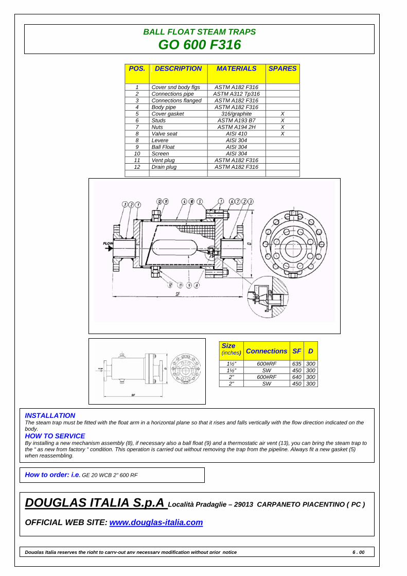
BALL FLOAT STEAM TRAPS
GO 600 F316
POS. DESCRIPTION MATERIALS SPARES
1 Cover snd body flgs ASTM A182 F316 2 Connections pipe ASTM A312 Tp316 3 Connections flanged ASTM A182 F316 4 Body pipe ASTM A182 F316 5 Cover gasket 316/graphite X 6 Studs ASTM A193 B7 X 7 Nuts ASTM A194 2H X 8 Valve seat AISI 410 X 8 Levere AISI 304 9 Ball Float AISI 304
10 Screen AISI 304 11 Vent plug ASTM A182 F316 12 Drain plug ASTM A182 F316
Size (inches) Connections SF D
1½” 600#RF 635 300 1½” SW 450 300 2” 600#RF 640 300 2” SW 450 300
INSTALLATION The steam trap must be fitted with the float arm in a horizontal plane so that it rises and falls vertically with the flow direction indicated on the body. HOW TO SERVICE By installing a new mechanism assembly (8), if necessary also a ball float (9) and a thermostatic air vent (13), you can bring the steam trap to the “ as new from factory “ condition. This operation is carried out without removing the trap from the pipeline. Always fit a new gasket (5) when reassembling.
How to order: i.e. GE 20 WCB 2” 600 RF
DOUGLAS ITALIA S.p.A Località Pradaglie – 29013 CARPANETO PIACENTINO ( PC ) OFFICIAL WEB SITE: www.douglas-italia.com
Douglas Italia reserves the right to carry-out any necessary modification without prior notice 6 . 00
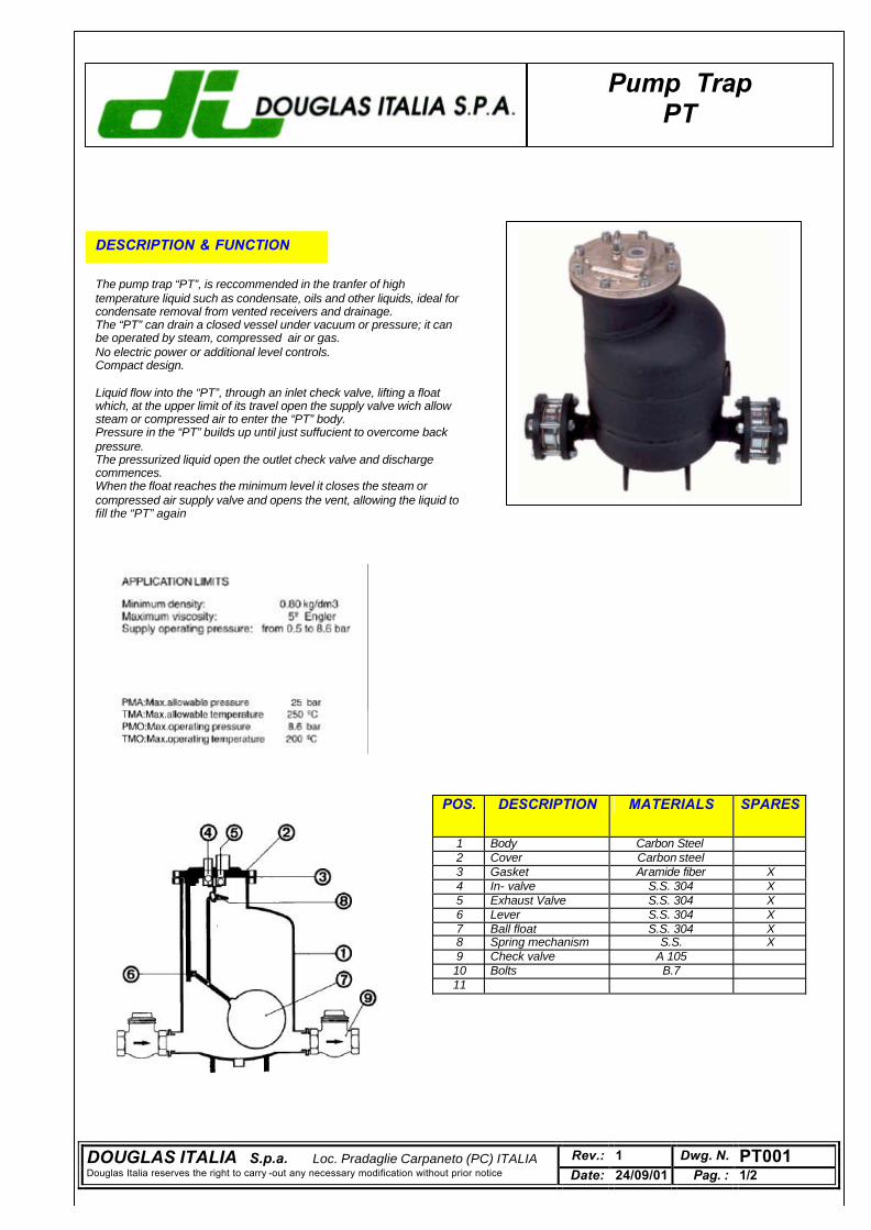
Pump Trap PT
DESCRIPTION & FUNCTION The pump trap “PT”, is reccommended in the tranfer of high temperature liquid such as condensate, oils and other liquids, ideal for condensate removal from vented receivers and drainage. The “PT” can drain a closed vessel under vacuum or pressure; it can be operated by steam, compressed air or gas. No electric power or additional level controls. Compact design. Liquid flow into the “PT”, through an inlet check valve, lifting a float which, at the upper limit of its travel open the supply valve wich allow steam or compressed air to enter the “PT” body. Pressure in the “PT” builds up until just suffucient to overcome back pressure. The pressurized liquid open the outlet check valve and discharge commences. When the float reaches the minimum level it closes the steam or compressed air supply valve and opens the vent, allowing the liquid to fill the “PT” again
POS. DESCRIPTION MATERIALS SPARES
1 Body Carbon Steel 2 Cover Carbon steel 3 Gasket Aramide fiber X 4 In- valve S.S. 304 X 5 Exhaust Valve S.S. 304 X 6 Lever S.S. 304 X 7 Ball float S.S. 304 X 8 Spring mechanism S.S. X 9 Check valve A 105 10 Bolts B.7 11
DOUGLAS ITALIA S.p.a. Loc. Pradaglie Carpaneto (PC) ITALIA Rev.: 1 Dwg. N. PT001 Douglas Italia reserves the right to carry -out any necessary modification without prior notice Date: 24/09/01 Pag. : 1/2
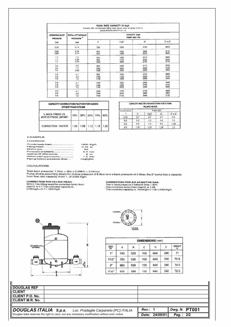
DOUGLAS REF CLIENT CLIENT P.O. No. CLIENT M.R. No.
DOUGLAS ITALIA S.p.a. Loc. Pradaglie Carpaneto (PC) ITALIA Rev.: 1 Dwg. N. PT001 Douglas Italia reserves the right to carry -out any necessary modification without prior notice Date: 24/09/01 Pag. : 2/2
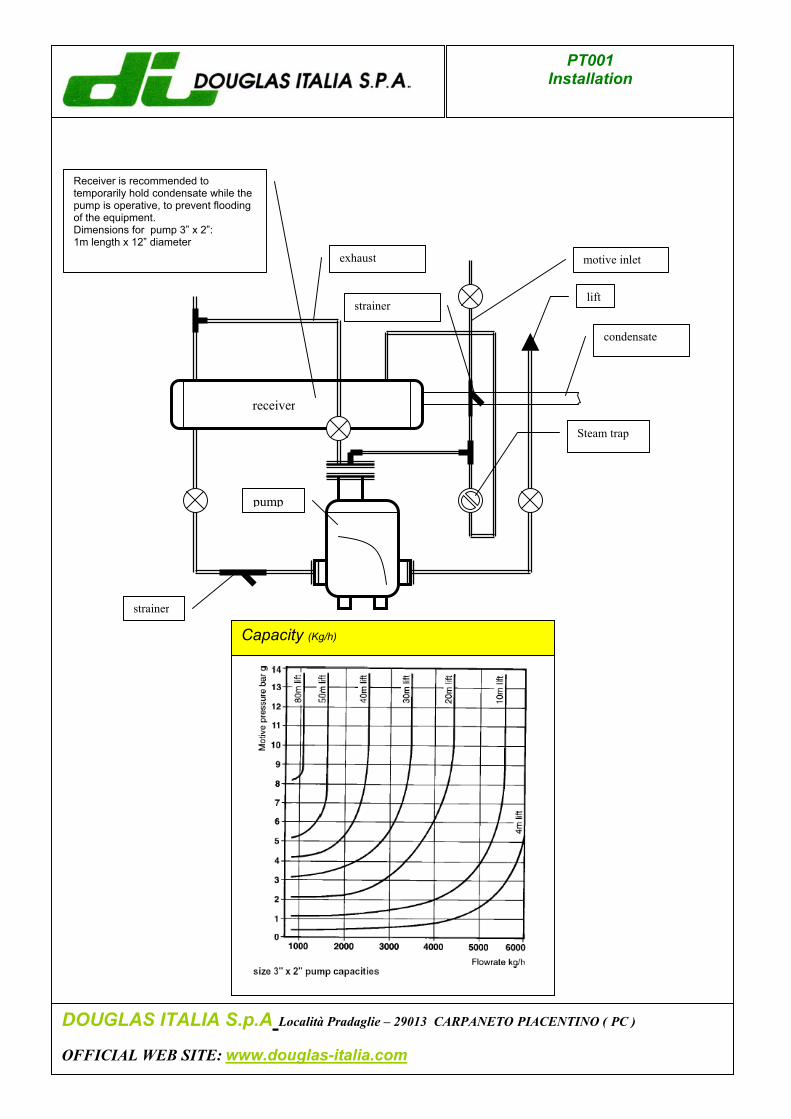
motive inlet
strainer
exhaust
condensate
strainer lift
C
Receiver is recommended to temporarily hold condensate while the pump is operative, to prevent flooding of the equipment. Dimensions for pump 3” x 2”: 1m length x 12” diameter
DOUGLAS ITALIA S.p OFFICIAL WEB SITE: ww
PT001 Installation
receiver
pump
Steam trap
apacity (Kg/h)
.A Località Pradaglie – 29013 CARPANETO PIACENTINO ( PC )
w.douglas-italia.com
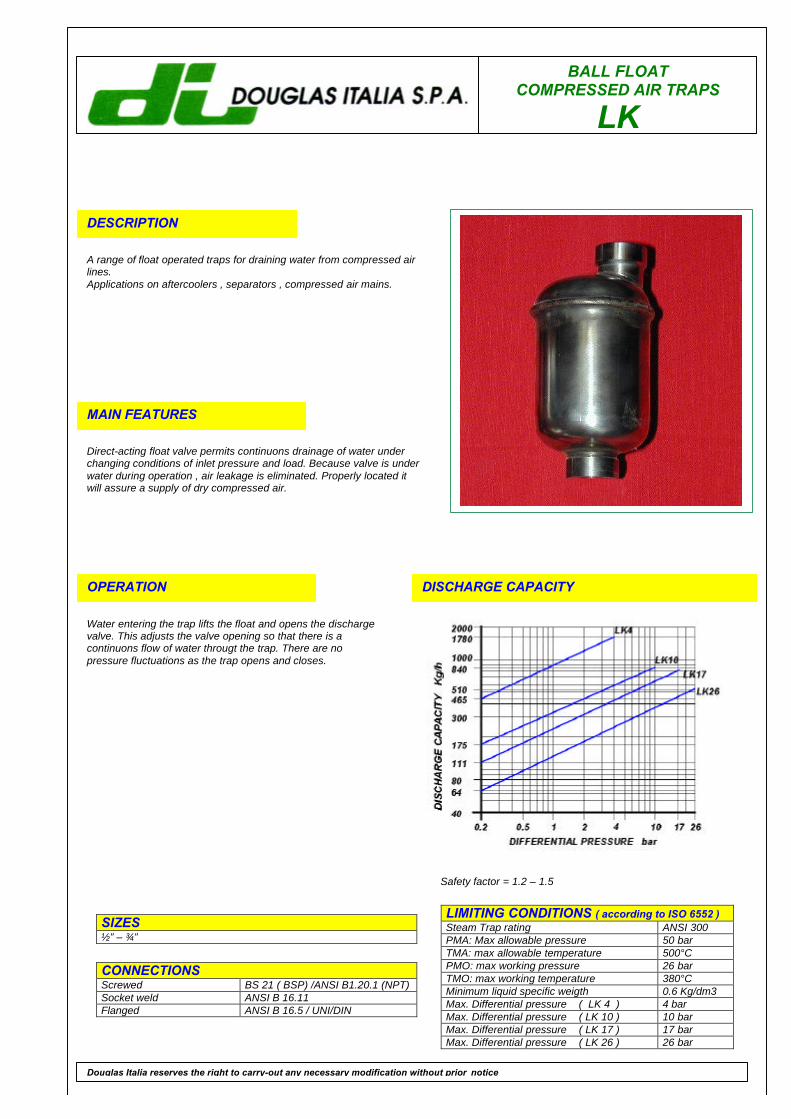
BALL FLOATCOMPRESSED AIR TRAPS
LK
DESCRIPTION
A range of float operated traps for draining water from compressed airlines.Applications on aftercoolers , separators , compressed air mains.
MAIN FEATURES
Direct-acting float valve permits continuons drainage of water underchanging conditions of inlet pressure and load. Because valve is underwater during operation , air leakage is eliminated. Properly located itwill assure a supply of dry compressed air.
OPERATION
Water entering the trap lifts the float and opens the dischargevalve. This adjusts the valve opening so that there is acontinuons flow of water througt the trap. There are nopressure fluctuations as the trap opens and closes.
DISCHARGE CAPACITY
LIMITING CONDITIONS ( according to ISO 6552 )Steam Trap rating ANSI 300PMA: Max allowable pressure 50 barTMA: max allowable temperature 500°CPMO: max working pressure 26 barTMO: max working temperature 380°CMinimum liquid specific weigth 0.6 Kg/dm3Max. Differential pressure ( LK 4 ) 4 barMax. Differential pressure ( LK 10 ) 10 barMax. Differential pressure ( LK 17 ) 17 barMax. Differential pressure ( LK 26 ) 26 bar
SIZES½” – ¾”
CONNECTIONSScrewed BS 21 ( BSP) /ANSI B1.20.1 (NPT)Socket weld ANSI B 16.11Flanged ANSI B 16.5 / UNI/DIN
Douglas Italia reserves the right to carry-out any necessary modification without prior notice
Safety factor = 1.2 – 1.5
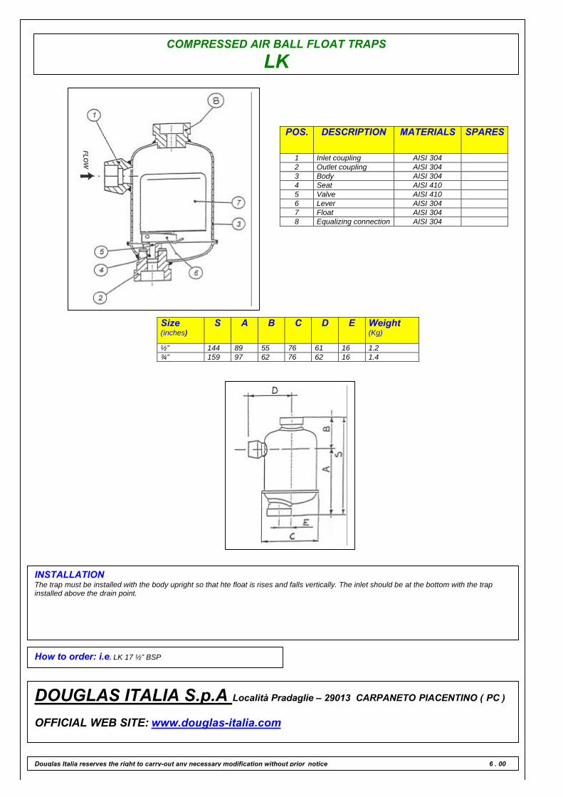
COMPRESSED AIR BALL FLOAT TRAPS
LK
POS. DESCRIPTION MATERIALS SPARES
1 Inlet coupling AISI 3042 Outlet coupling AISI 3043 Body AISI 3044 Seat AISI 4105 Valve AISI 4106 Lever AISI 3047 Float AISI 3048 Equalizing connection AISI 304
Size(inches)
S A B C D E Weight(Kg)
½” 144 89 55 76 61 16 1.2¾” 159 97 62 76 62 16 1.4
INSTALLATIONThe trap must be installed with the body upright so that hte float is rises and falls vertically. The inlet should be at the bottom with the trapinstalled above the drain point.
How to order: i.e. LK 17 ½” BSP
DOUGLAS ITALIA S.p.A Località Pradaglie – 29013 CARPANETO PIACENTINO ( PC )
OFFICIAL WEB SITE: www.douglas-italia.com
Douglas Italia reserves the right to carry-out any necessary modification without prior notice 6 . 00
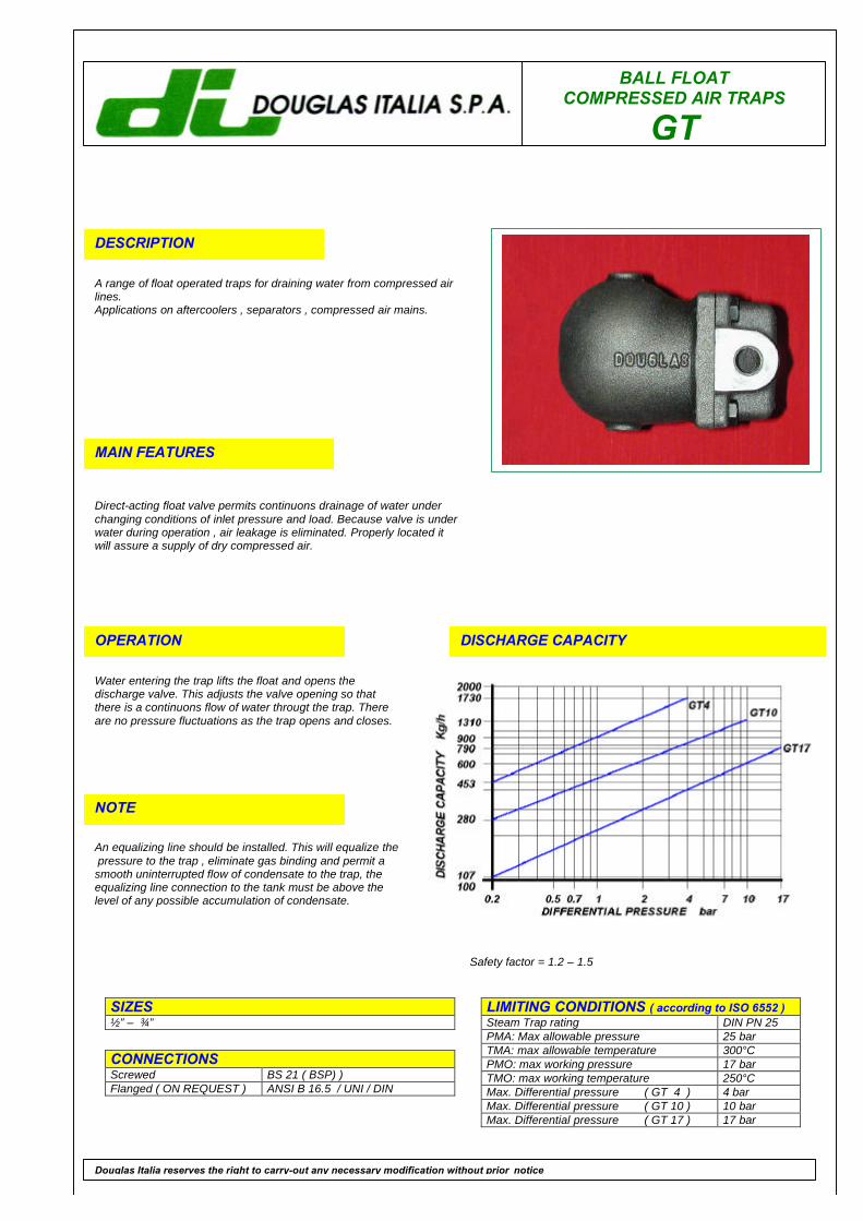
BALL FLOATCOMPRESSED AIR TRAPS
GT
DESCRIPTION
A range of float operated traps for draining water from compressed airlines.Applications on aftercoolers , separators , compressed air mains.
MAIN FEATURES
Direct-acting float valve permits continuons drainage of water underchanging conditions of inlet pressure and load. Because valve is underwater during operation , air leakage is eliminated. Properly located itwill assure a supply of dry compressed air.
OPERATION
Water entering the trap lifts the float and opens thedischarge valve. This adjusts the valve opening so thatthere is a continuons flow of water througt the trap. Thereare no pressure fluctuations as the trap opens and closes.
DISCHARGE CAPACITY
LIMITING CONDITIONS ( according to ISO 6552 )Steam Trap rating DIN PN 25PMA: Max allowable pressure 25 barTMA: max allowable temperature 300°CPMO: max working pressure 17 barTMO: max working temperature 250°CMax. Differential pressure ( GT 4 ) 4 barMax. Differential pressure ( GT 10 ) 10 barMax. Differential pressure ( GT 17 ) 17 bar
SIZES½” – ¾”
CONNECTIONSScrewed BS 21 ( BSP) )Flanged ( ON REQUEST ) ANSI B 16.5 / UNI / DIN
Douglas Italia reserves the right to carry-out any necessary modification without prior notice
NOTE
An equalizing line should be installed. This will equalize the pressure to the trap , eliminate gas binding and permit asmooth uninterrupted flow of condensate to the trap, theequalizing line connection to the tank must be above thelevel of any possible accumulation of condensate.
Safety factor = 1.2 – 1.5
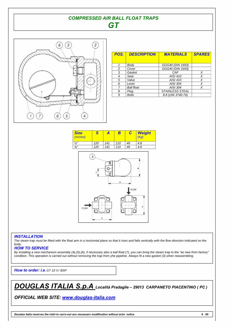
COMPRESSED AIR BALL FLOAT TRAPS
GT
POS. DESCRIPTION MATERIALS SPARES
1 Body GGG40 (DIN 1693)2 Cover GGG40 (DIN 1693)3 Gasket CAF X4 Seat AISI 410 X5 Valve AISI 410 X6 Lever AISI 304 X7 Ball float AISI 304 X8 Plug STAINLESS STEAL9 Bolts 8.8 (UNI 3740-74)
Size(inches)
S A B C Weight(Kg)
½” 120 141 110 49 4.8¾” 120 141 110 49 4.8
INSTALLATIONThe steam trap must be fitted with the float arm in a horizontal plane so that it rises and falls vertically with the flow direction indicated on thebody.HOW TO SERVICEBy installing a new mechanism assembly (4),(5),(6), if necessary also a ball float (7), you can bring the steam trap to the “as new from factory”condition. This operation is carried out without removing the trap from yhe pipeline. Always fit a new gasket (3) when reassembling.
How to order: i.e. GT 10 ½” BSP
DOUGLAS ITALIA S.p.A Località Pradaglie – 29013 CARPANETO PIACENTINO ( PC )
OFFICIAL WEB SITE: www.douglas-italia.com
Douglas Italia reserves the right to carry-out any necessary modification without prior notice 6 . 00
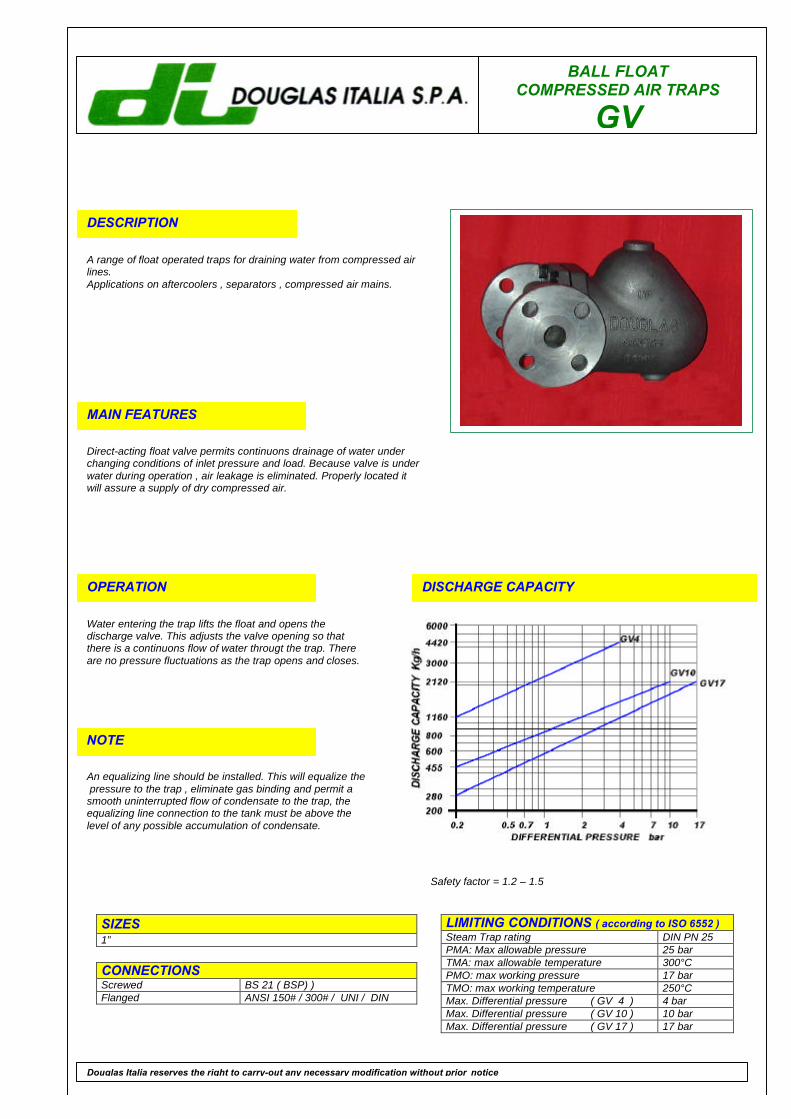
BALL FLOATCOMPRESSED AIR TRAPS
GV
DESCRIPTION
A range of float operated traps for draining water from compressed airlines.Applications on aftercoolers , separators , compressed air mains.
MAIN FEATURES
Direct-acting float valve permits continuons drainage of water underchanging conditions of inlet pressure and load. Because valve is underwater during operation , air leakage is eliminated. Properly located itwill assure a supply of dry compressed air.
OPERATION
Water entering the trap lifts the float and opens thedischarge valve. This adjusts the valve opening so thatthere is a continuons flow of water througt the trap. Thereare no pressure fluctuations as the trap opens and closes.
DISCHARGE CAPACITY
LIMITING CONDITIONS ( according to ISO 6552 )Steam Trap rating DIN PN 25PMA: Max allowable pressure 25 barTMA: max allowable temperature 300°CPMO: max working pressure 17 barTMO: max working temperature 250°CMax. Differential pressure ( GV 4 ) 4 barMax. Differential pressure ( GV 10 ) 10 barMax. Differential pressure ( GV 17 ) 17 bar
SIZES1”
CONNECTIONSScrewed BS 21 ( BSP) )Flanged ANSI 150# / 300# / UNI / DIN
Douglas Italia reserves the right to carry-out any necessary modification without prior notice
NOTE
An equalizing line should be installed. This will equalize the pressure to the trap , eliminate gas binding and permit asmooth uninterrupted flow of condensate to the trap, theequalizing line connection to the tank must be above thelevel of any possible accumulation of condensate.
Safety factor = 1.2 – 1.5
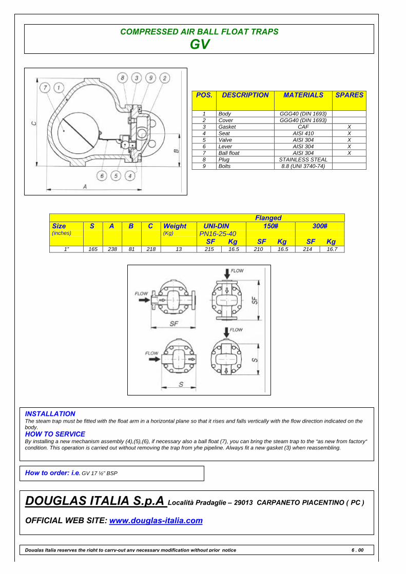
COMPRESSED AIR BALL FLOAT TRAPS
GV
POS. DESCRIPTION MATERIALS SPARES
1 Body GGG40 (DIN 1693)2 Cover GGG40 (DIN 1693)3 Gasket CAF X4 Seat AISI 410 X5 Valve AISI 304 X6 Lever AISI 304 X7 Ball float AISI 304 X8 Plug STAINLESS STEAL9 Bolts 8.8 (UNI 3740-74)
FlangedSize(inches)
S A B C Weight(Kg)
UNI-DINPN16-25-40
SF Kg
150#
SF Kg
300#
SF Kg1” 165 238 81 218 13 215 16.5 210 16.5 214 16.7
INSTALLATIONThe steam trap must be fitted with the float arm in a horizontal plane so that it rises and falls vertically with the flow direction indicated on thebody.HOW TO SERVICEBy installing a new mechanism assembly (4),(5),(6), if necessary also a ball float (7), you can bring the steam trap to the “as new from factory“condition. This operation is carried out without removing the trap from yhe pipeline. Always fit a new gasket (3) when reassembling.
How to order: i.e. GV 17 ½” BSP
DOUGLAS ITALIA S.p.A Località Pradaglie – 29013 CARPANETO PIACENTINO ( PC )
OFFICIAL WEB SITE: www.douglas-italia.com
Douglas Italia reserves the right to carry-out any necessary modification without prior notice 6 . 00
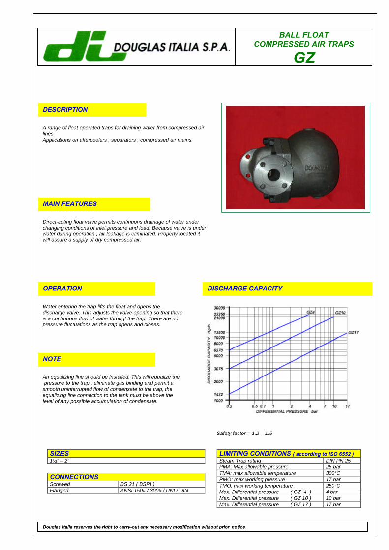
BALL FLOATCOMPRESSED AIR TRAPS
GZ
DESCRIPTION
A range of float operated traps for draining water from compressed airlines.Applications on aftercoolers , separators , compressed air mains.
MAIN FEATURES
Direct-acting float valve permits continuons drainage of water underchanging conditions of inlet pressure and load. Because valve is underwater during operation , air leakage is eliminated. Properly located itwill assure a supply of dry compressed air.
OPERATION
Water entering the trap lifts the float and opens thedischarge valve. This adjusts the valve opening so that thereis a continuons flow of water througt the trap. There are nopressure fluctuations as the trap opens and closes.
DISCHARGE CAPACITY
LIMITING CONDITIONS ( according to ISO 6552 )Steam Trap rating DIN PN 25PMA: Max allowable pressure 25 barTMA: max allowable temperature 300°CPMO: max working pressure 17 barTMO: max working temperature 250°CMax. Differential pressure ( GZ 4 ) 4 barMax. Differential pressure ( GZ 10 ) 10 barMax. Differential pressure ( GZ 17 ) 17 bar
SIZES1½” – 2”
CONNECTIONSScrewed BS 21 ( BSP) )Flanged ANSI 150# / 300# / UNI / DIN
Douglas Italia reserves the right to carry-out any necessary modification without prior notice
NOTE
An equalizing line should be installed. This will equalize the pressure to the trap , eliminate gas binding and permit asmooth uninterrupted flow of condensate to the trap, theequalizing line connection to the tank must be above thelevel of any possible accumulation of condensate.
Safety factor = 1.2 – 1.5
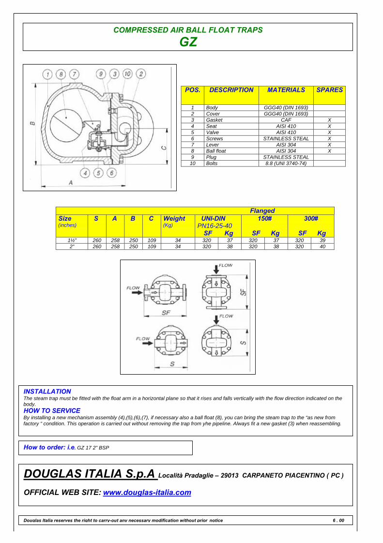
COMPRESSED AIR BALL FLOAT TRAPS
GZ
POS. DESCRIPTION MATERIALS SPARES
1 Body GGG40 (DIN 1693)2 Cover GGG40 (DIN 1693)3 Gasket CAF X4 Seat AISI 410 X5 Valve AISI 410 X6 Screws STAINLESS STEAL X7 Lever AISI 304 X8 Ball float AISI 304 X9 Plug STAINLESS STEAL10 Bolts 8.8 (UNI 3740-74)
FlangedSize(inches)
S A B C Weight(Kg)
UNI-DINPN16-25-40
SF Kg
150#
SF Kg
300#
SF Kg1½” 260 258 250 109 34 320 37 320 37 320 392” 260 258 250 109 34 320 38 320 38 320 40
INSTALLATIONThe steam trap must be fitted with the float arm in a horizontal plane so that it rises and falls vertically with the flow direction indicated on thebody.HOW TO SERVICEBy installing a new mechanism assembly (4),(5),(6),(7), if necessary also a ball float (8), you can bring the steam trap to the “as new fromfactory “ condition. This operation is carried out without removing the trap from yhe pipeline. Always fit a new gasket (3) when reassembling.
How to order: i.e. GZ 17 2” BSP
DOUGLAS ITALIA S.p.A Località Pradaglie – 29013 CARPANETO PIACENTINO ( PC )
OFFICIAL WEB SITE: www.douglas-italia.com
Douglas Italia reserves the right to carry-out any necessary modification without prior notice 6 . 00

BALL FLOATCOMPRESSED AIR TRAPS
GX WCB
DESCRIPTION
A range of float operated traps for draining water from compressed airlines.Applications on aftercoolers , separators , compressed air mains.
MAIN FEATURES
Direct-acting float valve permits continuons drainage of water underchanging conditions of inlet pressure and load. Because valve is underwater during operation , air leakage is eliminated. Properly located itwill assure a supply of dry compressed air.
OPERATION
Water entering the trap lifts the float and opens the dischargevalve. This adjusts the valve opening so that there is acontinuons flow of water througt the trap. There are nopressure fluctuations as the trap opens and closes.
DISCHARGE CAPACITY
LIMITING CONDITIONS ( according to ISO 6552 )Steam Trap rating ANSI 150PMA: Max allowable pressure 20 barTMA: max allowable temperature 350°CPMO: max working pressure 14 barTMO: max working temperature 300°CMax. Differential pressure ( GX 5 ) 5 barMax. Differential pressure ( GX 14 ) 14 bar
SIZES½” – ¾” – 1”
CONNECTIONSSCREWED ANSI B1.20.1 (NPT) / BS21 (BSP)SOCKET WELD ANSI B16.11FLANGED ANSI 150#/300#/600#/UNI/DIN
Douglas Italia reserves the right to carry-out any necessary modification without prior notice
NOTE
An equalizing line should be installed. This will equalize the pressure to the trap , eliminate gas binding and permit asmooth uninterrupted flow of condensate to the trap, theequalizing line connection to the tank must be above thelevel of any possible accumulation of condensate.
Safety factor = 1.2 – 1.5
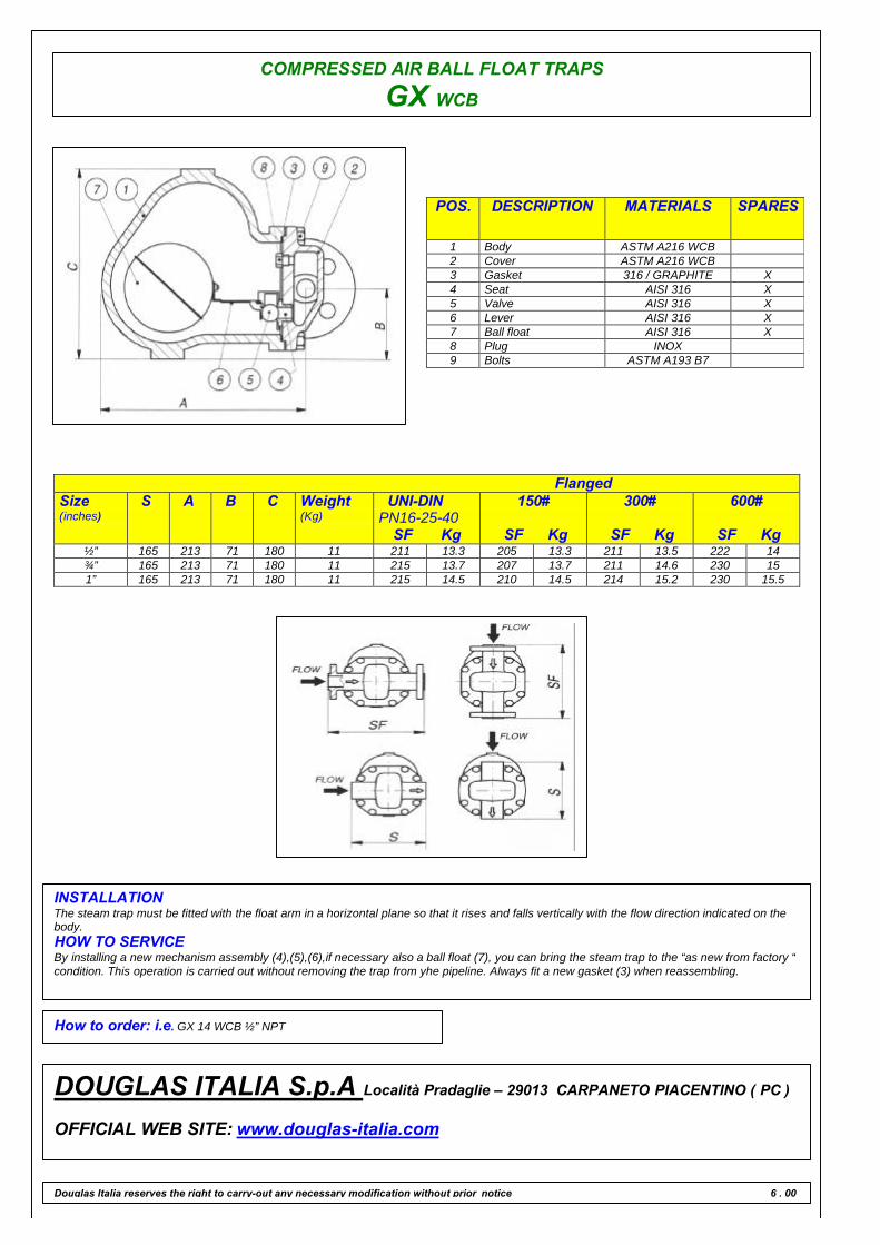
COMPRESSED AIR BALL FLOAT TRAPS
GX WCB
POS. DESCRIPTION MATERIALS SPARES
1 Body ASTM A216 WCB2 Cover ASTM A216 WCB3 Gasket 316 / GRAPHITE X4 Seat AISI 316 X5 Valve AISI 316 X6 Lever AISI 316 X7 Ball float AISI 316 X8 Plug INOX9 Bolts ASTM A193 B7
FlangedSize(inches)
S A B C Weight(Kg)
UNI-DINPN16-25-40
SF Kg
150#
SF Kg
300#
SF Kg
600#
SF Kg½” 165 213 71 180 11 211 13.3 205 13.3 211 13.5 222 14¾” 165 213 71 180 11 215 13.7 207 13.7 211 14.6 230 151” 165 213 71 180 11 215 14.5 210 14.5 214 15.2 230 15.5
INSTALLATIONThe steam trap must be fitted with the float arm in a horizontal plane so that it rises and falls vertically with the flow direction indicated on thebody.HOW TO SERVICEBy installing a new mechanism assembly (4),(5),(6),if necessary also a ball float (7), you can bring the steam trap to the “as new from factory “condition. This operation is carried out without removing the trap from yhe pipeline. Always fit a new gasket (3) when reassembling.
How to order: i.e. GX 14 WCB ½” NPT
DOUGLAS ITALIA S.p.A Località Pradaglie – 29013 CARPANETO PIACENTINO ( PC )
OFFICIAL WEB SITE: www.douglas-italia.com
Douglas Italia reserves the right to carry-out any necessary modification without prior notice 6 . 00
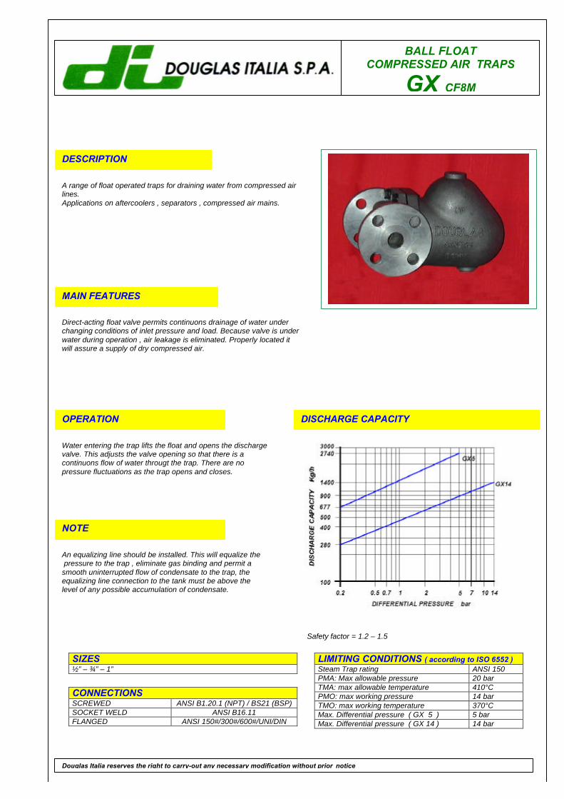
BALL FLOATCOMPRESSED AIR TRAPS
GX CF8M
DESCRIPTION
A range of float operated traps for draining water from compressed airlines.Applications on aftercoolers , separators , compressed air mains.
MAIN FEATURES
Direct-acting float valve permits continuons drainage of water underchanging conditions of inlet pressure and load. Because valve is underwater during operation , air leakage is eliminated. Properly located itwill assure a supply of dry compressed air.
OPERATION
Water entering the trap lifts the float and opens the dischargevalve. This adjusts the valve opening so that there is acontinuons flow of water througt the trap. There are nopressure fluctuations as the trap opens and closes.
DISCHARGE CAPACITY
LIMITING CONDITIONS ( according to ISO 6552 )Steam Trap rating ANSI 150PMA: Max allowable pressure 20 barTMA: max allowable temperature 410°CPMO: max working pressure 14 barTMO: max working temperature 370°CMax. Differential pressure ( GX 5 ) 5 barMax. Differential pressure ( GX 14 ) 14 bar
SIZES½” – ¾” – 1”
CONNECTIONSSCREWED ANSI B1.20.1 (NPT) / BS21 (BSP)SOCKET WELD ANSI B16.11FLANGED ANSI 150#/300#/600#/UNI/DIN
Douglas Italia reserves the right to carry-out any necessary modification without prior notice
NOTE
An equalizing line should be installed. This will equalize the pressure to the trap , eliminate gas binding and permit asmooth uninterrupted flow of condensate to the trap, theequalizing line connection to the tank must be above thelevel of any possible accumulation of condensate.
Safety factor = 1.2 – 1.5
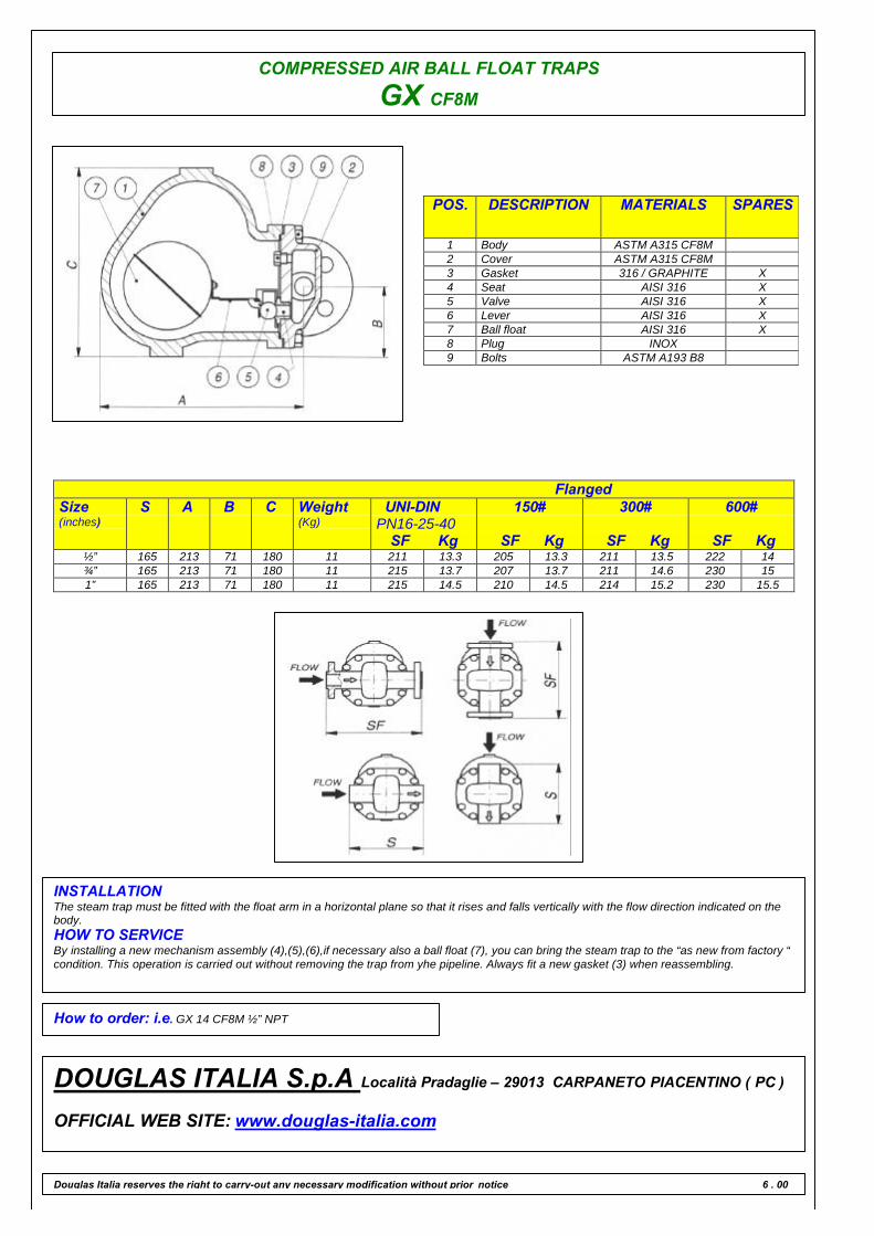
COMPRESSED AIR BALL FLOAT TRAPS
GX CF8M
POS. DESCRIPTION MATERIALS SPARES
1 Body ASTM A315 CF8M2 Cover ASTM A315 CF8M3 Gasket 316 / GRAPHITE X4 Seat AISI 316 X5 Valve AISI 316 X6 Lever AISI 316 X7 Ball float AISI 316 X8 Plug INOX9 Bolts ASTM A193 B8
FlangedSize(inches)
S A B C Weight(Kg)
UNI-DINPN16-25-40
SF Kg
150#
SF Kg
300#
SF Kg
600#
SF Kg½” 165 213 71 180 11 211 13.3 205 13.3 211 13.5 222 14¾” 165 213 71 180 11 215 13.7 207 13.7 211 14.6 230 151” 165 213 71 180 11 215 14.5 210 14.5 214 15.2 230 15.5
INSTALLATIONThe steam trap must be fitted with the float arm in a horizontal plane so that it rises and falls vertically with the flow direction indicated on thebody.HOW TO SERVICEBy installing a new mechanism assembly (4),(5),(6),if necessary also a ball float (7), you can bring the steam trap to the “as new from factory “condition. This operation is carried out without removing the trap from yhe pipeline. Always fit a new gasket (3) when reassembling.
How to order: i.e. GX 14 CF8M ½” NPT
DOUGLAS ITALIA S.p.A Località Pradaglie – 29013 CARPANETO PIACENTINO ( PC )
OFFICIAL WEB SITE: www.douglas-italia.com
Douglas Italia reserves the right to carry-out any necessary modification without prior notice 6 . 00
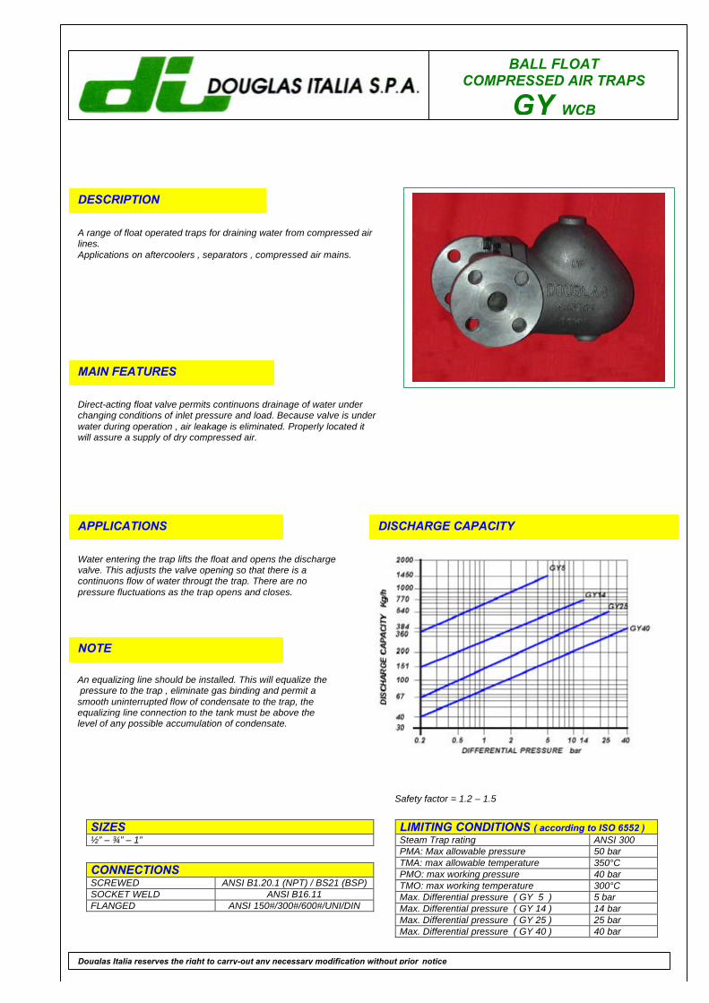
BALL FLOATCOMPRESSED AIR TRAPS
GY WCB
DESCRIPTION
A range of float operated traps for draining water from compressed airlines.Applications on aftercoolers , separators , compressed air mains.
MAIN FEATURES
Direct-acting float valve permits continuons drainage of water underchanging conditions of inlet pressure and load. Because valve is underwater during operation , air leakage is eliminated. Properly located itwill assure a supply of dry compressed air.
APPLICATIONS
Water entering the trap lifts the float and opens the dischargevalve. This adjusts the valve opening so that there is acontinuons flow of water througt the trap. There are nopressure fluctuations as the trap opens and closes.
DISCHARGE CAPACITY
LIMITING CONDITIONS ( according to ISO 6552 )Steam Trap rating ANSI 300PMA: Max allowable pressure 50 barTMA: max allowable temperature 350°CPMO: max working pressure 40 barTMO: max working temperature 300°CMax. Differential pressure ( GY 5 ) 5 barMax. Differential pressure ( GY 14 ) 14 barMax. Differential pressure ( GY 25 ) 25 barMax. Differential pressure ( GY 40 ) 40 bar
SIZES½” – ¾” – 1”
CONNECTIONSSCREWED ANSI B1.20.1 (NPT) / BS21 (BSP)SOCKET WELD ANSI B16.11FLANGED ANSI 150#/300#/600#/UNI/DIN
Douglas Italia reserves the right to carry-out any necessary modification without prior notice
NOTE
An equalizing line should be installed. This will equalize the pressure to the trap , eliminate gas binding and permit asmooth uninterrupted flow of condensate to the trap, theequalizing line connection to the tank must be above thelevel of any possible accumulation of condensate.
Safety factor = 1.2 – 1.5

COMPRESSED AIR BALL FLOAT TRAPS
GY WCB
POS. DESCRIPTION MATERIALS SPARES
1 Body ASTM A216 WCB2 Cover ASTM A216 WCB3 Gasket 316 / GRAPHITE X4 Seat AISI 316 X5 Valve AISI 316 X6 Lever AISI 316 X7 Ball float AISI 316 X8 Plug STAINLESS STEEL9 Bolts ASTM A193 B7
FlangedSize(inches)
S A B C Weight(Kg)
UNI-DINPN16-25-40
SF Kg
150#
SF Kg
300#
SF Kg
600#
SF Kg½” 165 213 71 180 11 211 13.3 205 13.3 211 13.5 222 14¾” 165 213 71 180 11 215 13.7 207 13.7 211 14.6 230 151” 165 213 71 180 11 215 14.5 210 14.5 214 15.2 230 15.5
INSTALLATIONThe steam trap must be fitted with the float arm in a horizontal plane so that it rises and falls vertically with the flow direction indicated on thebody.HOW TO SERVICEBy installing a new mechanism assembly (4),(5),(6),if necessary also a ball float (7), you can bring the steam trap to the “as new from factory“condition. This operation is carried out without removing the trap from yhe pipeline. Always fit a new gasket (3) when reassembling.
How to order: i.e. GY 40 WCB 1” 300 RF
DOUGLAS ITALIA S.p.A Località Pradaglie – 29013 CARPANETO PIACENTINO ( PC )
OFFICIAL WEB SITE: www.douglas-italia.com
Douglas Italia reserves the right to carry-out any necessary modification without prior notice 6 . 00

BALL FLOATCOMPRESSED AIR TRAPS
GY CF8M
DESCRIPTION
A range of float operated traps for draining water from compressed airlines.Applications on aftercoolers , separators , compressed air mains.
MAIN FEATURES
Direct-acting float valve permits continuons drainage of water underchanging conditions of inlet pressure and load. Because valve is underwater during operation , air leakage is eliminated. Properly located itwill assure a supply of dry compressed air.
APPLICATIONS
Water entering the trap lifts the float and opens the dischargevalve. This adjusts the valve opening so that there is acontinuons flow of water througt the trap. There are nopressure fluctuations as the trap opens and closes.
DISCHARGE CAPACITY
LIMITING CONDITIONS ( according to ISO 6552 )Steam Trap rating ANSI 300PMA: Max allowable pressure 50 barTMA: max allowable temperature 410°CPMO: max working pressure 40 barTMO: max working temperature 370°CMax. Differential pressure ( GY 5 ) 5 barMax. Differential pressure ( GY 14 ) 14 barMax. Differential pressure ( GY 25 ) 25 barMax. Differential pressure ( GY 40 ) 40 bar
SIZES½” – ¾” – 1”
CONNECTIONSSCREWED ANSI B1.20.1 (NPT) / BS21 (BSP)SOCKET WELD ANSI B16.11FLANGED ANSI 150#/300#/600#/UNI/DIN
Douglas Italia reserves the right to carry-out any necessary modification without prior notice
NOTE
An equalizing line should be installed. This will equalize the pressure to the trap , eliminate gas binding and permit asmooth uninterrupted flow of condensate to the trap, theequalizing line connection to the tank must be above thelevel of any possible accumulation of condensate.
Safety factor = 1.2 – 1.5

COMPRESSED AIR BALL FLOAT TRAPS
GY CF8M
POS. DESCRIPTION MATERIALS SPARES
1 Body ASTM A351 CF8M2 Cover ASTM A351 CF8M3 Gasket 316 / GRAPHITE X4 Seat AISI 316 X5 Valve AISI 316 X6 Lever AISI 316 X7 Ball float AISI 316 X8 Plug STAINLESS STEEL9 Bolts ASTM A193 B8
FlangedSize(inches)
S A B C Weight(Kg)
UNI-DINPN16-25-40
SF Kg
150#
SF Kg
300#
SF Kg
600#
SF Kg½” 165 213 71 180 11 211 13.3 205 13.3 211 13.5 222 14¾” 165 213 71 180 11 215 13.7 207 13.7 211 14.6 230 151” 165 213 71 180 11 215 14.5 210 14.5 214 15.2 230 15.5
INSTALLATIONThe steam trap must be fitted with the float arm in a horizontal plane so that it rises and falls vertically with the flow direction indicated on thebody.HOW TO SERVICEBy installing a new mechanism assembly (4),(5),(6),if necessary also a ball float (7), you can bring the steam trap to the “as new from factory“condition. This operation is carried out without removing the trap from yhe pipeline. Always fit a new gasket (3) when reassembling.
How to order: i.e. GY 40 CF8M 1” 300 RF
DOUGLAS ITALIA S.p.A Località Pradaglie – 29013 CARPANETO PIACENTINO ( PC )
OFFICIAL WEB SITE: www.douglas-italia.com
Douglas Italia reserves the right to carry-out any necessary modification without prior notice 6 . 00
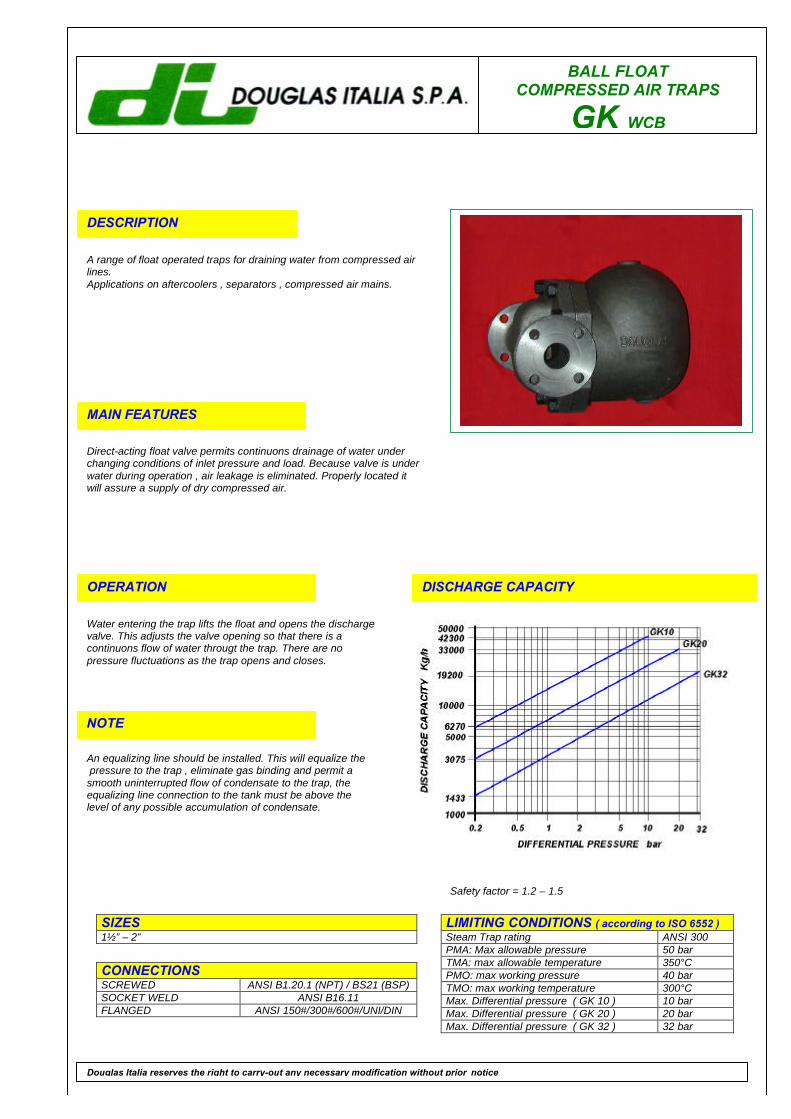
BALL FLOATCOMPRESSED AIR TRAPS
GK WCB
DESCRIPTION
A range of float operated traps for draining water from compressed airlines.Applications on aftercoolers , separators , compressed air mains.
MAIN FEATURES
Direct-acting float valve permits continuons drainage of water underchanging conditions of inlet pressure and load. Because valve is underwater during operation , air leakage is eliminated. Properly located itwill assure a supply of dry compressed air.
OPERATION
Water entering the trap lifts the float and opens the dischargevalve. This adjusts the valve opening so that there is acontinuons flow of water througt the trap. There are nopressure fluctuations as the trap opens and closes.
DISCHARGE CAPACITY
LIMITING CONDITIONS ( according to ISO 6552 )Steam Trap rating ANSI 300PMA: Max allowable pressure 50 barTMA: max allowable temperature 350°CPMO: max working pressure 40 barTMO: max working temperature 300°CMax. Differential pressure ( GK 10 ) 10 barMax. Differential pressure ( GK 20 ) 20 barMax. Differential pressure ( GK 32 ) 32 bar
SIZES1½” – 2”
CONNECTIONSSCREWED ANSI B1.20.1 (NPT) / BS21 (BSP)SOCKET WELD ANSI B16.11FLANGED ANSI 150#/300#/600#/UNI/DIN
Douglas Italia reserves the right to carry-out any necessary modification without prior notice
NOTE
An equalizing line should be installed. This will equalize the pressure to the trap , eliminate gas binding and permit asmooth uninterrupted flow of condensate to the trap, theequalizing line connection to the tank must be above thelevel of any possible accumulation of condensate.
Safety factor = 1.2 – 1.5

COMPRESSED AIR BALL FLOAT TRAPS
GK WCB
POS. DESCRIPTION MATERIALS SPARES
1 Body ASTM A216 WCB2 Cover ASTM A216 WCB3 Gasket 316 / GRAPHITE X4 Seat AISI 316 X5 Valve AISI 316 X6 Screws STAINLESS STEEL X7 Lever AISI 316 X8 Ball float AISI 316 X9 Plug A 10510 Bolts ASTM A193 B7
FlangedSize(inches)
S A B C Weight(Kg)
UNI-DINPN16-25-40
SF Kg
150#
SF Kg
300#
SF Kg
600#
SF Kg1½” 260 258 250 109 34 320 37 320 37 320 39 320 41”2” 260 258 250 109 34 320 38 320 38 320 40 320 42
INSTALLATIONThe steam trap must be fitted with the float arm in a horizontal plane so that it rises and falls vertically with the flow direction indicated on thebody.HOW TO SERVICEBy installing a new mechanism assembly (4),(5),(6),(7), if necessary also a ball float (8), you can bring the steam trap to the “ as new fromfactory “ condition. This operation is carried out without removing the trap from yhe pipeline. Always fit a new gasket (3) when reassembling.
How to order: i.e. GK 17 WCB 2” 300 RF
DOUGLAS ITALIA S.p.A Località Pradaglie – 29013 CARPANETO PIACENTINO ( PC )
OFFICIAL WEB SITE: www.douglas-italia.com
Douglas Italia reserves the right to carry-out any necessary modification without prior notice 6 . 00

BALL FLOATCOMPRESSED AIR TRAPS
GK CF8M
DESCRIPTION
A range of float operated traps for draining water from compressed airlines.Applications on aftercoolers , separators , compressed air mains.
MAIN FEATURES
Direct-acting float valve permits continuons drainage of water underchanging conditions of inlet pressure and load. Because valve is underwater during operation , air leakage is eliminated. Properly located itwill assure a supply of dry compressed air.
OPERATION
Water entering the trap lifts the float and opens the dischargevalve. This adjusts the valve opening so that there is acontinuons flow of water througt the trap. There are nopressure fluctuations as the trap opens and closes.
DISCHARGE CAPACITY
LIMITING CONDITIONS ( according to ISO 6552 )Steam Trap rating ANSI 300PMA: Max allowable pressure 50 barTMA: max allowable temperature 410°CPMO: max working pressure 40 barTMO: max working temperature 370°CMax. Differential pressure ( GK 10 ) 10 barMax. Differential pressure ( GK 20 ) 20 barMax. Differential pressure ( GK 32 ) 32 bar
SIZES1½” – 2”
CONNECTIONSSCREWED ANSI B1.20.1 (NPT) / BS21 (BSP)SOCKET WELD ANSI B16.11FLANGED ANSI 150#/300#/600#/UNI/DIN
Douglas Italia reserves the right to carry-out any necessary modification without prior notice
NOTE
An equalizing line should be installed. This will equalize the pressure to the trap , eliminate gas binding and permit asmooth uninterrupted flow of condensate to the trap, theequalizing line connection to the tank must be above thelevel of any possible accumulation of condensate.
Safety factor = 1.2 – 1.5
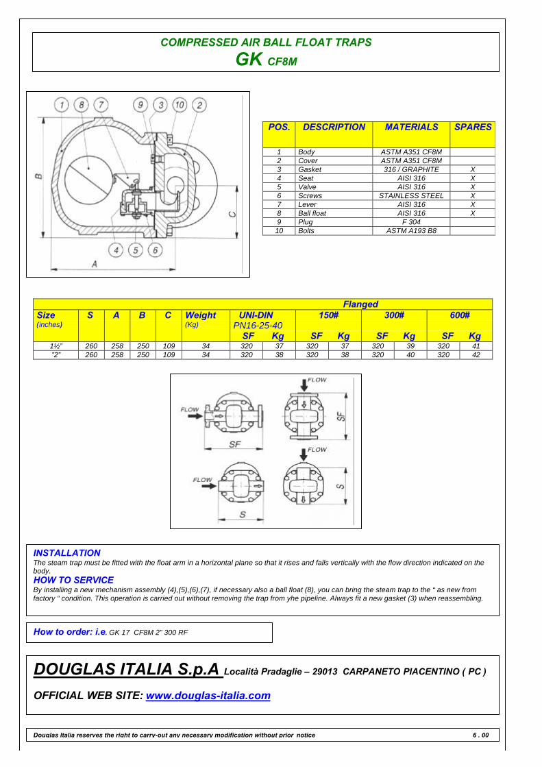
COMPRESSED AIR BALL FLOAT TRAPS
GK CF8M
POS. DESCRIPTION MATERIALS SPARES
1 Body ASTM A351 CF8M2 Cover ASTM A351 CF8M3 Gasket 316 / GRAPHITE X4 Seat AISI 316 X5 Valve AISI 316 X6 Screws STAINLESS STEEL X7 Lever AISI 316 X8 Ball float AISI 316 X9 Plug F 30410 Bolts ASTM A193 B8
FlangedSize(inches)
S A B C Weight(Kg)
UNI-DINPN16-25-40
SF Kg
150#
SF Kg
300#
SF Kg
600#
SF Kg1½” 260 258 250 109 34 320 37 320 37 320 39 320 41”2” 260 258 250 109 34 320 38 320 38 320 40 320 42
INSTALLATIONThe steam trap must be fitted with the float arm in a horizontal plane so that it rises and falls vertically with the flow direction indicated on thebody.HOW TO SERVICEBy installing a new mechanism assembly (4),(5),(6),(7), if necessary also a ball float (8), you can bring the steam trap to the “ as new fromfactory “ condition. This operation is carried out without removing the trap from yhe pipeline. Always fit a new gasket (3) when reassembling.
How to order: i.e. GK 17 CF8M 2” 300 RF
DOUGLAS ITALIA S.p.A Località Pradaglie – 29013 CARPANETO PIACENTINO ( PC )
OFFICIAL WEB SITE: www.douglas-italia.com
Douglas Italia reserves the right to carry-out any necessary modification without prior notice 6 . 00
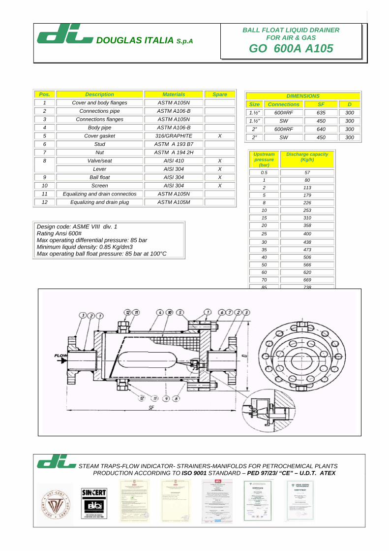
DOUGLAS ITALIA S.p.A
STEAM TRAPS-FLOW INDICATOR- STRAINERS-MANIFOLDS FOR PETROCHEMICAL PLANTS PRODUCTION ACCORDING TO ISO 9001 STANDARD – PED 97/23/ “CE” – U.D.T. ATEX
Pos. Description Materials Spare
1 Cover and body flanges ASTM A105N 2 Connections pipe ASTM A106-B 3 Connections flanges ASTM A105N 4 Body pipe ASTM A106-B 5 Cover gasket 316/GRAPHITE X 6 Stud ASTM A 193 B7 7 Nut ASTM A 194 2H
Valve/seat AISI 410 X 8 Lever AISI 304 X
9 Ball float AISI 304 X 10 Screen AISI 304 X 11 Equalizing and drain connectios ASTM A105N 12 Equalizing and drain plug ASTM A105M
BALL FLOAT LIQUID DRAINER FOR AIR & GAS
GO 600A A105
DIMENSIONS Size Connections SF D 1.½” 600#RF 635 300 1.½” SW 450 300
2” 600#RF 640 300 2” SW 450 300
Upstream pressure
(bar)
Discharge capacity (Kg/h)
0.5 57 1 80 2 113 5 179 8 226 10 253 15 310 20 358
25 400
30 438 35 473 40 506 50 566 60 620 70 669 85 738
Design code: ASME VIII div. 1 Rating Ansi 600# Max operating differential pressure: 85 bar Minimum liquid density: 0.85 Kg/dm3 Max operating ball float pressure: 85 bar at 100°C
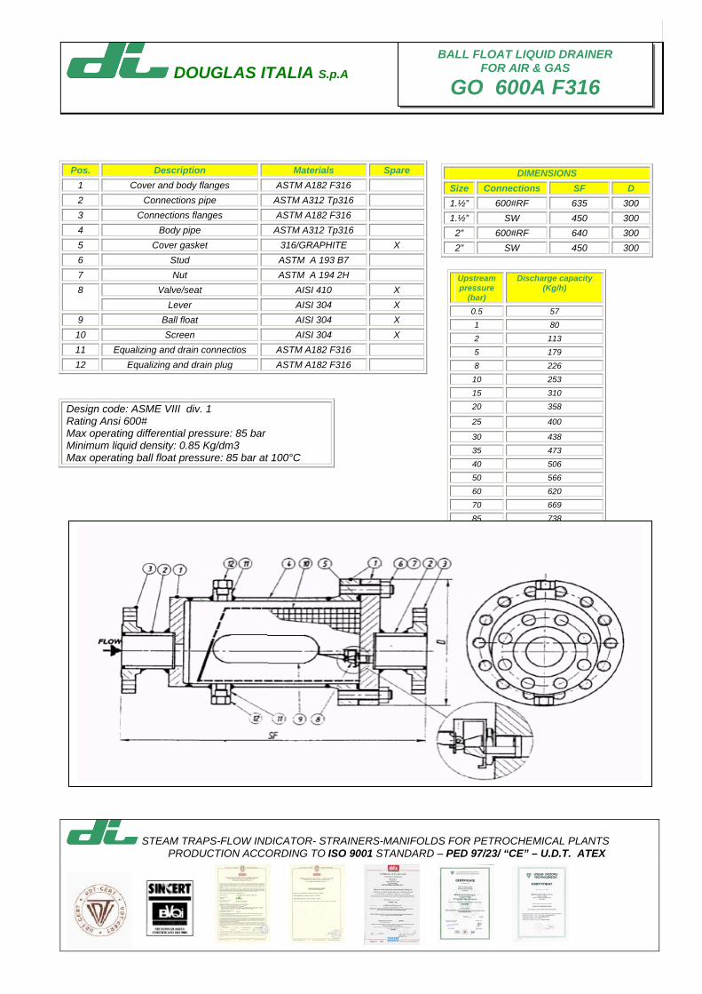
DOUGLAS ITALIA S.p.A
STEAM TRAPS-FLOW INDICATOR- STRAINERS-MANIFOLDS FOR PETROCHEMICAL PLANTS PRODUCTION ACCORDING TO ISO 9001 STANDARD – PED 97/23/ “CE” – U.D.T. ATEX
Pos. Description Materials Spare
1 Cover and body flanges ASTM A182 F316 2 Connections pipe ASTM A312 Tp316 3 Connections flanges ASTM A182 F316 4 Body pipe ASTM A312 Tp316 5 Cover gasket 316/GRAPHITE X 6 Stud ASTM A 193 B7 7 Nut ASTM A 194 2H
Valve/seat AISI 410 X 8 Lever AISI 304 X
9 Ball float AISI 304 X 10 Screen AISI 304 X 11 Equalizing and drain connectios ASTM A182 F316 12 Equalizing and drain plug ASTM A182 F316
BALL FLOAT LIQUID DRAINER FOR AIR & GAS
GO 600A F316
DIMENSIONS Size Connections SF D 1.½” 600#RF 635 300 1.½” SW 450 300
2” 600#RF 640 300 2” SW 450 300
Upstream pressure
(bar)
Discharge capacity (Kg/h)
0.5 57 1 80 2 113 5 179 8 226 10 253 15 310 20 358
25 400
30 438 35 473 40 506 50 566 60 620 70 669 85 738
Design code: ASME VIII div. 1 Rating Ansi 600# Max operating differential pressure: 85 bar Minimum liquid density: 0.85 Kg/dm3 Max operating ball float pressure: 85 bar at 100°C

AIR AND GAS VENTS FORLIQUID SYSTEM
GO BACK
AP
AK
GA 150A WCB
GA 150A CF8M
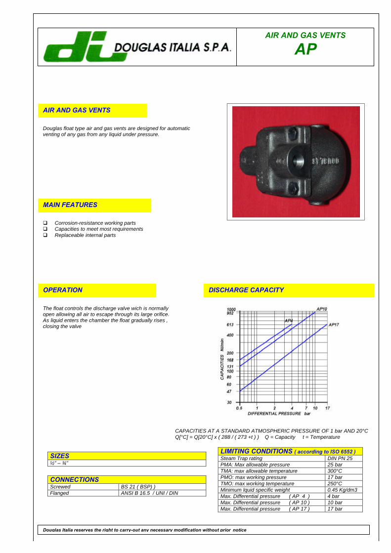
AIR AND GAS VENTS
AP
AIR AND GAS VENTS
Douglas float type air and gas vents are designed for automaticventing of any gas from any liquid under pressure.
MAIN FEATURES
q Corrosion-resistance working partsq Capacities to meet most requirementsq Replaceable internal parts
OPERATION
The float controls the discharge valve wich is normallyopen allowing all air to escape through its large orifice.As liquid enters the chamber the float gradually rises ,closing the valve
DISCHARGE CAPACITY
LIMITING CONDITIONS ( according to ISO 6552 )Steam Trap rating DIN PN 25PMA: Max allowable pressure 25 barTMA: max allowable temperature 300°CPMO: max working pressure 17 barTMO: max working temperature 250°CMinimum lquid specific weight 0.45 Kg/dm3Max. Differential pressure ( AP 4 ) 4 barMax. Differential pressure ( AP 10 ) 10 barMax. Differential pressure ( AP 17 ) 17 bar
SIZES½” – ¾”
CONNECTIONSScrewed BS 21 ( BSP) )Flanged ANSI B 16.5 / UNI / DIN
Douglas Italia reserves the right to carry-out any necessary modification without prior notice
CAPACITIES AT A STANDARD ATMOSPHERIC PRESSURE OF 1 bar AND 20°CQ[°C] = Q[20°C] x ( 288 / ( 273 +t ) ) Q = Capacity t = Temperature
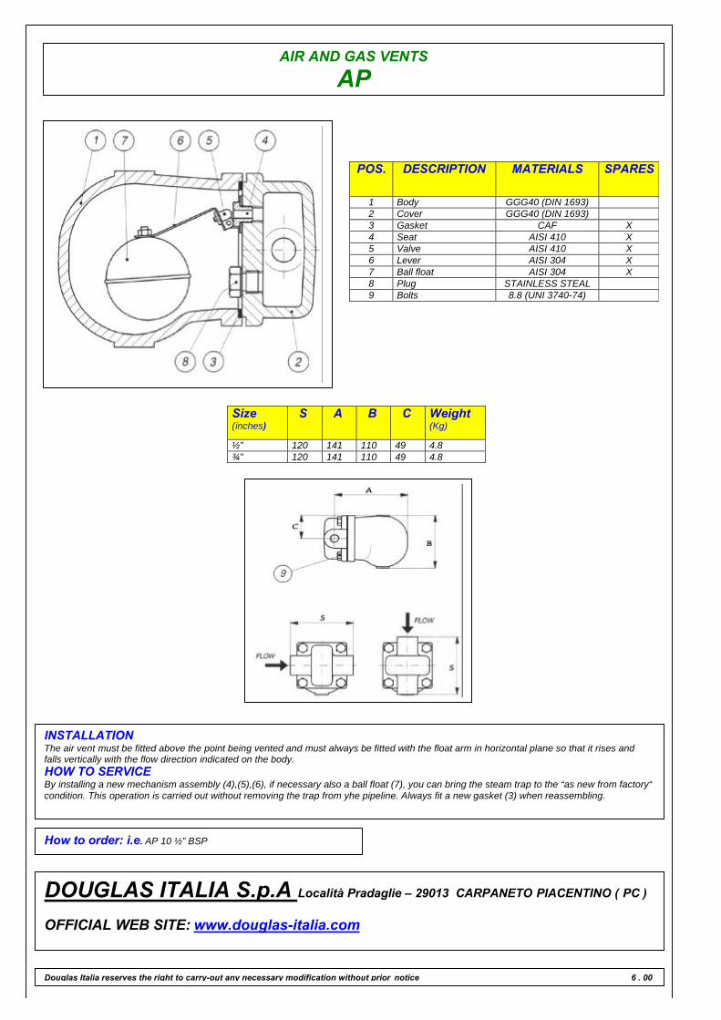
AIR AND GAS VENTS
AP
POS. DESCRIPTION MATERIALS SPARES
1 Body GGG40 (DIN 1693)2 Cover GGG40 (DIN 1693)3 Gasket CAF X4 Seat AISI 410 X5 Valve AISI 410 X6 Lever AISI 304 X7 Ball float AISI 304 X8 Plug STAINLESS STEAL9 Bolts 8.8 (UNI 3740-74)
Size(inches)
S A B C Weight(Kg)
½” 120 141 110 49 4.8¾” 120 141 110 49 4.8
INSTALLATIONThe air vent must be fitted above the point being vented and must always be fitted with the float arm in horizontal plane so that it rises andfalls vertically with the flow direction indicated on the body.HOW TO SERVICEBy installing a new mechanism assembly (4),(5),(6), if necessary also a ball float (7), you can bring the steam trap to the “as new from factory“condition. This operation is carried out without removing the trap from yhe pipeline. Always fit a new gasket (3) when reassembling.
How to order: i.e. AP 10 ½” BSP
DOUGLAS ITALIA S.p.A Località Pradaglie – 29013 CARPANETO PIACENTINO ( PC )
OFFICIAL WEB SITE: www.douglas-italia.com
Douglas Italia reserves the right to carry-out any necessary modification without prior notice 6 . 00
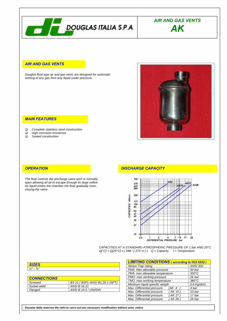
AIR AND GAS VENTS
AK
AIR AND GAS VENTS
Douglas float type air and gas vents are designed for automaticventing of any gas from any liquid under pressure.
MAIN FEATURES
q Complete stainless steel constructionq High corrosion resistenceq Sealed construction
OPERATION
The float controls the discharge valve wich is normallyopen allowing all air to escape through its large orifice.As liquid enters the chamber the float gradually rises ,closing the valve.
DISCHARGE CAPACITY
LIMITING CONDITIONS ( according to ISO 6552 )Steam Trap rating ANSI 300PMA: Max allowable pressure 50 barTMA: max allowable temperature 500°CPMO: max working pressure 26 barTMO: max working temperature 380°CMinimum liquid specific weigth 0.6 Kg/dm3Max. Differential pressure (AK 4 ) 4 barMax. Differential pressure ( AK 10 ) 10 barMax. Differential pressure ( AK 17 ) 17 barMax. Differential pressure ( AK 26 ) 26 bar
SIZES½” – ¾”
CONNECTIONSScrewed BS 21 ( BSP) /ANSI B1.20.1 (NPT)Socket weld ANSI B 16.11Flanged ANSI B 16.5 / UNI/DIN
Douglas Italia reserves the right to carry-out any necessary modification without prior notice
CAPACITIES AT A STANDARD ATMOSPHERIC PRESSURE OF 1 bar AND 20°CQ[°C] = Q[20°C] x ( 288 / ( 273 +t ) ) Q = Capacity t = Temperature
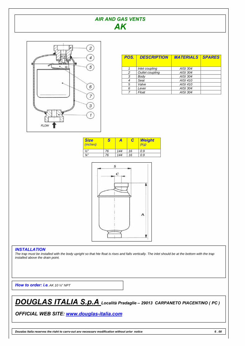
AIR AND GAS VENTS
AK
POS. DESCRIPTION MATERIALS SPARES
1 Inlet coupling AISI 3042 Outlet coupling AISI 3043 Body AISI 3044 Seat AISI 4105 Valve AISI 4106 Lever AISI 3047 Float AISI 304
Size(inches)
S A C Weight(Kg)
½” 76 144 16 0.9¾” 76 144 16 0.9
INSTALLATIONThe trap must be installed with the body upright so that hte float is rises and falls vertically. The inlet should be at the bottom with the trapinstalled above the drain point.
How to order: i.e. AK 10 ½” NPT
DOUGLAS ITALIA S.p.A Località Pradaglie – 29013 CARPANETO PIACENTINO ( PC )
OFFICIAL WEB SITE: www.douglas-italia.com
Douglas Italia reserves the right to carry-out any necessary modification without prior notice 6 . 00
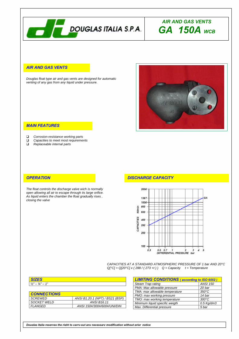
AIR AND GAS VENTS
GA 150A WCB
AIR AND GAS VENTS
Douglas float type air and gas vents are designed for automaticventing of any gas from any liquid under pressure.
MAIN FEATURES
q Corrosion-resistance working partsq Capacities to meet most requirementsq Replaceable internal parts
OPERATION
The float controls the discharge valve wich is normallyopen allowing all air to escape through its large orifice.As liquid enters the chamber the float gradually rises ,closing the valve
DISCHARGE CAPACITY
LIMITING CONDITIONS ( according to ISO 6552 )Steam Trap rating ANSI 150PMA: Max allowable pressure 20 barTMA: max allowable temperature 350°CPMO: max working pressure 14 barTMO: max working temperature 300°CMinimum liquid specific weigth 0.5 Kg/dm3Max. Differential pressure 5 bar
SIZES½” – ¾” – 1”
CONNECTIONSSCREWED ANSI B1.20.1 (NPT) / BS21 (BSP)SOCKET WELD ANSI B16.11FLANGED ANSI 150#/300#/600#/UNI/DIN
Douglas Italia reserves the right to carry-out any necessary modification without prior notice
CAPACITIES AT A STANDARD ATMOSPHERIC PRESSURE OF 1 bar AND 20°CQ[°C] = Q[20°C] x ( 288 / ( 273 +t ) ) Q = Capacity t = Temperature

AIR AND GAS VENTS
GA 150A WCB
POS. DESCRIPTION MATERIALS SPARES
1 Body ASTM A216 WCB2 Cover ASTM A216 WCB3 Gasket 316 / GRAPHITE X4 Seat AISI 316 X5 Valve AISI 316 X6 Lever AISI 316 X7 Ball float AISI 316 X8 Plug STAINLESS STEEL9 Bolts ASTM A193 B7
FlangedSize(inches)
S A B C Weight(Kg)
UNI-DINPN16-25-40
SF Kg
150#
SF Kg
300#
SF Kg
600#
SF Kg½” 165 213 71 180 11 211 13.3 205 13.3 211 13.5 222 14¾” 165 213 71 180 11 215 13.7 207 13.7 211 14.6 230 151” 165 213 71 180 11 215 14.5 210 14.5 214 15.2 230 15.5
INSTALLATIONThe air vent must be fitted above the point being vented and must always be fitted with the float arm in horizontal plane so that it rises andfalls vertically with the flow direction indicated on the body.HOW TO SERVICEBy installing a new mechanism assembly (4),(5),(6),if necessary also a ball float (7), you can bring the steam trap to the “as new from factory“condition. This operation is carried out without removing the trap from yhe pipeline. Always fit a new gasket (3) when reassembling.
How to order: i.e. GA 150A WCB ½” BSP
DOUGLAS ITALIA S.p.A Località Pradaglie – 29013 CARPANETO PIACENTINO ( PC )
OFFICIAL WEB SITE: www.douglas-italia.com
Douglas Italia reserves the right to carry-out any necessary modification without prior notice 6 . 00

AIR AND GAS VENTS
GA 150A CF8M
AIR AND GAS VENTS
Douglas float type air and gas vents are designed for automaticventing of any gas from any liquid under pressure.
MAIN FEATURES
q Corrosion-resistance working partsq Capacities to meet most requirementsq Replaceable internal parts
OPERATION
The float controls the discharge valve wich is normallyopen allowing all air to escape through its large orifice.As liquid enters the chamber the float gradually rises ,closing the valve
DISCHARGE CAPACITY
LIMITING CONDITIONS ( according to ISO 6552 )Steam Trap rating ANSI 150PMA: Max allowable pressure 20 barTMA: max allowable temperature 410°CPMO: max working pressure 14 barTMO: max working temperature 370°CMinimum liquid specific weigth 0.5 Kg/dm3Max. Differential pressure 5 bar
SIZES½” – ¾” – 1”
CONNECTIONSSCREWED ANSI B1.20.1 (NPT) / BS21 (BSP)SOCKET WELD ANSI B16.11FLANGED ANSI 150#/300#/600#/UNI/DIN
Douglas Italia reserves the right to carry-out any necessary modification without prior notice
CAPACITIES AT A STANDARD ATMOSPHERIC PRESSURE OF 1 bar AND 20°CQ[°C] = Q[20°C] x ( 288 / ( 273 +t ) ) Q = Capacity t = Temperature
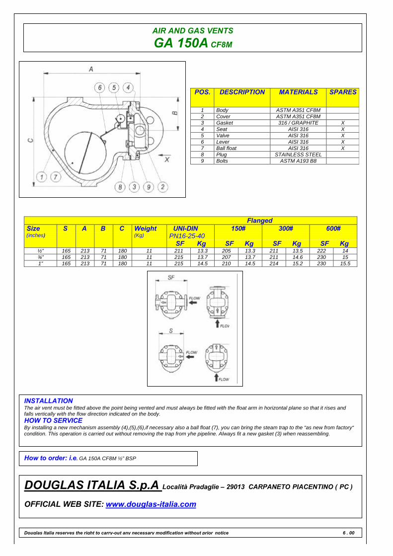
AIR AND GAS VENTS
GA 150A CF8M
POS. DESCRIPTION MATERIALS SPARES
1 Body ASTM A351 CF8M2 Cover ASTM A351 CF8M3 Gasket 316 / GRAPHITE X4 Seat AISI 316 X5 Valve AISI 316 X6 Lever AISI 316 X7 Ball float AISI 316 X8 Plug STAINLESS STEEL9 Bolts ASTM A193 B8
FlangedSize(inches)
S A B C Weight(Kg)
UNI-DINPN16-25-40
SF Kg
150#
SF Kg
300#
SF Kg
600#
SF Kg½” 165 213 71 180 11 211 13.3 205 13.3 211 13.5 222 14¾” 165 213 71 180 11 215 13.7 207 13.7 211 14.6 230 151” 165 213 71 180 11 215 14.5 210 14.5 214 15.2 230 15.5
INSTALLATIONThe air vent must be fitted above the point being vented and must always be fitted with the float arm in horizontal plane so that it rises andfalls vertically with the flow direction indicated on the body.HOW TO SERVICEBy installing a new mechanism assembly (4),(5),(6),if necessary also a ball float (7), you can bring the steam trap to the “as new from factory“condition. This operation is carried out without removing the trap from yhe pipeline. Always fit a new gasket (3) when reassembling.
How to order: i.e. GA 150A CF8M ½” BSP
DOUGLAS ITALIA S.p.A Località Pradaglie – 29013 CARPANETO PIACENTINO ( PC )
OFFICIAL WEB SITE: www.douglas-italia.com
Douglas Italia reserves the right to carry-out any necessary modification without prior notice 6 . 00
FORGED PISTON VALVE NEW
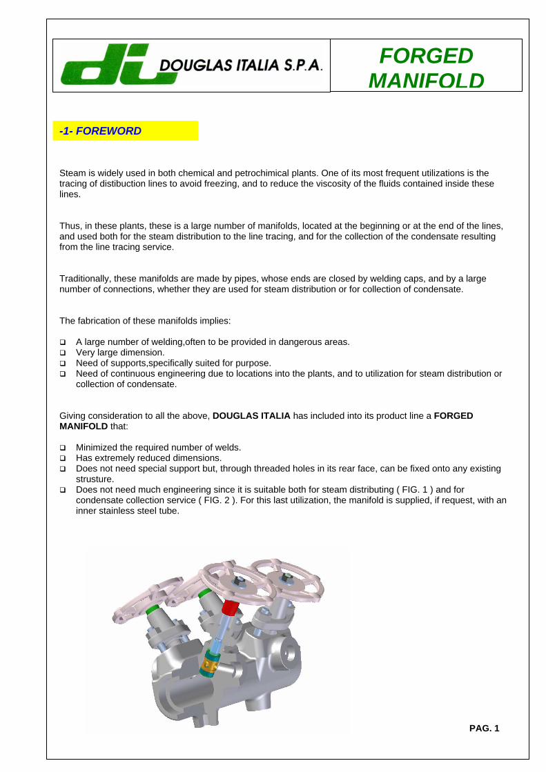
FORGED MANIFOLD
-1- FOREWORD
Steam is widely used in both chemical and petrochimical plants. One of its most frequent utilizations is the tracing of distibuction lines to avoid freezing, and to reduce the viscosity of the fluids contained inside these lines. Thus, in these plants, these is a large number of manifolds, located at the beginning or at the end of the lines, and used both for the steam distribution to the line tracing, and for the collection of the condensate resulting from the line tracing service. Traditionally, these manifolds are made by pipes, whose ends are closed by welding caps, and by a large number of connections, whether they are used for steam distribution or for collection of condensate. The fabrication of these manifolds implies:
A large number of welding,often to be provided in dangerous areas. Very large dimension. Need of supports,specifically suited for purpose. Need of continuous engineering due to locations into the plants, and to utilization for steam distribution or
collection of condensate. Giving consideration to all the above, DOUGLAS ITALIA has included into its product line a FORGED MANIFOLD that:
Minimized the required number of welds. Has extremely reduced dimensions. Does not need special support but, through threaded holes in its rear face, can be fixed onto any existing
strusture. Does not need much engineering since it is suitable both for steam distributing ( FIG. 1 ) and for
condensate collection service ( FIG. 2 ). For this last utilization, the manifold is supplied, if request, with an inner stainless steel tube.
PAG. 1
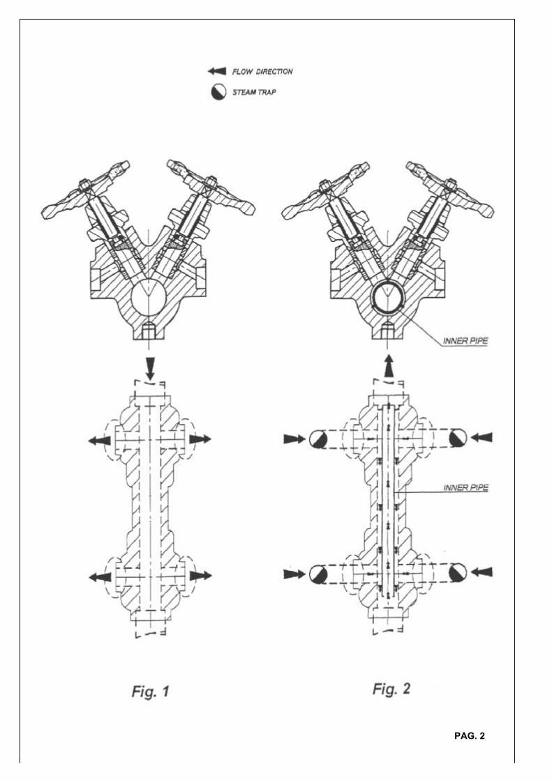
PAG. 2
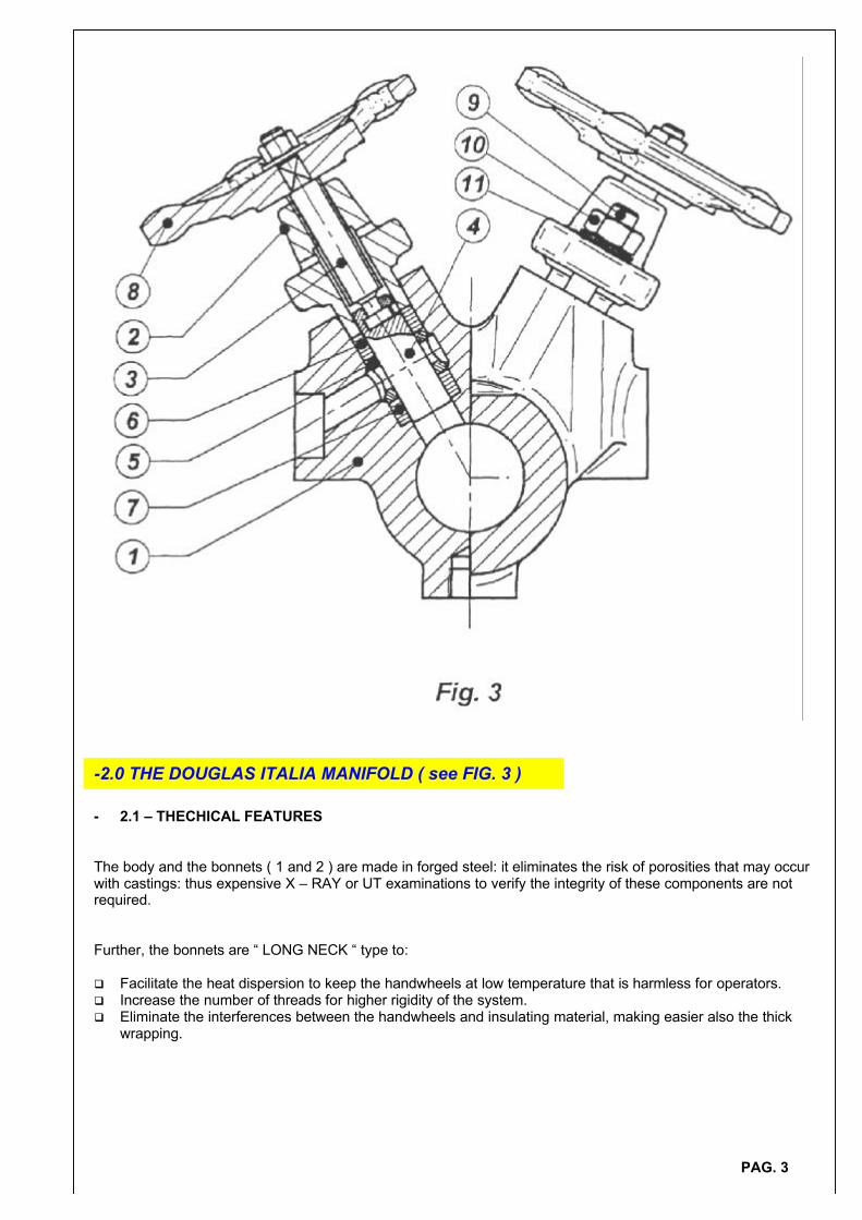
- 2.1 – THECHICAL FEATURES
The body and the bonnets ( 1 and 2 ) are made in forged steel: it eliminates the risk of porosities that may occurwith castings: thus expensive X – RAY or UT examinations to verify the integrity of these components are notrequired.
Further, the bonnets are “ LONG NECK “ type to:
q Facilitate the heat dispersion to keep the handwheels at low temperature that is harmless for operators.q Increase the number of threads for higher rigidity of the system.q Eliminate the interferences between the handwheels and insulating material, making easier also the thick
wrapping.
-2.0 THE DOUGLAS ITALIA MANIFOLD ( see FIG. 3 )
PAG. 3
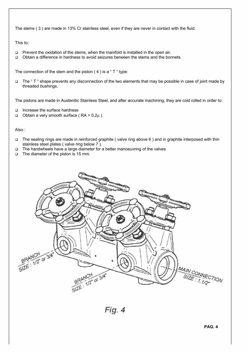
The stems ( 3 ) are made in 13% Cr stainless steel, even if they are never in contact with the fluid.
This to:
q Prevent the oxidation of the stems, when the manifold is installed in the open air.q Obtain a difference in hardness to avoid seizures berween the stems and the bonnets.
The connection of the stem and the piston ( 4 ) is a “ T “ type:
q The “ T “ shape prevents any disconnection of the two elements that may be possible in case of joint made bythreaded bushings.
The pistons are made in Austenitic Stainless Steel, and after accurate machining, they are cold rolled in order to:
q Increase the surface hardnessq Obtain a very smooth surface ( RA = 0,2µ ).
Also :
q The sealing rings are made in reinforced graphite ( valve ring above 6 ) and in graphite interposed with thinstainless steel plates ( valve ring below 7 ).
q The handwheels have a large diameter for a better manoeuvring of the valvesq The diameter of the piston is 15 mm.
PAG. 4
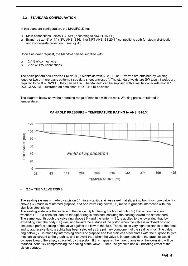
- 2.2 – STANDARD CONFIGURATION
In this standard configuration, the MANIFOLD has:
q Main connections : sizes 11⁄2” SW ( according to ANSI B16.11 ).q Branch : size 1⁄2” or 3⁄4” ( SW ANSI B16.11 or NPT ANSI B1.20.1 ) connections both for steam distribution
and condensate collection. ( see fig. 4 ).
Upon Customer request, the Manifold can be supplied with:
q 11⁄2” BW connectionsq 1⁄2” or 3⁄4” BW connections
The basic pattern has 4 valves ( MPV 04 ) ; Manifolds with 6 , 8 , 10 or 12 valves are obtained by weldingtogether two or more basic patterns ( see data sheet enclosed ). The standard welds are SW type ; if welds arerequired to be X – RAYED , they can be BW. The Manifold can be supplied with a insulation jackets model “DOUGLAS JM “ illustrated on data sheet N.9C241415 enclosed.
The diagram below show the operating range of manifold with the max. Working pressure related totemperature.
MANIFOLD PRESSURE – TEMPERATURE RATING to ANSI B16.34
- 2.3 – THE VALVE TRIMS
The sealing system is made by a piston ( 4 ) in austenitic stainless steel that slider into two rings, one valve ringabove ( 6 ) made in reinforced graphite, and one valve ring below ( 7 ) made in graphite interposed with thinstainless steel plates.The sealing surface is the surface of the piston. By tightening the bonnet nuts ( 9 ) that act on the springwashers ( 11 ), a constant load on the upper ring is obtained, securing the sealing toward the atmosphere.The same load, through the valve ring above ( 6 ) and the lantern ( 5 ), is applied to the lower ring that, byexpanding itself the body ( 1 ) wall, and toward the surface of the piston when the valve is in closed position,ensures a perfect sealing of the valve against the flow of the fluid. Thanks to its very high resistance to the heatand to aggressive fluid, graphite has been selected as the primary component of the sealing rings. The valvering below ( 7 ) is made by interposing sheets of graphite and thin stainless steel plates with the purpose to givemechanical streght to the graphite, and to avoid that, when the valve is in open position, the graphite wouldcollapse toward the empty space left by the piston. If this happens, the inner diameter of the lower ring will bereduced, seriously compromising the sealing of the valve. Futher, the graphite has a lubricating effect of thepiston surface.
PAG. 5
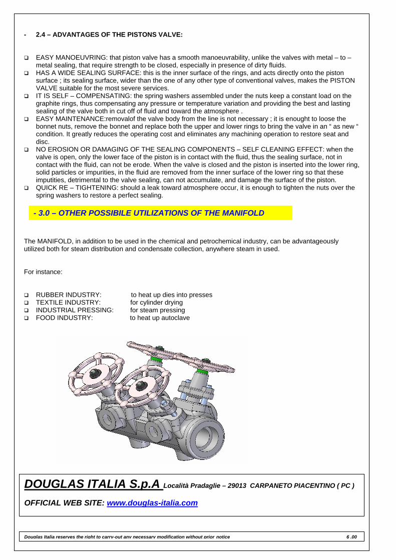
- 2.4 – ADVANTAGES OF THE PISTONS VALVE:
EASY MANOEUVRING: that piston valve has a smooth manoeuvrability, unlike the valves with metal – to –metal sealing, that require strength to be closed, especially in presence of dirty fluids.
HAS A WIDE SEALING SURFACE: this is the inner surface of the rings, and acts directly onto the piston surface ; its sealing surface, wider than the one of any other type of conventional valves, makes the PISTON VALVE suitable for the most severe services.
IT IS SELF – COMPENSATING: the spring washers assembled under the nuts keep a constant load on the graphite rings, thus compensating any pressure or temperature variation and providing the best and lasting sealing of the valve both in cut off of fluid and toward the atmosphere .
EASY MAINTENANCE:removalof the valve body from the line is not necessary ; it is enought to loose the bonnet nuts, remove the bonnet and replace both the upper and lower rings to bring the valve in an “ as new “ condition. It greatly reduces the operating cost and eliminates any machining operation to restore seat and disc.
NO EROSION OR DAMAGING OF THE SEALING COMPONENTS – SELF CLEANING EFFECT: when the valve is open, only the lower face of the piston is in contact with the fluid, thus the sealing surface, not in contact with the fluid, can not be erode. When the valve is closed and the piston is inserted into the lower ring, solid particles or impurities, in the fluid are removed from the inner surface of the lower ring so that these imputities, detrimental to the valve sealing, can not accumulate, and damage the surface of the piston.
QUICK RE – TIGHTENING: should a leak toward atmosphere occur, it is enough to tighten the nuts over the spring washers to restore a perfect sealing.
The MANIFOLD, in addition to be used in the chemical and petrochemical industry, can be advantageously utilized both for steam distribution and condensate collection, anywhere steam in used. For instance:
RUBBER INDUSTRY: to heat up dies into presses TEXTILE INDUSTRY: for cylinder drying INDUSTRIAL PRESSING: for steam pressing FOOD INDUSTRY: to heat up autoclave
- 3.0 – OTHER POSSIBILE UTILIZATIONS OF THE MANIFOLD
DOUGLAS ITALIA S.p.A Località Pradaglie – 29013 CARPANETO PIACENTINO ( PC ) OFFICIAL WEB SITE: www.douglas-italia.com
Douglas Italia reserves the right to carry-out any necessary modification without prior notice 6 .00
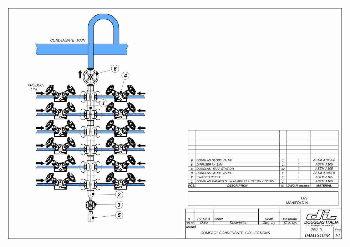
Agg. N° DescriptionModel
Date Dwg. by Chk. by.
Dwg. N. Sheet
DOUGLAS ITALIALoc. Pradaglie Carpaneto (PC)
0 15/09/04 Issue Volpi Masaratti
04M131028 1/1COMPACT CONDENSATE COLLECTIONS
1
6
5
2
3
4
CONDENSATE MAIN
6 DOUGLAS GLOBE VALVE 1 // ASTM A105/F65 DIFFUSER for Safe 1 // ASTM A1054 DOUGLAS TRAP STATION 12 // ASTM A1053 DOUGLAS GLOBE VALVE 1 // ASTM A105/F62 SWAGED NIPPLE 1 // ASTM A1051 DOUGLAS MANIFOLD model MPV 12 1.1/2" SW -1/2" SW 1 // ASTM A105
POS. DESCRIPTION N. DWG.N enclose MATERIAL
TAG :MANIFOLD N.:
PRODUCT LINE
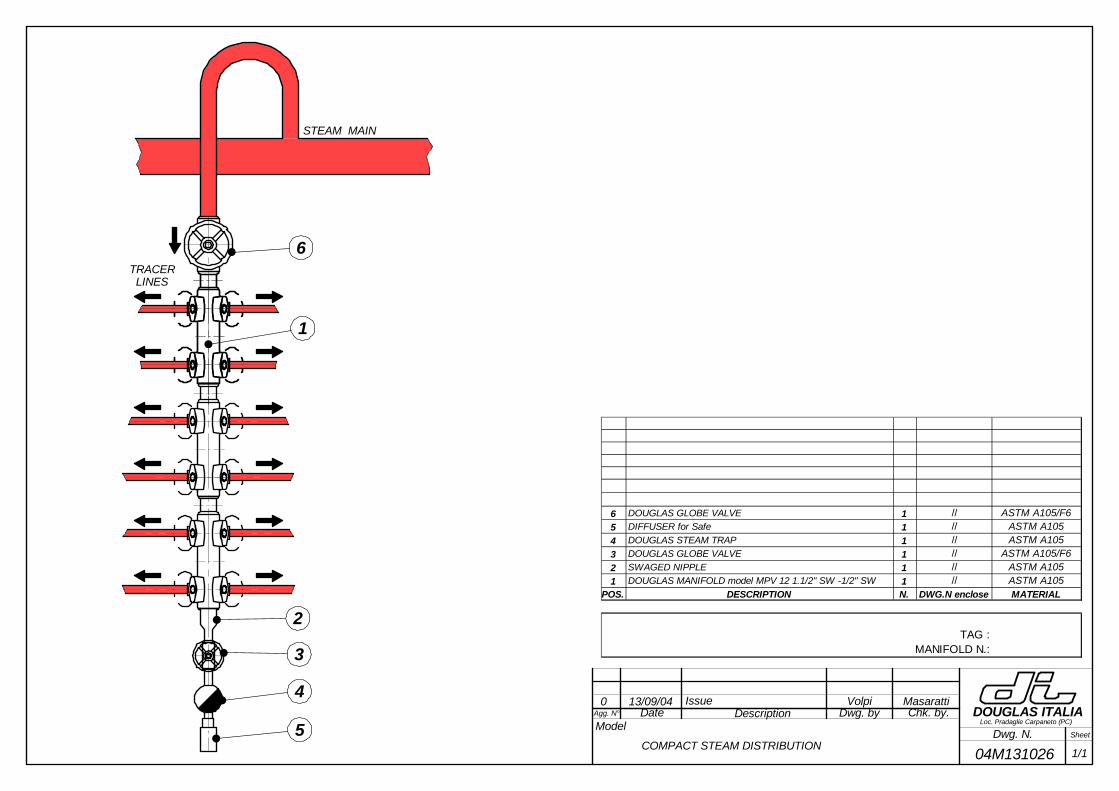
Agg. N° DescriptionModel
Date Dwg. by Chk. by.
Dwg. N. Sheet
DOUGLAS ITALIALoc. Pradaglie Carpaneto (PC)
0 13/09/04 Issue Volpi Masaratti
04M131026 1/1COMPACT STEAM DISTRIBUTION
1
6
5
2
3
4
TRACER LINES
STEAM MAIN
6 DOUGLAS GLOBE VALVE 1 // ASTM A105/F65 DIFFUSER for Safe 1 // ASTM A1054 DOUGLAS STEAM TRAP 1 // ASTM A1053 DOUGLAS GLOBE VALVE 1 // ASTM A105/F62 SWAGED NIPPLE 1 // ASTM A1051 DOUGLAS MANIFOLD model MPV 12 1.1/2" SW -1/2" SW 1 // ASTM A105
POS. DESCRIPTION N. DWG.N enclose MATERIAL
TAG :MANIFOLD N.:
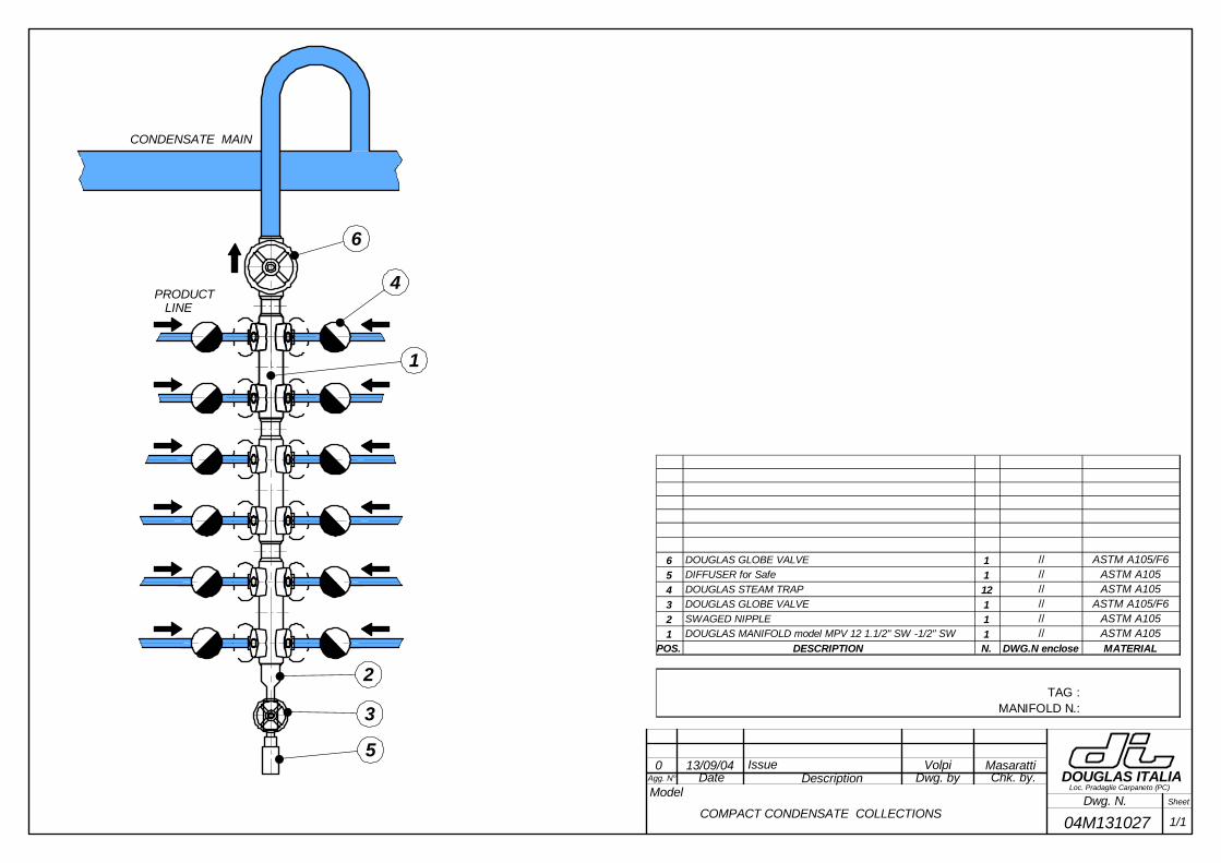
Agg. N° DescriptionModel
Date Dwg. by Chk. by.
Dwg. N. Sheet
DOUGLAS ITALIALoc. Pradaglie Carpaneto (PC)
0 13/09/04 Issue Volpi Masaratti
04M131027 1/1COMPACT CONDENSATE COLLECTIONS
1
6
5
2
3
4PRODUCT LINE
CONDENSATE MAIN
6 DOUGLAS GLOBE VALVE 1 // ASTM A105/F65 DIFFUSER for Safe 1 // ASTM A1054 DOUGLAS STEAM TRAP 12 // ASTM A1053 DOUGLAS GLOBE VALVE 1 // ASTM A105/F62 SWAGED NIPPLE 1 // ASTM A1051 DOUGLAS MANIFOLD model MPV 12 1.1/2" SW -1/2" SW 1 // ASTM A105
POS. DESCRIPTION N. DWG.N enclose MATERIAL
TAG :MANIFOLD N.:

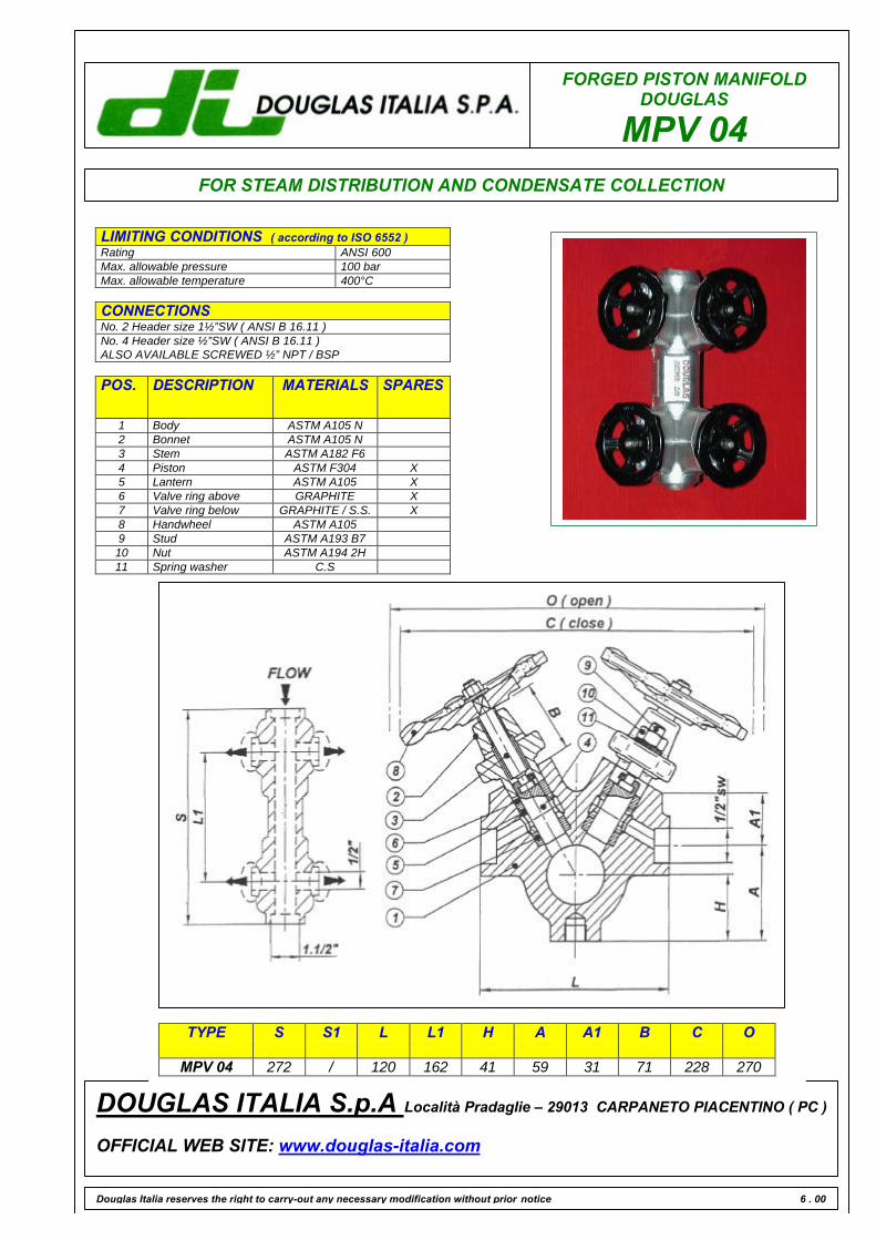
FORGED PISTON MANIFOLDDOUGLAS
MPV 04
LIMITING CONDITIONS ( according to ISO 6552 )Rating ANSI 600Max. allowable pressure 100 barMax. allowable temperature 400°C
CONNECTIONSNo. 2 Header size 1½”SW ( ANSI B 16.11 )No. 4 Header size ½”SW ( ANSI B 16.11 )ALSO AVAILABLE SCREWED ½” NPT / BSP
Douglas Italia reserves the right to carry-out any necessary modification without prior notice 6 . 00
DOUGLAS ITALIA S.p.A Località Pradaglie – 29013 CARPANETO PIACENTINO ( PC )
OFFICIAL WEB SITE: www.douglas-italia.com
POS. DESCRIPTION MATERIALS SPARES
1 Body ASTM A105 N2 Bonnet ASTM A105 N3 Stem ASTM A182 F64 Piston ASTM F304 X5 Lantern ASTM A105 X6 Valve ring above GRAPHITE X7 Valve ring below GRAPHITE / S.S. X8 Handwheel ASTM A1059 Stud ASTM A193 B710 Nut ASTM A194 2H11 Spring washer C.S
TYPE S S1 L L1 H A A1 B C O
MPV 04 272 / 120 162 41 59 31 71 228 270
FOR STEAM DISTRIBUTION AND CONDENSATE COLLECTION
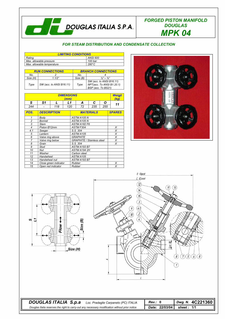
FORGED PISTON MANIFOLD DOUGLAS
MPK 04
LIMITING CONDITIONS Rating ANSI 600 Max. allowable pressure 100 bar Max. allowable temperature 300°C RUN CONNECTIONS BRANCH CONNECTIONS
No. 2 No. 4 Size (H) 1.1/2” Size (B) ½” – ¾”
SW (acc. to ANSI B16.11) NPT(acc. To ANSI B1.20.1) Type SW (acc. to ANSI B16.11) Type BSP (acc. To BS21)
POS. DESCRIPTION MATERIALS SPARES 1 Body ASTM A105 N 2 Bonnet ASTM A105 N 3 Stem ASTM A182 F6 4 Piston Ø12mm ASTM F304 X
4.1 Seeger S.S. 304 X 5 Lantern ASTM A105 X 6 Valve ring above GRAPHITE X 7 Valve ring below GRAPHITE / Stainless steel X 8 Grain S.S. 304 X 9 Stud ASTM A193 B7 10 Nut ASTM A194 2H 11 Washer Carbon steel 12 Handwheel ASTM A105 13 Handwheel nut ASTM A193 B7 14 Close green indicator Rubber X 15 Open red indicator Rubber X
DIMENSIONS (mm)
Weigjt (kg)
S S1 L L1 A C O 244 - 118 120 72 235 255 11
FOR STEAM DISTRIBUTION AND CONDENSATE COLLECTION
LIMITING CONDITIONS Rating ANSI 600 Max. allowable pressure 100 bar Max. allowable temperature 280°C
DOUGLAS ITALIA S.p.a Loc. Pradaglie Carpaneto (PC) ITALIA Rev.: 0 Dwg. N. 4C221360Douglas Italia reserves the right to carry-out any necessary modification without prior notice Date: 22/03/04 sheet : 1/1
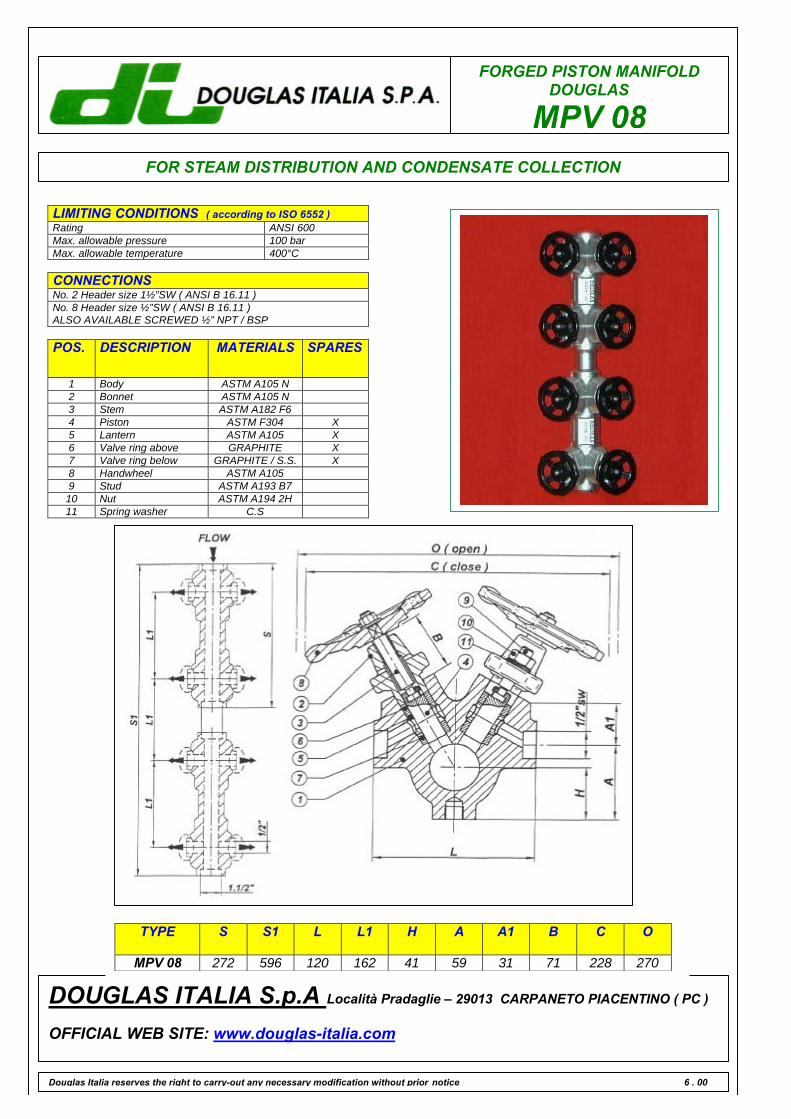
FORGED PISTON MANIFOLDDOUGLAS
MPV 08FOR STEAM DISTRIBUTION AND CONDENSATE COLLECTION
LIMITING CONDITIONS ( according to ISO 6552 )Rating ANSI 600Max. allowable pressure 100 barMax. allowable temperature 400°C
CONNECTIONSNo. 2 Header size 1½”SW ( ANSI B 16.11 )No. 8 Header size ½”SW ( ANSI B 16.11 )ALSO AVAILABLE SCREWED ½” NPT / BSP
POS. DESCRIPTION MATERIALS SPARES
1 Body ASTM A105 N2 Bonnet ASTM A105 N3 Stem ASTM A182 F64 Piston ASTM F304 X5 Lantern ASTM A105 X6 Valve ring above GRAPHITE X7 Valve ring below GRAPHITE / S.S. X8 Handwheel ASTM A1059 Stud ASTM A193 B710 Nut ASTM A194 2H11 Spring washer C.S
Douglas Italia reserves the right to carry-out any necessary modification without prior notice 6 . 00
DOUGLAS ITALIA S.p.A Località Pradaglie – 29013 CARPANETO PIACENTINO ( PC )
OFFICIAL WEB SITE: www.douglas-italia.com
TYPE S S1 L L1 H A A1 B C O
MPV 08 272 596 120 162 41 59 31 71 228 270
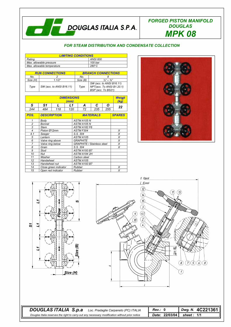
FORGED PISTON MANIFOLD DOUGLAS
MPK 08
LIMITING CONDITIONS Rating ANSI 600 Max. allowable pressure 100 bar Max. allowable temperature 300°C RUN CONNECTIONS BRANCH CONNECTIONS
No. 2 No. 8 Size (H) 1.1/2” Size (B) ½” – ¾”
SW (acc. to ANSI B16.11) NPT(acc. To ANSI B1.20.1) Type SW (acc. to ANSI B16.11) Type BSP (acc. To BS21)
POS. DESCRIPTION MATERIALS SPARES 1 Body ASTM A105 N 2 Bonnet ASTM A105 N 3 Stem ASTM A182 F6 4 Piston Ø12mm ASTM F304 X
4.1 Seeger S.S. 304 X 5 Lantern ASTM A105 X 6 Valve ring above GRAPHITE X 7 Valve ring below GRAPHITE / Stainless steel X 8 Grain S.S. 304 X 9 Stud ASTM A193 B7 10 Nut ASTM A194 2H 11 Washer Carbon steel 12 Handwheel ASTM A105 13 Handwheel nut ASTM A193 B7 14 Close green indicator Rubber X 15 Open red indicator Rubber X
FOR STEAM DISTRIBUTION AND CONDENSATE COLLECTION
LIMITING CONDITIONS Rating ANSI 600 Max. allowable pressure 100 bar Max. allowable temperature 280°C
DIMENSIONS (mm)
Weigjt (kg)
S S1 L L1 A C O 244 484 118 120 72 235 255 22
DOUGLAS ITALIA S.p.a Loc. Pradaglie Carpaneto (PC) ITALIA Rev.: 0 Dwg. N. 4C221361Douglas Italia reserves the right to carry-out any necessary modification without prior notice Date: 22/03/04 sheet : 1/1
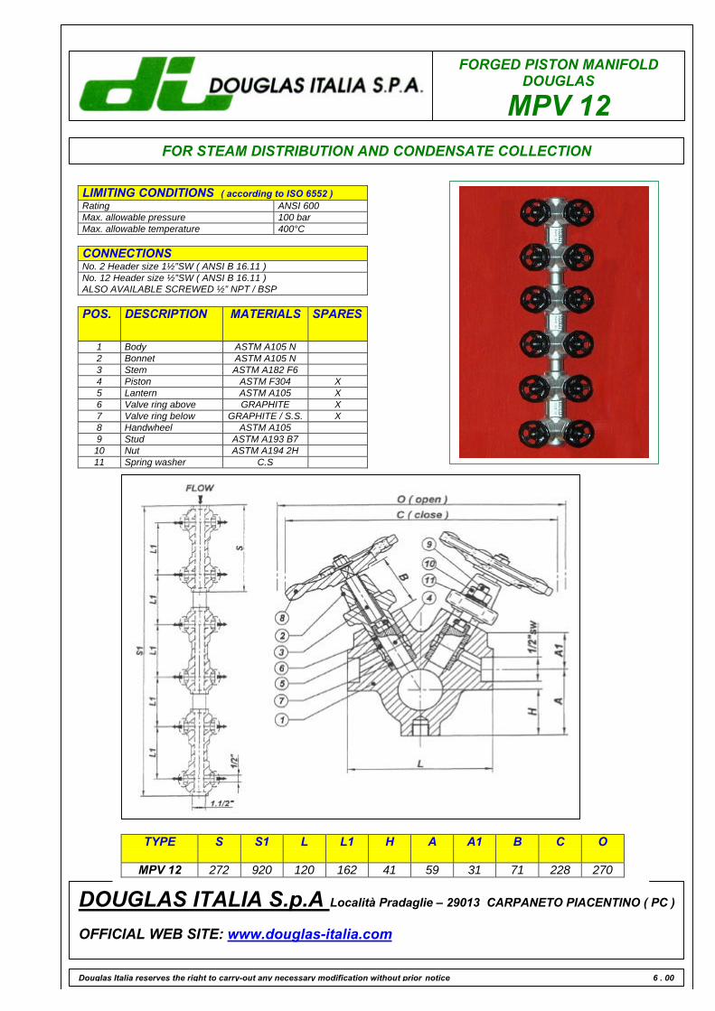
FORGED PISTON MANIFOLDDOUGLAS
MPV 12
LIMITING CONDITIONS ( according to ISO 6552 )Rating ANSI 600Max. allowable pressure 100 barMax. allowable temperature 400°C
CONNECTIONSNo. 2 Header size 1½”SW ( ANSI B 16.11 )No. 12 Header size ½”SW ( ANSI B 16.11 )ALSO AVAILABLE SCREWED ½” NPT / BSP
Douglas Italia reserves the right to carry-out any necessary modification without prior notice 6 . 00
DOUGLAS ITALIA S.p.A Località Pradaglie – 29013 CARPANETO PIACENTINO ( PC )
OFFICIAL WEB SITE: www.douglas-italia.com
POS. DESCRIPTION MATERIALS SPARES
1 Body ASTM A105 N2 Bonnet ASTM A105 N3 Stem ASTM A182 F64 Piston ASTM F304 X5 Lantern ASTM A105 X6 Valve ring above GRAPHITE X7 Valve ring below GRAPHITE / S.S. X8 Handwheel ASTM A1059 Stud ASTM A193 B710 Nut ASTM A194 2H11 Spring washer C.S
TYPE S S1 L L1 H A A1 B C O
MPV 12 272 920 120 162 41 59 31 71 228 270
FOR STEAM DISTRIBUTION AND CONDENSATE COLLECTION
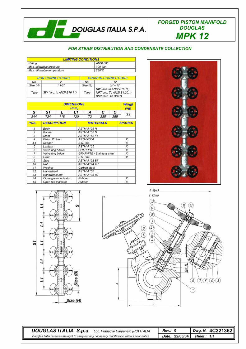
FORGED PISTON MANIFOLD DOUGLAS
MPK 12
LIMITING CONDITIONS Rating ANSI 600 Max. allowable pressure 100 bar Max. allowable temperature 300°C RUN CONNECTIONS BRANCH CONNECTIONS
No. 2 No. 12 Size (H) 1.1/2” Size (B) ½” – ¾”
SW (acc. to ANSI B16.11) NPT(acc. To ANSI B1.20.1) Type SW (acc. to ANSI B16.11) Type BSP (acc. To BS21)
POS. DESCRIPTION MATERIALS SPARES 1 Body ASTM A105 N 2 Bonnet ASTM A105 N 3 Stem ASTM A182 F6 4 Piston Ø12mm ASTM F304 X
4.1 Seeger S.S. 304 X 5 Lantern ASTM A105 X 6 Valve ring above GRAPHITE X 7 Valve ring below GRAPHITE / Stainless steel X 8 Grain S.S. 304 X 9 Stud ASTM A193 B7 10 Nut ASTM A194 2H 11 Washer Carbon steel 12 Handwheel ASTM A105 13 Handwheel nut ASTM A193 B7 14 Close green indicator Rubber X 15 Open red indicator Rubber X
FOR STEAM DISTRIBUTION AND CONDENSATE COLLECTION
LIMITING CONDITIONS Rating ANSI 600 Max. allowable pressure 100 bar Max. allowable temperature 280°C
DOUGLAS ITALIA S.p.a Loc. Pradaglie Carpaneto (PC) ITALIA Rev.: 0 Dwg. N. 4C221362Douglas Italia reserves the right to carry-out any necessary modification without prior notice Date: 22/03/04 sheet : 1/1
DIMENSIONS (mm)
Weigjt (kg)
S S1 L L1 A C O 244 724 118 120 72 235 255 33

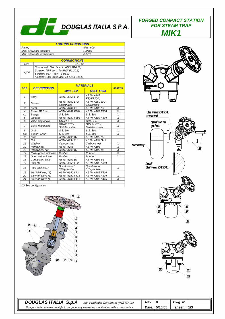
FORGED COMPACT STATION FOR STEAM TRAP
MIK1
LIMITING CONDITIONS Rating ANSI 600 Max. allowable pressure 100 bar Max. allowable temperature 300°C
CONNECTIONS Size ½” – ¾”
Socket weld SW (acc. to ANSI B16.11) Screwed NPT (acc. To ANSI B1.20.1) Screwed BSP (acc. To BS21) Type
Flanged 150# 300# (acc. To ANSI B16.5)
MATERIALS POS. DESCRIPTION
MIK1 LF2 MIK1 F304 SPARES
1 Body ASTM A350 LF2 ASTM A182 F304/F304L
2 Bonnet ASTM A350 LF2 Galvanized
ASTM A350 LF2 Galvanized
3 Stem ASTM A182 F6 ASTM A182 F6 X 4 Piston Ø12mm ASTM A182 F304 ASTM A182 F304 X
4.1 Seeger S.S. 304 S.S. 304 X 5 Lantern ASTM A182 F304 ASTM A182 F304 X 6 Valve ring above GRAPHITE GRAPHITE X
7 Valve ring below GRAPHITE / Stainless steel
GRAPHITE / Stainless steel X
8 Grain S.S. 304 S.S. 304 X 8.a Bottom Grain S.S. 304 S.S. 304 X 9 Stud ASTM A193 B7 ASTM A193 B8 10 Nut ASTM A194 2H ASTM A194 Gr.8 11 Washer Carbon steel Carbon steel X 12 Handwheel ASTM A105 ASTM A105 X 13 Handwheel nut ASTM A193 B7 ASTM A193 B7 X 14 Close green indicator Rubber Rubber X 15 Open red indicator Rubber Rubber X 16 Connection bolts ASTM A193 B7 ASTM A193 B8 17 Plug (1) ASTM A350 LF2 ASTM A182 F304
18 Plug gasket (1) Spiral wound 316/graphite
Spiral wound 316/graphite X
19 1/8” NPT plug (1) ASTM A350 LF2 ASTM A182 F304 20 Blow-off valve (1) ASTM A182 F416 ASTM A182 F304 X 21 Blow-off valve (1) ASTM A182 F416 ASTM A182 F416 X
(1) See configuration
LIMITING CONDITIONS Rating ANSI 600 Max. allowable pressure 100 bar Max. allowable temperature 425°C
DOUGLAS ITALIA S.p.A Loc. Pradaglie Carpaneto (PC) ITALIA Rev.: 0 Dwg. N. Douglas Italia reserves the right to carry-out any necessary modification without prior notice Date: 5/10/05 sheet : 1/3
13 11
1214159102348
6578.a
16 4.1
1
16Steam trap
Spiral woundgaskets
16
17
19
17
2021
20
18 18
Seal weld 304/304Lsee detail
DetailSeal weld 304/304L
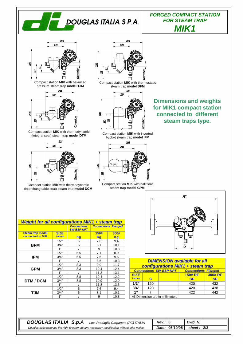
FORGED COMPACT STATION FOR STEAM TRAP
MIK1
FORGED COMPACT STATION FOR STEAM TRAP
MIK1
DOUGLAS ITALIA S.p.A Loc. Pradaglie Carpaneto (PC) ITALIA Rev.: 0 Dwg. N. Douglas Italia reserves the right to carry-out any necessary modification without prior notice Date: 05/10/05 sheet : 2/3
113130
130222
Conne
ction
243
306214
Conne
ction
11322
6
Compact station MIK with invertedbucket steam trap model IFM
Compact station MIK with ball floatsteam trap model GPM
Douglas
Conne
ction
11322
6
122214
Compact station MIK with balancedpressure steam trap model TJM
113
Conne
ction
226
226
Conne
ction
113
Compact station MIK with thermostaticsteam trap model BFM
61 61
129 129221 221
Compact station MIK with thermodynamic(integral seat) steam trap model DTM
Conne
ction
DOUGLAS
113
122
52
214
226
Compact station MIK with thermodynamic(interchangeable seat) steam trap model DCM
DIMENSION available for all configurations MIK1 + steam trap
Connections SW-BSP-NPT Connections Flanged SIZE inches
S
150# RF SF
300# RF SF
1/2” 120 420 432 3/4” 120 420 438 1” / 422 442
All Dimension are in millimeters
Weight for all configurations MIK1 + steam trap Connections
SW-BSP-NPT Connections Flanged
Steam trap model connected to MIK
SIZE inches
Kg
150# Kg
300# Kg
1/2” 6 7,6 9,4 3/4” 6 8,1 10,1
BFM
1” / 9 10,8 1/2” 5,5 7,1 8,9 3/4” 5,5 7,6 9,6
IFM
1” / 8,5 10,3 1/2” 8,3 9,9 11,7 3/4” 8,3 10,4 12,4
GPM
1” / 11,3 13,1 1/2” 8,8 10,4 12,2 3/4” 8,8 10,9 12,9
DTM / DCM
1” / 11,8 13,6 1/2” 6 7,6 9,4 3/4” 6 8,1 10,1
TJM
1” / 9 10,8
Dimensions and weights for MIK1 compact station
connected to different steam traps type.
SF
S
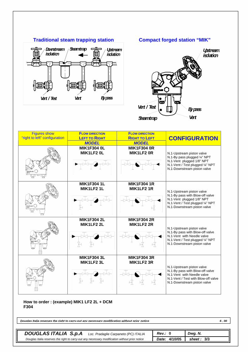
Douglas Italia reserves the right to carry-out any necessary modification without prior notice 6 . 00
FLOW DIRECTION LEFT TO RIGHT
FLOW DIRECTION RIGHT TO LEFT
Figures show “right to left” configuration
MODEL MODEL CONFIGURATION
MIK1F304 0L MIK1LF2 0L
MIK1F304 0R MIK1LF2 0R
N.1-Upstream piston valve N.1-By pass plugged ¼” NPT N.1-Vent plugged 1/8” NPT N.1-Vent / Test plugged ¼” NPT N.1-Downstream piston valve
MIK1F304 1L MIK1LF2 1L
MIK1F304 1R MIK1LF2 1R
N.1-Upstream piston valve N.1-By pass with Blow-off valve N.1-Vent plugged 1/8” NPT N.1-Vent / Test plugged ¼” NPT N.1-Downstream piston valve
MIK1F304 2L MIK1LF2 2L
MIK1F304 2R MIK1LF2 2R
N.1-Upstream piston valve N.1-By pass with Blow-off valve N.1-Vent with Needle valve N.1-Vent / Test plugged ¼” NPT N.1-Downstream piston valve
MIK1F304 3L MIK1LF2 3L
MIK1F304 3R MIK1LF2 3R
N.1-Upstream piston valve N.1-By pass with Blow-off valve N.1-Vent with Needle valve N.1-Vent / Test with Blow-off valveN.1-Downstream piston valve
Traditional steam trapping station Compact forged station “MIK”
By passVentVent / Test
Downstreamisolation
Steam trap Upstreamisolation
DOUGLAS ITALIA S.p.A Loc. Pradaglie Carpaneto (PC) ITALIA Rev.: 0 Dwg. N. Douglas Italia reserves the right to carry-out any necessary modification without prior notice Date: 4/10/05 sheet : 3/3
How to order : (example) MIK1 LF2 2L + DCM F304
By passVent
Vent / Test
Upstreamisolation
Steam trap
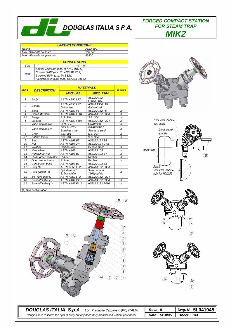
FORGED COMPACT STATION FOR STEAM TRAP
MIK2
LIMITING CONDITIONS Rating ANSI 600 Max. allowable pressure 100 bar Max. allowable temperature 300°C
CONNECTIONS Size ½” – ¾”
Socket weld SW (acc. to ANSI B16.11) Screwed NPT (acc. To ANSI B1.20.1) Screwed BSP (acc. To BS21) Type
Flanged 150# 300# (acc. To ANSI B16.5)
MATERIALS POS. DESCRIPTION
MIK2 LF2 MIK2 F304 SPARES
1 Body ASTM A350 LF2 ASTM A182 F304/F304L
2 Bonnet ASTM A350 LF2 Galvanized
ASTM A350 LF2 Galvanized
3 Stem ASTM A182 F6 ASTM A182 F6 X 4 Piston Ø12mm ASTM A182 F304 ASTM A182 F304 X
4.1 Seeger S.S. 304 S.S. 304 X 5 Lantern ASTM A182 F304 ASTM A182 F304 X 6 Valve ring above GRAPHITE GRAPHITE X
7 Valve ring below GRAPHITE / Stainless steel
GRAPHITE / Stainless steel X
8 Grain S.S. 304 S.S. 304 X 8.a Bottom Grain S.S. 304 S.S. 304 X 9 Stud ASTM A193 B7 ASTM A193 B8 10 Nut ASTM A194 2H ASTM A194 Gr.8 11 Washer Carbon steel Carbon steel X 12 Handwheel ASTM A105 ASTM A105 X 13 Handwheel nut ASTM A193 B7 ASTM A193 B7 X 14 Close green indicator Rubber Rubber X 15 Open red indicator Rubber Rubber X 16 Connection bolts ASTM A193 B7 ASTM A193 B8 17 Plug (1) ASTM A350 LF2 ASTM A182 F304
18 Plug gasket (1) Spiral wound 316/graphite
Spiral wound 316/graphite X
19 1/8” NPT plug (1) ASTM A350 LF2 ASTM A182 F304 20 Blow-off valve (1) ASTM A182 F416 ASTM A182 F304 X 21 Blow-off valve (1) ASTM A182 F416 ASTM A182 F416 X
(1) See configuration
LIMITING CONDITIONS Rating ANSI 600 Max. allowable pressure 100 bar Max. allowable temperature 425°C
13 11
12
14
15
9
10
2
3
4
8
6578.a
16 4.1
1
DOUGLAS ITALIA S.p.A Loc. Pradaglie Carpaneto (PC) ITALIA Rev.: 0 Dwg. N. 5L041045Douglas Italia reserves the right to carry-out any necessary modification without prior notice Date: 5/10/05 sheet : 1/3
16
Steam trap
Spiral woundgaskets
16
17
19
17
20
21
20
18 18
Seal weld 304/304Lsee detail
DetailSeal weld 304/304Lonly for MIK2LF2
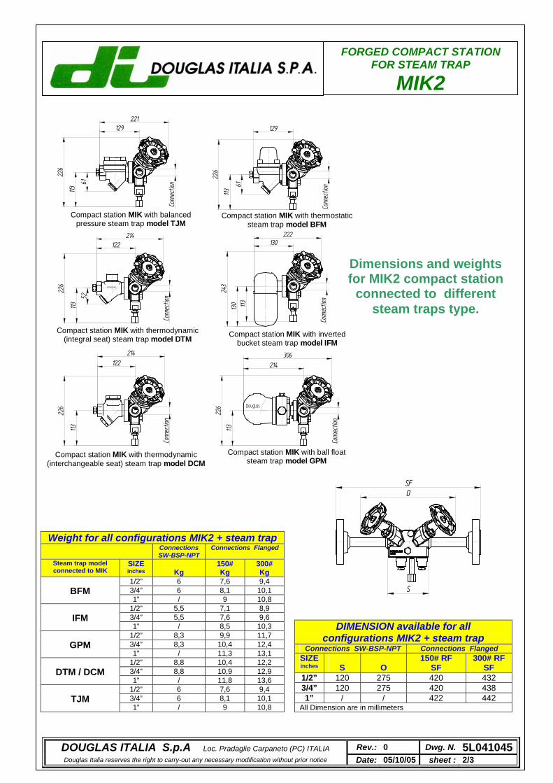
FORGED COMPACT STATION FOR STEAM TRAP
MIK2
DOUGLAS ITALIA S.p.A Loc. Pradaglie Carpaneto (PC) ITALIA Rev.: 0 Dwg. N. 5L041045Douglas Italia reserves the right to carry-out any necessary modification without prior notice Date: 05/10/05 sheet : 2/3
113130
130222
Conn
ectio
n
243
306214
Conn
ectio
n
113
226
Compact station MIK with invertedbucket steam trap model IFM
Compact station MIK with ball floatsteam trap model GPM
Douglas
Conn
ectio
n
113
226
122214
Compact station MIK with balancedpressure steam trap model TJM
113
Conn
ectio
n
226
226
Conn
ectio
n
113
Compact station MIK with thermostaticsteam trap model BFM
61 61
129 129221
Compact station MIK with thermodynamic(integral seat) steam trap model DTM
Conn
ectio
n
DOUGLAS
113
122
52
214
226
Compact station MIK with thermodynamic(interchangeable seat) steam trap model DCM
DIMENSION available for all configurations MIK2 + steam trap
Connections SW-BSP-NPT Connections Flanged SIZE inches
S
O
150# RF SF
300# RF SF
1/2” 120 275 420 432 3/4” 120 275 420 438 1” / / 422 442
All Dimension are in millimeters
Weight for all configurations MIK2 + steam trap Connections
SW-BSP-NPT Connections Flanged
Steam trap model connected to MIK
SIZE inches
Kg
150# Kg
300# Kg
1/2” 6 7,6 9,4 3/4” 6 8,1 10,1
BFM
1” / 9 10,8 1/2” 5,5 7,1 8,9 3/4” 5,5 7,6 9,6
IFM
1” / 8,5 10,3 1/2” 8,3 9,9 11,7 3/4” 8,3 10,4 12,4
GPM
1” / 11,3 13,1 1/2” 8,8 10,4 12,2 3/4” 8,8 10,9 12,9
DTM / DCM
1” / 11,8 13,6 1/2” 6 7,6 9,4 3/4” 6 8,1 10,1
TJM
1” / 9 10,8
SFO
S
Dimensions and weights for MIK2 compact station
connected to different steam traps type.
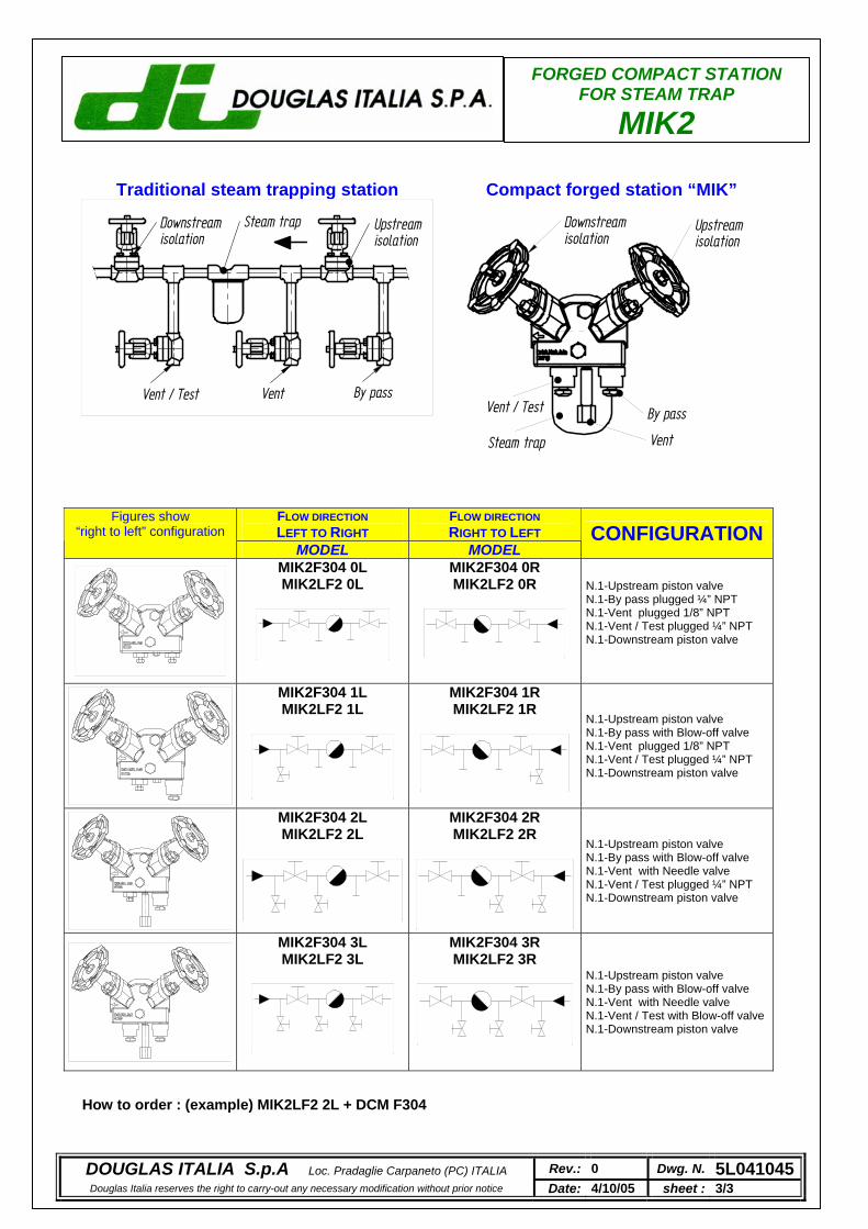
FORGED COMPACT STATION FOR STEAM TRAP
MIK2
FLOW DIRECTION LEFT TO RIGHT
FLOW DIRECTION RIGHT TO LEFT
Figures show “right to left” configuration
MODEL MODEL CONFIGURATION
MIK2F304 0L MIK2LF2 0L
MIK2F304 0R MIK2LF2 0R
N.1-Upstream piston valve N.1-By pass plugged ¼” NPT N.1-Vent plugged 1/8” NPT N.1-Vent / Test plugged ¼” NPT N.1-Downstream piston valve
MIK2F304 1L MIK2LF2 1L
MIK2F304 1R MIK2LF2 1R
N.1-Upstream piston valve N.1-By pass with Blow-off valve N.1-Vent plugged 1/8” NPT N.1-Vent / Test plugged ¼” NPT N.1-Downstream piston valve
MIK2F304 2L MIK2LF2 2L
MIK2F304 2R MIK2LF2 2R
N.1-Upstream piston valve N.1-By pass with Blow-off valve N.1-Vent with Needle valve N.1-Vent / Test plugged ¼” NPT N.1-Downstream piston valve
MIK2F304 3L MIK2LF2 3L
MIK2F304 3R MIK2LF2 3R
N.1-Upstream piston valve N.1-By pass with Blow-off valve N.1-Vent with Needle valve N.1-Vent / Test with Blow-off valveN.1-Downstream piston valve
Traditional steam trapping station Compact forged station “MIK”
By passVentVent / Test
Downstreamisolation
Steam trap Upstreamisolation
By pass
Vent
Vent / Test
Upstreamisolation
Downstreamisolation
Steam trap
DOUGLAS ITALIA S.p.A Loc. Pradaglie Carpaneto (PC) ITALIA Rev.: 0 Dwg. N. 5L041045Douglas Italia reserves the right to carry-out any necessary modification without prior notice Date: 4/10/05 sheet : 3/3
How to order : (example) MIK2LF2 2L + DCM F304

JACKET
GO BACK
JM
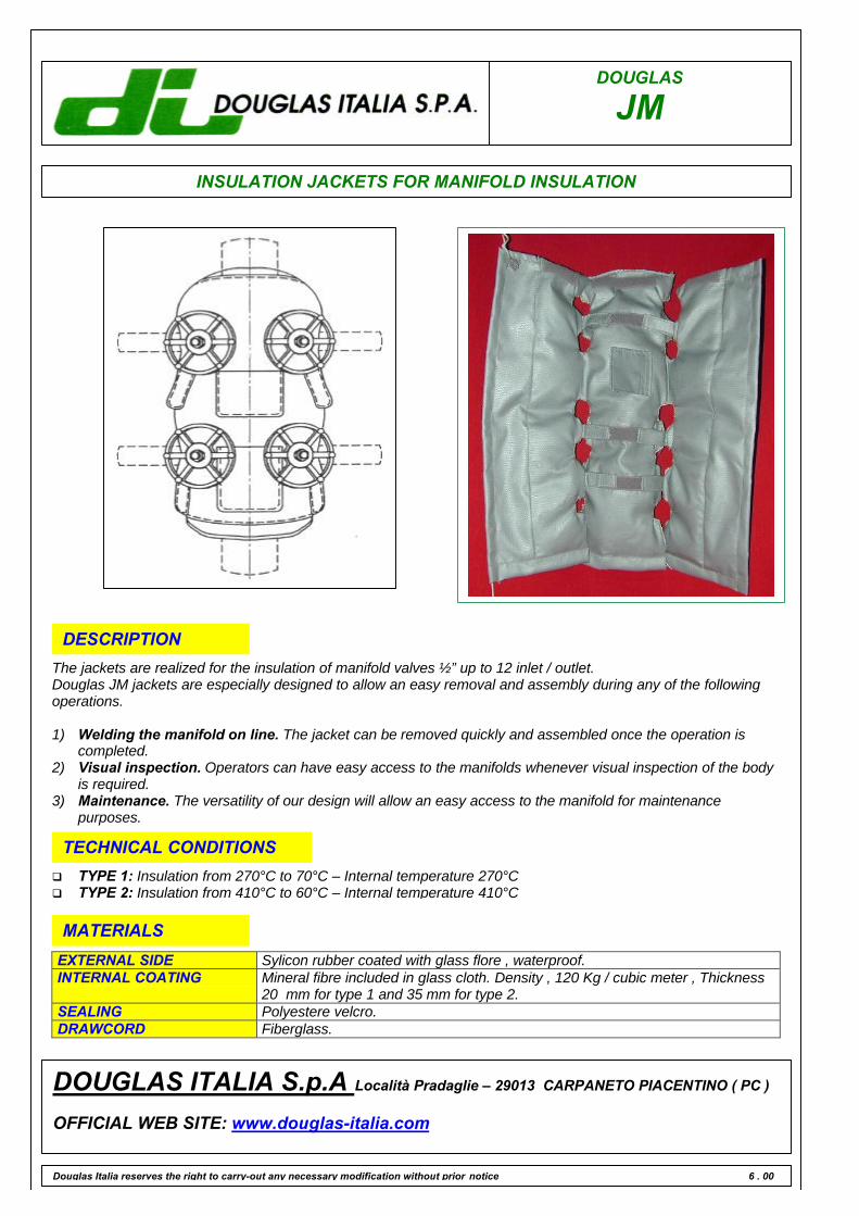
DOUGLAS
JM
INSULATION JACKETS FOR MANIFOLD INSULATION
Douglas Italia reserves the right to carry-out any necessary modification without prior notice 6 . 00
DOUGLAS ITALIA S.p.A Località Pradaglie – 29013 CARPANETO PIACENTINO ( PC )
OFFICIAL WEB SITE: www.douglas-italia.com
DESCRIPTION
EXTERNAL SIDE Sylicon rubber coated with glass flore , waterproof.INTERNAL COATING Mineral fibre included in glass cloth. Density , 120 Kg / cubic meter , Thickness
20 mm for type 1 and 35 mm for type 2.SEALING Polyestere velcro.DRAWCORD Fiberglass.
MATERIALS
q TYPE 1: Insulation from 270°C to 70°C – Internal temperature 270°Cq TYPE 2: Insulation from 410°C to 60°C – Internal temperature 410°C
TECHNICAL CONDITIONS
The jackets are realized for the insulation of manifold valves ½” up to 12 inlet / outlet.Douglas JM jackets are especially designed to allow an easy removal and assembly during any of the followingoperations.
1) Welding the manifold on line. The jacket can be removed quickly and assembled once the operation iscompleted.
2) Visual inspection. Operators can have easy access to the manifolds whenever visual inspection of the bodyis required.
3) Maintenance. The versatility of our design will allow an easy access to the manifold for maintenancepurposes.
FORGED PISTON VALVE
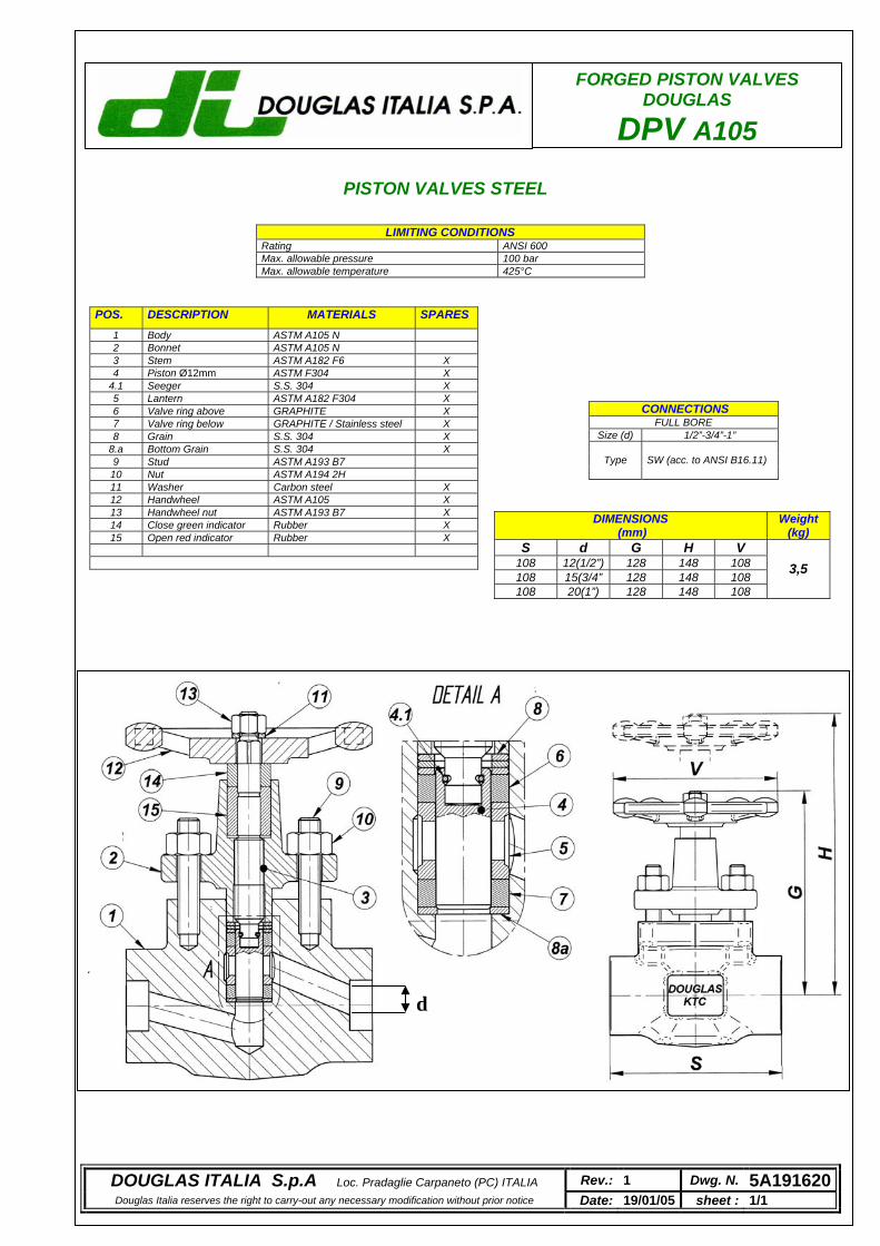
L
S 108 1108 1108
d
Rating Max. allowable pressure Max. allowable temperatu
FORGED PISTON VALVES DOUGLAS
DPV A105
Size (d
Type
DIMENSIONS (mm)
Weight (kg)
d G H V 2(1/2”) 128 148 108 5(3/4” 128 148 108
20(1”) 128 148 108
3,5
CONNECTIONS FULL BORE
) 1/2”-3/4”-1”
SW (acc. to ANSI B16.11)
PISTON VALVES STEE
DOUGLAS ITALIA S.p.A Loc. Pradaglie Carpaneto (PC) ITALIA Rev.: 1 Dwg. N. 5A191620Douglas Italia reserves the right to carry-out any necessary modification without prior notice Date: 19/01/05 sheet : 1/1
POS. DESCRIPTION MATERIALS SPARES 1 Body ASTM A105 N 2 Bonnet ASTM A105 N 3 Stem ASTM A182 F6 X 4 Piston Ø12mm ASTM F304 X
4.1 Seeger S.S. 304 X 5 Lantern ASTM A182 F304 X 6 Valve ring above GRAPHITE X 7 Valve ring below GRAPHITE / Stainless steel X 8 Grain S.S. 304 X
8.a Bottom Grain S.S. 304 X 9 Stud ASTM A193 B7 10 Nut ASTM A194 2H 11 Washer Carbon steel X 12 Handwheel ASTM A105 X 13 Handwheel nut ASTM A193 B7 X 14 Close green indicator Rubber X 15 Open red indicator Rubber X
LIMITING CONDITIONS ANSI 600 100 bar
re 425°C

FLOW INDICATORS
FLOW SIGHT GLASSES
FORGED
CAST
GO BACK
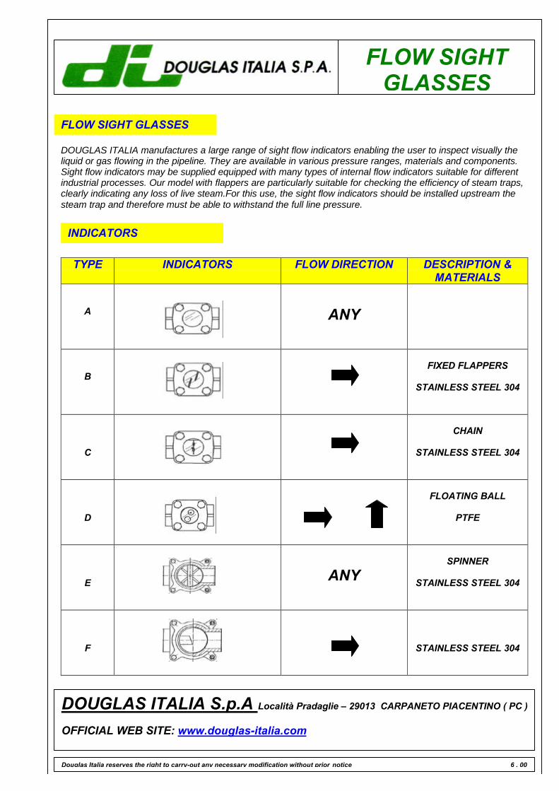
FLOW SIGHTGLASSES
FLOW SIGHT GLASSES
DOUGLAS ITALIA manufactures a large range of sight flow indicators enabling the user to inspect visually theliquid or gas flowing in the pipeline. They are available in various pressure ranges, materials and components.Sight flow indicators may be supplied equipped with many types of internal flow indicators suitable for differentindustrial processes. Our model with flappers are particularly suitable for checking the efficiency of steam traps,clearly indicating any loss of live steam.For this use, the sight flow indicators should be installed upstream thesteam trap and therefore must be able to withstand the full line pressure.
INDICATORS
DOUGLAS ITALIA S.p.A Località Pradaglie – 29013 CARPANETO PIACENTINO ( PC )
OFFICIAL WEB SITE: www.douglas-italia.com
Douglas Italia reserves the right to carry-out any necessary modification without prior notice 6 . 00
TYPE INDICATORS FLOW DIRECTION DESCRIPTION &MATERIALS
A ANY
BFIXED FLAPPERS
STAINLESS STEEL 304
C
CHAIN
STAINLESS STEEL 304
D
FLOATING BALL
PTFE
E ANYSPINNER
STAINLESS STEEL 304
F STAINLESS STEEL 304

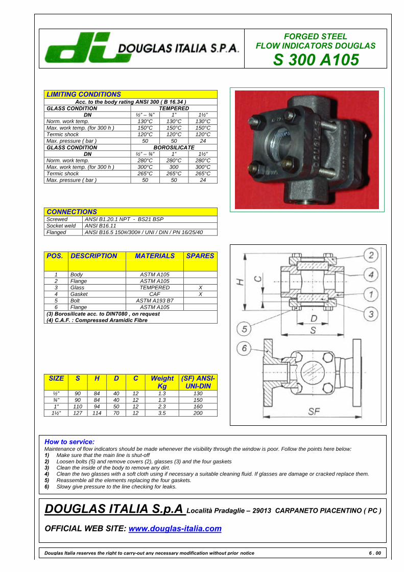
FORGED STEELFLOW INDICATORS DOUGLAS
S 300 A105
LIMITING CONDITIONSAcc. to the body rating ANSI 300 ( B 16.34 )
GLASS CONDITION TEMPEREDDN ½” – ¾” 1” 1½”
Norm. work temp. 130°C 130°C 130°CMax. work temp. (for 300 h ) 150°C 150°C 150°CTermic shock 120°C 120°C 120°CMax. pressure ( bar ) 50 50 24GLASS CONDITION BOROSILICATE
DN ½” – ¾” 1” 1½”Norm. work temp. 280°C 280°C 280°CMax. work temp. (for 300 h ) 300°C 300 300°CTermic shock 265°C 265°C 265°CMax. pressure ( bar ) 50 50 24
CONNECTIONSScrewed ANSI B1.20.1 NPT - BS21 BSPSocket weld ANSI B16.11Flanged ANSI B16.5 150#/300# / UNI / DIN / PN 16/25/40
Douglas Italia reserves the right to carry-out any necessary modification without prior notice 6 . 00
DOUGLAS ITALIA S.p.A Località Pradaglie – 29013 CARPANETO PIACENTINO ( PC )
OFFICIAL WEB SITE: www.douglas-italia.com
POS. DESCRIPTION MATERIALS SPARES
1 Body ASTM A1052 Flange ASTM A1053 Glass TEMPERED X4 Gasket CAF X5 Bolt ASTM A193 B76 Flange ASTM A105
(3) Borosilicate acc. to DIN7080 , on request(4) C.A.F. : Compressed Aramidic Fibre
SIZE S H D C WeightKg
(SF) ANSI-UNI-DIN
½” 90 84 40 12 1.3 130¾” 90 84 40 12 1.3 1501” 110 94 50 12 2.3 160
1½” 127 114 70 12 3.5 200
How to service:Maintenance of flow indicators should be made whenever the visibility through the window is poor. Follow the points here below:1) Make sure that the main line is shut-off2) Loosen bolts (5) and remove covers (2), glasses (3) and the four gaskets3) Clean the inside of the body to remove any dirt.4) Clean the two glasses with a soft cloth using if necessary a suitable cleaning fluid. If glasses are damage or cracked replace them.5) Reassemble all the elements replacing the four gaskets.6) Slowy give pressure to the line checking for leaks.
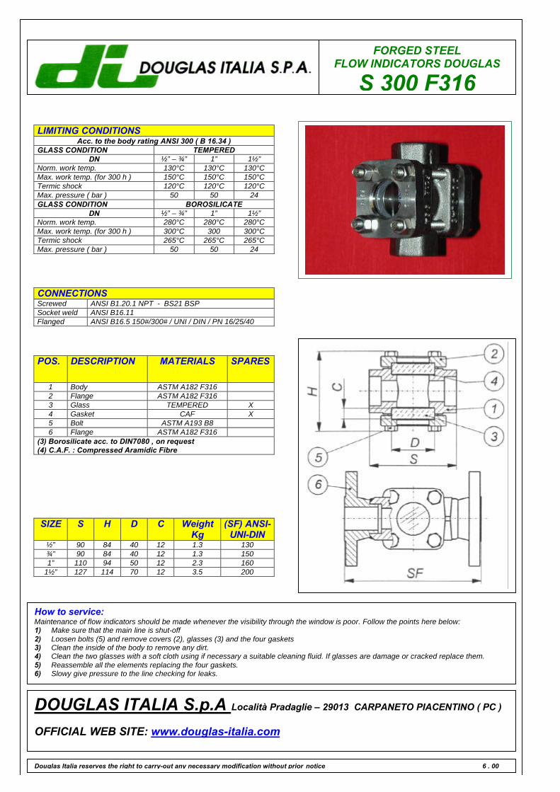
FORGED STEELFLOW INDICATORS DOUGLAS
S 300 F316
LIMITING CONDITIONSAcc. to the body rating ANSI 300 ( B 16.34 )
GLASS CONDITION TEMPEREDDN ½” – ¾” 1” 1½”
Norm. work temp. 130°C 130°C 130°CMax. work temp. (for 300 h ) 150°C 150°C 150°CTermic shock 120°C 120°C 120°CMax. pressure ( bar ) 50 50 24GLASS CONDITION BOROSILICATE
DN ½” – ¾” 1” 1½”Norm. work temp. 280°C 280°C 280°CMax. work temp. (for 300 h ) 300°C 300 300°CTermic shock 265°C 265°C 265°CMax. pressure ( bar ) 50 50 24
CONNECTIONSScrewed ANSI B1.20.1 NPT - BS21 BSPSocket weld ANSI B16.11Flanged ANSI B16.5 150#/300# / UNI / DIN / PN 16/25/40
POS. DESCRIPTION MATERIALS SPARES
1 Body ASTM A182 F3162 Flange ASTM A182 F3163 Glass TEMPERED X4 Gasket CAF X5 Bolt ASTM A193 B86 Flange ASTM A182 F316
(3) Borosilicate acc. to DIN7080 , on request(4) C.A.F. : Compressed Aramidic Fibre
Douglas Italia reserves the right to carry-out any necessary modification without prior notice 6 . 00
DOUGLAS ITALIA S.p.A Località Pradaglie – 29013 CARPANETO PIACENTINO ( PC )
OFFICIAL WEB SITE: www.douglas-italia.com
SIZE S H D C WeightKg
(SF) ANSI-UNI-DIN
½” 90 84 40 12 1.3 130¾” 90 84 40 12 1.3 1501” 110 94 50 12 2.3 160
1½” 127 114 70 12 3.5 200
How to service:Maintenance of flow indicators should be made whenever the visibility through the window is poor. Follow the points here below:1) Make sure that the main line is shut-off2) Loosen bolts (5) and remove covers (2), glasses (3) and the four gaskets3) Clean the inside of the body to remove any dirt.4) Clean the two glasses with a soft cloth using if necessary a suitable cleaning fluid. If glasses are damage or cracked replace them.5) Reassemble all the elements replacing the four gaskets.6) Slowy give pressure to the line checking for leaks.
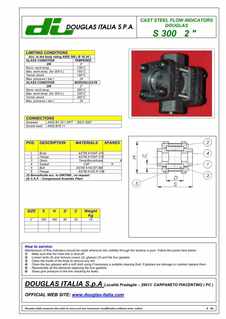
CAST STEEL FLOW INDICATORSDOUGLAS
S 300 2 "
LIMITING CONDITIONS Acc. to the body rating ANSI 300 ( B 16.34 )
GLASS CONDITION TEMPERED DN 2”
Norm. work temp. 130°C Max. work temp. (for 300 h ) 150°C Termic shock 120°C Max. pressure ( bar ) 24 GLASS CONDITION BOROSILICATE
DN 2” Norm. work temp. 280°C Max. work temp. (for 300 h ) 300°C Termic shock 265°C Max. pressure ( bar ) 24
CONNECTIONS Screwed ANSI B1.20.1 NPT - BS21 BSP Socket weld ANSI B16.11
Douglas Italia reserves the right to carry-out any necessary modification without prior notice 6 . 00
DOUGLAS ITALIA S.p.A Località Pradaglie – 29013 CARPANETO PIACENTINO ( PC ) OFFICIAL WEB SITE: www.douglas-italia.com
POS. DESCRIPTION MATERIALS SPARES
1 Body ASTM A105/F-316 2 Flange ASTM A105/F-316 3 Glass Temp/Borosilicate X 4 Gasket CAF X 5 Bolt ASTM A193 B7 /B8 6 Flange ASTM A105 /F-316
(3) Borosilicate acc. to DIN7080 , on request (4) C.A.F. : Compressed Aramidic Fibre
SIZE
S H D C Weight Kg
2” 160 180 80 20 15
How to service: Maintenance of flow indicators should be made whenever the visibility through the window is poor. Follow the points here below: 1) Make sure that the main line is shut-off 2) Loosen bolts (5) and remove covers (2), glasses (3) and the four gaskets 3) Clean the inside of the body to remove any dirt. 4) Clean the two glasses with a soft cloth using if necessary a suitable cleaning fluid. If glasses are damage or cracked replace them. 5) Reassemble all the elements replacing the four gaskets. 6) Slowy give pressure to the line checking for leaks.

CAST
GO BACK
S 150 WCB
S 150 CF8M
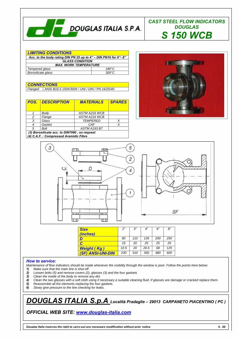
CAST STEEL FLOW INDICATORSDOUGLAS
S 150 WCBLIMITING CONDITIONSAcc. to the body rating DIN PN 25 up to 4” – DIN PN16 for 6”- 8”
GLASS CONDITIONMAX. WORK TEMPERATURE
Tempered glass 180°CBorosilicate glass 300°C
CONNECTIONSFlanged ANSI B16.5 150#/300# / UNI / DIN / PN 16/25/40
Douglas Italia reserves the right to carry-out any necessary modification without prior notice 6 . 00
DOUGLAS ITALIA S.p.A Località Pradaglie – 29013 CARPANETO PIACENTINO ( PC )
OFFICIAL WEB SITE: www.douglas-italia.com
POS. DESCRIPTION MATERIALS SPARES
1 Body ASTM A216 WCB2 Flange ASTM A216 WCB3 Glass TEMPERED X4 Gasket CAF X5 Bolt ASTM A193 B7
(3) Borosilicate acc. to DIN7080 , on request(4) C.A.F. : Compressed Aramidic Fibre
Size(inches)
2” 3” 4” 6” 8”
D 80 110 135 200 250
C 15 20 25 25 25
Weight ( Kg ) 10.5 20 26.5 68 125
(SF) ANSI-UNI-DIN 230 310 350 480 600
How to service:Maintenance of flow indicators should be made whenever the visibility through the window is poor. Follow the points here below:1) Make sure that the main line is shut-off2) Loosen bolts (5) and remove covers (2), glasses (3) and the four gaskets3) Clean the inside of the body to remove any dirt.4) Clean the two glasses with a soft cloth using if necessary a suitable cleaning fluid. If glasses are damage or cracked replace them.5) Reassemble all the elements replacing the four gaskets.6) Slowy give pressure to the line checking for leaks.
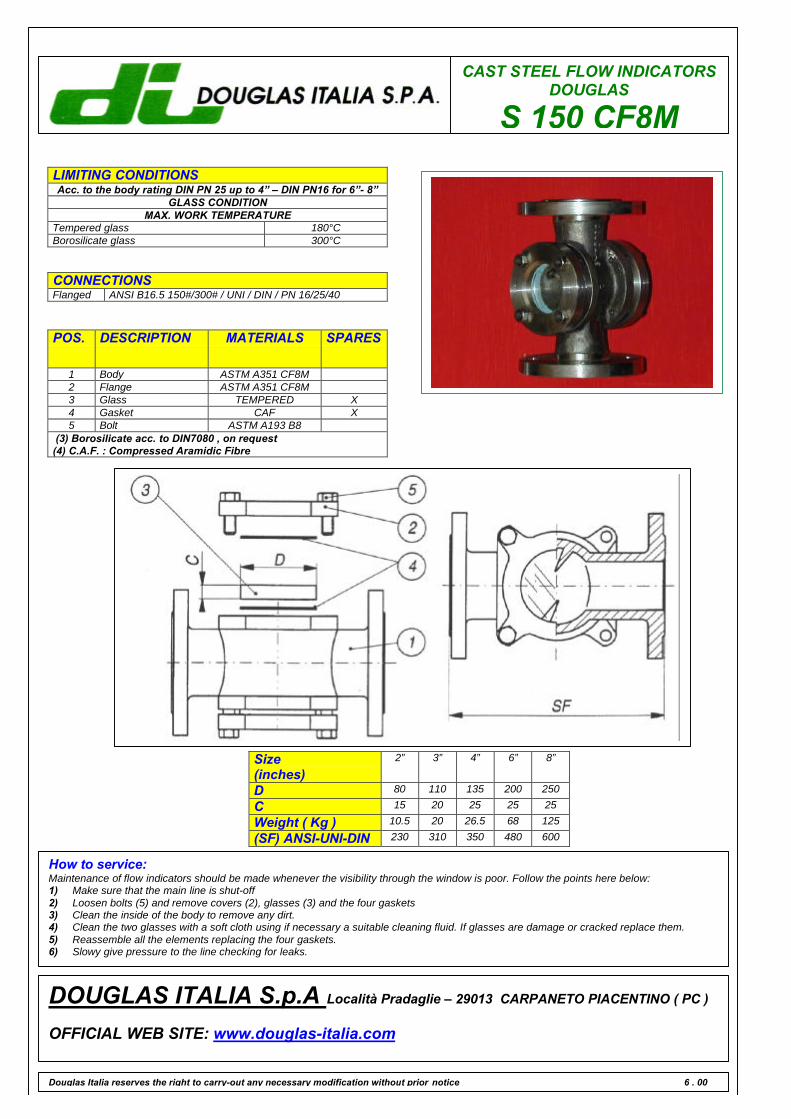
CAST STEEL FLOW INDICATORSDOUGLAS
S 150 CF8MLIMITING CONDITIONSAcc. to the body rating DIN PN 25 up to 4” – DIN PN16 for 6”- 8”
GLASS CONDITIONMAX. WORK TEMPERATURE
Tempered glass 180°CBorosilicate glass 300°C
CONNECTIONSFlanged ANSI B16.5 150#/300# / UNI / DIN / PN 16/25/40
POS. DESCRIPTION MATERIALS SPARES
1 Body ASTM A351 CF8M2 Flange ASTM A351 CF8M3 Glass TEMPERED X4 Gasket CAF X5 Bolt ASTM A193 B8
(3) Borosilicate acc. to DIN7080 , on request(4) C.A.F. : Compressed Aramidic Fibre
Douglas Italia reserves the right to carry-out any necessary modification without prior notice 6 . 00
DOUGLAS ITALIA S.p.A Località Pradaglie – 29013 CARPANETO PIACENTINO ( PC )
OFFICIAL WEB SITE: www.douglas-italia.com
Size(inches)
2” 3” 4” 6” 8”
D 80 110 135 200 250
C 15 20 25 25 25
Weight ( Kg ) 10.5 20 26.5 68 125
(SF) ANSI-UNI-DIN 230 310 350 480 600
How to service:Maintenance of flow indicators should be made whenever the visibility through the window is poor. Follow the points here below:1) Make sure that the main line is shut-off2) Loosen bolts (5) and remove covers (2), glasses (3) and the four gaskets3) Clean the inside of the body to remove any dirt.4) Clean the two glasses with a soft cloth using if necessary a suitable cleaning fluid. If glasses are damage or cracked replace them.5) Reassemble all the elements replacing the four gaskets.6) Slowy give pressure to the line checking for leaks.


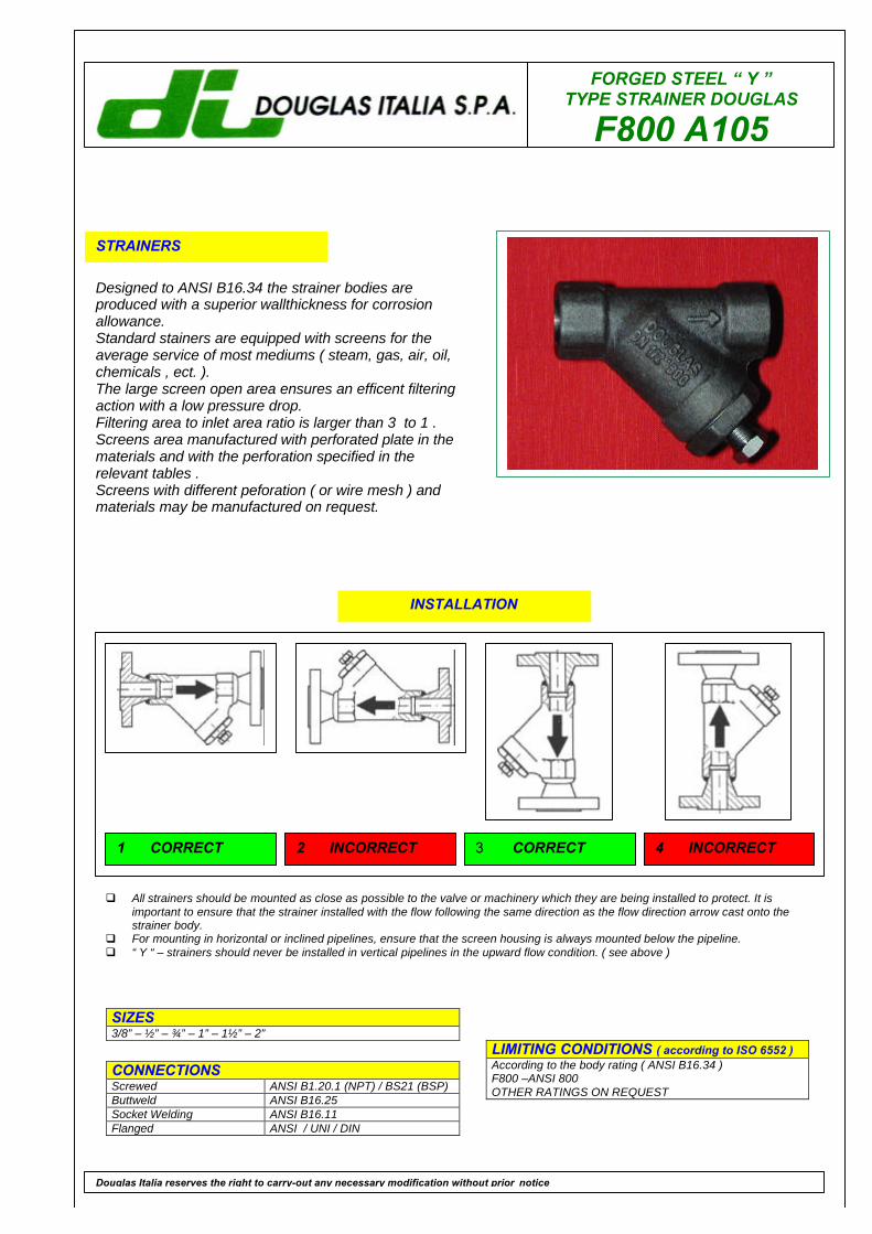
FORGED STEEL “ Y ”TYPE STRAINER DOUGLAS
F800 A105
STRAINERS
Designed to ANSI B16.34 the strainer bodies areproduced with a superior wallthickness for corrosionallowance.Standard stainers are equipped with screens for theaverage service of most mediums ( steam, gas, air, oil,chemicals , ect. ).The large screen open area ensures an efficent filteringaction with a low pressure drop.Filtering area to inlet area ratio is larger than 3 to 1 .Screens area manufactured with perforated plate in thematerials and with the perforation specified in therelevant tables .Screens with different peforation ( or wire mesh ) andmaterials may be manufactured on request.
LIMITING CONDITIONS ( according to ISO 6552 )According to the body rating ( ANSI B16.34 )F800 –ANSI 800OTHER RATINGS ON REQUEST
SIZES3/8” – ½” – ¾” – 1” – 1½” – 2”
CONNECTIONSScrewed ANSI B1.20.1 (NPT) / BS21 (BSP)Buttweld ANSI B16.25Socket Welding ANSI B16.11Flanged ANSI / UNI / DIN
Douglas Italia reserves the right to carry-out any necessary modification without prior notice
INSTALLATION
q All strainers should be mounted as close as possible to the valve or machinery which they are being installed to protect. It isimportant to ensure that the strainer installed with the flow following the same direction as the flow direction arrow cast onto thestrainer body.
q For mounting in horizontal or inclined pipelines, ensure that the screen housing is always mounted below the pipeline.q “ Y “ – strainers should never be installed in vertical pipelines in the upward flow condition. ( see above )
1 CORRECT 2 INCORRECT 3 CORRECT 4 INCORRECT
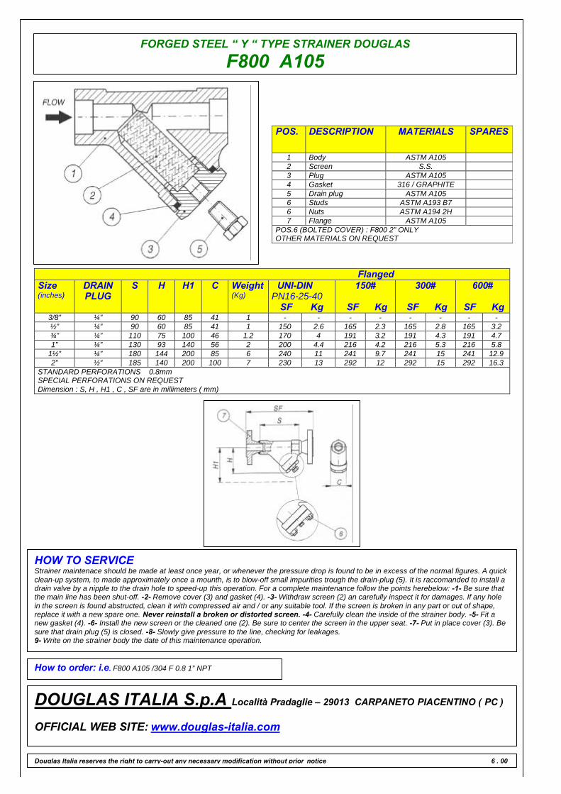
FORGED STEEL “ Y “ TYPE STRAINER DOUGLAS
F800 A105
POS. DESCRIPTION MATERIALS SPARES
1 Body ASTM A1052 Screen S.S.3 Plug ASTM A1054 Gasket 316 / GRAPHITE5 Drain plug ASTM A1056 Studs ASTM A193 B76 Nuts ASTM A194 2H7 Flange ASTM A105
POS.6 (BOLTED COVER) : F800 2” ONLYOTHER MATERIALS ON REQUEST
FlangedSize(inches)
DRAINPLUG
S H H1 C Weight(Kg)
UNI-DINPN16-25-40
SF Kg
150#
SF Kg
300#
SF Kg
600#
SF Kg3/8” ¼” 90 60 85 41 1 - - - - - - - -½” ¼” 90 60 85 41 1 150 2.6 165 2.3 165 2.8 165 3.2¾” ¼” 110 75 100 46 1.2 170 4 191 3.2 191 4.3 191 4.71” ¼” 130 93 140 56 2 200 4.4 216 4.2 216 5.3 216 5.8
1½” ¼” 180 144 200 85 6 240 11 241 9.7 241 15 241 12.92” ½” 185 140 200 100 7 230 13 292 12 292 15 292 16.3
STANDARD PERFORATIONS 0.8mmSPECIAL PERFORATIONS ON REQUESTDimension : S, H , H1 , C , SF are in millimeters ( mm)
HOW TO SERVICEStrainer maintenace should be made at least once year, or whenever the pressure drop is found to be in excess of the normal figures. A quickclean-up system, to made approximately once a mounth, is to blow-off small impurities trough the drain-plug (5). It is raccomanded to install adrain valve by a nipple to the drain hole to speed-up this operation. For a complete maintenance follow the points herebelow: -1- Be sure thatthe main line has been shut-off. -2- Remove cover (3) and gasket (4). -3- Withdraw screen (2) an carefully inspect it for damages. If any holein the screen is found abstructed, clean it with compressed air and / or any suitable tool. If the screen is broken in any part or out of shape,replace it with a new spare one. Never reinstall a broken or distorted screen. -4- Carefully clean the inside of the strainer body. -5- Fit anew gasket (4). -6- Install the new screen or the cleaned one (2). Be sure to center the screen in the upper seat. -7- Put in place cover (3). Besure that drain plug (5) is closed. -8- Slowly give pressure to the line, checking for leakages.9- Write on the strainer body the date of this maintenance operation.
How to order: i.e. F800 A105 /304 F 0.8 1” NPT
DOUGLAS ITALIA S.p.A Località Pradaglie – 29013 CARPANETO PIACENTINO ( PC )
OFFICIAL WEB SITE: www.douglas-italia.com
Douglas Italia reserves the right to carry-out any necessary modification without prior notice 6 . 00
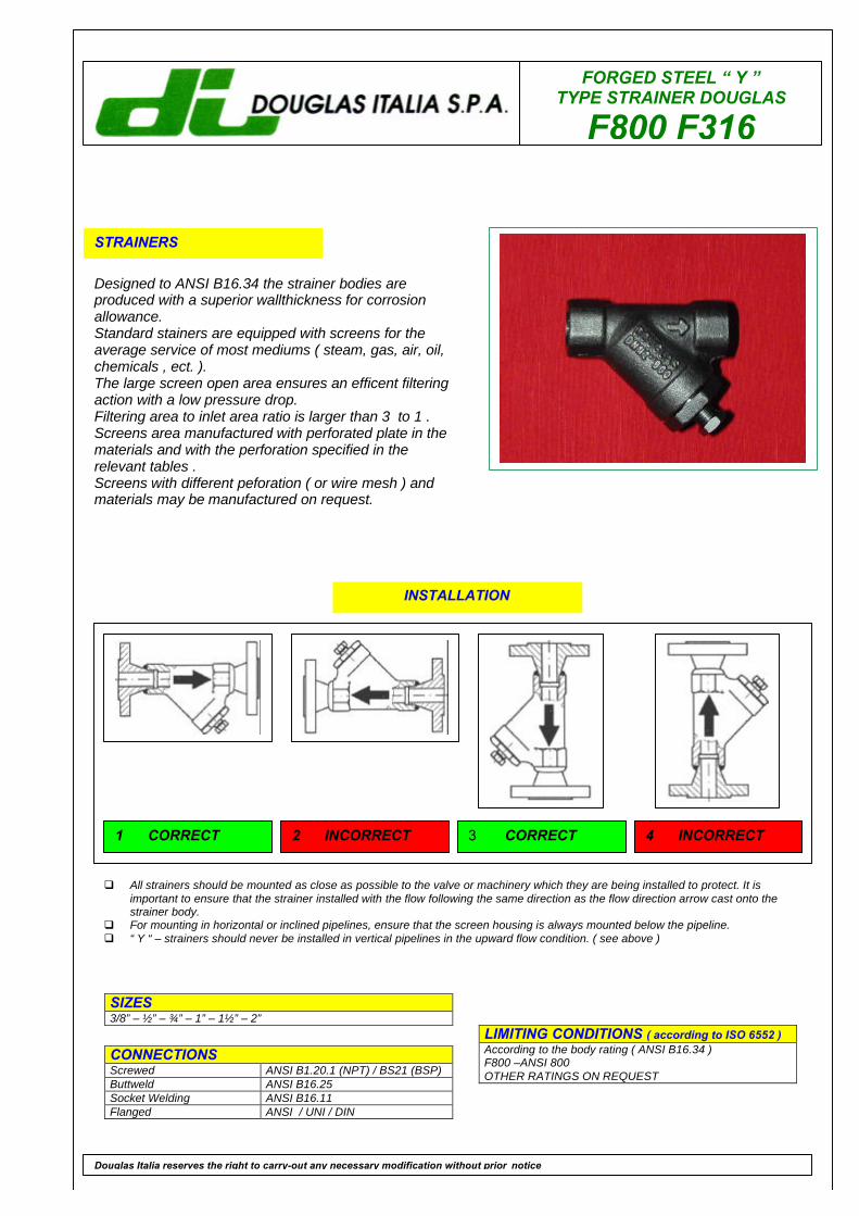
FORGED STEEL “ Y ”TYPE STRAINER DOUGLAS
F800 F316
STRAINERS
Designed to ANSI B16.34 the strainer bodies areproduced with a superior wallthickness for corrosionallowance.Standard stainers are equipped with screens for theaverage service of most mediums ( steam, gas, air, oil,chemicals , ect. ).The large screen open area ensures an efficent filteringaction with a low pressure drop.Filtering area to inlet area ratio is larger than 3 to 1 .Screens area manufactured with perforated plate in thematerials and with the perforation specified in therelevant tables .Screens with different peforation ( or wire mesh ) andmaterials may be manufactured on request.
LIMITING CONDITIONS ( according to ISO 6552 )According to the body rating ( ANSI B16.34 )F800 –ANSI 800OTHER RATINGS ON REQUEST
SIZES3/8” – ½” – ¾” – 1” – 1½” – 2”
CONNECTIONSScrewed ANSI B1.20.1 (NPT) / BS21 (BSP)Buttweld ANSI B16.25Socket Welding ANSI B16.11Flanged ANSI / UNI / DIN
Douglas Italia reserves the right to carry-out any necessary modification without prior notice
INSTALLATION
q All strainers should be mounted as close as possible to the valve or machinery which they are being installed to protect. It isimportant to ensure that the strainer installed with the flow following the same direction as the flow direction arrow cast onto thestrainer body.
q For mounting in horizontal or inclined pipelines, ensure that the screen housing is always mounted below the pipeline.q “ Y “ – strainers should never be installed in vertical pipelines in the upward flow condition. ( see above )
1 CORRECT 2 INCORRECT 3 CORRECT 4 INCORRECT
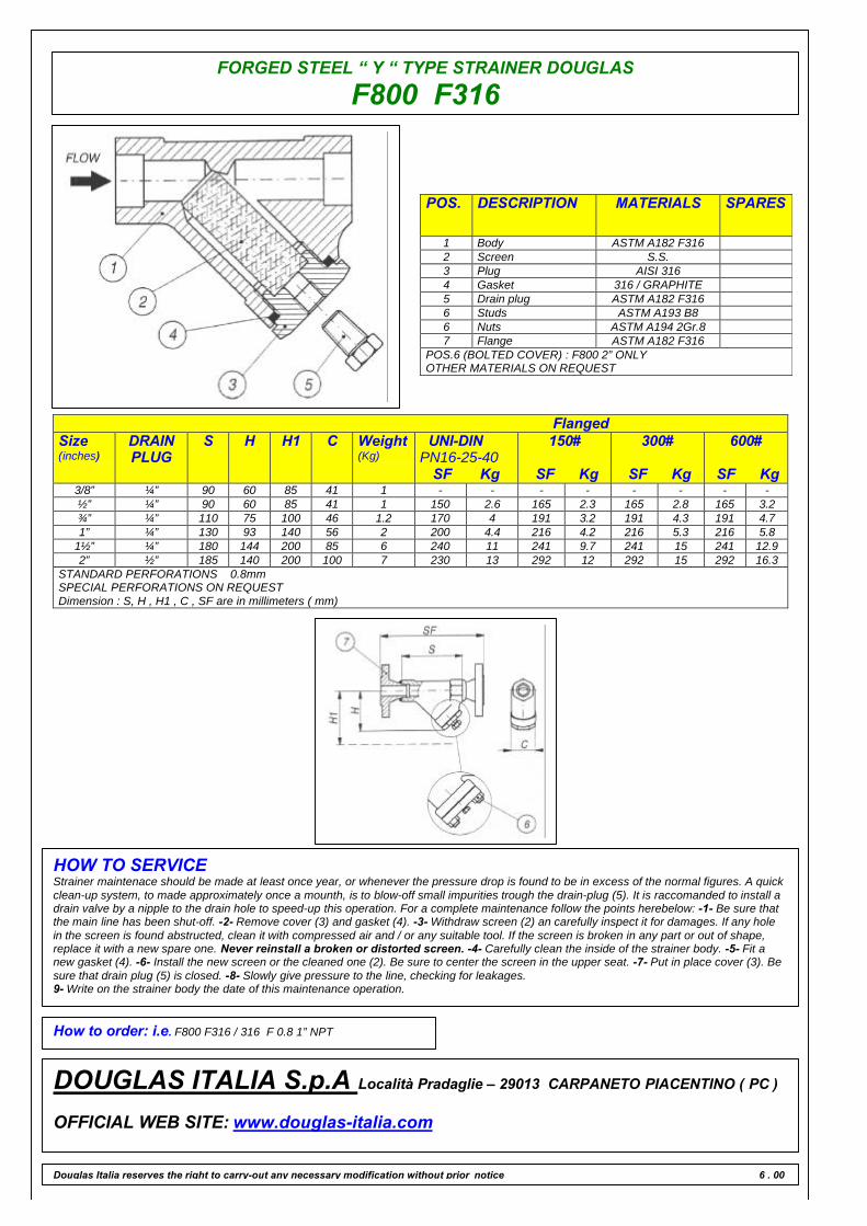
FORGED STEEL “ Y “ TYPE STRAINER DOUGLAS
F800 F316
POS. DESCRIPTION MATERIALS SPARES
1 Body ASTM A182 F3162 Screen S.S.3 Plug AISI 3164 Gasket 316 / GRAPHITE5 Drain plug ASTM A182 F3166 Studs ASTM A193 B86 Nuts ASTM A194 2Gr.87 Flange ASTM A182 F316
POS.6 (BOLTED COVER) : F800 2” ONLYOTHER MATERIALS ON REQUEST
FlangedSize(inches)
DRAINPLUG
S H H1 C Weight(Kg)
UNI-DINPN16-25-40
SF Kg
150#
SF Kg
300#
SF Kg
600#
SF Kg3/8” ¼” 90 60 85 41 1 - - - - - - - -½” ¼” 90 60 85 41 1 150 2.6 165 2.3 165 2.8 165 3.2¾” ¼” 110 75 100 46 1.2 170 4 191 3.2 191 4.3 191 4.71” ¼” 130 93 140 56 2 200 4.4 216 4.2 216 5.3 216 5.8
1½” ¼” 180 144 200 85 6 240 11 241 9.7 241 15 241 12.92” ½” 185 140 200 100 7 230 13 292 12 292 15 292 16.3
STANDARD PERFORATIONS 0.8mmSPECIAL PERFORATIONS ON REQUESTDimension : S, H , H1 , C , SF are in millimeters ( mm)
HOW TO SERVICEStrainer maintenace should be made at least once year, or whenever the pressure drop is found to be in excess of the normal figures. A quickclean-up system, to made approximately once a mounth, is to blow-off small impurities trough the drain-plug (5). It is raccomanded to install adrain valve by a nipple to the drain hole to speed-up this operation. For a complete maintenance follow the points herebelow: -1- Be sure thatthe main line has been shut-off. -2- Remove cover (3) and gasket (4). -3- Withdraw screen (2) an carefully inspect it for damages. If any holein the screen is found abstructed, clean it with compressed air and / or any suitable tool. If the screen is broken in any part or out of shape,replace it with a new spare one. Never reinstall a broken or distorted screen. -4- Carefully clean the inside of the strainer body. -5- Fit anew gasket (4). -6- Install the new screen or the cleaned one (2). Be sure to center the screen in the upper seat. -7- Put in place cover (3). Besure that drain plug (5) is closed. -8- Slowly give pressure to the line, checking for leakages.9- Write on the strainer body the date of this maintenance operation.
How to order: i.e. F800 F316 / 316 F 0.8 1” NPT
DOUGLAS ITALIA S.p.A Località Pradaglie – 29013 CARPANETO PIACENTINO ( PC )
OFFICIAL WEB SITE: www.douglas-italia.com
Douglas Italia reserves the right to carry-out any necessary modification without prior notice 6 . 00
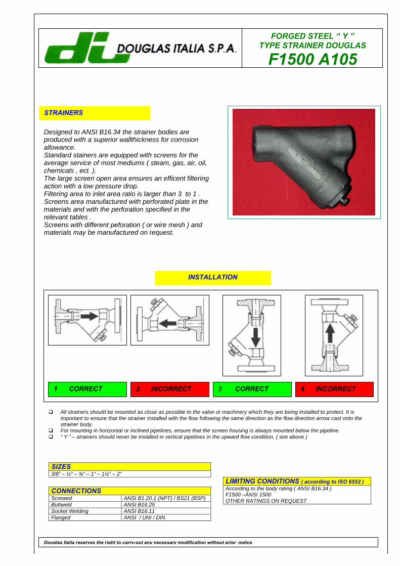
FORGED STEEL “ Y ”TYPE STRAINER DOUGLAS
F1500 A105
STRAINERS
Designed to ANSI B16.34 the strainer bodies areproduced with a superior wallthickness for corrosionallowance.Standard stainers are equipped with screens for theaverage service of most mediums ( steam, gas, air, oil,chemicals , ect. ).The large screen open area ensures an efficent filteringaction with a low pressure drop.Filtering area to inlet area ratio is larger than 3 to 1 .Screens area manufactured with perforated plate in thematerials and with the perforation specified in therelevant tables .Screens with different peforation ( or wire mesh ) andmaterials may be manufactured on request.
LIMITING CONDITIONS ( according to ISO 6552 )According to the body rating ( ANSI B16.34 )F1500 –ANSI 1500OTHER RATINGS ON REQUEST
SIZES3/8” – ½” – ¾” – 1” – 1½” – 2”
CONNECTIONSScrewed ANSI B1.20.1 (NPT) / BS21 (BSP)Buttweld ANSI B16.25Socket Welding ANSI B16.11Flanged ANSI / UNI / DIN
Douglas Italia reserves the right to carry-out any necessary modification without prior notice
INSTALLATION
q All strainers should be mounted as close as possible to the valve or machinery which they are being installed to protect. It isimportant to ensure that the strainer installed with the flow following the same direction as the flow direction arrow cast onto thestrainer body.
q For mounting in horizontal or inclined pipelines, ensure that the screen housing is always mounted below the pipeline.q “ Y “ – strainers should never be installed in vertical pipelines in the upward flow condition. ( see above )
1 CORRECT 2 INCORRECT 3 CORRECT 4 INCORRECT
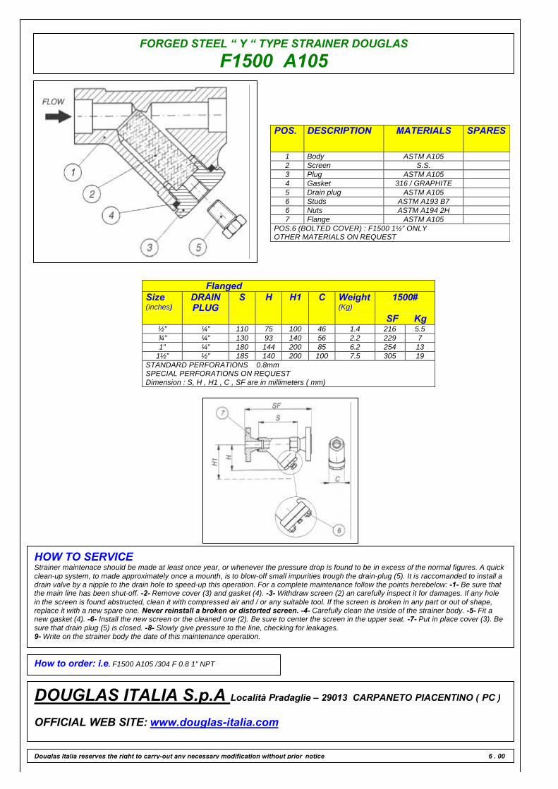
FORGED STEEL “ Y “ TYPE STRAINER DOUGLAS
F1500 A105
POS. DESCRIPTION MATERIALS SPARES
1 Body ASTM A1052 Screen S.S.3 Plug ASTM A1054 Gasket 316 / GRAPHITE5 Drain plug ASTM A1056 Studs ASTM A193 B76 Nuts ASTM A194 2H7 Flange ASTM A105
POS.6 (BOLTED COVER) : F1500 1½” ONLYOTHER MATERIALS ON REQUEST
FlangedSize(inches)
DRAINPLUG
S H H1 C Weight(Kg)
1500#
SF Kg½” ¼” 110 75 100 46 1.4 216 5.5¾” ¼” 130 93 140 56 2.2 229 71” ¼” 180 144 200 85 6.2 254 13
1½” ½” 185 140 200 100 7.5 305 19STANDARD PERFORATIONS 0.8mmSPECIAL PERFORATIONS ON REQUESTDimension : S, H , H1 , C , SF are in millimeters ( mm)
HOW TO SERVICEStrainer maintenace should be made at least once year, or whenever the pressure drop is found to be in excess of the normal figures. A quickclean-up system, to made approximately once a mounth, is to blow-off small impurities trough the drain-plug (5). It is raccomanded to install adrain valve by a nipple to the drain hole to speed-up this operation. For a complete maintenance follow the points herebelow: -1- Be sure thatthe main line has been shut-off. -2- Remove cover (3) and gasket (4). -3- Withdraw screen (2) an carefully inspect it for damages. If any holein the screen is found abstructed, clean it with compressed air and / or any suitable tool. If the screen is broken in any part or out of shape,replace it with a new spare one. Never reinstall a broken or distorted screen. -4- Carefully clean the inside of the strainer body. -5- Fit anew gasket (4). -6- Install the new screen or the cleaned one (2). Be sure to center the screen in the upper seat. -7- Put in place cover (3). Besure that drain plug (5) is closed. -8- Slowly give pressure to the line, checking for leakages.9- Write on the strainer body the date of this maintenance operation.
How to order: i.e. F1500 A105 /304 F 0.8 1” NPT
DOUGLAS ITALIA S.p.A Località Pradaglie – 29013 CARPANETO PIACENTINO ( PC )
OFFICIAL WEB SITE: www.douglas-italia.com
Douglas Italia reserves the right to carry-out any necessary modification without prior notice 6 . 00
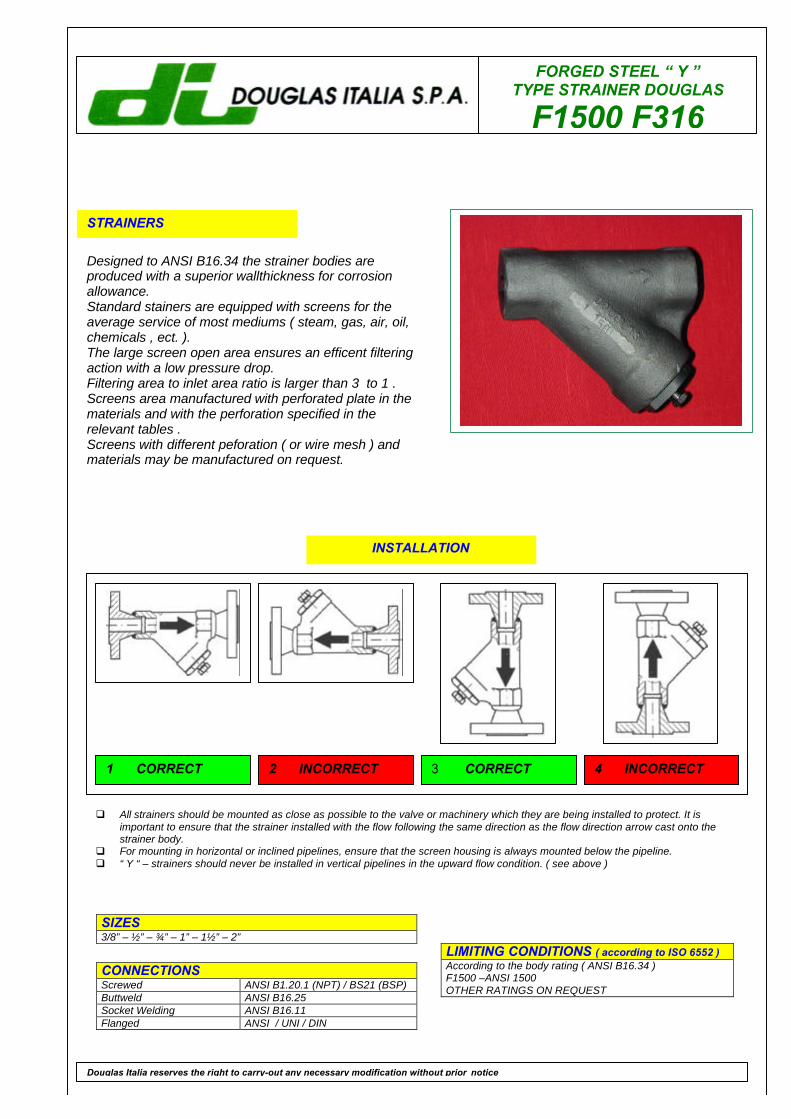
FORGED STEEL “ Y ”TYPE STRAINER DOUGLAS
F1500 F316
STRAINERS
Designed to ANSI B16.34 the strainer bodies areproduced with a superior wallthickness for corrosionallowance.Standard stainers are equipped with screens for theaverage service of most mediums ( steam, gas, air, oil,chemicals , ect. ).The large screen open area ensures an efficent filteringaction with a low pressure drop.Filtering area to inlet area ratio is larger than 3 to 1 .Screens area manufactured with perforated plate in thematerials and with the perforation specified in therelevant tables .Screens with different peforation ( or wire mesh ) andmaterials may be manufactured on request.
LIMITING CONDITIONS ( according to ISO 6552 )According to the body rating ( ANSI B16.34 )F1500 –ANSI 1500OTHER RATINGS ON REQUEST
SIZES3/8” – ½” – ¾” – 1” – 1½” – 2”
CONNECTIONSScrewed ANSI B1.20.1 (NPT) / BS21 (BSP)Buttweld ANSI B16.25Socket Welding ANSI B16.11Flanged ANSI / UNI / DIN
Douglas Italia reserves the right to carry-out any necessary modification without prior notice
INSTALLATION
q All strainers should be mounted as close as possible to the valve or machinery which they are being installed to protect. It isimportant to ensure that the strainer installed with the flow following the same direction as the flow direction arrow cast onto thestrainer body.
q For mounting in horizontal or inclined pipelines, ensure that the screen housing is always mounted below the pipeline.q “ Y “ – strainers should never be installed in vertical pipelines in the upward flow condition. ( see above )
1 CORRECT 2 INCORRECT 3 CORRECT 4 INCORRECT
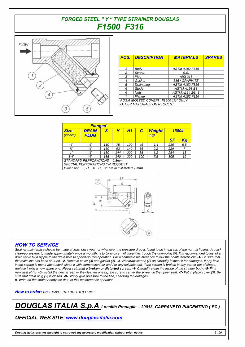
FORGED STEEL “ Y “ TYPE STRAINER DOUGLAS
F1500 F316
POS. DESCRIPTION MATERIALS SPARES
1 Body ASTM A182 F3162 Screen S.S.3 Plug AISI 3164 Gasket 316 / GRAPHITE5 Drain plug ASTM A182 F3166 Studs ASTM A193 B86 Nuts ASTM A194 2Gr.87 Flange ASTM A182 F316
POS.6 (BOLTED COVER) : F1500 1½” ONLYOTHER MATERIALS ON REQUEST
FlangedSize(inches)
DRAINPLUG
S H H1 C Weight(Kg)
1500#
SF Kg½” ¼” 110 75 100 46 1.4 216 5.5¾” ¼” 130 93 140 56 2.2 229 71” ¼” 180 144 200 85 6.2 254 13
1½” ½” 185 140 200 100 7.5 305 19STANDARD PERFORATIONS 0.8mmSPECIAL PERFORATIONS ON REQUESTDimension : S, H , H1 , C , SF are in millimeters ( mm)
HOW TO SERVICEStrainer maintenace should be made at least once year, or whenever the pressure drop is found to be in excess of the normal figures. A quickclean-up system, to made approximately once a mounth, is to blow-off small impurities trough the drain-plug (5). It is raccomanded to install adrain valve by a nipple to the drain hole to speed-up this operation. For a complete maintenance follow the points herebelow: -1- Be sure thatthe main line has been shut-off. -2- Remove cover (3) and gasket (4). -3- Withdraw screen (2) an carefully inspect it for damages. If any holein the screen is found abstructed, clean it with compressed air and / or any suitable tool. If the screen is broken in any part or out of shape,replace it with a new spare one. Never reinstall a broken or distorted screen. -4- Carefully clean the inside of the strainer body. -5- Fit anew gasket (4). -6- Install the new screen or the cleaned one (2). Be sure to center the screen in the upper seat. -7- Put in place cover (3). Besure that drain plug (5) is closed. -8- Slowly give pressure to the line, checking for leakages.9- Write on the strainer body the date of this maintenance operation.
How to order: i.e. F1500 F316 / 316 F 0.8 1” NPT
DOUGLAS ITALIA S.p.A Località Pradaglie – 29013 CARPANETO PIACENTINO ( PC )
OFFICIAL WEB SITE: www.douglas-italia.com
Douglas Italia reserves the right to carry-out any necessary modification without prior notice 6 . 00
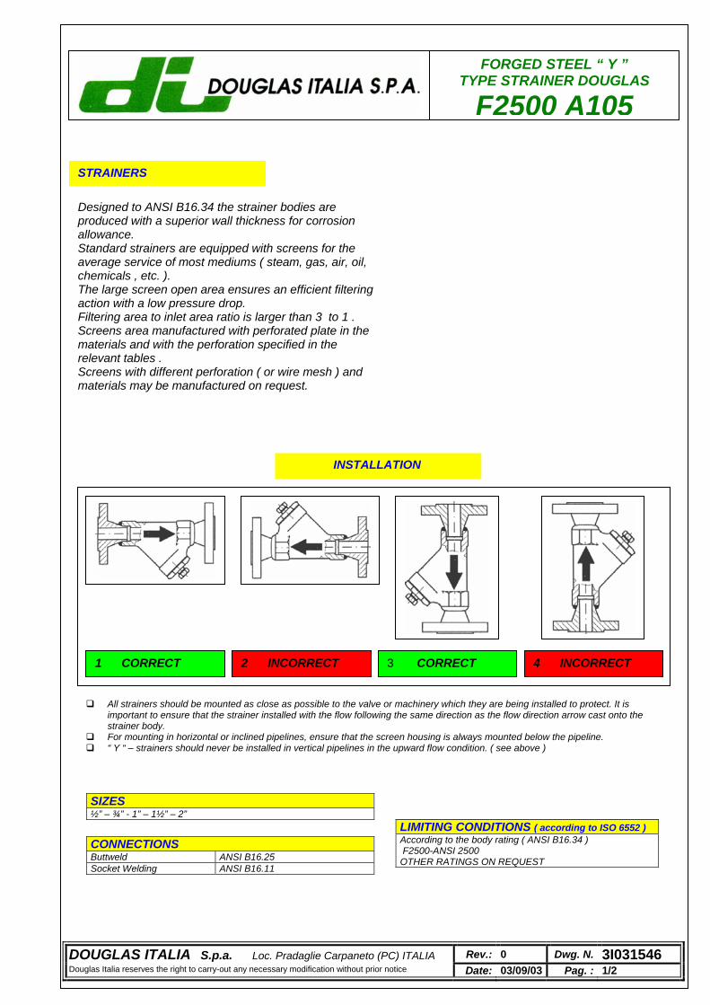
FORGED STEEL “ Y ” TYPE STRAINER DOUGLAS
F2500 A105
STRAINERS
Designed to ANSI B16.34 the strainer bodies are produced with a superior wall thickness for corrosion allowance. Standard strainers are equipped with screens for the average service of most mediums ( steam, gas, air, oil, chemicals , etc. ). The large screen open area ensures an efficient filtering action with a low pressure drop. Filtering area to inlet area ratio is larger than 3 to 1 . Screens area manufactured with perforated plate in the materials and with the perforation specified in the relevant tables . Screens with different perforation ( or wire mesh ) and materials may be manufactured on request.
LIMITING CONDITIONS ( according to ISO 6552 ) According to the body rating ( ANSI B16.34 ) F2500-ANSI 2500 OTHER RATINGS ON REQUEST
SIZES ½” – ¾” - 1” – 1½” – 2”
CONNECTIONS Buttweld ANSI B16.25 Socket Welding ANSI B16.11
INSTALLATION
All strainers should be mounted as close as possible to the valve or machinery which they are being installed to protect. It is important to ensure that the strainer installed with the flow following the same direction as the flow direction arrow cast onto the strainer body.
For mounting in horizontal or inclined pipelines, ensure that the screen housing is always mounted below the pipeline. “ Y “ – strainers should never be installed in vertical pipelines in the upward flow condition. ( see above )
1 CORRECT 2 INCORRECT 3 CORRECT 4 INCORRECT
DOUGLAS ITALIA S.p.a. Loc. Pradaglie Carpaneto (PC) ITALIA Rev.: 0 Dwg. N. 3I031546 Douglas Italia reserves the right to carry-out any necessary modification without prior notice Date: 03/09/03 Pag. : 1/2
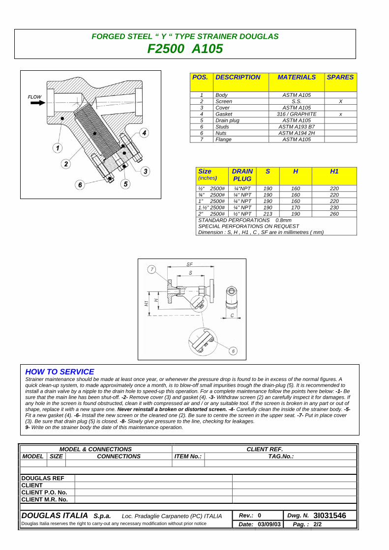
POS. DESCRIPTION MATERIALS SPARES
1 Body ASTM A105 2 Screen S.S. X 3 Cover ASTM A105 4 Gasket 316 / GRAPHITE x 5 Drain plug ASTM A105 6 Studs ASTM A193 B7 6 Nuts ASTM A194 2H 7 Flange ASTM A105
Size (inches)
DRAINPLUG
S
H H1
½“ 2500# ¼“NPT 190 160 220 ¾“ 2500# ¼“ NPT 190 160 220 1” 2500# ¼” NPT 190 160 220 1.½” 2500# ¼” NPT 190 170 230 2” 2500# ½” NPT 213 190 260 STANDARD PERFORATIONS 0.8mm SPECIAL PERFORATIONS ON REQUEST Dimension : S, H , H1 , C , SF are in millimetres ( mm)
HOW TO SERVICE Strainer maintenance should be made at least once year, or whenever the pressure drop is found to be in excess of the normal figures. A quick clean-up system, to made approximately once a month, is to blow-off small impurities trough the drain-plug (5). It is recommended to install a drain valve by a nipple to the drain hole to speed-up this operation. For a complete maintenance follow the points here below: -1- Be sure that the main line has been shut-off. -2- Remove cover (3) and gasket (4). -3- Withdraw screen (2) an carefully inspect it for damages. If any hole in the screen is found obstructed, clean it with compressed air and / or any suitable tool. If the screen is broken in any part or out of shape, replace it with a new spare one. Never reinstall a broken or distorted screen. -4- Carefully clean the inside of the strainer body. -5- Fit a new gasket (4). -6- Install the new screen or the cleaned one (2). Be sure to centre the screen in the upper seat. -7- Put in place cover (3). Be sure that drain plug (5) is closed. -8- Slowly give pressure to the line, checking for leakages. 9- Write on the strainer body the date of this maintenance operation.
MODEL & CONNECTIONS CLIENT REF. MODEL SIZE CONNECTIONS ITEM No.: TAG.No.:
DOUGLAS REF CLIENT CLIENT P.O. No. CLIENT M.R. No.
DOUGLAS ITALIA S.p.a. Loc. Pradaglie Carpaneto (PC) ITALIA Rev.: 0 Dwg. N. 3I031546 Douglas Italia reserves the right to carry-out any necessary modification without prior notice Date: 03/09/03 Pag. : 2/2
FORGED STEEL “ Y “ TYPE STRAINER DOUGLAS
F2500 A105

FORGED STEEL “ Y ” TYPE STRAINER DOUGLAS
F2500 F316
STRAINERS
Designed to ANSI B16.34 the strainer bodies are produced with a superior wall thickness for corrosion allowance. Standard strainers are equipped with screens for the average service of most mediums ( steam, gas, air, oil, chemicals , etc. ). The large screen open area ensures an efficient filtering action with a low pressure drop. Filtering area to inlet area ratio is larger than 3 to 1 . Screens area manufactured with perforated plate in the materials and with the perforation specified in the relevant tables . Screens with different perforation ( or wire mesh ) and materials may be manufactured on request.
LIMITING CONDITIONS ( according to ISO 6552 ) According to the body rating ( ANSI B16.34 ) F2500-ANSI 2500 OTHER RATINGS ON REQUEST
SIZES ½” – ¾” - 1” – 1½” – 2”
CONNECTIONS Buttweld ANSI B16.25 Socket Welding ANSI B16.11
INSTALLATION
All strainers should be mounted as close as possible to the valve or machinery which they are being installed to protect. It is important to ensure that the strainer installed with the flow following the same direction as the flow direction arrow cast onto the strainer body.
For mounting in horizontal or inclined pipelines, ensure that the screen housing is always mounted below the pipeline. “ Y “ – strainers should never be installed in vertical pipelines in the upward flow condition. ( see above )
1 CORRECT 2 INCORRECT 3 CORRECT 4 INCORRECT
DOUGLAS ITALIA S.p.a. Loc. Pradaglie Carpaneto (PC) ITALIA Rev.: 0 Dwg. N. 3I031546 Douglas Italia reserves the right to carry-out any necessary modification without prior notice Date: 03/09/03 Pag. : 1/2
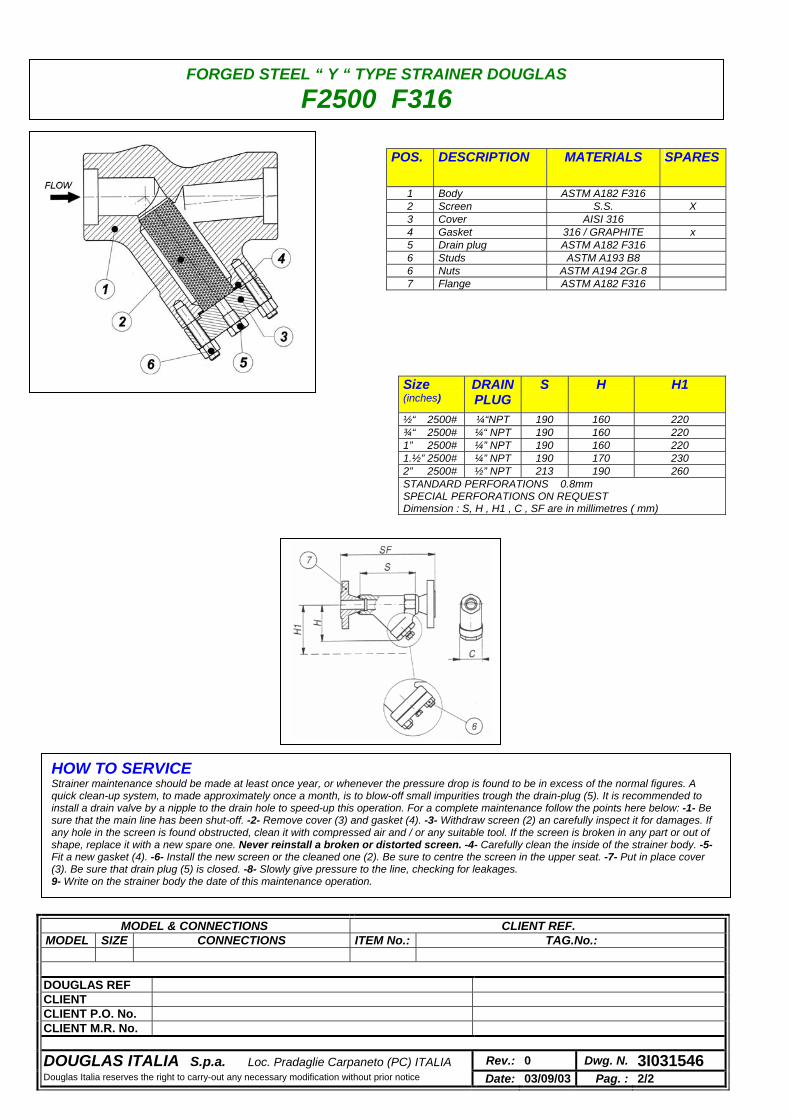
POS. DESCRIPTION MATERIALS SPARES
1 Body ASTM A182 F316 2 Screen S.S. X 3 Cover AISI 316 4 Gasket 316 / GRAPHITE x 5 Drain plug ASTM A182 F316 6 Studs ASTM A193 B8 6 Nuts ASTM A194 2Gr.8 7 Flange ASTM A182 F316
Size (inches)
DRAINPLUG
S
H H1
½“ 2500# ¼“NPT 190 160 220 ¾“ 2500# ¼“ NPT 190 160 220 1” 2500# ¼” NPT 190 160 220 1.½” 2500# ¼” NPT 190 170 230 2” 2500# ½” NPT 213 190 260 STANDARD PERFORATIONS 0.8mm SPECIAL PERFORATIONS ON REQUEST Dimension : S, H , H1 , C , SF are in millimetres ( mm)
HOW TO SERVICE Strainer maintenance should be made at least once year, or whenever the pressure drop is found to be in excess of the normal figures. A quick clean-up system, to made approximately once a month, is to blow-off small impurities trough the drain-plug (5). It is recommended to install a drain valve by a nipple to the drain hole to speed-up this operation. For a complete maintenance follow the points here below: -1- Be sure that the main line has been shut-off. -2- Remove cover (3) and gasket (4). -3- Withdraw screen (2) an carefully inspect it for damages. If any hole in the screen is found obstructed, clean it with compressed air and / or any suitable tool. If the screen is broken in any part or out of shape, replace it with a new spare one. Never reinstall a broken or distorted screen. -4- Carefully clean the inside of the strainer body. -5- Fit a new gasket (4). -6- Install the new screen or the cleaned one (2). Be sure to centre the screen in the upper seat. -7- Put in place cover (3). Be sure that drain plug (5) is closed. -8- Slowly give pressure to the line, checking for leakages. 9- Write on the strainer body the date of this maintenance operation.
MODEL & CONNECTIONS CLIENT REF. MODEL SIZE CONNECTIONS ITEM No.: TAG.No.:
DOUGLAS REF CLIENT CLIENT P.O. No. CLIENT M.R. No.
DOUGLAS ITALIA S.p.a. Loc. Pradaglie Carpaneto (PC) ITALIA Rev.: 0 Dwg. N. 3I031546 Douglas Italia reserves the right to carry-out any necessary modification without prior notice Date: 03/09/03 Pag. : 2/2
FORGED STEEL “ Y “ TYPE STRAINER DOUGLAS
F2500 F316

“ Y “ CAST
GO BACK
C 150 WCB
C 150 CF8M
C 300 WCB
C 300 CF8M
C 600 WCB
C 600 CF8M
C 900 WCB
C 900 CF8M
C 900 PS WCB
C 900 PS CF8M
C 1500 WCB
C 1500 CF8M
C 1500 PS WCB
C 1500 PS CF8M
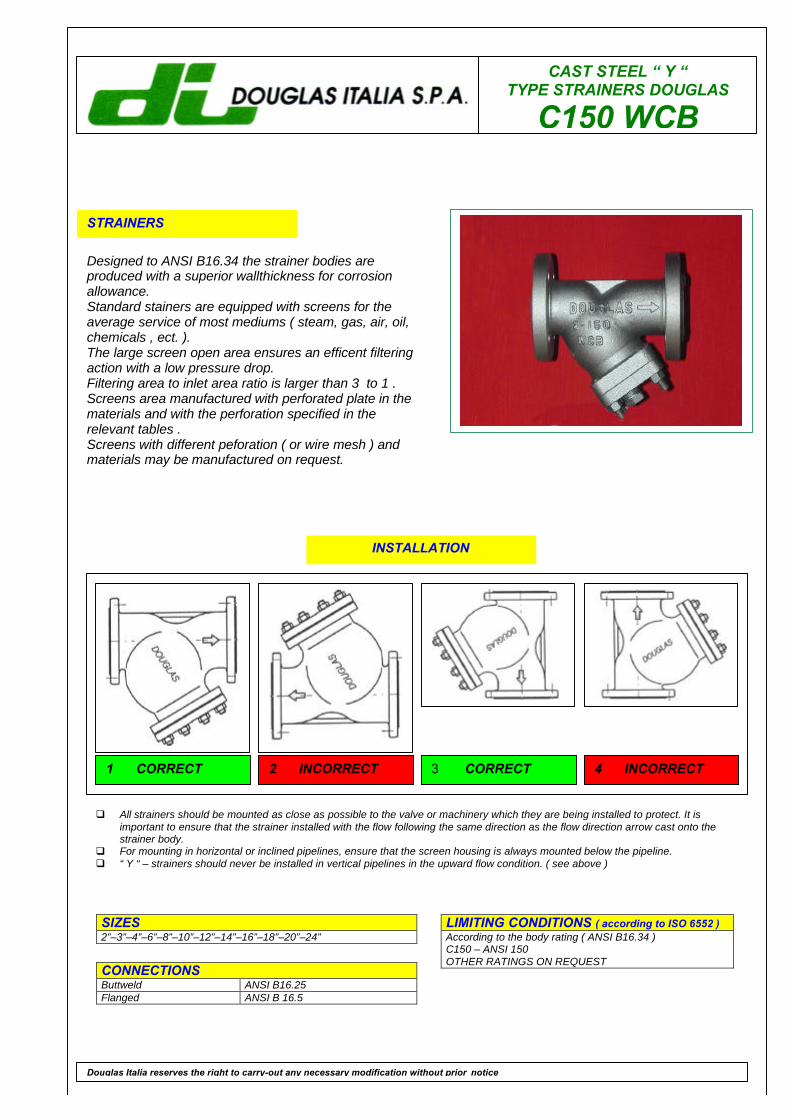
CAST STEEL “ Y “TYPE STRAINERS DOUGLAS
C150 WCB
STRAINERS
Designed to ANSI B16.34 the strainer bodies areproduced with a superior wallthickness for corrosionallowance.Standard stainers are equipped with screens for theaverage service of most mediums ( steam, gas, air, oil,chemicals , ect. ).The large screen open area ensures an efficent filteringaction with a low pressure drop.Filtering area to inlet area ratio is larger than 3 to 1 .Screens area manufactured with perforated plate in thematerials and with the perforation specified in therelevant tables .Screens with different peforation ( or wire mesh ) andmaterials may be manufactured on request.
LIMITING CONDITIONS ( according to ISO 6552 )According to the body rating ( ANSI B16.34 )C150 – ANSI 150OTHER RATINGS ON REQUEST
SIZES2”–3”–4”–6”–8”–10”–12”–14”–16”–18”–20”–24”
CONNECTIONSButtweld ANSI B16.25Flanged ANSI B 16.5
Douglas Italia reserves the right to carry-out any necessary modification without prior notice
INSTALLATION
q All strainers should be mounted as close as possible to the valve or machinery which they are being installed to protect. It isimportant to ensure that the strainer installed with the flow following the same direction as the flow direction arrow cast onto thestrainer body.
q For mounting in horizontal or inclined pipelines, ensure that the screen housing is always mounted below the pipeline.q “ Y “ – strainers should never be installed in vertical pipelines in the upward flow condition. ( see above )
1 CORRECT 2 INCORRECT 3 CORRECT 4 INCORRECT

CAST STEEL “ Y “ TYPE STRAINERS DOUGLAS
C150 WCB
POS. DESCRIPTION MATERIALS SPARES
1 Body ASTM A216 WCB2 Screen S.S. 304 X3 Cover ASTM A1054 Gasket 316 / GRAPHITE X5 Drain plug ASTM A1056 Studs ASTM A193 B77 Nuts ASTM A194 2H
OTHER MATERIALS ON REQUEST
Size(inches)
2” 3” 4” 6” 8” 10” 12” 14” 16” 18” 20” 24”
SRF 203 241 292 406 495 622 699 788 914 978 978 1295
S 203 241 292 406 495 622 699 788 914 978 978 1295
H 140 210 270 360 460 570 700 770 870 975 1095 1300
H1 190 260 340 400 580 660 800 1200 1400 1530 1750 2040
Kg 14 26 40 68 140 190 270 350 640 700 895 1370STANDARD PERFORATIONS 1.5 mmSPECIAL PERFORATIONS ON REQUEST . DRAIN PLUG SIZE ¾”Dimension : SRF , S , H , H1 are in millimeters ( mm)
HOW TO SERVICEStrainer maintenace should be made at least once year, or whenever the pressure drop is found to be in excess of the normal figures. A quickclean-up system, to made approximately once a mounth, is to blow-off small impurities trough the drain-plug (5). It is raccomanded to install adrain valve by a nipple to the drain hole to speed-up this operation. For a complete maintenance follow the points herebelow: -1- Be sure thatthe main line has been shut-off. -2- Untighten cover stud bolts (6) and nuts (7) and remove cover (3) and gasket (4). -3- Withdraw screen (2)an carefully inspect it for damages. If any hole in the screen is found abstructed, clean it with compressed air and / or any suitable tool. If thescreen is broken in any part or out of shape, replace it with a new spare one. Never reinstall a broken or distorted screen. -4- Carefullyclean the inside of the strainer body. -5- Fit a new gasket (4). -6- Install the new screen or the cleaned one (2). Be sure to center the screen inthe upper seat. -7- Put in place cover (3). Be sure that drain plug (5) is closed. -8- Slowly give pressure to the line, checking for leakages.9- Write on the strainer body the date of this maintenance operation.
How to order: i.e. C150 WCB / 304 F 1.5 2” 150 RF
DOUGLAS ITALIA S.p.A Località Pradaglie – 29013 CARPANETO PIACENTINO ( PC )
OFFICIAL WEB SITE: www.douglas-italia.com
Douglas Italia reserves the right to carry-out any necessary modification without prior notice 6 . 00
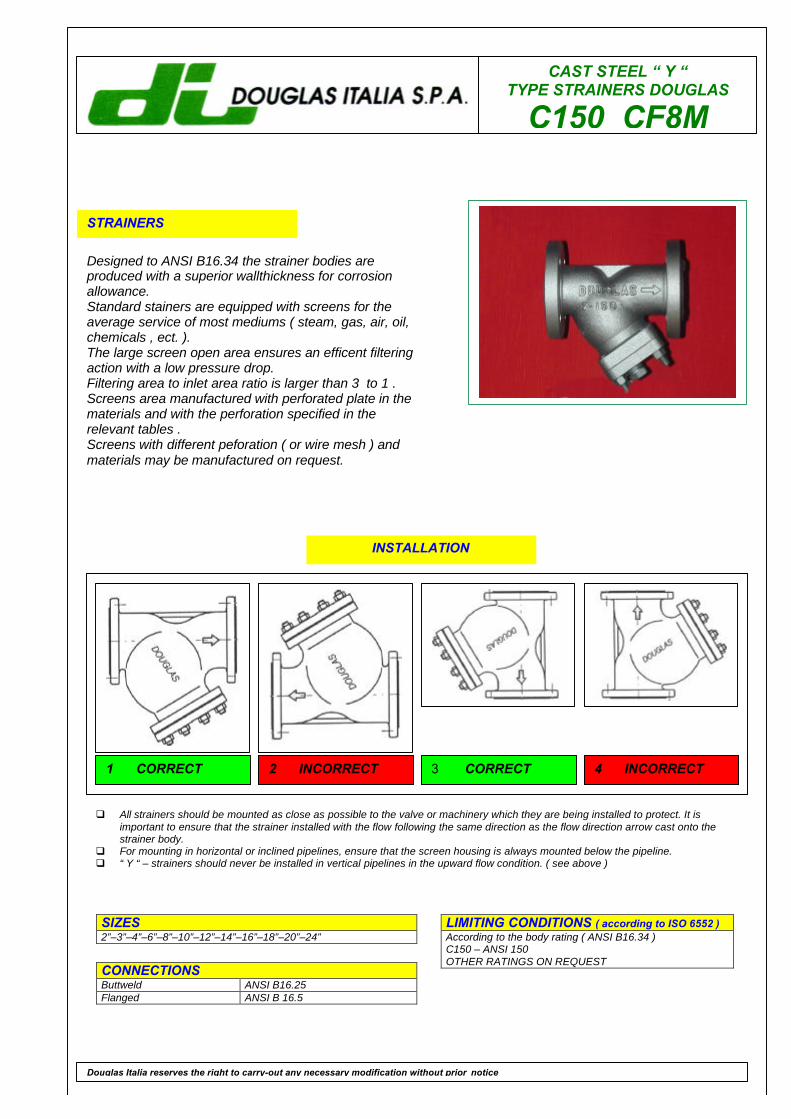
CAST STEEL “ Y “TYPE STRAINERS DOUGLAS
C150 CF8M
STRAINERS
Designed to ANSI B16.34 the strainer bodies areproduced with a superior wallthickness for corrosionallowance.Standard stainers are equipped with screens for theaverage service of most mediums ( steam, gas, air, oil,chemicals , ect. ).The large screen open area ensures an efficent filteringaction with a low pressure drop.Filtering area to inlet area ratio is larger than 3 to 1 .Screens area manufactured with perforated plate in thematerials and with the perforation specified in therelevant tables .Screens with different peforation ( or wire mesh ) andmaterials may be manufactured on request.
LIMITING CONDITIONS ( according to ISO 6552 )According to the body rating ( ANSI B16.34 )C150 – ANSI 150OTHER RATINGS ON REQUEST
SIZES2”–3”–4”–6”–8”–10”–12”–14”–16”–18”–20”–24”
CONNECTIONSButtweld ANSI B16.25Flanged ANSI B 16.5
Douglas Italia reserves the right to carry-out any necessary modification without prior notice
INSTALLATION
q All strainers should be mounted as close as possible to the valve or machinery which they are being installed to protect. It isimportant to ensure that the strainer installed with the flow following the same direction as the flow direction arrow cast onto thestrainer body.
q For mounting in horizontal or inclined pipelines, ensure that the screen housing is always mounted below the pipeline.q “ Y “ – strainers should never be installed in vertical pipelines in the upward flow condition. ( see above )
1 CORRECT 2 INCORRECT 3 CORRECT 4 INCORRECT
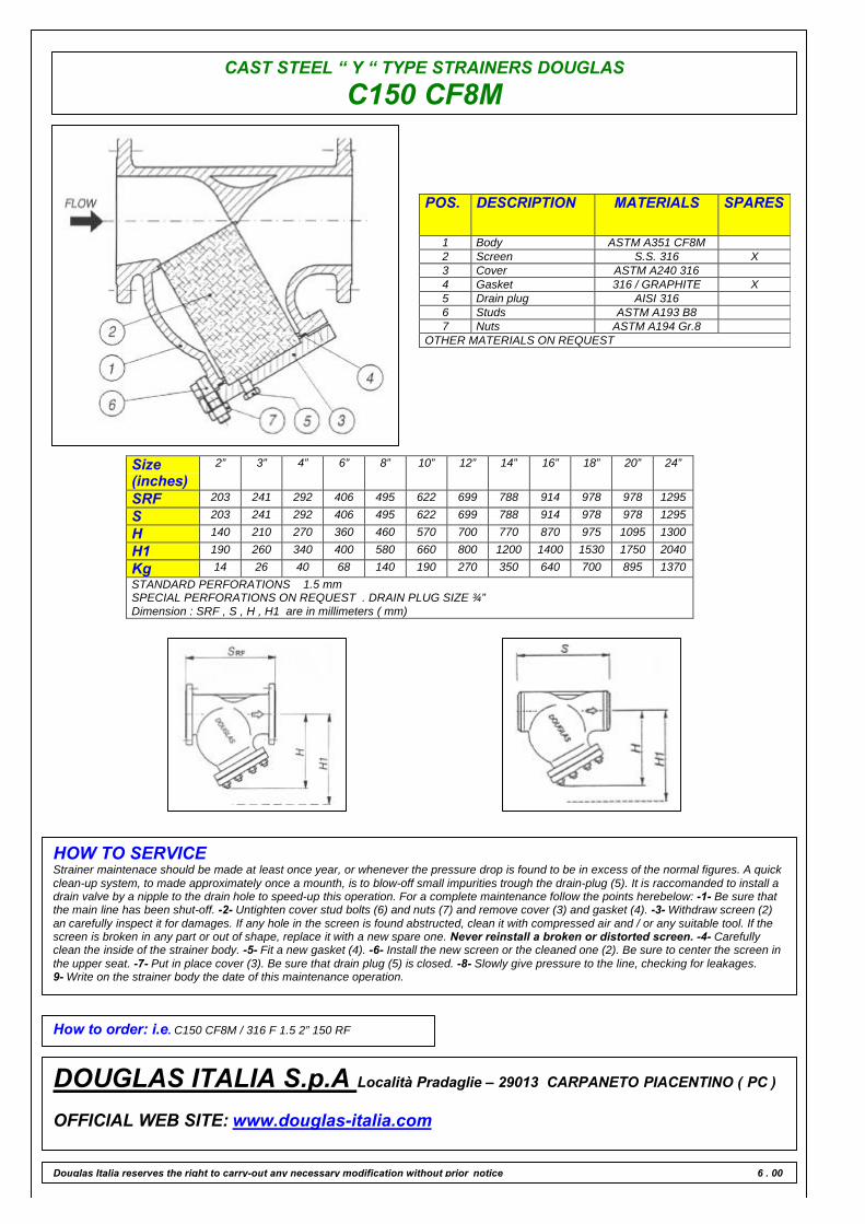
CAST STEEL “ Y “ TYPE STRAINERS DOUGLAS
C150 CF8M
POS. DESCRIPTION MATERIALS SPARES
1 Body ASTM A351 CF8M2 Screen S.S. 316 X3 Cover ASTM A240 3164 Gasket 316 / GRAPHITE X5 Drain plug AISI 3166 Studs ASTM A193 B87 Nuts ASTM A194 Gr.8
OTHER MATERIALS ON REQUEST
Size(inches)
2” 3” 4” 6” 8” 10” 12” 14” 16” 18” 20” 24”
SRF 203 241 292 406 495 622 699 788 914 978 978 1295
S 203 241 292 406 495 622 699 788 914 978 978 1295
H 140 210 270 360 460 570 700 770 870 975 1095 1300
H1 190 260 340 400 580 660 800 1200 1400 1530 1750 2040
Kg 14 26 40 68 140 190 270 350 640 700 895 1370STANDARD PERFORATIONS 1.5 mmSPECIAL PERFORATIONS ON REQUEST . DRAIN PLUG SIZE ¾”Dimension : SRF , S , H , H1 are in millimeters ( mm)
HOW TO SERVICEStrainer maintenace should be made at least once year, or whenever the pressure drop is found to be in excess of the normal figures. A quickclean-up system, to made approximately once a mounth, is to blow-off small impurities trough the drain-plug (5). It is raccomanded to install adrain valve by a nipple to the drain hole to speed-up this operation. For a complete maintenance follow the points herebelow: -1- Be sure thatthe main line has been shut-off. -2- Untighten cover stud bolts (6) and nuts (7) and remove cover (3) and gasket (4). -3- Withdraw screen (2)an carefully inspect it for damages. If any hole in the screen is found abstructed, clean it with compressed air and / or any suitable tool. If thescreen is broken in any part or out of shape, replace it with a new spare one. Never reinstall a broken or distorted screen. -4- Carefullyclean the inside of the strainer body. -5- Fit a new gasket (4). -6- Install the new screen or the cleaned one (2). Be sure to center the screen inthe upper seat. -7- Put in place cover (3). Be sure that drain plug (5) is closed. -8- Slowly give pressure to the line, checking for leakages.9- Write on the strainer body the date of this maintenance operation.
How to order: i.e. C150 CF8M / 316 F 1.5 2” 150 RF
DOUGLAS ITALIA S.p.A Località Pradaglie – 29013 CARPANETO PIACENTINO ( PC )
OFFICIAL WEB SITE: www.douglas-italia.com
Douglas Italia reserves the right to carry-out any necessary modification without prior notice 6 . 00

CAST STEEL “ Y “TYPE STRAINERS DOUGLAS
C300 WCB
STRAINERS
Designed to ANSI B16.34 the strainer bodies areproduced with a superior wallthickness for corrosionallowance.Standard stainers are equipped with screens for theaverage service of most mediums ( steam, gas, air, oil,chemicals , ect. ).The large screen open area ensures an efficent filteringaction with a low pressure drop.Filtering area to inlet area ratio is larger than 3 to 1 .Screens area manufactured with perforated plate in thematerials and with the perforation specified in therelevant tables .Screens with different peforation ( or wire mesh ) andmaterials may be manufactured on request.
LIMITING CONDITIONS ( according to ISO 6552 )According to the body rating ( ANSI B16.34 )C300 – ANSI 300OTHER RATINGS ON REQUEST
SIZES2”–3”–4”–6”–8”–10”–12”–14”–16”–18”–20”–24”
CONNECTIONSButtweld ANSI B16.25Flanged ANSI B 16.5
Douglas Italia reserves the right to carry-out any necessary modification without prior notice
INSTALLATION
q All strainers should be mounted as close as possible to the valve or machinery which they are being installed to protect. It isimportant to ensure that the strainer installed with the flow following the same direction as the flow direction arrow cast onto thestrainer body.
q For mounting in horizontal or inclined pipelines, ensure that the screen housing is always mounted below the pipeline.q “ Y “ – strainers should never be installed in vertical pipelines in the upward flow condition. ( see above )
1 CORRECT 2 INCORRECT 3 CORRECT 4 INCORRECT
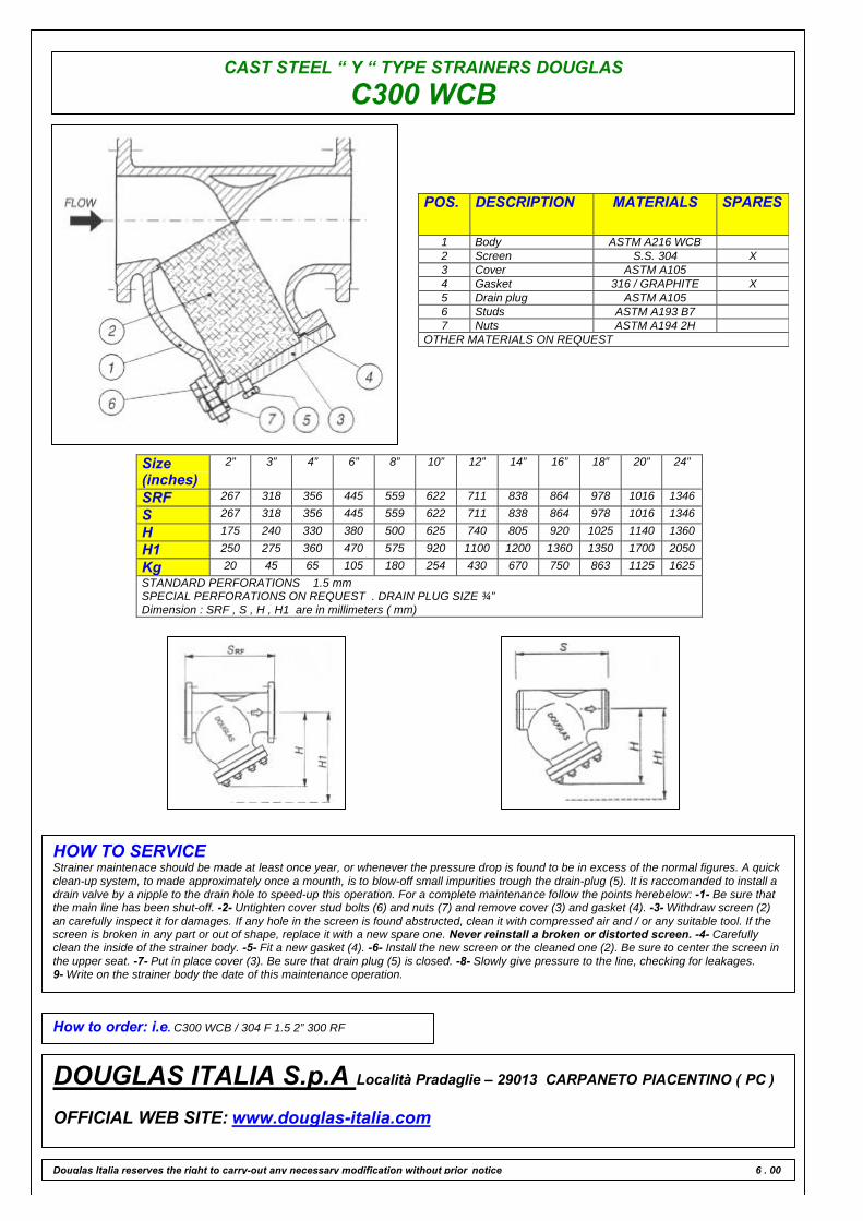
CAST STEEL “ Y “ TYPE STRAINERS DOUGLAS
C300 WCB
POS. DESCRIPTION MATERIALS SPARES
1 Body ASTM A216 WCB2 Screen S.S. 304 X3 Cover ASTM A1054 Gasket 316 / GRAPHITE X5 Drain plug ASTM A1056 Studs ASTM A193 B77 Nuts ASTM A194 2H
OTHER MATERIALS ON REQUEST
Size(inches)
2” 3” 4” 6” 8” 10” 12” 14” 16” 18” 20” 24”
SRF 267 318 356 445 559 622 711 838 864 978 1016 1346
S 267 318 356 445 559 622 711 838 864 978 1016 1346
H 175 240 330 380 500 625 740 805 920 1025 1140 1360
H1 250 275 360 470 575 920 1100 1200 1360 1350 1700 2050
Kg 20 45 65 105 180 254 430 670 750 863 1125 1625STANDARD PERFORATIONS 1.5 mmSPECIAL PERFORATIONS ON REQUEST . DRAIN PLUG SIZE ¾”Dimension : SRF , S , H , H1 are in millimeters ( mm)
HOW TO SERVICEStrainer maintenace should be made at least once year, or whenever the pressure drop is found to be in excess of the normal figures. A quickclean-up system, to made approximately once a mounth, is to blow-off small impurities trough the drain-plug (5). It is raccomanded to install adrain valve by a nipple to the drain hole to speed-up this operation. For a complete maintenance follow the points herebelow: -1- Be sure thatthe main line has been shut-off. -2- Untighten cover stud bolts (6) and nuts (7) and remove cover (3) and gasket (4). -3- Withdraw screen (2)an carefully inspect it for damages. If any hole in the screen is found abstructed, clean it with compressed air and / or any suitable tool. If thescreen is broken in any part or out of shape, replace it with a new spare one. Never reinstall a broken or distorted screen. -4- Carefullyclean the inside of the strainer body. -5- Fit a new gasket (4). -6- Install the new screen or the cleaned one (2). Be sure to center the screen inthe upper seat. -7- Put in place cover (3). Be sure that drain plug (5) is closed. -8- Slowly give pressure to the line, checking for leakages.9- Write on the strainer body the date of this maintenance operation.
How to order: i.e. C300 WCB / 304 F 1.5 2” 300 RF
DOUGLAS ITALIA S.p.A Località Pradaglie – 29013 CARPANETO PIACENTINO ( PC )
OFFICIAL WEB SITE: www.douglas-italia.com
Douglas Italia reserves the right to carry-out any necessary modification without prior notice 6 . 00
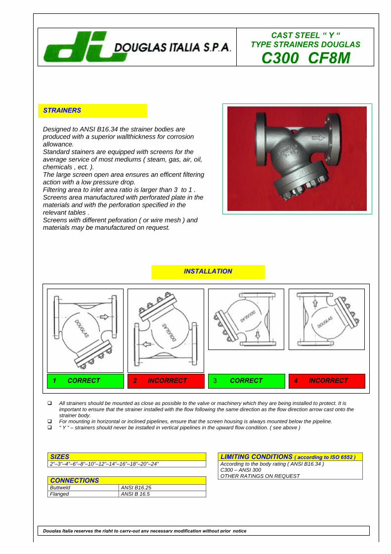
CAST STEEL “ Y “TYPE STRAINERS DOUGLAS
C300 CF8M
STRAINERS
Designed to ANSI B16.34 the strainer bodies areproduced with a superior wallthickness for corrosionallowance.Standard stainers are equipped with screens for theaverage service of most mediums ( steam, gas, air, oil,chemicals , ect. ).The large screen open area ensures an efficent filteringaction with a low pressure drop.Filtering area to inlet area ratio is larger than 3 to 1 .Screens area manufactured with perforated plate in thematerials and with the perforation specified in therelevant tables .Screens with different peforation ( or wire mesh ) andmaterials may be manufactured on request.
LIMITING CONDITIONS ( according to ISO 6552 )According to the body rating ( ANSI B16.34 )C300 – ANSI 300OTHER RATINGS ON REQUEST
SIZES2”–3”–4”–6”–8”–10”–12”–14”–16”–18”–20”–24”
CONNECTIONSButtweld ANSI B16.25Flanged ANSI B 16.5
Douglas Italia reserves the right to carry-out any necessary modification without prior notice
INSTALLATION
q All strainers should be mounted as close as possible to the valve or machinery which they are being installed to protect. It isimportant to ensure that the strainer installed with the flow following the same direction as the flow direction arrow cast onto thestrainer body.
q For mounting in horizontal or inclined pipelines, ensure that the screen housing is always mounted below the pipeline.q “ Y “ – strainers should never be installed in vertical pipelines in the upward flow condition. ( see above )
1 CORRECT 2 INCORRECT 3 CORRECT 4 INCORRECT
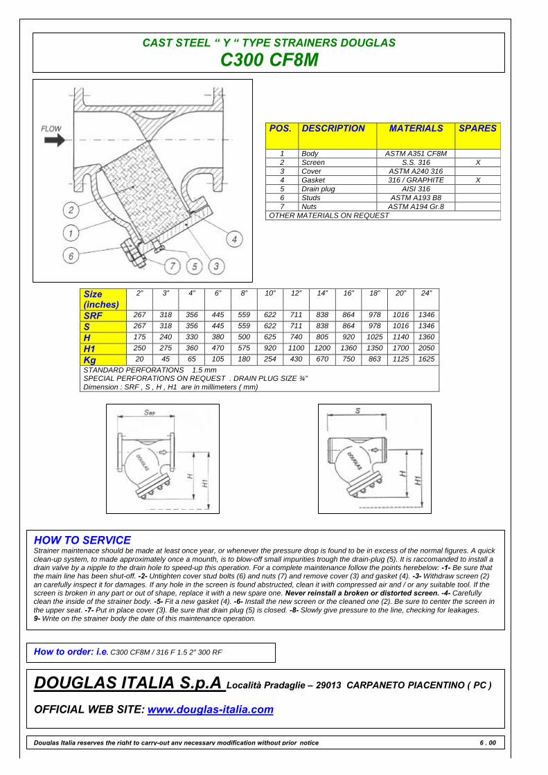
CAST STEEL “ Y “ TYPE STRAINERS DOUGLAS
C300 CF8M
POS. DESCRIPTION MATERIALS SPARES
1 Body ASTM A351 CF8M2 Screen S.S. 316 X3 Cover ASTM A240 3164 Gasket 316 / GRAPHITE X5 Drain plug AISI 3166 Studs ASTM A193 B87 Nuts ASTM A194 Gr.8
OTHER MATERIALS ON REQUEST
Size(inches)
2” 3” 4” 6” 8” 10” 12” 14” 16” 18” 20” 24”
SRF 267 318 356 445 559 622 711 838 864 978 1016 1346
S 267 318 356 445 559 622 711 838 864 978 1016 1346
H 175 240 330 380 500 625 740 805 920 1025 1140 1360
H1 250 275 360 470 575 920 1100 1200 1360 1350 1700 2050
Kg 20 45 65 105 180 254 430 670 750 863 1125 1625STANDARD PERFORATIONS 1.5 mmSPECIAL PERFORATIONS ON REQUEST . DRAIN PLUG SIZE ¾”Dimension : SRF , S , H , H1 are in millimeters ( mm)
HOW TO SERVICEStrainer maintenace should be made at least once year, or whenever the pressure drop is found to be in excess of the normal figures. A quickclean-up system, to made approximately once a mounth, is to blow-off small impurities trough the drain-plug (5). It is raccomanded to install adrain valve by a nipple to the drain hole to speed-up this operation. For a complete maintenance follow the points herebelow: -1- Be sure thatthe main line has been shut-off. -2- Untighten cover stud bolts (6) and nuts (7) and remove cover (3) and gasket (4). -3- Withdraw screen (2)an carefully inspect it for damages. If any hole in the screen is found abstructed, clean it with compressed air and / or any suitable tool. If thescreen is broken in any part or out of shape, replace it with a new spare one. Never reinstall a broken or distorted screen. -4- Carefullyclean the inside of the strainer body. -5- Fit a new gasket (4). -6- Install the new screen or the cleaned one (2). Be sure to center the screen inthe upper seat. -7- Put in place cover (3). Be sure that drain plug (5) is closed. -8- Slowly give pressure to the line, checking for leakages.9- Write on the strainer body the date of this maintenance operation.
How to order: i.e. C300 CF8M / 316 F 1.5 2” 300 RF
DOUGLAS ITALIA S.p.A Località Pradaglie – 29013 CARPANETO PIACENTINO ( PC )
OFFICIAL WEB SITE: www.douglas-italia.com
Douglas Italia reserves the right to carry-out any necessary modification without prior notice 6 . 00

CAST STEEL “ Y “TYPE STRAINERS DOUGLAS
C600 WCB
STRAINERS
Designed to ANSI B16.34 the strainer bodies areproduced with a superior wallthickness for corrosionallowance.Standard stainers are equipped with screens for theaverage service of most mediums ( steam, gas, air, oil,chemicals , ect. ).The large screen open area ensures an efficent filteringaction with a low pressure drop.Filtering area to inlet area ratio is larger than 3 to 1 .Screens area manufactured with perforated plate in thematerials and with the perforation specified in therelevant tables .Screens with different peforation ( or wire mesh ) andmaterials may be manufactured on request.
LIMITING CONDITIONS ( according to ISO 6552 )According to the body rating ( ANSI B16.34 )C600 – ANSI 600OTHER RATINGS ON REQUEST
SIZES2”–3”–4”–6”–8”–10”–12”–14”–16”
CONNECTIONSButtweld ANSI B16.25Flanged ANSI B 16.5
Douglas Italia reserves the right to carry-out any necessary modification without prior notice
INSTALLATION
q All strainers should be mounted as close as possible to the valve or machinery which they are being installed to protect. It isimportant to ensure that the strainer installed with the flow following the same direction as the flow direction arrow cast onto thestrainer body.
q For mounting in horizontal or inclined pipelines, ensure that the screen housing is always mounted below the pipeline.q “ Y “ – strainers should never be installed in vertical pipelines in the upward flow condition. ( see above )
1 CORRECT 2 INCORRECT 3 CORRECT 4 INCORRECT
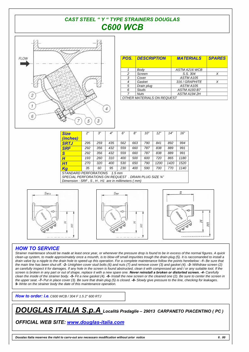
CAST STEEL “ Y “ TYPE STRAINERS DOUGLAS
C600 WCB
POS. DESCRIPTION MATERIALS SPARES
1 Body ASTM A216 WCB2 Screen S.S. 304 X3 Cover ASTM A1054 Gasket 316 / GRAPHITE X5 Drain plug ASTM A1056 Studs ASTM A193 B77 Nuts ASTM A194 2H
OTHER MATERIALS ON REQUEST
Size(inches)
2” 3” 4” 6” 8” 10” 12” 14” 16”
SRTJ 295 259 435 562 663 790 841 892 994
SRF 292 356 432 559 660 787 838 889 991
S 292 356 432 559 660 787 838 889 991
H 193 260 310 400 500 600 720 865 1180
H1 270 320 400 530 650 790 1200 1420 1520
Kg 35 60 95 230 400 590 700 770 1140STANDARD PERFORATIONS 1.5 mmSPECIAL PERFORATIONS ON REQUEST . DRAIN PLUG SIZE ¾”Dimension : SRF , S , H , H1 are in millimeters ( mm)
HOW TO SERVICEStrainer maintenace should be made at least once year, or whenever the pressure drop is found to be in excess of the normal figures. A quickclean-up system, to made approximately once a mounth, is to blow-off small impurities trough the drain-plug (5). It is raccomanded to install adrain valve by a nipple to the drain hole to speed-up this operation. For a complete maintenance follow the points herebelow: -1- Be sure thatthe main line has been shut-off. -2- Untighten cover stud bolts (6) and nuts (7) and remove cover (3) and gasket (4). -3- Withdraw screen (2)an carefully inspect it for damages. If any hole in the screen is found abstructed, clean it with compressed air and / or any suitable tool. If thescreen is broken in any part or out of shape, replace it with a new spare one. Never reinstall a broken or distorted screen. -4- Carefullyclean the inside of the strainer body. -5- Fit a new gasket (4). -6- Install the new screen or the cleaned one (2). Be sure to center the screen inthe upper seat. -7- Put in place cover (3). Be sure that drain plug (5) is closed. -8- Slowly give pressure to the line, checking for leakages.9- Write on the strainer body the date of this maintenance operation.
How to order: i.e. C600 WCB / 304 F 1.5 2” 600 RTJ
DOUGLAS ITALIA S.p.A Località Pradaglie – 29013 CARPANETO PIACENTINO ( PC )
OFFICIAL WEB SITE: www.douglas-italia.com
Douglas Italia reserves the right to carry-out any necessary modification without prior notice 6 . 00
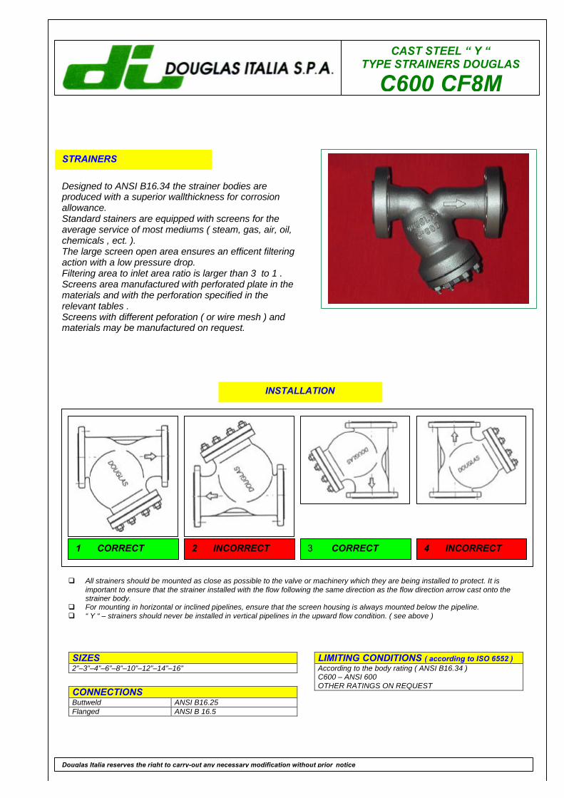
CAST STEEL “ Y “TYPE STRAINERS DOUGLAS
C600 CF8M
STRAINERS
Designed to ANSI B16.34 the strainer bodies areproduced with a superior wallthickness for corrosionallowance.Standard stainers are equipped with screens for theaverage service of most mediums ( steam, gas, air, oil,chemicals , ect. ).The large screen open area ensures an efficent filteringaction with a low pressure drop.Filtering area to inlet area ratio is larger than 3 to 1 .Screens area manufactured with perforated plate in thematerials and with the perforation specified in therelevant tables .Screens with different peforation ( or wire mesh ) andmaterials may be manufactured on request.
LIMITING CONDITIONS ( according to ISO 6552 )According to the body rating ( ANSI B16.34 )C600 – ANSI 600OTHER RATINGS ON REQUEST
SIZES2”–3”–4”–6”–8”–10”–12”–14”–16”
CONNECTIONSButtweld ANSI B16.25Flanged ANSI B 16.5
Douglas Italia reserves the right to carry-out any necessary modification without prior notice
INSTALLATION
q All strainers should be mounted as close as possible to the valve or machinery which they are being installed to protect. It isimportant to ensure that the strainer installed with the flow following the same direction as the flow direction arrow cast onto thestrainer body.
q For mounting in horizontal or inclined pipelines, ensure that the screen housing is always mounted below the pipeline.q “ Y “ – strainers should never be installed in vertical pipelines in the upward flow condition. ( see above )
1 CORRECT 2 INCORRECT 3 CORRECT 4 INCORRECT

CAST STEEL “ Y “ TYPE STRAINERS DOUGLAS
C600 CF8M
POS. DESCRIPTION MATERIALS SPARES
1 Body ASTM A351 CF8M2 Screen S.S. 316 X3 Cover ASTM A240 3164 Gasket 316 / GRAPHITE X5 Drain plug AISI 3166 Studs ASTM A193 B87 Nuts ASTM A194 Gr.8
OTHER MATERIALS ON REQUEST
Size(inches)
2” 3” 4” 6” 8” 10” 12” 14” 16”
SRTJ 295 259 435 562 663 790 841 892 994
SRF 292 356 432 559 660 787 838 889 991
S 292 356 432 559 660 787 838 889 991
H 193 260 310 400 500 600 720 865 1180
H1 270 320 400 530 650 790 1200 1420 1520
Kg 35 60 95 230 400 590 700 770 1140STANDARD PERFORATIONS 1.5 mmSPECIAL PERFORATIONS ON REQUEST . DRAIN PLUG SIZE ¾”Dimension : SRF , S , H , H1 are in millimeters ( mm)
HOW TO SERVICEStrainer maintenace should be made at least once year, or whenever the pressure drop is found to be in excess of the normal figures. A quickclean-up system, to made approximately once a mounth, is to blow-off small impurities trough the drain-plug (5). It is raccomanded to install adrain valve by a nipple to the drain hole to speed-up this operation. For a complete maintenance follow the points herebelow: -1- Be sure thatthe main line has been shut-off. -2- Untighten cover stud bolts (6) and nuts (7) and remove cover (3) and gasket (4). -3- Withdraw screen (2)an carefully inspect it for damages. If any hole in the screen is found abstructed, clean it with compressed air and / or any suitable tool. If thescreen is broken in any part or out of shape, replace it with a new spare one. Never reinstall a broken or distorted screen. -4- Carefullyclean the inside of the strainer body. -5- Fit a new gasket (4). -6- Install the new screen or the cleaned one (2). Be sure to center the screen inthe upper seat. -7- Put in place cover (3). Be sure that drain plug (5) is closed. -8- Slowly give pressure to the line, checking for leakages.9- Write on the strainer body the date of this maintenance operation.
How to order: i.e. C600 CF8M / 316 F 1.5 2” 600 RF
DOUGLAS ITALIA S.p.A Località Pradaglie – 29013 CARPANETO PIACENTINO ( PC )
OFFICIAL WEB SITE: www.douglas-italia.com
Douglas Italia reserves the right to carry-out any necessary modification without prior notice 6 . 00

CAST STEEL “ Y “TYPE STRAINERS DOUGLAS
C900 WCB
STRAINERS
Designed to ANSI B16.34 the strainer bodies areproduced with a superior wallthickness for corrosionallowance.Standard stainers are equipped with screens for theaverage service of most mediums ( steam, gas, air, oil,chemicals , ect. ).The large screen open area ensures an efficent filteringaction with a low pressure drop.Filtering area to inlet area ratio is larger than 3 to 1 .Screens area manufactured with perforated plate in thematerials and with the perforation specified in therelevant tables .Screens with different peforation ( or wire mesh ) andmaterials may be manufactured on request.
LIMITING CONDITIONS ( according to ISO 6552 )According to the body rating ( ANSI B16.34 )C900 – ANSI 900OTHER RATINGS ON REQUEST
SIZES2”–3”–4”–6”–8”–10”–12”
CONNECTIONSButtweld ANSI B16.25Flanged ANSI B 16.5
Douglas Italia reserves the right to carry-out any necessary modification without prior notice
INSTALLATION
q All strainers should be mounted as close as possible to the valve or machinery which they are being installed to protect. It isimportant to ensure that the strainer installed with the flow following the same direction as the flow direction arrow cast onto thestrainer body.
q For mounting in horizontal or inclined pipelines, ensure that the screen housing is always mounted below the pipeline.q “ Y “ – strainers should never be installed in vertical pipelines in the upward flow condition. ( see above )
1 CORRECT 2 INCORRECT 3 CORRECT 4 INCORRECT
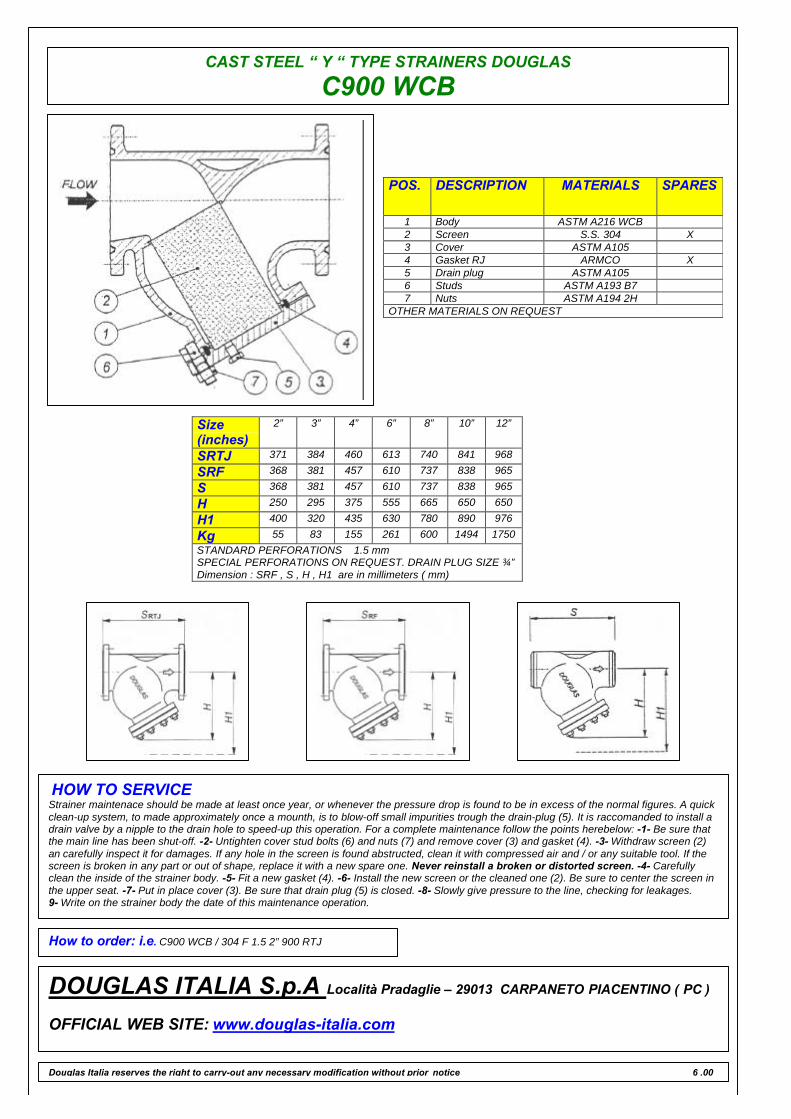
CAST STEEL “ Y “ TYPE STRAINERS DOUGLAS
C900 WCB
POS. DESCRIPTION MATERIALS SPARES
1 Body ASTM A216 WCB2 Screen S.S. 304 X3 Cover ASTM A1054 Gasket RJ ARMCO X5 Drain plug ASTM A1056 Studs ASTM A193 B77 Nuts ASTM A194 2H
OTHER MATERIALS ON REQUEST
Size(inches)
2” 3” 4” 6” 8” 10” 12”
SRTJ 371 384 460 613 740 841 968
SRF 368 381 457 610 737 838 965
S 368 381 457 610 737 838 965
H 250 295 375 555 665 650 650
H1 400 320 435 630 780 890 976
Kg 55 83 155 261 600 1494 1750STANDARD PERFORATIONS 1.5 mmSPECIAL PERFORATIONS ON REQUEST. DRAIN PLUG SIZE ¾”Dimension : SRF , S , H , H1 are in millimeters ( mm)
HOW TO SERVICEStrainer maintenace should be made at least once year, or whenever the pressure drop is found to be in excess of the normal figures. A quickclean-up system, to made approximately once a mounth, is to blow-off small impurities trough the drain-plug (5). It is raccomanded to install adrain valve by a nipple to the drain hole to speed-up this operation. For a complete maintenance follow the points herebelow: -1- Be sure thatthe main line has been shut-off. -2- Untighten cover stud bolts (6) and nuts (7) and remove cover (3) and gasket (4). -3- Withdraw screen (2)an carefully inspect it for damages. If any hole in the screen is found abstructed, clean it with compressed air and / or any suitable tool. If thescreen is broken in any part or out of shape, replace it with a new spare one. Never reinstall a broken or distorted screen. -4- Carefullyclean the inside of the strainer body. -5- Fit a new gasket (4). -6- Install the new screen or the cleaned one (2). Be sure to center the screen inthe upper seat. -7- Put in place cover (3). Be sure that drain plug (5) is closed. -8- Slowly give pressure to the line, checking for leakages.9- Write on the strainer body the date of this maintenance operation.
How to order: i.e. C900 WCB / 304 F 1.5 2” 900 RTJ
DOUGLAS ITALIA S.p.A Località Pradaglie – 29013 CARPANETO PIACENTINO ( PC )
OFFICIAL WEB SITE: www.douglas-italia.com
Douglas Italia reserves the right to carry-out any necessary modification without prior notice 6 .00

CAST STEEL “ Y “TYPE STRAINERS DOUGLAS
C900 CF8M
STRAINERS
Designed to ANSI B16.34 the strainer bodies areproduced with a superior wallthickness for corrosionallowance.Standard stainers are equipped with screens for theaverage service of most mediums ( steam, gas, air, oil,chemicals , ect. ).The large screen open area ensures an efficent filteringaction with a low pressure drop.Filtering area to inlet area ratio is larger than 3 to 1 .Screens area manufactured with perforated plate in thematerials and with the perforation specified in therelevant tables .Screens with different peforation ( or wire mesh ) andmaterials may be manufactured on request.
LIMITING CONDITIONS ( according to ISO 6552 )According to the body rating ( ANSI B16.34 )C900 – ANSI 900OTHER RATINGS ON REQUEST
SIZES2”–3”–4”–6”–8”–10”–12”
CONNECTIONSButtweld ANSI B16.25Flanged ANSI B 16.5
Douglas Italia reserves the right to carry-out any necessary modification without prior notice
INSTALLATION
q All strainers should be mounted as close as possible to the valve or machinery which they are being installed to protect. It isimportant to ensure that the strainer installed with the flow following the same direction as the flow direction arrow cast onto thestrainer body.
q For mounting in horizontal or inclined pipelines, ensure that the screen housing is always mounted below the pipeline.q “ Y “ – strainers should never be installed in vertical pipelines in the upward flow condition. ( see above )
1 CORRECT 2 INCORRECT 3 CORRECT 4 INCORRECT

CAST STEEL “ Y “ TYPE STRAINERS DOUGLAS
C900 CF8M
POS. DESCRIPTION MATERIALS SPARES
1 Body ASTM A351 CF8M2 Screen S.S. 316 X3 Cover ASTM A240 3164 Gasket RJ F316 X5 Drain plug AISI 3166 Studs ASTM A193 B87 Nuts ASTM A194 Gr.8
OTHER MATERIALS ON REQUEST
Size(inches)
2” 3” 4” 6” 8” 10” 12”
SRTJ 371 384 460 613 740 841 968
SRF 368 381 457 610 737 838 965
S 368 381 457 610 737 838 965
H 250 295 375 555 665 650 650
H1 400 320 435 630 780 890 976
Kg 55 83 155 261 600 1494 1750STANDARD PERFORATIONS 1.5 mmSPECIAL PERFORATIONS ON REQUEST. DRAIN PLUG SIZE ¾”Dimension : SRF , S , H , H1 are in millimeters ( mm)
HOW TO SERVICEStrainer maintenace should be made at least once year, or whenever the pressure drop is found to be in excess of the normal figures. A quickclean-up system, to made approximately once a mounth, is to blow-off small impurities trough the drain-plug (5). It is raccomanded to install adrain valve by a nipple to the drain hole to speed-up this operation. For a complete maintenance follow the points herebelow: -1- Be sure thatthe main line has been shut-off. -2- Untighten cover stud bolts (6) and nuts (7) and remove cover (3) and gasket (4). -3- Withdraw screen (2)an carefully inspect it for damages. If any hole in the screen is found abstructed, clean it with compressed air and / or any suitable tool. If thescreen is broken in any part or out of shape, replace it with a new spare one. Never reinstall a broken or distorted screen. -4- Carefullyclean the inside of the strainer body. -5- Fit a new gasket (4). -6- Install the new screen or the cleaned one (2). Be sure to center the screen inthe upper seat. -7- Put in place cover (3). Be sure that drain plug (5) is closed. -8- Slowly give pressure to the line, checking for leakages.9- Write on the strainer body the date of this maintenance operation.
How to order: i.e. C900 CF8M / 316 F 1.5 2” 900 RTJ
DOUGLAS ITALIA S.p.A Località Pradaglie – 29013 CARPANETO PIACENTINO ( PC )
OFFICIAL WEB SITE: www.douglas-italia.com
Douglas Italia reserves the right to carry-out any necessary modification without prior notice 6 . 00
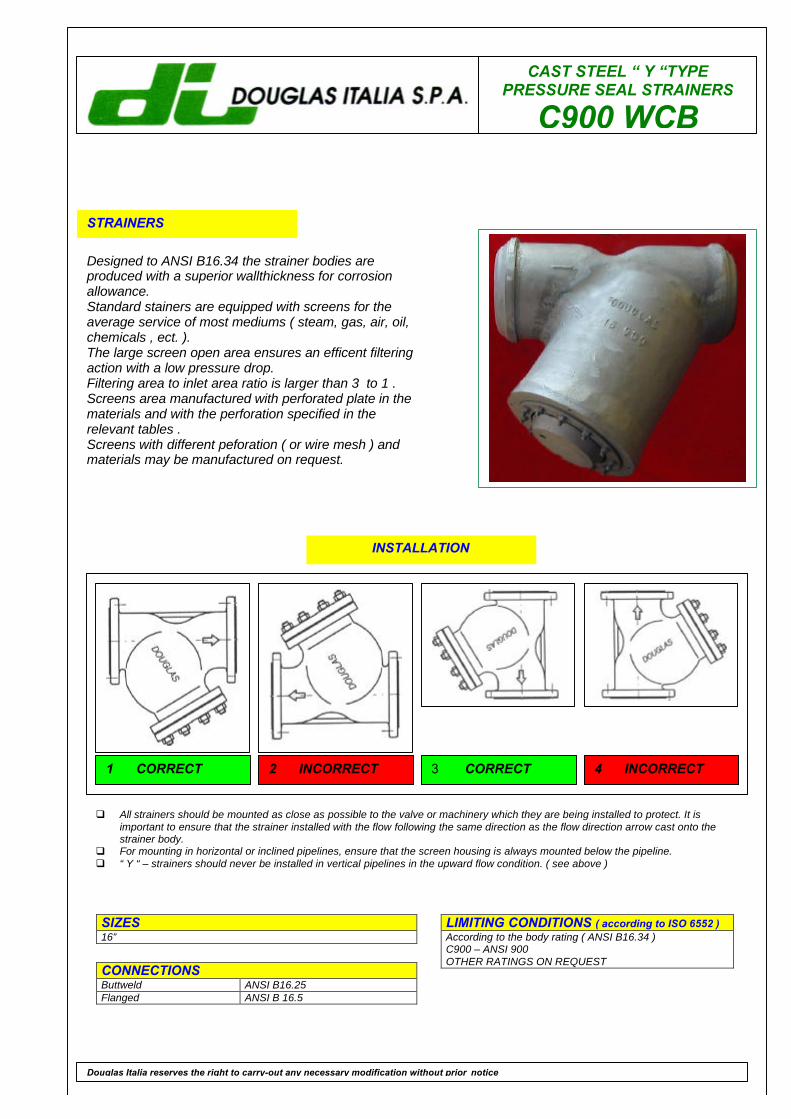
CAST STEEL “ Y “TYPEPRESSURE SEAL STRAINERS
C900 WCB
STRAINERS
Designed to ANSI B16.34 the strainer bodies areproduced with a superior wallthickness for corrosionallowance.Standard stainers are equipped with screens for theaverage service of most mediums ( steam, gas, air, oil,chemicals , ect. ).The large screen open area ensures an efficent filteringaction with a low pressure drop.Filtering area to inlet area ratio is larger than 3 to 1 .Screens area manufactured with perforated plate in thematerials and with the perforation specified in therelevant tables .Screens with different peforation ( or wire mesh ) andmaterials may be manufactured on request.
LIMITING CONDITIONS ( according to ISO 6552 )According to the body rating ( ANSI B16.34 )C900 – ANSI 900OTHER RATINGS ON REQUEST
SIZES16”
CONNECTIONSButtweld ANSI B16.25Flanged ANSI B 16.5
Douglas Italia reserves the right to carry-out any necessary modification without prior notice
INSTALLATION
q All strainers should be mounted as close as possible to the valve or machinery which they are being installed to protect. It isimportant to ensure that the strainer installed with the flow following the same direction as the flow direction arrow cast onto thestrainer body.
q For mounting in horizontal or inclined pipelines, ensure that the screen housing is always mounted below the pipeline.q “ Y “ – strainers should never be installed in vertical pipelines in the upward flow condition. ( see above )
1 CORRECT 2 INCORRECT 3 CORRECT 4 INCORRECT
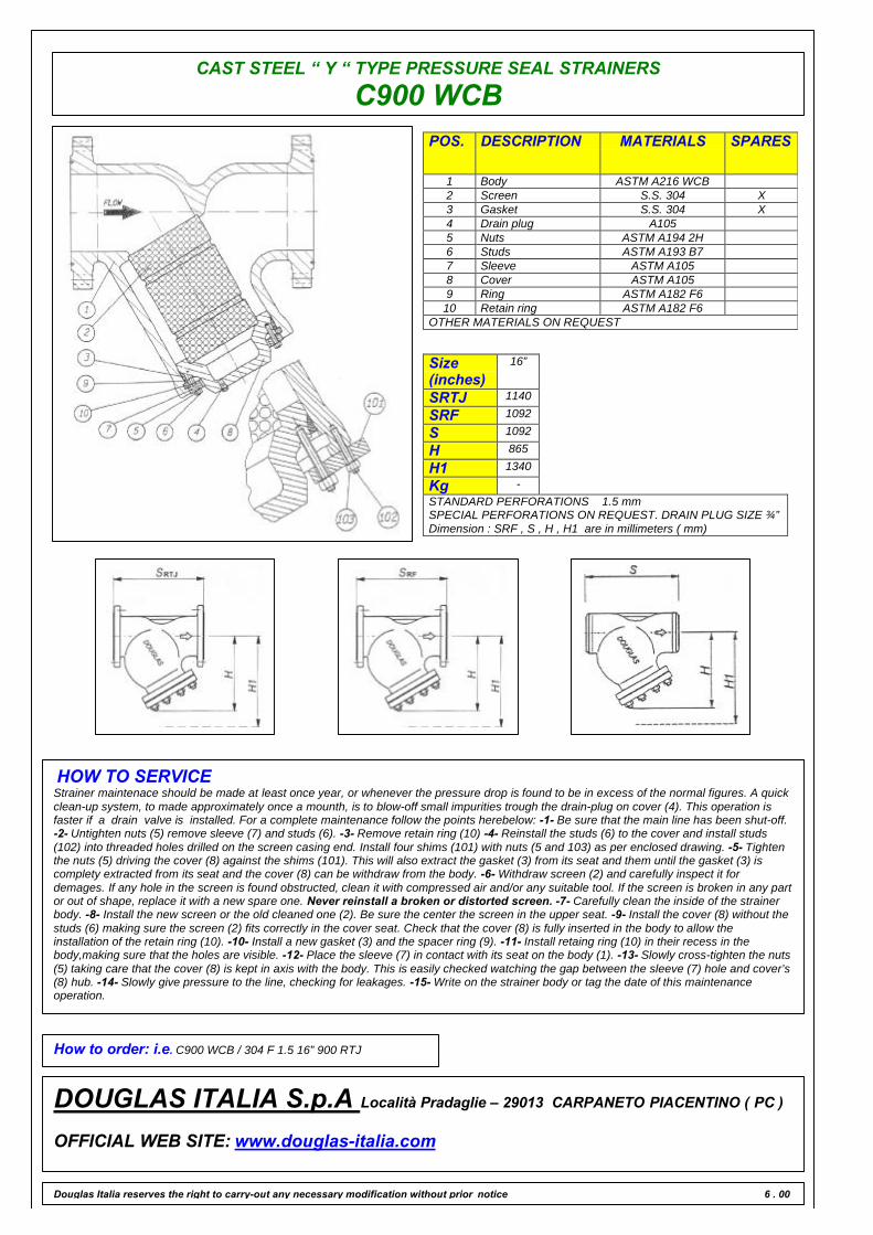
CAST STEEL “ Y “ TYPE PRESSURE SEAL STRAINERS
C900 WCBPOS. DESCRIPTION MATERIALS SPARES
1 Body ASTM A216 WCB2 Screen S.S. 304 X3 Gasket S.S. 304 X4 Drain plug A1055 Nuts ASTM A194 2H6 Studs ASTM A193 B77 Sleeve ASTM A1058 Cover ASTM A1059 Ring ASTM A182 F610 Retain ring ASTM A182 F6
OTHER MATERIALS ON REQUEST
Size(inches)
16”
SRTJ 1140
SRF 1092
S 1092
H 865
H1 1340
Kg -STANDARD PERFORATIONS 1.5 mmSPECIAL PERFORATIONS ON REQUEST. DRAIN PLUG SIZE ¾”Dimension : SRF , S , H , H1 are in millimeters ( mm)
HOW TO SERVICEStrainer maintenace should be made at least once year, or whenever the pressure drop is found to be in excess of the normal figures. A quickclean-up system, to made approximately once a mounth, is to blow-off small impurities trough the drain-plug on cover (4). This operation isfaster if a drain valve is installed. For a complete maintenance follow the points herebelow: -1- Be sure that the main line has been shut-off.-2- Untighten nuts (5) remove sleeve (7) and studs (6). -3- Remove retain ring (10) -4- Reinstall the studs (6) to the cover and install studs(102) into threaded holes drilled on the screen casing end. Install four shims (101) with nuts (5 and 103) as per enclosed drawing. -5- Tightenthe nuts (5) driving the cover (8) against the shims (101). This will also extract the gasket (3) from its seat and them until the gasket (3) iscomplety extracted from its seat and the cover (8) can be withdraw from the body. -6- Withdraw screen (2) and carefully inspect it fordemages. If any hole in the screen is found obstructed, clean it with compressed air and/or any suitable tool. If the screen is broken in any partor out of shape, replace it with a new spare one. Never reinstall a broken or distorted screen. -7- Carefully clean the inside of the strainerbody. -8- Install the new screen or the old cleaned one (2). Be sure the center the screen in the upper seat. -9- Install the cover (8) without thestuds (6) making sure the screen (2) fits correctly in the cover seat. Check that the cover (8) is fully inserted in the body to allow theinstallation of the retain ring (10). -10- Install a new gasket (3) and the spacer ring (9). -11- Install retaing ring (10) in their recess in thebody,making sure that the holes are visible. -12- Place the sleeve (7) in contact with its seat on the body (1). -13- Slowly cross-tighten the nuts(5) taking care that the cover (8) is kept in axis with the body. This is easily checked watching the gap between the sleeve (7) hole and cover’s(8) hub. -14- Slowly give pressure to the line, checking for leakages. -15- Write on the strainer body or tag the date of this maintenanceoperation.
How to order: i.e. C900 WCB / 304 F 1.5 16” 900 RTJ
DOUGLAS ITALIA S.p.A Località Pradaglie – 29013 CARPANETO PIACENTINO ( PC )
OFFICIAL WEB SITE: www.douglas-italia.com
Douglas Italia reserves the right to carry-out any necessary modification without prior notice 6 . 00
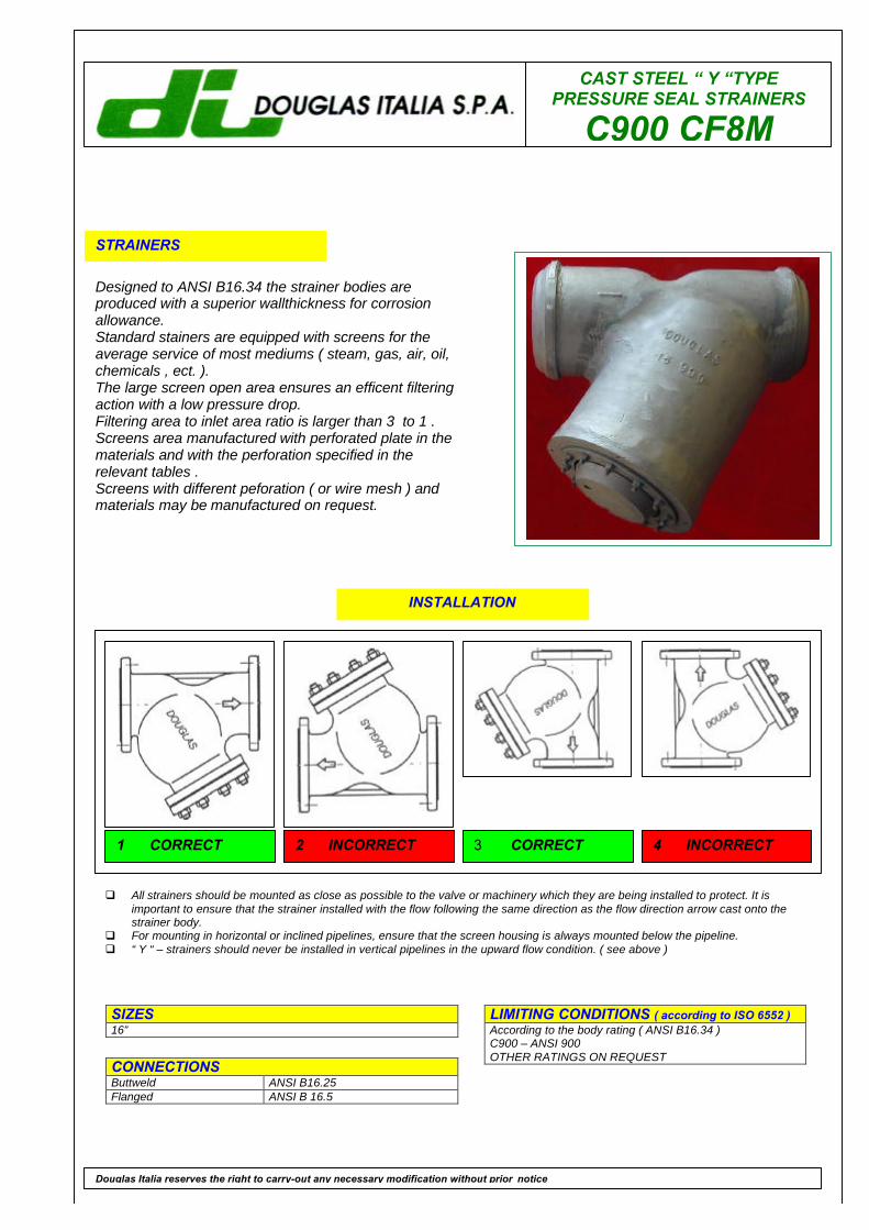
CAST STEEL “ Y “TYPEPRESSURE SEAL STRAINERS
C900 CF8M
STRAINERS
Designed to ANSI B16.34 the strainer bodies areproduced with a superior wallthickness for corrosionallowance.Standard stainers are equipped with screens for theaverage service of most mediums ( steam, gas, air, oil,chemicals , ect. ).The large screen open area ensures an efficent filteringaction with a low pressure drop.Filtering area to inlet area ratio is larger than 3 to 1 .Screens area manufactured with perforated plate in thematerials and with the perforation specified in therelevant tables .Screens with different peforation ( or wire mesh ) andmaterials may be manufactured on request.
LIMITING CONDITIONS ( according to ISO 6552 )According to the body rating ( ANSI B16.34 )C900 – ANSI 900OTHER RATINGS ON REQUEST
SIZES16”
CONNECTIONSButtweld ANSI B16.25Flanged ANSI B 16.5
Douglas Italia reserves the right to carry-out any necessary modification without prior notice
INSTALLATION
q All strainers should be mounted as close as possible to the valve or machinery which they are being installed to protect. It isimportant to ensure that the strainer installed with the flow following the same direction as the flow direction arrow cast onto thestrainer body.
q For mounting in horizontal or inclined pipelines, ensure that the screen housing is always mounted below the pipeline.q “ Y “ – strainers should never be installed in vertical pipelines in the upward flow condition. ( see above )
1 CORRECT 2 INCORRECT 3 CORRECT 4 INCORRECT
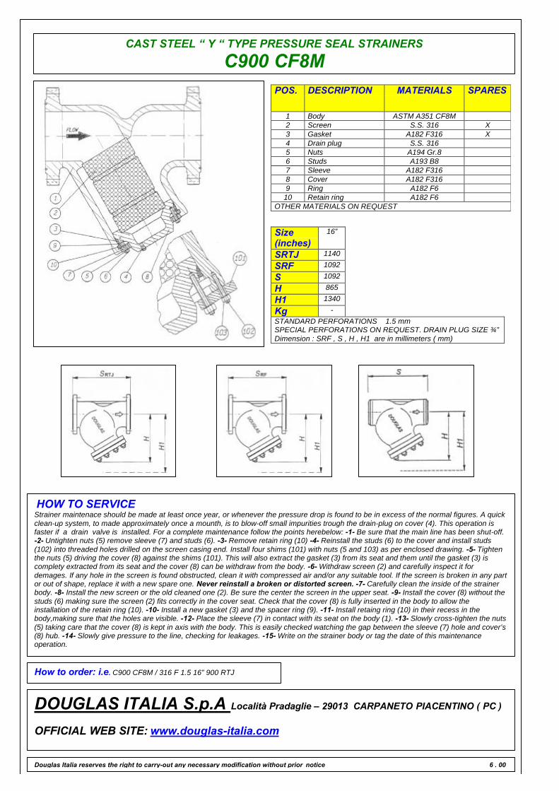
CAST STEEL “ Y “ TYPE PRESSURE SEAL STRAINERS
C900 CF8MPOS. DESCRIPTION MATERIALS SPARES
1 Body ASTM A351 CF8M2 Screen S.S. 316 X3 Gasket A182 F316 X4 Drain plug S.S. 3165 Nuts A194 Gr.86 Studs A193 B87 Sleeve A182 F3168 Cover A182 F3169 Ring A182 F610 Retain ring A182 F6
OTHER MATERIALS ON REQUEST
Size(inches)
16”
SRTJ 1140
SRF 1092
S 1092
H 865
H1 1340
Kg -STANDARD PERFORATIONS 1.5 mmSPECIAL PERFORATIONS ON REQUEST. DRAIN PLUG SIZE ¾”Dimension : SRF , S , H , H1 are in millimeters ( mm)
HOW TO SERVICEStrainer maintenace should be made at least once year, or whenever the pressure drop is found to be in excess of the normal figures. A quickclean-up system, to made approximately once a mounth, is to blow-off small impurities trough the drain-plug on cover (4). This operation isfaster if a drain valve is installed. For a complete maintenance follow the points herebelow: -1- Be sure that the main line has been shut-off.-2- Untighten nuts (5) remove sleeve (7) and studs (6). -3- Remove retain ring (10) -4- Reinstall the studs (6) to the cover and install studs(102) into threaded holes drilled on the screen casing end. Install four shims (101) with nuts (5 and 103) as per enclosed drawing. -5- Tightenthe nuts (5) driving the cover (8) against the shims (101). This will also extract the gasket (3) from its seat and them until the gasket (3) iscomplety extracted from its seat and the cover (8) can be withdraw from the body. -6- Withdraw screen (2) and carefully inspect it fordemages. If any hole in the screen is found obstructed, clean it with compressed air and/or any suitable tool. If the screen is broken in any partor out of shape, replace it with a new spare one. Never reinstall a broken or distorted screen. -7- Carefully clean the inside of the strainerbody. -8- Install the new screen or the old cleaned one (2). Be sure the center the screen in the upper seat. -9- Install the cover (8) without thestuds (6) making sure the screen (2) fits correctly in the cover seat. Check that the cover (8) is fully inserted in the body to allow theinstallation of the retain ring (10). -10- Install a new gasket (3) and the spacer ring (9). -11- Install retaing ring (10) in their recess in thebody,making sure that the holes are visible. -12- Place the sleeve (7) in contact with its seat on the body (1). -13- Slowly cross-tighten the nuts(5) taking care that the cover (8) is kept in axis with the body. This is easily checked watching the gap between the sleeve (7) hole and cover’s(8) hub. -14- Slowly give pressure to the line, checking for leakages. -15- Write on the strainer body or tag the date of this maintenanceoperation.
How to order: i.e. C900 CF8M / 316 F 1.5 16” 900 RTJ
DOUGLAS ITALIA S.p.A Località Pradaglie – 29013 CARPANETO PIACENTINO ( PC )
OFFICIAL WEB SITE: www.douglas-italia.com
Douglas Italia reserves the right to carry-out any necessary modification without prior notice 6 . 00

CAST STEEL “ Y “TYPE STRAINERS DOUGLAS
C1500 WCB
STRAINERS
Designed to ANSI B16.34 the strainer bodies areproduced with a superior wallthickness for corrosionallowance.Standard stainers are equipped with screens for theaverage service of most mediums ( steam, gas, air, oil,chemicals , ect. ).The large screen open area ensures an efficent filteringaction with a low pressure drop.Filtering area to inlet area ratio is larger than 3 to 1 .Screens area manufactured with perforated plate in thematerials and with the perforation specified in therelevant tables .Screens with different peforation ( or wire mesh ) andmaterials may be manufactured on request.
LIMITING CONDITIONS ( according to ISO 6552 )According to the body rating ( ANSI B16.34 )C1500 – ANSI 1500OTHER RATINGS ON REQUEST
SIZES2”–3”–4”–6”–8”
CONNECTIONSButtweld ANSI B16.25Flanged ANSI B 16.5
Douglas Italia reserves the right to carry-out any necessary modification without prior notice
INSTALLATION
q All strainers should be mounted as close as possible to the valve or machinery which they are being installed to protect. It isimportant to ensure that the strainer installed with the flow following the same direction as the flow direction arrow cast onto thestrainer body.
q For mounting in horizontal or inclined pipelines, ensure that the screen housing is always mounted below the pipeline.q “ Y “ – strainers should never be installed in vertical pipelines in the upward flow condition. (see above )
1 CORRECT 2 INCORRECT 3 CORRECT 4 INCORRECT
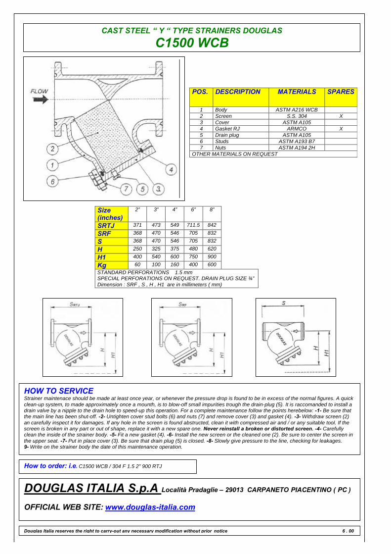
CAST STEEL “ Y “ TYPE STRAINERS DOUGLAS
C1500 WCB
POS. DESCRIPTION MATERIALS SPARES
1 Body ASTM A216 WCB2 Screen S.S. 304 X3 Cover ASTM A1054 Gasket RJ ARMCO X5 Drain plug ASTM A1056 Studs ASTM A193 B77 Nuts ASTM A194 2H
OTHER MATERIALS ON REQUEST
Size(inches)
2” 3” 4” 6” 8”
SRTJ 371 473 549 711.5 842
SRF 368 470 546 705 832
S 368 470 546 705 832
H 250 325 375 480 620
H1 400 540 600 750 900
Kg 60 100 160 400 600STANDARD PERFORATIONS 1.5 mmSPECIAL PERFORATIONS ON REQUEST. DRAIN PLUG SIZE ¾”Dimension : SRF , S , H , H1 are in millimeters ( mm)
HOW TO SERVICEStrainer maintenace should be made at least once year, or whenever the pressure drop is found to be in excess of the normal figures. A quickclean-up system, to made approximately once a mounth, is to blow-off small impurities trough the drain-plug (5). It is raccomanded to install adrain valve by a nipple to the drain hole to speed-up this operation. For a complete maintenance follow the points herebelow: -1- Be sure thatthe main line has been shut-off. -2- Untighten cover stud bolts (6) and nuts (7) and remove cover (3) and gasket (4). -3- Withdraw screen (2)an carefully inspect it for damages. If any hole in the screen is found abstructed, clean it with compressed air and / or any suitable tool. If thescreen is broken in any part or out of shape, replace it with a new spare one. Never reinstall a broken or distorted screen. -4- Carefullyclean the inside of the strainer body. -5- Fit a new gasket (4). -6- Install the new screen or the cleaned one (2). Be sure to center the screen inthe upper seat. -7- Put in place cover (3). Be sure that drain plug (5) is closed. -8- Slowly give pressure to the line, checking for leakages.9- Write on the strainer body the date of this maintenance operation.
How to order: i.e. C1500 WCB / 304 F 1.5 2” 900 RTJ
DOUGLAS ITALIA S.p.A Località Pradaglie – 29013 CARPANETO PIACENTINO ( PC )
OFFICIAL WEB SITE: www.douglas-italia.com
Douglas Italia reserves the right to carry-out any necessary modification without prior notice 6 . 00
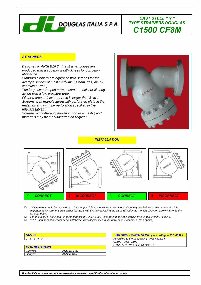
CAST STEEL “ Y “TYPE STRAINERS DOUGLAS
C1500 CF8M
STRAINERS
Designed to ANSI B16.34 the strainer bodies areproduced with a superior wallthickness for corrosionallowance.Standard stainers are equipped with screens for theaverage service of most mediums ( steam, gas, air, oil,chemicals , ect. ).The large screen open area ensures an efficent filteringaction with a low pressure drop.Filtering area to inlet area ratio is larger than 3 to 1 .Screens area manufactured with perforated plate in thematerials and with the perforation specified in therelevant tables .Screens with different peforation ( or wire mesh ) andmaterials may be manufactured on request.
LIMITING CONDITIONS ( according to ISO 6552 )According to the body rating ( ANSI B16.34 )C1500 – ANSI 1500OTHER RATINGS ON REQUEST
SIZES2”–3”–4”–6”–8”
CONNECTIONSButtweld ANSI B16.25Flanged ANSI B 16.5
Douglas Italia reserves the right to carry-out any necessary modification without prior notice
INSTALLATION
q All strainers should be mounted as close as possible to the valve or machinery which they are being installed to protect. It isimportant to ensure that the strainer installed with the flow following the same direction as the flow direction arrow cast onto thestrainer body.
q For mounting in horizontal or inclined pipelines, ensure that the screen housing is always mounted below the pipeline.q “ Y “ – strainers should never be installed in vertical pipelines in the upward flow condition (see above )
1 CORRECT 2 INCORRECT 3 CORRECT 4 INCORRECT

CAST STEEL “ Y “ TYPE STRAINERS DOUGLAS
C1500 CF8M
POS. DESCRIPTION MATERIALS SPARES
1 Body ASTM A351 CF8M2 Screen S.S. 316 X3 Cover ASTM A240 3164 Gasket RJ F316 X5 Drain plug AISI 3166 Studs ASTM A193 B87 Nuts ASTM A194 Gr.8
OTHER MATERIALS ON REQUEST
Size(inches)
2” 3” 4” 6” 8”
SRTJ 371 473 549 711.5 842
SRF 368 470 546 705 832
S 368 470 546 705 832
H 250 325 375 480 620
H1 400 540 600 750 900
Kg 60 100 160 400 600STANDARD PERFORATIONS 1.5 mmSPECIAL PERFORATIONS ON REQUEST. DRAIN PLUG SIZE ¾”Dimension : SRF , S , H , H1 are in millimeters ( mm)
HOW TO SERVICEStrainer maintenace should be made at least once year, or whenever the pressure drop is found to be in excess of the normal figures. A quickclean-up system, to made approximately once a mounth, is to blow-off small impurities trough the drain-plug (5). It is raccomanded to install adrain valve by a nipple to the drain hole to speed-up this operation. For a complete maintenance follow the points herebelow: -1- Be sure thatthe main line has been shut-off. -2- Untighten cover stud bolts (6) and nuts (7) and remove cover (3) and gasket (4). -3- Withdraw screen (2)an carefully inspect it for damages. If any hole in the screen is found abstructed, clean it with compressed air and / or any suitable tool. If thescreen is broken in any part or out of shape, replace it with a new spare one. Never reinstall a broken or distorted screen. -4- Carefullyclean the inside of the strainer body. -5- Fit a new gasket (4). -6- Install the new screen or the cleaned one (2). Be sure to center the screen inthe upper seat. -7- Put in place cover (3). Be sure that drain plug (5) is closed. -8- Slowly give pressure to the line, checking for leakages.9- Write on the strainer body the date of this maintenance operation.
How to order: i.e. C1500 CF8M / 316 F 1.5 2” 900 RTJ
DOUGLAS ITALIA S.p.A Località Pradaglie – 29013 CARPANETO PIACENTINO ( PC )
OFFICIAL WEB SITE: www.douglas-italia.com
Douglas Italia reserves the right to carry-out any necessary modification without prior notice 6 . 00
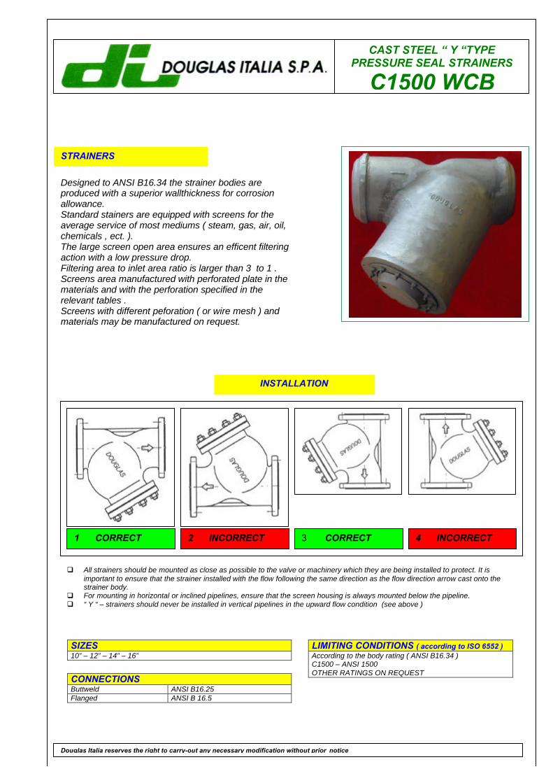
CAST STEEL “ Y “TYPEPRESSURE SEAL STRAINERS
C1500 WCB
STRAINERS
Designed to ANSI B16.34 the strainer bodies areproduced with a superior wallthickness for corrosionallowance.Standard stainers are equipped with screens for theaverage service of most mediums ( steam, gas, air, oil,chemicals , ect. ).The large screen open area ensures an efficent filteringaction with a low pressure drop.Filtering area to inlet area ratio is larger than 3 to 1 .Screens area manufactured with perforated plate in thematerials and with the perforation specified in therelevant tables .Screens with different peforation ( or wire mesh ) andmaterials may be manufactured on request.
LIMITING CONDITIONS ( according to ISO 6552 )According to the body rating ( ANSI B16.34 )C1500 – ANSI 1500OTHER RATINGS ON REQUEST
SIZES10” – 12” – 14” – 16”
CONNECTIONSButtweld ANSI B16.25Flanged ANSI B 16.5
Douglas Italia reserves the right to carry-out any necessary modification without prior notice
INSTALLATION
q All strainers should be mounted as close as possible to the valve or machinery which they are being installed to protect. It isimportant to ensure that the strainer installed with the flow following the same direction as the flow direction arrow cast onto thestrainer body.
q For mounting in horizontal or inclined pipelines, ensure that the screen housing is always mounted below the pipeline.q “ Y “ – strainers should never be installed in vertical pipelines in the upward flow condition (see above )
1 CORRECT 2 INCORRECT 3 CORRECT 4 INCORRECT
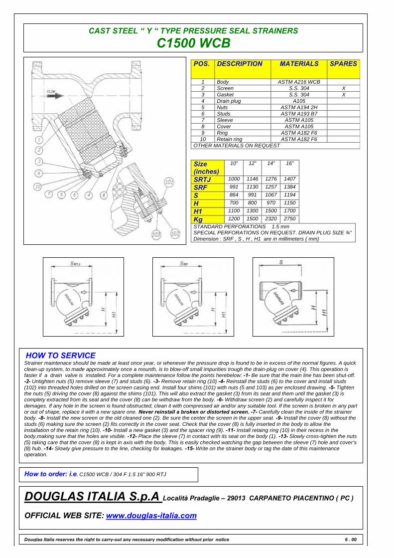
CAST STEEL “ Y “ TYPE PRESSURE SEAL STRAINERS
C1500 WCBPOS. DESCRIPTION MATERIALS SPARES
1 Body ASTM A216 WCB2 Screen S.S. 304 X3 Gasket S.S. 304 X4 Drain plug A1055 Nuts ASTM A194 2H6 Studs ASTM A193 B77 Sleeve ASTM A1058 Cover ASTM A1059 Ring ASTM A182 F610 Retain ring ASTM A182 F6
OTHER MATERIALS ON REQUEST
Size(inches)
10” 12” 14” 16”
SRTJ 1000 1146 1276 1407
SRF 991 1130 1257 1384
S 864 991 1067 1194
H 700 800 970 1150
H1 1100 1300 1500 1700
Kg 1200 1500 2320 2750STANDARD PERFORATIONS 1.5 mmSPECIAL PERFORATIONS ON REQUEST. DRAIN PLUG SIZE ¾”Dimension : SRF , S , H , H1 are in millimeters ( mm)
HOW TO SERVICEStrainer maintenace should be made at least once year, or whenever the pressure drop is found to be in excess of the normal figures. A quickclean-up system, to made approximately once a mounth, is to blow-off small impurities trough the drain-plug on cover (4). This operation isfaster if a drain valve is installed. For a complete maintenance follow the points herebelow: -1- Be sure that the main line has been shut-off.-2- Untighten nuts (5) remove sleeve (7) and studs (6). -3- Remove retain ring (10) -4- Reinstall the studs (6) to the cover and install studs(102) into threaded holes drilled on the screen casing end. Install four shims (101) with nuts (5 and 103) as per enclosed drawing. -5- Tightenthe nuts (5) driving the cover (8) against the shims (101). This will also extract the gasket (3) from its seat and them until the gasket (3) iscomplety extracted from its seat and the cover (8) can be withdraw from the body. -6- Withdraw screen (2) and carefully inspect it fordemages. If any hole in the screen is found obstructed, clean it with compressed air and/or any suitable tool. If the screen is broken in any partor out of shape, replace it with a new spare one. Never reinstall a broken or distorted screen. -7- Carefully clean the inside of the strainerbody. -8- Install the new screen or the old cleaned one (2). Be sure the center the screen in the upper seat. -9- Install the cover (8) without thestuds (6) making sure the screen (2) fits correctly in the cover seat. Check that the cover (8) is fully inserted in the body to allow theinstallation of the retain ring (10). -10- Install a new gasket (3) and the spacer ring (9). -11- Install retaing ring (10) in their recess in thebody,making sure that the holes are visible. -12- Place the sleeve (7) in contact with its seat on the body (1). -13- Slowly cross-tighten the nuts(5) taking care that the cover (8) is kept in axis with the body. This is easily checked watching the gap between the sleeve (7) hole and cover’s(8) hub. -14- Slowly give pressure to the line, checking for leakages. -15- Write on the strainer body or tag the date of this maintenanceoperation.
How to order: i.e. C1500 WCB / 304 F 1.5 16” 900 RTJ
DOUGLAS ITALIA S.p.A Località Pradaglie – 29013 CARPANETO PIACENTINO ( PC )
OFFICIAL WEB SITE: www.douglas-italia.com
Douglas Italia reserves the right to carry-out any necessary modification without prior notice 6 . 00
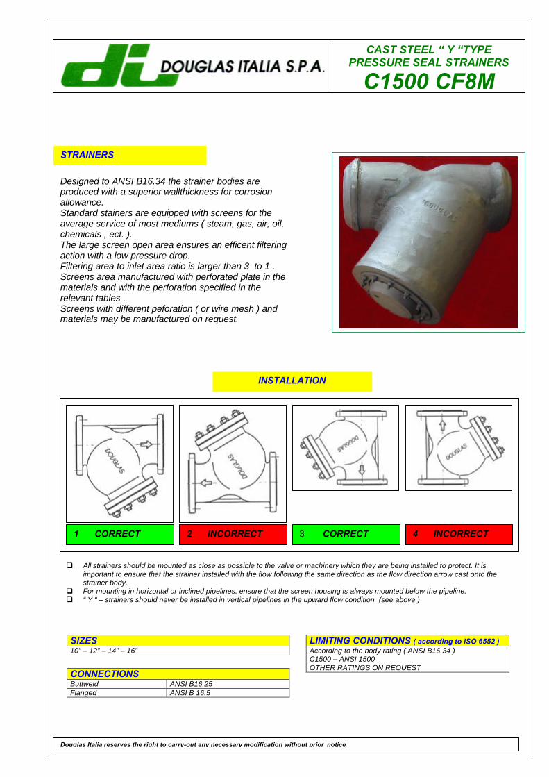
CAST STEEL “ Y “TYPEPRESSURE SEAL STRAINERS
C1500 CF8M
STRAINERS
Designed to ANSI B16.34 the strainer bodies areproduced with a superior wallthickness for corrosionallowance.Standard stainers are equipped with screens for theaverage service of most mediums ( steam, gas, air, oil,chemicals , ect. ).The large screen open area ensures an efficent filteringaction with a low pressure drop.Filtering area to inlet area ratio is larger than 3 to 1 .Screens area manufactured with perforated plate in thematerials and with the perforation specified in therelevant tables .Screens with different peforation ( or wire mesh ) andmaterials may be manufactured on request.
LIMITING CONDITIONS ( according to ISO 6552 )According to the body rating ( ANSI B16.34 )C1500 – ANSI 1500OTHER RATINGS ON REQUEST
SIZES10” – 12” – 14” – 16”
CONNECTIONSButtweld ANSI B16.25Flanged ANSI B 16.5
Douglas Italia reserves the right to carry-out any necessary modification without prior notice
INSTALLATION
q All strainers should be mounted as close as possible to the valve or machinery which they are being installed to protect. It isimportant to ensure that the strainer installed with the flow following the same direction as the flow direction arrow cast onto thestrainer body.
q For mounting in horizontal or inclined pipelines, ensure that the screen housing is always mounted below the pipeline.q “ Y “ – strainers should never be installed in vertical pipelines in the upward flow condition (see above )
1 CORRECT 2 INCORRECT 3 CORRECT 4 INCORRECT
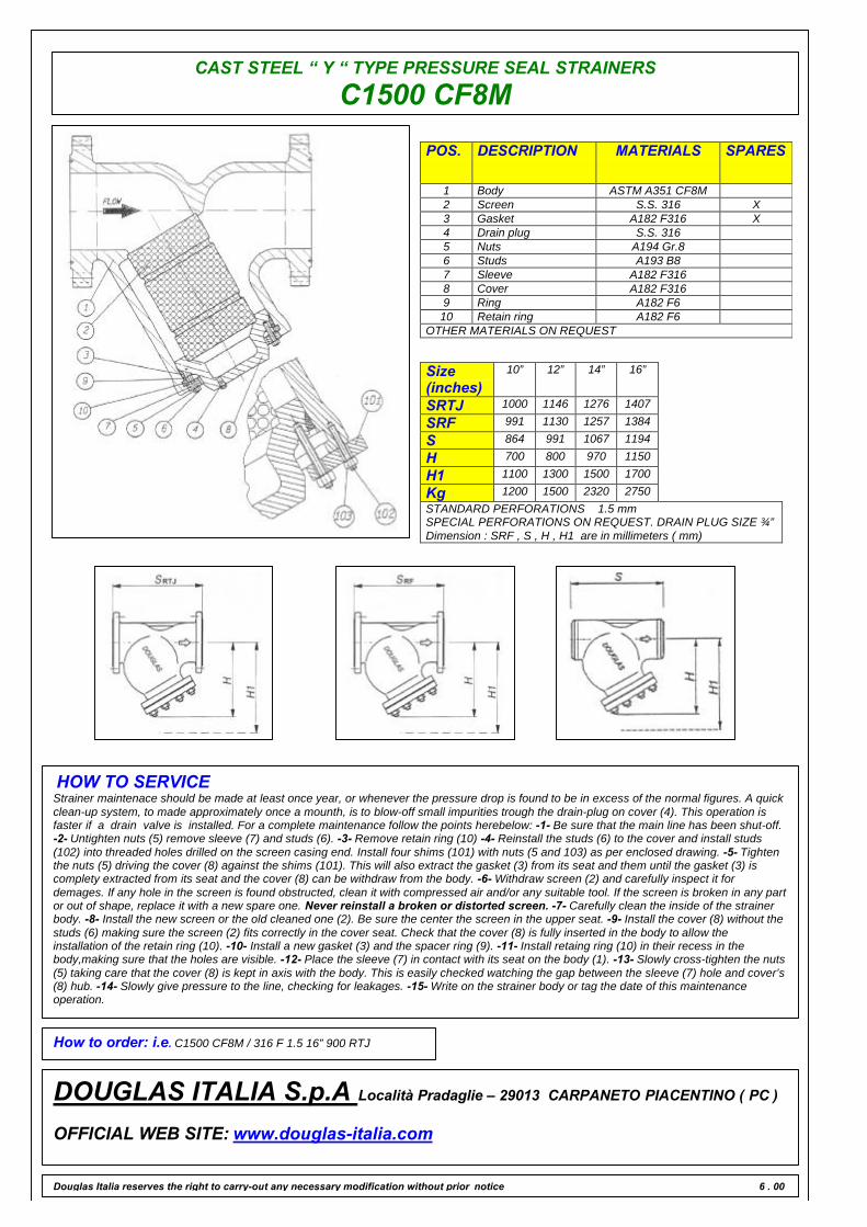
CAST STEEL “ Y “ TYPE PRESSURE SEAL STRAINERS
C1500 CF8M
POS. DESCRIPTION MATERIALS SPARES
1 Body ASTM A351 CF8M2 Screen S.S. 316 X3 Gasket A182 F316 X4 Drain plug S.S. 3165 Nuts A194 Gr.86 Studs A193 B87 Sleeve A182 F3168 Cover A182 F3169 Ring A182 F610 Retain ring A182 F6
OTHER MATERIALS ON REQUEST
Size(inches)
10” 12” 14” 16”
SRTJ 1000 1146 1276 1407
SRF 991 1130 1257 1384
S 864 991 1067 1194
H 700 800 970 1150
H1 1100 1300 1500 1700
Kg 1200 1500 2320 2750STANDARD PERFORATIONS 1.5 mmSPECIAL PERFORATIONS ON REQUEST. DRAIN PLUG SIZE ¾”Dimension : SRF , S , H , H1 are in millimeters ( mm)
HOW TO SERVICEStrainer maintenace should be made at least once year, or whenever the pressure drop is found to be in excess of the normal figures. A quickclean-up system, to made approximately once a mounth, is to blow-off small impurities trough the drain-plug on cover (4). This operation isfaster if a drain valve is installed. For a complete maintenance follow the points herebelow: -1- Be sure that the main line has been shut-off.-2- Untighten nuts (5) remove sleeve (7) and studs (6). -3- Remove retain ring (10) -4- Reinstall the studs (6) to the cover and install studs(102) into threaded holes drilled on the screen casing end. Install four shims (101) with nuts (5 and 103) as per enclosed drawing. -5- Tightenthe nuts (5) driving the cover (8) against the shims (101). This will also extract the gasket (3) from its seat and them until the gasket (3) iscomplety extracted from its seat and the cover (8) can be withdraw from the body. -6- Withdraw screen (2) and carefully inspect it fordemages. If any hole in the screen is found obstructed, clean it with compressed air and/or any suitable tool. If the screen is broken in any partor out of shape, replace it with a new spare one. Never reinstall a broken or distorted screen. -7- Carefully clean the inside of the strainerbody. -8- Install the new screen or the old cleaned one (2). Be sure the center the screen in the upper seat. -9- Install the cover (8) without thestuds (6) making sure the screen (2) fits correctly in the cover seat. Check that the cover (8) is fully inserted in the body to allow theinstallation of the retain ring (10). -10- Install a new gasket (3) and the spacer ring (9). -11- Install retaing ring (10) in their recess in thebody,making sure that the holes are visible. -12- Place the sleeve (7) in contact with its seat on the body (1). -13- Slowly cross-tighten the nuts(5) taking care that the cover (8) is kept in axis with the body. This is easily checked watching the gap between the sleeve (7) hole and cover’s(8) hub. -14- Slowly give pressure to the line, checking for leakages. -15- Write on the strainer body or tag the date of this maintenanceoperation.
How to order: i.e. C1500 CF8M / 316 F 1.5 16” 900 RTJ
DOUGLAS ITALIA S.p.A Località Pradaglie – 29013 CARPANETO PIACENTINO ( PC )
OFFICIAL WEB SITE: www.douglas-italia.com
Douglas Italia reserves the right to carry-out any necessary modification without prior notice 6 . 00

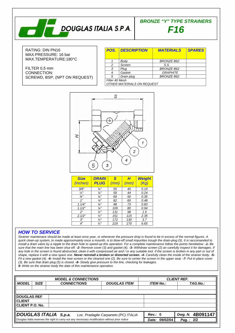
BRONZE “Y” TYPE STRAINERS
F16
POS. DESCRIPTION MATERIALS SPARES
1 Body BRONZE B62 2 Screen S.S. 3 Plug BRONZE B62 4 Gasket GRAPHITE 5 Drain plug BRONZE B62
Filter 40 Mesh OTHER MATERIALS ON REQUEST
Size (inches)
DRAINPLUG
S (mm)
H (mm)
Weight(Kg)
3/8” ¼” 55 40 0.19 ½” ¼” 59 44 0.24 ¾” ¼” 69 50 0.35 1” ¼” 82 60 0.48
1.1/4” ¼” 98 73 0.83 1.1/2” ¼” 109 80 0.94
2” ½” 131 98 1.5 2.1/2” ½” 151 115 2.35
3” ½” 172 130 3.7 4” ½” 219 170 6.65
HOW TO SERVICE Strainer maintenace should be made at least once year, or whenever the pressure drop is found to be in excess of the normal figures. A quick clean-up system, to made approximately once a mounth, is to blow-off small impurities trough the drain-plug (5). It is raccomanded to install a drain valve by a nipple to the drain hole to speed-up this operation. For a complete maintenance follow the points herebelow: -1- Be sure that the main line has been shut-off. -2- Remove cover (3) and gasket (4). -3- Withdraw screen (2) an carefully inspect it for damages. If any hole in the screen is found abstructed, clean it with compressed air and / or any suitable tool. If the screen is broken in any part or out of shape, replace it with a new spare one. Never reinstall a broken or distorted screen. -4- Carefully clean the inside of the strainer body. -5- Fit a new gasket (4). -6- Install the new screen or the cleaned one (2). Be sure to center the screen in the upper seat. -7- Put in place cover (3). Be sure that drain plug (5) is closed. -8- Slowly give pressure to the line, checking for leakages. 9- Write on the strainer body the date of this maintenance operation.
RATING: DIN PN16 MAX.PRESSURE: 16 bar MAX.TEMPERATURE:180°C FILTER 0,5 mm CONNECTION: SCREWD, BSP, (NPT ON REQUEST)
MODEL & CONNECTIONS CLIENT REF. MODEL SIZE CONNECTIONS DOUGLAS ITEM ITEM No.: TAG.No.:
DOUGLAS REF CLIENT CLIENT P.O. No.
DOUGLAS ITALIA S.p.a. Loc. Pradaglie Carpaneto (PC) ITALIA Rev.: 0 Dwg. N. 4B091147Douglas Italia reserves the right to carry-out any necessary modification without prior notice Date: 09/02/04 Pag. : 2/2

CONICAL
GO BACK
FT 1
FT 2
FT 3
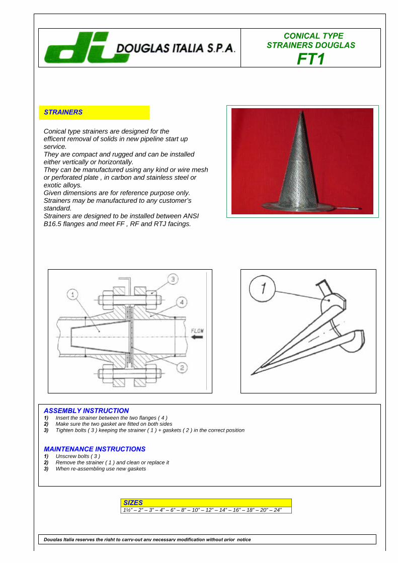
CONICAL TYPE STRAINERS DOUGLAS
FT1
STRAINERS
Conical type strainers are designed for theefficent removal of solids in new pipeline start upservice.They are compact and rugged and can be installedeither vertically or horizontally.They can be manufactured using any kind or wire meshor perforated plate , in carbon and stainless steel orexotic alloys.Given dimensions are for reference purpose only.Strainers may be manufactured to any customer’sstandard.Strainers are designed to be installed between ANSIB16.5 flanges and meet FF , RF and RTJ facings.
SIZES1½” – 2” – 3” – 4” – 6” – 8” – 10” – 12” – 14” – 16” – 18” – 20” – 24”
Douglas Italia reserves the right to carry-out any necessary modification without prior notice
ASSEMBLY INSTRUCTION1) Insert the strainer between the two flanges ( 4 )2) Make sure the two gasket are fitted on both sides3) Tighten bolts ( 3 ) keeping the strainer ( 1 ) + gaskets ( 2 ) in the correct position
MAINTENANCE INSTRUCTIONS1) Unscrew bolts ( 3 )2) Remove the strainer ( 1 ) and clean or replace it3) When re-assembling use new gaskets
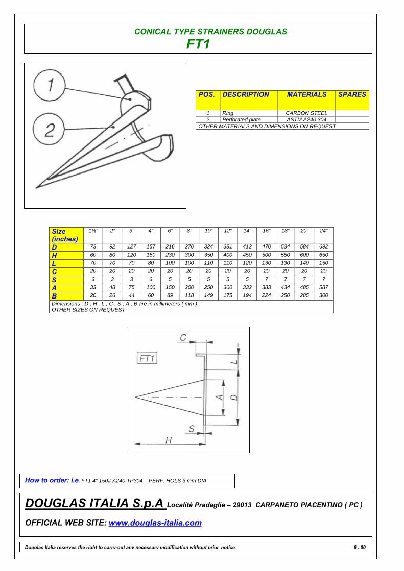
CONICAL TYPE STRAINERS DOUGLAS
FT1
POS. DESCRIPTION MATERIALS SPARES
1 Ring CARBON STEEL2 Perforated plate ASTM A240 304
OTHER MATERIALS AND DIMENSIONS ON REQUEST
Size(inches)
1½” 2” 3” 4” 6” 8” 10” 12” 14” 16” 18” 20” 24”
D 73 92 127 157 216 270 324 381 412 470 534 584 692
H 60 80 120 150 230 300 350 400 450 500 550 600 650
L 70 70 70 80 100 100 110 110 120 130 130 140 150
C 20 20 20 20 20 20 20 20 20 20 20 20 20
S 3 3 3 3 5 5 5 5 5 7 7 7 7
A 33 48 75 100 150 200 250 300 332 383 434 485 587
B 20 26 44 60 89 118 149 175 194 224 250 285 300Dimensions : D , H , L , C , S , A , B are in millimeters ( mm )OTHER SIZES ON REQUEST
How to order: i.e. FT1 4” 150# A240 TP304 – PERF. HOLS 3 mm DIA
DOUGLAS ITALIA S.p.A Località Pradaglie – 29013 CARPANETO PIACENTINO ( PC )
OFFICIAL WEB SITE: www.douglas-italia.com
Douglas Italia reserves the right to carry-out any necessary modification without prior notice 6 . 00
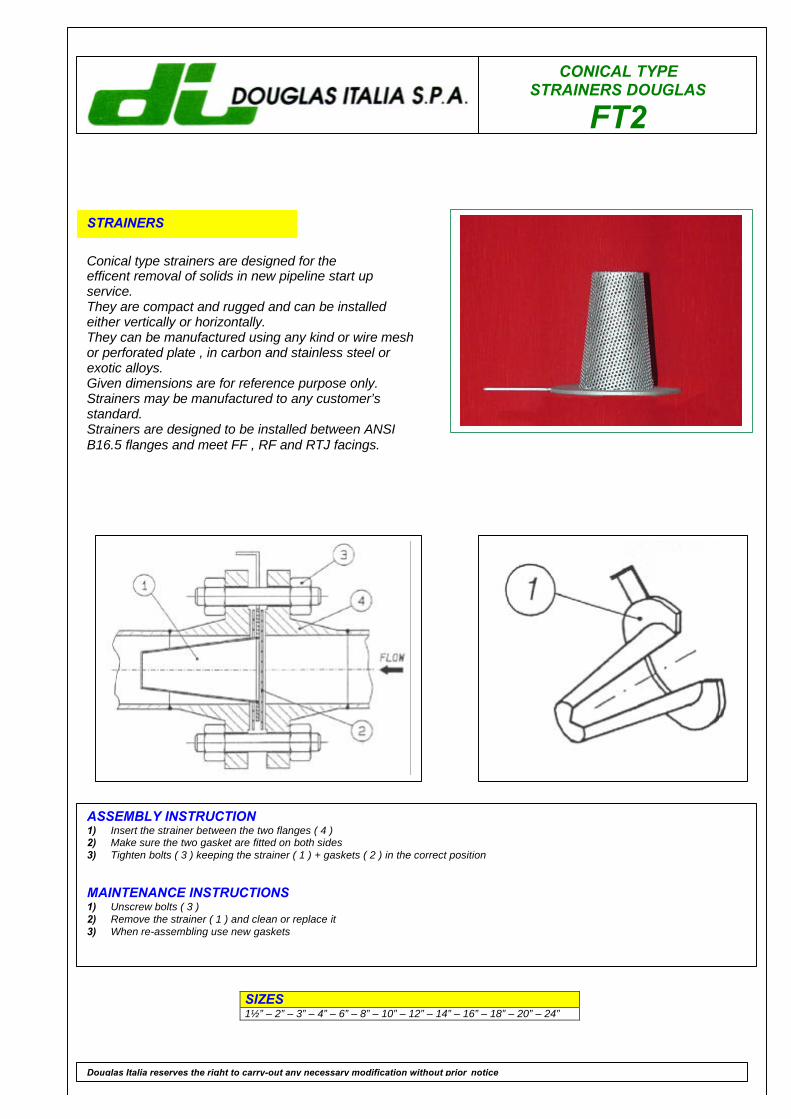
CONICAL TYPE STRAINERS DOUGLAS
FT2
STRAINERS
Conical type strainers are designed for theefficent removal of solids in new pipeline start upservice.They are compact and rugged and can be installedeither vertically or horizontally.They can be manufactured using any kind or wire meshor perforated plate , in carbon and stainless steel orexotic alloys.Given dimensions are for reference purpose only.Strainers may be manufactured to any customer’sstandard.Strainers are designed to be installed between ANSIB16.5 flanges and meet FF , RF and RTJ facings.
SIZES1½” – 2” – 3” – 4” – 6” – 8” – 10” – 12” – 14” – 16” – 18” – 20” – 24”
Douglas Italia reserves the right to carry-out any necessary modification without prior notice
ASSEMBLY INSTRUCTION1) Insert the strainer between the two flanges ( 4 )2) Make sure the two gasket are fitted on both sides3) Tighten bolts ( 3 ) keeping the strainer ( 1 ) + gaskets ( 2 ) in the correct position
MAINTENANCE INSTRUCTIONS1) Unscrew bolts ( 3 )2) Remove the strainer ( 1 ) and clean or replace it3) When re-assembling use new gaskets
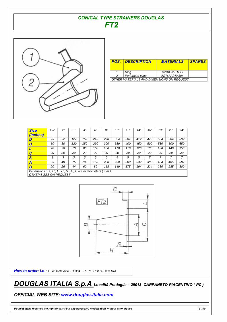
CONICAL TYPE STRAINERS DOUGLAS
FT2
POS. DESCRIPTION MATERIALS SPARES
1 Ring CARBON STEEL2 Perforated plate ASTM A240 304
OTHER MATERIALS AND DIMENSIONS ON REQUEST
Size(inches)
1½” 2” 3” 4” 6” 8” 10” 12” 14” 16” 18” 20” 24”
D 73 92 127 157 216 270 324 381 412 470 534 584 692
H 60 80 120 150 230 300 350 400 450 500 550 600 650
L 70 70 70 80 100 100 110 110 120 130 130 140 150
C 20 20 20 20 20 20 20 20 20 20 20 20 20
S 3 3 3 3 5 5 5 5 5 7 7 7 7
A 33 48 75 100 150 200 250 300 332 383 434 485 587
B 20 26 44 60 89 118 149 175 194 224 250 285 300Dimensions : D , H , L , C , S , A , B are in millimeters ( mm )OTHER SIZES ON REQUEST
How to order: i.e. FT2 4” 150# A240 TP304 – PERF. HOLS 3 mm DIA
DOUGLAS ITALIA S.p.A Località Pradaglie – 29013 CARPANETO PIACENTINO ( PC )
OFFICIAL WEB SITE: www.douglas-italia.com
Douglas Italia reserves the right to carry-out any necessary modification without prior notice 6 . 00
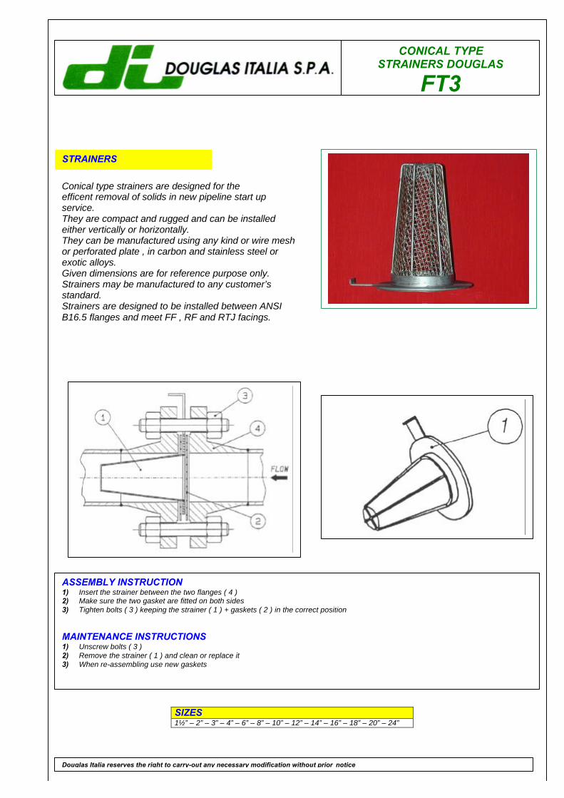
CONICAL TYPE STRAINERS DOUGLAS
FT3
STRAINERS
Conical type strainers are designed for theefficent removal of solids in new pipeline start upservice.They are compact and rugged and can be installedeither vertically or horizontally.They can be manufactured using any kind or wire meshor perforated plate , in carbon and stainless steel orexotic alloys.Given dimensions are for reference purpose only.Strainers may be manufactured to any customer’sstandard.Strainers are designed to be installed between ANSIB16.5 flanges and meet FF , RF and RTJ facings.
SIZES1½” – 2” – 3” – 4” – 6” – 8” – 10” – 12” – 14” – 16” – 18” – 20” – 24”
Douglas Italia reserves the right to carry-out any necessary modification without prior notice
ASSEMBLY INSTRUCTION1) Insert the strainer between the two flanges ( 4 )2) Make sure the two gasket are fitted on both sides3) Tighten bolts ( 3 ) keeping the strainer ( 1 ) + gaskets ( 2 ) in the correct position
MAINTENANCE INSTRUCTIONS1) Unscrew bolts ( 3 )2) Remove the strainer ( 1 ) and clean or replace it3) When re-assembling use new gaskets
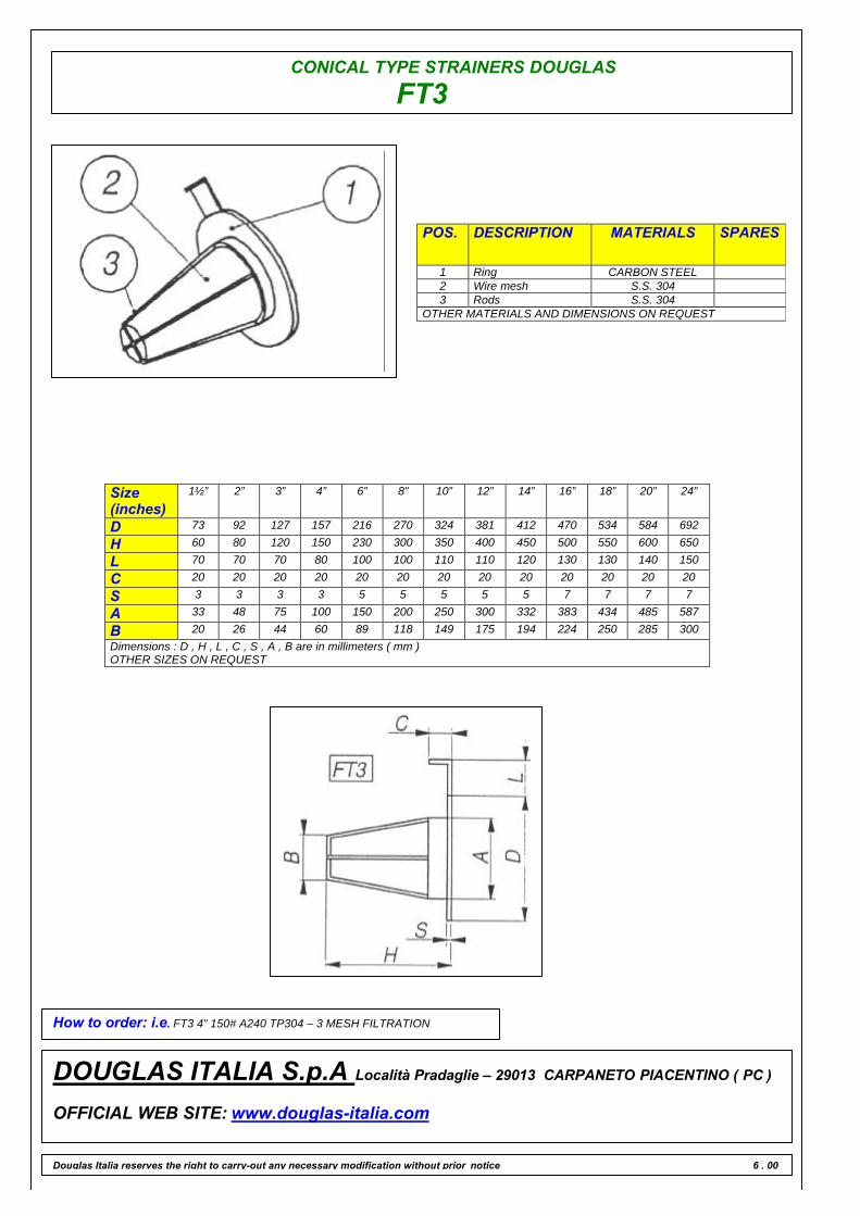
CONICAL TYPE STRAINERS DOUGLAS
FT3
POS. DESCRIPTION MATERIALS SPARES
1 Ring CARBON STEEL2 Wire mesh S.S. 3043 Rods S.S. 304
OTHER MATERIALS AND DIMENSIONS ON REQUEST
Size(inches)
1½” 2” 3” 4” 6” 8” 10” 12” 14” 16” 18” 20” 24”
D 73 92 127 157 216 270 324 381 412 470 534 584 692
H 60 80 120 150 230 300 350 400 450 500 550 600 650
L 70 70 70 80 100 100 110 110 120 130 130 140 150
C 20 20 20 20 20 20 20 20 20 20 20 20 20
S 3 3 3 3 5 5 5 5 5 7 7 7 7
A 33 48 75 100 150 200 250 300 332 383 434 485 587
B 20 26 44 60 89 118 149 175 194 224 250 285 300Dimensions : D , H , L , C , S , A , B are in millimeters ( mm )OTHER SIZES ON REQUEST
How to order: i.e. FT3 4” 150# A240 TP304 – 3 MESH FILTRATION
DOUGLAS ITALIA S.p.A Località Pradaglie – 29013 CARPANETO PIACENTINO ( PC )
OFFICIAL WEB SITE: www.douglas-italia.com
Douglas Italia reserves the right to carry-out any necessary modification without prior notice 6 . 00

TEE
GO BACK
FS 150
FS 300
FS 600
FS 900
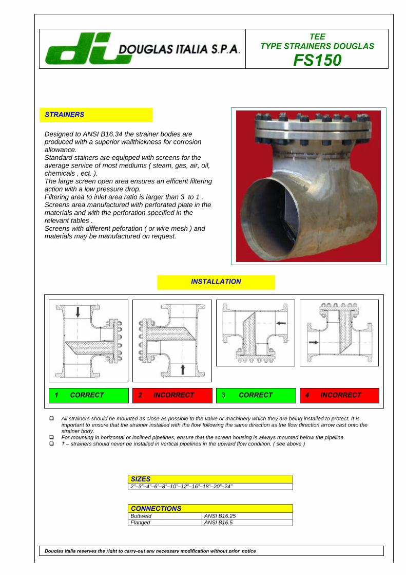
TEETYPE STRAINERS DOUGLAS
FS150
STRAINERS
Designed to ANSI B16.34 the strainer bodies areproduced with a superior wallthickness for corrosionallowance.Standard stainers are equipped with screens for theaverage service of most mediums ( steam, gas, air, oil,chemicals , ect. ).The large screen open area ensures an efficent filteringaction with a low pressure drop.Filtering area to inlet area ratio is larger than 3 to 1 .Screens area manufactured with perforated plate in thematerials and with the perforation specified in therelevant tables .Screens with different peforation ( or wire mesh ) andmaterials may be manufactured on request.
SIZES2”–3”–4”–6”–8”–10”–12”–16”–18”–20”–24”
CONNECTIONSButtweld ANSI B16.25Flanged ANSI B16.5
Douglas Italia reserves the right to carry-out any necessary modification without prior notice
INSTALLATION
q All strainers should be mounted as close as possible to the valve or machinery which they are being installed to protect. It isimportant to ensure that the strainer installed with the flow following the same direction as the flow direction arrow cast onto thestrainer body.
q For mounting in horizontal or inclined pipelines, ensure that the screen housing is always mounted below the pipeline.q T – strainers should never be installed in vertical pipelines in the upward flow condition. ( see above )
1 CORRECT 2 INCORRECT 3 CORRECT 4 INCORRECT
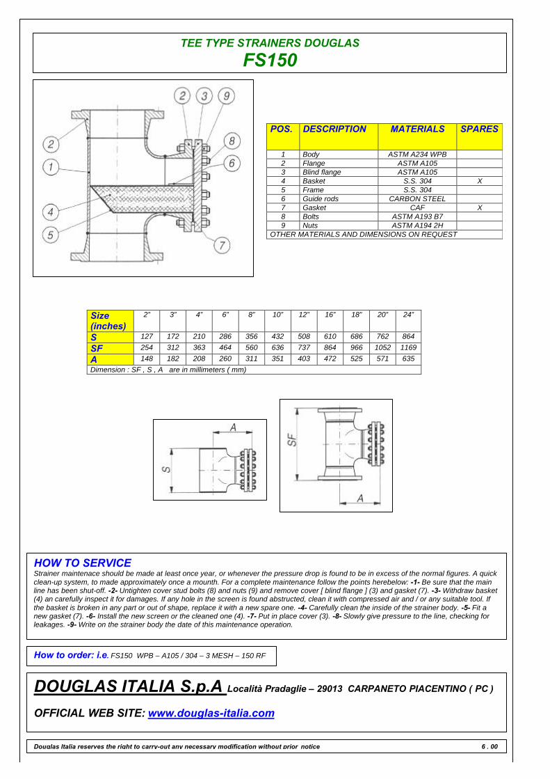
TEE TYPE STRAINERS DOUGLAS
FS150
POS. DESCRIPTION MATERIALS SPARES
1 Body ASTM A234 WPB2 Flange ASTM A1053 Blind flange ASTM A1054 Basket S.S. 304 X5 Frame S.S. 3046 Guide rods CARBON STEEL7 Gasket CAF X8 Bolts ASTM A193 B79 Nuts ASTM A194 2H
OTHER MATERIALS AND DIMENSIONS ON REQUEST
Size(inches)
2” 3” 4” 6” 8” 10” 12” 16” 18” 20” 24”
S 127 172 210 286 356 432 508 610 686 762 864
SF 254 312 363 464 560 636 737 864 966 1052 1169
A 148 182 208 260 311 351 403 472 525 571 635Dimension : SF , S , A are in millimeters ( mm)
HOW TO SERVICEStrainer maintenace should be made at least once year, or whenever the pressure drop is found to be in excess of the normal figures. A quickclean-up system, to made approximately once a mounth. For a complete maintenance follow the points herebelow: -1- Be sure that the mainline has been shut-off. -2- Untighten cover stud bolts (8) and nuts (9) and remove cover [ blind flange ] (3) and gasket (7). -3- Withdraw basket(4) an carefully inspect it for damages. If any hole in the screen is found abstructed, clean it with compressed air and / or any suitable tool. Ifthe basket is broken in any part or out of shape, replace it with a new spare one. -4- Carefully clean the inside of the strainer body. -5- Fit anew gasket (7). -6- Install the new screen or the cleaned one (4). -7- Put in place cover (3). -8- Slowly give pressure to the line, checking forleakages. -9- Write on the strainer body the date of this maintenance operation.
How to order: i.e. FS150 WPB – A105 / 304 – 3 MESH – 150 RF
DOUGLAS ITALIA S.p.A Località Pradaglie – 29013 CARPANETO PIACENTINO ( PC )
OFFICIAL WEB SITE: www.douglas-italia.com
Douglas Italia reserves the right to carry-out any necessary modification without prior notice 6 . 00

TEETYPE STRAINERS DOUGLAS
FS300
STRAINERS
Designed to ANSI B16.34 the strainer bodies areproduced with a superior wallthickness for corrosionallowance.Standard stainers are equipped with screens for theaverage service of most mediums ( steam, gas, air, oil,chemicals , ect. ).The large screen open area ensures an efficent filteringaction with a low pressure drop.Filtering area to inlet area ratio is larger than 3 to 1 .Screens area manufactured with perforated plate in thematerials and with the perforation specified in therelevant tables .Screens with different peforation ( or wire mesh ) andmaterials may be manufactured on request.
SIZES2”–3”–4”–6”–8”–10”–12”–16”–18”–20”–24”
CONNECTIONSButtweld ANSI B16.25Flanged ANSI B16.5
Douglas Italia reserves the right to carry-out any necessary modification without prior notice
INSTALLATION
q All strainers should be mounted as close as possible to the valve or machinery which they are being installed to protect. It isimportant to ensure that the strainer installed with the flow following the same direction as the flow direction arrow cast onto thestrainer body.
q For mounting in horizontal or inclined pipelines, ensure that the screen housing is always mounted below the pipeline.q T – strainers should never be installed in vertical pipelines in the upward flow condition. ( see above )
1 CORRECT 2 INCORRECT 3 CORRECT 4 INCORRECT

TEE TYPE STRAINERS DOUGLAS
FS300
POS. DESCRIPTION MATERIALS SPARES
1 Body ASTM A234 WPB2 Flange ASTM A1053 Blind flange ASTM A1054 Basket S.S. 304 X5 Frame S.S. 3046 Guide rods CARBON STEEL7 Gasket CAF X8 Bolts ASTM A193 B79 Nuts ASTM A194 2H
OTHER MATERIALS AND DIMENSIONS ON REQUEST
Size(inches)
2” 3” 4” 6” 8” 10” 12” 16” 18” 20” 24”
S 127 172 210 286 356 432 508 610 686 762 864
SF 268 332 382 483 579 668 769 903 1004 1086 1201
A 158 197 225 281 333 385 438 511 565 609 673Dimension : SF , S , A are in millimeters ( mm)
HOW TO SERVICEStrainer maintenace should be made at least once year, or whenever the pressure drop is found to be in excess of the normal figures. A quickclean-up system, to made approximately once a mounth. For a complete maintenance follow the points herebelow: -1- Be sure that the mainline has been shut-off. -2- Untighten cover stud bolts (8) and nuts (9) and remove cover [ blind flange ] (3) and gasket (7). -3- Withdraw basket(4) an carefully inspect it for damages. If any hole in the screen is found abstructed, clean it with compressed air and / or any suitable tool. Ifthe basket is broken in any part or out of shape, replace it with a new spare one. -4- Carefully clean the inside of the strainer body. -5- Fit anew gasket (7). -6- Install the new screen or the cleaned one (4). -7- Put in place cover (3). -8- Slowly give pressure to the line, checking forleakages. -9- Write on the strainer body the date of this maintenance operation.
How to order: i.e. FS300 WPB – A105 / 304 – 3 MESH – 300 RF
DOUGLAS ITALIA S.p.A Località Pradaglie – 29013 CARPANETO PIACENTINO ( PC )
OFFICIAL WEB SITE: www.douglas-italia.com
Douglas Italia reserves the right to carry-out any necessary modification without prior notice 6 . 00
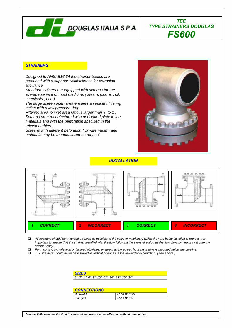
TEETYPE STRAINERS DOUGLAS
FS600
STRAINERS
Designed to ANSI B16.34 the strainer bodies areproduced with a superior wallthickness for corrosionallowance.Standard stainers are equipped with screens for theaverage service of most mediums ( steam, gas, air, oil,chemicals , ect. ).The large screen open area ensures an efficent filteringaction with a low pressure drop.Filtering area to inlet area ratio is larger than 3 to 1 .Screens area manufactured with perforated plate in thematerials and with the perforation specified in therelevant tables .Screens with different peforation ( or wire mesh ) andmaterials may be manufactured on request.
SIZES2”–3”–4”–6”–8”–10”–12”–16”–18”–20”–24”
CONNECTIONSButtweld ANSI B16.25Flanged ANSI B16.5
Douglas Italia reserves the right to carry-out any necessary modification without prior notice
INSTALLATION
q All strainers should be mounted as close as possible to the valve or machinery which they are being installed to protect. It isimportant to ensure that the strainer installed with the flow following the same direction as the flow direction arrow cast onto thestrainer body.
q For mounting in horizontal or inclined pipelines, ensure that the screen housing is always mounted below the pipeline.q T – strainers should never be installed in vertical pipelines in the upward flow condition. ( see above )
1 CORRECT 2 INCORRECT 3 CORRECT 4 INCORRECT

TEE TYPE STRAINERS DOUGLAS
FS600
POS. DESCRIPTION MATERIALS SPARES
1 Body ASTM A234 WPB2 Flange ASTM A1053 Blind flange ASTM A1054 Basket S.S. 304 X5 Frame S.S. 3046 Guide rods CARBON STEEL7 Gasket CAF X8 Bolts ASTM A193 B79 Nuts ASTM A194 2H
OTHER MATERIALS AND DIMENSIONS ON REQUEST
Size(inches)
2” 3” 4” 6” 8” 10” 12” 16” 18” 20” 24”
S 127 172 210 286 356 432 508 610 686 762 864
SF 286 351 427 535 636 750 833 979 1067 1156 1284
A 177 216 260 324 382 447 492 574 624 676 753Dimension : SF , S , A are in millimeters ( mm)
HOW TO SERVICEStrainer maintenace should be made at least once year, or whenever the pressure drop is found to be in excess of the normal figures. A quickclean-up system, to made approximately once a mounth. For a complete maintenance follow the points herebelow: -1- Be sure that the mainline has been shut-off. -2- Untighten cover stud bolts (8) and nuts (9) and remove cover [ blind flange ] (3) and gasket (7). -3- Withdraw basket(4) an carefully inspect it for damages. If any hole in the screen is found abstructed, clean it with compressed air and / or any suitable tool. Ifthe basket is broken in any part or out of shape, replace it with a new spare one. -4- Carefully clean the inside of the strainer body. -5- Fit anew gasket (7). -6- Install the new screen or the cleaned one (4). -7- Put in place cover (3). -8- Slowly give pressure to the line, checking forleakages. -9- Write on the strainer body the date of this maintenance operation.
How to order: i.e. FS600 WPB – A105 / 304 – 3 MESH – 600 RF
DOUGLAS ITALIA S.p.A Località Pradaglie – 29013 CARPANETO PIACENTINO ( PC )
OFFICIAL WEB SITE: www.douglas-italia.com
Douglas Italia reserves the right to carry-out any necessary modification without prior notice 6 . 00
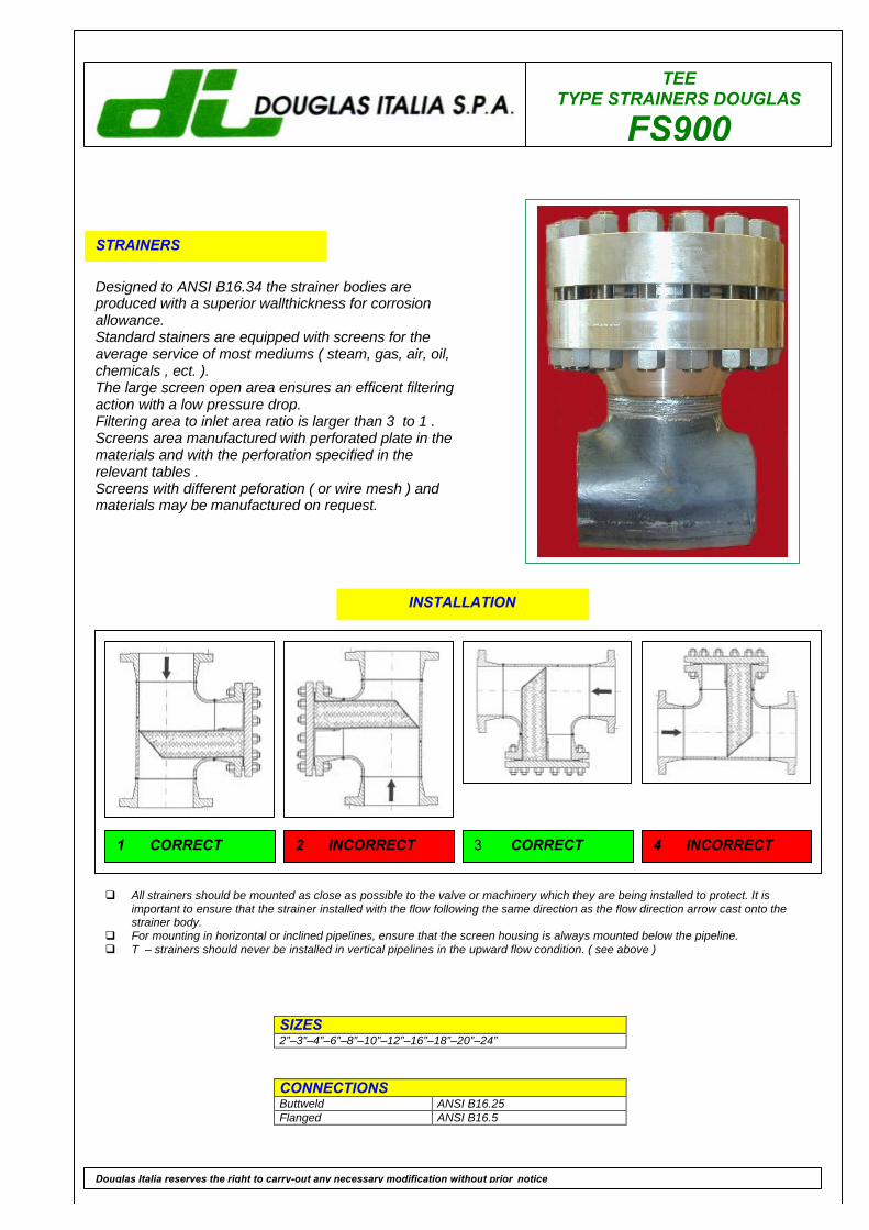
TEETYPE STRAINERS DOUGLAS
FS900
STRAINERS
Designed to ANSI B16.34 the strainer bodies areproduced with a superior wallthickness for corrosionallowance.Standard stainers are equipped with screens for theaverage service of most mediums ( steam, gas, air, oil,chemicals , ect. ).The large screen open area ensures an efficent filteringaction with a low pressure drop.Filtering area to inlet area ratio is larger than 3 to 1 .Screens area manufactured with perforated plate in thematerials and with the perforation specified in therelevant tables .Screens with different peforation ( or wire mesh ) andmaterials may be manufactured on request.
SIZES2”–3”–4”–6”–8”–10”–12”–16”–18”–20”–24”
CONNECTIONSButtweld ANSI B16.25Flanged ANSI B16.5
Douglas Italia reserves the right to carry-out any necessary modification without prior notice
INSTALLATION
q All strainers should be mounted as close as possible to the valve or machinery which they are being installed to protect. It isimportant to ensure that the strainer installed with the flow following the same direction as the flow direction arrow cast onto thestrainer body.
q For mounting in horizontal or inclined pipelines, ensure that the screen housing is always mounted below the pipeline.q T – strainers should never be installed in vertical pipelines in the upward flow condition. ( see above )
1 CORRECT 2 INCORRECT 3 CORRECT 4 INCORRECT

TEE TYPE STRAINERS DOUGLAS
FS900
POS. DESCRIPTION MATERIALS SPARES
1 Body ASTM A234 WPB2 Flange ASTM A1053 Blind flange ASTM A1054 Basket S.S. 304 X5 Frame S.S. 3046 Guide rods CARBON STEEL7 Gasket CAF X8 Bolts ASTM A193 B79 Nuts ASTM A194 2H
OTHER MATERIALS AND DIMENSIONS ON REQUEST
Size(inches)
2” 3” 4” 6” 8” 10” 12” 16” 18” 20” 24”
S 127 172 210 286 356 432 508 610 686 762 864
SF 343 389 453 579 694 813 922 1056 1157 1271 1462
A 219 242 279 353 419 485 549 626 689 752 879Dimension : SF , S , A are in millimeters ( mm)
HOW TO SERVICEStrainer maintenace should be made at least once year, or whenever the pressure drop is found to be in excess of the normal figures. A quickclean-up system, to made approximately once a mounth. For a complete maintenance follow the points herebelow: -1- Be sure that the mainline has been shut-off. -2- Untighten cover stud bolts (8) and nuts (9) and remove cover [ blind flange ] (3) and gasket (7). -3- Withdraw basket(4) an carefully inspect it for damages. If any hole in the screen is found abstructed, clean it with compressed air and / or any suitable tool. Ifthe basket is broken in any part or out of shape, replace it with a new spare one. -4- Carefully clean the inside of the strainer body. -5- Fit anew gasket (7). -6- Install the new screen or the cleaned one (4). -7- Put in place cover (3). -8- Slowly give pressure to the line, checking forleakages. -9- Write on the strainer body the date of this maintenance operation.
How to order: i.e. FS900 WPB – A105 / 304 – 3 MESH – 900 RF
DOUGLAS ITALIA S.p.A Località Pradaglie – 29013 CARPANETO PIACENTINO ( PC )
OFFICIAL WEB SITE: www.douglas-italia.com
Douglas Italia reserves the right to carry-out any necessary modification without prior notice 6 . 00
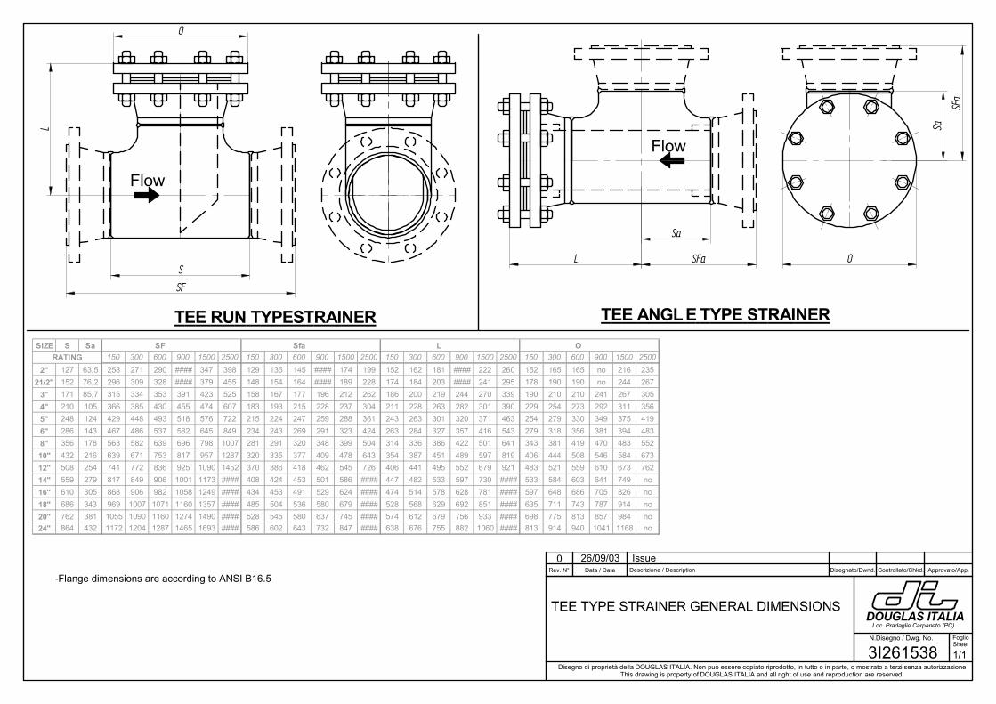
Disegno di proprietà della DOUGLAS ITALIA. Non può essere copiato riprodotto, in tutto o in parte, o mostrato a terzi senza autorizzazioneThis drawing is property of DOUGLAS ITALIA and all right of use and reproduction are reserved.
N.Disegno / Dwg. No. FoglioSheet
DOUGLAS ITALIALoc. Pradaglie Carpaneto (PC)
Rev. N° Descrizione / DescriptionData / Date Disegnato/Dwnd. Controllato/Chkd. Approvato/App.
S
SF
LO
L SFa
SFa
Sa
Sa
O
SIZE S Sa SF Sfa L ORATING 150 300 600 900 1500 2500 150 300 600 900 1500 2500 150 300 600 900 1500 2500 150 300 600 900 1500 2500
2" 127 63,5 258 271 290 #### 347 398 129 135 145 #### 174 199 152 162 181 #### 222 260 152 165 165 no 216 23521/2" 152 76,2 296 309 328 #### 379 455 148 154 164 #### 189 228 174 184 203 #### 241 295 178 190 190 no 244 267
3" 171 85,7 315 334 353 391 423 525 158 167 177 196 212 262 186 200 219 244 270 339 190 210 210 241 267 3054" 210 105 366 385 430 455 474 607 183 193 215 228 237 304 211 228 263 282 301 390 229 254 273 292 311 3565" 248 124 429 448 493 518 576 722 215 224 247 259 288 361 243 263 301 320 371 463 254 279 330 349 375 4196" 286 143 467 486 537 582 645 849 234 243 269 291 323 424 263 284 327 357 416 543 279 318 356 381 394 4838" 356 178 563 582 639 696 798 1007 281 291 320 348 399 504 314 336 386 422 501 641 343 381 419 470 483 55210" 432 216 639 671 753 817 957 1287 320 335 377 409 478 643 354 387 451 489 597 819 406 444 508 546 584 67312" 508 254 741 772 836 925 1090 1452 370 386 418 462 545 726 406 441 495 552 679 921 483 521 559 610 673 76214" 559 279 817 849 906 1001 1173 #### 408 424 453 501 586 #### 447 482 533 597 730 #### 533 584 603 641 749 no16" 610 305 868 906 982 1058 1249 #### 434 453 491 529 624 #### 474 514 578 628 781 #### 597 648 686 705 826 no18" 686 343 969 1007 1071 1160 1357 #### 485 504 536 580 679 #### 528 568 629 692 851 #### 635 711 743 787 914 no20" 762 381 1055 1090 1160 1274 1490 #### 528 545 580 637 745 #### 574 612 679 756 933 #### 698 775 813 857 984 no24" 864 432 1172 1204 1287 1465 1693 #### 586 602 643 732 847 #### 638 676 755 882 1060 #### 813 914 940 1041 1168 no
Flow
Flow
TEE RUN TYPE STRAINER TEE ANGLE TYPE STRAINER
TEE TYPE STRAINER GENERAL DIMENSIONS
0 26/09/03 Issue
1/13I261538
-Flange dimensions are according to ANSI B16.5

SIMPLEX
GO BACK
MO 150
MO 300
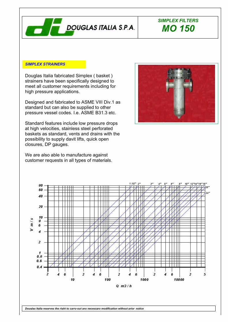
SIMPLEX FILTERS
MO 150
SIMPLEX STRAINERS
Douglas Italia fabricated Simplex ( basket )strainers have been specifically designed tomeet all customer requirements including forhigh pressure applications.
Designed and fabricated to ASME VIII Div.1 asstandard but can also be supplied to otherpressure vessel codes. I.e. ASME B31.3 etc.
Standard features include low pressure dropsat high velocities, stainless steel perforatedbaskets as standard, vents and drains with thepossibility to supply davit lifts, quick openclosures, DP gauges.
We are also able to manufacture againstcustomer requests in all types of materials.
Douglas Italia reserves the right to carry-out any necessary modification without prior notice
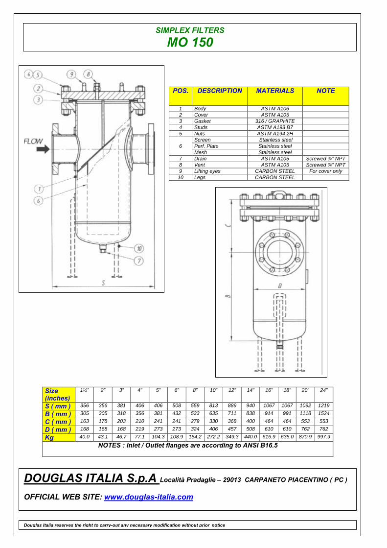
SIMPLEX FILTERS
MO 150
POS. DESCRIPTION MATERIALS NOTE
1 Body ASTM A1062 Cover ASTM A1053 Gasket 316 / GRAPHITE4 Studs ASTM A193 B75 Nuts ASTM A194 2H
Screen Stainless steelPerf. Plate Stainless steel6Mesh Stainless steel
7 Drain ASTM A105 Screwed ¾” NPT8 Vent ASTM A105 Screwed ¾” NPT9 Lifting eyes CARBON STEEL For cover only10 Legs CARBON STEEL
Size(inches)
1½” 2” 3” 4” 5” 6” 8” 10” 12” 14” 16” 18” 20” 24”
S ( mm ) 356 356 381 406 406 508 559 813 889 940 1067 1067 1092 1219
B ( mm ) 305 305 318 356 381 432 533 635 711 838 914 991 1118 1524
C ( mm ) 163 178 203 210 241 241 279 330 368 400 464 464 553 553
D ( mm ) 168 168 168 219 273 273 324 406 457 508 610 610 762 762
Kg 40.0 43.1 46.7 77.1 104.3 108.9 154.2 272.2 349.3 440.0 616.9 635.0 870.9 997.9
NOTES : Inlet / Outlet flanges are according to ANSI B16.5
DOUGLAS ITALIA S.p.A Località Pradaglie – 29013 CARPANETO PIACENTINO ( PC )
OFFICIAL WEB SITE: www.douglas-italia.com
Douglas Italia reserves the right to carry-out any necessary modification without prior notice
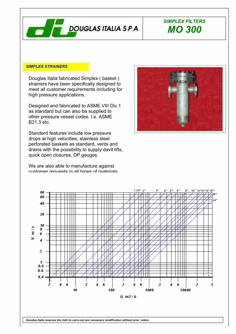
SIMPLEX FILTERS
MO 300
SIMPLEX STRAINERS
Douglas Italia reserves the right to carry-out any necessary modification without prior notice
Douglas Italia fabricated Simplex ( basket )strainers have been specifically designed tomeet all customer requirements including forhigh pressure applications.
Designed and fabricated to ASME VIII Div.1as standard but can also be supplied toother pressure vessel codes. I.e. ASMEB31.3 etc.
Standard features include low pressuredrops at high velocities, stainless steelperforated baskets as standard, vents anddrains with the possibility to supply davit lifts,quick open closures, DP gauges.
We are also able to manufacture againstcustomer requests in all types of materials
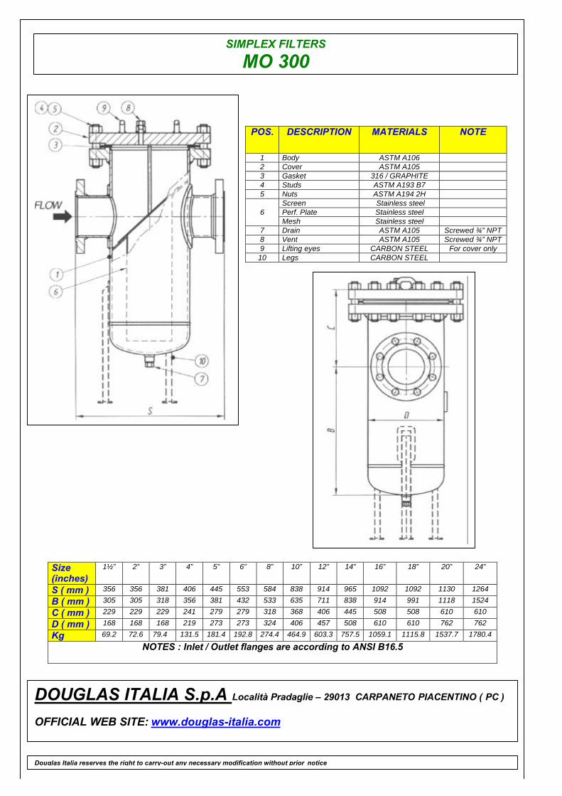
SIMPLEX FILTERS
MO 300
POS. DESCRIPTION MATERIALS NOTE
1 Body ASTM A1062 Cover ASTM A1053 Gasket 316 / GRAPHITE4 Studs ASTM A193 B75 Nuts ASTM A194 2H
Screen Stainless steelPerf. Plate Stainless steel6Mesh Stainless steel
7 Drain ASTM A105 Screwed ¾” NPT8 Vent ASTM A105 Screwed ¾” NPT9 Lifting eyes CARBON STEEL For cover only10 Legs CARBON STEEL
Size(inches)
1½” 2” 3” 4” 5” 6” 8” 10” 12” 14” 16” 18” 20” 24”
S ( mm ) 356 356 381 406 445 553 584 838 914 965 1092 1092 1130 1264
B ( mm ) 305 305 318 356 381 432 533 635 711 838 914 991 1118 1524
C ( mm ) 229 229 229 241 279 279 318 368 406 445 508 508 610 610
D ( mm ) 168 168 168 219 273 273 324 406 457 508 610 610 762 762
Kg 69.2 72.6 79.4 131.5 181.4 192.8 274.4 464.9 603.3 757.5 1059.1 1115.8 1537.7 1780.4
NOTES : Inlet / Outlet flanges are according to ANSI B16.5
DOUGLAS ITALIA S.p.A Località Pradaglie – 29013 CARPANETO PIACENTINO ( PC )
OFFICIAL WEB SITE: www.douglas-italia.com
Douglas Italia reserves the right to carry-out any necessary modification without prior notice

DUPLEX
GO BACK
DU 150
DU 300
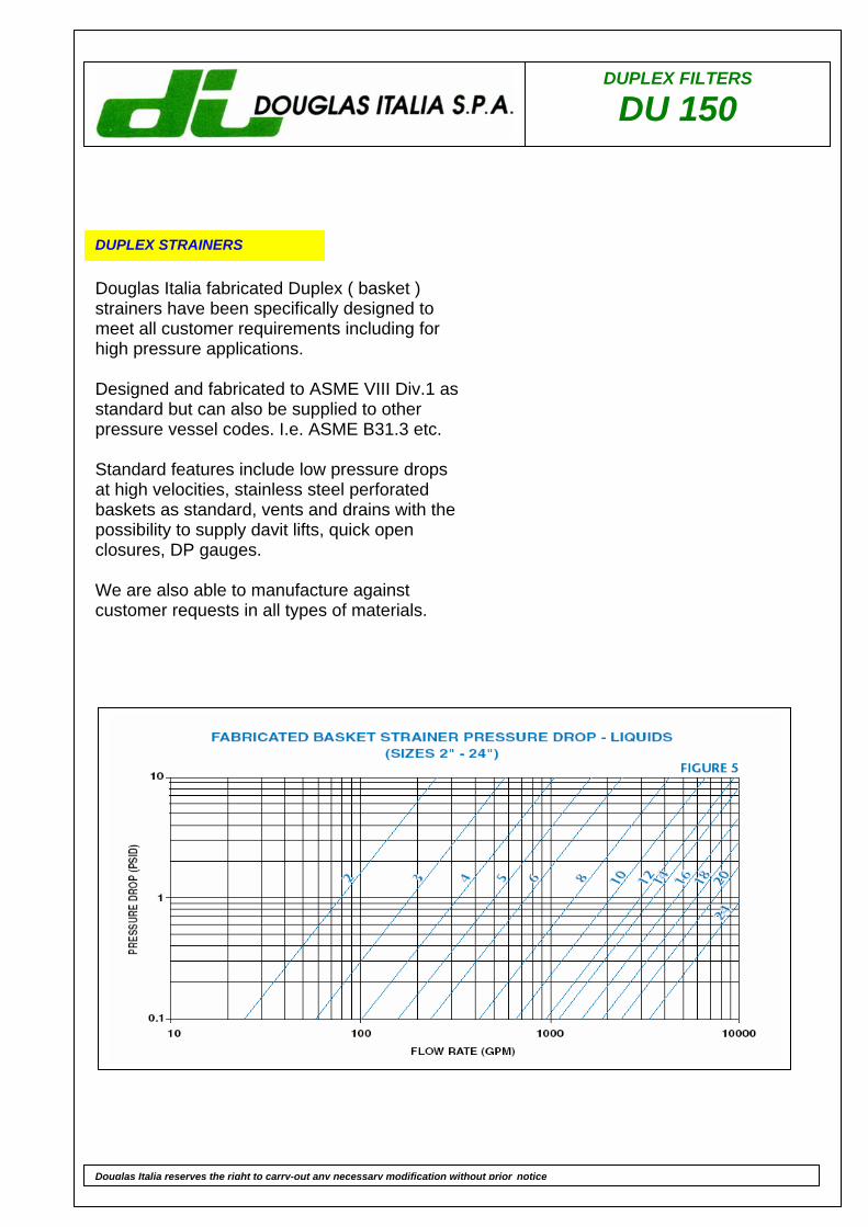
DUPLEX FILTERS
DU 150
DUPLEX STRAINERS
Douglas Italia fabricated Duplex ( basket ) strainers have been specifically designed to meet all customer requirements including for high pressure applications. Designed and fabricated to ASME VIII Div.1 as standard but can also be supplied to other pressure vessel codes. I.e. ASME B31.3 etc. Standard features include low pressure drops at high velocities, stainless steel perforated baskets as standard, vents and drains with the possibility to supply davit lifts, quick open closures, DP gauges. We are also able to manufacture against customer requests in all types of materials.
Douglas Italia reserves the right to carry-out any necessary modification without prior notice
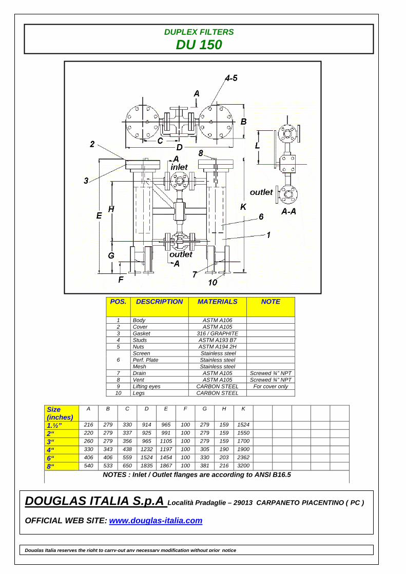
DUPLEX FILTERS
DU 150
POS. DESCRIPTION MATERIALS NOTE
1 Body ASTM A106 2 Cover ASTM A105 3 Gasket 316 / GRAPHITE 4 Studs ASTM A193 B7 5 Nuts ASTM A194 2H
Screen Stainless steel Perf. Plate Stainless steel 6 Mesh Stainless steel
7 Drain ASTM A105 Screwed ¾” NPT 8 Vent ASTM A105 Screwed ¾” NPT 9 Lifting eyes CARBON STEEL For cover only
10 Legs CARBON STEEL
Size (inches)
A B C D E F G H K
1.½” 216 279 330 914 965 100 279 159 1524
2“ 220 279 337 925 991 100 279 159 1550
3“ 260 279 356 965 1105 100 279 159 1700
4“ 330 343 438 1232 1197 100 305 190 1900
6“ 406 406 559 1524 1454 100 330 203 2362
8“ 540 533 650 1835 1867 100 381 216 3200
NOTES : Inlet / Outlet flanges are according to ANSI B16.5
DOUGLAS ITALIA S.p.A Località Pradaglie – 29013 CARPANETO PIACENTINO ( PC ) OFFICIAL WEB SITE: www.douglas-italia.com
Douglas Italia reserves the right to carry-out any necessary modification without prior notice
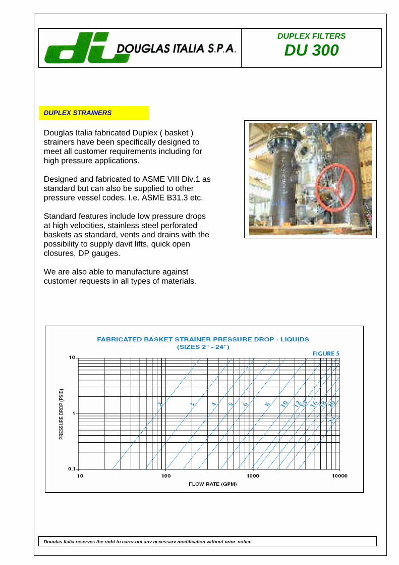
DUPLEX FILTERS
DU 300
DUPLEX STRAINERS
Douglas Italia fabricated Duplex ( basket ) strainers have been specifically designed to meet all customer requirements including for high pressure applications. Designed and fabricated to ASME VIII Div.1 as standard but can also be supplied to other pressure vessel codes. I.e. ASME B31.3 etc. Standard features include low pressure drops at high velocities, stainless steel perforated baskets as standard, vents and drains with the possibility to supply davit lifts, quick open closures, DP gauges. We are also able to manufacture against customer requests in all types of materials.
Douglas Italia reserves the right to carry-out any necessary modification without prior notice
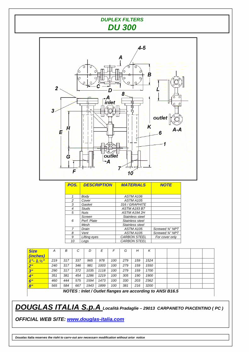
DUPLEX FILTERS
DU 300
POS. DESCRIPTION MATERIALS NOTE
1 Body ASTM A106 2 Cover ASTM A105 3 Gasket 316 / GRAPHITE 4 Studs ASTM A193 B7 5 Nuts ASTM A194 2H
Screen Stainless steel Perf. Plate Stainless steel 6 Mesh Stainless steel
7 Drain ASTM A105 Screwed ¾” NPT 8 Vent ASTM A105 Screwed ¾” NPT 9 Lifting eyes CARBON STEEL For cover only
10 Legs CARBON STEEL
Size (inches)
A B C D E F G H K
1”- 1.½” 219 317 337 965 978 100 279 159 1524
2“ 240 317 346 981 1003 100 279 159 1550
3“ 290 317 372 1035 1118 100 279 159 1700
4“ 351 381 454 1286 1219 100 305 190 1900
6“ 460 444 575 1594 1473 100 330 203 2362
8“ 565 584 667 1943 1899 100 381 216 3200
NOTES : Inlet / Outlet flanges are according to ANSI B16.5
DOUGLAS ITALIA S.p.A Località Pradaglie – 29013 CARPANETO PIACENTINO ( PC ) OFFICIAL WEB SITE: www.douglas-italia.com
Douglas Italia reserves the right to carry-out any necessary modification without prior notice

SPECIAL PRODUCTS
GO BACK

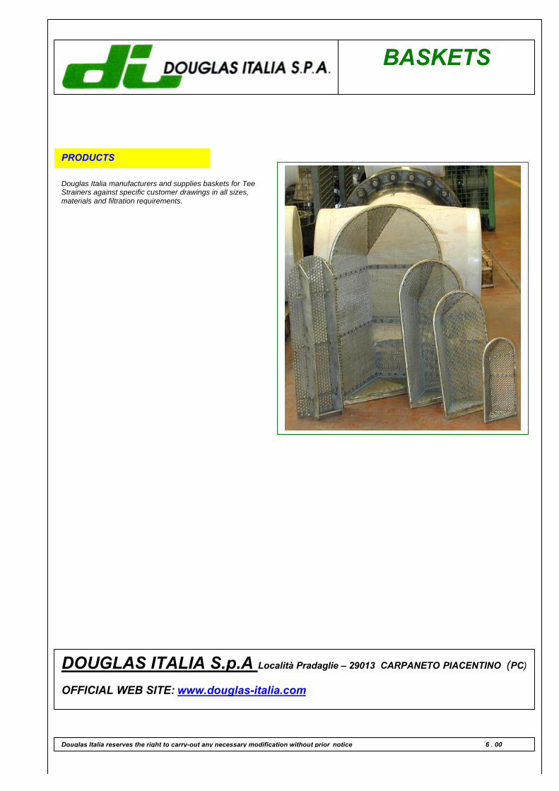
BASKETS
PRODUCTS
Douglas Italia manufacturers and supplies baskets for TeeStrainers against specific customer drawings in all sizes,materials and filtration requirements.
Douglas Italia reserves the right to carry-out any necessary modification without prior notice 6 . 00
DOUGLAS ITALIA S.p.A Località Pradaglie – 29013 CARPANETO PIACENTINO (PC)
OFFICIAL WEB SITE: www.douglas-italia.com
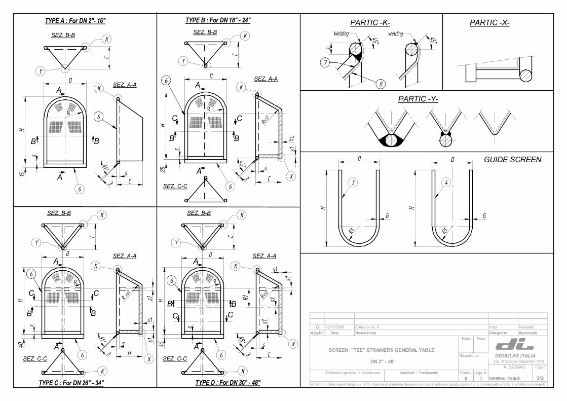
TYPE A : For DN 2"- 16" TYPE B : For DN 18" - 24"
TYPE C : For DN 26" - 34" TYPE D : For DN 36" - 48"
A
A
B B
H
s
sC
15
45°3
DY
K
K
C
A
A
B B
SEZ. B-B
SEZ. A-A
C C
25H
C
s
s1
s1
D
45°3
s
SEZ. B-B
SEZ. A-A
K
Y
K
XSEZ. C-C
C
H40
R=s1
D
s
s1
s1
H
C
s
3
45°
A
A
B B
C C
SEZ. B-B
SEZ. A-A
SEZ. C-C
R =s1
s1
K
Y
K
X
K
A
A
C C
SEZ. B-B
SEZ. A-A
SEZ. C-C
K
Y
K
X
K
H45
s
D
s
s1s1
C
45°3
C
B B
R1 s1
s1R=s
1
6
6
66
s
45°
8
7
45°
PARTIC -K- PARTIC -X-
PARTIC -Y-
3
H
G
D
6 6
6 6
Welding Welding
0 12/10/2000 Emission N. 0 Volpi MasarattiAgg.N° Data Descrizione Disegnato Approvato
Scala Peso
SCREEN "TEE" STRAINERS GENERAL TABLERicavato da DOUGLAS ITALIA
DN 2" - 48" Loc. Pradaglie Carpaneto (PC)N. DISEGNO Foglio
Tolleranze generali di lavorazione Materiale / Trattamento Emiss. Agg. N0 1 GENERAL TABLE 2/2
Ai termini delle vigenti leggi sui diritti d'autore,il presente disegno non potrà essere copiato,riprodotto o consegnato a terzi e a Ditte concorrenti
RR
R R
R1
4
GUIDE SCREEN
H
D
R1
G
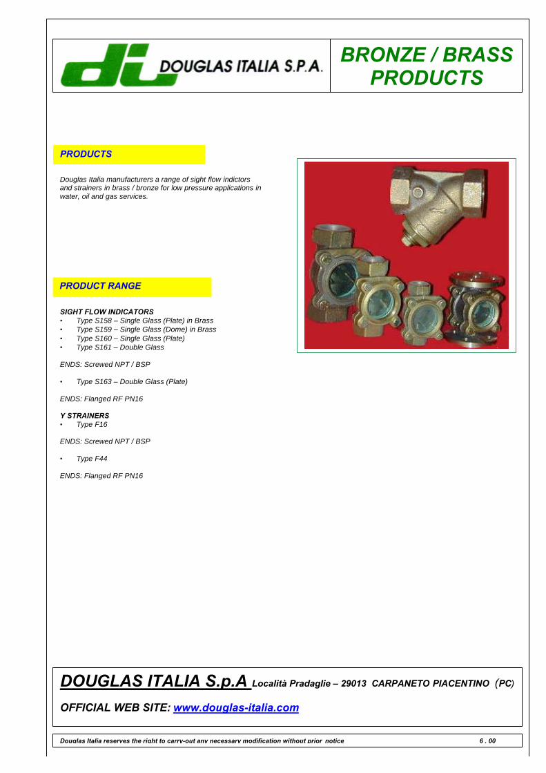
BRONZE / BRASSPRODUCTS
PRODUCTS
Douglas Italia manufacturers a range of sight flow indictorsand strainers in brass / bronze for low pressure applications inwater, oil and gas services.
PRODUCT RANGE
SIGHT FLOW INDICATORS• Type S158 – Single Glass (Plate) in Brass• Type S159 – Single Glass (Dome) in Brass• Type S160 – Single Glass (Plate)• Type S161 – Double Glass
ENDS: Screwed NPT / BSP
• Type S163 – Double Glass (Plate)
ENDS: Flanged RF PN16
Y STRAINERS• Type F16
ENDS: Screwed NPT / BSP
• Type F44
ENDS: Flanged RF PN16
Douglas Italia reserves the right to carry-out any necessary modification without prior notice 6 . 00
DOUGLAS ITALIA S.p.A Località Pradaglie – 29013 CARPANETO PIACENTINO (PC)
OFFICIAL WEB SITE: www.douglas-italia.com
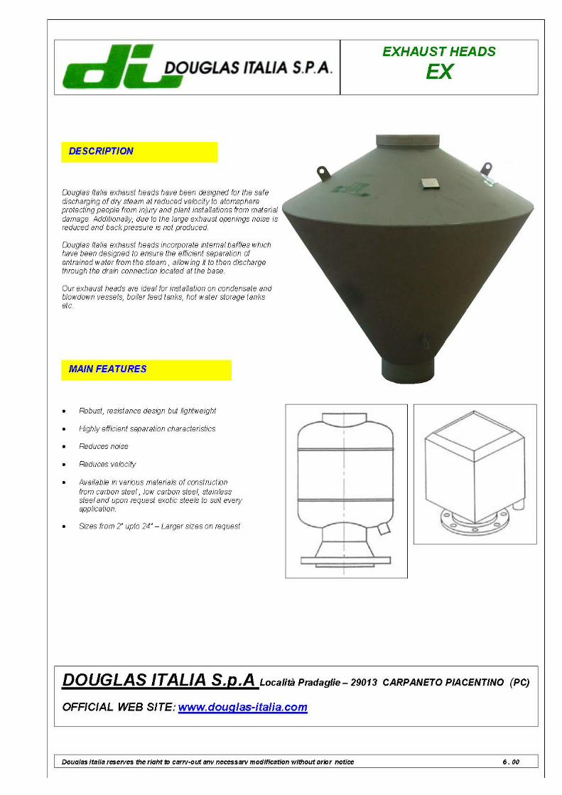
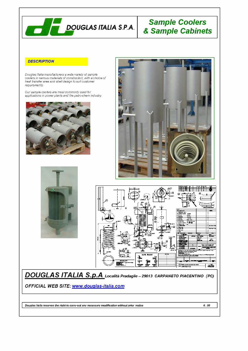
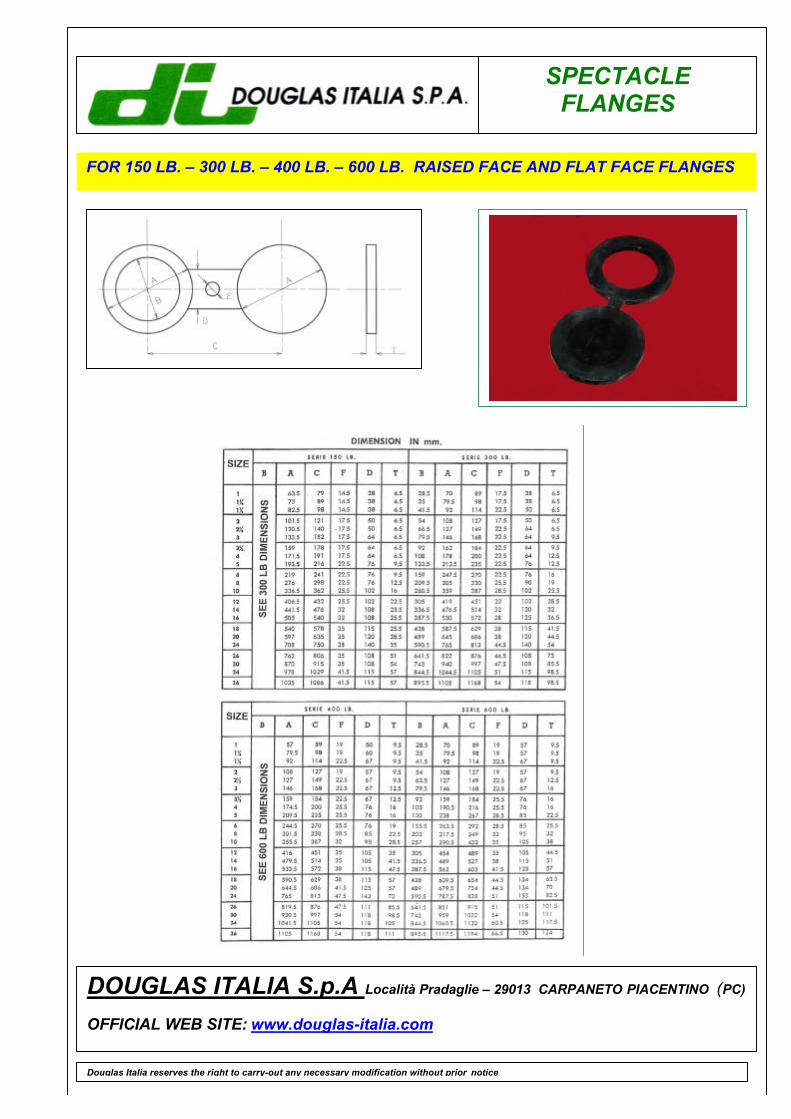
SPECTACLEFLANGES
Douglas Italia reserves the right to carry-out any necessary modification without prior notice
DOUGLAS ITALIA S.p.A Località Pradaglie – 29013 CARPANETO PIACENTINO (PC)
OFFICIAL WEB SITE: www.douglas-italia.com
FOR 150 LB. – 300 LB. – 400 LB. – 600 LB. RAISED FACE AND FLAT FACE FLANGES
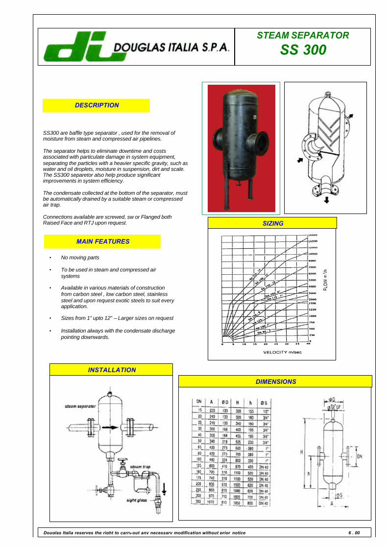
STEAM SEPARATOR SS 300
DESCRIPTION
SS300 are baffle type separator , used for the removal of moisture from steam and compressed air pipelines. The separator helps to eliminate downtime and costs associated with particulate damage in system equipment, separating the particles with a heavier specific gravity, such as water and oil droplets, moisture in suspension, dirt and scale. The SS300 separetor also help produce significant improvements in system efficiency. The condensate collected at the bottom of the separator, must be automatically drained by a suitable steam or compressed air trap. Connections available are screwed, sw or Flanged both Raised Face and RTJ upon request.
MAIN FEATURES
• No moving parts • To be used in steam and compressed air
systems • Available in various materials of construction
from carbon steel , low carbon steel, stainless steel and upon request exotic steels to suit every application.
• Sizes from 1” upto 12” – Larger sizes on request • Installation always with the condensate discharge
pointing downwards.
Douglas Italia reserves the right to carry-out any necessary modification without prior notice 6 . 00
INSTALLATION
SIZING
DIMENSIONS
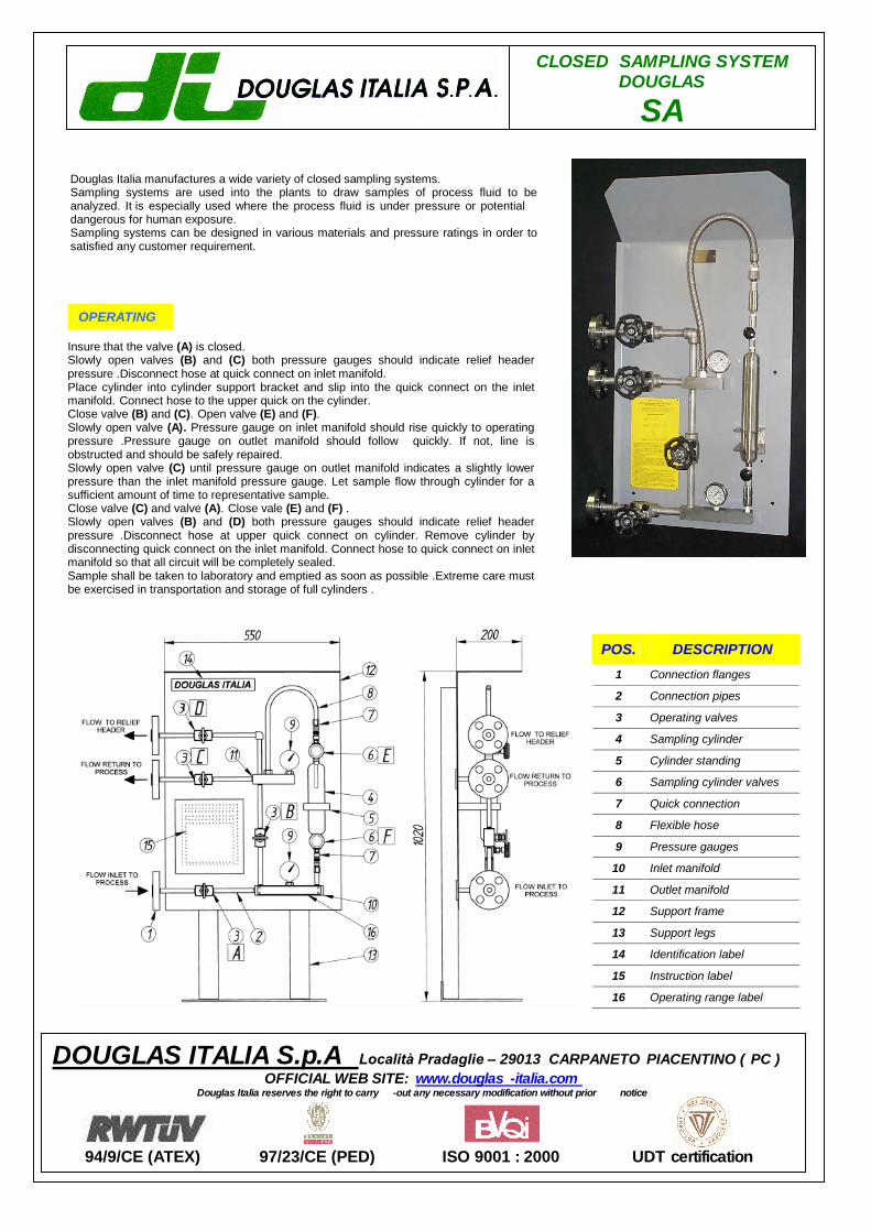
CLOSED SAMPLING SYSTEM DOUGLAS
SA
POS. DESCRIPTION
1 Connection flanges
2 Connection pipes
3 Operating valves
4 Sampling cylinder
5 Cylinder standing
6 Sampling cylinder valves
7 Quick connection
8 Flexible hose
9 Pressure gauges
10 Inlet manifold
11 Outlet manifold
12 Support frame
13 Support legs
14 Identification label
15 Instruction label
16 Operating range label
DOUGLAS ITALIA S.p.A Località Pradaglie – 29013 CARPANETO PIACENTINO ( PC ) OFFICIAL WEB SITE: www.douglaswww.douglas -italia.com
Douglas Italia reserves the right to carry -out any necessary modification without prior notice
94/9/CE (ATEX) 97/23/CE (PED) ISO 9001 : 2000 UDT certification
Insure that the valve (A) is closed. Slowly open valves (B) and (C) both pressure gauges should indicate relief header pressure .Disconnect hose at quick connect on inlet manifold. Place cylinder into cylinder support bracket and slip into the quick connect on the inlet manifold. Connect hose to the upper quick on the cylinder. Close valve (B) and (C). Open valve (E) and (F). Slowly open valve (A). Pressure gauge on inlet manifold should rise quickly to operating pressure .Pressure gauge on outlet manifold should follow quickly. If not, line is obstructed and should be safely repaired. Slowly open valve (C) until pressure gauge on outlet manifold indicates a slightly lower pressure than the inlet manifold pressure gauge. Let sample flow through cylinder for a sufficient amount of time to representative sample. Close valve (C) and valve (A). Close vale (E) and (F) . Slowly open valves (B) and (D) both pressure gauges should indicate relief header pressure .Disconnect hose at upper quick connect on cylinder. Remove cylinder by disconnecting quick connect on the inlet manifold. Connect hose to quick connect on inlet manifold so that all circuit will be completely sealed. Sample shall be taken to laboratory and emptied as soon as possible .Extreme care must be exercised in transportation and storage of full cylinders .
Douglas Italia manufactures a wide variety of closed sampling systems. Sampling systems are used into the plants to draw samples of process fluid to be analyzed. It is especially used where the process fluid is under pressure or potential dangerous for human exposure. Sampling systems can be designed in various materials and pressure ratings in order to satisfied any customer requirement.
OPERATING
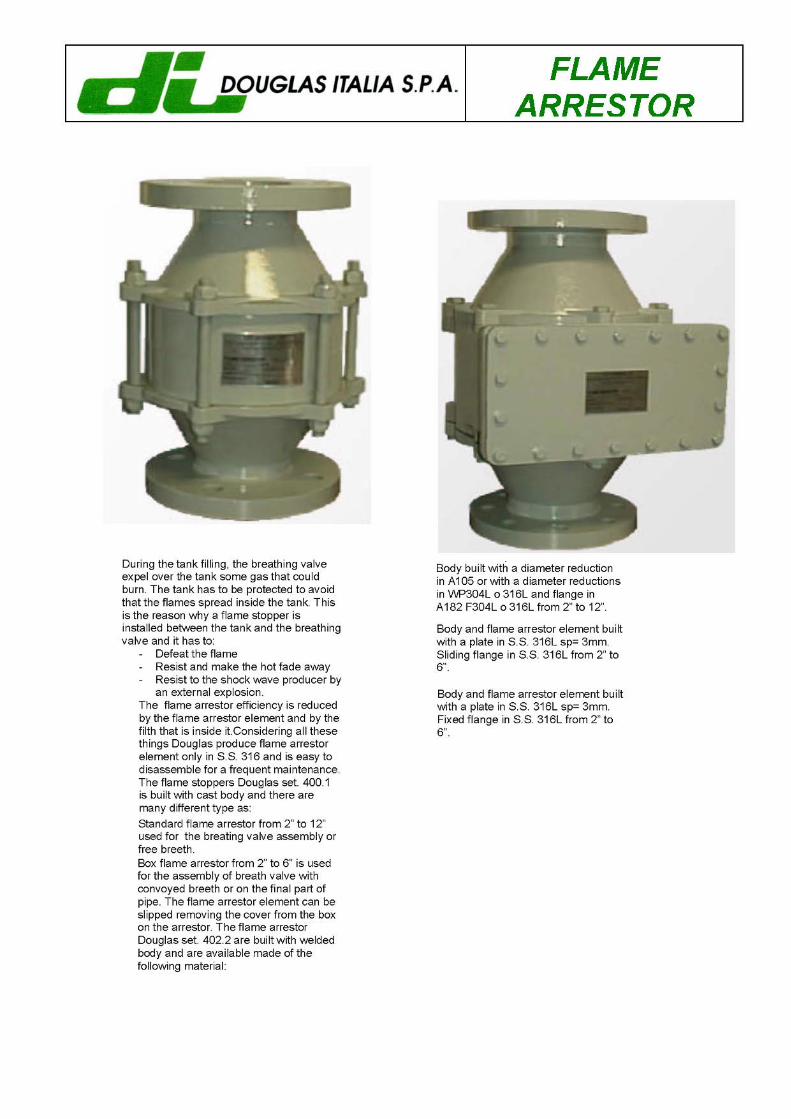

TECHNICAL DATA
GO BACK
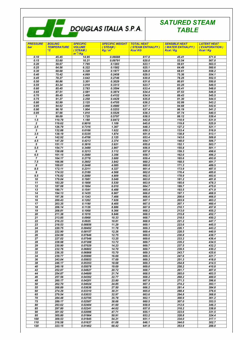
SATURED STEAMTABLE
PRESSUREbar
BOILINGTEMPERATURE°C
SPECIFICVOLUME( STEAM )m 3/ Kg
SPECIFIC WEIGHT( STEAM )Kg / m3
TOTAL HEAT( STEAM ENTHALPY )Kca/ KG
SENSIBLE HEAT( WATER ENTHALPY )Kcal / Kg
LATENT HEAT( EVAPORATION )Kcal / Kg
0.10 45.45 14.95 0.06688 617.0 45.41 571.60.15 53.60 10.21 0.09791 620.0 53.54 567.00.20 59.67 7.795 0.1283 623.1 59.61 563.50.25 64.56 6.322 0.1582 625.1 64.49 560.60.30 68.68 5.328 0.1877 626.8 68.61 558.20.40 75.42 4.069 0.2458 629.5 75.36 554.10.45 78.27 3.642 0.2746 630.8 78.25 552.50.50 80.86 3.301 0.3029 631.6 80.81 550.80.55 83.24 3.018 0.3313 623.7 83.25 549.50.60 85.45 2.783 0.3594 633.4 85.41 548.00.65 87.51 2.581 0.3874 634.4 87.53 546.90.70 89.45 2.409 0.4152 634.9 89.43 545.50.75 91.27 2.258 0.4429 635.8 91.30 544.50.80 92.99 2.125 0.4705 636.2 92.99 543.20.85 94.62 2.008 0.4980 637.1 94.68 542.60.90 96.18 1.904 0.5253 637.4 96.19 541.20.95 97.66 1.810 0.5526 638.3 97.74 540.5
1 99.09 1.725 0.5797 638.5 99.12 539.41.5 110.79 1.180 0.8472 642.8 110.9 531.92 119.62 0.9016 1.109 645.8 119.8 525.9
2.5 126.79 0.7316 1.367 648.3 127.2 521.13 132.88 0.6166 1.622 650.3 133.4 516.9
3.5 138.19 0.5335 1.874 651.9 138.8 513.14 142.92 0.4706 2.125 653.4 143.6 509.8
4.5 147.20 0.4213 2.374 654.7 148.0 506.75 151.11 0.3816 2.621 655.8 152.1 503.7
5.5 154.71 0.3489 2.867 656.9 155.8 501.16 158.08 0.3213 3.112 657.8 159.3 498.6
6.5 161.15 0.2980 3.356 658.7 162.6 496.27 164.17 0.2778 3.600 659.4 165.6 493.8
7.5 166.96 0.2602 3.842 660.2 168.5 491.78 169.61 0.2448 4.085 660.8 171.3 489.5
8.5 172.11 0.2311 4.327 661.4 173.9 487.59 174.53 0.2189 4.568 662.0 176.4 485.6
9.5 176.82 0.2080 4.809 662.5 178.9 483.610 179.04 0.1981 5.049 663.0 181.2 481.811 183.20 0.1808 5.530 663.9 185.6 478.312 187.08 0.1664 6.010 664.7 189.7 475.013 190.71 0.1541 6.488 665.4 193.5 471.914 194.13 0.1435 6.967 666.0 197.1 468.915 197.36 0.1343 7.466 666.6 200.6 466.016 200.43 0.1262 7.926 667.1 203.9 463.217 203.35 0.1190 8.405 667.5 207.1 460.418 206.14 0.1126 8.886 667.9 210.1 457.819 208.81 0.1068 9.366 668.2 213.0 455.220 211.38 0.1016 9.846 668.5 215.8 452.721 213.85 0.0968 10.33 668.7 218.5 450.222 216.23 0.0925 10.81 668.9 221.2 447.723 218.53 0.08856 11.29 669.1 223.6 445.524 220.75 0.08492 11.78 669.3 226.1 443.225 222.90 0.08157 12.26 669.4 228.5 440.926 224.99 0.07846 12.75 669.5 230.8 438.727 227.02 0.07548 13.25 669.6 233.2 436.428 228.98 0.07288 13.72 669.7 235.2 434.529 230.90 0.07029 14.23 669.7 237.5 432.230 232.76 0.06802 14.70 669.7 239.5 430.232 236.35 0.06868 15.70 669.3 243.7 425.634 239.77 0.05990 16.69 669.3 247.6 421.736 243.04 0.05653 17.69 669.3 251.3 418.038 246.17 0.05353 18.68 669.3 254.8 414.540 249.18 0.05078 19.69 669.0 258.2 410.842 252.07 0.04827 20.72 668.7 261.7 407.044 254.87 0.04600 21.74 668.5 265.0 403.546 257.56 0.04392 22.77 668.2 268.2 400.048 260.17 0.04201 23.80 667.9 271.3 396.650 262.70 0.04024 24.85 667.3 274.2 393.155 268.89 0.03636 27.50 666.2 281.4 384.860 274.29 0.03310 30.21 665.0 288.4 376.665 279.54 0.03033 32.97 663.6 294.8 368.870 284.48 0.02795 35.78 662.1 300.9 361.275 289.17 0.02587 38.66 660.5 307.0 353.580 293.62 0.02404 41.60 658.9 312.6 346.385 297.80 0.02241 44.62 657.0 318.2 338.890 301.92 0.02096 47.71 655.1 323.6 331.595 305.80 0.01964 50.91 653.2 328.8 324.4100 309.53 0.01845 54.21 651.1 334.0 317.1110 316.58 0.01637 61.08 646.1 344.0 302.7120 323.15 0.01462 68.42 641.9 353.9 288.0
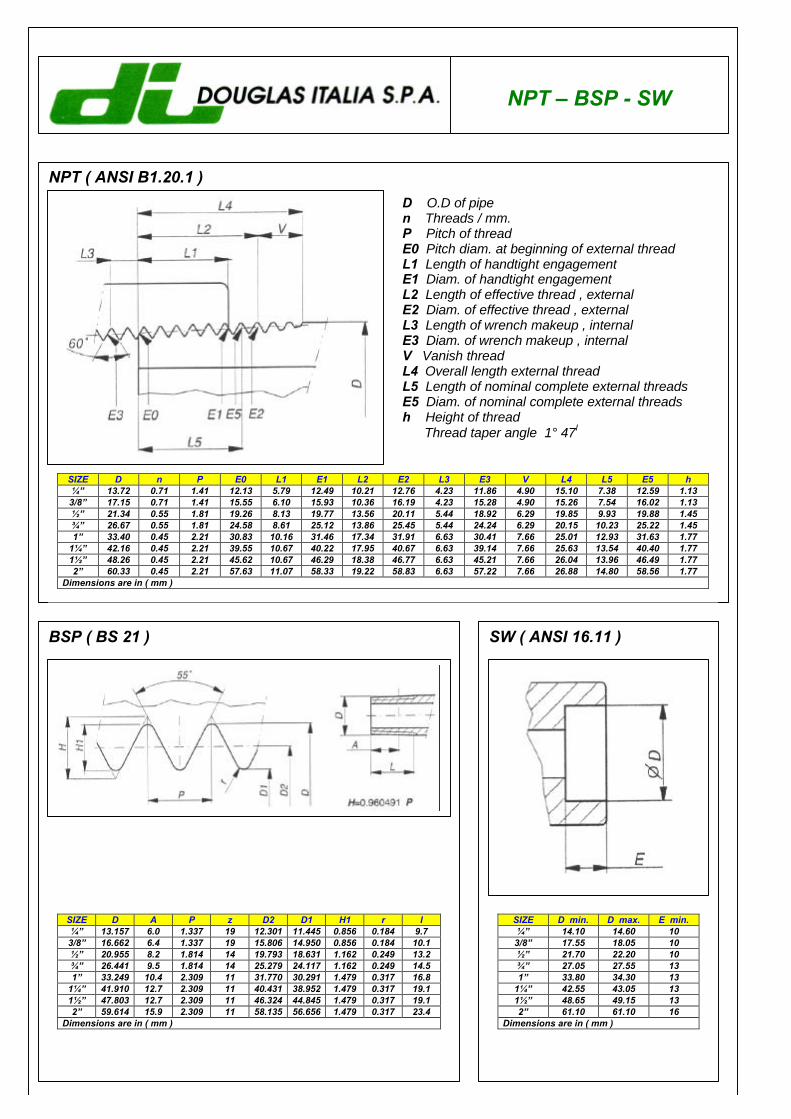
NPT – BSP - SW
NPT ( ANSI B1.20.1 )D O.D of pipen Threads / mm.P Pitch of threadE0 Pitch diam. at beginning of external threadL1 Length of handtight engagementE1 Diam. of handtight engagementL2 Length of effective thread , externalE2 Diam. of effective thread , externalL3 Length of wrench makeup , internalE3 Diam. of wrench makeup , internalV Vanish threadL4 Overall length external threadL5 Length of nominal complete external threadsE5 Diam. of nominal complete external threadsh Height of thread Thread taper angle 1° 47I
SIZE D n P E0 L1 E1 L2 E2 L3 E3 V L4 L5 E5 h1⁄4” 13.72 0.71 1.41 12.13 5.79 12.49 10.21 12.76 4.23 11.86 4.90 15.10 7.38 12.59 1.133/8” 17.15 0.71 1.41 15.55 6.10 15.93 10.36 16.19 4.23 15.28 4.90 15.26 7.54 16.02 1.131⁄2” 21.34 0.55 1.81 19.26 8.13 19.77 13.56 20.11 5.44 18.92 6.29 19.85 9.93 19.88 1.453⁄4” 26.67 0.55 1.81 24.58 8.61 25.12 13.86 25.45 5.44 24.24 6.29 20.15 10.23 25.22 1.451” 33.40 0.45 2.21 30.83 10.16 31.46 17.34 31.91 6.63 30.41 7.66 25.01 12.93 31.63 1.77
11⁄4” 42.16 0.45 2.21 39.55 10.67 40.22 17.95 40.67 6.63 39.14 7.66 25.63 13.54 40.40 1.7711⁄2” 48.26 0.45 2.21 45.62 10.67 46.29 18.38 46.77 6.63 45.21 7.66 26.04 13.96 46.49 1.772” 60.33 0.45 2.21 57.63 11.07 58.33 19.22 58.83 6.63 57.22 7.66 26.88 14.80 58.56 1.77
Dimensions are in ( mm )
BSP ( BS 21 ) SW ( ANSI 16.11 )
SIZE D A P z D2 D1 H1 r l1⁄4” 13.157 6.0 1.337 19 12.301 11.445 0.856 0.184 9.73/8” 16.662 6.4 1.337 19 15.806 14.950 0.856 0.184 10.11⁄2” 20.955 8.2 1.814 14 19.793 18.631 1.162 0.249 13.23⁄4” 26.441 9.5 1.814 14 25.279 24.117 1.162 0.249 14.51” 33.249 10.4 2.309 11 31.770 30.291 1.479 0.317 16.8
11⁄4” 41.910 12.7 2.309 11 40.431 38.952 1.479 0.317 19.111⁄2” 47.803 12.7 2.309 11 46.324 44.845 1.479 0.317 19.12” 59.614 15.9 2.309 11 58.135 56.656 1.479 0.317 23.4
Dimensions are in ( mm )
SIZE D min. D max. E min.1⁄4” 14.10 14.60 103/8” 17.55 18.05 101⁄2” 21.70 22.20 103⁄4” 27.05 27.55 131” 33.80 34.30 13
11⁄4” 42.55 43.05 1311⁄2” 48.65 49.15 132” 61.10 61.10 16
Dimensions are in ( mm )
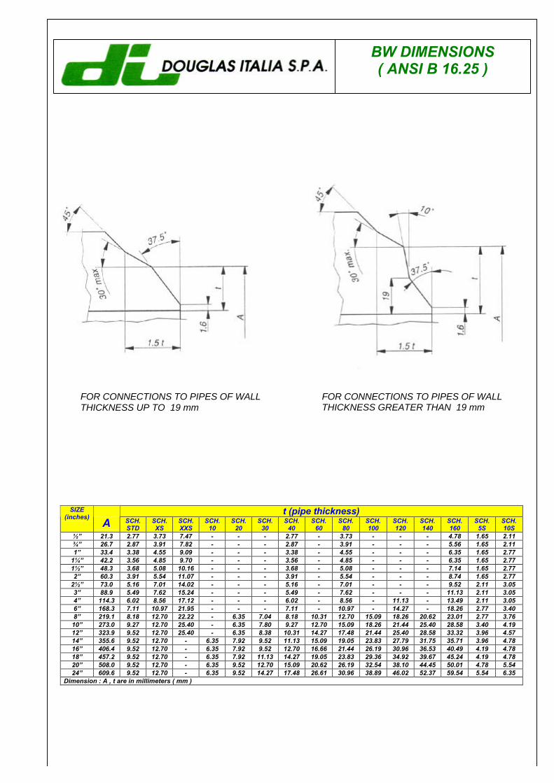
BW DIMENSIONS( ANSI B 16.25 )
FOR CONNECTIONS TO PIPES OF WALLTHICKNESS UP TO 19 mm
FOR CONNECTIONS TO PIPES OF WALLTHICKNESS GREATER THAN 19 mm
t (pipe thickness)SIZE(inches) A SCH.
STDSCH.XS
SCH.XXS
SCH.10
SCH.20
SCH.30
SCH.40
SCH.60
SCH.80
SCH.100
SCH.120
SCH.140
SCH.160
SCH.5S
SCH.10S
1⁄2” 21.3 2.77 3.73 7.47 - - - 2.77 - 3.73 - - - 4.78 1.65 2.113⁄4” 26.7 2.87 3.91 7.82 - - - 2.87 - 3.91 - - - 5.56 1.65 2.111” 33.4 3.38 4.55 9.09 - - - 3.38 - 4.55 - - - 6.35 1.65 2.77
11⁄4” 42.2 3.56 4.85 9.70 - - - 3.56 - 4.85 - - - 6.35 1.65 2.7711⁄2” 48.3 3.68 5.08 10.16 - - - 3.68 - 5.08 - - - 7.14 1.65 2.772” 60.3 3.91 5.54 11.07 - - - 3.91 - 5.54 - - - 8.74 1.65 2.77
21⁄2” 73.0 5.16 7.01 14.02 - - - 5.16 - 7.01 - - - 9.52 2.11 3.053” 88.9 5.49 7.62 15.24 - - - 5.49 - 7.62 - - - 11.13 2.11 3.054” 114.3 6.02 8.56 17.12 - - - 6.02 - 8.56 - 11.13 - 13.49 2.11 3.056” 168.3 7.11 10.97 21.95 - - - 7.11 - 10.97 - 14.27 - 18.26 2.77 3.408” 219.1 8.18 12.70 22.22 - 6.35 7.04 8.18 10.31 12.70 15.09 18.26 20.62 23.01 2.77 3.7610” 273.0 9.27 12.70 25.40 - 6.35 7.80 9.27 12.70 15.09 18.26 21.44 25.40 28.58 3.40 4.1912” 323.9 9.52 12.70 25.40 - 6.35 8.38 10.31 14.27 17.48 21.44 25.40 28.58 33.32 3.96 4.5714” 355.6 9.52 12.70 - 6.35 7.92 9.52 11.13 15.09 19.05 23.83 27.79 31.75 35.71 3.96 4.7816” 406.4 9.52 12.70 - 6.35 7.92 9.52 12.70 16.66 21.44 26.19 30.96 36.53 40.49 4.19 4.7818” 457.2 9.52 12.70 - 6.35 7.92 11.13 14.27 19.05 23.83 29.36 34.92 39.67 45.24 4.19 4.7820” 508.0 9.52 12.70 - 6.35 9.52 12.70 15.09 20.62 26.19 32.54 38.10 44.45 50.01 4.78 5.5424” 609.6 9.52 12.70 - 6.35 9.52 14.27 17.48 26.61 30.96 38.89 46.02 52.37 59.54 5.54 6.35
Dimension : A , t are in millimeters ( mm )
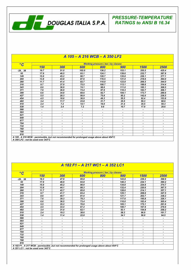
PRESSURE-TEMPERATURERATINGS to ANSI B 16.34
A 105 – A 216 WCB – A 350 LF2
Working pressure ( bar ) by classes°C 150 300 600 800 900 1500 2500-29 ÷÷ 38 19.7 51.0 102.0 136.2 153.1 255.5 425.4
93 17.9 46.5 93.1 124.1 139.6 232.7 387.8149 15.9 45.2 90.7 120.7 135.8 226.1 377.1204 13.8 43.8 87.6 116.5 131.0 218.6 364.0260 11.7 41.4 82.7 110.0 123.8 206.5 344.0316 9.7 37.9 75.5 100.7 113.1 188.6 314.4343 8.6 36.9 74.1 98.6 111.0 185.1 308.5371 7.6 36.9 73.4 97.9 110.3 183.7 306.1399 6.6 34.8 69.6 92.7 104.1 173.7 289.6427 5.5 28.3 56.9 75.8 85.2 142.0 236.5454 4.5 18.6 36.9 49.3 55.5 92.4 153.8482 3.4 11.7 23.8 31.7 35.5 59.3 98.6510 2.4 7.2 14.1 19.0 21.4 35.5 59.3538 1.4 3.4 7.2 9.6 10.7 17.9 29.6566 - - - - - - -593 - - - - - - -621 - - - - - - -649 - - - - - - -677 - - - - - - -704 - - - - - - -732 - - - - - - -760 - - - - - - -788 - - - - - - -816 - - - - - - -
A 105 , A 216 WCB : permissible ,but not recommended for prolonged usage above about 454°CA 350 LF2 : not be used over 343°C
A 182 F1 – A 217 WC1 – A 352 LC1
Working pressure ( bar ) by classes°C 150 300 600 800 900 1500 2500-29 ÷÷ 38 18.3 47.9 95.8 - 143.8 239.2 398.9
93 17.9 46.9 93.8 - 140.3 234.1 390.2149 15.9 45.2 90.0 - 134.8 224.8 374.7204 13.8 44.1 88.3 - 132.4 220.6 367.5260 11.7 42.7 85.8 - 128.6 214.1 357.1316 9.7 41.7 83.4 - 125.1 208.6 347.5343 8.6 40.7 81.0 - 121.7 202.7 338.2371 7.6 39.3 78.3 - 117.6 195.8 326.1399 6.6 36.5 73.4 - 110.0 183.4 305.4427 5.5 35.2 70.0 - 105.1 175.1 291.6454 4.5 33.4 67.2 - 100.7 167.9 279.9482 3.4 31.0 62.1 - 93.1 154.8 258.2510 2.4 19.3 38.6 - 58.3 96.9 161.7538 1.4 11.4 22.8 - 34.1 56.9 94.5566 - - - - - - -593 - - - - - - -621 - - - - - - -649 - - - - - - -677 - - - - - - -704 - - - - - - -732 - - - - - - -760 - - - - - - -788 - - - - - - -816 - - - - - - -
A 182 F1 , A 217 WCB : permissible ,but not recommended for prolonged usage above about 454°CA 351 LC1 : not be used over 343°C
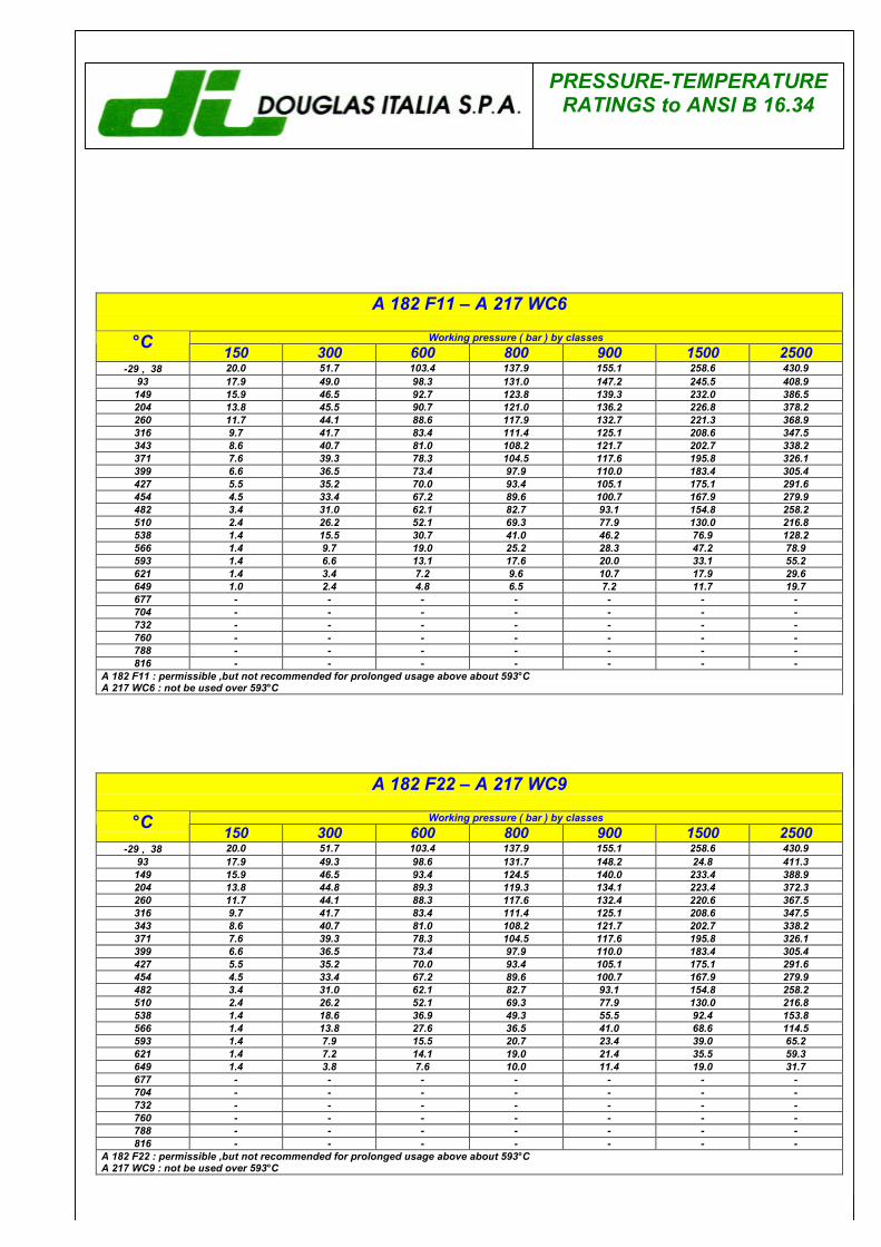
PRESSURE-TEMPERATURERATINGS to ANSI B 16.34
A 182 F11 – A 217 WC6
Working pressure ( bar ) by classes°C 150 300 600 800 900 1500 2500-29 ÷÷ 38 20.0 51.7 103.4 137.9 155.1 258.6 430.9
93 17.9 49.0 98.3 131.0 147.2 245.5 408.9149 15.9 46.5 92.7 123.8 139.3 232.0 386.5204 13.8 45.5 90.7 121.0 136.2 226.8 378.2260 11.7 44.1 88.6 117.9 132.7 221.3 368.9316 9.7 41.7 83.4 111.4 125.1 208.6 347.5343 8.6 40.7 81.0 108.2 121.7 202.7 338.2371 7.6 39.3 78.3 104.5 117.6 195.8 326.1399 6.6 36.5 73.4 97.9 110.0 183.4 305.4427 5.5 35.2 70.0 93.4 105.1 175.1 291.6454 4.5 33.4 67.2 89.6 100.7 167.9 279.9482 3.4 31.0 62.1 82.7 93.1 154.8 258.2510 2.4 26.2 52.1 69.3 77.9 130.0 216.8538 1.4 15.5 30.7 41.0 46.2 76.9 128.2566 1.4 9.7 19.0 25.2 28.3 47.2 78.9593 1.4 6.6 13.1 17.6 20.0 33.1 55.2621 1.4 3.4 7.2 9.6 10.7 17.9 29.6649 1.0 2.4 4.8 6.5 7.2 11.7 19.7677 - - - - - - -704 - - - - - - -732 - - - - - - -760 - - - - - - -788 - - - - - - -816 - - - - - - -
A 182 F11 : permissible ,but not recommended for prolonged usage above about 593°CA 217 WC6 : not be used over 593°C
A 182 F22 – A 217 WC9
Working pressure ( bar ) by classes°C 150 300 600 800 900 1500 2500-29 ÷÷ 38 20.0 51.7 103.4 137.9 155.1 258.6 430.9
93 17.9 49.3 98.6 131.7 148.2 24.8 411.3149 15.9 46.5 93.4 124.5 140.0 233.4 388.9204 13.8 44.8 89.3 119.3 134.1 223.4 372.3260 11.7 44.1 88.3 117.6 132.4 220.6 367.5316 9.7 41.7 83.4 111.4 125.1 208.6 347.5343 8.6 40.7 81.0 108.2 121.7 202.7 338.2371 7.6 39.3 78.3 104.5 117.6 195.8 326.1399 6.6 36.5 73.4 97.9 110.0 183.4 305.4427 5.5 35.2 70.0 93.4 105.1 175.1 291.6454 4.5 33.4 67.2 89.6 100.7 167.9 279.9482 3.4 31.0 62.1 82.7 93.1 154.8 258.2510 2.4 26.2 52.1 69.3 77.9 130.0 216.8538 1.4 18.6 36.9 49.3 55.5 92.4 153.8566 1.4 13.8 27.6 36.5 41.0 68.6 114.5593 1.4 7.9 15.5 20.7 23.4 39.0 65.2621 1.4 7.2 14.1 19.0 21.4 35.5 59.3649 1.4 3.8 7.6 10.0 11.4 19.0 31.7677 - - - - - - -704 - - - - - - -732 - - - - - - -760 - - - - - - -788 - - - - - - -816 - - - - - - -
A 182 F22 : permissible ,but not recommended for prolonged usage above about 593°CA 217 WC9 : not be used over 593°C
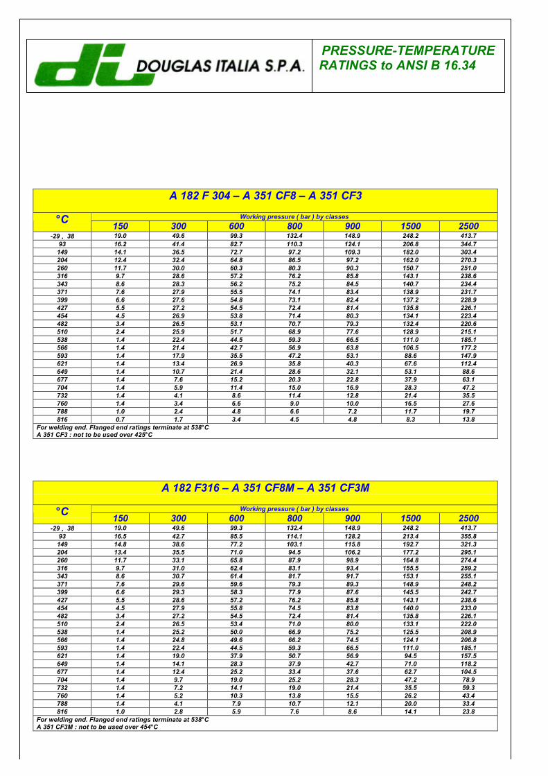
PRESSURE-TEMPERATURERATINGS to ANSI B 16.34
A 182 F 304 – A 351 CF8 – A 351 CF3
Working pressure ( bar ) by classes°C 150 300 600 800 900 1500 2500-29 ÷÷ 38 19.0 49.6 99.3 132.4 148.9 248.2 413.7
93 16.2 41.4 82.7 110.3 124.1 206.8 344.7149 14.1 36.5 72.7 97.2 109.3 182.0 303.4204 12.4 32.4 64.8 86.5 97.2 162.0 270.3260 11.7 30.0 60.3 80.3 90.3 150.7 251.0316 9.7 28.6 57.2 76.2 85.8 143.1 238.6343 8.6 28.3 56.2 75.2 84.5 140.7 234.4371 7.6 27.9 55.5 74.1 83.4 138.9 231.7399 6.6 27.6 54.8 73.1 82.4 137.2 228.9427 5.5 27.2 54.5 72.4 81.4 135.8 226.1454 4.5 26.9 53.8 71.4 80.3 134.1 223.4482 3.4 26.5 53.1 70.7 79.3 132.4 220.6510 2.4 25.9 51.7 68.9 77.6 128.9 215.1538 1.4 22.4 44.5 59.3 66.5 111.0 185.1566 1.4 21.4 42.7 56.9 63.8 106.5 177.2593 1.4 17.9 35.5 47.2 53.1 88.6 147.9621 1.4 13.4 26.9 35.8 40.3 67.6 112.4649 1.4 10.7 21.4 28.6 32.1 53.1 88.6677 1.4 7.6 15.2 20.3 22.8 37.9 63.1704 1.4 5.9 11.4 15.0 16.9 28.3 47.2732 1.4 4.1 8.6 11.4 12.8 21.4 35.5760 1.4 3.4 6.6 9.0 10.0 16.5 27.6788 1.0 2.4 4.8 6.6 7.2 11.7 19.7816 0.7 1.7 3.4 4.5 4.8 8.3 13.8
For welding end. Flanged end ratings terminate at 538°CA 351 CF3 : not to be used over 425°C
A 182 F316 – A 351 CF8M – A 351 CF3M
Working pressure ( bar ) by classes°C 150 300 600 800 900 1500 2500-29 ÷÷ 38 19.0 49.6 99.3 132.4 148.9 248.2 413.7
93 16.5 42.7 85.5 114.1 128.2 213.4 355.8149 14.8 38.6 77.2 103.1 115.8 192.7 321.3204 13.4 35.5 71.0 94.5 106.2 177.2 295.1260 11.7 33.1 65.8 87.9 98.9 164.8 274.4316 9.7 31.0 62.4 83.1 93.4 155.5 259.2343 8.6 30.7 61.4 81.7 91.7 153.1 255.1371 7.6 29.6 59.6 79.3 89.3 148.9 248.2399 6.6 29.3 58.3 77.9 87.6 145.5 242.7427 5.5 28.6 57.2 76.2 85.8 143.1 238.6454 4.5 27.9 55.8 74.5 83.8 140.0 233.0482 3.4 27.2 54.5 72.4 81.4 135.8 226.1510 2.4 26.5 53.4 71.0 80.0 133.1 222.0538 1.4 25.2 50.0 66.9 75.2 125.5 208.9566 1.4 24.8 49.6 66.2 74.5 124.1 206.8593 1.4 22.4 44.5 59.3 66.5 111.0 185.1621 1.4 19.0 37.9 50.7 56.9 94.5 157.5649 1.4 14.1 28.3 37.9 42.7 71.0 118.2677 1.4 12.4 25.2 33.4 37.6 62.7 104.5704 1.4 9.7 19.0 25.2 28.3 47.2 78.9732 1.4 7.2 14.1 19.0 21.4 35.5 59.3760 1.4 5.2 10.3 13.8 15.5 26.2 43.4788 1.4 4.1 7.9 10.7 12.1 20.0 33.4816 1.0 2.8 5.9 7.6 8.6 14.1 23.8
For welding end. Flanged end ratings terminate at 538°CA 351 CF3M : not to be used over 454°C
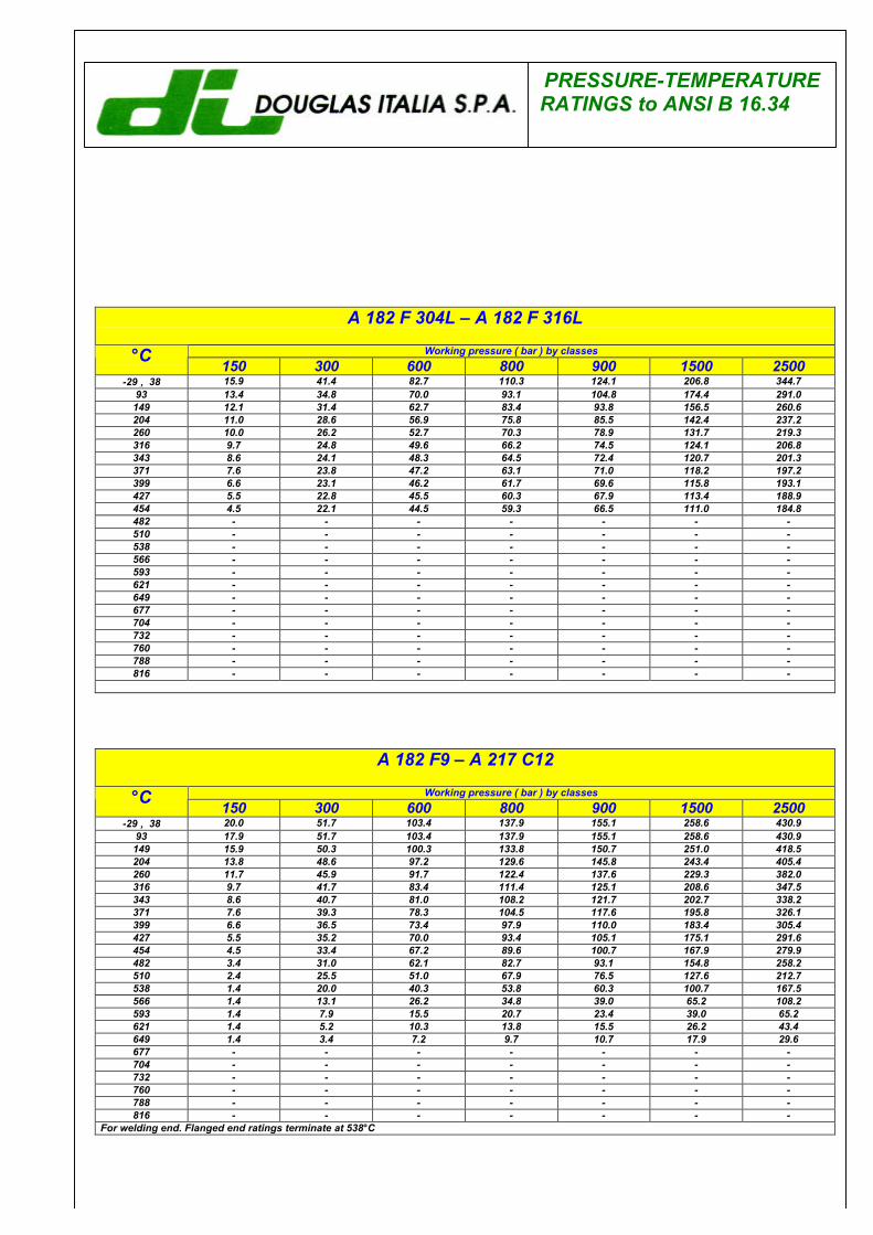
PRESSURE-TEMPERATURERATINGS to ANSI B 16.34
A 182 F 304L – A 182 F 316LWorking pressure ( bar ) by classes°C 150 300 600 800 900 1500 2500
-29 ÷÷ 38 15.9 41.4 82.7 110.3 124.1 206.8 344.793 13.4 34.8 70.0 93.1 104.8 174.4 291.0149 12.1 31.4 62.7 83.4 93.8 156.5 260.6204 11.0 28.6 56.9 75.8 85.5 142.4 237.2260 10.0 26.2 52.7 70.3 78.9 131.7 219.3316 9.7 24.8 49.6 66.2 74.5 124.1 206.8343 8.6 24.1 48.3 64.5 72.4 120.7 201.3371 7.6 23.8 47.2 63.1 71.0 118.2 197.2399 6.6 23.1 46.2 61.7 69.6 115.8 193.1427 5.5 22.8 45.5 60.3 67.9 113.4 188.9454 4.5 22.1 44.5 59.3 66.5 111.0 184.8482 - - - - - - -510 - - - - - - -538 - - - - - - -566 - - - - - - -593 - - - - - - -621 - - - - - - -649 - - - - - - -677 - - - - - - -704 - - - - - - -732 - - - - - - -760 - - - - - - -788 - - - - - - -816 - - - - - - -
A 182 F9 – A 217 C12Working pressure ( bar ) by classes°C 150 300 600 800 900 1500 2500
-29 ÷÷ 38 20.0 51.7 103.4 137.9 155.1 258.6 430.993 17.9 51.7 103.4 137.9 155.1 258.6 430.9149 15.9 50.3 100.3 133.8 150.7 251.0 418.5204 13.8 48.6 97.2 129.6 145.8 243.4 405.4260 11.7 45.9 91.7 122.4 137.6 229.3 382.0316 9.7 41.7 83.4 111.4 125.1 208.6 347.5343 8.6 40.7 81.0 108.2 121.7 202.7 338.2371 7.6 39.3 78.3 104.5 117.6 195.8 326.1399 6.6 36.5 73.4 97.9 110.0 183.4 305.4427 5.5 35.2 70.0 93.4 105.1 175.1 291.6454 4.5 33.4 67.2 89.6 100.7 167.9 279.9482 3.4 31.0 62.1 82.7 93.1 154.8 258.2510 2.4 25.5 51.0 67.9 76.5 127.6 212.7538 1.4 20.0 40.3 53.8 60.3 100.7 167.5566 1.4 13.1 26.2 34.8 39.0 65.2 108.2593 1.4 7.9 15.5 20.7 23.4 39.0 65.2621 1.4 5.2 10.3 13.8 15.5 26.2 43.4649 1.4 3.4 7.2 9.7 10.7 17.9 29.6677 - - - - - - -704 - - - - - - -732 - - - - - - -760 - - - - - - -788 - - - - - - -816 - - - - - - -
For welding end. Flanged end ratings terminate at 538°C
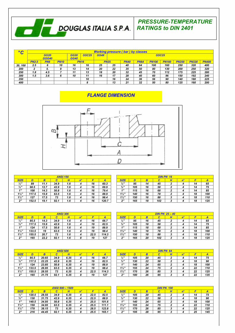
PRESSURE-TEMPERATURERATINGS to DIN 2401
Working pressure ( bar ) by classesGG20
GGG40GG20GG40
GSC25 GG40 GSC25°C
PN2.5 PN6 PN10 PN16 PN25 PN40 PN64 PN100 PN160 PN250 PN320 PN40020÷÷100 2.5 6 10 16 16 25 25 40 64 100 160 250 320 400
200 2 5. 8 13 14 20 22 35 50 80 130 200 250 320250 1.8 4.5 7 11 13 18 20 32 45 70 112 175 225 280300 1.5 3.6 6 10 11 16 17 28 40 60 96 150 192 240350 10 16 24 36 56 90 140 180 225400 8 13 21 32 50 80 125 160 200
FLANGE DIMENSION
ANSI 150SIZE D B C H n° F A1⁄2” 89 11.1 34.9 1.6 4 16 60.33⁄4” 98.5 12.7 42.9 1.6 4 16 69.91” 108 14.3 50.8 1.6 4 16 79.4
11⁄4” 117.5 15.9 63.5 1.6 4 16 88.911⁄2” 127 17.5 73 1.6 4 16 98.42” 152.5 19.1 92.1 1.6 4 16 120.7
DIN PN 16SIZE D B C H n° F A1⁄2” 95 14 45 2 4 14 653⁄4” 105 16 58 2 4 14 751” 115 16 68 2 4 14 85
11⁄4” 140 16 78 2 4 18 10011⁄2” 150 16 88 3 4 18 1102” 165 18 102 3 4 18 125
ANSI 300SIZE D B C H n° F A1⁄2” 95.5 14.3 34.9 1.6 4 16 66.73⁄4” 117.5 15.9 42.9 1.6 4 19 82.51” 124 17.5 50.8 1.6 4 19 88.9
11⁄4” 133.5 19 63.5 1.6 4 19 98.411⁄2” 155.5 20.7 73 1.6 4 22.5 114.32” 165 22.2 92.1 1.6 8 19 127
ANSI 600SIZE D B C H n° F A1⁄2” 95.5 20.65 34.9 6.35 4 16 66.73⁄4” 117.5 22.25 42.9 6.35 4 19 82.51” 124 23.85 50.8 6.35 4 19 88.9
11⁄4” 133.5 26.95 63.5 6.35 4 19 98.411⁄2” 155.5 28.55 73 6.35 4 22.5 114.32” 165 31.75 92.1 6.35 8 19 127
ANSI 900 – 1500SIZE D B C H n° F A1⁄2” 120.5 28.55 34.9 6.35 4 22.5 82.53⁄4” 130 31.75 42.9 6.35 4 22.5 88.91” 149.5 34.95 50.8 6.35 4 25.5 101.6
11⁄4” 159 34.95 63.5 6.35 4 25.5 111.111⁄2” 178 38.15 73 6.35 4 28.5 123.82” 216 44.45 92.1 6.35 8 25.5 165.1
DIN PN 25 – 40SIZE D B C H n° F A1⁄2” 95 16 45 2 4 14 653⁄4” 105 18 58 2 4 14 751” 115 18 68 2 4 14 85
11⁄4” 140 18 78 2 4 18 10011⁄2” 150 18 88 3 4 18 1102” 165 20 102 3 4 18 125
DIN PN 64SIZE D B C H n° F A1⁄2” 105 20 45 2 4 14 753⁄4” 130 22 58 2 4 18 901” 140 24 65 2 4 18 100
11⁄4” 155 24 75 2 4 22 11011⁄2” 170 26 85 3 4 22 1252” 180 26 95 3 4 22 135
DIN PN 100SIZE D B C H n° F A1⁄2” 105 20 45 2 4 14 753⁄4” 130 22 58 2 4 18 901” 140 24 65 2 4 18 100
11⁄4” 155 24 75 2 4 22 11011⁄2” 170 26 85 3 4 22 1252” 195 28 95 3 4 25 145
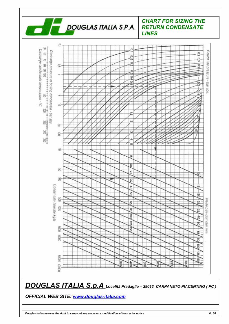
CHART FOR SIZING THERETURN CONDENSATELINES
Douglas Italia reserves the right to carry-out any necessary modification without prior notice 6 . 00
DOUGLAS ITALIA S.p.A Località Pradaglie – 29013 CARPANETO PIACENTINO ( PC )
OFFICIAL WEB SITE: www.douglas-italia.com