Jean Christophe Novelli Jérôme Cogné Teas and tipples Lady ...
Upload
khangminh22Category
view
0download
0
TEAS Working Group T. SaadInternet-Draft V. BeeramIntended status: Standards Track Juniper NetworksExpires: April 25, 2022 B. Wen Comcast D. Ceccarelli J. Halpern Ericsson S. Peng R. Chen ZTE Corporation X. Liu Volta Networks L. Contreras Telefonica R. Rokui Nokia October 22, 2021
Realizing Network Slices in IP/MPLS Networks draft-bestbar-teas-ns-packet-04
Abstract
Network slicing provides the ability to partition a physical network into multiple logical networks of varying sizes, structures, and functions so that each slice can be dedicated to specific services or customers. Network slices need to operate in parallel while providing slice elasticity in terms of network resource allocation. The Differentiated Service (Diffserv) model allows for carrying multiple services on top of a single physical network by relying on compliant nodes to apply specific forwarding treatment (scheduling and drop policy) on to packets that carry the respective Diffserv code point. This document adopts the Diffserv principles and proposes a scalable approach to realize network slicing in IP/MPLS networks. The solution does not mandate Diffserv to be enabled in the network to provide a specific forwarding treatment, but can co- exist with and complement it when enabled.
Status of This Memo
This Internet-Draft is submitted in full conformance with the provisions of BCP 78 and BCP 79.
Internet-Drafts are working documents of the Internet Engineering Task Force (IETF). Note that other groups may also distribute
Saad, et al. Expires April 25, 2022 [Page 1]
Internet-Draft IP/MPLS Network Slicing October 2021
working documents as Internet-Drafts. The list of current Internet- Drafts is at https://datatracker.ietf.org/drafts/current/.
Internet-Drafts are draft documents valid for a maximum of six months and may be updated, replaced, or obsoleted by other documents at any time. It is inappropriate to use Internet-Drafts as reference material or to cite them other than as "work in progress."
This Internet-Draft will expire on April 25, 2022.
Copyright Notice
Copyright (c) 2021 IETF Trust and the persons identified as the document authors. All rights reserved.
This document is subject to BCP 78 and the IETF Trust’s Legal Provisions Relating to IETF Documents (https://trustee.ietf.org/license-info) in effect on the date of publication of this document. Please review these documents carefully, as they describe your rights and restrictions with respect to this document. Code Components extracted from this document must include Simplified BSD License text as described in Section 4.e of the Trust Legal Provisions and are provided without warranty as described in the Simplified BSD License.
Table of Contents
1. Introduction . . . . . . . . . . . . . . . . . . . . . . . . 3 1.1. Terminology . . . . . . . . . . . . . . . . . . . . . . . 5 1.2. Acronyms and Abbreviations . . . . . . . . . . . . . . . 6 2. Network Resource Slicing Membership . . . . . . . . . . . . . 7 3. IETF Network Slice Realization . . . . . . . . . . . . . . . 7 3.1. Network Topology Filters . . . . . . . . . . . . . . . . 9 3.2. IETF Network Slice Service Request . . . . . . . . . . . 9 3.3. Slice Aggregation Mapping . . . . . . . . . . . . . . . . 9 3.4. Path Placement over Slice Aggregate Topology . . . . . . 10 3.5. Slice Policy Installation . . . . . . . . . . . . . . . . 10 3.6. Path Instantiation . . . . . . . . . . . . . . . . . . . 10 3.7. Service Mapping . . . . . . . . . . . . . . . . . . . . . 10 3.8. Network Slice Aggregate Relationships . . . . . . . . . . 11 4. Slice Policy Modes . . . . . . . . . . . . . . . . . . . . . 11 4.1. Data plane Slice Policy Mode . . . . . . . . . . . . . . 12 4.2. Control Plane Slice Policy Mode . . . . . . . . . . . . . 12 4.3. Data and Control Plane Slice Policy Mode . . . . . . . . 14 5. Slice Policy Instantiation . . . . . . . . . . . . . . . . . 15 5.1. Slice Policy Definition . . . . . . . . . . . . . . . . . 15 5.1.1. Slice Policy Data Plane Selector . . . . . . . . . . 16 5.1.2. Slice Policy Resource Reservation . . . . . . . . . . 19
Saad, et al. Expires April 25, 2022 [Page 2]
Internet-Draft IP/MPLS Network Slicing October 2021
5.1.3. Slice Policy Per Hop Behavior . . . . . . . . . . . . 20 5.1.4. Slice Policy Topology . . . . . . . . . . . . . . . . 21 5.2. Slice Policy Boundary . . . . . . . . . . . . . . . . . . 21 5.2.1. Slice Policy Edge Nodes . . . . . . . . . . . . . . . 21 5.2.2. Slice Policy Interior Nodes . . . . . . . . . . . . . 22 5.2.3. Slice Policy Incapable Nodes . . . . . . . . . . . . 22 5.2.4. Combining Slice Policy Modes . . . . . . . . . . . . 23 5.3. Mapping Traffic on Slice Aggregates . . . . . . . . . . . 24 6. Path Selection and Instantiation . . . . . . . . . . . . . . 24 6.1. Applicability of Path Selection to Slice Aggregates . . . 24 6.2. Applicability of Path Control Technologies to Slice Aggregates . . . . . . . . . . . . . . . . . . . . . . . 25 6.3. RSVP-TE Based Slice Aggregate Paths . . . . . . . . . . . 25 6.4. SR Based Slice Aggregate Paths . . . . . . . . . . . . . 25 7. Slice Policy Protocol Extensions . . . . . . . . . . . . . . 26 8. IANA Considerations . . . . . . . . . . . . . . . . . . . . . 27 9. Security Considerations . . . . . . . . . . . . . . . . . . . 27 10. Acknowledgement . . . . . . . . . . . . . . . . . . . . . . . 27 11. Contributors . . . . . . . . . . . . . . . . . . . . . . . . 27 12. References . . . . . . . . . . . . . . . . . . . . . . . . . 28 12.1. Normative References . . . . . . . . . . . . . . . . . . 28 12.2. Informative References . . . . . . . . . . . . . . . . . 30 Authors’ Addresses . . . . . . . . . . . . . . . . . . . . . . . 31
1. Introduction
Network slicing allows a Service Provider to create independent and logical networks on top of a common or shared physical network infrastructure. Such network slices can be offered to customers or used internally by the Service Provider to facilitate or enhance their service offerings. A Service Provider can also use network slicing to structure and organize the elements of its infrastructure. This document provides a path control technology agnostic solution that a Service Provider can deploy to realize network slicing in IP/ MPLS networks.
[I-D.ietf-teas-ietf-network-slices] specifies the definition of a network slice for use within the IETF and discusses the general framework for requesting and operating IETF Network Slices, their characteristics, and the necessary system components and interfaces. It also discusses the function of an IETF Network Slice Controller and the requirements on its northbound and southbound interfaces.
This document introduces the notion of a slice aggregate which comprises of one of more IETF network slice traffic streams. It also describes the slice policy that is used to instantiate control and data plane behaviors on select topological elements associated with
Saad, et al. Expires April 25, 2022 [Page 3]

Internet-Draft IP/MPLS Network Slicing October 2021
the Network Resource Partition that supports a slice aggregate - refer Section 5.1 for further details.
The IETF Network Slice Controller is responsible for the aggregation of multiple IETF network traffic streams into a slice aggregate, and for maintaining the mapping required between them. The mechanisms used by the controller to determine the mapping of one or more IETF network slice to a slice aggregate are outside the scope of this document. The focus of this document is on the mechanisms required at the device level to address the requirements of network slicing in packet networks.
In a Differentiated Service (Diffserv) domain [RFC2475], packets requiring the same forwarding treatment (scheduling and drop policy) are classified and marked with a Class Selector (CS) at domain ingress nodes. At transit nodes, the CS field inside the packet is inspected to determine the specific forwarding treatment to be applied before the packet is forwarded further. Similar principles are adopted by this document to realize network slicing. The solution proposed in this document does not mandate Diffserv to be enabled in the network to provide a specific forwarding treatment.
When logical networks associated with a Network Resource Partition are realized on top of a shared physical network infrastructure, it is important to steer traffic on the specific network resources partition that is allocated for the slice aggregate. In packet networks, the packets of a specific slice aggregate MAY be identified by one or more specific fields carried within the packet. A slice policy on an ingress boundary node populates the respective field(s) in packets that are mapped to a slice aggregate in order to allow interior slice policy nodes to identify and apply the specific Per Hop Behavior (PHB) associated with the slice aggregate. The PHB defines the scheduling treatment and, in some cases, the packet drop probability.
If Diffserv is enabled within the network, the slice aggregate traffic can further carry a Diffserv CS to enable differentiation of forwarding treatments for packets within the same slice aggregate.
For example, when using MPLS as a dataplane, it is possible to identify packets belonging to the same slice aggregate by carrying an identifier in an MPLS Label Stack Entry (LSE). Additional Diffserv classification may be indicated in the Traffic Class (TC) bits of the global MPLS label to allow further differentiation of forwarding treatments for traffic traversing the same Network Resource Partition.
Saad, et al. Expires April 25, 2022 [Page 4]
Internet-Draft IP/MPLS Network Slicing October 2021
This document covers different modes of slice policy and discusses how each slice policy mode can ensure proper placement of slice aggregate paths and respective treatment of slice aggregate traffic.
1.1. Terminology
The reader is expected to be familiar with the terminology specified in [I-D.ietf-teas-ietf-network-slices].
The following terminology is used in the document:
IETF Network Slice: a well-defined composite of a set of endpoints, the connectivity requirements between subsets of these endpoints, and associated requirements; the term ’network slice’ in this document refers to ’IETF network slice’ as defined in [I-D.ietf-teas-ietf-network-slices].
IETF Network Slice Controller (NSC): controller that is used to realize an IETF network slice [I-D.ietf-teas-ietf-network-slices].
Slice Policy: a policy construct that enables instantiation of mechanisms in support of IETF network slice specific control and data plane behaviors on select topological elements; the enforcement of a slice policy results in the creation of a Network Resource Partition.
Slice Aggregate: a collection of packets that match a slice policy selection criteria and are given the same forwarding treatment; a slice aggregate comprises of one or more IETF network slice traffic streams; the mapping of one or more IETF network slices to a slice aggregate is maintained by the IETF Network Slice Controller.
Network Resource Partition: the collection of resources that are used to support a slice aggregate.
Slice Policy Capable Node: a node that supports one of the slice policy modes described in this document.
Slice Policy Incapable Node: a node that does not support any of the slice policy modes described in this document.
Saad, et al. Expires April 25, 2022 [Page 5]
Internet-Draft IP/MPLS Network Slicing October 2021
Slice Aggregate Path: a path that is setup over the Network Resource Partition that is associated with a specific slice aggregate.
Slice Aggregate Packet: a packet that traverses over the Network Resource Partition that is associated with a specific slice aggregate.
Slice Policy Topology: a set of topological elements associated with a slice policy.
Slice Aggregate Aware TE: a mechanism for TE path selection that takes into account the available network resources associated with a specific slice aggregate.
The key words "MUST", "MUST NOT", "REQUIRED", "SHALL", "SHALL NOT", "SHOULD", "SHOULD NOT", "RECOMMENDED", "NOT RECOMMENDED", "MAY", and "OPTIONAL" in this document are to be interpreted as described in BCP 14 [RFC2119] [RFC8174] when, and only when, they appear in all capitals, as shown here.
1.2. Acronyms and Abbreviations
BA: Behavior Aggregate
CS: Class Selector
SS: Slice Selector
S-PHB: Slice policy Per Hop Behavior as described in Section 5.1.3
SSL: Slice Selector Label as described in Section 5.1.1
SSLI: Slice Selector Label Indicator
SLA: Service Level Agreement
SLO: Service Level Objective
Diffserv: Differentiated Services
MPLS: Multiprotocol Label Switching
LSP: Label Switched Path
RSVP: Resource Reservation Protocol
Saad, et al. Expires April 25, 2022 [Page 6]
Internet-Draft IP/MPLS Network Slicing October 2021
TE: Traffic Engineering
SR: Segment Routing
VRF: VPN Routing and Forwarding
AC: Attachment Circuit
CE: Customer Edge
PE: Provider Edge
2. Network Resource Slicing Membership
A Network Resource Partition that supports a slice aggregate can be instantiated over parts of an IP/MPLS network (e.g., all or specific network resources in the access, aggregation, or core network), and can stretch across multiple domains administered by a provider. A slice policy topology may include all or a sub-set of the physical nodes and links of an IP/MPLS network; it may be comprised of dedicated and/or shared network resources (e.g., in terms of processing power, storage, and bandwidth).
The physical network resources may be fully dedicated to a specific slice aggregate. For example, traffic belonging to a slice aggregate can traverse dedicated network resources without being subjected to contention from traffic of other slice aggregates. Dedicated physical network resource slicing allows for simple partitioning of the physical network resources amongst slice aggregates without the need to distinguish packets traversing the dedicated network resources since only one slice aggregate traffic stream can traverse the dedicated resource at any time.
To optimize network utilization, sharing of the physical network resources may be desirable. In such case, the same physical network resource capacity is divided among multiple Network Resource Partitions that support multiple slice aggregates. The shared physical network resources can be partitioned in the data plane (for example by applying hardware policers and shapers) and/or partitioned in the control plane by providing a logical representation of the physical link that has a subset of the network resources available to it.
3. IETF Network Slice Realization
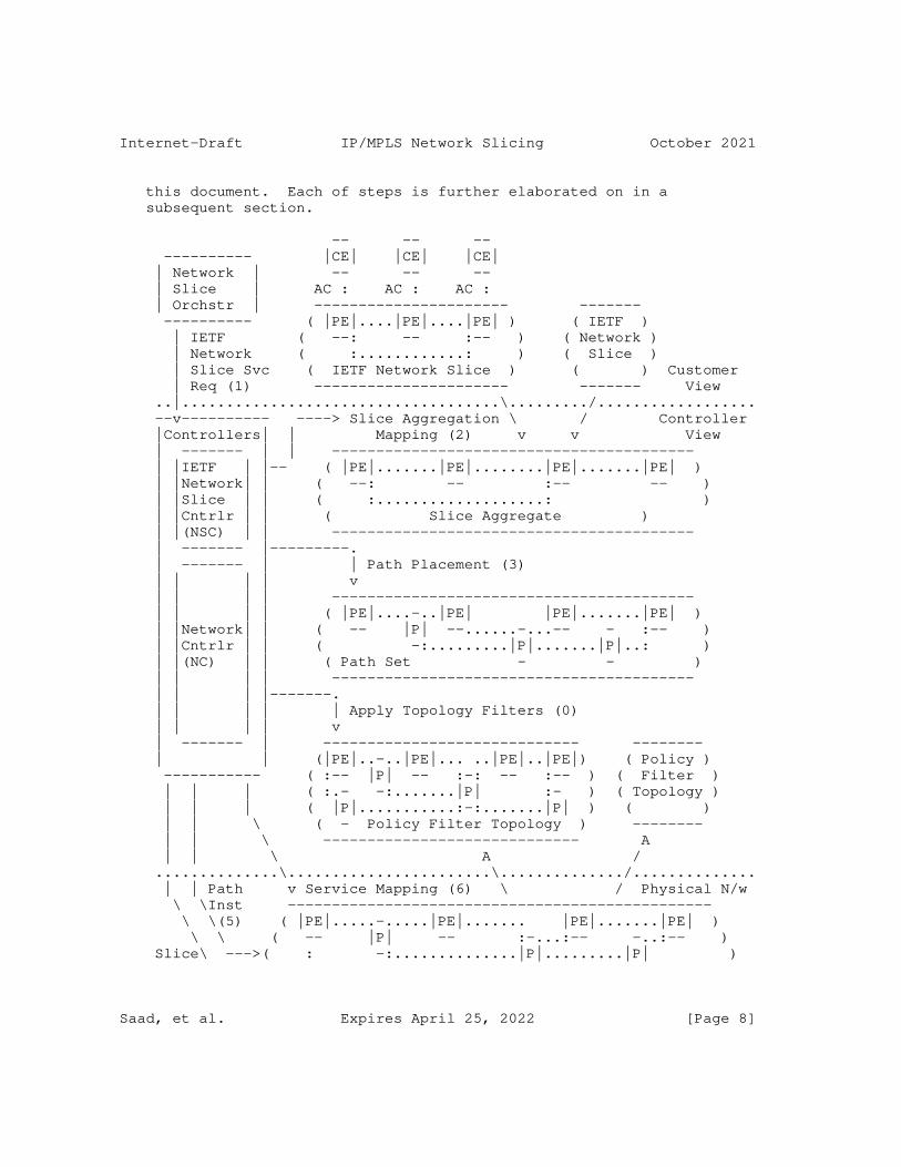
Figure 1 describes the steps required to realize an IETF network slice service in a provider network using the solution proposed in
Saad, et al. Expires April 25, 2022 [Page 7]
Internet-Draft IP/MPLS Network Slicing October 2021
this document. Each of steps is further elaborated on in a subsequent section.
-- -- -- ---------- |CE| |CE| |CE| | Network | -- -- -- | Slice | AC : AC : AC : | Orchstr | ---------------------- ------- ---------- ( |PE|....|PE|....|PE| ) ( IETF ) | IETF ( --: -- :-- ) ( Network ) | Network ( :............: ) ( Slice ) | Slice Svc ( IETF Network Slice ) ( ) Customer | Req (1) ---------------------- ------- View ..|....................................\........./.................. --v---------- ----> Slice Aggregation \ / Controller |Controllers| | Mapping (2) v v View | ------- | | ----------------------------------------- | |IETF | |-- ( |PE|.......|PE|........|PE|.......|PE| ) | |Network| | ( --: -- :-- -- ) | |Slice | | ( :...................: ) | |Cntrlr | | ( Slice Aggregate ) | |(NSC) | | ----------------------------------------- | ------- |---------. | ------- | | Path Placement (3) | | | | v | | | | ----------------------------------------- | | | | ( |PE|....-..|PE| |PE|.......|PE| ) | |Network| | ( -- |P| --......-...-- - :-- ) | |Cntrlr | | ( -:.........|P|.......|P|..: ) | |(NC) | | ( Path Set - - ) | | | | ----------------------------------------- | | | |-------. | | | | | Apply Topology Filters (0) | | | | v | ------- | ----------------------------- -------- | | (|PE|..-..|PE|... ..|PE|..|PE|) ( Policy ) ----------- ( :-- |P| -- :-: -- :-- ) ( Filter ) | | | ( :.- -:.......|P| :- ) ( Topology ) | | | ( |P|...........:-:.......|P| ) ( ) | | \ ( - Policy Filter Topology ) -------- | | \ ----------------------------- A | | \ A / ..............\.......................\............../.............. | | Path v Service Mapping (6) \ / Physical N/w \ \Inst ------------------------------------------------ \ \(5) ( |PE|.....-.....|PE|....... |PE|.......|PE| ) \ \ ( -- |P| -- :-...:-- -..:-- ) Slice\ --->( : -:..............|P|.........|P| )
Saad, et al. Expires April 25, 2022 [Page 8]
Internet-Draft IP/MPLS Network Slicing October 2021
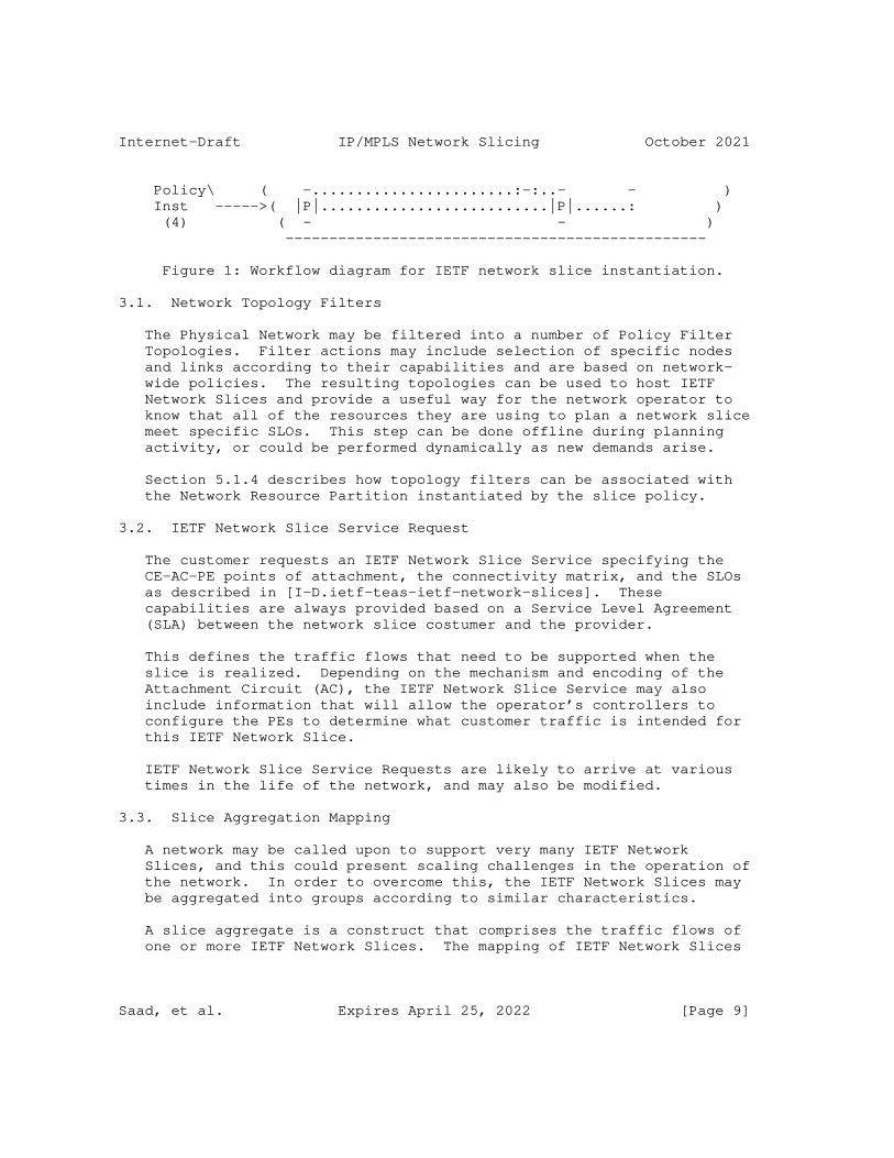
Policy\ ( -.......................:-:..- - ) Inst ----->( |P|..........................|P|......: ) (4) ( - - ) ------------------------------------------------
Figure 1: Workflow diagram for IETF network slice instantiation.
3.1. Network Topology Filters
The Physical Network may be filtered into a number of Policy Filter Topologies. Filter actions may include selection of specific nodes and links according to their capabilities and are based on network- wide policies. The resulting topologies can be used to host IETF Network Slices and provide a useful way for the network operator to know that all of the resources they are using to plan a network slice meet specific SLOs. This step can be done offline during planning activity, or could be performed dynamically as new demands arise.
Section 5.1.4 describes how topology filters can be associated with the Network Resource Partition instantiated by the slice policy.
3.2. IETF Network Slice Service Request
The customer requests an IETF Network Slice Service specifying the CE-AC-PE points of attachment, the connectivity matrix, and the SLOs as described in [I-D.ietf-teas-ietf-network-slices]. These capabilities are always provided based on a Service Level Agreement (SLA) between the network slice costumer and the provider.
This defines the traffic flows that need to be supported when the slice is realized. Depending on the mechanism and encoding of the Attachment Circuit (AC), the IETF Network Slice Service may also include information that will allow the operator’s controllers to configure the PEs to determine what customer traffic is intended for this IETF Network Slice.
IETF Network Slice Service Requests are likely to arrive at various times in the life of the network, and may also be modified.
3.3. Slice Aggregation Mapping
A network may be called upon to support very many IETF Network Slices, and this could present scaling challenges in the operation of the network. In order to overcome this, the IETF Network Slices may be aggregated into groups according to similar characteristics.
A slice aggregate is a construct that comprises the traffic flows of one or more IETF Network Slices. The mapping of IETF Network Slices
Saad, et al. Expires April 25, 2022 [Page 9]
Internet-Draft IP/MPLS Network Slicing October 2021
into an slice aggregate is a matter of local operator policy is a function executed by the Controller. The slice aggregate may be preconfigured, created on demand, or modified dynamically.
3.4. Path Placement over Slice Aggregate Topology
Depending on the underlying network technology, a Controller may plan the paths that the traffic flows will take through the network in order to best deliver the SLOs for the different services in the slice aggregate. The Controller performs the path placement function on the Policy Filter Topology selected to support the slice aggregate.
Note that this step may indicate the need to increase the capacity of the underlying Policy Filter Topology or to create a new Policy Filter Topology.
3.5. Slice Policy Installation
A Controller function programs the physical network with policies for handling the traffic flows belonging to the slice aggregate. These policies instruct network routers how to handle traffic for a specific slice aggregate: the routers correlate markers present in the packets that belong to the slice aggregate with the configured policy. The way in which the slice policy is installed in the routers and the way that the traffic is marked is implementation specific. The slice policy instantiation in the network is further described in Section 5.
3.6. Path Instantiation
Depending on the underlying network technology, a Controller function may install the forwarding state specific to the Slice Aggregate so that traffic is routed along paths derived in the Path Placement step described in Section 3.4. The way in which the paths are instantiated is implementation specific.
3.7. Service Mapping
Once the network has been set up, the edge points (PEs) can be configured to support the service. This involves telling them what customer traffic should be mapped to which slice aggregate possibly using information supplied when the IETF network slice service was requested. It also instructs the edge points how to mark the packets so that the network routers will know which policies and routing instructions to apply.
Saad, et al. Expires April 25, 2022 [Page 10]
Internet-Draft IP/MPLS Network Slicing October 2021
3.8. Network Slice Aggregate Relationships
The following describes the generalization relationships between the IETF network slice and different parts of the solution as described in Figure 1.
o A customer may request 1 or more IETF Network Slices.
o Any given Attachment Circuit (AC) may support the traffic for 1 or more IETF Network Slice, but if there is more than one IETF Network Slice using a single AC, the IETF Network Slice Service request must include enough information to allow the edge nodes to demultiplex the traffic for the different IETF Network Slices.
o By definition, multiple IETF Network Slices may be mapped to a single slice aggregate. However, it is possible for an slice aggregate to contain just a single IETF Network Slice. Furthermore, a slice aggregate can be planned and preconfigured, and may be "empty" having no IETF Network Slices mapped to it.
o The physical network may be filtered to multiple Policy Filter Topologies. Each such Policy Filter Topology provides a short-cut to planning the placement and support of slice aggregate by presenting only the subset of links and nodes that meet specific criteria. Note, however, that a network operator does not need to derive any Policy Filter Topologies, choosing to operate directly on the full physical network.
o It is anticipated that there may be very many IETF Network Slices supported by a network operator over a single physical network. The scaling mechanisms are deployment choices, but it may be that there are no more than 1000 slice aggregates supported by a network, with each slice aggregate supporting any number of IETF Network Slices.
4. Slice Policy Modes
A slice policy can be used to dictate if the network resource partitioning of the shared network resources among multiple slice aggregates can be achieved:
a) in data plane only,
b) in control plane only, or
c) in both control and data planes.
Saad, et al. Expires April 25, 2022 [Page 11]

Internet-Draft IP/MPLS Network Slicing October 2021
4.1. Data plane Slice Policy Mode
The physical network resources can be partitioned on network devices by applying a Per Hop forwarding Behavior (PHB) onto packets that traverse the network devices. In the Diffserv model, a Class Selector (CS) is carried in the packet and is used by transit nodes to apply the PHB that determines the scheduling treatment and drop probability for packets.
When data plane slice policy mode is applied, packets need to be forwarded on the specific Network Resource Partition that supports the slice aggregate to ensure the proper forwarding treatment dictated in the slice policy is applied (refer to Section 5.1 below). In this case, a Slice Selector (SS) MUST be carried in each packet to identify the slice aggregate that it belongs to.
The ingress node of a slice policy domain, in addition to marking packets with a Diffserv CS, MAY also add an SS to each slice aggregate packet. The transit nodes within a slice policy domain MAY use the SS to associate packets with a slice aggregate and to determine the Slice policy Per Hop Behavior (S-PHB) that is applied to the packet (refer to Section 5.1.3 for further details). The CS MAY be used to apply a Diffserv PHB on to the packet to allow differentiation of traffic treatment within the same slice aggregate.
When data plane only slice policy mode is used, routers may rely on a network state independent view of the topology to determine the best paths to reach destinations. In this case, the best path selection dictates the forwarding path of packets to the destination. The SS field carried in each packet determines the specific S-PHB treatment along the selected path.
For example, the Segment-Routing Flexible Algorithm [I-D.ietf-lsr-flex-algo] may be deployed in a network to steer packets on the IGP computed lowest cumulative delay path. A slice policy may be used to allow links along the least latency path to share its data plane resources amongst multiple slice aggregates. In this case, the packets that are steered on a specific slice policy carry the SS field that enables routers (along with the Diffserv CS) to determine the S-PHB to enforce on the slice aggregate traffic streams.
4.2. Control Plane Slice Policy Mode
Multiple Network Resource Partition can be realized over the same set of physical resources. It is possible in this case to allow the state reservations to occur on each Network Resource Partition.
Saad, et al. Expires April 25, 2022 [Page 12]
Internet-Draft IP/MPLS Network Slicing October 2021
The network reservation state for a specific partition can then be represented in a topology that may can contain all or a subset of the physical network elements (nodes and links). The logical network resources that appear in the topology can reflect a part, whole, or in-excess of the physical network resource capacity (e.g., when oversubscription is desired).
For example, the physical link bandwidth can be divided into fractions, each dedicated to a Network Resource Partition that supports a slice aggregate. The topology associated with the Network Resource Partition supporting a slice aggregate can be used by routing protocols, or by the ingress/PCE when computing slice aggregate aware TE paths.
To perform network state dependent path computation in this mode (slice aggregate aware TE), the resource reservation on each link needs to be slice aggregate aware. Details of required IGP extensions to support SA-TE are described in [I-D.bestbar-lsr-slice-aware-te].
The same physical link may be member of multiple slice policies that instantiate different Network Resource Partitions. The Network Resource Partition reservable or utilized bandwidth on such a link is updated (and may be advertised) whenever new paths are placed in the network. The Network Resource Partition reservation state, in this case, MAY be maintained on each device or off the device on a resource reservation manager that holds reservation states for those links in the network.
Multiple Network Resource Partitions that support slice aggregates can form a group and share the available network resources allocated to each. In this case, a node can update the reservable bandwidth for each Network Resource Partition to take into consideration the available bandwidth from other Network Resource Partitions in the same group.
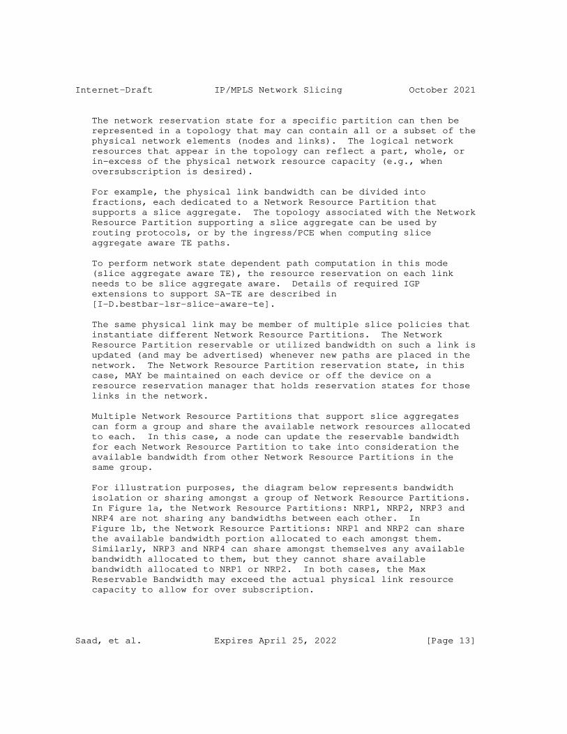
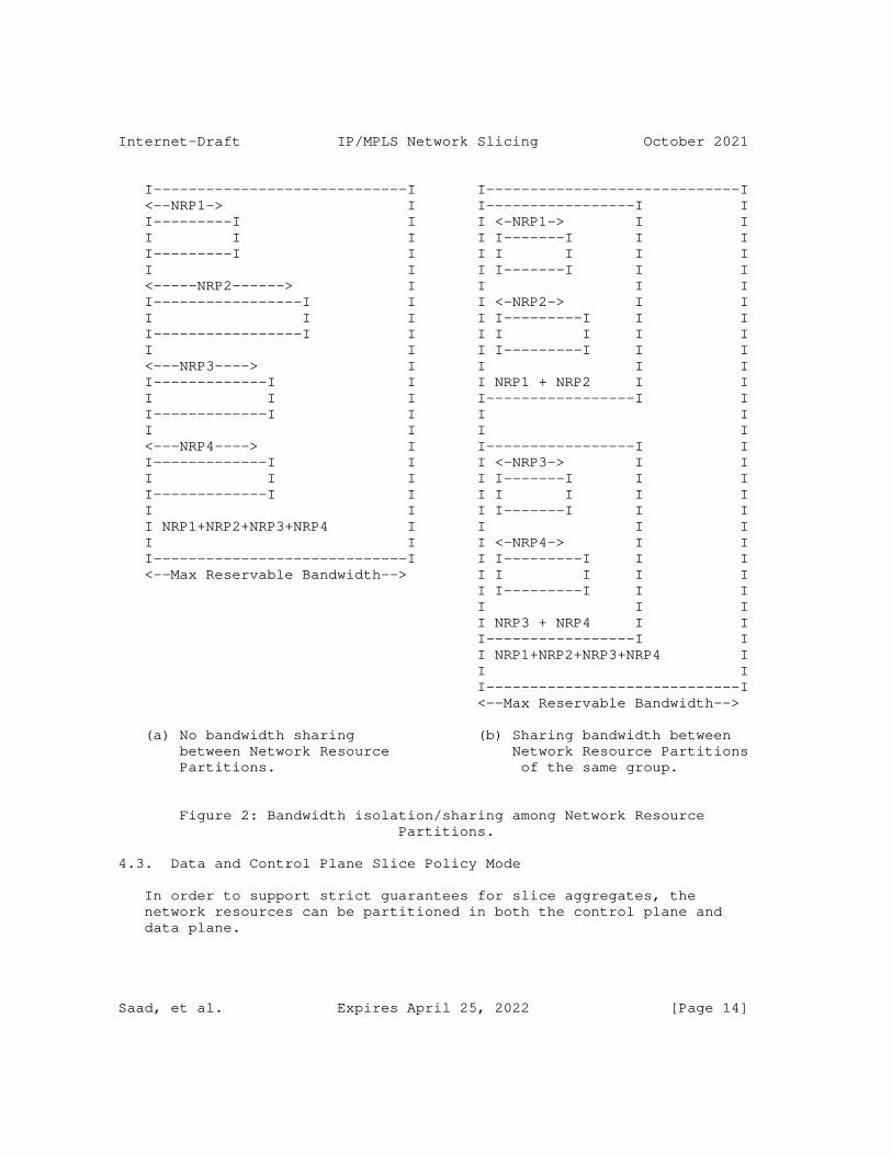
For illustration purposes, the diagram below represents bandwidth isolation or sharing amongst a group of Network Resource Partitions. In Figure 1a, the Network Resource Partitions: NRP1, NRP2, NRP3 and NRP4 are not sharing any bandwidths between each other. In Figure 1b, the Network Resource Partitions: NRP1 and NRP2 can share the available bandwidth portion allocated to each amongst them. Similarly, NRP3 and NRP4 can share amongst themselves any available bandwidth allocated to them, but they cannot share available bandwidth allocated to NRP1 or NRP2. In both cases, the Max Reservable Bandwidth may exceed the actual physical link resource capacity to allow for over subscription.
Saad, et al. Expires April 25, 2022 [Page 13]
Internet-Draft IP/MPLS Network Slicing October 2021
I-----------------------------I I-----------------------------I <--NRP1-> I I-----------------I I I---------I I I <-NRP1-> I I I I I I I-------I I I I---------I I I I I I I I I I I-------I I I <-----NRP2------> I I I I I-----------------I I I <-NRP2-> I I I I I I I---------I I I I-----------------I I I I I I I I I I I---------I I I <---NRP3----> I I I I I-------------I I I NRP1 + NRP2 I I I I I I-----------------I I I-------------I I I I I I I I <---NRP4----> I I-----------------I I I-------------I I I <-NRP3-> I I I I I I I-------I I I I-------------I I I I I I I I I I I-------I I I I NRP1+NRP2+NRP3+NRP4 I I I I I I I <-NRP4-> I I I-----------------------------I I I---------I I I <--Max Reservable Bandwidth--> I I I I I I I---------I I I I I I I NRP3 + NRP4 I I I-----------------I I I NRP1+NRP2+NRP3+NRP4 I I I I-----------------------------I <--Max Reservable Bandwidth-->
(a) No bandwidth sharing (b) Sharing bandwidth between between Network Resource Network Resource Partitions Partitions. of the same group.
Figure 2: Bandwidth isolation/sharing among Network Resource Partitions.
4.3. Data and Control Plane Slice Policy Mode
In order to support strict guarantees for slice aggregates, the network resources can be partitioned in both the control plane and data plane.
Saad, et al. Expires April 25, 2022 [Page 14]
Internet-Draft IP/MPLS Network Slicing October 2021
The control plane partitioning allows the creation of customized topologies per Network Resource Partition that each supports a slice aggregate. The ingress routers or a Path Computation Engine (PCE) can use the customized topologies to determine optimal path placement for specific demand flows (Slice aggregate aware TE).
The data plane partitioning provides isolation for slice aggregate traffic, and protection when resource contention occurs due to bursts of traffic from other slice aggregate traffic that traverses the same shared network resource.
5. Slice Policy Instantiation
A network slice can span multiple technologies and multiple administrative domains. Depending on the network slice customer requirements, a network slice can be differentiated from other network slices in terms of data, control or management planes.
The customer of a network slice expresses their intent by specifying requirements rather than mechanisms to realize the slice as described in Section 3.2.
The network slice controller consumes the network slice service intent and realizes it with an appropriate slice policy. Multiple IETF network slices MAY be mapped to the same slice policy resulting in a slice aggregate as described in Section 3.3.
The network wide consistent slice policy definition is distributed to the devices in the network as shown in Figure 1. The specification of the network slice intent on the northbound interface of the controller and the mechanism used to map the network slice to a slice policy are outside the scope of this document.
5.1. Slice Policy Definition
The slice policy is network-wide construct that is consumed by network devices, and may include rules that control the following:
o Data plane specific policies: This includes the SS, any firewall rules or flow-spec filters, and QoS profiles associated with the slice policy and any classes within it.
o Control plane specific policies: This includes guaranteed bandwidth, any network resource sharing amongst slice policies, and reservation preference to prioritize any reservations of a specific slice policy over others.
Saad, et al. Expires April 25, 2022 [Page 15]

Internet-Draft IP/MPLS Network Slicing October 2021
o Topology membership policies: This defines topology filter policies that dictate node/link/function network resource topology association for a specific slice policy.
There is a desire for flexibility in realizing network slices to support the services across networks consisting of products from multiple vendors. These networks may also be grouped into disparate domains and deploy various path control technologies and tunnel techniques to carry traffic across the network. It is expected that a standardized data model for slice policy will facilitate the instantiation and management of the Network Resource Partition on the topological elements selected by the slice policy topology filter. A YANG data model for the slice policy instantiation on network devices is described in [I-D.bestbar-teas-yang-slice-policy].
It is also possible to distribute the slice policy to network devices using several mechanisms, including protocols such as NETCONF or RESTCONF, or exchanging it using a suitable routing protocol that network devices participate in (such as IGP(s) or BGP). The extensions to enable specific protocols to carry a slice policy definition will be described in separate documents.
5.1.1. Slice Policy Data Plane Selector
A router MUST be able to identify a packet belonging to a slice aggregate before it can apply the associated forwarding treatment or S-PHB. One or more fields within the packet MAY be used as an SS to do this.
Forwarding Address Based Slice Selector:
It is possible to assign a different forwarding address (or MPLS forwarding label in case of MPLS network) for each slice aggregate on a specific node in the network. [RFC3031] states in Section 2.1 that: ’Some routers analyze a packet’s network layer header not merely to choose the packet’s next hop, but also to determine a packet’s "precedence" or "class of service"’. Assigning a unique forwarding address (or MPLS forwarding label) to each slice aggregate allows slice aggregate packets destined to a node to be distinguished by the destination address (or MPLS forwarding label) that is carried in the packet.
This approach requires maintaining per slice aggregate state for each destination in the network in both the control and data plane and on each router in the network. For example, consider a network slicing provider with a network composed of ’N’ nodes, each with ’K’ adjacencies to its neighbors. Assuming a node can be reached over ’M’ different slice aggregates, the node assigns
Saad, et al. Expires April 25, 2022 [Page 16]

Internet-Draft IP/MPLS Network Slicing October 2021
and advertises reachability to ’N’ unique forwarding addresses, or MPLS forwarding labels. Similarly, each node assigns a unique forwarding address (or MPLS forwarding label) for each of its ’K’ adjacencies to enable strict steering over the adjacency for each slice. The total number of control and data plane states that need to be stored and programmed in a router’s forwarding is (N+K)*M states. Hence, as ’N’, ’K’, and ’M’ parameters increase, this approach suffers from scalability challenges in both the control and data planes.
Global Identifier Based Slice Selector:
A slice policy MAY include a Global Identifier Slice Selector (GISS) field as defined in [I-D.kompella-mpls-mspl4fa] that is carried in each packet in order to associate it to the Network Resource Partition supporting a slice aggregate, independent of the forwarding address or MPLS forwarding label that is bound to the destination. Routers within the slice policy domain can use the forwarding address (or MPLS forwarding label) to determine the forwarding next-hop(s), and use the GISS field in the packet to infer the specific forwarding treatment that needs to be applied on the packet.
The GISS can be carried in one of multiple fields within the packet, depending on the dataplane used. For example, in MPLS networks, the GISS can be encoded within an MPLS label that is carried in the packet’s MPLS label stack. All packets that belong to the same slice aggregate MAY carry the same GISS in the MPLS label stack. It is also possible to have multiple GISS’s map to the same slice aggregate.
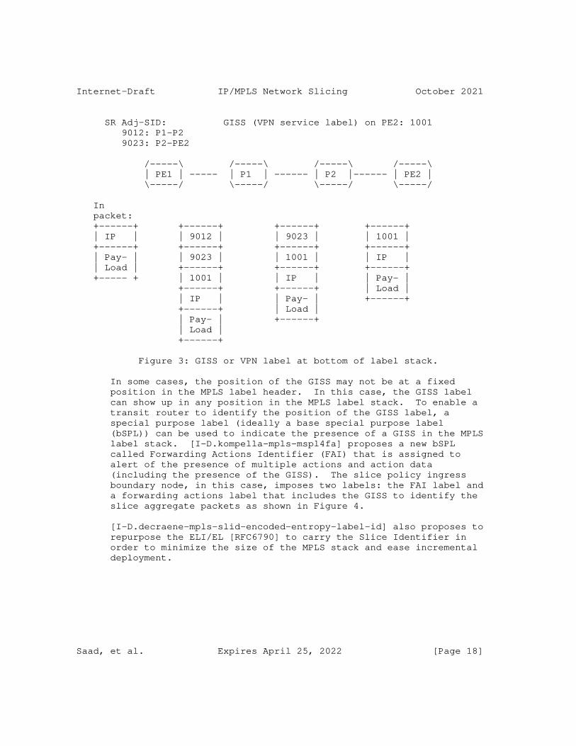
The GISS can be encoded in an MPLS label and may appear in several positions in the MPLS label stack. For example, the VPN service label may act as a GISS to allow VPN packets to be mapped to the slice aggregate. In this case, a single VPN service label acting as a GISS MAY be allocated by all Egress PEs of a VPN. Alternatively, multiple VPN service labels MAY act as GISS’s that map a single VPN to the same slice aggregate to allow for multiple Egress PEs to allocate different VPN service labels for a VPN. In other cases, a range of VPN service labels acting as multiple GISS’s MAY map multiple VPN traffic to a single slice aggregate. An example of such deployment is shown in Figure 3.
Saad, et al. Expires April 25, 2022 [Page 17]
Internet-Draft IP/MPLS Network Slicing October 2021
SR Adj-SID: GISS (VPN service label) on PE2: 1001 9012: P1-P2 9023: P2-PE2
/-----\ /-----\ /-----\ /-----\ | PE1 | ----- | P1 | ------ | P2 |------ | PE2 | \-----/ \-----/ \-----/ \-----/
In packet: +------+ +------+ +------+ +------+ | IP | | 9012 | | 9023 | | 1001 | +------+ +------+ +------+ +------+ | Pay- | | 9023 | | 1001 | | IP | | Load | +------+ +------+ +------+ +----- + | 1001 | | IP | | Pay- | +------+ +------+ | Load | | IP | | Pay- | +------+ +------+ | Load | | Pay- | +------+ | Load | +------+
Figure 3: GISS or VPN label at bottom of label stack.
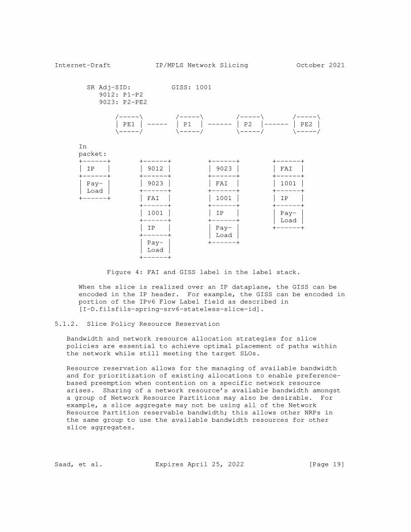
In some cases, the position of the GISS may not be at a fixed position in the MPLS label header. In this case, the GISS label can show up in any position in the MPLS label stack. To enable a transit router to identify the position of the GISS label, a special purpose label (ideally a base special purpose label (bSPL)) can be used to indicate the presence of a GISS in the MPLS label stack. [I-D.kompella-mpls-mspl4fa] proposes a new bSPL called Forwarding Actions Identifier (FAI) that is assigned to alert of the presence of multiple actions and action data (including the presence of the GISS). The slice policy ingress boundary node, in this case, imposes two labels: the FAI label and a forwarding actions label that includes the GISS to identify the slice aggregate packets as shown in Figure 4.
[I-D.decraene-mpls-slid-encoded-entropy-label-id] also proposes to repurpose the ELI/EL [RFC6790] to carry the Slice Identifier in order to minimize the size of the MPLS stack and ease incremental deployment.
Saad, et al. Expires April 25, 2022 [Page 18]
Internet-Draft IP/MPLS Network Slicing October 2021
SR Adj-SID: GISS: 1001 9012: P1-P2 9023: P2-PE2
/-----\ /-----\ /-----\ /-----\ | PE1 | ----- | P1 | ------ | P2 |------ | PE2 | \-----/ \-----/ \-----/ \-----/
In packet: +------+ +------+ +------+ +------+ | IP | | 9012 | | 9023 | | FAI | +------+ +------+ +------+ +------+ | Pay- | | 9023 | | FAI | | 1001 | | Load | +------+ +------+ +------+ +------+ | FAI | | 1001 | | IP | +------+ +------+ +------+ | 1001 | | IP | | Pay- | +------+ +------+ | Load | | IP | | Pay- | +------+ +------+ | Load | | Pay- | +------+ | Load | +------+
Figure 4: FAI and GISS label in the label stack.
When the slice is realized over an IP dataplane, the GISS can be encoded in the IP header. For example, the GISS can be encoded in portion of the IPv6 Flow Label field as described in [I-D.filsfils-spring-srv6-stateless-slice-id].
5.1.2. Slice Policy Resource Reservation
Bandwidth and network resource allocation strategies for slice policies are essential to achieve optimal placement of paths within the network while still meeting the target SLOs.
Resource reservation allows for the managing of available bandwidth and for prioritization of existing allocations to enable preference- based preemption when contention on a specific network resource arises. Sharing of a network resource’s available bandwidth amongst a group of Network Resource Partitions may also be desirable. For example, a slice aggregate may not be using all of the Network Resource Partition reservable bandwidth; this allows other NRPs in the same group to use the available bandwidth resources for other slice aggregates.
Saad, et al. Expires April 25, 2022 [Page 19]

Internet-Draft IP/MPLS Network Slicing October 2021
Congestion on shared network resources may result from sub-optimal placement of paths in different slice policies. When this occurs, preemption of some slice aggregate paths may be desirable to alleviate congestion. A preference based allocation scheme enables prioritization of slice aggregate paths that can be preempted.
Since network characteristics and its state can change over time, the slice policy topology and its network state need to be propagated in the network to enable ingress TE routers or Path Computation Engine (PCEs) to perform accurate path placement based on the current state of the slice policy network resources.
5.1.3. Slice Policy Per Hop Behavior
In Diffserv terminology, the forwarding behavior that is assigned to a specific class is called a Per Hop Behavior (PHB). The PHB defines the forwarding precedence that a marked packet with a specific CS receives in relation to other traffic on the Diffserv-aware network.
A Slice policy Per Hop Behavior (S-PHB) is the externally observable forwarding behavior applied to a specific packet belonging to a slice aggregate. The goal of an S-PHB is to provide a specified amount of network resources for traffic belonging to a specific slice aggregate. A single slice policy may also support multiple forwarding treatments or services that can be carried over the same logical network.
The slice aggregate traffic may be identified at slice policy ingress boundary nodes by carrying a SS to allow routers to apply a specific forwarding treatment that guarantee the SLA(s).
With Differentiated Services (Diffserv) it is possible to carry multiple services over a single converged network. Packets requiring the same forwarding treatment are marked with a Class Selector (CS) at domain ingress nodes. Up to eight classes or Behavior Aggregates (BAs) may be supported for a given Forwarding Equivalence Class (FEC) [RFC2475]. To support multiple forwarding treatments over the same slice aggregate, a slice aggregate packet MAY also carry a Diffserv CS to identify the specific Diffserv forwarding treatment to be applied on the traffic belonging to the same slice policy.
At transit nodes, the CS field carried inside the packets are used to determine the specific PHB that determines the forwarding and scheduling treatment before packets are forwarded, and in some cases, drop probability for each packet.
Saad, et al. Expires April 25, 2022 [Page 20]

Internet-Draft IP/MPLS Network Slicing October 2021
5.1.4. Slice Policy Topology
A key element of the slice policy is a customized topology that may include the full or subset of the physical network topology. The slice policy topology could also span multiple administrative domains and/or multiple dataplane technologies.
A slice policy topology can overlap or share a subset of links with another slice policy topology. A number of topology filtering policies can be defined as part of the slice policy to limit the specific topology elements that belong to a slice policy. For example, a topology filtering policy can leverage Resource Affinities as defined in [RFC2702] to include or exclude certain links that the Network Resource Partition is instantiated on in supports of the slice aggregate.
The slice policy may also include a reference to a predefined topology (e.g., derived from a Flexible Algorithm Definition (FAD) as defined in [I-D.ietf-lsr-flex-algo], or Multi-Topology ID as defined [RFC4915].
5.2. Slice Policy Boundary
A network slice originates at the edge nodes of a network slice provider. Traffic that is steered over the corresponding Network Resource Partition supporting a slice aggregate may traverse slice policy capable as well as slice policy incapable interior nodes.
The network slice may encompass one or more domains administered by a provider. For example, an organization’s intranet or an ISP. The network provider is responsible for ensuring that adequate network resources are provisioned and/or reserved to support the SLAs offered by the network end-to-end.
5.2.1. Slice Policy Edge Nodes
Slice policy edge nodes sit at the boundary of a network slice provider network and receive traffic that requires steering over network resources specific to a Network Resource Partition that supports a slice aggregate. These edge nodes are responsible for identifying slice aggregate specific traffic flows by possibly inspecting multiple fields from inbound packets (e.g., implementations may inspect IP traffic’s network 5-tuple in the IP and transport protocol headers) to decide on which slice policy it can be steered.
Network slice ingress nodes may condition the inbound traffic at network boundaries in accordance with the requirements or rules of
Saad, et al. Expires April 25, 2022 [Page 21]

Internet-Draft IP/MPLS Network Slicing October 2021
each service’s SLAs. The requirements and rules for network slice services are set using mechanisms which are outside the scope of this document.
When data plane slice policy is applied, the slice policy ingress boundary nodes are responsible for adding a suitable SS onto packets that belong to specific slice aggregate. In addition, edge nodes MAY mark the corresponding Diffserv CS to differentiate between different types of traffic carried over the same slice aggregate.
5.2.2. Slice Policy Interior Nodes
A slice policy interior node receives slice traffic and MAY be able to identify the packets belonging to a specific slice aggregate by inspecting the SS field carried inside each packet, or by inspecting other fields within the packet that may identify the traffic streams that belong to a specific slice aggregate. For example, when data plane slice policy is applied, interior nodes can use the SS carried within the packet to apply the corresponding S-PHB forwarding behavior. Nodes within the network slice provider network may also inspect the Diffserv CS within each packet to apply a per Diffserv class PHB within the slice policy, and allow differentiation of forwarding treatments for packets forwarded over the same Network Resource Partition that supports the slice aggregate.
5.2.3. Slice Policy Incapable Nodes
Packets that belong to a slice aggregate may need to traverse nodes that are slice policy incapable. In this case, several options are possible to allow the slice traffic to continue to be forwarded over such devices and be able to resume the slice policy forwarding treatment once the traffic reaches devices that are slice policy capable.
When data plane slice policy is applied, packets carry a SS to allow slice interior nodes to identify them. To enable end-to-end network slicing, the SS MUST be maintained in the packets as they traverse devices within the network - including slice policy incapable devices.
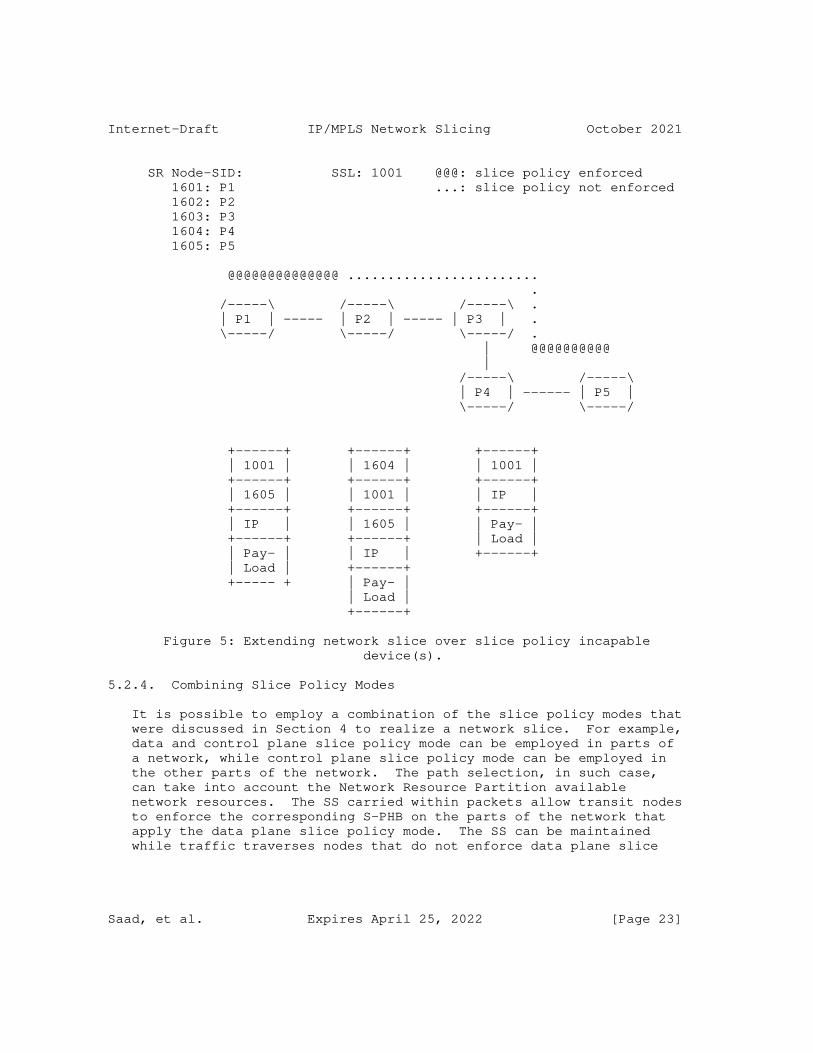
For example, when the SS is an MPLS label at the bottom of the MPLS label stack, packets can traverse over devices that are slice policy incapable without any further considerations. On the other hand, when the SSL is at the top of the MPLS label stack, packets can be bypassed (or tunneled) over the slice policy incapable devices towards the next device that supports slice policy as shown in Figure 5.
Saad, et al. Expires April 25, 2022 [Page 22]
Internet-Draft IP/MPLS Network Slicing October 2021
SR Node-SID: SSL: 1001 @@@: slice policy enforced 1601: P1 ...: slice policy not enforced 1602: P2 1603: P3 1604: P4 1605: P5
@@@@@@@@@@@@@@ ........................ . /-----\ /-----\ /-----\ . | P1 | ----- | P2 | ----- | P3 | . \-----/ \-----/ \-----/ . | @@@@@@@@@@ | /-----\ /-----\ | P4 | ------ | P5 | \-----/ \-----/
+------+ +------+ +------+ | 1001 | | 1604 | | 1001 | +------+ +------+ +------+ | 1605 | | 1001 | | IP | +------+ +------+ +------+ | IP | | 1605 | | Pay- | +------+ +------+ | Load | | Pay- | | IP | +------+ | Load | +------+ +----- + | Pay- | | Load | +------+
Figure 5: Extending network slice over slice policy incapable device(s).
5.2.4. Combining Slice Policy Modes
It is possible to employ a combination of the slice policy modes that were discussed in Section 4 to realize a network slice. For example, data and control plane slice policy mode can be employed in parts of a network, while control plane slice policy mode can be employed in the other parts of the network. The path selection, in such case, can take into account the Network Resource Partition available network resources. The SS carried within packets allow transit nodes to enforce the corresponding S-PHB on the parts of the network that apply the data plane slice policy mode. The SS can be maintained while traffic traverses nodes that do not enforce data plane slice
Saad, et al. Expires April 25, 2022 [Page 23]
Internet-Draft IP/MPLS Network Slicing October 2021
policy mode, and so slice PHB enforcement can resume once traffic traverses capable nodes.
5.3. Mapping Traffic on Slice Aggregates
The usual techniques to steer traffic onto paths can be applicable when steering traffic over paths established for a specific slice aggregate.
For example, one or more (layer-2 or layer-3) VPN services can be directly mapped to paths established for a slice aggregate. In this case, the per Virtual Routing and Forwarding (VRF) instance traffic that arrives on the Provider Edge (PE) router over external interfaces can be directly mapped to a specific slice aggregate path. External interfaces can be further partitioned (e.g., using VLANs) to allow mapping one or more VLANs to specific slice aggregate paths.
Another option is steer traffic to specific destinations directly over multiple slice policies. This allows traffic arriving on any external interface and targeted to such destinations to be directly steered over the slice paths.
A third option that can also be used is to utilize a data plane firewall filter or classifier to enable matching of several fields in the incoming packets to decide whether the packet belongs to a specific slice aggregate. This option allows for applying a rich set of rules to identify specific packets to be mapped to a slice aggregate. However, it requires data plane network resources to be able to perform the additional checks in hardware.
6. Path Selection and Instantiation
6.1. Applicability of Path Selection to Slice Aggregates
The path selection in the network can be network state dependent, or network state independent as described in Section 5.1 of [I-D.ietf-teas-rfc3272bis]. The latter is the choice commonly used by IGPs when selecting a best path to a destination prefix, while the former is used by ingress TE routers, or Path Computation Engines (PCEs) when optimizing the placement of a flow based on the current network resource utilization.
When path selection is network state dependent, the path computation can leverage Traffic Engineering mechanisms (e.g., as defined in [RFC2702]) to compute feasible paths taking into account the incoming traffic demand rate and current state of network. This allows avoiding overly utilized links, and reduces the chance of congestion on traversed links.
Saad, et al. Expires April 25, 2022 [Page 24]
Internet-Draft IP/MPLS Network Slicing October 2021
To enable TE path placement, the link state is advertised with current reservations, thereby reflecting the available bandwidth on each link. Such link reservations may be maintained centrally on a network wide network resource manager, or distributed on devices (as usually done with RSVP). TE extensions exist today to allow IGPs (e.g., [RFC3630] and [RFC5305]), and BGP-LS [RFC7752] to advertise such link state reservations.
When the network resource reservations are maintained for Network Resource Partitions, the link state can carry per Network Resource Partition state (e.g., reservable bandwidth). This allows path computation to take into account the specific network resources available for a Network Resource Partition. In this case, we refer to the process of path placement and path provisioning as slice aggregate aware TE.
6.2. Applicability of Path Control Technologies to Slice Aggregates
The slice policy modes described in this document are agnostic to the technology used to setup paths that carry slice aggregate traffic. One or more paths connecting the endpoints of the mapped IETF network slices may be selected to steer the corresponding traffic streams over the resources allocated for the Network Resource Partition that supports a slice aggregate.
The feasible paths can be computed using the slice policy topology and network state subject the optimization metrics and constraints.
6.3. RSVP-TE Based Slice Aggregate Paths
RSVP-TE [RFC3209] can be used to signal LSPs over the computed feasible paths in order to carry the slice aggregate traffic. The specific extensions to the RSVP-TE protocol required to enable signaling of slice aggregate aware RSVP LSPs are outside the scope of this document.
6.4. SR Based Slice Aggregate Paths
Segment Routing (SR) [RFC8402] can be used to setup and steer traffic over the computed slice aggregate feasible paths.
The SR architecture defines a number of building blocks that can be leveraged to support the realization of Network Resource Partitions that support slice aggregates in an SR network.
Such building blocks include:
o SR Policy with or without Flexible Algorithm.
Saad, et al. Expires April 25, 2022 [Page 25]

Internet-Draft IP/MPLS Network Slicing October 2021
o Steering of services (e.g. VPN) traffic over SR paths
o SR Operation, Administration and Management (OAM) and Performance Management (PM)
SR allows a headend node to steer packets onto specific SR paths using a Segment Routing Policy (SR Policy). The SR policy supports various optimization objectives and constraints and can be used to steer slice aggregate traffic in the SR network.
The SR policy can be instantiated with or without the IGP Flexible Algorithm (Flex-Algorithm) feature. It may be possible to dedicate a single SR Flex-Algorithm to compute and instantiate SR paths for one slice aggregate traffic. In this case, the SR Flex-Algorithm computed paths and Flex-Algorithm SR SIDs are not shared by other slice aggregates traffic. However, to allow for better scale, it may be desirable for multiple slice aggregates traffic to share the same SR Flex-Algorithm computed paths and SIDs. Further details on how the slice policy modes presented in this document can be realized in an SR network are discussed in [I-D.bestbar-spring-scalable-ns], and [I-D.bestbar-lsr-spring-sa].
7. Slice Policy Protocol Extensions
Routing protocols may need to be extended to carry additional per Network Resource Partition link state. For example, [RFC5305], [RFC3630], and [RFC7752] are ISIS, OSPF, and BGP protocol extensions to exchange network link state information to allow ingress TE routers and PCE(s) to do proper path placement in the network. The extensions required to support network slicing may be defined in other documents, and are outside the scope of this document.
The instantiation of a slice policy may need to be automated. Multiple options are possible to facilitate automation of distribution of a slice policy to capable devices.
For example, a YANG data model for the slice policy may be supported on network devices and controllers. A suitable transport (e.g., NETCONF [RFC6241], RESTCONF [RFC8040], or gRPC) may be used to enable configuration and retrieval of state information for slice policies on network devices. The slice policy YANG data model is outside the scope of this document, and is defined in [I-D.bestbar-teas-yang-slice-policy].
Saad, et al. Expires April 25, 2022 [Page 26]

Internet-Draft IP/MPLS Network Slicing October 2021
8. IANA Considerations
This document has no IANA actions.
9. Security Considerations
The main goal of network slicing is to allow for varying treatment of traffic from multiple different network slices that are utilizing a common network infrastructure and to allow for different levels of services to be provided for traffic traversing a given network resource.
A variety of techniques may be used to achieve this, but the end result will be that some packets may be mapped to specific resources and may receive different (e.g., better) service treatment than others. The mapping of network traffic to a specific slice policy is indicated primarily by the SS, and hence an adversary may be able to utilize resources allocated to a specific slice policy by injecting packets carrying the same SS field in their packets.
Such theft-of-service may become a denial-of-service attack when the modified or injected traffic depletes the resources available to forward legitimate traffic belonging to a specific slice policy.
The defense against this type of theft and denial-of-service attacks consists of a combination of traffic conditioning at slice policy domain boundaries with security and integrity of the network infrastructure within a slice policy domain.
10. Acknowledgement
The authors would like to thank Krzysztof Szarkowicz, Swamy SRK, Navaneetha Krishnan, and Prabhu Raj Villadathu Karunakaran for their review of this document, and for providing valuable feedback on it. The authors would also like to thank Adrian Farrel for detailed discussions that resulted in Section 3.
11. Contributors
The following individuals contributed to this document:
Saad, et al. Expires April 25, 2022 [Page 27]
Internet-Draft IP/MPLS Network Slicing October 2021
Colby Barth Juniper Networks Email: [email protected]
Srihari R. Sangli Juniper Networks Email: [email protected]
Chandra Ramachandran Juniper Networks Email: [email protected]
12. References
12.1. Normative References
[I-D.bestbar-lsr-slice-aware-te] Britto, W., Shetty, R., Barth, C., Wen, B., Peng, S., and R. Chen, "IGP Extensions for Support of Slice Aggregate Aware Traffic Engineering", draft-bestbar-lsr-slice-aware- te-00 (work in progress), February 2021.
[I-D.bestbar-lsr-spring-sa] Saad, T., Beeram, V. P., Chen, R., Peng, S., Wen, B., and D. Ceccarelli, "IGP Extensions for SR Slice Aggregate SIDs", draft-bestbar-lsr-spring-sa-01 (work in progress), September 2021.
[I-D.bestbar-spring-scalable-ns] Saad, T., Beeram, V. P., Chen, R., Peng, S., Wen, B., and D. Ceccarelli, "Scalable Network Slicing over SR Networks", draft-bestbar-spring-scalable-ns-02 (work in progress), September 2021.
[I-D.bestbar-teas-yang-slice-policy] Saad, T., Beeram, V. P., Wen, B., Ceccarelli, D., Peng, S., Chen, R., Contreras, L. M., and X. Liu, "YANG Data Model for Slice Policy", draft-bestbar-teas-yang-slice- policy-01 (work in progress), July 2021.
[I-D.decraene-mpls-slid-encoded-entropy-label-id] Decraene, B., Filsfils, C., Henderickx, W., Saad, T., Beeram, V. P., and L. Jalil, "Using Entropy Label for Network Slice Identification in MPLS networks.", draft- decraene-mpls-slid-encoded-entropy-label-id-02 (work in progress), August 2021.
Saad, et al. Expires April 25, 2022 [Page 28]
Internet-Draft IP/MPLS Network Slicing October 2021
[I-D.filsfils-spring-srv6-stateless-slice-id] Filsfils, C., Clad, F., Camarillo, P., Raza, K., Voyer, D., and R. Rokui, "Stateless and Scalable Network Slice Identification for SRv6", draft-filsfils-spring-srv6- stateless-slice-id-04 (work in progress), July 2021.
[I-D.ietf-lsr-flex-algo] Psenak, P., Hegde, S., Filsfils, C., Talaulikar, K., and A. Gulko, "IGP Flexible Algorithm", draft-ietf-lsr-flex- algo-17 (work in progress), July 2021.
[I-D.kompella-mpls-mspl4fa] Kompella, K., Beeram, V. P., Saad, T., and I. Meilik, "Multi-purpose Special Purpose Label for Forwarding Actions", draft-kompella-mpls-mspl4fa-01 (work in progress), July 2021.
[RFC2119] Bradner, S., "Key words for use in RFCs to Indicate Requirement Levels", BCP 14, RFC 2119, DOI 10.17487/RFC2119, March 1997, <https://www.rfc-editor.org/info/rfc2119>.
[RFC3031] Rosen, E., Viswanathan, A., and R. Callon, "Multiprotocol Label Switching Architecture", RFC 3031, DOI 10.17487/RFC3031, January 2001, <https://www.rfc-editor.org/info/rfc3031>.
[RFC3209] Awduche, D., Berger, L., Gan, D., Li, T., Srinivasan, V., and G. Swallow, "RSVP-TE: Extensions to RSVP for LSP Tunnels", RFC 3209, DOI 10.17487/RFC3209, December 2001, <https://www.rfc-editor.org/info/rfc3209>.
[RFC3630] Katz, D., Kompella, K., and D. Yeung, "Traffic Engineering (TE) Extensions to OSPF Version 2", RFC 3630, DOI 10.17487/RFC3630, September 2003, <https://www.rfc-editor.org/info/rfc3630>.
[RFC4915] Psenak, P., Mirtorabi, S., Roy, A., Nguyen, L., and P. Pillay-Esnault, "Multi-Topology (MT) Routing in OSPF", RFC 4915, DOI 10.17487/RFC4915, June 2007, <https://www.rfc-editor.org/info/rfc4915>.
[RFC5305] Li, T. and H. Smit, "IS-IS Extensions for Traffic Engineering", RFC 5305, DOI 10.17487/RFC5305, October 2008, <https://www.rfc-editor.org/info/rfc5305>.
Saad, et al. Expires April 25, 2022 [Page 29]
Internet-Draft IP/MPLS Network Slicing October 2021
[RFC6790] Kompella, K., Drake, J., Amante, S., Henderickx, W., and L. Yong, "The Use of Entropy Labels in MPLS Forwarding", RFC 6790, DOI 10.17487/RFC6790, November 2012, <https://www.rfc-editor.org/info/rfc6790>.
[RFC7752] Gredler, H., Ed., Medved, J., Previdi, S., Farrel, A., and S. Ray, "North-Bound Distribution of Link-State and Traffic Engineering (TE) Information Using BGP", RFC 7752, DOI 10.17487/RFC7752, March 2016, <https://www.rfc-editor.org/info/rfc7752>.
[RFC8174] Leiba, B., "Ambiguity of Uppercase vs Lowercase in RFC 2119 Key Words", BCP 14, RFC 8174, DOI 10.17487/RFC8174, May 2017, <https://www.rfc-editor.org/info/rfc8174>.
[RFC8402] Filsfils, C., Ed., Previdi, S., Ed., Ginsberg, L., Decraene, B., Litkowski, S., and R. Shakir, "Segment Routing Architecture", RFC 8402, DOI 10.17487/RFC8402, July 2018, <https://www.rfc-editor.org/info/rfc8402>.
12.2. Informative References
[I-D.ietf-teas-ietf-network-slices] Farrel, A., Gray, E., Drake, J., Rokui, R., Homma, S., Makhijani, K., Contreras, L. M., and J. Tantsura, "Framework for IETF Network Slices", draft-ietf-teas-ietf- network-slices-04 (work in progress), August 2021.
[I-D.ietf-teas-rfc3272bis] Farrel, A., "Overview and Principles of Internet Traffic Engineering", draft-ietf-teas-rfc3272bis-12 (work in progress), May 2021.
[RFC2475] Blake, S., Black, D., Carlson, M., Davies, E., Wang, Z., and W. Weiss, "An Architecture for Differentiated Services", RFC 2475, DOI 10.17487/RFC2475, December 1998, <https://www.rfc-editor.org/info/rfc2475>.
[RFC2702] Awduche, D., Malcolm, J., Agogbua, J., O’Dell, M., and J. McManus, "Requirements for Traffic Engineering Over MPLS", RFC 2702, DOI 10.17487/RFC2702, September 1999, <https://www.rfc-editor.org/info/rfc2702>.
[RFC6241] Enns, R., Ed., Bjorklund, M., Ed., Schoenwaelder, J., Ed., and A. Bierman, Ed., "Network Configuration Protocol (NETCONF)", RFC 6241, DOI 10.17487/RFC6241, June 2011, <https://www.rfc-editor.org/info/rfc6241>.
Saad, et al. Expires April 25, 2022 [Page 30]
Internet-Draft IP/MPLS Network Slicing October 2021
[RFC8040] Bierman, A., Bjorklund, M., and K. Watsen, "RESTCONF Protocol", RFC 8040, DOI 10.17487/RFC8040, January 2017, <https://www.rfc-editor.org/info/rfc8040>.
Authors’ Addresses
Tarek Saad Juniper Networks
Email: [email protected]
Vishnu Pavan Beeram Juniper Networks
Email: [email protected]
Bin Wen Comcast
Email: [email protected]
Daniele Ceccarelli Ericsson
Email: [email protected]
Joel Halpern Ericsson
Email: [email protected]
Shaofu Peng ZTE Corporation
Email: [email protected]
Ran Chen ZTE Corporation
Email: [email protected]
Saad, et al. Expires April 25, 2022 [Page 31]
Internet-Draft IP/MPLS Network Slicing October 2021
Xufeng Liu Volta Networks
Email: [email protected]
Luis M. Contreras Telefonica
Email: [email protected]
Reza Rokui Nokia
Email: [email protected]
Saad, et al. Expires April 25, 2022 [Page 32]

TEAS Working Group T. SaadInternet-Draft V. BeeramIntended status: Standards Track Juniper NetworksExpires: 6 August 2022 J. Dong Huawei Technologies B. Wen Comcast D. Ceccarelli J. Halpern Ericsson S. Peng R. Chen ZTE Corporation X. Liu Volta Networks L. Contreras Telefonica R. Rokui Nokia L. Jalil Verizon 2 February 2022
Realizing Network Slices in IP/MPLS Networks draft-bestbar-teas-ns-packet-08
Abstract
Network slicing provides the ability to partition a physical network into multiple logical networks of varying sizes, structures, and functions so that each slice can be dedicated to specific services or customers. Network slices need to co-exist on the same network while ensuring slice elasticity in terms of network resource allocation. The Differentiated Service (Diffserv) model allows for carrying multiple services on top of a single physical network by relying on compliant domains and nodes to provide forwarding treatment (scheduling and drop policy) on to packets that carry the respective Diffserv code point. This document adopts a similar approach to Diffserv and proposes a scalable approach to realize network slicing in IP/MPLS networks. The solution does not mandate Diffserv to be enabled in the network to provide a specific forwarding treatment, but can co-exist with and complement it when enabled.
Status of This Memo
This Internet-Draft is submitted in full conformance with the provisions of BCP 78 and BCP 79.
Saad, et al. Expires 6 August 2022 [Page 1]
Internet-Draft IP/MPLS Network Slicing February 2022
Internet-Drafts are working documents of the Internet Engineering Task Force (IETF). Note that other groups may also distribute working documents as Internet-Drafts. The list of current Internet- Drafts is at https://datatracker.ietf.org/drafts/current/.
Internet-Drafts are draft documents valid for a maximum of six months and may be updated, replaced, or obsoleted by other documents at any time. It is inappropriate to use Internet-Drafts as reference material or to cite them other than as "work in progress."
This Internet-Draft will expire on 6 August 2022.
Copyright Notice
Copyright (c) 2022 IETF Trust and the persons identified as the document authors. All rights reserved.
This document is subject to BCP 78 and the IETF Trust’s Legal Provisions Relating to IETF Documents (https://trustee.ietf.org/ license-info) in effect on the date of publication of this document. Please review these documents carefully, as they describe your rights and restrictions with respect to this document. Code Components extracted from this document must include Revised BSD License text as described in Section 4.e of the Trust Legal Provisions and are provided without warranty as described in the Revised BSD License.
Table of Contents
1. Introduction . . . . . . . . . . . . . . . . . . . . . . . . 3 1.1. Terminology . . . . . . . . . . . . . . . . . . . . . . . 5 1.2. Acronyms and Abbreviations . . . . . . . . . . . . . . . 6 2. Network Resource Slicing Membership . . . . . . . . . . . . . 7 3. IETF Network Slice Realization . . . . . . . . . . . . . . . 8 3.1. Network Topology Filters . . . . . . . . . . . . . . . . 9 3.2. IETF Network Slice Service Request . . . . . . . . . . . 9 3.3. Slice-Flow Aggregation Mapping . . . . . . . . . . . . . 10 3.4. Path Placement over NRP Topology . . . . . . . . . . . . 10 3.5. NRP Policy Installation . . . . . . . . . . . . . . . . . 10 3.6. Path Instantiation . . . . . . . . . . . . . . . . . . . 11 3.7. Service Mapping . . . . . . . . . . . . . . . . . . . . . 11 3.8. Network Slice-Flow Aggregate Relationships . . . . . . . 11 4. Network Resource Partition Modes . . . . . . . . . . . . . . 12 4.1. Data plane Network Resource Partition Mode . . . . . . . 12 4.2. Control Plane Network Resource Partition Mode . . . . . . 13 4.3. Data and Control Plane Network Resource Partition Mode . 15 5. Network Resource Partition Instantiation . . . . . . . . . . 15 5.1. NRP Policy Definition . . . . . . . . . . . . . . . . . . 15 5.1.1. Network Resource Partition Data Plane Selector . . . 16
Saad, et al. Expires 6 August 2022 [Page 2]
Internet-Draft IP/MPLS Network Slicing February 2022
5.1.2. Network Resource Partition Resource Reservation . . . 19 5.1.3. Network Resource Partition Per Hop Behavior . . . . . 20 5.1.4. Network Resource Partition Topology . . . . . . . . . 21 5.2. Network Resource Partition Boundary . . . . . . . . . . . 21 5.2.1. Network Resource Partition Edge Nodes . . . . . . . . 22 5.2.2. Network Resource Partition Interior Nodes . . . . . . 22 5.2.3. Network Resource Partition Incapable Nodes . . . . . 23 5.2.4. Combining Network Resource Partition Modes . . . . . 24 5.3. Mapping Traffic on Slice-Flow Aggregates . . . . . . . . 25 6. Path Selection and Instantiation . . . . . . . . . . . . . . 25 6.1. Applicability of Path Selection to Slice-Flow Aggregates . . . . . . . . . . . . . . . . . . . . . . . 25 6.2. Applicability of Path Control Technologies to Slice-Flow Aggregates . . . . . . . . . . . . . . . . . . . . . . . 26 6.2.1. RSVP-TE Based Slice-Flow Aggregate Paths . . . . . . 26 6.2.2. SR Based Slice-Flow Aggregate Paths . . . . . . . . . 26 7. Network Resource Partition Protocol Extensions . . . . . . . 27 8. IANA Considerations . . . . . . . . . . . . . . . . . . . . . 27 9. Security Considerations . . . . . . . . . . . . . . . . . . . 28 10. Acknowledgement . . . . . . . . . . . . . . . . . . . . . . . 28 11. Contributors . . . . . . . . . . . . . . . . . . . . . . . . 28 12. References . . . . . . . . . . . . . . . . . . . . . . . . . 29 12.1. Normative References . . . . . . . . . . . . . . . . . . 29 12.2. Informative References . . . . . . . . . . . . . . . . . 30 Authors’ Addresses . . . . . . . . . . . . . . . . . . . . . . . 32
1. Introduction
Network slicing allows a Service Provider to create independent and logical networks on top of a common or shared physical network infrastructure. Such network slices can be offered to customers or used internally by the Service Provider to enhance the delivery of their service offerings. A Service Provider can also use network slicing to structure and organize the elements of its infrastructure. This document provides a path control technology (e.g., RSVP, SR, or other) agnostic solution that a Service Provider can deploy to realize network slicing in IP/MPLS networks.
[I-D.ietf-teas-ietf-network-slices] provides the definition of a network slice for use within the IETF and discusses the general framework for requesting and operating IETF Network Slices, their characteristics, and the necessary system components and interfaces. It also discusses the function of an IETF Network Slice Controller and the requirements on its northbound and southbound interfaces.
This document introduces the notion of a Slice-Flow Aggregate which comprises of one of more IETF network slice traffic streams. It also describes the Network Resource Partition (NRP) and the NRP Policy
Saad, et al. Expires 6 August 2022 [Page 3]

Internet-Draft IP/MPLS Network Slicing February 2022
that can be used to instantiate control and data plane behaviors on select topological elements associated with the NRP that supports a Slice-Flow Aggregate - refer Section 5.1 for further details.
The IETF Network Slice Controller is responsible for the aggregation of multiple IETF network traffic streams into a Slice-Flow Aggregate, and for maintaining the mapping required between them. The mechanisms used by the controller to determine the mapping of one or more IETF network slice to a Slice-Flow Aggregate are outside the scope of this document. The focus of this document is on the mechanisms required at the device level to address the requirements of network slicing in packet networks.
In a Diffserv (DS) domain [RFC2475], packets requiring the same forwarding treatment (scheduling and drop policy) are classified and marked with the respective Class Selector (CS) Codepoint (or the Traffic Class (TC) field for MPLS packets [RFC5462]) at the DS domain ingress nodes. Such packets are said to belong to a Behavior Aggregates (BA) that has a common set of behavioral characteristics or a common set of delivery requirements. At transit nodes, the CS is inspected to determine the specific forwarding treatment to be applied before the packet is forwarded. A similar approach is adopted in this document to realize network slicing. The solution proposed in this document does not mandate Diffserv to be enabled in the network to provide a specific forwarding treatment.
When logical networks associated with an NRP are realized on top of a shared physical network infrastructure, it is important to steer traffic on the specific network resources partition that is allocated for a given Slice-Flow Aggregate. In packet networks, the packets of a specific Slice-Flow Aggregate may be identified by one or more specific fields carried within the packet. An NRP ingress boundary node (where Slice-Flow Aggregate traffic enters the NRP) populates the respective field(s) in packets that are mapped to a Slice-Flow Aggregate in order to allow interior NRP nodes to identify and apply the specific Per NRP Hop Behavior (NRP-PHB) associated with the Slice-Flow Aggregate. The NRP-PHB defines the scheduling treatment and, in some cases, the packet drop probability.
If Diffserv is enabled within the network, the Slice-Flow Aggregate traffic can further carry a Diffserv CS to enable differentiation of forwarding treatments for packets within a Slice-Flow Aggregate.
Saad, et al. Expires 6 August 2022 [Page 4]

Internet-Draft IP/MPLS Network Slicing February 2022
For example, when using MPLS as a dataplane, it is possible to identify packets belonging to the same Slice-Flow Aggregate by carrying an identifier in an MPLS Label Stack Entry (LSE). Additional Diffserv classification may be indicated in the Traffic Class (TC) bits of the global MPLS label to allow further differentiation of forwarding treatments for traffic traversing the same NRP.
This document covers different modes of NRPs and discusses how each mode can ensure proper placement of Slice-Flow Aggregate paths and respective treatment of Slice-Flow Aggregate traffic.
1.1. Terminology
The reader is expected to be familiar with the terminology specified in [I-D.ietf-teas-ietf-network-slices].
The following terminology is used in the document:
IETF Network Slice: refer to the definition of ’IETF network slice’ in [I-D.ietf-teas-ietf-network-slices].
IETF Network Slice Controller (NSC): refer to the definition in [I-D.ietf-teas-ietf-network-slices].
Network Resource Partition: the set of network resources that are used to support a Slice-Flow Aggregate to meet the requested SLOs and SLEs.
Slice-Flow Aggregate: a collection of packets that match an NRP Policy selection criteria and are given the same forwarding treatment; a Slice-Flow Aggregate comprises of one or more IETF network slice traffic streams; the mapping of one or more IETF network slices to a Slice-Flow Aggregate is maintained by the IETF Network Slice Controller.
Network Resource Partition Policy (NRP): a policy construct that enables instantiation of mechanisms in support of IETF network slice specific control and data plane behaviors on select topological elements; the enforcement of an NRP Policy results in the creation of an NRP.
NRP Identifier (NRP-ID): an identifier that is globally unique within an NRP domain and that can be used in the control or management plane to identify the resources associated with the NRP.
Saad, et al. Expires 6 August 2022 [Page 5]
Internet-Draft IP/MPLS Network Slicing February 2022
NRP Capable Node: a node that supports one of the NRP modes described in this document.
NRP Incapable Node: a node that does not support any of the NRP modes described in this document.
Slice-Flow Aggregate Path: a path that is setup over the NRP that is associated with a specific Slice-Flow Aggregate.
Slice-Flow Aggregate Packet: a packet that traverses over the NRP that is associated with a specific Slice-Flow Aggregate.
NRP Topology: a set of topological elements associated with a Network Resource Partition.
NRP state aware TE (NRP-TE): a mechanism for TE path selection that takes into account the available network resources associated with a specific NRP.
The key words "MUST", "MUST NOT", "REQUIRED", "SHALL", "SHALL NOT", "SHOULD", "SHOULD NOT", "RECOMMENDED", "NOT RECOMMENDED", "MAY", and "OPTIONAL" in this document are to be interpreted as described in BCP 14 [RFC2119] [RFC8174] when, and only when, they appear in all capitals, as shown here.
1.2. Acronyms and Abbreviations
BA: Behavior Aggregate
CS: Class Selector
NRP-PHB: NRP Per Hop Behavior as described in Section 5.1.3
FAS: Flow Aggregate Selector
FASL: Flow Aggregate Selector Label as described in Section 5.1.1
SLA: Service Level Agreements
SLO: Service Level Objectives
SLE: Service Level Expectations
Saad, et al. Expires 6 August 2022 [Page 6]
Internet-Draft IP/MPLS Network Slicing February 2022
Diffserv: Differentiated Services
MPLS: Multiprotocol Label Switching
LSP: Label Switched Path
RSVP: Resource Reservation Protocol
TE: Traffic Engineering
SR: Segment Routing
VRF: VPN Routing and Forwarding
AC: Attachment Circuit
CE: Customer Edge
PE: Provider Edge
PCEP: Path Computation Element (PCE) Communication Protocol (PCEP)
2. Network Resource Slicing Membership
An NRP that supports a Slice-Flow Aggregate can be instantiated over parts of an IP/MPLS network (e.g., all or specific network resources in the access, aggregation, or core network), and can stretch across multiple domains administered by a provider. The NRP topology may be comprised of dedicated and/or shared network resources (e.g., in terms of processing power, storage, and bandwidth).
The physical network resources may be fully dedicated to a specific Slice-Flow Aggregate. For example, traffic belonging to a Slice-Flow Aggregate can traverse dedicated network resources without being subjected to contention from traffic of other Slice-Flow Aggregates. Dedicated physical network resource slicing allows for simple partitioning of the physical network resources amongst Slice-Flow Aggregates without the need to distinguish packets traversing the dedicated network resources since only one Slice-Flow Aggregate traffic stream can traverse the dedicated resource at any time.
Saad, et al. Expires 6 August 2022 [Page 7]
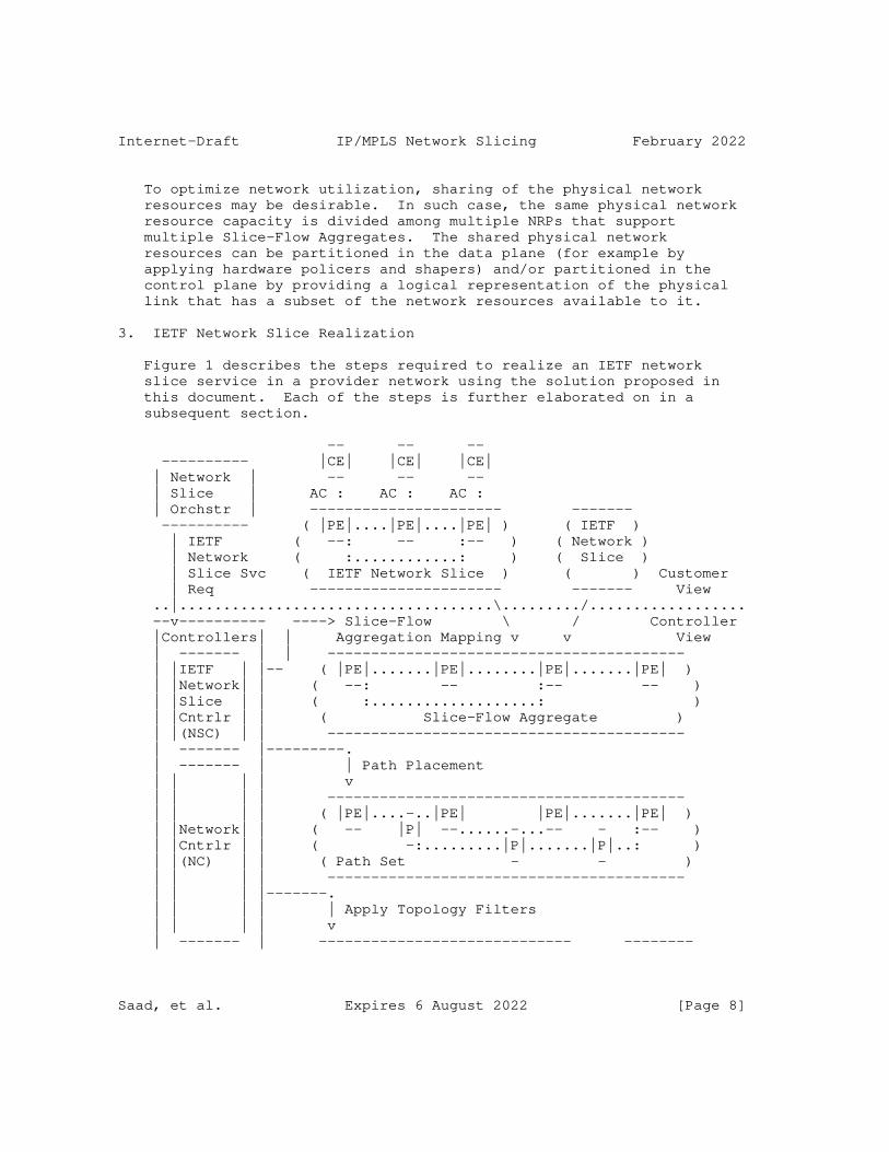
Internet-Draft IP/MPLS Network Slicing February 2022
To optimize network utilization, sharing of the physical network resources may be desirable. In such case, the same physical network resource capacity is divided among multiple NRPs that support multiple Slice-Flow Aggregates. The shared physical network resources can be partitioned in the data plane (for example by applying hardware policers and shapers) and/or partitioned in the control plane by providing a logical representation of the physical link that has a subset of the network resources available to it.
3. IETF Network Slice Realization
Figure 1 describes the steps required to realize an IETF network slice service in a provider network using the solution proposed in this document. Each of the steps is further elaborated on in a subsequent section.
-- -- -- ---------- |CE| |CE| |CE| | Network | -- -- -- | Slice | AC : AC : AC : | Orchstr | ---------------------- ------- ---------- ( |PE|....|PE|....|PE| ) ( IETF ) | IETF ( --: -- :-- ) ( Network ) | Network ( :............: ) ( Slice ) | Slice Svc ( IETF Network Slice ) ( ) Customer | Req ---------------------- ------- View ..|....................................\........./.................. --v---------- ----> Slice-Flow \ / Controller |Controllers| | Aggregation Mapping v v View | ------- | | ----------------------------------------- | |IETF | |-- ( |PE|.......|PE|........|PE|.......|PE| ) | |Network| | ( --: -- :-- -- ) | |Slice | | ( :...................: ) | |Cntrlr | | ( Slice-Flow Aggregate ) | |(NSC) | | ----------------------------------------- | ------- |---------. | ------- | | Path Placement | | | | v | | | | ----------------------------------------- | | | | ( |PE|....-..|PE| |PE|.......|PE| ) | |Network| | ( -- |P| --......-...-- - :-- ) | |Cntrlr | | ( -:.........|P|.......|P|..: ) | |(NC) | | ( Path Set - - ) | | | | ----------------------------------------- | | | |-------. | | | | | Apply Topology Filters | | | | v | ------- | ----------------------------- --------
Saad, et al. Expires 6 August 2022 [Page 8]
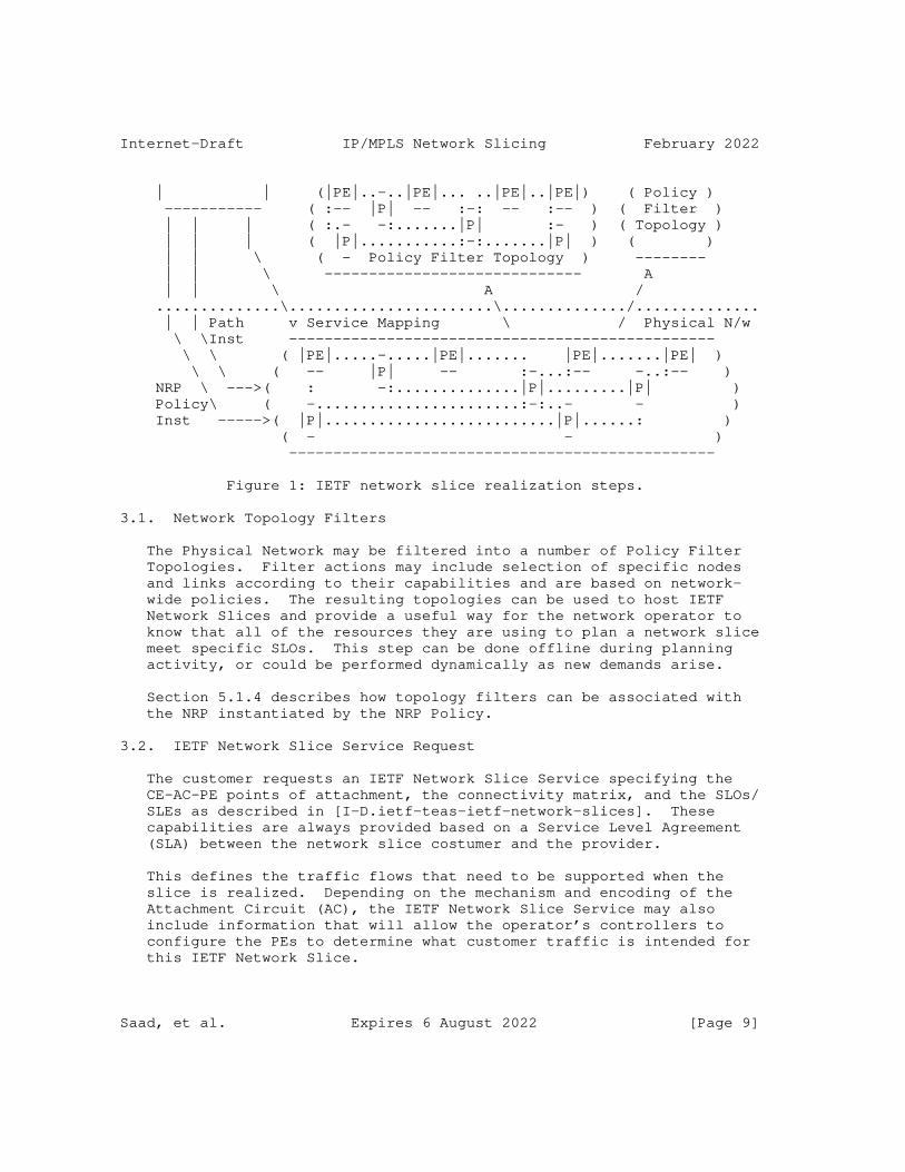
Internet-Draft IP/MPLS Network Slicing February 2022
| | (|PE|..-..|PE|... ..|PE|..|PE|) ( Policy ) ----------- ( :-- |P| -- :-: -- :-- ) ( Filter ) | | | ( :.- -:.......|P| :- ) ( Topology ) | | | ( |P|...........:-:.......|P| ) ( ) | | \ ( - Policy Filter Topology ) -------- | | \ ----------------------------- A | | \ A / ..............\.......................\............../.............. | | Path v Service Mapping \ / Physical N/w \ \Inst ------------------------------------------------ \ \ ( |PE|.....-.....|PE|....... |PE|.......|PE| ) \ \ ( -- |P| -- :-...:-- -..:-- ) NRP \ --->( : -:..............|P|.........|P| ) Policy\ ( -.......................:-:..- - ) Inst ----->( |P|..........................|P|......: ) ( - - ) ------------------------------------------------
Figure 1: IETF network slice realization steps.
3.1. Network Topology Filters
The Physical Network may be filtered into a number of Policy Filter Topologies. Filter actions may include selection of specific nodes and links according to their capabilities and are based on network- wide policies. The resulting topologies can be used to host IETF Network Slices and provide a useful way for the network operator to know that all of the resources they are using to plan a network slice meet specific SLOs. This step can be done offline during planning activity, or could be performed dynamically as new demands arise.
Section 5.1.4 describes how topology filters can be associated with the NRP instantiated by the NRP Policy.
3.2. IETF Network Slice Service Request
The customer requests an IETF Network Slice Service specifying the CE-AC-PE points of attachment, the connectivity matrix, and the SLOs/ SLEs as described in [I-D.ietf-teas-ietf-network-slices]. These capabilities are always provided based on a Service Level Agreement (SLA) between the network slice costumer and the provider.
This defines the traffic flows that need to be supported when the slice is realized. Depending on the mechanism and encoding of the Attachment Circuit (AC), the IETF Network Slice Service may also include information that will allow the operator’s controllers to configure the PEs to determine what customer traffic is intended for this IETF Network Slice.
Saad, et al. Expires 6 August 2022 [Page 9]
Internet-Draft IP/MPLS Network Slicing February 2022
IETF Network Slice Service Requests are likely to arrive at various times in the life of the network, and may also be modified.
3.3. Slice-Flow Aggregation Mapping
A network may be called upon to support very many IETF Network Slices, and this could present scaling challenges in the operation of the network. In order to overcome this, the IETF Network Slice streams may be aggregated into groups according to similar characteristics.
A Slice-Flow Aggregate is a construct that comprises the traffic flows of one or more IETF Network Slices. The mapping of IETF Network Slices into an Slice-Flow Aggregate is a matter of local operator policy is a function executed by the Controller. The Slice- Flow Aggregate may be preconfigured, created on demand, or modified dynamically.
3.4. Path Placement over NRP Topology
Depending on the underlying network technology, the paths are selected in the network in order to best deliver the SLOs for the different services carried by the Slice-Flow Aggregate. The path placement function (carried on ingress node or by a controller) is performed on the Policy Filtered Topology that is selected to support the Slice-Flow Aggregate.
Note that this step may indicate the need to increase the capacity of the underlying Policy Filter Topology or to create a new Policy Filter Topology.
3.5. NRP Policy Installation
A Controller function programs the physical network with policies for handling the traffic flows belonging to the Slice-Flow Aggregate. These policies instruct underlying routers how to handle traffic for a specific Slice-Flow Aggregate: the routers correlate markers present in the packets that belong to the Slice-Flow Aggregate. The way in which the NRP Policy is installed in the routers and the way that the traffic is marked is implementation specific. The NRP Policy instantiation in the network is further described in Section 5.
Saad, et al. Expires 6 August 2022 [Page 10]
Internet-Draft IP/MPLS Network Slicing February 2022
3.6. Path Instantiation
Depending on the underlying network technology, a Controller function may install the forwarding state specific to the Slice-Flow Aggregate so that traffic is routed along paths derived in the Path Placement step described in Section 3.4. The way in which the paths are instantiated is implementation specific.
3.7. Service Mapping
The edge points (PEs) can be configured to support the network slice service by mapping the customer traffic to Slice-Flow Aggregates, possibly using information supplied when the IETF network slice service was requested. The edge points MAY also be instructed to mark the packets so that the network routers will know which policies and routing instructions to apply.
3.8. Network Slice-Flow Aggregate Relationships
The following describes the generalization relationships between the IETF network slice and different parts of the solution as described in Figure 1.
o A customer may request 1 or more IETF Network Slices.
o Any given Attachment Circuit (AC) may support the traffic for 1 or more IETF Network Slice, but if there is more than one IETF Network Slice using a single AC, the IETF Network Slice Service request must include enough information to allow the edge nodes to demultiplex the traffic for the different IETF Network Slices.
o By definition, multiple IETF Network Slices may be mapped to a single Slice-Flow Aggregate. However, it is possible for an Slice- Flow Aggregate to contain just a single IETF Network Slice.
o The physical network may be filtered to multiple Policy Filter Topologies. Each such Policy Filter Topology facilitates planning the placement and support of the Slice-Flow Aggregate by presenting only the subset of links and nodes that meet specific criteria. Note, however, that a network operator does not need to derive any Policy Filter Topologies, choosing to operate directly on the full physical network.
o It is anticipated that there may be very many IETF Network Slices supported by a network operator over a single physical network. A network may support a limited number of Slice-Flow Aggregates, with each of the Slice-Flow Aggregates grouping any number of the IETF Network Slices streams.
Saad, et al. Expires 6 August 2022 [Page 11]
Internet-Draft IP/MPLS Network Slicing February 2022
4. Network Resource Partition Modes
An NRP Policy can be used to dictate if the network resource partitioning of the shared network resources among multiple Slice- Flow Aggregates can be achieved:
a) in data plane only,
b) in control plane only, or
c) in both control and data planes.
4.1. Data plane Network Resource Partition Mode
The physical network resources can be partitioned on network devices by applying a Per Hop forwarding Behavior (PHB) onto packets that traverse the network devices. In the Diffserv model, a Class Selector Codepoint (CS) is carried in the packet and is used by transit nodes to apply the PHB that determines the scheduling treatment and drop probability for packets.
When data plane NRP mode is applied, packets need to be forwarded on the specific NRP that supports the Slice-Flow Aggregate to ensure the proper forwarding treatment dictated in the NRP Policy is applied (refer to Section 5.1 below). In this case, a Flow Aggregate Selector (FAS) MUST be carried in each packet to identify the Slice- Flow Aggregate that it belongs to.
The ingress node of an NRP domain MAY also add an FAS to each Slice- Flow Aggregate packet. The transit nodes within an NRP domain MAY use the FAS to associate packets with a Slice-Flow Aggregate and to determine the Network Resource Partition Per Hop Behavior (NRP-PHB) that is applied to the packet (refer to Section 5.1.3 for further details). The CS MAY be used to apply a Diffserv PHB on to the packet to allow differentiation of traffic treatment within the same Slice-Flow Aggregate.
When data plane only NRP mode is used, routers may rely on a network state independent view of the topology to determine the best paths. In this case, the best path selection dictates the forwarding path of packets to the destination. The FAS field carried in each packet determines the specific NRP-PHB treatment along the selected path.
For example, the Segment-Routing Flexible Algorithm [I-D.ietf-lsr-flex-algo] may be deployed in a network to steer packets on the IGP computed lowest cumulative delay path. An NRP Policy may be used to allow links along the least latency path to share its data plane resources amongst multiple Slice-Flow
Saad, et al. Expires 6 August 2022 [Page 12]

Internet-Draft IP/MPLS Network Slicing February 2022
Aggregates. In this case, the packets that are steered on a specific NRP carry the FAS that enables routers (along with the Diffserv CS) to determine the NRP-PHB to enforce on the Slice-Flow Aggregate traffic streams.
4.2. Control Plane Network Resource Partition Mode
Multiple NRPs can be realized over the same set of physical resources. Each NRP is identified by an identifier (NRP-ID) that is globally unique within the NRP domain. The NRP state reservations for each NRP can be maintained on the network element or on a controller.
The network reservation states for a specific partition can be represented in a topology that contains all or a subset of the physical network elements (nodes and links) and reflect the network state reservations in that NRP. The logical network resources that appear in the NRP topology can reflect a part, whole, or in-excess of the physical network resource capacity (e.g., when oversubscription is desirable).
For example, the physical link bandwidth can be divided into fractions, each dedicated to an NRP that supports a Slice-Flow Aggregate. The topology associated with the NRP supporting a Slice- Flow Aggregate can be used by routing protocols, or by the ingress/ PCE when computing NRP state aware TE paths.
To perform NRP state aware Traffic Engineering (NRP-TE), the resource reservation on each link needs to be NRP aware. The NRP reservations state can be managed locally on the device or off device (e.g. on a controller). Details of required IGP extensions to support NRP-TE are described in [I-D.bestbar-lsr-slice-aware-te].
The same physical link may be member of multiple slice policies that instantiate different NRPs. The NRP reservable or utilized bandwidth on such a link is updated (and may be advertised) whenever new paths are placed in the network. The NRP reservation state, in this case, MAY be maintained on each device or off the device on a resource reservation manager that holds reservation states for those links in the network.
Multiple NRPs that support Slice-Flow Aggregates can form a group and share the available network resources allocated to each. In this case, a node can update the reservable bandwidth for each NRP to take into consideration the available bandwidth from other NRPs in the same group.
Saad, et al. Expires 6 August 2022 [Page 13]
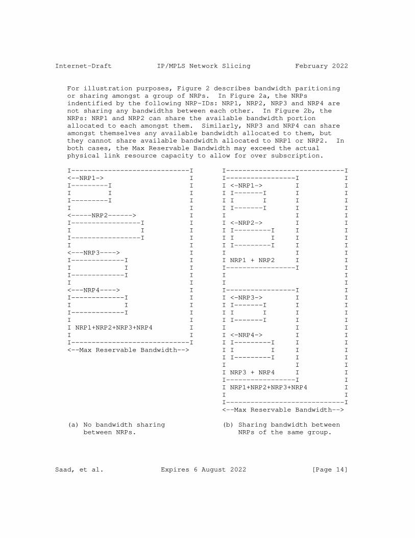
Internet-Draft IP/MPLS Network Slicing February 2022
For illustration purposes, Figure 2 describes bandwidth paritioning or sharing amongst a group of NRPs. In Figure 2a, the NRPs indentified by the following NRP-IDs: NRP1, NRP2, NRP3 and NRP4 are not sharing any bandwidths between each other. In Figure 2b, the NRPs: NRP1 and NRP2 can share the available bandwidth portion allocated to each amongst them. Similarly, NRP3 and NRP4 can share amongst themselves any available bandwidth allocated to them, but they cannot share available bandwidth allocated to NRP1 or NRP2. In both cases, the Max Reservable Bandwidth may exceed the actual physical link resource capacity to allow for over subscription.
I-----------------------------I I-----------------------------I <--NRP1-> I I-----------------I I I---------I I I <-NRP1-> I I I I I I I-------I I I I---------I I I I I I I I I I I-------I I I <-----NRP2------> I I I I I-----------------I I I <-NRP2-> I I I I I I I---------I I I I-----------------I I I I I I I I I I I---------I I I <---NRP3----> I I I I I-------------I I I NRP1 + NRP2 I I I I I I-----------------I I I-------------I I I I I I I I <---NRP4----> I I-----------------I I I-------------I I I <-NRP3-> I I I I I I I-------I I I I-------------I I I I I I I I I I I-------I I I I NRP1+NRP2+NRP3+NRP4 I I I I I I I <-NRP4-> I I I-----------------------------I I I---------I I I <--Max Reservable Bandwidth--> I I I I I I I---------I I I I I I I NRP3 + NRP4 I I I-----------------I I I NRP1+NRP2+NRP3+NRP4 I I I I-----------------------------I <--Max Reservable Bandwidth-->
(a) No bandwidth sharing (b) Sharing bandwidth between between NRPs. NRPs of the same group.
Saad, et al. Expires 6 August 2022 [Page 14]
Internet-Draft IP/MPLS Network Slicing February 2022
Figure 2: Bandwidth isolation/sharing among NRPs.
4.3. Data and Control Plane Network Resource Partition Mode
In order to support strict guarantees for Slice-Flow Aggregates, the network resources can be partitioned in both the control plane and data plane.
The control plane partitioning allows the creation of customized topologies per NRP that each supports a Slice-Flow Aggregate. The ingress routers or a Path Computation Engine (PCE) may use the customized topologies and the NRP state to determine optimal path placement for specific demand flows using NRP-TE.
The data plane partitioning provides isolation for Slice-Flow Aggregate traffic, and protection when resource contention occurs due to bursts of traffic from other Slice-Flow Aggregate traffic that traverses the same shared network resource.
5. Network Resource Partition Instantiation
A network slice can span multiple technologies and multiple administrative domains. Depending on the network slice customer requirements, a network slice can be differentiated from other network slices in terms of data, control, and management planes.
The customer of a network slice service expresses their intent by specifying requirements rather than mechanisms to realize the slice as described in Section 3.2.
The network slice controller is fed with the network slice service intent and realizes it with an appropriate Network Resource Partition Policy (NRP Policy). Multiple IETF network slices MAY be mapped to the same Slice-Flow Aggregate as described in Section 3.3.
The network wide consistent NRP Policy definition is distributed to the devices in the network as shown in Figure 1. The specification of the network slice intent on the northbound interface of the controller and the mechanism used to map the network slice to a Slice-Flow Aggregate are outside the scope of this document and will be addressed in separate documents.
5.1. NRP Policy Definition
The NRP Policy is network-wide construct that is supplied to network devices, and may include rules that control the following:
Saad, et al. Expires 6 August 2022 [Page 15]
Internet-Draft IP/MPLS Network Slicing February 2022
* Data plane specific policies: This includes the FAS, any firewall rules or flow-spec filters, and QoS profiles associated with the NRP Policy and any classes within it.
* Control plane specific policies: This includes bandwidth reservations, any network resource sharing amongst slice policies, and reservation preference to prioritize reservations of a specific NRP over others.
* Topology membership policies: This defines the topology filter policies that dictate node/link/function membership to a specific NRP.
There is a desire for flexibility in realizing network slices to support the services across networks consisting of implementations from multiple vendors. These networks may also be grouped into disparate domains and deploy various path control technologies and tunnel techniques to carry traffic across the network. It is expected that a standardized data model for NRP Policy will facilitate the instantiation and management of the NRP on the topological elements selected by the NRP Policy topology filter. A YANG data model for the Network Resource Partition Policy instantiation on the controller and network devices is described in [I-D.bestbar-teas-yang-slice-policy].
It is also possible to distribute the NRP Policy to network devices using several mechanisms, including protocols such as NETCONF or RESTCONF, or exchanging it using a suitable routing protocol that network devices participate in (such as IGP(s) or BGP). The extensions to enable specific protocols to carry an NRP Policy definition will be described in separate documents.
5.1.1. Network Resource Partition Data Plane Selector
A router MUST be able to identify a packet belonging to a Slice-Flow Aggregate before it can apply the associated dataplane forwarding treatment or NRP-PHB. One or more fields within the packet MAY be used as an FAS to do this.
Forwarding Address Based Selector:
It is possible to assign a different forwarding address (or MPLS forwarding label in case of MPLS network) for each Slice-Flow Aggregate on a specific node in the network. [RFC3031] states in Section 2.1 that: ’Some routers analyze a packet’s network layer header not merely to choose the packet’s next hop, but also to determine a packet’s "precedence" or "class of service"’. Assigning a unique forwarding address (or MPLS forwarding label)
Saad, et al. Expires 6 August 2022 [Page 16]
Internet-Draft IP/MPLS Network Slicing February 2022
to each Slice-Flow Aggregate allows Slice-Flow Aggregate packets destined to a node to be distinguished by the destination address (or MPLS forwarding label) that is carried in the packet.
This approach requires maintaining per Slice-Flow Aggregate state for each destination in the network in both the control and data plane and on each router in the network. For example, consider a network slicing provider with a network composed of ’N’ nodes, each with ’K’ adjacencies to its neighbors. Assuming a node can be reached over ’M’ different Slice-Flow Aggregates, the node assigns and advertises reachability to ’N’ unique forwarding addresses, or MPLS forwarding labels. Similarly, each node assigns a unique forwarding address (or MPLS forwarding label) for each of its ’K’ adjacencies to enable strict steering over the adjacency for each slice. The total number of control and data plane states that need to be stored and programmed in a router’s forwarding is (N+K)*M states. Hence, as ’N’, ’K’, and ’M’ parameters increase, this approach suffers from scalability challenges in both the control and data planes.
Global Identifier Based Selector:
An NRP Policy MAY include a Global Identifier FAS (GIS) field as defined in [I-D.kompella-mpls-mspl4fa] that is carried in each packet in order to associate it to the NRP supporting a Slice-Flow Aggregate, independent of the forwarding address or MPLS forwarding label that is bound to the destination. Routers within the NRP domain can use the forwarding address (or MPLS forwarding label) to determine the forwarding next-hop(s), and use the GIS field in the packet to infer the specific forwarding treatment that needs to be applied on the packet.
The GIS can be carried in one of multiple fields within the packet, depending on the dataplane used. For example, in MPLS networks, the GIS can be encoded within an MPLS label that is carried in the packet’s MPLS label stack. All packets that belong to the same Slice-Flow Aggregate MAY carry the same GIS in the MPLS label stack. It is also possible to have multiple GIS’s map to the same Slice-Flow Aggregate.
The GIS can be encoded in an MPLS label and may appear in several positions in the MPLS label stack. For example, the VPN service label may act as a GIS to allow VPN packets to be mapped to the Slice-Flow Aggregate. In this case, a single VPN service label acting as a GIS MAY be allocated by all Egress PEs of a VPN. Alternatively, multiple VPN service labels MAY act as GIS’s that map a single VPN to the same Slice-Flow Aggregate to allow for multiple Egress PEs to allocate different VPN service labels for a
Saad, et al. Expires 6 August 2022 [Page 17]
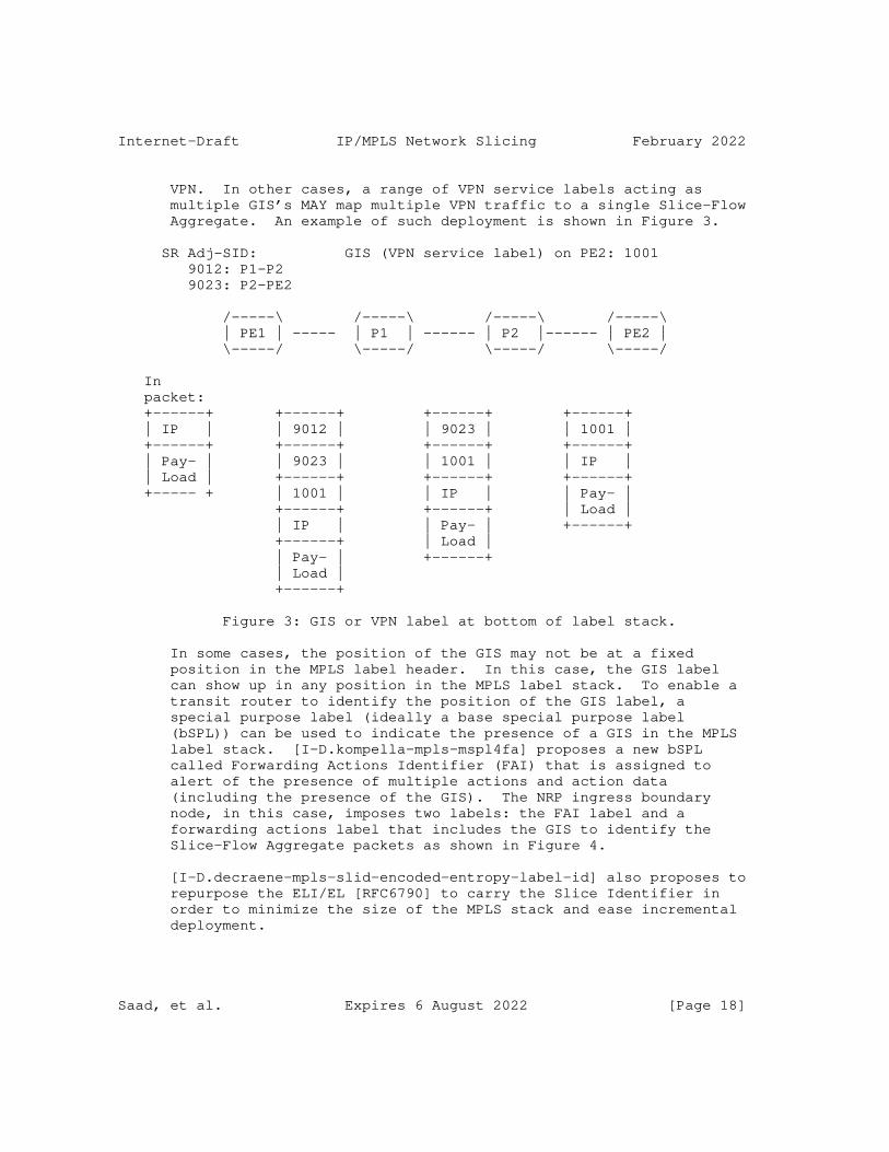
Internet-Draft IP/MPLS Network Slicing February 2022
VPN. In other cases, a range of VPN service labels acting as multiple GIS’s MAY map multiple VPN traffic to a single Slice-Flow Aggregate. An example of such deployment is shown in Figure 3.
SR Adj-SID: GIS (VPN service label) on PE2: 1001 9012: P1-P2 9023: P2-PE2
/-----\ /-----\ /-----\ /-----\ | PE1 | ----- | P1 | ------ | P2 |------ | PE2 | \-----/ \-----/ \-----/ \-----/
In packet: +------+ +------+ +------+ +------+ | IP | | 9012 | | 9023 | | 1001 | +------+ +------+ +------+ +------+ | Pay- | | 9023 | | 1001 | | IP | | Load | +------+ +------+ +------+ +----- + | 1001 | | IP | | Pay- | +------+ +------+ | Load | | IP | | Pay- | +------+ +------+ | Load | | Pay- | +------+ | Load | +------+
Figure 3: GIS or VPN label at bottom of label stack.
In some cases, the position of the GIS may not be at a fixed position in the MPLS label header. In this case, the GIS label can show up in any position in the MPLS label stack. To enable a transit router to identify the position of the GIS label, a special purpose label (ideally a base special purpose label (bSPL)) can be used to indicate the presence of a GIS in the MPLS label stack. [I-D.kompella-mpls-mspl4fa] proposes a new bSPL called Forwarding Actions Identifier (FAI) that is assigned to alert of the presence of multiple actions and action data (including the presence of the GIS). The NRP ingress boundary node, in this case, imposes two labels: the FAI label and a forwarding actions label that includes the GIS to identify the Slice-Flow Aggregate packets as shown in Figure 4.
[I-D.decraene-mpls-slid-encoded-entropy-label-id] also proposes to repurpose the ELI/EL [RFC6790] to carry the Slice Identifier in order to minimize the size of the MPLS stack and ease incremental deployment.
Saad, et al. Expires 6 August 2022 [Page 18]
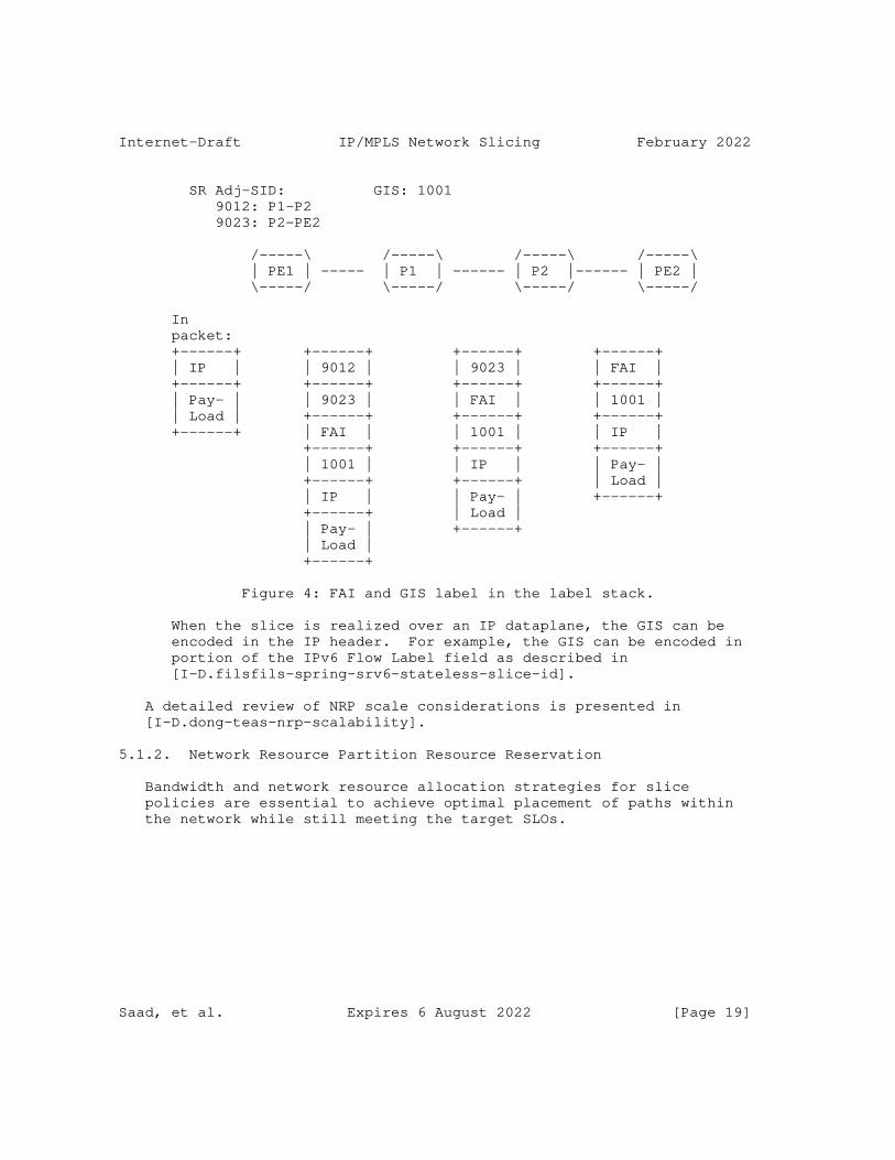
Internet-Draft IP/MPLS Network Slicing February 2022
SR Adj-SID: GIS: 1001 9012: P1-P2 9023: P2-PE2
/-----\ /-----\ /-----\ /-----\ | PE1 | ----- | P1 | ------ | P2 |------ | PE2 | \-----/ \-----/ \-----/ \-----/
In packet: +------+ +------+ +------+ +------+ | IP | | 9012 | | 9023 | | FAI | +------+ +------+ +------+ +------+ | Pay- | | 9023 | | FAI | | 1001 | | Load | +------+ +------+ +------+ +------+ | FAI | | 1001 | | IP | +------+ +------+ +------+ | 1001 | | IP | | Pay- | +------+ +------+ | Load | | IP | | Pay- | +------+ +------+ | Load | | Pay- | +------+ | Load | +------+
Figure 4: FAI and GIS label in the label stack.
When the slice is realized over an IP dataplane, the GIS can be encoded in the IP header. For example, the GIS can be encoded in portion of the IPv6 Flow Label field as described in [I-D.filsfils-spring-srv6-stateless-slice-id].
A detailed review of NRP scale considerations is presented in [I-D.dong-teas-nrp-scalability].
5.1.2. Network Resource Partition Resource Reservation
Bandwidth and network resource allocation strategies for slice policies are essential to achieve optimal placement of paths within the network while still meeting the target SLOs.
Saad, et al. Expires 6 August 2022 [Page 19]
Internet-Draft IP/MPLS Network Slicing February 2022
Resource reservation allows for the management of available bandwidth and the prioritization of existing allocations to enable preference- based preemption when contention on a specific network resource arises. Sharing of a network resource’s available bandwidth amongst a group of NRPs may also be desirable. For example, a Slice-Flow Aggregate may not be using all of the NRP reservable bandwidth; this allows other NRPs in the same group to use the available bandwidth resources for other Slice-Flow Aggregates.
Congestion on shared network resources may result from sub-optimal placement of paths in different slice policies. When this occurs, preemption of some Slice-Flow Aggregate paths may be desirable to alleviate congestion. A preference-based allocation scheme enables prioritization of Slice-Flow Aggregate paths that can be preempted.
Since network characteristics and its state can change over time, the NRP topology and its network state need to be propagated in the network to enable ingress TE routers or Path Computation Engine (PCEs) to perform accurate path placement based on the current state of the NRP network resources.
5.1.3. Network Resource Partition Per Hop Behavior
In Diffserv terminology, the forwarding behavior that is assigned to a specific class is called a Per Hop Behavior (PHB). The PHB defines the forwarding precedence that a marked packet with a specific CS receives in relation to other traffic on the Diffserv-aware network.
The NRP Per Hop Behavior (NRP-PHB) is the externally observable forwarding behavior applied to a specific packet belonging to a Slice-Flow Aggregate. The goal of an NRP-PHB is to provide a specified amount of network resources for traffic belonging to a specific Slice-Flow Aggregate. A single NRP may also support multiple forwarding treatments or services that can be carried over the same logical network.
The Slice-Flow Aggregate traffic may be identified at NRP ingress boundary nodes by carrying a FAS to allow routers to apply a specific forwarding treatment that guarantee the SLA(s).
Saad, et al. Expires 6 August 2022 [Page 20]

Internet-Draft IP/MPLS Network Slicing February 2022
With Differentiated Services (Diffserv) it is possible to carry multiple services over a single converged network. Packets requiring the same forwarding treatment are marked with a CS at domain ingress nodes. Up to eight classes or Behavior Aggregates (BAs) may be supported for a given Forwarding Equivalence Class (FEC) [RFC2475]. To support multiple forwarding treatments over the same Slice-Flow Aggregate, a Slice-Flow Aggregate packet MAY also carry a Diffserv CS to identify the specific Diffserv forwarding treatment to be applied on the traffic belonging to the same NRP.
At transit nodes, the CS field carried inside the packets are used to determine the specific PHB that determines the forwarding and scheduling treatment before packets are forwarded, and in some cases, drop probability for each packet.
5.1.4. Network Resource Partition Topology
A key element of the NRP Policy is a customized topology that may include the full or subset of the physical network topology. The NRP topology could also span multiple administrative domains and/or multiple dataplane technologies.
An NRP topology can overlap or share a subset of links with another NRP topology. A number of topology filtering policies can be defined as part of the NRP Policy to limit the specific topology elements that belong to the NRP. For example, a topology filtering policy can leverage Resource Affinities as defined in [RFC2702] to include or exclude certain links that the NRP is instantiated on in supports of the Slice-Flow Aggregate.
The NRP Policy may also include a reference to a predefined topology (e.g., derived from a Flexible Algorithm Definition (FAD) as defined in [I-D.ietf-lsr-flex-algo], or Multi-Topology ID as defined [RFC4915]. A YANG data model that covers generic topology filters is described in [I-D.bestbar-teas-yang-topology-filter]. Also, the Path Computation Element (PCE) Communication Protocol (PCEP) extensions to carry topology filters are defined in [I-D.xpbs-pce-topology-filter].
5.2. Network Resource Partition Boundary
A network slice originates at the edge nodes of a network slice provider. Traffic that is steered over the corresponding NRP supporting a Slice-Flow Aggregate may traverse NRP capable as well as NRP incapable interior nodes.
Saad, et al. Expires 6 August 2022 [Page 21]
Internet-Draft IP/MPLS Network Slicing February 2022
The network slice may encompass one or more domains administered by a provider. For example, an organization’s intranet or an ISP. The network provider is responsible for ensuring that adequate network resources are provisioned and/or reserved to support the SLAs offered by the network end-to-end.
5.2.1. Network Resource Partition Edge Nodes
NRP edge nodes sit at the boundary of a network slice provider network and receive traffic that requires steering over network resources specific to a NRP that supports a Slice-Flow Aggregate. These edge nodes are responsible for identifying Slice-Flow Aggregate specific traffic flows by possibly inspecting multiple fields from inbound packets (e.g., implementations may inspect IP traffic’s network 5-tuple in the IP and transport protocol headers) to decide on which NRP it can be steered.
Network slice ingress nodes may condition the inbound traffic at network boundaries in accordance with the requirements or rules of each service’s SLAs. The requirements and rules for network slice services are set using mechanisms which are outside the scope of this document.
When data plane NRP mode is employed, the NRP ingress nodes are responsible for adding a suitable FAS onto packets that belong to specific Slice-Flow Aggregate. In addition, edge nodes MAY mark the corresponding Diffserv CS to differentiate between different types of traffic carried over the same Slice-Flow Aggregate.
5.2.2. Network Resource Partition Interior Nodes
An NRP interior node receives slice traffic and MAY be able to identify the packets belonging to a specific Slice-Flow Aggregate by inspecting the FAS field carried inside each packet, or by inspecting other fields within the packet that may identify the traffic streams that belong to a specific Slice-Flow Aggregate. For example, when data plane NRP mode is applied, interior nodes can use the FAS carried within the packet to apply the corresponding NRP-PHB forwarding behavior. Nodes within the network slice provider network may also inspect the Diffserv CS within each packet to apply a per Diffserv class PHB within the NRP Policy, and allow differentiation of forwarding treatments for packets forwarded over the same NRP that supports the Slice-Flow Aggregate.
Saad, et al. Expires 6 August 2022 [Page 22]

Internet-Draft IP/MPLS Network Slicing February 2022
5.2.3. Network Resource Partition Incapable Nodes
Packets that belong to a Slice-Flow Aggregate may need to traverse nodes that are NRP incapable. In this case, several options are possible to allow the slice traffic to continue to be forwarded over such devices and be able to resume the NRP forwarding treatment once the traffic reaches devices that are NRP-capable.
When data plane NRP mode is employed, packets carry a FAS to allow slice interior nodes to identify them. To support end-to-end network slicing, the FAS MUST be maintained in the packets as they traverse devices within the network - including NRP capable and incapable devices.
For example, when the FAS is an MPLS label at the bottom of the MPLS label stack, packets can traverse over devices that are NRP incapable without any further considerations. On the other hand when the FASL is at the top of the MPLS label stack, packets can be bypassed (or tunneled) over the NRP incapable devices towards the next device that supports NRP as shown in Figure 5.
Saad, et al. Expires 6 August 2022 [Page 23]
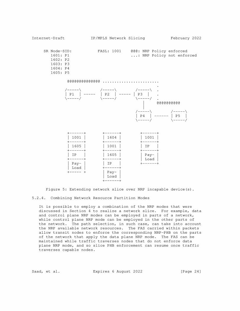
Internet-Draft IP/MPLS Network Slicing February 2022
SR Node-SID: FASL: 1001 @@@: NRP Policy enforced 1601: P1 ...: NRP Policy not enforced 1602: P2 1603: P3 1604: P4 1605: P5
@@@@@@@@@@@@@@ ........................ . /-----\ /-----\ /-----\ . | P1 | ----- | P2 | ----- | P3 | . \-----/ \-----/ \-----/ . | @@@@@@@@@@ | /-----\ /-----\ | P4 | ------ | P5 | \-----/ \-----/
+------+ +------+ +------+ | 1001 | | 1604 | | 1001 | +------+ +------+ +------+ | 1605 | | 1001 | | IP | +------+ +------+ +------+ | IP | | 1605 | | Pay- | +------+ +------+ | Load | | Pay- | | IP | +------+ | Load | +------+ +----- + | Pay- | | Load | +------+
Figure 5: Extending network slice over NRP incapable device(s).
5.2.4. Combining Network Resource Partition Modes
It is possible to employ a combination of the NRP modes that were discussed in Section 4 to realize a network slice. For example, data and control plane NRP modes can be employed in parts of a network, while control plane NRP mode can be employed in the other parts of the network. The path selection, in such case, can take into account the NRP available network resources. The FAS carried within packets allow transit nodes to enforce the corresponding NRP-PHB on the parts of the network that apply the data plane NRP mode. The FAS can be maintained while traffic traverses nodes that do not enforce data plane NRP mode, and so slice PHB enforcement can resume once traffic traverses capable nodes.
Saad, et al. Expires 6 August 2022 [Page 24]

Internet-Draft IP/MPLS Network Slicing February 2022
5.3. Mapping Traffic on Slice-Flow Aggregates
The usual techniques to steer traffic onto paths can be applicable when steering traffic over paths established for a specific Slice- Flow Aggregate.
For example, one or more (layer-2 or layer-3) VPN services can be directly mapped to paths established for a Slice-Flow Aggregate. In this case, the per Virtual Routing and Forwarding (VRF) instance traffic that arrives on the Provider Edge (PE) router over external interfaces can be directly mapped to a specific Slice-Flow Aggregate path. External interfaces can be further partitioned (e.g., using VLANs) to allow mapping one or more VLANs to specific Slice-Flow Aggregate paths.
Another option is steer traffic to specific destinations directly over multiple slice policies. This allows traffic arriving on any external interface and targeted to such destinations to be directly steered over the slice paths.
A third option that can also be used is to utilize a data plane firewall filter or classifier to enable matching of several fields in the incoming packets to decide whether the packet belongs to a specific Slice-Flow Aggregate. This option allows for applying a rich set of rules to identify specific packets to be mapped to a Slice-Flow Aggregate. However, it requires data plane network resources to be able to perform the additional checks in hardware.
6. Path Selection and Instantiation
6.1. Applicability of Path Selection to Slice-Flow Aggregates
The path selection in the network can be network state dependent, or network state independent as described in Section 5.1 of [I-D.ietf-teas-rfc3272bis]. The latter is the choice commonly used by IGPs when selecting a best path to a destination prefix, while the former is used by ingress TE routers, or Path Computation Engines (PCEs) when optimizing the placement of a flow based on the current network resource utilization.
When path selection is network state dependent, the path computation can leverage Traffic Engineering mechanisms (e.g., as defined in [RFC2702]) to compute feasible paths taking into account the incoming traffic demand rate and current state of network. This allows avoiding overly utilized links, and reduces the chance of congestion on traversed links.
Saad, et al. Expires 6 August 2022 [Page 25]
Internet-Draft IP/MPLS Network Slicing February 2022
To enable TE path placement, the link state is advertised with current reservations, thereby reflecting the available bandwidth on each link. Such link reservations may be maintained centrally on a network wide network resource manager, or distributed on devices (as usually done with RSVP). TE extensions exist today to allow IGPs (e.g., [RFC3630] and [RFC5305]), and BGP-LS [RFC7752] to advertise such link state reservations.
When the network resource reservations are maintained for NRPs, the link state can carry per NRP state (e.g., reservable bandwidth). This allows path computation to take into account the specific network resources available for an NRP. In this case, we refer to the process of path placement and path provisioning as NRP aware TE (NRP-TE).
6.2. Applicability of Path Control Technologies to Slice-Flow Aggregates
The NRP modes described in this document are agnostic to the technology used to setup paths that carry Slice-Flow Aggregate traffic. One or more paths connecting the endpoints of the mapped IETF network slices may be selected to steer the corresponding traffic streams over the resources allocated for the NRP that supports a Slice-Flow Aggregate.
The feasible paths can be computed using the NRP topology and network state subject the optimization metrics and constraints.
6.2.1. RSVP-TE Based Slice-Flow Aggregate Paths
RSVP-TE [RFC3209] can be used to signal LSPs over the computed feasible paths in order to carry the Slice-Flow Aggregate traffic. The specific extensions to the RSVP-TE protocol required to enable signaling of NRP aware RSVP LSPs are outside the scope of this document.
6.2.2. SR Based Slice-Flow Aggregate Paths
Segment Routing (SR) [RFC8402] can be used to setup and steer traffic over the computed Slice-Flow Aggregate feasible paths.
The SR architecture defines a number of building blocks that can be leveraged to support the realization of NRPs that support Slice-Flow Aggregates in an SR network.
Such building blocks include:
* SR Policy with or without Flexible Algorithm.
Saad, et al. Expires 6 August 2022 [Page 26]
Internet-Draft IP/MPLS Network Slicing February 2022
* Steering of services (e.g. VPN) traffic over SR paths
* SR Operation, Administration and Management (OAM) and Performance Management (PM)
SR allows a headend node to steer packets onto specific SR paths using a Segment Routing Policy (SR Policy). The SR policy supports various optimization objectives and constraints and can be used to steer Slice-Flow Aggregate traffic in the SR network.
The SR policy can be instantiated with or without the IGP Flexible Algorithm (Flex-Algorithm) feature. It may be possible to dedicate a single SR Flex-Algorithm to compute and instantiate SR paths for one Slice-Flow Aggregate traffic. In this case, the SR Flex-Algorithm computed paths and Flex-Algorithm SR SIDs are not shared by other Slice-Flow Aggregates traffic. However, to allow for better scale, it may be desirable for multiple Slice-Flow Aggregates traffic to share the same SR Flex-Algorithm computed paths and SIDs. Further details on how the NRP modes presented in this document can be realized in an SR network are discussed in [I-D.bestbar-spring-scalable-ns], and [I-D.bestbar-lsr-spring-sa].
7. Network Resource Partition Protocol Extensions
Routing protocols may need to be extended to carry additional per NRP link state. For example, [RFC5305], [RFC3630], and [RFC7752] are ISIS, OSPF, and BGP protocol extensions to exchange network link state information to allow ingress TE routers and PCE(s) to do proper path placement in the network. The extensions required to support network slicing may be defined in other documents, and are outside the scope of this document.
The instantiation of an NRP Policy may need to be automated. Multiple options are possible to facilitate automation of distribution of an NRP Policy to capable devices.
For example, a YANG data model for the NRP Policy may be supported on network devices and controllers. A suitable transport (e.g., NETCONF [RFC6241], RESTCONF [RFC8040], or gRPC) may be used to enable configuration and retrieval of state information for slice policies on network devices. The NRP Policy YANG data model is outside the scope of this document, and is defined in [I-D.bestbar-teas-yang-slice-policy].
8. IANA Considerations
This document has no IANA actions.
Saad, et al. Expires 6 August 2022 [Page 27]
Internet-Draft IP/MPLS Network Slicing February 2022
9. Security Considerations
The main goal of network slicing is to allow for varying treatment of traffic from multiple different network slices that are utilizing a common network infrastructure and to allow for different levels of services to be provided for traffic traversing a given network resource.
A variety of techniques may be used to achieve this, but the end result will be that some packets may be mapped to specific resources and may receive different (e.g., better) service treatment than others. The mapping of network traffic to a specific NRP is indicated primarily by the FAS, and hence an adversary may be able to utilize resources allocated to a specific NRP by injecting packets carrying the same FAS field in their packets.
Such theft-of-service may become a denial-of-service attack when the modified or injected traffic depletes the resources available to forward legitimate traffic belonging to a specific NRP.
The defense against this type of theft and denial-of-service attacks consists of a combination of traffic conditioning at NRP domain boundaries with security and integrity of the network infrastructure within an NRP domain.
10. Acknowledgement
The authors would like to thank Krzysztof Szarkowicz, Swamy SRK, Navaneetha Krishnan, Prabhu Raj Villadathu Karunakaran, Jie Dong, and Mohamed Boucadair for their review of this document and for providing valuable feedback on it. The authors would also like to thank Adrian Farrel for detailed discussions that resulted in Section 3.
11. Contributors
The following individuals contributed to this document:
Colby Barth Juniper Networks Email: [email protected]
Srihari R. Sangli Juniper Networks Email: [email protected]
Chandra Ramachandran Juniper Networks Email: [email protected]
Saad, et al. Expires 6 August 2022 [Page 28]
Internet-Draft IP/MPLS Network Slicing February 2022
12. References
12.1. Normative References
[I-D.bestbar-teas-yang-slice-policy] Saad, T., Beeram, V. P., Wen, B., Ceccarelli, D., Peng, S., Chen, R., Contreras, L. M., and X. Liu, "YANG Data Model for Slice Policy", Work in Progress, Internet-Draft, draft-bestbar-teas-yang-slice-policy-02, 25 October 2021, <https://www.ietf.org/archive/id/draft-bestbar-teas-yang- slice-policy-02.txt>.
[I-D.ietf-lsr-flex-algo] Psenak, P., Hegde, S., Filsfils, C., Talaulikar, K., and A. Gulko, "IGP Flexible Algorithm", Work in Progress, Internet-Draft, draft-ietf-lsr-flex-algo-18, 25 October 2021, <https://www.ietf.org/archive/id/draft-ietf-lsr- flex-algo-18.txt>.
[I-D.kompella-mpls-mspl4fa] Kompella, K., Beeram, V. P., Saad, T., and I. Meilik, "Multi-purpose Special Purpose Label for Forwarding Actions", Work in Progress, Internet-Draft, draft- kompella-mpls-mspl4fa-01, 12 July 2021, <https://www.ietf.org/archive/id/draft-kompella-mpls- mspl4fa-01.txt>.
[RFC2119] Bradner, S., "Key words for use in RFCs to Indicate Requirement Levels", BCP 14, RFC 2119, DOI 10.17487/RFC2119, March 1997, <https://www.rfc-editor.org/info/rfc2119>.
[RFC3031] Rosen, E., Viswanathan, A., and R. Callon, "Multiprotocol Label Switching Architecture", RFC 3031, DOI 10.17487/RFC3031, January 2001, <https://www.rfc-editor.org/info/rfc3031>.
[RFC3209] Awduche, D., Berger, L., Gan, D., Li, T., Srinivasan, V., and G. Swallow, "RSVP-TE: Extensions to RSVP for LSP Tunnels", RFC 3209, DOI 10.17487/RFC3209, December 2001, <https://www.rfc-editor.org/info/rfc3209>.
[RFC3630] Katz, D., Kompella, K., and D. Yeung, "Traffic Engineering (TE) Extensions to OSPF Version 2", RFC 3630, DOI 10.17487/RFC3630, September 2003, <https://www.rfc-editor.org/info/rfc3630>.
Saad, et al. Expires 6 August 2022 [Page 29]
Internet-Draft IP/MPLS Network Slicing February 2022
[RFC4915] Psenak, P., Mirtorabi, S., Roy, A., Nguyen, L., and P. Pillay-Esnault, "Multi-Topology (MT) Routing in OSPF", RFC 4915, DOI 10.17487/RFC4915, June 2007, <https://www.rfc-editor.org/info/rfc4915>.
[RFC5305] Li, T. and H. Smit, "IS-IS Extensions for Traffic Engineering", RFC 5305, DOI 10.17487/RFC5305, October 2008, <https://www.rfc-editor.org/info/rfc5305>.
[RFC6790] Kompella, K., Drake, J., Amante, S., Henderickx, W., and L. Yong, "The Use of Entropy Labels in MPLS Forwarding", RFC 6790, DOI 10.17487/RFC6790, November 2012, <https://www.rfc-editor.org/info/rfc6790>.
[RFC7752] Gredler, H., Ed., Medved, J., Previdi, S., Farrel, A., and S. Ray, "North-Bound Distribution of Link-State and Traffic Engineering (TE) Information Using BGP", RFC 7752, DOI 10.17487/RFC7752, March 2016, <https://www.rfc-editor.org/info/rfc7752>.
[RFC8174] Leiba, B., "Ambiguity of Uppercase vs Lowercase in RFC 2119 Key Words", BCP 14, RFC 8174, DOI 10.17487/RFC8174, May 2017, <https://www.rfc-editor.org/info/rfc8174>.
[RFC8402] Filsfils, C., Ed., Previdi, S., Ed., Ginsberg, L., Decraene, B., Litkowski, S., and R. Shakir, "Segment Routing Architecture", RFC 8402, DOI 10.17487/RFC8402, July 2018, <https://www.rfc-editor.org/info/rfc8402>.
12.2. Informative References
[I-D.bestbar-lsr-slice-aware-te] Britto, W., Shetty, R., Barth, C., Wen, B., Peng, S., and R. Chen, "IGP Extensions for Support of Slice Aggregate Aware Traffic Engineering", Work in Progress, Internet- Draft, draft-bestbar-lsr-slice-aware-te-00, 22 February 2021, <https://www.ietf.org/archive/id/draft-bestbar-lsr- slice-aware-te-00.txt>.
[I-D.bestbar-lsr-spring-sa] Saad, T., Beeram, V. P., Chen, R., Peng, S., Wen, B., and D. Ceccarelli, "IGP Extensions for SR Slice Aggregate SIDs", Work in Progress, Internet-Draft, draft-bestbar- lsr-spring-sa-01, 16 September 2021, <https://www.ietf.org/archive/id/draft-bestbar-lsr-spring- sa-01.txt>.
Saad, et al. Expires 6 August 2022 [Page 30]
Internet-Draft IP/MPLS Network Slicing February 2022
[I-D.bestbar-spring-scalable-ns] Saad, T., Beeram, V. P., Chen, R., Peng, S., Wen, B., and D. Ceccarelli, "Scalable Network Slicing over SR Networks", Work in Progress, Internet-Draft, draft- bestbar-spring-scalable-ns-02, 16 September 2021, <https://www.ietf.org/archive/id/draft-bestbar-spring- scalable-ns-02.txt>.
[I-D.bestbar-teas-yang-topology-filter] Beeram, V. P., Saad, T., Gandhi, R., and X. Liu, "YANG Data Model for Topology Filter", Work in Progress, Internet-Draft, draft-bestbar-teas-yang-topology-filter- 02, 25 October 2021, <https://www.ietf.org/archive/id/ draft-bestbar-teas-yang-topology-filter-02.txt>.
[I-D.decraene-mpls-slid-encoded-entropy-label-id] Decraene, B., Filsfils, C., Henderickx, W., Saad, T., Beeram, V. P., and L. Jalil, "Using Entropy Label for Network Slice Identification in MPLS networks.", Work in Progress, Internet-Draft, draft-decraene-mpls-slid- encoded-entropy-label-id-02, 6 August 2021, <https://www.ietf.org/archive/id/draft-decraene-mpls-slid- encoded-entropy-label-id-02.txt>.
[I-D.dong-teas-nrp-scalability] Dong, J., Li, Z., Gong, L., Yang, G., Guichard, J. N., Mishra, G., and F. Qin, "Scalability Considerations for Network Resource Partition", Work in Progress, Internet- Draft, draft-dong-teas-nrp-scalability-00, 17 December 2021, <https://www.ietf.org/archive/id/draft-dong-teas- nrp-scalability-00.txt>.
[I-D.filsfils-spring-srv6-stateless-slice-id] Filsfils, C., Clad, F., Camarillo, P., Raza, K., Voyer, D., and R. Rokui, "Stateless and Scalable Network Slice Identification for SRv6", Work in Progress, Internet- Draft, draft-filsfils-spring-srv6-stateless-slice-id-05, 30 January 2022, <https://www.ietf.org/archive/id/draft- filsfils-spring-srv6-stateless-slice-id-05.txt>.
[I-D.ietf-teas-ietf-network-slices] Farrel, A., Gray, E., Drake, J., Rokui, R., Homma, S., Makhijani, K., Contreras, L. M., and J. Tantsura, "Framework for IETF Network Slices", Work in Progress, Internet-Draft, draft-ietf-teas-ietf-network-slices-05, 25 October 2021, <https://www.ietf.org/archive/id/draft-ietf- teas-ietf-network-slices-05.txt>.
Saad, et al. Expires 6 August 2022 [Page 31]
Internet-Draft IP/MPLS Network Slicing February 2022
[I-D.ietf-teas-rfc3272bis] Farrel, A., "Overview and Principles of Internet Traffic Engineering", Work in Progress, Internet-Draft, draft- ietf-teas-rfc3272bis-13, 8 November 2021, <https://www.ietf.org/archive/id/draft-ietf-teas- rfc3272bis-13.txt>.
[I-D.xpbs-pce-topology-filter] Xiong, Q., Peng, S., Beeram, V. P., Saad, T., and M. Koldychev, "PCEP Extensions for Topology Filter", Work in Progress, Internet-Draft, draft-xpbs-pce-topology-filter- 01, 8 October 2021, <https://www.ietf.org/archive/id/ draft-xpbs-pce-topology-filter-01.txt>.
[RFC2475] Blake, S., Black, D., Carlson, M., Davies, E., Wang, Z., and W. Weiss, "An Architecture for Differentiated Services", RFC 2475, DOI 10.17487/RFC2475, December 1998, <https://www.rfc-editor.org/info/rfc2475>.
[RFC2702] Awduche, D., Malcolm, J., Agogbua, J., O’Dell, M., and J. McManus, "Requirements for Traffic Engineering Over MPLS", RFC 2702, DOI 10.17487/RFC2702, September 1999, <https://www.rfc-editor.org/info/rfc2702>.
[RFC5462] Andersson, L. and R. Asati, "Multiprotocol Label Switching (MPLS) Label Stack Entry: "EXP" Field Renamed to "Traffic Class" Field", RFC 5462, DOI 10.17487/RFC5462, February 2009, <https://www.rfc-editor.org/info/rfc5462>.
[RFC6241] Enns, R., Ed., Bjorklund, M., Ed., Schoenwaelder, J., Ed., and A. Bierman, Ed., "Network Configuration Protocol (NETCONF)", RFC 6241, DOI 10.17487/RFC6241, June 2011, <https://www.rfc-editor.org/info/rfc6241>.
[RFC8040] Bierman, A., Bjorklund, M., and K. Watsen, "RESTCONF Protocol", RFC 8040, DOI 10.17487/RFC8040, January 2017, <https://www.rfc-editor.org/info/rfc8040>.
Authors’ Addresses
Tarek Saad Juniper Networks
Email: [email protected]
Saad, et al. Expires 6 August 2022 [Page 32]
Internet-Draft IP/MPLS Network Slicing February 2022
Vishnu Pavan Beeram Juniper Networks
Email: [email protected]
Jie Dong Huawei Technologies
Email: [email protected]
Bin Wen Comcast
Email: [email protected]
Daniele Ceccarelli Ericsson
Email: [email protected]
Joel Halpern Ericsson
Email: [email protected]
Shaofu Peng ZTE Corporation
Email: [email protected]
Ran Chen ZTE Corporation
Email: [email protected]
Xufeng Liu Volta Networks
Email: [email protected]
Saad, et al. Expires 6 August 2022 [Page 33]
Internet-Draft IP/MPLS Network Slicing February 2022
Luis M. Contreras Telefonica
Email: [email protected]
Reza Rokui Nokia
Email: [email protected]
Luay Jalil Verizon
Email: [email protected]
Saad, et al. Expires 6 August 2022 [Page 34]
TEAS Working Group T. SaadInternet-Draft V. BeeramIntended status: Standards Track Juniper NetworksExpires: April 28, 2022 B. Wen Comcast D. Ceccarelli Ericsson S. Peng R. Chen ZTE Corporation LM. Contreras Telefonica X. Liu Volta Networks October 25, 2021
YANG Data Model for Slice Policy draft-bestbar-teas-yang-slice-policy-02
Abstract
A slice policy is a policy construct that enables instantiation of mechanisms in support of IETF network slice specific control and data plane behaviors on select topological elements. This document defines a YANG data model for the management of slice policies on slice policy capable nodes and controllers in IP/MPLS networks.
Requirements Language
The key words "MUST", "MUST NOT", "REQUIRED", "SHALL", "SHALL NOT", "SHOULD", "SHOULD NOT", "RECOMMENDED", "NOT RECOMMENDED", "MAY", and "OPTIONAL" in this document are to be interpreted as described in BCP 14 [RFC2119] [RFC8174] when, and only when, they appear in all capitals, as shown here.
Status of This Memo
This Internet-Draft is submitted in full conformance with the provisions of BCP 78 and BCP 79.
Internet-Drafts are working documents of the Internet Engineering Task Force (IETF). Note that other groups may also distribute working documents as Internet-Drafts. The list of current Internet- Drafts is at https://datatracker.ietf.org/drafts/current/.
Internet-Drafts are draft documents valid for a maximum of six months and may be updated, replaced, or obsoleted by other documents at any
Saad, et al. Expires April 28, 2022 [Page 1]
Internet-Draft Slice Policy YANG Data Model October 2021
time. It is inappropriate to use Internet-Drafts as reference material or to cite them other than as "work in progress."
This Internet-Draft will expire on April 28, 2022.
Copyright Notice
Copyright (c) 2021 IETF Trust and the persons identified as the document authors. All rights reserved.
This document is subject to BCP 78 and the IETF Trust’s Legal Provisions Relating to IETF Documents (https://trustee.ietf.org/license-info) in effect on the date of publication of this document. Please review these documents carefully, as they describe your rights and restrictions with respect to this document. Code Components extracted from this document must include Simplified BSD License text as described in Section 4.e of the Trust Legal Provisions and are provided without warranty as described in the Simplified BSD License.
Table of Contents
1. Introduction . . . . . . . . . . . . . . . . . . . . . . . . 3 1.1. Terminology . . . . . . . . . . . . . . . . . . . . . . . 3 1.2. Tree Structure . . . . . . . . . . . . . . . . . . . . . 4 2. Slice Policy Data Model . . . . . . . . . . . . . . . . . . . 4 2.1. Model Usage . . . . . . . . . . . . . . . . . . . . . . . 4 2.2. Model Structure . . . . . . . . . . . . . . . . . . . . . 4 2.3. Per-Hop-Behaviors . . . . . . . . . . . . . . . . . . . . 5 2.4. Slice Policies . . . . . . . . . . . . . . . . . . . . . 5 2.4.1. Resource Reservation . . . . . . . . . . . . . . . . 5 2.4.2. Slice Selectors . . . . . . . . . . . . . . . . . . . 6 2.4.3. Per-Hop-Behavior . . . . . . . . . . . . . . . . . . 7 2.4.4. Member Topologies . . . . . . . . . . . . . . . . . . 8 2.5. YANG Module . . . . . . . . . . . . . . . . . . . . . . . 8 3. Acknowledgements . . . . . . . . . . . . . . . . . . . . . . 25 4. Contributors . . . . . . . . . . . . . . . . . . . . . . . . 25 5. IANA Considerations . . . . . . . . . . . . . . . . . . . . . 25 6. Security Considerations . . . . . . . . . . . . . . . . . . . 26 7. References . . . . . . . . . . . . . . . . . . . . . . . . . 27 7.1. Normative References . . . . . . . . . . . . . . . . . . 27 7.2. Informative References . . . . . . . . . . . . . . . . . 28 Appendix A. Complete Model Tree Structure . . . . . . . . . . . 28 Authors’ Addresses . . . . . . . . . . . . . . . . . . . . . . . 31
Saad, et al. Expires April 28, 2022 [Page 2]
Internet-Draft Slice Policy YANG Data Model October 2021
1. Introduction
An IETF network slice [I-D.ietf-teas-ietf-network-slices] is a well- defined structure of connectivity requirements and associated network behaviors. An IETF Network Slice Controller (NSC) is responsible for the aggregation of multiple IETF network slice traffic streams into a slice aggregate [I-D.bestbar-teas-ns-packet]. The controller uses a policy construct called the slice policy to instantiate control and data plane behaviors on select topological elements associated with the Network Resource Partition (NRP) that supports a slice aggregate. An NRP is the collection of resources that are used to support a slice aggregate. The enforcement of the slice policy results in the creation of an NRP.
A slice policy specifies the topology associated with the NRP and dictates how an NRP associated with a slice aggregate can be realized in IP/MPLS networks using one of three modes. The slice policy dictates if the partitioning of the shared network resources can be achieved in (a) just the data plane or in (b) just the control plane or in (c) both the control and data planes.
The slice policy modes (a) and (c) require the forwarding engine on each slice policy capable node to identify the traffic belonging to a specific slice aggregate and to apply the corresponding Per-Hop Behavior (PHB) that determines the forwarding treatment of the packets belonging to the slice aggregate. The identification of the slice aggregate that the packet belongs to and the corresponding forwarding treatment that needs to be applied to the packet is dictated by the slice policy.
The slice policy modes (b) and (c) require the distributed/ centralized resource reservation manager in the control plane to manage NRP resource reservation. The provisions for enabling slice aggregate aware traffic engineering are dictated by the slice policy.
This document defines a YANG data model for the management of slice policies on slice policy capable nodes and controllers in IP/MPLS networks.
1.1. Terminology
The terminology for describing YANG data models is found in [RFC7950].
The reader is expected to be familiar with the terminology specified in [I-D.ietf-teas-ietf-network-slices] and [I-D.bestbar-teas-ns-packet]. The term "Network Slice" used in this
Saad, et al. Expires April 28, 2022 [Page 3]
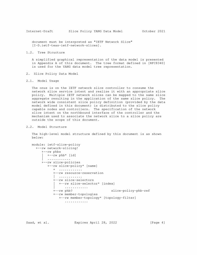
Internet-Draft Slice Policy YANG Data Model October 2021
document must be interpreted as "IETF Network Slice" [I-D.ietf-teas-ietf-network-slices].
1.2. Tree Structure
A simplified graphical representation of the data model is presented in Appendix A of this document. The tree format defined in [RFC8340] is used for the YANG data model tree representation.
2. Slice Policy Data Model
2.1. Model Usage
The onus is on the IETF network slice controller to consume the network slice service intent and realize it with an appropriate slice policy. Multiple IETF network slices can be mapped to the same slice aggregate resulting in the application of the same slice policy. The network wide consistent slice policy definition (provided by the data model defined in this document) is distributed to the slice policy capable nodes and controllers. The specification of the network slice intent on the northbound interface of the controller and the mechanism used to associate the network slice to a slice policy are outside the scope of this document.
2.2. Model Structure
The high-level model structure defined by this document is as shown below:
module: ietf-slice-policy +--rw network-slicing! +--rw phbs | +--rw phb* [id] | ............ +--rw slice-policies +--rw slice-policy* [name] + ............ +--rw resource-reservation | ............ +--rw slice-selectors | +--rw slice-selector* [index] | ............ +--rw phb? slice-policy-phb-ref +--rw member-topologies +--rw member-topology* [topology-filter] ............
Saad, et al. Expires April 28, 2022 [Page 4]
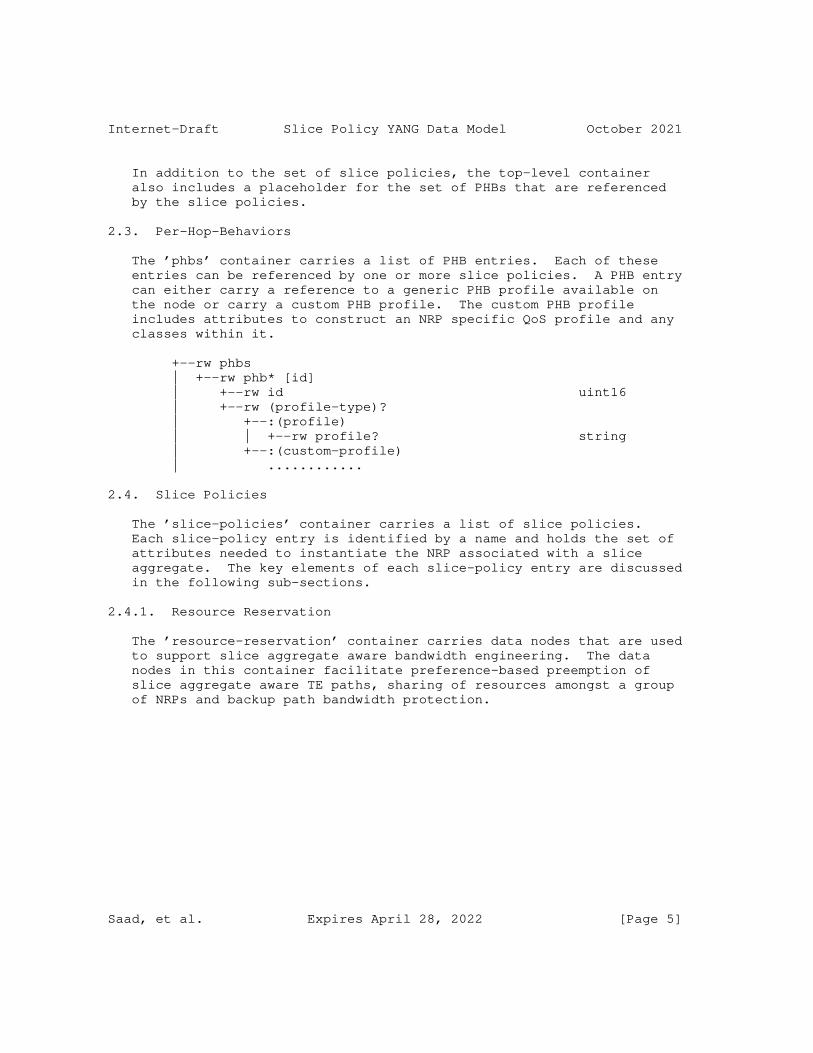
Internet-Draft Slice Policy YANG Data Model October 2021
In addition to the set of slice policies, the top-level container also includes a placeholder for the set of PHBs that are referenced by the slice policies.
2.3. Per-Hop-Behaviors
The ’phbs’ container carries a list of PHB entries. Each of these entries can be referenced by one or more slice policies. A PHB entry can either carry a reference to a generic PHB profile available on the node or carry a custom PHB profile. The custom PHB profile includes attributes to construct an NRP specific QoS profile and any classes within it.
+--rw phbs | +--rw phb* [id] | +--rw id uint16 | +--rw (profile-type)? | +--:(profile) | | +--rw profile? string | +--:(custom-profile) | ............
2.4. Slice Policies
The ’slice-policies’ container carries a list of slice policies. Each slice-policy entry is identified by a name and holds the set of attributes needed to instantiate the NRP associated with a slice aggregate. The key elements of each slice-policy entry are discussed in the following sub-sections.
2.4.1. Resource Reservation
The ’resource-reservation’ container carries data nodes that are used to support slice aggregate aware bandwidth engineering. The data nodes in this container facilitate preference-based preemption of slice aggregate aware TE paths, sharing of resources amongst a group of NRPs and backup path bandwidth protection.
Saad, et al. Expires April 28, 2022 [Page 5]
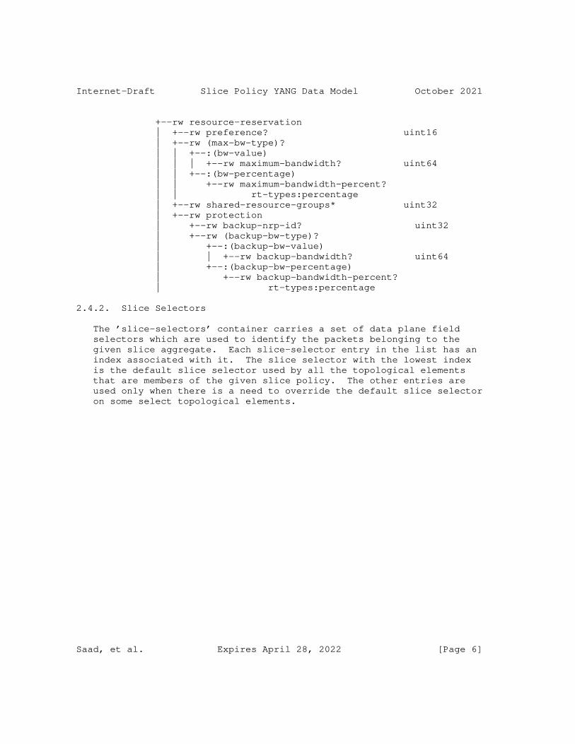
Internet-Draft Slice Policy YANG Data Model October 2021
+--rw resource-reservation | +--rw preference? uint16 | +--rw (max-bw-type)? | | +--:(bw-value) | | | +--rw maximum-bandwidth? uint64 | | +--:(bw-percentage) | | +--rw maximum-bandwidth-percent? | | rt-types:percentage | +--rw shared-resource-groups* uint32 | +--rw protection | +--rw backup-nrp-id? uint32 | +--rw (backup-bw-type)? | +--:(backup-bw-value) | | +--rw backup-bandwidth? uint64 | +--:(backup-bw-percentage) | +--rw backup-bandwidth-percent? | rt-types:percentage
2.4.2. Slice Selectors
The ’slice-selectors’ container carries a set of data plane field selectors which are used to identify the packets belonging to the given slice aggregate. Each slice-selector entry in the list has an index associated with it. The slice selector with the lowest index is the default slice selector used by all the topological elements that are members of the given slice policy. The other entries are used only when there is a need to override the default slice selector on some select topological elements.
Saad, et al. Expires April 28, 2022 [Page 6]
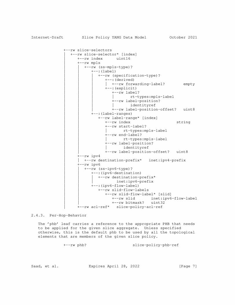
Internet-Draft Slice Policy YANG Data Model October 2021
+--rw slice-selectors | +--rw slice-selector* [index] | +--rw index uint16 | +--rw mpls | | +--rw (ss-mpls-type)? | | +--:(label) | | | +--rw (specification-type)? | | | +--:(derived) | | | | +--rw forwarding-label? empty | | | +--:(explicit) | | | +--rw label? | | | | rt-types:mpls-label | | | +--rw label-position? | | | | identityref | | | +--rw label-position-offset? uint8 | | +--:(label-ranges) | | +--rw label-range* [index] | | +--rw index string | | +--rw start-label? | | | rt-types:mpls-label | | +--rw end-label? | | | rt-types:mpls-label | | +--rw label-position? | | | identityref | | +--rw label-position-offset? uint8 | +--rw ipv4 | | +--rw destination-prefix* inet:ipv4-prefix | +--rw ipv6 | | +--rw (ss-ipv6-type)? | | +--:(ipv6-destination) | | | +--rw destination-prefix* | | | inet:ipv6-prefix | | +--:(ipv6-flow-label) | | +--rw slid-flow-labels | | +--rw slid-flow-label* [slid] | | +--rw slid inet:ipv6-flow-label | | +--rw bitmask? uint32 | +--rw acl-ref* slice-policy-acl-ref
2.4.3. Per-Hop-Behavior
The ’phb’ leaf carries a reference to the appropriate PHB that needs to be applied for the given slice aggregate. Unless specified otherwise, this is the default phb to be used by all the topological elements that are members of the given slice policy.
+--rw phb? slice-policy-phb-ref
Saad, et al. Expires April 28, 2022 [Page 7]
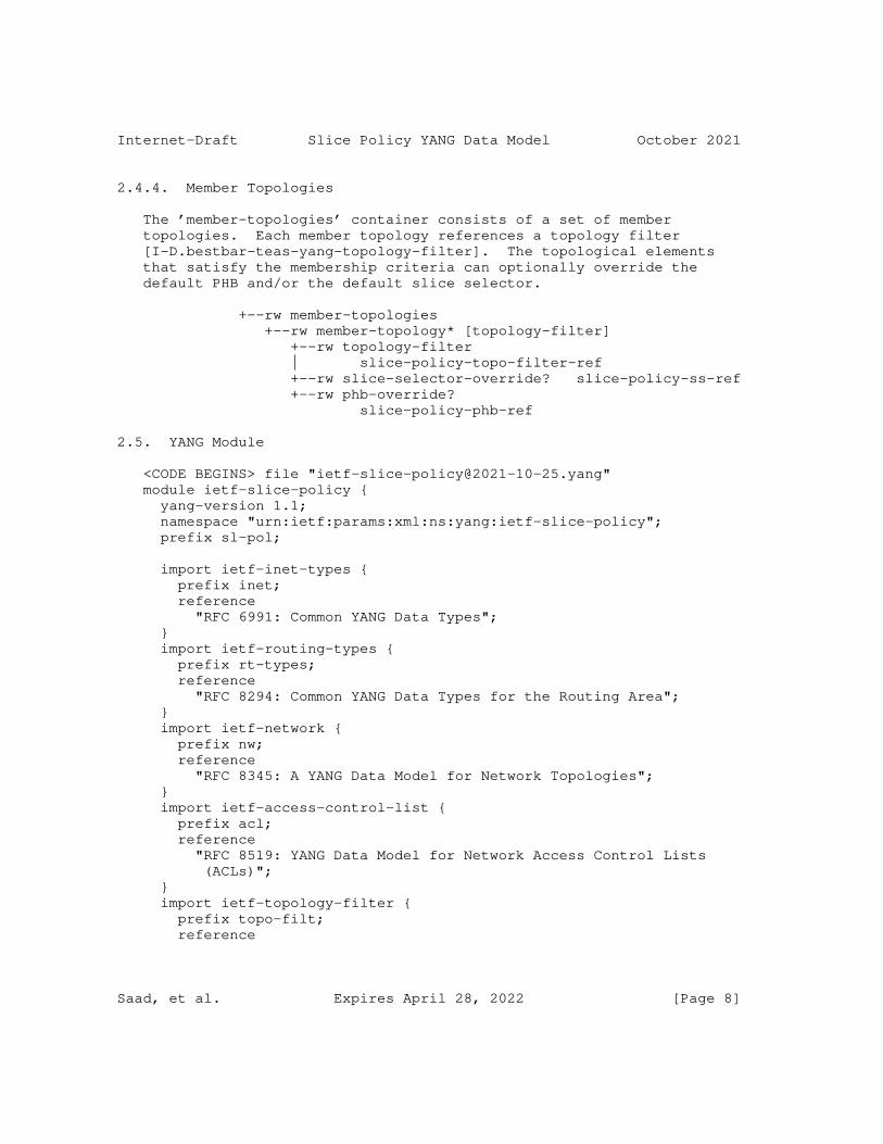
Internet-Draft Slice Policy YANG Data Model October 2021
2.4.4. Member Topologies
The ’member-topologies’ container consists of a set of member topologies. Each member topology references a topology filter [I-D.bestbar-teas-yang-topology-filter]. The topological elements that satisfy the membership criteria can optionally override the default PHB and/or the default slice selector.
+--rw member-topologies +--rw member-topology* [topology-filter] +--rw topology-filter | slice-policy-topo-filter-ref +--rw slice-selector-override? slice-policy-ss-ref +--rw phb-override? slice-policy-phb-ref
2.5. YANG Module
<CODE BEGINS> file "[email protected]" module ietf-slice-policy { yang-version 1.1; namespace "urn:ietf:params:xml:ns:yang:ietf-slice-policy"; prefix sl-pol;
import ietf-inet-types { prefix inet; reference "RFC 6991: Common YANG Data Types"; } import ietf-routing-types { prefix rt-types; reference "RFC 8294: Common YANG Data Types for the Routing Area"; } import ietf-network { prefix nw; reference "RFC 8345: A YANG Data Model for Network Topologies"; } import ietf-access-control-list { prefix acl; reference "RFC 8519: YANG Data Model for Network Access Control Lists (ACLs)"; } import ietf-topology-filter { prefix topo-filt; reference
Saad, et al. Expires April 28, 2022 [Page 8]
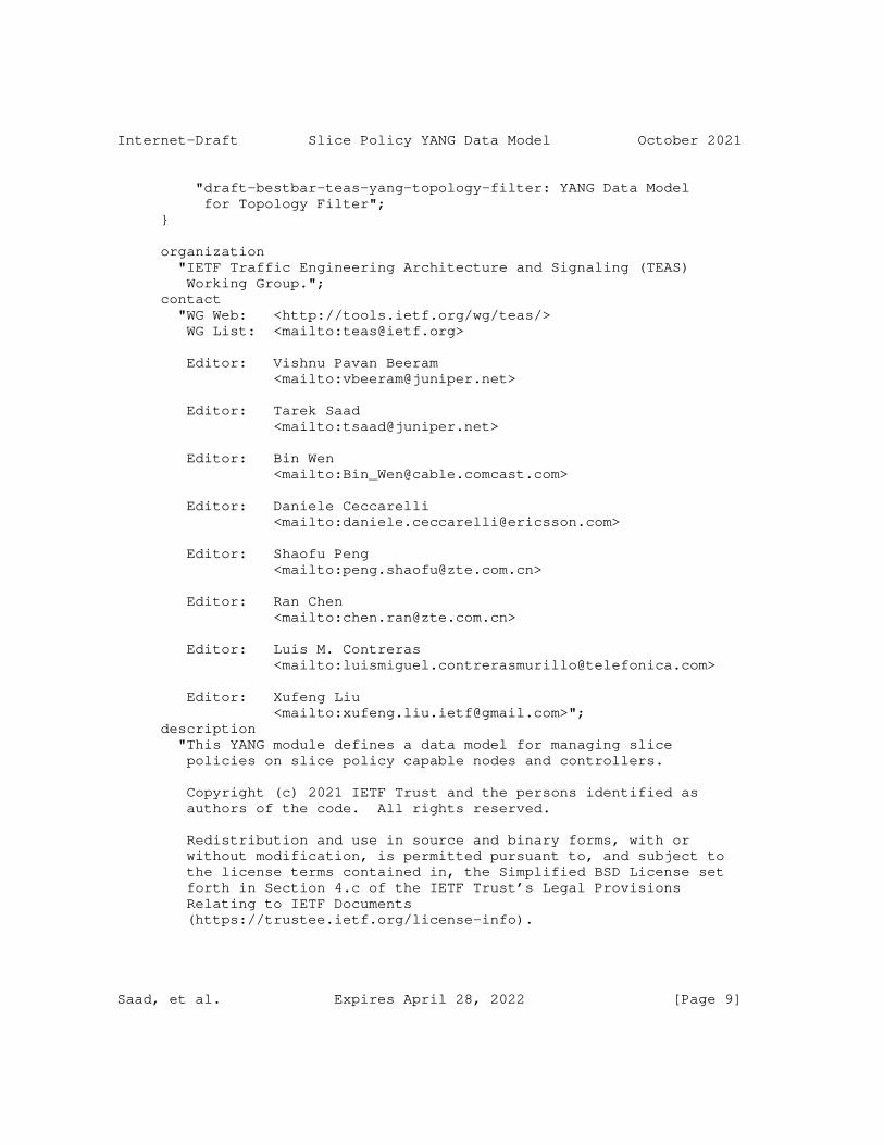
Internet-Draft Slice Policy YANG Data Model October 2021
"draft-bestbar-teas-yang-topology-filter: YANG Data Model for Topology Filter"; }
organization "IETF Traffic Engineering Architecture and Signaling (TEAS) Working Group."; contact "WG Web: <http://tools.ietf.org/wg/teas/> WG List: <mailto:[email protected]>
Editor: Vishnu Pavan Beeram <mailto:[email protected]>
Editor: Tarek Saad <mailto:[email protected]>
Editor: Bin Wen <mailto:[email protected]>
Editor: Daniele Ceccarelli <mailto:[email protected]>
Editor: Shaofu Peng <mailto:[email protected]>
Editor: Ran Chen <mailto:[email protected]>
Editor: Luis M. Contreras <mailto:[email protected]>
Editor: Xufeng Liu <mailto:[email protected]>"; description "This YANG module defines a data model for managing slice policies on slice policy capable nodes and controllers.
Copyright (c) 2021 IETF Trust and the persons identified as authors of the code. All rights reserved.
Redistribution and use in source and binary forms, with or without modification, is permitted pursuant to, and subject to the license terms contained in, the Simplified BSD License set forth in Section 4.c of the IETF Trust’s Legal Provisions Relating to IETF Documents (https://trustee.ietf.org/license-info).
Saad, et al. Expires April 28, 2022 [Page 9]
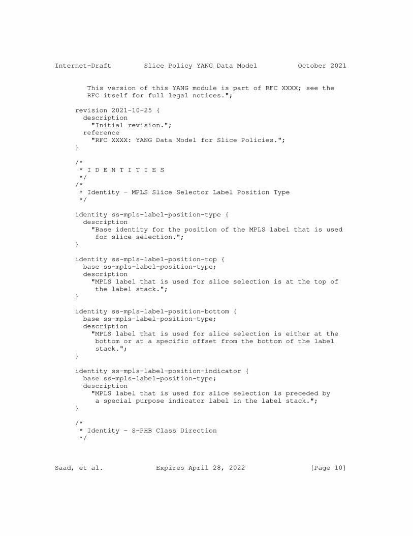
Internet-Draft Slice Policy YANG Data Model October 2021
This version of this YANG module is part of RFC XXXX; see the RFC itself for full legal notices.";
revision 2021-10-25 { description "Initial revision."; reference "RFC XXXX: YANG Data Model for Slice Policies."; }
/* * I D E N T I T I E S */ /* * Identity - MPLS Slice Selector Label Position Type */
identity ss-mpls-label-position-type { description "Base identity for the position of the MPLS label that is used for slice selection."; }
identity ss-mpls-label-position-top { base ss-mpls-label-position-type; description "MPLS label that is used for slice selection is at the top of the label stack."; }
identity ss-mpls-label-position-bottom { base ss-mpls-label-position-type; description "MPLS label that is used for slice selection is either at the bottom or at a specific offset from the bottom of the label stack."; }
identity ss-mpls-label-position-indicator { base ss-mpls-label-position-type; description "MPLS label that is used for slice selection is preceded by a special purpose indicator label in the label stack."; }
/* * Identity - S-PHB Class Direction */
Saad, et al. Expires April 28, 2022 [Page 10]

Internet-Draft Slice Policy YANG Data Model October 2021
identity s-phb-class-direction { description "Base identity for the direction of traffic to which the Slice PHB class profile is applied."; }
identity s-phb-class-direction-in { base s-phb-class-direction; description "Slice PHB class profile is applied to incoming traffic."; }
identity s-phb-class-direction-out { base s-phb-class-direction; description "Slice PHB class profile is applied to outgoing traffic."; }
identity s-phb-class-direction-in-out { base s-phb-class-direction; description "Slice PHB class profile is applied to both incoming and outgoing directions of traffic."; }
/* * Identity - S-PHB Class Priority */
identity s-phb-class-priority { description "Base identity for the priority of the child class scheduler."; }
identity s-phb-class-priority-low { base s-phb-class-priority; description "Priority of the child class scheduler is low."; }
identity s-phb-class-priority-strict-high { base s-phb-class-priority; description "Priority of the child class scheduler is strict-high."; }
/* * Identity - S-PHB Class Drop Probability
Saad, et al. Expires April 28, 2022 [Page 11]
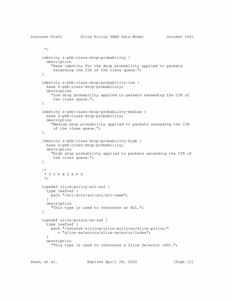
Internet-Draft Slice Policy YANG Data Model October 2021
*/
identity s-phb-class-drop-probability { description "Base identity for the drop probability applied to packets exceeding the CIR of the class queue."; }
identity s-phb-class-drop-probability-low { base s-phb-class-drop-probability; description "Low drop probability applied to packets exceeding the CIR of the class queue."; }
identity s-phb-class-drop-probability-medium { base s-phb-class-drop-probability; description "Medium drop probability applied to packets exceeding the CIR of the class queue."; }
identity s-phb-class-drop-probability-high { base s-phb-class-drop-probability; description "High drop probability applied to packets exceeding the CIR of the class queue."; }
/* * T Y P E D E F S */
typedef slice-policy-acl-ref { type leafref { path "/acl:acls/acl:acl/acl:name"; } description "This type is used to reference an ACL."; }
typedef slice-policy-ss-ref { type leafref { path "/network-slicing/slice-policies/slice-policy/" + "slice-selectors/slice-selector/index"; } description "This type is used to reference a Slice Selector (SS).";
Saad, et al. Expires April 28, 2022 [Page 12]
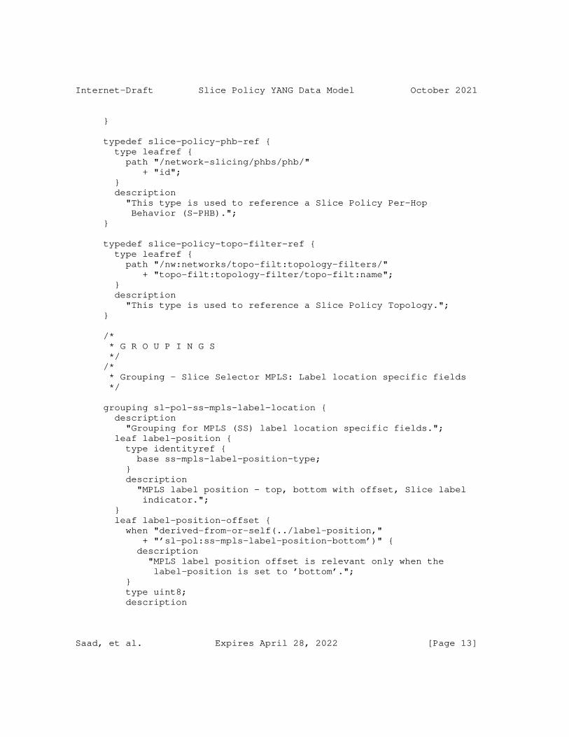
Internet-Draft Slice Policy YANG Data Model October 2021
}
typedef slice-policy-phb-ref { type leafref { path "/network-slicing/phbs/phb/" + "id"; } description "This type is used to reference a Slice Policy Per-Hop Behavior (S-PHB)."; }
typedef slice-policy-topo-filter-ref { type leafref { path "/nw:networks/topo-filt:topology-filters/" + "topo-filt:topology-filter/topo-filt:name"; } description "This type is used to reference a Slice Policy Topology."; }
/* * G R O U P I N G S */ /* * Grouping - Slice Selector MPLS: Label location specific fields */
grouping sl-pol-ss-mpls-label-location { description "Grouping for MPLS (SS) label location specific fields."; leaf label-position { type identityref { base ss-mpls-label-position-type; } description "MPLS label position - top, bottom with offset, Slice label indicator."; } leaf label-position-offset { when "derived-from-or-self(../label-position," + "’sl-pol:ss-mpls-label-position-bottom’)" { description "MPLS label position offset is relevant only when the label-position is set to ’bottom’."; } type uint8; description
Saad, et al. Expires April 28, 2022 [Page 13]
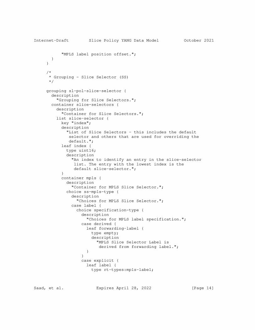
Internet-Draft Slice Policy YANG Data Model October 2021
"MPLS label position offset."; } }
/* * Grouping - Slice Selector (SS) */
grouping sl-pol-slice-selector { description "Grouping for Slice Selectors."; container slice-selectors { description "Container for Slice Selectors."; list slice-selector { key "index"; description "List of Slice Selectors - this includes the default selector and others that are used for overriding the default."; leaf index { type uint16; description "An index to identify an entry in the slice-selector list. The entry with the lowest index is the default slice-selector."; } container mpls { description "Container for MPLS Slice Selector."; choice ss-mpls-type { description "Choices for MPLS Slice Selector."; case label { choice specification-type { description "Choices for MPLS label specification."; case derived { leaf forwarding-label { type empty; description "MPLS Slice Selector Label is derived from forwarding label."; } } case explicit { leaf label { type rt-types:mpls-label;
Saad, et al. Expires April 28, 2022 [Page 14]
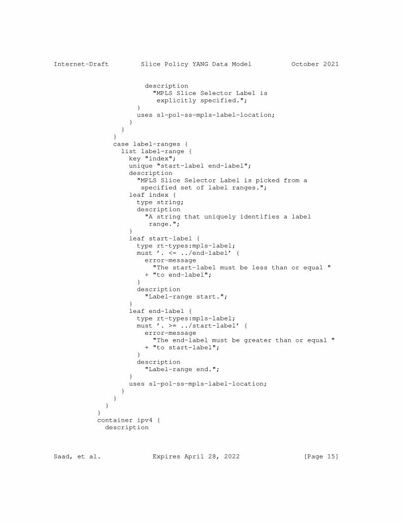
Internet-Draft Slice Policy YANG Data Model October 2021
description "MPLS Slice Selector Label is explicitly specified."; } uses sl-pol-ss-mpls-label-location; } } } case label-ranges { list label-range { key "index"; unique "start-label end-label"; description "MPLS Slice Selector Label is picked from a specified set of label ranges."; leaf index { type string; description "A string that uniquely identifies a label range."; } leaf start-label { type rt-types:mpls-label; must ’. <= ../end-label’ { error-message "The start-label must be less than or equal " + "to end-label"; } description "Label-range start."; } leaf end-label { type rt-types:mpls-label; must ’. >= ../start-label’ { error-message "The end-label must be greater than or equal " + "to start-label"; } description "Label-range end."; } uses sl-pol-ss-mpls-label-location; } } } } container ipv4 { description
Saad, et al. Expires April 28, 2022 [Page 15]
Internet-Draft Slice Policy YANG Data Model October 2021
"Container for IPv4 Slice Selector."; leaf-list destination-prefix { type inet:ipv4-prefix; description "IPv4 Slice Selector is picked from a specified set of IPv4 destination prefixes."; } } container ipv6 { description "Container for IPv6 Slice Selector."; choice ss-ipv6-type { description "Choices for IPv6 Slice Selector."; case ipv6-destination { leaf-list destination-prefix { type inet:ipv6-prefix; description "IPv6 Slice Selector is picked from a specified set of IPv6 destination prefixes."; } } case ipv6-flow-label { container slid-flow-labels { description "Container for a set of Slice IDs that are encoded within the flow label."; list slid-flow-label { key "slid"; description "IPv6 Slice Selector is picked from a set of Slice IDs that are encoded within the flow label."; leaf slid { type inet:ipv6-flow-label; description "Slice ID encoded inside the IPv6 flow label."; } leaf bitmask { type uint32; description "Bitmask to extract the encoded Slice ID from the IPv6 flow label."; } } } } }
Saad, et al. Expires April 28, 2022 [Page 16]
Internet-Draft Slice Policy YANG Data Model October 2021
} leaf-list acl-ref { type slice-policy-acl-ref; description "Slice Selection is done based on the specified list of ACLs."; } } } }
/* * Grouping - Slice Policy Resource Reservation */
grouping sl-pol-resource-reservation { description "Grouping for slice policy resource reservation."; container resource-reservation { description "Container for slice policy resource reservation."; leaf preference { type uint16; description "Control plane preference for the corresponding Network Resource Partition (NRP). A higher preference indicates a more favorable resource reservation than a lower preference."; } choice max-bw-type { description "Choice of maximum bandwidth specification."; case bw-value { leaf maximum-bandwidth { type uint64; description "The maximum bandwidth allocated to an NRP - specified as absolute value."; } } case bw-percentage { leaf maximum-bandwidth-percent { type rt-types:percentage; description "The maximum bandwidth allocated to an NRP - specified as percentage of link capacity."; }
Saad, et al. Expires April 28, 2022 [Page 17]
Internet-Draft Slice Policy YANG Data Model October 2021
} } leaf-list shared-resource-groups { type uint32; description "List of shared resource groups that an NRP shares its allocated resources with."; } container protection { description "Container for NRP rotection reservation."; leaf backup-nrp-id { type uint32; description "The ID that identifies the NRP used for backup paths that protect primary paths setup over a specific NRP."; } choice backup-bw-type { description "Choice of backup bandwidth specification."; case backup-bw-value { leaf backup-bandwidth { type uint64; description "The maximum bandwidth on a network resource that is allocated for backup traffic - specified as absolute value."; } } case backup-bw-percentage { leaf backup-bandwidth-percent { type rt-types:percentage; description "The maximum bandwidth on a network resource that is allocated for backup traffic - specified as percentage of the link capacity."; } } } } } }
/* * Grouping - Slice policy PHB (S-PHB) */
Saad, et al. Expires April 28, 2022 [Page 18]
Internet-Draft Slice Policy YANG Data Model October 2021
grouping sl-pol-phb { description "Grouping for S-PHB."; leaf phb { type slice-policy-phb-ref; description "Reference to a specific PHB from the list of global PHBs."; } }
/* * Grouping - Slice policy default profile override */
grouping sl-pol-override-options { description "Grouping of fields that are used to override the default profile of the slice policy."; leaf slice-selector-override { type slice-policy-ss-ref; description "Reference to a specific Slice Selector (different from default)."; } leaf phb-override { type slice-policy-phb-ref; description "Reference to a specific PHB (different from default)."; } }
/* * Grouping - Member Topologies */
grouping sl-pol-member-topologies { description "Grouping for member topologies."; container member-topologies { description "Container for member topologies."; list member-topology { key "topology-filter"; description "List of member topologies."; leaf topology-filter { type slice-policy-topo-filter-ref;
Saad, et al. Expires April 28, 2022 [Page 19]
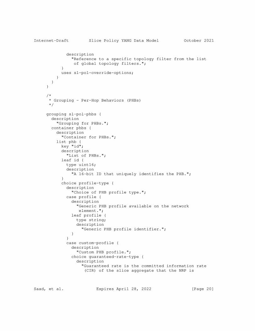
Internet-Draft Slice Policy YANG Data Model October 2021
description "Reference to a specific topology filter from the list of global topology filters."; } uses sl-pol-override-options; } } }
/* * Grouping - Per-Hop Behaviors (PHBs) */
grouping sl-pol-phbs { description "Grouping for PHBs."; container phbs { description "Container for PHBs."; list phb { key "id"; description "List of PHBs."; leaf id { type uint16; description "A 16-bit ID that uniquely identifies the PHB."; } choice profile-type { description "Choice of PHB profile type."; case profile { description "Generic PHB profile available on the network element."; leaf profile { type string; description "Generic PHB profile identifier."; } } case custom-profile { description "Custom PHB profile."; choice guaranteed-rate-type { description "Guaranteed rate is the committed information rate (CIR) of the slice aggregate that the NRP is
Saad, et al. Expires April 28, 2022 [Page 20]
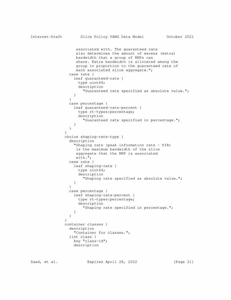
Internet-Draft Slice Policy YANG Data Model October 2021
associated with. The guaranteed rate also determines the amount of excess (extra) bandwidth that a group of NRPs can share. Extra bandwidth is allocated among the group in proportion to the guaranteed rate of each associated slice aggregate."; case rate { leaf guaranteed-rate { type uint64; description "Guaranteed rate specified as absolute value."; } } case percentage { leaf guaranteed-rate-percent { type rt-types:percentage; description "Guaranteed rate specified in percentage."; } } } choice shaping-rate-type { description "Shaping rate (peak information rate - PIR) is the maximum bandwidth of the slice aggregate that the NRP is associated with."; case rate { leaf shaping-rate { type uint64; description "Shaping rate specified as absolute value."; } } case percentage { leaf shaping-rate-percent { type rt-types:percentage; description "Shaping rate specified in percentage."; } } } container classes { description "Container for classes."; list class { key "class-id"; description
Saad, et al. Expires April 28, 2022 [Page 21]
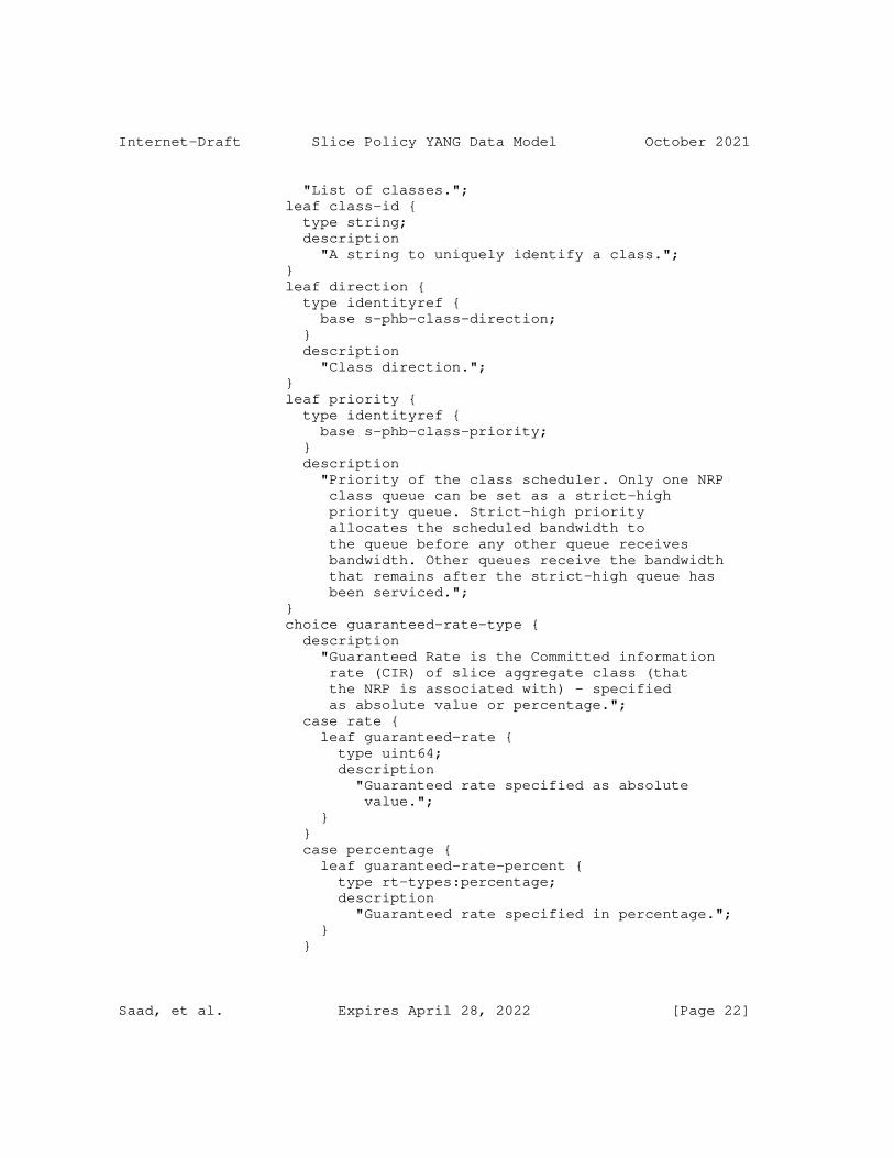
Internet-Draft Slice Policy YANG Data Model October 2021
"List of classes."; leaf class-id { type string; description "A string to uniquely identify a class."; } leaf direction { type identityref { base s-phb-class-direction; } description "Class direction."; } leaf priority { type identityref { base s-phb-class-priority; } description "Priority of the class scheduler. Only one NRP class queue can be set as a strict-high priority queue. Strict-high priority allocates the scheduled bandwidth to the queue before any other queue receives bandwidth. Other queues receive the bandwidth that remains after the strict-high queue has been serviced."; } choice guaranteed-rate-type { description "Guaranteed Rate is the Committed information rate (CIR) of slice aggregate class (that the NRP is associated with) - specified as absolute value or percentage."; case rate { leaf guaranteed-rate { type uint64; description "Guaranteed rate specified as absolute value."; } } case percentage { leaf guaranteed-rate-percent { type rt-types:percentage; description "Guaranteed rate specified in percentage."; } }
Saad, et al. Expires April 28, 2022 [Page 22]
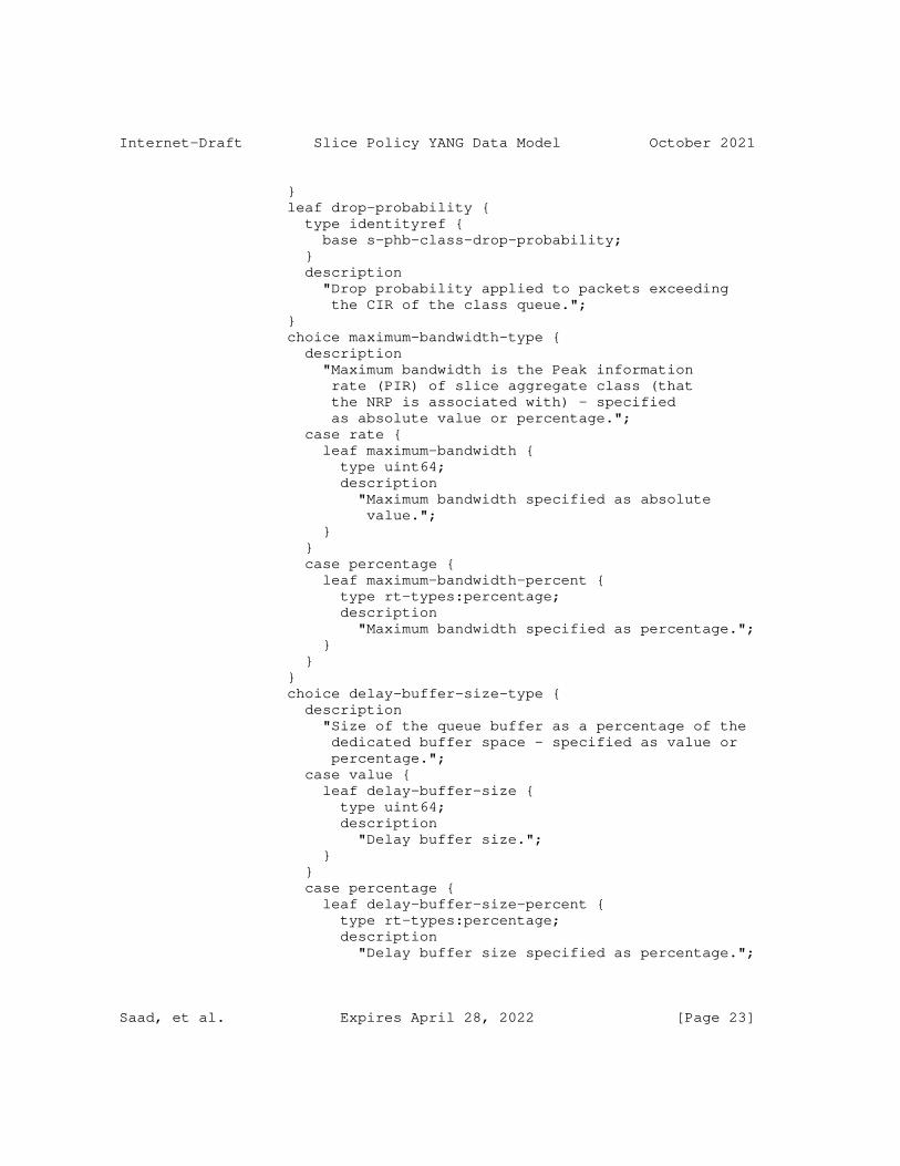
Internet-Draft Slice Policy YANG Data Model October 2021
} leaf drop-probability { type identityref { base s-phb-class-drop-probability; } description "Drop probability applied to packets exceeding the CIR of the class queue."; } choice maximum-bandwidth-type { description "Maximum bandwidth is the Peak information rate (PIR) of slice aggregate class (that the NRP is associated with) - specified as absolute value or percentage."; case rate { leaf maximum-bandwidth { type uint64; description "Maximum bandwidth specified as absolute value."; } } case percentage { leaf maximum-bandwidth-percent { type rt-types:percentage; description "Maximum bandwidth specified as percentage."; } } } choice delay-buffer-size-type { description "Size of the queue buffer as a percentage of the dedicated buffer space - specified as value or percentage."; case value { leaf delay-buffer-size { type uint64; description "Delay buffer size."; } } case percentage { leaf delay-buffer-size-percent { type rt-types:percentage; description "Delay buffer size specified as percentage.";
Saad, et al. Expires April 28, 2022 [Page 23]
Internet-Draft Slice Policy YANG Data Model October 2021
} } } } } } } } } }
/* * Grouping - Slice Policies */
grouping sl-policies { description "Grouping for slice policies."; container slice-policies { description "Container for slice policies."; list slice-policy { key "name"; unique "nrp-id"; description "List of slice policies."; leaf name { type string; description "A string that uniquely identifies the slice policy."; } leaf nrp-id { type uint32; description "A 32-bit ID that uniquely identifies the NRP created by the enforcement of this slice policy."; } uses sl-pol-resource-reservation; uses sl-pol-slice-selector; uses sl-pol-phb; uses sl-pol-member-topologies; } } }
/* * Top-level container - Network Slicing
Saad, et al. Expires April 28, 2022 [Page 24]
Internet-Draft Slice Policy YANG Data Model October 2021
*/
container network-slicing { presence "Enable network slicing."; description "Top-level container for network slicing specific constructs on a slice policy capable network entity."; uses sl-pol-phbs; uses sl-policies; } } <CODE ENDS>
3. Acknowledgements
The authors would like to thank Krzysztof Szarkowicz for his input from discussions.
4. Contributors
The following individuals contributed to this document:
Colby Barth Juniper Networks Email: [email protected]
Srihari R. Sangli Juniper Networks Email: [email protected]
Chandra Ramachandran Juniper Networks Email: [email protected]
5. IANA Considerations
This document registers the following URI in the IETF XML registry [RFC3688]. Following the format in [RFC3688], the following registration is requested to be made.
URI: urn:ietf:params:xml:ns:yang:ietf-slice-policy Registrant Contact: The TEAS WG of the IETF. XML: N/A, the requested URI is an XML namespace.
This document registers a YANG module in the YANG Module Names registry [RFC6020].
Saad, et al. Expires April 28, 2022 [Page 25]
Internet-Draft Slice Policy YANG Data Model October 2021
name: ietf-slice-policy namespace: urn:ietf:params:xml:ns:yang:ietf-slice-policy prefix: sl-pol reference: RFCXXXX
6. Security Considerations
The YANG module specified in this document defines a schema for data that is designed to be accessed via network management protocols such as NETCONF [RFC6241] or RESTCONF [RFC8040]. The lowest NETCONF layer is the secure transport layer, and the mandatory-to-implement secure transport is Secure Shell (SSH) [RFC6242]. The lowest RESTCONF layer is HTTPS, and the mandatory-to-implement secure transport is TLS [RFC8446].
The Network Configuration Access Control Model (NACM) [RFC8341] provides the means to restrict access for particular NETCONF or RESTCONF users to a preconfigured subset of all available NETCONF or RESTCONF protocol operations and content.
The data nodes defined in this YANG module that are writable/creatable/deletable (i.e., config true, which is the default) may be considered sensitive or vulnerable in some network environments. Write operations (e.g., edit-config) to these data nodes without proper protection can have a negative effect on network operations. These are the subtrees and data nodes and their sensitivity/vulnerability:
* "/network-slicing/phbs": This subtree specifies the configurations for slice policy per-hop behaviors. By manipulating these data nodes, a malicious attacker may cause unauthorized and improper behavior to be provided for the slice aggregate traffic on the network element.
* "/network-slicing/slice-policies": This subtree specifies the configurations for slice policies on a given network element. By manipulating these data nodes, a malicious attacker may cause unauthorized and improper behavior to be provided for the slice aggregate traffic on the network element.
The readable data nodes in this YANG module may be considered sensitive or vulnerable in some network environments. It is thus important to control read access (e.g., via get, get-config, or notification) to these data nodes. These are the subtrees and data nodes and their sensitivity/vulnerability:
* "/network-slicing/phbs": Unauthorized access to this subtree can disclose the slice policy PHBs defined on the network element.
Saad, et al. Expires April 28, 2022 [Page 26]
Internet-Draft Slice Policy YANG Data Model October 2021
* "/network-slicing/slice-policies": Unauthorized access to this subtree can disclose the slice policy definitions on the network element.
7. References
7.1. Normative References
[I-D.bestbar-teas-ns-packet] Saad, T., Beeram, V. P., Wen, B., Ceccarelli, D., Halpern, J., Peng, S., Chen, R., Liu, X., Contreras, L. M., and R. Rokui, "Realizing Network Slices in IP/MPLS Networks", draft-bestbar-teas-ns-packet-04 (work in progress), October 2021.
[I-D.bestbar-teas-yang-topology-filter] Beeram, V. P., Saad, T., and R. Gandhi, "YANG Data Model for Topology Filter", draft-bestbar-teas-yang-topology- filter-01 (work in progress), October 2021.
[RFC2119] Bradner, S., "Key words for use in RFCs to Indicate Requirement Levels", BCP 14, RFC 2119, DOI 10.17487/RFC2119, March 1997, <https://www.rfc-editor.org/info/rfc2119>.
[RFC3688] Mealling, M., "The IETF XML Registry", BCP 81, RFC 3688, DOI 10.17487/RFC3688, January 2004, <https://www.rfc-editor.org/info/rfc3688>.
[RFC6020] Bjorklund, M., Ed., "YANG - A Data Modeling Language for the Network Configuration Protocol (NETCONF)", RFC 6020, DOI 10.17487/RFC6020, October 2010, <https://www.rfc-editor.org/info/rfc6020>.
[RFC6241] Enns, R., Ed., Bjorklund, M., Ed., Schoenwaelder, J., Ed., and A. Bierman, Ed., "Network Configuration Protocol (NETCONF)", RFC 6241, DOI 10.17487/RFC6241, June 2011, <https://www.rfc-editor.org/info/rfc6241>.
[RFC6242] Wasserman, M., "Using the NETCONF Protocol over Secure Shell (SSH)", RFC 6242, DOI 10.17487/RFC6242, June 2011, <https://www.rfc-editor.org/info/rfc6242>.
[RFC7950] Bjorklund, M., Ed., "The YANG 1.1 Data Modeling Language", RFC 7950, DOI 10.17487/RFC7950, August 2016, <https://www.rfc-editor.org/info/rfc7950>.
Saad, et al. Expires April 28, 2022 [Page 27]
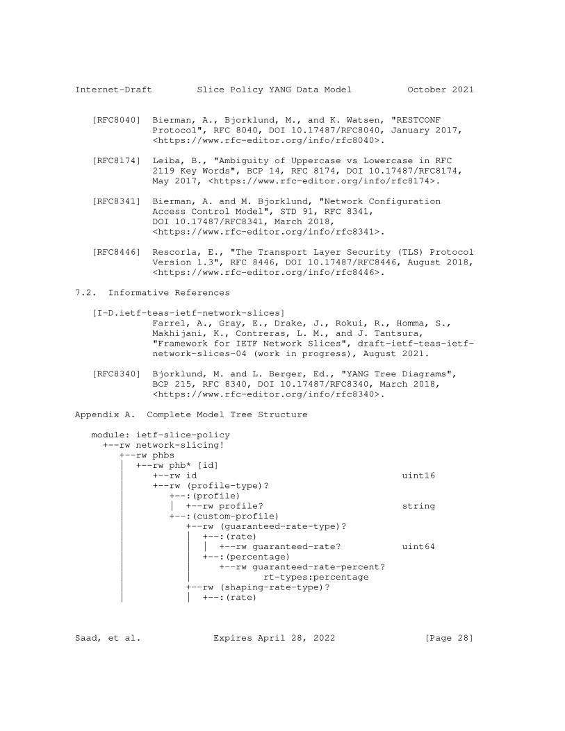
Internet-Draft Slice Policy YANG Data Model October 2021
[RFC8040] Bierman, A., Bjorklund, M., and K. Watsen, "RESTCONF Protocol", RFC 8040, DOI 10.17487/RFC8040, January 2017, <https://www.rfc-editor.org/info/rfc8040>.
[RFC8174] Leiba, B., "Ambiguity of Uppercase vs Lowercase in RFC 2119 Key Words", BCP 14, RFC 8174, DOI 10.17487/RFC8174, May 2017, <https://www.rfc-editor.org/info/rfc8174>.
[RFC8341] Bierman, A. and M. Bjorklund, "Network Configuration Access Control Model", STD 91, RFC 8341, DOI 10.17487/RFC8341, March 2018, <https://www.rfc-editor.org/info/rfc8341>.
[RFC8446] Rescorla, E., "The Transport Layer Security (TLS) Protocol Version 1.3", RFC 8446, DOI 10.17487/RFC8446, August 2018, <https://www.rfc-editor.org/info/rfc8446>.
7.2. Informative References
[I-D.ietf-teas-ietf-network-slices] Farrel, A., Gray, E., Drake, J., Rokui, R., Homma, S., Makhijani, K., Contreras, L. M., and J. Tantsura, "Framework for IETF Network Slices", draft-ietf-teas-ietf- network-slices-04 (work in progress), August 2021.
[RFC8340] Bjorklund, M. and L. Berger, Ed., "YANG Tree Diagrams", BCP 215, RFC 8340, DOI 10.17487/RFC8340, March 2018, <https://www.rfc-editor.org/info/rfc8340>.
Appendix A. Complete Model Tree Structure
module: ietf-slice-policy +--rw network-slicing! +--rw phbs | +--rw phb* [id] | +--rw id uint16 | +--rw (profile-type)? | +--:(profile) | | +--rw profile? string | +--:(custom-profile) | +--rw (guaranteed-rate-type)? | | +--:(rate) | | | +--rw guaranteed-rate? uint64 | | +--:(percentage) | | +--rw guaranteed-rate-percent? | | rt-types:percentage | +--rw (shaping-rate-type)? | | +--:(rate)
Saad, et al. Expires April 28, 2022 [Page 28]
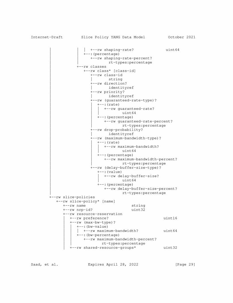
Internet-Draft Slice Policy YANG Data Model October 2021
| | | +--rw shaping-rate? uint64 | | +--:(percentage) | | +--rw shaping-rate-percent? | | rt-types:percentage | +--rw classes | +--rw class* [class-id] | +--rw class-id | | string | +--rw direction? | | identityref | +--rw priority? | | identityref | +--rw (guaranteed-rate-type)? | | +--:(rate) | | | +--rw guaranteed-rate? | | | uint64 | | +--:(percentage) | | +--rw guaranteed-rate-percent? | | rt-types:percentage | +--rw drop-probability? | | identityref | +--rw (maximum-bandwidth-type)? | | +--:(rate) | | | +--rw maximum-bandwidth? | | | uint64 | | +--:(percentage) | | +--rw maximum-bandwidth-percent? | | rt-types:percentage | +--rw (delay-buffer-size-type)? | +--:(value) | | +--rw delay-buffer-size? | | uint64 | +--:(percentage) | +--rw delay-buffer-size-percent? | rt-types:percentage +--rw slice-policies +--rw slice-policy* [name] +--rw name string +--rw nrp-id? uint32 +--rw resource-reservation | +--rw preference? uint16 | +--rw (max-bw-type)? | | +--:(bw-value) | | | +--rw maximum-bandwidth? uint64 | | +--:(bw-percentage) | | +--rw maximum-bandwidth-percent? | | rt-types:percentage | +--rw shared-resource-groups* uint32
Saad, et al. Expires April 28, 2022 [Page 29]
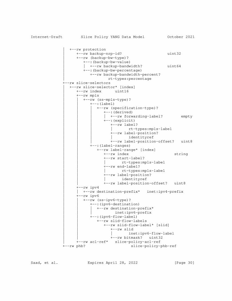
Internet-Draft Slice Policy YANG Data Model October 2021
| +--rw protection | +--rw backup-nrp-id? uint32 | +--rw (backup-bw-type)? | +--:(backup-bw-value) | | +--rw backup-bandwidth? uint64 | +--:(backup-bw-percentage) | +--rw backup-bandwidth-percent? | rt-types:percentage +--rw slice-selectors | +--rw slice-selector* [index] | +--rw index uint16 | +--rw mpls | | +--rw (ss-mpls-type)? | | +--:(label) | | | +--rw (specification-type)? | | | +--:(derived) | | | | +--rw forwarding-label? empty | | | +--:(explicit) | | | +--rw label? | | | | rt-types:mpls-label | | | +--rw label-position? | | | | identityref | | | +--rw label-position-offset? uint8 | | +--:(label-ranges) | | +--rw label-range* [index] | | +--rw index string | | +--rw start-label? | | | rt-types:mpls-label | | +--rw end-label? | | | rt-types:mpls-label | | +--rw label-position? | | | identityref | | +--rw label-position-offset? uint8 | +--rw ipv4 | | +--rw destination-prefix* inet:ipv4-prefix | +--rw ipv6 | | +--rw (ss-ipv6-type)? | | +--:(ipv6-destination) | | | +--rw destination-prefix* | | | inet:ipv6-prefix | | +--:(ipv6-flow-label) | | +--rw slid-flow-labels | | +--rw slid-flow-label* [slid] | | +--rw slid | | | inet:ipv6-flow-label | | +--rw bitmask? uint32 | +--rw acl-ref* slice-policy-acl-ref +--rw phb? slice-policy-phb-ref
Saad, et al. Expires April 28, 2022 [Page 30]
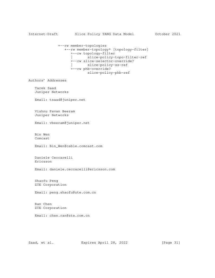
Internet-Draft Slice Policy YANG Data Model October 2021
+--rw member-topologies +--rw member-topology* [topology-filter] +--rw topology-filter | slice-policy-topo-filter-ref +--rw slice-selector-override? | slice-policy-ss-ref +--rw phb-override? slice-policy-phb-ref
Authors’ Addresses
Tarek Saad Juniper Networks
Email: [email protected]
Vishnu Pavan Beeram Juniper Networks
Email: [email protected]
Bin Wen Comcast
Email: [email protected]
Daniele Ceccarelli Ericsson
Email: [email protected]
Shaofu Peng ZTE Corporation
Email: [email protected]
Ran Chen ZTE Corporation
Email: [email protected]
Saad, et al. Expires April 28, 2022 [Page 31]
Internet-Draft Slice Policy YANG Data Model October 2021
Luis M. Contreras Telefonica
Email: [email protected]
Xufeng Liu Volta Networks
Email: [email protected]
Saad, et al. Expires April 28, 2022 [Page 32]
TEAS Working Group V. BeeramInternet-Draft T. SaadIntended status: Standards Track Juniper NetworksExpires: April 28, 2022 R. Gandhi Cisco Systems X. Liu Volta Networks October 25, 2021
YANG Data Model for Topology Filter draft-bestbar-teas-yang-topology-filter-02
Abstract
This document defines a YANG data model for the management of topology filters/filter-sets on network elements and controllers.
Requirements Language
The key words "MUST", "MUST NOT", "REQUIRED", "SHALL", "SHALL NOT", "SHOULD", "SHOULD NOT", "RECOMMENDED", "NOT RECOMMENDED", "MAY", and "OPTIONAL" in this document are to be interpreted as described in BCP 14 [RFC2119] [RFC8174] when, and only when, they appear in all capitals, as shown here.
Status of This Memo
This Internet-Draft is submitted in full conformance with the provisions of BCP 78 and BCP 79.
Internet-Drafts are working documents of the Internet Engineering Task Force (IETF). Note that other groups may also distribute working documents as Internet-Drafts. The list of current Internet- Drafts is at https://datatracker.ietf.org/drafts/current/.
Internet-Drafts are draft documents valid for a maximum of six months and may be updated, replaced, or obsoleted by other documents at any time. It is inappropriate to use Internet-Drafts as reference material or to cite them other than as "work in progress."
This Internet-Draft will expire on April 28, 2022.
Copyright Notice
Copyright (c) 2021 IETF Trust and the persons identified as the document authors. All rights reserved.
Beeram, et al. Expires April 28, 2022 [Page 1]
Internet-Draft Topology Filter YANG Data Model October 2021
This document is subject to BCP 78 and the IETF Trust’s Legal Provisions Relating to IETF Documents (https://trustee.ietf.org/license-info) in effect on the date of publication of this document. Please review these documents carefully, as they describe your rights and restrictions with respect to this document. Code Components extracted from this document must include Simplified BSD License text as described in Section 4.e of the Trust Legal Provisions and are provided without warranty as described in the Simplified BSD License.
Table of Contents
1. Introduction . . . . . . . . . . . . . . . . . . . . . . . . 2 1.1. Terminology . . . . . . . . . . . . . . . . . . . . . . . 2 1.2. Tree Structure . . . . . . . . . . . . . . . . . . . . . 3 2. Topology Filter Data Model . . . . . . . . . . . . . . . . . 3 2.1. Model Structure . . . . . . . . . . . . . . . . . . . . . 3 2.1.1. Topology Filters . . . . . . . . . . . . . . . . . . 3 2.1.1.1. Topology Reference . . . . . . . . . . . . . . . 3 2.1.1.2. Filters . . . . . . . . . . . . . . . . . . . . . 4 2.1.2. Topology Filter-Sets . . . . . . . . . . . . . . . . 5 2.2. YANG Module . . . . . . . . . . . . . . . . . . . . . . . 5 3. Acknowledgements . . . . . . . . . . . . . . . . . . . . . . 11 4. Contributors . . . . . . . . . . . . . . . . . . . . . . . . 11 5. IANA Considerations . . . . . . . . . . . . . . . . . . . . . 12 6. Security Considerations . . . . . . . . . . . . . . . . . . . 12 7. References . . . . . . . . . . . . . . . . . . . . . . . . . 13 7.1. Normative References . . . . . . . . . . . . . . . . . . 13 7.2. Informative References . . . . . . . . . . . . . . . . . 14 Appendix A. Complete Model Tree Structure . . . . . . . . . . . 15 Authors’ Addresses . . . . . . . . . . . . . . . . . . . . . . . 17
1. Introduction
A topology filter is a data construct that can be applied on either a native topology or a customized topology to produce a filtered set of topological elements. A topology filter-set is a union of multiple topology filters that can be applied in tandem on a topology. This document defines a YANG data model for the management of topology filters/filter-sets on network elements and controllers.
1.1. Terminology
The terminology for describing YANG data models is found in [RFC7950].
The reader is expected to be familiar with the topology modeling terminology specified in [RFC8345], [RFC8776] and [RFC8795].
Beeram, et al. Expires April 28, 2022 [Page 2]
Internet-Draft Topology Filter YANG Data Model October 2021
1.2. Tree Structure
A simplified graphical representation of the data model is presented in Appendix A of this document. The tree format defined in [RFC8340] is used for the YANG data model tree representation.
2. Topology Filter Data Model
2.1. Model Structure
The high-level model structure defined by this document is as shown below:
module: ietf-topology-filter augment /nw:networks: +--rw topology-filters! | +--rw topology-filter* [name] | +--rw name string | +--rw topology-ref | | .......... | +--rw include-any | | .......... | +--rw include-all | | .......... | +--rw exclude | .......... +--rw topology-filter-sets! +--rw topology-filter-set* [name] +--rw name string + ..........
The top-level ’networks’ container [RFC8345] is augmented with a set of topology filters and a set of topology filter-sets.
2.1.1. Topology Filters
The ’topology-filters’ container carries a list of topology filters. Each topology-filter entry specifies a set of include-any, include- all and exclude filtering rules that can be applied on either the native topology or a user specified topology.
2.1.1.1. Topology Reference
The ’topology-reference’ container indicates the topology on which the filtering rules need to be applied. The referenced topology could be a predefined TE topology and/or a specific IGP domain. The absence of the ’topology-reference’ indicates that the filtering rules are to be applied on the native topology.
Beeram, et al. Expires April 28, 2022 [Page 3]
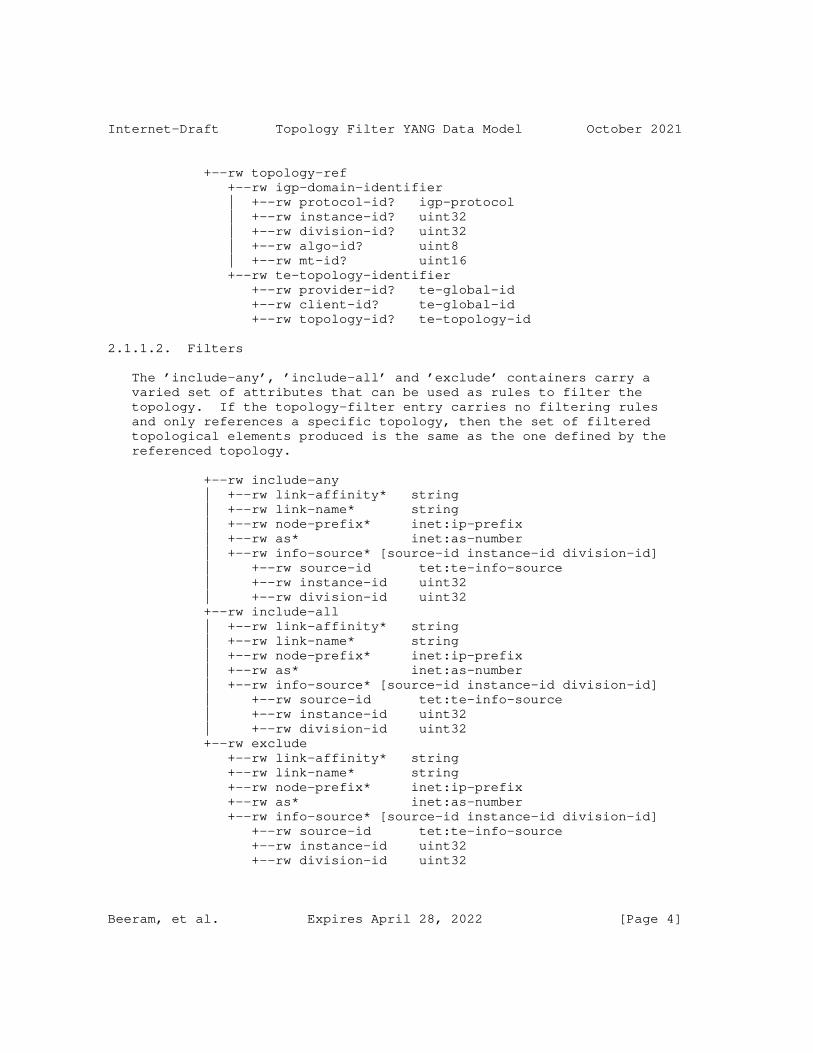
Internet-Draft Topology Filter YANG Data Model October 2021
+--rw topology-ref +--rw igp-domain-identifier | +--rw protocol-id? igp-protocol | +--rw instance-id? uint32 | +--rw division-id? uint32 | +--rw algo-id? uint8 | +--rw mt-id? uint16 +--rw te-topology-identifier +--rw provider-id? te-global-id +--rw client-id? te-global-id +--rw topology-id? te-topology-id
2.1.1.2. Filters
The ’include-any’, ’include-all’ and ’exclude’ containers carry a varied set of attributes that can be used as rules to filter the topology. If the topology-filter entry carries no filtering rules and only references a specific topology, then the set of filtered topological elements produced is the same as the one defined by the referenced topology.
+--rw include-any | +--rw link-affinity* string | +--rw link-name* string | +--rw node-prefix* inet:ip-prefix | +--rw as* inet:as-number | +--rw info-source* [source-id instance-id division-id] | +--rw source-id tet:te-info-source | +--rw instance-id uint32 | +--rw division-id uint32 +--rw include-all | +--rw link-affinity* string | +--rw link-name* string | +--rw node-prefix* inet:ip-prefix | +--rw as* inet:as-number | +--rw info-source* [source-id instance-id division-id] | +--rw source-id tet:te-info-source | +--rw instance-id uint32 | +--rw division-id uint32 +--rw exclude +--rw link-affinity* string +--rw link-name* string +--rw node-prefix* inet:ip-prefix +--rw as* inet:as-number +--rw info-source* [source-id instance-id division-id] +--rw source-id tet:te-info-source +--rw instance-id uint32 +--rw division-id uint32
Beeram, et al. Expires April 28, 2022 [Page 4]
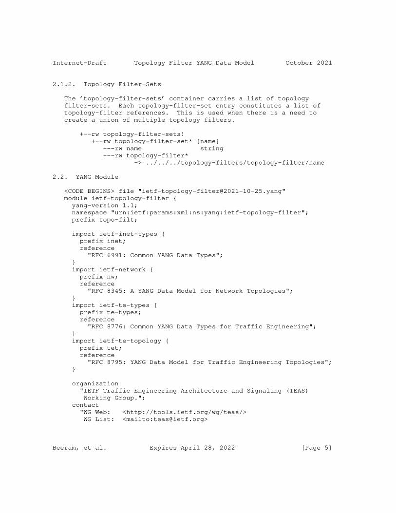
Internet-Draft Topology Filter YANG Data Model October 2021
2.1.2. Topology Filter-Sets
The ’topology-filter-sets’ container carries a list of topology filter-sets. Each topology-filter-set entry constitutes a list of topology-filter references. This is used when there is a need to create a union of multiple topology filters.
+--rw topology-filter-sets! +--rw topology-filter-set* [name] +--rw name string +--rw topology-filter* -> ../../../topology-filters/topology-filter/name
2.2. YANG Module
<CODE BEGINS> file "[email protected]" module ietf-topology-filter { yang-version 1.1; namespace "urn:ietf:params:xml:ns:yang:ietf-topology-filter"; prefix topo-filt;
import ietf-inet-types { prefix inet; reference "RFC 6991: Common YANG Data Types"; } import ietf-network { prefix nw; reference "RFC 8345: A YANG Data Model for Network Topologies"; } import ietf-te-types { prefix te-types; reference "RFC 8776: Common YANG Data Types for Traffic Engineering"; } import ietf-te-topology { prefix tet; reference "RFC 8795: YANG Data Model for Traffic Engineering Topologies"; }
organization "IETF Traffic Engineering Architecture and Signaling (TEAS) Working Group."; contact "WG Web: <http://tools.ietf.org/wg/teas/> WG List: <mailto:[email protected]>
Beeram, et al. Expires April 28, 2022 [Page 5]
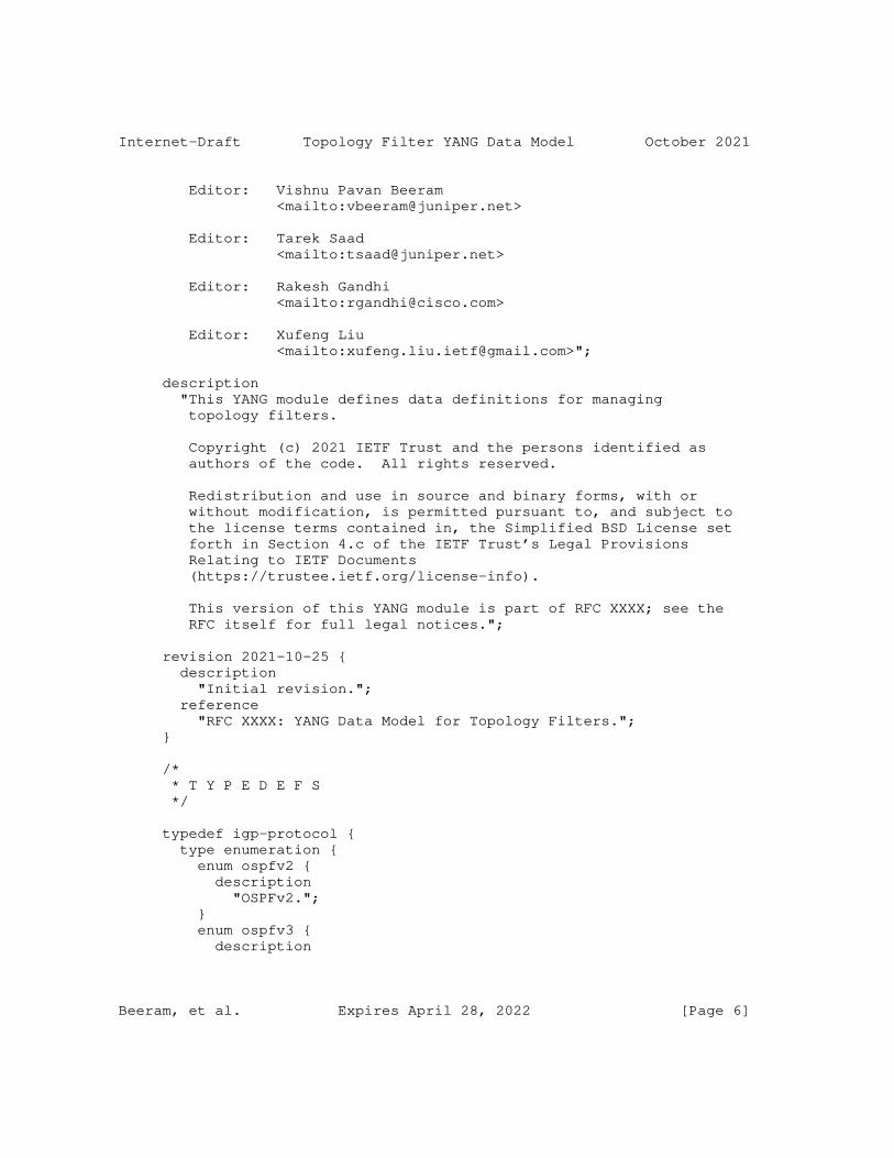
Internet-Draft Topology Filter YANG Data Model October 2021
Editor: Vishnu Pavan Beeram <mailto:[email protected]>
Editor: Tarek Saad <mailto:[email protected]>
Editor: Rakesh Gandhi <mailto:[email protected]>
Editor: Xufeng Liu <mailto:[email protected]>";
description "This YANG module defines data definitions for managing topology filters.
Copyright (c) 2021 IETF Trust and the persons identified as authors of the code. All rights reserved.
Redistribution and use in source and binary forms, with or without modification, is permitted pursuant to, and subject to the license terms contained in, the Simplified BSD License set forth in Section 4.c of the IETF Trust’s Legal Provisions Relating to IETF Documents (https://trustee.ietf.org/license-info).
This version of this YANG module is part of RFC XXXX; see the RFC itself for full legal notices.";
revision 2021-10-25 { description "Initial revision."; reference "RFC XXXX: YANG Data Model for Topology Filters."; }
/* * T Y P E D E F S */
typedef igp-protocol { type enumeration { enum ospfv2 { description "OSPFv2."; } enum ospfv3 { description
Beeram, et al. Expires April 28, 2022 [Page 6]

Internet-Draft Topology Filter YANG Data Model October 2021
"OSPFv3."; } enum isis { description "IS-IS."; } } description "IGP Protocol Type."; }
/* * G R O U P I N G S */ /* * Grouping - Topology Information Source. */
grouping igp-topology-info-source { description "Grouping for igp topology information source."; leaf protocol-id { type igp-protocol; description "IGP Protocol Type."; } leaf instance-id { type uint32; description "Information Source Instance."; } leaf division-id { type uint32; description "Information Source Division."; } }
/* * Grouping - IGP Domain Identifier. */
grouping igp-domain-identifier { description "Grouping for igp domain identifier."; container igp-domain-identifier { description "Container for igp domain identifier.";
Beeram, et al. Expires April 28, 2022 [Page 7]
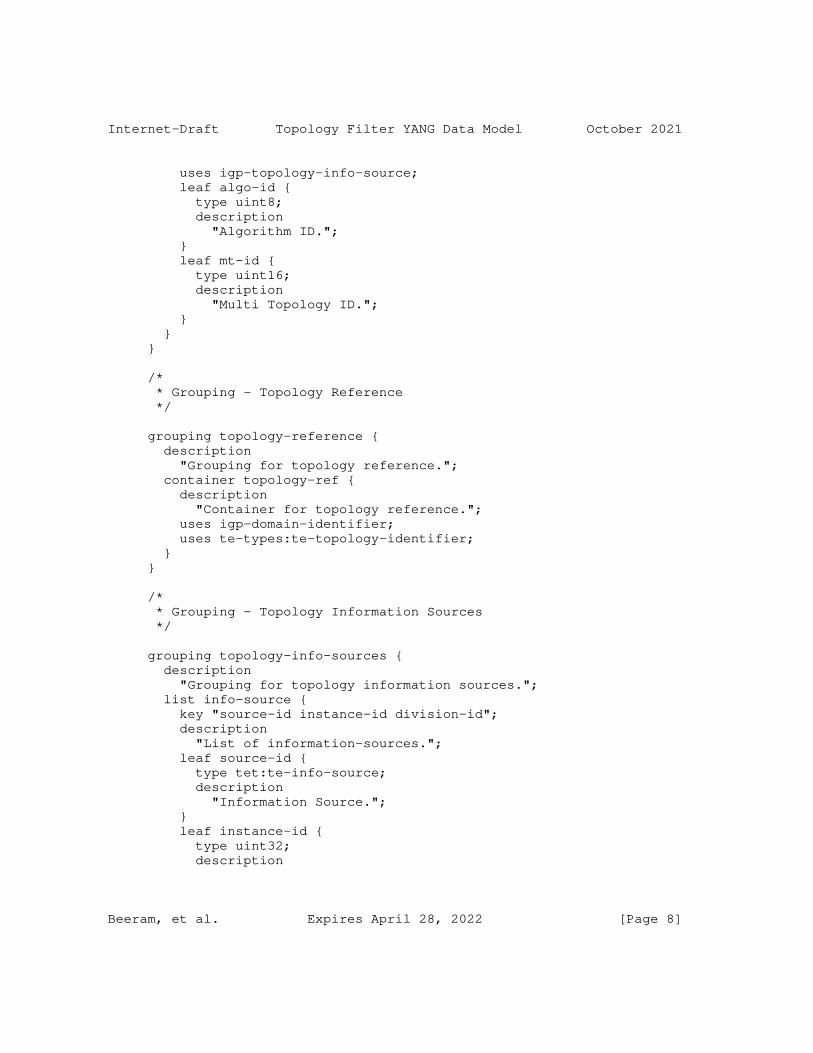
Internet-Draft Topology Filter YANG Data Model October 2021
uses igp-topology-info-source; leaf algo-id { type uint8; description "Algorithm ID."; } leaf mt-id { type uint16; description "Multi Topology ID."; } } }
/* * Grouping - Topology Reference */
grouping topology-reference { description "Grouping for topology reference."; container topology-ref { description "Container for topology reference."; uses igp-domain-identifier; uses te-types:te-topology-identifier; } }
/* * Grouping - Topology Information Sources */
grouping topology-info-sources { description "Grouping for topology information sources."; list info-source { key "source-id instance-id division-id"; description "List of information-sources."; leaf source-id { type tet:te-info-source; description "Information Source."; } leaf instance-id { type uint32; description
Beeram, et al. Expires April 28, 2022 [Page 8]
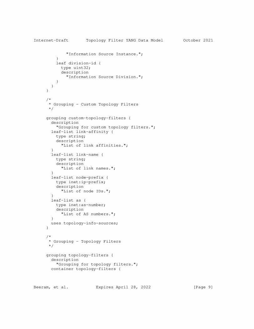
Internet-Draft Topology Filter YANG Data Model October 2021
"Information Source Instance."; } leaf division-id { type uint32; description "Information Source Division."; } } }
/* * Grouping - Custom Topology Filters */
grouping custom-topology-filters { description "Grouping for custom topology filters."; leaf-list link-affinity { type string; description "List of link affinities."; } leaf-list link-name { type string; description "List of link names."; } leaf-list node-prefix { type inet:ip-prefix; description "List of node IDs."; } leaf-list as { type inet:as-number; description "List of AS numbers."; } uses topology-info-sources; }
/* * Grouping - Topology Filters */
grouping topology-filters { description "Grouping for topology filters."; container topology-filters {
Beeram, et al. Expires April 28, 2022 [Page 9]
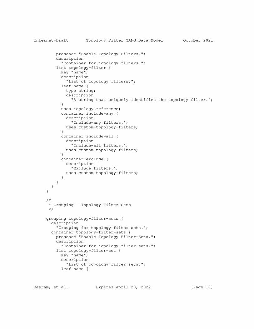
Internet-Draft Topology Filter YANG Data Model October 2021
presence "Enable Topology Filters."; description "Container for topology filters."; list topology-filter { key "name"; description "List of topology filters."; leaf name { type string; description "A string that uniquely identifies the topology filter."; } uses topology-reference; container include-any { description "Include-any filters."; uses custom-topology-filters; } container include-all { description "Include-all filters."; uses custom-topology-filters; } container exclude { description "Exclude filters."; uses custom-topology-filters; } } } }
/* * Grouping - Topology Filter Sets */
grouping topology-filter-sets { description "Grouping for topology filter sets."; container topology-filter-sets { presence "Enable Topology Filter-Sets."; description "Container for topology filter sets."; list topology-filter-set { key "name"; description "List of topology filter sets."; leaf name {
Beeram, et al. Expires April 28, 2022 [Page 10]
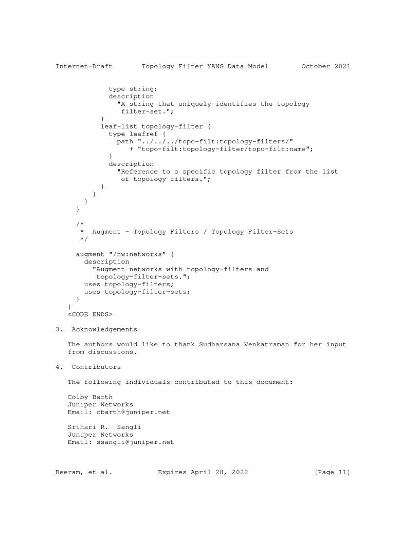
Internet-Draft Topology Filter YANG Data Model October 2021
type string; description "A string that uniquely identifies the topology filter-set."; } leaf-list topology-filter { type leafref { path "../../../topo-filt:topology-filters/" + "topo-filt:topology-filter/topo-filt:name"; } description "Reference to a specific topology filter from the list of topology filters."; } } } }
/* * Augment - Topology Filters / Topology Filter-Sets */
augment "/nw:networks" { description "Augment networks with topology-filters and topology-filter-sets."; uses topology-filters; uses topology-filter-sets; } } <CODE ENDS>
3. Acknowledgements
The authors would like to thank Sudharsana Venkatraman for her input from discussions.
4. Contributors
The following individuals contributed to this document:
Colby Barth Juniper Networks Email: [email protected]
Srihari R. Sangli Juniper Networks Email: [email protected]
Beeram, et al. Expires April 28, 2022 [Page 11]
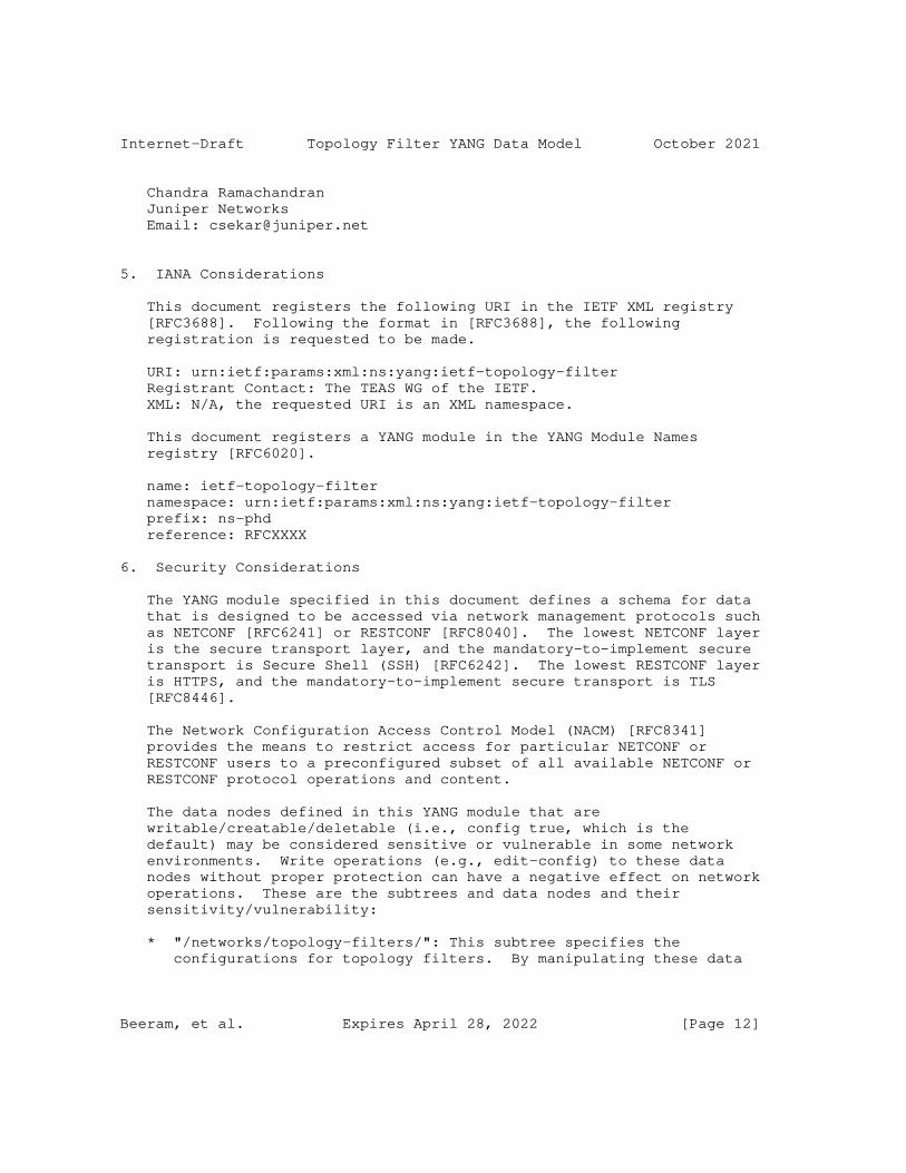
Internet-Draft Topology Filter YANG Data Model October 2021
Chandra Ramachandran Juniper Networks Email: [email protected]
5. IANA Considerations
This document registers the following URI in the IETF XML registry [RFC3688]. Following the format in [RFC3688], the following registration is requested to be made.
URI: urn:ietf:params:xml:ns:yang:ietf-topology-filter Registrant Contact: The TEAS WG of the IETF. XML: N/A, the requested URI is an XML namespace.
This document registers a YANG module in the YANG Module Names registry [RFC6020].
name: ietf-topology-filter namespace: urn:ietf:params:xml:ns:yang:ietf-topology-filter prefix: ns-phd reference: RFCXXXX
6. Security Considerations
The YANG module specified in this document defines a schema for data that is designed to be accessed via network management protocols such as NETCONF [RFC6241] or RESTCONF [RFC8040]. The lowest NETCONF layer is the secure transport layer, and the mandatory-to-implement secure transport is Secure Shell (SSH) [RFC6242]. The lowest RESTCONF layer is HTTPS, and the mandatory-to-implement secure transport is TLS [RFC8446].
The Network Configuration Access Control Model (NACM) [RFC8341] provides the means to restrict access for particular NETCONF or RESTCONF users to a preconfigured subset of all available NETCONF or RESTCONF protocol operations and content.
The data nodes defined in this YANG module that are writable/creatable/deletable (i.e., config true, which is the default) may be considered sensitive or vulnerable in some network environments. Write operations (e.g., edit-config) to these data nodes without proper protection can have a negative effect on network operations. These are the subtrees and data nodes and their sensitivity/vulnerability:
* "/networks/topology-filters/": This subtree specifies the configurations for topology filters. By manipulating these data
Beeram, et al. Expires April 28, 2022 [Page 12]
Internet-Draft Topology Filter YANG Data Model October 2021
nodes, a malicious attacker may cause unauthorized and improper behavior to any service that is making use of the filtered set of topological elements produced by the application of the compromised topology filter.
* "/networks/topology-filter-sets": This subtree specifies the configurations for topology filter-sets. By manipulating these data nodes, a malicious attacker may cause unauthorized and improper behavior to any service that is making use of the filtered set of topological elements produced by the application of the compromised topology filter-set.
The readable data nodes in this YANG module may be considered sensitive or vulnerable in some network environments. It is thus important to control read access (e.g., via get, get-config, or notification) to these data nodes. These are the subtrees and data nodes and their sensitivity/vulnerability:
* "/networks/topology-filter": Unauthorized access to this subtree can disclose the topology filters used in the network.
* "/networks/topology-filter-sets": Unauthorized access to this subtree can disclose the topology filter-sets used in the network.
7. References
7.1. Normative References
[RFC2119] Bradner, S., "Key words for use in RFCs to Indicate Requirement Levels", BCP 14, RFC 2119, DOI 10.17487/RFC2119, March 1997, <https://www.rfc-editor.org/info/rfc2119>.
[RFC3688] Mealling, M., "The IETF XML Registry", BCP 81, RFC 3688, DOI 10.17487/RFC3688, January 2004, <https://www.rfc-editor.org/info/rfc3688>.
[RFC6020] Bjorklund, M., Ed., "YANG - A Data Modeling Language for the Network Configuration Protocol (NETCONF)", RFC 6020, DOI 10.17487/RFC6020, October 2010, <https://www.rfc-editor.org/info/rfc6020>.
[RFC6241] Enns, R., Ed., Bjorklund, M., Ed., Schoenwaelder, J., Ed., and A. Bierman, Ed., "Network Configuration Protocol (NETCONF)", RFC 6241, DOI 10.17487/RFC6241, June 2011, <https://www.rfc-editor.org/info/rfc6241>.
Beeram, et al. Expires April 28, 2022 [Page 13]
Internet-Draft Topology Filter YANG Data Model October 2021
[RFC6242] Wasserman, M., "Using the NETCONF Protocol over Secure Shell (SSH)", RFC 6242, DOI 10.17487/RFC6242, June 2011, <https://www.rfc-editor.org/info/rfc6242>.
[RFC7950] Bjorklund, M., Ed., "The YANG 1.1 Data Modeling Language", RFC 7950, DOI 10.17487/RFC7950, August 2016, <https://www.rfc-editor.org/info/rfc7950>.
[RFC8040] Bierman, A., Bjorklund, M., and K. Watsen, "RESTCONF Protocol", RFC 8040, DOI 10.17487/RFC8040, January 2017, <https://www.rfc-editor.org/info/rfc8040>.
[RFC8174] Leiba, B., "Ambiguity of Uppercase vs Lowercase in RFC 2119 Key Words", BCP 14, RFC 8174, DOI 10.17487/RFC8174, May 2017, <https://www.rfc-editor.org/info/rfc8174>.
[RFC8341] Bierman, A. and M. Bjorklund, "Network Configuration Access Control Model", STD 91, RFC 8341, DOI 10.17487/RFC8341, March 2018, <https://www.rfc-editor.org/info/rfc8341>.
[RFC8345] Clemm, A., Medved, J., Varga, R., Bahadur, N., Ananthakrishnan, H., and X. Liu, "A YANG Data Model for Network Topologies", RFC 8345, DOI 10.17487/RFC8345, March 2018, <https://www.rfc-editor.org/info/rfc8345>.
[RFC8446] Rescorla, E., "The Transport Layer Security (TLS) Protocol Version 1.3", RFC 8446, DOI 10.17487/RFC8446, August 2018, <https://www.rfc-editor.org/info/rfc8446>.
[RFC8776] Saad, T., Gandhi, R., Liu, X., Beeram, V., and I. Bryskin, "Common YANG Data Types for Traffic Engineering", RFC 8776, DOI 10.17487/RFC8776, June 2020, <https://www.rfc-editor.org/info/rfc8776>.
[RFC8795] Liu, X., Bryskin, I., Beeram, V., Saad, T., Shah, H., and O. Gonzalez de Dios, "YANG Data Model for Traffic Engineering (TE) Topologies", RFC 8795, DOI 10.17487/RFC8795, August 2020, <https://www.rfc-editor.org/info/rfc8795>.
7.2. Informative References
[RFC8340] Bjorklund, M. and L. Berger, Ed., "YANG Tree Diagrams", BCP 215, RFC 8340, DOI 10.17487/RFC8340, March 2018, <https://www.rfc-editor.org/info/rfc8340>.
Beeram, et al. Expires April 28, 2022 [Page 14]

Internet-Draft Topology Filter YANG Data Model October 2021
Appendix A. Complete Model Tree Structure
Beeram, et al. Expires April 28, 2022 [Page 15]
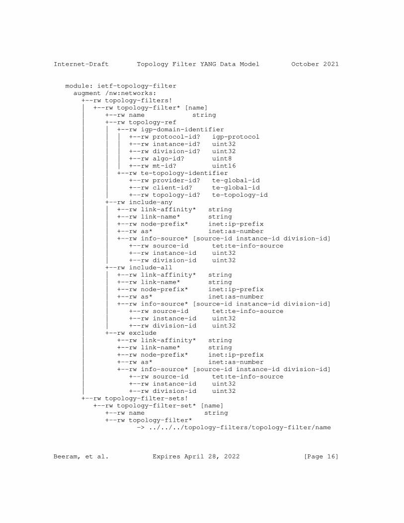
Internet-Draft Topology Filter YANG Data Model October 2021
module: ietf-topology-filter augment /nw:networks: +--rw topology-filters! | +--rw topology-filter* [name] | +--rw name string | +--rw topology-ref | | +--rw igp-domain-identifier | | | +--rw protocol-id? igp-protocol | | | +--rw instance-id? uint32 | | | +--rw division-id? uint32 | | | +--rw algo-id? uint8 | | | +--rw mt-id? uint16 | | +--rw te-topology-identifier | | +--rw provider-id? te-global-id | | +--rw client-id? te-global-id | | +--rw topology-id? te-topology-id | +--rw include-any | | +--rw link-affinity* string | | +--rw link-name* string | | +--rw node-prefix* inet:ip-prefix | | +--rw as* inet:as-number | | +--rw info-source* [source-id instance-id division-id] | | +--rw source-id tet:te-info-source | | +--rw instance-id uint32 | | +--rw division-id uint32 | +--rw include-all | | +--rw link-affinity* string | | +--rw link-name* string | | +--rw node-prefix* inet:ip-prefix | | +--rw as* inet:as-number | | +--rw info-source* [source-id instance-id division-id] | | +--rw source-id tet:te-info-source | | +--rw instance-id uint32 | | +--rw division-id uint32 | +--rw exclude | +--rw link-affinity* string | +--rw link-name* string | +--rw node-prefix* inet:ip-prefix | +--rw as* inet:as-number | +--rw info-source* [source-id instance-id division-id] | +--rw source-id tet:te-info-source | +--rw instance-id uint32 | +--rw division-id uint32 +--rw topology-filter-sets! +--rw topology-filter-set* [name] +--rw name string +--rw topology-filter* -> ../../../topology-filters/topology-filter/name
Beeram, et al. Expires April 28, 2022 [Page 16]

Internet-Draft Topology Filter YANG Data Model October 2021
Authors’ Addresses
Vishnu Pavan Beeram Juniper Networks
Email: [email protected]
Tarek Saad Juniper Networks
Email: [email protected]
Rakesh Gandhi Cisco Systems
Email: [email protected]
Xufeng Liu Volta Networks
Email: [email protected]
Beeram, et al. Expires April 28, 2022 [Page 17]

TEAS Working Group J. DongInternet-Draft Z. LiIntended status: Informational Huawei TechnologiesExpires: 28 April 2022 L. Gong China Mobile G. Yang China Telecom J. Guichard Futurewei Technologies G. Mishra Verizon Inc. F. Qin China Mobile 25 October 2021
Scalability Considerations for Enhanced VPN (VPN+) draft-dong-teas-enhanced-vpn-vtn-scalability-04
Abstract
Enhanced VPN (VPN+) aims to meet the needs of some customers or applications, including the customers and applications that are associated with 5G, which requires connectivity services with advanced characteristics, such as the assurance of some Service Level Objectives (SLOs) and specific Service Level Expectations (SLEs). VPN+ could be used for network slice realization both in the context of 5G and in more generic scenarios, such as enterprise services which have requirement on the performance assurance. With the demand for VPN+ services increases, scalability would become an important factor for the large scale deployment of VPN+. This document describes the scalability considerations about the network control plane and data plane in enabling VPN+ services, some optimization mechanisms are also proposed.
Status of This Memo
This Internet-Draft is submitted in full conformance with the provisions of BCP 78 and BCP 79.
Internet-Drafts are working documents of the Internet Engineering Task Force (IETF). Note that other groups may also distribute working documents as Internet-Drafts. The list of current Internet- Drafts is at https://datatracker.ietf.org/drafts/current/.
Dong, et al. Expires 28 April 2022 [Page 1]
Internet-Draft VPN+ Scalability October 2021
Internet-Drafts are draft documents valid for a maximum of six months and may be updated, replaced, or obsoleted by other documents at any time. It is inappropriate to use Internet-Drafts as reference material or to cite them other than as "work in progress."
This Internet-Draft will expire on 28 April 2022.
Copyright Notice
Copyright (c) 2021 IETF Trust and the persons identified as the document authors. All rights reserved.
This document is subject to BCP 78 and the IETF Trust’s Legal Provisions Relating to IETF Documents (https://trustee.ietf.org/ license-info) in effect on the date of publication of this document. Please review these documents carefully, as they describe your rights and restrictions with respect to this document. Code Components extracted from this document must include Simplified BSD License text as described in Section 4.e of the Trust Legal Provisions and are provided without warranty as described in the Simplified BSD License.
Table of Contents
1. Introduction . . . . . . . . . . . . . . . . . . . . . . . . 3 2. VPN+ Scalability Requirements . . . . . . . . . . . . . . . . 4 3. VTN Scalability Considerations . . . . . . . . . . . . . . . 5 3.1. Control Plane Scalability . . . . . . . . . . . . . . . . 6 3.1.1. Distributed Control Plane . . . . . . . . . . . . . . 6 3.1.2. Centralized Control Plane . . . . . . . . . . . . . . 6 3.2. Data Plane Scalability . . . . . . . . . . . . . . . . . 7 3.3. Gap Analysis of Existing Mechanisms . . . . . . . . . . . 8 4. Proposed Scalability Optimizations . . . . . . . . . . . . . 8 4.1. Control Plane Optimizations . . . . . . . . . . . . . . . 9 4.2. Data Plane Optimizations . . . . . . . . . . . . . . . . 11 5. Solution Evolution for Improved Scalability . . . . . . . . . 12 6. Security Considerations . . . . . . . . . . . . . . . . . . . 13 7. IANA Considerations . . . . . . . . . . . . . . . . . . . . . 13 8. Contributors . . . . . . . . . . . . . . . . . . . . . . . . 13 9. Acknowledgments . . . . . . . . . . . . . . . . . . . . . . . 13 10. References . . . . . . . . . . . . . . . . . . . . . . . . . 14 10.1. Normative References . . . . . . . . . . . . . . . . . . 14 10.2. Informative References . . . . . . . . . . . . . . . . . 14 Authors’ Addresses . . . . . . . . . . . . . . . . . . . . . . . 16
Dong, et al. Expires 28 April 2022 [Page 2]
Internet-Draft VPN+ Scalability October 2021
1. Introduction
Virtual Private Networks (VPNs) have served the industry well as a means of providing different customers with logically separated connectivity services over a common network infrastructure. The common or base network that is used to provide the VPNs is often referred to as the underlay, and the VPNs are often called the overlay. The underlay network is responsible for establishing the network connectivity and managing the network resources to meet specific service requirement. The overlay network is used to distribute the membership and reachability information of the customers, and provide logical separation in terms of service delivery between different customers in the shared network.
Enhanced VPN (VPN+) aims to meet the needs of some customers or applications, including the applications that are associated with 5G, which requires connectivity services with advanced characteristics, such as the assurance of Service Level Objectives (SLOs) and specific Service Level Expectations (SLEs). [I-D.ietf-teas-ietf-network-slices] defines the terminologies and the general framework of IETF network slices. VPN+ could be used for IETF network slice realization both in the context of 5G and in more generic scenarios, such as enterprise services which have requirement on the performance assurance.
[I-D.ietf-teas-enhanced-vpn] describes the framework for delivering VPN+ services. To meet the requirement of some VPN+ services, a Virtual Transport Networks (VTNs) need to be created, which has a subset of network resources allocated from the physical network and is associated with a logical network topology to meet the requirements of one or a group of VPN+ services. VPN+ services can be delivered by mapping one or a group of overlay VPNs to the appropriate VTNs as the virtual underlay.
Section 6 of [I-D.ietf-teas-enhanced-vpn] provides some general analysis of the scalability of VPN+. This document gives further analysis of the scalability considerations when a large number of VPN+ services needs to be provided. Since the scalability of the overlay is usually not the major bottleneck, this document mainly focuses on the scalability of the VTNs in the underlay .
Dong, et al. Expires 28 April 2022 [Page 3]
Internet-Draft VPN+ Scalability October 2021
2. VPN+ Scalability Requirements
As described in [I-D.ietf-teas-enhanced-vpn], VPN+ services may require additional state to be introduced into the network to take advantage of the enhanced functionality. This may introduces some concerns about the network scalability. This section gives some analysis of the number of VPN+ services and the VTNs that might be needed in different network scenarios.
Since the typical use case of VPN+ is to deliver IETF network slice [I-D.ietf-teas-ietf-network-slices] for customers and services in 5G and other scenarios, the number of IETF network slices required could reflect the number of VPN+ needed in the network. With the development and evolution of 5G and other services, it is expected that an increasing number of IETF network slices will be deployed. The number of network slices required depends on how IETF network slices will be used, and the progress of network slicing for the vertical industrial services. The potential number of VPN+ services and VTNs is analyzed by classifying the network slice deployment into three typical scenarios:
1. IETF network slices can be used by a network operator for different types of services. For example, in a converged multi- service network, different IETF network slices can be created to carry mobile transport service, fixed broadband service and enterprise services respectively, each type of service could be managed by a separate department or management team. Some service types, such as multicast service may also be deployed in a dedicated network slice. In this case, a separate VTN may need to be created for each service type. It is also possible that a network infrastructure operator provides IETF network slices to other network operators as a wholesale service, and a VTN may also be needed for each wholesale service customer. In this scenario, the number of VTNs in a network could be relatively small, such as in the order of 10 or so. This could be one of the typical cases in the beginning of IETF network slice deployment.
2. IETF network slices can be requested by customers in vertical industries, where the assurance of SLOs and the fulfilment of SLEs are quite important. At the early stage of the vertical industrial services, a few top customers in some industries will begin to use IETF network slices to provide performance assurance to their business, such as smart grid, manufacturing, public safety, on-line gaming, etc. The realization of such IETF network slices typically requires to provide different VTNs for different industries, and some top customers can require dedicated VTNs for strict service performance guarantee.
Dong, et al. Expires 28 April 2022 [Page 4]
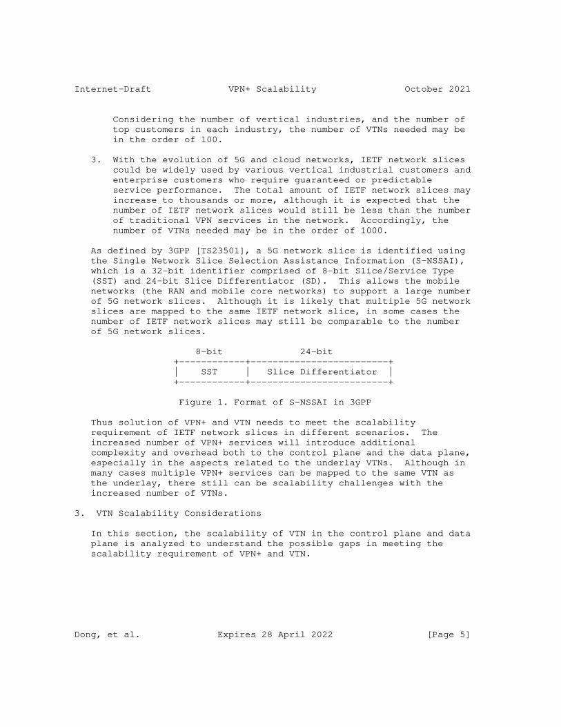
Internet-Draft VPN+ Scalability October 2021
Considering the number of vertical industries, and the number of top customers in each industry, the number of VTNs needed may be in the order of 100.
3. With the evolution of 5G and cloud networks, IETF network slices could be widely used by various vertical industrial customers and enterprise customers who require guaranteed or predictable service performance. The total amount of IETF network slices may increase to thousands or more, although it is expected that the number of IETF network slices would still be less than the number of traditional VPN services in the network. Accordingly, the number of VTNs needed may be in the order of 1000.
As defined by 3GPP [TS23501], a 5G network slice is identified using the Single Network Slice Selection Assistance Information (S-NSSAI), which is a 32-bit identifier comprised of 8-bit Slice/Service Type (SST) and 24-bit Slice Differentiator (SD). This allows the mobile networks (the RAN and mobile core networks) to support a large number of 5G network slices. Although it is likely that multiple 5G network slices are mapped to the same IETF network slice, in some cases the number of IETF network slices may still be comparable to the number of 5G network slices.
8-bit 24-bit +------------+-------------------------+ | SST | Slice Differentiator | +------------+-------------------------+
Figure 1. Format of S-NSSAI in 3GPP
Thus solution of VPN+ and VTN needs to meet the scalability requirement of IETF network slices in different scenarios. The increased number of VPN+ services will introduce additional complexity and overhead both to the control plane and the data plane, especially in the aspects related to the underlay VTNs. Although in many cases multiple VPN+ services can be mapped to the same VTN as the underlay, there still can be scalability challenges with the increased number of VTNs.
3. VTN Scalability Considerations
In this section, the scalability of VTN in the control plane and data plane is analyzed to understand the possible gaps in meeting the scalability requirement of VPN+ and VTN.
Dong, et al. Expires 28 April 2022 [Page 5]
Internet-Draft VPN+ Scalability October 2021
3.1. Control Plane Scalability
As described in [I-D.ietf-teas-enhanced-vpn], the control plane of VPN+ could be based on the hybrid of a centralized controller and the distributed control plane.
3.1.1. Distributed Control Plane
At part of the delivery of VPN+ services, it is necessary to create multiple VTNs, each of which is allocated with a set of dedicated or shared network resources, and is associated with a customized logical topology. The topological and resource attributes and the state information of each VTN may need to be exchanged among the network nodes. The scalability of the distributed control plane used for the distribution of VTN information needs to be considered in the following aspects:
* The number of control protocol instances maintained on each node
* The number of protocol sessions maintained on each link
* The number of routes advertised by each node
* The amount of attributes associated with each route
* The number of route computation (i.e. SPF computation) executed by each node
As the number of VTNs increases, it is expected that in some of the above aspects, the overhead in the control plane may increase dramatically. For example, the overhead of maintaining separated control protocol instances (e.g. IGP instances) for different VTNs is considered higher than maintaining the information of separated VTNs in the same control protocol instance with appropriate separation, and the overhead of maintaining separate protocol sessions for different VTNs is considered higher than using a shared protocol session for the information exchange of multiple VTNs. To meet the requirement of the increasing number of VTNs, It is suggested to choose the control plane mechanisms which could improve the scalability while still provide the required functionality.
3.1.2. Centralized Control Plane
By introducing the centralized network controller, the SDN approach can reduce the amount of control plane overhead in the distributed control plane, while it may also transfer some of the scalability concerns from network nodes to the centralized controller, thus the scalability of the controller also needs to be considered.
Dong, et al. Expires 28 April 2022 [Page 6]
Internet-Draft VPN+ Scalability October 2021
To provide global optimization for the Traffic Engineered (TE) paths in different VTNs, the controller needs to keep the topology and resource information of all the VTNs up-to-date. To achieve this, the controller may need to maintain a communication channel with each network node in the network. When there is significant change in the network, or multiple VTNs requires global optimization concurrently, there may be a heavy processing burden at the controller, and a heavy load in the network surrounding the controller for the distribution of the updated network state and the TE paths.
3.2. Data Plane Scalability
To provide different VPN+ services with the required SLOs and SLEs, it is necessary to allocate different subsets of network resources to different VTNs to avoid or reduce unexpected interruption. As the number of VTNs increases, it is required that the underlying network can provide fine-granular network resource partitioning, which means the amount of state about the partitioned network resources to be maintained on the network nodes will also increase.
In packet forwarding, VPN+ service traffic needs to be processed separately according to the topology and resource attributes of the VTN it mapped to, this means that some fields in the data packet needs to be used to identify the VTN topology and resources either directly or implicitly. Different approaches of encapsulating the VTN information in data packet can have different scalability implications.
One practical approach is to reuse some of the existing fields in the data packet to additionally identify the VTN the packet belongs to. For example, the destination IP addresses or the MPLS forwarding labels may be reused to further identify a VTN. This can avoid the cost of introducing new fields in the data packet, while since it introduces additional semantics to the existing fields, the processing of the existing fields in packet forwarding may need to be changed. Moreover, introducing VTN semantics to existing identifiers in the packet (e.g. IP addresses, MPLS forwarding labels, etc.) may result in the increase of the amount of the existing IDs in proportion to the number of the VTNs, which may cause scalability problem in networks where a relatively large number of VTNs is needed.
Dong, et al. Expires 28 April 2022 [Page 7]
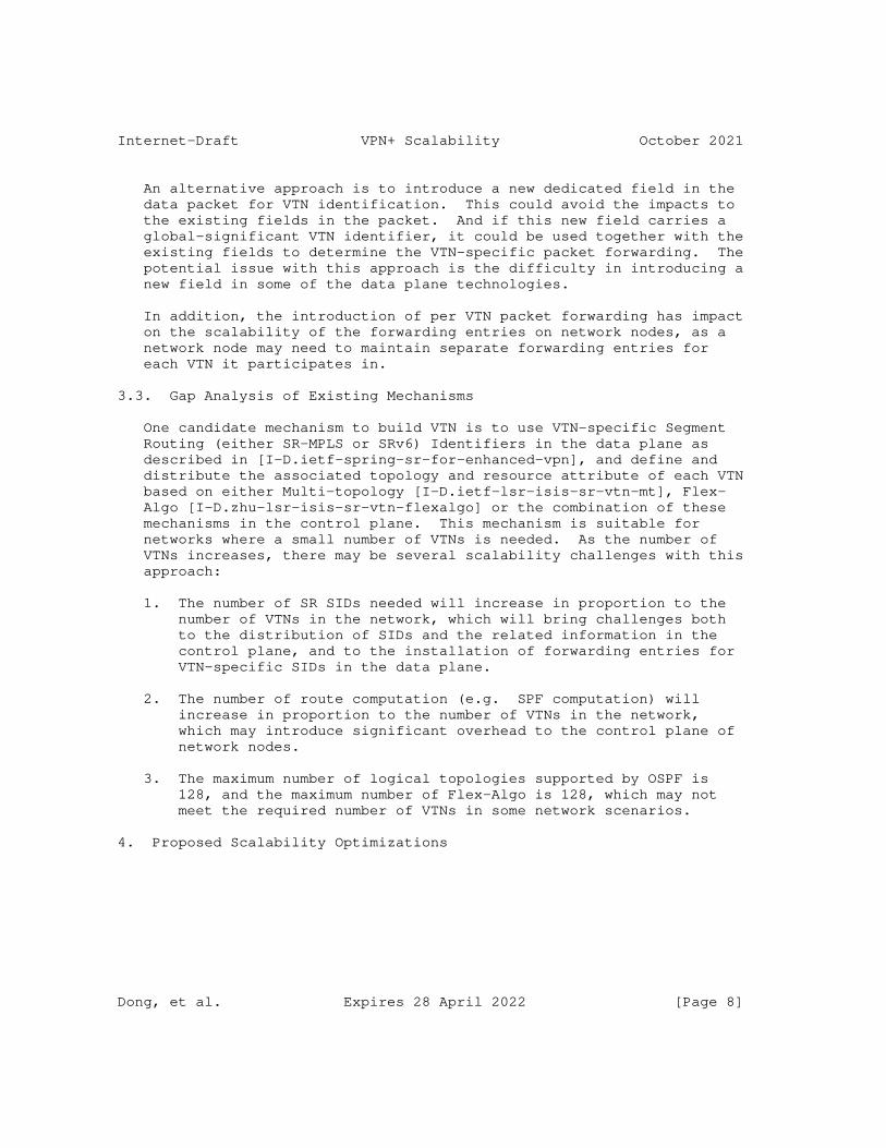
Internet-Draft VPN+ Scalability October 2021
An alternative approach is to introduce a new dedicated field in the data packet for VTN identification. This could avoid the impacts to the existing fields in the packet. And if this new field carries a global-significant VTN identifier, it could be used together with the existing fields to determine the VTN-specific packet forwarding. The potential issue with this approach is the difficulty in introducing a new field in some of the data plane technologies.
In addition, the introduction of per VTN packet forwarding has impact on the scalability of the forwarding entries on network nodes, as a network node may need to maintain separate forwarding entries for each VTN it participates in.
3.3. Gap Analysis of Existing Mechanisms
One candidate mechanism to build VTN is to use VTN-specific Segment Routing (either SR-MPLS or SRv6) Identifiers in the data plane as described in [I-D.ietf-spring-sr-for-enhanced-vpn], and define and distribute the associated topology and resource attribute of each VTN based on either Multi-topology [I-D.ietf-lsr-isis-sr-vtn-mt], Flex- Algo [I-D.zhu-lsr-isis-sr-vtn-flexalgo] or the combination of these mechanisms in the control plane. This mechanism is suitable for networks where a small number of VTNs is needed. As the number of VTNs increases, there may be several scalability challenges with this approach:
1. The number of SR SIDs needed will increase in proportion to the number of VTNs in the network, which will bring challenges both to the distribution of SIDs and the related information in the control plane, and to the installation of forwarding entries for VTN-specific SIDs in the data plane.
2. The number of route computation (e.g. SPF computation) will increase in proportion to the number of VTNs in the network, which may introduce significant overhead to the control plane of network nodes.
3. The maximum number of logical topologies supported by OSPF is 128, and the maximum number of Flex-Algo is 128, which may not meet the required number of VTNs in some network scenarios.
4. Proposed Scalability Optimizations
Dong, et al. Expires 28 April 2022 [Page 8]

Internet-Draft VPN+ Scalability October 2021
4.1. Control Plane Optimizations
For the distributed control plane, several optimizations can be considered to reduce the control plane overhead and improve the control plane scalability.
The first optimization mechanism is to reduce the amount of control plane sessions used for the establishment and maintenance of the VTNs. For multiple VTNs which have the same peering relationship between two adjacent network nodes, it is proposed that one single control protocol session is used for the establishment of multiple VTNs. The information of different VTNs can be exchanged over the same session, with necessary identification information to distinguish the VTNs in the control messages. This could reduce the overhead of maintaining a large number of control protocol sessions for different VTNs, and could also reduce the amount of control plane messages flooded in the network.
The second optimization mechanism is to decompose the attributes of a VTN into different groups, so that different types of VTN attribute can be advertised and processed separately in control plane. There are two basic types of attributes associated with a VTN: the topology attribute and the network resource attribute. In a network, it is possible that multiple VTNs share the same topology, and multiple VTNs may share the same set of network resources on particular network nodes and links. Then it is more efficient if only one copy of the topology information is advertised, and multiple VTNs sharing the same topology could refer to this topology information. More importantly, with this approach, the result of topology-based route computation could be shared by multiple VTNs, so that the overhead of per-VTN route computation could also be reduced . Similarly, information of a subset of network resources reserved on a particular network node or link could be advertised once and be referred to by multiple VTNs which share the same set of resources. This methodology could also apply to other attributes of VTN which may be introduced later and can be processed independently.
Dong, et al. Expires 28 April 2022 [Page 9]
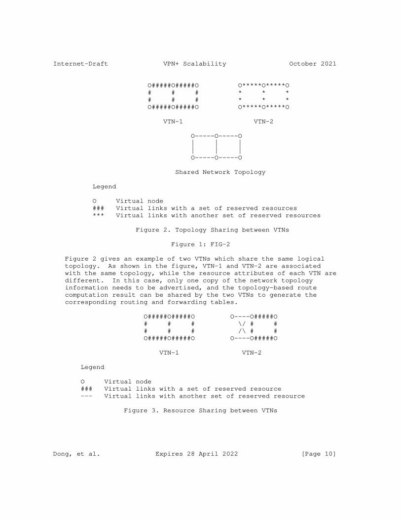
Internet-Draft VPN+ Scalability October 2021
O#####O#####O O*****O*****O # # # * * * # # # * * * O#####O#####O O*****O*****O
VTN-1 VTN-2
O-----O-----O | | | | | | O-----O-----O
Shared Network Topology
Legend
O Virtual node ### Virtual links with a set of reserved resources *** Virtual links with another set of reserved resources
Figure 2. Topology Sharing between VTNs
Figure 1: FIG-2
Figure 2 gives an example of two VTNs which share the same logical topology. As shown in the figure, VTN-1 and VTN-2 are associated with the same topology, while the resource attributes of each VTN are different. In this case, only one copy of the network topology information needs to be advertised, and the topology-based route computation result can be shared by the two VTNs to generate the corresponding routing and forwarding tables.
O#####O#####O O----O#####O # # # \/ # # # # # /\ # # O#####O#####O O----O#####O
VTN-1 VTN-2
Legend
O Virtual node ### Virtual links with a set of reserved resource --- Virtual links with another set of reserved resource
Figure 3. Resource Sharing between VTNs
Dong, et al. Expires 28 April 2022 [Page 10]
Internet-Draft VPN+ Scalability October 2021
Figure 3 gives another example of two VTNs which share the same set of network resources on some of the links. In this case, information about the resources allocated on each link only needs to be advertised once, then both VTN-1 and VTN-2 could refer to the reserved link resource for constraint based path computation.
For the optimization of the centralized control plane, it is suggested that the centralized controller is used as a complementary mechanism to the distributed control plane rather than a replacement, so that the workload for VTN specific path computation in control plane could be shared by both the centralized controller and the network nodes, and the scalability of both systems could be improved.
4.2. Data Plane Optimizations
To support more VPN+ services while keeping the amount of data plane state at a reasonable scale, one typical approach is to classify a set of VPN+ services which have similar service characteristics and performance requirements into a group, and such group of VPN+ services are mapped to one VTN, which is allocated with an aggregated set of network resources and the union of the required logical topologies to meet the service requirement of the whole group of VPN+ services. Different groups of VPN+ services can be mapped to different VTNs with different set of network resources allocated. With appropriate grouping of VPN+ services, a reasonable number of VTNs with network resources reservation and aggregation could still meet the service requirements.
Another optimization in the data plane is to decouple the identifiers used for topology-based forwarding and the identifier used for the resource-specific processing introduced by VTN. One possible mechanism is to introduce a dedicated VTN Resource identifier in the packet header to uniquely identify the set of local network resources allocated to a VTN on each network node for the processing and forwarding of the received packets. Then the existing identifiers in the packet header used for topology based forwarding (e.g. the destination IP address, MPLS forwarding labels) are kept unchanged. The benefit is the amount of the existing topology-specific identifiers will not be impacted by the increasing number of VTNs. Since this new VTN Resource ID field will be used together with other existing fields to determine the VTN-specific packet forwarding, this may require network nodes to support a hierarchical forwarding table in data plane. Figure 4 shows the concept of using different data plane identifiers for topology-specific and resource-specific packet forwarding and processing in a VTN respectively.
Dong, et al. Expires 28 April 2022 [Page 11]
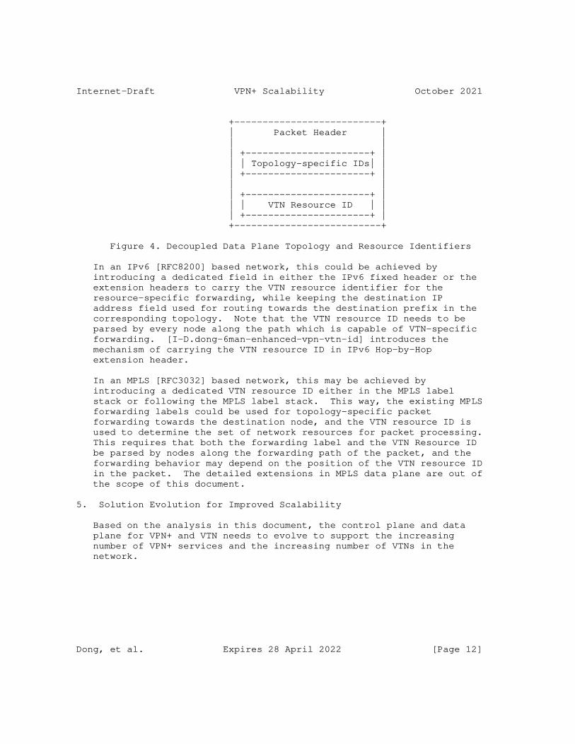
Internet-Draft VPN+ Scalability October 2021
+--------------------------+ | Packet Header | | | | +----------------------+ | | | Topology-specific IDs| | | +----------------------+ | | | | +----------------------+ | | | VTN Resource ID | | | +----------------------+ | +--------------------------+
Figure 4. Decoupled Data Plane Topology and Resource Identifiers
In an IPv6 [RFC8200] based network, this could be achieved by introducing a dedicated field in either the IPv6 fixed header or the extension headers to carry the VTN resource identifier for the resource-specific forwarding, while keeping the destination IP address field used for routing towards the destination prefix in the corresponding topology. Note that the VTN resource ID needs to be parsed by every node along the path which is capable of VTN-specific forwarding. [I-D.dong-6man-enhanced-vpn-vtn-id] introduces the mechanism of carrying the VTN resource ID in IPv6 Hop-by-Hop extension header.
In an MPLS [RFC3032] based network, this may be achieved by introducing a dedicated VTN resource ID either in the MPLS label stack or following the MPLS label stack. This way, the existing MPLS forwarding labels could be used for topology-specific packet forwarding towards the destination node, and the VTN resource ID is used to determine the set of network resources for packet processing. This requires that both the forwarding label and the VTN Resource ID be parsed by nodes along the forwarding path of the packet, and the forwarding behavior may depend on the position of the VTN resource ID in the packet. The detailed extensions in MPLS data plane are out of the scope of this document.
5. Solution Evolution for Improved Scalability
Based on the analysis in this document, the control plane and data plane for VPN+ and VTN needs to evolve to support the increasing number of VPN+ services and the increasing number of VTNs in the network.
Dong, et al. Expires 28 April 2022 [Page 12]
Internet-Draft VPN+ Scalability October 2021
At the first step, by introducing resource-awareness to segment routing SIDs [I-D.ietf-spring-resource-aware-segments], and using Multi-Topology or Flex-Algo as the control plane, it could provide a solution for building a limited number of VTNs in the network to meet the requirement of a relatively small number of VPN+ services in the network. This mechanism is considered as the basic SR VTN.
As the required number of VPN+ services increases, more VTNs may be needed, then the control plane scalability could be improved by decoupling the topology attribute from the resource attribute and other attributes of VTN, so that multiple VTNs could share the same topology or resource attribute to reduce the control plane and data plane overhead. This mechanism is considered as the scalable SR VTN. Both the basic and the scalable SR VTN mechanisms are described in [I-D.ietf-spring-sr-for-enhanced-vpn].
If the data plane scalability becomes a concern, a dedicated VTN resource ID can be introduced in the data packet to decouple the topology-specific identifiers from the VTN resource identifiers in the data plane, this could help to reduce the number of SR SIDs needed to support a large number of VTNs. This mechanism is considered as the Resource-Independent (RI) VTN.
6. Security Considerations
This document describes the scalability considerations about the network control plane and data plane in enabling VPN+ services and the VTNs, and proposes several scalability optimization mechanisms. The security considerations in [I-D.ietf-teas-enhanced-vpn] applies to this document.
7. IANA Considerations
This document makes no request of IANA.
8. Contributors
Zhibo Hu Email: [email protected]
Hongjie Yang Email: [email protected]
9. Acknowledgments
The authors would like to thank Adrian Farrel for the review and discussion of this document.
Dong, et al. Expires 28 April 2022 [Page 13]
Internet-Draft VPN+ Scalability October 2021
10. References
10.1. Normative References
[I-D.ietf-teas-enhanced-vpn] Dong, J., Bryant, S., Li, Z., Miyasaka, T., and Y. Lee, "A Framework for Enhanced Virtual Private Network (VPN+) Services", Work in Progress, Internet-Draft, draft-ietf- teas-enhanced-vpn-08, 12 July 2021, <https://www.ietf.org/archive/id/draft-ietf-teas-enhanced- vpn-08.txt>.
10.2. Informative References
[I-D.dong-6man-enhanced-vpn-vtn-id] Dong, J., Li, Z., Xie, C., Ma, C., and G. Mishra, "Carrying Virtual Transport Network Identifier in IPv6 Extension Header", Work in Progress, Internet-Draft, draft-dong-6man-enhanced-vpn-vtn-id-05, 8 September 2021, <https://www.ietf.org/archive/id/draft-dong-6man-enhanced- vpn-vtn-id-05.txt>.
[I-D.dong-lsr-sr-enhanced-vpn] Dong, J., Hu, Z., Li, Z., Tang, X., Pang, R., JooHeon, L., and S. Bryant, "IGP Extensions for Scalable Segment Routing based Enhanced VPN", Work in Progress, Internet- Draft, draft-dong-lsr-sr-enhanced-vpn-06, 11 July 2021, <https://www.ietf.org/archive/id/draft-dong-lsr-sr- enhanced-vpn-06.txt>.
[I-D.ietf-lsr-flex-algo] Psenak, P., Hegde, S., Filsfils, C., Talaulikar, K., and A. Gulko, "IGP Flexible Algorithm", Work in Progress, Internet-Draft, draft-ietf-lsr-flex-algo-17, 6 July 2021, <https://www.ietf.org/archive/id/draft-ietf-lsr-flex-algo- 17.txt>.
[I-D.ietf-lsr-isis-sr-vtn-mt] Xie, C., Ma, C., Dong, J., and Z. Li, "Using IS-IS Multi- Topology (MT) for Segment Routing based Virtual Transport Network", Work in Progress, Internet-Draft, draft-ietf- lsr-isis-sr-vtn-mt-01, 12 July 2021, <https://www.ietf.org/archive/id/draft-ietf-lsr-isis-sr- vtn-mt-01.txt>.
[I-D.ietf-spring-resource-aware-segments] Dong, J., Bryant, S., Miyasaka, T., Zhu, Y., Qin, F., Li, Z., and F. Clad, "Introducing Resource Awareness to SR
Dong, et al. Expires 28 April 2022 [Page 14]
Internet-Draft VPN+ Scalability October 2021
Segments", Work in Progress, Internet-Draft, draft-ietf- spring-resource-aware-segments-03, 12 July 2021, <https://www.ietf.org/archive/id/draft-ietf-spring- resource-aware-segments-03.txt>.
[I-D.ietf-spring-sr-for-enhanced-vpn] Dong, J., Bryant, S., Miyasaka, T., Zhu, Y., Qin, F., Li, Z., and F. Clad, "Segment Routing based Virtual Transport Network (VTN) for Enhanced VPN", Work in Progress, Internet-Draft, draft-ietf-spring-sr-for-enhanced-vpn-01, 12 July 2021, <https://www.ietf.org/archive/id/draft-ietf- spring-sr-for-enhanced-vpn-01.txt>.
[I-D.ietf-teas-ietf-network-slices] Farrel, A., Gray, E., Drake, J., Rokui, R., Homma, S., Makhijani, K., Contreras, L. M., and J. Tantsura, "Framework for IETF Network Slices", Work in Progress, Internet-Draft, draft-ietf-teas-ietf-network-slices-04, 23 August 2021, <https://www.ietf.org/archive/id/draft-ietf- teas-ietf-network-slices-04.txt>.
[I-D.zhu-lsr-isis-sr-vtn-flexalgo] Zhu, Y., Dong, J., and Z. Hu, "Using Flex-Algo for Segment Routing based VTN", Work in Progress, Internet-Draft, draft-zhu-lsr-isis-sr-vtn-flexalgo-03, 11 July 2021, <https://www.ietf.org/archive/id/draft-zhu-lsr-isis-sr- vtn-flexalgo-03.txt>.
[RFC3032] Rosen, E., Tappan, D., Fedorkow, G., Rekhter, Y., Farinacci, D., Li, T., and A. Conta, "MPLS Label Stack Encoding", RFC 3032, DOI 10.17487/RFC3032, January 2001, <https://www.rfc-editor.org/info/rfc3032>.
[RFC4915] Psenak, P., Mirtorabi, S., Roy, A., Nguyen, L., and P. Pillay-Esnault, "Multi-Topology (MT) Routing in OSPF", RFC 4915, DOI 10.17487/RFC4915, June 2007, <https://www.rfc-editor.org/info/rfc4915>.
[RFC5120] Przygienda, T., Shen, N., and N. Sheth, "M-ISIS: Multi Topology (MT) Routing in Intermediate System to Intermediate Systems (IS-ISs)", RFC 5120, DOI 10.17487/RFC5120, February 2008, <https://www.rfc-editor.org/info/rfc5120>.
[RFC8200] Deering, S. and R. Hinden, "Internet Protocol, Version 6 (IPv6) Specification", STD 86, RFC 8200, DOI 10.17487/RFC8200, July 2017, <https://www.rfc-editor.org/info/rfc8200>.
Dong, et al. Expires 28 April 2022 [Page 15]
Internet-Draft VPN+ Scalability October 2021
[TS23501] "3GPP TS23.501", 2016, <https://portal.3gpp.org/desktopmodules/Specifications/ SpecificationDetails.aspx?specificationId=3144>.
Authors’ Addresses
Jie Dong Huawei Technologies Huawei Campus, No. 156 Beiqing Road Beijing 100095 China
Email: [email protected]
Zhenbin Li Huawei Technologies Huawei Campus, No. 156 Beiqing Road Beijing 100095 China
Email: [email protected]
Liyan Gong China Mobile No. 32 Xuanwumenxi Ave., Xicheng District Beijing China
Email: [email protected]
Guangming Yang China Telecom No.109 West Zhongshan Ave., Tianhe District Guangzhou China
Email: [email protected]
Dong, et al. Expires 28 April 2022 [Page 16]
Internet-Draft VPN+ Scalability October 2021
James N Guichard Futurewei Technologies 2330 Central Express Way Santa Clara, United States of America
Email: [email protected]
Gyan Mishra Verizon Inc.
Email: [email protected]
Fengwei Qin China Mobile No. 32 Xuanwumenxi Ave., Xicheng District Beijing China
Email: [email protected]
Dong, et al. Expires 28 April 2022 [Page 17]
Network Working Group X. GengInternet-Draft J. DongIntended status: Informational Huawei TechnologiesExpires: 28 April 2022 R. Pang China Unicom L. Han China Mobile R. Rokui Nokia T. Niwa Individual J. Jin LG U+ C. Liu China Unicom N. Nageshar Individual 25 October 2021
5G End-to-end Network Slice Mapping from the view of Transport Network draft-geng-teas-network-slice-mapping-04
Abstract
Network Slicing is one of the core features in 5G. End-to-end network slice consists of 3 major types of network segments: Access Network (AN), Mobile Core Network (CN) and Transport Network (TN). This draft describes the procedure of mapping 5G end-to-end network slice to transport network slice defined in IETF. This draft also intends to expose some gaps in the existing network management plane and data plane technologies to support inter-domain network slice mapping. Further work may require collaboration between IETF and 3GPP (or other standard organizations). Data model specification, signaling protocol extension and new encapsulation definition are out of the scope of this draft.
Requirements Language
The key words "MUST", "MUST NOT", "REQUIRED", "SHALL", "SHALL NOT", "SHOULD", "SHOULD NOT", "RECOMMENDED", "MAY", and "OPTIONAL" in this document are to be interpreted as described in RFC 2119 [RFC2119].
Status of This Memo
This Internet-Draft is submitted in full conformance with the provisions of BCP 78 and BCP 79.
Geng, et al. Expires 28 April 2022 [Page 1]
Internet-Draft draft-geng-teas-network-slice-mapping-03 October 2021
Internet-Drafts are working documents of the Internet Engineering Task Force (IETF). Note that other groups may also distribute working documents as Internet-Drafts. The list of current Internet- Drafts is at https://datatracker.ietf.org/drafts/current/.
Internet-Drafts are draft documents valid for a maximum of six months and may be updated, replaced, or obsoleted by other documents at any time. It is inappropriate to use Internet-Drafts as reference material or to cite them other than as "work in progress."
This Internet-Draft will expire on 28 April 2022.
Copyright Notice
Copyright (c) 2021 IETF Trust and the persons identified as the document authors. All rights reserved.
This document is subject to BCP 78 and the IETF Trust’s Legal Provisions Relating to IETF Documents (https://trustee.ietf.org/ license-info) in effect on the date of publication of this document. Please review these documents carefully, as they describe your rights and restrictions with respect to this document. Code Components extracted from this document must include Simplified BSD License text as described in Section 4.e of the Trust Legal Provisions and are provided without warranty as described in the Simplified BSD License.
Table of Contents
1. Introduction . . . . . . . . . . . . . . . . . . . . . . . . 3 2. Terminologies . . . . . . . . . . . . . . . . . . . . . . . . 3 3. 5G End-to-End Network Slice Identification . . . . . . . . . 4 4. Network Slice Mapping Structure . . . . . . . . . . . . . . . 5 5. Network Slice Mapping Procedure . . . . . . . . . . . . . . . 8 5.1. Network Slice Mapping in Management Plane . . . . . . . . 9 5.2. Network Slice Mapping in Control Plane . . . . . . . . . 10 5.3. Network Slice Mapping in Data Plane . . . . . . . . . . . 10 5.3.1. Data Plane Mapping Considerations . . . . . . . . . . 10 5.3.2. Data Plane Mapping Options . . . . . . . . . . . . . 11 6. Network Slice Mapping Summary . . . . . . . . . . . . . . . . 15 7. IANA Considerations . . . . . . . . . . . . . . . . . . . . . 16 8. Security Considerations . . . . . . . . . . . . . . . . . . . 16 9. Acknowledgements . . . . . . . . . . . . . . . . . . . . . . 16 10. Normative References . . . . . . . . . . . . . . . . . . . . 16 Authors’ Addresses . . . . . . . . . . . . . . . . . . . . . . . 18
Geng, et al. Expires 28 April 2022 [Page 2]
Internet-Draft draft-geng-teas-network-slice-mapping-03 October 2021
1. Introduction
Driven by the new applications of 5G, the concept of network slicing is defined to provide a logical network with specific capabilities and characteristics. Network slice contains a set of network functions and allocated resources(e.g. computation, storage and network resources). According to [TS28530], a 5G end-to-end network slice is composed of three major types network segments: Radio Access Network (RAN), Transport Network (TN) and Mobile Core Network (CN). Transport network is supposed to provide the required connectivity between AN and CN, with specific performance commitment. For each end-to-end network slice, the topology and performance requirement for transport network can be very different, which requests transport network to have the capability of supporting multiple different transport network slices.
The concept of IETF network slice is discussed in [I-D.ietf-teas-ietf-network-slices]. In summary, an IETF Network Slice is a logical network topology connecting a number of endpoints using a set of shared or dedicated network resources that are used to satisfy specific Service Level Objectives SLOs) and Service Level Expectations (SLEs).
The realization of an IETF network slices in Transport network (TN) could span multiple technology (e.g., IP/MPLS, Optical) and multiple administrative domains. Depending on the consumer’s requirement, an IETF network slice could be isolated from other concurrent IETF network slices, in terms of data plane, control plane and management plane. The procedure for lifecycle of an end-to-end network slice instance (i.e., creation, deletion, modificatinon, termination etc.) is defined in [TS28531]. End-to-end network slicing provisioning is specified in ETSI [ZSM003]. But there is no specifications about how to map end-to-end network slice to IETF network slices in Transport Network (TN). This draft describes the procedure of mapping the 5G end-to-end network slice to IETF network slices in management plane, control plane and data plane.
2. Terminologies
The key words "MUST", "MUST NOT", "REQUIRED", "SHALL", "SHALL NOT", "SHOULD", "SHOULD NOT", "RECOMMENDED", "MAY", and "OPTIONAL" in this document are to be interpreted as described in [RFC2119].
The following terms are used in this document:
NSC: IETF Network Slice Controller
NSI: Network Slice Instance
Geng, et al. Expires 28 April 2022 [Page 3]
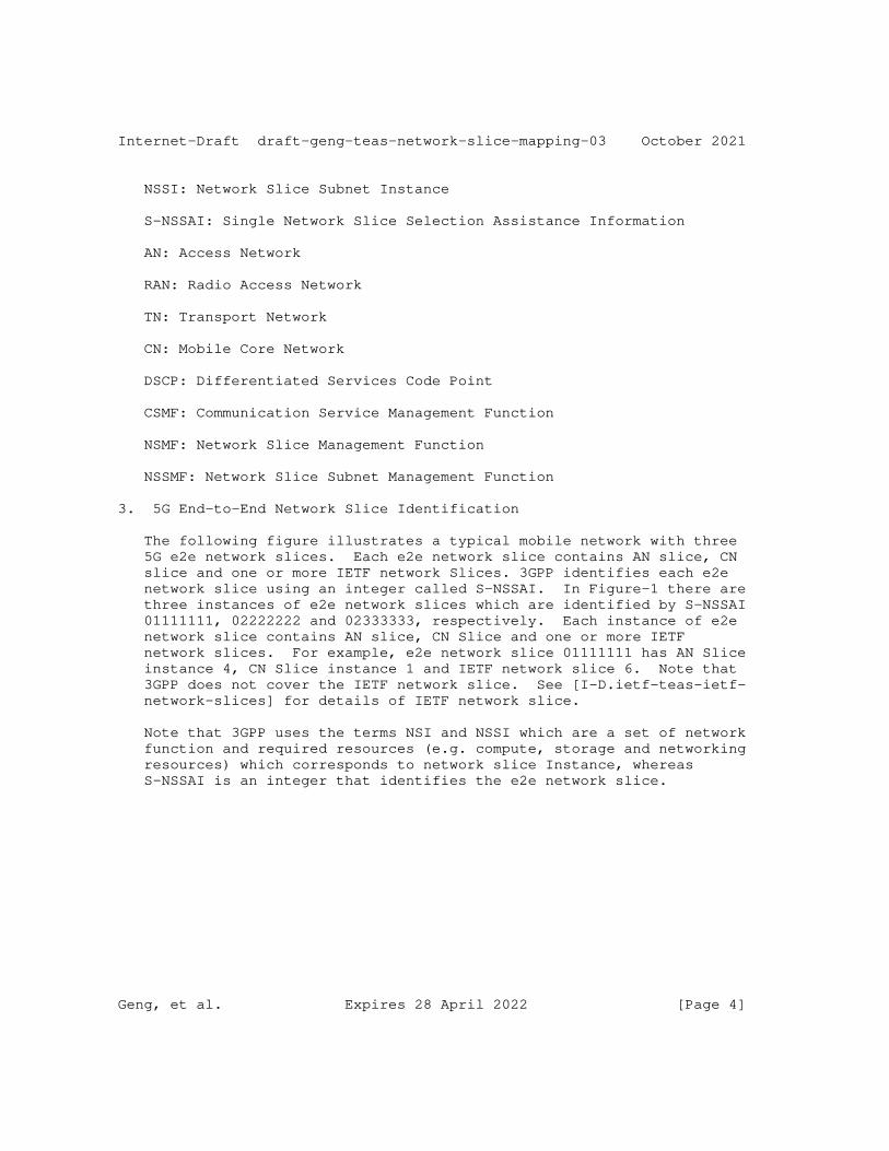
Internet-Draft draft-geng-teas-network-slice-mapping-03 October 2021
NSSI: Network Slice Subnet Instance
S-NSSAI: Single Network Slice Selection Assistance Information
AN: Access Network
RAN: Radio Access Network
TN: Transport Network
CN: Mobile Core Network
DSCP: Differentiated Services Code Point
CSMF: Communication Service Management Function
NSMF: Network Slice Management Function
NSSMF: Network Slice Subnet Management Function
3. 5G End-to-End Network Slice Identification
The following figure illustrates a typical mobile network with three 5G e2e network slices. Each e2e network slice contains AN slice, CN slice and one or more IETF network Slices. 3GPP identifies each e2e network slice using an integer called S-NSSAI. In Figure-1 there are three instances of e2e network slices which are identified by S-NSSAI 01111111, 02222222 and 02333333, respectively. Each instance of e2e network slice contains AN slice, CN Slice and one or more IETF network slices. For example, e2e network slice 01111111 has AN Slice instance 4, CN Slice instance 1 and IETF network slice 6. Note that 3GPP does not cover the IETF network slice. See [I-D.ietf-teas-ietf- network-slices] for details of IETF network slice.
Note that 3GPP uses the terms NSI and NSSI which are a set of network function and required resources (e.g. compute, storage and networking resources) which corresponds to network slice Instance, whereas S-NSSAI is an integer that identifies the e2e network slice.
Geng, et al. Expires 28 April 2022 [Page 4]
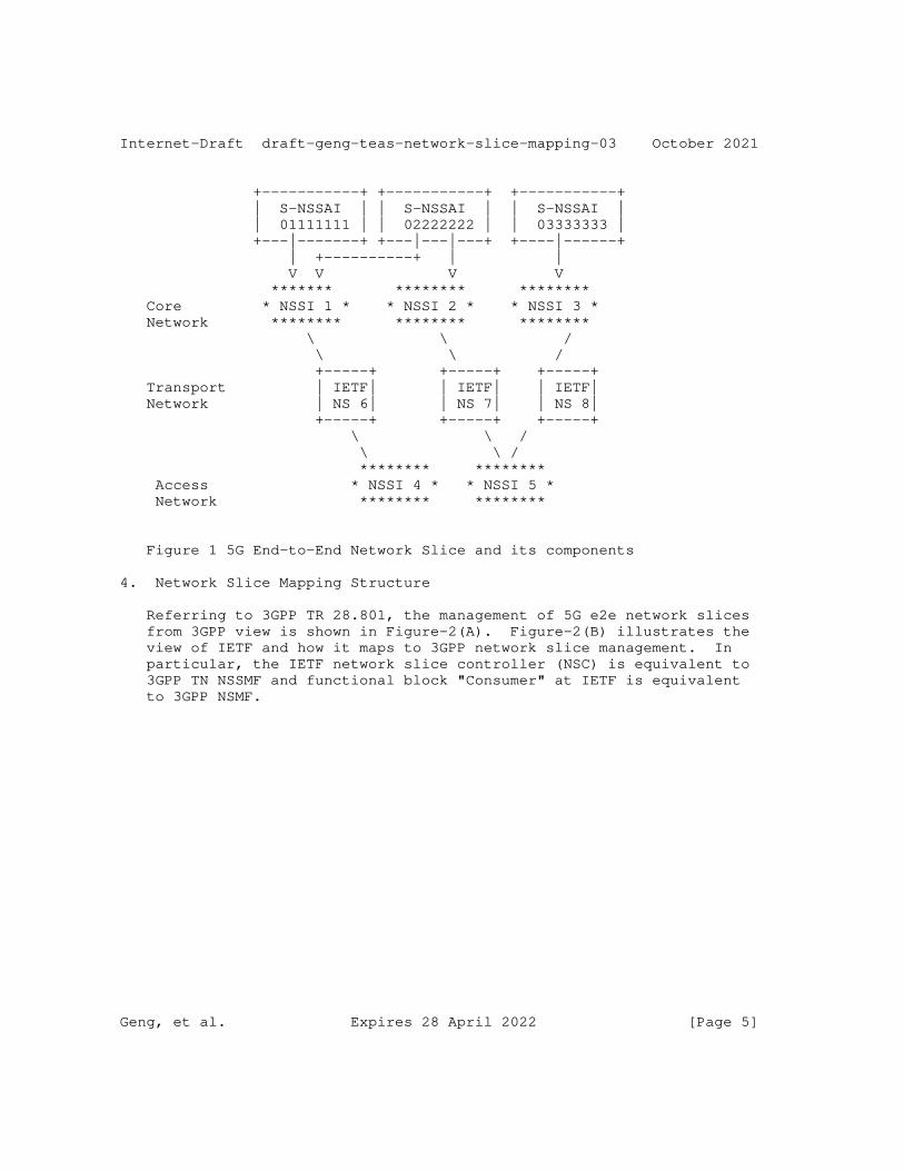
Internet-Draft draft-geng-teas-network-slice-mapping-03 October 2021
+-----------+ +-----------+ +-----------+ | S-NSSAI | | S-NSSAI | | S-NSSAI | | 01111111 | | 02222222 | | 03333333 | +---|-------+ +---|---|---+ +----|------+ | +----------+ | | V V V V ******* ******** ******** Core * NSSI 1 * * NSSI 2 * * NSSI 3 * Network ******** ******** ******** \ \ / \ \ / +-----+ +-----+ +-----+ Transport | IETF| | IETF| | IETF| Network | NS 6| | NS 7| | NS 8| +-----+ +-----+ +-----+ \ \ / \ \ / ******** ******** Access * NSSI 4 * * NSSI 5 * Network ******** ********
Figure 1 5G End-to-End Network Slice and its components
4. Network Slice Mapping Structure
Referring to 3GPP TR 28.801, the management of 5G e2e network slices from 3GPP view is shown in Figure-2(A). Figure-2(B) illustrates the view of IETF and how it maps to 3GPP network slice management. In particular, the IETF network slice controller (NSC) is equivalent to 3GPP TN NSSMF and functional block "Consumer" at IETF is equivalent to 3GPP NSMF.
Geng, et al. Expires 28 April 2022 [Page 5]
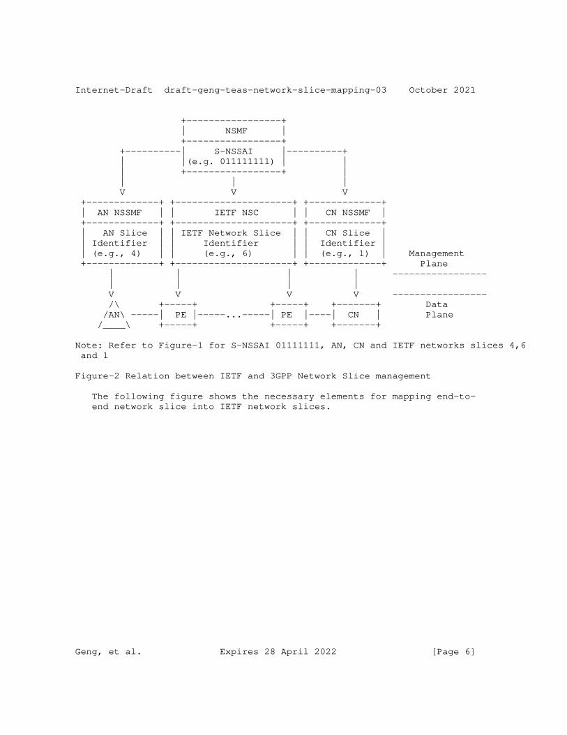
Internet-Draft draft-geng-teas-network-slice-mapping-03 October 2021
+-----------------+ | NSMF | +-----------------+ +----------| S-NSSAI |----------+ | |(e.g. 011111111) | | | +-----------------+ | | | | V V V +-------------+ +---------------------+ +-------------+ | AN NSSMF | | IETF NSC | | CN NSSMF | +-------------+ +---------------------+ +-------------+ | AN Slice | | IETF Network Slice | | CN Slice | | Identifier | | Identifier | | Identifier | | (e.g., 4) | | (e.g., 6) | | (e.g., 1) | Management +-------------+ +---------------------+ +-------------+ Plane | | | | ----------------- | | | | V V V V ----------------- /\ +-----+ +-----+ +-------+ Data /AN\ -----| PE |-----...-----| PE |----| CN | Plane /____\ +-----+ +-----+ +-------+
Note: Refer to Figure-1 for S-NSSAI 01111111, AN, CN and IETF networks slices 4,6 and 1
Figure-2 Relation between IETF and 3GPP Network Slice management
The following figure shows the necessary elements for mapping end-to- end network slice into IETF network slices.
Geng, et al. Expires 28 April 2022 [Page 6]
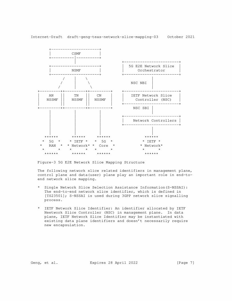
Internet-Draft draft-geng-teas-network-slice-mapping-03 October 2021
+---------------------+ | CSMF | +----------|----------+ | +------------------------+ +---------------------+ | 5G E2E Network Slice | | NSMF | | Orchestrator | +---------------------+ +------------------------+ / | \ | / | \ NSC NBI | / | \ | +---------++---------++---------+ +------------------------+ | AN || TN || CN | | IETF Network Slice | | NSSMF || NSSMF || NSSMF | | Controller (NSC) | | || || | +------------------------+ +---------++---------++---------+ NSC SBI | | | | | | | | +------------------------+ | | | | Network Controllers | | | | +------------------------+ | | | | | | | | ****** ****** ****** ****** * 5G * * IETF * * 5G * * IETF * * RAN * * Network* * Core * * Network* * * * * * * * * ****** ****** ****** ******
Figure-3 5G E2E Network Slice Mapping Structure
The following network slice related identifiers in management plane, control plane and data(user) plane play an important role in end-to- end network slice mapping.
* Single Network Slice Selection Assistance Information(S-NSSAI): The end-to-end network slice identifier, which is defined in [TS23501]; S-NSSAI is used during 3GPP network slice signalling process.
* IETF Network Slice Identifier: An identifier allocated by IETF Neetwork Slice Controller (NSC) in management plane. In data plane, IETF Network Slice Identifier may be instantiated with existing data plane identifiers and doesn’t necessarily require new encapsulation.
Geng, et al. Expires 28 April 2022 [Page 7]
Internet-Draft draft-geng-teas-network-slice-mapping-03 October 2021
* IETF Network Slice Interworking Identifier: Data-plane network slice identifier which is used for mapping the end-to-end network slice traffic to specific IETF network slice. The IETF Network Slice Interworking Identifier is a new concept introduced by this draft, which may be instantiated with existing data plane identifiers and doesn’t necessarily require new encapsulation.
The relationship between these identifiers are specifies in the following sections.
5. Network Slice Mapping Procedure
This section provides a general procedure of network slice mapping:
1. NSMF receives the request from CSMF for allocation of a network slice instance with certain characteristics.
2. Based on the service requirement , NSMF acquires requirements for the end-to-end network slice instance , which is defined in Service Profile([TS28541] section 6.3.3).
3. Based on Service Profile, NSMF identified the network function and the required resources in AN, CN and TN networks. It also assigns the unique ID S-NSSAI.
4. NSMF sends a request to AN NSSMF for creation of AN Slice.
5. NSMF sends a request to CN NSSMF for creation of CN Slice.
6. NSMF sends a request to IETF Network Slice Controller (NSC) for creation of IETF Network Slice. The request contains such attribute such as endpoints, required SLA/SLO along with other IETF network slice attributes. It also cotains mapping informatin for IETF Network Slice Interworking Identifier.
7. NSC realizes the IETF network slice which satisfies the requirement of IETF network slice between the specified endpoints (AN/ CN edge nodes). It assigns sliceID and send it to NSMF.
8. NSMF has the mapping relationship between S-NSSAI and IETF Network Slice ID;
9. When the User Equipment (UE) appears, and during the 5G signalling, it requests to be connected to specific e2e network slice identified by S-NASSI. Then a GTP tunnel (which is UDP/IP) will be created.
Geng, et al. Expires 28 April 2022 [Page 8]
Internet-Draft draft-geng-teas-network-slice-mapping-03 October 2021
10. UE starts sending traffic in context of e2e network slice for specific S-NASSI.
11. In context of GTP tunnel, the AN edge nodes encapsulates the packet with sliceIID according to the selected S-NSSAI ans send it to the transport network.
12. The transport network edge node receives the IP packet and parses the sliceIID from the packet and maps the packet to the corresponding IETF network slice. It may encapsulate packet with sliceID if needed (for example for enforcing QoS in transport network).
5.1. Network Slice Mapping in Management Plane
The transport network management Plane maintains the interface between NSMF and TN NSSMF, which 1) guarantees that IETF network slice could connect the AN and CN with specified characteristics that satisfy the requirements of communication; 2) builds up the mapping relationship between NSI identifier and TN NSSI identifier; 3) maintains the end-to-end slice relevant functions;
Service Profile defined in[TS28541] represents the requirement of end-to-end network slice instance in 5G network. Parameters defined in Service Profile include Latency, resource sharing level, availability and so on. How to decompose the end-to-end requirement to the transport network requirement is one of the key issues in Network slice requirement mapping. GSMA(Global System for Mobile Communications Association) defines the [GST] to indicate the network slice requirement from the view of service provider. [I-D.contreras-teas-slice-nbi] analysis the parameters of GST and categorize the parameters into three classes, including the attributes with direct impact on the IETF network slice definition. It is a good start for selecting the transport network relevant parameters in order to define Network Slice Profile for Transport Network. Network slice requirement parameters are also necessary for the definition of transport network northbound interface.
Inside the TN NSSMF, it is supposed to maintain the attributes of the IETF network slice. If the attributes of an existing TN NSSI could satisfy the requirement from TN Network Slice Profile, the existing TN NSSI could be selected and the mapping is finished If there is no existing TN NSSI which could satisfy the requirement, a new TN NSSI is supposed to be created by the NSSMF with new attributes.
TN NSSI resource reservation should be considered to avoid over allocation from multiple requests from NSMF (but the detailed mechanism should be out of scope in the draft)
Geng, et al. Expires 28 April 2022 [Page 9]
Internet-Draft draft-geng-teas-network-slice-mapping-03 October 2021
TN NSSMF sends the selected or newly allocated TN NSSI identifier to NSMF. The mapping relationship between NSI identifier and TN NSSI identifier is maintained in both NSMF and TN NSSMF.
YANG data model for the Transport Slice NBI, which could be used by a higher level system which is the Transport slice consumer of a Transport Slice Controller (TSC) to request, configure, and manage the components of a transport slices, is defined in [I-D.wd-teas-transport-slice-yang]. The northbound Interface of IETF network slice refers to [I-D.wd-teas-ietf-network-slice-nbi-yang].
5.2. Network Slice Mapping in Control Plane
There is no explicit interaction between transport network and AN/CN in the control plane, but the S-NSSAI defined in [TS23501] is treated as the end-to-end network slice identifier in the control plane of AN and CN, which is used in UE registration and PDU session setup. In this draft, we assume that there is mapping relationship between S-NSSAI and NSI in the management plane, thus it could be mapped to a IETF network slice .
Editor’s note: The mapping relationship between NSI defined in [TS23501] and S-NSSAI defined in [TS23501] is still in discussion.
5.3. Network Slice Mapping in Data Plane
If multiple network slices are carried through one physical interface between AN/CN and TN, IETF Network Slice Interworking ID in the data plane needs to be introduced. If different network slices are transported through different physical interfaces, Network Slices could be distinguished by the interface directly. Thus IETF Network Slice Interworking ID is not the only option for network slice mapping, while it may help in introducing new network slices.
5.3.1. Data Plane Mapping Considerations
The mapping relationship between AN or CN network slice identifier (either S-NSSAI in control plane or NSI/NSSI in management plane) and IETF Network Slice Interworking ID needs to be maintained in AN/CN network nodes, and the mapping relationship between IETF Network Slice Interworking ID and IETF Network Slice is maintained in the edge node of transport network. When the packet of a uplink flow goes from AN to TN, the packet is encapsulated based on the IETF Network Slice Interworking ID; then the encapsulation of IETF Network Slice Interworking ID is read by the edge node of transport network, which maps the packet to the corresponding IETF network slice.
Geng, et al. Expires 28 April 2022 [Page 10]
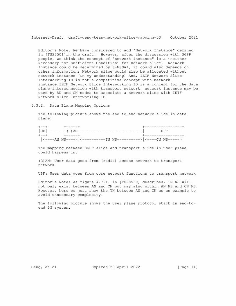
Internet-Draft draft-geng-teas-network-slice-mapping-03 October 2021
Editor’s Note: We have considered to add "Network Instance" defined in [TS23501]in the draft. However, after the discussion with 3GPP people, we think the concept of "network instance" is a ’neither Necessary nor Sufficient Condition’ for network slice. Network Instance could be determined by S-NSSAI, it could also depends on other information; Network slice could also be allocated without network instance (in my understanding) And, IETF Network Slice Interworking ID is not a competitive concept with network instance.IETF Network Slice Interworking ID is a concept for the data plane interconnection with transport network, network instance may be used by AN and CN nodes to associate a network slice with IETF Network Slice Interworking ID
5.3.2. Data Plane Mapping Options
The following picture shows the end-to-end network slice in data plane:
+--+ +-----+ +----------------+ |UE|- - - -|(R)AN|---------------------------| UPF | +--+ +-----+ +----------------+ |<----AN NS---->|<----------TN NS---------->|<----CN NS----->|
The mapping between 3GPP slice and transport slice in user plane could happens in:
(R)AN: User data goes from (radio) access network to transport network
UPF: User data goes from core network functions to transport network
Editor’s Note: As figure 4.7.1. in [TS28530] describes, TN NS will not only exist between AN and CN but may also within AN NS and CN NS. However, here we just show the TN between AN and CN as an example to avoid unncessary complexity.
The following picture shows the user plane protocol stack in end-to- end 5G system.
Geng, et al. Expires 28 April 2022 [Page 11]
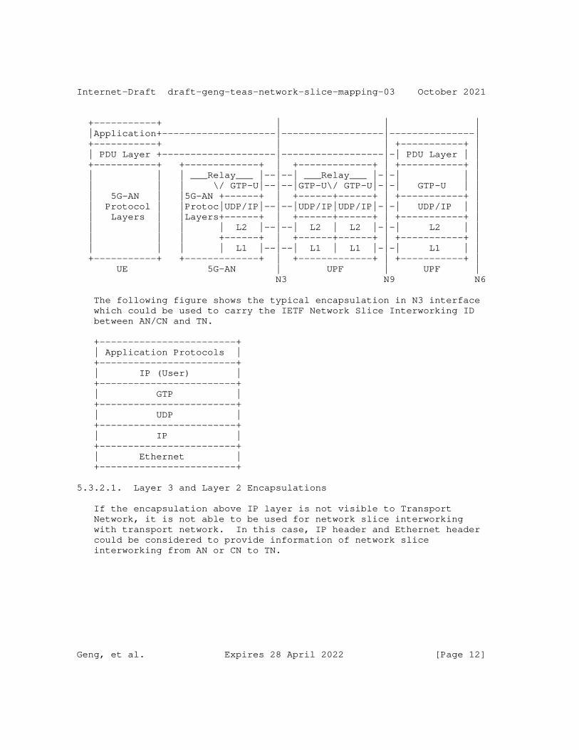
Internet-Draft draft-geng-teas-network-slice-mapping-03 October 2021
+-----------+ | | | |Application+--------------------|------------------|---------------| +-----------+ | | +-----------+ | | PDU Layer +--------------------|------------------|-| PDU Layer | | +-----------+ +-------------+ | +-------------+ | +-----------+ | | | | ___Relay___ |--|--| ___Relay___ |-|-| | | | | | \/ GTP-U|--|--|GTP-U\/ GTP-U|-|-| GTP-U | | | 5G-AN | |5G-AN +------+ | +------+------+ | +-----------+ | | Protocol | |Protoc|UDP/IP|--|--|UDP/IP|UDP/IP|-|-| UDP/IP | | | Layers | |Layers+------+ | +------+------+ | +-----------+ | | | | | L2 |--|--| L2 | L2 |-|-| L2 | | | | | +------+ | +------+------+ | +-----------+ | | | | | L1 |--|--| L1 | L1 |-|-| L1 | | +-----------+ +-------------+ | +-------------+ | +-----------+ | UE 5G-AN | UPF | UPF | N3 N9 N6
The following figure shows the typical encapsulation in N3 interface which could be used to carry the IETF Network Slice Interworking ID between AN/CN and TN.
+------------------------+ | Application Protocols | +------------------------+ | IP (User) | +------------------------+ | GTP | +------------------------+ | UDP | +------------------------+ | IP | +------------------------+ | Ethernet | +------------------------+
5.3.2.1. Layer 3 and Layer 2 Encapsulations
If the encapsulation above IP layer is not visible to Transport Network, it is not able to be used for network slice interworking with transport network. In this case, IP header and Ethernet header could be considered to provide information of network slice interworking from AN or CN to TN.
Geng, et al. Expires 28 April 2022 [Page 12]
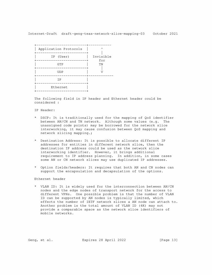
Internet-Draft draft-geng-teas-network-slice-mapping-03 October 2021
+------------------------+----------- | Application Protocols | ^ +------------------------+ | | IP (User) | Invisible +------------------------+ for | GTP | TN +------------------------+ | | UDP | V +------------------------+------------ | IP | +------------------------+ | Ethernet | +------------------------+
The following field in IP header and Ethernet header could be considered :
IP Header:
* DSCP: It is traditionally used for the mapping of QoS identifier between AN/CN and TN network. Although some values (e.g. The unassigned code points) may be borrowed for the network slice interworking, it may cause confusion between QoS mapping and network slicing mapping.;
* Destination Address: It is possible to allocate different IP addresses for entities in different network slice, then the destination IP address could be used as the network slice interworking identifier. However, it brings additional requirement to IP address planning. In addition, in some cases some AN or CN network slices may use duplicated IP addresses.
* Option fields/headers: It requires that both AN and CN nodes can support the encapsulation and decapsulation of the options.
Ethernet header
* VLAN ID: It is widely used for the interconnection between AN/CN nodes and the edge nodes of transport network for the access to different VPNs. One possible problem is that the number of VLAN ID can be supported by AN nodes is typically limited, which effects the number of IETF network slices a AN node can attach to. Another problem is the total amount of VLAN ID (4K) may not provide a comparable space as the network slice identifiers of mobile networks.
Geng, et al. Expires 28 April 2022 [Page 13]
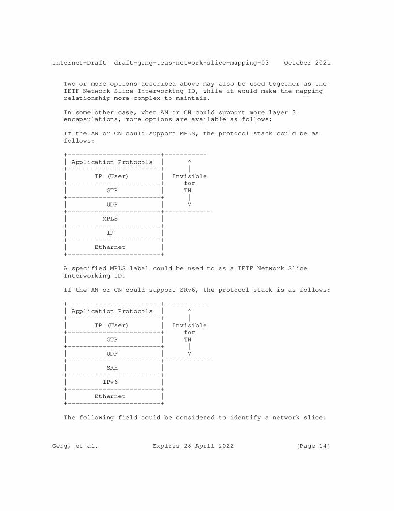
Internet-Draft draft-geng-teas-network-slice-mapping-03 October 2021
Two or more options described above may also be used together as the IETF Network Slice Interworking ID, while it would make the mapping relationship more complex to maintain.
In some other case, when AN or CN could support more layer 3 encapsulations, more options are available as follows:
If the AN or CN could support MPLS, the protocol stack could be as follows:
+------------------------+----------- | Application Protocols | ^ +------------------------+ | | IP (User) | Invisible +------------------------+ for | GTP | TN +------------------------+ | | UDP | V +------------------------+------------ | MPLS | +------------------------+ | IP | +------------------------+ | Ethernet | +------------------------+
A specified MPLS label could be used to as a IETF Network Slice Interworking ID.
If the AN or CN could support SRv6, the protocol stack is as follows:
+------------------------+----------- | Application Protocols | ^ +------------------------+ | | IP (User) | Invisible +------------------------+ for | GTP | TN +------------------------+ | | UDP | V +------------------------+------------ | SRH | +------------------------+ | IPv6 | +------------------------+ | Ethernet | +------------------------+
The following field could be considered to identify a network slice:
Geng, et al. Expires 28 April 2022 [Page 14]
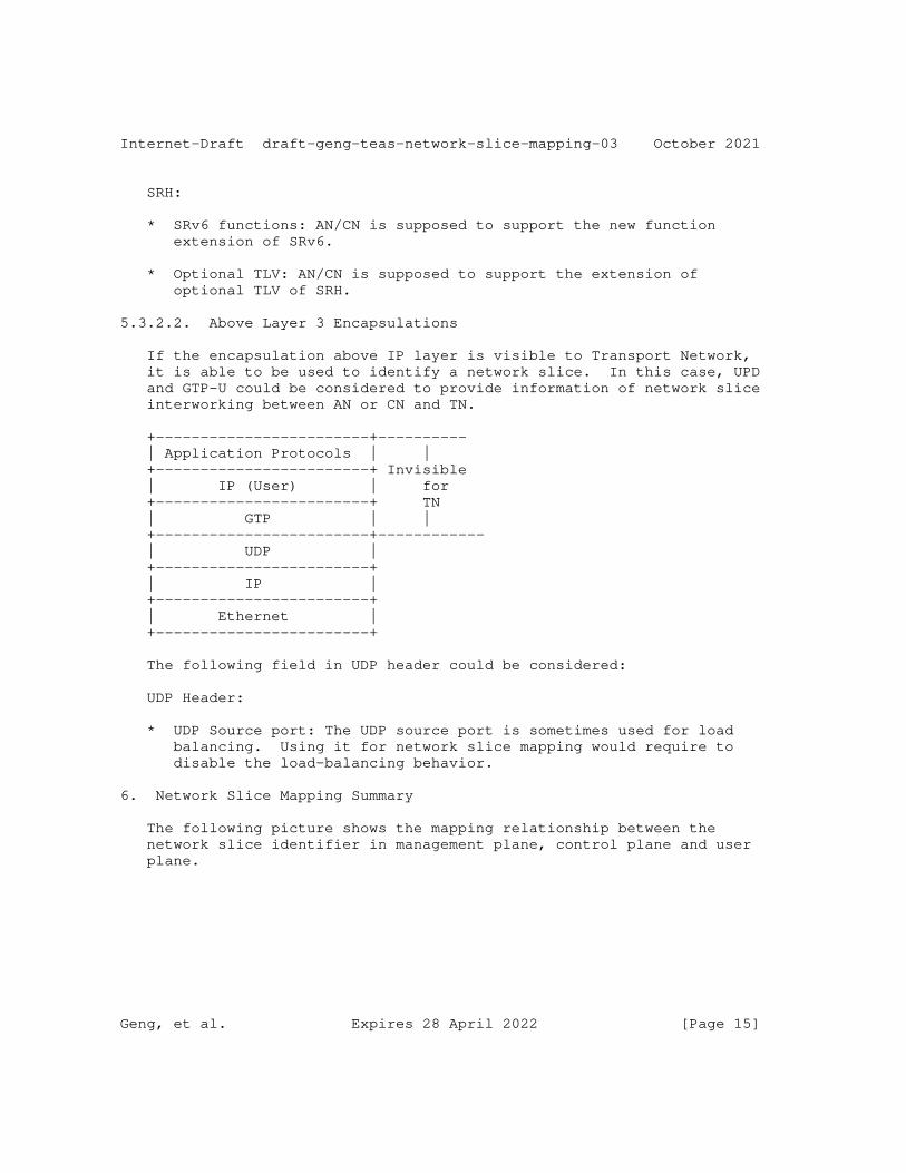
Internet-Draft draft-geng-teas-network-slice-mapping-03 October 2021
SRH:
* SRv6 functions: AN/CN is supposed to support the new function extension of SRv6.
* Optional TLV: AN/CN is supposed to support the extension of optional TLV of SRH.
5.3.2.2. Above Layer 3 Encapsulations
If the encapsulation above IP layer is visible to Transport Network, it is able to be used to identify a network slice. In this case, UPD and GTP-U could be considered to provide information of network slice interworking between AN or CN and TN.
+------------------------+---------- | Application Protocols | | +------------------------+ Invisible | IP (User) | for +------------------------+ TN | GTP | | +------------------------+------------ | UDP | +------------------------+ | IP | +------------------------+ | Ethernet | +------------------------+
The following field in UDP header could be considered:
UDP Header:
* UDP Source port: The UDP source port is sometimes used for load balancing. Using it for network slice mapping would require to disable the load-balancing behavior.
6. Network Slice Mapping Summary
The following picture shows the mapping relationship between the network slice identifier in management plane, control plane and user plane.
Geng, et al. Expires 28 April 2022 [Page 15]
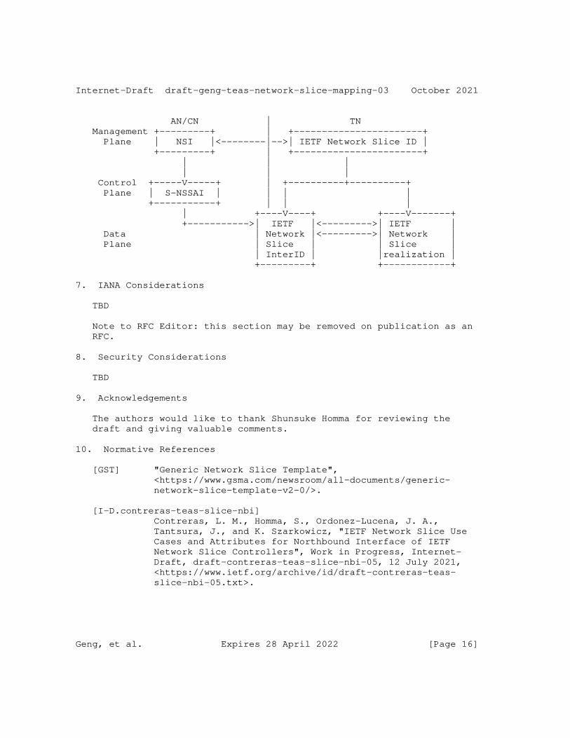
Internet-Draft draft-geng-teas-network-slice-mapping-03 October 2021
AN/CN | TN Management +---------+ | +-----------------------+ Plane | NSI |<--------|-->| IETF Network Slice ID | +---------+ | +-----------------------+ | | | | | | Control +-----V-----+ | +----------+----------+ Plane | S-NSSAI | | | | +-----------+ | | | | +----V----+ +----V-------+ +----------->| IETF |<--------->| IETF | Data | Network |<--------->| Network | Plane | Slice | | Slice | | InterID | |realization | +---------+ +------------+
7. IANA Considerations
TBD
Note to RFC Editor: this section may be removed on publication as an RFC.
8. Security Considerations
TBD
9. Acknowledgements
The authors would like to thank Shunsuke Homma for reviewing the draft and giving valuable comments.
10. Normative References
[GST] "Generic Network Slice Template", <https://www.gsma.com/newsroom/all-documents/generic- network-slice-template-v2-0/>.
[I-D.contreras-teas-slice-nbi] Contreras, L. M., Homma, S., Ordonez-Lucena, J. A., Tantsura, J., and K. Szarkowicz, "IETF Network Slice Use Cases and Attributes for Northbound Interface of IETF Network Slice Controllers", Work in Progress, Internet- Draft, draft-contreras-teas-slice-nbi-05, 12 July 2021, <https://www.ietf.org/archive/id/draft-contreras-teas- slice-nbi-05.txt>.
Geng, et al. Expires 28 April 2022 [Page 16]
Internet-Draft draft-geng-teas-network-slice-mapping-03 October 2021
[I-D.ietf-teas-ietf-network-slice-definition] Rokui, R., Homma, S., Makhijani, K., Contreras, L. M., and J. Tantsura, "Definition of IETF Network Slices", Work in Progress, Internet-Draft, draft-ietf-teas-ietf-network- slice-definition-01, 22 February 2021, <https://www.ietf.org/archive/id/draft-ietf-teas-ietf- network-slice-definition-01.txt>.
[I-D.ietf-teas-ietf-network-slices] Farrel, A., Gray, E., Drake, J., Rokui, R., Homma, S., Makhijani, K., Contreras, L. M., and J. Tantsura, "Framework for IETF Network Slices", Work in Progress, Internet-Draft, draft-ietf-teas-ietf-network-slices-04, 23 August 2021, <https://www.ietf.org/archive/id/draft-ietf- teas-ietf-network-slices-04.txt>.
[I-D.wd-teas-ietf-network-slice-nbi-yang] Wu, B., Dhody, D., Rokui, R., Saad, T., Han, L., and L. M. Contreras, "IETF Network Slice Service YANG Model", Work in Progress, Internet-Draft, draft-wd-teas-ietf-network- slice-nbi-yang-05, 26 September 2021, <https://www.ietf.org/archive/id/draft-wd-teas-ietf- network-slice-nbi-yang-05.txt>.
[I-D.wd-teas-transport-slice-yang] Wu, B., Dhody, D., Han, L., and R. Rokui, "A Yang Data Model for Transport Slice NBI", Work in Progress, Internet-Draft, draft-wd-teas-transport-slice-yang-02, 12 July 2020, <https://www.ietf.org/archive/id/draft-wd-teas- transport-slice-yang-02.txt>.
[RFC2119] Bradner, S., "Key words for use in RFCs to Indicate Requirement Levels", BCP 14, RFC 2119, DOI 10.17487/RFC2119, March 1997, <https://www.rfc-editor.org/info/rfc2119>.
[TS23501] "3GPP TS23.501", <https://portal.3gpp.org/desktopmodules/Specifications/ SpecificationDetails.aspx?specificationId=3144>.
[TS28530] "3GPP TS28.530", <https://portal.3gpp.org/desktopmodules/Specifications/ SpecificationDetails.aspx?specificationId=3273>.
[TS28531] "3GPP TS28.531", <https://portal.3gpp.org/desktopmodules/Specifications/ SpecificationDetails.aspx?specificationId=3274>.
Geng, et al. Expires 28 April 2022 [Page 17]
Internet-Draft draft-geng-teas-network-slice-mapping-03 October 2021
[TS28541] "3GPP TS 28.541", <https://portal.3gpp.org/desktopmodules/Specifications/ SpecificationDetails.aspx?specificationId=3400>.
[ZSM003] "ETSI ZSM003", <https://portal.3gpp.org/desktopmodules/Specifications/ SpecificationDetails.aspx?specificationId=3144>.
Authors’ Addresses
Xuesong Geng Huawei Technologies
Email: [email protected]
Jie Dong Huawei Technologies
Email: [email protected]
Ran Pang China Unicom
Email: [email protected]
Liuyan Han China Mobile
Email: [email protected]
Reza Rokui Nokia
Email: [email protected]
Tomonobu Niwa Individual
Email: [email protected]
Geng, et al. Expires 28 April 2022 [Page 18]
Internet-Draft draft-geng-teas-network-slice-mapping-03 October 2021
Jaehwan Jin LG U+
Email: [email protected]
Chang Liu China Unicom
Email: [email protected]
Nikesh Nageshar Individual
Email: [email protected]
Geng, et al. Expires 28 April 2022 [Page 19]
TEAS Working Group Y. Lee, Ed.Internet-Draft Samsung ElectronicsIntended status: Standards Track D. Dhody, Ed.Expires: 27 April 2022 S. Karunanithi Huawei Technologies R. Vilalta CTTC D. King Lancaster University D. Ceccarelli Ericsson 24 October 2021
YANG models for VN/TE Performance Monitoring Telemetry and Scaling Intent Autonomics draft-ietf-teas-actn-pm-telemetry-autonomics-07
Abstract
This document provides YANG data models that describe performance monitoring telemetry and scaling intent mechanisms for TE-tunnels and Virtual Networks (VNs).
The models presented in this document allow customers to subscribe to and monitor the key performance data of the TE-tunnel or the VN. The models also provide customers with the ability to program autonomic scaling intent mechanisms on the level of TE-tunnel as well as VN.
Status of This Memo
This Internet-Draft is submitted in full conformance with the provisions of BCP 78 and BCP 79.
Internet-Drafts are working documents of the Internet Engineering Task Force (IETF). Note that other groups may also distribute working documents as Internet-Drafts. The list of current Internet- Drafts is at https://datatracker.ietf.org/drafts/current/.
Internet-Drafts are draft documents valid for a maximum of six months and may be updated, replaced, or obsoleted by other documents at any time. It is inappropriate to use Internet-Drafts as reference material or to cite them other than as "work in progress."
This Internet-Draft will expire on 27 April 2022.
Lee, et al. Expires 27 April 2022 [Page 1]
Internet-Draft VN/TE Perf Monitoring October 2021
Copyright Notice
Copyright (c) 2021 IETF Trust and the persons identified as the document authors. All rights reserved.
This document is subject to BCP 78 and the IETF Trust’s Legal Provisions Relating to IETF Documents (https://trustee.ietf.org/ license-info) in effect on the date of publication of this document. Please review these documents carefully, as they describe your rights and restrictions with respect to this document. Code Components extracted from this document must include Simplified BSD License text as described in Section 4.e of the Trust Legal Provisions and are provided without warranty as described in the Simplified BSD License.
Table of Contents
1. Introduction . . . . . . . . . . . . . . . . . . . . . . . . 3 1.1. Terminology . . . . . . . . . . . . . . . . . . . . . . . 4 1.2. Tree Diagram . . . . . . . . . . . . . . . . . . . . . . 4 1.3. Prefixes in Data Node Names . . . . . . . . . . . . . . . 4 2. Use-Cases . . . . . . . . . . . . . . . . . . . . . . . . . . 5 3. Design of the Data Models . . . . . . . . . . . . . . . . . . 7 3.1. TE Telemetry Model . . . . . . . . . . . . . . . . . . . 7 3.2. VN Telemetry Model . . . . . . . . . . . . . . . . . . . 8 3.3. VPN Service Performance Monitoring . . . . . . . . . . . 9 4. Autonomic Scaling Intent Mechanism . . . . . . . . . . . . . 10 5. Notification . . . . . . . . . . . . . . . . . . . . . . . . 12 5.1. YANG Push Subscription Examples . . . . . . . . . . . . . 12 5.2. Scaling Examples . . . . . . . . . . . . . . . . . . . . 14 6. YANG Data Tree . . . . . . . . . . . . . . . . . . . . . . . 17 7. YANG Data Model . . . . . . . . . . . . . . . . . . . . . . . 20 7.1. ietf-te-telemetry model . . . . . . . . . . . . . . . . . 20 7.2. ietf-vn-telemetry model . . . . . . . . . . . . . . . . . 27 8. Security Considerations . . . . . . . . . . . . . . . . . . . 32 9. IANA Considerations . . . . . . . . . . . . . . . . . . . . . 33 10. Acknowledgements . . . . . . . . . . . . . . . . . . . . . . 34 11. References . . . . . . . . . . . . . . . . . . . . . . . . . 34 11.1. Normative References . . . . . . . . . . . . . . . . . . 34 11.2. Informative References . . . . . . . . . . . . . . . . . 36 Authors’ Addresses . . . . . . . . . . . . . . . . . . . . . . . 36
Lee, et al. Expires 27 April 2022 [Page 2]
Internet-Draft VN/TE Perf Monitoring October 2021
1. Introduction
The YANG [RFC7950] model in [I-D.ietf-teas-actn-vn-yang] is used to operate customer-driven Virtual Networks (VNs) during the computation of VN, its instantiation, and its life-cycle service management and operations. YANG model in [I-D.ietf-teas-yang-te] is used to operate TE-tunnels during the tunnel instantiation, and its life-cycle management and operations.
The models presented in this draft allow the applications hosted by the customers to subscribe to and monitor their key performance data of their interest on the level of VN [I-D.ietf-teas-actn-vn-yang] or TE-tunnel [I-D.ietf-teas-yang-te]. The key characteristic of the models presented in this document is a top-down programmability that allows the applications hosted by the customers to subscribe to and monitor key performance data of their interest and autonomic scaling intent mechanism on the level of VN as well as TE-tunnel.
According to the classification of [RFC8309], the YANG data models presented in this document can be classified as customer service models. These can be mapped to the CMI (Customer Network Controller (CNC)- Multi-Domain Service Coordinator (MSDC) interface) of ACTN [RFC8453].
[RFC8233] describes key network performance data to be considered for end-to-end path computation in TE networks. The services provided can be optimized to meet the requirements (such as traffic patterns, quality, and reliability) of the applications hosted by the customers.
This document provides YANG data models generically applicable to any VN/TE-Tunnel service clients to provide an ability to program their customized performance monitoring subscription and publication data models and automatic scaling in/out intent data models. These models can be utilized by a client network controller to initiate the capabilities to a TE network controller communicating with the client controller via a NETCONF [RFC8341] or a RESTCONF [RFC8040] interface.
The term performance monitoring is used in this document in a different from how the term has been used in TE networks for many years. Performance monitoring in this document refers to subscription and publication of streaming telemetry data. Subscription is initiated by the client (e.g., CNC) while publication is provided by the network (e.g., MDSC/Provisioning Network Controller (PNC)) based on the client’s subscription. As the scope of performance monitoring in this document is telemetry data on the level of a client’s VN or TE-tunnel, the entity interfacing to the client (e.g., MDSC) has to provide VN or TE-tunnel level information.
Lee, et al. Expires 27 April 2022 [Page 3]

Internet-Draft VN/TE Perf Monitoring October 2021
This requires the controller to have the capability to derive VN or TE-tunnel level performance data based on lower-level data collected via PM counters in the Network Elements (NE). How the controller entity derives such customized level data (i.e., VN or TE-tunnel level) is out of the scope of this document.
The data model includes configuration and state data according to the Network Management Datastore Architecture (NMDA) [RFC8342].
1.1. Terminology
Refer to [RFC8453], [RFC7926], and [RFC8309] for the key terms used in this document.
Scaling: This refers to the network’s ability to re-shape its own resources. "Scale out" refers to improve network performance by increasing the allocated resources, while "scale in" refers to decreasing the allocated resources, typically because the existing resources are unnecessary.
Scaling Intent: Scaling intent is used to declare scaling conditions. Specifically, scaling intent refers to how the client programs or configures conditions that will be applied to their key performance data to trigger either scaling out or scaling in. Various conditions can be set for scaling intent on either VN or TE-tunnel level.
Network Autonomics: This refers to the network automation capability that allows a client to initiate scaling intent mechanisms and provides the client with the status of the adjusted network resources based on the client’s scaling intent in an automated fashion.
1.2. Tree Diagram
A simplified graphical representation of the data model is used in Section 4 and Section 6 of this document. The meaning of the symbols in these diagrams is defined in [RFC8340].
1.3. Prefixes in Data Node Names
In this document, names of data nodes and other data model objects are prefixed using the standard prefix associated with the corresponding YANG imported modules, as shown in Table 1.
Lee, et al. Expires 27 April 2022 [Page 4]
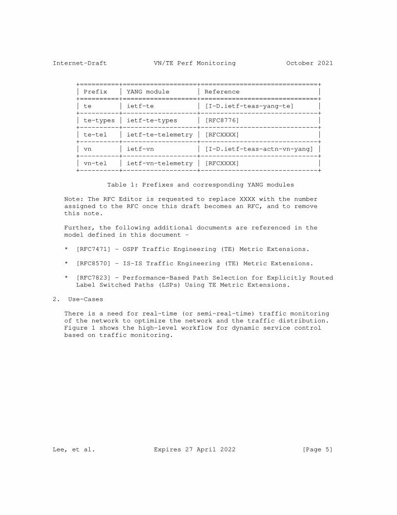
Internet-Draft VN/TE Perf Monitoring October 2021
+==========+===================+==============================+ | Prefix | YANG module | Reference | +==========+===================+==============================+ | te | ietf-te | [I-D.ietf-teas-yang-te] | +----------+-------------------+------------------------------+ | te-types | ietf-te-types | [RFC8776] | +----------+-------------------+------------------------------+ | te-tel | ietf-te-telemetry | [RFCXXXX] | +----------+-------------------+------------------------------+ | vn | ietf-vn | [I-D.ietf-teas-actn-vn-yang] | +----------+-------------------+------------------------------+ | vn-tel | ietf-vn-telemetry | [RFCXXXX] | +----------+-------------------+------------------------------+
Table 1: Prefixes and corresponding YANG modules
Note: The RFC Editor is requested to replace XXXX with the number assigned to the RFC once this draft becomes an RFC, and to remove this note.
Further, the following additional documents are referenced in the model defined in this document -
* [RFC7471] - OSPF Traffic Engineering (TE) Metric Extensions.
* [RFC8570] - IS-IS Traffic Engineering (TE) Metric Extensions.
* [RFC7823] - Performance-Based Path Selection for Explicitly Routed Label Switched Paths (LSPs) Using TE Metric Extensions.
2. Use-Cases
There is a need for real-time (or semi-real-time) traffic monitoring of the network to optimize the network and the traffic distribution. Figure 1 shows the high-level workflow for dynamic service control based on traffic monitoring.
Lee, et al. Expires 27 April 2022 [Page 5]
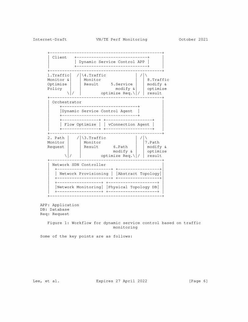
Internet-Draft VN/TE Perf Monitoring October 2021
+----------------------------------------------+ | Client +-----------------------------+ | | | Dynamic Service Control APP | | | +-----------------------------+ | +----------------------------------------------+ 1.Traffic| /|\4.Traffic | /|\ Monitor &| | Monitor | | 8.Traffic Optimize | | Result 5.Service | | modify & Policy | | modify &| | optimize \|/ | optimize Req.\|/ | result +----------------------------------------------+ | Orchestrator | | +-------------------------------+ | | |Dynamic Service Control Agent | | | +-------------------------------+ | | +---------------+ +-------------------+ | | | Flow Optimize | | vConnection Agent | | | +---------------+ +-------------------+ | +----------------------------------------------+ 2. Path | /|\3.Traffic | /|\ Monitor | | Monitor | |7.Path Request | | Result 6.Path | | modify & | | modify & | | optimize \|/ | optimize Req.\|/ | result +----------------------------------------------+ | Network SDN Controller | | +----------------------+ +-----------------+| | | Network Provisioning | |Abstract Topology|| | +----------------------+ +-----------------+| | +------------------+ +--------------------+ | | |Network Monitoring| |Physical Topology DB| | | +------------------+ +--------------------+ | +----------------------------------------------+
APP: Application DB: Database Req: Request
Figure 1: Workflow for dynamic service control based on traffic monitoring
Some of the key points are as follows:
Lee, et al. Expires 27 April 2022 [Page 6]
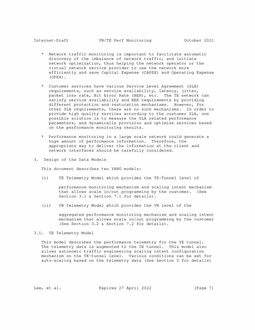
Internet-Draft VN/TE Perf Monitoring October 2021
* Network traffic monitoring is important to facilitate automatic discovery of the imbalance of network traffic, and initiate network optimization, thus helping the network operator or the virtual network service provider to use the network more efficiently and save Capital Expense (CAPEX) and Operating Expense (OPEX).
* Customer services have various Service Level Agreement (SLA) requirements, such as service availability, latency, jitter, packet loss rate, Bit Error Rate (BER), etc. The TE network can satisfy service availability and BER requirements by providing different protection and restoration mechanisms. However, for other SLA requirements, there are no such mechanisms. In order to provide high quality services according to the customer SLA, one possible solution is to measure the SLA related performance parameters, and dynamically provision and optimize services based on the performance monitoring results.
* Performance monitoring in a large scale network could generate a huge amount of performance information. Therefore, the appropriate way to deliver the information at the client and network interfaces should be carefully considered.
3. Design of the Data Models
This document describes two YANG models:
(i) TE Telemetry Model which provides the TE-Tunnel level of
performance monitoring mechanism and scaling intent mechanism that allows scale in/out programming by the customer. (See Section 3.1 & Section 7.1 for details).
(ii) VN Telemetry Model which provides the VN level of the
aggregated performance monitoring mechanism and scaling intent mechanism that allows scale in/out programming by the customer (See Section 3.2 & Section 7.2 for details).
3.1. TE Telemetry Model
This model describes the performance telemetry for the TE tunnel. The telemetry data is augmented to the TE tunnel. This model also allows autonomic traffic engineering scaling intent configuration mechanism on the TE-tunnel level. Various conditions can be set for auto-scaling based on the telemetry data (See Section 5 for details)
Lee, et al. Expires 27 April 2022 [Page 7]
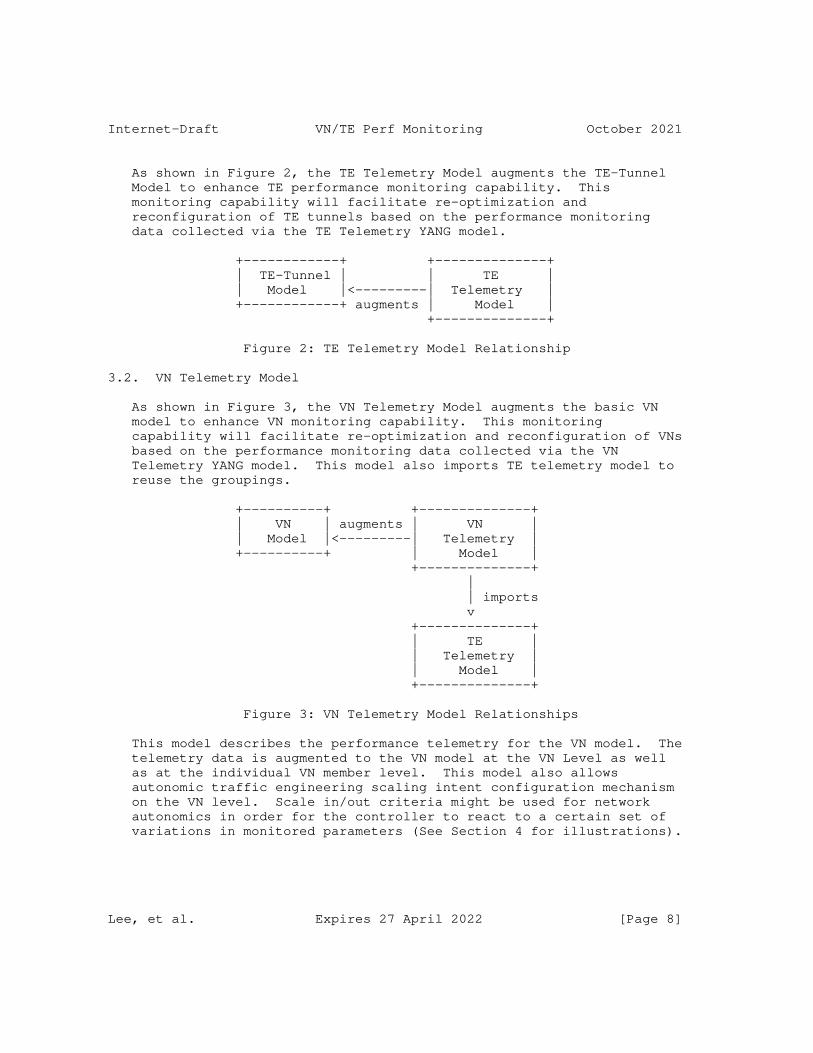
Internet-Draft VN/TE Perf Monitoring October 2021
As shown in Figure 2, the TE Telemetry Model augments the TE-Tunnel Model to enhance TE performance monitoring capability. This monitoring capability will facilitate re-optimization and reconfiguration of TE tunnels based on the performance monitoring data collected via the TE Telemetry YANG model.
+------------+ +--------------+ | TE-Tunnel | | TE | | Model |<---------| Telemetry | +------------+ augments | Model | +--------------+
Figure 2: TE Telemetry Model Relationship
3.2. VN Telemetry Model
As shown in Figure 3, the VN Telemetry Model augments the basic VN model to enhance VN monitoring capability. This monitoring capability will facilitate re-optimization and reconfiguration of VNs based on the performance monitoring data collected via the VN Telemetry YANG model. This model also imports TE telemetry model to reuse the groupings.
+----------+ +--------------+ | VN | augments | VN | | Model |<---------| Telemetry | +----------+ | Model | +--------------+ | | imports v +--------------+ | TE | | Telemetry | | Model | +--------------+
Figure 3: VN Telemetry Model Relationships
This model describes the performance telemetry for the VN model. The telemetry data is augmented to the VN model at the VN Level as well as at the individual VN member level. This model also allows autonomic traffic engineering scaling intent configuration mechanism on the VN level. Scale in/out criteria might be used for network autonomics in order for the controller to react to a certain set of variations in monitored parameters (See Section 4 for illustrations).
Lee, et al. Expires 27 April 2022 [Page 8]
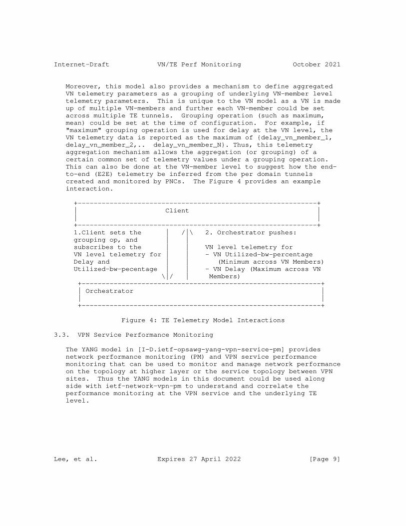
Internet-Draft VN/TE Perf Monitoring October 2021
Moreover, this model also provides a mechanism to define aggregated VN telemetry parameters as a grouping of underlying VN-member level telemetry parameters. This is unique to the VN model as a VN is made up of multiple VN-members and further each VN-member could be set across multiple TE tunnels. Grouping operation (such as maximum, mean) could be set at the time of configuration. For example, if "maximum" grouping operation is used for delay at the VN level, the VN telemetry data is reported as the maximum of {delay_vn_member_1, delay_vn_member_2,.. delay_vn_member_N}. Thus, this telemetry aggregation mechanism allows the aggregation (or grouping) of a certain common set of telemetry values under a grouping operation. This can also be done at the VN-member level to suggest how the end- to-end (E2E) telemetry be inferred from the per domain tunnels created and monitored by PNCs. The Figure 4 provides an example interaction.
+------------------------------------------------------------+ | Client | | | +------------------------------------------------------------+ 1.Client sets the | /|\ 2. Orchestrator pushes: grouping op, and | | subscribes to the | | VN level telemetry for VN level telemetry for | | - VN Utilized-bw-percentage Delay and | | (Minimum across VN Members) Utilized-bw-pecentage | | - VN Delay (Maximum across VN \|/ | Members) +------------------------------------------------------------+ | Orchestrator | | | +------------------------------------------------------------+
Figure 4: TE Telemetry Model Interactions
3.3. VPN Service Performance Monitoring
The YANG model in [I-D.ietf-opsawg-yang-vpn-service-pm] provides network performance monitoring (PM) and VPN service performance monitoring that can be used to monitor and manage network performance on the topology at higher layer or the service topology between VPN sites. Thus the YANG models in this document could be used along side with ietf-network-vpn-pm to understand and correlate the performance monitoring at the VPN service and the underlying TE level.
Lee, et al. Expires 27 April 2022 [Page 9]

Internet-Draft VN/TE Perf Monitoring October 2021
4. Autonomic Scaling Intent Mechanism
The scaling intent configuration mechanism allows the client to configure automatic scale-in and scale-out mechanisms on both the TE- tunnel and the VN level. Various conditions can be set for auto- scaling based on the PM telemetry data.
There are a number of parameters involved in the mechanism:
* scale-out-intent or scale-in-intent: whether to scale-out or scale-in.
* performance-type: performance metric type (e.g., one-way-delay, one-way-delay-min, one-way-delay-max, two-way-delay, two-way- delay-min, two-way-delay-max, utilized bandwidth, etc.)
* threshold-value: the threshold value for a certain performance- type that triggers scale-in or scale-out.
* scaling-operation-type: in case where scaling condition can be set with one or more performance types, then scaling-operation-type (AND, OR, MIN, MAX, etc.) is applied to these selected performance types and its threshold values.
* Threshold-time: the duration for which the criteria needs to hold true.
* Cooldown-time: the duration after a scaling action has been triggered, for which there will be no further operation.
The tree in Figure 5 is a part of ietf-te-telemetry tree whose model is presented in full detail in Sections 6 & 7.
Lee, et al. Expires 27 April 2022 [Page 10]
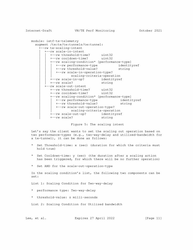
Internet-Draft VN/TE Perf Monitoring October 2021
module: ietf-te-telemetry augment /te:te/te:tunnels/te:tunnel: +--rw te-scaling-intent | +--rw scale-in-intent | | +--rw threshold-time? uint32 | | +--rw cooldown-time? uint32 | | +--rw scaling-condition* [performance-type] | | | +--rw performance-type identityref | | | +--rw threshold-value? string | | | +--rw scale-in-operation-type? | | | scaling-criteria-operation | | +--rw scale-in-op? identityref | | +--rw scale? string | +--rw scale-out-intent | +--rw threshold-time? uint32 | +--rw cooldown-time? uint32 | +--rw scaling-condition* [performance-type] | | +--rw performance-type identityref | | +--rw threshold-value? string | | +--rw scale-out-operation-type? | | scaling-criteria-operation | +--rw scale-out-op? identityref | +--rw scale? string
Figure 5: The scaling intent
Let’s say the client wants to set the scaling out operation based on two performance-types (e.g., two-way-delay and utilized-bandwidth for a te-tunnel), it can be done as follows:
* Set Threshold-time: x (sec) (duration for which the criteria must hold true)
* Set Cooldown-time: y (sec) (the duration after a scaling action has been triggered, for which there will be no further operation)
* Set AND for the scale-out-operation-type
In the scaling condition’s list, the following two components can be set:
List 1: Scaling Condition for Two-way-delay
* performance type: Two-way-delay
* threshold-value: z milli-seconds
List 2: Scaling Condition for Utilized bandwidth
Lee, et al. Expires 27 April 2022 [Page 11]
Internet-Draft VN/TE Perf Monitoring October 2021
* performance type: Utilized bandwidth
* threshold-value: w megabytes
5. Notification
This model does not define specific notifications. To enable notifications, the mechanism defined in [RFC8641] and [RFC8640] can be used. This mechanism currently allows the user to:
* Subscribe to notifications on a per client basis.
* Specify subtree filters or xpath filters so that only interested contents will be sent.
* Specify either periodic or on-demand notifications.
5.1. YANG Push Subscription Examples
[RFC8641] allows subscriber applications to request a continuous, customized stream of updates from a YANG datastore.
The example in Figure 6 shows the way for a client to subscribe to the telemetry information for a particular tunnel (Tunnel1). The telemetry parameter that the client is interested in is one-way- delay.
Lee, et al. Expires 27 April 2022 [Page 12]
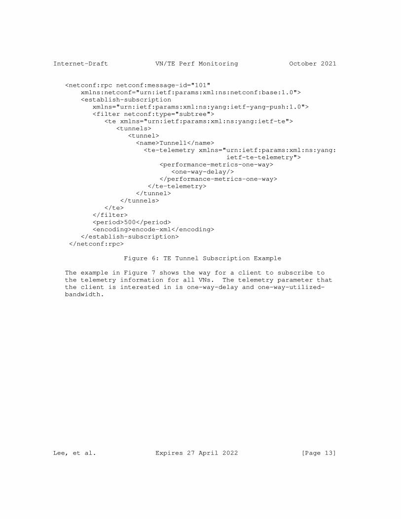
Internet-Draft VN/TE Perf Monitoring October 2021
<netconf:rpc netconf:message-id="101" xmlns:netconf="urn:ietf:params:xml:ns:netconf:base:1.0"> <establish-subscription xmlns="urn:ietf:params:xml:ns:yang:ietf-yang-push:1.0"> <filter netconf:type="subtree"> <te xmlns="urn:ietf:params:xml:ns:yang:ietf-te"> <tunnels> <tunnel> <name>Tunnel1</name> <te-telemetry xmlns="urn:ietf:params:xml:ns:yang: ietf-te-telemetry"> <performance-metrics-one-way> <one-way-delay/> </performance-metrics-one-way> </te-telemetry> </tunnel> </tunnels> </te> </filter> <period>500</period> <encoding>encode-xml</encoding> </establish-subscription> </netconf:rpc>
Figure 6: TE Tunnel Subscription Example
The example in Figure 7 shows the way for a client to subscribe to the telemetry information for all VNs. The telemetry parameter that the client is interested in is one-way-delay and one-way-utilized- bandwidth.
Lee, et al. Expires 27 April 2022 [Page 13]
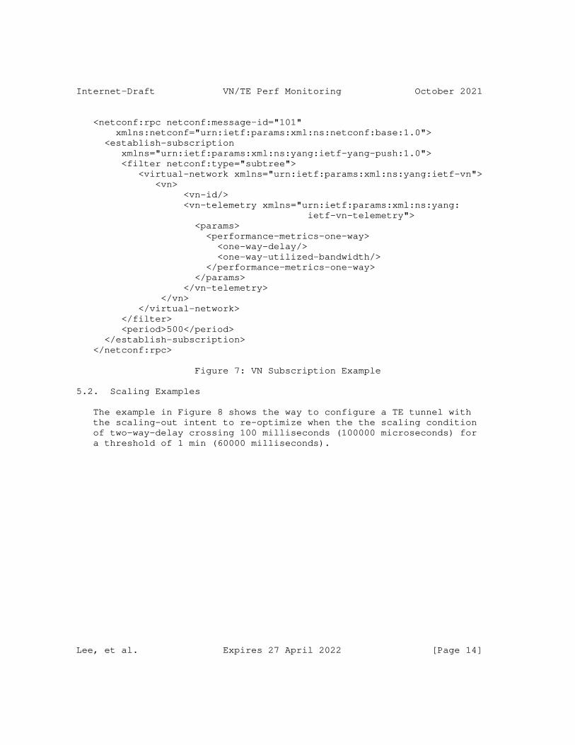
Internet-Draft VN/TE Perf Monitoring October 2021
<netconf:rpc netconf:message-id="101" xmlns:netconf="urn:ietf:params:xml:ns:netconf:base:1.0"> <establish-subscription xmlns="urn:ietf:params:xml:ns:yang:ietf-yang-push:1.0"> <filter netconf:type="subtree"> <virtual-network xmlns="urn:ietf:params:xml:ns:yang:ietf-vn"> <vn> <vn-id/> <vn-telemetry xmlns="urn:ietf:params:xml:ns:yang: ietf-vn-telemetry"> <params> <performance-metrics-one-way> <one-way-delay/> <one-way-utilized-bandwidth/> </performance-metrics-one-way> </params> </vn-telemetry> </vn> </virtual-network> </filter> <period>500</period> </establish-subscription> </netconf:rpc>
Figure 7: VN Subscription Example
5.2. Scaling Examples
The example in Figure 8 shows the way to configure a TE tunnel with the scaling-out intent to re-optimize when the the scaling condition of two-way-delay crossing 100 milliseconds (100000 microseconds) for a threshold of 1 min (60000 milliseconds).
Lee, et al. Expires 27 April 2022 [Page 14]
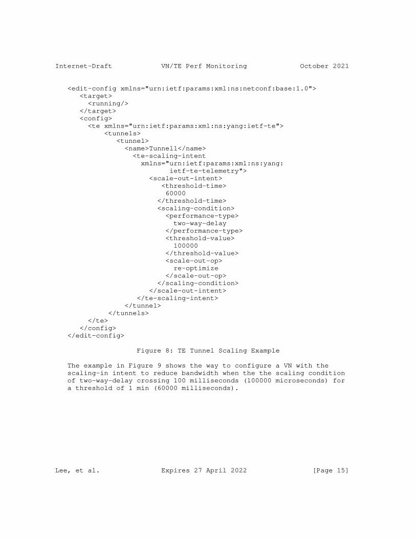
Internet-Draft VN/TE Perf Monitoring October 2021
<edit-config xmlns="urn:ietf:params:xml:ns:netconf:base:1.0"> <target> <running/> </target> <config> <te xmlns="urn:ietf:params:xml:ns:yang:ietf-te"> <tunnels> <tunnel> <name>Tunnel1</name> <te-scaling-intent xmlns="urn:ietf:params:xml:ns:yang: ietf-te-telemetry"> <scale-out-intent> <threshold-time> 60000 </threshold-time> <scaling-condition> <performance-type> two-way-delay </performance-type> <threshold-value> 100000 </threshold-value> <scale-out-op> re-optimize </scale-out-op> </scaling-condition> </scale-out-intent> </te-scaling-intent> </tunnel> </tunnels> </te> </config> </edit-config>
Figure 8: TE Tunnel Scaling Example
The example in Figure 9 shows the way to configure a VN with the scaling-in intent to reduce bandwidth when the the scaling condition of two-way-delay crossing 100 milliseconds (100000 microseconds) for a threshold of 1 min (60000 milliseconds).
Lee, et al. Expires 27 April 2022 [Page 15]
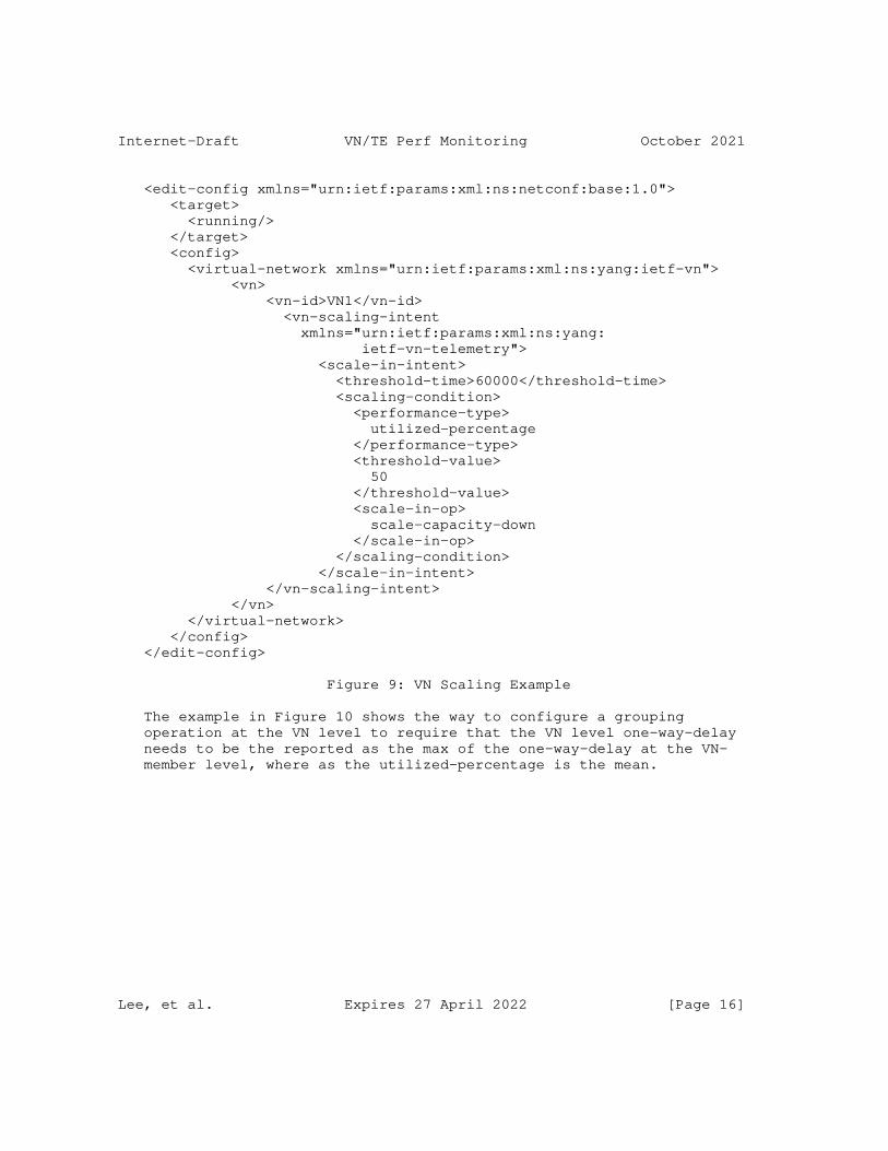
Internet-Draft VN/TE Perf Monitoring October 2021
<edit-config xmlns="urn:ietf:params:xml:ns:netconf:base:1.0"> <target> <running/> </target> <config> <virtual-network xmlns="urn:ietf:params:xml:ns:yang:ietf-vn"> <vn> <vn-id>VN1</vn-id> <vn-scaling-intent xmlns="urn:ietf:params:xml:ns:yang: ietf-vn-telemetry"> <scale-in-intent> <threshold-time>60000</threshold-time> <scaling-condition> <performance-type> utilized-percentage </performance-type> <threshold-value> 50 </threshold-value> <scale-in-op> scale-capacity-down </scale-in-op> </scaling-condition> </scale-in-intent> </vn-scaling-intent> </vn> </virtual-network> </config> </edit-config>
Figure 9: VN Scaling Example
The example in Figure 10 shows the way to configure a grouping operation at the VN level to require that the VN level one-way-delay needs to be the reported as the max of the one-way-delay at the VN- member level, where as the utilized-percentage is the mean.
Lee, et al. Expires 27 April 2022 [Page 16]
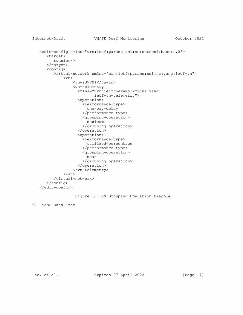
Internet-Draft VN/TE Perf Monitoring October 2021
<edit-config xmlns="urn:ietf:params:xml:ns:netconf:base:1.0"> <target> <running/> </target> <config> <virtual-network xmlns="urn:ietf:params:xml:ns:yang:ietf-vn"> <vn> <vn-id>VN1</vn-id> <vn-telemetry xmlns="urn:ietf:params:xml:ns:yang: ietf-vn-telemetry"> <operation> <performance-type> one-way-delay </performance-type> <grouping-operation> maximum </grouping-operation> </operation> <operation> <performance-type> utilized-percentage </performance-type> <grouping-operation> mean </grouping-operation> </operation> </vn-telemetry> </vn> </virtual-network> </config> </edit-config>
Figure 10: VN Grouping Operation Example
6. YANG Data Tree
Lee, et al. Expires 27 April 2022 [Page 17]
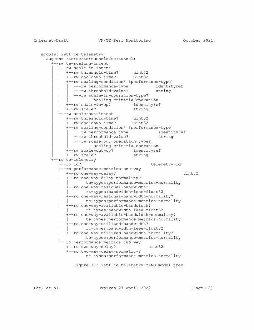
Internet-Draft VN/TE Perf Monitoring October 2021
module: ietf-te-telemetry augment /te:te/te:tunnels/te:tunnel: +--rw te-scaling-intent | +--rw scale-in-intent | | +--rw threshold-time? uint32 | | +--rw cooldown-time? uint32 | | +--rw scaling-condition* [performance-type] | | | +--rw performance-type identityref | | | +--rw threshold-value? string | | | +--rw scale-in-operation-type? | | | scaling-criteria-operation | | +--rw scale-in-op? identityref | | +--rw scale? string | +--rw scale-out-intent | +--rw threshold-time? uint32 | +--rw cooldown-time? uint32 | +--rw scaling-condition* [performance-type] | | +--rw performance-type identityref | | +--rw threshold-value? string | | +--rw scale-out-operation-type? | | scaling-criteria-operation | +--rw scale-out-op? identityref | +--rw scale? string +--ro te-telemetry +--ro id? telemetry-id +--ro performance-metrics-one-way | +--ro one-way-delay? uint32 | +--ro one-way-delay-normality? | | te-types:performance-metrics-normality | +--ro one-way-residual-bandwidth? | | rt-types:bandwidth-ieee-float32 | +--ro one-way-residual-bandwidth-normality? | | te-types:performance-metrics-normality | +--ro one-way-available-bandwidth? | | rt-types:bandwidth-ieee-float32 | +--ro one-way-available-bandwidth-normality? | | te-types:performance-metrics-normality | +--ro one-way-utilized-bandwidth? | | rt-types:bandwidth-ieee-float32 | +--ro one-way-utilized-bandwidth-normality? | te-types:performance-metrics-normality +--ro performance-metrics-two-way +--ro two-way-delay? uint32 +--ro two-way-delay-normality? te-types:performance-metrics-normality
Figure 11: ietf-te-telemetry YANG model tree
Lee, et al. Expires 27 April 2022 [Page 18]
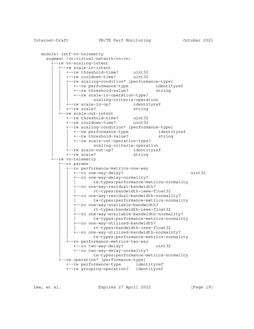
Internet-Draft VN/TE Perf Monitoring October 2021
module: ietf-vn-telemetry augment /vn:virtual-network/vn:vn: +--rw vn-scaling-intent | +--rw scale-in-intent | | +--rw threshold-time? uint32 | | +--rw cooldown-time? uint32 | | +--rw scaling-condition* [performance-type] | | | +--rw performance-type identityref | | | +--rw threshold-value? string | | | +--rw scale-in-operation-type? | | | scaling-criteria-operation | | +--rw scale-in-op? identityref | | +--rw scale? string | +--rw scale-out-intent | +--rw threshold-time? uint32 | +--rw cooldown-time? uint32 | +--rw scaling-condition* [performance-type] | | +--rw performance-type identityref | | +--rw threshold-value? string | | +--rw scale-out-operation-type? | | scaling-criteria-operation | +--rw scale-out-op? identityref | +--rw scale? string +--rw vn-telemetry +--ro params | +--ro performance-metrics-one-way | | +--ro one-way-delay? uint32 | | +--ro one-way-delay-normality? | | | te-types:performance-metrics-normality | | +--ro one-way-residual-bandwidth? | | | rt-types:bandwidth-ieee-float32 | | +--ro one-way-residual-bandwidth-normality? | | | te-types:performance-metrics-normality | | +--ro one-way-available-bandwidth? | | | rt-types:bandwidth-ieee-float32 | | +--ro one-way-available-bandwidth-normality? | | | te-types:performance-metrics-normality | | +--ro one-way-utilized-bandwidth? | | | rt-types:bandwidth-ieee-float32 | | +--ro one-way-utilized-bandwidth-normality? | | te-types:performance-metrics-normality | +--ro performance-metrics-two-way | +--ro two-way-delay? uint32 | +--ro two-way-delay-normality? | te-types:performance-metrics-normality +--rw operation* [performance-type] +--rw performance-type identityref +--rw grouping-operation? identityref
Lee, et al. Expires 27 April 2022 [Page 19]
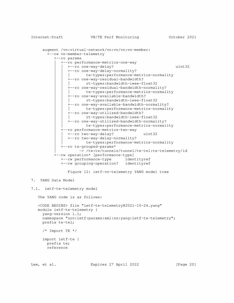
Internet-Draft VN/TE Perf Monitoring October 2021
augment /vn:virtual-network/vn:vn/vn:vn-member: +--rw vn-member-telemetry +--ro params | +--ro performance-metrics-one-way | | +--ro one-way-delay? uint32 | | +--ro one-way-delay-normality? | | | te-types:performance-metrics-normality | | +--ro one-way-residual-bandwidth? | | | rt-types:bandwidth-ieee-float32 | | +--ro one-way-residual-bandwidth-normality? | | | te-types:performance-metrics-normality | | +--ro one-way-available-bandwidth? | | | rt-types:bandwidth-ieee-float32 | | +--ro one-way-available-bandwidth-normality? | | | te-types:performance-metrics-normality | | +--ro one-way-utilized-bandwidth? | | | rt-types:bandwidth-ieee-float32 | | +--ro one-way-utilized-bandwidth-normality? | | te-types:performance-metrics-normality | +--ro performance-metrics-two-way | | +--ro two-way-delay? uint32 | | +--ro two-way-delay-normality? | | te-types:performance-metrics-normality | +--ro te-grouped-params* | -> /te:te/tunnels/tunnel/te-tel:te-telemetry/id +--rw operation* [performance-type] +--rw performance-type identityref +--rw grouping-operation? identityref
Figure 12: ietf-vn-telemetry YANG model tree
7. YANG Data Model
7.1. ietf-te-telemetry model
The YANG code is as follows:
<CODE BEGINS> file "[email protected]" module ietf-te-telemetry { yang-version 1.1; namespace "urn:ietf:params:xml:ns:yang:ietf-te-telemetry"; prefix te-tel;
/* Import TE */
import ietf-te { prefix te; reference
Lee, et al. Expires 27 April 2022 [Page 20]
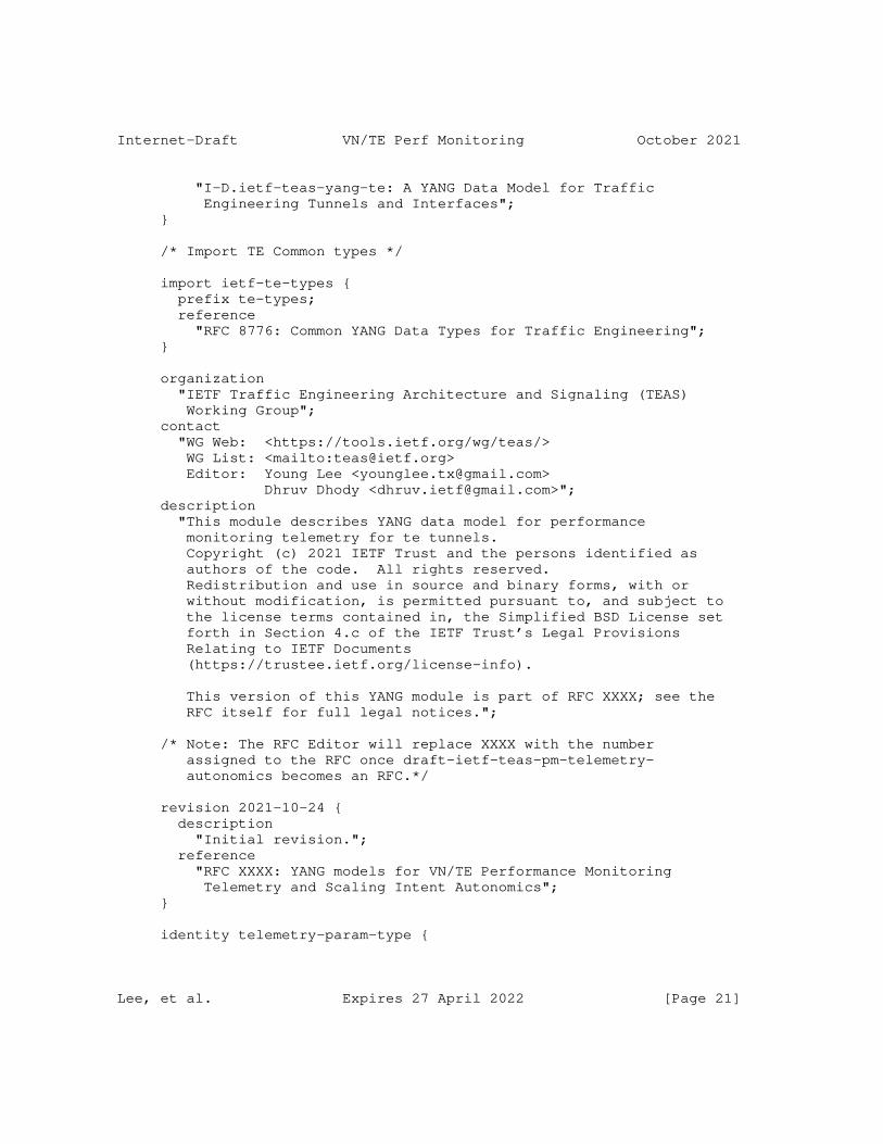
Internet-Draft VN/TE Perf Monitoring October 2021
"I-D.ietf-teas-yang-te: A YANG Data Model for Traffic Engineering Tunnels and Interfaces"; }
/* Import TE Common types */
import ietf-te-types { prefix te-types; reference "RFC 8776: Common YANG Data Types for Traffic Engineering"; }
organization "IETF Traffic Engineering Architecture and Signaling (TEAS) Working Group"; contact "WG Web: <https://tools.ietf.org/wg/teas/> WG List: <mailto:[email protected]> Editor: Young Lee <[email protected]> Dhruv Dhody <[email protected]>"; description "This module describes YANG data model for performance monitoring telemetry for te tunnels. Copyright (c) 2021 IETF Trust and the persons identified as authors of the code. All rights reserved. Redistribution and use in source and binary forms, with or without modification, is permitted pursuant to, and subject to the license terms contained in, the Simplified BSD License set forth in Section 4.c of the IETF Trust’s Legal Provisions Relating to IETF Documents (https://trustee.ietf.org/license-info).
This version of this YANG module is part of RFC XXXX; see the RFC itself for full legal notices.";
/* Note: The RFC Editor will replace XXXX with the number assigned to the RFC once draft-ietf-teas-pm-telemetry- autonomics becomes an RFC.*/
revision 2021-10-24 { description "Initial revision."; reference "RFC XXXX: YANG models for VN/TE Performance Monitoring Telemetry and Scaling Intent Autonomics"; }
identity telemetry-param-type {
Lee, et al. Expires 27 April 2022 [Page 21]
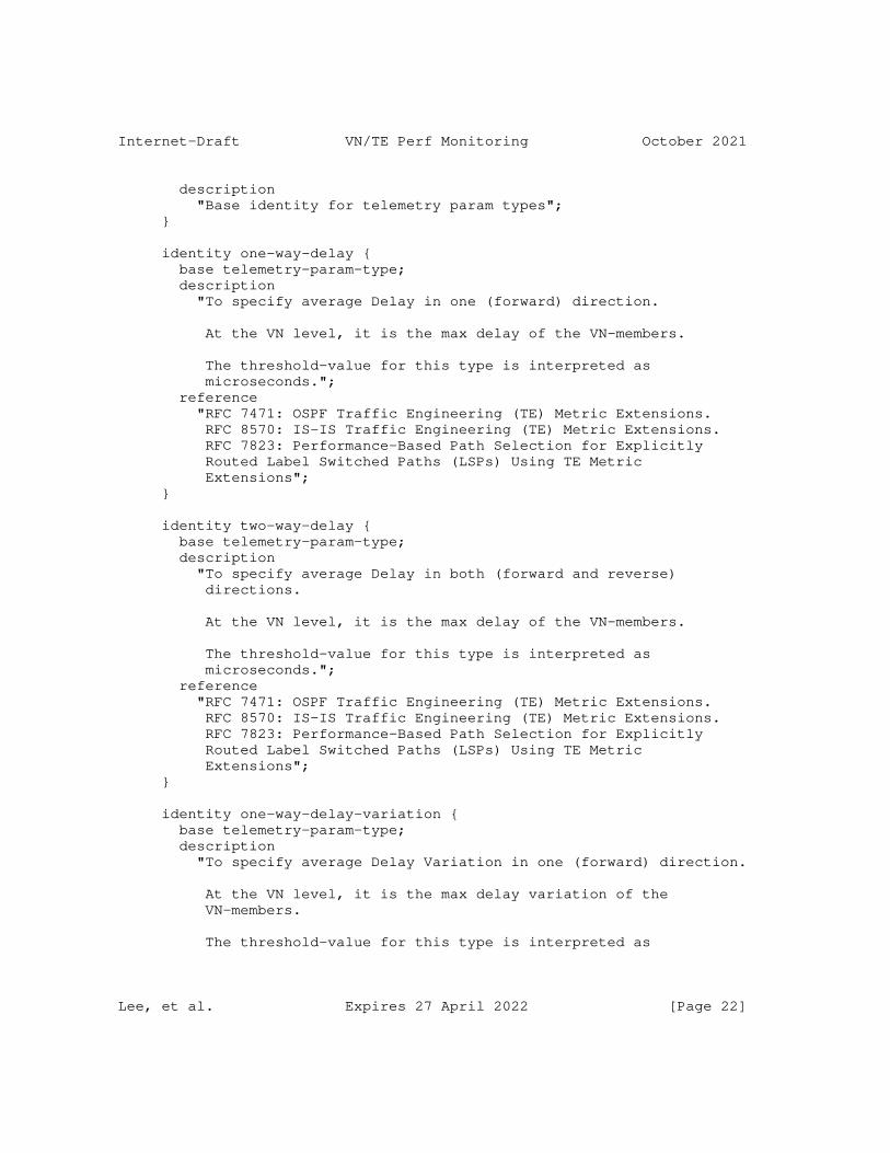
Internet-Draft VN/TE Perf Monitoring October 2021
description "Base identity for telemetry param types"; }
identity one-way-delay { base telemetry-param-type; description "To specify average Delay in one (forward) direction.
At the VN level, it is the max delay of the VN-members.
The threshold-value for this type is interpreted as microseconds."; reference "RFC 7471: OSPF Traffic Engineering (TE) Metric Extensions. RFC 8570: IS-IS Traffic Engineering (TE) Metric Extensions. RFC 7823: Performance-Based Path Selection for Explicitly Routed Label Switched Paths (LSPs) Using TE Metric Extensions"; }
identity two-way-delay { base telemetry-param-type; description "To specify average Delay in both (forward and reverse) directions.
At the VN level, it is the max delay of the VN-members.
The threshold-value for this type is interpreted as microseconds."; reference "RFC 7471: OSPF Traffic Engineering (TE) Metric Extensions. RFC 8570: IS-IS Traffic Engineering (TE) Metric Extensions. RFC 7823: Performance-Based Path Selection for Explicitly Routed Label Switched Paths (LSPs) Using TE Metric Extensions"; }
identity one-way-delay-variation { base telemetry-param-type; description "To specify average Delay Variation in one (forward) direction.
At the VN level, it is the max delay variation of the VN-members.
The threshold-value for this type is interpreted as
Lee, et al. Expires 27 April 2022 [Page 22]
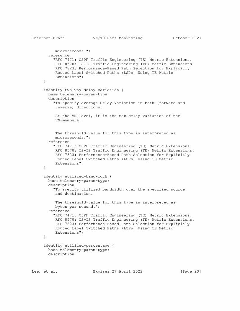
Internet-Draft VN/TE Perf Monitoring October 2021
microseconds."; reference "RFC 7471: OSPF Traffic Engineering (TE) Metric Extensions. RFC 8570: IS-IS Traffic Engineering (TE) Metric Extensions. RFC 7823: Performance-Based Path Selection for Explicitly Routed Label Switched Paths (LSPs) Using TE Metric Extensions"; }
identity two-way-delay-variation { base telemetry-param-type; description "To specify average Delay Variation in both (forward and reverse) directions.
At the VN level, it is the max delay variation of the VN-members.
The threshold-value for this type is interpreted as microseconds."; reference "RFC 7471: OSPF Traffic Engineering (TE) Metric Extensions. RFC 8570: IS-IS Traffic Engineering (TE) Metric Extensions. RFC 7823: Performance-Based Path Selection for Explicitly Routed Label Switched Paths (LSPs) Using TE Metric Extensions"; }
identity utilized-bandwidth { base telemetry-param-type; description "To specify utilized bandwidth over the specified source and destination.
The threshold-value for this type is interpreted as bytes per second."; reference "RFC 7471: OSPF Traffic Engineering (TE) Metric Extensions. RFC 8570: IS-IS Traffic Engineering (TE) Metric Extensions. RFC 7823: Performance-Based Path Selection for Explicitly Routed Label Switched Paths (LSPs) Using TE Metric Extensions"; }
identity utilized-percentage { base telemetry-param-type; description
Lee, et al. Expires 27 April 2022 [Page 23]
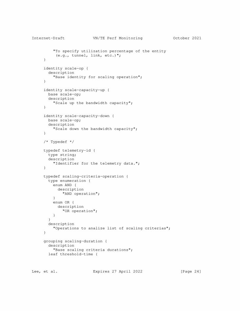
Internet-Draft VN/TE Perf Monitoring October 2021
"To specify utilization percentage of the entity (e.g., tunnel, link, etc.)"; }
identity scale-op { description "Base identity for scaling operation"; }
identity scale-capacity-up { base scale-op; description "Scale up the bandwidth capacity"; }
identity scale-capacity-down { base scale-op; description "Scale down the bandwidth capacity"; }
/* Typedef */
typedef telemetry-id { type string; description "Identifier for the telemetry data."; }
typedef scaling-criteria-operation { type enumeration { enum AND { description "AND operation"; } enum OR { description "OR operation"; } } description "Operations to analize list of scaling criterias"; }
grouping scaling-duration { description "Base scaling criteria durations"; leaf threshold-time {
Lee, et al. Expires 27 April 2022 [Page 24]
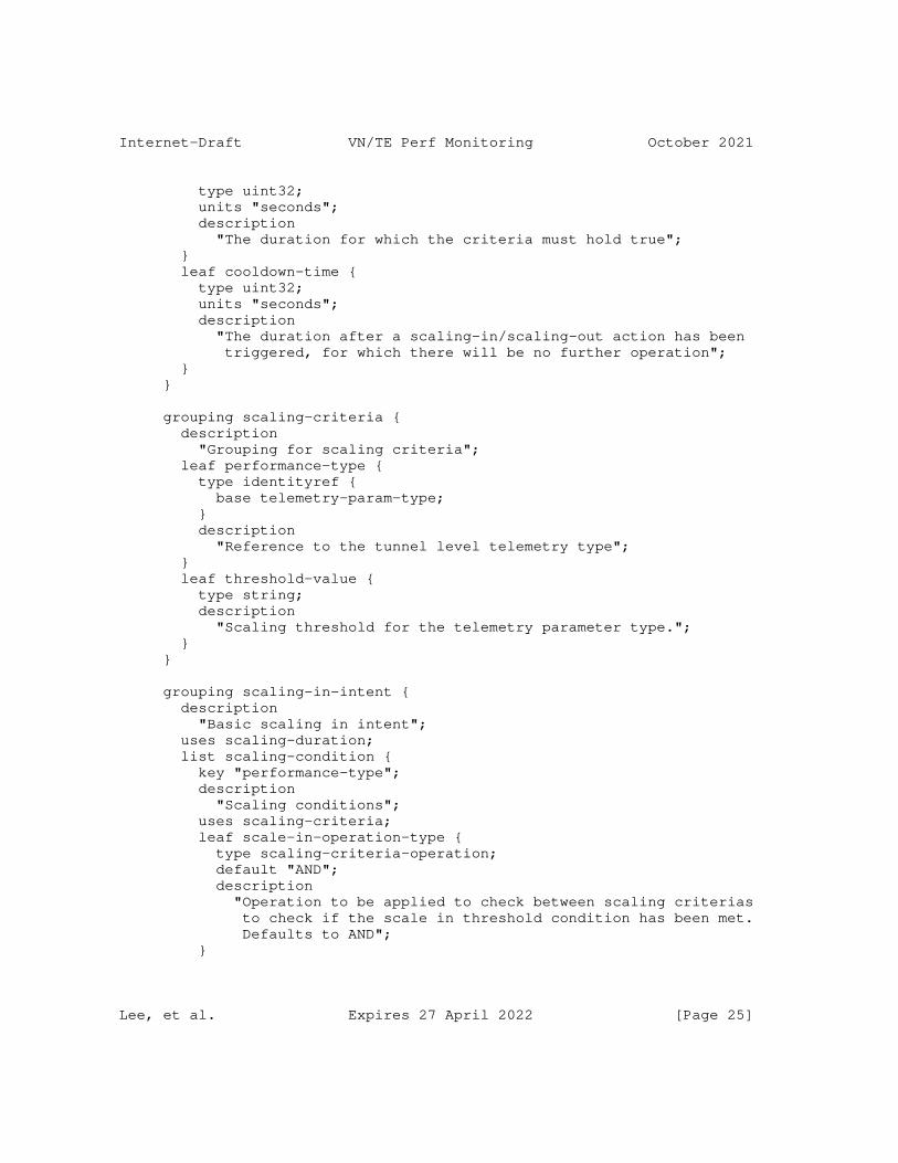
Internet-Draft VN/TE Perf Monitoring October 2021
type uint32; units "seconds"; description "The duration for which the criteria must hold true"; } leaf cooldown-time { type uint32; units "seconds"; description "The duration after a scaling-in/scaling-out action has been triggered, for which there will be no further operation"; } }
grouping scaling-criteria { description "Grouping for scaling criteria"; leaf performance-type { type identityref { base telemetry-param-type; } description "Reference to the tunnel level telemetry type"; } leaf threshold-value { type string; description "Scaling threshold for the telemetry parameter type."; } }
grouping scaling-in-intent { description "Basic scaling in intent"; uses scaling-duration; list scaling-condition { key "performance-type"; description "Scaling conditions"; uses scaling-criteria; leaf scale-in-operation-type { type scaling-criteria-operation; default "AND"; description "Operation to be applied to check between scaling criterias to check if the scale in threshold condition has been met. Defaults to AND"; }
Lee, et al. Expires 27 April 2022 [Page 25]
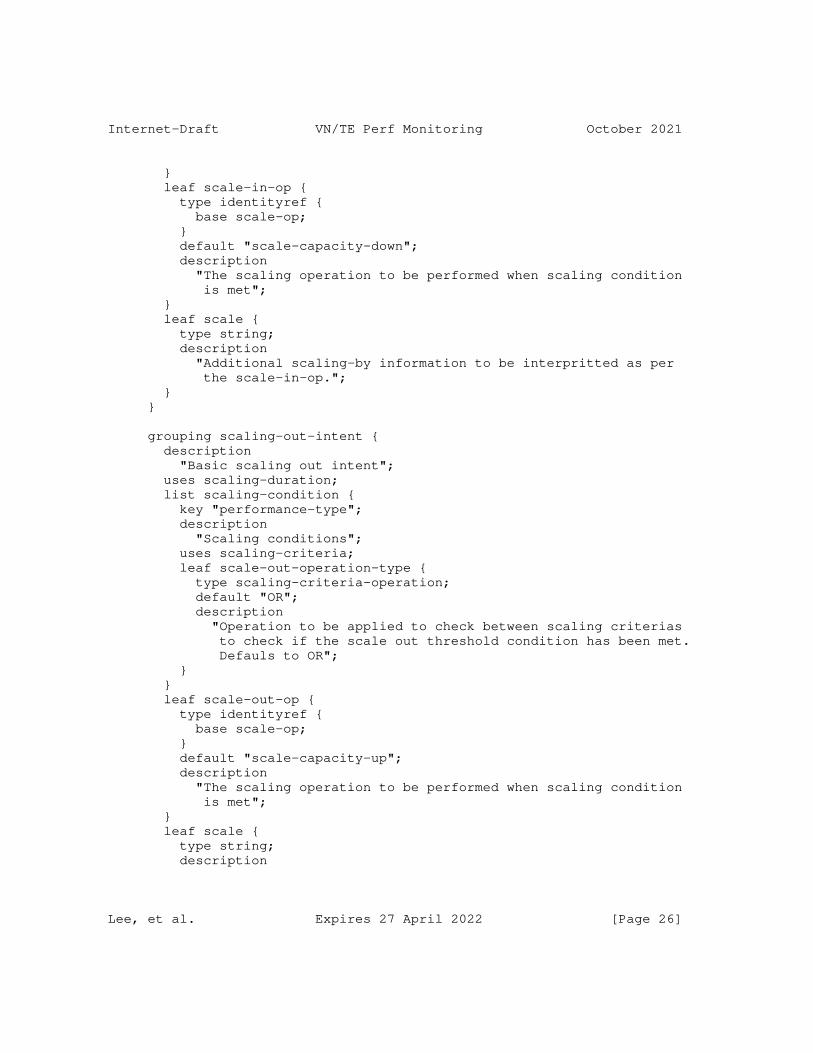
Internet-Draft VN/TE Perf Monitoring October 2021
} leaf scale-in-op { type identityref { base scale-op; } default "scale-capacity-down"; description "The scaling operation to be performed when scaling condition is met"; } leaf scale { type string; description "Additional scaling-by information to be interpritted as per the scale-in-op."; } }
grouping scaling-out-intent { description "Basic scaling out intent"; uses scaling-duration; list scaling-condition { key "performance-type"; description "Scaling conditions"; uses scaling-criteria; leaf scale-out-operation-type { type scaling-criteria-operation; default "OR"; description "Operation to be applied to check between scaling criterias to check if the scale out threshold condition has been met. Defauls to OR"; } } leaf scale-out-op { type identityref { base scale-op; } default "scale-capacity-up"; description "The scaling operation to be performed when scaling condition is met"; } leaf scale { type string; description
Lee, et al. Expires 27 April 2022 [Page 26]
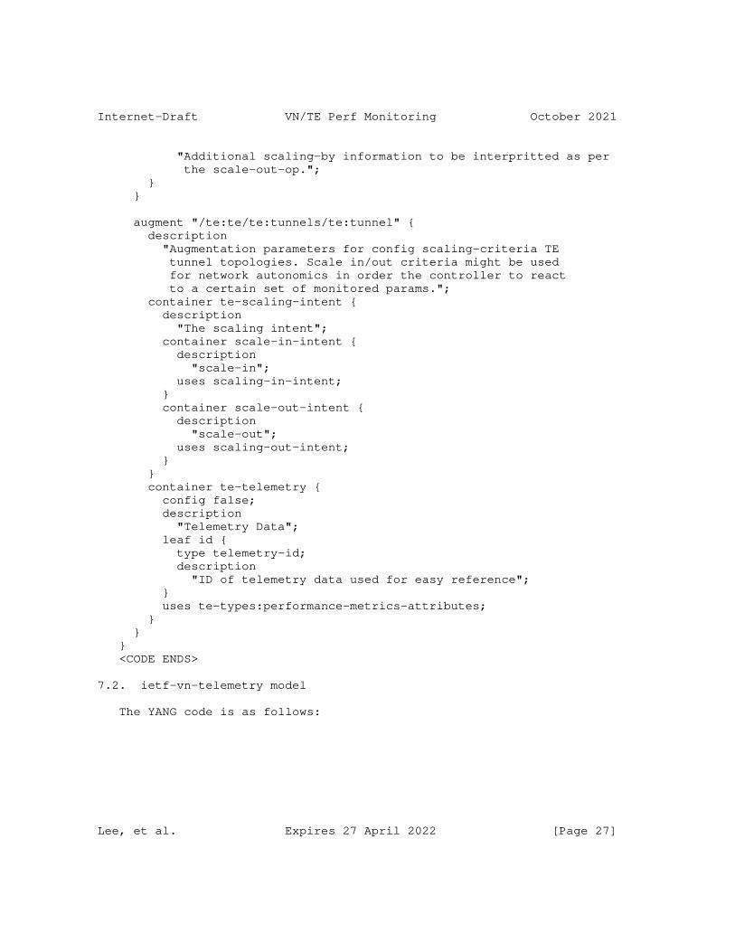
Internet-Draft VN/TE Perf Monitoring October 2021
"Additional scaling-by information to be interpritted as per the scale-out-op."; } }
augment "/te:te/te:tunnels/te:tunnel" { description "Augmentation parameters for config scaling-criteria TE tunnel topologies. Scale in/out criteria might be used for network autonomics in order the controller to react to a certain set of monitored params."; container te-scaling-intent { description "The scaling intent"; container scale-in-intent { description "scale-in"; uses scaling-in-intent; } container scale-out-intent { description "scale-out"; uses scaling-out-intent; } } container te-telemetry { config false; description "Telemetry Data"; leaf id { type telemetry-id; description "ID of telemetry data used for easy reference"; } uses te-types:performance-metrics-attributes; } } } <CODE ENDS>
7.2. ietf-vn-telemetry model
The YANG code is as follows:
Lee, et al. Expires 27 April 2022 [Page 27]
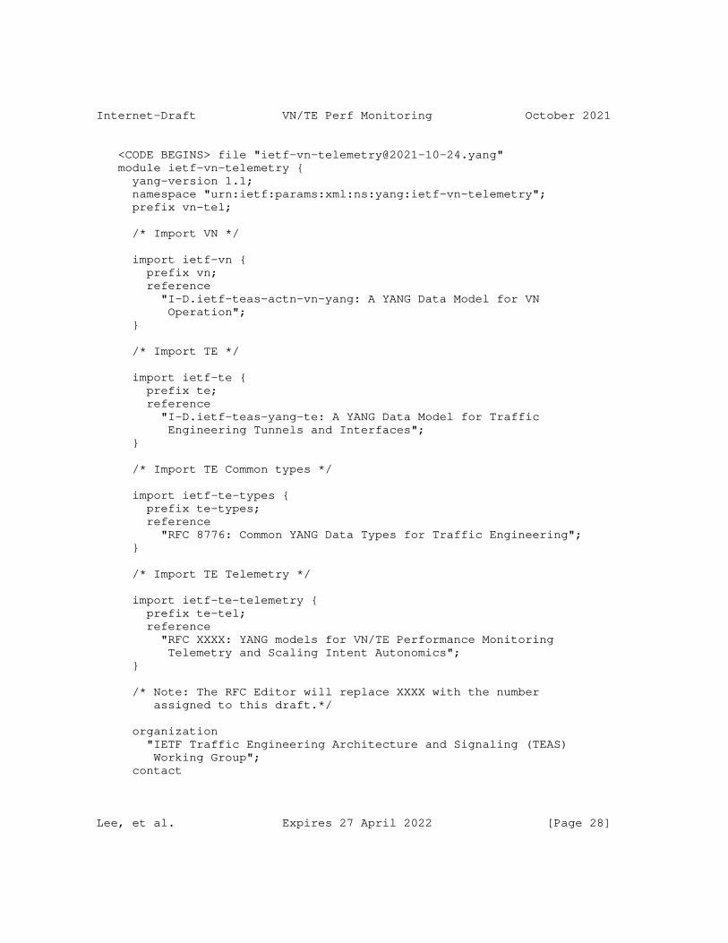
Internet-Draft VN/TE Perf Monitoring October 2021
<CODE BEGINS> file "[email protected]" module ietf-vn-telemetry { yang-version 1.1; namespace "urn:ietf:params:xml:ns:yang:ietf-vn-telemetry"; prefix vn-tel;
/* Import VN */
import ietf-vn { prefix vn; reference "I-D.ietf-teas-actn-vn-yang: A YANG Data Model for VN Operation"; }
/* Import TE */
import ietf-te { prefix te; reference "I-D.ietf-teas-yang-te: A YANG Data Model for Traffic Engineering Tunnels and Interfaces"; }
/* Import TE Common types */
import ietf-te-types { prefix te-types; reference "RFC 8776: Common YANG Data Types for Traffic Engineering"; }
/* Import TE Telemetry */
import ietf-te-telemetry { prefix te-tel; reference "RFC XXXX: YANG models for VN/TE Performance Monitoring Telemetry and Scaling Intent Autonomics"; }
/* Note: The RFC Editor will replace XXXX with the number assigned to this draft.*/
organization "IETF Traffic Engineering Architecture and Signaling (TEAS) Working Group"; contact
Lee, et al. Expires 27 April 2022 [Page 28]
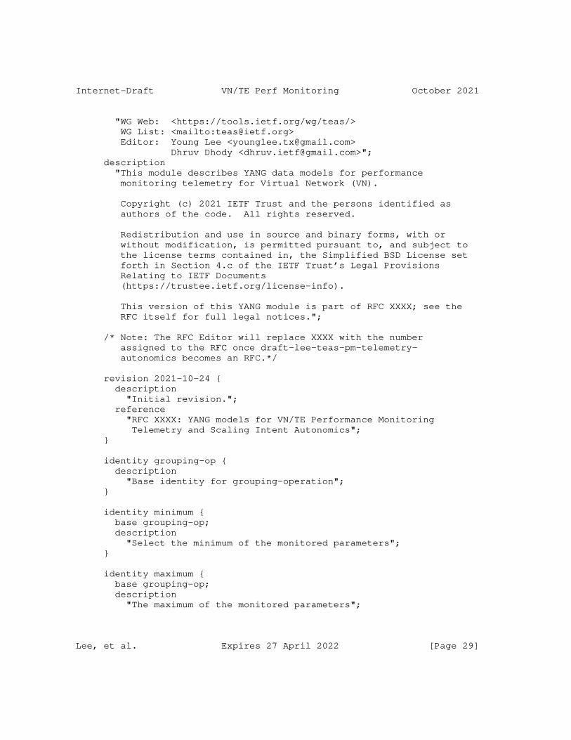
Internet-Draft VN/TE Perf Monitoring October 2021
"WG Web: <https://tools.ietf.org/wg/teas/> WG List: <mailto:[email protected]> Editor: Young Lee <[email protected]> Dhruv Dhody <[email protected]>"; description "This module describes YANG data models for performance monitoring telemetry for Virtual Network (VN).
Copyright (c) 2021 IETF Trust and the persons identified as authors of the code. All rights reserved.
Redistribution and use in source and binary forms, with or without modification, is permitted pursuant to, and subject to the license terms contained in, the Simplified BSD License set forth in Section 4.c of the IETF Trust’s Legal Provisions Relating to IETF Documents (https://trustee.ietf.org/license-info).
This version of this YANG module is part of RFC XXXX; see the RFC itself for full legal notices.";
/* Note: The RFC Editor will replace XXXX with the number assigned to the RFC once draft-lee-teas-pm-telemetry- autonomics becomes an RFC.*/
revision 2021-10-24 { description "Initial revision."; reference "RFC XXXX: YANG models for VN/TE Performance Monitoring Telemetry and Scaling Intent Autonomics"; }
identity grouping-op { description "Base identity for grouping-operation"; }
identity minimum { base grouping-op; description "Select the minimum of the monitored parameters"; }
identity maximum { base grouping-op; description "The maximum of the monitored parameters";
Lee, et al. Expires 27 April 2022 [Page 29]
Internet-Draft VN/TE Perf Monitoring October 2021
}
identity mean { base grouping-op; description "The mean of the monitored parameters"; }
identity standard-deviation { base grouping-op; description "The standard deviation of the monitored parameters"; }
identity sum { base grouping-op; description "The sum of the monitored parameters"; }
identity and { base grouping-op; description "Logical AND operation"; }
identity or { base grouping-op; description "Logical OR operation"; }
grouping grouping-operation { list operation { key "performance-type"; leaf performance-type { type identityref { base te-tel:telemetry-param-type; } description "Reference to the tunnel level telemetry type"; } leaf grouping-operation { type identityref { base grouping-op; } description "describes the operation to apply to the te-grouped-params";
Lee, et al. Expires 27 April 2022 [Page 30]
Internet-Draft VN/TE Perf Monitoring October 2021
} description "Grouping operation for each performance-type"; } description "Grouping operation for each performance-type"; }
augment "/vn:virtual-network/vn:vn" { description "Augmentation parameters for state TE VN topologies."; container vn-scaling-intent { description "scaling intent"; container scale-in-intent { description "VN scale-in"; uses te-tel:scaling-in-intent; } container scale-out-intent { description "VN scale-out"; uses te-tel:scaling-out-intent; } } container vn-telemetry { description "VN telemetry params"; container params { config false; description "Read-only telemetry parameters"; uses te-types:performance-metrics-attributes; } uses grouping-operation; } }
augment "/vn:virtual-network/vn:vn/vn:vn-member" { description "Augmentation parameters for state TE vn member topologies."; container vn-member-telemetry { description "VN member telemetry params"; container params { config false; description "Read-only telemetry parameters";
Lee, et al. Expires 27 April 2022 [Page 31]
Internet-Draft VN/TE Perf Monitoring October 2021
uses te-types:performance-metrics-attributes; leaf-list te-grouped-params { type leafref { path "/te:te/te:tunnels/te:tunnel/" + "te-tel:te-telemetry/te-tel:id"; } description "A list of underlying TE parameters that form the VN-member"; } } uses grouping-operation; } } } <CODE ENDS>
8. Security Considerations
The YANG modules specified in this document defines a schema for data that is designed to be accessed via network management protocols such as NETCONF [RFC6241] or RESTCONF [RFC8040]. The lowest NETCONF layer is the secure transport layer, and the mandatory-to-implement secure transport is Secure Shell (SSH) [RFC6242]. The lowest RESTCONF layer is HTTPS, and the mandatory-to-implement secure transport is TLS [RFC8446].
The Network Configuration Access Control Model (NACM) [RFC8341] provides the means to restrict access for particular NETCONF or RESTCONF users to a preconfigured subset of all available NETCONF or RESTCONF protocol operations and content.
There are a number of data nodes defined in this YANG module that are writable/creatable/deletable (i.e., config true, which is the default). These data nodes may be considered sensitive or vulnerable in some network environments. Write operations (e.g., edit-config) to these data nodes without proper protection can have a negative effect on network operations. These are the subtrees with the write operation that can be exploited to impact the network monitoring. An incorrect condition could cause frequent scaling operation to be executed causing harm to the network:
* /te:te/te:tunnels/te:tunnel/te-scaling-intent/scale-in-intent
* /te:te/te:tunnels/te:tunnel/te-scaling-intent/scale-out-intent
* /vn:virtual-network/vn:vn/vn-scaling-intent/scale-in-intent
Lee, et al. Expires 27 April 2022 [Page 32]
Internet-Draft VN/TE Perf Monitoring October 2021
* /vn:virtual-network/vn:vn/vn-scaling-intent/scale-out-intent
Further, following are the subtrees with the write operation that can be exploited by setting an incorrect grouping operation for the VN operation impacting the network monitoring:
* /vn:virtual-network/vn:vn/vn-telemetry/operation
* /vn:virtual-network/vn:vn/vn:vn-member/vn-member-telemetry/ operation
Some of the readable data nodes in this YANG module may be considered sensitive or vulnerable in some network environments. It is thus important to control read access (e.g., via get, get-config, or notification) to these data nodes. These are the subtrees with the read operations that can be exploited to learn real-time (and sensitive) telemetry information about the TE tunnels and VN:
* /te:te/te:tunnels/te:tunnel/te-telemetry
* /vn:virtual-network/vn:vn/vn-telemetry
* /vn:virtual-network/vn:vn/vn:vn-member/vn-member-telemetry
9. IANA Considerations
This document registers the following namespace URIs in the IETF XML registry [RFC3688]:
-------------------------------------------------------------------- URI: urn:ietf:params:xml:ns:yang:ietf-te-telemetry Registrant Contact: The IESG. XML: N/A, the requested URI is an XML namespace. --------------------------------------------------------------------
-------------------------------------------------------------------- URI: urn:ietf:params:xml:ns:yang:ietf-vn-telemetry Registrant Contact: The IESG. XML: N/A, the requested URI is an XML namespace. --------------------------------------------------------------------
This document registers the following YANG modules in the YANG Module registry.
Names registry [RFC7950]:
Lee, et al. Expires 27 April 2022 [Page 33]
Internet-Draft VN/TE Perf Monitoring October 2021
-------------------------------------------------------------------- name: ietf-te-telemetry namespace: urn:ietf:params:xml:ns:yang:ietf-te-telemetry prefix: te-tel reference: RFC XXXX --------------------------------------------------------------------
-------------------------------------------------------------------- name: ietf-vn-telemetry namespace: urn:ietf:params:xml:ns:yang:ietf-vn-telemetry prefix: vn-tel reference: RFC XXXX --------------------------------------------------------------------
10. Acknowledgements
We thank Adrian Farrel, Rakesh Gandhi, Tarek Saad, Igor Bryskin, Kenichi Ogaki, and Greg Mirsky for useful discussions and their suggestions for this work.
11. References
11.1. Normative References
[I-D.ietf-teas-actn-vn-yang] Lee, Y., Dhody, D., Ceccarelli, D., Bryskin, I., and B. Y. Yoon, "A YANG Data Model for VN Operation", Work in Progress, Internet-Draft, draft-ietf-teas-actn-vn-yang-13, 23 October 2021, <https://datatracker.ietf.org/doc/html/ draft-ietf-teas-actn-vn-yang-13>.
[I-D.ietf-teas-yang-te] Saad, T., Gandhi, R., Liu, X., Beeram, V. P., Bryskin, I., and O. G. D. Dios, "A YANG Data Model for Traffic Engineering Tunnels, Label Switched Paths and Interfaces", Work in Progress, Internet-Draft, draft-ietf-teas-yang-te- 27, 8 July 2021, <https://datatracker.ietf.org/doc/html/ draft-ietf-teas-yang-te-27>.
[RFC3688] Mealling, M., "The IETF XML Registry", BCP 81, RFC 3688, DOI 10.17487/RFC3688, January 2004, <https://www.rfc-editor.org/info/rfc3688>.
[RFC6241] Enns, R., Ed., Bjorklund, M., Ed., Schoenwaelder, J., Ed., and A. Bierman, Ed., "Network Configuration Protocol (NETCONF)", RFC 6241, DOI 10.17487/RFC6241, June 2011, <https://www.rfc-editor.org/info/rfc6241>.
Lee, et al. Expires 27 April 2022 [Page 34]
Internet-Draft VN/TE Perf Monitoring October 2021
[RFC6242] Wasserman, M., "Using the NETCONF Protocol over Secure Shell (SSH)", RFC 6242, DOI 10.17487/RFC6242, June 2011, <https://www.rfc-editor.org/info/rfc6242>.
[RFC7926] Farrel, A., Ed., Drake, J., Bitar, N., Swallow, G., Ceccarelli, D., and X. Zhang, "Problem Statement and Architecture for Information Exchange between Interconnected Traffic-Engineered Networks", BCP 206, RFC 7926, DOI 10.17487/RFC7926, July 2016, <https://www.rfc-editor.org/info/rfc7926>.
[RFC7950] Bjorklund, M., Ed., "The YANG 1.1 Data Modeling Language", RFC 7950, DOI 10.17487/RFC7950, August 2016, <https://www.rfc-editor.org/info/rfc7950>.
[RFC8040] Bierman, A., Bjorklund, M., and K. Watsen, "RESTCONF Protocol", RFC 8040, DOI 10.17487/RFC8040, January 2017, <https://www.rfc-editor.org/info/rfc8040>.
[RFC8233] Dhody, D., Wu, Q., Manral, V., Ali, Z., and K. Kumaki, "Extensions to the Path Computation Element Communication Protocol (PCEP) to Compute Service-Aware Label Switched Paths (LSPs)", RFC 8233, DOI 10.17487/RFC8233, September 2017, <https://www.rfc-editor.org/info/rfc8233>.
[RFC8340] Bjorklund, M. and L. Berger, Ed., "YANG Tree Diagrams", BCP 215, RFC 8340, DOI 10.17487/RFC8340, March 2018, <https://www.rfc-editor.org/info/rfc8340>.
[RFC8341] Bierman, A. and M. Bjorklund, "Network Configuration Access Control Model", STD 91, RFC 8341, DOI 10.17487/RFC8341, March 2018, <https://www.rfc-editor.org/info/rfc8341>.
[RFC8342] Bjorklund, M., Schoenwaelder, J., Shafer, P., Watsen, K., and R. Wilton, "Network Management Datastore Architecture (NMDA)", RFC 8342, DOI 10.17487/RFC8342, March 2018, <https://www.rfc-editor.org/info/rfc8342>.
[RFC8446] Rescorla, E., "The Transport Layer Security (TLS) Protocol Version 1.3", RFC 8446, DOI 10.17487/RFC8446, August 2018, <https://www.rfc-editor.org/info/rfc8446>.
[RFC8640] Voit, E., Clemm, A., Gonzalez Prieto, A., Nilsen-Nygaard, E., and A. Tripathy, "Dynamic Subscription to YANG Events and Datastores over NETCONF", RFC 8640, DOI 10.17487/RFC8640, September 2019, <https://www.rfc-editor.org/info/rfc8640>.
Lee, et al. Expires 27 April 2022 [Page 35]

Internet-Draft VN/TE Perf Monitoring October 2021
[RFC8641] Clemm, A. and E. Voit, "Subscription to YANG Notifications for Datastore Updates", RFC 8641, DOI 10.17487/RFC8641, September 2019, <https://www.rfc-editor.org/info/rfc8641>.
[RFC8776] Saad, T., Gandhi, R., Liu, X., Beeram, V., and I. Bryskin, "Common YANG Data Types for Traffic Engineering", RFC 8776, DOI 10.17487/RFC8776, June 2020, <https://www.rfc-editor.org/info/rfc8776>.
11.2. Informative References
[I-D.ietf-opsawg-yang-vpn-service-pm] Wu, B., Wu, Q., Boucadair, M., Dios, O. G. D., Wen, B., Liu, C., and H. Xu, "A YANG Model for Network and VPN Service Performance Monitoring", Work in Progress, Internet-Draft, draft-ietf-opsawg-yang-vpn-service-pm-01, 6 July 2021, <https://datatracker.ietf.org/doc/html/draft- ietf-opsawg-yang-vpn-service-pm-01>.
[RFC7471] Giacalone, S., Ward, D., Drake, J., Atlas, A., and S. Previdi, "OSPF Traffic Engineering (TE) Metric Extensions", RFC 7471, DOI 10.17487/RFC7471, March 2015, <https://www.rfc-editor.org/info/rfc7471>.
[RFC7823] Atlas, A., Drake, J., Giacalone, S., and S. Previdi, "Performance-Based Path Selection for Explicitly Routed Label Switched Paths (LSPs) Using TE Metric Extensions", RFC 7823, DOI 10.17487/RFC7823, May 2016, <https://www.rfc-editor.org/info/rfc7823>.
[RFC8309] Wu, Q., Liu, W., and A. Farrel, "Service Models Explained", RFC 8309, DOI 10.17487/RFC8309, January 2018, <https://www.rfc-editor.org/info/rfc8309>.
[RFC8453] Ceccarelli, D., Ed. and Y. Lee, Ed., "Framework for Abstraction and Control of TE Networks (ACTN)", RFC 8453, DOI 10.17487/RFC8453, August 2018, <https://www.rfc-editor.org/info/rfc8453>.
[RFC8570] Ginsberg, L., Ed., Previdi, S., Ed., Giacalone, S., Ward, D., Drake, J., and Q. Wu, "IS-IS Traffic Engineering (TE) Metric Extensions", RFC 8570, DOI 10.17487/RFC8570, March 2019, <https://www.rfc-editor.org/info/rfc8570>.
Authors’ Addresses
Lee, et al. Expires 27 April 2022 [Page 36]
Internet-Draft VN/TE Perf Monitoring October 2021
Young Lee (editor) Samsung Electronics
Email: [email protected]
Dhruv Dhody (editor) Huawei Technologies Divyashree Techno Park, Whitefield Bangalore 560066 Karnataka India
Email: [email protected]
Satish Karunanithi Huawei Technologies Divyashree Techno Park, Whitefield Bangalore 560066 Karnataka India
Email: [email protected]
Ricard Vilalta CTTC Centre Tecnologic de Telecomunicacions de Catalunya (CTTC/CERCA) Barcelona Spain
Email: [email protected]
Daniel King Lancaster University
Email: [email protected]
Daniele Ceccarelli Ericsson Torshamnsgatan,48 Stockholm, Sweden
Email: [email protected]
Lee, et al. Expires 27 April 2022 [Page 37]

TEAS Working Group Y. Lee, Ed.Internet-Draft Samsung ElectronicsIntended status: Standards Track D. Dhody, Ed.Expires: 26 April 2022 Huawei Technologies D. Ceccarelli Ericsson I. Bryskin Individual B. Yoon ETRI 23 October 2021
A YANG Data Model for VN Operation draft-ietf-teas-actn-vn-yang-13
Abstract
This document provides a YANG data model generally applicable to any mode of Virtual Network (VN) operation.
Status of This Memo
This Internet-Draft is submitted in full conformance with the provisions of BCP 78 and BCP 79.
Internet-Drafts are working documents of the Internet Engineering Task Force (IETF). Note that other groups may also distribute working documents as Internet-Drafts. The list of current Internet- Drafts is at https://datatracker.ietf.org/drafts/current/.
Internet-Drafts are draft documents valid for a maximum of six months and may be updated, replaced, or obsoleted by other documents at any time. It is inappropriate to use Internet-Drafts as reference material or to cite them other than as "work in progress."
This Internet-Draft will expire on 26 April 2022.
Copyright Notice
Copyright (c) 2021 IETF Trust and the persons identified as the document authors. All rights reserved.
This document is subject to BCP 78 and the IETF Trust’s Legal Provisions Relating to IETF Documents (https://trustee.ietf.org/ license-info) in effect on the date of publication of this document. Please review these documents carefully, as they describe your rights and restrictions with respect to this document. Code Components
Lee, et al. Expires 26 April 2022 [Page 1]
Internet-Draft VN YANG Model October 2021
extracted from this document must include Simplified BSD License text as described in Section 4.e of the Trust Legal Provisions and are provided without warranty as described in the Simplified BSD License.
Table of Contents
1. Introduction . . . . . . . . . . . . . . . . . . . . . . . . 2 1.1. Terminology . . . . . . . . . . . . . . . . . . . . . . . 4 1.1.1. Requirements Language . . . . . . . . . . . . . . . . 4 1.2. Tree diagram . . . . . . . . . . . . . . . . . . . . . . 4 1.3. Prefixes in Data Node Names . . . . . . . . . . . . . . . 4 2. Use-case of VN YANG Model in the ACTN context . . . . . . . . 5 2.1. Type 1 VN . . . . . . . . . . . . . . . . . . . . . . . . 5 2.2. Type 2 VN . . . . . . . . . . . . . . . . . . . . . . . . 6 3. High-Level Control Flows with Examples . . . . . . . . . . . 7 3.1. Type 1 VN Illustration . . . . . . . . . . . . . . . . . 7 3.2. Type 2 VN Illustration . . . . . . . . . . . . . . . . . 8 3.2.1. VN and AP Usage . . . . . . . . . . . . . . . . . . . 11 4. VN Model Usage . . . . . . . . . . . . . . . . . . . . . . . 12 4.1. Customer view of VN . . . . . . . . . . . . . . . . . . . 12 4.2. Auto-creation of VN by MDSC . . . . . . . . . . . . . . . 12 4.3. Innovative Services . . . . . . . . . . . . . . . . . . . 12 4.3.1. VN Compute . . . . . . . . . . . . . . . . . . . . . 12 4.3.2. Multi-sources and Multi-destinations . . . . . . . . 15 4.3.3. Others . . . . . . . . . . . . . . . . . . . . . . . 16 4.3.4. Summary . . . . . . . . . . . . . . . . . . . . . . . 16 5. VN YANG Model (Tree Structure) . . . . . . . . . . . . . . . 17 6. VN YANG Model . . . . . . . . . . . . . . . . . . . . . . . . 20 7. JSON Example . . . . . . . . . . . . . . . . . . . . . . . . 31 7.1. VN JSON . . . . . . . . . . . . . . . . . . . . . . . . . 32 7.2. TE-topology JSON . . . . . . . . . . . . . . . . . . . . 37 8. Security Considerations . . . . . . . . . . . . . . . . . . . 48 9. IANA Considerations . . . . . . . . . . . . . . . . . . . . . 49 10. Acknowledgments . . . . . . . . . . . . . . . . . . . . . . . 50 11. References . . . . . . . . . . . . . . . . . . . . . . . . . 50 11.1. Normative References . . . . . . . . . . . . . . . . . . 50 11.2. Informative References . . . . . . . . . . . . . . . . . 51 Appendix A. Performance Constraints . . . . . . . . . . . . . . 53 Appendix B. Contributors Addresses . . . . . . . . . . . . . . . 53 Authors’ Addresses . . . . . . . . . . . . . . . . . . . . . . . 54
1. Introduction
This document provides a YANG [RFC7950] data model generally applicable to any mode of Virtual Network (VN) operation.
Lee, et al. Expires 26 April 2022 [Page 2]
Internet-Draft VN YANG Model October 2021
The VN model defined in this document is applicable in generic sense as an independent model in and of itself. The VN model defined in this document can also work together with other customer service models such as L3SM [RFC8299], L2SM [RFC8466] and L1CSM [I-D.ietf-ccamp-l1csm-yang] to provide a complete life-cycle service management and operations.
The YANG model discussed in this document basically provides the following:
* Characteristics of Access Points (APs) that describe customer’s end point characteristics;
* Characteristics of Virtual Network Access Points (VNAP) that describe how an AP is partitioned for multiple VNs sharing the AP and its reference to a Link Termination Point (LTP) of the Provider Edge (PE) Node;
* Characteristics of Virtual Networks (VNs) that describe the customer’s VN in terms of multiple VN Members comprising a VN, multi- source and/or multi-destination characteristics of the VN Member, the VN’s reference to TE-topology’s Abstract Node;
The actual VN instantiation and computation is performed with Connectivity Matrices sub-module of TE-Topology Model [RFC8795] which provides TE network topology abstraction and management operation. Once TE-topology Model is used in triggering VN instantiation over the networks, TE-tunnel [I-D.ietf-teas-yang-te] Model will inevitably interact with TE-Topology model for setting up actual tunnels and LSPs under the tunnels.
Abstraction and Control of Traffic Engineered Networks (ACTN) describes a set of management and control functions used to operate one or more TE networks to construct virtual networks that can be represented to customers and that are built from abstractions of the underlying TE networks [RFC8453]. ACTN is the primary example of the usage of the VN YANG model.
Sections 2 and 3 provide the discussion of how the VN YANG model is applicable to the ACTN context where Virtual Network Service (VNS) operation is implemented for the Customer Network Controller (CNC)- Multi-Domain Service Coordinator (MSDC) interface (CMI).
The YANG model on the CMI is also known as customer service model in [RFC8309]. The YANG model discussed in this document is used to operate customer-driven VNs during the VN instantiation, VN computation, and its life-cycle service management and operations.
Lee, et al. Expires 26 April 2022 [Page 3]
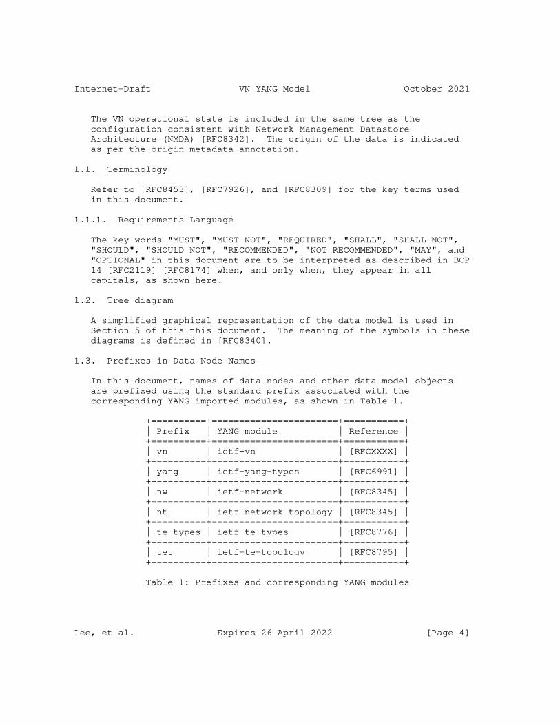
Internet-Draft VN YANG Model October 2021
The VN operational state is included in the same tree as the configuration consistent with Network Management Datastore Architecture (NMDA) [RFC8342]. The origin of the data is indicated as per the origin metadata annotation.
1.1. Terminology
Refer to [RFC8453], [RFC7926], and [RFC8309] for the key terms used in this document.
1.1.1. Requirements Language
The key words "MUST", "MUST NOT", "REQUIRED", "SHALL", "SHALL NOT", "SHOULD", "SHOULD NOT", "RECOMMENDED", "NOT RECOMMENDED", "MAY", and "OPTIONAL" in this document are to be interpreted as described in BCP 14 [RFC2119] [RFC8174] when, and only when, they appear in all capitals, as shown here.
1.2. Tree diagram
A simplified graphical representation of the data model is used in Section 5 of this this document. The meaning of the symbols in these diagrams is defined in [RFC8340].
1.3. Prefixes in Data Node Names
In this document, names of data nodes and other data model objects are prefixed using the standard prefix associated with the corresponding YANG imported modules, as shown in Table 1.
+==========+=======================+===========+ | Prefix | YANG module | Reference | +==========+=======================+===========+ | vn | ietf-vn | [RFCXXXX] | +----------+-----------------------+-----------+ | yang | ietf-yang-types | [RFC6991] | +----------+-----------------------+-----------+ | nw | ietf-network | [RFC8345] | +----------+-----------------------+-----------+ | nt | ietf-network-topology | [RFC8345] | +----------+-----------------------+-----------+ | te-types | ietf-te-types | [RFC8776] | +----------+-----------------------+-----------+ | tet | ietf-te-topology | [RFC8795] | +----------+-----------------------+-----------+
Table 1: Prefixes and corresponding YANG modules
Lee, et al. Expires 26 April 2022 [Page 4]
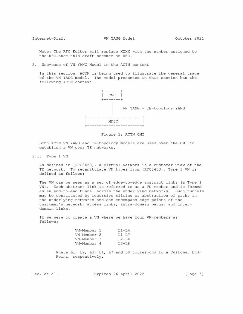
Internet-Draft VN YANG Model October 2021
Note: The RFC Editor will replace XXXX with the number assigned to the RFC once this draft becomes an RFC.
2. Use-case of VN YANG Model in the ACTN context
In this section, ACTN is being used to illustrate the general usage of the VN YANG model. The model presented in this section has the following ACTN context.
+-------+ | CNC | +-------+ | | VN YANG + TE-topology YANG | +-----------------------+ | MDSC | +-----------------------+
Figure 1: ACTN CMI
Both ACTN VN YANG and TE-topology models are used over the CMI to establish a VN over TE networks.
2.1. Type 1 VN
As defined in [RFC8453], a Virtual Network is a customer view of the TE network. To recapitulate VN types from [RFC8453], Type 1 VN is defined as follows:
The VN can be seen as a set of edge-to-edge abstract links (a Type 1 VN). Each abstract link is referred to as a VN member and is formed as an end-to-end tunnel across the underlying networks. Such tunnels may be constructed by recursive slicing or abstraction of paths in the underlying networks and can encompass edge points of the customer’s network, access links, intra-domain paths, and inter- domain links.
If we were to create a VN where we have four VN-members as follows:
VN-Member 1 L1-L4 VN-Member 2 L1-L7 VN-Member 3 L2-L4 VN-Member 4 L3-L8
Where L1, L2, L3, L4, L7 and L8 correspond to a Customer End- Point, respectively.
Lee, et al. Expires 26 April 2022 [Page 5]
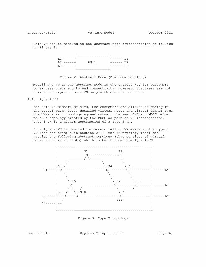
Internet-Draft VN YANG Model October 2021
This VN can be modeled as one abstract node representation as follows in Figure 2:
+---------------+ L1 ------| |------ L4 L2 ------| AN 1 |------ L7 L3 ------| |------ L8 +---------------+
Figure 2: Abstract Node (One node topology)
Modeling a VN as one abstract node is the easiest way for customers to express their end-to-end connectivity; however, customers are not limited to express their VN only with one abstract node.
2.2. Type 2 VN
For some VN members of a VN, the customers are allowed to configure the actual path (i.e., detailed virtual nodes and virtual links) over the VN/abstract topology agreed mutually between CNC and MDSC prior to or a topology created by the MDSC as part of VN instantiation. Type 1 VN is a higher abstraction of a Type 2 VN.
If a Type 2 VN is desired for some or all of VN members of a type 1 VN (see the example in Section 2.1), the TE-topology model can provide the following abstract topology (that consists of virtual nodes and virtual links) which is built under the Type 1 VN.
+----------------------------------------------+ | S1 S2 | | O---------------O | | ________/ \______ \ | | / \ \ | |S3 / \ S4 \ S5 | L1----|-O----------------------O---------O-----------|------L4 | \ \ \ | | \ \ \ | | \ S6 \ S7 \ S8 | | O ----------------O---------O-------|------L7 | / \ / \ ____/ | |S9 / \ /S10 \ / | L2-----|---O-----O---------------------O--------------|------L8 | / S11 | L3-----|-- | | | +----------------------------------------------+
Figure 3: Type 2 topology
Lee, et al. Expires 26 April 2022 [Page 6]
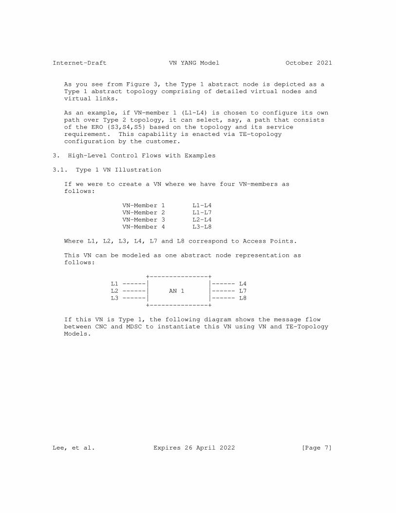
Internet-Draft VN YANG Model October 2021
As you see from Figure 3, the Type 1 abstract node is depicted as a Type 1 abstract topology comprising of detailed virtual nodes and virtual links.
As an example, if VN-member 1 (L1-L4) is chosen to configure its own path over Type 2 topology, it can select, say, a path that consists of the ERO {S3,S4,S5} based on the topology and its service requirement. This capability is enacted via TE-topology configuration by the customer.
3. High-Level Control Flows with Examples
3.1. Type 1 VN Illustration
If we were to create a VN where we have four VN-members as follows:
VN-Member 1 L1-L4 VN-Member 2 L1-L7 VN-Member 3 L2-L4 VN-Member 4 L3-L8
Where L1, L2, L3, L4, L7 and L8 correspond to Access Points.
This VN can be modeled as one abstract node representation as follows:
+---------------+ L1 ------| |------ L4 L2 ------| AN 1 |------ L7 L3 ------| |------ L8 +---------------+
If this VN is Type 1, the following diagram shows the message flow between CNC and MDSC to instantiate this VN using VN and TE-Topology Models.
Lee, et al. Expires 26 April 2022 [Page 7]
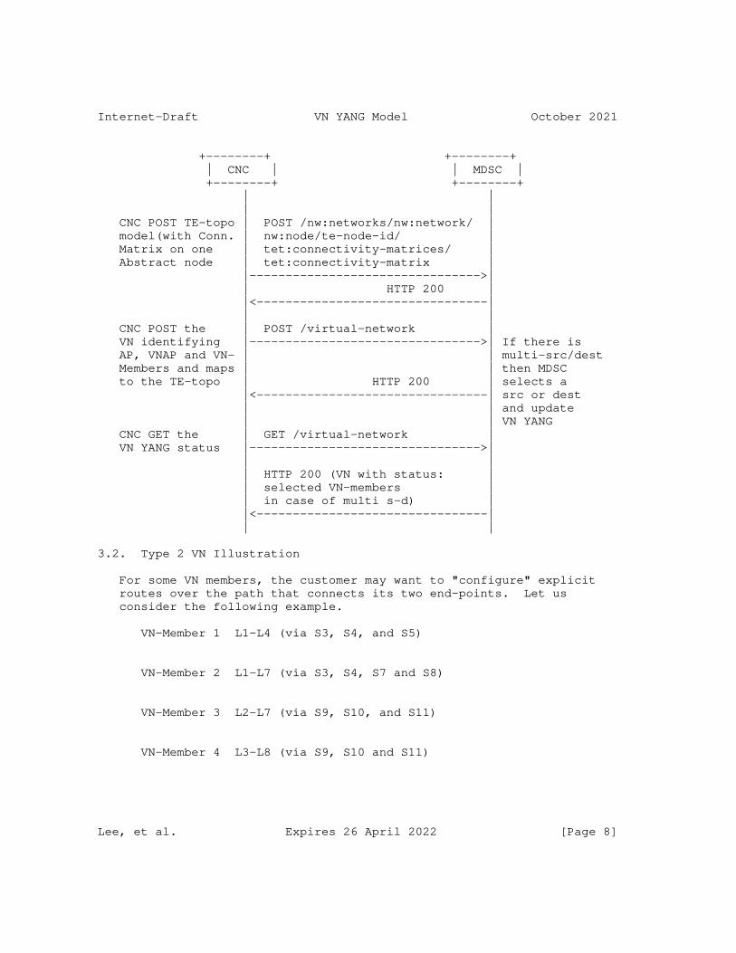
Internet-Draft VN YANG Model October 2021
+--------+ +--------+ | CNC | | MDSC | +--------+ +--------+ | | | | CNC POST TE-topo | POST /nw:networks/nw:network/ | model(with Conn. | nw:node/te-node-id/ | Matrix on one | tet:connectivity-matrices/ | Abstract node | tet:connectivity-matrix | |-------------------------------->| | HTTP 200 | |<--------------------------------| | | CNC POST the | POST /virtual-network | VN identifying |-------------------------------->| If there is AP, VNAP and VN- | | multi-src/dest Members and maps | | then MDSC to the TE-topo | HTTP 200 | selects a |<--------------------------------| src or dest | | and update | | VN YANG CNC GET the | GET /virtual-network | VN YANG status |-------------------------------->| | | | HTTP 200 (VN with status: | | selected VN-members | | in case of multi s-d) | |<--------------------------------| | |
3.2. Type 2 VN Illustration
For some VN members, the customer may want to "configure" explicit routes over the path that connects its two end-points. Let us consider the following example.
VN-Member 1 L1-L4 (via S3, S4, and S5)
VN-Member 2 L1-L7 (via S3, S4, S7 and S8)
VN-Member 3 L2-L7 (via S9, S10, and S11)
VN-Member 4 L3-L8 (via S9, S10 and S11)
Lee, et al. Expires 26 April 2022 [Page 8]
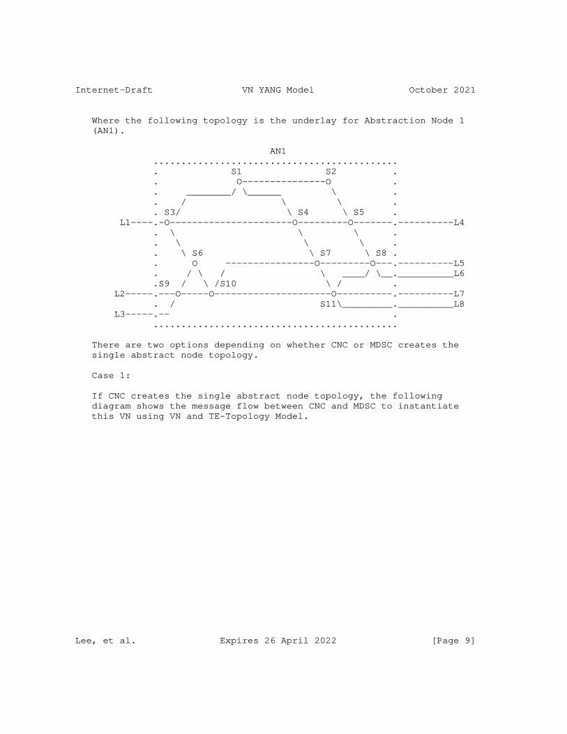
Internet-Draft VN YANG Model October 2021
Where the following topology is the underlay for Abstraction Node 1 (AN1).
AN1 ............................................ . S1 S2 . . O---------------O . . ________/ \______ \ . . / \ \ . . S3/ \ S4 \ S5 . L1----.-O----------------------O---------O-------.----------L4 . \ \ \ . . \ \ \ . . \ S6 \ S7 \ S8 . . O ----------------O---------O---.----------L5 . / \ / \ ____/ \__.__________L6 .S9 / \ /S10 \ / . L2-----.---O-----O---------------------O----------.----------L7 . / S11\_________.__________L8 L3-----.-- . ............................................
There are two options depending on whether CNC or MDSC creates the single abstract node topology.
Case 1:
If CNC creates the single abstract node topology, the following diagram shows the message flow between CNC and MDSC to instantiate this VN using VN and TE-Topology Model.
Lee, et al. Expires 26 April 2022 [Page 9]
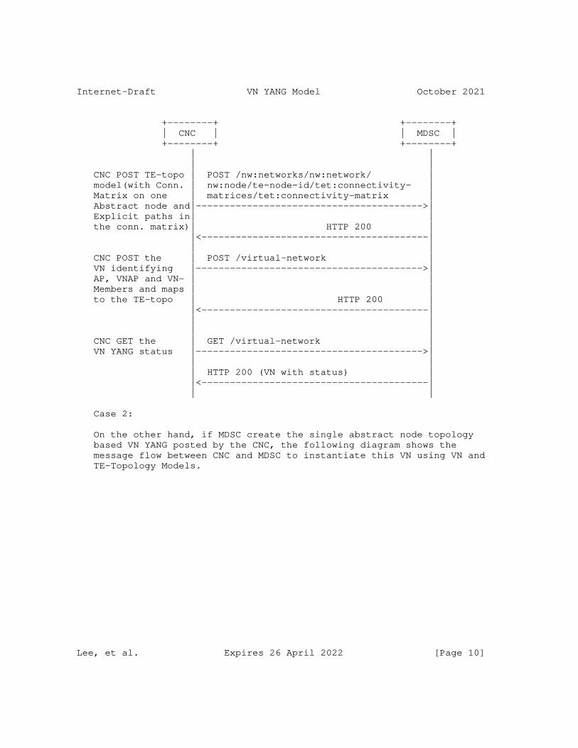
Internet-Draft VN YANG Model October 2021
+--------+ +--------+ | CNC | | MDSC | +--------+ +--------+ | | | | CNC POST TE-topo | POST /nw:networks/nw:network/ | model(with Conn. | nw:node/te-node-id/tet:connectivity- | Matrix on one | matrices/tet:connectivity-matrix | Abstract node and|---------------------------------------->| Explicit paths in| | the conn. matrix)| HTTP 200 | |<----------------------------------------| | | CNC POST the | POST /virtual-network | VN identifying |---------------------------------------->| AP, VNAP and VN- | | Members and maps | | to the TE-topo | HTTP 200 | |<----------------------------------------| | | | | CNC GET the | GET /virtual-network | VN YANG status |---------------------------------------->| | | | HTTP 200 (VN with status) | |<----------------------------------------| | |
Case 2:
On the other hand, if MDSC create the single abstract node topology based VN YANG posted by the CNC, the following diagram shows the message flow between CNC and MDSC to instantiate this VN using VN and TE-Topology Models.
Lee, et al. Expires 26 April 2022 [Page 10]
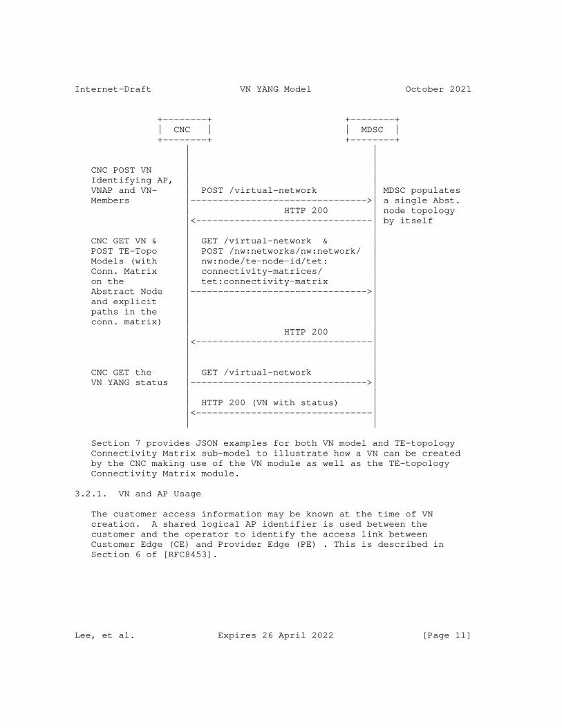
Internet-Draft VN YANG Model October 2021
+--------+ +--------+ | CNC | | MDSC | +--------+ +--------+ | | | | CNC POST VN | | Identifying AP, | | VNAP and VN- | POST /virtual-network | MDSC populates Members |-------------------------------->| a single Abst. | HTTP 200 | node topology |<--------------------------------| by itself | | CNC GET VN & | GET /virtual-network & | POST TE-Topo | POST /nw:networks/nw:network/ | Models (with | nw:node/te-node-id/tet: | Conn. Matrix | connectivity-matrices/ | on the | tet:connectivity-matrix | Abstract Node |-------------------------------->| and explicit | | paths in the | | conn. matrix) | | | HTTP 200 | |<--------------------------------| | | | | CNC GET the | GET /virtual-network | VN YANG status |-------------------------------->| | | | HTTP 200 (VN with status) | |<--------------------------------| | |
Section 7 provides JSON examples for both VN model and TE-topology Connectivity Matrix sub-model to illustrate how a VN can be created by the CNC making use of the VN module as well as the TE-topology Connectivity Matrix module.
3.2.1. VN and AP Usage
The customer access information may be known at the time of VN creation. A shared logical AP identifier is used between the customer and the operator to identify the access link between Customer Edge (CE) and Provider Edge (PE) . This is described in Section 6 of [RFC8453].
Lee, et al. Expires 26 April 2022 [Page 11]
Internet-Draft VN YANG Model October 2021
In some VN operations, the customer access may not be known at the initial VN creation. The VN operation allow a creation of VN with only PE identifier as well. The customer access information could be added later.
To achieve this the ’ap’ container has a leaf for ’pe’ node that allows AP to be created with PE information. The vn-member (and vn) could use APs that only have PE information initially.
4. VN Model Usage
4.1. Customer view of VN
The VN-YANG model allows to define a customer view, and allows the customer to communicate using the VN constructs as described in the [RFC8454]. It also allows to group the set of edge-to-edge links (i.e., VN members) under a common umbrella of VN. This allows the customer to instantiate and view the VN as one entity, making it easier for some customers to work on VN without worrying about the details of the provider based YANG models.
This is similar to the benefits of having a separate YANG model for the customer services as described in [RFC8309], which states that service models do not make any assumption of how a service is actually engineered and delivered for a customer.
4.2. Auto-creation of VN by MDSC
The VN could be configured at the MDSC explicitly by the CNC using the VN YANG model. In some other cases, the VN is not explicitly configured, but created automatically by the MDSC based on the customer service model and local policy, even in these case the VN YANG model can be used by the CNC to learn details of the underlying VN created to meet the requirements of customer service model.
4.3. Innovative Services
4.3.1. VN Compute
VN Model supports VN compute (pre-instantiation mode) to view the full VN as a single entity before instantiation. Achieving this via path computation or "compute only" tunnel setup does not provide the same functionality.
Lee, et al. Expires 26 April 2022 [Page 12]
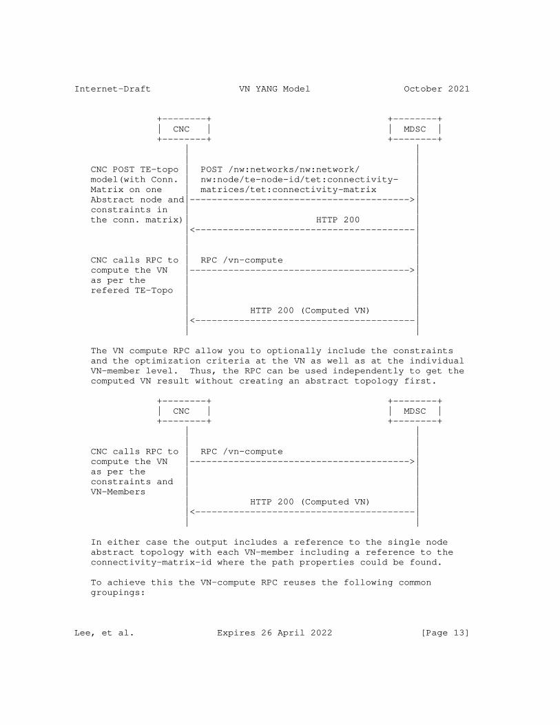
Internet-Draft VN YANG Model October 2021
+--------+ +--------+ | CNC | | MDSC | +--------+ +--------+ | | | | CNC POST TE-topo | POST /nw:networks/nw:network/ | model(with Conn. | nw:node/te-node-id/tet:connectivity- | Matrix on one | matrices/tet:connectivity-matrix | Abstract node and|---------------------------------------->| constraints in | | the conn. matrix)| HTTP 200 | |<----------------------------------------| | | | | CNC calls RPC to | RPC /vn-compute | compute the VN |---------------------------------------->| as per the | | refered TE-Topo | | | | | HTTP 200 (Computed VN) | |<----------------------------------------| | |
The VN compute RPC allow you to optionally include the constraints and the optimization criteria at the VN as well as at the individual VN-member level. Thus, the RPC can be used independently to get the computed VN result without creating an abstract topology first.
+--------+ +--------+ | CNC | | MDSC | +--------+ +--------+ | | | | CNC calls RPC to | RPC /vn-compute | compute the VN |---------------------------------------->| as per the | | constraints and | | VN-Members | | | HTTP 200 (Computed VN) | |<----------------------------------------| | |
In either case the output includes a reference to the single node abstract topology with each VN-member including a reference to the connectivity-matrix-id where the path properties could be found.
To achieve this the VN-compute RPC reuses the following common groupings:
Lee, et al. Expires 26 April 2022 [Page 13]
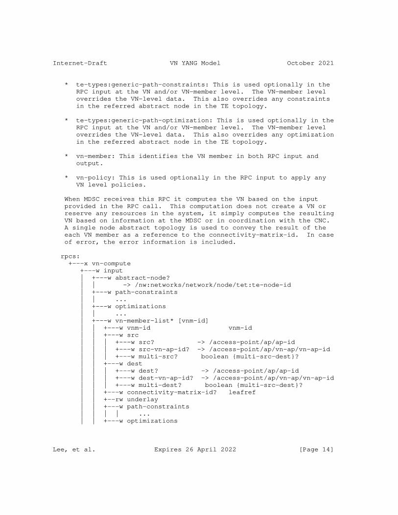
Internet-Draft VN YANG Model October 2021
* te-types:generic-path-constraints: This is used optionally in the RPC input at the VN and/or VN-member level. The VN-member level overrides the VN-level data. This also overrides any constraints in the referred abstract node in the TE topology.
* te-types:generic-path-optimization: This is used optionally in the RPC input at the VN and/or VN-member level. The VN-member level overrides the VN-level data. This also overrides any optimization in the referred abstract node in the TE topology.
* vn-member: This identifies the VN member in both RPC input and output.
* vn-policy: This is used optionally in the RPC input to apply any VN level policies.
When MDSC receives this RPC it computes the VN based on the input provided in the RPC call. This computation does not create a VN or reserve any resources in the system, it simply computes the resulting VN based on information at the MDSC or in coordination with the CNC. A single node abstract topology is used to convey the result of the each VN member as a reference to the connectivity-matrix-id. In case of error, the error information is included.
rpcs: +---x vn-compute +---w input | +---w abstract-node? | | -> /nw:networks/network/node/tet:te-node-id | +---w path-constraints | | ... | +---w optimizations | | ... | +---w vn-member-list* [vnm-id] | | +---w vnm-id vnm-id | | +---w src | | | +---w src? -> /access-point/ap/ap-id | | | +---w src-vn-ap-id? -> /access-point/ap/vn-ap/vn-ap-id | | | +---w multi-src? boolean {multi-src-dest}? | | +---w dest | | | +---w dest? -> /access-point/ap/ap-id | | | +---w dest-vn-ap-id? -> /access-point/ap/vn-ap/vn-ap-id | | | +---w multi-dest? boolean {multi-src-dest}? | | +---w connectivity-matrix-id? leafref | | +--rw underlay | | +---w path-constraints | | | | ... | | +---w optimizations
Lee, et al. Expires 26 April 2022 [Page 14]
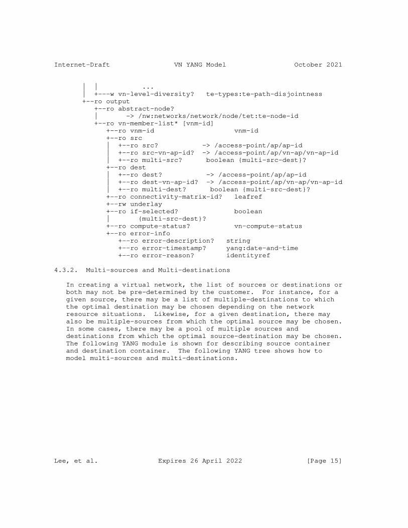
Internet-Draft VN YANG Model October 2021
| | ... | +---w vn-level-diversity? te-types:te-path-disjointness +--ro output +--ro abstract-node? | -> /nw:networks/network/node/tet:te-node-id +--ro vn-member-list* [vnm-id] +--ro vnm-id vnm-id +--ro src | +--ro src? -> /access-point/ap/ap-id | +--ro src-vn-ap-id? -> /access-point/ap/vn-ap/vn-ap-id | +--ro multi-src? boolean {multi-src-dest}? +--ro dest | +--ro dest? -> /access-point/ap/ap-id | +--ro dest-vn-ap-id? -> /access-point/ap/vn-ap/vn-ap-id | +--ro multi-dest? boolean {multi-src-dest}? +--ro connectivity-matrix-id? leafref +--rw underlay +--ro if-selected? boolean | {multi-src-dest}? +--ro compute-status? vn-compute-status +--ro error-info +--ro error-description? string +--ro error-timestamp? yang:date-and-time +--ro error-reason? identityref
4.3.2. Multi-sources and Multi-destinations
In creating a virtual network, the list of sources or destinations or both may not be pre-determined by the customer. For instance, for a given source, there may be a list of multiple-destinations to which the optimal destination may be chosen depending on the network resource situations. Likewise, for a given destination, there may also be multiple-sources from which the optimal source may be chosen. In some cases, there may be a pool of multiple sources and destinations from which the optimal source-destination may be chosen. The following YANG module is shown for describing source container and destination container. The following YANG tree shows how to model multi-sources and multi-destinations.
Lee, et al. Expires 26 April 2022 [Page 15]

Internet-Draft VN YANG Model October 2021
+--rw virtual-network +--rw vn* [vn-id] +--rw vn-id vn-id +--rw vn-topology-id? te-types:te-topology-id +--rw abstract-node? | -> /nw:networks/network/node/tet:te-node-id +--rw vn-member* [vnm-id] | +--rw vnm-id vnm-id | +--rw src | | +--rw src? -> /access-point/ap/ap-id | | +--rw src-vn-ap-id? -> /access-point/ap/vn-ap/vn-ap-id | | +--rw multi-src? boolean {multi-src-dest}? | +--rw dest | | +--rw dest? -> /access-point/ap/ap-id | | +--rw dest-vn-ap-id? -> /access-point/ap/vn-ap/vn-ap-id | | +--rw multi-dest? boolean {multi-src-dest}? | +--rw connectivity-matrix-id? leafref | +--rw underlay | +--ro oper-status? te-types:te-oper-status +--ro if-selected? boolean {multi-src-dest}? +--rw admin-status? te-types:te-admin-status +--ro oper-status? te-types:te-oper-status +--rw vn-level-diversity? te-types:te-path-disjointness
4.3.3. Others
The VN YANG model can be easily augmented to support the mapping of VN to the Services such as L3SM and L2SM as described in [I-D.ietf-teas-te-service-mapping-yang].
The VN YANG model can be extended to support telemetry, performance monitoring and network autonomics as described in [I-D.ietf-teas-actn-pm-telemetry-autonomics].
Note that the YANG model is tightly coupled with the TE Topology model [RFC8795]. Any underlay technology not supported by [RFC8795] is also not supported by this model. The model does include an empty container called "underlay" that can be augmented. For example the SR-policy information can be augmented for the SR underlay by a future model.
4.3.4. Summary
This section summarizes the innovative service features of the VN YANG.
* Maintenance of AP and VNAP along with VN
Lee, et al. Expires 26 April 2022 [Page 16]
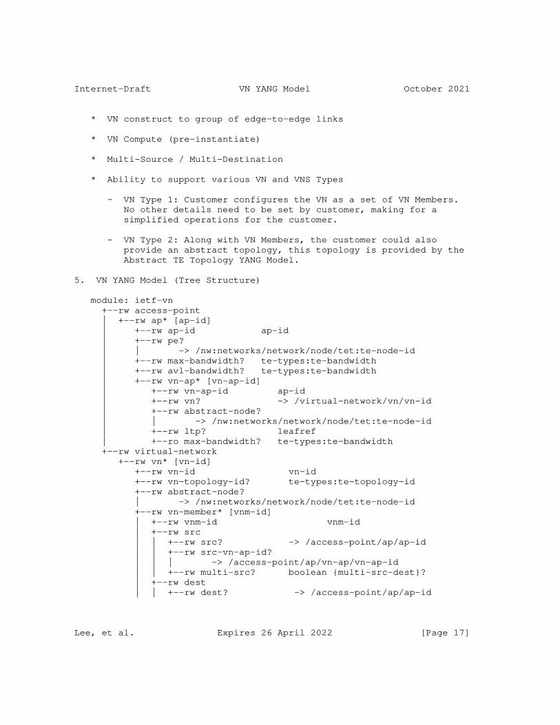
Internet-Draft VN YANG Model October 2021
* VN construct to group of edge-to-edge links
* VN Compute (pre-instantiate)
* Multi-Source / Multi-Destination
* Ability to support various VN and VNS Types
- VN Type 1: Customer configures the VN as a set of VN Members. No other details need to be set by customer, making for a simplified operations for the customer.
- VN Type 2: Along with VN Members, the customer could also provide an abstract topology, this topology is provided by the Abstract TE Topology YANG Model.
5. VN YANG Model (Tree Structure)
module: ietf-vn +--rw access-point | +--rw ap* [ap-id] | +--rw ap-id ap-id | +--rw pe? | | -> /nw:networks/network/node/tet:te-node-id | +--rw max-bandwidth? te-types:te-bandwidth | +--rw avl-bandwidth? te-types:te-bandwidth | +--rw vn-ap* [vn-ap-id] | +--rw vn-ap-id ap-id | +--rw vn? -> /virtual-network/vn/vn-id | +--rw abstract-node? | | -> /nw:networks/network/node/tet:te-node-id | +--rw ltp? leafref | +--ro max-bandwidth? te-types:te-bandwidth +--rw virtual-network +--rw vn* [vn-id] +--rw vn-id vn-id +--rw vn-topology-id? te-types:te-topology-id +--rw abstract-node? | -> /nw:networks/network/node/tet:te-node-id +--rw vn-member* [vnm-id] | +--rw vnm-id vnm-id | +--rw src | | +--rw src? -> /access-point/ap/ap-id | | +--rw src-vn-ap-id? | | | -> /access-point/ap/vn-ap/vn-ap-id | | +--rw multi-src? boolean {multi-src-dest}? | +--rw dest | | +--rw dest? -> /access-point/ap/ap-id
Lee, et al. Expires 26 April 2022 [Page 17]
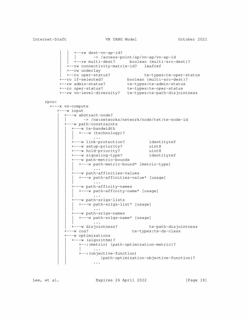
Internet-Draft VN YANG Model October 2021
| | +--rw dest-vn-ap-id? | | | -> /access-point/ap/vn-ap/vn-ap-id | | +--rw multi-dest? boolean {multi-src-dest}? | +--rw connectivity-matrix-id? leafref | +--rw underlay | +--ro oper-status? te-types:te-oper-status +--ro if-selected? boolean {multi-src-dest}? +--rw admin-status? te-types:te-admin-status +--ro oper-status? te-types:te-oper-status +--rw vn-level-diversity? te-types:te-path-disjointness
rpcs: +---x vn-compute +---w input | +---w abstract-node? | | -> /nw:networks/network/node/tet:te-node-id | +---w path-constraints | | +---w te-bandwidth | | | +---w (technology)? | | | ... | | +---w link-protection? identityref | | +---w setup-priority? uint8 | | +---w hold-priority? uint8 | | +---w signaling-type? identityref | | +---w path-metric-bounds | | | +---w path-metric-bound* [metric-type] | | | ... | | +---w path-affinities-values | | | +---w path-affinities-value* [usage] | | | ... | | +---w path-affinity-names | | | +---w path-affinity-name* [usage] | | | ... | | +---w path-srlgs-lists | | | +---w path-srlgs-list* [usage] | | | ... | | +---w path-srlgs-names | | | +---w path-srlgs-name* [usage] | | | ... | | +---w disjointness? te-path-disjointness | +---w cos? te-types:te-ds-class | +---w optimizations | | +---w (algorithm)? | | +--:(metric) {path-optimization-metric}? | | | ... | | +--:(objective-function) | | {path-optimization-objective-function}? | | ...
Lee, et al. Expires 26 April 2022 [Page 18]
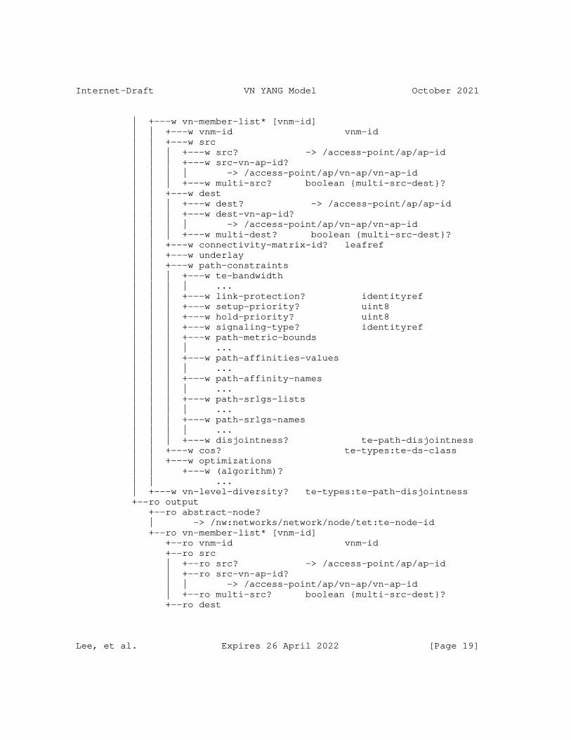
Internet-Draft VN YANG Model October 2021
| +---w vn-member-list* [vnm-id] | | +---w vnm-id vnm-id | | +---w src | | | +---w src? -> /access-point/ap/ap-id | | | +---w src-vn-ap-id? | | | | -> /access-point/ap/vn-ap/vn-ap-id | | | +---w multi-src? boolean {multi-src-dest}? | | +---w dest | | | +---w dest? -> /access-point/ap/ap-id | | | +---w dest-vn-ap-id? | | | | -> /access-point/ap/vn-ap/vn-ap-id | | | +---w multi-dest? boolean {multi-src-dest}? | | +---w connectivity-matrix-id? leafref | | +---w underlay | | +---w path-constraints | | | +---w te-bandwidth | | | | ... | | | +---w link-protection? identityref | | | +---w setup-priority? uint8 | | | +---w hold-priority? uint8 | | | +---w signaling-type? identityref | | | +---w path-metric-bounds | | | | ... | | | +---w path-affinities-values | | | | ... | | | +---w path-affinity-names | | | | ... | | | +---w path-srlgs-lists | | | | ... | | | +---w path-srlgs-names | | | | ... | | | +---w disjointness? te-path-disjointness | | +---w cos? te-types:te-ds-class | | +---w optimizations | | +---w (algorithm)? | | ... | +---w vn-level-diversity? te-types:te-path-disjointness +--ro output +--ro abstract-node? | -> /nw:networks/network/node/tet:te-node-id +--ro vn-member-list* [vnm-id] +--ro vnm-id vnm-id +--ro src | +--ro src? -> /access-point/ap/ap-id | +--ro src-vn-ap-id? | | -> /access-point/ap/vn-ap/vn-ap-id | +--ro multi-src? boolean {multi-src-dest}? +--ro dest
Lee, et al. Expires 26 April 2022 [Page 19]
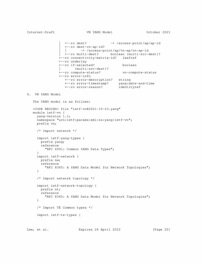
Internet-Draft VN YANG Model October 2021
| +--ro dest? -> /access-point/ap/ap-id | +--ro dest-vn-ap-id? | | -> /access-point/ap/vn-ap/vn-ap-id | +--ro multi-dest? boolean {multi-src-dest}? +--ro connectivity-matrix-id? leafref +--ro underlay +--ro if-selected? boolean | {multi-src-dest}? +--ro compute-status? vn-compute-status +--ro error-info +--ro error-description? string +--ro error-timestamp? yang:date-and-time +--ro error-reason? identityref
6. VN YANG Model
The YANG model is as follows:
<CODE BEGINS> file "[email protected]" module ietf-vn { yang-version 1.1; namespace "urn:ietf:params:xml:ns:yang:ietf-vn"; prefix vn;
/* Import network */
import ietf-yang-types { prefix yang; reference "RFC 6991: Common YANG Data Types"; } import ietf-network { prefix nw; reference "RFC 8345: A YANG Data Model for Network Topologies"; }
/* Import network topology */
import ietf-network-topology { prefix nt; reference "RFC 8345: A YANG Data Model for Network Topologies"; }
/* Import TE Common types */
import ietf-te-types {
Lee, et al. Expires 26 April 2022 [Page 20]

Internet-Draft VN YANG Model October 2021
prefix te-types; reference "RFC 8776: Common YANG Data Types for Traffic Engineering"; }
/* Import TE Topology */
import ietf-te-topology { prefix tet; reference "RFC 8795: YANG Data Model for Traffic Engineering (TE) Topologies"; }
organization "IETF Traffic Engineering Architecture and Signaling (TEAS) Working Group"; contact "WG Web: <https://tools.ietf.org/wg/teas/> WG List: <mailto:[email protected]> Editor: Young Lee <[email protected]> : Dhruv Dhody <[email protected]>"; description "This module contains a YANG module for the VN. It describes a VN operation module that takes place in the context of the CNC-MDSC Interface (CMI) of the ACTN architecture where the CNC is the actor of a VN Instantiation/modification/deletion as per RFC 8453.
Copyright (c) 2021 IETF Trust and the persons identified as authors of the code. All rights reserved.
Redistribution and use in source and binary forms, with or without modification, is permitted pursuant to, and subject to the license terms contained in, the Simplified BSD License set forth in Section 4.c of the IETF Trust’s Legal Provisions Relating to IETF Documents (https://trustee.ietf.org/license-info).
This version of this YANG module is part of RFC XXXX; see the RFC itself for full legal notices.
The key words ’MUST’, ’MUST NOT’, ’REQUIRED’, ’SHALL’, ’SHALL NOT’, ’SHOULD’, ’SHOULD NOT’, ’RECOMMENDED’, ’NOT RECOMMENDED’, ’MAY’, and ’OPTIONAL’ in this document are to be interpreted as described in BCP 14 (RFC 2119) (RFC 8174) when, and only when, they appear in all capitals, as shown here.";
Lee, et al. Expires 26 April 2022 [Page 21]
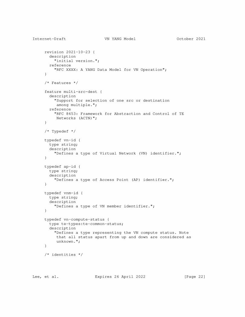
Internet-Draft VN YANG Model October 2021
revision 2021-10-23 { description "initial version."; reference "RFC XXXX: A YANG Data Model for VN Operation"; }
/* Features */
feature multi-src-dest { description "Support for selection of one src or destination among multiple."; reference "RFC 8453: Framework for Abstraction and Control of TE Networks (ACTN)"; }
/* Typedef */
typedef vn-id { type string; description "Defines a type of Virtual Network (VN) identifier."; }
typedef ap-id { type string; description "Defines a type of Access Point (AP) identifier."; }
typedef vnm-id { type string; description "Defines a type of VN member identifier."; }
typedef vn-compute-status { type te-types:te-common-status; description "Defines a type representing the VN compute status. Note that all status apart from up and down are considered as unknown."; }
/* identities */
Lee, et al. Expires 26 April 2022 [Page 22]
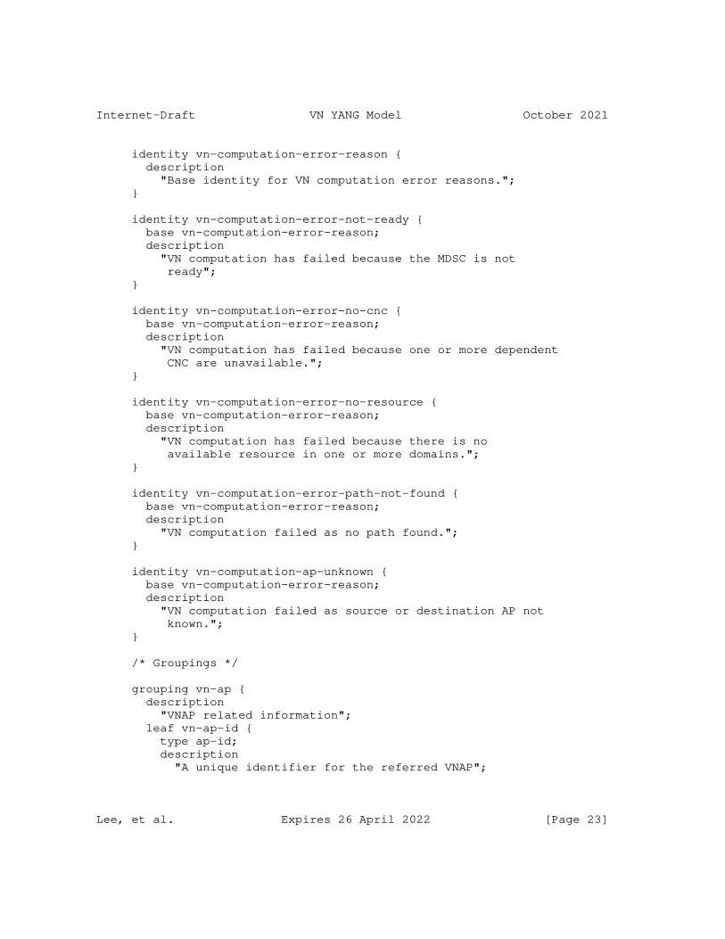
Internet-Draft VN YANG Model October 2021
identity vn-computation-error-reason { description "Base identity for VN computation error reasons."; }
identity vn-computation-error-not-ready { base vn-computation-error-reason; description "VN computation has failed because the MDSC is not ready"; }
identity vn-computation-error-no-cnc { base vn-computation-error-reason; description "VN computation has failed because one or more dependent CNC are unavailable."; }
identity vn-computation-error-no-resource { base vn-computation-error-reason; description "VN computation has failed because there is no available resource in one or more domains."; }
identity vn-computation-error-path-not-found { base vn-computation-error-reason; description "VN computation failed as no path found."; }
identity vn-computation-ap-unknown { base vn-computation-error-reason; description "VN computation failed as source or destination AP not known."; }
/* Groupings */
grouping vn-ap { description "VNAP related information"; leaf vn-ap-id { type ap-id; description "A unique identifier for the referred VNAP";
Lee, et al. Expires 26 April 2022 [Page 23]
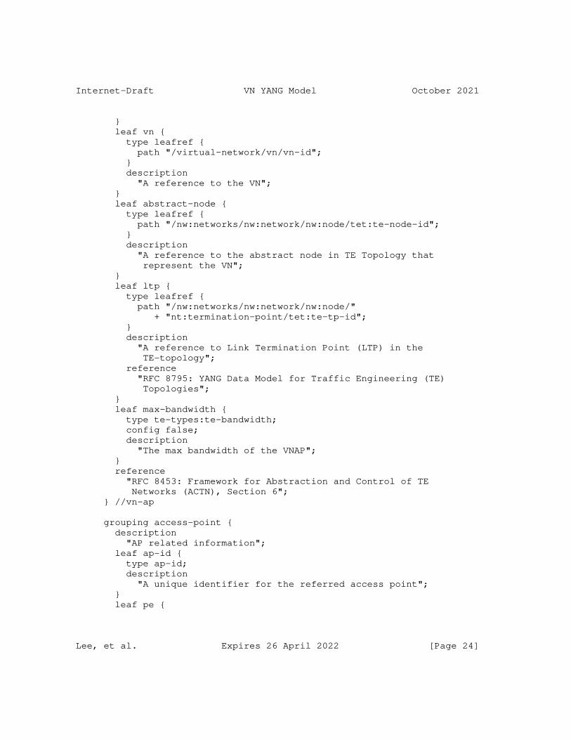
Internet-Draft VN YANG Model October 2021
} leaf vn { type leafref { path "/virtual-network/vn/vn-id"; } description "A reference to the VN"; } leaf abstract-node { type leafref { path "/nw:networks/nw:network/nw:node/tet:te-node-id"; } description "A reference to the abstract node in TE Topology that represent the VN"; } leaf ltp { type leafref { path "/nw:networks/nw:network/nw:node/" + "nt:termination-point/tet:te-tp-id"; } description "A reference to Link Termination Point (LTP) in the TE-topology"; reference "RFC 8795: YANG Data Model for Traffic Engineering (TE) Topologies"; } leaf max-bandwidth { type te-types:te-bandwidth; config false; description "The max bandwidth of the VNAP"; } reference "RFC 8453: Framework for Abstraction and Control of TE Networks (ACTN), Section 6"; } //vn-ap
grouping access-point { description "AP related information"; leaf ap-id { type ap-id; description "A unique identifier for the referred access point"; } leaf pe {
Lee, et al. Expires 26 April 2022 [Page 24]
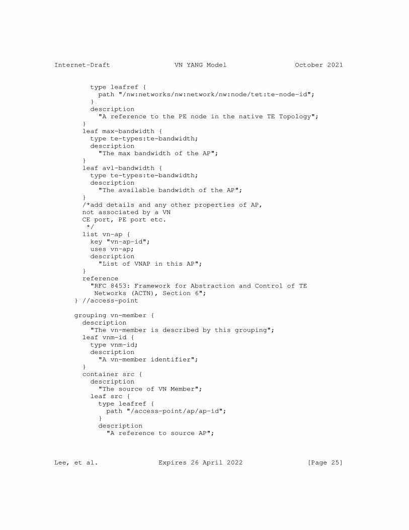
Internet-Draft VN YANG Model October 2021
type leafref { path "/nw:networks/nw:network/nw:node/tet:te-node-id"; } description "A reference to the PE node in the native TE Topology"; } leaf max-bandwidth { type te-types:te-bandwidth; description "The max bandwidth of the AP"; } leaf avl-bandwidth { type te-types:te-bandwidth; description "The available bandwidth of the AP"; } /*add details and any other properties of AP, not associated by a VN CE port, PE port etc. */ list vn-ap { key "vn-ap-id"; uses vn-ap; description "List of VNAP in this AP"; } reference "RFC 8453: Framework for Abstraction and Control of TE Networks (ACTN), Section 6"; } //access-point
grouping vn-member { description "The vn-member is described by this grouping"; leaf vnm-id { type vnm-id; description "A vn-member identifier"; } container src { description "The source of VN Member"; leaf src { type leafref { path "/access-point/ap/ap-id"; } description "A reference to source AP";
Lee, et al. Expires 26 April 2022 [Page 25]
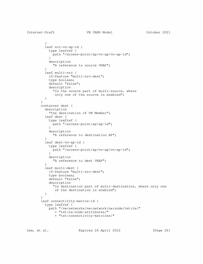
Internet-Draft VN YANG Model October 2021
} leaf src-vn-ap-id { type leafref { path "/access-point/ap/vn-ap/vn-ap-id"; } description "A reference to source VNAP"; } leaf multi-src { if-feature "multi-src-dest"; type boolean; default "false"; description "Is the source part of multi-source, where only one of the source is enabled"; } } container dest { description "the destination of VN Member"; leaf dest { type leafref { path "/access-point/ap/ap-id"; } description "A reference to destination AP"; } leaf dest-vn-ap-id { type leafref { path "/access-point/ap/vn-ap/vn-ap-id"; } description "A reference to dest VNAP"; } leaf multi-dest { if-feature "multi-src-dest"; type boolean; default "false"; description "Is destination part of multi-destination, where only one of the destination is enabled"; } } leaf connectivity-matrix-id { type leafref { path "/nw:networks/nw:network/nw:node/tet:te/" + "tet:te-node-attributes/" + "tet:connectivity-matrices/"
Lee, et al. Expires 26 April 2022 [Page 26]
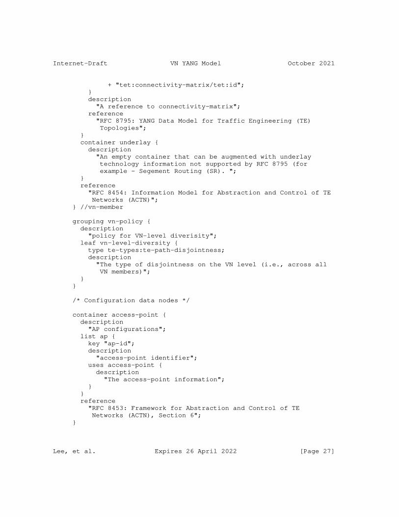
Internet-Draft VN YANG Model October 2021
+ "tet:connectivity-matrix/tet:id"; } description "A reference to connectivity-matrix"; reference "RFC 8795: YANG Data Model for Traffic Engineering (TE) Topologies"; } container underlay { description "An empty container that can be augmented with underlay technology information not supported by RFC 8795 (for example - Segement Routing (SR). "; } reference "RFC 8454: Information Model for Abstraction and Control of TE Networks (ACTN)"; } //vn-member
grouping vn-policy { description "policy for VN-level diverisity"; leaf vn-level-diversity { type te-types:te-path-disjointness; description "The type of disjointness on the VN level (i.e., across all VN members)"; } }
/* Configuration data nodes */
container access-point { description "AP configurations"; list ap { key "ap-id"; description "access-point identifier"; uses access-point { description "The access-point information"; } } reference "RFC 8453: Framework for Abstraction and Control of TE Networks (ACTN), Section 6"; }
Lee, et al. Expires 26 April 2022 [Page 27]
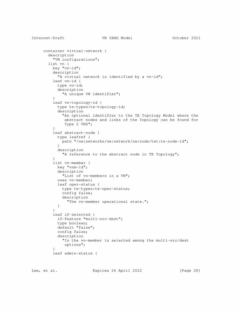
Internet-Draft VN YANG Model October 2021
container virtual-network { description "VN configurations"; list vn { key "vn-id"; description "A virtual network is identified by a vn-id"; leaf vn-id { type vn-id; description "A unique VN identifier"; } leaf vn-topology-id { type te-types:te-topology-id; description "An optional identifier to the TE Topology Model where the abstract nodes and links of the Topology can be found for Type 2 VNS"; } leaf abstract-node { type leafref { path "/nw:networks/nw:network/nw:node/tet:te-node-id"; } description "A reference to the abstract node in TE Topology"; } list vn-member { key "vnm-id"; description "List of vn-members in a VN"; uses vn-member; leaf oper-status { type te-types:te-oper-status; config false; description "The vn-member operational state."; } } leaf if-selected { if-feature "multi-src-dest"; type boolean; default "false"; config false; description "Is the vn-member is selected among the multi-src/dest options"; } leaf admin-status {
Lee, et al. Expires 26 April 2022 [Page 28]
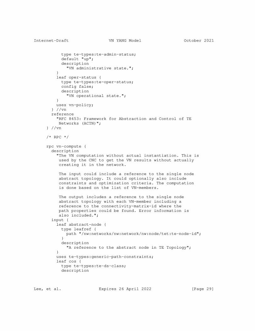
Internet-Draft VN YANG Model October 2021
type te-types:te-admin-status; default "up"; description "VN administrative state."; } leaf oper-status { type te-types:te-oper-status; config false; description "VN operational state."; } uses vn-policy; } //vn reference "RFC 8453: Framework for Abstraction and Control of TE Networks (ACTN)"; } //vn
/* RPC */
rpc vn-compute { description "The VN computation without actual instantiation. This is used by the CNC to get the VN results without actually creating it in the network.
The input could include a reference to the single node abstract topology. It could optionally also include constraints and optimization criteria. The computation is done based on the list of VN-members.
The output includes a reference to the single node abstract topology with each VN-member including a reference to the connectivity-matrix-id where the path properties could be found. Error information is also included."; input { leaf abstract-node { type leafref { path "/nw:networks/nw:network/nw:node/tet:te-node-id"; } description "A reference to the abstract node in TE Topology"; } uses te-types:generic-path-constraints; leaf cos { type te-types:te-ds-class; description
Lee, et al. Expires 26 April 2022 [Page 29]
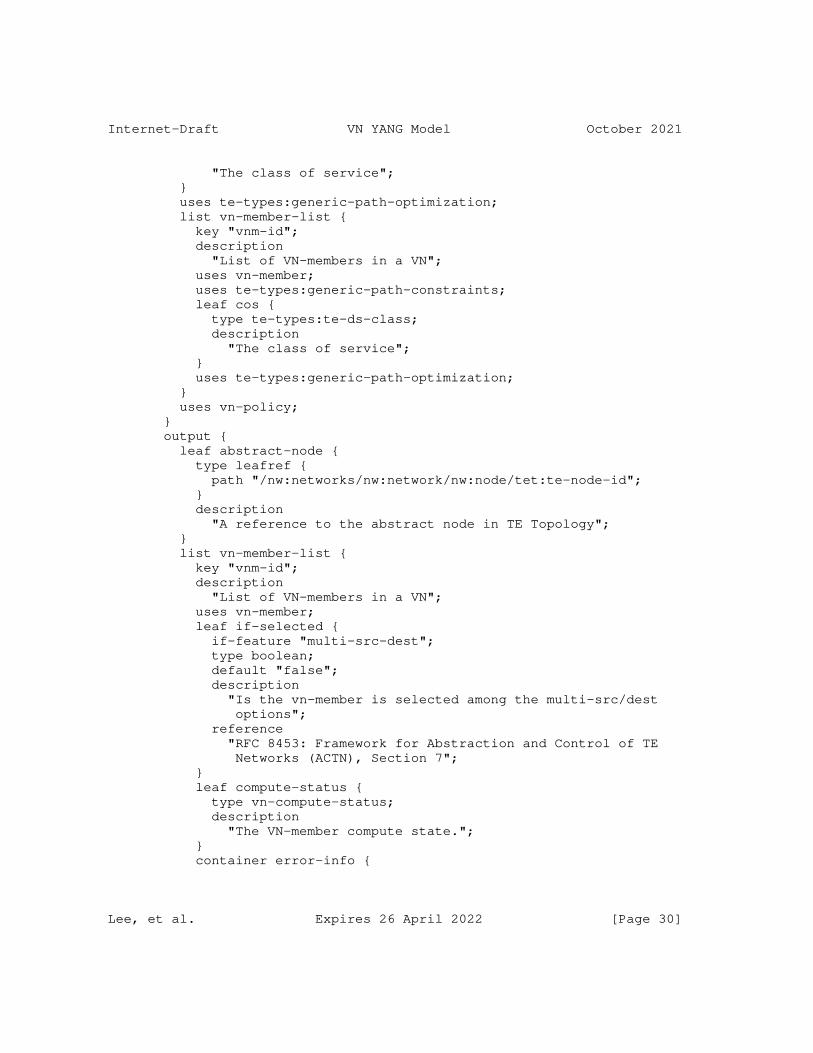
Internet-Draft VN YANG Model October 2021
"The class of service"; } uses te-types:generic-path-optimization; list vn-member-list { key "vnm-id"; description "List of VN-members in a VN"; uses vn-member; uses te-types:generic-path-constraints; leaf cos { type te-types:te-ds-class; description "The class of service"; } uses te-types:generic-path-optimization; } uses vn-policy; } output { leaf abstract-node { type leafref { path "/nw:networks/nw:network/nw:node/tet:te-node-id"; } description "A reference to the abstract node in TE Topology"; } list vn-member-list { key "vnm-id"; description "List of VN-members in a VN"; uses vn-member; leaf if-selected { if-feature "multi-src-dest"; type boolean; default "false"; description "Is the vn-member is selected among the multi-src/dest options"; reference "RFC 8453: Framework for Abstraction and Control of TE Networks (ACTN), Section 7"; } leaf compute-status { type vn-compute-status; description "The VN-member compute state."; } container error-info {
Lee, et al. Expires 26 April 2022 [Page 30]
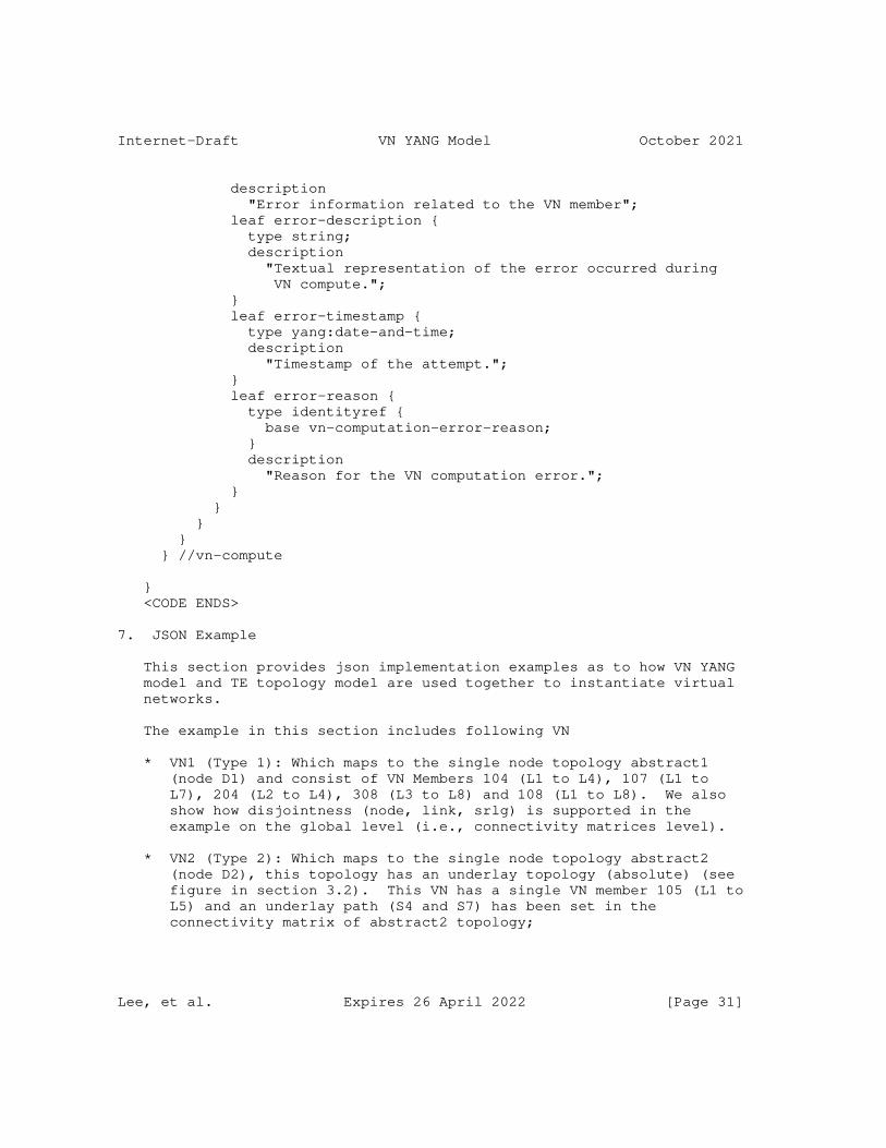
Internet-Draft VN YANG Model October 2021
description "Error information related to the VN member"; leaf error-description { type string; description "Textual representation of the error occurred during VN compute."; } leaf error-timestamp { type yang:date-and-time; description "Timestamp of the attempt."; } leaf error-reason { type identityref { base vn-computation-error-reason; } description "Reason for the VN computation error."; } } } } } //vn-compute
} <CODE ENDS>
7. JSON Example
This section provides json implementation examples as to how VN YANG model and TE topology model are used together to instantiate virtual networks.
The example in this section includes following VN
* VN1 (Type 1): Which maps to the single node topology abstract1 (node D1) and consist of VN Members 104 (L1 to L4), 107 (L1 to L7), 204 (L2 to L4), 308 (L3 to L8) and 108 (L1 to L8). We also show how disjointness (node, link, srlg) is supported in the example on the global level (i.e., connectivity matrices level).
* VN2 (Type 2): Which maps to the single node topology abstract2 (node D2), this topology has an underlay topology (absolute) (see figure in section 3.2). This VN has a single VN member 105 (L1 to L5) and an underlay path (S4 and S7) has been set in the connectivity matrix of abstract2 topology;
Lee, et al. Expires 26 April 2022 [Page 31]
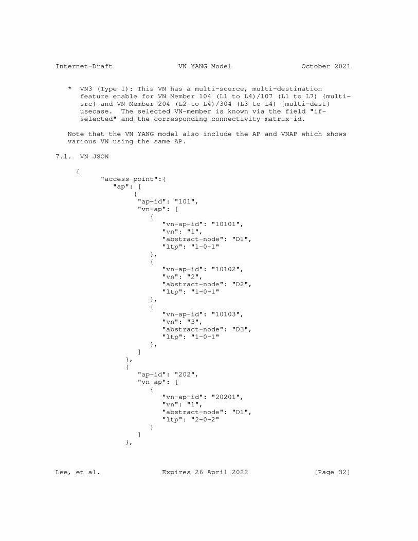
Internet-Draft VN YANG Model October 2021
* VN3 (Type 1): This VN has a multi-source, multi-destination feature enable for VN Member 104 (L1 to L4)/107 (L1 to L7) {multi- src} and VN Member 204 (L2 to L4)/304 (L3 to L4) {multi-dest} usecase. The selected VN-member is known via the field "if- selected" and the corresponding connectivity-matrix-id.
Note that the VN YANG model also include the AP and VNAP which shows various VN using the same AP.
7.1. VN JSON
{ "access-point":{ "ap": [ { "ap-id": "101", "vn-ap": [ { "vn-ap-id": "10101", "vn": "1", "abstract-node": "D1", "ltp": "1-0-1" }, { "vn-ap-id": "10102", "vn": "2", "abstract-node": "D2", "ltp": "1-0-1" }, { "vn-ap-id": "10103", "vn": "3", "abstract-node": "D3", "ltp": "1-0-1" }, ] }, { "ap-id": "202", "vn-ap": [ { "vn-ap-id": "20201", "vn": "1", "abstract-node": "D1", "ltp": "2-0-2" } ] },
Lee, et al. Expires 26 April 2022 [Page 32]
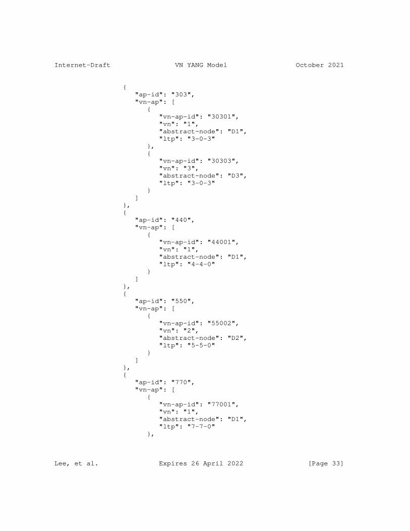
Internet-Draft VN YANG Model October 2021
{ "ap-id": "303", "vn-ap": [ { "vn-ap-id": "30301", "vn": "1", "abstract-node": "D1", "ltp": "3-0-3" }, { "vn-ap-id": "30303", "vn": "3", "abstract-node": "D3", "ltp": "3-0-3" } ] }, { "ap-id": "440", "vn-ap": [ { "vn-ap-id": "44001", "vn": "1", "abstract-node": "D1", "ltp": "4-4-0" } ] }, { "ap-id": "550", "vn-ap": [ { "vn-ap-id": "55002", "vn": "2", "abstract-node": "D2", "ltp": "5-5-0" } ] }, { "ap-id": "770", "vn-ap": [ { "vn-ap-id": "77001", "vn": "1", "abstract-node": "D1", "ltp": "7-7-0" },
Lee, et al. Expires 26 April 2022 [Page 33]
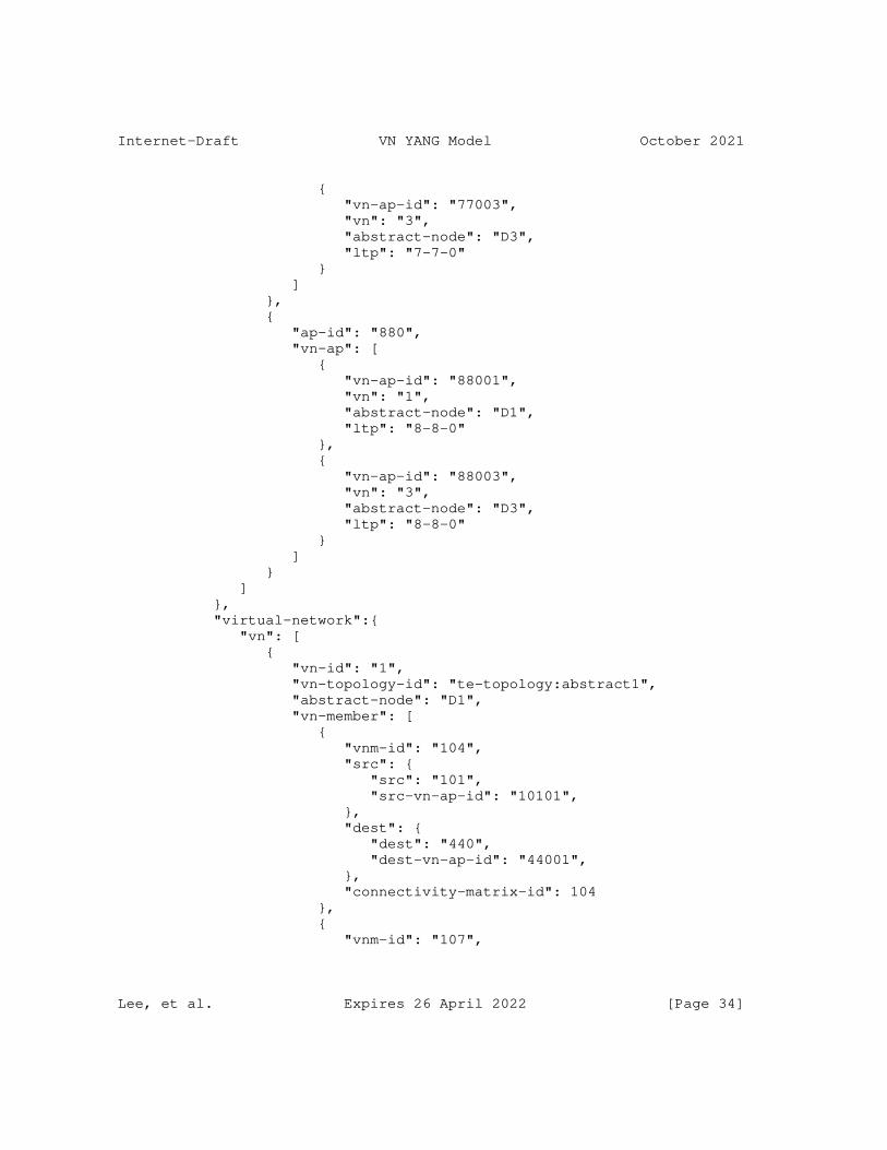
Internet-Draft VN YANG Model October 2021
{ "vn-ap-id": "77003", "vn": "3", "abstract-node": "D3", "ltp": "7-7-0" } ] }, { "ap-id": "880", "vn-ap": [ { "vn-ap-id": "88001", "vn": "1", "abstract-node": "D1", "ltp": "8-8-0" }, { "vn-ap-id": "88003", "vn": "3", "abstract-node": "D3", "ltp": "8-8-0" } ] } ] }, "virtual-network":{ "vn": [ { "vn-id": "1", "vn-topology-id": "te-topology:abstract1", "abstract-node": "D1", "vn-member": [ { "vnm-id": "104", "src": { "src": "101", "src-vn-ap-id": "10101", }, "dest": { "dest": "440", "dest-vn-ap-id": "44001", }, "connectivity-matrix-id": 104 }, { "vnm-id": "107",
Lee, et al. Expires 26 April 2022 [Page 34]
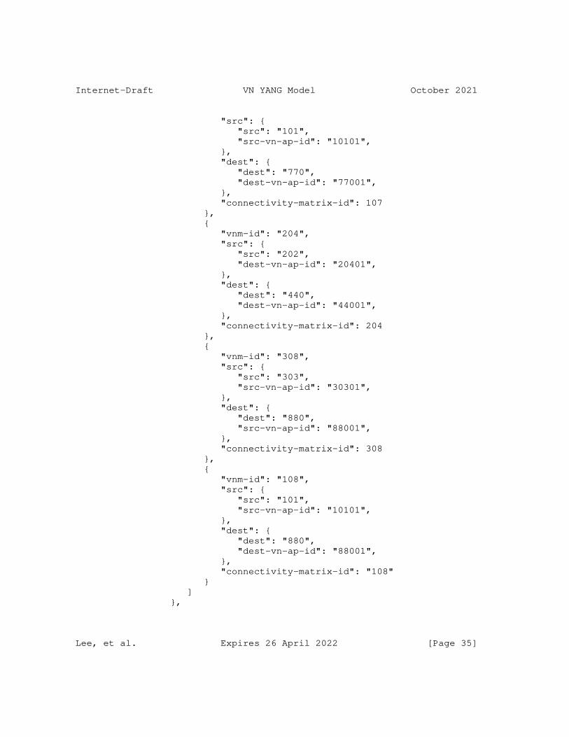
Internet-Draft VN YANG Model October 2021
"src": { "src": "101", "src-vn-ap-id": "10101", }, "dest": { "dest": "770", "dest-vn-ap-id": "77001", }, "connectivity-matrix-id": 107 }, { "vnm-id": "204", "src": { "src": "202", "dest-vn-ap-id": "20401", }, "dest": { "dest": "440", "dest-vn-ap-id": "44001", }, "connectivity-matrix-id": 204 }, { "vnm-id": "308", "src": { "src": "303", "src-vn-ap-id": "30301", }, "dest": { "dest": "880", "src-vn-ap-id": "88001", }, "connectivity-matrix-id": 308 }, { "vnm-id": "108", "src": { "src": "101", "src-vn-ap-id": "10101", }, "dest": { "dest": "880", "dest-vn-ap-id": "88001", }, "connectivity-matrix-id": "108" } ] },
Lee, et al. Expires 26 April 2022 [Page 35]
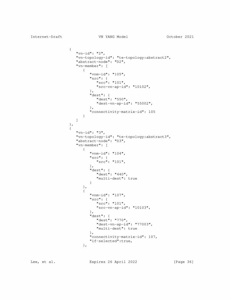
Internet-Draft VN YANG Model October 2021
{ "vn-id": "2", "vn-topology-id": "te-topology:abstract2", "abstract-node": "D2", "vn-member": [ { "vnm-id": "105", "src": { "src": "101", "src-vn-ap-id": "10102", }, "dest": { "dest": "550", "dest-vn-ap-id": "55002", }, "connectivity-matrix-id": 105 } ] }, { "vn-id": "3", "vn-topology-id": "te-topology:abstract3", "abstract-node": "D3", "vn-member": [ { "vnm-id": "104", "src": { "src": "101", }, "dest": { "dest": "440", "multi-dest": true } }, { "vnm-id": "107", "src": { "src": "101", "src-vn-ap-id": "10103", }, "dest": { "dest": "770", "dest-vn-ap-id": "77003", "multi-dest": true }, "connectivity-matrix-id": 107, "if-selected":true, },
Lee, et al. Expires 26 April 2022 [Page 36]
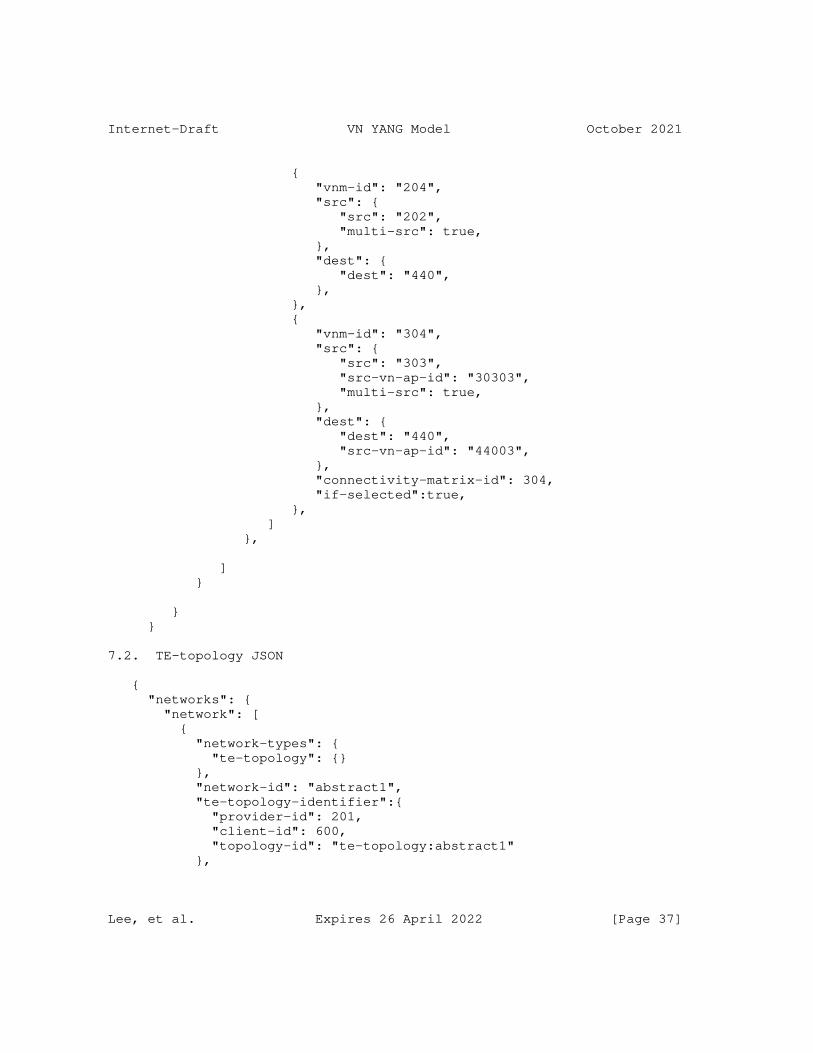
Internet-Draft VN YANG Model October 2021
{ "vnm-id": "204", "src": { "src": "202", "multi-src": true, }, "dest": { "dest": "440", }, }, { "vnm-id": "304", "src": { "src": "303", "src-vn-ap-id": "30303", "multi-src": true, }, "dest": { "dest": "440", "src-vn-ap-id": "44003", }, "connectivity-matrix-id": 304, "if-selected":true, }, ] },
] }
} }
7.2. TE-topology JSON
{ "networks": { "network": [ { "network-types": { "te-topology": {} }, "network-id": "abstract1", "te-topology-identifier":{ "provider-id": 201, "client-id": 600, "topology-id": "te-topology:abstract1" },
Lee, et al. Expires 26 April 2022 [Page 37]
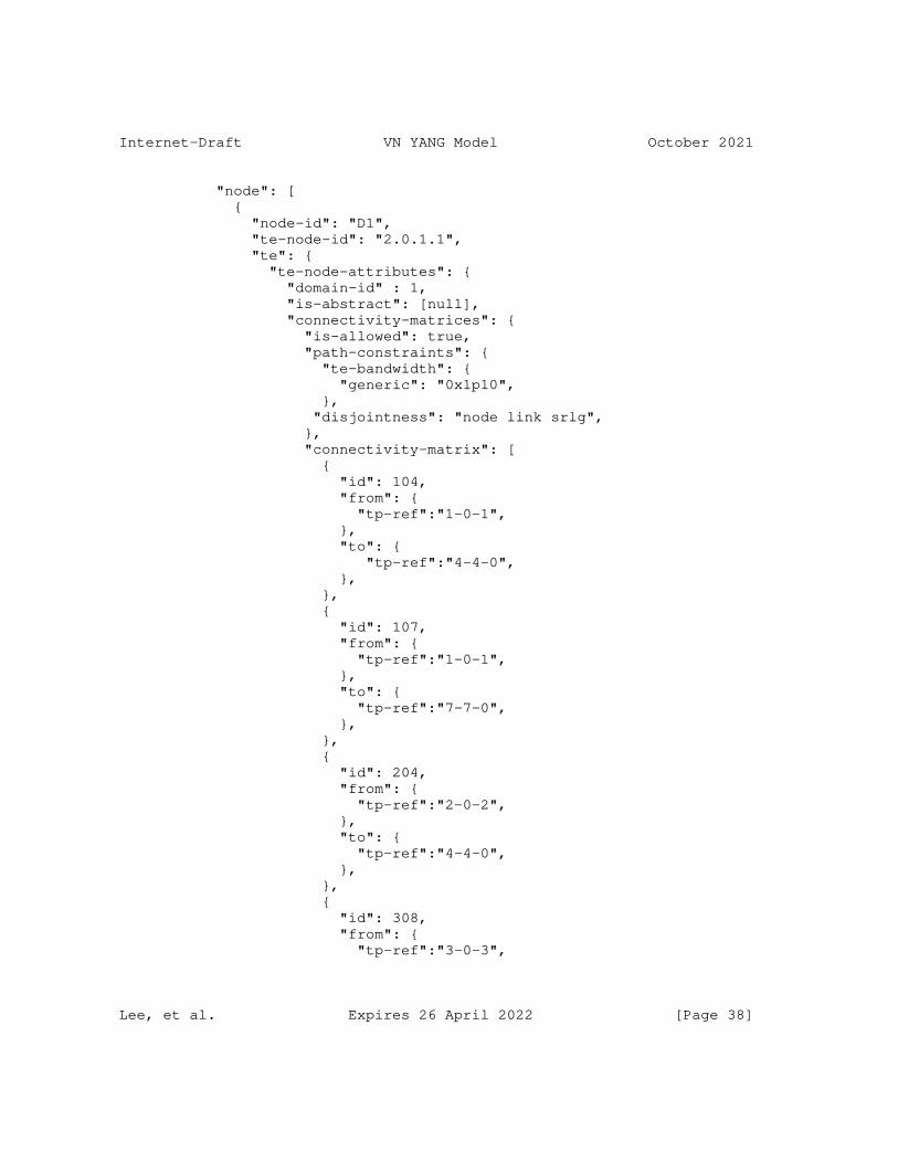
Internet-Draft VN YANG Model October 2021
"node": [ { "node-id": "D1", "te-node-id": "2.0.1.1", "te": { "te-node-attributes": { "domain-id" : 1, "is-abstract": [null], "connectivity-matrices": { "is-allowed": true, "path-constraints": { "te-bandwidth": { "generic": "0x1p10", }, "disjointness": "node link srlg", }, "connectivity-matrix": [ { "id": 104, "from": { "tp-ref":"1-0-1", }, "to": { "tp-ref":"4-4-0", }, }, { "id": 107, "from": { "tp-ref":"1-0-1", }, "to": { "tp-ref":"7-7-0", }, }, { "id": 204, "from": { "tp-ref":"2-0-2", }, "to": { "tp-ref":"4-4-0", }, }, { "id": 308, "from": { "tp-ref":"3-0-3",
Lee, et al. Expires 26 April 2022 [Page 38]
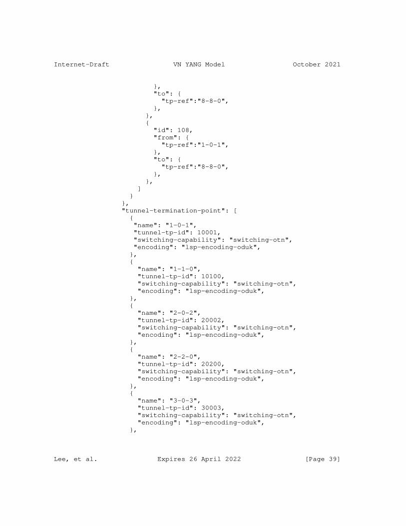
Internet-Draft VN YANG Model October 2021
}, "to": { "tp-ref":"8-8-0", }, }, { "id": 108, "from": { "tp-ref":"1-0-1", }, "to": { "tp-ref":"8-8-0", }, }, ] } }, "tunnel-termination-point": [ { "name": "1-0-1", "tunnel-tp-id": 10001, "switching-capability": "switching-otn", "encoding": "lsp-encoding-oduk", }, { "name": "1-1-0", "tunnel-tp-id": 10100, "switching-capability": "switching-otn", "encoding": "lsp-encoding-oduk", }, { "name": "2-0-2", "tunnel-tp-id": 20002, "switching-capability": "switching-otn", "encoding": "lsp-encoding-oduk", }, { "name": "2-2-0", "tunnel-tp-id": 20200, "switching-capability": "switching-otn", "encoding": "lsp-encoding-oduk", }, { "name": "3-0-3", "tunnel-tp-id": 30003, "switching-capability": "switching-otn", "encoding": "lsp-encoding-oduk", },
Lee, et al. Expires 26 April 2022 [Page 39]
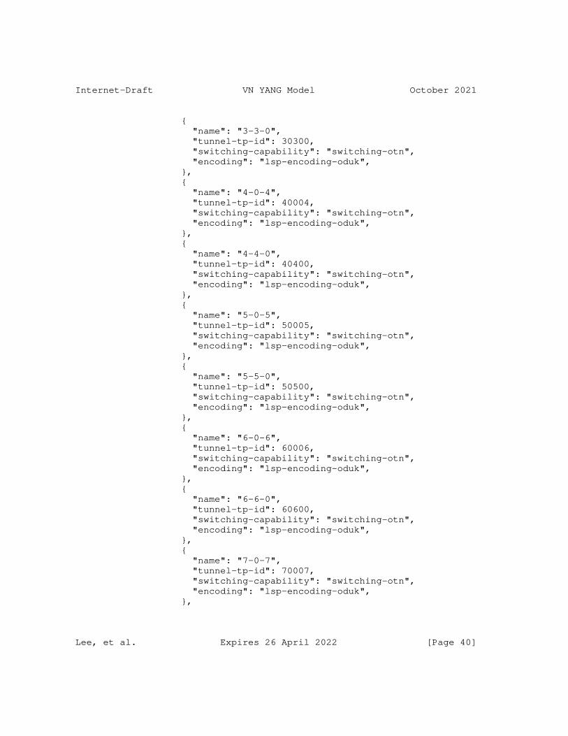
Internet-Draft VN YANG Model October 2021
{ "name": "3-3-0", "tunnel-tp-id": 30300, "switching-capability": "switching-otn", "encoding": "lsp-encoding-oduk", }, { "name": "4-0-4", "tunnel-tp-id": 40004, "switching-capability": "switching-otn", "encoding": "lsp-encoding-oduk", }, { "name": "4-4-0", "tunnel-tp-id": 40400, "switching-capability": "switching-otn", "encoding": "lsp-encoding-oduk", }, { "name": "5-0-5", "tunnel-tp-id": 50005, "switching-capability": "switching-otn", "encoding": "lsp-encoding-oduk", }, { "name": "5-5-0", "tunnel-tp-id": 50500, "switching-capability": "switching-otn", "encoding": "lsp-encoding-oduk", }, { "name": "6-0-6", "tunnel-tp-id": 60006, "switching-capability": "switching-otn", "encoding": "lsp-encoding-oduk", }, { "name": "6-6-0", "tunnel-tp-id": 60600, "switching-capability": "switching-otn", "encoding": "lsp-encoding-oduk", }, { "name": "7-0-7", "tunnel-tp-id": 70007, "switching-capability": "switching-otn", "encoding": "lsp-encoding-oduk", },
Lee, et al. Expires 26 April 2022 [Page 40]
Internet-Draft VN YANG Model October 2021
{ "name": "7-7-0", "tunnel-tp-id": 70700, "switching-capability": "switching-otn", "encoding": "lsp-encoding-oduk", }, { "name": "8-0-8", "tunnel-tp-id": 80008, "switching-capability": "switching-otn", "encoding": "lsp-encoding-oduk", }, { "name": "8-8-0", "tunnel-tp-id": 80800, "switching-capability": "switching-otn", "encoding": "lsp-encoding-oduk", }, ], }, }, ], }, { "network-types": { "te-topology": {} }, "network-id": "abstract2", "te-topology-identifier":{ "provider-id": 201, "client-id": 600, "topology-id": "te-topology:abstract2" }, "node": [ { "node-id": "D2", "te-node-id": "2.0.1.2", "te": { "te-node-attributes": { "domain-id" : 1, "is-abstract": [null], "connectivity-matrices": { "is-allowed": true, "underlay": { "enabled": true }, "path-constraints": { "te-bandwidth": {
Lee, et al. Expires 26 April 2022 [Page 41]
Internet-Draft VN YANG Model October 2021
"generic": "0x1p10", }, }, "optimizations": { "objective-function": { "objective-function-type": "of-maximize-residual-bandwidth" }, }, "connectivity-matrix": [ { "id": 105, "from": { "tp-ref": "1-0-1", }, "to": { "tp-ref": "5-5-0", }, "underlay": { "enabled": true, "primary-path": { "network-ref": "absolute", "path-element": [ { "path-element-id": 1, "numbered-node-hop": { "node-id": "4.4.4.4", "hop-type": "strict" } }, { "path-element-id": 2, "numbered-hop": { "node-id": "7.7.7.7", "hop-type": "strict" } } ] } } } ] } }, "tunnel-termination-point": [ { "name": "1-0-1", "tunnel-tp-id": 10001,
Lee, et al. Expires 26 April 2022 [Page 42]
Internet-Draft VN YANG Model October 2021
"switching-capability": "switching-otn", "encoding": "lsp-encoding-oduk", }, { "name": "1-1-0", "tunnel-tp-id": 10100, "switching-capability": "switching-otn", "encoding": "lsp-encoding-oduk", }, { "name": "2-0-2", "tunnel-tp-id": 20002, "switching-capability": "switching-otn", "encoding": "lsp-encoding-oduk", }, { "name": "2-2-0", "tunnel-tp-id": 20200, "switching-capability": "switching-otn", "encoding": "lsp-encoding-oduk", }, { "name": "3-0-3", "tunnel-tp-id": 30003, "switching-capability": "switching-otn", "encoding": "lsp-encoding-oduk", }, { "name": "3-3-0", "tunnel-tp-id": 30300, "switching-capability": "switching-otn", "encoding": "lsp-encoding-oduk", }, { "name": "4-0-4", "tunnel-tp-id": 40004, "switching-capability": "switching-otn", "encoding": "lsp-encoding-oduk", }, { "name": "4-4-0", "tunnel-tp-id": 40400, "switching-capability": "switching-otn", "encoding": "lsp-encoding-oduk", }, { "name": "5-0-5", "tunnel-tp-id": 50005,
Lee, et al. Expires 26 April 2022 [Page 43]
Internet-Draft VN YANG Model October 2021
"switching-capability": "switching-otn", "encoding": "lsp-encoding-oduk", }, { "name": "5-5-0", "tunnel-tp-id": 50500, "switching-capability": "switching-otn", "encoding": "lsp-encoding-oduk", }, { "name": "6-0-6", "tunnel-tp-id": 60006, "switching-capability": "switching-otn", "encoding": "lsp-encoding-oduk", }, { "name": "6-6-0", "tunnel-tp-id": 60600, "switching-capability": "switching-otn", "encoding": "lsp-encoding-oduk", }, { "name": "7-0-7", "tunnel-tp-id": 70007, "switching-capability": "switching-otn", "encoding": "lsp-encoding-oduk", }, { "name": "7-7-0", "tunnel-tp-id": 70700, "switching-capability": "switching-otn", "encoding": "lsp-encoding-oduk", }, { "name": "8-0-8", "tunnel-tp-id": 80008, "switching-capability": "switching-otn", "encoding": "lsp-encoding-oduk", }, { "name": "8-8-0", "tunnel-tp-id": 80800, "switching-capability": "switching-otn", "encoding": "lsp-encoding-oduk" }, ], }, },
Lee, et al. Expires 26 April 2022 [Page 44]
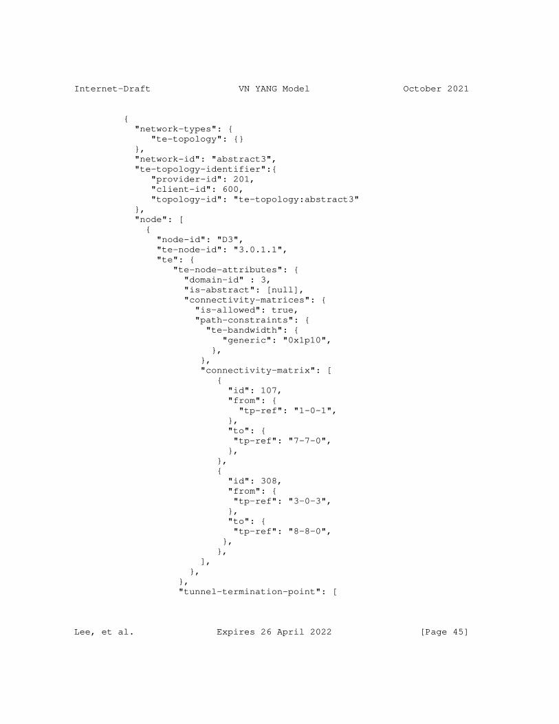
Internet-Draft VN YANG Model October 2021
{ "network-types": { "te-topology": {} }, "network-id": "abstract3", "te-topology-identifier":{ "provider-id": 201, "client-id": 600, "topology-id": "te-topology:abstract3" }, "node": [ { "node-id": "D3", "te-node-id": "3.0.1.1", "te": { "te-node-attributes": { "domain-id" : 3, "is-abstract": [null], "connectivity-matrices": { "is-allowed": true, "path-constraints": { "te-bandwidth": { "generic": "0x1p10", }, }, "connectivity-matrix": [ { "id": 107, "from": { "tp-ref": "1-0-1", }, "to": { "tp-ref": "7-7-0", }, }, { "id": 308, "from": { "tp-ref": "3-0-3", }, "to": { "tp-ref": "8-8-0", }, }, ], }, }, "tunnel-termination-point": [
Lee, et al. Expires 26 April 2022 [Page 45]
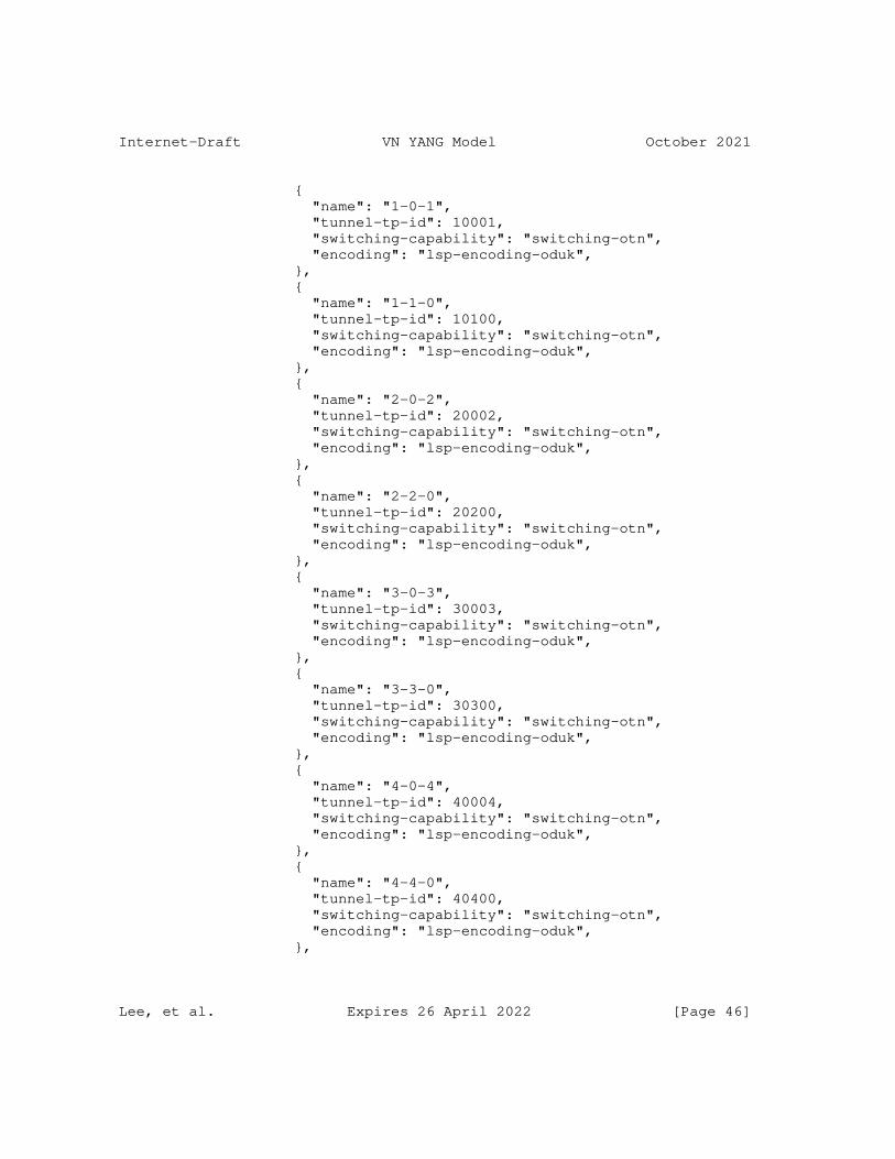
Internet-Draft VN YANG Model October 2021
{ "name": "1-0-1", "tunnel-tp-id": 10001, "switching-capability": "switching-otn", "encoding": "lsp-encoding-oduk", }, { "name": "1-1-0", "tunnel-tp-id": 10100, "switching-capability": "switching-otn", "encoding": "lsp-encoding-oduk", }, { "name": "2-0-2", "tunnel-tp-id": 20002, "switching-capability": "switching-otn", "encoding": "lsp-encoding-oduk", }, { "name": "2-2-0", "tunnel-tp-id": 20200, "switching-capability": "switching-otn", "encoding": "lsp-encoding-oduk", }, { "name": "3-0-3", "tunnel-tp-id": 30003, "switching-capability": "switching-otn", "encoding": "lsp-encoding-oduk", }, { "name": "3-3-0", "tunnel-tp-id": 30300, "switching-capability": "switching-otn", "encoding": "lsp-encoding-oduk", }, { "name": "4-0-4", "tunnel-tp-id": 40004, "switching-capability": "switching-otn", "encoding": "lsp-encoding-oduk", }, { "name": "4-4-0", "tunnel-tp-id": 40400, "switching-capability": "switching-otn", "encoding": "lsp-encoding-oduk", },
Lee, et al. Expires 26 April 2022 [Page 46]

Internet-Draft VN YANG Model October 2021
{ "name": "5-0-5", "tunnel-tp-id": 50005, "switching-capability": "switching-otn", "encoding": "lsp-encoding-oduk", }, { "name": "5-5-0", "tunnel-tp-id": 50500, "switching-capability": "switching-otn", "encoding": "lsp-encoding-oduk", }, { "name": "6-0-6", "tunnel-tp-id": 60006, "switching-capability": "switching-otn", "encoding": "lsp-encoding-oduk", }, { "name": "6-6-0", "tunnel-tp-id": 60600, "switching-capability": "switching-otn", "encoding": "lsp-encoding-oduk", }, { "name": "7-0-7", "tunnel-tp-id": 70007, "switching-capability": "switching-otn", "encoding": "lsp-encoding-oduk", }, { "name": "7-7-0", "tunnel-tp-id": 70700, "switching-capability": "switching-otn", "encoding": "lsp-encoding-oduk", }, { "name": "8-0-8", "tunnel-tp-id": 80008, "switching-capability": "switching-otn", "encoding": "lsp-encoding-oduk", }, { "name": "8-8-0", "tunnel-tp-id": 80800, "switching-capability": "switching-otn", "encoding": "lsp-encoding-oduk", }
Lee, et al. Expires 26 April 2022 [Page 47]
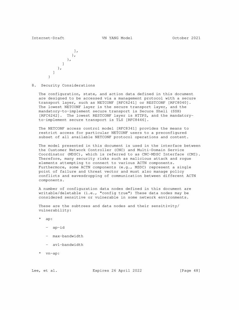
Internet-Draft VN YANG Model October 2021
], }, }, ] }, ] }
8. Security Considerations
The configuration, state, and action data defined in this document are designed to be accessed via a management protocol with a secure transport layer, such as NETCONF [RFC6241] or RESTCONF [RFC8040]. The lowest NETCONF layer is the secure transport layer, and the mandatory-to-implement secure transport is Secure Shell (SSH) [RFC6242]. The lowest RESTCONF layer is HTTPS, and the mandatory- to-implement secure transport is TLS [RFC8446].
The NETCONF access control model [RFC8341] provides the means to restrict access for particular NETCONF users to a preconfigured subset of all available NETCONF protocol operations and content.
The model presented in this document is used in the interface between the Customer Network Controller (CNC) and Multi-Domain Service Coordinator (MDSC), which is referred to as CNC-MDSC Interface (CMI). Therefore, many security risks such as malicious attack and rogue elements attempting to connect to various ACTN components. Furthermore, some ACTN components (e.g., MSDC) represent a single point of failure and threat vector and must also manage policy conflicts and eavesdropping of communication between different ACTN components.
A number of configuration data nodes defined in this document are writable/deletable (i.e., "config true") These data nodes may be considered sensitive or vulnerable in some network environments.
These are the subtrees and data nodes and their sensitivity/ vulnerability:
* ap:
- ap-id
- max-bandwidth
- avl-bandwidth
* vn-ap:
Lee, et al. Expires 26 April 2022 [Page 48]

Internet-Draft VN YANG Model October 2021
- vn-ap-id
- vn
- abstract-node
- ltp
* vn
- vn-id
- vn-topology-id
- abstract-node
* vnm-id
- src
- src-vn-ap-id
- dest
- dest-vn-ap-id
- connectivity-matrix-id
9. IANA Considerations
IANA is requested to make the following allocation for the URIs in the "ns" subregistry within the "IETF XML Registry" [RFC3688]:
-------------------------------------------------------------------- URI: urn:ietf:params:xml:ns:yang:ietf-vn Registrant Contact: The IESG. XML: N/A, the requested URI is an XML namespace. --------------------------------------------------------------------
IANA is requested to make the following allocation for the YANG module in the "YANG Module Names" registry [RFC6020]:
Lee, et al. Expires 26 April 2022 [Page 49]
Internet-Draft VN YANG Model October 2021
-------------------------------------------------------------------- name: ietf-vn namespace: urn:ietf:params:xml:ns:yang:ietf-vn prefix: vn reference: RFC XXXX --------------------------------------------------------------------
10. Acknowledgments
The authors would like to thank Xufeng Liu, Adrian Farrel, and Tom Petch for their helpful comments and valuable suggestions.
Thanks to Andy Bierman for YANGDIR review.
11. References
11.1. Normative References
[RFC2119] Bradner, S., "Key words for use in RFCs to Indicate Requirement Levels", BCP 14, RFC 2119, DOI 10.17487/RFC2119, March 1997, <https://www.rfc-editor.org/info/rfc2119>.
[RFC3688] Mealling, M., "The IETF XML Registry", BCP 81, RFC 3688, DOI 10.17487/RFC3688, January 2004, <https://www.rfc-editor.org/info/rfc3688>.
[RFC6020] Bjorklund, M., Ed., "YANG - A Data Modeling Language for the Network Configuration Protocol (NETCONF)", RFC 6020, DOI 10.17487/RFC6020, October 2010, <https://www.rfc-editor.org/info/rfc6020>.
[RFC6241] Enns, R., Ed., Bjorklund, M., Ed., Schoenwaelder, J., Ed., and A. Bierman, Ed., "Network Configuration Protocol (NETCONF)", RFC 6241, DOI 10.17487/RFC6241, June 2011, <https://www.rfc-editor.org/info/rfc6241>.
[RFC6242] Wasserman, M., "Using the NETCONF Protocol over Secure Shell (SSH)", RFC 6242, DOI 10.17487/RFC6242, June 2011, <https://www.rfc-editor.org/info/rfc6242>.
[RFC6991] Schoenwaelder, J., Ed., "Common YANG Data Types", RFC 6991, DOI 10.17487/RFC6991, July 2013, <https://www.rfc-editor.org/info/rfc6991>.
[RFC7950] Bjorklund, M., Ed., "The YANG 1.1 Data Modeling Language", RFC 7950, DOI 10.17487/RFC7950, August 2016, <https://www.rfc-editor.org/info/rfc7950>.
Lee, et al. Expires 26 April 2022 [Page 50]
Internet-Draft VN YANG Model October 2021
[RFC8040] Bierman, A., Bjorklund, M., and K. Watsen, "RESTCONF Protocol", RFC 8040, DOI 10.17487/RFC8040, January 2017, <https://www.rfc-editor.org/info/rfc8040>.
[RFC8174] Leiba, B., "Ambiguity of Uppercase vs Lowercase in RFC 2119 Key Words", BCP 14, RFC 8174, DOI 10.17487/RFC8174, May 2017, <https://www.rfc-editor.org/info/rfc8174>.
[RFC8340] Bjorklund, M. and L. Berger, Ed., "YANG Tree Diagrams", BCP 215, RFC 8340, DOI 10.17487/RFC8340, March 2018, <https://www.rfc-editor.org/info/rfc8340>.
[RFC8341] Bierman, A. and M. Bjorklund, "Network Configuration Access Control Model", STD 91, RFC 8341, DOI 10.17487/RFC8341, March 2018, <https://www.rfc-editor.org/info/rfc8341>.
[RFC8342] Bjorklund, M., Schoenwaelder, J., Shafer, P., Watsen, K., and R. Wilton, "Network Management Datastore Architecture (NMDA)", RFC 8342, DOI 10.17487/RFC8342, March 2018, <https://www.rfc-editor.org/info/rfc8342>.
[RFC8345] Clemm, A., Medved, J., Varga, R., Bahadur, N., Ananthakrishnan, H., and X. Liu, "A YANG Data Model for Network Topologies", RFC 8345, DOI 10.17487/RFC8345, March 2018, <https://www.rfc-editor.org/info/rfc8345>.
[RFC8446] Rescorla, E., "The Transport Layer Security (TLS) Protocol Version 1.3", RFC 8446, DOI 10.17487/RFC8446, August 2018, <https://www.rfc-editor.org/info/rfc8446>.
[RFC8776] Saad, T., Gandhi, R., Liu, X., Beeram, V., and I. Bryskin, "Common YANG Data Types for Traffic Engineering", RFC 8776, DOI 10.17487/RFC8776, June 2020, <https://www.rfc-editor.org/info/rfc8776>.
[RFC8795] Liu, X., Bryskin, I., Beeram, V., Saad, T., Shah, H., and O. Gonzalez de Dios, "YANG Data Model for Traffic Engineering (TE) Topologies", RFC 8795, DOI 10.17487/RFC8795, August 2020, <https://www.rfc-editor.org/info/rfc8795>.
11.2. Informative References
[I-D.ietf-ccamp-l1csm-yang] Lee, Y., Lee, K., Zheng, H., Dios, O. G. D., and D. Ceccarelli, "A YANG Data Model for L1 Connectivity Service Model (L1CSM)", Work in Progress, Internet-Draft, draft-
Lee, et al. Expires 26 April 2022 [Page 51]
Internet-Draft VN YANG Model October 2021
ietf-ccamp-l1csm-yang-15, 8 September 2021, <https://datatracker.ietf.org/doc/html/draft-ietf-ccamp- l1csm-yang-15>.
[I-D.ietf-teas-actn-pm-telemetry-autonomics] Lee, Y., Dhody, D., Karunanithi, S., Vilalta, R., King, D., and D. Ceccarelli, "YANG models for VN/TE Performance Monitoring Telemetry and Scaling Intent Autonomics", Work in Progress, Internet-Draft, draft-ietf-teas-actn-pm- telemetry-autonomics-06, 25 August 2021, <https://datatracker.ietf.org/doc/html/draft-ietf-teas- actn-pm-telemetry-autonomics-06>.
[I-D.ietf-teas-te-service-mapping-yang] Lee, Y., Dhody, D., Fioccola, G., Wu, Q., Ceccarelli, D., and J. Tantsura, "Traffic Engineering (TE) and Service Mapping Yang Model", Work in Progress, Internet-Draft, draft-ietf-teas-te-service-mapping-yang-08, 28 August 2021, <https://datatracker.ietf.org/doc/html/draft-ietf- teas-te-service-mapping-yang-08>.
[I-D.ietf-teas-yang-te] Saad, T., Gandhi, R., Liu, X., Beeram, V. P., Bryskin, I., and O. G. D. Dios, "A YANG Data Model for Traffic Engineering Tunnels, Label Switched Paths and Interfaces", Work in Progress, Internet-Draft, draft-ietf-teas-yang-te- 27, 8 July 2021, <https://datatracker.ietf.org/doc/html/ draft-ietf-teas-yang-te-27>.
[RFC7926] Farrel, A., Ed., Drake, J., Bitar, N., Swallow, G., Ceccarelli, D., and X. Zhang, "Problem Statement and Architecture for Information Exchange between Interconnected Traffic-Engineered Networks", BCP 206, RFC 7926, DOI 10.17487/RFC7926, July 2016, <https://www.rfc-editor.org/info/rfc7926>.
[RFC8299] Wu, Q., Ed., Litkowski, S., Tomotaki, L., and K. Ogaki, "YANG Data Model for L3VPN Service Delivery", RFC 8299, DOI 10.17487/RFC8299, January 2018, <https://www.rfc-editor.org/info/rfc8299>.
[RFC8309] Wu, Q., Liu, W., and A. Farrel, "Service Models Explained", RFC 8309, DOI 10.17487/RFC8309, January 2018, <https://www.rfc-editor.org/info/rfc8309>.
Lee, et al. Expires 26 April 2022 [Page 52]
Internet-Draft VN YANG Model October 2021
[RFC8453] Ceccarelli, D., Ed. and Y. Lee, Ed., "Framework for Abstraction and Control of TE Networks (ACTN)", RFC 8453, DOI 10.17487/RFC8453, August 2018, <https://www.rfc-editor.org/info/rfc8453>.
[RFC8454] Lee, Y., Belotti, S., Dhody, D., Ceccarelli, D., and B. Yoon, "Information Model for Abstraction and Control of TE Networks (ACTN)", RFC 8454, DOI 10.17487/RFC8454, September 2018, <https://www.rfc-editor.org/info/rfc8454>.
[RFC8466] Wen, B., Fioccola, G., Ed., Xie, C., and L. Jalil, "A YANG Data Model for Layer 2 Virtual Private Network (L2VPN) Service Delivery", RFC 8466, DOI 10.17487/RFC8466, October 2018, <https://www.rfc-editor.org/info/rfc8466>.
Appendix A. Performance Constraints
At the time of creation of VN, it is natural to provide VN level constraints and optimization criteria. It should be noted that this YANG model rely on the TE-Topology Model [RFC8795] by using a reference to an abstract node to achieve this. Further, connectivity-matrix structure is used to assign the constraints and optimization criteria include delay, jitter etc. [RFC8776] define some of the metric-types already and future documents are meant to augment it.
Note that the VN compute allows inclusion of the constraints and the optimization criteria directly in the RPC to allow it to be used independently.
Appendix B. Contributors Addresses
Lee, et al. Expires 26 April 2022 [Page 53]
Internet-Draft VN YANG Model October 2021
Qin Wu Huawei Technologies Email: [email protected]
Peter Park KT Email: [email protected]
Haomian Zheng Huawei Technologies Email: [email protected]
Xian Zhang Huawei Technologies Email: [email protected]
Sergio Belotti Nokia Email: [email protected]
Takuya Miyasaka KDDI Email: [email protected]
Kenichi Ogaki KDDI Email: [email protected]
Authors’ Addresses
Young Lee (editor) Samsung Electronics
Email: [email protected]
Dhruv Dhody (editor) Huawei Technologies Divyashree Techno Park, Whitefield Bangalore 560066 Karnataka India
Email: [email protected]
Lee, et al. Expires 26 April 2022 [Page 54]
Internet-Draft VN YANG Model October 2021
Daniele Ceccarelli Ericsson Torshamnsgatan,48 Stockholm, Sweden
Email: [email protected]
Igor Bryskin Individual
Email: [email protected]
Bin Yeong Yoon ETRI
Email: [email protected]
Lee, et al. Expires 26 April 2022 [Page 55]
Network Working Group B. WuInternet-Draft D. DhodyIntended status: Standards Track Huawei TechnologiesExpires: 1 April 2022 R. Rokui Nokia T. Saad Juniper Networks L. Han China Mobile 28 September 2021
IETF Network Slice Service YANG Model draft-ietf-teas-ietf-network-slice-nbi-yang-00
Abstract
This document provides a YANG data model for the IETF Network Slice service model. The model can be used by a IETF Network Slice customer to manage IETF Network Slice from an IETF Network Slice Controller (NSC).
Status of This Memo
This Internet-Draft is submitted in full conformance with the provisions of BCP 78 and BCP 79.
Internet-Drafts are working documents of the Internet Engineering Task Force (IETF). Note that other groups may also distribute working documents as Internet-Drafts. The list of current Internet- Drafts is at https://datatracker.ietf.org/drafts/current/.
Internet-Drafts are draft documents valid for a maximum of six months and may be updated, replaced, or obsoleted by other documents at any time. It is inappropriate to use Internet-Drafts as reference material or to cite them other than as "work in progress."
This Internet-Draft will expire on 1 April 2022.
Copyright Notice
Copyright (c) 2021 IETF Trust and the persons identified as the document authors. All rights reserved.
This document is subject to BCP 78 and the IETF Trust’s Legal Provisions Relating to IETF Documents (https://trustee.ietf.org/ license-info) in effect on the date of publication of this document. Please review these documents carefully, as they describe your rights
Wu, et al. Expires 1 April 2022 [Page 1]
Internet-Draft IETF Network Slice NBI YANG model September 2021
and restrictions with respect to this document. Code Components extracted from this document must include Simplified BSD License text as described in Section 4.e of the Trust Legal Provisions and are provided without warranty as described in the Simplified BSD License.
Table of Contents
1. Introduction . . . . . . . . . . . . . . . . . . . . . . . . 2 2. Conventions used in this document . . . . . . . . . . . . . . 3 2.1. Tree Diagrams . . . . . . . . . . . . . . . . . . . . . . 4 3. IETF Network Slice Service Model Usage . . . . . . . . . . . 4 4. IETF Network Slice Service Model Overview . . . . . . . . . . 5 5. IETF Network Slice Templates . . . . . . . . . . . . . . . . 9 6. IETF Network Slice Modeling Description . . . . . . . . . . . 9 6.1. IETF Network Slice Connectivity Type . . . . . . . . . . 10 6.2. IETF Network Slice SLO and SLE Policy . . . . . . . . . . 11 6.3. IETF Network Slice Endpoint (NSE) . . . . . . . . . . . . 13 7. IETF Network Slice Monitoring . . . . . . . . . . . . . . . . 16 8. IETF Network Slice Service Module . . . . . . . . . . . . . . 17 9. Security Considerations . . . . . . . . . . . . . . . . . . . 37 10. IANA Considerations . . . . . . . . . . . . . . . . . . . . . 38 11. Acknowledgments . . . . . . . . . . . . . . . . . . . . . . . 38 12. References . . . . . . . . . . . . . . . . . . . . . . . . . 38 12.1. Normative References . . . . . . . . . . . . . . . . . . 38 12.2. Informative References . . . . . . . . . . . . . . . . . 40 Appendix A. IETF Network Slice NBI Model Usage Example . . . . . 41 Appendix B. Comparison with Other Possible Design choices for IETF Network Slice NBI . . . . . . . . . . . . . . . . . . . . 44 B.1. ACTN VN Model Augmentation . . . . . . . . . . . . . . . 44 B.2. RFC8345 Augmentation Model . . . . . . . . . . . . . . . 45 Appendix C. Appendix B IETF Network Slice Match Criteria . . . . 45 Authors’ Addresses . . . . . . . . . . . . . . . . . . . . . . . 47
1. Introduction
This document provides a YANG [RFC7950] data model for the IETF Network Slice service model.
The YANG model discussed in this document is defined based on the description of the IETF Network Slice in [I-D.ietf-teas-ietf-network-slices], which is used to operate IETF Network Slices during the IETF Network Slice instantiation. This YANG model supports various operations on IETF Network Slices such as creation, modification, deletion, and monitoring.
The IETF Network Slice Controller (NSC) is a logical entity that allows customers to manage IETF network slices. Customers operate on abstract IETF network slices. Details related to the production of
Wu, et al. Expires 1 April 2022 [Page 2]
Internet-Draft IETF Network Slice NBI YANG model September 2021
slices that fulfil the request are internal to the entity that operates the network. Such details are deployment- and implementation-specific.
The NSC receives request from its customer-facing interface (e.g., from a management system). This interface carries data objects the IETF network slice user provides, describing the needed IETF network slices in terms of topology, target service level objectives (SLO), and also monitoring and reporting requirements. These requirements are then translated into technology-specific actions that are implemented in the underlying network using a network-facing interface. The details of how the IETF network slices are put into effect are out of scope for this document.
The YANG model discussed in this document describes the requirements of an IETF Network Slice from the point of view of the customer. It is thus classified as customer service model in [RFC8309].
The IETF Network Slice operational state is included in the same tree as the configuration consistent with Network Management Datastore Architecture [RFC8342].
2. Conventions used in this document
The keywords "MUST", "MUST NOT", "REQUIRED", "SHALL", "SHALL NOT", "SHOULD", "SHOULD NOT", "RECOMMENDED", "NOT RECOMMENDED", "MAY", and "OPTIONAL" in this document are to be interpreted as described in BCP14, [RFC2119], [RFC8174] when, and only when, they appear in all capitals, as shown here.
The following terms are defined in [RFC6241] and are used in this specification:
* client
* configuration data
* state data
This document makes use of the terms defined in [RFC7950].
This document also makes use of the terms introduced in the Framework for IETF Network Slices [I-D.ietf-teas-ietf-network-slices]:
This document defines the following term:
Wu, et al. Expires 1 April 2022 [Page 3]
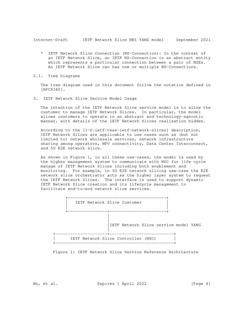
Internet-Draft IETF Network Slice NBI YANG model September 2021
* IETF Network Slice Connection (NS-Connection): In the context of an IETF Network Slice, an IETF NS-Connection is an abstract entity which represents a particular connection between a pair of NSEs. An IETF Network Slice can has one or multiple NS-Connections.
2.1. Tree Diagrams
The tree diagram used in this document follow the notation defined in [RFC8340].
3. IETF Network Slice Service Model Usage
The intention of the IETF Network Slice service model is to allow the customer to manage IETF Network Slices. In particular, the model allows customers to operate in an abstract and technology-agnostic manner, with details of the IETF Network Slices realization hidden.
According to the [I-D.ietf-teas-ietf-network-slices] description, IETF Network Slices are applicable to use cases such as (but not limited to) network wholesale services, network infrastructure sharing among operators, NFV connectivity, Data Center Interconnect, and 5G E2E network slice.
As shown in Figure 1, in all these use-cases, the model is used by the higher management system to communicate with NSC for life cycle manage of IETF Network Slices including both enablement and monitoring. For example, in 5G E2E network slicing use-case the E2E network slice orchestrator acts as the higher layer system to request the IETF Network Slices. The interface is used to support dynamic IETF Network Slice creation and its lifecycle management to facilitate end-to-end network slice services.
+----------------------------------------+ | IETF Network Slice Customer | | | +----------------+-----------------------+ | | |IETF Network Slice service model YANG | +---------------------+--------------------------+ | IETF Network Slice Controller (NSC) | +------------------------------------------------+
Figure 1: IETF Network Slice Service Reference Architecture
Wu, et al. Expires 1 April 2022 [Page 4]
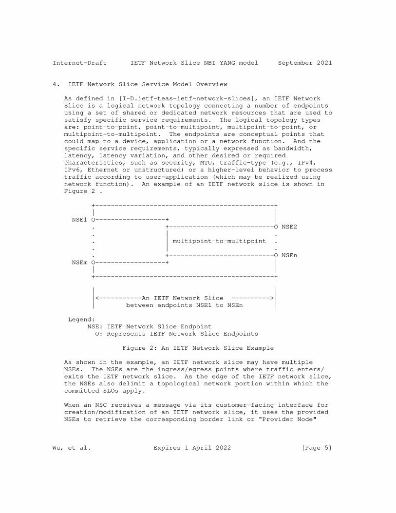
Internet-Draft IETF Network Slice NBI YANG model September 2021
4. IETF Network Slice Service Model Overview
As defined in [I-D.ietf-teas-ietf-network-slices], an IETF Network Slice is a logical network topology connecting a number of endpoints using a set of shared or dedicated network resources that are used to satisfy specific service requirements. The logical topology types are: point-to-point, point-to-multipoint, multipoint-to-point, or multipoint-to-multipoint. The endpoints are conceptual points that could map to a device, application or a network function. And the specific service requirements, typically expressed as bandwidth, latency, latency variation, and other desired or required characteristics, such as security, MTU, traffic-type (e.g., IPv4, IPv6, Ethernet or unstructured) or a higher-level behavior to process traffic according to user-application (which may be realized using network function). An example of an IETF network slice is shown in Figure 2 .
+----------------------------------------------+ | | NSE1 O------------------+ | . +---------------------------O NSE2 . | . . | multipoint-to-multipoint . . | . . +---------------------------O NSEn NSEm O------------------+ | | | +----------------------------------------------+
| | |<-----------An IETF Network Slice ---------->| | between endpoints NSE1 to NSEn |
Legend: NSE: IETF Network Slice Endpoint O: Represents IETF Network Slice Endpoints
Figure 2: An IETF Network Slice Example
As shown in the example, an IETF network slice may have multiple NSEs. The NSEs are the ingress/egress points where traffic enters/ exits the IETF network slice. As the edge of the IETF network slice, the NSEs also delimit a topological network portion within which the committed SLOs apply.
When an NSC receives a message via its customer-facing interface for creation/modification of an IETF network slice, it uses the provided NSEs to retrieve the corresponding border link or "Provider Node"
Wu, et al. Expires 1 April 2022 [Page 5]
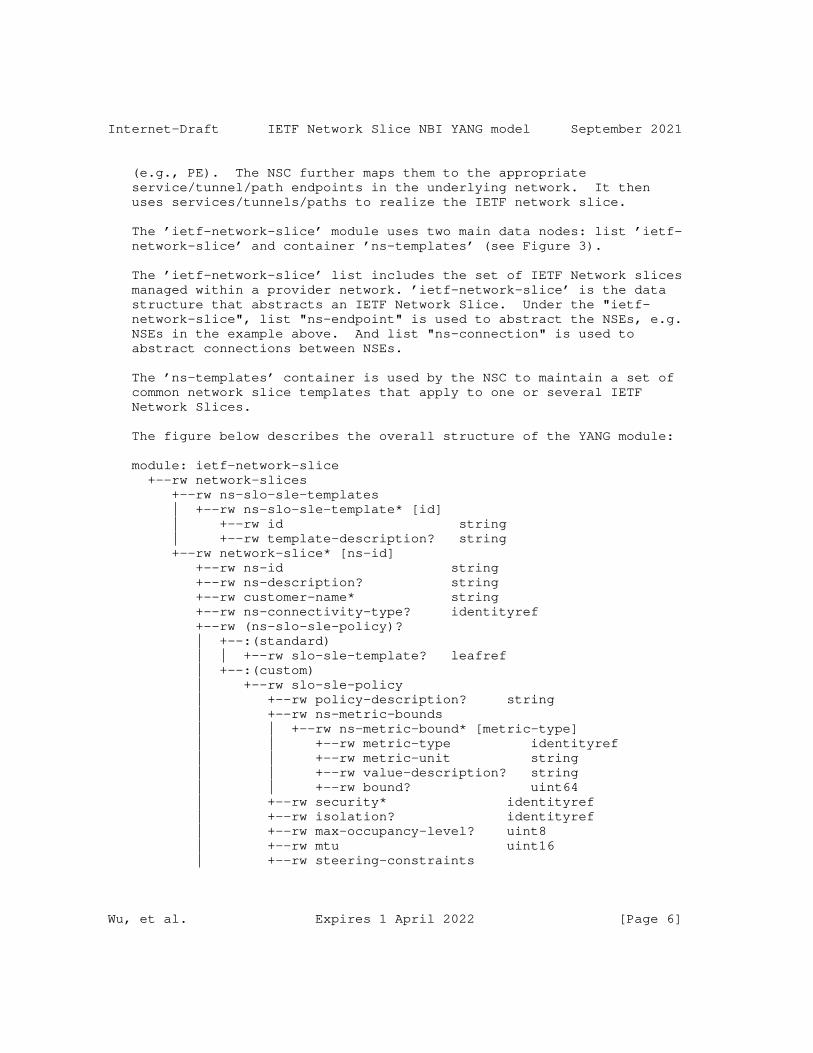
Internet-Draft IETF Network Slice NBI YANG model September 2021
(e.g., PE). The NSC further maps them to the appropriate service/tunnel/path endpoints in the underlying network. It then uses services/tunnels/paths to realize the IETF network slice.
The ’ietf-network-slice’ module uses two main data nodes: list ’ietf- network-slice’ and container ’ns-templates’ (see Figure 3).
The ’ietf-network-slice’ list includes the set of IETF Network slices managed within a provider network. ’ietf-network-slice’ is the data structure that abstracts an IETF Network Slice. Under the "ietf- network-slice", list "ns-endpoint" is used to abstract the NSEs, e.g. NSEs in the example above. And list "ns-connection" is used to abstract connections between NSEs.
The ’ns-templates’ container is used by the NSC to maintain a set of common network slice templates that apply to one or several IETF Network Slices.
The figure below describes the overall structure of the YANG module:
module: ietf-network-slice +--rw network-slices +--rw ns-slo-sle-templates | +--rw ns-slo-sle-template* [id] | +--rw id string | +--rw template-description? string +--rw network-slice* [ns-id] +--rw ns-id string +--rw ns-description? string +--rw customer-name* string +--rw ns-connectivity-type? identityref +--rw (ns-slo-sle-policy)? | +--:(standard) | | +--rw slo-sle-template? leafref | +--:(custom) | +--rw slo-sle-policy | +--rw policy-description? string | +--rw ns-metric-bounds | | +--rw ns-metric-bound* [metric-type] | | +--rw metric-type identityref | | +--rw metric-unit string | | +--rw value-description? string | | +--rw bound? uint64 | +--rw security* identityref | +--rw isolation? identityref | +--rw max-occupancy-level? uint8 | +--rw mtu uint16 | +--rw steering-constraints
Wu, et al. Expires 1 April 2022 [Page 6]
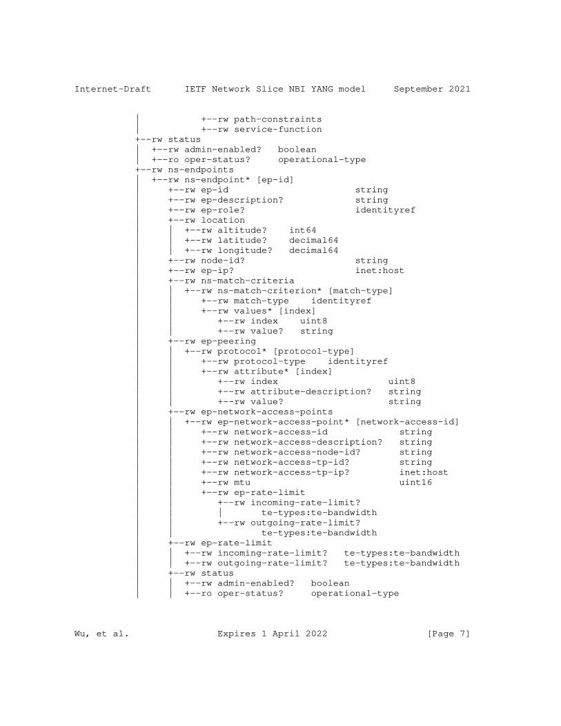
Internet-Draft IETF Network Slice NBI YANG model September 2021
| +--rw path-constraints | +--rw service-function +--rw status | +--rw admin-enabled? boolean | +--ro oper-status? operational-type +--rw ns-endpoints | +--rw ns-endpoint* [ep-id] | +--rw ep-id string | +--rw ep-description? string | +--rw ep-role? identityref | +--rw location | | +--rw altitude? int64 | | +--rw latitude? decimal64 | | +--rw longitude? decimal64 | +--rw node-id? string | +--rw ep-ip? inet:host | +--rw ns-match-criteria | | +--rw ns-match-criterion* [match-type] | | +--rw match-type identityref | | +--rw values* [index] | | +--rw index uint8 | | +--rw value? string | +--rw ep-peering | | +--rw protocol* [protocol-type] | | +--rw protocol-type identityref | | +--rw attribute* [index] | | +--rw index uint8 | | +--rw attribute-description? string | | +--rw value? string | +--rw ep-network-access-points | | +--rw ep-network-access-point* [network-access-id] | | +--rw network-access-id string | | +--rw network-access-description? string | | +--rw network-access-node-id? string | | +--rw network-access-tp-id? string | | +--rw network-access-tp-ip? inet:host | | +--rw mtu uint16 | | +--rw ep-rate-limit | | +--rw incoming-rate-limit? | | | te-types:te-bandwidth | | +--rw outgoing-rate-limit? | | te-types:te-bandwidth | +--rw ep-rate-limit | | +--rw incoming-rate-limit? te-types:te-bandwidth | | +--rw outgoing-rate-limit? te-types:te-bandwidth | +--rw status | | +--rw admin-enabled? boolean | | +--ro oper-status? operational-type
Wu, et al. Expires 1 April 2022 [Page 7]
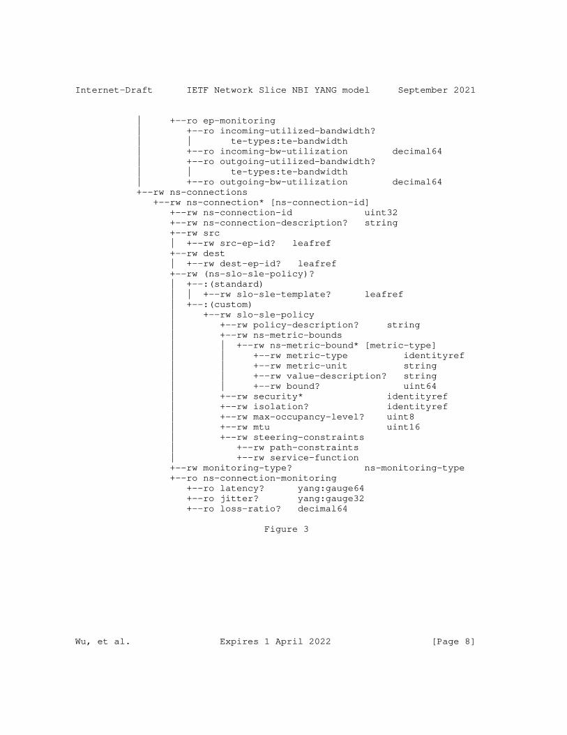
Internet-Draft IETF Network Slice NBI YANG model September 2021
| +--ro ep-monitoring | +--ro incoming-utilized-bandwidth? | | te-types:te-bandwidth | +--ro incoming-bw-utilization decimal64 | +--ro outgoing-utilized-bandwidth? | | te-types:te-bandwidth | +--ro outgoing-bw-utilization decimal64 +--rw ns-connections +--rw ns-connection* [ns-connection-id] +--rw ns-connection-id uint32 +--rw ns-connection-description? string +--rw src | +--rw src-ep-id? leafref +--rw dest | +--rw dest-ep-id? leafref +--rw (ns-slo-sle-policy)? | +--:(standard) | | +--rw slo-sle-template? leafref | +--:(custom) | +--rw slo-sle-policy | +--rw policy-description? string | +--rw ns-metric-bounds | | +--rw ns-metric-bound* [metric-type] | | +--rw metric-type identityref | | +--rw metric-unit string | | +--rw value-description? string | | +--rw bound? uint64 | +--rw security* identityref | +--rw isolation? identityref | +--rw max-occupancy-level? uint8 | +--rw mtu uint16 | +--rw steering-constraints | +--rw path-constraints | +--rw service-function +--rw monitoring-type? ns-monitoring-type +--ro ns-connection-monitoring +--ro latency? yang:gauge64 +--ro jitter? yang:gauge32 +--ro loss-ratio? decimal64
Figure 3
Wu, et al. Expires 1 April 2022 [Page 8]
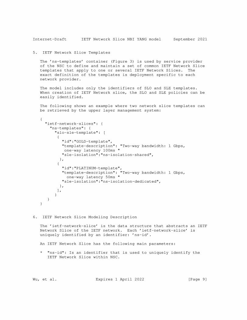
Internet-Draft IETF Network Slice NBI YANG model September 2021
5. IETF Network Slice Templates
The ’ns-templates’ container (Figure 3) is used by service provider of the NSC to define and maintain a set of common IETF Network Slice templates that apply to one or several IETF Network Slices. The exact definition of the templates is deployment specific to each network provider.
The model includes only the identifiers of SLO and SLE templates. When creation of IETF Network slice, the SLO and SLE policies can be easily identified.
The following shows an example where two network slice templates can be retrieved by the upper layer management system:
{ "ietf-network-slices": { "ns-templates": { "slo-sle-template": [ { "id":"GOLD-template", "template-description": "Two-way bandwidth: 1 Gbps, one-way latency 100ms " "sle-isolation":"ns-isolation-shared", }, { "id":"PLATINUM-template", "template-description": "Two-way bandwidth: 1 Gbps, one-way latency 50ms " "sle-isolation":"ns-isolation-dedicated", }, ], } } }
6. IETF Network Slice Modeling Description
The ’ietf-network-slice’ is the data structure that abstracts an IETF Network Slice of the IETF network. Each ’ietf-network-slice’ is uniquely identified by an identifier: ’ns-id’.
An IETF Network Slice has the following main parameters:
* "ns-id": Is an identifier that is used to uniquely identify the IETF Network Slice within NSC.
Wu, et al. Expires 1 April 2022 [Page 9]
Internet-Draft IETF Network Slice NBI YANG model September 2021
* "ns-description": Gives some description of an IETF Network Slice service.
* "ns-connectivity-type": Indicates the network connectivity type for the IETF Network Slice: Hub-and-Spoke, any-to-any, or custom type.
* "status": Is used to show the operative and administrative status of the IETF Network Slice, and can be used as indicator to detect network slice anomalies.
* "customer-name": Is used to show the correlation between actual slice customers and IETF network slices. It can be used by the NSC for monitoring and assurance of the IETF network slices where NSC can notify the higher system by issuing the notifications. For example, multiple actual customers use a same network slice.
* "ns-slo-sle-policy": Defines SLO and SLE policies for the "ietf- network-slice". More description are provided in Section 6.2
The "ns-endpoint" is an abstrac entity that represents a set of matching rules applied to an IETF network edge device or a customer network edge device involved in the IETF Network Slice and each ’ns- endpoint’ belongs to a single ’ietf-network-slice’. More description are provided in Section 6.3
6.1. IETF Network Slice Connectivity Type
Based on the customer’s traffic pattern requirements, an IETF Network Slice connection type could be point-to-point (P2P), point-to- multipoint (P2MP), multipoint-to-point (MP2P), or multipoint-to- multipoint (MP2MP). The "ns-connectivity-type" under the node "ietf- network-slice" is used for this.
According to the network services defined in [I-D.ietf-opsawg-vpn-common], some well-known connectivity types are proposed for IETF network slices. The type could be any-to-any, Hub- and-Spoke (where Hubs can exchange traffic), and the custom. By default, the any-to-any is used. New connectivity type could be added via augmentation or by list of ’ns-connection’ specified.
In addition, "ep-role" under the node "ns-endpoint" also needs to be defined, which specifies the role of the NSE in a particular Network Slice connectivity type. In the any-to-any, all NSEs MUST have the same role, which will be "any-to-any-role". In the Hub-and-Spoke, NSEs MUST have a Hub role or a Spoke role.
Wu, et al. Expires 1 April 2022 [Page 10]

Internet-Draft IETF Network Slice NBI YANG model September 2021
6.2. IETF Network Slice SLO and SLE Policy
As defined in [I-D.ietf-teas-ietf-network-slices], the SLO and SLE policy of an IETF Network Slice defines the minimum IETF Network Slice SLO attributes, and additional attributes can be added as needed.
"ns-slo-sle-policy" is used to represent specific SLO and SLE policies. During the creation of an IETF Network Slice, the policy can be specified either by a standard SLO and SLO template or a customized SLO and SLE policy.
The policy could both apply one per Network Slice or per connection ’ns-connection’.
The model allows multiple SLO and SLE attributes to be combined to meet different SLO and SLE requirements. For example, some NSs are used for video services and require high bandwidth, some NSs are used for key business services and request low latency and reliability, and some NSs need to provide connections for a large number of NSEs. That is, not all SLO or SLE attributes must be specified to meet the particular requirements of a slice.
"ns-metric-bounds" contains all these variations, which includes a list of "ns-metric-bound" and each "ns-metric-bound" could specify a particular "metric-type". "metric-type" is defined with YANG identity and the YANG module supports the following options:
"ns-slo-one-way-bandwidth": Indicates the guaranteed minimum bandwidth between any two NSE. And the bandwidth is unidirectional.
"ns-slo-two-way-bandwidth": Indicates the guaranteed minimum bandwidth between any two NSE. And the bandwidth is bidirectional.
"network-slice-slo-one-way-latency": Indicates the maximum one-way latency between two NSE.
"network-slice-slo-two-way-latency": Indicates the maximum round- trip latency between two NSE.
"ns-slo-one-way-delay-variation": Indicates the jitter constraint of the slice maximum permissible delay variation, and is measured by the difference in the one-way latency between sequential packets in a flow.
"ns-slo-two-way-delay-variation": Indicates the jitter constraint
Wu, et al. Expires 1 April 2022 [Page 11]
Internet-Draft IETF Network Slice NBI YANG model September 2021
of the slice maximum permissible delay variation, and is measured by the difference in the two-way latency between sequential packets in a flow.
"ns-slo-one-way-packet-loss": Indicates maximum permissible packet loss rate, which is defined by the ratio of packets dropped to packets transmitted between two endpoints.
"ns-slo-two-way-packet-loss": Indicates maximum permissible packet loss rate, which is defined by the ratio of packets dropped to packets transmitted between two endpoints.
"ns-slo-availability": Is defined as the ratio of up-time to total_time(up-time+down-time), where up-time is the time the IETF Network Slice is available in accordance with the SLOs associated with it.
Some other Network Slice SLOs or SLEs could be extended when needed.
Note: The definition of "slo-sle-policy" and "steering-constraints" will be updated when WG converge on the terms.
Note: RFC7297 shaping/policing for out of profile traffic.
The following shows an example where a network slice policy can be configured:
Wu, et al. Expires 1 April 2022 [Page 12]
Internet-Draft IETF Network Slice NBI YANG model September 2021
{ "ietf-network-slices": { "ietf-network-slice": { "slo-policy": { "policy-description":"video-service-policy", "ns-metric-bounds": { "ns-metric-bound": [ { "metric-type": "ns-slo-one-way-bandwidth", "metric-unit": "mbps" "bound": "1000" }, { "metric-type": "ns-slo-availability", "bound": "99.9%" }, ], } } } } }
6.3. IETF Network Slice Endpoint (NSE)
An IETF Network Slice Endpoint has several characteristics:
* "ep-id": Uniquely identifies the NSE within Network Slice Controller (NSC). The identifier is a string that allows any encoding for the local administration of the IETF Network Slice.
* "location": Indicates NSE location information that facilities NSC easy identification of a NSE.
* "ep-role": Represents a connectivity type role of a NSE belonging to an IETF network slice, as described in Section 6.1. The "ep- role" leaf defines the role of the endpoint in a particular NS connectivity type. In the any-to-any, all NSEs MUST have the same role, which will be "any-to-any-role".
* "node-id": The NSE node information facilities NSC with easy identification of a NSE.
* "ep-ip": The NSE IP information facilities NSC with easy identification of a NSE.
* "ns-match-criteria": A matching policies to apply on a given NSE.
Wu, et al. Expires 1 April 2022 [Page 13]
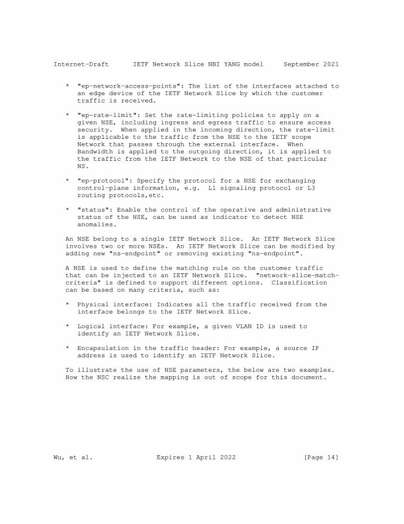
Internet-Draft IETF Network Slice NBI YANG model September 2021
* "ep-network-access-points": The list of the interfaces attached to an edge device of the IETF Network Slice by which the customer traffic is received.
* "ep-rate-limit": Set the rate-limiting policies to apply on a given NSE, including ingress and egress traffic to ensure access security. When applied in the incoming direction, the rate-limit is applicable to the traffic from the NSE to the IETF scope Network that passes through the external interface. When Bandwidth is applied to the outgoing direction, it is applied to the traffic from the IETF Network to the NSE of that particular NS.
* "ep-protocol": Specify the protocol for a NSE for exchanging control-plane information, e.g. L1 signaling protocol or L3 routing protocols,etc.
* "status": Enable the control of the operative and administrative status of the NSE, can be used as indicator to detect NSE anomalies.
An NSE belong to a single IETF Network Slice. An IETF Network Slice involves two or more NSEs. An IETF Network Slice can be modified by adding new "ns-endpoint" or removing existing "ns-endpoint".
A NSE is used to define the matching rule on the customer traffic that can be injected to an IETF Network Slice. "network-slice-match- criteria" is defined to support different options. Classification can be based on many criteria, such as:
* Physical interface: Indicates all the traffic received from the interface belongs to the IETF Network Slice.
* Logical interface: For example, a given VLAN ID is used to identify an IETF Network Slice.
* Encapsulation in the traffic header: For example, a source IP address is used to identify an IETF Network Slice.
To illustrate the use of NSE parameters, the below are two examples. How the NSC realize the mapping is out of scope for this document.
Wu, et al. Expires 1 April 2022 [Page 14]
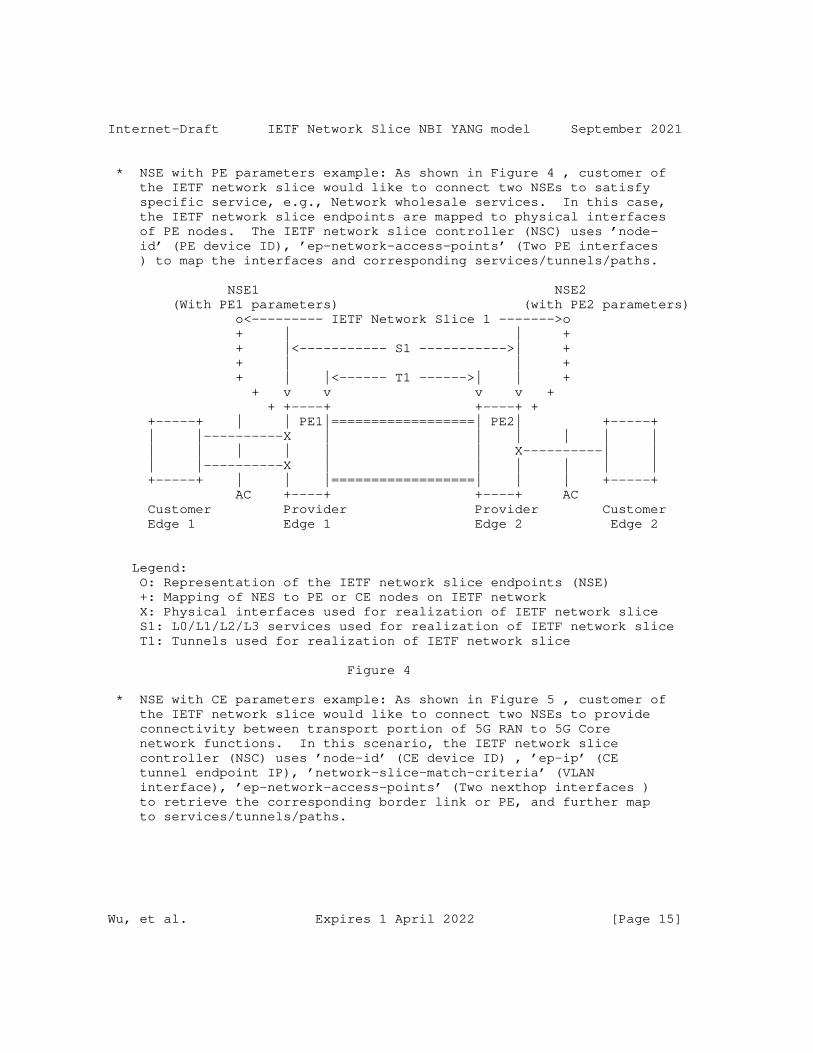
Internet-Draft IETF Network Slice NBI YANG model September 2021
* NSE with PE parameters example: As shown in Figure 4 , customer of the IETF network slice would like to connect two NSEs to satisfy specific service, e.g., Network wholesale services. In this case, the IETF network slice endpoints are mapped to physical interfaces of PE nodes. The IETF network slice controller (NSC) uses ’node- id’ (PE device ID), ’ep-network-access-points’ (Two PE interfaces ) to map the interfaces and corresponding services/tunnels/paths.
NSE1 NSE2 (With PE1 parameters) (with PE2 parameters) o<--------- IETF Network Slice 1 ------->o + | | + + |<----------- S1 ----------->| + + | | + + | |<------ T1 ------>| | + + v v v v + + +----+ +----+ + +-----+ | | PE1|==================| PE2| +-----+ | |----------X | | | | | | | | | | | | X----------| | | |----------X | | | | | | +-----+ | | |==================| | | +-----+ AC +----+ +----+ AC Customer Provider Provider Customer Edge 1 Edge 1 Edge 2 Edge 2
Legend: O: Representation of the IETF network slice endpoints (NSE) +: Mapping of NES to PE or CE nodes on IETF network X: Physical interfaces used for realization of IETF network slice S1: L0/L1/L2/L3 services used for realization of IETF network slice T1: Tunnels used for realization of IETF network slice
Figure 4
* NSE with CE parameters example: As shown in Figure 5 , customer of the IETF network slice would like to connect two NSEs to provide connectivity between transport portion of 5G RAN to 5G Core network functions. In this scenario, the IETF network slice controller (NSC) uses ’node-id’ (CE device ID) , ’ep-ip’ (CE tunnel endpoint IP), ’network-slice-match-criteria’ (VLAN interface), ’ep-network-access-points’ (Two nexthop interfaces ) to retrieve the corresponding border link or PE, and further map to services/tunnels/paths.
Wu, et al. Expires 1 April 2022 [Page 15]
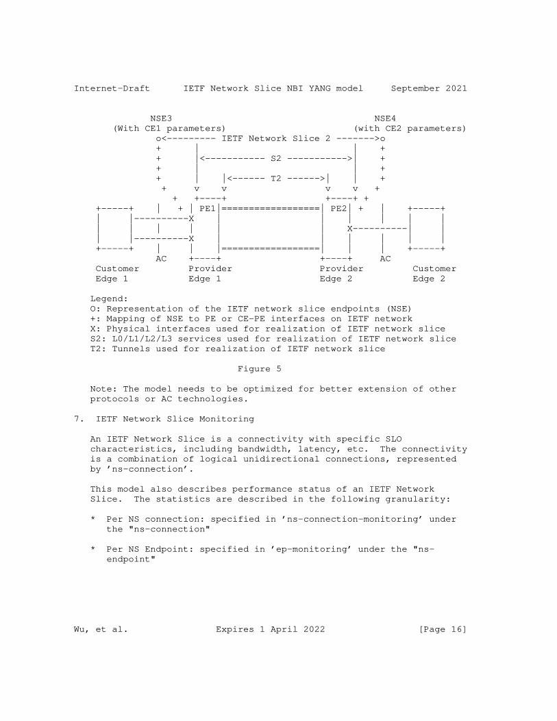
Internet-Draft IETF Network Slice NBI YANG model September 2021
NSE3 NSE4 (With CE1 parameters) (with CE2 parameters) o<--------- IETF Network Slice 2 ------->o + | | + + |<----------- S2 ----------->| + + | | + + | |<------ T2 ------>| | + + v v v v + + +----+ +----+ + +-----+ | + | PE1|==================| PE2| + | +-----+ | |----------X | | | | | | | | | | | | X----------| | | |----------X | | | | | | +-----+ | | |==================| | | +-----+ AC +----+ +----+ AC Customer Provider Provider Customer Edge 1 Edge 1 Edge 2 Edge 2
Legend: O: Representation of the IETF network slice endpoints (NSE) +: Mapping of NSE to PE or CE-PE interfaces on IETF network X: Physical interfaces used for realization of IETF network slice S2: L0/L1/L2/L3 services used for realization of IETF network slice T2: Tunnels used for realization of IETF network slice
Figure 5
Note: The model needs to be optimized for better extension of other protocols or AC technologies.
7. IETF Network Slice Monitoring
An IETF Network Slice is a connectivity with specific SLO characteristics, including bandwidth, latency, etc. The connectivity is a combination of logical unidirectional connections, represented by ’ns-connection’.
This model also describes performance status of an IETF Network Slice. The statistics are described in the following granularity:
* Per NS connection: specified in ’ns-connection-monitoring’ under the "ns-connection"
* Per NS Endpoint: specified in ’ep-monitoring’ under the "ns- endpoint"
Wu, et al. Expires 1 April 2022 [Page 16]
Internet-Draft IETF Network Slice NBI YANG model September 2021
This model does not define monitoring enabling methods. The mechanism defined in [RFC8640] and [RFC8641] can be used for either periodic or on-demand subscription.
By specifying subtree filters or xpath filters to ’ns-connection’ or ’ns-endpoint’ ,so that only interested contents will be sent. These mechanisms can be used for monitoring the IETF Network Slice performance status so that the customer management system could initiate modification based on the IETF Network Slice running status.
Note: More critical events affecting service delivery need to be added.
8. IETF Network Slice Service Module
The "ietf-network-slice" module uses types defined in [RFC6991], [RFC8776].
<CODE BEGINS> file "[email protected]" module ietf-network-slice { yang-version 1.1; namespace "urn:ietf:params:xml:ns:yang:ietf-network-slice"; prefix ietf-ns;
import ietf-inet-types { prefix inet; reference "RFC 6991: Common YANG Types."; } import ietf-yang-types { prefix yang; reference "RFC 6991: Common YANG Types."; } import ietf-te-types { prefix te-types; reference "RFC 8776: Common YANG Data Types for Traffic Engineering."; }
organization "IETF Traffic Engineering Architecture and Signaling (TEAS) Working Group"; contact "WG Web: <https://tools.ietf.org/wg/teas/> WG List: <mailto:[email protected]> Editor: Bo Wu <[email protected]> : Dhruv Dhody <[email protected]>
Wu, et al. Expires 1 April 2022 [Page 17]
Internet-Draft IETF Network Slice NBI YANG model September 2021
: Reza Rokui <[email protected]> : Tarek Saad <[email protected]>"; description "This module contains a YANG module for the IETF Network Slice.
Copyright (c) 2021 IETF Trust and the persons identified as authors of the code. All rights reserved.
Redistribution and use in source and binary forms, with or without modification, is permitted pursuant to, and subject to the license terms contained in, the Simplified BSD License set forth in Section 4.c of the IETF Trust’s Legal Provisions Relating to IETF Documents (http://trustee.ietf.org/license-info).
This version of this YANG module is part of RFC XXXX; see the RFC itself for full legal notices.";
revision 2021-07-20 { description "initial version."; reference "RFC XXXX: A Yang Data Model for IETF Network Slice Operation"; }
/* Features */ /* Identities */
identity ns-isolation-type { description "Base identity for IETF Network slice isolation level."; }
identity ns-isolation-shared { base ns-isolation-type; description "Shared resources (e.g. queues) are associated with the Network Slice traffic. Hence, the IETF network slice traffic can be impacted by effects of other services traffic sharing the same resources."; }
identity ns-isolation-dedicated { base ns-isolation-type; description "Dedicated resources (e.g. queues) are associated with the Network Slice traffic. Hence, the IETF network slice traffic is isolated from other servceis traffic sharing the same
Wu, et al. Expires 1 April 2022 [Page 18]
Internet-Draft IETF Network Slice NBI YANG model September 2021
resources."; }
identity ns-security-type { description "Base identity for for IETF Network security level."; }
identity ns-security-authenticate { base ns-security-type; description "IETF Network Slice requires authentication."; }
identity ns-security-integrity { base ns-security-type; description "IETF Network Slice requires data integrity."; }
identity ns-security-encryption { base ns-security-type; description "IETF Network Slice requires data encryption."; }
identity ns-connectivity-type { description "Base identity for IETF Network Slice topology."; }
identity any-to-any { base ns-connectivity-type; description "Identity for any-to-any IETF Network Slice topology."; }
identity hub-spoke { base ns-connectivity-type; description "Identity for Hub-and-Spoke IETF Network Slice topology."; }
identity custom { base ns-connectivity-type; description "Identity of a custom NS topology where Hubs can act as Spoke for certain parts of the network or Spokes as Hubs.";
Wu, et al. Expires 1 April 2022 [Page 19]
Internet-Draft IETF Network Slice NBI YANG model September 2021
}
identity endpoint-role { description "Base identity of a NSE role in an IETF Network Slice topology."; }
identity any-to-any-role { base endpoint-role; description "Identity of any-to-any NS."; }
identity spoke-role { base endpoint-role; description "A NSE is acting as a Spoke."; }
identity hub-role { base endpoint-role; description "A NSE is acting as a Hub."; }
identity ns-slo-metric-type { description "Base identity for IETF Network Slice SLO metric type."; }
identity ns-slo-one-way-bandwidth { base ns-slo-metric-type; description "SLO bandwidth metric. Minimum guaranteed bandwidth between two endpoints at any time and is measured unidirectionally"; }
identity ns-slo-two-way-bandwidth { base ns-slo-metric-type; description "SLO bandwidth metric. Minimum guaranteed bandwidth between two endpoints at any time"; }
identity ns-slo-one-way-latency { base ns-slo-metric-type; description "SLO one-way latency is upper bound of network latency when
Wu, et al. Expires 1 April 2022 [Page 20]
Internet-Draft IETF Network Slice NBI YANG model September 2021
transmitting between two endpoints. The metric is defined in RFC7679"; }
identity ns-slo-two-way-latency { base ns-slo-metric-type; description "SLO two-way latency is upper bound of network latency when transmitting between two endpoints. The metric is defined in RFC2681"; }
identity ns-slo-one-way-delay-variation { base ns-slo-metric-type; description "SLO one-way delay variation is defined by RFC3393, is the difference in the one-way delay between sequential packets between two endpoints."; }
identity ns-slo-two-way-delay-variation { base ns-slo-metric-type; description "SLO two-way delay variation is defined by RFC5481, is the difference in the round-trip delay between sequential packets between two endpoints."; }
identity ns-slo-one-way-packet-loss { base ns-slo-metric-type; description "SLO loss metric. The ratio of packets dropped to packets transmitted between two endpoints in one-way over a period of time as specified in RFC7680"; }
identity ns-slo-two-way-packet-loss { base ns-slo-metric-type; description "SLO loss metric. The ratio of packets dropped to packets transmitted between two endpoints in two-way over a period of time as specified in RFC7680"; }
identity ns-slo-availability { base ns-slo-metric-type; description "SLO availability level.";
Wu, et al. Expires 1 April 2022 [Page 21]
Internet-Draft IETF Network Slice NBI YANG model September 2021
}
identity ns-match-type { description "Base identity for IETF Network Slice traffic match type."; }
identity ns-phy-interface-match { base ns-match-type; description "Use the physical interface as match criteria for the IETF Network Slice traffic."; }
identity ns-vlan-match { base ns-match-type; description "Use the VLAN ID as match criteria for the IETF Network Slice traffic."; }
identity ns-label-match { base ns-match-type; description "Use the MPLS label as match criteria for the IETF Network Slice traffic."; }
identity peering-protocol-type { description "Base identity for NSE peering protocol type."; }
identity peering-protocol-bgp { base peering-protocol-type; description "Use BGP as protocol for NSE peering with customer device."; }
identity peering-static-routing { base peering-protocol-type; description "Use static routing for NSE peering with customer device."; }
/* * Identity for availability-type */
Wu, et al. Expires 1 April 2022 [Page 22]

Internet-Draft IETF Network Slice NBI YANG model September 2021
identity availability-type { description "Base identity from which specific availability types are derived."; }
identity level-1 { base availability-type; description "level 1: 99.9999%"; }
identity level-2 { base availability-type; description "level 2: 99.999%"; }
identity level-3 { base availability-type; description "level 3: 99.99%"; }
identity level-4 { base availability-type; description "level 4: 99.9%"; }
identity level-5 { base availability-type; description "level 5: 99%"; }
/* typedef */
typedef operational-type { type enumeration { enum up { value 0; description "Operational status UP."; } enum down { value 1; description
Wu, et al. Expires 1 April 2022 [Page 23]
Internet-Draft IETF Network Slice NBI YANG model September 2021
"Operational status DOWN."; } enum unknown { value 2; description "Operational status UNKNOWN."; } } description "This is a read-only attribute used to determine the status of a particular element."; }
typedef ns-monitoring-type { type enumeration { enum one-way { description "Represents one-way measurments monitoring type."; } enum two-way { description "represents two-way measurements monitoring type."; } } description "An enumerated type for monitoring on a IETF Network Slice connection."; }
/* Groupings */
grouping status-params { description "A grouping used to join operational and administrative status."; container status { description "A container for the administrative and operational state."; leaf admin-enabled { type boolean; description "The administrative status."; } leaf oper-status { type operational-type; config false; description "The operational status."; }
Wu, et al. Expires 1 April 2022 [Page 24]
Internet-Draft IETF Network Slice NBI YANG model September 2021
} }
grouping ns-match-criteria { description "A grouping for the IETF Network Slice match definition."; container ns-match-criteria { description "Describes the IETF Network Slice match criteria."; list ns-match-criterion { key "match-type"; description "List of the IETF Network Slice traffic match criteria."; leaf match-type { type identityref { base ns-match-type; } description "Identifies an entry in the list of the IETF Network Slice match criteria."; } list values { key "index"; description "List of match criteria values."; leaf index { type uint8; description "Index of an entry in the list."; } leaf value { type string; description "Describes the IETF Network Slice match criteria, e.g. IP address, VLAN, etc."; } } } } }
grouping ns-connection-group-metric-bounds { description "Grouping of Network Slice metric bounds that are shared amongst multiple connections of a Network Slice."; leaf ns-slo-shared-bandwidth { type te-types:te-bandwidth;
Wu, et al. Expires 1 April 2022 [Page 25]
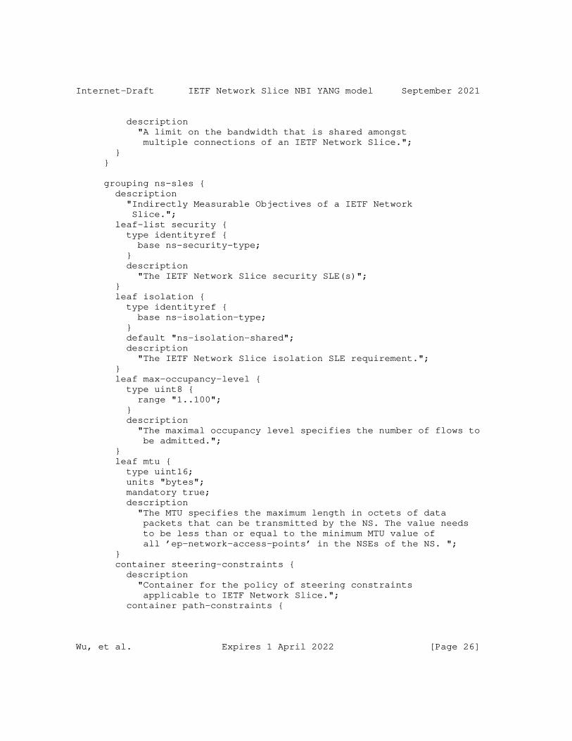
Internet-Draft IETF Network Slice NBI YANG model September 2021
description "A limit on the bandwidth that is shared amongst multiple connections of an IETF Network Slice."; } }
grouping ns-sles { description "Indirectly Measurable Objectives of a IETF Network Slice."; leaf-list security { type identityref { base ns-security-type; } description "The IETF Network Slice security SLE(s)"; } leaf isolation { type identityref { base ns-isolation-type; } default "ns-isolation-shared"; description "The IETF Network Slice isolation SLE requirement."; } leaf max-occupancy-level { type uint8 { range "1..100"; } description "The maximal occupancy level specifies the number of flows to be admitted."; } leaf mtu { type uint16; units "bytes"; mandatory true; description "The MTU specifies the maximum length in octets of data packets that can be transmitted by the NS. The value needs to be less than or equal to the minimum MTU value of all ’ep-network-access-points’ in the NSEs of the NS. "; } container steering-constraints { description "Container for the policy of steering constraints applicable to IETF Network Slice."; container path-constraints {
Wu, et al. Expires 1 April 2022 [Page 26]
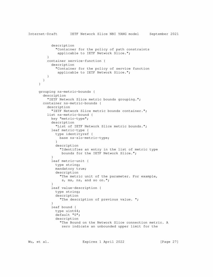
Internet-Draft IETF Network Slice NBI YANG model September 2021
description "Container for the policy of path constraints applicable to IETF Network Slice."; } container service-function { description "Container for the policy of service function applicable to IETF Network Slice."; } } }
grouping ns-metric-bounds { description "IETF Network Slice metric bounds grouping."; container ns-metric-bounds { description "IETF Network Slice metric bounds container."; list ns-metric-bound { key "metric-type"; description "List of IETF Network Slice metric bounds."; leaf metric-type { type identityref { base ns-slo-metric-type; } description "Identifies an entry in the list of metric type bounds for the IETF Network Slice."; } leaf metric-unit { type string; mandatory true; description "The metric unit of the parameter. For example, s, ms, ns, and so on."; } leaf value-description { type string; description "The description of previous value. "; } leaf bound { type uint64; default "0"; description "The Bound on the Network Slice connection metric. A zero indicate an unbounded upper limit for the
Wu, et al. Expires 1 April 2022 [Page 27]
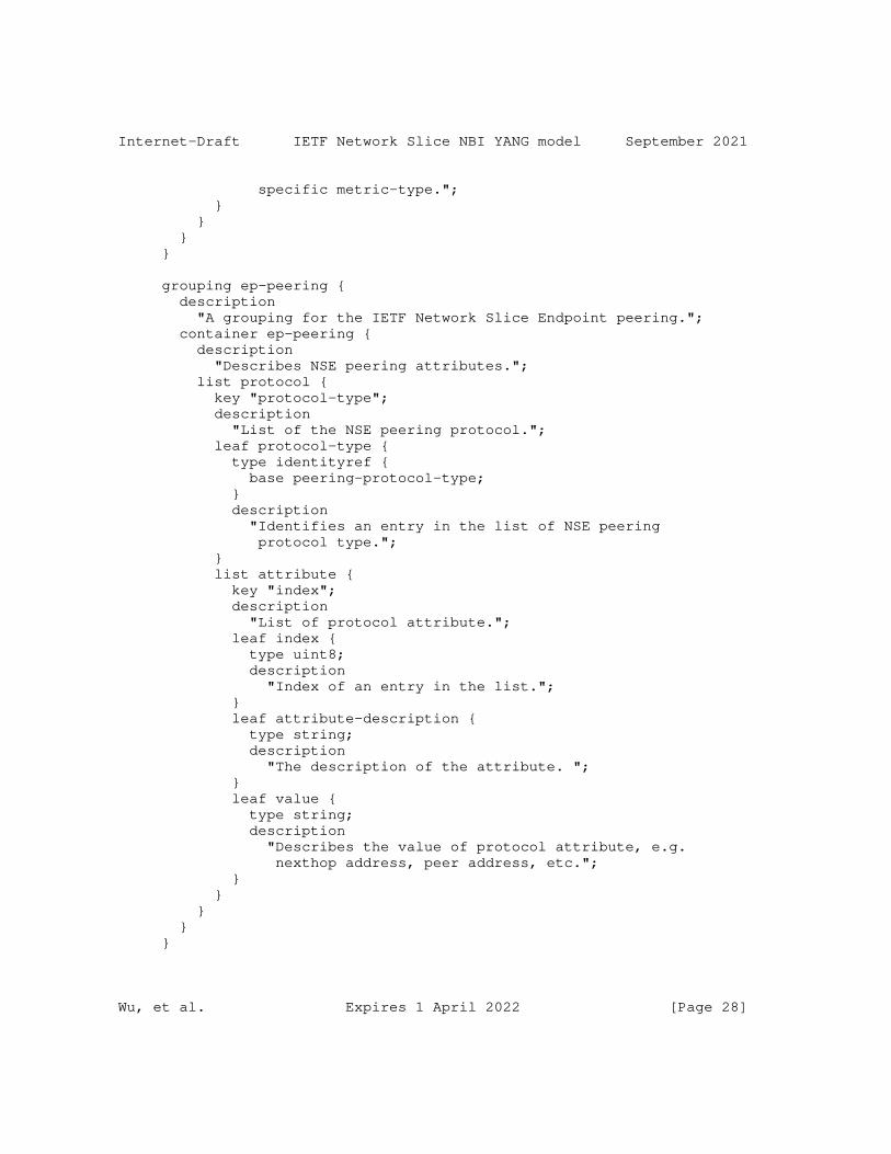
Internet-Draft IETF Network Slice NBI YANG model September 2021
specific metric-type."; } } } }
grouping ep-peering { description "A grouping for the IETF Network Slice Endpoint peering."; container ep-peering { description "Describes NSE peering attributes."; list protocol { key "protocol-type"; description "List of the NSE peering protocol."; leaf protocol-type { type identityref { base peering-protocol-type; } description "Identifies an entry in the list of NSE peering protocol type."; } list attribute { key "index"; description "List of protocol attribute."; leaf index { type uint8; description "Index of an entry in the list."; } leaf attribute-description { type string; description "The description of the attribute. "; } leaf value { type string; description "Describes the value of protocol attribute, e.g. nexthop address, peer address, etc."; } } } } }
Wu, et al. Expires 1 April 2022 [Page 28]
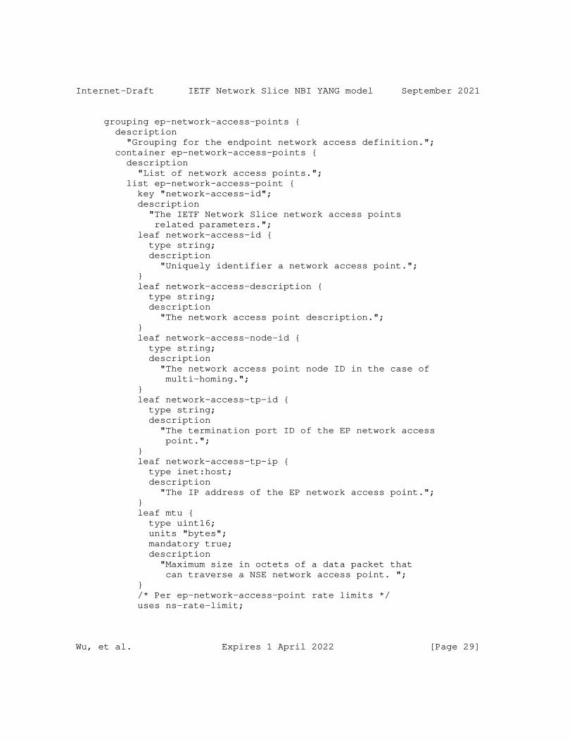
Internet-Draft IETF Network Slice NBI YANG model September 2021
grouping ep-network-access-points { description "Grouping for the endpoint network access definition."; container ep-network-access-points { description "List of network access points."; list ep-network-access-point { key "network-access-id"; description "The IETF Network Slice network access points related parameters."; leaf network-access-id { type string; description "Uniquely identifier a network access point."; } leaf network-access-description { type string; description "The network access point description."; } leaf network-access-node-id { type string; description "The network access point node ID in the case of multi-homing."; } leaf network-access-tp-id { type string; description "The termination port ID of the EP network access point."; } leaf network-access-tp-ip { type inet:host; description "The IP address of the EP network access point."; } leaf mtu { type uint16; units "bytes"; mandatory true; description "Maximum size in octets of a data packet that can traverse a NSE network access point. "; } /* Per ep-network-access-point rate limits */ uses ns-rate-limit;
Wu, et al. Expires 1 April 2022 [Page 29]
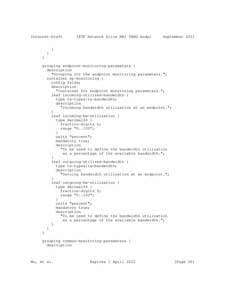
Internet-Draft IETF Network Slice NBI YANG model September 2021
} } }
grouping endpoint-monitoring-parameters { description "Grouping for the endpoint monitoring parameters."; container ep-monitoring { config false; description "Container for endpoint monitoring parameters."; leaf incoming-utilized-bandwidth { type te-types:te-bandwidth; description "Incoming bandwidth utilization at an endpoint."; } leaf incoming-bw-utilization { type decimal64 { fraction-digits 5; range "0..100"; } units "percent"; mandatory true; description "To be used to define the bandwidth utilization as a percentage of the available bandwidth."; } leaf outgoing-utilized-bandwidth { type te-types:te-bandwidth; description "Outoing bandwidth utilization at an endpoint."; } leaf outgoing-bw-utilization { type decimal64 { fraction-digits 5; range "0..100"; } units "percent"; mandatory true; description "To be used to define the bandwidth utilization as a percentage of the available bandwidth."; } } }
grouping common-monitoring-parameters { description
Wu, et al. Expires 1 April 2022 [Page 30]
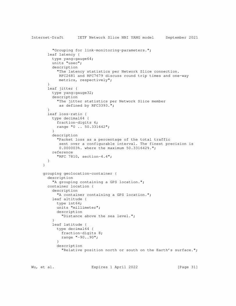
Internet-Draft IETF Network Slice NBI YANG model September 2021
"Grouping for link-monitoring-parameters."; leaf latency { type yang:gauge64; units "usec"; description "The latency statistics per Network Slice connection. RFC2681 and RFC7679 discuss round trip times and one-way metrics, respectively"; } leaf jitter { type yang:gauge32; description "The jitter statistics per Network Slice member as defined by RFC3393."; } leaf loss-ratio { type decimal64 { fraction-digits 6; range "0 .. 50.331642"; } description "Packet loss as a percentage of the total traffic sent over a configurable interval. The finest precision is 0.000003%. where the maximum 50.331642%."; reference "RFC 7810, section-4.4"; } }
grouping geolocation-container { description "A grouping containing a GPS location."; container location { description "A container containing a GPS location."; leaf altitude { type int64; units "millimeter"; description "Distance above the sea level."; } leaf latitude { type decimal64 { fraction-digits 8; range "-90..90"; } description "Relative position north or south on the Earth’s surface.";
Wu, et al. Expires 1 April 2022 [Page 31]
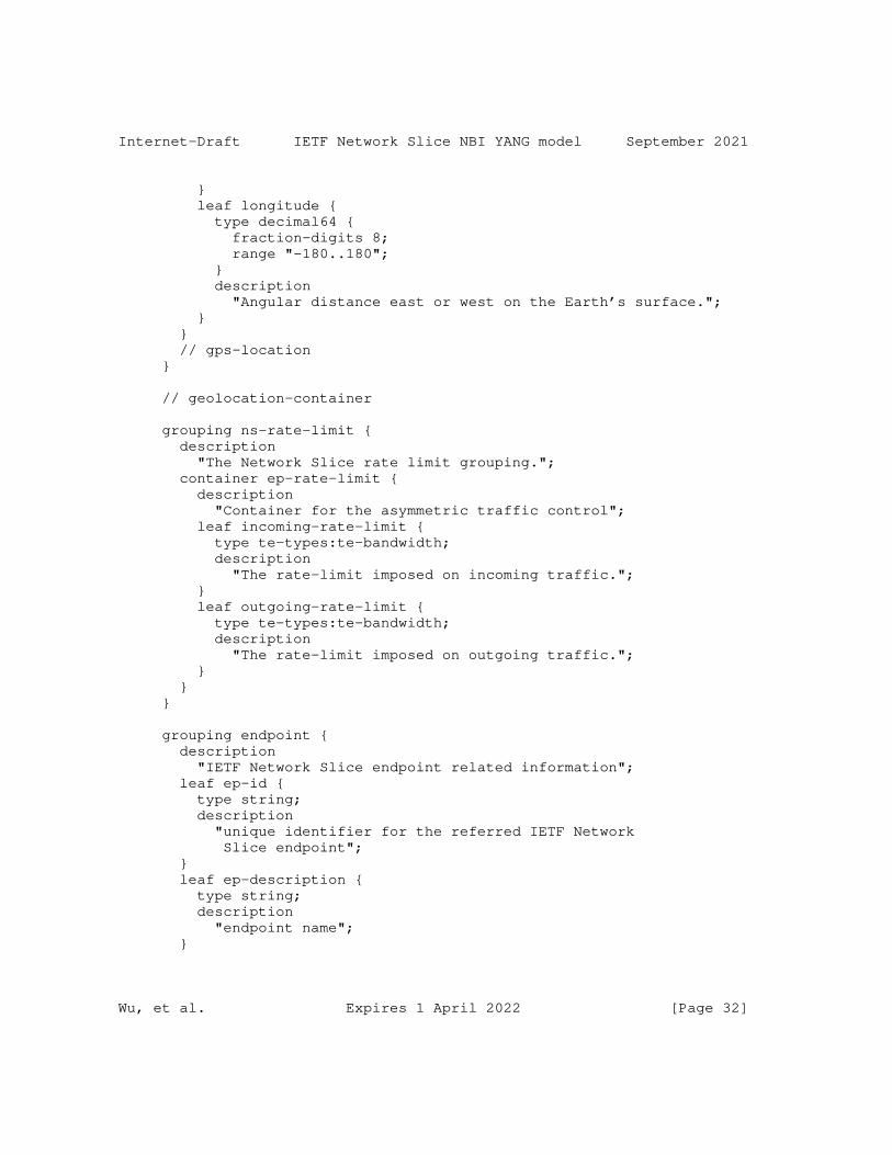
Internet-Draft IETF Network Slice NBI YANG model September 2021
} leaf longitude { type decimal64 { fraction-digits 8; range "-180..180"; } description "Angular distance east or west on the Earth’s surface."; } } // gps-location }
// geolocation-container
grouping ns-rate-limit { description "The Network Slice rate limit grouping."; container ep-rate-limit { description "Container for the asymmetric traffic control"; leaf incoming-rate-limit { type te-types:te-bandwidth; description "The rate-limit imposed on incoming traffic."; } leaf outgoing-rate-limit { type te-types:te-bandwidth; description "The rate-limit imposed on outgoing traffic."; } } }
grouping endpoint { description "IETF Network Slice endpoint related information"; leaf ep-id { type string; description "unique identifier for the referred IETF Network Slice endpoint"; } leaf ep-description { type string; description "endpoint name"; }
Wu, et al. Expires 1 April 2022 [Page 32]
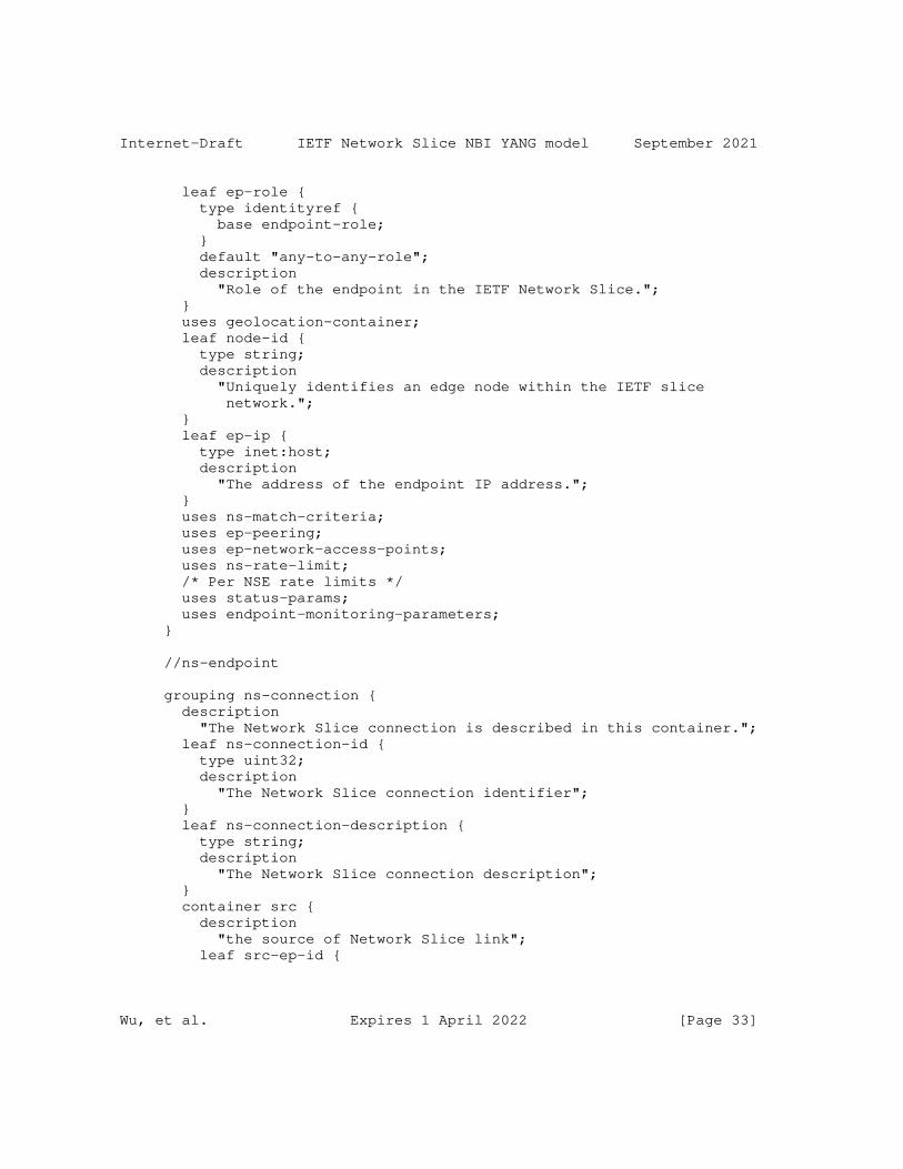
Internet-Draft IETF Network Slice NBI YANG model September 2021
leaf ep-role { type identityref { base endpoint-role; } default "any-to-any-role"; description "Role of the endpoint in the IETF Network Slice."; } uses geolocation-container; leaf node-id { type string; description "Uniquely identifies an edge node within the IETF slice network."; } leaf ep-ip { type inet:host; description "The address of the endpoint IP address."; } uses ns-match-criteria; uses ep-peering; uses ep-network-access-points; uses ns-rate-limit; /* Per NSE rate limits */ uses status-params; uses endpoint-monitoring-parameters; }
//ns-endpoint
grouping ns-connection { description "The Network Slice connection is described in this container."; leaf ns-connection-id { type uint32; description "The Network Slice connection identifier"; } leaf ns-connection-description { type string; description "The Network Slice connection description"; } container src { description "the source of Network Slice link"; leaf src-ep-id {
Wu, et al. Expires 1 April 2022 [Page 33]
Internet-Draft IETF Network Slice NBI YANG model September 2021
type leafref { path "/network-slices/network-slice" + "/ns-endpoints/ns-endpoint/ep-id"; } description "reference to source Network Slice endpoint"; } } container dest { description "the destination of Network Slice link "; leaf dest-ep-id { type leafref { path "/network-slices/network-slice" + "/ns-endpoints/ns-endpoint/ep-id"; } description "reference to dest Network Slice endpoint"; } } uses ns-slo-sle-policy; /* Per connection ns-slo-sle-policy overrides * the per network slice ns-slo-sle-policy. */ leaf monitoring-type { type ns-monitoring-type; description "One way or two way monitoring type."; } container ns-connection-monitoring { config false; description "SLO status Per network-slice endpoint to endpoint "; uses common-monitoring-parameters; } }
//ns-connection
grouping slice-template { description "Grouping for slice-templates."; container ns-slo-sle-templates { description "Contains a set of network slice templates to reference in the IETF network slice."; list ns-slo-sle-template { key "id";
Wu, et al. Expires 1 April 2022 [Page 34]
Internet-Draft IETF Network Slice NBI YANG model September 2021
leaf id { type string; description "Identification of the Service Level Objective (SLO) and Service Level Expectation (SLE) template to be used. Local administration meaning."; } leaf template-description { type string; description "Description of the SLO & SLE policy template."; } description "List for SLO and SLE template identifiers."; } } }
/* Configuration data nodes */
grouping ns-slo-sle-policy { description "Network Slice policy grouping."; choice ns-slo-sle-policy { description "Choice for SLO and SLE policy template. Can be standard template or customized template."; case standard { description "Standard SLO template."; leaf slo-sle-template { type leafref { path "/network-slices" + "/ns-slo-sle-templates/ns-slo-sle-template/id"; } description "Standard SLO and SLE template to be used."; } } case custom { description "Customized SLO template."; container slo-sle-policy { description "Contains the SLO policy."; leaf policy-description { type string; description
Wu, et al. Expires 1 April 2022 [Page 35]
Internet-Draft IETF Network Slice NBI YANG model September 2021
"Description of the SLO policy."; } uses ns-metric-bounds; uses ns-sles; } } } }
container network-slices { description "IETF network-slice configurations"; uses slice-template; list network-slice { key "ns-id"; description "a network-slice is identified by a ns-id"; leaf ns-id { type string; description "A unique network-slice identifier across an IETF NSC "; } leaf ns-description { type string; description "Give more description of the network slice"; } leaf-list customer-name { type string; description "List of the customer that actually uses the slice. In the case that multiple customers sharing same slice service, e.g., 5G, customer name may help with operational management"; } leaf ns-connectivity-type { type identityref { base ns-connectivity-type; } default "any-to-any"; description "Network Slice topology."; } uses ns-slo-sle-policy; uses status-params; container ns-endpoints { description "Endpoints";
Wu, et al. Expires 1 April 2022 [Page 36]
Internet-Draft IETF Network Slice NBI YANG model September 2021
list ns-endpoint { key "ep-id"; uses endpoint; description "List of endpoints in this slice"; } } container ns-connections { description "Connections container"; list ns-connection { key "ns-connection-id"; description "List of Network Slice connections."; uses ns-connection; } } } //ietf-network-slice list } } <CODE ENDS>
9. Security Considerations
The YANG module defined in this document is designed to be accessed via network management protocols such as NETCONF [RFC6241] or RESTCONF [RFC8040]. The lowest NETCONF layer is the secure transport layer, and the mandatory-to-implement secure transport is Secure Shell (SSH) [RFC6242]. The lowest RESTCONF layer is HTTPS, and the mandatory-to-implement secure transport is TLS [RFC8446].
The NETCONF access control model [RFC8341] provides the means to restrict access for particular NETCONF or RESTCONF users to a preconfigured subset of all available NETCONF or RESTCONF protocol operations and content.
There are a number of data nodes defined in this YANG module that are writable/creatable/deletable (i.e., config true, which is the default). These data nodes may be considered sensitive or vulnerable in some network environments. Write operations (e.g., edit-config) to these data nodes without proper protection can have a negative effect on network operations.
o /ietf-network-slice/network-slices/network-slice
Wu, et al. Expires 1 April 2022 [Page 37]
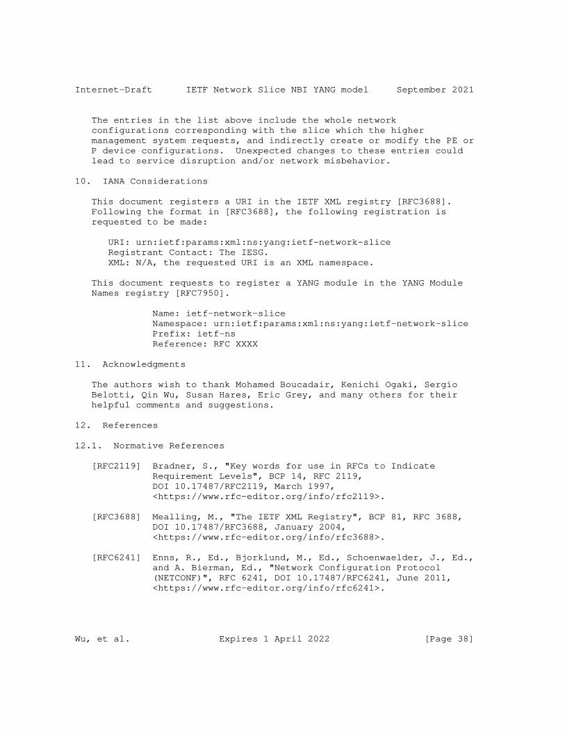
Internet-Draft IETF Network Slice NBI YANG model September 2021
The entries in the list above include the whole network configurations corresponding with the slice which the higher management system requests, and indirectly create or modify the PE or P device configurations. Unexpected changes to these entries could lead to service disruption and/or network misbehavior.
10. IANA Considerations
This document registers a URI in the IETF XML registry [RFC3688]. Following the format in [RFC3688], the following registration is requested to be made:
URI: urn:ietf:params:xml:ns:yang:ietf-network-slice Registrant Contact: The IESG. XML: N/A, the requested URI is an XML namespace.
This document requests to register a YANG module in the YANG Module Names registry [RFC7950].
Name: ietf-network-slice Namespace: urn:ietf:params:xml:ns:yang:ietf-network-slice Prefix: ietf-ns Reference: RFC XXXX
11. Acknowledgments
The authors wish to thank Mohamed Boucadair, Kenichi Ogaki, Sergio Belotti, Qin Wu, Susan Hares, Eric Grey, and many others for their helpful comments and suggestions.
12. References
12.1. Normative References
[RFC2119] Bradner, S., "Key words for use in RFCs to Indicate Requirement Levels", BCP 14, RFC 2119, DOI 10.17487/RFC2119, March 1997, <https://www.rfc-editor.org/info/rfc2119>.
[RFC3688] Mealling, M., "The IETF XML Registry", BCP 81, RFC 3688, DOI 10.17487/RFC3688, January 2004, <https://www.rfc-editor.org/info/rfc3688>.
[RFC6241] Enns, R., Ed., Bjorklund, M., Ed., Schoenwaelder, J., Ed., and A. Bierman, Ed., "Network Configuration Protocol (NETCONF)", RFC 6241, DOI 10.17487/RFC6241, June 2011, <https://www.rfc-editor.org/info/rfc6241>.
Wu, et al. Expires 1 April 2022 [Page 38]
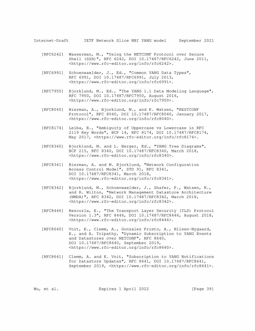
Internet-Draft IETF Network Slice NBI YANG model September 2021
[RFC6242] Wasserman, M., "Using the NETCONF Protocol over Secure Shell (SSH)", RFC 6242, DOI 10.17487/RFC6242, June 2011, <https://www.rfc-editor.org/info/rfc6242>.
[RFC6991] Schoenwaelder, J., Ed., "Common YANG Data Types", RFC 6991, DOI 10.17487/RFC6991, July 2013, <https://www.rfc-editor.org/info/rfc6991>.
[RFC7950] Bjorklund, M., Ed., "The YANG 1.1 Data Modeling Language", RFC 7950, DOI 10.17487/RFC7950, August 2016, <https://www.rfc-editor.org/info/rfc7950>.
[RFC8040] Bierman, A., Bjorklund, M., and K. Watsen, "RESTCONF Protocol", RFC 8040, DOI 10.17487/RFC8040, January 2017, <https://www.rfc-editor.org/info/rfc8040>.
[RFC8174] Leiba, B., "Ambiguity of Uppercase vs Lowercase in RFC 2119 Key Words", BCP 14, RFC 8174, DOI 10.17487/RFC8174, May 2017, <https://www.rfc-editor.org/info/rfc8174>.
[RFC8340] Bjorklund, M. and L. Berger, Ed., "YANG Tree Diagrams", BCP 215, RFC 8340, DOI 10.17487/RFC8340, March 2018, <https://www.rfc-editor.org/info/rfc8340>.
[RFC8341] Bierman, A. and M. Bjorklund, "Network Configuration Access Control Model", STD 91, RFC 8341, DOI 10.17487/RFC8341, March 2018, <https://www.rfc-editor.org/info/rfc8341>.
[RFC8342] Bjorklund, M., Schoenwaelder, J., Shafer, P., Watsen, K., and R. Wilton, "Network Management Datastore Architecture (NMDA)", RFC 8342, DOI 10.17487/RFC8342, March 2018, <https://www.rfc-editor.org/info/rfc8342>.
[RFC8446] Rescorla, E., "The Transport Layer Security (TLS) Protocol Version 1.3", RFC 8446, DOI 10.17487/RFC8446, August 2018, <https://www.rfc-editor.org/info/rfc8446>.
[RFC8640] Voit, E., Clemm, A., Gonzalez Prieto, A., Nilsen-Nygaard, E., and A. Tripathy, "Dynamic Subscription to YANG Events and Datastores over NETCONF", RFC 8640, DOI 10.17487/RFC8640, September 2019, <https://www.rfc-editor.org/info/rfc8640>.
[RFC8641] Clemm, A. and E. Voit, "Subscription to YANG Notifications for Datastore Updates", RFC 8641, DOI 10.17487/RFC8641, September 2019, <https://www.rfc-editor.org/info/rfc8641>.
Wu, et al. Expires 1 April 2022 [Page 39]
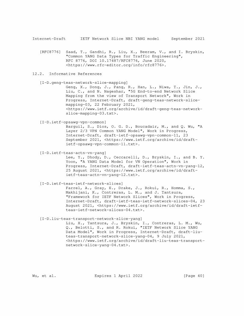
Internet-Draft IETF Network Slice NBI YANG model September 2021
[RFC8776] Saad, T., Gandhi, R., Liu, X., Beeram, V., and I. Bryskin, "Common YANG Data Types for Traffic Engineering", RFC 8776, DOI 10.17487/RFC8776, June 2020, <https://www.rfc-editor.org/info/rfc8776>.
12.2. Informative References
[I-D.geng-teas-network-slice-mapping] Geng, X., Dong, J., Pang, R., Han, L., Niwa, T., Jin, J., Liu, C., and N. Nageshar, "5G End-to-end Network Slice Mapping from the view of Transport Network", Work in Progress, Internet-Draft, draft-geng-teas-network-slice- mapping-03, 22 February 2021, <https://www.ietf.org/archive/id/draft-geng-teas-network- slice-mapping-03.txt>.
[I-D.ietf-opsawg-vpn-common] Barguil, S., Dios, O. G. D., Boucadair, M., and Q. Wu, "A Layer 2/3 VPN Common YANG Model", Work in Progress, Internet-Draft, draft-ietf-opsawg-vpn-common-11, 23 September 2021, <https://www.ietf.org/archive/id/draft- ietf-opsawg-vpn-common-11.txt>.
[I-D.ietf-teas-actn-vn-yang] Lee, Y., Dhody, D., Ceccarelli, D., Bryskin, I., and B. Y. Yoon, "A YANG Data Model for VN Operation", Work in Progress, Internet-Draft, draft-ietf-teas-actn-vn-yang-12, 25 August 2021, <https://www.ietf.org/archive/id/draft- ietf-teas-actn-vn-yang-12.txt>.
[I-D.ietf-teas-ietf-network-slices] Farrel, A., Gray, E., Drake, J., Rokui, R., Homma, S., Makhijani, K., Contreras, L. M., and J. Tantsura, "Framework for IETF Network Slices", Work in Progress, Internet-Draft, draft-ietf-teas-ietf-network-slices-04, 23 August 2021, <https://www.ietf.org/archive/id/draft-ietf- teas-ietf-network-slices-04.txt>.
[I-D.liu-teas-transport-network-slice-yang] Liu, X., Tantsura, J., Bryskin, I., Contreras, L. M., Wu, Q., Belotti, S., and R. Rokui, "IETF Network Slice YANG Data Model", Work in Progress, Internet-Draft, draft-liu- teas-transport-network-slice-yang-04, 9 July 2021, <https://www.ietf.org/archive/id/draft-liu-teas-transport- network-slice-yang-04.txt>.
Wu, et al. Expires 1 April 2022 [Page 40]
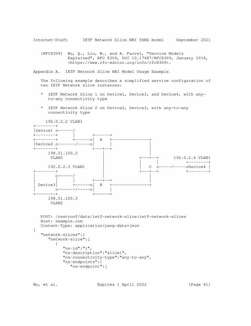
Internet-Draft IETF Network Slice NBI YANG model September 2021
[RFC8309] Wu, Q., Liu, W., and A. Farrel, "Service Models Explained", RFC 8309, DOI 10.17487/RFC8309, January 2018, <https://www.rfc-editor.org/info/rfc8309>.
Appendix A. IETF Network Slice NBI Model Usage Example
The following example describes a simplified service configuration of two IETF Network slice instances:
* IETF Network Slice 1 on Device1, Device3, and Device4, with any- to-any connectivity type
* IETF Network Slice 2 on Device2, Device3, with any-to-any connectivity type
192.0.2.2 VLAN1+--------+|Device1 o------/+--------+ | +------++--------+ +------o| A +---------------+|Device2 o-------/-----o| | |+--------+ +---+--+ | 198.51.100.2 | | VLAN2 | +---+--+ 192.0.2.4 VLAN1 | | | +--------+ 192.0.2.3 VLAN1 | | C o-----/-----oDevice4 |+--------+ | +---+--+ +--------+| o------/ | || | | +---+--+ || Device3| +------o| B +---------------+| o-------/-----o| |+--------+ +------+ 198.51.100.3 VLAN2
POST: /restconf/data/ietf-network-slice:ietf-network-slices Host: example.com Content-Type: application/yang-data+json{ "network-slices":{ "network-slice":[ { "ns-id":"1", "ns-description":"slice1", "ns-connectivity-type":"any-to-any", "ns-endpoints":{ "ns-endpoint":[
Wu, et al. Expires 1 April 2022 [Page 41]
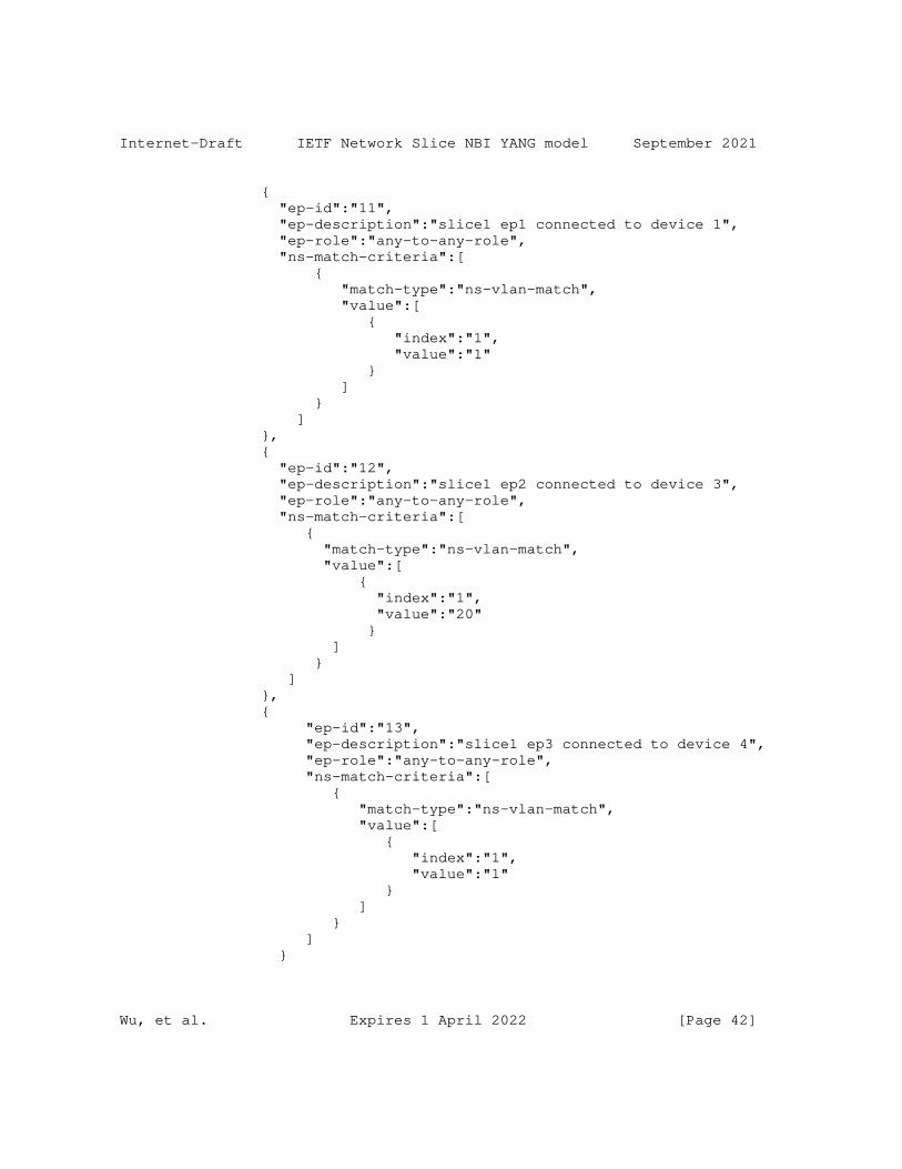
Internet-Draft IETF Network Slice NBI YANG model September 2021
{ "ep-id":"11", "ep-description":"slice1 ep1 connected to device 1", "ep-role":"any-to-any-role", "ns-match-criteria":[ { "match-type":"ns-vlan-match", "value":[ { "index":"1", "value":"1" } ] } ] }, { "ep-id":"12", "ep-description":"slice1 ep2 connected to device 3", "ep-role":"any-to-any-role", "ns-match-criteria":[ { "match-type":"ns-vlan-match", "value":[ { "index":"1", "value":"20" } ] } ] }, { "ep-id":"13", "ep-description":"slice1 ep3 connected to device 4", "ep-role":"any-to-any-role", "ns-match-criteria":[ { "match-type":"ns-vlan-match", "value":[ { "index":"1", "value":"1" } ] } ] }
Wu, et al. Expires 1 April 2022 [Page 42]
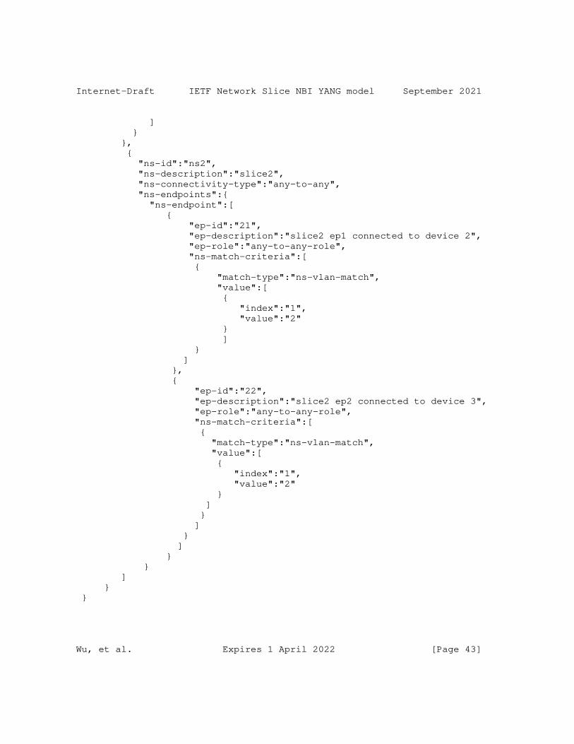
Internet-Draft IETF Network Slice NBI YANG model September 2021
] } }, { "ns-id":"ns2", "ns-description":"slice2", "ns-connectivity-type":"any-to-any", "ns-endpoints":{ "ns-endpoint":[ { "ep-id":"21", "ep-description":"slice2 ep1 connected to device 2", "ep-role":"any-to-any-role", "ns-match-criteria":[ { "match-type":"ns-vlan-match", "value":[ { "index":"1", "value":"2" } ] } ] }, { "ep-id":"22", "ep-description":"slice2 ep2 connected to device 3", "ep-role":"any-to-any-role", "ns-match-criteria":[ { "match-type":"ns-vlan-match", "value":[ { "index":"1", "value":"2" } ] } ] } ] } } ] } }
Wu, et al. Expires 1 April 2022 [Page 43]
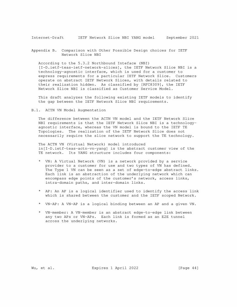
Internet-Draft IETF Network Slice NBI YANG model September 2021
Appendix B. Comparison with Other Possible Design choices for IETF Network Slice NBI
According to the 5.3.2 Northbound Inteface (NBI) [I-D.ietf-teas-ietf-network-slices], the IETF Network Slice NBI is a technology-agnostic interface, which is used for a customer to express requirements for a particular IETF Network Slice. Customers operate on abstract IETF Network Slices, with details related to their realization hidden. As classified by [RFC8309], the IETF Network Slice NBI is classified as Customer Service Model.
This draft analyzes the following existing IETF models to identify the gap between the IETF Network Slice NBI requirements.
B.1. ACTN VN Model Augmentation
The difference between the ACTN VN model and the IETF Network Slice NBI requirements is that the IETF Network Slice NBI is a technology- agnostic interface, whereas the VN model is bound to the IETF TE Topologies. The realization of the IETF Network Slice does not necessarily require the slice network to support the TE technology.
The ACTN VN (Virtual Network) model introduced in[I-D.ietf-teas-actn-vn-yang] is the abstract customer view of the TE network. Its YANG structure includes four components:
* VN: A Virtual Network (VN) is a network provided by a service provider to a customer for use and two types of VN has defined. The Type 1 VN can be seen as a set of edge-to-edge abstract links. Each link is an abstraction of the underlying network which can encompass edge points of the customer’s network, access links, intra-domain paths, and inter-domain links.
* AP: An AP is a logical identifier used to identify the access link which is shared between the customer and the IETF scoped Network.
* VN-AP: A VN-AP is a logical binding between an AP and a given VN.
* VN-member: A VN-member is an abstract edge-to-edge link between any two APs or VN-APs. Each link is formed as an E2E tunnel across the underlying networks.
Wu, et al. Expires 1 April 2022 [Page 44]
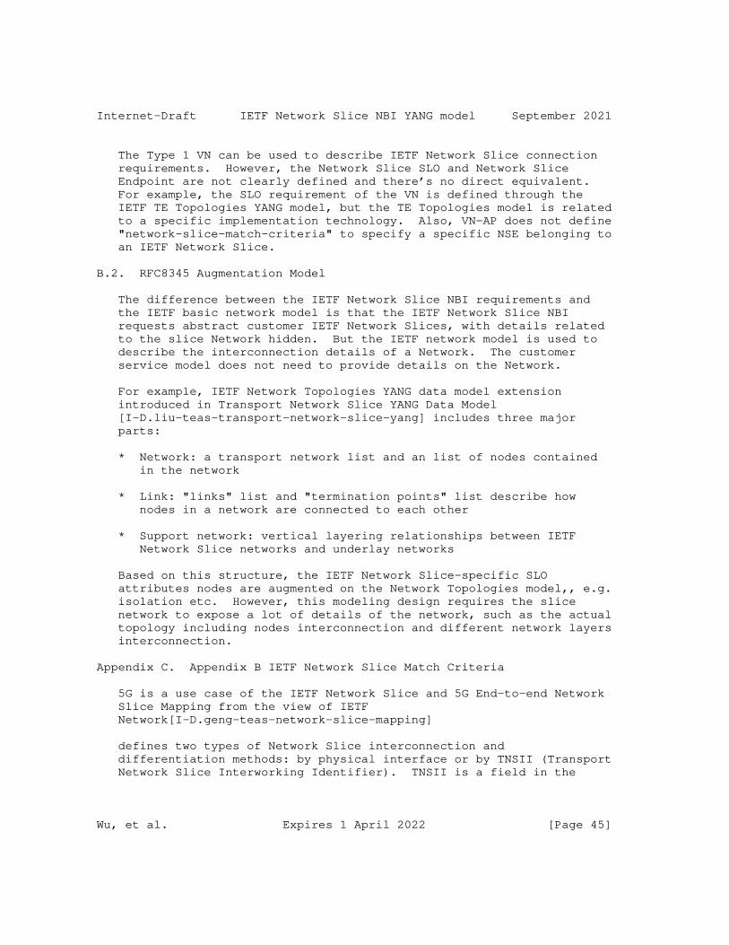
Internet-Draft IETF Network Slice NBI YANG model September 2021
The Type 1 VN can be used to describe IETF Network Slice connection requirements. However, the Network Slice SLO and Network Slice Endpoint are not clearly defined and there’s no direct equivalent. For example, the SLO requirement of the VN is defined through the IETF TE Topologies YANG model, but the TE Topologies model is related to a specific implementation technology. Also, VN-AP does not define "network-slice-match-criteria" to specify a specific NSE belonging to an IETF Network Slice.
B.2. RFC8345 Augmentation Model
The difference between the IETF Network Slice NBI requirements and the IETF basic network model is that the IETF Network Slice NBI requests abstract customer IETF Network Slices, with details related to the slice Network hidden. But the IETF network model is used to describe the interconnection details of a Network. The customer service model does not need to provide details on the Network.
For example, IETF Network Topologies YANG data model extension introduced in Transport Network Slice YANG Data Model [I-D.liu-teas-transport-network-slice-yang] includes three major parts:
* Network: a transport network list and an list of nodes contained in the network
* Link: "links" list and "termination points" list describe how nodes in a network are connected to each other
* Support network: vertical layering relationships between IETF Network Slice networks and underlay networks
Based on this structure, the IETF Network Slice-specific SLO attributes nodes are augmented on the Network Topologies model,, e.g. isolation etc. However, this modeling design requires the slice network to expose a lot of details of the network, such as the actual topology including nodes interconnection and different network layers interconnection.
Appendix C. Appendix B IETF Network Slice Match Criteria
5G is a use case of the IETF Network Slice and 5G End-to-end Network Slice Mapping from the view of IETF Network[I-D.geng-teas-network-slice-mapping]
defines two types of Network Slice interconnection and differentiation methods: by physical interface or by TNSII (Transport Network Slice Interworking Identifier). TNSII is a field in the
Wu, et al. Expires 1 April 2022 [Page 45]

Internet-Draft IETF Network Slice NBI YANG model September 2021
packet header when different 5G wireless network slices are transported through a single physical interfaces of the IETF scoped Network. In the 5G scenario, "network-slice-match-criteria" refers to TNSII.
+------------------------------------------------------------+ | 5G E2E network slice orchestrator | ++-----------------------------------------------------+-----+ | | | | IETF Network Slice NBI | +---+-------+ | +-----+-----+ | | +------------------+ | | |RAN Slice | |IETF Network Slice| |Core Slice | |controller | | controller | | controller| +----+------+ +-------+----------+ +-----+-----+ | | | | | | +---+--+ +------------+----------------+ ++-----+ | | | | | | | | | | | | |+----+| | | | | || ||NS1-NSE1 | Network Slice 1 | |+----+| ||gNB1|+---------+-----+-----------------------+--------+|UPF1|| || |+************ / |NS1-NSE3|+----+| |+----+|NS2-NSE1 | */ | | | | | /* | | | |+----+|NS1-NSE2 | / * | | | || |+---------- * Network Slice 2 |NS2-NSE3|+----+| ||gNB2|+************************************************+|UPF2|| || ||NS2-NSE2 | | |+----+| |+----+| | | | | | | | | | | | | | | | +------+ +----------- -----------------+ +------+
As shown in the figure, gNodeB 1 and gNodeB 2 use IP gNB1 and IP gNB2 to communicate with the IETF network, respectively. In addition, the traffic of NS1 and NS2 on gNodeB 1 and gNodeB 2 is transmitted through the same access links to the IETF slice network. The IETF slice network need to to distinguish different IETF Network Slice traffic of same gNB. Therefore, in addition to using "node-id" and "ep-ip" to identify a Network Slice Endpont, other information is needed along with these parameters to uniquely distinguish a NSE. For example, VLAN IDs in the user traffic can be used to distinguish the NSEs of gNBs and UPFs.
Wu, et al. Expires 1 April 2022 [Page 46]
Internet-Draft IETF Network Slice NBI YANG model September 2021
Authors’ Addresses
Bo Wu Huawei Technologies 101 Software Avenue, Yuhua District Nanjing Jiangsu, 210012 China
Email: [email protected]
Dhruv Dhody Huawei Technologies Divyashree Techno Park Bangalore 560066 Karnataka India
Email: [email protected]
Reza Rokui Nokia
Email: [email protected]
Tarek Saad Juniper Networks
Email: [email protected]
Liuyan Han China Mobile
Email: [email protected]
Wu, et al. Expires 1 April 2022 [Page 47]
Network Working Group A. Farrel, Ed.Internet-Draft Old Dog ConsultingIntended status: Informational E. GrayExpires: April 28, 2022 Independent J. Drake Juniper Networks R. Rokui Nokia S. Homma NTT K. Makhijani Futurewei LM. Contreras Telefonica J. Tantsura Microsoft October 25, 2021
Framework for IETF Network Slices draft-ietf-teas-ietf-network-slices-05
Abstract
This document describes network slicing in the context of networks built from IETF technologies. It defines the term "IETF Network Slice" and establishes the general principles of network slicing in the IETF context.
The document discusses the general framework for requesting and operating IETF Network Slices, the characteristics of an IETF Network Slice, the necessary system components and interfaces, and how abstract requests can be mapped to more specific technologies. The document also discusses related considerations with monitoring and security.
This document also provides definitions of related terms to enable consistent usage in other IETF documents that describe or use aspects of IETF Network Slices.
Status of This Memo
This Internet-Draft is submitted in full conformance with the provisions of BCP 78 and BCP 79.
Internet-Drafts are working documents of the Internet Engineering Task Force (IETF). Note that other groups may also distribute
Farrel, et al. Expires April 28, 2022 [Page 1]
Internet-Draft IETF Network Slices October 2021
working documents as Internet-Drafts. The list of current Internet- Drafts is at https://datatracker.ietf.org/drafts/current/.
Internet-Drafts are draft documents valid for a maximum of six months and may be updated, replaced, or obsoleted by other documents at any time. It is inappropriate to use Internet-Drafts as reference material or to cite them other than as "work in progress."
This Internet-Draft will expire on April 28, 2022.
Copyright Notice
Copyright (c) 2021 IETF Trust and the persons identified as the document authors. All rights reserved.
This document is subject to BCP 78 and the IETF Trust’s Legal Provisions Relating to IETF Documents (https://trustee.ietf.org/license-info) in effect on the date of publication of this document. Please review these documents carefully, as they describe your rights and restrictions with respect to this document. Code Components extracted from this document must include Simplified BSD License text as described in Section 4.e of the Trust Legal Provisions and are provided without warranty as described in the Simplified BSD License.
Table of Contents
1. Introduction . . . . . . . . . . . . . . . . . . . . . . . . 3 1.1. Background . . . . . . . . . . . . . . . . . . . . . . . 4 2. Terms and Abbreviations . . . . . . . . . . . . . . . . . . . 5 2.1. Core Terminology . . . . . . . . . . . . . . . . . . . . 5 3. IETF Network Slice Objectives . . . . . . . . . . . . . . . . 7 3.1. Definition and Scope of IETF Network Slice . . . . . . . 7 3.2. IETF Network Slice Service . . . . . . . . . . . . . . . 8 3.2.1. Ancillary CEs . . . . . . . . . . . . . . . . . . . . 10 4. IETF Network Slice System Characteristics . . . . . . . . . . 10 4.1. Objectives for IETF Network Slices . . . . . . . . . . . 10 4.1.1. Service Level Objectives . . . . . . . . . . . . . . 11 4.1.2. Service Level Expectations . . . . . . . . . . . . . 13 4.2. IETF Network Slice Endpoints . . . . . . . . . . . . . . 15 4.3. IETF Network Slice Decomposition . . . . . . . . . . . . 18 5. Framework . . . . . . . . . . . . . . . . . . . . . . . . . . 18 5.1. IETF Network Slice Stakeholders . . . . . . . . . . . . . 19 5.2. Expressing Connectivity Intents . . . . . . . . . . . . . 19 5.3. IETF Network Slice Controller (NSC) . . . . . . . . . . . 21 5.3.1. IETF Network Slice Controller Interfaces . . . . . . 23 5.3.2. Management Architecture . . . . . . . . . . . . . . . 24 5.4. IETF Network Slice Structure . . . . . . . . . . . . . . 25
Farrel, et al. Expires April 28, 2022 [Page 2]
Internet-Draft IETF Network Slices October 2021
6. Realizing IETF Network Slices . . . . . . . . . . . . . . . . 27 6.1. Architecture to Realize IETF Network Slices . . . . . . . 27 6.2. Procedures to Realize IETF Network Slices . . . . . . . . 29 6.3. Applicability of ACTN to IETF Network Slices . . . . . . 30 6.4. Applicability of Enhanced VPNs to IETF Network Slices . . 31 6.5. Network Slicing and Slice Aggregation in IP/MPLS Networks 31 7. Isolation in IETF Network Slices . . . . . . . . . . . . . . 32 7.1. Isolation as a Service Requirement . . . . . . . . . . . 32 7.2. Isolation in IETF Network Slice Realization . . . . . . . 32 8. Management Considerations . . . . . . . . . . . . . . . . . . 32 9. Security Considerations . . . . . . . . . . . . . . . . . . . 32 10. Privacy Considerations . . . . . . . . . . . . . . . . . . . 34 11. IANA Considerations . . . . . . . . . . . . . . . . . . . . . 34 12. Informative References . . . . . . . . . . . . . . . . . . . 34 Acknowledgments . . . . . . . . . . . . . . . . . . . . . . . . . 37 Contributors . . . . . . . . . . . . . . . . . . . . . . . . . . 38 Authors’ Addresses . . . . . . . . . . . . . . . . . . . . . . . 39
1. Introduction
A number of use cases benefit from network connections that along with the connectivity provide assurance of meeting a specific set of objectives with respect to network resources use. This connectivity and resource commitment is referred to as a network slice. Since the term network slice is rather generic, the qualifying term "IETF" is used in this document to limit the scope of network slice to network technologies described and standardized by the IETF. This document defines the concept of IETF Network Slices that provide connectivity coupled with a set of specific commitments of network resources between a number of endpoints (known as customer edge (CE) devices - see Section 2.1) over a shared underlay network. Services that might benefit from IETF Network Slices include, but are not limited to:
o 5G services (e.g. eMBB, URLLC, mMTC)(See [TS23501])
o Network wholesale services
o Network infrastructure sharing among operators
o NFV connectivity and Data Center Interconnect
IETF Network Slices are created and managed within the scope of one or more network technologies (e.g., IP, MPLS, optical). They are intended to enable a diverse set of applications that have different requirements to coexist on the shared underlay network. A request for an IETF Network Slice is technology-agnostic so as to allow a customer to describe their network connectivity objectives in a common format, independent of the underlying technologies used.
Farrel, et al. Expires April 28, 2022 [Page 3]
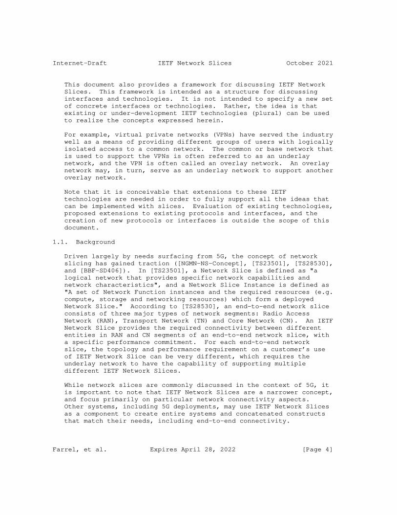
Internet-Draft IETF Network Slices October 2021
This document also provides a framework for discussing IETF Network Slices. This framework is intended as a structure for discussing interfaces and technologies. It is not intended to specify a new set of concrete interfaces or technologies. Rather, the idea is that existing or under-development IETF technologies (plural) can be used to realize the concepts expressed herein.
For example, virtual private networks (VPNs) have served the industry well as a means of providing different groups of users with logically isolated access to a common network. The common or base network that is used to support the VPNs is often referred to as an underlay network, and the VPN is often called an overlay network. An overlay network may, in turn, serve as an underlay network to support another overlay network.
Note that it is conceivable that extensions to these IETF technologies are needed in order to fully support all the ideas that can be implemented with slices. Evaluation of existing technologies, proposed extensions to existing protocols and interfaces, and the creation of new protocols or interfaces is outside the scope of this document.
1.1. Background
Driven largely by needs surfacing from 5G, the concept of network slicing has gained traction ([NGMN-NS-Concept], [TS23501], [TS28530], and [BBF-SD406]). In [TS23501], a Network Slice is defined as "a logical network that provides specific network capabilities and network characteristics", and a Network Slice Instance is defined as "A set of Network Function instances and the required resources (e.g. compute, storage and networking resources) which form a deployed Network Slice." According to [TS28530], an end-to-end network slice consists of three major types of network segments: Radio Access Network (RAN), Transport Network (TN) and Core Network (CN). An IETF Network Slice provides the required connectivity between different entities in RAN and CN segments of an end-to-end network slice, with a specific performance commitment. For each end-to-end network slice, the topology and performance requirement on a customer’s use of IETF Network Slice can be very different, which requires the underlay network to have the capability of supporting multiple different IETF Network Slices.
While network slices are commonly discussed in the context of 5G, it is important to note that IETF Network Slices are a narrower concept, and focus primarily on particular network connectivity aspects. Other systems, including 5G deployments, may use IETF Network Slices as a component to create entire systems and concatenated constructs that match their needs, including end-to-end connectivity.
Farrel, et al. Expires April 28, 2022 [Page 4]
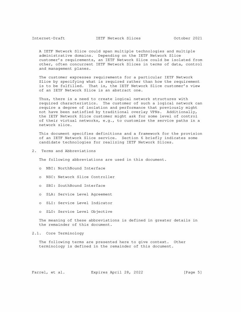
Internet-Draft IETF Network Slices October 2021
A IETF Network Slice could span multiple technologies and multiple administrative domains. Depending on the IETF Network Slice customer’s requirements, an IETF Network Slice could be isolated from other, often concurrent IETF Network Slices in terms of data, control and management planes.
The customer expresses requirements for a particular IETF Network Slice by specifying what is required rather than how the requirement is to be fulfilled. That is, the IETF Network Slice customer’s view of an IETF Network Slice is an abstract one.
Thus, there is a need to create logical network structures with required characteristics. The customer of such a logical network can require a degree of isolation and performance that previously might not have been satisfied by traditional overlay VPNs. Additionally, the IETF Network Slice customer might ask for some level of control of their virtual networks, e.g., to customize the service paths in a network slice.
This document specifies definitions and a framework for the provision of an IETF Network Slice service. Section 6 briefly indicates some candidate technologies for realizing IETF Network Slices.
2. Terms and Abbreviations
The following abbreviations are used in this document.
o NBI: NorthBound Interface
o NSC: Network Slice Controller
o SBI: SouthBound Interface
o SLA: Service Level Agreement
o SLI: Service Level Indicator
o SLO: Service Level Objective
The meaning of these abbreviations is defined in greater details in the remainder of this document.
2.1. Core Terminology
The following terms are presented here to give context. Other terminology is defined in the remainder of this document.
Farrel, et al. Expires April 28, 2022 [Page 5]

Internet-Draft IETF Network Slices October 2021
Customer: A customer is the requester of an IETF Network Slice service. Customers may request monitoring of SLOs. A customer may be an entity such as an enterprise network or a network operator, an individual working at such an entity, a private individual contracting for a service, or an application or software component. A customer may be an external party (classically a paying customer) or a division of a network operator that uses the service provided by another division of the same operator. Other terms that have been applied to the customer role are "client" and "consumer".
Provider: A provider is the organization that delivers an IETF Network Slice service. A provider is the network operator that controls the network resources used to construct the network slice (that is, the network that is sliced). The provider’s network maybe a physical network or may be a virtual network supplied by another service provider.
Customer Edge (CE): The customer device that is attached to an IETF Network Slice Service. Examples include routers, Ethernet switches, firewalls, 4G/5G RAN or Core nodes, application accelerators, server load balancers, HTTP header enrichment functions, and PEPs (Performance Enhancing Proxy). Each CE must have a unique identifier (e.g., an IP address or MAC address) within a given IETF Network Slice Service and may use the same identifier in multiple IETF Network Slice Services. In some circumstances CEs are provided to the customer and managed by the provider. Note that in the context of an IETF Network Slice, a CE represents the endpoint of an IETF Network Slice Service (see also Section 4.2) and as such may be a device or software component and may, in the case of netork functions virtualization (for example), be an abstract function supported within the provider’s network.
Provider Edge: The device within the provider network to which a CE is attached. A CE may be attached to multiple PEs and multiple CEs may be attached to a given PE.
Attachment Circuit (AC): A channel connecting a CE and a PE over which packets belonging to an IETF Network Slice Service are exchanged. The customer and provider agree on which values in which combination of layer 2 and layer 3 fields within a packet identify to which {IETF Network Slice Service, connectivity matrix, and SLOs/SLEs} that packet is assigned. The customer and provider may agree on a per {IETF Network Slice Service, connectivity matrix, and SLOs/SLEs} basis to police or shape traffic in both the ingress (CE to PE) direction and egress (PE to CE) direction. This ensures that the traffic is within the capacity profile that is agreed in a Network Slide Service.
Farrel, et al. Expires April 28, 2022 [Page 6]
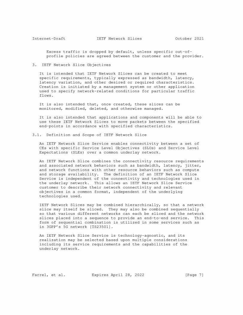
Internet-Draft IETF Network Slices October 2021
Excess traffic is dropped by default, unless specific out-of- profile policies are agreed between the customer and the provider.
3. IETF Network Slice Objectives
It is intended that IETF Network Slices can be created to meet specific requirements, typically expressed as bandwidth, latency, latency variation, and other desired or required characteristics. Creation is initiated by a management system or other application used to specify network-related conditions for particular traffic flows.
It is also intended that, once created, these slices can be monitored, modified, deleted, and otherwise managed.
It is also intended that applications and components will be able to use these IETF Network Slices to move packets between the specified end-points in accordance with specified characteristics.
3.1. Definition and Scope of IETF Network Slice
An IETF Network Slice Service enables connectivity between a set of CEs with specific Service Level Objectives (SLOs) and Service Level Expectations (SLEs) over a common underlay network.
An IETF Network Slice combines the connectivity resource requirements and associated network behaviors such as bandwidth, latency, jitter, and network functions with other resource behaviors such as compute and storage availability. The definition of an IETF Network Slice Service is independent of the connectivity and technologies used in the underlay network. This allows an IETF Network Slice Service customer to describe their network connectivity and relevant objectives in a common format, independent of the underlying technologies used.
IETF Network Slices may be combined hierarchically, so that a network slice may itself be sliced. They may also be combined sequentially so that various different networks can each be sliced and the network slices placed into a sequence to provide an end-to-end service. This form of sequential combination is utilized in some services such as in 3GPP’s 5G network [TS23501].
An IETF Network Slice Service is technology-agnostic, and its realization may be selected based upon multiple considerations including its service requirements and the capabilities of the underlay network.
Farrel, et al. Expires April 28, 2022 [Page 7]
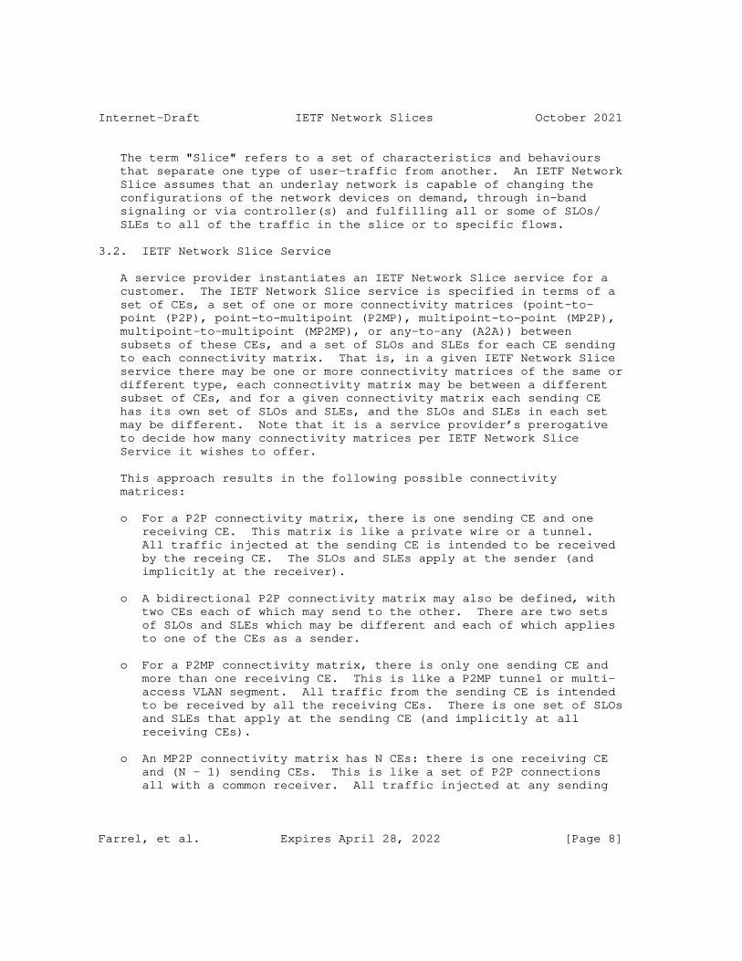
Internet-Draft IETF Network Slices October 2021
The term "Slice" refers to a set of characteristics and behaviours that separate one type of user-traffic from another. An IETF Network Slice assumes that an underlay network is capable of changing the configurations of the network devices on demand, through in-band signaling or via controller(s) and fulfilling all or some of SLOs/ SLEs to all of the traffic in the slice or to specific flows.
3.2. IETF Network Slice Service
A service provider instantiates an IETF Network Slice service for a customer. The IETF Network Slice service is specified in terms of a set of CEs, a set of one or more connectivity matrices (point-to- point (P2P), point-to-multipoint (P2MP), multipoint-to-point (MP2P), multipoint-to-multipoint (MP2MP), or any-to-any (A2A)) between subsets of these CEs, and a set of SLOs and SLEs for each CE sending to each connectivity matrix. That is, in a given IETF Network Slice service there may be one or more connectivity matrices of the same or different type, each connectivity matrix may be between a different subset of CEs, and for a given connectivity matrix each sending CE has its own set of SLOs and SLEs, and the SLOs and SLEs in each set may be different. Note that it is a service provider’s prerogative to decide how many connectivity matrices per IETF Network Slice Service it wishes to offer.
This approach results in the following possible connectivity matrices:
o For a P2P connectivity matrix, there is one sending CE and one receiving CE. This matrix is like a private wire or a tunnel. All traffic injected at the sending CE is intended to be received by the receing CE. The SLOs and SLEs apply at the sender (and implicitly at the receiver).
o A bidirectional P2P connectivity matrix may also be defined, with two CEs each of which may send to the other. There are two sets of SLOs and SLEs which may be different and each of which applies to one of the CEs as a sender.
o For a P2MP connectivity matrix, there is only one sending CE and more than one receiving CE. This is like a P2MP tunnel or multi- access VLAN segment. All traffic from the sending CE is intended to be received by all the receiving CEs. There is one set of SLOs and SLEs that apply at the sending CE (and implicitly at all receiving CEs).
o An MP2P connectivity matrix has N CEs: there is one receiving CE and (N - 1) sending CEs. This is like a set of P2P connections all with a common receiver. All traffic injected at any sending
Farrel, et al. Expires April 28, 2022 [Page 8]

Internet-Draft IETF Network Slices October 2021
CE is received by the single receiving CE. Each sending CE has its own set of SLOs and SLEs, and they may all be different (the combination of those SLOs and SLEs gives the implicit SLOs and SLEs for the receiving CE - that is, the receiving CE is expected to receive all traffic from all senders).
o In an MP2MP connectivity matrix each of the N CEs can be a sending CE such that its traffic is delivered to all of the other CEs. Each sending CE has its own set of SLOs and SLEs and they may all be different. The combination of those SLOs/SLEs gives the implicit SLOs/SLEs for each/all of the receiving CEs since each receiving CE is expect to receive all traffic from all/any sender.
o With an A2A matrix, any sending CE may send to any one receiving CE or any set of receiving CEs. There is an implicit level of routing in this connectivity matrix that is not present in the other connectivity matrices as the matrix must determine to which receiving CEs to deliver each packet. The SLOs/SLEs apply to individual sending CEs and individual receiving CEs, but there is no implicit linkage and a sending CE may be "disappointed" if the receiver is over-subscribed.
If a CE has multiple attachment circuits to a given IETF Network Slice Service and they are operating in single-active mode, then all traffic between the CE and its attached PEs transits a single attachment circuit; if they are operating in in all-active mode, then traffic between the CE and its attached PEs is distributed across all of the active attachment circuits.
A given sending CE may be part of multiple connectivity matrices within a single IETF Network Slice service, and the CE may have different SLOs and SLEs for each connectivity matrix to which it is sending. Note that a given sending CE’s SLOs and SLEs for a given connectivity matrix apply between it and each of the receiving CEs for that connectivity matrix.
An IETF Network Slice service provider may freely make a deployment choice as to whether to offer a 1:1 relationship between IETF Network Slice service and connectivity matrix, or to support multiple connectivity matrices in a single IETF Network Slice service. In the former case, the provider might need to deliver multiple IETF Network Slice services to achive the function of the second case.
It should be noted that per Section 9 of [RFC4364] an IETF Network Slice service customer may actually provide IETF Network Slice services to other customers in a mode sometimes refered to as "carrier’s carrier". In this case, the underlying IETF Network Slice service provider may be owned and operated by the same or a different
Farrel, et al. Expires April 28, 2022 [Page 9]
Internet-Draft IETF Network Slices October 2021
provider network. As noted in Section 3.1, network slices may be composed hierarchically or serially.
Section 4.2 provides a description of endpoints in the context of IETF network slicing. For a given IETF Network Slice service, the IETF Network Slice customer and provider agree, on a per-CE basis which end of the attachment circuit provides the service demarcation point (i.e., whether the attachment circuit is inside or outside the IETF Network Slice service). This determines whether the attachment circuit is subject to the set of SLOs and SLEs for the specific CE.
Section 4.2 provides a description of service demarcation endpoints. For a given IETF Network Slice Service, the customer and provider agree, on a per-CE basis, which end of the attachment circuit provides the service demarcation endpoint (i.e., whether the attachment circuit is inside or outside the IETF Network Slice Service). This determines whether the attachment circuit is subject to the set of SLOs and SLEs for the specific CE. This point is illustrated further in Section 4.2.
3.2.1. Ancillary CEs
It may be the case that a customer’s set of CEs needs to be supplemented with additional senders or receivers. An additional sender could be, for example, an IPTV or DNS server either within the provider’s network or attached to it, while an extra receiver could be, for example, a node reachable via the Internet. This will be modelled as a set of ancillary CEs which supplement the customer’s set of CEs in one or more connectivity matrices, or which have their own connectivity matrices. Note that an ancillary CE can either have a resolvable address, e.g., an IP address or MAC address, or it may be a placeholder, e.g., IPTV or DNS server, which is resolved within the provider’s network when the IETF Network Slice Service is instantiated.
4. IETF Network Slice System Characteristics
The following subsections describe the characteristics of IETF Network Slices.
4.1. Objectives for IETF Network Slices
An IETF Network Slice service is defined in terms of quantifiable characteristics known as Service Level Objectives (SLOs) and unquantifiable characteristics known as Service Level Expectations (SLEs). SLOs are expressed in terms Service Level Indicators (SLIs), and together with the SLEs form the contractual agreement between
Farrel, et al. Expires April 28, 2022 [Page 10]
Internet-Draft IETF Network Slices October 2021
service customer and service provider known as a Service Level Agreement (SLA).
The terms are defined as follows:
o A Service Level Indicator (SLI) is a quantifiable measure of an aspect of the performance of a network. For example, it may be a measure of throughput in bits per second, or it may be a measure of latency in milliseconds.
o A Service Level Objective (SLO) is a target value or range for the measurements returned by observation of an SLI. For example, an SLO may be expressed as "SLI <= target", or "lower bound <= SLI <= upper bound". A customer can determine whether the provider is meeting the SLOs by performing measurements on the traffic.
o A Service Level Expectation (SLE) is an expression of an unmeasurable service-related request that a customer of an IETF Network Slice makes of the provider. An SLE is distinct from an SLO because the customer may have little or no way of determining whether the SLE is being met, but they still contract with the provider for a service that meets the expectation.
o A Service Level Agreement (SLA) is an explicit or implicit contract between the customer of an IETF Network Slice service and the provider of the slice. The SLA is expressed in terms of a set of SLOs and SLEs that are to be applied for a given connectivity matrix between a sending CE and the set of receiving CEs, and may include commercial terms as well as any consequences for violating these SLOs and SLEs.
4.1.1. Service Level Objectives
SLOs define a set of measurable network attributes and characteristics that describe an IETF Network Slice Service. SLOs do not describe how an IETF Network Slice Service is realized in the underlay network. Instead, they define the dimensions of operation (time, capacity, etc.), availability, and other attributes. An SLO is applied to a given connectivity matrix between a sending CE and the set of receiving CEs.
An IETF Network Slice service may include multiple connection constructs that associate sets of endpoints. SLOs apply to sets of two or more CEs and apply to specific directions of traffic flow. That is, they apply to a specific source CE and the connection to specific destination CEs.
The SLOs are combined with Service Level Expectations in an SLA.
Farrel, et al. Expires April 28, 2022 [Page 11]
Internet-Draft IETF Network Slices October 2021
4.1.1.1. Some Common SLOs
SLOs can be described as ’Directly Measurable Objectives’: they are always measurable. See Section 4.1.2 for the description of Service Level Expectations which are unmeasurable service-related requests sometimes known as ’Indirectly Measurable Objectives’.
Objectives such as guaranteed minimum bandwidth, guaranteed maximum latency, maximum permissible delay variation, maximum permissible packet loss rate, and availability are ’Directly Measurable Objectives’. Future specifications (such as IETF Network Slice service YANG models) may precisely define these SLOs, and other SLOs may be introduced as described in Section 4.1.1.2.
The definition of these objectives are as follows:
Guaranteed Minimum Bandwidth
Minimum guaranteed bandwidth between two endpoints at any time. The bandwidth is measured in data rate units of bits per second and is measured unidirectionally.
Guaranteed Maximum Latency
Upper bound of network latency when transmitting between two endpoints. The latency is measured in terms of network characteristics (excluding application-level latency). [RFC2681] and [RFC7679] discuss round trip times and one-way metrics, respectively.
Maximum Permissible Delay Variation
Packet delay variation (PDV) as defined by [RFC3393], is the difference in the one-way delay between sequential packets in a flow. This SLO sets a maximum value PDV for packets between two endpoints.
Maximum Permissible Packet Loss Rate
The ratio of packets dropped to packets transmitted between two endpoints over a period of time. See [RFC7680].
Availability
The ratio of uptime to the sum of uptime and downtime, where uptime is the time the IETF Network Slice is available in accordance with the SLOs associated with it.
Farrel, et al. Expires April 28, 2022 [Page 12]
Internet-Draft IETF Network Slices October 2021
4.1.1.2. Other Service Level Objectives
Additional SLOs may be defined to provide additional description of the IETF Network Slice service that a customer requests. These would be specified in further documents.
If the IETF Network Slice service is traffic aware, other traffic specific characteristics may be valuable including MTU, traffic-type (e.g., IPv4, IPv6, Ethernet or unstructured), or a higher-level behavior to process traffic according to user-application (which may be realized using network functions).
4.1.2. Service Level Expectations
SLEs define a set of network attributes and characteristics that describe an IETF Network Slice service, but which are not directly measurable by the customer. Even though the delivery of an SLE cannot usually be determined by the customer, the SLEs form an important part of the contract between customer and provider.
Quite often, an SLE will imply some details of how an IETF Network Slice service is realized by the provider, although most aspects of the implementation in the underlying network layers remain a free choice for the provider.
SLEs may be seen as aspirational on the part of the customer, and they are expressed as behaviors that the provider is expected to apply to the network resources used to deliver the IETF Network Slice service. An IETF Network Slice service can have one or more SLEs associated with it. The SLEs are combined with SLOs in an SLA.
An IETF Network Slice service may include multiple connection constructs that associate sets of endpoints. SLEs apply to sets of two or more endpoints and apply to specific directions of traffic flow. That is, they apply to a specific source endpoint and the connection to specific destination endpoints. However, being more general in nature, SLEs may commonly be applied to all connection constructs in an IETF Network Slice service.
4.1.2.1. Some Common SLEs
SLEs can be described as ’Indirectly Measurable Objectives’: they are not generally directly measurable by the customer.
Security, geographic restrictions, maximum occupancy level, and isolation are example SLEs as follows.
Security
Farrel, et al. Expires April 28, 2022 [Page 13]
Internet-Draft IETF Network Slices October 2021
A customer may request that the provider applies encryption or other security techniques to traffic flowing between endpoints of an IETF Network Slice service. For example, the customer could request that only network links that have MACsec [MACsec] enabled are used to realize the IETF Network Slice service.
This SLE may include the request for encryption (e.g., [RFC4303]) between the two endpoints explicitly to meet architecture recommendations as in [TS33.210] or for compliance with [HIPAA] or [PCI].
Whether or not the provider has met this SLE is generally not directly observable by the customer and cannot be measured as a quantifiable metric.
Please see further discussion on security in Section 9.
Geographic Restrictions
A customer may request that certain geographic limits are applied to how the provider routes traffic for the IETF Network Slice service. For example, the customer may have a preference that its traffic does not pass through a particular country for political or security reasons.
Whether or not the provider has met this SLE is generally not directly observable by the customer and cannot be measured as a quantifiable metric.
Maximal Occupancy Level
The maximal occupancy level specifies the number of flows to be admitted and optionally a maximum number of countable resource units (e.g., IP or MAC addresses) an IETF Network Slice service can consume. Since an IETF Network Slice service may include multiple connection constructs, this SLE should also say whether it applies for the entire IETF Network Service slice, for group of connections, or on a per connection basis.
Again, a customer may not be able to fully determine whether this SLE is being met by the provider.
Isolation
As described in Section 7, a customer may request that its traffic within its IETF Network Slice service is isolated from the effects of other network services supported by the same provider. That is, if another service exceeds capacity or has
Farrel, et al. Expires April 28, 2022 [Page 14]
Internet-Draft IETF Network Slices October 2021
a burst of traffic, the customer’s IETF Network Slice service should remain unaffected and there should be no noticeable change to the quality of traffic delivered.
In general, a customer cannot tell whether a service provider is meeting this SLE. They cannot tell whether the variation of an SLI is because of changes in the underlying network or because of interference from other services carried by the network. And if the service varies within the allowed bounds of the SLOs, there may be no noticeable indication that this SLE has been violated.
Diversity
A customer may request that traffic on the connection between one set of endpoints should use different network resources from the traffic between another set of endpoints. This might be done to enhance the availability of the IETF Network Slice service.
While availability is a measurable objective (see Section 4.1.1.1) this SLE requests a finer grade of control and is not directly measurable (although the customer might become suspicious if two connections fail at the same time).
4.2. IETF Network Slice Endpoints
As noted in Section 3.1, an IETF Network Slice is a logical network topology connecting a number of endpoints. Section 3.2 goes on to describe how the IETF Network Slice service is composed of a set of one or more connectivity matrices that describe connectivity between the endoints across the underlying network.
The characteristics of IETF Network Slice Endpoints (NSEs) are as follows:
o IETF NSEs are conceptual points of connection to an IETF Network Slice. As such, they serve as the IETF Network Slice ingress/ egress points.
o Each NSE maps to a device, application, or a network function, such as (but not limited to): routers, switches, firewalls, WAN, 4G/5G RAN nodes, 4G/5G Core nodes, application accelerators, Deep Packet Inspection (DPI) engines, server load balancers, NAT44 [RFC3022], NAT64 [RFC6146], HTTP header enrichment functions, and TCP optimizers.
Farrel, et al. Expires April 28, 2022 [Page 15]
Internet-Draft IETF Network Slices October 2021
o An NSE is identified by a unique identifier in the context of an IETF Network Slice customer.
o Each NSE is associated with a set of provider-scope identifiers such as IP addresses, encapsulation-specific identifiers (e.g., VLAN tag, MPLS Label), interface/port numbers, node ID, etc.
o IETF NSEs are mapped to endpoints of services/tunnels/paths within the IETF Network Slice during its initialization and realization.
* A combination of NSE identifier and NSE network-scope identifiers defines an NSE in the context of the NSC.
* The NSC will use the NSE network-scope identifiers as part of the process of realizing the IETF Network Slice.
For a given IETF network slice service, the IETF Network Slice customer and provider agree where the endpoint (i.e., the service demarcation point) is located. This determines what resrouces at the edge of the network form part of the IETF Network Slice and are subject to the set of SLOs and SLEs for a specific endpoint.
Figure 1 shows different potential scopes of an IETF Network Slice that are consistent with the different endpoint positions. For the purpose of example and without loss of generality, the figure shows customer edge (CE) and provider edge (PE) nodes connected by access circuits (ACs). Notes after the figure give some explanations.
Farrel, et al. Expires April 28, 2022 [Page 16]
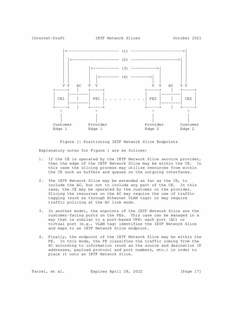
Internet-Draft IETF Network Slices October 2021
|<---------------------- (1) ---------------------->| | | | |<-------------------- (2) -------------------->| | | | | | | | |<----------- (3) ----------->| | | | | | | | | | | | |<-------- (4) -------->| | | | | | | | | | | | V V AC V V V V AC V V +-----+ | +-----+ +-----+ | +-----+ | |--------| | | |--------| | | CE1 | | | PE1 |. . . . . . . . .| PE2 | | | CE2 | | |--------| | | |--------| | +-----+ | +-----+ +-----+ | +-----+ ^ ^ ^ ^ | | | | | | | | Customer Provider Provider Customer Edge 1 Edge 1 Edge 2 Edge 2
Figure 1: Positioning IETF Network Slice Endpoints
Explanatory notes for Figure 1 are as follows:
1. If the CE is operated by the IETF Network Slice service provider, then the edge of the IETF Network Slice may be within the CE. In this case the slicing process may utilize resources from within the CE such as buffers and queues on the outgoing interfaces.
2. The IETF Network Slice may be extended as far as the CE, to include the AC, but not to include any part of the CE. In this case, the CE may be operated by the customer or the provider. Slicing the resources on the AC may require the use of traffic tagging (such as through Ethernet VLAN tags) or may require traffic policing at the AC link ends.
3. In another model, the enpoints of the IETF Network Slice are the customer-facing ports on the PEs. This case can be managed in a way that is similar to a port-based VPN: each port (AC) or virtual port (e.g., VLAN tag) identifies the IETF Network Slice and maps to an IETF Network Slice endpoint.
4. Finally, the endpoint of the IETF Network Slice may be within the PE. In this mode, the PE classifies the traffic coming from the AC according to information (such as the source and desination IP addresses, payload protocol and port numbers, etc.) in order to place it onto an IETF Network Slice.
Farrel, et al. Expires April 28, 2022 [Page 17]
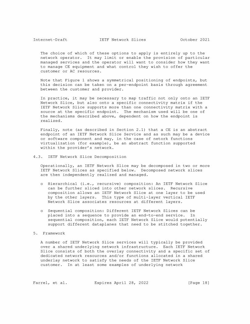
Internet-Draft IETF Network Slices October 2021
The choice of which of these options to apply is entirely up to the network operator. It may limit or enable the provision of particular managed services and the operator will want to consider how they want to manage CE equipment and what control they wish to offer the customer or AC resources.
Note that Figure 1 shows a symmetrical positioning of endpoints, but this decision can be taken on a per-endpoint basis through agreement between the customer and provider.
In practice, it may be necessary to map traffic not only onto an IETF Network Slice, but also onto a specific connectivity matrix if the IETF Network Slice supports more than one connectivity matrix with a source at the specific endpoint. The mechanism used will be one of the mechanisms described above, dependent on how the endpoint is realized.
Finally, note (as described in Section 2.1) that a CE is an abstract endpoint of an IETF Network Slice Service and as such may be a device or software component and may, in the case of netork functions virtualization (for example), be an abstract function supported within the provider’s network.
4.3. IETF Network Slice Decomposition
Operationally, an IETF Network Slice may be decomposed in two or more IETF Network Slices as specified below. Decomposed network slices are then independently realized and managed.
o Hierarchical (i.e., recursive) composition: An IETF Network Slice can be further sliced into other network slices. Recursive composition allows an IETF Network Slice at one layer to be used by the other layers. This type of multi-layer vertical IETF Network Slice associates resources at different layers.
o Sequential composition: Different IETF Network Slices can be placed into a sequence to provide an end-to-end service. In sequential composition, each IETF Network Slice would potentially support different dataplanes that need to be stitched together.
5. Framework
A number of IETF Network Slice services will typically be provided over a shared underlying network infrastructure. Each IETF Network Slice consists of both the overlay connectivity and a specific set of dedicated network resources and/or functions allocated in a shared underlay network to satisfy the needs of the IETF Network Slice customer. In at least some examples of underlying network
Farrel, et al. Expires April 28, 2022 [Page 18]
Internet-Draft IETF Network Slices October 2021
technologies, the integration between the overlay and various underlay resources is needed to ensure the guaranteed performance requested for different IETF Network Slices.
5.1. IETF Network Slice Stakeholders
An IETF Network Slice and its realization involves the following stakeholders and it is relevant to define them for consistent terminology. The IETF Network Slice customer and IETF Network Slice provider (see Section 2.1) are also stakeholders.
Orchestrator: An orchestrator is an entity that composes different services, resource and network requirements. It interfaces with the IETF NSC.
IETF Network Slice Controller (NSC): It realizes an IETF Network Slice in the underlying network, maintains and monitors the run- time state of resources and topologies associated with it. A well-defined interface is needed between different types of IETF NSCs and different types of orchestrators. An IETF Network Slice operator (or slice operator for short) manages one or more IETF Network Slices using the IETF NSCs.
Network Controller: is a form of network infrastructure controller that offers network resources to the NSC to realize a particular network slice. These may be existing network controllers associated with one or more specific technologies that may be adapted to the function of realizing IETF Network Slices in a network.
5.2. Expressing Connectivity Intents
The NSC northbound interface (NBI) can be used to communicate between IETF Network Slice customers and the NSC.
An IETF Network Slice customer may be a network operator who, in turn, provides the IETF Network Slice to another IETF Network Slice customer.
Using the NBI, a customer expresses requirements for a particular slice by specifying what is required rather than how that is to be achieved. That is, the customer’s view of a slice is an abstract one. Customers normally have limited (or no) visibility into the provider network’s actual topology and resource availability information.
This should be true even if both the customer and provider are associated with a single administrative domain, in order to reduce
Farrel, et al. Expires April 28, 2022 [Page 19]
Internet-Draft IETF Network Slices October 2021
the potential for adverse interactions between IETF Network Slice customers and other users of the underlay network infrastructure.
The benefits of this model can include:
o Security: because the underlay network (or network operator) does not need to expose network details (topology, capacity, etc.) to IETF Network Slice customers the underlay network components are less exposed to attack;
o Layered Implementation: the underlay network comprises network elements that belong to a different layer network than customer applications, and network information (advertisements, protocols, etc.) that a customer cannot interpret or respond to (note - a customer should not use network information not exposed via the NSC NBI, even if that information is available);
o Scalability: customers do not need to know any information beyond that which is exposed via the NBI.
The general issues of abstraction in a TE network is described more fully in [RFC7926].
This framework document does not assume any particular layer at which IETF Network Slices operate as a number of layers (including virtual L2, Ethernet or IP connectivity) could be employed.
Data models and interfaces are of course needed to set up IETF Network Slices, and specific interfaces may have capabilities that allow creation of specific layers.
Layered virtual connections are comprehensively discussed in IETF documents and are widely supported. See, for instance, GMPLS-based networks [RFC5212] and [RFC4397], or Abstraction and Control of TE Networks (ACTN) [RFC8453] and [RFC8454]. The principles and mechanisms associated with layered networking are applicable to IETF Network Slices.
There are several IETF-defined mechanisms for expressing the need for a desired logical network. The NBI carries data either in a protocol-defined format, or in a formalism associated with a modeling language.
For instance:
o Path Computation Element (PCE) Communication Protocol (PCEP) [RFC5440] and GMPLS User-Network Interface (UNI) using RSVP-TE [RFC4208] use a TLV-based binary encoding to transmit data.
Farrel, et al. Expires April 28, 2022 [Page 20]
Internet-Draft IETF Network Slices October 2021
o Network Configuration Protocol (NETCONF) [RFC6241] and RESTCONF Protocol [RFC8040] use XML and JSON encoding.
o gRPC/GNMI [I-D.openconfig-rtgwg-gnmi-spec] uses a binary encoded programmable interface;
o For data modeling, YANG ([RFC6020] and [RFC7950]) may be used to model configuration and other data for NETCONF, RESTCONF, and GNMI - among others; ProtoBufs can be used to model gRPC and GNMI data.
While several generic formats and data models for specific purposes exist, it is expected that IETF Network Slice management may require enhancement or augmentation of existing data models.
5.3. IETF Network Slice Controller (NSC)
The IETF NSC takes abstract requests for IETF Network Slices and implements them using a suitable underlying technology. An IETF NSC is the key building block for control and management of the IETF Network Slice. It provides the creation/modification/deletion, monitoring and optimization of IETF Network Slices in a multi-domain, a multi-technology and multi-vendor environment.
The main task of the IETF NSC is to map abstract IETF Network Slice requirements to concrete technologies and establish required connectivity, and ensuring that required resources are allocated to the IETF Network Slice.
An NSC northbound interface (NBI) is needed for communicating details of a IETF Network Slice (configuration, selected policies, operational state, etc.), as well as providing information to a slice requester/customer about IETF Network Slice status and performance. The details for this NBI are not in scope for this document.
The controller provides the following functions:
o Provides a technology-agnostic NBI for creation/modification/ deletion of the IETF Network Slices. The API exposed by this NBI communicates the endpoints of the IETF Network Slice, IETF Network Slice SLO parameters (and possibly monitoring thresholds), applicable input selection (filtering) and various policies, and provides a way to monitor the slice.
o Determines an abstract topology connecting the endpoints of the IETF Network Slice that meets criteria specified via the NBI. The NSC also retains information about the mapping of this abstract topology to underlying components of the IETF Network Slice as necessary to monitor IETF Network Slice status and performance.
Farrel, et al. Expires April 28, 2022 [Page 21]
Internet-Draft IETF Network Slices October 2021
o Provides "Mapping Functions" for the realization of IETF Network Slices. In other words, it will use the mapping functions that:
* map technology-agnostic NBI request to technology-specific SBIs
* map filtering/selection information as necessary to entities in the underlay network.
o Via an SBI, the controller collects telemetry data (e.g., OAM results, statistics, states, etc.) for all elements in the abstract topology used to realize the IETF Network Slice.
o Using the telemetry data from the underlying realization of a IETF Network Slice (i.e., services/paths/tunnels), evaluates the current performance against IETF Network Slice SLO parameters and exposes them to the IETF Network Slice customer via the NBI. The NSC NBI may also include a capability to provide notification in case the IETF Network Slice performance reaches threshold values defined by the IETF Network Slice customer.
An IETF Network Slice customer is served by the IETF Network Slice Controller (NSC), as follows:
o The NSC takes requests from a management system or other application, which are then communicated via an NBI. This interface carries data objects the IETF Network Slice customer provides, describing the needed IETF Network Slices in terms of topology, applicable service level objectives (SLO), and any monitoring and reporting requirements that may apply. Note that - in this context - "topology" means what the IETF Network Slice connectivity is meant to look like from the customer’s perspective; it may be as simple as a list of mutually (and symmetrically) connected endpoints, or it may be complicated by details of connection asymmetry, per-connection SLO requirements, etc.
o These requests are assumed to be translated by one or more underlying systems, which are used to establish specific IETF Network Slice instances on top of an underlying network infrastructure.
o The NSC maintains a record of the mapping from customer requests to slice instantiations, as needed to allow for subsequent control functions (such as modification or deletion of the requested slices), and as needed for any requested monitoring and reporting functions.
Farrel, et al. Expires April 28, 2022 [Page 22]
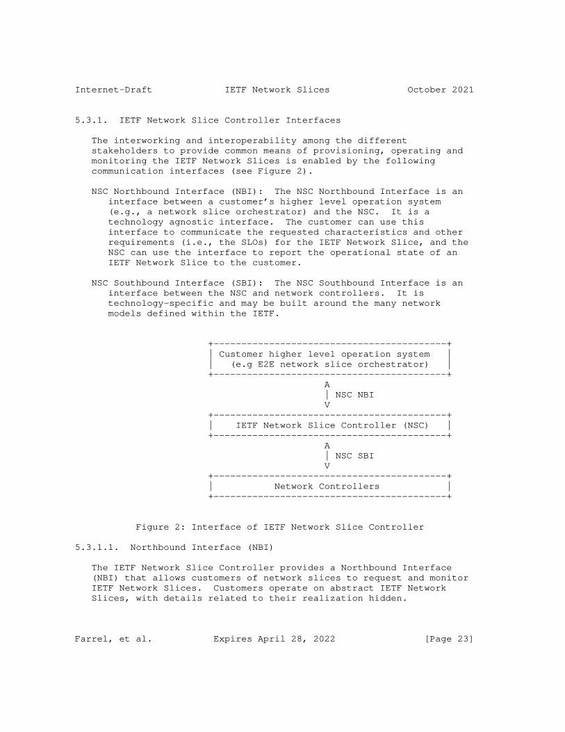
Internet-Draft IETF Network Slices October 2021
5.3.1. IETF Network Slice Controller Interfaces
The interworking and interoperability among the different stakeholders to provide common means of provisioning, operating and monitoring the IETF Network Slices is enabled by the following communication interfaces (see Figure 2).
NSC Northbound Interface (NBI): The NSC Northbound Interface is an interface between a customer’s higher level operation system (e.g., a network slice orchestrator) and the NSC. It is a technology agnostic interface. The customer can use this interface to communicate the requested characteristics and other requirements (i.e., the SLOs) for the IETF Network Slice, and the NSC can use the interface to report the operational state of an IETF Network Slice to the customer.
NSC Southbound Interface (SBI): The NSC Southbound Interface is an interface between the NSC and network controllers. It is technology-specific and may be built around the many network models defined within the IETF.
+------------------------------------------+ | Customer higher level operation system | | (e.g E2E network slice orchestrator) | +------------------------------------------+ A | NSC NBI V +------------------------------------------+ | IETF Network Slice Controller (NSC) | +------------------------------------------+ A | NSC SBI V +------------------------------------------+ | Network Controllers | +------------------------------------------+
Figure 2: Interface of IETF Network Slice Controller
5.3.1.1. Northbound Interface (NBI)
The IETF Network Slice Controller provides a Northbound Interface (NBI) that allows customers of network slices to request and monitor IETF Network Slices. Customers operate on abstract IETF Network Slices, with details related to their realization hidden.
Farrel, et al. Expires April 28, 2022 [Page 23]
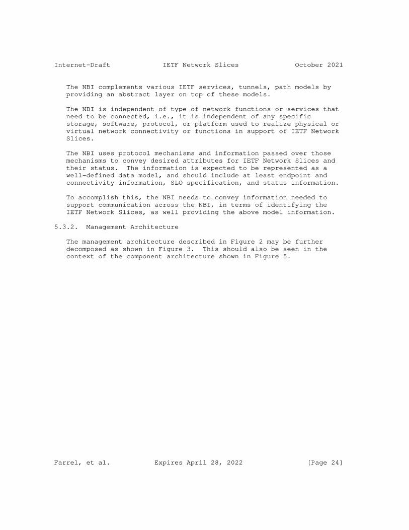
Internet-Draft IETF Network Slices October 2021
The NBI complements various IETF services, tunnels, path models by providing an abstract layer on top of these models.
The NBI is independent of type of network functions or services that need to be connected, i.e., it is independent of any specific storage, software, protocol, or platform used to realize physical or virtual network connectivity or functions in support of IETF Network Slices.
The NBI uses protocol mechanisms and information passed over those mechanisms to convey desired attributes for IETF Network Slices and their status. The information is expected to be represented as a well-defined data model, and should include at least endpoint and connectivity information, SLO specification, and status information.
To accomplish this, the NBI needs to convey information needed to support communication across the NBI, in terms of identifying the IETF Network Slices, as well providing the above model information.
5.3.2. Management Architecture
The management architecture described in Figure 2 may be further decomposed as shown in Figure 3. This should also be seen in the context of the component architecture shown in Figure 5.
Farrel, et al. Expires April 28, 2022 [Page 24]
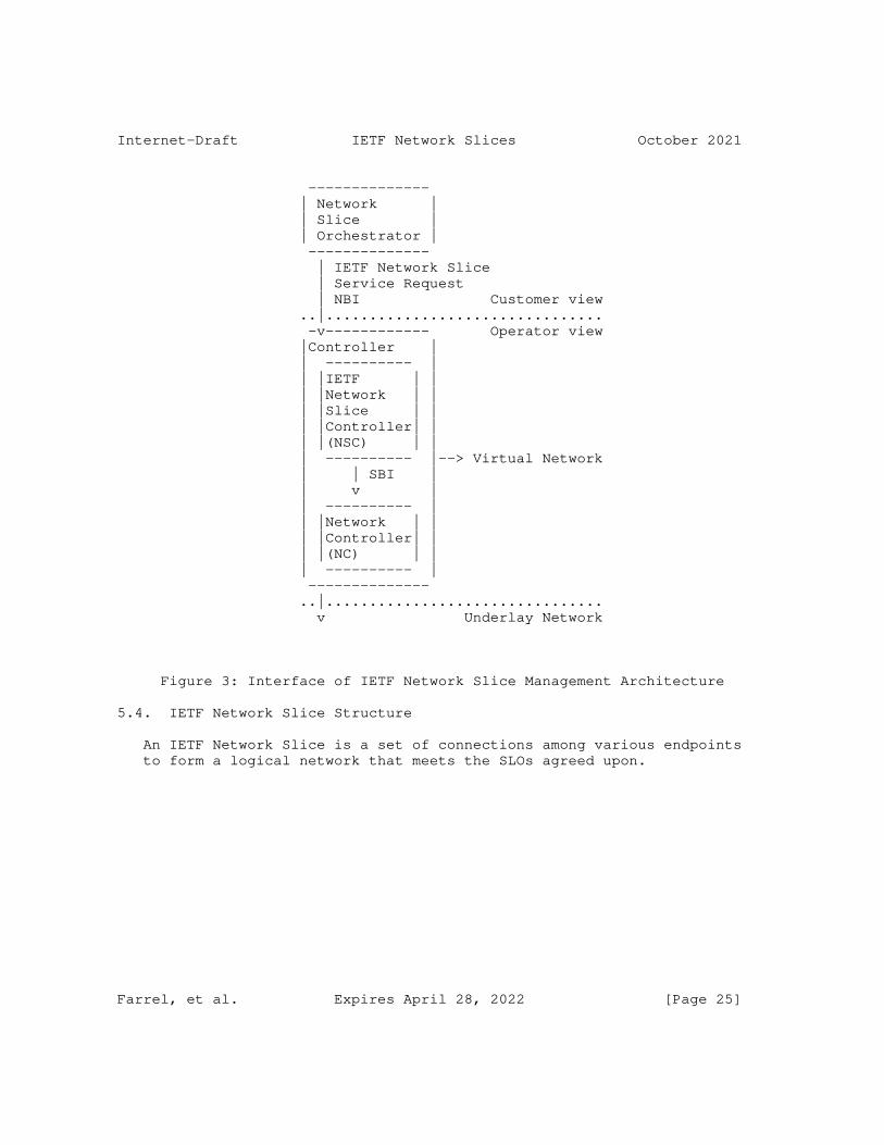
Internet-Draft IETF Network Slices October 2021
-------------- | Network | | Slice | | Orchestrator | -------------- | IETF Network Slice | Service Request | NBI Customer view ..|................................ -v------------ Operator view |Controller | | ---------- | | |IETF | | | |Network | | | |Slice | | | |Controller| | | |(NSC) | | | ---------- |--> Virtual Network | | SBI | | v | | ---------- | | |Network | | | |Controller| | | |(NC) | | | ---------- | -------------- ..|................................ v Underlay Network
Figure 3: Interface of IETF Network Slice Management Architecture
5.4. IETF Network Slice Structure
An IETF Network Slice is a set of connections among various endpoints to form a logical network that meets the SLOs agreed upon.
Farrel, et al. Expires April 28, 2022 [Page 25]
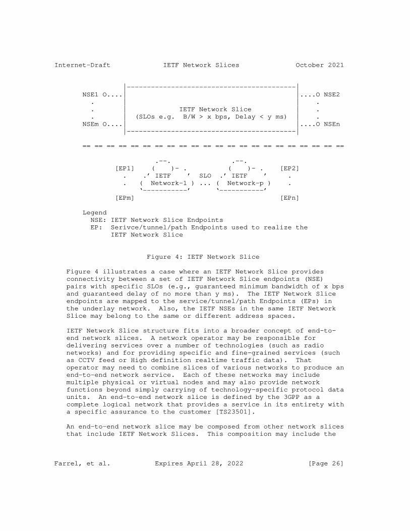
Internet-Draft IETF Network Slices October 2021
|------------------------------------------| NSE1 O....| |....O NSE2 . | | . . | IETF Network Slice | . . | (SLOs e.g. B/W > x bps, Delay < y ms) | . NSEm O....| |....O NSEn |------------------------------------------|
== == == == == == == == == == == == == == == == == == == == == ==
.--. .--. [EP1] ( )- . ( )- . [EP2] . .’ IETF ’ SLO .’ IETF ’ . . ( Network-1 ) ... ( Network-p ) . ‘-----------’ ‘-----------’ [EPm] [EPn]
Legend NSE: IETF Network Slice Endpoints EP: Serivce/tunnel/path Endpoints used to realize the IETF Network Slice
Figure 4: IETF Network Slice
Figure 4 illustrates a case where an IETF Network Slice provides connectivity between a set of IETF Network Slice endpoints (NSE) pairs with specific SLOs (e.g., guaranteed minimum bandwidth of x bps and guaranteed delay of no more than y ms). The IETF Network Slice endpoints are mapped to the service/tunnel/path Endpoints (EPs) in the underlay network. Also, the IETF NSEs in the same IETF Network Slice may belong to the same or different address spaces.
IETF Network Slice structure fits into a broader concept of end-to- end network slices. A network operator may be responsible for delivering services over a number of technologies (such as radio networks) and for providing specific and fine-grained services (such as CCTV feed or High definition realtime traffic data). That operator may need to combine slices of various networks to produce an end-to-end network service. Each of these networks may include multiple physical or virtual nodes and may also provide network functions beyond simply carrying of technology-specific protocol data units. An end-to-end network slice is defined by the 3GPP as a complete logical network that provides a service in its entirety with a specific assurance to the customer [TS23501].
An end-to-end network slice may be composed from other network slices that include IETF Network Slices. This composition may include the
Farrel, et al. Expires April 28, 2022 [Page 26]
Internet-Draft IETF Network Slices October 2021
hierarchical (or recursive) use of underlying network slices and the sequential (or stitched) combination of slices of different networks.
6. Realizing IETF Network Slices
Realization of IETF Network Slices is out of scope of this document. It is a mapping of the definition of the IETF Network Slice to the underlying infrastructure and is necessarily technology-specific and achieved by the NSC over the SBI. However, this section provides an overview of the components and processes involved in realizing an IETF Network Slice.
The realization can be achieved in a form of either physical or logical connectivity using VPNs, virtual networks (VNs), or a variety of tunneling technologies such as Segment Routing, MPLS, etc. Accordingly, endpoints (NSEs) may be realized as physical or logical service or network functions.
6.1. Architecture to Realize IETF Network Slices
The architecture described in this section is deliberately at a high level. It is not intended to be prescriptive: implementations and technical solutions may vary freely. However, this approach provides a common framework that other documents may reference in order to facilitate a shared understanding of the work.
Figure 5 shows the architectural components of a network managed to provide IETF Network Slices. The customer’s view is of individual IETF Network Slices with their endpoint CEs and connectivity matrices. Requests for IETF Network Slices are delivered to the NSC.
Farrel, et al. Expires April 28, 2022 [Page 27]
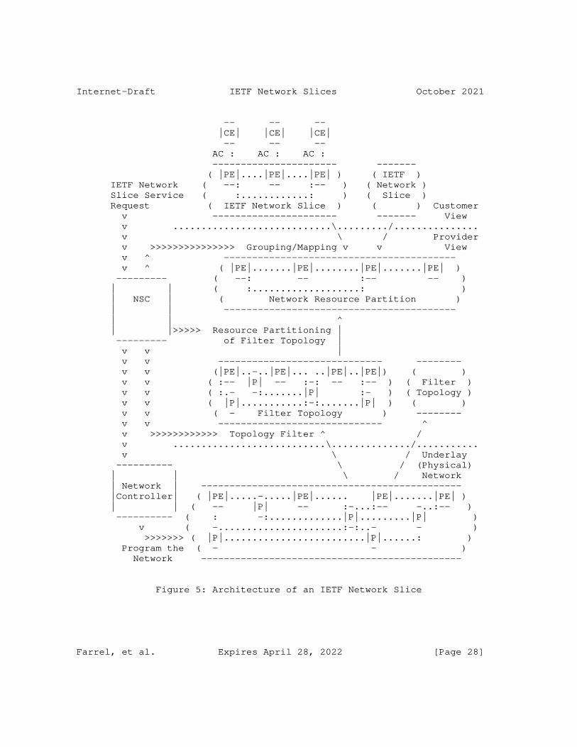
Internet-Draft IETF Network Slices October 2021
-- -- -- |CE| |CE| |CE| -- -- -- AC : AC : AC : ---------------------- ------- ( |PE|....|PE|....|PE| ) ( IETF ) IETF Network ( --: -- :-- ) ( Network ) Slice Service ( :............: ) ( Slice ) Request ( IETF Network Slice ) ( ) Customer v ---------------------- ------- View v ............................\........./............... v \ / Provider v >>>>>>>>>>>>>>> Grouping/Mapping v v View v ^ ----------------------------------------- v ^ ( |PE|.......|PE|........|PE|.......|PE| ) --------- ( --: -- :-- -- ) | | ( :...................: ) | NSC | ( Network Resource Partition ) | | ----------------------------------------- | | ^ | |>>>>> Resource Partitioning | --------- of Filter Topology | v v | v v ----------------------------- -------- v v (|PE|..-..|PE|... ..|PE|..|PE|) ( ) v v ( :-- |P| -- :-: -- :-- ) ( Filter ) v v ( :.- -:.......|P| :- ) ( Topology ) v v ( |P|...........:-:.......|P| ) ( ) v v ( - Filter Topology ) -------- v v ----------------------------- ^ v >>>>>>>>>>>> Topology Filter ^ / v ...........................\............../........... v \ / Underlay ---------- \ / (Physical) | | \ / Network | Network | ---------------------------------------------- |Controller| ( |PE|.....-.....|PE|...... |PE|.......|PE| ) | | ( -- |P| -- :-...:-- -..:-- ) ---------- ( : -:.............|P|.........|P| ) v ( -......................:-:..- - ) >>>>>>> ( |P|.........................|P|......: ) Program the ( - - ) Network ----------------------------------------------
Figure 5: Architecture of an IETF Network Slice
Farrel, et al. Expires April 28, 2022 [Page 28]
Internet-Draft IETF Network Slices October 2021
The network itself (at the bottom of the figure) comprises an underlay network. This could be a physical network, but may be a virtual network. The underlay network is provisioned through network controllers.
The underlay network may be filtered by the network operator into a number of Filter Topologies. Filter actions may include selection of specific resources (e.g., nodes and links) according to their capabilities, and are based on network-wide policies. The resulting topologies can be used as candidates to host IETF Network Slices and provide a useful way for the network operator to know in advance that all of the resources they are using to plan an IETF Network Slice would be able to meet specific SLOs and SLEs. The filtering procedure could be an offline planning activity or could be performed dynamically as new demands arise. The use of Filter Topologies is entirely optional in the architecture, and IETF Network Slices could be hosted directly on the underlay network.
For scalability reasons, IETF Network Slices may be grouped together according to characteristics (including SLOs and SLEs). This grouping allows an operator to host a number of slices on a particular set of resources and so reduce the amount of state information needed in the network. The NSC is responsible for grouping the IETF Network Slice requests.
Each group of IETF Network Slices is mapped onto a set of network resources that are available to carry traffic and meet the SLOs and SLEs. These resources are known as a Network Resource Partition and are selected from the Filter Topology (or direct from the underlay network): they may be reserved and dedicated for use by the group of IETF Network Slices, or may be shared between groups depending on the details of the SLOs and SLEs.
The steps described here can be applied in a variety of orders according to implementation and deployment preferences. Furthermore, the steps may be iterative so that the components are continually refined and modified as network conditions change and as service requests are received or relinquished, and even the underlay network could be extended if necessary to meet the customers’ demands.
6.2. Procedures to Realize IETF Network Slices
There are a number of different technologies that can be used in the underlay, including physical connections, MPLS, time-sensitive networking (TSN), Flex-E, etc.
Farrel, et al. Expires April 28, 2022 [Page 29]
Internet-Draft IETF Network Slices October 2021
An IETF Network Slice can be realized in a network, using specific underlying technology or technologies. The creation of a new IETF Network Slice will be realized with following steps:
o The NSC exposes the network slicing capabilities that it offers for the network it manages.
o The customer may issue a request to determine whether a specific IETF Network Slice could be supported by the network. The NSC may respond indicating a simple yes or no, and may supplement a negative response with information about what it could support were the customer to change some requirements.
o The customer requests an IETF Network Slice. The NSC may respond that the slice has or has not been created, and may supplement a negative response with information about what it could support were the customer to change some requirements.
o When processing a customer request for an IETF Network Slice, the NSC maps the request to the network capabilities and applies provider policies before creating or supplementing the resource partition.
Regardless of how IETF Network Slice is realized in the network (i.e., using tunnels of different types), the definition of the IETF Network Slice does not change at all. The only difference is how the slice is realized. The following sections briefly introduce how some existing architectural approaches can be applied to realize IETF Network Slices.
6.3. Applicability of ACTN to IETF Network Slices
Abstraction and Control of TE Networks (ACTN - [RFC8453]) is a management architecture and toolkit used to create virtual networks (VNs) on top of a TE underlay network. The VNs can be presented to customers for them to operate as private networks.
In many ways, the function of ACTN is similar to IETF network slicing. Customer requests for connectivity-based overlay services are mapped to dedicated or shared resources in the underlay network in a way that meets customer guarantees for service level objectives and for separation from other customers’ traffic. [RFC8453] the function of ACTN as collecting resources to establish a logically dedicated virtual network over one or more TE networks. Thus, in the case of a TE-enabled underlying network, the ACTN VN can be used as a basis to realize an IETF network slicing.
Farrel, et al. Expires April 28, 2022 [Page 30]
Internet-Draft IETF Network Slices October 2021
While the ACTN framework is a generic VN framework that can be used for VN services beyond the IETF Network Slice, it also a suitable basis for delivering and realizing IETF Network Slices.
Further discussion of the applicability of ACTN to IETF Network Slices including a discussion of the relevant YANG models can be found in [I-D.king-teas-applicability-actn-slicing].
6.4. Applicability of Enhanced VPNs to IETF Network Slices
An enhanced VPN (VPN+) is designed to support the needs of new applications, particularly applications that are associated with 5G services, by utilizing an approach that is based on existing VPN and TE technologies and adds characteristics that specific services require over and above traditional VPNs.
An enhanced VPN can be used to provide enhanced connectivity services between customer sites (a concept similar to an IETF Network Slice) and can be used to create the infrastructure to underpin network slicing.
It is envisaged that enhanced VPNs will be delivered using a combination of existing, modified, and new networking technologies.
[I-D.ietf-teas-enhanced-vpn] describes the framework for Enhanced Virtual Private Network (VPN+) services.
6.5. Network Slicing and Slice Aggregation in IP/MPLS Networks
Network slicing provides the ability to partition a physical network into multiple isolated logical networks of varying sizes, structures, and functions so that each slice can be dedicated to specific services or customers.
Many approaches are currently being worked on to support IETF Network Slices in IP and MPLS networks with or without the use of Segment Routing. Most of these approaches utilize a way of marking packets so that network nodes can apply specific routing and forwarding behaviors to packets that belong to different IETF Network Slices. Different mechanisms for marking packets have been proposed (including using MPLS labels and Segment Rouing segment IDs) and those mechanisms are agnostic to the path control technology used within the underlay network.
These approaches are also sensitive to the scaling concerns of supporting a large number of IETF Network Slices within a single IP or MPLS network, and so offer ways to aggregate the slices so that the packet markings indicate an aggregate or grouping of IETF Network
Farrel, et al. Expires April 28, 2022 [Page 31]
Internet-Draft IETF Network Slices October 2021
Slices where all of the packets are subject to the same routing and forwarding behavior.
At this stage, it is inappropriate to mention any of these proposed solutions that are currently work in progress and not yet adopted as IETF work.
7. Isolation in IETF Network Slices
7.1. Isolation as a Service Requirement
An IETF Network Slice customer may request that the IETF Network Slice delivered to them is delivered such that changes to other IETF Network Slices or services do not have any negative impact on the delivery of the IETF Network Slice. The IETF Network Slice customer may specify the degree to which their IETF Network Slice is unaffected by changes in the provider network or by the behavior of other IETF Network Slice customers. The customer may express this via an SLE it agrees with the provider. This concept is termed ’isolation’
7.2. Isolation in IETF Network Slice Realization
Isolation may be achieved in the underlying network by various forms of resource partitioning ranging from dedicated allocation of resources for a specific IETF Network Slice, to sharing of resources with safeguards. For example, traffic separation between different IETF Network Slices may be achieved using VPN technologies, such as L3VPN, L2VPN, EVPN, etc. Interference avoidance may be achieved by network capacity planning, allocating dedicated network resources, traffic policing or shaping, prioritizing in using shared network resources, etc. Finally, service continuity may be ensured by reserving backup paths for critical traffic, dedicating specific network resources for a selected number of IETF Network Slices.
8. Management Considerations
IETF Network Slice realization needs to be instrumented in order to track how it is working, and it might be necessary to modify the IETF Network Slice as requirements change. Dynamic reconfiguration might be needed.
9. Security Considerations
This document specifies terminology and has no direct effect on the security of implementations or deployments. In this section, a few of the security aspects are identified.
Farrel, et al. Expires April 28, 2022 [Page 32]
Internet-Draft IETF Network Slices October 2021
o Conformance to security constraints: Specific security requests from customer defined IETF Network Slices will be mapped to their realization in the underlay networks. It will be required by underlay networks to have capabilities to conform to customer’s requests as some aspects of security may be expressed in SLEs.
o IETF NSC authentication: Underlying networks need to be protected against the attacks from an adversary NSC as they can destabilize overall network operations. It is particularly critical since an IETF Network Slice may span across different networks, therefore, IETF NSC should have strong authentication with each those networks. Furthermore, both SBI and NBI need to be secured.
o Specific isolation criteria: The nature of conformance to isolation requests means that it should not be possible to attack an IETF Network Slice service by varying the traffic on other services or slices carried by the same underlay network. In general, isolation is expected to strengthen the IETF Network Slice security.
o Data Integrity of an IETF Network Slice: A customer wanting to secure their data and keep it private will be responsible for applying appropriate security measures to their traffic and not depending on the network operator that provides the IETF Network Slice. It is expected that for data integrity, a customer is responsible for end-to-end encryption of its own traffic.
Note: see NGMN document[NGMN_SEC] on 5G network slice security for discussion relevant to this section.
IETF Network Slices might use underlying virtualized networking. All types of virtual networking require special consideration to be given to the separation of traffic between distinct virtual networks, as well as some degree of protection from effects of traffic use of underlying network (and other) resources from other virtual networks sharing those resources.
For example, if a service requires a specific upper bound of latency, then that service can be degraded by added delay in transmission of service packets through the activities of another service or application using the same resources.
Similarly, in a network with virtual functions, noticeably impeding access to a function used by another IETF Network Slice (for instance, compute resources) can be just as service degrading as delaying physical transmission of associated packet in the network.
Farrel, et al. Expires April 28, 2022 [Page 33]
Internet-Draft IETF Network Slices October 2021
While a IETF Network Slice might include encryption and other security features as part of the service, customers might be well advised to take responsibility for their own security needs, possibly by encrypting traffic before hand-off to a service provider.
10. Privacy Considerations
Privacy of IETF Network Slice service customers must be preserved. It should not be possible for one IETF Network Slice customer to discover the presence of other customers, nor should sites that are members of one IETF Network Slice be visible outside the context of that IETF Network Slice.
In this sense, it is of paramount importance that the system use the privacy protection mechanism defined for the specific underlying technologies used, including in particular those mechanisms designed to preclude acquiring identifying information associated with any IETF Network Slice customer.
11. IANA Considerations
This document makes no requests for IANA action.
12. Informative References
[BBF-SD406] Broadband Forum, "End-to-end network slicing", BBF SD-406, <https://wiki.broadband-forum.org/display/BBF/SD-406+End- to-End+Network+Slicing>.
[HIPAA] HHS, "Health Insurance Portability and Accountability Act - The Security Rule", February 2003, <https://www.hhs.gov/hipaa/for-professionals/security/ index.html>.
[I-D.ietf-teas-enhanced-vpn] Dong, J., Bryant, S., Li, Z., Miyasaka, T., and Y. Lee, "A Framework for Enhanced Virtual Private Network (VPN+) Services", draft-ietf-teas-enhanced-vpn-09 (work in progress), October 2021.
[I-D.king-teas-applicability-actn-slicing] King, D., Drake, J., Zheng, H., and A. Farrel, "Applicability of Abstraction and Control of Traffic Engineered Networks (ACTN) to Network Slicing", draft- king-teas-applicability-actn-slicing-10 (work in progress), March 2021.
Farrel, et al. Expires April 28, 2022 [Page 34]
Internet-Draft IETF Network Slices October 2021
[I-D.openconfig-rtgwg-gnmi-spec] Shakir, R., Shaikh, A., Borman, P., Hines, M., Lebsack, C., and C. Morrow, "gRPC Network Management Interface (gNMI)", draft-openconfig-rtgwg-gnmi-spec-01 (work in progress), March 2018.
[MACsec] IEEE, "IEEE Standard for Local and metropolitan area networks - Media Access Control (MAC) Security", 2018, <https://1.ieee802.org/security/802-1ae>.
[NGMN-NS-Concept] NGMN Alliance, "Description of Network Slicing Concept", https://www.ngmn.org/uploads/ media/161010_NGMN_Network_Slicing_framework_v1.0.8.pdf , 2016.
[NGMN_SEC] NGMN Alliance, "NGMN 5G Security - Network Slicing", April 2016, <https://www.ngmn.org/wp-content/uploads/Publication s/2016/160429_NGMN_5G_Security_Network_Slicing_v1_0.pdf>.
[PCI] PCI Security Standards Council, "PCI DSS", May 2018, <https://www.pcisecuritystandards.org>.
[RFC2681] Almes, G., Kalidindi, S., and M. Zekauskas, "A Round-trip Delay Metric for IPPM", RFC 2681, DOI 10.17487/RFC2681, September 1999, <https://www.rfc-editor.org/info/rfc2681>.
[RFC3022] Srisuresh, P. and K. Egevang, "Traditional IP Network Address Translator (Traditional NAT)", RFC 3022, DOI 10.17487/RFC3022, January 2001, <https://www.rfc-editor.org/info/rfc3022>.
[RFC3393] Demichelis, C. and P. Chimento, "IP Packet Delay Variation Metric for IP Performance Metrics (IPPM)", RFC 3393, DOI 10.17487/RFC3393, November 2002, <https://www.rfc-editor.org/info/rfc3393>.
[RFC4208] Swallow, G., Drake, J., Ishimatsu, H., and Y. Rekhter, "Generalized Multiprotocol Label Switching (GMPLS) User- Network Interface (UNI): Resource ReserVation Protocol- Traffic Engineering (RSVP-TE) Support for the Overlay Model", RFC 4208, DOI 10.17487/RFC4208, October 2005, <https://www.rfc-editor.org/info/rfc4208>.
[RFC4303] Kent, S., "IP Encapsulating Security Payload (ESP)", RFC 4303, DOI 10.17487/RFC4303, December 2005, <https://www.rfc-editor.org/info/rfc4303>.
Farrel, et al. Expires April 28, 2022 [Page 35]
Internet-Draft IETF Network Slices October 2021
[RFC4364] Rosen, E. and Y. Rekhter, "BGP/MPLS IP Virtual Private Networks (VPNs)", RFC 4364, DOI 10.17487/RFC4364, February 2006, <https://www.rfc-editor.org/info/rfc4364>.
[RFC4397] Bryskin, I. and A. Farrel, "A Lexicography for the Interpretation of Generalized Multiprotocol Label Switching (GMPLS) Terminology within the Context of the ITU-T’s Automatically Switched Optical Network (ASON) Architecture", RFC 4397, DOI 10.17487/RFC4397, February 2006, <https://www.rfc-editor.org/info/rfc4397>.
[RFC5212] Shiomoto, K., Papadimitriou, D., Le Roux, JL., Vigoureux, M., and D. Brungard, "Requirements for GMPLS-Based Multi- Region and Multi-Layer Networks (MRN/MLN)", RFC 5212, DOI 10.17487/RFC5212, July 2008, <https://www.rfc-editor.org/info/rfc5212>.
[RFC5440] Vasseur, JP., Ed. and JL. Le Roux, Ed., "Path Computation Element (PCE) Communication Protocol (PCEP)", RFC 5440, DOI 10.17487/RFC5440, March 2009, <https://www.rfc-editor.org/info/rfc5440>.
[RFC6020] Bjorklund, M., Ed., "YANG - A Data Modeling Language for the Network Configuration Protocol (NETCONF)", RFC 6020, DOI 10.17487/RFC6020, October 2010, <https://www.rfc-editor.org/info/rfc6020>.
[RFC6146] Bagnulo, M., Matthews, P., and I. van Beijnum, "Stateful NAT64: Network Address and Protocol Translation from IPv6 Clients to IPv4 Servers", RFC 6146, DOI 10.17487/RFC6146, April 2011, <https://www.rfc-editor.org/info/rfc6146>.
[RFC6241] Enns, R., Ed., Bjorklund, M., Ed., Schoenwaelder, J., Ed., and A. Bierman, Ed., "Network Configuration Protocol (NETCONF)", RFC 6241, DOI 10.17487/RFC6241, June 2011, <https://www.rfc-editor.org/info/rfc6241>.
[RFC7679] Almes, G., Kalidindi, S., Zekauskas, M., and A. Morton, Ed., "A One-Way Delay Metric for IP Performance Metrics (IPPM)", STD 81, RFC 7679, DOI 10.17487/RFC7679, January 2016, <https://www.rfc-editor.org/info/rfc7679>.
[RFC7680] Almes, G., Kalidindi, S., Zekauskas, M., and A. Morton, Ed., "A One-Way Loss Metric for IP Performance Metrics (IPPM)", STD 82, RFC 7680, DOI 10.17487/RFC7680, January 2016, <https://www.rfc-editor.org/info/rfc7680>.
Farrel, et al. Expires April 28, 2022 [Page 36]
Internet-Draft IETF Network Slices October 2021
[RFC7926] Farrel, A., Ed., Drake, J., Bitar, N., Swallow, G., Ceccarelli, D., and X. Zhang, "Problem Statement and Architecture for Information Exchange between Interconnected Traffic-Engineered Networks", BCP 206, RFC 7926, DOI 10.17487/RFC7926, July 2016, <https://www.rfc-editor.org/info/rfc7926>.
[RFC7950] Bjorklund, M., Ed., "The YANG 1.1 Data Modeling Language", RFC 7950, DOI 10.17487/RFC7950, August 2016, <https://www.rfc-editor.org/info/rfc7950>.
[RFC8040] Bierman, A., Bjorklund, M., and K. Watsen, "RESTCONF Protocol", RFC 8040, DOI 10.17487/RFC8040, January 2017, <https://www.rfc-editor.org/info/rfc8040>.
[RFC8453] Ceccarelli, D., Ed. and Y. Lee, Ed., "Framework for Abstraction and Control of TE Networks (ACTN)", RFC 8453, DOI 10.17487/RFC8453, August 2018, <https://www.rfc-editor.org/info/rfc8453>.
[RFC8454] Lee, Y., Belotti, S., Dhody, D., Ceccarelli, D., and B. Yoon, "Information Model for Abstraction and Control of TE Networks (ACTN)", RFC 8454, DOI 10.17487/RFC8454, September 2018, <https://www.rfc-editor.org/info/rfc8454>.
[TS23501] 3GPP, "System architecture for the 5G System (5GS)", 3GPP TS 23.501, 2019.
[TS28530] 3GPP, "Management and orchestration; Concepts, use cases and requirements", 3GPP TS 28.530, 2019.
[TS33.210] 3GPP, "3G security; Network Domain Security (NDS); IP network layer security (Release 14).", December 2016, <https://portal.3gpp.org/desktopmodules/Specifications/ SpecificationDetails.aspx?specificationId=2279>.
Acknowledgments
The entire TEAS Network Slicing design team and everyone participating in related discussions has contributed to this document. Some text fragments in the document have been copied from the [I-D.ietf-teas-enhanced-vpn], for which we are grateful.
Significant contributions to this document were gratefully received from the contributing authors listed in the "Contributors" section. In addition we would like to also thank those others who have
Farrel, et al. Expires April 28, 2022 [Page 37]

Internet-Draft IETF Network Slices October 2021
attended one or more of the design team meetings, including the following people not listed elsewhere:
o Aihua Guo
o Bo Wu
o Greg Mirsky
o Lou Berger
o Rakesh Gandhi
o Ran Chen
o Sergio Belotti
o Stewart Bryant
o Tomonobu Niwa
o Xuesong Geng
Further useful comments were received from Daniele Ceccarelli, Uma Chunduri, Pavan Beeram, Tarek Saad, Med Boucadair, Kenichi Okagi, Oscar Gonzalez de Dios, and Xiaobing Niu.
This work is partially supported by the European Commission under Horizon 2020 grant agreement number 101015857 Secured autonomic traffic management for a Tera of SDN flows (Teraflow).
Contributors
The following authors contributed significantly to this document:
Farrel, et al. Expires April 28, 2022 [Page 38]
Internet-Draft IETF Network Slices October 2021
Jari Arkko Ericsson Email: [email protected]
Dhruv Dhody Huawei, India Email: [email protected]
Jie Dong Huawei Email: [email protected]
Xufeng Liu Volta Networks Email: [email protected]
Authors’ Addresses
Adrian Farrel (editor) Old Dog Consulting UK
Email: [email protected]
Eric Gray Independent USA
Email: [email protected]
John Drake Juniper Networks USA
Email: [email protected]
Reza Rokui Nokia
Email: [email protected]
Farrel, et al. Expires April 28, 2022 [Page 39]
Internet-Draft IETF Network Slices October 2021
Shunsuke Homma NTT Japan
Email: [email protected]
Kiran Makhijani Futurewei USA
Email: [email protected]
Luis M. Contreras Telefonica Spain
Email: [email protected]
Jeff Tantsura Microsoft Inc.
Email: [email protected]
Farrel, et al. Expires April 28, 2022 [Page 40]


TEAS Working Group Y. Lee, Ed.Internet-Draft Samsung ElectronicsIntended status: Standards Track D. Dhody, Ed.Expires: 27 April 2022 G. Fioccola Q. Wu, Ed. Huawei Technologies D. Ceccarelli Ericsson J. Tantsura Microsoft 24 October 2021
Traffic Engineering (TE) and Service Mapping YANG Model draft-ietf-teas-te-service-mapping-yang-09
Abstract
This document provides a YANG data model to map customer service models (e.g., the L3VPN Service Model (L3SM)) to Traffic Engineering (TE) models (e.g., the TE Tunnel or the Virtual Network (VN) model). These models are referred to as TE Service Mapping Model and are applicable generically to the operator’s need for seamless control and management of their VPN services with underlying TE support.
The models are principally used for monitoring and diagnostics of the management systems to show how the service requests are mapped onto underlying network resource and TE models.
Status of This Memo
This Internet-Draft is submitted in full conformance with the provisions of BCP 78 and BCP 79.
Internet-Drafts are working documents of the Internet Engineering Task Force (IETF). Note that other groups may also distribute working documents as Internet-Drafts. The list of current Internet- Drafts is at https://datatracker.ietf.org/drafts/current/.
Internet-Drafts are draft documents valid for a maximum of six months and may be updated, replaced, or obsoleted by other documents at any time. It is inappropriate to use Internet-Drafts as reference material or to cite them other than as "work in progress."
This Internet-Draft will expire on 27 April 2022.
Lee, et al. Expires 27 April 2022 [Page 1]
Internet-Draft TE Service Mapping October 2021
Copyright Notice
Copyright (c) 2021 IETF Trust and the persons identified as the document authors. All rights reserved.
This document is subject to BCP 78 and the IETF Trust’s Legal Provisions Relating to IETF Documents (https://trustee.ietf.org/ license-info) in effect on the date of publication of this document. Please review these documents carefully, as they describe your rights and restrictions with respect to this document. Code Components extracted from this document must include Simplified BSD License text as described in Section 4.e of the Trust Legal Provisions and are provided without warranty as described in the Simplified BSD License.
Table of Contents
1. Introduction . . . . . . . . . . . . . . . . . . . . . . . . 3 1.1. Purpose of TE Service Mapping for Service Model . . . . . 4 1.2. Purpose of TE Service Mapping for Network Model . . . . . 5 1.3. Terminology . . . . . . . . . . . . . . . . . . . . . . . 6 1.4. Tree diagram . . . . . . . . . . . . . . . . . . . . . . 6 1.5. Prefixes in Data Node Names . . . . . . . . . . . . . . . 6 2. TE and Service Related Parameters . . . . . . . . . . . . . . 8 2.1. VN/Tunnel Selection Requirements . . . . . . . . . . . . 8 2.2. TE Policy . . . . . . . . . . . . . . . . . . . . . . . . 9 2.2.1. Availability Requirement . . . . . . . . . . . . . . 9 3. YANG Modeling Approach . . . . . . . . . . . . . . . . . . . 9 3.1. Forward Compatibility . . . . . . . . . . . . . . . . . . 11 3.2. TE and Network Models . . . . . . . . . . . . . . . . . . 11 4. L3VPN Architecture in the ACTN Context . . . . . . . . . . . 12 4.1. Service Mapping . . . . . . . . . . . . . . . . . . . . . 16 4.2. Site Mapping . . . . . . . . . . . . . . . . . . . . . . 16 5. Applicability of TE-Service Mapping in Generic context . . . 17 6. YANG Data Trees . . . . . . . . . . . . . . . . . . . . . . . 17 6.1. Service Mapping Types . . . . . . . . . . . . . . . . . . 17 6.2. Service Models . . . . . . . . . . . . . . . . . . . . . 18 6.2.1. L3SM . . . . . . . . . . . . . . . . . . . . . . . . 18 6.2.2. L2SM . . . . . . . . . . . . . . . . . . . . . . . . 19 6.2.3. L1CSM . . . . . . . . . . . . . . . . . . . . . . . . 20 6.3. Network Models . . . . . . . . . . . . . . . . . . . . . 21 6.3.1. L3NM . . . . . . . . . . . . . . . . . . . . . . . . 21 6.3.2. L2NM . . . . . . . . . . . . . . . . . . . . . . . . 22 7. YANG Data Models . . . . . . . . . . . . . . . . . . . . . . 23 7.1. ietf-te-service-mapping-types . . . . . . . . . . . . . . 23 7.2. Service Models . . . . . . . . . . . . . . . . . . . . . 32 7.2.1. ietf-l3sm-te-service-mapping . . . . . . . . . . . . 33 7.2.2. ietf-l2sm-te-service-mapping . . . . . . . . . . . . 35 7.2.3. ietf-l1csm-te-service-mapping . . . . . . . . . . . . 37
Lee, et al. Expires 27 April 2022 [Page 2]
Internet-Draft TE Service Mapping October 2021
7.3. Network Models . . . . . . . . . . . . . . . . . . . . . 39 7.3.1. ietf-l3nm-te-service-mapping . . . . . . . . . . . . 39 7.3.2. ietf-l2nm-te-service-mapping . . . . . . . . . . . . 41 8. Security Considerations . . . . . . . . . . . . . . . . . . . 43 9. IANA Considerations . . . . . . . . . . . . . . . . . . . . . 44 10. Acknowledgements . . . . . . . . . . . . . . . . . . . . . . 46 11. References . . . . . . . . . . . . . . . . . . . . . . . . . 46 11.1. Normative References . . . . . . . . . . . . . . . . . . 46 11.2. Informative References . . . . . . . . . . . . . . . . . 49 Appendix A. Examples . . . . . . . . . . . . . . . . . . . . . . 50 Appendix B. Contributor Addresses . . . . . . . . . . . . . . . 52 Authors’ Addresses . . . . . . . . . . . . . . . . . . . . . . . 52
1. Introduction
Data models are a representation of objects that can be configured or monitored within a system. Within the IETF, YANG [RFC7950] is the language of choice for documenting data models, and YANG models have been produced to allow configuration or modeling of a variety of network devices, protocol instances, and network services. YANG data models have been classified in [RFC8199] and [RFC8309].
Framework for Abstraction and Control of Traffic Engineered Networks (ACTN) [RFC8453] introduces an architecture to support virtual network services and connectivity services. [I-D.ietf-teas-actn-vn-yang] defines a YANG model and describes how customers or end-to-end orchestrator can request and/or instantiate a generic virtual network service. [I-D.ietf-teas-actn-yang] describes the way IETF YANG models of different classifications can be applied to the ACTN interfaces. In particular, it describes how customer service models can be mapped into the CNC-MDSC Interface (CMI) of the ACTN architecture.
The models presented in this document are also applicable in generic context [RFC8309] as part of Customer Service Model used between Service Orchestrator and Customer.
[RFC8299] provides a L3VPN service delivery YANG model for PE-based VPNs. The scope of that draft is limited to a set of domains under control of the same network operator to deliver services requiring TE tunnels.
[RFC8466] provides a L2VPN service delivery YANG model for PE-based VPNs. The scope of that draft is limited to a set of domains under control of the same network operator to deliver services requiring TE tunnels.
Lee, et al. Expires 27 April 2022 [Page 3]
Internet-Draft TE Service Mapping October 2021
[I-D.ietf-ccamp-l1csm-yang] provides a L1 connectivity service delivery YANG model for PE-based VPNs. The scope of that draft is limited to a set of domains under control of the same network operator to deliver services requiring TE tunnels.
While the IP/MPLS Provisioning Network Controller (PNC) is responsible for provisioning the VPN service on the Provider Edge (PE) nodes, the Multi-Domain Service Coordinator (MDSC) can coordinate how to map the VPN services onto Traffic Engineering (TE) tunnels. This is consistent with the two of the core functions of the MDSC specified in [RFC8453]:
* Customer mapping/translation function: This function is to map customer requests/commands into network provisioning requests that can be sent to the PNC according to the business policies that have been provisioned statically or dynamically. Specifically, it provides mapping and translation of a customer’s service request into a set of parameters that are specific to a network type and technology such that the network configuration process is made possible.
* Virtual service coordination function: This function translates customer service-related information into virtual network service operations in order to seamlessly operate virtual networks while meeting a customer’s service requirements. In the context of ACTN, service/virtual service coordination includes a number of service orchestration functions such as multi-destination load balancing, guarantees of service quality, bandwidth and throughput. It also includes notifications for service fault and performance degradation and so forth.
Section 2 describes a set of TE and service related parameters that this document addresses as "new and advanced parameters" that are not included in the service models. Section 3 discusses YANG modeling approach.
1.1. Purpose of TE Service Mapping for Service Model
The TE service mapping for the LxSM supports:
Lee, et al. Expires 27 April 2022 [Page 4]

Internet-Draft TE Service Mapping October 2021
* A mapping of the LxSM with the underlying TE resources. The TE resources could be in a form of VN, set of TE tunnels, TE abstract topology etc. This mapping can be populated by the network at the time of realization of the service. It is also possible to configure the mapping provided one is aware of VN/tunnels. This mapping model is used only when the there is an awareness of VN or TE by the consumer of the model. Otherwise this mapping information is internal and used for monitoring and diagnostics purpose such as telemetry, auto-scaling, closed-loop automation.
* Possibility to request creation of a new VN/Tunnel to be binded to LxSM .
* Indication to share the VN/Tunnel sharing (with or without modification) for the LxSM.
* Support for configuration of underlying TE properties (as apposed to existing VN or tunnels).
* Provide some additional service characteristics for the LxSM models
1.2. Purpose of TE Service Mapping for Network Model
Apart from the service model, the TE mapping is equally applicable to the Network Models (L3 VPN Service Network Model (L3NM) [I-D.ietf-opsawg-l3sm-l3nm], L2 VPN Service Network Model (L2NM) [I-D.ietf-opsawg-l2nm] etc.). See Section 3.2 for details.
The TE service mapping for the LxNM supports:
* A mapping of the LxNM with the underlying TE resources. The TE resources could be in a form of VN, set of TE tunnels, TE abstract topology etc. This mapping can be populated by the network or configured. This mapping is useful to understand the TE realization of the LxVPN as well for monitoring/diagnostic purpose.
* Possibility to request creation of a new VN/Tunnel to be binded to LxNM .
* Indication to share the VN/Tunnel sharing (with or without modification) for the LxNM.
* Support for configuration of underlying TE properties (as apposed to existing VN or tunnels).
Lee, et al. Expires 27 April 2022 [Page 5]

Internet-Draft TE Service Mapping October 2021
* Provide some additional service characteristics for the LxNM models
1.3. Terminology
Refer to [RFC8453], [RFC7926], and [RFC8309] for the key terms used in this document.
The terminology for describing YANG data models is found in [RFC7950].
1.4. Tree diagram
A simplified graphical representation of the data model is used in Section 5 of this this document. The meaning of the symbols in these diagrams is defined in [RFC8340].
1.5. Prefixes in Data Node Names
In this document, names of data nodes and other data model objects are prefixed using the standard prefix associated with the corresponding YANG imported modules, as shown in Table 1.
Lee, et al. Expires 27 April 2022 [Page 6]
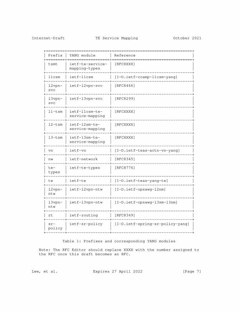
Internet-Draft TE Service Mapping October 2021
+========+==================+==================================+ | Prefix | YANG module | Reference | +========+==================+==================================+ | tsmt | ietf-te-service- | [RFCXXXX] | | | mapping-types | | +--------+------------------+----------------------------------+ | l1csm | ietf-l1csm | [I-D.ietf-ccamp-l1csm-yang] | +--------+------------------+----------------------------------+ | l2vpn- | ietf-l2vpn-svc | [RFC8466] | | svc | | | +--------+------------------+----------------------------------+ | l3vpn- | ietf-l3vpn-svc | [RFC8299] | | svc | | | +--------+------------------+----------------------------------+ | l1-tsm | ietf-l1csm-te- | [RFCXXXX] | | | service-mapping | | +--------+------------------+----------------------------------+ | l2-tsm | ietf-l2sm-te- | [RFCXXXX] | | | service-mapping | | +--------+------------------+----------------------------------+ | l3-tsm | ietf-l3sm-te- | [RFCXXXX] | | | service-mapping | | +--------+------------------+----------------------------------+ | vn | ietf-vn | [I-D.ietf-teas-actn-vn-yang] | +--------+------------------+----------------------------------+ | nw | ietf-network | [RFC8345] | +--------+------------------+----------------------------------+ | te- | ietf-te-types | [RFC8776] | | types | | | +--------+------------------+----------------------------------+ | te | ietf-te | [I-D.ietf-teas-yang-te] | +--------+------------------+----------------------------------+ | l2vpn- | ietf-l2vpn-ntw | [I-D.ietf-opsawg-l2nm] | | ntw | | | +--------+------------------+----------------------------------+ | l3vpn- | ietf-l3vpn-ntw | [I-D.ietf-opsawg-l3sm-l3nm] | | ntw | | | +--------+------------------+----------------------------------+ | rt | ietf-routing | [RFC8349] | +--------+------------------+----------------------------------+ | sr- | ietf-sr-policy | [I-D.ietf-spring-sr-policy-yang] | | policy | | | +--------+------------------+----------------------------------+
Table 1: Prefixes and corresponding YANG modules
Note: The RFC Editor should replace XXXX with the number assigned to the RFC once this draft becomes an RFC.
Lee, et al. Expires 27 April 2022 [Page 7]

Internet-Draft TE Service Mapping October 2021
2. TE and Service Related Parameters
While L1/L2/L3 service models (L1CSM, L2SM, L3SM) are intended to provide service-specific parameters for VPN service instances, there are a number of TE Service related parameters that are not included in these service models.
Additional ’service parameters and policies’ that are not included in the aforementioned service models are addressed in the YANG models defined in this document.
2.1. VN/Tunnel Selection Requirements
In some cases, the service requirements may need addition VN/TE tunnels to be established. This may occur when there are no suitable existing VN/TE tunnels that can support the service requirements, or when the operator would like to dynamically create and bind tunnels to the VPN such that they are not shared by other VPNs, for example, for network slicing. The establishment of TE tunnels is subject to the network operator’s policies.
To summarize, there are three modes of VN/Tunnel selection operations to be supported as follows. Additional modes may be defined in the future.
* New VN/Tunnel Binding - A customer could request a VPN service based on VN/Tunnels that are not shared with other existing or future services. This might be to meet VPN isolation requirements. Further, the YANG model described in Section 4 of this document can be used to describe the mapping between the VPN service and the ACTN VN. The VN (and TE tunnels) could be bound to the VPN and not used for any other VPN. Under this mode, the following sub-categories can be supported:
1. Hard Isolation with deterministic characteristics: A customer could request a VPN service using a set of TE Tunnels with deterministic characteristics requirements (e.g., no latency variation) and where that set of TE Tunnels must not be shared with other VPN services and must not compete for bandwidth or other network resources with other TE Tunnels.
2. Hard Isolation: This is similar to the above case but without the deterministic characteristics requirements.
3. Soft Isolation: The customer requests a VPN service using a set of new TE tunnels which can be shared with other VPN services if need be.
Lee, et al. Expires 27 April 2022 [Page 8]
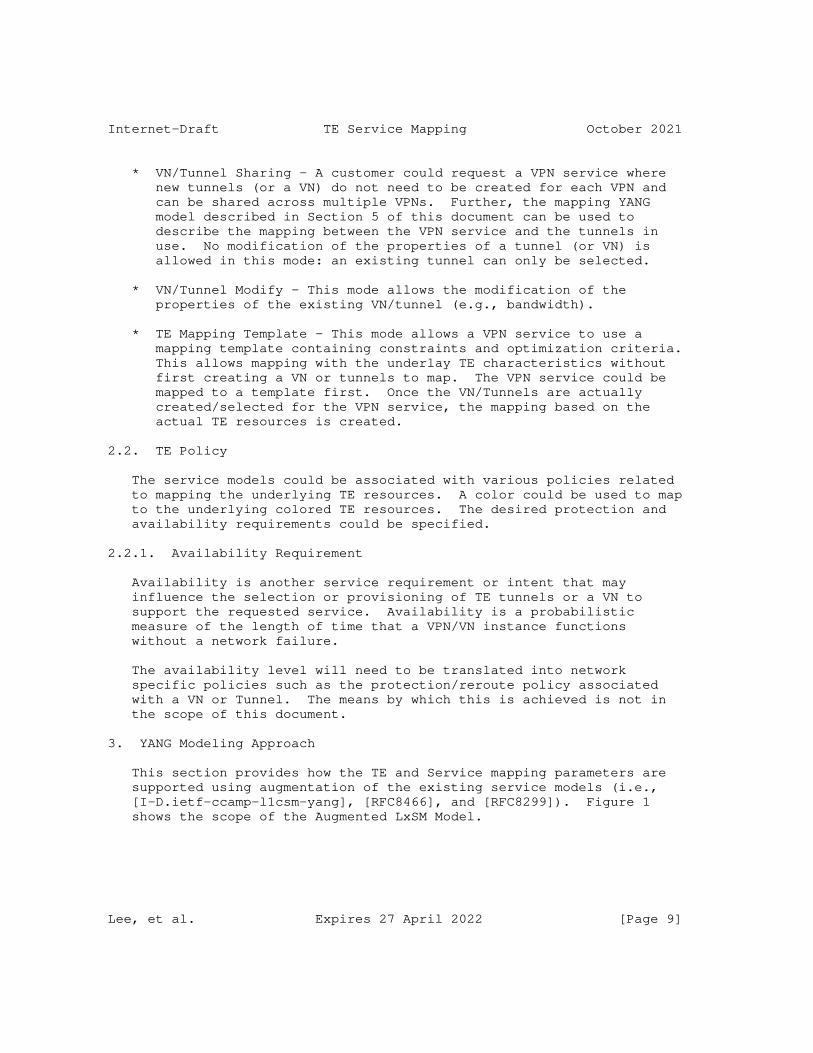
Internet-Draft TE Service Mapping October 2021
* VN/Tunnel Sharing - A customer could request a VPN service where new tunnels (or a VN) do not need to be created for each VPN and can be shared across multiple VPNs. Further, the mapping YANG model described in Section 5 of this document can be used to describe the mapping between the VPN service and the tunnels in use. No modification of the properties of a tunnel (or VN) is allowed in this mode: an existing tunnel can only be selected.
* VN/Tunnel Modify - This mode allows the modification of the properties of the existing VN/tunnel (e.g., bandwidth).
* TE Mapping Template - This mode allows a VPN service to use a mapping template containing constraints and optimization criteria. This allows mapping with the underlay TE characteristics without first creating a VN or tunnels to map. The VPN service could be mapped to a template first. Once the VN/Tunnels are actually created/selected for the VPN service, the mapping based on the actual TE resources is created.
2.2. TE Policy
The service models could be associated with various policies related to mapping the underlying TE resources. A color could be used to map to the underlying colored TE resources. The desired protection and availability requirements could be specified.
2.2.1. Availability Requirement
Availability is another service requirement or intent that may influence the selection or provisioning of TE tunnels or a VN to support the requested service. Availability is a probabilistic measure of the length of time that a VPN/VN instance functions without a network failure.
The availability level will need to be translated into network specific policies such as the protection/reroute policy associated with a VN or Tunnel. The means by which this is achieved is not in the scope of this document.
3. YANG Modeling Approach
This section provides how the TE and Service mapping parameters are supported using augmentation of the existing service models (i.e., [I-D.ietf-ccamp-l1csm-yang], [RFC8466], and [RFC8299]). Figure 1 shows the scope of the Augmented LxSM Model.
Lee, et al. Expires 27 April 2022 [Page 9]
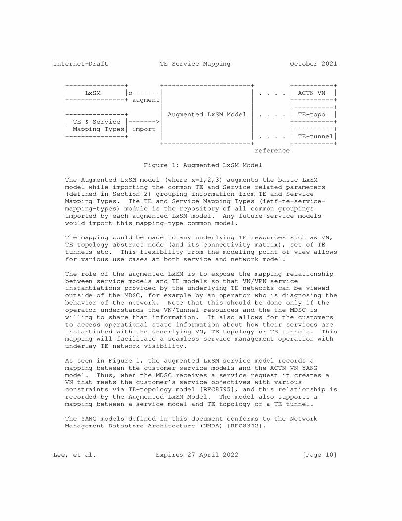
Internet-Draft TE Service Mapping October 2021
+--------------+ +----------------------+ +----------+ | LxSM |o-------| | . . . . | ACTN VN | +--------------+ augment| | +----------+ | | +----------+ +--------------+ | Augmented LxSM Model | . . . . | TE-topo | | TE & Service |------->| | +----------+ | Mapping Types| import | | +----------+ +--------------+ | | . . . . | TE-tunnel| +----------------------+ +----------+ reference
Figure 1: Augmented LxSM Model
The Augmented LxSM model (where x=1,2,3) augments the basic LxSM model while importing the common TE and Service related parameters (defined in Section 2) grouping information from TE and Service Mapping Types. The TE and Service Mapping Types (ietf-te-service- mapping-types) module is the repository of all common groupings imported by each augmented LxSM model. Any future service models would import this mapping-type common model.
The mapping could be made to any underlying TE resources such as VN, TE topology abstract node (and its connectivity matrix), set of TE tunnels etc. This flexibility from the modeling point of view allows for various use cases at both service and network model.
The role of the augmented LxSM is to expose the mapping relationship between service models and TE models so that VN/VPN service instantiations provided by the underlying TE networks can be viewed outside of the MDSC, for example by an operator who is diagnosing the behavior of the network. Note that this should be done only if the operator understands the VN/Tunnel resources and the the MDSC is willing to share that information. It also allows for the customers to access operational state information about how their services are instantiated with the underlying VN, TE topology or TE tunnels. This mapping will facilitate a seamless service management operation with underlay-TE network visibility.
As seen in Figure 1, the augmented LxSM service model records a mapping between the customer service models and the ACTN VN YANG model. Thus, when the MDSC receives a service request it creates a VN that meets the customer’s service objectives with various constraints via TE-topology model [RFC8795], and this relationship is recorded by the Augmented LxSM Model. The model also supports a mapping between a service model and TE-topology or a TE-tunnel.
The YANG models defined in this document conforms to the Network Management Datastore Architecture (NMDA) [RFC8342].
Lee, et al. Expires 27 April 2022 [Page 10]
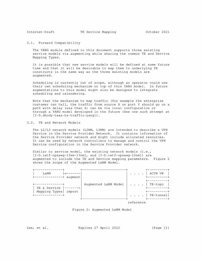
Internet-Draft TE Service Mapping October 2021
3.1. Forward Compatibility
The YANG module defined in this document supports three existing service models via augmenting while sharing the common TE and Service Mapping Types.
It is possible that new service models will be defined at some future time and that it will be desirable to map them to underlying TE constructs in the same way as the three existing models are augmented.
Scheduling is currently out of scope, although an operator could use their own scheduling mechanism on top of this YANG model. In future augmentations to this model might also be designed to integrate scheduling and calendering.
Note that the mechanism to map traffic (for example the enterprise customer can tell, the traffic from source X on port Y should go on a path with delay less than Z) can be via local configuration or through a YANG model developed in the future (See one such attempt at [I-D.dhody-teas-te-traffic-yang]).
3.2. TE and Network Models
The L2/L3 network models (L2NM, L3NM) are intended to describe a VPN Service in the Service Provider Network. It contains information of the Service Provider network and might include allocated resources. It can be used by network controllers to manage and control the VPN Service configuration in the Service Provider network.
Similar to service model, the existing network models (i.e., [I-D.ietf-opsawg-l3sm-l3nm], and [I-D.ietf-opsawg-l2nm]) are augmented to include the TE and Service mapping parameters. Figure 2 shows the scope of the Augmented LxNM Model.
+--------------+ +----------------------+ +----------+ | LxNM |o-------| | . . . . | ACTN VN | +--------------+ augment| | +----------+ | | +----------+ +--------------+ | Augmented LxNM Model | . . . . | TE-topo | | TE & Service |------->| | +----------+ | Mapping Types| import | | +----------+ +--------------+ | | . . . . | TE-tunnel| +----------------------+ +----------+ reference
Figure 2: Augmented LxNM Model
Lee, et al. Expires 27 April 2022 [Page 11]
Internet-Draft TE Service Mapping October 2021
The Augmented LxNM model (where x=2,3) augments the basic LxNM model while importing the common TE mapping related parameters (defined in Section 2) grouping information from TE and Service Mapping Types. The role of the augmented LxNM network model is to expose the mapping relationship between network models and TE models.
4. L3VPN Architecture in the ACTN Context
Figure 3 shows the architectural context of this document referencing the ACTN components and interfaces.
Lee, et al. Expires 27 April 2022 [Page 12]
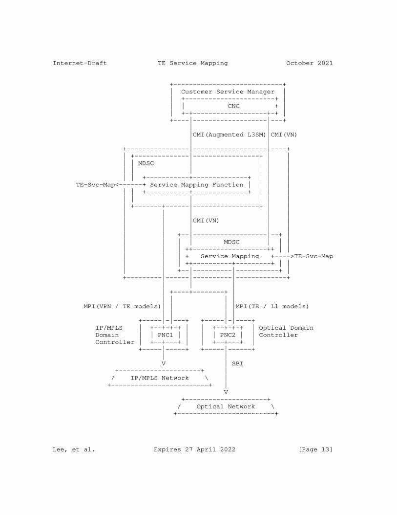
Internet-Draft TE Service Mapping October 2021
+----------------------------+ | Customer Service Manager | | +-----------------------+ | | | CNC + | | +-+-------------------+-+ | +----|-------------------|---+ | | |CMI(Augmented L3SM)|CMI(VN) | | +----------------|-------------------|----+ | +--------------|-----------------+ | | | | MDSC | | | | | | | | | | | | +-----------+--------------+ | | | TE-Svc-Map<------+ Service Mapping Function | | | | | | +-----------+--------------+ | | | | | | | | | | +-------+------|-----------------+ | | | | | | | | | |CMI(VN) | | | | | | | | | +--|-------------------|--+ | | | | | MDSC | | | | | | ++-------------------++ | | | | | + Service Mapping +---->TE-Svc-Map | | | ++----------+---------+ | | | | +--|----------|-----------+ | +---------|------|----------|-------------+ | | | | +----+--------+ | | | | | MPI(VPN / TE models)| | | |MPI(TE / L1 models) | | | | +-----|-|---+ +-----|-|----+ IP/MPLS | +--+-+-+ | | +--+-+-+ | Optical Domain Domain | | PNC1 | | | | PNC2 | | Controller Controller | +--+---+ | | +--+---+ | +-----|-----+ +-----|------+ | | V | SBI +---------------------+ | / IP/MPLS Network \ | +-------------------------+ | V +---------------------+ / Optical Network \ +-------------------------+
Lee, et al. Expires 27 April 2022 [Page 13]
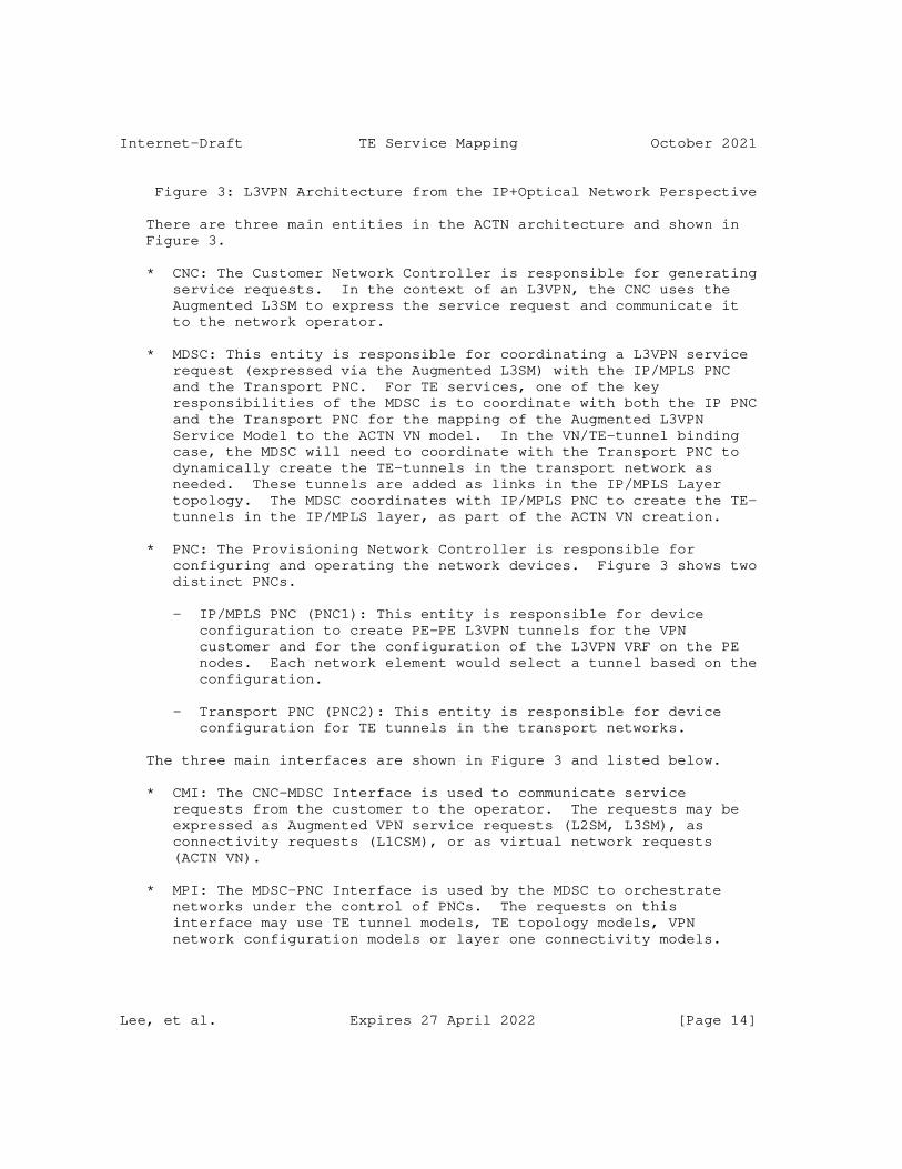
Internet-Draft TE Service Mapping October 2021
Figure 3: L3VPN Architecture from the IP+Optical Network Perspective
There are three main entities in the ACTN architecture and shown in Figure 3.
* CNC: The Customer Network Controller is responsible for generating service requests. In the context of an L3VPN, the CNC uses the Augmented L3SM to express the service request and communicate it to the network operator.
* MDSC: This entity is responsible for coordinating a L3VPN service request (expressed via the Augmented L3SM) with the IP/MPLS PNC and the Transport PNC. For TE services, one of the key responsibilities of the MDSC is to coordinate with both the IP PNC and the Transport PNC for the mapping of the Augmented L3VPN Service Model to the ACTN VN model. In the VN/TE-tunnel binding case, the MDSC will need to coordinate with the Transport PNC to dynamically create the TE-tunnels in the transport network as needed. These tunnels are added as links in the IP/MPLS Layer topology. The MDSC coordinates with IP/MPLS PNC to create the TE- tunnels in the IP/MPLS layer, as part of the ACTN VN creation.
* PNC: The Provisioning Network Controller is responsible for configuring and operating the network devices. Figure 3 shows two distinct PNCs.
- IP/MPLS PNC (PNC1): This entity is responsible for device configuration to create PE-PE L3VPN tunnels for the VPN customer and for the configuration of the L3VPN VRF on the PE nodes. Each network element would select a tunnel based on the configuration.
- Transport PNC (PNC2): This entity is responsible for device configuration for TE tunnels in the transport networks.
The three main interfaces are shown in Figure 3 and listed below.
* CMI: The CNC-MDSC Interface is used to communicate service requests from the customer to the operator. The requests may be expressed as Augmented VPN service requests (L2SM, L3SM), as connectivity requests (L1CSM), or as virtual network requests (ACTN VN).
* MPI: The MDSC-PNC Interface is used by the MDSC to orchestrate networks under the control of PNCs. The requests on this interface may use TE tunnel models, TE topology models, VPN network configuration models or layer one connectivity models.
Lee, et al. Expires 27 April 2022 [Page 14]
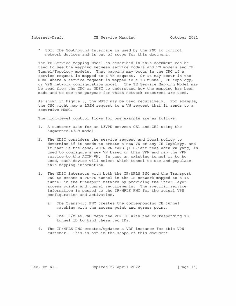
Internet-Draft TE Service Mapping October 2021
* SBI: The Southbound Interface is used by the PNC to control network devices and is out of scope for this document.
The TE Service Mapping Model as described in this document can be used to see the mapping between service models and VN models and TE Tunnel/Topology models. That mapping may occur in the CNC if a service request is mapped to a VN request. Or it may occur in the MDSC where a service request is mapped to a TE tunnel, TE topology, or VPN network configuration model. The TE Service Mapping Model may be read from the CNC or MDSC to understand how the mapping has been made and to see the purpose for which network resources are used.
As shown in Figure 3, the MDSC may be used recursively. For example, the CNC might map a L3SM request to a VN request that it sends to a recursive MDSC.
The high-level control flows for one example are as follows:
1. A customer asks for an L3VPN between CE1 and CE2 using the Augmented L3SM model.
2. The MDSC considers the service request and local policy to determine if it needs to create a new VN or any TE Topology, and if that is the case, ACTN VN YANG [I-D.ietf-teas-actn-vn-yang] is used to configure a new VN based on this VPN and map the VPN service to the ACTN VN. In case an existing tunnel is to be used, each device will select which tunnel to use and populate this mapping information.
3. The MDSC interacts with both the IP/MPLS PNC and the Transport PNC to create a PE-PE tunnel in the IP network mapped to a TE tunnel in the transport network by providing the inter-layer access points and tunnel requirements. The specific service information is passed to the IP/MPLS PNC for the actual VPN configuration and activation.
a. The Transport PNC creates the corresponding TE tunnel matching with the access point and egress point.
b. The IP/MPLS PNC maps the VPN ID with the corresponding TE tunnel ID to bind these two IDs.
4. The IP/MPLS PNC creates/updates a VRF instance for this VPN customer. This is not in the scope of this document.
Lee, et al. Expires 27 April 2022 [Page 15]
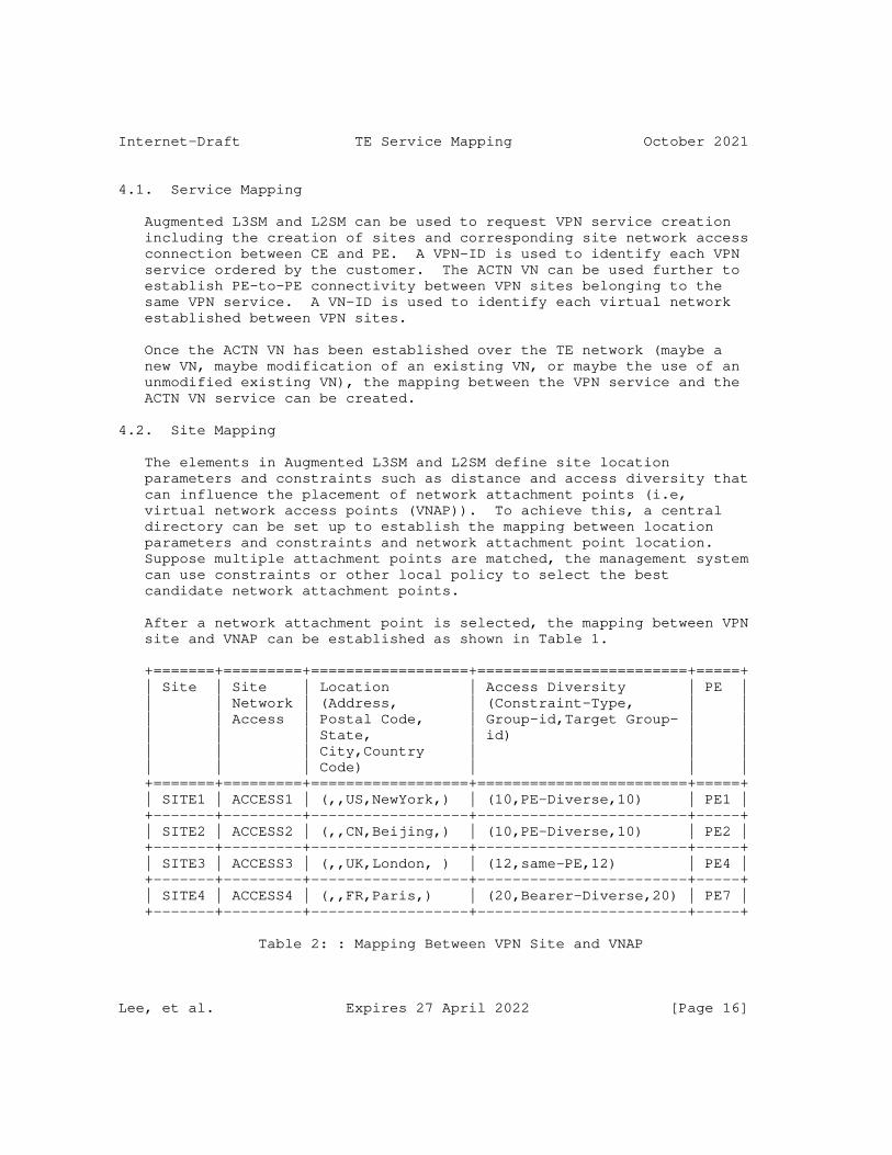
Internet-Draft TE Service Mapping October 2021
4.1. Service Mapping
Augmented L3SM and L2SM can be used to request VPN service creation including the creation of sites and corresponding site network access connection between CE and PE. A VPN-ID is used to identify each VPN service ordered by the customer. The ACTN VN can be used further to establish PE-to-PE connectivity between VPN sites belonging to the same VPN service. A VN-ID is used to identify each virtual network established between VPN sites.
Once the ACTN VN has been established over the TE network (maybe a new VN, maybe modification of an existing VN, or maybe the use of an unmodified existing VN), the mapping between the VPN service and the ACTN VN service can be created.
4.2. Site Mapping
The elements in Augmented L3SM and L2SM define site location parameters and constraints such as distance and access diversity that can influence the placement of network attachment points (i.e, virtual network access points (VNAP)). To achieve this, a central directory can be set up to establish the mapping between location parameters and constraints and network attachment point location. Suppose multiple attachment points are matched, the management system can use constraints or other local policy to select the best candidate network attachment points.
After a network attachment point is selected, the mapping between VPN site and VNAP can be established as shown in Table 1.
+=======+=========+==================+========================+=====+ | Site | Site | Location | Access Diversity | PE | | | Network | (Address, | (Constraint-Type, | | | | Access | Postal Code, | Group-id,Target Group- | | | | | State, | id) | | | | | City,Country | | | | | | Code) | | | +=======+=========+==================+========================+=====+ | SITE1 | ACCESS1 | (,,US,NewYork,) | (10,PE-Diverse,10) | PE1 | +-------+---------+------------------+------------------------+-----+ | SITE2 | ACCESS2 | (,,CN,Beijing,) | (10,PE-Diverse,10) | PE2 | +-------+---------+------------------+------------------------+-----+ | SITE3 | ACCESS3 | (,,UK,London, ) | (12,same-PE,12) | PE4 | +-------+---------+------------------+------------------------+-----+ | SITE4 | ACCESS4 | (,,FR,Paris,) | (20,Bearer-Diverse,20) | PE7 | +-------+---------+------------------+------------------------+-----+
Table 2: : Mapping Between VPN Site and VNAP
Lee, et al. Expires 27 April 2022 [Page 16]
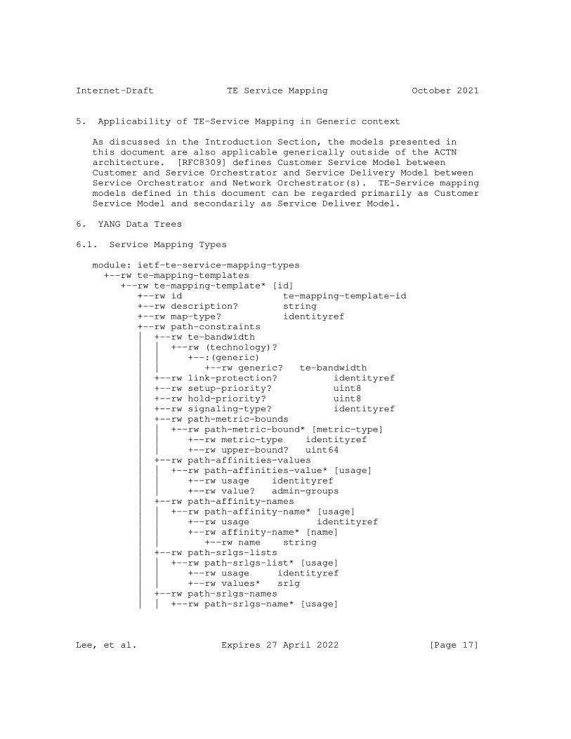
Internet-Draft TE Service Mapping October 2021
5. Applicability of TE-Service Mapping in Generic context
As discussed in the Introduction Section, the models presented in this document are also applicable generically outside of the ACTN architecture. [RFC8309] defines Customer Service Model between Customer and Service Orchestrator and Service Delivery Model between Service Orchestrator and Network Orchestrator(s). TE-Service mapping models defined in this document can be regarded primarily as Customer Service Model and secondarily as Service Deliver Model.
6. YANG Data Trees
6.1. Service Mapping Types
module: ietf-te-service-mapping-types +--rw te-mapping-templates +--rw te-mapping-template* [id] +--rw id te-mapping-template-id +--rw description? string +--rw map-type? identityref +--rw path-constraints | +--rw te-bandwidth | | +--rw (technology)? | | +--:(generic) | | +--rw generic? te-bandwidth | +--rw link-protection? identityref | +--rw setup-priority? uint8 | +--rw hold-priority? uint8 | +--rw signaling-type? identityref | +--rw path-metric-bounds | | +--rw path-metric-bound* [metric-type] | | +--rw metric-type identityref | | +--rw upper-bound? uint64 | +--rw path-affinities-values | | +--rw path-affinities-value* [usage] | | +--rw usage identityref | | +--rw value? admin-groups | +--rw path-affinity-names | | +--rw path-affinity-name* [usage] | | +--rw usage identityref | | +--rw affinity-name* [name] | | +--rw name string | +--rw path-srlgs-lists | | +--rw path-srlgs-list* [usage] | | +--rw usage identityref | | +--rw values* srlg | +--rw path-srlgs-names | | +--rw path-srlgs-name* [usage]
Lee, et al. Expires 27 April 2022 [Page 17]
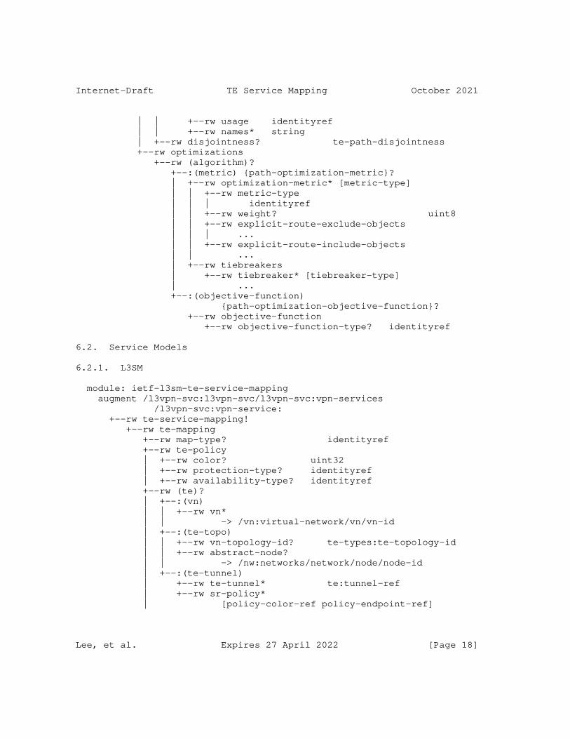
Internet-Draft TE Service Mapping October 2021
| | +--rw usage identityref | | +--rw names* string | +--rw disjointness? te-path-disjointness +--rw optimizations +--rw (algorithm)? +--:(metric) {path-optimization-metric}? | +--rw optimization-metric* [metric-type] | | +--rw metric-type | | | identityref | | +--rw weight? uint8 | | +--rw explicit-route-exclude-objects | | | ... | | +--rw explicit-route-include-objects | | ... | +--rw tiebreakers | +--rw tiebreaker* [tiebreaker-type] | ... +--:(objective-function) {path-optimization-objective-function}? +--rw objective-function +--rw objective-function-type? identityref
6.2. Service Models
6.2.1. L3SM
module: ietf-l3sm-te-service-mapping augment /l3vpn-svc:l3vpn-svc/l3vpn-svc:vpn-services /l3vpn-svc:vpn-service: +--rw te-service-mapping! +--rw te-mapping +--rw map-type? identityref +--rw te-policy | +--rw color? uint32 | +--rw protection-type? identityref | +--rw availability-type? identityref +--rw (te)? | +--:(vn) | | +--rw vn* | | -> /vn:virtual-network/vn/vn-id | +--:(te-topo) | | +--rw vn-topology-id? te-types:te-topology-id | | +--rw abstract-node? | | -> /nw:networks/network/node/node-id | +--:(te-tunnel) | +--rw te-tunnel* te:tunnel-ref | +--rw sr-policy* | [policy-color-ref policy-endpoint-ref]
Lee, et al. Expires 27 April 2022 [Page 18]
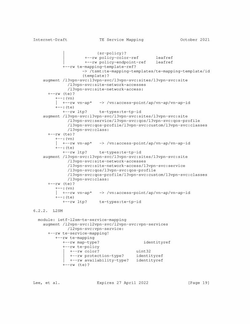
Internet-Draft TE Service Mapping October 2021
| {sr-policy}? | +--rw policy-color-ref leafref | +--rw policy-endpoint-ref leafref +--rw te-mapping-template-ref? -> /tsmt:te-mapping-templates/te-mapping-template/id {template}? augment /l3vpn-svc:l3vpn-svc/l3vpn-svc:sites/l3vpn-svc:site /l3vpn-svc:site-network-accesses /l3vpn-svc:site-network-access: +--rw (te)? +--:(vn) | +--rw vn-ap* -> /vn:access-point/ap/vn-ap/vn-ap-id +--:(te) +--rw ltp? te-types:te-tp-id augment /l3vpn-svc:l3vpn-svc/l3vpn-svc:sites/l3vpn-svc:site /l3vpn-svc:service/l3vpn-svc:qos/l3vpn-svc:qos-profile /l3vpn-svc:qos-profile/l3vpn-svc:custom/l3vpn-svc:classes /l3vpn-svc:class: +--rw (te)? +--:(vn) | +--rw vn-ap* -> /vn:access-point/ap/vn-ap/vn-ap-id +--:(te) +--rw ltp? te-types:te-tp-id augment /l3vpn-svc:l3vpn-svc/l3vpn-svc:sites/l3vpn-svc:site /l3vpn-svc:site-network-accesses /l3vpn-svc:site-network-access/l3vpn-svc:service /l3vpn-svc:qos/l3vpn-svc:qos-profile /l3vpn-svc:qos-profile/l3vpn-svc:custom/l3vpn-svc:classes /l3vpn-svc:class: +--rw (te)? +--:(vn) | +--rw vn-ap* -> /vn:access-point/ap/vn-ap/vn-ap-id +--:(te) +--rw ltp? te-types:te-tp-id
6.2.2. L2SM
module: ietf-l2sm-te-service-mapping augment /l2vpn-svc:l2vpn-svc/l2vpn-svc:vpn-services /l2vpn-svc:vpn-service: +--rw te-service-mapping! +--rw te-mapping +--rw map-type? identityref +--rw te-policy | +--rw color? uint32 | +--rw protection-type? identityref | +--rw availability-type? identityref +--rw (te)?
Lee, et al. Expires 27 April 2022 [Page 19]
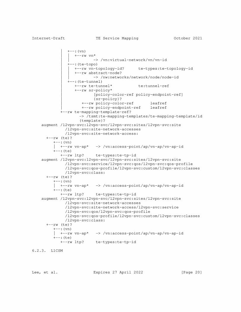
Internet-Draft TE Service Mapping October 2021
| +--:(vn) | | +--rw vn* | | -> /vn:virtual-network/vn/vn-id | +--:(te-topo) | | +--rw vn-topology-id? te-types:te-topology-id | | +--rw abstract-node? | | -> /nw:networks/network/node/node-id | +--:(te-tunnel) | +--rw te-tunnel* te:tunnel-ref | +--rw sr-policy* | [policy-color-ref policy-endpoint-ref] | {sr-policy}? | +--rw policy-color-ref leafref | +--rw policy-endpoint-ref leafref +--rw te-mapping-template-ref? -> /tsmt:te-mapping-templates/te-mapping-template/id {template}? augment /l2vpn-svc:l2vpn-svc/l2vpn-svc:sites/l2vpn-svc:site /l2vpn-svc:site-network-accesses /l2vpn-svc:site-network-access: +--rw (te)? +--:(vn) | +--rw vn-ap* -> /vn:access-point/ap/vn-ap/vn-ap-id +--:(te) +--rw ltp? te-types:te-tp-id augment /l2vpn-svc:l2vpn-svc/l2vpn-svc:sites/l2vpn-svc:site /l2vpn-svc:service/l2vpn-svc:qos/l2vpn-svc:qos-profile /l2vpn-svc:qos-profile/l2vpn-svc:custom/l2vpn-svc:classes /l2vpn-svc:class: +--rw (te)? +--:(vn) | +--rw vn-ap* -> /vn:access-point/ap/vn-ap/vn-ap-id +--:(te) +--rw ltp? te-types:te-tp-id augment /l2vpn-svc:l2vpn-svc/l2vpn-svc:sites/l2vpn-svc:site /l2vpn-svc:site-network-accesses /l2vpn-svc:site-network-access/l2vpn-svc:service /l2vpn-svc:qos/l2vpn-svc:qos-profile /l2vpn-svc:qos-profile/l2vpn-svc:custom/l2vpn-svc:classes /l2vpn-svc:class: +--rw (te)? +--:(vn) | +--rw vn-ap* -> /vn:access-point/ap/vn-ap/vn-ap-id +--:(te) +--rw ltp? te-types:te-tp-id
6.2.3. L1CSM
Lee, et al. Expires 27 April 2022 [Page 20]
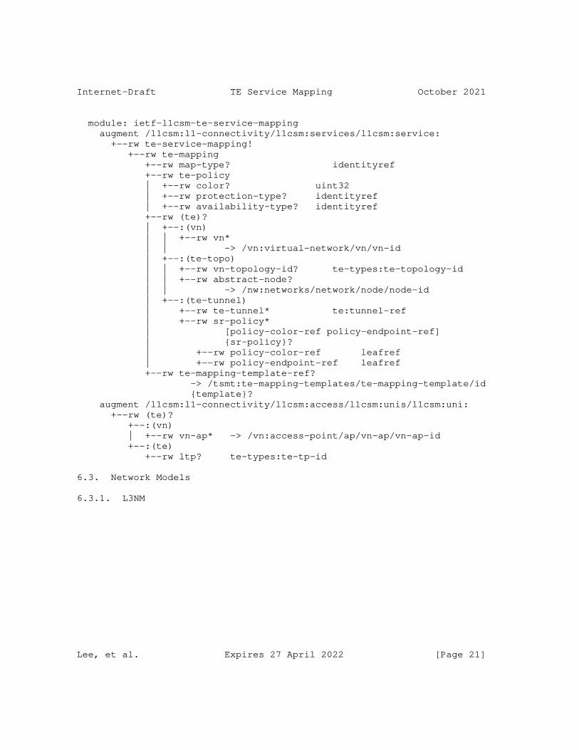
Internet-Draft TE Service Mapping October 2021
module: ietf-l1csm-te-service-mapping augment /l1csm:l1-connectivity/l1csm:services/l1csm:service: +--rw te-service-mapping! +--rw te-mapping +--rw map-type? identityref +--rw te-policy | +--rw color? uint32 | +--rw protection-type? identityref | +--rw availability-type? identityref +--rw (te)? | +--:(vn) | | +--rw vn* | | -> /vn:virtual-network/vn/vn-id | +--:(te-topo) | | +--rw vn-topology-id? te-types:te-topology-id | | +--rw abstract-node? | | -> /nw:networks/network/node/node-id | +--:(te-tunnel) | +--rw te-tunnel* te:tunnel-ref | +--rw sr-policy* | [policy-color-ref policy-endpoint-ref] | {sr-policy}? | +--rw policy-color-ref leafref | +--rw policy-endpoint-ref leafref +--rw te-mapping-template-ref? -> /tsmt:te-mapping-templates/te-mapping-template/id {template}? augment /l1csm:l1-connectivity/l1csm:access/l1csm:unis/l1csm:uni: +--rw (te)? +--:(vn) | +--rw vn-ap* -> /vn:access-point/ap/vn-ap/vn-ap-id +--:(te) +--rw ltp? te-types:te-tp-id
6.3. Network Models
6.3.1. L3NM
Lee, et al. Expires 27 April 2022 [Page 21]
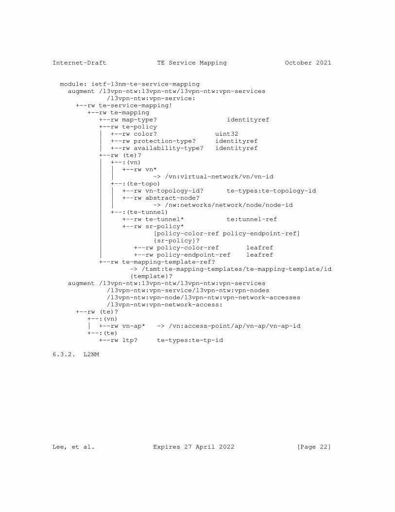
Internet-Draft TE Service Mapping October 2021
module: ietf-l3nm-te-service-mapping augment /l3vpn-ntw:l3vpn-ntw/l3vpn-ntw:vpn-services /l3vpn-ntw:vpn-service: +--rw te-service-mapping! +--rw te-mapping +--rw map-type? identityref +--rw te-policy | +--rw color? uint32 | +--rw protection-type? identityref | +--rw availability-type? identityref +--rw (te)? | +--:(vn) | | +--rw vn* | | -> /vn:virtual-network/vn/vn-id | +--:(te-topo) | | +--rw vn-topology-id? te-types:te-topology-id | | +--rw abstract-node? | | -> /nw:networks/network/node/node-id | +--:(te-tunnel) | +--rw te-tunnel* te:tunnel-ref | +--rw sr-policy* | [policy-color-ref policy-endpoint-ref] | {sr-policy}? | +--rw policy-color-ref leafref | +--rw policy-endpoint-ref leafref +--rw te-mapping-template-ref? -> /tsmt:te-mapping-templates/te-mapping-template/id {template}? augment /l3vpn-ntw:l3vpn-ntw/l3vpn-ntw:vpn-services /l3vpn-ntw:vpn-service/l3vpn-ntw:vpn-nodes /l3vpn-ntw:vpn-node/l3vpn-ntw:vpn-network-accesses /l3vpn-ntw:vpn-network-access: +--rw (te)? +--:(vn) | +--rw vn-ap* -> /vn:access-point/ap/vn-ap/vn-ap-id +--:(te) +--rw ltp? te-types:te-tp-id
6.3.2. L2NM
Lee, et al. Expires 27 April 2022 [Page 22]
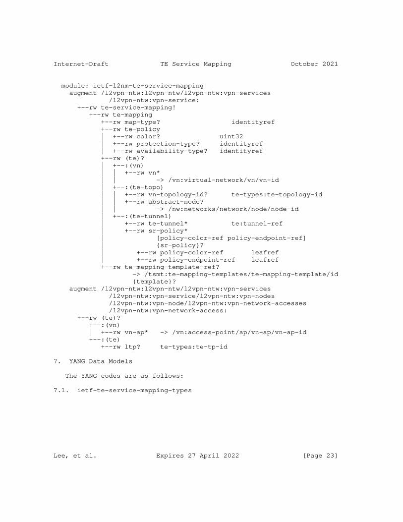
Internet-Draft TE Service Mapping October 2021
module: ietf-l2nm-te-service-mapping augment /l2vpn-ntw:l2vpn-ntw/l2vpn-ntw:vpn-services /l2vpn-ntw:vpn-service: +--rw te-service-mapping! +--rw te-mapping +--rw map-type? identityref +--rw te-policy | +--rw color? uint32 | +--rw protection-type? identityref | +--rw availability-type? identityref +--rw (te)? | +--:(vn) | | +--rw vn* | | -> /vn:virtual-network/vn/vn-id | +--:(te-topo) | | +--rw vn-topology-id? te-types:te-topology-id | | +--rw abstract-node? | | -> /nw:networks/network/node/node-id | +--:(te-tunnel) | +--rw te-tunnel* te:tunnel-ref | +--rw sr-policy* | [policy-color-ref policy-endpoint-ref] | {sr-policy}? | +--rw policy-color-ref leafref | +--rw policy-endpoint-ref leafref +--rw te-mapping-template-ref? -> /tsmt:te-mapping-templates/te-mapping-template/id {template}? augment /l2vpn-ntw:l2vpn-ntw/l2vpn-ntw:vpn-services /l2vpn-ntw:vpn-service/l2vpn-ntw:vpn-nodes /l2vpn-ntw:vpn-node/l2vpn-ntw:vpn-network-accesses /l2vpn-ntw:vpn-network-access: +--rw (te)? +--:(vn) | +--rw vn-ap* -> /vn:access-point/ap/vn-ap/vn-ap-id +--:(te) +--rw ltp? te-types:te-tp-id
7. YANG Data Models
The YANG codes are as follows:
7.1. ietf-te-service-mapping-types
Lee, et al. Expires 27 April 2022 [Page 23]
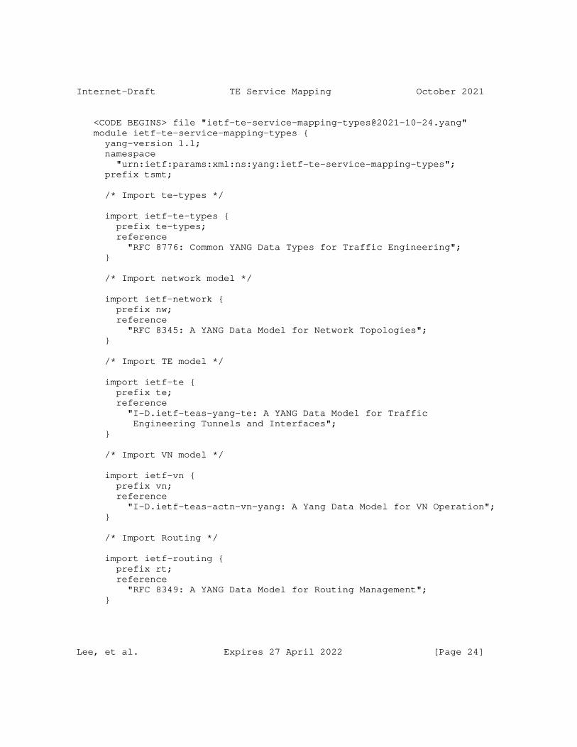
Internet-Draft TE Service Mapping October 2021
<CODE BEGINS> file "[email protected]" module ietf-te-service-mapping-types { yang-version 1.1; namespace "urn:ietf:params:xml:ns:yang:ietf-te-service-mapping-types"; prefix tsmt;
/* Import te-types */
import ietf-te-types { prefix te-types; reference "RFC 8776: Common YANG Data Types for Traffic Engineering"; }
/* Import network model */
import ietf-network { prefix nw; reference "RFC 8345: A YANG Data Model for Network Topologies"; }
/* Import TE model */
import ietf-te { prefix te; reference "I-D.ietf-teas-yang-te: A YANG Data Model for Traffic Engineering Tunnels and Interfaces"; }
/* Import VN model */
import ietf-vn { prefix vn; reference "I-D.ietf-teas-actn-vn-yang: A Yang Data Model for VN Operation"; }
/* Import Routing */
import ietf-routing { prefix rt; reference "RFC 8349: A YANG Data Model for Routing Management"; }
Lee, et al. Expires 27 April 2022 [Page 24]
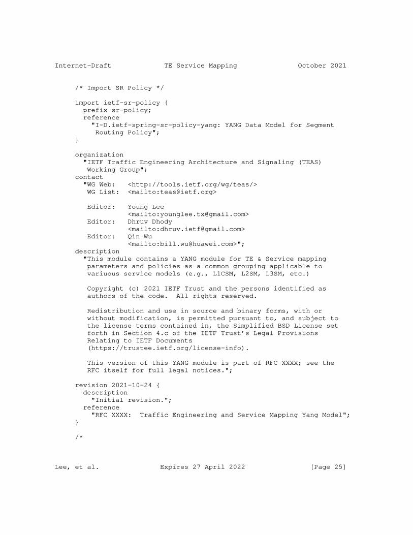
Internet-Draft TE Service Mapping October 2021
/* Import SR Policy */
import ietf-sr-policy { prefix sr-policy; reference "I-D.ietf-spring-sr-policy-yang: YANG Data Model for Segment Routing Policy"; }
organization "IETF Traffic Engineering Architecture and Signaling (TEAS) Working Group"; contact "WG Web: <http://tools.ietf.org/wg/teas/> WG List: <mailto:[email protected]>
Editor: Young Lee <mailto:[email protected]> Editor: Dhruv Dhody <mailto:[email protected]> Editor: Qin Wu <mailto:[email protected]>"; description "This module contains a YANG module for TE & Service mapping parameters and policies as a common grouping applicable to variuous service models (e.g., L1CSM, L2SM, L3SM, etc.)
Copyright (c) 2021 IETF Trust and the persons identified as authors of the code. All rights reserved.
Redistribution and use in source and binary forms, with or without modification, is permitted pursuant to, and subject to the license terms contained in, the Simplified BSD License set forth in Section 4.c of the IETF Trust’s Legal Provisions Relating to IETF Documents (https://trustee.ietf.org/license-info).
This version of this YANG module is part of RFC XXXX; see the RFC itself for full legal notices.";
revision 2021-10-24 { description "Initial revision."; reference "RFC XXXX: Traffic Engineering and Service Mapping Yang Model"; }
/*
Lee, et al. Expires 27 April 2022 [Page 25]
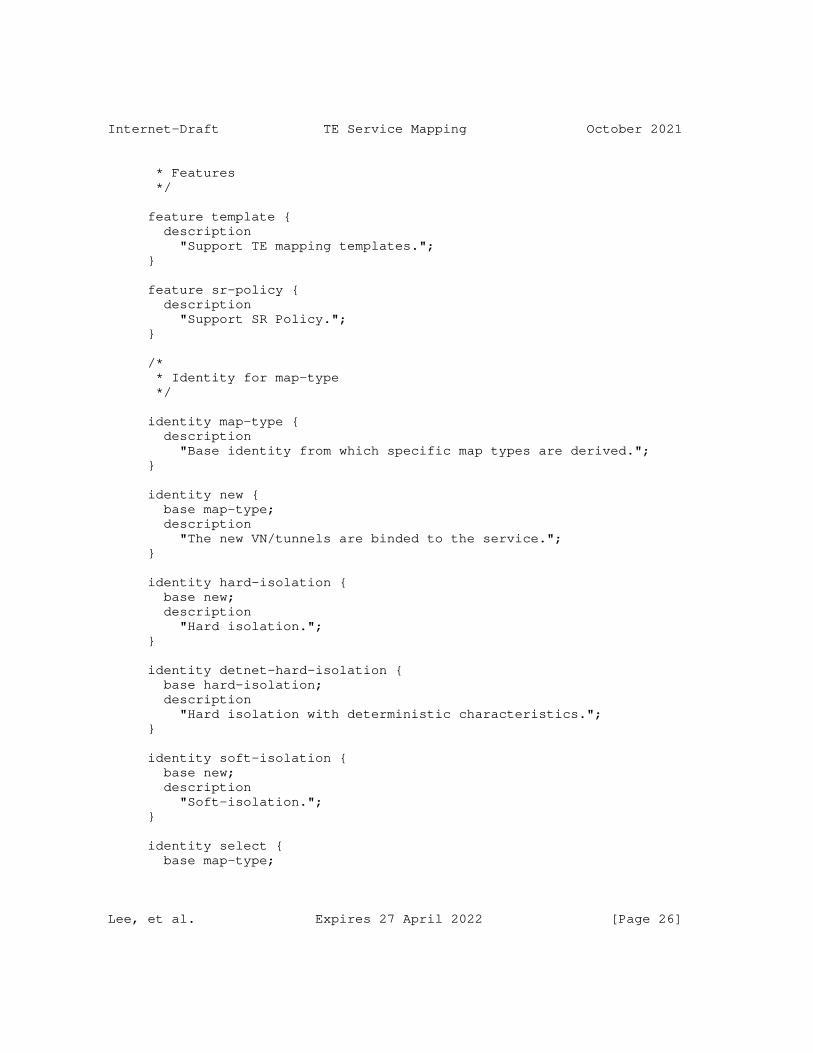
Internet-Draft TE Service Mapping October 2021
* Features */
feature template { description "Support TE mapping templates."; }
feature sr-policy { description "Support SR Policy."; }
/* * Identity for map-type */
identity map-type { description "Base identity from which specific map types are derived."; }
identity new { base map-type; description "The new VN/tunnels are binded to the service."; }
identity hard-isolation { base new; description "Hard isolation."; }
identity detnet-hard-isolation { base hard-isolation; description "Hard isolation with deterministic characteristics."; }
identity soft-isolation { base new; description "Soft-isolation."; }
identity select { base map-type;
Lee, et al. Expires 27 April 2022 [Page 26]
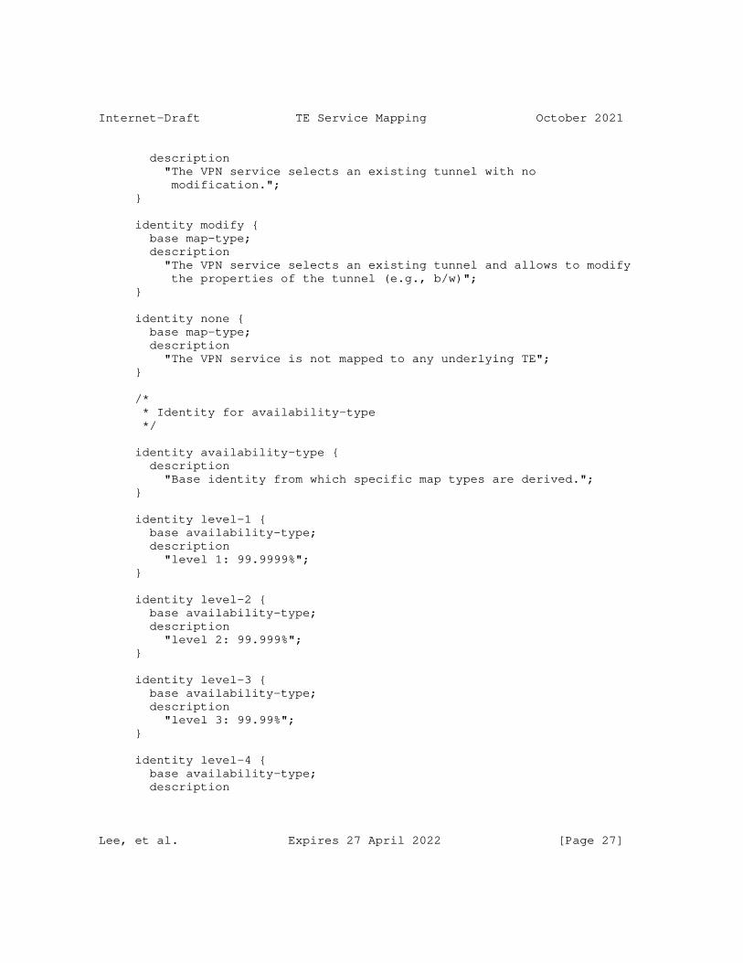
Internet-Draft TE Service Mapping October 2021
description "The VPN service selects an existing tunnel with no modification."; }
identity modify { base map-type; description "The VPN service selects an existing tunnel and allows to modify the properties of the tunnel (e.g., b/w)"; }
identity none { base map-type; description "The VPN service is not mapped to any underlying TE"; }
/* * Identity for availability-type */
identity availability-type { description "Base identity from which specific map types are derived."; }
identity level-1 { base availability-type; description "level 1: 99.9999%"; }
identity level-2 { base availability-type; description "level 2: 99.999%"; }
identity level-3 { base availability-type; description "level 3: 99.99%"; }
identity level-4 { base availability-type; description
Lee, et al. Expires 27 April 2022 [Page 27]
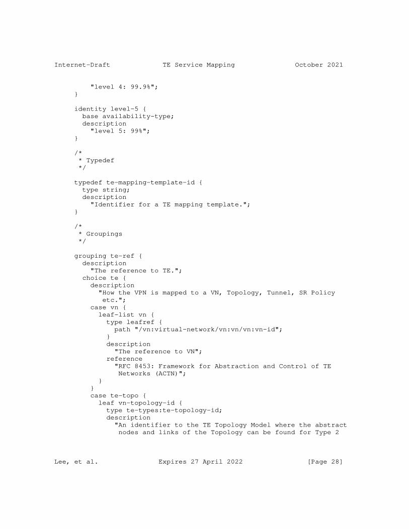
Internet-Draft TE Service Mapping October 2021
"level 4: 99.9%"; }
identity level-5 { base availability-type; description "level 5: 99%"; }
/* * Typedef */
typedef te-mapping-template-id { type string; description "Identifier for a TE mapping template."; }
/* * Groupings */
grouping te-ref { description "The reference to TE."; choice te { description "How the VPN is mapped to a VN, Topology, Tunnel, SR Policy etc."; case vn { leaf-list vn { type leafref { path "/vn:virtual-network/vn:vn/vn:vn-id"; } description "The reference to VN"; reference "RFC 8453: Framework for Abstraction and Control of TE Networks (ACTN)"; } } case te-topo { leaf vn-topology-id { type te-types:te-topology-id; description "An identifier to the TE Topology Model where the abstract nodes and links of the Topology can be found for Type 2
Lee, et al. Expires 27 April 2022 [Page 28]
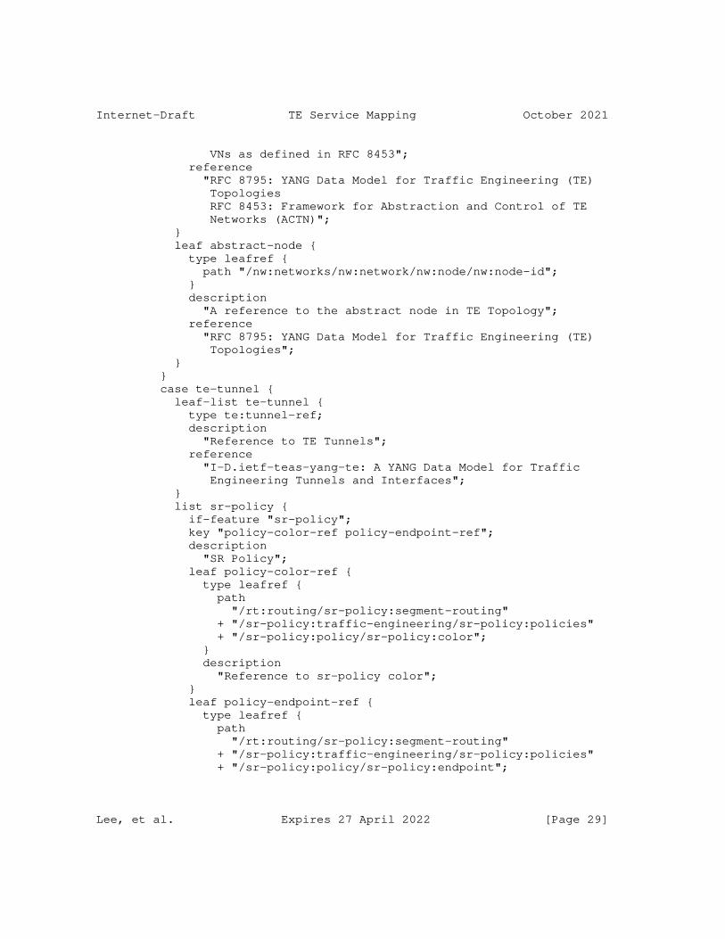
Internet-Draft TE Service Mapping October 2021
VNs as defined in RFC 8453"; reference "RFC 8795: YANG Data Model for Traffic Engineering (TE) Topologies RFC 8453: Framework for Abstraction and Control of TE Networks (ACTN)"; } leaf abstract-node { type leafref { path "/nw:networks/nw:network/nw:node/nw:node-id"; } description "A reference to the abstract node in TE Topology"; reference "RFC 8795: YANG Data Model for Traffic Engineering (TE) Topologies"; } } case te-tunnel { leaf-list te-tunnel { type te:tunnel-ref; description "Reference to TE Tunnels"; reference "I-D.ietf-teas-yang-te: A YANG Data Model for Traffic Engineering Tunnels and Interfaces"; } list sr-policy { if-feature "sr-policy"; key "policy-color-ref policy-endpoint-ref"; description "SR Policy"; leaf policy-color-ref { type leafref { path "/rt:routing/sr-policy:segment-routing" + "/sr-policy:traffic-engineering/sr-policy:policies" + "/sr-policy:policy/sr-policy:color"; } description "Reference to sr-policy color"; } leaf policy-endpoint-ref { type leafref { path "/rt:routing/sr-policy:segment-routing" + "/sr-policy:traffic-engineering/sr-policy:policies" + "/sr-policy:policy/sr-policy:endpoint";
Lee, et al. Expires 27 April 2022 [Page 29]
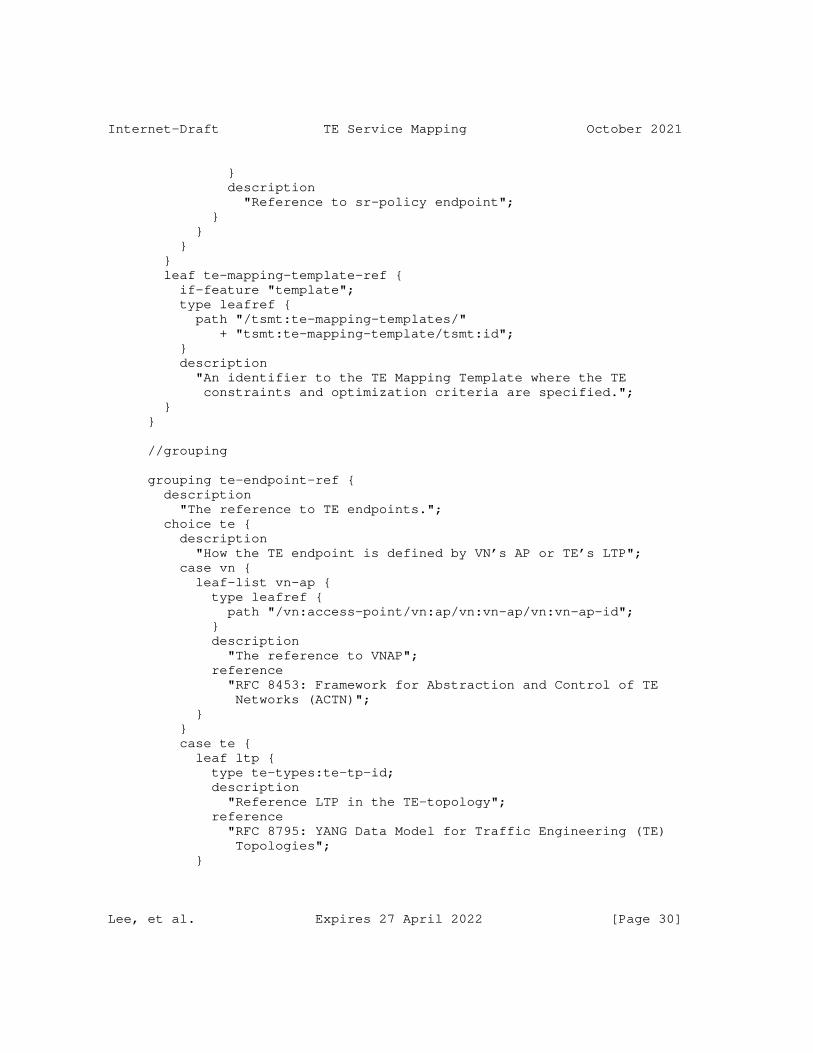
Internet-Draft TE Service Mapping October 2021
} description "Reference to sr-policy endpoint"; } } } } leaf te-mapping-template-ref { if-feature "template"; type leafref { path "/tsmt:te-mapping-templates/" + "tsmt:te-mapping-template/tsmt:id"; } description "An identifier to the TE Mapping Template where the TE constraints and optimization criteria are specified."; } }
//grouping
grouping te-endpoint-ref { description "The reference to TE endpoints."; choice te { description "How the TE endpoint is defined by VN’s AP or TE’s LTP"; case vn { leaf-list vn-ap { type leafref { path "/vn:access-point/vn:ap/vn:vn-ap/vn:vn-ap-id"; } description "The reference to VNAP"; reference "RFC 8453: Framework for Abstraction and Control of TE Networks (ACTN)"; } } case te { leaf ltp { type te-types:te-tp-id; description "Reference LTP in the TE-topology"; reference "RFC 8795: YANG Data Model for Traffic Engineering (TE) Topologies"; }
Lee, et al. Expires 27 April 2022 [Page 30]
Internet-Draft TE Service Mapping October 2021
} } }
//grouping
grouping te-policy { description "Various underlying TE policy requirements"; leaf color { type uint32; description "Maps to the underlying colored TE resources"; } leaf protection-type { type identityref { base te-types:lsp-protection-type; } description "Desired protection level for the underlying TE resources"; } leaf availability-type { type identityref { base availability-type; } description "Availability Requirement for the Service"; } }
//grouping
grouping te-mapping { description "Mapping between Services and TE"; container te-mapping { description "Mapping between Services and TE"; leaf map-type { type identityref { base map-type; } description "Isolation Requirements, Tunnel Bind or Tunnel Selection"; } container te-policy {
Lee, et al. Expires 27 April 2022 [Page 31]

Internet-Draft TE Service Mapping October 2021
uses te-policy; description "Desired Underlying TE Policy"; } uses te-ref; } }
//grouping
container te-mapping-templates { description "The TE constraints and optimization criteria"; list te-mapping-template { key "id"; leaf id { type te-mapping-template-id; description "Identification of the Template to be used."; } leaf description { type string; description "Description of the template."; } leaf map-type { type identityref { base map-type; } must "0 = derived-from-or-self(.,’none’)" { error-message "The map-type must be other than " + "none"; } description "Map type for the VN/Tunnel creation/ selection."; } uses te-types:generic-path-constraints; uses te-types:generic-path-optimization; description "List for templates."; } } } <CODE ENDS>
7.2. Service Models
Lee, et al. Expires 27 April 2022 [Page 32]
Internet-Draft TE Service Mapping October 2021
7.2.1. ietf-l3sm-te-service-mapping
<CODE BEGINS> file "[email protected]" module ietf-l3sm-te-service-mapping { yang-version 1.1; namespace "urn:ietf:params:xml:ns:yang:ietf-l3sm-te-service-mapping"; prefix l3-tsm;
import ietf-te-service-mapping-types { prefix tsmt; reference "RFC XXXX: Traffic Engineering and Service Mapping Yang Model"; } import ietf-l3vpn-svc { prefix l3vpn-svc; reference "RFC 8299: YANG Data Model for L3VPN Service Delivery"; }
organization "IETF Traffic Engineering Architecture and Signaling (TEAS) Working Group"; contact "WG Web: <http://tools.ietf.org/wg/teas/> WG List: <mailto:[email protected]>
Editor: Young Lee <mailto:[email protected]> Editor: Dhruv Dhody <mailto:[email protected]> Editor: Qin Wu <mailto:[email protected]>"; description "This module contains a YANG module for the mapping of Layer 3 Service Model (L3SM) to the TE and VN.
Copyright (c) 2021 IETF Trust and the persons identified as authors of the code. All rights reserved.
Redistribution and use in source and binary forms, with or without modification, is permitted pursuant to, and subject to the license terms contained in, the Simplified BSD License set forth in Section 4.c of the IETF Trust’s Legal Provisions Relating to IETF Documents (https://trustee.ietf.org/license-info). This version of this YANG module is part of RFC XXXX; see the RFC itself for full legal notices.";
Lee, et al. Expires 27 April 2022 [Page 33]
Internet-Draft TE Service Mapping October 2021
revision 2021-10-24 { description "Initial revision."; reference "RFC XXXX: Traffic Engineering and Service Mapping Yang Model"; }
/* * Augmentation to L3SM */
augment "/l3vpn-svc:l3vpn-svc/l3vpn-svc:vpn-services" + "/l3vpn-svc:vpn-service" { description "L3SM augmented to include TE parameters and mapping"; container te-service-mapping { presence "Indicates L3 service to TE mapping"; description "Container to augment l3sm to TE parameters and mapping"; uses tsmt:te-mapping; } }
//augment
augment "/l3vpn-svc:l3vpn-svc/l3vpn-svc:sites/l3vpn-svc:site" + "/l3vpn-svc:site-network-accesses" + "/l3vpn-svc:site-network-access" { description "This augment is only valid for TE mapping of L3SM network-access to TE endpoints"; uses tsmt:te-endpoint-ref; }
//augment
augment "/l3vpn-svc:l3vpn-svc/l3vpn-svc:sites/l3vpn-svc:site" + "/l3vpn-svc:service/l3vpn-svc:qos/l3vpn-svc:qos-profile" + "/l3vpn-svc:qos-profile/l3vpn-svc:custom" + "/l3vpn-svc:classes/l3vpn-svc:class" { description "This augment is for per-class in site for custom QoS profile"; uses tsmt:te-endpoint-ref; }
augment "/l3vpn-svc:l3vpn-svc/l3vpn-svc:sites/l3vpn-svc:site"
Lee, et al. Expires 27 April 2022 [Page 34]
Internet-Draft TE Service Mapping October 2021
+ "/l3vpn-svc:site-network-accesses" + "/l3vpn-svc:site-network-access" + "/l3vpn-svc:service/l3vpn-svc:qos/l3vpn-svc:qos-profile" + "/l3vpn-svc:qos-profile/l3vpn-svc:custom" + "/l3vpn-svc:classes/l3vpn-svc:class" { description "This augment is for per-class in site-network-access for custom QoS profile"; uses tsmt:te-endpoint-ref; } } <CODE ENDS>
7.2.2. ietf-l2sm-te-service-mapping
<CODE BEGINS> file "[email protected]" module ietf-l2sm-te-service-mapping { yang-version 1.1; namespace "urn:ietf:params:xml:ns:yang:ietf-l2sm-te-service-mapping"; prefix l2-tsm;
import ietf-te-service-mapping-types { prefix tsmt; reference "RFC XXXX: Traffic Engineering and Service Mapping Yang Model"; } import ietf-l2vpn-svc { prefix l2vpn-svc; reference "RFC 8466: A YANG Data Model for Layer 2 Virtual Private Network (L2VPN) Service Delivery"; }
organization "IETF Traffic Engineering Architecture and Signaling (TEAS) Working Group"; contact "WG Web: <http://tools.ietf.org/wg/teas/> WG List: <mailto:[email protected]>
Editor: Young Lee <mailto:[email protected]> Editor: Dhruv Dhody <mailto:[email protected]> Editor: Qin Wu <mailto:[email protected]>"; description
Lee, et al. Expires 27 April 2022 [Page 35]
Internet-Draft TE Service Mapping October 2021
"This module contains a YANG module for the mapping of Layer 2 Service Model (L2SM) to the TE and VN.
Copyright (c) 2021 IETF Trust and the persons identified as authors of the code. All rights reserved.
Redistribution and use in source and binary forms, with or without modification, is permitted pursuant to, and subject to the license terms contained in, the Simplified BSD License set forth in Section 4.c of the IETF Trust’s Legal Provisions Relating to IETF Documents (https://trustee.ietf.org/license-info).
This version of this YANG module is part of RFC XXXX; see the RFC itself for full legal notices.";
revision 2021-10-24 { description "Initial revision."; reference "RFC XXXX: Traffic Engineering and Service Mapping Yang Model"; }
/* * Augmentation to L2SM */
augment "/l2vpn-svc:l2vpn-svc/l2vpn-svc:vpn-services/" + "l2vpn-svc:vpn-service" { description "L2SM augmented to include TE parameters and mapping"; container te-service-mapping { presence "indicates L2 service to te mapping"; description "Container to augment L2SM to TE parameters and mapping"; uses tsmt:te-mapping; } }
//augment
augment "/l2vpn-svc:l2vpn-svc/l2vpn-svc:sites/l2vpn-svc:site" + "/l2vpn-svc:site-network-accesses" + "/l2vpn-svc:site-network-access" { description "This augment the L2SM network-access with a reference to TE endpoints when underlying TE is used"; uses tsmt:te-endpoint-ref;
Lee, et al. Expires 27 April 2022 [Page 36]
Internet-Draft TE Service Mapping October 2021
}
//augment
augment "/l2vpn-svc:l2vpn-svc/l2vpn-svc:sites/l2vpn-svc:site" + "/l2vpn-svc:service/l2vpn-svc:qos/l2vpn-svc:qos-profile" + "/l2vpn-svc:qos-profile/l2vpn-svc:custom" + "/l2vpn-svc:classes/l2vpn-svc:class" { when ’./l2vpn-svc:bandwidth/l2vpn-svc:end-to-end’ { description "applicable only with end-to-end"; } description "This augment is for per-class in site for custom QoS profile"; uses tsmt:te-endpoint-ref; }
augment "/l2vpn-svc:l2vpn-svc/l2vpn-svc:sites/l2vpn-svc:site" + "/l2vpn-svc:site-network-accesses" + "/l2vpn-svc:site-network-access" + "/l2vpn-svc:service/l2vpn-svc:qos/l2vpn-svc:qos-profile" + "/l2vpn-svc:qos-profile/l2vpn-svc:custom" + "/l2vpn-svc:classes/l2vpn-svc:class" { description "This augment is for per-class in site-network-access for custom QoS profile"; uses tsmt:te-endpoint-ref; } } <CODE ENDS>
7.2.3. ietf-l1csm-te-service-mapping
<CODE BEGINS> file "[email protected]" module ietf-l1csm-te-service-mapping { yang-version 1.1; namespace "urn:ietf:params:xml:ns:yang:ietf-l1csm-te-service-mapping"; prefix l1-tsm;
import ietf-te-service-mapping-types { prefix tsmt; reference "RFC XXXX: Traffic Engineering and Service Mapping Yang Model"; } import ietf-l1csm {
Lee, et al. Expires 27 April 2022 [Page 37]
Internet-Draft TE Service Mapping October 2021
prefix l1csm; reference "I-D.ietf-ccamp-l1csm-yang: A YANG Data Model for L1 Connectivity Service Model (L1CSM)"; }
organization "IETF Traffic Engineering Architecture and Signaling (TEAS) Working Group"; contact "WG Web: <http://tools.ietf.org/wg/teas/> WG List: <mailto:[email protected]>
Editor: Young Lee <mailto:[email protected]> Editor: Dhruv Dhody <mailto:[email protected]> Editor: Qin Wu <mailto:[email protected]>"; description "This module contains a YANG module for the mapping of Layer 1 Connectivity Service Module (L1CSM) to the TE and VN
Copyright (c) 2021 IETF Trust and the persons identified as authors of the code. All rights reserved.
Redistribution and use in source and binary forms, with or without modification, is permitted pursuant to, and subject to the license terms contained in, the Simplified BSD License set forth in Section 4.c of the IETF Trust’s Legal Provisions Relating to IETF Documents (https://trustee.ietf.org/license-info).
This version of this YANG module is part of RFC XXXX; see the RFC itself for full legal notices.";
revision 2021-10-24 { description "Initial revision."; reference "RFC XXXX: Traffic Engineering and Service Mapping Yang Model"; }
/* * Augmentation to L1CSM */
augment "/l1csm:l1-connectivity/l1csm:services/l1csm:service" {
Lee, et al. Expires 27 April 2022 [Page 38]
Internet-Draft TE Service Mapping October 2021
description "L1CSM augmented to include TE parameters and mapping"; container te-service-mapping { presence "Indicates L1 service to TE mapping"; description "Container to augment L1CSM to TE parameters and mapping"; uses tsmt:te-mapping; } }
//augment
augment "/l1csm:l1-connectivity/l1csm:access/l1csm:unis/" + "l1csm:uni" { description "This augment the L1CSM UNI with a reference to TE endpoints"; uses tsmt:te-endpoint-ref; }
//augment } <CODE ENDS>
7.3. Network Models
7.3.1. ietf-l3nm-te-service-mapping
<CODE BEGINS> file "[email protected]" module ietf-l3nm-te-service-mapping { yang-version 1.1; namespace "urn:ietf:params:xml:ns:yang:ietf-l3nm-te-service-mapping"; prefix l3nm-tsm;
import ietf-te-service-mapping-types { prefix tsmt; reference "RFC XXXX: Traffic Engineering and Service Mapping Yang Model"; } import ietf-l3vpn-ntw { prefix l3vpn-ntw; reference "I-D.ietf-opsawg-l3sm-l3nm: A Layer 3 VPN Network YANG Model"; }
organization "IETF Traffic Engineering Architecture and Signaling (TEAS)
Lee, et al. Expires 27 April 2022 [Page 39]
Internet-Draft TE Service Mapping October 2021
Working Group"; contact "WG Web: <http://tools.ietf.org/wg/teas/> WG List: <mailto:[email protected]>
Editor: Young Lee <mailto:[email protected]> Editor: Dhruv Dhody <mailto:[email protected]> Editor: Qin Wu <mailto:[email protected]>"; description "This module contains a YANG module for the mapping of Layer 3 Network Model (L3NM) to the TE and VN.
Copyright (c) 2021 IETF Trust and the persons identified as authors of the code. All rights reserved.
Redistribution and use in source and binary forms, with or without modification, is permitted pursuant to, and subject to the license terms contained in, the Simplified BSD License set forth in Section 4.c of the IETF Trust’s Legal Provisions Relating to IETF Documents (https://trustee.ietf.org/license-info). This version of this YANG module is part of RFC XXXX; see the RFC itself for full legal notices.";
revision 2021-10-24 { description "Initial revision."; reference "RFC XXXX: Traffic Engineering and Service Mapping Yang Model"; }
/* * Augmentation to L3NM */
augment "/l3vpn-ntw:l3vpn-ntw/l3vpn-ntw:vpn-services" + "/l3vpn-ntw:vpn-service" { description "L3SM augmented to include TE parameters and mapping"; container te-service-mapping { presence "Indicates L3 network to TE mapping"; description "Container to augment l3nm to TE parameters and mapping"; uses tsmt:te-mapping; }
Lee, et al. Expires 27 April 2022 [Page 40]
Internet-Draft TE Service Mapping October 2021
}
//augment
augment "/l3vpn-ntw:l3vpn-ntw/l3vpn-ntw:vpn-services" + "/l3vpn-ntw:vpn-service" + "/l3vpn-ntw:vpn-nodes/l3vpn-ntw:vpn-node" + "/l3vpn-ntw:vpn-network-accesses" + "/l3vpn-ntw:vpn-network-access" { description "This augment the L3NM network-access with a reference to TE endpoints when underlying TE is used"; uses tsmt:te-endpoint-ref; }
//augment } <CODE ENDS>
7.3.2. ietf-l2nm-te-service-mapping
<CODE BEGINS> file "[email protected]" module ietf-l2nm-te-service-mapping { yang-version 1.1; namespace "urn:ietf:params:xml:ns:yang:ietf-l2nm-te-service-mapping"; prefix l2nm-tsm;
import ietf-te-service-mapping-types { prefix tsmt; reference "RFC XXXX: Traffic Engineering and Service Mapping Yang Model"; } import ietf-l2vpn-ntw { prefix l2vpn-ntw; reference "I-D.ietf-opsawg-l2nm: A Layer 2 VPN Network YANG Model"; }
organization "IETF Traffic Engineering Architecture and Signaling (TEAS) Working Group"; contact "WG Web: <http://tools.ietf.org/wg/teas/> WG List: <mailto:[email protected]>
Editor: Young Lee <mailto:[email protected]>
Lee, et al. Expires 27 April 2022 [Page 41]
Internet-Draft TE Service Mapping October 2021
Editor: Dhruv Dhody <mailto:[email protected]> Editor: Qin Wu <mailto:[email protected]>"; description "This module contains a YANG module for the mapping of Layer 2 Network Model (L2NM) to the TE and VN.
Copyright (c) 2021 IETF Trust and the persons identified as authors of the code. All rights reserved.
Redistribution and use in source and binary forms, with or without modification, is permitted pursuant to, and subject to the license terms contained in, the Simplified BSD License set forth in Section 4.c of the IETF Trust’s Legal Provisions Relating to IETF Documents (https://trustee.ietf.org/license-info).
This version of this YANG module is part of RFC XXXX; see the RFC itself for full legal notices.";
revision 2021-10-24 { description "Initial revision."; reference "RFC XXXX: Traffic Engineering and Service Mapping Yang Model"; }
/* * Augmentation to L2NM */
augment "/l2vpn-ntw:l2vpn-ntw/l2vpn-ntw:vpn-services" + "/l2vpn-ntw:vpn-service" { description "L2SM augmented to include TE parameters and mapping"; container te-service-mapping { presence "Indicates L2 network to TE mapping"; description "Container to augment l2nm to TE parameters and mapping"; uses tsmt:te-mapping; } }
//augment
augment "/l2vpn-ntw:l2vpn-ntw/l2vpn-ntw:vpn-services" + "/l2vpn-ntw:vpn-service"
Lee, et al. Expires 27 April 2022 [Page 42]

Internet-Draft TE Service Mapping October 2021
+ "/l2vpn-ntw:vpn-nodes/l2vpn-ntw:vpn-node" + "/l2vpn-ntw:vpn-network-accesses" + "/l2vpn-ntw:vpn-network-access" { description "This augment the L2NM network-access with a reference to TE endpoints when underlying TE is used"; uses tsmt:te-endpoint-ref; }
//augment } <CODE ENDS>
8. Security Considerations
The YANG modules defined in this document is designed to be accessed via network management protocol such as NETCONF [RFC6241] or RESTCONF [RFC8040]. The lowest NETCONF layer is the secure transport layer and the mandatory-to-implement secure transport is SSH [RFC6242]. The lowest RESTCONF layer is HTTPS, and the mandatory-to-implement secure transport is TLS [RFC8446]
The NETCONF access control model [RFC8341] provides the means to restrict access for particular NETCONF or RESTCONF users to a pre- configured subset of all available NETCONF or RESTCONF protocol operations and content.
There are a number of data nodes defined in the YANG moduleS which are writable/creatable/deletable (i.e., config true, which is the default). These data nodes may be considered sensitive or vulnerable in some network environments. Write operations (e.g., <edit-config>) to these data nodes without proper protection can have a negative effect on network operations. These are the subtrees and data nodes and their sensitivity/vulnerability:
* /l3vpn-svc/vpn-services/vpn-service/te-service-mapping/te-mapping/ - can configure TE Service mapping.
* /l3vpn-svc/sites/site/site-network-accesses/site-network-access/ te/ - can configure TE Endpoint mapping.
* /l2vpn-svc/vpn-services/vpn-service/te-service-mapping/te-mapping/ - can configure TE Service mapping.
* /l2vpn-svc/sites/site/site-network-accesses/site-network-access/ te/ - can configure TE Endpoint mapping.
Lee, et al. Expires 27 April 2022 [Page 43]
Internet-Draft TE Service Mapping October 2021
* /l1-connectivity/services/service/te-service-mapping/te-mapping/ - can configure TE Service mapping.
* /l1-connectivity/access/unis/uni/te/ - can configure TE Endpoint mapping.
* /l3vpn-ntw/vpn-services/vpn-service/te-service-mapping/te-mapping/ - can configure TE Network mapping.
* /l3vpn-ntw/vpn-services/vpn-service/vpn-nodes/vpn-node/vpn- network-accesses/vpn-network-access/te/ - can configure TE Endpoint mapping.
* /l2vpn-ntw/vpn-services/vpn-service/te-service-mapping/te-mapping/ - can configure TE Network mapping.
* /l2vpn-ntw/vpn-services/vpn-service/vpn-nodes/vpn-node/vpn- network-accesses/vpn-network-access/te/ - can configure TE Endpoint mapping.
Unauthorized access to above list can adversely affect the VPN service.
Some of the readable data nodes in the YANG module may be considered sensitive or vulnerable in some network environments. It is thus important to control read access (e.g., via get, get-config, or notification) to these data nodes. The TE related parameters attached to the VPN service can leak sensitive information about the network. This is applicable to all elements in the yang models defined in this document.
This document has no RPC defined.
9. IANA Considerations
This document request the IANA to register six URIs in the "IETF XML Registry" [RFC3688]. Following the format in RFC 3688, the following registrations are requested -
Lee, et al. Expires 27 April 2022 [Page 44]
Internet-Draft TE Service Mapping October 2021
URI: urn:ietf:params:xml:ns:yang:ietf-te-service-mapping-types Registrant Contact: The IESG. XML: N/A, the requested URI is an XML namespace.
URI: urn:ietf:params:xml:ns:yang:ietf-l3sm-te-service-mapping Registrant Contact: The IESG. XML: N/A, the requested URI is an XML namespace.
URI: urn:ietf:params:xml:ns:yang:ietf-l2sm-te-service-mapping Registrant Contact: The IESG. XML: N/A, the requested URI is an XML namespace.
URI: urn:ietf:params:xml:ns:yang:ietf-l1csm-te-service-mapping Registrant Contact: The IESG. XML: N/A, the requested URI is an XML namespace.
URI: urn:ietf:params:xml:ns:yang:ietf-l3nm-te-service-mapping Registrant Contact: The IESG. XML: N/A, the requested URI is an XML namespace.
URI: urn:ietf:params:xml:ns:yang:ietf-l2nm-te-service-mapping Registrant Contact: The IESG. XML: N/A, the requested URI is an XML namespace.
This document request the IANA to register six YANG modules in the "YANG Module Names" registry [RFC6020], as follows -
Lee, et al. Expires 27 April 2022 [Page 45]
Internet-Draft TE Service Mapping October 2021
Name: ietf-te-service-mapping-types Namespace: urn:ietf:params:xml:ns:yang:ietf-te-service-mapping-types Prefix: tsmt Reference: [This.I-D]
Name: ietf-l3sm-te-service-mapping Namespace: urn:ietf:params:xml:ns:yang:ietf-l3sm-te-service-mapping Prefix: l3-tsm Reference: [This.I-D]
Name: ietf-l2sm-te-service-mapping Namespace: urn:ietf:params:xml:ns:yang:ietf-l2sm-te-service-mapping Prefix: l2-tsm Reference: [This.I-D]
Name: ietf-l1csm-te-service-mapping Namespace: urn:ietf:params:xml:ns:yang:ietf-l1csm-te-service-mapping Prefix: l1-tsm Reference: [This.I-D]
Name: ietf-l3nm-te-service-mapping Namespace: urn:ietf:params:xml:ns:yang:ietf-l3nm-te-service-mapping Prefix: l3nm-tsm Reference: [This.I-D]
Name: ietf-l2nm-te-service-mapping Namespace: urn:ietf:params:xml:ns:yang:ietf-l2nm-te-service-mapping Prefix: l2nm-tsm Reference: [This.I-D]
10. Acknowledgements
We thank Diego Caviglia, and Igor Bryskin for useful discussions and motivation for this work.
11. References
11.1. Normative References
[I-D.ietf-ccamp-l1csm-yang] Lee, Y., Lee, K., Zheng, H., Dios, O. G. D., and D. Ceccarelli, "A YANG Data Model for L1 Connectivity Service Model (L1CSM)", Work in Progress, Internet-Draft, draft- ietf-ccamp-l1csm-yang-15, 8 September 2021, <https://datatracker.ietf.org/doc/html/draft-ietf-ccamp- l1csm-yang-15>.
Lee, et al. Expires 27 April 2022 [Page 46]
Internet-Draft TE Service Mapping October 2021
[I-D.ietf-opsawg-l2nm] Barguil, S., Dios, O. G. D., Boucadair, M., and L. A. Munoz, "A Layer 2 VPN Network YANG Model", Work in Progress, Internet-Draft, draft-ietf-opsawg-l2nm-09, 20 October 2021, <https://datatracker.ietf.org/doc/html/ draft-ietf-opsawg-l2nm-09>.
[I-D.ietf-opsawg-l3sm-l3nm] Barguil, S., Dios, O. G. D., Boucadair, M., Munoz, L. A., and A. Aguado, "A Layer 3 VPN Network YANG Model", Work in Progress, Internet-Draft, draft-ietf-opsawg-l3sm-l3nm-18, 8 October 2021, <https://datatracker.ietf.org/doc/html/ draft-ietf-opsawg-l3sm-l3nm-18>.
[I-D.ietf-spring-sr-policy-yang] Raza, K., Sawaya, R., Shunwan, Z., Voyer, D., Durrani, M., Matsushima, S., and V. P. Beeram, "YANG Data Model for Segment Routing Policy", Work in Progress, Internet-Draft, draft-ietf-spring-sr-policy-yang-01, 7 April 2021, <https://datatracker.ietf.org/doc/html/draft-ietf-spring- sr-policy-yang-01>.
[I-D.ietf-teas-actn-vn-yang] Lee, Y., Dhody, D., Ceccarelli, D., Bryskin, I., and B. Y. Yoon, "A YANG Data Model for VN Operation", Work in Progress, Internet-Draft, draft-ietf-teas-actn-vn-yang-13, 23 October 2021, <https://datatracker.ietf.org/doc/html/ draft-ietf-teas-actn-vn-yang-13>.
[I-D.ietf-teas-yang-te] Saad, T., Gandhi, R., Liu, X., Beeram, V. P., Bryskin, I., and O. G. D. Dios, "A YANG Data Model for Traffic Engineering Tunnels, Label Switched Paths and Interfaces", Work in Progress, Internet-Draft, draft-ietf-teas-yang-te- 27, 8 July 2021, <https://datatracker.ietf.org/doc/html/ draft-ietf-teas-yang-te-27>.
[RFC3688] Mealling, M., "The IETF XML Registry", BCP 81, RFC 3688, DOI 10.17487/RFC3688, January 2004, <https://www.rfc-editor.org/info/rfc3688>.
[RFC6020] Bjorklund, M., Ed., "YANG - A Data Modeling Language for the Network Configuration Protocol (NETCONF)", RFC 6020, DOI 10.17487/RFC6020, October 2010, <https://www.rfc-editor.org/info/rfc6020>.
Lee, et al. Expires 27 April 2022 [Page 47]
Internet-Draft TE Service Mapping October 2021
[RFC6242] Wasserman, M., "Using the NETCONF Protocol over Secure Shell (SSH)", RFC 6242, DOI 10.17487/RFC6242, June 2011, <https://www.rfc-editor.org/info/rfc6242>.
[RFC7926] Farrel, A., Ed., Drake, J., Bitar, N., Swallow, G., Ceccarelli, D., and X. Zhang, "Problem Statement and Architecture for Information Exchange between Interconnected Traffic-Engineered Networks", BCP 206, RFC 7926, DOI 10.17487/RFC7926, July 2016, <https://www.rfc-editor.org/info/rfc7926>.
[RFC7950] Bjorklund, M., Ed., "The YANG 1.1 Data Modeling Language", RFC 7950, DOI 10.17487/RFC7950, August 2016, <https://www.rfc-editor.org/info/rfc7950>.
[RFC8040] Bierman, A., Bjorklund, M., and K. Watsen, "RESTCONF Protocol", RFC 8040, DOI 10.17487/RFC8040, January 2017, <https://www.rfc-editor.org/info/rfc8040>.
[RFC8299] Wu, Q., Ed., Litkowski, S., Tomotaki, L., and K. Ogaki, "YANG Data Model for L3VPN Service Delivery", RFC 8299, DOI 10.17487/RFC8299, January 2018, <https://www.rfc-editor.org/info/rfc8299>.
[RFC8340] Bjorklund, M. and L. Berger, Ed., "YANG Tree Diagrams", BCP 215, RFC 8340, DOI 10.17487/RFC8340, March 2018, <https://www.rfc-editor.org/info/rfc8340>.
[RFC8341] Bierman, A. and M. Bjorklund, "Network Configuration Access Control Model", STD 91, RFC 8341, DOI 10.17487/RFC8341, March 2018, <https://www.rfc-editor.org/info/rfc8341>.
[RFC8342] Bjorklund, M., Schoenwaelder, J., Shafer, P., Watsen, K., and R. Wilton, "Network Management Datastore Architecture (NMDA)", RFC 8342, DOI 10.17487/RFC8342, March 2018, <https://www.rfc-editor.org/info/rfc8342>.
[RFC8345] Clemm, A., Medved, J., Varga, R., Bahadur, N., Ananthakrishnan, H., and X. Liu, "A YANG Data Model for Network Topologies", RFC 8345, DOI 10.17487/RFC8345, March 2018, <https://www.rfc-editor.org/info/rfc8345>.
[RFC8349] Lhotka, L., Lindem, A., and Y. Qu, "A YANG Data Model for Routing Management (NMDA Version)", RFC 8349, DOI 10.17487/RFC8349, March 2018, <https://www.rfc-editor.org/info/rfc8349>.
Lee, et al. Expires 27 April 2022 [Page 48]
Internet-Draft TE Service Mapping October 2021
[RFC8446] Rescorla, E., "The Transport Layer Security (TLS) Protocol Version 1.3", RFC 8446, DOI 10.17487/RFC8446, August 2018, <https://www.rfc-editor.org/info/rfc8446>.
[RFC8466] Wen, B., Fioccola, G., Ed., Xie, C., and L. Jalil, "A YANG Data Model for Layer 2 Virtual Private Network (L2VPN) Service Delivery", RFC 8466, DOI 10.17487/RFC8466, October 2018, <https://www.rfc-editor.org/info/rfc8466>.
[RFC8776] Saad, T., Gandhi, R., Liu, X., Beeram, V., and I. Bryskin, "Common YANG Data Types for Traffic Engineering", RFC 8776, DOI 10.17487/RFC8776, June 2020, <https://www.rfc-editor.org/info/rfc8776>.
[RFC8795] Liu, X., Bryskin, I., Beeram, V., Saad, T., Shah, H., and O. Gonzalez de Dios, "YANG Data Model for Traffic Engineering (TE) Topologies", RFC 8795, DOI 10.17487/RFC8795, August 2020, <https://www.rfc-editor.org/info/rfc8795>.
11.2. Informative References
[I-D.dhody-teas-te-traffic-yang] Dhody, D., "Traffic Mapping YANG model for Traffic Engineering (TE)", Work in Progress, Internet-Draft, draft-dhody-teas-te-traffic-yang-00, 24 October 2021, <https://datatracker.ietf.org/doc/html/draft-dhody-teas- te-traffic-yang-00>.
[I-D.ietf-teas-actn-yang] Lee, Y., Zheng, H., Ceccarelli, D., Yoon, B. Y., and S. Belotti, "Applicability of YANG models for Abstraction and Control of Traffic Engineered Networks", Work in Progress, Internet-Draft, draft-ietf-teas-actn-yang-08, 8 September 2021, <https://datatracker.ietf.org/doc/html/draft-ietf- teas-actn-yang-08>.
[RFC6241] Enns, R., Ed., Bjorklund, M., Ed., Schoenwaelder, J., Ed., and A. Bierman, Ed., "Network Configuration Protocol (NETCONF)", RFC 6241, DOI 10.17487/RFC6241, June 2011, <https://www.rfc-editor.org/info/rfc6241>.
[RFC8199] Bogdanovic, D., Claise, B., and C. Moberg, "YANG Module Classification", RFC 8199, DOI 10.17487/RFC8199, July 2017, <https://www.rfc-editor.org/info/rfc8199>.
Lee, et al. Expires 27 April 2022 [Page 49]
Internet-Draft TE Service Mapping October 2021
[RFC8309] Wu, Q., Liu, W., and A. Farrel, "Service Models Explained", RFC 8309, DOI 10.17487/RFC8309, January 2018, <https://www.rfc-editor.org/info/rfc8309>.
[RFC8453] Ceccarelli, D., Ed. and Y. Lee, Ed., "Framework for Abstraction and Control of TE Networks (ACTN)", RFC 8453, DOI 10.17487/RFC8453, August 2018, <https://www.rfc-editor.org/info/rfc8453>.
Appendix A. Examples
This section details a few examples on how the TE-service mapping is used in various scenarios.
Example 1: An L3VPN service with an optimization criteria for the underlying TE as delay can be set in the mapping template and then augmented to the L3SM service.
{ "te-mapping-template":[ { "id": "delay", "map-type": "select", "optimizations": { "algorithm":{ "optimization-metric": [ { "metric-type":"path-metric-delay-average" } ] } } } ] }
The L3SM service can map it to the existing least delay TE resources in form of a VN or TE-tunnels.
Example 2: An L2VPN service with a bandwidth constraint and a hop- limit criteria for the underlying TE can be set in the mapping template and then augmented to the L2SM service.
Lee, et al. Expires 27 April 2022 [Page 50]
Internet-Draft TE Service Mapping October 2021
{ "te-mapping-template":[ { "id": "bw-hop", "map-type": "new", "path-constraints":{ "te-bandwidth":{ "generic":10000 }, "path-metric-bounds":{ "path-metric-bound":[ { "metric-type":"path-metric-hop", "upper-bound":10 } ] } } ] }
The L2SM service can map it to a new TE resources in form of a VN or TE-tunnels.
Example 3: A VN (VN1) could be created before hand and then explicitly mapped to the L2VPN service as shown below.
<?xml version="1.0"?> <l2vpn-svc xmlns="urn:ietf:params:xml:ns:yang:ietf-l2vpn-svc"> <vpn-services> <vpn-service> <vpn-id>VPN1</vpn-id> <te-service-mapping> <te-mapping> <map-type>select</map-type> <te> <vn>VN1</vn> </te> </te-mapping> </te-service-mapping> </vpn-service> </vpn-services> </l2vpn-svc>
Example 4: A VPN service may want different optimization criteria for some of its sites. The template does not allow for such a case but it can be achieved by creating the TE resources separately and then mapping them to the service.
Lee, et al. Expires 27 April 2022 [Page 51]
Internet-Draft TE Service Mapping October 2021
Appendix B. Contributor Addresses
Adrian Farrel Old Dog Consulting
EMail: [email protected]
Italo Busi Huawei Technologies
EMail: [email protected]
Haomian Zheng Huawei Technologies
EMail: [email protected]
Anton Snitser Sedonasys
EMail: [email protected]
SAMIER BARGUIL GIRALDO Telefonica
EMail: [email protected]
Oscar Gonzalez de Dios Telefonica
EMail: [email protected]
Carlo Perocchio Ericsson
EMail: [email protected]
Kenichi Ogaki KDDI Email: [email protected]
Authors’ Addresses
Young Lee (editor) Samsung Electronics
Email: [email protected]
Lee, et al. Expires 27 April 2022 [Page 52]
Internet-Draft TE Service Mapping October 2021
Dhruv Dhody (editor) Huawei Technologies Divyashree Techno Park, Whitefield Bangalore 560066 Karnataka India
Email: [email protected]
Giuseppe Fioccola Huawei Technologies
Email: [email protected]
Qin Wu (editor) Huawei Technologies
Email: [email protected]
Daniele Ceccarelli Ericsson Torshamnsgatan,48 Stockholm, Sweden
Email: [email protected]
Jeff Tantsura Microsoft
Email: [email protected]
Lee, et al. Expires 27 April 2022 [Page 53]
Network Working Group Z. LiInternet-Draft J. DongIntended status: Standards Track Huawei TechnologiesExpires: 28 April 2022 R. Pang China Unicom Y. Zhu China Telecom 25 October 2021
Framework for End-to-End IETF Network Slicing draft-li-teas-e2e-ietf-network-slicing-01
Abstract
Network slicing can be used to meet the connectivity and performance requirement of different services or customers in a shared network. An IETF network slice may be used for 5G or other network scenarios. In the context of 5G, the 5G end-to-end network slices consist of three major types of network segments: Radio Access Network (RAN), Transport Network (TN) and Core Network (CN). And in the transport network, the IETF network slice may span multiple network domains.
In order to facilitate the mapping between network slices in different network segments and network domains, it is beneficial to carry the identifiers of the 5G end-to-end network slice, the multi- domain IETF network slice together with the intra-domain network slice identifier in the data packet.
This document describes the framework of end-to-end IETF network slicing, and introduces the identifiers for 5G end-to-end network slice and the multi-domain IETF network slice in the data packet. The roles of the different identifiers in packet forwarding is also described. The network slice identifiers can be instantiated with different data planes.
Requirements Language
The key words "MUST", "MUST NOT", "REQUIRED", "SHALL", "SHALL NOT", "SHOULD", "SHOULD NOT", "RECOMMENDED", "MAY", and "OPTIONAL" in this document are to be interpreted as described in RFC 2119 [RFC2119].
Status of This Memo
This Internet-Draft is submitted in full conformance with the provisions of BCP 78 and BCP 79.
Li, et al. Expires 28 April 2022 [Page 1]
Internet-Draft E2E IETF Network Slicing October 2021
Internet-Drafts are working documents of the Internet Engineering Task Force (IETF). Note that other groups may also distribute working documents as Internet-Drafts. The list of current Internet- Drafts is at https://datatracker.ietf.org/drafts/current/.
Internet-Drafts are draft documents valid for a maximum of six months and may be updated, replaced, or obsoleted by other documents at any time. It is inappropriate to use Internet-Drafts as reference material or to cite them other than as "work in progress."
This Internet-Draft will expire on 28 April 2022.
Copyright Notice
Copyright (c) 2021 IETF Trust and the persons identified as the document authors. All rights reserved.
This document is subject to BCP 78 and the IETF Trust’s Legal Provisions Relating to IETF Documents (https://trustee.ietf.org/ license-info) in effect on the date of publication of this document. Please review these documents carefully, as they describe your rights and restrictions with respect to this document. Code Components extracted from this document must include Simplified BSD License text as described in Section 4.e of the Trust Legal Provisions and are provided without warranty as described in the Simplified BSD License.
Table of Contents
1. Introduction . . . . . . . . . . . . . . . . . . . . . . . . 2 2. Framework . . . . . . . . . . . . . . . . . . . . . . . . . . 3 3. Requirements on E2E IETF Network Slicing . . . . . . . . . . 5 3.1. Data Plane . . . . . . . . . . . . . . . . . . . . . . . 5 3.2. Management Plane/Control Plane . . . . . . . . . . . . . 5 4. IANA Considerations . . . . . . . . . . . . . . . . . . . . . 5 5. Security Considerations . . . . . . . . . . . . . . . . . . . 6 6. Acknowledgements . . . . . . . . . . . . . . . . . . . . . . 6 7. References . . . . . . . . . . . . . . . . . . . . . . . . . 6 7.1. Normative References . . . . . . . . . . . . . . . . . . 6 7.2. Informative References . . . . . . . . . . . . . . . . . 6 Authors’ Addresses . . . . . . . . . . . . . . . . . . . . . . . 6
1. Introduction
[I-D.ietf-teas-ietf-network-slices] introduce the concept and the characteristics of IETF network slice, and describes a general framework for IETF network slice management and operation.
Li, et al. Expires 28 April 2022 [Page 2]
Internet-Draft E2E IETF Network Slicing October 2021
[I-D.ietf-teas-enhanced-vpn] describes the framework and the candidate component technologies for providing enhanced VPN (VPN+) services based on existing VPN and Traffic Engineering (TE) technologies with enhanced characteristics that specific services require above traditional VPNs. It also introduces the concept of Virtual Transport Network (VTN). A Virtual Transport Network (VTN) is a virtual underlay network which consists of a set of dedicated or shared network resources allocated from the physical underlay network, and is associated with a customized logical network topology. VPN+ services can be delivered by mapping one or a group of overlay VPNs to the appropriate VTNs as the underlay, so as to provide the network characteristics required by the customers. Enhanced VPN (VPN+) and VTN can be used for the realization of IETF network slices.
[I-D.dong-teas-enhanced-vpn-vtn-scalability] describes the scalability considerations in the control plane and data plane to enable VPN+ services, and proposed several suggestions to improve the scalability of VTN. In the control plane, It proposes the approach of decoupling the topology and resource attributes of VTN, so that multiple VTNs may share the same topology and the result of topology based path computation. In the data plane, it proposes to carry a VTN-ID of a network domain in the data packet to determine the set of resources reserved for the corresponding VTN.
An IETF network slice may span multiple network domains. Further in the context of 5G, there can be end-to-end network slices which consists of three major types of network segments: Radio Access Network (RAN), Transport Network (TN) and Core Network (CN). In order to facilitate the mapping between network slices in different network segments and network domains, it may be beneficial to also carry the identifiers of the 5G end-to-end network slice, the multi- domain IETF network slice together with the intra-domain network slice identifier in the data packet.
This document describes the scenarios of end-to-end network slicing, and the framework of network slice mapping between different network segments and network domains. Then multiple network slice related identifiers are defined to covers different network scopes. These network slice identifiers can be instantiated using different data planes, such as MPLS and IPv6.
2. Framework
Li, et al. Expires 28 April 2022 [Page 3]
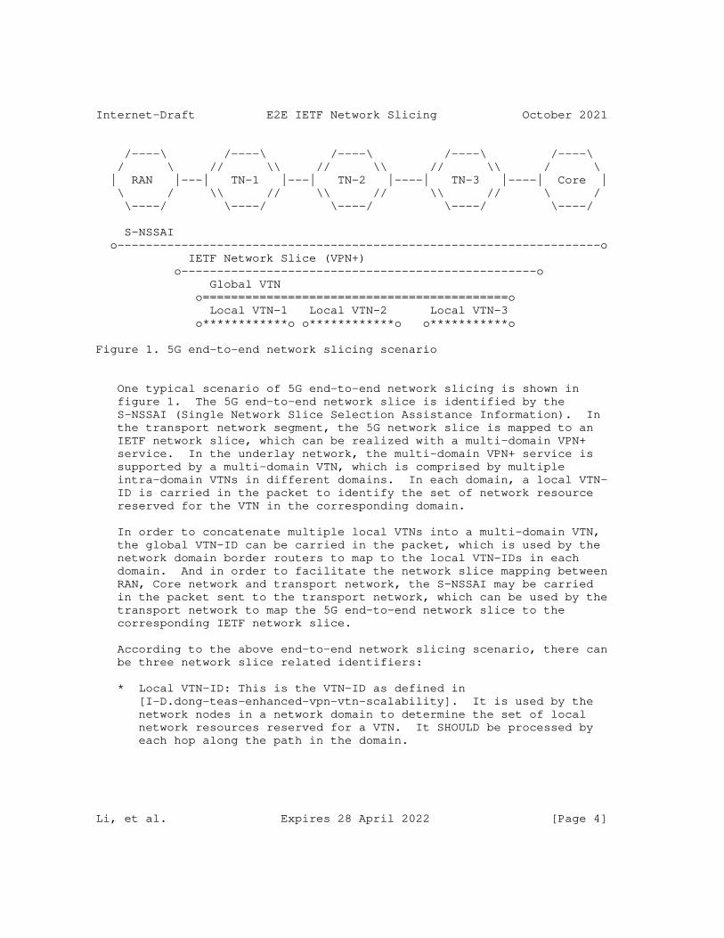
Internet-Draft E2E IETF Network Slicing October 2021
/----\ /----\ /----\ /----\ /----\ / \ // \\ // \\ // \\ / \ | RAN |---| TN-1 |---| TN-2 |----| TN-3 |----| Core | \ / \\ // \\ // \\ // \ / \----/ \----/ \----/ \----/ \----/
S-NSSAI o--------------------------------------------------------------------o IETF Network Slice (VPN+) o--------------------------------------------------o Global VTN o===========================================o Local VTN-1 Local VTN-2 Local VTN-3 o************o o************o o***********o
Figure 1. 5G end-to-end network slicing scenario
One typical scenario of 5G end-to-end network slicing is shown in figure 1. The 5G end-to-end network slice is identified by the S-NSSAI (Single Network Slice Selection Assistance Information). In the transport network segment, the 5G network slice is mapped to an IETF network slice, which can be realized with a multi-domain VPN+ service. In the underlay network, the multi-domain VPN+ service is supported by a multi-domain VTN, which is comprised by multiple intra-domain VTNs in different domains. In each domain, a local VTN- ID is carried in the packet to identify the set of network resource reserved for the VTN in the corresponding domain.
In order to concatenate multiple local VTNs into a multi-domain VTN, the global VTN-ID can be carried in the packet, which is used by the network domain border routers to map to the local VTN-IDs in each domain. And in order to facilitate the network slice mapping between RAN, Core network and transport network, the S-NSSAI may be carried in the packet sent to the transport network, which can be used by the transport network to map the 5G end-to-end network slice to the corresponding IETF network slice.
According to the above end-to-end network slicing scenario, there can be three network slice related identifiers:
* Local VTN-ID: This is the VTN-ID as defined in [I-D.dong-teas-enhanced-vpn-vtn-scalability]. It is used by the network nodes in a network domain to determine the set of local network resources reserved for a VTN. It SHOULD be processed by each hop along the path in the domain.
Li, et al. Expires 28 April 2022 [Page 4]
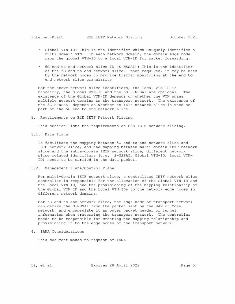
Internet-Draft E2E IETF Network Slicing October 2021
* Global VTN-ID: This is the identifier which uniquely identifies a multi-domain VTN. In each network domain, the domain edge node maps the global VTN-ID to a local VTN-ID for packet forwarding.
* 5G end-to-end network slice ID (S-NSSAI): This is the identifier of the 5G end-to-end network slice. When required, it may be used by the network nodes to provide traffic monitoring at the end-to- end network slice granularity.
For the above network slice identifiers, the local VTN-ID is mandatory, the Global VTN-ID and the 5G S-NSSAI are optional. The existence of the Global VTN-ID depends on whether the VTN spans multiple network domains in the transport network. The existence of the 5G S-NSSAI depends on whether an IETF network slice is used as part of the 5G end-to-end network slice.
3. Requirements on E2E IETF Network Slicing
This section lists the requirements on E2E IETF network slicing.
3.1. Data Plane
To facilitate the mapping between 5G end-to-end network slice and IETF network slice, and the mapping between multi-domain IETF network slice and the intra-domain IETF network slice, different network slice related identifiers (e.g. S-NSSAI, Global VTN-ID, local VTN- ID) needs to be carried in the data packet.
3.2. Management Plane/Control Plane
For multi-domain IETF network slice, a centralized IETF network slice controller is responsible for the allocation of the Global VTN-ID and the Local VTN-ID, and the provisioning of the mapping relationship of the Global VTN-ID and the Local VTN-IDs to the network edge nodes in different network domains.
For 5G end-to-end network slice, the edge node of transport network can derive the S-NSSAI from the packet sent by the RAN or Core network, and encapsulate it an outer packet header or tunnel information when traversing the transport network. The controller needs to be responsible for creating the mapping relationship and provisioning it to the edge nodes of the transport network.
4. IANA Considerations
This document makes no request of IANA.
Li, et al. Expires 28 April 2022 [Page 5]
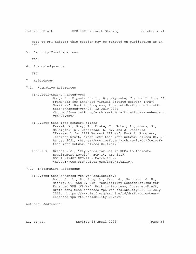
Internet-Draft E2E IETF Network Slicing October 2021
Note to RFC Editor: this section may be removed on publication as an RFC.
5. Security Considerations
TBD
6. Acknowledgements
TBD
7. References
7.1. Normative References
[I-D.ietf-teas-enhanced-vpn] Dong, J., Bryant, S., Li, Z., Miyasaka, T., and Y. Lee, "A Framework for Enhanced Virtual Private Network (VPN+) Services", Work in Progress, Internet-Draft, draft-ietf- teas-enhanced-vpn-08, 12 July 2021, <https://www.ietf.org/archive/id/draft-ietf-teas-enhanced- vpn-08.txt>.
[I-D.ietf-teas-ietf-network-slices] Farrel, A., Gray, E., Drake, J., Rokui, R., Homma, S., Makhijani, K., Contreras, L. M., and J. Tantsura, "Framework for IETF Network Slices", Work in Progress, Internet-Draft, draft-ietf-teas-ietf-network-slices-04, 23 August 2021, <https://www.ietf.org/archive/id/draft-ietf- teas-ietf-network-slices-04.txt>.
[RFC2119] Bradner, S., "Key words for use in RFCs to Indicate Requirement Levels", BCP 14, RFC 2119, DOI 10.17487/RFC2119, March 1997, <https://www.rfc-editor.org/info/rfc2119>.
7.2. Informative References
[I-D.dong-teas-enhanced-vpn-vtn-scalability] Dong, J., Li, Z., Gong, L., Yang, G., Guichard, J. N., Mishra, G., and F. Qin, "Scalability Considerations for Enhanced VPN (VPN+)", Work in Progress, Internet-Draft, draft-dong-teas-enhanced-vpn-vtn-scalability-03, 11 July 2021, <https://www.ietf.org/archive/id/draft-dong-teas- enhanced-vpn-vtn-scalability-03.txt>.
Authors’ Addresses
Li, et al. Expires 28 April 2022 [Page 6]
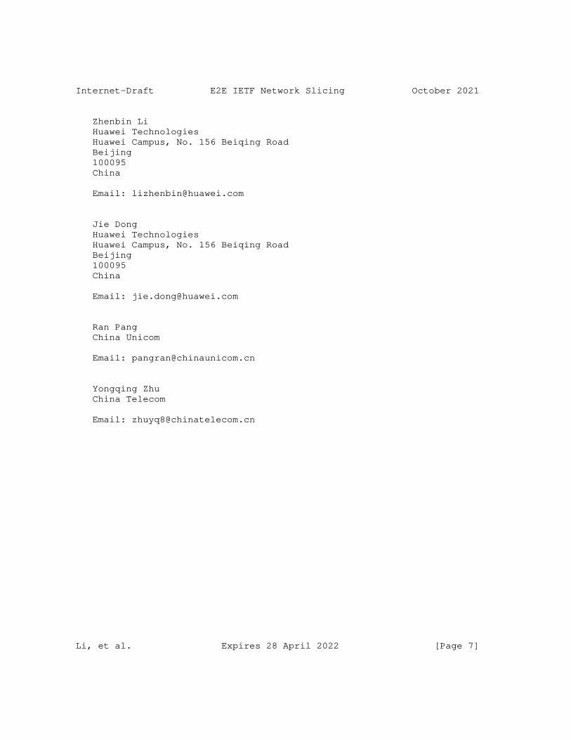
Internet-Draft E2E IETF Network Slicing October 2021
Zhenbin Li Huawei Technologies Huawei Campus, No. 156 Beiqing Road Beijing 100095 China
Email: [email protected]
Jie Dong Huawei Technologies Huawei Campus, No. 156 Beiqing Road Beijing 100095 China
Email: [email protected]
Ran Pang China Unicom
Email: [email protected]
Yongqing Zhu China Telecom
Email: [email protected]
Li, et al. Expires 28 April 2022 [Page 7]

Network Working Group Z. LiInternet-Draft Z. HuIntended status: Standards Track J. DongExpires: April 28, 2022 Huawei Technologies October 25, 2021
Intent-based Routing draft-li-teas-intent-based-routing-00
Abstract
This document defines the intent-based routing mechanism through which the packet can carry the intent information and the network node can enforce the policy according to the intent information (typically steering the packet into the SR policy or the underlay slice which can meet the intent). The intent-based routing mechanism provides a simple and scalable solution to meet the different service requirements for the inter-domain routing.
Requirements Language
The key words "MUST", "MUST NOT", "REQUIRED", "SHALL", "SHALL NOT", "SHOULD", "SHOULD NOT", "RECOMMENDED", "MAY", and "OPTIONAL" in this document are to be interpreted as described in RFC 2119 [RFC2119].
Status of This Memo
This Internet-Draft is submitted in full conformance with the provisions of BCP 78 and BCP 79.
Internet-Drafts are working documents of the Internet Engineering Task Force (IETF). Note that other groups may also distribute working documents as Internet-Drafts. The list of current Internet- Drafts is at https://datatracker.ietf.org/drafts/current/.
Internet-Drafts are draft documents valid for a maximum of six months and may be updated, replaced, or obsoleted by other documents at any time. It is inappropriate to use Internet-Drafts as reference material or to cite them other than as "work in progress."
This Internet-Draft will expire on April 28, 2022.
Copyright Notice
Copyright (c) 2021 IETF Trust and the persons identified as the document authors. All rights reserved.
Li, et al. Expires April 28, 2022 [Page 1]
Internet-Draft Intent-based Routing October 2021
This document is subject to BCP 78 and the IETF Trust’s Legal Provisions Relating to IETF Documents (https://trustee.ietf.org/license-info) in effect on the date of publication of this document. Please review these documents carefully, as they describe your rights and restrictions with respect to this document. Code Components extracted from this document must include Simplified BSD License text as described in Section 4.e of the Trust Legal Provisions and are provided without warranty as described in the Simplified BSD License.
Table of Contents
1. Introduction . . . . . . . . . . . . . . . . . . . . . . . . 2 2. Terminologies . . . . . . . . . . . . . . . . . . . . . . . . 3 3. Intent-based Routing . . . . . . . . . . . . . . . . . . . . 3 4. Illustration . . . . . . . . . . . . . . . . . . . . . . . . 5 5. IPv6 Encapsulation . . . . . . . . . . . . . . . . . . . . . 8 6. Security Considerations . . . . . . . . . . . . . . . . . . . 9 7. IANA Considerations . . . . . . . . . . . . . . . . . . . . . 9 8. References . . . . . . . . . . . . . . . . . . . . . . . . . 9 8.1. Normative References . . . . . . . . . . . . . . . . . . 9 8.2. Informative References . . . . . . . . . . . . . . . . . 10 Authors’ Addresses . . . . . . . . . . . . . . . . . . . . . . . 11
1. Introduction
[I-D.hegde-spring-mpls-seamless-sr] describes the requirements for end-to-end intent-based paths spanning multi-domain networks. [I-D.kaliraj-idr-bgp-classful-transport-planes] specifies the BGP based mechanisms to signal the packet paths which span multiple domains and provide different SLA characteristics. Since these SR paths need to setup according to the pair <color, endpoint>, it means more SR paths are introduced and this will cause more challenges on scalability.
In order to reduce the challenge of scalability introduced by the inter-domain routing with different service requirements, this document proposes the intent-based routing mechanism through which the packet can carry the intent information and the network node can steer the packet into the SR policy to satisfy the service requirement (that is, meet the specific intent). With the intent- based routing mechanism, network nodes do not need to maintain the fine-granularity connection state for each destination in the control plane, which can improve the scalability of the end- to-end routing significantly.
Besides steering the packet into the SR policy, the intent-based routing mechanism can also be used to steer the traffic into the
Li, et al. Expires April 28, 2022 [Page 2]
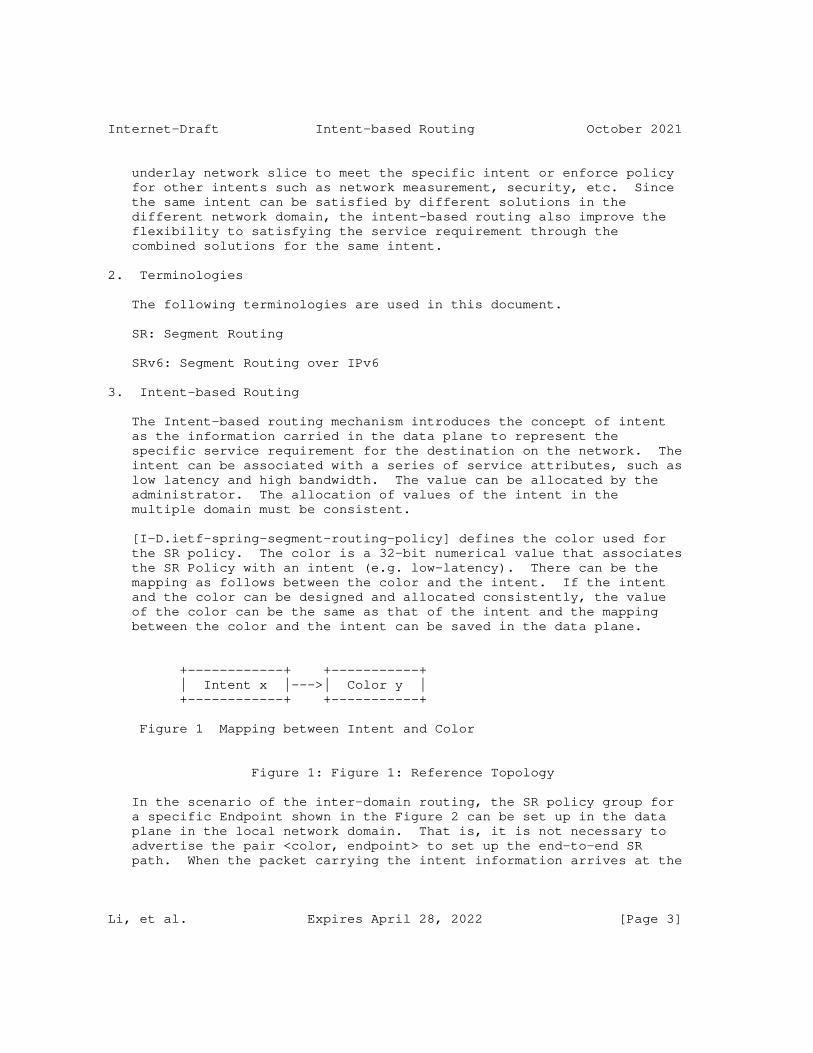
Internet-Draft Intent-based Routing October 2021
underlay network slice to meet the specific intent or enforce policy for other intents such as network measurement, security, etc. Since the same intent can be satisfied by different solutions in the different network domain, the intent-based routing also improve the flexibility to satisfying the service requirement through the combined solutions for the same intent.
2. Terminologies
The following terminologies are used in this document.
SR: Segment Routing
SRv6: Segment Routing over IPv6
3. Intent-based Routing
The Intent-based routing mechanism introduces the concept of intent as the information carried in the data plane to represent the specific service requirement for the destination on the network. The intent can be associated with a series of service attributes, such as low latency and high bandwidth. The value can be allocated by the administrator. The allocation of values of the intent in the multiple domain must be consistent.
[I-D.ietf-spring-segment-routing-policy] defines the color used for the SR policy. The color is a 32-bit numerical value that associates the SR Policy with an intent (e.g. low-latency). There can be the mapping as follows between the color and the intent. If the intent and the color can be designed and allocated consistently, the value of the color can be the same as that of the intent and the mapping between the color and the intent can be saved in the data plane.
+------------+ +-----------+ | Intent x |--->| Color y | +------------+ +-----------+
Figure 1 Mapping between Intent and Color
Figure 1: Figure 1: Reference Topology
In the scenario of the inter-domain routing, the SR policy group for a specific Endpoint shown in the Figure 2 can be set up in the data plane in the local network domain. That is, it is not necessary to advertise the pair <color, endpoint> to set up the end-to-end SR path. When the packet carrying the intent information arrives at the
Li, et al. Expires April 28, 2022 [Page 3]
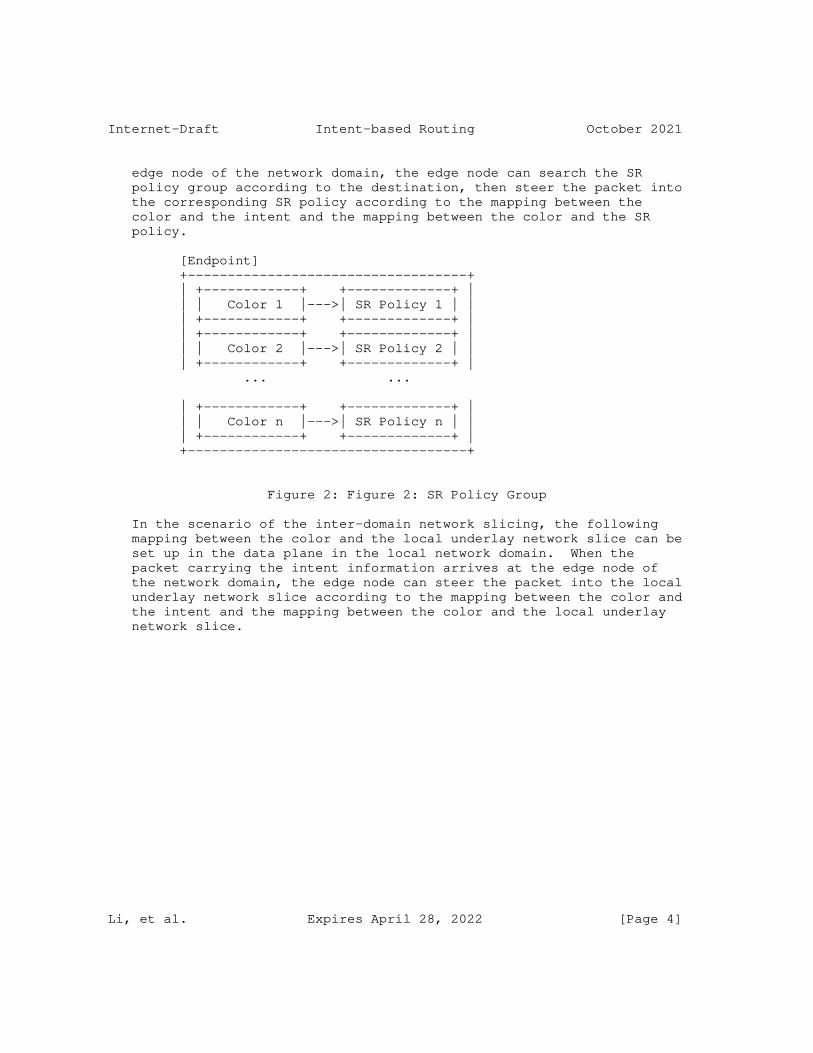
Internet-Draft Intent-based Routing October 2021
edge node of the network domain, the edge node can search the SR policy group according to the destination, then steer the packet into the corresponding SR policy according to the mapping between the color and the intent and the mapping between the color and the SR policy.
[Endpoint] +-----------------------------------+ | +------------+ +-------------+ | | | Color 1 |--->| SR Policy 1 | | | +------------+ +-------------+ | | +------------+ +-------------+ | | | Color 2 |--->| SR Policy 2 | | | +------------+ +-------------+ | ... ...
| +------------+ +-------------+ | | | Color n |--->| SR Policy n | | | +------------+ +-------------+ | +-----------------------------------+
Figure 2: Figure 2: SR Policy Group
In the scenario of the inter-domain network slicing, the following mapping between the color and the local underlay network slice can be set up in the data plane in the local network domain. When the packet carrying the intent information arrives at the edge node of the network domain, the edge node can steer the packet into the local underlay network slice according to the mapping between the color and the intent and the mapping between the color and the local underlay network slice.
Li, et al. Expires April 28, 2022 [Page 4]
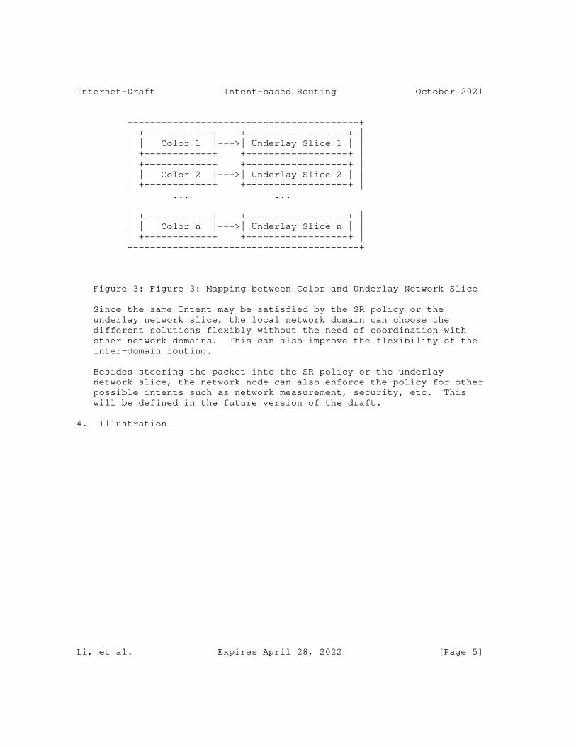
Internet-Draft Intent-based Routing October 2021
+----------------------------------------+ | +------------+ +------------------+ | | | Color 1 |--->| Underlay Slice 1 | | | +------------+ +------------------+ | | +------------+ +------------------+ | | | Color 2 |--->| Underlay Slice 2 | | | +------------+ +------------------+ | ... ...
| +------------+ +------------------+ | | | Color n |--->| Underlay Slice n | | | +------------+ +------------------+ | +----------------------------------------+
Figure 3: Figure 3: Mapping between Color and Underlay Network Slice
Since the same Intent may be satisfied by the SR policy or the underlay network slice, the local network domain can choose the different solutions flexibly without the need of coordination with other network domains. This can also improve the flexibility of the inter-domain routing.
Besides steering the packet into the SR policy or the underlay network slice, the network node can also enforce the policy for other possible intents such as network measurement, security, etc. This will be defined in the future version of the draft.
4. Illustration
Li, et al. Expires April 28, 2022 [Page 5]
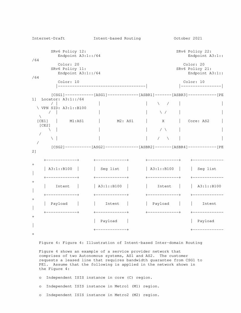
Internet-Draft Intent-based Routing October 2021
SRv6 Policy 12: SRv6 Policy 22: Endpoint A3:1::/64 Endpoint A3:1::/64 Color: 20 Color: 20 SRv6 Policy 11: SRv6 Policy 21: Endpoint A3:1::/64 Endpoint A3:1::/64 Color: 10 Color: 10 |-------------------------------------| |-----------------|
[CSG1]------------[ASG1]-------------[ASBR1]-------[ASBR3]------------[PE1] Locator: A3:1::/64 / | | | \ / | | \ VPN SID: A3:1::B100 / | | | \ / | | \ [CE1] | M1:AS1 | M2: AS1 | X | Core: AS2 | [CE2] \ | | | / \ | | / \ | | | / \ | | / [CSG2]-----------[ASG2]--------------[ASBR2]-------[ASBR4]------------[PE2]
+-------------+ +-------------+ +-------------+ +-------------+ | A3:1::B100 | | Seg list | | A3:1::B100 | | Seg list | +-------------+ +-------------+ +-------------+ +-------------+ | Intent | | A3:1::B100 | | Intent | | A3:1::B100 | +-------------+ +-------------+ +-------------+ +-------------+ | Payload | | Intent | | Payload | | Intent | +-------------+ +-------------+ +-------------+ +-------------+ | Payload | | Payload | +-------------+ +-------------+
Figure 4: Figure 4: Illustration of Intent-based Inter-domain Routing
Figure 4 shows an example of a service provider network that comprises of two Autonomous systems, AS1 and AS2. The customer requests a leased line that requires bandwidth guarantee from CSG1 to PE1. Assume that the following is applied in the network shown in the Figure 4:
o Independent ISIS instance in core (C) region.
o Independent ISIS instance in Metro1 (M1) region.
o Independent ISIS instance in Metro2 (M2) region.

o BGP between ASBRs
o PE1‘s locator is A3:1::/64, and VPN SID is A3:1::B100.
o Core‘s aggregated routes are redistributed from Core to M (M1 and M2).
Li, et al. Expires April 28, 2022 [Page 6]
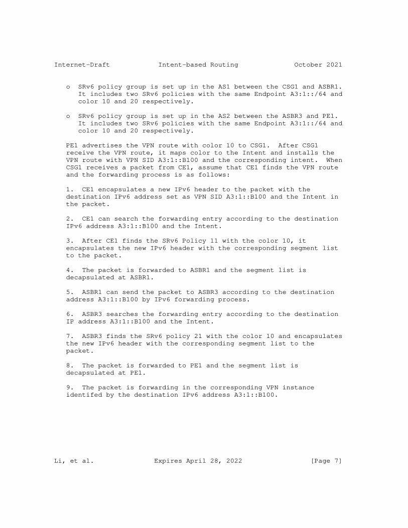
Internet-Draft Intent-based Routing October 2021
o SRv6 policy group is set up in the AS1 between the CSG1 and ASBR1. It includes two SRv6 policies with the same Endpoint A3:1::/64 and color 10 and 20 respectively.
o SRv6 policy group is set up in the AS2 between the ASBR3 and PE1. It includes two SRv6 policies with the same Endpoint A3:1::/64 and color 10 and 20 respectively.
PE1 advertises the VPN route with color 10 to CSG1. After CSG1 receive the VPN route, it maps color to the Intent and installs the VPN route with VPN SID A3:1::B100 and the corresponding intent. When CSG1 receives a packet from CE1, assume that CE1 finds the VPN route and the forwarding process is as follows:
1. CE1 encapsulates a new IPv6 header to the packet with the destination IPv6 address set as VPN SID A3:1::B100 and the Intent in the packet.
2. CE1 can search the forwarding entry according to the destination IPv6 address A3:1::B100 and the Intent.
3. After CE1 finds the SRv6 Policy 11 with the color 10, it encapsulates the new IPv6 header with the corresponding segment list to the packet.
4. The packet is forwarded to ASBR1 and the segment list is decapsulated at ASBR1.
5. ASBR1 can send the packet to ASBR3 according to the destination address A3:1::B100 by IPv6 forwarding process.
6. ASBR3 searches the forwarding entry according to the destination IP address A3:1::B100 and the Intent.
7. ASBR3 finds the SRv6 policy 21 with the color 10 and encapsulates the new IPv6 header with the corresponding segment list to the packet.
8. The packet is forwarded to PE1 and the segment list is decapsulated at PE1.
9. The packet is forwarding in the corresponding VPN instance identifed by the destination IPv6 address A3:1::B100.
Li, et al. Expires April 28, 2022 [Page 7]
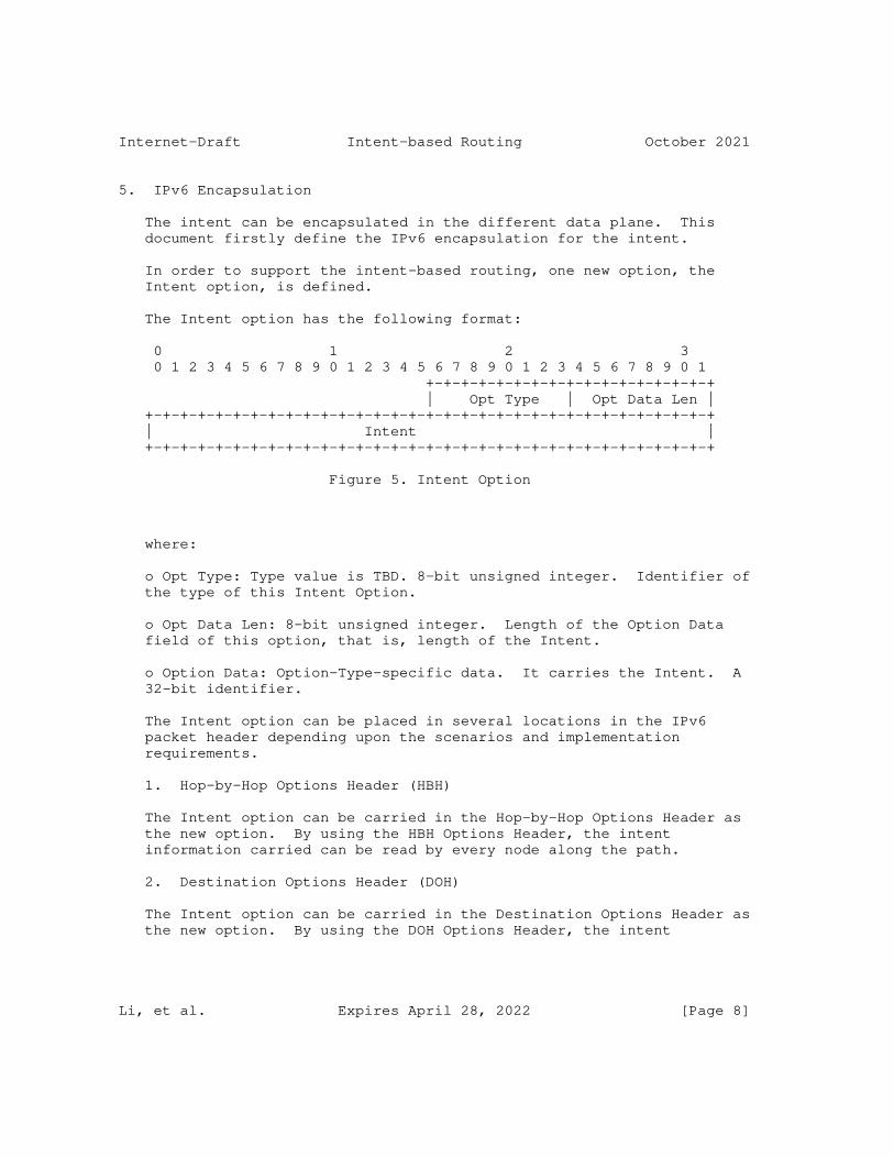
Internet-Draft Intent-based Routing October 2021
5. IPv6 Encapsulation
The intent can be encapsulated in the different data plane. This document firstly define the IPv6 encapsulation for the intent.
In order to support the intent-based routing, one new option, the Intent option, is defined.
The Intent option has the following format:
0 1 2 3 0 1 2 3 4 5 6 7 8 9 0 1 2 3 4 5 6 7 8 9 0 1 2 3 4 5 6 7 8 9 0 1 +-+-+-+-+-+-+-+-+-+-+-+-+-+-+-+-+ | Opt Type | Opt Data Len | +-+-+-+-+-+-+-+-+-+-+-+-+-+-+-+-+-+-+-+-+-+-+-+-+-+-+-+-+-+-+-+-+ | Intent | +-+-+-+-+-+-+-+-+-+-+-+-+-+-+-+-+-+-+-+-+-+-+-+-+-+-+-+-+-+-+-+-+
Figure 5. Intent Option
where:
o Opt Type: Type value is TBD. 8-bit unsigned integer. Identifier of the type of this Intent Option.
o Opt Data Len: 8-bit unsigned integer. Length of the Option Data field of this option, that is, length of the Intent.
o Option Data: Option-Type-specific data. It carries the Intent. A 32-bit identifier.
The Intent option can be placed in several locations in the IPv6 packet header depending upon the scenarios and implementation requirements.
1. Hop-by-Hop Options Header (HBH)
The Intent option can be carried in the Hop-by-Hop Options Header as the new option. By using the HBH Options Header, the intent information carried can be read by every node along the path.
2. Destination Options Header (DOH)
The Intent option can be carried in the Destination Options Header as the new option. By using the DOH Options Header, the intent
Li, et al. Expires April 28, 2022 [Page 8]
Internet-Draft Intent-based Routing October 2021
information carried can be read by the destination node along the path.
Besides the Intent option, the intent can also be carried combining with Application-aware Networking ([I-D.li-apn-framework]). [I-D.li-apn-header] and [I-D.li-apn-ipv6-encap] defines that the intent can be carried in the APN header which is encapsulated in the APN option in the IPv6 data plane.
6. Security Considerations
TBD
7. IANA Considerations
TBD
8. References
8.1. Normative References
[RFC2119] Bradner, S., "Key words for use in RFCs to Indicate Requirement Levels", BCP 14, RFC 2119, DOI 10.17487/RFC2119, March 1997, <https://www.rfc-editor.org/info/rfc2119>.
[RFC7356] Ginsberg, L., Previdi, S., and Y. Yang, "IS-IS Flooding Scope Link State PDUs (LSPs)", RFC 7356, DOI 10.17487/RFC7356, September 2014, <https://www.rfc-editor.org/info/rfc7356>.
[RFC7490] Bryant, S., Filsfils, C., Previdi, S., Shand, M., and N. So, "Remote Loop-Free Alternate (LFA) Fast Reroute (FRR)", RFC 7490, DOI 10.17487/RFC7490, April 2015, <https://www.rfc-editor.org/info/rfc7490>.
[RFC8400] Chen, H., Liu, A., Saad, T., Xu, F., and L. Huang, "Extensions to RSVP-TE for Label Switched Path (LSP) Egress Protection", RFC 8400, DOI 10.17487/RFC8400, June 2018, <https://www.rfc-editor.org/info/rfc8400>.
[RFC8402] Filsfils, C., Ed., Previdi, S., Ed., Ginsberg, L., Decraene, B., Litkowski, S., and R. Shakir, "Segment Routing Architecture", RFC 8402, DOI 10.17487/RFC8402, July 2018, <https://www.rfc-editor.org/info/rfc8402>.
Li, et al. Expires April 28, 2022 [Page 9]
Internet-Draft Intent-based Routing October 2021
[RFC8665] Psenak, P., Ed., Previdi, S., Ed., Filsfils, C., Gredler, H., Shakir, R., Henderickx, W., and J. Tantsura, "OSPF Extensions for Segment Routing", RFC 8665, DOI 10.17487/RFC8665, December 2019, <https://www.rfc-editor.org/info/rfc8665>.
[RFC8667] Previdi, S., Ed., Ginsberg, L., Ed., Filsfils, C., Bashandy, A., Gredler, H., and B. Decraene, "IS-IS Extensions for Segment Routing", RFC 8667, DOI 10.17487/RFC8667, December 2019, <https://www.rfc-editor.org/info/rfc8667>.
[RFC8679] Shen, Y., Jeganathan, M., Decraene, B., Gredler, H., Michel, C., and H. Chen, "MPLS Egress Protection Framework", RFC 8679, DOI 10.17487/RFC8679, December 2019, <https://www.rfc-editor.org/info/rfc8679>.
8.2. Informative References
[I-D.hegde-spring-mpls-seamless-sr] Hegde, S., Bowers, C., Xu, X., Gulko, A., Bogdanov, A., Uttaro, J., Jalil, L., Khaddam, M., Alston, A., and L. M. Contreras, "Seamless SR Problem Statement", draft-hegde- spring-mpls-seamless-sr-06 (work in progress), September 2021.
[I-D.ietf-spring-segment-routing-policy] Filsfils, C., Talaulikar, K., Voyer, D., Bogdanov, A., and P. Mattes, "Segment Routing Policy Architecture", draft- ietf-spring-segment-routing-policy-14 (work in progress), October 2021.
[I-D.kaliraj-idr-bgp-classful-transport-planes] Vairavakkalai, K., Venkataraman, N., Rajagopalan, B., Mishra, G., Khaddam, M., Xu, X., Szarecki, R. J., and D. J. Gowda, "BGP Classful Transport Planes", draft-kaliraj- idr-bgp-classful-transport-planes-12 (work in progress), August 2021.
[I-D.li-apn-framework] Li, Z., Peng, S., Voyer, D., Li, C., Liu, P., Cao, C., Mishra, G., Ebisawa, K., Previdi, S., and J. N. Guichard, "Application-aware Networking (APN) Framework", draft-li- apn-framework-03 (work in progress), May 2021.
Li, et al. Expires April 28, 2022 [Page 10]
Internet-Draft Intent-based Routing October 2021
[I-D.li-apn-header] Li, Z. and S. Peng, "Application-aware Networking (APN) Header", draft-li-apn-header-00 (work in progress), October 2021.
[I-D.li-apn-ipv6-encap] Li, Z. and S. Peng, "Application-aware IPv6 Networking (APN6) Encapsulation", draft-li-apn-ipv6-encap-00 (work in progress), October 2021.
[RFC5226] Narten, T. and H. Alvestrand, "Guidelines for Writing an IANA Considerations Section in RFCs", RFC 5226, DOI 10.17487/RFC5226, May 2008, <https://www.rfc-editor.org/info/rfc5226>.
[RFC5462] Andersson, L. and R. Asati, "Multiprotocol Label Switching (MPLS) Label Stack Entry: "EXP" Field Renamed to "Traffic Class" Field", RFC 5462, DOI 10.17487/RFC5462, February 2009, <https://www.rfc-editor.org/info/rfc5462>.
Authors’ Addresses
Zhenbin Li Huawei Technologies Beijing 100095 China
Email: [email protected]
Zhibo Hu Huawei Technologies Beijing 100095 China
Email: [email protected]
Jie Dong Huawei Technologies Beijing 100095 China
Email: [email protected]
Li, et al. Expires April 28, 2022 [Page 11]
Copyright © 2022 FDOKUMEN