Dist ributed FACT Controllers as an Effective Tool for Reduction in Environmental pollution due to...
10
Distributed FACT Controllers as an Effective Tool for Reduction in Environmental pollution due to Thermal Power Plant KISHOR PORATE Assistant Professor, Department of Electrical Engineering G.H.Raisoni College of Engineering CRPF Gate No. 3, Digdoh Hills, Hingna Road, Nagpur INDIA [email protected] K.L.THAKRE Professor, Department of Electrical Engineering Visvesvaraya National Institute of Technology, Nagpur INDIA [email protected] G.L. BODHE Senior Assistant Director National Environmental Engineering Research Institute, Nagpur INDIA [email protected] Abstract: - Flexible AC Transmission (FACTS) devices are installed in the transmission network to divert the power flow, minimize the power losses and to improve the line performance but it has some limitations and drawbacks. Distributed Flexible AC Transmission (D-FACTS) is a improved version of FACTS devices which is used to improve the security and reliability of the network in a cost effective manner. This paper discusses the concept of D-FACTS technology for saving of electrical energy, minimization of losses, reduction of coal consumption and minimization of environmental pollution from thermal power plants. This paper also discusses comparative evaluation of passive and active approaches in design of controllers for transmission line. Analysis also deals with computer simulation for reactances, equivalent voltages required for injection in the transmission line, and number of distributed modules per conductor per kilometre. Computations for saving of coal and associated environmental pollution have been achieved. System details are presented in the paper along with simulation results. Key-Words: - Distributed series compensator, D-FACTS, FACTS, Electrical energy saving, Coal economics, Environmental pollution. 1 Introduction An AC power system is a complex network of synchronous generators, transmission lines and loads. Each transmission line can be represented as a reactive ladder network composed of series inductors and shunt capacitors. The total series inductance which is proportional to the length of the line, at a given voltage determines the maximum transmittable power. The shunt capacitance influences the voltage profile along the transmission line.The transmitted power over a given line is determined by the line impedance, the magnitude and phase angle between the end voltages. The most significant issue in terms of grid utilization is that of active power flow control and it is possible by reactive power compensation. Thus, control of real power flows at a particular instant on WSEAS TRANSACTIONS on POWER SYSTEMS Kishor Porate, K. L. Thakre, G. L. Bodhe ISSN: 1790-5060 85 Issue 3, Volume 4, March 2009
-
Upload
nagpuruniversity -
Category
Documents
-
view
2 -
download
0
Transcript of Dist ributed FACT Controllers as an Effective Tool for Reduction in Environmental pollution due to...
Distributed FACT Controllers as an Effective Tool for Reduction in
Environmental pollution due to Thermal Power Plant
KISHOR PORATE
Assistant Professor, Department of Electrical Engineering
G.H.Raisoni College of Engineering
CRPF Gate No. 3, Digdoh Hills, Hingna Road, Nagpur
INDIA
K.L.THAKRE
Professor, Department of Electrical Engineering
Visvesvaraya National Institute of Technology, Nagpur
INDIA
G.L. BODHE
Senior Assistant Director
National Environmental Engineering Research Institute, Nagpur
INDIA
Abstract: - Flexible AC Transmission (FACTS) devices are installed in the transmission network to divert the
power flow, minimize the power losses and to improve the line performance but it has some limitations and
drawbacks. Distributed Flexible AC Transmission (D-FACTS) is a improved version of FACTS devices which
is used to improve the security and reliability of the network in a cost effective manner. This paper discusses
the concept of D-FACTS technology for saving of electrical energy, minimization of losses, reduction of coal
consumption and minimization of environmental pollution from thermal power plants. This paper also
discusses comparative evaluation of passive and active approaches in design of controllers for transmission
line. Analysis also deals with computer simulation for reactances, equivalent voltages required for injection in
the transmission line, and number of distributed modules per conductor per kilometre. Computations for saving
of coal and associated environmental pollution have been achieved. System details are presented in the paper
along with simulation results.
Key-Words: - Distributed series compensator, D-FACTS, FACTS, Electrical energy saving, Coal economics,
Environmental pollution.
1 Introduction An AC power system is a complex network of
synchronous generators, transmission lines and
loads. Each transmission line can be represented as
a reactive ladder network composed of series
inductors and shunt capacitors. The total series
inductance which is proportional to the length of the
line, at a given voltage determines the maximum
transmittable power. The shunt capacitance
influences the voltage profile along the transmission
line.The transmitted power over a given line is
determined by the line impedance, the magnitude
and phase angle between the end voltages.
The most significant issue in terms of grid
utilization is that of active power flow control and it
is possible by reactive power compensation. Thus,
control of real power flows at a particular instant on
WSEAS TRANSACTIONS on POWER SYSTEMS Kishor Porate, K. L. Thakre, G. L. Bodhe
ISSN: 1790-5060 85 Issue 3, Volume 4, March 2009

the network is of critical importance. Management
of reactive power has prime importance to improve
the performance of ac power system. Active power
flow control requires cost effective ‘series VAR’
solutions that can alter the impedance of the power
lines artificially or change the angle of voltage
applied across the line, thus controlling the power
flow [1].
Traditionally, reactive compensation and
phase angle control have been applied by fixed or
mechanically switched inductors, capacitors and tap
changing transformers, to improve steady state
power transmission. This traditional approach has
several limitations and not fully controlled.
Series capacitors have been successfully
used to enhance the stability and lodability of high
voltage transmission network. The principle is to
compensate the inductive voltage drop in the line by
an inserted capacitive voltage which results in
decrease of effective reactance of the transmission
line. The inserted voltage provided by a series
capacitor is in proportion to and in quadrature with
the line current. Thus the generated reactive power
provided by the capacitor is proportional to the
square of the current. This means that a series
capacitor has a self regulating impact but non
controllable [2].
Considering economic, social and
legislative development, Electric Power Research
Institute formulated the vision of Flexible AC
Transmission System (FACTS) in which various
power electronic based controllers regulate the
power flow and transmission voltage through rapid
control action. The main objectives of FACTS are to
increase the useable transmission capacity of lines
and control power flow over designated
transmission routes [3].
Even though FACTS technology is
technically proven, it has not seen widespread
commercial acceptance due to a number of reasons
- High-cost resulting from device complexity
and component requirements
- High fault currents and insulation
requirement, stress the power electronic
system, making implementation of FACTS
systems in particular series connected
devices, very difficult and expensive
- Single point failure can cause the entire
system to shut down
- Maintenance and on site repair requirements
for a complex custom engineered systems
adds significantly to system operating cost
and increases mean time to repair
- Lumped nature of system and initial over
rating of devices to accommodate future
growth provides poor return on investment
- Custom engineered nature of system results
in long design and build cycles, resulting in
high system cost that will not easily scale
down with volume [4]
FACTS devices like thyristor controlled
series capacitor (TCSC) and the static synchronous
series compensator (SSSC) can be used for
controlling active power flow on transmission lines,
close to its terminal capacity, without compromising
its stability limits. Implementations of these devices
are very difficult and expensive and have rarely
been deployed [5].
Distributed Flexible AC Transmission (D-
FACTS) system is the new concept for realizing the
functionality of FACTS devices.
Advancement in computer technology
associated with intellectual activities resulted in new
field of artificial intelligence. Fuzzy and artificial
neural intelligence are used to design the controller
and for their optimal location [6].
For economic load flow the basic operating
requirement of an AC power system is that the
synchronous generators must remain in synchronism
and the voltages must be kept close to their rated
values. If synchronous generators are coal based
then they must run at minimum environmental
pollution level with minimum operating cost.
This paper discusses the concept of
distributed flexible AC transmission (D-FACT)
series type devices for power flow control and
reduction in environmental pollution due to coal
based thermal generation. The objective is to
determine the ratings of the distributed module in
terms of reactance and equivalent voltage required
for the series injection in transmission line. For the
analysis and simulation transmission network
connected to coal base thermal power plant is
considered. Calculations are made for total series
reactance, reactance of distributed modules and
equivalent voltages for injection in the transmission
line. Quantity of distributed modules per phase per
kilometre with their physical dimensions and cost
are mentioned. Use of D-FACTS saves the electrical
energy hence reduction in generation, coal
consumption and minimization in environmental
pollution. Saving of electrical energy, coal
consumption and environmental pollution has been
calculated. Computer simulation for two bus
transmission network has been made with and
without D-FACT devices for 1200 MW and for
1275 MW at 400KV.
WSEAS TRANSACTIONS on POWER SYSTEMS Kishor Porate, K. L. Thakre, G. L. Bodhe
ISSN: 1790-5060 86 Issue 3, Volume 4, March 2009

2 Distributed Flexible AC
Transmission (D-FACTS)
Technology D-FACT is a new concept for realising the
functionality of FACTS devices. In this technology
total impedance or voltage required for the
compensation has been distributed along the
transmission line in series. Impedance or equivalent
injected by single turn transformer in series by
mutual induction is of small magnitude. It can be
considered as a synchronous voltage source as it can
inject an almost sinusoidal voltage of variable and
controllable amplitude and phase angle, in series
with a transmission line. The injected voltage is
almost in quadrature with the line current. A small
part of the injected voltage that is in phase with the
line current provides the losses in the inverter. Most
of the injected voltage, which is in quadrature with
the line current, provides the effect of inserting an
inductive or capacitive reactance in series with the
transmission line. This variable reactance influences
the electric power flow in the transmission line.Such
a module could be low rated, light and small enough
to be suspended from the power line, floating both
electrically and mechanically on the transmission
line itself. With the use of power electronics
devices, injected voltages dynamically control the
impedance of transmission line, allowing control of
active power flow. The distributed module can be
used to either increase or decrease the effective line
impedance, allowing current to be pushed away
from or pulled into transmission line. As the devices
are float on the transmission line, all the issues
related to voltage rating and insulation are avoided.
Following characteristics and benefits may be
realised for distributed series compensator system.
- Enhance asset utilization
- Reduce system congestion
- Increase available transfer capacity of the
system
- Enhance system reliability and capacity
under contingencies
- Enhance system stability
- Forcing power to flow along contract
paths
- Marginal reduction of fault current
- High system reliability due to massive
redundancy, single unit failure has
negligible impact on system performance
- Can be used with conventional or
advanced conductors
- Mass produced modules can be stocked on
the shelf and repaired in the factory – does
not require skilled staff on site
- Easy and rapid installation and
can do with lower capital and operating cost than
most conventional single point lumped solutions,
such as FACTS devices [7] – [8].
3 Economic Emission Load Dispatch The combustion of coal in thermal power plant
gives rise to particulate material and gaseous
pollunts. The particulate materials, oxides of carbon
(Cox), oxides of suplhur (Sox) and oxides of
nitrogen (Nox) causes detrimental effects on human
beings. The usual control practice is to reduce
offensive emission through post combustion
cleaning systems such as electrostatic precipitator,
stack gas scrubbers or switching permanantly to
fuels with low emissions potentials. There is a shee
need for minimizing pollution level and it is
possible by economic-emission load dispatch. The
environmental / economic power dispatch problem
is to minimization of two objective functions, fuel
cost and emission due to impact of, oxides of carbon
(Cox), oxides of suplhur (Sox) and oxides of nitrogen
(Nox), while satisfying equality and inequality
constraints.
3.1 Economy objective The fuel cost of a thermal unit is the main criterion
for economic feasibility. The fuel cost curve is
assumed to be approximated by a quadratic function
of generator power output Pgi as,
)(2
1
1 igiiig
NG
i
i cPbPaF ++=∑=
Rs/h (1)
Where ai,bi and ci are cost coefficients and NG is the
number of generators.
3.2 Environmental objectives The emission curves can be directly related to the
cost curve through the emission rate per Mkcal,
which is a constant factor for a given type of fuel.
Therefore, the amount of NOx emission is given as a
quadratic function of generator output Pgi, i.e,
)( 11
2
1
12 igiiig
NG
i
ifPePdF ++=∑
=
kg/h (2)
Where d1i, e1i and f1i are NOx coefficients.
WSEAS TRANSACTIONS on POWER SYSTEMS Kishor Porate, K. L. Thakre, G. L. Bodhe
ISSN: 1790-5060 87 Issue 3, Volume 4, March 2009
Similarly the amount of SO2 emission is
given as a quadratic function of generator output Pgi,
i.e,
)( 22
2
1
23 igiiig
NG
i
ifPePdF ++=∑
=
kg/h (3)
Where d2i, e2i and f2i are SO2 coefficients.
Similarly the amount of CO2 emission is
given as a quadratic function of generator output Pgi,
i.e,
)( 33
2
1
34 igiiig
NG
i
ifPePdF ++=∑
=
kg/h (4)
Where d3i, e3i and f3i are CO2 coefficients.
3.3 Constraints To insure a real power balance, an equality
constraint is imposed, i.e,
0)(1
=+−∑=
LDig
NG
i
PPP (5)
Where PD is the power demand
PL is the transmission losses, which are
approximated in terms of B-coefficients as
∑∑∑= ==
++=
NG
i
NG
j
gjijgiig
NG
i
iL PBPPBBP1 11
000 MW (6)
The inequality constraints imposed on generator
output are
maxmin
gigiig PPP ≤≤ (i= 1,2, ……. NG) (7)
Where Pgi min
is the lower limit and Pgi max
is the
upper limit of generator output.
The multiobjective optimization problem is
defined as, minimization of equations (1) to (4),
subject to equations (5) and (7), [9]-[10].
For minimisation of total fuel cost of
generation and environmental pollution caused by
coal based thermal power plant, various techniques
and approaches are available. Multiobjective Ant
colony optimization (ACO) method is one of the
approaches for optimal power flow [11]-[12].
A dynamic and linear programming based
approach could be implemented for the generation
scheduling of thermal units considering the voltage
security and environmental constraints of electric
power system [13].Several approaches are also
available to reduce the environmental emissions
mainly oxides of carbon (Cox), oxides of suplhur
(Sox) and oxides of nitrogen (Nox) [14]-[15].
Analytical approach used in this paper for
the determination of cost and emission.
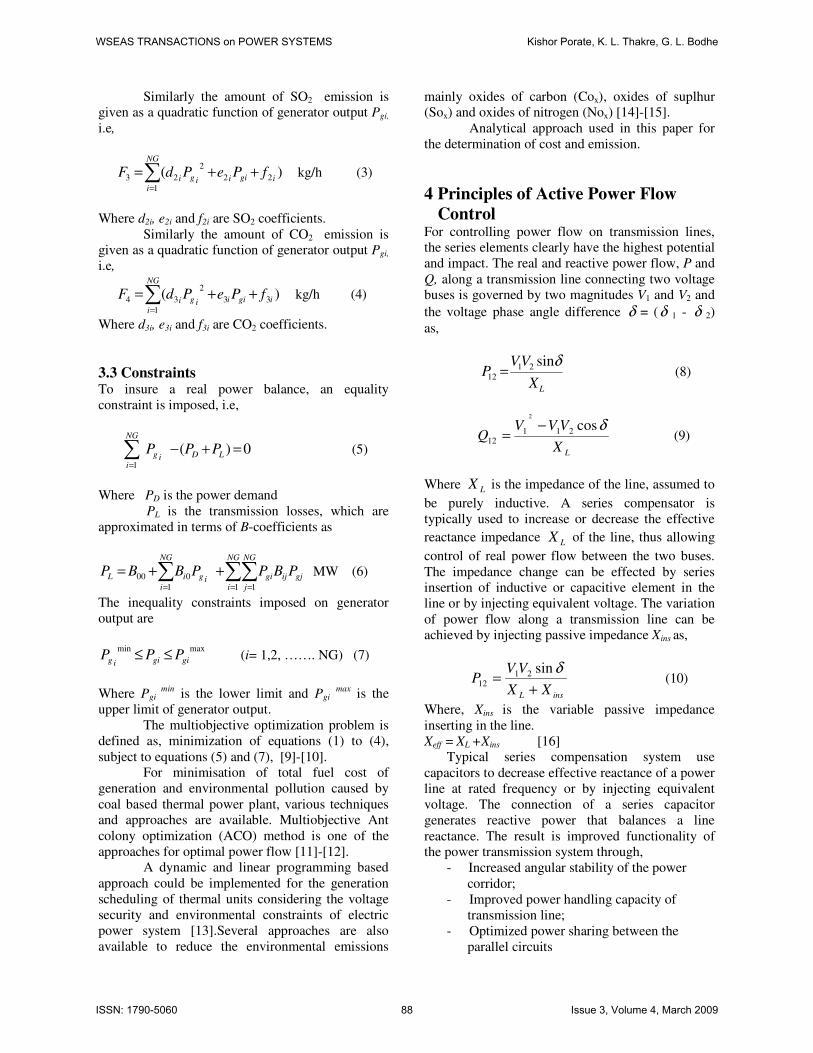
4 Principles of Active Power Flow
Control For controlling power flow on transmission lines,
the series elements clearly have the highest potential
and impact. The real and reactive power flow, P and
Q, along a transmission line connecting two voltage
buses is governed by two magnitudes V1 and V2 and
the voltage phase angle difference δ = (δ 1 - δ 2)
as,
LX
VVP
δsin21
12 = (8)
LX
VVVQ
δcos21112
2
−= (9)
Where LX is the impedance of the line, assumed to
be purely inductive. A series compensator is
typically used to increase or decrease the effective
reactance impedance LX of the line, thus allowing
control of real power flow between the two buses.
The impedance change can be effected by series insertion of inductive or capacitive element in the
line or by injecting equivalent voltage. The variation
of power flow along a transmission line can be
achieved by injecting passive impedance Xins as,
insL XX
VVP
+=
δsin2112 (10)
Where, Xins is the variable passive impedance
inserting in the line.
Xeff = XL +Xins [16]
Typical series compensation system use
capacitors to decrease effective reactance of a power
line at rated frequency or by injecting equivalent
voltage. The connection of a series capacitor
generates reactive power that balances a line
reactance. The result is improved functionality of
the power transmission system through,
- Increased angular stability of the power
corridor;
- Improved power handling capacity of
transmission line;
- Optimized power sharing between the
parallel circuits
WSEAS TRANSACTIONS on POWER SYSTEMS Kishor Porate, K. L. Thakre, G. L. Bodhe
ISSN: 1790-5060 88 Issue 3, Volume 4, March 2009

5 An Example For the analysis of distributed series compensator a
simple two bus system is considered. The sending
end terminal is connected to source with zero
internal impedance hence voltage of that end is
known and fixed, while the receiving end voltage
depends on the power flow. The circuit is assumed
to be balanced and the frequency variation is
ignored. Fig. 1 shows simple example of two bus
power system without any compensation. Two lines
of unequal lengths are used to transfer power from bus 1 to bus 2. The assumed line parameters are
listed in Table 1, [17]
Table 1, Line Parameters for Example of Fig. 1
Parameters Rating
Length, Line 1 600 km
Length, Line 2 800 km
Sending &
receiving end
voltages V1=V2=V
400 Kv
Line Impedance (0.31+j 0.327)
ohms/Km
Line Thermal
rating I Max 1064 A
Three analyses have been made on the system
shown in fig. 1.
5.1 Case1. Power Flow over parallel lines
without compensation. Power flow of the system shown in fig.1 is carried
out by computer simulation. Power available on
reference bus 1 is 1200 MW and transmitted
through line 1 and line 2 to bus 2. The power
transmitted through line 1 (P1) and line 2 (P2) are
685.7 MW and 514.3 MW respectively. Power
received at bus 2 is 1089.4 MW with power loss of
110.6 MW. i.e. 9.22%. Current flowing through line
1 (I1) and line 2 (I2) are 1064A and 798A
respectively. For the power flow, power angle (δ)
observed is -54.040.
As per the simulation for 1275 MW power
transfer, power losses are 156.44 MW (12.27 %).
Current flowing through line 1 is more than its
thermal capacity which is not desirable.
Compensation is applied to the lines to divert the
additional current through line 2 which has
unutilized capacity. Power flow for 1200 MW is
shown on fig. 1.
Fig.1, Power Flow over parallel lines without
compensation
This analysis shows that for 1200 MW
power flow, current flowing through the lines is
within the thermal limit. Line 1 reaches to thermal
limit before line 2 does. At that point no power can
be transferred without overloading line 1, even
though line 2 has additional unutilized capacity.
Transmission and sub-transmission system today
tend to be increasingly meshed and interconnected.
The ability to switch out faulted lines without
impacting service has a dramatic impact on system
reliability. However, in such interconnected
systems, current flow is determined by line
impedances and the system operator has very
limited ability to control where the current flow in
the network. In such systems, the first line to reach
thermal capacity limits the capacity of the entire
network, even as other lines remain considerably
under utilized. For 1200 MW power flow voltage
drop across line 1 and 2 are 347.93 v/Km and
260.95 v/Km respectively.
5.2 Case 2. Power Flow over parallel lines
with increased power and compensation Power available on reference bus is 1275 MW and
the objective of this case is to divert additional
power of 75 MW through line 2, as line 1 is already
at its maximum thermal limit. To divert this power
flow through line 2 compensation of 9% is required.
For equivalent reactance compensation
approach insertion of 0.0294 ohms/Km inductive
reactance in line 1 and capacitive reactance in line 2
is required. Total inductive reactance inserted in line
1 is 17.66 ohms and capacitive reactance inserted in
line 2 is 23.54 ohms. As per D-FACTS voltage
injection of 31.32 v/km and 23.48 v/km is required
in line 1 and line 2 respectively. Total voltage
injected is 18.78 Kv.
Power available on reference bus 1 is 1275
MW and transmitted through line 1 and line 2 to bus
2. The power transmitted through line 1 (P1) and
line 2 (P2) are 669.9 MW and 605.1 MW
respectively. Power received at bus 2 is 1144 MW
with power loss of 131 MW. i.e. 10.27%. Current
WSEAS TRANSACTIONS on POWER SYSTEMS Kishor Porate, K. L. Thakre, G. L. Bodhe
ISSN: 1790-5060 89 Issue 3, Volume 4, March 2009

flowing through line 1 (I1) and line 2 (I2) are 1064A
and 954.4A respectively. For the power flow, power
angle (δ) observed is -59.280. Power angle in this
case is larger than case 1. It is the indication of
system instability. The power transfer through line 2
has been increased by approximately 90 MW, while
line 1 has been controlled to well within its thermal
limit. System representation and simulation results
for passive and active compensation are shown in
fig. 2 and 3.
Fig. 2, Power Flow over parallel lines with 9%
passive compensation
Fig. 3, Power Flow over parallel lines with 9%
active compensation
5.3 Case 3. Power Flow over parallel lines
with compensation for system stability In case 2 additional power is diverted through line
2, but power angle (δ) changes from -54.040 to
-59.280, it is indication of loss of system stability.
To regain system stability i.e to maintain power
angle (δ) and to maintain line capacity, 20 %
compensation in line 2 is calculated, keeping same
compensation in line 1. The effective capacitive
reactance inserted in line 2 is 52.32 ohms and the
equivalent voltage is 41.75 Kv. Total capacitive
reactance inserted in line 2 is 52.32 ohms. Total
voltage injected is 41.75 Kv.
Power available on reference bus 1 is 1275
MW and transmitted through line 1 and line 2 to bus
2. The power transmitted through line 1 (P1) and
line 2 (P2) are 627.8 MW and 647.2 MW
respectively. Power received at bus 2 is 1148 MW
with power loss of 137 MW. i.e. 9.96%. Current
flowing through line 1 (I1) and line 2 (I2) are 977.6A
and 995.8A respectively. The power transfer
through line 2 has been increased by 42 MW and the
power transfer through line 1 decreases by 57 MW
with decreasing δ from -59.280 to -54.040. It is
observed that system stability improves and the
current flow through each line is within the thermal
capacity of the lines with saving of 0.31% power.
System representation and simulation results for
passive and active compensation are shown in fig. 4
and 5.
Fig. 4, Power Flow over parallel lines with
compensation for system stability
Fig. 5, Power Flow over parallel lines with active
compensation for system stability
This simple example confirms the ability of
series controllers to control loop flows, to manage
congestion and to increase the power handling
capacity of transmission lines. Inserted reactances
and injected voltages for each case are shown in
Table 2. Results of all these three cases are
summarized in Table 3.
WSEAS TRANSACTIONS on POWER SYSTEMS Kishor Porate, K. L. Thakre, G. L. Bodhe
ISSN: 1790-5060 90 Issue 3, Volume 4, March 2009
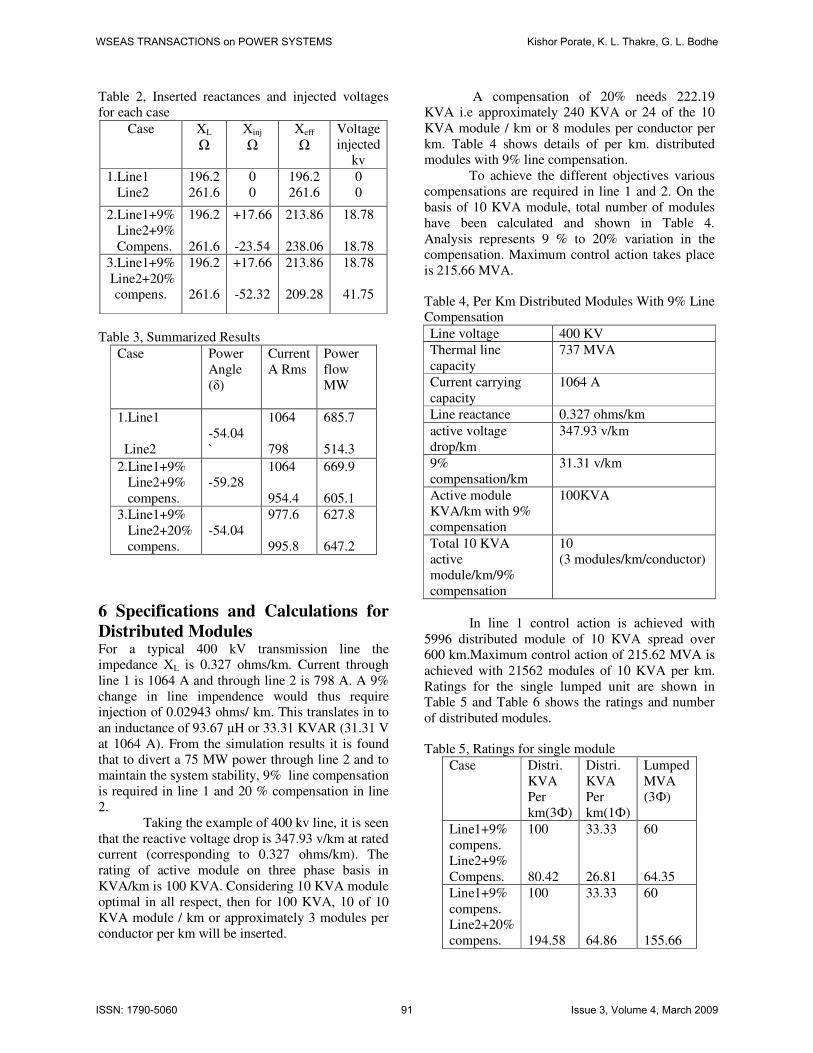
Table 2, Inserted reactances and injected voltages
for each case
Case XL
Ω
Xinj
Ω
Xeff
Ω
Voltage
injected
kv
1.Line1
Line2
196.2
261.6
0
0
196.2
261.6
0
0
2.Line1+9%
Line2+9%
Compens.
196.2
261.6
+17.66
-23.54
213.86
238.06
18.78
18.78
3.Line1+9%
Line2+20%
compens.
196.2
261.6
+17.66
-52.32
213.86
209.28
18.78
41.75
Table 3, Summarized Results
Case Power
Angle
(δ)
Current
A Rms
Power
flow
MW
1.Line1
Line2
-54.04
`
1064
798
685.7
514.3
2.Line1+9%
Line2+9%
compens.
-59.28
1064
954.4
669.9
605.1
3.Line1+9%
Line2+20%
compens.
-54.04
977.6
995.8
627.8
647.2
6 Specifications and Calculations for
Distributed Modules For a typical 400 kV transmission line the
impedance XL is 0.327 ohms/km. Current through
line 1 is 1064 A and through line 2 is 798 A. A 9%
change in line impendence would thus require
injection of 0.02943 ohms/ km. This translates in to
an inductance of 93.67 µH or 33.31 KVAR (31.31 V
at 1064 A). From the simulation results it is found
that to divert a 75 MW power through line 2 and to
maintain the system stability, 9% line compensation
is required in line 1 and 20 % compensation in line
2.
Taking the example of 400 kv line, it is seen
that the reactive voltage drop is 347.93 v/km at rated
current (corresponding to 0.327 ohms/km). The
rating of active module on three phase basis in
KVA/km is 100 KVA. Considering 10 KVA module
optimal in all respect, then for 100 KVA, 10 of 10
KVA module / km or approximately 3 modules per
conductor per km will be inserted.
A compensation of 20% needs 222.19
KVA i.e approximately 240 KVA or 24 of the 10
KVA module / km or 8 modules per conductor per
km. Table 4 shows details of per km. distributed
modules with 9% line compensation.
To achieve the different objectives various
compensations are required in line 1 and 2. On the
basis of 10 KVA module, total number of modules
have been calculated and shown in Table 4.
Analysis represents 9 % to 20% variation in the
compensation. Maximum control action takes place
is 215.66 MVA.
Table 4, Per Km Distributed Modules With 9% Line
Compensation
Line voltage 400 KV
Thermal line
capacity
737 MVA
Current carrying
capacity
1064 A
Line reactance 0.327 ohms/km
active voltage
drop/km
347.93 v/km
9%
compensation/km
31.31 v/km
Active module
KVA/km with 9%
compensation
100KVA
Total 10 KVA
active
module/km/9%
compensation
10
(3 modules/km/conductor)
In line 1 control action is achieved with
5996 distributed module of 10 KVA spread over
600 km.Maximum control action of 215.62 MVA is
achieved with 21562 modules of 10 KVA per km.
Ratings for the single lumped unit are shown in
Table 5 and Table 6 shows the ratings and number
of distributed modules.
Table 5, Ratings for single module
Case Distri.
KVA
Per
km(3Ф)
Distri.
KVA
Per
km(1Ф)
Lumped
MVA
(3Ф)
Line1+9%
compens.
Line2+9%
Compens.
100
80.42
33.33
26.81
60
64.35
Line1+9%
compens.
Line2+20%
compens.
100
194.58
33.33
64.86
60
155.66
WSEAS TRANSACTIONS on POWER SYSTEMS Kishor Porate, K. L. Thakre, G. L. Bodhe
ISSN: 1790-5060 91 Issue 3, Volume 4, March 2009
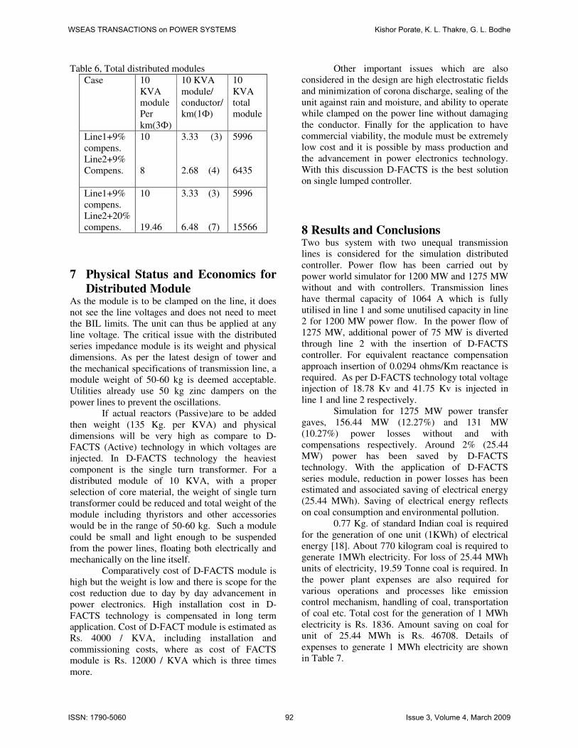
Table 6, Total distributed modules
Case 10
KVA
module
Per
km(3Ф)
10 KVA
module/
conductor/
km(1Ф)
10
KVA
total
module
Line1+9%
compens.
Line2+9%
Compens.
10
8
3.33 (3)
2.68 (4)
5996
6435
Line1+9%
compens.
Line2+20%
compens.
10
19.46
3.33 (3)
6.48 (7)
5996
15566
7 Physical Status and Economics for
Distributed Module As the module is to be clamped on the line, it does
not see the line voltages and does not need to meet
the BIL limits. The unit can thus be applied at any
line voltage. The critical issue with the distributed
series impedance module is its weight and physical
dimensions. As per the latest design of tower and
the mechanical specifications of transmission line, a
module weight of 50-60 kg is deemed acceptable.
Utilities already use 50 kg zinc dampers on the
power lines to prevent the oscillations.
If actual reactors (Passive)are to be added
then weight (135 Kg. per KVA) and physical
dimensions will be very high as compare to D-
FACTS (Active) technology in which voltages are
injected. In D-FACTS technology the heaviest
component is the single turn transformer. For a
distributed module of 10 KVA, with a proper
selection of core material, the weight of single turn
transformer could be reduced and total weight of the
module including thyristors and other accessories
would be in the range of 50-60 kg. Such a module
could be small and light enough to be suspended
from the power lines, floating both electrically and
mechanically on the line itself.
Comparatively cost of D-FACTS module is
high but the weight is low and there is scope for the
cost reduction due to day by day advancement in
power electronics. High installation cost in D-
FACTS technology is compensated in long term
application. Cost of D-FACT module is estimated as
Rs. 4000 / KVA, including installation and
commissioning costs, where as cost of FACTS
module is Rs. 12000 / KVA which is three times
more.
Other important issues which are also
considered in the design are high electrostatic fields
and minimization of corona discharge, sealing of the
unit against rain and moisture, and ability to operate
while clamped on the power line without damaging
the conductor. Finally for the application to have
commercial viability, the module must be extremely
low cost and it is possible by mass production and
the advancement in power electronics technology.
With this discussion D-FACTS is the best solution
on single lumped controller.
8 Results and Conclusions Two bus system with two unequal transmission
lines is considered for the simulation distributed
controller. Power flow has been carried out by
power world simulator for 1200 MW and 1275 MW
without and with controllers. Transmission lines
have thermal capacity of 1064 A which is fully
utilised in line 1 and some unutilised capacity in line
2 for 1200 MW power flow. In the power flow of
1275 MW, additional power of 75 MW is diverted
through line 2 with the insertion of D-FACTS
controller. For equivalent reactance compensation
approach insertion of 0.0294 ohms/Km reactance is
required. As per D-FACTS technology total voltage
injection of 18.78 Kv and 41.75 Kv is injected in
line 1 and line 2 respectively.
Simulation for 1275 MW power transfer
gaves, 156.44 MW (12.27%) and 131 MW
(10.27%) power losses without and with
compensations respectively. Around 2% (25.44
MW) power has been saved by D-FACTS
technology. With the application of D-FACTS
series module, reduction in power losses has been
estimated and associated saving of electrical energy
(25.44 MWh). Saving of electrical energy reflects
on coal consumption and environmental pollution.
0.77 Kg. of standard Indian coal is required
for the generation of one unit (1KWh) of electrical
energy [18]. About 770 kilogram coal is required to
generate 1MWh electricity. For loss of 25.44 MWh
units of electricity, 19.59 Tonne coal is required. In
the power plant expenses are also required for
various operations and processes like emission
control mechanism, handling of coal, transportation
of coal etc. Total cost for the generation of 1 MWh
electricity is Rs. 1836. Amount saving on coal for
unit of 25.44 MWh is Rs. 46708. Details of
expenses to generate 1 MWh electricity are shown
in Table 7.
WSEAS TRANSACTIONS on POWER SYSTEMS Kishor Porate, K. L. Thakre, G. L. Bodhe
ISSN: 1790-5060 92 Issue 3, Volume 4, March 2009
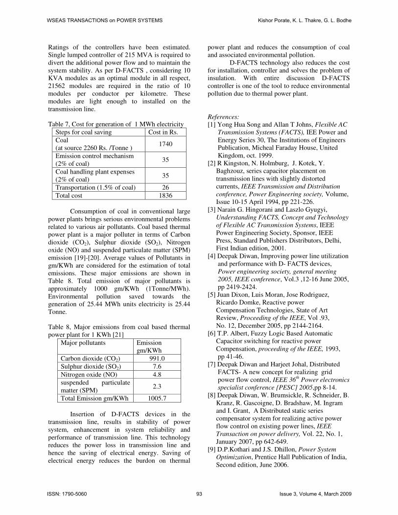
Ratings of the controllers have been estimated.
Single lumped controller of 215 MVA is required to
divert the additional power flow and to maintain the
system stability. As per D-FACTS , considering 10
KVA modules as an optimal module in all respect,
21562 modules are required in the ratio of 10
modules per conductor per kilometre. These
modules are light enough to installed on the
transmission line.
Table 7, Cost for generation of 1 MWh electricity
Steps for coal saving Cost in Rs.
Coal
(at source 2260 Rs. /Tonne ) 1740
Emission control mechanism
(2% of coal) 35
Coal handling plant expenses
(2% of coal) 35
Transportation (1.5% of coal) 26
Total cost 1836
Consumption of coal in conventional large
power plants brings serious environmental problems
related to various air pollutants. Coal based thermal
power plant is a major polluter in terms of Carbon
dioxide (CO2), Sulphur dioxide (SO2), Nitrogen
oxide (NO) and suspended particulate matter (SPM)
emission [19]-[20]. Average values of Pollutants in
gm/KWh are considered for the estimation of total
emissions. These major emissions are shown in
Table 8. Total emission of major pollutants is
approximately 1000 gm/KWh (1Tonne/MWh).
Environmental pollution saved towards the
generation of 25.44 MWh units electricity is 25.44
Tonne.
Table 8, Major emissions from coal based thermal
power plant for 1 KWh [21]
Major pollutants Emission
gm/KWh
Carbon dioxide (CO2) 991.0
Sulphur dioxide (SO2) 7.6
Nitrogen oxide (NO) 4.8
suspended particulate
matter (SPM) 2.3
Total Emission gm/KWh 1005.7
Insertion of D-FACTS devices in the
transmission line, results in stability of power
system, enhancement in system reliability and
performance of transmission line. This technology
reduces the power loss in transmission line and
hence the saving of electrical energy. Saving of
electrical energy reduces the burdon on thermal
power plant and reduces the consumption of coal
and associated environmental pollution.
D-FACTS technology also reduces the cost
for installation, controller and solves the problem of
insulation. With entire discussion D-FACTS
controller is one of the tool to reduce environmental
pollution due to thermal power plant.
References:
[1] Yong Hua Song and Allan T Johns, Flexible AC
Transmission Systems (FACTS), IEE Power and
Energy Series 30, The Institutions of Engineers
Publication, Micheal Faraday House, United
Kingdom, oct. 1999.
[2] R Kingston, N. Holmburg, J. Kotek, Y.
Baghzouz, series capacitor placement on
transmission lines with slightly distorted
currents, IEEE Transmission and Distribution
conference, Power Engineering society, Volume,
Issue 10-15 April 1994, pp 221-226.
[3] Narain G. Hingorani and Laszlo Gyugyi,
Understanding FACTS, Concept and Technology
of Flexible AC Transmission Systems, IEEE
Power Engineering Society, Sponsor, IEEE
Press, Standard Publishers Distributors, Delhi,
First Indian edition, 2001.
[4] Deepak Diwan, Improving power line utilization
and performance with D- FACTS devices,
Power engineering society, general meeting
2005, IEEE conference, Vol.3 ,12-16 June 2005,
pp 2419-2424.
[5] Juan Dixon, Luis Moran, Jose Rodriguez,
Ricardo Domke, Reactive power
Compensation Technologies, State of Art
Review, Proceeding of the IEEE, Vol .93,
No. 12, December 2005, pp 2144-2164.
[6] T.P. Albert, Fuzzy Logic Based Automatic
Capacitor switching for reactive power
Compensation, proceeding of the IEEE, 1993,
pp 41-46.
[7] Deepak Diwan and Harjeet Johal, Distributed
FACTS- A new concept for realizing grid
power flow control, IEEE 36th Power electronics
specialist conference PESC] 2005,pp 8-14.
[8] Deepak Diwan, W. Brumsickle, R. Schneider, B.
Kranz, R. Gascoigne, D. Bradshaw, M. Ingram
and I. Grant, A Distributed static series
compensator system for realizing active power
flow control on existing power lines, IEEE
Transaction on power delivery, Vol. 22, No. 1,
January 2007, pp 642-649.
[9] D.P.Kothari and J.S. Dhillon, Power System
Optimization, Prentice Hall Publication of India,
Second edition, June 2006.
WSEAS TRANSACTIONS on POWER SYSTEMS Kishor Porate, K. L. Thakre, G. L. Bodhe
ISSN: 1790-5060 93 Issue 3, Volume 4, March 2009
[10] M.A.Abido, member IEEE, Environmental /
Power Dispatch using Multiobjective
Evolutionary Algorithms, IEEE Transaction on
Power Systems, Vol.18, No. 3, Nov.2003,
pp1529-1537.
[11] Linda Slimani and Tarek Bouktir, Economic
Power Dispatch of Power system with pollution
control using Multiobjective Ant Colony
Optimization, International Journal of
Computational Intelligence Research, Vol. 3,
No.2, 2007, pp 145-153.
[12] P. Venkatesh, R. Gnanadass and Narayana
Prasad Padhy, Comparison and Application of
Evalutionary Programming Techniques to
Combined Economic Emission Dispatch with
Line Flow Constraints, IEEE Transactions on
Power System, Vol. 18, No. 2, 2May 2003, pp
688-697.
[13] K. Yu and Y.H.Song, Short Term Generation
Scheduling of Thermal Units with Voltage
Security and Environmental Constraints, IEEE
Procedding of Generation, Transmission and
Distribution, Vol. 144, No. 5, Sept. 1997, pp
469-477.
[14] F.B.Chaaban, T.Mezher and
M.Ouwayjan, Options for Emissions Reduction
from Power Plants, Elseviers, Electrical Power
and Energy Systems, Vol. 26, 2004, pp 57-63.
[15] J.H.Talang, Ferial and M.E.El-Hawary,
Minimum Emissions Power Flow, IEEE
Transactions on Power System, Vol. 9, No. 1,
February 1994, pp 429-435.
[16] Dirk Van Hertem, Jody Verboomen, Ronnie
Belmans and Wil L. Kling, Power flow
controlling devices, An overview of their
working principales and their application
range, future power systems, 2005
international conference, 16-18 Nov. 2005,
pp 1-6.
[17] Rakosh Das Begamudre, Extra high voltage
AC Transmission Engineering, Second edition,
New AGE International(p) Limited, Publishers,
New Delhi. India.
[18] Lalit Kapoor, Central Pollution Control Board
of India.
[19] Moti L. Mittal and C. Sharma, Anthropogenic
Emissions from Energy Activities in India:
Generation and Source Characterization,
Emissions from Thermal Power Generation in
India. Part 1.OSC -Research program for
Computational Reactive Mechanism (PCRM).
[20] G.K.Pandey and S.K.Tyagi, Management of
Thermal Power Plant in India, International
conference at BAQ 2006 AT Yogykarta,
Indonesia.
[21] Coal India Limited, Ministry of coal, Pricing-
Domestic price fixation, 12 Dec. 2007.
WSEAS TRANSACTIONS on POWER SYSTEMS Kishor Porate, K. L. Thakre, G. L. Bodhe
ISSN: 1790-5060 94 Issue 3, Volume 4, March 2009