DISPERSION COMPENSATED LONG- HAUL OPTICAL ...
109
DISPERSION COMPENSATED LONG- HAUL OPTICAL COMMUNICATION SYSTEM EMPLOYING MODIFIED SLPCF AND EDFA MD. AZIZUL HAKIM Student ID: 15202035-P DEPARTMENT OF ELECTRICAL AND ELECTRONIC ENGINEERING DHAKA UNIVERSITY OF ENGINEERING & TECHNOLOGY, GAZIPUR June, 2021
-
Upload
khangminh22 -
Category
Documents
-
view
4 -
download
0
Transcript of DISPERSION COMPENSATED LONG- HAUL OPTICAL ...

DISPERSION COMPENSATED LONG-
HAUL OPTICAL COMMUNICATION
SYSTEM EMPLOYING MODIFIED SLPCF
AND EDFA
MD. AZIZUL HAKIM Student ID: 15202035-P
DEPARTMENT OF ELECTRICAL AND ELECTRONIC ENGINEERING
DHAKA UNIVERSITY OF ENGINEERING & TECHNOLOGY, GAZIPUR
June, 2021

ii

iii
Declaration
It is hereby declared that this thesis or any part of it has not been submitted
elsewhere for the award of any degree or diploma.
Signature of the candidate
------------------------------
Md. Azizul Hakim
(Student ID. 15202035-P)

iv
ACKNOWLEDGEMENT
At first, I would like to express my gratitude to almighty. Then, I would
like to express my sincere gratitude to my thesis supervisor, Prof. Dr. Md.
Shaheen Hasan Chowdhury and I am grateful to Prof. Dr. E J Zinat Mahol
Sathi, for her help, support and guidelines. Their continuous encouragement
with extreme enthusiasm toward research has motivated me during my entire
research life. I am eternally grateful for the things both academic and
nonacademic which I have learnt from my supervisors. I will always remember
the countless hours we spent together discussing the research work with ideas.
I am indebted to Prof. Dr. Ruma, Head, Department of Electrical and
Electronic Engineering, DUET, for her caring and guidelines. My sincere
gratitude and thanks to Prof. Dr. Masuma Akter and Prof. Dr. Mohammad
Jakir Hossain for their valuable feedback and comments throughout the
research period. It is my pleasure to thank Dr. Arifur Rahman for his
continuous inspiration and comments regarding this research. I wish to thank
the member of my thesis committee Prof. Dr. Pran Kanai Saha for his
invaluable feedback on my work. I am obliged to Prof. Dr. Md. Sharafat
Hossain for his motivation and suggestions.
Finally, thanks to all the faculty and staff of the EEE department for
their help and motivation throughout the research.
At last, I would like to thank my father and my mother for their
continuous support, love and positive attitude towards my research life.

v
ABSTRACT
In this thesis, photonic crystal fibre (PCF) is designed and assessed as dispersion
compensating fibre (DCF) to compensate dispersion. The PCF, termed as modified square
lattice photonic crystal fibre (SLPCF), is designed with square in outer shape having
circular and elliptical air holes, and is proposed as a new approach of dispersion
compensation. Here, various PCF structures are designed and modelled by varying the
shape and lattice type of air holes in the core and cladding by using COMSOL
Multiphysics. Spectral characteristics such as effective mode index, mode field
distribution, effective refractive index and light propagation through various PCFs of
square, circular and elliptical lattice structures are analyzed. The effective mode index
(EMI), responsible for improving light confinement within the fibre, was not very high in
earlier work resulting in a higher confinement loss. Therefore, the term modified SLPCF
remarks square core within the square lattice consisting of circular and elliptical air holes
and compared this one with other PCF structures to find suitable DCF with improved EMI.
The optical characteristics of these PCFs are evaluated and compared at 1.55 μm (or
193.414 THz).
Besides dispersion compensation, reduction of bit error rate (BER) is essential in
communication link since higher BER gives a slower data rate that degrades the quality of
data link. Radio over fibre (RoF) link at different data rates is used for information
transmission in single mode fibre where signal weakens during transmission and needs to
be amplified. In this research, a RoF link is designed with modified square lattice PCF and
erbium doped fibre amplifier (EDFA) and evaluated its performance by varying the pump
power of the continuous wave (CW) laser that is used to excite the EDFA. Here, EDFA is
used as an in-line optical amplifier to boost up the weak optical signal in the proposed RoF
link.
It is observed that the proposed RoF link shows remarkable lower dispersion as -
0.90E-14 for modified SLPCF where as it is found in previous -0.5E-14 (Circular Core), -
0.47E-14 (Elliptical Core), 30.76 (Square Core), and BER, sharper eye diagram and both
the improved Q-factor and eye height. Therefore, the proposed model for PCF and RoF
link can be used for designing cost-effective long-haul optical communication system.

vi
LIST OF ABBREVIATIONS
AM Amplitude Modulation
ARQ Automatic Repeat Request
AMB Access of Mobile Broadband
BER Bit Error Rate
CW Continuous Wave
CPCF Chalcogenide Photonic Crystal Fibre
CD Chromatic Dispersion
CN Cellular Networks
DCF Dispersion Compensating Fibre
EDF Erbium Doped Fibre
ECC Error Correcting Code
EDFA Erbium Doped Fibre Amplifier
EMI Effective Mode Index
FDTD Finite Difference Time Domain Method
FBG Fibre Bragg Grating
FWM Four Wave Mixing
FEC Forward Error Correction
FM Frequency Modulation
FEM Finite Element Method
HNDSF Highly Nonlinear Dispersion Shifted Fibre
HARQ Hybrid Schemes Combining ARQ and ECC
LASER Light Amplification by Stimulated Emission of Radiation
LEAF Large Effective Area Fibre
MRI Magnetic Resonance Imaging
MIMO Multiple-Input Multiple-Output
NA Numerical Aperture
NRZ Non Return to Zero
OA Optical Attenuator
OSA Optical Spectrum Analyzer

vii
OPM Optical Power Meter
OPG Optical Phase Conjugator
PCF Photonic Crystal Fibre
PRBS Pseudo-Random Bit Sequence
PWE Plane Wave Expansion Method
PCM Phase Conjugate Mirror.
PBG Photonic Bandgap
RA Raman Amplifier
RF Radio Frequency
RE Rare Earthed
RADAR Radio Detection and Ranging
RoF Radio over Fibre
SLPCF Square Lattice Photonic Crystal Fibre
SMF Single Mode Fibre
SONAR Sound Navigation and Ranging
SC Satellite Control
SC Square in Circular Core
SS Square in Square Core
SE Square Elliptical Core
TIR Total Internal Reflection
VDS Video Distribution Systems
VC Vehicle Communication
WLAN Wireless Local Area Network
WDM Wavelength Division Multiplexing

viii
LIST OF FIGURES
Figure 2.1 Basic block diagram of a simple radio over fibre (RoF) link. ........................... 7
Figure 2.2 Chromatic dispersion in an optical fibre communication system. .................... 9
Figure 2.3 Dispersion compensation by means of using DCF to have zero dispersion.... 10
Figure 2.4 Optical communication system using EDFA. ................................................. 11
Figure 2.5 Pump radiation with respect to three energy levels for EDFA. ....................... 11
Figure 3.1 Use of PCF in sensing application................................................................... 15
Figure 3.2 Photonic crystal fibre fabrication. ................................................................... 16
Figure 3.3 Microscope picture of birefringent PCF at 1.55 µm. ...................................... 17
Figure 3.4 Schematic of (a) solid core PCF, (b) hollow core PCF, and (c) SMF. ............ 18
Figure 3.5 Light gathering capacity of PCF. ..................................................................... 20
Figure 3.6 Yee cell. ........................................................................................................... 21
Figure 3.7 A fabricated hollow-core Hexagonal cladding PCF. ....................................... 22
Figure 3.8 Triangular lattice photonic crystal fibre. ......................................................... 23
Figure 3.9 A typical elliptical PCF with hexagonal core. ................................................. 25
Figure 3.10 Modeling outlines of a typical square in square PCF with hollow core. ....... 27
Figure 4.1 COMSOL modeling Flowchart. ...................................................................... 29
Figure 4.2 Space dimension selection. .............................................................................. 30
Figure 4.3 Physics Selection. ............................................................................................ 30
Figure 4.4 Study selection................................................................................................. 31
Figure 4.5 Creating a new model using Blank Model. ..................................................... 31
Figure 4.6 Select the geometry. ........................................................................................ 32
Figure 4.7 Materials selection. .......................................................................................... 33
Figure 4.8 Mesh Analysis. ................................................................................................ 34
Figure 4.9 Preform the study. ........................................................................................... 34
Figure 4.10 Effective mode index of Circular PCF. ......................................................... 37
Figure 4.11 Effective mode index of Elliptical PCF......................................................... 38
Figure 4.12 Effective mode index of SLPCF.................................................................... 39
Figure 4.13 Cross section of proposed SLPCF. ................................................................ 40
Figure 4.14 Circular shape PCF. ....................................................................................... 41
Figure 4.15 Light Propagation through SLPCF. ............................................................... 42

ix
Figure 4.16 Cross sectional view of light propagation through modified SLPCF............ 42
Figure 4.17 Light propagation through an elliptical core PCF. ........................................ 44
Figure 4.18 Light propagation inside square core PCF. ................................................... 45
Figure 4.19 Light propagation inside circular core PCF. .................................................. 46
Figure 4.20 Total Internal Reflection (TIR). .................................................................... 47
Figure 4.21 Total Internal Reflection inside SLPCF. ....................................................... 48
Figure 5.1 Model of a typical Elliptical core PCF with circular air hole only. ................ 49
Figure 5.2 Model of a typical circular core PCF with circular air hole only. ................... 52
Figure 5.3 Model of a typical square core PCF (SLPCF) with circular air hole only. ..... 54
Figure 5.4 Modified SLPCF. ............................................................................................ 56
Figure 5.5 Effective mode index for circular core PCF with circular air hole only. ........ 56
Figure 5.6 Effective mode index for elliptical core PCF with circular air hole only. ...... 57
Figure 5.7 EMI for square core PCF with both circular and elliptical air hole. ............... 58
Figure 5.8 Comparison of EMI for various PCFs. ............................................................ 58
Figure 5.9 BER characteristics. ........................................................................................ 60
Figure 5.10 Dispersion of various PCF structures. ........................................................... 61
Figure 5.11 Dispersion of various PCFs structures .......................................................... 62
Figure 5.12 Effective Area of various PCF structures ...................................................... 62
Figure 5.13 Summarized effective Area of various PCF structures ................................. 63
Figure 5.14 Nonlinearity, γ of various PCF structures. .................................................... 64
Figure 5.15 Summarized nonlinearity, γ of various PCF structures ................................. 64
Figure 5.16 Flow chart of the RoF link analysis. .............................................................. 66
Figure 5.17 Flowchart for RoF link analysis using OptiSystem. ...................................... 68
Figure 5.18 Proposed Model for improved RoF link. ....................................................... 69
Figure 5.19 Simulation model using conventional SMF. ................................................. 70
Figure 5.20 Optical spectra at 1 dBm ............................................................................... 70
Figure 5.21 Optical spectra at 1dBm ................................................................................ 71
Figure 5.22 Optical spectra at 10 dBm ............................................................................. 71
Figure 5.23 Optical spectra at 10dBm .............................................................................. 72
Figure 5.24 Optical spectra at 15 dBm ............................................................................. 72
Figure 5.25 Optical spectra at 15dBm .............................................................................. 73

x
Figure 5.26 Q-factor for conventional SMF. .................................................................... 74
Figure 5.27 Eye pattern for conventional SMF. ............................................................... 74
Figure 5.28 Q- factor and BER pattern for previously used SLPCF. ............................... 75
Figure 5.29 Q-factor for 1dBm CW laser input power ..................................................... 75
Figure 5.30 Eye pattern for 1dBm CW laser input power. ............................................... 76
Figure 5.31 Q-factor for 10dBm CW laser input power. .................................................. 76
Figure 5.32 Eye pattern for 10dBm CW laser input power. ............................................. 77
Figure 5.33 Q- factor for 15dBm CW laser input power. ................................................. 77
Figure 5.34 Eye pattern for 15dBm CW laser input power. ............................................. 78
xi
LIST OF TABLES
Table 3-1 Development of PCFs....................................................................................... 14
Table 3-2 Modeling outlines of a typical hexagonal PCF ................................................ 21
Table 3-3 Modeling outlines of a Triangular lattice PCF ................................................. 23
Table 3-4 Parameters of elliptical PCF hexagonal core with circular air hole only. ........ 24
Table 3-5 Parameters of a typical square core PCF with circular air hole only. .............. 26
Table 4-1 Electromagnetic mode analysis (multimode analysis) of various PCFs. ......... 39
Table 4-2 Materials properties required materials. ........................................................... 40
Table 4-3 Modeling outlines of a TIR-Total Internal Reflection ..................................... 47
Table 5-1 Parameters of a typical Elliptical core PCF with circular air hole only. .......... 50
Table 5-2 Modeling outlines of a typical circular core PCF. ............................................ 51
Table 5-3 Parameters of a typical square core PCF with circular air hole only. .............. 53
Table 5-4 Parameters of a square core PCF with circular and elliptical air hole.............. 55
Table 5-5 Summary of PCF parameters from simulation. ................................................ 65
Table 5-6 Component Properties used in modeling RoF link........................................... 68
Table 5-7 Summary of performance of RoF link from simulation results. ...................... 78

xii
TABLE OF CONTENTS
Acknowledgement ............................................................................................................. iv
Abstract ............................................................................................................................... v
List of Abbreviations ......................................................................................................... vi
List of Figures .................................................................................................................. viii
List of tables ....................................................................................................................... xi
CHAPTER 1 INTRODUCTION
1.1 Introduction ............................................................................................................... 1
1.2 Problem statement ..................................................................................................... 2
1.3 Aim of the thesis ....................................................................................................... 5
1.4 Chapter Orientation ................................................................................................... 6
CHAPTER 2 IPMAIRMENTS IN ROF LINK
2.1 Introduction ............................................................................................................... 7
2.2 Radio over fibre (RoF) link....................................................................................... 7
2.3 Dispersion in long-haul optical communication ....................................................... 8
2.4 Dispersion compensation .......................................................................................... 9
2.4.1 Dispersion compensating fibre (DCF) ............................................................. 9
2.5 Erbium doped fibre amplifier (EDFA) ................................................................... 10
2.6 Conclusion .............................................................................................................. 12
CHAPTER 3 STUDY OF PHOTONIC CRYSTAL FIBRE (PCF)
3.1 Introduction ............................................................................................................. 13
3.2 PCF basics ............................................................................................................... 13
3.3 Development of PCF............................................................................................... 13
3.4 Applications of PCF ................................................................................................ 14
3.5 Methods of PCF fabrication .................................................................................... 16

xiii
3.6 Types of PCFs ......................................................................................................... 17
3.6.1 PCFs with solid core ...................................................................................... 17
3.6.2 PCFs with highly birefringent ........................................................................ 17
3.6.3 PCFs with large mode area ............................................................................ 17
3.6.4 Operation Modes ............................................................................................ 18
3.7 Optical properties of PCF ....................................................................................... 18
3.7.1 Properties in terms of dispersion.................................................................... 19
3.7.2 Properties in terms of effective Area ............................................................. 19
3.7.3 Properties in terms of light gathering capacity .............................................. 19
3.7.4 Properties in terms of non-linearity coefficient, γ ......................................... 20
3.8 Methods of PCF modeling ...................................................................................... 20
3.9 PCF modeling ......................................................................................................... 21
3.10 Conclusion ............................................................................................................ 27
CHAPTER 4 DESIGN OF VARIOUS PCF STRUCTURES USING COMSOL
MULTIPHYSICS
4.1 Introduction ............................................................................................................. 28
4.2 Modeling Flowchart using COMSOL Multiphysics............................................... 28
4.3 New Model Creation ............................................................................................... 29
4.3.1 Using model wizard creation of a new model ............................................... 29
4.3.2 Using Blank Model creation of a new model ................................................ 31
4.4 Parameters, Variables, and scope............................................................................ 31
4.4.1 Global Definition ........................................................................................... 31
4.4.2 Geometry Unit ............................................................................................... 32
4.4.3 Selection of materials ..................................................................................... 32
4.5 Boundary Selection with other geometric conditions ............................................. 33

xiv
4.5.1 Performing the mesh condition ...................................................................... 33
4.5.2 Performing the study condition ...................................................................... 34
4.6 Modeling specifications of various PCF Lattice Structures. .................................. 35
4.6.1 Label: Material properties .............................................................................. 35
4.6.2 Label: Electromagnetic Waves Analysis (Frequency Domain) ..................... 35
4.6.3 Label: Mesh ................................................................................................... 35
4.6.4 Label: Mode Analysis .................................................................................... 36
4.6.5 Label: Eigenvalue Solver ............................................................................... 36
4.6.6 Mode analysis solver...................................................................................... 36
4.7 Electromagnetic mode analysis of various PCF structures ..................................... 36
4.8 Characteristics of SLPCF ........................................................................................ 40
4.9 Electromagnetic mode analysis for various structure (single mode analysis) at 1550
nm or 193.4 THz ........................................................................................................... 43
4.10 Conclusion ............................................................................................................ 48
CHAPTER 5 ANALYSIS OF RESULTS OF MODIFIED SLPCF
5.1 Introduction ............................................................................................................. 49
5.2 Modeling and analysis of various SLPCF structures .............................................. 49
5.2.1 Square lattice PCF with elliptical core ........................................................... 49
5.2.2 Circular core PCF with circular air hole ........................................................ 50
5.2.3 Analysis of square core PCF .......................................................................... 52
5.2.4 Square core PCF with circular and elliptical air hole .................................... 54
5.3 Effective mode analysis for various photonic crystal fibre (PCF) .......................... 56
5.4 Numerical Methods and Equations ......................................................................... 58
5.5 Result of simulation of modification with respect to other PCFs ........................... 60
5.6 Performance improvement in RoF link using SLPCF and EDFA .......................... 65

xv
5.8 Flow chart for RoF link design ............................................................................... 66
5.9 Design and analysis of RoF link using OptiSystem................................................ 67
5.10 Performance evaluation of RoF link ..................................................................... 69
5.11 Conclusion ............................................................................................................ 80
CHAPTER 6 CONCLUSION AND DISCUSSION
6.1 Conclusion .............................................................................................................. 81
6.2 Scopes for future research ....................................................................................... 81
REFERENCES ................................................................................................................. 83
1
CHAPTER 1
INTRODUCTION
1.1 Introduction
This chapter is an introduction to the overall thesis work on dispersion compensated
optical fibre link using special type of photonic crystal fibre (PCF) and erbium doped fibre
amplifier (EDFA). The motivation behind research on this topic is briefed by describing
the present state of research on this area from analysis on recent literatures followed by
specific aim of the thesis. An outline of thesis chapters is presented at the end of this
chapter. The dispersion and nonlinear effects are the vital impairment in long-haul optical
communication for RoF link. The dispersion (optical pulses get widened) reduces the data
transmission rate. As a result cost of RoF communication will be increased due to lower
data transmission rate to meet up the huge consumer demand. That is why dispersion
should be compensated for better RoF communication. There are various dispersion
compensation techniques are exist such as fibre Bragg grating (FBG), phase conjugation,
dispersion compensation fibre (DCF), photonic crystal fibre etc. are used to reduce
dispersion impairments in fibre link. PCF structures have many advantageous
characteristics over other dispersion compensation methods because dispersion; non-
linearity are often controlled individually by varying the air-hole diameter (d) and pitch
(Λ), and by changing the lattice structures of PCF. Also SMF can propagate the light in
small distance but PCFs can propagate the light in long-haul optical communication.
Furthermore SLPCF was found better dispersion compensation characteristics over other
PCF structures. But the modification of SLPCF is needed over other PCFs including
previously used SLPCF to improve the overall performance of long-haul optical
communication like RoF link communication. The modification of SLPCF design was
presented by varying the lattice structures, material types and combination of lattice in core
and cladding. Also another RoF communication link impairments BER, lower Q factor,
closer eye height etc. are studied in this research.

2
1.2 Problem statement
The evolution of communication system prospers with time and technological
improvement. Communication devices and medium play significant impact on overall
communication system. However, numerous impairments are present within the optical
communication network hampering the event towards an efficient communication system.
Various sorts of PCF structures have become attractive among scientific groups for their
optimistic optical properties. For example, by varying the dimensions and size or shape of
the cladding holes and/or the core, the dispersion, nonlinearity, transmission spectrum,
mode shape, air filling fraction and birefringence, etc. are tuned to design suitable PCFs.
These feature in PCFs show an enormous amount in mint conditional and ameliorate
applications within the fibre optic communication system [1].
PCF offers design simplicity over single mode fibres (SMFs). SMFs have stubborn
arrangement parameter such that the optical characteristics cannot be maintained
independently. But in PCFs, various optical impairments like dispersion; non-linearity are
often controlled individually by varying the air-hole diameter (d) and pitch (Λ), and by
changing the lattice structures. In symmetric PCF, the air-holes are arranged symmetric to
the middle core. In asymmetric PCF, one or more holes near the core is removed. By
suitable design it is possible to shift the zero dispersion wavelengths closer to
telecommunication wavelength. The obtained zero dispersion wavelengths found to be
much smaller than normal silica. The core diameter in symmetric structures is far reduced
to nanometer range while the encompassing air hole diameter is large than core. Supported
light guiding mechanism photonic crystal fibres has two types. (i) Hollow core fibre and
(ii) Index guiding fibre. The index guiding fibres are suitable for telecommunication
application [2]. The applications of hollow-core fibres are: narrow line width delivery,
power delivery, pulse shaping and compression, nonlinear optics, gas spectroscopy, fibre
optic gyroscopes, and sensors [3]. Consistent with the sunshine guiding mechanisms in
photonic crystal fibre are as follows (i) index-guiding mechanism, (ii) photonic band gap
guiding mechanism, (iii) Hybrid guiding mechanism (combination of index-guiding
mechanism and photonic band gap guiding mechanism) [4, 5].
For all kinds of PCFs, fibre properties like effective area [6], dispersion [7],
nonlinearity [8], birefringence [9], confinement loss [10], and propagation constant [11]

3
etc. are varied by changing hole’s size, arrangement of spacing and shape. Various optical
properties of PCFs have contributed to the development of these structures in numerous
applications within the optical communications [7], [10], nonlinear optics [8] and high-
power technology [12]. Effective index of refraction is a crucial term for PCF design which
has relation with the evaluation of various properties of optical communication [13]. This
index of refraction is obtained in complex form and can simply be varied with the
wavelength of PCF. Again, this variation of index of refraction also varies these important
optical properties e.g. effective area, waveguide dispersion, confinement loss, propagation
constant etc. [14]. Confinement loss depends on the imaginary value of effective index of
refraction and effective area, waveguide dispersion also as propagation constant depend
upon the important a part of effective index of refraction. So, it is possible to style
application oriented guiding properties, by means of tuning the diameter and pitch of the
air holes within the cladding [15]. The massive effective mode area PCFs are required in
optical transmission systems [16] which they're required to support broadband optical
transmission also on minimize the coupling losses through the fibres.
A design of a highly nonlinear dispersion-shifted fibre (HNDSF) with an efficient
area of 9.3 μm2 is obtainable [17], and this advanced HNDSF structure offers also low
attenuation, and bending losses. Besides, fibre dispersion and confinement loss also play
vital roles in broadband communications systems. This is often rigorously achieved by
ensuring ultra-flattened dispersion characteristics of fibres [18] also as low confinement
loss [7]. Hence, there is only variety of published papers handling PCFs having both better
effective area and dispersion-flattened characteristics at an equivalent time [19, 20]. So,
there's still scope to style PCF of various structures with low confinement loss also a slow
dispersion.
Photonic crystals structures are unnatural structures those have a regular variation
of the refractive index in one, two, or three dimensions. Like an electronic band gap
between conduction and valence bands, photonic crystals structures create a photonic band
gap. Therefore, the electromagnetic waves cannot propagate through the device within the
band gap with band gap frequencies [21, 22]. This property is very attracting, giving new
chances for guiding light which is never think about before [23].

4
Finite Element Method (FEM), Plane Wave Expansion Method (PWE) and Finite
Difference Time Domain Method (FDTD) can be employed for designing and manipulate
the PCFs [24, 26]. For the development of long-haul optical communication systems
including RoF link, minimization of these impairments is necessary. Among the lower
promising advancements towards cost-effective long-haul transmission are the use of
Fibber Bragg Gratings (FBGs) and Optical Phase Conjugator (OPC) showing some
identical improvement in the link performance due to lower value of optical impairments
like dispersion [27]. The special optical light guide PCF shows the refractive index of core
region (silica glass) is higher than that of cladding region along the fibre [28]. Single mode
fibres have raspy modeling where the size of the core is bounded where light propagation
occurs using TIR-total internal reflection method [29], as a result light can propagate a
small distance. But PCFs can propagate the light in long-haul optical communication with
the help of EDFA [30].
Furthermore square-lattice based PCF (SLPCF) is found better than triangular-
lattice PCF for certain characteristics [31, 32]. SLPCF consists of single-mode fibre and
cladding of photonic crystal lattice like square in shape. Square-lattice PCF shows wider
range of single mode operation with the same 𝑑/Λ value compared to the triangular one
[31]. The effective area of square-lattice PCF is higher than triangular one, making the
former better for high power management [32]. Square-lattice PCF can better compensate
the inline dispersion around the 1550 nm wavelength than the triangular-lattice PCF [32].
In recent times, a square-lattice PCF preform has been realized with a standard fabrication
process, stack and draw, in order to study the localization and control of high frequency
sound by introducing two solid defects in the periodic distribution of air-holes [33]. So,
square-lattice PCF can be experimentally realized like that of the usual triangular-lattice
PCF. Finally, one can choose SLPCF for better long-haul optical communication. But the
modification of SLPCF is needed over other PCFs including previously used SLPCF to
improve the overall performance of long-haul optical communication like RoF link
communication. The modification of SLPCF design was presented by varying the lattice
structures, material types and combination of lattice in core and cladding. For instance,
GeS2 was found to minimize dispersion in square lattice PCF (SLPCF) compared to that
using GeO2 [34]. The premature technique is based on regular SLPCF with all the air-hole

5
of same uniform diameter and the effective size of the air-holes are modified with a
selective infiltration of the air-holes with liquids [35]. A fabrication problem arises between
previously used doped core (GeO2 or GeS2) and background material (fused silica), which
is insufferable due to some basic rule of physics, since the molecules of doping material
diffuse from its original location to adjacent undoped areas [36]. Therefore, the furthermore
modification is needed which is described in this work later. Where modification was done
by considering square in square with circular and elliptical air hole in cladding structure.
Therefore, compared with various PCF structure like circular, elliptical and conventional
SLPCF. For dispersion compensation in RoF link improved technique is necessary. SLPCF
is used to provide smooth hole diameter and hole pitch and to achieve lower nonlinearity,
low insertion loss, and its relative dispersion slope copes well with the formal SMF
assuring lower confinement loss which were not achievable from DCF [37, 39]. In addition
to dispersion compensation, reduction of BER is essential in communication link; since
higher BER gives a slower data rate degrades the quality of data link. Moreover, the
quality-factor (Q-factor) shows the system tolerance in dB. The Q-factor and BER have a
single valued function a larger Q-factor provides smaller BER and better RoF link
performance. Usually, three techniques are considered to reduce BER: automatic repeat
request (ARQ), forward error correction (FEC) or Error correcting code (ECC) and Hybrid
schemes combining ARQ and ECC (HARQ). Although SLPCF is preferred over SMF or
other PCFs in RoF link due to compensate dispersion and moreover, the eye diagram in
RoF with modified SLPCF is found sharper than that of conventional SMF or other PCFs,
the bit error rate is increased, Q-factor and eye height are not improved in SMF or other
PCFs [40].
1.3 Aim of the thesis
The thesis aims to understand the performance of the dispersion compensated long-
haul optical communication system employing modified SLPCF and EDFA. In this work,
performance of PCFs with various lattice structures namely square, circular, elliptical etc.
are analyzed and compared. Then, a modified SLPCF is designed for improved dispersion
characteristics to use in optical communication systems. A RoF link incorporating EDFA)
and CW laser of definite power is proposed as a new approach of forward error correction

6
(FEC). In particular, the RoF model operates with CW laser driven at various input powers.
The RoF link is designed to produce reduced dispersion and BER, sharper eye diagram and
both the improved Q-factor and eye height. Thus, the performance of the RoF link using
modified SLPCF incorporating EDFA and CW laser is aimed for cost-effective RoF link
[40, 41].
It focuses following objectives in the thesis:
• To analyze the optical performance of PCFs designed with various lattice
structures.
• To modify the SLPCF for obtaining improved dispersion property.
• To design and to evaluate the performance of RoF link in terms of dispersion, BER,
Q-factor, eye diagram using SLPCF and EDFA.
1.4 Chapter Orientation
The overall thesis is presented in the following way:
Chapter 1 gives the introduction of the research work by outlining the motivation and aim
of the thesis.
Chapter 2 presents the literature review on RoF link and discusses the impairments of long-
haul optical communication systems with an indication to solve them.
Chapter 3 describes the fundamentals of PCF design and characterization methods for
dispersion compensation.
Chapter 4 presents the research work on design, analysis and performance comparison
among various PCF lattice structures using COMSOL Multiphysics.
Chapter 5 presents the design and characterization of modified SLPCF and evaluates its
performance over other PCF structures for dispersion compensation. Describes the design
and analysis on RoF link using SLPCF and EDFA for dispersion compensated long-haul
optical communication system using OptiSystem software.
Chapter 6 presents the conclusion of the thesis and briefs possible scopes for further
research in future.

7
CHAPTER 2
IPMAIRMENTS IN ROF LINK
2.1 Introduction
In this chapter, fundamentals on RoF link are discussed. The impairments of RoF
link such as dispersion and non-linearity effects are described and methods to compensate
those impairments are presented.
2.2 Radio over fibre (RoF) link
Microwave signals are transmitted as radio waves through optical fibre link in RoF
(Radio-over-fibre) [42] as shown in Figure 2.1 [44]. Where the RW signal is converted into
light signal, then transmitted through optical fibre. In RoF link, signals are usually acquired
via FM [43]. When a conventional optical communication system that follows AM is
interconnected with a RoF system that follows FM, AM-to-FM up conversion is required.
AM-to-FM up conversion is obtained by using optically injected semiconductor laser
namely CW laser. Then, the FM signal is transmitted through RoF link generally using
single mode fibre (SMF). However, chromatic dispersion in fibre link is the critical
impairment in RoF transmission system due to pulse broadening.
Figure 2.1 Basic block diagram of a simple RoF link.
Various dispersion compensation techniques such as fibre Bragg grating (FBG),
phase conjugation and dispersion compensation fibre (DCF) etc. are used to mitigate
dispersion impairments in fibre link. Although DCF is more effective among these, it has

8
some negative aspect for compensating dispersion, for instance, high insertion loss and
bulk size. Hence, for dispersion compensation in RoF improved technique is necessary.
The two main threats in the modeling of higher rate long-haul optical fibre communication
system are as follows [45]: (i) radio frequency (RF) signals distribution [46]; and the
solution is to employ RoF link system and (ii) the production of the RF signals in higher
order [47]; and it depends on the production of RF signals within the optical signal
processing [48]. The important merits of a RoF communication system are namely,
(a) Bandwidth is high.
(b) Low attenuation loss.
(c) Using cells of small size.
(d) Use the multiple-input multiple-output (MIMO) method.
(e) Low power loss.
(f) Wireless coverage is wide where backhaul wireless is not coverable.
(g) More economic.
Another benefit of the RoF system over the wireless backhaul is the no difficulty with
which it can be install, uninstall, and insertion anywhere one can desire [49]. Main
applications RoF link are:
• SC (Satellite Control)
• VC (Vehicle Communication)
• WLAN (Wireless LAN)
• AMB (Access of Mobile Broadband)
• VDS (Video Distribution Systems)
• CN (Cellular Networks)
2.3 Dispersion in long-haul optical communication
The dispersion and nonlinear effects are the vital impairment in long-haul optical
communication. In long-haul optical communication system including the RoF link,
signals in the form of optical pulses are transmitted through single mode fibre (SMF).
While transmission, optical pulses get widened limiting the data transmission rate. This
unwanted phenomenon is known as dispersion or more specifically, chromatic dispersion
(CD) as shown in Figure 2.2 [50].

9
Figure 2.2 Chromatic dispersion in an optical fibre communication system.
The reason of increasing the spectral width, after propagating the signals through optical
fibre is the wave guide and material property of the link. That is Dispersion occurs since
the speed of light depends on the wavelength and propagation mode. While travelling long
distances, slight differences in speed accumulate resulting in BER. Thus, CD decreases the
system performance and makes the system more costly.
2.4 Dispersion compensation
Accompanied by modal dispersion and polarization mode dispersion, dispersion
consists of two main components - material dispersion and waveguide dispersion. Material
dispersion, which is positive for silica glass at telecom wavelengths, is related to material
properties, fibre length and the width of spectrum of an optical source. Waveguide
dispersion depends on the geometry of fibre. It is possible to obtain overall negative CD of
the fibre through high negative waveguide dispersion [51].
2.4.1 Dispersion compensating fibre (DCF)
Dispersion compensating fibre (DCF) is widely used as the solution for
compensation of dispersion in long-haul optical transmission links such as RoF link.
However, DCF has some limitations like bulky, nonlinearity and very high insertion loss.
In DCFs, material and waveguide dispersion is designed to combine them in such a way
that results zero CD at the required wavelength. Figure 2.3 shows zero CD produced at
1.50 µm by designing material dispersion and waveguide dispersion in a DCF [52].

10
Figure 2.3 Dispersion compensation by means of using DCF to have zero dispersion
at 1.50 µm wavelength.
In previous Fiber Br agg Gratings (FBGs) and Optical Phase Conjugator (OPC) are
considered as the dispersion compensating method [53].
2.5 Erbium doped fibre amplifier (EDFA)
In addition to dispersion effects causing pulse spreading, optical communication
systems are affected by absorption mechanisms within the optical link causing signal
weakening [54]. In long-haul optical communication system, signals travel through fibres
for very large distances and becomes weaker and need to strengthen that is to amplify the
signal. Electrical repeaters were used to overcome the above problem earlier [55]. The
general types of amplifiers used in optical system are: semiconductor optical amplifier [56,
57], Raman amplifier (RA) [58, 59] and rare-earth doped fibre amplifier (DFA) [60]. The
commonly used rare earthed doped fibre amplifier is erbium-doped fibre amplifier (EDFA)
due to the broad window and low attenuation properties [61]. EDFAs are pumped by a
laser. Types of pumping methods are as follows: (a) forward, (b) backward, (c) bi-
directional [62].

11
The Figure 2.4 below shows a typical configuration of EDFA based long-haul optical
communication network operating at 1550 nm [63]. First of all, the signal is passed via an
optical isolator through an optical coupler that can fend off reflection. The mechanism
which is allowed the pumping signal input to the link with lower loss is called optical
coupler. Being a rare-earthed (RE) material namely Erbium (Er) when doped in silica glass
makes amplifier that is EDFA.
IsolatorCoupler Isolator
Pumping Laser
(980/1480 nm)
EDFA
Signal 1550 nm
Output
(Amplified)
Figure 2.4 Optical communication system using EDFA.
The Figure 2.5 shows energy levels of erbium doped fibre [63]. It may be noted
that the energy levels form three groups of energy levels marked with their spectroscopic
notations. Here, the configuration energy states are divided into three types of energy levels
as the ground states (g), the metastable (m) and the upper (u).
Figure 2.5 Pump radiation with respect to three energy levels for EDFA.
When the radiation that is beam of light of desired frequency is not present, the ions
are located at ground states (g). If a radiation is appeared on the model, the ions will then

12
excited from lower energy levels to the higher energy levels. This is known as pump
radiation.
In a third transmission window EDFA can be used to amplify signal in two bands
system. First band is called C-band or the conventional band having wavelength range 1530
nm to 1565 nm and the second band is called as the L band or the long band having
wavelength range from 1565 nm to 1625 nm.
2.6 Conclusion
Basic understanding on RoF link are described in this chapter. The impairments of
RoF link and methods to compensate them namely the dispersion are presented. Microwave
signals is introduced. The important merits and applications of RoF communication system
are described. The use of frequency modulation (FM) is introduced in RoF link. Amplitude
modulation (AM)-to-FM up conversion is described in the interconnected RoF system by
using optically injected semiconductor laser namely CW laser. The general types of
amplifiers used in optical system are: semiconductor optical amplifier, Raman amplifier
(RA) and rare-earth doped fibre amplifier (DFA) are shown. Then, fundamentals of the
commonly used rare earthed doped fibre amplifier (DFA) is erbium-doped fibre amplifier
(EDFA) are discussed.
13
CHAPTER 3
STUDY OF PHOTONIC CRYSTAL FIBRE (PCF)
3.1 Introduction
In this chapter the evolution and structural features of various types of photonic
crystal fibres (PCF) along with their applications in optical system are described. Design
issues, essential parameters and considerations behind PCF design are illustrated.
3.2 PCF basics
PCF is one kind of optical fibre based on the characteristics of photonic crystals
lattice. At University of Bath, UK in 1996 PCF was first surveyed. PCF has confinement
properties that signal can be confined into the core of PCF but which is not possible in
SMF. Photonic crystal fibres have vast applications in optical fibre communications
like lasers fibre, nonlinear optics, high-power applications, sensing applications etc. PCF
has many structures like photonic-bandgap (PBG) fibre, Hollow Core, hole-assisted fibre
and Bragg fibre. PCFs are micro structured arrangement of high refractive-index and low
refractive index materials based on the properties of photonic crystals. PCFs can also be
classified according to its microstructure.
3.3 Development of PCF
According to the Table 3-1 it is shown that PCF introduction was held in 1992
which is applicable for high power applications, multi-wavelength fibre laser development
etc. Then in 1997 PCF endlessly single mode absence of higher order modes was
developed. Which is applicable in sensing, mode filtering applications, interferometers etc.
In 2000 PCF with more birefringence and PCF with super continuum source were
developed for high data rate, mirror, RADAR, SONAR, Echography, wavelength division
multiplexing etc. applications. In 2001-2005 PCF with double cladding, PCF with ultra-
flattened dispersion, Chalcogenide Photonic Crystal Fibres (CPCF), Kagome Lattice PCF
were introduced for high power, spectrophotometry in Cancer, diagnostics pulse
transmission. In 2006 Photonic Crystal Fibre in Hybrid lattice was introduced for
polarization, sensing etc. In 2014 PCF based Nano displacement sensor was introduced for

14
nano-displacement sensor applications. In 2015 Combination of Fibre Laser with Photonic
Crystal Fibres (PCF) was introduced for high power applications. Therefore, various hybrid
structure like SLPCF, Hexagonal PCF, triangular PCF, circular PCF, elliptical PCF,
butterfly PCF etc. were developed for various applications like sensing, optoelectronics,
digital displays etc.
Table 3-1 Development of PCFs
Year Development Applications
1992 PCF introduction [64] • high power applications
• multi-wavelength fibre laser
development
1997 PCF - endlessly single mode [65]
absence of higher order modes
• Sensor development
• mode filtering applications
• interferometers
2000 PCF with more birefringence [66] • high data rates
• mirror (fibre loop type)
2000 PCF with Super continuum
source [67]
Radar, sonar and echography,
wavelength-division multiplexing etc.
2001 -2005 • PCF with double cladding
[68]
• PCF with ultra-flattened
dispersion [69]
• Chalcogenide Photonic
Crystal Fibres (CPCF) [70]
• Kagome Lattice PCF
introduction [71]
• High power.
• Spectrophotometry in Cancer
Diagnostics
• pulse transmission
2006-2015 • Photonic Crystal Fibre in
Hybrid lattice [72]
• PCF based Nano
displacement sensor [73]
• Combination of Fibre Laser
with Photonic Crystal Fibres
(PCF) [74]
• Polarization, sensing etc.
• Nano-displacement sensor
• High Power Applications.
3.4 Applications of PCF
PCFs are being considered for use in many applications, including tunable sensors,
high power communication, and medical applications. PCFs are widely used in light
guidance for λ that strongly absorbs infra-red range, gas lasers (hollow core), fibre lasers
(doped core). In fibre nanoparticle transportation ion the hollow core that is tweezers etc.

15
Besides the PCF has vast applications [75, 76]:
i) Sensing Application: The use of PCF in sensing applications are shown in Figure 3.1 as
follows:
Figure 3.1 Use of PCF in sensing application.
ii) Applications in medical sector:
a) Imaging (MRI, X-Ray, CT scan etc.).
b) Electrochemical sensor, biosensors, nano chemical sensors etc.
iii) Applications in communication sector.
iv) Applications in LASER sector.
v) Interconnection in optical networks.
vi) Applications in multi-structured fibre like square in square, square in circular, square
in elliptical.
Sensors
Physical Bio-chemical
Vibration
Electric
Refractive Index
Pressure
Torsion
Displacement
Curvature
Temperature
Gas
Molecular
pH Sensor

16
3.5 Methods of PCF fabrication
PCF is an important topic in the modern time. But it’s modeling and accurate design
is very necessary to consider before fabrication. To obtain one’s goal one have to accurate
design the PCF. To model the accurate PCF, there are some important steps to follow, [75,
76].
1. The neatly arrangement and draw procedure.
2. Projection and substantial technology.
3. For fabricating asymmetrical shaped photonic crystal fibre Sol-gel method is applied.
The master technic for fabrication of PCFs is multiple thinning whether the type of
glass and the type of structure are less important than that. The projection process is applied
for fabrication of PCF of soft glass. Initially, creation of individual capillaries is needed.
Then formation of the preform, drawing of intermediate preform by extra glass rods, finally
drawing of the final fibre. The entire process is shown in Figure 3.2 [77] as follows.
Figure 3.2 Photonic crystal fibre fabrication.
The Figure 3.2 (a) shows creation of individual capillaries, (b) shows formation of
the preform, (c) shows drawing of intermediate preform, (d) shows drawing of the final
fibre. Finally, extra layers of polymer are applied to make a coating of the fibre for
protection of fibre. The main problems in fabrication process are (i) appearance of
deformed air holes, (ii) need of extra holes, and (iii) disorder of the lattice symmetry [78].

17
Various fibres made from silicate [78], chalcogenide [79], and tellurite glass [80] have been
mentioned.
3.6 Types of PCFs
Various types of PCFs are described in this section.
3.6.1 PCFs with solid core
PCF of index guiding types with a cladding of air hole and solid core shows various
advantageous features to the application of fibre optics. Inside the microstructure, PCFs
cladding has the lower effective refractive index and solid core having higher refractive
index as a result of low birefringence, lower dispersion, low attenuation loss etc.
3.6.2 PCFs with highly birefringent
If the two orthogonal polarized mode SMF propagate at different rates, then this
phenomenon is called birefringent fibres. They are used to control the polarization states.
In this case the propagated modes are symmetric. The cross-section of a birefringent PCF
is shown in Figure 3.3.
3.6.3 PCFs with large mode area
To make a PCF having large effective area it is necessary to change the geometrical
behavior of the fibre structure. Thus, one can fabricate the large mode area PCFs as shown
in the Figure below.
Figure 3.3 Microscope picture of birefringent PCF at 1.55 µm.
The Figure 3.3 describes the effective area of the PCFs: the cross-section (left) and the core
region of a highly birefringent PCF (right).

18
Figure 3.4 Schematic of (a) solid core PCF, (b) hollow core PCF, and (c) SMF.
The Figure 3.4 shows the micro structured PCFs core modeling where L is the fibre
length, d is diameter of core and h is the pitch of air hole. To avoid complexity the Figure
3.4 [81] has represented hereby.
3.6.4 Operation Modes
According to the confinement mechanism the PCFs could be classified as two
types. A solid core PCF having a core of high refractive index than the cladding refractive
index can be maintained as a SMF. Therefore, applications in polarization controlling
fibres, nonlinear optics etc. On the other hand, PBG that is photonic bandgap (PBG) fibre,
can be made with reverse structure of index guiding structure. That in PBG core having
lower refractive index than the refractive index for cladding. The advantages of a hollow
core is finding out the presence of some substance like finding out the greenhouse gas,
fibre connection at house etc.
3.7 Optical properties of PCF
In the early 1860’s the nature of mode fields was developed by Maxwell. It shows
that, the fundamental relationship between electricity and magnetism. The electromagnetic
fields governed by the Maxwell’s equations is adopted to the mode observed in a
waveguide is a physical property. The studies of wave propagation in the fibres is added in
our study for the background material which is described by Maxwell’s equations. Finite
difference frequency domain method helps to numerical analysis. Waveguide properties
such as the mode analysis, light propagation, and dispersion mechanisms are also studied
in this work.

19
3.7.1 Properties in terms of dispersion
Dispersion can be defined as the broadening of optical pulses. Dispersion is related
with effective refractive index as shown in equation 1. It is known that if the value of
effective mode index is increased then the value of effective refractive index increased and
vice versa. Thus, the effective refractive index can vary the dispersion property of PCF.
There are various types of dispersion as follows:
1. Group-Velocity Dispersion
2. Material Dispersion
3. Waveguide Dispersion
4. Chromatic Dispersion
3.7.2 Properties in terms of effective Area
For a photonic crystal fibre, the effective area is defined as the area where the light
is enclosed in a fibre. It can measure the spreading field within the cladding. Effective area
is expressed as,
= dxdyEdxdyEAeff
4
2
22
1 /)(
Where, E1 is the electric field amplitude in the medium. If the value of effective
mode index (EMI) is increased according to Maxwell’s equation, then the electric field
amplitude in the medium will be increased. As a result of increasing the value of effective
area of PCF. In photonic crystal fibre, the effective area, Aeff combines the region of core
and the region of a small portion of areas in the cladding. Directly it is stated if EMI is
increased then Aeff will be increased according to the above equation.
3.7.3 Properties in terms of light gathering capacity
Light gathering capacity or the numerical aperture (NA) remarks about the capacity
of gathering light of the fibre. It is known as properties of the range of angles over which
the system can absorb or release the light. Figure 3.5 [82] shows the light gathering capacity
of PCFs. In this Figure Light gathering capacity=𝑆𝑖𝑛𝜃 where the divergence angle is 𝜃 and
the refractive index of air is 1. It is a dimensionless parameter.

20
Figure 3.5 Light gathering capacity of PCF.
For short wavelengths the modal field is tightly confined in silica glass region i.e.
core region that’s why, light gathering capacity is less in this case, however, at higher
wavelengths it cuts into the air hole of the cladding region and hence increase light
gathering capacity. So, NA is also related to effective area.
3.7.4 Properties in terms of non-linearity coefficient, γ
The third order susceptibility (χ(3)) can produce the effect nonlinearity. Wavelength
is related with nonlinear coefficient and it is expressed as,
)/()2( 2 effAn =
Where, n2 = 1.45 refractive index of silica glass. Nonlinearity is related with
effective refractive index, refractive index of background material and wavelength.
Everyone can find out the value of nonlinearity using the required parameter as described.
If Aeff is increased then, nonlinearity (γ) will be decreased according to the above equation.
3.8 Methods of PCF modeling
Generally, the method which is used in modeling of SMF or DCF that method
cannot applied for modeling PCF. Because there need to adapt the electromagnetic fields
mode and micro structures. The finite difference time domain (FDTD) is vastly used in
modeling purpose of PCF [83]. The propagation of light wave can be found from Maxwell's
equations. Time and Space analysis is needed in this case. The assessment of the various
mode field is analyzed on a Yee cell is shown in Figure 3.6 [84] below. The boundary
conditions are necessary in modeling, such as impedance boundary condition, scattering
boundary condition, transition boundary condition etc.
21
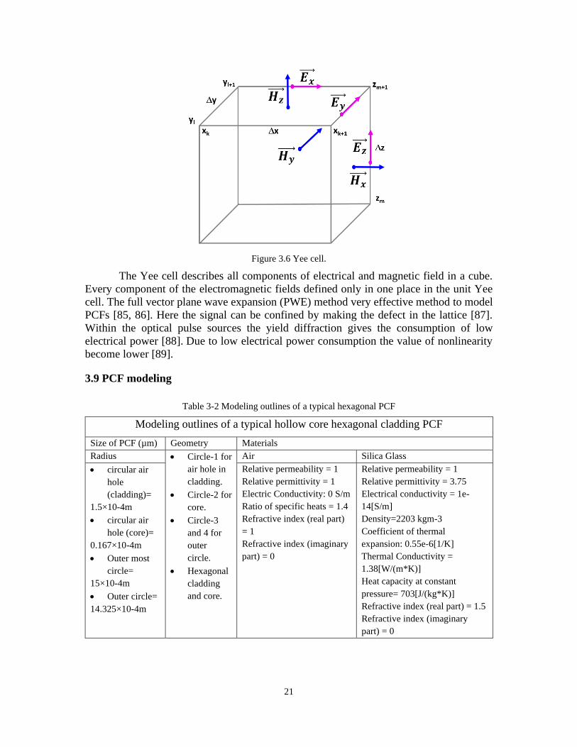
Figure 3.6 Yee cell.
The Yee cell describes all components of electrical and magnetic field in a cube.
Every component of the electromagnetic fields defined only in one place in the unit Yee
cell. The full vector plane wave expansion (PWE) method very effective method to model
PCFs [85, 86]. Here the signal can be confined by making the defect in the lattice [87].
Within the optical pulse sources the yield diffraction gives the consumption of low
electrical power [88]. Due to low electrical power consumption the value of nonlinearity
become lower [89].
3.9 PCF modeling
Table 3-2 Modeling outlines of a typical hexagonal PCF
Modeling outlines of a typical hollow core hexagonal cladding PCF
Size of PCF (µm) Geometry Materials
Radius • Circle-1 for
air hole in
cladding.
• Circle-2 for
core.
• Circle-3
and 4 for
outer
circle.
• Hexagonal
cladding
and core.
Air Silica Glass
• circular air
hole
(cladding)=
1.5×10⁻⁴m
• circular air
hole (core)=
0.167×10⁻⁴m
• Outer most
circle=
15×10-4m
• Outer circle=
14.325×10⁻⁴m
Relative permeability = 1
Relative permittivity = 1
Electric Conductivity: 0 S/m
Ratio of specific heats = 1.4
Refractive index (real part)
= 1
Refractive index (imaginary
part) = 0
Relative permeability = 1
Relative permittivity = 3.75
Electrical conductivity = 1e-
14[S/m]
Density=2203 kgm-3
Coefficient of thermal
expansion: 0.55e-6[1/K]
Thermal Conductivity =
1.38[W/(m*K)]
Heat capacity at constant
pressure= 703[J/(kg*K)]
Refractive index (real part) = 1.5
Refractive index (imaginary
part) = 0

22
The background material is typically silica glass (undoped) having high refractive
index while the low refractive index region is usually provided by air holes. The Table 3-
2 shows the Modeling outlines of a typical hollow core hexagonal cladding PCF. The
Figure 3.7 shows structure of a typical hollow core hexagonal core PCF with circular air
hole only. The design has done with the help of COMSOL Multiphysics 5.3a. Where the
desired modeling input parameter has shown in Table 3-2. Here, the desired parameters
have selected from global definitions. The geometry from component block is square in
circular solid core with circular air hole in cladding. The air hole (cladding) radius, r is 150
µm, outer most radius is 0.0015 µm, outer circle radius is 0.0014 µm. Circular core having
radius 0.0000167 µm. Types of air hole in cladding is circular only. Then select the
materials from component block as air and silica glass. The properties of air and silica glass
is shown in Table 3-2. The electromagnetic waves, frequency domain conditions from
component block would be selected as desired. Here the boundary has mentioned if
required. Then the mesh is selected as user defined as finer. Then perform the mode
analysis from study block. Select the mode analysis frequency is 193.4 THz or 1.55 µm.
Figure 3.7 A fabricated hollow-core Hexagonal cladding PCF.
The Table 3-3 shows the Modeling outlines of a Modeling outlines of a Triangular
lattice PCF as follows.
Air hole
radius, r is
150 µm

23
Table 3-3 Modeling outlines of a Triangular lattice PCF
Modeling outlines of a Triangular lattice PCF
Size of PCF (µm) Geometry Materials
Radius • Circle-1 for
air hole in
cladding.
Air Silica Glass
• circular air
hole=
1.5×10⁻⁴m
Relative permeability = 1
Relative permittivity = 1
Electric Conductivity: 0 S/m
Ratio of specific heats = 1.4
Refractive index (real part)
= 1
Refractive index (imaginary
part) = 0
Relative permeability = 1
Relative permittivity = 3.75
Electrical conductivity = 1e-
14[S/m]
Density=2203 kgm-3
Coefficient of thermal
expansion: 0.55e-6[1/K]
Thermal Conductivity =
1.38[W/(m*K)]
Heat capacity at constant
pressure= 703[J/(kg*K)]
Refractive index (real part) = 1.5
Refractive index (imaginary
part) = 0
The Figure 3.8 shows structure of a typical Triangular lattice PCF design of size air
hole is 1.5×10⁻⁴m with circular air hole only.
Figure 3.8 Triangular lattice photonic crystal fibre.
The design has done with the help of COMSOL Multiphysics 5.3a. Where the
desired modeling input parameter has shown in Table 3-3. Firstly the desired parameters
have selected from global definitions. The geometry from component block is triangular

24
with circular air hole in cladding. The air hole (cladding) radius, r is 150 µm, Types of air
hole in cladding is circular only. The number of air hole in cladding are 15. Then select the
materials from component block as air and silica glass. The properties of air and silica glass
is shown in Table 3-3. The electromagnetic waves, frequency domain conditions from
component block would be selected as desired. Here the boundary has mentioned if
required. Then the mesh is selected as user defined as finer. Then perform the mode
analysis from study block. Select the mode analysis frequency is 193.4 THz or 1.55 µm.
Table 3-4 Parameters of elliptical PCF hexagonal core with circular air hole only.
Modeling outlines of a typical elliptical shape hexagonal core PCF with circular air hole only
Size of PCF
(µm)
Geometry Materials No. of
cladding
layer
Types of
air hole
in
cladding
No. of
air holes
in
claddin
g
• Air hole
(cladding)
Radius=
150 µm
• Outer shape
square size
300×300 µm
• Elliptical
core:
a-semi
axis=1050 µm
b-semi axis=850
µm
• Circle for
air hole in
cladding.
• Elliptical
solid core
Air Silica Glass 3 Circular
only
155
Relative
permeability = 1
Relative
permittivity = 1
Electric
Conductivity: 0
S/m
Ratio of specific
heats = 1.4
Refractive index
(real part) = 1
Refractive index
(imaginary part)
= 0
Relative
permeability = 1
Relative
permittivity = 3.75
Electrical
conductivity = 1e-
14[S/m]
Density=2203
kgm-3
Coefficient of
thermal expansion:
0.55e-6[1/K]
Thermal
Conductivity =
1.38[W/(m*K)]
Heat capacity at
constant pressure=
703[J/(kg*K)]
Refractive index
(real part) = 1.5
Refractive index
(imaginary part) =
0

25
The Table 3-4 shows the modeling outlines of a typical elliptical shape hexagonal
core PCF with circular air hole only as follows. The Figure 3.9 shows structure of a typical
elliptical shape with hexagonal core PCF with circular air hole only. The design has done
with the help of COMSOL Multiphysics 5.3a. Where the desired modeling input parameter
has shown in Table 3-4. Firstly, the desired parameters have selected from global
definitions. The geometry from component block is elliptical in hexagonal core with
circular air hole in cladding. The air hole (cladding) radius is 150 µm, elliptical shape
having a-semi axis=1050 µm, b-semi axis=850 µm. Types of air hole in cladding is circular
only. Then select the materials from component block as air and silica glass. The properties
of air and silica glass is shown in Table 3-4. The electromagnetic waves, frequency domain
conditions from component block would be selected as desired. Here the boundary has
mentioned if required. Then the mesh is selected as user defined as finer. Then perform the
mode analysis from study block. Select the mode analysis frequency is 193.4 THz or 1.55
µm.
Figure 3.9 A typical elliptical PCF with hexagonal core.
The Table 3-5 shows the modeling outlines of a typical square core PCF with circular air
hole only as follows.

26
Table 3-5 Parameters of a typical square core PCF with circular air hole only.
Modeling outlines of a typical square core PCF with circular air hole only
Size of PCF
(µm)
Geometry Materials No. of
core
layer
Types of
air hole in
core
No. of air
holes in
core
Air hole
(cladding)
Radius=
150 µm
Outer shape
square size
300×300 µm
square solid
core:
size 100×100
µm
Circle for air
hole in
cladding.
Solid square
for core
Air Silica Glass 3 Circular
only
155
Relative
permeability =
1
Relative
permittivity = 1
Electric
Conductivity: 0
S/m
Ratio of
specific heats =
1.4
Refractive
index (real part)
= 1
Refractive
index
(imaginary part)
= 0
Relative permeability
= 1
Relative permittivity
= 3.75
Electrical
conductivity = 1e-
14[S/m]
Density=2203 kgm-3
Coefficient of thermal
expansion: 0.55e-
6[1/K]
Thermal Conductivity
= 1.38[W/(m*K)]
Heat capacity at
constant pressure=
703[J/(kg*K)]
Refractive index (real
part) = 1.5
Refractive index
(imaginary part) = 0
The Figure 3.10 shows structure of a typical square core PCF with circular air hole
only. The design has done with the help of COMSOL Multiphysics 5.3a. Where the desired
modeling input parameter has shown in Table 3-5. Firstly the desired parameters have
selected from global definitions. The geometry from component block is square in square
core with circular air hole in core. The air hole (core) radius is 150 µm, Outer shape square
size is 300×300 µm, square core having size of 100×100 µm. Consider the number of core
layer 3. Types of air hole in core is circular only. Number of air hole in core are 25. Then
select the materials from component block as air and silica glass. The properties of air and
silica glass is shown in Table 3-5. The electromagnetic waves, frequency domain
conditions from component block would be selected as desired. Here the boundary has
mentioned if required. Then the mesh is selected as user defined as finer. Then perform the

27
mode analysis from study block. Select the mode analysis frequency is 193.4 THz or 1.55
µm.
Figure 3.10 Modeling outlines of a typical square in square PCF with hollow core.
A low refractive index material is needed for cladding around the PCF core.
3.10 Conclusion
Photonic crystal fibres (PCFs) integrate the characteristics of photonic crystals
microstructure and conventional optical fibres. Development of PCFs is still very new age
topic and one may explore new research, more accurate and efficient methods for modeling
and designing. In this chapter, typical properties of PCFs are discussed. The evolution and
applications of PCFs are summarized. Design method and consideration for various PCF
structures are illustrated.

28
CHAPTER 4
DESIGN OF VARIOUS PCF STRUCTURES USING COMSOL
MULTIPHYSICS
4.1 Introduction
In this chapter, the design and modeling of various PCF lattice structures and
analyze their performance in compensating dispersion are presented when they are used in
optical communication system. The PCFs are designed and analyzed using COMSOL
Multiphysics software of version 5.3a.
4.2 Modeling Flowchart using COMSOL Multiphysics
In this work COMSOL Multiphysics is used for modeling purpose. Firstly select
the model wizards from the following space dimensions: 3D, 2D Axisymmetric, 2D, 1D
Axisymmetric, 1D, and 0D. Then select the desired physics. Then added the required study
from study block. Then insert the parameters from global definition unit. Add the condition
of components and hence the geometry of the structure. Then add the materials as needed.
Then perform the mesh generation. Select user defined physics control condition. Select
finer as physics quality. Then built the mesh. Then select the boundary condition from
Electromagnetic waves, frequency domain. If a boundary is unselected, then its color is
typically gray. But if selected then color will be blue. First select Electromagnetic waves,
frequency domain, then right click on it and select the boundary condition. Then select the
boundary as needed from boundary list like impedance boundary condition, scattering
boundary condition, transition boundary condition etc. Then perform study from study unit.
Select the boundary mode analysis for three dimensional physics or mode analysis for two
dimensional physics. Here the frequency range must be selected. Select the desired mode
number. Then compute the solution. Then observe the post processing, visualization and
results. The Figure 4.1 shows the modeling and working procedure of photonic crystal fibre
in a flowchart as follows:

29
Figure 4.1 COMSOL modeling Flowchart.
4.3 New Model Creation
One may select a model from Model Wizard or start directly from a Blank Model.
4.3.1 Using model wizard creation of a new model
From Model Wizard the space dimension, physics, and study process are selected
within some following steps:
Select the model wizard
Added the physics interfaces
Added the required study
Insert the parameters in detailed
Add the condition of components and hence the geometry of the structure
Add the materials
Mesh generation
Compute the solution
Post processing
Visualization and Results
Unsatisfactory

30
Step-1. Select one from the following space dimensions: 3D, 2D Axisymmetric, 2D, 1D
Axisymmetric, 1D, 0D see Figure 4.2.
Figure 4.2 Space dimension selection.
Step-2: Select one or more physics from organized Physics block see the Figure 4.3.
Figure 4.3 Physics Selection.
Step-2: Select the Study from study block. Therefore, click on done. The desktop is now
shown with a blank model.

31
Figure 4.4 Study selection.
4.3.2 Using Blank Model creation of a new model
One can create a blank model without following previous steps. Just open
COMSOL Multiphysics 5.3a. Then only select the Blank Model.
Figure 4.5 Creating a new model using Blank Model.
4.4 Parameters, Variables, and scope.
4.4.1 Global Definition
The parameters on Global Definition block are defined by user. Where the user can
put the name, expression and value of the parameters.

32
4.4.2 Geometry Unit
Set the cursor on geometry and right click on mouse and select the necessary
geometrical structure. Select the type of object sizes and shapes are also be defined easily
in this block.
Figure 4.6 Select the geometry.
Location of user file path:
The file path for windows operating system is:
C:\Program Files\COMSOL\COMSOL5.3a\Multiphysics\applications.
Its location by default in Windows operating system is:
C:\ProgramFiles\COMSOL\COMSOL5.3\Multiphysics\applications\COMSOL_Multiph
ysics\ Structural Mechanics\wrench.mph\bin.
4.4.3 Selection of materials
Select the materials from materials library which are appeared in component block
or node. That is shown in Figure 4.7

33
Figure 4.7 Materials selection.
Select the add materials block. The materials can be added window in two steps:
Step-1: From the ribbon, select the Home tab and then click add material.
Step-2: Right-click on Comp. 1 > Materials in the model builder and select add material
4.5 Boundary Selection with other geometric conditions
From the electromagnetic waves, frequency domain boundary can be selected. If a
boundary is unselected, then its color is typically gray. But if selected then color will be
blue. First select electromagnetic waves, frequency domain, then right click on it and select
the boundary condition. That is shown in Figure 4.7.
4.5.1 Performing the mesh condition
Mesh is selected to mention the element size and sequence type. That is shown in
Figure 4.8.

34
Figure 4.8 Mesh Analysis.
4.5.2 Performing the study condition
This is the final stage. Here mode frequency, mode number etc are selected to
analyze the desired structures. That is shown in Figure 4.9.
Figure 4.9 Preform the study.
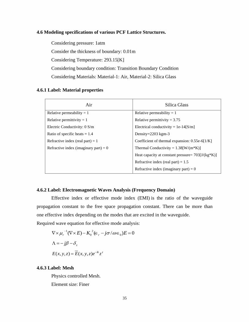
35
4.6 Modeling specifications of various PCF Lattice Structures.
Considering pressure: 1atm
Consider the thickness of boundary: 0.01m
Considering Temperature: 293.15[K]
Considering boundary condition: Transition Boundary Condition
Considering Materials: Material-1: Air, Material-2: Silica Glass
4.6.1 Label: Material properties
4.6.2 Label: Electromagnetic Waves Analysis (Frequency Domain)
Effective index or effective mode index (EMI) is the ratio of the waveguide
propagation constant to the free space propagation constant. There can be more than
one effective index depending on the modes that are excited in the waveguide.
Required wave equation for effective mode analysis:
0)/()( 0
2
0
1=−−
−EjKE rr
zj −−=
zik zezyxEzyxE −= ),,(),,(
4.6.3 Label: Mesh
Physics controlled Mesh.
Element size: Finer
Air Silica Glass
Relative permeability = 1
Relative permittivity = 1
Electric Conductivity: 0 S/m
Ratio of specific heats = 1.4
Refractive index (real part) = 1
Refractive index (imaginary part) = 0
Relative permeability = 1
Relative permittivity = 3.75
Electrical conductivity = 1e-14[S/m]
Density=2203 kgm-3
Coefficient of thermal expansion: 0.55e-6[1/K]
Thermal Conductivity = 1.38[W/(m*K)]
Heat capacity at constant pressure= 703[J/(kg*K)]
Refractive index (real part) = 1.5
Refractive index (imaginary part) = 0

36
4.6.4 Label: Mode Analysis
Mode Analysis Frequency: 193 GHz
Mode search method: Manual
Desired Number Modes: 5
4.6.5 Label: Eigenvalue Solver
Relative solver: 1E-6
Eigenvalue Transformation: Effective mode index
Desired number Eigenvalues: 6
4.6.6 Mode analysis solver
PARDISO Solver which having thread-safe, high-performance, robust, memory
efficient and easy to use software for solving large sparse symmetric and asymmetric linear
systems of equations with electromagnetic propagation on shared-memory and distributed-
memory multiprocessors.
4.7 Electromagnetic mode analysis of various PCF structures
The Figure 4.10 shows structure of a typical circular core PCF with circular air hole
only. The design has done with the help of COMSOL Multiphysics 5.3a. Firstly the desired
parameters have selected from global definitions. The geometry from component block is
square in circular solid core with circular air hole in cladding. The air hole (cladding)
radius, r is 150 µm, circular core having radius r/1.5 µm. Then select the materials from
component block as air and silica glass. The electromagnetic waves, frequency domain
conditions from component block would be selected as desired. Here the boundary has
mentioned if required. Then the mesh is selected as user defined as finer. Then perform the
mode analysis from study block and number of mode is 5. Select the mode analysis
frequency is 193.4 THz or 1.55 µm.

37
Figure 4.10 Effective mode index of Circular PCF.
The Figure 4.11 shows structure of a typical Elliptical core PCF with circular air
hole only. The design has done with the help of COMSOL Multiphysics 5.3a. Firstly the
desired parameters have selected from global definitions. The geometry from component
block is square in elliptical solid core with circular air hole in cladding. The air hole
(cladding) radius is 150 µm, elliptical core having a-semi axis=105 µm b-semi axis=85
µm. Then select the materials from component block as air and silica glass. The
electromagnetic waves, frequency domain conditions from component block would be
selected as desired. Here the boundary has mentioned if required. Then the mesh is selected
as user defined as finer. Then perform the mode analysis from study block and number of
mode is 5. Select the mode analysis frequency is 193.4 THz or 1.55 µm.

38
Figure 4.11 Effective mode index of Elliptical PCF.
The Figure 4.12 shows structure of a typical square core PCF with circular air hole
only. The design has done with the help of COMSOL Multiphysics 5.3a. Firstly the desired
parameters have selected from global definitions. The geometry from component block is
square in square solid core with circular air hole in cladding. The air hole (cladding) radius
is 150 µm, square core having size of 100×100 µm. Then select the materials from
component block as air and silica glass. The electromagnetic waves, frequency domain
conditions from component block would be selected as desired. Here the boundary has
mentioned if required. Then the mesh is selected as user defined as finer. Then perform the
mode analysis from study block and number of mode is 5. Select the mode analysis
frequency is 193.4 THz or 1.55 µm.

39
Figure 4.12 Effective mode index of SLPCF.
The Table 4-1 shows the electromagnetic mode analysis or light propagation of
various PCF lattice structures without central mode.
Table 4-1 Electromagnetic mode analysis (multimode analysis) of various PCFs.
PCF Lattice Effective Mode Index
Circular 0.7894
Elliptical 0.84301
SLPCF 0.89832
PCFs [91, 92] shows a robust variety of possible geometries in shape, size, and
micro structured cladding. Obtaining very high negative values of dispersion is the target
in future [93, 105]. In this work to obtain high negative dispersion value with regular square
lattice have studied rigorously. Square-lattice-based PCF is better over other PCF [98, 105].
Modified SLPCF provide smooth hole diameter and hole pitch and to achieve lower
nonlinearity, low insertion loss, and lower dispersion [106, 107]. Modified Square-lattice
PCF shows wider range of single mode operation with the same value compared to the

40
others. The effective area of modified square-lattice PCF is higher than others. The Figure
4.13 shows the cross section of a typical PCF.
Figure 4.13 Cross section of proposed SLPCF.
Now a days, a SLPCF preform has a standard fabrication process, arranged and
design [108]. In another characteristic, the study of negative refraction has been studied
with modified SLPCF [109].
4.8 Characteristics of SLPCF
Multimode analysis (Multimode mode, 1550 nm – 193.4 THz).
Table 4-2 Materials properties required materials.
Air Silica Glass
Relative permeability = 1
Relative permittivity = 1
Electric Conductivity: 0 S/m
Ratio of specific heats = 1.4
Refractive index (real part) = 1
Refractive index (imaginary part) = 0
Relative permeability = 1
Relative permittivity = 3.75
Electrical conductivity = 1e-14[S/m]
Density=2203 kgm-3
Coefficient of thermal expansion: 0.55e-6[1/K]
Thermal Conductivity = 1.38[W/(m*K)]
Heat capacity at constant pressure= 703[J/(kg*K)]
Refractive index (real part) = 1.5
Refractive index (imaginary part) = 0

41
Figure 4.14 Circular shape PCF.
The Figure 4.14 light propagation of a typical circular core PCF with circular air
hole only. The design has done with the help of COMSOL Multiphysics 5.3a. Where the
desired modeling input parameter has shown in Table 4-2. Firstly the desired parameters
have selected from global definitions. The geometry from component block is square in
circular solid core with circular air hole in cladding. The air hole (cladding) radius, r is 150
µm, circular core having radius r/1.5 µm. Then select the materials from component block
as air and silica glass. The properties of air and silica glass is shown in Table 4-2. The
electromagnetic waves, frequency domain conditions from component block would be
selected as desired. Here the boundary has mentioned if required. Then the mesh is selected
as user defined as finer. Then perform the mode analysis from study block and number of
mode is 5. Select the mode analysis frequency is 193.4 THz or 1.55 µm.

42
Figure 4.15 Light Propagation through SLPCF.
The Figure 4.15 shows light propagation of a typical circular core PCF with circular
air hole only. The design has done with the help of COMSOL Multiphysics 5.3a. Where
the desired modeling input parameter has shown in Table 4-2.
Figure 4.16 Cross sectional view of light propagation through modified SLPCF.
Firstly, the desired parameters have selected from global definitions. The geometry
from component block is square in square solid core with circular air hole in cladding. The

43
air hole (cladding) radius is 150 µm, square core having size of 100×100 µm. Then select
the materials from component block as air and silica glass. The properties of air and silica
glass is shown in Table 4-2. The electromagnetic waves, frequency domain conditions from
component block would be selected as desired. Here the boundary has mentioned if
required. Then the mesh is selected as user defined as finer. Then perform the mode
analysis from study block and number of modes is 5. Select the mode analysis frequency
is 193.4 THz or 1.55 µm.
4.9 Electromagnetic mode analysis for various structure (single mode analysis) at
1550 nm or 193.4 THz
The Figure 4.17 is shown in below shows structure of a typical Elliptical core PCF
with circular air hole only. The design has done with the help of COMSOL Multiphysics
5.3a. Where the desired modeling input parameter has shown in Table 4-2. Firstly, the
desired parameters have selected from global definitions. The geometry from component
block is square in elliptical solid core with circular air hole in cladding. The air hole
(cladding) radius is 150 µm, elliptical core having a-semi axis=105 µm b-semi axis=85
µm. Then select the materials from component block as air and silica glass. The properties
of air and silica glass is shown in Table 4-2. The electromagnetic waves, frequency domain
conditions from component block would be selected as desired. Here the boundary has
mentioned if required. Then the mesh is selected as user defined as finer. Then perform the
mode analysis from study block and number of modes is 1. Select the mode analysis
frequency is 193.4 THz or 1.55 µm.

44
Figure 4.17 Light propagation through an elliptical core PCF.
The Figure 4.18 is shown in below shows the structure of a typical square core PCF
with circular air hole only. The design has done with the help of COMSOL Multiphysics
5.3a. Where the desired modeling input parameter has shown in Table 4-2. Firstly the
desired parameters have selected from global definitions. The geometry from component
block is square in square solid core with circular air hole in cladding. The air hole
(cladding) radius is 150 µm, square core having size of 100×100 µm. Then select the
materials from component block as air and silica glass. The properties of air and silica glass
is shown in Table 4-2. The electromagnetic waves, frequency domain conditions from
component block would be selected as desired. Here the boundary has mentioned if
required. Then the mesh is selected as user defined as finer. Then perform the mode
analysis from study block and number of mode is 1. Select the mode analysis frequency is
193.4 THz or 1.55 µm.

45
Figure 4.18 Light propagation inside square core PCF.
The Figure 4.19 shows structure of a typical circular core PCF with circular air hole
only. The design has done with the help of COMSOL Multiphysics 5.3a. Where the desired
modeling input parameter has shown in Table 4-2. Firstly the desired parameters have
selected from global definitions. The geometry from component block is square in circular
solid core with circular air hole in cladding. The air hole (cladding) radius, r is 150 µm,
circular core having radius r/1.5 µm. Then select the materials from component block as
air and silica glass. The properties of air and silica glass is shown in Table 4-2. The
electromagnetic waves, frequency domain conditions from component block would be
selected as desired. Here the boundary has mentioned if required. Then the mesh is selected
as user defined as finer. Then perform the mode analysis from study block and number of
mode is 1. Select the mode analysis frequency is 193.4 THz or 1.55 µm.

46
Figure 4.19 Light propagation inside circular core PCF.
By varying core diameter it is possible to shift zero dispersion wavelengths.
Dispersion can be calculated directly from effective mode index. In same modeling
condition SLPCF shows more effective mode index, which increase neff , a result of lower
dispersion, according to the following equation.
22 /][)/()( dnRdcD effe−=
Total Internal Reflection: When light pulse travels from one dense medium to
another dense it changes speed and is refracted. If the light rays are travelling for a less
dense material to a dense medium they are refracted towards the normal and if they are
travelling from a dense to less dense medium they are refracted away from the normal.
For total internal reflection to occur the light must travel from a dense medium to a less
dense medium (e.g. glass to air or water to air). As the angle of incidence increases so does
the angle of refraction. When the angle of incidence reaches a value known as the critical
angle the refracted rays travel along the surface of the medium or in other words are
refracted to an angle of 90°. The critical angle for the angle of incidence in glass is 42°.
The Figure 4.20 shows the Total Internal Reflection (TIR) within an optical fibre.
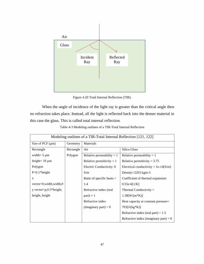
47
Figure 4.20 Total Internal Reflection (TIR).
When the angle of incidence of the light ray is greater than the critical angle then
no refraction takes place. Instead, all the light is reflected back into the denser material in
this case the glass. This is called total internal reflection.
Table 4-3 Modeling outlines of a TIR-Total Internal Reflection
Modeling outlines of a TIR-Total Internal Reflection [121, 122]
Size of PCF (µm) Geometry Materials
Rectangle
width= 5 µm
height= 10 µm
Polygon
P=0.1*height
x
vector=0,width,width,0
y vector=p,0.5*height,
height, height
Rectangle
Polygon
Air Silica Glass
Relative permeability = 1
Relative permittivity = 1
Electric Conductivity: 0
S/m
Ratio of specific heats =
1.4
Refractive index (real
part) = 1
Refractive index
(imaginary part) = 0
Relative permeability = 1
Relative permittivity = 3.75
Electrical conductivity = 1e-14[S/m]
Density=2203 kgm-3
Coefficient of thermal expansion:
0.55e-6[1/K]
Thermal Conductivity =
1.38[W/(m*K)]
Heat capacity at constant pressure=
703[J/(kg*K)]
Refractive index (real part) = 1.5
Refractive index (imaginary part) = 0
Air
Glass
Incident
Ray
Reflected
Ray

48
Figure 4.21 Total Internal Reflection inside SLPCF.
The Figure 4.21 shows the Total Internal Reflection in the SLPCF. The geometry
is selected as a reactangle and a polygon. The height and width of rectangle 5 µm and
10 µm respectively. The Polygon parameter, p is 0.1*height. The x vector parameter is
0, width, width, 0 and y vector parameter is p, 0.5*height, height, height. Here the
incident angle is greater than the critical angle. Where the desired modeling input
parameter has shown in Table 4-3.
4.10 Conclusion
Various types of PCF structures and determined various optical properties of the
modeled PCFs using COMSOL Multiphysics are modeled. Especially, the TIR of the
PCFs are evaluated and compared for assessing the capability of PCF to use in long-
haul optical communication system.

49
CHAPTER 5
ANALYSIS OF RESULTS OF MODIFIED SLPCF
5.1 Introduction
In this chapter, the proposed square lattice PCF or the modified SLPCF is modeled
with an aim to mitigate dispersion in long-haul optical communication system. The optical
properties of the proposed SLPCF are evaluated to confirm its dispersion minimization
ability over other PCF structures.
5.2 Modeling and analysis of various SLPCF structures
The Figure 5.1 shows structure of a typical Elliptical core PCF with circular air hole
only. The design has done with the help of COMSOL Multiphysics 5.3a. Where the desired
modeling input parameter has shown in Table 5-1.
5.2.1 Square lattice PCF with elliptical core
Figure 5.1 Model of a typical Elliptical core PCF with circular air hole only.
The optical parameters used for designing the elliptical core PCF is given in Table
5-1 below.

50
Table 5-1 Parameters of a typical Elliptical core PCF with circular air hole only.
Modeling outlines of a typical Elliptical core PCF with circular air hole only
Size of PCF
(µm)
Geometry Materials No. of
cladding
layer
Types of
air hole
in
cladding
No. of air
holes in
cladding
Air hole
(cladding)
Radius=
150 µm
Outer shape
square size
300×300 µm
Elliptical core:
a-semi axis=105
µm
b-semi axis=85
µm
Circle for air
hole in
cladding.
Elliptical solid
core
Air Silica Glass 3 Circular
only
155
Relative
permeability = 1
Relative
permittivity = 1
Electric
Conductivity: 0
S/m
Ratio of specific
heats = 1.4
Refractive index
(real part) = 1
Refractive index
(imaginary part)
= 0
Relative
permeability = 1
Relative
permittivity = 3.75
Electrical
conductivity = 1e-
14[S/m]
Density=2203
kgm-3
Coefficient of
thermal
expansion: 0.55e-
6[1/K]
Thermal
Conductivity =
1.38[W/(m*K)]
Heat capacity at
constant pressure=
703[J/(kg*K)]
Refractive index
(real part) = 1.5
Refractive index
(imaginary part) =
0
5.2.2 Circular core PCF with circular air hole
The Figure 5.2 shows structure of a typical circular core PCF with circular air hole
only.

51
Table 5-2 Modeling outlines of a typical circular core PCF.
Modeling outlines of a typical circular core PCF
Size of PCF
(µm)
Geometry Materials No. of
cladding
layer
Types of
air hole in
cladding
No. of
air
holes
in
claddi
ng
Air hole
(cladding)
Radius=
150 µm
Outer shape
square size
300×300 µm
circular solid
core:
Radius = r/1.5
µm
Circle for air
hole in
cladding.
Solid Circle for
core
Air Silica Glass 3 Circular
only
155
Relative
permeability = 1
Relative
permittivity = 1
Electric
Conductivity: 0
S/m
Ratio of specific
heats = 1.4
Refractive index
(real part) = 1
Refractive index
(imaginary part) =
0
Relative
permeability = 1
Relative
permittivity = 3.75
Electrical
conductivity = 1e-
14[S/m]
Density=2203
kgm-3
Coefficient of
thermal expansion:
0.55e-6[1/K]
Thermal
Conductivity =
1.38[W/(m*K)]
Heat capacity at
constant pressure=
703[J/(kg*K)]
Refractive index
(real part) = 1.5
Refractive index
(imaginary part) =
0
The design has done with the help of COMSOL Multiphysics 5.3a. Where the
desired modeling input parameter has shown in Table 5-2.

52
Figure 5.2 Model of a typical circular core PCF with circular air hole only.
The electromagnetic waves, frequency domain conditions from component block
would be selected as desired. Here the boundary has mentioned if required. Then the mesh
is selected as user defined as finer. Then perform the mode analysis from study block.
Select the mode analysis frequency is 193.4 THz or 1.55 µm.
5.2.3 Analysis of square core PCF
The desired modeling input parameter has shown in Table 5-3. In the design,, the
desired parameters have selected from global definitions. The geometry from component
block is square in square solid core with circular air hole in cladding. The air hole
(cladding) radius, r is 150 µm, Outer shape square size is 300×300 µm, square core having
size of 100×100 µm. Consider the number of cladding layer 3. Types of air hole in cladding
is circular only. Number of air hole in cladding are 155. Then select the materials from
component block as air and silica glass. The properties of air and silica glass is shown in
Table 5-3. The electromagnetic waves, frequency domain conditions from component
block would be selected as desired. Here the boundary has mentioned if required. Then the
mesh is selected as user defined as finer. Then perform the mode analysis from study block.
Select the mode analysis frequency is 193.4 THz or 1.55 µm.

53
Table 5-3 Parameters of a typical square core PCF with circular air hole only.
Modeling outlines of a typical square core PCF with circular air hole only
Size of PCF
(µm)
Geometry Materials No. of
cladding
layer
Types of
air hole in
cladding
No. of air
holes in
cladding
Air hole
(cladding)
Radius=
150 µm
Outer shape
square size
300×300 µm
square solid
core:
size 100×100
µm
Circle for air
hole in
cladding.
Solid square
for core
Air Silica Glass 3 Circular
only
155
Relative
permeability =
1
Relative
permittivity = 1
Electric
Conductivity: 0
S/m
Ratio of
specific heats =
1.4
Refractive
index (real part)
= 1
Refractive
index
(imaginary part)
= 0
Relative
permeability = 1
Relative
permittivity = 3.75
Electrical
conductivity = 1e-
14[S/m]
Density=2203
kgm-3
Coefficient of
thermal
expansion: 0.55e-
6[1/K]
Thermal
Conductivity =
1.38[W/(m*K)]
Heat capacity at
constant pressure=
703[J/(kg*K)]
Refractive index
(real part) = 1.5
Refractive index
(imaginary part) =
0
The Figure 5.3 shows structure of a typical square core PCF with circular air hole
only. The design has done with the help of COMSOL Multiphysics 5.3a.

54
Figure 5.3 Model of a typical square core PCF (SLPCF) with circular air hole only.
5.2.4 Square core PCF with circular and elliptical air hole
The Figure 5.4 shows structure of a typical square core PCF with circular and
elliptical air hole. The design has done with the help of COMSOL Multiphysics 5.3a.
Where the desired modeling input parameter has shown in Table 5-4. Firstly, the desired
parameters have selected from global definitions. The geometry from component block is
square in square solid core with circular air hole in cladding. The circular air hole
(cladding) radius is 150 µm, elliptical air hole (cladding) having a-semi axis=25 µm b-semi
axis=10 µm Outer shape square size is 300×300 µm, square core having size of 100×100
µm. Consider the number of cladding layer 3. Types of air hole in cladding is circular and
elliptical. Where the circular cladding has 2 layer and elliptical has 1 layer. Number of air
hole in cladding are 155. Where circular air holes are 130 and elliptical air hole is 25. Then
select the materials from component block as air and silica glass. The properties of air and
silica glass is shown in Table 5-4. The electromagnetic waves, frequency domain
conditions from component block would be selected as desired. Here the boundary has
mentioned if required. Then the mesh is selected as user defined as finer. Then perform the
mode analysis from study block. Select the mode analysis frequency is 193.4 THz or 1.55
µm.

55
Table 5-4 Parameters of a square core PCF with circular and elliptical air hole.
Modeling outlines of a typical square core PCF with circular and elliptical air hole
Size of PCF (µm) Geometry Materials No. of
cladding
layer
Types of
air hole
in
cladding
No.
of air
holes
in
claddi
ng
Air hole (cladding)
Radius=
150 µm
Elliptical cladding
a-semi axis=25 µm
b-semi axis=10 µm
Outer shape
square size 300×300
µm
square solid core:
size 100×100 µm
Circle for
air hole in
cladding
Elliptical
cladding.
Solid
square for
core
Air Silica Glass 3 Circular
(2 layer)
and
elliptical
(1 layer).
Circul
ar=13
0
Ellipti
cal=2
5
Total
=155
Relative
permeability = 1
Relative
permittivity = 1
Electric
Conductivity: 0
S/m
Ratio of specific
heats = 1.4
Refractive index
(real part) = 1
Refractive index
(imaginary part)
= 0
Relative permeability = 1
Relative permittivity =
3.75
Electrical conductivity =
1e-14[S/m]
Density=2203 kgm-3
Coefficient of thermal
expansion: 0.55e-6[1/K]
Thermal Conductivity =
1.38[W/(m*K)]
Heat capacity at constant
pressure= 703[J/(kg*K)]
Refractive index (real part)
= 1.5
Refractive index
(imaginary part) = 0

56
Figure 5.4 Modified SLPCF.
The Figure 5.4 shows the model of a typical square core PCF (Modified SLPCF)
with both circular elliptical air hole to analysis the compensation of dispersion property of
long-haul optical communication.
5.3 Effective mode analysis for various photonic crystal fibre (PCF)
In this work the proposed modeling shows the effective mode index for various
PCF for various required criteria described earlier in this chapter.
Figure 5.5 Effective mode index for circular core PCF with circular air hole only.

57
The Figure 5.5 shows the effective mode index for circular core PCF with circular
air hole only. Where the outer structure having the size of 300×300 µm. For circular core
PCF with circular air hole the effective mode index is shown by simulation is 0.98648.
Here the core size is 100×100 µm.
Figure 5.6 Effective mode index for elliptical core PCF with circular air hole only.
The Figure 5.6 shows the effective mode index for elliptical core PCF with circular
air hole only. Where the outer structure having the size of 300×300 µm. For elliptical core
PCF with circular air hole the effective mode index is shown by simulation is 0.92777.
Here the core size is a-semi axis is 25 µm and b-semi axis is 10 µm.
The Figure 5.7 shows the effective mode index (EMI) for square core PCF with
circular and elliptical air hole. Where the outer structure having the size of 300×300 µm.
For square core PCF with circular and elliptical air hole the effective mode index is shown
by simulation is 1.0003. Here the core size is 100×100 µm.

58
Figure 5.7 EMI for square core PCF with both circular and elliptical air hole.
The summarized values are shown in Figure 5.8 as follows.
Figure 5.8 Comparison of EMI for various PCFs.
5.4 Numerical Methods and Equations
The dispersion can be calculated or defined as the sum of wave-guide dispersions
and material dispersions (D = Dmaterial + Dwaveguide) [110]. The wave-guide dispersion in
PCFs can be easily controlled by modifying the air hole dimensions, numbers and center-
1 2 3
Series1 0.98648 0.92777 1.0003
0.98648
0.92777
1.0003
Effe
ctiv
e m
od
e in
de
x
1. Circular 2. Elliptical 3. Modified SLPCF
Effective mode analysis for various PCFs

59
to-center pitch [110]. In such configuration, the output waveform is distorted because of
noise, non-linear effects and dispersion. Dispersion D can be obtained using the following
relation [111]:
22 /][)/()( dnRdcD effe−= ……………………………………………....Equation (1)
Where, the effective refractive index (neff) is the measure of optical intensity
distribution.
For a photonic crystal fibre, the effective area is defined as the area where the light
is confined in a fibre. It can measure the spreading field within the cladding. Effective area
is expressed as,
= dxdyEdxdyEAeff
4
2
22
1 /)( ....................………………………………….Equation (2)
Where, E1 is the electric field amplitude in the medium. In photonic crystal fibre,
the effective area, Aeff combines the region of core and the region of a small portion of areas
in the cladding [112].
Wavelength is related with nonlinear coefficient as [90],
)/()2( 2 effAn = ....……………………………………………. …….Equation (3)
Where, n2 = 1.45 refractive index of silica glass. Because third order susceptibility
(χ(3)) the effect nonlinearity creates. If Aeff is increased then, nonlinearity (γ) will be
decreased according to equation (3).
If EMI is increased then Aeff will be increased according to equation (2). It is known
that, if Effective Mode Index (EMI) is increased as a result the measure of optical intensity
distribution i.e. neff is also be increased, therefore according to equation (1) dispersion D
(λ) will be will be decreased.
The Quality-factor (Q-factor) represents optical signal to noise ratio of a RoF link
when binary signals are transmitted. The Q-factor of a RoF link can be determined using
the following expression [113]:
)()( 0101 +−=Q ..………………… …………………….……………Equation (4)
Here, μ0 and σ0 refer to the mean and standard deviation, respectively, for the
Gaussian pulse, S0. Similarly, μ1 and σ1 refer to the mean and standard deviation,
respectively, for the Gaussian pulse, S1.

60
When two signals S0 and S1 with probability density functions (pdf) Pso and Ps1,
respectively, are transferred through a RoF link, the overlapping region between the pdf
represents the BER for S0 and S1, as shown in Figure 5.9 below.
Figure 5.9 BER characteristics.
The Figure 5.9 [114] shows the overlapping region between the probability density
function Pso and Ps1 of two symbols S0 and S1 represents the BER. In optical
communication, BER is generally defined as the ratio of total number of bits received in
error to the total number of bits transmitted through the transmission link and is given in
equation 5 [113]:
BER = Total bit received error Total bit transmitted………...……………Equation (5)
The Q factor and BER are related having a single valued function. Relation between
Q-factor and BER is given as follows [115]:
)2exp()2/1( 12 −−= QQBER ..………………………………...……...….....Equation (6)
If the relative permeability μr is increased for optoelectronic applications, then Q-
factor will be increased according to equation (5).
If Q-factor increased, then BER will be decreased according to equation (6).
5.5 Result of simulation of modification with respect to other PCFs
It is known that if the effective mode index (EMI) is increased then the value of
effective refractive index is increased and vice-versa. The simulation result shows that the

61
effective mode index (EMI) of modified SLPCF is noticeably higher than that of other
PCFs like circular photonic crystal fibre, elliptical photonic crystal fibre.
The Figure 5.10 shows that the dispersion properties for various PCF structures.
According to known method the effective refractive index is increased with the increased
of effective mode index (EMI). The dispersion for SLPCF is 30.76 [2], circular photonic
crystal fibre is -0.5E-14, elliptical photonic crystal fibre is -0.47E-14 and modified SLPCF
is -0.90E-14.
Figure 5.10 Dispersion of various PCF structures.
Due to the modification of core lattice it is found that the effective mode index
(EMI) of modified SLPCF is higher than that of other PCFs like circular photonic crystal
fibre, elliptical photonic crystal fibre. Therefore, according to the following equation the
value of dispersion is negatively increased that is dispersion is decreased.
22 /][)/()( dnRdcD effe−=
The summarized dispersion of various PCFs structures are shown in Figure 5.11.
PCF-Square
PCF-Elliptical
PCF-Circular
Modified SLPCF

62
Figure 5.11 Dispersion of various PCFs structures
The Figure 5.12 shows that the effective area properties for various PCF
structures.
Figure 5.12 Effective Area of various PCF structures
When Effective Mode Index (EMI) is increased then Aeff is also increased according
to the following equation.
= dxdyEdxdyEAeff
4
2
22
1 /)(
-5
0
5
10
15
20
25
30
35
1 2 3 4
Series1 30.76 -5.00E-15 -4.70E-15 -9.00E-15
30.76
-5.00E-15-4.70E-15
-9.00E-15
Dis
per
sio
n (
ps/
nm
/km
)
1. SLPCF 2. Circular 3. Elliptical 4. Modified SLPCF
Dispersion of various PCFs structures

63
The calculated value of the effective area from the designed structures for SLPCF
is 40000 µm2, circular photonic crystal fibre is 31416 µm2, elliptical photonic crystal fibre
is 280338 µm2 and modified SLPCF is 40785.4 µm2. Therefore, according to equation 2 it
is analyzed that the effective area of proposed modified SLPCF is higher than that of other
PCFs like circular photonic crystal fibre, elliptical photonic crystal fibre or ordinary
SLPCF. The summarized effective area of various PCF structures is shown in Figure 5.13
as follows.
Figure 5.13 Summarized effective Area of various PCF structures
The Figure 5.14 shows the nonlinearity properties for various PCF structures. It is
known that if effective area, Aeff is increased then, nonlinearity (γ) will be decreased
according to the following equation.
)/()2( 2 effAn =
Considering the value of refractive index of silica glass, n2 is 1.45. Wavelength is
1.55 µm. Then according to known method, the designed various structures show the
different values of nonlinearity. The nonlinearity of SLPCF is 1.47×10¹⁴ W
-1km-1, circular
photonic crystal fibre is 1.87×10¹⁴ W
-1km-1, elliptical photonic crystal fibre is 2.1×10¹⁴
W-
1km-1 and modified SLPCF is 1.40×10¹⁴
W-1km
-1.
1 2 3 4
Series1 40000 31416 28038 40785.4
40000
3141628038
40785.4
Effe
ctiv
e A
rea
of
PC
Fs (
µm
2)
1. SLPCF 2. Circular 3. Elliptical 4. Modified SLPCF
Effective Area of various PCF structures

64
Figure 5.14 Nonlinearity, γ of various PCF structures.
From the modification it is found that the nonlinearity of modified SLPCF is much
lower than that of other PCFs like circular photonic crystal fibre, elliptical photonic crystal
fibre or ordinary SLPCF. The summarized nonlinearity, γ of various PCFs structures are
shown in Figure 5.15 as follows.
Figure 5.15 Summarized nonlinearity, γ of various PCF structures
1 2 3 4
Series1 1.47E+14 1.87E+14 2.10E+14 1.40E+14
1.47E+14
1.87E+142.10E+14
1.40E+14
No
nlin
ear
ity,
γ [
W-1
km-1
]
1. SLPCF 2. Circular 3. Elliptical 4. Modified SLPCF
Nonlinearity of various PCF structures
PCF-Square
PCF-
Elliptical
PCF-Circular
Modified SLPCF
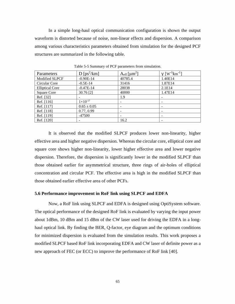
65
In a simple long-haul optical communication configuration is shown the output
waveform is distorted because of noise, non-linear effects and dispersion. A comparison
among various characteristics parameters obtained from simulation for the designed PCF
structures are summarized in the following table.
Table 5-5 Summary of PCF parameters from simulation.
Parameters D [ps2/km] Aeff [μm2] γ [W-1km
-1] Modified SLPCF -0.90E-14 40785.4 1.40E14
Circular Core -0.5E-14 31416 1.87E14
Elliptical Core -0.47E-14 28038 2.1E14
Square Core 30.76 [2] 40000 1.47E14
Ref. [32] - 1.9 -
Ref. [116] 1×10-17 - -
Ref. [117] 0.65 ± 0.05 - -
Ref. [118] 0.77, 0.99 - -
Ref. [119] -47500 - -
Ref. [120] - 16.2 -
It is observed that the modified SLPCF produces lower non-linearity, higher
effective area and higher negative dispersion. Whereas the circular core, elliptical core and
square core shows higher non-linearity, lower higher effective area and lower negative
dispersion. Therefore, the dispersion is significantly lower in the modified SLPCF than
those obtained earlier for asymmetrical structure, three rings of air-holes of elliptical
concentration and circular PCF. The effective area is high in the modified SLPCF than
those obtained earlier effective area of other PCFs.
5.6 Performance improvement in RoF link using SLPCF and EDFA
Now, a RoF link using SLPCF and EDFA is designed using OptiSystem software.
The optical performance of the designed RoF link is evaluated by varying the input power
about 1dBm, 10 dBm and 15 dBm of the CW laser used for driving the EDFA in a long-
haul optical link. By finding the BER, Q-factor, eye diagram and the optimum conditions
for minimized dispersion is evaluated from the simulation results. This work proposes a
modified SLPCF based RoF link incorporating EDFA and CW laser of definite power as a
new approach of FEC (or ECC) to improve the performance of RoF link [40].

66
5.8 Flow chart for RoF link design
A modified SLPCF Radio-over-fibre (RoF) link incorporating EDFA and CW laser
of definite power is proposed as a new approach of forward error correction (FEC). In
particular, the RoF model operates with CW laser driven at 1 dBm, 10 dBm and 15 dBm
input powers. The model is simulated considering 1010-bit sequence and the results are
compared with those using conventional SMF and previously described SLPCF
configuration.
Figure 5.16 Flow chart of the RoF link analysis.
It is observed that the proposed RoF link produces reduced dispersion and BER,
sharper eye diagram and both the improved Q-factor and eye height. Thus, the performance
of the RoF link using modified SLPCF incorporating EDFA and CW laser definite power
Mode analysis of square,
circular and elliptical
PCFs
Design of RoF link using
modified SLPCF and EDFA
(OptiSystem)
Assessment and
comparison with others
work
Optimized RoF link
Satisfactory
Modification of
Design
Unsatisfactory
Design and analysis of
square lattice PCF or
modified SLPCF
Analysis of Q-Factor,
BER and Eye
Diagram of RoF link

67
is noticeably improved, therefore, the model can be useful for cost-effective RoF link
design.
5.9 Design and analysis of RoF link using OptiSystem
The proposed model comprises user defined bit sequence generator, NRZ Pulse
generator, Mach-Zehnder as modulation technique, CW Laser, EDFA, a low pass Bessel
filter, BER analyzer, photodetector, SLPCF, optical spectrum analyzer (OSA), optical
power meter and a 50 km fibre link. A 50 km fibre link is discussed here; however, the
proposed model can be applicable for long-haul optical communication. The CW laser was
driven at optical input powers of 1dBm, 10 dBm and 15 dBm. The EDFA is used as a fibre
amplifier and its amplification window concurs with the third transmission window of
SLPCF. A complementary filter, namely, the Gaussian optical filter is used for arbitrary
pulse shape and filtering.
The modified SLPCF RoF link is simulated with Non-Return to Zero-bit sequence
1010 and initialized at 10 Gbps data sending rate and the simulated outputs are analyzed
for performance evaluation. From the BER analyzer, the Quality factor, BER pattern,
minimum BER, eye height is observed and from the OSA, the wave shapes of input power,
output power and noise are viewed. In addition, optical power meter gives the magnitude
of input and output powers, noise power, total power, signal power, sampled signal power
and parameterized signal power. The BER is varied based on the following components:
EDFA parameters, input power to the CW laser and the modulation technique. The Figure
5.18 shows flowchart for proposed RoF link using OptiSystem.
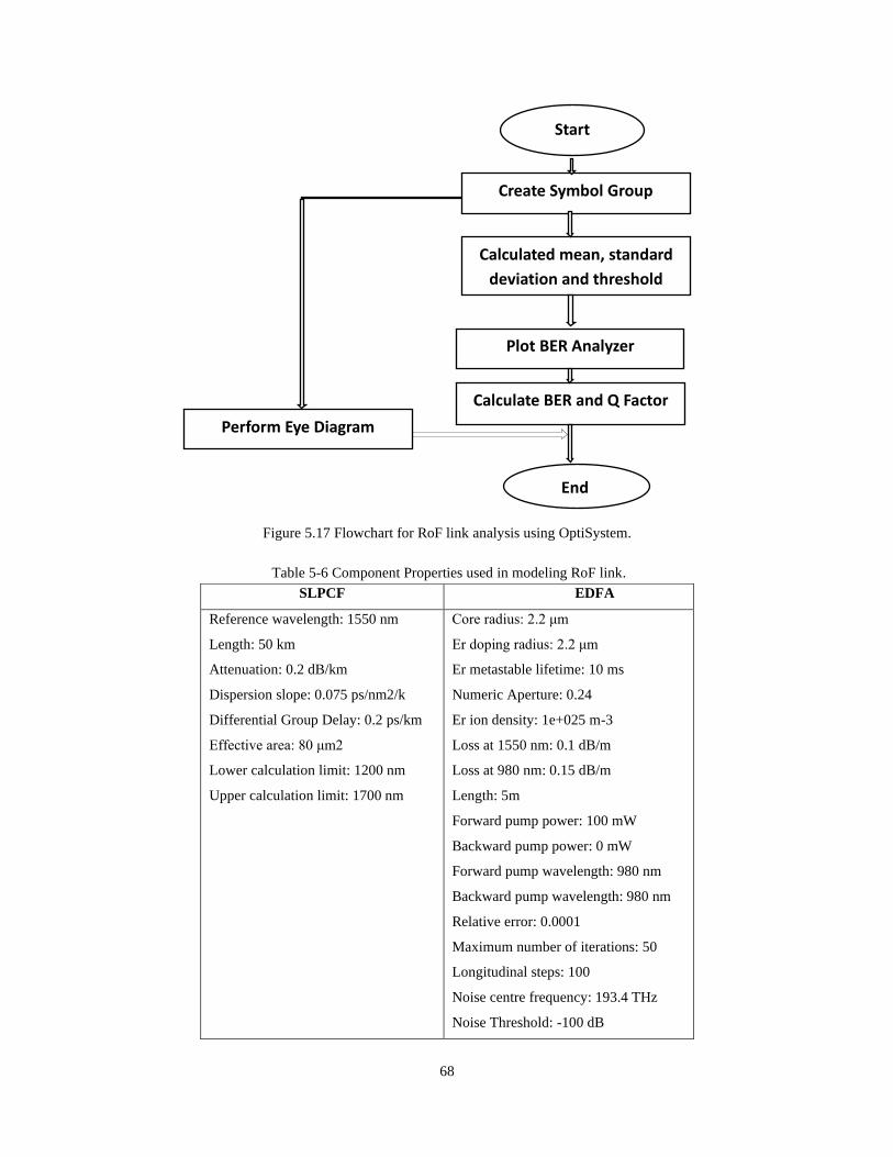
68
Figure 5.17 Flowchart for RoF link analysis using OptiSystem.
Table 5-6 Component Properties used in modeling RoF link.
SLPCF EDFA
Reference wavelength: 1550 nm
Length: 50 km
Attenuation: 0.2 dB/km
Dispersion slope: 0.075 ps/nm2/k
Differential Group Delay: 0.2 ps/km
Effective area: 80 μm2
Lower calculation limit: 1200 nm
Upper calculation limit: 1700 nm
Core radius: 2.2 μm
Er doping radius: 2.2 μm
Er metastable lifetime: 10 ms
Numeric Aperture: 0.24
Er ion density: 1e+025 m-3
Loss at 1550 nm: 0.1 dB/m
Loss at 980 nm: 0.15 dB/m
Length: 5m
Forward pump power: 100 mW
Backward pump power: 0 mW
Forward pump wavelength: 980 nm
Backward pump wavelength: 980 nm
Relative error: 0.0001
Maximum number of iterations: 50
Longitudinal steps: 100
Noise centre frequency: 193.4 THz
Noise Threshold: -100 dB
Start
Create Symbol Group
Calculated mean, standard
deviation and threshold
level
Plot BER Analyzer
Calculate BER and Q Factor
Perform Eye Diagram
End

69
The model of the modified SLPCF based RoF link incorporating EDFA and CW
laser of definite power is presented in Figure 5.19.
Figure 5.18 Proposed Model for improved RoF link.
In Figure 5.19 BER analyzer have three input terminals. Where one input is
connected to bit sequence generator (provides transmitted bit sequence), one input is
connected to low pass bessel filter (provide the received bit sequence), another input is
connected to NRZ pulse generator (allows users to create a sequence of non-return to zero
pulses that are coded by a digital signal input which makes the process continuous). As it
is known that BER analyzer calculates the transmitted bit sequence to the received bit
sequence and calculates the number of errors. BER is generally defined as the ratio of total
number of bits received in error to the total number of bits transmitted through the
transmission link.
5.10 Performance evaluation of RoF link
The configuration of a conventional SMF based RoF link is presented in Figure 5.19
and the simulated outputs for BER, Q-factor and eye-diagram can be understood from
Figure 5.20-5.28.

70
Figure 5.19 Simulation model using conventional SMF.
Here, Pseudo-Random Bit Sequence (PRBS) Generator: Sends the bit sequence to
the NRZ Pulse Generator. The user defined bit sequence generator can be used to generate
a bit sequence that is user defined. The transmitter is using a direct laser modulation scheme
the Photodetector PIN receives the optical signal attenuated by the Optical Attenuator
(OA), the Low Pass Bessel Filter filters the electrical signal. Optical Spectrum Analyzer
(OSA): Displays the modulated optical signal in the frequency domain.
Figure 5.20 Optical spectra at 1 dBm
The Figure 5.20 shows the power in digital format of the frequency domain
modulated optical signal for 1 dBm. At 1 dBm Optical Power Meter (OPM) shows the high
power loss and low active power as 39.708E-3W.

71
Figure 5.21 Optical spectra at 1dBm
The Figure 5.21 shows the frequency domain modulated optical signal for 1 dBm.
At 1 dBm Optical Spectrum Analyzer (OSA) shows the lower negative spectra than that of
at 1dBm at negative power in the range from-1dBm to -100dBm.
Figure 5.22 Optical spectra at 10 dBm
The Figure 5.22 shows the power in digital format of the frequency domain
modulated optical signal for 10 dBm. At 10 dBm Optical Power Meter (OPM) shows the
lower power loss than that of 1 dBm and medium level of active power as 48.009E-3W.

72
Figure 5.23 Optical spectra at 10dBm
The Figure 5.23 shows the frequency domain modulated optical signal for 10 dBm.
At 10 dBm Optical Spectrum Analyzer (OSA) shows the lower negative spectra than that
of at 1dBm at power in the range from less than 10 dBm to -98 dBm.
\
Figure 5.24 Optical spectra at 15 dBm
The Figure 5.24 shows the power in digital format of the frequency domain
modulated optical signal for 15 dBm. At 15 dBm Optical Power Meter (OPM) shows the
lower power loss than that of 1 dBm and 10 dBm and higher level of active power as
50.208E-3W.

73
Figure 5.25 Optical spectra at 15dBm
The Figure 5.25 shows the frequency domain modulated optical signal for 15 dBm.
At 15 dBm Optical Spectrum Analyzer (OSA) shows the lower negative spectra than that
of at 1dBm and 10 dBm at power in the range from 10 dBm to -93 dBm.
BER Analyzer: determine the BER of the system based on the signal propagation.
Double-click in an Analyzer show the result. The Mach-Zehnder Modulator is used for
signal modulation.

74
Figure 5.26 Q-factor for conventional SMF.
The Figure 5.26 shows the Q-factor for conventional SMF as 6.59497.
Figure 5.27 Eye pattern for conventional SMF.
The Figure 5.27 shows the eye diagram for conventional SMF as more noisy and
dispersed.

75
The Q-factor and BER pattern of the RoF link with previously used SLPCF, without
using EDFA and undefined input power of CW laser are shown in the following Figures:
Figure 5.28 Q- factor and BER pattern for previously used SLPCF.
The Figure 5.28 shows Q- factor and BER pattern for previously used SLPCF
without using EDFA and with undefined input power of CW laser.
Figure 5.29 Q-factor for 1dBm CW laser input power

76
The Figure 5.29 shows the Q-factor for 1dBm CW laser input power. The BER
pattern, Q-factor and eye diagram of the proposed RoF link for varied input powers to the
CW laser (1 dBm, 10 dBm and 15 dBm) are given in Figure 5.30-5.35.
Figure 5.30 Eye pattern for 1dBm CW laser input power.
The Figure 5.30 shows the Eye pattern for 1dBm CW laser input power.
Figure 5.31 Q-factor for 10dBm CW laser input power.
The Figure 5.31 shows the Q-factor for 10dBm CW laser input power.

77
Figure 5.32 Eye pattern for 10dBm CW laser input power.
The Figure 5.32 shows the Eye pattern for 10dBm CW laser input power.
Figure 5.33 Q- factor for 15dBm CW laser input power.
The Figure 5.33 shows the Q-factor for 15dBm CW laser input power. It is found
from Figure 5.33 and Figure 5.34 that the Q-factor of 40.7822, BER of tentatively 0 and

78
eye height of 8.29269×10⁻² are produced for the RoF link incorporating EDFA and CW
laser driven at 15 dBm input power.
Figure 5.34 Eye pattern for 15dBm CW laser input power.
The Figure 5.34 shows the Eye pattern for 15dBm CW laser input power. From the
simulation results, the Q-factor, BER pattern and eye height of the modified SLPCF
incorporating EDFA and CW driven at definite power are extracted and compared with
those observed for conventional SMF and previously used SLPCF-the results are
summarized in Table 5-7.
Table 5-7 Summary of performance of RoF link from simulation results.
Parameters Q-factor BER Eye Height
Conventional SMF 6.59497 2.12369×10⁻¹¹ 6.56285×10⁻⁵
Previously used SLPCF 6.7715 5.78501×10⁻¹² 3.99937×10⁻²
Proposed
Modified
SLPCF
For 1dBm 26.7827 2.18494×10-158 5.66037×10⁻²
For 10dBm 30.7237 1.07765×10-207 7.33338×10⁻²
For 15dBm 40.7822 0 (Approximately) 8.29269×10⁻²
Ref. [43] - 10-9 -
Ref. [44] - 2.13×10⁻² -
Ref. [113] - 3.9942x10⁻⁸ -
Ref. [116] - 1×10-17 -
It is found from Table 5-7 that when conventional SMF is used, the RoF link shows
a Q-factor of 6.59497, BER of 2.12369×10⁻¹¹ and eye height of 6.56285×10⁻⁵ (Figure 5.26-

79
5.27). Therefore, high BER causes the signal noisy in conventional SMF (Figure 5.27) and
the dispersion becomes high. Previously, coventional SMF was replaced by SLPCF to
reduce dispersion and BER. Therefore, the simulated RoF link using SLPCF (without
EDFA and definite input power CW laser) as shown in Figure 6.14, then the Q-factor of
6.7715, BER of 5.78501×10⁻¹² and eye height of 3.99937×10⁻² are found. When compared
with the conventional SMF, the Q-factor and eye height are not significantly improved
(although the eye diagram is found sharper) in the SLPCF than those obtained in the
conventional SMF. Therefore, SLPCF without definite input power to CW laser and without
EDFA does not accurately compensate dispersion and as a result, a small amount of noise
is associated with the BER pattern (Figure 5.35). To overcome this dilemma, a RoF link is
proposed using SLPCF incorporating EDFA and CW laser operated at 1 dBm, 10 dBm and
15 dBm input powers. The simulation results of the RoF link are summarized next.
For 1 dBm input power to CW laser:
It is observed that the Q-factor of 26.7827, BER of 2.18494×10-158 and eye height of
5.66037×10⁻² are achieved in the RoF link incorporating EDFA and CW laser driven at 1
dBm input power (Figure 5.29 and Figure 5.30). Therefore, the Q-factor and eye height are
improved than those obtained in previously used SLPCF and conventional SMF.
Furthermore, the BER becomes lower than those of previously used SLPCF and
conventional SMF.
For 10 dBm input power to CW laser and:
When the CW laser is driven at 10 dBm, the proposed RoF link produces Q-factor
of 30.7237, BER of 1.07765×10-207 and eye height of 7.33338×10⁻² (Figure 5.31 and Figure
5.32). Here, the Q-factor and eye height are increased and the BER is decreased compared
to those obtained for previously used SLPCF and conventional SMF, and also for 1dBm
input power to CW laser.
For 15 dBm input power to CW laser:
It is found from (Figure 5.33 and Figure 5.34). that the Q-factor of 40.7822, BER of
tentatively 0 and eye height of 8.29269×10⁻² are produced for the RoF link incorporating
EDFA and CW laser driven at 15 dBm input power. In this case, the Q-factor is improved
(as high as 40.7822 for 15 dBm to CW), which is higher than those obtained by using
conventional SMF (6.59497) and SLPCF (6.7715). Moreover, the Q-factor and eye height

80
are significantly increased than those for 1 dBm or 10 dBm input power. In addition, the
BER is found zero with a sharper eye diagram.
Therefore, the BER is significantly reduced (tentatively zero) in the modified RoF
link incorporating EDFA and CW laser than those obtained earlier: approximately 10-9 in
[43], 2.13×10⁻² in [44], 3.9942x10⁻⁸ for 8 levels PAM in [113] and 1×10-17 in [116].
Moreover, the eye diagram becomes sharper in this model compared with those presented
earlier [114]. Therefore, numerical results of the modified SLPCF have shown a
remarkable reduction in BER, enhancements in the Q-factor as well as compensation of
dispersion.
5.11 Conclusion
Various dispersion compensating PCFs lattice structures are investigated. The
design parameters are shown in different table as necessary. The total modeling has been
done using COMSOL Multiphysics 5.3a. The structures modeled here are square in
elliptical core with three layer circular air hole only, square in circular core with three layer
circular air hole only, square in square core with three layer circular air hole only and the
modification has done by inserting elliptical air hole as first layer within the cladding and
rest of the cladding layer was inserted as circular air hole. Then compute the structures
according to description from the chapter 4. RoF link with SLPCF incorporating EDFA
and CW laser of definite power has been proposed as a new approach of forward error
correction (FEC). The model has been simulated considering 1010-bit sequence using CW
laser driven at definite powers of 1 dBm, 10 dBm and 15 dBm. The simulation results show
that the BER and dispersion of the modified SLPCF RoF link are significantly reduced
compared to those obtained using conventional SMF and previously described SLPCF
configuration. In addition, the eye diagram is found sharper and both the Q-factor and eye
height are improved in the proposed link. Therefore, due to the improved RoF link
performance such as lower BER, reduced dispersion, enhanced Q-factor and improved eye
height, along with the advantageous attributes of SLPCF, the modified SLPCF with EDFA
and CW laser of definite power could be very beneficial for cost effective RoF optical
communication and related applications.

81
CHAPTER 6
CONCLUSION AND DISCUSSION
6.1 Conclusion
The effect of dispersion, nonlinearity, and others losses play an important role in
modeling the PCFs for the formation of an effective pulse compressor. The solution could
be a modified SLPCF, is designed and the performance of SLPCF on dispersion
compensation is evaluated over other PCFs of various lattice structures. The performance
of dispersion compensated long-haul optical communication system employing SLPCF
and EDFA is analyzed. RoF link is designed for improvement in dispersion, BER, Q-factor,
eye diagram using SLPCF incorporating EDFA.
A modified SLPCF RoF link incorporating EDFA and CW laser of definite power
has been proposed as a new approach of forward error correction (FEC). The model has
been simulated considering 1010-bit sequence using CW laser driven at definite powers of
1 dBm, 10 dBm and 15 dBm. The simulation results show that the BER and dispersion of
the modified SLPCF RoF link are significantly reduced compared to those obtained using
conventional SMF and previously described SLPCF configuration. In addition, the eye
diagram is found sharper and both the Q-factor and eye height are improved in the proposed
link. Therefore, due to the improved RoF link performance such as lower BER, reduced
dispersion, enhanced Q-factor and improved eye height, along with the advantageous
attributes of SLPCF, namely, negative dispersion and high birefringence, the modified
SLPCF with EDFA and CW laser of definite power could be very beneficial for cost
effective RoF optical communication and related applications like an effective pulse
compressor..
6.2 Scopes for future research
The proposed modified SLPCF model is notably unsophisticated than other
structures proposed so far for compensating the dispersion and at the same time higher
effective mode index characteristics have been obtained at 1.55 μm. Additionally our
proposed modified SLPCF model shows low confinement losses, which are novel
properties in lower dispersion design. The main conclusion of this systematic approach is

82
that with a modest number of design parameters including Square in square with circular
and elliptical air hole which could optimize the dispersion properties of the PCF. Our
architecture is suitable for applications as a dispersion controller, dispersion compensator,
pulse compressor etc. Hence, there is scope of improving other properties. Besides, the
fabrication of proposed fibre which is also a big challenge. Moreover, there are also some
sensitivity properties which have great impact. These effects could not find because of
constraints of time and resource. Those properties should also be taken under consideration
while designing a sensing application.
However, the modified model will have an impact on compensating the way to
design better RoF link communication. The attempt of modifying SLPCF as a dispersion
compensation module will have a contribution of introducing effective RoF link
communication with most favorable characteristics like higher Q-factor, lower BER,
sharper eye diagram etc. The proposed modified model can also be implemented in
optoelectronic devices like electronic displays in future.

83
REFERENCES
[1] A.M.R. Pinto and M.L. Amo, “Photonic Crystal Fibres for Sensing Applications”,
Journal of Sensors, Hindawi Publishing Corporation, pp. 21, 2012.
[2] S.V. Raja, A. Mahalingam, K. Senthilnathan and P.R. Babu, “Comparison of low
dispersion and high nonlinear PCF with different lattices: Triangular, square and
asymmetric,” Innovations in Power and Advanced Computing Technologies (i-
PACT), Vellore, pp. 1-4, 2017.
[3] NKT Photonics, “Hollow-core photonic bandgap fibres.pdf”, 2019.
[4] P. Zu, C.C. Chan, T. Gong, Y.Jin, W.C. Wong, and X. Dong, “Magneto-optical
fibre sensor based on bandgap effect of photonic crystal fibre infiltrated with
magnetic fluid”, Appl. Phys. Lett., vol. 101, pp. 241118, 2012.
[5] X. Sun, “Wavelength-selective coupling of dual-core photonic crystal fibre with a
hybrid light-guiding mechanism”, Opt. Lett., vol. 32, pp. 2484-2486, 2007.
[6] S. Guo, F. Wu, S. Albin, H. Tai, and R.S. Rogowski, “Loss and Dispersion Analysis
of Microstructured Fibres by Finite-Difference Method”, Optics Express, vol. 12,
pp. 3341-3352, 2004.
[7] K. Saitoh, M. Koshiba, T. Hasegawa and E. Sasaoka, “Chromatic Dispersion
Control in Photonic Crystal Fibres: Application to Ultra-Flattened Dispersion”,
Optics Express, vol. 11, pp. 843-852, 2003.
[8] K.P. Hansen, “Dispersion Flattened Hybrid-Core Nonlinear Photonic Crystal
Fibre”, Optics Express, vol. 11, pp. 1503-1509, 2003.
[9] M.J. Steel and R.M. Osgood, “Elliptical-Hole Photonic Crystal Fibres”, Optics
Letters, vol. 26, pp. 229-231, 2001.
[10] M.S. Habib, M.I. Hasan, S.M.A. Razzak, R.R. Mahmud and Y. Namihira,
“Microstructure Holey Fibres as Wideband Dispersion Compensating Media for
High Speed Transmission System”, Optik-International Journal for Light and
Electron Optics, vol. 124, pp. 4984-4988, 2013.
[11] K.R. Priya, A.S. Raja and D.S. Sundar, “Design of a Dual-Core Liquid-Filled
Photonic Crystal Fibre Coupler and Analysis of Its Optical Characteristics”,
Journal of Optical Technology, vol. 83, pp. 569-573, 2016.

84
[12] P.S.J. Russell, “Photonic-Crystal Fibres”, Journal of Lightwave Technology, vol.
24, pp. 4729-4749, 2006.
[13] S.E. Kim, B.H. Kim, C.G. Lee, S. Lee, K. Oh and C.S. Kee, “Elliptical Defected
Core Photonic Crystal Fibre with High Birefringence and Negative Flattened
Dispersion”, Optics Express, vol. 20, pp. 1385-1391, 2012.
[14] D. Chen, M.L.V. Tse and H.Y. Tam, “Optical Properties of Photonic Crystal Fibres
with a Fibre Core of Arrays of Subwavelength Circular Air Holes: Birefringence
and Dispersion”, Progress in Electromagnetics Research, vol. 105, pp. 193-212,
2010.
[15] K. Saitoh, N. Florous and M. Koshiba, “Ultra-Flattened Chromatic Dispersion
Controllability using a Defected-Core Photonic Crystal Fibre with Low
Confinement Losses”, Optics Express, vol. 13, pp. 8365-8371, 2005.
[16] T. Matsui, J. Zhou, K. Nakajima and I. Sankawa, “Dispersion-Flattened Photonic
Crystal Fibre with Large Effective Area and Low Confinement Loss”, Journal of
Lightwave Technology, vol. 23, pp. 4178-4183, 2005.
[17] K.W. Chung, S. Kim and S. Yin, “Design of a Highly Nonlinear Dispersion- Shifted
Fibre with a Small Effective Area by Use of the Beam Propagation Method with
the Gaussian Approximation Method”, Optics Letters, vol. 28, pp. 2031-2033,
2003.
[18] A. Ferrando, E. Silvestre, J.J. Miret and P. Andres, “Nearly Zero Ultraflattened
Dispersion in Photonic Crystal Fibres”, Optics Letters, vol. 25, pp. 790-792, 2000.
[19] P.J. Roberts, F. Couny, H. Sabert, B.J. Mangan, D.P. Williams, L. Farr, M.W.
Mason, A. Tomlinson, T.A. Birks, J.C. Knight and P.S.J. Russell, “Ultimate Low
Loss of Hollow-Core Photonic Crystal Fibres”, Optics Express, vol. 13, pp. 236-
244, 2005.
[20] N. Florous, K. Saitoh and M. Koshiba, “The Role of Artificial Defects for
Engineering Large Effective Mode Area, Flat Chromatic Dispersion, and Low
Leakage Losses in Photonic Crystal Fibres: Towards High Speed Reconfigurable
Transmission Platforms”, Optics Express, vol. 14, pp. 901-913, 2006.
[21] E. Yablonovitch, “Inhibited spontaneous emission in solid-state physics and
electronics,” Physical review letters, vol. 58, pp. 2059, 1987.

85
[22] S. John, “Strong localization of photons in certain disordered dielectric
superlattices,” Physical review letters, vol. 58, pp. 2486, 1987.
[23] H.N.S. Pereira, J.N. Rocha, L.E.P. Caballero and O.P.V. Neto, “Photonic crystal
design tool," 32nd Symposium on Microelectronics Technology and Devices
(SBMicro), Fortaleza, pp. 1-4, 2017.
[24] S.G. Johnson and J.D. Joannopoulos, “Block-iterative frequencydomain methods
for maxwell’s equations in a planewave basis,” Opt. Express, vol. 8, pp. 173–190,
2001.
[25] H.Y.D. Yang, “Finite difference analysis of 2-d photonic crystals,” IEEE
Transactions on Microwave Theory and Techniques, vol. 44, pp. 2688–2695, 1996.
[26] E. Degirmenci and P. Landais, “Finite element method analysis of band gap and
transmission of two-dimensional metallic photonic crystals at terahertz
frequencies,” Appl. Opt., vol. 52, pp. 7367–7375, 2013.
[27] M.S. Uddin, S.M.R. Ullah and M.A. Hakim, “Dispersion Compensation of Optical
Fibre with Fibre Bragg Grating and Phase Conjugator”, National Conference on
Natural Sciences and Technology (NCNST), 2014.
[28] S.A. Razzak and Y. Namihira, “Tailoring Dispersion and Confinement Losses of
Photonic Crystal Fibres Using Hybrid Cladding”, Journal of Lightwave
Technology, vol. 26, pp. 1909-1914, 2008.
[29] G.K.L. Wong, A.Y.H. Chen, S.W. Ha, R.J. Kruhlak, S.G. Murdoch, R. Leonhardt,
J.D. Harvey and N.Y. Joly, “Characterization of Chromatic Dispersion in Photonic
Crystal Fibres Using Scalar Modulation Instability”, Optics Express, vol. 13, pp.
8662-8670, 2005.
[30] R.S. Quimby, Photonics and Lasers: An Introduction. John Wiley & Sons, Inc.,
Hoboken, New Jersey, pp. 473-483, 2006.
[31] F. Poli, M. Foroni, M. Bottacini, M. Fuochi, N. Burani, L. Rosa, A. Cucinotta and
S. Selleri, “Single-mode regime of square-lattice photonic crystal fibres,” Journal
of the Optical Society of America A: Optics and Image Science, and Vision, vol. 22,
pp. 1655–1661, 2005.
[32] A.H. Bouk, A. Cucinotta, F. Poli, and S. Selleri, “Dispersion properties of square-
lattice photonic crystal fibres,” Optics Express, vol. 12, no. 5, pp. 941–946, 2004.

86
[33] P.S.J. Russell, E. Marin, A. D´ıez, S. Guenneau and A.B. Movchan, “Sonic band
gaps in PCF preforms: enhancing the interaction of sound and light,” Optics
Express, vol. 11, pp. 2555–2560, 2003.
[34] M.A. Hakim and M.M. Miah, “A Comparative Study on Modification of
Dispersion Compensating SLPCF by GeS2 and GeO2”, International Conference
on Computer, Communication, Chemical, Materials and Electronic Engineering
(IC4ME2)-2017.
[Available at: http://dept.ru.ac.bd/ic4me2/2017/proceedings/Part_02.pdf]
[35] T. Fujisawa, K. Saitoh, K. Wada and M. Koshiba, “Chromatic dispersion profile
optimization of dual-concentric-core photonic crystal fibres for broadband
dispersion compensation”, Optics Express, vol. 14, pp. 893-900, 2006.
[36] L. Yao, S. Lou, H. Fang, T. Guo and H. Li, “High negative dispersion and low
confinement loss photonic crystal fibre”, Optical Fibre Communication and
Optoelectronics Conference, pp. 373-375, 2007.
[37] J.C. Knight, ‘‘Photonic crystal fibres”, Nature, vol. 424, pp. 847-851, 2003.
[38] J.C. knight, T.A. Birks, P.S.J. Russell and D.M. Aktin, “All-silica single-mode
optical fibre with photonic crystal cladding,” Opt. Lett., vol. 21, pp.1547-1549,
1996.
[39] J. Wanga, C. Jianga, W. Hua and M. Gao, “Modified design of photonic crystal
fibres with flattened dispersion”, Optics and Laser Technol., vol. 38, pp. 169-172,
2006.
[40] M.A. Hakim and Z.M. Sathi, ‘‘Modified Square Lattice Photonic Crystal Fibre
(SLPCF) Incorporating EDFA and Definite Power CW Laser for Improved RoF
Link”, IEEE ICEEE, 2017.
[41] K.O. Hill and G. Meltz, “Fibre Bragg Grating technology fundamentals and
overview”, Journal of.Lightwave Technoogy, vol. 15, pp. 1263-1276, 1997.
[42] S.C. Chan, S.K. Hwang and J.M. Liu, “Radio-over-fibre transmission from an
optically injected semiconductor laser in period-one state”, in Proc. of SPIE, vol.
6468, pp. 646811-1, 2007.
[43] S.C. Chan, S.K. Hwang and J.M. Liu, “Radio-over-fibre AM-to-FM upconversion
using an optically injected semiconductor laser”, Opt. Lett, vol. 31, 2006.

87
[44] M.S. Ali, N. Ahmed and S.M. Shahriar, “Dispersion Compensating Photonic
Crystal Fibre for Telecommunication Band with a Dispersion Compensation over
300 nm Bandwidth”, 2nd International Conference on Business, Science &
Technology (ICBST), 2015.
[45] V. Thomas, S. Ghafoor, M.E. Hajjar and L. Hanzo, “The "rap" on ROF: Radio over
Fibre Using Radio Access Point for High Data Rate Wireless Personal Area
Networks”, IEEE Microwave Magazine, vol. 16, pp. 64-78, 2015.
[46] F. Zeng and J. Yao, “Ultrawideband impulse radio signal generation using a high-
speed electrooptic phase modulator and a fibrebragg-grating-based frequency
discriminator,” IEEE Photon. Technol. Lett., vol. 18, pp. 2062–2064, 2006.
[47] G.H. Nguyen, B. Cabon, and Y.L. Guennec, “Generation of 60-GHz MB-OFDM
signal-over-fibre by up-conversion using cascaded external modulators,”
IEEE/OSA J. Lightwave Technol., vol. 27, pp. 1496–1502, 2009.
[48] J. Yao, “Photonics for ultrawideband communications,” IEEE Microwave Mag.,
vol. 10, pp. 82–95, 2009.
[49] T. Naveh, “Mobile backhaul: Fibre vs. microwave: Case study analyzing various
backhaul technology strategies,” Ceragon White Paper, vol. 1, pp. 1-11, 2009.
[50] Chromatic Dispersion available at, “http://osd.com.au/how-far-can-you-go/”.
[51] S. Kraus, M. Lucki, “Dispersion compensating photonic crystal fibre with enhanced
properties achieved by modified core geometry”, Optics and Optoelectronics, vol.
10, 2012.
[52] J. Hecht, Understanding Fibre Optics. 5th ed., Laser Light Press, Auburndale,
Massachusetts, USA, pp 31-179, 2011.
[53] S.S. Dabhade & S. Bhosale, “Fibre Bragg Grating and Phase Conjugator as
Dispersion Compensator”, International Journal of Advanced Electrical and
Electronics Engineering (IJAEEE), vol. 1, Issue-1, 2012.
[54] G.P. Agrawal, “ Fibre-Optic Communication Systems”, 3rd ed.; John Wiley &
Sons: New York, NY, USA, 2002.
[55] P.C. Becker, N.A. Olsson and J.R. Simpson, “Erbium-Doped Fibre Amplifier:
Fundamental and Technologies”, 4th ed.; Academic Press: New York, NY, USA,
1997.

88
[56] B.H. Choi and S.S. Lee, “Input power dynamic range analysis of SOA and EDFA
link extenders on TDM–PON systems without bufirst effect control”, J. Opt.
Commun. vol. 286, pp. 187-191, 2013. [CrossRef]
[57] P. Zhou, W. Zhan, M. Mukaikubo, Y. Nakano and T. Tanemura, “Reflective
semiconductor optical amplifier with segmented electrodes for high-speed self-
seeded colorless transmitter”, J. Opt. Express, vol 25, pp. 28547-28555, 2017.
[CrossRef]
[58] S. Singh, A. Singh and R.S. Kaler, “Performance evaluation of EDFA, RAMAN
and SOA optical amplifier for WDM systems”, Optik, vol. 124, pp. 95-101, 2013
[CrossRef]
[59] I. Barth and N.J. Fisch, “Multi frequency raman amplifiers”, J. Phys. Rev. E, vol.
97, pp. 1-6, 2018. [CrossRef] [PubMed]
[60] W.J. Miniscalco, “Optical and electronic properties of rare earth ions in glasses. In
Rare-Earth-Doped Fibre Lasers and Amplifiers”, Digonnet, M.J.F., Ed.; Marcel
Dekker: New York, NY, USA, pp. 17-105, 2001.
[61] E. Desurvire, J.R. Simpson, “Amplification of spontaneous emission in erbium-
doped single-mode fifibres”, J. Lightw. Technol, vol. 7, pp. 835-845, 1989.
[CrossRef]
[62] T.C. Liang, Y.K. Chen, J.H. Su, W.H. Tzeng, C. Hu, Y.T. Lin and Y.C. Lai,
“Optimum configuration and design of 1480-nm pumped L-band gain-flattened
EDFA using conventional erbium-doped fibre”, J. Opt. Commun., vol. 183, pp. 51–
63, 2000. [CrossRef]
[63] Erbium Doped Fiber Amplifiers (EDFA) at a glance. [online] Available at:
[http://www.cdeep.iitb.ac.in/webpage_data/nptel/Electrical%20&%20Comm%20
Engg/Optical%20Communication/DKG/edfa/edfa/edfa.html]
[64] P. Megrett, S. Bette, C. Crunelle, C. Caucheteur, “Fibre Bragg Gratings:
Fundamentals and Applications,” Journal of Univ. de Mons, Electromagnetism &
Telecom, 2007.
[65] R. Buczynski, “Photonic Crystal Fibres”, Information Optics Group, Faculty of
Physics, Warsaw University, Pasteura 7, 02- 093 Warsaw, Poland, Acta Physica
Polonica A, vol. 106, no. 2, 2004.

89
[66] M.D. Nielsen, J.R. Folkenberg and N.A. Mortensen and N.A. Mortensen, “Single-
mode Photonic Crystal Fibre with an effective Area of 600μm2 and Low Bending
Loss”, Birkerød, Denmark, DK-3460.
[67] T.A. Birks, J.C. Knight and P.S.J. Russel, “Endlessly Single Mode Photonic Crystal
Fibre”, Optical Letters, vol. 22, Issue 13, pp. 961-963, 1997.
[68] D.D. Diba, “Photonic Band-Gap Fibre”, Umeå University, Department of Physics,
Advanced Materials 7.5 ECTS, 2010.
[69] J. Ju, W. Jin, and M.S. Demokan, “Properties of Highly Birefringent Photonic
Crystal Fibre”, IEEE Photonics Technology Letters, vol. 15, no. 10, 2003.
[70] J.M. Dudley, G. Genty and S. Coen, “Super continuum Generation in Photonic
Crystal Fibre”, Reviews of Modern Physics, vol. 78, October-December 2006.
[71] Fibre Bragg grating. [Online]. Available at: [www.wikipedia.org].
[72] K. Li, Y. Wang, W. Zhao, G. Chen, Q. Peng, D. Cui and Z. Xu, “High Power
Double-Clad Large-Mode-Area Photonic Crystal Fibre Laser”, Chinese Optics
Letters, vol. 3, no. 8, 2005.
[73] W.H. Reeves, J.C. Knight, P.S.J. Russell and P.J. Roberts, “Demonstration of
Ultra-Flattened Dispersion in Photonic Crystal Fibres”, optics express 613, vol. 10,
no. 14, 2002.
[74] G. Vienne, Y. Xu, C. Jakobsen, H.J. Deyerl, J.B. Jensen, T. Sørensen, T.P. Hansen,
Y. Huang, M. Terrel, R.K. Lee, N.A. Mortensen, J. Broeng, H. Simonsen, A.
Bjarklev and A. Yariv., “Ultra-Large Bandwidth Hollow-Core Guiding in all-Silica
Bragg Fibres with Nano-Supports”. Opt. Express, vol. 12, p. 3500-3508 2004.
[75] D. Méchin, L. Brilland, J. Troles, T. Chartier, P. Besnard, G. Canat, and G.
Renversez "Recent advances in very highly nonlinear chalcogenide photonic
crystal fibres and their applications", Proc. SPIE, Optical Components and
Materials IX, vol. 82570C, vol. 8257, 2012.
[76] Latest Developments in Photonic Crystal Fibre. [Online]. Available at:
[www.youtube.com].
[77] S.J.A. Cerqueira, F. Luan, C.M.B. Cordeiro , A.K. George and J.C. Knight, “Hybrid
Photonic Crystal Fibre”, Optics Express 92623, vol. 14, pp. 2, 2006 .

90
[78] M. Hermatschweiler, A. Ledermann, G.A. Ozin, M. Wegener and G.V. Freymann,
“Fabrication of Silicon Inverse Woodpile Photonic Crystals”, Advanced Functional
Materials, pp. 2273–2277, 2007.
[79] R.A. Correa, “Development of Hollow-core Photonic Bandgap Fibres Tree of
Surface Modes”, U.S., Optoelectronics research center, 2009.
[80] G. Zhang, F. Xing, P. Yan, H. Wei, H. Li, S. Huang, R. Lin and K. Chen, “Double
Cladding Seven-Core Photonic Crystal Fibre”, Optics and Photonics Journal, pp.
47-49, 2013
[81] B. Troia, A. Paolicelli, F. Leonardis and V. Passaro, “Photonic Crystals for Optical
Sensing”, a Review. 10.5772/53897, 2013.
[82] A. Bjarkleb, J. Broeng, and A.S. Bjarklev, “Photonic Crystal Fibre”, Kluwer
Academic Publishers, 2003.
[83] S. Yin and R. Guo, “Advances in Materials and Innovations in Device Applications
VIII”, SPIE Proceedings, 9200A, 2014.
[84] T.S. Sainia, A. Bailib, A. Kumara, R. Cherifb, M. Zghalb and R.K. Sinhaa, “Design
and Analysis of Equiangular Spiral Photonic Crystal Fibre for mid-infrared
Supercontinuum Generation”, Journal of Modern Optics, vol. 62, Issue 19, pp.
1570-1576, 2015.
[85] P. Dupriez and C. Aguergarary, “Advances in Integration of Photonic Crystal
Fibres in High-power Fibre Laser”, Workshop on Specialty Optical Fibres and
Their Applications OSA Technical Digest (online) (Optical Society of America),
paper WT2A.2, 2015.
[86] F. Zolla, G. Renversez, A. Nicolet, D. Kuhlmey, S. Guennea, and D. Felbecq,
“Foundations of Photonic Crystal Fibre”, Imperial College Press, 2005.
[87] N.A. Mortensen, J.R. Folkenberg, M.D. Nielsen and K.P. Hansen, “Modal cutoff
and the V parameter in photonic crystal fibres,” Optics Letters, vol. 28, pp. 1879–
1881, 2003.
[88] C.J.S. De Matos, J.R. Taylor, T.P. Hansen, K.P. Hansen and J. Broeng, “All-fibre
chirped pulse amplification using highly-dispersive air-core photonic bandgap
fibre,” Optics Express, vol. 11, pp. 2832–2837, 2003.

91
[89] J. Limpert, T. Schreiber, S. Nolte, H. Zellmer and A. Tunnermann, “All fibre
chirped-pulse amplification system based on compression in air guiding photonic
bandgap fibre,” Optics Express, vol. 11, pp. 3332–3337, 2003.
[90] F. Poli, A. Cucinotta and S. Selleri, “Photonic Crystal Fibres: Properties and
Application.pdf”.
[91] D. Pysz, I. Kujawa, R. Stepien, M. Klimczak, A. Filipkowski, M. Franczyk, L.
Kociszewski, J. Buzniak, K. Harasny and R.. Buczynski, “Stack and draw
fabrication of soft glass microstructured fibre optics”, Bulletin of the Polish
Academy of Sciences: Technical Sciences, vol. 62, pp. 667-682, 2014.
[92] D. Pysz, R. Stepien, P. Szarniak, R. Buczynski and T. Szoplik, “Silicate all-solid
photonic crystal fibers with a glass high index contrast”, Proc. SPIE vol. 5576, no.
78, 2004.
[93] T. Monro, Y. West, D. Hevak, N. Broderick and D. Richardson, “Chalcogenide
holey fibres”, Electron. Lett. vol. 36, pp. 1998, 2000.
[94] V. Ravi Kanth Kumar, A. George, J. Knighr and P. Russell, “Tellurite photonic
crystal fiber”, Opt. Expr. vol. 11, pp. 2641, 2003.
[95] A. Taflove and S. Hagness, "Computational Electrodynamics: The Finite
Difference Time-Domain Method”, Artech House, and Boston, 2000.
[96] 3D electromagnetic fields-Finite Difference Time Domain Method (FDTD).
[Online]. Available at: [https://www.qwed.com.pl/app/app_emfields.html].
[97] E. Silvestre, T.P. Ortega, P. Andrés, J.J. Miret and A.O. Blanch, “Analytical
evaluation of chromatic dispersion in photonic crystal fibers”, Opt. Lett., vol. 30,
pp. 453-455, 2005.
[98] A. Ferrando, E. Silvestre, J.J. Miret, P. Andres and M.V. Andres, “Full-vector
analysis of a realistic photonic crystal fiber”, Opt. Lett. vol. 24, pp. 276, 1999.
[99] N.A. Mortensen, J.R. Folken, P.M.W. Skovgaard and J. Broeng, "Numerical
aperture of single-mode photonic crystal fibres”, IEEE Photonics Technology
Letters, vol. 14, no. 8, pp. 1094-1096, 2002.
[100] J. Broeng, D. Mogilevstev, S.E. Barkou, and A. Bjarklev, “Photonic crystal fibres:
a new class of optical waveguides”, Optical Fibre Technology, vol. 5, no. 3, pp.
305-330, 1999.

92
[101] J.C. Knight, “Photonic crystal fibres”, Nature, vol. 424, no. 6950, pp. 847-851,
2003.
[102] L.P. Shen, W.P. Huang, G.X. Chen and S.S. Jian, “Design and optimization of
photonic crystal fibres for broad-band dispersion compensation”, IEEE Photonics
Technology Letters, vol. 15, no. 4, pp. 540-542, 2003.
[103] A. Huttunen and P. Törmä, “Optimization of dual-core and microstructure fibre
geometries for dispersion compensation and large mode area”, Optics Express, vol.
13, no. 2, pp. 627-635, 2005.
[104] G. Prabhakar, A. Peer, V. Rastogi and A. Kumar, “Large-effective-area dispersion-
compensating fibre design based on dual-core microstructure”, Applied Optics, vol.
52, no. 19, pp. 4505-4509, 2013.
[105] G. Ouyang, Y. Xu, and A. Yariv, “Theoretical study on dispersion compensation
in air-core Bragg fibres”, Optics Express, vol. 10, no. 17, pp. 899-908, 2002.
[106] F. Poli, A. Cucinotta, M. Fuochi, S. Selleri, and L. Vincetti, “Characterization of
microstructured optical fibres for wideband dispersion compensation”, Journal of
the Optical Society of America, vol. 20, no. 10, pp. 1958-1962, 2003.
[107] L.P. Shen, W.P. Huang, and S.S. Jian, “Design of photonic crystal fibres for
dispersion-related applications”, Journal of Lightwave Technology, vol. 21, no. 7,
pp. 1644-1651, 2003.
[108] B. Zsigri, J. Lægsgaard and A. Bjarklev, “A novel photonic crystal fibre design for
dispersion compensation”, Journal of Optics A: Pure and Applied Optics, vol. 6,
no. 7, pp. 717-720, 2004.
[109] Y. Ni, L. Zhang, L. An, J. Peng and C. Fan, “Dual-core photonic crystal fibre for
dispersion compensation”, IEEE Photonics, vol. 16, no. 6, pp. 1516–1518, 2004.
[110] Y.E. Monfared and A. Ahmadian, “Broadband dispersion compensating using
rectangular-lattice photonic crystal fibre”, Phys. Script, T157, 014017, 2013.
[111] F. Gérôme, J.L. Auguste and J.M. Blondy, “Design of dispersion-compensating
fibres based on a dual-concentric-core photonic crystal fibre”, Optics Letters, vol.
29, no. 23, pp. 2725-2727, 2004.
[112] S. Yang, Y. Zhang, X. Peng, Y. Lu, S. Xie, J. Li, W. Chen, Z. Jiang, J. Peng and H.
Li, “Theoretical study and experimental fabrication of high negative dispersion

93
photonic crystal fibre with large area mode field”, Optics Express, vol. 14, no. 7,
pp. 3015–3023, 2006.
[113] M.F.L Abdullah and R. Talib, ‘‘Multilevel Signal Analyzer Tool for Optical
Communication System”, International Journal of Electrical and Computer
Engineering (IJECE), vol. 2, no. 4, pp. 529-536, 2012.
[114] T. Ivaniga and P. Ivaniga, “Evaluation of the bit error rate and Q-factor in optical
networks”, IOSR Journal of Electronics and Communication Engineering (IOSR-
JECE), vol. 9, no. 6p- ISSN: 2278-8735, pp. 01-03, 2014.
[115] Support.huawei.com. (2017), OSNR, BER, and Q Value. [online] Available at:
http://support.huawei.com/onlinetoolsweb/resources/en/ 16_osnr.html [Accessed
28 Nov. 2017].
[116] A.F.B. Pérez, J.F.B. Cadavid, E.R. Vera and N.G. Cardona, ‘‘Hexagonal Photonic
Crystal Fibre Behaviour as a Chromatic Dispersion Compensator of A 40 Gbps
Link”, Intl. Journal of Electronics and Telecommunications, vol. 63, no. 1, pp. 93-
98, 2017.
[117] M.A. Islam, M.R. Islam, M.M.I. Khan, J.A. Chowdhury, F Mehjabin and M. Islam,
‘‘Highly Birefringent Slotted Core Photonic Crystal Fibre for THz Wave
Propagation”, Phys. Wave Phen. vol. 28, pp. 58–67, 2020.
[118] A. Ahmadian, Y.E. Monfared, ‘‘Chalcogenide–Tellurite Composite Photonic
Crystal Fibre: Extreme Non-Linearity Meets Large Birefringence”, Appl. Sc, 9,
4445, pp. 4-10, 2019.
[119] P.S. Maji, P.R. Chaudhuri, ‘‘Designing an Ultra-Negative Dispersion Photonic
Crystal Fibre with Square-Lattice Geometry”, International Scholarly Research
Notices, Article ID 545961, pp. 7, 2014.
[120] E. Liu, W. Tan, B. Yan, J. Xie, R. Ge, J. Liu, ‘‘Broadband ultra-flattened dispersion,
ultra-low confinement loss and large effective mode area in an octagonal photonic
quasi-crystal fibre”, J Opt Soc Am A Opt Image Sci Vis, vol. 35(3), pp. 431-436,
Mar 1, 2018.
[121] Total internal reflection-TIR details design parameters. [online] Available at:
https://www.comsol.com/forum/thread/123931/ray-tracing-optical-fiber.

94
[122] B. Lustermann, B.M. Quandt, S. Ulrich, F. Spano, R.M. Rossi and L.F. Boesel,
‘‘Experimental determination and ray-tracing simulation of bending losses in melt-
spun polymer optical fibres”, Nature (Sci. Rep. 10), Article ID 11885, 2020.