
Directly Coupled Electromagnetic Field-Electric Circuit Model for Analysis of a Vector-Controlled...
8
IEEE TRANSACTIONS ON ENERGY CONVERSION, VOL. 26, NO. 4, DECEMBER 2011 1033 Directly Coupled Electromagnetic Field-Electric Circuit Model for Analysis of a Vector-Controlled Wound Field Brushless Starter Generator John F. Bangura, Senior Member, IEEE Abstract—Directly coupled electromagnetic field-electric circuit modeling approach for coupling an electrical machine to its as- sociated external circuit and power electronics has been widely reported in the literature. However, the inclusion of a closed-loop control system, such as conventional vector (field-oriented) con- trol, within a directly coupled electromagnetic field-electric circuit model has not been widely studied. This is partly because it is a rather complex task. This paper introduces a directly coupled elec- tromagnetic field-electric circuit computational model in which a conventional vector control system has been incorporated for detail simulation of vector-controlled electric machinery drive systems. The model has been successfully applied in the design and analy- sis of a vector-controlled wound field brushless starter-generator system prototype. Comparison between the simulation and test results for both motor and generator modes show excellent corre- lation that validates the efficacy and computational soundness of the modeling approach. Index Terms—Brushless starter-generator, coupled field-circuit, D-Q model, feedback control loop, feedforward control loop, finite element, modified nodal formulation, state space, vector control, voltage control. I. INTRODUCTION D IRECTLY coupled electromagnetic field-electric circuit models for simulation of electric machinery drive sys- tems have been widely reported in the literature [1]–[11]. Gen- erally, the electromagnetic field-electric circuit model comprises a magnetic field finite element-based model of the electrical ma- chine that is directly coupled to its associated external power electronic converter circuit model. The majority of the tech- niques reported in [1]–[11] discussed the field-electric circuit coupling technique from a circuit theoretical point of view us- ing relatively simple circuits that do not include control struc- tures. A number of these field-electric circuit models included some form of control structures. However, most of the control structures incorporated in the models are invariably limited to very simple opened-loop control schemes, such as controlling the inverter switches using rotor angular position and speed [3], or pulse-width modulation (PWM) control signals generated by comparing three-phase idealized reference voltages with a com- Manuscript received July 27, 2010; revised January 4, 2011 and March 17, 2011; accepted May 5, 2011. Date of publication September 26, 2011; date of current version November 23, 2011. Paper no. TEC-00304-2010. The author is with the Electric Power Generation Engineering, Hamilton Sundstrand, Rockford, IL 61125 USA (e-mail: [email protected]). Digital Object Identifier 10.1109/TEC.2011.2164922 mon isosceles triangle carrier waveform [6]. Furthermore, very limited studies [12], [13] have been reported in the literature thus far on the inclusion of an advanced closed-loop control structure, namely vector control, within a directly coupled elec- tromagnetic field-electric circuit model. Thus, this paper introduces a system-level simulation model that directly couples the electrical machine to its associated power electronic circuit and control system. That is, a di- rectly coupled electromagnetic field-electric circuit computa- tional model that incorporates a conventional torque (or current) vector control system for detail simulation of a vector-controlled electric machinery drive system is presented. A notable feature of the modeling technique discussed in this paper with respect to other techniques reported in the literature [1]–[11] is the sim- plicity and system-level nature of its direct coupling formulation that enables flexibility to perform sought-after computations and parameters of the machine and control system, as well as im- plementation of a robust and reliable system-level simulation environment that directly couples the electrical machine, power electronic circuit and control systems. The vector control scheme discussed in this paper includes d-axis and q-axis proportional-plus-integral current regulators, parameter estimators as well as feedback and feedforward con- trol loops. The model discussed in this paper comprises: 1) a two-dimensional (2-D) magnetic field finite element (FE) model for the electrical machine, 2) a state-space model based on a novel augmented form of the modified nodal analysis (MNA) formulation [14] in order to include the Faraday’s induced volt- ages and currents of the electrical machine as well as simplify the coupling of the electromagnetic field and electric circuit equations with much simpler and fewer matrix manipulations, 3) a motor mode torque vector control model that is based on d-q equivalent circuits of the main machine, and 4) a generator mode voltage control model that is based on d-q equivalent cir- cuits of the main machine and exciter for regulating the output dc voltage of the machine. Furthermore, the model can adequately capture impacts of time-varying (instantaneous) load-dependent magnetic satura- tion which is dependent on instantaneous machine winding cur- rents, space harmonics introduced as a result of the complex machine magnetic circuit geometry and winding layouts and their associated saturation patterns, interaction between space harmonics and time harmonics resulting from the switching of the power electronic converter, current ripples and associated torque pulsations and core losses, and other influences associ- ated with the control structure and scheme. 0885-8969/$26.00 © 2011 IEEE
-
Upload
independent -
Category
Documents
-
view
0 -
download
0
Transcript of Directly Coupled Electromagnetic Field-Electric Circuit Model for Analysis of a Vector-Controlled...
IEEE TRANSACTIONS ON ENERGY CONVERSION, VOL. 26, NO. 4, DECEMBER 2011 1033
Directly Coupled Electromagnetic Field-ElectricCircuit Model for Analysis of a Vector-Controlled
Wound Field Brushless Starter GeneratorJohn F. Bangura, Senior Member, IEEE
Abstract—Directly coupled electromagnetic field-electric circuitmodeling approach for coupling an electrical machine to its as-sociated external circuit and power electronics has been widelyreported in the literature. However, the inclusion of a closed-loopcontrol system, such as conventional vector (field-oriented) con-trol, within a directly coupled electromagnetic field-electric circuitmodel has not been widely studied. This is partly because it is arather complex task. This paper introduces a directly coupled elec-tromagnetic field-electric circuit computational model in which aconventional vector control system has been incorporated for detailsimulation of vector-controlled electric machinery drive systems.The model has been successfully applied in the design and analy-sis of a vector-controlled wound field brushless starter-generatorsystem prototype. Comparison between the simulation and testresults for both motor and generator modes show excellent corre-lation that validates the efficacy and computational soundness ofthe modeling approach.
Index Terms—Brushless starter-generator, coupled field-circuit,D-Q model, feedback control loop, feedforward control loop, finiteelement, modified nodal formulation, state space, vector control,voltage control.
I. INTRODUCTION
D IRECTLY coupled electromagnetic field-electric circuitmodels for simulation of electric machinery drive sys-
tems have been widely reported in the literature [1]–[11]. Gen-erally, the electromagnetic field-electric circuit model comprisesa magnetic field finite element-based model of the electrical ma-chine that is directly coupled to its associated external powerelectronic converter circuit model. The majority of the tech-niques reported in [1]–[11] discussed the field-electric circuitcoupling technique from a circuit theoretical point of view us-ing relatively simple circuits that do not include control struc-tures. A number of these field-electric circuit models includedsome form of control structures. However, most of the controlstructures incorporated in the models are invariably limited tovery simple opened-loop control schemes, such as controllingthe inverter switches using rotor angular position and speed [3],or pulse-width modulation (PWM) control signals generated bycomparing three-phase idealized reference voltages with a com-
Manuscript received July 27, 2010; revised January 4, 2011 and March 17,2011; accepted May 5, 2011. Date of publication September 26, 2011; date ofcurrent version November 23, 2011. Paper no. TEC-00304-2010.
The author is with the Electric Power Generation Engineering, HamiltonSundstrand, Rockford, IL 61125 USA (e-mail: [email protected]).
Digital Object Identifier 10.1109/TEC.2011.2164922
mon isosceles triangle carrier waveform [6]. Furthermore, verylimited studies [12], [13] have been reported in the literaturethus far on the inclusion of an advanced closed-loop controlstructure, namely vector control, within a directly coupled elec-tromagnetic field-electric circuit model.
Thus, this paper introduces a system-level simulation modelthat directly couples the electrical machine to its associatedpower electronic circuit and control system. That is, a di-rectly coupled electromagnetic field-electric circuit computa-tional model that incorporates a conventional torque (or current)vector control system for detail simulation of a vector-controlledelectric machinery drive system is presented. A notable featureof the modeling technique discussed in this paper with respectto other techniques reported in the literature [1]–[11] is the sim-plicity and system-level nature of its direct coupling formulationthat enables flexibility to perform sought-after computations andparameters of the machine and control system, as well as im-plementation of a robust and reliable system-level simulationenvironment that directly couples the electrical machine, powerelectronic circuit and control systems.
The vector control scheme discussed in this paper includesd-axis and q-axis proportional-plus-integral current regulators,parameter estimators as well as feedback and feedforward con-trol loops. The model discussed in this paper comprises: 1) atwo-dimensional (2-D) magnetic field finite element (FE) modelfor the electrical machine, 2) a state-space model based on anovel augmented form of the modified nodal analysis (MNA)formulation [14] in order to include the Faraday’s induced volt-ages and currents of the electrical machine as well as simplifythe coupling of the electromagnetic field and electric circuitequations with much simpler and fewer matrix manipulations,3) a motor mode torque vector control model that is based ond-q equivalent circuits of the main machine, and 4) a generatormode voltage control model that is based on d-q equivalent cir-cuits of the main machine and exciter for regulating the outputdc voltage of the machine.
Furthermore, the model can adequately capture impacts oftime-varying (instantaneous) load-dependent magnetic satura-tion which is dependent on instantaneous machine winding cur-rents, space harmonics introduced as a result of the complexmachine magnetic circuit geometry and winding layouts andtheir associated saturation patterns, interaction between spaceharmonics and time harmonics resulting from the switching ofthe power electronic converter, current ripples and associatedtorque pulsations and core losses, and other influences associ-ated with the control structure and scheme.
0885-8969/$26.00 © 2011 IEEE
1034 IEEE TRANSACTIONS ON ENERGY CONVERSION, VOL. 26, NO. 4, DECEMBER 2011
In the subsequent sections of this paper, the developmentof the model and its successful application in the design andanalysis of a wound field brushless starter-generator systemprototype for aircraft main engine starting and electrical powergeneration are discussed.
II. 2-D MAGNETIC FIELD FINITE ELEMENT MODEL
A finite element approach, which represents the state-of-the-art in numerical magnetic field computations and design ofelectrical machines, is utilized to model the electrical machine.Based on Maxwell’s equations, the partial differential equationgoverning the physical behavior of the magnetic field distribu-tion in the 2-D x-y plane cross-section of the machine solutiondomain can be expressed as follows [1]–[11]:
∇×(ν∇× A
)= J (1)
where, ν is the magnetic reluctivity of the medium based onthe normal dc saturation curve of the magnetic material, that is,hysteresis phenomenon of the magnetic material is not consid-ered; J and A are the axial (z) components of the total currentdensity and magnetic vector potential. The current density, J ,in the field equation can have contributions from: 1) regionsin which skin effect is taken into account (solid conductors),2) regions in which the current density is uniformly distributedover the cross-section of the conductor (stranded or eddy cur-rent free conductors), and 3) regions in which the equivalentcurrent density is due to the presence of permanent magnets. Inthe 2-D formulation, A and J have only the axial components,and hence the current density can be expressed as follows:
J = Js + σ
(−∂A
∂t+
Vσ
L
)+ ν
(∂Bry
∂x− ∂Brx
∂y
). (2)
The first term in (2) represents the component of currentdensities in stranded conductor regions due to applied voltage,the second term represents the sum of the induced and “applied”voltage components of the current densities in solid conductorregions, and the third term represents the equivalent currentdensities due to the presence of permanent magnet regions. Inaddition, L is the axial length of the device, σ is the conductivityof conductor regions, Vσ is the voltage between the terminalsof a given solid conductor, and Brx and Bry are the x- andy-components of the remanence flux density of the permanentmagnets.
Upon substituting for the current density expression, (2), into(1) and applying the standard Garlerkin’s procedure and finiteelement algebra, the resulting equation can be written in com-pact matrix form as follows:
SA + Tσ
∂A
∂t= HsIs + Q
σV σ + IPM . (3)
Here, A is the vector of nodal magnetic vector potential val-ues; Is is the vector of currents through stranded conductors;V σ is the vector of “applied” voltages across the solid conduc-tors; and IPM is the vector of equivalent current contributionsto the finite element nodes due to the presence of permanentmagnets. The conductivity matrix, Tσ , comprises terms relatedto eddy-current effects in solid conductors; Hs and Q
σare
coupling matrices that provide the relationships between themagnetic vector potentials and external circuit current and volt-age variables. The stiffness matrix, S, depends on the nonlinearelemental reluctivities, which are in turn functions of the ele-mental flux densities, and hence functions of the nodal magneticvector potentials. The field equations for the stator and rotor arewritten in their own coordinate systems and the solutions arematched with each other in the air gap. Thus, coordinate systemtransformation terms are not needed in the field equations. It isworth pointing out that effects of demagnetization in permanentmagnets can be adequately incorporated in the S matrix. Theelements of the stiffness, conductivity and coupling matrices,S, Tσ , Hs and Q
σare given as follows:
Sij =∫∫
Ων∇ξi∇ξj dΩ (4)
Tσij = σ
∫∫
Ωξiξj dΩ (5)
Qσki =σk
L
∫∫
Ωξi dΩ (6)
Hski =Nsk
Sk.
∫∫
Ωξi dΩ. (7)
In (4) through (7), ξi and ξj are shape functions associatedwith nodes i and j in the finite element mesh, and k denotes thekth stranded conductor and kth solid conductor, respectively.Also, Ω represents the area of an element in the finite elementmesh, and Sk and Nsk represent the cross-sectional area andnumber of turns of the kth stranded conductor. The aforemen-tioned equations, (3)–(7), are the primary equations of the 2-Dfinite element model of the electrical machine, and it is throughthe use of these equations that the electromagnetic model islinked to the associated external power electronic circuit modelto form a directly coupled field-electric circuit model.
III. MNA-BASED STATE-SPACE MODEL
In this work, a proposed augmented form of the MNA formu-lation approach [14] has been used to formulate the state-spacemodel of the external converter circuit that includes the electro-magnetic responses of the electrical machine. These responsesare the Faraday’s induced voltages and currents. The MNA for-mulation approach, which improves upon the limitations of thenodal approach, has unique advantages in that it: 1) providessimplicity and ease in formulating the state equations of an ex-ternal circuit of arbitrary topology; 2) improves upon nodal andloop analysis techniques without the need for intricate topolog-ical details of tree/cotree enumeration and manipulation of cut-set matrices and many matrix manipulations that arise becausethe state variables are limited to inductor currents and capaci-tor voltages [15]; 3) allows easy handling of independent volt-age sources, voltage-controlled sources and current-controlledsources; and 4) enables state variables to include any set ofsystem variables, such as inductor currents, capacitor voltages,node voltages, voltage source currents, branch currents, etc.
In general, the time-domain expression for the state-spacemodel of a given circuit based on the standard MNA formulation
BANGURA: DIRECTLY COUPLED ELECTROMAGNETIC FIELD-ELECTRIC CIRCUIT MODEL 1035
Fig. 1. Coupled electromagnetic field-electric circuit model representation.
approach can be expressed as follows [14]:
C0dX
dt+ G0X = B0Ws + W 0 (8)
where, C0 is a time-dependent, usually very sparse, singular ma-trix that contains the frequency-dependent coefficients related tothe capacitor voltage and inductor current state variables; G0 isa time-dependent matrix containing the frequency-independentcoefficients related to the conductance state variables; X is avector of state variables comprising the stranded and solid con-ductor currents, voltage source currents, inductor currents andnodal voltages; W 0 is a vector containing the initial conditionsof the state variables of the system; B0 is a matrix containingthe coefficients related to the number of independent inputs; andWs is a vector of independent voltage and current inputs.
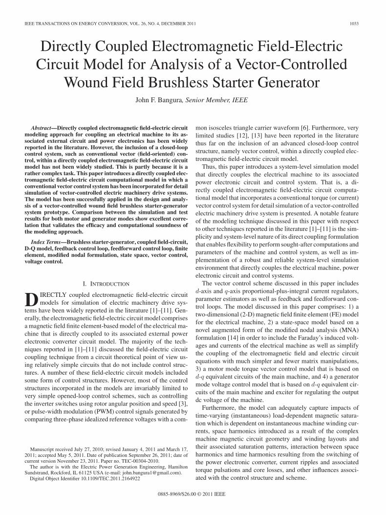
The expression given in (8) is modified to include the effectsof the electrical machine coupled to its external electric circuit.Specifically, (8) is augmented to include the Faraday’s inducedvoltages and currents for stranded and solid conductors as shownin Fig. 1, and proposed herein in (9)
C0dX
dt+ G0X = B0Ws + B1V mag + B2Imag + W 0 . (9)
In (9), V mag is a vector representing the induced voltageresponses of the magnetic circuit in stranded conductors, andImag is a vector that represents the induced current responses ofthe magnetic circuit in solid conductors. Meanwhile, the matri-ces B1 and B2 are related to the number of stranded and solidconductors of the electromagnetic device. It is through theseinduced voltages and currents that the coupling between theelectromagnetic field finite element model of the electromag-netic device and the external circuit variables is established.Thus, in this work the stator and main rotor field stranded wind-ings of the starter-generator are represented using Thevenin’sequivalent circuit representation and the rotor damper bars are
represented using Norton’s equivalent circuit representation asshown in Fig. 1.
IV. ELECTROMAGNETIC FIELD-ELECTRIC CIRCUIT
COUPLED SYSTEM MODEL
From (3) and (9), and expressing Faraday’s voltage and cur-rent expressions for stranded and solid conductors in terms ofthe magnetic field vector potential, A, the coupled system com-prises the following:
SA + Tσ
∂A
∂t= HsIs + Q
σV σ + IPM (10)
C0dX
dt+ G0X = B0Ws + B1V mag + B2Imag + W 0 (11)
V mag = −LHTs
∂A
∂t(12)
Imag = −LQTσ
∂A
∂t. (13)
In this work, the consumer notation in which positive poweris always assumed to be flowing into the machine and circuit el-ements is adopted. Hence, the relationships linking the strandedand solid conductor current and voltage variables to the systemstate variable, X , are given as follows:
Is = −BT1 X (14)
V σ = −BT2 X. (15)
Upon substituting (12) through (15) into (10) and (11), oneobtains the primary equations that directly couple the electro-magnetic field model of the machine to the external electriccircuit
SA + Tσ
∂A
∂t+
(HsB
T1 + Q
σBT
2)X = IPM (16)
C0dX
dt+ G0X + L
(HsB
T1 + Q
σBT
2)T ∂A
∂t= B0Ws + W 0 .
(17)
The time dependence of (16) and (17) is discretized usingGear’s second-order numerical integration technique and theresulting set of nonlinear algebraic equations expressed in termsof the current and previous time steps, Δt and Δt1, are as givenin (18) below.⎡
⎢⎢⎣
S +3
2ΔtT σ
(HsB
T1 + Q
σBT
2)
(HsB
T1 + Q
σBT
2)T 2Δt
3L
(3
2ΔtC0 + G0
)
⎤
⎥⎥⎦
[A(t + Δt)
X(t + Δt)
]
=
⎡
⎢⎢⎢⎣
(Δt + 3Δt12ΔtΔt1
)Tσ 0
(Δt + 3Δt1
3Δt1
)(HsB
T1 + Q
σBT
2)T
(Δt + 3Δt1
3Δt1
)1L
C0
⎤
⎥⎥⎥⎦
×[
A (t)
X (t)
]
1036 IEEE TRANSACTIONS ON ENERGY CONVERSION, VOL. 26, NO. 4, DECEMBER 2011
Fig. 2. Motoring mode torque vector control representation.
+
⎡
⎢⎢⎢⎣
−(
12Δt1
)Tσ 0
−(
Δt
3Δt1
)(HsB
T1 + Q
σBT
2)T −
(Δt
3Δt1
)1L
C0
⎤
⎥⎥⎥⎦
×[
A(t − Δt1)
X(t − Δt1)
]+
⎡
⎣IPM
2Δt
3LB0Ws(t + Δt)
⎤
⎦+[
0
W 0
]. (18)
The coefficient matrices in (18) are symmetric, very sparseand not positive definite. The solutions have been obtained usinga direct solver with robust storage and reordering schemes thatgreatly reduced computing time and computer storage require-ments. The formulation has been implemented in such a mannerthat it is very flexible to perform sought-after post processingcomputations.
V. INCORPORATING MOTOR MODE TORQUE
VECTOR CONTROL MODEL
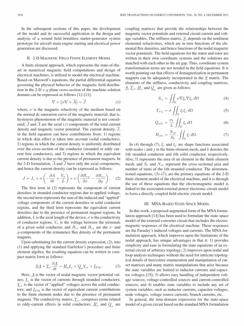
For control purposes, the vector control model is based ona conventional d-q equivalent circuit model of a wound fieldsynchronous machine. The d-q model essentially provides amathematically convenient way for deriving the necessary re-lationships for dynamic vector control. The torque (or current)vector control scheme [16], [17] implemented in this work isdepicted in Fig. 2, without any of the necessary current, volt-age and other system protection features. The dynamics of thestator currents with the stator voltages as inputs are coupledand nonlinear. By decoupling compensation the stator currentdynamics become linear and decoupled, and hence two inde-pendent proportional-plus-integral (PI) current regulators areused for current tracking. At every time step and correspond-ing rotor angular position, θ, the time-domain solutions of thecoupled field-electric circuit model, (18), are used to computeall the self and mutual winding inductances from which the d-qinductances are derived. In addition, the steady-state balancedthree-phase stator currents are transformed into a flux-producingcurrent component, isd , and a torque-producing current compo-
nent, isq using the power invariant form of Park’s transformationin synchronous reference frame as follows:
[isd
isq
]= Tabc→dqB
T1 X (19)
where,
Tabc→dq
=
√23
⎡
⎢⎢⎢⎣
cos(θ) cos(θ − 2
3π
)cos
(θ − 4
3π
)
− sin(θ) − sin(θ − 2
3π
)− sin
(θ − 4
3π
)
⎤
⎥⎥⎥⎦
. (20)
The estimated d-q current components are compared withtheir reference command values and the generated actuatingerror signals are the inputs to the PI current regulators. Thereference current commands, I∗sd and I∗sq , are determined fromthe reference torque command, T ∗
ref . The PI current regulatorsare utilized to force the estimated d-q currents to follow thereference command values so that field-oriented control canbe achieved. The outputs of the PI current regulators are thesynchronous reference frame d-q stator voltages expressed asfollows:[
vsd
vsq
]=
[Rs 0
0 Rs
] [isd
isq
]+
[Lsd 0
0 Lsq
]d
dt
[isd
isq
]
+[
0 −ωeLsq
ωeLsd 0
][isd
isq
]+
[0
ωeLmd
]if d . (21)
In (21), Rs , Lsd , Lsq , Isd , Isq , Lmd , If d and ωe are the statorphase winding resistance, d-axis inductance, q-axis inductance,d-axis (flux producing) current, q-axis (torque producing) cur-rent, d-axis magnetizing inductance, main field dc excitationcurrent, and rotor speed in electrical radians per second. Thed-q stator phase voltages are then transformed into abc phasevoltages using the rotor angular position and inverse of thepower invariant form of Park’s transformation given in (22)
Tdq→abc =
√23
⎡
⎢⎢⎢⎢⎢⎢⎣
cos(θ) − sin(θ)
cos(
θ − 23π
)− sin
(θ − 2
3π
)
cos(
θ − 43π
)− sin
(θ − 4
3π
)
⎤
⎥⎥⎥⎥⎥⎥⎦
.
(22)The abc phase voltages are applied to the input of the space
vector pulse-width modulation (SVPWM) modulator [18] thatimplements the modulation strategy.
Meanwhile, the two PI current regulators independently con-trol the isd and isq currents to track the referenced I∗sd and I∗sq
command currents according to the control laws given in (23)and (24)
e∗d = Kpd (i∗sd−isd) + Kid
∫(i∗sd−isd)dt (23)
e∗q = Kpq
(i∗sq−isq
)+ Kiq
∫ (i∗sq−isq
)dt (24)
BANGURA: DIRECTLY COUPLED ELECTROMAGNETIC FIELD-ELECTRIC CIRCUIT MODEL 1037
Fig. 3. Generator mode output voltage regulation representation.
where, Kpd , Kid , Kpq , Kiq are the d-axis and q-axis propor-tional and integral gains. The integral terms in (23) and (24)are approximated using trapezoidal summation. Meanwhile, theproportional and integral gains are calculated as follows:
Kpdq =
√(Rs)2 + (ωcLsdq )
2
1 + tan2 (θc)(25)
Kidq = −ωcKpdq tan (θc) (26)
where, ωc is the crossover frequency, and Lsdq = Lsd for thed-axis current regulator, Lsdq = Lsq for the q-axis current reg-ulator, and θc is the current regulator phase angle. The currentregulator phase angle expressed in terms of the closed loopphase margin, ϕPM , is given as follows:
θc = −180◦ + φPM + atan(
ωcLsdq
Rs
). (27)
The PI current regulator gains have been tuned based on (25)through (27) and used in the simulation of the wound fieldstarter-generator prototype motor mode operation.
VI. INCORPORATING GENERATOR MODE VOLTAGE
CONTROL MODEL
The generator mode voltage regulation scheme is accom-plished using two control loops as shown in Fig. 3, withoutany of the necessary speed and load current limiting, fold-backcontrol and other system protection features. It comprises aninner loop that regulates the exciter current and an outer loopthat regulates the output dc voltage so that it is maintained at thereference output voltage for all generator mode operating condi-tions. The outer loop PI controller is designed based on the d-qmodel of the main generator and the inner loop PI controller isbased on the d-q model of the exciter. Meanwhile, their controllaws are described in a similar manner as given in (23) and (24)for the motor mode.
At every time step during the simulation, the calculated outputdc voltage, Vt, is compared with its reference command value,V ∗
ref , and an actuating error signal is generated. The actuatingsignal is then used as the input to the outer loop PI controller.Meanwhile, the output of the outer loop PI controller, I∗ref , is theexciter current reference command value that is compared to thecomputed value and used as input to the inner loop PI controller.The output of the inner PI controller is then fed to the exciterpulse-width modulation (PWM) modulator that implements themodulation strategy for adjusting the exciter current, and hencethe output dc voltage.
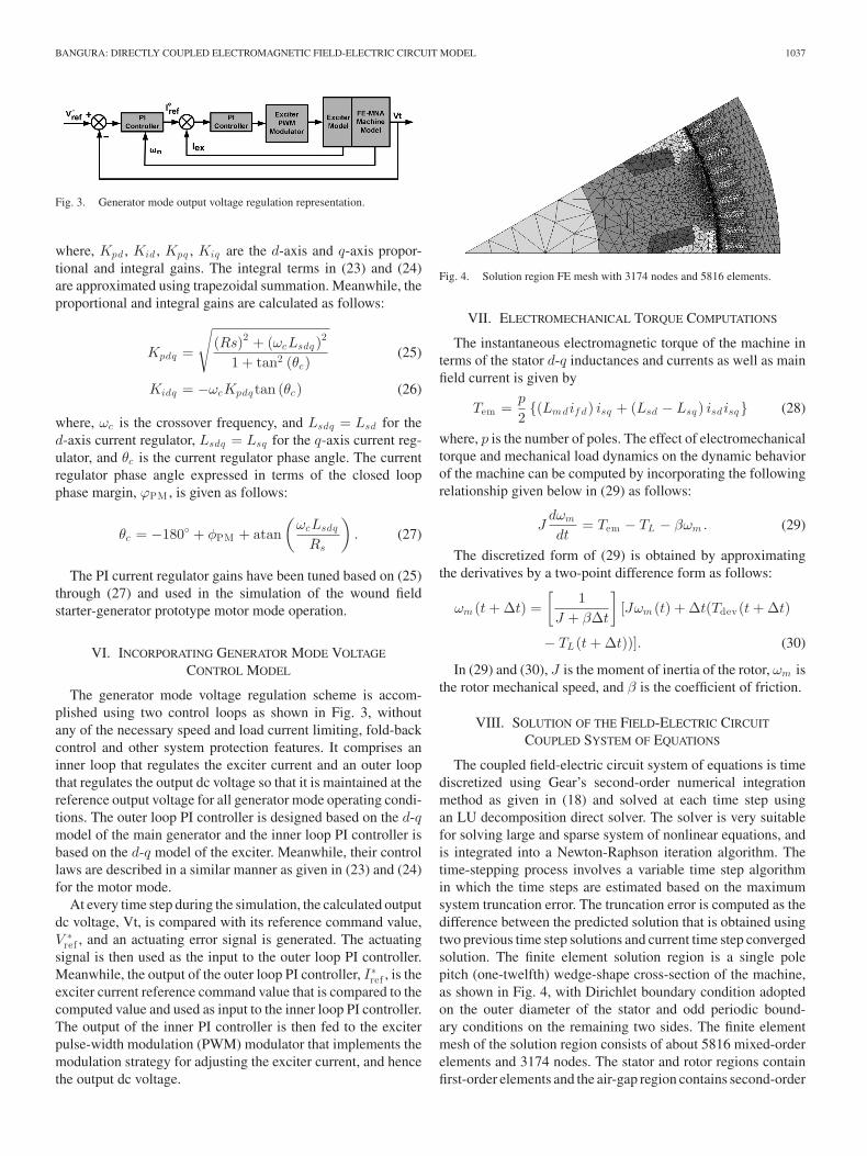
Fig. 4. Solution region FE mesh with 3174 nodes and 5816 elements.
VII. ELECTROMECHANICAL TORQUE COMPUTATIONS
The instantaneous electromagnetic torque of the machine interms of the stator d-q inductances and currents as well as mainfield current is given by
Tem =p
2{(Lmdif d) isq + (Lsd − Lsq ) isdisq} (28)
where, p is the number of poles. The effect of electromechanicaltorque and mechanical load dynamics on the dynamic behaviorof the machine can be computed by incorporating the followingrelationship given below in (29) as follows:
Jdωm
dt= Tem − TL − βωm . (29)
The discretized form of (29) is obtained by approximatingthe derivatives by a two-point difference form as follows:
ωm (t + Δt) =[
1J + βΔt
][Jωm (t) + Δt(Tdev(t + Δt)
− TL (t + Δt))]. (30)
In (29) and (30), J is the moment of inertia of the rotor, ωm isthe rotor mechanical speed, and β is the coefficient of friction.
VIII. SOLUTION OF THE FIELD-ELECTRIC CIRCUIT
COUPLED SYSTEM OF EQUATIONS
The coupled field-electric circuit system of equations is timediscretized using Gear’s second-order numerical integrationmethod as given in (18) and solved at each time step usingan LU decomposition direct solver. The solver is very suitablefor solving large and sparse system of nonlinear equations, andis integrated into a Newton-Raphson iteration algorithm. Thetime-stepping process involves a variable time step algorithmin which the time steps are estimated based on the maximumsystem truncation error. The truncation error is computed as thedifference between the predicted solution that is obtained usingtwo previous time step solutions and current time step convergedsolution. The finite element solution region is a single polepitch (one-twelfth) wedge-shape cross-section of the machine,as shown in Fig. 4, with Dirichlet boundary condition adoptedon the outer diameter of the stator and odd periodic bound-ary conditions on the remaining two sides. The finite elementmesh of the solution region consists of about 5816 mixed-orderelements and 3174 nodes. The stator and rotor regions containfirst-order elements and the air-gap region contains second-order

1038 IEEE TRANSACTIONS ON ENERGY CONVERSION, VOL. 26, NO. 4, DECEMBER 2011
TABLE ISTARTER-GENERATOR PROTOTYPE DESIGN DATA
Fig. 5. Cross-section of starter-generator magnetic circuit.
elements. The solver algorithm code developed in Borland C++takes about 3 h of CPU time on a Pentium(R) 4 CPU 3.20 GHzprocessor to complete 40 cycles of the motor mode operation at4000 rpm with a PWM switching frequency of 10 kHz.
IX. SIMULATION AND TEST RESULTS
The coupled electromagnetic field-electric circuit model dis-cussed in this paper was utilized in the analysis and design of astarter-generator prototype whose data is given in Table I. Thecross-section of the magnetic circuit topology of the three-phasewound field starter-generator prototype and flux plot are shownin Fig. 5. The model was used to compute the generator modeand motor mode performance characteristics.
Meanwhile, the test setup consists of a 1500 hp dynamometerthat can be programmed with the required assist/resist torque-speed curves for motor and generator modes, and an open dataacquisition, control and safety system (ODACS). The ODACSprovides data acquisition capability to record starter-generatorvoltages, currents, torque, speed, input/output power, as wellas winding, coolant-in/coolant-out, bearing and other tempera-tures, etc. It also controls, monitors test operation continuously,and provides safety protection with regards to over-temperature,over-speed, over-torque, etc., during testing.
A. Generator Mode Test and Simulation Results
Examples of the generator mode simulation and test results ofthe normalized open circuit line-to-line voltage versus main fieldexcitation current and time-domain main stator output voltagewaveforms are shown in Figs. 6 and 7. Also, results of the nor-malized steady-state phase currents for 40 kW load at 15500 rpm
Fig. 6. Generator mode open-circuit voltage versus field current at15500 r/min.
Fig. 7. Generator mode open-circuit line-to-line voltage waveforms at15500 r/min with 20 A field current.
Fig. 8. Generator mode test results for 40 kW at 15500 rpm.
are shown in Figs. 8 and 9 for test and simulation. Comparisonof these results clearly demonstrates the excellent agreement inthe waveforms and magnitudes between the test and simulationdata. Meanwhile, in Fig. 10 are shown simulation results of astep load transient from 40 kW to 80 kW. That is, the electricalload was changed from 40 kW to 80 kW by a sudden connec-tion of a resistive load. The results show that the PI controllers,whose gains were calculated using (25) and (26), can providegood regulation.
B. Motor Mode Test and Simulation Results
Samples of the motor mode normalized simulation and testresults phase currents at a steady-state speed 4000 rpm and

BANGURA: DIRECTLY COUPLED ELECTROMAGNETIC FIELD-ELECTRIC CIRCUIT MODEL 1039
Fig. 9. Generator mode simulation results for 40 kW at 15500 rpm.
Fig. 10. Simulated generator mode sudden load change from 40 to 80 kW.
Fig. 11. Measured motor mode currents at 4000 r/min and 67.8 Nm.
torque of 67.8 Nm (50 ft-lb) are shown in Figs. 11 and 12.Comparison of the results shows that the simulated phase currentexhibited slightly higher ripple peaks. This can be attributed tothe fact that the winding inductances computed by 2-D finiteelements are lower than those of the actual prototype, and hencehigher current ripple peaks. The very good comparison betweenthese results clearly validates the computational soundness andefficacy of the developed model.
Normalized simulation results of the regulated average d-axis and q-axis currents in response to a step load change inthe command torque from 67.8 Nm to 50 Nm at 4000 rpm areshown in Fig. 13. The normalized average d-axis currents forthese two command torque cases are regulated about zero and
Fig. 12. Simulated motor mode currents at 4000 r/min and 67.8 Nm.
Fig. 13. Simulated motor mode average Id and Iq currents for 67.8 Nm and50 Nm command torque cases.
the average q-axis currents are regulated about 1.00 and 0.75per unit, respectively.
X. CONCLUSION
This paper has reported a directly coupled electromagneticfield-electric circuit model that incorporates an advanced closed-loop control structure, namely, a conventional torque (or current)vector control, for design and analysis of electric machinerydrive systems. The model comprises a 2-D magnetic field finiteelement model of the electrical machine directly coupled to astate-space model. The state-space model formulation is basedon a novel augmented form of the MNA formulation approachproposed herein in order to include the Faraday’s induced volt-ages and currents of the electrical machine. A notable featureof the modeling technique discussed in this paper with respectto other techniques reported in the literature is the simplicityand system-level nature of its direct coupling formulation thatenables flexibility to perform sought-after computations andparameters of the machine and control system, as well as im-plementation of a robust and reliable system-level simulationenvironment that directly couples the electrical machine, powerelectronic circuit and control systems.
The model can adequately capture impacts of time-varying(instantaneous) load-dependent magnetic saturation that is de-pendent on machine winding currents, space harmonics dueto the complex machine magnetic circuit geometry and wind-ing layouts and their associated saturation patterns, interaction

1040 IEEE TRANSACTIONS ON ENERGY CONVERSION, VOL. 26, NO. 4, DECEMBER 2011
between space harmonics and time harmonics resulting fromthe switching of the power electronic converter, current ripplesand associated torque pulsations and core losses, as well asinfluences associated with the control structure and scheme.
The model was utilized in the design and analysis of a three-phase wound field brushless starter-generator prototype. Theefficacy and computational soundness of the model were ade-quately validated by the excellent comparison between simula-tion and experimental results. Finally, the model developed inthis work can simulate various transient and steady-state oper-ating conditions for both generate and start modes. In addition,it is quite versatile and can be utilized to simulate other electricmachinery drive systems.
REFERENCES
[1] A. Demenko, “Time-stepping FE analysis of electric motor drives withsemiconductor converters,” IEEE Trans. Magn., vol. 30, no. 5, pp. 3264–3267, Sep. 1994.
[2] P. Kuo-Peng, N. Sadowski, J. P. A. Bastos, R. Carlson, N. J. Batistela,and M. Lajoie-Mazenc, “A general method for coupling static converterswith electromagnetic structures,” IEEE Trans. Magn., vol. 33, no. 2,pp. 2004–2009, Mar. 1997.
[3] P. Kuo-Peng, J. P. A. Bastos, N. Sadowski, and R. Carlson, “Analysis ofa combined converter-electromagnetic device by taking into account itscontrol loop,” IEEE Trans. Energy Convers., vol. 14, no. 4, pp. 1430–1434, Dec. 1999.
[4] P. Kuo-Peng, N. Sadowski, N. J. Batistela, and J. P. A. Bastos, “Coupledfield and circuit analysis considering the electromagnetic device motion,”IEEE Trans. Magn., vol. 36, no. 4, pp. 1458–1461, Jul. 2000.
[5] W. N. Fu, P. Zhou, D. Lin, S. Stanton, and Z. J. Cendes, “Modeling ofsolid conductors in two-dimensional transient finite-element analysis andits application to electric machines,” IEEE Trans. Magn., vol. 40, no. 2,pp. 426–434, Mar. 2004.
[6] P. Zhou, W. N. Fu, D. Lin, and S. Stanton, “Numerical modeling ofmagnetic devices,” IEEE Trans. Ind. Appl., vol. 40, no. 4, pp. 1803–1809,Jul. 2004.
[7] J. Vaananen, “Circuit theoretical approach to couple two-dimensional fi-nite element models with external circuit equations,” IEEE Trans. Magn.,vol. 32, no. 2, pp. 400–410, Mar. 1996.
[8] P. Lombard and G. Meunier, “A general method for electric and magneticcoupled problem in 2D and magnetodynamic domain,” IEEE Trans.Magn., vol. 28, no. 2, pp. 1291–1294, Mar. 1992.
[9] F. Piviou and A. Razek, “Finite element analysis in electromagnetic sys-tems accounting for electrical circuit,” IEEE Trans. Magn., vol. 29, no. 2,pp. 1669–1675, Mar. 1993.
[10] S. L. Ho, H. L. Li, W. N. Fu, and H. C. Wong, “A novel approachto circuit-field-torque coupled time-stepping finite element modeling ofelectric machines,” IEEE Trans. Magn., vol. 36, no. 4, pp. 1886–1889,Jul. 2000.
[11] O. A. Mohamed, N. Y. Abed, and S. Ganu, “Modeling and characterizationof induction motor internal faults using finite-element and discrete wavelettransforms,” IEEE Trans. Magn., vol. 42, no. 10, pp. 3434–3436, Oct.2006.
[12] S. C. Ahn, J. H. Lee, and D. S. Hyun, “Dynamic characteristic analysisof LIM using coupled FEM and control algorithm,” IEEE Trans. Magn.,vol. 36, no. 4, pp. 1876–1880, Jul. 2000.
[13] Y. Ohdachi, Y. Kawase, and M. Hirako, “Dynamic analysis of vectorcontrolled induction motor using finite element method,” IEEE Trans.Magn., vol. 31, no. 3, pp. 1904–1907, May 1995.
[14] S. Natarajan, “A systematic method for obtaining state equations usingMNA,” Circuits, Devices Syst., IEE Proc. G, vol. 138, no. 3, pp. 341–346,Jun. 1991.
[15] N. Deo, Graph Theory with Application to Engineering and ComputerScience. Englewood Cliffs, NJ: Prince-Hall, 1974.
[16] R. Bojoi, M. Lazzari, F. Profumo, and A. Tenconi, “Digital field orientedcontrol for dual three-phase induction motor drives,” IEEE Trans. Ind.Appl., vol. 43, no. 3, pp. 818–825, May/Jun. 2007.
[17] C. Gerada, K. J. Bradley, M. Summer, and P. Sewell, “Evaluation andmodeling of cross saturation due to leakage flux in vector-controlled in-duction machines,” IEEE Trans. Ind. Appl., vol. 43, no. 3, pp. 694–702,May/Jun. 2007.
[18] K. Zhou and D. Wang, “Relationship between space-vector modulationand three-phase carrier-based PWM: A comprehensive analysis,” IEEETrans. Ind. Electron., vol. 49, no. 1, pp. 186–196, Feb. 2002.
John F. Bangura (M’99–SM’07) received the B.S.E.E. degree from ClarksonUniversity, Potsdam, NY, and the M.S.E.E. and Ph.D. degrees from MarquetteUniversity, Milwaukee, Wisconsin, in 1996 and 1999, respectively.
From 1999 to 2004, he was a Senior Engineer at Black & Decker, Inc.,Towson, Maryland, where he worked on flux switching brushless ac and brush-less dc motor drives for power tool applications. From 2002 to 2004, he was anAdjunct Professor with the Department of Mechanical Engineering, Universityof Maryland, Baltimore. From 2004 to 2005, he was an Engineering Managerat Alltrade Tools, Long Beach, CA, where he steered the development of com-pressors, portable generators, power washers, and other power equipment. From2005 to 2009, he was a Senior Magnetics Engineering Specialist and ProjectEngineer at Pacific Scientific Electro-Kinetics Division, Danaher Corporation,Santa Barbara, CA. During this period, he worked on permanent magnet starter-generators for military ground vehicles – JLTV, MULE, STRYKER, hybridhomopolar generators for down-hole oil exploration, and wound field brushlessstarter-generators for commercial aerospace main and auxiliary engine electricstart and power generation applications. In 2009, he joined the Electric SystemsGroup at Hamilton Sundstrand where he is working on wound field brushlessstarter-generators, permanent magnet motors and induction motors for aircraftelectric start, power generation, compressor and fan applications. He is currentlya Chief Engineer, and his current interests include magnetic field finite element-based simulation models and techniques that integrate field-oriented and othercontrol structures for analysis and design of electric machinery drives systems.