— Electronic Compact Starter Short-circuit protection - ABB
15
— WHITEPAPER Electronic Compact Starter Short-circuit protection
-
Upload
khangminh22 -
Category
Documents
-
view
1 -
download
0
Transcript of — Electronic Compact Starter Short-circuit protection - ABB

— WHITEPAPER
Electronic Compact Starter Short-circuit protection

2
—
Table of contents
1. Introduction 3
1.1 Explanation - Hybrid technology 3
1.2 Applications 4
2. Fuseless design 5
2.1 Description of MO132 5
2.2 What is meant by fuseless design? 5
2.3 Benefits of fuseless design 5
2.4 Single mounting 5
2.5 Group mounting 7
2.5.1 Group mounting – example 1 8
2.5.2 Group mounting – example 2 8
3. Protection with fuses 9
3.1 Single mounting fused design 9
3.2 Group mounting fused design 10
4. Short-circuit protection for use in UL market 11
5. Glossary 12
6. Standards and Directives 13
7. Safety Instructions 14

3
1. Introduction
Electronic Compact Starters (HF-Starters) are multifunctional devices for motor control and protection up to 3 kW/400 V AC. The HF-Starter is useful where space is limited but high functionality is required. HF-Starters provide direct on-line and reverse start, over-load protection and emergency stop features all in one device which is only 22.5 mm in width.
This white paper is to show which short-circuit protection devices should be used in combination with the Electronic Compact Starter.
1.1 Explanation - Hybrid technology
HF-Starters use hybrid technology - a combination of semiconductors (Triac) and relays. As the HF-Starter is used for AC switching, two Thyristors must be combined. This anti-parallel combination of two Thyristors is called a Triac.
The integrated microprocessor coordinates two Triacs (V1 and V2), two pairs of relays (K1 and K2) and two bypass relays (K3) in one device. The switching principle of the switch-on process takes place in three steps. First, the relays K1 and K2 are switching. Until this time there is no current flow in phases L1, L2 and L3 since the Triacs (V1 and V2) have not switched. In the second step, the Triacs V1 and V2 are switching. Now the inrush current is conducted through all three phases and the motor starts. The Triacs are generating high power losses, which results in heat dissipation. To avoid heat dissipa-tion the microprocessor starts with the third step and switch the bypass relays (K3) on. The bypass relays K3 are conducting now the nominal current of the motor. The all in one hybrid technology results in a high lifetime of 30 Mio. electrical switching cy-cles, a high switching frequency of 7200x per hour, reduced power loss, galvanic isolation and finally the ability to save space in the control cabinet.
K3V1
M3~
I1
L1
K3V2
L2 L3
I2
I3
K1 K1 K2
K2
Contact energized
— Figure 1 Main circuit of the HF-Starter
1/L1 3/L2 5/L3
2/T1 4/T2 6/T3
µController
Us ON MAN RES AUT
95 97
96
Signal
— Figure 2 Connection diagram of HF-DOL

4
1.2 Applications
You can find the HF-Starter for applications such as:
• OEMs for lifters, where the lifted good needs to be positioned up/down and left/right
• OEMs for straightening machines to position coils and cooling motors
• Panel builders for integration into control cabinets, e.g. for snow guns which needs to be controlled to the left and right side
• Controlling machine axis
All four applications listed above require a long electrical lifetime, low space consump-tion in control cabinets and multi-functionality. To provide our customers with the best possible short-circuit protection, ABB decided to combine its well-known Manual Motor Starter MO132 with the outstanding Electronic Compact Starter for single and group mounting.
— Figure 3 Single and group mounting with MO132 and Electronic Compact Starter for fuseless short-circuit protection
Group mounting
MO132
MO132
HF HF
Single mounting

5
2. Fuseless design
2.1 Description of MO132 The “MO132 Manual Motor Starter magnetic only” is a compact 45 mm width device available for different nominal currents. It provides short-circuit protection either to pro-tect the motor and wires or additionally to protect control devices when used in a starter combination, e.g., with contactors or the Electronic Compact Starter.
2.2 What is meant by fuseless design? A fuseless design means using a Manual Motor Starter like the MO132 for short-circuit pro-tection in combination with the Electronic Compact Starter. After the tripping of the MO132 starter due to a short-circuit no fuse replacement is needed. Please note it is important to change the Electronic Compact Starter after a short-circuit has occurred.
2.3 Benefits of fuseless design One favorable attribute of using a fuseless design, which is an advantage of the MO132, is that it can be used as power disconnect and can provide isolation from the network. For any application that may require regular service this is an attractive benefit. Even the ro-tary handle can be locked to ensure power reconnection during service. The second benefit for the customer is the visual indication. The rotary handle will stop in the “Trip” position to show that a short-circuit occurred. This feature saves diagnostic time. The third benefit is the possibility to broaden the functionality with accessories such as auxiliary contacts, signaling contacts, undervoltage releases and more.
2.4 Single mounting Single mounting means that one Manual Motor Starter protects one HF-Starter. The maxi-mal current of the motor defines the size of the short-circuit protection device (SCPD) and which HF-Starter is best to use. Please find all the installation proposals in Table 1 for 500 V AC and Table 2 for 415 V AC.

6
— Table 1: Type 1 coordination of HF-Starter with Manual Motor Starter MO132 at 500 V AC
HF-Starter Iq [kA]
SCPD Max. Current [A]
Max. Voltage [V AC]
HF0.6 35 MO132-0.63 0.075 500
HF0.6 35 MO132-0.63 0.63 500
HF2.4 35 MO132-0.63 0.63 500
HF2.4 35 MO132-1.0 1 500
HF2.4 35 MO132-1.6 1.6 500
HF2.4 35 MO132-2.5 2.4 500
HF9 35 MO132-1.6 1.6 500
HF9 35 MO132-2.5 2.4 500
HF9 35 MO132-4.0 4.0 500
HF9 35 MO132-6.3 6.5 500
HF9 35 MO132-10 91.) 500
1) HF9 variants can switch 6.5A in utilization category AC-53a and 9A in AC-51.
— Table 2: Type 1 coordination of HF-Starter with Manual Motor Starter MO132 at 415 V AC
HF-Starter Iq [kA]
SCPD Max. Current [A]
Max. Voltage [V AC]
HF0.6 70 MO132-0.63 0.075 415
HF0.6 70 MO132-0.63 0.63 415
HF2.4 70 MO132-0.63 0.63 415
HF2.4 70 MO132-1.0 1 415
HF2.4 70 MO132-1.6 1.6 415
HF2.4 70 MO132-2.5 2.4 415
HF9 70 MO132-1.6 1.6 415
HF9 70 MO132-2.5 2.5 415
HF9 70 MO132-4.0 4.0 415
HF9 70 MO132-6.3 6.5 415
HF9 35 MO132-10 91.) 415
1) HF9 variants can switch 6.5A in utilization category AC-53a and 9A in AC-51.

7
2.5 Group mounting
Group mounting HF-Starters provides significant space saving in control cabinets. One MO132 can be used to protect several Electronic Compact Starters. Test results are pre-sented in Table 3 for 500 V AC and Table 4 for 415 V AC. Two installation proposals for group protection are shown in Figure 5 and Figure 6. Please note that the sum of the current for all of the HF-Starters must not exceed the maximum current of the MO132 chosen. E.g., if the maximum current is 20 A, then the MO132-20 must be chosen and the sum of the HF-Starter current must not exceed 20 A in total.
— Table 3: Type 1 coordination of HF-Starter with Manual Motor Starter MO132 at 500 V AC
Max. sum of cur-rent of HF-Starter in group
Iq [kA]
SCPD Max. Current [A]
Max. Voltage [V AC]
6.5 35 MO132-6.3 6.5 500
10 3 MO132-10 10 500
12 3 MO132-12 12 500
16 3 MO132-16 16 500
20 3 MO132-20 20 500
25 3 MO132-25 25 500
32 3 MO132-32 32 500
— Table 4: Type 1 coordination of HF-Starter with Manual Motor Starter MO132 at 415 V AC
Max. sum of current of HF-Starter in group
Iq [kA]
SCPD Max. Current [A]
Max. Voltage [V AC]
6.5 70 MO132-6.3 6.5 415
10 35 MO132-10 10 415
12 3 MO132-12 12 415
16 3 MO132-16 16 415
20 3 MO132-20 20 415
25 3 MO132-25 25 415
32 3 MO132-32 32 415
8
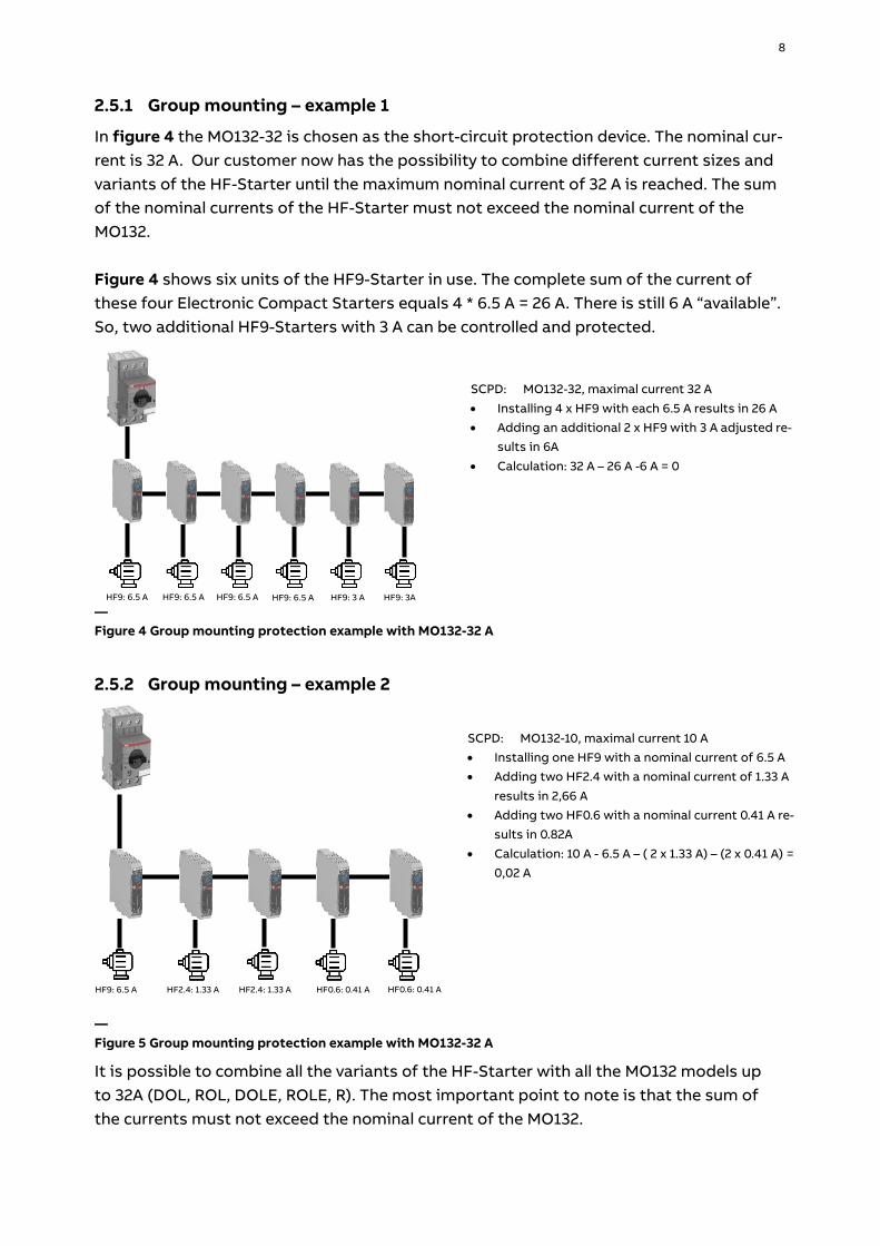
2.5.1 Group mounting – example 1
In figure 4 the MO132-32 is chosen as the short-circuit protection device. The nominal cur-rent is 32 A. Our customer now has the possibility to combine different current sizes and variants of the HF-Starter until the maximum nominal current of 32 A is reached. The sum of the nominal currents of the HF-Starter must not exceed the nominal current of the MO132. Figure 4 shows six units of the HF9-Starter in use. The complete sum of the current of these four Electronic Compact Starters equals 4 * 6.5 A = 26 A. There is still 6 A “available”. So, two additional HF9-Starters with 3 A can be controlled and protected.
2.5.2 Group mounting – example 2
It is possible to combine all the variants of the HF-Starter with all the MO132 models up to 32A (DOL, ROL, DOLE, ROLE, R). The most important point to note is that the sum of the currents must not exceed the nominal current of the MO132.
SCPD: MO132-10, maximal current 10 A • Installing one HF9 with a nominal current of 6.5 A • Adding two HF2.4 with a nominal current of 1.33 A
results in 2,66 A • Adding two HF0.6 with a nominal current 0.41 A re-
sults in 0.82A
• Calculation: 10 A - 6.5 A – ( 2 x 1.33 A) – (2 x 0.41 A) = 0,02 A
HF9: 6.5 A
HF2.4: 1.33 A
SCPD: MO132-32, maximal current 32 A
• Installing 4 x HF9 with each 6.5 A results in 26 A • Adding an additional 2 x HF9 with 3 A adjusted re-
sults in 6A
• Calculation: 32 A – 26 A -6 A = 0
HF9: 6.5 A HF9: 6.5 A HF9: 6.5 A HF9: 6.5 A HF9: 3 A HF9: 3A
— Figure 4 Group mounting protection example with MO132-32 A
HF2.4: 1.33 A
HF0.6: 0.41 A
HF0.6: 0.41 A
— Figure 5 Group mounting protection example with MO132-32 A

9
3. Protection with fuses
3.1 Single mounting fused design All variants of the HF-Starter can be combined with the following fuses for short-circuit protection. Table 4 shows test results for 500 V AC and Table 5 shows the results for 415 V AC.
— Table 4: Type 1 coordination of HF-Starter with Fuses at 500 V AC
HF-Starter Iq [kA]
SCPD Max. Current [A]
Max. Voltage [V AC]
HF0.6 35 Fuse 25A gG 0.63 500
HF2.4 35 Fuse 25A gG 2.4 500
HF9 35 Fuse 25A gG 91) 500
1) HF9 variants can switch 6.5A in utilization category AC-53a and 9A in AC-51.
— Table 5: Type 1 coordination of HF-Starter with Fuse 25AgG at 415 V AC
HF-Starter Iq [kA]
SCPD Max. Current [A]
Max. Voltage [V AC]
HF0.6 50 Fuse 25A gG 0.63 415
HF2.4 50 Fuse 25A gG 2.4 415
HF9 50 Fuse 25A gG 91) 415
1) HF9 variants can switch 6.5A in utilization category AC-53a and 9A in AC-51.

10
3.2 Group mounting fused design Group mounting HF-Starters results in significant space saving in control cabinets. Instal-lation proposals are shown in Table 6 for 500 V AC and Table 7 for 415 V AC.
— Table 6: Type 1 coordination of HF-Starter with Fuse 25AgG at 500 V AC
HF-Starter Iq [kA]
SCPD Max. current [A]
Max. Voltage [V AC]
HF0.6 35 Fuse 25A gG 25 500
HF2.4 35 Fuse 25A gG 25 500
HF9 35 Fuse 25A gG 25 500
— Table 7: Type 1 coordination of HF-Starter with Fuse 25AgG at 415 V AC
HF-Starter Iq [kA]
SCPD Max. [A]
Max. Voltage [V AC]
HF0.6 50 Fuse 25A gG 25 415
HF2.4 50 Fuse 25A gG 25 415
HF9 50 Fuse 25A gG 25 415
11
4. Short-circuit protection for use in the UL market For single or group protection the following fuses can be used for UL applications ac-cording to UL 60947-1/-4-1 Type 1 coordination.
— Table 8: Type 1 coordination of HF-Starter with fuses according to UL60947-1/-4-1
HF-Starter FLA [A / V AC]
Iq [kA]
SCPD Max. current [A] Max. Voltage [V AC]
HF0.6 0.6 / 500 100 Fuse class J or CC 30 480
HF2.4 2.4 / 500 100 Fuse class J or CC 30 480
HF9 6.5 / 500 100 Fuse class J or CC 30 480
HF0.6 0.6 / 500 5 Fuse RK 5 20 480
HF2.4 2.4 / 500 5 Fuse RK 5 20 480
HF9 6.5 / 500 5 Fuse RK 5 20 480
12
5. Glossary
Iq According to IEC 60947-1: The rated conditional short-circuit current of a piece of equipment is the value of the prospective current, stated by the manufacturer, which the equipment, protected by a short-circuit protective device specified by the manufacturer, can withstand satisfactorily for the operating time of this de-vice under the test conditions specified in the relevant product standard.
SCPD The abbreviation “SCPD” is defined in IEC 60947-4-1 (3.7) as a “Short-circuit protective device”. It means the co-ordination of contactors and starters is characterized by the type, ratings and characteristics of the short-circuit protective devices (SCPD) that provide protection of the contactor and starter against short-circuit currents.
FLA Full Load Amps (sometimes also FLC= Full Load Current), rated-current at rated-load and rated-voltage. This is the amount of current (amps) the mo-tor will draw from the electrical system when producing its rated output horsepower (UL 508).
Trip class This class number indicates the trip time from a cold state and should be se-lected according to the starting characteristics of the motor. The trip char-acteristics are defined in Table 4 of IEC60947-4-2. Please find a short extract in Table 9 below.
Table 8 Extract of IEC 60947-4-2 Table 4
Class 10A 10 20 30
Tripping time
2 < Tp ≤ 10 4 < Tp ≤ 10 6 < Tp ≤ 20 9 < Tp ≤ 30
All HF-Starters provide tripping class 10A except HF9-R-24VDC, which has no protection functionality.
AC-53a Conforming to IEC/EN 60947-4-2 utilization category AC-53a means the control of squirrel cage motors: 8 h of duty with on-load currents for start-ing, acceleration, and running by using AC semiconductors in motor control-lers and starters.
AC-51 Conforming to IEC/EN 60947-4-3 utilization category AC-51 means the con-trol of non-inductive or slightly inductive loads, or resistance furnaces by us-ing an AC semiconductor controller and contactors for non-motor loads.
Device self-protection
If the current exceeds 45 A for more than 2 s, the electronic compact starter switches off the motor and indicates the cause of the trip through the ERR LED and trip signaling contact.
13
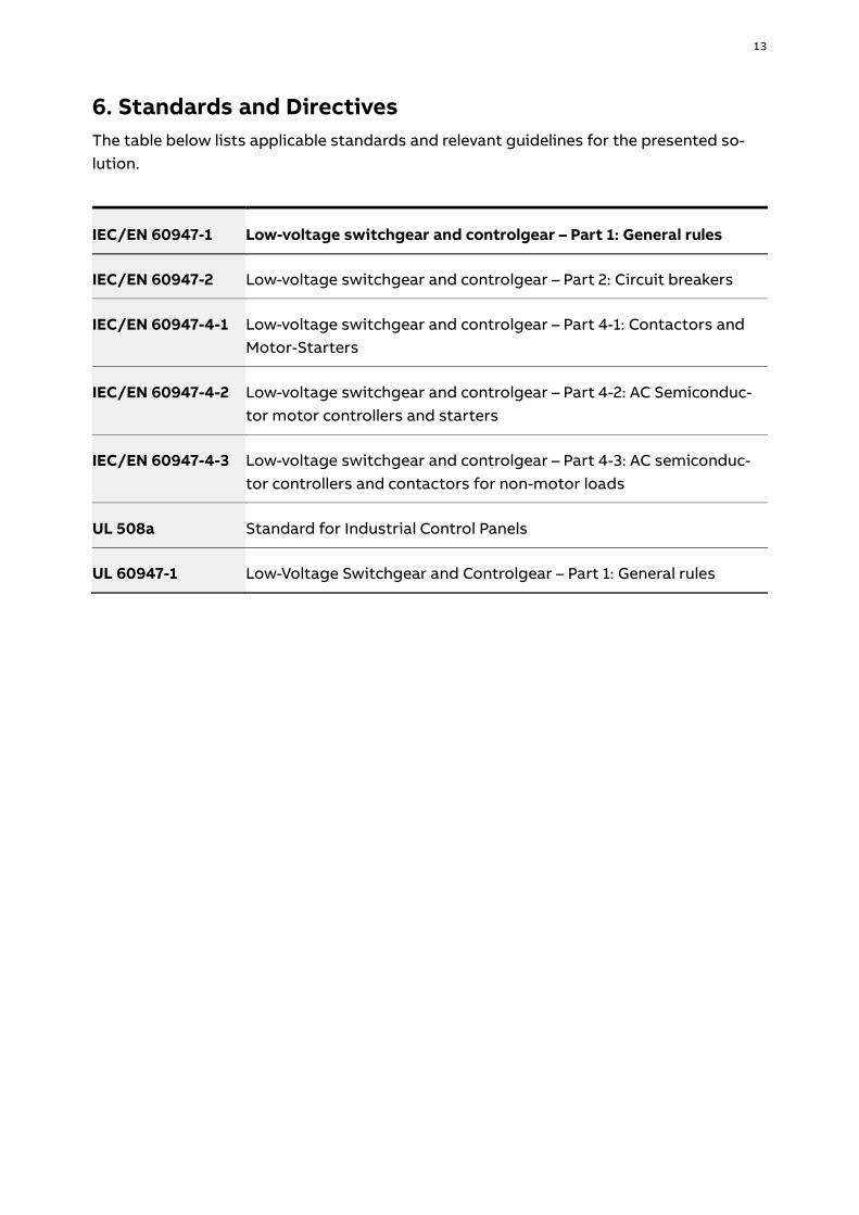
6. Standards and Directives The table below lists applicable standards and relevant guidelines for the presented so-lution.
IEC/EN 60947-1 Low-voltage switchgear and controlgear – Part 1: General rules
IEC/EN 60947-2 Low-voltage switchgear and controlgear – Part 2: Circuit breakers
IEC/EN 60947-4-1 Low-voltage switchgear and controlgear – Part 4-1: Contactors and Motor-Starters
IEC/EN 60947-4-2 Low-voltage switchgear and controlgear – Part 4-2: AC Semiconduc-tor motor controllers and starters
IEC/EN 60947-4-3 Low-voltage switchgear and controlgear – Part 4-3: AC semiconduc-tor controllers and contactors for non-motor loads
UL 508a Standard for Industrial Control Panels
UL 60947-1 Low-Voltage Switchgear and Controlgear – Part 1: General rules

14
7. Safety Instructions
Safety instructions
• Attention! Hazardous voltage! Installation by trained people with electro tech-nical expertise only.
• Mounting and installation may only be done by trained technical personnel, ac-cording to the recognized technical rules, regulations, and relevant standards!
• Insufficiently tightened locking screws will lead to an impermissible rise in tem-perature!
• Always observe the permitted ambient conditions (see technical data and cata-log).
• Devices with visible transport damage must not be used. Warnings ! If the short-circuit protection device (SCPD) has tripped, the Electronic Compact
Starter must be replaced! ! The diagnostic function provided by LEDs on the front side of the HF-Starter has
no significance after a short-circuit has occurred. ! Standard or safety variants of the HF-Starter can be used in combination with the
mentioned short-circuit protection devices.
— ABB STOTZ-KONTAKT GmbH Eppelheimer Straße 82 69123 Heidelberg Germany You can find the address of your local sales organization on the ABB home page: www.abb.com/lowvoltage
Additional information We reserve the right to make technical changes or modify the contents of this document without prior notice. With regard to purchase orders, the agreed particulars shall prevail. ABB AG does not accept any responsibility whatsoever for potential errors or possible lack of information in this document. We reserve all rights in this document and in the subject matter and illustrations contained therein. Any reproduction, disclosure to third parties or utilization of its contents – in whole or in parts – is forbidden without prior written consent of ABB AG. © Copyright 2019 ABB. All rights reserved.
Specifications subject to change without notice.
2CD
C13
5089
M0
201
Rev.
A (0
5/20
19)