Direct Torque Control of Induction Machine based on Intelligent Techniques
7
International Journal of Computer Applications (0975 – 8887) Volume 10– No.8, November 2010 29 Direct Torque Control of Induction Machine based on Intelligent Techniques Soufien Gdaim Laboratory of Electronics and Microelectronics of the FSM. National Engineering School of Monastir, Avenue Ibn ElJazzar, 5019 Monastir, Tunisia. Abdellatif Mtibaa Laboratory of Electronics and Microelectronics of the FSM. National Engineering School of Monastir, Avenue Ibn ElJazzar, 5019 Monastir, Tunisia. Mohamed Faouzi Mimouni Research Unit " Réseaux et Machines Electriques". National Engineering School of Monastir, Avenue Ibn ElJazzar, 5019 Monastir, Tunisia. ABSTRACT Induction machine drive based on Direct Torque Control (DTC) allows high dynamic performance with very simple hysteresis control scheme. Conventional Direct Torque Control (CDTC) suffers from some drawbacks such as high current, flux and torque ripple, difficulties in torque as well as flux control at very low speed. In this paper, we propose two intelligent approaches to improve the direct torque control of induction machine; fuzzy logic control and artificial neural networks control. We carry out a detailed comparison study between direct torque fuzzy control (DTFC), direct torque neural networks control (DTNNC) and CDTC applied to switching select voltage vector. The theoretical foundation principle, the numerical simulation procedure and the performances of both methods are also presented. Keywords Direct torque control, fuzzy logic control, neural networks, induction motor. 1. INTRODUCTION The induction machine is one of the most widely used machines in industrial applications due to its reliability, relatively low cost and modest maintenance requirement [1]. High performance electrical drives require decoupled torque and flux control. This control is offered in a dynamic fashion by the direct torque control. In DTC the torque and flux are directly controlled using the selection of the optimum voltage vector. The switching logic control facilitates the generation of the stator voltage space vector, with a suitable choice of the switching pattern of the inverter, on the basis of the knowledge of the sector and the amplitude of the stator flux and the torque [2]. The DTC scheme is characterized by its simple implementation and its fast dynamic response. Nevertheless, DTC presents some disadvantages such as high current, flux and torque ripple, difficulties in torque and flux control at very low speed, slow transient response to the step change in torque during start-up [1], [3] [4]. It is well established that these disadvantages are mainly due to the use of hysteresis torque and flux controllers [5]. For this reason, most of the methods used to overcome these disadvantages are based on replacing the hysteresis with the non- hysteresis-based controllers. Since it was first introduced in 1986 [4], several studies have been proposed by researchers to overcome disadvantages of CDTC drive [6]-[11]. The study proposed in [6] uses multiple inverters in order to reduce the torque ripples, but the number of power devices is higher, which consequently increases costs. Another solution consists of using space vector modulation (SVM) instead of improving the DTC look-up table [8]-[10]. This solution needs however several motor parameters and increases the complexity of the DTC algorithm. Currently, several works use techniques from artificial intelligence (AI) like neural networks, fuzzy logic and genetic algorithms [1], [3], [5], [11]. Artificial neural networks (ANNs) are able to learn the mapping between system signals’ input and output without knowing its exact mathematical model. Some approaches use neural networks for parameters identification and state estimation of electrical machine [12]. Others use neural networks to emulate the switching table [2], [11], [13], without being able to reduce the torque and flux ripples. Fuzzy control also allows controlling systems without knowing the plant mathematic model. It uses the intuition and experience of the designer to build its control rule base. There are many applications using fuzzy controllers for induction machine control. For instance, in [3] and [5], DTC rules have been replaced with fuzzy rules. Fuzzy logic controllers based on space vector modulation have proven to be effective for DTC [8]. In this paper, two strategies of direct torque control are proposed and compared with respect to the CDTC strategy: a direct torque fuzzy control and a direct torque neural networks control. DTC based on AI techniques are applied to overcome some disadvantages of CDTC such as minimizing the torque, current and flux ripple. We use fuzzy logic (DTFC) and neural networks (DTNNC) controllers in order to replace the switching table and the two hysteresis controllers. The paper is organized as follows. In section 2, a brief layout to the motor model is presented. Then, we give more details on DTC in section 3. In sections 4 and 5 we present and discuss the DTFC and DTNNC approaches respectively. In section 6 we carry out a comparative study between all three DTC strategies: CDTC, DTFC and DTNNC. In the final section, we conclude the paper and draw the outlines of the future work. 2. MATHEMATICAL MODEL OF INDUCTION MOTOR When the motor operates in both steady and transient states, the standard induction motor equivalent model can be used to calculate machine variables such as stator current, rotor current, developed torque, etc. The induction motor can be modeled with stator current and flux in reference (α, β) as state variables expressed as follows: BU AX X dt d + = (1) Where [ ] [ ] , , T s s T r r s s V V U i i X β α β α β α ϕ ϕ = =
-
Upload
independent -
Category
Documents
-
view
1 -
download
0
Transcript of Direct Torque Control of Induction Machine based on Intelligent Techniques
International Journal of Computer Applications (0975 – 8887)
Volume 10– No.8, November 2010
29
Direct Torque Control of Induction Machine based on Intelligent Techniques
Soufien Gdaim Laboratory of Electronics and Microelectronics of the FSM. National Engineering School of Monastir, Avenue Ibn ElJazzar,
5019 Monastir, Tunisia.
Abdellatif Mtibaa
Laboratory of Electronics and Microelectronics of the FSM. National Engineering School of Monastir, Avenue Ibn ElJazzar,
5019 Monastir, Tunisia.
Mohamed Faouzi Mimouni Research Unit " Réseaux et Machines Electriques".
National Engineering School of Monastir, Avenue Ibn ElJazzar,
5019 Monastir, Tunisia.
ABSTRACT
Induction machine drive based on Direct Torque Control
(DTC) allows high dynamic performance with very simple
hysteresis control scheme. Conventional Direct Torque Control
(CDTC) suffers from some drawbacks such as high current,
flux and torque ripple, difficulties in torque as well as flux
control at very low speed. In this paper, we propose two
intelligent approaches to improve the direct torque control of
induction machine; fuzzy logic control and artificial neural
networks control. We carry out a detailed comparison study
between direct torque fuzzy control (DTFC), direct torque
neural networks control (DTNNC) and CDTC applied to
switching select voltage vector. The theoretical foundation
principle, the numerical simulation procedure and the
performances of both methods are also presented.
Keywords Direct torque control, fuzzy logic control, neural networks,
induction motor.
1. INTRODUCTION The induction machine is one of the most widely used
machines in industrial applications due to its reliability,
relatively low cost and modest maintenance requirement [1].
High performance electrical drives require decoupled torque and flux control. This control is offered in a dynamic fashion by the
direct torque control. In DTC the torque and flux are directly
controlled using the selection of the optimum voltage vector.
The switching logic control facilitates the generation of the stator
voltage space vector, with a suitable choice of the switching
pattern of the inverter, on the basis of the knowledge of the
sector and the amplitude of the stator flux and the torque [2]. The
DTC scheme is characterized by its simple implementation and
its fast dynamic response. Nevertheless, DTC presents some
disadvantages such as high current, flux and torque ripple,
difficulties in torque and flux control at very low speed, slow transient response to the step change in torque during start-up
[1], [3] [4]. It is well established that these disadvantages are
mainly due to the use of hysteresis torque and flux controllers
[5]. For this reason, most of the methods used to overcome these
disadvantages are based on replacing the hysteresis with the non-
hysteresis-based controllers.
Since it was first introduced in 1986 [4], several studies have
been proposed by researchers to overcome disadvantages of
CDTC drive [6]-[11]. The study proposed in [6] uses multiple
inverters in order to reduce the torque ripples, but the number of
power devices is higher, which consequently increases costs.
Another solution consists of using space vector modulation (SVM) instead of improving the DTC look-up table [8]-[10].
This solution needs however several motor parameters and
increases the complexity of the DTC algorithm. Currently,
several works use techniques from artificial intelligence (AI) like neural networks, fuzzy logic and genetic algorithms [1], [3], [5],
[11]. Artificial neural networks (ANNs) are able to learn the
mapping between system signals’ input and output without
knowing its exact mathematical model. Some approaches use
neural networks for parameters identification and state estimation of electrical machine [12]. Others use neural networks
to emulate the switching table [2], [11], [13], without being able
to reduce the torque and flux ripples. Fuzzy control also allows
controlling systems without knowing the plant mathematic
model. It uses the intuition and experience of the designer to
build its control rule base. There are many applications using
fuzzy controllers for induction machine control. For instance, in
[3] and [5], DTC rules have been replaced with fuzzy rules.
Fuzzy logic controllers based on space vector modulation have
proven to be effective for DTC [8].
In this paper, two strategies of direct torque control are
proposed and compared with respect to the CDTC strategy: a direct torque fuzzy control and a direct torque neural networks
control. DTC based on AI techniques are applied to overcome
some disadvantages of CDTC such as minimizing the torque,
current and flux ripple. We use fuzzy logic (DTFC) and neural
networks (DTNNC) controllers in order to replace the switching
table and the two hysteresis controllers. The paper is organized as follows. In section 2, a brief layout to the motor model is
presented. Then, we give more details on DTC in section 3. In
sections 4 and 5 we present and discuss the DTFC and DTNNC
approaches respectively. In section 6 we carry out a comparative
study between all three DTC strategies: CDTC, DTFC and
DTNNC. In the final section, we conclude the paper and draw
the outlines of the future work.
2. MATHEMATICAL MODEL OF
INDUCTION MOTOR When the motor operates in both steady and transient states,
the standard induction motor equivalent model can be used to
calculate machine variables such as stator current, rotor current,
developed torque, etc. The induction motor can be modeled with
stator current and flux in reference (α, β) as state variables expressed as follows:
BUAXXdt
d+= (1)
Where
[ ] [ ] ,,T
ss
T
rrss VVUiiX βαβαβα ϕϕ ==
International Journal of Computer Applications (0975 – 8887)
Volume 10– No.8, November 2010
30
+=
sr
r
s
s
LL
MR
L
R
σσγ
2
2
=
−
−−
−−
−
=
00
00
10
01
1,
0
0
0
0
s
r
r
r
r
rr
r
r
r
r
LB
T
k
T
M
T
k
T
M
T
kk
kT
k
Aσ
ω
ω
ωγ
ωγ
These differential equations are used for the simulations
presented in this paper.
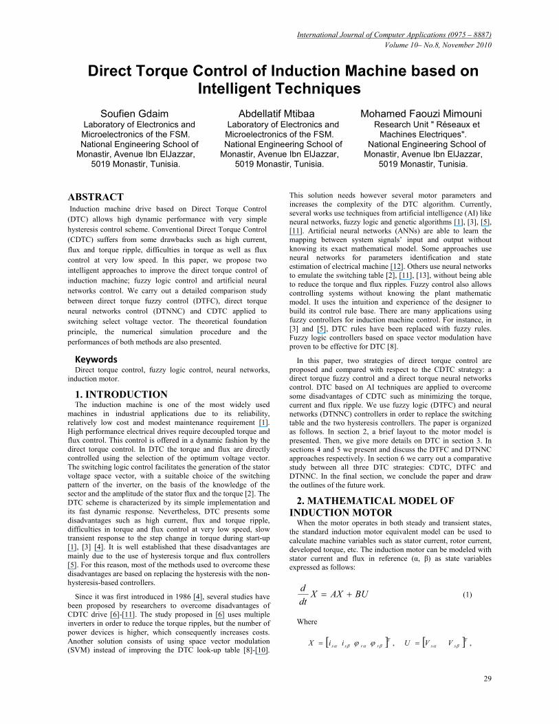
3. PRINCIPLE OF THE DTC The diagram of CDTC for an induction motor drive is shown
in Figure 1. Te* and φs
* are torque and flux reference values; Te
and φs are the estimated torque and stator flux values; ω* is the
command speed value; ω is the real speed value and θs is the
stator flux angle.
-
ω
+
-+
-
Eφ
Ec
N
Voltage source
inverter
IM
PI Speed
controller
Switching Table
Eφ Ec S1 S2 S3 S4 S5 S6
1 V2 V3 V4 V5 V6 V1
0 V7 V0 V7 V0 V7 V0 1 -1 V6 V1 V2 V3 V4 V5
1 V3 V4 V5 V6 V1 V2
0 V0 V7 V0 V7 V0 V7 0 -1 V5 V6 V1 V2 V3 V4
Sa Sb Sc
φ*
Te*
φs
Te
θs
Stator Flux & Torque Estimator
∫ −= dtIRV SSSS )(ϕ
)(2
3αββα ϕϕ sssse iipT −=
iA iB
E
-
+
ω*
+
+
Figure 1. Diagram of the CDTC method
A PI or PID controller is used to determine the reference
torque, based on the difference between the reference and the
instantaneous speed of the motor.
The basic idea of the DTC concept is to choose the best vector
of the voltage, which makes the flux rotate and produce the
desired torque. During this rotation, the amplitude of the flux
remains in a pre-defined band [14]. In order to control the
induction motor, the supply voltage and stator current are
sampled. Only two phase currents are needed to measure iA and
iB, the third phase can be calculed as follow: iC=-iA-iB. The stator
flux on the stationary reference axes αβ is estimated as follows:
−=Φ
−=Φ
∫∫
dtiRV
dtiRV
ssss
ssss
)(
)(
βββ
ααα (2)
where sΦ is the stator flux and Rs is the stator resistance. The
module of the stator flux is given by equation (3), the developed
electromagnetic torque Te of the motor can be evaluated by
equation (4) and the angle between the referential and φs is
presented by equation (5).
22
βα ϕϕφ sss += (3)
( )βααβ ϕϕ sssse iipT −=2
3 (4)
= −
β
α
ϕϕ
θs
ss
1tan (5)
The estimated values of the torque and stator flux are
compared to the command values, Te* and φs
* respectively. It can
be seen from figure 1 that the error between the estimated torque
Te and the reference torque Te* is the input of a three level
hysteresis comparator, where the error between the estimated
stator flux magnitude φs and the reference stator flux magnitude
φs* is the input of a two level hysteresis comparator.
Finally, the outputs of the comparators with stator flux sector,
where the stator flux space vector is located, select an
appropriate inverter voltage vector from the switching Table 1.
The selected voltage vector will be applied to the induction
motor at the end of the sample time [4].
Table 1. The switching table for basic DTC
Eφ Ec S1 S2 S3 S4 S5 S6
1 V2 V3 V4 V5 V6 V1
0 V7 V0 V7 V0 V7 V0 1
-1 V6 V1 V2 V3 V4 V5
1 V3 V4 V5 V6 V1 V2
0 V0 V7 V0 V7 V0 V7 0
-1 V5 V6 V1 V2 V3 V4
Vectors V1,…,V6 represent the six active vectors that can be
generated by a voltage source inverter (VSI) where V0 and V7
are the two zero voltage vectors. Figure 2 gives the partition of
the complex plan in six angular sectors Si=1…6.
V 1
V 2 V 3
V 4
V 5 V 6
Sector 1
Sector 2 Sector 3
Sector 4
Sector 6 Sector 5
Figure 2. Partition of the complex plan in six angular sectors
When flux is in zone i, vector Vi+1 or Vi-1 is selected to
increase the level of the flux, and Vi+2 or Vi-2 is selected to
decrease it. At the same time, vector Vi+1 or Vi-2 is selected to
increase the level of torque, and Vi-1 or Vi-2 is selected to
decrease it.
If V0 or V7 is selected, the rotation of flux is stopped and the
torque decreases whereas the amplitude of flux remains
unchanged. This shows that the choice of the vector tension
depends on the sign of the error of flux and torque independently
from its amplitude [4]. This explains why the output of the
hysteresis comparator of flux and torque must be a Boolean
variable. We can add a band of hysteresis around zero to avoid
useless commutations when the error of flux is very small [4].

International Journal of Computer Applications (0975 – 8887)
Volume 10– No.8, November 2010
31
With this type of hysteresis comparator, we can easily control
and maintain the end of the vector flux within a circular ring.
4. FUZZY LOGIC DTC CONTROLLER
4.1 Principles of Fuzzy Torque Control Since none of the inverter switching vectors is able to generate
the exact voltage required to produce the desired changes in
torque and flux, torque and flux ripples compose a real problem
in DTC induction motor drive [15]. In this section, a fuzzy
approach is proposed to reduce torque ripple. This target is
achieved by the fuzzy controller which determinates the desired
inverter vector state. Figure 3 illustrates the proposed fuzzy
version of the DTC with induction motor.
eφ
eT
Voltage source
inverter
IM
PI Speed
controller
Sa Sb Sc
φ*
Te*
φs
Te
θs
Stator Flux & Torque Estimator
∫ −= dtIRV SSSS )(ϕ
)(2
3αββα ϕϕ ssssem iip −=Γ
iA iB
E
-
+
ω*
Fuzzy controller -
ω
-
-
+
+
+
Figure 3. Diagram of the fuzzy logic DTC method
Our method of DTC differs from the conventional one by
using a fuzzy controller instead of the hysteresis and switching
tables. The fuzzy controller is designed in such a way that it
requires three inputs and one single output. The inputs are the
error of torque, the error in stator and the stator flux angle.
The fuzzy controller generally consists of three parts:
fuzzification, fuzzy reasoning and defuzzification. The
fuzzification is performed using a membership function. The
performance of the fuzzy controller is based upon both the shape
of the membership function and the fuzzy reasoning rules.
4.2 Fuzzy Variables The flux error membership function is represented by three
fuzzy sets as shown in Figure 4: a negative flux error (N), a zero
flux error (Z) and a positive flux error (P).
0
Z N P
1 -1
eφ (Wb)
µφ
1
Figure 4. The fuzzy membership functions of eφ.
The torque error membership function is decomposed into five
fuzzy sets as shown in Figure 5: an entitled negative large error
(NL), a negative small error (NS), a zero error (Z), a positive
small error (PS), and a positive large error (PL).
1
0 -0.5 1 -1 0.5
Z NL NS PS PL
eT (N.m)
µT
Figure 5. The fuzzy membership functions of eT.
For more accuracy of stator flux angle θs, the universe of the
discourse of this fuzzy variable is divided into twelve fuzzy sets
denoted θ1 to θ12 as shown in Figure 6. The associated
membership functions are defined in the same way as for flux
and torque errors.
θ1 θ8 θ7 θ6 θ5 θ4 θ3 θ2 θ12 θ11 θ10 θ9
12
π12
3π12
5π12
7π12
9π12
11π12
13π12
15π12
17π12
19π12
21π12
23π
θ (rad)
µθ
Figure 6. The fuzzy membership functions of eφ.
This novel stator flux locus is introduced in Figure 7
V1
V2V3
V4
V5 V6
S10 S11
S12
S1
S2
S3
S4
S9
S8
S7
S6S5
V1(Fhi,Tld)
V2(Fhi,Tli) V3(Fld,Thi)
V4(Fhd,Tli)
V5(Fhd,Tld)V6(Fli,Thd)
V1(Fhi,Tli)
V2 (Fli,Thi)V3(Fhd,Tli)
V4(Fhd,Tld)
V5(Fld,Thd) V6(Fhi,Tld)
Figure 7. Stator flux vector with twelve sectors. Fhd/Fhi:
flux high decrease /increase. Fsd/Fsi: flux small decrease
/increase. Thd/Thi: Torque high decrease /increase. Tld/Tli:
Torque low decrease /increase.
The output variable of the fuzzy controller is designed so that
it has seven singleton subsets, one zero voltage vector and six
non-zero voltage vectors. The membership functions of the
output space voltage vectors are shown in Figure 8.
1 2 3 4 5 6 0
1 V1 V2 V3 V4 V5 V6 V0
Figure 8. The fuzzy membership functions of output
4.3 Fuzzy Control Rules The rule base monitors the behavior of the fuzzy controller. It
stores the expert knowledge on how to control the plant. Fuzzy
control rules can be deduced from the diagram of voltage vector
in Figure 7. For example, supposing the positional angle θ of
stator’s flux is located in domain θ2, we can have the following
decision rules: if desired control is to make torque decrease
slowly and make flux increase rapidly, then desired decision is V1.
The control goal is to maintain the stator flux at a level value
while keeping the torque‘s response fast. It is easy to show that
we can build up to 180 control rules as shown in Table 2.
International Journal of Computer Applications (0975 – 8887)
Volume 10– No.8, November 2010
32
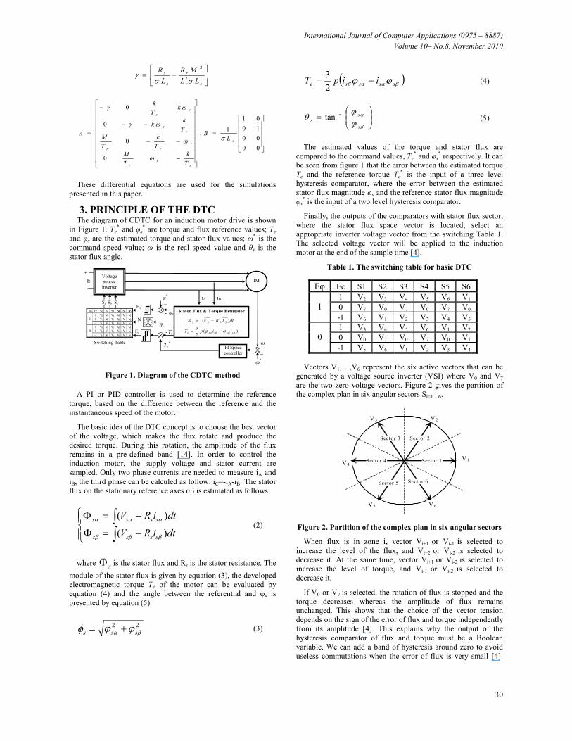
Table 2. Voltage vector fuzzy control table
eφ eT θ1 θ2 θ3 θ4 θ5 θ6 θ7 θ8 θ9 θ10 θ11 θ12
PL V2 V3 V3 V4 V4 V5 V5 V6 V6 V1 V1 V2
PS V2 V2 V3 V3 V4 V4 V5 V5 V6 V6 V1 V1
Z V0 V7 V7 V0 V0 V7 V7 V0 V0 V7 V7 V0
NS V1 V1 V2 V2 V3 V3 V4 V4 V5 V5 V6 V6
P
NL V6 V1 V1 V2 V2 V3 V3 V4 V4 V5 V5 V6
PL V2 V3 V3 V4 V4 V5 V5 V6 V6 V1 V1 V2
PS V2 V3 V3 V4 V4 V5 V5 V6 V6 V1 V1 V2
Z V7 V0 V0 V7 V7 V0 V0 V7 V7 V0 V0 V7
NS V7 V0 V0 V7 V7 V0 V0 V7 V7 V0 V0 V7
Z
NL V6 V1 V1 V2 V2 V3 V3 V4 V4 V5 V5 V6
PL V3 V4 V4 V5 V5 V6 V6 V1 V1 V2 V2 V3
PS V4 V4 V5 V5 V6 V6 V1 V1 V2 V2 V3 V3
Z V7 V7 V0 V0 V7 V7 V0 V0 V7 V7 V0 V0
NS V5 V5 V6 V6 V1 V1 V2 V2 V3 V3 V4 V4
N
NL V5 V6 V6 V1 V1 V2 V2 V3 V3 V4 V4 V5
Each control rule from table 2 can be described using the
input variables torque error ec, flux error eφ, flux angle θ and the
output variable v as shown in equation 6:
Ri : if eφ is Ai and eT is Bi and θ is Ci then v is Vi. (6)
where Ai, Bi and Ci denote the fuzzy set of the variable eφ, eT
and θ respectively. Vi and Ri are the fuzzy singleton and control
of rule number i.
4.4 Fuzzy Inferences The inference method used in this paper is Mamdani’s
procedure based on min-max decision. The membership
functions of variables A, B, C and V are given by µA, µB, µC and
µV respectively. The weighting factor αi for the ith rule is
computed using the min operator:
αi = min (µAi(eφ), µBi(eT), µCi(θ)). (7)
µ'Vi(v)= min (αi , µVi(v)) (8)
In this case, the outputs are crisp values.
The maximum criterion method is used for defuzzification. By
this method, the value of fuzzy output which has the maximum
possibility distribution is used as the control output.
Μ'Vout(v)= 180
1max
=i
( µ'Vi(v)) (9)
The concrete reasoning of fuzzy logic system is shown in the
flowchart of Figure 9. For each combination of inputs, usually
more than one rule is validated. Each rule generates a significant
control action depending on the input values of the variables.
Then defuzzification is applied to generate the control output.
Max
MF(NL,NS,
Z,PS,PL)
Input 1
eφ
Input 3
eT
Input 2
θs
Rule 1 If eφ is P and eT is PL
and θs is θ1 Then v is v2
Output V (0..7)
Rule 2 If eφ is P and eT is PS and
θs is θ1 Then v is v2
Rule 3 If eφ is P and eT is Z and
θs is θ1 Then v is v0
Rule180 If eφ is N and eT is NL and
θs is θ12 Then v is v5
……
..
MF (N,Z,P)
MF (θ1 … θ12)
All rules are evaluated in parallel using
fuzzy reasoning The output
is a crisp
number
Defuzzifica
tion (Min-
Max)
Fuzzification
(Membership
Fonction)
The inputs
are crisp
numbers
Figure 9. Flowchart of fuzzy logic system
5. NEURAL NETWORKS DTC
CONTROLLER
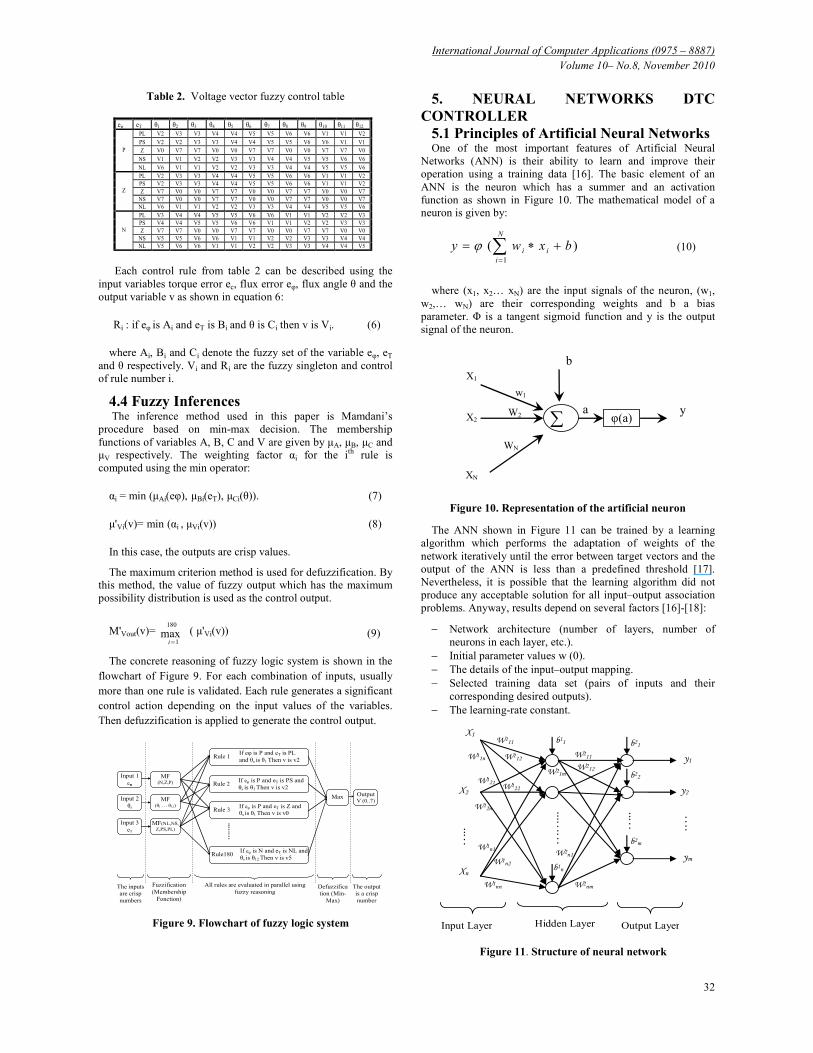
5.1 Principles of Artificial Neural Networks One of the most important features of Artificial Neural
Networks (ANN) is their ability to learn and improve their
operation using a training data [16]. The basic element of an
ANN is the neuron which has a summer and an activation
function as shown in Figure 10. The mathematical model of a
neuron is given by:
)(1
∑=
+∗=N
i
ii bxwy ϕ (10)
where (x1, x2… xN) are the input signals of the neuron, (w1,
w2,… wN) are their corresponding weights and b a bias
parameter. Φ is a tangent sigmoid function and y is the output
signal of the neuron.
X1
X2
XN
b
φ(a) a y
w1
W2
WN
∑
Figure 10. Representation of the artificial neuron
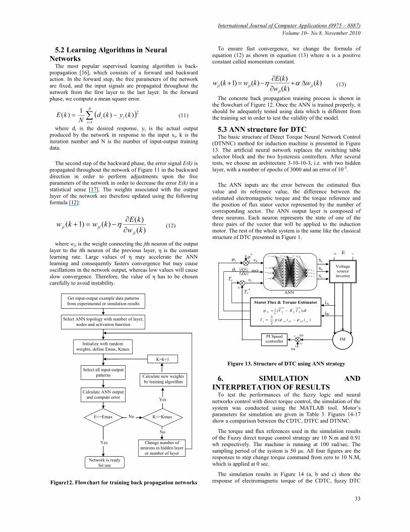
The ANN shown in Figure 11 can be trained by a learning
algorithm which performs the adaptation of weights of the
network iteratively until the error between target vectors and the
output of the ANN is less than a predefined threshold [17].
Nevertheless, it is possible that the learning algorithm did not
produce any acceptable solution for all input–output association
problems. Anyway, results depend on several factors [16]-[18]:
− Network architecture (number of layers, number of
neurons in each layer, etc.).
− Initial parameter values w (0).
− The details of the input–output mapping.
− Selected training data set (pairs of inputs and their
corresponding desired outputs).
− The learning-rate constant.
b1n
……
...
W2n1
W2nm
W21m
W212
W211
W1nn
W1n2
W1n1
W11n
W121 W1
22
W12n
W112
W111
….. …
..
X1
X2
Xn
y1
y2
ym
.…
b11 b21
b22
b2m
Input Layer Hidden Layer Output Layer
Figure 11. Structure of neural network
International Journal of Computer Applications (0975 – 8887)
Volume 10– No.8, November 2010
33
5.2 Learning Algorithms in Neural
Networks The most popular supervised learning algorithm is back-
propagation [16], which consists of a forward and backward
action. In the forward step, the free parameters of the network
are fixed, and the input signals are propagated throughout the
network from the first layer to the last layer. In the forward
phase, we compute a mean square error.
( )∑=
−=N
i
ii kykdN
kE1
2)()(
1)( (11)
where di is the desired response, yi is the actual output
produced by the network in response to the input xi, k is the
iteration number and N is the number of input-output training
data.
The second step of the backward phase, the error signal E(k) is
propagated throughout the network of Figure 11 in the backward
direction in order to perform adjustments upon the free
parameters of the network in order to decrease the error E(k) in a
statistical sense [17]. The weights associated with the output
layer of the network are therefore updated using the following
formula [12]:
)(
)()()1(
kw
kEkwkw
ji
jiji ∂∂
−=+ η (12)
where wji is the weight connecting the jth neuron of the output
layer to the ith neuron of the previous layer, η is the constant
learning rate. Large values of η may accelerate the ANN
learning and consequently fasters convergence but may cause
oscillations in the network output, whereas low values will cause
slow convergence. Therefore, the value of η has to be chosen
carefully to avoid instability.
Get input-output example data patterns
from experimental or simulation results
Select ANN topology with number of layer,
nodes and activation function
Initialize with random
weights, define Emax, Kmax
Select all input-output
patterns
Calculate ANN output
and compute error
E<=Emax No
Yes
Calculate new weights
by training algorithm
K<=Kmax
K=k+1
Yes
No
Network is ready
for use
Change number of
neurons in hidden layer
or number of layer
Figure12. Flowchart for training back propagation networks
To ensure fast convergence, we change the formula of
equation (12) as shown in equation (13) where α is a positive
constant called momentum constant.
)()(
)()()1( kw
kw
kEkwkw ji
ji
jiji ∆+∂∂
−=+ αη (13)
The concrete back propagation training process is shown in
the flowchart of Figure 12. Once the ANN is trained properly, it
should be adequately tested using data which is different from
the training set in order to test the validity of the model.
5.3 ANN structure for DTC The basic structure of Direct Torque Neural Network Control
(DTNNC) method for induction machine is presented in Figure
13. The artificial neural network replaces the switching table
selector block and the two hysteresis controllers. After several
tests, we choose an architecture 3-10-10-3, i.e. with two hidden
layer, with a number of epochs of 3000 and an error of 10-3.
The ANN inputs are the error between the estimated flux
value and its reference value, the difference between the
estimated electromagnetic torque and the torque reference and
the position of flux stator vector represented by the number of
corresponding sector. The ANN output layer is composed of
three neurons. Each neuron represents the state of one of the
three pairs of the vector that will be applied to the induction
motor. The rest of the whole system is the same like the classical
structure of DTC presented in Figure 1.
ANN
+
-
eφ
ec
sect
Te*
Te
θs
iA
+
- φ
*
φs Sa
Sb
Sc
ω
+
- IM
PI Speed
controller
Stator Flux & Torque Estimator
∫ −= dtIRV SSSS )(ϕ
)(2
3αββα ϕϕ sssse iipT −=
iB
ω*
Voltage
source
inverter
E
-
+
e c
e φ
s e c t S a
S b
S c
b 1 b 2 b 3
Figure 13. Structure of DTC using ANN strategy
6. SIMULATION AND
INTERPRETATION OF RESULTS To test the performances of the fuzzy logic and neural
networks control with direct torque control, the simulation of the
system was conducted using the MATLAB tool. Motor’s
parameters for simulation are given in Table 3. Figures 14-17
show a comparison between the CDTC, DTFC and DTNNC.
The torque and flux references used in the simulation results
of the Fuzzy direct torque control strategy are 10 N.m and 0.91
wb respectively. The machine is running at 100 rad/sec. The
sampling period of the system is 50 µs. All four figures are the
responses to step change torque command from zero to 10 N.M,
which is applied at 0 sec.
The simulation results in Figure 14 (a, b and c) show the
response of electromagnetic torque of the CDTC, fuzzy DTC
International Journal of Computer Applications (0975 – 8887)
Volume 10– No.8, November 2010
34
and neural network respectively. It can be seen that the torque's
ripples with fuzzy direct torque control in steady state is
significantly reduced compared to conventional and neural
networks DTC. It is obvious from Figure 14.d that in fuzzy
direct torque control, the torque trajectory is established quickly
than in the conventional or the neural network DTC. The torque
trajectories with conventional and neural networks DTC in start-
up are almost similar.
a b
DTFC
DTNNC
DTC
d c
(a).CDTC. (b). DTFC. (c). DTNNC. (d) Conventional, Fuzzy
and neural DTC plots
Figure 14. Electromagnetic torque response
Figure 15 (a, b and c) illustrates the response of stator flux
magnitude of the CDTC, fuzzy DTC and neural network
respectively. Compared with the CDTC, ripple of stator flux
with fuzzy and neural network DTC is reduced significantly. The
stator flux of the fuzzy DTC has the fast response time in
transient state as shown in Figure 15.d.
a b
c
DTFC
DTNNC
DTC
d
(a).CDTC. (b). DTFC. (c). DTNNC. (d) Conventional, Fuzzy
and neural DTC
Figure 15. The stator flux magnitude
The simulation results in Figure16 (a, b and c) show that the
current's stator ripples with direct torque neural networks control
in steady state is significantly reduced compared to CDTC.
Compared to the neural DTC, ripple of stator current with fuzzy
DTC is almost similar.
a
b
c
(a). Fuzzy DTC. (b).Neural network DTC. (c). CDTC.
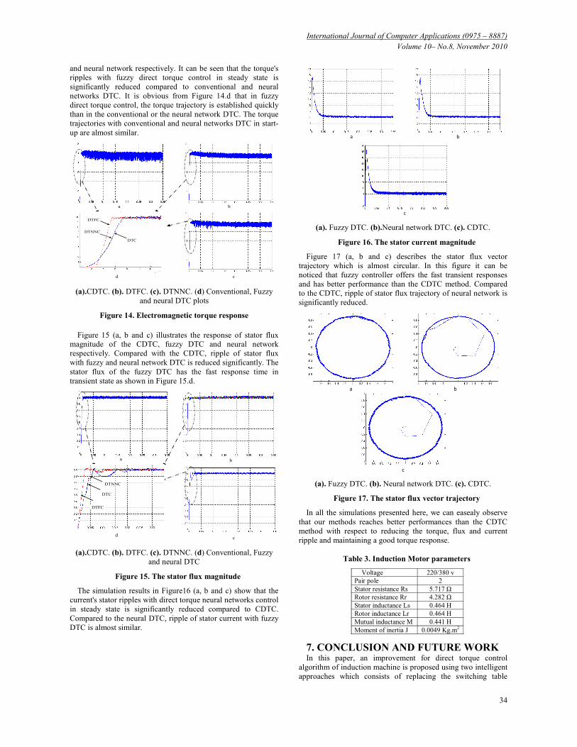
Figure 16. The stator current magnitude
Figure 17 (a, b and c) describes the stator flux vector
trajectory which is almost circular. In this figure it can be
noticed that fuzzy controller offers the fast transient responses
and has better performance than the CDTC method. Compared
to the CDTC, ripple of stator flux trajectory of neural network is
significantly reduced.
a
b
c
(a). Fuzzy DTC. (b). Neural network DTC. (c). CDTC.
Figure 17. The stator flux vector trajectory
In all the simulations presented here, we can easealy observe
that our methods reaches better performances than the CDTC
method with respect to reducing the torque, flux and current
ripple and maintaining a good torque response.
Table 3. Induction Motor parameters
Voltage 220/380 v
Pair pole 2
Stator resistance Rs 5.717 Ω
Rotor resistance Rr 4.282 Ω
Stator inductance Ls 0.464 H
Rotor inductance Lr 0.464 H
Mutual inductance M 0.441 H
Moment of inertia J 0.0049 Kg.m2
7. CONCLUSION AND FUTURE WORK In this paper, an improvement for direct torque control
algorithm of induction machine is proposed using two intelligent
approaches which consists of replacing the switching table
International Journal of Computer Applications (0975 – 8887)
Volume 10– No.8, November 2010
35
selector block and the two hysteresis controllers. Simulations
have shown that the two proposed strategies have better
performances than the CDTC. In fact, they alloaw a significant
reduced torque and stator flux ripples and a good starting
behavior. Using the intelligent techniques, the selection of the
voltage vector becomes much convenient and the switching state
can be obtained when the error of the torque and stator flux is
attained. The validity of the proposed control is confirmed by the
simulative results. None of the known advantages of the CDTC
are impacted by the proposed methods. It has been found that the
direct torque fuzzy control strategy allows a higher dynamic
behavior than the conventional and neural network DTC.
In the future research, the simulative results will be brought
into the experimental system to prove the proposed neural
network and fuzzy logic control. A digital implementation of
these intelligent controls may be performed using different
devices such as custom design, programmable logic, etc. In a
Field Programmable Gate Array (FPGA), which is a family of
programmable devices, multiple operations can be executed in
parallel so that algorithms can run faster, which is required for
control systems.
8. REFERENCES 1. Abbou A, Mahmoudi H. Performance of a sensorless speed
control for induction motor using DTFC strategy and
intelligent techniques. Journal of Electrical Systems.
Volume 5, Issue 3, September 2009.
2. A. Sivasubramanian, B. Jayanand. Application of Neural
Network Structure in Voltage Vector Selection of Direct
Torque Control Induction Motor. International Journal of
Applied Engineering Research. Volume 4 Number 6, 2009.
3. Luis R, Antoni A, Emiliano A, Marcel G. Novel Direct
Torque Control (DTC) Sheme With Fuzzy Adaptive
Torque- Ripple Reduction. IEEE Transactions On Industrial
Electronics, vol 50, No.3, June 2003.
4. Takahashi I, Noguchi T. A new quick-response and high
efficiency control strategy of an induction motor, IEEE
trans. Vol IA-22, no 5. 1986.
5. Deng J, Tu L. Improvement of Direct Torque Control Low-
speed Performance by Using Fuzzy Logic Technique.
International Conference on Mechatronics and Automation.
June 25-28, Luoyang, china.
6. Toh C, Idris N, Yatim A, Muhamad N, Elbuluk M.
Implementation of a New Torque and Flux Controllers for
Direct Torque Control (DTC) of Induction Machine
Utilizing Digital Signal Processor (DSP) and Field
Programmable Gate Arrays (FPGA). Power Electronics
Specialists Conference, 2005. IEEE 36th 16-16 June 2005.
7. Bibhu P, Dinkar P, Sabyasachi S. A Simple hardware
realization of switching table based direct torque control of
induction motor. Electric Power Systems research 2007.
Elsevier Publisher.
8. Mengjia J, Jianqi Q, Cenwei S, Ruiguang L. A fuzzy DTC
method with a SVM defuzzification to Permanent Magnet
synchronous Machine. The 30th annual conference of the
IEEE inductrial electronics society, November 2-5, 2004 korea.
9. Saurabh N, Pandya A, Chatterjee J. Torque Ripple
Minimisation in direct torque control based IM drive, Part 1
: Single-rate control strategy. 978-1-4244-1762-9/08. 2008
IEEE.
10. Yuttana K, Suuttichai P, Hamid A. Modified Direct Torque
Control method for induction motor drives based on
amplitude and angle control of stator flux. Electric Power
Systems research 2008. Elsevier Publisher.
11. Rajesh K, Gupta R, Bhangale S, Himanshu G. Artificial
Neural Network Based Direct Torque Control of Induction
Motor Drives. IET-UK International Conference on
Information and Communication Technology in Electrical
sciences (ICTES 2007)
12. A. Goedtel, I.. N. Silva, P. J. Serni, Load torque
identification in induction motor using neural networks
technique, Electric Power Syustem Research, Science
Direct 2006.
13. A. Abbou , H. Mahmoudi. Performance of a sensorless speed
control for induction motor using DTFC strategy and
intelligent techniques. Journal of Electrical Systems.
Volume 5, Issue 3, September 2009.
14. Kaboli S, Zlghadri M, Emadi A. A Fast Flux Search
Controller for DTC Based Induction Motor Drives. Power
Electronics Specialists Conference, 2005. PESC '05. IEEE
36th Publication Date: 16-16 June 2005.
15. Fatiha Z, Rachid N. Direct torque control of induction motor
with fuzzy minimization torque ripple. Journal of
electrique engineering, vol 56, no 7-8, 2005.
16. M. Cirstea, A. Dinu, J. Khor, M. Mccormick, "Neural and
Fuzzy Logic Control of Drives and Power Systems",
Newnes, An imprint of Elsevier Science First published
2002. 412 pages.
17. S. Haykin, "Neural Network – A comprehensive
Foundation", Prentice Hall 1999. 897 pages.
18. B. Bose, "Power Electronics and Motor Drives, Advances
and Trends", Academic Press is an imprint of Elsevier,
published 2006, 935 pages.