
Digital Protection Relay Digital Integrated Metering & Control ...
24
SMART - MEC series Digital Protection Relay / Digital Integrated Metering & Control Equipment ISO14001, ISO9001 Digital Protection Relay (DPR) Digital Integrated Metering & Control Equipment (GIMAC-Ⅲ) 00 -05 00 -05
-
Upload
khangminh22 -
Category
Documents
-
view
6 -
download
0
Transcript of Digital Protection Relay Digital Integrated Metering & Control ...

SMAR
T-M
EC s
erie
sDig
ital P
rotect
ion Re
lay/ D
igital
Integ
rated
Meter
ing &
Contr
ol Eq
uipme
nt
ISO14001, ISO9001
Digital Protection Relay (DPR)
Digital Integrated Metering & ControlEquipment (GIMAC-ⅢⅢ)
00 -0500 -05
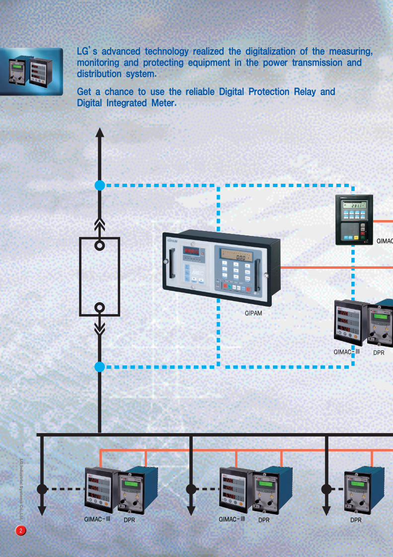
LG’s advanced technology realized the digitalization of the measuring, monitoring and protecting equipment in the power transmission and distribution system.
Get a chance to use the reliable Digital Protection Relay and Digital Integrated Meter.
GGIIMMAACC--ⅢⅢ
GGIIPPAAMM
DDPPRR
2
GGIIMMAACC--ⅢⅢ DDPPRR GGIIMMAACC--ⅢⅢ DDPPRR DDPPRR
GGIIMMAACC

IItt iiss aapppplliiccaabbllee ttoo vvaarriioouuss pprrooggrraammss ffoorr ppoowweerr mmoonniittoorriinngg && ccoonnttrrooll ssyysstteemm..
3
II--NNEETT ccoommmmuunniiccaattiioonn
nneettwwoorrkk
PPrroottooccoollCCoonnvveerrtteerr
GGMMPPCC--ⅡⅡ
DDeesskkttoopp PPCC
RRSS223322CCRRSS448855
DDPPRR μμ--RRTTUU
CC--ⅡⅡ

4
�� WWiiddee rraannggee ooff tthhee PPTT iinnppuutt vvoollttaaggee((AACC 448800VV))�48�576Vac without additional primary PT.
�� MMeeaassuurree tthhee 1122 vvaalluueess wwiitthh oonnee DDiiggiittaall IInntteeggrraatteedd MMeetteerr..�12 values are displayed by the three LED windows�Saving the installation space and easy wiring, compare with those of Analog type’s
�� VVaarriioouuss ffuunnccttiioonn wwiitthh ccoommppaacctt ddiimmeennssiioonn�144mm(Width)×177mm(Height)×100mm(Depth)
�� EEaassyy ttoo ooppeerraattee aanndd sseett�Set and check all the values by operating the ket button in the front.
�� AAppppllyy tthhee EEEEPPRROOMM ((EElleeccttrriiccaallllyy EErraassaabbllee PPrrooggrraammmmaabbllee RReeaadd oonnllyy MMeemmoorryy)) mmeemmoorryy�Power capacity 〔wh〕value can be recorded and restored during the electrical outage.
�� EEMMCC tteesstt cceerrttiiffiiccaattee�EMC test certified by TOKIN in Korea
�� VVaarriioouuss ccoommmmuunniiccaattiioonn nneettwwoorrkk�By the I-NET’s exclusive communication and Modbus communication(option), it is available for network constitution and remote supervision with the higer systems
�Easy to change the communication module and it provides easy constitution of a communication network.�By connecting with the protocol transducer(GMPC), it can be changed from I-NET to RS232C serial communication
�� PPuullssee oouuttppuutt ffoorr tthhee AAccttiivvee aanndd RReeaaccttiivvee ppoowweerr ccaappaacciittyy
�� AAppppllyy tthhee IInntteerrnnaattiioonnaall ssttaannddaarrdd�IEC 1036, KEMC 1110
Digital Integrated Meter(GIMAC-III)

S M A R T - M E C S E R I E SRatings and measurementDIGITAL INTEGRATED METER
Ratings
TTyyppee ddeessiiggnnaattiioonn GGIIMMAACC--221155NNNN
WWiirriinngg ttyyppee 1phase 2wires, 1phase 3wires, 3phase 3wires, 3phase 4wires
IInnppuutt Voltage(Vn) AC480V (48�576V)
Current(In) 5A (0.125�6A)
Frequency 60Hz (45�65Hz)
Control voltage DC110V (DC88�126V)
Input burden PT:0.3VA CT:0.15VA Power consumption:10VA
OOuuttppuutt Pulse out Active power capacity A cycle : Min. 250ms, width : 100ms Note1)
Reactive power capacity Accuracy : 2.0%
Output element SSR(Solid State Relay)
External power supply DC 24V(DC12�24V)
Continuous carrying current 0.4A
Maximum output pulse 4Hz
DDiissppllaayy ttyyppee 4digit 7segments×2line, 5digit 7segment×1line
CCoommmmuunniiccaattiioonn ffuunnccttiioonn I-NET (MODBUS) Note2)
IInnssuullaatteedd rreessiissttaannccee DC 500V 100MΪ and over
IInnssuullaattiioonn vvoollttaaggee (Power frequency withstand voltage) AC 2kV(1kV) for 1 minute and over
IImmppuullssee vvoollttaaggee (Lightning impulse withstand voltage) 5kV(3kV) for 1.2×50㎲ and over
OOvveerrllooaadd wwiitthhssttaanndd Current circuit In×2 for 3 hours
ccaappaacciittyy In×20 for 2 seconds
Voltage circuit Vn×1.2 for 3 hours
TTeemmppeerraattuurree Transporting -20�55℃
Storage -25�75℃
HHuummiiddiittyy 80% RH (non-condensing)
AAllttiittuuddee 2000m and below
AApppplliiccaabbllee ssttaannddaarrdd IEC1036, KEMC1110
WWeeiigghhtt(Without communication function) 0.86kg (0.81kg)
DDiimmeennssiioonn 144(W) × 177(H) × 100(D)mm
Voltage(V) 0�9,999kV ±1.0% each phase/wire to wire voltage
Current(A) 0�9,999kA ±1.0% each wire current indication
Active power(W) 0�99,999MW ±2.0%
Reactive power(Var) 0�99,999MVar ±2.0%
Active power watts(Wh) 0�99,999MWh ±2.0%
Reactive power vars(Varh) 0�99,999MVarh ±2.0%
Power factor(PF) -1.0�1.0 ±2.0% (-) : phase
Frequency(F) 45�65Hz ±0.5%
Reverse active power(Reverse W) 0�99,999MW ±2.0% “W”LED flickers on
Reverse active power watts(Reverse Wh) 0�99,999MWh ±2.0% “WH”LED flickers on
Current demands 0�9,999kA “WINDOW 2”flickers on
Power demands 0�99,999MW “WINDOW 3”flickers on
PPaarraammeetteerr RRaannggee AAccccuurraaccyy RReemmaarrkk
Note1) The ratio of pulse output can be changeable according to the parameter setting described in page 7.Note2) For MODBUS communication, please contact us when you order
5
�“WINDOW 1”: It can be displayed each phase/phase to phase voltage by operating No. 1 of key.�“WINDOW 2”: It can be displayed each wire current and current demands by operating No. 2 of key.�“WINDOW 3”: It can be displayed active/reactive power (and capacity), power factor, frequency, reverse power (and capacity), power demands by operating No. 3 of key.
�All measured parameters will be scroll displayed when pushing the “ENTER”key at normal operation mode.�The reverse power will be displayed at “WINDOW 3”when it happens
Measuring indication
GIM
AC-III

ConstitutionDIGITAL INTEGRATED METER
CT10 P1
P2
P3
P0
FG
CT11CT20
CT21CT30CT31PUL0
PUL1DC0DC1
100ms 150ms
DC24V
DC110V
M3.5 screw
M3 screw
LOAD
Min.
TX0 TX1 RX0 RX1
RX0
GMPC-ⅡⅡ
RX1 TX0 TX1
6
CCOOMMMM LLEEDD
Flickers on during normal communication
WWIINNDDOOWW 11Each phase/Line- line
voltage indication
WWIINNDDOOWW 33
Active/Reactive powerReverse power, Power factor, FrequencyPower demands indication
WWIINNDDOOWW 22
Each line current and current demands indication
LLEEDD iinnddiiccaattiioonnIndicating parameter or unit
displayed at each WINDOWs
UUPP KKeeyy((11))
- WINDOW1 parameter indication- Searching setting value and settingparameter at setting mode
DDOOWWNN KKeeyy((22))
- WINDOW2 parameter indication- Searching setting value and settingparameter at setting mode
ENTER Key (RESET)- Returning to normal operating mode after
setting completion
- Each parameter initialized at setting mode
- Scroll displaying measured parameter
SSEELLEECCTT KKeeyy((33))
- WINDOW 3 parameter indication- Searching setting value and settingparameter at setting mode

S M A R T - M E C S E R I E SOperating and setting methodDIGITAL INTEGRATED METER
Wiring type
PPaarraammeetteerrss
PT ratio
CT ratio
Pulse output ratio
Output pulse
Communication
transmission function
Address
Power demand time
Current demand time
Watts/Vars
indication unit
Active power watts resetReactive power vars resetReactive power capacityreset
Current demand reset
Program version
Power demand reset
1�6
1.0�30,000
1�30,000
1�30,000
1�2
1�2
1�255
1�60(분)
10�3,600(sec)
10�3,600(sec)
10�3,600(sec)
1�3
×××××
Measured value and storage value
1: 1P2W 4: 3P3W (Open delta)
2: 1P3W 5: 3P4W (Phase voltage indication)
3: 3P3W(Direct) 6: 3P4W (Wire to wire voltage indication)
0.1 step
1 step
1 step
1 step
1: Active power capacity pulse output
2: Reactive power capacity pulse output
1: Disable for periodic up-date of measured data
2: Available for periodic up-date of measured data(GIMAC⇔I-NET card)
Setting the time interval of power demand(1 step)
Setting the time interval for the current demand of 1st wire(1 step)
Setting the time interval for the current demand of 2nd wire(1 step)
Setting the time interval for the current demand of 3rd wire(1 step)
1: Basic (Wh, Varh)
2: Kilo (kWh, kVarh)
3: Mega (MWh, MVarh)
Data initialized when one time pressing SELECT(3) key
and then pressing ENTER key
Indicating the software version applied to the product
(Not changeable)
NNOODDiissppllaayy
WWIINNDDOOWW 11 WWIINNDDOOWW 33
① It will be changed to the setting mode when pressing No. 2 key and No. 3 key at the same time.Setting parameter is indicated at “WINDOW 1”and the setting value is indicated at “WINDOW 3”
② Search the setting parameters by pushing the UP(1) or DOWN(2) key
③“WINDOW 1”displayed setting parameter flickers on if the SELECT(3) key is pressed one time.At this time please set the required data value at “WINDOW 3”with UP(1) or DOWN(2)key,then it will be completed to set the relevant parameter by pushing the SELECT(3) key once again.
④ Continuously, please set another parameters by repeating the sequence of ② and ③.
⑤ Please reset to normal operation mode by pressing the ENTER key one time after all settings completed.
1
2
3
4
5
6
7
8
9
10
11
12
13
14
15
16
7
RReemmaarrkkss
Operating and setting method
Setting parameters

Connection methodsDIGITAL INTEGRATED METER
1P 2W CONNECTIONLINELOAD
CT10 P1
P2
P3
P0
FG
CT11
CT20
CT21
CT30
CT31
PUL0
PUL1
DC0
DC1DC110V
CT10 P1
P2
P3
P0
FG
CT11
CT20
CT21
CT30
CT31
PUL0
PUL1
DC0
DC1DC110V
CT10 P1
P2
P3
P0
FG
CT11
CT20
CT21
CT30
CT31
PUL0
PUL1
DC0
DC1DC110V
CT10 P1
P2
P3
P0
FG
CT11
CT20
CT21
CT30
CT31
PUL0
PUL1
DC0
DC1DC110V
CT10 P1
P2
P3
P0
FG
CT11
CT20
CT21
CT30
CT31
PUL0
PUL1
DC0
DC1DC110V
CT10 P1
P2
P3
P0
FG
CT11
CT20
CT21
CT30
CT31
PUL0
PUL1
DC0
DC1DC110v
3P 3W OPEN DELTA CONNECTIONLINELOAD
1P 3W CONNECTIONLINELOAD
L1
N
L2
L1
L2
L3
3P 3W DIRECT CONNECTION-3CTLINELOAD
L1
L2
L3
3P 4W DIRECT CONNECTIONLINELOAD
L1
L2
L3
N
3P 3W DIRECT CONNECTIONLINELOAD
L1
L2
L3
8

S M A R T - M E C S E R I E SDimensions and ordering informationDIGITAL INTEGRATED METER
9
Ordering information
Cut-out dimension
Note 1) Non-standaed type is applicable to GIMAC-II(Type 1)and please refer the catalog of GIMAC-II
Note 2) Only available for GIMAC-III
PPTT rraattiioo
N Standard
S Non-standard Note1)
MMeeaassuurriinngg eelleemmeenntt
5 Measuring integrated
CCoonnttrrooll vvoollttaaggee
1 DC110V
CCoommmmuunniiccaattiioonn uunniitt
COM I-NET communication module(for GIMAC-115N)
COMII I-NET communication module(for GIMAC-215N)
TTyyppee
1 Relay connecting type(GIMAC-II) Note1)
2 Separated window type(GIMAC-III)
CCoommmmuunniiccaattiioonn ffuunnccttiioonn Note2)
N Built-in communication card
O No communication card

10
�� CCoommppaacctt ddeessiiggnn�124mm(Width) × 177mm(Height) × 243mm(Depth)
�� EEaassyy ttoo ooppeerraattee aanndd sseett�Set and check all the values by operating the ket button in the front.
�� BBaacckk--lliitt LLCCDD ddiissppllaayy�Back-lit LCD diaplay provide increased visibility�Easy to check the cause of a fault and setting status by the abundant indication functions�LCD flickers when all trips happens
�� AAddjjuussttaabbllee ccuurrrreenntt aanndd ooppeerraattiioonn ttiimmee�Minute setting steps for the current and time are appropriate for network protection.
�� TThhee uussee ooff tthhee oouuttppuutt ccoonnttaaccttss aarree pprrooggrraammmmaabbllee�Various settings for output contacts(Trip or Alarm) are available�For details, refer to the table in page 15, 19
�� FFaauulltt rreeccoorrddiinngg ffuunnccttiioonn�When there is a fault in the power line, it records the fault wave forms for 10 cycles to the EEPROM.
�� SSeeqquueennccee ooff EEvveenntt FFuunnccttiioonn((SS..OO..EE//OOppttiioonnaall))�It provides the sequence of the event (relay operation and cause of the fault and data adjustment, etc) to the higher system by the mili second intervals and it helps to analyze the cause of the fault easily.
�� VVaarriioouuss ccoommmmuunniiccaattiioonn nneettwwoorrkk ccoonnffiigguurraattiioonnss�I-NET exclusive communication and Modbus communication(optional)
�� EEMMCC//EEMMII tteesstt cceerrttiiffiieedd
Digital Protection Relay (DPR)

S M A R T - M E C S E R I E SEnvironmental characteristicsDIGITAL PROTECTION RELAY
DDiieelleeccttrriicc wwiitthhssttaanndd IEC 255-5 2kV rms. for 1 minute between all case terminals connected together and the case earth.
KEMC1120 2kV rms. for 1 between all terminals of independent circuitswith terminals and each independent circuit connected together
1kV rms. for I minute between each all terminals of open contact circuits
HHiigghh vvoollttaaggee iimmppuullssee IEC 255-5 5kV peak, 1.2×50㎲, between all terminals connected together and case earth
KEMC1120 5kV peak, 1.2×50㎲, between mutual PT/CT circuits
5kV peak, 1.2×50㎲, between PT/CT circuits and control circuits
3kV peak, 1.2×50㎲, between mutual control circuits
3kV peak, 1.2×50㎲, between all terminals of PT/CT circuits
3kV peak, 1.2×50㎲, between all terminals of control power supply circuits
IInnssuullaattiioonn rreessiissttaannccee IEC 255-5 DC 500V 10㏁ and over between all case terminals connected together and the case earth.
KEMC1120 DC 500V 5㏁ and over between all terminals of independent circuitswith terminals and each independent circuits connected together DC 500V 5㏁ and over between each terminals of open contact circuits
OOvveerrllooaadd ccaappaacciittyy KEMC1120 Current circuit : In×2 for 3 hours(2 times by 1 minute interval) In×20 for 2 seconds
JEC-2500 In×40 for 1 second
KEMC1120 Voltage circuit : Vn×1.15 for 3 hours (1 time)
HHiigghh ffrreeqquueennccyy ddiissttuurrbbaannccee IEC 255-22-1 2.5kV Peak between independent circuits and case
ClassIII 1.0kV Peak across terminals of the same circuit
FFaasstt ttrraannssiieenntt ddiissttuurrbbaannccee IEC 255-22-4 4kV applied directly to power input
ClassIV 2kV applied to other inputs
EElleeccttrroossttaattiicc ddiisscchhaarrggee IEC 255-22-2 8kV discharge in air with cover in place
((EESSDD)) Class III 6kV point contact discharge with cover removed
RRFFII KEMC1120 Making a wave by accessing to the edge of relaywith 5W transceiver(150MHz, 400MHz)
EEMMII EN 50081-2 AC power:0.15�0.50MHz, standard 79dB, average 66dB
ClassII 0.50�30MHz, standard 73dB, average 60dB
OOppeerraattiinngg tteemmppeerraattuurree IEC 68-2-1 -10�55℃
SSttoorraaggee tteemmppeerraattuurree IEC 68-2-2 -20�70℃
HHuummiiddiittyy IEC 68-2-3 56 days at 93% RH and +40℃
SShhoocckk IEC 255-21-2 30g, 3times/dir.
KEMC 1120
VViibbrraattiioonn KEMC 1120 30Hz, 0.4mm vibration applied for 600 seconds
EEnncclloossuurree pprrootteeccttiioonn IEC 529 IP 50(dust protected)
11
ClassⅢ
DPR

ConstitutionDIGITAL PROTECTION RELAY
I-NET I-NET
RS232CRS485
GMPC-Ⅱ
Protocolconverter
DPR1
DPR2
DPR3
DPR4
DPR2
DPR20
DPR1
GIMAC20
GIMAC4
GIMAC3
12
DISPLAY2 lines’back-lit LCD for
fault indication and setting
M4 screw
DOWN keyDecreasing setting value
Shifting to each menu
INDICATORSAlarm: Alarm status LED
Run: Normal operation status LED
Comm: Communication status LED
Trip: Trip status LED
System constitution
ENT/RESET keyENT : Selecting menu or data
Reset: Resetting after relay operation
Increasing setting value
Shifting to each menu
UUPP kkeeyy
Shifting to each menu
FUNC key

S M A R T - M E C S E R I E SAdditional functionsDIGITAL PROTECTION RELAY
High reliability of relay will be provided by various self-diagnostics function.When errors occurs it will be displayed “Error No.”at LCD display window, then thefront ALARM LED lights on and LCD display window flickers on also.At the same time ALARM relay(Sys fail) will be output.
1. Internal ROM check: “Error 1”2. Internal RAM check: “Error 2”3. A/D converter check: “Error 3”4. CPU watchdog check: “Error 4”5. Power supply check: “Error 5”6. EEPROM(Backup memory) check: “Error 6”7. Calibration check: “Error 7”When the self-diagnostics error happens, the relay is not operated until the cause of that fault is cleared.
1. The fault curves are recorded into EEPROM when line fault happens, which will providefast and correct grasping for the cause of a fault.
2. Storage the sample value of each phase for 10 cycles before and after the fault�5 cycles before the fault�5 cycles after the fault�8 samples for a cycle
3. A fault recording information is available for ascertaining them via communications.
Many events (including relay operation, cause of fault, data adjustment) can be provided to the higher system
1. Kinds of event�The cause of a relay operation(trip) �The data adjustment of a relay�Error occurrence of auto-diagnostics�Relay resetting
2. Twenty events are stored in a buffer (maximum)
1. I-NET communication
High speed, high reliability of serial communication by use of the custom LSI(GC829016) developed by LGIS
1) Data rate : 250kbps2) Cable length : 1000m(max.)3) Insulation : Pulse Transformer 4) Connection : 4 Wires multi-drop5) Signal modulation : Bipolar modulation6) Connectable quantity : Max. 20units per a
GMPC(a protocol converter)7) Address : Parameter setting from 1 to 2558) Communication cable : Low capacitance LAN interface cable�Spec : LIREV AMESB 22AWG 2-pair (1/0.643)�Impedance : 10MHz, 120(Ϊ)�Termination : Please use it by connecting 2 resistors with each end of cable
2. MODBUS communication (Optional)�FIELD BUS open protocol applied�Please contact us before applying this communication method
13
CCoonnssttaanntt--ssuuppeerrvviissiioonn wwiitthh sseellff--ddiiaaggnnoossttiiccss
FFaauulltt rreeccoorrddss
SSeeqquueennccee ooff eevveenntt ((SS..OO..EE))
CCoommmmuunniiccaattiioonn ssppeecciiffiiccaattiioonn

Overcurrent relay for phase and ground faults
(OCR & OCGR)
14
�Self-diagnostics�Fault recording �Sequence of event(S.O.E) �High speed serial data communication�International standard applied
-IEC 255, IEC 1000-4, KEMC 1120
�Standard inverse time�Very inverse time�Extremely inverse time �Long inverse time�Definite time
TTyyppee ddeessiiggnnaattiioonn DDPPRR--001111SS DDPPRR--111111SS
AANNSSII ccooddee 50/51 × 3 50/51×3
50/51N×1RRaattiinnggss Current(In) 5A
Frequency(fn) 50/60Hz
Control power(Vx) DC 110/125V (DC85�150V)
Input burdens 0.5VA and belowRReellaayy eelleemmeennttss 3 phase overcurrent protection(OCR) 3 phase overcurrent protection(OCR)
Ground fault overcurrent protection(OCGR)SSeettttiinngg rraannggee Time delayed Phase 1�16A/0.5A (20�200%) 1�16A/0.5A (20�200%)
setting Earth 0.2�2.5A/0.1A (4�50%)
Instantaneous Phase 10�160A/5A (200�3200%), Lock 10�160A/5A (200�3200%), Lock
setting Earth 2.5�40A/2.5A (50�800%), LockOOppeerraattiinngg ttiimmee Time delayed Inverse Standard inverse, Very inverse, Extremely inverse, Long inverse
element 0.05�1seconds in a 0.2 step
Definite 0.1�10seconds in a 0.2 step
Instantaneous Definite Within 35msecAAddddiittiioonnaall ffuunnccttiioonn Self-diagnostics
Fault recording
Sequence of event(S.O.E)CCoommmmuunniiccaattiioonn mmooddee I-NET(MODBUS) Note1)DDiissppllaayy Back-lit LCD(Dot matrix)OOuuttppuutt ccoonnttaaccttss Switching Make 10A/250Vac, 0.5sec, resistive
capacity Break 1A/250Vac 0.1PF
Constitution (7EA) Note2) Trip relay 2a, 1250VA and over
Alarm relay 4a
System fail relay 1a
Type At trip operation Trip relay+Trip LED+Alarm relay
Seif-diagnostics error System fail relay+Alarm relay
At normal RUN LEDIInnssuullaattiioonn rreessiissttaannccee DC 500V 100㏁ and overDDiieelleeccttrriicc wwiitthhssttaanndd 2kV(1kV) rms. and over for 1 minuteHHiigghh vvoollttaaggee iimmppuullssee 5kV(3kv) peak and over applied for 1.2 × 50㎲OOvveerrllooaadd ccaappaacciittyy Current circuit Rated current(In)×2 for 3 hours
Rated current(In)×20 for 3 seconds
Rated current(In)×40 for 3 seconds
Voltage circuit Rated Voltage(Vn)×1.15 for 3 hours TTeemmppeerraattuurree Operating -10�55℃
Storage -20�70℃HHuummiiddiittyy 80% RH (Non-condensing)AApppplliieedd ssttaannddaarrdd IEC 255, IEC 1000-4, KEMC 1120WWeeiigghhtt 3.2kgDDiimmeennssiioonn 124(W)×177(H)×243(D)mm
Note1) Pleaee contact us for MODBUS communication before your order.Note2) The output contacts are programmable.
DPR-111S
Features
Operation characteristic curves ( Refer to page22 )

S M A R T - M E C S E R I E S
1
3
5
7
9
11
13
15
17
19
21
23
2
4
6
8
10
12
14
16
18
20
22
24
OCR/OCGR-A
F.G
DC+
DC-
TRIP 1
TRIP 1
TRIP 2
TRIP 2
ALARM1
ALARM1
TX0
TX1
RX0
RX1
ALARM2
ALARM2
ALARM3
ALARM3
ALARM4
ALARM4
ALARM5
ALARM5
1
3
5
7
9
11
13
15
17
19
21
23
2
4
6
8
10
12
14
16
18
20
22
24
OCR/OCGR-B
Rk
Sk
Tk
Nk
Rℓ
Sℓ
Tℓ
Nℓ
R S T
R S T N
B1
B2
B3
B4
B5
B6
3phase 3wires
3phase 4wires
B1
B2
B3
B4
B5
B6
B7
B8
DPR-111S
A1
A3
A4
A5
A6
A8
A2
A13
A15
A17
A19
A21
A23
A10
A12
A14
A16
A18
A20
A22
A24
TRIP 2
TRIP 1
ALARM 1
ALARM 2
ALARM 3
ALARM 4
ALARM 5
Outputcontacts
Kinds ofcontactsUnit
OCR
/
OCGR
for Trip
for Alarm
Purpose of contacts Instantaneous
Trip
Time delayed
TripTripTrip Alarm Instantaneous
TripTime delayed
Trip
“R”phase
Trip
“S”phase
Trip“T”phase
Trip
“N”phase
Trip
●:Default(When shipment) ○:Programmable ×:Not available
Powersupply
I-NET/MODBUSCommunicationterminal
Note 1) Alarm relay can not be used for Trip (CB control) contacts.Note 2) Alarm-I4 is not available for DPR-011S(OCR)Note 3) In case of Trip1, Trip2, the contacts, status are stored as an EVENT, if they were changed during operation
15
Terminal Block
DC+
DC-
TX0
TX1
RX0
RX1
Connection methods
OOuuttppuutt ccoonnttaaccttss OOCCRR,, OOCCGGRR
TRIP 1
TRIP 2
ALARM 1
ALARM 2
ALARM 3
ALARM 4
ALARM 5
TRIP Trip-INST Trip-TD ALM-Trip ALM-INST ALM-TD ALM- I1 ALM-I2 ALM-I3 ALM-Sys Fail PICK-Up No use ALM-I4
TRIP RELAY ALARM RELAY
●●×
×
×
×
×
○○×
×
×
×
×
○○×
×
×
×
×
×
×
○○○○×
×
×
○○○○×
×
×
○○○○×
×
×
●○○○×
×
×
○●○○×
×
×
○
○
●
○
×
×
×
○○○●×
×
×
×
×
×
×
●
×
×
○○○○×
×
×
○○○○×
Self-diagnoticsError
OverloadPre alarm
No use

SSeelleeccttiivvee GGrroouunndd RReellaayy((SSGGRR))DIGITAL PROTECTION RELAY
16
TTyyppee ddeessiiggnnaattiioonn DDPPRR--221111SS
AANNSSII ccooddee 67G
RRaattiinnggss Zero phase current(lon) 1.5mA
Frequency(fn) 50/60Hz
Zero sequence voltage(Von) 190V
Control power(Vx) DC 110/125V(DC85�150V)
Input burdens 0.5VA and below
RReellaayy eelleemmeennttss Selective earth fault protection(SGR)
SSeettttiinngg rraannggee Operating current(Io) 0.9�5.4mA/0.3mA
Operating voltage(Vo) 4�76V/4V
Operating phase angle 0 �, 30�, 45�, 60�, 90�
OOppeerraattiinngg ttiimmee Definite time 0.1�10seconds in a 0.1초 step
AAddddiittiioonnaall ffuunnccttiioonn Self-diagnostics
Fault recording
Sequence of event(S.O.E)
CCoommmmuunniiccaattiioonn mmooddee I-NET(MODBUS) Note1)
DDiissppllaayy Back-lit LCD(Dot matrix)
OOuuttppuutt ccoonnttaaccttss Switching capacity Make 10A/250Vac, 0.5sec, resistive
Break 1A/250Vac 0.1PF
Constitution (3EA) Trip relay 1a, 1250VA and over
Alarm relay 1a
System fail relay 1a
Type At trip operation Trip relay+Trip LED +Alarm relay
Self-diagnostics error System fail relay+Alarm LED
At normal RUN LED
IInnssuullaattiioonn rreessiissttaannccee DC 500V 100㏁ and over
DDiieelleeccttrriicc wwiitthhssttaanndd 2kV(1kV) rms. and over for 1 minute
HHiigghh vvoollttaaggee iimmppuullssee 5kV(3kv) peak and over applied for 1.2× 50㎲
OOvveerrllooaadd ccaappaacciittyy Voltage circuit Vn×1.15 for 3 hours
TTeemmppeerraattuurree Operating -10�55℃
Storage -20�70℃
HHuummiiddiittyy 80% RH
AApppplliieedd ssttaannddaarrdd IEC 255, IEC 1000-4, KEMC 1120
WWeeiigghhtt 2.8kg
DDiimmeennssiioonn 124(W)×177(H)×243(D)mm
Note 1) Please contact us for MODBUS communication before your order
DPR-211S
�Self-diagnostics�Fault recording �Sequence of event(S.O.E) �High speed serial data communication�International standard applied
-IEC 255, IEC 1000-4, KEMC 1120
�Definite time
Features
Operation characteristic curves (Refer to page 22)

S M A R T - M E C S E R I E S
17
Unit
SGR
Trip
Alarm 1
Alarm2
for Trip
for Alarm
Trip relay
TRIP
Alarm relay
ALM-Trip ALM-Sys fail
●
×
×
Trip
×
○
○
Trip Alarm
×
×
×
Kinds ofcontactsOutput
contacts
Purpose of contacts
Note) 1. Alarm relay can not be used for Trip(CB control) contacts.
1
3
5
7
9
11
13
15
17
19
21
23
2
4
6
8
10
12
14
16
18
20
22
24
SGR
F.G
DC+
DC_
GPTk
ZCTk
TRIP
TRIP
TX0
TX1
RX0
RX1
GPTℓ
ZCTℓ
ALARM1
ALARM1
ALARM2
ALARM2
10
9
13
14
GPT
ZCT
1st GPT
k
200/1.5mA
l
R S T
21
8
6
4
2
5
3
1
23
18
20
22
24
Powersupply
I-NET/MODBUSCommunicationterminal
TRIP
ALARM 1
ALARM 2
●:Default(when shipment) ○:Programmable ×:Not available
�Voltage/current status of Zone 1 : Vo>Vos, lo>los�RCA : Relay characteristic angle
OOppeerraattiinngg pphhaassee cchhaarraacctteerriissttiiccss
Zero currentsetting value(los)
Zero voltagesetting value(Vos)
Zero CurrentRCA(45°)
ZONE 1
ZONE 2
318°
132°
Operational zone : Zone 1 (RCA±87。)
Zero Voltage
DPR-211S
TTeerrmmiinnaall bblloocckk
DC+
DC-
TX0
TX1
RX0
RX1
Connection methods
OOuuttppuutt ccoonnttaaccttss ooff SSGGRR
Self-DiagnosticsError

Under and Overvoltage Relay (UVR & OVR)DIGITAL PROTECTION RELAY
18
TTyyppee ddeessiiggnnaattiioonn DDPPRR--331111SS DDPPRR--441111SS
AANNSSII ccooddee 59(27) 59/27
RRaattiinnggss Volltage(Vn) 110V
Frequency(fn) 50/60Hz
Control power(Vx) DC 110/125V (DC85�150V)
Input burdens 0.5VA and below
RReellaayy eelleemmeennttss 3phase overvoltage protection(undervoltage protection) 3phase overvoltage protection(OVR)
-Selecting UVR or OVR 3phase overvoltage protection(UVR)
SSeettttiinngg rraannggee Time delayed OVR 121�165V/2V (110�150%)
UVR 55�99V/2V (50�90%), No-voltagge locking Note1)
OOppeerraattiinngg ttiimmee Time delayed definite element 0.05, 0.1�10seconds in a 0.1 step
AAddddiittiioonnaall ffuunnccttiioonn Self-diagnostics
Fault records
Sequence of event(S.O.E)
CCoommmmuunniiccaattiioonn mmooddee I-NET(MODBUS) Note2)
DDiissppllaayy Back-lit LCD (Dot matrix)
OOuuttppuutt ccoonnttaaccttss Switching capacity Make 10A/250Vac, 0.5sec, resistive
Break 1A/250Vac 0.1PF
Constitution(6EA) Note3 Trip relay 2a, 1250VA and over
Alarm relay 3a
System fail relay 1a
Type At Trip operation Trip relay+Trip LED+Alarm relay
Self-diagnostics error System fail relay+Alarm relay
At Normal RUN LED
IInnssuullaattiioonn rreessiissttaannccee DC 500V 100㏁ and over
DDiieelleeccttrriicc wwiitthhssttaanndd 2kV(1kV) rms, and over for 1minute
HHiigghh vvoollttaaggee iimmppuullssee 5kv(3kV) peak and over applied for 1.2×50㎲
OOvveerrllooaadd ccaappaacciittyy Voltage circuit Vn×1.15 for 2 hours
TTeemmppeerraattuurree Operating -10�55℃
Storage -20�70℃
HHuummiiddiittyy 80% RH (Non- condensing)
AApppplliieedd ssttaannddaarrdd IEC 255, IEC 1000-4, KEMC 1120
WWeeiigghhtt 3.1kg
DDiimmeennssiioonn 124(W)×177(H)×243(D) mm
Note 1) No-voltage Lock : The lock function can be selected not to be tripped when no input voltage appeared (20% and under of rated voltage)
Note 2) Please contact us about MODBUS systemNote 3) The output contacts are programmable
DPR-411S
�Self-diagnostics�Fault recording�Sequence of Event(S.O.E)�High speed serial data communication�International standard applied
-IEC 255, IEC 1000-4, KEMC 1120
�Definite time
Features
Operation characteristic curves (Refer to page 22)
element

19
S M A R T - M E C S E R I E S
Note 1) Alarm relay can not be used for Trip(CB control) contacts.Note 2) DPR-311S is available for selectable use as OVR or UVR, and it will be set on UVR when shipment.Note 3) DPR-411S is used as OVR, UVR multiple relay. The Trip 1 is OVR and Trip 2 is for UVR as Trip contacts and it can be selected by Trip or Trip- 3phase.
9
10
11
12
13
14
PT1
PT2
PT3
PTFuse
Fuse
Fuse
R S T N
Powersupply
1
3
5
2
4
6
8
17
19
21
23
16
18
20
22
24
I-NET/MODBUSCommunicationterminal
TRIP 1
TRIP 2
ALARM 1
ALARM 2
ALARM 3
ALARM 4
ALARM COM
DPR-411S
Trip 1
Trip 2
Alarm 1
Alarm 2
Alarm 3
Alarm 4
Unit
OVR
/
UVR
for Trip
Note 3)
●
×
×
×
×
×
×
●
×
×
×
×
×
×
○
○
○
×
×
×
○
○
○
×
×
×
●
○
○
×
×
×
○
●
○
×
×
×
○
○
●
×
×
×
×
×
×
●
×
×
○
○
○
×
×
×
○
○
○
×
for Alarm
Purpose of contacts “T”phase
Trip“S”phase
Trip“R”phase
Trip3phaseTrip
1phase andover trip
R,S,T allphase fault
1phase and overfault among of
R,S,T
Self-diagnosticsError
OverloadPre alarm
No use
●:Default(When shipment) ○:Programmable ×:Not available
1
3
5
7
9
11
13
15
17
19
21
23
2
4
6
8
10
12
14
16
18
20
22
24
OVR/UVR
F.G
DC+
DC_
Rk
Sk
Tk
TRIP1
TRIP1
TRIP2
TRIP2
TX0
TX1
RX0
RX1
Rℓ
Sℓ
Tℓ
ALARM1
ALARM2
ALARM3
ALARM4
ALARM COM
Kinds ofcontacts
TRIP TRIP-3phase ALM-Trip ALM-3phase ALM-V1 ALM-V2 ALM-V3 ALM-Sys fail PICK-Up No useOutputcontacts
Trip relay Alarm relay
TTeerrmmiinnaall BBlloocckk
DDeeffiinniittee TTiimmee
DC+
DC-
TX0
TX1
RX0
RX1
Connection methods
OOuuttppuutt ccoonnttaaccttss ooff OOVVRR//UUVVRR

OOvveerr VVoollttaaggee GGrroouunndd RReellaayy((OOVVGGRR))DIGITAL PROTECTION RELAY
Type designation DPR-511S
ANSI code 64
Ratings Voltage(Von) 190V
Frequency(fn) 50/60Hz
Control power(Vx) DC 110/125V (DC85�150V)
Input burdens 0.5VA and below
Relay elements Over Voltage Ground Protection (OVGR)
Setting range Time delayed setting 20�76V/2V (10.5�40%)
Instantaneous setting 20�76V/2V (10.5�40%), Lock
Operating time Time delayed element Inverse Standard inverse, Very inverse, Extremely inverse
0.05�1.00sec in a 0.01sec step
Definite time 0.1�10sec in a 0.1sec step
Instantaneous element Definite time Within 35 msec
Additional function Self-diagnostics
Fault records
Sequence of event(S.O.E)
Communication mode I-NET(MODBUS) Note1)
Display Back-lit LCD (Dot matrix)
Output contacts Switching capacity Make 10A/250Vac, 0.5sec, resistive
Back 1A/250Vac, 0.1PF
Constitution (3EA) Trip relay 1a, 1250VA and over
Alarm relay 1a
System fail relay 1a
Type At Trip operation Trip relay+Trip LED+Alarm relay
Self-diagnostics error System fail relay+Alarm relay
At Normal RUN LED
Insulation resistance DC 500V 100㏁ and over
Dielectric withstand 2kV(1kV) rms. and over for 1 minute
High voltage impulse 5kV(3kV) peak and over applied 1.2×50㎲
Overload capacity Voltage circuit Vn×1.15 for 3 hours
Temperature Operating -10�55℃
Storage -20�70℃
Humidity 80% RH
Applied standard IEC255, IEC1000-4, KEMC1120
Weight 2.8kg
Dimension 124(W)×177(H)×243(D) mm
Note 1) Please contact us about MODBUS system
DPR-511S
20
�Self-diagnostics�Fault recording �sequence of event(S.O.E) �High speed serial data communication�International standard applied
-IEC 255, IEC 1000-4, KEMC 1120
�Standard inverse time�Very inverse time�Extremely inverse time �Long inverse time�Definite time
Features
Operation characteristic curves( Refer to page 22)

S M A R T - M E C S E R I E S
Alarm relay
Self-diagnosticserrorTrip alarm
Note 1) Alarm relay can not be used for Trip(CB control) contacts.
ALM-Sys failALM-Trip
Trip relay
for Trip
for Alarm
TRIP
Trip
Unit
OVGR
Trip
Alarm1
Alarm2
●
×
×
×
●
×
×
×
●
Kinds ofcontacts Output
contacts
Purpose of contacts
1
3
5
7
9
11
13
15
17
19
21
23
2
4
6
8
10
12
14
16
18
20
22
24
OVGR
F.G
DC+
DC_
GPTk
TRIP
TRIP
TX0
TX1
RX0
RX1
GPTℓ
ALARM1
ALARM1
ALARM2
ALARM2
●:Default(When shipment) ○:Programmable ×:Not available
10
9
GPT
1st GPT
R S T
21
8
6
4
2
5
3
1
23
18
20
22
24
Powersupply
I-NET/MODBUSCommunicationterminal
TRIP
ALARM 1
ALARM 2
DPR-511S
21
Terminal Block
DC+
DC-
TX0
TX1
RX0
RX1
Connection methods
OOuuttppuutt ccoonnttaaccttss ooff OOVVGGRR

Characteristics curveDIGITAL PROTECTION RELAY
22
Standard inverse - (OCR, OCGR, OVGR)
Standard inverse time (SI)
Current(Multiples of setting, I/Is)
Very inverse time (VI)
Extremely inverse time (EI) Long inverse time (LI)
Very inverse - (OCR, OCGR, OVGR)
Extremely inverse - (OCR, OCGR, OVGR) Long inverse - (OCR, OCGR, OVGR)
10
0.1101 20
0.05
0.2
0.3
0.4
1.0
Ope
ratin
g(sec)
100
0.1
Current(Multiples of setting, I/Is)
1000
100
10
1
0.1
0.01
10 10010.05
0.20.30.4
1.0
Ope
ratin
g(sec)
0.1
Current(Multiples of setting, I/Is)
1000
100
10
0.1
1
10 201
0.05
0.2
0.30.4
1.0
Ope
ratin
g(sec)
0.1
Current(Multiples of setting, I/Is)
10
1
00.1
0.1
101 20
0.05
0.2
0.30.4
1.0
Ope
ratin
g(sec)
0.1
100
1

S M A R T - M E C S E R I E SDimensions and ordering
information
23
Note 1) DPR-311S is available for selectable use for OVR or UVR and DPR -411S is multi-relay with OVR and UVRNote 2) Please contact us about MODBUS communication system
�
Selection and ordering data
Cut-out dimension
- Standard
S S.O.E function
OOppttiioonnaall
1 I-NET
2 MODBUS Note2)
CCoommmmuunniiccaattiioonn
1 DC110/125V
CCoonnttrrooll vvoollttaaggeePPrrootteeccttiioonn eelleemmeenntt
0 OCR
1 OCG/OCGR
2 SGR
3 OVR(UVR)
4 OVR/UVR
5 OVGR
Note1)

■HEAD OFFICELG Mullae Building 10, Mullae-dong, 6-ga, Youngdungpo-gu,Seoul 150-096, KoreaTEL:(82)02-2006-3203�3215 Fax:(82)02-2006-3910
■E-mail address: sungokp@ lgis.lg.co.kr■http://www.lgis.lg.co.kr
LG constantly endeavors to improveour products, so that information in
this catalog is subject to change without notice.
DPR/GIMAC-III 00.0005/May. 2000 Printed in Korea STAFF