Development of an Electrostatic Micro Transportation System (MTS) with Strider-like Movement of...
6
Development of an Electrostatic Micro Transportation System (MTS) with Strider-like Movement of Micro Carts Dzung Viet Dao , Phuc Hong Pham2 and Susumu Sugiyama3 Research Organization for Science and Engineering, Ritsumeikan University 2 Graduate School of Science and Engineering, Ritsumeikan University 3 Center for Promotion of the 2 Ist Century COE Program, Ritsumeikan University 1-1-1 Noji-Higashi, Kusatsu, Shiga, 525-8577 Japan Abstract motors to move a sliding shuttle. In this case, the This paper presents a novel micro transportation driving mechanism requires at least two groups of system (MTS), which can drive micro carts by bidirectional XY actuators which were turned on and off utilizing electrostatic actuator and ratchet at suitable times, alternately holding and driving a mechanism. The micro cart, which has driving-wings shuttle. In another work [5], Fujimasa reported the and anti-reverse-wings attached to its central integrated actuator which was actuated by vibration and 'backbone', is driven by electrostatic actuator wedge mechanism. A shake of slider in X direction through the ratchet racks in the direction would drive itself to move in Y direction. Recently, we perpendiculars to the movement direction of the reported a MTS in which a micro container was driven cart. The driving wings of the cart play a role like to move in a straight path [6]. In this work, the the legs of a water strider. The MTS was fabricated movement of micro carts was in the same direction of from SOI wafer by using only one mask. The the driving actuator. Electrostatic comb actuator and movement of the micro cart has been tested with . driving frequency ranges from lHz to 20Hz. The velocity of the micro cart was linearly proportional In this paper, we describe a novel MTS utilizing to the driving frequency, and it matched well with electrostatic force and ratchet mechanism to move theoretical calculation. The MTS combined with micro carts forwards. Different from the reported work microscopes is expected to be applied in bio-medical [6], here the micro cart has a structure like a water analysis for transportation and classification of small strider, and it is driven by electrostatic force in the samples. direction perpendicular to the movement direction of 1. Introduction micro cart. This MTS is expected to use in bio-medical applications, where tiny samples are transported to the A MTS is a system that can move and handle micro desirable points for check, (e.g. by a microscope or objects from one place to another. It can be used in bio- other measurement equipment), or disposal, etc. medical analysis for carrying and classification of small The advantages of proposed MTS using samples, in automatic assembling systems or micro total electrostatic comb-drive actuators are simple analysis systems (,u-TAS). There were several reports configuration and control, small size, and batch on micro transportation systems using air flow [1, 2], in fabrication. which the objects were levitated and carried by compressed air flows from many micro actuators 2. Configuration and working principle of the MTS underneath. There are no direct contacts between objects and actuators; therefore the friction is reduced Figure 1 shows one typical silicon MTS developed considerably. However this type required sophisticate by our group. It consists of straight and turning control systems and it is not suitable for inclined modules, where the micro carts will move along. Linear working planes. Shigematsu et al [3] used surface comb actuators, ratchet racks also can be seen in this acoustic wave in piezoelectric substrate to move a micro figure. In this paper, only movement of micro carts in object in XYplane. The speed of the moving object was the straight module is presented. Figures 2 to 4 show very high, however, it consumed very large power main components of a MTS. Working principle of the compared to other MTS. Yeh et al [4], used inchworm system is describes as below. 978-1-4244-]1858-9/07/$25.00 ©C2007 IEEE -3 33-
-
Upload
independent -
Category
Documents
-
view
1 -
download
0
Transcript of Development of an Electrostatic Micro Transportation System (MTS) with Strider-like Movement of...

Development of an Electrostatic Micro Transportation System (MTS)with Strider-like Movement of Micro Carts
Dzung Viet Dao , Phuc Hong Pham2 and Susumu Sugiyama3Research Organization for Science and Engineering, Ritsumeikan University
2 Graduate School of Science and Engineering, Ritsumeikan University3 Center for Promotion of the 2 Ist Century COE Program, Ritsumeikan University
1-1-1 Noji-Higashi, Kusatsu, Shiga, 525-8577 Japan
Abstract motors to move a sliding shuttle. In this case, the
This paper presents a novel micro transportation driving mechanism requires at least two groups of
system (MTS), which can drive micro carts by bidirectional XY actuators which were turned on and off
utilizing electrostatic actuator and ratchet at suitable times, alternately holding and driving amechanism. The micro cart, which has driving-wings shuttle. In another work [5], Fujimasa reported theand anti-reverse-wings attached to its central integrated actuator which was actuated by vibration and'backbone', is driven by electrostatic actuator wedge mechanism. A shake of slider in X directionthrough the ratchet racks in the direction would drive itself to move in Y direction. Recently, weperpendiculars to the movement direction of the reported a MTS in which a micro container was drivencart. The driving wings of the cart play a role like to move in a straight path [6]. In this work, thethe legs of a water strider. The MTS was fabricated movement of micro carts was in the same direction offrom SOI wafer by using only one mask. The the driving actuator. Electrostatic comb actuator andmovement of the micro cart has been tested with
.driving frequency ranges from lHz to 20Hz. Thevelocity of the micro cart was linearly proportional In this paper, we describe a novel MTS utilizingto the driving frequency, and it matched well with electrostatic force and ratchet mechanism to movetheoretical calculation. The MTS combined with micro carts forwards. Different from the reported workmicroscopes is expected to be applied in bio-medical [6], here the micro cart has a structure like a wateranalysis for transportation and classification of small strider, and it is driven by electrostatic force in thesamples.
direction perpendicular to the movement direction of
1. Introduction micro cart. This MTS is expected to use in bio-medicalapplications, where tiny samples are transported to the
A MTS is a system that can move and handle micro desirable points for check, (e.g. by a microscope orobjects from one place to another. It can be used in bio- other measurement equipment), or disposal, etc.medical analysis for carrying and classification of small The advantages of proposed MTS usingsamples, in automatic assembling systems or micro total electrostatic comb-drive actuators are simpleanalysis systems (,u-TAS). There were several reports configuration and control, small size, and batchon micro transportation systems using air flow [1, 2], in fabrication.which the objects were levitated and carried bycompressed air flows from many micro actuators 2. Configuration and working principle of the MTSunderneath. There are no direct contacts betweenobjects and actuators; therefore the friction is reduced Figure 1 shows one typical silicon MTS developedconsiderably. However this type required sophisticate by our group. It consists of straight and turningcontrol systems and it is not suitable for inclined modules, where the micro carts will move along. Linearworking planes. Shigematsu et al [3] used surface comb actuators, ratchet racks also can be seen in thisacoustic wave in piezoelectric substrate to move a micro figure. In this paper, only movement of micro carts inobject in XYplane. The speed of the moving object was the straight module is presented. Figures 2 to 4 showvery high, however, it consumed very large power main components of a MTS. Working principle of thecompared to other MTS. Yeh et al [4], used inchworm system is describes as below.
978-1-4244-]1858-9/07/$25.00 ©C2007 IEEE -333-
Separation le Turning module
Straight module Straight module
X Micro cart -t
Figure 1. Configuration of one micro transportation system with three basic modules.
A linear electrostatic comb-drive actuator and A micro cart consists of four wings and four anti-ratchet rack are connected together as shown in figure 2. reverse hairs attached to both sides of a backbone asRatchet racks, with suitably shaped teeth as saw teeth, shown in figure 3. The length and width of the cart arereceive reciprocating motions in x-direction from the 450pj..m and 250p..m, respectively. Each wing islinear comb actuators. They transmit motion to the connected to the backbone by an elastic structure at thedriving wings of the cart. The pitch and the height of a end point of the wing so that the wing can bend aroundratchet tooth arep = 1Ojm and b = 6pam, respectively, this point easily (see enlargement in figure 3). The anti-
reverse hairs of the micro cart act as ratchet teeth, allowtx , 10 Ftm , the cart moves forward only. Note that the slope angle a.
~~~ m~~ of the wing is larger than that of the anti-reverse hair.
Co
Rathe rac When applying a periodic voltage (V12) between_ ~~~~~fixed electrodes and movable comb fingers as shown in
figure 4, the movable fingers will move forward anda ~~~~~~~~backward in lateral direction (i.e. x-direction). The left
Figure 1Configuration ofonemic pand right ratchet racks are connected to the movableA Inear electrostatic Imdi actuator I IAIIlcomb of actuators, so they can move together (see more
ratche rackareconecte togeter asshownin figure 2).eerehar attahedingvlaesapiedtothhsdefaakoe lef
and right actuator in the way so that the motions of thereceive rcrcig oisixdeleft and right ratchet racks are opposite. When the right
FixedipartseMovablerBeam c ratchet rack moves to the left, the left ratchet moves tothe right at the same time with the same displacement,
Figure 2. Schematic view of a linear comb-drive the wings of cart will rotate inward around the elasticactuator with ratchet rack attached to the movable part points. As a result, cart is pushed to move in y-direction.Of actuator. Therefore, the anti-reverse hairs also move in y-
direction. The free end of anti-reverse hairs slide on the
Anti-reverse~ ~ ~ ~ ~ fiur 4in theinmoalWings ilmoefrwr n
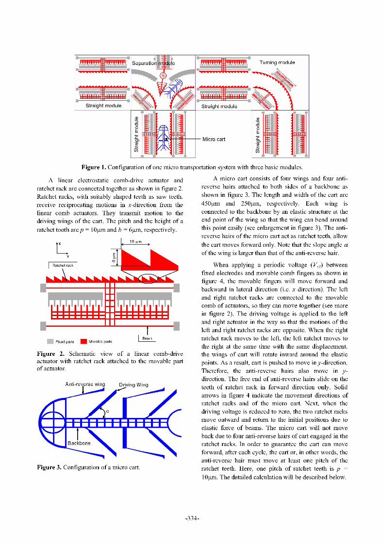
Anti-reverse wing Driving Wing teeth of ratchet rack in forwarddirection only. Solid/ /~~~~~~~arrows in figure 4 indicate the movement directions of
r ratchet racksandof the micr oc art.N ext,when thei l_ 2 Tc driving voltage is reduced to zero, the two ratchet racks
m and r etrnth o theiti potions due toeleasic forice Of ceams. hce mireop cart Will not move
\ | | |\ | _ ~~~~~~~~~backdue to four anti-reverse hairs of cart engaged in theFixedBpartskbovable parts
m ratchet racks. In order to guarantee the cart can moveFigure 2 Schemativiewoalineacomb-dive forward, after each cycle, the cart or, in other words, the
anti-reverse hair must move at least one pitch of theFigure 3. Configuration of a micro cart. ratchet teeth. Here, one pitch of ratchet teeth is p =
1lOasm. The detailed calculation will be described below.
-334-

The equation (5) shows a relation between........................................ displacement of cart zl/yand displacement of ratchet
teeth Ax. As mentioned above, the displacement of thecart Aly must be larger than pitch of ratchet tooth p =
A ~~~~~1O~tm and thus, from equation (5), we need:Ax . 10.9%tm. If including the height of ratchet tooth b= 6ttm, the necessary displacement Ax must be larger
- t V2 sabliy ndtoobai te ptma gomtrthan 16.9etm.
3. Simulation of the ratchet-actuator
The comb-drive actuators have been simulated incoupled field electrostatic-structure model using
. ...N.Y..msoftware to check the relation between the0adriving voltage and the displacement, the lateral
stability and to obtain the optimal geometry dimensionsV12 of the ratchet actuator.
Figure 4. Electrical diagram for creating a straight The dimensions of the comb finger used inmovement of the micro cart. The left and right ratchet- simulation are as follows: finger thickness h = 30jtm;actuators always move in opposite directions. gap g = 2 7tm;finger width w = 34.m; overlap ovi =
finger length ic =40of m; (illustrated in figure 6).The elastic force of wing and anti-reverse hair of
the micro cart and frictional force between the microcart and substrate are included in the FEA analysis.
c art AxQuadratic relation between displacement of ratchet-
y ~~~~~~~~~~~actuator and driving voltage was obtained as shown infigure 11, with main dimensions as follows: Beam
movement~~ ~ ~ ~ ~~~prore and the lateral resonan frqunc iscr 3at569Hz.direction,~ ~ ~ ~Y xi legtL5p is 700ngth bea widt bwn =n 4slope Movbltcobl
movable comb fingers n = 134. Modal analysis has been
Yl = Lw cosz (2)~X perforedfrthafoancylethelaealrsoa thfrequecye racs356Hz
Figure 5. Diagram for calculation of displacement ofthe micro cart in each cycle
A calculation scheme of displacement of the micro Fixed combcart is shown in figure 5. Ax is movement of the ratchetteeth (or free end of wing) in x-direction, Aly ismovement of the elastic point (or micro cart) in y-
Mvbecm
direction, Lw = lSOjim is length of the wing and slope Movbl combangle a = 45'. With reference from figure 5, we have: Figure 6. Dimensions of comb finger for simulation
XI =L sina (1) 4. Force analysis
Y -L,coa|c (2) Inthe first.I thal ofiace,Fithebothatchectracstare
moigiwad3h3itrciv5ocs-ewe rtht

force and Fb is the total elastic force of the beams of are width and length of beam of actuator, respectively.actuator. Net driving force acting on the cart is (Fe - Fb) k, and Ax are stiffness and deflection of the actuatorand load on the free end of the wings. Fw is the elastic system in the x-direction, respectively. kx is calculated toforce of wing in x-direction. Fa is an elastic force of the be 6.06tN/4tm. kw = 1.49 tN/4tm is the stiffness of oneanti-reverse hairs. Fra is a frictional force between anti- wing in x-direction. fm = 0.38 is frictional coefficientreverse hair and surface of ratchet tooth. Fr is a between the silicon-silicon contact surfaces [7], m is thefrictional force between micro cart and substrate. Fd is mass of cart, G is gravitational acceleration.reactive force from ratchet tooth acting on the wing in y-direction to balance with total hindering force acting on As discussed in section 2, in order to guarantee thethe cart. Since the ratchet racks do not move in y- cartcanmove forwardweneed:direction, the force Fd becomes driving force to push the .'x> c =16.9M (13)cart forward.
Considering the forces acting on the wing, we havef the equilibrium equation of moment around the pointO
as below:0
IF -Fb -2F_, L,sina-Ax (14)Fr Fd VL2-(L sina-A)2
Fa From equation (14), we can obtain the relationFb Fe Fe Fb between driving voltage V and displacement Ax:
F F (L sin-a 2 1(I t t - \ X I _ Fd l g rd
T sFna+2FA (I,.Fw \/nhee, L gL -(L sina -)2bx) w
y t I 1liltYFe- FbLx A proportional relation between driving voltage V and displaceme]
Figure 7. The interactive forces between ratchet teeth 32and micro cart 30 '
28-These forces can be expressed by the equations 26
from (6) to (12) below: D 24X-X
nhe EFe 8 0V2 (6) t 20g 0- 18-
T 16 9
Fb = kX.Ax 3 Ax (7) 1412
10 91.96
Fw =kw.(AX- b) (8) 60 70 80 90 100 110 120 130Driving voltage (V)
3EIF 3 .Ax (9) Figure 8. Relation between displacement Ax and
driving voltage V including interactive forces betweenfra=tm Fa cos, (10) ratchet-actuator and micro cart.
F = fmG 5. Fabrication and characterizations
F =- + 21F .cos,8 (12) 5.1. Fabrication process2 ra
The fabrication process of the MTS was simple. Thewhere ,6= 300 is mhersop angleo chet tooth = MTS was fabricated from SOI wafer with the134 fingers iS total number of movable comb finger, h = thcnseofdvelar,bid502ay,ad30pim iS thickness of the comb finger, g = 2pim iS gap ..between two fingers, £ andl £ are permittivity of air anda iio usrt ee 0i,4i n 0~mvacuum, respectively. V is driving voltage. b = 6jam is respectively. Firstly, the MTS patterns were transferredthe height of ratchet tooth. F = 169 GPa is Young's to the surface of SOI wafer by photolithography.modulus of single crystalline silicon. I is the inertia Secondly, D-RIE process was performed to etch 30pammoment of anti-reverse cross-section, 1 = 150pam is depth to reach the buried oxide layer, and then vaporHFlength of anti-reverse hair. bw = 4.5pim and L = 700pim etching process was done to etch the 5i02 underneath
-336-

the device layer and the movable stiructures werereleased. Vapor HF etching was the key technique here ~4to overcome the sticking problem, which is mostfrequently occurred in fabrication of silicon combactuators. The etching rate Of SiO2 by vapor HF withconcentration of 4600 at 40'C was 0.1 am/minute. AfterHF etching, the actuator stiructure was dried at 120'Cfor 10 minutes to further reduce the sticking possibility.The silicon MTS and its components after fabrication Figure 12. SEM image of a comb fingers (left) andare shown in figures 9, 10,11 and 12. ratchet teeth (right).
5.2. Test the performance ofMTS
Firstly, DC voltage was applied to the fixed andmovable electrodes to check the relation betweendisplacement x of actuator and driving voltage withoutmicro cart. The result is shown in figure 13. Themeasurement results are veray close to the simulation.
30 -29.49-A- Simulation
E 25 Measurement
20-
E 15-
Figure 9. SEM image of one MTS with straight, turningmodules and micro carts. An ant is standing on top just 7.32for scaling view. rt .8
00 25 50 75 100
~~~~~~~~~~~~~~Drivingvoltage (V)
Figure 13. Relation between the displacement ofratchet- actuator and driving voltage without micro cart
-- -~..- Next, straight movement of the micro cart has beentested by applying a sine wave driving voltage with Vpp
W.~ ~ ~ ~ /- of 1IOOV. A diagram of electrical connection isillustrated in figure 4. Velocity of the micro cart wasmeasured with driving frequency ranges from 1Hz to
Figure 10. SEM image of the straight module of MTS. 20Hz.Let us calculate a velocity of the cart. In the first
half of a cycle, the both ratchet actuator move inward,444 ~~~and the cart is pushed forward with a displacement z.ly
mentioned in equation (5). In the second half of thecycle, the ratchet actuators return to original place. Theelastic force of wing and anti-reverse hairs will pull thecart backward. Since the anti-reverse hair acts as
ratchet, therefore the cart just moves back until zly = i.p,(i is an integer), i.e. when the free end of an anti-reverse

where function int(x) returns the integer portion ofx;f is IOOV) and n = 134 fingers, can be calculated to be aboutdriving frequency of the applying voltage V. 55.7mW.
The test have been performed with Vpp = 1 OOV and 6. Conclusionsmovable fingers number n = 134, and thus zAy = 12.4ptm,int(zly/p) = 1. We have a velocity calculated by equation This paper has presented the design, fabrication and(16) as v =pf= lOf(jtm/s). The result is shown in figure evaluation of novel silicon MTS based on electrostatic14. The measured velocity is very close to calculation comb-drive actuators and ratchet mechanism.value. The linear-proportional relations between Movement of cart is created by pushing the wings of thevelocity of the micro cart v and the driving frequencyf cart perpendicularly with cart's movement direction.have been obtained. The anti-reverse hair structure combines with ratchet
teeth allow the carts move forward only.
200 The silicon MTS and its components have been+ Calculation fabricated by D-RIE and vapor HF etching techniques
150o Measurement =
and using only one mask. They were experimentally150 checked to confirm the working principle and to
E measure the characteristics. Straight movement of the> 100 micro cart has been tested and evaluated successfully.O Further development ofMTS will be packaging anda)
50 / control circuit to make a more sophisticated MTSsystem for different applications such as micro roboticor micro assembly systems.
00 5 10 15 20
Frequency (Hz) References
Figure 14. Relation between the velocity of micro cart [1] S Konishi and H Fujita, "A Conveyance System Using Airand driving frequency, Vpp = 1OOV. Flow Based on the Concept of Distributed Micro Motion5.3. Power consumption ofthe MTS Systems", IEEE Journal of MicroElectroMech. Systems,5.3.Power consumption ofthe MTS Vol.3, No.2, (1994), pp 54-58The power dissipation of the MTS can be [2] Y Fukuta, M Yanada, A Ino, Y Mita, Y A Chapuis, S
considered as the power dissipation in capacitor of the Konishi and H Fujita, "Conveyor for Pneumatic Two-electrostatic comb actuator. The MTS operates by Dimensional Manipulation Realized by Arrayed MEMS andreciprocating displacement of electrostatic comb its Control", Journal of Robotics and Mechatronics, Vol.16,actuator at frequencyf Therefore, the power dissipation No.2, (2004), pp 163-170can be calculated by [4, 6]: [3] T Shigematsu and M K Kurosawa, "XY Surface Acoustic
Wave Motor with Nanometer Resolution", Proceeding of 21s1P= CV2f (17) Sensor Symposium (2004), pp 237-240
where V is driving voltage, and C is the total [4] R Yeh, S Hollar and Kristofer S J Pister, "Single Mask,whercitaneV istrvng voltafge, andoCf the toVal Large Force, and Large Displacement Electrostatic Linearcapacitance between comb fingers of the MTS. Vand C Inchworm Motors", J. Microelectromech. Syst. (2002),are functions of time as below: Vol.11, pp 330-336
V(t)- V + V0 sin(2Ifi) (18) [5] I Fujimasa, "Micromachines, a new Era in MechanicalEngineering", Oxford University Press, pp 115-117, 135
2nh2c2 (1996)C(t) = 2knhe V2 (l + sin(2Zft))2 (19) [6] Phuc Hong Pham, Dzung Viet Dao et al, "Straight
g x Movement of Micro Containers Based on Ratchet Mechanism. . . ~~~~~~~andElectrostatic Comb-Drive Actuators", J. Micromech.Therefore, the power dissipation can be expressed by: Microeng. Vol.16, No.12, (2006), pp 2532-2538
2nh2e£ V04 Y (20) [7] Noguchi K, Fujita H, Suzuki M and Yoshimura N, "TheP f. .2* (lsin22ft)4 .dt Measurements of Friction on Micromechatronics Elements",
gxk 0 Proceedings of an Investigation of Micro Structures, Sensors,Actuators, Machines and Robots. IEEE-MEMS'91 (1991), ppAs an example, power consumption of the MTS at 148-153
a frequencyf= 10Hz, bias voltage Vo = 50V (Vpp =
-338-