Correcting for Purifying Selection: An Improved Human Mitochondrial Molecular Clock
Upload
independentCategory
view
1download
0
D
A
aafmdsncS
K
1
seAqsimtpfpttf
ISA Transactions®Volume 45, Number 3, July 2006, pages 319–328
0
evelopment of a virtual linearizer for correcting transducer staticnonlinearity
Amar Partap Singh,a Tara Singh Kamal,b Shakti Kumarc
aDepartment of Electrical and Instrumentation Engineering, SLIET, Longowal-148106 (District: Sangrur) Punjab, IndiabDepartment of Electronics and Communications Engineering, SLIET, Longowal-148106 (District: Sangrur) Punjab, India
cCentre for Advanced Technologies, Haryana Engineering College, Jagadhri-135003, Haryana, India
�Received 21 September 2004; accepted 28 September 2005�
bstract
This paper reports the development of an artificial neural network based virtual linearizer for correcting nonlinearityssociated with transducers connected to the data-acquisition system of a computer-based measurement system. Innalog processing techniques, nonlinearity is considered to be a very serious problem that at one time was solvedrequently by the piecewise linear segment approach modeled by linear electronic circuits. Since the cost oficrocomputers has been reduced drastically, they are currently used in most applications of measurement, including
ata-acquisition subsystems. Therefore, the hardware-based analog techniques of linearization are often replaced by theoftware-based numerical ones. In this context, it has been found that a multilayer feed-forward back-propagationetwork trained with the Levenberg-Marquardt learning rule provides an optimal solution to implement an efficient softompensator to correct transducer static-nonlinearity. © 2006 ISA—The Instrumentation, Systems, and Automationociety.
eywords: Transducer; Nonlinearity; Inverse model; Artificial neural network; Linearizer
avUrwccalt
mtdwm
. Introduction
In almost all the transducer based measurementystems, transducers are normally highly nonlin-ar related to the physical parameter they sense.lso, if the measurement is done using a data ac-uisition system-oriented computer-based mea-urement system, a small amount of nonlinearitys added invariably by the signal conditioning
odules of a data acquisition system in addition tohe inherent static nonlinearity associated with theractical transducer �1�. Further, inherent manu-acturing tolerances always present an additionalroblem in the event of replacement of a faultyransducer or signal conditioning module even ifhe new one is chosen from the same batch of
abrication. Moreover, with the passage of time, b019-0578/2006/$ - see front matter © 2006 ISA—The Instrumentat
ging becomes more responsible for introducingariations in the transducer characteristics �2–4�.nder such situations, calibration of transducers is
equired frequently. Therefore, the issues relatedith the transducer nonlinearity and its self-
ompensation must be addressed collectively inomputer-based measurement, instrumentation,nd control systems taking into account the non-inearity associated with the transducer as well ashat of signal conditioning modules.
There are several software-based numericalethods to estimate scaled output signals from
ransducers �5,6� correctly. These methods may beivided into three broad groups �7�. The simplestay is to store a look-up table in read-onlyemory and calculate the quantity to be measured
y linear interpolation �5�. The calculation for-
ion, Systems, and Automation Society.

mioqoumqntpeptrvtmiirnfien
2
btssnmtmttccnl
cTaksgcaiect
ash�htaiftTtdimnmiapfsn
dtvtaefbtpdmm
320 Singh, Kamal, and Kumar / ISA Transactions 45, (2006) 319–328
ula is simple and universal, but the difficulty liesn the fact that each type of transducer requires itswn table. Moreover, for good accuracy, this re-uires a large storage capacity or memory. An-ther way is to use an interpolation formula �7�sing three or more calibration points. In thisethod, one routine is sufficient to calculate the
uantity to be measured by any transducer. It isot necessary to know the transfer function of theransducer explicitly, a limited set of calibrationoints being sufficient. However, for hard nonlin-arity, the technique fails because the referenceoints are numerous under such conditions. Thehird method is to store a set of characteristic pa-ameters for each transducer and calculate the in-erse function of the relationship between its elec-rical output and the physical quantity to be
easured �8�. Now, only a small set of parameterss sufficient. But each type of transducer requirests own, sometimes rather complicated calculationoutine. Besides, in this context, use of artificialeural networks has also been suggested as an ef-cient alternative method to linearize the transduc-rs and have shown the ability to correct staticonlinearity associated with them.
. Neural linearizer
For successful implementation of a softwareased linearizer, a good inverse model of theransducer element is required invariably �8� in theystem for linearizing its input-output static re-ponse. The schematic arrangement of an artificialeural network as a nonlinear compensating ele-ent is shown in Fig. 1. A main characteristic of
his solution is that function �F� to be approxi-ated is given not explicitly but implicitly
hrough a set of input-output pairs, named as araining set that can be obtained easily from thealibration data of measurement systems. In thisontext, the usage of artificial neural network tech-iques for modeling the system behavior provides
Fig. 1. Schematic of inverse modeling of a transducer.
ower interpolation error when compared with d
lassical methods of interpolation stated above �9�.he main advantages of artificial neural networksre their ability to generalize results obtained fromnown situations to unforeseen situations, fast re-ponse time in operational phase due to high de-ree of structural parallelism, reliability, and effi-iency. Due to these reasons, the applications ofrtificial neural networks have emerged as a prom-sing area of research for linearizing the transduc-rs, since its adaptive behavior has the potential ofonveniently modeling strongly nonlinear charac-eristics.
An adaptive technique based on the concept ofn artificial neural network trained by least meanquares and recursive least squares learning rulesas been used successfully in channel equalization10�, system identification �11,12� and line en-ancement �4�, etc. Based on the concept of adap-ive technique for obtaining the inverse model, anrtificial neural network based inverse model wasmplemented in this work using a multilayer feed-orward back-propagation network trained withhe Levenberg-Marquardt learning algorithm �13�.he training process is carried out in such a way
hat the combined transfer function of the trans-ucer and its inverse model becomes unity in anterative manner. The schematic of the inverse
odel of a transducer using an artificial neuraletwork as its adaptive compensating nonlinearodel is shown in Fig. 2. Here, the neural network
s suitably adapted to model a nonlinear transducerccurately in inverse mode using a back-ropagation learning mechanism based on the in-ormation acquired from the transducer. As a re-ult, the effect of associated nonlinearity iseutralized automatically.This concept of inverse modeling of the trans-
ucer, in fact, has been borrowed from the adap-ive channel equalization process based on the in-erse modeling principle performed at the end ofhe receiver in communication systems �10�. By andaptive learning procedure, the inverse modelvolves in such a way that the combined transferunction of the transducer and its inverse modelecomes unity in an iterative manner. As a result,he measurand is estimated accurately at the out-ut of the inverse model irrespective of the trans-ucer static nonlinearity. The synthesized inverseodel of the transducer is used to estimate theeasurand for calibration as well as for providing
irect digital readout.

3
vmmMtptCpe
3s
mggFsctfitdfdaatses
vatb�Wooi
npfitttsmmi
F
321Singh, Kamal, and Kumar / ISA Transactions 45, (2006) 319–328
. Development of the virtual linearizer
The development of the virtual linearizer in-olved the development of two integrated softwareodules �9,14�. The first module was imple-ented in the form of a Data Acquisition andanagement Software supported on the architec-
ure of an inbuilt Algorithm of Control and Com-utations. The second module was implemented inhe form of an artificial neural network based Softompensator to perform the function of signalrocessing component of the proposed virtual lin-arizer.
.1. Synthesis of data acquisition managementoftware
In the present work, the data acquisition andanagement software was developed using fourth
eneration, object-oriented, and graphical pro-ramming technology in the form of a singleront-panel and various Subpanels using test-pointoftware �15�. The different test-point objects werearefully researched, configured, and interlinkedo develop a highly customized user-interactiveront panel. The synthesized front panel is shownn Fig. 3. The algorithm of control and computa-ions was implemented in the form of an embed-ed code containing different Action Lists writtenor various test-point objects chosen to developifferent panels of the data acquisition and man-gement software including the front panel. Thelgorithm of control and computations coordinateshe functioning of various modules �front panel,ubpanels, and objects� of the proposed virtual lin-arizer. The virtual linearizer enables a compari-
Fig. 2. Schematic of artificial neural net
on of the actual and estimated values of the in- l
erse response and associated data in the tabulars well as in graphical form. The algorithm of con-rol and computations exchanged the informationetween test-point and MATLAB environments16� using the dynamic data exchange feature of
indows. Selecting “Direction” on the front panelpens another subpanel displaying the stepwiseperating procedure of the proposed virtual linear-zer.
A strain-gauge type of pressure transducer con-ected to the data acquisition system of a com-uter based measurement system is chosen hereor experimental study. The virtual linearizer ismplemented to acquire the input-output data fromhe data acquisition system-connected pressureransducer working in a real-time environment forhe purpose of training the neural network andubsequent validation thereof. Provision has beenade to further validate the implemented inverseodel of the given transducer for its performance
n the production phase. In order to do so, the
ased inverse modeling of a transducer.
ig. 3. User-interactive front-panel of the proposed virtual
work b
inearizer.
icitfassfqsttgmmaacptnoif
3
pm
ftsbabiitimbcmsfpqhppat�
ippt
opagat
322 Singh, Kamal, and Kumar / ISA Transactions 45, (2006) 319–328
mplemented virtual linearizer is operated to pro-ess the signal continuously. To increase the flex-bility of its use, the provision has been made inhe virtual linearizer to acquire stored data offlinerom the excel-sheet in case the transducer is notvailable online. The corresponding maximum ab-olute values of absolute error and error �% fullpan� are also displayed by the virtual linearizeror comparison purposes. However, the data ac-uisition and management system was designed toerve the function of measurement, modeling, es-imation, and display of static inverse response ofransducers. Also, the provision is provided forraphical, tabular, and digital display of variouseasured and estimated data related to inverseodeling. Further, computation of absolute error
s well as error �% full span� between the actualnd estimated inverse response along with theirorresponding maximum absolute values was alsorovided for each calibration point. In addition tohis, the proposed virtual linearizer having a neuraletwork as its soft-compensator element may beperated on-line for the display of the measurandn the form of a digital readout as well as in theorm of a bar indicator.
.2. Synthesis of soft compensator
In the present work, the synthesis of soft com-ensator is carried out in the form of an inverse
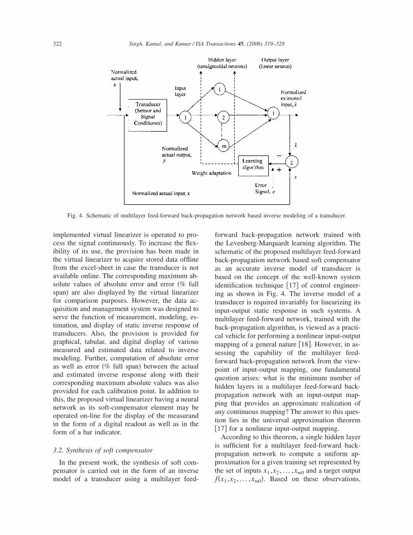
Fig. 4. Schematic of multilayer feed-forward back-pr
odel of a transducer using a multilayer feed-
orward back-propagation network trained withhe Levenberg-Marquardt learning algorithm. Thechematic of the proposed multilayer feed-forwardack-propagation network based soft compensators an accurate inverse model of transducer isased on the concept of the well-known systemdentification technique �17� of control engineer-ng as shown in Fig. 4. The inverse model of aransducer is required invariably for linearizing itsnput-output static response in such systems. A
ultilayer feed-forward network, trained with theack-propagation algorithm, is viewed as a practi-al vehicle for performing a nonlinear input-outputapping of a general nature �18�. However, in as-
essing the capability of the multilayer feed-orward back-propagation network from the view-oint of input-output mapping, one fundamentaluestion arises: what is the minimum number ofidden layers in a multilayer feed-forward back-ropagation network with an input-output map-ing that provides an approximate realization ofny continuous mapping? The answer to this ques-ion lies in the universal approximation theorem17� for a nonlinear input-output mapping.
According to this theorem, a single hidden layers sufficient for a multilayer feed-forward back-ropagation network to compute a uniform ap-roximation for a given training set represented byhe set of inputs x1 ,x2 , . . . ,xm0 and a target output
ion network based inverse modeling of a transducer.
f�x1 ,x2 , . . . ,xm0�. Based on these observations,

ce
ba=fa
Femitasat
Fs
Ft
323Singh, Kamal, and Kumar / ISA Transactions 45, (2006) 319–328
onsider N input patterns, �yn�, each with a singlelement applied to the multilayer feed-forward
ig. 5. Tabular representation of acquired training data andstimated results displayed by virtual linearizer usingultilayer feed-forward back-propagation network based
nverse modeling of pressure transducer �MTR-Measuredransducer response �in volts�; Measur�A�-Applied measur-nd to the transducer �in bars�; Measur�E�-Estimated mea-urand �in bars�; Error�Ab�-Absolute error between actualnd estimated measurands; and Error�% Full Span�-Error inerms of percentage full span�.
ig. 7. Learning characteristics of multilayer feed-forwa
ransducer.ack-propagation network based inverse model oftransducer producing an output pattern �x�, n�1,2 , . . . ,N�. In this context, a multilayer feed-
orward back-propagation network manifests itselfs a nested sigmoidal scheme. Therefore, based on
ig. 6. Results of data acquisition constituting the traininget displayed by the virtual linearizer.
k-propagation network based inverse model of pressure
rd bac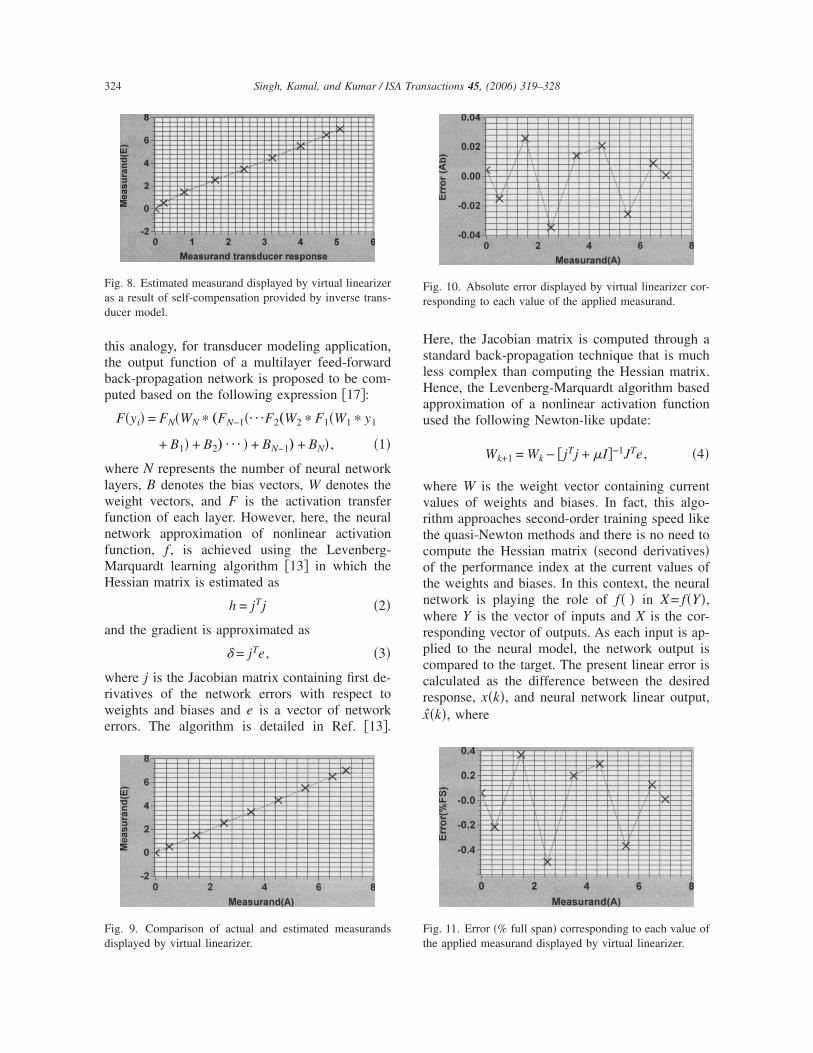
ttbp
wlwfnfMH
a
wrwe
HslHau
wvrtcotnwrpccrx
Fad
Fd
Fr
F
324 Singh, Kamal, and Kumar / ISA Transactions 45, (2006) 319–328
his analogy, for transducer modeling application,he output function of a multilayer feed-forwardack-propagation network is proposed to be com-uted based on the following expression �17�:
F�yi� = FN�WN � „FN−1�¯F2„W2 � F1�W1 � y1
+ B1� + B2… ¯ � + BN−1… + BN� , �1�
here N represents the number of neural networkayers, B denotes the bias vectors, W denotes theeight vectors, and F is the activation transfer
unction of each layer. However, here, the neuraletwork approximation of nonlinear activationunction, f , is achieved using the Levenberg-
arquardt learning algorithm �13� in which theessian matrix is estimated as
h = jTj �2�
nd the gradient is approximated as
� = jTe , �3�
here j is the Jacobian matrix containing first de-ivatives of the network errors with respect toeights and biases and e is a vector of network
rrors. The algorithm is detailed in Ref. �13�.
ig. 8. Estimated measurand displayed by virtual linearizers a result of self-compensation provided by inverse trans-ucer model.
ig. 9. Comparison of actual and estimated measurands
isplayed by virtual linearizer. tere, the Jacobian matrix is computed through atandard back-propagation technique that is muchess complex than computing the Hessian matrix.ence, the Levenberg-Marquardt algorithm based
pproximation of a nonlinear activation functionsed the following Newton-like update:
Wk+1 = Wk − �jTj + �I�−1JTe , �4�
here W is the weight vector containing currentalues of weights and biases. In fact, this algo-ithm approaches second-order training speed likehe quasi-Newton methods and there is no need toompute the Hessian matrix �second derivatives�f the performance index at the current values ofhe weights and biases. In this context, the neuraletwork is playing the role of f� � in X= f�Y�,here Y is the vector of inputs and X is the cor-
esponding vector of outputs. As each input is ap-lied to the neural model, the network output isompared to the target. The present linear error isalculated as the difference between the desiredesponse, x�k�, and neural network linear output,
ˆ�k�, where
ig. 10. Absolute error displayed by virtual linearizer cor-esponding to each value of the applied measurand.
ig. 11. Error �% full span� corresponding to each value of
he applied measurand displayed by virtual linearizer.
bmst
NgpittbLf=fn
4
iedt�d
4
tsmat
tmdeppc6unpdish7aon
ondpac�mgstsasa0mmv
TRu
325Singh, Kamal, and Kumar / ISA Transactions 45, (2006) 319–328
x̂k = WkTYk . �5�
In fact, the ultimate aim of the neural networkased least mean square regression method is toinimize the mean square error �19� and as a con-
equence the performance index in this case, i.e.,he mean squared error �MSE� is given by
MSE =1
N �k=1
k=N
e�k�2 =1
N �k=1
k=N
�x�k� − x̂�k��2. �6�
eural network toolbox �20� and MATLAB pro-ramming �21� were used to synthesize the pro-osed neural model as the soft compensator serv-ng the purpose of signal processing component ofhe proposed virtual linearizer. For the example inhis part of the work, the multilayer feed-forwardack-propagation network is trained with theevenberg-Marquardt learning algorithm with the
ollowing parameters: performance goal �MSE�7.89256e-006; learning rate=0.01; factor to use
or memory/speed tradeoff=1; and maximumumber of epochs=100.
. Results and discussion
The practical use of the proposed virtual linear-zer is examined experimentally for correcting theffect of static nonlinearity associated with theata acquisition system-connected strain-gaugeype of pressure transducer �SenSym:S
100DN� using the synthesized soft compensatorescribed below.
.1. Simulation of soft compensator
To examine the practical use of a proposed vir-ual linearizer for approximating the nonlineartatic inverse response of transducers, an experi-ental study is carried out by measuring data fromstandard practical strain-gauge type of pressure
able 1esults of multilayer feed-forward back-propagation netwsing training data.
Range ofoperation
Numberof
hiddenneurons Epochs
0–7 bars 2 69
ransducer �SenSym:S�100DN� connected to t
he data acquisition system of a computer basedeasurement system. Nine pairs of input-output
ata constituting the training set are acquired cov-ring the entire range of its operation using theroposed virtual linearizer. The acquired trainingairs displayed by the virtual linearizer numeri-ally and graphically are shown in Fig. 5 and Fig., respectively. The results of inverse modelingsing a multilayer feed-forward back-propagationetwork as a soft compensator element of the pro-osed virtual linearizer with nine pairs of trainingata are also shown in Fig. 5. Learning character-stics of the proposed inverse model of the pres-ure transducer under study are shown in Fig. 7. Itas been found that a mean square error level of.89256e-006 is attained at only 69 epochs in re-lizing the inverse model with a 1-2-1 architecturef a multilayer feed-forward back-propagationetwork.The estimated measurand displayed as a result
f the multilayer feed-forward back-propagationetwork based inverse modeling of pressure trans-ucer is shown in Fig. 8. Fig. 9 displays a com-arison between actual and estimated measurandsnd shows a close resemblance between them. Theorresponding values of absolute error and error% full span� between the estimated and actualeasurands, displayed by the virtual linearizer
raphically, are shown in Fig. 10 and Fig. 11, re-pectively. It is found that the assumption of onlywo hidden neurons has led to the maximum ab-olute error of only 0.0343804 between the actualnd estimated inverse response. The maximum ab-olute value of error �% full span� between actualnd estimated response is found to be only.491119. Achievement of such a low level ofaximum values of said errors ensures that esti-ated values are an accurate measure of the true
alues. The result of inverse modeling of pressure
sed inverse modeling of strain-gauge pressure transducer
SE
Absolutevalue of
maximumabsolute error
Absolutevalue of
maximumerror �% full
span�
6e-006 0.0343804 0.491119
ork ba
M
7.8925
ransducer is also shown Table 1. The use of only
tpm
4
1bmtmipwmtoslcnp1sacibpsm�Ttfs
mecpo
4
f
Ft
Fv
Fd
F
326 Singh, Kamal, and Kumar / ISA Transactions 45, (2006) 319–328
wo hidden neurons reduces the architectural com-lexity and hence computational load of the neuralodel drastically.
.2. Validation of the soft compensator
In order to validate our assumption of using-2-1 architecture of a multilayer feed-forwardack-propagation network as an accurate inverseodel of the given pressure transducer, a valida-
ion study was carried out with a trained neuralodel by acquiring all the remaining 34 pairs of
nput-output data as the validation set using theroposed virtual linearizer. In fact, these pairsere not used in the training phase of the neuralodel and cover the entire range of operation of
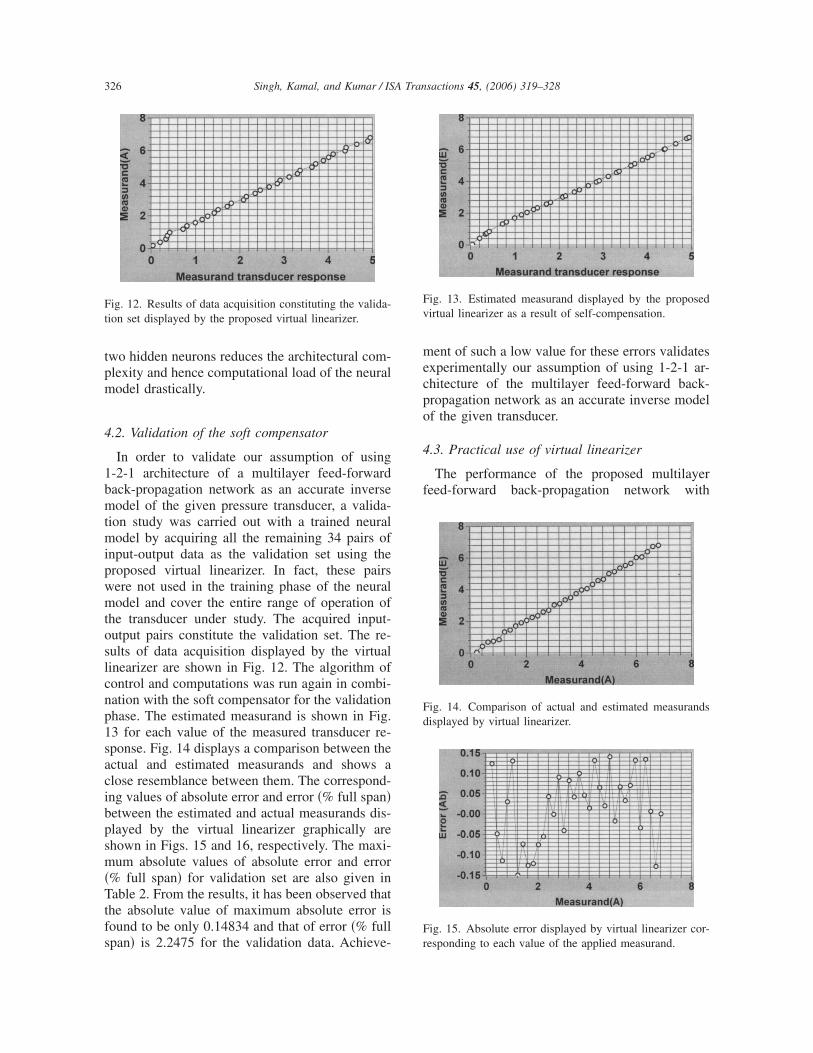
he transducer under study. The acquired input-utput pairs constitute the validation set. The re-ults of data acquisition displayed by the virtualinearizer are shown in Fig. 12. The algorithm ofontrol and computations was run again in combi-ation with the soft compensator for the validationhase. The estimated measurand is shown in Fig.3 for each value of the measured transducer re-ponse. Fig. 14 displays a comparison between thectual and estimated measurands and shows alose resemblance between them. The correspond-ng values of absolute error and error �% full span�etween the estimated and actual measurands dis-layed by the virtual linearizer graphically arehown in Figs. 15 and 16, respectively. The maxi-um absolute values of absolute error and error
% full span� for validation set are also given inable 2. From the results, it has been observed that
he absolute value of maximum absolute error isound to be only 0.14834 and that of error �% full
ig. 12. Results of data acquisition constituting the valida-ion set displayed by the proposed virtual linearizer.
pan� is 2.2475 for the validation data. Achieve- r
ent of such a low value for these errors validatesxperimentally our assumption of using 1-2-1 ar-hitecture of the multilayer feed-forward back-ropagation network as an accurate inverse modelf the given transducer.
.3. Practical use of virtual linearizer
The performance of the proposed multilayereed-forward back-propagation network with
ig. 13. Estimated measurand displayed by the proposedirtual linearizer as a result of self-compensation.
ig. 14. Comparison of actual and estimated measurandsisplayed by virtual linearizer.
ig. 15. Absolute error displayed by virtual linearizer cor-
esponding to each value of the applied measurand.
1cvfiutdcvefmicat
5
fiwtmba
elltwastwf
A
Snttw
R
�
Ft
TCmt
327Singh, Kamal, and Kumar / ISA Transactions 45, (2006) 319–328
-2-1 structure as an efficient signal processingomponent is further evaluated by operating theirtual linearizer in the production phase. The per-ormance of the proposed neural model is exam-ned with the complete set of input-output datased in the training and validation phases coveringhe entire range of operation of the given trans-ucer. The results obtained in the production phaseonfirm the results obtained in the training andalidation phases. This has further validated theffectiveness of the proposed multilayer feed-orward back-propagation network based inverseodel trained with the Levenber-Marquardt learn-
ng algorithm as an efficient soft compensator fororrecting the effect of static-nonlinearity associ-ted with the data acquisition system-connectedransducers.
. Conclusion
The paper proposed a simple practical approachor transducer inverse modeling and correction ofts static nonlinearity using an artificial neural net-ork based virtual linearizer. The main contribu-
ion of this paper is the development of aultilayer feed-forward back-propagation network
ased soft compensator and its performance is ex-mined for the solution of linearizing the nonlin-
ig. 16. Error �% full span� corresponding to each value ofhe applied measurand displayed by virtual linearizer.
able 2omparison of the error obtained as a result of inverseodeling of strain-gauge pressure transducer using valida-
ion data.
Range ofoperation
Absolute valueof maximumabsolute error
Absolute valueof maximum error
�% full span�
0.2–6.8 bars 0.14834 2.2475
ar transducer. Use of the Levenberg-Marquardtearning algorithm provided an extremely fastearning for the synthesis of inverse models ofransducers while ensuring an optimal solutionith regard to network architectural complexity
nd hence computational load. The method de-cribed in this paper has a large area of applica-ions in all transducer based measurement systemshere transducer static nonlinearity is the main
actor to be considered.
cknowledgment
The authors wish to thank Prof. �Dr.� N. P.ingh, Director, Sant Longowal Institute of Engi-eering and Technology, Longowal-148106 �Dis-rict: Sangrur� Punjab, India for his stimulating in-erest and constant encouragement throughout theork.
eferences
�1� Bolk, W. T., A general digital linearizing method oftransducers. J. Phys. E 18, 61–64 �1985�.
�2� Patra, J. C. and Pal, R. N., Inverse modeling of pres-sure sensors using artificial neural networks. AMSEInt. Conf. Signals, Data and Syst., Bangalore, India,1993, pp. 225–236.
�3� Patra, J. C., Panda, G., and Baliarsingh, R., Artificialneural network-based nonlinearity estimation of pres-sure sensors. IEEE Trans. Instrum. Meas. 43�6�, 874–881 �1994�.
�4� Khan, S. A., Agarwala, A. K., and Shahani, D. T.,Artificial neural network �ANN� based nonlinearity es-timation of thermistor temperature sensors. Proceed-ings of the 24th National Systems Conference, Ban-glore, India, �2000�, pp. 296–302.
�5� Patranabis, D., Sensors and Transducers. WheelerPublishing Co., Delhi, 1997, pp. 249–254.
�6� Patranabis, D., Ghosh, S., and Bakshi, C., Linearizingtransducer characteristics. IEEE Trans. Instrum. Meas.37�1�, 66–69 �1988�.
�7� Mahana, P. N. and Trofimenkoff, F. N., Transduceroutput signal processing using an eight-bit microcom-puter. IEEE Trans. Instrum. Meas. IM-35�2�, 182–186�1986�.
�8� Bentley, J. P., Principles of Measurement Systems, 3rded., Pearson Education Asia Pte. Ltd., New Delhi,2000.
�9� Pereira, J. M. D., Postolache, O., and Girao, P. S., Atemperature compensated system for magnetic fieldmeasurement based on artificial neural networks.IEEE Trans. Instrum. Meas. 47�2�, 494–498 �1998�.
10� Patra, J. C., Pal, R. N., Chatterji, B. N., and Panda, G.,Nonlinear channel equalization for QAM signal can-cellation using artificial neural network. IEEE Trans.Syst., Man, Cybern., Part B: Cybern. 29�2�, 262–271
�1999�.
�
�
�
�
�
�
�
�
�
�
�
mggtStE
CCalEIttggwtlIS1tia
Fa5C
328 Singh, Kamal, and Kumar / ISA Transactions 45, (2006) 319–328
11� Teeter, J. and Chow, M., Application of functional linkneural network in HVAC thermal dynamic systemidentification. IEEE Trans. Ind. Electron. 45, 170–176�1998�.
12� Patra, J. C., Pal, R. N., Chatterji, B. N., and Panda, G.,Identification of nonlinear dynamic systems usingfunctional link artificial neural networks. IEEE Trans.Syst., Man, Cybern., Part B: Cybern. 29�2�, 254–262�1999�.
13� Hagan, M. T. and Menhaj, M., Training feed-forwardnetworks with the Marquardt algorithm, IEEE Trans.Neural Netw. 5�6�, 989–993 �1994�.
14� Bilski, P. and Winiecki, W., Virtual spectrum analyzerbased on data acquisition card. IEEE Trans. Instrum.Meas. 51�1�, 82–87 �2002�.
15� Test-Point Software-User’s Manual �Version 3.1�.Capital Equipment Corp., 1997.
16� MATLAB Application Program Interface Guide Us-er’s Manual �Version 5�. 7.32–7.42, 1998.
17� Haykin, S., Neural networks: A Comprehensive Foun-dation. Pearson Education Asia, 2001, pp. 118–120.
18� Widrow, B. and Steams, S. D., Adaptive Signal Pro-cessing, Prentice Hall, Englewood Cliffs, NJ, 1995,pp. 118–120.
19� Hornik, K. M., Stinchcombe, M., and White, H.,Multilayer feed-forward networks are universal ap-proximators. Neural Networks 2�5�, 359–366 �1989�.
20� Demuth, H. and Beale, M., Neural Network Toolboxfor use with MATLAB-User’s Guide. Natick, M. A.,The Maths Works Inc., 1993.
21� Pratap, R., Getting Started with MATLAB 5. OxfordUniversity Press, 2001, pp. 14–122.
Dr. Amar Partap Singh wasborn in 1967 at Sangrur �Punjab�India. He received his B. Tech.�Electronics Engineering� Degreein 1990 from Guru Nanak DevUniversity, Amritsar and M. Tech.�Instrumentation� in 1994 fromRegional Engineering College,Kurukshetra. Also, he got hisPh.D. �Electronics and Communi-cations Engineering� in 2005from Punjab Technical University,Jalandhar. He is working as anAssistant Professor in the Depart-
ent of Electrical and Instrumentation Engineering at Sant Lon-owal Institute of Engineering and Technology �SLIET�, Lon-owal �District: Sangrur�, Punjab �India�. He has published morehan 43 papers at various International and National levelymposia/Conferences and Journals. His areas of interest are Vir-
ual Instrumentation, Artificial Neural Networks and Medicallectronics.
Prof. (Dr.) Tara Singh Kamalwas born at Dhanaula �District:Sangrur�, Punjab �India� in 1941.He graduated in Electronics andCommunications Engineering andobtained his Masters Degree inCommunication Systems, bothfrom the University of Roorkee,Roorkee, and he received a GoldMedal by standing first in M.E.He got his Ph.D. degree fromPunjab University, Chandigarh.He started teaching at the Depart-ment of Electrical and Electronics
ommunications Engineering in Punjab Engineering College,handigarh in January 1966 and retired as a Professor in Electricalnd Electronics Communications in June 1999 from the same col-ege. At present, he is working as a Professor in the Department oflectronics and Communications Engineering at Sant Longowal
nstitute of Engineering and Technology �SLIET�, Longowal �Dis-rict: Sangrur�, Punjab �India�. He held various prestigious posi-ions, such as Dean �Research and Technology Transfer�, and hasuided nine Ph.D. students. Two more research scholars under hisuidance are in the completion stage of their Ph.D. theses. He is aidely traveled teacher and has published more than 110 papers in
he International and National Journals and Conferences. He is aife fellow of IE �I�, IETE, member ISTE, and Senior Member ofEEE �USA�. He was the Chairman of Punjab and Chandigarhtate Center of the Institution of Engineers �India� for the years999–2001 and also remained as the Vice President of the Institu-ion of Engineers �India� for the term 2001–2002. His areas ofnterest are Artificial Neural Networks, Digital Communications,nd Intelligent Instrumentation.
Prof. (Dr.) Shakti Kumar re-ceived his MS from BITS Pilaniin 1990, and his Ph.D. in 1996.He has taught at BITS, PilaniDubai Centre of Al Ghurair Uni-versity Dubai, UAE, Atlim Uni-versity, Ankara, Turkey, and Na-tional Institute of Technology,Kurukshetra �formerly REC, Ku-rukshetra�. At present he is work-ing as Professor and AdditionalDirector, Haryana EngineeringCollege Jagadhri �Haryana�, In-dia. His areas of interest include
uzzy Logic Based System Design, Artificial Neural Networks,nd Digital System Design. Prof. Kumar has published more than0 research papers in National/International Journals andonferences.
Copyright © 2022 FDOKUMEN