
Applications of depth-resolved cathodoluminescence spectroscopy
Upload
uni-siegenCategory
view
0download
0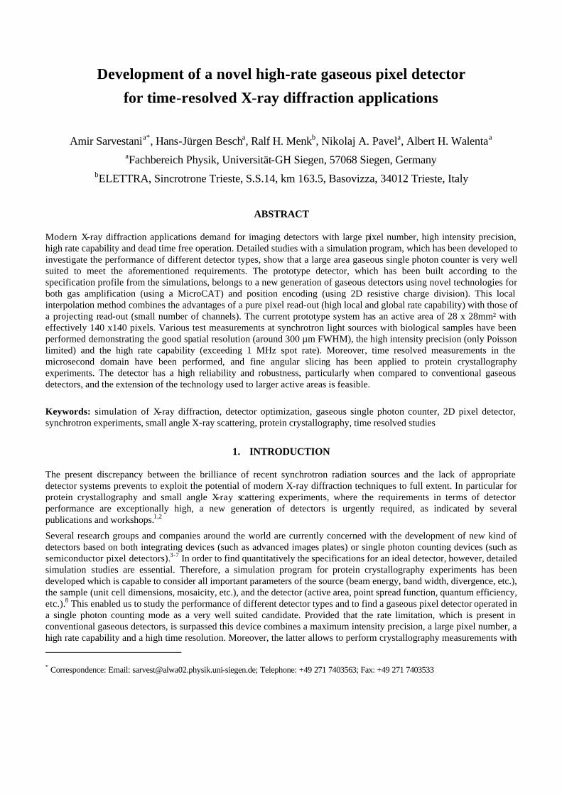
Development of a novel high-rate gaseous pixel detector
for time-resolved X-ray diffraction applications
Amir Sarvestania*, Hans-Jürgen Bescha, Ralf H. Menkb, Nikolaj A. Pavela, Albert H. Walentaa aFachbereich Physik, Universität-GH Siegen, 57068 Siegen, Germany
bELETTRA, Sincrotrone Trieste, S.S.14, km 163.5, Basovizza, 34012 Trieste, Italy
ABSTRACT
Modern X-ray diffraction applications demand for imaging detectors with large pixel number, high intensity precision, high rate capability and dead time free operation. Detailed studies with a simulation program, which has been developed to investigate the performance of different detector types, show that a large area gaseous single photon counter is very well suited to meet the aforementioned requirements. The prototype detector, which has been built according to the specification profile from the simulations, belongs to a new generation of gaseous detectors using novel technologies for both gas amplification (using a MicroCAT) and position encoding (using 2D resistive charge division). This local interpolation method combines the advantages of a pure pixel read-out (high local and global rate capability) with those of a projecting read-out (small number of channels). The current prototype system has an active area of 28 x 28mm² with effectively 140 x140 pixels. Various test measurements at synchrotron light sources with biological samples have been performed demonstrating the good spatial resolution (around 300 µm FWHM), the high intensity precision (only Poisson limited) and the high rate capability (exceeding 1 MHz spot rate). Moreover, time resolved measurements in the microsecond domain have been performed, and fine angular slicing has been applied to protein crystallography experiments. The detector has a high reliability and robustness, particularly when compared to conventional gaseous detectors, and the extension of the technology used to larger active areas is feasible.
Keywords: simulation of X-ray diffraction, detector optimization, gaseous single photon counter, 2D pixel detector, synchrotron experiments, small angle X-ray scattering, protein crystallography, time resolved studies
* Correspondence: Email: [email protected]; Telephone: +49 271 7403563; Fax: +49 271 7403533
1. INTRODUCTION
The present discrepancy between the brilliance of recent synchrotron radiation sources and the lack of appropriate detector systems prevents to exploit the potential of modern X-ray diffraction techniques to full extent. In particular for protein crystallography and small angle X-ray scattering experiments, where the requirements in terms of detector performance are exceptionally high, a new generation of detectors is urgently required, as indicated by several publications and workshops.1,2
Several research groups and companies around the world are currently concerned with the development of new kind of detectors based on both integrating devices (such as advanced images plates) or single photon counting devices (such as semiconductor pixel detectors).3-7 In order to find quantitatively the specifications for an ideal detector, however, detailed simulation studies are essential. Therefore, a simulation program for protein crystallography experiments has been developed which is capable to consider all important parameters of the source (beam energy, band width, divergence, etc.), the sample (unit cell dimensions, mosaicity, etc.), and the detector (active area, point spread function, quantum efficiency, etc.).8 This enabled us to study the performance of different detector types and to find a gaseous pixel detector operated in a single photon counting mode as a very well suited candidate. Provided that the rate limitation, which is present in conventional gaseous detectors, is surpassed this device combines a maximum intensity precision, a large pixel number, a high rate capability and a high time resolution. Moreover, the latter allows to perform crystallography measurements with

fine angular slicing.
The simulation program was also used to reduce parasitic detector characteristics, such as the parallax effect arising in planar gaseous detectors, by tuning particular detector parameters.
For the realization of a prototype detector satisfying the requirements of the detector profile from the simulation studies a special encoding method was selected. It is based on resistive charge division allowing an asynchronous and parallel position interpolation in discrete cells. By the cell interpolation a position resolution is obtained which is much smaller than the cell dimension. This device can therefore be considered as a hybrid of a pure pixel detector and a projective system. On the one hand, a factor of about 400 less channels are required than in case of a pure pixel detector (e.g. the PAD detector7). On the other hand, still a high global rate capability in the GHz-domain is feasible surpassing distinctly those of pure projective read-out systems (e.g. the RAPID detector5, which is limited to about 107 Hz).
A fully functioning prototype detector with 140 x 140 pixels is currently existing and has been extensively tested under synchrotron beam line conditions in order to determine its suitability for advanced diffraction studies (rate capability, spatial resolution, intensity precision and time resolution).
2. SIMULATION STUDIES
A detailed description of the simulation program and its applications has already been presented elsewhere.8,9 The two major advantages of a single photon counter are the high intensity precision, which is limited by Poisson statistics only, and the fast read out allowing to perform fine angular slicing crystallography. Fig. 1 exemplifies the enhanced intensity precision of a single photon counter when compared to a conventional integrating device (image plate). The increased signal-to-background ratio in case of fine angular slicing is demonstrated in Fig. 2. Apart from this, the signal-to-background ratio can also be increased by selecting large detector-to-sample distances10 thus requiring large active areas which are feasible with gaseous detectors rather than with integrating devices. The enhanced signal-to-background ratio is particularly important for high resolution spots and for diffraction patterns from large unit cells (in both cases very weak diffraction intensities are observed).
(a) (b) (a) (b)
Fig. 1: Intensity precision: simulation of a diffraction pattern detail from a collagenase protein crystal for (a) a MAR image plate detector and (b) a single photon counter; only in case of (b) the weak spot in the right part can be detected.
Fig. 2: Small angular slicing: simulation of a diffraction pattern detail (at 5.5 Å resolution) from a collagenase protein crystal recorded with an oscillation interval of (a) ? ? = 0.5° and (b) ? ? = 0.01°; both images are scaled to the same background.
Beside the evaluation of the essential advantages of a gaseous single photon counter also critical parameters have been studied with the simulation program. In case of a planar geometry parallax effects occur since photons entering the detector's gas volume with angles different from normal incident and thus are projected onto the imaging plane as smeared spots with tails pointing away from the beam center. Eventually, this results in overlapping spots affecting the precise determination of the spot intensities. However, by selecting gas mixture with high atomic numbers Z, high pressures and large detector distances parallax smearing can be reduced (see the example in Fig. 3). Using the simulation program these parameters have been tuned to obtain the maximum resolution for the unit cell size and the wavelength given. From the selected scenarios shown in Table 1 one concludes that for unit cells up to 200 Å and wavelength around 1 Å an operation with a xenon-based gas mixture at atmospheric pressure is sufficient. However, when large unit cells and shorter

wavelengths are demanded gas pressures around 5 bars are required.
(a) (b) (c)
Fig. 3: Parallax reduction: simulation of diffraction patterns from a collagenase protein crystal for a gaseous detector filled with a xenon-based mixture at a pressure of (a) 1 bar, (b) 5 bar, and (c) 10 bar.
beam energy wavelength gas pressure detector distance
unit cell size detector diameter
max scatter. angle
effective resolution
10.4 keV 1.2 Å 1 bar 15 cm 50 Å 28 cm 43.0° 1.6 Å 12.5 keV 1.0 Å 1 bar 18 cm 50 Å 28 cm 37.2° 1.6 Å 15.6 keV 0.8 Å 1 bar 30 cm 50 Å 28 cm 25.0° 1.8 Å
10.4 keV 1.2 Å 1 bar 18 cm 100 Å 28 cm 36.7° 1.9 Å 12.5 keV 1.0 Å 1 bar 27 cm 100 Å 28 cm 27.0° 2.1 Å 15.6 keV 0.8 Å 1 bar 42 cm 100 Å 28 cm 18.0° 2.6 Å
10.4 keV 1.2 Å 1 bar 38 cm 200 Å 56 cm 36.4° 1.9 Å 12.5 keV 1.0 Å 1 bar 54 cm 200 Å 56 cm 27.0° 2.1 Å 15.6 keV 0.8 Å 1 bar 85 cm 200 Å 56 cm 18.2° 2.5 Å
10.4 keV 1.2 Å 5 bar 18 cm 500 Å 28 cm 36.7° 1.9 Å 12.5 keV 1.0 Å 5 bar 27 cm 500 Å 28 cm 27.0° 2.1 Å 15.6 keV 0.8 Å 5 bar 42 cm 500 Å 28 cm 18.0° 2.6 Å
10.4 keV 1.2 Å 5 bar 24 cm 500 Å 56 cm 49.4° 1.4 Å 12.5 keV 1.0 Å 5 bar 36 cm 500 Å 56 cm 37.2° 1.6 Å 15.6 keV 0.8 Å 5 bar 60 cm 500 Å 56 cm 25.0° 1.8 Å
Table 1. Scenarios for protein crystallography experiments using a gaseous detector with planar geometry (two versions: 28 cm diameter and 56 cm diameter); the maximum scattering angle is determined by the limit due to spot overlap by parallax; detector distance and gas pressure (a xenon-based mixture is assumed) are adjusted to obtain the maximum resolution for the wavelength and the unit cell size given.
3. DETECTOR SET-UP
The detector set-up is briefly summarized in this chapter while detailed descriptions can be found in earlier works of the authors.11,12 As depicted in Fig. 4, the photons entering the detector through the entrance window (thin carbon fiber) and the drift cathode (aluminized Mylar foil) are absorbed by the detector gas (typically a xenon/CO2 mixture). During this process primary charge is generated. In the constant drift field (24 mm length) the ions are transported to the drift cathode, whilst the electrons are transported to the gas amplification structure (MicroCAT).12 The MicroCAT consists of a 55 µm thick nickel foil perforated with micro-holes (116 µm diameter) in a hexagonal arrangement with a pitch of 164 µm. At a distance of about 200 µm below the MicroCAT, which is supplied with negative high voltage (typically -1000 V), the grounded anode is placed. Due to this configuration the electric field strongly increases in the vicinity of the micro-holes reaching an almost constant plateau between the MicroCAT and the anode (typically 40-80 kV/cm). Therefore,

unlike in wire or microstrip chambers the gas amplification arising at such high fields is distributed along a relatively long path. For the small active area given here the use of a frame-like spacer outside the active region is sufficient. However, for larger active areas (e.g. 20 x 20 cm²) a constant distance between the cathode and anode can only be ensured by intrinsic spacers placed within the active region. In this regard, a chamber has recently been equipped with a new spacer system based on small insulating pillars (set-up and performance will be published soon).
The anode serves also as the position encoding structure. It consists of specially structured resistive layers printed on a ceramic substrate which contains a quadratic array of read-out nodes with 4 mm pitch being through-connected to pads on the backside.11 Each node is separately connected to an amplifier. A square of four read-out nodes defines an interpolation cell (4 x 4 mm² in size). Each cell consists of a high resistive central area (100 k? /square) surrounded by a low resistive border (1 k? /square) (see detail in Fig. 4). This design forces the charge, which is deposited in such a cell, to flow to the low resistive borders where a charge division to the adjacent read-out nodes occurs. Hence, from the signal distribution on the four nodes surrounding the cell, the position of the event can be calculated by simple linear equations (similar to the position interpolation method in case of one-dimensional resistive charge division). Currently, this system allows a 20 x 20 pixel interpolation per read-out node, thus reducing the number of channels by a factor of 400 compared to a pure pixel detector. In total, the prototype detector has 8 x 8 read-out nodes fully equipped with electronics, thus 7 x 7 interpolations cells. This corresponds to an active area of 28 x 28 mm² and effectively 140 x 140 pixels with a pixel size of 200 x 200 µm².
All electronics used for read-out are in-house developments based on hybrid and multi-layer technology. The 64 charge sensitive, low resistive input amplifiers conjunct pre-amplification and shaping on one module. The amplifiers are followed by 64 analogue-to-digital converters (flash ADC’s) distributed among four boards. They are operated as transient recorders sampling at a rate of 8 MHz with 8 bit resolution and 16 samples per signal. The system is triggered by the signals from the MicroCAT structure (global trigger), that is, once a photon is detected all 64 channels are read out in parallel. The sampled data are latched in 64 buffer RAM’s (each 1 kByte memory). Once the RAM’s are full the read-out cycle starts, in which data are transferred via a 32 bit PCI I/O interface into a PC. This part is currently the bottleneck of the read-out electronics limiting the overall read-out speed to some kHz. Nevertheless, still very high time resolutions can be obtained, since the writing cycle is almost dead time free and all signals can be stored together with the corresponding detection time. Signal calibration, position interpolation, and image formation is done on-line by software on the PC.
Fig. 4: Exposed view of the prototype detector plus details of the gas gain structure (MicroCAT) and the resistive position encoding
structure (one single interpolation cell). The full active area of 28 x 28 mm² is composed of 7 x 7 interpolation cells, each one 4 x 4 mm² in size.

4. DETECTOR PERFORMANCE
4.1. Rate capability
Measurements evaluating the rate performance of the prototype detector have been performed with both conventional X-ray tubes and synchrotron radiation.13
Up to rates of 7 MHz/mm² a stable gas gain operation with values of around 5000 was proven using an intensive pencil beam of 8 keV energy. Space charge effects within the drift region are a serious problem for most gaseous detectors. In case of the detector presented here, however, space charge effects are distinctly suppressed due to the very fast removal time of the ions created in the gas gain avalanche (typically around 1 µs). It was demonstrated that the severe condition of a weak spot located at a distance of only 0.5 mm from a hot spot of 1 MHz count rate will not introduce any spatial distortions or efficiency losses caused by space charge effects. Also saturation effects due to signal pile-up are kept at a low level due to the fast signal generation (values of some 100 ns - including the full ion contribution - can be obtained depending on gas mixture, gas pressure and spacer gap).
The rate studies have demonstrated a distortion free operation of the detector with local spot rate as high as 1 MHz (hot spot) located at close distances. However, the size of one interpolation cell (currently 4 x 4 mm²) limits the total number of hot spots. Realistically, 1-5 hot spots within one interpolation cell can be processed simultaneously, which is sufficient for most diffraction patterns.
Rate depended breakdowns, which have been observed in almost all new micro pattern detectors,14 occur also in case of the MicroCAT, but only at gas gain values well above the level required for imaging, moreover, they do not cause any damage to the detector or the read out electronics.
4.2. Quantum efficiency
For the energy range of 6-24 keV, used in most diffraction applications, gaseous detectors can easily be adjusted to obtain a quantum efficiency close to 100 %. In case of energies below 12 keV and xenon-based gas mixtures at atmospheric pressure, a quantum efficiency larger than 70 % is obtained for 24 mm drift length. When choosing energies up to 24 keV the detector has to be operated with xenon-based gas mixtures at pressures up to 6 bar in order to obtain the aforesaid quantum efficiency for 24 mm drift length. So far, the detector has been successfully operated with different argon-, krypton-, and xenon-based gas mixtures at atmospheric pressures. Using argon-based gas mixtures also high pressure operation up to 6 bar was performed.
4.3. Intensity precision
As expected for a single photon counting detector with negligible dark rate, the intensity precision obtained is only limited by Poisson statistics, provided that no saturation effects arise.
4.4. Imaging performance
The imaging performance was evaluated by recording images from various collimators placed directly in front of the detector which was uniformly illuminated. Fig. 5 shows a selected example of such an image demonstrating the quality of the image formation with this detector. As described in chapter 3 simple linear encoding algorithms are chosen to calculate the position of each event. However, close to the borders of the interpolation cells the linearity gets lost due to systematic effects, such as resistive noise of the read out structure, cross-talk of the electronic channels and charge losses to neighboring cells. This explains the slight distortions observed at these regions. As demonstrated in a previous paper these distortions can be avoid by using slightly non linear corrections, which are of course more time consuming than the linear ones.15 It is expected that by minor modifications of the encoding structure and the read out electronics a distortion free image can be obtained even when using linear equations.
The spatial resolution was determined by recording images from double hole collimators with different hole distances (double spot resolution). The profile cut shown in Fig. 6, which was extracted from such an image, demonstrates the good spatial resolution which is around 300 µm FWHM close to the cell center. However, when approaching the cell borders the spatial resolution gets worse so that a consistent value valid for all regions can presently not be specified.

0 1 2 3 4
0
200
400
600
inte
nsi
ty [c
ou
nts
]
cell position [mm] Fig. 5: Recorded image (28 x 28 mm²) of a specially shaped
collimator illuminated with a 55Fe source placed centrally in front of the detector at a distance of 17 cm; the detector was operated with a XeArCO2 (40/40/20) gas mixture at 1.2 bar; the thin white lines indicate the cell borders (4 mm pitch).
Fig. 6: Profile cut through a cell of a recorded image of a double hole collimator with a hole distance of 500 µm and a hole diameter of 150 µm; a uniform 6.4 keV illumination was used (from a iron foil illuminated with the 8 keV primary beam of the SAXS beam line at ELETTRA); the detector was operated with a XeCO2 (87/13) gas mixture at 1.2 bar; the asymmetry is due to differences in the hole diameters.
4.5. Time resolution
Single photon counters have a time resolution, which is in principle only limited by the signal generation time. In particular with detector presented here, where very fast signals are observed, time resolutions in the sub-microsecond domain are feasible. This was demonstrated by time-resolved experiments with different rapidly moving mechanical systems. X-ray movies of processes with time intervals as low as 18 µs per single images have been produced. A publication of these measurements is currently in preparation.16
4.6. Diffraction measurements
In order to test the detector under real synchrotron experiment conditions diffraction measurements with a set of biological samples have been performed.19 For these measurements at the SAXS beam line at the Sincrotrone Trieste (Italy) a monochromatic primary beam of 8 keV and a camera length of 77 cm was selected.17,18 The photon flux was controlled by different stacks of aluminum foils placed into the primary beam directly in front of the sample. The detector was operated with a Xe/CO2 (87/13) mixture at a pressure around 1.2 bar. During all measurements a gas gain of about 5000 and a drift field of 1000 V/cm was maintained.
The first sample was a phospholipid (1,2-Distearoyl-sn-Glycero-3-Phosphatidylcholin) featuring a very strong diffraction power. The diffraction pattern shown in Fig. 7 was – due to the limited detector area – composed of 6 separately recorded images. The observed concentric diffraction rings, which reflect the different orders of diffraction, demonstrate the correct image formation (however still affected by the cell border distortions) and the large dynamic range of the detector. The electron density of the sample, which was calculated from of the recorded pattern, is in good accordance with that from literature. Fig. 8 demonstrate the advantage of the time resolution of this detector. Here the same sample was illuminated with the full primary beam (about 5?1011 photons/mm²/sec) while the diffraction pattern was continuously recorded. Since each photon was separately stored together with its time stamp, after the measurements the data could be cut in any desired time slices. In the given case time intervals of 4.3 s were sufficient to demonstrate the degradation of the diffraction power due to radiation damage.
As a second sample a rat tail tendon collagen sample - a widely used standard calibrations sample for small angle X-ray scattering experiments - was selected. Several two dimensional diffraction patterns have been recorded at different fluxes. This allowed us to deduce from the intensity linearity of the diffraction peaks that there are no saturation effects up to the
maximum rate the beam line could deliver (some 100 kHz on the detector area of 28 x 28 mm2). Fig. 9 shows a profile cut through one of the recorded patterns allowing to identify the different orders of diffraction (notice again the intensity drop at the cell borders). For comparison a further profile curve is shown which has been recorded from the same sample and with the same beam line adjustment, but with a conventional one dimensional delay line detector (Gabriel type).20 As a result the profile from the delay line detector is characterized by a poor signal-to-background ratio, possibly due to a detector misalignment or saturation effects.
Due to the limited active area of the prototype detector the recording of full diffraction patterns from macromolecular crystals is obviously not possible. However, several details of protein diffraction patterns have been recorded with the detector, as the one shown in Fig. 10, where a strong diffraction peak can be identified. As this measurement was performed with a constant sample rotation (oscillation), the continuously recorded data could be cut into images with any desired angular slice. Here, angular slices of 0.001° were chosen enabling us to extract precisely the rocking curve of the diffraction spot. As shown in Fig. 11 a very narrow curve with a FWHM of about 0.01° is observed, which was to be expected since the mosaicity of the selected sample was very small. As mentioned in chapter 2 the small slicing ability can tremendously enhance the signal-to-background ratio of diffraction peaks. In order to verify this also with the new 2D detector the same diffraction pattern has been recorded with large and with small oscillation intervals (see Fig. 12). Notice, that this measurement has been performed with a former prototype detector (14 x 14 mm² active area, gas amplification by a microstrip structure, strong image distortion due to systematic effects) at LURE synchrotron using a wavelength of 1 Å.
-2 -1 0 1 2 3 4 5 6 7 8 9100
101
102
103
104
order of
diffraction
z [cm]
beam
stop
4 th3 r d
2nd
1st 1st
inte
nsity
[a.u
.]
Fig. 7: Recorded diffraction pattern from a phospholipid sample in logarithmic scale together with a profile curve derived from a central cut;
the 2D pattern is composed of 6 images which have separately been recorded; the cell border distortions mentioned previously are responsible for the quadratic sub-structure in the 2D pattern and the sharp drops in the profile curve.19

1
10
diffraction intensity [a.u.]
20
2
0 50004000300020001000time [s]
0 4 8 12 16 20 24 280.0
0.2
0.4
0.6
0.8
1.0
intensity [a.u.]
order of
diffraction
14th
13th12th
11th
10th
9th
8th
7th 5th
6th
cell
border
new 2D detector
1D Gabriel detector
x [mm]
Fig. 8: Intensity of a part of the first order diffraction ring from the phospholipid diffraction pattern (normalized on a background section not being overlapped by the diffraction structure) as a function of the illumination duration; the data have been derived from cutting the continuously recorded patterns in time slices of 4.3 s width; the error bars reflect the Poisson fluctuations.19
Fig. 9: Profile cut through a dry rat tail tendon collagen diffraction pattern recorded with the 2D detector. For comparison a profile is plotted which has been recorded with a 1D delay line detector (Gabriel type) with about the same statistic. Both curves are scaled to the same integral.19
04
812
1620
2428 0
48
1216
2024
280
500
1000
1500
2000
y [mm]x [mm]
0.00° 0.05° 0.10° 0.15° 0.20°
0
200
400
600
800
1000
1200
1400
spot intensity [counts]
oscialltion angle
Fig. 10: Diffraction spot from a protein crystal (unit cell: a = 53.3 Å, b = 72.5 Å, c = 72.8 Å; space group: P212121) recorded during a sample rotation of 0.012°; the spot corresponds to a resolution of 41.4 Å (8 keV beam energy), and is located close to the vertical layer (the rotation axis is located in the horizontal layer).19
Fig. 11: Rocking curve of the diffraction spot from Fig. 10; the data have been derived from cutting the continuously recorded pattern in angular slices of 0.001° width; the intensity is determined by summing all entries inside a square area covering the spot and by normalizing it on the surrounding background which is rotation independent.19

(a) (b)
Fig. 12: Same detail of a diffraction pattern from a collagenase protein crystal (unit cell: a = 112 Å, b = 112 Å, c = 166 Å; space group: I422) in case of (a) 1° oscillation, (b) still angular position; both measurements were performed with nearly the same statistics.
5. CONCEPT FOR THE FINAL DETECTOR
The prototype detector has been extensively tested and has proven its suitability for advanced time-resolved diffraction studies. A high intensity precision is combined with a good spatial resolution, a high local rate capability and a very high time resolution. The reliability and robustness of this detector type makes it very well suited for a permanent installation at the rough environment of present synchrotron radiation stations.
The prototype phase is now completed and we are facing the construction of the final large area detector. For this purpose concepts for the detector as well as for the read out electronics, which obviously has to be realized in highly integrated circuits (VLSI technology), have already been worked out resulting a proposal which has recently been submitted to the European Community.
current status future objectives
active area 28 x 28 mm² 280 x 280 mm²
pixel number 140 x 140 1120 x 1120
pixel size 200 x 200 µm² 250 x 250 µm²
read-out electronics 8 x 8 (= 64) channels in hybrid technology
57 x 57 (= 3249) channels in VLSI technology
local rate capability > 1 MHz 1 MHz
global rate capability not specified 320 MHz
intensity precision at Poisson limit at Poisson limit
time slicing 18 µs 1 µs
energy range 6 - 24 keV 6 - 24 keV
detection efficiency > 70 % > 70 %
Table 2. Status and objectives of the development of an advanced 2D diffraction detector.

Table 2 summarizes the actual status and the objectives of the proposal. The aim is to build a detector system with an active area of 280 x 280 mm² with effectively 1120 x 1120 pixels. This requires 4096 electronics channels to be distributed among 64 VLSI chips. The expected rate capability will be 5 MHz (local) and 320 MHz (global) surpassing distinctly that of all existing single photon counting pixel detectors. The histogramming memory will be realized as a PC cluster allowing time resolved measurements with 1 µs time intervals and 1000 slices. The whole system will be build modular so that an array of modules can be assembled to obtain larger active areas (e.g. a 3 x 3 array will yield an active area of 840 x 840 mm²), which would be required for crystallography with huge molecules exceeding unit cells of 1000 Å. Pressurized operation, which is planned as an option only, will be possible with a helium buffer system - similar to the one used at the Daresbury Laboratory -21 which has to be installed directly in front of the entrance window of the detector. This solves the problem of designing an entrance window as large a the active area which can stand the pressure of the detector's gas filling (up to 10 bar) and is still transparent for the aspired energy range (6-24 keV).
6. CONCLUSION
The employment of the final detector in X-ray diffraction studies would enhance data quality and shorten acquisition times distinctly. This would allow to study more complex bio-molecules and very radiation sensitive samples as well as to perform advanced time-resolved in vivo experiments.
ACKNOWLEDGMENTS
The authors are indebted to M. Adamek, D. Gebauer, D. Junge, M. Junk, W. Meißner, A. Orthen, R. Stiehler, C. Strietzel and N. Sauer form the detector group in Siegen for sharing their knowledge and experimental skills. We highly appreciate the support and all the fruitful discussions. The help of H. Amentisch, S. Bernstorff, P. Dubceck, G. Pabst and M. Rappolt during the beam line experiments is gratefully acknowledged. The authors would also like to thank all of those who are not mentioned by name but whose contributions are appreciated. The research for this article has been supported by the European Community (contract no. FMBICT980104 and FMBICT961694).
REFERENCES
1. J. R. Helliwell, S. Ealick, P. Doing, T. Irving, M. Szebenyi, "Towards the measurement of ideal data for macromolecular crystallography using synchrotron sources", Acta Cryst. D 49, pp. 120-128, 1993.
2. Several contributions in Proceedings of the "Pixel Detector Workshop for Protein Crystallography at the Swiss Light Source (SLS)", PSI - Paul Scherrer Institute, Zürich, Switzerland, 9-10 November 1998.
3. M. Stanton, W. C. Phillips, D. O’Mara, I. Naday, E. Westbrook, "Area Detector Design II: Application to a Modular CCD-based Detector for X-ray Crystallography", Nucl. Instr. and Meth. A325, pp. 558-567, 1993.
4. P. Datte, E. Beuville, J-F. Beche, C. Cork, T. Earnest, J. Millaud, D. Nygren, H. Padmore, B. Turko, N-H. Xuong, "A prototype 8 x 8 pixel array X-ray detector for protein crystallography", Nucl. Instr. and Meth. A 391, pp. 471-480, 1997.
5. R. A. Lewis, W. I. Helsby, A. O. Jones, C. J. Hall, B. Parker, J. Sheldon, P. Clifford, M. Hillen, I. Sumner, N. S. Fore, R. W. M. Jones, K. M. Roberts, "The RAPID high rate large area X-ray detector system", Nucl. Instr. and Meth. A 392, pp. 32-41, 1997.
6. M. Thoms, "The dynamic range of X-ray imaging with image plates", Nucl. Instr. and Meth. A 389, pp. 437-440, 1997.
7. E. F. Eikenberry, S. L. Barna, M. W. Tate, G. Rossi, R. L. Wixted, P. J. Sellin, S. M. Gruner, "A pixel-array detector for time-resolved X-ray diffraction", J. Synchrotron Rad. 5, pp. 252-253, 1998.
8. A. Sarvestani, A. H. Walenta, E. Busetto, A. Lausi, R. Fourme, "Simulation and Measurement of X-ray Diffraction from Single Crystals and Evaluation of Optimized Data Collection", J. Appl. Cryst. 31, pp. 899-909, 1998.
9. A. Sarvestani, "Detektoroptimierung für die Proteinkristallographie", Ph.D. thesis, University of Siegen, Germany, 1998.
10. U. W. Arndt, "X-ray television area detectors", Synchrotron Radiation News, Vol. 3, No. 4, pp. 17-22, 1990. 11. H. J. Besch, M. Junk, W. Meißner, A. Sarvestani, R. Stiehler, A. H. Walenta, "An interpolating 2D pixel readout
structure for synchrotron X-ray diffraction in protein crystallography", Nucl. Instr. and Meth. A 392, pp. 244-248, 1997.
12. A. Sarvestani, H. J. Besch, M. Junk, W. Meißner, N. Sauer, R. Stiehler, A. H. Walenta, R. H. Menk, "Study and Application of Hole Structures as Gas Gain Devices for Two Dimensional High Rate X-ray Detectors", Nucl. Instr. and Meth. A 410, pp. 238-258, 1998.
13. A. Sarvestani, H. J. Besch, R. H. Menk, N. Pavel, N. Sauer, C. Strietzel, A. H. Walenta, "Study of the high rate performance of the MicroCAT detector", Proceedings of the 6th International Conference of Advanced Technology in Particle Physics, Villa Olmo, Como, Italy, 5 - 9 Oct. 1998, subm. to Nucl. Instr. and Meth. B, 1998.
14. A. Bressan, M. Hoch, P. Pagano, L. Ropelewski, F. Sauli, S. Biagi, A. Buzulutskov, M. Gruwé, G. De Lentdecker, M. Moermann, A. Sharma, "High rate behavior and discharge limits in micro-pattern detectors", CERN-EP/98-139. Subm. Nucl. Instr. and Meth. in Phys. Res., 1998.
15. A. Sarvestani, H. J. Besch, M. Junk, W. Meißner, N. Sauer, R. Stiehler, A. H. Walenta, R. H. Menk, "Gas amplifying hole structures with resistive position encoding: A new concept for a high rate imaging pixel detector", Nucl. Instr. and Meth. A 419, pp. 444-451, 1998.
16. A. Sarvestani, H. J. Besch, R. H. Menk, N. A. Pavel, N. Sauer, C. Strietzel, A. H. Walenta, "Microsecond Time-resolved 2D X-ray Imaging of repetitive processes", in preparation, 1999.
17. H. Amenitsch, M. Rappolt, M. Kirchbaum, H. Mio, P. Laggner, S. Bernstorff, "First performance assessment of the small-angle X-ray scattering beamline at ELETTRA", J. Synchrotron Rad. 5, pp. 506-508, 1998.
18. S. Bernstorff, H. Amenitsch, P. Laggner, "High-throughput asymmetric double-crystal monochromator of the SAXS beamline at ELETTRA", J. Synchrotron Rad. 5, pp. 1215-1221, 1998.
19. A. Sarvestani, H. Amenitsch, S. Bernstorff, H. J. Besch, R. H. Menk, A. Orthen, N. Pavel, M. Rappolt, N. Sauer, A. H. Walenta, “Biological X-ray Diffraction Measurements with a Prototype of a Novel 2D Gaseous Pixel Detector “, subm. to J. Synchrotron Rad., 1999.
20. A. Gabriel, "Position sensitive x-ray detector", Rev. Sci. Instrum. 48, pp. 1303-1305, 1977. 21. F. Ortuno-Prados, C. Hall, W. Helsby, A. Jones, R. A. Lewis, B. Parker, J. Sheldon, A. Bazzano, P. Ubertini, "A large
area 2D high pressure MWPC for wide angle diffraction", Nucl. Instr. and Meth. A 392, pp. 47-50, 1997.
Copyright © 2022 FDOKUMEN