
Development of a Novel Concept of Efficient Superconducting ...
188
Development of a Novel Concept of Efficient Superconducting Magnet for Radioisotope Production Cyclotron Desarrollo de un nuevo concepto de imán superconductor eficiente para un ciclotrón de producción de radioisótopos Author: Javier Munilla López Centro de Investigaciones Energéticas, Medioambientales y Tecnológicas – CIEMAT Universidad Pontificia Comillas – UPCO Supervisors: Dr. Fernando Toral Fernández Centro de Investigaciones Energéticas, Medioambientales y Tecnológicas – CIEMAT Dr. Mario Castro Ponce Universidad Pontificia Comillas – UPCO Madrid, September 2019
-
Upload
khangminh22 -
Category
Documents
-
view
0 -
download
0
Transcript of Development of a Novel Concept of Efficient Superconducting ...

Development of a Novel Concept of
Efficient Superconducting Magnet for
Radioisotope Production Cyclotron
Desarrollo de un nuevo concepto de imán superconductor
eficiente para un ciclotrón de producción de radioisótopos
Author:
Javier Munilla López
Centro de Investigaciones Energéticas, Medioambientales y Tecnológicas – CIEMAT
Universidad Pontificia Comillas – UPCO
Supervisors:
Dr. Fernando Toral Fernández
Centro de Investigaciones Energéticas, Medioambientales y Tecnológicas – CIEMAT
Dr. Mario Castro Ponce
Universidad Pontificia Comillas – UPCO
Madrid, September 2019

Development of a novel concept of efficient superconducting magnet for a radioisotope production cyclotron
ii

Development of a novel concept of efficient superconducting magnet for a radioisotope production cyclotron
iii
Summary
Radioisotopes are nowadays extensively used in several applications, including
material science, industry or nuclear medicine. In the specific case of nuclear medicine,
radioisotopes play an essential role which can be classified in terms of two main categories:
Diagnosis and Therapeutics. A radiopharmaceutical for diagnosis is customized to be located
into specific organ or tumor by taking advantage of its metabolic process before the
radioactive decay occurs. After that, when radioisotope decays, the emitted radiation is
detected and analyzed by imaging monitors and techniques. On the other hand,
radiopharmaceuticals for therapeutics emit controlled damaging radiation to targeted cells
(e.g. cancerous tumors) while minimizing the radioactive dose to the surrounding healthy
tissues.
Radioisotopes found in nature are typically not suitable for the human body. They
belong to elements with a clear lack of biocompatibility or their half-lives are so long that the
radiation suffered by the human body could be even more toxic than the disease to be cured.
Those of them with a proper combination of properties are not so common because they
simply decay too fast to accumulate. Therefore, radioisotopes of medical interest must be
artificially produced.
Nowadays 80% of all diagnostic medical scans use 99Mo, which is needed to produce
99mTc. At this moment it can be only produced at reactors. There are just 17 reactors
worldwide producing radioisotopes in 2019, so reactor-produced medical isotopes rely
exclusively on the availability of these nuclear reactors. Some of them were constructed in
the 1960s and they are approaching the end of their life. Future reactors are projected but
they need time to be operational at nominal capabilities. This is even more critical when
taking into account that the demand has been increasing above the expectations during the
last years. This trend could be extrapolated to the future. There is a real possibility of a near
future in which the global production cannot satisfy the total demand of radioisotopes.
Accelerator-based radioisotopes can be considered as an emerging alternative, providing a
complementary production scheme to take care of a wider range of different radioisotopes.

Development of a novel concept of efficient superconducting magnet for a radioisotope production cyclotron
iv
The main objective of this thesis is the development of a procedure for compact and
efficient superconducting magnets suitable for the production of radiopharmaceuticals. The
AMIT project, promoted by CDTI (Centro de Desarrollo Tecnológico Industrial) was an
excellent framework to carry out this process while a prototype can be manufactured. One of
its main objectives was to improve the accessibility of the radiopharmaceuticals production
technology (18F and 11C). In addition, general and exhaustive arguments based on all the
feasible alternatives can be detailed for an actual tailored system based on the specifications
of a national project.
This Thesis describes each of the steps to consider in the design of a compact
superconducting magnet, analyzing the existing alternatives in the state of the art and their
potential improvements. Later on, the final decision based on the particular case of the AMIT
project specifications is explained. The proposed accelerator is a classical cyclotron
(Chapter 1). This Thesis follows the classical route for the development of these devices:
conceptual (Chapter 2), electromagnetic (Chapter 3), mechanical (Chapter 4) and engineering
(Chapter 5) designs. Procedures well-established in the literature will be of general
application, using analytical or numerical tools according to each case. On the other hand,
there are some particular cases where innovative or custom-made procedures and /or tools
will be proposed. Some examples are the internal cooling of the coils and the hybrid
cryogenic circuit, which are critical to minimize the size, or the support and alignment system
which is critical for optimized efficiency.
Once that the general procedure and the particular AMIT design is finished, the
manufacturing procedure for the prototype is shown in Chapter 6. The results for this
prototype are exposed in Chapter 7, while focus is applied to the electromagnetic and
thermal results. This Thesis includes an assessment of the possible steps to continue
improving this prototype, based on the previous analysis and the results obtained. Additional
dissertation is included about the possible improvements that could be incorporated in a
hypothetical second version of this prototype or similar equipment. Finally, some applications
are outlined: The procedure proposed in this Thesis could be used to potentially improve the
size or the efficiency of the devices currently used for them.
LuisGarciaTabares
Resaltado

Development of a novel concept of efficient superconducting magnet for a radioisotope production cyclotron
v
Resumen
El uso de radioisótopos en la actualidad está ampliamente extendido en diferentes
campos, abarcando desde la ciencia de materiales o la industria hasta la medicina nuclear. En
éste último, los radioisótopos son componente fundamental de los radiofármacos empleados
dentro de dos categorías principales: Radiodiagnóstico y Radioterapia. En el primer caso, los
radiofármacos son especialmente formulados para, al ser administrados al paciente, poder
estudiar los procesos metabólicos de algún órgano o tumor en particular, combinando la
actividad metabólica propia de la formulación del radiofármaco con la actividad radioactiva
del radioisótopo, que puede ser analizada. Por otro lado, las técnicas de radioterapia emplean
la propia radioactividad del radiofármaco como componente activo en el tratamiento de la
enfermedad, como puede ser la eliminación de células cancerosas.
Los radioisótopos que se pueden encontrar en la naturaleza no pueden ser
empleados de forma práctica en ninguna de estas técnicas de medicina nuclear, bien porque
pertenecen a elementos tóxicos para el cuerpo humano, o porque sus vidas medias son
demasiado largas (produciendo efectos secundarios dañinos que no compensan el efecto
positivo) o demasiado cortas (y por tanto no es viable su extracción, procesado y utilización
en dosis suficientes). Por tanto, los radioisótopos de interés médico deben ser producidos
artificialmente. Las dos principales vías de producción existentes actualmente son los
reactores nucleares y los aceleradores de partículas.
Actualmente el 80% de los procedimientos diagnósticos con radioisótopos a escala
mundial emplean 99mTc producido a partir de 99Mo que a su vez ha sido producido en un
reactor. Debido a que el número de reactores operativos a nivel mundial está decreciendo y
no se espera que, al menos a medio plazo, vaya a aumentar su número o capacidad
productiva, se plantea la necesidad de un cambio para afrontar las necesidades de
radiofármacos que, por otro lado, se espera que sigan aumentando su demanda en las
próximas décadas. Los aceleradores de partículas como productores de radioisótopos se
plantean como una alternativa complementaria emergente.
El objeto de esta tesis es el de desarrollar un procedimiento para imanes
superconductores compactos adecuados para la producción de radiofármacos. Por otro lado,

Development of a novel concept of efficient superconducting magnet for a radioisotope production cyclotron
vi
el proyecto AMIT, impulsado por CDTI (Centro de Desarrollo Tecnológico Industrial) supuso un
marco excepcional para llevarlo a cabo con la fabricación de un prototipo por lo que además
de desarrollar una argumentación general y exhaustiva basado en todas alternativas
tecnológicamente viables, ésta se concreta en decisiones e innovaciones a medida para las
especificaciones reales de un proyecto nacional. Entre sus principales objetivos se encontraba
el impulso de la tecnología de producción de 18F y 11C haciéndola más accesible.
El autor de esta tesis plantea cada uno de los pasos a considerar en el diseño de un
imán superconductor compacto, analizando las alternativas existentes en el estado de la
tecnología actual junto a su potencial de innovación, justificando y detallando las soluciones o
innovaciones concretas para el caso particular de las especificaciones del proyecto AMIT. En
esta tesis se justifica un ciclotrón clásico como el acelerador más adecuado (Capítulo 1). A
continuación avanza en cada uno de los apartados tradicionalmente empleados en estos
dispositivos: diseño conceptual (Capítulo 2), electromagnético (Capítulo 3), mecánico
(Capítulo 4) e ingeniería de diseño (Capítulo 5). Procedimientos bien establecidos en la
literatura serán de aplicación general, empleando herramientas analíticas, numéricas o
cálculos con software comercial según cada caso. Por otro lado, en algunos casos particulares
donde se justifique, serán propuestos procedimientos y/o métodos innovadores o
desarrollados a medida. Algunos ejemplos son el concepto de refrigeración interna y el
circuito criogénico híbrido, claves para optimizar el tamaño del sistema, y el sistema de
soportes y alineamiento, claves para su eficiencia optimizada.
A continuación se exponen los principales pasos y detalles constructivos (Capítulo 6)
para finalmente exponer y analizar los resultados (Capítulo 7) obtenidos de forma objetiva,
clasificados de nuevo en resultados electromagnéticos y mecánicos (fundamentalmente
térmicos). La tesis incluye una valoración de los posibles pasos a seguir desarrollando o
mejorando de este prototipo y una valoración, fundada tanto en el análisis previo como en
los resultados obtenidos, de las posibles mejoras que podrían incorporarse en una hipotética
segunda versión del imán o en otros equipos similares. Finalmente, se esbozan algunas
posibles aplicaciones en las que un procedimiento como el detallado en esta tesis podría ser
fácilmente adaptado y potencialmente interesante para optimizar el tamaño o la eficiencia de
los dispositivos actualmente empleados en dichas aplicaciones.

Acknowledgements
I would like to give my sincere gratitude to those who made possible this Thesis. The
first one is my supervisor Fernando Toral who is responsible of the Particles Accelerators Unit
at CIEMAT. His tenacity, deep knowledge and wide engineering view were the core of this
work. The financial support was supplied mainly by the AMIT consortium and CIEMAT, while
the academic support was received from Mario Castro and Universidad Pontificia Comillas.
It has been a pleasure to be involved in the development of a complete particle
accelerator from the very beginning. There is still a lot of work to develop and the CIEMAT
team is looking forward on it. Along these years, this team has been changing so some
colleagues collaborated just punctually or temporarily, I would like to appreciate their efforts
and participation. For those involved from the initial stage (all of us sharing their time with
other projects), Luis and Jose Manuel were responsible for making it possible from the very
first concept and creating the adequate working frame. The beam dynamics were perfectly
carried out by Conchi, the control system by Cristina and Antonio, the RF system by Dani, the
diagnosis by Ivan, shielding by Jose Ignacio, the ion source by Diego, etc. The manufacturing
and assembly processes could not success without a great team of CIEMAT technicians: Jesus,
Jose Luis, Pablo, Dani and Luismi widely helped to overcome any difficulty. This includes all
the unexpected issues which arise when the theoretical design becomes real in the workshop.
I am very glad that I could be part of this team, hoping that the expectations were fulfilled.
Several other companies and external people were also directly involved in this work,
being Antec (Antecsa) and TVP (The Vacuum Projects) the main companies. From Antec, Rafa
and Borja developed a great work manufacturing the magnet and I am very grateful with
them and their know-how, especially with the superconducting coils. And of course Leire,
whose diligence was critical for bringing order into the engineering project. The
manufacturing of the cryostat was possible thanks to the expertise of Pepe, and the
technicians from TVP, in this field including complex assemblies and joints.

Development of a novel concept of efficient superconducting magnet for a radioisotope production cyclotron
viii
The collaborations from other institutes were also needed and I really appreciate the
help and knowledge coming from experts at each field. ALBA-CELLS provided an excellent
magnetic measurement bench for even longer time than initially expected. From the
Cryogenic Group at CERN, I would like to thank Matthias and Friedrich for their valuable input
in terms of the first version of the CSS, and also some suggestions and interesting debate for
the modifications.
Last but not least, I am very thankful to my parents and family, as they provided the
foundations for my scientific career while encouraging and giving me unconditional support. I
am very glad to count on my friends and other partners at the different aspects of my life, as I
have received tons of confidence from them. And of course thanks to Sandra, because her
invaluable help and understanding along the last steps of this Thesis.

Development of a novel concept of efficient superconducting magnet for a radioisotope production cyclotron
ix
Table of Contents
Summary .................................................................................................................................... iii
Resumen ...................................................................................................................................... v
Acknowledgements .................................................................................................................. vii
Table of Contents ...................................................................................................................... ix
List of figures ............................................................................................................................. xi
List of tables .............................................................................................................................. xv
Chapter 1. Introduction ........................................................................................................... 1
1.1 Radioisotope production .......................................................................................................................... 1
1.2 State of the art ....................................................................................................................................... 10
1.3 The AMIT Project ................................................................................................................................... 15
1.4 Thesis objectives ................................................................................................................................... 15
Chapter 2. Cyclotron Conceptual Design ........................................................................... 21
2.1 Main specifications ................................................................................................................................. 21
2.2 A Compact Superconducting Cyclotron .................................................................................................. 23
2.3 Cooling concept ..................................................................................................................................... 29
2.4 Definition of magnet interactions with other cyclotron subsystems ......................................................... 34
2.5 Summary of Concept Design ................................................................................................................. 37
Chapter 3. Electromagnetic Design ..................................................................................... 39
3.1 2D concept and refinement (Pseudo 2D) .............................................................................................. 39
3.2 3D design ............................................................................................................................................. 49
3.3 Quench simulation .................................................................................................................................. 52
3.4 Summary and Contribution about the Concept Design ........................................................................... 55
Chapter 4. Mechanical Design .............................................................................................. 57
4.1 Conceptual design of the cryostat .......................................................................................................... 57
4.2 Mechanical calculations ......................................................................................................................... 60
4.3 Evaluation of thermal losses .................................................................................................................. 65
4.4 Refrigeration system .............................................................................................................................. 78
4.5 Alignment and support system ................................................................................................................ 86

Development of a novel concept of efficient superconducting magnet for a radioisotope production cyclotron
x
4.6 Current leads .......................................................................................................................................... 90
4.7 Vacuum system ....................................................................................................................................... 93
4.8 Cryogenic Supply System ....................................................................................................................... 94
4.9 Summary and Contributions about the Mechanical Design ................................................................... 100
Chapter 5. Engineering Design .......................................................................................... 101
5.1 Connection box .................................................................................................................................... 101
5.2 Material choices ................................................................................................................................... 103
5.3 Fabrication techniques ......................................................................................................................... 106
5.4 Validation of the refrigeration scheme. ................................................................................................. 113
5.5 Summary and Contributions about the Engineering Design .................................................................. 121
Chapter 6. Fabrication and Assembly ............................................................................... 123
6.1 Superconducting coils ........................................................................................................................... 123
6.2 Helium vessel ....................................................................................................................................... 131
6.3 Cryostat ................................................................................................................................................ 134
6.4 Iron assembly ....................................................................................................................................... 137
6.5 Connection box assembly .................................................................................................................... 138
6.6 Summary of Fabrication and Assembly Chapter ................................................................................... 141
Chapter 7. Magnet Testing.................................................................................................. 143
7.1 Pre-cooling tests .................................................................................................................................. 143
7.2 Liquid Helium tests ............................................................................................................................... 146
7.3 Modified CSS tests ............................................................................................................................... 151
7.4 Autonomous operation of the cyclotron ................................................................................................ 153
7.5 Transfer line tests ................................................................................................................................. 156
7.6 Summary of Magnet Testing Chapter ................................................................................................... 158
Chapter 8. Conclusions. Future developments ................................................................ 159
List of Publications ................................................................................................................ 163
References .............................................................................................................................. 165

Development of a novel concept of efficient superconducting magnet for a radioisotope production cyclotron
xi
List of figures
Fig. 1.1. Beta decay and scanning concept ................................................................................................ 3
Fig. 1.2. Basics of a cyclotron ..................................................................................................................... 8
Fig. 1.3. Cyclotron poles according to the AVF concept: Rutgers Cyclotron [24] ..................................... 10
Fig. 2.1. Radiation energy (horizontal axis) needed for providing a 11
C single dose in terms of time and
beam current (vertical axis). .................................................................................................................... 22
Fig. 2.2. Superconducting transition of a resistive material ..................................................................... 27
Fig. 2.3. Sumitomo cryocooler RDK415 load map .................................................................................... 33
Fig. 2.4. RF system overview (already installed on cyclotron magnet) .................................................... 36
Fig. 2.5. Cyclotron mid-plane cross section showing extracted particle ideal trajectory. ........................ 37
Fig. 3.1. Load line of the magnet for a given design ................................................................................ 42
Fig. 3.2. Magnetic field map with left edge as symmetry axis (left). Load Line of the magnet from 2D
design. Nominal operation is highlighted by the circle (right) ................................................................. 46
Fig. 3.3. Cyclotron magnetic model (3D and its pseudo-2D) .................................................................... 47
Fig. 3.4. Magnetic field map in the final Pseudo 3D magnetic model(left) and magnetic field vs radial
position graph (right). .............................................................................................................................. 49
Fig. 3.5. 3D magnetic model. ................................................................................................................... 50
Fig. 3.6. Overview of vertical magnetic forces on each coil (z axis). The force is positive towards the iron,
that is, coil forces are repulsive ................................................................................................................ 51
Fig. 3.7. Schematic of the magnet protection circuit. .............................................................................. 55
Fig. 3.8. Simulation of the current decay and resistive voltage evolution for a quench at nominal current
with a dump resistor of 3 ohm ................................................................................................................. 55
Fig. 4.1. Magnetic forces in coils and first schematic of a casing with openings for the RF vacuum
chamber. .................................................................................................................................................. 58
Fig. 4.2. Coil alignment concept inside the casing. .................................................................................. 59
Fig. 4.3. Coil model for averaged mechanical properties evaluation ....................................................... 61
Development of a novel concept of efficient superconducting magnet for a radioisotope production cyclotron
xii
Fig. 4.4. Magnetic force density and radial stress distributions inside the coil without shrinking cylinder.
.................................................................................................................................................................. 62
Fig. 4.5. Radial and hoop stresses distribution in the coil and shrinking cylinder at the three main load
cases ......................................................................................................................................................... 63
Fig. 4.6. Von Mises stress in Casing at worst load scenario (Amplified strain for easier view) ................ 64
Fig. 4.7. Vapour pressure of different gases at cryogenic temperatures.................................................. 67
Fig. 4.8. Thermal conductivity of selected materials ................................................................................ 69
Fig. 4.9. Thermal FEM Model of cold mass support................................................................................. 74
Fig. 4.10. Heat load to casing ................................................................................................................... 76
Fig. 4.11. Cryogenic concept for AMIT cyclotron including the CSS system for autonomous operation. . 80
Fig. 4.12. Schematic flow diagram of the custom code to compute the cooling fluid behavior ............... 84
Fig. 4.13. Schematic of dedicated FEM model for transient calculations (ForcedFlowN.m)..................... 84
Fig. 4.14. He Pressure evolution in case of a quench. ............................................................................... 85
Fig. 4.15. Supporting concept: detailed view of one support (left) and overall view (right)..................... 87
Fig. 4.16. Directional deformation (axial displacement) of casing after cool down. ................................ 88
Fig. 4.17. Stresses at supporting structure while casing is cold ................................................................ 89
Fig. 4.18. Supporting structure under horizontal magnetic misalignment (1 mm) .................................. 90
Fig. 4.19. Current leads concept design .................................................................................................... 91
Fig. 4.20. Temperature distribution at the conduction heat exchanger for the warm end of HTS current
leads. ........................................................................................................................................................ 92
Fig. 4.21. HTS Current leads shunts for quench protection: temperature distribution (left) and time
evolution (right) for the most pessimistic scenario .................................................................................. 93
Fig. 4.22. Vaccum system scheme ............................................................................................................ 94
Fig. 4.23. a) The Cryogenic Supply System (artistic view). b) 3D model of the low loss Transfer Line. ..... 95
Fig. 4.24. Cryogenic Supply System schematics as supplied by CERN (left) and modified at CIEMAT ready
for cyclotron magnet cooling (right)......................................................................................................... 98
Fig. 4.25. Helium flow circuit .................................................................................................................... 99

Development of a novel concept of efficient superconducting magnet for a radioisotope production cyclotron
xiii
Fig. 5.1. Connection box: front (top) and rear view without main flange (bottom) ............................... 102
Fig. 5.2. Magnetization curve of the procured ASTM 1010 material ..................................................... 104
Fig. 5.3. Welding preparation (casing) .................................................................................................. 107
Fig. 5.4. Cross section of the iron yoke. Each individual part is drawn with a different pattern. .......... 111
Fig. 5.5. Cross sectional view of coil and casing mock-up ..................................................................... 115
Fig. 5.6. Test setup for cooling scheme validation ................................................................................ 116
Fig. 5.7. Coil inside the casing for test. Insert ready to be installed in the test cryostat ........................ 117
Fig. 5.8. Temperature distribution computed by FEM simulations on Coil(a) and cryostat (b).............. 118
Fig. 5.9. Coil temperature during cool down on Single Coil Test: comparison of measurements (dots) and
calculations (dashed line)....................................................................................................................... 120
Fig. 5.10. Equilibrium temperature of coil as a function of LHe mass flow: comparison of measurements
(dots) and calculations (solid line) assuming 5 W of heat loss in the transfer line for any mass flow. .. 120
Fig. 6.1. Coil manufacturing: Winding (Left) and thermoretractable tape wrapping (Right) ................ 124
Fig. 6.2. Insulation defect at the inner diameter of SC2 coil .................................................................. 125
Fig. 6.3. Inductance spectrum of SC2 and SC3 ....................................................................................... 129
Fig. 6.4. Superconducting coil including temperature sensor ................................................................ 131
Fig. 6.5. (left) Coil assembly inside the casing. (right) Detail of the welds ............................................. 132
Fig. 6.6. Setup for leak test at 77K of the finished casing ...................................................................... 133
Fig. 6.7. Casing covered by low emissivity aluminum foil ...................................................................... 133
Fig. 6.8. Preliminary fitting of thermal shield around casing(left). Detail view of rods thermal anchoring
manufacturing: slots improve flexibility (right)...................................................................................... 135
Fig. 6.9. Electrical measurements on cryostat after rods assembly ....................................................... 136
Fig. 6.10. Thermal testing of the cryostat with liquid Nitrogen ............................................................. 136
Fig. 6.11. Iron assembly (left) and pole assembly (right) ....................................................................... 137
Fig. 6.12. Dedicated supporting structure during connection box manufacturing ................................ 138
Fig. 6.13. Input pipe assembly. (left) Welding setup. (right). ................................................................. 139

Development of a novel concept of efficient superconducting magnet for a radioisotope production cyclotron
xiv
Fig. 6.14. Connection box ready to be closed ......................................................................................... 140
Fig. 6.15. Intermediate assembly step of the connection box cryogenic connection to rigid transfer line
................................................................................................................................................................ 140
Fig. 7.1. Setup for first magnet cooling test ........................................................................................... 143
Fig. 7.2. Cooling down curves using liquid Nitrogen ............................................................................... 144
Fig. 7.3. Setup for magnetic measurements ........................................................................................... 145
Fig. 7.4. Magnetic field measured at low current (0.65 A) ..................................................................... 146
Fig. 7.5. Cooling down curves using liquid Helium from a Dewar .......................................................... 147
Fig. 7.6. Magnetic field measured at cyclotron center ........................................................................... 149
Fig. 7.7. Magnetic field measured at low current (30 A) ........................................................................ 149
Fig. 7.8. Broken strain gauge after powering tests ................................................................................ 150
Fig. 7.9. Autonomous cool down of AMIT cyclotron with a dummy load ............................................... 152
Fig. 7.10. (left) Modified CSS tests and dummies. (right) He pump circuit ............................................ 153
Fig. 7.11. Autonomous operation of AMIT cyclotron .............................................................................. 154
Fig. 7.12. Autonomous cool down of AMIT cyclotron ............................................................................. 154
Fig. 7.13. CSS and transfer line with dummy load test ........................................................................... 158
Fig. 8.1. Thesis objectives: completed (green) and partial/in progress (orange) ................................... 160

Development of a novel concept of efficient superconducting magnet for a radioisotope production cyclotron
xv
List of tables
TABLE I SELECTION OF CYCLOTRONS FOR RADIOISOTOPE PRODUCTION ............................................... 14
TABLE II THESIS OBJECTIVES .................................................................................................................... 19
TABLE III NOMINAL THERMAL POWER AVAILABLE FROM CSS ................................................................ 34
TABLE IV MAIN MAGNET SPECIFICATIONS .............................................................................................. 39
TABLE V EFFECT OF CU/NCU RATIO ON THE QUENCH PROTECTION RESULTS ....................................... 45
TABLE VI MAGNET PARAMETERS DEFINED FROM 2D MODEL ................................................................ 46
TABLE VII MAGNETIC FORCES ................................................................................................................. 52
TABLE VIII QUENCH SIMULATIONS SUMMARY ....................................................................................... 54
TABLE IX MECHANICAL PROPERTIES OF MAGNET MATERIALS AT WORKING TEMPERATURE ............... 60
TABLE X AVERAGED MECHANICAL PROPERTIES OF COIL (4.2 K) (COMPUTED) ...................................... 62
TABLE XI INTEGRAL THERMAL CONDUCTIVITY FOR SELECTED MATERIALS [W/m] ................................ 70
TABLE XII CYCLOTRON MAGNET: THERMAL BUDGET OF COLD MASS .................................................... 77
TABLE XIII RESIDUAL GAS CONDUCTION ................................................................................................. 77
TABLE XIV CYCLOTRON MAGNET: THERMAL BUDGET .......................................................................... 114
TABLE XV STEADY STATE HEAT LOSSES CALCULATIONS FOR SINGLE COIL TEST ................................... 119
TABLE XVI COILS METROLOGICAL MEASUREMENTS ............................................................................. 125
TABLE XVII COILS ELECTRICAL MEASUREMENTS ................................................................................... 127
TABLE XVIII COIL TRAINING ................................................................................................................... 130
TABLE XIX MODIFIED CSS PERFORMANCE ............................................................................................ 152
TABLE XX THERMAL PERFORMANCE OF THE CYCLOTRON REFRIGERATED BY THE CSS ........................ 155
TABLE XXI TRANSFER LINE THERMAL BALANCE AT SECOND STAGE ..................................................... 158


Chapter 1. Introduction
1.1 Radioisotope production
Cancer, cardiovascular and brain diseases are found among the top leading causes of
death in 2016, according to the World Health Organization[1]. Thus, the development and
implementation of techniques to provide a better understanding of the causes and allowing
earlier diagnosis and/or treatment should be promoted.
Radioisotopes are nowadays extensively used in several applications, ranging from
material science to industry, transportation or national security. In the specific case of nuclear
medicine, radionuclides play an essential role which can be classified in terms of two main
categories: Diagnosis and Therapeutics. Both of them use radiopharmaceuticals based on
specific molecules which include radioisotopes in their formulation [2].
When using radiopharmaceuticals for diagnosis, a radioactive dose is given to the
patient and then dynamic processes can be studied in combination with imaging devices. The
interesting point is that these radiopharmaceuticals can be customized to be localized into
specific organs, tumors or cellular activities. Therapeutic techniques are typically more
innovative but already important nowadays. They are based on radiopharmaceuticals which
emit controlled damaging radiation to targeted cells (e.g. cancerous tumors) while minimizing
the radioactive dose to the surrounding healthy tissues [3].
Radioisotopes for Diagnostic Radiopharmaceuticals
For diagnostic procedures, radiopharmaceuticals must interact with the patient body
before the radioactive decay occurs. After that, when radionuclide decays, the emitted
radiation has to escape the body to be detected by a specific device. Such a simple
explanation is enough to extract important conclusions about the preferred radioisotopes to
be used.
First of all, lifetime should be long enough to keep radiological activity from the
production stage to the moment at which radiopharmaceutical molecule finishes the

Chapter 1. Introduction
2
expected biological processes. This includes the transportation/storage, administration to the
patient and any biological process involved (e.g. delivery from the blood to the cells inside the
organ to be diagnosed).
On the other hand, radiation emitted by radioisotopes should ideally vanish quickly
once the diagnostic procedure finishes. This would reduce the radiation suffered by the
patient, which may be dangerous, so the dose should be limited to the minimum needed for
the diagnostic.
Based on the same safety criterion, radiation emitted by the radioisotope should
have low energy, but high enough to be efficiently detected by the imaging devices taking
into account the attenuation inside the body patient.
These points are taken into consideration by the two main techniques for nuclear
medicine diagnostics, which are SPECT (Single-Photon Emission Computed Tomography) and
PET (Positron-Emission Tomography). Their differences rely on the radiation mechanism.
SPECT uses gamma-emitting radioisotopes. These gamma particles (electromagnetic
radiation or photons) can be detected by cameras surrounding the patient (or a single camera
moving around the patient, for example). When the information in the photons detected by
all the cameras is processed (reconstruction), reports with very valuable data can be
generated for the medical doctors, including 3D images or 2D slices, both of them static or as
a function of time [4]. The most widely used radionuclides for SPECT are 99mTc and 123I. Their
emission energies are 140 keV and 159 keV, respectively, while half-lives are 6 and 13 hours.
PET is a similar technique but involves a different radioactive source. PET
radiopharmaceuticals include a positron-emitting isotope which decays generating a positron.
The positron is annihilated by a nearby electron and this process results in the simultaneous
emission of two 511 keV gamma rays in opposite directions [5]. These two reactions are
presented in equations (1) and (2). The main advantage of PET compared to SPECT is that in
the former there are two photons generated and detected, each one with its own time to
reach a detector (Fig. 1.1, extracted from [6] and [7]). This additional information can be used
for a more precise image compared to SPECT, where just one photon is emitted from each
nucleoid.

Chapter 1. Introduction
3
(1)
(2)
Fig. 1.1. Beta decay and scanning concept
Some technological limitations, such as the efficiency and time resolution of
detectors are important for PET performance. Common PET scanners use “coincident”
detections on opposite detectors, so a LOR (Line Of Response) is evaluated for each
coincidence event. Advanced PET scanners have been improved by increasing detector
specifications (and computing capabilities). One of the improvements, for example, is the
time resolution for each detection, which could be fine enough to take into account the
timing between both detected gamma particles, providing a more precise location (in the
order of centimeters) rather than the LOR. This technique is called TOF-PET (Time of Flight
PET)
The main PET isotope is 18F, since it has proven to be the most accurate non-invasive
method of detecting and evaluating most cancers. In this specific case, 18F is combined in a
radiotracer molecule called fluorodeoxyglucose (FDG), commonly known as 18F-FDG or FDG-
PET [8]. Once it is inside the patient, as it is similar to glucose, it is taken up by high-glucose-
using cells so real FDG distribution in the body is a good indication of “standard” glucose
distribution. The distribution of glucose absorption by cells is the information that medical
doctors need for diagnosis and follow-up the patient’s response to a certain treatment [7],
[8]. The best example is cancer diagnosis, because as it is well known by experts in the field,

Chapter 1. Introduction
4
cancer cells develop an increased glucose uptake and depict metabolic abnormalities even
before morphological alterations are visible [10].
In addition, new procedures in diagnostics using radioisotopes are being developed.
For example, PET/CT, which basically combine PET with Computed X-ray Tomography at the
same time [8]. Processed information extracted by both methods simultaneously allows
better diagnosis than both techniques separately. This strategy can be used also for other
diagnostic procedures, for example MRI (Magnetic Resonance Imaging) resulting in PET-MRI
[11].
Radioisotopes for Therapeutic Radiopharmaceuticals
Radioisotopes for therapy are quite different from diagnosis ones even when the
radiation can be localized in the required organ in the same way as diagnosis (through a
radiopharmaceutical which is able to follow certain biological path). In this case radionuclides
providing high ionizing and short range radiation are needed, as the main objective is to
deliver a large dose to the targeted cells [12]. There are two main benefits, the first one is to
eliminate cancerous tumors (or at least control their growth) because they are sensitive to
damage by radiation. The second one is to use it as palliative, for example to relieve pain in
case of cancer-induced bone pain.
Radiopharmaceuticals for therapy use α, β- and Auger emitters. The best selection is
based on each specific situation. Half-lives for these radioisotopes are typically longer than
for diagnosis, so that the dose is applied for longer time and keeps causing damage to the
cancerous cells, even if they are still replicating. It is likewise for the case of long-lasting pain-
relief palliative treatment. In these cases lifetimes in the order of hours are typical, while a
few days can be also found [3].
Auger electrons are very well suited for small tumors and disseminated cancer cells
because their typical range is in the order of nanometers and their energies are very low
(from eV to keV). Auger electron cascades coming from 99mTc are also used as a therapeutic
agent (not as the most widely use of being an imaging agent as explained before). Their
therapeutic effectiveness occurs mainly due to the extensive DNA fragmentation of the
carcinogenic cells [13].

Chapter 1. Introduction
5
Targeted Alpha-particle therapy (TAT) uses α emitters as radioisotopes. These α-
particles (two protons and two neutrons, identical to a 4He nucleus) are more energetic than
Auger electrons and their effective range for energy relief is in the micrometric scale. 223Ra
and 225Ac are examples of α emitters for therapeutic uses against prostate cancer and
leukemia, respectively.
Finally, a β- emitter is a radioisotope which undergoes β- decay, so that one neutron
from its nucleus is converted into a proton, an electron and an electron antineutrino. As this
radiation can travel higher distances before the deposition of its energy (millimeters), they
are better suited for treating bigger lesions or macro-metastatic. The most popular β- emitter
is 131I which for example can be used for hyperthyroidism therapy.
Radioisotopes Production
Radioisotopes found in nature are typically not suitable for the human body. They
belong to elements with a clear lack of biocompatibility or their half-lives are so long that the
radiation suffered by the human body could be even more toxic than the disease to be cured.
Those of them with proper combination of properties are not so common because they
simply decay too fast to accumulate. Therefore, radioisotopes of medical interest must be
artificially produced.
There are two main sources to produce these radioisotopes (for both imaging and
therapeutic purposes): nuclear reactors and particle accelerators. The choice between them
relies on several considerations [14].
First of all, not every radioisotope can be produced (or not efficiently) in both
schemes. Those radioisotopes which are neutron-rich, like 99mTc, are generally produced in
research nuclear reactors while neutron-deficient ones (18F for example) are typically
produced via charged particle reactions in accelerators.
In terms of radioactive waste and nuclear weapon proliferation risk, which are the
two main global concerns on this matter, accelerators are in a better position. Moreover,
operational and decommissioning costs are lower for accelerators, as it is also the initial
capital investment. On the other hand, production rate of reactors is usually higher, so that
the cost per dose could be lower than accelerators.

Chapter 1. Introduction
6
Nowadays 80% of all diagnostic medical scans use 99Mo, which is needed to produce
99mTc. At this moment it can be only produced at reactors [15].
During the last decade, this scenario has started to change due to the reactors
shutdowns, for example OSIRIS in 2015 and NRU in 2016, the growth of radioisotope
therapies and the expanding demand of different radionuclides, including short-life ones.
According to IAEA (International Atomic Energy Agency), there are just 17 reactors worldwide
producing radioisotopes in 2019 [16], so reactor-produced medical isotopes rely exclusively
on the availability of these nuclear reactors. Some of them were constructed in the 1960s and
they are approaching the end of their life. Future reactors are projected or being constructed
currently, but they need time to be operational at nominal capabilities. This is even more
critical when taking into account that the demand has been increasing above the
expectations during the last years. This trend could be extrapolated to the future. Moreover,
emerging markets bring additional demand. There is a real possibility of a near future in
which the global production cannot satisfy the total demand of radioisotopes.
Accelerator-based radioisotopes can be considered as an emerging alternative,
providing a complementary production scheme to take care of a wider range of different
radioisotopes. It could be used for both imaging and therapy techniques compared to a
globally centralized scheme of (mainly) 99mTc supplied by a limited number of producers.
There are a number of possible accelerators to produce radioisotopes, as well of
production routes [17]. Hadron accelerators can produce radioisotopes “directly” (cyclotrons,
linear accelerators, electrostatic-machines, etc…). Photo-induced reactions can be used with
electron machines. Neutron-induced reactions (based on high energy spallation sources) or
particle-induced fission reactions can be obtained in accelerator-driven reactors.
Each production route could show advantages and drawbacks depending on the
nature of the radioisotope to be produced. The best route should provide the maximum yield
of radioisotope and the minimum level of impurities. In addition, some other parameters like
costs, facility versatility for efficiently producing several radioisotopes, or the overall footprint
could be critical for a final decision on the selected accelerator.
Finally, it is important to mention that the accelerator itself is not the only
component to be developed for a future mature technology. Targetry, raw radioisotopes

Chapter 1. Introduction
7
processing and recycling should be developed at the same time to result in effective
radiopharmaceutical facilities.
At this moment, when different accelerators are compared, cyclotrons are becoming
the most popular option because they are relatively simple and cheap while they are a quite
mature technology. Different cyclotrons have been developed, including some that are
already commercially available.
Cyclotrons for Radioisotope Production
A cyclotron is a quite simple accelerator machine which accelerates (and guides)
charged particles through a designed path using magnetic and electric fields. The basic
concept of a cyclotron is shown in Fig. 1.2 (extracted from [18]). Particles are emitted in the
ion source inside a uniform magnetic field. Due to the Lorentz force, they bend their
trajectory according to their physical parameters (energy, mass and electric charge). Along
with this circular movement they are crossing electrical fields which accelerate them by
electrostatic gradients. These particles could be as simple as H+ or H- or highly charged heavy
ions.
By using such a machine, many particles can be accelerated up to certain energy.
There are two critical parameters to consider from the point of view of radiopharmaceutical
production: energy and current. Both are referred to the accelerated particles extracted from
the machine. Energy value should be high enough to use these particles for
radiopharmaceutical production. Higher current or energy leads to quicker production rate.
From the design point of view, the main cyclotron parameters are the electric and
magnetic fields. The magnetic field is responsible for bending particle trajectories, so stronger
magnetic fields provide the possibility to reach higher energies at a given radius. The electric
field is responsible for the acceleration: the stronger the electrical field, the higher the energy
supplied to the particles at each turn. Then, a strong electric field means that a certain value
of final energy can be achieved after a reduced number of turns, and therefore lower particle
losses.
In fact, a cyclotron is usually partitioned in three different systems to be solved quite
independently: Ion Source (Production of particles), RF system (Electrical field) and Magnet

Chapter 1. Introduction
8
(Magnetic field). An additional system, Targetry, is needed in case of a cyclotron for
radioisotope production.
The Ion Source is responsible for providing the needed amount of particles to be
accelerated at a specific place, timing and energy.
The RF system is responsible for providing the electrical field. As from the basic
equations of a charged particle moving inside a uniform magnetic field, orbit period is
constant even if the energy changes, (as long as relativistic effects are negligible) a simple
alternating field (constant frequency) can be used for accelerating the particles twice per
turn.
Fig. 1.2. Basics of a cyclotron
For the specific case of a cyclotron magnet and to keep particles turning around, a
“uniform” magnetic field must be supplied to the trajectories region. Then, a cyclotron
magnet is basically a dipole for the most simple configuration [19]. When the magnetic field is
studied in detail, some possibilities can be found depending on the kind of cyclotron:
Classical, Synchrocyclotron or Isochronous [20].
Classical cyclotrons (also called Lawrence cyclotrons) are axially symmetric magnets,
in which the magnetic field is basically uniform but a small decreasing gradient in the
magnetic field strength along radius is designed to provide some focusing to the particles.
This is called weak focusing. Focusing is the action of bending particle trajectories in such a
way that small deviations of a particle in position or velocity from the ideal trajectory are

Chapter 1. Introduction
9
compensated [21]. Two possibilities can be found in terms of focusing strategy: weak and
strong.
Weak focusing is provided by the field itself as explained in the previous paragraph
and classical cyclotrons do not include any strong focusing. If a number of particles move
inside a magnetic field starting at slightly different initial positions, relative distances between
them will change around the movement and eventually these distances could be reduced.
Mathematical equations can be developed to show that the condition for an axially
symmetric cyclotron to perform using weak focusing (for both radial and axial stabilities) is
eq. (3), being eq. (4) the definition of the n-index. Also, axial and azimuthal components of
the magnetic field should be constant to satisfy the stability conditions.
These equations are only valid for non-relativistic dynamics. In case of enough energy
to reach relativistic effects, particle mass is not constant anymore (it becomes a function of
speed) and vertical focusing is not available anymore. The main consequence is that there is a
limitation on the maximum energy that a classical cyclotron can achieve.
(3)
(4)
Strong focusing could be included by design in the magnet to improve focusing
effects on the particles. One magnet can be designed, for example, as the azimuthally varying
field (AVF) which includes vertical strong focusing. This AVF concept is shown in Fig. 1.3 and it
is an example of an isochronous cyclotron.
Alternating magnetic fields along circular paths produce an alternating focusing-
defocusing effect that can be tuned for optimized beam dynamics. A collateral effect coming
with AVF cyclotrons is that particles trajectories are not circles, because bending force is not
equal at valleys (larger air gaps at the magnetic circuit yield low field) and hills (smaller gaps
with higher field). The strategy of isochronous cyclotrons to keep accelerating relativistic

Chapter 1. Introduction
10
particles is to use a constant frequency RF signal, but a radially increasing magnetic field to
provide a constant period for particles trajectory even if they change their mass.
Another variation to handle relativistic effects is the synchrocyclotron. In this case, RF
frequency is not constant. Frequency must change at the same rate than the period of the
particles along the acceleration (mass variations result in period shifts).
Focusing, stability and some other physical parameters of these machines and the
particles are intensively evaluated and computed according to beam dynamics techniques
and procedures which are out of the scope of this thesis. More information can be found, for
example, in references [22] and [23].
Fig. 1.3. Cyclotron poles according to the AVF concept: Rutgers Cyclotron [24]
In any of these cyclotrons, when used for radioisotopes production, once that the
particles reach certain energy, they are sent to the so-called “target system” in which, by
means of physical and/or chemical reactions, the radioisotopes will be produced [25]. A very
important consequence of the extraction of particles, which is made at mean-plane (because
it is the plane in which the particles are actually moving), is that the coil arrangement must be
compatible with the free path needed by the particles to reach the target.
1.2 State of the art
Starting with the first cyclotron, developed in 1932 at Berkeley, the number of active
cyclotrons has raised rapidly. More than 1000 cyclotrons are used worldwide nowadays for
nuclear medicine or research. There are already some review and state-of-the-art papers

Chapter 1. Introduction
11
which summarize the evolution of cyclotrons including the most typical configurations and
approaches, for example [26],[27] or [28]. They cover the whole range of applications and
possible parameters. According to many authors [29] [30], cyclotrons for radioisotopes
production are better classified in terms of their energy, which also defines the major
nuclides that they can produce.
Cyclotrons used for imaging techniques like PET need low energies. A minimum
energy value of 3.7 MeV is needed for producing 15O, while a machine accelerating single
negative particles up to energy in the order of 10 MeV could be used for producing positron-
emitting radionuclides like 11C, 13N, 15O and 18F. Cyclotrons reaching medium energies,
between 15 MeV and 30 MeV, are used for producing radioisotopes for SPECT and several
other PET isotopes. Finally, cyclotrons reaching higher energies, in the order of 100 MeV,
have the capability of producing many more radionuclides for radiotherapy.
Intense R&D is being developed to produce new cyclotrons for nuclides production at
both low (≤ 10 MeV) and high energy (≥ 30 MeV). Low energy cyclotrons are enough to
produce the most demanded nuclides, while they are susceptible of a greater improvement in
terms of volume, weight and operational costs to make them affordable and more efficient.
New concepts on high energy cyclotrons could potentially result in a new universe of
nucleoids or medical procedures to be discovered taking advantage of this available energy
spectrum. Besides, the same improvements in terms of volume, efficiency and reliability are
interesting for existing but innovative techniques like hadron therapy.
About the state of the art in the low energy range, one of the last designs, ION-12SC,
was developed by Ionetix [31]. It is a compact superconducting cyclotron able to reach
12 MeV and 10 µA which are used to provide 13N-ammonia PET radiopharmaceutical. The
extremely short life of 13N isotope (t1/2 = 10 min) yields to a need of a cyclotron producing it
just beside the patient. Compact and cost-effective design is critical in this situation in which
scale economy on doses production cannot be applied. For this reason, the cyclotron is
expected to be portable in a truck, since cyclotron weight is as low as 2 tons [32].
Also, the company ABT Molecular Imaging has recently developed a compact low
energy cyclotron for nucleoid production, which is called BG-75 [33]. Its specifications state a
final energy of 7.5 MeV for positive ions and less than 5 µA beam current. This cyclotron is the

Chapter 1. Introduction
12
core of an integrated solution optimized for 18F production on demand. Simple operation, low
power consumption and reliability are the key points which ABT decided to work on for this
solution. Moreover, a self-shielding device is provided for being able to fit a complete PET
production facility in a small room, which is an advantage for its installation at the PET
demanding sites.
An interesting proposal by VECC (Kolkata, India) is based on the concept of a
superconducting ironless AVF cyclotron. The magnetic field shape is completely generated by
the main coils plus 4 sector coils. Expected performance would reach a beam of 25 MeV
protons weighting just 2 tons [34].
There are some other commercial designs on low energy cyclotrons available
nowadays:
1. ISOTRACE is based on the Oxford Instruments cyclotron OSCAR-12, modified
to provide a beam current of up to 50 µA at a fixed energy of 12 MeV. Its
weight is 4.5 tons.[35]
2. GE Healthcare has developed MINItrace, a cyclotron to accelerate 50 µA of
9.6 MeV H-. The weight for the total system, able to provide 18F, is about
50 tons[36].
3. Siemens Healthcare design, Eclypse RD Cyclotron, is focused on flexibility,
being able to produce 13N, 15O, 11C and 18F. It accelerates H- up to 11 MeV,
with a magnet weight of 10 tons [37].
4. Cyclone 11 is the main cyclotron in this category from IBA, which accelerates
H- up to 11 MeV and it is based on the previous version Cyclone 10 [38].
Moving from the low to the high energy range, R&D is mainly focused on reducing the
footprint and operational costs for the whole facility. But in this case, magnet design is not so
challenging because of the restrictions coming from the physics laws underlying the
operational concept, as explained in the previous section. As the energy is raised, the radius is
increasing due to the difficulty of achieving strong magnetic field. Because of this reason,
“compact” cyclotrons for high energy levels are, anyway, much bigger than low energy ones
and the impact of an effort on reducing the magnet it is not so critical for the facility. The
LuisGarciaTabares
Resaltado

Chapter 1. Introduction
13
main R&D projects for high energy cyclotrons are not focused on the compactness of the
cyclotron, but on the optimization of some other important components, like gantries and
beam lines for delivering the particles to the proper destination.
In fact, at these energy levels, up to 300 MeV, cyclotrons are competing with
synchrotrons [39] and LINACS (LINear ACcelerators) [40], as they are also candidates for
providing proton or carbon ions for hadrontherapy. Moreover, the possibility of using a low
energy cyclotron followed by a LINAC to increase energy before the beam reaches the
patient, which is called cyclinac, is being explored by the TULIP project at CERN [41]. An
interesting review on the comparison of every solution can be found at [42]. The energy of a
cyclotron is typically a fixed value, so absorbers are needed to fine tuning the energy
deposition on the patient, but the time needed for changing the energy is in the order of
100 ms and some additional and dangerous radiation can arise from them. Conventional
synchrotrons can vary the energy by themselves, but in a time scale in the order of seconds.
This is not quick enough for moving organs, like heart or lungs. Linacs and cyclinacs are the
best options according to their energy variation flexibility, as they can supply proton beams of
varying energy in just few milliseconds. The disadvantage of linacs is the volume needed for
the facility. Cyclinacs are more compact but they are more complex and expensive as they are
in fact two accelerator systems coupled together, both needing their own design and
maintenance.
Table I summarizes this brief explanation on some existing cyclotrons for comparison.
Some others are also included with their references for further information.

Chapter 1. Introduction
14
TABLE I SELECTION OF CYCLOTRONS FOR RADIOISOTOPE PRODUCTION
Cyclotron
name Company
Energy
(MeV)
Current
(µA)
Magnetic Field
(T)
Weight
(tons) Ref.
BG75 ABT 7.5 5 1.8 3.2 [43]
GENtrace GE 7.8 ≈25 2.2 6.7 [36]
MINItrace GE 9.6 >50 2.2 9.1 [36]
Eclypse Siemens HC 11 >120 1.9 11 [37]
Cyclone10 IBA 10 >150 1.9 12 [44]
ISOtrace Oxford Ins. 12 ≈50 2.4 4 [35]
Cyclone11 IBA 11 120 1.9 13 [44]
ION12 Ionetix 12.5 ≈2 4 2.3 [31]
PETtrace GE 16.5 >100 1.9 22 [36]
Cyclone18 IBA 18 150 1.9 25 [44]
TR24 ACSI 24 >300 2.1 84 [45]
Cyclone30 IBA 30 <1500 1.7 50 [44]
Cyclone70 IBA 70 <750 1.6 145 [44]
BEST70 BEST 70 700 1.6 195 [46]

Chapter 1. Introduction
15
1.3 The AMIT Project
The AMIT (Advanced Molecular Imaging Technologies) project was a Spanish research
project focused on developing the core technology needed for molecular imaging in Medicine
and Biomedicine, in special for human brain and mental diseases [47]. It worked in two main
challenges: Increasing the capability of medical centers to access to radiopharmaceuticals and
improving the tools for a better diagnostic coming from the information provided by PET
scans.
The first scope of this project fits perfectly as an application for this thesis, in which
several designs of a machine able to produce radiotracers for PET (18F and 11C) will be
explored and a prototype will be manufactured according to the guidelines developed here. A
cyclotron fulfilling the specifications of compact, autonomous, efficient and based on-
demand production of radioisotopes will be a great achievement for cheaper and wider
access to radiodiagnosis.
1.4 Thesis objectives
The main objectives of this Thesis include the goals related to the development of a
really innovative solution or the exploration of the frontiers of technology regarding compact
and efficient superconducting magnets for radioisotope production cyclotrons. In order to
accomplish the challenge of developing such a cyclotron under AMIT project premises, partial
objectives will be defined. Secondary objectives are not so critical for a successful machine
but they are desirable for an optimal result. These are summarized in TABLE II.
Main objectives
The first objective is the development of a procedure for the design, manufacturing
and testing of compact magnets suitable for efficient cyclotrons aimed to low energy
radioisotope production. This is a multidisciplinary work, and the state of technology will be
checked in several fields at the same time. The main challenge of this thesis is to provide a
procedure for the design of such magnets while considering the whole picture and the
associated technologies.

Chapter 1. Introduction
16
The efficiency of this magnet design will include decisions related to manufacturing,
operational and maintenance costs besides the radioisotopes production ratio.
Compactness will be defined in comparison with similar cyclotrons but an additional
feature will be required: it should be compact enough for installation in radioisotopes user’s
facilities (e.g., hospitals).
These previous objectives (efficiency and compactness) can only be achieved if one
additional requirement is satisfied: This cyclotron must be able to operate in a non-dedicated
facility. This means that specifications in terms of power supply, refrigeration demands,
operational risks and environmental effects should be limited enough for this kind of facilities.
Finally, the last main objective is to provide a magnet design able to be used as a
prototype. Every component should be able to be easily dismantled, minimizing production
dead times due to maintenance or any other technical manipulation of the machine. This is
extremely important for example for the targetry system and the ion source, as they could be
changed for experimental reasons or for producing a different radioisotope. This first
prototype magnet should be versatile enough for technology development and testing,
providing interesting data for further designs in the future.
Secondary objectives
Some additional objectives are desirable. They could be also considered as a first
attempt to check the feasibility of further improvements in a second version of the prototype.
The first secondary objective is the magnetic field optimization according to beam
dynamics for reaching the best results in terms of current and radioisotope production ratio.
Measuring accurately the magnetic field will require the use of a MMB (Magnetic
Measurement Bench). In the framework of a Collaboration Agreement, ALBA-CELLS
(Cerdanyola, Spain) will provide the MMB for these measurements. This device will be
installed at CIEMAT-CEDEX facilities. Mechanical relative positioning between field sensors
and magnet is also important, so that metrological equipment will be needed during the
measurements. Finally, a custom program will be coded for processing the data, so that this
objective will be considered completed once that the magnetic field is optimized and

Chapter 1. Introduction
17
measured in the whole volume where particles will be accelerated and guided, from the ion
source to the target.
The second additional objective is to provide a system as autonomous as possible.
This requirement means that additional supplies should be reduced as much as possible so
that operational costs are minimized. Even when the main objectives are met (i.e., the system
is efficient), autonomy is a further step on the overall specifications. Nevertheless, it could be
a critical point to take into account when installation in a non-dedicated facility is expected.
One example of this matter is the possibility of using common power lines for feeding the
whole system with no additional electrical installation or supply needed. Another one is to
provide the whole refrigeration power needed from conventional systems. Some cyclotrons
require a dedicated facility for refrigeration or periodic refilling of expensive cryogens. These
issues should be avoided if possible. Collaboration with the Technology Department at CERN
is expected for this objective, because they have a lot of experience on particle accelerators,
including of course expertise on refrigeration schemes.
Both secondary objectives are important in a medium-term future, but this work will
focus on the main ones. The secondary ones will not be considered mandatory because of
two main reasons: Firstly, there are significant technological risks associated with them as
complexity increases noticeably, and secondly, these two objectives are not completely
within the scope of this work. Both of them are being done in collaboration with different
institutes, so that schedule is not overlapping exactly with the timeframe of this Thesis.
Alternative objectives
Even when secondary objectives are not considered mandatory for this work, some
alternative objectives will be defined just in case the secondary ones cannot be achieved.
Some possible problems when measuring the magnetic field in the whole volume
inside the cyclotron could happen. For example, the availability of the MMB is not guaranteed
as it is property of ALBA-CELLS. Moreover, this cyclotron will be the first system to be
measured with it, so additional difficulties could arise. In these cases, or any other in which
the magnetic field cannot be accurately measured with the MMB, the alternative objective
will be to measure the magnetic field by means of conventional measuring methods. These
measurements have been done in the past at CIEMAT using own tools. The accuracy of the

Chapter 1. Introduction
18
measurements will be diminished in the 3D volume compared with the MMB expected
specifications. In this situation, the magnetic field quality could be limited if this secondary
objective is not met. Anyway, this alternative objective of adjusting the magnet by measuring
its magnetic field by conventional tools should be enough for the particle acceleration, but
only for a limited beam current. A beam current lower than expected will reduce the
radioisotope production ratio but the beam energy will allow to produce them.
If thermal losses are higher than expected and autonomous operation cannot be
achieved, an alternative procedure will be foreseen for a proper refrigeration scheme. This
alternative method could be based on conventional techniques like cryogen refilling or some
other hybrid solutions to reach the main objective of a working and reliable cyclotron.
Finally, a situation in which the magnet cannot completely provide the expected
magnitude of magnetic field is also a possibility. In this case, a weaker magnetic field would
reduce the energy values of the particles able to reach the target. For a given radioisotope,
there is a hard physical constraint in the energy value needed. If the expected energy is not
achieved, at least this minimum value for the desired radioisotopes production should be
reached. Obviously, in this case the production ratio and, therefore, the system efficiency
would be reduced.

Chapter 1. Introduction
19
TABLE II THESIS OBJECTIVES
Main Objectives Secondary Objectives Alternative Objectives
Development of a procedure for designing accelerator magnets for radioisotope production
Optimized magnetic field according to beam dynamics for optimum production ratio
Tuned magnetic field good enough for extracting radioisotopes
These magnets must be compact and efficient
Autonomous system, no special requirements or refills, including cryogenics
Hybrid solution for cryogenics, including conventional cooling schemes if needed
One magnet will be manufactured for testing the technology and design method
LuisGarciaTabares
Resaltado
LuisGarciaTabares
Resaltado


Chapter 2. Cyclotron Conceptual Design
As explained in Chapter 1, this Thesis will study and develop a method for designing
magnets for low energy cyclotrons for radioisotope production while optimizing compactness
and efficiency. In this Chapter, the main concepts behind the design of such machines will be
analyzed, with special attention to those features and choices which are significant for the
magnet layout.
2.1 Main specifications
A variety of parameters must be fixed since a cyclotron is a complex machine which
includes many subsystems, so different studies were done to decide their values. The first of
them is the particle energy needed for producing the radiopharmaceuticals. As the AMIT
cyclotron will be the application of this method, it must be able to produce at least 18F and
11C.
The time needed for producing one dose of 11C is shown in Fig. 2.1. It is extracted
from [48] and it was calculated from data obtained from the IAEA Nuclear Medicine Database
[49]. The production time depends on the energy and particle current, once the energy is high
enough. Basically, 6.5 MeV is the minimum energy to produce it, but as far as half-life time is
so short, a higher rate is needed to produce single doses in a reasonable time. A typical
current value for a small cyclotron is in the order of 10 µA. This is limited by the ion source
and the magnetic field map accuracy. Ion sources technology is a quite mature field in which
no great advantages can be foreseen in the near future, while the magnetic field map
accuracy is supposed to be of standard quality for an accelerator machine at this stage of the
design (field non-uniformities measured in few units per 10000).
From these assumptions, producing 11C (half-life of 22 min) with a 10 µA beam
current in a reasonable time (in the order of 7-8 min each dose, one third of the
disintegration rate) will require at least 8.5 MeV.

Chapter 2. Cyclotron Conceptual Design
22
On the other hand, the specific type of cyclotron must be selected. As explained in
the state of the art Section, each cyclotron concept provides certain advantages and
drawbacks. For a low energy and high beam current, a classical cyclotron is much cheaper
than any other possibility. Furthermore, increasing the magnetic field will result in a
comparatively much complicated ion source and focusing scheme. Weak focusing is enough
given the beam parameters (mainly energy) so there is no need for a strong focusing
machine.
Fig. 2.1. Radiation energy (horizontal axis) needed for providing a 11C single dose in terms of
time and beam current (vertical axis).
Once the energy is fixed, eq. (5) provides a mathematical correlation between the
minimum beam trajectory radius r and the magnetic field B in terms of particle mass m and
electrical charge q for a classical cyclotron.
It is quite straightforward that the higher the magnetic field is, the lower the radius,
so that the compactness is maximized. Some features could be used to achieve that objective:
(5)

Chapter 2. Cyclotron Conceptual Design
23
1. Ferromagnetic materials as iron can be used to enhance the magnetic field
intensity, but they are limited by saturation. Even more, particles need a high
vacuum environment to be accelerated without collisions, so at least one iron
gap is needed in the magnetic circuit to allocate the vacuum chamber. Also,
the ion source needs some room for the particles to be injected into the
cyclotron. This air gap could be optimized to mitigate its effects on the
magnetic field as much as possible, but saturation at high fields is
unavoidable (around 2 T).
2. Bigger coils or higher nominal current can of course increase the magnetic
field intensity, but the overall cyclotron size would be increased, likewise the
cooling power.
3. Another possibility is to use superconducting technology, which allows a good
compromise to increase the number of ampere-turns while compactness is
preserved. In fact, this compactness has consequences for the major
concerns of the near-future challenges of radioisotope production worldwide.
2.2 A Compact Superconducting Cyclotron
In the past, a layout of large dedicated facilities for radioisotope production was
found to be a cost-effective method for supplying the serialized production of
radiopharmaceuticals demanded by high-density population areas (cities). At this moment,
the medical sector is claiming for new features to radiopharmaceuticals supply that overcome
the next main drawbacks [50]:
- Limited availability of radiopharmaceuticals on demand: a large facility designed for
a serialized production of just one or few species of radioisotopes is not flexible
enough to accommodate an “on-demand” production strategy.
- Limited lifetime of radioisotopes (inevitable physical constraint) results in an
inefficient consumption of radiopharmaceuticals. Delivery of a radioactive material
from the production center to the hospital and then to the patient can be expensive
and time consuming. Half-life time for 18F is about 110 minutes. This means that the

Chapter 2. Cyclotron Conceptual Design
24
amount of active radioisotope is halved after two hours and therefore the
production must be enlarged accordingly to the time gap from the production to the
final use.
- The scheme itself is inherently biased to a very limited market, dominated by a small
number of competitors, each one typically controlling one large area or region. The
main reason to explain this situation is the great capital investment and,
consequently, the need of a long-time demand of a large amount of serialized
production of radioisotopes.
Thus, a new production method is desired to make possible the following
improvements:
- Flexibility for providing single doses of non-standard radioisotopes which could be
useful for improving diagnosis or treatments of specific diseases or patients (custom-
made radioisotopes)
- Radiopharmaceuticals production at the hospital or institute themselves, reducing
delivery time and radioactive decay of the active molecule. It will enhance the ratio
of useful to manufactured amount of the compound.
- Possibility of producing its own non-standard radioisotopes will enhance the market
competitiveness. This could reduce the costs for these custom-made
radiopharmaceuticals and improve their availability to a larger number of potential
patients.
- Finally, on-site production in non-dedicated facilities will make radiopharmaceuticals
accessible to small cities or not so densely populated areas.
On the other hand, by using large and dedicated cyclotrons it is relatively simple to
reach enough energy and current on the accelerated particles. Because of that, cyclotrons
have been typically chosen as the ideal accelerator for isotope production [51]. However,
such a simple configuration yields some drawbacks: radiation protection of the whole facility,
size, weight and costs (manufacturing and operating).
One of the main points to be dramatically changed from the “traditional” production
technique is the accelerator machine layout. Typical accelerators used for

Chapter 2. Cyclotron Conceptual Design
25
radiopharmaceuticals production are large dedicated cyclotrons, while new compact
cyclotrons can offer real advantages for an installation close to the final users. Shielding size
depends on the cyclotron dimension. The whole facility footprint could be drastically reduced
by using a compact cyclotron while the radiation levels are kept at minimum values. In fact,
these are the most important concerns when installing radioisotope production facilities close
to the final users (mainly in cities). Some other ancillary subsystems should be included in this
analysis. Power supply and electrical consumption of the facility could be an issue for existing
hospitals in terms of installed power capacity and/or operational costs. Also, additional
specialized manpower could be needed in the hospital for maintenance or, at least,
operation.
Superconducting compact cyclotrons are expected to be the most suitable machines
for solving or minimizing most of the aforementioned problems [52]:
- Superconducting magnets can reach stronger magnetic fields by using much higher
current density. This means a smaller machine for a given energy. The cyclotron
weight is approximately proportional to the third power of the extraction radius.
- Taking advantage of iron properties to enhance magnetic flux felt by particles and to
reduce magnetic field levels outside the machine (reduce fringe field) means that a
superconducting magnet decreases particle trajectory radius for a given energy. The
total iron weight scales as the total volume (power 2 to 3 of the particle radius
trajectory), and so the iron weight (which is the main component of total weight) is
dramatically reduced.
- Investment costs could be reduced. Some parts are of course more expensive than in
a non-compact or non-superconducting cyclotron (e.g., the coils) but some of the
most relevant initial costs can be reduced, being the shield the main one.
- Operational costs can be also reduced by superconducting technology. Even when
superconductors require cryogenics, the electrical supply is dramatically reduced in
comparison to the equivalent resistive magnet (normal conducting).
Superconductive state is a special matter phase in which the material shows zero
electrical resistivity. This superconducting behavior has been found in some materials, and, as
Chapter 2. Cyclotron Conceptual Design
26
any other phase transition, superconducting-resistive transition depends on several intrinsic
parameters. For a given material the main ones are temperature, current density and
magnetic field. These three parameters for type I superconductors are linked to a transition
surface named critical surface. Any combination of these parameters above the critical
surface will produce resistive behavior of the material and vice versa. Critical surface of NbTi
is shown at Fig. 2.2 as found in [53].
The greatest advantage of a superconducting magnet for being accelerator magnet,
as explained in the previous chapter, is the current density. Then, accelerator magnets are
typically designed for the highest feasible current density. Nevertheless, cost-effective criteria
should be considered. For example, a slight improvement in current density could be not
profitable if the manufacturing costs are dramatically increased. In fact, the suitable
possibilities are not so many because of some important reasons [54]:
- Most of the superconducting materials handled by current technology are ceramics.
Ceramics are typically fragile, and they cannot be extruded to wire shape so easily as
for example ductile metals (common copper wire). This implies a lot of problems in
terms of manufacturing reliable long cables. The developing costs of a new (or a
custom-made) wire are huge. On the other hand, using a well-known and available
wire can be much more efficient in terms of economic terms, even if it is not the
optimum from the magnetic point of view.
- Operating temperatures for superconducting wires require cryogenics. Low
temperature superconducting wires need Helium for refrigeration, since there is no
other cryogen capable to operate at such a low temperature. High temperature
superconductors could be operated being refrigerated by Helium, nitrogen or a few
other possibilities (argon, neon, oxygen and hydrogen). In any case, the operational
temperature of the magnet is quite related to the liquefaction temperature of the
cryogen and its latent heat (vaporization energy). This temperature can be slightly
modified by changing cryogen pressure, but there is no doubt that the working
temperature of the wire is not a completely free parameter.
- Finally, the magnetic field in the superconducting wire is coupled to the magnetic
field map and size requirements for the accelerator magnet.

Chapter 2. Cyclotron Conceptual Design
27
Being constrained or limited by the possibilities about material, manufacturing
process, temperature and magnetic field, the only free parameter to optimize is the current
density for the chosen wire for the given environment (cryogen, temperature, etc.). There is a
maximum value of the current density, so-called critical, but the designer is free to choose the
operating current density below the critical one.
Fig. 2.2. Superconducting transition of a resistive material
Another important aspect of accelerator magnets is the so-called field quality. This is
about how perfect is the magnetic field in the volume in which particles are travelling. This is
critical for circular accelerators, because any imperfection of the magnetic field at a certain
point will be applied to the particles at each turn. Moreover, as particles are not moving in
the ideally centered trajectory, small imperfections in the magnetic field could produce
misalignment amplification, spreading out the particles from the desired trajectory. For this
reason, accelerator magnets should be able to bend particle trajectories without beam losses.
Field quality is measured in units per 10000 compared to the main harmonic, which means
much better fitting of the ideal magnetic field profile to the real one than any other
conventional magnet. Because of this, accelerator magnets and, in particular, compact
superconducting cyclotrons, typically need some fine tuning once manufactured to reach field
quality requirements. It is more complex for superconducting magnets than resistive ones
because the fields are higher and the dimensions smaller, so the field is more sensitive to
misalignments and dimension errors.

Chapter 2. Cyclotron Conceptual Design
28
Compact cyclotrons are also much more complex in terms of the ion source, targetry,
cryogenics… All these topics should be studied in detail. This Thesis is focused on the magnet,
thus magnetic field, structural and thermal design will be the addressed challenges. All the
others are out of the scope (as far as their interactions do not affect the magnet), so
reference [55] is recommended for more information about them.
Once that a superconducting magnet has been set as the preferred option and the
energy is fixed (8.5 MeV minimum), coming back to eq. (5) and discarding the effects of iron
saturation (because the coils can provide higher magnetic fields than the 2 T limitation of the
iron), the new limit on the magnetic field is linked to the choice of the superconductor
material (critical magnetic field).
Considering the materials available in the market, NbTi is well established as a mature
technology. For a superconducting magnet up to 4 T, NbTi technology is the common
solution, so it is quite easy and cheap to procure NbTi wire long enough for the coil
fabrication. On the other hand, NbTi material is not so good for values of magnetic field
above 4 T because its critical current density decays noticeably. In order to produce a magnet
working at higher magnetic fields, MgB2 or Nb3Sn could be selected, but these materials are
quite exotic choices as their technology is not well established and nowadays the material
itself is too much expensive within the scope of a cheap cyclotron. A conceptual design of a
HTS-based magnet cyclotron has been described in [56] as a possible path to be explored in
the future.
This limitation on technical and commercial availability of the superconducting wire is
then the reason to set the magnetic field at 4 T.
As explained in the introduction, there are a number of cyclotron concepts. For that
magnetic field (4 T), the classical cyclotron or AVF could be used. A classical cyclotron needs a
stronger electrical field for acceleration but an AVF is much more complicated for high
magnetic fields as 4 T. A classical cyclotron was selected as the best choice for a compact and
efficient machine taking into account the desired electromagnetic fields and energy [57]
because the more complicated strong focusing provided by the AVF cyclotron is not necessary
at this energy level.
LuisGarciaTabares
Resaltado
LuisGarciaTabares
Resaltado

Chapter 2. Cyclotron Conceptual Design
29
2.3 Cooling concept
As explained in the previous Section, superconducting state is reached just under
certain conditions. Typical parameters involved, for “classical” superconductor materials, are
temperature, magnetic field and current density. Because of the first requirement, cryogenic
design and supply become critical tasks to face for a superconducting machine development.
Cyclotron cold mass configuration
The superconducting coils will require cryogenic temperatures to develop
superconductivity, but there is also a possibility of cooling just the coils or the whole magnet
(including, for example, the iron yoke if it exists):
- “Cold iron” layout: Both the coils and the iron are cooled down. In this situation, the
iron itself could be part of the support structure for the coils. The magnet would be
very compact, because there is no need for thermal insulation inside the volume in
which the magnetic field is high. The main drawback for this solution arises when
analyzing thermal transients. As low cooling power is desirable for an efficient
magnet, cooling down the whole iron yoke (in the order of tons for low energy
cyclotrons) and the coils (hundreds of kilograms) would take much more time to be
cooled down than just refrigerating the coils.
- “Warm iron” layout: For this option, coils are cooled down while the iron yoke is at
ambient temperature. Cold mass is small, but additional free space between iron
and coils is needed for support structure and thermal insulation.
Regarding the total volume for the magnet, both are similar because for the first one
the active parts of the magnet are optimized in terms of volume, but the supports and
thermal insulation for the whole iron will be much bigger.
As a conclusion, transient operation for both configurations should be considered. For
magnets including small mass of iron yoke, or when cooling power is high enough for a quick-
enough cooling down for the application, the “cold iron” solution could be a good candidate
and it should be studied. In fact, a recent patent was settled in United States for a cold iron
cyclotron [58].

Chapter 2. Cyclotron Conceptual Design
30
In the specific frame of this work, the “warm iron” solution is preferred for AMIT
cyclotron given the constraint on the cooling power. As a first rough estimation, one
commercial cryocooler can cool 200 kg of copper down to around 4 K in about one week.
Cooling down 300 kg of copper plus 3 tons of iron would spend about two months:
Given the specific heat of iron from ambient temperature to 4.2 K [59], around
77000 J/kg are needed to cool down it. Assuming a mean value for cooling power of the
second stage of the cryocooler around 50 W [60], it would take 53 days to cool down 3 tons
of iron. This simplified calculation is not taking into account the coil and supporting structure
which could be estimated as an additional 10% more time. Of course, this is just a rule of
thumb but enough to discard cold-iron concept when the whole cryogenic supply relies on
just one cryocooler and the availability of the system is critical for production rate.
Cryogen supply
Up to four different possibilities can be found for the cryogen supply to
superconducting devices:
- Bath-type refrigeration: In this design, certain amount of liquid cryogen is directly
injected into the system. Enthalpy change in the cryogen is used to refrigerate the
material, which is kept at the vaporization temperature of the cryogen. Evaporated
Helium can be used for refrigeration of parts at intermediate temperatures. The best
and most important example is the current lead refrigeration. They provide a path for
the current to flow from ambient temperature (power supply) to the coil (liquid
Helium temperature), so it is an important input heat source. It can be reduced
following several strategies to refrigerate the current leads with the Helium vapor
before letting it go out. This is the simplest way to cool down the material, but it is not
typically efficient for a long-lasting and continuous operation machine. It requires a
periodic refill of cryogen, which can be expensive.
- Conductive refrigeration: One or more cryocoolers are in contact with the material to
be cooled down. A cryocooler becomes cold by means of a thermodynamic cycle
inside, while the refrigeration cryogen stays inside the cryocooler. Thermal contact is
critical in this strategy and limited power is available for each cryocooler. Moreover,

Chapter 2. Cyclotron Conceptual Design
31
both magnetic and cryogenic systems are completely related to each other: some
space close to the coils needs to be available for the cryocooler cold head. Also, as
cryocoolers efficiency is reduced by magnetic fields, some shielding could be needed.
Finally, accessibility for maintenance operation of cryocoolers should be taken into
account during design. Because of these reasons, magnetic circuit design is linked to
the thermal one in this scheme. Conductive refrigeration is also the only configuration
which cannot be easily scaled in terms of cooling power. Once that the design is fixed
for a given cryocooler, it cannot be updated by changing it or adding higher amount of
cryogen like in the other options. This should not be a drawback for a well-known
product, but this work is focused on a prototype machine which could be used as the
baseline for a number of updates or improvements in the future.
- Hybrid solution: One or more cryocoolers are used in this scheme, but they are not in
direct contact with superconducting material, which is actually refrigerated by certain
amount of liquid Helium like in the bath-type configuration. The difference is that the
evaporated Helium is liquefied again by the cryocooler inside the cyclotron cryostat.
Liquefied Helium returns to the bath, so in this case the objective is to keep a constant
liquid level without any refill.
- Flow refrigeration: Certain amount of cryogen is cooled down and then it is pumped
into the system to be cooled down. It could be an open or closed cycle; it depends if
the exhaust cryogen is recovered or not. Cryogenic and superconducting systems can
be designed independently. Large systems are usually based on this configuration as it
allows developing a scalable cryogen liquefaction facility based on the thermodynamic
cycle preferred for that specific application.
As this work is intended to provide a design procedure for single cyclotrons to
produce on-demand radiopharmaceuticals close to the patient, there is no option for a large
liquefaction cryogenic facility. This type of cyclotrons should be autonomous and cheap, so
that bath type refrigeration is discarded as it would require periodic refill of cryogen by skilled
technicians, which means also higher operational costs. The conductive and Hybrid solutions
are quite interesting possibilities, which in fact were explored. They were finally discarded
because of the compactness objective. They would require accommodating the cryocooler

Chapter 2. Cyclotron Conceptual Design
32
close to the coils, so that the iron size (and so the cyclotron size) would increase. Field quality
could be affected also because the cryostat and iron designs are cumbersome.
Flow refrigeration was then the preferred option for this work. For autonomous,
cheap and compact radioisotope production facility, a closed cycle cryogenic system is
selected, in order to eliminate the need of periodic refills or the construction of a large
cryogenic system. The design and commissioning of a custom cryogenic system able to
provide and pump the needed liquid Helium is a difficult task. Therefore, autonomous
liquefactor system for producing this liquid Helium was developed in collaboration with CERN.
It was called Cryogenic Supply System (CSS). It includes one commercial cryocooler inside.
Using just one cryocooler for liquefaction was found to be feasible (and challenging) by CERN
cryogenic experts. This decision perfectly fits into the main objective of a compact and low
cost facility (for both investing and operational costs, like maintenance or electrical
consumption).
The core of CSS is one SRDK-415D Sumitomo cryocooler [61]. It is based on a Gifford-
McMahon cycle able to provide up to 1.5 W of cooling power at its second stage (at 4.2 K)
and 35 W at its first stage (at 50 K). Typical load map from supplier is presented in Fig. 2.3.
The actual working point will depend strongly on the thermal power demanded by the system
at each stage. The temperature of the second stage must be low enough for Helium
liquefaction (i.e., 4.2 K at ambient pressure), thus the thermal power at the first stage could
be 30 to 60 W while its temperature will be around 40 to 70 K for reaching 1.5 W of cooling
power at the second stage. These values are valid just for the cryocooler, but additional losses
are expected when assembled inside the CSS system.
The CSS is an assembly of heat exchangers, heaters and temperature sensors that
receives two inlets of gas Helium (ambient temperature and cold gases). It cools them down
to first and second stage temperatures, respectively. Once the steady state is reached, the
latter one will become liquid Helium.
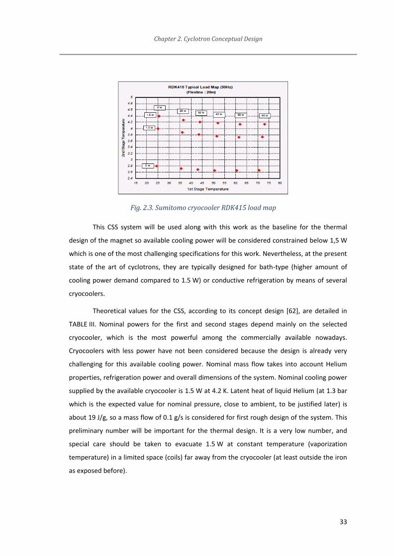
Chapter 2. Cyclotron Conceptual Design
33
Fig. 2.3. Sumitomo cryocooler RDK415 load map
This CSS system will be used along with this work as the baseline for the thermal
design of the magnet so available cooling power will be considered constrained below 1,5 W
which is one of the most challenging specifications for this work. Nevertheless, at the present
state of the art of cyclotrons, they are typically designed for bath-type (higher amount of
cooling power demand compared to 1.5 W) or conductive refrigeration by means of several
cryocoolers.
Theoretical values for the CSS, according to its concept design [62], are detailed in
TABLE III. Nominal powers for the first and second stages depend mainly on the selected
cryocooler, which is the most powerful among the commercially available nowadays.
Cryocoolers with less power have not been considered because the design is already very
challenging for this available cooling power. Nominal mass flow takes into account Helium
properties, refrigeration power and overall dimensions of the system. Nominal cooling power
supplied by the available cryocooler is 1.5 W at 4.2 K. Latent heat of liquid Helium (at 1.3 bar
which is the expected value for nominal pressure, close to ambient, to be justified later) is
about 19 J/g, so a mass flow of 0.1 g/s is considered for first rough design of the system. This
preliminary number will be important for the thermal design. It is a very low number, and
special care should be taken to evacuate 1.5 W at constant temperature (vaporization
temperature) in a limited space (coils) far away from the cryocooler (at least outside the iron
as exposed before).
Chapter 2. Cyclotron Conceptual Design
34
TABLE III NOMINAL THERMAL POWER AVAILABLE FROM CSS
Parameter Value
First stage nominal power and temperature 1.4 W @ 4,5 K
Second stage nominal power and temperature 25 W @ 40 K
Nominal mass flow (Helium) 0.1 g/s
2.4 Definition of magnet interactions with other cyclotron subsystems
Basic subsystems included at the cyclotron are:
- Superconducting magnet
- Accelerating subsystem
- Ion source
- Target and particle extraction
- Control system
All of these systems must be compatible between each other, in terms of
specifications, availability, robustness, and, of course, geometrical constraints.
Even when this Thesis is about the development of the superconducting magnet,
some details of the other subsystems will be explained. Interfaces between subsystems are,
at several points, important or critical design constraints for the magnet.
2.4.1 RF subsystem
The accelerating subsystem will be based on a single 180º dee. Given the expected
magnetic field and radius, an electric field up to 60 kV will be needed [57]. These numbers are
considered as input parameters for this work as their definition and the work done on the
conceptual RF design to get them is out of the scope. So just as a brief explanation, the higher
the electrical field, the lower the number of turns needed to reach certain energy (energy
supplied at each turn is proportional to the field intensity) and it could lead to lower beam
LuisGarciaTabares
Resaltado

Chapter 2. Cyclotron Conceptual Design
35
losses ( lower losses coming from collisions in the non-perfect vacuum and lower chances for
instabilities to grow). The selected electric field of 60 kV is quite a big number for a compact
cyclotron. It will need a considerable volume to avoid breakdowns, even if the design is
optimal. Besides, too much high voltages could produce stripping losses and would increase
RF losses (proportional to V2). In any case, it will certainly affect the magnetic yoke geometry
and magnetic field quality, so it is important to take it into account from the very beginning.
RF resonator was designed to be out of the iron yoke for magnet compactness, but a
connection between the resonator and the dee (which is of course inside the magnet) should
be provided to allow the current flow between them. Also, refrigeration water will be used at
the dee for keeping temperature during operation at safe values. Because of these reasons,
and the maximum vertical amplitude of the beam according to beam dynamics analysis (+/-
6 mm from midplane), the following free volume through the magnet should be provided:
Length 280 mm, height 74 mm. The height directly determines the air gap in the magnetic
circuit. This choice is a tradeoff between the necessary number of ampere-turns and the RF
power.
Moreover, a second cylindrical hole of 210 mm radius should be drilled to allow the
resonator to be as close as possible to the iron, minimizing the total dimensions of the
cyclotron and, the most important reason, to reduce power losses in the RF cavity [57]. A
draft image of this concept is shown in Fig. 2.4.
In fact, these holes in the iron could produce perturbing resonances in the beam
dynamics, so it is needed to replicate them at the opposite side in the sake of symmetry. As
these additional holes must be drilled, ion source and targetry will take advantage from them
to provide accessibility.
Finally, the magnet should be able to withstand not only its own weight and magnetic
forces, but also the weight coming from the RF system, which will be partially hanging from
the iron yoke for alignment reasons.

Chapter 2. Cyclotron Conceptual Design
36
Fig. 2.4. RF system overview (already installed on cyclotron magnet)
2.4.2 Ion Source
The Ion source is responsible for providing the particles to be accelerated (or
energized to be more precise in general).
For a compact and low cost cyclotron, it is preferable to include an internal ion
source. The beam transport from an external ion source through the iron and inside the high
field region is cumbersome. However the interfaces between the internal ion source and the
magnet are also challenging.
First of all, the internal ion source should be small in order to be accommodated in a
quite restrictive volume inside the cyclotron. Due to the strong magnetic field and the limited
electric field for beam extraction, the first orbit radius is small. The ion source has to be
placed inside the volume defined by the first orbit.
Moreover, the ion source is a system that needs significant maintenance and tuning.
Because of this reason, there should be an easy and quick procedure to tune and even
replace the ion source system or any of its components.
This internal ion source is inside the RF cavity for optimizing the inner volume of the
cyclotron. Therefore, the RF cavity must be accessible to be extracted from the iron yoke and
easily opened for accessing this subsystem [63].

Chapter 2. Cyclotron Conceptual Design
37
2.4.3 Target and extraction
The AMIT extraction system is based on the stripping foil method. This is basically a
thin carbon foil (pyrolytic graphite) which strips off the electrons of the H- particles. As H-
particles become protons (H+) when the nuclei lose both electrons, their trajectory bends into
the opposite direction of the incoming beam. Stripping foil nominal position was established
at 108 mm radius by beam dynamics study (Fig. 2.5), so the magnet was designed to provide
a good quality focusing field up to 110 mm [64].
The available lateral hole opposite to RF resonator was used for the extraction path
of the protons. This is for allowing the targetry system to be as close as possible to the carbon
foil, reducing the beam losses and radiation. The targetry system will use the extracted
protons to produce the radioisotopes needed for pharmaceuticals. This is also out of the
scope of this thesis, more information can be found in [65].
Fig. 2.5. Cyclotron mid-plane cross section showing extracted particle ideal trajectory.
2.5 Summary of Concept Design
In this Chapter, the Author describes a general procedure for the conceptual of
superconducting magnets when the compactness and the efficiency are the most important
objectives. Each decision is analyzed and finally a solution is defined based on the
specifications coming from the AMIT project. A brief description of other additional
subsystems in the cyclotron is provided when they affect the magnet design.

Chapter 2. Cyclotron Conceptual Design
38
The main contribution from the Author in this Chapter is the compilation of the state
of the art and the related literature to provide a reasonable methodology and guidelines for
superconducting magnets development. The contents of this Chapter were widely discussed
between most of the members of the Accelerators Technology Unit (CIEMAT), providing a
multidisciplinary overview and agreement. In addition, the innovative cooling concept was
developed in closed collaboration with an external institute and its experts.
Some of the contents of this Chapter were shown in AIME16, Madrid (Academia-
Industry Matching Event) [66] by the Author, and in the IPAC17, Copenhagen (International
Particle Accelerator Conference) [64].

Chapter 3. Electromagnetic Design
As it was already explained, on one hand, classical cyclotrons are relatively simple in
terms of the required magnetic field map. On the other hand, very tight precision should be
reached in order to provide weak focusing to the particles and finally extract enough number
of particles (current).
In the particular case of AMIT cyclotron, magnet specifications (TABLE IV) are coming
from the beam dynamics and the combination of efficiency and compactness, as explained in
previous chapter.
TABLE IV MAIN MAGNET SPECIFICATIONS
Parameter Value
Cold mass distribution Warm iron
Magnetic field 4 T
n index 1.5 %
Extraction radius 108 mm
Air Gap Height >74 mm
3.1 2D concept and refinement (Pseudo 2D)
The three usual electromagnet designs able to create the uniform field required by
the cyclotron are evaluated below:
1. Solenoid: This electromagnet is based on a single coil and it is the simplest
possibility. If this coil is long enough compared to its diameter, the field inside
the coil at the mean plane is uniform along the cross-section. Solenoid coil is
discarded for this cyclotron because there is no option for mean plane access.
As explained in the previous chapter, a cyclotron requires a path at mean

Chapter 3. Electromagnetic Design
40
plane for particles extraction, access for ion source maintenance and space
for the electrical connection of resonator and dee.
2. Helmholtz coils: This configuration is similar to the previous one, but it
consists of two short coils instead of a single, long one. The uniformity of the
mean plane field is not as good as the solenoid one, but it can be designed to
meet the required uniformity. Mean plane access is intrinsic to this
configuration and its value (related to the distance between coils) can be
adjusted during design stage to meet specifications.
3. Maxwell coils: This configuration is similar to the Helmholtz one, but
additional coil/s are included having higher diameter than the Helmholtz
ones. This or these coils can be aimed from design to accomplish different
purposes. For example, this configuration can enhance the uniformity of the
magnetic field or reduce the fringe field. This configuration is clearly the most
complex one in terms of both design and manufacturing. Also, additional coils
result in higher manufacturing costs and sometimes in bigger magnets. Mean
plane access can be obtained as far as outer coils are also designed to be far
enough from it.
The Helmholtz arrangement of coils is selected for this specific cyclotron as it can
provide the required uniformity of the field while simplicity and low cost are preserved.
Once that the concept design of the cyclotron coils is fixed, the proposed design
method starts by a simple geometry definition in a 2D axisymmetric model. Analytical models
cannot be used in this case because of the saturation of the iron yoke starting at fields close
to 2 T. A user-friendly FE (Finite Element) software (QuickField [67]) is used for this first
approach. This software provides a simple and quick environment for 2D FE models including
magnetostatic ones. All the elements use linear shape functions. Non-linear properties of
ferromagnetic materials can be modeled by means of curves defined by points. It also
includes some other features to provide quick solutions, such as completely automatic
meshing algorithms. It is not as powerful in terms of flexibility or accuracy as some other
commercial packages (for example Opera [68] or Ansys Maxwell [69]) but it is proposed as a

Chapter 3. Electromagnetic Design
41
quick starter software for a first rough design. Afterwards, it will be refined by using more
complex (3D) and accurate models.
At this stage, the most important parameters to define are the nominal current, the
loading factor on the load line and the magnet protection method. The first decision must be
taken on the superconducting wire to be used. In the following paragraphs, reasonable
starting parameters for the numerical calculation will be chosen.
A low nominal current will allow the use of a monolithic wire insulated with varnish.
This choice is very convenient for a cheap coil: there are many wires commercially available,
the winding tooling is not complicate and the winding techniques are well-known.
Furthermore, the thermal losses through the current leads are somehow proportional to the
current, which is very important taking into account the limited cooling capacity. A starting
guess for the design would be a current interval between 100 and 300 A.
Some of the wire properties are fixed once the material to be used is selected; while
some others (e.g., engineering current density) will depend on the actual wire. NbTi
technology is quite mature, but just a few number of wires are available in the market. Due to
the small demanded quantity and the necessity to reduce costs, a commercial wire is
preferred, so the design will select wire parameters from a bunch of possibilities.
The maximum current that a superconducting wire can carry (without changing to
normal state) is called critical current. As any other intrinsic critical variable (temperature and
magnetic field), it is a material property, in this case of NbTi. However, manufacturing
techniques or wire layout (superconducting filament diameter mainly) can slightly improve or
reduce actual critical current, so real performance should be analyzed by using the supplier
information.
A safety margin should be defined for the electromagnetic design. For a
superconducting magnet, it is defined as the maximum ratio between actual current in the
wire at nominal operation and the real critical current given the temperature and magnetic
field for any point of the coil. This is called load line margin (or loading factor) as explained in
Fig. 3.1 (extracted from [70]). Given the material properties of the actual wire and the
temperature, a curve is plotted in a J-B graph as the superconductive-resistive transition (pink
line). If actual magnet operation is below that curve, it is superconducting. By evaluating

Chapter 3. Electromagnetic Design
42
operational point of the wire for several current values, a load line on the same graph can be
plotted (blue line). The green line is the actual magnetic field seen by the particles in the
aperture. The value of current at which both blue and pink curves intersect is the critical
current of the magnet. The ratio between the lengths of the line from the nominal point to
the intersection divided by the total length from the intersection to the origin is called the
load line margin. Note that critical current of the wire and critical current of the magnet are
different values as the latter depends on the magnet geometry.
Fig. 3.1. Load line of the magnet for a given design
If the load line margin is small, there is a high risk that quenches trigger often. It
would sharply reduce the efficiency of a radioisotope production cyclotron with limited
cooling power. On the other hand, superconducting Helmholtz coils usually show a good
mechanical performance, because the electromagnetic force distribution is quite symmetric,
which eases the design of the support structure. Based on these remarks and practical
experience, one can assume 70% as a good starting value for the working point on the load
line [71].
Another important parameter is the copper to non-copper ratio (Cu/nCu) of the wire,
which is defined as the amount of copper in the wire divided by the amount of non-copper
material (NbTi). A high value means that the wire includes a large amount of copper and just
a little superconducting material and vice versa. A high ratio yields three main advantages:
- The higher the value, the better the thermal stability: In case of a quench (sudden
loss of superconductivity state), the superconducting filaments become resistive and Joule
losses could increase coil temperature or voltage up to dangerous levels. By adding copper to
the wire, during normal operation all the current flows through the superconducting

Chapter 3. Electromagnetic Design
43
filaments and in case of a quench there is a parallel path for the current to flow: the copper. It
is not as good as the superconductor, but Joule losses will be much lower than for the
resistive NbTi.
- Electrical stability. In case of a quench in one coil, the current will decay due to the
developed resistance and a voltage proportional to the product of coil inductance by di/dt
will rise on the other coil. If there is just a small amount of Cu, the current will decay very fast
(because of resistance) and the voltage can reach dangerous values. Higher Cu/nCu ratios are
important to keep electrical resistance at reasonable values in case of quench so that the
current decays slowly and the peak voltage is safe.
- Thermal stability. Superconducting material resistance is zero at nominal conditions
(constant current). Nevertheless, there are electrical losses during current transients (for
example the ramp-up when powering), even at superconducting state. This copper will help
on evacuating the generated power to the outer surface of the coils and/or spreading it to
decrease the peak temperature. Filament size is controlled as this parameter is the most
important one for this kind of losses.
On the other hand, a high Cu/nCu ratio shows the following drawbacks:
- The higher the Cu/nCu ratio, the higher the weight of the wire and the higher the
cost as the amount of material to be extruded in the billet is increased.
- The higher the Cu/nCu ratio, the lower the engineering current density. For a given
number of ampere-turns, coil size will be increased.
Moreover, NbTi is a brittle material while long filaments are needed to produce high
quality superconducting wire (high critical current). Extruding a brittle material is not easy as
it will break in the process, so it is extruded in a billet beside some amount of a ductile
material: copper. Billet geometry is carefully designed by supplier for providing certain
specifications on the produced wire, including Cu/nCu ratio, filament size, arrangement of
filaments, etc. These details are out of the scope of this work, so the attention will be paid at
the performance parameters stated by the suppliers for the available wires on the market.
In short, there are a number of criteria with sensitivity of opposite signs, so it is
necessary to find a trade-off to choose a reasonable starting value for the Cu/nCu ratio.
Chapter 3. Electromagnetic Design
44
Taking into account the hard constraint on the cooling power, which leads to a low nominal
current, one can deduce that the magnet self-inductance will be relatively high and, as a
consequence, peak voltage and temperatures are prone to reach dangerous values during the
quench. Based on this reasons and know-how, one can expect that a Cu/nCu ratio between 3
and 5 will be adequate for this application and available on the market.
Magnetic design would require as boundary condition a value for the minimum
separation between the iron and the coils, which will be defined as the minimum distance
technologically feasible for the thermal insulation and mechanical support of the coils
surrounded by the warm iron. For the concept design, a typical cryogenic solution for a
magnet cooled by liquid Helium will be used, so it will include a thermal shield and a high
vacuum chamber (a good reference on the state-of-the-art about cryostat design can be for
example [72]). A number of parts will be accommodated in this free space between iron and
coil: casing as supporting structure of the magnetic forces of the coils, thermal shield for
insulation of the cold mass, and cryostat wall as vacuum vessel. A rough number for this first
design is usually chosen by know-how and previous experience, and a review of existing
cryostats results in typical values from 30 to 60 mm [73], depending on the geometry and the
complexity.
For a compact design this dimension is critical: first of all, higher distance to the iron
means higher distance to the magnetic axis, and so the efficiency of the coils to produce the
magnetic field is reduced. Moreover, coil cross-section needs to be increased and so the
outer cryostat radius is increased even more. Iron total volume would increase as well in a
positive feedback loop. Because of its critical effect on the compactness, 30 mm will be
selected as the baseline for starting the magnetic design of the magnet. This value for such a
complex geometry is very challenging but seems to be feasible. Magnetic design of the
magnet will be done for 32 mm in order to accommodate +/- 1 mm movement of the cryostat
for tuning and assembly tolerances.
The total ampere-turns to provide 4 T at the center with the requested air-gap and
beam extraction radius can be easily checked by means of the FE software. A number of
iterations are needed to find optimal values or, at least, a well-balanced proposal:

Chapter 3. Electromagnetic Design
45
1. First, select a wire from suppliers accomplishing the given ranges for nominal
current, load line margin and Cu/nCu ratio.
2. Evaluate the needed number of turns. Define the coil cross-section geometry and
position.
3. Analyze the results: ratio between peak field at coils and center field, real load
margin, magnet weight, field homogeneity and magnet protection.
4. Perform next new design iteration.
All of these parameters should be taken into account for a cyclotron design, but there
is no analytical cost function to mathematically search the best option. The main advantages
and disadvantages for minimizing or maximizing any of these parameters have been already
slightly explained. For every superconducting magnet to be designed all the boundary
conditions should be considered and design decisions should be taken consequently.
As an example, the results regarding the magnet protection are presented in TABLE V
when some Cu/nCu ratios are compared. Peak voltage and temperature are not very sensitive
to the copper content. It can be explained as a result of the huge self-inductance, between 40
and 100 H, depending on the iron saturation. The current decay is very slow, in the order of
10 seconds, and thermal conductivity is very good in this type of coils, so generated heat is
well distributed all over the coil. However, a high copper content is chosen to enhance the
thermal stability of the wire and avoid premature quenches in case of cooling instabilities.
TABLE V EFFECT OF CU/NCU RATIO ON THE QUENCH PROTECTION RESULTS
Cu/nCu Maximum
temperature (K)
Maximum Resistive
Voltage (V)
2 101 1532
3 99 1387
4.5 98 1315
5 97 1270
6 96 1240

Chapter 3. Electromagnetic Design
46
Eventually, a 2D electromagnetic design of the magnet will be reached by this
procedure, including iron yoke and coil geometry, current and number of turns. The results
are shown in Fig. 3.2 and TABLE VI.
Fig. 3.2. Magnetic field map with left edge as symmetry axis (left). Load Line of the magnet
from 2D design. Nominal operation is highlighted by the circle (right)
TABLE VI MAGNET PARAMETERS DEFINED FROM 2D MODEL
Parameter Value
Wire Diameter (bare/insulated) 0.85/0.90 mm
Coil cross section (width/height) 70.55/76.53 mm
Nominal Current 108.6 A
Number of turns 4235
Self-Inductance (nominal current, both coils) 38.35 H
Cu/nCu ratio 4.5:1
Distance from coil to iron 32 mm
The RF cavity will spoil the axisymmetric geometry of the iron. In order to speed up
simulations during the concept design, a pseudo 3D model is proposed. The calculation is
made with a 2D model, but the results are very close to those obtained with an actual 3D
model. It is based on the distribution of the iron reluctance in the magnetic circuit at different
angular positions. The 2D iron model is split in two different parts. The first one will represent

Chapter 3. Electromagnetic Design
47
the axisymmetric iron fraction (shown with scarce line density at Fig. 3.3). For the second one,
modeling the parts with holes at certain angular positions, its material magnetic properties
(permeability) are considered to be an averaged value of iron and air, weighted by their
volume fractions along the revolution. As the air relative permeability is 1, the relative
permeability µ* of this custom material is the iron permeability reduced by the ratio between
the actual iron volume divided by the total volume.
Magnetic field tuning should be the next step to refine. Boundary conditions from
beam dynamics analysis are considered at this stage.
The proposal from this work is to automatize an iterative method for reaching a
magnetic field profile as close as possible to the optimum one. It is proposed to apply
modifications just on the iron pole, since the field quality at the gap is mainly depending on
its geometry.
Fig. 3.3. Cyclotron magnetic model (3D and its pseudo-2D)
The iron pole was defined as the shape resulting by connecting a number of points
along the radius. Radial position for each point is fixed and axial position can vary according
boundary conditions (for example, the minimum value of the gap to insert the RF cavity).
Axial positions are displaced and the magnetic field profile is evaluated for each trial.
Magnetic field shape is compared to the ideal one (given by beam dynamics analysis), by
means of a nonlinear cost function , defined as eq. (6). This function includes the optimum
Chapter 3. Electromagnetic Design
48
shape of the magnetic field from the particles dynamics point of view (G) and the actual
magnetic field evaluated for the iron shape under analysis (B). Numerical derivatives on the B
field are evaluated at each iteration (dB), according to eq. (7).
For a given discretization of both profiles, four terms are evaluated and weighted
according to A0…A3 parameters. The first one is related to the actual magnetic field in the
center of the magnet compared to the optimum value at that point. In the second one, a sum
of the absolute values of their differences along the radius is evaluated. Also the sum of the
absolute value of the differences of their numerical derivatives is included, which is actually
related to the n index value. Finally, the last term is included as a hard constraint: actual
magnetic field profile should never show a positive derivate over the radial direction at any
position because it will produce instability and defocusing on the beam dynamics. The A3
parameter should be set large enough for the algorithm to discard any field shape in which
this fourth term is not zero.
This simple proposal, which is a quite typical procedure for multivariable decision
analysis, can be easily adapted to any other accelerator magnet once that the desired shape
of the magnetic field is known.
Values for the A parameters, the initial iron design and the procedure on how the
iron yoke shape should be changing from previous iteration to the next one should be defined
according to previous expertise on similar magnets and operational resources available for
the optimization.
( ) ∑{ (‖ ‖) (‖
‖)
(‖ ‖ )}
(6)
(7)

Chapter 3. Electromagnetic Design
49
In the framework of this work, an initial guess was introduced manually and
parameters were changing following linear steps. The pole shape was generated in Matlab
[74] (v. R2016a) for each evaluation. Then the geometry is sent to QuickField [75] (v. 5.8)to be
evaluated and the result is read and processed by Matlab.
From the point of view of the beam dynamics, the best solution is an almost constant
magnetic field but including a small negative gradient along the radius. Final design is shown
in Fig. 3.4. It includes the magnetic field profile. It is important to note that due to the
axisymmetric condition, the derivative of the magnetic field at the center is always zero. Thus,
it is physically impossible to reach a perfectly constant n index. In addition, the larger the pole
diameter, the easier is to design a smooth profile for a given extraction radius, but increasing
the pole dimension will have a huge impact on the overall cyclotron dimensions.
A convincing result from beam dynamics analysis ([64]) was found quite quickly, so no
further efforts were paid on programming a custom code for finding the real absolute
optimum design.
Fig. 3.4. Magnetic field map in the final Pseudo 3D magnetic model(left) and magnetic field vs
radial position graph (right).
3.2 3D design
Once that a 2D design is completed, 3D calculations should be performed to check
important features for any superconducting accelerator magnet:

Chapter 3. Electromagnetic Design
50
- Real magnetic field quality in the whole volume. A 3D model allows considering the
detailed geometry and evaluating the effects of all the asymmetries of the iron on the beam
trajectory.
- Real magnetic forces distribution. Any misalignment of the coils will produce a
magnetic force which cannot be modeled, generally speaking, under the assumptions of an
axisymmetric model. Obviously, some of the possible misalignments would break
axisymmetric conditions.
Fig. 3.5. 3D magnetic model.
For the 3D (Fig. 3.5) evaluation of magnetic field and forces, Opera software [68]
(v. 16) was used. A 3D model including the main features of the iron was modeled (holes for
RF cavity for example) and the magnetic field was mapped. The magnetic field map was
transferred to the beam analysis group, which checked the complete orbit of particles and
validated the magnet design.
As a qualitative comparison, a desktop computer (Intel Core i7, 16 GB RAM) can
compute a 2D or a pseudo-2D model in QuickField in about 2 minutes while a complete 3D
model in Opera requires about 3 hours. This is the main reason for optimizing the design
using a pseudo-2D model. Unfortunately, a complete 3D model is needed to evaluate the
effect of any misalignment of the coils.
Tight tolerances for magnet manufacturing and high positioning accuracy for the
supporting system would reduce the magnetic forces to be handled, because the
misalignment between the magnetic axis of the iron and the coils would be small. In that
case, the supporting system could be slimmer and perform lower thermal losses. On the
other hand, stress measurement and control become also critical if a high precision
positioning is required.

Chapter 3. Electromagnetic Design
51
The definition of the maximum allowed tolerances for manufacturing and assembly
should be done according to all these details. The supporting system design will be detailed in
a specific chapter and it should be designed in parallel to this 3D model. A positioning
accuracy of +/- 1 mm for the coils in all three directions is considered to be a reasonable
number from the experience of alignment of some other precision mechanical systems [73].
Finally, the maximum lumped forces on the coils can be evaluated under a
combination of misalignments at simultaneous directions and they will be used as inputs for
supporting structure design (TABLE VII and Fig. 3.6). The magnetic field calculated under the
assumption of misalignment combinations will be used for checking feasibility via beam
dynamics analysis.
Fig. 3.6. Overview of vertical magnetic forces on each coil (z axis). The force is positive towards
the iron, that is, coil forces are repulsive

Chapter 3. Electromagnetic Design
52
TABLE VII MAGNETIC FORCES
Parameter Value
Coil Force (Axial Force @ Nominal Current) 71 kN
X-Axis Force @ 1 mm X misalignment 4000 kN
Y-Axis Force @ 1 mm Y misalignment 3400 kN
Z-Axis Force @ 1 mm Z misalignment 6700 kN
3.3 Quench simulation
A quench event is, of course, a potentially dangerous situation for a superconducting
magnet. Generally speaking, quenches should be avoided but they are always present and the
following considerations must be taken into account for magnet design:
- Robustness. Under unexpected operational conditions, any of the parameters
involved in the phase transition to resistive state could provoke the quench. Examples of this
could be an increase in local temperature at any point or the injection of higher current from
the power source.
- Magnets usually need some training before reaching nominal operation conditions.
Due to manufacturing tolerances, material inhomogeneity, poor design of the support
structure or any other reason, superconducting coils do not usually reach nominal current at
their first run. Some (or several) runs are needed to reach the ultimate current, which is
above nominal current by a given safety margin to guarantee the stable operation of the
magnet at nominal conditions. Training is a well-established procedure for superconducting
magnet manufacturing. A superconducting magnet is expected to reach nominal conditions
after a reasonable amount of quenches, ideally reaching a higher current after each run [76].
The design should focus at least on two main topics. Both of them can be treated as
independent features.
- Electromechanical effects: Once that the first small volume of the coil transits to the
resistive state (for any reason), a high amount of heat will be generated in it (Joule effect).
Eventually, the whole coil will be warmed up and completely transited to resistive mode. A

Chapter 3. Electromagnetic Design
53
critical parameter to be checked at this point is the maximum temperature inside the coil
(this is called “hot-spot temperature”) and it should be designed to be low enough to avoid
damaging the coil or its components (the resin and insulation materials are typically the less
temperature resistant). For highly inductive magnets it is important to check the maximum
voltages induced in the coils due to the quick transition of the current in the coil (Lenz law),
otherwise insulation breakage could occur.
- Fluid-Mechanical effects: This is not usually considered. Most of superconducting
devices are refrigerated by a bath-cooling concept so ambient pressure (or slightly above) is
the nominal condition. Moreover, many of them include also a Helium reservoir in the cold
mass cryostat for thermal insulation. It can provide a large effective area for Helium flow at
the event of a massive liquid evaporation (which is the case in a quench). Under these
conditions, no problems are expected due to the high gas pressure from the fluid vaporization
in the case of a quench. In conclusion, fluid-mechanical behavior of quench is in fact more
related to the mechanical and refrigeration design than to the electromagnetic design.
Therefore, it will be analyzed in the next chapter.
There are several models, procedures and even custom codes for quench protection
design and to check coil integrity after a quench. This is out of the scope of this work so for
more information check reference [77]. For the specific case under development in this work,
custom made code from CIEMAT, so-called SQUID, was used [78]. TABLE VIII collects the
results of the simulations. Firstly, the quench was simulated for the coils and the power
supply, without any protection. It is assumed that the power supply is switched off by its
overvoltage protection, providing a path for the current to keep circulating. Results are
slightly pessimistic, because no AC losses are included, although they will take place in some
other parts: the copper thermal shield, the aluminum shrinking cylinder, the iron yoke, etc.
The hot-spot temperature is quite low, but the peak voltage to ground is high, about 650 V,
which takes place at the splice between both coils.

Chapter 3. Electromagnetic Design
54
TABLE VIII QUENCH SIMULATIONS SUMMARY
Dump Resistor
Hot Spot
Temperature
Developed Resistive
Peak Voltage
Peak Voltage to
Ground
Self-Protection No 98 K 1315 V 657 V
Dump Resistor 3 Ω 88 K 964 V 600 V
There is a classical resource to reduce the hot-spot temperature and peak voltage,
which is the use of a dump resistor. The voltage reduction is somehow proportional to the
value of the resistor. Therefore, its upper value is limited by the maximum accepted voltage
to ground in the circuit. For this kind of superconducting wire, insulated with varnish, a
maximum voltage from coil to ground of 500 V is commonly fixed. It means that a dump
resistor around 3 Ohm is adequate for this application. The dump resistor is in parallel with
the magnet, with a diode in series to avoid dissipating power in the resistor during normal
operation. An active switch is in series with the power supply, to disconnect it in case of
quench (Fig. 3.7). The delay time of that switch is not critical for the magnet protection
because the current decay is very slow. The stored magnetic energy at nominal current is
241.3 kJ. In case of a quench at nominal current, 55 kJ are dissipated at the resistor. The
current decay and the evolution of the resistive voltage are shown in Fig. 3.8. The peak
voltage due to the developed resistance is reduced about 30%. In the most pessimistic case,
when the electrical circuit is grounded at the current lead of the non-quenched coil, the peak
voltage to ground takes place at the inter-coil splice. It is about 600 V, which is not a large
improvement compared with the self-protected case study. However, the dump resistor was
kept in the design because it is necessary for the fast discharge of the magnet in case of an
interlock (for instance, power failure or thermal runaway at current leads). In fact, the actual
values will be more pessimistic, due to the contribution of the induced losses in the near
conducting elements. Therefore, it was decided to keep 500 V as the standard test voltage for
the magnet assembly. Only in the case that the leakage current is high, higher voltage or
longer test time will be used, to be decided according to the circumstances.

Chapter 3. Electromagnetic Design
55
Fig. 3.7. Schematic of the magnet protection circuit.
Fig. 3.8. Simulation of the current decay and resistive voltage evolution for a quench at
nominal current with a dump resistor of 3 ohm
3.4 Summary and Contribution about the Concept Design
In this Chapter, the Author describes a detailed procedure for the electromagnetic
design of superconducting magnets. Each possibility is briefly discussed and then a decision is
taken based on the particular specifications of the AMIT project and the state of the art.
The main contribution from the Author in this Chapter is the description of a
comprehensible discussion on how to proceed to design a superconducting magnet when
compactness and efficiency are critical. Referenced books and papers can be found for
designing accelerator magnets, but none of them are focused on the efficiency or
compactness as the most important parameters.


Chapter 4. Mechanical Design
As a result of the design choices explained in the previous chapters, the
superconducting coils will be cooled by a Helium flow and the iron will be at room
temperature. Besides, the thermal losses must be small and the existing space for the
cryostat walls is only 30 mm (available distance from the coils to the iron). Finally, the
cryostat must be able to hold the magnetic forces when the coils are powered. In the next
paragraphs, the cryostat design will be carefully analyzed, with special attention to the
thermal losses, compactness and mechanical analysis.
4.1 Conceptual design of the cryostat
The expected electromagnetic forces in the coils can be studied in two components:
axial and radial ones. In this coil configuration, axial forces tend to move the coil closer to the
iron yoke. Depending on the value of the air gap and the distance between coils, axial forces
could be attractive. Radial forces tend to expand the coil to a larger diameter. This effect is
typically known as magnetic pressure.
In radial direction, as far as the coil is axisymmetric, it results in zero net in-plane
force. On the other hand, each coil will suffer a net vertical force which is of opposite
direction and the same magnitude.
Moreover, as the coils are thick according to their cross-section dimensions [52],
positive radial stresses will arise inside the coil. These radial stresses should be avoided
because of the brittle nature of the wound coil at cold
Finally, as a relatively large clearance area is needed at the mean plane of the magnet
(to accommodate the RF cavity and the targetry components), the supporting structure of the
coils will suffer a bending moment coming from the axial forces at each coil.
Because of these reasons, a special structure, so-called casing (Fig. 4.1), should be
designed to:

Chapter 4. Mechanical Design
58
Support axial forces of both coils, keeping them at their positions. As they are
supported inside a unique structure, no net axial forces are transferred to the
cryostat, whose wall can be kept thin, able to take care of the atmospheric
pressure only
Provide radial stiffness to hold the radial electromagnetic forces and apply
some compressive pressure avoiding positive radial stresses inside the coil.
This effect cannot be fulfilled with a casing surrounding the coils, because of
the different thermal contraction coefficients of the materials and the
manufacturing tolerances. However, if a shrinking cylinder surrounds each
coil, the casing design and assembly eases noticeably.
Provide space for the cryogen flow to be in intimate contact with the coils.
Alternative solutions based on a Helium flow inside a pipe glued to the coils
or weld to the casing have been analyzed, but they are less compact and
effective.
Provide a procedure for fine tuning of coil position and alignment once the
cryostat is finished and the iron yoke is assembled around.
Fig. 4.1. Magnetic forces in coils and first schematic of a casing with openings for the RF
vacuum chamber.
The casing will be made in a non-magnetic grade of stainless steel, because it does
not affect the magnetic field quality. It is stiff, easy to weld and its thermal contraction
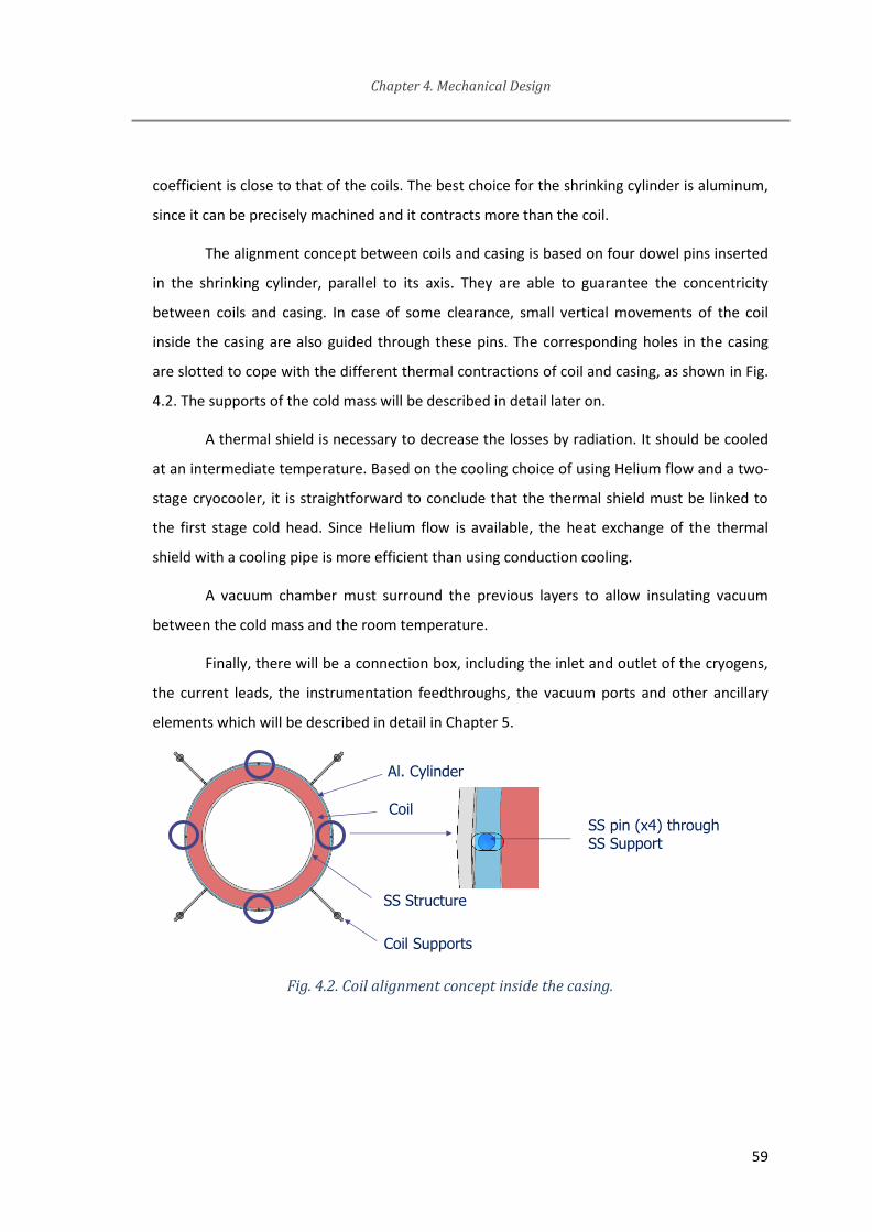
Chapter 4. Mechanical Design
59
coefficient is close to that of the coils. The best choice for the shrinking cylinder is aluminum,
since it can be precisely machined and it contracts more than the coil.
The alignment concept between coils and casing is based on four dowel pins inserted
in the shrinking cylinder, parallel to its axis. They are able to guarantee the concentricity
between coils and casing. In case of some clearance, small vertical movements of the coil
inside the casing are also guided through these pins. The corresponding holes in the casing
are slotted to cope with the different thermal contractions of coil and casing, as shown in Fig.
4.2. The supports of the cold mass will be described in detail later on.
A thermal shield is necessary to decrease the losses by radiation. It should be cooled
at an intermediate temperature. Based on the cooling choice of using Helium flow and a two-
stage cryocooler, it is straightforward to conclude that the thermal shield must be linked to
the first stage cold head. Since Helium flow is available, the heat exchange of the thermal
shield with a cooling pipe is more efficient than using conduction cooling.
A vacuum chamber must surround the previous layers to allow insulating vacuum
between the cold mass and the room temperature.
Finally, there will be a connection box, including the inlet and outlet of the cryogens,
the current leads, the instrumentation feedthroughs, the vacuum ports and other ancillary
elements which will be described in detail in Chapter 5.
Fig. 4.2. Coil alignment concept inside the casing.
SS pin (x4) through SS Support
Coil
Al. Cylinder
SS Structure
Coil Supports
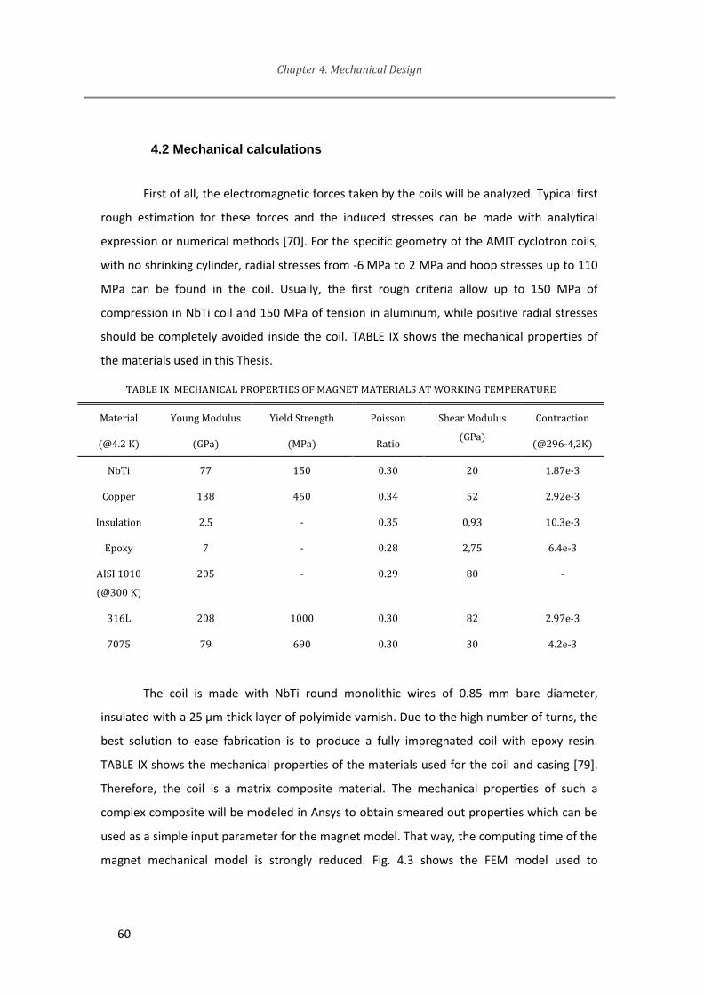
Chapter 4. Mechanical Design
60
4.2 Mechanical calculations
First of all, the electromagnetic forces taken by the coils will be analyzed. Typical first
rough estimation for these forces and the induced stresses can be made with analytical
expression or numerical methods [70]. For the specific geometry of the AMIT cyclotron coils,
with no shrinking cylinder, radial stresses from -6 MPa to 2 MPa and hoop stresses up to 110
MPa can be found in the coil. Usually, the first rough criteria allow up to 150 MPa of
compression in NbTi coil and 150 MPa of tension in aluminum, while positive radial stresses
should be completely avoided inside the coil. TABLE IX shows the mechanical properties of
the materials used in this Thesis.
TABLE IX MECHANICAL PROPERTIES OF MAGNET MATERIALS AT WORKING TEMPERATURE
Material
(@4.2 K)
Young Modulus
(GPa)
Yield Strength
(MPa)
Poisson
Ratio
Shear Modulus
(GPa)
Contraction
(@296-4,2K)
NbTi 77 150 0.30 20 1.87e-3
Copper 138 450 0.34 52 2.92e-3
Insulation 2.5 - 0.35 0,93 10.3e-3
Epoxy 7 - 0.28 2,75 6.4e-3
AISI 1010
(@300 K)
205 - 0.29 80 -
316L 208 1000 0.30 82 2.97e-3
7075 79 690 0.30 30 4.2e-3
The coil is made with NbTi round monolithic wires of 0.85 mm bare diameter,
insulated with a 25 µm thick layer of polyimide varnish. Due to the high number of turns, the
best solution to ease fabrication is to produce a fully impregnated coil with epoxy resin.
TABLE IX shows the mechanical properties of the materials used for the coil and casing [79].
Therefore, the coil is a matrix composite material. The mechanical properties of such a
complex composite will be modeled in Ansys to obtain smeared out properties which can be
used as a simple input parameter for the magnet model. That way, the computing time of the
magnet mechanical model is strongly reduced. Fig. 4.3 shows the FEM model used to

Chapter 4. Mechanical Design
61
evaluate the 2D and 3D mechanical properties of the wound coil. The idea is to model the
composite as an assembly of each constituent, taking into account the exact distribution of
materials. Boundary conditions will be modeled as bonded body, as the wires will be
impregnated and cured together.
Bonding capabilities will be checked to assure that no cracks appear, and no inner
voids will be assumed. Once the model is ready, a set of simulations are conducted to
evaluate mechanical properties on each direction. The orthotropic properties can be assumed
due to the geometric constraints (once that the helicoidal behavior of the wire is neglected
because of the large radius of the coil compared to the helix pitch). Therefore, for each
direction, a fixed support will be applied to one face and a fixed traction pressure will be
applied to the opposite side. Additional constraints could be needed for identical strain on
the loaded side. This procedure can be used also for the calculation of average coefficients of
thermal contraction.
Fig. 4.3. Coil model for averaged mechanical properties evaluation
TABLE X summarizes the results of the simulations on the mechanical properties of
the composite. The coil was modeled as behaving in the same way in both transverse
directions, which is close to reality, because the coil cross section is nearly a square. This
means that an orthotropic behavior is expected and the table includes just the minimum
number of independent elastic parameters for this kind of material [80].
rz

Chapter 4. Mechanical Design
62
TABLE X AVERAGED MECHANICAL PROPERTIES OF COIL (4.2 K) (COMPUTED)
Young Modulus
(GPa)
Poisson
Ratio
Contraction
(@296-4,2K)
94 2.99e-3
r 35 3.90e-3
z 35 3.93e-3
r 0.08
z 0.08
rz 0.35
Once that the material properties are defined in detail, the complete 3D FEM analysis
can be done. Fig. 4.4 depicts the 3D coil model evaluated in Ansys including the iron yoke and,
therefore, the real magnetic field inside the coil.
Fig. 4.4. Magnetic force density and radial stress distributions inside the coil without shrinking
cylinder.
Positive tensile stress can be found in the coil. Its value is not high, but stability of
magnet operation is a must, so that a shrinking cylinder will be included to avoid quenches
triggered because of the brittle behavior of the epoxy resin of the coil. Moreover, some
interference is needed even at room temperature between the cylinder and the coil to
eliminate the tensile stresses at cold when the coil is energized. The choice of the
interference is made to have some margin (compressive stress) while not applying high
stresses to the coil or cylinder.

Chapter 4. Mechanical Design
63
Three load cases have been analyzed: assembly at room temperature, cool-down to
operating temperature and powering at nominal current. Fig. 4.5Fig. shows the radial and
hoop stresses along a radial path at each load step. In all cases, the maximum stresses are
safe and there are not radial tensile stresses in the coil.
Fig. 4.5. Radial and hoop stresses distribution in the coil and shrinking cylinder at the three
main load cases
The casing around the coil should be designed to hold the coils and the Helium inside,
so that both magnetic forces on the coils and Helium pressure should be taken into account.
This casing will be the inner core of the magnet so this design must take into account the
most pessimistic scenario and additional safety factor. It is the most expensive and the most
difficult part to reach once the cyclotron is manufactured, so that it should be one of the
most reliable components of the magnet. Fig. 4.6 shows FEM results on this casing when
maximum axial forces are applied to the upper inner surface of the casing and there is the
maximum Helium pressure of 7 bar inside (outside the casing it is vacuum). Yield strength for
Path definition for stress evaluations:FROM INTERNAL Face of COIL TO EXTERNAL FACE of Shrinkage
Stresses at Warm Stresses at 4,2K
X Axis(mm)
Y Axis(MPa)
Stresses at 4,2K and Magnet ON
Radial (Left Axis)
Hoop (Right Axis)
Radial (Left Axis)
Hoop (Right Axis)
Radial (Left Axis)
Hoop (Right Axis)
COIL AL. COIL AL. COIL AL.

Chapter 4. Mechanical Design
64
316LN steel is around 350 MPa at ambient temperature and around 1000 MPa at 4 K. The
wall thickness of the casing is not homogeneous, because the outer side of the coil is
surrounded by the shrinking cylinder. Deformation of the casing is also important because of
the small distances between components of the cryostat. From all of these points, the final
design of the casing includes wall thickness values of 8 mm (inner wall) and 4 mm (outer
wall). The inner wall is thicker to allow space for the helium flow channel. Maximum
equivalent stress of 265 MPa and maximum displacement of 0.27 mm are found as shown at
Fig. 4.6. The number for the pressure level inside for the simulation is proposed from the
maximum pressure of Helium during cooling down (3 bar, which will be justified later) and the
maximum overpressure allowed in case of quench. In the case this casing, as liquid helium is
flowing inside a small channel and pipes from outside the magnet, this overpressure could be
high and thus, a 7 bar was selected for calculations. Later on, the pressure relief system will
be defined accordingly.
Fig. 4.6. Von Mises stress in Casing at worst load scenario (Amplified strain for easier view)

Chapter 4. Mechanical Design
65
4.3 Evaluation of thermal losses
Thermal losses are probably the most important calculation for a compact and
efficient superconducting cyclotron. As it is well known, there are three mechanisms for the
heat to flow between two bodies at different temperatures: conduction, convection and
radiation. All of them must be considered for a competitive cryostat design.
In this first stage, only thermal losses from the magnet itself will be studied.
Contributions from cryogenic supply system will be included later on.
There are quite good references on cryostat design for liquid Helium temperature
(e.g., see [72] and [81]). Some recommendations are quite well established, and some
specific materials are usually selected for the construction as there is a lot of experience on
their behavior at such a low temperature.
These common procedures are of course included in this cryostat design as it will be
explained along this chapter, but the Author proposes a quite innovative approach in how the
design will try to push the limits to reach a really low-thermal-loss cryostat given the
compactness and geometry constraints.
4.3.1. Vacuum
Generally speaking, it is quite easy to overcome convection losses. Just by keeping
some distance from the cold mass to the cryostat wall at vacuum is enough to drastically
reduce this type of losses. Nevertheless, real vacuum, even ultra-high vacuum, is not
completely free of losses. Convection effects can be negligible but residual gas conduction
should be considered. Also, proper design for optimizing the vacuum level will require to
include some details in manufacturing drawings, welding procedures, materials and surface
treatments as they will be critical to reach good vacuum levels and, finally, minimum residual
gas heat conduction. These details will be explained in Chapter 5.
In order to evaluate which vacuum level is needed, its effects on the thermal losses
should be defined. According to kinetic theory of gases, mean free path of molecules is
Chapter 4. Mechanical Design
66
√2 (8)
Where R is the gas constant, T is the temperature, d is the mean diameter of
molecules, NA is the Avogadro number and P is the pressure. In order to be in residual gas
conduction regime, instead of the fluid one (for which thermal losses are lower), mean free
path must be greater than the distance between surfaces. At ambient temperature and given
a distance for the cryostat in the order of millimeters, maximum pressure at residual gas
regime at warm is in the order of 10-3 mbar. This is indeed the typical vacuum level which can
be easily reached by means of a turbomolecular pump at warm, even if the conductance is
not very good because there are trapped volumes difficult to evacuate.
Then, one can assume that a vacuum pump has already reduced the pressure inside
the cryostat and cool-down has started. Any residual gas inside the cryostat will be
condensed on the cold surfaces. This cryocondensation depends on the gas species and
surface temperatures. It has two main effects:
1. It will reduce even more the residual pressure inside the cryostat.
2. It will lead to a segregation of gas species. As cryocondensation depends on
the vapor pressure of the gases inside the cryostat, the actual composition of
residual gas inside the cryostat (not condensed) will change.
Given the final temperature of cold mass (refrigerated by liquid Helium, so around
4.5 K), basically all the non-condensed gas molecules will be Helium.
Residual gas regime according to gas kinetic theory (for example [82]) leads to this
heat transfer function between two surfaces (number 1 is cold, 2 is the warm one):
( ) (9)
Being S1 the cold surface, p the pressure, a coefficient depending on the gas species
and α a coefficient that depends on the gas species, the temperatures and the geometry.
There are some analytical equations for simple geometries in terms of gas properties. Also, it

Chapter 4. Mechanical Design
67
is important to notice the linear behavior based on pressure, which is not the usual case
when considering heat transfer by gas conduction at fluid regime (not vacuum).
For the cryostat design of a superconducting magnet refrigerated by liquid Helium,
these assumptions will be taken:
Most of the gas molecules inside the cryostat will be pumped out by the
vacuum pump at ambient temperature (before cooling down the casing).
Those molecules not extracted by the vacuum pump will be cryoadsorpted by
the cold surface once it reaches the temperature/pressure values
corresponding to the vapor pressure curve for each gas (Fig. 4.7, extracted
from [83]).
Even Hydrogen molecules (H2) will be finally adsorpted when surface reach
temperatures in order of few Kelvins, so that at nominal temperature, Helium
will be assumed to be the only one responsible for residual gas conduction.
Moreover, as there will be Helium inside the cold mass (refrigeration circuit),
a small but a finite leak of Helium could be expected in the insulation vacuum
volume around the cold mass.
Fig. 4.7. Vapour pressure of different gases at cryogenic temperatures
Chapter 4. Mechanical Design
68
According to these assumptions, residual gas composition will be almost pure Helium.
Equation (9) (residual gas conduction) does not include the distance between surfaces. It
could be taken into account by parameter α, but for the ideal cases of large planar surfaces or
concentric walls of similar radius, the thermal losses do not depend on the distance. This
result will be used to reduce as much as possible the distance between the different layers
inside the cryostat (providing that they do not touch each other) for a compact solution. For
the specific case of the AMIT cyclotron, gas conduction is achieved at vacuum pressures
below 0.001 mbar.
4.3.2. Supports
The second heat transfer mechanism to be considered is conduction through the
supports of the cold mass. As it is well known, Fourier’s law expresses the heat conduction in
solids as being proportional to a temperature gradient, the solid cross section (A) and the
material thermal conductivity (k):
(10)
At cryogenic temperatures, thermal conductivity is strongly non-linear, and values for
typical structural materials cover a wide range of several orders of magnitude, as shown in
Fig. 4.8, from [84]. Typical approaches for designing supports and vessels for cold mass inside
a cryostat include some assumptions on the heat transfer, and they use the integral thermal
conductivity [59]. It is defined from the total heat conducted from one side at warm
temperature T2 to the opposite side at cold temperature T1. This procedure provides a simpler
classification and evaluation scheme for the total heat losses at different temperatures: for
instance, integral thermal conductivity from 20 K to 80 K can be found just as the integral
from 0K to 80K minus the integral from 0K to 20 K. Some selected values can be found in
TABLE XI.
Then, according to Fourier’s law, in order to reduce thermal losses up to certain value
Q, the length to cross surface ratio of the support will be designed according eq. (11).

Chapter 4. Mechanical Design
69
(11)
Fig. 4.8. Thermal conductivity of selected materials
This procedure, which is quite simple and easy for a rough estimation or first concept
design, can be improved by the addition of a thermal intercept. As it will be clearly stated at
the refrigeration scheme chapter, the amount of available cooling power depends strongly on
the temperature. Because of basic thermodynamic principles (Carnot efficiency), each cooling
watt becomes more and more difficult to be generated as temperature decreases. Thus,
given also that the thermal conductivity is decreasing with temperature, the result is that
using thermal intercepts is usually an improvement to reduce the necessary amount of

Chapter 4. Mechanical Design
70
cooling power at the lowest temperature (even if the need for cooling power at intermediate
temperature increases, total input power of cooling cycle will be reduced for a given cold
mass heat loss).
It is within the scope of this work to get an optimized thermal behavior as one of the
main objectives, so that an improved method is proposed for the thermal design of the cold
mass supports inside a compact cryostat (in which the available length is limited).
As explained in the concept design of the magnet, there is a constraint on the
maximum diameter for the cryostat, which will be inside the magnet yoke. In terms of radius,
there is just 30 mm from the coils to the iron inner surface to allocate the cryostat, which is
clearly not enough for good thermal insulation for any support capable of withstanding the
expected forces from the combination of weight and magnetic forces.
TABLE XI INTEGRAL THERMAL CONDUCTIVITY FOR SELECTED MATERIALS [W/m]
From 0K up
to… 20 K 80 K 290 K
OFHC copper 11000 60600 152000
DHP copper 395 5890 46100
1100
Aluminum 2740 23300 72100
304 Steel 16.3 2420 3060
G10 composite 2 18 153
The distance between coils and yoke (30 mm) is definitively too short for any support
with low thermal losses. The supports can be made longer and, consequently, more efficient,
while keeping the overall size of the cryostat, if they protrude from the cryostat but not from
the iron. Thermal intercept is also studied to improve the efficiency of cooling power at low
temperature.
In general, the choice of the temperature of the thermal intercept is usually the
boiling temperature of one of the common cooling fluids (Nitrogen). In our case, as pointed
out earlier, it is the temperature of the first stage of the cryocooler.

Chapter 4. Mechanical Design
71
Usually thermal intercepts are designed in one of these two ways:
1. There is some good conductor thermally anchored to the intermediate
temperature refrigerator and then somehow attached to the right place at
certain position of the support.
2. The support is in fact split in two parts, being inserted an intermediate part,
which is a good conductor and possibly directly attached to the intermediate
refrigerator.
The second one provides the best solution as it really intercepts all the heat coming
from the warm side before getting into the cold side of the support. Temperature
homogeneity of this intermediate part is the key compared to the first solution, in which the
inner section of the support may be not enough refrigerated.
4.3.3. Thermal shield
In addition, the thermal intercept for the supports can be designed for reducing the
radiation losses of the whole cold mass (i.e., casing and coils). Radiation heat transfer
between two grey surfaces forming an enclosure is governed by eq. (12):
(
)
(12)
where T is temperature, A is surface, ε emissivity, σ is the Stefan-Boltzmann constant
and F is the view factor. And index numbers 1, 2 and 12 mean surface 1, surface 2 and from
surface 1 to surface 2, respectively.
According to this equation, the heat transfer is proportional to the difference of the
fourth power of temperatures. Thus, it is very convenient to set up one or more intermediate
temperature layers between the ambient temperature cryostat wall (300 K) and the outer
surface of the cold mass cryostat (4 K). This is a quite usual procedure in cryostat design, and
they are called thermal shields. These could be actively refrigerated to evacuate the heat
more efficiently or just passive parts in thermal equilibrium by radiation heat transfer:

Chapter 4. Mechanical Design
72
- If passive thermal shields are used, which is a quite economical and easy way to
reduce the radiation losses, more than one layer is usually included. This is the operational
concept of multilayer insulation (MLI), for which a reduction of the heat losses in the order of
1/(N-1) can be found when N layers are applied [59] compared to the situation without
shield.
- If an actively refrigerated thermal shield is used, steady-state temperature and heat
losses values can be custom designed. Physical parameters (e.g., emissivity, view factor) and
cooling capabilities become important for the actual performance of the thermal shielding.
An additional advantage of using one active shield is the possibility of coupling the thermal
intercept of the support to this shield, so that the refrigeration power applied to the shield
will be used to reduce also the conduction heat losses of the support.
- It is quite common to combine both types of radiation thermal shields. One layer of
a refrigerated thermal shield is then covered by MLI. This is usually the best solution in terms
of efficient radiation insulation, while the preferred option, if there are no concerns on the
available space or limited thermal power, is using just MLI.
Ideally, the material of one actively refrigerated thermal shield should satisfy two
conditions: good thermal conductivity and low emissivity. At the same time, its design should
provide a homogeneous temperature in the surface to reduce temperature gradients in the
cold mass. The simplest design to meet these specifications is to provide a path for the
cryogen to refrigerate the whole thermal shield, for example by a bath cooling concept. If
there is no available space for this bath, channels or pipes can be used to refrigerate the
shield as homogeneously as possible.
4.3.4. Cold mass design
In the particular case of the AMIT cyclotron, there is not enough distance between
the casing and the thermal shield and between the thermal shield and the cryostat to
efficiently use MLI, so that a cooled thermal shield is needed. It will be used to refrigerate
also the thermal intercepts of the supports.
Moreover, in this Thesis, a proposal for a slightly different concept of thermal
intercept is presented. In terms of thermal efficiency, it is exactly the same as a common split

Chapter 4. Mechanical Design
73
support, but in case that the forces to be supported by the cryostat are high, this procedure
can improve the overall performance of the cryostat. This will be clearer after the study on
the loads to be supported.
Finally, as a further step to improve accuracy, this method takes into account not only
conduction heat losses through supports, but also radiation. The radiation term is not the
main one but it can lead to a different temperature distribution along the support, so that the
classical integral conductivity parameter is not valid anymore (it is calculated under the
assumption that conduction is the only term for heat flow between cold and warm bodies).
Including radiation will be important also for the real temperature distribution in the thermal
shield.
Then, a FEA (Finite Elements Analysis) model should be evaluated including the real
conductivity and emissivity curves for the materials (as a function of temperature). In this
situation, a parametric study is suggested. This parametric study will help for finding the
optimum design (in terms of geometry) and yield also a sensitivity analysis.
A sensitivity analysis is important for example for the emissivity values. They are quite
sensitive to actual material (procured material, manufacturing method, etc…) and assembly
process. Some improvements are possible, for example using some low-emissivity coatings
but real values for emissivity even for these specific materials are strongly dependent on the
manufacturing/assembly procedures and cleaning procedures.
In the case of the AMIT cyclotron, this procedure was followed. The FEA model used
is shown in Fig. 4.9. Radiation and conduction terms for heat transfer were included and
nonlinear patterns for material properties were used. Thermal constraints for the model
included uniform temperature inside the casing (4.5 K, liquid Helium temperature), and
outside the cryostat (295 K, ambient temperature). It is not simple to refrigerate both sides of
the thermal shield because there is no enough clearance between parts to accommodate a
pipe or to design a flow path for the cryogen around it. Because of this reason, just one side
of the thermal shield is in contact with the cryogen. The most convenient place to refrigerate
the thermal shield is at one of the upper or lower plates. Cryogen flow and piping design will
determine which one is better, but for the present thermal calculations this selection is not
important, and the lower plate is selected by now. Temperature for this lower plate of the

Chapter 4. Mechanical Design
74
thermal shield is coming from the CSS operational point, which is about 50 K for the first
stage (at nominal conditions). The output values from these evaluations are the heat flows at
casing and thermal shield (demanded cooling power from each cryocooler stage).
Fig. 4.9. Thermal FEM Model of cold mass support.
Parameters included in the study are the material, cross section of the rods and the
length of the supports.
Regarding the material for the rods, two main possibilities are commonly used in
cryostat design: glassfiber and titanium alloys:
G10-CR (Cryogenic grade fiberglass) is an established and well known
material used for low-loss supports at cryogenic temperatures. This material
is usually available and supplied as plates or round bars. As the machining of
composite materials (this one is made of thermoset epoxy resin and glass
fibers) is not easy, expensive and even not recommended because its
mechanical properties can be degraded [85], these two common shapes are
retained as candidates.
Ti6Al4V (Titanium alloy) is also used for cryogenic supports because of its
combination of high strength, low contraction and low thermal conductivity
(for a metal). Moreover, they are made of a homogeneous material instead of

Chapter 4. Mechanical Design
75
a composite. According to the properties found in [86], ratio between
strength and thermal conductivity integral is not as good as G10-CR one.
Therefore, it is used when strength and/or thermal contraction properties are
critical (very high loads or dimensions). For the AMIT compact cyclotron,
thermal properties are the most important ones so that G10-CR glass fiber is
selected.
Rod cross section shape was fixed to a rectangular one for this particular case based
on the following rationale:
1. It provides higher flexural stiffness. The mechanical design will try to
minimize any other loads than tension, but some flexion could arise from
friction or misalignments of the rods. In this case, the rectangular shape (in
which the axis with higher flexural stiffness is properly aligned) is better
suited to deal with it compared to the round one.
2. The rectangular cross-section can be easily adapted to a compact design.
Nevertheless, the volume occupied by the supports will go through the iron
yoke, so the amount of ferromagnetic material is reduced and it will finally
spoil the magnetic performance of the magnet. The thinner the rod, the
smaller the volume of removed iron.
This FEM model will also provide information on the need (or not) of covering cold
mass with low emissivity material. It is easily understood that although emissivity values for
all the surfaces in radiative contact are included in the equation for the total heat transferred,
the cold mass one is the most important. For this reason, liquid Helium cold mass surface
(casing) will be covered by low emissivity foil, and also the outer surface of thermal shield,
which will be in radiative contact with the cryostat wall (ambient temperature).
The results of the FEM model show an optimum length for the thermal anchoring
despite of the simplified first approximation given by eq. (11). In that first approximation, the
longer the support the better, but in this specific case of the AMIT cyclotron, the temperature
of the thermal anchor will be higher when the length is increased because refrigeration is
applied at the bottom side of the thermal shield. Also, the radiation heat from the thermal
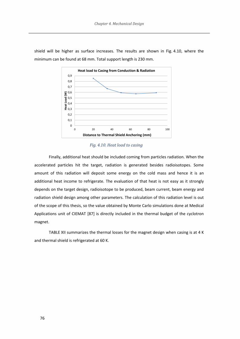
Chapter 4. Mechanical Design
76
shield will be higher as surface increases. The results are shown in Fig. 4.10, where the
minimum can be found at 68 mm. Total support length is 230 mm.
Fig. 4.10. Heat load to casing
Finally, additional heat should be included coming from particles radiation. When the
accelerated particles hit the target, radiation is generated besides radioisotopes. Some
amount of this radiation will deposit some energy on the cold mass and hence it is an
additional heat income to refrigerate. The evaluation of that heat is not easy as it strongly
depends on the target design, radioisotope to be produced, beam current, beam energy and
radiation shield design among other parameters. The calculation of this radiation level is out
of the scope of this thesis, so the value obtained by Monte Carlo simulations done at Medical
Applications unit of CIEMAT [87] is directly included in the thermal budget of the cyclotron
magnet.
TABLE XII summarizes the thermal losses for the magnet design when casing is at 4 K
and thermal shield is refrigerated at 60 K.
0
0,1
0,2
0,3
0,4
0,5
0,6
0,7
0,8
0,9
0 20 40 60 80 100
He
at L
oad
(W
)
Distance to Thermal Shield Anchoring (mm)
Heat load to Casing from Conduction & Radiation

Chapter 4. Mechanical Design
77
TABLE XII CYCLOTRON MAGNET: THERMAL BUDGET OF COLD MASS
Contribution Heat (W)
Loads @ Casing 4K
Conduction (supports) 0.52
Thermal radiation (from thermal shield) 0.05
Target radiation to casing[86] 0.12
TOTAL at 4.5 K 0.69
Loads @ Thermal Shield 60K
Conduction (supports) 0.9
Radiation (from cryostat) 10.5
TOTAL at 60 K 11.4
The emissivity value of casing surface covered by low emissivity tape was considered
as a pessimistic value of 0.02. If no covering was added, expected emissivity of 0.05 to 0.1
could be found as reasonable for the stainless steel casing and, as a result, heat losses from
radiation could increase up to 0.15 W.
Heat losses from residual gas conduction can be neglected as far as vacuum level is
preserved at 1e-7 mbar or better, as shown in TABLE XIII. This vacuum level is considered
achievable with a proper design of the cryostat and the connection box.
TABLE XIII RESIDUAL GAS CONDUCTION
Pressure
(mbar)
Heat to Casing from-
Thermal shield (mW)
Heat to Thermal Shield from
cryostat (mW)
1e-4 529 1960
1e-6 5.29 19.6
1e-7 0.53 1.96
1e-8 0.05 0.19

Chapter 4. Mechanical Design
78
4.4 Refrigeration system
As seen in previous chapters, a warm iron superconducting cyclotron refrigerated
using liquid Helium flow provided by an autonomous CSS is the preferred solution for this
specific radioisotope producer.
Under this premise, the CSS will liquefy the needed Helium by means of a cryocooler,
send it to the magnet and then recover it in a closed loop to liquefy it again. Room
temperature Helium gas will be needed to be liquefied, but the cooling scheme is similar to
the classical situation of using liquid cryogens. Cryogenic equipment can be kept far away
from the radioactive environment to provide safer operating conditions and easier access for
maintenance. Regarding the drawbacks of this concept, there is some inefficiency due to the
transportation of this cryogen (not the whole cooling power generated by the cryocooler is
transferred to the coil) and there are also some additional devices and electric input power
needed for pumping and controlling the closed loop system.
This work will use this refrigeration scheme, partially based on the work developed in
collaboration with CERN [62], shown in Fig. 4.11. There are three heat exchangers, HX1, 2 and
3. The first one starts to cool down the Helium gas with the cold gas coming out from CSS.
The second heat exchanger is directly connected to the first stage of the cryocooler, while the
third one is linked to the cold head. The cold gas coming out from HX2 is sent to cool down
the thermal shield and the connection box, and then enters HX3 for further cooling. The liquid
Helium exits from HX3 and is sent to cool both coils sequentially, so there could be a small
temperature difference between them. There is a pump at room temperature to compensate
the pressure drop of the circuit. Besides, this scheme allows working at different mass flows,
that is, different cooling capacities depending on the operation mode.
Because of the limited cooling capacity of the cryocooler, the cooling down time of
the cold mass is quite long. Assuming a weight of the cold mass around 300 kg of copper, it
can be estimated that 5 days are necessary to reach an operating temperature around 5 K if
all the cooling power could be transferred to the coils. The heat capacity of copper can be
evaluated using properties from [86], to be around 50 kJ/kg when cooled down from ambient
temperature to 5 K. From the reference load map of Sumitomo for the cryocooler [61], a

Chapter 4. Mechanical Design
79
mean value of 40 W cooling capability along the whole temperature range could be defined
to obtain the rough estimation of 5 days for cooling down. In addition, stable temperature
would be reached once that the Helium liquefaction has finished. This second stage of the
cool down process is very sensitive to the actual thermal losses of the system and the total
volume to be liquefied, but about 10 days could be a realistic estimation based on the first
test results on the CSS performance. During this first stand-alone test operation of CSS, an
additional 24 h were needed to liquefy and stabilize the temperature of the inner parts of the
CSS heat exchangers plus a dummy cold mass about 5 kg of copper [89].
However, the heat exchange between Helium and coils does not only depend on the
available cooling power. It depends also on the Helium mass flow, the pipe roughness, the
temperature distribution, etc. The cooling down time can be shortened by increasing the
Helium mass flow, which can be done by raising the pressure. Assuming a maximum testing
pressure of 6 bar and a safety factor of 2 for the components under pressure, it is reasonable
to choose 3 bar as the pressure set-point during cool down. Due to the unavoidable pressure
increase after quench, it is better to choose a steady state pressure close to 1 bar.
This cooling scheme includes some additional advantages:
- From the point of view of the cyclotron, it is not important at all how the liquid
Helium was generated or purchased, so the cyclotron design could be refrigerated by
the CSS, any other liquefaction system or even by a liquid Helium Dewar directly. The
cyclotron is therefore versatile and for example it could keep producing
radioisotopes with a secondary cryogenic supply during CSS maintenance.
- In order to minimize the volume, instead of a bath scheme, it is proposed a cooling
channel in which a forced internal flow of two-phase Helium will be in direct contact
with the coils. Besides, it is intrinsically more effective, given that the coolant is in
direct contact with the coil. This is a quite innovative concept and it will be tested in
a mock-up as a proof-of-concept check. The reduction of liquid Helium volume will
reduce the quench pressure while the casing compactness is optimized.
Therefore, thermal design must deal with just a low mass flow of liquid Helium. It is
so small that basically both coils will be refrigerated not by pure liquid, but by liquid-gas
mixture (two-phase flow). Such an innovative proposed solution is first checked by numerical

Chapter 4. Mechanical Design
80
methods using liquid Helium correlations. In the next paragraphs, the thermal properties of
the coil will be evaluated for proper accuracy of the model.
Fig. 4.11. Cryogenic concept for AMIT cyclotron including the CSS system for autonomous
operation.
4.4.1. Liquid Helium flow model
For the numerical method to compute the Helium flow properties, a set of Matlab
functions were developed by the Author. A schematic overview about the basic flow diagram
for this code is shown in Fig. 4.12.
Multiphase prediction and simulation is not a simple issue, and great efforts have
been devoted to establishing a confident and general procedure to deal with it. Up to now it
is not completely solved, but some literature can be found for general attempts or particular
solutions [90].

Chapter 4. Mechanical Design
81
The core of the program is a Matlab function (ForcedFlowN.m), which, is coded to
evaluate a general unidimensional straight pipe (Fig. 4.13). Input parameters are the cross-
section, length, surface roughness, orientation, temperature at the inlet and the wall, mass
flow, inlet pressure and quality factor (ratio of liquid mass over total mass in a biphasic flow).
This function will calculate the output temperature, heat flow, pressure drop and outlet
quality factor for a given gas flow. The heat input from the coil is considered to be
homogeneously distributed along the whole surface. The properties for each element can be
an input from the user or they can be evaluated as a compound value from the constitutive
materials according to the standard rule of mixtures [91]. Fluid behavior is modeled according
to the equations found in [92], taking into account the actual boiling regime. In order to
model heat transfer and pressure drop due to the two-phase Helium flow, a homogeneous
model was chosen. Thus, each phase is evaluated according to its mean fluid properties and
the frictional pressure drop is calculated with the typical Darcy-Weisbach factor. Convective
contribution is evaluated according to the homogeneous model, while for the boiling
contribution the Kutateladze correlation is used [92].
When one phase flow is to be evaluated (for example during the cool-down, when all
the Helium is evaporated before getting inside the cryostat), common heat transfer
correlations for forced one-phase flow were used [93].
The first function (CircuitGen.m) is responsible for the actual path definition, so it will
generate a matrix for saving the input and output values at each element. All the elements,
one immediately after the other, will define the whole path of the cooling circuit. This matrix
will include also information about the geometry, heat loads and initial conditions
(temperature, pressure). It will be saved as a Matlab file called Mesh. This function does not
include any calculation, as it will just set up the information into the Mesh file. Additional
functions for any other configurations than a single circuit could be easily developed if
needed in the future.
The main function (Circuit.m) takes the information from the Mesh file and sends it to
the core function (ForcedFlowN.m). Output values from each step and element are used to
refresh the input data for the next element and time step. This is managed by the main
function, as it sets the conditions for each element before it is evaluated. Some additional

Chapter 4. Mechanical Design
82
management is also provided by this function, as it will be in charge of memory and
processing time management. Some basic post-processing is available at the end of the
simulation.
For more sophisticated post-processing including time variation of one element, or
temperature distribution in the circuit at a given time step, additional functions have been
coded. All of them are specific to this case, so they will not be explained here. The
comparison between the simulation results and the measurements are shown at each test
independently in the next Chapters.
This program is very versatile. It will be used for cooling performance prediction not
only for the liquid Helium, but also for the tests with liquid nitrogen. It may be used for any
path, gas or flow. There are just four limitations on its applicability:
1. It cannot be more accurate than the empirical correlations on which it is based.
Fluid correlations are typically fitted from smooth linear paths and completely
developed fluid flow regime. In the case of complex paths, variable cross-
sections and curved pipes with short straight sections, the actual fluid behavior
could be significantly different from the numerical result.
2. The length of each element, as in any other FE method, is important to achieve
good results. As this is a transient simulation, time step is also an important
parameter. Reducing too much both of them will lead to the need of a high
amount of computational resources and calculation time.
3. This set of Matlab functions was developed for the particular situation of a
cryogenic circuit in which the mass flow is constant. This means that the
amount of cryogen flowing through one element will flow through the next one
(even if the cryogen changed temperature or quality factor). This has two
consequences: firstly, no additional cryogen can be included at an intermediate
point of the circuit; secondly, no cryogen can be stored or removed at any
element. This is of course true in a closed system at steady-state, but some
transient effects cannot be evaluated (for instance, the fluid dynamics during
the first seconds of a quench). This limitation is also related to the constraints

Chapter 4. Mechanical Design
83
of the correlations, which are not fitted for this kind of transient effects
anyway.
4. This program was developed for the simulation of the thermal transients of a
superconducting magnet, so that the cryogen circuit is composed as the serial
connection of individual elements. Therefore, it is not possible to simulate
thermal links between two non-adjacent elements. This is the situation of a
heat exchanger: two different elements of the circuit are thermally coupled
while there is no mass transfer between them. The conclusion for this
limitation is that the CSS cannot be simulated. Anyway, there is not enough
public information about the cryocooler performance at intermediate
temperatures, which is mandatory for a realistic model. In the future, when
some experimental data about the cryocooler performance will be available, it
could be possible to implement the capabilities of heat exchangers modeling as
an interesting future development of the program.
On the other hand, this method is much simpler and more efficient than complete FE
modeling of real fluid flow inside the pipe. Just one element is used for each partition of the
path, while a complete fluid model by means of a commercial FE program will require at least
thousands of 3D elements for each partition and each time step. One must keep in mind that
empirical validation will be needed in both cases.
The developed custom program was first cross-checked during the thermal test of the
coils assembly using liquid nitrogen. As test results were very close to calculations, the
validation mock-up for the refrigeration scheme was first simulated by using this program and
then checked empirically as exposed in Chapter 5.4.

Chapter 4. Mechanical Design
84
Fig. 4.12. Schematic flow diagram of the custom code to compute the cooling fluid behavior
Fig. 4.13. Schematic of dedicated FEM model for transient calculations (ForcedFlowN.m)
4.4.2. Overpressure in case of quench
It is also necessary to check the stress distribution in the cooling circuit in case of a
quench. A custom made Excel spreadsheet was developed to compute the peak pressure
distribution along the whole transient. Classical equations of fluid motion inside a circular
pipe and Helium properties were used ([82], [94]). The casing, from the mechanical design,

Chapter 4. Mechanical Design
85
was checked up to 7 bar. The maximum pressure allowed in case of quench was fixed at
5 bar. This number is proposed as a compromise between the maximum operational pressure
of Helium during cooling down (3 bar, which will be justified later) and the maximum testing
pressure for the pressurized elements at manufacturing (6 bar, assuming a safety factor of 2).
The dimensions of the pressure relief pipes were designed by this procedure. The maximum
pressure in the worst point and circumstances after a coil quench was found to be 4.6 bar for
the final design, including 16 mm pipe diameter and safety valves. Time evolution of pressure
after quench (quench @ t=0) is shown in Fig. 4.14. It includes the very first moments after the
quench, which are in fact the most dangerous ones in a flow refrigeration concept. Relief
valves cannot be close to the liquid Helium because they would increase thermal losses too
much. Therefore, these relief valves are outside the cryostat, at ambient temperature. It was
evaluated that about 1 second is needed for the pressure to reach the relief valve position. In
order to increase the system safety, two operational modes will be defined: First one with a
pressure relief valve set at 1.5 bar (for nominal conditions in which pressure will be 1.3 bar)
and a second one set at 4.5 bar (for the 3 bar during cool down).
Fig. 4.14. He Pressure evolution in case of a quench.

Chapter 4. Mechanical Design
86
4.5 Alignment and support system
As it was explained in previous chapters, there is a need for a supporting structure of
the cold mass that complies with several requests:
- It should hold the own weight of the cold mass while keeping low thermal losses.
- It must allow aligning the cold mass in the six degrees of freedom respect to the iron
yoke, considering the cold mass as a rigid body.
- It should be compatible with thermal contractions in any temperature distribution,
not only during nominal operating conditions, also during the cooling down at different
speeds.
Magnetic forces on the coils were already shown in Fig. . The important point is that
the nominal magnet design, where the coils are perfectly centered with the iron, is unstable.
If there is any misalignment in any direction, a magnetic force will appear that tend to
increase even more the misalignment.
Thus, the stiffness of the support system is very important, and the measurement of
the actual forces during operation is critical. The strategy proposed here is to develop a
supporting system which includes alignment capabilities. Therefore, it will be possible to
increase the current by small steps while fine tuning of the alignment is done.
The overall view of the supporting system is shown in Fig. 4.15. The proposal includes
rods at both upper and lower halves of the cold mass. In this specific case, given the large
expected magnetic forces and to improve the iron symmetry (which is important for the
stability of the particles), four rods are proposed from the upper side and four from the lower
one. Strictly speaking, only rods at the upper side are necessary to hold the weight, but those
on the lower side are needed to hold the magnetic forces. There is one joint at every rod end.
This joint will give free rotation to the rod end, so the transmitted load will be purely
tensional. Of course, the torsion around revolution axis is not free and it will produce some
flexural loads on the rods, but due to the symmetry of the system, this kind of torque is not
expected by design.

Chapter 4. Mechanical Design
87
The thermal shield is linked to the intermediate metallic piece of each support, where
two joints provide flexibility to the assembly, which is very convenient during cooling down
and powering. Besides, those joints avoid that the supports take any compressive load, which
is not adequate for the rods, since they are made from G-10CR. The positioning system is
based on a thread at the tip of the support. A nut is pressing a surface on the iron yoke so it is
possible to enlarge or reduce the distance between the cold mass and the iron yoke. As
thread pitch will be designed for about 1 mm, alignment and positioning sensitivity will be in
the order of 0.1 mm in the direction of each support.
It is worth to notice that eight rods under tension behave as a hyperstatic structure. It
means that in order to shorten the distance between the iron and the cold mass in one
direction, the rods on the opposite side must be loosen to allow that movement. This strategy
is a bit slow procedure, but it is expected to be necessary only during commissioning.
Fig. 4.15. Supporting concept: detailed view of one support (left) and overall view (right).
A FE model in Ansys was developed to evaluate all the loading cases:
- Ambient temperature for all elements in the cryostat.
- Nominal temperatures at cold for casing and shield.
- Custom defined temperatures distribution (all the parts at intermediate
temperatures, as expected during cooling down).
At nominal temperatures, a number of additional simulations were performed:
- Effect of misalignments in all directions (one each time and a combination of them).
STEEL
G10-CRCu
Adjustment Nut(Rod Axis Displacement)Possibility of fine tuning at cold;Once adjusted, they keep positionwhen thermal cycles occur

Chapter 4. Mechanical Design
88
- Effect of operation on the adjusting nut.
Some of the results are shown in the next images. The first structural simulation is
shown in Fig. 4.16, which presents the total deformation of the cold mass after cool-down. In
this figure, the grey shadow is the initial position at warm and the strain is amplified in the
picture for clarification. There are some important features to be pointed out:
- Upper rod tips remain at their initial positions because they are attached to the
warm wall of the cryostat, hold by the magnet iron.
- Lower rods are moving axially upwards guided by the joint on the cryostat. This joint
is flexible so that shrinkage does not lead to thermal stresses at any temperature.
- At this position, lower rods can be fixed, so that they can contribute to support
magnetic forces, but they are still free for elongation in case of warming up the cold
mass.
- The whole cold mass is hanging from the upper rods, so that when it is cooled down,
the cold mass moves almost 2 mm upwards. This movement should be foreseen in
the design as there would be two consequences: The first one is that the clearance
between cold mass to upper wall of the cryostat will be reduced in 2 mm compared
to the warm dimensions. The second, the mean plane of the coils will be shifted,
also, if compared to the iron and the fixed nuts of the supports. The manufacturing
drawings and parts dimensions at warm will include these details.
Fig. 4.16. Directional deformation (axial displacement) of casing after cool down.

Chapter 4. Mechanical Design
89
The results on the equivalent stress of the G10-CR parts of two rods at cold condition
are shown in Fig. 4.17. They are holding the weight of the cold mass and thermal stresses, but
no magnetic forces are included. In this case, every rod is just under pure tensional loads,
because of the revolute joints at each end.
As an example of the situation under non-centered magnetic forces, the case of 1 mm
of horizontal misalignment is shown in Fig. 4.18. Horizontal magnetic forces are probably the
most dangerous ones, because of the inherent instability of magnetic forces.
Moreover, horizontal magnetic forces are the only ones that could lead to a non-pure
tensional load on the rods. In fact, any rod which is not perfectly aligned to the magnetic
force direction will suffer some bending. This is the main reason for using as many as eight
rods. The larger the angular separation between rods, the higher the probability of a
magnetic force misaligned respect to the rods appearing, and the higher the bending loads
applied to the rods. This concept including four supports, equally distributed along symmetry
axis, and each one including two rods has been found in this specific case as an optimal
compromise in terms of low thermal losses, high stiffness and moderate stresses for any
expected magnetic misalignment.
Fig. 4.17. Stresses at supporting structure while casing is cold

Chapter 4. Mechanical Design
90
Fig. 4.18. Supporting structure under horizontal magnetic misalignment (1 mm)
4.6 Current leads
There are several possibilities for current lead design [95]. Generally speaking, a
moderate current, below 600 A, allows to keep low heat losses. There are two main options,
vapour-cooled and HTS (High Temperature Superconductor) current leads. The latter are
more expensive, but thermal losses are intrinsically much lower. Furthermore, they are more
compact, since they are shorter and the Helium gas does not need to flow through them, so
they can be placed horizontally.
HTS current leads are usually conduction-refrigerated, so they are not in direct
contact with the Helium, but both ends must be refrigerated to a temperature lower than the
critical one. Commercial HTS current leads cover a wide range of nominal currents, and they
minimize thermal losses at liquid Helium temperature from temperatures up to about 100 K
at the warm end. Then, a resistive stage (usually a copper plate) is needed for the current
path from ambient temperature to the warm end of the HTS current lead. HTS current leads
will be refrigerated by cryogenic flow of Helium coming from the CSS first stage (“warm” end)

Chapter 4. Mechanical Design
91
while the “cold” end is refrigerated by the liquid Helium used for the coils (see Fig. 4.19). The
cold end of the HTS current lead is connected to the coil leads with a custom made
feedthrough, tight to liquid Helium.
Fig. 4.19. Current leads concept design
Heat exchangers were designed for the refrigeration of both HTS ends. The warm
heat exchanger (designed for temperatures from 40 to 80 K) is shown in Fig. 4.20. It includes
57 drilled holes of 4 mm diameter to optimize the heat transfer in a compact design of 75 mm
length. This heat exchanger is connected to the HTS by means of flexible cooper braid to
avoid thermal stress at cold temperature.
The superconducting wires are going through the connector of the cold exchanger, so
there is not any splice at the feedthrough, which is a significant advantage. These NbTi wires
will be duplicated to increase operation safety and margin in temperature. This is because
they will not be directly cooled by the liquid Helium once that they are out of the
feedthrough, so their temperature will be slightly higher.

Chapter 4. Mechanical Design
92
Fig. 4.20. Temperature distribution at the conduction heat exchanger for the warm end of HTS
current leads.
Also, a protection system is proposed as a backup circuit for the current to flow from
the power supply to the coil. In case that one or both HTS current leads fail (typically due to a
quench or thermal runaway), an alternative path for the current is provided by means of a
shunt. The geometry and material for this shunt will be designed according to the following
assumption: The temperature distribution and time evolution in the proposed shunt is shown
in Fig. 4.21, which corresponds to the most pessimistic scenario, that is, including adiabatic
boundary conditions and completely open circuit at the superconducting current leads. The
maximum temperature is reached after 30 s from the quench, and its value is 275 ºC,
considered safe for a stainless steel shunt. This hot spot occurs because Joule heating exceeds
the heat diffusivity capability of the shunt at that point. The current decay is very slow
because of the large time constant of the magnet, about 30 s. The variable geometry of the
shunt, taking advantage of the nonlinear effect of temperature on the thermal properties of
the shunt, led to a just 40 mW thermal loss added by both shunts.

Chapter 4. Mechanical Design
93
Fig. 4.21. HTS Current leads shunts for quench protection: temperature distribution (left) and
time evolution (right) for the most pessimistic scenario
4.7 Vacuum system
The vacuum pumping system schematic is shown in Fig. 4.22. A turbomolecular pump
was selected according to conventional guidelines that can be found for example in [96]. The
vacuum level at ambient temperature should be 0.001 mbar or better, and the minimum port
diameter (to minimize vacuum impedance) was set, for this specific situation, as ISO-K 160
flange size. Both turbomolecular (f) and primary (j) pumps require limited background
magnetic field as proper working conditions (in the order of 10 to 50 mT). Because of that,
the turbomolecular pump will be connected to a “long” pipe coming from the magnet
cryostat. It can be checked that the longer the pipe the higher the impedance, so a
compromise length in the order of 400 mm was found to be the best design in this case.
Additional magnetic shield will be needed at this distance, which will be done by covering the
pump by two layers of MuMetal [97]. A primary pump was designed for serial connection to
the turbomolecular one, but it can be directly connected to the cryostat (a) for the initial
rough pumping by means of the bypass valve (g). It is important to provide a backup system
for limited damage in case of, for example, power failure. In this case, a normally close gate
valve (c) was placed at turbomolecular pump inlet flange. In case of a power failure, this valve
gate will close protecting both the pump and the cryostat vacuum. Additional vacuum

Chapter 4. Mechanical Design
94
sensors, at high (b) and low (i) vacuum levels are needed for the control system to set the
optimum speed of the turbomolecular pump.
Another pressure release valve (e) is included also at the cryostat through one of the
connection box walls. All the cryostat should be in vacuum in normal operation, but in case of
a Helium leak from the inner pipes or a quick rise of the temperature levels of the cold mass
(when all the cryoadsorpted gases at the cold surfaces are released), the pressure level in the
cryostat could increase dramatically.
It is a relatively complicated vacuum system with many safety valves, but the
prototype performance should be robust under any circumstances, preventing damages to
important components.
Fig. 4.22. Vaccum system scheme
4.8 Cryogenic Supply System
As previously mentioned, the CSS was developed in collaboration with CERN. The first
objective was to prove the capability to liquefy Helium gas and to check the efficiency of the
system to transfer the cooling power of the cryocooler to the cryogens. In consequence, the
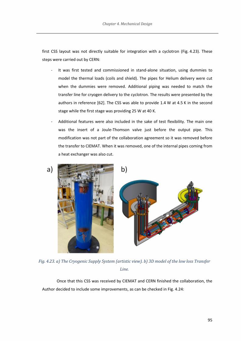
Chapter 4. Mechanical Design
95
first CSS layout was not directly suitable for integration with a cyclotron (Fig. 4.23). These
steps were carried out by CERN:
- It was first tested and commissioned in stand-alone situation, using dummies to
model the thermal loads (coils and shield). The pipes for Helium delivery were cut
when the dummies were removed. Additional piping was needed to match the
transfer line for cryogen delivery to the cyclotron. The results were presented by the
authors in reference [62]. The CSS was able to provide 1.4 W at 4.5 K in the second
stage while the first stage was providing 25 W at 40 K.
- Additional features were also included in the sake of test flexibility. The main one
was the insert of a Joule-Thomson valve just before the output pipe. This
modification was not part of the collaboration agreement so it was removed before
the transfer to CIEMAT. When it was removed, one of the internal pipes coming from
a heat exchanger was also cut.
Fig. 4.23. a) The Cryogenic Supply System (artistic view). b) 3D model of the low loss Transfer
Line.
Once that this CSS was received by CIEMAT and CERN finished the collaboration, the
Author decided to include some improvements, as can be checked in Fig. 4.24:

Chapter 4. Mechanical Design
96
- In order to improve its cooling capabilities, an additional port should be included for
the optional injection of liquid Helium from an external Dewar, which can be seen
schematically in Fig. 4.24 as a red line. It is designed as a double wall pipe. The outer
channel is in high-vacuum, while the inner one is the pipe to guide the injected liquid
Helium into the circuit. These pipes are made of stainless steel and thin walls were
used to reduce thermal losses. It is also as long as possible (between the main upper
flange and the output pipe of liquid Helium of the CSS. Additionally, thermal
anchoring is applied to the outer pipe at CSS thermal shield temperature. This will
increase thermal losses at the first stage, but the losses at the second stage which
are much more critical, are minimized.
- Due to the so long piping of the final real system, expected pressure drop will be
high. At nominal conditions, mass flow is very low so pressure drop will not be a
problem. However, during cooling down when Helium is not cold enough, the
maximum mass flow delivered by the pump is limited. Moreover, thermal power of
the first stage is higher than the second stage but the mass to be refrigerated at the
second stage is much larger (coils and casing). Because of these reasons, a manual
valve was developed. It was done to bypass the second stage heat exchanger during
the cool down until low temperatures are reached (green lines in Fig. 4.24). This
bypass was added to the original CSS by means of a manual needle valve to keep low
thermal losses.
- The Helium circuit was also revised to increase safeness and robustness of the
system in case of quench.
A schematic of the complete Helium system is presented in Fig. 4.25. Inlet and
vacuum ports are needed for cleaning the circuit by purging cycles. Helium purity is critical for
liquefaction, as present impurities could solidify and block the Helium flow. These cycles can
be done manually, starting by pumping air out from the circuit. Then, pure Helium gas from a
commercial bottle is used to fill in the circuit. Afterwards, the Helium is pumped away and
filled again with new pure Helium. The amount of air or any other gas species inside the
circuit is dramatically reduced at each cycle. Usually, a number from 3 to 5 cycles is
considered enough, depending on the actual initial situation of the circuit. The proposed

Chapter 4. Mechanical Design
97
procedure is to use 4 cycles under normal conditions, but up to 8 cycles if it is the first use
after a change in the Helium circuit which includes important modifications (e.g., brazing
pipes, new filter). The purging procedure can be easily done with the manual valves MV2 and
MV3.
A manual valve bypassing the compressor (MV1) is used to reduce the pressure at the
inlet. As it is a volumetric compressor, it provides a constant volumetric flow. At warm
conditions the pressure drop in the system is so high that the inlet pressure would increase
too much for the nominal volumetric flow. By partially opening this valve, the net volumetric
flow provided by the compressor is reduced and so the needed pressure.
The safety system for overpressure management in case of quench, already explained
in the previous chapter, is shown also in Fig. 4.25 (PR1, PR2 and EV1). Under normal
operation it is not affecting the Helium flow at all because PR1 and PR2 are closed. Just in
case of overpressure these valves will open and then they will reduce the pressure at
cyclotron side. The pipes involved in this pressure relief system should be designed to be as
long as possible to keep low thermal losses. Nevertheless, it is providing a direct path for the
heat to flow from ambient temperature to the liquid Helium parts. The thermal anchoring of
this pipe to the thermal shield is also done to reduce thermal losses in the cold part of the
circuit.

Chapter 4. Mechanical Design
98
Fig. 4.24. Cryogenic Supply System schematics as supplied by CERN (left) and modified at
CIEMAT ready for cyclotron magnet cooling (right)
There are two buffers in the circuit. Both are needed to provide stable flow in the
circuit. Since just one compressor is being used, pressure is not really stable and this should
be corrected because of three main reasons:
- The MFC1 (Mass Flow Controller) is measuring pressure, temperature and mass flow.
It is acting on its internal valve to maintain the mass flow setpoint based on a closed
loop control system. If it is directly connected to the compressor outlet without a
buffer, the mass flow and pressure oscillations could result in a non-stable operation
of the MFC valve.
- It is a quite long piping system for the Helium to flow from the pump to the
liquefaction stage inside the CSS cryostat. On the other hand, once that liquid
Helium cooled the cyclotron coils, the resulting vaporized Helium is returning directly
to the return pipe of the circuit. Returning pressure variations from the compressor
coupled to the typical thermo-acoustic oscillations [98] when the Helium is being
liquefied could result in a non-stable operation or even the impossibility of Helium
liquefaction.

Chapter 4. Mechanical Design
99
- The pressure regulator in the Helium supply bottle is not a precise valve.
Conventional industry grade was selected for this valve. When it opens or closes
according to the actual pressure level in the circuit, transient effects could be
noticeable. By using a buffer between the supply bottle and the circuit, any abrupt
pressure change in the pressure regulator is dumped in the buffer. The most critical
moment is during the cool-down stage, when liquid Helium starts to be liquefied.
Liquid density is much higher than gas density and therefore additional Helium is
injected to the circuit because of the constant volume of the circuit. This Helium
injection is not smooth or continuous, so that the buffer is responsible of dumping
the pressure oscillations in the system.
Fig. 4.25. Helium flow circuit

Chapter 4. Mechanical Design
100
4.9 Summary and Contributions about the Mechanical Design
In this Chapter, the Author describes a detailed procedure for the structural and the
thermal designs of superconducting magnets. Each possibility is briefly discussed and then a
decision is taken based on the particular specifications of the AMIT project and the state of
the art. The use of computation is needed for the optimization at several situations.
This chapter is one of the main contributions of the Author. It summarizes the
structural challenges of a superconducting magnet and the possible solutions. A conventional
design was selected from the state of the art while compactness is optimized. A procedure for
the thermal design is given in detail because it is critical for the efficiency objective. It
includes conventional procedures from the literature but also additional contributions from
the Author. One of them is the analysis of the radiation effects over the supporting rods and
the thermal shield to optimize the thermal anchoring position on the rods.
Some custom-made innovative solutions from the Author are also detailed in this
Chapter. They were developed to solve specific challenges of AMIT project:
- A simple code for rough calculations of thermal transients (which is useful when the
cooling power available is low compared to the mass to be cooled down)
- One example of a flexible heat exchanger between one gas pipe and a solid part for
low mass flow conditions when compactness and efficiency are critical and thermal
strains are expected between them.
- Procedure to design and optimize current leads shunts, taking advantage of the
material properties at each temperature.
Finally, the contribution about the adaptation of the CSS is explained. The conceptual
design of these changes is not really innovative, as they were found in the state of the art, but
their adaptation to an innovative device such as the CSS required important changes and
considerations to the whole system as reported in this Chapter.
Some of the contents of this Chapter were shown in MT24, Seoul (International
Conference on Magnet Technology, 2015) [99]. It was also published in [100].

Chapter 5. Engineering Design
A general overview of the proposed method to design a magnet for compact
superconducting cyclotrons has been shown, including some of the explicit choices for a
number of specifications. This chapter will provide additional information on the solutions for
the specific case of the AMIT cyclotron, as a reference for any other superconducting
compact magnet. It is important to depict how the theoretical concepts can be converted into
solutions which, even if sometimes are not optimal, they are a balanced trade-off.
5.1 Connection box
The necessity of connecting the cryogenic pipes while preserving the tight constraint
of the compactness was solved by designing a connection box. It will be placed below the iron
yoke (Fig. 5.1).
For the AMIT cyclotron, cryogens delivery is done through a 2.5 m rigid transfer line.
In order to minimize thermal losses while keeping the possibility of disassembly, special and
custom design was developed based on a retractable cover (A). All the elements and piping
inside the connection box are allowed to move to cope with the differential thermal
contractions, including those of the transfer line. Besides, all these elements are supported by
low losses rods, which are optimized while they allow easy access for maintenance.
This connection box is also a good place for adding some other ancillary components
which should be close to the cold mass and the coils but cannot be fitted inside the cryostat
due to space restrictions for enhancing the magnet compactness: for instance, the pressure
management components. Therefore, the vacuum pump will be connected to it (B), but also
the pressure relief system in case of quench (C).
Moreover, this connection box is also very convenient for the connections of all the
instrumentation wires coming from the casing and thermal shield, including thermal sensors
and voltage taps. Every connection should be done with high vacuum feedthroughs (D).

Chapter 5. Engineering Design
102
The current leads will be installed inside this connection box, so that the cryogenic
pipes will also refrigerate the current leads heat exchangers. The power supply feedthroughs
are also included in this component (E).
Fig. 5.1. Connection box: front (top) and rear view without main flange (bottom)

Chapter 5. Engineering Design
103
5.2 Material choices
In the next paragraphs, the material selection for the main components of the
cyclotron magnet will be reviewed:
- Iron yoke: Usually, pure iron is selected for a superconducting magnet
with a nominal field of 4 T, because of the high saturation field. However,
pure iron is very soft and so its machinability is poor. Therefore, a low-
carbon steel (ASTM 1010) was selected because its magnetic properties
are quite similar to pure iron, while improved mechanical properties can
be reached. Magnetic properties of ASTM 1010 up to a field about 2 T can
be found from the supplier datasheet. On the other hand, the actual
properties of the material are sensitive to the exact amount of
components and the manufacturing process, so it was decided to
measure the magnetic properties of the actual material before the final
design. Moreover, microstructural characterization was done in the
samples to check any anisotropy due to the manufacturing process (grain
anisotropy) or the machining of the samples (surface effect). No
evidences were found by the Materials unit of Ciemat about different
magnetic behavior at different directions or surfaces. The magnetization
curve used in the simulations is shown in Fig. 5.2. High field
magnetization values (from 2 to 12 T) were included by extrapolation and
the whole curve was smoothed to speed up the simulations. This steel is
relatively soft, so that a surface treatment (bluing) was applied on every
part. This is also convenient to prevent corrosion damage, for instance.

Chapter 5. Engineering Design
104
Fig. 5.2. Magnetization curve of the procured ASTM 1010 material
- Casing: 316L: Stainless steel is preferred for the casing and cryostat for
several reasons including weldability, thermal contraction coefficient
close to that of the superconducting coils, corrosion resistance and
emissivity at low temperatures. Additionally, it is important that the
material for the casing and cryostat is as much insensitive to the
magnetic field as possible. For this later specification, austenitic stainless
steel is the best choice. In terms of fracture toughness, some austenitic
steels tend to become brittle at cryogenic temperatures. The best
common austenitic steels for low temperatures while preserving ductile
behavior are the series 304 and 316. Finally, by considering the best
combination of low temperature behavior, stress limits and corrosion
resistance, 316L was selected for this specific device. 316LN would be a
slightly better choice from the point of view of magnetic permeability,
but it is very difficult to be found in the market for such a small quantity
and complex geometries. The casing is split in several welded parts to
ease assembly and also machining, taking into account the size and shape
of the available commercial steels. For reducing the radiation heat input
into the casing, surface finish is important, but in order to minimize as

Chapter 5. Engineering Design
105
much as possible this heat, low emissivity foil will be wrapped around the
whole outer surface of the casing. The filler selected material was
ER316LMn [101] which is a commonly used material for cryogenics. It can
be used for TIG and MIG welding applications for austenitic steels where
two important properties are required: impact toughness at low
temperature and non-magnetic weld. ER316LMn is a low carbon material
resulting in a completely austenitic weld so magnetic susceptibility is low
and it is not affected by the welding process.
- Rods: As explained in the thermal design chapter, a thermal insulating
material is needed for supports. It must be non-magnetic (same reason as
for the stainless steel) and as stiff as possible (to reduce displacements of
the coil if magnetic forces change after a current variation). In this case,
the figure of merit for candidate materials could be stress limit vs.
thermal conductivity. Glass Fiber Reinforced Composites (GFRC) are the
best option. Being these composites made of glass fibers and a thermoset
polymer, they are electric insulators and besides a small cross section can
withstand a high load. Being thermal insulators with small cross section,
thermal losses will be very low. Of course GFRC are, because of their
constituents, intrinsically affected by low temperatures, and most of
them become brittle when cooled down. Fortunately, there are some
specialized composites in the market designed for cryogenic
environments. They are labeled as CR, being G-10CR and G-11CR the
most common grades. Market availability is a very important constraint
for using composite materials: the cost of producing custom material is
very high, while machining of the composites is risky and not
recommended so material as close as possible to the final shape should
be purchased [85]. For the AMIT cyclotron, G-10CR was found in proper
geometry (plate) and then the final section was designed according to the
available thickness plate. It is also important to take into account the
orientation of the glass cloth to keep the mechanical properties of these
composites.
Chapter 5. Engineering Design
106
- Thermal Shield: Oxygen Free Copper. The most important parameter for
the thermal shield material is its thermal conductivity. As it will be
refrigerated from just one side (lower side), while the heat coming
through the thermal intercepts at the rods and radiating from cryostat is
distributed around the whole shield, the higher the conductivity the
lower the temperature gradient. The thermal conductivity should be high
even at low temperatures (it will be cool down to 50 K). Mechanical
properties are not so critical, but of course it must be feasible to
manufacture such a complex geometry, being supported at the thermal
intercepts, without large deformations. Copper capabilities for being bent
or soldered are useful for the design. Moreover, it can be bought in a
wide range of thickness and, even more, if is thick enough, some threads
can be machined. The oxygen free grade is preferred for improved
thermal conductivity at low temperatures. The surface roughness of the
thermal shield is important for the emissivity, even critical for the outer
surface which will be in radiative contact with the cryostat wall. The
cryostat will work at vacuum conditions, but to prevent the risk of
corrosion-induced increase of emissivity and to minimize the actual
value, the external surface will be covered by cryogenic low-emissivity
foil. Because of the reduced available space, and to ease vacuum
pumping, low emissivity foil RUAG Coolcat 4K has been used instead of
classical multilayer insulation.
5.3 Fabrication techniques
Some special fabrication techniques are included in this proposal for a compact
superconducting cyclotron magnet. While most of them are well known in the state of the art
for this kind of cryogenic devices, a few are more innovative to reach certain particular
specifications.

Chapter 5. Engineering Design
107
High-vacuum environment
The magnet cryostat, transfer line and CSS need high vacuum for optimal thermal
insulation. Therefore, clean surfaces are needed for all the parts in vacuum. Dust or grease on
the surfaces is a potential problem for the vacuum system and the minimum achievable
vacuum level. When possible, closed volumes should be avoided, as the trapped air will
require a lot of time to be evacuated. For example, for joining two parts, it is preferred a bolt
and a nut rather than a bolt screwed to a threaded blind hole.
Welding preparations will be designed in such a way that small volumes or clearances
are not in the vacuum side of the assembly. There will be structural welds, but most of them
will be vacuum-tight. The manufacturing procedures will include leak and pressure tests at
intermediate steps of the fabrication and assembly to be sure that the welds are compliant
with the vacuum specification.
Besides, welding preparations must induce small deformations. For example, the
casing parts are welded around the coils, keeping them aligned while minimizing the gaps to
avoid unexpected movements of the coil inside the casing during powering. As shown in
Fig. 5.3, there are machined channels close to the weld to reduce the heat conduction to the
coils, which are very close, and to minimize deformations. The low thermal conductivity of
the stainless steel is a further advantage. At the same time, the coils must not undergo a
dangerous overpressure during welding. The overpressure is limited by parts of the casing
which are not welded and machined with high accuracy, behaving like a hard stop.
Fig. 5.3. Welding preparation (casing)

Chapter 5. Engineering Design
108
Assembly procedure
As a consequence of the compactness objective, integration procedure is challenging.
Even more, it is very likely that disassembly (at least, partial) will be needed in this first
prototype. Since many parts are welded, disassembly is complicated, but always kept in mind
during the engineering design of the magnet.
As the cryostat was designed to be as compact as possible, its assembly is required to
be done directly on its final position (around the casing). Then, the cryostat was designed as a
group of nested layers.
The thermal shield around the cold section of the supports is made of the same
oxygen-free copper but it was found that its stiffness could be a problem for the supporting
concept. These supports can just hold pure tension, and the joints are free to rotate but
under certain conditions the shield stiffness could restrict the proper rotation of the rod as it
will be shown in Fig. 6.8. It illustrates how some grooves were designed at the shield to
reduce its stiffness so that the rod can rotate and accommodate much better any possible
movement of the casing, like, for example, the obvious thermal contractions when cooled
down. The angle of the rods would change depending on the temperature of the cold mass,
but the supporting system is always working under a purely tensional load.
Similar situations can be found for pipes inside the cryostat; some of them must be
finally joined or bent after preassembly with adjacent parts to check actual position. In such a
confined volume, there is no place for long pipes capable to absorb small geometric
discrepancies. For instance, when two parts are connected by a pipe, this pipe will be tuned
after a preassembly check. For these joints, it could happen that welding is too dangerous
because of the high temperatures. Brazing techniques are proposed in these situations. There
are some other advantages for brazing compared to welding like its capability for dissimilar
joints. It is recommended for joining stainless steel to copper. From the thermal conductivity
point of view, copper is better than steel, but some parts must be made of stainless steel,
mainly connectors for vacuum or pressure gaskets.
For example, a removable joint is preferred at certain points for inspection, allowing
access to check/repair feedthroughs or wires, removable filter maintenance or even easier
assembly. In all these situations, a removable cryogenic hermetic sealing is needed. There are

Chapter 5. Engineering Design
109
some commercial solutions available from the market. For the AMIT cyclotron the ones
selected were Kenol fittings [102] and CF fittings [103]. Both of them require stainless steel
flanges. The reason is that the fitting is actually made by pressing two steel flanges (hard) on
a soft metal seal. There is a range of materials available for the seal, the most typical ones
being Cu, Al or In. Suppliers provide some guidance for selecting the most proper one for
each application in terms of temperature, pressure and expected time before reopening
[102]. For the challenging case of liquid Helium, aluminum gaskets are recommended for a
mock-up which is expected to be re-assembled several times, but stainless steel ones are
better for the definitive assembly.
Another important check to be done in cryostats concerns thermal induced stresses.
As some parts are at ambient temperature and some at cryogenic temperature, the
supporting scheme must cope with thermal strains for releasing any possible thermal stress,
both during transient and permanent modes of operation. In the case of the AMIT cyclotron,
there is one pressurized circuit inside a vacuum vessel. The design should ensure a proper
contraction and positioning of cold parts without producing thermal stresses. Sometimes a
flexible part is needed for this requirement to be met. Metallic bellows can be found in the
market, and they are usually made of stainless steel and can be procured including desired
flanges for installation. However, they are not adequate for high overpressures.
In a similar way, the iron yoke will be assembled around the cryostat. It has been split
in several parts, compatible with the existing plates of low carbon steel in the market, and the
complex geometry of the cryostat, mainly due to the supports and apertures for vacuum
chamber and cryogenics. A cross-section is shown in Fig. 5.4, where three important
considerations were taken into account in the design:
- In order to maximize symmetries for beam dynamics stability, there are some
additional holes included in the iron which are idle, not used for any component. This is the
case of the four vertical holes going through the iron; two of them are needed to
accommodate the Helium pipes, while the other two are for radial symmetry and all the
upper side ones are drilled for the horizontal mid-plane symmetry.
- Poles should be easily dismountable in case that their profile must be tuned after
the first magnetic characterization. Mechanical tolerances (from manufacturing and
Chapter 5. Engineering Design
110
assembly) for the whole cyclotron (including not only the magnet but also the RF cavity, ion
source, target…) are critical for the actual extracted beam current. It is a quite common step
in every cyclotron to adapt the pole geometry after the real first measurements are done, so
this possibility cannot be excluded, even when the design will try to get it good enough for
specifications at first attempt. Because of that, this design was done to make pole
disassembly possible while the cryostat and other parts remain in place.
- For the first assembly, the iron will be mounted around the cryostat alone, but the
connection box will be assembled immediately afterwards, and welded to the lower end of
the pipes. Because of this, the iron partitions for accessing the poles are according to a more
complicated scheme than expected. General procedure for the iron design and assembly
should take into account any special needs for accessories and peripheral systems.
In addition to this, some other minor details are considered in the following
paragraphs.
When feasible, radial partitions are preferred as they have minimal effect on the
magnetic field map. Partitions in the iron yoke resulting in non-radial gaps could produce a
non-negligible effect on the total magnetic flux because of the differences in reluctance
between the air and the iron and how the magnetic field tends to follow the lower reluctance
path. Radial gaps can be easily avoided by the flux, while transversal ones are crossed by the
flux. Everywhere a transverse gap cannot be avoided, special care should be added to provide
as good contact as possible between the iron parts.
Some constraints coming from material procurement could affect the dimensions of
individual parts, in especial when the magnetic properties of the material are much more
critical than the geometry. Then, the final iron design should start just after the material is
checked. Maximum weight for a single part should be checked also in case that there is any
constraint for handling it for assembly or disassembly at final operation site. Additional
partitions could be needed.

Chapter 5. Engineering Design
111
Fig. 5.4. Cross section of the iron yoke. Each individual part is drawn with a different pattern.
Instrumentation
A prototype is typically equipped with many sensors to be able to understand the
performance and to identify the potential sources of problems. In this cyclotron magnet, we
will mainly need sensors to measure temperatures, voltages and stresses. Vacuum and
pressure gauges are also necessary but they are commercial, so no special attention is
devoted to them.
Cernox sensors are selected for this magnet as they are able to measure with good
accuracy temperatures of few Kelvins in a high background field. Cryogenic temperature
measurements are not simple because of several reasons. For instance, the measurement is
very sensitive to the quality of the bonding between sensors and the part to be measured
(risk of high contact thermal resistance). In addition, the intrinsic low thermal capacity and
conductivity of the materials at cryogenic temperatures yield in large temperature oscillations
and temperature gradients, even for low input heat values. The input heat from the wires
which connect the sensor to the monitor is also important to be considered when designing
the system. General guidelines on cryogenics measurements should be followed to minimize
these difficulties, which can be found for example in [104]. Temperature sensors are bonded
using Stycast 2850 FT which features a good balance of thermal conductivity and electrical
insulation at low temperatures.

Chapter 5. Engineering Design
112
The voltage taps allow measuring the voltage drop at each coil, which is the best
method to detect quench propagation. In the order of milliseconds, a quench can be detected
and protection systems can be fired. It was decided to put a voltage tap at the splice between
both coils. It is a risk, because that is the point with the highest voltage to ground in the case
of a coil quenches, but it allows to distinguish which coil is quenching and early detection of
the quench, because subtraction of the voltage drop of each coil eliminates the inductive
component of the voltage. Special care needs to be taken to insulate that voltage tap, which
has very difficult access indeed. The voltage drop at the superconducting and resistive
sections of the current leads can be also monitored to detect a quench or a thermal runaway.
The measurement of the mechanical load in the rods, as stated in the previous
chapter, is critical. A number of strain gages will be bonded to the end part of the cryostat
supports. Since the rods are round, two flat planes will be machined at opposite sides. Four
strain gauges will be glued, two on each opposite plane, one for transverse strain and the
other one longitudinally. They will be calibrated and tested to increase accuracy.
This configuration will yield the best sensitivity for tensional strain measurement. The
relationship between load and strain measured by the gages should be first evaluated, from
analytical equations or FEM methods. Once the expected range of measurement is known,
the gain of the acquisition electronics can be tuned to achieve the highest sensitivity.
Gages selection is very important for a proper measurement, so typical
recommendations should be followed [105]. The method of installation proposed in this work
includes some advantages compared to other possibilities:
- The parts on which the gages are bonded are at ambient temperature, so no special
adhesives are needed to operate under cryogenic temperatures.
- The gages are outside the cryostat, so there is no need for vacuum feedthroughs.
Access for maintenance is easy.
- As a complete bridge is bonded at each rod, the ambient temperature variations are
self-compensated. Besides, bending torques are also compensated between the opposite
gages, and only pure tensile longitudinal stresses are measured.

Chapter 5. Engineering Design
113
On the other hand, as the rods are tested and calibrated before installation, special
care should be taken to not damage the gages or the bonding adhesive during the welding
operation of the near parts of the cryostat.
During calibration of gain and offset of each bridge, it is important to use the same
cable to the converter. In the case of this cyclotron, the control rack will be far away from the
cyclotron to reduce the footprint, then, long cables will be used which will affect the
measurement. Moreover, calibration should be done with the same cable, being this cable
made of paired shielded wires to minimize electromagnetic interferences (EMI).
5.4 Validation of the refrigeration scheme.
The total power needed for the AMIT magnet is detailed in TABLE XIV. These are the
thermal demands to be satisfied by the refrigeration scheme. These numbers depend on the
actual temperatures of both stages, so they are valid just for the indicated temperatures
(4.5 K and 60 K).
As described in earlier sections, the proposed refrigeration scheme is based on small
mass flow of liquid Helium in intimate contact with the coils. Thus, it is an internal biphasic
forced flow system. Therefore, it is a quite complicated system for an analytical study
because all the heat transfer modes should be included in the equations: convection,
buoyancy, viscosity, conductivity, etc. Moreover, liquid Helium properties are quite special
compared to other fluids. For the specific situation of coil refrigeration by using the liquefied
Helium from the CSS, the fluid path is very complex and usual relations for fully developed
flow regime cannot be directly applied. Based on these circumstances, the proposed model of
using empirical correlations for liquid Helium flow needs to be checked by empirical
validation for the specific situation of the AMIT cyclotron.

Chapter 5. Engineering Design
114
TABLE XIV CYCLOTRON MAGNET: THERMAL BUDGET
Contribution Heat (W)
Loads @ 4.5K
Casing 0.69
Cold mass at connection box 0.05
HTS Current leads (cold side) 0.07
Pressure relief system 0.1
TOTAL at 4.5 K 0.91
Loads @ Thermal Shield 60K
Thermal shield (cryostat) 11.4
Thermal shield (connection box) 5.3
HTS Current leads (warm side) 10.5
Pressure Relief system 7.0
TOTAL at 60 K 34.2
The cooling concept of the cyclotron magnet is based on a liquid Helium flow in direct
contact to the coils through a channel. In the sake of compactness, the inlet of the coolant
will be below the iron yoke, where there is space for the connection box. The coolant will go
to the lower coil and then cool the upper one, going back to the connection box and, finally,
to the CSS for cycling. The size of this channel is designed as a compromise: The channel
should be small enough to fit into the casing in a compact design but also to provide a
turbulent flow in nominal conditions (0.1 g/s, ambient pressure) for enhancing the convection
heat transfer from the coil surface. On the other hand, this channel should accommodate
higher mass flow during the cool down stage (considered up to 0.5 g/s and 3 bar) without
significant pressure drop (in the order of mbar). A cross section of 10 by 2.5 mm was found
adequate for the casing wall thickness of 8.5 mm, while the Reynolds number for nominal
flow is about 5000 and thus, it is turbulent according to [106], which states that turbulent
flow is reached for a tubed-shaped geometry for ReD>4000, being ReD the Reynolds number
based on the hydraulic diameter of the cross section geometry. The expected pressure drop
during cool down with this channel is in the order of 10 mbar if one complete turn is done at
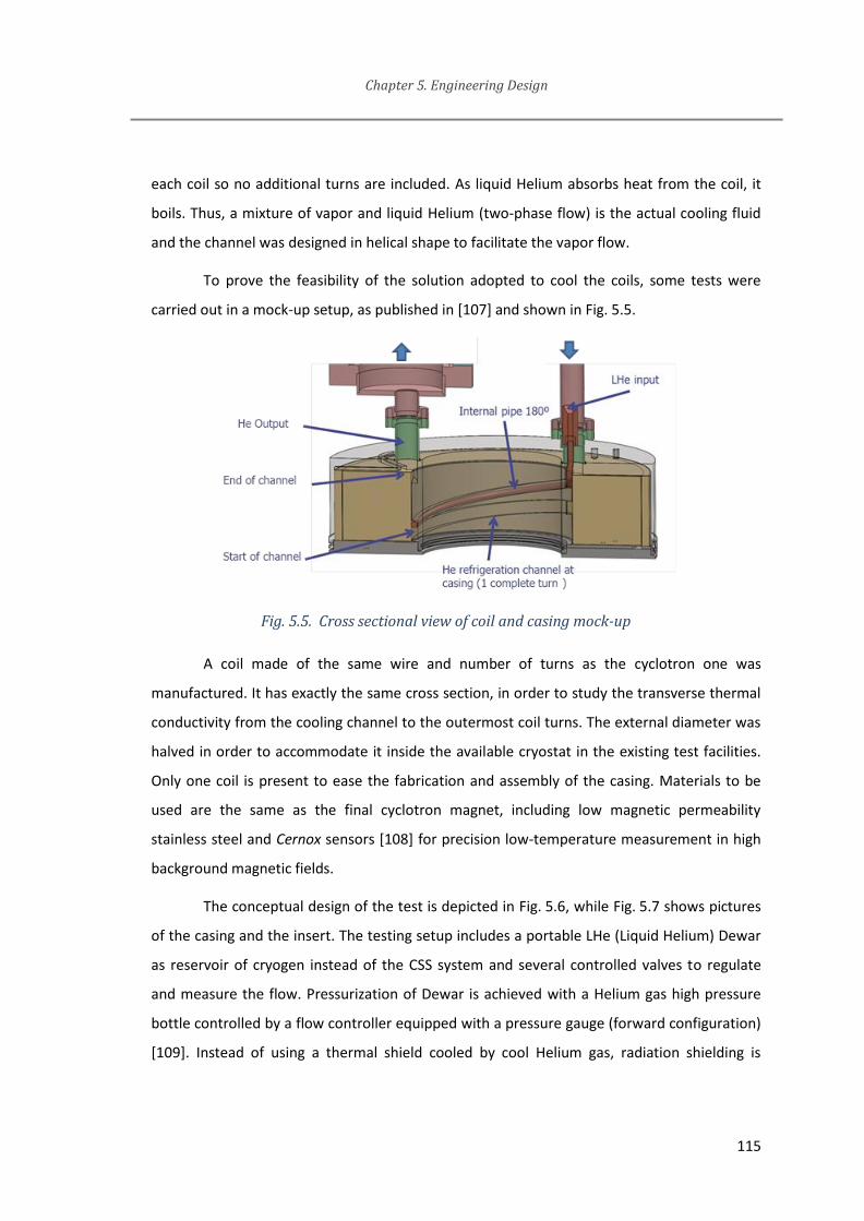
Chapter 5. Engineering Design
115
each coil so no additional turns are included. As liquid Helium absorbs heat from the coil, it
boils. Thus, a mixture of vapor and liquid Helium (two-phase flow) is the actual cooling fluid
and the channel was designed in helical shape to facilitate the vapor flow.
To prove the feasibility of the solution adopted to cool the coils, some tests were
carried out in a mock-up setup, as published in [107] and shown in Fig. 5.5.
Fig. 5.5. Cross sectional view of coil and casing mock-up
A coil made of the same wire and number of turns as the cyclotron one was
manufactured. It has exactly the same cross section, in order to study the transverse thermal
conductivity from the cooling channel to the outermost coil turns. The external diameter was
halved in order to accommodate it inside the available cryostat in the existing test facilities.
Only one coil is present to ease the fabrication and assembly of the casing. Materials to be
used are the same as the final cyclotron magnet, including low magnetic permeability
stainless steel and Cernox sensors [108] for precision low-temperature measurement in high
background magnetic fields.
The conceptual design of the test is depicted in Fig. 5.6, while Fig. 5.7 shows pictures
of the casing and the insert. The testing setup includes a portable LHe (Liquid Helium) Dewar
as reservoir of cryogen instead of the CSS system and several controlled valves to regulate
and measure the flow. Pressurization of Dewar is achieved with a Helium gas high pressure
bottle controlled by a flow controller equipped with a pressure gauge (forward configuration)
[109]. Instead of using a thermal shield cooled by cool Helium gas, radiation shielding is

Chapter 5. Engineering Design
116
cooled by a liquid nitrogen reservoir. This is much easier in terms of mock-up design and
manufacturing, while the actual power refrigeration supplied by the Helium flow is not
affected at all. Besides, the validation calculations are simpler because the temperature of
the thermal shield is very uniform.
Helium mass flow is measured at the outlet by two mass flow controllers. The first
controller measures the Helium flow through the current leads (vapor cooled) while the
second controller measures the Helium flowing out at the main port of the cryostat upper
flange. Long pipes at the outlet including optional heaters to control the temperature of the
exhaust are mounted. As a result, the Helium flow is measured at ambient temperature
which is an important constraint to get accurate values from the mass flow gauge.
Fig. 5.6. Test setup for cooling scheme validation

Chapter 5. Engineering Design
117
Fig. 5.7. Coil inside the casing for test. Insert ready to be installed in the test cryostat
The analytical calculation of stress and temperature distribution for this single coil
test were reported in [76]. In order to include in the model the mechanical and thermal
anisotropy of the coil and the cryostat thermal losses distribution, FEM models were
performed using ANSYS (Structural and Thermal) modules coupled with Ansoft Maxwell
(Magnetic). Results from these models are summarized in Fig. 5.8 (temperature distribution)
and TABLE XV (heat losses), where K is the integral conductivity. About 1.5 W of heat losses
are expected for this setup, while the real cyclotron magnet needs just 1 W. Calculations and
models can be extrapolated to the cyclotron magnet even if they are not fully compatible.
The main reasons for this discrepancy are the inlet and outlet Helium pipes inside the cryostat
and the Helium vapour cooled resistive current leads. Also, radiation shield temperature for
this setup is about 77 K, instead of 60 K for the real cyclotron magnet.
The first parameter to be checked, which is directly linked to the temperature
distribution shown in Fig. 5.8 (a), is the coil thermal conductivity. Real constituent materials
are included in the coil model, so that the actual properties of the composite material (Cu,
NbTi, insulation and epoxy) are evaluated in each direction. The temperature distribution in
the cryostat can be also checked in Fig. 5.8 (b). Liquid Helium flows inside the casing and the
evaporated Helium is evacuated through the outlet pipe while it is used for cooling the
current leads. A high vacuum level is kept in the cryostat around this assembly to avoid
thermal losses by convection.

Chapter 5. Engineering Design
118
Fig. 5.8. Temperature distribution computed by FEM simulations on Coil(a) and cryostat (b).
The refrigeration capabilities of the fluid inside the circuit, both steady state and
transient, were modeled by using the custom-made FEM code based on dedicated Matlab
functions developed by the Author and explained in Chapter 4. Limitations on the physics
included in this model were already exposed, but in this validation test a good match was
found compared to the experimental results.
The temperature evolution of the coil was measured at a constant LHe flow input to
check accuracy of heat loads and fluid flow models. Temperature sensors were placed in the
flat side of the coil, near the outlet of the casing while the calculated temperature shown in
Fig. 5.9 is the coil mean value. An unexpected fast cool down was found at the beginning of
the process. The whole casing was cooled using liquid nitrogen which was then evacuated
prior to the liquid Helium flow. Once the Helium mass flow is kept constant (450 g/h), the
simulated and measured temperature evolutions is very close.
On the other hand, real final temperature of the coil is not 4.2 K as expected for this
450 g/h LHe flow. This can be explained as the effect of an important heat loss (about 4 –
5 W) at the LHe transfer line connecting the Dewar and cryostat. Since no information about
the transfer line performance was available, a second test was performed.

Chapter 5. Engineering Design
119
TABLE XV STEADY STATE HEAT LOSSES CALCULATIONS FOR SINGLE COIL TEST
Heat loss contribution Main parameters
Value
(W at 4,2 K)
Conduction (Rods) K 0-77K = 18 W/m 0.028
Conduction (Inlet) K 0-77K = 3000 W/m 0.42
Conduction (Outlet) K 0-77K = 3000 W/m 0.08
Conduction (GHe In) K 0-300K = 27 W/m 0.027
Conduction (GHe Out) K 0-300K = 27 W/m 0.3
Radiation to casing Cold Surface 0.16 m2 0.57
Current Leads 100 A (nominal) 0.1
Conduction Vacuum 0.07 W/m2 0.012
TOTAL 1.54
Once the mock-up coil was filled with liquid Helium and the temperature was stable,
the transfer line was removed. In those conditions, the vaporization rate of LHe was 220 g/h,
or 1.3 W. This value is very close to the predicted one, 1.5 W.
For the third test, the equilibrium temperature of the coil as a function of LHe mass
flow was measured. Results can be found in Fig. 5.10. Simulations were performed including
additional heat losses to model the effect of the transfer line based on the results of the
second test. In this case, the best correlation with experiment data was found for high mass
flow if including 5 W of heat losses at transfer line as shown. The lower the mass flow, the
lower the losses from the transfer line, which can be explained from the depressurization of
the Dewar [110]. In fact, the increment of the flow is achieved by pressurization of the Dewar.
The difference between heat losses with and without transfer line confirms a real heat loss of
4.5 ±0.5 W in the transfer line and 1.3 W in the casing. And so, the cooling scheme was
proved to be feasible for this cooling power and temperature. During the first stage of this
test (Fig. 5.9), additional mass flow was injected into the system (higher than 450 g/h) due to
an operational mishandling. This is the reason of the punctual increment on the cooling rate.
The simulation was performed for a constant mass flow.

Chapter 5. Engineering Design
120
Finally, a training test of the superconducting coil was performed. No quench was
triggered before reaching nominal critical current considering the load line of the wires for
this mock-up (169 A). Both the first and second quenches reached the same value, that is, no
degradation took place. Then, the coil manufacturing techniques, including winding,
impregnation, splicing and concept design of the aluminum shrinkage cylinder, were validated
with this setup before moving to the production of cyclotron coils.
Fig. 5.9. Coil temperature during cool down on Single Coil Test: comparison of measurements
(dots) and calculations (dashed line)
Fig. 5.10. Equilibrium temperature of coil as a function of LHe mass flow: comparison of
measurements (dots) and calculations (solid line) assuming 5 W of heat loss in the transfer line
for any mass flow.
Chapter 5. Engineering Design
121
As a result of this test, the following conclusions must be outlined:
- It has proved that the proposed cooling scheme of the cyclotron, based
on a helical channel, is sufficient to evacuate about 1 W of heat at 4,2 K
while keeping a compact design. Potential risks come from the transfer
line and possible mechanical overpressures after quench, where pipes
are longer that in this test setup. Overpressure management should be
designed carefully as described in previous chapters.
- Fluid dynamics modeled from empirical relations related to non-
dimensional parameters are not perfect but good enough to roughly
describe the behavior of the system. The custom-made FEM model has
been proved to be very effective in terms of accuracy versus
computational resources ratio. The presence of not completely
developed flow is probably one of the most limiting assumptions in the
model.
- Electromagnetic and structural design procedures have been proved to
be adequate in terms of specifications and performance. Fabrication
techniques are validated prior to the manufacturing of the larger coils of
the cyclotron.
5.5 Summary and Contributions about the Engineering Design
In this Chapter, the Author describes important features involved in the development
of a superconducting magnet. Discussions about materials, welding procedures and high-
vacuum environments are detailed. Innovative solution for assembly procedure is presented
to fit the compact design from previous chapters.
In addition, the validation tests for the refrigeration concept are detailed and their
results are shown. They were published in [107] and presented in EuCAS15, Lyon (European
Conference on Applied Superconductivity) [111].


Chapter 6. Fabrication and Assembly
In the previous chapters, design tools and manufacturing procedures have been
proposed for compact and efficient superconducting magnets for cyclotrons. Some of them
have been detailed for the particular specifications of the AMIT cyclotron. This chapter will
provide additional information on how they can be used in real life and how it was done for
this cyclotron project. The superconducting coils and the Helium vessel were manufactured at
ANTECSA [112] (Portugalete, Spain) while the thermal shield and the cryostat were
manufactured at “The Vacuum Projects” [113] (Paterna, Spain). Iron assembly and further
tests were done at CIEMAT-CEDEX facilities in Madrid.
6.1 Superconducting coils
The superconducting coils are basically two solenoids with nearly square cross-
section. Epoxy resin is used to provide mechanic stability. Wet impregnation is more
economical than vacuum one, both from the point of view of tooling complexity and
manpower. However, it is a challenging technique for a coil with such a high number of turns
because of the short pot life. A collapsible mandrel allows easy disassembly of the winding
tooling. Tight tolerances of this tooling guarantees good dimensional accuracy of the finished
coils. Its feasibility was proved with the fabrication of the coil for the validation of the
refrigeration concept.
In order to manufacture a robust coil with good electrical insulation, in special during
handling and assembly into the casing, glass fiber foils are added onto the flat sides and
prepreg clothes wrapped around the last layer of wires.
Finally, a thermoretractable tape was wrapped around the coil. When the coil is
introduced into the oven to cure the resin, the wires are pressed, which improves their
compactness and dimensional accuracy. Of course, additional paths are provided for the
excess of resin to flow outside the coil while the pressure is applied. Some steps of the
manufacturing process are shown in Fig. 6.1.

Chapter 6. Fabrication and Assembly
124
Fig. 6.1. Coil manufacturing: Winding (Left) and thermoretractable tape wrapping (Right)
Once that the coil is cured, and the tape and mandrel dismantled, the coil is perfectly
characterized by metrological verification. The assembly of the coil with the shrinking cylinder
demands a very accurate and polished coil outer diameter. The glassfiber bandage is
machined in a lathe to accomplish the tight tolerances for its dimension and circular shape.
Special care must be taken to not machine or damage any of the outermost wires.
The first manufactured coil was made of copper wire for the validation of the
refrigeration concept to check the winding procedure. Its diameter is halved compared to the
cyclotron coils, but any other parameter is identical (e.g., number of turns, wire diameter,
manufacturing process). Therefore, it is used as a Reference Coil (RC) for electrical
comparison at warm temperature. Four superconducting coils were manufactured and
tested, named from SC1 to SC4. Three of them were considered successful. A selection of the
most relevant parameters from the metrological measurements is shown at TABLE XVI.

Chapter 6. Fabrication and Assembly
125
TABLE XVI COILS METROLOGICAL MEASUREMENTS
Nominal value SC1 SC3 SC4
Coil Ext. Diameter 525 526.00 525.55 524.95
Cilindricity <0.1 0.069 0.064 0.058
Int. Diameter 413.72 413.56 413.55
Height 5 56.13 56.09 56.01
Some problems when manufacturing coils can arise, such as damage of the wire
insulation (see Fig. 6.2). In this case, in the second coil, SC2, it occurred at the inner diameter
during the demoulding of the coil from the mandrel.
Fig. 6.2. Insulation defect at the inner diameter of SC2 coil
Sometimes damage like the one reported above can be repaired, but, unfortunately,
this kind of damage is not always visible. Moreover, the quality of the coils is critical for the
magnet performance. For instance, one short circuit between two adjacent wires will reduce
accordingly the total ampere-turns in the coils, and so the magnetic field provided by the coil.
Besides, there is a significant risk of major damage at that weak point in case of a quench.
Electrical measurements are the best option to check coils integrity along the
manufacturing processes. The leakage current between the wires and the tools is
continuously measured during winding. After curing, a complete set of electrical
measurements should be done to check the integrity of the coil. There is also a risk of

Chapter 6. Fabrication and Assembly
126
damaging the coil, for example, during the assembly of the aluminum shrinkage, so
measurements should be repeated after each assembly step.
The electrical insulation measurements are carried out at ambient temperature and
they are better evaluated by comparison against a reference coil. When there are just few
turns in the coil, this kind of damage can be easily detected by direct resistance or inductance
measurement, or discharging a capacitor. In the specific case of such a large number of turns,
there may be not enough accuracy in these measurements.
Another possibility is to measure the resistance and the self-inductance as a function
of frequency by means of an impedance analyzer. It provides information on the electrical
behavior of the coil when compared to a reference coil. This technique is usually sensitive
enough for detecting faults and it is very powerful if combined with a common ground
insulation measurement. Applied voltage for this insulation measurement should be high
enough to cover any possible situation of the coil during its application. In the specific case of
these coils, they were tested up to 500 V, as explained in the quench protection chapter.
TABLE XVII shows the impedance measurements for direct current and three
frequency values. The measurements obtained for the reference coil when one short-circuit
was intentionally induced in one layer show that the highest sensitivity can be found at the
resistance value for high frequencies. This is shown in the table in bold numbers.
In general, the electrical parameter shift is a complex function of several variables:
coil geometry, wire specifications, number of turns and of course the kind and severity of the
damage.

Chapter 6. Fabrication and Assembly
127
TABLE XVII COILS ELECTRICAL MEASUREMENTS
Reference Coil
(Cu, half
diameter)
Ref. Coil
(1 layer short-
circuited)
SC1 SC2 SC3 SC4
R (Ω) 87.66 87.78 225.82 222.2 224.15 227.78
100 Hz
L (H) 3.366 3.36 12.46 12.42 12.43 12.44
D(R/X) 0.042 0.043 0.030 0.029 0.029 0.029
Rs (kΩ) 0.089 0.091 0.236 0.224 0.229 0.230
s (kΩ) 2.115 2.111 7.828 7.80 7.81 7.815
1 kHz
L (H) 3.456 3.44 17.96 19.1 18.01 17.679
D 0.0089 0.0238 0.0098 0.011 0.013 0.0122
Rs (kΩ) 0.193 0.514 1.09 1.22 1.53 1.270
s (kΩ) 21.715 21.614 112.7 113.6 113.1 111.08
10 kHz
L (H) -1.96 -2.098 -0.46 -0.414 -0.458 -0.482
D 0.0802 0.159 0.02 0.0206 0.023 0.024
Rs (kΩ) 9.877 20.96 0.6 0.56 0.62 0.7
s (kΩ) -123.151 -131.82 -27.9 -25.99 -27.71 -29.101
The electrical measurements shown in TABLE XVII were done before the assembly of
each coil with aluminum shrinkage. All the coils seemed to be perfect, because there were no
major changes in the values when comparing the coils. When the next assembly step was
performed, the shrinkage of the aluminum cylinder, the insulation of the SC2 was degraded
and therefore it was discarded. Concerning the SC3 coil, a variation in the value of RS was
found for 1 kHz (1.53 %), but not as high as for the reference coil, so this test is not decisive in
this case. In order to clarify it and to understand the reason, a further step was taken on the
frequency analysis of the coils. A complete scan of impedance measurements from 5 Hz to
10 kHz was carried out. The measurements are presented in Fig. 6.3, which include the
impedance scan of coils SC2 and SC3. In addition, two artificial short-circuits in a single turn
were induced sequentially by soldering a copper wire (0 Ω) and a 0.5 Ω resistor between two

Chapter 6. Fabrication and Assembly
128
adjacent turns of the SC2 coil. External insulation damage on SC2 should not affect the
resonance, and using SC2 as the reference for a short-circuit is very convenient.
After performing the complete frequency scan, the reason was found and so, this
work proposes to directly test the superconducting coil with this procedure.
The coil is not a perfect inductor: it has some stray resistances and capacitances
associated to it. The inductive and the capacitive components of the impedance are related to
the frequency according to eq. (13). The Self Resonant Frequency (SRF) of the coil is the
frequency at which these two components are equal. Thus, the equation for the resonant
frequency is the same as a general RLC system, this is eq. (14).
2
2 (13)
2 √
(14)
The inductive value L, for a coil, is always known from design because the main
contribution is the actual inductance of the coil (for example, parasitic inductive effects of the
leads are negligible). On the other hand, the value of the reactance C strongly depends on the
parasitic components.
In general, the value of the resonant frequency of a coil is very high, so that it works
well below the resonance and the higher frequency, the higher the sensitivity to check coil
integrity, as explained before.
In the particular case of the AMIT cyclotron, the SRF is about 1765 Hz and the
spectrum is quite narrow. Thus, both measurements done at 1 kHz and 10 kHz were outside
the resonance effects. This “low” frequency could be explained from the induction value L for
the coil, which is quite high (12 H).

Chapter 6. Fabrication and Assembly
129
Fig. 6.3. Inductance spectrum of SC2 and SC3
In conclusion, these measurements are the example of how the impedance can be
used for checking the integrity of a coil if the measurements are done close enough to the
resonance frequency. In this case, SC3 seems to suffer a lack of insulation between loops. It is
clear that there is no direct short-circuit, but a contact value in the order of 1 Ω has been
measured for one wire loop.
Two coils are perfectly compliant with the specifications (SC1 and SC4) while a third
one just partially (SC3). The next step is the assembly of the aluminum shrinking ring. There is
some interference (0.2 mm in diameter) at ambient temperature as it was designed and
explained in the previous chapter. The safest procedure for the assembly is by temperature
difference. The aluminum ring was heated up 100 ºC and the coil was cooled down to -20 ºC.
For a reference temperature of 20 ºC, and thermal expansion coefficients of 2.4e-5 K-1 for
Aluminum and 2e-6 K-1 for the coil, the shrinkage diameter increases 0.30 mm and the coil
reduces 0.042 mm. This is enough for the interference plus a clearance of 0.1 mm, needed for
the assembly.
Finally, the coils were tested at nominal temperature and current. Strain gages were
measuring the stresses at the shrinkage cylinder and current was increasing up to the value
which provided the nominal working point on the load line. Nominal design current is

Chapter 6. Fabrication and Assembly
130
different because these tests were performed without the iron yoke. Therefore, the magnetic
field is not the same in the coils for the same current and the consequence is a shift on the
load line margin. In order to test the coil at an equivalent margin, the current in the tests
must be increased. Nominal equivalent current for the tests is 125 A (70 % working point),
and current up to 150 A (80 % working point) was the maximum value for the tests. Some
information about these tests can be found in TABLE XVIII. All these three coils reached
successfully the ultimate current in few quenches. They were tested immersed in a liquid
Helium bath at CERN facilities (SM-18), because there are cryostats large enough to
accommodate these coils. In fact, two coils were placed at the same time in a vertical
cryostat. Electrical connections with the cryostat current leads were done carefully because
the induced flux in the idle coil can change rapidly during the quench, yielding large induced
voltages. SC1 showed worse memory than SC4, but is was considered valid since it reached
again the ultimate current in few quenches and none of the quenches was below nominal
current. SC3 reached the maximum test value at first power up.
TABLE XVIII COIL TRAINING
Equivalent Nominal Current: 125 A, Tests up to 150 A
Run SC1 (A) SC3 (A) SC4 (A)
1 130 >153 119
2 136 148
3 152 >150
Retraining
1 138 153
2 143
3 152
To summarize, four coils were manufactured. All of them were characterized and this
is the decision on which ones are used: The SC1 coil was used as lower coil and SC4 as the
upper coil. SC3 remained as a spare part because of the medium detected short circuit, and
SC2 discarded as previously explained. The manufacturing of the shrinking aluminum
cylinders and the casing parts was tailored to the actual dimensions of the selected coils to be
used.

Chapter 6. Fabrication and Assembly
131
The final step is the installation of the temperature sensors (Fig. 6.4). As it is very
important to monitor coil temperature with accuracy, sensors must be installed directly on
the coil surface. Even more, two sensors are placed closely for redundancy, since there is a
high risk of damaging the wires during the assembly of the coils with the casing and the
cryostat.
Fig. 6.4. Superconducting coil including temperature sensor
6.2 Helium vessel
The Helium vessel, or casing, is the hermetic container for the coils as explained in
the previous chapters. It must provide the path for the liquid Helium to flow in intimate
contact to the coils, and also withstand the magnetic forces between them. Its main features
were already explained, but some other minor (but important) details should be highlighted.
Additional grooves were designed in the inner surface of the casing to accommodate the
temperature sensors, their wires and the protective resin.
In order to limit the deformation of the casing because of the welds, they are made in
lengths of few centimeters, alternatively from one position to the opposite one, to balance
the induced stresses. An intense Argon gas flow is introduced in the casing to protect from
oxidation and to help to evacuate the heat, protecting the coils from high temperatures.
Some details of the welds are shown in Fig. 6.5. It is also important to notice that these

Chapter 6. Fabrication and Assembly
132
fabrication techniques were validated during the fabrication of the casing for the single coil
test.
There is also a risk of heating too much the wires, both the superconducting and the
instrumentation ones. For the latter, as they are much lighter and then their heat capacity is
very limited, a protective shielding of glass fiber plates was included between the wires and
the welding part (when applicable).
Some of the welds are structural, but others should be vacuum-tight to Helium. A leak
test was performed to guarantee the tightness. Additionally, a cold test with liquid nitrogen
was done to check the proper behavior under thermal contractions at low temperature, since
most of the contraction between room and liquid Helium temperature is already present at a
liquid nitrogen bath (see Fig. 6.6). The leak test was repeated at that moment, to guarantee
that there was not any leak at cold, which would be very risky, taking into account the very
difficult disassembly of the finished cyclotron magnet. The temperature sensors were
measuring properly. The electrical insulation to ground was also performing well.
Fig. 6.5. (left) Coil assembly inside the casing. (right) Detail of the welds

Chapter 6. Fabrication and Assembly
133
Fig. 6.6. Setup for leak test at 77K of the finished casing
Finally, the casing was cleaned in an ultrasonic bath to be ready for working in a high
vacuum environment. A foil of low emissivity aluminum was wrapped around to decrease the
heat losses by radiation (see Fig. 6.7).
Fig. 6.7. Casing covered by low emissivity aluminum foil

Chapter 6. Fabrication and Assembly
134
6.3 Cryostat
The manufacturing of the cryostat covers a lot of work and steps. It starts with the
assembly of the thermal shield around the casing, then the supports and, finally, the cryostat
wall around them.
The thermal shield was split in several parts to allow the proper installation of such a
complex geometry around the casing. Metrological control was always in mind at every step
due to the small gaps between the three layers of the cryostat. Tolerances specified in the
manufacturing and assembly drawings were carefully evaluated in advance. This process was
quite time consuming as there are complex geometries, small clearances, at least eight
degrees of freedom (arbitrary tensions can be applied to each supporting rod) and the
complete range of temperatures should be taken into account (nominal temperate
distribution but also intermediate temperatures during transient operation)
The thermal shield is basically assembled by screws, and cryogenic grease (Apiezon N)
with good thermal conductivity was applied to all the surfaces in contact to reduce thermal
contact resistance.
A challenging problem is how to hold the casing while the thermal shield is being
assembled. Of course, the thermal shield is completely covering the casing in all directions,
but there is no support yet for the casing. The assembly (see Fig. 6.8) was done by using a
custom table. This table had some holes to accommodate screws and custom cylindrical rods
as temporary feet for the casing. The casing is then lying on these feet at certain height from
the table level. On the other hand, the thermal shield was split from the design at the specific
places that the feet are. These holes at the bottom plate of the thermal shield were not
directly covered by bonding or soldering a disk. They were covered by a shifted and larger
circular copper part for additional reasons: the radiation from cryostat to casing is covered
(there is no direct radiative contact between both parts) but the vacuum conductance
between inner and outer side of the thermal shield is improved. As the vacuum level to be
reached is so high, it is important to keep in mind during the whole design and manufacturing
processes of any high-vacuum device that the lower the vacuum impedance at any volume of
the cryostat to the vacuum pump, the better the vacuum achieved, and the lower the time

Chapter 6. Fabrication and Assembly
135
needed to reach steady state. In this case, these windows are located in fact facing the port
where the vacuum pump is connected.
Fig. 6.8. Preliminary fitting of thermal shield around casing(left). Detail view of rods thermal
anchoring manufacturing: slots improve flexibility (right)
Besides the dimensional control, electrical measurements were done to check the
fabrication quality (see Fig. 6.9). The three layers of the cryostat were electrically insulated by
the G10-CR rods. The position of the casing was changed with respect to the cryostat wall
using the adjusting nuts while monitoring the electrical continuity. In that way, the full range
of movement was validated. Furthermore, the electrical insulation between the casing, the
thermal shield and the cryostat wall was successfully tested up to 500 V.
Finally, the casing was cooled down with liquid nitrogen (Fig. 6.10) while the cryostat
was under vacuum, to test the leaks, the relative movements and the overall behavior of this
complex structure. The test was successful. No contacts between the parts were detected.
The cooling time was close to expectations.

Chapter 6. Fabrication and Assembly
136
Fig. 6.9. Electrical measurements on cryostat after rods assembly
Fig. 6.10. Thermal testing of the cryostat with liquid Nitrogen

Chapter 6. Fabrication and Assembly
137
6.4 Iron assembly
The iron assembly process starts once the cryostat is finished. Due to the complex
geometry of the cryostat, the iron was split in parts to make it possible to mount, as
explained in the previous chapter. Fig. 6.11 shows intermediate steps of the assembly. The
gaps between the cryostat and the iron were checked with the help of precision gauges,
together with the expected range of movement of the cryostat respect the iron (+/- 1 mm).
The first test is to check if the upper supports measure the weight of the cryostat,
equally distributed between the four arms. The second step is to test again the range of
movement of the casing respect the cryostat, and to inspect if there are contacts between
the different layers (by means of electrical continuity).
Fig. 6.11. Iron assembly (left) and pole assembly (right)

Chapter 6. Fabrication and Assembly
138
6.5 Connection box assembly
The connection box was manufactured on-site after the iron assembly (Fig. 6.12).
Liquid Helium pipes are the first ones to be mounted because the wires from the coils and the
temperature sensors will be installed through a custom-made feedthrough.
Later on, thermal anchoring for the low temperature end of current leads is installed
at the same time than safety shunts made of stainless steel. Once that resistive side of
current leads is installed, and all the contacts are electrically insulated using kapton, pressure
relief pipes and lateral walls of the cryostat are assembled. Same for the wires of thermal
sensors and voltage taps.
Fig. 6.12. Dedicated supporting structure during connection box manufacturing

Chapter 6. Fabrication and Assembly
139
Fig. 6.13. Input pipe assembly. (left) Welding setup. (right).
The thermal shield for limiting radiated heat losses from all the cold parts in the
connection box is hold by screws. It is not fixed to the box to minimize thermal stresses from
contractions. Nevertheless, the pipes are quite long so the expected displacements are in the
order of millimeters.
As a rough number, the transfer line is 2.5 m long since that is the distance between
the CSS and the cyclotron. The cryostat is at ambient temperature but inside there will be
stainless steel pipes at liquid Helium temperature. Given an integral contraction around
3 mm/m, there will be a total displacement of 7.5 mm if one side was free and the other one
completely fixed.
The thermal shield is simply supported by three rods made of stainless steel. Once
the casing is cooled down, the whole thermal shield will be free to move upwards, since it is
attached to the cryostat thermal shield and therefore, to the same supporting rods as the
casing.
The last part to be installed is the lower wall which is the one for the vacuum pump
connection. The completely mounted connection box can be seen in Fig. 6.14.
Finally, the integration of the cyclotron and the CSS will be done through the transfer
line. Fittings between them are Kenol connectors, and thermal protection will be wrapped
around them: Multi-Layer Insulation (MLI) is covering both low-temperature fittings and a
second MLI is connecting both thermal shields, the one at the transfer line and the one from

Chapter 6. Fabrication and Assembly
140
connection box. This process is presented in Fig. 6.15, where the intermediate step is shown
(low-temperature pipes are covered, Helium gas pipes are not covered yet).
Fig. 6.14. Connection box ready to be closed
Fig. 6.15. Intermediate assembly step of the connection box cryogenic connection to rigid
transfer line

Chapter 6. Fabrication and Assembly
141
6.6 Summary of Fabrication and Assembly Chapter
In this Chapter, the Author describes the steps during the manufacturing stage of the
superconducting magnet designed along the previous chapters. Some of the most important
quality controls and acceptance tests are shown and discussed. In addition, general advises
and recommendations from the experience are supplied. The Author was in charge of the
follow-up of fabrication and assembly.


Chapter 7. Magnet Testing
This work has proposed a procedure for designing and developing compact and
efficient superconducting magnets for accelerators. As a case study, a superconducting
magnet according to the AMIT project specifications was presented. This chapter provides
information on the tests and results obtained with the actual manufactured magnet.
7.1 Pre-cooling tests
The first test of the magnet was carried out by cooling it with liquid Nitrogen from a
Dewar. For the second one, it was cooled by liquid Helium from a Dewar. This strategy was
preferred in order to perfectly check the magnet behavior before using the CSS, which is a
complex system and, as such, it also needs its own commissioning.
A dedicated transfer line was developed by the Author in order to provide a path for
the Nitrogen to be pumped through the cyclotron coils (Fig. 7.1). The cryogen mass flow was
controlled with a mass flow controller just before the warm exhaust venting outlet.
Every temperature inside the magnet, as well as strain gauges, Helium mass flow and
any other measured variable were monitored, stored and/or controlled by the actual final
cyclotron control system for its validation. The results can be also found in [114].
Fig. 7.1. Setup for first magnet cooling test

Chapter 7. Magnet Testing
144
Testing the system by using LN (Liquid Nitrogen) allows checking the cool down
process, the steady-state temperatures and the flow control. This test provides important
data on the thermal performance of the cyclotron in an economically and easily way
compared to using liquid Helium (LHe) as cryogen. With this test, the achievement of the
superconducting state at the HTS current leads can also be verified while its main limitation is
that the coil is not able to become superconductor. Fig. 7.2 shows the cool down curves,
according to the expected values in terms of time and cryogen flow requirements (29 h
expected for 3 kg/h LN flow, instead of 27 h). In the simulation, the coil temperature and its
properties are evaluated in the refrigerated surface as a weighted mean of its constituent
materials. This is not accurate if the temperature distribution in the cross section is not
homogeneous because of the non-linear behavior of the materials. Thus, some discrepancies
can be found during the cool-down transient. Besides, a thermo-camera was employed to
check the cryostat during the cool down; no cold regions were detected at the surface.
Fig. 7.2. Cooling down curves using liquid Nitrogen
Additionally, this test allows another interesting measurement. Since the coil is fully
immersed in LN and its electrical resistance decreases with the temperature, cooling the
magnet down with LN allows to power the coil, in a non-superconducting state, up to 0.65 A,
a limit given by the maximum voltage that the available power supply is able to provide,
150 V. Although this current is really small compared to nominal current, it allows checking

Chapter 7. Magnet Testing
145
the magnetic field map at very low currents, which provides valuable information from the
point of view of electromagnetic model verification.
The magnetic field is measured using the test bench developed in collaboration with
ALBA (Fig. 7.3). It is based on three Hall sensors, perpendicularly oriented, attached to a non-
magnetic carbon fiber strip, which can be moved with high accuracy in the region of interest.
An important point about this magnetic measurement is to set the procedure on the
alignment and reference frames between the magnet and the magnetic test bench. This
procedure was carried out by using a FARO Arm attached to the mobile part of the test
bench, so that the magnet was measured at different positions and the information was
correlated to the internal encoders of the test bench. This allows knowing not only the
translation vector from Hall sensor absolute position to magnet measuring point but also the
rotation matrix from one coordinate frame to the other.
Fig. 7.3. Setup for magnetic measurements
The magnetic field distribution for 0.65 A test current can be checked by comparing
simulated and measured values (see Fig. 7.4). Deviation is less than 0.5 % for any position in a
circle of 150 mm diameter centered with the iron poles. This is a good partial result, but the
iron is not saturated as at nominal condition so that the magnetic field profile is very different
compared to the nominal one.

Chapter 7. Magnet Testing
146
Fig. 7.4. Magnetic field measured at low current (0.65 A)
7.2 Liquid Helium tests
Once that the magnet and the set-up were successfully checked down to LN
temperature including its control system, sensors and valves, a test with LHe was carried out.
After precooling the magnet with LN, the Nitrogen was removed and then purged
with several cycles of Helium gas flow and vacuum, alternatively. Then, LHe from a
pressurized Dewar was injected into the system through the same dedicated transfer line
used for the pre-cooling test. The flow was controlled by a mass flow controller at the outlet
in a similar way as it was done in the previous test with LN. The amount of LHe required and
the cool down curves were measured to evaluate the thermal performance of the system.
The cooling down curve when using LHe and the amount of Helium required is
presented in Fig. 7.5. The expected time from the simulation done with the developed Matlab
program, for a 0.8 kg/h mass flow, was around 11 h, while casing reached liquid temperature
in just 9h. It is important to notice that the two cooling circuits are directly connected, so
temperatures at the second stage are lower than the ones expected at working conditions
with the CSS. Moreover, the Helium enthalpy is not completely used, as the Helium gas in the
exhaust pipe is at 34 K. At nominal conditions using the CSS, this enthalpy will be recovered
by precooling the incoming Helium gas to the cryocooler.

Chapter 7. Magnet Testing
147
Steady-state conditions were achieved when the whole magnet circuit was full of
LHe. Measuring Helium temperature at the outlet of the cyclotron allows evaluating the
enthalpy change of the Helium used for refrigerating the magnet. It results in an overall
required power of 31 W, while the design value was 34 W according to TABLE XIV. It is also
important to notice that in this test the temperature distribution is not the same as nominal
because the second circuit is cooled with the evaporated liquid Helium instead of being
cooled with gas Helium at 60 K. In addition, there is no current through the current leads
during the cool down process. Future tests will be aimed at separating the power
requirements for each circuit from the Helium quality factor data coming from the first
circuit.
Fig. 7.5. Cooling down curves using liquid Helium from a Dewar
Once the temperature was stabilized, magnetic measurements were performed. The
current was increased by steps, measuring the magnetic field at some points for each current
value. This strategy allowed checking the magnetization properties of the iron and its effects
on the magnetic field in the mean plane of the cyclotron. Fig. 7.6 shows the magnetic field in
the center of the cyclotron compared to the simulation value at the same point. Measured

Chapter 7. Magnet Testing
148
values for magnetic field at magnet center are slightly bigger. Iron properties were measured
just up to 2 T and the magnetic test bench was calibrated up to 2 T, so the iron properties
used for calculations and the calibration curve of the sensors above 2 T are extrapolated and
this could be the reason for this difference.
Regarding the magnetic field mapping of the iron, it was first performed at 30 A, and
some interesting results were drawn. Measured values are very close to the calculated ones.
However, one should notice that not only the absolute value of the magnetic field is different
when comparing powering the magnet at 30 A or at nominal current, but also the shape
differs slightly. This small difference on the field shape and particularly on the fact that the
magnetic field at the center is not a global maximum value represents a major difference in
terms of particles stability. This means that higher values of current are needed not only to
reduce the bending radius of the particles, but also to achieve beam stability with this iron
pole profile.
Another important check to be done is to confirm the azimuthal symmetry of the
magnetic field. It will greatly affect the beam stability and the beam current reaching the
target. The magnetic field at 30 A at a cyclotron diameter in the mean plane is shown in
Fig. 7.7. While the nominal curve is fully symmetric, the measured curve shows a 0.5 %
deviation on this symmetry. As particles will be moving in circular paths, they will feel
alternative oscillations in the magnetic field at a given radius and this should be considered
for the beam dynamics and its stability. It can be easily proved by simulations that the real
position of the coils cannot explain this effect, so the iron properties, its dimensional
accuracies (small irregular gaps) and the misalignment between the hall probes and the
cyclotron magnet should be the reason for this non symmetrical behavior.

Chapter 7. Magnet Testing
149
Fig. 7.6. Magnetic field measured at cyclotron center
When increasing the current to higher values, specifically at 75 A, several supports of
the cold mass were broken. It was a problem with the measurements of the corresponding
strain gauges. The most likely reason for this problem is related to the bonding of the strain
gauges. A picture showing the situation of one strain gauge proves that it was not perfectly
bonded to the surface of the rod (Fig. 7.8).
Fig. 7.7. Magnetic field measured at low current (30 A)

Chapter 7. Magnet Testing
150
Fig. 7.8. Broken strain gauge after powering tests
All the strain gages were tested after bonding them to the supports, so it is clear that
this strain gage was broken after the magnet assembly. The most critical step for the gages
integrity is the welding of the stainless steel parts which are close to the rods in the cryostat.
The gauges were covered for protection and Argon flow was applied inside the cryostat to
keep the high temperature levels far away from the gages, but at least one of them
definitively suffered damage. Furthermore, the damage was not so severe to be noticeable at
low strain levels, but high enough to completely break the bonding at medium strain levels
and, as a result, uncontrolled misalignment of the coils occurred, breaking some supports at
their weakest point: the neck besides the joint at warm side.
Fortunately, the magnet was quite well aligned and the supports which survived were
enough to hold the cold mass up to 65 A. The tests continued using 30 A as the maximum
current for magnetic measurement because of safety reasons.
The reparation of these supports and their strain gages to control and to monitor the
misalignment of the coils is under development. The magnet disassembly for a full repair has
been discarded for the time being, because of the long dead time and cost.

Chapter 7. Magnet Testing
151
7.3 Modified CSS tests
Prior to test the autonomous operation of the cooling system, it was needed to
evaluate the CSS performance after the modifications and adaptations for using it with the
AMIT cyclotron.
Two dummy loads were included inside the CSS vacuum vessel (dummy thermal
shield and dummy coil). Temperature sensors and heaters were installed in both dummies.
The results for the modified version of the CSS are presented in Fig. 7.9. This test will also
allow checking the Helium pumping system and its control system (see Fig. 7.10).
Regarding the time needed for cooling down, it was reduced from about 11 h ([89]) to
9 h thanks to the implemented bypass valve. The results were considered satisfactory, as the
time needed for cooling down the dummy load was improved by 18 %, while small
increments of thermal losses were measured (see TABLE XIX). As the reference value of the
CSS for the second stage is 1.40 [email protected] K, it can be interpolated from the measured
conditions of the modified version that it can deliver 1.27 [email protected] K. Alternatively, it can be
compared for the same heat load at the dummy coil, and then the interpolated working point
is 1.4 [email protected] K. Thus, the effect of the modifications (bypass valve, injection pipe and the
filter) can be quantified as 0.13 W or 0.27 K when compared to the first version of the CSS.
The effect of the bypass valve on the cool down time is related to the amount of mass
to be refrigerated by the second stage of the cryocooler, so that the expected improvement
of 25 % for the cyclotron magnet seems to be feasible. In addition, no problems were
detected because of the added filter for impurities in the cold return pipe of the CSS.
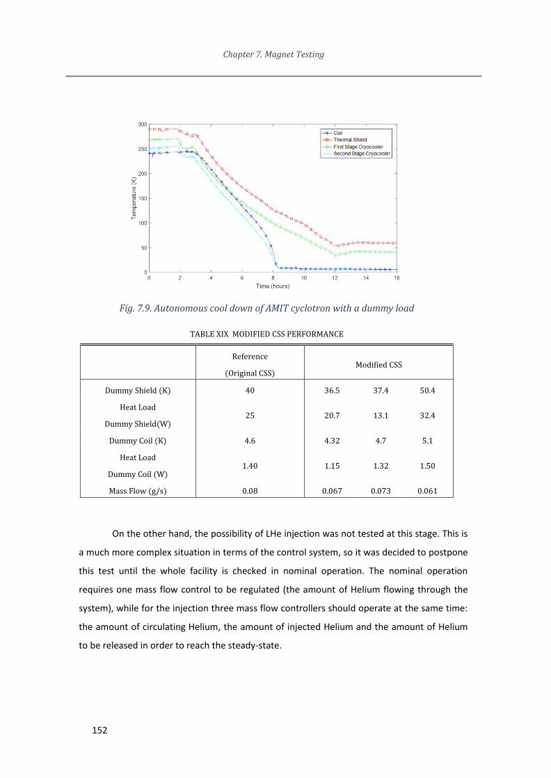
Chapter 7. Magnet Testing
152
Fig. 7.9. Autonomous cool down of AMIT cyclotron with a dummy load
TABLE XIX MODIFIED CSS PERFORMANCE
Reference
(Original CSS) Modified CSS
Dummy Shield (K) 40 36.5 37.4 50.4
Heat Load
Dummy Shield(W) 25 20.7 13.1 32.4
Dummy Coil (K) 4.6 4.32 4.7 5.1
Heat Load
Dummy Coil (W) 1.40 1.15 1.32 1.50
Mass Flow (g/s) 0.08 0.067 0.073 0.061
On the other hand, the possibility of LHe injection was not tested at this stage. This is
a much more complex situation in terms of the control system, so it was decided to postpone
this test until the whole facility is checked in nominal operation. The nominal operation
requires one mass flow control to be regulated (the amount of Helium flowing through the
system), while for the injection three mass flow controllers should operate at the same time:
the amount of circulating Helium, the amount of injected Helium and the amount of Helium
to be released in order to reach the steady-state.

Chapter 7. Magnet Testing
153
Fig. 7.10. (left) Modified CSS tests and dummies. (right) He pump circuit
7.4 Autonomous operation of the cyclotron
The proposed method in this work is to sequentially test each single component
before installing it as a part of a more complex assembly. Once that both the cyclotron and
the CSS are tested independently, the autonomous operation of the AMIT cyclotron
refrigerated by the modified version of the CSS is shown in this chapter. The overall picture
for this test is presented in Fig. 7.11. Helium mass flow was about 10 g/min while the bypass
was opened and 0.1 g/min once that it was closed.

Chapter 7. Magnet Testing
154
Fig. 7.11. Autonomous operation of AMIT cyclotron
Fig. 7.12. Autonomous cool down of AMIT cyclotron

Chapter 7. Magnet Testing
155
TABLE XX THERMAL PERFORMANCE OF THE CYCLOTRON REFRIGERATED BY THE CSS
Temperature Heat losses Expected
First Stage 85 K
CSS+T.F. 97 K 7.9 W -
Thermal
Shield 167 K 44 W 35 W
Second Stage 7 K
CSS+T.F 10.5 K 3 W 0.3 W
Coils 11.2 K 1.4 W 0.9 W
The most important results are included in TABLE XX. The first noticeable fact is that
the nominal temperature of the coils cannot be reached by means of the CSS, but a number
of relevant conclusions can be extracted:
- Both the control system and the Helium pumping circuit were working as
expected when connected to the cyclotron. The additional pressure drop,
volume and mass coming from the cyclotron compared to the tested
dummies could be handled by the system without further problems, as
expected.
- The overall behavior of the whole system was stable and smooth when
cooling the magnet with gas Helium up to 11 K (Fig. 7.12).
- The expected rough number for the cool down time using the bypass
valve was in accordance with the actual time needed. It took 4 days to
reach 11 K.
- The second stage of the cryocooler reached its steady state operation but
the Helium returning from the heat exchanger was so warm that no
liquefaction was possible.
- Both the CSS and the cyclotron magnet were tested separately and no
major problems were detected. The actual conditions of these

Chapter 7. Magnet Testing
156
independent tests were not exactly the conditions for the nominal
operation of the assembly, but this cannot explain such a large deviation.
Finally, it was concluded that there were just two possibilities to explain the lack of
liquid Helium inside the casing:
1. The cyclotron magnet or the CSS were damaged from the previous tests to
this one. This could have happened during handling for setting up the tests,
for instance.
2. There are unexpected thermal losses between the CSS and the cyclotron.
They could be in the connectors or the transfer line.
Detailed inspection of every part was done and no other evidences that could explain
this result were found. The procedure for assembly and disassembly each part was also
revised reaching the same result.
Based on these premises, an additional test was proposed to check the transfer line
performance between the CSS and the cyclotron.
7.5 Transfer line tests
The transfer line was connected to the CSS but two dummy loads were cooled down
instead of the cyclotron. Each one of these dummy loads, made of copper, has a heater
attached at one side and a temperature cernox sensor on the opposite side. The first dummy
is connected to the first stage of the CSS as the cyclotron thermal shield. The second dummy
is connected to the second stage as the casing. First dummy actually covers the second one to
avoid radiation thermal losses in the second dummy. In addition, temperature sensors were
attached to the pipes of the transfer line to distinguish between the heat losses coming from
the connections and the losses coming from the transfer line.
The overall view of this test and the lowest temperature reached by the dummy as a
function of the thermal power supplied by the heater are presented in Fig. 7.13. The
conclusion is clear, the refrigeration capabilities of the system (CSS + transfer line) cannot
provide liquid Helium to the dummy if the required thermal power is higher than 0.2 W.

Chapter 7. Magnet Testing
157
After additional post processing of the test data was done, a detailed view of the
thermal balance can be shown in TABLE XXI. It explains the situation and it proves that the
performance of the transfer line is far away from the specifications coming from the supplier
[62].
No clear explanation could be found for these values from the inspection of the
transfer line or from the revision of its manufacturing drawings. The most likely possibility is
that the transfer line suffered some mechanical damage on its internal parts during
transportation. It could also have suffered damaging when welding the outer pipe, which is
one of the most dangerous steps in its manufacturing process.
A new transfer line is being developed at this moment. Some changes were
implemented in this second version by the Author to achieve a more robust transfer line,
including its manufacturing processes and disassembly capabilities for further inspection, if
needed. As examples, the assembly of this new transfer line does not include any weld in the
outer pipe (which could lead to insulation damage) and the management of the thermal
strains was changed to avoid any possibility of thermal contacts at intermediate
temperatures during the cool down. The details are out of the scope of this Thesis, but it will
hopefully provide the required low-loss cryogenic connection between the CSS and the
cyclotron for autonomous operation of the magnet.

Chapter 7. Magnet Testing
158
TABLE XXI TRANSFER LINE THERMAL BALANCE AT SECOND STAGE
Contribution Expected (W) Measured
From Cryocooler to the LHe Outlet 0.15 0.29
From GHe return pipe to HX3 0.08 0.17
TFL LOSSES 0.05 0.66
Thermal losses/efficiency inside CSS (HX3) Unknown 0.20
Dummy Losses (when the heater is OFF) 0.03 0.06
TOTAL at 4.5 K 0.3 1.32
Fig. 7.13. CSS and transfer line with dummy load test
7.6 Summary of Magnet Testing Chapter
In this Chapter, the Author describes a proposal for testing superconducting and
autonomous prototype magnets. Several steps are described to test subsystems in sequence
before the complete system test. The Author was in charge of the tests.
The results and the discussion in this Chapter were published in [114] by the Author
and presented in MT25 Conference in Amsterdam [115].

Chapter 8. Conclusions. Future developments
Literature about superconducting magnets can be broadly found and some good
examples were used for this work. Most of them are related to applied superconductivity
while some others to accelerator magnets, but none of them focused on compact and
efficient magnets. Scientific papers, including both reviews on the state of the art and
descriptions about a single machine are not so exhaustive or just fragmented information is
provided along sequential papers.
A complete and exhaustive procedure for compact accelerator magnet design has
been developed and exposed in this Thesis. Each decision based on a rationale. An actual
project has been chosen as a practical application case. Its main requirements were
compactness and efficiency.
This procedure can be easily adapted for the development of a number of different
magnets and applications which could benefit from these design criteria. There are some
fields which are nowadays developing or considering superconducting magnets as an
emergent technology, like (but not limited to) renewable energy production, transportation
and energy storage [116].
All the three main objectives of this work can be considered fully completed (Fig. 8.1).
About the last main objective, manufacturing one magnet following this procedure to
test its feasibility and its actual performance, it was done under the AMIT project
specifications and AMIT consortium/CIEMAT financial support. The magnet was tested at
nominal temperature but it did not reach the nominal field because of a problem with the
strain gauges measurements. Once it is repaired, the magnetic characterization will be
performed till nominal field. Therefore, additional work and time are still needed for future
steps before the magnet can be used for radioisotopes production because some of them
could not be completed by the time of writing this work. They are related to the secondary
objectives.

Chapter 8. Conclusions. Future Developments
160
The optimization of the magnetic field according to beam dynamics is a secondary
objective not completed yet. It should continue in the future. A complete campaign of
magnetic measurements is needed, so that the stable operation of the superconducting coils
should be achieved. Cooling down the coils by means of a Helium Dewar, as shown in
previous chapter, is the first step but it is too expensive to keep it for a long time.
Fig. 8.1. Thesis objectives: completed (green) and partial/in progress (orange)
This is in fact the other secondary objective: the autonomous operation. It is well
advanced. Most of the subsystems, like power supply or control, are autonomous, but not the
cooling system. The CSS is commissioned, but a new low-loss transfer line, designed by the
Author is in fabrication. Once it is ready, the cooling system will be completed and the
commissioning will lead to full autonomous operation.
On the other hand, alternative objectives were completed. The magnetic field
measurements were carried out successfully at several field levels. The positioning system for
magnetic calibration worked as expected.
A hybrid solution for the cryogenics was already included as a possibility from the
very beginning of this Thesis because of the challenging and risky specification of refrigerating
the whole cyclotron magnet using just one cryocooler which is 2.5 m far away from the
cyclotron. This hybrid solution was successfully added by the Author to the CSS designed by
CERN, so that this alternative objective is considered also completed.

Chapter 8. Conclusions. Future Developments
161
Besides these proposals for the enhancement of the performance of the first magnet
prototype, a second prototype based on this procedure and the experience gained can be
envisaged:
- Alignment concept for the magnet could be improved by increasing the sensitivity of
movements of the rods. Also, strain gages should be moved to a different location in
which they could be more easily checked or replaced in case of problems or
malfunction.
- Pressure management system in case of quench could be revised based on the
experience of this prototype to reduce thermal losses. Design was quite conservative
in terms of maximum pressure and time of transient so that thermal losses were not
completely optimized in this first design.
- Compactness could be improved even more if cryogenic system is located close to
the magnet. It could reduce the height of the magnet because no connector box and
transfer line are needed. On the other hand, cryocooler would be inside the
radiation shield, so maintenance could be more difficult and/or expensive.
Another possible future step in this technology could be the development of a
superconducting system for different applications for example for energy storage, energy
production or others. Superconductivity could provide essential advantages but nowadays it
could not be profitable because of additional weight, volume or operational costs compared
to resistive technology. This work could be used as a baseline for these developments while
further work on the specific details of each application will be of course necessary.


List of Publications
Main contributions by the Author from this Thesis
[100] J Munilla et al., “Development of a Superconducting Magnet for a Compact Cyclotron for Radioisotope Production,” IEEE Transactions on Applied Superconductivity, vol. 26, no. 4, pp. 1–4, Jun. 2016. Presented at International Conference on Magnet Technology 2015, MT24 in Korea by F. Toral.
[107] J. Munilla et al., “Validation Test of the Forced-Flow Cooling Concept for the Superconducting Magnet of AMIT Cyclotron,” IEEE Transactions on Applied Superconductivity, vol. 26, no. 3, pp. 1–4, Apr. 2016. Presented at European Conference of Applied Superconductivity 2015 (EuCAS15) in Lyon by the
Author.
[114] J. Munilla et al., “Cold Tests and Magnetic Characterization of a Superconducting Magnet for a Compact Cyclotron for Radioisotope Production,” IEEE Transactions on Applied Superconductivity, vol. 28, no. 3, pp. 1–5, Apr. 2018 Presented at International Conference on Magnet Technology 2017, MT25, Amsterdam by L.
García-Tabarés.
Secondary and/or coauthored contributions related to this Thesis
[117] J. Munilla, “Superconducting Compact Cyclotrons for Isotope Production,” in Academia-Industry Matching Event on Superconductivity, CIEMAT, Madrid, 2013. Presented by the Author.
[64] C. Oliver, J. Munilla, C. Vazquez, F. Toral, and D. Obradors, “Optimizing the radioisotope production with a weak focusing compact cyclotron,” 2013. Cyclotrons conference 2013, Vancouver. Presented by C. Oliver
[118] D. Obradors et al., “Characterization of the AMIT Internal Ion Source With a Devoted DC Extraction Test Bench”, International Particle Accelerator Conference, 2017, Geneva. Presented by D. Obradors.

164
Additional contributions by the Author partially related to the contents of this
Thesis.
[119] J. Munilla, “Mechanical design of the common-coils option,” in FCC Week 2017, Berlin, 2017. Presented by the Author
[120] F. Toral et al., “EuroCirCol 16 T Common-Coil Dipole Option for the FCC,” IEEE Transactions on Applied Superconductivity, vol. 27, no. 4, pp. 1–5, Jun. 2017.
[121] F. Toral, J. Munilla, and T. Salmi, “Magnetic and Mechanical Design of a 16 T Common Coil Dipole for an FCC,” IEEE Transactions on Applied Superconductivity, vol. 28, no. 3, pp. 1–5, Apr. 2018.
[122] J. Munilla et al., “16T dipoles for FCC,”
Presented at the North American Particle Accelerator Conference (NAPAC19), in Michigan, 2019

References
[1] “The top 10 causes of death, WHO.” [Online]. Available: https://www.who.int/news-room/fact-sheets/detail/the-top-10-causes-of-death. [Accessed: 30-Apr-2019].
[2] “Information Library - World Nuclear Association.” [Online]. Available: http://www.world-nuclear.org/information-library/non-power-nuclear-applications.aspx. [Accessed: 29-Apr-2019].
[3] “Therapeutic Radiopharmaceuticals - Chemical Reviews (ACS Publications).” [Online]. Available: https://pubs.acs.org/doi/abs/10.1021/cr9804386. [Accessed: 30-Apr-2019].
[4] M. M. Khalil, J. L. Tremoleda, T. B. Bayomy, and W. Gsell, “Molecular SPECT Imaging: An Overview,” International Journal of Molecular Imaging, 2011. [Online]. Available: https://www.hindawi.com/journals/ijmi/2011/796025/. [Accessed: 02-May-2019].
[5] “Introduction to PET Physics: The physical principles of PET.” [Online]. Available: http://depts.washington.edu/nucmed/IRL/pet_intro/intro_src/section2.html. [Accessed: 01-Sep-2017].
[6] “PET: Positron Emission Tomography.” [Online]. Available: http://web2.uwindsor.ca/courses/physics/high_schools/2006/Medical_Imaging/petphysics.html. [Accessed: 16-Aug-2019].
[7] J. L. Herraiz, “Técnicas avanzadas de reconstrucción de imagen nuclear PET, X-CT y SPECT,” p. 115.
[8] V. Kapoor, B. M. McCook, and F. S. Torok, “An Introduction to PET-CT Imaging,” RadioGraphics, vol. 24, no. 2, pp. 523–543, Mar. 2004.
[9] K. R. Zasadny, M. Tatsumi, and R. L. Wahl, “FDG metabolism and uptake versus blood flow in women with untreated primary breast cancers,” Eur J Nucl Med, vol. 30, no. 2, pp. 274–280, Feb. 2003.
[10] D. Vriens, J. A. Disselhorst, W. J. G. Oyen, L.-F. de Geus-Oei, and E. P. Visser, “Quantitative Assessment of Heterogeneity in Tumor Metabolism Using FDG-PET,” International Journal of Radiation Oncology*Biology*Physics, vol. 82, no. 5, pp. e725–e731, Apr. 2012.
[11] C. Catana, A. Drzezga, W.-D. Heiss, and B. R. Rosen, “PET/MRI for Neurologic Applications,” J Nucl Med, vol. 53, no. 12, pp. 1916–1925, Dec. 2012.
[12] “Radioisotopes in Medicine | Nuclear Medicine - World Nuclear Association.” [Online]. Available: http://www.world-nuclear.org/information-library/non-power-nuclear-applications/radioisotopes-research/radioisotopes-in-medicine.aspx. [Accessed: 29-Apr-2019].
[13] A. Alex, R. S. Tavares, J. M. R. S. Tavares, P. João, and M. R. S. Tavares, “99m Tc Auger Electrons for Targeted Tumor Therapy: A Review,” International Journal of Radiation Biology, vol. 86, no. 4, p. 261, 2010.
[14] “NIDC: Isotope Production Methods.” [Online]. Available: https://www.isotopes.gov/sites/production.html. [Accessed: 02-May-2019].

166
[15] “Radioisotope production in research reactors,” 15-Jul-2016. [Online]. Available: https://www.iaea.org/topics/radioisotope-production-in-research-reactors. [Accessed: 02-May-2019].
[16] “RRDB Search.” [Online]. Available: https://nucleus.iaea.org/RRDB/RR/ReactorSearch.aspx. [Accessed: 02-May-2019].
[17] C. Birattari, “Radioisotopes Production by Accelerators,” in Advances in Radiation Protection and Dosimetry in Medicine, R. H. Thomas and V. Perez-Mendez, Eds. Boston, MA: Springer US, 1980, pp. 269–288.
[18] “Cyclotron - Engineering Physics Class.” [Online]. Available: https://sites.google.com/site/puenggphysics/home/unit-iii/cyclotron. [Accessed: 01-Sep-2017].
[19] E. Wilson and E. J. N. Wilson, An Introduction to Particle Accelerators. Oxford University Press, 2001.
[20] T. Antaya, “Cyclotron Basics,” presented at the USPAS, Nashville, Tennessee, 2009.
[21] S. Y. Lee, Accelerator Physics. World Scientific, 2012.
[22] H. Wiedemann, Particle Accelerator Physics I: Vol. 1-. Springer Science & Business Media, 1999.
[23] S. I. Tzenov, Contemporary Accelerator Physics. World Scientific, 2004.
[24] K. J. Ruisard and R. University, “The Rutgers Cyclotron: Placing Student’s Careers on Target,” p. 5, 2013.
[25] D. J. Schlyer, “PET tracers and radiochemistry,” Annals-Academy of Medicine Singapore, vol. 33, no. 2, pp. 146–154, 2004.
[26] L. Calabretta and M. Seidel, “50 Years of Cyclotron Development,” IEEE Transactions on Nuclear Science, vol. 63, no. 2, pp. 965–991, Apr. 2016.
[27] M. F. Vorogushin, Y. N. Gavrish, A. V. Stepanov, and A. P. Strokach, “Status of development work on cyclotrons for applications,” Atomic Energy, vol. 95, no. 1, pp. 493–498, 2003.
[28] J. M. Schippers, “Developments in Accelerators Used for Particle Therapy,” IEEE Transactions on Nuclear Science, vol. 63, no. 2, pp. 939–948, Apr. 2016.
[29] S. M. Qaim, “Cyclotron Production of Medical Radionuclides,” in Handbook of Nuclear Chemistry, A. Vértes, S. Nagy, Z. Klencsár, R. G. Lovas, and F. Rösch, Eds. Boston, MA: Springer US, 2011, pp. 1903–1933.
[30] A. Chao, Reviews of Accelerator Science and Technology: Accelerator Applications in Industry and the Environment. World Scientific, 2012.
[31] “ION-12sc Radiopharmaceutical Cyclotron,” Ionetix. [Online]. Available: https://www.ionetix.com/ion-12sc/. [Accessed: 03-Mar-2018].
[32] T. Antaya, “Future trends in cyclotrons,” presented at the Accelerators for Medical Applications, Vösendorf, Austria, 30-May-2015.

167
[33] “ABT BG-75 Mini Cyclotron.” [Online]. Available: http://abt-mi.com/en/our-solutions/overview. [Accessed: 03-Mar-2018].
[34] M. K. Dey and A. Dutta Gupta, “Design of Ultra-light Superconducting proton Cyclotron for production of isotopes for medical applications,” presented at the Cyclotrons2013, Vancouver, Canada, 2014.
[35] “ISOTRACE cyclotron: 12 MeV compact and helium-free superconducting medical cyclotron | PMB.” [Online]. Available: https://www.pmb-alcen.com/en/products/isotrace-cyclotron. [Accessed: 03-Mar-2018].
[36] “GEHealthCare Cyclotrons.” [Online]. Available: http://www.gehealthcare.com/en/products/molecular-imaging/cyclotrons. [Accessed: 02-May-2019].
[37] “Eclipse RD Cyclotron.” [Online]. Available: https://www.healthcare.siemens.co.uk/medical-imaging/molecular-imaging/cyclotron-chemistry-solution/eclipse-rd-cyclotron/technical-details. [Accessed: 03-Mar-2018].
[38] V. Nuttens et al., “Design of IBA Cyclone® 11 Cyclotron Magnet,” Cyclotrons 2010—Proceedings, 2010.
[39] M. G. Pullia, “Synchrotrons for Hadrontherapy,” in Reviews Of Accelerator Science And Technology: Volume 2: Medical Applications of Accelerators, World Scientific, 2009, pp. 157–178.
[40] U. Amaldi, S. Braccini, and P. Puggioni, “High Frecuency Linacs for Hadrontherapy,” Reviews of Accelerator Science and Technology, vol. 2, no. 1, pp. 111–131, 2009.
[41] U. Amaldi, “The TERA TULIP Project,” presented at the CLIC Workshop 2014, CERN, 06-Mar-2014.
[42] U. Amaldi et al., “Accelerators for hadrontherapy: From Lawrence cyclotrons to linacs,” Nuclear Instruments and Methods in Physics Research Section A: Accelerators, Spectrometers, Detectors and Associated Equipment, vol. 620, no. 2–3, pp. 563–577, Aug. 2010.
[43] “A ‘dose on demand’ Biomarker Generator for automated production of [(18)F]F(-) and [(18)F]FDG.” [Online]. Available: https://read.qxmd.com/read/24650573/a-dose-on-demand-biomarker-generator-for-automated-production-of-18-f-f-and-18-f-fdg. [Accessed: 02-May-2019].
[44] G. Bleu, “IBA Cyclotrons webpage,” IBA RadioPharma Solutions. [Online]. Available: https://www.iba-radiopharmasolutions.com/products/cyclotrons. [Accessed: 02-May-2019].
[45] “TR cyclotrons - Advanced Commercial Cyclotrons | ACSI - Advanced Cyclotron Systems Inc.” [Online]. Available: http://www.advancedcyclotron.com/cyclotron-solutions. [Accessed: 02-May-2019].
[46] V. Sabaiduc et al., “BEST 70P Cyclotron Commissioning at INFN LN Legnaro,” p. 3, 2016.
[47] “AMIT - Tecnologías de Imagen Molecular Avanzadas.” [Online]. Available: http://www.citic.es/index.php/proyectos/finalizados/10-proyectos/512-amit-tecnologias-de-imagen-molecular-avanzadas. [Accessed: 30-Aug-2017].

168
[48] C. Oliver, “Compact Weak Focusing Cyclotrons for isotope production: Status of AMIT Project,” presented at the Compact Accelerators for Isotope Production, Cockcroft Institute, 2015, p. 28.
[49] “NUclear Medicine DAtaBase (NUMDAB),” 02-Apr-2019. [Online]. Available: https://www.iaea.org/resources/databases/numdab. [Accessed: 16-Aug-2019].
[50] U. Zetterberg, “A_change_in_usage_of_cyclotrons_for_medical_web.pdf,” presented at the Compact Accelerators for Isotope Production Workshop, Cockcroft Institute, 2015.
[51] W. Scharf, Particle Accelerators and Their Uses. CRC Press, 1986.
[52] M. N. Wilson, Superconducting Magnets. Clarendon Press, 1987.
[53] M. Wilson, “JUAS_15_lect_1_intro__matls.ppt,” presented at the Joint Universities Accelerator School, Liverpool, UK, 2015.
[54] K.-H. Mess, S. Wolff, and P. Schmüser, Superconducting Accelerator Magnets. World Scientific, 1996.
[55] P. C. Portela, “Compact accelerators for radioisotope production: The AMIT project,” presented at the ARIES WP3 Kick-off meeting, 2017.
[56] H. Ueda et al., “Conceptual Design of Next Generation HTS Cyclotron,” IEEE Transactions on Applied Superconductivity, vol. 23, no. 3, pp. 4100205–4100205, Jun. 2013.
[57] D. Gavela et al., “Calculation and Design of a RF Cavity for a Novel Compact Superconducting Cyclotron for Radioisotope Production,” Proceedings of the 6th Int. Particle Accelerator Conf., vol. IPAC2015, p. USA-, 2015.
[58] T. A. Antaya, “Compact, cold, superconducting isochronous cyclotron,” US8558485B2, 15-Oct-2013.
[59] P. Lebrun, “Introduction to Cryogenics,” CAS School in Accelerators, vol. 2006, p. 77.
[60] J. Fuerst, “Cryostat Design for the APS-U SCUs,” p. 37, 2018.
[61] “RDK-415D 4K Cryocooler Series - SHI Cryogenics Group.” .
[62] F. Haug et al., “A small scale remote cooling system for a superconducting cyclotron magnet,” IOP Conference Series: Materials Science and Engineering, vol. 171, p. 012038, Feb. 2017.
[63] P. Calvo et al., “Optimization of the ion source for the compact superconducting AMIT cyclotron for radioisotope production,” presented at the CERN Accelerator School, Budapest, 2016, p. 1.
[64] C. Oliver, J. Munilla, C. Vazquez, F. Toral, and D. Obradors, “Optimizing the radioisotope production with a weak focusing compact cyclotron,” 2013.
[65] International Atomic Energy Agency, Cyclotron produced radionuclides: operation and maintenance of gas and liquid targets., vol. 4. Vienna: International Atomic Energy Agency, 2012.

169
[66] J. Munilla, “Compact Accelerators for Radioisotope Production: The AMIT Project,” presented at the Academia-Industry Matching Event on Superconductivity for Accelerators for Medical Applications, Madrid, Nov-2016.
[67] “QuickField support site.” [Online]. Available: https://quickfield.com/index.htm. [Accessed: 10-Dec-2018].
[68] “Opera FEA Simulation Software,” OperaFEA, 20-Sep-2013. .
[69] “ANSYS Maxwell: Low Frequency Electromagnetic Fields.” [Online]. Available: https://www.ansys.com/es-es/products/electronics/ansys-maxwell. [Accessed: 10-Dec-2018].
[70] M. N. Wilson and R. Lab, “Superconducting magnets for Accelerators,” presented at the CERN Accelerator School, Frascati, 2008, p. 58.
[71] F. Toral, “The AMIT Cyclotron Magnet,” presented at the AMIT Cyclotron Panel Review, Madrid, 2012.
[72] V. Parma, “Cryostat Design,” CERN Yellow Report, vol. CERN-2014, no. 005, pp. 353–399, 2014.
[73] CIEMAT and Haug, F, “Panel Review on AMIT cyclotron,” presented at the AMIT Cyclotron panel review, Madrid, 2013.
[74] “MATLAB - El lenguaje del cálculo técnico.” [Online]. Available: https://es.mathworks.com/products/matlab.html. [Accessed: 23-Sep-2019].
[75] “QuickField support site.” [Online]. Available: https://quickfield.com/. [Accessed: 23-Sep-2019].
[76] “Case Studies in Superconducting Magnets - Design and | Yukikazu Iwasa | Springer.” [Online]. Available: http://www.springer.com/us/book/9780387097992. [Accessed: 10-Aug-2017].
[77] Seog-Whan Kim, “Quench simulation program for superconducting accelarator magnets,” in PACS2001. Proceedings of the 2001 Particle Accelerator Conference (Cat. No.01CH37268), Chicago, IL, USA, 2001, vol. 5, pp. 3457–3459.
[78] F. Toral Fernández, “Desarrollo de una metodología de cálculo y de diseño de imanes superconductores para aceleradores de partículas: Aplicación a un imán cuadrupolar del LHC,” CERN Document Server, 2001. [Online]. Available: https://cds.cern.ch/record/2212267. [Accessed: 02-May-2019].
[79] B. Seeber, Handbook of Applied Superconductivity. CRC Press, 1998.
[80] L. D. Landau, Theory of Elasticity. Elsevier, 1986.
[81] Weisend, J.G., Cryostat Design: Case Studies, Principles and Engineering. Springer International Publishing, 2016.
[82] F. P. Incropera and D. P. DeWitt, Fundamentos de transferencia de calor. Pearson Educación, 1999.
[83] “Cryopumps | ULVAC CRYOGENICS INC.” [Online]. Available: https://www.ulvac-cryo.com/products-en/cryopumps/?lang=en. [Accessed: 01-Jul-2019].

170
[84] Lakeshore.com, “Cryogenic Reference Tables.” [Online]. Available: https://www.lakeshore.com/Documents/LSTC_appendixI_l.pdf. [Accessed: 23-Nov-2018].
[85] J. Ahmad, Machining of Polymer Composites. Boston, MA: Springer US, 2009.
[86] “Cryogenics Material Properties.” [Online]. Available: https://trc.nist.gov/cryogenics/materials/materialproperties.htm. [Accessed: 16-Aug-2019].
[87] A. P, “AMIT Cyclotron Panel Review: Shielding and Radiation Issues.” 2012.
[88] I. Podadera et al., “Beam Diagnostics for Commissioning and Operation of a Novel Compact Cyclotron for Radioisotope Production,” p. 4, 2013.
[89] F. Haug, M. Michels, D. Österle, and H. Esslingen, “AMIT cyclotron project _ CSS report _2016,” p. 42.
[90] M. Jerez-Carrizales, J. E. Jaramillo, and D. Fuentes, “Prediction of Multiphase Flow in Pipelines: Literature Review,” 1, vol. 11, no. 22, pp. 213–233, Aug. 2015.
[91] K. K. Chawla, Composite Materials: Science and Engineering, 3rd ed. New York: Springer-Verlag, 2012.
[92] R. F. Barron and G. F. Nellis, Cryogenic Heat Transfer, Second Edition. CRC Press, 2016.
[93] Yu. P. Filippov, “Characteristics of horizontal two-phase helium flows: Part I—flow patterns and void fraction,” Cryogenics, vol. 39, no. 1, pp. 59–68, Jan. 1999.
[94] “Propiedades termofísicas de sistemas fluidos.” [Online]. Available: https://webbook.nist.gov/chemistry/fluid/. [Accessed: 03-May-2019].
[95] A. Ballarino, “Current Leads, Links and Buses,” CERN Yellow Report, vol. CERN-2014, no. 005, pp. 547–558, 2015.
[96] D. Garton, “Vacuum Technology and Vacuum Design Handbook for Accelerator Technicians,” 2011.
[97] Magnetic Shield Corp., “MuMetal Datasheet.” [Online]. Available: http://www.magnetic-shield.com/pdf/mu-2.pdf. [Accessed: 26-Jun-2019].
[98] M. Nagao, T. Inaguchi, H. Yoshimura, T. Yamada, and M. Iwamoto, “Helium Liquefaction by a Gifford-Mcmahon Cycle Cryocooler,” in Advances in Cryogenic Engineering: Part A & B, R. W. Fast, Ed. Boston, MA: Springer US, 1990, pp. 1251–1260.
[99] “International Conference on Magnet Technology MT24,” Seoul, Korea, 2015.
[100]J. Munilla et al., “Development of a Superconducting Magnet for a Compact Cyclotron for Radioisotope Production,” IEEE Transactions on Applied Superconductivity, vol. 26, no. 4, pp. 1–4, Jun. 2016.
[101]Midalloy, “TB-ER316LMn-Bare-Wire.pdf.” [Online]. Available: http://www.midalloy.com/wp-content/uploads/2016/08/TB-ER316LMn-Bare-Wire.pdf. [Accessed: 24-Jun-2019].
[102]“KENOL® Joints | Technetics Group.” [Online]. Available: https://technetics.com/products/sealing-solutions/sealing-systems-and-subassemblies/kenol/. [Accessed: 03-May-2019].

171
[103]“CF Fittings – Danvec.” [Online]. Available: http://www.danvec.com/product/cf-fittings/. [Accessed: 03-May-2019].
[104]Lakeshore Cryotronics, “Temperature Measurement and Control Catalog,” Lakeshore.com. [Online]. Available: https://www.lakeshore.com/docs/default-source/product-downloads/lakeshoretc_h.pdf?sfvrsn=9f53e477_1. [Accessed: 25-Jun-2019].
[105]Micro-Measurements, “Strain Gage Selection,” Micro-measurements Tech Notes. [Online]. Available: http://www.vishaypg.com/docs/11055/tn505.pdf. [Accessed: 30-Nov-2018].
[106]B. Baudouy, “Heat Transfer and Cooling Techniques at Low Temperature,” arXiv:1501.07153 [physics], 2014.
[107]J. Munilla et al., “Validation Test of the Forced-Flow Cooling Concept for the Superconducting Magnet of AMIT Cyclotron,” IEEE Transactions on Applied Superconductivity, vol. 26, no. 3, pp. 1–4, Apr. 2016.
[108]“Cernox | Overview | Lake Shore Cryotronics, Inc.” [Online]. Available: https://www.lakeshore.com/products/cryogenic-temperature-sensors/cernox/models/pages/overview.aspx. [Accessed: 03-May-2019].
[109]“Vögtlin’s Mass Flow Meters & Mass Flow Controllers (MFC),” Vögtlin Instruments GmbH. .
[110]R. H. Kropschot and B. W. Birmingham, Technology of liquid Helium. United States, 1968.
[111]“12th European Conference on Applied Superconductivity (EUCAS 2015) | EuCARD-2: Enhanced European Coordination for Accelerator Research & Development.” [Online]. Available: http://eucard2.web.cern.ch/events/12th-european-conference-applied-superconductivity-eucas-2015. [Accessed: 24-Sep-2019].
[112]https://antec-group.com/, “Antec,” Antecsa. [Online]. Available: https://antec-group.com/. [Accessed: 03-May-2019].
[113]http://web2.vacuum-projects.net/, “The Vacuum Projects,” The Vacuum Projects. [Online]. Available: http://web2.vacuum-projects.net/. [Accessed: 03-May-2019].
[114]J. Munilla et al., “Cold Tests and Magnetic Characterization of a Superconducting Magnet for a Compact Cyclotron for Radioisotope Production,” IEEE Transactions on Applied Superconductivity, vol. 28, no. 3, pp. 1–5, Apr. 2018.
[115]“25th International Conference on Magnet Technology,” IEEE Trans. Appl. Supercond., 2018. [Online]. Available: https://cds.cern.ch/record/2306288. [Accessed: 24-Sep-2019].
[116]“CCAS - Coalition for the Commercial Application of Superconductors.” [Online]. Available: http://www.ccas-web.org/superconductivity/renewableenergy/. [Accessed: 02-Jul-2019].
[117]J. Munilla, “Superconducting Compact Cyclotrons for Isotope Production,” in Academia-Industry Matching Event on Superconductivity, CIEMAT, Madrid, 2013, p. 21.
[118]D. Obradors-Campos et al., “Characterization of the AMIT Internal Ion Source With a Devoted DC Extraction Test Bench,” 2017.
[119]J. Munilla, “Mechanical design of the common-coils option,” in FCC Week 2017, Berlin, 2017.

172
[120]F. Toral et al., “EuroCirCol 16 T Common-Coil Dipole Option for the FCC,” IEEE Transactions on Applied Superconductivity, vol. 27, no. 4, pp. 1–5, Jun. 2017.
[121]F. Toral, J. Munilla, and T. Salmi, “Magnetic and Mechanical Design of a 16 T Common Coil Dipole for an FCC,” IEEE Transactions on Applied Superconductivity, vol. 28, no. 3, pp. 1–5, Apr. 2018.
[122]J. Munilla, “16T dipoles for FCC,” presented at the NAPAC19, Michigan, 2019.