Stator Design and Performance of Superconducting Motors for ...
6
HAL Id: hal-01592386 https://hal.archives-ouvertes.fr/hal-01592386v2 Submitted on 3 Mar 2018 HAL is a multi-disciplinary open access archive for the deposit and dissemination of sci- entific research documents, whether they are pub- lished or not. The documents may come from teaching and research institutions in France or abroad, or from public or private research centers. L’archive ouverte pluridisciplinaire HAL, est destinée au dépôt et à la diffusion de documents scientifiques de niveau recherche, publiés ou non, émanant des établissements d’enseignement et de recherche français ou étrangers, des laboratoires publics ou privés. Stator Design and Performance of Superconducting Motors for Aerospace Electric Propulsion Systems Charalampos Manolopoulos, Matteo Iacchetti, Alexander Smith, Kévin Berger, Mark Husband, Paul Miller To cite this version: Charalampos Manolopoulos, Matteo Iacchetti, Alexander Smith, Kévin Berger, Mark Husband, et al.. Stator Design and Performance of Superconducting Motors for Aerospace Electric Propulsion Systems. IEEE Transactions on Applied Superconductivity, Institute of Electrical and Electronics Engineers, 2018, 28 (4), pp.5207005. 10.1109/TASC.2018.2814742. hal-01592386v2
-
Upload
khangminh22 -
Category
Documents
-
view
0 -
download
0
Transcript of Stator Design and Performance of Superconducting Motors for ...

HAL Id: hal-01592386https://hal.archives-ouvertes.fr/hal-01592386v2
Submitted on 3 Mar 2018
HAL is a multi-disciplinary open accessarchive for the deposit and dissemination of sci-entific research documents, whether they are pub-lished or not. The documents may come fromteaching and research institutions in France orabroad, or from public or private research centers.
L’archive ouverte pluridisciplinaire HAL, estdestinée au dépôt et à la diffusion de documentsscientifiques de niveau recherche, publiés ou non,émanant des établissements d’enseignement et derecherche français ou étrangers, des laboratoirespublics ou privés.
Stator Design and Performance of SuperconductingMotors for Aerospace Electric Propulsion Systems
Charalampos Manolopoulos, Matteo Iacchetti, Alexander Smith, KévinBerger, Mark Husband, Paul Miller
To cite this version:Charalampos Manolopoulos, Matteo Iacchetti, Alexander Smith, Kévin Berger, Mark Husband, et al..Stator Design and Performance of Superconducting Motors for Aerospace Electric Propulsion Systems.IEEE Transactions on Applied Superconductivity, Institute of Electrical and Electronics Engineers,2018, 28 (4), pp.5207005. �10.1109/TASC.2018.2814742�. �hal-01592386v2�

Template version 8.0d, 22 August 2017. IEEE will put copyright information in this area
See http://www.ieee.org/publications_standards/publications/rights/index.html for more information.
1
Stator Design and Performance of Superconducting Motors for Aerospace Electric Propulsion Systems
Charalampos D. Manolopoulos, Matteo F. Iacchetti, Member, IEEE, Alexander C. Smith, Senior Member, IEEE, Kévin Berger,
Mark Husband, and Paul Miller
Abstract—Hybrid electric propulsion has been identified as a
potential solution to the ambitious environmental emissions and noise targets of the aerospace industry. Superconducting ma-chines may be the key component of that topology enabling the high power densities and efficiencies needed in aerospace. Fully superconducting machines, however, are not a mature technolo-gy. This paper looks at the different machine design configura-tions focusing on the stator magnetic circuit of a fully supercon-ducting motor. The motor has been designed for an aerospace distributed fan propulsion motor with an aerospace benchmark specification of 1 MW. The AC fully superconducting machine includes superconducting bulk magnets mounted on a conven-tional rotor core and an MgB2 superconducting wire wound sta-tor. The AC losses in the stator winding are particularly sensitive to exposure to the main rotor field so different screening solu-tions were used to shield the superconducting windings from the rotor field. The effectiveness of the screening techniques for the stator coils and the impact on the machine performance and weight were evaluated for different stator designs, such as full stator core and air core with and without flux diverters. Various combinations of pole numbers, diverter geometries and magnetic materials have been checked. Results show that there is a trade-off between stator iron losses and superconducting losses.
Index Terms—Superconducting AC machine, Flux diverter, AC superconducting losses, Magnesium Diboride.
I. INTRODUCTION
IR TRAFFIC growth and environmental regulations to
reduce noise and emissions are driving major improve-
ments in aerospace fuel and noise efficiencies. One of the dis-
ruptive technologies identified as promising is the hybrid elec-
tric distributed propulsion (HEDP) accompanied by a redesign
of the airframe such as the hybrid wing body [1], [2]. Whilst
conventional electrical power systems may be used for smaller
Manuscript receipt and acceptance dates will be inserted here. This work
was supported in part by the EPSRC, U.K. and in part by Rolls-Royce plc.
C. D. Manolopoulos, M. F. Iacchetti and A. C. Smith are with the Power
and Energy Division, School of Electrical and Electronic Engineering, The
University of Manchester, Manchester M13 9PL, U.K.
(e-mail: [email protected];
[email protected]; [email protected]).
K. Berger is with the Group of Research in Electrical Engineering of
Nancy, Faculties of Sciences and Technologies, University of Lorraine, 54506
Vandoeuvre-lès-Nancy, France (e-mail: [email protected]).
M. Husband is with the Electrical Capability Group, Rolls-Royce plc,
Derby DE24 8BJ, U.K. (e-mail: [email protected]).
P. Miller is with the Rolls-Royce Future Technologies Group, Derby DE24 8BJ, U.K. (e-mail: [email protected]).
Color versions of one or more of the figures in this paper are available online at http://ieeexplore.ieee.org.
Digital Object Identifier will be inserted here upon acceptance.
aircraft, much larger aircraft are likely to require the use of
superconducting electrical power systems to enable the re-
quired whole system power density and efficiency levels to be
achieved. HEDP consists of distributed electric fan propulsion
units connected to a number of generator/gas units through
power management units. In these systems the gas-turbine is
decoupled from propulsion units and studies have shown that
this reduces emissions and noise [3], [4]. A power dense and
high efficiency superconducting motor is the key component
of this promising architecture and the development of such a
machine designed for aircraft propulsion systems would ena-
ble the hybrid electric aero-propulsion concept [5], [6].
Early superconducting machines were generally large syn-
chronous generators using superconducting dc field windings
[7]. However to meet the high efficiencies and power densities
of aerospace, fully superconducting machines were consid-
ered. Fully superconducting machines offer higher electrical
loadings than the partially superconducting machines. Another
advantage is the reduced airgap which increases the magnetic
loading as the stator armature and the rotor dc winding have
similar temperatures. Different fully superconducting machine
prototypes have been developed worldwide to demonstrate the
feasibility of the concept. A fully superconducting machine for
an electric vehicle [8] and an inductor type fully superconduct-
ing machine for ship propulsion [9] were built in Japan. A ful-
ly superconducting prototype with YBCO stator coils operat-
ing in liquid nitrogen bath was developed in Cambridge, UK
[10] and a fully superconducting machine cooled by iron con-
duction was built in China [11]. Fully superconducting ma-
chines have also been proposed for offshore wind turbine ap-
plications [12].
The major challenge of fully superconducting machines is
the increased AC losses in the stator windings. AC losses are
an important consideration because high losses in the super-
conducting stator windings could diminish the benefits of a
fully superconducting design by requiring large cooling sys-
tems. AC losses in superconducting coils or tapes have been
studied mainly in small samples or coils [13], [14]. Flux di-
verters have also been examined to reduce the overall losses
but most of the studies have focused on transport applications
[15], [16] or sinusoidal external fields [17].That is not the case
in a machine environment where the field seen by the stator
conductors cannot be considered as purely alternating.
This paper looks at different stator design configurations of
a fully superconducting motor for an aerospace distributed fan
motor. The machine performance in terms of weight and effi-
A
2
ciency was evaluated for the different stator designs.
II. SUPERCONDUCTING MACHINE DESIGN
A suitable benchmark motor specification has been chosen
for a distributed electric fan motor for a short-haul aircraft.
These commonly have a gearbox so that a high-speed motor
can be used to reduce weight and improve the power density.
The fan motor is assumed here to have an output power of
1 MW with a maximum speed of 12,000 rpm. The design
guidelines for a permanent-magnet (PM) machine were initial-
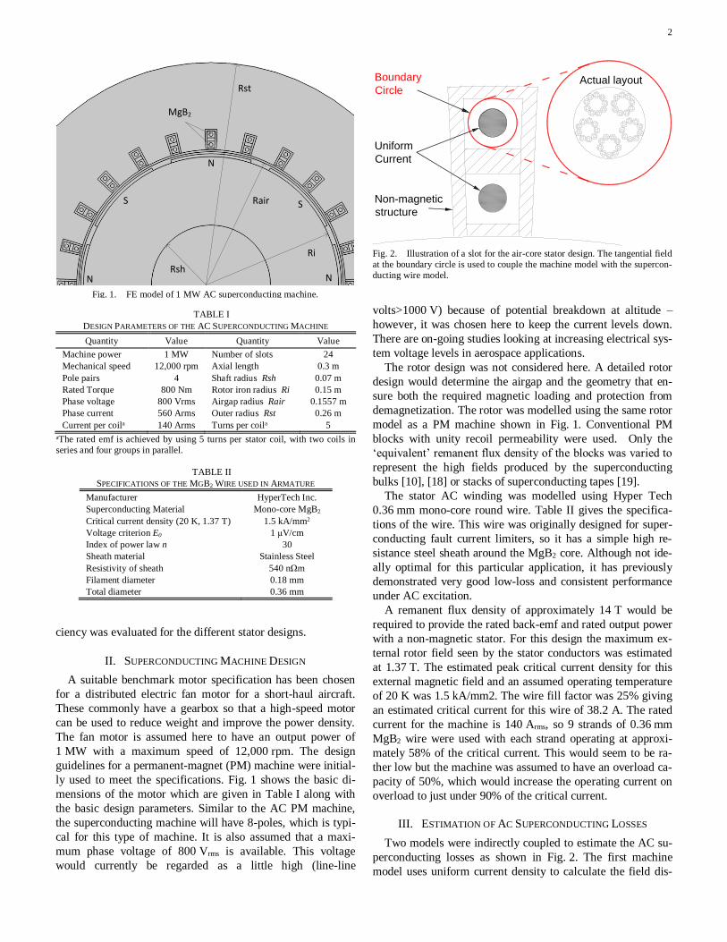
ly used to meet the specifications. Fig. 1 shows the basic di-
mensions of the motor which are given in Table I along with
the basic design parameters. Similar to the AC PM machine,
the superconducting machine will have 8-poles, which is typi-
cal for this type of machine. It is also assumed that a maxi-
mum phase voltage of 800 Vrms is available. This voltage
would currently be regarded as a little high (line-line
volts>1000 V) because of potential breakdown at altitude –
however, it was chosen here to keep the current levels down.
There are on-going studies looking at increasing electrical sys-
tem voltage levels in aerospace applications.
The rotor design was not considered here. A detailed rotor
design would determine the airgap and the geometry that en-
sure both the required magnetic loading and protection from
demagnetization. The rotor was modelled using the same rotor
model as a PM machine shown in Fig. 1. Conventional PM
blocks with unity recoil permeability were used. Only the
‘equivalent’ remanent flux density of the blocks was varied to
represent the high fields produced by the superconducting
bulks [10], [18] or stacks of superconducting tapes [19].
The stator AC winding was modelled using Hyper Tech
0.36 mm mono-core round wire. Table II gives the specifica-
tions of the wire. This wire was originally designed for super-
conducting fault current limiters, so it has a simple high re-
sistance steel sheath around the MgB2 core. Although not ide-
ally optimal for this particular application, it has previously
demonstrated very good low-loss and consistent performance
under AC excitation.
A remanent flux density of approximately 14 T would be
required to provide the rated back-emf and rated output power
with a non-magnetic stator. For this design the maximum ex-
ternal rotor field seen by the stator conductors was estimated
at 1.37 T. The estimated peak critical current density for this
external magnetic field and an assumed operating temperature
of 20 K was 1.5 kA/mm2. The wire fill factor was 25% giving
an estimated critical current for this wire of 38.2 A. The rated
current for the machine is 140 Arms, so 9 strands of 0.36 mm
MgB2 wire were used with each strand operating at approxi-
mately 58% of the critical current. This would seem to be ra-
ther low but the machine was assumed to have an overload ca-
pacity of 50%, which would increase the operating current on
overload to just under 90% of the critical current.
III. ESTIMATION OF AC SUPERCONDUCTING LOSSES
Two models were indirectly coupled to estimate the AC su-
perconducting losses as shown in Fig. 2. The first machine
model uses uniform current density to calculate the field dis-
TABLE I
DESIGN PARAMETERS OF THE AC SUPERCONDUCTING MACHINE
Quantity Value Quantity Value
Machine power 1 MW Number of slots 24
Mechanical speed 12,000 rpm Axial length 0.3 m
Pole pairs 4 Shaft radius Rsh 0.07 m
Rated Torque 800 Nm Rotor iron radius Ri 0.15 m
Phase voltage 800 Vrms Airgap radius Rair 0.1557 m
Phase current 560 Arms Outer radius Rst 0.26 m
Current per coila 140 Arms Turns per coila 5
aThe rated emf is achieved by using 5 turns per stator coil, with two coils in
series and four groups in parallel.
TABLE II
SPECIFICATIONS OF THE MGB2 WIRE USED IN ARMATURE
Manufacturer HyperTech Inc.
Superconducting Material Mono-core MgB2
Critical current density (20 K, 1.37 T) 1.5 kA/mm2
Voltage criterion E0 1 μV/cm
Index of power law n 30
Sheath material Stainless Steel
Resistivity of sheath 540 nΩm
Filament diameter 0.18 mm
Total diameter 0.36 mm
Fig. 2. Illustration of a slot for the air-core stator design. The tangential field
at the boundary circle is used to couple the machine model with the supercon-
ducting wire model.
Non-magnetic
structure
Uniform
Current
Boundary
CircleActual layout
Fig. 1. FE model of 1 MW AC superconducting machine.
Rsh
Ri
Rair
Rst
MgB2
N
S
NN
S

3
tribution, neglecting the superconducting properties. The sta-
tor current in the machine model is aligned with the q-axis of
the rotor to achieve maximum torque. The tangential magnetic
field at the boundary circle is then applied to the second su-
perconducting wire model to obtain the current distribution
and finally the superconducting losses [20], [21]. Fig. 3 shows
the tangential field around the boundary circle used to couple
the two models for an outer layer coil of the air-cored stator.
The 2D FE superconducting wire model uses the
H-formulation to simulate the cross section of the real ar-
rangement of the superconducting coils [22], [23]. The gov-
erning equation is:
0
t
ΗH
(1)
where ρ, μ, and H are the resistivity, the permeability and the
magnetic field, respectively.The sheath of the superconducting
wire does not include any magnetic material so a constant
permeability is used, μ=μ0. The resistivity of the sheath is con-
stant whereas for the MgB2 the non-linear power law was
used: ρsc=(E0/Jc)(J/Jc)n-1. Generally, Jc varies with temperature
and magnetic field; however a constant critical current model
was used to reduce the simulation time. The sheath resistivity,
the constant critical current density and the values of E0 and n
are given in Table II.
The superconductor wire losses can be attributed to several
factors: hysteretic losses in the MgB2; eddy current losses in
the sheath material; coupling losses between the strands of
MgB2 and proximity losses which are a redistribution of the
eddy currents caused by the proximity of different current-
carrying conductors. The eddy current losses in the sheath are
negligible due to the high resistivity of the stainless steel.
Transposition is assumed to eliminate the coupling losses.
Each strand carries the same current even if the strands are
connected at the coil ends.
Fig. 4 shows the current density distribution for an out-
er-layer coil of the air-cored stator. The proximity losses can
be neglected for an air-cored stator as the major loss factor is
the magnetization losses in the superconductors due to the ex-
posure from the main rotor field. Fig. 4 shows the eddy cur-
rents produced inside each superconducting strand by the ex-
ternal rotating magnetic field. These eddy currents are respon-
sible for the significant increase in the losses compared to the
self-field transport losses.
IV. DIFFERENT MACHINE DESIGNS
A. Flux Diverter Design
To reduce the field seen by the superconducting coils a
C-shape flux diverter was initially proposed and tested. A flux
diverter was placed around the two coils of each slot with the
open side towards the rotor, as shown in Fig. 5. This design al-
lows the flux to pass around the coils and at the same time re-
duces the flux passing through the superconducting coils. In
order to assess the different designs the magnetic loading was
assumed to be constant. The first harmonic therefore of the
magnetic flux density in the airgap was maintained at 1 T by
Fig. 3. Tangential magnetic flux density Bt(ωt,d) along the boundary con-
tour for one electrical cycle for an outer layer coil of the air-core stator.
Fig. 4. Normalized current density distribution J/Jc in an outer-layer coil of
the air-core stator after one electrical period (north magnet below the slot).The
coil has 5 turns composed of 9 strands. Each strand carries the same current as
transposition is assumed.
Fig. 5. Schematic diagram of thin (left) and thick (right) flux diverter posi-
tion around the superconducting coils.
Boundary
Circle
structureCurrentVacoflux 50

4
changing the remanent flux density of the superconducting ro-
tor magnets. A magnetic loading of 1 T is common in conven-
tional PM machines but for a non-magnetic stator this value
would only be achievable with strong superconducting mag-
nets. The electric loading was also kept the same for all the
different designs by setting the rated value of 140 Arms in each
coil.
The criteria used to assess the diverter performance and
generally the stator design were the screening effectiveness,
the iron losses and the added weight. The screening effective-
ness was determined by calculating the average flux density
inside the two coils of one slot for each rotor position during
one electrical cycle. This value was compared with the corre-
sponding one for an air-core stator with no flux diverters. Co-
balt iron electrical steel Vacoflux50 from Vacuumschmelze
GmbH was chosen for the flux diverters because of its high
saturation flux density. Initially, thin diverters 2 mm thick
were selected to avoid increasing the weight. This value was
later doubled to assess the effect of diverter thickness on the
machine performance.
B. Pole Number Assessment - Four Pole Design
Another way to reduce the superconducting losses is to re-
duce the frequency. This reduces both hysteresis losses in the
superconducting coils and iron losses in the diverters. The fre-
quency and pole number were reduced by half to maintain the high speed and power density. The geometry, the slot number
and the current in each coil are the same as the 8-pole designs.
To enable direct comparison of the designs, the magnetic load-
ing was kept the same. The 4-pole air-core design requires
higher-field superconducting magnets compared to the 8-pole
air-core design because of the longer flux paths through the
air, as shown in Fig. 6. The flux diverter performance was
then tested in the 4-pole design.
V. RESULTS
Table III gives the superconducting losses in each layer of a
slot for one electrical cycle. It is assumed that each slot has the
same losses so the total armature losses are the sum of the slot
losses multiplied by the slot number and the active length. The
end-winding losses are not included because the calculation of
the field around the end windings would require a full 3D ma-
chine model. The end winding conductors would not be ex-
posed to full rotor field so it is thought that the losses would
be closer to the self-field losses. A more accurate estimation of
the superconducting losses would require the calculation of the losses in each slot of a pole pitch due to the different phase
angle of the field with respect to the coil current. Analytical
models have shown that the losses are maximised when the
current and magnetic field are in phase for low external mag-
netic fields with H0<<Ic/(2aπ) for 2a width strip [24]; howev-
er for higher external magnetic fields the losses are maximized
at intermediate phase angles [14], [25]. The inner layer coil
which is closer to the rotor has higher superconducting losses
compared to the outer layer coil for all the designs because it
is exposed to higher external fields. If the thickness of the flux
diverters is increased, the losses are reduced, however the full
magnetic stator has the lowest superconducting losses because the coils are not exposed to the full rotor field.
Table IV summarizes the performance figures for the dif-
ferent machine designs. The different magnetic circuit of each
stator design would affect the rotor design and weight. Never-
theless, at this stage the rotor was kept the same for all the de-
signs and only the remanent flux density of the magnets was
changed. On one hand, as the volume of the iron is increased
in the machine, the more effective the screening becomes and
the lower the superconducting losses are. On the other hand,
because of the extra mass, the added iron reduces the power
density significantly. Direct comparison is possible here be-
cause the magnetic and electric loadings are the same for all
the designs. In the 4-pole designs, higher-field superconduct-
ing magnets are needed compared to the 8-pole designs repre-
sented by the higher remanent flux densities in Table IV. The
TABLE III
STATOR SUPERCONDUCTING LOSSES FOR DIFFERENT MACHINE DESIGNS
Superconducting
losses1
4-Pole Designs 8-Pole Designs
AC4 FD4 AC8 FD8 TFD8 MS8
Outer layer coil (W/m) 259 239 269 196 161 13
Inner layer coil (W/m) 665 569 478 404 290 43
Total stator loss
(active length) (W) 6653 5818 5378 4320 3247 403
Key: AC-Air core, FD-Flux diverter (2mm), TFD-Thick flux diverter (4mm),
MS-magnetic stator, the subscript is the pole number. 1All the designs have 1 T magnetic loading and the same electrical loading.
Fig. 6. Magnetic field distribution for a single pole for the 4-pole (left) and
the 8-pole (right) air-core design. The flux path for the 4-pole design is con-
siderably longer compare to the 8-pole design.
TABLE IV
STATOR EFFICIENCY AND WEIGHT FOR DIFFERENT MACHINE DESIGNS
Design Parameter1 4-Pole Designs 8-Pole Designs
AC4 FD4 AC8 FD8 TFD8 MS8
Output Power (kW) 925.9 925.9 850.7 909.8 967.6 1173.7
Mean torque (Nm) 736 736 677 724 770 934
Torque ripple (%) 41 150 14 336 430 26
Remanent Flux (T) 27.5 25 11.5 10 8.2 2
Screening (%) 0 21.4 0 30.8 54.4 87.5
St. iron loss (W) 0 1161 0 3391 5598 7037
St. MgB2 loss (W) 6653 5818 5378 4320 3247 403
St. ‘cold’ inefficien-
cy2 (%) 0.72 0.63 0.63 0.47 0.33 0.034
St. efficiency (%) 99.29 99.25 99.37 99.16 99.09 99.37
St. weight (kg) 0.5 7.7 0.5 7.7 16 308
Key: AC-Air core, FD-Flux diverter (2mm), TFD-Thick flux diverter (4mm),
MS-magnetic stator , the subscript is the pole number, St-Stator active length. 1All the designs have 1 T magnetic loading and the same electrical loading. 2This is defined as the armature superconducting losses in the cryogenic sys-
tem as a percentage of the machine output power [6].

5
frequency is halved in the 4-pole designs compared to the 8-
pole designs. The 4-pole designs however produce higher su-
perconducting losses because of the high fields at the coils.
For the 8-pole machine, the air-core design has a similar
stator efficiency with the full magnetic stator design because
the added iron losses are equal to the reduction of the super-
conducting losses due to screening. It should be noted howev-er, that the superconducting losses are generated at 20 K so an
air-core design, although very light, would impose a signifi-
cant load on the cryocoolers. For an iron-cored machine how-
ever, the iron could be operated at room temperature but that
would cause very high temperature gradients across the insula-
tion between the coils and the iron. The flux diverters reduce
the superconducting losses compared to the air-core design
without adding significant weight independently of the pole
number. However, the reduction is not significant and the su-
perconducting losses remain prohibitive for the low operating
temperature. Another problem with the flux diverter designs is
the high torque ripple produced because of the non-uniform magnetic circuit (cogging torques). Different magnetic materi-
als, for example soft magnetic composites (SMC), were also
explored to reduce the weight of the diverters, but with no ad-
vantage. In these materials, the permeability drops quickly de-
teriorating the screening performance. The only design with
manageable superconducting losses for the cryocoolers is the
full magnetic stator design, which has a ‘cold inefficiency’
figure lower than 0.05% as indicated in [6, Table III]; The co-
efficient of performance is 1.46% [6], [12], assuming the cry-
ocooler efficiency is 15% of Carnot efficiency and the ambient
temperature at high altitude is 225 K. So a motor dedicated cryocooler would require 28 kW at 225 K to remove the stator
superconducting losses and the total stator efficiency would
drop to 97%. However, in order to increase the cryocooler ef-
ficiency and reduce the weight a centralised system with large
cryocoolers and a liquid methane cryo-tank may be used [6].
Although the magnetic stator design has the lowest MgB2
losses, it suffers from high iron losses and weight. Further re-
search on superconducting materials and/or winding tech-
niques that reduce the sensitivity of the AC losses to external
fields is required to enable a fully superconducting machine
concept for hybrid electric aero-propulsion.
VI. CONCLUSIONS
This paper looks at the design feasibility of the stator of a
fully superconducting motor for an aerospace distributed fan
motor. The selected fan motor was assumed to have an output
power of 1 MW with a maximum speed of 12,000 rpm. The
AC superconducting machine used superconducting bulk
magnets mounted on the rotor and a round MgB2 supercon-
ducting wire for the stator winding. The paper demonstrates a
way of coupling the machine model with the superconducting
wire model. This model is based on the real arrangement of
the superconducting strands. The superconducting losses were
calculated for different stator designs such as a full stator core
and an air core with and without flux diverters. The effect of
pole number and diverter thickness was examined as well. The
results showed that there is a trade-off between added iron
losses and the superconducting losses.
REFERENCES
[1] H. D. Kim, G. V. Brown, and J. L. Felder, "Distributed turboelectric
propulsion for hybrid wing body aircraft," in 9th International Powered
Lift conference, London, UK, 2008.
[2] J. L. Felder, et al., "Turboelectric distributed propulsion in a hybrid wing
body aircraft," in 20th ISABE conference, Gothenburg, Sweden, 2011.
[3] F. Berg, et al., "HTS Electrical System for a Distributed Propulsion
Aircraft," IEEE Trans. Appl. Supercond., vol. 25, Jun 2015.
[4] P. Malkin and M. Pagonis, "Superconducting electric power systems for
hybrid electric aircraft," Aircraft Engineering and Aerospace
Technology, vol. 86, pp. 515-518, 2014.
[5] C. A. Luongo, et al., "Next Generation More-Electric Aircraft: A
Potential Application for HTS Superconductors," IEEE Trans. Appl.
Supercond., vol. 19, pp. 1055-1068, Jun 2009.
[6] F. Berg, et al., "HTS System and Component Targets for a Distributed
Aircraft Propulsion System," IEEE Trans. Appl. Supercond., vol. 27, Jun
2017.
[7] S. S. Kalsi, et al., "Development status of rotating machines employing
superconducting field windings," Proceedings of the IEEE, vol. 92, pp.
1688-1704, Oct 2004.
[8] D. Sekiguchi, et al., "Trial Test of Fully HTS Induction/Synchronous
Machine for Next Generation Electric Vehicle," IEEE Trans. Appl.
Supercond., vol. 22, Jun 2012.
[9] T. Takeda, H. Togawa, and T. Oota, "Development of liquid nitrogen-
cooled full superconducting motor," IHI Eng. Rev., vol. 39, p. 89, 2006.
[10] Z. Huang, et al., "Trial Test of a Bulk-Type Fully HTS Synchronous
Motor," IEEE Trans. Appl. Supercond., vol. 24, Jun 2014.
[11] T. M. Qu, et al., "Development and testing of a 2.5 kW synchronous
generator with a high temperature superconducting stator and permanent
magnet rotor," Supercond. Sci. Technol., vol. 27, Apr 2014.
[12] X. Song, et al., "Design Study of Fully Superconducting Wind Turbine
Generators," IEEE Trans. Appl. Supercond., vol. 25, pp. 1-5, 2015.
[13] X. Z. Pei, et al., "Design, Build and Test of an AC Coil Using MgB2
Wire for Use in a Superconducting Machine," IEEE Trans. Appl.
Supercond., vol. 23, Jun 2013.
[14] F. Grilli, et al., "Computation of Losses in HTS Under the Action of
Varying Magnetic Fields and Currents," IEEE Trans. Appl. Supercond.,
vol. 24, Feb 2014.
[15] M. D. Ainslie, W. J. Yuan, and T. J. Flack, "Numerical Analysis of AC
Loss Reduction in HTS Superconducting Coils Using Magnetic
Materials to Divert Flux," IEEE Trans. Appl. Supercond., vol. 23, pp.
4700104-4700104, Jun 2013.
[16] D. Hu, et al., "Transport AC Loss Measurements of a Triangular Epoxy-
Impregnated High-Temperature Superconducting Coil," IEEE Trans.
Appl. Supercond., vol. 27, Jun 2017.
[17] P. Kruger, et al., "Superconductor/ferromagnet heterostructures exhibit
potential for significant reduction of hysteretic losses," Appl. Phys. Lett.,
vol. 102, May 20 2013.
[18] K. Berger, et al., "Magnetization and Demagnetization Studies of an
HTS Bulk in an Iron Core," IEEE Trans. Appl. Supercond., vol. 26, Jun
2016.
[19] M. Baghdadi, et al., "Investigation of Demagnetization in HTS Stacked
Tapes Implemented in Electric Machines as a Result of Crossed
Magnetic Field," IEEE Trans. Appl. Supercond., vol. 25, Jun 2015.
[20] V. M. R. Zermeno, et al., "Simulation of an HTS Synchronous
Superconducting Generator," Superconductivity Centennial Conference
2011, vol. 36, pp. 786-790, 2012.
[21] X. Song, et al., "AC Losses and Their Thermal Effect in High-
Temperature Superconducting Machines," IEEE Trans. Appl.
Supercond., vol. 26, pp. 1-5, 2016.
[22] Z. Hong, A. M. Campbell, and T. A. Coombs, "Numerical solution of
critical state in superconductivity by finite element software,"
Supercond. Sci. Technol., vol. 19, pp. 1246-1252, Dec 2006.
[23] R. Brambilla, F. Grilli, and L. Martini, "Development of an edge-
element model for AC loss computation of high-temperature
superconductors," Supercond. Sci. Technol., vol. 20, pp. 16-24, 2007.
[24] Y. Mawatari and K. Kajikawa, "Hysteretic ac loss of superconducting
strips simultaneously exposed to ac transport current and phase-different
ac magnetic field," Appl. Phys. Lett., vol. 90, p. 022506, 2007.
[25] D. N. Nguyen, et al., "Experimental and numerical studies of the effect
of phase difference between transport current and perpendicular applied
magnetic field on total ac loss in Ag-sheathed (Bi, Pb) 2 Sr 2 Ca 2 Cu 3
O x tape," J. Appl. Phys., vol. 98, p. 073902, 2005.