Mechanical and Chemical Reliability Assessment of Silica Optical Fibres

Journal of Colloid and Interface Science 312 (2007) 333–340www.elsevier.com/locate/jcis
Detachment of liquid droplets from fibres—Experimental andtheoretical evaluation of detachment force due to interfacial tension effects
Benjamin J. Mullins a,b,∗, Andreas Pfrang c, Roger D. Braddock d, Thomas Schimmel c,e,Gerhard Kasper b
a Centre of Excellence in Cleaner Production, Curtin University of Technology, GPO Box U1987, Perth WA 6845, Australiab Universität Karlsruhe (TH), Institute for Mechanical Process Engineering and Mechanics, D-76128 Karlsruhe, Germany
c Universität Karlsruhe (TH), Institute of Applied Physics, D-76128 Karlsruhe, Germanyd School of Environmental Engineering, Griffith University, Nathan QLD 4111, Australia
e Forschungszentrum Karlsruhe, Institute of Nanotechnology, D-76021 Karlsruhe, Germany
Received 15 November 2006; accepted 26 March 2007
Available online 30 March 2007
Abstract
The detachment of barrel-shaped oil droplets from metal, glass and polymer fibres was examined using an atomic force microscope (AFM). TheAFM was used to detach the droplets from the fibres while measuring the force–distance relationship. A novel fibre–droplet interfacial tensionmodel was applied to predict the force required to draw the droplet away from its preferential axisymmetric position on the fibre, and also topredict the maximal force required to detach the droplet. The model assumes that the droplet retains a spherical shape during detachment, i.e., thatdroplet distortion is negligible. This assumption was found to be reasonably accurate for small radius oil droplets (<10 µm), however less accuratefor larger droplets (>25 µm). However, it was found that the model produced a good agreement with the maximal detachment force measuredexperimentally—regardless of droplet size and degree of deformation—even though the model could not predict droplet extension beyond a lengthof one droplet radius.© 2007 Elsevier Inc. All rights reserved.
Keywords: Droplet; Fibre; Atomic force microscope (AFM); Interfacial tension; Capillary bridge
1. Introduction
The interaction between liquid droplets and fibres has manyimportant applications, such as textile wetting and cleaningprocesses [1,2], fibre or wire coating processes [3,4], liquidaerosol filtration [5] and oil–water separation. The detachmentof droplets from fibres and the force required to detach suchdroplets (in relation to interfacial tension and droplet–fibre con-tact angles) is an important problem, which has received littleattention in the past.
Conversely the detachment of spheres joined by a liquid cap-illary bridge has received significant attention [6–8], and thetheoretical and experimental evaluation of the forces involvedhas been developed. However, this is a somewhat simpler prob-
* Corresponding author. Fax: +61 8 9266 4811.E-mail address: [email protected] (B.J. Mullins).
0021-9797/$ – see front matter © 2007 Elsevier Inc. All rights reserved.doi:10.1016/j.jcis.2007.03.051
lem, since the exact geometries of the solid spheres, the liquidbridge and the solid–liquid contact angles are far more easilydefined than for a droplet and fibre.
It is known that as a fibre is wetted by a liquid, the liq-uid column or cylinder will be unstable in almost all cases,and is broken-up by Plateau–Rayleigh instability [9] into a se-ries of initially equally-spaced droplets. The spacing betweendroplet centres on moderate-high energy surfaces is often ini-tially 2π
√qa—where q = 2 and a is the radius of the fibre—
however it has been found that as the droplets grow by ac-cretion, the droplet spacing increases by integer addition to q
(3, 4, . . . ) [10]. When a fibre is continuously and uniformly ac-creting more liquid (such as in the case of filter fibres collectingliquid nanoparticles), the location of large and small dropletson the fibre is not always clear. While the spacing generally ad-heres to the relationship given above, the presence of very largedroplets at one location rather than another is perhaps governed

334 B.J. Mullins et al. / Journal of Colloid and Interface Science 312 (2007) 333–340
as much by local irregularities in surface energy or surfaceroughness (surface heterogeneity), than by Plateau–Rayleighinstability [11,12]. Droplet spacing on fibres and droplet diam-eters are vitally important in oil–mist and oil–water separators,since (a) the capture of influent particles is performed almostentirely by bare fibre sections (without droplets) and (b) verylarge droplets are greatly effected by airflow (drag) forces, andare likely to be re-entrained (detached) from fibres, rather thanremoved from the fluid stream as desired [10,13–15]. The twomain droplet profiles on fibres are the barrel and the clamshell,the former being defined by its axisymmetric nature and contactangle (θ) � 90◦, the latter being defined by its nonaxisymmet-ric nature and θ > 60◦ (note that an exact demarcation betweenbarrel and clamshell does not exist) [16]. The higher the en-ergy of the surface or fibre being wetted, the lower the contactangle, with glass and gold being among the highest energysurfaces reported in Ref. [17]. Stainless steels are reported tohave an intermediate surface energy, which is highly dependenton surface finish, oxidation and surface composition [18], andpolymers have a widely varied surface energy, depending onthe structure and composition of the polymer—specifically atthe surface [19].
There is a reasonable body of work on the wetting of fibresby liquids and the determination of the contact angles involved[16,20–22]. There is also a small body of work which has exam-ined the effect of gravitational forces on droplets, which resultsin differing contact angles at the top of the droplet (receding),and at the bottom of the droplet (advancing) [23,24]. A numberof studies have examined the interfacial energies and tensionsbetween fibres and the clamshell and barrel droplet conforma-tions [25–27], which relate to the energy of the fibre surfaceupon which the droplet is resides.
A study of the extension of droplets away from their pref-erential position on the fibre, and the total force required todetach such droplets, will provide important information onthe interfacial tension between droplets and fibres. This workis important to the filtration of liquid nanoparticles, where ac-cumulated droplets can be detached from filter fibres by dragforces [5], as well as to oil–water separation, and other fibrewetting research, where detachment may be due to secondaryor tertiary contacts with the droplet, or other forces.
The atomic force microscope (AFM), is an established appa-ratus for measuring surface profiles and force–distance relation-ships in the nanoscale region [28,29]. Although predominantlyused for examining the structure of solid surfaces and solidparticle systems, AFMs have been used to examine the con-tact angle of sub-micron oil droplets on flat surfaces [30], andthe surface forces and deformation of oil–water emulsions [31].This study has utilised an AFM to measure the force required topull barrel-shaped droplets away from, and detach them com-pletely from, filter fibres.
2. Droplet extension and detachment model
To model this process, we consider a cylindrical fibre of ra-dius a, with a barrel droplet of radius b, as shown in Fig. 1.The droplet is assumed to be nearly spherical as surface tension
Fig. 1. Diagram of a simplified (spherical) barrel droplet on a fibre, with themass centre (G) displaced by a distance r from the axisymmetric position. Thepoint A refers to an arbitrary point on the contact line, with the parameter ψ
measuring position on the contact circle (see inset). Each point on the contactline would possess a corresponding droplet–fibre contact angle, (θ ), measuredparallel to the fibre axis.
forces are large. The droplet is shown with its mass centre G,displaced a distance r from the (axisymmetric) rest position,where the displacement is due to a force acing on the droplet(e.g., contact with a surface, or fibre, drawing the droplet awayfrom the fibre, or drag force in the case of mist filtration). Thex-, y-, and z-coordinates centred at G, are also given in Fig. 1.The mass centre of the droplet is taken as the origin. The equa-tion of the cylindrical fibre can be expressed in the form
(1)xc − r = a cos(ψ),
(2)yc = a sin(ψ),
where ψ denotes angular position on the contact line around thefibre, 0 � ψ � 2π , and the zf coordinate value is arbitrary. Theline of contact between the cylinder and the sphere is specifiedby xc and yc above, and with zc given by
(3)z2c = b2 − r2 − a2 − 2ra cos(ψ).
The positive square root value for zc corresponds to the uppercontact line shown in Fig. 1; the lower contact line correspondsto the negative root. Note the requirement for zc to be real in thisequation. If this holds for all ψ , then the fibre passes throughthe interior of the droplet and corresponds to b − a � r . Atr = b−a, the contact lines from the top and bottom, meet as thefibre is starting to exit from the droplet. For b − a � r � b + a,parts of the fibre lie outside the droplet, and the contact lines aredescribed for −ψc � ψ � ψc, where ψc is obtained from thecondition zc = 0. Then zc takes complex values for values of ψ
out side of the above ranges. This definition of the contact lineignores the effects of contact angle and the small local surfacedeformations, but is a necessary approximation, since accuratedynamic measurements of the contact angle (θ ) for all of ψ arenot possible.
Consider the point A in Fig. 1, which lies on this line ofcontact, and its position vector is represented by r∼A
whosecomponents are given by (xA, yA, zA) above, for a particular

B.J. Mullins et al. / Journal of Colloid and Interface Science 312 (2007) 333–340 335
value of ψ . The tangent plane to the droplet, at A, is given by
(4)r∼u∼A= b,
where r∼ is the position vector of a point in the tangent plane,and u∼A
= r∼A/|r∼A
| is a unit normal to the sphere at A. The nor-mal to the fibre, u∼f
at A, is given by
(5)u∼f= 2 i∼(xA − r) + 2j∼yA,
where i∼ and j∼ are unit vectors in the x- and y-coordinate di-rections, respectively. A line in the tangent plane, which is alsoperpendicular to the contact line at A, may be written in theform
(6)r∼ = r∼A+ ν∼s,
where s is a parameter, and the vector ν∼ has the form
(7)ν∼ = 2 i∼(xA − r) + 2j∼yA + k∼V,
where k∼ is the unit vector in the direction of the z-coordinate,and V is a constant to be found from the condition ν∼u∼A
= 0.Applying this condition gives
(8)V = (2x2
A − 2rxA + 2y2A
)/zA.
Then the vector ν∼ at A, is in the direction of the surface tensionat A and is readily normalized to provide a unit vector ν̂∼ foreach value of ψ , and hence for all points around the contactline.
The total force due to interfacial tension, is then∮C
σ ν̂∼ds
where C is the contact line. A similar contribution is obtainedfrom the lower contact line.
The force required to draw a droplet away from the axisym-metric location, and ultimately detach the droplet, T , operatesonly along the x-axis, or in the i∼ direction, and is in balancewith the surface tension forces. Thus, the restoring force in thehorizontal direction is given by
(9)T = 2σ
2π∫
0
a cos(ψ)
√(a2 + r2a2 sin2(ψ)/z2
A)
{a2 + ((ra cos(ψ) + a2)2)/z2A}1/2
dψ,
where z2A is given in Eq. (3). Note that this description depends
on the relative sizes of r , and b−a, and whether the fibre is stillcompletely inside of the spherical droplet. Once the fibre startsto pull out of the droplet, the equations are no longer valid, andcomplex values are returned. Therefore, we will only considerthis model for −ψc � ψ � ψc, as mentioned.
The integral (9) is not able to be evaluated by analytic meth-ods, and numerical methods need to be used, such as thoseavailable in the MATLAB package. The model (see Fig. 3)shows a near-linear force-extension relationship until approx-imately 1/2 of the droplet radius, then the total interfacial ten-sion force increases more rapidly, with only a small changein the displacement of the droplet. This is possibly due to thecontact line lengthening quickly, thus giving a greater contactlength on which the interfacial tension forces can act. As the fi-bre starts to break through the surface of the droplet, the rate ofincrease in tension force slows to less than the rate of increase
in displacement, reaching a plateau. The model calculation isterminated when r − b = a (when the fibre starts to exit fromthe droplet, and there after the model results become complex).
It should be noted that the model assumes that the surfacetension forces acting on the droplet are sufficiently strong toensure the droplet remains spherical or very-near-spherical dur-ing the detachment process—that the droplet does not distort,unlike the necking with increasing detachment force which hasbeen documented in capillary bridges [6]. This lack of deforma-tion may not be completely accurate, for real liquids, especiallywith oil which has a relatively low surface tension compared toother liquids such as water. However this assumption is a nec-essary simplification of the geometry of the system, in order toallow a solution to the problem to be obtained.
With respect to the effect of physical properties of the liq-uid on the model results—it can be observed from Eq. (9) thatthe liquid surface tension (σ ) and the droplet radius are theonly (liquid related) parameters. This is realistic, as other pa-rameters such as density and viscosity should have little or noeffect on the detachment process and the forces involved. It isobvious from Eq. (9) that increases or decreases in σ wouldhave a strong direct relationship to the magnitude of T . Workon necking of capillary bridges [6] has necessarily includedthe profile of the capillary bridge in the force determination,as has work on the contact angle recession and advance de-termination due to gravity-induced deformation of droplets onvertical fibres [24]. The model (9) also does not account forsurface roughness or surface inhomogeneity effects, or contactangle effects, since these are exceedingly difficult to measurefor inclusion in the model, and measurement of such proper-ties was not possible in this study. These factors are, however,known to affect wettability [12]. Likewise, Laplace excess pres-sure [21] and gravitational forces are not considered. For ourspherical assumption, Laplace excess pressure would be con-stant, however if droplet deformation occurs it would change tosome (minor) extent during deformation. It is expected that thischange would, however, not induce significant error. Gravita-tional forces would be expected to remain constant throughoutthe detachment process, so can be neglected.
It can be argued that the approximations introduced in themodel are an over simplification of the system, however, dueto the exceedingly complex geometries involved—the exact na-ture of which is not known due to lack of data, and the diffi-culties in measuring contact angles around fibres in 3D—thesimplifications are necessary. Furthermore, it is believed thatthe model considers the forces of greatest importance, and theapproximations should not induce unacceptable error.
3. Materials and methods
Table 1 shows the properties of the fibres used in the exper-iments, with the designations in Table 1 used henceforth. Thefibres were attached to magnetic-stainless-steel AFM mounts,with a spacing of approximately 10 mm between fixing points,and positioned approximately 2 mm above the surface of themount. The fibres were fixed as rigidly as possible, so as to min-imise any fibre movement, although the glass fibre (GF) fibres

336 B.J. Mullins et al. / Journal of Colloid and Interface Science 312 (2007) 333–340
Table 1Fibres used in experiments
Fibre designation Fibre material Fibre radius (µm) Manufacturer
SS 316 Stainless Steel 4.2 Bekaert, Kortrijk, BelgiumGF Glass 3.5 Manufacturer unknown, RussiaPP Polypropylene 17.1 Freudenberg, Weinheim, GermanyPE Polyester 10.2 Barnet, Aachen, Germany
Fig. 2. Approximate oil–droplet conformations on coated and uncoated AFM cantilevers, and representation of droplet attachment and detachment process.
were found to possess very poor tensile strength, so could not befixed under sufficient tension, to ensure no deformation of thefibre during the experiment. All fibres were used as supplied bythe manufacturer, except for the glass fibres which were knownto be contaminated, so were cleaned by washing with acetone,distilled water, and then oven-dried at 105 ◦C. The fibres wereused as supplied, since they are commercial filter fibres, andan aim of the work was to determine how droplets behave onsuch filters in real situations. At the end of the manufactur-ing process, the SS fibres are finished using H2SO4 to removea copper coating used during manufacturing, therefore can beconsidered free from contaminants. The fibres were loaded(while in the AFM mounts) with mineral oil nanoparticles us-ing a collision nebuliser, which produced polydisperse particleswith a geometric mean radius of approximately 150 nm. Theseaerosol particles coalesced on the fibre to form barrel-shapeddroplets—it should be noted that due to the accretion, coales-cence, and transport effects of the droplets, the only control overdroplet size which was possible was through varying the load-ing time with the nebuliser. The mineral oil used was Sigma–Aldrich M3516, with a density (ρ0) of 841 kg m−3, a viscosity(η) of 0.03 Pa s, and a surface tension (σ ), of 0.028 N m−1.M3516 is a multi-component blended mineral oil. The three di-mensional contact angles between the droplets and the fibresis exceedingly difficult to measure precisely, particularly as thedroplets are being detached, but were observed to be less than30◦ for all droplets. However, this information is not necessaryas a model input.
A commercial AFM (Autoprobe CP, Park Scientific Instru-ments, Sunnyvale, USA), operated at ambient conditions, wasused for the determination of the force between the mineraloil droplets and the fibres. Commercially available rectangu-lar, (Si3N4-coated) silicon cantilevers with a force constant of0.3 N/m were used (NSC12, µmasch, Tallinn, Estonia). Theexperiments were initially trialled using the cantilevers as sup-plied by the manufacturer. However, as expected [32], it wasfound that the surface energy of the cantilever was too high andthe droplets spread along the cantilever (as shown in Fig. 2).Therefore, a commercial fluorinated co-polymer coating (GSH,Thor Chemie, Speyer, Germany) was applied to the cantileverin order to decrease its surface energy, and also decrease thecontact angle of the oil droplet on the cantilever. The polymeri-sation process involved placing the cantilever in an aqueously-diluted polymer solution and heating to 120 ◦C. This processleft a thin (near-atomic) layer of polymer on the surface of thecantilever. The GSH coating was also applied to glass-slides,and it was found that the contact angle of mineral oil dropletsand distilled water droplets on the treated glass slides were>90◦.
For the determination of force–distance curves, a linear re-lationship between the A–B signal from the position sensitivephoto detectors and bending of the cantilever was found forthe chosen setup of the system. An optical microscope witha 10× long working distance objective and CCD camera (asfitted standard to the AFM) was used to monitor the tip of theAFM, and the sample region, from above. The radius of each

B.J. Mullins et al. / Journal of Colloid and Interface Science 312 (2007) 333–340 337
Fig. 3. Comparison of measured and modelled tension force against droplet displacement—for a 9.1 µm oil droplet on an SS fibre.
droplet used in the experiments was determined from imagesobtained using the CCD camera. A small, free-standing, opticalmicroscope (without camera) was used for initial positioning ofthe AFM tip.
The cantilever was initially “loaded” with an oil droplet ofknown size and detached from the fibre (Fig. 2—note the fig-ure shows idealised spherical droplets, with droplet–fibre anddroplet–cantilever contact regions not shown). This droplet wasthen lowered onto the fibre (either back to its original posi-tion or to a droplet-free location), until contact was made, andthen lowered further until the droplet had returned to its ax-isymmetric position (determined by the droplet radius, and the“zero” A–B value—which were both found to correspond toeach other). From this point, the cantilever was raised (in thex-direction—see Fig. 1) and the droplet detached from the fi-bre. Measurements resulted in a force–distance curve for thedroplet detachment being obtained. Each droplet studied wasrepeatedly attached and re-attached to the fibre, in the originallocation and other bare (droplet free) locations, with a mini-mum of 5 and a maximum of 10 repetitions for each droplet.No residual droplets could be observed on fibres after detach-ment, so it is assumed the entire droplet was detached, whichis supported by previous work [5,33], and by the low variabil-ity between experimental repetitions using the same droplet. Itshould be noted that due to the configuration of the AFM used,no images of the droplet shape during detachment were ob-tainable, as the camera is located directly above the cantilever,rather than on a horizontal plane, as would be preferable. Onlyvisual observation of the detachment process was possible, us-ing a moveable microscope used for positioning the cantilever,however this microscope was not fitted with a camera.
It should also be noted that ideally, a substance such as H2Owould have been used, as the increased surface tension wouldhave allowed the droplet to remain closer to the ideal sphericalshape, considered by the model. However this was not possi-ble for two reasons: (a) an aim of the work was to simulatereal-world processes in oil–mist filtration; and (b) initial exper-
iments conducted with H2O were unsuccessful as the dropletsevaporated in under 10 s, therefore the AFM would need tobe contained in a controlled environment at 100% RH, whichwould be far from ideal for the AFM.
4. Results and discussion
During the experiments it was found that the SS fibresgave the best results, since they possessed the greatest tensilestrength, and so were able to be pre-tensioned sufficiently dur-ing installation. The GF fibres appeared to displace slightlyduring the detachment process (due to the tensile strength prob-lems mentioned earlier), and the oil droplets were found tohave a stronger adhesion to the PP and PE fibres than to thecantilever—presumably due to the longer contact line presenton the larger diameter fibres.
Fig. 3 shows the force–distance relationship for a b = 9.1 µmoil droplet on an SS fibre, together with the model calculationfor the droplet size, and fibre and oil properties used in the ex-periment. Note that all data in Figs. 3 and 4 are for droplets fromthe (axisymmetric) rest position until detachment. The horizon-tal axis is the ratio between droplet radius and droplet extension,where a value of unity is the maximum that a droplet could ex-tend without detachment (if the droplet did not deform). Theerror bars on the measured data represent one standard devia-tion from the mean force for each repetition. It can be seen thatthe data shows a relatively constant increase in restoring ten-sion (T ) until just over 2/3 of the droplet radius, whereuponthe force becomes near-constant with time (or even reducesslightly). The model shows a similar relationship, though notas linear as the data, and also shows the switch to the flatter re-gion near detachment. It should be noted that, for these smalldroplets, detachment occurred prior to one-radius of extension,which implies that the droplet stays relatively spherical in thiscase and “stretching” of the droplet is insignificant.
For the data in Fig. 3, it will be observed that the secondderivative of the experimental data immediately prior to de-
338 B.J. Mullins et al. / Journal of Colloid and Interface Science 312 (2007) 333–340
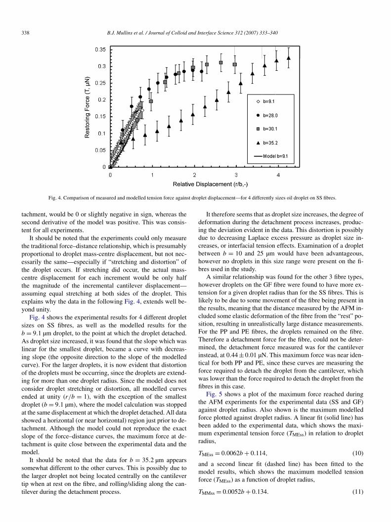
Fig. 4. Comparison of measured and modelled tension force against droplet displacement—for 4 differently sizes oil droplet on SS fibres.
tachment, would be 0 or slightly negative in sign, whereas thesecond derivative of the model was positive. This was consis-tent for all experiments.
It should be noted that the experiments could only measurethe traditional force–distance relationship, which is presumablyproportional to droplet mass-centre displacement, but not nec-essarily the same—especially if “stretching and distortion” ofthe droplet occurs. If stretching did occur, the actual mass-centre displacement for each increment would be only halfthe magnitude of the incremental cantilever displacement—assuming equal stretching at both sides of the droplet. Thisexplains why the data in the following Fig. 4, extends well be-yond unity.
Fig. 4 shows the experimental results for 4 different dropletsizes on SS fibres, as well as the modelled results for theb = 9.1 µm droplet, to the point at which the droplet detached.As droplet size increased, it was found that the slope which waslinear for the smallest droplet, became a curve with decreas-ing slope (the opposite direction to the slope of the modelledcurve). For the larger droplets, it is now evident that distortionof the droplets must be occurring, since the droplets are extend-ing for more than one droplet radius. Since the model does notconsider droplet stretching or distortion, all modelled curvesended at unity (r/b = 1), with the exception of the smallestdroplet (b = 9.1 µm), where the model calculation was stoppedat the same displacement at which the droplet detached. All datashowed a horizontal (or near horizontal) region just prior to de-tachment. Although the model could not reproduce the exactslope of the force–distance curves, the maximum force at de-tachment is quite close between the experimental data and themodel.
It should be noted that the data for b = 35.2 µm appearssomewhat different to the other curves. This is possibly due tothe larger droplet not being located centrally on the cantilevertip when at rest on the fibre, and rolling/sliding along the can-tilever during the detachment process.
It therefore seems that as droplet size increases, the degree ofdeformation during the detachment process increases, produc-ing the deviation evident in the data. This distortion is possiblydue to decreasing Laplace excess pressure as droplet size in-creases, or interfacial tension effects. Examination of a dropletbetween b = 10 and 25 µm would have been advantageous,however no droplets in this size range were present on the fi-bres used in the study.
A similar relationship was found for the other 3 fibre types,however droplets on the GF fibre were found to have more ex-tension for a given droplet radius than for the SS fibres. This islikely to be due to some movement of the fibre being present inthe results, meaning that the distance measured by the AFM in-cluded some elastic deformation of the fibre from the “rest” po-sition, resulting in unrealistically large distance measurements.For the PP and PE fibres, the droplets remained on the fibre.Therefore a detachment force for the fibre, could not be deter-mined, the detachment force measured was for the cantileverinstead, at 0.44 ± 0.01 µN. This maximum force was near iden-tical for both PP and PE, since these curves are measuring theforce required to detach the droplet from the cantilever, whichwas lower than the force required to detach the droplet from thefibres in this case.
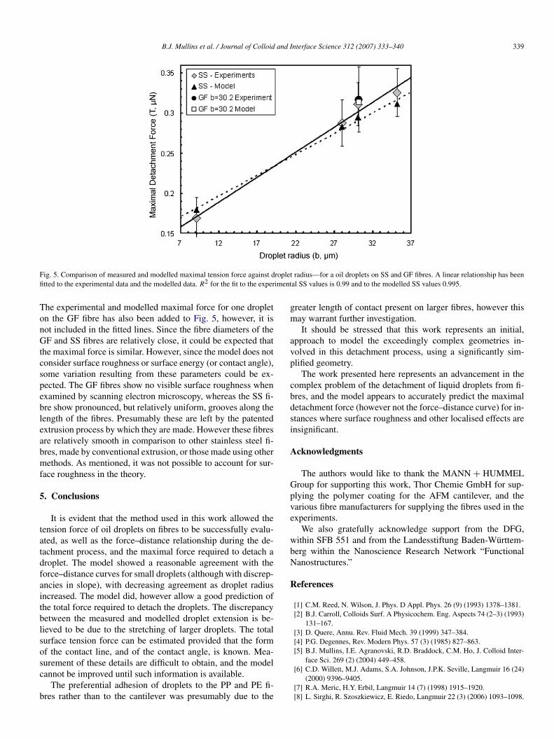
Fig. 5 shows a plot of the maximum force reached duringthe AFM experiments for the experimental data (SS and GF)against droplet radius. Also shown is the maximum modelledforce plotted against droplet radius. A linear fit (solid line) hasbeen added to the experimental data, which shows the maxi-mum experimental tension force (TMEss) in relation to dropletradius,
(10)TMEss = 0.0062b + 0.114,
and a second linear fit (dashed line) has been fitted to themodel results, which shows the maximum modelled tensionforce (TMEss) as a function of droplet radius,
(11)TMMss = 0.0052b + 0.134.
B.J. Mullins et al. / Journal of Colloid and Interface Science 312 (2007) 333–340 339
Fig. 5. Comparison of measured and modelled maximal tension force against droplet radius—for a oil droplets on SS and GF fibres. A linear relationship has beenfitted to the experimental data and the modelled data. R2 for the fit to the experimental SS values is 0.99 and to the modelled SS values 0.995.
The experimental and modelled maximal force for one dropleton the GF fibre has also been added to Fig. 5, however, it isnot included in the fitted lines. Since the fibre diameters of theGF and SS fibres are relatively close, it could be expected thatthe maximal force is similar. However, since the model does notconsider surface roughness or surface energy (or contact angle),some variation resulting from these parameters could be ex-pected. The GF fibres show no visible surface roughness whenexamined by scanning electron microscopy, whereas the SS fi-bre show pronounced, but relatively uniform, grooves along thelength of the fibres. Presumably these are left by the patentedextrusion process by which they are made. However these fibresare relatively smooth in comparison to other stainless steel fi-bres, made by conventional extrusion, or those made using othermethods. As mentioned, it was not possible to account for sur-face roughness in the theory.
5. Conclusions
It is evident that the method used in this work allowed thetension force of oil droplets on fibres to be successfully evalu-ated, as well as the force–distance relationship during the de-tachment process, and the maximal force required to detach adroplet. The model showed a reasonable agreement with theforce–distance curves for small droplets (although with discrep-ancies in slope), with decreasing agreement as droplet radiusincreased. The model did, however allow a good prediction ofthe total force required to detach the droplets. The discrepancybetween the measured and modelled droplet extension is be-lieved to be due to the stretching of larger droplets. The totalsurface tension force can be estimated provided that the formof the contact line, and of the contact angle, is known. Mea-surement of these details are difficult to obtain, and the modelcannot be improved until such information is available.
The preferential adhesion of droplets to the PP and PE fi-bres rather than to the cantilever was presumably due to the
greater length of contact present on larger fibres, however thismay warrant further investigation.
It should be stressed that this work represents an initial,approach to model the exceedingly complex geometries in-volved in this detachment process, using a significantly sim-plified geometry.
The work presented here represents an advancement in thecomplex problem of the detachment of liquid droplets from fi-bres, and the model appears to accurately predict the maximaldetachment force (however not the force–distance curve) for in-stances where surface roughness and other localised effects areinsignificant.
Acknowledgments
The authors would like to thank the MANN + HUMMELGroup for supporting this work, Thor Chemie GmbH for sup-plying the polymer coating for the AFM cantilever, and thevarious fibre manufacturers for supplying the fibres used in theexperiments.
We also gratefully acknowledge support from the DFG,within SFB 551 and from the Landesstiftung Baden-Württem-berg within the Nanoscience Research Network “FunctionalNanostructures.”
References
[1] C.M. Reed, N. Wilson, J. Phys. D Appl. Phys. 26 (9) (1993) 1378–1381.[2] B.J. Carroll, Colloids Surf. A Physicochem. Eng. Aspects 74 (2–3) (1993)
131–167.[3] D. Quere, Annu. Rev. Fluid Mech. 39 (1999) 347–384.[4] P.G. Degennes, Rev. Modern Phys. 57 (3) (1985) 827–863.[5] B.J. Mullins, I.E. Agranovski, R.D. Braddock, C.M. Ho, J. Colloid Inter-
face Sci. 269 (2) (2004) 449–458.[6] C.D. Willett, M.J. Adams, S.A. Johnson, J.P.K. Seville, Langmuir 16 (24)
(2000) 9396–9405.[7] R.A. Meric, H.Y. Erbil, Langmuir 14 (7) (1998) 1915–1920.[8] L. Sirghi, R. Szoszkiewicz, E. Riedo, Langmuir 22 (3) (2006) 1093–1098.

340 B.J. Mullins et al. / Journal of Colloid and Interface Science 312 (2007) 333–340
[9] B.J. Carroll, J. Lucassen, J. Chem. Soc. Faraday Trans. I 70 (7) (1974)1228–1239.
[10] B.J. Mullins, G. Kasper, Chem. Eng. Sci. 61 (18) (2006) 6223–6227.[11] J. Drelich, J.L. Wilbur, J.D. Miller, G.M. Whitesides, Langmuir 12 (7)
(1996) 1913–1922.[12] G. Wolansky, A. Marmur, Langmuir 14 (18) (1998) 5292–5297.[13] T. Frising, D. Thomas, D. Bemer, P. Contal, Chem. Eng. Sci. 60 (10)
(2005) 2751–2762.[14] P.C. Raynor, D. Leith, J. Aerosol Sci. 31 (1) (2000) 19–34.[15] B.J. Mullins, R.D. Braddock, I.E. Agranovski, R.A. Cropp, J. Colloid In-
terface Sci. 300 (2) (2006) 704–712.[16] R.J. Roe, J. Colloid Interface Sci. 50 (1) (1975) 70–79.[17] A.W. Adamson, A.P. Gast, Physical Chemistry of Surfaces, sixth ed., Wi-
ley, New York, 1997.[18] L. Boulange-Petermann, C. Gabet, B. Baroux, Colloids Surf. A Physico-
chem. Eng. Aspects 272 (1–2) (2006) 56–62.[19] M. Miyama, Y.X. Yang, T. Yasuda, T. Okuno, H.K. Yasuda, Langmuir
13 (20) (1997) 5494–5503.[20] B.J. Carroll, J. Appl. Phys. 70 (1) (1991) 493–494.[21] B.J. Carroll, J. Colloid Interface Sci. 57 (3) (1976) 488–495.[22] B.J. Carroll, J. Adhes. Sci. Technol. 6 (9) (1992) 983–994.
[23] A. Kumar, S. Hartland, J. Colloid Interface Sci. 124 (1) (1988) 67–76.[24] A. Kumar, S. Hartland, J. Colloid Interface Sci. 136 (2) (1990) 455–
469.[25] C. Bauer, S. Dietrich, Phys. Rev. E 62 (2) (2000) 2428–2438.[26] G.O. Berim, E. Ruckenstein, J. Phys. Chem. B 109 (25) (2005) 12515–
12524.[27] G. McHale, M.I. Newton, B.J. Carroll, Oil Gas Sci. Technol.—Revue De
L Institut Francais Du Petrole 56 (1) (2001) 47–54.[28] G. Binnig, C.F. Quate, C. Gerber, Phys. Rev. Lett. 56 (9) (1986) 930–933.[29] M.A. Poggi, E.D. Gadsby, L.A. Bottomley, W.P. King, E. Oroudjev,
H. Hansma, Anal. Chem. 76 (12) (2004) 3429–3443.[30] S.D.A. Connell, S. Allen, C.J. Roberts, J. Davies, M.C. Davies, S.J.B.
Tendler, P.M. Williams, Langmuir 18 (5) (2002) 1719–1728.[31] P.G. Hartley, F. Grieser, P. Mulvaney, G.W. Stevens, Langmuir 15 (21)
(1999) 7282–7289.[32] N.V. Churaev, A.P. Ershov, N.E. Esipova, G.A. Iskandarjan, E.A. Mad-
jarova, I.P. Sergeeva, V.D. Sobolev, T.F. Svitova, M.A. Zakharova, Z.M.Zorin, J.E. Poirier, Colloids Surf. A Physicochem. Eng. Aspects 91 (1994)97–112.
[33] B.J. Mullins, R.D. Braddock, I.E. Agranovski, R.A. Cropp, R.A. O’Leary,J. Colloid Interface Sci. 284 (1) (2005) 245–254.
Copyright © 2022 FDOKUMEN