A coupled interface-body nonlocal damage model for FRP strengthening detachment
34
Preprint of the paper to be published in: Computational Mechanics, 50:335–351, DOI 10.1007/s00466-011-0592-7, 2012. A coupled interface-body nonlocal damage model for FRP strengthening detachment S. Marfia, E. Sacco, J. Toti DiMSAT, Department of Mechanics, Structures and Environment, University of Cassino, Italy. Abstract Aim of the paper is to propose a new coupled interface-body damage model for the study of the detachment process in concrete or masonry structures strengthened with Fiber Reinforced Plastic (FRP). In particular, a model of the FRP-concrete or -masonry interface, accounting for the coupling between the degradation of the cohesive material and the FRP detachment, is presented. To this end, a nonlocal damage model is considered for the quasi-brittle material. Regarding the interface, a model which accounts for damage, unilateral contact and friction is developed. The novelty of the proposed model consists in taking into account the coupling between the body and the interface damage, ensuring that the interface damage is not lower than the body one. Some numerical examples and a comparison with experimental data are presented in order to verify the efficiency of the proposed model in reproducing the FRP decohesion from the support cohesive material. 1. Introduction The use of Fiber Reinforced Polymers (FRP) in civil engineering structures has increased at very rapidly rate in recent years. FRP materials are characterized by very high performances and low weight so that they can be successfully adopted to retrofit and repair deteriorated concrete or masonry structures with reduced installation costs. For these reasons several researches have been devoted to study the effectiveness of the application of FRP for the strengthening of the structural elements. Thus, experimental campaigns and theoretical and numerical models have been developed considering concrete [18][12][23] or masonry [24][13][25][1][11][4] structures. The use of FRP materials applied on the external surface of concrete or masonry structures has aroused new modeling problems. One of the main problem in the use of FRP is the so- called detachment phenomenon, which consists in the sudden and brittle decohesion of the FRP reinforcement from the concrete or masonry support element. Furthermore, the decohesion force results often significantly lower than the load capability of FRP layer. In order to model the detachment phenomenon and to predict the possible decohesion of the FRP from the support material, interface models can be adopted.
-
Upload
independent -
Category
Documents
-
view
1 -
download
0
Transcript of A coupled interface-body nonlocal damage model for FRP strengthening detachment

Preprint of the paper to be published in: Computational Mechanics, 50:335–351, DOI 10.1007/s00466-011-0592-7, 2012.
A coupled interface-body nonlocal damage model for FRP strengthening detachment
S. Marfia, E. Sacco, J. Toti DiMSAT, Department of Mechanics, Structures and Environment,
University of Cassino, Italy. Abstract
Aim of the paper is to propose a new coupled interface-body damage model for the study of the detachment process in concrete or masonry structures strengthened with Fiber Reinforced Plastic (FRP). In particular, a model of the FRP-concrete or -masonry interface, accounting for the coupling between the degradation of the cohesive material and the FRP detachment, is presented. To this end, a nonlocal damage model is considered for the quasi-brittle material. Regarding the interface, a model which accounts for damage, unilateral contact and friction is developed. The novelty of the proposed model consists in taking into account the coupling between the body and the interface damage, ensuring that the interface damage is not lower than the body one. Some numerical examples and a comparison with experimental data are presented in order to verify the efficiency of the proposed model in reproducing the FRP decohesion from the support cohesive material.
1. Introduction The use of Fiber Reinforced Polymers (FRP) in civil engineering structures has increased at very rapidly rate in recent years. FRP materials are characterized by very high performances and low weight so that they can be successfully adopted to retrofit and repair deteriorated concrete or masonry structures with reduced installation costs. For these reasons several researches have been devoted to study the effectiveness of the application of FRP for the strengthening of the structural elements. Thus, experimental campaigns and theoretical and numerical models have been developed considering concrete [18][12][23] or masonry [24][13][25][1][11][4] structures.
The use of FRP materials applied on the external surface of concrete or masonry structures has aroused new modeling problems. One of the main problem in the use of FRP is the so-called detachment phenomenon, which consists in the sudden and brittle decohesion of the FRP reinforcement from the concrete or masonry support element. Furthermore, the decohesion force results often significantly lower than the load capability of FRP layer.
In order to model the detachment phenomenon and to predict the possible decohesion of the FRP from the support material, interface models can be adopted.
2
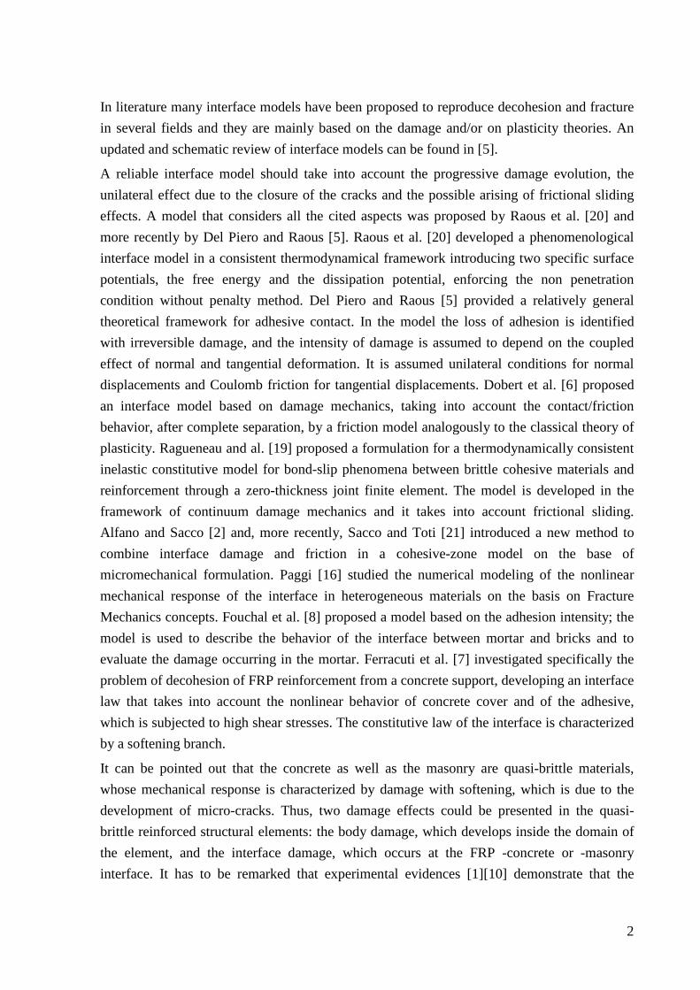
In literature many interface models have been proposed to reproduce decohesion and fracture in several fields and they are mainly based on the damage and/or on plasticity theories. An updated and schematic review of interface models can be found in [5].
A reliable interface model should take into account the progressive damage evolution, the unilateral effect due to the closure of the cracks and the possible arising of frictional sliding effects. A model that considers all the cited aspects was proposed by Raous et al. [20] and more recently by Del Piero and Raous [5]. Raous et al. [20] developed a phenomenological interface model in a consistent thermodynamical framework introducing two specific surface potentials, the free energy and the dissipation potential, enforcing the non penetration condition without penalty method. Del Piero and Raous [5] provided a relatively general theoretical framework for adhesive contact. In the model the loss of adhesion is identified with irreversible damage, and the intensity of damage is assumed to depend on the coupled effect of normal and tangential deformation. It is assumed unilateral conditions for normal displacements and Coulomb friction for tangential displacements. Dobert et al. [6] proposed an interface model based on damage mechanics, taking into account the contact/friction behavior, after complete separation, by a friction model analogously to the classical theory of plasticity. Ragueneau and al. [19] proposed a formulation for a thermodynamically consistent inelastic constitutive model for bond-slip phenomena between brittle cohesive materials and reinforcement through a zero-thickness joint finite element. The model is developed in the framework of continuum damage mechanics and it takes into account frictional sliding. Alfano and Sacco [2] and, more recently, Sacco and Toti [21] introduced a new method to combine interface damage and friction in a cohesive-zone model on the base of micromechanical formulation. Paggi [16] studied the numerical modeling of the nonlinear mechanical response of the interface in heterogeneous materials on the basis on Fracture Mechanics concepts. Fouchal et al. [8] proposed a model based on the adhesion intensity; the model is used to describe the behavior of the interface between mortar and bricks and to evaluate the damage occurring in the mortar. Ferracuti et al. [7] investigated specifically the problem of decohesion of FRP reinforcement from a concrete support, developing an interface law that takes into account the nonlinear behavior of concrete cover and of the adhesive, which is subjected to high shear stresses. The constitutive law of the interface is characterized by a softening branch.
It can be pointed out that the concrete as well as the masonry are quasi-brittle materials, whose mechanical response is characterized by damage with softening, which is due to the development of micro-cracks. Thus, two damage effects could be presented in the quasi-brittle reinforced structural elements: the body damage, which develops inside the domain of the element, and the interface damage, which occurs at the FRP -concrete or -masonry interface. It has to be remarked that experimental evidences [1][10] demonstrate that the

3
detachment of the FRP from the support material often occurs with peeling of a thin layer from the external surface of the quasi-brittle material; this collapse behavior is due to the fact that the strength of the glue used to fix the FRP to the support is generally greater than the strength of the concrete or masonry support. From this observation, it can be deduced that the body damage and the interface damage cannot evolve independently one from the other; in other words, they are coupled. In particular, the interface damage has to depend on the distribution of the body damage. In the knowledge of the authors, the first paper in which a coupled body-interface damage model has been developed is due to Freddi and Frémond [9]. They proposed a full thermodynamically consistent coupled approach, considering a body nonlocal damage model characterized by a damage gradient regularization, viscosity and an interface nonlocal damage model. The two damages are completely coupled thus, the body damage induces interface damage and vice-versa.
In the present paper a new coupled interface-body nonlocal damage model is proposed in order to study the problem of decohesion of FRP reinforcement from a cohesive material, such as masonry or concrete. In particular, a nonlocal damage model is developed for the quasi-brittle material. The damage evolution is governed by an equivalent strain variable. In order to prevent strain localization and strong mesh sensitivity of the solution, typical of cohesive materials subjected to damage and softening, an integral-type of nonlocal model based on the weighted spatial averaging of the equivalent strain is developed. For what concerns the interface, a model which accounts for the mode I, mode II and mixed mode of damage and for the unilateral contact and friction effects is developed. The damage evolution is governed by the relative displacement occurring at bond surface. The novelty of the proposed model consists in considering the coupling between the body damage and the interface damage ensuring that the interface damage is not lower than the body damage computed on the bond surface.
Some numerical applications are performed in order to assess the performances of the proposed model in reproducing the mechanical behavior of quasi-brittle material strengthened with external FRP reinforcements. A comparison with available experimental data is carried out in order to study the detachment phenomenon.
In the following, first the coupled interface-body nonlocal damage model is described; then, some aspects regarding the numerical procedure are presented; finally, some numerical applications are illustrated in order to study the detachment mechanism in FRP reinforced structures.

4
2. A coupled interface-body nonlocal damage model
2.1. Position of the problem
The structural system, schematizing the FRP reinforced concrete or masonry element, is studied in the framework of two-dimensional elasticity, considering small strain and displacement regime. The system, represented in Figure 1, consists in three subsystems:
• body 1Ω , modeling the concrete or masonry element, characterized by a cohesive
constitutive law;
• body 2Ω , modeling the FRP reinforcement, characterized by a linear elastic behavior;
• interface ℑ , modeling the bond between the reinforcement and the quasi-brittle material, characterized by a damaging behavior with friction and unilateral contact effects.
It can be remarked that the interface ℑ is assumed to be constituted by the glue, whose mechanical properties are much better than those of the support cohesive material, and by a thin layer of the support cohesive material. Indeed, experimental evidence shows that, during the application of the reinforcement, the glue penetrates the pores inside the body 1Ω
improving the mechanical properties of a thin layer which, as a consequence, remains linked with the glue to the FRP reinforcement, during the detachment process. In Figure 2 and Figure 3 the schematization of the interface between the body 1Ω and the body 2Ω is clearly
illustrates.
The constitutive laws of the three subsystems are specified in the following.
2.2. Nonlocal damage model for body 1Ω
A damage model, characterized by the following classical constitutive law, is considered:
( ) 11 DΩ= −σ C ε (1)
with σ and ε the stress and strain tensors, respectively, 1C the elasticity tensor and DΩ the
scalar damage variable whose value can vary from zero to one: 0DΩ = corresponds to the
undamaged material, while 1DΩ = corresponds to the completely damaged material.
As the softening constitutive law (1) is introduced for the body 1Ω , localization of the strain
and damage could occur. In order to overcome this pathological problem, to account for the correct size of the localization zone and, also, to avoid strong mesh sensitivity in finite element analyses, nonlocal constitutive law is considered [17]. In particular, an integral
5
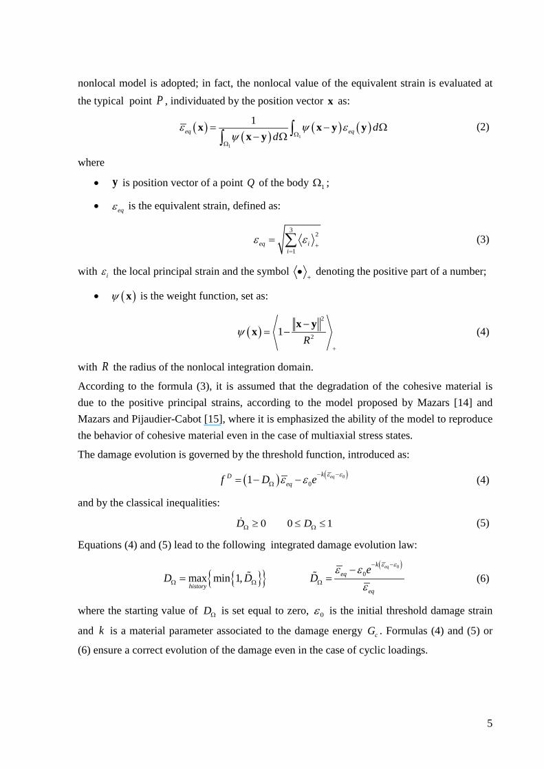
nonlocal model is adopted; in fact, the nonlocal value of the equivalent strain is evaluated at the typical point P , individuated by the position vector x as:
( )( )
( ) ( )1
1
1eq eq d
dε ψ ε
ψ ΩΩ
= − Ω− Ω ∫∫
x x y yx y
(2)
where
• y is position vector of a point Q of the body 1Ω ;
• eqε is the equivalent strain, defined as:
3
2
1eq i
iε ε
+=
= ∑ (3)
with iε the local principal strain and the symbol +
• denoting the positive part of a number;
• ( )ψ x is the weight function, set as:
( )2
21R
ψ+
−= −
x yx (4)
with R the radius of the nonlocal integration domain.
According to the formula (3), it is assumed that the degradation of the cohesive material is due to the positive principal strains, according to the model proposed by Mazars [14] and Mazars and Pijaudier-Cabot [15], where it is emphasized the ability of the model to reproduce the behavior of cohesive material even in the case of multiaxial stress states.
The damage evolution is governed by the threshold function, introduced as:
( ) ( )0
01 eqkDeqf D e ε εε ε − −
Ω= − − (4)
and by the classical inequalities:
0 0 1D DΩ Ω≥ ≤ ≤ (5)
Equations (4) and (5) lead to the following integrated damage evolution law:
( )0
0max min 1,eqk
eq
historyeq
eD D D
ε εε εε
− −
Ω Ω Ω
−= = (6)
where the starting value of DΩ is set equal to zero, 0ε is the initial threshold damage strain
and k is a material parameter associated to the damage energy cG . Formulas (4) and (5) or
(6) ensure a correct evolution of the damage even in the case of cyclic loadings.
6
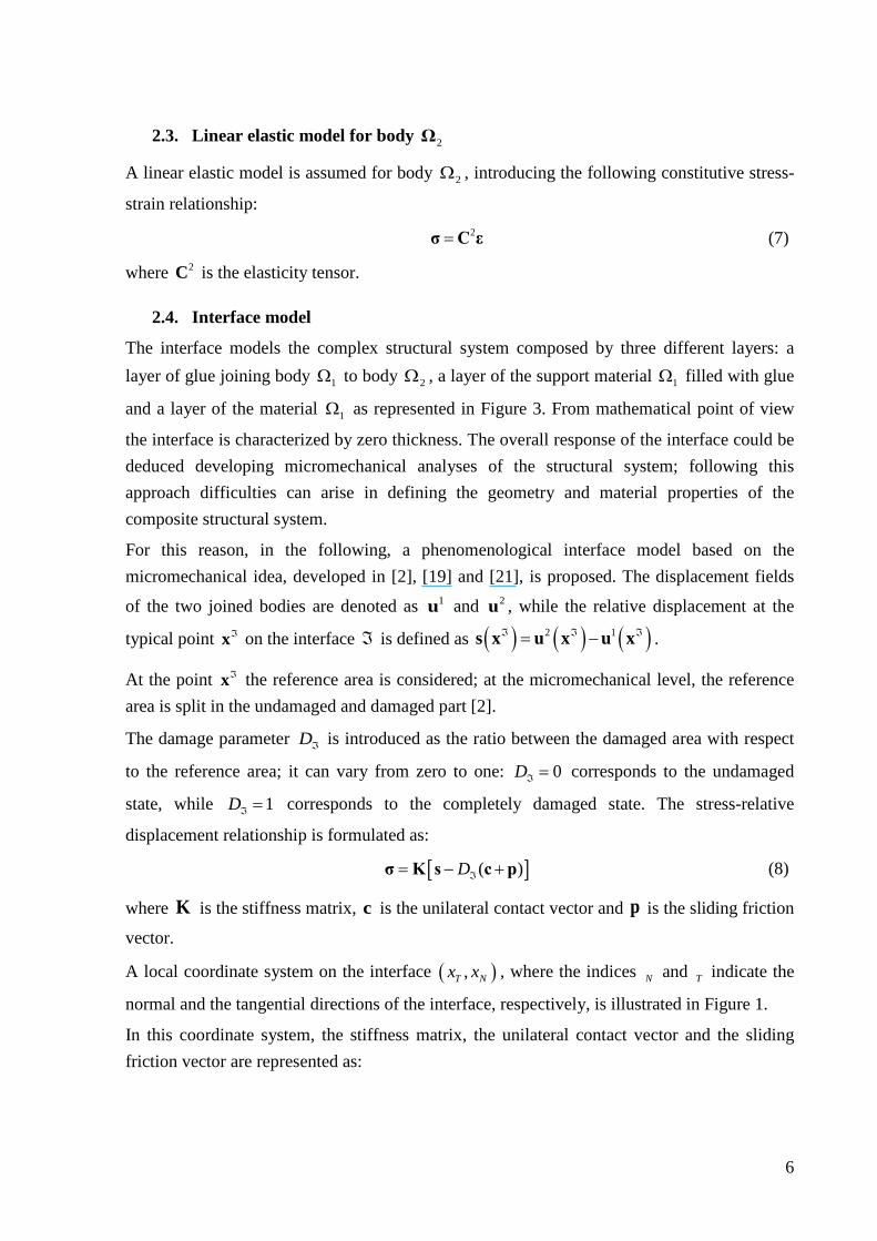
2.3. Linear elastic model for body 2Ω
A linear elastic model is assumed for body 2Ω , introducing the following constitutive stress-
strain relationship:
2=σ C ε (7)
where 2C is the elasticity tensor.
2.4. Interface model
The interface models the complex structural system composed by three different layers: a layer of glue joining body 1Ω to body 2Ω , a layer of the support material 1Ω filled with glue
and a layer of the material 1Ω as represented in Figure 3. From mathematical point of view
the interface is characterized by zero thickness. The overall response of the interface could be deduced developing micromechanical analyses of the structural system; following this approach difficulties can arise in defining the geometry and material properties of the composite structural system.
For this reason, in the following, a phenomenological interface model based on the micromechanical idea, developed in [2], [19] and [21], is proposed. The displacement fields
of the two joined bodies are denoted as 1u and 2u , while the relative displacement at the
typical point ℑx on the interface ℑ is defined as ( ) ( ) ( )2 1ℑ ℑ ℑ= −s x u x u x .
At the point ℑx the reference area is considered; at the micromechanical level, the reference area is split in the undamaged and damaged part [2].
The damage parameter Dℑ is introduced as the ratio between the damaged area with respect
to the reference area; it can vary from zero to one: 0Dℑ = corresponds to the undamaged
state, while 1Dℑ = corresponds to the completely damaged state. The stress-relative
displacement relationship is formulated as:
[ ]( )Dℑ= − +σ K s c p (8)
where K is the stiffness matrix, c is the unilateral contact vector and p is the sliding friction
vector.
A local coordinate system on the interface ( ),T Nx x , where the indices N and T indicate the
normal and the tangential directions of the interface, respectively, is illustrated in Figure 1.
In this coordinate system, the stiffness matrix, the unilateral contact vector and the sliding friction vector are represented as:
7
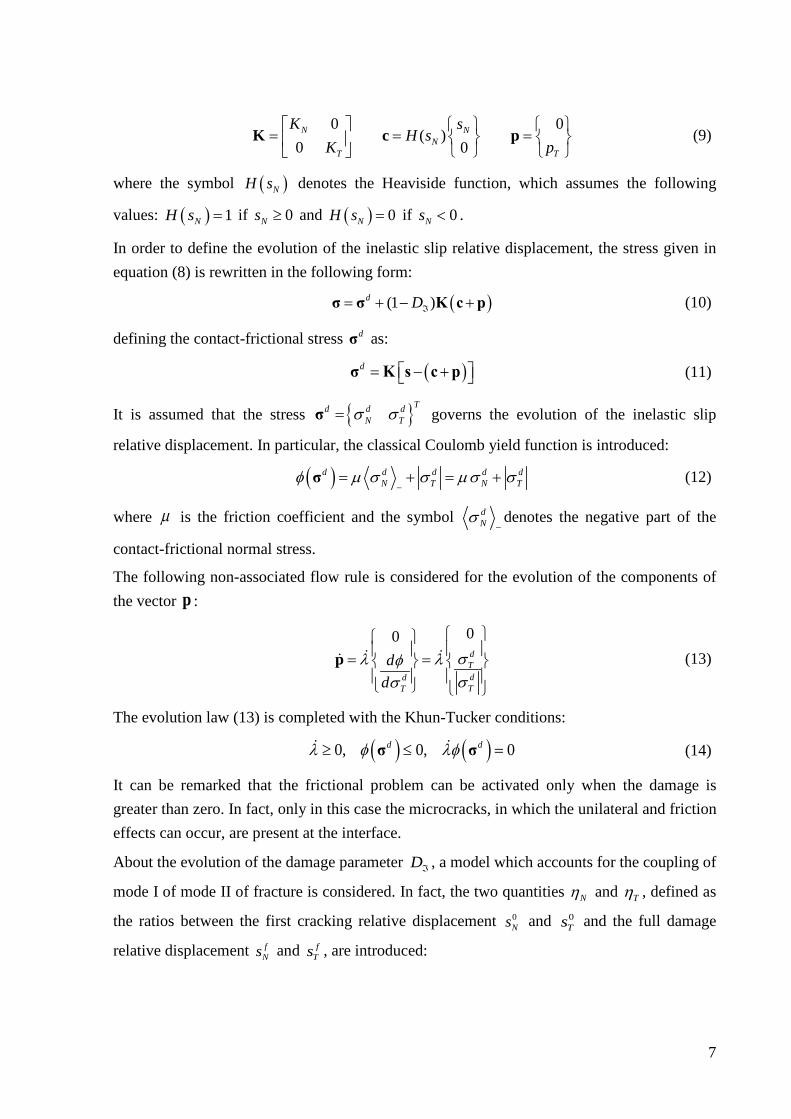
0 0
( )0 0
N NN
T T
K sH s
K p
= = =
K c p (9)
where the symbol ( )NH s denotes the Heaviside function, which assumes the following
values: ( ) 1NH s = if 0Ns ≥ and ( ) 0NH s = if 0Ns < .
In order to define the evolution of the inelastic slip relative displacement, the stress given in equation (8) is rewritten in the following form:
( )(1 )d Dℑ= + − +σ σ K c p (10)
defining the contact-frictional stress dσ as:
( )d = − + σ K s c p (11)
It is assumed that the stress Td d dN Tσ σ=σ governs the evolution of the inelastic slip
relative displacement. In particular, the classical Coulomb yield function is introduced:
( )d d d d dN T N Tφ µ σ σ µσ σ
−= + = +σ (12)
where µ is the friction coefficient and the symbol dNσ
−denotes the negative part of the
contact-frictional normal stress.
The following non-associated flow rule is considered for the evolution of the components of the vector p :
00dTddTT
dd
σλ λφσσ
= =
p
(13)
The evolution law (13) is completed with the Khun-Tucker conditions:
( ) ( )0, 0, 0d dλ φ λφ≥ ≤ =σ σ (14)
It can be remarked that the frictional problem can be activated only when the damage is greater than zero. In fact, only in this case the microcracks, in which the unilateral and friction effects can occur, are present at the interface.
About the evolution of the damage parameter Dℑ , a model which accounts for the coupling of
mode I of mode II of fracture is considered. In fact, the two quantities Nη and Tη , defined as
the ratios between the first cracking relative displacement 0Ns and 0
Ts and the full damage
relative displacement fNs and f
Ts , are introduced:

8
0 0 0 0 0 0
,2 2
N N N T T TN Tf f
N cN T cT
s s s ss G s G
σ ση η= = = = (15)
where 0Nσ and 0
Tσ are the peak stresses corresponding to the first cracking relative
displacement and cNG and cTG are the specific fracture energies in mode I and mode II,
respectively. Then, the parameter η , which relates the two modes of fracture, is defined as
follows:
2 2
2 2N T
N T
s sη η η+= +s s
(16)
where T
N Ts s+
=s . The relative displacement ratios are introduced as:
0 0N T
N TN T
s sY Ys s
+= = (17)
and the equivalent relative displacement ratio is considered:
2 2N TY Y Y= + (18)
Finally, the evolution of the damage parameter is assumed given by:
( )2
1 0 0 01
D Y D DY ηℑ ℑ ℑ= ≥ ≤ ≤
− (18)
which can be rewritten in the equivalent integrated form as function of the history of relative displacement:
max min 1,history
D Dℑ ℑ= (19)
where the quantity Dℑ is expressed by the relationship :
( )
11
YDY ηℑ
−=
− (20)
The starting value of Dℑ is set equal to zero. Note that the equation (20) allows to obtain a
linear stress - relative displacement relationship when the ratio /N Ts s is assigned.
It can be remarked that equations (18), (19) and (20) ensure an accurate evolution of the damage variable also in the case of cyclic loading. In fact, there is no damage evolution, i.e. damage remains frozen, during unloading phases.
9
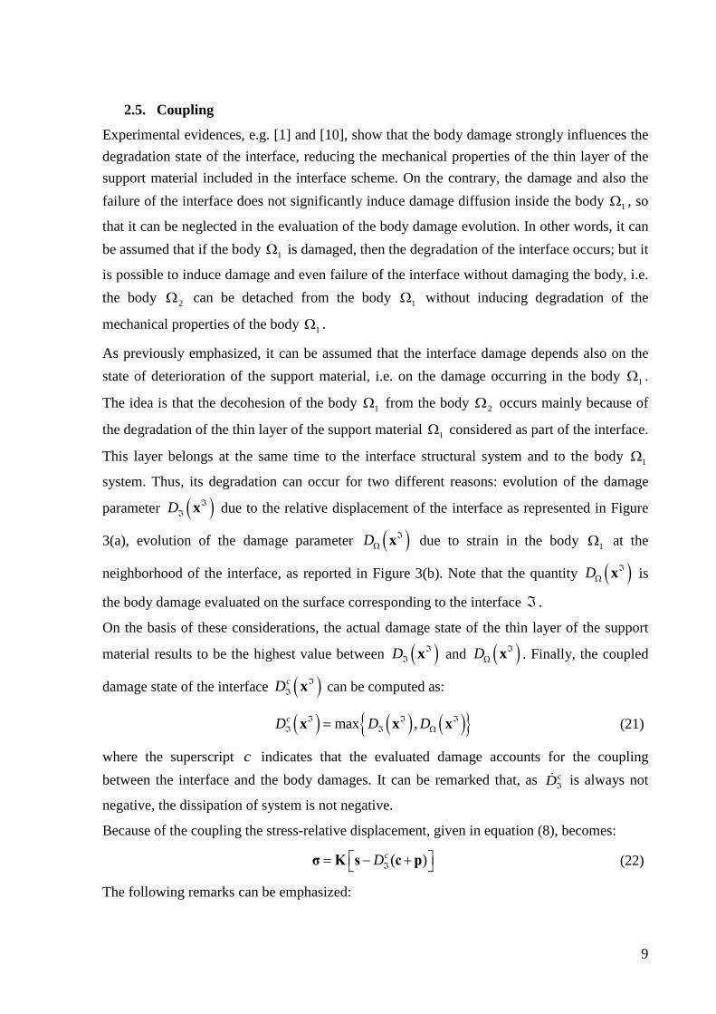
2.5. Coupling
Experimental evidences, e.g. [1] and [10], show that the body damage strongly influences the degradation state of the interface, reducing the mechanical properties of the thin layer of the support material included in the interface scheme. On the contrary, the damage and also the failure of the interface does not significantly induce damage diffusion inside the body 1Ω , so
that it can be neglected in the evaluation of the body damage evolution. In other words, it can be assumed that if the body 1Ω is damaged, then the degradation of the interface occurs; but it
is possible to induce damage and even failure of the interface without damaging the body, i.e. the body 2Ω can be detached from the body 1Ω without inducing degradation of the
mechanical properties of the body 1Ω .
As previously emphasized, it can be assumed that the interface damage depends also on the state of deterioration of the support material, i.e. on the damage occurring in the body 1Ω .
The idea is that the decohesion of the body 1Ω from the body 2Ω occurs mainly because of
the degradation of the thin layer of the support material 1Ω considered as part of the interface.
This layer belongs at the same time to the interface structural system and to the body 1Ω
system. Thus, its degradation can occur for two different reasons: evolution of the damage
parameter ( )D ℑℑ x due to the relative displacement of the interface as represented in Figure
3(a), evolution of the damage parameter ( )D ℑΩ x due to strain in the body 1Ω at the
neighborhood of the interface, as reported in Figure 3(b). Note that the quantity ( )D ℑΩ x is
the body damage evaluated on the surface corresponding to the interface ℑ .
On the basis of these considerations, the actual damage state of the thin layer of the support
material results to be the highest value between ( )D ℑℑ x and ( )D ℑ
Ω x . Finally, the coupled
damage state of the interface ( )cD ℑℑ x can be computed as:
( ) ( ) ( ) max ,cD D Dℑ ℑ ℑℑ ℑ Ω=x x x (21)
where the superscript c indicates that the evaluated damage accounts for the coupling between the interface and the body damages. It can be remarked that, as cDℑ
is always not
negative, the dissipation of system is not negative.
Because of the coupling the stress-relative displacement, given in equation (8), becomes:
( )cDℑ = − + σ K s c p (22)
The following remarks can be emphasized:
10
• if the body 1Ω is damaged, implicitly the interface is even damaged; in other words,
the damage state of the interface depends on the state of degradation of the body;
• if the body 1Ω is not damaged, the interface damage is governed by the variable Dℑ ,
i.e. by the relative displacement occurring at the interface.
3. Computational aspects A numerical procedure for solving the equations governing the mechanical response of the body-interface nonlocal damage model, described in the previous section, is developed.
The nonlinear behavior has to be evaluated by solving the evolutive equations of the proposed body-interface model through a step by step time integration algorithm. In particular, the time integration is performed adopting a backward-Euler implicit procedure. The time interval of interest is subdivided in subincrements and the evolutive problem is solved into a typical interval [ ]1,n nt t + , being 1n nt t+ > . The time-discrete interface model is solved at a typical point
of the structural system, adopting a predictor-corrector algorithm through a displacement-based formulation [22].
The proposed numerical procedure is implemented in the finite element code FEAP [26]. In particular, two-dimensional four node quadrilateral elements are adopted to model the bodies
1Ω and 2Ω and four node interface elements are developed to model the interface ℑ . In view
of the specific considered structural problem, as the body 2Ω is usually very thin, it could be
modeled also adopting frame or truss elements.
A crucial computational aspect in the definition of the coupled interface damage ( )cD ℑℑ x is
the evaluation the body damage ( )D ℑΩ x at a typical point ℑx of the surface corresponding to
the interface ℑ .
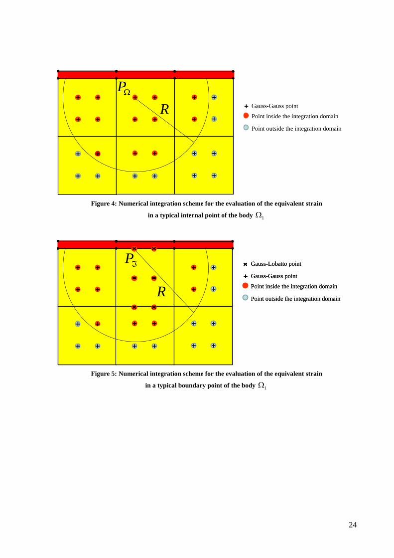
For the evaluation of the damage DΩ at a typical internal point PΩ of the body 1Ω , the
nonlocal equivalent strain is evaluated performing a standard numerical integration adopting Gauss points in both the direction in all the finite elements of the discretization, as schematically illustrated in Figure 4.
In order to evaluate the body damage DΩ at the point Pℑ belonging to the boundary of 1Ω in
correspondence of the interface ℑ , the nonlocal equivalent strain has to be evaluated at Pℑ
which can be considered as a Gauss point of the finite element only in one direction but not in the other. This difficulty is overcome adopting a different integration technique along the two directions only in the finite element, where Pℑ is located; in fact, in one direction the classical

11
Gauss quadrature can be used, while in the other direction the Lobatto technique is adopted to compute the nonlocal equivalent strain, as schematically illustrated in Figure 5.
Although the tangent stiffness matrix for a nonlocal model assures the fast convergence of the Newton's iterative method, the secant operator is used for the elements, in modeling the body
1Ω . The choice of a secant operator leads to satisfactory convergence rate and, in the
meantime, results of simpler implementation in the FEAP code, with respect to the development of the tangent operator for the integral nonlocal damage model, proposed in ref. [27].
The secant operator, derived from the relationship (1), takes the following form:
( ) 11s DΩ= −K C (23)
For what concerns the interface element, two different iterative stiffness matrices are implemented. In fact, when the damage is governed by the relative displacement, i.e.
cD Dℑ ℑ= , the consistent tangent operator, accordingly to the local integration algorithmic
scheme, is implemented. By the derivative /∂ ∂σ s of the constitutive relationship −σ s , the expression of tangent operator is obtained:
( )( ( )t DD Dℑℑ ℑ
∂∂ ∂ ∂ ∂ = = − + = − + ⊗ − + ∂ ∂ ∂ ∂ ∂
σ c pK K s c p K I c ps s s s s
(24)
Explicitly, the partial derivates are computed as follows:
( )( ) ( ) ( )
( )
|
2|2 23
if
21 1 1 if 11
if 01 0
if 00 0
0 01 1 if 0 e 0
otherwise
n
T Nn
N
N
dT d
N d NT T
D DD
Y Y D DY
s
s
K sK
η ηη
η
σµ φσ
ℑ ℑ
ℑ
ℑ ℑ
≤∂ = −∂ − − + − < ≤ −
≤∂ = >∂
< ≥∂ = ∂
0
s A Q ss
0cs
σps
0
(25)
where ( ) ( )2 20 0diag[1/ , 1/ ]N Ts s=A and 22diag[ , ]T Ns s+
= −Q . The parameter |nDℑ , indicates
the value of the interface damage at the beginning of each time step and it is equal to zero at

12
the beginning of the analysis. The derivation of the consistent tangent stiffness matrix is discussed in detail in ref. [21].
It can be remarked that, because of the non-associative interface constitutive law, the consistent tangent matrix could not be symmetric.
On contrary, when the damage is equal to the body one, i.e. cD Dℑ Ω= , the adopted iterative
operator is derived from the expression (24) setting /cDℑ∂ ∂ =s 0 , as the damage evolution is
not governed by equations (15)-(20).
4. Numerical applications Some numerical applications are carried out in order to assess the efficiency of the proposed coupled nonlocal damage interface-body model in describing the decohesion phenomenon of the FRP reinforcement from the cohesive material.
In particular, first a simple tensile test is performed in order to show that the damage occurring in the body 1Ω significantly influences the response of the interface. Then, the
maximum detachment force is evaluated for different values of the adhesion lengths and of the initial values of the body damage. Finally, a comparison with experimental data regarding detachment tests is performed.
All the numerical computations are developed considering a plain strain state. Indeed in some cases a full 3D analysis could be required, but the 2D plane strain approach can be considered a reasonable approximation for the applications proposed in the following.
The properties of the materials adopted in the following numerical applications are set on the basis of the experimental decohesion tests performed on masonry brick elements reinforced with FRP [10]. In particular, the interface mechanical properties, i.e. the stiffness and the damage parameters, are identified on the basis of experimental tests [10].
• Body 1Ω
1 12
0
15300 MPa 0.20.00026 15.0mm 0.0168 N/mmc
ER Gν
ε= == = =
(26)
• Body 2Ω
2 2160000 MPa 0.3E ν= = (27)
• Interface ℑ
3
0 0
600 N/mm 0.54.7 MPa 0.34 N/mm
N T
N T cN cT
K KG Gµ
σ σ= = == = = =
(28)

13
where 1E , 1ν , 2E and 2ν are the Young modulus and the Poisson coefficient of the body 1Ω
and 2Ω , respectively.
The radius of the nonlocal integration domain R is evaluated as function of the dimensions of the greatest inert of the cohesive material [3].
4.1. Tensile test
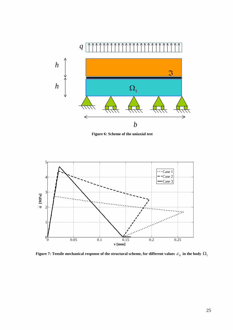
The geometry and loading condition of the scheme considered to perform the tensile test are shown in Figure 6. The geometrical parameters are
500 mm 49mmb h= = (29)
and an unit thickness is adopted.
For the interface ℑ and the body 1Ω and 2Ω the material parameters indicated above are
adopted. In order to investigate the influence of the damaging behavior of the body 1Ω on the
tensile mechanical response of the interface and, as a consequence, of the whole structure, three analyses are developed considering different values of the initial threshold damage strain 0ε and keeping constant the fracture energy cG ; in particular it is set:
• Case 1: 0 0.00016ε =
• Case 2: 0 0.00026ε =
• Case 3: 0 0.00036ε =
The computations are performed adopting an arc-length technique and considering the relative normal displacement Ns at the interface as control parameter. In the Figure 7, Figure 8 and
Figure 9, the results are plotted with a dotted line for Case 1, with a dashed line for Case 2 and with a solid line for Case 3. Furthermore, the average tensile stress is introduced as
2 /F bσ = and the average strain in the body 1Ω is set as /v hε = ∆ with v∆ the relative
vertical displacement between the two opposite edges of the body 1Ω .
In Figure 7 the average tensile stress is plotted versus the vertical displacement v of the points of the free edge of the body 2Ω for the three examined cases. It can be noted that in
Case 3 the mechanical response of the structure is strongly influenced only by the softening behavior of the interface as in this analysis damage does not occur in the body. In the other two cases the tensile mechanical response of the structure depends on the coupling of the body and interface damage. This aspect could be better understood looking at Figure 8 and Figure 9.

14
In particular, in Figure 8 the tensile interface response is plotted in terms of the tensile stress
Nσ and the relative displacement Ns for the three examined cases. In the same figure, the
tensile constitutive response of the interface is also reported with a curve marked by the circles. It can be pointed out that in Case 3 the tensile interface response is equal to the constitutive interface law as, for this analysis, no body damage occurs. In the other cases, the tensile response of the interface differs from the constitutive behavior. The maximum tensile interface stress in Case 1 and Case 2 is significantly lower than the one in Case 3 that coincides with the tensile strength of the interface. In fact, the body starts to damage and, as a consequence of the coupled model, the body damage induces degradation of the interface. After the peak, the interface tensile response is characterized by a softening branch with a slope different from the one of the constitutive behavior until the damage of the interface governed by the relative displacement becomes higher than the body damage at the interface. At this point of the analysis, the softening tensile response also in Case 1 and 2 becomes equal to the constitutive one.
In Figure 9 the body tensile response is represented in terms of the average tensile stress σ and of the average strain ε for the three examined cases. It can be noted that in Case 3 no damage occurs in the body; when the interface starts to damage, the body is subjected to elastic unloading. In the other two cases the body starts to damage when the nonlocal equivalent strain becomes higher than 0ε ; then, the mechanical response is characterized by a
softening branch until the damage Dℑ governed by the relative displacement becomes higher
than the body damage computed at the interface; at this point of the analysis the body damage does not increase anymore and the body is subjected to unloading with a constant value of the damage.
4.2. Maximum decohesion force
In modeling of the FRP-concrete or masonry damage interface, the independent evolution of the two damage variables can lead to physically unacceptable results. In order to demonstrate this thesis, a simple numerical application concerning the detachment problem between the FRP and the cohesive support is developed.
The computations are performed considering the scheme and the geometry illustrated in Figure 10. The FRP laminate (body 2Ω ) is bonded to a masonry support (body 1Ω ) made of
two clay bricks separated by an unitary layer of mortar. The FRP laminate is subjected to tensile loading.

15
The mechanical properties of the materials, previously reported, are adopted. For simplicity, the same values of the material parameters are assumed for the layer of mortar and for the clay bricks.
The finite element analyses are performed in order to evaluate the maximum value of the carried force maxF in correspondence of the decohesion of the body 2Ω from the body 1Ω ,
for different values of the adhesion length bL and for different prescribed initial damage state
of the body 1Ω .
All computations are developed assuming two interface damage models: the uncoupled model, i.e. considering no interaction between body and interface degradation, and the coupled one, i.e. considering the body damage inducing interface damage.
In Figure 11 the value of maxF is plotted versus the adhesion length bL . Note that each curve
is denoted by a symbol made of a letter and a number. The letter U is used to indicate that the analysis is performed adopting the uncoupled damage model, while the letter C is used to characterize the analysis developed with the coupled damage theory. The number near the letter indicates the initial damage level uniformly assigned at the body 1Ω . In particular, the
number 1, 2, 3, and 4 corresponds to the damage value equal to 0, 0.5, 0.7, and 0.9, respectively.
The numerical results reported in Figure 11 emphasize that, increasing the adhesion length bL ,
the value of maxF grows till the optimal adhesion length eL is reached, after which maxF
remains constant.
In particular, from the type U curves marked by the discontinuous line, which represents the numerical results obtained taking into account the independent evolution of the two damage variables, it can be noted that:
• for higher values of the damage state of the body 1Ω the optimal adhesion length eL increases;
• for higher values of the damage state of the body 1Ω the maximum value of maxF is
quite constant and, in some cases, it tends to increase;
• for very high values of the damage state of the body 1Ω the maximum value of maxF
decreases.
While the first result is absolutely expected, the second one appears physically unacceptable, as it implies that even if the support material is more damaged, equal or higher values of the forces can be transmitted from 2Ω to 1Ω . On the contrary, only when the damage level of the
16
body 1Ω becomes very high the force decreases. This strange effect is due to the uncoupled
damage evolution of the body and of the interface damage state.
With reference to the all type C curves marked by the solid line where the coupling between the interface and body damage is accounted for, the following observations can be remarked:
• for higher values of the damage state of the body 1Ω the optimal adhesion length eL increases, as in the case of the uncoupled model;
• for higher values of the damage state of the body 1Ω the maximum value of maxF
decreases.
This last results appears much more reasonable and, as a consequence, more reliable with respect to the one obtained adopting the uncoupled damage model, as it does not suffer from the physical unacceptable effect found in the uncoupled one.
4.3. Comparison with experimental data
In this section, numerical analyses concerning the decohesion mechanism of the fiber reinforced plastic laminates externally applied on clay masonry bricks are developed. The numerical results are compared with the experimental ones, recovered from a previous experimental campaign carried out by Grande et al. [10]. The experimental program illustrated in ref. [10] was performed to study the behavior of FRP-sheets glued on masonry blocks for different adhesion lengths.
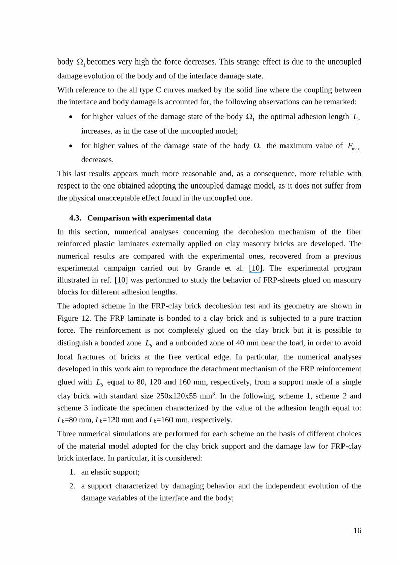
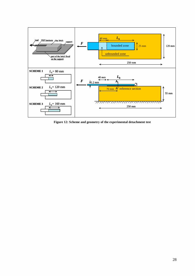
The adopted scheme in the FRP-clay brick decohesion test and its geometry are shown in Figure 12. The FRP laminate is bonded to a clay brick and is subjected to a pure traction force. The reinforcement is not completely glued on the clay brick but it is possible to distinguish a bonded zone bL and a unbonded zone of 40 mm near the load, in order to avoid
local fractures of bricks at the free vertical edge. In particular, the numerical analyses developed in this work aim to reproduce the detachment mechanism of the FRP reinforcement glued with bL equal to 80, 120 and 160 mm, respectively, from a support made of a single
clay brick with standard size 250x120x55 mm3. In the following, scheme 1, scheme 2 and scheme 3 indicate the specimen characterized by the value of the adhesion length equal to: Lb=80 mm, Lb=120 mm and Lb=160 mm, respectively.
Three numerical simulations are performed for each scheme on the basis of different choices of the material model adopted for the clay brick support and the damage law for FRP-clay brick interface. In particular, it is considered:
1. an elastic support;
2. a support characterized by damaging behavior and the independent evolution of the damage variables of the interface and the body;
17
3. a support with damaging behavior and the proposed coupled damage theory for the FRP-clay brick interface.
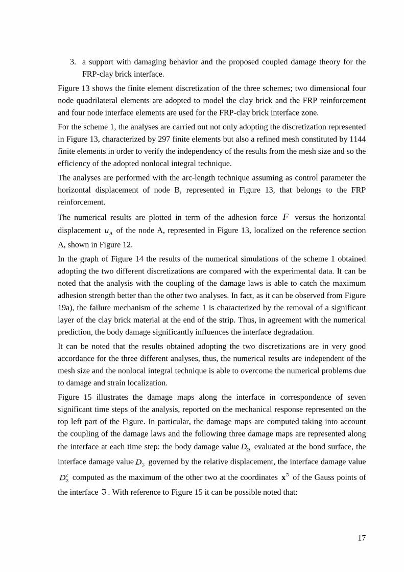
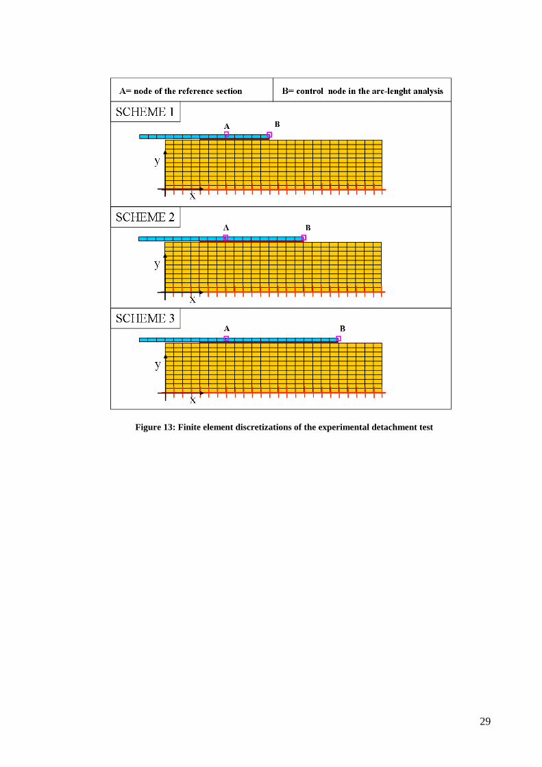
Figure 13 shows the finite element discretization of the three schemes; two dimensional four node quadrilateral elements are adopted to model the clay brick and the FRP reinforcement and four node interface elements are used for the FRP-clay brick interface zone.
For the scheme 1, the analyses are carried out not only adopting the discretization represented in Figure 13, characterized by 297 finite elements but also a refined mesh constituted by 1144 finite elements in order to verify the independency of the results from the mesh size and so the efficiency of the adopted nonlocal integral technique.
The analyses are performed with the arc-length technique assuming as control parameter the horizontal displacement of node B, represented in Figure 13, that belongs to the FRP reinforcement.
The numerical results are plotted in term of the adhesion force F versus the horizontal displacement Au of the node A, represented in Figure 13, localized on the reference section
A, shown in Figure 12.
In the graph of Figure 14 the results of the numerical simulations of the scheme 1 obtained adopting the two different discretizations are compared with the experimental data. It can be noted that the analysis with the coupling of the damage laws is able to catch the maximum adhesion strength better than the other two analyses. In fact, as it can be observed from Figure 19a), the failure mechanism of the scheme 1 is characterized by the removal of a significant layer of the clay brick material at the end of the strip. Thus, in agreement with the numerical prediction, the body damage significantly influences the interface degradation.
It can be noted that the results obtained adopting the two discretizations are in very good accordance for the three different analyses, thus, the numerical results are independent of the mesh size and the nonlocal integral technique is able to overcome the numerical problems due to damage and strain localization.
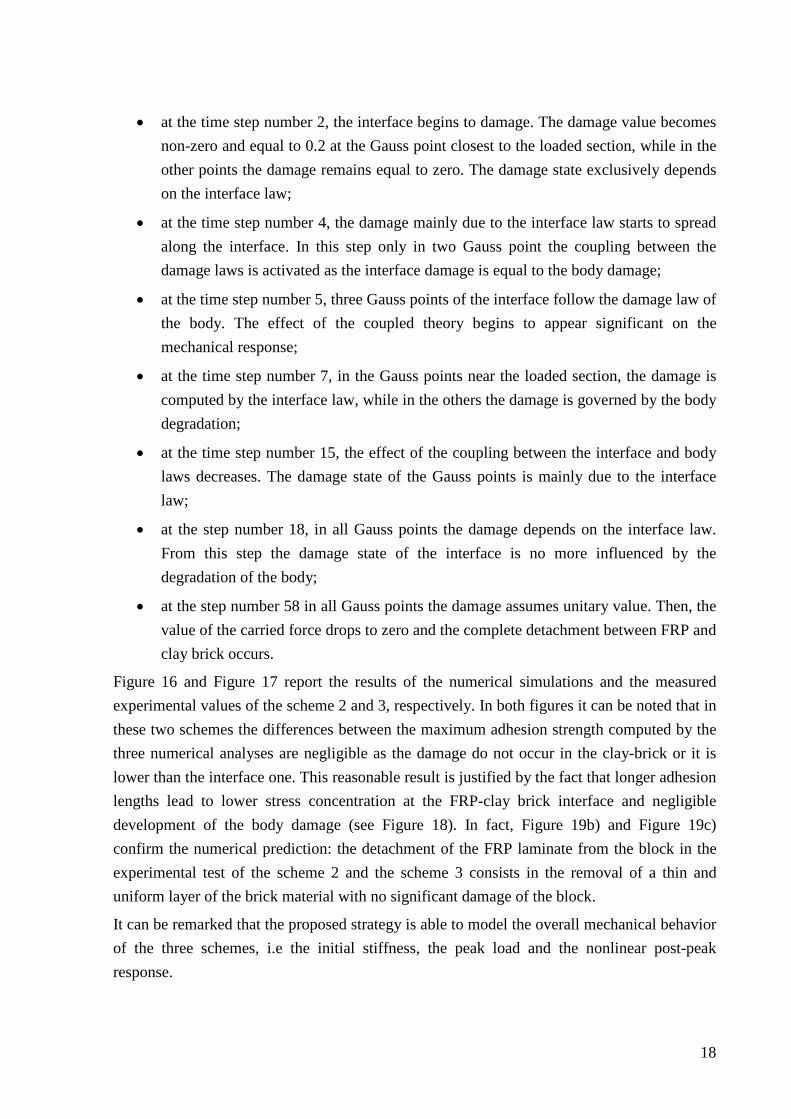
Figure 15 illustrates the damage maps along the interface in correspondence of seven significant time steps of the analysis, reported on the mechanical response represented on the top left part of the Figure. In particular, the damage maps are computed taking into account the coupling of the damage laws and the following three damage maps are represented along the interface at each time step: the body damage value DΩ evaluated at the bond surface, the
interface damage value Dℑ governed by the relative displacement, the interface damage value cDℑ computed as the maximum of the other two at the coordinates ℑx of the Gauss points of
the interface ℑ . With reference to Figure 15 it can be possible noted that:
18
• at the time step number 2, the interface begins to damage. The damage value becomes non-zero and equal to 0.2 at the Gauss point closest to the loaded section, while in the other points the damage remains equal to zero. The damage state exclusively depends on the interface law;
• at the time step number 4, the damage mainly due to the interface law starts to spread along the interface. In this step only in two Gauss point the coupling between the damage laws is activated as the interface damage is equal to the body damage;
• at the time step number 5, three Gauss points of the interface follow the damage law of the body. The effect of the coupled theory begins to appear significant on the mechanical response;
• at the time step number 7, in the Gauss points near the loaded section, the damage is computed by the interface law, while in the others the damage is governed by the body degradation;
• at the time step number 15, the effect of the coupling between the interface and body laws decreases. The damage state of the Gauss points is mainly due to the interface law;
• at the step number 18, in all Gauss points the damage depends on the interface law. From this step the damage state of the interface is no more influenced by the degradation of the body;
• at the step number 58 in all Gauss points the damage assumes unitary value. Then, the value of the carried force drops to zero and the complete detachment between FRP and clay brick occurs.
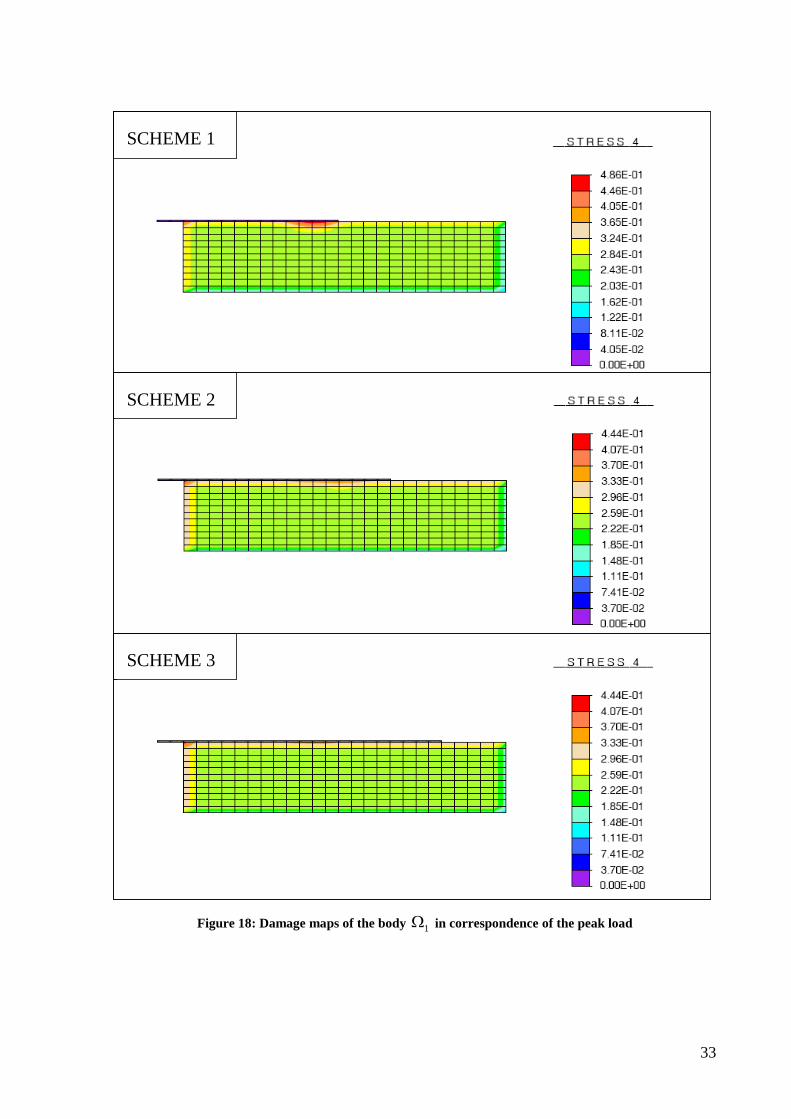
Figure 16 and Figure 17 report the results of the numerical simulations and the measured experimental values of the scheme 2 and 3, respectively. In both figures it can be noted that in these two schemes the differences between the maximum adhesion strength computed by the three numerical analyses are negligible as the damage do not occur in the clay-brick or it is lower than the interface one. This reasonable result is justified by the fact that longer adhesion lengths lead to lower stress concentration at the FRP-clay brick interface and negligible development of the body damage (see Figure 18). In fact, Figure 19b) and Figure 19c) confirm the numerical prediction: the detachment of the FRP laminate from the block in the experimental test of the scheme 2 and the scheme 3 consists in the removal of a thin and uniform layer of the brick material with no significant damage of the block.
It can be remarked that the proposed strategy is able to model the overall mechanical behavior of the three schemes, i.e the initial stiffness, the peak load and the nonlinear post-peak response.

19
5. Conclusions A coupled interface-body nonlocal damage model is proposed in order to study the detachment process in masonry or concrete structures reinforced with FRP. In particular, a nonlocal damage model is adopted for the cohesive material. An integral-type of nonlocal model based on the weighted spatial averaging of a strain-like quantity is developed in order to prevent strain localization and strong mesh sensitivity of the solution.
An interface model which accounts for the mode I, mode II and mixed mode of damage, unilateral effect and friction is presented. The coupling between the body damage and the interface damage is performed computing the body damage on the bond surface and prescribing the interface damage not lower than the body one. This coupling represents the main novelty of the proposed model.
The presented applications consider simple structural schemes, subjected to elementary loading histories and they show the efficiency of the proposed coupled interface model in reproducing the decohesion process of the FRP reinforcement from a cohesive support.
In fact, the numerical results remark the necessity of the use of the coupled damage model for the analysis of the reinforced concrete or masonry structural elements as the body degradation significantly influences the detachment process. The coupled interface model allows to obtain reliable values of the detachment force and of the optimal adhesion length also when the support material is damaged.
The comparison of the numerical results with experimental data shows that the presented interface model is able to reproduce the decohesion process in all the three considered experimental tests characterized by different adhesion lengths.
Acknowledgments The financial supports of the University of Cassino and of the Consorzio RELUIS (Department of Civil Protection) are gratefully acknowledged.
References [1] Aiello MA, Sciolti MS (2003) Masonry structures strengthened with FRP sheets:
experimental investigation of bond between FRP laminates and ashlars. International Journal for Restoration of Buildings and Monuments 9: 639-662

20
[2] Alfano G, Sacco E (2006) Combining interface damage and fiction in a cohesive-zone model. International Journal For Numerical Methods in Engineering 68: 542–582
[3] Bazant Z P, Pijauder-Cabot G (1989) Measurement of characteristic length of nonlocal continuum. Journal of Engineering Mechanics 115(4): 755-767
[4] Cancelliere I, Imbimbo M, Sacco E (2010) Numerical and experimental study of masonry arches. Engineering Structures 32: 776-792
[5] Del Piero G, Raous M (2010) A unified model for adhesive interfaces with damage, viscosity, and friction. European Journal of Mechanics A/Solids 29: 496-507
[6] Dobert C, Mahnken R, Stein E (2000) Numerical simulation of interface debonding with a combined damage/friction constitutive law. Computational Mechanics 25: 456-467
[7] Ferracuti B, Savoia M, Mazzotti C (2006) A numerical model for FRP-concrete delamination. Composites: Part B 37:356-364
[8] Fouchal F, Lebon F, Titeux I (2009) Contribution to the modeling of interfaces in masonry construction. Construction and Building Materials 23: 2428-2441
[9] Freddi F, Frémond M (2006) Damage in domains and interfaces: a coupled predictive theory. Journal of Mechanics of Materials and Structures 1:1205-1233
[10] Grande E, Imbimbo M, Sacco E (2011) Bond behavior of CFRP laminates glued on clay bricks: Experimental and numerical study. Journal of Composites Part B: Engineering 42: 330-340
[11] Grande E, Milani G, Sacco E (2008) Modelling and analysis of FRP-strengthened masonry panels. Engineering Structures 30: 1842–1860
[12] Karbhari VM, Zhao L (2000) Use of composites for the 21st century civil infrastructure. Computer Methods in Applied Mechanics and Engineering 185: 433-454
[13] Marfia S, Sacco E (2001) Modeling of reinforced masonry elements. International Journal of Solids and Structures 38: 4177-4198
[14] Mazars J (1986) A description of micro- and macro-scale damage of concrete structures. Journal of Engineering Fracture Mechanics 25: 729-737

21
[15] Mazars J, Pijaudier-Cabot G (1989) Continuum damage theory: application to concrete. Journal of Engineering Mechanics ASCE 115: 345-365
[16] Paggi M (2005) Interface Mechanical Problems in Heterogeneous Materials. Phd Thesis. Politecnico di Torino. Torino. Italy.
[17] Pijaudier-Cabot G., Bazant Z.P. (1987) Non local damage theory. J. of Eng. Mech. ASCE 113: 1512-1533.
[18] Plevris N, Triantaffilou TC, Veneziano D (1995) Reliability of RC members strengthened with CFRP laminates. Journal of Structural Engineering ASCE 121: 1037-1044.
[19] Ragueneau F, Dominguez N, Ibrahimbegovic A (2006) Thermodynamic-based interface model for cohesive brittle materials: Application to bond slip in RC structures. Computer Methods in Applied Mechanics and Engineering 195: 7249-7263.
[20] Raous R, Cangemi L, Cocou M (1999) A consistent model coupling adhesion friction and unilateral contact. Computer Methods in Applied Mechanics and Engineering 177: 383-399.
[21] Sacco E, Toti J (2010) Interface elements for the analysis of masonry structures. International Journal for Computational Methods in Engineering Science and Mechanics 11: 354-373
[22] Simo JC, T.J.R. Hughes, Computational Inelasticity, Springer-Verlag, New York, 1999.
[23] Taljsten B (2003) FRP Strengthening of Existing Concrete Structures. Design Guidelines, Second edition. Division of Structural Engineering, Luleå University of Technology, Luleå.
[24] Triantafillou TC, Fardis MN (1997) Strengthening of historic masonry structures with composite materials, Materials and Structures 30: 486-496
[25] Valluzzi MR, Valdemarca M, Modena C (2001) Behavior of brick masonry vaults strengthened by FRP laminates. Journal of Composites for Constructions ASCE 163-169
[26] Zienkiewicz OC, Taylor RL (1991) The Finite Element Method, 4th edn. McGraw-Hill, London
[27] Jirásek M, Patzák B, (2002) Consistent tangent stiffness for nonlocal damage models, Computers and Structures 80: 1279-1293

22
Figures
1Ω
2Ωℑ
Nx
Tx
1Ω
2Ωℑ
Nx
Tx
Figure 1: Mechanical system of two bodies in adhesion
1Ω
2Ω
1Ω
2Ω
ℑglue interface
glue inside the pores of the
body Ω1
thin layer of the body Ω1
1Ω
2Ω
1Ω
2Ω
ℑglue interface
glue inside the pores of the
body Ω1
thin layer of the body Ω1
Figure 2: Schematization of the interface zone between the body 1Ω and body 2Ω

23
INTERFACE
1Ω
first layer of supportmaterial filled with glue
layer of support material
Dℑ
glue
2Ω
(a)
DΩ
1Ωlayer of support material
glue
2Ω
(b)
first layer of supportmaterial filled with glue
INTERFACE
Figure 3: Damage mechanisms in the layer of the support material of the interface:
(a) interface damage; (b) body damage.
24
Gauss-Gauss point
Point inside the integration domain+
Point outside the integration domain
RPΩ +
+
++
++
+
+
+
+
++++
++ ++ ++ ++
++ ++
++ ++
++
+
+
+
+
Figure 4: Numerical integration scheme for the evaluation of the equivalent strain
in a typical internal point of the body 1Ω
Gauss-Gauss point
Point inside the integration domain
Gauss-Lobatto point
+
Point outside the integration domainR
Pℑ +
+
+
+
+
+
+
+
++
+ + + +
++ +
+ +
+
Gauss-Gauss point
Point inside the integration domain
Gauss-Lobatto point
+
Point outside the integration domainR
Pℑ +
+
++
++
+
+
+
+
+++
++ ++ ++ ++
++ ++
++ ++
++
Figure 5: Numerical integration scheme for the evaluation of the equivalent strain
in a typical boundary point of the body 1Ω
25
2Ω
1Ω
ℑ
b
h
h
q
Figure 6: Scheme of the uniaxial test
v [mm]
σ[M
Pa]
0 0.05 0.1 0.15 0.2 0.250
1
2
3
4
5
Case 1Case 2Case 3
Figure 7: Tensile mechanical response of the structural scheme, for different values 0ε in the body 1Ω

26
sN [mm]
σ[M
Pa]
0 0.02 0.04 0.06 0.08 0.1 0.12 0.14 0.160
1
2
3
4
5
Case 1Case 2Case 3Interface constitutive law
Figure 8: Interface tensile mechanical response, for different values of 0ε the body 1Ω
0 0.5 1 1.5 2 2.5 3 3.5x 10⁻³
0
1
2
3
4
5
Case 1Case 2Case 3
ε
σ[M
Pa]
Figure 9: Tensile mechanical response of the body 1Ω , for different values 0ε in the body 1Ω

27
F Lb40 mm
55 mm
250 mm 250 mm10 mm
2Ωℑ
1Ω
F Lb40 mm
55 mm
250 mm 250 mm10 mm
2Ωℑ
1Ω
Figure 10: Scheme of the FRP-masonry brick detachment test
0 50 100 150 200 250 300 350 400 4500
1000
2000
3000
4000
5000
6000
7000
8000
9000
10000
Lb [mm]
F MA
X[N
]
C4
U4C3
C2
U1
C1
U2U3
Le (C4)
U uncoupled theory
C coupled theory
1 DΩ=0.0
2 DΩ=0.5
3 DΩ=0.7
4 DΩ=0.9
Figure 11: Decohesion force maxF versus adhesion length bL ,
adopting uncoupled and coupled damage models
28
40 mm Lb
bounded zone
unbounded zone
250 mm
120 mmF
25 mm
F
reference sectionA
A
250 mm
55 mm
40 mm
70 mm
Lb
1.2 mm
Lb= 80 mm
Lb= 120 mm
Lb= 160 mm
SCHEME 1
SCHEME 2
SCHEME 3
ℑ
40 mm Lb
bounded zone
unbounded zone
250 mm
120 mmF
25 mm
F
reference sectionA
A
250 mm
55 mm
40 mm
70 mm
Lb
1.2 mm
Lb= 80 mm
Lb= 120 mm
Lb= 160 mm
SCHEME 1
SCHEME 2
SCHEME 3
ℑ
Figure 12: Scheme and geometry of the experimental detachment test
29
Figure 13: Finite element discretizations of the experimental detachment test

30
uA [mm]
F [N
]
0 0.02 0.04 0.06 0.08 0.1 0.12 0.14 0.16 0.18 0.20
1000
2000
3000
4000
5000
6000
7000
8000
Experimental dataFRP on elastic support - 297 elementsUncoupled damage laws - 297 elementsCoupled damage laws - 297 elementsFRP on elastic support - 1144 elementsUncoupled damage laws - 1144 elementsCoupled damage laws - 1144 elements
Figure 14: Mechanical response of the detachment test for the scheme 1

31
D
D D
D
D
[mm]ℑx
[mm]ℑx
[mm]ℑx[mm]ℑx
[mm]ℑx
[mm]ℑx
D
[mm]ℑx0 0.05 0.1 0.15 0.2
0
2000
4000
6000
8000
Uncoupled damage lawsCoupled damage laws
F [N
]
u [mm]
2
45
7 1518
58
40 60 80 100 1200
0.2
0.4
0.6
0.8
1
DcDcDc
DΩ
Dcℑ
Dℑ
TIME STEP =2
40 60 80 100 1200
0.2
0.4
0.6
0.8
1
DcDcDcTIME STEP =4
D
Dcℑ
Dℑ
DΩ
40 60 80 100 1200
0.2
0.4
0.6
0.8
1
DcDcDcTIME STEP =5 Dcℑ
Dℑ
DΩ
40 60 80 100 1200
0.2
0.4
0.6
0.8
1
DcDcDcTIME STEP =7
40 60 80 100 1200
0.2
0.4
0.6
0.8
1
DcDcDcTIME STEP =15
40 60 80 100 1200
0.2
0.4
0.6
0.8
1
DcDcDc
40 60 80 100 1200
0.2
0.4
0.6
0.8
1
DcDcDcTIME STEP =58TIME STEP =18
DΩ
Dcℑ
Dℑ
Dcℑ
Dℑ
DΩ
Dcℑ
Dℑ
DΩ
Dcℑ
Dℑ
DΩ
Figure 15: Damage maps in correspondence of some time steps of the numerical analysis

32
uA [mm]
F [N
]
0 0.02 0.04 0.06 0.08 0.1 0.12 0.14 0.16 0.18 0.20
1000
2000
3000
4000
5000
6000
7000
8000
9000
10000
11000
Experimental dataFRP on elastic supportUncoupled damage lawsCoupled damage laws
Figure 16: Mechanical response of the detachment test for the scheme 2
0 0.02 0.04 0.06 0.08 0.1 0.12 0.14 0.16 0.18 0.20
1000
2000
3000
4000
5000
6000
7000
8000
9000
10000
11000
Experimental dataFRP on elastic supportUncoupled damage lawsCoupled damage laws
uA [mm]
F [N
]
Figure 17: Mechanical response of the detachment test for the scheme 3
33
SCHEME 3
SCHEME 2
SCHEME 1
SCHEME 3
SCHEME 2
SCHEME 1
Figure 18: Damage maps of the body 1Ω in correspondence of the peak load

34
Figure 19: Failure mechanisms: a) Scheme 1; b) Scheme 2; c) Scheme 3