Design suggestions for improvements of the Kendu Bay ...
111
Emil Martinsson Erik Martinsson Sören Säf Bachelor’s of Science Thesis Level ECTS: 30 credits Spring Term 2007 School of Technology and Society Development Assistance Engineering University of Skövde Sweden
-
Upload
khangminh22 -
Category
Documents
-
view
3 -
download
0
Transcript of Design suggestions for improvements of the Kendu Bay ...

Emil Martinsson Erik Martinsson
Sören Säf
Bachelor’s of Science Thesis Level ECTS: 30 credits
Spring Term 2007
School of Technology and Society Development Assistance Engineering
University of Skövde Sweden

Supervised by: Programme director Mr. Per Hellström, Development Assistance Enginering Programme School of Technology and Society, University of Skövde, Sweden and Dr. Okumo Odira, Department of Civil and Construction Engineering, University of Nairobi, Kenya. Examinator: Dr. Tobias Andersson, School of Technology and Society, University of Skövde, Sweden ISBN 978-91-633-2366-9 © Emil Martinsson, Erik Martinsson, Sören Säf 2007 Printed by Sören Säf, Jönköping, Sweden, 2007

i
Abstract The process of allocating necessary resources like clean water, fuel/energy and food have resulted in an unsustainable use of natural resources causing problems with Soil erosion, soil fertility, desertification, deforestation, eutrophication and global warming. The purpose of this study was to gain information on the functional design of a waste management system enabling the organic components of domestic waste to be processed as useful resources while at the same time allow them to be re-circulated. The main part of this study was carried out at the Kendu SDA Hospital in the Rachyonyo district in western Kenya. For the case of this study two main objectives where chosen. The first was to develop a principal technological solution using three classed “appropriate technologies” found suitable for the purpose namely biogas, ecological water treatment systems and slow sand filtration. The second was to further analyse each included technology to further develop their potential to fit the concept. Results from the pilot facilities where then to be retrieved from the actual component selection and construction process itself, with performance analysis left for future studies. The main purpose of the biogas system study has been to evaluate the original ideas of overall concept, details, materials and construction methods. The 1 m3 biogas system has improved significantly during the development process and is today not far from an implementation, i.e. construction on a slightly larger scale. The biogas system developed during the project has proven to have potential for digestion of both latrine and kitchen waste. Using the two as fuel for the process does not only remove a problem – it grants several benefits. The ecological waste water treatment system main objective was to design and construct a pilot SSF-wetland. Results show that the construction process for smaller scaled SSF systems is simple and does not require trained personnel or specialized equipment and that significant cost reduction can be made by using locally available materials. The slow sand filtration sub system concept is called PT SCX and though still in the stage of development proved to have great potential concerning both efficiency and sustainability. The PT SCX comprises the advantages of slow sand filtration with further development of individual system solutions. It was adapted to enable both integration to the IWESS solution and stand alone installations purifying even highly turbid surface water sources to drinking water quality. The result from the study confirms the suitability of the three included technologies, ecological waste water treatment, biogas and slow sand filtration to work in an integrated system called IWESS- Integrated Water Energy and Sanitation Solution. The combined subsystems can together with source separated sewage offer full resource recovery enabling recirculation of both nutrients and water. In addition the system can be designed as a net producer of renewable and emission free energy. Keywords: ecological waste water treatment, slow sand filtration, biogas, source separation, nutrient re-circulation, waste water reuse, waste to resource, soil erosion, soil fertility, desertification, deforestation, eutrophication, global warming, appropriate technologies, anaerobic process.

ii
ACRONYMS BOD Biochemical oxygen demand COD Chemical oxygen demand CW Constructed wetland EPDM Ethylene propylene diene monomer rubber FWS Free water surface GRP Glass fibre reinforced plastic IWESS Integrated water energy and sanitation solution MDG Millenium development goals NTU Nephelometric turbidity units PE Poly ethylene RWH Rain water harvesting SSF Slow sand filtration TS Total solids TSS Totally suspended solids VS Volatile solids WSP Waste stabilization pond

iii
This study has been carried out within the framework of the Minor Field Studies Scholarship Programme, MFS, which is funded by the Swedish International Development Cooperation Agency, Sida. The MFS Scholarship Programme offers Swedish university students an opportunity to carry out two months’ field work, usually the student’s final degree project, in a country in Africa, Asia or Latin America. The results of the work are presented in an MFS report which is also the student’s Master of Science Thesis. Minor Field Studies are primarily conducted within subject areas of importance from a development perspective and in a country where Swedish international cooperation is ongoing.
The main purpose of the MFS Programme is to enhance Swedish university students’ knowledge and understanding of these countries and their problems and opportunities. MFS should provide the student with initial experience of conditions in such a country. The overall goals are to widen the Swedish human resources cadre for engagement in international development cooperation as well as to promote scientific exchange between unversities, research institutes and similar authorities as well as NGOs in developing countries and in Sweden. The International Office at KTH, the Royal Institute of Technology, Stockholm, administers the MFS Programme for the faculties of engineering and natural sciences in Sweden. Sigrun Santesson Programme Officer MFS Programme
International Office, MFS
KTH, SE-100 44 Stockholm. Phone: +46 8 790 6000. Fax: +46 8 790 8192. E-mail: [email protected] www.kth.se/student/utlandsstudier/examensarbete/mfs

iv
Acknowledgements
Mr. Wycliffe Odhiambo Osumba, Kendu Bay SDA Hospital, Kenya
Mr. Erick Agembe with staff, business manager, Kendu Bay SDA Hospital, Kenya
Dr. Odira Patts M. Akumu, University of Nairobi, Kenya
Mr. Orodi Odhiambo, University of Nairobi, Kenya
Mr. Paul Mboya, University of Nairobi, Kenya
Mr. Justin Onyango, University of Nairobi, Kenya
Mr. Björn Martén, GEIST, Sweden
Mr. Jørgen Løgstrup, Transform Danish Root Zone, Denmark
Mr. Folke Günther, Holon Ecosystem, Sweden
Mr. Per Hellström, University of Skövde, Sweden
Mrs. Karin Ekman, University of Skövde, Sweden
Prof. Gunnel Dalhammar, KTH the Royal Institute of Technology, Sweden
Ms. Sigrun Santesson, KTH the Royal Institute of Technology, Sweden

v
Table of contents Abstract ...................................................................................................................................... i ACRONYMS ............................................................................................................................ ii Acknowledgements .................................................................................................................. iv Table of contents ....................................................................................................................... v 1 Introduction ........................................................................................................................... 1
1.1 Background ................................................................................................................ 1 1.2 Objectives ................................................................................................................... 2
2 Current sanitary waste management, disadvantages and appropriate improvements 3
2.1 The drop and store principle ....................................................................................... 3 2.2 The Flush and discharge/MIFSLA system principle .................................................. 4
3 IWESS - Integrated Water Energy and Sanitation Solution ............................................ 6 3.1 An IWESS design for the Lake Victoria basin, Kenya .................................................... 6
4 Biogas system for the IWESS concept ................................................................................. 9 4.1 Biogas plants made for the third world ............................................................................ 9 4.2 Individual Benefits ......................................................................................................... 10
4.2.1 Removal of waste .................................................................................................... 10 4.2.1.1 Bacteria ................................................................................................................ 10 4.2.1.2 Virus ..................................................................................................................... 11 4.2.1.3 Fungi .................................................................................................................... 11 4.2.1.4 Parasitic protozoa and helminths ........................................................................ 11 4.2.1.5 Odour ................................................................................................................... 11 4.2.2 Energy ..................................................................................................................... 11 4.2.3 Effluent .................................................................................................................... 12
4.3 Biogas in an integrated system ....................................................................................... 13 4.4 Pilot site in Kendu Bay, Kenya ...................................................................................... 14
4.4.1 Background ............................................................................................................. 14 4.4.2 Overview of plant .................................................................................................... 14 4.4.3 Operation ................................................................................................................. 14 4.4.3.1 Start-up Procedure ............................................................................................... 14 Start-up procedure of the pilot plant ................................................................................ 15 4.4.3.2 Feeding ................................................................................................................. 16 Kitchen waste ................................................................................................................... 16 Toilet waste ...................................................................................................................... 16 4.4.3.3 Feeding of the pilot plant ..................................................................................... 17 4.4.3.2 Calculated loading rate for pilot plant ................................................................ 20 4.4.5 Construction materials and methods ....................................................................... 20 4.4.5.1 Plastic ................................................................................................................... 20 HDPE ............................................................................................................................... 21 Plastic Welding ................................................................................................................ 21 4.4.5.2 EPDM-rubber ....................................................................................................... 21 4.4.6 Detailed description ................................................................................................. 22 4.4.6.1 Latrine .................................................................................................................. 22 4.4.6.2 Mixing chamber .................................................................................................... 22 4.4.6.3 Digester ................................................................................................................ 23 4.4.6.4 Storage bladder .................................................................................................... 24 4.4.6.5 Distribution of Gas and Water Seals .................................................................... 25
vi
4.4.6.6 Stove ..................................................................................................................... 25 4.4.6.7 Insulation .............................................................................................................. 26 Cradle with walls ............................................................................................................. 26 Roof .................................................................................................................................. 26 Bags of grass .................................................................................................................... 27 4.4.7 Measuring modifications and analyses ................................................................... 27
4.4.9 Performance of the pilot plant ..................................................................................... 27 4.4.9.1 Overall .................................................................................................................. 27 4.4.9.2 Latrine .................................................................................................................. 28 4.4.9.3 Mixing chamber .................................................................................................... 28 4.4.9.4 Digester ................................................................................................................ 28 4.4.9.5 Storage bladder .................................................................................................... 29 4.4.9.6 Distribution of Gas and Water Seals .................................................................... 29 4.4.9.7 Stove ..................................................................................................................... 29 4.4.9.8 Roof ...................................................................................................................... 29 4.4.9.9 Cradle with walls ................................................................................................. 30
5 Design and construction of the Kendu SDA Hospital Pilot SSF wetland system .......... 31 5.1 Introduction .................................................................................................................... 31
5.1.1 Background ............................................................................................................. 31 5.1.2 Objectives ................................................................................................................ 32
5.2 Design and construction of the Kendu SDA Hospital Pilot SSF wetland system. ......... 32 5.2.1 Introduction ............................................................................................................. 32 5.2.1.1 Background .......................................................................................................... 32 5.2.1.2 Objectives ............................................................................................................. 33 5.2.2 Waste water Source details ..................................................................................... 33 5.2.2.1 Design flow meassurement ................................................................................... 33 5.2.2.2 Chemical analysis ................................................................................................ 34 5.2.3 Process/physical design ........................................................................................... 35 5.2.3.1 Site selection ......................................................................................................... 35 5.2.3.2 Basin lining .......................................................................................................... 35 5.2.3.3 Substrate ............................................................................................................... 36 Substrate choices/ availability ......................................................................................... 36 5.2.3.4 Macrophytes, Bamboo .......................................................................................... 40 5.2.3.5 Airation tubes/natural airation ............................................................................ 42 5.2.3.6 Calculating wetland surface-area ........................................................................ 43 5.2.3.7 Aspect ratio configuration .................................................................................... 45 5.2.3.8 Theoretical hydraulic retention time .................................................................... 47 5.2.3.9 Hydrological budget ............................................................................................. 47 5.2.4 Physical design/construction of pilot system .......................................................... 48 5.2.4.1 Grey water separation and conveyance ................................................................ 48 5.2.4.2 Basin construction ................................................................................................ 49 5.2.4.3 Inlet structures ...................................................................................................... 50 5.2.4.4 Substrates ............................................................................................................. 52 5.2.4.5 Outlet structures ................................................................................................... 52 5.2.4.6 Airation tubes ....................................................................................................... 53 5.2.4.7 Sampling tubes ..................................................................................................... 53 5.2.4.8 Planting ................................................................................................................ 54 5.2.5 Costs ........................................................................................................................ 54
6 Small scale decentralised slow sand filtration for the IWESS concept .......................... 57 6.1 Introduction .................................................................................................................... 57

vii
6.1.1 Background ............................................................................................................. 57 6.1.2 Objectives ................................................................................................................ 58
6.2 Introduction to slow sand filtration ................................................................................ 58 6.2.1 System dimensioning .............................................................................................. 59 6.2.2 The characteristics of the sand ................................................................................ 64
6.3 SSF maintenance and operation ..................................................................................... 66 6.4 Pre-treatment of raw water ............................................................................................. 67
6.4.1 Roughing filters ....................................................................................................... 67 6.4.2 Chemically enhanced coagulation/flocculation/sedimentation ............................... 68
6.5 Areas of use/applications for traditional SSF systems ................................................... 69 6.6 Limitations of traditional SSF systems .......................................................................... 69 6.7 The PT SCX system solution ......................................................................................... 70
The decentralised out reaching water purification system ............................................... 70 6.8 Initial evaluation in Kendu bay, Kenya. ......................................................................... 71
6.8.1 Surface water quality ............................................................................................... 71 6.8.2 System appropriateness/sustainability in relation to operation and maintenance ... 73 6.8.3 Local financial survey ............................................................................................. 74
6.9 Second prototype evaluation .......................................................................................... 75 6.10 PT SC(X) system principle description ........................................................................ 76 6.11 PT 2000SCX system production capacity .................................................................... 77 6.12 Operation scheme ......................................................................................................... 77 6.13 System cost and cost recovery plan .............................................................................. 79 6.14 Further development .................................................................................................... 80 6.15 The PT SCX system role in the IWESS principle. ....................................................... 81
7 Conclusions and recomendations .................................................................................. 82 8 References ....................................................................................................................... 85 Appendix A ............................................................................................................................. 89 Appendix B .............................................................................................................................. 95

viii

IWESS, an Integrated Water, Energy and Sanitation Solution - A holistic approach to reach sustainability through organic waste management for the Lake Victoria Basin, Kenya ___________________________________________________________________________
1
1 Introduction
1.1 Background One billion people lack access to safe drinking water and 1.8 million die every year from diarrhoeal diseases. 80% of these cases can be directly linked to inadequate access to safe water sources and basic sanitation1. As the year 2015, and the deadline for the Millennium Development Goals fast approaching the need for a solution is getting more and more critical if the goals are to be achieved. In Kenya as well as in many other parts of the world local problems caused by underdeveloped infrastructure are also closely linked to regional, national and global environmental problems. The process of allocating necessary resources like clean water, fuel/energy and food have resulted in an unsustainable use of natural resources causing problems with Soil erosion, degraded soil fertility, desertification, deforestation, global warming and eutrophication. Problems which are even further contributed to, due to the inadequate management of the wastes produced after consumption.1
“Goal 7, target 10 of the Millennium Development Goals aims at halving by 2015 the proportion of people without sustainable access to safe drinking water and basic sanitation”

Chapter 1 – Introduction ___________________________________________________________________________
2
The above mentioned problems are generally not realized to be closely connected and solutions are developed to solve each separately. This is an expensive and non sustainable approach which has not yet gained much success. To meat the UN millennium development goals by 2015 and battle the overall environmental degradation it is crucial to engineer multipurpose solutions with the goal of developing a more sustainable way of living where the current problems are correctly linked to a holistic solution. When comparing the organic components of domestic waste which are mainly water and nutrients, it can easily be realized that part of the current problems are not caused by lack of resources but because of poor resource management. By designing waste management systems which make these resources available many of the previously mentioned problems can be partly solved. Re-connecting the nutrient cycle, from consumption to production, to the waste management is the only sustainable option if the depletion of natural resources is to be stopped. In an effort to find a sustainable design concept for a recirculating waste management system a cooperation was started with the Swedish biogas organisation GEIST with partner organization VIRED, together with the Departments of Civil and Construction Engineering and the Department of Environmental and Biosystem Engineering at the University of Nairobi. The cooperation included the design of three pilot systems constructed at the Kendu SDA Hospital, in Kendu Bay Kenya, In April to June 2007, which will be the base for this report. The mentioned cooperation will also be responsible for further research based on the results gained from this study.
1.2 Objectives The purpose of this study was to gain information on the functional design of a waste management system enabling the organic components of domestic waste to be processed as useful resources while at the same time allow them to be recirculated back to the nutrient cycle. The system was to be based on so called appropriate technology found to be accessible and feasible to implement in the Lake Victoria region Kenya, and the design will be suitable for that region and similar regions both concerning environmental, but also economical and socio-cultural issues For the case of this study two main objectives where chosen. The first was to develop a principal technological solution using three classed “appropriate technologies” found suitable for the purpose namely biogas, ecological water treatment systems and slow sand filtration. The second was to further analyse each included technology to further develop their potential to fit the concept. The second objective was to be achieved in part by the construction of three pilot subsystems on site in Kenya as well as by literature studies and consultation with experts from each respective field. Results from the pilot facilities where then to be retrieved from the actual component selection and construction process itself, with performance analysis left for future studies.
IWESS, an Integrated Water, Energy and Sanitation Solution - A holistic approach to reach sustainability through organic waste management for the Lake Victoria Basin, Kenya ___________________________________________________________________________
3
2 Current sanitary waste management, disadvantages and appropriate improvements
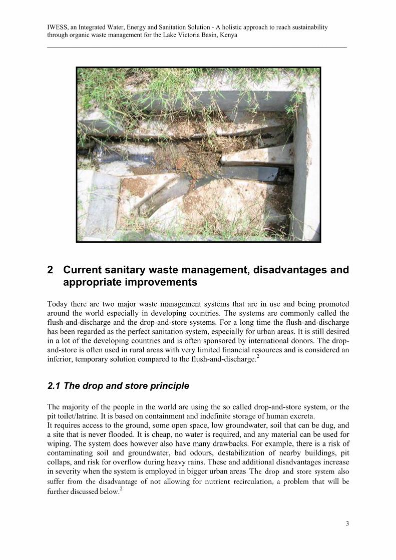
Today there are two major waste management systems that are in use and being promoted around the world especially in developing countries. The systems are commonly called the flush-and-discharge and the drop-and-store systems. For a long time the flush-and-discharge has been regarded as the perfect sanitation system, especially for urban areas. It is still desired in a lot of the developing countries and is often sponsored by international donors. The drop-and-store is often used in rural areas with very limited financial resources and is considered an inferior, temporary solution compared to the flush-and-discharge.2
2.1 The drop and store principle
The majority of the people in the world are using the so called drop-and-store system, or the pit toilet/latrine. It is based on containment and indefinite storage of human excreta. It requires access to the ground, some open space, low groundwater, soil that can be dug, and a site that is never flooded. It is cheap, no water is required, and any material can be used for wiping. The system does however also have many drawbacks. For example, there is a risk of contaminating soil and groundwater, bad odours, destabilization of nearby buildings, pit collaps, and risk for overflow during heavy rains. These and additional disadvantages increase in severity when the system is employed in bigger urban areas The drop and store system also suffer from the disadvantage of not allowing for nutrient recirculation, a problem that will be further discussed below.2

Chapter 2 – Current sanitary waste management, disadvantages and appropriate improvements ___________________________________________________________________________
4
2.2 The Flush and discharge/MIFSLA system principle
The flush and discharge system principle most common in urban and developed areas is both highly energy consuming and inefficient concerning the transportation and the centralized processing and disposal of the treatment products. This traditional waste management system follows a principle which
can be called MIFSLA, short for MIx First and Separate Later. It’s principles or method can also be referred to as an energy consuming problem mover since the only thing accomplished is a transportation followed by a separation of the waste which from the beginning was not mixed. This method also uses large volumes of treated water for the transportation only and it does not involve any solution for a recirculation of nutrients, mainly phosphorous, back to the agriculture. 3
In one year the average person using the MIFSLA system flushes 400-500 litres of urine and 50 litres of faeces together with 15 000 litres of pure water. The mix called black water is then mixed again with an additional 15 000 – 30 000 litres of water from bath, kitchen and laundry water – referred to as grey water. Before arriving to the treatment plant more water from industries and storm-water run-off are added along with distribution pipe infiltration caused
by insufficient sealing and cracks due to poor maintenance. The dangerous component, the 50 litres of faeces, is contaminating not only the urine but also tens of thousands of litres of almost clean water.3
Figure 1: Waste water constituent distribution, showing the by volume small parts of feaces and urine mixed with large volume of flushing water and grey water.3
Figure 2.2: Illustration showing the principles of flush and discharge, whereby the waste water constituents are mixed only to be separated later in an energy consuming process

IWESS, an Integrated Water, Energy and Sanitation Solution - A holistic approach to reach sustainability through organic waste management for the Lake Victoria Basin, Kenya ___________________________________________________________________________
5
The system most commonly used in the developed world is this type of flush-and-discharge method with the principle of mixing grey water and black water, transporting it, and later treating it in a centralized plant. This traditional waste management principle has also been employed in most of the larger urban settlements of developing countries. Since the financial requirements related to the management of such a system are very high the outcome is not rarely a complete failure of the finalizing treatment step with the even worse result that over 90% of all sewage in the developing world is discharged completely untreated. If however treatment is carried out the purified water exiting the treatment plants is more polluted than all of the single added components initially mixed except from the faeces.3
Chapter 3 – IWESS - Integrated Water Energy and Sanitation Solution ___________________________________________________________________________
6
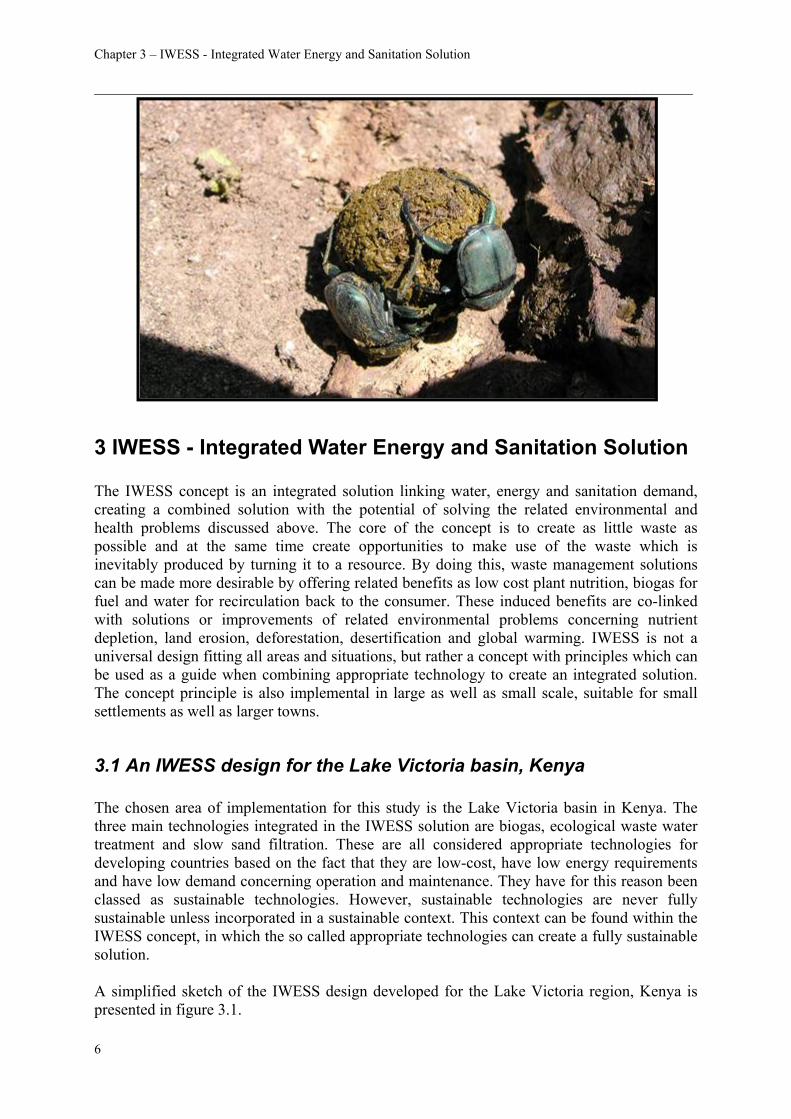
3 IWESS - Integrated Water Energy and Sanitation Solution The IWESS concept is an integrated solution linking water, energy and sanitation demand, creating a combined solution with the potential of solving the related environmental and health problems discussed above. The core of the concept is to create as little waste as possible and at the same time create opportunities to make use of the waste which is inevitably produced by turning it to a resource. By doing this, waste management solutions can be made more desirable by offering related benefits as low cost plant nutrition, biogas for fuel and water for recirculation back to the consumer. These induced benefits are co-linked with solutions or improvements of related environmental problems concerning nutrient depletion, land erosion, deforestation, desertification and global warming. IWESS is not a universal design fitting all areas and situations, but rather a concept with principles which can be used as a guide when combining appropriate technology to create an integrated solution. The concept principle is also implemental in large as well as small scale, suitable for small settlements as well as larger towns.
3.1 An IWESS design for the Lake Victoria basin, Kenya The chosen area of implementation for this study is the Lake Victoria basin in Kenya. The three main technologies integrated in the IWESS solution are biogas, ecological waste water treatment and slow sand filtration. These are all considered appropriate technologies for developing countries based on the fact that they are low-cost, have low energy requirements and have low demand concerning operation and maintenance. They have for this reason been classed as sustainable technologies. However, sustainable technologies are never fully sustainable unless incorporated in a sustainable context. This context can be found within the IWESS concept, in which the so called appropriate technologies can create a fully sustainable solution. A simplified sketch of the IWESS design developed for the Lake Victoria region, Kenya is presented in figure 3.1.

IWESS, an Integrated Water, Energy and Sanitation Solution - A holistic approach to reach sustainability through organic waste management for the Lake Victoria Basin, Kenya ___________________________________________________________________________
7
Consumer
AgricultureBiogas
Ecological waste water treatment
Slow sand filter
Water
Grey water
Fuel
Food
Fertilizer
Organic
waste
Hum
an waste
As can be seen in the figure full source separation is incorporated in the system by installation of separate piping. The grey water is conveyed to an ecological treatment plant, where it is purified to a quality sufficiently good for recirculation back to the system to be used as grey water again. The ecological treatment plant can be designed to include additional benefits which take advantage of the remaining nutrients left in the grey water. Aquaculture applications can be used to re-circulate these nutrients either through the biogas system or by direct consumption. The design of the ecological treatment plant depends on a number of factors further discussed in chapter 5. To replace water lost by evapotranspiration, and to prevent salt accumulation in the system water is added either by rain water harvesting or from any other available water source. An appropriate quantity of the water purified in the grey water treatment step can be additionally treated by an added slow sand filter, producing a water of a quality sufficiently good for potable use. The design of slow sand filter systems are discussed further in chapter 6. The human waste produced (faeces and urine) is transported trough a separate sewage system to the biogas system. These products together with the organic waste produced are digested to produce a pathogen free plant nutrition which allows for the nutrients to be re-circulated to the food producing agriculture. As an additional benefit biogas will be produced offering a renewable and nearly emission free source of fuel. In order to make the organic waste available for digestion a source separation is also necessary for the dry waste. This could
Figure 3.1: Principal illustration of an IWESS concept suitable for installation in Kenya. The figure shows that recirculation is possible of all included constituents.

Chapter 3 – IWESS - Integrated Water Energy and Sanitation Solution ___________________________________________________________________________
8
simply be arranged for by dividing the waste products into organic and inorganic components, much like the systems being developed in the western world today. The design of suitable biogas systems are discussed further in chapter 4. As the figure illustrates this concept will allow for recirculation of almost all wastes produced, both nutrients and water. The associated benefits will be a more energy efficient system, hence more economical. The load on external resources will also be dramatically reduced.
IWESS, an Integrated Water, Energy and Sanitation Solution - A holistic approach to reach sustainability through organic waste management for the Lake Victoria Basin, Kenya ___________________________________________________________________________
9
4 Biogas system for the IWESS concept
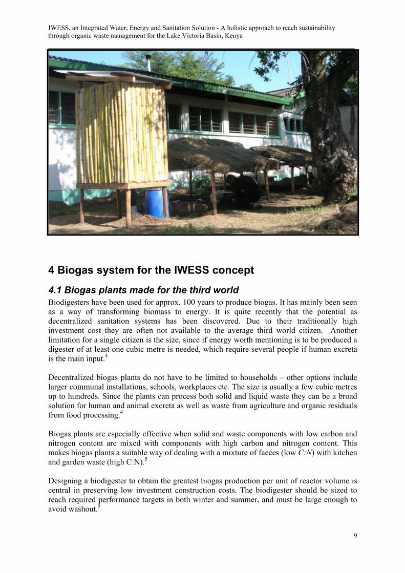
4.1 Biogas plants made for the third world Biodigesters have been used for approx. 100 years to produce biogas. It has mainly been seen as a way of transforming biomass to energy. It is quite recently that the potential as decentralized sanitation systems has been discovered. Due to their traditionally high investment cost they are often not available to the average third world citizen. Another limitation for a single citizen is the size, since if energy worth mentioning is to be produced a digester of at least one cubic metre is needed, which require several people if human excreta is the main input.4
Decentralized biogas plants do not have to be limited to households – other options include larger communal installations, schools, workplaces etc. The size is usually a few cubic metres up to hundreds. Since the plants can process both solid and liquid waste they can be a broad solution for human and animal excreta as well as waste from agriculture and organic residuals from food processing.4
Biogas plants are especially effective when solid and waste components with low carbon and nitrogen content are mixed with components with high carbon and nitrogen content. This makes biogas plants a suitable way of dealing with a mixture of faeces (low C:N) with kitchen and garden waste (high C:N).5
Designing a biodigester to obtain the greatest biogas production per unit of reactor volume is central in preserving low investment construction costs. The biodigester should be sized to reach required performance targets in both winter and summer, and must be large enough to avoid washout.5

Chapter 4 - Biogas system for the IWESS concept ___________________________________________________________________________
10
4.2 Individual Benefits Using biogas technology generates several benefits for the consumer. They can be structured down to three main categories - each highly integrated with the other. The categories are:
• Removal of waste • Energy • Effluent
For comparison, most sanitation system can generate two of the benefits but seldom three. The removal of waste, being the main purpose when talking sanitation, is obvious. Energy can be obtained, as in traditionally India where cow dung is being burned as fuel. The usable effluent can be obtained in systems like the eco-san where the waste is composed and later used as fertilizer.4
Biogas also generates several positive spinoff effects for communities, the environment etc. Examples include work opportunities generated by the construction and forests not being cut down for charcoal.4
4.2.1 Removal of waste Waste product from farms and ordinary households are highly contaminated by pathogenic microorganism and are as a result of this harmful for animals and humans. Wastes such as animal and human excreta, reminder of slaughter, and other organic rest are infected by bacteria, fungal spores, parasite eggs and viruses. If the waste is disposed by land application these microorganisms may pollute equipment, soil, and surface water.4
The pathogens are a threat to family members, farmers, consumers, as well as animals. Prophylactic treatment, such as medication, can help control pathogens. But these treatment are not only expensive they are less effective as drug resistance can build up in the microorganisms. A treatment process is needed to destroy pathogens consequently protect environmental health.4
4.2.1.1 Bacteria Experiments have shown that the anaerobic thermophilic process reduces coli form bacteria by 6-7 logarithmic units, and salmonellae to below the level that are usually detectable.10 The needed retention time varies and is often unpredictable. At mesophilic digestion the time needed to kill 90% of the bacteria can be referred to as “days” in contrast to weeks and months in conventional treatment.6
Picture 4.1: Biogas plant near Nairobi, Kenya.

IWESS, an Integrated Water, Energy and Sanitation Solution - A holistic approach to reach sustainability through organic waste management for the Lake Victoria Basin, Kenya ___________________________________________________________________________
11
4.2.1.2 Virus Human enteric viruses are virtually all the time present in sewage, and remain active in numerous conventional-treatments. It is believed that viruses affecting animals are present in animal waste although there have not been so many studies. Some viruses are able to remain active in nature for a long time and they migrate freely in ground water. Viruses are therefore posing a risk for ground water contamination if waste is emptied untreated in the environment.10 The ability to absorb to solids in waste is a major problem and prolongs the survival time during treatment. Studies have shown that several enteric viruses are more or less inactive during anaerobic treatment.4
4.2.1.3 Fungi The studies related to fungi and fungi destruction in waste treatment processes is often debated and the end result is today uncertain. Clear is that they can be found in various sludge and effluents from municipal waste treatment plants. Only one study have been published where pathogenic fungus was seeded into an anaerobic digester and followed during the viability. A 99% loss of the viability was detected after 28 hours in a mesophyllic anaerobic digester.4
4.2.1.4 Parasitic protozoa and helminths Many of these organisms have a life cycle with a stage where they live in the animal gut, often as eggs, and are therefore often present in animal waste. The effect of anaerobic treatment varies depending on time and temperature. Anaerobic treatment often retards egg development since there is no oxygen present. Studies in China showed that the public health regarding protozoa and helminths in rural areas was improved when a large number of digesters were installed in the 1970s.4
4.2.1.5 Odour The biogas process also removes the odour from different kinds of overloaded and/or improperly managed kinds of storages. The odours from human and animal waste affect the air quality and may cause nucience for nearby communities. The odour is reduced since the volatile organic acids, which cause the odour, are consumed by the biogas producing bacteria.7
4.2.2 Energy The quality of biogas produced from household size plants depend on numerous factors. Examples of such factors are temperature, pH and pressure. To generalize, a digested medium with a high amount of carbohydrate results in a gas quality of 55% methane while a medium high in fats can generate gas with a content of 75% methane.4
With a calorific value of 9 000 kcal/m3 for pure methane biogas has a calorific value of 4 800 – 6 900 kcal/m3 at 15.5 °C and a pressure of one atmosphere. 1.33 – 1.87 m3 of biogas therefore has the same energy equivalent as 1 litre of gasoline fuel. The specific gravity is
Picture 4.2: Outlet at the pilot plant in Kendu Bay with effluent.

Chapter 4 - Biogas system for the IWESS concept ___________________________________________________________________________
12
86% of air and a flame speed factor of 11.1 – causing the flame to “lift off” if the burner is not design properly.4
Cooking and lightning has to be considered the primary use for domestic biogas. If biogas is used without compression, which is the common method, the stove has to be specially designed for biogas usage. Using biogas for lighting can be arranged by using a gas mantle or by generating electricity. The highest lamp efficiencies require a gas pressure of 4 kPa which today only can be reached with fixed dome digesters. Daily need for cooking is reported to be around 0.4 m3 per day and capita while lighting require 0.15 m3 per hour (100 candle power).4
Biogas can also be used as fuel in engines, for example water pumps, drive machinery or generate electricity. It can be used in both spark and compression engines. A spark ignition engine can easily be modified to run on biogas by using a gas carburettor and minor adjustment. If needed, additional fuels can be used. If the amount of biogas fluctuates or there is only a small amount available dual fuel diesel engines can be used. The engine starts with diesel and the portion of biogas is raised with time. If a mixture of 80 % biogas is used with 20% diesel 20% more horsepower’s are generated compared to an engine run only on diesel.4
The usual consumption for engines is approx. 0.45 m3 of biogas per horsepower-hour. If used for electricity approx. 0.75 m3 of biogas is consumed per kilowatt hour. The expected operation time is between 12 000 and 20 000 hours.4
A problem often encountered when using combustion engines is the corrosive effects of the hydrogen sulphide content of the biogas. However, engines have been run in China for five years without internal corrosion.4
4.2.3 Effluent Several economic evaluations have shown the importance of using not only the biogas but also the digested slurry. The insight of the importance to use the effluent is spreading in both the developed countries as well as the developing.4
Since digested sludge is decomposed and, to a high degree, separated into the different organic contents it acts as fast nutrient that can easily enter into the soil solution. It can therefore become immediately available to the plants. The sludge does not only serve as nutrients directly for the plants but also for the development of soil organisms.4
The effluent from a biogas digester contains approx. 1-12% solids and consists of refractory organics, new cells formed during digestion, and ash. The effluent can be used in its liquid or solid fractions, dried or as total slurry.4 It is much less odorous compared to the influent. A proper retention time will remove almost all odorous substances.8
None of the nutrition, such as nitrogen, phosphorous, potassium and magnesium, or the trace elements essential to plant growth, is removed during the digestion process. The C:N ratio is lowered due to loss of carbon. This is generally an improvement in terms of fertilizing since a C:N ration of 1:15 has a favourable phytophysiological effect. The level of phosphate is not affected either. Approx. 50% of the total phosphate is available as nutrition in the form of P2O5. Likewise, the level of available potstassium is not affected by anaerobic fermentation.4
The slurry can be used as fertilizer all year round but is most effective when spread on fields shortly before the beginning of the vegetation period. More slurry can be spread during the

IWESS, an Integrated Water, Energy and Sanitation Solution - A holistic approach to reach sustainability through organic waste management for the Lake Victoria Basin, Kenya ___________________________________________________________________________
13
growth phase but should be avoided when/if leafs are developed due to hygiene. Each hectare require a dose of about 33 kg N, 11 kg P2O5 and 48 kg K2O to compensate for an annual yield of 1-1.2 tons of, for example, sorghum or peanuts. Each hectare would then need 3-6 tons of solid substance depending on the nutrive content. If slurry with a TS quote of 10% is used 30-60 tons would be needed.4
Studies have reviled that using digested slurry as fertilizer increase the yields by 6-10%, regardless of kinds of soils. Long-time experiments have showed that the chemical and physical properties were enhanced markedly after a few years with regular fertilizing with digested slurry. The yields were 11-20% higher than control crops. The results are approx. the same as for using compost (for example from an ecco-san toilet) but digested slurry does not increase the salinity of the soil end reduce residual effects in the long term.4
Biogas effluent can also be used as fertilizer for fishponds. The nutrients stimulate the growth of phytoplankton and zooplankton, which the fish reap. Studies have reviled that tilapia seems to be one of the most suitable fishes for this purpose.4
4.3 Biogas in an integrated system In order to make the biogas system more efficient the harvesting and use of biomass need to be incorporated in an integrated source recovery plan. A biogas system can be build and used in numerous possible integrated systems. Variable factors include feed, biogas technique and the use of biogas and slurry. One of the complex integrated systems is the relation between fuel, food and fertilizer.4
If fuel is the wanted key advantage from a biogas system the nutrients in the slurry can either be used to grow feedstock that generates remains to be used as feeding or the nutrients can be used to grow feedstock that the system can be fed upon directly. This is an example on how, although all components of the material are used, the result is not the most profitable one. The usage of the biogas also affects the production of fuel. If the gas is used only for cooking and lighting no positive effects are added to the production of engine fuel. If the gas on the other hand is used in a dual fuel engine, the power can be used to water fields with improved agricultural remaining available for digestion. Also, if an engine is used the waste heat can be used to heat the digester resulting in improved production of gas. The net outcome could be an energy loop, leading to enlarged quantity of energy obtainable from a set quantity of land.4

Chapter 4 - Biogas system for the IWESS concept ___________________________________________________________________________
14
4.4 Pilot site in Kendu Bay, Kenya
4.4.1 Background During the late spring of 2007 a pilot site was built at the Kendu Adventist Hospital located in western Kenya in the Rachuonyo district approx. 5 km south of Kendu bay town allong the kendu Bay-Oyugis road (00˚ 24.086’ S and 34 39.872’ E). The main purpose was to evaluate the concept, and in particular the latrine connection, the construction methods, and the stove. Since the hospital management has been searching for a biogas solution for many years it also serves the purpose of evaluating the acceptance and usage possibilities of the hospital staff, in particular the personnel working in the hospital kitchen. The main responsibility for the construction was laid on the students from the University of Skövde, the students from Nairobi have the maintenance and monitoring as their main responsibility.
4.4.2 Overview of plant The black water and organic waste from the hospital kitchen will be separated and treated in a plug flow biogas system. The system consists of a digester lying parallel to the ground with two inlets, one for the latrine and one for the kitchen waste. The system has an outlet for the gas which is connected to a PVC-bladder for storage. There is also an outlet for the digester effluent which enables easy collection. Through the centre of the digester there is an axle fitted with stirring blades for mixing of the slurry. The digester is continuously fed with waste every day, maintaining a plug flow movement and ensuring a stable retention time. When the slurry exists after 30 days it has been completely digested. The digester has a total volume of 1 m³ and is fed daily with 25 litres of waste mixed with water. A good mixture of the wastes is guaranteed by a mixing chamber with rotating blades. To ensure a handling of the waste that is safe in a view of pathogen exposure, a latrine is built with a connection to the mixing chamber. The latrine was built of bamboo – the same plant used in the constructed wetland – to promote its abilities and capacity. See picture A.1.1, Appendix for a schematic sketch. Each day about one cubic meter of biogas with a quality of 60 percent of methane should be produced. Thanks to a very energy efficient stove isolated with clay this volume is sufficient to cover the daily cooking needs for a household of six to seven people. The digester design has several advantages compared to other types. In most digesters the slurry is mixed horizontally, with the consequence that some of the slurry is exited after a short period of time. In the pilot design the slurry will form a plug slowly moving forward giving a guarantee that the slurry stays for the desired 30 days – producing a hygienic and pathogen-free effluent.
4.4.3 Operation
4.4.3.1 Start-up Procedure The first filling of a new biogas plant should consist of either slurry from an operational plant or cattle dung. Cattle dung is partially digested and the process will continue if transferred to a biogas plant. If cattle dung is used it should be diluted with water, preferably in the ratio 1:1. However, if enough dung cannot be found, it can be diluted more to enlarge the quantity of filling slurry. Following the filling the plant might need anything from days to weeks to achieve a stable production.

IWESS, an Integrated Water, Energy and Sanitation Solution - A holistic approach to reach sustainability through organic waste management for the Lake Victoria Basin, Kenya ___________________________________________________________________________
15
The period after the filling is characterized by:9
• Low quality biogas containing more than 60 % CO2 • Very odorous biogas • Sinking pH • Irregular gas production
The process will stabilize more quickly if the slurry is mixed quite often and intensive. If the process is extremely resistant to stabilisation cattle dung or lime can be added. Preferably no more biomass should be added during the starting phase. Once the process has stabilized, there will be a great rate of gas due to the big amount of unfermented biomass. When the gas production is being lowered because of lack of unfermented biogas regular feeding can commence.8
Biogas with a low quantity of oxygen poses a risk of explosion, therefore should the two first fillings of the storage bladder be emptied without being combusted. The following gas can be used for the intended purposes.9
Start-up procedure of the pilot plant The pilot plant was filled during almost a week due to lack of cattle dung. A shortage of storage containers also made it hard to store the product before the plant was finished. During the fed the cattle dung was mixed with approx. 2/3 of water and mixed properly. Three days later the gas production was so intense that the outlet hose created bubbles when lowered into a water filled bottle. As expected it was very odorous with the distinctive smell of sulphur. The bladder was connected and during the first days it was expanding while being filled with gas. One week after the bladder was connected the expansion ended and it was believed that the process had now stabilised. The feeding of 30 litres each day commenced. However, it was fed by a mixture of cow dung and water instead of a mixture of toilet and kitchen waste. The reasons were two. First, the latrine was not yet constructed due to a delay mainly caused by a lack of bamboo - the intentioned construction material. Secondly, if the plant needed any modifications after the first filling cow dung was considered safer to handle rather than human excrement. After one week of daily feeding and maintenance there was still no gas production from the pilot plant. It was believed to be a mechanical failure rather than a chemical or biological error with the process. The reason for the suspicion was the inlet and outlet that kept clogging from cow dung. It was in need of daily clearing and this could be an indicator of more stiffed cow dung inside the digester – leading to layers causing the fresh cow dung to go through the plug flow in shorter time than calculated. After the system had been emptied and the diameter of the inlet and outlet had been enlarged the system was filled once again. This time it is believed that the process went sour due to an to early daily fed.* After ten days of rest for stabilisation the yield of biogas was commenced and raised during the last four days of the field study. Local contacts have reported that the process stabilised and the gas is combustible.
* Björn Martén, GEIST-swedish biogas organization, interview 2007-05-10

Chapter 4 - Biogas system for the IWESS concept ___________________________________________________________________________
16
4.4.3.2 Feeding The two main sources for waste to put in the biogas plant are the kitchen and the latrine. A grease trap in the nearby constructed wetland is also used but it is unclear how much fat that can be produced from it.
Kitchen waste An examination of the kitchen waste show that it contains mainly beans, ugali (porridge made from maize flour or similar) and sukumawiki (a vegetable, quite similar to spinach). An analysis performed by Mr. Paul Mboya at the University of Nairobi shows that they have a quite similar solid content. The feeding calculations have therefore been simplified by calculating a mean value, see table 4.1.
Waste Total Solids (TS) [%] Volatile Solids (VS) of TS [%]Beans 58.9 91Ugali 48.6 97Sukumawiki 37.2 99Mean value 48.2 94
Compared to general list values the analysis has to be considered quite un-accurate. Beans, for example, usually have a TS value of 41.7%10 and vegetables usually have VS-values of 86-92%11. The result of the analysis has therefore been rounded down to the first ten-value – giving the following numbers for the calculations: TS of kitchen waste: 40% VS of kitchen waste: 90% Before being entered into the system the kitchen waste needs to be grinded. This is done by a meat grinder installed in connection with the plant.
Toilet waste At the pilot plant, the critical source is the toilet waste. Although a lot of people are in the vicinity most of them prefer the conventional toilets (water closets). Today only two people are using the latrine. The amount of faeces and urine produced per capita per day may vary for different regions. Reasons for this can be different dietary habits and climate conditions. In Africa the amount of faeces is approx. 400 g/cap/d and approx. 1 200 g/cap/d of urine.12
List values regarding solids for human waste, see table 4.2, reveals the following:
Waste Total Solids (TS) [%] Volatile Solids (VS) of TS [%]Excrement 12 85%
Urine 2 85%
Table 4.1: Analysis results of solid test.
Table 4.2: TS and VS values for human waste.13

IWESS, an Integrated Water, Energy and Sanitation Solution - A holistic approach to reach sustainability through organic waste management for the Lake Victoria Basin, Kenya ___________________________________________________________________________
17
4.4.3.3 Feeding of the pilot plant The biogas plant is fed with kitchen waste once every day. A feeding of three-four times per day would be preferred, from a bacteriological point of view, but it is difficult since the amount added depends on the amount that has entered from the latrine and lack of time for the local caretaker. The bucket at the digester-outlet can be used to measure how much the latrine has been used – as long as it is emptied each time kitchen waste is entered. However, since so few are using the latrine the little amount do not make such a big difference at the liquid level – due to the comparatively large surface area. List values are therefore used to calculate the amount of human waste. The desired TS-quote for a plug-flow digester is 10-13 % according to different sources.14,15
The mean value 11.5% is used in the calculations. Since the density of the solids is close to the density of water, one litre of water is considered to have the same weight as one litre of waste – regardless of TS-quote. The human waste, consisting of excrement and urine, is the critical source so this should be used primarily with the kitchen waste used to reach the desired volume. The effective volume, Ve, is calculated using equation 4.1:
KVV te += (4.1)
Where: Vt = Total volume, 1 000 l K = ¾, a constant used to create enough free volume inside the digester. This gives:
lVe 750≈ The daily feed, F, is calculated by dividing the effective volume with the retention time, R, in this case 30 days – a common time when using plug flow-digesters operating at the mesophilic temperature range, see equation 5.2.4
RVF e= (5.2)

Chapter 4 - Biogas system for the IWESS concept ___________________________________________________________________________
18
Which gives:
daylF /25=
The daily feed can also be written as in equation 4.3.
AWF += (4.3) Where: W = The total waste entered each day A = The amount of water added each day. To find the daily fed amount of total solids added each day, S, is calculated using equation 4.4:
FTSS = (4.4)
Where: TS = The mean TS-quote for a plug-flow digester calculated earlier to approx. 11.5% Which gives:
daylS /9.2≈
The human waste, Weu, consist of excrement, We, and urine, Wu, and is the critical source which should be used primarily with kitchen waste, Wk, used to complete the desired volume. The relation between the different wastes can be written as in equation 4.5:
kuekeu WWWWWW ++=+= (4.5)
The list values for human waste, stated previously, are used to calculate the waste inputs. The amount of solids in the human waste, SWeu is calculated by insertion of the TS values from table 4.2 into equation 4.6.
ueue WWSw 02.012.0 += (4.6)

IWESS, an Integrated Water, Energy and Sanitation Solution - A holistic approach to reach sustainability through organic waste management for the Lake Victoria Basin, Kenya ___________________________________________________________________________
19
Which gives:
daygSweu /144≈ The solids needed to be entered via the kitchen waste, SWk, to reach the desirable TS-quote can then be calculated by extraction from equation 4.7.
keu SwSwS += (4.7)
Where: S = 2.9l/day
Which gives:
daykgSwk /7.2≈
Using the mean value of the TS-quote for the kitchen waste (40%), the desirable volume of kitchen waste entered each day can be calculated using equation 4.8.
4.0kk SwW = (4.8)
Which gives:
daylWk /8.6≈ The volume of water to be added each day is calculated by rearranging equation 4.3 and inserting it in equation 4.5. which gives:
daylWWWFA kue /15)( ≈++−=
To summarise, each day the pilot plant should be filled with approx. 7 l of kitchen waste and approx. 15 l of water – if the two persons continue using the latrine each day.

Chapter 4 - Biogas system for the IWESS concept ___________________________________________________________________________
20
Note: The grease from the grease trap has been disregarded due to the presumed small quantity. When enough grease has been collected, approx. 1 l, the amount can be added without any more precise calculations than a subtraction of one litre from the added kitchen waste.
4.4.3.2 Calculated loading rate for pilot plant The loading rate for a plug flow-digester is recommended between 1 up to 2.5 kg/VS per m3 of total volume of digester per day but small scale plants have been confirmed to operate up to 6.5 kg/VS per m3 of total volume of digester per day. If the plant is overfed with volatile solids the process might turn sour – lowering the production of gas.16
The amount of volatile solids in the human waste, VWeu, is calculated by multiplying the value for SWeu with the value for volatile solids from table 4.2. Which gives:
VSgSwVw eueu /4.12285.0 == per m3 of total volum f digesr per day The amount of volatile solids in the kitchen waste, VWk, is calculated by combining the value for SWk with the value for volatile solids in table 4.1:
VsKgSwV kwk /43.29.0 =+= pr m3 of total volume of digester pr day
Adding the two kinds of waste the total loading rate, is determined:
VSKgVwVwV keu /6.2≈+= per m3 of total volum of digester per day
4.4.5 Construction materials and methods Different plastic materials and different manufacturing methods have different durability when they are exposed to aggressive slurry, mechanical stress and UV radiation, as well as their gas permeability.
4.4.5.1 Plastic Traditional materials for biogas plants include concrete, bricks, and steel. All of them are often heavy, expensive, and hard to repair. Digesters made out of Glass-fibre reinforced plastic (GRP) have been used in several successive plants, as long as in-service static stresses are accounted for in the manufacturing procedure. The digesters made from GRP are very resistant to corrosion and seldom create problems with the gas-tightness.17 But recent studies have showed that GRP have a tendency of getting cracks between the fibres.*
Different kinds of plastic material have been more widespread during the last years but are rumoured to be expensive. Plastic can be expansive but do not have to be. A source of plastic

IWESS, an Integrated Water, Energy and Sanitation Solution - A holistic approach to reach sustainability through organic waste management for the Lake Victoria Basin, Kenya ___________________________________________________________________________
21
used in the pilot site was “blue barrels”. They are used as containers for soap, candy, paint, and other chemicals and are then exposed of and treated as garbage. Plastic combined with a small plastic welder can build all kinds of gas tight containers of different shapes and looks. An ordinary drum can be completely sealed, have inlets and outlets added together with taps and hatchets for samples. As long as there is access to electric power the possibilities are very broad.
HDPE Containers suitable for modification come in a variety of different plastics. PVC is common but unsuitable due to its sensitivity against UV-radiation. A type of plastic often used in containers, especially bigger ones, is poly ethylene (PE) and similar types. If mixed with stabilizers it provides a good protection against UV-radiation.18
High density polyethylene (HDPE) is the high density version of PE plastic. It is harder, stronger and a little heavier than low density polyethylene and PE, but less ductile. It can be molded, machined, and joined together using welding, but it is quite difficult to glue. The appearance is wax-like and matte in color. The use of UV-stabilization (carbon black) improves its weather resistance but turns it black. It can be identified by the smell after it has been burned or melted – it should smell like candle wax.19
Used HDPE plastic can be recycled through re-melting although there is a quality loss. Incineration is straightforward and comparable to oil, since HDPE only consists of hydrogen and carbon atoms. However common additives like UV-stabilizators, dyeing agents and fire protectors can produce other waste products. The heating value is equivalent to 3/4 kg of oil.19 The quality loss when remelting can often be found on cheaper containers. See digester under detailed description in chapter 4.4.6.3.
Plastic Welding The welder used was a Leiser Triac S. It heats the material from 20˚C-700˚C, has an electronic heating element protection, an automatic safety shut off at low carbon levels, and is very suitable for continues operation. The low weight (1.4 kg) makes it possible to transport both internationally as well as locally.19 The drawback is the need for electrical power, something that can be very unreliable in Africa. Since welding requires plastic materials of the same type, rods were cut out off the utensils supposed to be joined together, and after joined the seam should have 90% of the material strength. 19
4.4.5.2 EPDM-rubber Ethylene propylene diene monomer (EPDM) is a sturdy membrane developed over 20 years ago. EPDM display good elongation characteristics and high tensile strength. Compared to
Picture 4.3:Using the plastic welding machine.

Chapter 4 - Biogas system for the IWESS concept ___________________________________________________________________________
22
other kinds of rubber of the same thickness it shows a good resistance to punctures, UV radiation, weathering and microbial attack. It does not expand or shrink much when exposed to different temperatures thus enabling it to lay flat on surfaces in bigger sheets. The cost of the material is approx. 15 USD per square metre. 20
Factory seams are vulcanised but it is possible to glue it with rubber cement. Welding is also an option.20
4.4.6 Detailed description
4.4.6.1 Latrine To ensure that the human waste can enter the digester without human contact a latrine was built. The frame is constructed with cedar-poles, which is considered to be a very durable wood, even when it is in contact with the ground.21 On the poles, a frame made from blue gum (a type of eucalyptus) was placed. Blue gum originates from Tasmania but has been planted around the world, making it a common building material in the region. It is very hard and is associated with high quality.22 The material used for the walling is the giant bamboo. By using bamboo the material and its abilities is promoted and the benefits of including it as a harvestable treatment plant in the constructed wetland system is showcased. A lot of materials were discussed for the roof but finally an iron sheet was used. It is cheap, durable, and in the region it is associated with very high quality. The latrine connection requires some height so the latrine is built approx. 70 cm above ground and is entered by stairs. Since hygiene is essential a sink was built from 200 mm HDPE pipe and joined with the latrine connection. It is also serving as ventilation, with a small piece of mosquito net on the out-let to prevent flies etc. to enter. Water for washing hands has been placed in a bucket under the ceiling with a tap placed just above the sink. A universal hose connects the two together. A sketch of the latrine can be found in picture A.1.2, Appendix.
4.4.6.2 Mixing chamber The main idea of the system is to take care of two kinds of wastes, kitchen waste and toilet waste. The two kinds of waste needs to be mixed with each other before entering the digester to ensure a homogenic mixture, concerning, solids, carbon/nitrogen, etc. Constructed from a 160 litres blue barrel made of HDPE it has two inlets and one outlet. One inlet for the toilet waste (with the opening inside the latrine) and one inlet on top of the barrel for kitchen waste. The latrine inlet is placed higher than the top of the barrel to ensure that a stop in the outlet will not flood the latrine with waste. The outlet goes to the digester via a 150 mm pipe and is protected by a sheet of plastic welded in the bottom and walls of the mixing chamber. The purpose is to
Figure 4.1: One of the mixing blades.

IWESS, an Integrated Water, Energy and Sanitation Solution - A holistic approach to reach sustainability through organic waste management for the Lake Victoria Basin, Kenya ___________________________________________________________________________
23
ensure the waste is not leaving straight into the digester without being mixed first. The stirring axle is made from a 25 mm PVC pipe with four blades made from HDPE attached to the axle with copper wire. The two lower are shaped to create a flow upwards while the upper two are shaped to create a flow downwards. This enhances the flow and creates a powerful blending effect between the two middle blades. The top of the barrel is easy to remove thanks to a snap-on lid. However, it is designed to be removed only during service – the waste can be poured down into the chamber thanks to a hole in the lid with a removable top, made from a 200 mm HDPE pipe and plastic leftovers. The handle to the stirring axle is removable and joined to the axle with two pins made from stainless steel. A pin has also been placed directly under the lid to avoid the axle from being pulled up from the footing. Finally, a plastic arrow was welded to the lid to make sure that the handle is pulled in the right direction. A sketch of the mixing chamber can be found as picture A.1.3, Appendix.
4.4.6.3 Digester To create the actual digester two water tanks from Kentank was used. They come in a variety of volumes, in this case 500 litres. They are produced locally in Kenya and are very similar to other local brands, such as Kentainers, Roto Moulders, etc. They are built with two layers, a blue PVC layer on the inside and a black PE layer on the outside, with a total thickness of three millimetres. To create the plug-flow digester the bottoms of the tanks were removed, only leaving a vertical piece to stabilize the stirring axle, and welded together. The top parts from two 160 litres HDPE barrels were then removed and welded to the opening making it possible to enclose the digester with two snap-lids. An inlet and outlet was created with two 150 millimetre holes. To keep the system modular and easy to disassemble two elbows made from sheets of HDPE was welded to them. A PVC pipe with a matching outer diameter was then pushed from the hole in the mixing chamber to an
Figure 4.2: Top detail of mixing chamber. The mixing handle has insertions on top to facilitate assembling after being removed.
Picture 4.4: One of the tanks before modification.

Chapter 4 - Biogas system for the IWESS concept ___________________________________________________________________________
24
elbow in the digester inlet. To make it water tight a 3 millimetre PVC membrane was used. At the outlet a PVC pipe, with the end in the same level as the liquid level in the digester, was inserted into the elbow. A sketch of the digester can be found as picture A.1.3, Appendix. A plug flow digester needs vertical stirring without affecting the horizontal flow. An axle made from 25 mm PVC was therefore placed in the middle of the digester. Sheets of HDPE plastics have been formed as paddles. The main idea is similar to the blades in the mixing chamber, but these are not designed to create a flow. The most important purpose is to break the surface thus hindering foam to be established on the surface. If foam is created it can quickly grow to a height of 1-2 meters in less than 30 minutes. When the foam dries pieces sturdy enough to walk on will form.23 Another purpose of the stirring is to homogenise the slurry, since different densities can create layers in the digester. A see-through of the digester can be found as picture A.1.4, Appendix. The axle is inserted into a footing on the inside of one end of the digester and the other end is pulled trough the other end trough a bushing to enable to turn the attached handle. The handle is placed on the outlet side of the digester, since digested and pathogen free slurry is preferred before inlet slurry in case of leakage trough the bushing. The level of the axle is below the liquid level, thus preventing the valuable gas to reach the surroundings. The axle bushing was made with the help of a PVC-union fitted with O-rings. Two short pipes were placed at both ends and the space between them was filled with organic grease. The gas outlet was placed at the top of the digester at the slurry outlet side. A small plastic union made from PE was welded in a small hole. The plastic union was of a type often found used for laboratory equipment.
4.4.6.4 Storage bladder As gas-holder a bladder constructed from EPDM membrane was used, see Figure A.1.1, Appendix. The bladder was welded from a big sheet of rubber using the same methods and tools as the plastic welding. Silicone was also applied to ensure that it was completely gas tight. As outlet/inlet a nozzle from a car tire inner tube was used. The volume is estimated to be approx. 1 m3. When installed the gas is pressurized by applying weight on the bladder. To protect the bladder it was placed in a shallow hole, no more than 20 cm deep which was covered with a roof of the same type as on the digester. The rubber is quite sturdy against wear caused by friction but a pointy object could puncture it fairly easy. If that would occur it is easy to repair using an ordinary puncture repair kit. A hole in the bladder could have severe consequences. It would not only waste energy – it can also be dangerous. A gas mixture of at least 5 % air can explode upon ignition.* Holes should
* Björn Martén, GEIST-swedish biogas organization, interview 2007-05-10
Picture 4.5: The finished digester being carried by four children to the site for installation.

IWESS, an Integrated Water, Energy and Sanitation Solution - A holistic approach to reach sustainability through organic waste management for the Lake Victoria Basin, Kenya ___________________________________________________________________________
25
therefore be repaired as soon as possible if they occur. Biogas is however lighter than air which makes it much less dangerous than for example LPG (Liquid Petrolium Gas).
4.4.6.5 Distribution of Gas and Water Seals An ordinary reinforced garden hose is used to distribute the gas from the digester to the bladder and onwards to the stove. When the gas exits the digester it will go through a water seal to the bladder. A t-connection is placed between the first water seal and the bladder. It is a three way connection and it is the same kind of laboratory equipment used to the gas outlet. After passing a second water seal the gas enters the stove. Hose clips are placed on the outside of all connections. The water seals have two purposes. The first is to protect against backflames – a phenomena that can happen when the stove is lit. Without protection the flame will then go through the pipes into the bladder causing an explosion or fire. The second purpose is to make sure that the gas only flows in one direction. When pressure is put on the bladder the gas go to the stove – not back into the digester. The water seals are made from a small plastic container with a screw on lid. A hole in the bottom and a hole near the top, each with a small plastic tube that the pipes can connect to. Water is then filled above the lower hole. The gas can now enter through the lower hole but not go back, since it would require a much greater force due to the large surface area of the water. The pressure inside the digester can now be adjusted by adjusting the amount of water. It works as a back flame protection by adding a gap of water in the continuous gas flow.
4.4.6.6 Stove A study of existing biogas systems show that most biogas stoves used in developing countries are highly ineffective. Many of them consist of a simple burner with an open flame heating standard aluminium or steel pots. The absence of insulation increases the energy demand significantly and this is one of the most important details when constructing an effective small scale biogas plant.4
The design used for the pilot system consists of a cover in clay – a widely used and inexpensive material. Holes in the bottom makes it possible for oxygen to enter and then exit from the holes near the top after passing the pot, thereby heating it as much as possible. The pot is a standard stainless
Picture 4.6: A common biogas stove. The lack of insulation makes it very ineffective.
Figure 4.3: One of the water seals.

Chapter 4 - Biogas system for the IWESS concept ___________________________________________________________________________
26
steel jar with lid imported from China. A bigger lid made from clay is placed on top to maximize the thermos effect. The burner consists of a welding hose with ball point pen ink cartridges as nozzles and a standard brass gas valve. The stove can be constructed by any established pottery. The molding of the clay will take less than one hour for a skilled pottery worker; however, it has to dry in a cool and dark environment for several weeks. The exact amount of weeks depends on different factors, for example weather and the moisture level of the clay. In the case of the field-study in Kenya the stove needed to dry for approximately four weeks. When the clay has dried it needs to be burned in a pottery stove. The need for a stove is not the only reason why an established pottery should be used. It is very hard to estimate the deformation the clay will undergo during the drying for a layman. A professional is also needed to establish and maintain the environment. The clay makes the stove quite fragile and it is as good as impossible to repair but due to the low cost it cannot be considered a big investment to buy a new one. Pieces of clay from an old stove will not cause any negative environmental effects either. Most of the non-clay components are easy to find spare parts to. The valve is standard and available on a big market, the welding hose is possible to find in every village with a welder, and the pen tips for the burner is available from ordinary pens. The stainless pot is hard to repair if it would brake – a new one is probably necessary. The stove is simple and easy to operate. When the valve handle is turned the gas can be ignited. The valve can then be used to adjust the flame until a desirable heat is attained. When the stove is in need of cleaning it could either be wiped with a wet rag or carefully washed with flowing water. A sketch of the stove can be found in Figure A.1.5, Appendix A.
4.4.6.7 Insulation Allthough heating is not an option due to increased costs and absent of energy (except the gas produced by the plant) insulation is vital to stabalize the temperature in the digester. The bio-methanation is very sensible to variations in temperature, especially in plants operating at low temperatures. In plants operating in the mesophilic range a variation of ± 1˚C/h is acceptable.*
To stabilize the temperature, and to some level give protection from external threats (animals, weather, children etc.) three methods were used to reduce the amount of moving air around the digester; a cradle with walls, a roof, and bags with grass. An sketch of the roofs and cradle can be found in Figure A.1.6, Appendix A.
Cradle with walls For further protection a cradle and walls made from bricks was constructed. The cradle reaches about 30 cm from the ground, allowing for air to insulate against the cool ground. The walls have been placed 20 cm from the side of the digester.
Roof To shield the digester from temperature variations caused by the sun, give extra insulation and protection from outer threats (animals, accidents caused by people etc.) a roof was placed on top. Using long-established methods decreases the price, guarantees a functional design, and adds a traditional touch to the modern system. The same type of roof was also constructed over the storage bladder – mainly for physical protection against people and accidents.
* Björn Martén, GEIST-swedish biogas organization, interview 2007-05-10

IWESS, an Integrated Water, Energy and Sanitation Solution - A holistic approach to reach sustainability through organic waste management for the Lake Victoria Basin, Kenya ___________________________________________________________________________
27
On top of poles of cedar a frame of blue gum was constructed. As support for the roofing a grid was laid made from sisal poles split into half. They are lightweight, durable, and cheap. Finally a thick layer of grass was put on top and attached with sisal yarn.
Bags of grass To add extra insulation, bags were filled with the same type of grass used on the roofs, and put on top of the digester. They are believed to give more temperature stabilization but until the temperature inside the digester cannot be measured their effectiveness is unknown.
4.4.7 Measuring modifications and analyses To keep an eye on the performance of the plant two modifications were added. The two modifications allow follow up on the temperature and samples from the slurry in different stages. Thermocouples were installed in the middle of the digester. The first thermocouple is placed in the centre, the second half way between the centre and inner surface, and the third on the inner surface. One is supposed to be mounted inside of the roof and the last one outside in an open area. This will give figures of the effectiveness of the temperature stabilization. The thermocouples used were of the type T (cupper/constantan). A data logger was supplied by the University of Nairobi, however, due to missing parts it could not be used during the field study. A study of the temperature and temperature variations will be made by students from the University of Nairobi when the data logger is complete. To take samples from the slurry three taps were installed on the sides of the digester (near the outlet, near the inlet, and one in the middle).By placing them at these positions tests can be done on slurry that have been inside for a few days, two weeks, and a few days before exit. The purpose is to monitor values that reveal information regarding the process. The hospital will make analyses concerning contents of e-coli and other bacteria. Due to lack of resources external analyses regarding parasites like worms, viruses, etc. will not be made. If needed the University of Nairobi can carry out pH-tests of the slurry and thereby identify which of the three steps that particular sample has reached.
4.4.9 Performance of the pilot plant
4.4.9.1 Overall The amount of gas produced is different to estimate for several reasons. The exact volume of the storage bladder is not known and it is not possible to make an accurate estimation on how full it is at the end of a specific time interval. The only absolute observation to be made is the expansion of the bladder and thus the gas being produced. Even if the exact volume being produced is known the methane content would still be unknown, i.e. the quality of the gas. Local contacts have been trying to make estimations but are very unsure of the accuracy. Based on the assumption that the storage bladder has an approx. volume of 1 m3 they estimate the daily yield to 250 litres – 800 litres. A few welding seams came loose during the field study but after being repaired when the plastic welding machine was still in the country no other failures have been reported.

Chapter 4 - Biogas system for the IWESS concept ___________________________________________________________________________
28
4.4.9.2 Latrine Most of the bamboo which could be found in the area was growing more or less without maintenance – making it quite curved and with a variable diameter. Double layers were used but still some narrow openings were impossible to avoid. In the drying process some of the opening expanded but could be covered with small pieces of bamboo. The curved characteristics made the material quite flexible and hard to get stiff, in particular when building the door. The other materials were quite sturdy and very hard. It is believed that the frame will be standing long after the walls have withered away. The only downside was the quite difficult and hard work of joining them together with the, quite soft, locally produced nails. Also, the lack of experience from both local workers as well as Swedish engineers did for sure affect the final creation as well.
4.4.9.3 Mixing chamber The outlet to the digester was originally a 50 mm HDPE pipe. It kept clogging and was later changed to the 150 mm PVC pipe. After the exchange no clogging has occurred. When the contents are mixed with the mixing device the substances in the latrine connection is sucked into the mixing chamber. However, toilet paper etc. need some time before arriving to the mixing chamber – the gravity pulls it rather than the mixing device. The wall design ensures a proper mixing of the wastes and also works as a gatherer for undigestible material – like straw and rocks. This is very useful in the start-up process since that kind of substances is quite common in cow dung. Originally the mixing blades were attached to the axle with four zip-ties per blade but most of them were broken after two weeks. It is believed the principle will work if more sturdy zip-ties are used. Unfortunate, they cannot be found locally near the construction site.
4.4.9.4 Digester The long term quality of the water collection tanks is uncertain. The tanks themselves have an outer layer which is full of pores - probably affecting the quality. They are also made to be used standing – not laid on the side in a horizontal position. The pressure on the side has caused the walls to bend outwards creating deformations on the top of the digester. The deformations will probably not cause cracks in the surface as long as they are not shifting. The major problem with the deformation is the stirring blades that touch them. If the deformations expand it might be hard to stir the slurry without damaging the axle. Local contacts have reported that it might be possible to remove the deformations by stiffen the digester by adding sheets of HDPE on the sides. But such an operation requires a plastic welding machine, something that is not locally available. The deformation of the digester could probably also be avoided by letting the cradle go further up on the sides of the digester. Like for the mixing chamber, the inlet and outlet pipes were originally 50 mm HDPE, but were later exchanged to 150 mm PVC. No problem of clogging or delayed exiting slurry has occurred after the exchange. No leakages have been reported from the digester. In the upper part of the digester, in the gas phase two possible sources for leaking exist. One is the gas outlet and the other is the joint between the two tanks. No smell of sulphur has been noticed and test with soup did not detect any escape of valuable gas.

IWESS, an Integrated Water, Energy and Sanitation Solution - A holistic approach to reach sustainability through organic waste management for the Lake Victoria Basin, Kenya ___________________________________________________________________________
29
In the lower and middle part, six possible sources for leakage exist. They are the inlet, the first lid, the joint between the tanks, the outlet, the second lid and the hole where the stirring axle go through. None of them have any leakage which is quite surprising. The hole for the axle was expected to generate a small leak but is has performed well over expectations. If a small leakage would occur in the lower and middle part it is not at major threat to the system in any way. The only downside is a risk for bad odour.
4.4.9.5 Storage bladder No signs of leakages have been reported. Biogas can have a relative high amount of water vapour and if it condensate in the bladder it can be quite hard to get it out again. But so far no water at all has been noticed inside the bladder.
4.4.9.6 Distribution of Gas and Water Seals No feedback has been received regarding the water seals with the conclusion that they work as intended. It is believed that the containers that the seals are built from are quite fragile and might break. On the other hand, they are easy and cheap to build as long as the inlets and outlets are being used again.
4.4.9.7 Stove To get the stove made to specifications it took approx. two months due to numerous misunderstandings and continued waiting time. The final stove was finished two days before the field study was finished – making it hard to finalize, test and evaluate it. At the time the gas from the digester was of very poor quality making it even harder to test it. The nozzles could be lit and stayed burning as long as a smaller secondary flame was placed underneath it. The height and heat was impressive and the spread of the flames was to the eye effective if used on a pot. The stove has after the field study not been used properly, or it has not been possible to use it properly. Presumably there is not enough oxygen entering the space under the pot thus extinguishing the flames. Another source of error could be the pressure – it might be too high or too low. Both theories can be tested quite easily – enlarging the holes in the stove and applying less or more weight on the bladder. The present design only allows one size of pots but a future model could include a series of inlays so smaller pots can fit. Since a stove made of clay is so inexpensive two or three stoves of different sizes could be another solution (the same regulator can be used for all of them).
4.4.9.8 Roof The use of traditional designs, materials and construction methods was successful. It does provide excellent protection despite the very low cost. The only plausible alternation is to lower the roof over the digester thus giving better insulation. An extra piece of roofing could also be constructed to give sun and rain protection for the person using the grinder and mixing chamber.
Picture 4.7: One of the nozzles being lit by a match.

Chapter 4 - Biogas system for the IWESS concept ___________________________________________________________________________
30
4.4.9.9 Cradle with walls In an attempt to use locally available materials and find a cheap solution termite clay was used instead of factory made cement. It did not take many days until the walls were curved inwards and it was clear that it would not survive for even one rainy season. During the modification of the digester the walls and cradle was therefore remade with high quality cement.The walls and cradle have after the reconstruction not been subject to any further damage. The space in the bottom of the cradle poses as a possible home for spiders, snakes and insects – which all can be dangerous if encountered. People should therefore be advised not to blindly search with their hands for dropped items etc.
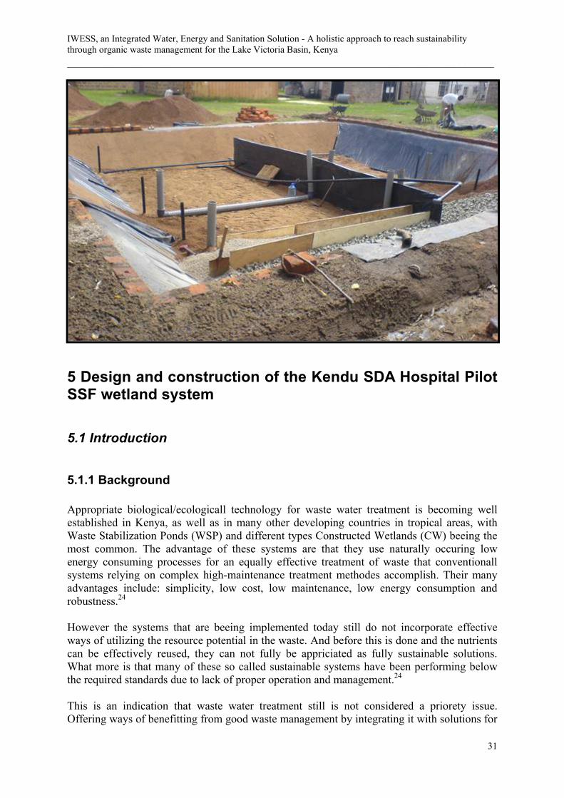
IWESS, an Integrated Water, Energy and Sanitation Solution - A holistic approach to reach sustainability through organic waste management for the Lake Victoria Basin, Kenya ___________________________________________________________________________
31
5 Design and construction of the Kendu SDA Hospital Pilot SSF wetland system
5.1 Introduction
5.1.1 Background Appropriate biological/ecologicall technology for waste water treatment is becoming well established in Kenya, as well as in many other developing countries in tropical areas, with Waste Stabilization Ponds (WSP) and different types Constructed Wetlands (CW) beeing the most common. The advantage of these systems are that they use naturally occuring low energy consuming processes for an equally effective treatment of waste that conventionall systems relying on complex high-maintenance treatment methodes accomplish. Their many advantages include: simplicity, low cost, low maintenance, low energy consumption and robustness.24 However the systems that are beeing implemented today still do not incorporate effective ways of utilizing the resource potential in the waste. And before this is done and the nutrients can be effectively reused, they can not fully be appriciated as fully sustainable solutions. What more is that many of these so called sustainable systems have been performing below the required standards due to lack of proper operation and management.24 This is an indication that waste water treatment still is not considered a priorety issue. Offering ways of benefitting from good waste management by integrating it with solutions for

Chapter 5 - Design and construction of the Kendu SDA Hospital Pilot SSF wetland system __________________________________________________________________________________________
32
other problem areas in accordance with the IWESS concept could be a good way of securing the on going development within the sector.
5.1.2 Objectives The purpose of this study was to use a practical approach to gain more experience of how a so called “appropriate” waste water treatment system can be developed to fit an IWESS concept. The specific technology chosen to be inluded was a type of constructed wetland namely Sub Surface Flow (SSF) The objective of the study was to design and construct a pilot SSF-wetland suitable for use in a source separating sewege system treating domestic grey water, focusing on increasing performance and accessability by using non-expensive solutions and locally available materials. In addition the introcuction of bamboo as a treatment plant was included as a possible option for nutrient recovery. The results presented will be based mainly on the experiencess gained from the process of actually constructing the facility.
5.2 Design and construction of the Kendu SDA Hospital Pilot SSF wetland system.
5.2.1 Introduction
5.2.1.1 Background The information about SSF wetland performance and function has been found to be very conflicting. Some designers promote the use of the wetland type while others discurage from using it, and instead recommend other types of systems considered to be more efficient for example FWS wetlands. Issues that have been used to claim the disadvantage of SSF wetlands are for example the huge cost associated with the process of solving the issue of SSF wetland substrate and also the lack of oxygen in the bed, which does not allow for nitrogen compound reducing processes to be completed.25 A second “group” of researchers and designers however claim that SSF-systems indeed have the capability of transporting sufficient oxygen to the bed for previously mentioned reactions to be able to perform.* Despite of the seemingly unclear performance qualities, the SSF wetland alternative offers certain benefits that make them very attractive solutions in various situations. For example when the sewage system because of lack of appropriate land, needs to be located close to settlements where there with FWS systems could be problems with public access, mosquitos and odour. A solution which could be placed closer to the population to be served and thereby reduce the costs of sewage conveyance could also prove to be cost effective compared to FWS systems despite of the substrate cost.24
The qualities defining an effective and implemental SSF, based on the negative issues stated above should be a system where oxygen can be made more available inside the substrate bed and also constructed with materials which are low cost and locally available. A descision was therefore made to include an in-depth investigation of different suitable materials and
* Transform af 1994 Aps, Interview 2007.03.20

IWESS, an Integrated Water, Energy and Sanitation Solution - A holistic approach to reach sustainability through organic waste management for the Lake Victoria Basin, Kenya ___________________________________________________________________________
33
techniques that could fulfill above stated qualities and produce an improved design for SSF systems, reducing the previously mentioned negative properties. The design was constructed as a pilot scale facility for treating greywater and the process analyzed to gain further information about the appropriateness of the system. Because of the time needed for the system to mature (commonly several months) results of the pilot system performance could not be included in this report.
5.2.1.2 Objectives The purpose of designing and constructing the pilot system was to test design ideas which can make SSF wetlands for treating greywater more effective, attractive and more accessible. The pilot plant wetland will hopefully be able to demonstrate a suitable design to be included into a complete source separating IWESS system containing modules for biogas generation and drinking water purification. The focus will be on developing a solution which is affordable and constructed with locally available materials. Because of the time needed for a wetland to reach maturaty and full capacity, and also the time necessary for sampling and analysing the system this report will not be able to include a full assessment of the systems purification performance. Instead focus will be put on the experience gained during the design and construction process and issues that arose from that work. Included will be recommendations regarding construction techniques, material choices, and design details and components as well as future research needs. Preceding the final design decission for the SSF wetland was an indepth study of design, both by litterature studies and also discussion with designers. Different solutions for the problems discussed earlier with lack of oxygen in the bed and expensive substrates was analysed both in terms of function and efficiency as well as cost.
5.2.2 Waste water Source details As a grey water source the hospital kitchen was used because of the relatively easy separation of black and grey water (for detailes se chapter 5.4.1). The kitchen cooks for patients, some of the staff as well as the students at the primary and nursing school located at the hospital compound. The grey water from the kitchen is mainly water used for cooking and doing dishes and was therefore found to be the closest match of regular domestic greywater that could be found on the hospital compound, which could also produce a regular and steady flow for the pilot plant.
5.2.2.1 Design flow meassurement The easiest way of meassuring the flow of grey water from the kitchen was by using buckets with a known volume, which was placed under each sink, a total of six collection points, see figure 5.1. As the buckets filled upp they where counted and emptied, this procedure was continued for a hole day, from that the kitchen started using water in the morning untill activity seaced in the evening.

Chapter 5 - Design and construction of the Kendu SDA Hospital Pilot SSF wetland system __________________________________________________________________________________________
34
The kitchen routines where found to be more or less similar every day with small differeces in water consumption, which led to the assumption that flow measurements for one day of the week would be sufficient to get an accurate design flow (an assumption confirmed by the kitchen staff). The result from the meassurement is presented in table 5.1. As can be seen in the table, the combined grey water production for the kitchen is 2.3 m³.
5.2.2.2 Chemical analysis Sampling and analysis of the kitchen grey water was done in cooperation with the University of Nairobi. Samples where taken from each collection point 1-6 with hourly intervals. Samples from the same collection point were mixed together, creating a total of six samples representing the collective result from the entire day. Because of the limited time for the design and construction process, as well as the long distance to appropriate lab facilities only the analyzes directly necessary for the primary design of the wetland was executed in this phase of the project. The results from the analysis are presented in table 5.2.
Flow meassurement, Kitchen
Outlet 1 160 litres 6.9% Outlet 2 260 litres 11.3% Outlet 3 800 litres 34.7% Outlet 4 340 litres 14.7% Outlet 5 420 litres 18.2% Outlet 6 320 litres 13.9%
TOTAL: 2300 litres
Analysis result, Kitchen Grey Water pH 8.7 DS (mg/l) 130 Turbidity (FTU) 120 COD (mg/l) 272 BOD (mg/l) 345
Figure 5.1: The waste water production was meassured for each sink, a total of six collection points.
Table 5.1: Flow meassurement results from the six collection points for the Hospital kitchen.
Table 5.2: Results from analysis of kitchen grey water. All water analyzes were performed at the University of Nairobi.
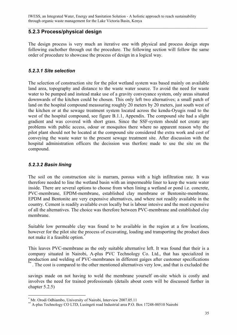
IWESS, an Integrated Water, Energy and Sanitation Solution - A holistic approach to reach sustainability through organic waste management for the Lake Victoria Basin, Kenya ___________________________________________________________________________
35
5.2.3 Process/physical design The design process is very much an iterative one with physical and process design steps following eachother through out the procedure. The following section will follow the same order of procedure to showcase the process of design in a logical way.
5.2.3.1 Site selection The selection of construction site for the pilot wetland system was based mainly on available land area, topography and distance to the waste water source. To avoid the need for waste water to be pumped and instead make use of a gravity conveyance system, only areas situated downwards of the kitchen could be chosen. This only left two alternatives; a small patch of land on the hospital compound meassuring roughly 20 meters by 20 meters, just south west of the kitchen or at the sewage treatment system located across the kendu-Oyugis road to the west of the hospital compound, see figure B.1.1, Appendix. The compound site had a slight gradient and was covered with short grass. Since the SSF-system should not create any problems with public access, odour or mosquitos there where no apparent reason why the pilot plant should not be located at the compound site considered the extra work and cost of conveying the waste water to the present sewage treatment site. After discussion with the hospital administration officers the decission was therfore made to use the site on the compound.
5.2.3.2 Basin lining The soil on the construction site is marram, porous with a high infiltration rate. It was therefore needed to line the wetland basin with an impermeable liner to keep the waste water inside. There are several options to choose from when lining a wetland or pond i.e. concrete, PVC-membrane, EPDM-membrane, established clay membrane or Bentonite-membrane. EPDM and Bentonite are very expensive alternatives, and where not readily available in the country. Cement is readily available even locally but is labour intesive and the most expensive of all the alternatives. The choice was therefore between PVC-membrane and established clay membrane. Suitable low permeable clay was found to be available in the region at a few locations, however for the pilot site the process of excavating, loading and transporting the product does not make it a feasible option.*
This leaves PVC-membrane as the only suitable alternative left. It was found that their is a company situated in Nairobi, A-plus PVC Technology Co. Ltd., that has specialized in production and welding of PVC-membranes in different gaiges after customer specifications ** . The cost is compared to the other mentioned alternatives very low, and that is excluded the savings made on not having to weld the membrane yourself on-site which is costly and involves the need for trained professionals (details about costs will be discussed further in chapter 5.2.5)
* Mr. Orodi Odhiambo, University of Nairobi, Interview 2007.05.11 ** A-plus Technology CO LTD, Lusingeti road Industrial area P.O. Box 17248-00510 Nairobi

Chapter 5 - Design and construction of the Kendu SDA Hospital Pilot SSF wetland system __________________________________________________________________________________________
36
Because of the comparatevily low cost of the the PVC-membrane and relative simple and easy installation it was considered a very affordable and otherwise favourable option for lining of small to medium sized systems and was therefore chosen for the pilot system.
5.2.3.3 Substrate
Substrate choices/ availability Substrates in SSF-wetlands are usually made up by some type of gravel or coarse sand. Choosing the treatment substrate is one the most important design considerations for SSF-wetlands. During design carefull consideration must be taken to the type, size, uniformity, porosity and hydraulic conductivity of the media material. These characteristics affect the flow of wastewater in the system and thereby the system performance. Substrate is generally a major post in the cosntruction costs of SSF-wetlands. The process of locating, producing, sieving, washing and transporting the product is very labour demanding and expensive, and therefore often considered as one of the major descision issues that needs to be solved when desiding on constructing a SSF-wetland. An effort was therefore put on finding a locally available material which could reduce the above mentioned costs as much as possible, thereby creating an affordable and otherwise resonable alternative.26
There are a lot of different types of gravel available in Kenya, for example pumice which is a lavarock common in the Rift Valley in the Naivasha and Sultan Hamud area, as well as in the northern parts of the country in the Turkana area The pumice in Kenya is extracted by local firms mainly as a source of building material. 27
Pumice is a lightweight and porous rock which is not unkommon in water filtration applications, some research has also been done on the potential use of the material as a substrate medium in constructed wetlands, with interesting results regarding phosphorous adsorption.28 Crushed rock aggregates and other construction purpose materials are also readilly available in most parts of the country. The material is made out of hard rock crushed either by industry machinery, or locally in small scale by hand. This is the material which is most common as a substrate in the SSF-wetlands constructed in Kenya today. However it is quite expensive because of the work-input needed to produce the material.*
The most common rock material in mots parts of the country is what is locally called “Marram”, which scientific name is Laterite. The material is enriched in iron and aluminium and develops by intensive and long lasting weathering of the underlying parent rock.29 Laterite is a very common road contruction material and is readilly available at regularly spaced quarry sites troughout the country. The availability of the material made it very interesting, so further studies where conducted on the properties of the material and the possebility for it to be used as a constructed wetland substrate in Kenya. * Mr. Orodi Odhiambo, University of Nairobi, Interview 2007.05.11

IWESS, an Integrated Water, Energy and Sanitation Solution - A holistic approach to reach sustainability through organic waste management for the Lake Victoria Basin, Kenya ___________________________________________________________________________
37
Laterite as wetland substrate Litterature studies showed that the the use of the material in wetland applications has been subject for some research in for example Uganda.30 The material used in these studies where granular Laterite, which is solid and physically resistant. From the studies excellent results regarding phosphorous and heavy metal adsorption was registered (the results where gathered from a pilot-scaled plant during its start-up phase and no long term performance was therefore recorded), and the overall performance considered made it seem like a very suitable substrate material. These results encouraged a more detailed field study of the type and availability of granular latrite in the local area of the pilot system construction. A number of local quarry sites where visited and samples tested for grain size distribution and stability. The granulate laterite was found to be packed in a matrix with lose soil, and pebbles from other types of rock, see picture 6.1. Consultation with a an FAO expert in Nairobi revealed information from previous research about river bank erosion which suggested that granulate sizes with a diameter bigger than 4mm
Picture 5.2: A set of sieves were used with deminishing size to determine grain size distribution of the Laterite granulates. Mesh sizes of 2 mm to 10 mm where used for the pilot system substrate.
Picture 5.1: Samples collected at local quarry sites showed that the granulate Laterite was found in a matrix of loose soil and pebbles from other types of rock.

Chapter 5 - Design and construction of the Kendu SDA Hospital Pilot SSF wetland system __________________________________________________________________________________________
38
where not yet stable, and would therefore continue to break down untill reaching this size.* These results are very important to have in mind when searching for a suitable gravel since a gradual grainsize reduction within the substrate bed of a wetland could significantly alter its performance31. Analysing the lactite from different quary sites in the local area indeed confirmed that in sertain areas larger granulats where very unstable and could easily be broken down into smaller grains. However at other sites the granulates where found to be stable for sizes reaching 8 mm and sites where also found where granulates smaller than 4 mm where unstable as well. These results lead to the conclusion that laterite stability varies a lot from source to source, and the previously claimed information that there is a singel maximum grainsize for stability shared by all sources could not be confirmed. However these statements are based on the experience gathered from a few sources with simple methods. A more thorough study is recommended before the implementation of any large scale projects. The final descision on which quary sites to use for the pilot system was based on granulate size distribution and stability. Since sieving of the material is time consuming a site needs to be found which contains a high concentration of stable granulates in appropriate sizes. If a site is chosen which only have a low concentration of the wanted product a lot of work have to be done sieving materials which can not be used, resulting in a much more expensive product. An initial effort on finding a good source from the beginning is therefore recommended. The method used for locating such a source for this project was to sort random samples collected from different points within a quary through a series of mechanical sieves of diminishing size. The sieves used were a set designed specifically for determining grain size distribution for small samples. For the analysis of the substrate for the pilot system mesh sizes from 2 mm to 10 mm where used and size distribution visualy recorded, see picture 6.2. Ideally, weight of each size should be used to determine grain size ratios but for this case visual determination was considered to be sufficient to make a rough estimation of the distribution. The result from the sieving tests was that stable granulates in sizes ranging between 4-8 mm where the most common and hence available material. This size distribution should not be a problem in the SSF-wetland because of the relatively slow moving water, on condition that the substrate is well mixed, and was therefore chosen as the pilot system substrate. One way to narrow the search for a quarry site delivering stabile granulate laterite is to locate sites which have been used by road construction companies, since the same quality material is prefered for this purpose as well. When the decission was made on the material to use, porosity and conductivity where determined. It was found that some of the sieved laterite still contained a lot of soil attached to the granulates, which could not be removed. To prevent clogging in the wetland bed thorough washing was therefore necessary. Laterite Porosity determination Porosity is an expression of the amount of void spaces in a substrate. The porosity can be determined by measuring the volume of water needed to fill up all voids in a material. This is easily done by filling a measuring glass of known volume, with a drain hole in the bottom, with the substrate to be measured. The material is then saturated with water and the volume
* Mr. Christian Omutu, FAO Nairobi, Interview 2007.05.13

IWESS, an Integrated Water, Energy and Sanitation Solution - A holistic approach to reach sustainability through organic waste management for the Lake Victoria Basin, Kenya ___________________________________________________________________________
39
required is noted, the same as pore volume. The container is then drained and the volume is recorded again. To be able to drain the capillary bounded water the last water is blown out of the glass. The water that remains after this is mainly absorbed water. The porosity, n, is than calculated using equation 6.1.
VVn n100= (5.1)
Where: Vn = Pore volume [%] V = Total volume of air, water and substrate, in other words the previously known volume of the glass. For the chosen Substrate, Laterite 4-8 mm, this gives:
%382.0076.0
=⎭⎬⎫
==
nlV
lVn
The value n is defined as the remaining cross-sectional area available for flow, which for the Laterite used for the pilot system was calculated to 38 percent. Laterite hydraulic conductivity determination
Hydraulic conductiviy should be determined in the field or laboratory, prior to system design. This can be done by using for example a flume or a through. However, since this equipment was not available during the construction of the pilot system, preliminary data was collected from table 5.3 below.31
Media Charateristics for subsurface flow wetlands Media type
Max 10% grain size
Prosity (n)
Hydraulic Conductivity (Ks)
K20
[mm] [m/d] Medium
sand 1 0,35 420 1.84
Coarse sand
2 0,39 480 1.35
Gravelly sand
8 0,42 500 0,86
From the table it can be found that the hydraulic conductivity for the substrate chosen for the pilot system with a grainsize distribution between 4-8 mm should be between 480-500 m/d. Since the selection of a hydraulic conductivity constant should always be chosen conservatively to prevent problems with clogging and surface flow, the lower value of Ks =
Table 5.3: Media characteristics for different grain sizes of subsurface flow wetlands22

Chapter 5 - Design and construction of the Kendu SDA Hospital Pilot SSF wetland system __________________________________________________________________________________________
40
480 m/d is a good enough estimation for the pilot system substrate. However it is recommended that only 1/3 of the effective hydraulic conductivity is used as an additional safety factor to prevent surface flow16. This gives:
dmK s /160=
Calsium for pH buffering Although the pH meassurement made on the influent water to the wetland indicated alcaline water in this case, it is normally recommended to include a calsium source in the inlet zone of the wetland to neutralise possible acidity. Calsium rich rock types in Kenya include limestone, with deposits mainly in the coastal basin, calcrete which is extracted in the Athi river quarry south east of Nairobi, dolomite which is found in the south-east of the country near Voi and carbonatites which are mined in the areas Homa, Koru and Rangwa.27
Since Homa is the closest to Kendu Bay, and the construction site, carbonatite was chosen for the pilot system. The Homa quarry, previously mined by Homa Lime is now abandoned. For larger volumes of Calsium the site in Koru is therefore recommended as the closest quarry still operating. For the pilot system however an agreement with the land owner at the Homa site was made which made it possible to get 2 m³ of lime gravel sieved to a grain-size of 4-8 mm (same size as for the Laterite substrate), see picture 6.3.
5.2.3.4 Macrophytes, Bamboo Resent research results have made some designers question the capability of common wetland plants to actually beeing able to transport sufficient ammounts of oxygen to the substrate bed for nitrogen compound reducing processes to be effective. Instead some claim that nitrogen reduction in SSF-wetlands would be even better if the beds where left unplanted, for them to be able to take full advantage of atmospheric airation instead. A process which is said to be reduced in fully planted beds because of detritus from the plants covering the substrate surface32. However if oxygen could be supplied by other techniques (see following chapter), the macrophytes could be grown inside the wetland to create other benefits, for example to serve as a source of income if harvested.
Picture 5.3: Carbonatite from the Homa quary (right) was chosen for the pilot system which was sieved to a grain-size of 4-8 mm which is the same size as for the laterite substrate.The substrate to the left is carbonatite from the Koru quarry.

IWESS, an Integrated Water, Energy and Sanitation Solution - A holistic approach to reach sustainability through organic waste management for the Lake Victoria Basin, Kenya ___________________________________________________________________________
41
In this way the nutrients and water from wastes could be reused and serve as resources instead. One plant that has been showned to have a large number of benefits and income generating qualities is bamboo. Harvested bamboo can be used as construction material, food, production of handicrafts etc. and could provide self-employment and job opportunities to the rural population in Kenya. The bamboo resources in Kenya consist of indigenous and introduced (exotic) species. The indigenous bamboo species is mainly found in gazetted indigenous forests and small proportions are in farmlands. Over 20 other exotic bamboo species were introduced into the country during the last two decades, largely through the support of IDRC (International Development Research Centre). Fifteen species have successfully been established in various ecological zones in the country. Utilization of bamboo in Kenya is still largely confined to domestic usage. In the highland areas where the resource is plentiful fencing, houses and food storage constructions are major consumers of bamboo. The later usage is done with minimal processing. This is the same case for bamboo used in the making of tea picking baskets. On commercial scale bamboo has increasingly gained importance in the flower farming industry where it has been used for support purposes. Its use in horticulture does not involve any substantial processing. To a large scale, but less documented, is the use of bamboo by farmers in the highlands to support pea farming. Other small-scale commercial uses include production of toothpicks and small handicraft articles. Furniture making using bamboo is not a specialization in Kenya but the potential is there.32
There has not been a lot of research on the utilisation of bamboo for use in constructed wetlands, however some resent projects have included it in their objectives. Bamboo for Europe was a research project (December 1996 to May 2000) initialized by the European commission with the main objective to define and to overcome major problems and limitations to large-scale introduction of bamboo in the European Community33. Among the main specific objectives was the development of a wastewater treatment unit with bamboo, through constructed wetland technology. As part of this project a wastewater treatment plant demonstration unit of 8 m² has been implemented and tested comparing the traditional water plant Phragmites Australis with 2 bamboo species: Phyllostachys Nidularia and Phyllostachys heteroclada. The unit is in operation since August 1998. Bamboo was said to represent some advantages versus the traditional water plants, There among: - Same level of treatment (compared to Phragmetis.)
Picture 5.4: T. Siamensis is a relativerly small bamboo type

Chapter 5 - Design and construction of the Kendu SDA Hospital Pilot SSF wetland system __________________________________________________________________________________________
42
- Lower density for plantation (1 plant/m² instead of 6-11 plants/m²) - Less maintenance To explore bamboo as an alterntive in a SSF-wetland the choice was made to split the pilot system into two equally sized cells. One of the cells was to be planted with Thyrsostachys siamensis, a major commersial bamboo in Thailand. The bamboo was bougth as siedlings from KEFRI (The Kenya Forestry Research Institute) in Nairobi which bring up and sell many of the introduced exotic species of bamboo mentioned above. T. Siamensis is a relatively small bamboo, see picture 6.4*
The canes are around 5cm in diameter, very flexible yet strong and almost solid growing to a size of approx. 7-12 m. It´s rooting depth was unknown but past experience from the KEFRI planting projects confirmed that an available depth for rooting of approx. 60 cm should be sufficient. The other cell in the pilot system was planted with a local reed, representing a more conventional macrophyte in present constructed wetlands. Beeing more commonly implemented in previous systems the reed will serve as a reference for comparison with the bamboo cell.*
5.2.3.5 Airation tubes/natural airation In an attempt to increase oxygen avalability inside the substrate bed for nitrogen compound reducing processes to be effective a solution chosen to be called airation-tubes was implemented in the pilot system. The airation tubes use the principal of natural airation to supply oxygen to the substrate bed. The airation tubes are built up by 100 mm diameter PVC-pipes, see figure 5.2. The pipes are slotted and placed at the bottom of the substrate bed stretching the full with of the wetland cell. It is necessary for the slots to meassure 2.5 mm by 5 mm, since smaller or circular slotts will be clogged by the macrophyte roots. At each end a riser is mounted stretching to the surface of the bed. The risers have a difference in length of 200 mm, which will create the circulation effect by creating a pressure and temperature difference between the lowest ventilation point (the bed bottom) and the outlet point. The airation-tubes are placed in series at the beginning of the wetland cells, for small onsite
* KEFRI, Visit 2007.04.15 * KEFRI, Visit 2007.04.15
Figure 5.2: Airation tubes was installed in the wetland to take advantages of natural aeration for oxygenation of the substrate bed.

IWESS, an Integrated Water, Energy and Sanitation Solution - A holistic approach to reach sustainability through organic waste management for the Lake Victoria Basin, Kenya ___________________________________________________________________________
43
systems such as the pilot system two sets of airation tubes per cell will be implemented, see picture 5.5.**
5.2.3.6 Calculating wetland surface-area The pilot system surface area is calculated based on a first-order plug flow assumption, using the equations of Reed. Reed’s model use a volumetric, temperature-dependent basis, with the calculations being based on the available volume of the wetland and the average water temperature.25
The general form of the first order plug flow model for BOD removal can be written as in equation 5.2.
)( tKoe
TeCC −= (5.2)
Where: Ce = Effluent BOD [mg/l] Co = Influent BOD [mg/l] KT = Temperature dependent rate constant [d-1] t = Hydraulic retention time [d] K20 = Rate constant at 20ºC T = Temperature of liquid in the system [ºC] The temperature dependent rate constant, KT, is calculated using equation 5.3. )20(
20 )( °−= TT KK θ (5.3)
** Transform af 1994 Aps, Interview 2007.03.20
Picture 5.5: The airation tubes are palced in series of two in the beginning of the wetland bed

Chapter 5 - Design and construction of the Kendu SDA Hospital Pilot SSF wetland system __________________________________________________________________________________________
44
Where: Ө = 1.06 T = 20,4ºC K20 = 1.28d-1
The temperature data is retrieved from the World Water and Climate Atlas software developed by IWMI-International Water Management Institute, see table 5.4.34
Media types including medium to gravelly sand have a K20 value of approx. 1.28d-1.For the K20 factor a safety factor of 75% is recommeded 25, which gives:
120 98.075.0 −=→= dKK T
The hydraulic retention time, t, from equation 5.2, is expressed as in equation 5.4:
QnLWdt )(= (5.4)
n = Effective porosity of media [%] L = Length of bed [m] W = Width of bed [m] d = Average depth of liquid in the bed [m] Q = Average flow through the bed [m³/d] Equations 5.2.3 and 4 can be combined to calculate the necessary wetland area, As, in equation 5.5.
Temperature, daily mean
Month Temp. [ºC] Month Temp. [ºC]
Jan 21,7 Jul 20,4 Feb 22,1 Aug 20,8 Mar 22 Sep 21,1 Apr 21,5 Oct 21,7 May 21,2 Nov 21,2 Jun 20,6 Dec 21,3
Table 5.4: The lowest daily mean temperature in the local area is 20.4ºC, which is retrieved from the month of June34

IWESS, an Integrated Water, Energy and Sanitation Solution - A holistic approach to reach sustainability through organic waste management for the Lake Victoria Basin, Kenya ___________________________________________________________________________
45
( )[ ] nTeos dKCCQWLA ln))(( == (5.5)
Where: As= Bed surface area, [m²] L = Length of bed, [m] W = Width of bed, [m] d = Average depth of liquid in bed, [m] Ce = Concentration, effluent, [mg/l] Other terms defined previously It is recommended that the hydraulic gradient in the bed is limited to 10 percent of the potential available. This will produce an average depth equal to 95 percent of the total depth of the substrate in the bed.25
The effluent BOD is influenced by the production of residual BOD within the wetland from decomposition of plant detritus and other naturally occuring organics. Thus residual BOD is typically in the range of 2 to 7 mg/l. As a result equation 5 shoud not be used for design for a final BOD < 5 mg/l.25
For the pilot system no specific effluant standards will be the goal, instead the design value for Ce will be 5 mg/l, which is the minimum value considered attainable because of residual BOD produced within the wetland. This gives, with: Qtot = 2.3m³ Ce = 5mg/l C0 = 345mg/l n = 0.38 d = 0.57m (95% of total depth) Q = 2.3m³/d Ce = 5mg/l KT = 0.96d-1
28.46 mAs =
5.2.3.7 Aspect ratio configuration The aspect ratio is the length/width ratio of the wetland. It is a very important detail in the configuration of a SSF-wetland if surface flow is to be avoided. The flow regime in a porous media can be described using Darcy´s law, which is defined with equation 5.6.

Chapter 5 - Design and construction of the Kendu SDA Hospital Pilot SSF wetland system __________________________________________________________________________________________
46
SAKQ cs= (5.6)
Where:
Q = Design flow [m³/d] Ks = Hydraulic conductivity of a unit area of the substrate perpendicular to the flow direction [m³/m²/d] Ac = Total cross-sectional area, perpendicular to the flow, [m²] S = Hydraulic gradient of the water surface in the flow system [dh/dL] Because of hydraulic gradient requirements (dh/dL) the aspect ratio (L:W) will have to be relatively low, in the range of 0,4:1 to 3:1 (0,3m depth in the lower range and 0,6 in the upper). This will help sustain subsurface flow in the system and create flexibility and reserve capacity for future operational adjustments. A preliminary aspect ratio of 2:1 is chosen for the pilot systems two equally sized cells (A1 and A2) (depth = 0,6 meters), which gives:
24.23221 mAAA ===
[ ] mWmWWWLLWAA 4.34.23222 22221 =→=→→=→==
[ ] mLWL 8.62 =→=
The width calculated above will have to be checked with Darcy´s law to confirm that the flow will be able to be kept below the surface of the substrate. If the width is to small it will have to be increased to the minimum value accepted by darcy´s law and the length recalculated as before using the same aspect ratio criteria. The minimum width accepted by Darcy´s law is calculated by rearanging equation 5.6 as below:
[ ] SdKQWLWASAKQ scs 2,12,12,1 =→=→=
Where: Q1,2 = Qtot/2 = 1.15m³/d Ks = 160m/d S = 0.5º = 0.005 (same as for flat bottom) d = 0.57m Which gives:
mW 5.22,1 =
2.5m < 3.4m → The preliminary width calculated is acceptable

IWESS, an Integrated Water, Energy and Sanitation Solution - A holistic approach to reach sustainability through organic waste management for the Lake Victoria Basin, Kenya ___________________________________________________________________________
47
5.2.3.8 Theoretical hydraulic retention time The hydraulic retention time (HRT) of a CW is the average time that water remains in the wetland. The hydraulic retention time in each of the two parallel cells is calculated with equation 6.7.
2,12,1 QnLWdt = (5.7)
Where: t1,2 = Hydraulic retention time in each of the two cells n = 0.38 L = 6.8m W = 3.4m d = 0.57m Q1,2 = 1.15m³/d Gives:
dayst 35.42,1 =
5.2.3.9 Hydrological budget It is not safe to ignore water exchange with the atmosphere, mainly because it can significantly affect the water flows. To maintain the liquid level in the ponds, the inflow must also be at least greater than net evapotranspiration losses at all times. It is therefore necessary to prepare an accurate monthly hydrological budget to see if adjustments will have to be done to the original design plan. The hydrological budget or water balance for the SSF-wetland is an account of the inflow, storage and outflow of water, and can be calculated as presented in equation 5.8. The equation does not consider the inflow from, and to, the groundwater, since the SSF-wetland will be lined.25
ETPQQdtdV ei −+−= (5.8) Where: Qi = influent waste water flow [m³/month] Qe = Effluent waste water flow [m³/month] P = Precipitation [m³/month] ET = Evapotranspiration [m³/month] V = Volume T = time

Chapter 5 - Design and construction of the Kendu SDA Hospital Pilot SSF wetland system __________________________________________________________________________________________
48
Table B.3.1, Appendix is derived with data retrieved from the World Water and Climate Atlas software developed by IWMI-International Water Management Institute. The result from the table show that only marginal changes in water flows is to be expected, which should not affect wetland performance noticebly. A net increase in water flow is most likely to occur in April-May, during the longer rainy season. During all other months prevailing evapotranspiration will cause a net loss of water and a reduction in flows. These flow alterations will not affect system performance noticebly, and the original design will therefore not recuire any adjustments. Also, water inflows are significantly higher than net evaporation losses which eliminates problems with low water levels in the wetland.34
However it should be noted that if the wetland is to be used in a water re-cirulation system the losses due to evaporation can lead to a salt build up within the system. For these installations it is therefore recommended to include an external water source which can continually replace the lost water. A rain water harvesting system could be a possible alternative, which increases the surface on which precipitation can be collected.25
5.2.4 Physical design/construction of pilot system
5.2.4.1 Grey water separation and conveyance The separation of the greywater from the kitchen was simple since separate piping was used for each source (sinks and toilet) and connection was made on an external main sewage line. This made it possible to connect to optional sources before the sewage was mixed and convey it to the pilot system in a separate pipe system, see figure 5.3. Most of the buildings on the compound has GI-pipe plumbing on the outside, including the kitchen whitch also made the practical issue of connection simple. The distribution piping used was 50 mm diameter HDPE-pipes with plastic compression fittings, see picture 5.6. The piping was dug down in the ground to a depth of 0.4 meters to protect it against physical damage. For easy access in case of blockage manholes where placed evenly along the conveyance line.
Figure 5.3: Separated grey-water conveyance system with connection points and manholes.

IWESS, an Integrated Water, Energy and Sanitation Solution - A holistic approach to reach sustainability through organic waste management for the Lake Victoria Basin, Kenya ___________________________________________________________________________
49
5.2.4.2 Basin construction The basin was dug out to a depth of 0.6 meters with a 45 degree slope on the sides, see drawing B.2.1, Appendix . To confine the water inside the wetland and also minimize the chance for surface water to reach the wetland a watertight containment structure of berms and an impermeable liner was constructed around the basin. The berm surrounding the wetland was added as an extension to the sides of the basin, building a barrier against surface water intrusion 0.3 meters high. The berms where constructed using a mixture of the excavated laterite soil, water and dug out “anthills” or termite nests, see picture 5.7. The mixture is the same used for constructing tradiditonal houses and forms a clay like material that when it dries forms a hard surface more resistant to to weather erosion. The anthill material is very abundant and could serve as a cheaper and more feasible alternative to cement for small scale systems. The berms where planted with grass to further protect it against erosion. The liner used was a 0.5 mm PVC membrane prefabricated
Picture 5.7: A 0.3 meter high berm constructed with termite mixture was added surrounding the wetland to prevent surface water from entering.
Picture 5.6:The distribution piping used was 50mm HDPE-pipes with plastic compression fittings. The piping was connected to the kitchen GI plumbing on the outside.
Figure 5.4: The ends of the liner were anchored inside the berm by covering them with bricks and termite mixture

Chapter 5 - Design and construction of the Kendu SDA Hospital Pilot SSF wetland system __________________________________________________________________________________________
50
at A-plus PVC technology CO. LTD. Nairobi*. The liner was delivered to the site and installed in one piece, welded according to designer specifications, see picture 5.8. As a precaution against punctures by rocks a protective layer of sand was added on the bottom and of the basin before the membrane was installed as well as on the top of the membrane before filling of substrate.
The the liner were ends of anchored inside the berms as illustrated in figure 5.4. The separation of the two cells was done with a divider made of timber coated with the same membrane liner used for the wetland basin. The slope of the wetland bottom was 0.5 degrees in the direction of flow, see drawing B.2.1, Appendix, this is enough for drainage if necessary. The wetland bottom must be absolutely horizontal along the width of the bed to avoid short circuting of the flow. The small size of the wetland allowed for the grading to be calulated
and meassured using reference points, spirit levels and marker strings, a method found to be simple and effective, see picture 5.9.
5.2.4.3 Inlet structures The conveyance line from the kitchen connects to a 1 m³ plastic inlet tank see drawing B.2.1, Appendix. The inlet tank allows for primary settlement of solids and also separation and collection of grease.
The grease collection is made possible
due to a lowering of the outlet pipe opening, which traps the floating grease on the water surface in the tank, see picture 5.10.
The outlet-pipe from the inlet tank, further on referred to the inlet pipe to the
wetland, connects to a perforated (10mm diameter orifices)
* A-plus Technology CO LTD, Lusingeti road Industrial area P.O. Box 17248-00510 Nairobi
Picture 5.9: The grading of the wetland was measured and calculated using reference points, spirit levels and marker strings.
Picture 5.10: Lowering of the outlet pipe inlet allows for primary settlement of solids and also separation and collection of grease.
Picture 5.8: The liner used was a pre-fabricated (welded)0.5mm PVC membrane. The liner was delivered to the site and installed in one piece.

IWESS, an Integrated Water, Energy and Sanitation Solution - A holistic approach to reach sustainability through organic waste management for the Lake Victoria Basin, Kenya ___________________________________________________________________________
51
manifold stretching the full width of the wetland, see picture 5.11.
The inlet pipe to the wetland is casted into a concrete slab to which the PVC-liner is glued (product recommeded by A-plus1), creating a water proof seal, see picture 5.12. The manifold is located just beneth the surface of an inlet bed constructed with 32-64 mm diameter aggregates, which function is to dispurce the water evenly out into the wetland. The manifold is fitted with clean-outs at both ends which allow for easy access in case of blockage problems, see picture 5.13.
* A-plus Technology CO LTD, Lusingeti road Industrial area P.O. Box 17248-00510 Nairobi
Picture 5.11: The water enters the wetland trough a perforated manifold stretching the full width of the wetland.
Picture 5.13: The inlet manifold is placed just underneath the surface of a gravel bed of 32-64mm aggregates, which function is to evenly disperce the water into the wetland.
Picture 5.12: The inlet pipe to the wetland is casted into a concrete slab to which the PVC-liner is glued creating a water proof seal.

Chapter 5 - Design and construction of the Kendu SDA Hospital Pilot SSF wetland system __________________________________________________________________________________________
52
5.2.4.4 Substrates The aggregate inlet bed is directly followed by a pH-buffering zone constructed with 4-8 mm diameter carbonatite gravel/sand. The zone is 0.4 meters in length and 0.4 meters deep, stretching the entire width of the substrate bed. Following the pH buffering zone is the main 4-8 mm diameter laterite substrate bed, which has a depth of 0.5 meters. The wetland is separated into two equally sized parallell cells just before the pH-buffering zone, each recieving 50 % of the influent water, see picture 5.14. All substrates used in the wetland have been trouroughly washed to remove any silt that could clogg the bed creating surface flow.
5.2.4.5 Outlet structures The water is collected 0.1 meters from the bottom of the wetland bed by the same type of perforated manifold used at the inlet, see picture 5.15. The outlet pipe is casted into a concrete slab in the same way as for the inlet end. When collected the water gravitates to a 1m³ outlet tank, see drawing B.2.1 Appendix B, trough a flexible pipe which allows for the water level inside the wetland to be adjusted, see picture 5.16 .
Picture 5.14: The inlet zone is followed by a pH-buffering carbonite bed. Following the pH-buffering zone is the main 4-8 mm diameter Laterite substrate.

IWESS, an Integrated Water, Energy and Sanitation Solution - A holistic approach to reach sustainability through organic waste management for the Lake Victoria Basin, Kenya ___________________________________________________________________________
53
5.2.4.6 Airation tubes The airation tubes are placed in a series of two in each cell, see picture 5.5 . For the oxygen to be available in the beginning of the bed the first tube is placed 1,5 meters in front of the inlet pipe and the second 2 meters after the first one. To prevent debrie from blocking the tubes caps are mounted on top which are open on the sides to allow air to circulate freely, see picture 5.17.
5.2.4.7 Sampling tubes To make analysis of wetland performance more effective four sampling tubes reaching the bottom of the bed where placed along the length of both cells, see drawing B.2.1, Appendix. The interval of the sampling points represent each day of the total theoretical retention time, sampling point one representing one day retention time and so on. The tubes have a perforated bottom which prevents gravel from entering, enabeling easier access to the water, see figure 5.5.
Picture 5.15: The wetland effluent is collected in a perforated manifold stretching the full width of the wetland.
Picture 5.16: A flexible outlet pipe allows for the water level inside the wetland to be adjusted.
Picture 5.17: To prevent debrie from blocking the tubes caps where mounted on top, allowing air to circulate freely trough the sides.

Chapter 5 - Design and construction of the Kendu SDA Hospital Pilot SSF wetland system __________________________________________________________________________________________
54
5.2.4.8 Planting Planting was made by hand with seedlings from both reeds and bamboo, see picture 5.17. A planting density of 1 meter centers for the bamboo and 0.5 meter for the reeds was used. The planting density of the bamboo should preferably be higher, to get a more rapid development of a mature and completely functonal wetland system. However at the time of construction there was a shortage of seedlings so the planting density had to be reduced. The reed seedlings were collected locally from a river bank. At the time of planting the substrate bed was fully saturated with water and the seedlings was planted at a depth of 10 centimeters. Ash was mixed down in the substrate at each planting location as a nutrient complement to help the seedlings getting established.
5.2.5 Costs The choice of treatment system is often based primarily on financial issues; therefore the process of developing an appropriate and implemental system includes a thorough analysis of the associated costs. All the expences assossiated with construction of the pilot system was therefore recorded and compared with gathered information from previously constructed
Figure 5.5: The sampling tubes reach the bottom of the substrate preventing the gravel from entering allowing for access to the water. The tubes have orifices drilled out to allow for the water to flow trough them.
Picture 5.17: Planting was made by hand with seedlings from both reeds (left) and bamboo (right)

IWESS, an Integrated Water, Energy and Sanitation Solution - A holistic approach to reach sustainability through organic waste management for the Lake Victoria Basin, Kenya ___________________________________________________________________________
55
wetland systems, Sub surface flow (SSF) as well as free water surface (FWS). A summary of the capital costs for the pilot system is to be found in table B.3.2, Appendix. At the time for the study 1Ksh = 0.65USD. Results from previous research show that the recurring major items in the capital investment of a sub surface system are construction, land, basin liner, labour and substrates, with substrates significantly larger than any other single post sometimes reaching values above 50% of the total cost of a system25. A reduction of the substrate cost would therefore have a substancial effect on the added cost of a SSF-system. Diagram 5.5 is based on values from table B.3.3, Appendix and presents the major expences for the pilot SSF-system as cost per m² as well as in a percentage of the total cost. The result reveals a shift in cost distribution compared to the previous discussion, as the cost for substrates is lower than the construction cost. Land cost was not included because of lack of reliable data but is normally in the range of 5-15 %25. In fact results from the construction of the pilot system (see table B.3.3, Appendix) show that Laterite gravel suitable for use in wetlands was produced at a cost approx. 65 % of conventional wetland media. For comparison diagram 5.6 is based on the same costs as in diagram 5.5 but the Laterite gravel has been replaced with a conventionally used substrate (Agregates). The result show a more comparable cost distribution to previous research with substrates beeing the dominant item at values reaching 50 %25.
Diagram 5.5: Cost distribution of major cost items included in the construction of the pilot SSF-system using Laterite substrate at Kendu SDA hospital Kenya.
Diagram 5.6: Cost distribution of major cost items included in a system similar to the pilot SSF-system at Kendu SDA hospital Kenya, but using conventional gravel as substrate.

Chapter 5 - Design and construction of the Kendu SDA Hospital Pilot SSF wetland system __________________________________________________________________________________________
56
The internal cost distribution for the Laterite gravel is interesting as well because it can be used as a guide to find ways to further reduce costs. From diagram 6.7 it can be seen that transportation as well as excavation/sieving are large items, each at 43 % of the total cost. Transportation is generally expensive in Kenya and with fuel prizes rizing reduction of this cost is not probable, unless larger quantites are to be moved which could create oportunities to negotiate prices. Excavation/sieving is a large cost mainly because the method used for the pilot project is very labour intensive. However, unless new techniques and equipment is developed manual sieving is probably the only feasible alternative for small-scaled systems if materials are to be used which are available locally. There is off-course the option of setting up central facilities which could produce the material at lower cost, but the further away from the construction site the larger the transportation costs and savings in production costs are soon reduced to zero and below. The raw material is the cost for the unprocessed material and is decided by the quarry owner. The cost is generally quite low, in this case only 14 % of total, and is therefore not a priority for an added cost reduction of the process. On the issue of FWS-systems compared to SSF-systems regarding costs, most of the major cost items are dependent on the design surface area and the unit costs are essentially the same for both systems. The major difference between the two systems is the substrate cost for the SSF-system, making the construction cost higher per unit area than the FWS-system. However the FWS system generally needs to be designed about 70 percent larger than a SSF-system to achieve the same BOD performance25. Calculation of the cost of a FWS-system, see table B.3.4 Appendix B, inded show that the construction cost per area unit is the smallest but because of the larger area needed the cost will be about the same as for the SSF-system with conventional substrates. The pilot SSF-system is in comparence the cheapest system with approximately 15 %. The selection of the more cost-effective altrenative is generally said to depend on treatment goals, the availability and cost of land in the area, and on the cost of the media for the SSF alternative. Other factors include mosquito and odour issues as well as the concern over public access, factors that all favour the SSF alternative in areas in close proximity to public facilities and dwellings.
Diagram 5.7: Internal cost-distribution of the major items included in the allocation of laterite gravel for the pilot SSF-system at Kendu SDA hospital.
27000; 43%
9000; 14%
27000; 43%
Cost distribution for Laterite
transportation
Raw material
excavation/sieving
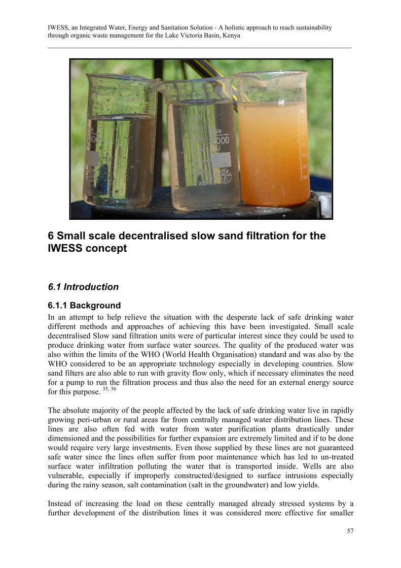
IWESS, an Integrated Water, Energy and Sanitation Solution - A holistic approach to reach sustainability through organic waste management for the Lake Victoria Basin, Kenya ___________________________________________________________________________
57
6 Small scale decentralised slow sand filtration for the IWESS concept
6.1 Introduction
6.1.1 Background In an attempt to help relieve the situation with the desperate lack of safe drinking water different methods and approaches of achieving this have been investigated. Small scale decentralised Slow sand filtration units were of particular interest since they could be used to produce drinking water from surface water sources. The quality of the produced water was also within the limits of the WHO (World Health Organisation) standard and was also by the WHO considered to be an appropriate technology especially in developing countries. Slow sand filters are also able to run with gravity flow only, which if necessary eliminates the need for a pump to run the filtration process and thus also the need for an external energy source for this purpose. 35, 36
The absolute majority of the people affected by the lack of safe drinking water live in rapidly growing peri-urban or rural areas far from centrally managed water distribution lines. These lines are also often fed with water from water purification plants drastically under dimensioned and the possibilities for further expansion are extremely limited and if to be done would require very large investments. Even those supplied by these lines are not guaranteed safe water since the lines often suffer from poor maintenance which has led to un-treated surface water infiltration polluting the water that is transported inside. Wells are also vulnerable, especially if improperly constructed/designed to surface intrusions especially during the rainy season, salt contamination (salt in the groundwater) and low yields. Instead of increasing the load on these centrally managed already stressed systems by a further development of the distribution lines it was considered more effective for smaller

Chapter 6 - Small scale decentralised slow sand filtration for the IWESS concept __________________________________________________________________________________________
58
communities and even individual families to run and maintain their own systems if they were offered a suitable solution.
It was however found that the small scale slow sand filtration system solutions available on the international market were not fully developed or adapted nor effective enough to meet the local requirements of a typical rural or peri-urban settlement in a developing country. Systems that could be built on-site using traditional building materials also proved both expensive and in other ways limited not offering optimal benefits to the user.
6.1.2 Objectives During the minor field study an initial prototype was to be constructed and tested and from the results reached a new slow san filtration system solution design more beneficial and better adapted to the situation requirements was to be developed. The final system solution based on the initial study was, if to be beneficial, needed to be able to purify highly turbid surface water sources, be easy to operate and maintain, meet realistic local demands of both water quality and volume, be reliable and low cost concerning both the initial investment, operation and maintenance costs yet of high quality concerning both durability and effectiveness. It also had to be easily shipped and distributed to the people and communities with an expressed need of such a system. To enable better resource management the possibilities to connect such a system to a ecological grey water treatment system was also to be evaluated linking the slow sand filtration system to the IWESS-concept which is the base for this report. This section of the concerning slow sand filtration will start with a basic description of the slow sand filtration technique including its benefits and limitations. This will be followed by a thorough description of the slow sand filtration concept developed during this study. The system is called PT SCX and has several advantages compared to the solutions offered on the international market today. The PT SCX´s role in the IWESS principle will also be explained.
6.2 Introduction to slow sand filtration Slow Sand Filtration has been used to purify water since the 19th century although the knowledge of its potential was not realised until quite recently. At first slow sand filtration was considered to be purely a simple yet effective mechanical filter only purifying the water by straining out particles bigger than the interstices between the sand grains. Although this straining does occur its contribution to the entire purifying process in the filter must be considered minimal. The true potential of the filtration effectiveness was not realised until the knowledge of pathogenic contaminants in drinking water and their effects on the human health were discovered. Bacteria and other pathogens are far smaller than the interstices between the sand leading to the conclusion that other processes besides simple mechanical straining are responsible for the very high levels of purification achieved by a properly maintained slow sand filter. Today it is known that intricate biological, physical and chemical processes and mechanism all work simultaneously in braking down and retaining impurities

IWESS, an Integrated Water, Energy and Sanitation Solution - A holistic approach to reach sustainability through organic waste management for the Lake Victoria Basin, Kenya ___________________________________________________________________________
59
from the raw water fed through the filter. These processes make it possible for the slow sand filtration to deliver water practically free from all pathogens with a level of purity accepted by the WHO as safe for human consumption. 36 It is however still the sand that is the key factor to the efficiency. The basic or main principle of slow sand filtration is to take advantage of the very large surface area of sand and its ability to sustain biological activity. One cubic meter of sand can have a total surface area of up to 15000 square meters (depending on the grain size) and if simple criteria are met this area can be habited by micro organisms and bacteria that through processes explained later brakes down or removes impurities from the water fed through the filter media. The characteristics of the sand used in these filters also presents the opportunity for chemical and physical processes to either indirectly contribute by enhancing the efficiency of the purification or directly purify the water either by braking down or retaining impurities within the filter media. 36
To achieve maximum efficiency the filtration rate or retention time for the water passing through the filter is crucial. If the retention time or the speed of the water passing through the filter is too high the processes and mechanisms that directly or indirectly purify the water will not have enough time to be fully effective. The slow sand filtration system is therefore fully dependent on a slow and steady flow of water between 0.1-0.4m/h and the only factor that can be altered to produce larger volumes of purified water from the filter is the surface area of the filter bed. If a larger diameter filter bed is used larger quantities of water will have the opportunity to pass through it and be collected. 36
It is these two basic yet essential characteristics, slow flow and fine sand, that consequently gave the technique its name, slow sand filtration. The technique is also often referred to as bio filtration or bio active filters referring to the biological processes taking place in the filter media.36 Because the technique has these relatively undemanding requirements but at the same time delivers high quality water without the need of any expensive and highly maintenance requiring machinery or power source to sustain the filtration process that they are considered by many including WHO to be a particularly suitable water purification technique for developing countries.36
The technique is today used all over the world from the City of London in Great Britain to small rural communities in Africa. It has proven itself for a century but is not to be considered obsolete in any way. Because of its unique advantages it is still a strong competitor to more expensive technologies like reversed osmosis and UV-sterilisation. 36
6.2.1 System dimensioning When designing a slow sand filtration system the first aspect that has to be considered is the demand of the people that is to be served. Is it to cover their entire water consumption including water for washing clothes, doing the dishes etc. or only the drinking water needs. The simplest and often most accurate way of achieving this figure is to determine the demand for a number of people in the specific area of implementation, summarize the values given and calculate the mean value (a greater number of people will give a more

Chapter 6 - Small scale decentralised slow sand filtration for the IWESS concept __________________________________________________________________________________________
60
accurate/representative value). This figure is multiplied with the amount of people in the specific area where the filter is to be installed. There are figures given by the WHO that states the minimum requirements which can be used as a reference but it is important to remember that the water consumption differs for example between different cultures and levels of the society (mainly due to access) and of course with temperatures and physical activity. 37 When the initial volume of water has been calculated Darcy´s law, equation 6.1, can be used to calculate the dimension of the filter. 38
( )( )LAHkQ = (6.1)
Q = Flow [m³/hour] k = coefficient of permeability or the hydraulic conductivity of the media (m/h) A = surface area of the bed [m²] H = head loss/resistance [m] L = depth of the sand bed [m] Because of the relatively low filtration rates in slow sand filtration the flow can always be expected to be laminar throughout the entire bed. The resistance through the bed can thus be calculated using equation 6.2 36
( )LkH fυ= (6.2)
Where: H = the resistance (head to obtain required flow) L = the thickness of the bed υf = the filtration rate k = the coefficient of permeability H is in other words the head of water needed on top of the sand bed to obtain the filtration rate υf chosen. The coefficient of permeability, k [m/h], is best achieved by laboratory testing but can also be calculated using Equation 6.3.
( ) 2223 1)028.072.0(150 sdTk ϕρρ −+= (6.3)

IWESS, an Integrated Water, Energy and Sanitation Solution - A holistic approach to reach sustainability through organic waste management for the Lake Victoria Basin, Kenya ___________________________________________________________________________
61
Where: T = the temperature [ºC] ρ = porosity of the media φ = shape factor (sphericity) ds = specific sand grain diameter [mm] The shape of sand grains can vary widely, see Picture 6.1. The shape factor associated with the shape of the grain is given by Table 6.1 below.
With slow sand filtration it is though more common to instead of the specific sand grain diameter and shape factor use the effective diameter and uniformity coefficient. The specific sand grain diameter is more interesting when dealing with rapid sand filtration because the media used in that type of filtration has to have a greater consistency in the individual grain diameter. If not the media would, because of the much more turbulent flows mainly during backwashing, grade itself in the filter. This is however not the case for slow sand filtration and the effective diameter is thus sufficient. The effective diameter is determined by sieve testing of the media to be used with the filter. The effective size is equal to the diameter of a sieve’s perforations through which no more than 10% in weight of the total amount of the sample will pass. The effective size is, referring to this test, also given the symbol d10.
36 The uniformity coefficient U is the ratio d60/d10. d60 consequently represents the diameter of a sieve’s perforations through which 60% in weight of the specific media will just pass. The greater the value of this difference the less uniform the media is. A value of one represents a media with perfect uniformity. 36
Picture 6.1: Microscopic picture of sand grains illustrating the differences in shape. a) angular b) nearly spherical c) spherical. 39
Spherical nearly spherical rounded worn angular brokenφ 1.00 0.95 0.90 0.85 0.75 0.65
Table 6.1: The table gives the shape factor associated with the shape of the grains used in the sand bed. 36

Chapter 6 - Small scale decentralised slow sand filtration for the IWESS concept __________________________________________________________________________________________
62
The ratio ψ between the specific and effective diameter can be obtained from Table 6.1.
Sieves used for grading sand normally have square openings. Since the most common shape of sand used for filtration has an ellipsoidal shape volumetrically larger grains will pass. Because of this a factor, for ellipsoidal grains 1.10, it is normally added to the sieve openings s, d = 1.10s. The same type of factor is used for rounded grains (1.05) and elongated grains (1.20). 36
From this relationship and the ratio between the specific and effective grain size the equation for calculating the permeability coefficient is rewritten to:
( ) ( ) ( )210
2223 10.11028.072.0150 sTk ψϕρρ −+= Or:
( ) ( ) 210
2223 1028.072.0180 sTk ψϕρρ −+= (6.4) Where: s10 = represents the effective size which is the size of a square opening of a sieve that would pass 10%, in weight, of the media to be used (other values in equation 6 are already described). 36
The porosity of the sand media is equal to the space in between the sand grains. It can be easily obtained by just covering a known volume of sand with water. The volume of water is then poured or drained off, measured and the obtained value is divided by the entire volume. This value represents the media porosity (normally written in percent). Ex: s10 = 0.35 U = 2 → Ψ² = 1.6 (given by table 6.2) φ² = 0.9 (nearly spherical) ρ = 38% (0.38) T = 20 ºC Equation 6.4 gives:
( ) ( ) 80.51028.072.0180 102223 =−+= sTk ψϕρρ
U 1.0 2.0 3.0 4.0 5.0ψ 1.00 1.60 1.93 2.11 2.21
Table 6.2: ψ equals the ratio between the specific and effective diameter of the sand grains. 36

IWESS, an Integrated Water, Energy and Sanitation Solution - A holistic approach to reach sustainability through organic waste management for the Lake Victoria Basin, Kenya ___________________________________________________________________________
63
The calculated permeability coefficient, 5.80, inserted in equation (6.2) gives, if the bed thickness is 0.7m and the filtration speed is 0.3m/h:
( ) mhkfH 048.0== υ
The high value of the permeability coefficient, 5.80, indicates the need to regulate the filtration rate as described earlier. An unrestricted flow of 5.8 m/h through the filter would not be sufficient to produce a high quality water safe for consumption. Rearrangement of equation 7.2 gives:
kHLQA = (6.5)
If the demand of water is 10 m³ (10000 litres), the filter is run with a flow of 1 m³/h for 10 hours, the sand bed depth is set to 0,65 m, the hydraulic coefficient of permeability is 5.6 m/h and the resistance is 0.048 m equation 6.2 gives:
24.2 mkHLQA == The surface area, A, of a circle is πr², thus the radius r of the filter with the given characteristics producing 1 m3/h is:
( ) mrDiameterArrA 75.1)2(87.02 21 =→==→= ππ (6.6)
To obtain half of any given produced volume of water the area needed is also halved. The diameter of the tank is however not reduced to half which means that a bigger filter could be more cost effective considering the price per litre produced water. This does however not necessarily have to be true since the stress and forces on the construction is less leading to less material requirements for the smaller filter. An evaluation for each specific case is necessary. Since the volume of water needed and the filtration rate is fixed consideration also has to be taken concerning the time for filtration and the surface area of the filter. If the time for filtration is increased a smaller filter could be used which would save the users money. But if the production of water is slow the distribution is also slow which could prove to be very inconvenient. If the filter production rate is too high the filtration efficiency will suffer since no water will be flowing through the filter when demand has been met resulting in a potentially expensive but ineffective filter. The most optimal solution for the filtration efficiency is thus not always the most practical for the user and a compromise is often needed.

Chapter 6 - Small scale decentralised slow sand filtration for the IWESS concept __________________________________________________________________________________________
64
Since the production rate of the filter is fixed there is also a need for a solution to meet peak demands. This is most often solved by a clean water buffer tank which holds an additional volume of clean water. This buffer tank can also be used to solve the problem described above by using a smaller filter that runs continuously filling the buffer tank. Since the filter process never is interrupted (except for service and cleaning) peak filter efficiency can be obtained without disturbing the efficiency of the distribution. 36
As stated earlier the height is not considered in the designing of a slow sand filter. There are larger filters where cleaning is done by scraping the surface of the filter removing a thin layer of sand every time. To prevent the need of constantly refilling the filter every time cleaning is done extra sand is used in these filters. This adding of the thickness to the sand layer has in other words nothing to do with the effectiveness of the filter. The purifying processes and mechanisms described earlier are the same no matter the filter size and height is consequently constant and not interesting when dimensioning a system not using the described technique when cleaned. 36
6.2.2 The characteristics of the sand To achieve optimal performance from the purification processes and mechanisms certain aspects must be fulfilled. The slow sand filter can only work properly if the different processes are given enough time. 36
To achieve an optimal removal the oxygen and nourishment in the water must be fed through the filter in such a fashion so to make it accessible by the purifying micro organisms and the biochemical and microbiological oxidation. If the water is fed too fast it will simply pass through the media without the processes and mechanisms in the filter media having a chance to keep up. If the speed and force of the water fed through the filter is too high it is also more difficult for the micro organisms needed for the purification to adhere to the filter media thus disturbing the formation of the Schmutzdecke and zoogloel. If the filter is fed too fast the upper part containing the Schmutzdecke will clog very fast making frequent cleaning necessary to restore a proper flow through the filter. 36 The sand itself helps to slow the flow of water down, constantly altering its direction through the interstices of the sand. The resistance of the sand does however not provide an optimal speed or retention time as will be shown below. The flow must therefore be adjusted further by using valves setting the head of water on top of the sand reaching an optimal speed of between 0.1 to 0.4 meters per hour. Since there is no requirement of any access pressure to force the water through the media there is also no need for a pump and thus no need for any external power sources to operate the process. 36

IWESS, an Integrated Water, Energy and Sanitation Solution - A holistic approach to reach sustainability through organic waste management for the Lake Victoria Basin, Kenya ___________________________________________________________________________
65
It is also not recommended to feed the filter too slow. It is necessary to maintain a certain flow through the filter to ensure proper oxygenation and meet a reasonable demand in production of clean water. 36 Because of the pre-set flow of between 0.1-0.4 m/h through the filter media the production capacity of each system is determined by the diametrical area of the filter surface. A filter unit with a large area produces more water per unit time than a filter with a smaller area although the speed of the water passing through the different filters is normally kept the same. The difference in purification efficiency in relation to filtration rates and grain sizes is compared in Table 6.3. 38
The sand used in sand filters should be of high quality silica or quartz sand preferably graded with a uniformity coefficient not exceeding 3. The reason for this is mainly to avoid substantial differences of pore sizes throughout the filter which could give an uneven effectiveness in the media but it is also done to achieve a sufficient porosity. A uniformity coefficient of 1.5-2 would be preferable but below 1.5 the advantages is normally overcome by the added cost of the grading procedures required. The sand should also be free from clay, loam and organic matter. If necessary the sand should be cleaned, a process that would also remove finer sand grains with a subsequent lowering of the uniformity coefficient. The sand should also not contain more than 2 % carbonates like calcium and magnesium which could be broken down by high concentrations of carbon dioxide causing cavities in the filter bed. The effective, ES, size d10 should lie between 0.15 and 0.35 to ensure a sufficient surface area and thus purification efficiency. An effective size of 0.15 to 0.35 also enables an effective screening of larger particles at the surface of the filter to prevent them from penetrating too deep and being difficult to remove by surface scraping. 36
(a) Filter 1: (ES=0.20 mm)
Filtration rate (m/hr) Average % Removal
FC TC Turbidity Colour 0.1 0.2 0.3
99.60 98.70 98.30
99.70 98.90 98.10
96.50 90.10 89.10
95.10 93.80 89.60
(b) Filter 1: (ES=0.35 mm)
Filtration rate (m/hr) Average % Removal
FC TC Turbidity Colour 0.1 0.2 0.3
99.30 98.40 98.00
99.30 98.40 97.30
96.50 89.20 88.90
95.10 92.80 88.20
(c) Filter 3: (ES=0.45 mm)
Filtration rate (m/hr) Average % Removal
FC TC Turbidity Colour 0.1 0.2 0.3
99.00 97.00 96.70
98.60 97.00 96.40
96.20 88.30 87.90
92.00 89.20 83.00
Table 6.3: The table illustrates the purification efficiency in relation to filtration rate and the effective size of the sand grains in the media. 38

Chapter 6 - Small scale decentralised slow sand filtration for the IWESS concept __________________________________________________________________________________________
66
6.3 SSF maintenance and operation Slow sand filters are if properly operated low in maintenance requirements. The main task that has to be performed is regular cleaning of the top filter bed. This is indicated by reduced flow or pressure head loss. The method most commonly used for small scale sand filters is a process called wet harrowing. This method of cleaning the filter does not require the water to be exited thus also eliminating the risks involved with exposing the Schmutzdecke to air with the subsequent risk of the bed drying out. Because of this wet harrowing is more gentle with less stress on the living processes and consequently shorter regeneration/ripening times. The process involves scraping the upper two to four centimetres of sand re-suspending the blocking material mainly caught in the Schmutzdecke because of the reasons described earlier. Since there is still water kept on top of the sand bed the re-suspended particles can be flushed out using a valve positioned just above the sand bed. This procedure is repeated with refilling of new water until no substantial amounts of particles are left in the upper sand layer. In smaller filter systems the procedure of scraping or raking the surface of the filter and operating the out flush valve can easily be done manually. 36 The regeneration or ripening time for a filter subjected to this procedure can be as short as a day up to a week (if properly executed). The frequency at which the procedure needs to be executed depends on filter loading rates but under normal conditions it should not be necessary to clean the filter more than every to every other month. The less frequent alternative being the preferred one since every cleaning affects the purification efficiency and does require time for filter regeneration. During the regeneration or ripening time all water that is delivered from the system must go to waste or be used for purposes not associated with consumption since its quality cannot be guaranteed. 36 Another common method for cleaning sand filters is back washing. The principle of which is to flush water in the opposite direction than that of the normal filtration process. This flushing with high pressure cleans the sand by forcing the grains to rub against each other releasing all organic and inorganic residue built up during the previous filter run. All suspended or adsorbed matter is thus removed leaving only clean sand. Though effective it renders the sand so clean that the regeneration takes much longer than for the more gentle wet harrowing method. Back flushing also requires substantial amounts of water for the cleaning process which makes it less attractive especially in water scarce areas and where costs for pumping water and water availability are a concern. It does however offer benefits. The back washing is often preferred where the need for automatic operation is higher and cost of operation is more linked to labour than to cost of fuel for the running of pumps. If pumps are not used there is a possibility of using gravity pressure to back wash the filter but this would require an additional tank, piping and valves adding to the initial investment of a system. 36 For small scale filters especially when installed in developing countries the wet harrowing method is the overall most preferred technique because of its simplicity, effectiveness, relatively short ripening time and low requirements of water needed for the cleaning process. 36
If possible the use of two individual systems would insure constant production and minimize the inconvenience of production stops when filter cleaning is done. 36 Operation of a slow sand filters is also quite simple and relatively undemanding. When a routine for distribution of the clean water is set the main work load is to maintain a stable

IWESS, an Integrated Water, Energy and Sanitation Solution - A holistic approach to reach sustainability through organic waste management for the Lake Victoria Basin, Kenya ___________________________________________________________________________
67
filtration speed and raw water quality. This includes frequent monitoring of the raw water quality (mainly turbidity) and eventual head pressure losses or flow reductions indicating the need for filter cleaning. Since these are not time consuming chores the main work concerning system operation is thus not with the running of the filter unit itself but with the pre-treatment of raw water to reduce the cleaning frequency.
6.4 Pre-treatment of raw water Slow sand filters have one major weakness when dealing with surface water sources. Due to the effectiveness in straining particles sand filters have a tendency to clog rapidly when water of high turbidity is fed to the system. It is therefore recommended to use some form of pre-treatment of the water intended to be purified if the turbidity is above 20 NTU for more than 3-5 days. 36 As raw water flows through the filter particulate suspended matter will gradually clog the filter mainly in the top Schmutzdecke, which can drastically reduce the flow. To regain flow the filter has to be cleaned either by back flushing or wet harrowing, both described earlier. Both these techniques disturb the biological balance in the filter thus reducing its effectiveness in removing impurities. To minimize the need of cleaning some form of pre-treatment reducing the amount of suspended matter is often necessary especially if the water is highly turbid. 36
Beside the risk of clogging, pre-treatment as mentioned earlier reduces the biological and chemical oxygen demand indirectly increasing the amount of oxygen available for the biochemical and microbiological oxidation and thus making the purification more effective. 36
There are mainly two methods for pre-treatment of highly turbid water that is to be filtered, chemically enhanced coagulation/flocculation/sedimentation and roughing filters. They can either be used separately or together with the flocculation being followed by the roughing filter. 36
Plain sedimentation without the adding of chemicals is also a solution but this method requires large raw water storage tanks and long retention times which makes them a very expensive and space consuming alternative. 36
6.4.1 Roughing filters Roughing filters work in much the same way as a slow sand filter though with much greater grain sizes. The basic function of the roughing filter is to filter off larger suspended matter and particles with the coarser grain sizes allowing for longer filter runs without clogging. The flow in a roughing filter is normally reversed to that of a slow sand filter flowing from the bottom of the filter towards the top. This makes the removal efficiency, mainly removal through screening and sedimentation, in the filter more effective. 40
There are however also several significant disadvantages with the use of roughing filters. The first one is that they require back washing. In many developing countries the turbidity can be extremely high mainly during the rainy season frequently exceeding 150-200 NTU:s. At these

Chapter 6 - Small scale decentralised slow sand filtration for the IWESS concept __________________________________________________________________________________________
68
levels of turbidity even the roughing filter will experience rapid clogging, especially when the suspended particles to be filtered out are of a silt or clay character, with frequent subsequent cleaning being inevitable. 40 Other drawbacks are that an additional filtration unit has to be installed requiring additional filtration media adding to the initial investment for the user/users along with additional space requirements. The benefits of using this method for pre-treatment are that it requires no chemicals and if turbidity levels are low it requires little maintenance.
6.4.2 Chemically enhanced coagulation/flocculation/sedimentation Another method commonly used as pre-treatment before filtration is chemically enhanced coagulation followed by flocculation and sedimentation. There are several chemicals that can be used to achieve this, Aluminium Sulphate, Ferric Chloride, Ferric Sulphate, and Cationic Polymers, the most common and available one being Aluminium Sulphate. 41 Colloid suspended particles causing turbidity have a negative charge which in practise means that they repel each other hence hindering effective settling since their individual mass is too small. As a reference a particle of very small mass i.e. a virus with a size of 1 nm would in absolutely stagnant water need 200 years to settle. Chemical coagulants on the other hand have a positive charge. When added to a solution containing suspended particles they adhere to the negatively charged particles neutralising them and thus making it possible for them to flocculate. When they flocculate they combine their masses allowing them to settle much faster. In this way they can be separated from the water destined for the filtration stage. The coagulated and flocculated particles not yet settled can also more easily be filtered out of the solution reducing the load and thus the frequency at which the filter has to be cleaned. 41 Aluminium sulphate’s effectiveness decreases when the pH value of the raw water goes below or above the limits of 5-8. If the raw water aimed for this method of pre-treatment has a pH outside these limits an alternative flocculent has to be chosen if optimal efficiency is to be maintained. 41 Aluminium Sulphate occurs naturally in the environment as mineral alunogenite and is widely used all over the world for drinking and waste water treatment in the paper industry and other industrial branches. It is also commonly used in gardens to lower the pH of the soil. Studies have been made on the environmental disadvantages of using Aluminium Sulphate without achieving results indicating any negative environmental impacts. Since Aluminium is so abound in the natural environment the run off containing Aluminium from deposits of flocculation residue does not increase levels enough to be detected 42. Concerning the handling and risks on human health it is not to be considered more dangerous than other household chemicals like chlorine bleach and different washing agents. Other commonly used household agents or detergents even pose a considerably greater risk to the local environment and personal health than that of Aluminium Sulphate 43. The greatest disadvantage of using chemical coagulation/flocculation/sedimentation as pre-treatment is that it increases the operational labour demand. The flocculation agent has to be mixed and properly dosed to the raw water to achieve proper results or a financially

IWESS, an Integrated Water, Energy and Sanitation Solution - A holistic approach to reach sustainability through organic waste management for the Lake Victoria Basin, Kenya ___________________________________________________________________________
69
sustainable operation which could prove difficult for the user. By using flocculation a mixing/settling tank would also have to be built increasing the initial cost of the investment. The benefit of using Aluminium Sulphate is mainly the effectiveness. Very high levels of suspended particles can be separated from the raw water allowing the filter to be used with highly turbid surface water sources. There are also low maintenance requirements associated with the use of this method. Aluminium Sulphate is also very common all over the world and is most likely to be used in water treatment plants especially in developing countries. The price, though it might vary locally, is still considerably low and affordable by even those considered poor in the world (see chapter 7.9).
6.5 Areas of use/applications for traditional SSF systems Slow sand filtration is used for drinking water production in the entire world from London city to rural African settlements. The technique can be used in small scale solutions for treatment of surface water, rainwater and surface contaminated well water as well as well water contaminated with manganese and ferrous compounds. 36
It is an exceptional method for purifying surface water sources (if efficient pre-treatment is used) to a quality within the limits set by the WHO and because of its low operational and maintenance requirements along with low running and maintenance costs it is especially well suited for water treatment in developing countries where an equally as effective and appropriate drinking water treatment system for surface water sources is yet to be presented. 36
6.6 Limitations of traditional SSF systems If properly maintained SSF does not require any additional purification or disinfection steps. There is however a need for pre-treatment if the water source to be treated is highly turbid. If high turbidity water is fed to the filter the need for frequent cleaning is also high which elevates the requirements of maintenance. Since the filter is also biologically active it can be sensitive to alterations in raw water quality and filtration rates which consequently alters the living conditions of the micro organisms and bacteria crucial to the purification processes. Frequent cleaning of the filter also disturbs the filters biological balance and should be avoided if not absolutely necessary. But since cleaning is necessary there is always a drop in filtration efficiency and thus also a drop in the produced water quality. The answer to this as explained earlier is either to use two systems or two individual cells that work independently of each other which naturally would increase the initial investment cost and space requirements. The other alternative would be to run the produced water to waste until the ripening or regeneration period is done and the filter is fully effective. This would consequently upset the distribution to the consumer. 36 Another disadvantage is that slow sand filtration has only a moderate to poor reduction of colour taste and odour. These esthetical properties of the water are very important though not a direct threat to human health. A water of poor esthetical quality could have the undesirable effect that people go elsewhere to collect their water to sources that potentially poses a major health risk to the consumer. * * Åslund P, Swedish Rescue Service Agency, Interview 2007.08.09

Chapter 6 - Small scale decentralised slow sand filtration for the IWESS concept __________________________________________________________________________________________
70
The drop in filtration efficiency when cleaned, the poor reduction of esthetical properties and the ineffectiveness of the filter when subjected to raw water with high turbidity (mainly caused by silt and clay) are the main disadvantages of slow sand filtration.
6.7 The PT SCX system solution
The decentralised out reaching water purification system Due to patent restrictions system information and details have been left out of this version of the report concerning the development of the PT SCX water purification system. If further detailed information is of interest please contact one of the authors. The need for fresh clean and for most safe water will always be subject of concern. Today a large portion of the population in the world cannot enjoy the luxury of turning a tap in their household, expecting nothing less than near perfect quality water. A much larger portion of the world’s population can however not expect nothing more than a light to dark brownish liquid that they are forced to drink to stay alive yet poses a great danger to their health even death when they do so. The problem is not limited to developing countries only. Natural disasters and war can eliminate the possibility to expect clean safe water from the always reliant household tap forcing people even from rich industrialized regions and countries to rearrange and re-evaluate their priorities. The solutions, referring to the technological equipment, to face these problems are many and come in all shapes and sizes. One important aspect that needs to be considered is that a shortage of clean safe water is often accompanied by a shortage or unavailability of fuel for power/energy. In a catastrophic situation the unavailability is often absolute. In a developing country the unavailability could be absolute but is mainly associated to the high costs not always obtainable by the communities in need. Two other closely linked and important factors that have to be considered is the cost of the solution itself and the scale at which it should be implemented. The main part of the population in developing countries lives either in growing peri-urban areas or in smaller rural settlements. Therefore, the price of the system itself and the cost of the distribution must be compared. In a catastrophic/humanitarian situation the systems has to be installed quickly to meet acute demands possibly at multiple locations very hard or impossible to determine in advance. The cost of the solution also has to be weighed against the possibilities to either construct it locally at any given location using locally available materials or minimize the size to make it possible to ship effectively and to a low cost to minimize the financial load. Although the system solution has to meet all of these requirements it can still not make any sacrifice on water quality and reliability.

IWESS, an Integrated Water, Energy and Sanitation Solution - A holistic approach to reach sustainability through organic waste management for the Lake Victoria Basin, Kenya ___________________________________________________________________________
71
To be able to develop a solution to meet these requirements the market was scanned for high potential available technology. The only technology found with the possibility to face both the developing and catastrophic/humanitarian situation demands was slow sand filtration. Already established solutions were located partly answering to the criteria described above but further development was found to be necessary to ensure sustainability and system efficiency. The solution developed is called PT SCX and though still in the stage of development it is considered to have great potential to meet the stated demands in a sustainable fashion both financially, socio-culturally and technologically. The PT SC(X) comprises the advantages of slow sand filtration with further development of individual system solutions to optimize the performance and reliability. It is adapted to meet expressed demands and local yet universal situation requirements but still be easy to install, operate and maintain using simple instructions.
6.8 Initial evaluation in Kendu bay, Kenya. Between the 10th of April to the 10th of June 2007 a pilot system was constructed and evaluated in Kendu Bay near Lake Victoria, Kenya. The aim of this initial field study was to determine the local situation requirements needed for the development of the PT SC(X) system. The main concerns that had to be established to allow for further development of the system was recognized to be surface water quality in relation to filter effectiveness, system cost and system appropriateness/sustainability in relation to operation and maintenance. The pilot system constructed and tested gave important initial information concerning local requirements that had to be met by the system to be developed if to be sustainable yet effective. The system was also evaluated by local community members and adjusted to meet given/stated demands. The results achieved from the initial study formed the base from which further development of the system through new prototypes followed.
6.8.1 Surface water quality As explained earlier the turbidity of a surface water source used with a slow sand filter is crucial. The field study in Kenya was conducted during the rainy season. The heavy rains during this period combined with the hard soils are associated with massive surface runoff and very high turbidity levels in surface water sources and often also in poorly protected wells flooded by the rains, see picture 6.2. The water source chosen for the study was a river which was the main fresh water source in the area and was also used by the municipal water supply, see Picture 6.3.

Chapter 6 - Small scale decentralised slow sand filtration for the IWESS concept __________________________________________________________________________________________
72
The turbidity levels of the raw water directly from the river continuously exceeded the maximum turbidity levels by a factor ten (200NTU) reducing filter runs to hours or less making it impossible to establish a functioning filter balance with efficient purification due to constant cleaning of the filter bed, see Picture 6.4. Pre-treatment using roughing filters alone was considered ineffective since the level of turbidity would lead to frequent clogging and the only effective pre-treatment was found to be chemically enhanced flocculation with Aluminium Sulphate. The pH of the water was determined to 6, which is within the limits of effectiveness for Aluminium Sulphate 40 Tests were conducted using different concentrations of the Aluminium sulphate solution. Initially one volumetric part of Aluminium Sulphate mixed with ten volumetric parts of water was mixed into a totally solved solution. From this solution doses ranging from one ml up to ten ml was added to one litre samples of the raw water. The samples were then mixed for one minute and then left for observation. The dose that proved to be the most effective was the two ml one. This was established by comparing results in flocculation and settling times and efficiencies between the samples. The samples
Picture 6.3: Highly turbid river water source used during the testing of the initial prototype.
Picture 6.2: Un-protected highly turbid surface water source readily used by the public.
1%CLAY/SILT
WATER
Picture 6.4: The sample to the left is a raw water sample taken from the river. The sample to the right is a sample of the sludge or mud content in 40 litres of raw water with the same turbidity as of the left sample. The lower figure illustrates the 1% clay and silt content in the raw water.

IWESS, an Integrated Water, Energy and Sanitation Solution - A holistic approach to reach sustainability through organic waste management for the Lake Victoria Basin, Kenya ___________________________________________________________________________
73
below two ml did not achieve the desired level of turbidity removal. The samples containing two or more ml of the 1/10 part Aluminium Sulphate solution did not differ sufficiently in turbidity levels after treatment to justify the additional dosage. The time for effective sedimentation was 45 minutes. The 1/10 part Aluminium Sulphate solution was then added in a two ml per litre dosage to a forty litre raw water sample to establish the settling efficiency in a larger volume. In both the one litre sample and the forty litres sample a 1% volumetric content of clay and silt was observed (1dl/10litres) further enhancing the ineffectiveness of using a roughing filter as only pre-treatment during the high turbidity months of the rainy season. Aluminium Sulphate was obtained locally and the price was very low with one kilo selling at 30Ksh (1 Ksh = 0.65USD). Considering the density of aluminium Sulphate, 2.672g/cm³, 10m³ of water if the same concentration as described above is used would cost:
( )( )( ) Ksh160100003010/002.0672.2 =∗∗∗ (As a reference this amount would equal 10 avocados on the local market) Since the turbidity levels can be expected to be considerably lower during the dry season a system combining a small roughing filter and a coagulation/flocculation and sedimentation step was considered. This would present the opportunity to eliminate the need of flocculation during large periods of the year. During periods of excessive turbidity where the roughing filter is no longer sufficient the single roughing step could be preceded by the flocculation step. This combination with an integrated roughing filter would also present the opportunity to reduce the turbidity even further of the flocculated water by screening of particles not yet settled before entering the sand filter.
6.8.2 System appropriateness/sustainability in relation to operation and maintenance The actual pilot system and the system principle were discussed with the local inhabitants. It was obvious that clean water was a major concern and that a solution of the sort being developed would be very appreciated. Since most of the wells in the area were contaminated with salt a system solution for surface water was even more welcomed. Since a flocculation step would add to the load concerning operation and maintenance this solution was presented to individuals in the community, see Picture 6.5. It was maid apparent that the technique using Aluminium Sulphate was already being put to use by the local community. This was considered very positive when related to the future sustainability concerning the operation of a system incorporating this technique of pre-treatment. Although it is used in its most simple form by the local community, just adding it to the raw water waiting for flocculation and then decanting the clear

Chapter 6 - Small scale decentralised slow sand filtration for the IWESS concept __________________________________________________________________________________________
74
upper volume, it still proves that the technique is accepted and understood. Since slow sand filtration is widely used and accepted several of the people faced with the system was also familiar with this technique. Though both slow sand filtration and treatment using Aluminium Sulphate was not entirely unfamiliar it was not considered to present an opportunity to lessen the efforts on the development of the system to be as simple to use and understand as possible to minimize the risk of misuse with subsequent system failure. There was a municipal water treatment supply present, however this supply could only provide the people living in the village of Kendu Bay with water. People not connected were forced to either use untreated water from rivers, other surface water sources or wells or buy water produced by the local water works for 5Ksh/20litres (2500Ksh/10m³). This enhances the problems with centralized treatment works and distribution already discussed. The people living in the area are also normally grouped into smaller communities with around 100 inhabitants. They are also accustomed to work together solving problems with a single individual holding a leading position in the group. This local segregation into smaller communities would further straighten the sustainability with the use of smaller decentralised systems strategically placed at surface water sources (sufficient in yield) close to the community members.
6.8.3 Local financial survey As mentioned in chapter 6.8.1 the use of separate systems with chemical flocculation would in this individual case, reduce the cost per litre for the individual user, 160 Ksh to be compared with 2500Ksh for 10m³. To install a PT SCX system would require an initial investment. This investment is however shared by all the members in a community or institution and would be much lower than the combined installation cost for the individual households to the municipal distribution line. To the system investment the cost for purchase and delivery of sand would be added. This sand can however be found locally and is a onetime investment and will not have to be replaced once bought. If several communities come together the delivery cost could be further reduced both concerning the sand and the filters themselves. The shipping cost of the filters will be further reduced by disassembly before shipping. From individual discussions with people in the local communities an individual household contribution of 15 000 – 20 000Ksh is considered the maximum threshold. This would in a community of 100 people and 5 members in each household come to a combined sum of 300-400 000Ksh. This figure is accordingly the maximum limit of the system including cost of
Picture 6.5: The initial prototype and water quality is discussed with the local community.

IWESS, an Integrated Water, Energy and Sanitation Solution - A holistic approach to reach sustainability through organic waste management for the Lake Victoria Basin, Kenya ___________________________________________________________________________
75
sand and shipping costs of both the sand and the filtration system. Since these can vary widely it is only used as a reference and not as an absolute. It is important to bear in mind that a system in this price range would supply a community or institution with 100 individuals with their entire daily water demand, calculated at 50lpcd (litres per capita daily), not only drinking water 37. The same size filter could also supply around 1250 people with their drinking water demand only. 1250 people would roughly equal 250 households all sharing the system cost. The threshold is though reduced when the drinking water need only is delivered by the system. The possibilities to use a small roughing filter integrated into the filter design was also taken into consideration for the third prototype potentially allowing for further reduction of the operational cost. The cost recovery or pay-back period for the developed system will be discussed in chapter 6.14.
6.9 Second prototype evaluation After the initial study and prototype evaluation in Kenya the information and data gained was used to construct a second prototype. The second prototype included a fully functional flocculation tank that could be mounted on top of the filter tank with operational valves and an additional filter cartridge integrated in the main filter tank. The system was constructed from two 200 litre polyethylene barrels with screw on lids. The flocculation tank was connected to the main filter tank by screwing the sections together. A silicone seal in-between the upper and lower tank prevented water leakage. This solution although functional was considered to be very complicated to solve and expensive especially for larger systems if put into production. To make sure that the connection was water tight considerable force had to be used further adding to the disadvantage of the solution. It was also difficult to fit the threads properly which would both be inconvenient but foremost present a risk of damage if improperly screwed together. The connection of the tanks was instead changed to a single connection point using a quick release connector leaving the rest of the upper tank intact. On this second prototype the entire upper tank also had to be lifted off the main filter tank for access to the valves of each tank and for cleaning of the sand bed along with access to the additional filter cartridge. This proved difficult and inconvenient and would on a larger system require two persons if to be properly executed and without risk of system damage. The single inclination flocculation divider was not, considering its principle function, altered from the initial prototype and once again proved insufficient in the collection and removal of residual sedimentation product and was found necessary to develop a different more efficient solution.
Picture 6.6: Screening device to prevent larger debris from entering the main filter tank.

Chapter 6 - Small scale decentralised slow sand filtration for the IWESS concept __________________________________________________________________________________________
76
The disadvantages, as explained above, for this second prototype system solution was also considered to increase with increasing system sizes. The placement and function of the valves controlling the release of sediment residue and pre-treated water proved to be very favourable and was passed on to the third PT SCX system solution. The only alteration done was the removal of the screening device on the second prototype placed at the pre-treated water intake to prevent larger particles and other debris from entering, see Picture 6.6. The function of this screen proved not to be needed for the third prototype and would also be of inconvenience to the user especially on larger systems when it is necessary to be removed and maintained from on top of the system. The carbon cartridge solution also proved very favourable and was like the valve system also transferred.
6.10 PT SC(X) system principle description From the experiences gained from the field study and from analysing current system solutions available on the market the PT SCX was developed. The PT SCX offers the same benefits as traditional slow sand filter systems but with added innovative solutions to make it better adapted to the specific criteria and requirements of both catastrophic/humanitarian and standard development situations. The main criteria that has been of focus in the development of PT SCX is raw water pre-treatment, system effectiveness considering water quality (primarily esthetical improvements of the water delivered from the system), system cost, system operation and maintenance and system logistics/shipping. The system uses two individual tanks one placed on top of the other. The upper tank is the buffer and pre-treatment unit with an integrated flocculation and roughing filter system to enable pre-treatment of the raw water before it enters the sand filter unit. By placing one tank directly on top of the other not only saves space it also makes the entire volume in the upper tank available for gravity distribution to the filter system. The flocculation is enabled by dividing the upper tank into two parts with the flocculation taking place in the upper most part. After the flocculation process the water is separated from the sedimentation residue using two valves one releasing the pre-treated water to be filtered and the other exits the sediment residue from the system. The pre-treated water enters the lower part of the upper tank and is, before it enters the lower container, forced to pass an additional roughing filter. The function of this roughing filter is either to reduce the turbidity of untreated raw water if flocculation is not considered necessary. It can also be used as a second pre-treatment step in combination with the flocculation removing not yet settled particles from the water before it enters the sand filter unit. If the flocculation step is not used the entire upper tank can be used as a buffer or storage volume eliminating the need of constant filling of the system with raw water. An added filter cartridge integrated in the main sand filter module has also been developed for the PT SCX system. This allows for additional treatment of the water without the need for external filter cartridges. The additional filter cartridge can be used together with activated

IWESS, an Integrated Water, Energy and Sanitation Solution - A holistic approach to reach sustainability through organic waste management for the Lake Victoria Basin, Kenya ___________________________________________________________________________
77
carbon that is exceptional in its removal of aesthetically reducing water contaminants. The possibilities of using other filter media like for example Arsenic removal media is being evaluated.
6.11 PT 2000SCX system production capacity The maximum production capacity for the PT 2000SCX is calculated using equation 6.1. As described the production efficiency differs between media. For this example an ES of 0.35 mm of the media will be used, the filtration rate is set to 0.4 m/h, the sand bed depth is set to 0.65 m, the available sand bed area is calculated using equation 6.7. The diameter of the filter tank which is 1.5 m. The resistance is calculated using equation 6.2.
22 767.1 mrA ==π (6.7)
( ) mLkfH 05.0== υ
( )( ) hourlhmLAHkQ /700/37068.0 ≈==
At optimal filtration rate (0.4 m/h) the PT 2000SCX can thus produce 700 litres of water per hour if the head on top of the sand bed is maintained at 5 cm.
6.12 Operation scheme The operation scheme for the PT 2000SCX system either includes or excludes the flocculation step depending on raw water turbidity. If the turbidity is high due to seasonal or other local factors affecting the raw water quality flocculation needs to be added. If flocculation is not required this step in the operation scheme is simply excluded with the pre-treated water release valve left open and the sediment residue valve left closed using the upper system tank as a buffer tank only. If flocculation is excluded there are mainly two factors to be considered; raw water feeding and Piezo-metric level observation to determine the need for sand bed cleaning. Since the roughing filter is placed before the main filter tank, reduction in the main filter feeding rate is a sign that the roughing filter is beginning to clog. This is also a task in need of supervision preferably combined with the task of filling or maintaining the water level in the upper filter/buffer tank.
Picture 6.7: Example of different sized dosing bottles all fitted with access to the main compartment for refilling. 44

Chapter 6 - Small scale decentralised slow sand filtration for the IWESS concept __________________________________________________________________________________________
78
To make the dosing of the Aluminium Sulphate easier for the user a dosing bottle can be used with the system, see Picture 6.7. To make sure that a sufficient amount is added a fixed high concentration solution can be used not altering the dosage between different levels of turbidity. This is however not the most cost-effective method since more Aluminium Sulphate is likely to be used if compared to what is optimally required to achieve a nearly equal result. Instead a method using a colour chart is being evaluated which if from extended studies proved effective would provide the user the alternative to quickly alter the dosage by comparing colours of the raw water at hand with the colour of the chart. Each colour corresponds with a predetermined dose from the dosing bottle. A transparent test tube could enable quick and easy comparing along with a white reference frame on the chart which combined also results in a more accurate reading. The colour of the chart can also be adapted to fit different types of water for example clay and silt rich waters or algae rich waters, see Figure 6.8. The purpose of this method is not to determine the optimal dose. It is instead to be considered a guide to be used by the operator mainly to enable dose reduction. When the proper dose has been given it is then mixed manually, by stirring, and left for a predetermined time corresponding to the amount of time it takes for the free water volume to travel through the sand bed. Since the concentration of Aluminium Sulphate is predetermined and adjusted to give the same result despite raw water turbidity the time expectance for the procedure always corresponds to the filtration rate. For the PT 2000SCX with a free water volume of 1150 litres and a maximum rate of filtration of 0.4m/h the time for filtration would be the volume to be filtrated divided by the maximum production rate of 700litres/hour.
min40164.1/7001150 hourhourshourlitreslitres ≈=
During field testing the amount of time required for effective coagulation, flocculation and sedimentation was between 45 minutes to one hour. Effective sedimentation can thus be assumed before flocculated water release to allow continuous use. Effective settlement in the full scale sedimentation tank has though not yet been tested and the dose required to obtain this is not established. When the Aluminium Sulphate solution in the dosing bottle is used up a pre-measured and packaged dose of dry powdered Aluminium Sulphate can be added to the dosing bottle followed by filling with clean water and mixing by shaking the bottle until the Aluminium Sulphate is fully dissolved. This way the margin of error concerning the dosage and concentration is also minimized. It also minimizes the physical handling of the chemical by the user. The issue of delivering raw water to the system although not directly linked to filter operation can be done in several ways with cost being the major factor of limitation and concern especially when dealing with community development. There are great possibilities to
Figure 6.8: Example of a colour chart to be used with the dosing of Aluminium Sulphate.

IWESS, an Integrated Water, Energy and Sanitation Solution - A holistic approach to reach sustainability through organic waste management for the Lake Victoria Basin, Kenya ___________________________________________________________________________
79
connect a pump to the system driven by for example solar power or diesel/petrol generators. To further easing the work load associated with the operation of the filter these pumps could be operated by electrical level controls automatically shutting on and off the pump when required. If this proves too expensive an effective hand pump adapted to the site specific requirements can be integrated with the filter. The pump could either be directly fed from the raw water source itself or from a raw water reservoir filled with water carried to the site. The pumping could either be operated by designated system operators or by the people in need of the service bringing raw water and collecting safe water using a system of common jerry cans. They are also a potentially very good alternative for water kiosks or small water enterprises (SWE). Water kiosks are a small scale commercial business which sells water to the public. If not miss treated by the supplier it offers a possibility for people not capable of a system investment to still have access to safe drinking water 45, 46. A pump and collect idea is also of interest where the people in need of water uses a hand-pump connected to the system and directly collects water pumped by another individual before him/her. This system can be compared to the regular well water source and can be used in both a joined community approach and in the water kiosk approach offering a possibility to lower the prize for the water.
6.13 System cost and cost recovery plan The individual PT SCX system cost has not been able to be calculated at this stage. The price of the prototypes are not comparable with the finished product cost and is thus of no interest for this report. To minimize system cost standard components and larger production series are the main areas of focus. Although the system cost is not yet established a cost recovery plan for the maximum threshold obtained from the study in Kenya described in chapter 6.8.3 can be determined. This example assumes that the water is normally bought from the municipal water supply at 5 Ksh/20 litres. The operational and maintenance costs are assumed to be a contribution by the individual communities. One PT 2000SCX is capable of producing 700 litres of water each hour. If a volume of 5000 litres is assumed to be produced in one day the cost for this volume is, if flocculation is used, 80 Ksh according to the calculation in chapter 6.8.1. The same volume if bought from municipal water supply would cost 1250 Ksh. The use of the PT 2000SCX system would accordingly save the community 1170 Ksh each day. If the system cost is assumed to be within the maximum initial investment threshold the payback period, P, for the system would be:
1170P = 400 000 → P = 342 days
After the initial investment is paid off the system would in this example save the community 430 000 Ksh every year to be spent on other activities. It could for example over time be spent on simple distribution systems to eliminate the need of carrying water to and from the system freeing time that instead can be used for income generating activities. Since children often are responsible for the collection of water the freed time could instead also be spent in school which is a crucial aspect to community development. The use of a pumped distribution to the

Chapter 6 - Small scale decentralised slow sand filtration for the IWESS concept __________________________________________________________________________________________
80
filtration system would also reduce the risk of re-contaminating the water since the same containers for carrying the water could otherwise be used both to and from the system. Since the system can either supply 100 individuals with their entire daily need or 1250 with their drinking water need the individual cost would be either 20 000 Ksh or 1600 Ksh per household (five individuals/household). This money could be collected if not already available by the use of the newly highlighted micro credit system gaining in popularity and subsequent accessibility not only in the originating country of Bangladesh and the Grameen bank/foundation 47. It is however not possible to fully evaluate these possibilities and financial recovery plans at this point since the unit price is needed which in turn is directly dependent on production costs and production volumes not yet obtained or determined.
6.14 Further development Several details in the PT SCX system are still in need of further testing and development. At this point the most essential areas of concern are the membrane solution including structural integrity and efficiency, the roughing filter and the additional filter cartridge with associated filtration media composition. Concerning the additional filter cartridge an extensive and thorough analysis of the possibilities to include additional media to complement the activated carbon and make the solution suitable for an extended number of implementation areas is needed. With the knowledge gained from such a study the specific criteria for each media possible to be used in combination with the carbon would have to be translated to the design criteria of the cartridge. The possible alterations would then have to be weighed against any negative effects that might arise mainly if the cartridge volume needs to be increased. Another important aspect is the hydraulic characteristics of the media that might interfere with the optimal filtration rate settings. If the media proved to reduce the filtration rate the benefits of using it would have to be weighed against the production requirements/efficiency. The roughing filter is as mentioned also in need of further evaluation and development. The two main issues concerning this is the composition of the synthetic media and the individual interstice size for each layer. The combination must be effective in turbidity reduction yet allow for acceptable filtration runs. The second issue is how to design a solution that can be combined with single filter use and with the use of the combined two tank system. Other issues that have arisen during the development, that is of interest of further development, is the integration of a hand/motor pump and a UV-treatment driven by solar power. The possibility of a solar driven automatic chlorination unit would also be of interest. Another possibility of great interest is the development of readymade kits including the components needed for turning a conventional plastic water tank into a functional sand filter. These kits could include standard connections along with the automatic level control switch, the added filter cartridge and roughing filter found in the PT 2000SCX but with minor alterations making them easy to install. The colour chart for the dosing of Aluminium Sulphate dose as already mentioned also require further testing an evaluation.

IWESS, an Integrated Water, Energy and Sanitation Solution - A holistic approach to reach sustainability through organic waste management for the Lake Victoria Basin, Kenya ___________________________________________________________________________
81
A valve with preset values for filtration rates will also be evaluated. This would allow the user to adjust the filtration rate and thus maximise filtration runs and filtration continuation. As described earlier the need for an easy to understand yet fully covering “User’s Manual” must also be developed preferably with easy to understand illustrations. Illustrations etc. describing the operation and maintenance schemes can also be developed and transferred directly to the containers of the system allowing it to always be at hand where it is needed.
6.15 The PT SCX system role in the IWESS principle. The Integrated Water Energy and Sanitation scheme’s main directive is a sustainable use of resources and even a conversion of waste into resource, in this section of the report focusing on potable water. By implementation of ecological resource effective management of both waste water and its reintroduction to the environment with constructed wetlands along with the management of human excreta by the use of biogas technology surface water sources once condemned unsafe can once again be of great potential as a main fresh water provider for the public. Since both constructed wetlands and the biogas technology can be adapted to suite both households and large scale implementations they offer a solution with potential to better the state of surface waters not only locally but regionally at every level at which it is introduced. This bettering of surface water quality indirectly contributes to the effectiveness of slow sand filtration further straightening its potential for drinking water production. It is however considered that current systems on the market could be improved and better adapted to meet the requirements and needs of those suffering from a lack of safe water and a new slow sand filtration system was found necessary to be developed. The PT SCX system can beside from the benefits already offered be further integrated to the IWESS principle. For example pumps driven by electric power produced by biogas converted generators can be combined with the filter to free time and further economise the system. The same pumps can also be used to elevate the produced water from the sand filter to enable gravity distribution eliminating the problematic associated with time consuming water collection described earlier. If further developed a system including a wetland and sand filter directly linked to each other could even have the possibility to re-circulate water of drinking water quality back to the consumer. This is however only possible if a solution allowing for separation of grey and black water is made available. This would reduce pressure on low yield wells and eventual expensive pumping costs. By reducing the main pathogenic, chemical substances and turbidity of the grey water before it enters the sand filter this could be possible. It might even eliminate the need of pre-treatment using Aluminium Sulphate rendering the solution more cost effective and less requiring considering operation and maintenance. It would also be fully organic and unreliant of the potential administrative challenge of a continuous supply of Aluminium Sulphate. Biogas can also be used as fuel for boiling of water adding disinfection to the water scheme preceded by slow sand filtration.

Chapter 7 - Conclusions and recommendations __________________________________________________________________________________________
82
7 Conclusions and recomendations The practical conclusions drawn based on the work with the pilot systems are as follows:
The result from the study confirms the suitability of the three included technologies, ecological waste water treatment, biogas and slow sand filtration to work in an IWESS system. The combined subsystems can together with source separated sewage offer full resource recovery enabling recirculation of both nutrients and water. In addition the system can be designed as a net producer of renewable and emission free energy. These qualities build a waste management system superior in sustainability both to conventional technologies as well as to the included subsystems working separately. The details of an appropriate design will vary with local demand and site specific requirements as well as with the results from future performance analysis.
Separation will be one of the major issues in the development of IWESS type waste
management systems. The solution for the separation will be determined by the location, existing infrastructure as well as available financial resources. For areas with a developed flush and discharge systems the solution used for the Kendu SDA hospital pilot SSF wetland system with a separate grey water line is a feasible solution. The black water will be conveyed in the existing plumbing to the biogas system. Despite of the cost of dual sewage lines it is the cheapest alternative which at the same time does not sacrifice the system convenience. The added benefits of adopting an IWESS system will also make the investment profitable. A problem though is the large amounts of water which is used for flushing. Even though some of the water is needed in the biogas system the amount used for flushing in regular toilets is too large. The problem can be reduced by adjusting the existing toilets to use less water for flushing. Since the toilets in the area are generally very old significant amounts of water can be saved using very simple and cheap adjustments.
The results from the Kendy SDA Hospital pilot SSF wetland cost analysis shows that
SSF-systems using Laterite gravel is the most cost effective option despite land availability. The reason for this result is partly because of the Laterite being locally available and, has a comparatively low production price and also because of the lower construction costs due to the smaller land area needed. However, the cost analysis is only valid if comparable performance is assumed and no final conclusions can be made until a systems performance analysis has been completed. The infrastructure involved in making the Laterite an accessible option will also have to be further analyzed, including development of more effective processing equipment.
The lack of previous experience from bamboo in wetland treatment systems made the
qualities of a suitable bamboo hard to evaluate in advance. More appropriate types of bamboo for use in wetlands, available in Kenya should be investigated further along side the results received from the Kendu SDA Hospital pilot plant.
A possible alternative to a strict SSF wetland is a hybrid system using sequencing
FWS and SSF cells, combining the benefits from both system types. In the hybrid system open water zones can be used to enhance airation enabling nitrogen reducing

IWESS, an Integrated Water, Energy and Sanitation Solution - A holistic approach to reach sustainability through organic waste management for the Lake Victoria Basin, Kenya ___________________________________________________________________________
83
processes to occur. Gravel beds can be used for filtration with the extra benefit of reducing the necessary area of the combined system. The hybrid system would also enable the use of water hyacinths, which are easier to harvest and suitable for biogas production.
The construction process for smaller scaled SSF wetland systems is simple and does
not need a lot of trained personnel or specialized equipment or materials (an exception is the membrane which will have to be sourced from Nairobi). This will allow for a single technician to supervise a build using locally available workers and materials.
The only technology available today that has the possibility to be sustainable and
practicle is slow sand filtration. With the adaptions found on the PT SCX it is considered possible to implement the technology at a decentralised level managed and maintained by the community itself.
The lack of a sustainable and effective pre-treatment of the raw water has been very
limiting considering the spread and usage of small scale slow sand filtration. The integration of an easily operated and maintained pre-treatment solution increases the sustainability of the PT SCX system solution.
By adding the roughing filter stage between the initial pre-treatment step and the main
filtration step the period of time between main sand filter cleaning is prolonged adding to the efficiency of the filter.
Since the PT SCX system can be prepared to be used with flocculation by the turn of a
valve at any given time during the process it does not require any preperations in addition to the establishment of an adequate supply of flocculent. Since the flocculation step due to the three stage principle also does not alter the filtration rates or the filtration continuency, no negative effects on delivered water quality is to be be expected. These benefits, not offered on conventional small scale decntralised slow sand filters add to the sustainability concidering operation and maintenance of the system.
It has been shown that if estethicly effecting water properties is not reduced in the
offered potable water the consumer might consider using unsafe water sources instead. By adding an eastethically improving purification stage integrated into the PT SCX system solution, not offered by traditional slow sand filtration systems, the positive benefits is more easily recogniseble by the consumer increasing the chances of succesfull implementation.
Since the system cost has not yet been determined the possibilities of the intended
users ability to afford the system can not be determined. Altough concidering the positive benefits offered and the fact that up to 60% of the household capital in many cases is currently spent on the access to safe water the benefits offered by the PT SCX system is to be considered very valuable. Since pay-back times due to this also can be expcted to be quite short it will not negatively effect the economic situation for extended periods of time. Instead the investment can begin to repay itself soon after the initial investment thus not only contributing to the access to safe water but also to the possibilities of furter community development.

Chapter 7 - Conclusions and recommendations __________________________________________________________________________________________
84
The concept of low-cost and locally constructed plastic biogas systems is feasible. It can fulfill needs in terms of sanitation, food production and energy in the developing world. However, more studies are required to find a design suitable for mass production. The present design and prototype have several advantages compared to other existing designs but also some flaws. The idea of a direct connection from a latrine into a mixing chamber together with kitchen waste is developed to a very high degree. Most of the other principles, for example axles and methods to ensure that no leakage will occur are also good solutions. The major downside and where the focus should be put on in future concepts is the stove – the theory for modification exists but it needs to be tested.
The shape of the digester and the construction with two water collection tanks is well
worth to continue to develop. However, two tanks made for standing is not an option for the next generation. Either tanks constructed for horizontal installation could be used or possibly a single tank made for standing up – if it is reinforced.
Using a plastic welding machine is very useful even if producing larger quantities. The
quality of the seams created is high and is often hard to distinguish from factory made equivalences. But it is expensive and once removed from the site it is hard to find options when need for repairs and modifications arise.
Equipment for measuring gas quantity and quality needs to be obtained if new
solutions are to be compared with present solutions.

IWESS, an Integrated Water, Energy and Sanitation Solution - A holistic approach to reach sustainability through organic waste management for the Lake Victoria Basin, Kenya ___________________________________________________________________________
85
8 References
1. World Agroforestry Centre (2004) Restoring kenya´s degraded land. Available on the Internet: http://www.worldagroforestrycentre.org/ar2004/te_story02.asp [Downloaded 2007.10.11]
2. Winblad, U. (1998) Ecological Sanitation. Gothenburg: Novum Grafiska AB
3. Günther, F. (2000) The MIFSLA attitude to waste water treatment. Available on
the Internet: http://www.holon.se/folke/kurs/Distans/Ekofys/Recirk/Eng/mifsla_en.shtml [Downloaded 2007.08.03]
4. Marchaim, U. (1992) Biogas processes for sustainable development. Rome: Food
and Agriculture Organization of the United Nations. 5. Food and Agriculture Organization of the United Nations (1996) Biogas
technology: A training manual for extension. Kathmandu: Consolidated Management Services Nepal.
6. Sahlström, L. (2003) A review of survival of pathogenic bacteria in organic waste
used in biogas plants. Uppsala: National Veterinary Institute. 7. Mattocks, R. (2007) The AgSTAR Program: Handbook and Software. Washington
DC. 8. Information and Advisory Service on Appropriate Technology (1999) Biogas
Digest Volume I Biogas Basics. Leipzig. 9. Information and Advisory Service on Appropriate Technology (1999) Biogas
Digest Volume II Biogas- Application and Product Development. Leipzig. 10. Mr. Björn Martén (personal contact in August 2007) 11. Ismail, M. K. (2007) How much water we need? Available on the Internet:
http://www.bawarchi.com/health/water.html [Downloaded 07.11.29] 12. Bouallagui, H. & Touhami, Y. & Ben Cheikh, R. & Hamdia, M. (2004)
Bioreactor performance in anaerobic digestion of fruit and vegetable. Tunis: Tunisia b Ecole Nationale d’Ingénieurs de Tunis.
13. Aalbers, H. (1999) Resource Recovery from Faecal Sludge using Constructed
Wetlands. Gouda: WASTE

Chapter 8 – References ___________________________________________________________________________
86
14. Meher, K. & Murthy, M. & Gollakota, K. (1994) Psychrophilic anaerobic digestion of human waste. Elsevier: Bioresource Technology.
15. Lorimor, J. (2004) MIXED DIGESTERS. Iowa State Univ. Ag & Biosystems
Department. 16. Gooch, A. (2007) Anaerobic Digestion in the United States. Ithaca: Cornell
University. 17. Fry, L. (2005) Methane Digesters for Fuel Gas and Fertilizer.Journey to forever. 18. Lenau, T. (2003) HDPE - high density polyethylene. Available on the Internet:
http://designinsite.dk/htmsider/m0002.htm [Downloaded 07.11.30] 19. Leister Process Technologies (2007) Available on the Internet:
http://www.hotairtools.com/ [Downloaded 07.11.30] 20. Irrigation Australia Limited (2003) EPDM rubber. Available on the Internet:
http://www.irrigation.org.au/seepage/4_2_19_8_epdm.html [Downloaded 07.11.29]
21. Ace Commercial Real Estate (2007) Benefits of Cedar Log Homes. Available on
the Internet: http://www.acecommercialrealestate.com/cedar-log.php [Downloaded 07.11.29]
22. Timber Research Unit (2007) Tasmanian Blue Gum: Eucalyptus globulus subsp.
globulus. Launceston. 23. BioSystem AB (2004) Biosystem. Available on the Internet:
http://www.biosystem.se/[Downloaded 07.07.19] 24. UNEP (2005) Waste Stabilization Ponds and Constructed Wetland Design
Manual. Available on the Internet: http://www.unep.or.jp/ietc/Publications/Water_Sanitation/ponds_and_wetlands/index.asp [Downloaded 07.04.11]
25. EPA (2000) Design Manual: Constructed Wetlands Treatment of Municipal
Wastewater. Available on the Internet: http://www.epa.gov/owow/wetlands/watersheds/cwetlands.html [Downloaded 07.03.16]
26. EPA (1993) Subsurface Flow Constructed Wetlands for Wastewater Treatment: A
Technology Assessment. Available on the Internet: http://www.epa.gov/owow/wetlands/watersheds/cwetlands.html

IWESS, an Integrated Water, Energy and Sanitation Solution - A holistic approach to reach sustainability through organic waste management for the Lake Victoria Basin, Kenya ___________________________________________________________________________
87
[Downloaded 07.03.23]
27. University of Guelph (2002) Rocks for Crops, Agrominerals of Sub-Saharan Africa. Available on the Internet: http://www.uoguelph.ca/~geology/rocks_for_crops/31kenya.PDF. [Downloaded 07.09.12]
28. Njau, KN. & Minja, RJ. & Katima, JH. (2003) Pumice soil: a potential wetland substrate for treatment of domestic wastewater. Dar es Salam: University of Dar es Salam
29. Wikipedia (2007) Laterite. Available on the Internet:
http://en.wikipedia.org/wiki/Laterite [Downloaded 07.05.23]
30. Stephen, B. Kintu Sekiranda & Ssonko Kiwanuka (1997) A study of nutrient removal efficiency of Phragmites mauritianus in experimental reactors in Uganda. Available on the Internet: http://www.springerlink.com/content/r401h5h467kq8212/ [Downloaded 07.10.10]
31. EPA (1988) Design Manual Constructed Wetlands and Aquatic Plant Systems for
Municipal Waste Water Treatment. Available on the Internet: http://www.epa.gov/owow/wetlands/watersheds/cwetlands.html [Downloaded 2007.02.23]
32. Bernard, NK. (1993) An overview of bamboo and rattan sector in kenya.
Available on the Internet: http://www.inbar.int/documents/country%20report/KENYA.htm [Downloaded 2007.09.05]
33. Joris, DV. (2000) Bamboo for Europé-final report EEC Brussels. Portugal. Fitotec
34. IWMI (2007) World Water & Climate Atlas. Available on the Internet:
http://www.iwmi.cgiar.org/index.htm [Downloaded 2007.09.12]
35. WHO (2006) Guidelines for drinking-water quality. Available on the Internet: http://www.who.int/water_sanitation_health/dwq/gdwq0506.pdf [Downloaded 07.11.30]
36. WHO (1974) Slow Sand Filtration, L. Huisman & W.E. Wood, Available on the
Internet: http://www.who.int/water_sanitation_health/publications/ssf9241540370.pdf [Downloaded 07.11.30]

Chapter 8 – References ___________________________________________________________________________
88
37. WHO (2006) Domestic Water Quantity, Service Level and Health, Available on the Internet: http://www.whqlibdoc.who.int/hq/2003/WHO_SDE_WSH_03.02.pdf [downloaded 07.11.30]
38. Biosandfilter.org (2007) Flow rates. Available on the Internet:
http://www.biosandfilter.org/biosandfilter/index.php/item/317
39. University of Adelaid, Department of sand and soil systems and the department of geology and geophysics (2004) Genesis of a Terra Rossa soil over marble and the influence of a neighbouring texture contrast soil, Jordan Foster & David J. Chittleborough & Karen Barovich. Available on the Internet: http://www.regional.org.au/au/asssi/supersoil2004/s11/poster/1607_fosterj-4.gif [Downloaded 07.11.30]
40. World Health Organisation (2000) Water treatment, Available on the Internet:
http://whqlibdoc.who.int/hq/2000/a68673_tech_aspects_2.pdf [Downloaded 07.11.30]
41. EPA (1999) Turbidity through the treatment processes. Available on the Internet:
http://www.epa.gov/safewater/mdbp/pdf/turbidity/chap_10.pdf [Downloaded 07.11.30]
42. Health Canada (2000) Priority Substances List Assessment Report for Aluminum
Chloride, Aluminum Nitrate, Aluminum Sulphate. Available on the Internet: http://www.hc-sc.gc.ca/ewh-semt/alt_formats/hecs-sesc/pdf/pubs/contaminants/psl2-lsp2/aluminum/aluminum_e.pdf [Downloaded 07.11.30]
43. United States National Library of Health (2007) Household product database.
Available on the Internet: http://householdproducts.nlm.nih.gov/search.htm [Downloaded 07.11.30]
44. Richards Packaging inc. Internet address:
http://www.richardspackaging.com/plastic/chemical/bettix/twinneck.html
45. WEDC (2006) How water kiosks can improve access to water for the urban poor, Mike Smith et al. Available on the Internet: http://wedc.lboro.ac.uk/publications/details.php?book=978%201%2084380%20108%205&keyword=%water%20kiosks%&subject=0&sort=TITLE [Downloaded 07.11.30]
46. WEDC (2005) How Small Water Enterprises can contribute to MDGs for water,
Dr Cyrus Njiru. Available on the Internet: http://www.lboro.ac.uk/well/resources/fact-sheets/fact-sheets-htm/Small%20water%20enterprises.htm [Downloaded 07.11.30]
47. Grameen Foundation USA. Internet address: http://www.grameenfoundation.org/
IWESS, an Integrated Water, Energy and Sanitation Solution - A holistic approach to reach sustainability through organic waste management for the Lake Victoria Basin, Kenya ___________________________________________________________________________
89
Appendix A
Design and construction of the Kendu SDA Hospital pilot
biogas system
A.1 Figures
A.1.1: A schematic sketch of the biogas plant.
A.1.2: A sketch of the latrine.
A.1.3: A sketch of the mixing chamber.
A.1.4: A sketch of the digester.
A.1.5: A cross-section of the digester.
A.1.6: A sketch of the stove.
A.1.7: A sketch of the roofs and craddle.
A.1.8: An overview of the raw biogas plant.

Appendix A ___________________________________________________________________________
90
Appendix A.1 - Figures
Figure A.1.1: A schematic sketch of the biogas plant.

IWESS, an Integrated Water, Energy and Sanitation Solution - A holistic approach to reach sustainability through organic waste management for the Lake Victoria Basin, Kenya ___________________________________________________________________________
91
Figure A.1.3: A sketch of the mixing chamber.
Figure A.1.2: A sketch of the latrine.

Appendix A ___________________________________________________________________________
92
Figure A.1.5: A cross-section of the digester.
Figure A.1.4: A sketch of the digester.

IWESS, an Integrated Water, Energy and Sanitation Solution - A holistic approach to reach sustainability through organic waste management for the Lake Victoria Basin, Kenya ___________________________________________________________________________
93
Figure A.1.6: A sketch of the stove.
Figure A.1.7: A sketch of the roofs and craddle.

Appendix A ___________________________________________________________________________
94
Figure A.1.8: An overview of the raw biogas plant.

IWESS, an Integrated Water, Energy and Sanitation Solution - A holistic approach to reach sustainability through organic waste management for the Lake Victoria Basin, Kenya ___________________________________________________________________________
95
Appendix B
Design and construction of the Kendu SDA hospital pilot SSF wetland system
B.1 Figures
B.1.1 Site alternatives for Kendu SDA Hospital pilot SSF-Wetland.
B.2 Drawings
B.2.1 Final design of the Kendu SDA Hospital pilot SSf-Wetland.
B.3 Tables
B.3.1 Summary of capital costs Kendu SDA Hospital pilot SSF wetland. B.3.2 Cost distribution for the Kendu SDA Hospital pilot SSF wetland using laterite as substrate as well as conventional substrate. B.3.3 Cost distribution for a FWS wetland comparatevly equal in performance to the Kendu SDA Hospital pilot SSF wetland.

Appendix B ___________________________________________________________________________
96
Appendix B.1-Figures
Figure B.1.1 Site alternatives (marked with red dot). for Kendu SDA Hospital pilot SSF-Wetland.Pilot system placement

IWESS, an Integrated Water, Energy and Sanitation Solution - A holistic approach to reach sustainability through organic waste management for the Lake Victoria Basin, Kenya ___________________________________________________________________________
97
Appendix B.2 – Drawings
Drawing B.2.1 Final design of the Kendu SDA Hospital pilot SSf-Wetland.

Appendix B ___________________________________________________________________________
98
Appendix B.3 –Tables
Table B.3.1 Hydrological budget for the Kendu SDA Hospital SSF-wetland pilot plant. All metrological data was retrieved from the World Water and Climate Atlas software developed by IWMI-International Water Management Atlas.41
Month days/month Qi [m³/month]
P [mm/month]
ET [mm/month]
P [m³/month]
ET [m³/month]
Qe + dV/dt [m³]
(Qi-(Qe+dV/dt))
Jan 31 71,3 27,4 151,8 1,28 7,1 65,48 5,82 Feb 28 64,4 39,8 144,5 1,86 6,76 59,5 4,9 Mar 31 71,3 92,7 149,3 4,34 6,99 68,65 2,65 Apr 30 69 144 127,6 6,74 5,97 69,77 -0,77 May 31 71,3 147,7 120,3 6,91 5,63 72,58 -1,28 Jun 30 69 69,7 113,3 3,26 5,3 66,96 2,04 Jul 31 71,3 55,8 117,9 2,61 5,52 68,39 2,91 Aug 31 71,3 86,9 125,4 4,07 5,87 69,5 1,8 Sept 30 69 74,2 140,4 3,47 6,57 65,9 3,1 Oct 31 71,3 65,6 146 3,07 6,83 67,54 3,76 Nov 30 69 75,6 130,3 3,54 6,1 66,44 2,56 Dec 31 71,3 52,7 137,1 2,47 6,42 67,35 3,95 Table B.3.2 Summary of capital costs Kendu SDA Hospital pilot SSF wetland. Summary capital costs
WETLAND
Materials
Item Product descr. Supplier Unit Qty. Price per. Unit [Ksh]
Ammount incl. VAT [Ksh]
PVC-membrane liner Gage:0,5mm A-plus PVC tech. Ltd., Nairobi m² 120 150 20880
Inlet/outlet tank 1000l Rototank Pabari enterprise Ltd., Kisumu PCS 2 5300 12296
Inlet/outlet piping Ø11/2", PVC, 6m Pabari enterprise Ltd., Kisumu PCS 5 340 1972
Airation tubes Ø 4", PVC slitted pipe, 6m
Eslon plastics of Kenya Ltd, nairobi PCS 4 2645 12272,8
Bricks for berm Clay bricks Local producer, Kendu-Bay PCS 1000 5 5000
Aggregate rock* Ø 32-64mm Local producer, Kendy-Bay Lorry** 2 10000 20000
Limestone Ø 4-8mm Quarry, Homa -Bay m³ 2 2000 4000
Marram substrate*** Ø 4-8mm Quarry, Kendu-Bay Lorry 9 7000 63000

IWESS, an Integrated Water, Energy and Sanitation Solution - A holistic approach to reach sustainability through organic waste management for the Lake Victoria Basin, Kenya ___________________________________________________________________________
99
Sand fine Local producer, Kendu-Bay Lorry 2 4300 8600
Cement 50kg bag Pabari enterprise Ltd., Kisumu PCS 2 780 1560
BRC-mesh - - m² 2 200 400
Membrane/slab glue 1 litre can A-plus PVC tech. Ltd., Nairobi PCS 1 600 600
Fittings: Ø 4", PVC-elbow Eslon plastics of Kenya Ltd, nairobi PCS 8 500 4640
Ø 1 1/2", PVC-elbow Laknani Ltd., Kisumu PCS 5 180 1044
Ø 1 1/2", PVC-socket Laknani Ltd., Kisumu PCS 4 80 371,2
Ø 1 1/2", PVC-tee Laknani Ltd., Kisumu PCS 2 260 603,2
Flexible outlet pipe Ø 1 1/2", suction pipe
Jay Swami enterprises, kisumu m 2 450 900
Plants Bamboo seedlings, (T. Siamensis) KEFRI, Muguga Nairobi PCS 30 236 7080
Misc. (estimated 5%) - - - - - 8260,96
TOTAL: 173480,16 * Inlclusive transportation
**Lorry = 3m³
*** All inclusive
Labour*
Task Labour spec. Estimated salary/day [Ksh] Number Days
Ammount [Ksh]
Clearing site Casual workers 200 2 1 400
Bassin excavation/grading Casual workers 200 7 25 35000
Berm construction Casual workers 200 3 7 4200
filling of substrate Casual workers 200 4 4 3200
Planting Casual workers 200 1 1 200
Installations Casual workers 200 3 3 1800
Masonry 400 1 2 800
Designer/technician** - - - - -
TOTAL: 45600
* Labour for sieving marram is included in material costs
** Cost for technician/Designer is not included

Appendix B ___________________________________________________________________________
100
SEPARATION/CONVEYANCE SYSTEM
Materials
Item Product descr. Supplier Unit Qty. Price per. Unit [Ksh]
Ammount incl. VAT [Ksh]
Distr.pipe Ø 50mm, HDPE-Pipe, 100m role
Eslon plastics of Kenya Ltd, nairobi PCS 2 9900 19800
Fittings Ø 50mm, HDPE-elbow Eslon plastics of Kenya Ltd, nairobi PCS 2 550 1100
Ø 50mm-1 1/2", HDPE-adapter
Eslon plastics of Kenya Ltd, nairobi PCS 4 350 1400
GI-pipes Ø 1 1/2", 6m Pabari enterprise Ltd., Kisumu PCS 2 2770 6426,4
Fittings Ø 1 1/2", GI-tee Pabari enterprise Ltd., Kisumu PCS 5 82 475,6
Ø 1 1/2", GI-elbow Pabari enterprise Ltd., Kisumu 7 61 495,32
Ø 1 1/2", GI-plug Pabari enterprise Ltd., Kisumu PCS 4 31 143,84
Ø 1 1/2", GI-nipple Pabari enterprise Ltd., Kisumu PCS 4 50 232
Ø 1 1/2", GI-reducing socket
Pabari enterprise Ltd., Kisumu PCS 2 42 97,44
Ø 1 1/2", GI-reducing union EDMAK Hardware, Kisii PCS 1 200 232
Ø 1 1/2", sink waste EDMAK Hardware, Kisii PCS 1 200 232
bricks Clay bricks Local producer PCS 240 5 1200
Cement 50kg bag Pabari enterprise Ltd., Kisumu PCS 4 780 3619,2
Misc. (estimated 5%) - - - - - 1772,69
TOTAL: 37226,49
Labour*
Task Labour spec. Estimated salary/day [Ksh] Number Days
Ammount [Ksh]
Clearing site Casual workers 200 2 1 400 Trench excavation/grading Casual labour 200 4 6 4800
Plumbing Plumber 350 1 1 350
Man hole constr. Masonry 350 1 2 700
Masonry assistant 200 1 2 400
Installations casual labour 200 2 1 400
TOTAL: 7050
GRAND TOTAL: 263356,65

IWESS, an Integrated Water, Energy and Sanitation Solution - A holistic approach to reach sustainability through organic waste management for the Lake Victoria Basin, Kenya ___________________________________________________________________________
101
Table B.3.3 Cost distribution for the Kendu SDA Hospital pilot SSF wetland using laterite as substrate as well as conventional substrate. SSF Wetland Cost distribution with Laterite substrate cost cost per m2 percentage of total Bassin liner 29480,00 629,91 13 Substrates 63000,00 1346,15 29 labour 45600,00 974,36 21 Construction 73920,00 1579,49 34 Plants 7080,00 151,28 3 Area [m²] 46,80 Total [Ksh] 219080,00 Total cost/m² [Ksh] 4681,20 Cost distribution with conventional substrate cost cost per m2 percentage of total Bassin liner 29480,00 629,91 11 Substrates 99000,00 2115,38 39 labour 45600,00 974,36 18 Construction 73920,00 1579,49 29 Plants 7080,00 151,28 3 Area [m²] 46,80 Total [Ksh] 255126,80 Total cost/m² [Ksh] 5451,43
Table B.3.4 Cost distribution for a FWS wetland comparatevly equal in performance to the Kendu SDA Hospital pilot SSF wetland. FWS wetland 70% larger surface area and substrate excluded Cost Cost per m² Percentage of total Bassin liner 50116,00 629,91 19 Substrates labour 77520,00 974,36 29 Construction 125664,00 1579,49 47 Plants 12036,00 151,28 5 Area [m²] 79,56 Total [Ksh] 265336,00 Total cost/m² [Ksh] 3335,04